
Laboratory Experiences at The University of Texas
21
Laboratory Experiences at The University of Texas Surya Santoso, Austin TX Jaime Ramos, Pan American, Edinburg, TX Eduard Muljadi, NREL, Golden, CO 1 978-1-4799-6415-4/14/$31.00 ©2014 IEEE
Transcript of Laboratory Experiences at The University of Texas

Laboratory Experiences at The University of Texas
Surya Santoso, Austin TXJaime Ramos, Pan American, Edinburg, TX
Eduard Muljadi, NREL, Golden, CO
1
978-1-4799-6415-4/14/$31.00 ©2014 IEEE
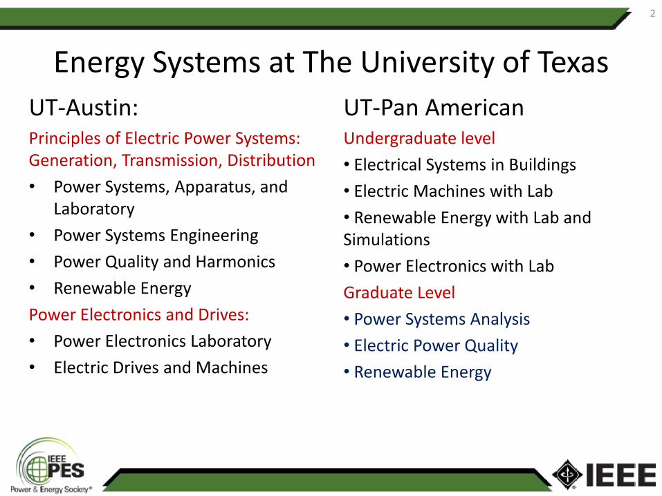
Energy Systems at The University of Texas UT-Austin:Principles of Electric Power Systems: Generation, Transmission, Distribution• Power Systems, Apparatus, and
Laboratory• Power Systems Engineering• Power Quality and Harmonics• Renewable Energy Power Electronics and Drives:• Power Electronics Laboratory• Electric Drives and Machines
UT-Pan AmericanUndergraduate level• Electrical Systems in Buildings• Electric Machines with Lab• Renewable Energy with Lab and Simulations• Power Electronics with LabGraduate Level• Power Systems Analysis• Electric Power Quality• Renewable Energy
2

Power Systems, Apparatus, and Laboratory• First course in power systems
• Course format– Lecture: 3 lecture hours– Laboratory: 3 hours
• Grading: – Small exams: 5 x 8 = 40 points– Final exam: 20 points – Laboratory: 40 points (15 lab components)
• Class size: 32 students with 2 teaching assistants
• Topics: ‘from generation to distribution and utilization’
3

Power Systems, Apparatus, and LaboratoryBalanced three-phase power systems: phasors to real and reactive power, transmission and distribution systems
Lab Experiments: Concepts of RMS values Real Power and Reactive Power Power Factor Correction
Transformers and per-units: ideal, equivalent circuits, single- and three-phase, two- and three-winding, auto
Lab Experiments: Single- and Three Phase TransformersTransformer PolarityTransformer RegulationAutotransformer
Synchronous machines: equivalent circuits, real and reactive power control, loading capability
Lab Experiments: Phase sequenceSynchronous machines as generatorsSynchronization of generatorsActive and reactive power control
Power Systems in Steady-state: line models, voltage regulation, loadability, reactive power compensationLab Experiments: Power Flow and Voltage Regulation Phase Angle and Voltage Drop Between Sender and ReceiverParameters which Affect Real and Reactive Power Flow
4

Power Systems, Apparatus, and LaboratoryInduction machines and wind generation: equiv. ckt, squirrel and wound rotor, power and torque characteristics, Type 1 – 4 turbines
Lab Experiments: Prime Mover and Torque MeasurementSquirrel Cage and Wound Rotor IMs Direct-connect Fixed Speed Wind TurbinesReactive Power Requirement
Power Flow Analysis: problem formulation, solution (GS & NR), control
Lab Experiments: Power flow using PowerWorldWrite a Matlab code for a 5-bus system
Short-circuit Faults: sequence components, three-phase and single line-to-ground faults
System Protection: circuit breakers, reclosers, fuses, relays (overcurrent), zones of protection, relays (distance and differential)
Lab Experiments: Under development: SEL 351
5

Safety Guidelines• During the first lab, safety guidelines are
presented to the students. Topics include:• Physiological effects of AC current• Equipment Insulation Categories• Electrical Hazards to the Body
– What parameters need to be measured?– What range of voltages and currents can
occur during the test?– What are environmental conditions of the
test object?– At what point in the power supply will the
measurements be taken?• Pollution in the lab environment• Students review guidelines and sign a
safety agreement
6

Laboratory Manual
• Students encouraged to read discussion of theory and procedure prior to each laboratory session
• Organization– Objective– Discussion of Theory– Instruments and Components– Experiment Procedure– Review Questions
7
Lab Experiment: Concept of RMS
• Objectives– Create better understanding of the concept of RMS
• Procedure– Lamps on synchronizing module are used to compare brightness based
on input voltage– First lamp is connected to 120 VAC RMS; Second lamp is connected to
a variable DC source– Lamp with DC voltage is varied until both lamps glow with equal
brightness
• Results– 120 VDC results in equal lamp brightness (equal power dissipation)– This is equal to the RMS value of AC voltage waveform
8

Lab Experiment: Concept of RMS
• Sample Review Questions and Responses4
2
5
3
6
0-120Vac
0-120Vdc V0-200
Vdc
1
7
N
1
N
+
-
9
3) An lllcandescent laIllp, rated at 100 W, gives a certain amollllt ofligllt Whetl placed across tile 120 VAC power line. Would theamount of light increase, decrease or remain tile saIne, wIlen thelamp is placed across a 120 VDC power line? Explain youranswer.
The amount of light is expected to remain the same becausethe rms value of an AC voltage is equal to the DC voltage thatwould cause the same heating (lighting) effect.
4) What is the effective (nns) vallIe of an AC sine wave having apeak vallIe of 4A?
2.85A
5) Do Y01I know why the DC voltllleter arId the DC allillleter llldicatezero in procedure 7? Explalll.
The DC voltmeter and ammetel" indicate zero because theyal"e connected in an AC circuit and they meaSUl"e the averagevalue of voltage and CUl"I"ent which al"e both equal to zero.

Lab Experiment: Transformer Polarity
• Objectives– Determine polarity of transformer windings
• Procedure– A single phase transformer with one primary winding and three secondary
windings with different turn-ratios is used in this experiment– 10 VDC voltage source is connected to the transformer primary winding– DC voltmeter is connected to the secondary winding being tested– The DC voltage source on the primary winding is energized and the deflection of
the DC voltmeter on the secondary winding is observed– This procedure is repeated for all three secondary windings
• Results– If the voltmeter pointer momentarily deflects to the right (positive), the terminals
of the DC voltage source and DC voltmeter have the same polarity – The polarity is determined for all windings using this procedure
10

Lab Experiment: Transformer Polarity
• Sample Review Questions and Responses
11
1) Assmning you have a 120VAC power som"ce and that all of thewindings on your slllgie-phase transfonner rllodule produce tlleir ratedvoltage, show in the spaces provided how you would COlmect thewindings to obtain the followlllg voltages:
a) 240V:
Connect terminals 2 and 5, measure from terminals 1 and 6
b) 88V:
Connect terminals 1 and 3, measure from terminals 2 and 4
c) 180V:
Connect terminals 2 and 5, measure from terminals 1 and 9
d) 92V:
Connect terminals 2 and 4, measure from terminals 1 and 8

Lab Experiment: Synchronization of Synchronous Generators
• Objectives– Demonstrate how to synchronize a
synchronous generator to the power grid• Procedure
– DC motor acts as the prime mover for the synchronous machine
– Output of the synchronous machine is connected to an open synchronizing switch which is connected to the grid at 208 VLL
– DC motor is adjusted to approximately synchronous speed (1800 rpm)
– DC excitation of the synchronous machine is adjusted until output voltage is equal to the grid voltage (synchronizing lights are now flickering)
12
Lab Experiment: Synchronization of Synchronous Generators
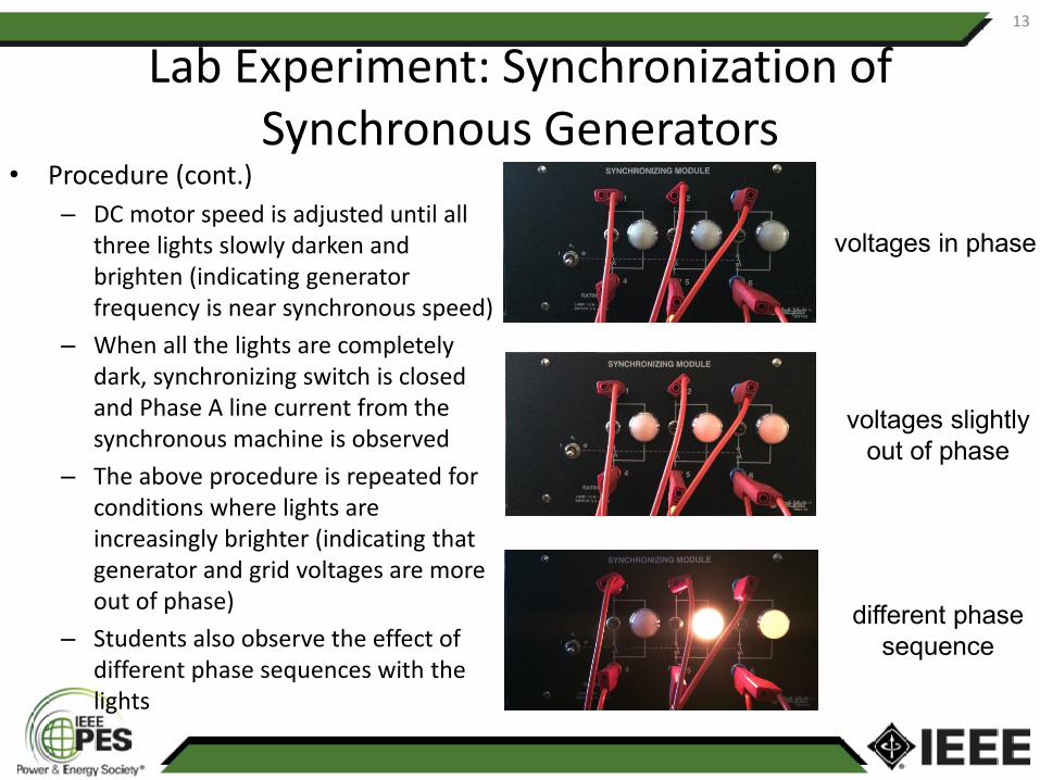
voltages in phase
voltages slightly out of phase
different phase sequence
• Procedure (cont.)– DC motor speed is adjusted until all
three lights slowly darken and brighten (indicating generator frequency is near synchronous speed)
– When all the lights are completely dark, synchronizing switch is closed and Phase A line current from the synchronous machine is observed
– The above procedure is repeated for conditions where lights are increasingly brighter (indicating that generator and grid voltages are more out of phase)
– Students also observe the effect of different phase sequences with the lights
13
Lab Experiment: Synchronization of Synchronous Generators
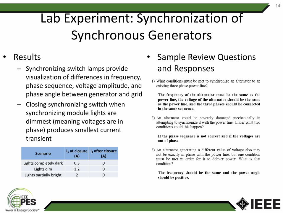
• Results– Synchronizing switch lamps provide
visualization of differences in frequency, phase sequence, voltage amplitude, and phase angle between generator and grid
– Closing synchronizing switch when synchronizing module lights are dimmest (meaning voltages are in phase) produces smallest current transient
• Sample Review Questions and Responses
Scenario I1 at closure (A)
I1 after closure (A)
Lights completely dark 0.3 0Lights dim 1.2 0
Lights partially bright 2 0
14
1) What conditions Inust be met to synchronize an aiteillator to anexisting three phase power line?
The frequency of the alternator must be the same as thepower line, the voltage of the alternator should be the sameas the power line, and the three phases should be connectedin the same sequence.
2) An alteluator could be severely dmnaged Inechanically inattelnpting to synchronize it with the power line. Under what twoconditions could this happen?
If the phase sequence is not correct and if the voltages areout of phase.
3) An aiteillator generating a different value of voltage also Inaynot be exactly in phase with the power line., but one conditionInust be met in order for it to deliver power. What is thatcondition?
The frequency should be the same and the power angleshould be positive.

Lab Experiment: Fixed-Speed Wind Turbine
• Objective– Determine real and reactive power below, at, and above synchronous speed of
induction machine• Procedure
– DC motor acts as the prime mover for the squirrel-cage induction machine– The power supply to the induction machine is adjusted to 208 VLL
– The speed of the DC motor is adjusted to 1720 rpm (below synchronous speed of 1800 rpm)
– Measurements are taken for the three line currents, real power, and reactive power; power factor and slip are calculated
– DC motor speed is increased in increments of 10 rpm and the measurements are taken again
– It is observed that the induction machines goes into generating mode above synchronous speed and real power flow is reversed
15

Lab Experiment: Fixed-Speed Wind Turbine
SQUIRREL-CAGEINDUCTION MACHINE
2 5
1 4
3 6
AI3
AI2
AI1
0-2.5 A ac
VarW
2 31 5 64
0-208V ac
5
4
0-208V ac
6
V
0-250 V ac
120 V dc
DC SHUNT MOTOR
N1
3
5
4
6
2
7 8
8
16

Lab Experiment: Fixed-Speed Wind Turbine
• Results • Sample Review Questions and Responses
17
2) In this experitnent, the slip varied between 4.44% and-2.78%. TIns is a large variation. In real life, a fixed speedwind turbine typically has slip from 0 to -2%. Can youexplain the reason for this difference?
Most of the extra variation is due to the fact that we ranthe machine in motoring mode for part of thisexperiment. In real life you would never run a windturbine in motoring mode.
3) Plot and attach to back of tills doculnent:
• P, Q and S vs. speed in RPM on a single graph
• Iavg vs. speed in RPM
• PF vs. speed in RPM
4) Explain why the CUITent Ineasmoed is a IniniInuln atsynchronous speed.
At synchronous speed, current is required only tomagnetize the machine (and take care of the statorlosses). Since no real power is delivered to the load, itrequires no current, thus the total current is minimized.

Lab Implementation at UTPA
UTPA equipment characteristics:1)Open work bench, allow students more visibility2)Three phase digital meters3)Participants must work under supervision
18

Renewable Energy Power System Simulations
• Computer laboratory simulation is a major tool use by utility planners, renewable energy developers, and power engineers and researchers.
• Access to control center at the wind power plant, PV power plant, conventional power plant, or utility system operators (ERCOT, CAISO) is limited. Students can benefit from computer simulations to train them to use the software commonly utilized by the utility planners and engineers.
• In this lab, we give short lectures on using steady state and dynamic model of wind turbine generator/wind plant, PV generator/plant and Concentrated Solar Power plant to simulate a real system under normal condition or specific contingencies.
19

Steady state simulation
• Equivalencing hundreds of generators into single generator representation
• Real and reactive power settings of the Renewable Energy generators
• Different types of reactive power compensation
• Impact of over/under compensation on the power systems
• Comparison between normal operation and contingency operation
• Issues in transmitting renewable energy over long distance
20

Dynamic simulation
• Different types of generators – different types of dynamic models
• Real and reactive power settings of the Renewable Energy generators
• Impact of reactive power limitation
• Example of self clearing fault
• Example of fault clearing by removal of transmission
• Concept critical clearing time of circuit breakers
21