Laboratory determinations of the magnetic properties of...
13
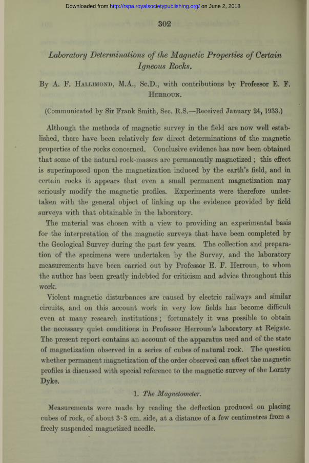
302 Laboratory Determinations of the Magnetic Properties of Certain Igneous Rocks. By A. F. H allimond, M.A., Sc.D., with contributions by Professor E. F. H erroun. (Communicated by Sir Frank Smith, Sec. R.S.—Received January 24, 1933.) Although the methods of magnetic survey in the field are now well estab- lished, there have been relatively few direct determinations of the magnetic properties of the rocks concerned. Conclusive evidence has now been obtained that some of the natural rock-masses are permanently magnetized ; this effect is superimposed upon the magnetization induced by the earth’s field, and in certain rocks it appears that even a small permanent magnetization may seriously modify the magnetic profiles. Experiments were therefore under- taken with the general object of linking up the evidence provided by field surveys with that obtainable in the laboratory. The material was chosen with a view to providing an experimental basis for the interpretation of the magnetic surveys that have been completed by the Geological Survey during the past few years. The collection and prepara- tion of the specimens were undertaken by the Survey, and the laboratory measurements have been carried out by Professor E. F. Herroun, to whom the author has been greatly indebted for criticism and advice throughout this work. Violent magnetic disturbances are caused by electric railways and similar circuits, and on this account work in very low fields has become difficult even at many research institutions ; fortunately it was possible to obtain the necessary quiet conditions in Professor Herroun’s laboratory at Reigate. The present report contains an account of the apparatus used and of the state of magnetization observed in a series of cubes of natural rock. The question whether permanent magnetization of the order observed can affect the magnetic profiles is discussed with special reference to the magnetic survey of the Lornty Dyke. 1. The Magnetometer. Measurements were made by reading the deflection produced on placing cubes of rock, of about 3 •3 cm. side, at a distance of a few centimetres from a freely suspended magnetized needle. on June 2, 2018 http://rspa.royalsocietypublishing.org/ Downloaded from
Transcript of Laboratory determinations of the magnetic properties of...
302
Laboratory Determinations of the Magnetic Properties of CertainIgneous Rocks.
By A. F. H allimond, M.A., Sc.D., with contributions by Professor E. F.H erroun .
(Communicated by Sir Frank Smith, Sec. R.S.—Received January 24, 1933.)
Although the methods of magnetic survey in the field are now well established, there have been relatively few direct determinations of the magnetic properties of the rocks concerned. Conclusive evidence has now been obtained that some of the natural rock-masses are permanently magnetized ; this effect is superimposed upon the magnetization induced by the earth’s field, and in certain rocks it appears that even a small permanent magnetization may seriously modify the magnetic profiles. Experiments were therefore undertaken with the general object of linking up the evidence provided by field surveys with that obtainable in the laboratory.
The material was chosen with a view to providing an experimental basis for the interpretation of the magnetic surveys that have been completed by the Geological Survey during the past few years. The collection and preparation of the specimens were undertaken by the Survey, and the laboratory measurements have been carried out by Professor E. F. Herroun, to whom the author has been greatly indebted for criticism and advice throughout this work.
Violent magnetic disturbances are caused by electric railways and similar circuits, and on this account work in very low fields has become difficult even at many research institutions ; fortunately it was possible to obtain the necessary quiet conditions in Professor Herroun’s laboratory at Reigate. The present report contains an account of the apparatus used and of the state of magnetization observed in a series of cubes of natural rock. The question whether permanent magnetization of the order observed can affect the magnetic profiles is discussed with special reference to the magnetic survey of the Lornty Dyke.
1. The Magnetometer.
Measurements were made by reading the deflection produced on placing cubes of rock, of about 3 • 3 cm. side, at a distance of a few centimetres from a freely suspended magnetized needle.
on June 2, 2018http://rspa.royalsocietypublishing.org/Downloaded from

Magnetic Properties of Igneous Rocks. 303
The cube must necessarily be of fair size in order to obtain a measureable magnetic moment; owing to its low intensity of magnetization it must be placed rather near the needle of the magnetometer, in which position its pole- face subtends a considerable solid angle a t the distance of the needle. This face can hardly be treated as a magnetic shell and its surface may not be uniformly magnetized. The latter condition is due partly to the fact that the surfaces of the cube, as cut, are not normal to the axis of magnetization, and partly to the distribution of the active constituent (magnetite) not being always uniform throughout its volume.
I t was therefore considered best, in order to minimize these errors, to place the cube as far from the needle as possible, consistent with reliable deflections being obtained with the mirror and scale ; and further to increase the sensitivity by the use of a small compensating magnet placed on the side of the needle remote from the specimen so as to weaken the restoring force of the earth’s field a t the needle.
Accordingly the cubes were carefully placed centrally on a horizontal brass turn-table, the centre of which was 7 • 0 cm. from the suspended needle ; on the other side of the needle on the E—W line the small compensating magnet was placed with its axis in the magnetic meridian and by a very small movement in the N—S direction the zero of the scale reading could be made to coincide with the original zero in the earth’s field.
The value of the reduced field at the needle was compared with the full field due to H both by finding the squares of the periodic times of oscillation of the needle and also by the deflection method with and without the compensating magnet. In this way the reduced field a t the needle was found to be from 0-067 to 0-07 C.G.S. unit under the various conditions in which the instrument was employed.
I t is evidently undesirable to use much smaller cubes than those described and to place these very close to the needle, since the latter when deflected might induce polarity in the specimen and give misleading, high, results.
But the uncertainty of the distance between the effective poles with a cube of 3 • 3 cm. in the side is a drawback ; moreover, the usual method of eliminating all but the higher terms of If2by taking two distances, say in the ratio of 3 : 4, is not applicable to the cubes as received, for with any material increase in distance the deflection falls to such an extent as to render its reading unreliable. With an artificially magnetized cube, however, good deflections are obtainable at 15 or 20 cm. from the needle, but this distance is too great for the feebly magnetized cube in its natural state.
on June 2, 2018http://rspa.royalsocietypublishing.org/Downloaded from

304 A. F. Hallimond and E. F. Herroun.
By the use of small bars of hard steel, weakly magnetized, and a small cut bar of magnetite of known magnetic moment, constants for this instrument were obtained for the 7 cm. distance. The cubes were all substantially of the same dimensions, they were placed centrally on the turn-table and readings were obtained on rotating the cube through 180°. I t is believed, therefore, that the results are strictly comparable with each other and that they represent the true values to within 3 or 4 per cent.
A magnetizing solenoid and compensating coil were also used with this magnetometer ; when a cube of Cleveland Dyke rock was put inside the solenoid and a current giving a calculated value of H within the solenoid of 1-186 C.G.S. was switched on and reversed, deflections wrere obtained giving M = 0-103, J = 0-00299 and = 0-00252, a result in very good agreement with values found by instruments of the type of the Curie balance for somewhat higher fields.
I t is evident that, with such a low K v value, the “ end effects,” even with cubes, must be small.
II. Permanent Magnetization of Rocks in situ.
The Effects of Lightning.—Ground struck by lightning is penetrated to a depth of many feet, the path of the discharge being indicated in extreme cases by tubes of fused rock termed “ fulgurites.” I t may be anticipated, therefore, that pieces of rock collected from an old land surface will ha ve been magnetized at some period in their history. Loewinson-Lessing* has described a very marked instance of this effect: andesite from the summit of the mountain Petit Ararat has been penetrated by fulgurites and is intensely magnetized, to a degree far greater than that produced by cooling in the earth’s field.
Lightning discharges are less frequent in open country than on mountain summits, but there can be little doubt that rocks like that of the Swynnerton Dyke must have occasionally undergone magnetization from this cause, for they have been exposed at the surface of the ground for a very long period of time.
Magnetization by lightning is virtually instantaneous ; indeed Pockelsf has made use of the effect to record the current in a conductor carrying a lightning discharge ; small bars of basalt were placed in the vicinity of the conductor, and their magnetization was subsequently determined.
* ‘ Bull. Acad. Sci. U.S.S.R.,’ p. 875 (1927); ‘ C. R. Acad. Sci. Paris,’ vol. 180, p. 242 (1925).
f ‘ Ann. Chcm. Phys.,’ vol. 63, p. 195 (1897), and ‘ Phys. Z.,’ vol. 2, p. 334 (1901).
on June 2, 2018http://rspa.royalsocietypublishing.org/Downloaded from

Magnetic Properties of Igneous Rocks. 305
Lightning strokes differ in effect from the earth’s field in that the resulting magnetization is not uniform in strength or direction. Not only does the discharge ramify in the ground, but each line of current exerts a circular field, so that pieces of rock on either side of the discharge are magnetized in opposite directions; the total external effect may therefore be relatively small. To produce an appreciable effect a t a height of 4 feet a magnetized area exceeding several inches in diameter would be necessary. Tests by Koenigsberger* showed that in most cases the irregular polarity when present varies from point to point within a few inches distance ; it is therefore likely that magnetization of this kind is generally too irregularly distributed to affect the magnetic profiles. This would explain the consistency of the results obtained in field surveys, e.g., over the outcrop of the Swynnerton Dykes, and it will apply with even greater force when the rock mass is a t a greater distance from the instrument. Lightning strokes, except under abnormally severe conditions, and at a direct outcrop, can probably be ignored in considering the results of a magnetic survey.f In laboratory determinations, on the other hand, where small samples are used, practically all measurements on outcrop material will be subject to large errors from this cause ; it therefore seems advisable to use only specimens taken from a considerable depth, say 50 feet.
For the first test of the magnetic condition of a rock taken at depth, specimens were collected from the Cleveland Dyke. + This rock is mined at Goath- land, N. Yorkshire, as a roadstone ; the drift is a t a depth of about 100 feet below the open moorland, where the rock outcrop will be subject to considerable risk of lightning stokes. Five rough specimens, each about 4 inches across, selected from the mined material, were tested in front of the magnetometer and gave the following deflections: 25, 20, 15, 10, 25 scale divisions.
The polarity appeared to be somewhat irregular in distribution, but this effect was in no specimen large and it seems clear that the rock at this depth possesses a weak but fairly uniform magnetization. A cube with 3-3 cm. side was next cut from a representative piece of the above set, and was found to be magnetized with the intensity 43 X 10~5. The Cleveland rock at depth is thus only weakly magnetized. If the susceptibility is taken as 250 X 10-5, the induced magnetization (&V), due to the earth’s field Y, will be about 125 X 10~5, a value nearly three times the permanent magnetization.
* ‘ Beitr. Geophys.,’ vol. 35, p. 204 (1932), containing reference to earlier papers, t These remarks apply to moderate anomalies due to ordinary igneous rocks—hardly
to magnetite deposits, t Slide E 16778.
on June 2, 2018http://rspa.royalsocietypublishing.org/Downloaded from

306 A. F. Hallimond and E. F. Herroun.
In order to ascertain the direction in which the dyke is magnetized, it would be necessary to take orientated samples from the rock in situ ; arrangements were accordingly made to do this for the material collected from the Blairgowrie Dyke and from Leicestershire. The last-named rocks proved, however, to be only very weakly magnetic, for reasons to be mentioned below.
Parallel determinations on the Leicestershire, Blairgowrie and other rocks are given in Table I.
Table I.—Permanent Magnetization of Bock Cubes as cut. Intensity ofMagnetization J along the cube axes , 6, c.
Specimen. a. b. C .Susceptibility
x io -6.
Roadstone No. 970, Seacliff Quarry, N. Berwick (depth not known) .............................. 121 26 69 (q) 363
Cleveland Dyke, Goathland, N. Yorks............ 22 37 0 (r) 253Tholeite, Cat’s Craig Quarry, Blairgowrie....... - 8 0 26 (p) 164, (q) 226Do., 2nd sample .............................................. similar values to preceding.Greenstone Dyke, Mt. Sorrel, Leics................. 0 0 0 (q) 36-5Granophyre, Bradgate Hill Quarry, Groby,
Leics. (No. 18) .............................................. 0 0 0 (r) 5*4Granophyre, “ New Quarry,” Groby ........... 0 0 0 (2) 13-3
N ote.—The susceptibilities are in 10-5 C.G.S. They were determined as follows: (p) on a cut cube, II = 5*0 ; (?) on powder, H == 88 ; (q') on powder, H = 130; (r) on a cut bar, H high.
Orientation*.—The last five samples were orientated and here the axis c was vertical, b pointing E—W and a N—S (magnetic). The sign given is positive when the upper, the eastern, or the southern end of the sample has “ south ” polarity.
The Seaclifi specimen was selected for a preliminary test, from the collection of roadstones ; it may have been at any depth in the quarry. The others were specially taken at depths of 30 feet or more below the surface of the ground.
The values for the Leicestershire rocks are low. This agrees with the weak effects observed in a magnetic survey (not published) over a small area of the Groby granophyre. Equally low laboratory results were obtained for the Mount Sorrel granite; this rock is extensively reddened, and only the grey variety was susceptible.f From the very definite results obtained in a magnetic
* The pieces collected were loose but still in position in the quarry. The orientated piece was marked with an arrow to indicate the magnetic north, and a line to show the horizontal plane; it was then detached from the quarry face. At the same time six pieces of the rock were collected within about a yard of the marked piece, to check the uniformity of the magnetization.
t Gf. measurements by Wilson, * Phil. Trans.,’ A, vol. 219, p. 84 (1919).
on June 2, 2018http://rspa.royalsocietypublishing.org/Downloaded from
Magnetic Properties of Igneous Rocks. 307
survey it may be assumed that the granite in depth is susceptible, but in view of the weak and variable laboratory results it has not been possible to get decisive evidence for the present purpose from any of the Leicestershire rocks. The oxidation and loss of magnetic properties may be associated with the fact that this region is an old desert land-surface, in which weathering may have operated to considerable depths.
III. Effect of Permanent Magnetization on the Magnetic Profiles.The Lornty Dyke.
Magnetic profiles obtained in the survey of the Swynnerton Dyke were symmetrical and gave no indication of any important degree of cross-magnetization. At other localities, however, profiles have been recorded indicating the presence of a considerable effect which might be due to permanent magnetization of the dyke rock. One outstanding case is that recorded by Schulze* for dykes in Saxony. Here the curves, instead of a simple maximum above the magnetic rock, have also a negative portion, so that their general form is that shown in fig. 3 ; the south side of the dyke had apparently a magnetic “ south ” polarity.
The first example of this kind to be recorded in Great Britain was observed by Drs. McLintock and Phemister in their survey of the Lornty Dyke, near Blairgowrie, in Perthshire.f The Lornty curves suggest permanent magnetization, but the direction is the opposite of that which would be induced by the earth’s present field. I t was with considerable interest, therefore, that specimens of this rock were tested by the present methods in order to ascertain directly the intensity and direction of the permanent magnetization in the cut cubes. I t will be shown that the values observed, though at first sight small, are in the required direction and are of the order required to account for the very well-marked peculiarities of the Lornty profiles.
Six rough specimens and two orientated pieces were collected from Cat’s Craig Quarry, the only quarry from which fresh rock was obtainable. The depth was about 30 feet. One of the rough pieces proved to be rather strongly magnetic (deflection — 150 divisions) and probably represents a local variation in the dyke ; a microsection (E 29624) shows that the rock is greener and more completely crystalline ; the other pieces (E 29622/3) show confused interstitial patches (mesostasis) containing fine-grained magnetite with a few red flakes of ferric oxide. Otherwise the rocks are very similar. The
* ‘ Z. Geophys.,’ vol. 6, p. 141 (1930).t * Summary of Progress for 1930,’ Part III (Mem. Geol. Survey), pp. 24-29 (1931).
on June 2, 2018http://rspa.royalsocietypublishing.org/Downloaded from

308 A. F. Hallimond and E. F. Herroun.
remaining pieces were moderately magnetic, yielding the deflections 14, 15, 20, 13, 14, so that the magnetization appears, as in the Cleveland Dyke, to be fairly uniform. Two cubes were cut from the special orientated pieces, with axes pointing respectively magnetic north, west and vertical. These when tested on the magnetometer yielded the following values :—
Deflection scale divisions.
Intensity of magnetization 10-5 C.G.S.
Axis c (vertical) ................... 3 25a (N—S) ....................... — 1 nearly —8b (E—W) ....................... 0 0
The results for cube 2 were exactly similar.These values are small but are quite consistent and decisive.The resultant intensity of permanent magnetization is therefore J = 26 X
lO-5 C.G.S.The direction is approximately in the present magnetic meridian, but inclined
about 15° northwards from the vertical with the south pole on the north side of the dyke. I t is thus inclined at about 35° to the earth’s present field. The intensity of magnetization on the walls of the dyke will be 20, and on the horizontal top of the dyke, 25 X 10~5 C.G.S.
When placed in a solenoid with approximate field-strength 5*0 C.G.S. the susceptibility of one of the cubes was found to be 164 X 10~5 C.G.S.
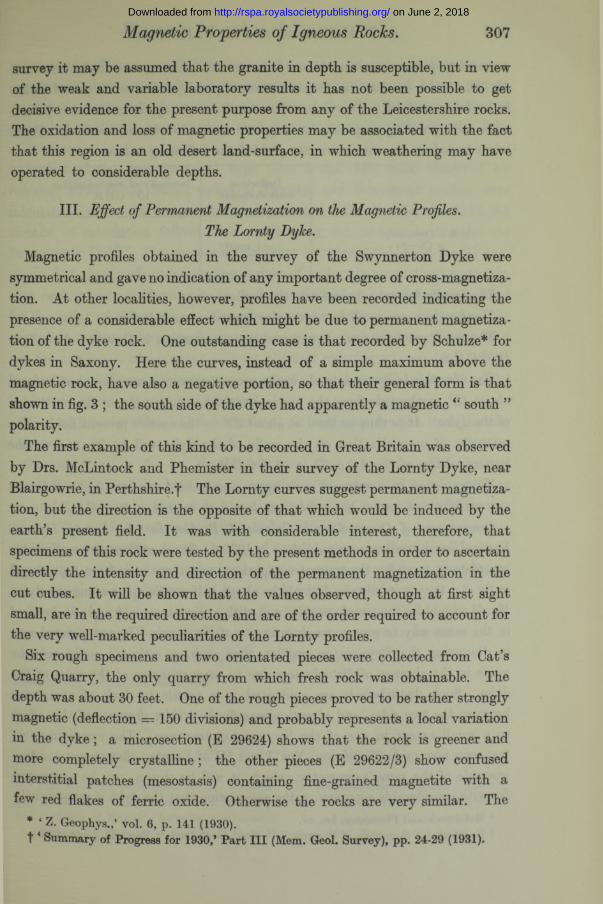
Comparison of Observed with Calculated Profiles for the Lornty Dyke.— Vertical force profiles were published in 1930.* Three of these are sufficiently complete to serve for the present comparison, and these have been reproduced in fig. 3 ; they were obtained at places about half a mile apart along the dyke. No. II resembles the simple profiles met with at Swynnerton,f and can be used in the same way to give a rough estimate of the depth. I t was pointed out, in discussing the Swynnerton profiles, that such an estimate could only be made in the absence of disturbances due to magnetization of the sides of the dyke. Such disturbances are evidenced in a profile by lack of symmetry between the two sides, and attention was drawn to the presence of this effect to a small extent in one of the Swynnerton traverses. The remaining two traverses now under discussion, Nos. I and III at Lornty, offer an outstanding example of the same asymmetry, which, it will be shown, can be accounted for with considerable accuracy on the assumption that the dyke is permanently
* McLintock and Phemister, loc. cit.t Hallimond, “ Summary of Progress ” (‘ Mem. Geol. Surv.’)> Part III, p. 44 (1929).
on June 2, 2018http://rspa.royalsocietypublishing.org/Downloaded from

Magnetic Properties of Igneous Rocks. 309
magnetized. The susceptibility measured on the cut cube of Lornty rock agrees with that required by all three profiles, while the small degree of permanent magnetization measured on the cubes is the same in direction though somewhat smaller in amount than that required by the profiles for the dyke as a whole.
Profiles of the unsymmetrical type (like I and III) were observed by Schulze* over E—W basalt dykes in Saxony, and theoretical profiles were calculated by way of the gravitational potential. For the Lornty Dyke the method of calculation follows that outlined by the present author for the Swynnerton Dyke. The geological structure is represented by a model constructed of plane surfaces separating regions of uniformly magnetized m aterial; each surface has a uniform polarity, and the effect of each surface is calculated for the point of observation. Thus the magnetic anomaly is obtained as the sum of a number of terms each representing one of the surfaces. This method has the advantage of assigning a direct physical meaning to each term, and it is correspondingly easy to estimate the effect upon the profile when the model is altered either in shape or in material.
Vertical force profiles will be calculated in this way for the three Lornty traverses.
General Formulae for the Profiles above an Inclined Dyke.—The dyke is regarded as a parallel-sided layer of material with susceptibility k, dipping at an angle </> to the horizon and extending indefinitely downwards and to the sides. The top is a horizontal infinite strip, of width w.
(1) Magnetic profiles due to the top of a wide dyke : horizontal and vertical forces at a point P above a horizontal infinite strip of width w, intensity of magnetization i.Notation as in fig. 1 ; AB is the trace of the strip.
From the calculation already made for the Swynnerton Dyke,f the forces at a point P due to the elementary infinite strip whose trace is are
v = 2 icos 0 dx/1 h = 2 sin 0 dx/l.
Integrating across the strip AB,
v = f \ d 0 = 2 i (02 - 0X),J9iC02 . h — 1 2 i tan 0d0 = 2 i(log sec 02 — log sec 0X).J0i
* Loc. cit. For calculation see H. Haalck, “ Die magnetischen Verfahren ” (Berlin, 1927); Sliehter, ‘ Amer. Inst. Min. & Met. Eng., Tech. Pub.,’ No. 120, p. 17 (1928) points out that one of Haalck’s formulae is erroneous.
t 1 Summary of Progress for 1929,” Part III, ‘ Mem. Geol. Surv.,’ p. 51 (1930).
on June 2, 2018http://rspa.royalsocietypublishing.org/Downloaded from

310 A. F. Hallimond and E. F. Herroun.
These formulae give the vertical and horizontal force profiles for traverses a t right angles to the dyke. The vertical force expression is very simple, being proportional to the angle subtended by the horizontal strip. I t is very widely useful, both for the top of a dyke and for the concealed boundary of a magnetic formation, when the face of contact is not magnetized.*
Fig. 1.—Magnetic forces due to a horizontal strip.
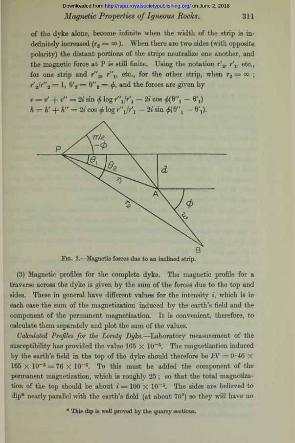
(2) The sides of the dyke.(a) Vertical and horizontal forces at a point P above an inclined plane strip.
Notation as in fig. 2. AB is the trace of an infinite strip of width winclined at an angle </>, but with its edges horizontal.
The forces at P perpendicular and parallel to the plane of the strip have already been obtained in (1). They are
Force perpendicular to AB — 2t(02 — 0!)
Force parallel to AB = 2 ilog Se- - ^ 2 ^ = 2 log r2/rvsec (0! +
The vertical and horizontal forces at P are therefore
v — 2ilog r2fr1 sin </> — (02 — 0X) cos </> h = 2 ilog rJr-L cos </> — (02 — 0X) sin (/>.
(b) Magnetic profile due to the two sides of an inclined dyke. The horizontaland vertical forces calculated in the preceding paragraph for one side
* In the case of an isolated boundary the width of the “ dyke ” is infinite and the formula becomes v — 2i(7t/2 — 0!); for a point above the magnetic rock distant from the boundary, v = 2m ; for a point directly above the boundary at a distance dfrom the boundary, 0 = 45° = tt/4 and v = Itivi. Thus d can be obtained directly from the profile.
on June 2, 2018http://rspa.royalsocietypublishing.org/Downloaded from
Magnetic Properties of Igneous Rocks. 311
of the dyke alone, become infinite when the width of the strip is indefinitely increased (r2 = °o ). When there are two sides (with opposite polarity) the distant portions of the strips neutralize one another, and the magnetic force a t P is still finite. Using the notation / 2, etc., for one strip and r"2, r'\, etc., for the other strip, when r2 = <x> r'2/r''2 = 1, 0'2 = 0"2 = (f>, and the forces are given by
v — v' -f- v" = 2 isin <f> log r"1fr\ — 2 cos </>(0' — 0^) h = h' -J- h" = 2 icos </> log r’\ \ r \ — 2 sin — 0'j).
Fig. 2.—^Magnetic forces due to an inclined strip.
(3) Magnetic profiles for the complete dyke. The magnetic profile for a traverse across the dyke is given by the sum of the forces due to the top and sides. These in general have different values for the intensity i, which is in each case the sum of the magnetization induced by the earth’s field and the component of the permanent magnetization. I t is convenient, therefore, to calculate them separately and plot the sum of the values.
Calculated Profiles for the Lornty Dyke.—Laboratory measurement of the susceptibility has provided the value 165 X 10-5. The magnetization induced by the earth’s field in the top of the dyke should therefore be kV = 0-46 X 165 X 10"3 * 5 = 76 X 10-5. To this must be added the component of the permanent magnetization, which is roughly 25 ; so that the total magnetization of the top should be about i = 100 x 10~5. The sides are believed to dip* nearly parallel with the earth’s field (at about 70°) so they will have no
* This dip is well proved by the quarry sections.
on June 2, 2018http://rspa.royalsocietypublishing.org/Downloaded from

312 A. F. Hallimond and E, F. Herroun.
induced magnetization, but the laboratory values indicate a permanent magnetization of about 20 units, the north side being south polar.
The width of the dyke is known to be about 30 fee t; profiles were accordingly constructed with width 30, dip 65° and depth (a) 6 feet, (6) 30 feet. The values proved to be of the right order, but one alteration had to be made before the curves could be brought into numerical agreement with the profiles measured in the field survey. I t was found necessary to regard the sides of the dyke as magnetized in the direction already indicated, but with a greater intensity, of about 100 X 10-G. The theoretical curves for these values are shown superposed upon the observed profiles in fig. 3. The agreement is fairly good both in form and in magnitudes, the only serious deviation being the rather high observed values to the north of the outcrop. In traverse I the curves would indicate that the dyke is a little wider than 30 feet and the cover a little thicker than 6 feet. Traverse II is not at right angles to the dyke and the peak is consequently rather widened ; the depth indicated is about 30 feet and the width 30 feet. Traverse III is over a direct outcrop and is in very close agreement, the dyke being apparently just under 30 feet wide.
Nearly all dykes contain patches of more basic material, usually near the sides. These may be erratic in their distribution, and the principal difference in the curves (which suggests more magnetic material in the deeper part of the dyke) might be explained either by basic patches or by incipient weathering of the top part of the dyke.
Self-magmtization.—The preceding calculation ignores disturbances due to the magnetization of the dyke in its own field. The corners of the dyke are subject to a field due to the polarity distributed over the top and sides. The direction and amount of this field outside the dyke have been calculated above (assuming uniform magnetization); at a distance of 6 feet above the corner the force is of the order of 0-00500 C.G.S. But the permeability is only 0-0016, so that the magnetizing effect of the rest of the dyke on a piece of dyke material at 6 feet away would be negligible. Any edge effect might be expected to become noticeable only within a foot or less of the extreme corner of the dyke. I t is difficult to suppose that this will account for the apparently enhanced value of the permanent magnetization as indicated in the profiles, though some allowance may be required. The disturbance would apparently take the form of roughly diagonal magnetization outcropping in narrow strips along the corners. The effects of top and sides reinforce on the northern corner and neutralize on the southern, so that it seems likely that the general effect would be to accentuate the positive peak of the profile.
on June 2, 2018http://rspa.royalsocietypublishing.org/Downloaded from

Magnetic Properties of Igneous Rocks. 313
Summary.
An account is given of the magnetic properties of igneous rock specimens collected by H.M. Geological Survey. The rocks were taken from localities at which field surveys have been made with the magnetic vertical force variometer
Gamma, 6QO
300-S S £
/ \ \/ \/ ''
/ v v - N NW
i.__ .
20 4t BO tOO 120 140 160 iBO 2 0 0 2 2 0 F ee t'\Approxifpat4\ \' p o s i t io n ' \
of D y k e
Gammjxzoo-,
S.S £
n - - ~ -N N W
20 40 Vo too i2o i4 o too iso 200 Feet
Gamma730 -
6 0 0 -
450-
300-
150-
5
m
/V
0 - J > --------------‘--------------- 1--------------- 1--------------- 1--------------- 1--------------- 1--------------- 1__________ I__________ L_________ i--- ,--- -------1--------- ------ 1--------------- 1° 20 40 60 BO too 120 140 /60 l&O 200 220 24 0 2 6 0 f e e l
\A pprox/m atd p o s i t io n of Dyke
Fig. 3.—Observed and calculated vertical force profiles across the Lornty Dyke. The “ calculated ” profiles and corresponding position of the dykes are shown by broken lines. Points on the “ observed ” curves represent magnetometer readings.
during the past few years. A group of several specimens was taken at each place in order to ensure uniformity, and from one of these a 3*3 cm. cube was
VOL. c x l i .— A. Y
on June 2, 2018http://rspa.royalsocietypublishing.org/Downloaded from

314 H. Neuber.
cut for magnetic determination in the laboratory. The measurements, which were made by Professor Herroun, were obtained by placing the cube near a freely suspended magnetized needle, in a partially neutralized field. The instrument was standardized by means of bars of known moment and by the time of swing. Susceptibility was measured by surrounding the cube with a coil.
Specimens from Leicestershire (Charnwood Rocks) gave low values, but a measureable degree of permanent magnetization and susceptibility was found for the Cleveland Dyke and for the dyke at Lornty in Perthshire. A method is developed for calculating the magnetic profile from the geological model assuming uniformity of magnetization. Calculated and observed curves for the Lornty profiles show a fairly good agreement; they indicate that the north side of the dyke is south-polar, so that the magnetization appears to be in the opposite sense to that recorded for certain dykes in Germany, and does not coincide with that which would be produced by cooling in the earth’s present field.
New Method of Deriving Stresses Graphically from Photo-ElasticObservations.
By H. N eu ber ,* Munich.
(Communicated by E. G. Coker, F.R.S.—Received February 4, 1933.)
In transparent bodies under plane stress the difference and directions of the two principal stresses are obtained by observations with polarized light. To separate the stresses either additional measurements can be used, for instance changes of thicknessf ; or we may resort to any method of graphical integration. Although several different methods exist, J all are based upon the equations of equilibrium and involve considerable time. A new method, which has now been worked out by the writer, based entirely upon elastic equations, enables
* In charge of the photo-elastic investigation in the Mech. Techn. Labor., Technical University, Munich under the direction of Professor L. F6ppl.
t Coker and Filon, “ A Treatise on Photo-Elasticity,” Camb., 1931, §§ 2-47-2-49.% Coker and Filon, loc. cit., § 2.30; Filon, ‘ Brit. Ass.,’ Rep. 1923, p. 350 ; L. Foppl,
‘ SitzBer. bayer. Akad. Wiss.,’ p. 246 (1928); Widdern and Kurzhals, ‘ Mitt. mech. techn. Lab., Munchen,’ vol. 34, p. 4 (1930) and vol. 35, p. 14 (1931); Baud, ‘ J. Frank]. Inst.,’ vol. 211, p. 457 (1931).
on June 2, 2018http://rspa.royalsocietypublishing.org/Downloaded from