Laboratori Nazionali di Legnaro (Italy) DTL status A.Pisent ESS Roma 2012.
37
Laboratori Nazionali di Legnaro (Italy) DTL status A.Pisent ESS Roma 2012
-
Upload
scot-richard -
Category
Documents
-
view
219 -
download
0
Transcript of Laboratori Nazionali di Legnaro (Italy) DTL status A.Pisent ESS Roma 2012.

Laboratori Nazionali di Legnaro (Italy)
DTL status
A.Pisent ESS Roma 2012

Laboratori Nazionali di Legnaro (Italy)
Group involved
• The participation to IFMIF-EVEDA project (RFQ realization) is based on four INFN sites (LNL,Padova,Torino,Bologna) with competences in accelerator physiscs, RF, mechanical engineering, computer controls, vacuum, brazing......
• Almost all of these competences (+Naples) will be gradually involved in ESS DTL, at present
– AP (coordination)– M. Comunian (beam dynamics)– F. Grespan (RF)– R.De Prisco (RF)– P. Mereu (Mechanical design, Torino)– V. Vaccaro (RF stabilization, Napoli)– C. Roncolato (vacuum)– E. Fagotti (cooling system and acc.Phys.)
A.Pisent ESS Roma 2012
LNL group
IFMIF EVEDA RFQ organizationIn INFN

Laboratori Nazionali di Legnaro (Italy)
• Collaboration on DTL since 2006, in design (F. Grespan 1 year visit at CERN for PHD thesis on DTL stabilization)
• participation of INFN to the construction of DTL prototype.
• INFN is in charge of the construction of movable tuners of linac4.
• 13 Sept 2011 we had a mini-workshop on main aspects of DTL realization. https://indico.cern.ch/conferenceDisplay.py?confId=152766
• We are finalizing the the paper work for full access to Catia drawings (possible starting point).
Collaboration with CERN linac4

Laboratori Nazionali di Legnaro (Italy)
DTL Physics design: general parametersRF frequency 352.21 MHz
Design Current (10% margin included) 55 mAInput energy 3 MeV
Final energy (approx.) 81 MeVMaximum power/Tank 2.2 MWMaximum Surface field 1.5 Kilp
Maximum Surface field at 3 MeV 1.2 kilpPMQ maximum integrated field 3.8 T
Lattice FODO PMQ law Equipart.
Trans. Input emittance 0.24 mmmradLong. Input emittance 0.35 mmmrad
A.Pisent ESS Roma 2012
Tank No modules/Cells Length (m) Wfinal (MeV) Power (MW)1 4/70 8.19 22.08 2.0
2 3/26 5.48 39.63 2.2
3 2/18 4.67 54.64 2.0.
4 2/16 4.71 69.21 2.1
5 2/14 4.52 82.52 2.0
Total 144 27.57 10.3

Laboratori Nazionali di Legnaro (Italy)
DTL Physics design: final energyRF frequency 352.21 MHz
Design Current (10% margin included) 55 mAInput energy 3 MeV
Final energy (approx.) 81 MeVMaximum power/Tank 2.2 MWMaximum Surface field 1.5 Kilp
Maximum Surface field at 3 MeV 1.2 kilpPMQ maximum integrated field 3.8 T
Lattice FODO PMQ law Equipart.
Trans. Input emittance 0.24 mmmradLong. Input emittance 0.35 mmmrad
A.Pisent ESS Roma 2012
Tank No modules/Cells Length (m) Wfinal (MeV) Power (MW)1 4/70 8.19 22.08 2.0
2 3/26 5.48 39.63 2.2
3 2/18 4.67 54.64 2.0.
4 2/16 4.71 69.21 2.1
5 2/14 4.52 82.52 2.0
Total 144 27.57 10.3
0
10
20
30
40
50
60
0 10 20 30 40 50 60 70 80 90
ZTT
(MO
hm/m
)
E out (MeV)
ZTT (0.8 x SF value)
50-80 MeV shunt impedance higher than for any other structure (probably)
2.5 m module limit as for GSI galvanicMohammad Eshraqi, Jim Stovall
Laboratori Nazionali di Legnaro (Italy)
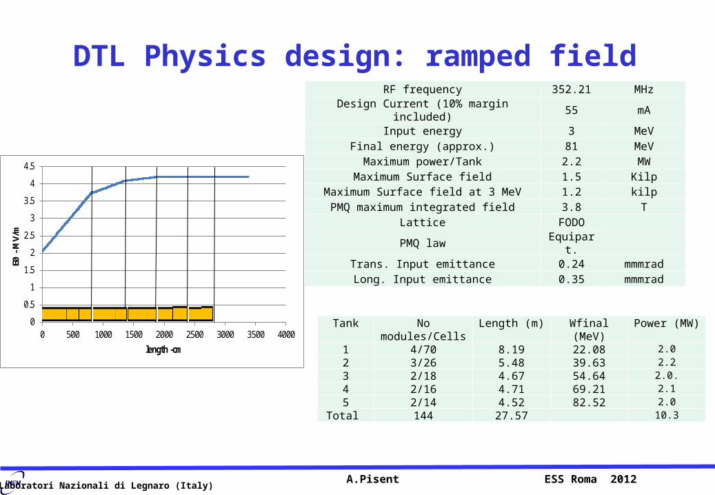
DTL Physics design: ramped fieldRF frequency 352.21 MHz
Design Current (10% margin included) 55 mAInput energy 3 MeV
Final energy (approx.) 81 MeVMaximum power/Tank 2.2 MWMaximum Surface field 1.5 Kilp
Maximum Surface field at 3 MeV 1.2 kilpPMQ maximum integrated field 3.8 T
Lattice FODO PMQ law Equipart.
Trans. Input emittance 0.24 mmmradLong. Input emittance 0.35 mmmrad
A.Pisent ESS Roma 2012
Tank No modules/Cells Length (m) Wfinal (MeV) Power (MW)1 4/70 8.19 22.08 2.0
2 3/26 5.48 39.63 2.2
3 2/18 4.67 54.64 2.0.
4 2/16 4.71 69.21 2.1
5 2/14 4.52 82.52 2.0
Total 144 27.57 10.3
0
0.5
1
1.5
2
2.5
3
3.5
4
4.5
0 500 1000 1500 2000 2500 3000 3500 4000
E0 -
MV/
m
length -cm

Laboratori Nazionali di Legnaro (Italy)
DTL Physics design: FODO latticeRF frequency 352.21 MHz
Design Current (10% margin included) 55 mAInput energy 3 MeV
Final energy (approx.) 81 MeVMaximum power/Tank 2.2 MWMaximum Surface field 1.5 Kilp
Maximum Surface field at 3 MeV 1.2 kilpPMQ maximum integrated field 3.8 T
Lattice FODO PMQ law Equipart.
Trans. Input emittance 0.24 mmmradLong. Input emittance 0.35 mmmrad
A.Pisent ESS Roma 2012
Tank No modules/Cells Length (m) Wfinal (MeV) Power (MW)1 4/70 8.19 22.08 2.0
2 3/26 5.48 39.63 2.2
3 2/18 4.67 54.64 2.0.
4 2/16 4.71 69.21 2.1
5 2/14 4.52 82.52 2.0
Total 144 27.57 10.3
2.5 m module limit as for GSI galvanic
Space available for dipole steerers and BPM(@SNS FF0DD0 and @CERN FFDD)
In operation Beam center can be tuned, not phase advance (should be sufficient).FODO allowes better shunt impedance if large-small DT alternance is possible (em quads?)

Laboratori Nazionali di Legnaro (Italy)
DTL Physics design: equipartitioningRF frequency 352.21 MHz
Design Current (10% margin included) 55 mAInput energy 3 MeV
Final energy (approx.) 81 MeVMaximum power/Tank 2.2 MWMaximum Surface field 1.5 Kilp
Maximum Surface field at 3 MeV 1.2 kilpPMQ maximum integrated field 3.8 T
Lattice FODO PMQ law Equipart.
Trans. Input emittance 0.24 mmmradLong. Input emittance 0.35 mmmrad
A.Pisent ESS Roma 2012
Tank No modules/Cells Length (m) Wfinal (MeV) Power (MW)1 4/70 8.19 22.08 2.0
2 3/26 5.48 39.63 2.2
3 2/18 4.67 54.64 2.0.
4 2/16 4.71 69.21 2.1
5 2/14 4.52 82.52 2.0
Total 144 27.57 10.3
PMQ max=69 T/mPMQ min=28 T/m
From the second Tank
block design PMQ can be used.

Laboratori Nazionali di Legnaro (Italy)
Beam envelopes
• Each tank begins with an empty Drift Tube (for BPM).• Only a transverse matching is needed. • Matching by using 2 PMQ at tank end and 2 PMQ at tank begin
SNS Tank1-Tank2: 1
Linac4 DTL Tank1-Tank2: 2

Laboratori Nazionali di Legnaro (Italy)
F O D O F O
Intertank space: 1
From first to second tank=180 mm
Laboratori Nazionali di Legnaro (Italy)
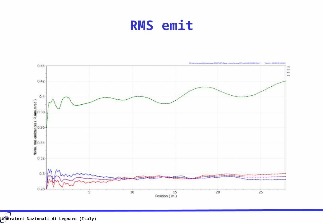
RMS emit

Laboratori Nazionali di Legnaro (Italy)
Phase advance/m

Laboratori Nazionali di Legnaro (Italy)
Output phase space using Gaussian dist. (6 )

Laboratori Nazionali di Legnaro (Italy)
DTL Physics design: error study
• The error study is preliminary (not done with the last tank subdivision)
A.Pisent ESS Roma 2012
Emit [75%] = 6.9900 Pi.mm.mrad [ Norm. ] Emit [75%] = 8.2433 Pi.deg.MeV [ Norm. ]
DTL 50 mA

Laboratori Nazionali di Legnaro (Italy)
DTL Physics design: error study
• The error study is preliminary (not done with the last tank subdivision)
A.Pisent ESS Roma 2012
• Magnetic center respect the geometrical center shake of +/- 0.2 mm• Yaw/pitch/Roll of +/-1°=17mrad• Gradient error of +/-1%• All errors apply together with a Gaussian (6) input beam distribution• 100 random DTL generated.• 10^6 particles i.e. 0.32 W for particle at 100 mA, 0.16 Watts for particle at 50 mA.•Separate X,Y Steerer used with max force of 1.6 mT*m.
Errors are the double of the CERN PMQ tender specification

Laboratori Nazionali di Legnaro (Italy)
Steerers on FODO Lattice• Using the empty space it has been put steerers X or Y almost at 90° phase advance apart for
tank.
• 8 Steerers (2 couples for each plane) and 4 BPM for tank1.• 4 steerers and 2 BPM for the other tanks.• Every tank starts with a BPM.• Max steerer strength of 1.6 mT*m.
SNS Steerer,max 1.9 mT*m
DTL 100 mA,Strength at max errors

Laboratori Nazionali di Legnaro (Italy)
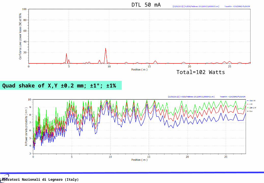
DTL 50 mA
Step 1 Maximum Quad shake of X,Y ±0.2 mm; ±1°; ±1%
Errors results with correction steerers
Laboratori Nazionali di Legnaro (Italy)
Total=102 Watts
Quad shake of X,Y ±0.2 mm; ±1°; ±1%
DTL 50 mA

Laboratori Nazionali di Legnaro (Italy)
In the last tanks we can increase the bore radiuswith the same ZTT
The losses can be further decreased by increasing the DTL bore radius at high energy, above 50 MeV.
Laboratori Nazionali di Legnaro (Italy)
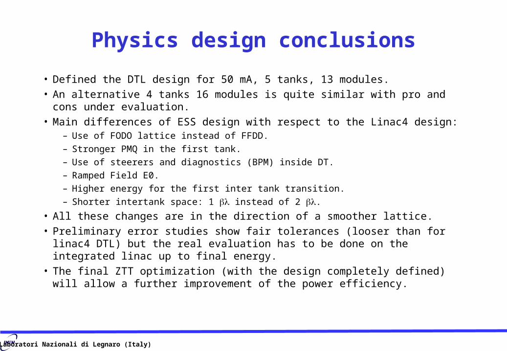
Physics design conclusions
• Defined the DTL design for 50 mA, 5 tanks, 13 modules.• An alternative 4 tanks 16 modules is quite similar with pro and cons under evaluation.• Main differences of ESS design with respect to the Linac4 design:
– Use of FODO lattice instead of FFDD.
– Stronger PMQ in the first tank.
– Use of steerers and diagnostics (BPM) inside DT.
– Ramped Field E0.
– Higher energy for the first inter tank transition.
– Shorter intertank space: 1 instead of 2 .
• All these changes are in the direction of a smoother lattice.• Preliminary error studies show fair tolerances (looser than for linac4 DTL) but the real
evaluation has to be done on the integrated linac up to final energy.• The final ZTT optimization (with the design completely defined) will allow a further
improvement of the power efficiency.
Laboratori Nazionali di Legnaro (Italy)
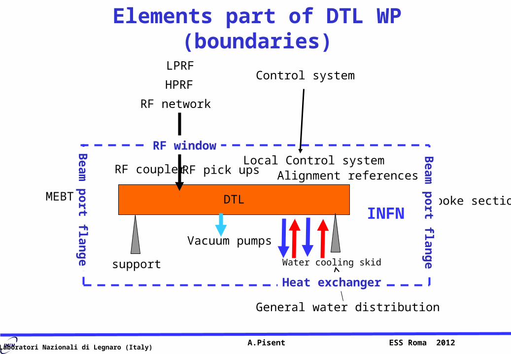
Elements part of DTL WP (boundaries)
A.Pisent ESS Roma 2012
DTL
Vacuum pumps
RF network
RF coupler
Control system
Water cooling skid
RF pick ups
HPRF
LPRF
Local Control system
support
INFN
Alignment references
General water distribution
Spoke sectionMEBT
RF window
Heat exchanger
Beam
po
rt flang
e
Beam
po
rt flang
e
Laboratori Nazionali di Legnaro (Italy) A. Dallocchio 13.09.2011 22
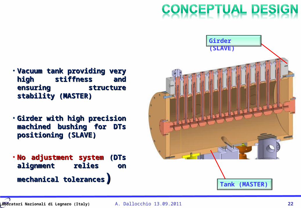
• Vacuum tank providing very Vacuum tank providing very high stiffness and ensuring high stiffness and ensuring structure stability (MASTER)structure stability (MASTER)
• Girder with high precision Girder with high precision machined bushing for DTs machined bushing for DTs positioning (SLAVE)positioning (SLAVE)
• No adjustment system No adjustment system (DTs (DTs alignment relies on mechanical alignment relies on mechanical
tolerancestolerances))
Girder (SLAVE)
Tank (MASTER)

Laboratori Nazionali di Legnaro (Italy) A. Dallocchio 13.09.2011 23
• DTL made of 3 TanksDTL made of 3 Tanks
• Inter-TanksInter-Tanks
• Each Tank independently supported on alignment jacks Each Tank independently supported on alignment jacks (isostatic configuration)(isostatic configuration)
• Each tank segment equipped with girder and DTs (~ 2m Each tank segment equipped with girder and DTs (~ 2m long)long)
• ESS lay out will be similarESS lay out will be similar
• Five tanks of 8.2+5.5+5+5+5 m, 4+3+2+2+2 Five tanks of 8.2+5.5+5+5+5 m, 4+3+2+2+2 modules, maximum module length 2.4 mmodules, maximum module length 2.4 m
• Each tank with 2 couplers and 1 pumping stationEach tank with 2 couplers and 1 pumping station

Laboratori Nazionali di Legnaro (Italy) A. Dallocchio 13.09.2011 24
Survey TargetRF Tuners
Alignment Jack
Post Couplers
Pick-up Movable Tuners
RF Wave-guide Coupler
Laboratori Nazionali di Legnaro (Italy) A. Dallocchio 13.09.2011 25
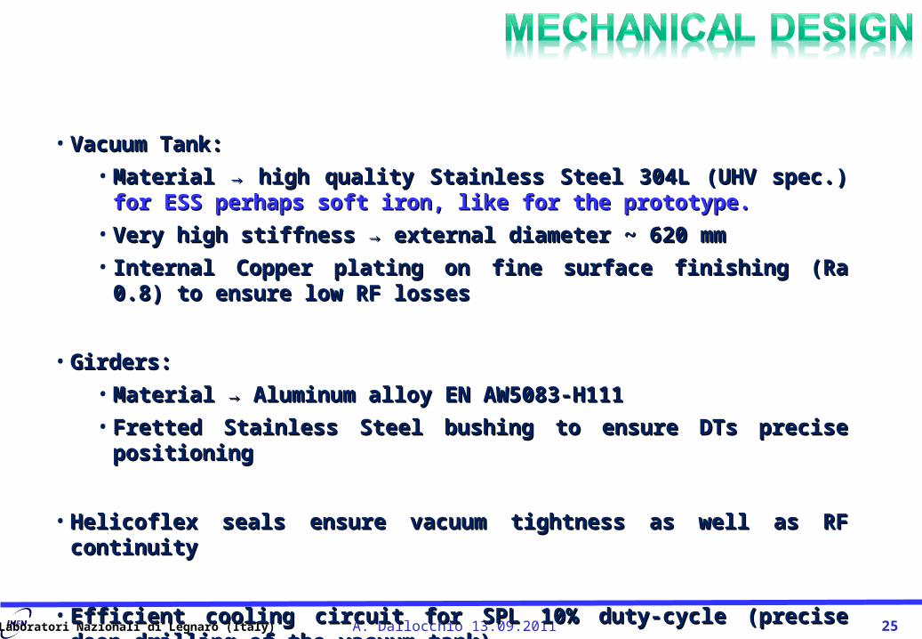
• Vacuum Tank: Vacuum Tank:
• Material → high quality Stainless Steel 304L (UHV spec.) Material → high quality Stainless Steel 304L (UHV spec.) for ESS for ESS perhaps soft iron, like for the prototype.perhaps soft iron, like for the prototype.
• Very high stiffness → external diameter ~ 620 mmVery high stiffness → external diameter ~ 620 mm
• Internal Copper plating on fine surface finishing (Ra 0.8) to ensure low Internal Copper plating on fine surface finishing (Ra 0.8) to ensure low RF lossesRF losses
• Girders:Girders:
• Material → Aluminum alloy EN AW5083-H111Material → Aluminum alloy EN AW5083-H111
• Fretted Stainless Steel bushing to ensure DTs precise positioningFretted Stainless Steel bushing to ensure DTs precise positioning
• Helicoflex seals ensure vacuum tightness as well as RF continuityHelicoflex seals ensure vacuum tightness as well as RF continuity
• Efficient cooling circuit for SPL 10% duty-cycle (precise deep-drilling of the Efficient cooling circuit for SPL 10% duty-cycle (precise deep-drilling of the vacuum tank)vacuum tank)

Laboratori Nazionali di Legnaro (Italy) A. Dallocchio 13.09.2011 26

Laboratori Nazionali di Legnaro (Italy) A. Dallocchio 13.09.2011 27
Bushing
PMQ
DT Assembly tool
Drift Tube(including cooling circuit and precise
PMQ housing)
Vacuum Barrier(Helicoflex seal)
Helicoflex seal
Laboratori Nazionali di Legnaro (Italy) A.Pisent ESS Roma 2009
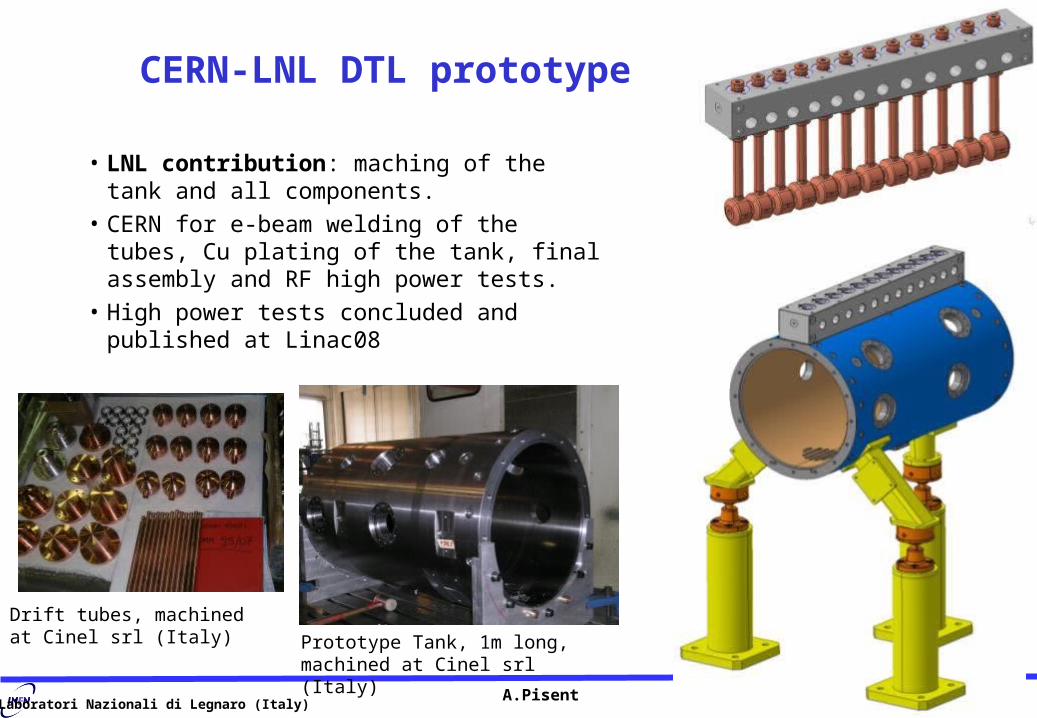
CERN-LNL DTL prototype
• LNL contribution: maching of the tank and all components.
• CERN for e-beam welding of the tubes, Cu plating of the tank, final assembly and RF high power tests.
• High power tests concluded and published at Linac08
Prototype Tank, 1m long, machined at Cinel srl (Italy)
Drift tubes, machined at Cinel srl (Italy)

Laboratori Nazionali di Legnaro (Italy) A. Dallocchio 13.09.2011 29
First reduced prototype (1 m) built by CINEL (Italy) and
successfully tested at CERN

Laboratori Nazionali di Legnaro (Italy)
DTL Tank design, copper plating• Copper plating at CERN will be almost impossible due to
workload; industrial or GSI alternative.
• Dimensions (2.5 m long and 0.6 m diameter), thickness
20um, Ru0.8 um, are challenging. • R&D a full scale prototype of the tank R&D a full scale prototype of the tank
(with design compatible with linac use) is (with design compatible with linac use) is necessarynecessary
A.Pisent ESS Roma 2012
Tank proto painted to avoid corrosion
All flanges and the contact surface of the beam are protected by PVC covers, sealed with FPM o-rings
courtesy M.Malabaila
Courtesy of G.Vandoni, TE-VSC

Laboratori Nazionali di Legnaro (Italy)
DT for steerer dipoles
• New DT with electrical and cooling water connection for steerers (and BPM) has to be developed.
• Same mechanical interface if possible (perhaps looser positioning accuracy is possible).
• R&D A prototype of such R&D A prototype of such DT can be tested at CERN DT can be tested at CERN in the DTL prototype.in the DTL prototype.
A.Pisent ESS Roma 2012
PM drift tube (courtesy of Y. Cuvet)
SNS Steerer,max 1.9 mT*m

Laboratori Nazionali di Legnaro (Italy)
Permanent magnetsCERN DTL: prototypes with ASTER and European industry Elytt.
We have to follow this production and possibly prototype our 70 T/m quads.
It is a small serie (72 quads) other suppliers are possible. Cinel has experience with PM for example for ECR exapoles.
A.Pisent ESS Roma 2012
(courtesy of A. Lombardi)
16 silver-plated screws
16 pole pieces 04/19/23
This is not the final quad!!!!

Laboratori Nazionali di Legnaro (Italy)
PMQ(108 items)Os = 1x10⁻⁹ mbar Lt/cm2-s As = 0.1 m2
Total Gas Load = 1.08x10⁻⁴ mbar Lt/s
PMQ(108 items)Os = 1x10⁻⁹ mbar Lt/cm2-s As = 0.1 m2
Total Gas Load = 1.08x10⁻⁴ mbar Lt/s
HelicoFlex Sealing (w/ RF continuity ) on•Frontal Flange•Upper part of Stems
HelicoFlex Sealing (w/ RF continuity ) on•Frontal Flange•Upper part of Stems
PumpsIon Pumps (rough estimation 10 units)Oil Free Primary Pumps and Turbo-PumpsNEG Pump
PumpsIon Pumps (rough estimation 10 units)Oil Free Primary Pumps and Turbo-PumpsNEG Pump

Laboratori Nazionali di Legnaro (Italy)
Power couplers
• We have experience with design of high power coupling loops, but the coupler chosen by CERN worked very well in the tests of the DTL prototype.
• The design has improved with the use of posts for tuning of the coupling constant .
• Is a 2 MW coupler Is a 2 MW coupler possible? possible? (R&D)(R&D)
A.Pisent ESS Roma 2012
Coupling to pi mode cavity TM (courtesy of Patricia Ugena Tiradof)

Laboratori Nazionali di Legnaro (Italy)
Tuning with movable tuners or water temperature
• We have experience with both the approaches (TRASCO RFQ and linac3 RFQ)
• Movable tuners react faster, but with high duty cycle t regulation is more reliable, without sliding contacts.
• We have not yet reliable thermal simulations to choose.
A.Pisent ESS Roma 2012
Laboratori Nazionali di Legnaro (Italy)
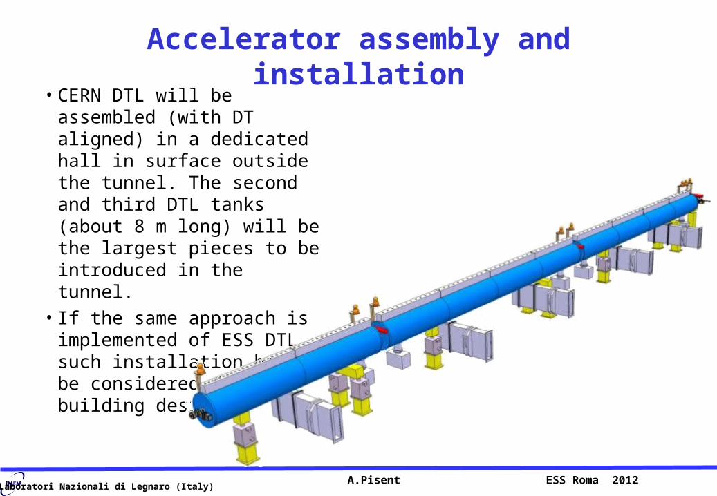
Accelerator assembly and installation• CERN DTL will be assembled
(with DT aligned) in a dedicated hall in surface outside the tunnel. The second and third DTL tanks (about 8 m long) will be the largest pieces to be introduced in the tunnel.
• If the same approach is implemented of ESS DTL, such installation has to be considered for building design
A.Pisent ESS Roma 2012

Laboratori Nazionali di Legnaro (Italy)
Conclusions
• Plan for prototyping• Mechanical design based on tank design developed at CERN (accurate positioning
and fixing of tube position, metallic gaskets).
• Our design has FODO lattice, steerers or BPMs inside DT, field ramping short transition
• We plan to develop DT for steerers or diagnostics, with electrical connections out of the stem.
• Such DT will be tested at high power in the DTL prototype (developed by CERN and INFN)
• PM with trapezoidal components should be prototyped
• Construction and tests perspective– Tank and DT can be built in local industry (see again prototype). Brazing and e-beam
welding are possible in 70 km distance.
– We are looking for an industrial partner for copper electro-plating, the design is compatible with GSI galvanic. Full scale prototyping of a tank would be beneficial.
– INFN (LNL and PD) has the structures for high precision milling, vacuum brazing, CMM, EDM, RF measurements, laser tracking, assembly of the tank and low power tests.
– Moreover a power system could be installed in LNL for high power tests and conditioning of couplers and tanks (dedicated space under discussion with management).