Lab.%2% - Gonzaga Universityweb02.gonzaga.edu/faculty/talarico/CP430/LABS/Lab3.pdfInclude a printout...
4
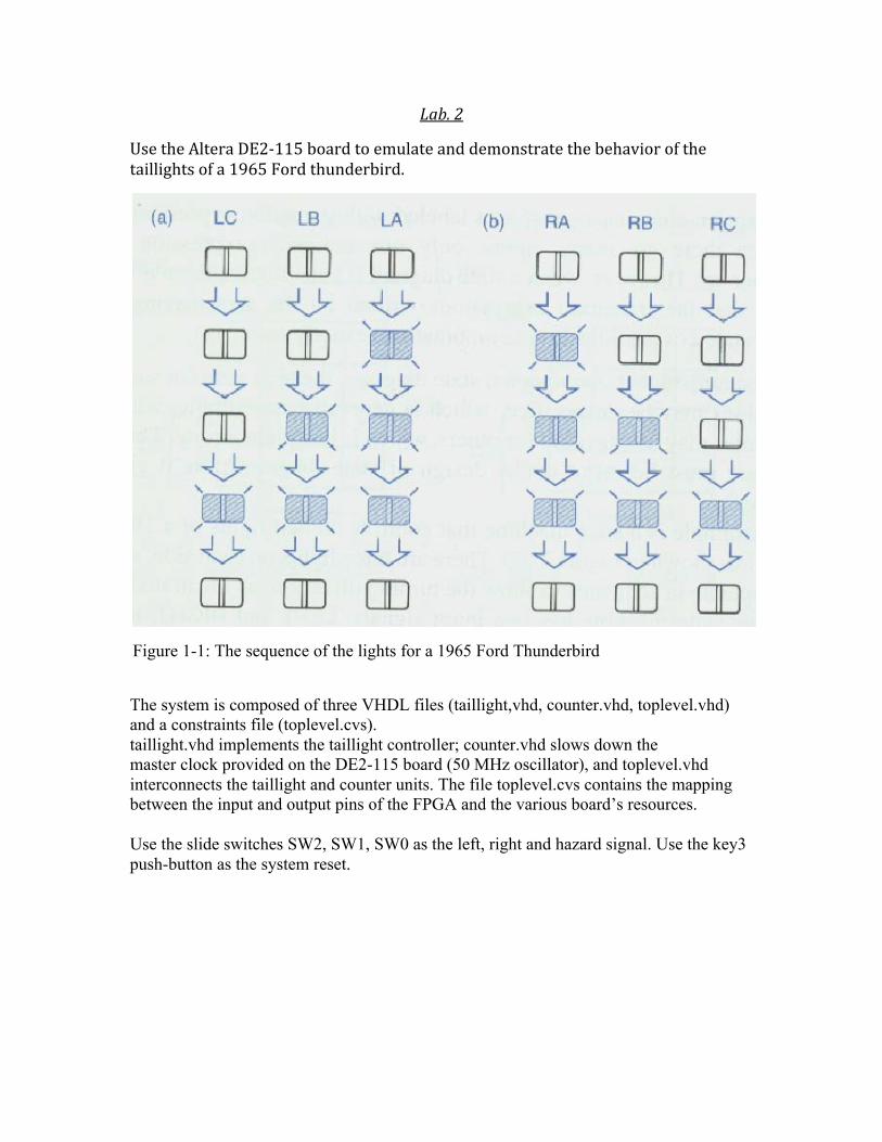
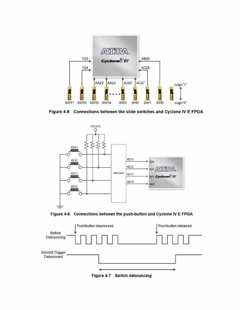
Lab. 2 Use the Altera DE2115 board to emulate and demonstrate the behavior of the taillights of a 1965 Ford thunderbird. Figure 1-1: The sequence of the lights for a 1965 Ford Thunderbird The system is composed of three VHDL files (taillight,vhd, counter.vhd, toplevel.vhd) and a constraints file (toplevel.cvs). taillight.vhd implements the taillight controller; counter.vhd slows down the master clock provided on the DE2-115 board (50 MHz oscillator), and toplevel.vhd interconnects the taillight and counter units. The file toplevel.cvs contains the mapping between the input and output pins of the FPGA and the various board’s resources. Use the slide switches SW2, SW1, SW0 as the left, right and hazard signal. Use the key3 push-button as the system reset.
Transcript of Lab.%2% - Gonzaga Universityweb02.gonzaga.edu/faculty/talarico/CP430/LABS/Lab3.pdfInclude a printout...
Lab. 2
Use the Altera DE2-‐115 board to emulate and demonstrate the behavior of the taillights of a 1965 Ford thunderbird.
Figure 1-1: The sequence of the lights for a 1965 Ford Thunderbird
The system is composed of three VHDL files (taillight,vhd, counter.vhd, toplevel.vhd) and a constraints file (toplevel.cvs). taillight.vhd implements the taillight controller; counter.vhd slows down the master clock provided on the DE2-115 board (50 MHz oscillator), and toplevel.vhd interconnects the taillight and counter units. The file toplevel.cvs contains the mapping between the input and output pins of the FPGA and the various board’s resources. Use the slide switches SW2, SW1, SW0 as the left, right and hazard signal. Use the key3 push-button as the system reset.
talarico
Rectangle

Use the green LED 7,6,5 as the left lights and the green LED 2,1,0 as the right lights.
Use CLOCK_50 as the master clock of the system.

Write a short report summarizing the main characteristic of the design (think of the document as the “data sheet” of the system). Include a printout of the VHDL code and a short analysis of the synthesis and implementation reports (area and timing). Demonstrate the operation of the circuit on the prototyping board Grading will be based on: A. Correctness of the design [40 pts] B. Coding style quality [30 pts] D. Quality of the report [30 pts]