Lab Report 2 AM Modulation and Demodulation.
15
Abu Dhabi University EEN 335 - Introduction to Communication Systems Lab Report 2 AM Modulation and Demodulation. Authors: Muhammad Obaidullah 1030313 Bilal Arshad 1011929 Supervisor: Dr. Montasir Qasymeh Lab Instructor: Eng. Ahmed Sweleh Section 1 May 11, 2013
Transcript of Lab Report 2 AM Modulation and Demodulation.

Abu Dhabi University
EEN 335 - Introduction to Communication Systems
Lab Report 2
AM Modulation and Demodulation.
Authors:Muhammad Obaidullah 1030313Bilal Arshad 1011929
Supervisor:Dr. Montasir Qasymeh
Lab Instructor:Eng. Ahmed Sweleh
Section 1
May 11, 2013
Contents
1 Introduction 2
2 Experiment Set-up 42.1 DSB-LC . . . . . . . . . . . . . . . . . . . . . . . . . . . . . . . . . . . . . . . . . . . 42.2 DSB-SC . . . . . . . . . . . . . . . . . . . . . . . . . . . . . . . . . . . . . . . . . . . 42.3 SSB-SC . . . . . . . . . . . . . . . . . . . . . . . . . . . . . . . . . . . . . . . . . . . 5
3 List of Equipment used 5
4 Procedure 54.1 DSB-LC . . . . . . . . . . . . . . . . . . . . . . . . . . . . . . . . . . . . . . . . . . . 54.2 DSB-SC . . . . . . . . . . . . . . . . . . . . . . . . . . . . . . . . . . . . . . . . . . . 64.3 SSB-SC . . . . . . . . . . . . . . . . . . . . . . . . . . . . . . . . . . . . . . . . . . . 7
5 Results and Discussions 8
6 Conclusion 13
7 Team Dynamics 14
1
Abstract
In this lab experiment, we are going to first generate Amplitude modulated signals by DSB-LC, DSB-SC, and SSB-SC and then try different techniques on how to demodulate these signals.
1 Introduction
In this lab we are going to perform AM Modulation and Demodulation. Demodulation is recov-ering the original message signal from a modulated carrier signal. Telecommunication receivers aremade for the purpose of demodulation of a specific or different types of signals.
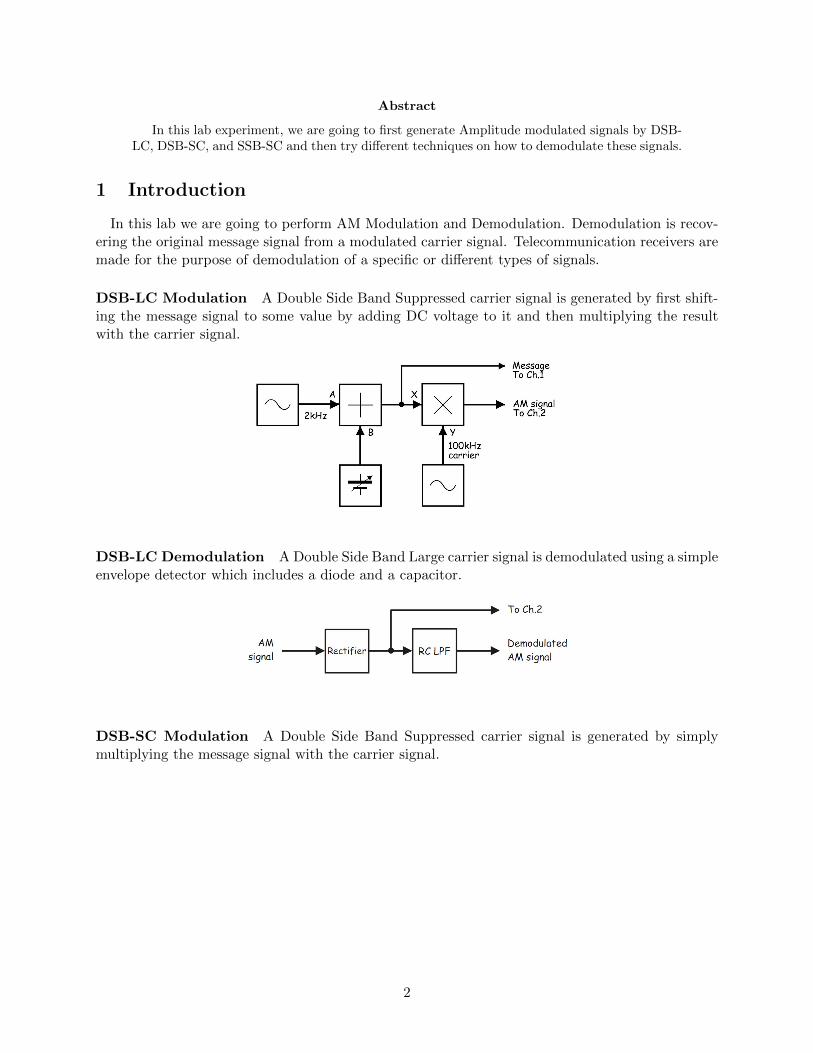
DSB-LC Modulation A Double Side Band Suppressed carrier signal is generated by first shift-ing the message signal to some value by adding DC voltage to it and then multiplying the resultwith the carrier signal.
DSB-LC Demodulation A Double Side Band Large carrier signal is demodulated using a simpleenvelope detector which includes a diode and a capacitor.
DSB-SC Modulation A Double Side Band Suppressed carrier signal is generated by simplymultiplying the message signal with the carrier signal.
2

DSB-SC Demodulation A Double Side Band Suppressed carrier signal is demodulated usinga multiplier at the receiver side, multiplying the incoming signal with the carrier of the samefrequency and then applying a low pass filtering.
SSB-SC Modulation As we can see from the name SSBSC transmits only one sideband of thetwo, it does not matter which side band is transmitted as both have the information. SSB needshalf of the bandwidth that of the DSB which is a good advantage.
One of the methods to make a SSB is to make a DSBSC and then filter it so that we are leftwith only one sideband. This method is known as filter method. In this case good filters are to beused which can be very expensive. Other alternative method to make and SSB is using the phasemethod, this uses phase discrimination technique which leaves us with only one sideband.
SSB-SC Demodulation A Single Side Band Suppressed carrier signal is demodulated usinga multiplier at the receiver side, multiplying the incoming signal with the carrier of the samefrequency and then applying a low pass filtering.
3

2 Experiment Set-up
2.1 DSB-LC
For generating DSB-LC we followed the same basic technique and connected the apparatus asshown below:-
Figure 1: This is how we setup the circuit for generating DSB-LC Signal
2.2 DSB-SC
For generating DSB-SC we followed the multiplier technique and connected the apparatus as shownbelow:-
Figure 2: This is how we setup the circuit for generating DSB-SC Signal
4
2.3 SSB-SC
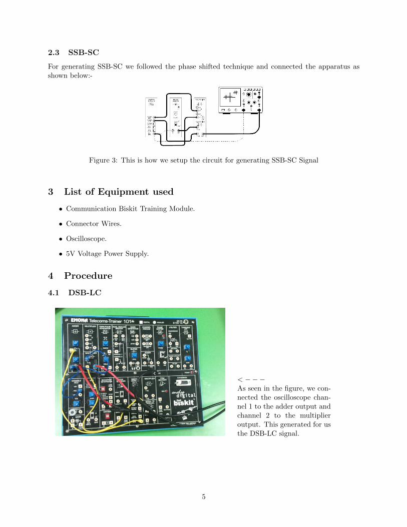
For generating SSB-SC we followed the phase shifted technique and connected the apparatus asshown below:-
Figure 3: This is how we setup the circuit for generating SSB-SC Signal
3 List of Equipment used
• Communication Biskit Training Module.
• Connector Wires.
• Oscilloscope.
• 5V Voltage Power Supply.
4 Procedure
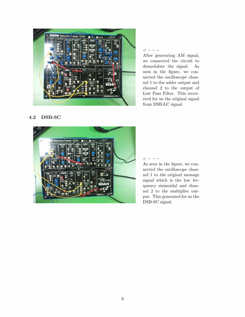
4.1 DSB-LC
< −−−As seen in the figure, we con-nected the oscilloscope chan-nel 1 to the adder output andchannel 2 to the multiplieroutput. This generated for usthe DSB-LC signal.
5
< −−−After generating AM signal,we connected the circuit todemodulate the signal. Asseen in the figure, we con-nected the oscilloscope chan-nel 1 to the adder output andchannel 2 to the output ofLow Pass Filter. This recov-ered for us the original signalfrom DSB-LC signal.
4.2 DSB-SC
< −−−As seen in the figure, we con-nected the oscilloscope chan-nel 1 to the original messagesignal which is the low fre-quency sinusoidal and chan-nel 2 to the multiplier out-put. This generated for us theDSB-SC signal.
6

< −−−After generating DSB-SC sig-nal, we connected the circuitto demodulate the signal. Asseen in the figure, we con-nected the oscilloscope chan-nel 1 to the original mes-sage signal which is a low fre-quency sinusoidal and chan-nel 2 to the output of LowPass Filter. This recoveredfor us the original signal fromDSB-LC signal.
4.3 SSB-SC
< −−−As seen in the figure, we con-nected the oscilloscope chan-nel 1 to the original messagesignal which is the low fre-quency sinusoidal and chan-nel 2 to the adder output.This generated for us theSSB-SC signal.
7
< −−−After generating SSB-SC sig-nal, we connected the circuitto demodulate the signal. Asseen in the figure, we con-nected the oscilloscope chan-nel 1 to the original mes-sage signal which is a low fre-quency sinusoidal and chan-nel 2 to the output of LowPass Filter. This recoveredfor us the original signal fromDSB-SC signal.
5 Results and Discussions
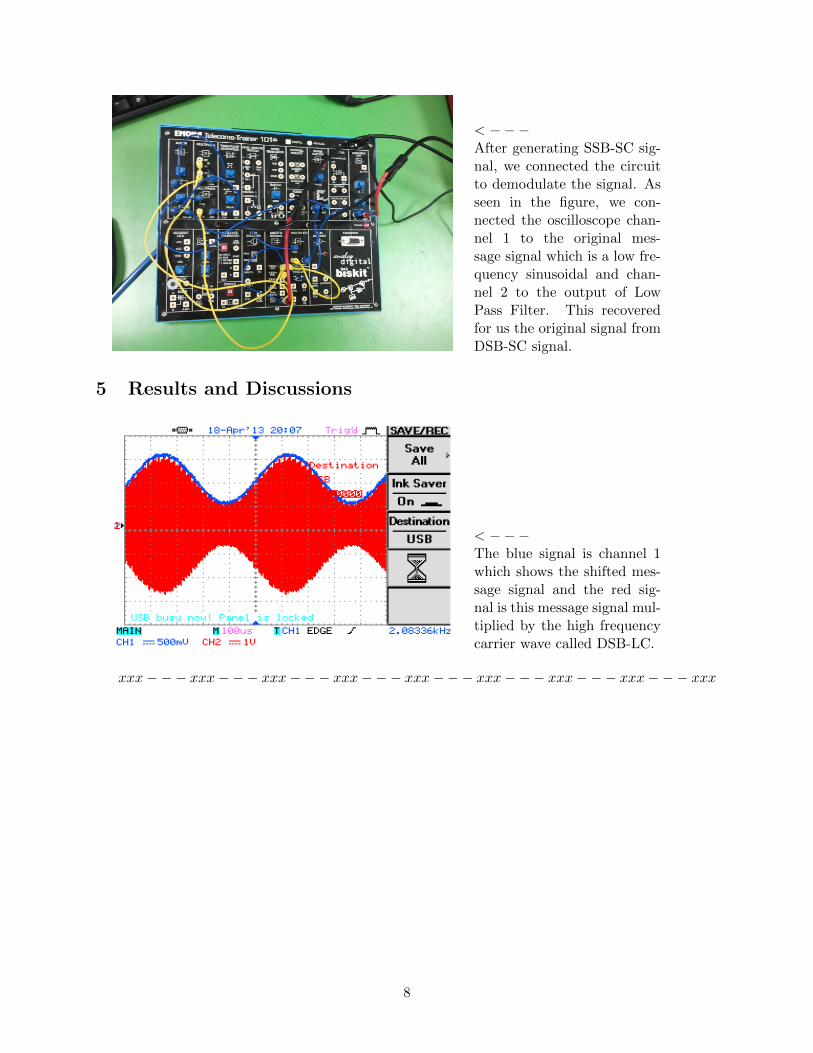
< −−−The blue signal is channel 1which shows the shifted mes-sage signal and the red sig-nal is this message signal mul-tiplied by the high frequencycarrier wave called DSB-LC.
xxx−−− xxx−−− xxx−−− xxx−−− xxx−−− xxx−−− xxx−−− xxx−−− xxx
8
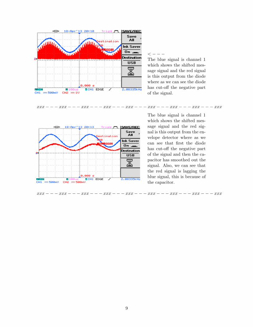
< −−−The blue signal is channel 1which shows the shifted mes-sage signal and the red signalis this output from the diodewhere as we can see the diodehas cut-off the negative partof the signal.
xxx−−− xxx−−− xxx−−− xxx−−− xxx−−− xxx−−− xxx−−− xxx−−− xxx
The blue signal is channel 1which shows the shifted mes-sage signal and the red sig-nal is this output from the en-velope detector where as wecan see that first the diodehas cut-off the negative partof the signal and then the ca-pacitor has smoothed out thesignal. Also, we can see thatthe red signal is lagging theblue signal, this is because ofthe capacitor.
xxx−−− xxx−−− xxx−−− xxx−−− xxx−−− xxx−−− xxx−−− xxx−−− xxx
9
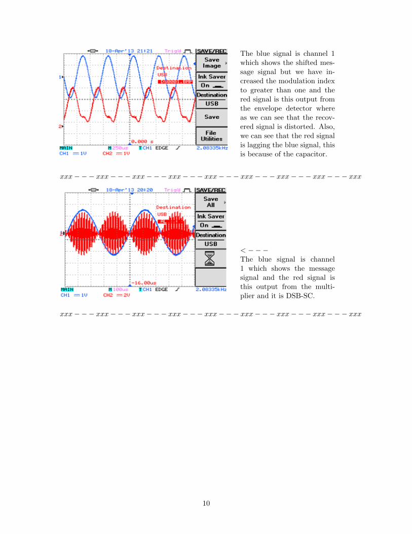
The blue signal is channel 1which shows the shifted mes-sage signal but we have in-creased the modulation indexto greater than one and thered signal is this output fromthe envelope detector whereas we can see that the recov-ered signal is distorted. Also,we can see that the red signalis lagging the blue signal, thisis because of the capacitor.
xxx−−− xxx−−− xxx−−− xxx−−− xxx−−− xxx−−− xxx−−− xxx−−− xxx
< −−−The blue signal is channel1 which shows the messagesignal and the red signal isthis output from the multi-plier and it is DSB-SC.
xxx−−− xxx−−− xxx−−− xxx−−− xxx−−− xxx−−− xxx−−− xxx−−− xxx
10
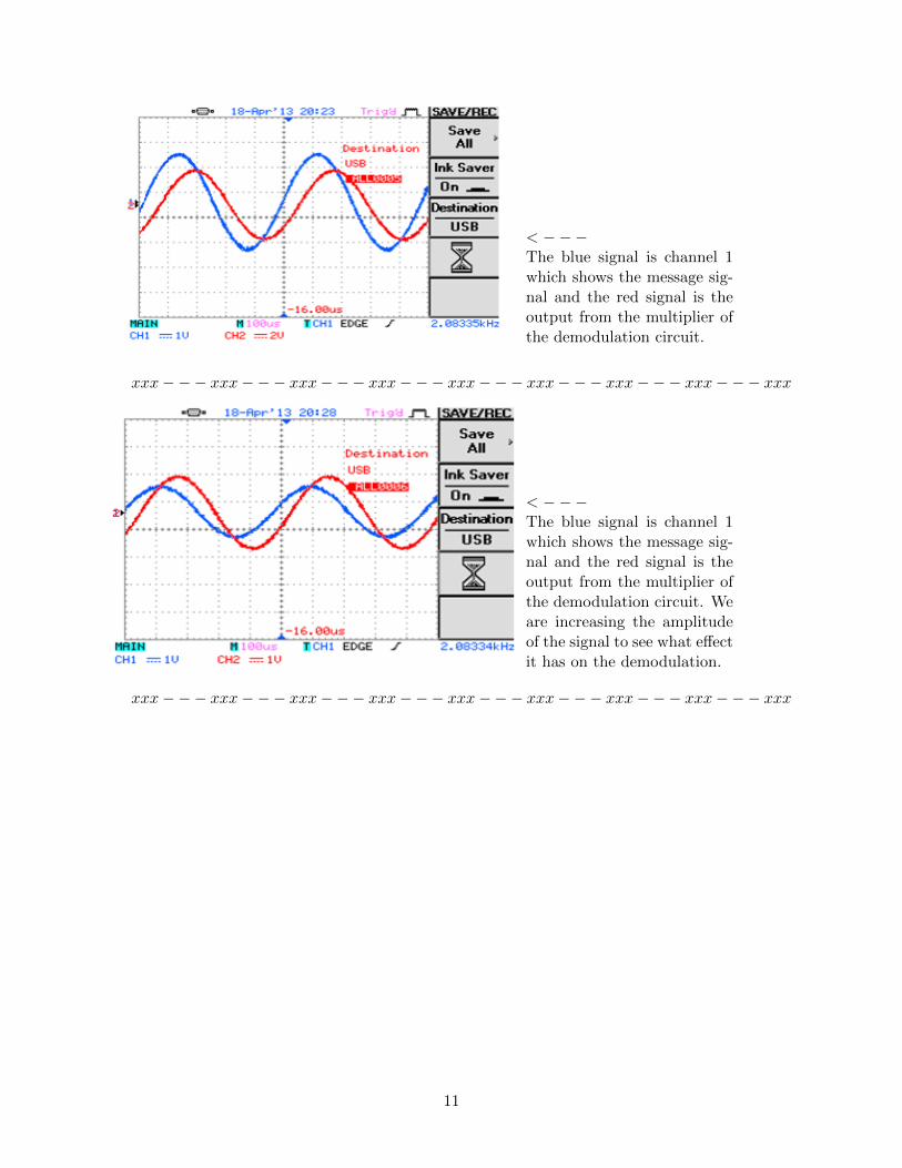
< −−−The blue signal is channel 1which shows the message sig-nal and the red signal is theoutput from the multiplier ofthe demodulation circuit.
xxx−−− xxx−−− xxx−−− xxx−−− xxx−−− xxx−−− xxx−−− xxx−−− xxx
< −−−The blue signal is channel 1which shows the message sig-nal and the red signal is theoutput from the multiplier ofthe demodulation circuit. Weare increasing the amplitudeof the signal to see what effectit has on the demodulation.
xxx−−− xxx−−− xxx−−− xxx−−− xxx−−− xxx−−− xxx−−− xxx−−− xxx
11

< −−−And sure enough, the demod-ulated signal becomes dis-torted after reaching somemaximum amplitude. Thisis because the message signalhas more amplitude than thesupply voltage in the multi-plier.
xxx−−− xxx−−− xxx−−− xxx−−− xxx−−− xxx−−− xxx−−− xxx−−− xxx
< −−−The channel 1 in blue showsthe original message signalwhereas, the channel 2 in redshows the phase shifted signalwhich will be used to makethe SSB-SC signal.
xxx−−− xxx−−− xxx−−− xxx−−− xxx−−− xxx−−− xxx−−− xxx−−− xxx
12

< −−−The channel 1 in blue showsthe original message signalwhereas, the channel 2 in redshows the SSB-SC signal.
xxx−−− xxx−−− xxx−−− xxx−−− xxx−−− xxx−−− xxx−−− xxx−−− xxx
< −−−The channel 1 in blue showsthe original message signalwhereas, the channel 2 in redshows the demodulated SSB-SC signal.
xxx−−− xxx−−− xxx−−− xxx−−− xxx−−− xxx−−− xxx−−− xxx−−− xxx
6 Conclusion
• The DSB-SC and SSB-SC can be demodulated using the same demodulation technique andequipment, but SSB-SC has a bandwidth advantage over DSB-SC such that SSB-SC uses halfthe bandwidth compared to DSB-SC.
• The SSB-SC demodulated signal is phase shifted to about 90 Degrees.
• Changing the amplitude of the original message signal can cause the demodulated signal todistort because the modulation index is changed when we change the amplitude.
• The best type of AM modulation is SSB-SC as it uses half the frequency of the DSB-LC orDSB-SC.
• Meanwhile DSB-LC allows the use of very easy-to-make and cheap receiver which is very idealin many situations where there are many receivers and limited transmitters. One example isRadio Receiver/Transmitter.
13
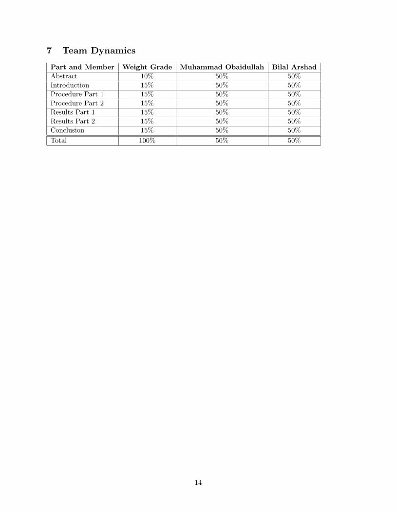
7 Team Dynamics
Part and Member Weight Grade Muhammad Obaidullah Bilal Arshad
Abstract 10% 50% 50%
Introduction 15% 50% 50%
Procedure Part 1 15% 50% 50%
Procedure Part 2 15% 50% 50%
Results Part 1 15% 50% 50%
Results Part 2 15% 50% 50%
Conclusion 15% 50% 50%
Total 100% 50% 50%
14