Lab-on-a-Chip White Blood Cell Counter - Home | University ... · PDF fileLab-on-a-Chip White...
11
Lab-on-a-Chip White Blood Cell Counter MicroNanoBio Final Paper University of Colorado April 29, 2005 David Boteler Toni Newville Hung Nguyen Ian Orzechowski Lindsey Wright
Transcript of Lab-on-a-Chip White Blood Cell Counter - Home | University ... · PDF fileLab-on-a-Chip White...

Lab-on-a-Chip White Blood Cell Counter
MicroNanoBio Final PaperUniversity of Colorado
April 29, 2005
David BotelerToni NewvilleHung Nguyen
Ian OrzechowskiLindsey Wright

2
Specific Aims
The goal of this project is to conceive and develop a blood testing system, scaled down toa chip with MEMS sized components, which would permit an end-user to conveniently monitorhis or her white blood cell (WBC) count on a regular basis. This would serve as a diagnostic fora variety of diseases, including leukemia and severe infections. Designed to be cost effective,this type of test could be self-administered at home or on-the-go, by means of a small, disposablemicrofluidic chip placed into a base-unit for blood chemistry analysis. If adequate funding isacquired, the major product design tasks to be completed in order to demonstrate proof-of-concept would include:
• Design of a functional base unit• Disposable chip construction• Reservoirs containing stain and pressurized gas• Obtaining a blood sample of specific volume• Fluid transport and mixing• Sample focusing for optical analysis• Cell imaging using LED and CCD arrays
Background and Significance
White blood cell levels are a critical indicator of many diseases, including leukemia,HIV, and bone marrow deficiencies. Therefore, it would be very beneficial to create a quick,handheld, portable WBC counter that a consumer could purchase and use in a similar fashion asa glucose tester. This would lower the need for doctor’s visits and provide a rapid indication of apatient’s health.
A differential cell count will include all of the cell types within a blood sample. Thisincludes the five different white blood cell types, as well as red blood cells and platelets. Thefive different types of white blood cells and their relative percentages in blood are neutrophils,40-70%; eosinophils, 5%; basophils, 0.5%; lymphocytes, 20-50%; and monocytes, 1-5%. Eachtype has a specific purpose, so increased or decreased levels will determine how well a patient isrecovering, or what type of foreign object the body is trying to fight. For example, lymphocytesrespond to viral infections. If high levels of this type of cell appeared on the test results, thepatient could quickly determine that he or she had a viral disease. Our handheld device willeliminate hours of lab time and will greatly increase the accuracy of the count over manualcounting methods.
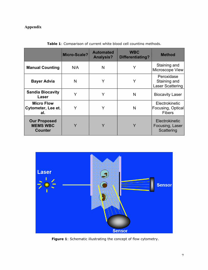
Table 1 in the appendix describes several current methods of white blood cell counting.The traditional method of manual staining involves a lab technician separating WBCs from otherblood components with a centrifuge, staining the cells, and analyzing them under a microscope.This process is expensive, time-consuming, and inaccurate due to technician error and the smallsample size used (generally about 100 WBCs).
Various companies have devised macro-scale processing units capable of determiningwhite blood cell counts quickly and accurately. For example, Bayer Healthcare’s Advia series ofautomated blood analysis systems stain the cells and use a process called flow cytometry toproduce a differential cell count. Figure 1 illustrates the flow cytometry concept: cells in anarrow channel are focused into a single-file line using hydrodynamic focusing (laminar flow of

3
a surrounding fluid). A light source is focused on the cell flow, while two sensors record thefraction of scattered and transmitted light. Each blood cell type has a distinctivescatter/absorption profile, so the total number of each type can be counted. Advantages of thisautomated system over manual cell counts include faster analysis, higher counts per sample(resulting in statistically more-accurate results), and reduced level of uncertainty due to humaninterpretation. Some drawbacks of this type of system are the prohibitive capital costs, thenecessity of a doctor’s visit, and the delicate nature of system calibration and operation.
Several groups have attempted to create micro-scale differential cell counters that can beused at a patient’s convenience. Sandia Labs has produced a coin-sized blood cell analyzer thatuses a biocavity laser, in which cells are passed through the laser cavity. Changes in laser outputsignify a deformed or misshapen cell, which could indicate diseases such as sickle-cell anemia.Currently, the price for a Sandia cell analyzer chip starts at $5,000 and requires a laptopcomputer.
Other researched methods, such as the Micro Flow Cytometer proposed by Lee et. al.,have demonstrated that flow cytometry can be effective at the MEMS scale. Current techniquesinvolve hydrodynamic or electrokinetic focusing to narrow a column of cells for optical analysis.These devices, however, have not yet been applied to differentiating white blood cells, nor havethey been designed for mass-manufacturing.
Research Design and Objectives
Rather than attempt to pioneer new technology, our goal with this project has been to takeexisting cell counting technology and transfer it to a MEMS scale lab-on-a-chip specificallytailored to white blood cell counting. Of the various WBC-counting approaches, flow cytometryappears to be the most promising for reduction to the microscale. Our approach makes use ofproven or demonstrated techniques drawn from a variety of microfluidic chip designs inexistence.
Proposed Design
Specific Aim 1: Base UnitThe WBC counter we envision consists of two components: an inexpensive disposable
chip on which all microfluidic interactions occur, and a hand-held base unit. The philosophyhere is to concentrate specialized electronics and components too expensive to be “disposable” ina reusable, compact device capable of powering and controlling all on-chip processes, collectingand processing all data, and providing a user-friendly interface. A blood sample is drawn, thechip is inserted into the base unit, and the WBC counting process begins. On-chip activities(electroosmosis, dielectrophoresis, pneumatic actuation, etc.) are controlled from the base unit bymeans of electrical contacts. Light sources and sensors residing on the base unit detect thepassage of cells through a thin “viewport” section on the chip. An onboard CPU processes rawsignals from the sensors, categorizing each cell that passes in real-time. Upon completion of thetest, WBC count results and other useful information can be viewed directly by means of asimple integrated display, or can be uploaded to other electronic devices for further processing or

4
transmission. The used chip is discarded, while the base unit (which has no direct contact withany on-chip fluids) can be reused. Power consumption will ideally be low enough for the unit tobe run by rechargeable battery. The base unit contains the electronics necessary to control andanalyze the WBC counting process, but there is nothing particularly exceptional about it;electronic devices for similar purposes abound.
Specific Aim 2: Disposable Chip ConstructionBy contrast, it is the disposable microfluidic chip that will take advantage of some of the
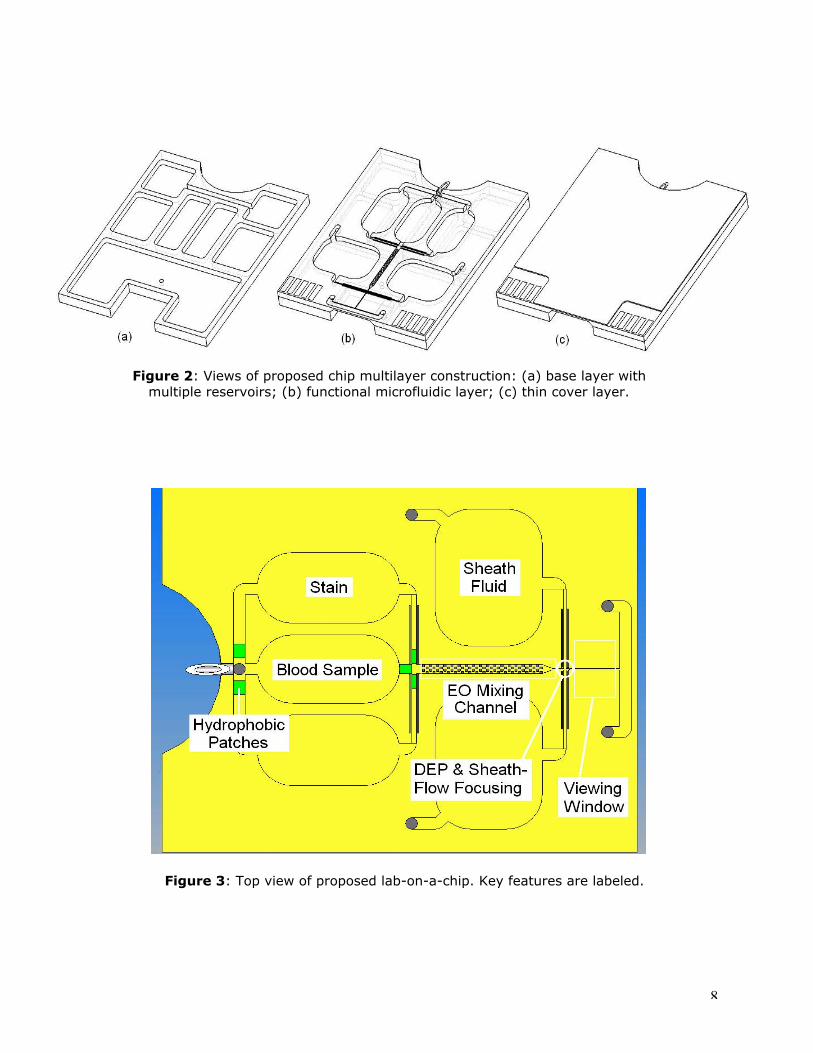
latest technologies. The chip will be fabricated from a biocompatible polymer such as PMMA,using RTP (rapid thermal process) injection molding. The transparent plastic construction iswell-suited for optical detection techniques, and assures that such chips will be relativelyaffordable in when produced in volume. Multiple layers can be bonded together by anadhesiveless process known as thermoplastic fusion bonding, which has been used successfullyfor the fabrication of similar microfluidic chips with minimal distortion of features. Stackinglayers in this way allows relatively complex internal features to be fabricated from injection-molded layers with ease; the overall chip footprint can be kept small, while the increasedthickness improves chip durability and flatness control. Figure 2 shows a conceptual three-layerchip design, consisting of a multiple-reservoir base layer (a) to which a functional fluidic layer(b) and a thin cover layer (c) are bonded. Depending on final design requirements, additionallayers containing electrodes, traces, electric or pneumatic vias and the like could be incorporated.Figure 3 shows a top view of the functional layer of the chip.
Specific Aim 3: ReservoirsA key feature of the chip design is that it is self-contained, making it truly portable and
easy to use. With the exception of electrical power, which the base unit supplies, all necessaryingredients are contained in chambers on the chip. Pressurized gas is stored in sealed reservoirsin the thick base layer, eliminating the need for an external air supply or complex on-boardpumping mechanism. Gas in a particular reservoir is tapped by passing electrical current fromthe controller through a microheating element; a hole is melted in the reservoir wall, andpressurized gas escapes into an adjacent airway. Peroxidase or other stains, anticoagulants, andsheath-flow fluids are stored in various reservoirs on the fluidics level of the chip, kept containedby hydrophobic patches until forced to pass through under pressure. After fluids have passedthrough the viewing channel, exit ducts empty into a waste fluid reservoir located on the lowerlevel of the chip. A hydrophobic vent permits air to escape as the reservoir fills.
Specific Aim 4: Obtaining Blood SampleA small hypodermic needle integrated into the chip permits blood sample acquisition by
capillary action. An exact volume of blood is isolated by means of a hydrophobic patch; oncethe blood sample has filled the microfluidic channel and reaches the patch, further capillaryaction cannot occur. The sample reservoir is sized to hold one microliter of whole blood, whichgenerally contains 5,000 to 10,000 white blood cells – a quantity permitting statistically-significant confidence levels. While limited conclusions may be drawn with counts as few as 100WBCs, evaluation of at least a few thousand white blood cells is far preferable. Basophils,eosinophils, and monocytes each make up just a few percent of the total WBC count, and samplesizes containing less than several thousand white blood cells, therefore, lead to significant errorsin counts of these less-numerous cell types.

5
Specific Aim 5: Fluid Transport and Mixing To keep the design simple and reliable, the chip has no moving parts; all microfluidicmotion is accomplished by a combination of differential pressure and electroosmosis. The use ofa pressurized gas to drive microfluidic flow is common, and in particular, pressure sourcesresiding on-chip have been successfully implemented in a number of cases. Since our designrelies on breaching discrete pressure reservoirs, gas pressure cannot be regulated or turned offonce applied. For this reason, electroosmosis (EO) is employed as a secondary motive force foraugmentation and fine control of fluid flow properties. Electroosmotic efficiency is actuallyenhanced in small cross-section channels, whereas an impractically high pressure differentialmight be necessary in a corresponding flow driven by pressure only. Since EO can beregulated from the controller in real-time, relatively complex flow schemes are possible. Therelative concentration of peroxidase stain mixed into the blood sample can be increased ordecreased by applying EO selectively. EO patches in the mixing channel are used to generatelocal reversals in flow direction, ensuring thorough mixing of stain and sample prior to imaging.
Specific Aim 6: Sample Focusing Electroosmosis also plays a key role in controlling sheath flow in the sample focusingsection of the chip (a close-up view of this region is shown in Figure 4). Flow cytometry relieson laminar sheath flow around the sample, with the relative volumes of the sheath and sampleflows governing to large extent how tightly focused the column of sampled cells will be.Controlling by EO the amount of sheath fluid introduced on each side of the blood-stain mixturewill guarantee optimal focusing on a real-time basis, since the controller may use detector outputas feedback to control EO voltages. The sample imaging channel is tentatively designed with a30x30 um cross-section, to allow passage of the largest blood cell type (monocytes, which areabout 20 microns in diameter). In the event that at the relatively low fluid-flow speeds on thechip (estimated at no more than a few millmeters per second) sheath flow alone provesinadequate to achieve the necessary focusing, dielectrophoresis (DEP) offers additionalpossibilities. With the blood sample already prefocused by sheath flow, electrodes above andbelow the imaging channel create a DEP "funnel" to further focus WBCs or other bloodcomponents of interest. DEP power consumption is a possible concern, so electrode size anddistance from the sample flow are kept as small as possible.
Specific Aim 7: Cell ImagingMounted in the base unit, an array of white LEDs will be aligned with a triad of CCD
sensors, as seen in Figure 5. Light will shine down through cells passing along the viewingchannel in the disposable chip and onto the CCD array. The two skewed chips are at 45o anglesfrom parallel. These two will sense side-scatter from the cells. The LED array will contain 24micro LEDs, with a 240_m diameter, and a diffraction angle of approximately 24o. This willensure minimal interference of two or more light sources on a single CCD pixel array.
The reason for an array, rather than a single LED and CCD, is twofold. First, the entiredata acquisition system is based on a differential of light intensities, thus all pixels can be testedimmediately after the chip has been inserted to see which light intensities are greatest, anddifferentiate between the two strongest signals, yielding a diffraction pattern much more accuratethan a single LED-chip array would be. The second reason is more of a practical one. There willlikely be very small misalignments of the inserted lab-on-a-chip and the sensor array. These

6
micrometer misalignments are due to the small compression forces on the sample chip.However, these misalignments are quite significant, as the sensors are performing detection onthe micrometer level. Thus, an array is needed to ensure that the blood cell isn’t ‘missed’ whenit passes through the window, and that all chips can be accurately read, accounting for minordefects and natural variation in physical manufacturing of the lab-on-a-chip.
The CCD chips themselves will be what is known as a “Line CCD”. The entirecomponent will be approximately 512 pixels long by 4 pixels wide, as can be seen in Figure 6.Each pixel is only 16_m2, which is more than enough area to capture an adequate light patternfor our design concept. This cell imaging system delivers raw electronic signals to the unit’sCPU for data processing and reduction to a histogram of light intensity on each CCD chip. Whendata from the histograms is correlated, a composite image as shown in Figure 7 results.
The diffraction pattern of each white blood cell is unique, with the exception of two. Ifneeded, additional steps (such as a second staining solution) may be taken to differentiate thesecells.
Potential Difficulties and Alternative ApproachesOur proposed design is by no means finalized. Testing and evaluation of prototypes will
likely expose many design aspects that need more research. Currently, we have noted severalcomponents that may be problematic. First, blood may coagulate during mixing and pumping,preventing flow or skewing optical data. This could be prevented by mixing an anticoagulantinto the peroxidase stain. Second, certain cell types are sometimes difficult to differentiate usingflow cytometry. If this becomes problematic, differentiation can be improved by adding anadditional stain. Additionally, the device may require considerable amounts of power, especiallyto supply the megahertz frequency needed for DEP. If necessary, this could be solved byplugging the base unit into a power outlet rather than using a battery.
Expected Results and Impact on the Field
This lab on a chip white blood cell counter will revolutionize the hematological field.The chip will be more accurate than manual counting, and as accurate as the large blood cellsorters found in hospitals and laboratories. It will also reduce the time required for analysis,without compromising accuracy. This will result in a faster and more accurate diagnosis. Fewerhours of lab work will be required, resulting in lower costs for the patient and the medicalcommunity.
The chip will be manufactured in such a way that it will be affordable to everyone. This,coupled with its portability, means that the chip could become a common household healthmonitor. For example, patients undergoing treatments for ailments such as leukemia will be ableto monitor their own progress. Another example is that healthy people could use the chip to seeif they are developing any serious conditions. This would result in an increase in early detectionof many diseases, resulting in saved lives. Additionally, results obtained from the chip could besent across the Internet to any doctor in the world. This would mean that travelers around theworld could use the chip and send their results to their own personal doctor for review.
7
Appendix
Micro-Scale?AutomatedAnalysis?
WBCDifferentiating?
Method
Manual Counting N/A N YStaining and
Microscope View
Bayer Advia N Y YPeroxidase
Staining andLaser Scattering
Sandia BiocavityLaser
Y Y N Biocavity Laser
Micro FlowCytometer, Lee et.
al.Y Y N
ElectrokineticFocusing, Optical
Fibers
Our ProposedMEMS WBC
CounterY Y Y
ElectrokineticFocusing, Laser
Scattering
Table 1: Comparison of current white blood cell counting methods.
Figure 1: Schematic illustrating the concept of flow cytometry.
8
Figure 3: Top view of proposed lab-on-a-chip. Key features are labeled.
Figure 2: Views of proposed chip multilayer construction: (a) base layer withmultiple reservoirs; (b) functional microfluidic layer; (c) thin cover layer.

9
Figure 5: Schematic of optical cell differentiation setup using LED and CCD arrays.
Passing Blood cell
CCD Array
LED Array
Figure 4: Schematic of sample focusing using sheath flow and DEP.

10
Figure 4: blah with blah blah!.
Figure 7: Histrogram produced by flow cytometry of blood cells.
LED Array
Figure 6: Line CCD example.
11
References
Disposable Smart Lab On A Chip For Point-Of-Care Clinical Diagnostics. Ahn, C.H.; Jin-Woo Choi; Beaucage,G.; Nevin, J.H.; Jeong-Bong Lee; Puntambekar, A.; Lee, J.Y. Proceedings of the IEEE Volume 92, Issue 1, Jan2004 pp. 154-173.
Bayer Healthcare Diagnostics Division website, http://www.labnews.de/en/products/a_21_wbc.php
Cell Transport Via Electromigration In Polymer-Based Microfluidic Devices, Malgorzata A. Witek, Suying Wei,Bikas Vaidya, Andre A. Adams, Li Zhu, Wieslaw Stryjewski, Robin L. McCarley, Steven A. Soper, Lab on a Chip,2004, 464-472.
A Functional On-Chip Pressure Generator Using Solid Chemical Propellant For Disposable Lab-On-A-Chip,Chien-Chong Hong; Murugesan, S.; Sanghyo Kim; Beaucage, G.; Jin-Woo Choi; Ahn, C.H.; Micro ElectroMechanical Systems, Jan 2003 pp. 16-19.
Counting And Sizing Of Particles And Particle Agglomerates In A Microfluidic Device Using Laser LightScattering: Application To A Particle-Enhanced Immunoassay, Nicole Pamme, Ryuji Koyama, Andreas Manz, Labon a Chip, 2003, 187-192.
Dynamics Of Capillary Flow Of Blood Into A Microfluidic Channel, Suman Chakraborty, Lab on a Chip, 2005, 421-430.
Effects Of The Cell Geometry And Operating Parameters On The Performance Of An External ContactlessConductivity Detector For Microchip Electrophoresis, Pavel Kuba , Peter C. Hauser, Lab on a Chip, 2005, 407-415.
Dielectrophoresis-Based Sample Handling In General-Purpose Programmable Diagnostic Instruments, Gascoyne,P.R.C.; Vykoukal, J.V.; Proceedings of the IEEE Volume 92, Issue 1, Jan 2004 pp. 22-42.
Micro Flow Cytometers Using Electrokinetic Forces With Integrated Optical Fibers For On-Line Cell/ParticleCounting And Sorting, Gwo-Bin Lee’, Lung-Ming Fu’, RueyJen Yang’, Yu-Jen Pan’; 7th International Conferenceon Miniaturized Chemical and Biochemical Analysts Systems, October 5-9, 2003, pp. 45-48
Flow Cytometry in Biotechnology, Marco Rieseberg, Cornelia Kasper, Kenneth F. Reardon, Thomas Scheper.Applied Microbiology and Biotechnology. Volume 56, Numbers 3-4. August 2001. Pages: 350 – 360.
Electrokinetic Focusing Injection Methods on Microfluidic Devices, M. Fu, R. J. Yang, G. B. Lee, AnalyticalChemistry, 75, 1905-1910, (2003).
The Differential Cell Count, Houwen B. Laboratory Hematology 2001; 7:89-100.
https://histo.life.uiuc.edu/histo/lab/lab1/text.htm
A Disposable Plastic Biochip Cartridge With On-Chip Power Sources For Blood Analysis, Jin-Woo Choi;Puntambekar, A.; Chien-Chong Hong; Chuan Gao; Xiaoshan Zhu; Trichur, R.; Jungyoup Han; Chilukuru, S.; Dutta,M.; Murugesan, S.; Sanghyo Kim; Young-Soo Sohn; Nevin, J.H.; Beaucage, G.; Jeong-Bong Lee; Lee, J.Y.; Bissell,M.G.; Ahn, C.H.; Micro Electro Mechanical Systems, Jan 2003 pp. 447-450.