Discharge Coefficient Performance of Venturi Standard Concentric

SHREE RAMCHANDRA EDUCATION SOCIETY’S
SHREE RAMCHANDRA COLLEGE OF ENGINEERING,
LONIKAND, PUNE – 412 216
DEPARTMENT OF MECHANICAL ENGINEERING
LAB MANUAL
FLUID MECHANICS (ME) Semester-III
Prepared by
Prof. Phatangare P. A. (Assistant Professor)

FLUID MECHANICS(FM)
SRCOE PUNE
List of Experiments (S.P.UNIPUNE SYLLABUS)
Note: - 1.Eleven experiments from below list should be performed; out of whichat least seven trials
should be conducted.
Sr.
No
Name of Experiment
1 StudyofPressureMeasuringdevices.
2 Determinationofviscosityofliquidsanditsvariation with temperature.
3 Determination of metacentric height of floating object
4 Verification of modified Bernoulli’s equation.
5 Calibration of Venturimeter meter.
6 Determination of hydraulic coefficients of orifice.
7 Flow over trangular notch apparatus
8 Reynold’s experiment
9 Losses in pipe fittings apparatus
10 Flow around immersed bodies, point of stagnation, formation of wake etc. by Haleshaw
apparatus.
11 Pressure distribution on flow over cylinder using wind tunnel/CFD too

FLUID MECHANICS(FM)
SRCOE PUNE
INDEX
Sr.
No
Name of Experiment
1 Study of Pressure Measuring devices.
2 Determination of viscosity of liquids and its variation with temperature .
3 Determination of metacentric height of floating object
4 Verification of modified Bernoulli’s equation.
5 Calibration of Venturimeter meter.
6 Flow over trangular notch apparatus
7 Reynold’s experiment
8 Losses in pipe fittings apparatus
FLUID MECHANICS(FM)
SRCOE PUNE Page 4
SHREE RAMCHANDRA COLLEGE OF ENGG. LONIKAND LABORATORY MANUAL
PRACTICAL EXPERIMENT INSTRUCTION SHEET
EXPERIMENT TITLE: REDWOOD VISCOMETER
DEPARTMENT OF MECHANICAL ENGINEERING
EXPERIMENT NO. : SRCOE/MECH/SE/FM/ SEMESTER : III(SE) PAGE:
EXPERIMENT NO.:- 2
----------------------------------------------------------------------------------------------------
REDWOOD VISCOMETER
AIM:-
To determine the kinematic viscosity of a liquid and it’s verification with
temperature.
APPARATUS:-
Redwood Viscometer with its accessories such as a flask, ball valve, heating
arrangement, thermometer, stopwatch, oil, etc.
THEORY:-
DYNAMIC VISCOSITY-
It is define as the property of fluid which offers resistance to
flow of one layer of fluid over another adjacent fluid layer. It is measure of the
internal fluid friction which causes resistance to flow. It is denoted by ‘μ’.

FLUID MECHANICS(FM)
SRCOE PUNE Page 5
KINEMATIC VISCOSITY-
It is defined s the ratio of dynamic viscosity to the density
of liquid. It is denoted by ‘𝜈’.
𝜈 =𝜇
𝜌
In SI unit it is measured in 𝑚2
𝑠 . In C.G.S. it is measured in stoke’s
1 stoke’s=10−4 𝑚2 𝑠
Kinematic viscosity of liquid can be determined with the help of a redwood
viscometer. The empirical relation to determine the kinematic viscosity of liquid is
given by.
𝑣 = 𝐴 × 𝑡 −𝐵
𝑡
Where,
A=Constant=0.0026
B=Constant=1.1176
t=Time in sec=Time required to collect 50cc of liquid in measuring
flask.
Variation of viscosity with Temperature:
Viscosity is affected by temperature. The viscosity of liquid decreases but that of
gases increases in temperature. This is due to reason that in liquids the shear stress is
due to the intermolecular cohesion which decreases with increase in temperature. In
gases the intermolecular cohesion is negligible and the shear stress is due to
exchange of momentum of the molecules, normal to the direction of motion. The
molecular activity increases with rise in temperature and so does the viscosity of gas.
FLUID MECHANICS(FM)
SRCOE PUNE Page 6
EXPERIMENTAL PROCEDURE:-
1. Level the viscometer with help of leveling screws. 2. Fill the water jacket with water and heat it to the desired temperature by using
electric heater provided around the water jacket. 3. Close the orifice by means of a ball valve and pour the oil whose viscosity is to
be determined into the cylinder up to the index mark. 4. Record the temperature of oil and keep the measuring flask below the orifice. 5. Lift the ball valve and start the stop watch simultaneously. 6. Measure the time in sec required to collect 50cc of oil to various
temperatures.
OBSERVATION TABLE:-
Sr. no. Temperature (°C) Time (sec) Kinematic viscosity (m²/s)
1
2
3
4
5

FLUID MECHANICS(FM)
SRCOE PUNE Page 7
CALCULATIONS:-
Relation to determine Kinematic viscosity of liquid is given by,
𝑣 = 𝐴 × 𝑡 −𝐵
𝑡
Where,
A=Constant=0.0026
B=Constant=1.1176
CONCLUSION:-
FLUID MECHANICS(FM)
SRCOE PUNE Page 8
EXPERIMENT NO.:- 3
--------------------------------------------------------------------------------------------------
-
METACENTRIC HEIGHT OF SHIP MODEL
AIM: -
Stability of floating bodies and optimum loading capacity.
APPARATUS:-
Model of ship, tank of water, weight etc.
THEORY:-
When a body is immersed in fluid, it is subjected to an upwards force
which tends to lift up the body. This is called buoyancy and the upward force
is called buoyant force. Archimedes principle states that when a body is
immersed in a fluid, wholly or partially, it is buoyed or lifted up by a force
which is equal to the weight of the fluid displaced by the body.
When a body is floating in liquid, it is acted upon by two forces, viz.
Weight of body acting downwards through center of gravity and upward
buoyant force acting through center of buoyancy. Both these forces are equal
and opposite in direction and the body is equilibrium. Center of buoyancy of a
body is centroid of the volume of liquid displaced. If the body is tilted
slightly, then position of center of gravity remains the same but center of
buoyancy occupies the new position, as geometry volume changes. If a
vertical line is drawn through the new center of buoyancy, it intersects the line
joining initial center of buoyancy and center of gravity at a point, known as

FLUID MECHANICS(FM)
SRCOE PUNE Page 9
metacenter. The distance between metacenter and center of gravity is called
metacentric height.
Stability of a floating body depends upon the metacentric height .If
metacenter lies above the center of gravity, the slight angular displacement
of body causes to form a restoring couple, which tends to bring the body to
its original position. This is called stable equilibrium.
When multicenter lies below the center of gravity, then slight angular
displacement of body causes to form a couple which tends to increase the
angular displacement further. This is called unstable equilibrium. When
metacenter lies exactly on center of gravity then slight angular displacement
does not create any couple, hence body remains in its new position. This is
called neutral equilibrium. Hence, in design of ship, care has to be taken to
keep the metacenter well above the center of gravity, so that ship is in stable
equilibrium.
The apparatus consist of a ship model, which is made of
rectangular shape for the purpose of simplicity. A movable weight slides in a
guide bar at the deck. An upright is provided at the center of the ship from
which is hung a plumb. When the weight is shifted from the center position,
the ship tilts slightly. The angle of tilt (or angle of heel) is determined with
the help of plumb. The position of metacenter is then determined by
displacement of weight and angle of heel. The Metacentric height (GM) is
found (equating tilting and restoring moments) from the following relation
𝐺𝑀 =𝑤×𝑥
𝑊 𝑡𝑎𝑛𝜃
Where,
w- Known weight

FLUID MECHANICS(FM)
SRCOE PUNE Page 10
x- Distance of applied weight from center of ship
model
W- Applied weight
Θ -Tilt angle of ship
EXPERIMENTAL PROCEDURE;-
1] Fill up water in the floating tank.
2] Keep the ship floating over the water.
3] See that plumb indicates zero reading.
4] Displace the weight on the deck.
5] Measure the displacement of weight and distance indicated
by plumb.
6] Repeat the procedure for different displacement of weight.
SPECIFICATIONS:-
1] Weight of ship (W) =3.2 Kg
2] Distance of applied weight from ship center on both side (x)
=0.110m
OBSERVATION TABLE:-

FLUID MECHANICS(FM)
SRCOE PUNE Page 11
Sr.
no.
Distance of
applied weight
'x' m
Tilt angle
(Θ) Applied Weight (w) Kg
Metacentric
height (GM)
m
1
2
3
4
5
CALCULATIONS:-
Metacentric Height,
𝐺𝑀 =𝑤×𝑥
𝑊 𝑡𝑎𝑛𝜃
CONCLUSIONS:-
EXPERIMENT NO.:- 4

FLUID MECHANICS(FM)
SRCOE PUNE Page 12
--------------------------------------------------------------------------------------
VERIFICATION OF MODIFIED BERNOULLI’S EQUATION
AIM: -
To verify modified Bernoulli’s equation.
APPARATUS:
A taper (converging-diverging) rectangular pipe (piezometer tubes fitted at different
sections), supply tank of water, measuring tank, stop watch, scale etc.
THEORY:-
When an incompressible fluid is flowing through a closed conduit, is may be
subjected to various forces, which cause change of velocity, acceleration or energies
involved. The major forces involved are pressure and body forces. Due to elevation of
conduits, pressure may change or due to change of cross section, velocity of fluid may
change. But, though there is change of velocity, pressure also changes accordingly. In
other words, if velocity energy of fluid is raised, its pressure will drop, i.e. total energy of
fluid is constant at any two points in the path of flow. The theorem is known as
Bernoulli’s theorem. Hence, when applied to steady irrotational flow ofincompressible
fluids, (Density is Constant)
𝑃
𝑤+
𝑉2
2𝑔+ 𝑍 = 𝐶𝑜𝑛𝑠𝑡𝑎𝑛𝑡
Where,
P = Pressure

FLUID MECHANICS(FM)
SRCOE PUNE Page 13
V = Velocity at the point
Z = Potential head from datum
w = Specific Weight
Bernoulli’s equation for section 1& section 2 are
𝑃1
𝑤+
𝑉21
2𝑔+ 𝑍1 =
𝑃2
𝑤+
𝑉22
2𝑔+ 𝑍2
But all the real fluids are viscous and hence offer resistance to flow. Thus there
are always some losses in fluid flows and hence in the application of Bernoulli’s equation,
these losses have to be taken into consideration. Therefore Modified Bernoulli’s equation is
𝑃1
𝑤+
𝑉21
2𝑔+ 𝑍1 =
𝑃2
𝑤+
𝑉22
2𝑔+ 𝑍2 + 𝐿
Where,
𝐿=Loss of head between section 1 and section 2
Section velocity
𝑉𝑥 =𝑄𝑥
𝐴𝑥
Where,
𝑄𝑥 =Discharge through section

FLUID MECHANICS(FM)
SRCOE PUNE Page 14
=𝑉𝑜𝑙𝑢𝑚𝑒𝑜𝑓𝑤𝑎𝑡𝑒𝑟
𝑇𝑖𝑚𝑒𝑟𝑒𝑞𝑢𝑖𝑟𝑒𝑑𝑡𝑜𝑐𝑜𝑙𝑙𝑒𝑐𝑡𝑤𝑎𝑡𝑒𝑟𝑖𝑛𝑤𝑎𝑡𝑒𝑟𝑡𝑎𝑛𝑘𝑓𝑜𝑟 0.1𝑚𝑟𝑖𝑠𝑒
=𝐴𝑟𝑒𝑎𝑜𝑓𝑡𝑎𝑛𝑘 × 𝑅𝑖𝑠𝑒𝑜𝑓𝑤𝑎𝑡𝑒𝑟𝑙𝑒𝑣𝑒𝑙
𝑇𝑖𝑚𝑒
EXPERIMENTAL PROCEDURE:
1. Connect the water pipe to the inlet valve.
2. Reduce flow by inlet gate valve, so that there is only a small rise of water in the last pressure
tapping.
3. Allow the levels to stabilize and note down the heads.
4. Close outlet valve of the measuring tank, and measure the time to rise water level by10cms.
5. Now, repeat the procedure by changing the discharge, and note the drop of head towards
outlet for each observation.
SPECIFICATIONS:-
1. Area of tank=0.3×0.3 m²
2. Rise of water =0.1 m
3. Volume of tank=0.3×0.3×0.1 m³
4. Cross section areas of converging-diverging pipe

FLUID MECHANICS(FM)
SRCOE PUNE Page 15
OBSERVATION TABLE:-
Sr.
no.
Piezo
. no.
Rise of
water in
piezo.
Tube in
h₁ ( m)
Pressure
Head
H=(h+h₁) in
(m)
C/S Area
in (m²)
Section
Velocity
in (m/s)
Velocity
Head
V²/2g
Total Head
(P/ρg+V²/2g
) in (m)
1 1
2 2
3 3
4 4
5 5
6 6
7 7
8 8
9 9
10 10
11 11
12 12
13 13
14 14

FLUID MECHANICS(FM)
SRCOE PUNE Page 16
CALCULATIONS:-
1. Discharge:
𝑄𝑎𝑐𝑡 =𝑉𝑜𝑙𝑢𝑚𝑒𝑜𝑓𝑤𝑎𝑡𝑒𝑟
𝑇𝑖𝑚𝑒𝑟𝑒𝑞𝑢𝑖𝑟𝑒𝑑𝑡𝑜𝑐𝑜𝑙𝑙𝑒𝑐𝑡𝑤𝑎𝑡𝑒𝑟𝑖𝑛𝑤𝑎𝑡𝑒𝑟𝑡𝑎𝑛𝑘𝑓𝑜𝑟 0.1𝑚𝑟𝑖𝑠𝑒
=𝐴𝑟𝑒𝑎𝑜𝑓𝑡𝑎𝑛𝑘 × 𝑅𝑖𝑠𝑒𝑜𝑓𝑤𝑎𝑡𝑒𝑟𝑙𝑒𝑣𝑒𝑙
𝑇𝑖𝑚𝑒
=0.3×0.3×0.1
𝑡m³/s
2. Section Velocity
𝑄𝑎𝑐𝑡 = Area of tube ×Velocity
Velocity =𝑄𝑎𝑐𝑡
𝐴𝑟𝑒𝑎 𝑜𝑓 𝑡𝑢𝑏𝑒
3. Velocity Head
=𝑉2
2𝑔
4. Total Head
(𝑃
𝜌𝑔)+(
𝑉2
2𝑔)=
CONCLUSION:-

FLUID MECHANICS(FM)
SRCOE PUNE Page 17
EXPERIMENT NO.:- 5
-------------------------------------------------------------------------------------------------
VENTURIMETER APPARATUS
AIM: -
To determine coefficient of discharge for venturimeter.
APPARATUS:-
Venturimeter (with known diameter at mouth and throat), Measuring tank, U-
tube Manometer, scale, stop watch, etc.
THEORY:-
A venturimeter is an instrument to measure the rate of discharge on a pipeline
and is often fixed permanently at different sections of pipeline to know the
discharge there. The discharge (Q) through is given by the relation:
𝑄𝑡 =𝑎1 × 𝑎2
𝑎21 − 𝑎2
2
× 2𝑔
Where,
𝑎1 =Cross sectional area of pipe
𝑎2 =Cross sectional area of throat

FLUID MECHANICS(FM)
SRCOE PUNE Page 18
=Difference in pressure head
= 𝑥(𝑆
𝑆𝑂− 1)
Where,
𝑥 =Difference in Mercury level in manometer
𝑆 =Specific gravity of mercury=13.6
𝑆𝑂 =Specific gravity of water=1
Venturimeter consist of three main parts viz.converging, throat, and diverging
part. Angle of converging part is greater than diverging part. Actual discharge is
obtained by the following relation
𝑄𝑎𝑐𝑡 =Discharge through Venturimeter
=𝑉𝑜𝑙𝑢𝑚𝑒𝑜𝑓𝑤𝑎𝑡𝑒𝑟
𝑇𝑖𝑚𝑒𝑟𝑒𝑞𝑢𝑖𝑟𝑒𝑑𝑡𝑜𝑐𝑜𝑙𝑙𝑒𝑐𝑡𝑤𝑎𝑡𝑒𝑟𝑖𝑛𝑤𝑎𝑡𝑒𝑟𝑡𝑎𝑛𝑘𝑓𝑜𝑟 0.1𝑚𝑟𝑖𝑠𝑒
=𝐴𝑟𝑒𝑎𝑜𝑓𝑡𝑎𝑛𝑘 × 𝑅𝑖𝑠𝑒𝑜𝑓𝑤𝑎𝑡𝑒𝑟𝑙𝑒𝑣𝑒𝑙
𝑇𝑖𝑚𝑒
Coefficient of discharge (𝐶𝑑 ):
It is defined as the ratio of actual discharge to the theoretical discharge. For
venturimeter its value lies between 0.92 to 0.99.

FLUID MECHANICS(FM)
SRCOE PUNE Page 19
𝐶𝑑 =𝑄𝑎𝑐𝑡
𝑄𝑡
EXPERIMENTAL PROCEDURE: -
Before starting the experiment please see that;
1. Clean water in the sump tank is filled to approx. ¾ of its height.
2. The pressure relief valves above the manometer tubes are fully open.
3. The pressure valves of both the meters are fully closed.
4. The bypass gate valve, drain valve of the measuring tank and the gate valve
of the meter (say Venturimeter) which is to be calibrated is kept open while
that of the gate valve of the other meter is kept fully closed. Now, start the
flow.
5. Open the manometer pressure cocks of the Venturimeter. Let the water
flow through the pressure relief valves above the manometer.
Remove all the air bubbles and then close both the pressure relief cocks
slowly and simultaneously so that mercury does not get lifted out from the
manometer. Observe the mercury head difference in the manometer.
6. Close the gate valve of measuring tank and measure the time required for 10
cm rise of the water in the measuring tank. Repeat the procedure by
changing the discharge.
7. Also the same procedure may be followed for Orifice meter.

FLUID MECHANICS(FM)
SRCOE PUNE Page 20
SPECIFICATIONS:-
1. Diameter of pipe d₁ = 28mm
2. Diameter of Throat d₂ = 14mm
3. Area of Tank = 0.3×0.3 m²
4. Rise of water level = 0.1m
5. Volume of tank = 0.3×0.3×0.1 m³
OBSERVATION TABLE:-
Sr.
no.
Difference
in Hg level
'x' (m)
Difference
in
pressure
head 'h'
(m)
Time
taken for
10cm rise
of water
level (sec)
Actual
Discharge
()
Theoretical
Discharge()
Coefficient
of
Discharge
()
1
2
3
4
5
CALCULATIONS:-
5. Discharge:

FLUID MECHANICS(FM)
SRCOE PUNE Page 21
𝑄𝑎𝑐𝑡 =𝑉𝑜𝑙𝑢𝑚𝑒𝑜𝑓𝑤𝑎𝑡𝑒𝑟
𝑇𝑖𝑚𝑒𝑟𝑒𝑞𝑢𝑖𝑟𝑒𝑑𝑡𝑜𝑐𝑜𝑙𝑙𝑒𝑐𝑡𝑤𝑎𝑡𝑒𝑟𝑖𝑛𝑤𝑎𝑡𝑒𝑟𝑡𝑎𝑛𝑘𝑓𝑜𝑟 0.1𝑚𝑟𝑖𝑠𝑒
=𝐴𝑟𝑒𝑎𝑜𝑓𝑡𝑎𝑛𝑘 × 𝑅𝑖𝑠𝑒𝑜𝑓𝑤𝑎𝑡𝑒𝑟𝑙𝑒𝑣𝑒𝑙
𝑇𝑖𝑚𝑒
=0.3×0.3×0.1
𝑡m³/s
6. Pressure Head (h) = 𝑥(𝑆
𝑆0− 1)
7. a₁ = cross sectional area of pipe = (∏
4)×d₁²
8. a₂ = cross sectional area of throat = (∏
4)×d₂²
9. 𝑄𝑡 =𝑎₁×𝑎₂
(𝑎₁²−𝑎²₂)× 2𝑔
10. 𝐶𝑑 =𝑄𝑎𝑐𝑡
𝑄𝑡
CONCLUSIONS:-

FLUID MECHANICS(FM)
SRCOE PUNE Page 22
EXPERIMENT NO.:-6
---------------------------------------------------------------------------------------------------
FLOW OVER TRANGULAR NOTCH APPARATUS
AIM: -
To determine the coefficient of discharge for right angled triangular Notch.
APPARATUS:-
A wear tank with baffle plates (to reduce velocity of approach) fitted with a right angle
triangular notch, a collecting /measuring tank, a stop watch, etc.
THEORY:-
The Notch is hydraulically defined as an opening provided in the side of tank liquid
level in tank is below the top edge of the opening. Notches are generally used for
measuring the flow of liquid in channels.
Different shapes of ‘NOTCH' generally used are Triangular, Rectangular, Trapezoidal
etc.
FLUID MECHANICS(FM)
SRCOE PUNE Page 23
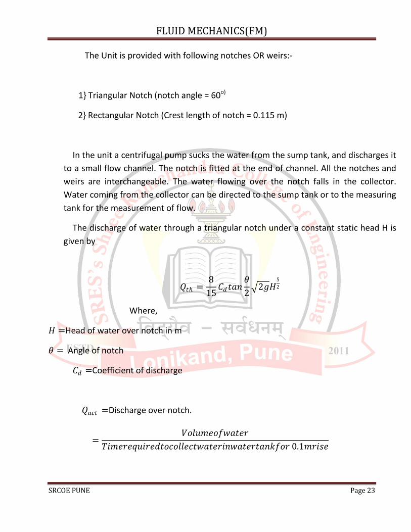
The Unit is provided with following notches OR weirs:-
1} Triangular Notch (notch angle = 60o)
2} Rectangular Notch (Crest length of notch = 0.115 m)
In the unit a centrifugal pump sucks the water from the sump tank, and discharges it
to a small flow channel. The notch is fitted at the end of channel. All the notches and
weirs are interchangeable. The water flowing over the notch falls in the collector.
Water coming from the collector can be directed to the sump tank or to the measuring
tank for the measurement of flow.
The discharge of water through a triangular notch under a constant static head H is
given by
𝑄𝑡 =8
15𝐶𝑑𝑡𝑎𝑛
𝜃
2 2𝑔𝐻
5
2
Where,
𝐻 =Head of water over notch in m
𝜃 = Angle of notch
𝐶𝑑 =Coefficient of discharge
𝑄𝑎𝑐𝑡 =Discharge over notch.
=𝑉𝑜𝑙𝑢𝑚𝑒𝑜𝑓𝑤𝑎𝑡𝑒𝑟
𝑇𝑖𝑚𝑒𝑟𝑒𝑞𝑢𝑖𝑟𝑒𝑑𝑡𝑜𝑐𝑜𝑙𝑙𝑒𝑐𝑡𝑤𝑎𝑡𝑒𝑟𝑖𝑛𝑤𝑎𝑡𝑒𝑟𝑡𝑎𝑛𝑘𝑓𝑜𝑟 0.1𝑚𝑟𝑖𝑠𝑒
FLUID MECHANICS(FM)
SRCOE PUNE Page 24
=𝐴𝑟𝑒𝑎𝑜𝑓𝑡𝑎𝑛𝑘 × 𝑅𝑖𝑠𝑒𝑜𝑓𝑤𝑎𝑡𝑒𝑟𝑙𝑒𝑣𝑒𝑙
𝑇𝑖𝑚𝑒
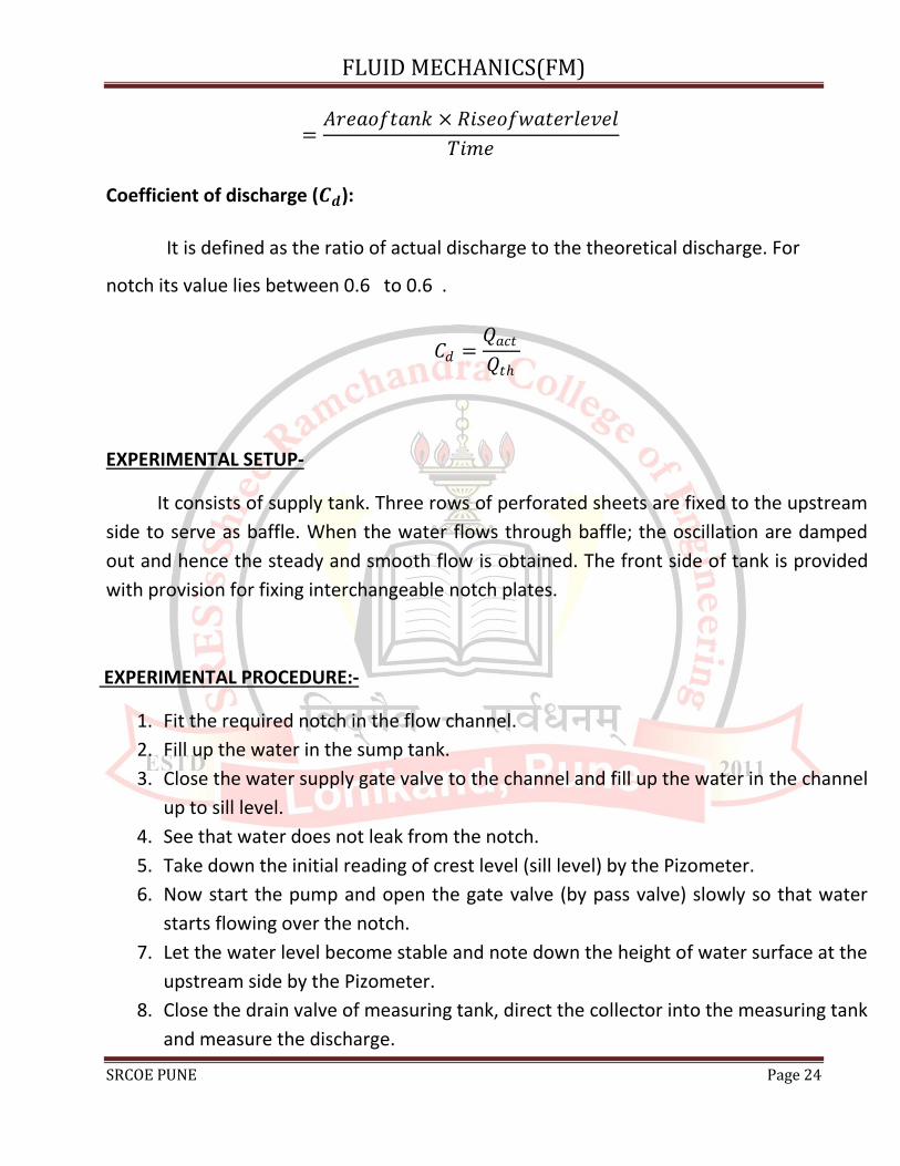
Coefficient of discharge (𝑪𝒅):
It is defined as the ratio of actual discharge to the theoretical discharge. For
notch its value lies between 0.6 to 0.6 .
𝐶𝑑 =𝑄𝑎𝑐𝑡
𝑄𝑡
EXPERIMENTAL SETUP-
It consists of supply tank. Three rows of perforated sheets are fixed to the upstream
side to serve as baffle. When the water flows through baffle; the oscillation are damped
out and hence the steady and smooth flow is obtained. The front side of tank is provided
with provision for fixing interchangeable notch plates.
EXPERIMENTAL PROCEDURE:-
1. Fit the required notch in the flow channel.
2. Fill up the water in the sump tank.
3. Close the water supply gate valve to the channel and fill up the water in the channel
up to sill level.
4. See that water does not leak from the notch.
5. Take down the initial reading of crest level (sill level) by the Pizometer.
6. Now start the pump and open the gate valve (by pass valve) slowly so that water
starts flowing over the notch.
7. Let the water level become stable and note down the height of water surface at the
upstream side by the Pizometer.
8. Close the drain valve of measuring tank, direct the collector into the measuring tank
and measure the discharge.

FLUID MECHANICS(FM)
SRCOE PUNE Page 25
9. Take the readings for different flow rates.
10. Repeat the same procedure for other notch also.
SPECIFICATIONS:-
6. Area of Tank = 0.3×0.3 m²
7. Rise of water level = 0.1m
8. Volume of tank = 0.3×0.3×0.1 m³
9. Initial still level Reading = h₀ m
OBSERVATION TABLE:-
Sr.
no.
Initial
still
level
reading
h₀ (m)
Final
still
level
reading
h₁ (m)
Head H =
(h₁-h₀)
(m)
Time
for
10cm
rise of
water
𝑸𝒂𝒄𝒕 𝑸𝒕𝒉 ln 𝑸𝒂𝒄𝒕 ln 𝑸𝒕𝒉 𝑪𝒅
1
2
3
4
5
CALCULATIONS:-

FLUID MECHANICS(FM)
SRCOE PUNE Page 26
11. Discharge:
𝑄𝑎𝑐𝑡 =𝑉𝑜𝑙𝑢𝑚𝑒𝑜𝑓𝑤𝑎𝑡𝑒𝑟
𝑇𝑖𝑚𝑒𝑟𝑒𝑞𝑢𝑖𝑟𝑒𝑑𝑡𝑜𝑐𝑜𝑙𝑙𝑒𝑐𝑡𝑤𝑎𝑡𝑒𝑟𝑖𝑛𝑤𝑎𝑡𝑒𝑟𝑡𝑎𝑛𝑘𝑓𝑜𝑟 0.1𝑚𝑟𝑖𝑠𝑒
=𝐴𝑟𝑒𝑎𝑜𝑓𝑡𝑎𝑛𝑘 × 𝑅𝑖𝑠𝑒𝑜𝑓𝑤𝑎𝑡𝑒𝑟𝑙𝑒𝑣𝑒𝑙
𝑇𝑖𝑚𝑒
=0.3×0.3×0.1
𝑡m³/s
12. Head H = (h₁-h₀) m
3. Theoretical discharge
𝑄𝑡 =8
15× 𝑡𝑎𝑛
𝛩
2× 2𝑔 ×
52
For right angled triangle Θ = 90°
4. 𝐶𝑑 =𝑄𝑎𝑐𝑡
𝑄𝑡
CONCLUSIONS:-

FLUID MECHANICS(FM)
SRCOE PUNE Page 27
EXPERIMENT NO.:-7
--------------------------------------------------------------------------------------
REYNOLD’S EXPERIMENT
AIM: -
To determine different regimes of flow by Reynold’s Apparatus.
APPARATUS:-
A constant head water tank having a glass tube leading out of it, the horizontal
glass tube has a bell mouth at entrance, A regulating valve at outlet, A dye container
(small tank) with an arrangement for injecting a fine element of dye (specific weight
is same as that of water) at the entrance of glass tube, A collecting tank, A stop
watch, A scale, etc.
THEORY:-

FLUID MECHANICS(FM)
SRCOE PUNE Page 28
Whenever a fluid is flowing through a pipe, the flow is either laminar or
turbulent. When fluid is flowing in parallel layers or laminar, sliding past adjacent
laminar, it is called laminar flow. When the fluid does not flow in parallel layers
and there is intermingling of fluid particles then the flow is said to be turbulent.
Existence of these two types was first demonstrated by OSBORN REYNOLDS in
1883.
The apparatus consists of a constant head supply tank supplied with water.
This tank is provided with a bell mouth outlet to which a transparent tube is fitted.
At outlet of the tube a regulating valve is providing. A dye tank containing colored
dye is fitted above the supply tank the water flows through pipe and dye is
injected at the center of the pipe. When the velocity of flow is low, (i.e. flow is
laminar) then dye remains in the form of straight filament. As the velocity of
water (i.e. flow of water) is increased, a state is reached when the dye filament
becomes irregular and water. With further increase of velocity of water through
the tube, dye filament becomes more and more irregular and ultimately the dye
diffuses over the entire cross section of the tube.
The velocity at which the flow changes from laminar to turbulent for the case of a
given fluid at given temperature and in a given pipe is known as critical velocity.
The state of flow between these two types of flow is known as ‘transition state’ or
flow in transition.
The occurrence of laminar and turbulent flow is governed by relative
magnitudes of inertia and viscous forces. Reynolds related the inertia to viscous
forces and arrived at a dimensionless parameter now called Reynolds number.
Reynold’s apparatus demonstrated the existence of two types of flows.
1. Laminar flow 𝑅𝑒 < 2000
2. Turbulent flow 𝑹𝒆 > 4000
3. 𝑹𝒆 Between 2000 to 4000 indicates transition flow from laminar to turbulent flow.

FLUID MECHANICS(FM)
SRCOE PUNE Page 29
The discharge Q can be calculated as
Q =𝑉𝑜𝑙𝑢𝑚𝑒𝑜𝑓𝑤𝑎𝑡𝑒𝑟
𝑇𝑖𝑚𝑒𝑟𝑒𝑞𝑢𝑖𝑟𝑒𝑑𝑡𝑜𝑐𝑜𝑙𝑙𝑒𝑐𝑡𝑤𝑎𝑡𝑒𝑟𝑖𝑛𝑤𝑎𝑡𝑒𝑟𝑡𝑎𝑛𝑘𝑓𝑜𝑟 0.1𝑚𝑟𝑖𝑠𝑒
=𝐴𝑟𝑒𝑎𝑜𝑓𝑡𝑎𝑛𝑘 × 𝑅𝑖𝑠𝑒𝑜𝑓𝑤𝑎𝑡𝑒𝑟𝑙𝑒𝑣𝑒𝑙
𝑇𝑖𝑚𝑒
The Reynold’s number (𝑹𝒆),
𝑅𝑒 =𝜌𝑉𝐷
𝜇=
𝑉 × 𝐷
𝜈
Where,
𝑅𝑒 = Reynold’s number.
𝝆 =Density of water.
𝜇 =Dynamic Viscosity.
𝑉 =Velocity water in the glass tube.
𝐷 =Diameter of glass tube.
𝜈 =Kinematic viscosity of water.
=1.006×10⁻⁶ 𝑚2
𝑠
EXPERIMENTAL PROCEDURE:-
1. Fill up sufficient water in dye tank and put a small amount of potassium paramagnet in to water.
2. Start water flow. Adjust the water flow to about 2 lpm. Start the pump & dye injection.
3. Wait for same time. A steady line of dye will be observed. Adjust dye flow, if required.

FLUID MECHANICS(FM)
SRCOE PUNE Page 30
4. Slowly increases the water flow see that water level in supply tank remains constant. At particular flow rate, dye line will be disturbed note down this flow rate.
5. Further increase the flow. The disturbances of dye line will go on increasing and at certain flow; the dye line diffuses over the entire cross section. Note down this flow.
6. Slightly increase the flow and then slowly reduce the flow. Note the flow at which diffused dye tends to become steady, (beginning of transition zone while reducing velocity.)
7. Further reduce the flow and note the flow at which dye line becomes straight and steady.
SPECIFICATIONS:-
1. Diameter of glass tube = ---------m
2. Area of tank = -------------m²
3. Rise of water level = 10cm = 0.1m
OBSERVATION TABLE:-
Sr.
no.
Time
required
for
10cm
rise of
water
Discharge
(Q) Velocity (V)
Reynold's
no. (Re)
Observed flow
regimes
1
FLUID MECHANICS(FM)
SRCOE PUNE Page 31
CALCULATIONS:-
13. Discharge:
𝑄𝑎𝑐𝑡 =𝑉𝑜𝑙𝑢𝑚𝑒𝑜𝑓𝑤𝑎𝑡𝑒𝑟
𝑇𝑖𝑚𝑒𝑟𝑒𝑞𝑢𝑖𝑟𝑒𝑑𝑡𝑜𝑐𝑜𝑙𝑙𝑒𝑐𝑡𝑤𝑎𝑡𝑒𝑟𝑖𝑛𝑤𝑎𝑡𝑒𝑟𝑡𝑎𝑛𝑘𝑓𝑜𝑟 0.1𝑚𝑟𝑖𝑠𝑒
=𝐴𝑟𝑒𝑎𝑜𝑓𝑡𝑎𝑛𝑘 × 𝑅𝑖𝑠𝑒𝑜𝑓𝑤𝑎𝑡𝑒𝑟𝑙𝑒𝑣𝑒𝑙
𝑇𝑖𝑚𝑒
=0.3×0.3×0.1
𝑡m³/s
2. Velocity
𝑄𝑎𝑐𝑡 = Area of pipe ×Velocity
Velocity =𝑄𝑎𝑐𝑡
𝐴𝑟𝑒𝑎 𝑜𝑓 𝑝𝑖𝑝𝑒
3. Reynold’s number
2
3
4
5

FLUID MECHANICS(FM)
SRCOE PUNE Page 32
𝑅𝑒 =𝑣 × 𝑑
𝜐
Where,
𝑣 =Velocity
𝑑 =Diameter of pipe
𝜐 =Kinematic viscosity of water = 1.006×10⁻⁶ m²/s
CONCLUSIONS:-
EXPERIMENT NO.:- 8
------------------------------------------------------------------------------------------
LOSSES IN PIPE FITTINGS APPARATUS
AIM: -
Determination of minor losses due to pipe fittings (expansion, contraction, bend,
elbow, gate valve, globe valve etc.)
APPARATUS:-
A Pipe Elbow, a Sudden Contraction, a Sudden Expansion, a Pipe Bend, A
collecting tank, a stop watch, Scale, etc.
THEORY:-

FLUID MECHANICS(FM)
SRCOE PUNE Page 33
While installing a pipeline for conveying a fluid, it is generally not possible
to install a long pipeline of same size all over for various reasons, like space
restrictions, aesthetics, location of outlet, etc hence, the pipe size varies and it
changes its direction. Also, various fittings are required to be used. All these
variations of sizes and the fittings cause the loss of fluid head. The apparatus is
designed to demonstrate the loss of head due to the following fittings-
1) Pipe Elbow. 2) Sudden Contraction. 3) Sudden Expansion. & 4) Pipe
Bend.
The set up consists of basic piping in which the above fittings are
installed. A pressure tapping is provided at inlet and outlet of each fitting. This
pressure tapping is connected to water head trappings. A gate valve at outlet
and a bypass valve at pump discharge is used to control the pressure and flow
of water through the test section.
1) ELBOW:
In elbow, there is no change in the magnitude of velocity of water, but there
is change in the direction of water hence head loss exists.
2) SUDDEN CONTRACTION:
At sudden contraction, velocity of water increases which causes pressure
head to drop (according to Bernoulli’s theorem), in addition to this there is loss of
head due to sudden contraction
3) SUDDEN EXPANSION
At sudden expansion of flow, pressure increases due to reduction in velocity, but
there is pressure drop due to sudden expansion also, hence, at sudden Expansion
one gets rise of pressure lesser than that predicted theoretically.
4) PIPE BEND:

FLUID MECHANICS(FM)
SRCOE PUNE Page 34
Similar to elbow, loss of head at bend is due to change in the direction of water
but unlike the elbow, Change of direction is not abrupt; hence loss of head is
less as compared to elbow.
EXPERIMENTAL PROCEDURE:
1. Fill up sufficient clean water in the sump tank.
2. Before starting the experiment, see that,
3. The bypass valve, flow control valve & manometer base cocks are fully
opened.
4. Start the pump and close the bypass valve, so that water starts flowing
through the entire manometer overflow tubes. This ensures that there is
no air gap in the manometer piping.
5. Close all the manometer base cocks and wait till all the water is drained
out from all the backside tubes.
6. Now again open the bypass by 2 to 3 turns such that the pressure in the
piping is decreased.
7. Open all the manometer base cocks and take the water heights of the
corresponding tapping.
8. Repeat the procedure for different flow rates.
SPECIFICATIONS:-
1. Basic piping of 28 mm size.
2. Pipe Elbow of 16 mm – 1 no.
3. Sudden contraction from 28 mm to 16 mm piping.
4. Sudden expansion from 16 mm to 28 mm piping.
5. Pipe Bend of 16 mm.
6. ½ H.P. pump to circulate water through the piping.
7. Sump tank of size 300 mm x 1050 mm x 400 mm.

FLUID MECHANICS(FM)
SRCOE PUNE Page 35
8. Measuring tank of 300 x 300 x 550 mm height.
OBSERVATION TABLE:-
CALCULATIONS:-
Sr.no.
Manometer Water Head Difference Time
for 10
cm rise
of
water
Elbow Sudden
enlargement
Sudden
contraction Bend
Inlet Outlet Inlet Outlet Inlet Outlet Inlet Outlet
1
2
3
4
5

FLUID MECHANICS(FM)
SRCOE PUNE Page 36
1. Discharge (Q)
=0.3 × 0.3 × 0.05
t
2. Elbow
Mean velocity 𝑉 =𝑄
𝐴
A = (π
4) × d2
Loss of head at elbow 𝑒𝑥𝑝𝑡 = − − − − −𝑚 of water
Actual Loss of head at elbow
𝑎𝑐𝑡 = 𝐾 =𝑣2
2𝑔m of water
K = ---------------.
3. Sudden Contraction
Water head difference = (Head drop due to increment of velocity) + (Head loss
due to sudden contraction)
𝐡 = 𝐡𝐯 + 𝐡𝐜
Inlet size diameter ‘di’ = -----------m Ai = -----------------m2
Outlet size diameter ‘do’ = ---------m Ao =------------------m2

FLUID MECHANICS(FM)
SRCOE PUNE Page 37
Where, Ai and Ao are Inlet and outlet areas respectively
Also,
Vi =Q
A im/s&Vo =
Q
Ao m/s
Drop of head due to velocity increment,
𝐡𝐯 = (𝐕𝐨
𝟐
𝟐𝐠−
𝐕𝐢𝟐
𝟐𝐠)
Actual drop due to sudden contraction
𝐡𝐜 = 𝐡 − 𝐡𝐯
Theoretically,
𝐡𝐜 = 𝐊(𝐕𝐨
𝟐
𝟐𝐠)
K = ---------------.
4. Sudden Enlargement
Water head difference = (Head drop due to decrement of velocity) + (Head loss
due to sudden expansion)
𝐡 = 𝐡𝐯 + 𝐡𝐞
Inlet size diameter ‘di’ = -----------m Ai = -----------------m2
Outlet size diameter ‘do’ = ---------m Ao =------------------m2
Where, Ai and Ao are Inlet and outlet areas respectively

FLUID MECHANICS(FM)
SRCOE PUNE Page 38
Also,
Vi =Q
A im/s&Vo =
Q
Ao m/s
Drop of head due to velocity decrement,
𝐡𝐯 = (𝐕𝐢
𝟐
𝟐𝐠−
𝐕𝐨𝟐
𝟐𝐠)
Actual drop due to sudden expansion,
𝐡𝐞 = 𝐡𝐯 − 𝐡
Theoretically,
𝐡𝐞 = 𝐊(𝐕𝐨
𝟐
𝟐𝐠)
K = ---------------.
5. Bend
Mean velocity 𝑉 =𝑄
𝐴
A = (π
4) × d2
Diameter of bend = 0.016 m
Loss of head at bend 𝑒𝑥𝑝𝑡 = − − − − −𝑚 of water
Actual Loss of head at bend,
𝑎𝑐𝑡 = 𝐾 =𝑣2
2𝑔m of water

FLUID MECHANICS(FM)
SRCOE PUNE Page 39
K = --------------
CONCLUSIONS:-