Lab Manual ECE212
30
LABORATORY MANUAL ECE-212 MICROPROCESSOR LAB Prepared By: Gursharanjeet Singh (13586) P
Transcript of Lab Manual ECE212
LABORATORY MANUAL
ECE-212
MICROPROCESSOR LAB
Prepared By: Gursharanjeet Singh (13586)
P
2
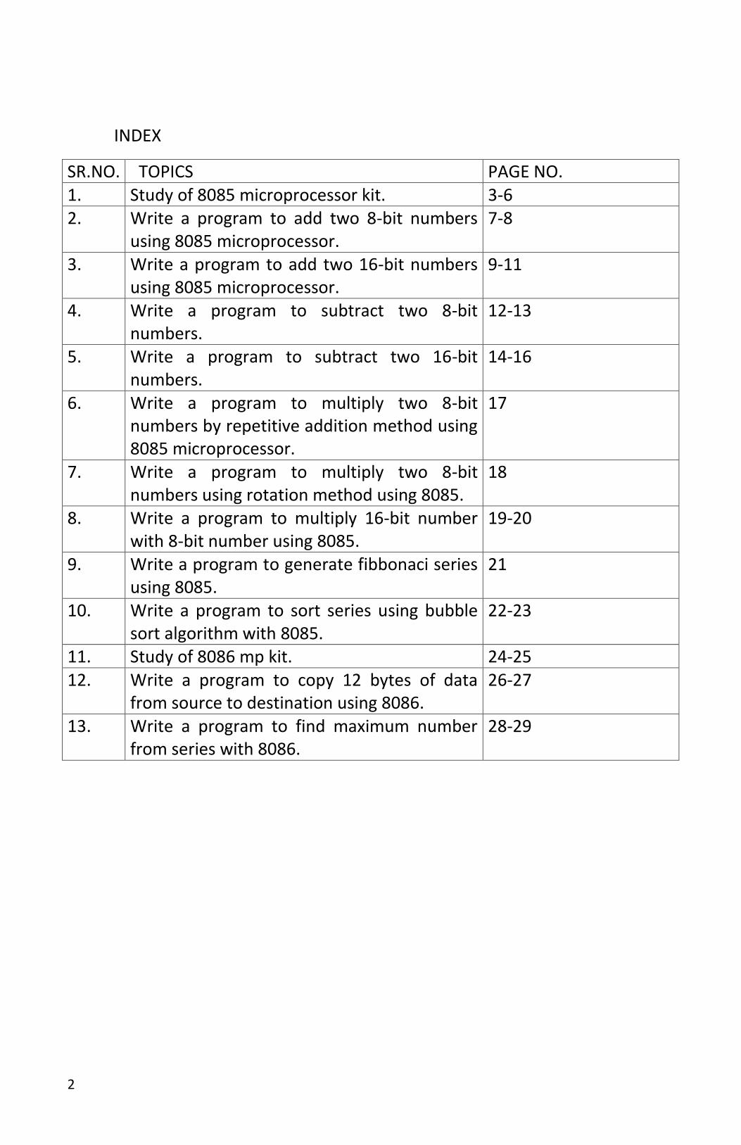
INDEX
SR.NO. TOPICS PAGE NO. 1. Study of 8085 microprocessor kit. 3-6 2. Write a program to add two 8-bit numbers
using 8085 microprocessor. 7-8
3. Write a program to add two 16-bit numbers using 8085 microprocessor.
9-11
4. Write a program to subtract two 8-bit numbers.
12-13
5. Write a program to subtract two 16-bit numbers.
14-16
6. Write a program to multiply two 8-bit numbers by repetitive addition method using 8085 microprocessor.
17
7. Write a program to multiply two 8-bit numbers using rotation method using 8085.
18
8. Write a program to multiply 16-bit number with 8-bit number using 8085.
19-20
9. Write a program to generate fibbonaci series using 8085.
21
10. Write a program to sort series using bubble sort algorithm with 8085.
22-23
11. Study of 8086 mp kit. 24-25 12. Write a program to copy 12 bytes of data
from source to destination using 8086. 26-27
13. Write a program to find maximum number from series with 8086.
28-29

3
Exp 1: EXPT 13:
Introduction to 8085 microprocessor kit
8085 micro processor:
It is also known as CPU or complete computation engine that is fabricated on a
single chip. The first microprocessor was INTEL 4004 introduced in 1971. It was
not very powerful as it was used only for simple arithmetic operations.
Secondly, it could process only 4 bits at a time.
Features of 8085 MP:
1. Control Unit
Generates signals within uP to carry out the instruction, which has been decoded. In reality causes certain connections between blocks of the uP to be opened or closed, so that data goes where it is required, and so that ALU operations occur.
2. Arithmetic Logic Unit
The ALU performs the actual numerical and logic operation such as ‘add’, ‘subtract’, ‘AND’, ‘OR’, etc. It uses data from memory and from accumulator to perform arithmetic. It always stores result of operation in Accumulator.
3. Registers
4
The 8085 includes six registers, one accumulator and one flag register. In addition, it has two 16-bit registers: the stack pointer and the program counter. They are described briefly as follows:
The 8085 has six general-purpose registers to store 8-bit data; these are identified as B, C, D, E, H, and L as shown in the figure. They can be combined as register pairs - BC, DE, and HL - to perform some 16-bit operations. The programmer can use these registers to store or copy data into the registers by using data copy instructions.
4. Accumulator
The accumulator is an 8-bit register that is a part of arithmetic/logic unit (ALU). This register is used to store 8-bit data and to perform arithmetic and logical operations. The result of an operation is stored in the accumulator. The accumulator is also identified as register A.
5. Flags
The ALU includes five flip-flops, which are set or reset after an operation according to data conditions of the result in the accumulator and the flags which are Zero (Z), Carry (CY), Sign (S), Parity (P) and Auxiliary Carry (AC) flags. They are listed in the table and their bit positions in the flag register are shown in the figure below. The most commonly used flags are Zero, Carry, and Sign. The microprocessor uses these flags to test data conditions.
For example, after an addition of two numbers, if the sum in the accumulator is larger than eight bits, the flip-flop uses to indicate a carry called the Carry flag (CY) which is set to one. When an arithmetic operation results in zero, the flip-flop called the Zero (Z) flag is set to one. The flags are stored in the 8-bit register so that the programmer can examine these flags (data conditions) by accessing the register through an instruction.
6. Program Counter (PC)
This 16-bit register deals with sequencing the execution of instructions. This register is a memory pointer. Memory locations have 16-bit addresses, and that is why this is a 16-bit register.
The microprocessor uses this register to sequence the execution of the instructions. The function of the program counter is to point to the memory address from which the next byte is to be fetched. When a byte (machine code) is being fetched, the program counter is incremented by one to point to the next memory location
7. Stack Pointer (SP)
5
The stack pointer is also a 16-bit register used as a memory pointer. It points to a memory location in R/W memory called the stack. The beginning of the stack is defined by loading 16-bit address in the stack pointer.
8. 8085 System Bus:
a). Address Bus
One wire for each bit, therefore 16 bits = 16 wires is needed. Binary number carried alerts memory to ‘open’ the designated box. Data (binary) can then be put in or taken out. The Address Bus consists of 16 wires, therefore 16 bits. Its "width" is 16 bits. A 16 bit binary number allows 216 different numbers, or 65536 different numbers, i.e., 0000000000000000 up to 1111111111111111. Because memory consists of boxes, each with a unique address, the size of the address bus determines the size of memory which can be used. To communicate with memory the microprocessor sends an address on the address bus, eg0000000000000011 (3 in decimal), to the memory. The memory selects box number 3 for reading or writing data. Address bus is unidirectional, i.e. numbers only sent from microprocessor to memory.
b). Data Bus
Data Bus: carries ‘data’, in binary form, between µP and other external units, such as memory. Typical size is 8 or 16 bits. Size determined by size of boxes in memory and µP size helps determine performance of µP. The Data Bus typically consists of 8 wires, therefore, 28 combinations of binary digits. Data bus used to transmit "data", i.e. information, results of arithmetic, etc, between memory and the microprocessor. Bus is bi-directional. Size of the data bus determines what arithmetic can be done. If only 8 bits wide then largest number is 11111111 (255 in decimal). Therefore, larger number has to be broken down into chunks of 255 which slow down the microprocessor. Data Bus also carries instructions from memory to the microprocessor. Size of the bus therefore limits the number of possible instructions to 256, each specified by a separate number.
c). Control Bus: Control Bus consists of various lines which have specific functions for coordinating and controlling µP operations. eg: Read/Not Write line, single binary digit. Control whether memory is being ‘written to’ (data stored in memory) or ‘read from’ (data taken out of memory) 1 = Read, 0 = Write. There May also be clock line(s) for timing/synchronizing, ‘interrupts’, ‘reset’ etc.
6
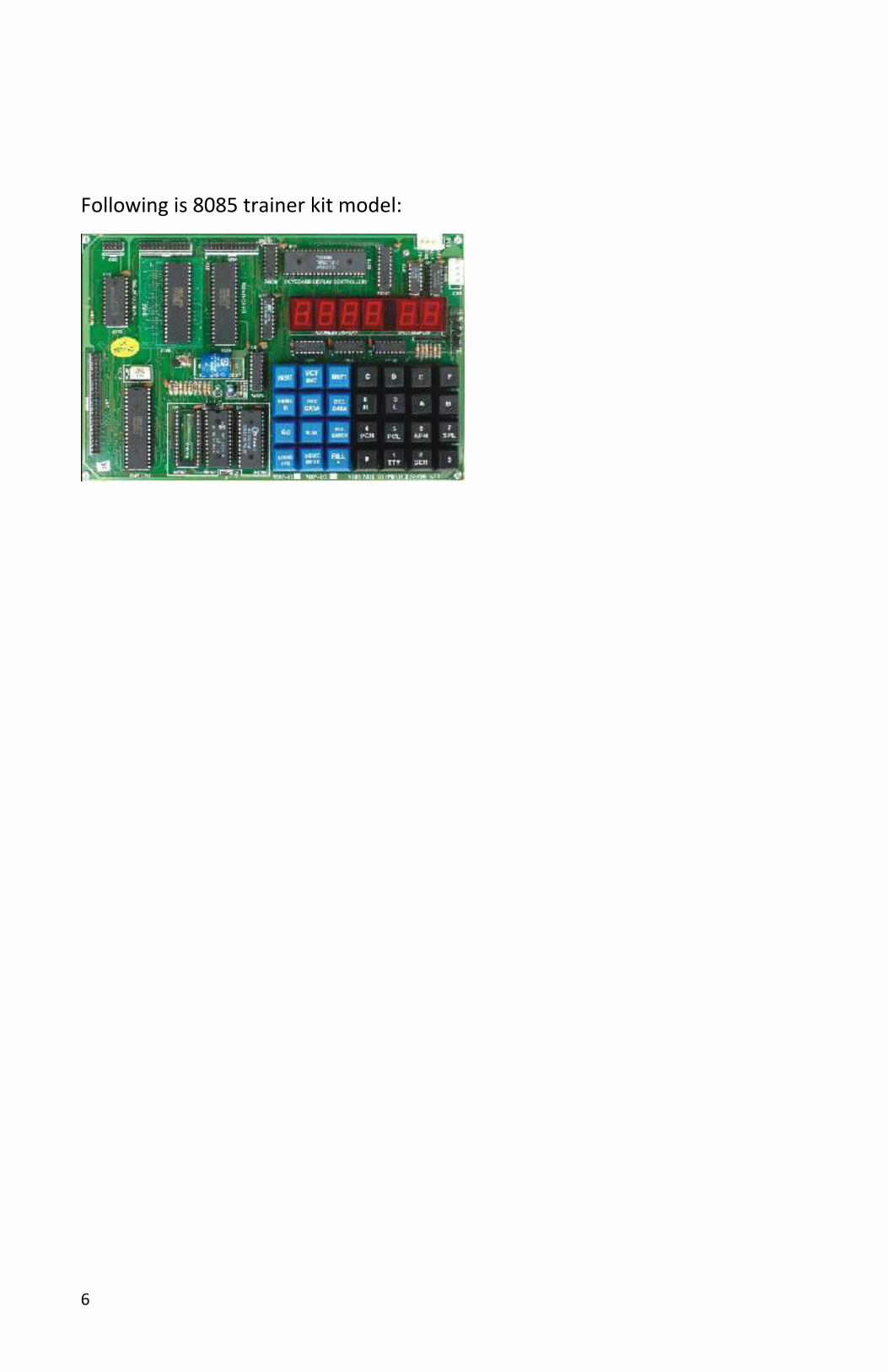
Following is 8085 trainer kit model:
7
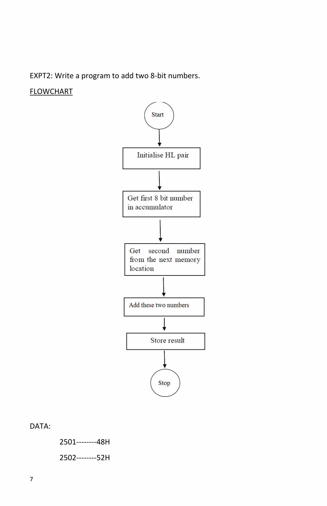
EXPT2: Write a program to add two 8-bit numbers.
FLOWCHART
DATA:
2501--------48H
2502--------52H

8
9
Result: The resultant will be stored at 2503.
2503----------- 9A
MEMORY ADDRESS
MACHINE CODE/DATA
LABEL
MNEO-MONICS
OPERANDS COMMENTS
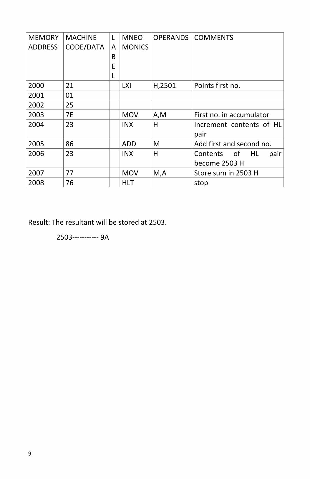
2000 21 LXI H,2501 Points first no. 2001 01 2002 25 2003 7E MOV A,M First no. in accumulator 2004 23 INX H Increment contents of HL
pair 2005 86 ADD M Add first and second no. 2006 23 INX H Contents of HL pair
become 2503 H 2007 77 MOV M,A Store sum in 2503 H 2008 76 HLT stop
10
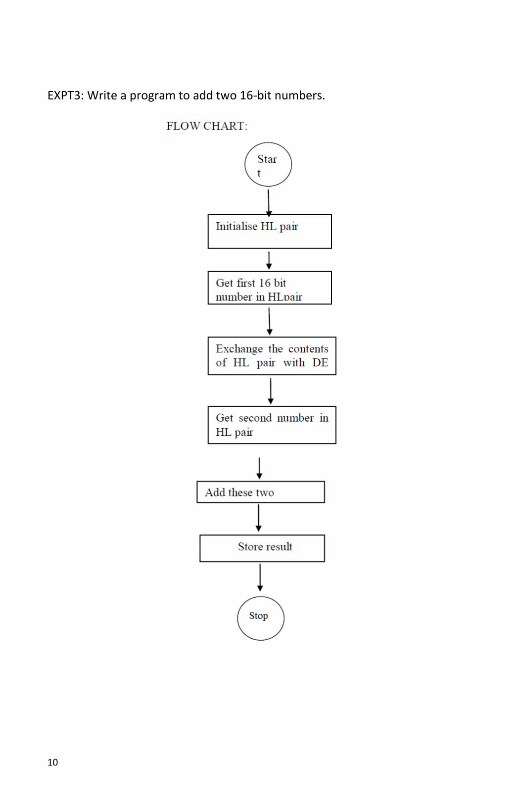
EXPT3: Write a program to add two 16-bit numbers.
11
MEMORY ADDRESS
MACHINE CODE/DATA
LABEL MNEOMONICS OPERANDS COMMENTS
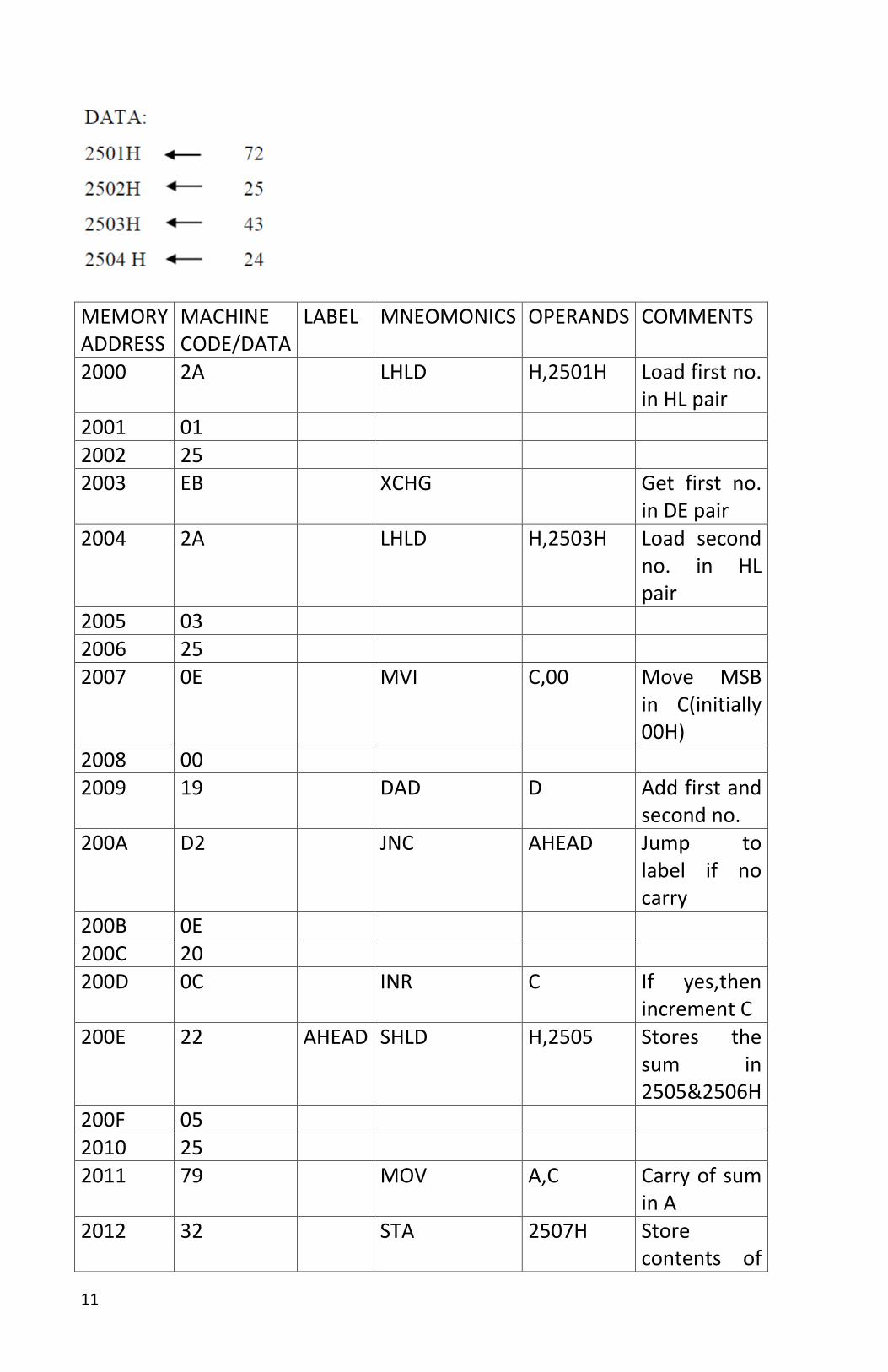
2000 2A LHLD H,2501H Load first no. in HL pair
2001 01 2002 25 2003 EB XCHG Get first no.
in DE pair 2004 2A LHLD H,2503H Load second
no. in HL pair
2005 03 2006 25 2007 0E MVI C,00 Move MSB
in C(initially 00H)
2008 00 2009 19 DAD D Add first and
second no. 200A D2 JNC AHEAD Jump to
label if no carry
200B 0E 200C 20 200D 0C INR C If yes,then
increment C 200E 22 AHEAD SHLD H,2505 Stores the
sum in 2505&2506H
200F 05 2010 25 2011 79 MOV A,C Carry of sum
in A 2012 32 STA 2507H Store
contents of

12
A in 2507H 2013 07 2014 25 2015 76 HLT Stop
13
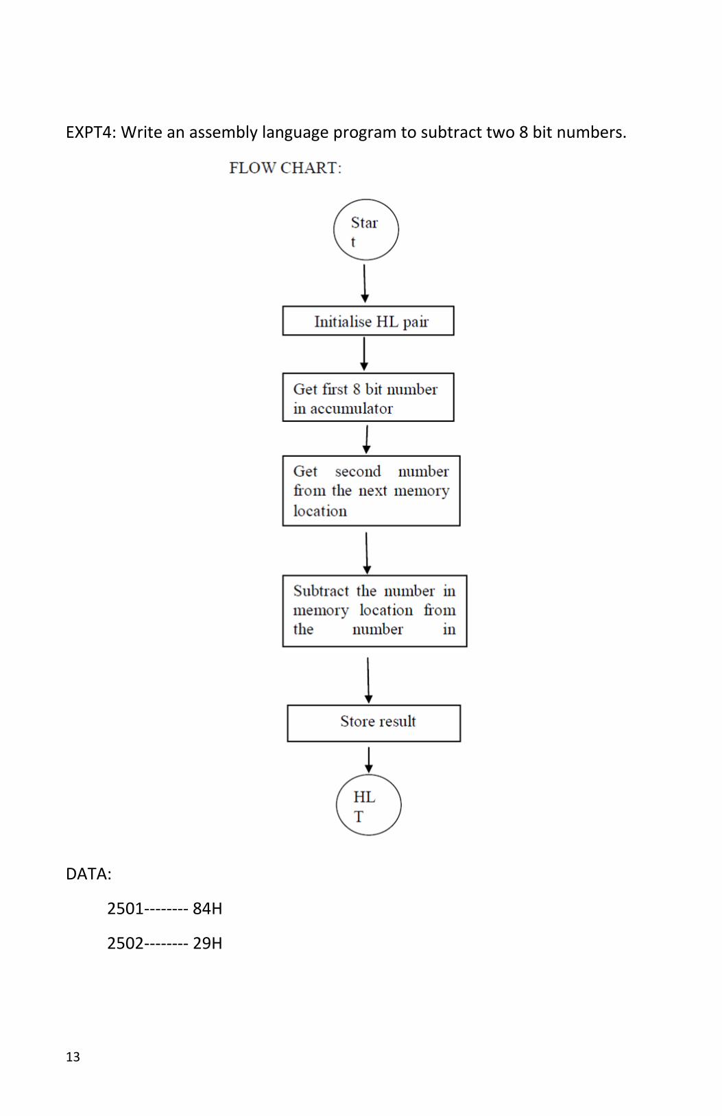
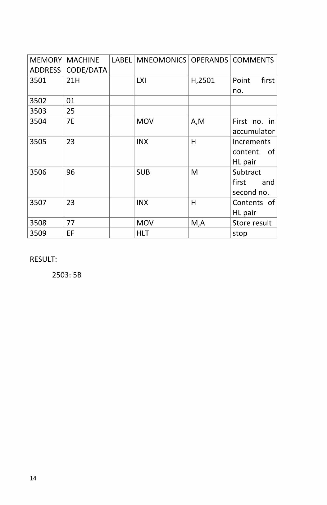
EXPT4: Write an assembly language program to subtract two 8 bit numbers.
DATA:
2501-------- 84H
2502-------- 29H
14
MEMORY ADDRESS
MACHINE CODE/DATA
LABEL MNEOMONICS OPERANDS COMMENTS
3501 21H LXI H,2501 Point first no.
3502 01 3503 25 3504 7E MOV A,M First no. in
accumulator 3505 23 INX H Increments
content of HL pair
3506 96 SUB M Subtract first and second no.
3507 23 INX H Contents of HL pair
3508 77 MOV M,A Store result 3509 EF HLT stop
RESULT:
2503: 5B
15
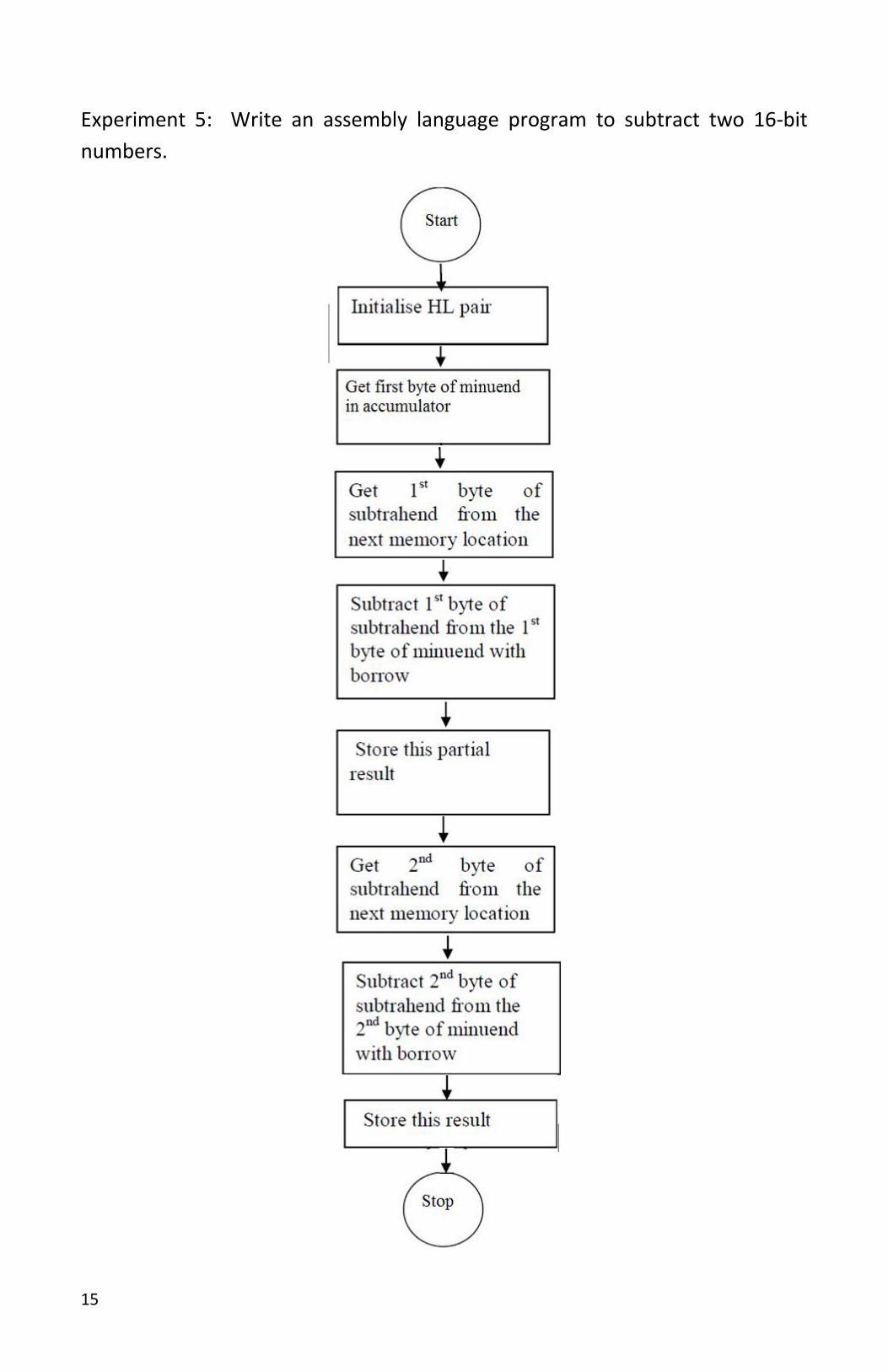
Experiment 5: Write an assembly language program to subtract two 16-bit
numbers.
16
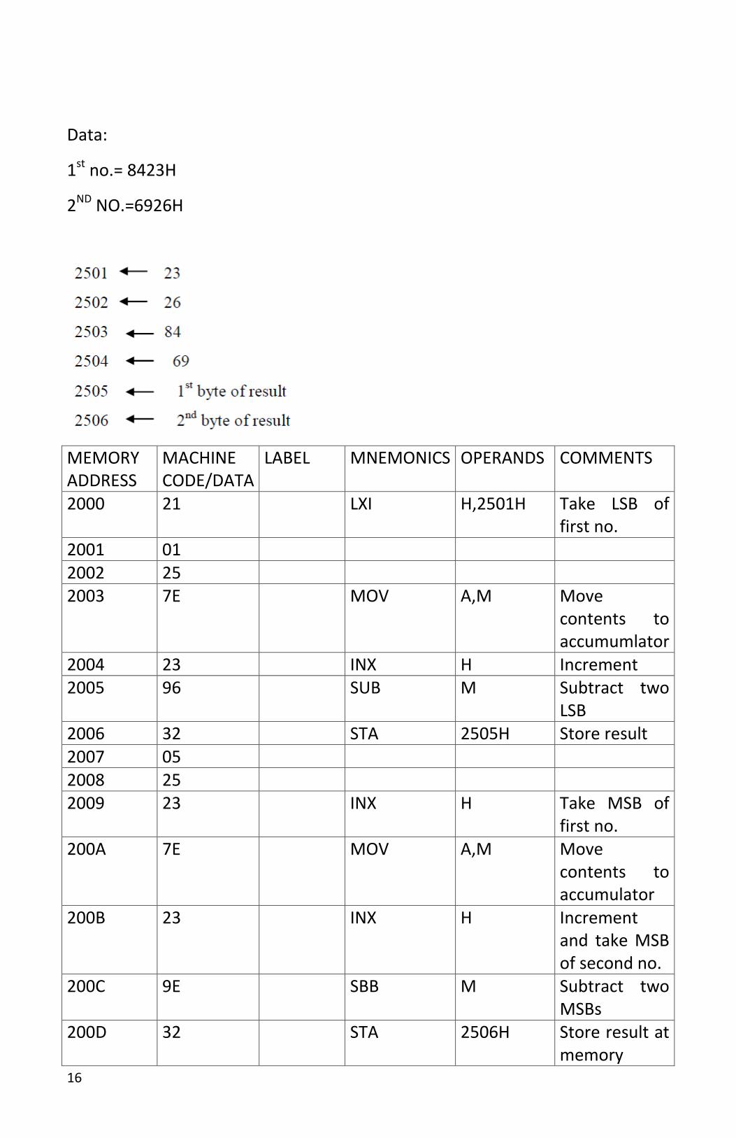
Data:
1st no.= 8423H
2ND NO.=6926H
MEMORY ADDRESS
MACHINE CODE/DATA
LABEL MNEMONICS OPERANDS COMMENTS
2000 21 LXI H,2501H Take LSB of first no.
2001 01 2002 25 2003 7E MOV A,M Move
contents to accumumlator
2004 23 INX H Increment 2005 96 SUB M Subtract two
LSB 2006 32 STA 2505H Store result 2007 05 2008 25 2009 23 INX H Take MSB of
first no. 200A 7E MOV A,M Move
contents to accumulator
200B 23 INX H Increment and take MSB of second no.
200C 9E SBB M Subtract two MSBs
200D 32 STA 2506H Store result at memory
17
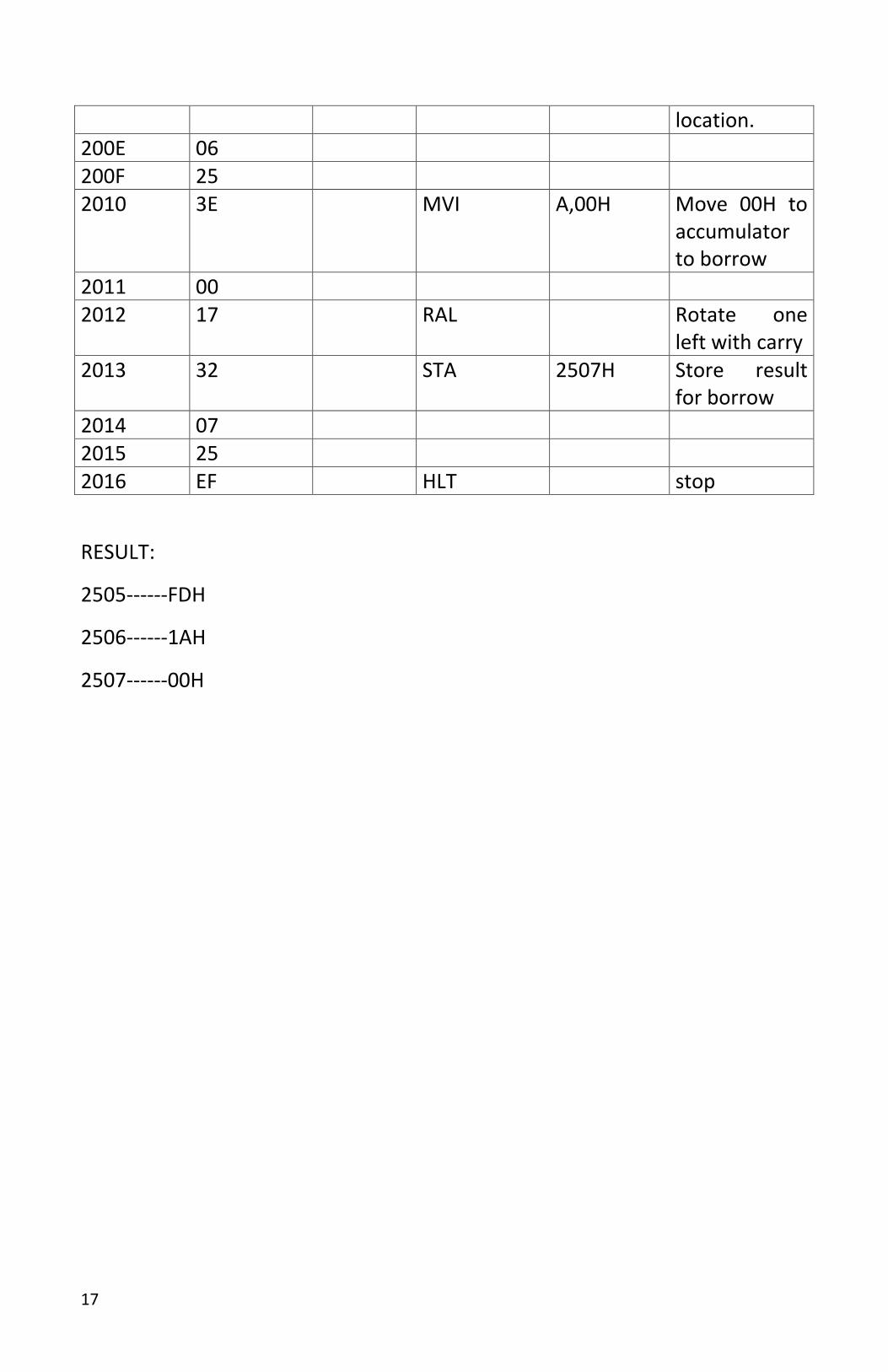
location. 200E 06 200F 25 2010 3E MVI A,00H Move 00H to
accumulator to borrow
2011 00 2012 17 RAL Rotate one
left with carry 2013 32 STA 2507H Store result
for borrow 2014 07 2015 25 2016 EF HLT stop
RESULT:
2505------FDH
2506------1AH
2507------00H
18
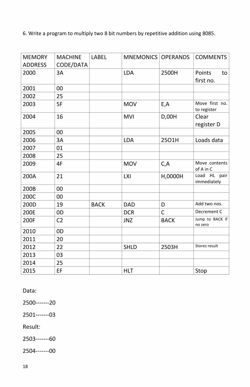
6. Write a program to multiply two 8 bit numbers by repetitive addition using 8085.
MEMORY ADDRESS
MACHINE CODE/DATA
LABEL MNEMONICS OPERANDS COMMENTS
2000 3A LDA 2500H Points to first no.
2001 00 2002 25 2003 5F MOV E,A Move first no.
to register
2004 16 MVI D,00H Clear register D
2005 00 2006 3A LDA 25O1H Loads data 2007 01 2008 25 2009 4F MOV C,A Move contents
of A in C
200A 21 LXI H,0000H Load HL pair immediately
200B 00 200C 00 200D 19 BACK DAD D Add two nos.
200E 0D DCR C Decrement C
200F C2 JNZ BACK Jump to BACK if no zero
2010 0D 2011 20 2012 22 SHLD 2503H Stores result
2013 03 2014 25 2015 EF HLT Stop
Data:
2500-------20
2501-------03
Result:
2503-------60
2504-------00
19
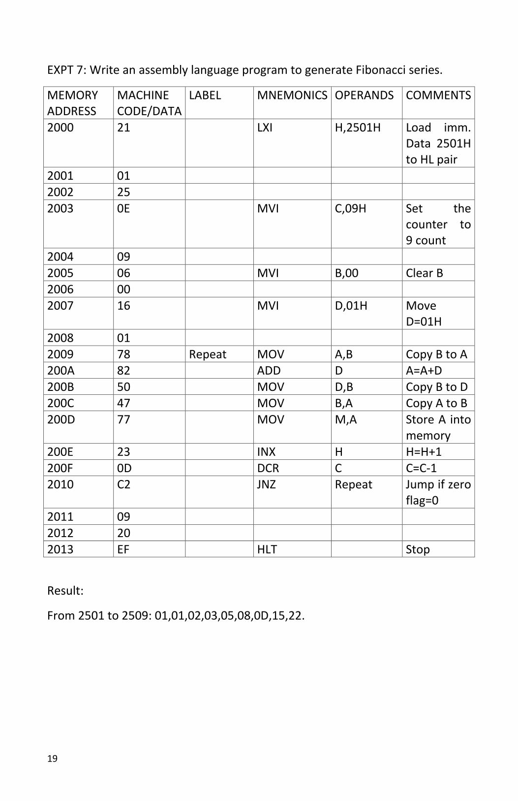
EXPT 7: Write an assembly language program to generate Fibonacci series.
MEMORY ADDRESS
MACHINE CODE/DATA
LABEL MNEMONICS OPERANDS COMMENTS
2000 21 LXI H,2501H Load imm. Data 2501H to HL pair
2001 01 2002 25 2003 0E MVI C,09H Set the
counter to 9 count
2004 09 2005 06 MVI B,00 Clear B 2006 00 2007 16 MVI D,01H Move
D=01H 2008 01 2009 78 Repeat MOV A,B Copy B to A 200A 82 ADD D A=A+D 200B 50 MOV D,B Copy B to D 200C 47 MOV B,A Copy A to B 200D 77 MOV M,A Store A into
memory 200E 23 INX H H=H+1 200F 0D DCR C C=C-1 2010 C2 JNZ Repeat Jump if zero
flag=0 2011 09 2012 20 2013 EF HLT Stop
Result:
From 2501 to 2509: 01,01,02,03,05,08,0D,15,22.
20
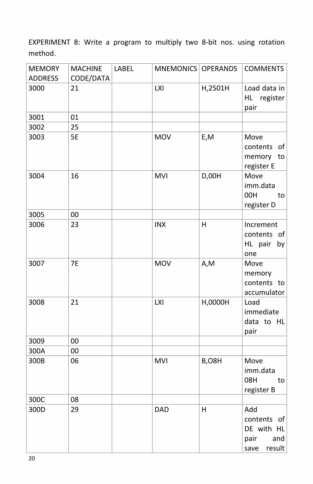
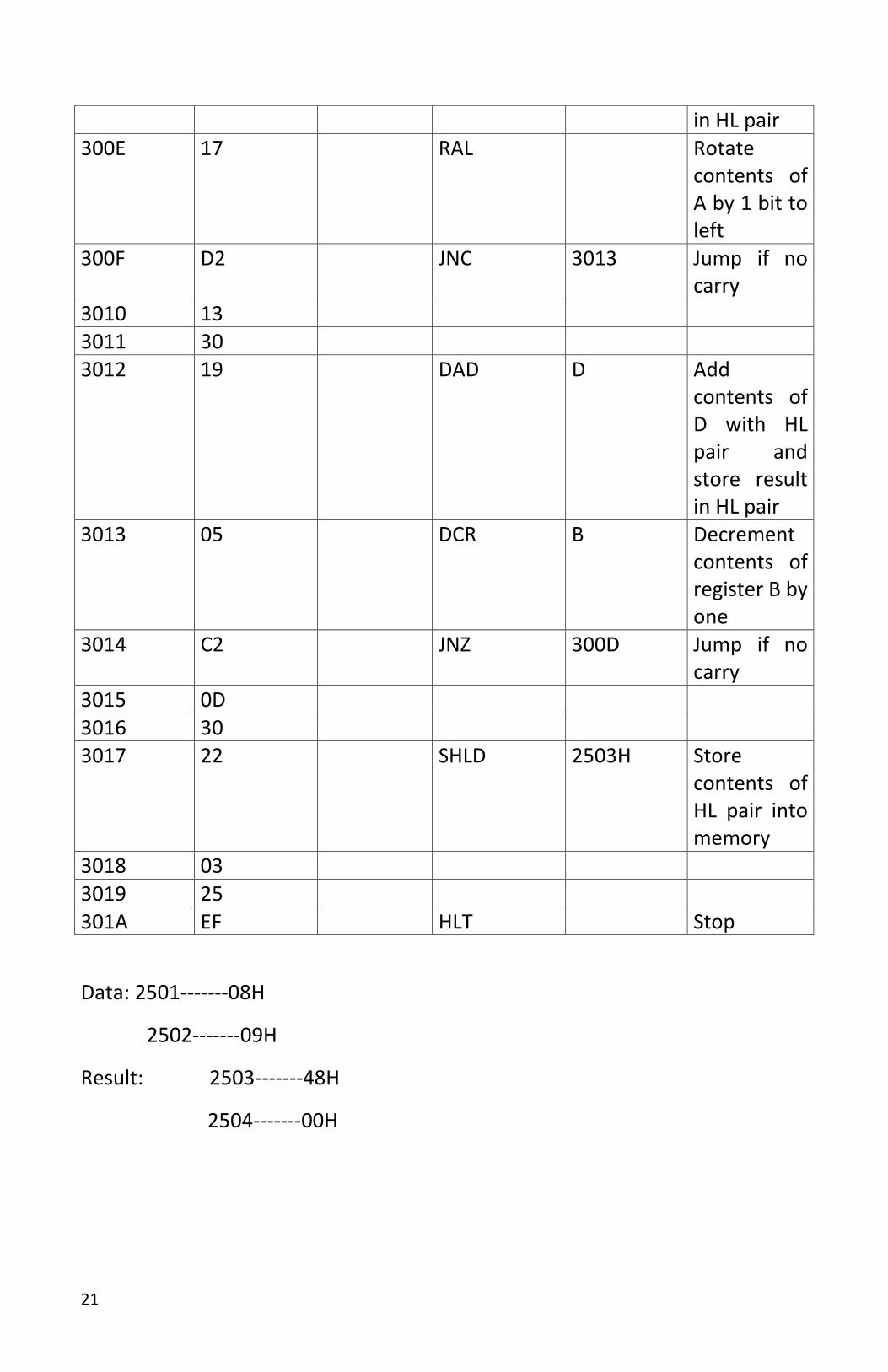
EXPERIMENT 8: Write a program to multiply two 8-bit nos. using rotation
method.
MEMORY ADDRESS
MACHINE CODE/DATA
LABEL MNEMONICS OPERANDS COMMENTS
3000 21 LXI H,2501H Load data in HL register pair
3001 01 3002 25 3003 5E MOV E,M Move
contents of memory to register E
3004 16 MVI D,00H Move imm.data 00H to register D
3005 00 3006 23 INX H Increment
contents of HL pair by one
3007 7E MOV A,M Move memory contents to accumulator
3008 21 LXI H,0000H Load immediate data to HL pair
3009 00 300A 00 300B 06 MVI B,O8H Move
imm.data 08H to register B
300C 08 300D 29 DAD H Add
contents of DE with HL pair and save result
21
in HL pair 300E 17 RAL Rotate
contents of A by 1 bit to left
300F D2 JNC 3013 Jump if no carry
3010 13 3011 30 3012 19 DAD D Add
contents of D with HL pair and store result in HL pair
3013 05 DCR B Decrement contents of register B by one
3014 C2 JNZ 300D Jump if no carry
3015 0D 3016 30 3017 22 SHLD 2503H Store
contents of HL pair into memory
3018 03 3019 25 301A EF HLT Stop
Data: 2501-------08H
2502-------09H
Result: 2503-------48H
2504-------00H
22
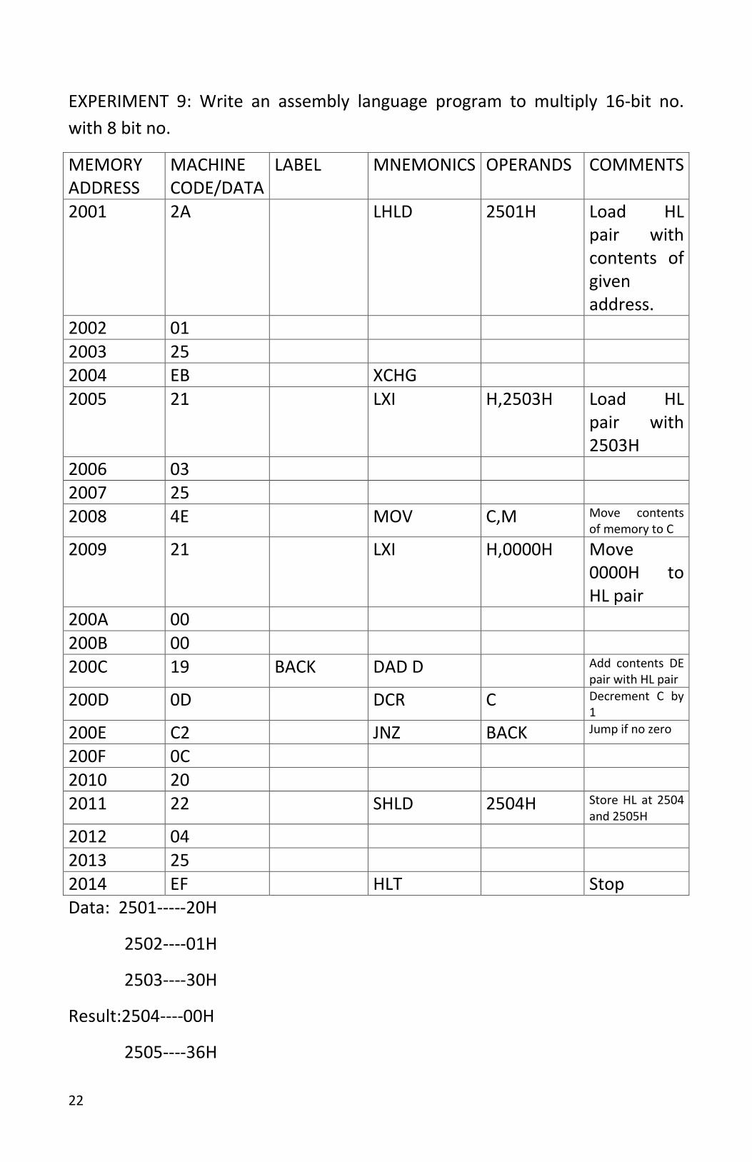
EXPERIMENT 9: Write an assembly language program to multiply 16-bit no.
with 8 bit no.
MEMORY ADDRESS
MACHINE CODE/DATA
LABEL MNEMONICS OPERANDS COMMENTS
2001 2A LHLD 2501H Load HL pair with contents of given address.
2002 01 2003 25 2004 EB XCHG 2005 21 LXI H,2503H Load HL
pair with 2503H
2006 03 2007 25 2008 4E MOV C,M Move contents
of memory to C
2009 21 LXI H,0000H Move 0000H to HL pair
200A 00 200B 00 200C 19 BACK DAD D Add contents DE
pair with HL pair
200D 0D DCR C Decrement C by 1
200E C2 JNZ BACK Jump if no zero
200F 0C 2010 20 2011 22 SHLD 2504H Store HL at 2504
and 2505H
2012 04 2013 25 2014 EF HLT Stop Data: 2501-----20H
2502----01H
2503----30H
Result:2504----00H
2505----36H
23
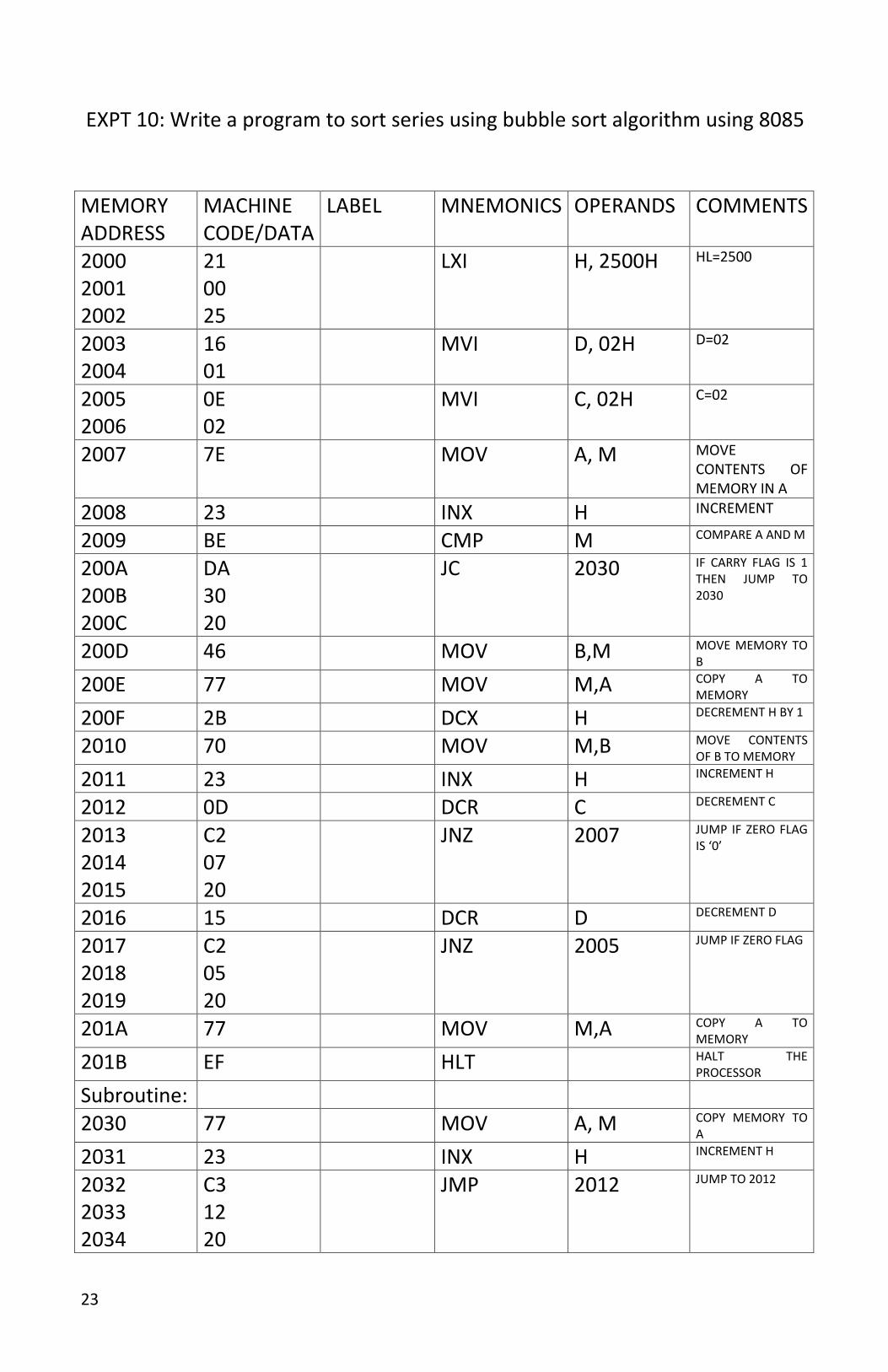
EXPT 10: Write a program to sort series using bubble sort algorithm using 8085
MEMORY ADDRESS
MACHINE CODE/DATA
LABEL MNEMONICS OPERANDS COMMENTS
2000 2001 2002
21 00 25
LXI H, 2500H HL=2500
2003 2004
16 01
MVI D, 02H D=02
2005 2006
0E 02
MVI C, 02H C=02
2007 7E MOV A, M MOVE CONTENTS OF MEMORY IN A
2008 23 INX H INCREMENT
2009 BE CMP M COMPARE A AND M
200A 200B 200C
DA 30 20
JC 2030 IF CARRY FLAG IS 1 THEN JUMP TO 2030
200D 46 MOV B,M MOVE MEMORY TO B
200E 77 MOV M,A COPY A TO MEMORY
200F 2B DCX H DECREMENT H BY 1
2010 70 MOV M,B MOVE CONTENTS OF B TO MEMORY
2011 23 INX H INCREMENT H
2012 0D DCR C DECREMENT C
2013 2014 2015
C2 07 20
JNZ 2007 JUMP IF ZERO FLAG IS ‘0’
2016 15 DCR D DECREMENT D
2017 2018 2019
C2 05 20
JNZ 2005 JUMP IF ZERO FLAG
201A 77 MOV M,A COPY A TO MEMORY
201B EF HLT HALT THE PROCESSOR
Subroutine:
2030 77 MOV A, M COPY MEMORY TO A
2031 23 INX H INCREMENT H
2032 2033 2034
C3 12 20
JMP 2012 JUMP TO 2012

24
Data input:
2500-----87
2501-----37
2502-----48
Result:
2500-----37
2501-----48
2502-----87
25
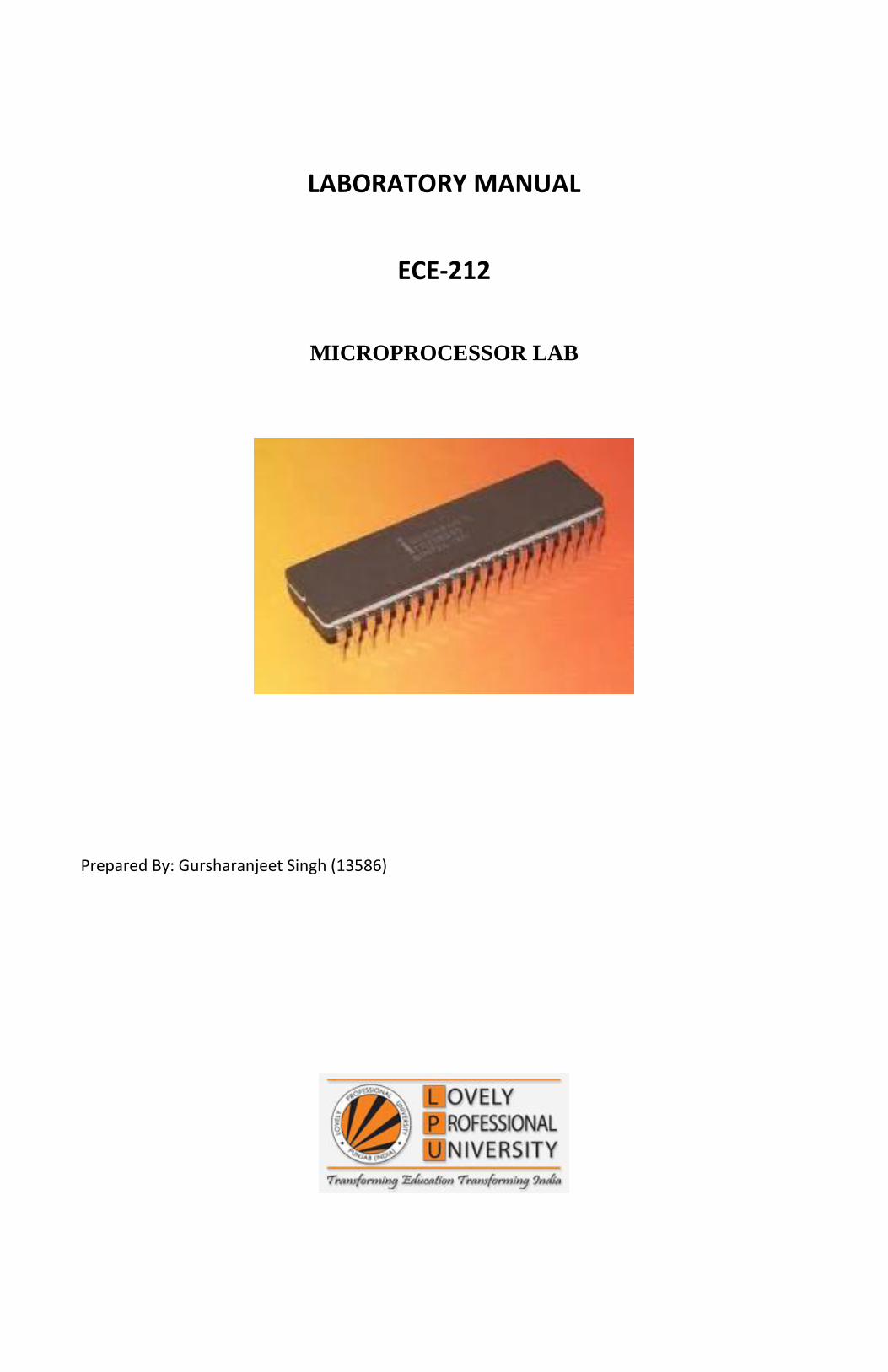
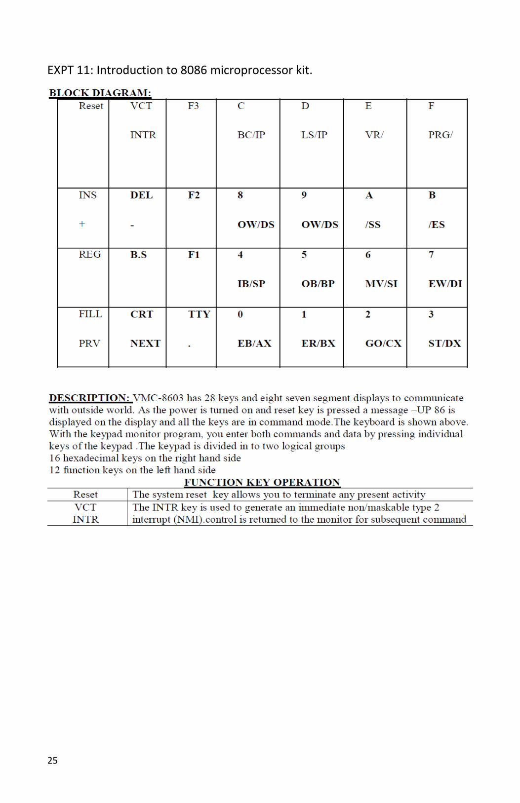
EXPT 11: Introduction to 8086 microprocessor kit.
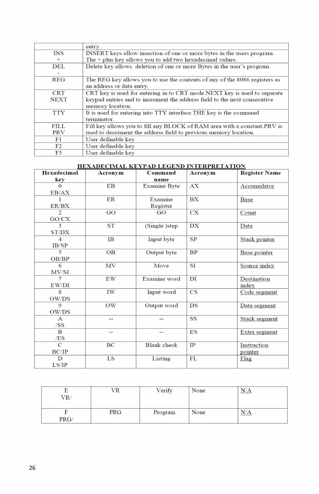
26
27
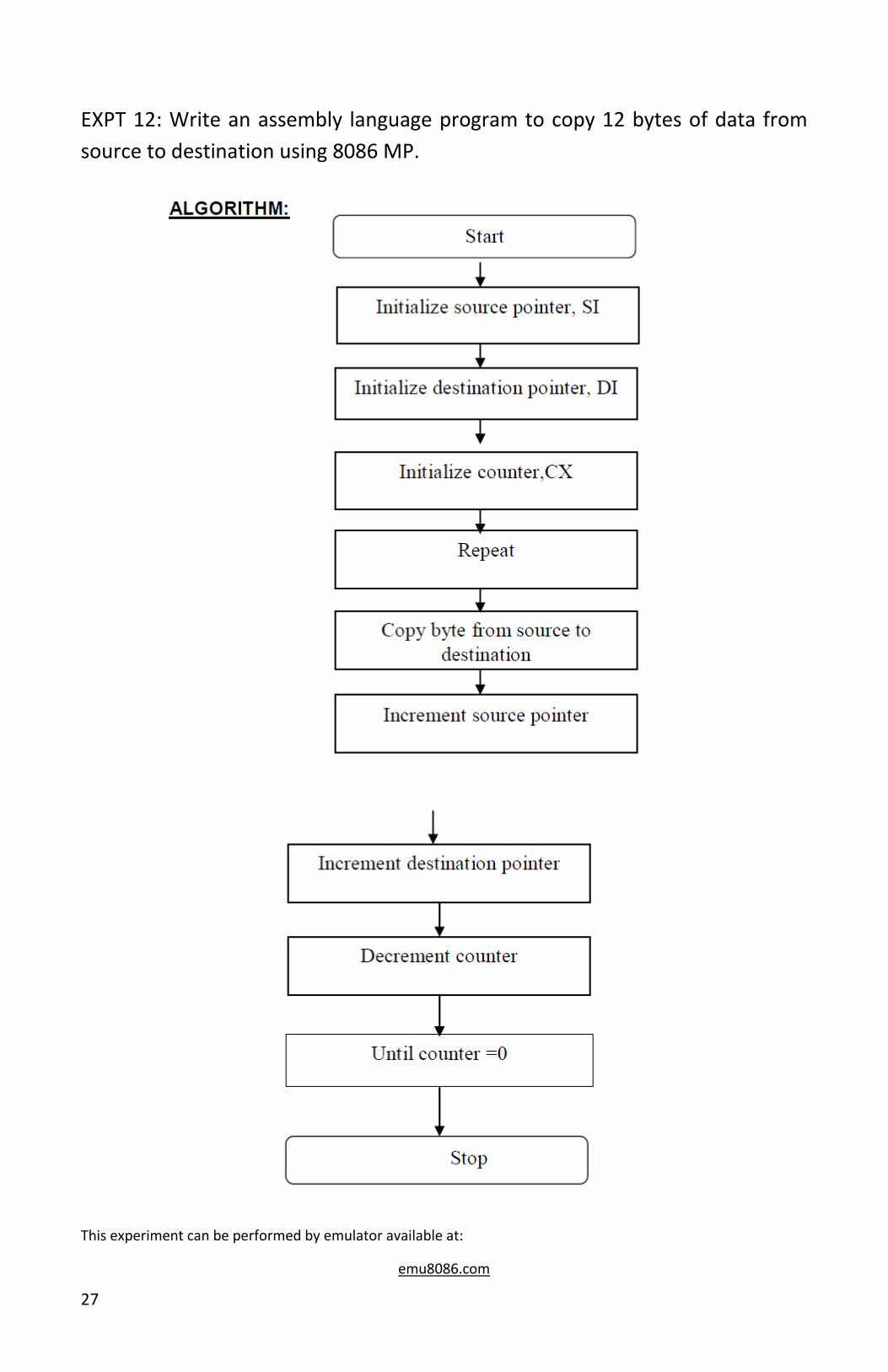
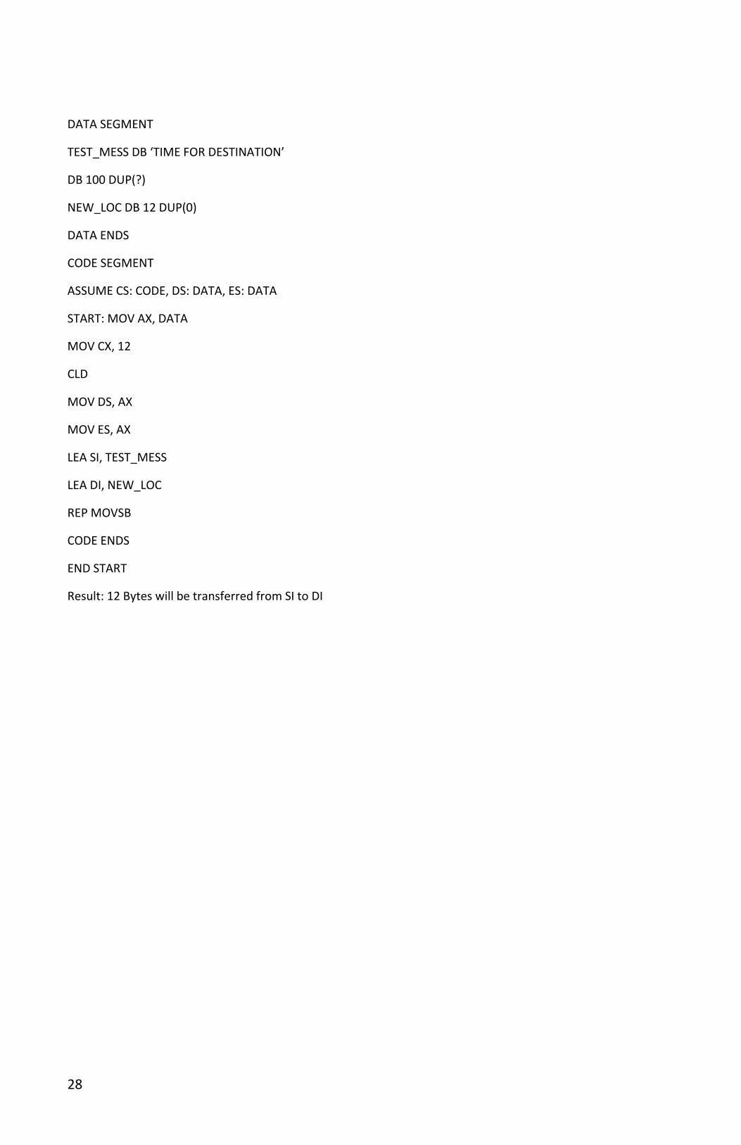
EXPT 12: Write an assembly language program to copy 12 bytes of data from
source to destination using 8086 MP.
This experiment can be performed by emulator available at:
emu8086.com
28
DATA SEGMENT
TEST_MESS DB ‘TIME FOR DESTINATION’
DB 100 DUP(?)
NEW_LOC DB 12 DUP(0)
DATA ENDS
CODE SEGMENT
ASSUME CS: CODE, DS: DATA, ES: DATA
START: MOV AX, DATA
MOV CX, 12
CLD
MOV DS, AX
MOV ES, AX
LEA SI, TEST_MESS
LEA DI, NEW_LOC
REP MOVSB
CODE ENDS
END START
Result: 12 Bytes will be transferred from SI to DI
29
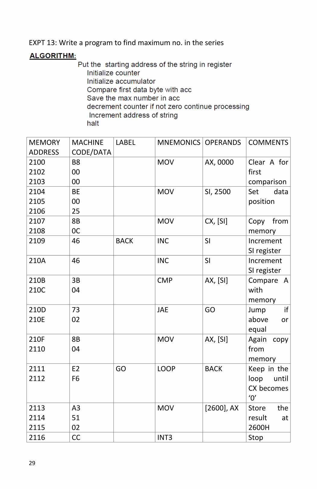
EXPT 13: Write a program to find maximum no. in the series
MEMORY ADDRESS
MACHINE CODE/DATA
LABEL MNEMONICS OPERANDS COMMENTS
2100 2102 2103
B8 00 00
MOV AX, 0000 Clear A for first comparison
2104 2105 2106
BE 00 25
MOV SI, 2500 Set data position
2107 2108
8B 0C
MOV CX, [SI] Copy from memory
2109 46 BACK INC SI Increment SI register
210A 46 INC SI Increment SI register
210B 210C
3B 04
CMP AX, [SI] Compare A with memory
210D 210E
73 02
JAE GO Jump if above or equal
210F 2110
8B 04
MOV AX, [SI] Again copy from memory
2111 2112
E2 F6
GO LOOP BACK Keep in the loop until CX becomes ‘0’
2113 2114 2115
A3 51 02
MOV [2600], AX Store the result at 2600H
2116 CC INT3 Stop

30
Data:
2500----05
2501----00
2502----41
2503----83
2504----58
2505----72
2506----39
2507----46
2508----53
2509----84
250A----30
250B----96
Result:
2600----30
2601----96