Lab Manual : Do-it-Yourself Solar LED Lantern Kitstore.sundancesolar.com/content/Solar Jar Light...
20
1 Lab Manual : Do-it-Yourself Solar LED Lantern Kit (For use with Sundance Solar item No. 900-10017-35) Welcome, and thank you for purchasing this educational do-it-yourself kit! Not only will you learn about solar energy, circuits, electromagnetism, batteries, and alternative energy, but you will also make your own customized solar garden lantern! You can also feel good about your purchase of this product: your ‘upcycled’ jar or housing is being kept out of the waste stream (and the materials such as plastic or glass takes hundreds to millions of years to decompose), you are creating and utilizing ‘clean’ energy, and a portion of the proceeds from this purchase help to support projects for building solar-powered lanterns for those in lesser developed nations who live without electricity (more on that later). Solar cells, also called photovoltaic cells, convert sunlight into electricity. That electricity can be used to power many different electrical devices, especially for outdoor use. Recently, there has been a surge of solar-powered landscape lights on the market, and understandably so; no power cords to bury, no timer to program, no access to a power supply, and zero operating cost. In this kit, you can design your OWN customized solar-powered LED light, where the variations in style and décor are only limited by your imagination! The glass jar (or other opaque lantern cover) is NOT included in this kit. This is not just because the glass is fragile and harder to ship. Rather, this kit was designed with ‘upcycling’ in mind. Glass jars with lids are virtually everywhere, and creativity and individuality is fostered in your choice of other types of repurposed materials to use. The circuitry of designing a light that recharges itself in the sunshine seems fairly simple, at first thought. The solar panel charges the battery by day, and at night, the battery discharges its stored electrical energy back out through the LED light. The next day, the process repeats itself. As you’ll read further in the Lab Manual, there’s a good deal of history, math, and science involved in what seems to be a ‘simple’ solar-powered lantern.
Transcript of Lab Manual : Do-it-Yourself Solar LED Lantern Kitstore.sundancesolar.com/content/Solar Jar Light...
1
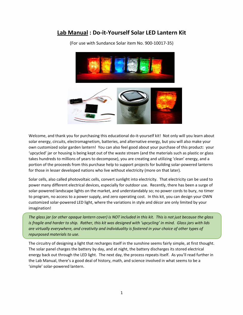
Lab Manual : Do-it-Yourself Solar LED Lantern Kit
(For use with Sundance Solar item No. 900-10017-35)
Welcome, and thank you for purchasing this educational do-it-yourself kit! Not only will you learn about
solar energy, circuits, electromagnetism, batteries, and alternative energy, but you will also make your
own customized solar garden lantern! You can also feel good about your purchase of this product: your
‘upcycled’ jar or housing is being kept out of the waste stream (and the materials such as plastic or glass
takes hundreds to millions of years to decompose), you are creating and utilizing ‘clean’ energy, and a
portion of the proceeds from this purchase help to support projects for building solar-powered lanterns
for those in lesser developed nations who live without electricity (more on that later).
Solar cells, also called photovoltaic cells, convert sunlight into electricity. That electricity can be used to
power many different electrical devices, especially for outdoor use. Recently, there has been a surge of
solar-powered landscape lights on the market, and understandably so; no power cords to bury, no timer
to program, no access to a power supply, and zero operating cost. In this kit, you can design your OWN
customized solar-powered LED light, where the variations in style and décor are only limited by your
imagination!
The glass jar (or other opaque lantern cover) is NOT included in this kit. This is not just because the glass
is fragile and harder to ship. Rather, this kit was designed with ‘upcycling’ in mind. Glass jars with lids
are virtually everywhere, and creativity and individuality is fostered in your choice of other types of
repurposed materials to use.
The circuitry of designing a light that recharges itself in the sunshine seems fairly simple, at first thought.
The solar panel charges the battery by day, and at night, the battery discharges its stored electrical
energy back out through the LED light. The next day, the process repeats itself. As you’ll read further in
the Lab Manual, there’s a good deal of history, math, and science involved in what seems to be a
‘simple’ solar-powered lantern.

2
Table of Contents
How it Works: Solar Cells……………………………………………………………………………….. page 3
How it Works: LEDs………………………………………………………………………………………… page 7
How it Works: Rechargeable Batteries………………………………………………….………. page 8
Intro to Circuits…………..…………………………………………………………………………………. page 9
Series vs. Parallel Circuits………………………………………………………………………………. page 10
Putting it All Together…………………………………………………………………………………… page 11
Assembly Instructions…………………………………………………………………………………….. page 13
Explaining Voltage and Current……………………………………………………………….….... page 13
Calculating Recharge Times…………………………………………………………………………… page 14
Solar Insolation Maps…………………………………………………………..………………..…….. page 15
STEM Application: Developing Solar Lanterns for South Africans………………… page 17
Glossary and References……………………………………………………………………………… page 18-19
Solar Jar Light Kit Materials List
In each Solar Lantern Kit:
1 - 3V 70mA polycrystalline solar panel with wires
1 - Circuit board (pcb) with dusk/dawn operation with 2 LED’s
1 – Battery holder for 2 AAA batteries
2 – AAA NiMH rechargeable batteries
4 – Grey wire nuts
Required For the Optional “Time Out and Try It” Activities: Digital
multimeters, extra assorted LEDs, red and black coated wires
Not included: Mason jars or other “containers” for your solar
lantern, electric drill and drill bits, silicon adhesive and/or hot glue gun, 4 to 6 light sources

3
How it Works: Solar Cells
Photovoltaic (fo-to-vol-ta-ik) systems are solar systems that produce electricity directly from sunlight.
The term "photo" comes from the Greek "phos," meaning light. "Voltaic" is named for Alessandro Volta
(1745-1827), a pioneer in the study of electricity for whom the term "volt" was named. Photovoltaics,
then, means "light electricity." Photovoltaic systems produce clean, reliable electricity without
consuming any fossil fuels. They are being used in a wide variety of applications, from providing power
for watches, highway signs, and space stations, to providing for a household's electrical needs.
First, a Brief History Lesson…
A.E. Becquerel (1839) first discovered the photoelectric effect (converting light into electricity at the
atomic level) at the age of only 19 when he exposed platinum electrodes coated with silver compounds
to light inside of an acidic solution which acted as an electrolyte. The combination created both voltage
and current, which creates power! Later in 1905, Albert Einstein described the basic nature of light in
which photovoltaic technology is based. In 1954, Bell Laboratories created the first conventional
photovoltaic system module, which was then called a “solar battery.” By the 1960s, photovoltaic
systems were further developed by the space industry, and the 1970s energy crisis further increased the
demand for residential and commercial use. By the 1980s, photovoltaic cells were most popular to
power small electronics, such as calculators, watches, and radios.
How Solar Cells Typically Operate Today…
Solar panels are made up a number of solar cells. Solar cells are primarily made of thin wafers of silicon,
the second most abundant substance on earth, the same substance that makes up sand. An atom of
silicon has 14 electrons arranged in three general electron shells. The first two shells closest to the
nucleus are full. The outer shell has four electrons and is only half full, as seen in the atomic model
below. Only the outer four electrons are capable of ‘moving’, which will help to create the electric
current.
14 protons (+)
14 neutrons (0)
The four outermost electrons (black dots) are called valence electrons.
They have a negative charge, and are capable of being released to create an electrical current.
Silicon is called a semiconductor. It will transfer its outer four electrons better than materials called
insulators (like wood or plastic) but will not conduct electrons better than a conductor (such as copper
or other metals). By itself, silicon does not conduct electricity well enough to create an effective solar
cell. Therefore, the silicon needs to be ‘doped up’ with other elements that will lose and gain electrons
more easily. To ‘dope’ the silicon with more electrons that are free to move about, the silicon has some
phosphorus mixed in with it, which is electrically more negative (phosphorus has one more electron

4
than silicon). Conversely, silicon that has some boron mixed in with it will be electrically more positive
(boron has one less electron than silicon).
Phosphorus will have an extra electron left when it binds with silicon, and will want to lose it, making phosphorus
more positive. Boron will be missing an electron when it binds with silicon, and will have a ‘hole’ where it will accept
another electron.
Most of the ‘magic’ of the solar cell lies in how the cell is set up. When the phosphorus-doped silicon
layer is first placed on top of the boron-doped silicon, the extra electrons from the phosphorus will
immediately move to fill in the ‘holes’ in the boron layer below.
Step 1: Electron Flow due to the Cell’s Initial Setup
( - ) Is a “free” electron ( ) is an electron ‘hole’
- - - - - - - - - - - - Phosphorus-doped layer (more free electrons)
Junction (shuttles the flow of electrons)
Boron-doped layer (more ‘holes’ to accept electrons)
Electric Force – caused by an electric field, making electrons ‘roll downhill’
Due to the setup of the solar cell, electrons flow at first from the top to the bottom layer. The loss of
electrons in the top layer then causes the top to develop a more positive charge. Conversely, due to the
electrons gained, the bottom layer develops a more negative charge. Do all the free electrons fill all the
free holes? No. If they did, then the whole arrangement wouldn't be very useful. However, right at the
junction, they do mix and form something of a barrier, making it harder and harder for electrons on the
phosphorus side to cross over to the boron side. Eventually, equilibrium is reached, and we have an
electric field separating the two sides. This electric field acts as a diode, or a ‘one way traffic signal’
allowing (and even pushing) electrons to flow from the phosphorus layer to the boron layer, but not the
other way around. It's like a hill -- electrons can easily go down the hill (to the boron layer), but can't
climb it (to the phosphorus layer).
When sunlight hits the solar panel, the packets of light (in units called photons) ‘bounce’ off of the
electrons in the boron layer, knocking the electrons free. Once freed, the electron, energized by light,
has enough energy to ‘climb the hill’ back to the phosphorus layer of the cell, where it feeds in to the
negative terminal at the top of the cell.
Step 2: Electron Flow due to Energy of Sunlight
the sun’s photons give the electrons enough energy to ‘carry them back uphill’
Phosphorus-doped layer – electrons get returned
- - - - - - - - - - - Boron-doped layer – energized electrons ‘jump up’
Electric Force – caused by an electric field, making electrons ‘roll downhill’

5
Therefore, the energy in the photons are transferred to the electrons. There are a billion billion photons
falling on the solar cells every second, so there are lots of electrons knocked loose! If you tap these
loose electrons by connecting a wire to the top layer, it becomes a negative terminal! Then, connect a
wire to the bottom layer and it becomes a positive terminal! In sum, the electron flow provides the
current (the degree of ‘flow’ of electrons, in units called amps), and the cell's electric field causes a
voltage (the amount of ‘push’ of electrons, in units called volts). With both current and voltage, we have
power (in units called watts), which is the product of the two multiplied together.
SIMPLY PUT…When light falls on a solar cell, electrons are freed by light. Because of the electric field
purposefully set up in the solar cell, freed electrons build up on the top layer. This is what creates voltage
between the (+) and the (-) terminals. Connecting the solar cell to a circuit creates power.
Side Note: Solar panels produce electricity in the form of direct (DC) current. This means that the electricity is
flowing in ONE direction only. The type of current we use for ordinary household/utility use is alternating (AC)
current, which reverses itself many times a second. So if you have solar panels powering a house, an inverter (a
power box that converts DC current into AC current) is needed.
Optional “Time Out and Try It”: Measuring Solar Panel Voltage
Want to see the solar panel in action? Let’s measure the voltage, or the amount of ‘push’ that the
electrons are running at, for the solar panel. Get out the multimeter in this kit. The black probe should
be in the black multimeter port (usually labeled COM) and the red probe should be in the red multimeter
port labeled “V”. For some multimeters, this may be the same port used to measure current. It may be
labeled “VΩmA” instead of just “V”.
Make sure the meter is set to 20 DCV (Direct Current Volts – usually on the left side of the dial). If you
cannot see “DCV” on the dial, look for the V with a solid line above a dashed line (the universal symbol for
direct current), then the number 20. Connect the solar panel to the multimeter by attaching the probes
directly to the wires of the solar panel – black probe to black wire, red probe to red wire.
If you shine a bright light directly above your solar panel, your DC voltage should be close to 3.0 V, due to
the specifications of the solar panel (look at the sticker on the back of the solar panel!).
So what happens to the solar panel’s voltage when you change the angle of light or tilt the panel? Try it!

6
Optional “Time Out and Try It”: Measuring Solar Panel Current
Now let’s measure current, or the degree of ‘flow’ of electrons, for the solar panel. The probes on the
multimeter should be in the same position: the black probe should be in the black multimeter port (usually
labeled COM) and the red probe should be in the red multimeter port labeled “V”. The black multimeter
port is labeled “V” or “VΩmA”
Turn the multimeter dial toward the DCA range (Direct Current Amps – usually on the right side of the
dial). If you can’t find the initials “DCA”, find the “A” with a solid line above a dashed line (the universal
symbol for direct current). Set the dial to “20m”.
If you shine a bright light directly above your solar panel, your DC current should be close to 70 mA, due
to the specifications of the solar panel (look at the sticker on the back of the solar panel!). Be aware that
measuring current is a bit ‘trickier’ than measuring voltage.
So what happens to the solar panel’s current when you change the angle of light or tilt the panel? Try it!
Limitations of Solar Cells
Some of the larger setbacks for solar energy include its variability due to weather and position on the
earth, its price, and the amount of space solar panels take up. But the largest problem is their
efficiency: solar panels currently on the market only harvest 12 and 20 percent of the energy of the sun.
So why is it so challenging to make the most of a sunny day?
The primary issue lies in the type of light that the solar panels can absorb. Only small portion of the
sun’s light energy actually has the ability to separate the electrons from the atoms. Sunlight, of course,
comes in a range of wavelengths with different energy levels. But only a certain wavelength range (with
an optimum on the red end of the visible light spectrum) has the right amount of energy to alter an
electron-hole pair. The rest of light’s energy gets reflected, turned into heat, or passes right through the
solar cell. This accounts for the loss of an estimated 60-70 percent of the total radiation energy
potential of sunlight.
Other shortcomings in solar cell physics, materials, or design affect the cells’ overall efficiency. As of yet,
there is no possible ‘ideal’ material with the capability to absorb the entire solar spectrum. However, as
7
technology advances, it is predicted that materials and solar cell designs will be created which have a
greater solar absorbance ratio and a lower cost.
How it Works: LEDs
Pairing photovoltaic cells and LEDs is like “coming around full circle”. Photovoltaic cells produce energy
in the form of direct current (DC). This direct current can be run through an LED in order to convert it
back to (you guessed it) light! Basically, a photovoltaic cell and an LED run on the same basic concept,
but their inputs and outputs are reversed!
Light Emitting Diodes, commonly called LEDs, do dozens of different jobs and are found in all kinds of
electronic devices. They are the basic functional unit in a remote control, form the numbers on digital
clocks, light up watches, tell you when your appliances are turned on, illuminate traffic lights, and are
the base of the thinnest flat screen televisions and computer monitors on the market today. Because
they can be made so small, LEDs can embellish false eyelashes or be infused into contact lenses!
As the name implies, an LED acts as a diode, which only allows electrons to move in one direction. The
science behind the way an LED works is parallel to how a photovoltaic cell works. First, semiconductors
are again doped with impurities. When a semiconductor is doped with extra electrons, it is called an N-
type material. Semiconductor materials with ‘holes’ are called P-type materials. As in the solar cell,
there is a ‘flow’ of free electrons in the N-type to the holes in the P-type materials. These free electrons
moving across an LED can fall into empty holes from the P-type layer. When the ‘free’ electrons drop
into a ‘hole’ in the atom of a semiconductor, it drops into to a lower electron orbital, releasing energy in
the form of photons! The frequency (or color) of the photon depends upon the conductivity of the LED.
LEDs can be built to shine in infrared, ultraviolet, and all the colors of the visible spectrum inbetween,
depending on the types of materials used and their setup.
Advantages of LEDs
Unlike ordinary incandescent bulbs, LEDs don't have a filament that will burn out, they don't get
especially hot, and they are much more energy efficient. Incandescent bulbs must generate a lot of heat
in order to create light: so much heat that you can bake a small cake with them, as EasyBake ovens have
utilized ordinary 100 watt light bulbs for decades! LEDs are also use less energy, are more compact, last
longer, and are less toxic than fluorescent light bulbs. LEDs cost much more up front, but in the long run
they save you more money in replacement bulbs and operating costs than incandescent bulbs or even
fluorescent bulbs. For the purpose of constructing a solar garden lantern for this kit, only an LED light
would be small enough and efficient enough in order to work.
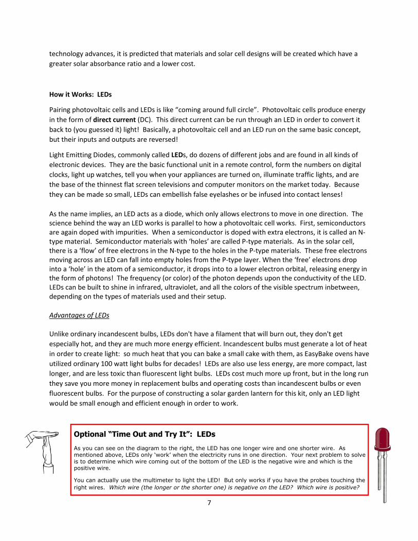
Optional “Time Out and Try It”: LEDs
As you can see on the diagram to the right, the LED has one longer wire and one shorter wire. As mentioned above, LEDs only ‘work’ when the electricity runs in one direction. Your next problem to solve is to determine which wire coming out of the bottom of the LED is the negative wire and which is the positive wire.
You can actually use the multimeter to light the LED! But only works if you have the probes touching the
right wires. Which wire (the longer or the shorter one) is negative on the LED? Which wire is positive?

8
How it Works: Rechargeable Batteries
Of course, the photovoltaic energy produced must be stored and later released through the LED in order
to create a functional garden lantern. In effect, you are saving the sun’s photons in the form of electrical
current, storing the current in a battery, and converting it back into photons at night!
Non-rechargeable batteries, or ‘primary’ cells, and rechargeable batteries, or ‘secondary’ cells, produce
current exactly the same way: through an electrochemical reaction involving an anode (the negative
terminal), cathode (the positive terminal) and electrolyte (a conducting fluid or paste that allows the
transfer of electrons). In general, a battery creates a voltage by introducing two chemical reactions
which produce separate negative and positive terminals. The reaction in the anode releases electrons,
and the reaction in the cathode needs them. Solid conductors (electrodes) are located on the anode and
cathode and a conducting liquid solution or paste (electrolyte) is found in between. By simply
connecting the supply and demand side electrodes to a circuit, you allow these electrons to supply
power. In a non-rechargeable primary cell, the chemical reaction at the anode will eventually reach a
limit where no more electrons can be produced, and the battery is dead. In a rechargeable battery,
however, the reaction is reversible, so that electrical energy from an outside source can recharge the
battery.
Optional “Time Out and Try It”: Batteries
Now it’s time to test the batteries to see if they are fully charged. Start with a single AAA battery in the
lantern kit. Set the multimeter to 20 DCV. Touch the + probe of the multimeter to the + end of the
battery and the – probe of the multimeter to the – end of the battery.
What is the voltage of the battery (measured by the multimeter) compared to the voltage listed on the
side of the battery? Does the battery need to be recharged?
Now test the second battery, and place both batteries in the battery pack. Predict what you think the
total voltage of two batteries together should be.
What is the total voltage of both batteries together? Is this what you predicted?
Touch the wires of the battery pack (turned on, with batteries) to the wires of the LED. What happens?
Limitations of NiMH Rechargeable Batteries
The type of rechargeable batteries used in this kit can be recharged hundreds of times, but they still
have a life expectancy limited only to 2 to 5 years. NiMH batteries also have an operable temperature
range of -20 and 60 degrees Celsius. It is well known that higher temperatures will cause the batteries
to deteriorate. Lower temperatures reduce the rate of reaction, creating less power. This is the reason
why cars containing rechargeable batteries (such as the Toyota Prius) have their own thermal
management systems.
9
Intro to Circuits
A circuit is a closed path in which electrons can flow. Circuits are typically designed to ultimately
perform some type of work, such as lighting a bulb or running an electric motor to propel a fan. But to
get a current to flow through the light bulb or motor, it needs to start at a source and then also return
back to that source. Electricity will flow out of the negative end of a battery and towards the positive
end of a battery.
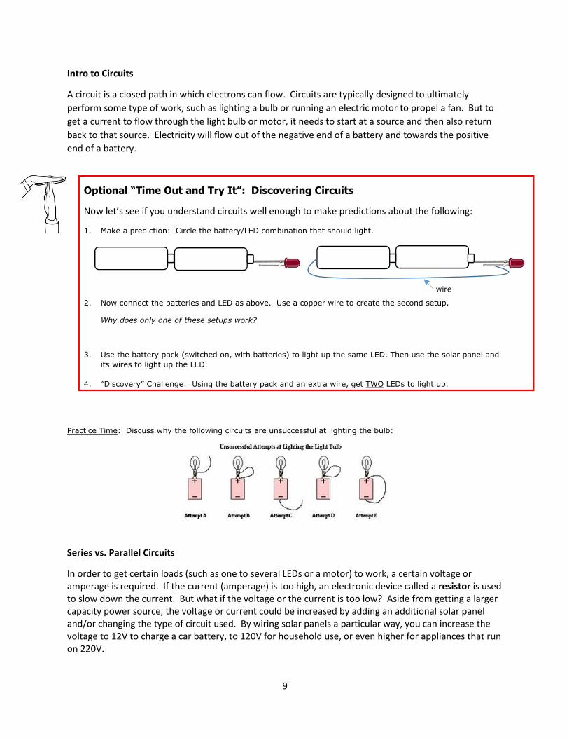
Optional “Time Out and Try It”: Discovering Circuits
Now let’s see if you understand circuits well enough to make predictions about the following:
1. Make a prediction: Circle the battery/LED combination that should light.
wire
2. Now connect the batteries and LED as above. Use a copper wire to create the second setup.
Why does only one of these setups work?
3. Use the battery pack (switched on, with batteries) to light up the same LED. Then use the solar panel and
its wires to light up the LED.
4. “Discovery” Challenge: Using the battery pack and an extra wire, get TWO LEDs to light up.
Practice Time: Discuss why the following circuits are unsuccessful at lighting the bulb:
Series vs. Parallel Circuits
In order to get certain loads (such as one to several LEDs or a motor) to work, a certain voltage or
amperage is required. If the current (amperage) is too high, an electronic device called a resistor is used
to slow down the current. But what if the voltage or the current is too low? Aside from getting a larger
capacity power source, the voltage or current could be increased by adding an additional solar panel
and/or changing the type of circuit used. By wiring solar panels a particular way, you can increase the
voltage to 12V to charge a car battery, to 120V for household use, or even higher for appliances that run
on 220V.
10
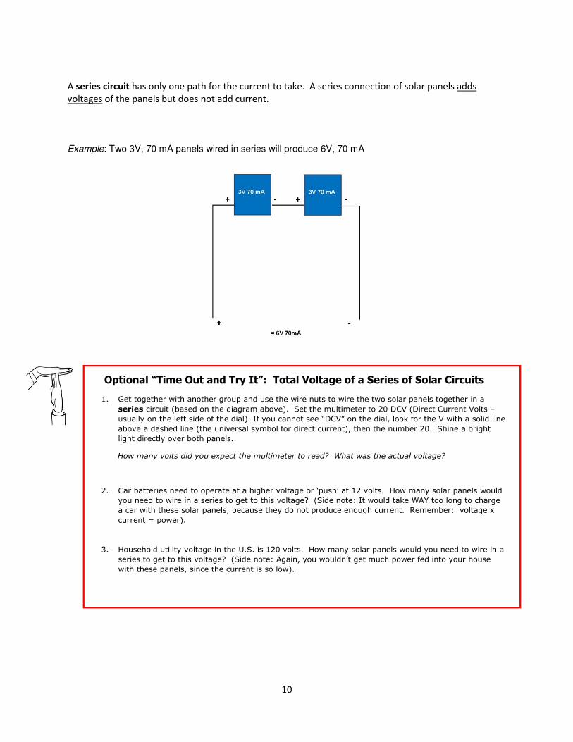
A series circuit has only one path for the current to take. A series connection of solar panels adds
voltages of the panels but does not add current.
Example: Two 3V, 70 mA panels wired in series will produce 6V, 70 mA
Optional “Time Out and Try It”: Total Voltage of a Series of Solar Circuits
1. Get together with another group and use the wire nuts to wire the two solar panels together in a
series circuit (based on the diagram above). Set the multimeter to 20 DCV (Direct Current Volts –
usually on the left side of the dial). If you cannot see “DCV” on the dial, look for the V with a solid line
above a dashed line (the universal symbol for direct current), then the number 20. Shine a bright
light directly over both panels.
How many volts did you expect the multimeter to read? What was the actual voltage?
2. Car batteries need to operate at a higher voltage or ‘push’ at 12 volts. How many solar panels would
you need to wire in a series to get to this voltage? (Side note: It would take WAY too long to charge
a car with these solar panels, because they do not produce enough current. Remember: voltage x
current = power).
3. Household utility voltage in the U.S. is 120 volts. How many solar panels would you need to wire in a
series to get to this voltage? (Side note: Again, you wouldn’t get much power fed into your house
with these panels, since the current is so low).

11
When more current is needed, a parallel circuit is used, where there are several paths for the current to
take. A parallel connection of solar panels adds current outputs of panels but does not add voltages.
Example: Two 3V, 70 mA panels wired in parallel will produce 3V, 140 mA
Optional “Time Out and Try It”: Total Current for a Parallel Circuit of Solar Panels
1. Get together with another group and use the wire nuts to wire the two solar panels together in a
parallel circuit (based on the diagram above). You’re going to need an extra red and black wire to
do this. Set the multimeter to “200m DCA” (Direct Current Amps – usually on the right side of the
dial). If you can’t find the initials “DCA”, find the “A” with a solid line above a dashed line (the
universal symbol for direct current). Remember: measuring current is a bit more ‘tricky.’
How many milliamps did you expect the multimeter to read? What was the actual current?
2. A single AAA rechargeable battery can hold 600 mAh (milliamp hours – see the number on the side of the battery). This is the
battery’s capacity at full charge. If a single solar panel produces 70 mA under direct sunlight, then how many hours of direct
sunlight would it take for the solar panel to fully charge a single battery? (HINT: battery capacity ÷ solar panel output =
number of hours. The answer will not be a whole number).
3. If you wired a parallel circuit of two solar panels, then how many hours of direct sunlight would it take for the two solar panels
to fully charge a single battery? (HINT: battery capacity ÷ solar panel output = number of hours. The answer will not be a
whole number).
Putting it All Together
So, all we have to do is hook up the solar panel to the rechargeable battery and the LED lights, and
we’ve got the makings of an operable solar lantern, right? Of course, it’s not that easy!
Electricity flows in circuits: closed paths through which electrons flow. Within these circuits or “loops”
for the electrons to flow, one needs to incorporate a voltage source, switches, and loads (something
that the circuit operates and performs a certain task - in this case, it is the LEDs or the rechargeable
batteries). BUT…the LEDs cannot get too much power (or they will burn out), the electricity has to be
blocked from leaving the batteries when they are charging, and an automatic switch needs to be

12
integrated into the circuit so that the LEDs turn OFF during the day but turn ON at night. Each of these
jobs requires a separate component on the circuit board.
Making Sense of the Schematic of the PCB (printed circuit board)
Working from left to right, you can see that there is an outer and an inner circuit leading from the solar
cell to the blocking diodes (1N5819) before it gets to the batteries, in order to keep energy in batteries.
The outer circuit is for the optional external on/off switch, so that the lantern can be manually turned on
or off regardless of time of day or battery charge level. In the inner circuit, there is a resistor which
reduces current and voltage, thereby keeping the LEDs from getting too much power. Inside the jar,
there are two switches (above LED1 and LED2) which can manually turn on or turn off the LEDs from
within in order to set the brightness desired or conserve energy if sun hours are low. The ‘dusk to dawn’
switch is a semiconductor device called a PNP bipolar junction transistor, which in this case is used to
switch electric signals or ‘routes’ depending on the amount of energy coming from the solar panel. If
there is a productive flow of electricity coming from the solar pane, then the energy is stored in the
batteries. If there is little to no energy coming from the solar panels, then the circuit is re-routed to
utilize the energy in the batteries to light the LEDs. Transistors are used in electronics to amplify and
switch electric signals and power. Transistors contain at least three terminals for connection to an
external circuit. In the case of the solar lantern, the transistor acts as a ‘traffic light’ for a three-way
intersection with the solar panel, the batteries, and the LEDs.

13
Assembling the Solar Lantern
(copies also available in individual kits)
1. Using a grey wire nut, connect the two red wires together from the
battery holder to the circuit board (marked BATTERY on the circuit
board in small white letters). Repeat with 2 black wires from the
battery holder to the circuit board.
2. Using a grey wire nut, connect the two red wires together from
the solar panel to the circuit board (marked SOLAR on the
circuit board in small white letters). Repeat with the two black
wires from the solar panel to the circuit board.
3. You can now test your light. If the LEDs do not turn on, check
the switches for the battery pack and the LEDs (the ‘on’
position for the LEDs is toward the center of the green ‘chip’
called the printed circuit board or PCB). Now check to see how the
LEDs respond when in bright or dark light. The LEDs should light
when the solar panel is not in bright light and should turn off
automatically when it is in bright light.
4. You can now install your LED light in a wide-mouthed canning jar or
a recycled jar (peanut butter or mayonnaise jars work well – you
need a rather wide lid). Disconnect the wire nuts connecting the
wires to the solar panel. Drill 2 holes in the top of your jar and lead the
wires through with the solar panel on top of the lid. If you have a metal lid,
use electrical tape to make sure that the solder contacts do not touch the
lid, causing your solar panel to ‘short out’. You may want to wrap or tidy
up the wires with electrical tape. Use hot glue or silicon sealant to adhere
the solar panel above and battery pack/PCB/LED complex under the lid.
OPERATION…The solar garden light should get as much sun as possible. When the solar panel is
covered or when it is dark, turn on inner switches for the LEDs until they light. If you take the
lantern back out into the sun, the LEDs will go off. At night, the LEDs will turn back on
automatically. Have fun!
Explaining Voltage and Current:
It is useful to envision electricity running through a circuit as being similar to water flowing through a
pipe. Just as water flows downhill, electrons flow from places of higher potential to places of lower
potential. The difference in the electrical potential provides the force that pushes a charge through a
circuit. The unit of measure of potential difference is called the volt (V). Electrons will flow as long as
there is a potential difference, or voltage, between the two parts of a circuit. Voltage supplies the
“push” to the electrons that are flowing.

14
The ‘water tower’ analogy can make voltage easier to understand. In the diagram below, the tank on
the left would have a lower ‘push’ but the tank on the right would have a greater ‘push’. This is similar
to the concept of voltage – it’s the force of electrons pushing through a circuit.
Higher Voltage
Lower Voltage
The amount of electrons flowing through a material is called the current. The standard unit for
measuring an electric current is the ampere (amp), but is usually abbreviated with an I (think of “I” as
describing amps by using the word “Intensity”). Using the water analogy, current would be similar to
the “water pressure”, determined by the volume of water flowing in a defined area.
The ‘water tower’ analogy can make current easier to understand. In the diagram below, the tank on
the left would have a less water flowing through the pipe, but there would be more water flowing
through the pipe. This is similar to the concept of current – it’s the amount of electrons flowing through
a circuit.
Lower Current Higher Current
Calculating Recharge Times
For solar-charging batteries, it’s important to know about battery capacity. Battery capacity is measured
in a unit called mAh, standing for milliAmps per hour (the prefix ‘milli’ means one thousandth). These
batteries have a capacity of 600 mAh when they are fully charged. You can find this number printed on
the battery. This tells you that the how much of a certain current it can produce before the battery
needs to be recharged. For example, if the load in your circuit uses 400mA (or .4 A) then a single NIMH
battery can power it for 1 ½ hours (400 mAh x 1.5 hours = 600 mAh).

15
You can use the same calculations to figure out how long it will take to charge a battery with a certain
amount of current. For example, if a solar module is producing 100 mA of current, it would take 10
hours to recharge the battery (100mA x 10 hours = 1000mAh).
So the calculations are pretty simple, but there is one complication: if you set up your solar module to
face the sun in the morning and then leave it to charge all day, you will find that the current produced
by the solar module changes as the sun moves through the sky! These simple calculations only work
when the current stays the same. Therefore, the next topic to discuss is how to calculate the charge
time of a battery no matter where you are on the Earth. To do this, you need to refer to a solar
insolation map.
Solar Insolation Maps
When sunlight reaches the earth’s surface, it has the potential to produce about 1000 watts per square
meter at noon on a cloudless day (that is, if the sun was shining at the most direct angle and assuming
that 100% of it was able to be converted into electricity). The standard 1000 watts/m2 is also called the
‘peak sun’ or ‘peak hours’. This potential energy varies, however, due to time of day and
geographical location (along with the efficiency of the photovoltaic cell). Scientists estimate
that sunlight will provide useful solar energy for only about 6 ‘peak hours’ per day, but only in the best
areas of the U.S (the areas more south and with less cloud cover). Deserts, with very dry air and little
16
cloud cover, receive the most sun—and has the energy equivalent of more than 6 kilowatt-hours (KWH)
per day per square meter. Northern climates, such as Boston, get closer to 3.6 kilowatt-hours. A solar
insolation map provides data indicating the number of productive hours of direct sunlight (or “peak
hours”) for a particular area.
Additionally, photovoltaic output is directly correlated to the efficiency of the solar panels.
Unfortunately, solar panels can never be made to be 100% efficient. That’s because when you convert
energy from one form (solar) to another (electricity), some energy will invariably be converted into heat.
On top of this, conventional photovoltaic panels absorb only a narrow band of the solar spectrum, and
the rest of the wavelengths get ‘wasted’ by being reflected or converted into heat. Photovoltaic panels
commercially available today have a relatively low efficiency, averaging only 15%.
Here’s how to use solar insolation maps to calculate how long it will take to fully charge a battery;
simply find the total number of peak sun hours per day at your location, and then multiply that number
by the maximum current that the solar module will produce in a peak sun. That will tell you the total Ah
(amp hours) that you can charge into the battery in a day. For example, a solar insolation map shows
that Maine has about 5 peak sun hours per day in May. The maximum power output of our solar array is
70 mA, so in one day you can produce about 70 mA x 5 hours = 350 mAh. The battery capacity for each
battery is 600 mAh, and they are connected in a series circuit (which does not add current, so the
battery capacity remains at 600 mAh). Therefore, it would take 600 / 350 or less than 2 days to
completely charge both batteries.
The math above aligns with the ‘field observations’ with the solar lanterns. They seem to operate best
when “let out in full sun” for a day or two to charge the batteries before switching on the LEDs.
Fortunately, the LEDs use comparatively little current; about 20 mA each (but current use varies by LED
color). The LEDs are in a parallel circuit, which adds current, making the total current necessary for both
LEDs 40 mA. Therefore, assuming 9 hours or nighttime LED light x 40 mA = 360 mAh per night.
Comparing solar power inputs to LED outputs, we have a relatively ‘balanced’ system, where the solar
lanterns should charge and discharge at about the same rate each day. However, several variables
including overcast days and outdoor temperatures may apply. Therefore, long-range field observations
of the solar lanterns in states throughout the U.S. are currently underway.
Solar insolation maps can be found online on different web sites, but the most common site is
http://www.nrel.gov/gis/solar.html.

17
STEM Application: Developing Solar Lanterns for South Africans
Excerpt from Pamela Ulicny, Biology and Environmental Science teacher in Tri-Valley Jr/Sr High School in
Hegins, Pennsylvania:
“The inspiration for developing this solar-powered lantern was originally spurred by Mark
Gamble, CEO of Educo Africa. I was fortunate enough to be granted a professional development
trip to South Africa through the Toyota International Teacher Program, funded by Toyota Motor
Sales and the Institute for International Education. The trip was the experience of a lifetime and
an invaluable experience to share with my students. I was particularly moved by the plight of
poverty in South Africa, and how Educo Africa works to restore the dignity, power, and self-
worth of South African youth from disadvantaged communities. The solar-powered lanterns
were designed with the eventual and ultimate purpose of teaching South Africans science,
technology, math, sustainability, and job skills as they are trained to build their own solar-
powered lanterns. The enterprise piloted by Educo Africa would eventually build and sell solar
lanterns to those who do not have access to electricity. Families without electricity currently
use kerosene lanterns, which pose a fire hazard and have already resulted in severe burns,
fatalities, and the destruction of many homes. Additionally, using kerosene lanterns habitually
is equivalent to smoking two packs of cigarettes a day, and inhaling its fumes increases the
chance of cataracts, respiratory infections, tuberculosis or lung and throat cancers.”
Let’s say that we want to create a solar powered lantern that will light up a small room for an Educo
Africa participant whose home is without electricity. Cape Town, South Africa (where the headquarters
of Educo Africa is located) has an average solar radiation of 4.9 peak sun hours per day. Let’s say that
you want to charge a 6V 1600mAh NiMH battery for a solar powered lantern. The solar panel produces
a maximum power output of 6V at 330 mA. So in one average day you can produce 4.9h x 330 mA =
1,617 mAh, which is enough to fully charge the battery. In order to get enough lumens (brightness) to
read, let’s get an LED light that gives off 500 lumens (equivalent in brightness to a 50W incandescent)
and uses 8 watts. Since power (watts) is the product of volts (V) times current (Amp), then the amount
of time that the light bulb could run on this solar module would be calculated as follows:

18
Watts = Volts x Amps
8 = 6 x A
A = 1.333 = 1333 mA
1600 mAh (in battery) ÷ 1333 mA (needed for light bulb) = 1.2 hours = 72 minutes.
Unfortunately, this may not be enough time necessary for nighttime reading, housework, and
schoolwork. So in this example, a larger solar panel and a larger capacity battery may be necessary.
Another possibility is to find an LED light that gives off an equivalent amount of lumens but uses less
watts.
Glossary:
alternating current - An electric current that reverses its direction many times a second at regular
intervals, typically used in power supplies.
anode - The negatively charged (electron supplying) electrode of a device supplying current such as a
battery.
cathode- The positively charged electrode of battery that receives electrons, supplying current.
current – A flow of electric charge. It is how ‘crowded’ the electrons are as they flow in a circuit. The
unit that measures the amount of current or ‘electrical flow’ going through a material is called an amp
(ampere, Amp or I).
diode – A semiconductor device with two terminals, typically allowing the flow of current in one
direction only.
direct current - An electric current flowing in one direction only.
electrolyte - A liquid or gel that contains ions and can transfer an electric current.
LED – Light Emitting Diode - A semiconductor diode that converts applied voltage to light and is used in
lamps and digital displays.
parallel circuit - a closed circuit in which the current divides into two or more paths before recombining
to complete the circuit. This type of circuit adds current but does not add voltages.
photon - A particle representing a unit of light or other electromagnetic radiation, also defined as a
“packet” of solar energy of a particular wavelength.
photovoltaic effect – the creation of voltage or electric current in a material upon exposure to light.
power - is the rate of doing work, measured in watts, and represented by the letter P.

19
semiconductor – materials that have properties in-between insulators (which does not allow charges to
flow freely) and conductors (which permits the flow of charges in one or more directions), thereby
allowing electrical conductivity in varying degrees.
series circuit - An electric circuit connected so that current passes through each circuit element in turn
without branching. This type of circuit adds voltages but does not add current.
transistor - A small electronic device containing a semiconductor and having at least three electrical
contacts, used in a circuit as an amplifier, detector, or switch.
voltage - electric potential or potential difference expressed in volts. A volt (V) is a unit that measures
the amount of ‘push’ that moves the electrons in a circuit.
watt – the standard unit for measuring power (P), defined as a joule of energy per second. Power (W) is
the product of voltage (V) times current (Amp or I).
References and Further Reading
http://science1.nasa.gov/science-news/science-at-nasa/2002/solarcells/ - How Do Photovoltaics Work?
http://science.howstuffworks.com/environmental/energy/solar-cell.htm - How Solar Cells Work
http://electronics.howstuffworks.com/led.htm - How Light Emitting Diodes Work
http://phet.colorado.edu/en/simulation/photoelectric - PhET: an interactive simulation of the
photoelectric effect
http://electronics.howstuffworks.com/everyday-tech/battery5.htm - How Batteries Work
http://data.energizer.com/PDFs/nickelmetalhydride_appman.pdf - NiMH Handbook and Application
Manual
http://electronics.howstuffworks.com/transistor.htm - How Transistors Work
http://www.youtube.com/watch?v=IcrBqCFLHIY – Video: How Does a Transistor Work?
http://www.nrel.gov/gis/solar.html - National Renewable Energy Laboratory: Solar Insolation Maps
Pre-wired kits are available here:
http://store.sundancesolar.com/sunbender-do-it-yourself-solar-led-jar-light-kit-pre-wired-no-soldering/
Contact [email protected] for classroom pricing.
Kits are also available with soldering required and a curriculum manual is available for high school and
elementary students.

20
A portion of the sale of these solar lantern kits will be donated to Educo Africa in Cape Town, so
that we can do our part to put an end to energy poverty. Our dream is to offer a safe and
sustainable light source so that disadvantaged students get a greater chance to read, study,
complete their homework and chores, and achieve their goals. If your school, club, or religious
organization would like to learn more, please contact Pam Ulicny or Ed Bender (contact
information below) and ask about the “This Little Light of Mine” fundraiser.
Questions & comments:
Ed Bender [email protected]
Pam Ulicny [email protected]