
LAB MANUAL · 2020-01-13 · PO1 Engineering knowledge: Apply the knowledge of mathematics,...
37
LAB MANUAL OBJECT ORIENTED ANALYSIS AND DESIGN LABORATORY Prepared by Ms. N Shalini Assistant Professor COMPUTER SCIENCE AND ENGINEERING INSTITUTE OF AERONAUTICAL ENGINEERING (Autonomous) Dundigal, Hyderabad - 500 043 Academic Year : 2019 - 2020 Course Code : ACS108 Regulations : IARE - R16 Semester : VI Branch : CSE
Transcript of LAB MANUAL · 2020-01-13 · PO1 Engineering knowledge: Apply the knowledge of mathematics,...

LAB MANUAL
OBJECT ORIENTED ANALYSIS AND DESIGN LABORATORY
Prepared by
Ms. N Shalini
Assistant Professor
COMPUTER SCIENCE AND ENGINEERING
INSTITUTE OF AERONAUTICAL ENGINEERING
(Autonomous)
Dundigal, Hyderabad - 500 043
Academic Year : 2019 - 2020
Course Code : ACS108
Regulations : IARE - R16
Semester : VI
Branch : CSE

INSTITUTE OF AERONAUTICAL ENGINEERING (Autonomous)
Dundigal, Hyderabad - 500 043
Vision
To bring forth professionally competent and socially sensitive engineers, capable of working across
cultures meeting the global standards ethically.
Mission To provide students with an extensive and exceptional education that prepares them to excel in their
profession, guided by dynamic intellectual community and be able to face the technically complex
world with creative leadership qualities.
Further, be instrumental in emanating new knowledge through innovative research that emboldens
entrepreneurship and economic development for the benefit of wide spread community.
Quality Policy Our policy is to nurture and build diligent and dedicated community of engineers providing a
professional and unprejudiced environment, thus justifying the purpose of teaching and satisfying the
stake holders.
A team of well qualified and experienced professionals ensure quality education with its practical
application in all areas of the Institute.
Philosophy The essence of learning lies in pursuing the truth that liberates one from the darkness of ignorance and
Institute of Aeronautical Engineering firmly believes that education is for liberation.
Contained therein is the notion that engineering education includes all fields of science that plays a
pivotal role in the development of world-wide community contributing to the progress of civilization.
This institute, adhering to the above understanding, is committed to the development of science and
technology in congruence with the natural environs. It lays great emphasis on intensive research and
education that blends professional skills and high moral standards with a sense of individuality and
humanity. We thus promote ties with local communities and encourage transnational interactions in
order to be socially accountable. This accelerates the process of transfiguring the students into
complete human beings making the learning process relevant to life, instilling in them a sense of
courtesy and responsibility.

INSTITUTE OF AERONAUTICAL ENGINEERING (Autonomous)
Dundigal, Hyderabad - 500 043
Program Outcomes
PO1 Engineering knowledge: Apply the knowledge of mathematics, science, engineeringfundamentals,
and an engineering specialization to the solution of complex engineering problems.
PO2 Problem analysis: Identify, formulate, review research literature, and analyze complexengineering
problems reaching substantiated conclusions using first principles of mathematics, natural sciences,
and engineering sciences.
PO3 Design/development of solutions: Design solutions for complex engineering problems anddesign
system components or processes that meet the specified needs with appropriate consideration for the
public health and safety, and the cultural, societal, and environmental considerations.
PO4 Conduct investigations of complex problems: Use research-based knowledge and researchmethods
including design of experiments, analysis and interpretation of data, and synthesis of the information
to provide valid conclusions.
PO5 Modern tool usage: Create, select, and apply appropriate techniques, resources, and
modernengineering and IT tools including prediction and modeling to complex engineering activities
with an understanding of the limitations.
PO6 The engineer and society: Apply reasoning informed by the contextual knowledge to assesssocietal,
health, safety, legal and cultural issues and the consequent responsibilities relevant to the professional
engineering practice.
PO7 Environment and sustainability: Understand the impact of the professional engineering solutionsin
societal and environmental contexts, and demonstrate the knowledge of, and need for sustainable
development.
PO8 Ethics: Apply ethical principles and commit to professional ethics and responsibilities and norms
ofthe engineering practice.
PO9 Individual and team work: Function effectively as an individual, and as a member or leader
indiverse teams, and in multidisciplinary settings.
PO10 Communication: Communicate effectively on complex engineering activities with the
engineeringcommunity and with society at large, such as, being able to comprehend and write
effective reports and design documentation, make effective presentations, and give and receive clear
instructions.
PO11 Project management and finance: Demonstrate knowledge and understanding of theengineering and
management principles and apply these to one’s own work, as a member and leader in a team, to
manage projects and in multidisciplinary environments.
PO12 Life-long learning: Recognize the need for, and have the preparation and ability to engage
inindependent and life-long learning in the broadest context of technological change.

INSTITUTE OF AERONAUTICAL ENGINEERING (Autonomous)
Dundigal, Hyderabad - 500 043
Program Specific Outcomes
PSO1 Professional Skills: The ability to understand, analyze and develop computer programs in the areas
related to algorithms, system software, multimedia, web design, big data analytics, and networking for
efficient design of computer-based systems of varying complexity.
PSO2 Problem-Solving Skills: The ability to apply standard practices and strategies in software project
development using open-ended programming environments to deliver a quality product for business
success.
PSO3 Successful Career and Entrepreneurship: The ability to employ modern computer languages,
environments, and platforms in creating innovative career paths to be an entrepreneur, and a zest for
higher studies.
INSTITUTE OF AERONAUTICAL ENGINEERING
(AUTONOMOUS)
Dundigal, Hyderabad - 500 043
ATTAINMENT OF PROGRAM OUTCOMES & PROGRAM SPECIFIC OUTCOMES
EXPT.No.
COMPUTER SCIENCE AND ENGINEERING
Program Outcomes Attained Program Specific Outcomes Attained
I PO1, PO2, PO3 PSO2, PSO3
II PO1, PO2, PO3 PSO2, PSO3
III PO1, PO2, PO3 PSO2, PSO3
IV PO1, PO2, PO3 PSO2, PSO3
V PO1, PO2, PO3 PSO2, PSO3
VI PO1, PO2, PO3 PSO2, PSO3
VII PO1, PO2, PO3, PO5 PSO2, PSO3
VIII PO1, PO2, PO3 PSO2, PSO3
IX PO1, PO2, PO3, PO5 PSO2, PSO3
X PO1, PO2, PO3, PO5 PSO2, PSO3
XI PO1, PO2, PO3, PO5 PSO2, PSO3
XII PO1, PO2, PO3, PO5 PSO2, PSO3

INSTITUTE OF AERONAUTICAL ENGINEERING
(AUTONOMOUS)
Dundigal, Hyderabad - 500 043
Certificate
This is to certify that it is a bonafide record of Practical work done by
Sri/Kum. _____________________________________ bearing
the Roll No. ______________________ of ____________ class
_______________________________________ branch in the
____________________________ laboratory during the academic
year ___________________ under our supervision.
Head of the Department
Lecture In-Charge
External Examiner Internal Examiner

Index
S. No. List of Experiments Page No. Date Remarks
I SOFTWARE REQUIREMENTS SPECIFICATION
II USE CASE DIAGRAM
III
ACTIVITY DIAGRAM
IV DOMAIN MODEL
V SCENARIOS
VI STATE CHART DIAGRAM
VII STATE CHART DIAGRAM
VIII ARCHITECTURE DIAGRAM
IX ARCHITECTURE DIAGRAM
X COMPONENT DIAGRAM
XI COMPONENT DIAGRAM
XII DEPLOYMENT DIAGRAMS
XIII DEPLOYMENT DIAGRAMS

SYLLABUS
LIST OF EXPERIMENTS
Week-1 SOFTWARE REQUIREMENTS SPECIFICATION
Introduction to UML Diagrams. Create SRS for Recruitment System
Week-2 USE CASE DIAGRAM
a. Passport Automation System
b. Book bank management system
c. Online course reservation system
d. Foreign trading system
e. Conference Management System
f. BPO Management System
Week-3 ACTIVITY DIAGRAM
a. Passport Automation System
b. Book bank management system
c. Online course reservation system
d. Foreign trading system
e. Conference Management System
f. BPO Management System
Week-4 DOMAIN MODEL
Identity the conceptual classes and Develop a domain model with UML Class diagram for passport
automation system
Week-5 SCENARIOS
Using the identified scenarios find the interaction between objects and represent them using UML
Interaction diagrams.
Week-6 STATE CHART DIAGRAM
Draw a state chart diagram for
a. Passport Automation System
b. Book bank management system
c. Online course reservation system
Week-7 STATE CHART DIAGRAM
a. Foreign trading system
b. Conference Management System
c. BPO Management System
Week-8 ARCHITECTURE DIAGRAM
Identify the User Interface, Domain objects, and Technical services
Week-9 ARCHITECTURE DIAGRAM
Draw the partial layered, logical architecture diagram with UML package diagram notation
Week-10 COMPONENT DIAGRAM
Draw a Component diagram for
a. Passport Automation System
b. Book bank management system
c. Online course reservation system
Week-11 COMPONENT DIAGRAM

Draw a Component diagram for
a. Foreign trading system
b. Conference Management System
c. BPO Management System
Week-12 DEPLOYMENT DIAGRAMS
Draw a Component diagram for
a. Passport Automation System
b. Book bank management system
c. Online course reservation system
Week-13 DEPLOYMENT DIAGRAMS
Draw a Component diagram for
a. Passport Automation System
b. Book bank management system
c. Online course reservation system

WEEK-l
SOFTWARE REQUIREMENTS SPECIFICATION
INTRODUCTION TO UML DIAGRAMS. CREATE SRS FOR RECRUITMENT
SYSTEM.
ANALYSIS AND DESIGN
The applications method recommends the use of static and dynamic views of a logical model
and a physical model to capture the in-process products of object-oriented analysis and
design. Using the notation, the application enables you to create and refine these views within
an overall model representing your problem domain and software system.
This overall model contains classes, use cases, objects, packages, operations, component
packages, components, processors, devices and the relationships between them. Each of these
model elements possesses model properties that identify and characterize them. The notation
provides graphical icons to represent each kind of model element and relationship.
A model also contains diagrams and specifications, which provide a means of visualizing and
manipulating the models elements and their model properties. Since diagrams are used to
illustrate multiple views of a model, icons representing a model element can appear in none,
one, or several of models diagrams. The application therefore enables you to control, which
element, relationship, and property icons appear on each diagram, using facilities provided by
its application window. Within its application window, it displays each diagram in a diagram
window, and each specification in a specification window.
USE CASE VIEW
Contains the use case models, flow of events and supplementary documentation.
It is a contract between customer and developer.
It is essential for analysis, design and test activities.
It also contains activity diagrams.
It contains the use case diagrams.
It is the heart of the other views that represent the required behaviour of the system.
LOGICAL VIEW
It supports the functional requirements of the system.
It includes the use case realization, class diagram, interaction diagram, state chart and
activity diagram.
PROCESS VIEW
It addresses the performance, scalability and throughput of the system.
It includes the threads and the processes that found the system concurrency and
synchronization mechanism.

It is not necessary for single processing environment.
COMPONENT VIEW
The component view addresses the ease of development management of software assets,
reuse, subcontracting and of the shelf components.
Describes the organization of static software, like source call data files components in
terms of packaging, layering and configuration management.
DEPLOYMENT VIEW
It addresses the issue like deployment installation and performance.
The deployment view is used for distributed systems only.
It shows the various executables like a runtime components and computing modes.
It contains deployment diagrams.
A Software Requirements Specification (SRS) is a document that describes the nature of a
project, software or application. In simple words, SRS document is a manual of a project
provided it is prepared before you kick-start a project/application. This document is also
known by the names SRS report, software document. A software document is primarily
prepared for a project, software or any kind of application.
There are a set of guidelines to be followed while preparing the software requirement
specification document. This includes the purpose, scope, functional and nonfunctional
requirements, software and hardware requirements of the project. In addition to this, it also
contains the information about environmental conditions required, safety and security
requirements, software quality attributes of the project etc.
1. Software Requirements Specification document
A Software requirements specification document describes the intended purpose,
requirements and nature of a software to be developed. It also includes the yield and cost of
the software.
In this document, flight management project is used as an example to explain few points.
1.1 PURPOSE
The purpose of this document is to build an online system to manage flights and passengers to
ease the flight management.
1.2 DOCUMENT CONVENTIONS
This document uses the following conventions. <<Include the conventions as per your
application >>
DB Database

DDB Distributed Database
ER Entity Relationship
1.3 INTENDED AUDIENCE AND READING SUGGESTIONS
This project is a prototype for the flight management system and it is restricted within the
college premises. This has been implemented under the guidance of college professors. This
project is useful for the flight management team and as well as to the passengers.
1.4 PROJECT SCOPE
The purpose of the online flight management system is to ease flight management and to
create a convenient and easy-to-use application for passengers, trying to buy airline tickets.
The system is based on a relational database with its flight management and reservation
functions.
2. OVERALL DESCRIPTION
2.1 PRODUCT PERSPECTIVE
A distributed airline database system stores the following information.
Flight details:
It includes the originating flight terminal and destination terminal, along with the stops in
between, the number of seats booked/available seats between two destinations etc.
Customer description:
It includes customer code, name, address and phone number. This information may be used
for keeping the records of the customer for any emergency or for any other kind of
information.
Reservation description:
It includes customer details, code number, flight number, date of booking, date of travel.

WEEK-2
USE CASE DIAGRAM
1. ANALYSIS
Identifying the Actors Identifying the Use Cases
2. REQUIREMENTS
System Requirements
Software Requirements
3. DESIGN
Passport Automation System
Book bank management system
Online course reservation system
Foreign trading system
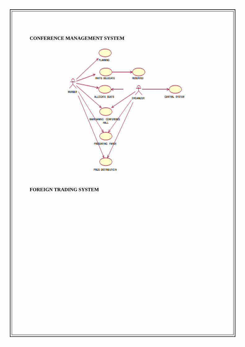
Conference Management System
BPO Management System
PASSPORT AUTOMATION SYSTEM

BOOK BANK REGISTRATION
ONLINE COURSE RESERVATION SYSTEM
CONFERENCE MANAGEMENT SYSTEM
FOREIGN TRADING SYSTEM

BPO MANAGEMENT SYSTEM

WEEK-3
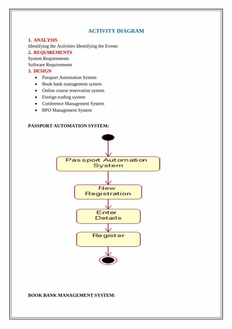
ACTIVITY DIAGRAM
1. ANALYSIS
Identifying the Activities Identifying the Events
2. REQUIREMENTS
System Requirements
Software Requirements
3. DESIGN
Passport Automation System
Book bank management system
Online course reservation system
Foreign trading system
Conference Management System
BPO Management System
PASSPORT AUTOMATION SYSTEM:
BOOK BANK MANAGEMENT SYSTEM:

Online course reservation system
FOREIGN TRADING
SYSTEM

CONFERENCE MANAGEMENT SYSTEM
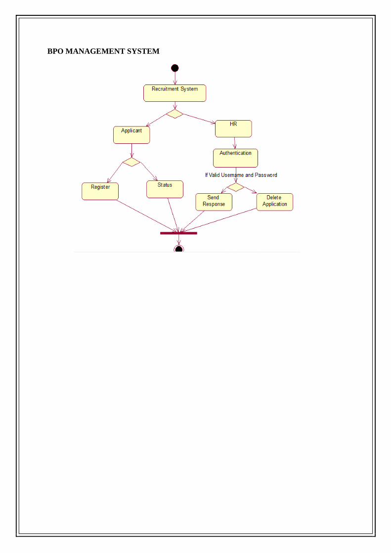
BPO MANAGEMENT SYSTEM

WEEK-4
DOMAIN MODEL
1. ANALYSIS
Identifying the Classes Identifying the Objects
2. REQUIREMENTS
System Requirements Software Requirements
3. DESIGN
Identity the conceptual classes and Develop a domain model with UML Class diagram for
passport automation system
INTRODUCTION
Passport Automation System is an interface between the Applicant and the Authority
responsible for the Issue of Passport. It aims at improving the efficiency in the Issue of
Passport and reduces the complexities involved in it to the maximum possible extent.
PURPOSE
If the entire process of 'Issue of Passport' is done in a manual manner then it would take
several months for the passport to reach the applicant. Considering the fact that the number of
applicants for passport is increasing every year, an Automated System becomes essential to
meet the demand. So this system uses several programming and database techniques to
elucidate the work involved in this process. As this is a matter of National Security, the
system has been carefully verified and validated in order to satisfy it.
SCOPE
The System provides an online interface to the user where they can fill in their personal
details
The authority concerned with the issue of passport can use this system to reduce his
workload and process the application in a speedy manner.
Provide a communication platform between the applicant and the administrator.
Transfer of data between the Passport Issuing Authority and the Local Police for
verification of applicant's information.
CLASS DIAGRAM
A class is drawn as rectangle box with three compartments or components separated by
horizontal lines. The top compartment holds the class name and middle compartment holds
the attribute and bottom compartment holds list of operations.

CLASS DIAGRAM FOR PASSPORT AUTOMATION SYSTEM
Documentation of Class Diagram:
Applicant-The applicant has attribute such as name and password and operations are login, givedetails and
logout. The applicant login and fill the details that are required for applying the passport .After applying the
person can view the status of the passport verification process.
The Database-The database has attributed such as name and operation is store. The purpose is to store the data.
Regional Administrator- The regional administrator has attribute such as name and operation are get details,
verify details and send. The regional administrator get the details form database and verify with their database
Passport Administrator-The passport administrator has attributed such as name and operation are get details,
verify details and issue. The passport administrator get the details form database and verify with their database,
update the verification and issue the passport
The Police-The police has attribute such as name and operation are get details, verify details and send. The
police get the details form database and verify with their database, update the verification in the database

WEEK-5
SCENARIOS
Using the identified scenarios find the interaction between objects and represent them using
UML Interaction diagrams.
Both sequence diagrams and collaboration diagrams are kinds of interaction diagrams.
Interaction diagrams address the dynamic view of a system. A sequence diagram is an
interaction diagram that emphasizes the time-ordering of messages. It depicts the objects and
classes involved in the scenario and the sequence of messages exchanged between the objects
needed to carry out the functionality of the scenario. Typically, you’ll use one sequence
diagram to specify a use case’s main flow, and variations of that diagram to specify a use
case’s exceptional flows.
Sequence Diagram
A sequence diagram shows an interaction arranged in time sequence,
It shows object participating in interaction by their lifeline by the message they exchange
arranged in time sequence. Vertical dimension represent time and horizontal dimension
represent object.
Example: Sequence Diagram for Passport automation system

COLLABORATION DIAGRAM
A collaboration diagram is similar to sequence diagram but the message in number format. In
a collaboration diagram sequence diagram is indicated by the numbering the message. A
collaboration diagram, also called a communication diagram or interaction diagram, A
sophisticated modeling tool can easily convert a collaboration diagram into a sequence
diagram and the vice versa. A collaboration diagram resembles a flowchart that portrays the
roles, functionality and behavior of individual objects as well as the overall operation of the
system in real time.
Example: Collaboration Diagram for Passport automation system

WEEK-6
STATE CHART DIAGRAMS
1. ANALYSIS
Identifying the States
Identifying the
2. REQUIREMENTS
System Requirements
Software Requirements
3. DESIGN
Passport Automation System
Book bank management system
Online course reservation system
State chart Diagram: The state chart diagram contains the states in the rectangle boxes and
starts in indicated by the dot and finish is indicated by dot encircled. The purpose of state
chart diagram is to understand the algorithm in the performing method.
Documentation of State Chart Diagram
The states of the passport automation system are denoted in the state chartdiagram
Login state represent authentication for login the passport automationsystem.
In this state, it checks whether the applicant has provided all the details that isrequired.
Police, regional administrator and passport administrator get necessary details and
verification of the applicant are denoted from the Get detail state and verificationstate.
Passport Automation System

Book Bank Management System
Online Course Reservation System
Login1
Fill Details
Select Flight
Booking Ticket
SearchFlig ht
Cancelling

WEEK-7
STATE CHART DIAGRAMS
1. ANALYSIS
Identifying the States
Identifying the
2. REQUIREMENTS
System Requirements
Software Requirements
3. DESIGN
Foreign trading system
Conference Management System
BPO Management System
State chart Diagram: The state chart diagram contains the states in the rectangle boxes and
starts in indicated by the dot and finish is indicated by dot encircled. The purpose of state
chart diagram is to understand the algorithm in the performing method.
Documentation of State Chart Diagram
The states of the passport automation system are denoted in the state chartdiagram
Login state represent authentication for login the passport automationsystem.
In this state, it checks whether the applicant has provided all the details that isrequired.
Police, regional administrator and passport administrator get necessary details and
verification of the applicant are denoted from the Get detail state and verificationstate.
Foreign Trading System
Login
Sourcing
place order
Bill
Pay
Logout

Conference Management System
login
submit the paper
review the paper
sending paper confirmation
details
submit revised and camera
ready paper
registration

BPO Management System
login
fetches data 4rm database
calls the customer
pitches the product
sales the product
proceeds another call

Week-8
COMPONENT DIAGRAM
Passport Automation System
Book bank management system
Online course reservation system
Component diagram. The component diagram is represented by figure dependency and it is
a graph of design of figure dependency. The component diagram's main purpose is to show
the structural relationships between the components of a systems. It is represented by boxed
figure. Dependencies are represented by communication association.
Passport Automation System
Book Bank Management System:
Documentation of Component Diagram
The main component in this component diagram is online book bank management systems.
And member details, issue for first year, issue for second year issue for third year and issue
for fourth year are components comes under the main component.

Online Course Reservation System

Week-9
COMPONENT DIAGRAM
Draw a Component diagram for
a. Foreign trading system
b. Conference Management System
c. BPO Management System
Foreign Trading System
Documentation Of Component Diagram
The main component in the component diagram is foreign trading system. The trader who
come to do the trading process and administrator who manages all the other processes is the
subcomponents.
Conference Management System
Documentation of Component Diagram
The main component in this component diagram is conference management system and
submit the paper, review the paper and registration.

BPO Management System
Documentation of Component Diagram
The main component in this component diagram is BPO management systems. And the agent
calls customer, pitches about his product and makes the sale are the main component comes
under the componentdiagram.
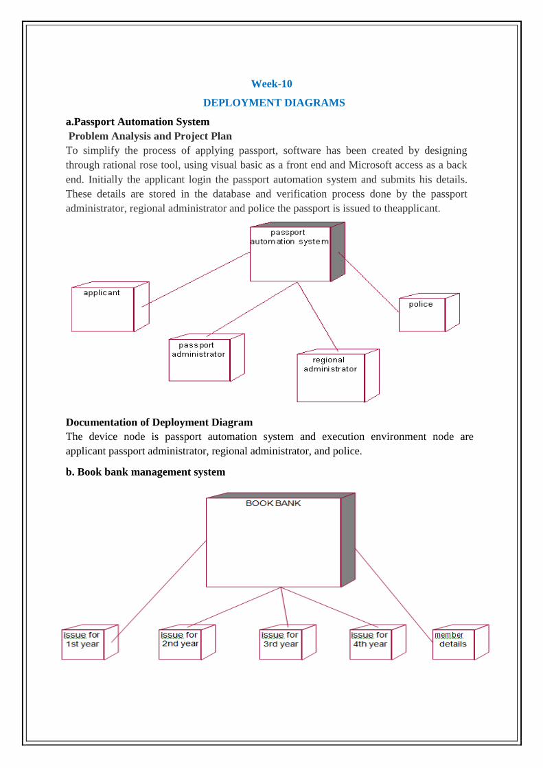
Week-10
DEPLOYMENT DIAGRAMS
a.Passport Automation System
Problem Analysis and Project Plan
To simplify the process of applying passport, software has been created by designing
through rational rose tool, using visual basic as a front end and Microsoft access as a back
end. Initially the applicant login the passport automation system and submits his details.
These details are stored in the database and verification process done by the passport
administrator, regional administrator and police the passport is issued to theapplicant.
Documentation of Deployment Diagram
The device node is passport automation system and execution environment node are
applicant passport administrator, regional administrator, and police.
b. Book bank management system

Documentation Of Deployment Diagram
The processor in this deployment diagram is the book bank which is the main part and which
are the some of the main activities performed in the system. And issue for first year, issue for
second year issue for third year and issue for fourth year are some activities performed in this
system.
C. Online course reservation system
Documentation Of Deployment Diagram
The device node is online course reservation and execution nodes are course details, login
and college details

Week-11
DEPLOYMENT DIAGRAMS
Draw a Deployment diagram for
a. Foreign trading system
b. Conference Management System
c. BPO Management System
a. Foreign trading system
Documentation of Deployment Diagram
The processor in this diagram is the foreign trading system. The devices are the trader and
administrator who perform the main activities in the system.

b. Conference Management System
Documentation Of Deployment Diagram
The processor in this deployment diagram is the conference management system which is the
main part and the devices are the candidate, appear for do conference , reviewer will reviews
paper , database will store all details which are the some of the main activities performed in
the system.
C.BPO Management System
Documentation Of Deployment Diagram
The processor in this deployment diagram is the BPO management system which is the main
part and the devices are the agent, customer and to sell the product to the customer are the
main activities performed in the system.


![R3.2 Rev 3 Document Title Main Requirements · 3.1.1 Requirements to achieve the AUTOSAR PO1 (CONSIDERATION OF ... [Main70] AUTOSAR shall provide complete interfaces to application](https://static.fdocuments.in/doc/165x107/5e315c8da0501a003432fee5/r32-rev-3-document-title-main-requirements-311-requirements-to-achieve-the-autosar.jpg)
