Lab: Global Parameters, Global Control! - Paul F....
28
Session 2.2 Lab: Global Parameters, Global Control! Paul F. Aubin, www.paulaubin.com Class Description One of the most exciting new features to appear in Revit in some time is Global Parameters. What are global parameters you may ask? Global parameters bring the power of the family editor into the project environment! You can now create parameters and label dimensions directly in the project environment. Imagine being able to drive an offset distance between elements in multiple locations around the entire project, or driving instance parameters of several independent families from a single control panel. These are the kind of things that are possible with global parameters! In this hands-on lab we will walk through several scenarios of using GP to establish relationships in your projects. We will explore using them for establishing critical design dimensions and defining code requirements. We will also look at how GP can make your content even more robust by allowing you to control several families at once without needing to embed the families into one another first. If you want to explore the new and exciting global parameters feature, come join us and learn about them the best way possible: hands-on! About the Speaker: Paul F. Aubin is the author of many Revit book titles including the widely acclaimed: The Aubin Academy Series, Renaissance Revit and Revit video training at www.lynda.com/paulaubin. Paul is an independent architectural consultant providing Revit® for Architecture implementation, training, and support services. Paul’s involvement in the architectural profession spans over 25 years, with experience in design, production, CAD management, mentoring, coaching and training. He is an active member of the Autodesk user community, an Expert Elite and is a top-rated repeat speaker at Autodesk University, Revit Technology Conference and Midwest University. His diverse experience in architectural firms, as a CAD manager, and an educator gives his writing and his classroom instruction a fresh and credible focus. Paul is an associate member of the American Institute of Architects and lives in Chicago with his wife and three children.
-
Upload
nguyenduong -
Category
Documents
-
view
218 -
download
2
Transcript of Lab: Global Parameters, Global Control! - Paul F....

Session 2.2
Lab: Global Parameters, Global Control! Paul F. Aubin, www.paulaubin.com
Class Description
One of the most exciting new features to appear in Revit in some time is Global Parameters. What are global parameters you may ask? Global parameters bring the power of the family editor into the project environment! You can now create parameters and label dimensions directly in the project environment. Imagine being able to drive an offset distance between elements in multiple locations around the entire project, or driving instance parameters of several independent families from a single control panel. These are the kind of things that are possible with global parameters! In this hands-on lab we will walk through several scenarios of using GP to establish relationships in your projects. We will explore using them for establishing critical design dimensions and defining code requirements. We will also look at how GP can make your content even more robust by allowing you to control several families at once without needing to embed the families into one another first. If you want to explore the new and exciting global parameters feature, come join us and learn about them the best way possible: hands-on!
About the Speaker:
Paul F. Aubin is the author of many Revit book titles including the widely acclaimed: The Aubin Academy Series, Renaissance Revit and Revit video training at www.lynda.com/paulaubin. Paul is an independent architectural consultant providing Revit® for Architecture implementation, training, and support services. Paul’s involvement in the architectural profession spans over 25 years, with experience in design, production, CAD management, mentoring, coaching and training. He is an active member of the Autodesk user community, an Expert Elite and is a top-rated repeat speaker at Autodesk University, Revit Technology Conference and Midwest University. His diverse experience in architectural firms, as a CAD manager, and an educator gives his writing and his classroom instruction a fresh and credible focus. Paul is an associate member of the American Institute of Architects and lives in Chicago with his wife and three children.
Lab: Global Parameters, Global Control! Paul F. Aubin, www.paulaubin.com
Page 2 of 28
Introduction Global parameters are created in the project environment and can be used to drive the instance or type values of inserted families and can also be used to label dimensions thereby providing constraints that can be flexed from a single location. Global parameters were first introduced in the Revit 2016 R2 release and were enhanced further in Revit 2017. This paper was written with Revit 2017. So if you are using 2016 R2, some of the features shown herein may not apply to you. Global parameters work well for driving multiple objects or dimensions that must all maintain the same value. They are similar to other constraints like locked dimensions and equality constraints but are more flexible. This is because unlike locked dimensions that must be unlocked to be changed and which are individual constraints that are not coordinated with other locked dimensions, global parameters can be applied to multiple elements and can be flexed from the “Global Parameters” dialog and will thereby update throughout the project. They also offer an alternative to equality dimensions and provide the flexibility to be applied to discontinuous elements; something equality dimensions cannot do. The lessons that follow will showcase some of these benefits across several representative examples.
Setting a common hold dimension A very basic use of a global parameter is to define a simply “hold” dimension. This can be useful whenever you have a situation where a particular dimension value is critical to the design in some way. This might be to maintain a design relationship or to adhere to a building code requirement. These kinds of things can be done with locked dimensions. But if you need to change them after locking, you would need to unlock and modify each one. A global parameter gives the same constraint potential, but is much easier to modify.
Setting a “standard” door jamb In this example, we will establish a common jamb dimension for the doors across a floor plan.
1. Open the file named: 01_Door Jambs_!Start.rvt.
2. Create an aligned dimension between the face of wall and the left edge of the door on the left.

Lab: Global Parameters, Global Control! Paul F. Aubin, www.paulaubin.com
Page 3 of 28
3. Repeat for the other doors.
There are only five doors and it is easy enough to create these dimensions, but if you would rather skip, here’s a catch-up file: CATCH UP! You can open the file completed to this point named: 01_Door Jambs_A.rvt.
4. Select the first dimension that you created.
5. On the ribbon, on the Modify | Dimensions tab, on the Label Dimension panel, click the small Create Parameter icon.
If you have worked in the family editor before, this is very similar to labelling a dimension in a family. All we need to do is define the new parameter.
6. Input the name for the parameter such as: Typ Door Jamb.
7. Accept the default “group under” and optionally add a tooltip.
A tooltip provides a more detailed reminder of what the parameter is intended for. You will see the tip when you pause over the name of the parameter in dialogs. While it is not required, it is recommended.

Lab: Global Parameters, Global Control! Paul F. Aubin, www.paulaubin.com
Page 4 of 28
8. Click OK to finish defining the parameter.
Whenever the labelled dimension is selected, it will now display a small pencil icon next to it to indicate that it is labelled.
Now you can apply this same label to the other dimensions.
9. Select all of the other four dimensions added above.
10. On the ribbon, from the label drop-down, choose: Typ Door Jamb.
CATCH UP! You can open the file completed to this point named: 01_Door Jambs_B.rvt.
Now we can flex this parameter to test it out. There are two ways to do this. The simplest way to access the “Global Parameters” dialog and edit is to select one of
Lab: Global Parameters, Global Control! Paul F. Aubin, www.paulaubin.com
Page 5 of 28
the dimensions, and then click the small pencil icon. The other way is to use the Global Parameters button on the Mange tab of the ribbon.
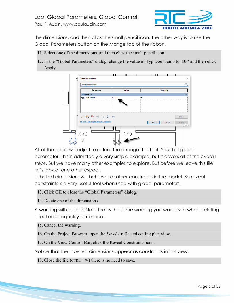
11. Select one of the dimensions, and then click the small pencil icon.
12. In the “Global Parameters” dialog, change the value of Typ Door Jamb to: 10" and then click Apply.
All of the doors will adjust to reflect the change. That’s it. Your first global parameter. This is admittedly a very simple example, but it covers all of the overall steps. But we have many other examples to explore. But before we leave this file, let’s look at one other aspect. Labelled dimensions will behave like other constraints in the model. So reveal constraints is a very useful tool when used with global parameters.
13. Click OK to close the “Global Parameters” dialog.
14. Delete one of the dimensions.
A warning will appear. Note that is the same warning you would see when deleting a locked or equality dimension.
15. Cancel the warning.
16. On the Project Browser, open the Level 1 reflected ceiling plan view.
17. On the View Control Bar, click the Reveal Constraints icon.
Notice that the labelled dimensions appear as constraints in this view.
18. Close the file (CTRL + W) there is no need to save.

Lab: Global Parameters, Global Control! Paul F. Aubin, www.paulaubin.com
Page 6 of 28
Reporting Parameters Using the concepts from the previous example, we can get slightly more advanced and use a global parameter to help us identify places in our model that do not meet minimum code requirements. To do this, we will leverage three features: first we will set up a new global parameter as a “reporting parameter.” Second we will create a formula to test the value of the reporting parameter against the code rule and finally we will set up a filter in the view to display the results.
Check for code compliance Let’s start by adding a new global parameter in the location where we need to check for code compliance.
1. Open the file named: 02_Door Check_!Start.rvt.
2. Select the dimension on the right side of door 1 (currently 1'-3").
3. On the Modify | Dimensions tab, on the Label Dimension panel, click the Create Parameter icon. Name it: Door 105 Check. Optionally add a tooltip and click OK.
This parameter is now like the other one we created and if you try to flex it, it will create a warning. Go ahead and try it… This is because we are currently constraining both sides of the door. To remedy this, we need to change our new parameter to a “Reporting” parameter. Similar to the reporting parameters we can create in the family editor, a reporting global parameter will not drive geometry, but rather will simply “report” the value of the labelled dimension. In the context of a project, you may wonder why we would need this and how it differs from a simple non-labelled dimension? Onscreen, there will not appear to be much difference. When geometry moves, this dimension will update.
The difference is that we can use reporting parameters in formulas.
4. On the Manage tab of the ribbon, click the Global Parameters button.
5. Select Door 105 Check and then click the small edit icon.

Lab: Global Parameters, Global Control! Paul F. Aubin, www.paulaubin.com
Page 7 of 28
6. In the “Global Parameter Properties” dialog, check the Reporting Parameter checkbox and then click OK.
7. Flex the Typ Door Jamb parameter.
As you try values for Typ Door Jamb and apply them, the Door 105 Check dimension will adjust onscreen accordingly. (Sadly in my testing, you have to click OK to update the reporting parameter in the dialog, it seems Apply will not do it).
8. Set the value of Type Door Jamb to: 6" and then click OK
CATCH UP! You can open the file completed to this point named: 02_Door Check_A.rvt.
Now we want to have an onscreen alert when the value of the Door 15 Check parameter drops below that allowed by code. To do this, we need a new Project Parameter for the doors category and a filter in this view.
9. On the view tab, click the Visibility/Graphics button (or type: VG).
10. In the “Visibility/Graphic Overrides” dialog, click the Filters tab.
11. At the bottom, click the Edit/New button.
12. In the “Filters” dialog, click the new icon. Name it: Door Code Check and then click OK.
13. In the middle of the dialog, check the Doors category.
14. On the right, next to Filter by, click the small browse icon.

Lab: Global Parameters, Global Control! Paul F. Aubin, www.paulaubin.com
Page 8 of 28
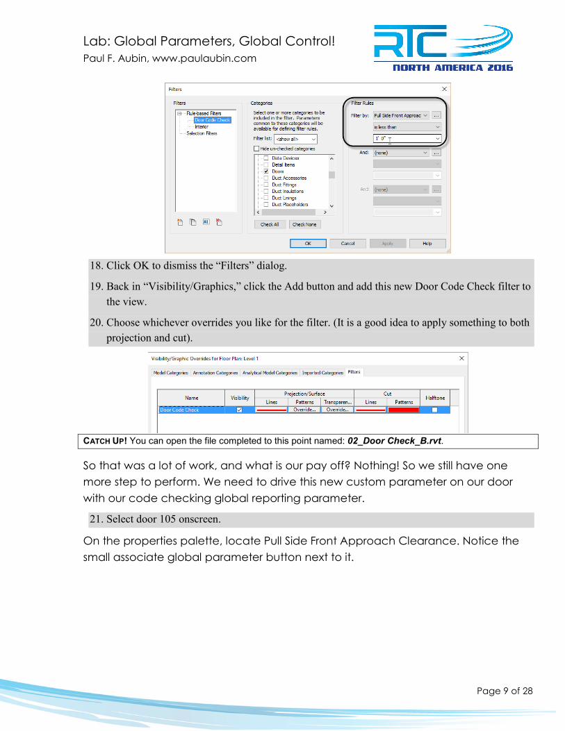
15. In the “Project Parameters” dialog that displays, click the Add button.
16. Name the new parameter: Pull Side Front Approach Clearance. On the right, assign it to Doors, accept the other defaults and then click OK twice.
17. Back in the “Filters” dialog, from the Filter by list, choose: Pull Side Front Approach Clearance. Set the operator to: is less than, and then type: 1'-0" in the text field.
Lab: Global Parameters, Global Control! Paul F. Aubin, www.paulaubin.com
Page 9 of 28
18. Click OK to dismiss the “Filters” dialog.
19. Back in “Visibility/Graphics,” click the Add button and add this new Door Code Check filter to the view.
20. Choose whichever overrides you like for the filter. (It is a good idea to apply something to both projection and cut).
CATCH UP! You can open the file completed to this point named: 02_Door Check_B.rvt.
So that was a lot of work, and what is our pay off? Nothing! So we still have one more step to perform. We need to drive this new custom parameter on our door with our code checking global reporting parameter.
21. Select door 105 onscreen.
On the properties palette, locate Pull Side Front Approach Clearance. Notice the small associate global parameter button next to it.

Lab: Global Parameters, Global Control! Paul F. Aubin, www.paulaubin.com
Page 10 of 28
22. Click the Associate Global Parameter button, choose: Door 105 Check (report) and then click OK.
Still nothing… Well, now we just need to flex.
23. Open the “Global Parameters” dialog and flex the Typ Door Jamb parameter.
As we saw above, the reporting parameter will update onscreen, but not in the dialog until you close and re-open it. But the doors should immediately change display to match your overrides in the filter above!
CATCH UP! You can open the file completed to this point named: 02_Door Check_C.rvt.
How practical is this? Now, is it worth it? Well this is a tricky one. The issue here is that since we are making an evaluation of the door’s proximity to other model geometry (a wall in this case) we cannot simply build this into the door family. Now, we certainly could build in

Lab: Global Parameters, Global Control! Paul F. Aubin, www.paulaubin.com
Page 11 of 28
clearance geometry that we can toggle on and off, and many folks do this in their office standard content. But nothing about those clearance solids will react when they intersect walls or other geometry save when performing a clash detection. This approach leverages the global parameter to assess this very specific condition: is the door too close to the wall. It works well, but there is a lot of setup here and you would potentially need several such parameters per door to test each possible condition. So as interesting as this solution may be, I am not sure exactly how practical it is.
Driving Materials Now let’s look at a much more practical example. In the family editor, when you have nested families, you can create parameters in the host family and have them drive the parameters of the nested families. Using global parameters, we can achieve similar behavior in a project allowing you to control several families at once without needing to embed the families into one another first. Driving a collection of materials across many similar families is one such example.
1. Open the file named: 03_Materials_!Start.rvt.
2. Select one of the base cabinets onscreen and click the Edit Type button.
There are three material parameters. Notice that next to each one is an associate global parameter button.
3. Next to Cabinet Material, click the Associate Global Parameter button.
4. In the “Associate Global Parameter” dialog that appears, click the new icon at the bottom.
5. In the “Global Parameter Properties” dialog, name the new parameter: Cabinet Material and then click OK twice.

Lab: Global Parameters, Global Control! Paul F. Aubin, www.paulaubin.com
Page 12 of 28
6. Repeat for Door/Drawer Material and Handle Material.
7. Click OK in the “Type Properties” dialog to finish the first cabinet.
8. Select the next base cabinet onscreen.
9. Edit Type and click the Associate Global Parameter button for the Cabinet Material.
10. Assign it to the Cabinet Material parameter you created above and then click OK.
11. Repeat for the other two materials and then click OK to complete this family.
12. Repeat the process for each of the remaining cabinet families in the project.
This is a little tedious and will take a bit of time, so if you prefer, you can skip to the catch-up file. CATCH UP! You can open the file completed to this point named: 03_Materials_A.rvt.
Also keep in mind that these are type parameters in these families. Therefore, if you intend to use any of the other types in this file later on, you will need to edit those
Lab: Global Parameters, Global Control! Paul F. Aubin, www.paulaubin.com
Page 13 of 28
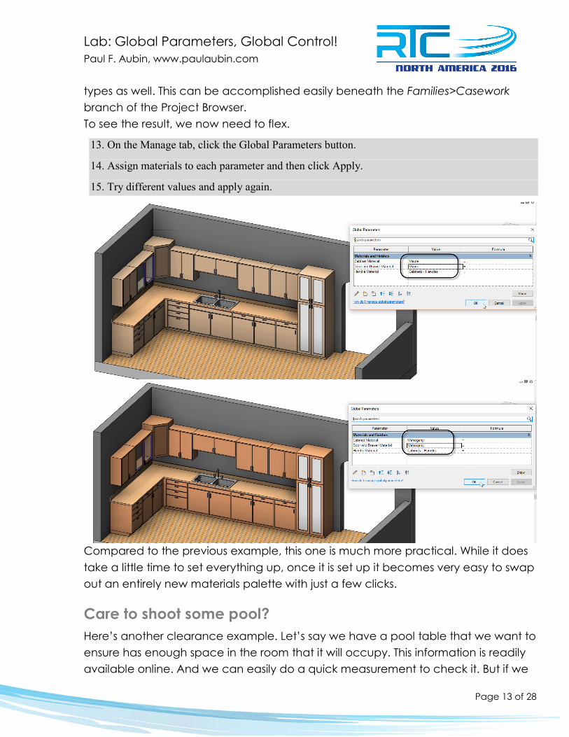
types as well. This can be accomplished easily beneath the Families>Casework branch of the Project Browser. To see the result, we now need to flex.
13. On the Manage tab, click the Global Parameters button.
14. Assign materials to each parameter and then click Apply.
15. Try different values and apply again.
Compared to the previous example, this one is much more practical. While it does take a little time to set everything up, once it is set up it becomes very easy to swap out an entirely new materials palette with just a few clicks.
Care to shoot some pool? Here’s another clearance example. Let’s say we have a pool table that we want to ensure has enough space in the room that it will occupy. This information is readily available online. And we can easily do a quick measurement to check it. But if we

Lab: Global Parameters, Global Control! Paul F. Aubin, www.paulaubin.com
Page 14 of 28
put the values we want into a couple custom parameters, we can have the check performed live in the project and even display it in a custom color scheme.
1. Open the file named: 04_Pool Table_!Start.rvt.
Build the parameters Let’s start by labelling the dimensions in the Billiard Room.
2. Select each of the dimensions onscreen and label them with new parameters called: Billiard Room Length and Billiard Room Width.
Next we’ll create a parameter to evaluate these dimensions compared to the recommended room size. There are a few ways to approach this. Assuming a 57" cue, the recommended size of the room for an 8 foot table is: 16'-9" x 13'-2". Naturally there would a little give and take in these numbers and other factors might come into play like other room furnishings, circulation patterns and the precise placement and size of the table. This being more of a proof-of-concept example, and to simplify a bit, we will not factor in any of those extra variables. For this example, we will consider three ranges: sizes less than the recommended, sizes within a foot or so of the recommended and sizes greater than the recommended. Furthermore, since our ultimate goal is to display the results graphically, we will combine the results of evaluating each dimension into a single formula.
3. On the Manage tab, click the Global Parameters button and create a new parameter.
4. Name the parameter: Room Clearance. Change the Type of parameter to: Text and for the tooltip, input: Evaluates the length and width of the room and reports how adequate the size is compared to the recommended size.
Lab: Global Parameters, Global Control! Paul F. Aubin, www.paulaubin.com
Page 15 of 28
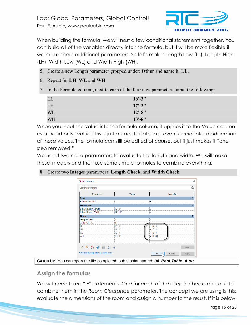
When building the formula, we will nest a few conditional statements together. You can build all of the variables directly into the formula, but it will be more flexible if we make some additional parameters. So let’s make: Length Low (LL), Length High (LH), Width Low (WL) and Width High (WH).
5. Create a new Length parameter grouped under: Other and name it: LL.
6. Repeat for LH, WL and WH.
7. In the Formula column, next to each of the four new parameters, input the following:
LL 16'-3" LH 17'-3" WL 12'-8" WH 13'-8"
When you input the value into the formula column, it applies it to the Value column as a “read only” value. This is just a small failsafe to prevent accidental modification of these values. The formula can still be edited of course, but it just makes it “one step removed.” We need two more parameters to evaluate the length and width. We will make these integers and then use some simple formulas to combine everything.
8. Create two Integer parameters: Length Check, and Width Check.
CATCH UP! You can open the file completed to this point named: 04_Pool Table_A.rvt.
Assign the formulas We will need three “IF” statements. One for each of the integer checks and one to combine them in the Room Clearance parameter. The concept we are using is this: evaluate the dimensions of the room and assign a number to the result. If it is below
Lab: Global Parameters, Global Control! Paul F. Aubin, www.paulaubin.com
Page 16 of 28
recommended values, we will assign a negative number. If it is within recommended values, we will assign zero. If it is above, we will assign positive one. When you add the results in the two parameters, it will yield a combined value that can be evaluated to give a final qualitative score.
9. In the formula field next to Length Check, input:
if(Billiard Room Length < LL,-2,if(and(not(Billiard Room Length < LL), Billiard Room Length < LH),0,1))
10. In the formula field next to Width Check, input:
if(Billiard Room Width < WL,-2,if(and(not(Billiard Room Width < WL), Billiard Room Width < WH),0,1))
11. In the formula field next to Room Clearance, input:
if(Length Check + Width Check <0,"Inadequate",if(Length Check + Width Check=0,"Acceptable","Generous"))
You can find these formulas in the file: Pool Table Formula.txt. CATCH UP! You can open the file completed to this point named: 04_Pool Table_B.rvt.
Create a Color Scheme The value of the Room Clearance parameter should already be reporting the results and if you flex either the Billiard Room Length or the Billiard Room Width parameter, it will adjust to reflect the change. However, it might be nice to see the result graphically onscreen. Let’s push the result of the Room Clearance parameter into a custom project parameter for the room.
12. On the Manage tab, click the Project Parameters button and then click Add.
13. Name the parameter: Billiard Table Clearance, for the Type of parameter, choose: Text and be sure to check the Rooms checkbox on the right.

Lab: Global Parameters, Global Control! Paul F. Aubin, www.paulaubin.com
Page 17 of 28
14. Click OK twice to finish.
15. Select the room onscreen, and then on the Properties palette, click the small associate global parameter icon next to Billiard Table Clearance.
16. Choose Room Clearance and then click OK.
17. Deselect the room, and on the Properties palette, click the <none> button for Color Scheme.
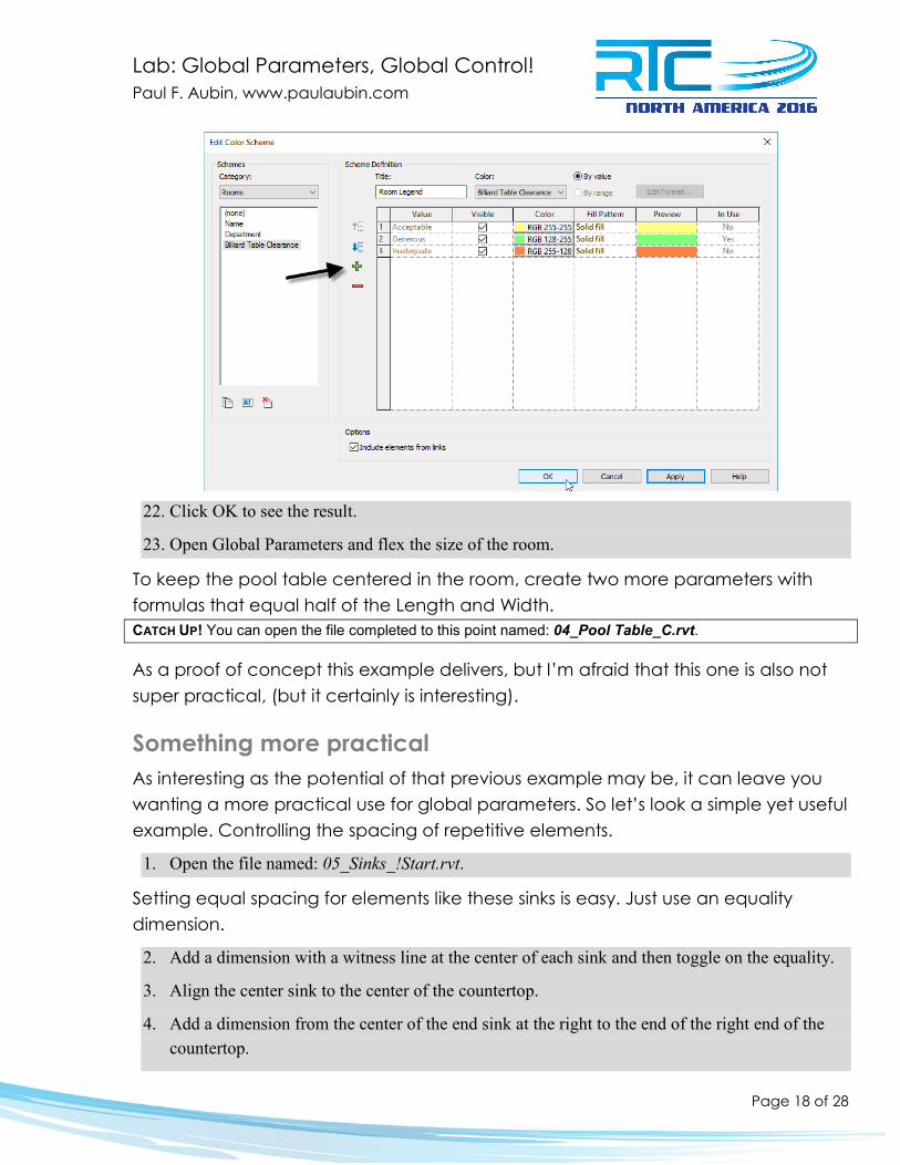
18. Change the Category to Rooms, and then Duplicate one of the schemes. Call it: Billiard Table Clearance.
19. In the Scheme Definition area, click the Add Value button and name it: Generous. Change the color to Green.
20. Add another two values: Inadequate set it to Orange and Acceptable set it to Yellow.
21. Change the Color option to: Billiard Table Clearance and click OK in the message that appears.
Lab: Global Parameters, Global Control! Paul F. Aubin, www.paulaubin.com
Page 18 of 28
22. Click OK to see the result.
23. Open Global Parameters and flex the size of the room.
To keep the pool table centered in the room, create two more parameters with formulas that equal half of the Length and Width. CATCH UP! You can open the file completed to this point named: 04_Pool Table_C.rvt.
As a proof of concept this example delivers, but I’m afraid that this one is also not super practical, (but it certainly is interesting).
Something more practical As interesting as the potential of that previous example may be, it can leave you wanting a more practical use for global parameters. So let’s look a simple yet useful example. Controlling the spacing of repetitive elements.
1. Open the file named: 05_Sinks_!Start.rvt.
Setting equal spacing for elements like these sinks is easy. Just use an equality dimension.
2. Add a dimension with a witness line at the center of each sink and then toggle on the equality.
3. Align the center sink to the center of the countertop.
4. Add a dimension from the center of the end sink at the right to the end of the right end of the countertop.

Lab: Global Parameters, Global Control! Paul F. Aubin, www.paulaubin.com
Page 19 of 28
5. Add a dimension from the center of the end sink at the left to the left end of the countertop. Use the TAB key to ensure that you are dimensioning to the “Reference” and not the “Shape Handle” for this end.
6. Select one of the side dimensions and label it with a new parameter called: Sink End Offset.
7. Select the other end dimension and label it with the same dimension.
8. Open the “Global Parameters” dialog and flex the Sink End Offset parameter.
CATCH UP! You can open the file completed to this point named: 05_Sinks_A.rvt.
With this arrangement, you can control the end distances equally and have all of the sinks spaced equally as well.

Lab: Global Parameters, Global Control! Paul F. Aubin, www.paulaubin.com
Page 20 of 28
Now how much would you pay? If you want the end distances equal to the space between the sinks, you need to do some math and configure things a bit differently. First, we will replace the equality dimension with a global parameter. Next, instead of the end offset parameter, we will calculate the distance from one end. Finally, we will use a reporting parameter to help us do the math and another length parameter to drive the length of the countertop and to form the basis of the calculation.
9. Delete the dimension at the left end. When the warning appears, click the Unconstrain button.
To be sure that the parameter is removed, you can use the Reveal Constraints icon on the View Control Bar.
10. Select the equality dimension and toggle off the equality. Then label it with a new parameter called: Sink Spacing.
Notice that with global parameters, you can actually label a multi-segment dimension! This behaves identically to an equality dimension since the label is applied to all segments of the multi-segment dimension.
11. Dimension one of the sinks (with witness lines measuring the sink’s width).
12. Label this with a new parameter called: Sink Width and then click OK.

Lab: Global Parameters, Global Control! Paul F. Aubin, www.paulaubin.com
Page 21 of 28
13. Select the countertop and then on the Properties palette, click the associate global parameter button next to the Length parameter.
14. In the “Associate Global Parameter” dialog, click the New Global Parameter icon and name the new parameter: Countertop Length. Click OK twice.
In this case, the quantity is five sinks. We won’t be varying this. In my tests, I found no good way to have global parameters drive an array. So if you need a variable number of sinks, you cannot do this with a GP. To calculate the spacing, we subtract the width of five sinks from the countertop length, divide this by six spaces (four between sinks, one at each end) and then add this value back to the width of one sink. This is the distance between sinks. To calculate the end offset, it is the same calculation but added to only half the sink width.
15. Open the “Global Parameters” dialog and in the formula field for the Sink End Offset parameter, input:
((Countertop Length - (Sink Width * 5)) / 6) + (Sink Width / 2)
16. For the formula of the Sink Spacing parameter, input:
((Countertop Length - (Sink Width * 5)) / 6) + Sink Width
17. Flex the Countertop Length.
CATCH UP! You can open the file completed to this point named: 05_Sinks_B.rvt.
Create a collection of shelving units Let’s look at another practical example. In this exercise, we will layout a collection of retail shelving units and set the spacing with global parameters. This example uses an array, but as I noted above, sadly we cannot drive the array quantity with a global parameter. So you have to flex the quantity onscreen and the spacing values in the “Global Parameters” dialog.

Lab: Global Parameters, Global Control! Paul F. Aubin, www.paulaubin.com
Page 22 of 28
1. Open the file named: 06_Shelves_!Start.rvt.
2. Select the free-standing shelving unit and then on the Properties palette, click the small Associate Global Parameter icon next to the Width parameter.
3. Click the Add Parameter icon and create a new parameter called: Shelf Width.
4. Array the shelving unit. Be sure Group and Associate is checked and keep the quantity at: 2.
5. Add a dimension between the two resulting array group elements.
6. Select the dimension and then label it with a new parameter named: Distance Between Units and then click OK.
Now we can use the Global Parameters dialog to link these two global parameters together.
7. On the Manage tab, click the Global Parameters button.
8. In the Formula field next to Distance Between Units, type: Shelf Width (Case sensitive).

Lab: Global Parameters, Global Control! Paul F. Aubin, www.paulaubin.com
Page 23 of 28
9. Click OK to finish.
Your shelving units should now be flush to one another. Furthermore, you can now flex the Shelf Width (in the “Global Parameters” dialog) or adjust the quantity of arrayed elements (direclty onscreen) and the shelving units will all flex together and remain flush to one another. CATCH UP! You can open the file completed to this point named: 06_Shelves_A.rvt.
Curtain Wall bay spacing When global parameters first came out, this was one of the first things I thought of using them for. When designing curtain walls, you have three options: use a type-based design, lay it out manually or do a combination of the two. Type-based designs are nice because they automatically add curtain grids, mullions and panels based on the rules in the type. However, you only get one grid spacing in each direction. If you lay it out manually, you can vary the spacing in each direction in any way that you like, but you must layout each grid line manually. It is also possible to leverage type-based settings to establish the overall bay spacing and then add additional bays manually. Equality dimensions and multiple copy can help with the manual bays, but it is still a tedious process; particularly when modifying the design. Well this is where global parameters can really help. You can now define parameters for each major bay spacing and then apply them directly to the grids in the curtain wall design. When it comes time to edit, simply modify the global parameters! Here’s a simple example:
1. Open the file named: 07_Curtain Wall_!Start.rvt.
This design is laid out manually, the grid spacing in each direction is set to: None in the type. Notice that the sides and top are narrower than the middle bays.
2. On the Project Browser, open the South elevation.
3. Add a dimension from Level 2 down to the horizontal curtain grid directly beneath it.

Lab: Global Parameters, Global Control! Paul F. Aubin, www.paulaubin.com
Page 24 of 28
4. Repeat to dimension the two small left and right bay in each larger bay.
5. Select all of the dimensions except the rightmost and leftmost vertical bays.
6. Label them with a new parameter called: Small Bay.
7. Select the rightmost and leftmost dimensions and label them with a new parameter called: Small Bay End.
8. Open the “Global Parameters” dialog and in the formula field next to Small Bay End, input: Small Bay + 1 1/4".
9. Flex the Small Bay parameter.
CATCH UP! You can open the file completed to this point named: 07_Curtain Wall_A.rvt.
This is just a simple example. Using the same strategy, you could build a much more robust curtain wall design. You are encouraged to experiment further on your own.
Column Spacing – intercolumniation When I wrote Renaissance Revit, a book that takes a “deep dive” into the family editor and explores the creation of the classical orders of architecture as fully parametric families, we did not have global parameters. One of the challenges that was therefore left unsolved in that book was the connecting the proportions of various families to one another. For example, the orders utilize a series of interconnected proportions that are based on the diameter of the column

Lab: Global Parameters, Global Control! Paul F. Aubin, www.paulaubin.com
Page 25 of 28
measured at its base. This proportion is applied not just to the column and its base, capital and shaft, but also to the entablature and even the spacing of the columns relative to one another. In other words, the system of proportions will inform the entire façade, not just its columns. Without global parameters, changing the value of the base diameter in the column will not change the entablature or the column spacing. But with global parameters, it can!
1. Open the file named: 08_Colonnade_!Start.rvt.
This file uses the Doric order. The Doric order is perhaps the most stringent when it comes to it proportions. The most characteristic feature of the Doric order is its triglyphs and metopes. A triglyph is an adornment that is meant to represent the ends of a beam as they would appear projecting through the frieze of the entablature. A metope is the portion of the frieze between each triglyph. Metopes are precisely square in shape at 0.750 diameters per side. A triglyph is 0.750 diameters high by 0.500 diameters wide. In addition, you must have a triglyph over the center of each column. This makes only certain column spacings allowable. Specifically: 1.25, 2.5, 3.75 and 5 diameters. For this example, we’ll use a value of 3.75 diameters and use this to drive all of the other proportions.
2. Select an instance of the entablature family onscreen.
3. On the Properties palette, click the Edit Type button, click the Rename button and name it: Flex.
4. Click the Associate Global Parameter button next to Base Diameter. Click the New parameter icon and name it: Base Diameter.

Lab: Global Parameters, Global Control! Paul F. Aubin, www.paulaubin.com
Page 26 of 28
5. Click OK three times.
The base diameter of the columns is calculated automatically from the distance between the two levels. So we need a reporting global parameter for the distance between Level 1 and 2.
6. Open the South elevation.
7. Add a dimension between Level 1 and Level 2. Label it with a new global parameter.
8. Name the parameter: Column Height and then check the Reporting Parameter checkbox.
9. Click OK to complete the parameter.
In the family editor, when you label a dimension it shows the name of the parameter on the dimension. Global parameters do not do this by default, but you can override them to display this way.

Lab: Global Parameters, Global Control! Paul F. Aubin, www.paulaubin.com
Page 27 of 28
10. Click directly on the text value of the dimension.
11. In the “Dimension Text” dialog, choose the “Show Label in View” option and then click OK.
12. Open the Level 1 floor plan view.
13. Select the equality dimension and then toggle off the equality.
14. Hold down the ctrl key and add the other dimension (between column A and B) to the selection.
15. Create a new global parameter to label the selected dimensions and name it: Column Spacing.
We need one more parameter.
16. Open the “Global Parameters” dialog and click the New Global Parameter icon.
17. Name the new parameter: Intercolumniation and change the Type of parameter to: Number.
18. Click OK to create the parameter and set its value to: 3.75.
That’s all of the parameters we need. Now we just need a few formulas. The Doric order is eight diameters tall.
19. So for the Base Diameter, in the formula field type: Column Height / 8
20. For Column Spacing, input a formula of: Base Diameter * Intercolumniation

Lab: Global Parameters, Global Control! Paul F. Aubin, www.paulaubin.com
Page 28 of 28
That’s it! To flex we just adjust the location of Level 2.
21. Edit the height of Level 2 and change it to: 12. Try another value, such as: 9.
Further Study You can find more information and tutorials in my books and video training. Please visit my website at: www.paulaubin.com for more information on my books. I also have Revit video training available at: www.lynda.com/paulaubin. I have several courses at lynda.com including: Revit Essential Training, Revit Family Editor
and Revit Architecture Rendering, Advanced Modelling in Revit Architecture, Formulas and Curves and many more.
If you have any questions about this session or Revit in general, you can use the contact form at www.paulaubin.com to send me an email.
Follow me on twitter: @paulfaubin
Thank you for attending. Please fill out your evaluation.