LTspice IV Getting Started GuideLTspice IV Getting Started ...
Colorado Department of Transportation Page 11
LAB 1 - Getting Started in InRoads
This lab demonstrates how to start and set up InRoads to work on a project. It demonstrates the Project Creation Utility, starting InRoads, loading data, and changing some InRoads settings.
Chapter Objectives:
Create a new project folder structure.
Start InRoads and set up the InRoads project defaults.
Load the initial project data.
Demonstrate how the Locks work.
Demonstrate Precisions and Factors.
The following files are used in this lab:
C:\Projects\12345\Design\Drawings\Reference_Files\12345DES_Model.dgn
C:\Projects\12345\Design\InRoads\12345DES_Geometry.alg
C:\Projects\12345\Design\InRoads\12345 existing ground.dtm
C:\Projects\12345\Design\InRoads\DES12345_Templates.itl
Lab 1.1 - Creating a Project Directory
The first step when beginning a project is to create a project directory structure. Use the Project Creation Utility to generate a uniform directory structure which will allow other users easy access to the project data when they need it.
Section Objectives:
♦ Create a project directory.
♦ Explore the folder structure created.
♦ Demonstrate how the PCF file works
1. From the Windows Explorer, navigate to:
C:\Workspace\Workspace-CDOT_V8i\Standards-Global\MicroStation \exes
2. <D> the Project Creation Utility icon to open the CDOT Project Creation Utility dialog box.
3. In the CDOT Project Creation Utility dialog box, <D> in the Job Project Code (JPC) field and key in 54321.

Page 12 Colorado Department of Transportation
LAB 1 - Getting Started in InRoads Labs for InRoads V8i SS2
4. Verify that Create Project Configuration File is toggled on. This file automatically sets the directory path in MicroStation so that navigating to the correct project folder is easier.
5. <D> Apply then <D> Close to dismiss the dialog box.
6. Open Windows Explorer and navigate to C:\Projects\54321\Design\Drawings\. Notice that the directory structure has been built for all disciplines and it has been populated with the standard drawings.
7. Close the Windows Explorer.
8. Start MicroStation.
9. In the MicroStation Manager dialog box, set the Project: to 54321. Notice that the Look In: folder automatically changes to the 54321 directory.
10. In the MicroStation Manager dialog box, navigate to the Design > Drawings > Reference Files folder.

Colorado Department of Transportation Page 13
Labs for InRoads V8i SS2 LAB 1 - Getting Started in InRoads
11. <D> on 54321DES_Model.dgn then <D> Open. This is the location and file that most Roadway Design work is done in.
12. Close MicroStation.
Section Summary:♦ Using the Project Creation Utility builds a standard directory structure for the project.
♦ Standard drawing files with project specific names are included in the project directories.
♦ Using the PCF file in MicroStation make navigation within the project directory easy.
Lab 1.2 - Initial InRoads Set-up
MicroStation uses the pcf file to set directory paths. InRoads use a different method called Project Defaults. The process of setting project defaults is normally a tedious job. However, using the CDOT_V8i Disciplines.reg file supplied with the CDOT workspace makes this job very simple. The .reg file uses variables stored in the pcf to set the directory paths when opening or saving InRoads related data files.
In addition to setting up the project defaults, students will learn how to create a project file which allows several data files to be loaded into InRoads simultaneously.
Note: This lab uses the 12345 project directory which already has the initial InRoads data for the remaining labs.
Section Objectives:
♦ Open MicroStation and InRoads using the 12345.pcf file.
♦ Import the CDOT_V8i Disciplines.reg file into the project defaults.
♦ Load the project alignment, surface, and template data.
♦ Create a project (rwk) file.
Page 14 Colorado Department of Transportation
LAB 1 - Getting Started in InRoads Labs for InRoads V8i SS2
1. Start MicroStation and InRoads by selecting Start > All Programs > Bentley > InRoads Group V8i (SELECTsceries 2) > InRoads or select the InRoads desktop icon.
2. In the MicroStation Manager dialog box, set the Project: to 12345. This setting accesses the 12345.pcf file.
3. In the MicroStation Manager dialog box, navigate to the Design > Drawings > Reference Files folder.
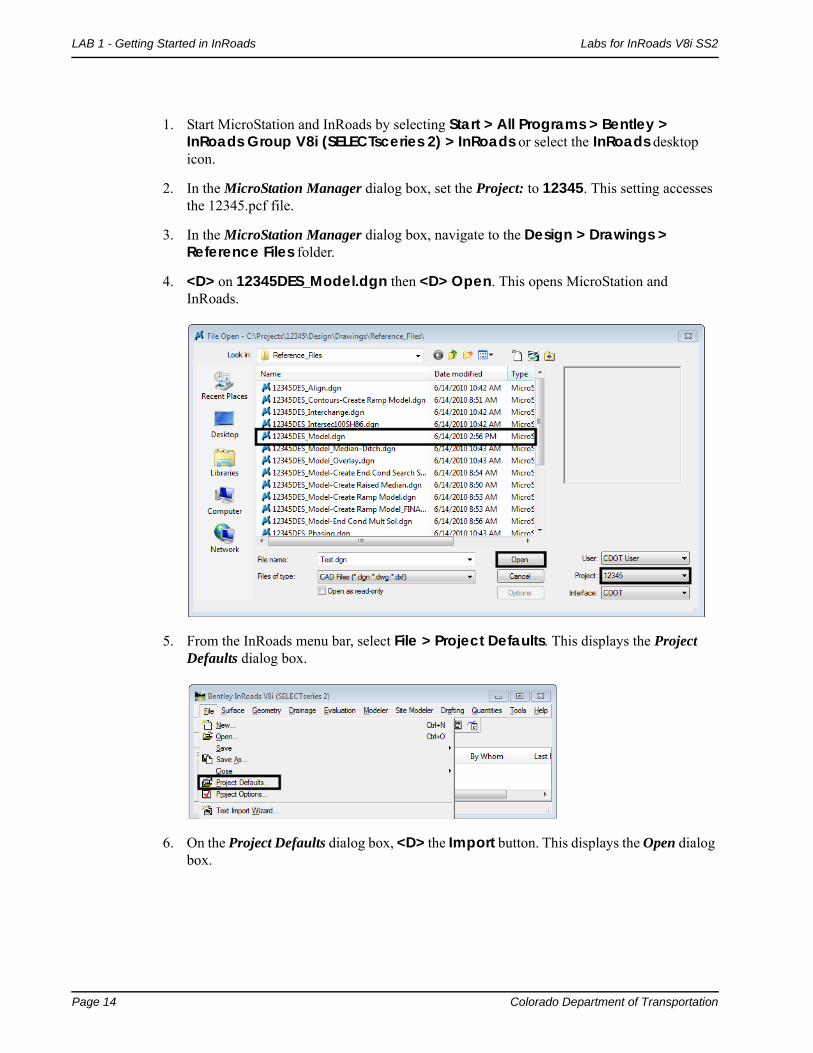
4. <D> on 12345DES_Model.dgn then <D> Open. This opens MicroStation and InRoads.
5. From the InRoads menu bar, select File > Project Defaults. This displays the Project Defaults dialog box.
6. On the Project Defaults dialog box, <D> the Import button. This displays the Open dialog box.

Colorado Department of Transportation Page 15
Labs for InRoads V8i SS2 LAB 1 - Getting Started in InRoads
7. In the Open dialog box, navigate to C:\Workspace\Workspace-CDOT_V8i\ Standards-Global\InRoads\Preferences\ and highlight the CDOT_V8i Disciplines.reg file.
8. <D> Open.
This loads the data into the Project Defaults dialog box. This file only has to be loaded one time. Once loaded, it will work with any project so long as the pcf file is used when starting MicroStation and InRoads.
9. Back on the Set Project Defaults dialog box, set the Configuration Name to CDOT Design Discipline.
Note: Although the Design Discipline is used for this lab, there are project defaults for each of the other disciplines as well.
10. <D> Apply then <D> Close.
Setting the project defaults using this method defines the default locations for both general InRoads resource files and project specific data files. This will make it easier to conform to graphics standards and assist in navigating to the correct project directories when loading or saving data files.
Page 16 Colorado Department of Transportation
LAB 1 - Getting Started in InRoads Labs for InRoads V8i SS2
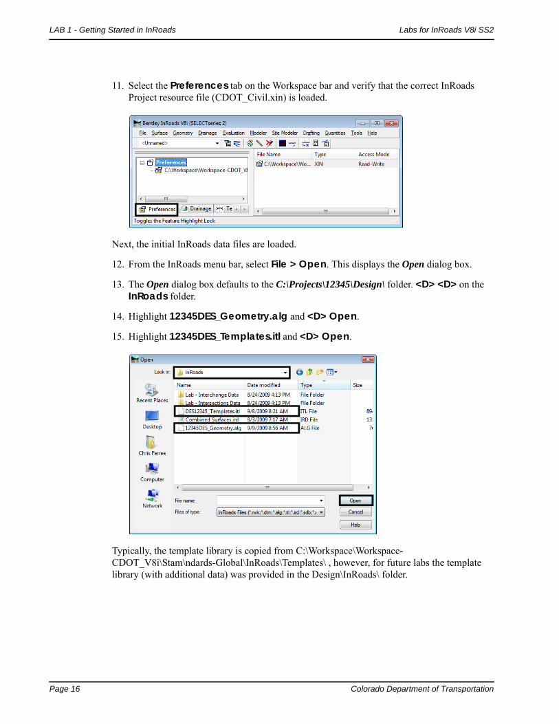
11. Select the Preferences tab on the Workspace bar and verify that the correct InRoads Project resource file (CDOT_Civil.xin) is loaded.
Next, the initial InRoads data files are loaded.
12. From the InRoads menu bar, select File > Open. This displays the Open dialog box.
13. The Open dialog box defaults to the C:\Projects\12345\Design\ folder. <D> <D> on the InRoads folder.
14. Highlight 12345DES_Geometry.alg and <D> Open.
15. Highlight 12345DES_Templates.itl and <D> Open.
Typically, the template library is copied from C:\Workspace\Workspace-CDOT_V8i\Stam\ndards-Global\InRoads\Templates\ , however, for future labs the template library (with additional data) was provided in the Design\InRoads\ folder.
Colorado Department of Transportation Page 17
Labs for InRoads V8i SS2 LAB 1 - Getting Started in InRoads
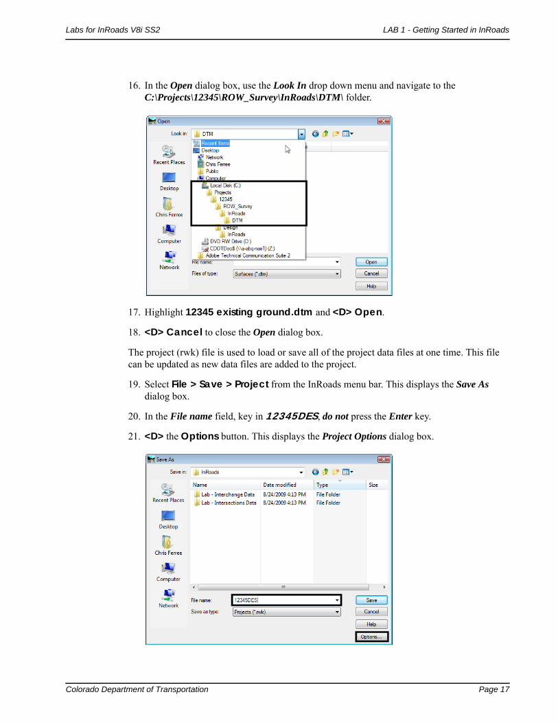
16. In the Open dialog box, use the Look In drop down menu and navigate to the C:\Projects\12345\ROW_Survey\InRoads\DTM\ folder.
17. Highlight 12345 existing ground.dtm and <D> Open.
18. <D> Cancel to close the Open dialog box.
The project (rwk) file is used to load or save all of the project data files at one time. This file can be updated as new data files are added to the project.
19. Select File > Save > Project from the InRoads menu bar. This displays the Save As dialog box.
20. In the File name field, key in 12345DES, do not press the Enter key.
21. <D> the Options button. This displays the Project Options dialog box.

Page 18 Colorado Department of Transportation
LAB 1 - Getting Started in InRoads Labs for InRoads V8i SS2
22. In the Project Options dialog box, toggle on the Update check box for the data files loaded above.
23. <D> OK to dismiss the Project Options dialog box.
24. In the Save As dialog box, <D> Save then <D> Cancel to dismiss the dialog box.
Section Summary:♦ The CDOT_V8i Disciplines.reg file only needs to be imported one time, then it can be
used for any project.
♦ Initial project data is loaded after the project defaults are set up. This data must include an existing ground dtm and may include geometry as well.
♦ Creating a project (rwk) file speeds up the process of loading and saving project data.
Lab 1.3 - Toolbars
This lab demonstrates how the InRoads Interface can be populated with toolbars for easy access to commands. The drop-down menus can be used to select the correct tool, but it may be more convenient to use toolbar icons. All InRoads toolbars can be customized to fit your workflow or personal preferences.
Section Objectives:
♦ Learn how to access addition toolbars used for viewing and reviewing geometry.
♦ Learn how to access and use the Global Scale Factor Add-in
Colorado Department of Transportation Page 19
Labs for InRoads V8i SS2 LAB 1 - Getting Started in InRoads
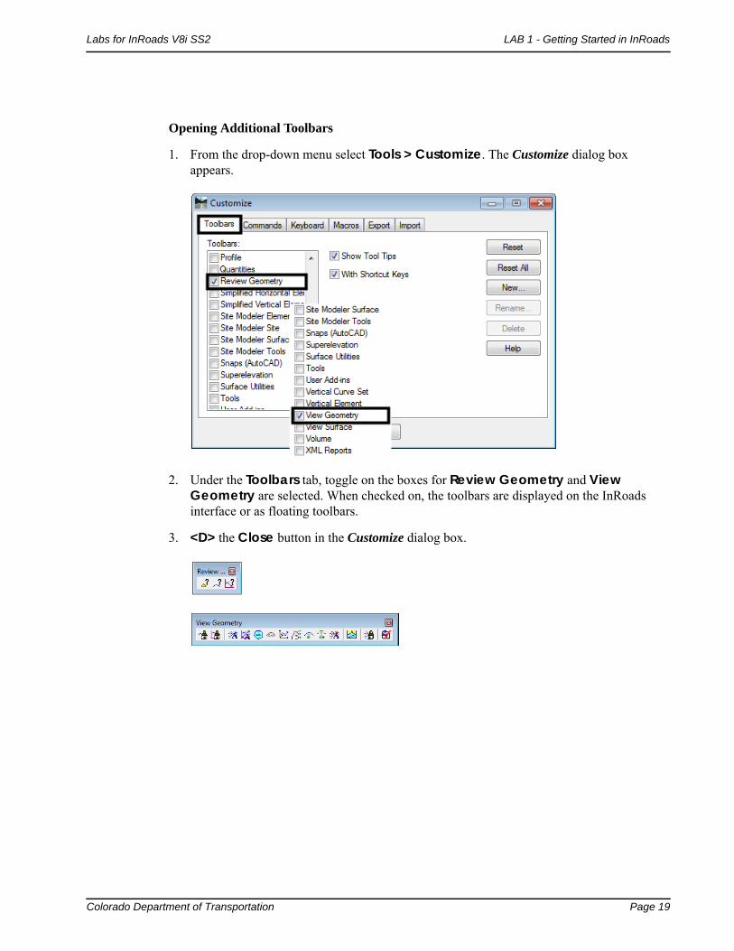
Opening Additional Toolbars
1. From the drop-down menu select Tools > Customize. The Customize dialog box appears.
2. Under the Toolbars tab, toggle on the boxes for Review Geometry and View Geometry are selected. When checked on, the toolbars are displayed on the InRoads interface or as floating toolbars.
3. <D> the Close button in the Customize dialog box.
Page 20 Colorado Department of Transportation
LAB 1 - Getting Started in InRoads Labs for InRoads V8i SS2
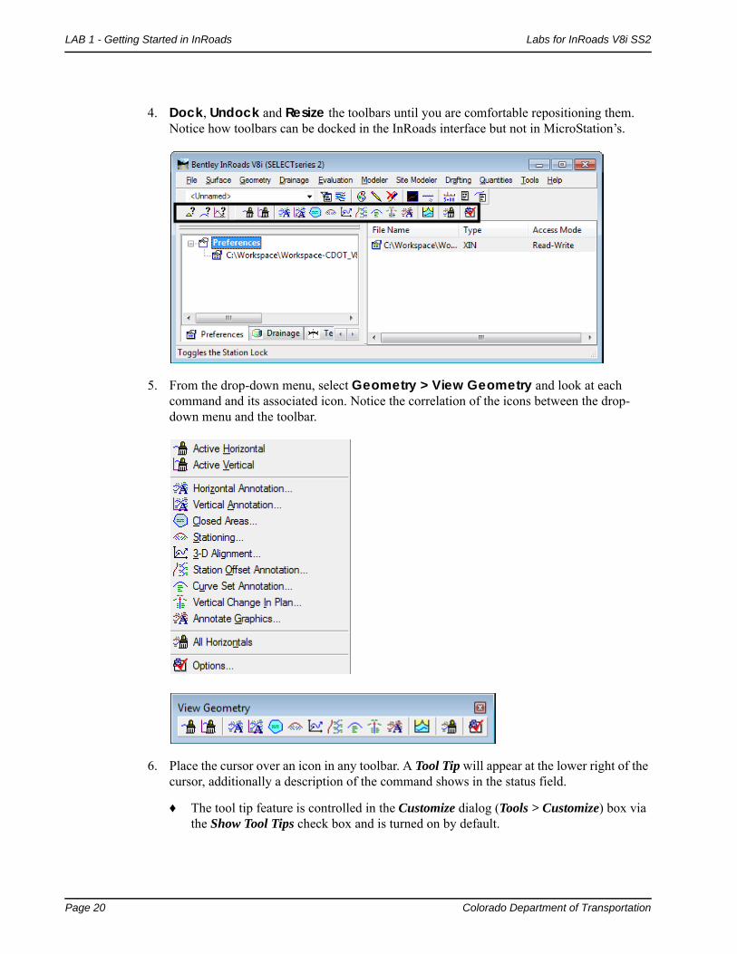
4. Dock, Undock and Resize the toolbars until you are comfortable repositioning them. Notice how toolbars can be docked in the InRoads interface but not in MicroStation’s.
5. From the drop-down menu, select Geometry > View Geometry and look at each command and its associated icon. Notice the correlation of the icons between the drop-down menu and the toolbar.
6. Place the cursor over an icon in any toolbar. A Tool Tip will appear at the lower right of the cursor, additionally a description of the command shows in the status field.
♦ The tool tip feature is controlled in the Customize dialog (Tools > Customize) box via the Show Tool Tips check box and is turned on by default.

Colorado Department of Transportation Page 21
Labs for InRoads V8i SS2 LAB 1 - Getting Started in InRoads
Global Scale Factors
Global scale factors are used to determine the size of displayed text, cells, and linestyles. The global scale factor function can be found under the File > Project Options [Factors] tab. However, enabling the command directly from the menu bar is more efficient.
7. Select Tools > Application Add-ins to display a list of available InRoads commands and functions that can be added to the InRoads interface.
Selecting an item displays a description of the tool(s). The command category shows both the menu location and the InRoads product(s) it can be activated with.
8. Toggle on Global Scale Factor, <D> OK, and Close the dialog box.
9. Select Tools > Global Scale Factors…
10. Set the Text and Cell factors to 100. Set the Line Style factor to 1.
11. <D> Apply then Close.
These settings are multipliers for displayed graphics. Generally the values should be set to correspond to the plotting scale factor. As with most MicroStation or InRoads commands, you have the option of either enabling or disabling the lock symbol to input values universally or individually.
Page 22 Colorado Department of Transportation
LAB 1 - Getting Started in InRoads Labs for InRoads V8i SS2
Note: Global Scale Factors apply to all InRoads data displayed. This includes the display of features from a DTM. While it is possible to ‘regenerate’ plan view topography by displaying the features from a survey-supplied DTM, this is NOT an accepted workflow. The reason for this is because any attributes collected in the field are processed by InRoads Survey. These attributes (rotation, Q & Z reports, etc) are not stored in the DTM and the resulting graphics will be incomplete and/or incorrect without being evident.
Section Summary:♦ Students learned how to access the Review Geometry and View Geometry toolbars and
how they compare with the pull-down menus.
♦ Students learned how to access the Global Scale Factors Add-in and how the global scale factors impacts graphics generated from InRoads commands.
Lab 1.4 - Locks
This lab illustrates the use of the Feature Filter lock, Pen/Pencil Mode, and Station Lock.
Section Objectives:
♦ Demonstrate how the Feature Filter lock reduces items in list boxes.
♦ Demonstrate the difference between Pen and Pencil mode.
♦ Demonstrate the effects of Station lock.
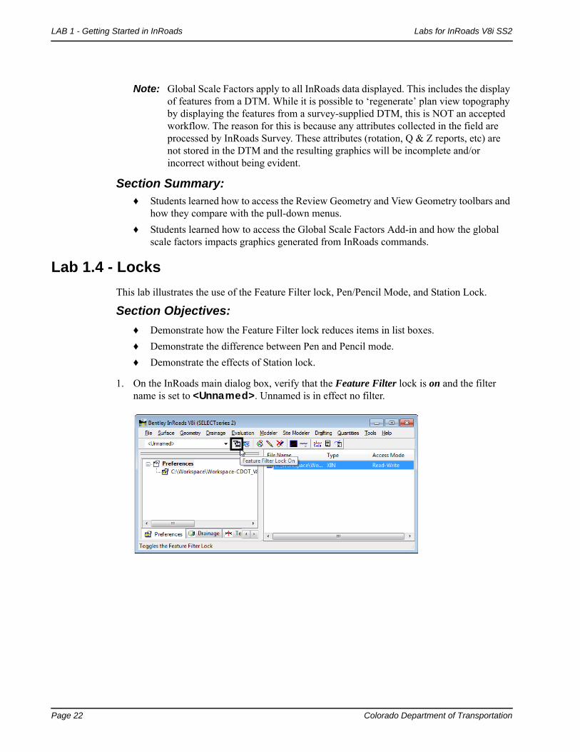
1. On the InRoads main dialog box, verify that the Feature Filter lock is on and the filter name is set to <Unnamed>. Unnamed is in effect no filter.
Colorado Department of Transportation Page 23
Labs for InRoads V8i SS2 LAB 1 - Getting Started in InRoads
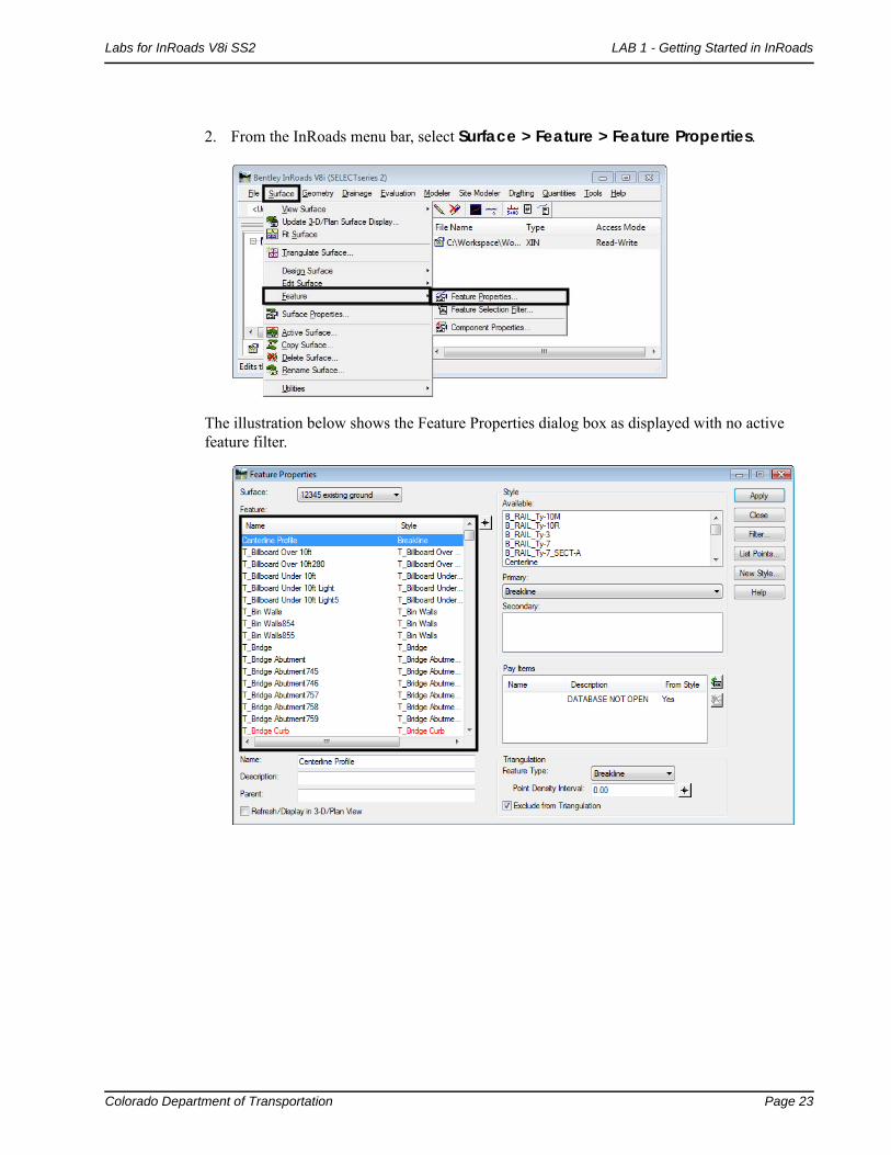
2. From the InRoads menu bar, select Surface > Feature > Feature Properties.
The illustration below shows the Feature Properties dialog box as displayed with no active feature filter.
Page 24 Colorado Department of Transportation
LAB 1 - Getting Started in InRoads Labs for InRoads V8i SS2
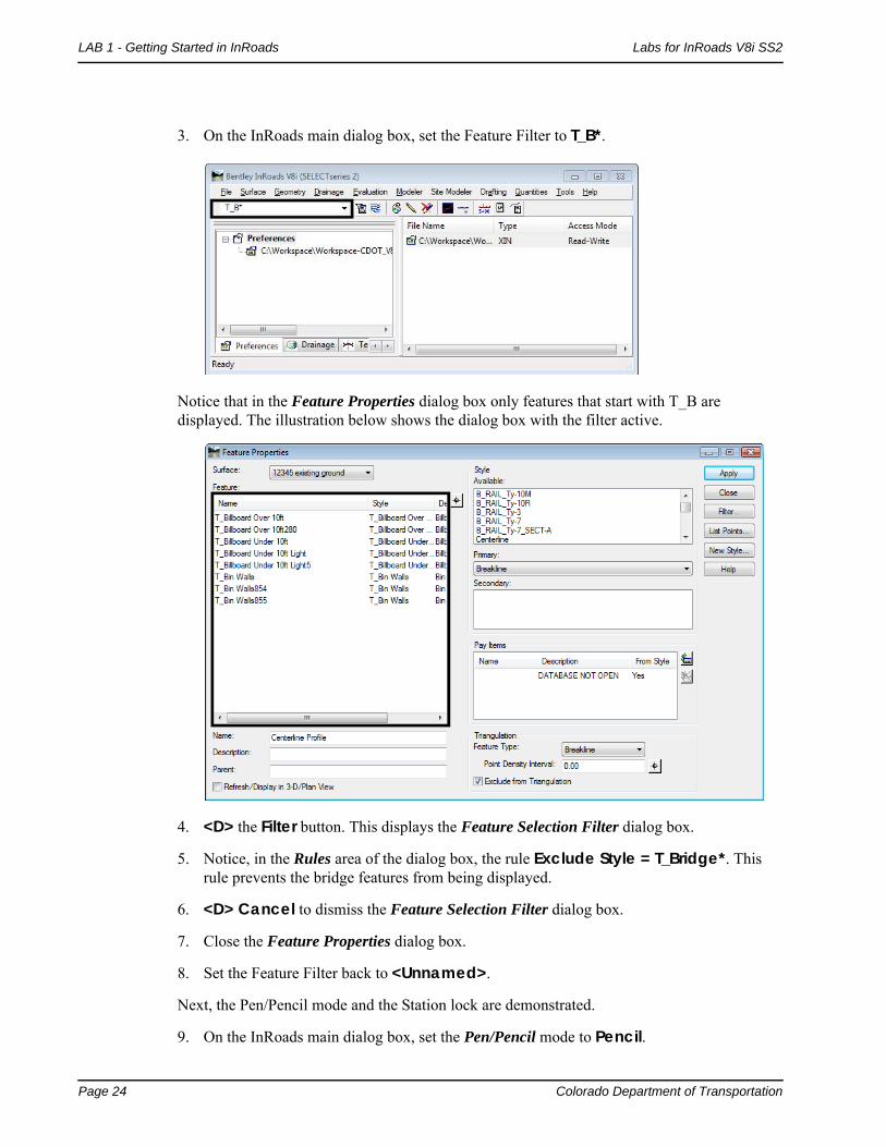
3. On the InRoads main dialog box, set the Feature Filter to T_B*.
Notice that in the Feature Properties dialog box only features that start with T_B are displayed. The illustration below shows the dialog box with the filter active.
4. <D> the Filter button. This displays the Feature Selection Filter dialog box.
5. Notice, in the Rules area of the dialog box, the rule Exclude Style = T_Bridge*. This rule prevents the bridge features from being displayed.
6. <D> Cancel to dismiss the Feature Selection Filter dialog box.
7. Close the Feature Properties dialog box.
8. Set the Feature Filter back to <Unnamed>.
Next, the Pen/Pencil mode and the Station lock are demonstrated.
9. On the InRoads main dialog box, set the Pen/Pencil mode to Pencil.

Colorado Department of Transportation Page 25
Labs for InRoads V8i SS2 LAB 1 - Getting Started in InRoads
10. Turn the Station lock off.
11. <D> the Geometry tab in the InRoads Explorer and verify that the SH 86 alignment is active.
12. From the InRoads menu bar, select Geometry > View Geometry > Stationing.
13. On the View Stationing dialog box, <D> Apply.

Page 26 Colorado Department of Transportation
LAB 1 - Getting Started in InRoads Labs for InRoads V8i SS2
14. Examine the stationing displayed. The regular stations end in “+80”. This is not CDOT standard.
15. On the InRoads main dialog box, turn the Station lock on.
16. Redisplay the Stationing.
17. Examine the stationing displayed. There are two things to note. First, the original stationing was deleted and the new stationing was displayed. This is a result of the Pencil mode. Second, the stations end in “+00” in even 500 foot intervals.
Colorado Department of Transportation Page 27
Labs for InRoads V8i SS2 LAB 1 - Getting Started in InRoads
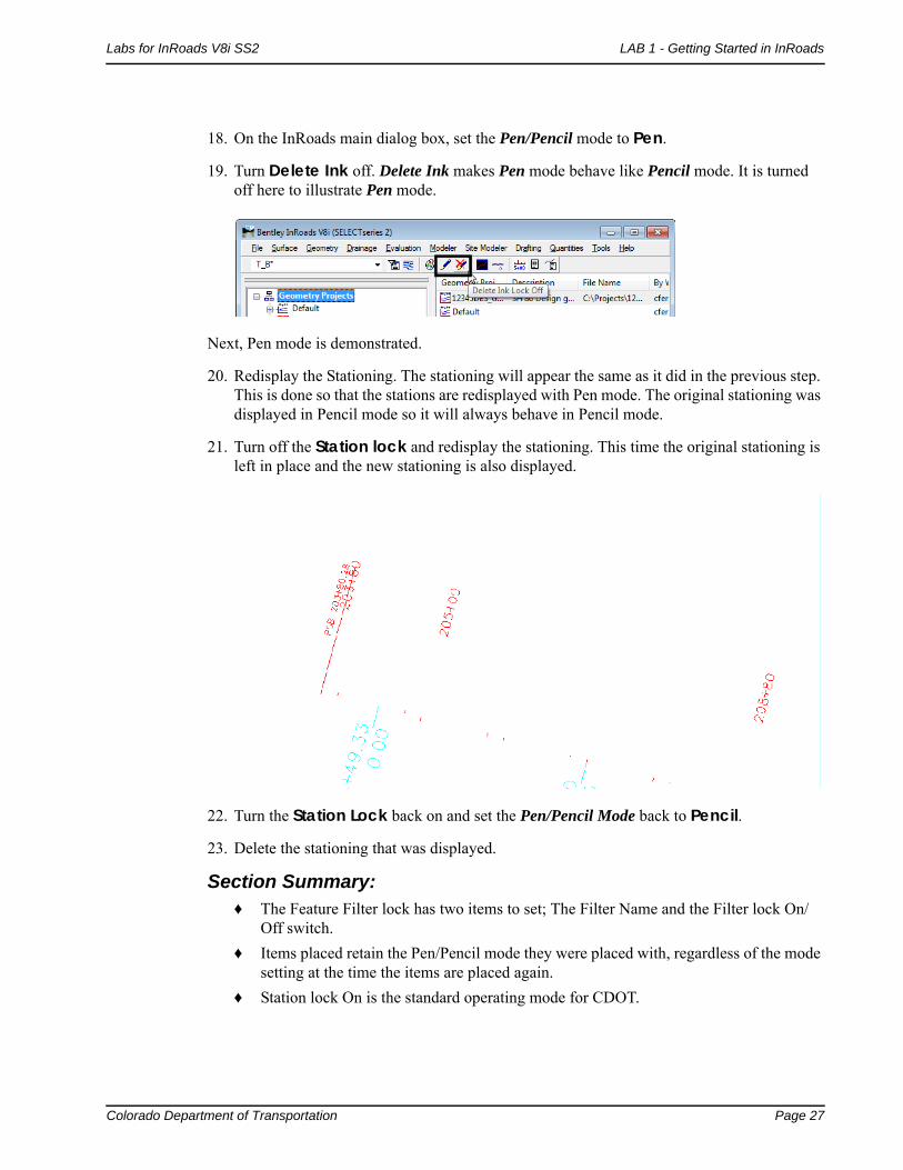
18. On the InRoads main dialog box, set the Pen/Pencil mode to Pen.
19. Turn Delete Ink off. Delete Ink makes Pen mode behave like Pencil mode. It is turned off here to illustrate Pen mode.
Next, Pen mode is demonstrated.
20. Redisplay the Stationing. The stationing will appear the same as it did in the previous step. This is done so that the stations are redisplayed with Pen mode. The original stationing was displayed in Pencil mode so it will always behave in Pencil mode.
21. Turn off the Station lock and redisplay the stationing. This time the original stationing is left in place and the new stationing is also displayed.
22. Turn the Station Lock back on and set the Pen/Pencil Mode back to Pencil.
23. Delete the stationing that was displayed.
Section Summary:♦ The Feature Filter lock has two items to set; The Filter Name and the Filter lock On/
Off switch.
♦ Items placed retain the Pen/Pencil mode they were placed with, regardless of the mode setting at the time the items are placed again.
♦ Station lock On is the standard operating mode for CDOT.

Page 28 Colorado Department of Transportation
LAB 1 - Getting Started in InRoads Labs for InRoads V8i SS2
Lab 1.5 - Precision and Factors
Precision affects the number of decimal places used in InRoads dialog boxes. Factors determine the size of graphic elements displayed by InRoads. This lab illustrates these affects.
First, precision is examined. The Review Horizontal Alignment command is used to illustrate the affects.
1. In the InRoads Explorer, select the Geometry tab.
2. Expand the 12345DES_Geometry geometry project to show the SH 86 alignment.
3. From the InRoads menu bar, select File > Project Options.
4. Verify that the Precision tab is active.
Notice that the precision for Station is set to 0.12.
5. In the InRoads Explorer, <R> on the SH 86 alignment and select Review from the right click menu.

Colorado Department of Transportation Page 29
Labs for InRoads V8i SS2 LAB 1 - Getting Started in InRoads
In the Review Horizontal Alignment dialog box, notice that the stations have 2 decimal places.
6. Close the Review Horizontal Alignment dialog box.
7. In the Project Options dialog box, change the Station precision to 0.1234.
8. <D> Apply.

Page 30 Colorado Department of Transportation
LAB 1 - Getting Started in InRoads Labs for InRoads V8i SS2
9. Redisplay the Review Horizontal Alignment dialog box for SH 86.
Notice that the stations now show 4 decimal places. Next the affects of factors is demonstrated.
10. Reset the Station precision back to 0.12.
11. On the Project Options dialog box, <D> the Factors tab. Notice that the Text Scale Factor is set to 100.
12. From the InRoads main menu, select Geometry > View Geometry > Stationing.
13. On the View Stationing dialog box, <D> Apply.
14. Zoom in on a station and note the size of the text.

Colorado Department of Transportation Page 31
Labs for InRoads V8i SS2 LAB 1 - Getting Started in InRoads
15. On the Project Options dialog box, key in 50 for the Text Scale Factor and <D> Apply.
16. Redisplay the stationing and notice the change in the text size. The illustration below shows the difference.
17. Reset the Text Scale Factor to 100.
18. Delete all of the graphics displayed in the drawing, then close InRoads and MicroStation.
Section Summary:♦ Precision controls the decimal places displayed in InRoads dialog boxes only.
♦ Factors control the size of text, cells, and linestyles displayed by InRoads.
♦ The Linestyle Scale should be set to 1, Text and Cell scales should be set to the plot scale.
Chapter Summary:
Start a project by creating the directory for the project.
Project defaults make it easier to Open and Save project data files.
Locks affect the way InRoads works and displays information. These should be set as desired prior to work on the project.
Precision and Factors affect displays in InRoads dialog boxes and items placed by InRoads. These should be set as desired prior to work on the project

Page 32 Colorado Department of Transportation
LAB 1 - Getting Started in InRoads Labs for InRoads V8i SS2


![Skaffold - storage.googleapis.com · [getting-started getting-started] Hello world! [getting-started getting-started] Hello world! [getting-started getting-started] Hello world! 5.](https://static.fdocuments.in/doc/165x107/5ec939f2a76a033f091c5ac7/skaffold-getting-started-getting-started-hello-world-getting-started-getting-started.jpg)