Lab 9 Simple Circuits - University of...
12
Lab 9 – Simple Circuits Name _________________________________ Date ____________________________ University of Virginia Physics Department 1 Lab 9 Simple Circuits Relevant SOLs: PS.1k, PS.6b, PS.6c, PS.11a, 3.1a, 3.1j, 4.1a, 4.3a, 4.3b, 4.3d, 6.2e Overview In this series of investigations you will learn how to construct a circuit and analyze some of the different ways that circuit elements can be connected to each other. You will be using wires to connect your circuit elements, but in many devices, conductive material is painted onto a circuit board to connect devices as in Fig. 9.0.1. Fig. 9.0.1 The light colored lines are conductive and serve as the wires on this circuit board. (Image from wisegeek.org)
Transcript of Lab 9 Simple Circuits - University of...

Lab 9 – Simple Circuits
Name _________________________________ Date ____________________________
University of Virginia Physics Department
1
Lab 9 Simple Circuits
Relevant SOLs: PS.1k, PS.6b, PS.6c, PS.11a, 3.1a, 3.1j, 4.1a, 4.3a, 4.3b, 4.3d, 6.2e Overview
In this series of investigations you will learn how to construct a circuit and analyze some of the different ways that circuit elements can be connected to each other.
You will be using wires to connect your circuit elements, but in many devices, conductive material is painted onto a circuit board to connect devices as in Fig. 9.0.1.
Fig. 9.0.1 The light colored lines are conductive and serve as the wires on this circuit board. (Image from wisegeek.org)

Lab 9 – Simple Circuits
Name _________________________________ Date ____________________________
University of Virginia Physics Department
2
Activity 9 - 1: Lighting a Bulb
Objective: Build a complete circuit that will light a bulb. SOLs: PS.1k, PS.6b, PS.6c, PS.11a, 3.1a, 3.1j, 4.1a, 4.3a, 4.3b, 4.3d, 6.2e Materials: ● Light bulb ● 1.5 V D Cell Battery ● Wire with alligator clip ends
Prediction: In this Activity, you will be using a single wire to light a bulb. Do you think that the bulb in Fig. 9.1.1 will light up? Why or why not? ____________________________
Fig. 9.1.1 Observation and Procedure
1. Connect your battery, wire, and bulb as in Fig. 9.1.1. Does the bulb light up? __
2. Hold the light bulb and touch the end of the bulb against the free end of the battery as in Fig. 9.1.2. Does the bulb light up? Explain___________________

Lab 9 – Simple Circuits
Name _________________________________ Date ____________________________
University of Virginia Physics Department
3
Fig. 9.1.2
3. If your bulb did not light up in either step it is possible that it is damaged. If this
might be the case, consult with your teacher or try a different bulb.
4. Try other ways of hooking up the battery, bulb, and wire. Sketch one additional way that allows the bulb to light up. (Hint, try switching where the wire is connected to the bulb or battery).
Explanation
1. Explain what happened in Step 1 and provide an explanation. ______________
2. Explain what happened in Step 2 and provide an explanation. _______________
3. When the bulb lit up, there are electric charges moving around the circuit. Make a general statement about the properties of a circuit that are necessary to make charges flow. _____________________________________________________

Lab 9 – Simple Circuits
Name _________________________________ Date ____________________________
University of Virginia Physics Department
4
Activity 9 - 2: Building a Circuit
Objective: Construct a simple circuit to test continuity of the current flow. SOLs: PS.1k, PS.6b, PS.6c, PS.11a, 3.1j, 4.3b, 4.3d, 6.2e Materials: ● Battery holder with leads ● Light bulb ● Alligator wires ● Light bulb holder ● 1.5 V battery
Procedure
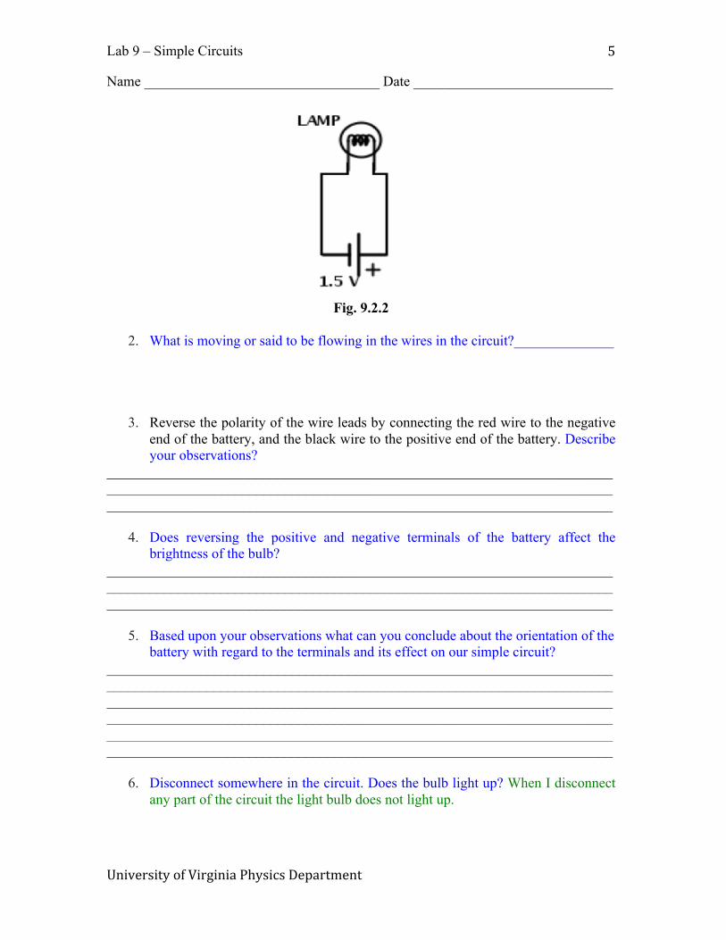
1. Place the battery in the battery holder, and connect the red wire with alligator clips to the positive end of the battery and the other end of the red wire to the light bulb. Connect the black wire to the negative end of the battery and the other end of the black wire to the other side of the light bulb. See Fig. 9.2.1 and Fig. 9.2.2. Describe your observations. _____________________________________
Fig. 9.2.1
Lab 9 – Simple Circuits
Name _________________________________ Date ____________________________
University of Virginia Physics Department
5
Fig. 9.2.2
2. What is moving or said to be flowing in the wires in the circuit?______________
3. Reverse the polarity of the wire leads by connecting the red wire to the negative end of the battery, and the black wire to the positive end of the battery. Describe your observations?
_____________________________________________________________________________________________________________________________________________________________________________________________________________________
4. Does reversing the positive and negative terminals of the battery affect the brightness of the bulb?
_____________________________________________________________________________________________________________________________________________________________________________________________________________________
5. Based upon your observations what can you conclude about the orientation of the battery with regard to the terminals and its effect on our simple circuit?
_____________________________________________________________________________________________________________________________________________________________________________________________________________________ _____________________________________________________________________________________________________________________________________________________________________________________________________________________
6. Disconnect somewhere in the circuit. Does the bulb light up? When I disconnect any part of the circuit the light bulb does not light up.

Lab 9 – Simple Circuits
Name _________________________________ Date ____________________________
University of Virginia Physics Department
6
7. Now connect three batteries in series with the help of another battery holder. See Fig. 9.2.3. Note the brightness of the bulb. Explain why the brightness of the bulbs changes again as you added more batteries.
_____________________________________________________________________________________________________________________________________________________________________________________________________________________ _____________________________________________________________________________________________________________________________________________________________________________________________________________________
Fig 9.2.3 Each battery has a voltage of 1.5 V. When connected in series, the voltages
add together.
8. What can be inferred about the relationship between voltage and current assuming brightness as an indication of current?
_____________________________________________________________________________________________________________________________________________________________________________________________________________________
9. Now connect three bulbs in series as shown in Fig. 9.2.4 and Fig. 9.2.5. Note that the black alligator clip is not yet connected in the picture because we want to use it as a switch to turn the bulbs on and off. Compare the brightness of each bulb with that of one bulb connected to one battery as in step 1. Record your observations here. Do you see any similarity between the two cases? Why do you think that happens?
_____________________________________________________________________________________________________________________________________________________________________________________________________________________ _____________________________________________________________________________________________________________________________________________________________________________________________________________________

Lab 9 – Simple Circuits
Name _________________________________ Date ____________________________
University of Virginia Physics Department
7
Fig. 9.2.4
Fig. 9.2.5
10. Assume each bulb has the same amount of resistance against electricity. When
more bulbs are added in series, how does the resistance change?
11. How does the current change in response to that? _____________________________________________________________________________________________________________________________________________________________________________________________________________________
12. Now connect three bulbs in parallel as shown in Fig. 9.2.6 and Fig. 9.2.7 Note that the white alligator clip in the picture is not yet connected to the bulbs because we want to use it as a switch to turn the bulbs on and off.

Lab 9 – Simple Circuits
Name _________________________________ Date ____________________________
University of Virginia Physics Department
8
Fig. 9.2.6
Fig. 9.2.7
13. How does the brightness of each bulb compare to the earlier case in Step 7 when
one bulb was connected to three batteries? Explain why. _____________________________________________________________________________________________________________________________________________________________________________________________________________________
14. How does the voltage across each bulb change as more bulbs are added in parallel?

Lab 9 – Simple Circuits
Name _________________________________ Date ____________________________
University of Virginia Physics Department
9
_____________________________________________________________________________________________________________________________________________________________________________________________________________________
15. As bulbs are added in parallel, does the total current in the circuit increase or decrease? Explain why.
_____________________________________________________________________________________________________________________________________________________________________________________________________________________ _____________________________________________________________________________________________________________________________________________________________________________________________________________________
Lab 9 – Simple Circuits
Name _________________________________ Date ____________________________
University of Virginia Physics Department
10
Activity 9 – 3: Ohm’s Law V = IR Objective: Explore Ohm’s Law Materials:
• Breadboard • Multimeter • 100 Ω resistors • Battery holder • Alligator Wires • Jumper wires • 3 D size batteries
Procedure:
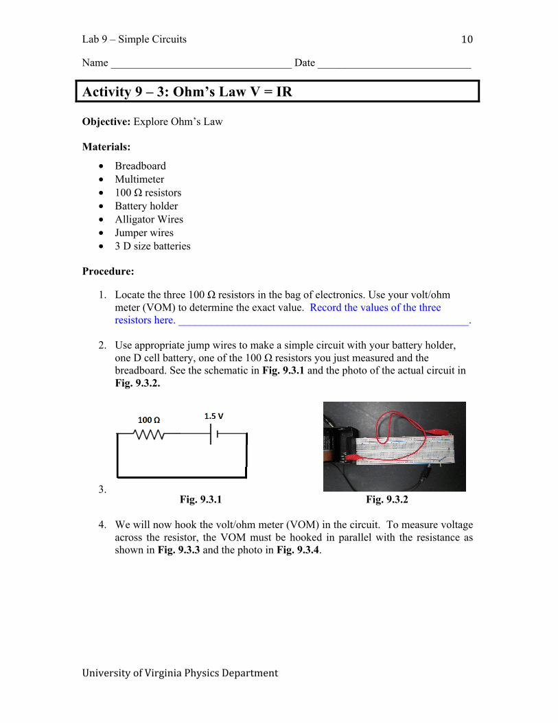
1. Locate the three 100 Ω resistors in the bag of electronics. Use your volt/ohm meter (VOM) to determine the exact value. Record the values of the three resistors here. _____________________________________________________.
2. Use appropriate jump wires to make a simple circuit with your battery holder, one D cell battery, one of the 100 Ω resistors you just measured and the breadboard. See the schematic in Fig. 9.3.1 and the photo of the actual circuit in
Fig. 9.3.2.
3. Fig. 9.3.1 Fig. 9.3.2
4. We will now hook the volt/ohm meter (VOM) in the circuit. To measure voltage
across the resistor, the VOM must be hooked in parallel with the resistance as shown in Fig. 9.3.3 and the photo in Fig. 9.3.4.

Lab 9 – Simple Circuits
Name _________________________________ Date ____________________________
University of Virginia Physics Department
11
Fig. 9.3.3
Fig. 9.3.4
5. We will now determine the voltage and the current in the circuit. Remember to
start your VOM on the HIGHEST voltage/current scale when making measurements. Failure to do so may damage your VOM. Measure the voltage across the resistor and tabulate it in Table 9.3.1 in the row and column for 1 battery.

Lab 9 – Simple Circuits
Name _________________________________ Date ____________________________
University of Virginia Physics Department
12
6. To measure current through the resistor, the VOM must be hooked in series with the resistor. See Fig. 9.3.5 and Fig 9.3.6 as an example of how to connect up VOM as ammeter (A) in series to measure current. Record your values in volts and amps in Table 9.3.1. Make sure the units are correct. Ask your instructor for confirmation here.
Fig. 9.3.5 Fig. 9.3.6
7. Now place two batteries in your circuit. We will hook another battery holder in series with the first battery holder. Record the voltage and the current in the circuit in Table 9.3.1. Then repeat with 3 batteries. Record the values in Table 9.3.1.
Number of Batteries in series
Measured Voltage (V)
Measured Current (A)
Measured Resistance (Ω)
Calculated Voltage using Ohms Law V=I*R
1 2 3
Table 9.3.1
8. In the final column of Table 9.3.1, calculate the voltage by multiplying the measured Current (I) times your measured Resistance (R).
9. How does the calculated voltage from Ohms Law compare with the measured
voltage? _________________________________________________________ 9. Explain why you expect see a difference between Ohms law and the measured value.____________________________________________________________