Lab 7: Faraday Effect and Lenz’ law Physics 208 Name Section · PDF fileLab 7: Faraday...
13
Lab 7: Faraday Effect and Lenz’ law Physics 208 Name_____________________________ Section___________ This sheet is the lab document your TA will use to score your lab. It is to be turned in at the end of lab. To receive full credit you must use complete sentences and explain your reasoning clearly. What’s this lab about? In this lab you investigate effects arising from magnetic fields that vary in time. There are three parts to the lab: PART A Move a bar magnet through a coil of wire to investigate induced EMF and current. PART B Drop a strong magnet through various metal tubes to investigate the forces caused by induced current. PART C Quantitatively investigate Faraday’s law by using a time-dependent current through a coil of wire to generate a time-dependent magnetic field. Why are we doing this? Time-varying magnetic fields are all around us. We most often see effects generated by physically moving permanent- or electro-magnets, or by changing the current through an electromagnet. The EMF, electric currents, and forces generated by these can be quite impressive, even enough to help brake a subway car. What should I be thinking about before I start this lab? Last week in lab you looked at the properties of static (time-independent) magnetic fields, produced by permanent magnets and by loops of current. These static fields varied throughout space in direction and magnitude, but were the same at all times. This week you discover some very unusual properties of time-varying magnetic fields. In particular, a time-varying magnetic field produces an electric field. This means that there is more than one way to make an electric field. ***Any safety issues?*** Yes , yes , yes !!! The permanent disk magnet you use in this lab is EXTREMELY powerful. As long as you have only one, you are reasonably safe. But two of them attracting together can pinch your skin between them quite painfully. Two of the disk magnets stuck to each other are almost impossible to get apart. ALSO , keep the magnet away from your credit cards – it will erase them!
Transcript of Lab 7: Faraday Effect and Lenz’ law Physics 208 Name Section · PDF fileLab 7: Faraday...
Lab 7: Faraday Effect and Lenz’ law Physics 208 Name_____________________________ Section___________ This sheet is the lab document your TA will use to score your lab. It is to be turned in at the end of lab. To receive full credit you must use complete sentences and explain your reasoning clearly. What’s this lab about? In this lab you investigate effects arising from magnetic fields that vary in time. There are three parts to the lab: PART A Move a bar magnet through a coil of wire to investigate induced EMF and current. PART B Drop a strong magnet through various metal tubes to investigate the forces caused
by induced current. PART C Quantitatively investigate Faraday’s law by using a time-dependent current through a
coil of wire to generate a time-dependent magnetic field. Why are we doing this? Time-varying magnetic fields are all around us. We most often see effects generated by physically moving permanent- or electro-magnets, or by changing the current through an electromagnet. The EMF, electric currents, and forces generated by these can be quite impressive, even enough to help brake a subway car.
What should I be thinking about before I start this lab? Last week in lab you looked at the properties of static (time-independent) magnetic fields, produced by permanent magnets and by loops of current. These static fields varied throughout space in direction and magnitude, but were the same at all times.
This week you discover some very unusual properties of time-varying magnetic fields. In particular, a time-varying magnetic field produces an electric field. This means that there is more than one way to make an electric field.
***Any safety issues?*** Yes, yes, yes!!! The permanent disk magnet you use in this lab is EXTREMELY powerful. As long as you have only one, you are reasonably safe. But two of them attracting together can pinch your skin between them quite painfully. Two of the disk magnets stuck to each other are almost impossible to get apart.
ALSO, keep the magnet away from your credit cards – it will erase them!
2
A. Induced fields in a loop of wire
You can make an electric field with electric charges, as around a point charge or between charged capacitor plates, but also an electric field accompanies a time-varying magnetic field. Wherever there is a time-varying magnetic field, there is also an electric field. For instance, waving a permanent magnet in the air produces an electric field.
In this case the electric field is said to be induced by the time-varying magnetic field. This induced electric field exerts a force on charged particles, and so work is required to move a charged particle against this field. Pretty much like the electric fields we’ve worked with before, except that there aren’t any electric charges around producing this electric field.
A simple way to measure this induced electric field is to put a piece of wire where you want to measure the electric field. At any point in a conductor where there is an electric field, there is also a current, according to
€
j =σ
E , where
€
j is the current
density,
€
E is the electric field, and
€
σ is the conductivity.
This means that there can be an electric field in the wire, and a current in the wire, without a battery anywhere. Faraday’s law: Faraday discovered a quantitative relation between the induced electric field and the time-varying magnetic field. He found that the EMF around a closed loop is equal to the negative of the time rate of
change of the magnetic flux through a surface bounded by the loop:
€
ε = −dΦdt
.
The EMF around a closed loop represents the work/Coulomb required for you to move a positive charge around that closed loop.

3
A2. First you measure the EMF induced in coil of wire by a changing magnetic flux. You will start by using the 800 turn coil on your lab table. Remember that this induced EMF will cause a current to flow in the wire. So connect the 800 turn coil to the Digital Multimeter (DMM), making sure that the DMM is set to measure current.
The long arrow on the coil indicates that the coil is wound clockwise from the bottom terminal to the top terminal
Connect the top terminal to the red terminal of the DMM and the bottom terminal to the black terminal for this measurement. Note that the DMM displays a positive number when current flows into its red terminal and out of its black terminal.
Take the NdFeB disk magnet and hold it on top of the coil. Pull it away quickly, watching the current on the DMM. Do the other combinations indicated in the ‘motion’ column below, and fill in the ‘Dir of induced current’ column based on your measurements.
Motion Sign of flux
Sign of change in flux
Dir of induced current
(CW/CCW)
Sign of flux from current
Sign of voltage diff. Vred-Vblack
N pole down, pull away from coil
N pole down, push toward coil
S pole down, pull away from coil
S pole down, push toward coil
Fill in the rest the first four columns of the table. For the sign of the flux, define a
positive flux through the coil as produced by a magnet field directed down through the coil.
A3. Explain how this table is consistent or inconsistent with Lenz’ law.
Red
Black
4
A4. Now switch the DMM to voltmeter mode on auto scale, and fill in the fourth column of the table.
A5. You now make a measurement of the EMF with the computer. Plug the coil
directly into channel A of the Pasco interface. Click on the LabSettings1 file from the course web site. Take data by holding the disk magnet directly above the coil as before, and pull the magnet very quickly upward away from the coil. Do this several times while recording the data, practicing until you get a consistent peak.
What is the value of the peak voltage? How does it depend on how fast you pull the magnet away? Explain
A6. Now measure the induced EMF in the 400-turn coil using the computer. Try to pull
your magnet away in the same way as you did with the 800-turn coil. How does your peak voltage compare to that measured in the 800-turn coil? Explain.
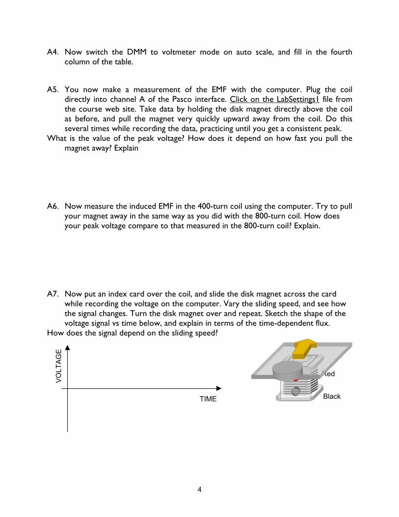
A7. Now put an index card over the coil, and slide the disk magnet across the card
while recording the voltage on the computer. Vary the sliding speed, and see how the signal changes. Turn the disk magnet over and repeat. Sketch the shape of the voltage signal vs time below, and explain in terms of the time-dependent flux.
How does the signal depend on the sliding speed?
Red
Black TIME
VO
LTA
GE

5
A credit card swipe is based on the effect you just demonstrated in A7. The magnetic strip on the back is made up of many tiny magnetic particles acting as bar magnets. A tiny coil generates a current from the changing flux, reading out a string of 1’s and 0’s corresponding to N and S orientation of the magnetic particles that encode information about you. There is a card swipe attached to the computer by
the printer. It behaves as a keyboard, and will type whatever information is on your card into an open word-processing program.
A8. Swipe your card and see what information is on there. (Close the window and open a new one when you are done!)
What is the slowest speed (cm/s) at which the card swipe works? Why does the swipe speed matter?
There are three tracks of information on the stripe, arranged as below. You can’t see the individual tracks: they are just different defined regions of the magnetic strip.
The first track can hold numbers and letters: it starts with a “%” and ends with a “?”. On a credit card you’ll probably find your account # and name.
The second track can hold only numbers: it starts with a “;” and ends with a “?”. You’ll probably find your acct. #, expiration date, etc here.
The third track isn’t used very often: it starts with a “+” and ends with a “?”. The read head has three coils with the correct spacing to pick up the three tracks of
magnetically encoded information. Circuitry then translates the bits into numbers and letters that you see on the screen.
Track 1
Track 2
Track 3
Three-track read head
Just what might be on your credit card…
Swipe Motion
6
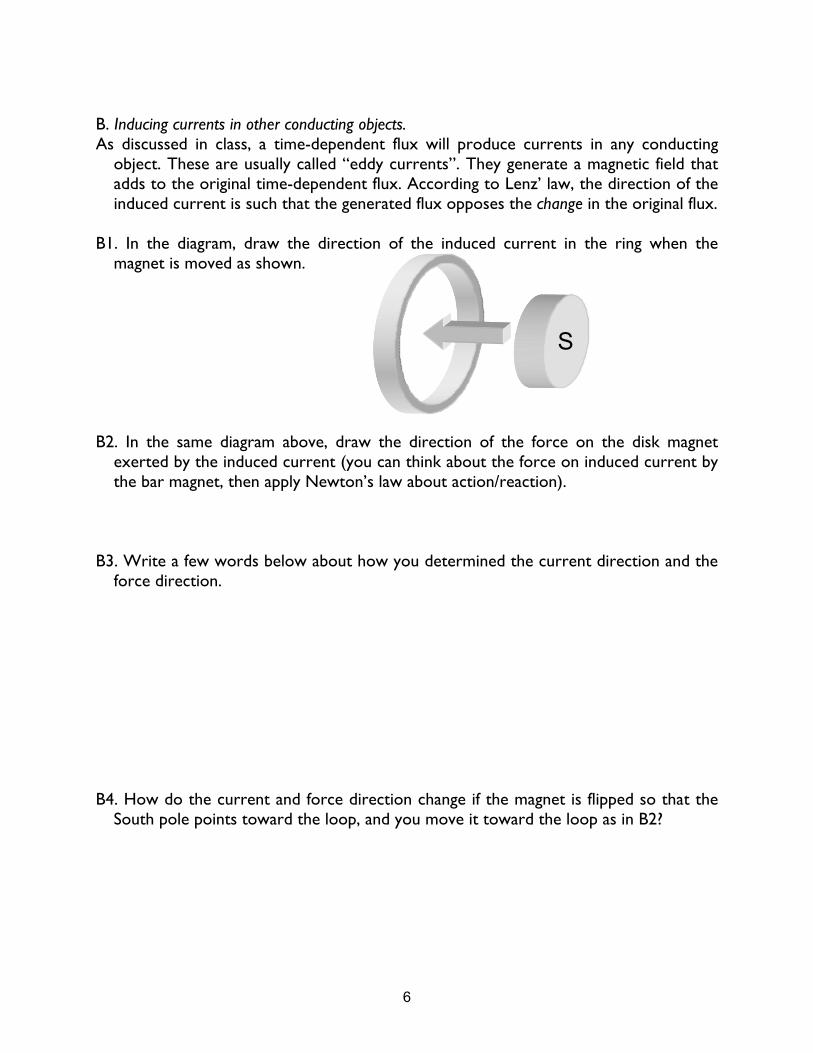
B. Inducing currents in other conducting objects. As discussed in class, a time-dependent flux will produce currents in any conducting
object. These are usually called “eddy currents”. They generate a magnetic field that adds to the original time-dependent flux. According to Lenz’ law, the direction of the induced current is such that the generated flux opposes the change in the original flux.
B1. In the diagram, draw the direction of the induced current in the ring when the
magnet is moved as shown. B2. In the same diagram above, draw the direction of the force on the disk magnet
exerted by the induced current (you can think about the force on induced current by the bar magnet, then apply Newton’s law about action/reaction).
B3. Write a few words below about how you determined the current direction and the
force direction. B4. How do the current and force direction change if the magnet is flipped so that the
South pole points toward the loop, and you move it toward the loop as in B2?
S
7
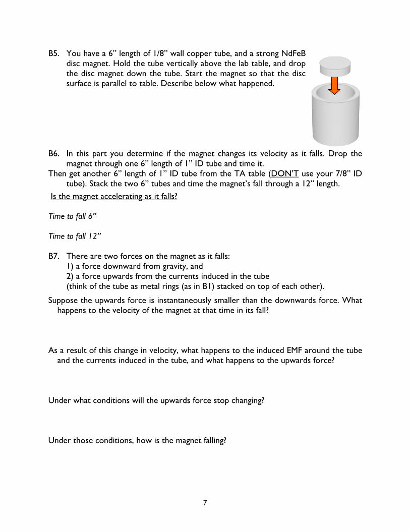
B5. You have a 6” length of 1/8” wall copper tube, and a strong NdFeB disc magnet. Hold the tube vertically above the lab table, and drop the disc magnet down the tube. Start the magnet so that the disc surface is parallel to table. Describe below what happened.
B6. In this part you determine if the magnet changes its velocity as it falls. Drop the
magnet through one 6” length of 1” ID tube and time it. Then get another 6” length of 1” ID tube from the TA table (DON’T use your 7/8” ID
tube). Stack the two 6” tubes and time the magnet’s fall through a 12” length.
Is the magnet accelerating as it falls? Time to fall 6” Time to fall 12” B7. There are two forces on the magnet as it falls:
1) a force downward from gravity, and 2) a force upwards from the currents induced in the tube (think of the tube as metal rings (as in B1) stacked on top of each other).
Suppose the upwards force is instantaneously smaller than the downwards force. What happens to the velocity of the magnet at that time in its fall?
As a result of this change in velocity, what happens to the induced EMF around the tube
and the currents induced in the tube, and what happens to the upwards force? Under what conditions will the upwards force stop changing? Under those conditions, how is the magnet falling?
8
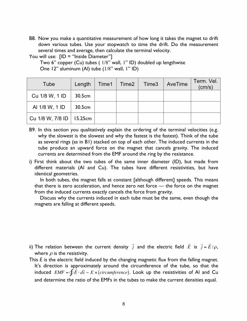
B8. Now you make a quantitative measurement of how long it takes the magnet to drift
down various tubes. Use your stopwatch to time the drift. Do the measurement several times and average, then calculate the terminal velocity.
You will use: [ID = “Inside Diameter”] Two 6” copper (Cu) tubes ( 1/8” wall, 1” ID) doubled up lengthwise One 12” aluminum (Al) tube (1/8” wall, 1” ID)
Tube Length Time1 Time2 Time3 AveTime Term. Vel. (cm/s)
Cu 1/8 W, 1 ID 30.5cm
Al 1/8 W, 1 ID 30.5cm
Cu 1/8 W, 7/8 ID 15.25cm
B9. In this section you qualitatively explain the ordering of the terminal velocities (e.g. why the slowest is the slowest and why the fastest is the fastest). Think of the tube as several rings (as in B1) stacked on top of each other. The induced currents in the tube produce an upward force on the magnet that cancels gravity. The induced currents are determined from the EMF around the ring by the resistance.
i) First think about the two tubes of the same inner diameter (ID), but made from different materials (Al and Cu). The tubes have different resistivities, but have identical geometries.
In both tubes, the magnet falls at constant [although different] speeds. This means that there is zero acceleration, and hence zero net force — the force on the magnet from the induced currents exactly cancels the force from gravity.
Discuss why the currents induced in each tube must be the same, even though the magnets are falling at different speeds.
ii) The relation between the current density
€
j and the electric field
€
E is
€
j = E /ρ ,
where ρ is the resistivity. This E is the electric field induced by the changing magnetic flux from the falling magnet.
It’s direction is approximately around the circumference of the tube, so that the induced
€
EMF = E ⋅ d s ∫ ~ E × circumference( ). Look up the resistivities of Al and Cu
and determine the ratio of the EMFs in the tubes to make the current densities equal.

9
iii) How is the induced EMF related to the falling speed of the magnet? Determine the ratio of the falling speeds in the two different tubes that make equal current densities in the tubes. Compare to your experimental results.
10
Drive Coil
Sense Coil
Power Amp
I(t)
8-pin gray cable, connect to back of power amp
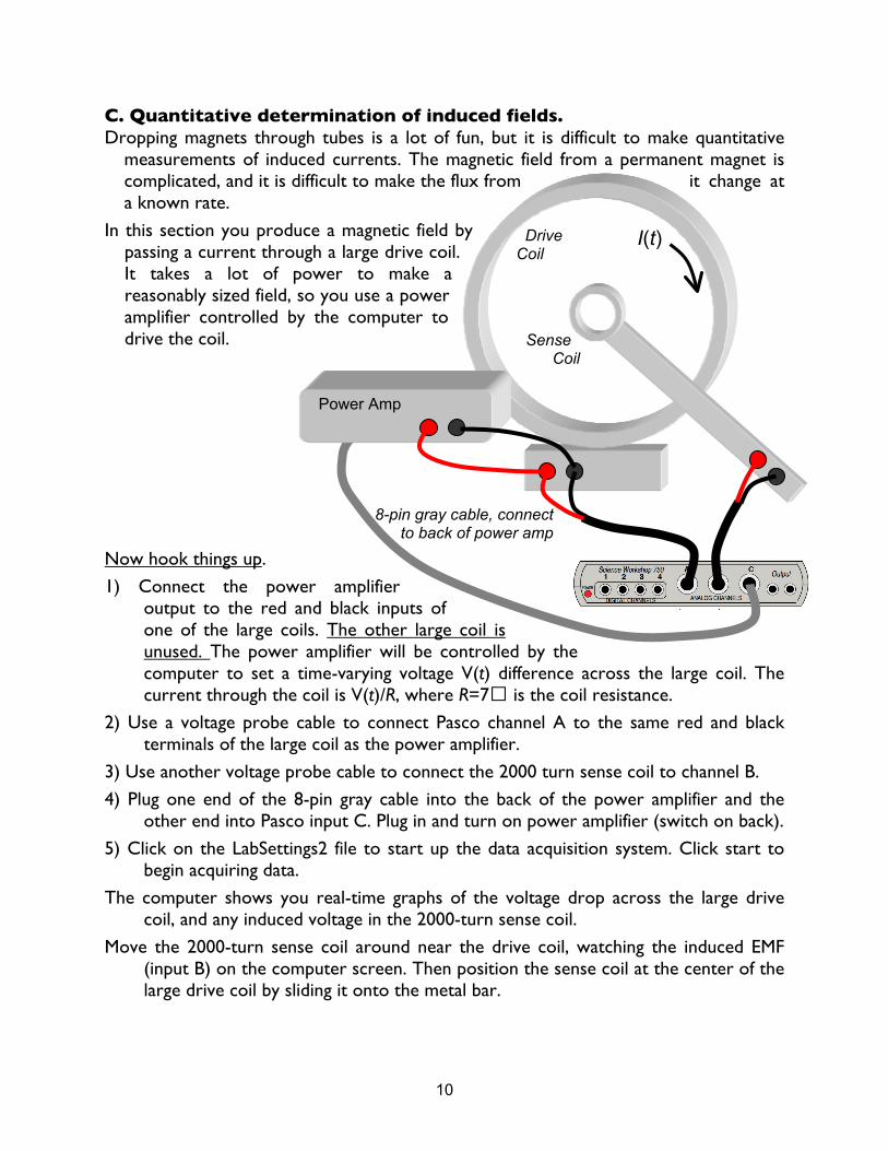
C. Quantitative determination of induced fields. Dropping magnets through tubes is a lot of fun, but it is difficult to make quantitative
measurements of induced currents. The magnetic field from a permanent magnet is complicated, and it is difficult to make the flux from it change at a known rate.
In this section you produce a magnetic field by passing a current through a large drive coil. It takes a lot of power to make a reasonably sized field, so you use a power amplifier controlled by the computer to drive the coil.
Now hook things up.
1) Connect the power amplifier output to the red and black inputs of one of the large coils. The other large coil is unused. The power amplifier will be controlled by the computer to set a time-varying voltage V(t) difference across the large coil. The current through the coil is V(t)/R, where R=7� is the coil resistance.
2) Use a voltage probe cable to connect Pasco channel A to the same red and black terminals of the large coil as the power amplifier.
3) Use another voltage probe cable to connect the 2000 turn sense coil to channel B.
4) Plug one end of the 8-pin gray cable into the back of the power amplifier and the other end into Pasco input C. Plug in and turn on power amplifier (switch on back).
5) Click on the LabSettings2 file to start up the data acquisition system. Click start to begin acquiring data.
The computer shows you real-time graphs of the voltage drop across the large drive coil, and any induced voltage in the 2000-turn sense coil.
Move the 2000-turn sense coil around near the drive coil, watching the induced EMF (input B) on the computer screen. Then position the sense coil at the center of the large drive coil by sliding it onto the metal bar.
11
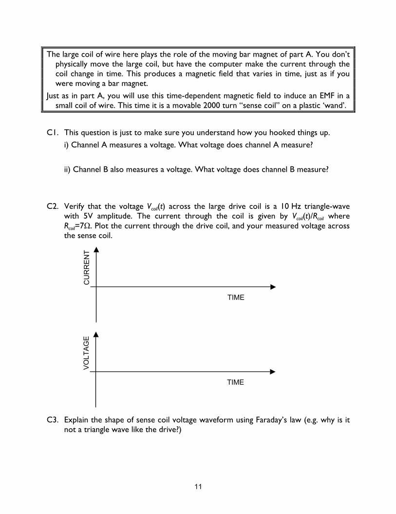
The large coil of wire here plays the role of the moving bar magnet of part A. You don’t physically move the large coil, but have the computer make the current through the coil change in time. This produces a magnetic field that varies in time, just as if you were moving a bar magnet.
Just as in part A, you will use this time-dependent magnetic field to induce an EMF in a small coil of wire. This time it is a movable 2000 turn “sense coil” on a plastic ‘wand’.
C1. This question is just to make sure you understand how you hooked things up.
i) Channel A measures a voltage. What voltage does channel A measure?
ii) Channel B also measures a voltage. What voltage does channel B measure?
C2. Verify that the voltage Vcoil(t) across the large drive coil is a 10 Hz triangle-wave with 5V amplitude. The current through the coil is given by Vcoil(t)/Rcoil where Rcoil=7Ω. Plot the current through the drive coil, and your measured voltage across the sense coil.
C3. Explain the shape of sense coil voltage waveform using Faraday’s law (e.g. why is it not a triangle wave like the drive?)
TIME
CU
RR
EN
T
TIME
VO
LTA
GE
12
C4. In C6 you saw that the EMF around the sense coil is constant over some period of time. Here you calculate the numerical value of this constant EMF in the sense coil.
i) Calculate the magnetic field produced at the center of the large drive coil, given by
€
µo
2NIR
, where N=200 is the number of turns, I is the current through the coil, and R is
the coil radius. Use the 10.5cm average radius of the drive coil for R. How is this field oriented with respect to the axis of the coil?
ii) Calculate the flux through one turn of the sense coil for a drive coil current of 1 amp.
(Assume the magnetic field produced by the drive coil is constant over the sense coil. Use the 1.43 cm average radius of the sense coil to determine its area).
iii) The triangle voltage wave sent to the drive coil by the computer makes the drive-coil current change at a constant rate (apart from changing sign). For your 10 Hz, 5V amplitude, triangle wave, calculate the time-rate-of-change of the current through the drive coil (drive coil resistance=7Ω).
iv) From ii) and iii), calculate the time-rate-of-change of the flux through one turn of sense coil for your 10 Hz triangle wave.
v) From iv), calculate the EMF around the 2000-turn sense coil and compare to your measurement.
13
C5. Take your disk magnet and move it around near the sense coil while the data acquisition is running. Explain what is happening.
C6. Take the sense coil off the bar but hold it on the axis of the large drive coil. Slowly change direction of the axis of the coil (e.g. parallel/perpendicular to drive coil axis) and watch the display on the computer. Explain these results. Think about the direction of the magnetic field from the drive coil, and the flux through the sense coil.
C7. Change the frequency of the triangle to 5 Hz. Describe and explain how the sense coil voltage has changed from the 10 Hz frequency setting.