Lab-5: Permanent Magnet Stepper Motor
14
Lab-5: Permanent Magnet Stepper Motor 1 Objectives In this laboratory experiment you will be working with a small 2-phase Permanent Magnet Stepper Motor standard frame size NEMA 17. It is assumed that the motor parameters and the name-plate information are unknown. During this lab, you will determine its most relevant parameters and summarize them in your Lab Report. The goals for this lab are: • to fully characterize a small permanent magnet stepper motor; • to drive the stepper motor with full, half, and micro steps; • to observe the effects of inductance on the motor speed performance; • and to observe the effects of electromechanical resonance on the motor performance. 2 Background and Prelab Stepper motors are frequently used in mechatronics applications for positioning devices. While stepper motors at first appear similar to synchronous and brushless DC machines, the mode in which these motors are typically operated is quite different. Stepper motors typically have a large number of poles (and even larger number of teeth) for fine step resolution. The stepper motors are also often driven in an open loop. The efficiency of stepper motors is quite low compared to many other motors. However, the advantage of simple open-loop speed and position control make these motors ideal for many electromechanical devices including printers, scanners, camera zoom control, machining equipment, etc. In this lab, the students will be given a small Stepper Motor. It is assumed that the motor parameters and the name-plate information are unknown. During this lab, the students will determine the most relevant parameters of the motor and summarize them in the Lab Report. Prelab Review the lecture notes Module and the textbook Chapter corresponding to Stepper Motors. Assume a permanent magnet stepper motor with bipolar winding depicted in figure below Determine and sketch the step sequence to achieve clockwise rotation with the following conditions a) full step, b) half step, c) full step both windings energized. Use the Excel or Matlab to generate a micro-step waveform pattern with 10 steps per cycle and 10V amplitude. Print these waveforms and bring them with you. Hint: The Micro-Step pattern is approximated by a cosine function on one channel and a sine function on the other channel.
Transcript of Lab-5: Permanent Magnet Stepper Motor

Lab-5: Permanent Magnet Stepper Motor 1 Objectives In this laboratory experiment you will be working with a small 2-phase Permanent Magnet Stepper Motor standard frame size NEMA 17. It is assumed that the motor parameters and the name-plate information are unknown. During this lab, you will determine its most relevant parameters and summarize them in your Lab Report. The goals for this lab are:
• to fully characterize a small permanent magnet stepper motor; • to drive the stepper motor with full, half, and micro steps; • to observe the effects of inductance on the motor speed performance; • and to observe the effects of electromechanical resonance on the motor performance.
2 Background and Prelab
Stepper motors are frequently used in mechatronics applications for positioning devices. While stepper motors at first appear similar to synchronous and brushless DC machines, the mode in which these motors are typically operated is quite different. Stepper motors typically have a large number of poles (and even larger number of teeth) for fine step resolution. The stepper motors are also often driven in an open loop. The efficiency of stepper motors is quite low compared to many other motors. However, the advantage of simple open-loop speed and position control make these motors ideal for many electromechanical devices including printers, scanners, camera zoom control, machining equipment, etc.
In this lab, the students will be given a small Stepper Motor. It is assumed that the motor parameters and the name-plate information are unknown. During this lab, the students will determine the most relevant parameters of the motor and summarize them in the Lab Report.
Prelab Review the lecture notes Module and the textbook Chapter corresponding to Stepper Motors. Assume a permanent magnet stepper motor with bipolar winding depicted in figure below
Determine and sketch the step sequence to achieve clockwise rotation with the following conditions a) full step, b) half step, c) full step both windings energized. Use the Excel or Matlab to generate a micro-step waveform pattern with 10 steps per cycle and 10V amplitude. Print these waveforms and bring them with you. Hint: The Micro-Step pattern is approximated by a cosine function on one channel and a sine function on the other channel.

2
3 Apparatus This lab requires the following components:
Load CellConnector Phase A
Phase B
Rotary Table
Stepper Motor
Stepper Motor Test Bench: This lab uses a specially built bench shown on the left for testing small stepper motors. The bench has a special Load Cell for measuring the developed torque. The side of the Bench has connectors for the Load Cell and for the motor phases, as shown on the picture on the left. The operation of this bench is described below in more detail.
Stepper Motor: The Stepper Motor used in this lab is a small 2-phase machine standard frame size NEMA 17 made by Astrosyn and shown in figure on the left. During this lab, you will determine its most relevant parameters and summarize them in your Lab Report. The motor is mounted on the Test Bench.
Mass Clamp: A brass Mass Clamp shown in the figure on the left can be attached to the Torque Arm to increase the moment of inertia. This is useful for adding more mass when performing the electro-mechanical resonance tests. This Mass Clamp has a thumbscrew that enables it to be tightly fixed on a particular position on the Torque Arm.
Power Amplifier Box: This box contains two controllable medium current Linear Power Amplifiers (channel A and B) capable of delivering output up to ±10 V at 400 mA. The output of each channel is controlled through the LabView interface. There is also additional input for the Load Cell for measuring the force and or torque.

3
NI ELVIS Box: The Measurement Box must be plugged into the National Instrument unit (NI ELVIS), which in turn connects to the Data Acquisition (DAQ) card inside the PC. Make sure that the NI ELVIS box is turned on using both switches, one on the front panel (left side) and another one on the back (right side).
3.1 Stepper Motor Test Bench: A detailed picture of the Stepper Motor Test Bench is shown in Fig. 1. The Stepper Motor
itself is mounted to a Rotary Table. The base on which the Rotary Table and the Stepper Motor are mounted can slide to the right and to the left. When the base is moved to the right (see Fig. 1 top image) the test bench can be set up for measuring the static torque. The static torque is measured using the Torque Arm off the motor shaft that is connected to a Load Cell. When the base is moved to the left (see Fig. 1 bottom image) the Torque Arm can spin freely and the test bench can be used for dynamic experiments.
3.2 Torque Sensor:
The Torque Sensor shown in detail in Fig. 2 uses a Load Cell to measure the static torque. A flexible brass plate connects the load cell to the Torque Arm on the motor shaft to absorb any off-axis forces from a possible misalignment. A thumb-screw is used to detach the Torque Arm from the brass plate when you want the Torque Arm to rotate freely. The Load Cell is calibrated to directly measure torque instead of force.
3.3 Rotary Table:
The Rotary Table shown in detail in Fig. 3 allows the motor to rotate by a precisely measured angle while the motor shaft remains fixed by the Torque Arm. There is about 1 degree of backlash in the table gearing which should be considered during the measurement. To return to the same point, it is important to always rotate the table in the same rotational direction. A thumb-screw on the side needs to be tightened to produce enough friction that the table will not slip backwards, but loose enough so that it can still rotate. The base on which the table and motor are mounted can slide to the left. This configuration is used to freely spin the Torque Arm in some of the experiments.

4
Fig. 1: Stepper Motor Test Bench: top – static torque measurement position; bottom – position for motor rotation.
Fig. 2: Torque Sensor.

5
Fig. 3: Rotary Table.
3.4 Power Amplifier:
A special Power Amplifier box shown in Fig. 4 has been designed for experiments with small Stepper Motors and Solenoids. The Power Amplifier has two output channels denoted by Channel A and B. These Channels need to be connected to the Stepper Motor phases, and a DIN cable needs to be connected between the Torque Sensor and the Power Amplifier box for measuring torque. The Power Amplifier box is to be plugged on the top of the NI ELVIS unit.
Fig. 4: Power Amplifier box.

6
3.5 PC Data Acquisition: There are a total of four LabView programs which will be used during this lab. These programs
are found in the appropriate folder on your desktop, or on the class web page: Stepper Torque Meter – Reads the torque present on the load cell. Used for generating the static torque curve of the stepper motors
Inductance Meter – This program is used to generate the inductance profile versus rotor position. This program also measures the DC resistance of the coil connected to one of the Channels of the Power Amplifier box.
7
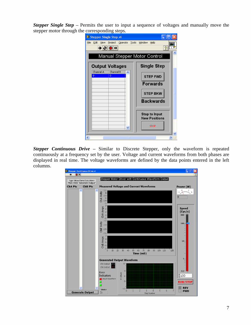
Stepper Single Step – Permits the user to input a sequence of voltages and manually move the stepper motor through the corresponding steps.
Stepper Continuous Drive – Similar to Discrete Stepper, only the waveform is repeated continuously at a frequency set by the user. Voltage and current waveforms from both phases are displayed in real time. The voltage waveforms are defined by the data points entered in the left columns.

8
4 Experimental Part
Task 1: Static Measurements of Torque & Inductance Profiles Connect the motor Torque Arm to the Torque Sensor (Load Cell) for measuring the static torque as depicted in Fig. 1 (top image). Connect the wires to power both phases of the Stepper Motor from the Power Amplifier box. Also, connect the Load Cell cable from the Stepper Motor Bench to the Power Amplifier box so that you can measure the developed electromagnetic torque.
Task 1 A: Static Torque vs. Rotor Position
1) Open the software program called “Stepper Torque”. This application displays the real time torque present on the load cell and also lets you adjust the output drive voltage to each coil. Zero the Toque Sensor torque cell while there is no current through any of the phases.
2) Apply 10 volts on one phase of the Stepper Motor (for example Phase A). Mark (note) the zero location of your Rotary Table with a fine pencil so that you can return to the same position.
3) Make sure that the Thumb Screw on the Rotary Table is gently tightened so that the Rotary Table does not slip under the torque developed by the motor. Measure and record the torque in 1 degree steps until you have covered at least one complete cycle and the waveform starts to repeat. Instead of writing the measurements on a paper, you can open a Spreadsheet file (or its equivalent) and type the measured data directly into the file.
4) Return the Stepper Motor to the zero position noted in part 2). Repeat step 3) with the other phase energized to 10V (for example Phase B).
5) Return the Stepper Motor to the zero position. Repeat step 3) with both Phase A and B energized at 10V.
Task 1 B: Inductance vs. Rotor Position
1) Launch the program “Inductance Meter”. Set the parameters to measure the inductance at approximately 10V amplitude and frequency of 20Hz. This program can also measure the DC resistance of the winding. Click on the button Get R and record the DC resistance of the motor winding in your Lab Report in Table 6 with Motor Parameters.
2) Use the measured DC resistance in appropriate field on the program interface. Then, measure the inductance of one phase at the same points as used in Task 1 A, step 3). Record the measured data directly into the Spreadsheet file. Calculate the average inductance and also record it in your Lab Report in Table 6 with Motor Parameters.
Task 2: Discrete Stepping Remove the Torque Arm from the Torque Sensor load cell by loosening the Thumb Screw (see Fig. 1 bottom image and Fig. 3). Slide the Rotary Table backwards so that the shaft can spin freely. This configuration is depicted on the bottom image in Fig 1. Be sure to re-tighten all the screws to avoid loosing any during the rotation. Launch the software program “Stepper Single Step”. This will allow you to manually sequence through the step positions of your motor.

9
1) Determine the sequence of voltage steps required to operate this motor at Full-Step with one winding energized at a time. Use the amplitude of 10V and enter (type in) the corresponding number sequences into the columns “Channel A” and “Channel B” of the program interface. The steps can be separated by either a new line or a comma. Also, record this sequence in Table 1 of your Lab Report.
2) You can sequence through the pattern by either clicking “STEP FWD” or “STEP BKW”, or by highlighting the desired state with your mouse cursor.
3) Determine how many full steps are required for one complete revolution of the shaft and record the value in Table 5 of your Lab Report.
4) Determine the sequence of voltage steps required to operate this motor at Full-Step with both windings energized at a time. Record this sequence in Table 2 of your Lab Report. Experiment with stepping “STEP FWD” and “STEP BKW”.
5) Determine the sequence required for the Half-Stepping operation with amplitude of 10V and enter the corresponding numbers into the “Channel A” and “Channel B” of the program interface. Record the sequence in Table 3. Repeat steps 2 through 3 for the Half-Stepping. Do all of the half steps appear to be equally spaced? You will need to answer this question for your report.
6) Experiment/Question: What happens to the direction of rotation when the polarity of one of
the phase connections is reversed by plugging the cables in the other way? What if both phases are reversed? You will need to answer this question for your report.
Task 3: Continuous Rotation Launch the “Stepper Continuous Drive” program. This program allows the repeated cycling of the user-defined voltage waveforms on both output channels. 1) Using the provided columns on the left side, enter the Full-Step waveforms for driving one
phase at a time using the full 10V amplitude. Each number you input represents the voltage of the channel at that step/time point. The steps can be separated by either a new line or a comma.
2) Click the button “Generate Waveform”. This causes the software to read the text values in the columns and write them to a circular buffer in the DAQ card. The output wave is also displayed in the bottom chart to let you verify that the data was entered correctly. Make sure that the displayed waveform is what you need.
3) Click the “RUN/STOP” button to begin driving the output. The speed of the motor is then controlled with the Slider Bar on the right and is calibrated in complete electrical cycles per second, while the voltage and current waveforms are displayed on a scrolling chart.
4) Slowly increase the rotor speed until the motor looses lock and record in Table 4 at what speed this happened. As the speed was increased, did the power increase or decrease? Also observe how the shape of the current waveform changes with the motor speed and drive frequency.
5) Attach the Mass Clamp to the Torque Arm and re-run the part 3 to 4. Note how the additional mass affects the maximum speed? Could you observe an electro-mechanical resonance (oscillatory vibrations) of the Torque Arm? You will need to answer this question for your report.
6) If the time permits, repeat steps 1 through 5 using a 10V Full-Step but with both phases energized at a time. Record the maximum speed in Table 4.
7) Question: How do you think it might be possible to drive the given stepper motor at even
higher speeds than in parts 4 and 5? You will need to answer this question for your report.
10
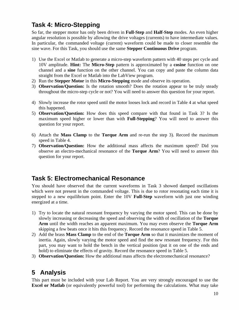
Task 4: Micro-Stepping So far, the stepper motor has only been driven in Full-Step and Half-Step modes. An even higher angular resolution is possible by allowing the drive voltages (currents) to have intermediate values. In particular, the commanded voltage (current) waveform could be made to closer resemble the sine wave. For this Task, you should use the same Stepper Continuous Drive program.
1) Use the Excel or Matlab to generate a micro-step waveform pattern with 40 steps per cycle and
10V amplitude. Hint: The Micro-Step pattern is approximated by a cosine function on one channel and a sine function on the other channel. You can copy and paste the column data straight from the Excel or Matlab into the LabView program.
2) Run the Stepper Motor in this Micro-Stepping mode and observe its operation. 3) Observation/Question: Is the rotation smooth? Does the rotation appear to be truly steady
throughout the micro-step cycle or not? You will need to answer this question for your report. 4) Slowly increase the rotor speed until the motor looses lock and record in Table 4 at what speed
this happened. 5) Observation/Question: How does this speed compare with that found in Task 3? Is the
maximum speed higher or lower than with Full-Stepping? You will need to answer this question for your report.
6) Attach the Mass Clamp to the Torque Arm and re-run the step 3). Record the maximum
speed in Table 4. 7) Observation/Question: How the additional mass affects the maximum speed? Did you
observe an electro-mechanical resonance of the Torque Arm? You will need to answer this question for your report.
Task 5: Electromechanical Resonance You should have observed that the current waveforms in Task 3 showed damped oscillations which were not present in the commanded voltage. This is due to rotor resonating each time it is stepped to a new equilibrium point. Enter the 10V Full-Step waveform with just one winding energized at a time.
1) Try to locate the natural resonant frequency by varying the motor speed. This can be done by
slowly increasing or decreasing the speed and observing the width of oscillation of the Torque Arm until the width reaches an apparent maximum. You may even observe the Torque Arm skipping a few beats once it hits this frequency. Record the resonance speed in Table 5.
2) Add the brass Mass Clamp to the end of the Torque Arm so that it maximizes the moment of inertia. Again, slowly varying the motor speed and find the new resonant frequency. For this part, you may want to hold the bench in the vertical position (put it on one of the ends and hold) to eliminate the effects of gravity. Record the resonance speed in Table 5.
3) Observation/Question: How the additional mass affects the electromechanical resonance?
5 Analysis This part must be included with your Lab Report. You are very strongly encouraged to use the Excel or Matlab (or equivalently powerful tool) for performing the calculations. What may take
11
you 5 hours to calculate using a hand calculator may take only 10 minutes in Matlab! Discuss and perform the following data analysis:
Task 6 A: Determining Motor Parameters
1) Plot the inductance of the motor winding as a function of angular position. Does the inductance changes significantly? Based on this result, would you say that the variable reluctance effect plays a large or small effect in this particular motor?
2) Plot the motor torque curves as a function of angular position. Superimpose/show Phase A, Phase B, and Phases A+B all on the same plot.
3) Verify that the measured torque curve for A+B corresponds to the expected value calculated from adding the torque from A and from B energized. Included this plot on a separate figure (or subplot) below the previous plot.
4) Based on your plots in steps 2 and 3 you should be able to calculate the step length SLθ , number of rotor teeth RTN , and the PM flux constant mλ .
5) Complete Table 6 to characterize your previously “unknown” stepper motor:
Task 6 B: Questions
1) Provide briefly answers to all the questions you were asked in Tasks 1-5. 2) Calculate the theoretical resolution of your 40 position micro-step routine. Given your
observations of the rotating Torque Arm while micro-stepping, do you think the actual position accuracy is as good as your predicted resolution? Is it possible to do the micro-stepping so that the actual resolution is this good? Explain your answer.
6 Reporting Prepare the Lab Report that includes: 1) Title Page (all filled-in, with signatures) 2) Pages with the measured data (pages 12 – 14) 3) Additional pages with calculations, discussions, plots, and/or answers to questions in Task 6, 4) Brief Conclusion/Summary stating what you and your lab partner have learned in this Lab.

12
EECE ____
Lab Experiment: ____ Section: ____
Bench #: ____
Partners Student ID #: % participation
Signatures
Date Performed: Date Submitted:
13
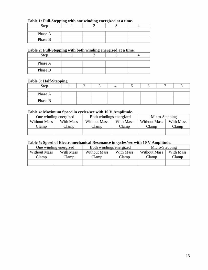
Table 1: Full-Stepping with one winding energized at a time. Step 1 2 3 4
Phase A Phase B
Table 2: Full-Stepping with both winding energized at a time. Step 1 2 3 4
Phase A
Phase B
Table 3: Half-Stepping. Step 1 2 3 4 5 6 7 8
Phase A Phase B
Table 4: Maximum Speed in cycles/sec with 10 V Amplitude. One winding energized Both windings energized Micro-Stepping
Without Mass Clamp
With Mass Clamp
Without Mass Clamp
With Mass Clamp
Without Mass Clamp
With Mass Clamp
Table 5: Speed of Electromechanical Resonance in cycles/sec with 10 V Amplitude. One winding energized Both windings energized Micro-Stepping
Without Mass Clamp
With Mass Clamp
Without Mass Clamp
With Mass Clamp
Without Mass Clamp
With Mass Clamp

14
Table 6: Stepper Motor Parameters. Parameter (symbol) Value Units
Stator winding resistance, sr
Stator winding inductance (average), sL
Stator winding time constant, sss rL=τ
Max holding torque at 10V, max,eT
PM flux constant, mλ
Number of rotor teeth, RTN
Rotor tooth pitch, RTTP
Number of full steps per one revolution
Step length, SLθ
Max rotation speed at 10V, max,rω
Max rotation speed at 10V, maxn rpm
Type of winding (bipolar, unipolar, etc.)