Lab 4 -- Introduction to SPI interfacingpeople.ucalgary.ca/.../16_Nov/16-10-14T_Lab4A.pdfLab 4 --...
16
Lab 4 -- Introduction to SPI interfacing The problem The HD44780 device has an 11 bit control register R/W* -- Active low read / write* RS* -- Active low – device accepts B7 – B0 lines as instructions RS – Active high – device B7 – B0 lines as data E E* -- Device operates on active low edge AND ignores levels 11/13/2016 SPI and LCD , Copyright M. Smith, ECE, University of Calgary, Canada 2 / 30
-
Upload
truongcong -
Category
Documents
-
view
221 -
download
0
Transcript of Lab 4 -- Introduction to SPI interfacingpeople.ucalgary.ca/.../16_Nov/16-10-14T_Lab4A.pdfLab 4 --...
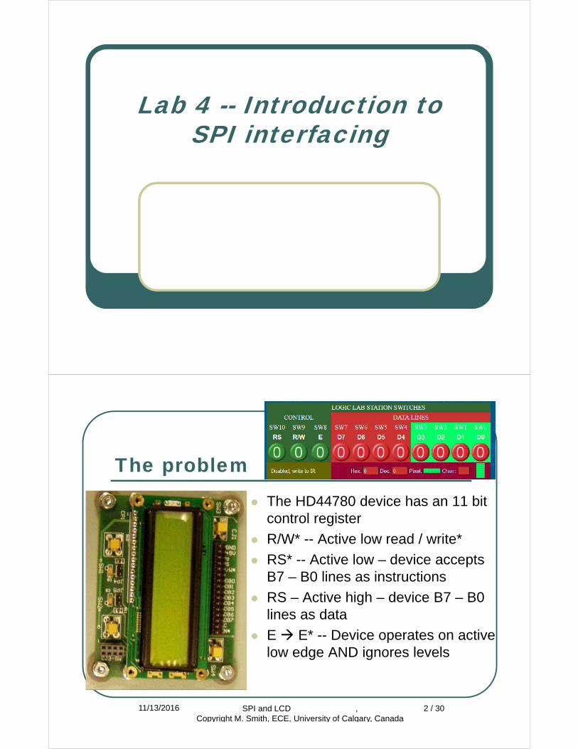
Lab 4 -- Introduction to SPI interfacing
The problem The HD44780 device has an 11 bit
control register
R/W* -- Active low read / write*
RS* -- Active low – device accepts B7 – B0 lines as instructions
RS – Active high – device B7 – B0 lines as data
E E* -- Device operates on active low edge AND ignores levels
11/13/2016 SPI and LCD , Copyright M. Smith, ECE, University of Calgary, Canada
2 / 30
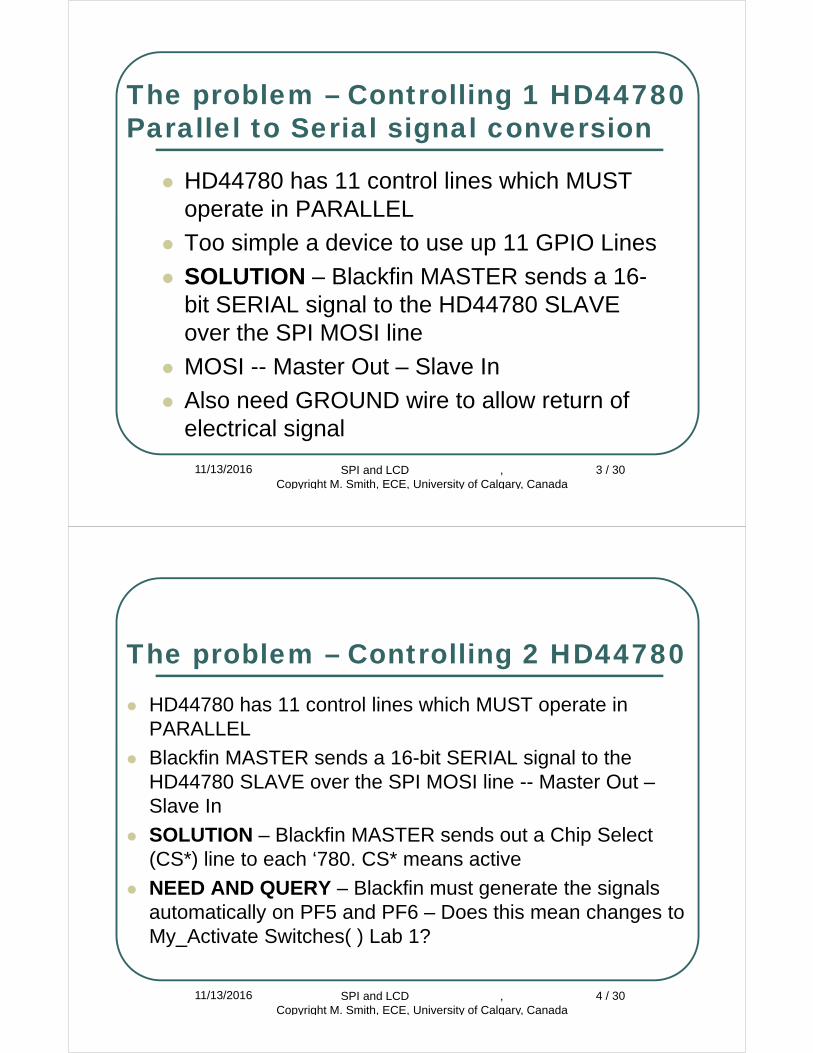
The problem – Controlling 1 HD44780Parallel to Serial signal conversion
HD44780 has 11 control lines which MUST operate in PARALLEL
Too simple a device to use up 11 GPIO Lines
SOLUTION – Blackfin MASTER sends a 16-bit SERIAL signal to the HD44780 SLAVE over the SPI MOSI line
MOSI -- Master Out – Slave In
Also need GROUND wire to allow return of electrical signal
11/13/2016 SPI and LCD , Copyright M. Smith, ECE, University of Calgary, Canada
3 / 30
The problem – Controlling 2 HD44780 HD44780 has 11 control lines which MUST operate in
PARALLEL
Blackfin MASTER sends a 16-bit SERIAL signal to the HD44780 SLAVE over the SPI MOSI line -- Master Out –Slave In
SOLUTION – Blackfin MASTER sends out a Chip Select (CS*) line to each ‘780. CS* means active
NEED AND QUERY – Blackfin must generate the signals automatically on PF5 and PF6 – Does this mean changes to My_Activate Switches( ) Lab 1?
11/13/2016 SPI and LCD , Copyright M. Smith, ECE, University of Calgary, Canada
4 / 30
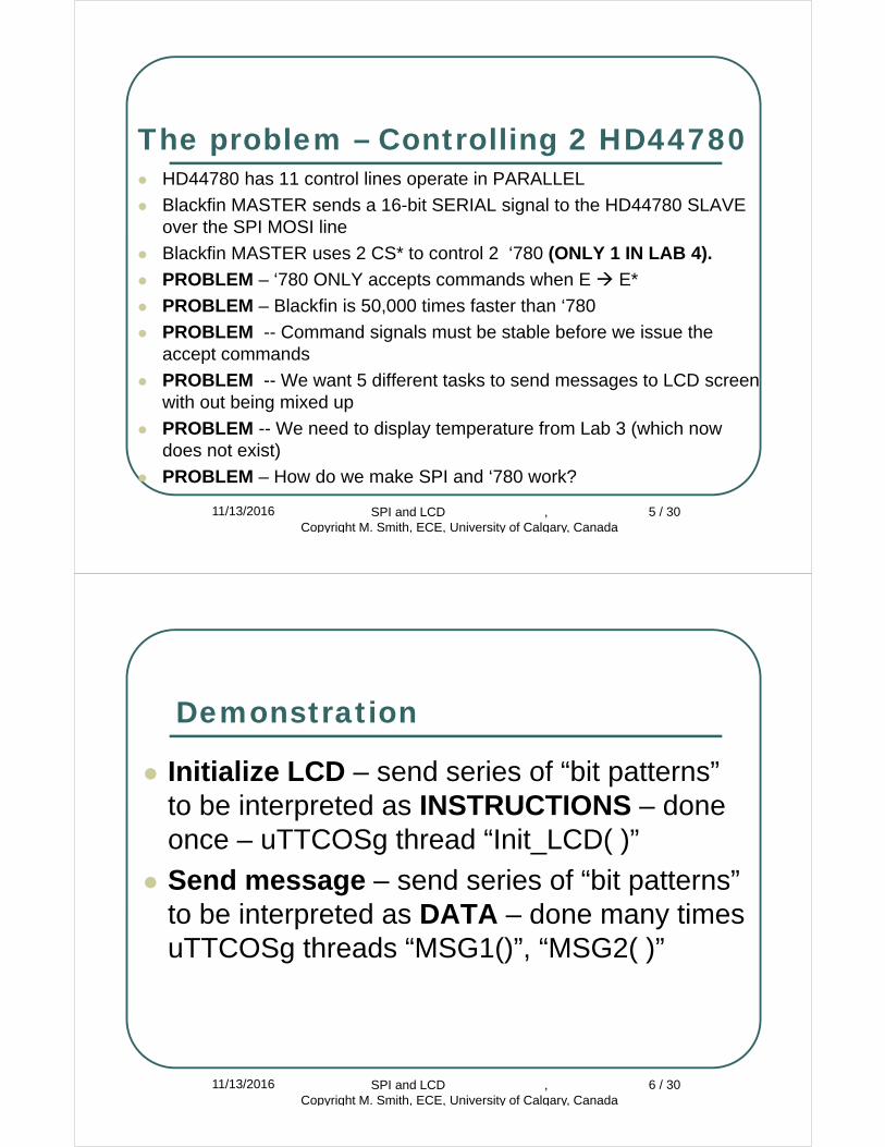
The problem – Controlling 2 HD44780 HD44780 has 11 control lines operate in PARALLEL
Blackfin MASTER sends a 16-bit SERIAL signal to the HD44780 SLAVE over the SPI MOSI line
Blackfin MASTER uses 2 CS* to control 2 ‘780 (ONLY 1 IN LAB 4).
PROBLEM – ‘780 ONLY accepts commands when E E*
PROBLEM – Blackfin is 50,000 times faster than ‘780
PROBLEM -- Command signals must be stable before we issue the accept commands
PROBLEM -- We want 5 different tasks to send messages to LCD screen with out being mixed up
PROBLEM -- We need to display temperature from Lab 3 (which now does not exist)
PROBLEM – How do we make SPI and ‘780 work?
11/13/2016 SPI and LCD , Copyright M. Smith, ECE, University of Calgary, Canada
5 / 30
Demonstration
Initialize LCD – send series of “bit patterns” to be interpreted as INSTRUCTIONS – done once – uTTCOSg thread “Init_LCD( )”
Send message – send series of “bit patterns” to be interpreted as DATA – done many times uTTCOSg threads “MSG1()”, “MSG2( )”
11/13/2016 SPI and LCD , Copyright M. Smith, ECE, University of Calgary, Canada
6 / 30
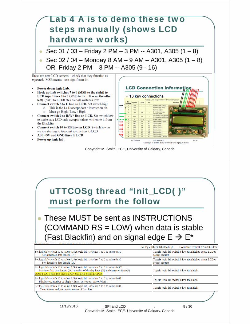
Lab 4 A is to demo these two steps manually (shows LCD hardware works)
Sec 01 / 03 – Friday 2 PM – 3 PM -- A301, A305 (1 – 8)
Sec 02 / 04 – Monday 8 AM – 9 AM – A301, A305 (1 – 8)OR Friday 2 PM – 3 PM -- A305 (9 - 16)
11/13/2016 SPI and LCD , Copyright M. Smith, ECE, University of Calgary, Canada
7 / 30
uTTCOSg thread “Init_LCD( )”must perform the follow
These MUST be sent as INSTRUCTIONS (COMMAND RS = LOW) when data is stable (Fast Blackfin) and on signal edge E E*
11/13/2016 SPI and LCD , Copyright M. Smith, ECE, University of Calgary, Canada
8 / 30
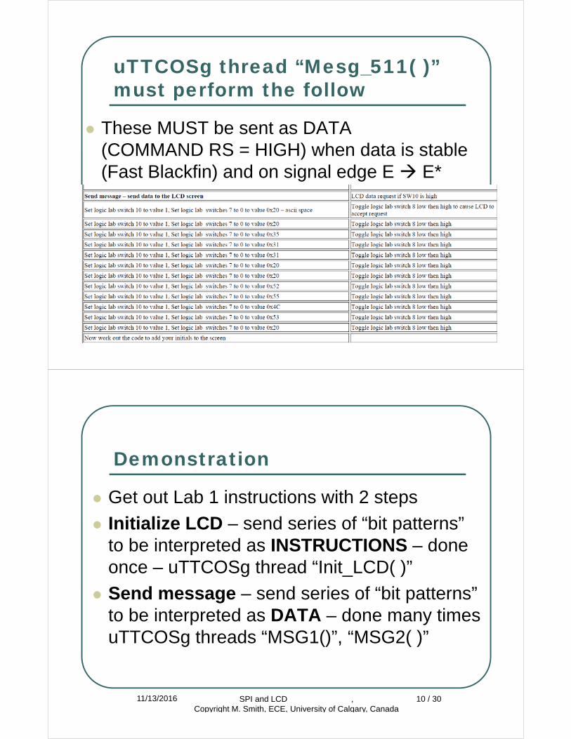
uTTCOSg thread “Mesg_511( )”must perform the follow
These MUST be sent as DATA (COMMAND RS = HIGH) when data is stable (Fast Blackfin) and on signal edge E E*
11/13/2016 SPI and LCD , Copyright M. Smith, ECE, University of Calgary, Canada
9 / 30
Demonstration
Get out Lab 1 instructions with 2 steps
Initialize LCD – send series of “bit patterns” to be interpreted as INSTRUCTIONS – done once – uTTCOSg thread “Init_LCD( )”
Send message – send series of “bit patterns” to be interpreted as DATA – done many times uTTCOSg threads “MSG1()”, “MSG2( )”
11/13/2016 SPI and LCD , Copyright M. Smith, ECE, University of Calgary, Canada
10 / 30
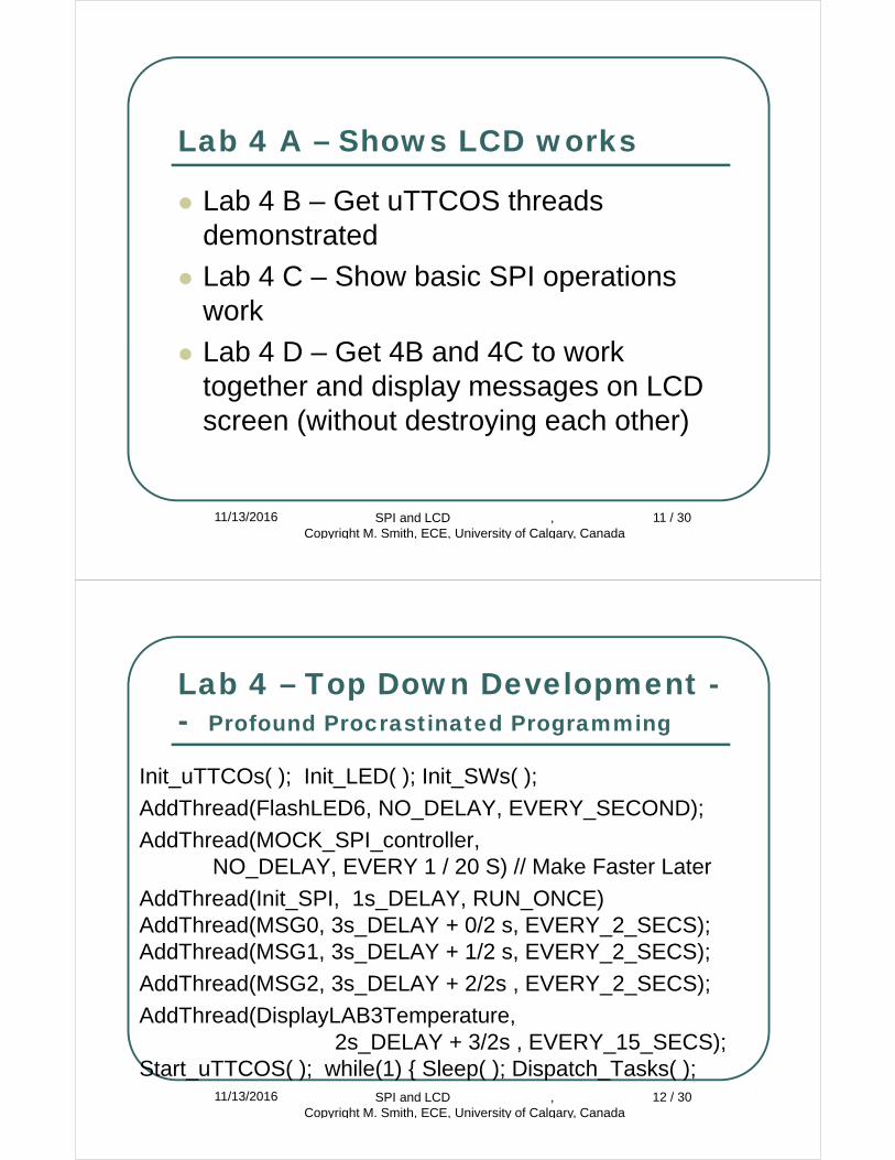
Lab 4 A – Shows LCD works
Lab 4 B – Get uTTCOS threads demonstrated
Lab 4 C – Show basic SPI operations work
Lab 4 D – Get 4B and 4C to work together and display messages on LCD screen (without destroying each other)
11/13/2016 SPI and LCD , Copyright M. Smith, ECE, University of Calgary, Canada
11 / 30
Lab 4 – Top Down Development -- Profound Procrastinated Programming
Init_uTTCOs( ); Init_LED( ); Init_SWs( );
AddThread(FlashLED6, NO_DELAY, EVERY_SECOND);
AddThread(MOCK_SPI_controller, NO_DELAY, EVERY 1 / 20 S) // Make Faster Later
AddThread(Init_SPI, 1s_DELAY, RUN_ONCE) AddThread(MSG0, 3s_DELAY + 0/2 s, EVERY_2_SECS); AddThread(MSG1, 3s_DELAY + 1/2 s, EVERY_2_SECS);
AddThread(MSG2, 3s_DELAY + 2/2s , EVERY_2_SECS);
AddThread(DisplayLAB3Temperature, 2s_DELAY + 3/2s , EVERY_15_SECS);
Start_uTTCOS( ); while(1) { Sleep( ); Dispatch_Tasks( );11/13/2016 SPI and LCD ,
Copyright M. Smith, ECE, University of Calgary, Canada12 / 30
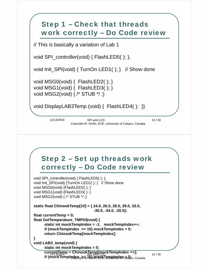
Step 1 – Check that threads work correctly – Do Code review
11/13/2016 SPI and LCD , Copyright M. Smith, ECE, University of Calgary, Canada
13 / 30
// This is basically a variation of Lab 1
void SPI_controller(void) { FlashLED5( ); },
void Init_SPI(void) { TurnOn LED1( ); } // Show done
void MSG0(void) { FlashLED2( ); }void MSG1(void) { FlashLED3( ); }void MSG2(void) { /* STUB */ ;}
void DisplayLAB3Temp (void) { FlashLED4( ); }}
Step 2 – Set up threads work correctly – Do Code review
11/13/2016 SPI and LCD , Copyright M. Smith, ECE, University of Calgary, Canada
14 / 30
void SPI_controller(void) { FlashLED5( ); }, void Init_SPI(void) {TurnOn LED1( ); } // Show donevoid MSG0(void) {FlashLED2( ); }void MSG1(void) {FlashLED3( ); }void MSG2(void) { /* STUB */ ;}
static float ChinookTemp[10] = { 24.0, 26.0, 28.0, 29.0, 33.0, -35.0, -34.0, -20.0};
float currentTemp = 0;float GetTemperature_TMP03(void) {
static int mockTempIndex = -1; mockTempIndex++;if (mockTempIndex >= 10) mockTempIndex = 0;return ChinookTemp[mockTempIndex];
}void LAB3_temp(void) {
static int mockTempIndex = 0;currentTemp = ChinookTemp[mockTempIndex ++];if (mockTempIndex >= 10) mockTempIndex = 0;
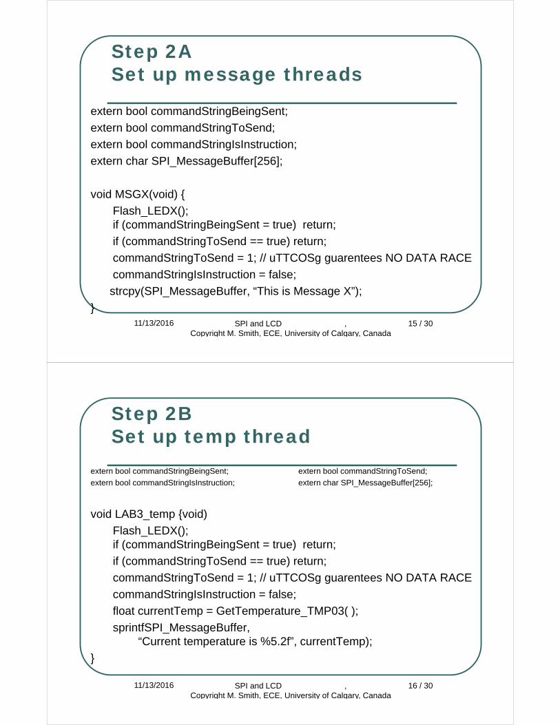
Step 2A Set up message threads
extern bool commandStringBeingSent;
extern bool commandStringToSend;
extern bool commandStringIsInstruction;
extern char SPI_MessageBuffer[256];
void MSGX(void) {
Flash_LEDX();if (commandStringBeingSent = true) return;
if (commandStringToSend == true) return;
commandStringToSend = 1; // uTTCOSg guarentees NO DATA RACE
commandStringIsInstruction = false;
strcpy(SPI_MessageBuffer, “This is Message X”);
}11/13/2016 SPI and LCD ,
Copyright M. Smith, ECE, University of Calgary, Canada15 / 30
Step 2B Set up temp thread
extern bool commandStringBeingSent; extern bool commandStringToSend;
extern bool commandStringIsInstruction; extern char SPI_MessageBuffer[256];
void LAB3_temp {void)
Flash_LEDX();if (commandStringBeingSent = true) return;
if (commandStringToSend == true) return;
commandStringToSend = 1; // uTTCOSg guarentees NO DATA RACE
commandStringIsInstruction = false;
float currentTemp = GetTemperature_TMP03( );
sprintfSPI_MessageBuffer,“Current temperature is %5.2f”, currentTemp);
}
11/13/2016 SPI and LCD , Copyright M. Smith, ECE, University of Calgary, Canada
16 / 30
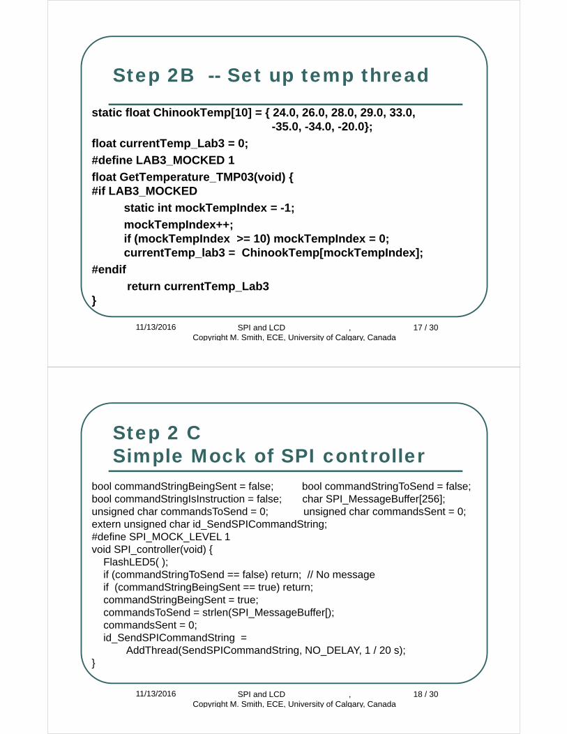
Step 2B -- Set up temp thread
static float ChinookTemp[10] = { 24.0, 26.0, 28.0, 29.0, 33.0, -35.0, -34.0, -20.0};
float currentTemp_Lab3 = 0;
#define LAB3_MOCKED 1
float GetTemperature_TMP03(void) {#if LAB3_MOCKED
static int mockTempIndex = -1;
mockTempIndex++;if (mockTempIndex >= 10) mockTempIndex = 0;currentTemp_lab3 = ChinookTemp[mockTempIndex];
#endif
return currentTemp_Lab3}
11/13/2016 SPI and LCD , Copyright M. Smith, ECE, University of Calgary, Canada
17 / 30
Step 2 C Simple Mock of SPI controller
11/13/2016 SPI and LCD , Copyright M. Smith, ECE, University of Calgary, Canada
18 / 30
bool commandStringBeingSent = false; bool commandStringToSend = false;bool commandStringIsInstruction = false; char SPI_MessageBuffer[256];unsigned char commandsToSend = 0; unsigned char commandsSent = 0;extern unsigned char id_SendSPICommandString;#define SPI_MOCK_LEVEL 1void SPI_controller(void) {
FlashLED5( ); if (commandStringToSend == false) return; // No messageif (commandStringBeingSent == true) return;commandStringBeingSent = true;commandsToSend = strlen(SPI_MessageBuffer[);commandsSent = 0;id_SendSPICommandString =
AddThread(SendSPICommandString, NO_DELAY, 1 / 20 s);}
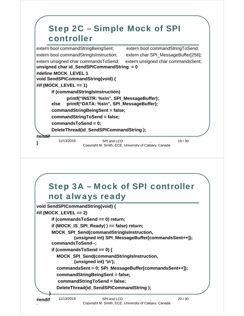
Step 2C – Simple Mock of SPI controller
extern bool commandStringBeingSent; extern bool commandStringToSend;
extern bool commandStringIsInstruction; extern char SPI_MessageBuffer[256];
extern unsigned char commandsToSend; extern unsigned char commandsSent;unsigned char id_SendSPICommandString = 0
#define MOCK_LEVEL 1void SendSPICommandString(void) {
#if (MOCK_LEVEL == 1)
if (commandStringIsInstruction)
printf(“INSTR: %s\n”, SPI_MessageBuffer);else printf(“DATA: %s\n”, SPI_MessageBuffer);
commandStringBeingSent = false;
commandStringToSend = false;
commandsToSend = 0;
DeleteThread(id_SendSPICommandString );
#endif
} 11/13/2016 SPI and LCD , Copyright M. Smith, ECE, University of Calgary, Canada
19 / 30
Step 3A – Mock of SPI controller not always ready
void SendSPICommandString(void) {
#if (MOCK_LEVEL == 2)
if (commandsToSend == 0) return;
if (MOCK_IS_SPI_Ready( ) == false) return;
MOCK_SPI_Send(commandStringIsInstruction, (unsigned int) SPI_MessageBuffer[commandsSent++]);
commandsToSend--;
if (commandsToSend == 0) {
MOCK_SPI_Send(commandStringIsInstruction, (unsigned int) ‘\n’);
commandsSent = 0; SPI_MessageBuffer[commandsSent++]);
commandStringBeingSent = false;
commandStringToSend = false;
DeleteThread(id_SendSPICommandString );}
#endif
}
11/13/2016 SPI and LCD , Copyright M. Smith, ECE, University of Calgary, Canada
20 / 30
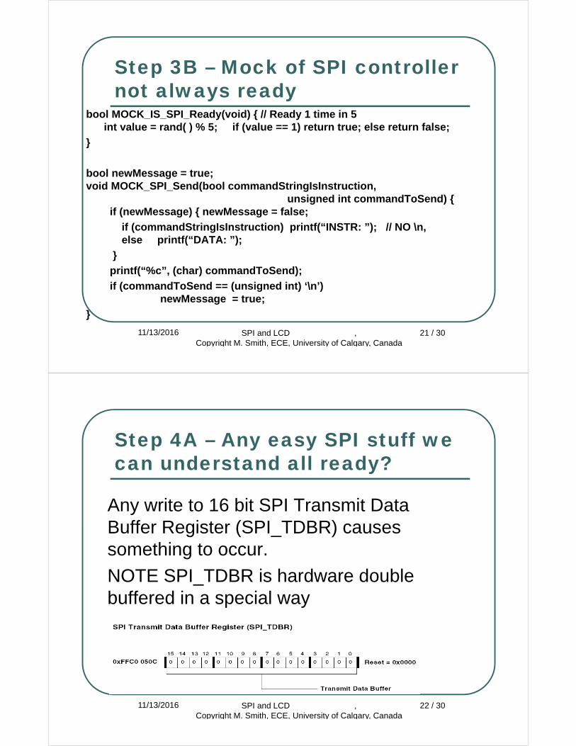
Step 3B – Mock of SPI controller not always ready
bool MOCK_IS_SPI_Ready(void) { // Ready 1 time in 5int value = rand( ) % 5; if (value == 1) return true; else return false;
}
bool newMessage = true;void MOCK_SPI_Send(bool commandStringIsInstruction,
unsigned int commandToSend) {if (newMessage) { newMessage = false;
if (commandStringIsInstruction) printf(“INSTR: ”); // NO \n, else printf(“DATA: ”);
}
printf(“%c”, (char) commandToSend);
if (commandToSend == (unsigned int) ‘\n’)newMessage = true;
}
11/13/2016 SPI and LCD , Copyright M. Smith, ECE, University of Calgary, Canada
21 / 30
Step 4A – Any easy SPI stuff we can understand all ready?
Any write to 16 bit SPI Transmit Data Buffer Register (SPI_TDBR) causes something to occur.
NOTE SPI_TDBR is hardware double buffered in a special way
11/13/2016 SPI and LCD , Copyright M. Smith, ECE, University of Calgary, Canada
22 / 30
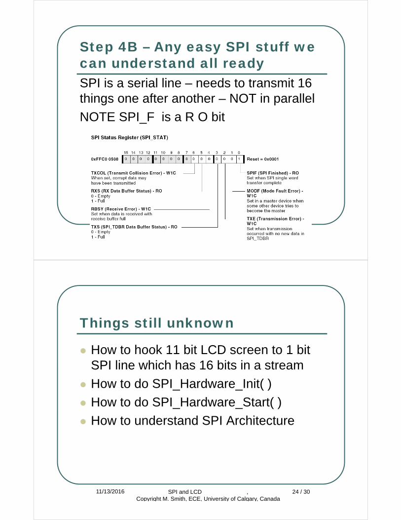
Step 4B – Any easy SPI stuff we can understand all readySPI is a serial line – needs to transmit 16 things one after another – NOT in parallel
NOTE SPI_F is a R O bit
11/13/2016 SPI and LCD , Copyright M. Smith, ECE, University of Calgary, Canada
23 / 30
Things still unknown
How to hook 11 bit LCD screen to 1 bit SPI line which has 16 bits in a stream
How to do SPI_Hardware_Init( )
How to do SPI_Hardware_Start( )
How to understand SPI Architecture
11/13/2016 SPI and LCD , Copyright M. Smith, ECE, University of Calgary, Canada
24 / 30
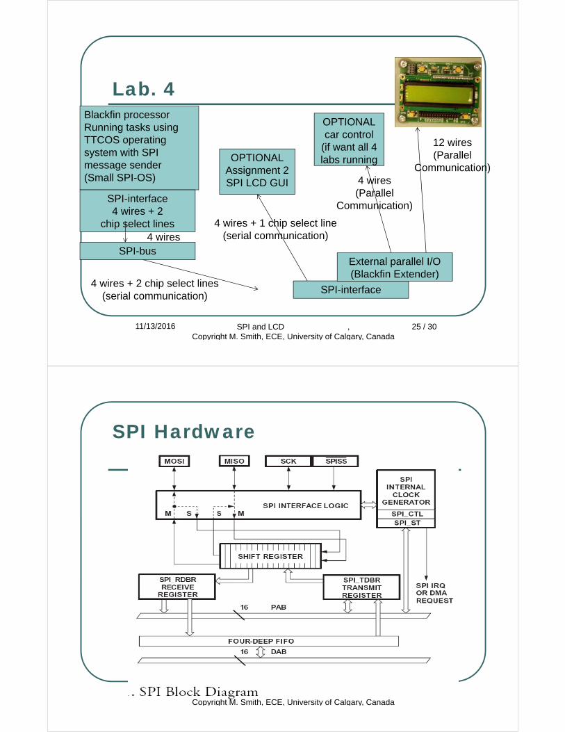
Lab. 4
11/13/2016 SPI and LCD , Copyright M. Smith, ECE, University of Calgary, Canada
25 / 30
Blackfin processorRunning tasks using TTCOS operating system with SPI message sender(Small SPI-OS)
SPI-interface4 wires + 2
chip select lines
SPI-bus
SPI-interface
External parallel I/O(Blackfin Extender)
4 wires
4 wires + 2 chip select lines(serial communication)
12 wires(Parallel
Communication)
OPTIONALcar control
(if want all 4 labs runningOPTIONAL
Assignment 2 SPI LCD GUI 4 wires
(ParallelCommunication)
4 wires + 1 chip select line(serial communication)
SPI Hardware
11/13/2016 SPI and LCD , Copyright M. Smith, ECE, University of Calgary, Canada
26 / 30
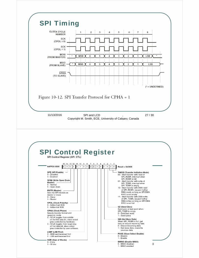
SPI Timing
11/13/2016 SPI and LCD , Copyright M. Smith, ECE, University of Calgary, Canada
27 / 30
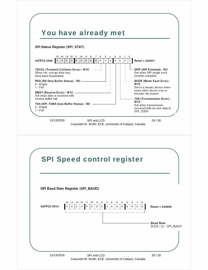
SPI Control Register
11/13/2016 SPI and LCD , Copyright M. Smith, ECE, University of Calgary, Canada
28 / 30
You have already met
11/13/2016 SPI and LCD , Copyright M. Smith, ECE, University of Calgary, Canada
29 / 30
SPI Speed control register
11/13/2016 SPI and LCD , Copyright M. Smith, ECE, University of Calgary, Canada
30 / 30

SPI – Flag Register
11/13/2016 SPI and LCD , Copyright M. Smith, ECE, University of Calgary, Canada
31 / 30