Lab 3, Logix Basic Motion Instructions -...
30
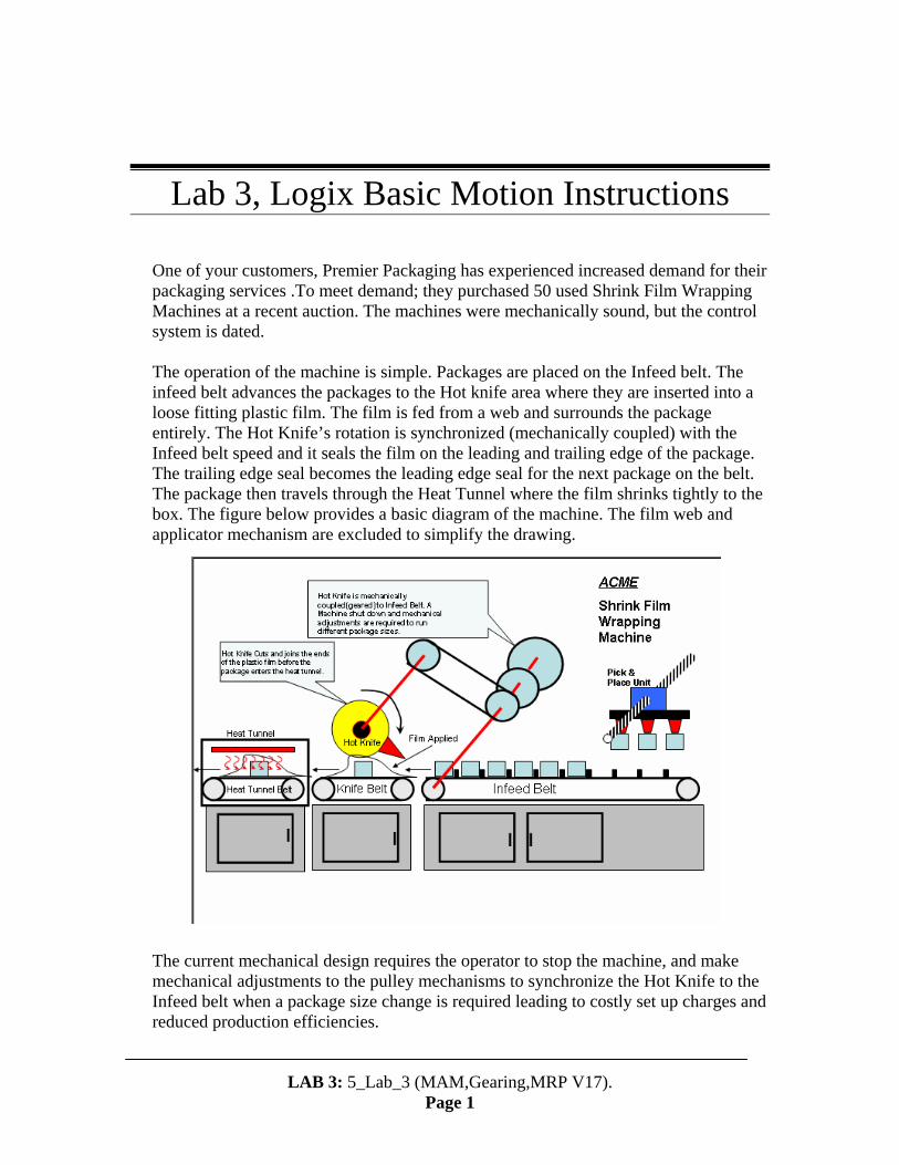
Lab 3, Logix Basic Motion Instructions One of your customers, Premier Packaging has experienced increased demand for their packaging services .To meet demand; they purchased 50 used Shrink Film Wrapping Machines at a recent auction. The machines were mechanically sound, but the control system is dated. The operation of the machine is simple. Packages are placed on the Infeed belt. The infeed belt advances the packages to the Hot knife area where they are inserted into a loose fitting plastic film. The film is fed from a web and surrounds the package entirely. The Hot Knife’s rotation is synchronized (mechanically coupled) with the Infeed belt speed and it seals the film on the leading and trailing edge of the package. The trailing edge seal becomes the leading edge seal for the next package on the belt. The package then travels through the Heat Tunnel where the film shrinks tightly to the box. The figure below provides a basic diagram of the machine. The film web and applicator mechanism are excluded to simplify the drawing. The current mechanical design requires the operator to stop the machine, and make mechanical adjustments to the pulley mechanisms to synchronize the Hot Knife to the Infeed belt when a package size change is required leading to costly set up charges and reduced production efficiencies. LAB 3: 5_Lab_3 (MAM,Gearing,MRP V17). Page 1
Transcript of Lab 3, Logix Basic Motion Instructions -...
Lab 3, Logix Basic Motion Instructions One of your customers, Premier Packaging has experienced increased demand for their packaging services .To meet demand; they purchased 50 used Shrink Film Wrapping Machines at a recent auction. The machines were mechanically sound, but the control system is dated. The operation of the machine is simple. Packages are placed on the Infeed belt. The infeed belt advances the packages to the Hot knife area where they are inserted into a loose fitting plastic film. The film is fed from a web and surrounds the package entirely. The Hot Knife’s rotation is synchronized (mechanically coupled) with the Infeed belt speed and it seals the film on the leading and trailing edge of the package. The trailing edge seal becomes the leading edge seal for the next package on the belt. The package then travels through the Heat Tunnel where the film shrinks tightly to the box. The figure below provides a basic diagram of the machine. The film web and applicator mechanism are excluded to simplify the drawing. The current mechanical design requires the operator to stop the machine, and make mechanical adjustments to the pulley mechanisms to synchronize the Hot Knife to the Infeed belt when a package size change is required leading to costly set up charges and reduced production efficiencies.
LAB 3: 5_Lab_3 (MAM,Gearing,MRP V17).
Page 1
The Existing Control System consists of the following:
• DC Motor & Drive (Coupled to Infeed Belt). Speed is controlled through a potentiometer. All other speed synchronization is done mechanically.
• PLC to control the Sequential Logic of the Machine. • Separate Temperature Controllers on the Hot Knife and Heat Tunnel.
The customer is requesting a control system that will provide the following benefits:
• Integrated Motion, Sequential Logic, and precise temperature control (PID) to eliminate the standalone temperature controllers. .
• An expandable system capable of handling additional axis for handling future pick and place units or controlling multiple machines.
• Future connectivity to a Rockwell Automation Visualization Product. • Future connectivity to the plant wide network for production scheduling and
recipe download. • Efficient method of synchronizing the machinery with an existing Plant Wide
Material Handling System (Logix Controlled) You realize immediately that our Logix Integrated Motion solution with Kinetix 6000 drives offers all of the above. Your customer agrees and purchases the first system. 1. For the initial system, Premier Packaging has decided to replace the old controls
with a 3 Axis Control Logix System using Kinetix 6000 Drives. Let’s familiarize ourselves with the Logix Motion Instructions required to run the Shrink Wrap Machine. Open RS Logix 5000 by clicking on the shortcut in the upper right corner of the desktop.
RS Logix 5000 will open. Select File Open Local Disk (C:) Motion HOT 2005 Basic Motion Programming. Select the Basic_Motion_Programming_Beg_V17.ACD file and click on Open.
LAB 3: 5_Lab_3 (MAM,Gearing,MRP V17).
Page 2

2. After the file opens, examine the Controller Organizer Window. Each Axis for
the machine is preconfigured. Let’s examine the properties for each axis individually. Select the Knife Axis Right Click Properties.
The Knife Axis is configured for Node 99 which is the IAM Module and the top MPL motor on the drives demo. Select the Conversion Tab.
LAB 3: 5_Lab_3 (MAM,Gearing,MRP V17).
Page 3

The Knife is configured as a Rotary Axis with rev. selected as the unit of measure. The axis will rollover every revolution. Other units of measure may be used such as radians, or degrees. To make the trend feature more useful later in the lab, rev. will be used. Select the Homing Tab. 3. For the Knife, the Axis will home to the Marker. For a Rotary Axis that rolls over
every revolution, homing to the marker is very accurate and a home switch isn’t required. Select OK to close the Knife Properties Window.
LAB 3: 5_Lab_3 (MAM,Gearing,MRP V17).
Page 4

4. Select the Infeed Axis Right Click Properties. The Infeed Axis is configured for Node 100 which is an Axis Module and the bottom MPL motor on the drives demo. Select the Conversion Tab.
LAB 3: 5_Lab_3 (MAM,Gearing,MRP V17).
Page 5
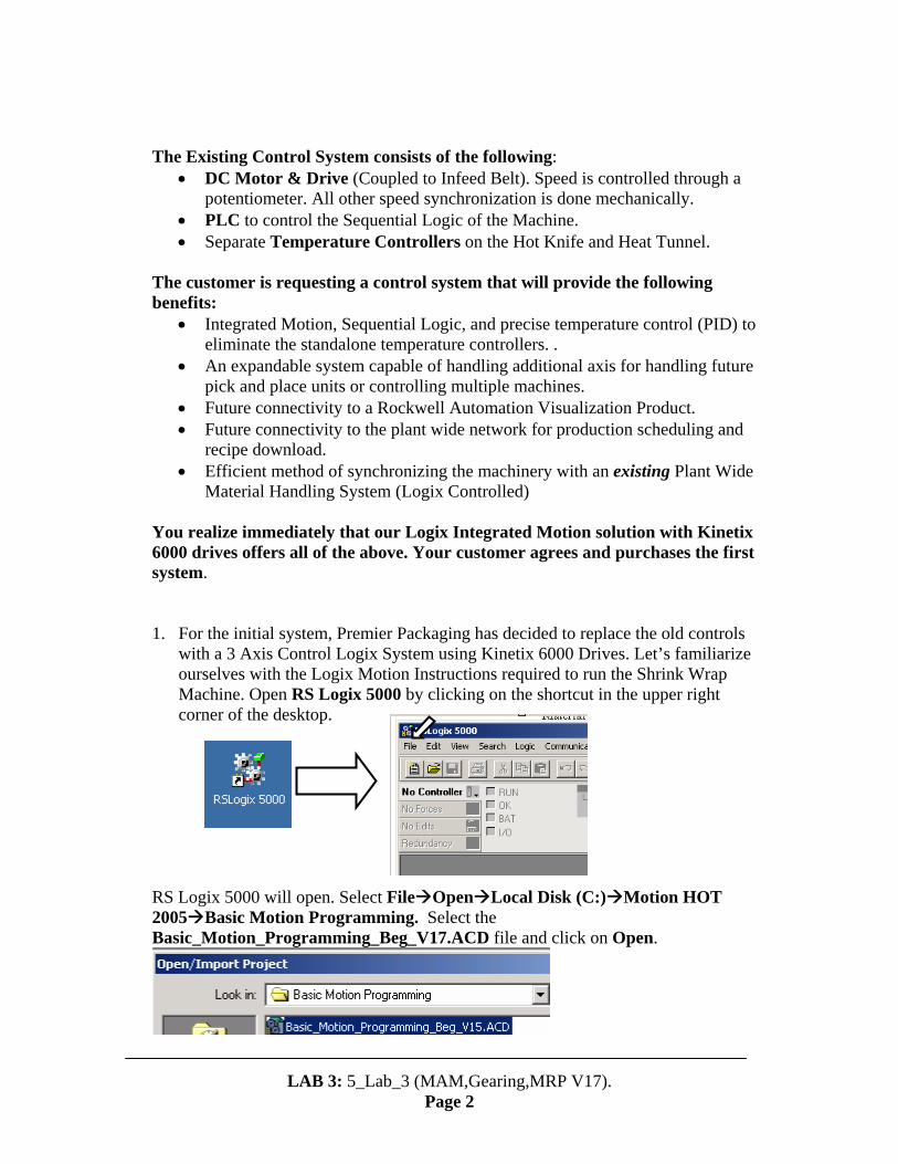
5. The Infeed Belt is also configured as a Rotary Axis. The pitch diameter of the belt
roll is designed to move one package length per revolution of the motor for the largest package length as defined in the machine specification. Package spacing is determined by pin spacing on the belt. The old mechanical design required a pulley ratio of (1:1) between the Hot Knife and the Infeed Belt to move the largest packages through the machine. Select the Homing Tab.
1:1
Package length set my pin spacing on belt.
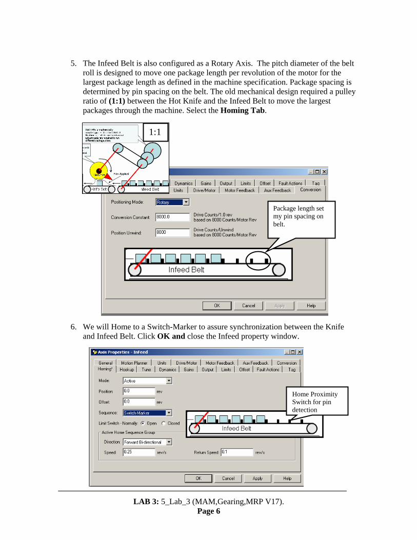
6. We will Home to a Switch-Marker to assure synchronization between the Knife
and Infeed Belt. Click OK and close the Infeed property window.
Home Proximity Switch for pin detection
LAB 3: 5_Lab_3 (MAM,Gearing,MRP V17).
Page 6

7. Select the Pick_Place Axis Right Click Properties.
LAB 3: 5_Lab_3 (MAM,Gearing,MRP V17).
Page 7
8. Review the General Homing Conversion Tabs for the Pick_Place Axis.
Click OK and close the Pick_Place property window.

9. Let’s cover the Logix Motion Instructions required to enable the drives and
synchronize the machine Axis. Double Click on the Initialization Routine in the MainProgram Routine.
10. The three instructions shown below will Enable/Disable the Infeed Drive and
Home the Infeed axis. Review the descriptions of each instruction below. Note, both MSO and MAH Instruction Enable the Drive. Enabling the Drive through an MSO, however, will allows the operator to move the axis prior to a home.
LAB 3: 5_Lab_3 (MAM,Gearing,MRP V17).
Page 8
Instruction Tag (Instruction Structure This instruction initiates the Home Sequence. If the
Homing operation is configured for Active, the drive is enabled and the home operation commences as configured. This is a transitional instruction.
The Motion Servo Off (MSF) instruction directly and immediately turns off drive outputs and disables the servo loop on any physical servo axis. This is a transitional instruction.
The Motion Servo On (MSO) instruction Directly activates the drive and enables the configured servo loop. It can be used anywhere in the program, but shouldn’t be used while the axis is moving. This will generate an ”Axis in Motion” error. This is a transitional instruction.
Axis Tag (Axis Structure)

RSLogix has an exceptional Instruction Help menu. Select Help Instruction Help. 11. Scroll down to the Motion Instructions for Relay Ladder Instructions. Let’s
briefly examine the Instruction Help for the MAH Instruction. Error codes can be found in the Instruction Structure. The Error Descriptions in the Help menus are very useful when debugging the motion program.
LAB 3: 5_Lab_3 (MAM,Gearing,MRP V17).
Page 9
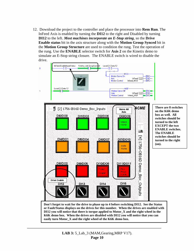
12. Download the project to the controller and place the processor into Rem Run. The
InFeed Axis is enabled by turning the DI12 to the right and Disabled by turning DI12 to the left. Most machines incorporate an E-Stop string, so the Drive Enable status bit in the axis structure along with the Motion Group Synced bit in the Motion Group Structure are used to condition the rung. Test the operation of the rung. Use the ENABLE selector switch for Axis 2 on the Kinetix demo to simulate an E-Stop string closure. The ENABLE switch is wired to disable the drive.
Don’t forget to wait for the drive to phase up to 4 before switching DI12. See the Status or Fault/Status displays on the drives for this number. When the drives are enabled with DI12 you will notice that there is torque applied to Motor_X and the right wheel in the K6K demo box. When the drives are disabled with DI12 you will notice that you can easily turn Motor_X and the right wheel of the K6K demo box.
There are 8 switches on the K6K demo box as well. All switches should be turned to the left EXCEPT the two ENABLE switches. The ENABLE switches should be turned to the right (on).
LAB 3: 5_Lab_3 (MAM,Gearing,MRP V17).
Page 10
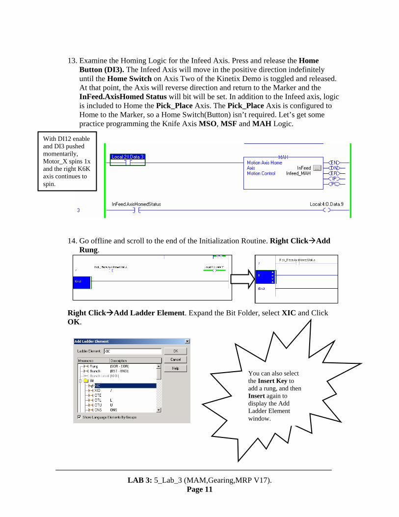
13. Examine the Homing Logic for the Infeed Axis. Press and release the Home
Button (DI3). The Infeed Axis will move in the positive direction indefinitely until the Home Switch on Axis Two of the Kinetix Demo is toggled and released. At that point, the Axis will reverse direction and return to the Marker and the InFeed.AxisHomed Status will bit will be set. In addition to the Infeed axis, logic is included to Home the Pick_Place Axis. The Pick_Place Axis is configured to Home to the Marker, so a Home Switch(Button) isn’t required. Let’s get some practice programming the Knife Axis MSO, MSF and MAH Logic.
With DI12 enable and DI3 pushed momentarily, Motor_X spins 1x and the right K6K axis continues to spin.
14. Go offline and scroll to the end of the Initialization Routine. Right Click Add
Rung. Right Click Add Ladder Element. Expand the Bit Folder, select XIC and Click OK.
You can also select the Insert Key to add a rung, and then Insert again to display the Add Ladder Element window.
LAB 3: 5_Lab_3 (MAM,Gearing,MRP V17).
Page 11

15. Double Click on the question mark and select the pull down arrow to display tags.
Axis Structure Tags are found under Controller Scope. Double Click on Knife.EnableInputStatus to accept the XIC. Scrolling for a status bit can be time consuming. If you know the name of your status bit, start typing it (i.e. Knife.E…) after double clicking on the instruction ?. RS-Logix will advance automatically and narrow your search.
Right Click Add Ladder Element to add the next XIC
Lets add the XIC elements for the Kinetix_Lab.GroupSynced and the Drive Enable Selector Switch (DI12) XIC elements in series with the Knife.EnableInputStatus XIC.
LAB 3: 5_Lab_3 (MAM,Gearing,MRP V17).
Page 12
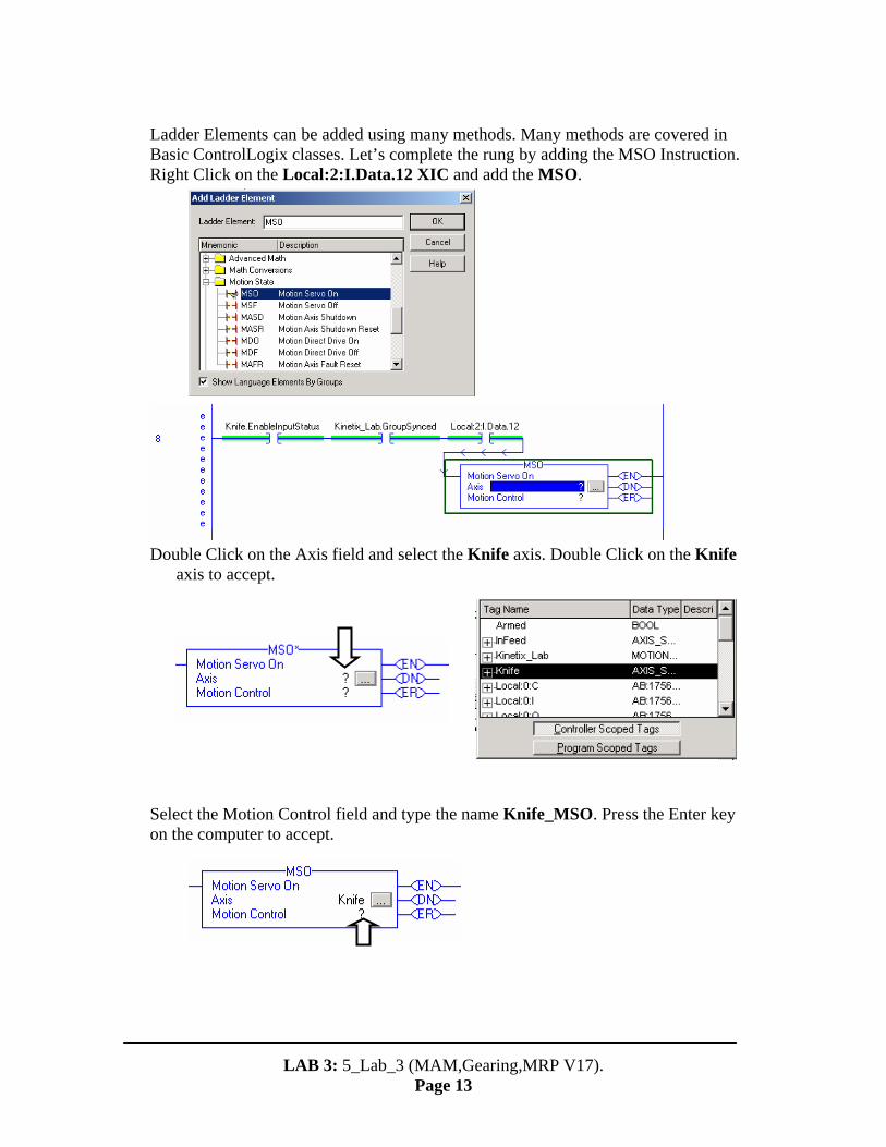
Ladder Elements can be added using many methods. Many methods are covered in Basic ControlLogix classes. Let’s complete the rung by adding the MSO Instruction. Right Click on the Local:2:I.Data.12 XIC and add the MSO. Double Click on the Axis field and select the Knife axis. Double Click on the Knife
axis to accept. Select the Motion Control field and type the name Knife_MSO. Press the Enter key on the computer to accept.
LAB 3: 5_Lab_3 (MAM,Gearing,MRP V17).
Page 13

16. The Motion Control field is used in every Logix Motion Instruction. This field
contains the unique tag or “Instruction Structure”for each Motion Command. The status bits and error data contained within a structure are used for sequencing Motion Commands and for diagnostics. Right Click on Knife_MSO and select New “Knife_MSO” Select a Data Type of Motion Instruction and a Main Program Scope.
Right Click
Select OK to create the new Instruction Structure Tag “Knife_MSO” for the MSO. This completes the rung. 17. Enter the remaining rungs displayed below, download and test operation.
Remember to right click on the Motion Control Field to create a new Instruction Structure for each Motion Instruction. When you’re finished, close the Initialization Routine.
LAB 3: 5_Lab_3 (MAM,Gearing,MRP V17).
Page 14
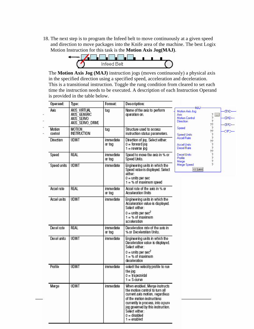
18. The next step is to program the Infeed belt to move continuously at a given speed
and direction to move packages into the Knife area of the machine. The best Logix Motion Instruction for this task is the Motion Axis Jog(MAJ).
The Motion Axis Jog (MAJ) instruction jogs (moves continuously) a physical axis in the specified direction using a specified speed, acceleration and deceleration. This is a transitional instruction. Toggle the rung condition from cleared to set each time the instruction needs to be executed. A description of each Instruction Operand is provided in the table below.
LAB 3: 5_Lab_3 (MAM,Gearing,MRP V17).
Page 15

Transitional Instructions are activated and run to completion. The MAJ will run indefinitely, unless we tell it to stop. The Logix Motion Instruction used to stop a MAJ is a Motion Axis Stop(MAS). The Motion Axis Stop(MAS) is used to initiate a controlled stop of any Motion process without disabling the servo loop. Examine the Stop Type Operand descriptions to gain a feel for the scope of this instruction. 19. Double Click on Infeed_Speed_Control Routine.
LAB 3: 5_Lab_3 (MAM,Gearing,MRP V17).
Page 16
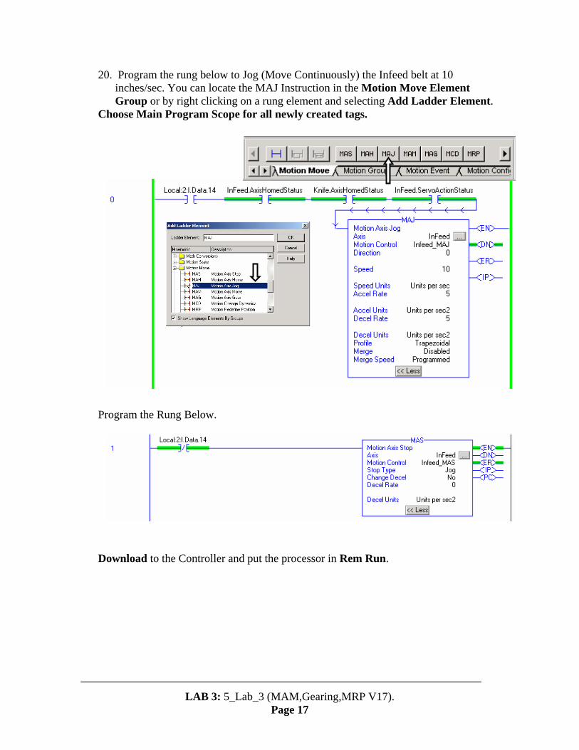
20. Program the rung below to Jog (Move Continuously) the Infeed belt at 10 inches/sec. You can locate the MAJ Instruction in the Motion Move Element Group or by right clicking on a rung element and selecting Add Ladder Element.
Choose Main Program Scope for all newly created tags. Program the Rung Below. Download to the Controller and put the processor in Rem Run.
LAB 3: 5_Lab_3 (MAM,Gearing,MRP V17).
Page 17

21. View your Logic. Based on your entered logic, the Drive must be Enabled and all
axis must be homed (synchronized). The Axis Structure Status bits are used in the MAJ rung to assure that all conditions are met prior to motion. Enable the drive by turning on DI12, Home all Axis by pressing DI3 on the Logix Demo and AXIS 2 HOME on K6K demo. After all axes are Homed, turn the Infeed Belt (DI14) On and Off and observe the Kinetix Drive.
Before enabling, put all white markers to the front and 12 noon positon. Follow the sequence below. Note
The Infeed(Axis 2) requires a simulated Home Switch Closure on the Kinetix Demo Unit.
LAB 3: 5_Lab_3 (MAM,Gearing,MRP V17).
Page 18
When the Infeed Belt is turned on, it accelerates at 5 in/sec^2. When it’s turned off, it decelerates at the configured Maximum Deceleration Rate (reference Dynamics Tab in Axis Properties. On a real machine, an abrupt deceleration can cause damage. Let’s fix the problem. Go Offline and make the changes below to Rung 1 in the Infeed Speed Control routine. Download and test. The Infeed Belt will decelerate at 5 in/sec^2.
AXIS 2 HOME on K6K demo box.
When you hit this home switch, the Motor_X motor spin 1X, the left K6K motor spins ½ X, and the right K6K motor continues to spin until the next step.
Now you can jog the right K6K motor on and off.

22. The Infeed belt Jogs nicely, but now we need to vary the speed. Different
packages require different package feedrates. The Instruction required to do the job is the Motion Change Dynamics(MCD). The MCD instruction changes the speed, acceleration and deceleration of trapezoidal profiles moves on the fly. The MCD is a transitional instruction.
LAB 3: 5_Lab_3 (MAM,Gearing,MRP V17).
Page 19

23. Add the rungs below to the Infeed_Speed_Control Routine. The Infeed_Speed
Tag(Program Scope) has been created and is an alias for AI0( potentiometer on Logix Demo). The MCD in our example is used to change the speed of the infeed belt. Save and Download to the processor and test your logic. Place the processor in the Rem Run mode. Prior to testing your logic,turn on the Drive Enable(DI12) and Home(DI3) all the axis. You’ll need to follow this sequence after every program download. Turn on the Infeed Belt and rotate the AI0 potentiometer. The speed will change. This is a simple exercise, yet very powerful. Our speed is now a variable capable of being accessed and changed from a visualization product, from a recipe or from a Level II production scheduling system via one of Rockwell’s network solutions.
Remember the sequence is: wait for SERCOS drive to get to phase 4, turn on DI12 to enable, push DI3 to home Pick and Place (Ultra) and Knife (left K6K), turn AXIS 2 HOME to home Infeed belt (right K6K), then turn on DI14 to jog the Infeed belt (right K6K). To vary the speed of the Infeed belt (right K6K) vary the position of AI0 of the ControlLogix demo box.
AI0 in ControlLogix demo box is the Infeed Speed control.
MCD is a transitional instruction. TON is required to pulse the MCD with the new speed values as the potentiometer is varied.
LAB 3: 5_Lab_3 (MAM,Gearing,MRP V17).
Page 20
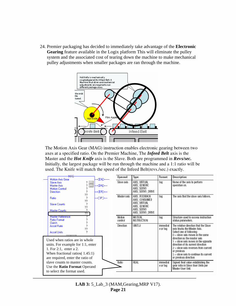
24. Premier packaging has decided to immediately take advantage of the Electronic
Gearing feature available in the Logix platform This will eliminate the pulley system and the associated cost of tearing down the machine to make mechanical pulley adjustments when smaller packages are ran through the machine.
The Motion Axis Gear (MAG) instruction enables electronic gearing between two axes at a specified ratio. On the Premier Machine, The Infeed Belt axis is the Master and the Hot Knife axis is the Slave. Both are programmed in Revs/sec. Initially, the largest package will be run through the machine and a 1:1 ratio will be used. The Knife will match the speed of the Infeed Belt(revs./sec.) exactly.
LAB 3: 5_Lab_3 (MAM,Gearing,MRP V17).
Page 21
Used when ratios are in whole units. For example for 1:1, enter 1. For 2:1, enter a 2. When fractional ratios( 1.45:1) are required, enter the ratio of slave counts to master counts. Use the Ratio Format Operand to select the format used.

25. Select offline mode.
On the Premier Machine, Gearing on the Infeed Belt and the Knife will be enabled simultaneously. Therefore the knife will accelerate smoothly at 5 revs/sec as it tracks the Infeed belt. If the infeed was moving at steady state when gearing was enabled, the clutch feature would be used to prevent abrupt motion. If you’ve ever driven a stick shift, compare Accel Rate/Decel Rate to how fast you release the clutch.
Use Command for smooth velocity control. Use Actual for tight Position Control.
LAB 3: 5_Lab_3 (MAM,Gearing,MRP V17).
Page 22
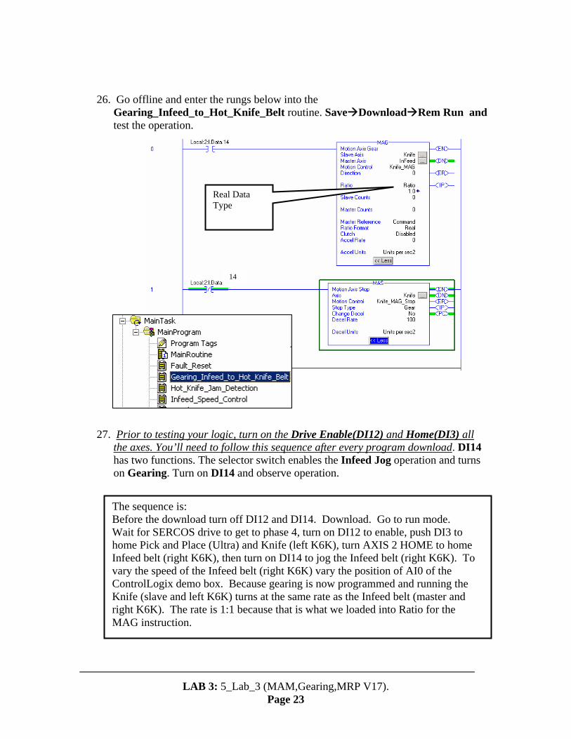
26. Go offline and enter the rungs below into the
Gearing_Infeed_to_Hot_Knife_Belt routine. Save Download Rem Run and test the operation.
14
Real Data Type
27. Prior to testing your logic, turn on the Drive Enable(DI12) and Home(DI3) all
the axes. You’ll need to follow this sequence after every program download. DI14 has two functions. The selector switch enables the Infeed Jog operation and turns on Gearing. Turn on DI14 and observe operation.
The sequence is: Before the download turn off DI12 and DI14. Download. Go to run mode. Wait for SERCOS drive to get to phase 4, turn on DI12 to enable, push DI3 to home Pick and Place (Ultra) and Knife (left K6K), turn AXIS 2 HOME to home Infeed belt (right K6K), then turn on DI14 to jog the Infeed belt (right K6K). To vary the speed of the Infeed belt (right K6K) vary the position of AI0 of the ControlLogix demo box. Because gearing is now programmed and running the Knife (slave and left K6K) turns at the same rate as the Infeed belt (master and right K6K). The rate is 1:1 because that is what we loaded into Ratio for the MAG instruction.
LAB 3: 5_Lab_3 (MAM,Gearing,MRP V17).
Page 23

28. The Infeed and Knife should track each other in a 1:1 relationship. Adjust the
AI0 potentiometer and observe the speed of both axis. Double Click on the Gearing Trend Run.
LAB 3: 5_Lab_3 (MAM,Gearing,MRP V17).
Page 24
Commanded Position for the Infeed and Knife are monitored in the trend above. We can display how tightly the axis are synchronized by disabling the isolated trending feature. To accomplish this, place the mouse pointer over the trend area. Right Click Chart Properties Y-Axis Deselect Isolated Graphing OK.
Deselect
Adjust the speed and x-axis trend timing to obtain the view displayed
Infeed, blue, master, right K6K and top pen Knife, green, slave, left K6K and bottom pen
It appears like the Infeed Position(Blue Pen) has been eliminated. In reality, they are tracking very closely and the Infeed is hidden behind the Knife commanded position. Close the Gearing Trend.
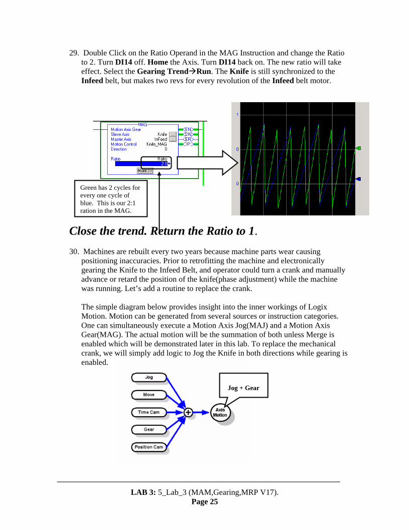
29. Double Click on the Ratio Operand in the MAG Instruction and change the Ratio to 2. Turn DI14 off. Home the Axis. Turn DI14 back on. The new ratio will take effect. Select the Gearing Trend Run. The Knife is still synchronized to the Infeed belt, but makes two revs for every revolution of the Infeed belt motor.
LAB 3: 5_Lab_3 (MAM,Gearing,MRP V17).
Page 25
Close the trend. Return the Ratio to 1.
Green has 2 cycles for every one cycle of blue. This is our 2:1 ration in the MAG.
30. Machines are rebuilt every two years because machine parts wear causing
positioning inaccuracies. Prior to retrofitting the machine and electronically gearing the Knife to the Infeed Belt, and operator could turn a crank and manually advance or retard the position of the knife(phase adjustment) while the machine was running. Let’s add a routine to replace the crank.
The simple diagram below provides insight into the inner workings of Logix Motion. Motion can be generated from several sources or instruction categories. One can simultaneously execute a Motion Axis Jog(MAJ) and a Motion Axis Gear(MAG). The actual motion will be the summation of both unless Merge is enabled which will be demonstrated later in this lab. To replace the mechanical crank, we will simply add logic to Jog the Knife in both directions while gearing is enabled.
Jog + Gear

31. Double Click on the Manual_Hot_Knife_Phase_Correction Routine. Four Rungs will display(2 shown above). They simply jog and stop the Knife in both both directions of travel. Select Online Rem Run.
Enable(DI12) and Home(DI3 and AXIS 2 HOME) the axis. Turn on the Infeed Belt On/Enable Gearing(DI14). Open the Gear Trend Run .Note the phase relationship between the Knife and Infeed as you Jog( DI1 & DI2) the Knife in both directions. Close the trend.
Notice that the Knife (slave and left K6K) speeds up when you hold DI1 and slows down when you hold DI2.
LAB 3: 5_Lab_3 (MAM,Gearing,MRP V17).
Page 26

32. So far, we’ve run the machine in a continuous mode (Gearing). With Logix, we’ve eliminated costly downtime by synchronizing the Knife speed to the Infeed Belt speed with Motion Axis Gearing. Premier Packaging has decided to add an additional axis to control a pick and place unit. This is a single axis picker.
The operation is very simple. Every third box on the infeed belt trips a photo eye. The picker photo eye is examined in the Pick_Place_State_Machine Routine The routine commands the axis to move to a conveyor, activate the grippers(grabs packages), move back to the Infeed Belt and deactivate the gripper to place the packages on the belt. Waits for the photo-eye(DI8) to start over.
The Pick_Place State Machine routine uses the Motion Axis Move(MAM) Instruction to control the Picker. The Motion Axis Move (MAM) instruction moves a physical axis to a specified position (Absolute Move) or by a specified incremental distance (Incremental Move) at a specified speed, acceleration and deceleration.
33. Double Click and Open the Pick_Place_State_Machine routine.
LAB 3: 5_Lab_3 (MAM,Gearing,MRP V17).
Page 27
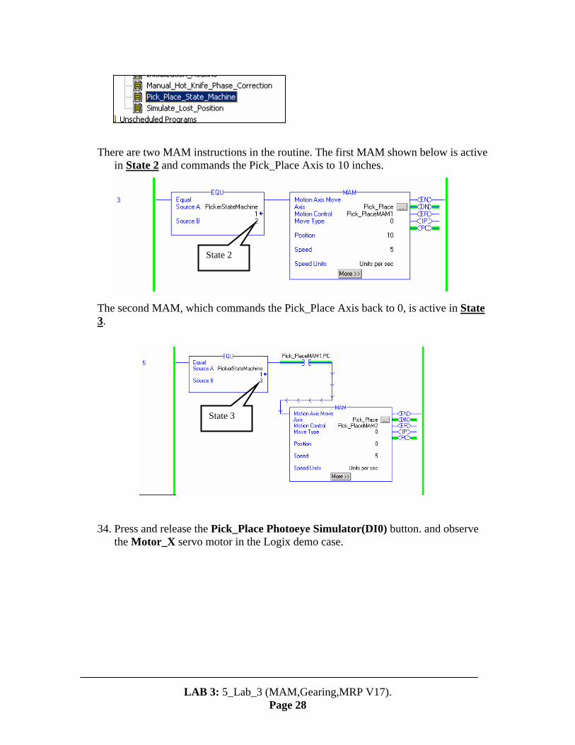
There are two MAM instructions in the routine. The first MAM shown below is active
in State 2 and commands the Pick_Place Axis to 10 inches.
State 2
The second MAM, which commands the Pick_Place Axis back to 0, is active in State 3.
State 3
34. Press and release the Pick_Place Photoeye Simulator(DI0) button. and observe
the Motor_X servo motor in the Logix demo case.
LAB 3: 5_Lab_3 (MAM,Gearing,MRP V17).
Page 28

35. The motor will rotate 10 revs. In the positive direction, decelerate to a stop, turn
on DO08, and then -10revs. And return to the 0 position and turn off DO08.
The pilot lights may be burned out on your demo box. To can observe the bit going true via being online to the ladder logic editor.
Using a State Machine model is useful in programming. In addition to providing an easy method of using the MAM Instruction Structure (i.e. .IP, .PC bits) bits to schedule sequential moves, it also allows for quick diagnosis of machine problems. Press and release the Photoeye Simulator Button(DI0). Quickly turn off the Drive Enable(DI12) while the axis is moving in the positive direction. Upon examination of the program Pick_Place State_Machine program, you know immediately that the Pick & Place unit is hung up in State 2 The Axis Structure will reveal that Servo Action is off. Turn on Drive Enable(DI12). This is a simplistic example. The power of State Machine becomes more apparent as machinery becomes more complex.
Controller Tags, Controller Scope.
36. Periodically, a package jam occurs. When this occurs, the Knife and Infeed belt
must disable gearing immediately, and move to a safe position. This is easily accomplished by a series with a MAM instruction with Merge enabled.
Retract the Knife, back up the Infeed belt to a safe position to prevent crushing the entire package.
LAB 3: 5_Lab_3 (MAM,Gearing,MRP V17).
Page 29

37. Double Click on the Hot_Knife_Jam_Detection routine.The program consist of
two MAM instructions. Both have Merge enabled. A Motion instruction with Merge enabled simply cancels any other motion operation taking place (Gearing in our example) and executes its commanded motion until completion.
Rotary Negative Move will command the Infeed belt to return to zero in the negative direction every time it is executed regardless of the position of the Infeed belt when the MAM below is executed..
Rotary Shortest path is selected for the Knife. This is the best selection for the knife. If the Knife is at 0.51 revs, it has advanced past the bottom. If the MAM below is executed, the Knife will continue traveling in the positive direction until it reaches 0.00. Conversely, if the Knife is at 0.49 revs and not reached the bottom, it will reverse direction and return to zero.
38. Turn off all Control Logix Demo Case Selector Switches. Enable the
Drive(DI12), Home the Axis(DI03 and AXIS 2 HOME), turn on Infeed On/Knife(DI14) . Adjust AI0 to a speed that allows you to easily observe the rotation of the axis. Turn on Jam(DI15) observe what happens. Turn off Jam(DI15) and Infeed On/Knife(DI14). Turn on Infeed On/Knife(DI14) to re-enable the axis in the gearing mode. Simulate a jam with the knife in different positions and observe. (To vary the position you must turn off DI12, DI14 and DI15, then you rotate the white markers on the two K6K axes. Then turn on the switches DI12, DI14 and DI15 in that order.)
This concludes the basic motion lab.
LAB 3: 5_Lab_3 (MAM,Gearing,MRP V17).
Page 30