Orientation Winthrop University-School Partnership Network Orientation.

EPS 116 – Laboratory Structural Geology
Lab Exercise #1 Spring 2016 Page 1 of 9
LAB #1 – Orientation of Structures in Space Familiarize yourself with the following terms. Sketch each feature and include relevant details, e.g., footwall, hanging wall, motion arrows, etc. Also always include at least 3 horizontal layers and an up arrow in the cross sections and a north arrow in each map view. Stress vs. Strain compression tension contraction/shortening extension Brittle Deformation joint fault earthquake thrust/reverse fault normal fault footwall hanging wall strike-slip fault right lateral or dextral left lateral or sinistral dip-slip oblique-slip Ductile Deformation fold anticline syncline Map View longitude latitude geographic vs. magnetic north topography scale profile
Feature Cross Section Map View
Horst and Graben (Label hanging /foot wall and slip direction)
Thrust Fault (Label hanging / footwall and slip direction)
Anticline (Label hinge axis, force direction, contact topo lines in map view)
Normal Fault (Label hanging / footwall and slip direction)
Syncline (Label hinge axis, force direction, contact topo lines in map view)
Strike-Slip fault (Label hanging / footwall and slip direction)

EPS 116 – Laboratory Structural Geology
Lab Exercise #1 Spring 2016 Page 2 of 9
Strike & Dip Strike and dip describe the orientation of a plane in space. Example: the peaked roof of a house:
Strike is the orientation of the intersection line of the plane in question (roof of a house) with the horizontal plane. If you were to look down on the house from directly above, it would look like this: The angle between the strike line and north is used to describe the strike. In this example the strike is, in essence, the direction the house is facing. If you look at the front of the house, it looks like this: The angle that the roof makes with the horizontal is called the dip. In this example the dip is, in essence, the steepness of the roof.
Water Analogy If you submerge a plane, the strike line will be the water-line.
The dip direction is the direction that a drop of water will flow down the plane.
Strike Line
Dip Direction
Strike Line North
Strike
Dip Horizontal

EPS 116 – Laboratory Structural Geology
Lab Exercise #1 Spring 2016 Page 3 of 9
Trend & Plunge In structural geology, the orientations of linear features are also important. The orientation of lines in space can be described using two distinct angles referred to as the trend and plunge. To measure the trend and plunge of a linear feature, look at it end on: A horizontal line will look like a point. This line has a plunge of 0 degrees: But a line that is not horizontal will look like this when viewed end on: To measure the trend of this line, you simply record the direction that you are facing when the linear feature is viewed dead on. From above, this will look like: From the side, that same line may look like: Look familiar? It is. To measure strike, you took the trend of a horizontal line that you called the strike-line. To measure the dip, you envisioned a linear feature on the plane -- its dip direction line -- and you measured the plunge of that line Rake Rake is a single angle measurement that, along with the strike and dip of a plane, will give the orientation of linear features in a plane. You can measure rake by laying a protractor against the plane and measuring the angle between the strike line and the linear features. You can always use trend and plunge to describe the orientation of linear features but rake only describes linear features that exist in a plane.
North
Trend
Plunge
Horizontal
Linear Feature in Plane (e.g., slickenlines)
Strike Line
Rake
EPS 116 – Laboratory Structural Geology
Lab Exercise #1 Spring 2016 Page 4 of 9
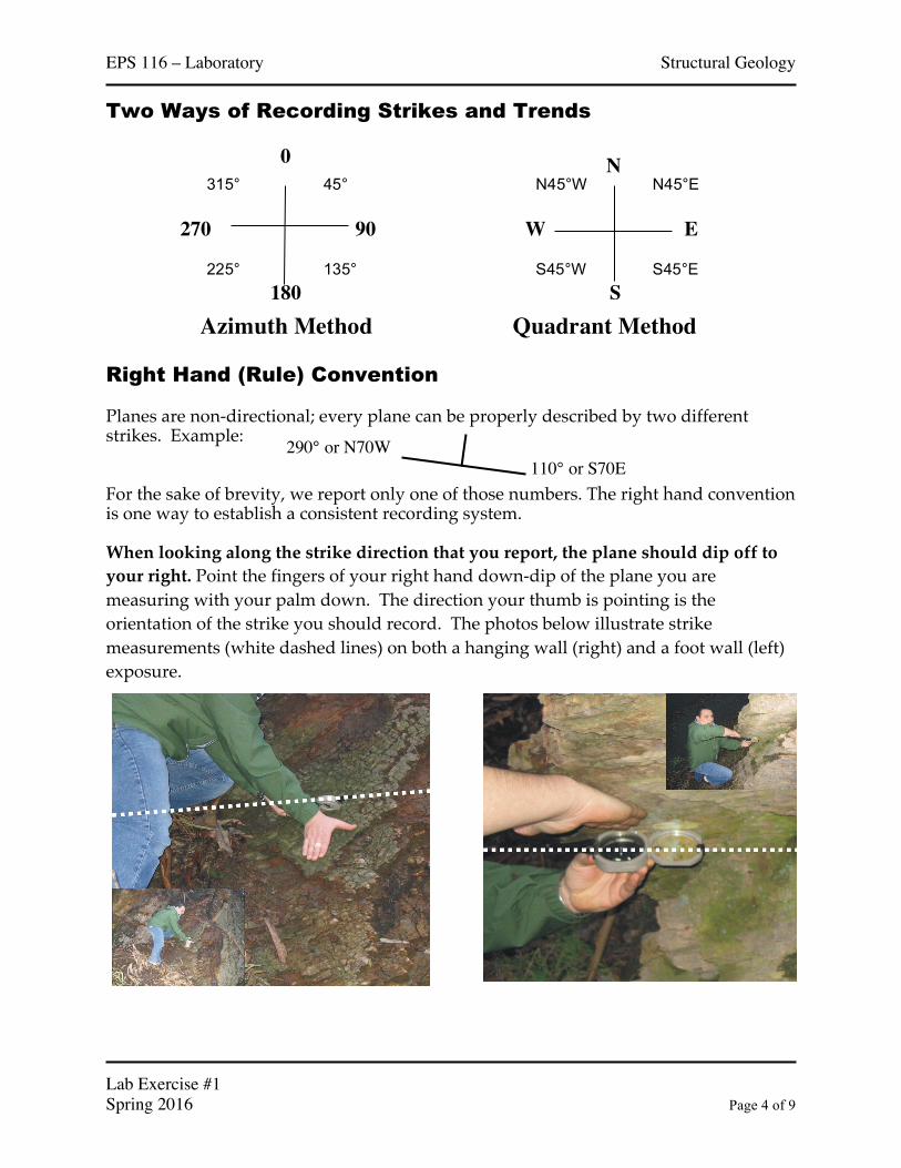
Two Ways of Recording Strikes and Trends Right Hand (Rule) Convention Planes are non-directional; every plane can be properly described by two different strikes. Example: For the sake of brevity, we report only one of those numbers. The right hand convention is one way to establish a consistent recording system. When looking along the strike direction that you report, the plane should dip off to your right. Point the fingers of your right hand down-dip of the plane you are measuring with your palm down. The direction your thumb is pointing is the orientation of the strike you should record. The photos below illustrate strike measurements (white dashed lines) on both a hanging wall (right) and a foot wall (left) exposure.
0
90
180
270
45°
135° 225°
315° N
E
S
W
N45°E
S45°E S45°W
N45°W
Azimuth Method Quadrant Method
110° or S70E 290° or N70W

EPS 116 – Laboratory Structural Geology
Lab Exercise #1 Spring 2016 Page 5 of 9
Measuring Strike & Dip -- Tips Since strike is measured in the horizontal plane, your Brunton transit/compass should always be horizontal. Use the bull’s-eye level to maintain horizontality during measurement. When measuring dips, be sure to measure the TRUE dip. The true dip is the steepest angle that you can measure on a plane. Try rotating your Brunton a bit while making your dip measurements to ensure that you are recording the maximum dip. Here is an example of a geologic structure whose orientation you might want to measure some day:
NORTH
Strike Line
Dip Direction

EPS 116 – Laboratory Structural Geology
Lab Exercise #1 Spring 2016 Page 6 of 9
LAB Exercise #1 PARTA–Completeinlab.Willbegradedbeforeleaving.
1. Campus scavenger hunt. (20 pts)
a. Rock 1 – Outside McCone What is the strike and dip of the face that we’re looking at now? (3 pts) What is the trend and plunge of the lineation in amphiboles? (3 pts) What are the rock types? (BONUS 2 pt)
b. Rock 2 – Outside McCone What is the strike and dip of the face? (3 pts) What is the trend and plunge of the linear feature on this face? (3 pts)
c. Stairwell 1 – Outside East Asian Library What is the strike and dip of the lower staircase handrail? (2 pts)
d. Stairwell 2 – Near Doe Library What is the strike and dip of the lower staircase handrail? (2 pts) What is the strike and dip of the upper staircase handrail? (2 pts) How much would you have to rotate the first handrail by so that it would look like the second; i.e. what strike will give you the same dip angle? (2 pt)
EPS 116 – Laboratory Structural Geology
Lab Exercise #1 Spring 2016 Page 7 of 9
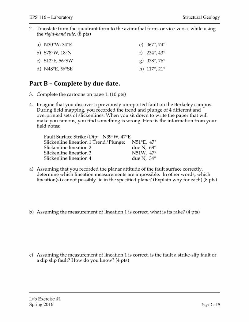
2. Translate from the quadrant form to the azimuthal form, or vice-versa, while using the right-hand rule. (8 pts) a) N30°W, 34°E b) S78°W, 18°N c) S12°E, 56°SW d) N48°E, 56°SE
e) 067°, 74° f) 234°, 43° g) 078°, 76° h) 117°, 21°
PartB–Completebyduedate.3. Complete the cartoons on page 1. (10 pts)
4. Imagine that you discover a previously unreported fault on the Berkeley campus. During field mapping, you recorded the trend and plunge of 4 different and overprinted sets of slickenlines. When you sit down to write the paper that will make you famous, you find something is wrong. Here is the information from your field notes:
Fault Surface Strike/Dip: N39°W, 47°E
Slickenline lineation 1 Trend/Plunge: N51°E, 47° Slickenline lineation 2 due N, 68° Slickenline lineation 3 N51W, 47° Slickenline lineation 4 due N, 34° a) Assuming that you recorded the planar attitude of the fault surface correctly,
determine which lineation measurements are impossible. In other words, which lineation(s) cannot possibly lie in the specified plane? (Explain why for each) (8 pts)
b) Assuming the measurement of lineation 1 is correct, what is its rake? (4 pts) c) Assuming the measurement of lineation 1 is correct, is the fault a strike-slip fault or
a dip slip fault? How do you know? (4 pts)

EPS 116 – Laboratory Structural Geology
Lab Exercise #1 Spring 2016 Page 8 of 9
5. Think in 3 dimensions. Sketch a 3D isometric block diagram of a cube (like the example provided). Indicate the orientation of the three dimensional coordinate system that defines your reference frame (east-north-up). Within the volume of this cube, draw a plane whose attitude is 225˚, 30˚NW that cuts through the cube. Label the strike and dip with respect to the ‘missing’ portion of the block. Make sure to use a ruler to keep the line straight so the angle estimates are correct. (10 pts)
6. Why do we learn strike and dip? Why is it important to describe the orientation of
planes and lines in the field? (20 pts – 5 -10 sentences)

EPS 116 – Laboratory Structural Geology
Lab Exercise #1 Spring 2016 Page 9 of 9
7. Sometimes, the orientation of geologic structures is recorded by someone else and reported in graphical format. The maps below show contours of the depth of a lithologic contact below sea-level with North direction towards the top of the page. Estimate the attitude of the contact at point X for each of the structural contour maps and describe the structure using a simple phrase (i.e., "anticline") and explain your reasoning. (16 pts)


![New Member Orientation [Insert Club Name Here]. 2Lions Clubs InternationalNew Member Orientation New Member Orientation Summary New member orientation.](https://static.fdocuments.in/doc/165x107/551aa195550346e0158b5933/new-member-orientation-insert-club-name-here-2lions-clubs-internationalnew-member-orientation-new-member-orientation-summary-new-member-orientation.jpg)