
LA1403 (e)-9Y111-00882 - KUBOTA - produkty japonského ... · Weight 210 kg (463 lbs) 235 kg (518...
119
WORKSHOP MANUAL FRONT LOADER LA1403 KiSC issued 08, 2008 A
Transcript of LA1403 (e)-9Y111-00882 - KUBOTA - produkty japonského ... · Weight 210 kg (463 lbs) 235 kg (518...
WORKSHOP MANUALFRONT LOADER
LA1403
KiSC issued 08, 2008 A
TO THE READER
This Workshop Manual has been prepared to provide servicing personnel withinformation on the mechanism, service and maintenance of KUBOTA Front LoaderLA1403. It is divided into three parts, “General”, “Mechanism” and “Servicing”.
GeneralInformation on the tractor identification, the general precautions, maintenance check
list, check and maintenance and special tools are described.
MechanismInformation on the construction and function are included. This part should be
understood before proceeding with troubleshooting, disassembling and servicing.Refer to Front Loader Mechanism Workshop Manual (Code No. 9Y021-18210) for
the one which has not been described in this workshop manual.
ServicingInformation on the troubleshooting, servicing specification lists, tightening torque,
checking and adjusting, disassembling and assembling, and servicing which coverprocedures, precautions, factory specifications and allowable limits.
All information illustrations and specifications contained in this manual are based onthe latest product information available at the time of publication. The right is reservedto make changes in all information at any time without notice.
July 2008© KUBOTA Corporation 2008
KiSC issued 08, 2008 A
1
LA1403, WSM SAFETY INSTRUCTIONS
SAFETY INSTRUCTIONS
BEFORE SERVICING AND REPAIRING• Read all instructions and safety instructions in this
manual and on your engine safety decals.• Clean the work area and engine.• Park the machine on a firm and level ground.• Allow the engine to cool before proceeding.• Stop the engine, and remove the key.• Disconnect the battery negative cable.• Hang a “DO NOT OPERATE” tag in operator
station.
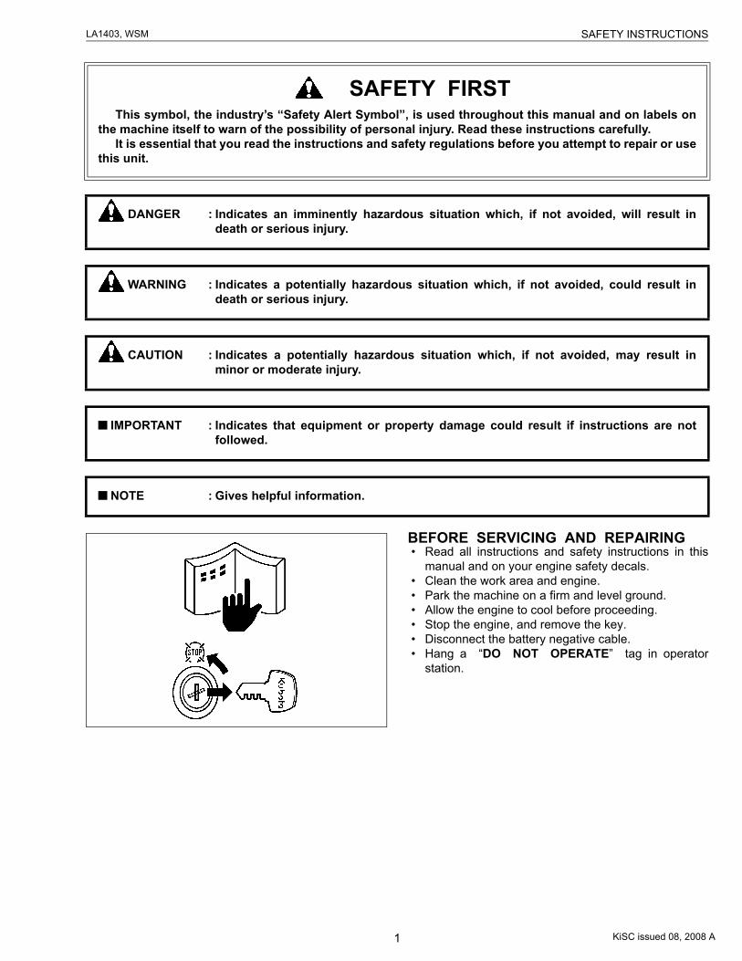
SAFETY FIRSTThis symbol, the industry’s “Safety Alert Symbol”, is used throughout this manual and on labels on
the machine itself to warn of the possibility of personal injury. Read these instructions carefully.It is essential that you read the instructions and safety regulations before you attempt to repair or use
this unit.
DANGER : Indicates an imminently hazardous situation which, if not avoided, will result indeath or serious injury.
WARNING : Indicates a potentially hazardous situation which, if not avoided, could result indeath or serious injury.
CAUTION : Indicates a potentially hazardous situation which, if not avoided, may result inminor or moderate injury.
IMPORTANT : Indicates that equipment or property damage could result if instructions are notfollowed.
NOTE : Gives helpful information.
KiSC issued 08, 2008 A
2
LA1403, WSM SAFETY INSTRUCTIONS
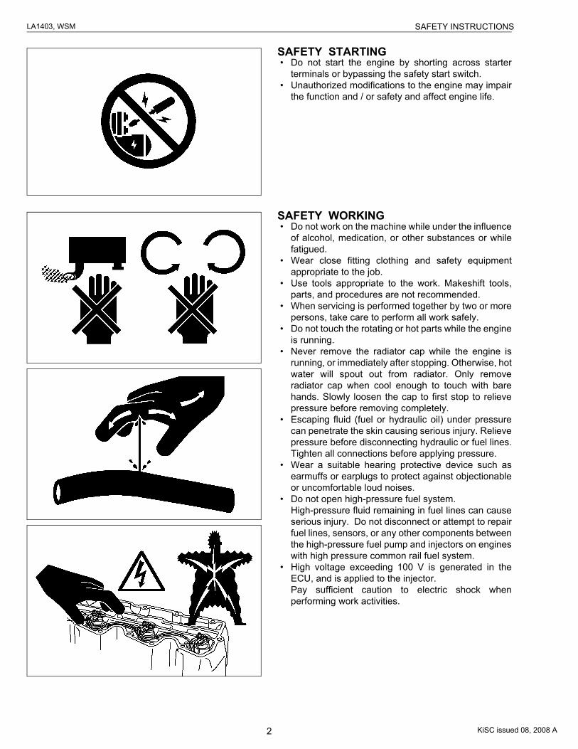
SAFETY STARTING• Do not start the engine by shorting across starter
terminals or bypassing the safety start switch.• Unauthorized modifications to the engine may impair
the function and / or safety and affect engine life.
SAFETY WORKING• Do not work on the machine while under the influence
of alcohol, medication, or other substances or whilefatigued.
• Wear close fitting clothing and safety equipmentappropriate to the job.
• Use tools appropriate to the work. Makeshift tools,parts, and procedures are not recommended.
• When servicing is performed together by two or morepersons, take care to perform all work safely.
• Do not touch the rotating or hot parts while the engineis running.
• Never remove the radiator cap while the engine isrunning, or immediately after stopping. Otherwise, hotwater will spout out from radiator. Only removeradiator cap when cool enough to touch with barehands. Slowly loosen the cap to first stop to relievepressure before removing completely.
• Escaping fluid (fuel or hydraulic oil) under pressurecan penetrate the skin causing serious injury. Relievepressure before disconnecting hydraulic or fuel lines.Tighten all connections before applying pressure.
• Wear a suitable hearing protective device such asearmuffs or earplugs to protect against objectionableor uncomfortable loud noises.
• Do not open high-pressure fuel system.High-pressure fluid remaining in fuel lines can causeserious injury. Do not disconnect or attempt to repairfuel lines, sensors, or any other components betweenthe high-pressure fuel pump and injectors on engineswith high pressure common rail fuel system.
• High voltage exceeding 100 V is generated in theECU, and is applied to the injector.Pay sufficient caution to electric shock whenperforming work activities.
KiSC issued 08, 2008 A
3
LA1403, WSM SAFETY INSTRUCTIONS
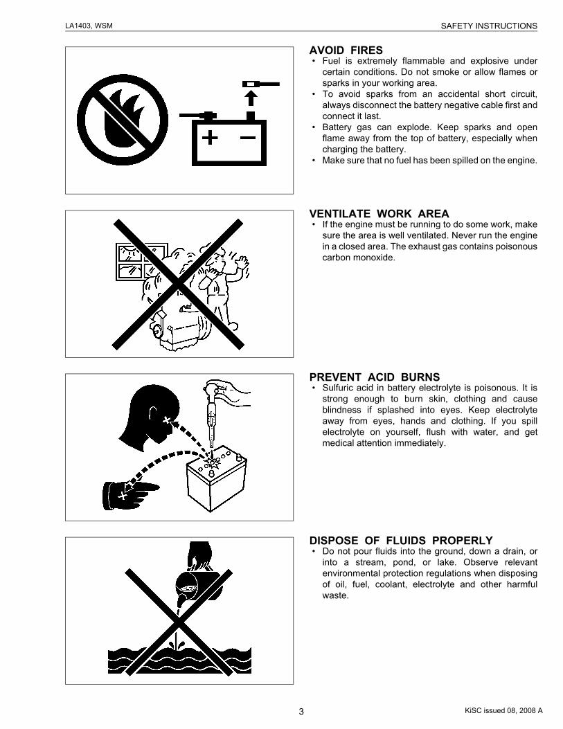
AVOID FIRES• Fuel is extremely flammable and explosive under
certain conditions. Do not smoke or allow flames orsparks in your working area.
• To avoid sparks from an accidental short circuit,always disconnect the battery negative cable first andconnect it last.
• Battery gas can explode. Keep sparks and openflame away from the top of battery, especially whencharging the battery.
• Make sure that no fuel has been spilled on the engine.
VENTILATE WORK AREA• If the engine must be running to do some work, make
sure the area is well ventilated. Never run the enginein a closed area. The exhaust gas contains poisonouscarbon monoxide.
PREVENT ACID BURNS• Sulfuric acid in battery electrolyte is poisonous. It is
strong enough to burn skin, clothing and causeblindness if splashed into eyes. Keep electrolyteaway from eyes, hands and clothing. If you spillelectrolyte on yourself, flush with water, and getmedical attention immediately.
DISPOSE OF FLUIDS PROPERLY• Do not pour fluids into the ground, down a drain, or
into a stream, pond, or lake. Observe relevantenvironmental protection regulations when disposingof oil, fuel, coolant, electrolyte and other harmfulwaste.
KiSC issued 08, 2008 A
4
LA1403, WSM SAFETY INSTRUCTIONS
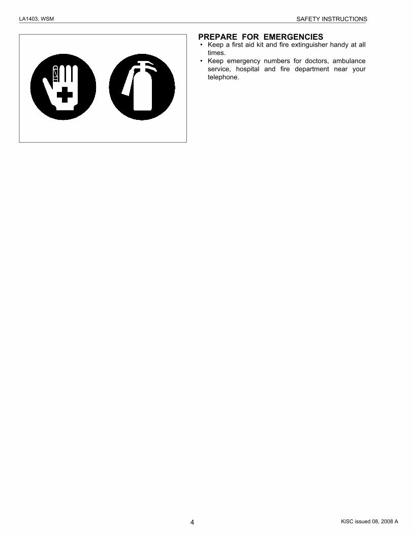
PREPARE FOR EMERGENCIES• Keep a first aid kit and fire extinguisher handy at all
times.• Keep emergency numbers for doctors, ambulance
service, hospital and fire department near yourtelephone.
KiSC issued 08, 2008 A
5
LA1403, WSM SAFETY INSTRUCTIONS
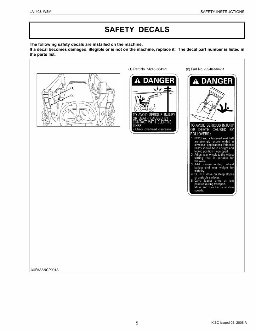
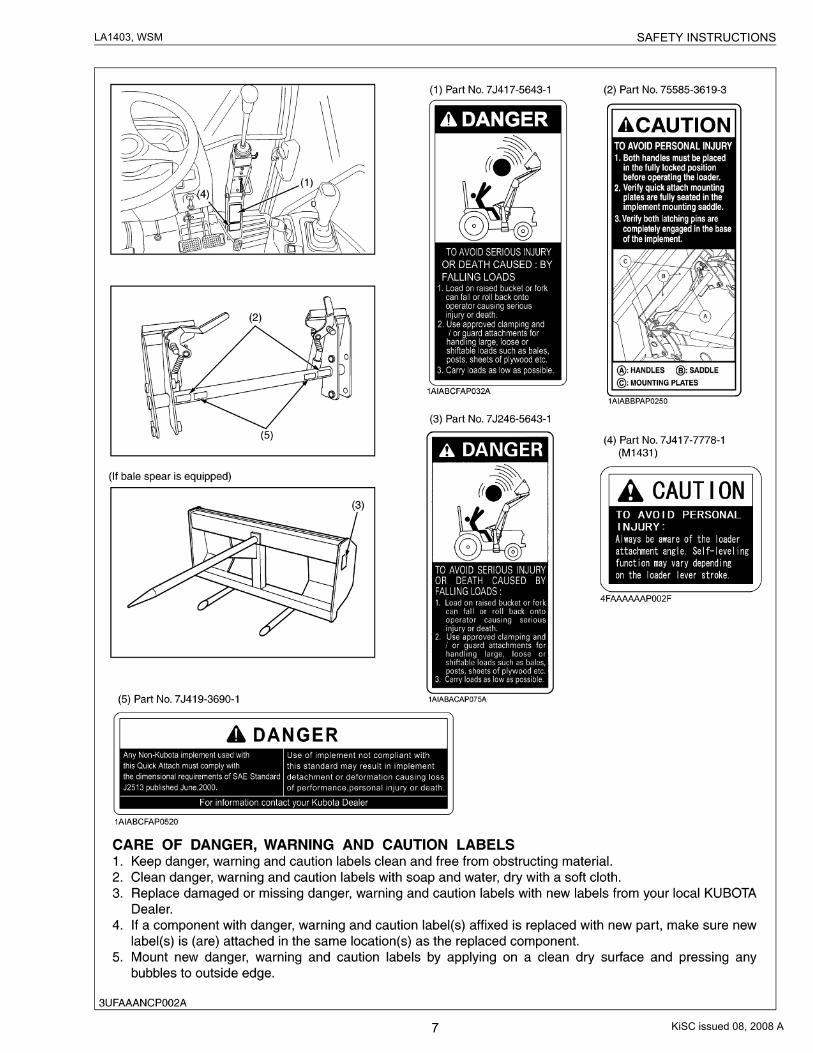
The following safety decals are installed on the machine.If a decal becomes damaged, illegible or is not on the machine, replace it. The decal part number is listed inthe parts list.
SAFETY DECALS
KiSC issued 08, 2008 A
6
LA1403, WSM SAFETY INSTRUCTIONS
KiSC issued 08, 2008 A
7
LA1403, WSM SAFETY INSTRUCTIONS
KiSC issued 08, 2008 A
8
LA1403, WSM LOADER TERMINOLOGY
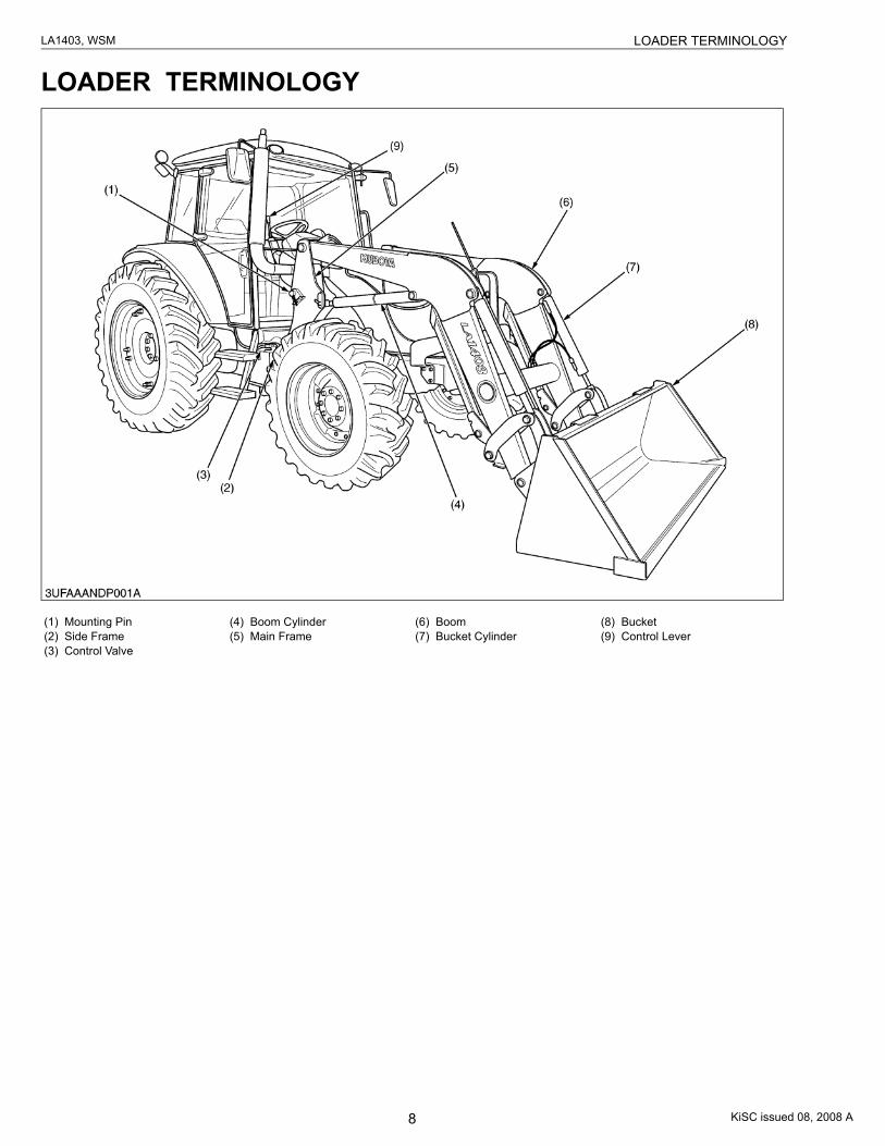
LOADER TERMINOLOGY
(1) Mounting Pin(2) Side Frame(3) Control Valve
(4) Boom Cylinder(5) Main Frame
(6) Boom(7) Bucket Cylinder
(8) Bucket(9) Control Lever
KiSC issued 08, 2008 A
9
LA1403, WSM SPECIFICATIONS
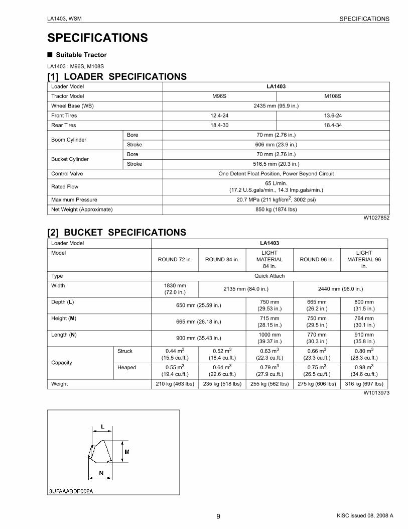
SPECIFICATIONS Suitable Tractor
LA1403 : M96S, M108S
[1] LOADER SPECIFICATIONS
W1027852
[2] BUCKET SPECIFICATIONS
W1013973
Loader Model LA1403
Tractor Model M96S M108S
Wheel Base (WB) 2435 mm (95.9 in.)
Front Tires 12.4-24 13.6-24
Rear Tires 18.4-30 18.4-34
Boom CylinderBore 70 mm (2.76 in.)
Stroke 606 mm (23.9 in.)
Bucket CylinderBore 70 mm (2.76 in.)
Stroke 516.5 mm (20.3 in.)
Control Valve One Detent Float Position, Power Beyond Circuit
Rated Flow 65 L/min.(17.2 U.S.gals/min., 14.3 Imp.gals/min.)
Maximum Pressure 20.7 MPa (211 kgf/cm2, 3002 psi)
Net Weight (Approximate) 850 kg (1874 lbs)
Loader Model LA1403
ModelROUND 72 in. ROUND 84 in.
LIGHT MATERIAL
84 in.ROUND 96 in.
LIGHT MATERIAL 96
in.
Type Quick Attach
Width 1830 mm (72.0 in.) 2135 mm (84.0 in.) 2440 mm (96.0 in.)
Depth (L) 650 mm (25.59 in.) 750 mm (29.53 in.)
665 mm (26.2 in.)
800 mm (31.5 in.)
Height (M) 665 mm (26.18 in.) 715 mm (28.15 in.)
750 mm (29.5 in.)
764 mm (30.1 in.)
Length (N) 900 mm (35.43 in.) 1000 mm (39.37 in.)
770 mm (30.3 in.)
910 mm (35.8 in.)
Capacity
Struck 0.44 m3 (15.5 cu.ft.)
0.52 m3 (18.4 cu.ft.)
0.63 m3 (22.3 cu.ft.)
0.66 m3 (23.3 cu.ft.)
0.80 m3 (28.3 cu.ft.)
Heaped 0.55 m3 (19.4 cu.ft.)
0.64 m3 (22.6 cu.ft.)
0.79 m3 (27.9 cu.ft.)
0.75 m3 (26.5 cu.ft.)
0.98 m3 (34.6 cu.ft.)
Weight 210 kg (463 lbs) 235 kg (518 lbs) 255 kg (562 lbs) 275 kg (606 lbs) 316 kg (697 lbs)
KiSC issued 08, 2008 A
10
LA1403, WSM SPECIFICATIONS
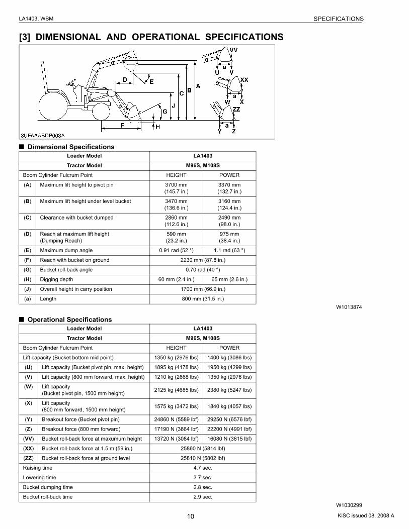
[3] DIMENSIONAL AND OPERATIONAL SPECIFICATIONS
Dimensional Specifications
W1013874
Operational Specifications
W1030299
Loader Model LA1403
Tractor Model M96S, M108S
Boom Cylinder Fulcrum Point HEIGHT POWER
(A) Maximum lift height to pivot pin 3700 mm(145.7 in.)
3370 mm(132.7 in.)
(B) Maximum lift height under level bucket 3470 mm(136.6 in.)
3160 mm(124.4 in.)
(C) Clearance with bucket dumped 2860 mm(112.6 in.)
2490 mm(98.0 in.)
(D) Reach at maximum lift height(Dumping Reach)
590 mm(23.2 in.)
975 mm(38.4 in.)
(E) Maximum dump angle 0.91 rad (52 °) 1.1 rad (63 °)
(F) Reach with bucket on ground 2230 mm (87.8 in.)
(G) Bucket roll-back angle 0.70 rad (40 °)
(H) Digging depth 60 mm (2.4 in.) 65 mm (2.6 in.)
(J) Overall height in carry position 1700 mm (66.9 in.)
(a) Length 800 mm (31.5 in.)
Loader Model LA1403
Tractor Model M96S, M108S
Boom Cylinder Fulcrum Point HEIGHT POWER
Lift capacity (Bucket bottom mid point) 1350 kg (2976 lbs) 1400 kg (3086 lbs)
(U) Lift capacity (Bucket pivot pin, max. height) 1895 kg (4178 lbs) 1950 kg (4299 lbs)
(V) Lift capacity (800 mm forward, max. height) 1210 kg (2668 lbs) 1350 kg (2976 lbs)
(W) Lift capacity (Bucket pivot pin, 1500 mm height) 2125 kg (4685 lbs) 2380 kg (5247 lbs)
(X) Lift capacity (800 mm forward, 1500 mm height) 1575 kg (3472 lbs) 1840 kg (4057 lbs)
(Y) Breakout force (Bucket pivot pin) 24860 N (5589 lbf) 29250 N (6576 lbf)
(Z) Breakout force (800 mm forward) 17190 N (3864 lbf) 22200 N (4991 lbf)
(VV) Bucket roll-back force at maxumum height 13720 N (3084 lbf) 16080 N (3615 lbf)
(XX) Bucket roll-back force at 1.5 m (59 in.) 25860 N (5814 lbf)
(ZZ) Bucket roll-back force at ground level 25810 N (5802 lbf)
Raising time 4.7 sec.
Lowering time 3.7 sec.
Bucket dumping time 2.8 sec.
Bucket roll-back time 2.9 sec.
KiSC issued 08, 2008 A

CONTENTS
GENERAL
1. LOADER IDENTIFICATION............................................................................ G-12. GENERAL PRECAUTIONS ............................................................................ G-23. LUBRICANTS .................................................................................................. G-34. TIGHTENING TORQUES ............................................................................... G-4
[1] GENERAL USE SCREWS, BOLTS AND NUTS (FOR FRONTLOADER AND BACKHOE) ...................................................................... G-4
[2] STUD BOLTS............................................................................................ G-4[3] AMERICAN STANDARD SCREWS, BOLTS AND NUTS WITH UNC
OR UNF THREADS ................................................................................. G-5[4] PLUGS....................................................................................................... G-5[5] HYDRAULIC FITTINGS............................................................................ G-6
5. MAINTENANCE CHECK LIST....................................................................... G-76. CHECK AND MAINTENANCE....................................................................... G-8
[1] CHECK POINTS OF EACH USE OR DAILY ....................................... G-8[2] CHECK POINTS OF EVERY 10 HOURS .............................................. G-9[3] CHECK POINT OF EVERY 50 HOURS ............................................... G-9
KiSC issued 08, 2008 A
G-1
LA1403, WSM G GENERAL
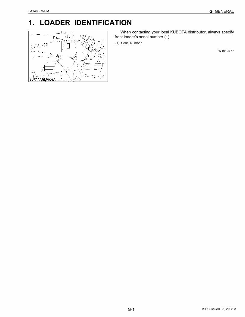
1. LOADER IDENTIFICATIONWhen contacting your local KUBOTA distributor, always specify
front loader’s serial number (1).
W1010477
(1) Serial Number
KiSC issued 08, 2008 A
G-2
LA1403, WSM G GENERAL
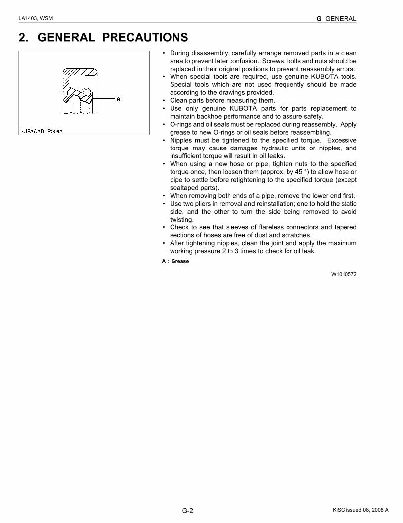
2. GENERAL PRECAUTIONS• During disassembly, carefully arrange removed parts in a clean
area to prevent later confusion. Screws, bolts and nuts should bereplaced in their original positions to prevent reassembly errors.
• When special tools are required, use genuine KUBOTA tools.Special tools which are not used frequently should be madeaccording to the drawings provided.
• Clean parts before measuring them.• Use only genuine KUBOTA parts for parts replacement to
maintain backhoe performance and to assure safety.• O-rings and oil seals must be replaced during reassembly. Apply
grease to new O-rings or oil seals before reassembling.• Nipples must be tightened to the specified torque. Excessive
torque may cause damages hydraulic units or nipples, andinsufficient torque will result in oil leaks.
• When using a new hose or pipe, tighten nuts to the specifiedtorque once, then loosen them (approx. by 45 °) to allow hose orpipe to settle before retightening to the specified torque (exceptsealtaped parts).
• When removing both ends of a pipe, remove the lower end first.• Use two pliers in removal and reinstallation; one to hold the static
side, and the other to turn the side being removed to avoidtwisting.
• Check to see that sleeves of flareless connectors and taperedsections of hoses are free of dust and scratches.
• After tightening nipples, clean the joint and apply the maximumworking pressure 2 to 3 times to check for oil leak.
W1010572
A : Grease
KiSC issued 08, 2008 A
G-3
LA1403, WSM G GENERAL
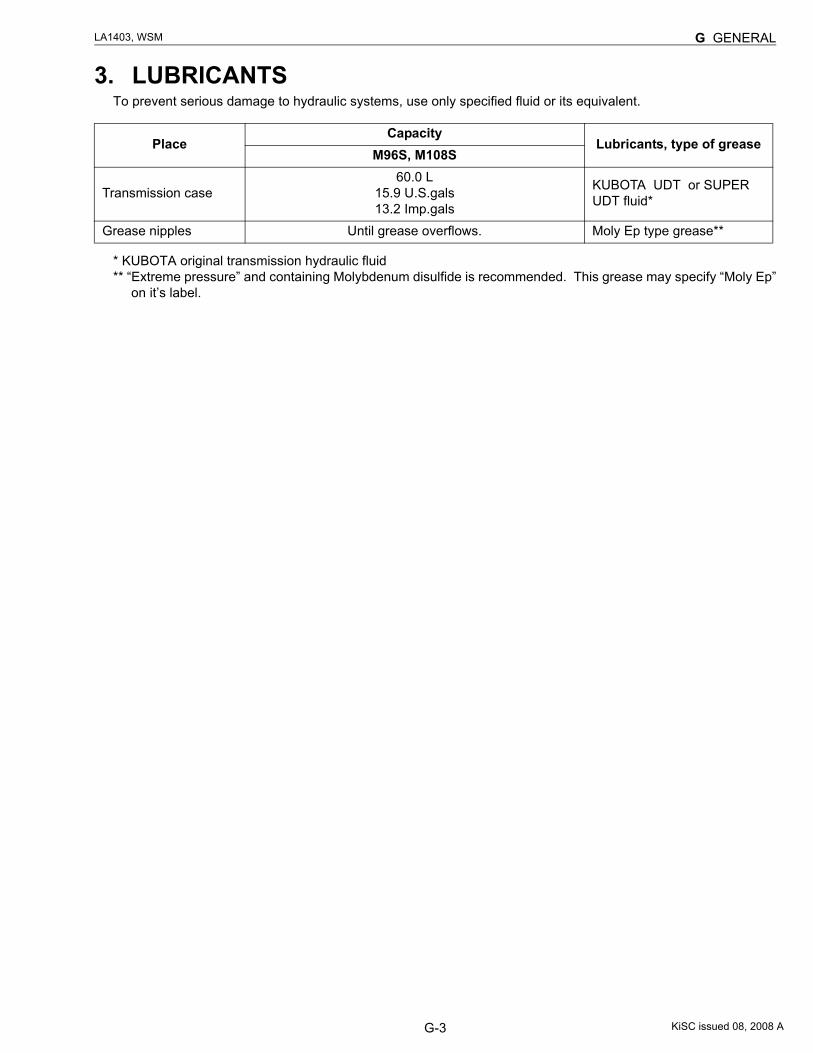
3. LUBRICANTSTo prevent serious damage to hydraulic systems, use only specified fluid or its equivalent.
* KUBOTA original transmission hydraulic fluid** “Extreme pressure” and containing Molybdenum disulfide is recommended. This grease may specify “Moly Ep”
on it’s label.
PlaceCapacity
Lubricants, type of greaseM96S, M108S
Transmission case60.0 L
15.9 U.S.gals13.2 Imp.gals
KUBOTA UDT or SUPER UDT fluid*
Grease nipples Until grease overflows. Moly Ep type grease**
KiSC issued 08, 2008 A
G-4
LA1403, WSM G GENERAL
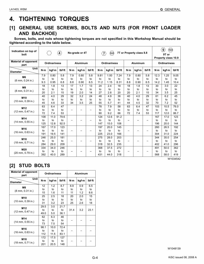
4. TIGHTENING TORQUES[1] GENERAL USE SCREWS, BOLTS AND NUTS (FOR FRONT LOADER
AND BACKHOE)Screws, bolts, and nuts whose tightening torques are not specified in this Workshop Manual should be
tightened according to the table below.
W1034542
[2] STUD BOLTS
W1048139
Indication on top of bolt No-grade or 4T 7T or Property class 8.8
9T orProperty class 10.9
Material of opponent part Ordinariness Aluminum Ordinariness Aluminum Ordinariness
Unit Diameter N·m kgf·m lbf·ft N·m kgf·m lbf·ft N·m kgf·m lbf·ft N·m kgf·m lbf·ft N·m kgf·m lbf·ft
M6(6 mm, 0.24 in.)
7.9to9.3
0.80to
0.95
5.8to
6.8
7.9to
8.8
0.80to
0.90
5.8to
6.5
9.81to
11.2
1.00to
1.15
7.24to
8.31
7.9to
8.8
0.80to
0.90
5.8to
6.5
12.3to
14.2
1.25to
1.45
9.05to
10.4
M8(8 mm, 0.31 in.)
18to20
1.8to
2.1
13to15
17to19
1.7to
2.0
13to14
24to27
2.4to
2.8
18to20
18to20
1.8to
2.1
13to15
30to34
3.0to
3.5
22to25
M10(10 mm, 0.39 in.)
40to45
4.0to
4.6
29to33
32to34
3.2to
3.5
24to25
48to55
4.9to
5.7
36to41
40to44
4.0to
4.5
29to32
61to70
6.2to
7.2
45to52
M12(12 mm, 0.47 in.)
63to72
6.4to
7.4
47to53
– – –78to90
7.9to
9.2
58to66
63to72
6.4to
7.4
47to53
103to
117
10.5to
12.0
76.0to
86.7
M14(14 mm, 0.55 in.)
108to
125
11.0to
12.8
79.6to
92.5– – –
124to
147
12.6to
15.0
91.2to
108– – –
167to
196
17.0to
20.0
123to
144
M16(16 mm, 0.63 in.)
167to
191
17.0to
19.5
123to
141– – –
197to
225
20.0to
23.0
145to
166– – –
260to
304
26.5to
31.0
192to
224
M18(18 mm, 0.71 in.)
246to
284
25.0to
29.0
181to
209– – –
275to
318
28.0to
32.5
203to
235– – –
344to
402
35.0to
41.0
254to
296
M20(20 mm, 0.79 in.)
334to
392
34.0to
40.0
246to
289– – –
368to
431
37.5to
44.0
272to
318– – –
491to
568
50.0to
58.0
362to
419
Material of opponent part Ordinariness Aluminum
Unit Diameter N·m kgf·m lbf·ft N·m kgf·m lbf·ft
M8(8 mm, 0.31 in.)
12to15
1.2to
1.6
8.7to11
8.9to11
0.9to
1.2
6.5to
8.6
M10(10 mm, 0.39 in.)
25to31
2.5to
3.2
18to23
20to25
2.0to
2.6
15to18
M12(12 mm, 0.47 in.)
29.5to
49.0
3.0to
5.0
21.7to
36.131.4 3.2 23.1
M14(14 mm, 0.55 in.)
62to73
6.3to
7.5
46to54
– – –
M16(16 mm, 0.63 in.)
98.1to
112
10.0to
11.5
72.4to
83.1– – –
M18(18 mm, 0.71 in.)
172to
201
17.5to
20.5
127to
148– – –
KiSC issued 08, 2008 A
G-5
LA1403, WSM G GENERAL
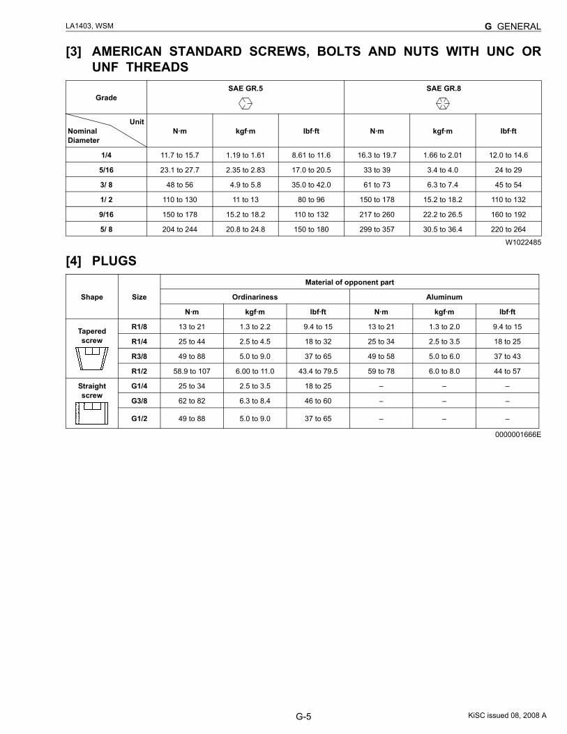
[3] AMERICAN STANDARD SCREWS, BOLTS AND NUTS WITH UNC ORUNF THREADS
W1022485
[4] PLUGS
0000001666E
GradeSAE GR.5 SAE GR.8
Unit Nominal Diameter
N·m kgf·m lbf·ft N·m kgf·m lbf·ft
1/4 11.7 to 15.7 1.19 to 1.61 8.61 to 11.6 16.3 to 19.7 1.66 to 2.01 12.0 to 14.6
5/16 23.1 to 27.7 2.35 to 2.83 17.0 to 20.5 33 to 39 3.4 to 4.0 24 to 29
3/ 8 48 to 56 4.9 to 5.8 35.0 to 42.0 61 to 73 6.3 to 7.4 45 to 54
1/ 2 110 to 130 11 to 13 80 to 96 150 to 178 15.2 to 18.2 110 to 132
9/16 150 to 178 15.2 to 18.2 110 to 132 217 to 260 22.2 to 26.5 160 to 192
5/ 8 204 to 244 20.8 to 24.8 150 to 180 299 to 357 30.5 to 36.4 220 to 264
Shape Size
Material of opponent part
Ordinariness Aluminum
N·m kgf·m lbf·ft N·m kgf·m lbf·ft
Taperedscrew
R1/8 13 to 21 1.3 to 2.2 9.4 to 15 13 to 21 1.3 to 2.0 9.4 to 15
R1/4 25 to 44 2.5 to 4.5 18 to 32 25 to 34 2.5 to 3.5 18 to 25
R3/8 49 to 88 5.0 to 9.0 37 to 65 49 to 58 5.0 to 6.0 37 to 43
R1/2 58.9 to 107 6.00 to 11.0 43.4 to 79.5 59 to 78 6.0 to 8.0 44 to 57
Straightscrew
G1/4 25 to 34 2.5 to 3.5 18 to 25 – – –
G3/8 62 to 82 6.3 to 8.4 46 to 60 – – –
G1/2 49 to 88 5.0 to 9.0 37 to 65 – – –
KiSC issued 08, 2008 A
G-6
LA1403, WSM G GENERAL
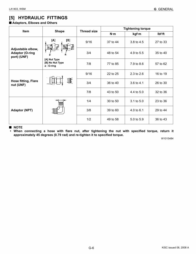
[5] HYDRAULIC FITTINGS Adaptors, Elbows and Others
NOTE• When connecting a hose with flare nut, after tightening the nut with specified torque, return it
approximately 45 degrees (0.79 rad) and re-tighten it to specified torque.W1015484
Item Shape Thread sizeTightening torque
N·m kgf·m lbf·ft
Adjustable elbow, Adaptor (O-ring port) (UNF)
[A] Nut Type[B] No Nut Typea : O-ring
9/16 37 to 44 3.8 to 4.5 27 to 33
3/4 48 to 54 4.9 to 5.5 35 to 40
7/8 77 to 85 7.9 to 8.6 57 to 62
Hose fitting, Flare nut (UNF)
9/16 22 to 25 2.3 to 2.6 16 to 19
3/4 36 to 40 3.6 to 4.1 26 to 30
7/8 43 to 50 4.4 to 5.0 32 to 36
Adaptor (NPT)
1/4 30 to 50 3.1 to 5.0 23 to 36
3/8 39 to 60 4.0 to 6.1 29 to 44
1/2 49 to 58 5.0 to 5.9 36 to 43
KiSC issued 08, 2008 A
G-7
LA1403, WSM G GENERAL
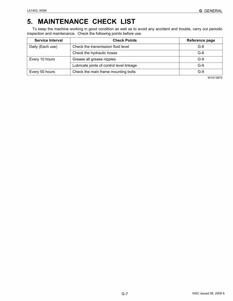
5. MAINTENANCE CHECK LISTTo keep the machine working in good condition as well as to avoid any accident and trouble, carry out periodic
inspection and maintenance. Check the following points before use.
W1013874
Service Interval Check Points Reference pageDaily (Each use) Check the transmission fluid level G-8
Check the hydraulic hoses G-8Every 10 hours Grease all grease nipples G-9
Lubricate joints of control level linkage G-9Every 50 hours Check the main frame mounting bolts G-9
KiSC issued 08, 2008 A
G-8
LA1403, WSM G GENERAL
6. CHECK AND MAINTENANCECAUTION
• When checking and repairing, park the tractor on flat ground and apply the parking brake.• When checking and repairing, lower the bucket and stop the engine.
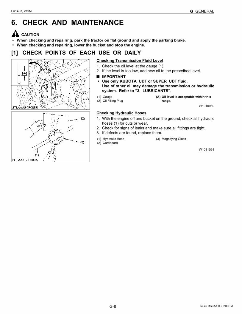
[1] CHECK POINTS OF EACH USE OR DAILYChecking Transmission Fluid Level1. Check the oil level at the gauge (1).2. If the level is too low, add new oil to the prescribed level.
IMPORTANT• Use only KUBOTA UDT or SUPER UDT fluid.
Use of other oil may damage the transmission or hydraulicsystem. Refer to “3. LUBRICANTS”.
W1010960
Checking Hydraulic Hoses1. With the engine off and bucket on the ground, check all hydraulic
hoses (1) for cuts or wear.2. Check for signs of leaks and make sure all fittings are tight.3. If defects are found, replace them.
W1011064
(1) Gauge(2) Oil Filling Plug
(A) Oil level is acceptable within this range.
(1) Hydraulic Hose(2) Cardboard
(3) Magnifying Glass
KiSC issued 08, 2008 A
G-9
LA1403, WSM G GENERAL
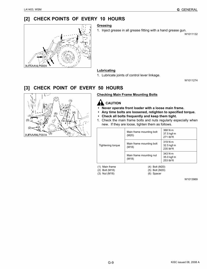
[2] CHECK POINTS OF EVERY 10 HOURSGreasing1. Inject grease in all grease fitting with a hand grease gun.
W1011132
Lubricating1. Lubricate joints of control lever linkage.
W1011274
[3] CHECK POINT OF EVERY 50 HOURSChecking Main Frame Mounting Bolts
CAUTION• Never operate front loader with a loose main frame.• Any time bolts are loosened, retighten to specified torque.• Check all bolts frequently and keep them tight.
1. Check the main frame bolts and nuts regularly especially whennew. If they are loose, tighten them as follows.
W1013969
Tightening torque
Main frame mounting bolt (M20)
368 N·m37.5 kgf·m271 lbf·ft
Main frame mounting bolt (M18)
319 N·m32.5 kgf·m235 lbf·ft
Main frame mounting nut (M18)
343 N·m35.0 kgf·m253 lbf·ft
(1) Main frame(2) Bolt (M18)(3) Nut (M18)
(4) Bolt (M20)(5) Bolt (M20)(6) Spacer
KiSC issued 08, 2008 A
CONTENTS
MECHANISM
1. CONTROL VALVE ASSEMBLY (STANDARD VALVE) ............................... M-1[1] HYDRAULIC CIRCUIT.............................................................................. M-1[2] STRUCTURE............................................................................................. M-2[3] OPERATION.............................................................................................. M-3[4] RELIEF VALVE......................................................................................... M-9
2. CONTROL VALVE ASSEMBLY (SELF-LEVELING VALVE) ..................... M-12[1] HYDRAULIC CIRCUIT............................................................................ M-12[2] STRUCTURE........................................................................................... M-13[3] OPERATION............................................................................................ M-14[4] RELIEF VALVE....................................................................................... M-54
(1) Main Relief Valve ............................................................................... M-54(2) Overload Relief Valve ........................................................................ M-55
3. BOOM CYLINDER AND BUCKET CYLINDER.......................................... M-574. 3RD FUNCTION VALVE (OPTION)............................................................ M-58
[1] HYDRAULIC CIRCUIT............................................................................ M-58[2] 3RD FUNCTION SOLENOID VALVE OPERATION ............................ M-59[3] ELECTRICAL CIRCUIT .......................................................................... M-62
5. HYDRAULIC ACCUMULATOR (OPTION)................................................... M-63[1] HYDRAULIC CIRCUIT............................................................................ M-63[2] ACCUMULATOR VALVE........................................................................ M-64[3] HYDRAULIC ACCUMULATOR............................................................... M-65[4] ACCUMULATOR RELIEF VALVE ......................................................... M-66
KiSC issued 08, 2008 A
M-1
LA1403, WSM FRONT LOADER
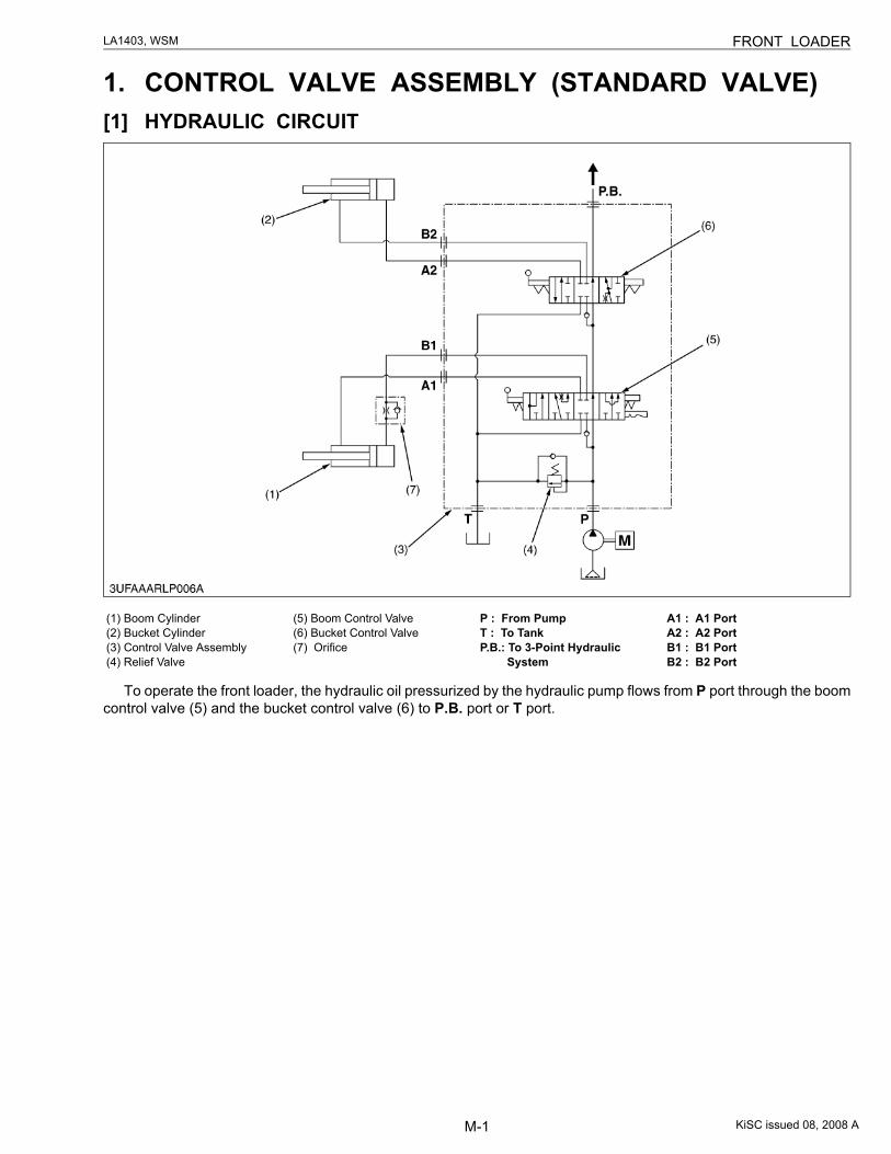
1. CONTROL VALVE ASSEMBLY (STANDARD VALVE)[1] HYDRAULIC CIRCUIT
To operate the front loader, the hydraulic oil pressurized by the hydraulic pump flows from P port through the boomcontrol valve (5) and the bucket control valve (6) to P.B. port or T port.
(1) Boom Cylinder(2) Bucket Cylinder(3) Control Valve Assembly(4) Relief Valve
(5) Boom Control Valve(6) Bucket Control Valve(7) Orifice
P : From PumpT : To TankP.B.: To 3-Point Hydraulic
System
A1 : A1 Port A2 : A2 Port B1 : B1 Port B2 : B2 Port
KiSC issued 08, 2008 A
M-2
LA1403, WSM FRONT LOADER
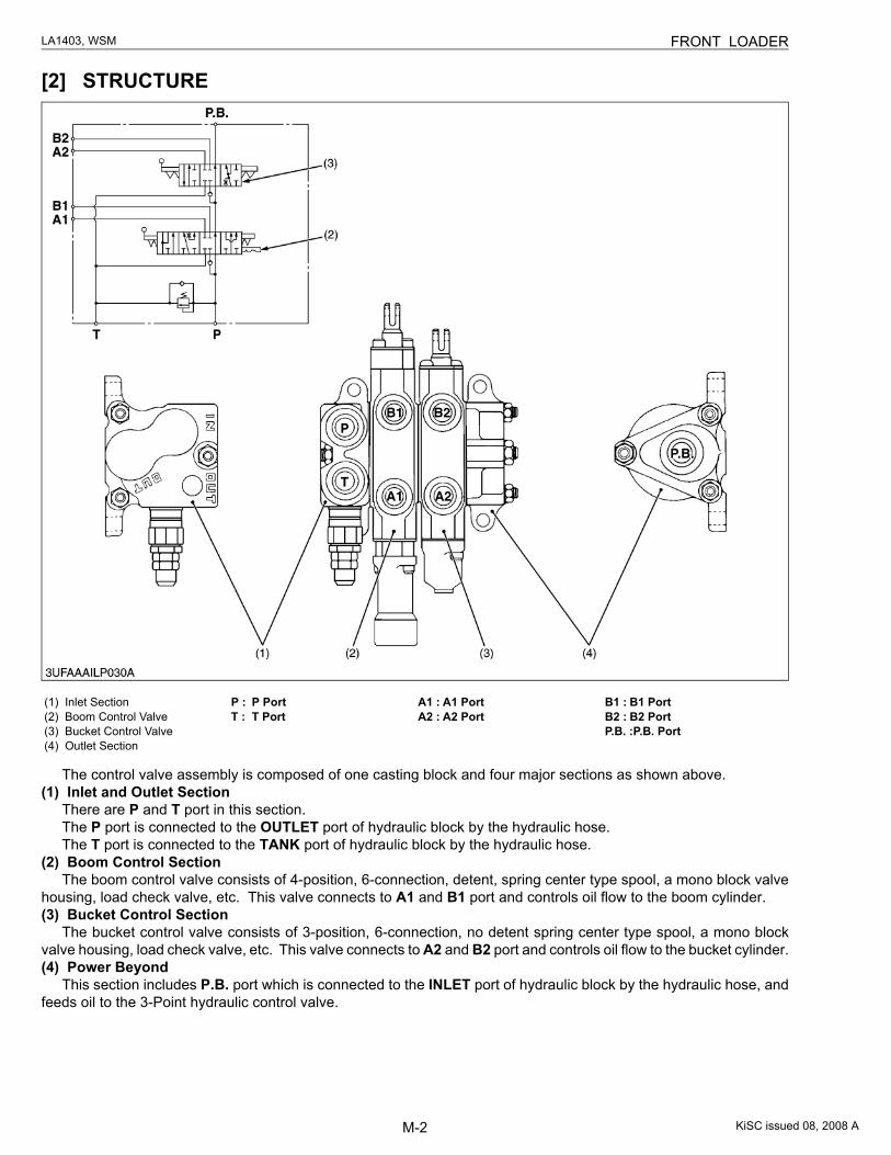
[2] STRUCTURE
The control valve assembly is composed of one casting block and four major sections as shown above.(1) Inlet and Outlet Section
There are P and T port in this section.The P port is connected to the OUTLET port of hydraulic block by the hydraulic hose.The T port is connected to the TANK port of hydraulic block by the hydraulic hose.
(2) Boom Control SectionThe boom control valve consists of 4-position, 6-connection, detent, spring center type spool, a mono block valve
housing, load check valve, etc. This valve connects to A1 and B1 port and controls oil flow to the boom cylinder.(3) Bucket Control Section
The bucket control valve consists of 3-position, 6-connection, no detent spring center type spool, a mono blockvalve housing, load check valve, etc. This valve connects to A2 and B2 port and controls oil flow to the bucket cylinder.(4) Power Beyond
This section includes P.B. port which is connected to the INLET port of hydraulic block by the hydraulic hose, andfeeds oil to the 3-Point hydraulic control valve.
(1) Inlet Section(2) Boom Control Valve(3) Bucket Control Valve(4) Outlet Section
P : P PortT : T Port
A1 : A1 PortA2 : A2 Port
B1 : B1 PortB2 : B2 PortP.B. :P.B. Port
KiSC issued 08, 2008 A
M-3
LA1403, WSM FRONT LOADER
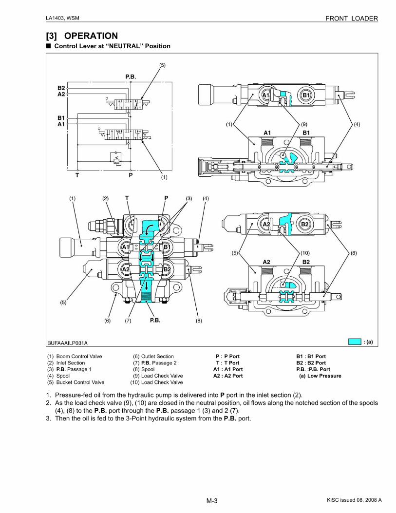
[3] OPERATION Control Lever at “NEUTRAL” Position
1. Pressure-fed oil from the hydraulic pump is delivered into P port in the inlet section (2).2. As the load check valve (9), (10) are closed in the neutral position, oil flows along the notched section of the spools
(4), (8) to the P.B. port through the P.B. passage 1 (3) and 2 (7).3. Then the oil is fed to the 3-Point hydraulic system from the P.B. port.
(1) Boom Control Valve(2) Inlet Section(3) P.B. Passage 1(4) Spool(5) Bucket Control Valve
(6) Outlet Section(7) P.B. Passage 2(8) Spool(9) Load Check Valve
(10) Load Check Valve
P : P PortT : T Port
A1 : A1 PortA2 : A2 Port
B1 : B1 PortB2 : B2 PortP.B. :P.B. Port(a) Low Pressure
KiSC issued 08, 2008 A
M-4
LA1403, WSM FRONT LOADER
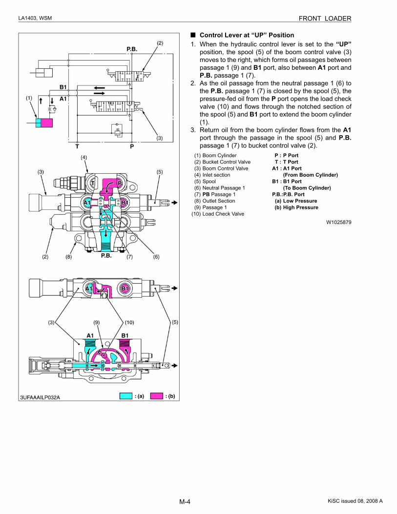
Control Lever at “UP” Position1. When the hydraulic control lever is set to the “UP”
position, the spool (5) of the boom control valve (3)moves to the right, which forms oil passages betweenpassage 1 (9) and B1 port, also between A1 port andP.B. passage 1 (7).
2. As the oil passage from the neutral passage 1 (6) tothe P.B. passage 1 (7) is closed by the spool (5), thepressure-fed oil from the P port opens the load checkvalve (10) and flows through the notched section ofthe spool (5) and B1 port to extend the boom cylinder(1).
3. Return oil from the boom cylinder flows from the A1port through the passage in the spool (5) and P.B.passage 1 (7) to bucket control valve (2).
W1025879
(1) Boom Cylinder(2) Bucket Control Valve(3) Boom Control Valve(4) Inlet section(5) Spool(6) Neutral Passage 1(7) PB Passage 1(8) Outlet Section(9) Passage 1
(10) Load Check Valve
P : P PortT : T Port
A1 : A1 Port (From Boom Cylinder)
B1 : B1 Port (To Boom Cylinder)
P.B.:P.B. Port(a) Low Pressure(b) High Pressure
KiSC issued 08, 2008 A
M-5
LA1403, WSM FRONT LOADER
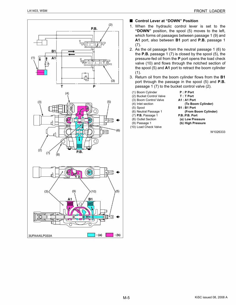
Control Lever at “DOWN” Position1. When the hydraulic control lever is set to the
“DOWN” position, the spool (5) moves to the left,which forms oil passages between passage 1 (9) andA1 port, also between B1 port and P.B. passage 1(7).
2. As the oil passage from the neutral passage 1 (6) tothe P.B. passage 1 (7) is closed by the spool (5), thepressure-fed oil from the P port opens the load checkvalve (10) and flows through the notched section ofthe spool (5) and A1 port to retract the boom cylinder(1).
3. Return oil from the boom cylinder flows from the B1port through the passage in the spool (5) and P.B.passage 1 (7) to the bucket control valve (2).
W1026333
(1) Boom Cylinder(2) Bucket Control Valve(3) Boom Control Valve(4) Inlet section(5) Spool(6) Neutral Passage 1(7) P.B. Passage 1(8) Outlet Section(9) Passage 1
(10) Load Check Valve
P : P PortT : T Port
A1 : A1 Port (To Boom Cylinder)
B1 : B1 Port (From Boom Cylinder)
P.B.: P.B. Port(a) Low Pressure(b) High Pressure
KiSC issued 08, 2008 A
M-6
LA1403, WSM FRONT LOADER
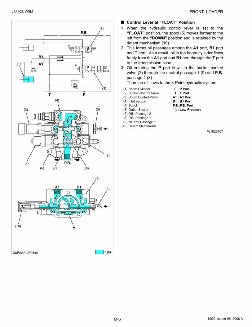
Control Lever at “FLOAT” Position1. When the hydraulic control lever is set to the
“FLOAT” position, the spool (5) moves further to theleft from the “DOWN” position and is retained by thedetent mechanism (10).
2. This forms oil passages among the A1 port, B1 portand T port. As a result, oil in the boom cylinder flowsfreely from the A1 port and B1 port through the T portto the transmission case.
3. Oil entering the P port flows to the bucket controlvalve (2) through the neutral passage 1 (9) and P.B.passage 1 (8).Then the oil flows to the 3-Point hydraulic system.
W1026767
(1) Boom Cylinder(2) Bucket Control Valve(3) Boom Control Valve(4) Inlet section(5) Spool(6) Outlet Section(7) P.B. Passage 2(8) P.B. Passage 1(9) Neutral Passage 1
(10) Detent Mechanism
P : P PortT : T Port
A1 : A1 PortB1 : B1 PortP.B.: P.B. Port(a) Low Pressure
KiSC issued 08, 2008 A
M-7
LA1403, WSM FRONT LOADER
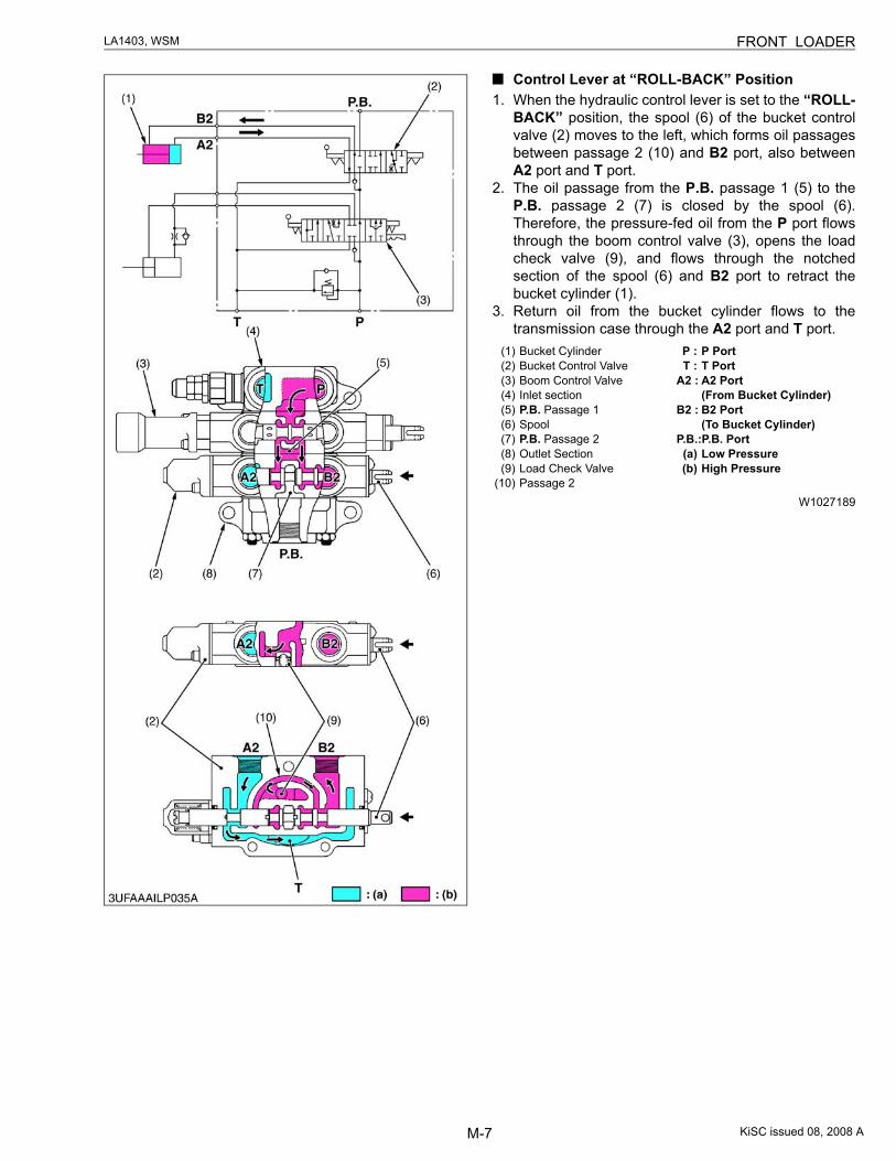
Control Lever at “ROLL-BACK” Position1. When the hydraulic control lever is set to the “ROLL-
BACK” position, the spool (6) of the bucket controlvalve (2) moves to the left, which forms oil passagesbetween passage 2 (10) and B2 port, also betweenA2 port and T port.
2. The oil passage from the P.B. passage 1 (5) to theP.B. passage 2 (7) is closed by the spool (6).Therefore, the pressure-fed oil from the P port flowsthrough the boom control valve (3), opens the loadcheck valve (9), and flows through the notchedsection of the spool (6) and B2 port to retract thebucket cylinder (1).
3. Return oil from the bucket cylinder flows to thetransmission case through the A2 port and T port.
W1027189
(1) Bucket Cylinder(2) Bucket Control Valve(3) Boom Control Valve(4) Inlet section(5) P.B. Passage 1(6) Spool(7) P.B. Passage 2(8) Outlet Section(9) Load Check Valve
(10) Passage 2
P : P PortT : T Port
A2 : A2 Port (From Bucket Cylinder)
B2 : B2 Port (To Bucket Cylinder)
P.B.: P.B. Port(a) Low Pressure(b) High Pressure
KiSC issued 08, 2008 A
M-8
LA1403, WSM FRONT LOADER
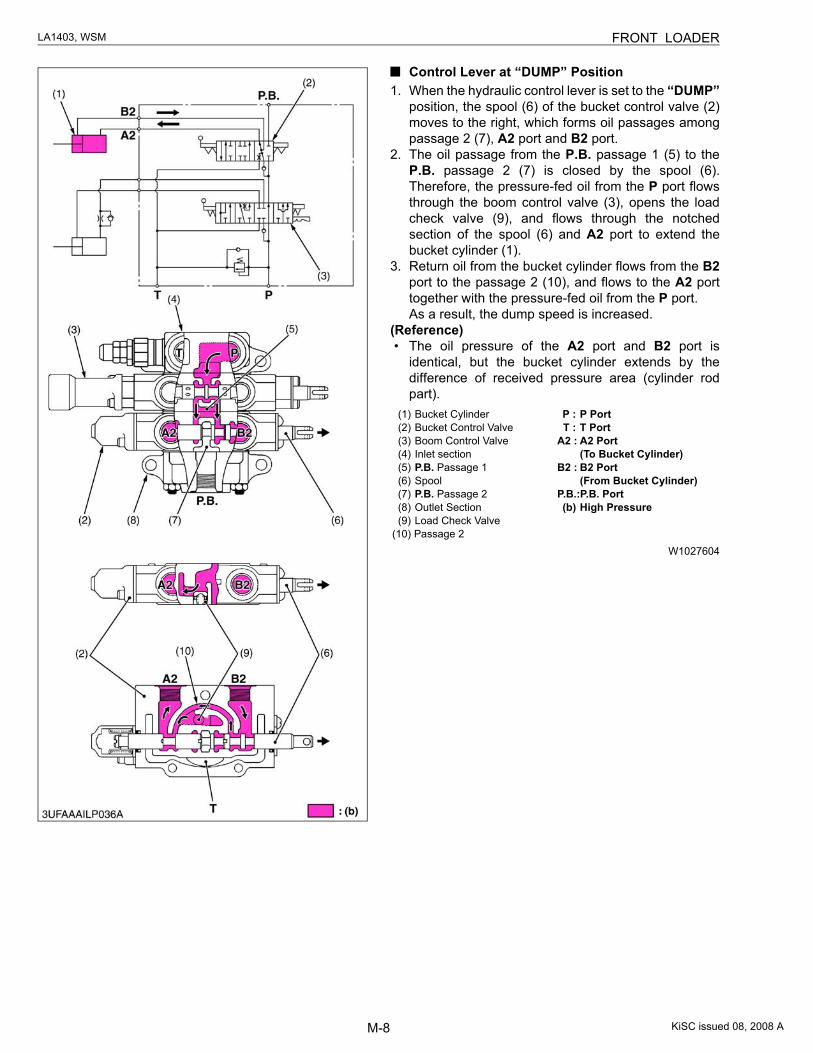
Control Lever at “DUMP” Position1. When the hydraulic control lever is set to the “DUMP”
position, the spool (6) of the bucket control valve (2)moves to the right, which forms oil passages amongpassage 2 (7), A2 port and B2 port.
2. The oil passage from the P.B. passage 1 (5) to theP.B. passage 2 (7) is closed by the spool (6).Therefore, the pressure-fed oil from the P port flowsthrough the boom control valve (3), opens the loadcheck valve (9), and flows through the notchedsection of the spool (6) and A2 port to extend thebucket cylinder (1).
3. Return oil from the bucket cylinder flows from the B2port to the passage 2 (10), and flows to the A2 porttogether with the pressure-fed oil from the P port.As a result, the dump speed is increased.
(Reference)• The oil pressure of the A2 port and B2 port is
identical, but the bucket cylinder extends by thedifference of received pressure area (cylinder rodpart).
W1027604
(1) Bucket Cylinder(2) Bucket Control Valve(3) Boom Control Valve(4) Inlet section(5) P.B. Passage 1(6) Spool(7) P.B. Passage 2(8) Outlet Section(9) Load Check Valve
(10) Passage 2
P : P PortT : T Port
A2 : A2 Port (To Bucket Cylinder)
B2 : B2 Port (From Bucket Cylinder)
P.B.: P.B. Port(b) High Pressure
KiSC issued 08, 2008 A
M-9
LA1403, WSM FRONT LOADER
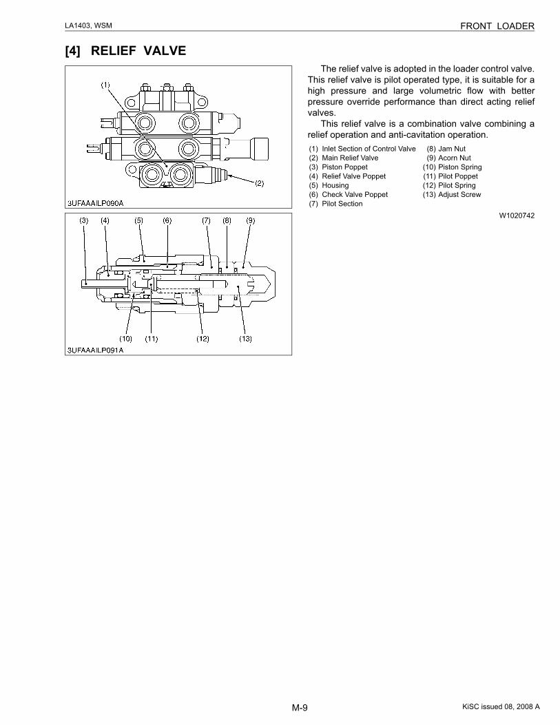
[4] RELIEF VALVEThe relief valve is adopted in the loader control valve.
This relief valve is pilot operated type, it is suitable for ahigh pressure and large volumetric flow with betterpressure override performance than direct acting reliefvalves.
This relief valve is a combination valve combining arelief operation and anti-cavitation operation.
W1020742
(1) Inlet Section of Control Valve(2) Main Relief Valve(3) Piston Poppet(4) Relief Valve Poppet(5) Housing(6) Check Valve Poppet(7) Pilot Section
(8) Jam Nut(9) Acorn Nut
(10) Piston Spring(11) Pilot Poppet(12) Pilot Spring(13) Adjust Screw
KiSC issued 08, 2008 A
M-10
LA1403, WSM FRONT LOADER
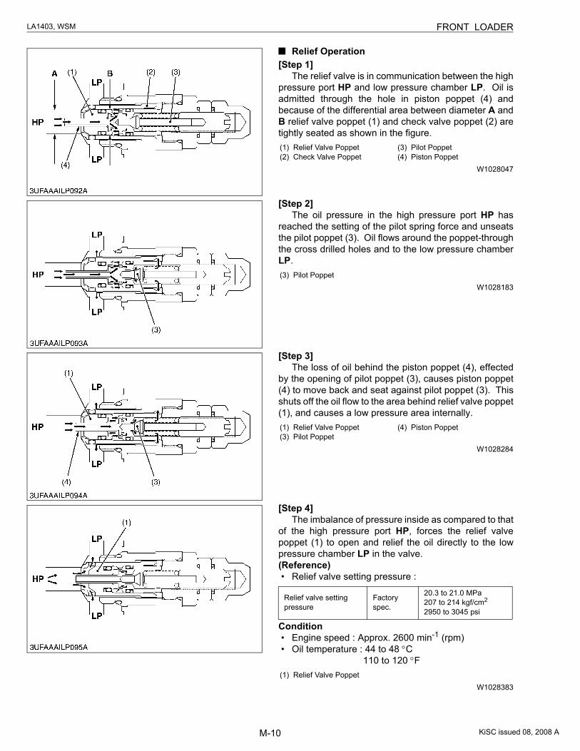
Relief Operation[Step 1]
The relief valve is in communication between the highpressure port HP and low pressure chamber LP. Oil isadmitted through the hole in piston poppet (4) andbecause of the differential area between diameter A andB relief valve poppet (1) and check valve poppet (2) aretightly seated as shown in the figure.
W1028047
[Step 2]The oil pressure in the high pressure port HP has
reached the setting of the pilot spring force and unseatsthe pilot poppet (3). Oil flows around the poppet-throughthe cross drilled holes and to the low pressure chamberLP.
W1028183
[Step 3]The loss of oil behind the piston poppet (4), effected
by the opening of pilot poppet (3), causes piston poppet(4) to move back and seat against pilot poppet (3). Thisshuts off the oil flow to the area behind relief valve poppet(1), and causes a low pressure area internally.
W1028284
[Step 4]The imbalance of pressure inside as compared to that
of the high pressure port HP, forces the relief valvepoppet (1) to open and relief the oil directly to the lowpressure chamber LP in the valve. (Reference)• Relief valve setting pressure :
Condition• Engine speed : Approx. 2600 min-1 (rpm)• Oil temperature : 44 to 48 °C
110 to 120 °F
W1028383
(1) Relief Valve Poppet(2) Check Valve Poppet
(3) Pilot Poppet(4) Piston Poppet
(3) Pilot Poppet
(1) Relief Valve Poppet(3) Pilot Poppet
(4) Piston Poppet
Relief valve setting pressure
Factory spec.
20.3 to 21.0 MPa207 to 214 kgf/cm2
2950 to 3045 psi
(1) Relief Valve Poppet
KiSC issued 08, 2008 A
M-11
LA1403, WSM FRONT LOADER
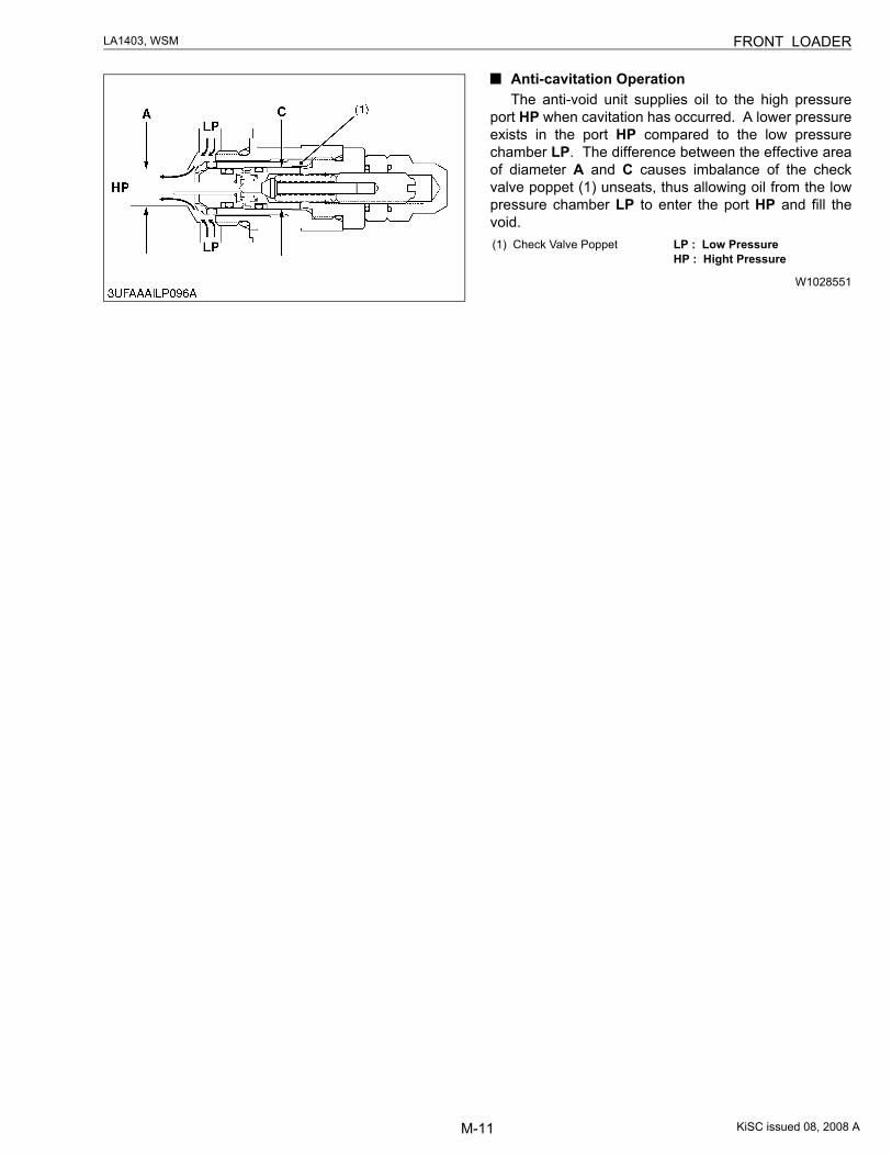
Anti-cavitation OperationThe anti-void unit supplies oil to the high pressure
port HP when cavitation has occurred. A lower pressureexists in the port HP compared to the low pressurechamber LP. The difference between the effective areaof diameter A and C causes imbalance of the checkvalve poppet (1) unseats, thus allowing oil from the lowpressure chamber LP to enter the port HP and fill thevoid.
W1028551
(1) Check Valve Poppet LP : Low Pressure HP : Hight Pressure
KiSC issued 08, 2008 A
M-12
LA1403, WSM FRONT LOADER
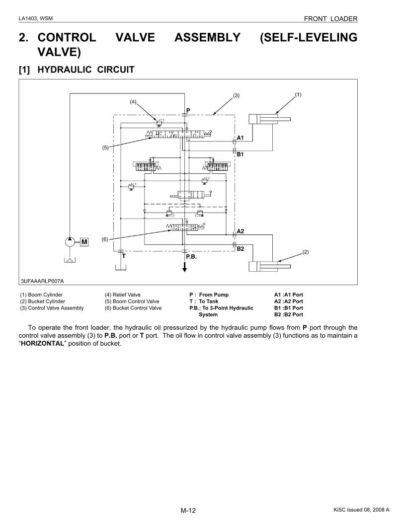
2. CONTROL VALVE ASSEMBLY (SELF-LEVELINGVALVE)
[1] HYDRAULIC CIRCUIT
To operate the front loader, the hydraulic oil pressurized by the hydraulic pump flows from P port through thecontrol valve assembly (3) to P.B. port or T port. The oil flow in control valve assembly (3) functions as to maintain a“HORIZONTAL” position of bucket.
(1) Boom Cylinder(2) Bucket Cylinder(3) Control Valve Assembly
(4) Relief Valve(5) Boom Control Valve(6) Bucket Control Valve
P : From PumpT : To TankP.B.: To 3-Point Hydraulic
System
A1 :A1 Port A2 :A2 Port B1 :B1 Port B2 :B2 Port
KiSC issued 08, 2008 A
M-13
LA1403, WSM FRONT LOADER
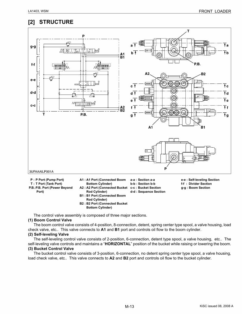
[2] STRUCTURE
The control valve assembly is composed of three major sections.(1) Boom Control Valve
The boom control valve consists of 4-position, 8-connection, detent, spring center type spool, a valve housing, loadcheck valve, etc.. This valve connects to A1 and B1 port and controls oil flow to the boom cylinder.(2) Self-leveling Valve
The self-leveling control valve consists of 2-position, 6-connection, detent type spool, a valve housing, etc.. Theself-leveling valve controls and maintains a “HORIZONTAL” position of the bucket while raising or lowering the boom.(3) Bucket Control Valve
The bucket control valve consists of 3-position, 6-connection, no detent spring center type spool, a valve housing,load check valve, etc.. This valve connects to A2 and B2 port and controls oil flow to the bucket cylinder.
P : P Port (Pump Port)T : T Port (Tank Port)
P.B.: P.B. Port (Power Beyond Port)
A1 : A1 Port (Connected Boom Bottom Cylinder)
A2 : A2 Port (Connected Bucket Rod Cylinder)
B1 : B1 Port (Connected Boom Rod Cylinder)
B2 : B2 Port (Connected Bucket Bottom Cylinder)
a-a : Section a-ab-b : Section b-bc-c : Bucket Sectiond-d : Sequence Section
e-e : Self-leveling Sectionf-f : Divider Sectiong-g : Boom Section
KiSC issued 08, 2008 A
M-14
LA1403, WSM FRONT LOADER
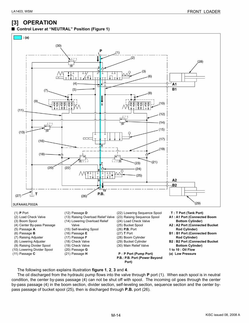
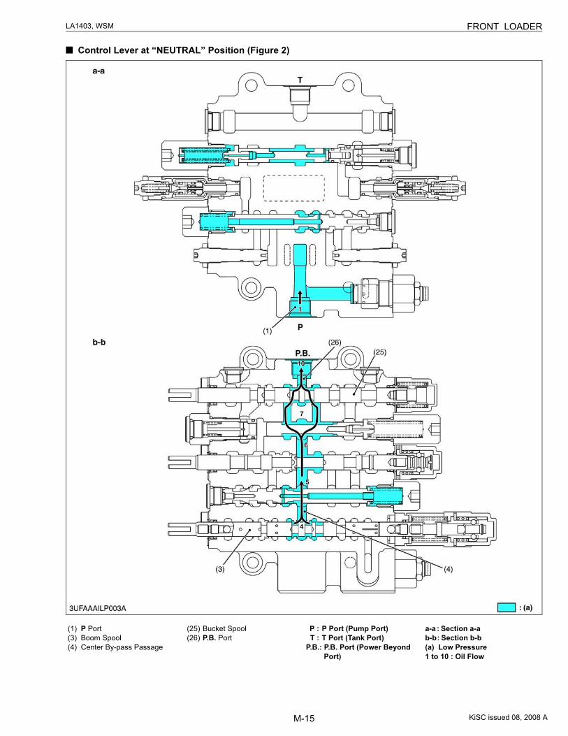
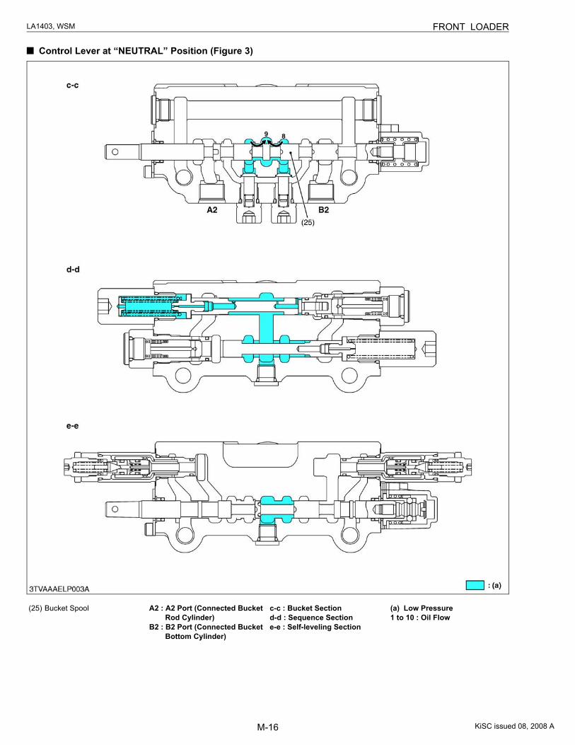
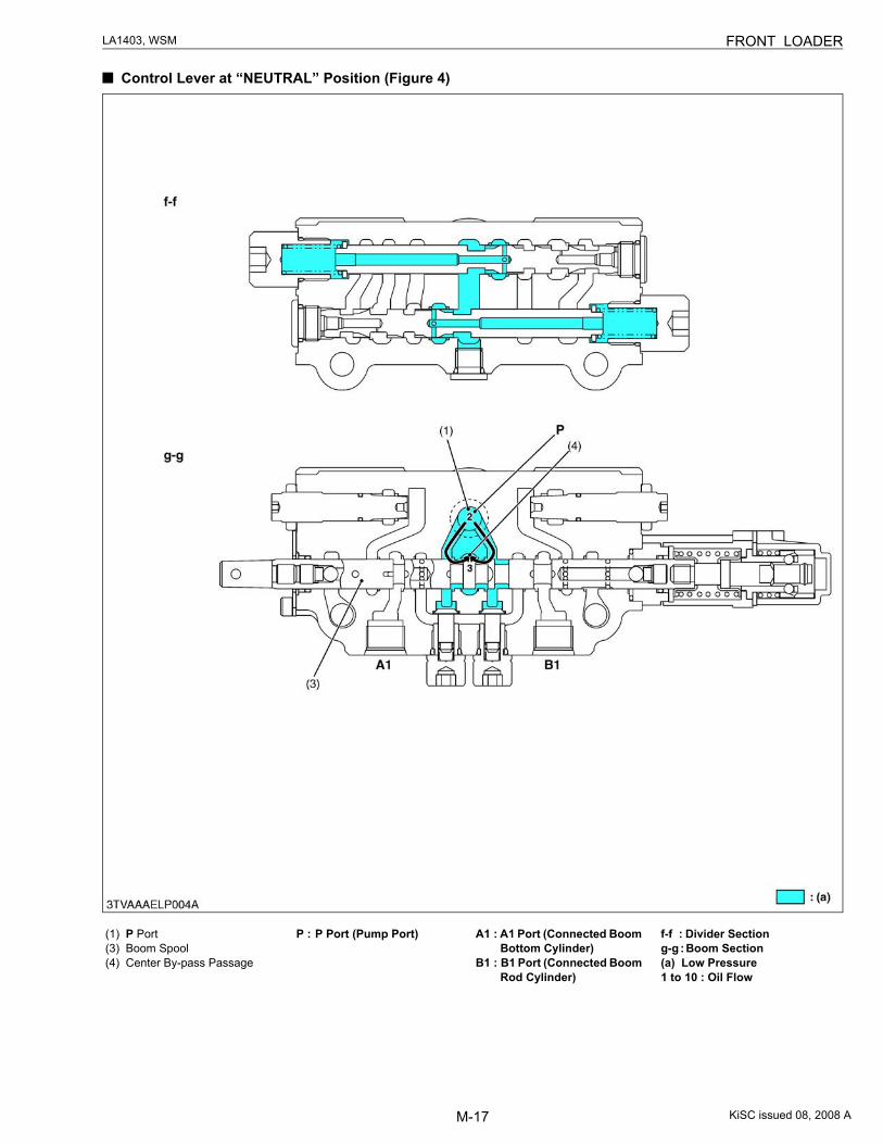
[3] OPERATION Control Lever at “NEUTRAL” Position (Figure 1)
The following section explains illustration figure 1, 2, 3 and 4.The oil discharged from the hydraulic pump flows into the valve through P port (1). When each spool is in neutral
condition, the center by-pass passage (4) can not be shut off with spool. The incoming oil goes through the centerby-pass passage (4) in the boom section, divider section, self-leveling section, sequence section and the center by-pass passage of bucket spool (25), then is discharged through P.B. port (26).
(1) P Port(2) Load Check Valve(3) Boom Spool(4) Center By-pass Passage(5) Passage A(6) Passage B(7) Raising Adjuster(8) Lowering Adjuster(9) Raising Divider Spool
(10) Lowering Divider Spool(11) Passage C
(12) Passage D(13) Raising Overload Relief Valve(14) Lowering Overload Relief
Valve(15) Self-leveling Spool(16) Passage E(17) Passage F(18) Check Valve(19) Check Valve(20) Passage G(21) Passage H
(22) Lowering Sequence Spool(23) Raising Sequence Spool(24) Load Check Valve(25) Bucket Spool(26) P.B. Port(27) T Port(28) Boom Cylinder(29) Bucket Cylinder(30) Main Relief Valve
P : P Port (Pump Port)P.B.: P.B. Port (Power Beyond
Port)
T : T Port (Tank Port)A1 : A1 Port (Connected Boom
Bottom Cylinder)A2 : A2 Port (Connected Bucket
Rod Cylinder)B1 : B1 Port (Connected Boom
Rod Cylinder)B2 : B2 Port (Connected Bucket
Bottom Cylinder)1 to 10 : Oil Flow(a) Low Pressure
KiSC issued 08, 2008 A
M-15
LA1403, WSM FRONT LOADER
Control Lever at “NEUTRAL” Position (Figure 2)
(1) P Port(3) Boom Spool(4) Center By-pass Passage
(25) Bucket Spool(26) P.B. Port
P : P Port (Pump Port)T : T Port (Tank Port)
P.B.: P.B. Port (Power Beyond Port)
a-a : Section a-ab-b : Section b-b(a) Low Pressure1 to 10 : Oil Flow
KiSC issued 08, 2008 A
M-16
LA1403, WSM FRONT LOADER
Control Lever at “NEUTRAL” Position (Figure 3)
(25) Bucket Spool A2 : A2 Port (Connected Bucket Rod Cylinder)
B2 : B2 Port (Connected Bucket Bottom Cylinder)
c-c : Bucket Sectiond-d : Sequence Sectione-e : Self-leveling Section
(a) Low Pressure1 to 10 : Oil Flow
KiSC issued 08, 2008 A
M-17
LA1403, WSM FRONT LOADER
Control Lever at “NEUTRAL” Position (Figure 4)
(1) P Port(3) Boom Spool(4) Center By-pass Passage
P : P Port (Pump Port) A1 : A1 Port (Connected Boom Bottom Cylinder)
B1 : B1 Port (Connected Boom Rod Cylinder)
f-f : Divider Sectiong-g : Boom Section(a) Low Pressure1 to 10 : Oil Flow
KiSC issued 08, 2008 A
M-18
LA1403, WSM FRONT LOADER
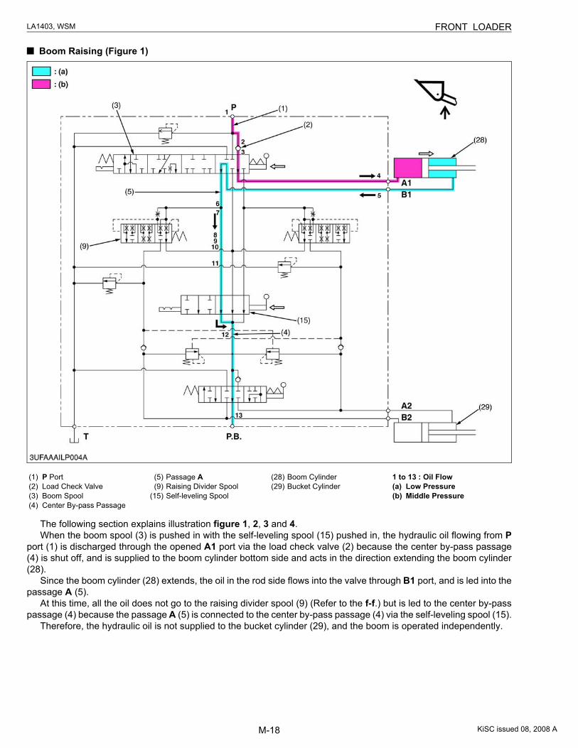
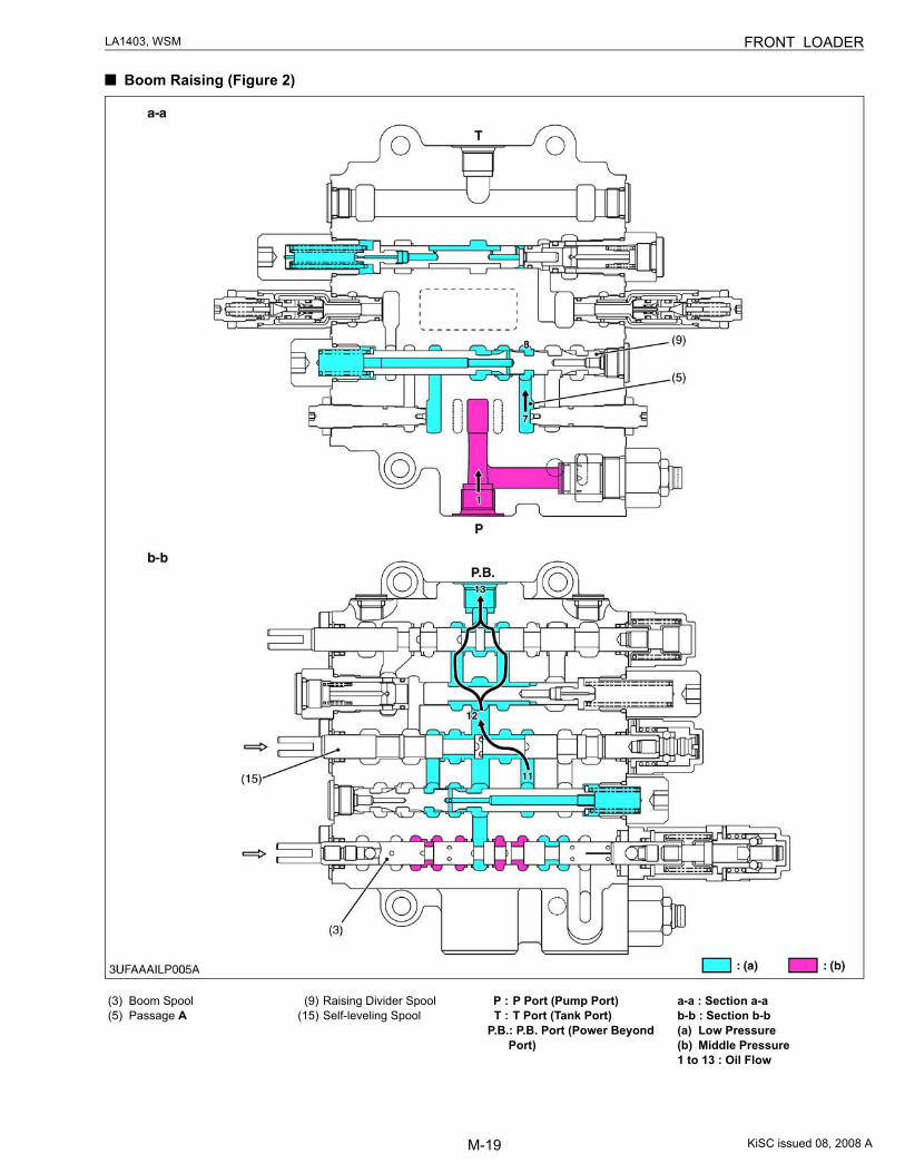
Boom Raising (Figure 1)
The following section explains illustration figure 1, 2, 3 and 4.When the boom spool (3) is pushed in with the self-leveling spool (15) pushed in, the hydraulic oil flowing from P
port (1) is discharged through the opened A1 port via the load check valve (2) because the center by-pass passage(4) is shut off, and is supplied to the boom cylinder bottom side and acts in the direction extending the boom cylinder(28).
Since the boom cylinder (28) extends, the oil in the rod side flows into the valve through B1 port, and is led into thepassage A (5).
At this time, all the oil does not go to the raising divider spool (9) (Refer to the f-f.) but is led to the center by-passpassage (4) because the passage A (5) is connected to the center by-pass passage (4) via the self-leveling spool (15).
Therefore, the hydraulic oil is not supplied to the bucket cylinder (29), and the boom is operated independently.
(1) P Port(2) Load Check Valve(3) Boom Spool(4) Center By-pass Passage
(5) Passage A(9) Raising Divider Spool
(15) Self-leveling Spool
(28) Boom Cylinder(29) Bucket Cylinder
1 to 13 : Oil Flow(a) Low Pressure(b) Middle Pressure
KiSC issued 08, 2008 A
M-19
LA1403, WSM FRONT LOADER
Boom Raising (Figure 2)
(3) Boom Spool(5) Passage A
(9) Raising Divider Spool(15) Self-leveling Spool
P : P Port (Pump Port)T : T Port (Tank Port)
P.B.: P.B. Port (Power Beyond Port)
a-a : Section a-ab-b : Section b-b(a) Low Pressure(b) Middle Pressure1 to 13 : Oil Flow
KiSC issued 08, 2008 A
M-20
LA1403, WSM FRONT LOADER
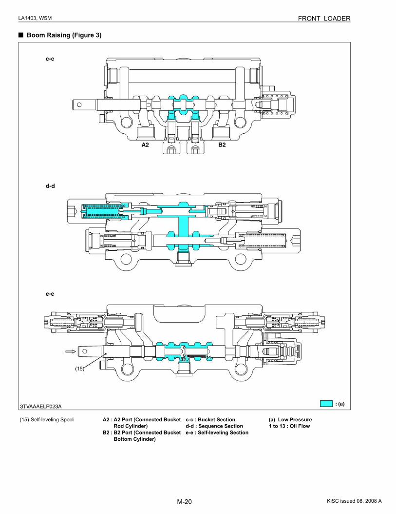
Boom Raising (Figure 3)
(15) Self-leveling Spool A2 : A2 Port (Connected Bucket Rod Cylinder)
B2 : B2 Port (Connected Bucket Bottom Cylinder)
c-c : Bucket Sectiond-d : Sequence Sectione-e : Self-leveling Section
(a) Low Pressure1 to 13 : Oil Flow
KiSC issued 08, 2008 A
M-21
LA1403, WSM FRONT LOADER
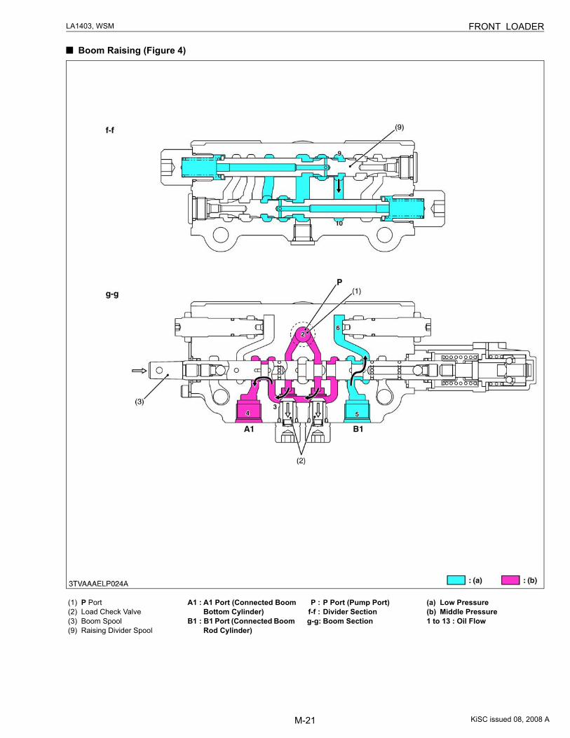
Boom Raising (Figure 4)
(1) P Port(2) Load Check Valve(3) Boom Spool(9) Raising Divider Spool
A1 : A1 Port (Connected Boom Bottom Cylinder)
B1 : B1 Port (Connected Boom Rod Cylinder)
P : P Port (Pump Port)f-f : Divider Sectiong-g: Boom Section
(a) Low Pressure(b) Middle Pressure1 to 13 : Oil Flow
KiSC issued 08, 2008 A
M-22
LA1403, WSM FRONT LOADER
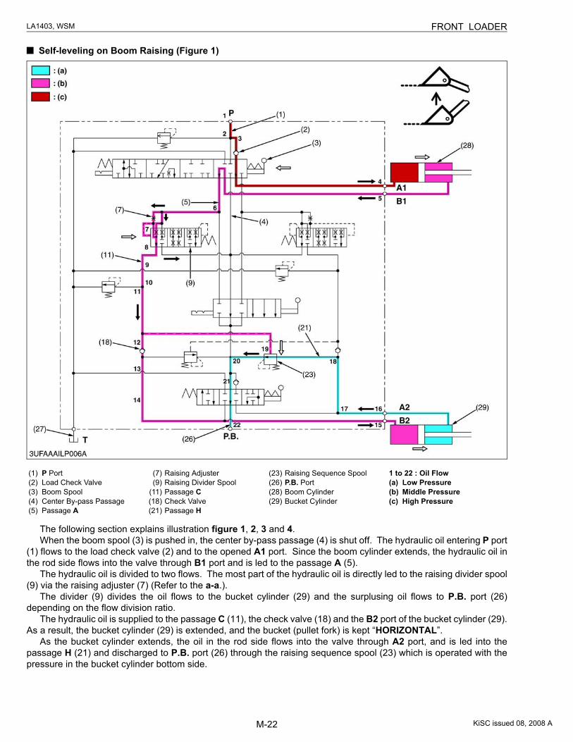
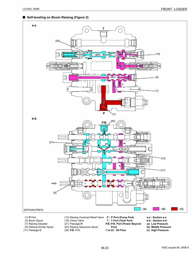
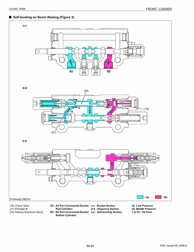
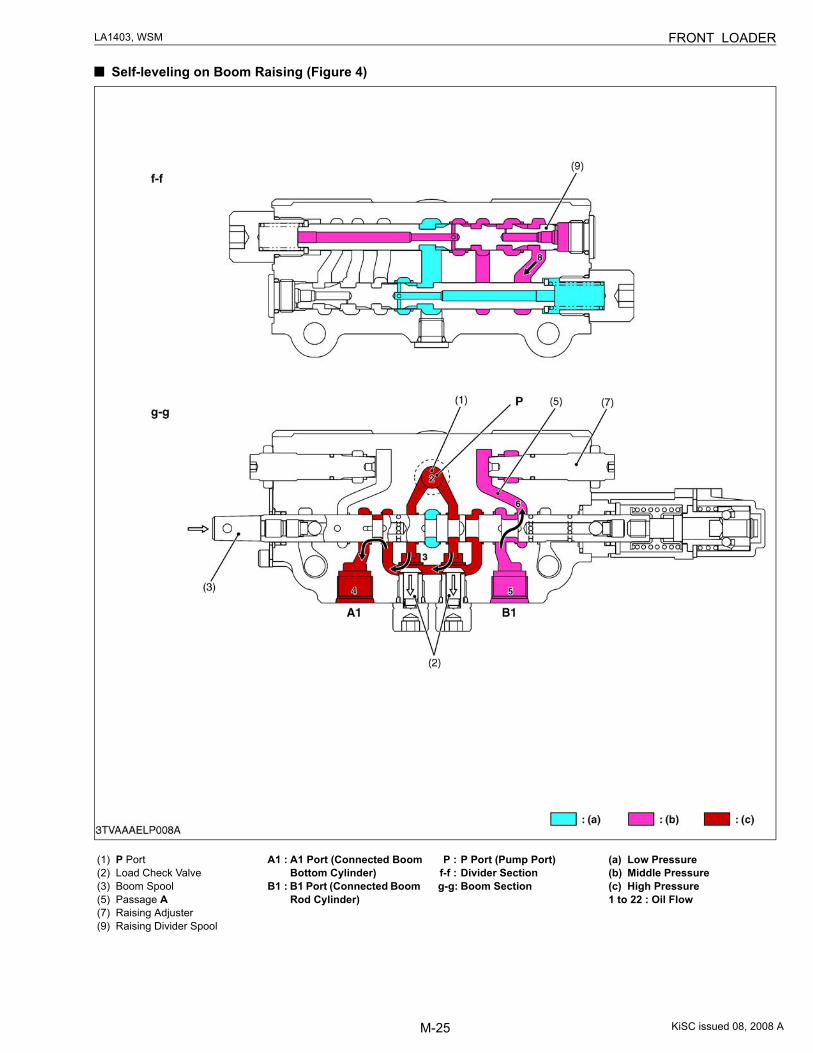
Self-leveling on Boom Raising (Figure 1)
The following section explains illustration figure 1, 2, 3 and 4.When the boom spool (3) is pushed in, the center by-pass passage (4) is shut off. The hydraulic oil entering P port
(1) flows to the load check valve (2) and to the opened A1 port. Since the boom cylinder extends, the hydraulic oil inthe rod side flows into the valve through B1 port and is led to the passage A (5).
The hydraulic oil is divided to two flows. The most part of the hydraulic oil is directly led to the raising divider spool(9) via the raising adjuster (7) (Refer to the a-a.).
The divider (9) divides the oil flows to the bucket cylinder (29) and the surplusing oil flows to P.B. port (26)depending on the flow division ratio.
The hydraulic oil is supplied to the passage C (11), the check valve (18) and the B2 port of the bucket cylinder (29).As a result, the bucket cylinder (29) is extended, and the bucket (pullet fork) is kept “HORIZONTAL”.
As the bucket cylinder extends, the oil in the rod side flows into the valve through A2 port, and is led into thepassage H (21) and discharged to P.B. port (26) through the raising sequence spool (23) which is operated with thepressure in the bucket cylinder bottom side.
(1) P Port(2) Load Check Valve(3) Boom Spool(4) Center By-pass Passage(5) Passage A
(7) Raising Adjuster(9) Raising Divider Spool
(11) Passage C(18) Check Valve(21) Passage H
(23) Raising Sequence Spool(26) P.B. Port(28) Boom Cylinder(29) Bucket Cylinder
1 to 22 : Oil Flow(a) Low Pressure(b) Middle Pressure(c) High Pressure
KiSC issued 08, 2008 A
M-23
LA1403, WSM FRONT LOADER
Self-leveling on Boom Raising (Figure 2)
(1) P Port(3) Boom Spool(7) Raising Adjuster(9) Raising Divider Spool
(11) Passage C
(13) Raising Overload Relief Valve(18) Check Valve(21) Passage H(23) Raising Sequence Spool(26) P.B. Port
P : P Port (Pump Port)T : T Port (Tank Port)
P.B.: P.B. Port (Power Beyond Port)
1 to 22 : Oil Flow
a-a : Section a-ab-b : Section b-b(a) Low Pressure(b) Middle Pressure(c) High Pressure
KiSC issued 08, 2008 A
M-24
LA1403, WSM FRONT LOADER
Self-leveling on Boom Raising (Figure 3)
(18) Check Valve(21) Passage H(23) Raising Sequence Spool
A2 : A2 Port (Connected Bucket Rod Cylinder)
B2 : B2 Port (Connected Bucket Bottom Cylinder)
c-c : Bucket Sectiond-d : Sequence Sectione-e : Self-leveling Section
(a) Low Pressure(b) Middle Pressure1 to 22 : Oil Flow
KiSC issued 08, 2008 A
M-25
LA1403, WSM FRONT LOADER
Self-leveling on Boom Raising (Figure 4)
(1) P Port(2) Load Check Valve(3) Boom Spool(5) Passage A(7) Raising Adjuster(9) Raising Divider Spool
A1 : A1 Port (Connected Boom Bottom Cylinder)
B1 : B1 Port (Connected Boom Rod Cylinder)
P : P Port (Pump Port)f-f : Divider Sectiong-g: Boom Section
(a) Low Pressure(b) Middle Pressure(c) High Pressure1 to 22 : Oil Flow
KiSC issued 08, 2008 A
M-26
LA1403, WSM FRONT LOADER
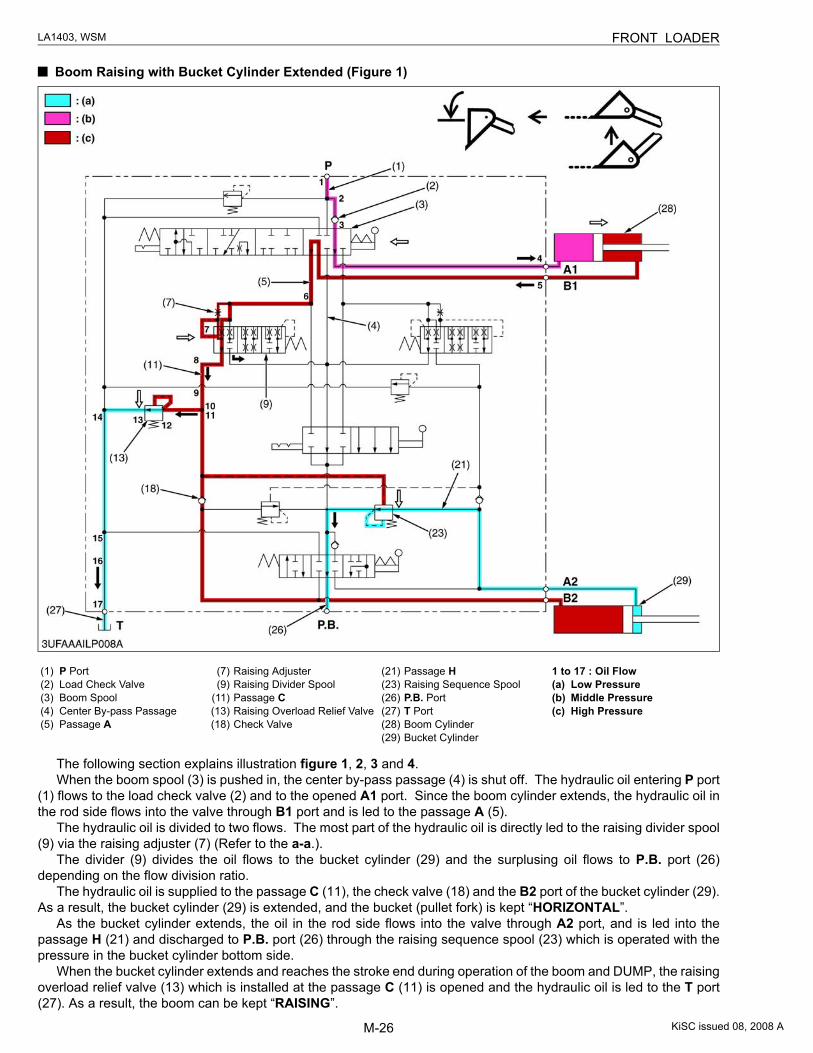
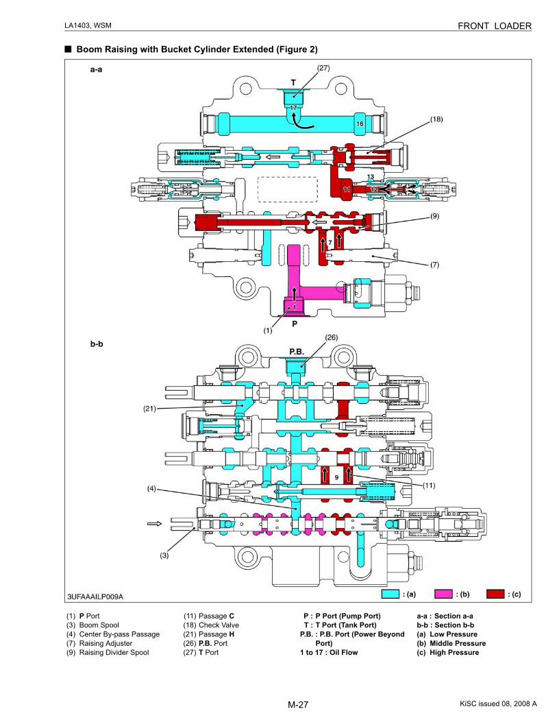
Boom Raising with Bucket Cylinder Extended (Figure 1)
The following section explains illustration figure 1, 2, 3 and 4.When the boom spool (3) is pushed in, the center by-pass passage (4) is shut off. The hydraulic oil entering P port
(1) flows to the load check valve (2) and to the opened A1 port. Since the boom cylinder extends, the hydraulic oil inthe rod side flows into the valve through B1 port and is led to the passage A (5).
The hydraulic oil is divided to two flows. The most part of the hydraulic oil is directly led to the raising divider spool(9) via the raising adjuster (7) (Refer to the a-a.).
The divider (9) divides the oil flows to the bucket cylinder (29) and the surplusing oil flows to P.B. port (26)depending on the flow division ratio.
The hydraulic oil is supplied to the passage C (11), the check valve (18) and the B2 port of the bucket cylinder (29).As a result, the bucket cylinder (29) is extended, and the bucket (pullet fork) is kept “HORIZONTAL”.
As the bucket cylinder extends, the oil in the rod side flows into the valve through A2 port, and is led into thepassage H (21) and discharged to P.B. port (26) through the raising sequence spool (23) which is operated with thepressure in the bucket cylinder bottom side.
When the bucket cylinder extends and reaches the stroke end during operation of the boom and DUMP, the raisingoverload relief valve (13) which is installed at the passage C (11) is opened and the hydraulic oil is led to the T port(27). As a result, the boom can be kept “RAISING”.
(1) P Port(2) Load Check Valve(3) Boom Spool(4) Center By-pass Passage(5) Passage A
(7) Raising Adjuster(9) Raising Divider Spool
(11) Passage C(13) Raising Overload Relief Valve(18) Check Valve
(21) Passage H(23) Raising Sequence Spool(26) P.B. Port(27) T Port(28) Boom Cylinder(29) Bucket Cylinder
1 to 17 : Oil Flow(a) Low Pressure(b) Middle Pressure(c) High Pressure
KiSC issued 08, 2008 A
M-27
LA1403, WSM FRONT LOADER
Boom Raising with Bucket Cylinder Extended (Figure 2)
(1) P Port(3) Boom Spool(4) Center By-pass Passage(7) Raising Adjuster(9) Raising Divider Spool
(11) Passage C(18) Check Valve(21) Passage H(26) P.B. Port(27) T Port
P : P Port (Pump Port)T : T Port (Tank Port)
P.B. : P.B. Port (Power Beyond Port)
1 to 17 : Oil Flow
a-a : Section a-ab-b : Section b-b(a) Low Pressure(b) Middle Pressure(c) High Pressure
KiSC issued 08, 2008 A
M-28
LA1403, WSM FRONT LOADER
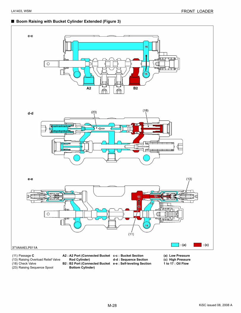
Boom Raising with Bucket Cylinder Extended (Figure 3)
(11) Passage C(13) Raising Overload Relief Valve(18) Check Valve(23) Raising Sequence Spool
A2 : A2 Port (Connected Bucket Rod Cylinder)
B2 : B2 Port (Connected Bucket Bottom Cylinder)
c-c : Bucket Sectiond-d : Sequence Sectione-e : Self-leveling Section
(a) Low Pressure(c) High Pressure1 to 17 : Oil Flow
KiSC issued 08, 2008 A
M-29
LA1403, WSM FRONT LOADER
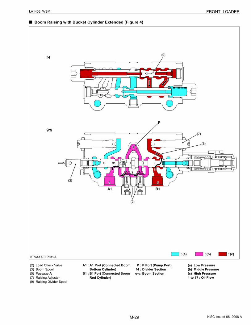
Boom Raising with Bucket Cylinder Extended (Figure 4)
(2) Load Check Valve(3) Boom Spool(5) Passage A(7) Raising Adjuster(9) Raising Divider Spool
A1 : A1 Port (Connected Boom Bottom Cylinder)
B1 : B1 Port (Connected Boom Rod Cylinder)
P : P Port (Pump Port)f-f : Divider Sectiong-g: Boom Section
(a) Low Pressure(b) Middle Pressure(c) High Pressure1 to 17 : Oil Flow
KiSC issued 08, 2008 A
M-30
LA1403, WSM FRONT LOADER
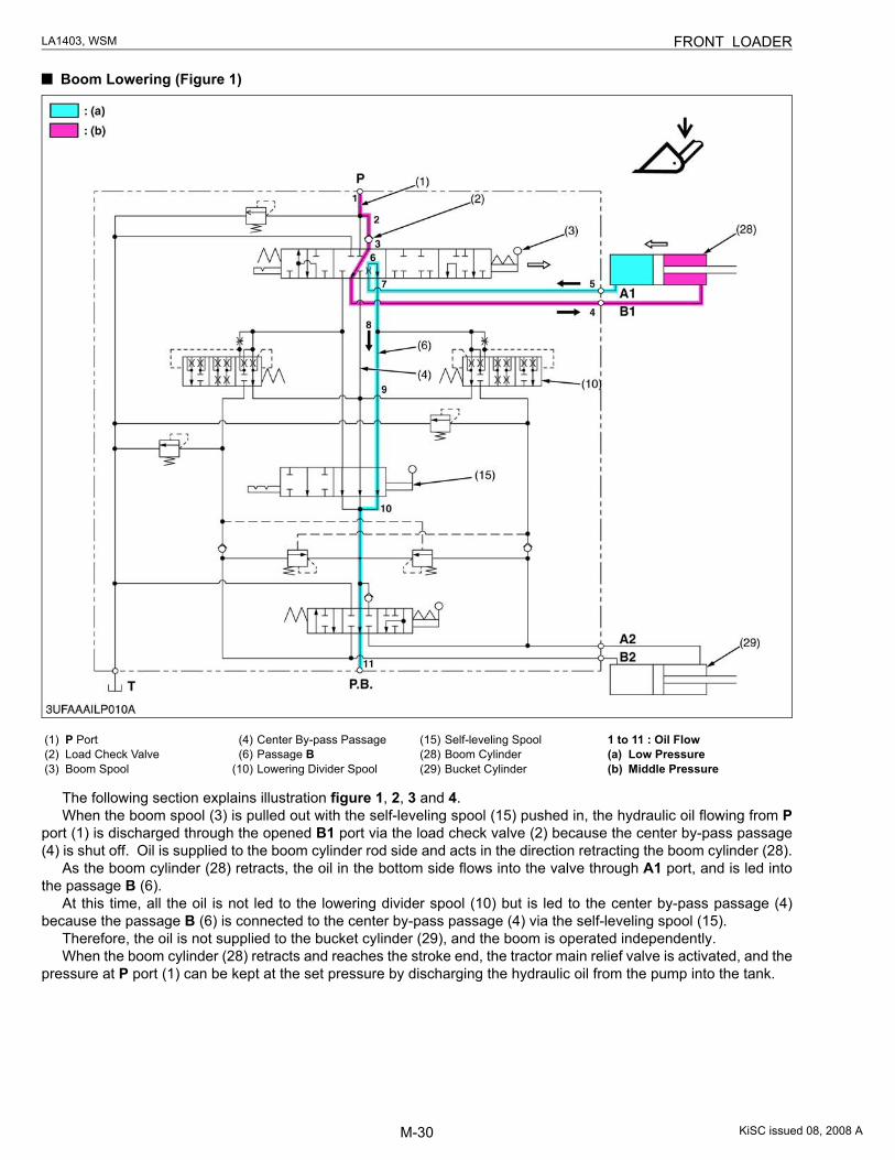
Boom Lowering (Figure 1)
The following section explains illustration figure 1, 2, 3 and 4.When the boom spool (3) is pulled out with the self-leveling spool (15) pushed in, the hydraulic oil flowing from P
port (1) is discharged through the opened B1 port via the load check valve (2) because the center by-pass passage(4) is shut off. Oil is supplied to the boom cylinder rod side and acts in the direction retracting the boom cylinder (28).
As the boom cylinder (28) retracts, the oil in the bottom side flows into the valve through A1 port, and is led intothe passage B (6).
At this time, all the oil is not led to the lowering divider spool (10) but is led to the center by-pass passage (4)because the passage B (6) is connected to the center by-pass passage (4) via the self-leveling spool (15).
Therefore, the oil is not supplied to the bucket cylinder (29), and the boom is operated independently.When the boom cylinder (28) retracts and reaches the stroke end, the tractor main relief valve is activated, and the
pressure at P port (1) can be kept at the set pressure by discharging the hydraulic oil from the pump into the tank.
(1) P Port(2) Load Check Valve(3) Boom Spool
(4) Center By-pass Passage(6) Passage B
(10) Lowering Divider Spool
(15) Self-leveling Spool(28) Boom Cylinder(29) Bucket Cylinder
1 to 11 : Oil Flow(a) Low Pressure(b) Middle Pressure
KiSC issued 08, 2008 A

M-31
LA1403, WSM FRONT LOADER
Boom Lowering (Figure 2)
(1) P Port(3) Boom Spool(4) Center By-pass Passage(6) Passage B
(15) Self-leveling Spool
P : P Port (Pump Port)T : T Port (Tank Port)
P.B. : P.B. Port (Power Beyond Port)
a-a : Section a-ab-b : Section b-b
(a) Low Pressure(b) Middle Pressure1 to 11 : Oil Flow
KiSC issued 08, 2008 A
M-32
LA1403, WSM FRONT LOADER
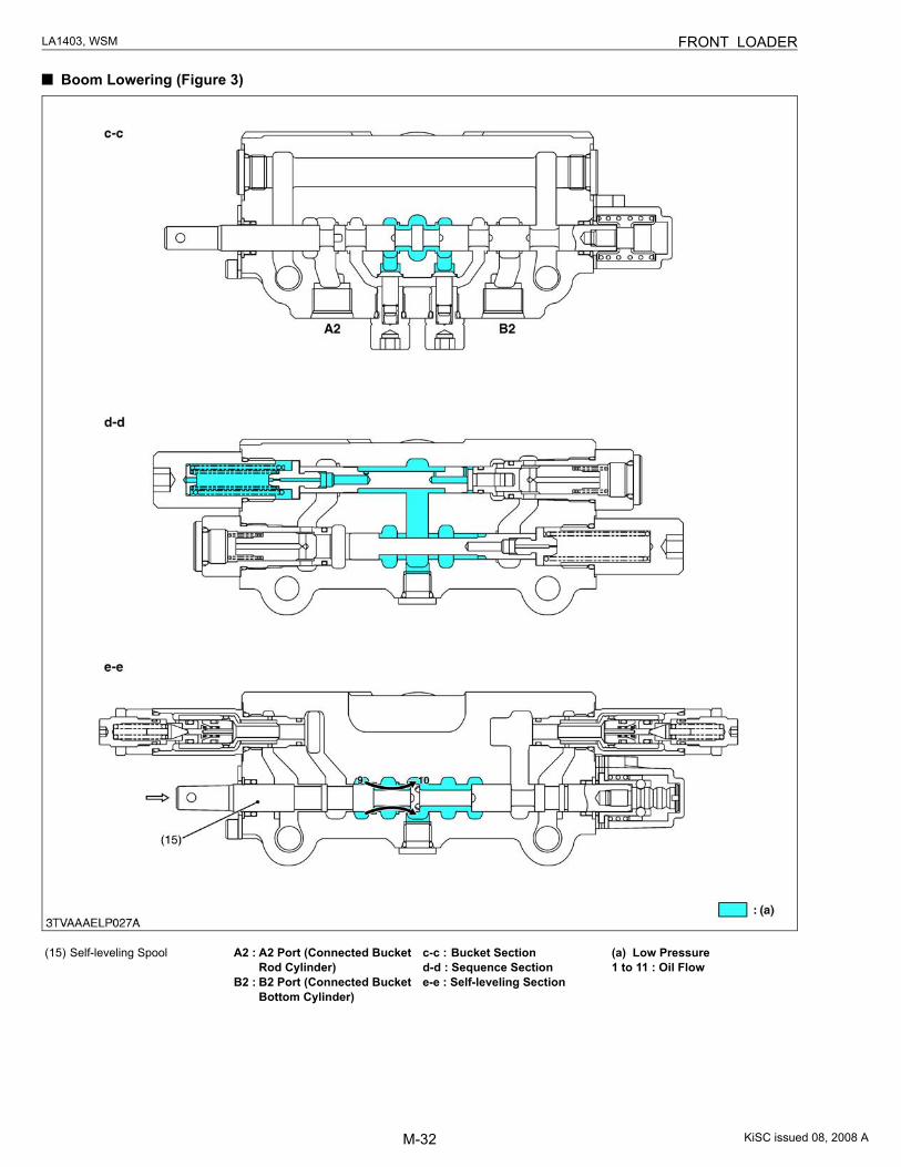
Boom Lowering (Figure 3)
(15) Self-leveling Spool A2 : A2 Port (Connected Bucket Rod Cylinder)
B2 : B2 Port (Connected Bucket Bottom Cylinder)
c-c : Bucket Sectiond-d : Sequence Sectione-e : Self-leveling Section
(a) Low Pressure1 to 11 : Oil Flow
KiSC issued 08, 2008 A
M-33
LA1403, WSM FRONT LOADER
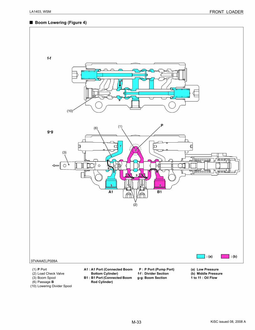
Boom Lowering (Figure 4)
(1) P Port(2) Load Check Valve(3) Boom Spool(6) Passage B
(10) Lowering Divider Spool
A1 : A1 Port (Connected Boom Bottom Cylinder)
B1 : B1 Port (Connected Boom Rod Cylinder)
P : P Port (Pump Port)f-f : Divider Sectiong-g: Boom Section
(a) Low Pressure(b) Middle Pressure1 to 11 : Oil Flow
KiSC issued 08, 2008 A
M-34
LA1403, WSM FRONT LOADER
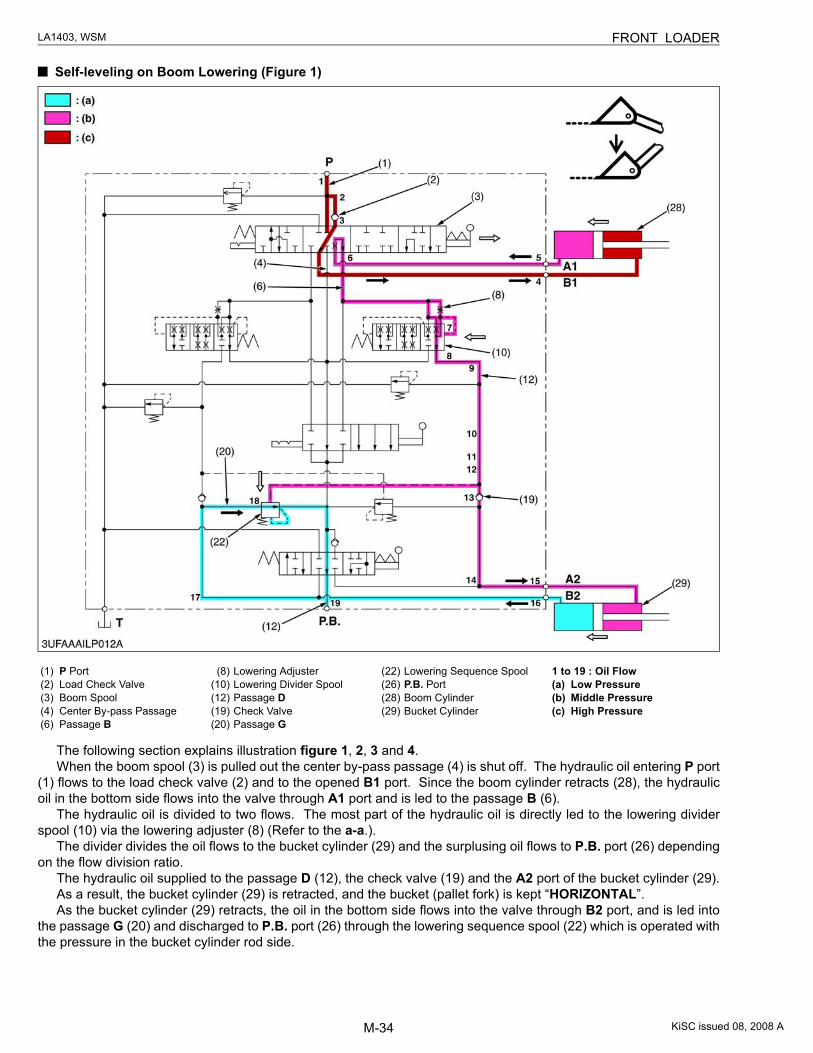
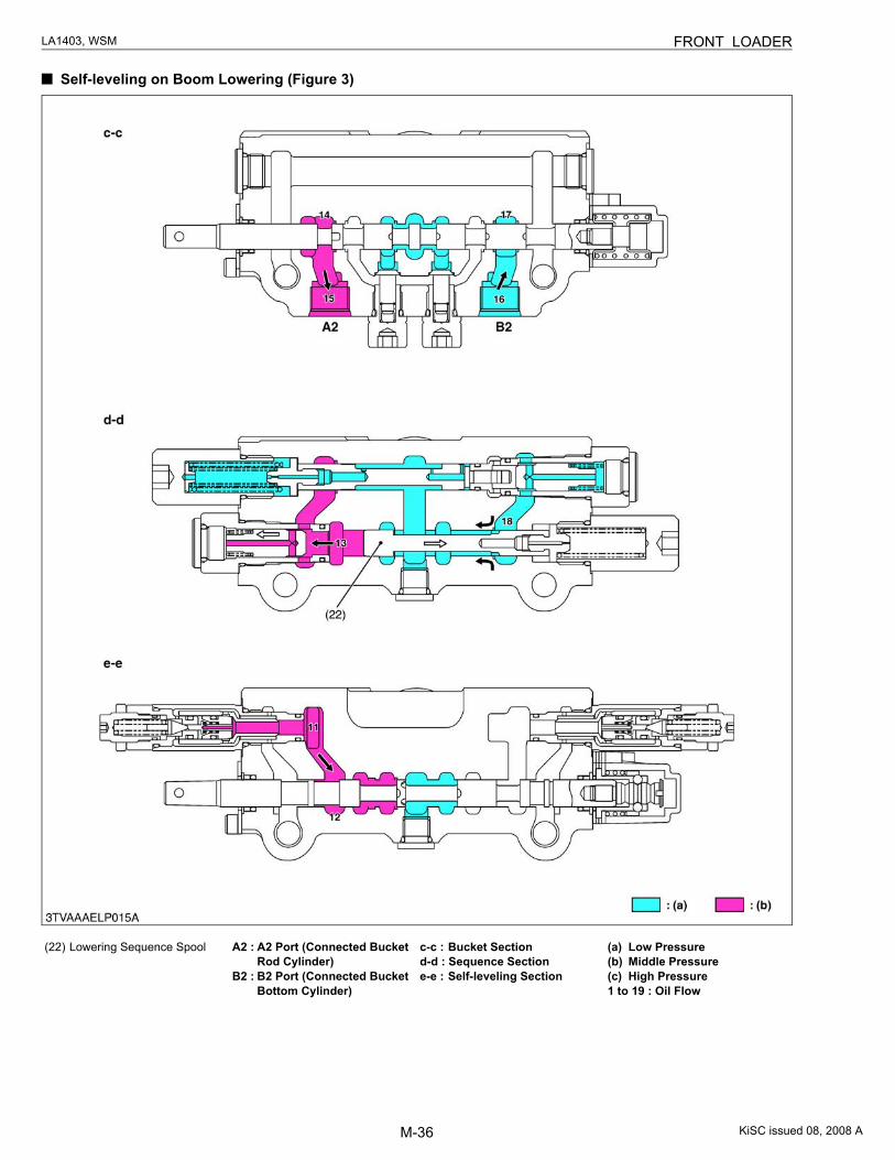
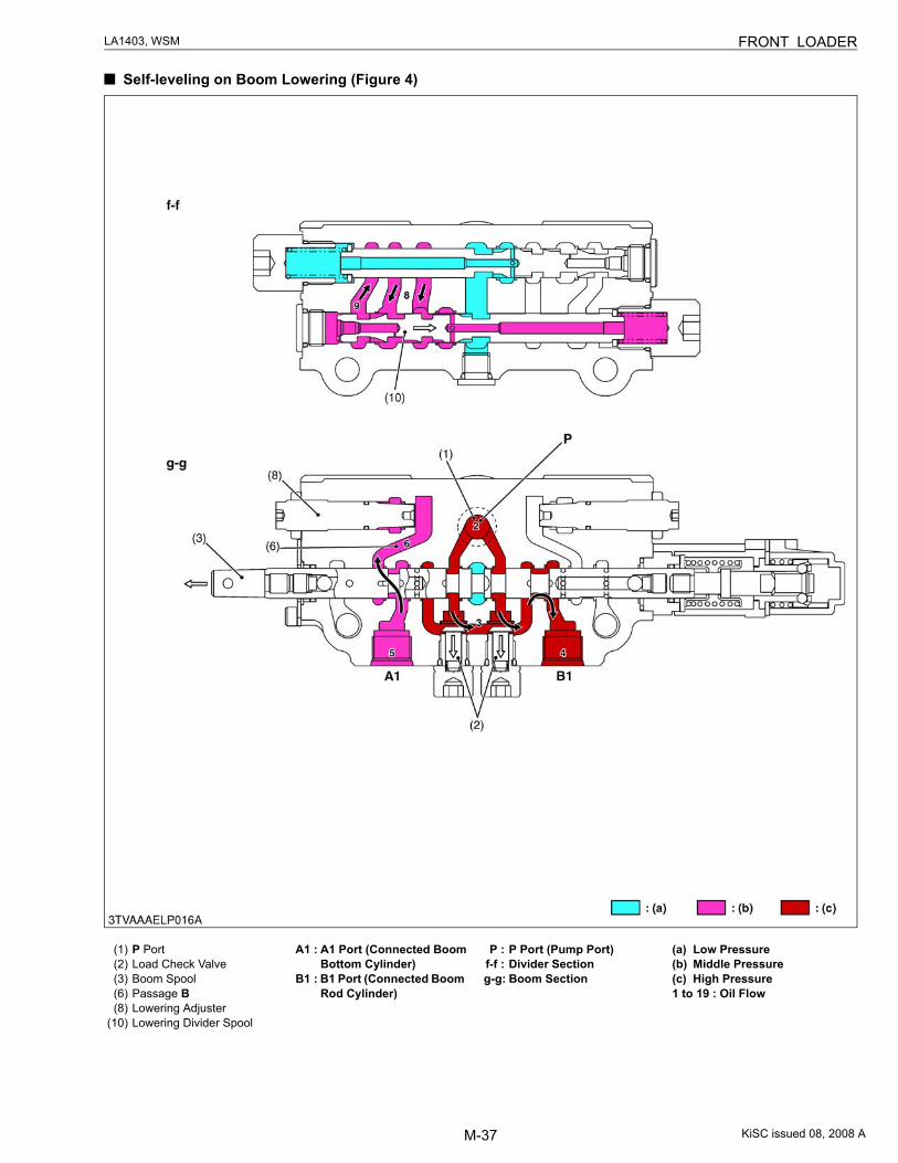
Self-leveling on Boom Lowering (Figure 1)
The following section explains illustration figure 1, 2, 3 and 4.When the boom spool (3) is pulled out the center by-pass passage (4) is shut off. The hydraulic oil entering P port
(1) flows to the load check valve (2) and to the opened B1 port. Since the boom cylinder retracts (28), the hydraulicoil in the bottom side flows into the valve through A1 port and is led to the passage B (6).
The hydraulic oil is divided to two flows. The most part of the hydraulic oil is directly led to the lowering dividerspool (10) via the lowering adjuster (8) (Refer to the a-a.).
The divider divides the oil flows to the bucket cylinder (29) and the surplusing oil flows to P.B. port (26) dependingon the flow division ratio.
The hydraulic oil supplied to the passage D (12), the check valve (19) and the A2 port of the bucket cylinder (29).As a result, the bucket cylinder (29) is retracted, and the bucket (pallet fork) is kept “HORIZONTAL”.As the bucket cylinder (29) retracts, the oil in the bottom side flows into the valve through B2 port, and is led into
the passage G (20) and discharged to P.B. port (26) through the lowering sequence spool (22) which is operated withthe pressure in the bucket cylinder rod side.
(1) P Port(2) Load Check Valve(3) Boom Spool(4) Center By-pass Passage(6) Passage B
(8) Lowering Adjuster(10) Lowering Divider Spool(12) Passage D(19) Check Valve(20) Passage G
(22) Lowering Sequence Spool(26) P.B. Port(28) Boom Cylinder(29) Bucket Cylinder
1 to 19 : Oil Flow(a) Low Pressure(b) Middle Pressure(c) High Pressure
KiSC issued 08, 2008 A
M-35
LA1403, WSM FRONT LOADER
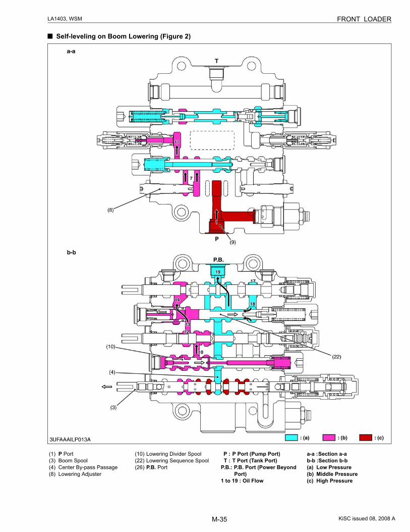
Self-leveling on Boom Lowering (Figure 2)
(1) P Port(3) Boom Spool(4) Center By-pass Passage(8) Lowering Adjuster
(10) Lowering Divider Spool(22) Lowering Sequence Spool(26) P.B. Port
P : P Port (Pump Port)T : T Port (Tank Port)
P.B.: P.B. Port (Power Beyond Port)
1 to 19 : Oil Flow
a-a :Section a-ab-b :Section b-b(a) Low Pressure(b) Middle Pressure(c) High Pressure
KiSC issued 08, 2008 A
M-36
LA1403, WSM FRONT LOADER
Self-leveling on Boom Lowering (Figure 3)
(22) Lowering Sequence Spool A2 : A2 Port (Connected Bucket Rod Cylinder)
B2 : B2 Port (Connected Bucket Bottom Cylinder)
c-c : Bucket Sectiond-d : Sequence Sectione-e : Self-leveling Section
(a) Low Pressure(b) Middle Pressure(c) High Pressure1 to 19 : Oil Flow
KiSC issued 08, 2008 A
M-37
LA1403, WSM FRONT LOADER
Self-leveling on Boom Lowering (Figure 4)
(1) P Port(2) Load Check Valve(3) Boom Spool(6) Passage B (8) Lowering Adjuster
(10) Lowering Divider Spool
A1 : A1 Port (Connected Boom Bottom Cylinder)
B1 : B1 Port (Connected Boom Rod Cylinder)
P : P Port (Pump Port)f-f : Divider Sectiong-g: Boom Section
(a) Low Pressure(b) Middle Pressure(c) High Pressure1 to 19 : Oil Flow
KiSC issued 08, 2008 A
M-38
LA1403, WSM FRONT LOADER
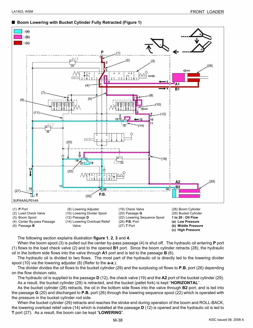
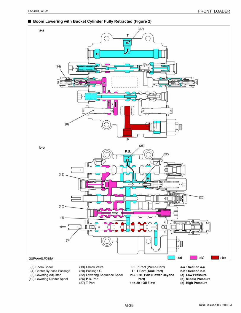
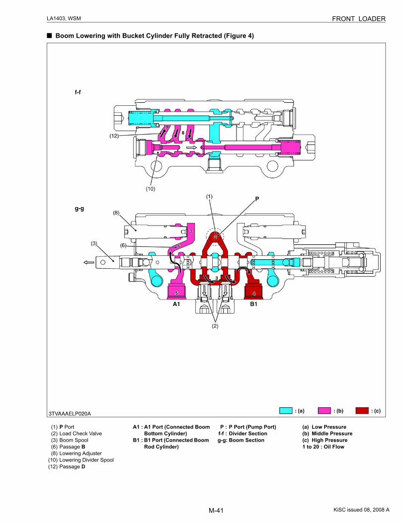
Boom Lowering with Bucket Cylinder Fully Retracted (Figure 1)
The following section explains illustration figure 1, 2, 3 and 4.When the boom spool (3) is pulled out the center by-pass passage (4) is shut off. The hydraulic oil entering P port
(1) flows to the load check valve (2) and to the opened B1 port. Since the boom cylinder retracts (28), the hydraulicoil in the bottom side flows into the valve through A1 port and is led to the passage B (6).
The hydraulic oil is divided to two flows. The most part of the hydraulic oil is directly led to the lowering dividerspool (10) via the lowering adjuster (8) (Refer to the a-a.).
The divider divides the oil flows to the bucket cylinder (29) and the surplusing oil flows to P.B. port (26) dependingon the flow division ratio.
The hydraulic oil is supplied to the passage D (12), the check valve (19) and the A2 port of the bucket cylinder (29).As a result, the bucket cylinder (29) is retracted, and the bucket (pallet fork) is kept “HORIZONTAL”.As the bucket cylinder (28) retracts, the oil in the bottom side flows into the valve through B2 port, and is led into
the passage G (20) and discharged to P.B. port (26) through the lowering sequence spool (22) which is operated withthe pressure in the bucket cylinder rod side.
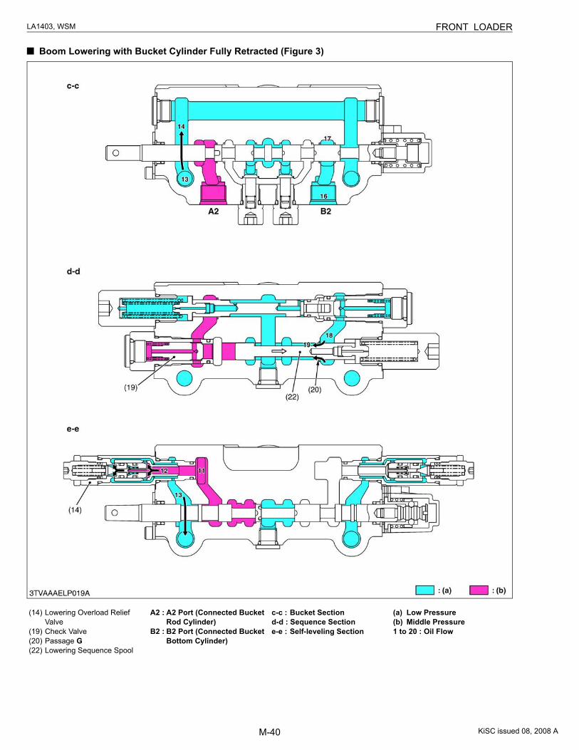
When the bucket cylinder (29) retracts and reaches the stroke end during operation of the boom and ROLL-BACK,the lowering overload relief valve (14) which is installed at the passage D (12) is opened and the hydraulic oil is led toT port (27). As a result, the boom can be kept “LOWERING”.
(1) P Port(2) Load Check Valve(3) Boom Spool(4) Center By-pass Passage(6) Passage B
(8) Lowering Adjuster(10) Lowering Divider Spool(12) Passage D(14) Lowering Overload Relief
Valve
(19) Check Valve(20) Passage G(22) Lowering Sequence Spool(26) P.B. Port(27) T Port
(28) Boom Cylinder(29) Bucket Cylinder1 to 20 : Oil Flow(a) Low Pressure(b) Middle Pressure(c) High Pressure
KiSC issued 08, 2008 A
M-39
LA1403, WSM FRONT LOADER
Boom Lowering with Bucket Cylinder Fully Retracted (Figure 2)
(3) Boom Spool(4) Center By-pass Passage(8) Lowering Adjuster
(10) Lowering Divider Spool
(19) Check Valve(20) Passage G(22) Lowering Sequence Spool(26) P.B. Port(27) T Port
P : P Port (Pump Port)T : T Port (Tank Port)
P.B.: P.B. Port (Power Beyond Port)
1 to 20 : Oil Flow
a-a : Section a-ab-b : Section b-b(a) Low Pressure(b) Middle Pressure(c) High Pressure
KiSC issued 08, 2008 A
M-40
LA1403, WSM FRONT LOADER
Boom Lowering with Bucket Cylinder Fully Retracted (Figure 3)
(14) Lowering Overload Relief Valve
(19) Check Valve(20) Passage G(22) Lowering Sequence Spool
A2 : A2 Port (Connected Bucket Rod Cylinder)
B2 : B2 Port (Connected Bucket Bottom Cylinder)
c-c : Bucket Sectiond-d : Sequence Sectione-e : Self-leveling Section
(a) Low Pressure(b) Middle Pressure1 to 20 : Oil Flow
KiSC issued 08, 2008 A
M-41
LA1403, WSM FRONT LOADER
Boom Lowering with Bucket Cylinder Fully Retracted (Figure 4)
(1) P Port(2) Load Check Valve(3) Boom Spool(6) Passage B (8) Lowering Adjuster
(10) Lowering Divider Spool(12) Passage D
A1 : A1 Port (Connected Boom Bottom Cylinder)
B1 : B1 Port (Connected Boom Rod Cylinder)
P : P Port (Pump Port)f-f : Divider Sectiong-g: Boom Section
(a) Low Pressure(b) Middle Pressure(c) High Pressure1 to 20 : Oil Flow
KiSC issued 08, 2008 A
M-42
LA1403, WSM FRONT LOADER
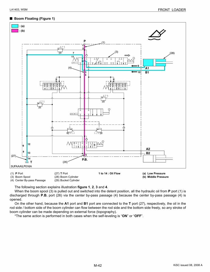
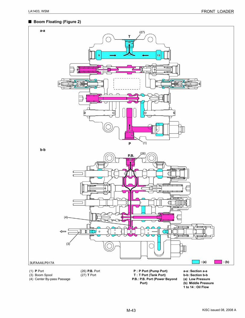
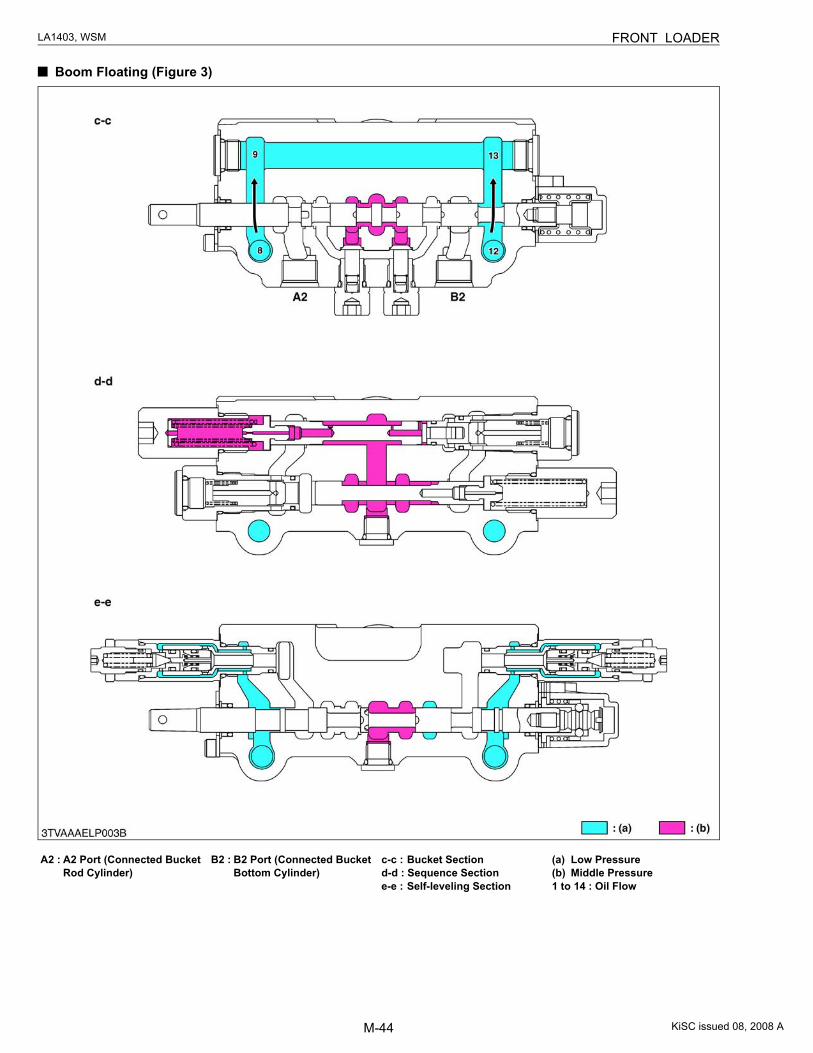
Boom Floating (Figure 1)
The following section explains illustration figure 1, 2, 3 and 4.When the boom spool (3) is pulled out and switched into the detent position, all the hydraulic oil from P port (1) is
discharged through P.B. port (26) via the center by-pass passage (4) because the center by-pass passage (4) isopened.
On the other hand, because the A1 port and B1 port are connected to the T port (27), respectively, the oil in therod side / bottom side of the boom cylinder can flow between the rod side and the bottom side freely, so any stroke ofboom cylinder can be made depending on external force (topography).
*The same action is performed in both cases when the self-leveling is “ON” or “OFF”.
(1) P Port(3) Boom Spool(4) Center By-pass Passage
(27) T Port(28) Boom Cylinder(29) Bucket Cylinder
1 to 14 : Oil Flow (a) Low Pressure(b) Middle Pressure
KiSC issued 08, 2008 A
M-43
LA1403, WSM FRONT LOADER
Boom Floating (Figure 2)
(1) P Port(3) Boom Spool(4) Center By-pass Passage
(26) P.B. Port(27) T Port
P : P Port (Pump Port)T : T Port (Tank Port)
P.B.: P.B. Port (Power Beyond Port)
a-a : Section a-ab-b : Section b-b(a) Low Pressure(b) Middle Pressure1 to 14 : Oil Flow
KiSC issued 08, 2008 A
M-44
LA1403, WSM FRONT LOADER
Boom Floating (Figure 3)
A2 : A2 Port (Connected Bucket Rod Cylinder)
B2 : B2 Port (Connected Bucket Bottom Cylinder)
c-c : Bucket Sectiond-d : Sequence Sectione-e : Self-leveling Section
(a) Low Pressure(b) Middle Pressure1 to 14 : Oil Flow
KiSC issued 08, 2008 A
M-45
LA1403, WSM FRONT LOADER
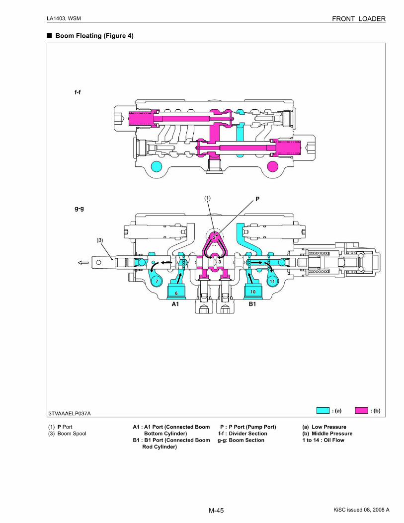
Boom Floating (Figure 4)
(1) P Port(3) Boom Spool
A1 : A1 Port (Connected Boom Bottom Cylinder)
B1 : B1 Port (Connected Boom Rod Cylinder)
P : P Port (Pump Port)f-f : Divider Sectiong-g: Boom Section
(a) Low Pressure(b) Middle Pressure1 to 14 : Oil Flow
KiSC issued 08, 2008 A
M-46
LA1403, WSM FRONT LOADER
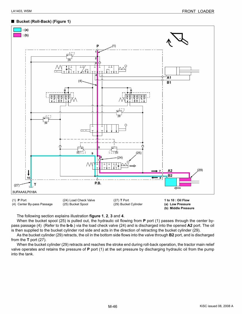
Bucket (Roll-Back) (Figure 1)
The following section explains illustration figure 1, 2, 3 and 4.When the bucket spool (25) is pulled out, the hydraulic oil flowing from P port (1) passes through the center by-
pass passage (4) (Refer to the b-b.) via the load check valve (24) and is discharged into the opened A2 port. The oilis then supplied to the bucket cylinder rod side and acts in the direction of retracting the bucket cylinder (29).
As the bucket cylinder (29) retracts, the oil in the bottom side flows into the valve through B2 port, and is dischargedfrom the T port (27).
When the bucket cylinder (29) retracts and reaches the stroke end during roll-back operation, the tractor main reliefvalve operates and retains the pressure of P port (1) at the set pressure by discharging hydraulic oil from the pumpinto the tank.
(1) P Port(4) Center By-pass Passage
(24) Load Check Valve(25) Bucket Spool
(27) T Port(29) Bucket Cylinder
1 to 10 : Oil Flow(a) Low Pressure(b) Middle Pressure
KiSC issued 08, 2008 A
M-47
LA1403, WSM FRONT LOADER
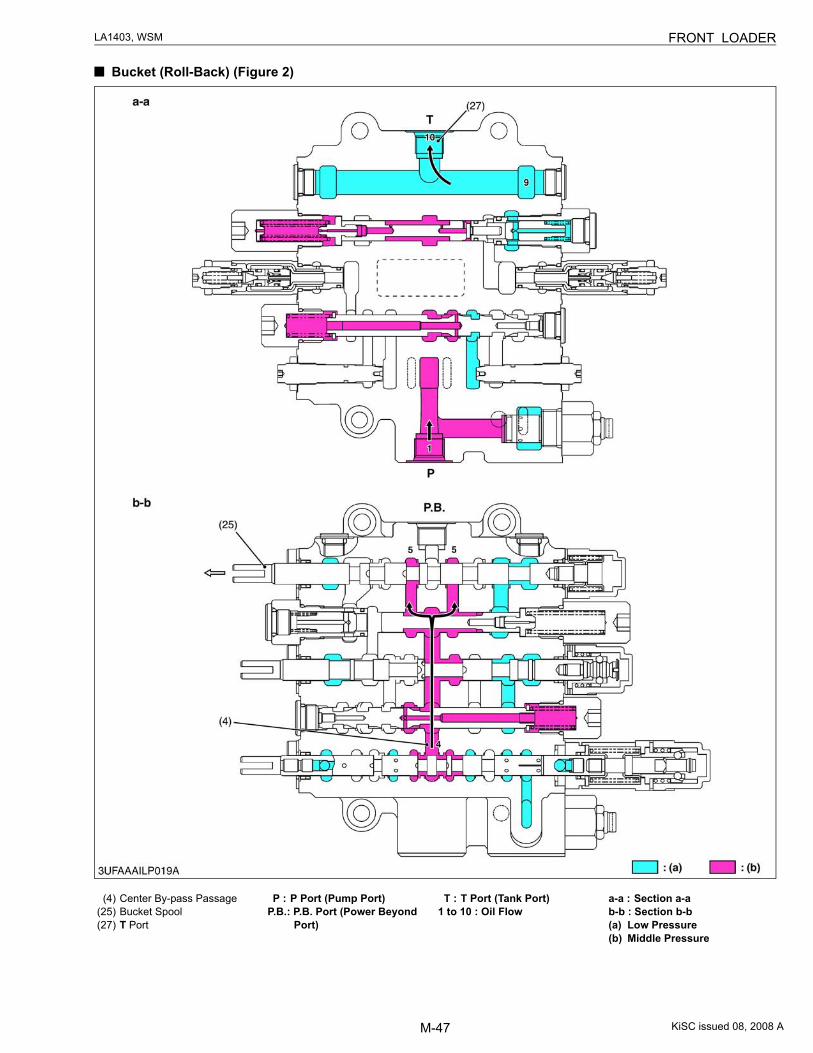
Bucket (Roll-Back) (Figure 2)
(4) Center By-pass Passage(25) Bucket Spool(27) T Port
P : P Port (Pump Port)P.B.: P.B. Port (Power Beyond
Port)
T : T Port (Tank Port)1 to 10 : Oil Flow
a-a : Section a-ab-b : Section b-b(a) Low Pressure(b) Middle Pressure
KiSC issued 08, 2008 A
M-48
LA1403, WSM FRONT LOADER
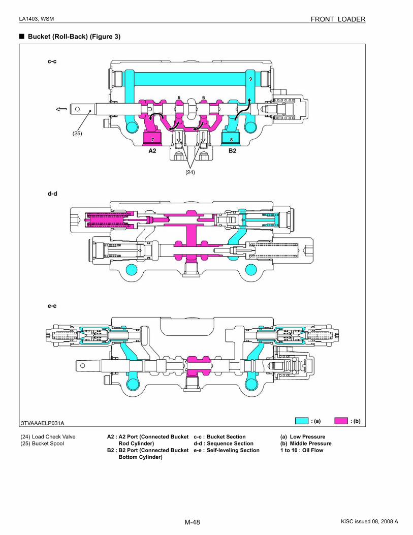
Bucket (Roll-Back) (Figure 3)
(24) Load Check Valve(25) Bucket Spool
A2 : A2 Port (Connected Bucket Rod Cylinder)
B2 : B2 Port (Connected Bucket Bottom Cylinder)
c-c : Bucket Sectiond-d : Sequence Sectione-e : Self-leveling Section
(a) Low Pressure(b) Middle Pressure1 to 10 : Oil Flow
KiSC issued 08, 2008 A
M-49
LA1403, WSM FRONT LOADER
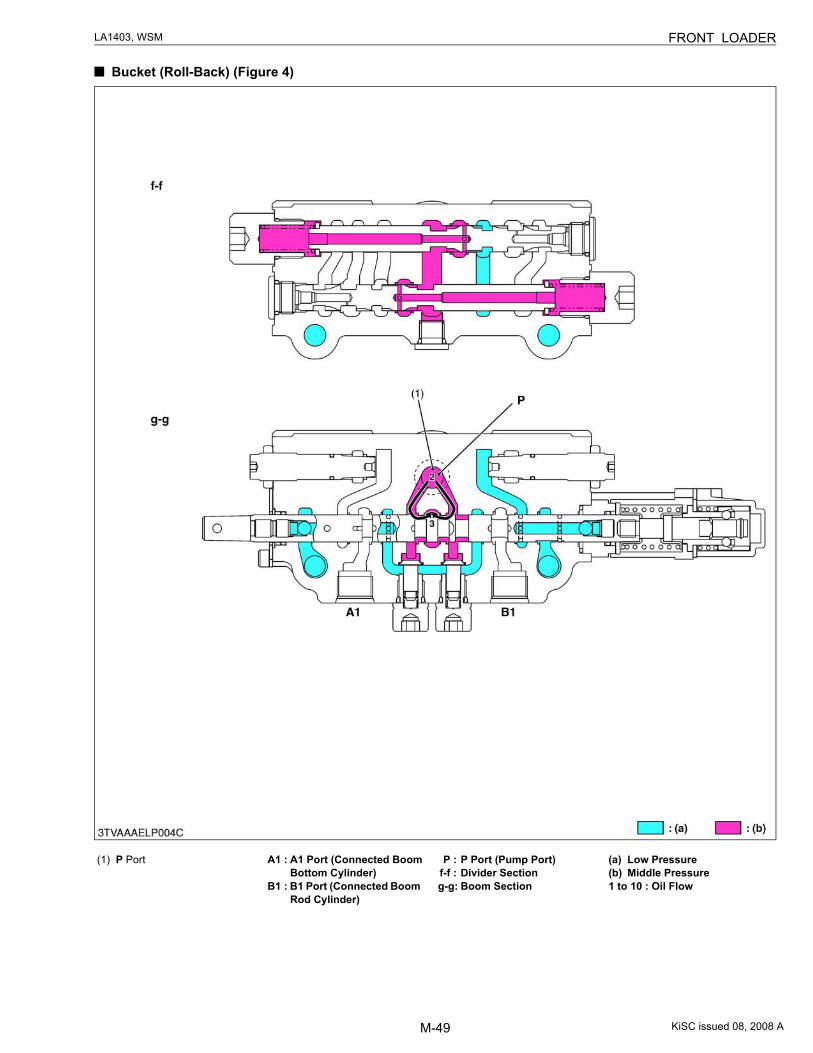
Bucket (Roll-Back) (Figure 4)
(1) P Port A1 : A1 Port (Connected Boom Bottom Cylinder)
B1 : B1 Port (Connected Boom Rod Cylinder)
P : P Port (Pump Port)f-f : Divider Sectiong-g: Boom Section
(a) Low Pressure(b) Middle Pressure1 to 10 : Oil Flow
KiSC issued 08, 2008 A
M-50
LA1403, WSM FRONT LOADER
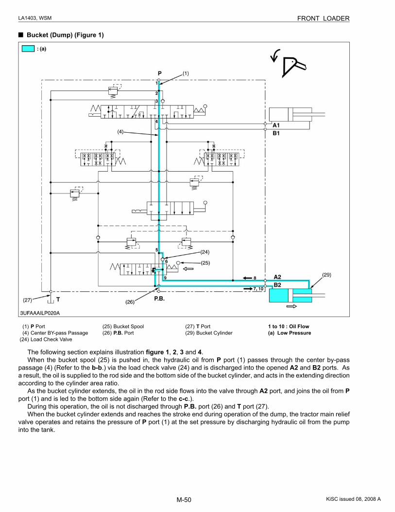
Bucket (Dump) (Figure 1)
The following section explains illustration figure 1, 2, 3 and 4.When the bucket spool (25) is pushed in, the hydraulic oil from P port (1) passes through the center by-pass
passage (4) (Refer to the b-b.) via the load check valve (24) and is discharged into the opened A2 and B2 ports. Asa result, the oil is supplied to the rod side and the bottom side of the bucket cylinder, and acts in the extending directionaccording to the cylinder area ratio.
As the bucket cylinder extends, the oil in the rod side flows into the valve through A2 port, and joins the oil from Pport (1) and is led to the bottom side again (Refer to the c-c.).
During this operation, the oil is not discharged through P.B. port (26) and T port (27).When the bucket cylinder extends and reaches the stroke end during operation of the dump, the tractor main relief
valve operates and retains the pressure of P port (1) at the set pressure by discharging hydraulic oil from the pumpinto the tank.
(1) P Port(4) Center BY-pass Passage
(24) Load Check Valve
(25) Bucket Spool(26) P.B. Port
(27) T Port(29) Bucket Cylinder
1 to 10 : Oil Flow(a) Low Pressure
KiSC issued 08, 2008 A
M-51
LA1403, WSM FRONT LOADER
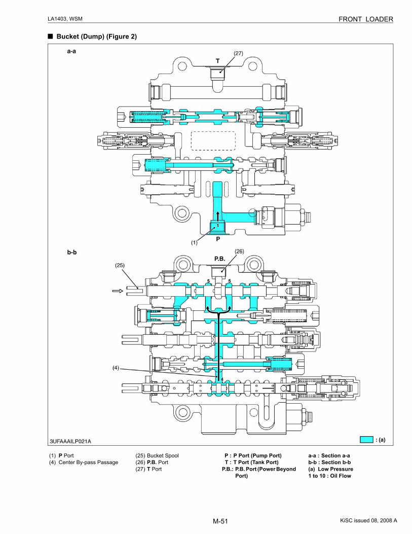
Bucket (Dump) (Figure 2)
(1) P Port(4) Center By-pass Passage
(25) Bucket Spool(26) P.B. Port(27) T Port
P : P Port (Pump Port)T : T Port (Tank Port)
P.B.: P.B. Port (Power Beyond Port)
a-a : Section a-ab-b : Section b-b(a) Low Pressure1 to 10 : Oil Flow
KiSC issued 08, 2008 A
M-52
LA1403, WSM FRONT LOADER
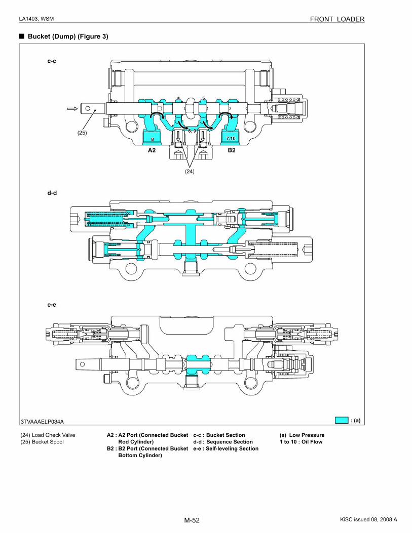
Bucket (Dump) (Figure 3)
(24) Load Check Valve(25) Bucket Spool
A2 : A2 Port (Connected Bucket Rod Cylinder)
B2 : B2 Port (Connected Bucket Bottom Cylinder)
c-c : Bucket Sectiond-d : Sequence Sectione-e : Self-leveling Section
(a) Low Pressure1 to 10 : Oil Flow
KiSC issued 08, 2008 A
M-53
LA1403, WSM FRONT LOADER
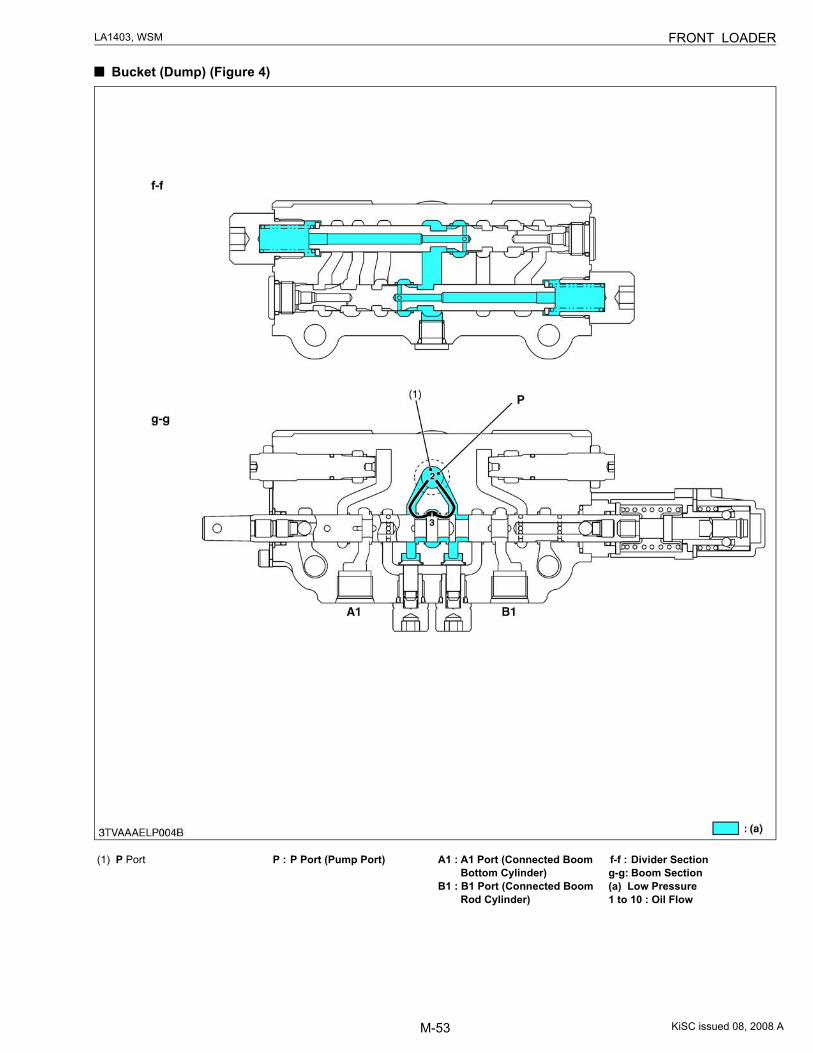
Bucket (Dump) (Figure 4)
(1) P Port P : P Port (Pump Port) A1 : A1 Port (Connected Boom Bottom Cylinder)
B1 : B1 Port (Connected Boom Rod Cylinder)
f-f : Divider Sectiong-g: Boom Section(a) Low Pressure1 to 10 : Oil Flow
KiSC issued 08, 2008 A
M-54
LA1403, WSM FRONT LOADER
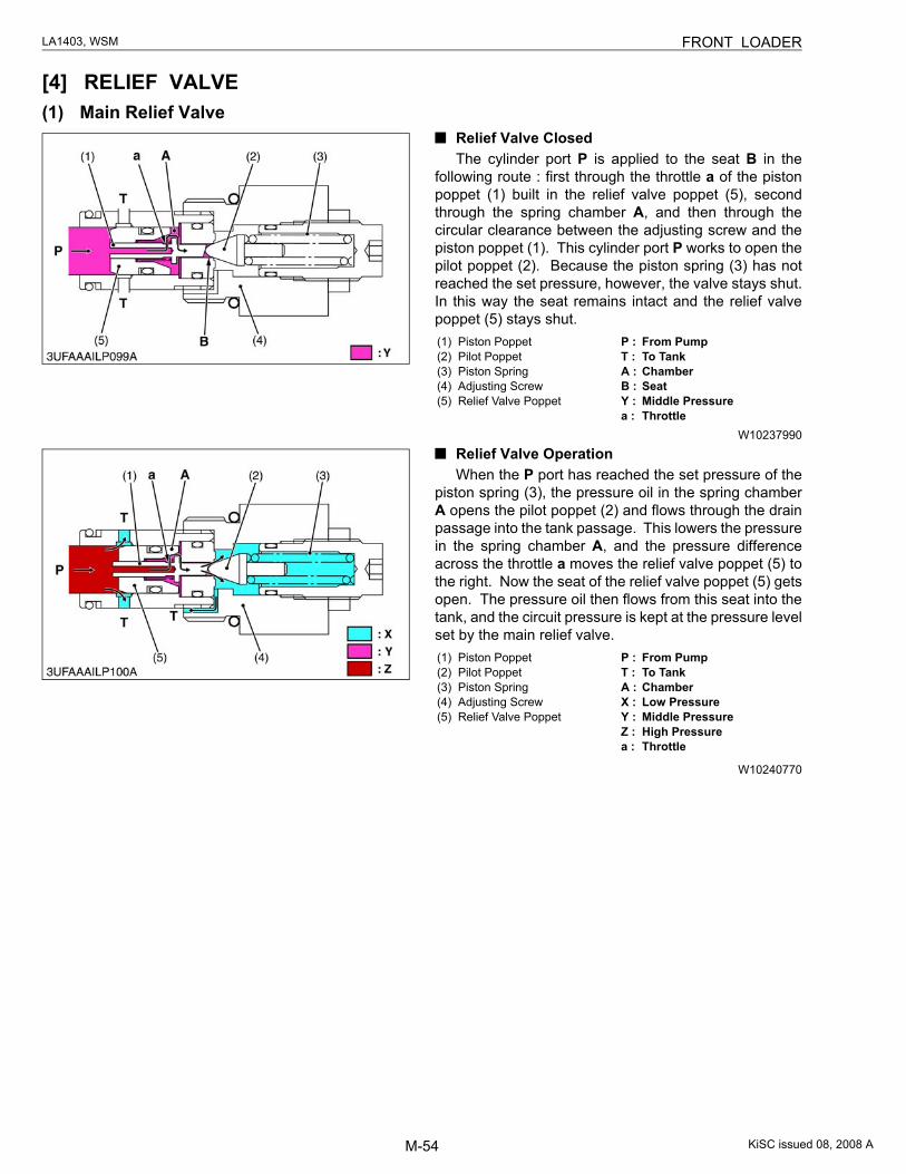
[4] RELIEF VALVE(1) Main Relief Valve
Relief Valve ClosedThe cylinder port P is applied to the seat B in the
following route : first through the throttle a of the pistonpoppet (1) built in the relief valve poppet (5), secondthrough the spring chamber A, and then through thecircular clearance between the adjusting screw and thepiston poppet (1). This cylinder port P works to open thepilot poppet (2). Because the piston spring (3) has notreached the set pressure, however, the valve stays shut.In this way the seat remains intact and the relief valvepoppet (5) stays shut.
W10237990
Relief Valve OperationWhen the P port has reached the set pressure of the
piston spring (3), the pressure oil in the spring chamberA opens the pilot poppet (2) and flows through the drainpassage into the tank passage. This lowers the pressurein the spring chamber A, and the pressure differenceacross the throttle a moves the relief valve poppet (5) tothe right. Now the seat of the relief valve poppet (5) getsopen. The pressure oil then flows from this seat into thetank, and the circuit pressure is kept at the pressure levelset by the main relief valve.
W10240770
(1) Piston Poppet(2) Pilot Poppet(3) Piston Spring(4) Adjusting Screw(5) Relief Valve Poppet
P : From PumpT : To TankA : ChamberB : SeatY : Middle Pressurea : Throttle
(1) Piston Poppet(2) Pilot Poppet(3) Piston Spring(4) Adjusting Screw(5) Relief Valve Poppet
P : From PumpT : To TankA : ChamberX : Low PressureY : Middle PressureZ : High Pressurea : Throttle
KiSC issued 08, 2008 A
M-55
LA1403, WSM FRONT LOADER
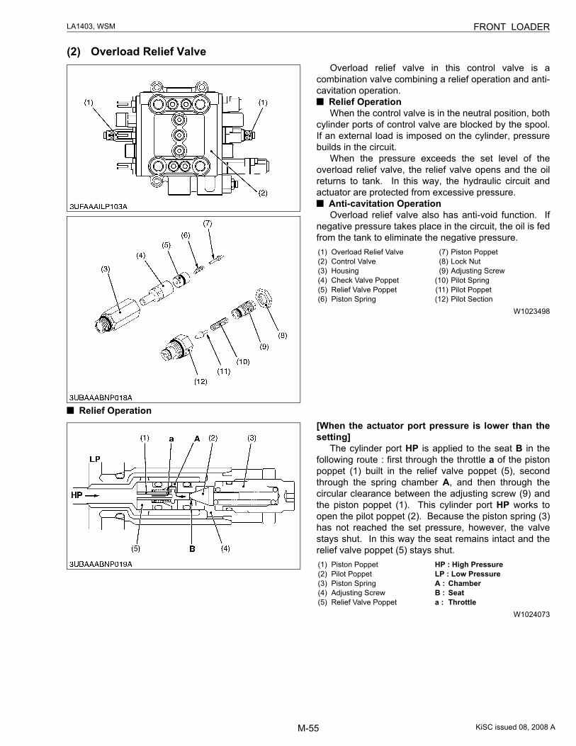
(2) Overload Relief ValveOverload relief valve in this control valve is a
combination valve combining a relief operation and anti-cavitation operation.
Relief OperationWhen the control valve is in the neutral position, both
cylinder ports of control valve are blocked by the spool.If an external load is imposed on the cylinder, pressurebuilds in the circuit.
When the pressure exceeds the set level of theoverload relief valve, the relief valve opens and the oilreturns to tank. In this way, the hydraulic circuit andactuator are protected from excessive pressure.
Anti-cavitation OperationOverload relief valve also has anti-void function. If
negative pressure takes place in the circuit, the oil is fedfrom the tank to eliminate the negative pressure.
W1023498
Relief Operation[When the actuator port pressure is lower than thesetting]
The cylinder port HP is applied to the seat B in thefollowing route : first through the throttle a of the pistonpoppet (1) built in the relief valve poppet (5), secondthrough the spring chamber A, and then through thecircular clearance between the adjusting screw (9) andthe piston poppet (1). This cylinder port HP works toopen the pilot poppet (2). Because the piston spring (3)has not reached the set pressure, however, the valvestays shut. In this way the seat remains intact and therelief valve poppet (5) stays shut.
W1024073
(1) Overload Relief Valve(2) Control Valve(3) Housing(4) Check Valve Poppet(5) Relief Valve Poppet(6) Piston Spring
(7) Piston Poppet(8) Lock Nut(9) Adjusting Screw
(10) Pilot Spring(11) Pilot Poppet(12) Pilot Section
(1) Piston Poppet(2) Pilot Poppet(3) Piston Spring(4) Adjusting Screw(5) Relief Valve Poppet
HP : High PressureLP : Low PressureA : ChamberB : Seata : Throttle
KiSC issued 08, 2008 A
M-56
LA1403, WSM FRONT LOADER
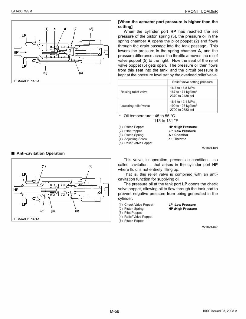
[When the actuator port pressure is higher than thesetting]
When the cylinder port HP has reached the setpressure of the piston spring (3), the pressure oil in thespring chamber A opens the pilot poppet (2) and flowsthrough the drain passage into the tank passage. Thislowers the pressure in the spring chamber A, and thepressure difference across the throttle a moves the reliefvalve poppet (5) to the right. Now the seat of the reliefvalve poppet (5) gets open. The pressure oil then flowsfrom this seat into the tank, and the circuit pressure iskept at the pressure level set by the overload relief valve.
• Oil temperature : 45 to 55 °C 113 to 131 °F
W1024163
Anti-cavitation OperationThis valve, in operation, prevents a condition – so
called cavitation – that arises in the cylinder port HPwhere fluid is not entirely filling up.
That is, this relief valve is combined with an anti-cavitation function for supplying oil.
The pressure oil at the tank port LP opens the checkvalve poppet, allowing oil to flow through the tank port toprevent negative pressure from being generated in thecylinder.
W1024467
Relief valve setting pressure
Raising relief valve16.3 to 16.8 MPa167 to 171 kgf/cm2
2370 to 2430 psi
Lowering relief valve18.6 to 19.1 MPa190 to 195 kgf/cm2
2700 to 2783 psi
(1) Piston Poppet(2) Pilot Poppet(3) Piston Spring(4) Adjusting Screw(5) Relief Valve Poppet
HP :High PressureLP :Low PressureA : Chambera : Throttle
(1) Check Valve Poppet(2) Piston Spring(3) Pilot Poppet(4) Relief Valve Poppet(5) Piston Poppet
LP :Low PressureHP :High Pressure
KiSC issued 08, 2008 A
M-57
LA1403, WSM FRONT LOADER
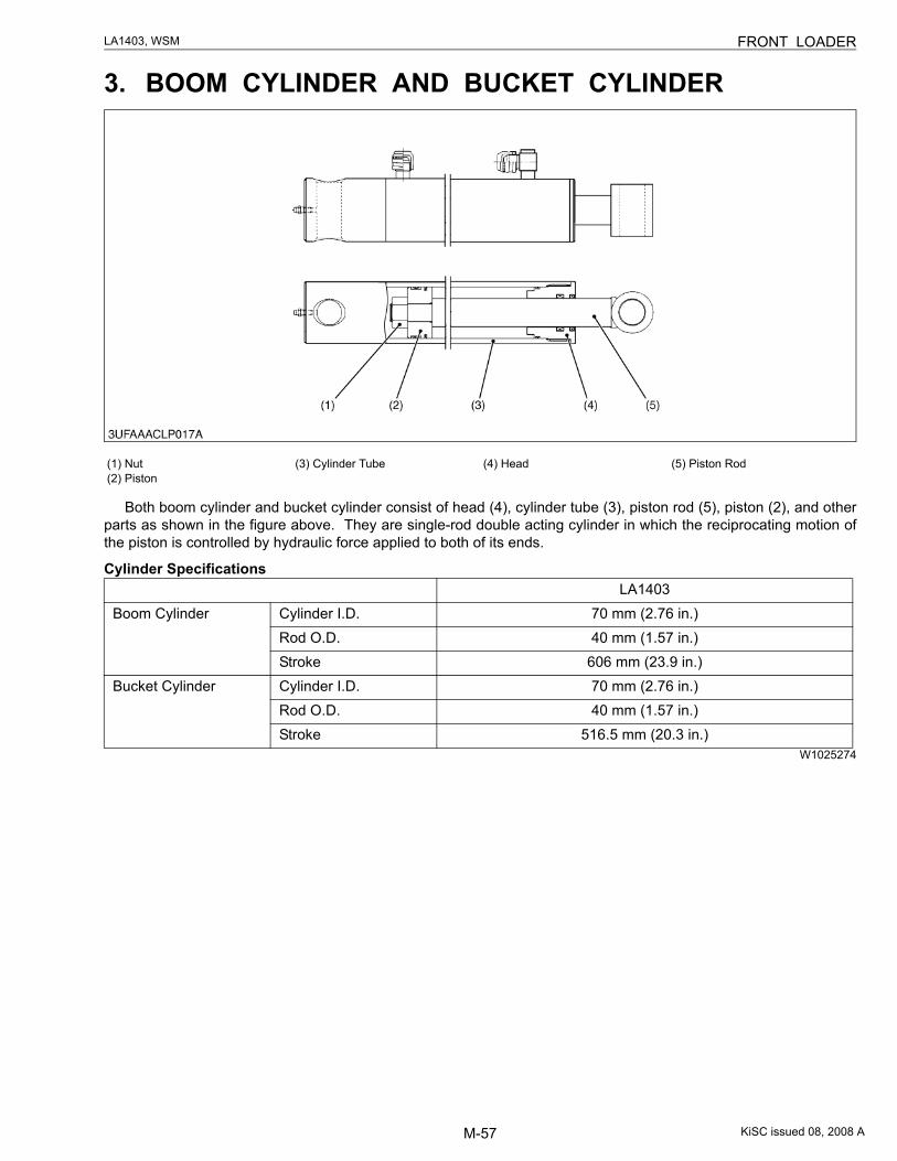
3. BOOM CYLINDER AND BUCKET CYLINDER
Both boom cylinder and bucket cylinder consist of head (4), cylinder tube (3), piston rod (5), piston (2), and otherparts as shown in the figure above. They are single-rod double acting cylinder in which the reciprocating motion ofthe piston is controlled by hydraulic force applied to both of its ends.
Cylinder Specifications
W1025274
(1) Nut(2) Piston
(3) Cylinder Tube (4) Head (5) Piston Rod
LA1403Boom Cylinder Cylinder I.D. 70 mm (2.76 in.)
Rod O.D. 40 mm (1.57 in.)Stroke 606 mm (23.9 in.)
Bucket Cylinder Cylinder I.D. 70 mm (2.76 in.)Rod O.D. 40 mm (1.57 in.)Stroke 516.5 mm (20.3 in.)
KiSC issued 08, 2008 A
M-58
LA1403, WSM FRONT LOADER
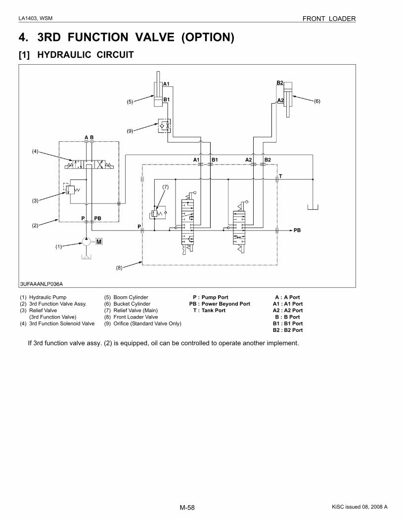
4. 3RD FUNCTION VALVE (OPTION)[1] HYDRAULIC CIRCUIT
If 3rd function valve assy. (2) is equipped, oil can be controlled to operate another implement.
(1) Hydraulic Pump(2) 3rd Function Valve Assy.(3) Relief Valve
(3rd Function Valve)(4) 3rd Function Solenoid Valve
(5) Boom Cylinder(6) Bucket Cylinder(7) Relief Valve (Main)(8) Front Loader Valve(9) Orifice (Standard Valve Only)
P : Pump PortPB : Power Beyond Port
T : Tank Port
A : A PortA1 : A1 PortA2 : A2 PortB : B Port
B1 : B1 PortB2 : B2 Port
KiSC issued 08, 2008 A
M-59
LA1403, WSM FRONT LOADER
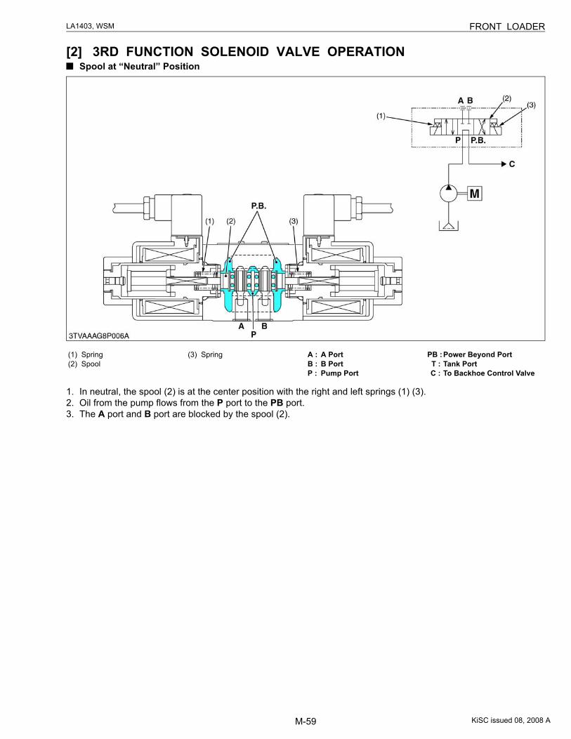
[2] 3RD FUNCTION SOLENOID VALVE OPERATIONSpool at “Neutral” Position
1. In neutral, the spool (2) is at the center position with the right and left springs (1) (3).2. Oil from the pump flows from the P port to the PB port.3. The A port and B port are blocked by the spool (2).
(1) Spring(2) Spool
(3) Spring A : A PortB : B PortP : Pump Port
PB :Power Beyond PortT : Tank PortC : To Backhoe Control Valve
KiSC issued 08, 2008 A
M-60
LA1403, WSM FRONT LOADER
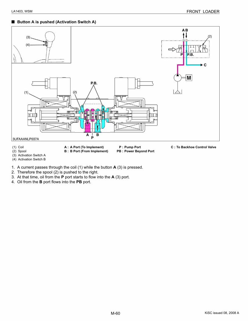
Button A is pushed (Activation Switch A)
1. A current passes through the coil (1) while the button A (3) is pressed.2. Therefore the spool (2) is pushed to the right.3. At that time, oil from the P port starts to flow into the A (3) port.4. Oil from the B port flows into the PB port.
(1) Coil(2) Spool(3) Activation Switch A(4) Activation Switch B
A : A Port (To Implement)B : B Port (From Implement)
P : Pump PortPB : Power Beyond Port
C : To Backhoe Control Valve
KiSC issued 08, 2008 A
M-61
LA1403, WSM FRONT LOADER
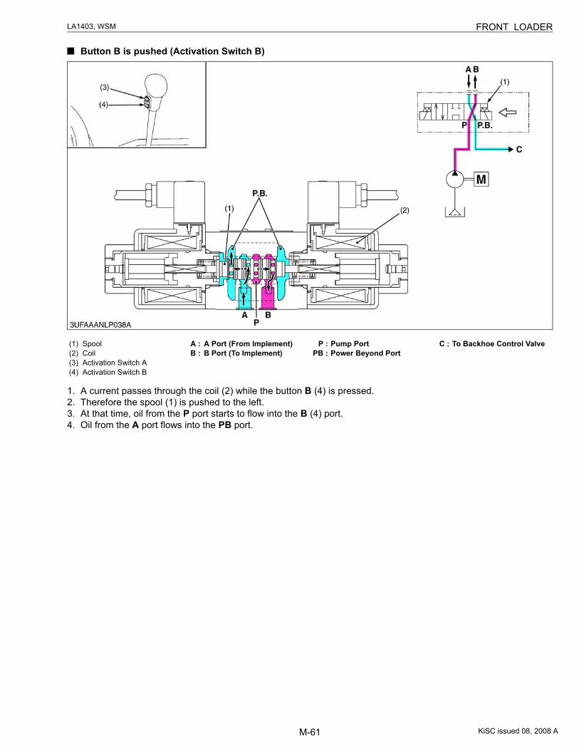
Button B is pushed (Activation Switch B)
1. A current passes through the coil (2) while the button B (4) is pressed.2. Therefore the spool (1) is pushed to the left.3. At that time, oil from the P port starts to flow into the B (4) port.4. Oil from the A port flows into the PB port.
(1) Spool(2) Coil(3) Activation Switch A(4) Activation Switch B
A : A Port (From Implement)B : B Port (To Implement)
P : Pump PortPB : Power Beyond Port
C : To Backhoe Control Valve
KiSC issued 08, 2008 A
M-62
LA1403, WSM FRONT LOADER
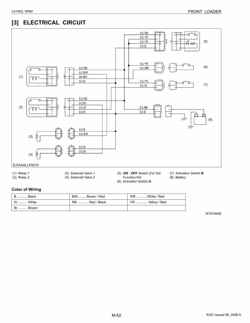
[3] ELECTRICAL CIRCUIT
Color of Wiring
W1019456
(1) Relay 1(2) Relay 2
(3) Solenoid Valve 1(4) Solenoid Valve 2
(5) ON - OFF Switch (For 3rd Function Kit)
(6) Activation Switch A
(7) Activation Switch B(8) Battery
B ........... Black BrR ........ Brown / Red WR ........... White / Red
W .......... White RB ............ Red / Black YR ............. Yellow / Red
Br .......... Brown
KiSC issued 08, 2008 A
M-63
LA1403, WSM FRONT LOADER
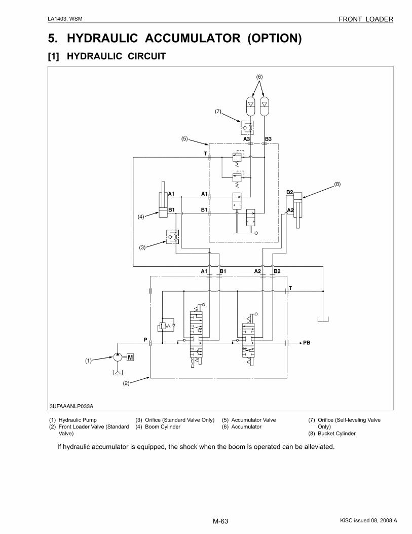
5. HYDRAULIC ACCUMULATOR (OPTION)[1] HYDRAULIC CIRCUIT
If hydraulic accumulator is equipped, the shock when the boom is operated can be alleviated.
(1) Hydraulic Pump(2) Front Loader Valve (Standard
Valve)
(3) Orifice (Standard Valve Only)(4) Boom Cylinder
(5) Accumulator Valve(6) Accumulator
(7) Orifice (Self-leveling Valve Only)
(8) Bucket Cylinder
KiSC issued 08, 2008 A
M-64
LA1403, WSM FRONT LOADER
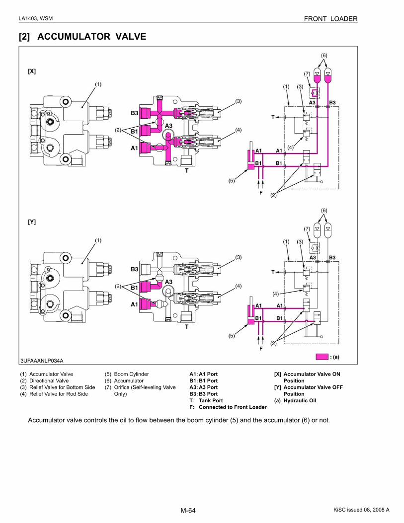
[2] ACCUMULATOR VALVE
Accumulator valve controls the oil to flow between the boom cylinder (5) and the accumulator (6) or not.
(1) Accumulator Valve(2) Directional Valve(3) Relief Valve for Bottom Side(4) Relief Valve for Rod Side
(5) Boom Cylinder(6) Accumulator(7) Orifice (Self-leveling Valve
Only)
A1: A1 PortB1: B1 PortA3: A3 PortB3: B3 PortT: Tank PortF: Connected to Front Loader
[X] Accumulator Valve ON Position
[Y] Accumulator Valve OFF Position
(a) Hydraulic Oil
KiSC issued 08, 2008 A
M-65
LA1403, WSM FRONT LOADER
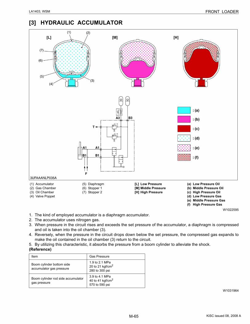
[3] HYDRAULIC ACCUMULATOR
W1022595
1. The kind of employed accumulator is a diaphragm accumulator.2. The accumulator uses nitrogen gas.3. When pressure in the circuit rises and exceeds the set pressure of the accumulator, a diaphragm is compressed
and oil is taken into the oil chamber (3).4. Reversely, when the pressure in the circuit drops down below the set pressure, the compressed gas expands to
make the oil contained in the oil chamber (3) return to the circuit.5. By utilizing this characteristic, it absorbs the pressure from a boom cylinder to alleviate the shock.(Reference)
W1031964
(1) Accumulator(2) Gas Chamber(3) Oil Chamber(4) Valve Poppet
(5) Diaphragm(6) Stopper 1(7) Stopper 2
[L] Low Pressure[M] Middle Pressure[H] High Pressure
(a) Low Pressure Oil(b) Middle Pressure Oil(c) High Pressure Oil(d) Low Pressure Gas(e) Middle Pressure Gas(f) High Pressure Gas
Item Gas Pressure
Boom cylinder bottom side accumulator gas pressure
1.9 to 2.1 MPa20 to 21 kgf/cm2
280 to 300 psi
Boom cylinder rod side accumulator gas pressure
3.9 to 4.1 MPa40 to 41 kgf/cm2
570 to 590 psi
KiSC issued 08, 2008 A
M-66
LA1403, WSM FRONT LOADER
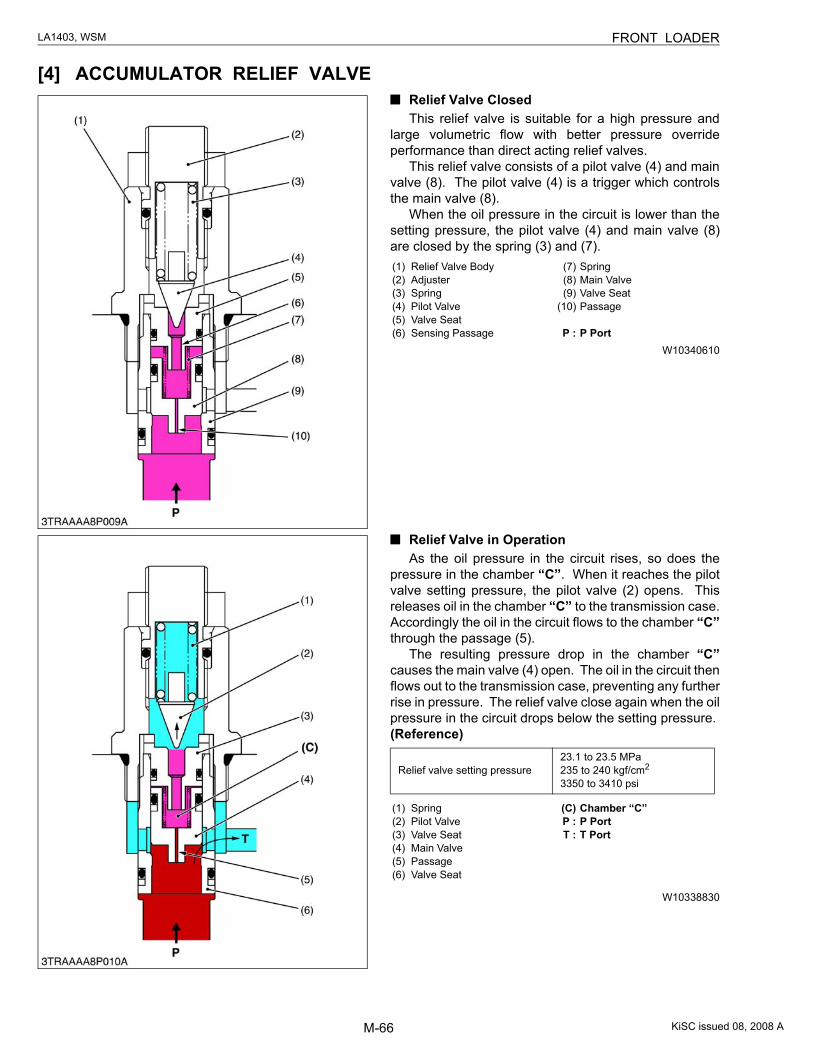
[4] ACCUMULATOR RELIEF VALVERelief Valve ClosedThis relief valve is suitable for a high pressure and
large volumetric flow with better pressure overrideperformance than direct acting relief valves.
This relief valve consists of a pilot valve (4) and mainvalve (8). The pilot valve (4) is a trigger which controlsthe main valve (8).
When the oil pressure in the circuit is lower than thesetting pressure, the pilot valve (4) and main valve (8)are closed by the spring (3) and (7).
W10340610
Relief Valve in OperationAs the oil pressure in the circuit rises, so does the
pressure in the chamber “C”. When it reaches the pilotvalve setting pressure, the pilot valve (2) opens. Thisreleases oil in the chamber “C” to the transmission case.Accordingly the oil in the circuit flows to the chamber “C”through the passage (5).
The resulting pressure drop in the chamber “C”causes the main valve (4) open. The oil in the circuit thenflows out to the transmission case, preventing any furtherrise in pressure. The relief valve close again when the oilpressure in the circuit drops below the setting pressure.(Reference)
W10338830
(1) Relief Valve Body(2) Adjuster(3) Spring(4) Pilot Valve(5) Valve Seat(6) Sensing Passage
(7) Spring(8) Main Valve(9) Valve Seat
(10) Passage
P : P Port
Relief valve setting pressure23.1 to 23.5 MPa235 to 240 kgf/cm2
3350 to 3410 psi
(1) Spring(2) Pilot Valve(3) Valve Seat(4) Main Valve(5) Passage(6) Valve Seat
(C) Chamber “C”P : P PortT : T Port
KiSC issued 08, 2008 A
CONTENTS
SERVICING
1. TROUBLESHOOTING ......................................................................................S-12. SERVICING SPECIFICATIONS ......................................................................S-23. TIGHTENING TORQUES (ESPECIALLY SPECIFIED) .................................S-34. DISMOUNTING FRONT LOADER FROM TRACTOR..................................S-45. CHECKING, DISASSEMBLING AND SERVICING........................................S-6
[1] CHECKING AND ADJUSTING .................................................................S-6(1) Control Valve ........................................................................................S-6(2) Adjusting Self-leveling...........................................................................S-7(3) 3rd Function Valve (Option) ..................................................................S-9
[2] DISASSEMBLING AND ASSEMBLING..................................................S-12(1) Control Valve Assembly......................................................................S-12(2) Control Valve ......................................................................................S-14(3) Controller and Cables .........................................................................S-19(4) Bucket, Boom and Hydraulic Cylinders...............................................S-20(5) Main Frame and Others ......................................................................S-25(6) Accumulator (Option) ..........................................................................S-27
[3] SERVICING ..............................................................................................S-28
KiSC issued 08, 2008 A
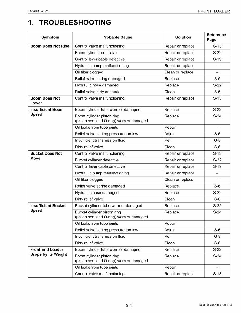
S-1
LA1403, WSM FRONT LOADER
1. TROUBLESHOOTING
Symptom Probable Cause Solution Reference Page
Boom Does Not Rise Control valve malfunctioning Repair or replace S-13Boom cylinder defective Repair or replace S-22Control lever cable defective Repair or replace S-19Hydraulic pump malfunctioning Repair or replace –Oil filter clogged Clean or replace –Relief valve spring damaged Replace S-6Hydraulic hose damaged Replace S-22Relief valve dirty or stuck Clean S-6
Boom Does Not Lower
Control valve malfunctioning Repair or replace S-13
Insufficient Boom Speed
Boom cylinder tube worn or damaged Replace S-22Boom cylinder piston ring (piston seal and O-ring) worn or damaged
Replace S-24
Oil leaks from tube joints Repair –Relief valve setting pressure too low Adjust S-6Insufficient transmission fluid Refill G-8Dirty relief valve Clean S-6
Bucket Does Not Move
Control valve malfunctioning Repair or replace S-13Bucket cylinder defective Repair or replace S-22Control lever cable defective Repair or replace S-19Hydraulic pump malfunctioning Repair or replace –Oil filter clogged Clean or replace –Relief valve spring damaged Replace S-6Hydraulic hose damaged Replace S-22Dirty relief valve Clean S-6
Insufficient Bucket Speed
Bucket cylinder tube worn or damaged Replace S-22Bucket cylinder piston ring (piston seal and O-ring) worn or damaged
Replace S-24
Oil leaks from tube joints Repair –Relief valve setting pressure too low Adjust S-6Insufficient transmission fluid Refill G-8Dirty relief valve Clean S-6
Front End Loader Drops by its Weight
Boom cylinder tube worn or damaged Replace S-22Boom cylinder piston ring (piston seal and O-ring) worn or damaged
Replace S-24
Oil leaks from tube joints Repair –Control valve malfunctioning Repair or replace S-13
KiSC issued 08, 2008 A
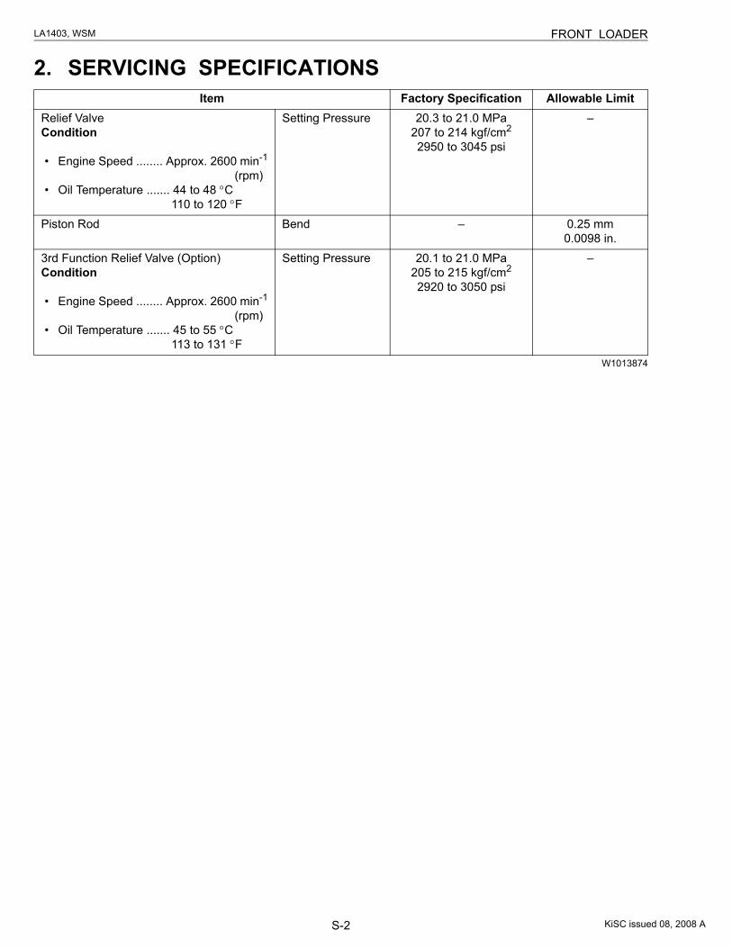
S-2
LA1403, WSM FRONT LOADER
2. SERVICING SPECIFICATIONS
W1013874
Item Factory Specification Allowable LimitRelief ValveCondition
• Engine Speed ........ Approx. 2600 min-1
(rpm)• Oil Temperature ....... 44 to 48 °C
110 to 120 °F
Setting Pressure 20.3 to 21.0 MPa207 to 214 kgf/cm2
2950 to 3045 psi
–
Piston Rod Bend – 0.25 mm0.0098 in.
3rd Function Relief Valve (Option)Condition
• Engine Speed ........ Approx. 2600 min-1
(rpm)• Oil Temperature ....... 45 to 55 °C
113 to 131 °F
Setting Pressure 20.1 to 21.0 MPa205 to 215 kgf/cm2
2920 to 3050 psi
–
KiSC issued 08, 2008 A
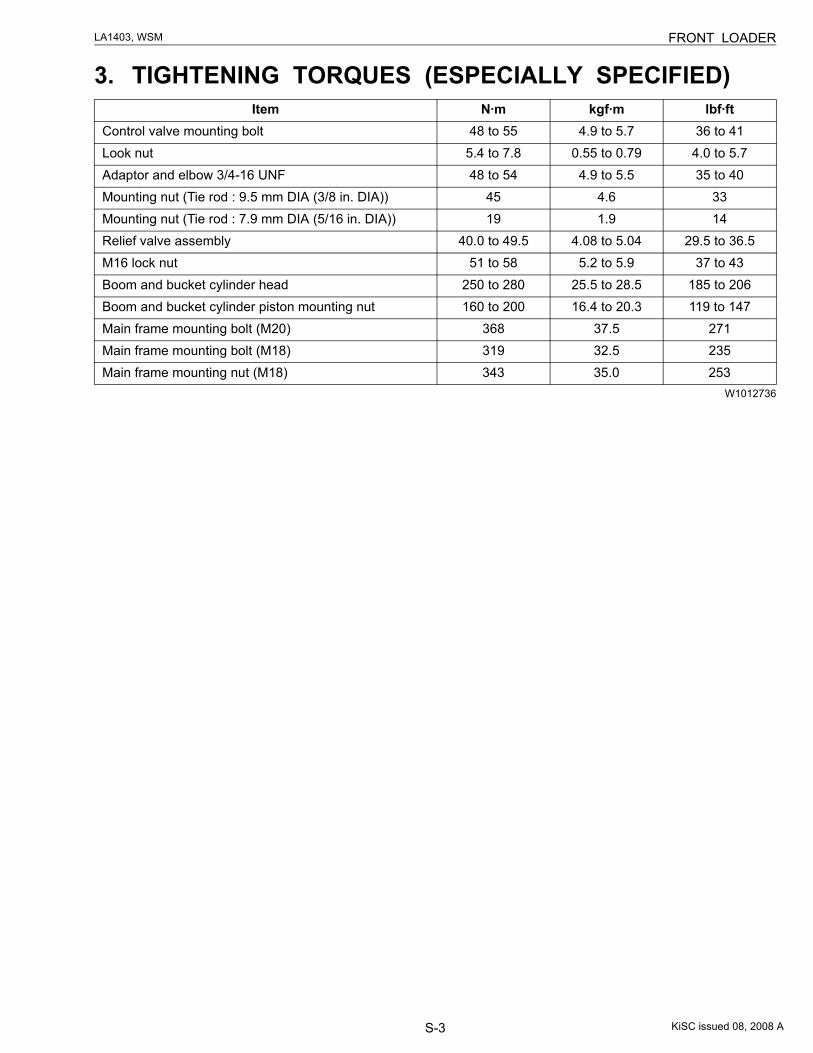
S-3
LA1403, WSM FRONT LOADER
3. TIGHTENING TORQUES (ESPECIALLY SPECIFIED)
W1012736
Item N·m kgf·m lbf·ftControl valve mounting bolt 48 to 55 4.9 to 5.7 36 to 41Look nut 5.4 to 7.8 0.55 to 0.79 4.0 to 5.7Adaptor and elbow 3/4-16 UNF 48 to 54 4.9 to 5.5 35 to 40Mounting nut (Tie rod : 9.5 mm DIA (3/8 in. DIA)) 45 4.6 33Mounting nut (Tie rod : 7.9 mm DIA (5/16 in. DIA)) 19 1.9 14Relief valve assembly 40.0 to 49.5 4.08 to 5.04 29.5 to 36.5M16 lock nut 51 to 58 5.2 to 5.9 37 to 43Boom and bucket cylinder head 250 to 280 25.5 to 28.5 185 to 206Boom and bucket cylinder piston mounting nut 160 to 200 16.4 to 20.3 119 to 147Main frame mounting bolt (M20) 368 37.5 271Main frame mounting bolt (M18) 319 32.5 235Main frame mounting nut (M18) 343 35.0 253
KiSC issued 08, 2008 A
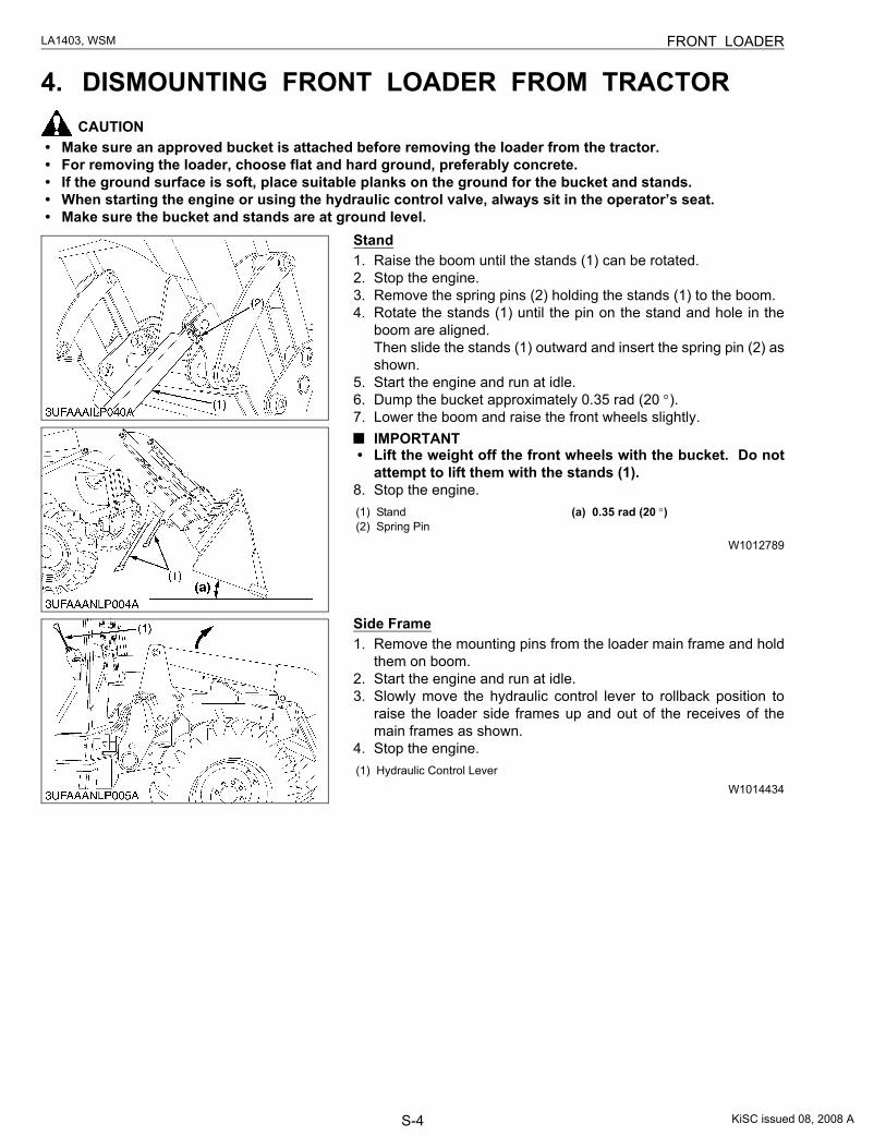
S-4
LA1403, WSM FRONT LOADER
4. DISMOUNTING FRONT LOADER FROM TRACTORCAUTION
• Make sure an approved bucket is attached before removing the loader from the tractor.• For removing the loader, choose flat and hard ground, preferably concrete.• If the ground surface is soft, place suitable planks on the ground for the bucket and stands.• When starting the engine or using the hydraulic control valve, always sit in the operator’s seat.• Make sure the bucket and stands are at ground level.
Stand1. Raise the boom until the stands (1) can be rotated.2. Stop the engine.3. Remove the spring pins (2) holding the stands (1) to the boom.4. Rotate the stands (1) until the pin on the stand and hole in the
boom are aligned.Then slide the stands (1) outward and insert the spring pin (2) asshown.
5. Start the engine and run at idle.6. Dump the bucket approximately 0.35 rad (20 °).7. Lower the boom and raise the front wheels slightly.
IMPORTANT• Lift the weight off the front wheels with the bucket. Do not
attempt to lift them with the stands (1).8. Stop the engine.
W1012789
Side Frame1. Remove the mounting pins from the loader main frame and hold
them on boom.2. Start the engine and run at idle.3. Slowly move the hydraulic control lever to rollback position to
raise the loader side frames up and out of the receives of themain frames as shown.
4. Stop the engine.
W1014434
(1) Stand(2) Spring Pin
(a) 0.35 rad (20 °)
(1) Hydraulic Control Lever
KiSC issued 08, 2008 A
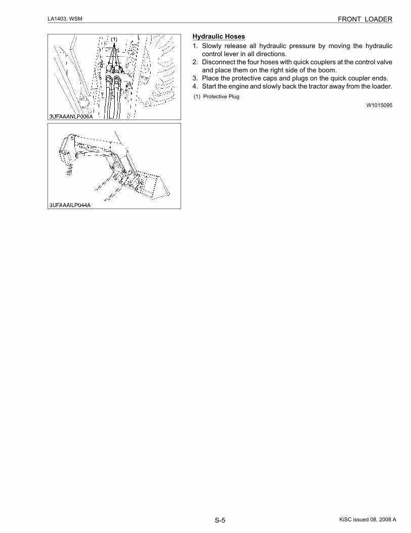
S-5
LA1403, WSM FRONT LOADER
Hydraulic Hoses1. Slowly release all hydraulic pressure by moving the hydraulic
control lever in all directions.2. Disconnect the four hoses with quick couplers at the control valve
and place them on the right side of the boom.3. Place the protective caps and plugs on the quick coupler ends.4. Start the engine and slowly back the tractor away from the loader.
W1015095(1) Protective Plug
KiSC issued 08, 2008 A
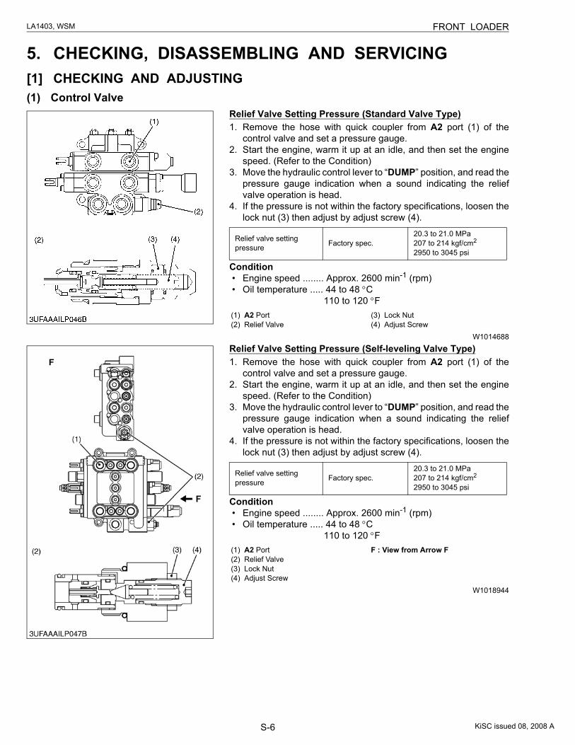
S-6
LA1403, WSM FRONT LOADER
5. CHECKING, DISASSEMBLING AND SERVICING[1] CHECKING AND ADJUSTING(1) Control Valve
Relief Valve Setting Pressure (Standard Valve Type)1. Remove the hose with quick coupler from A2 port (1) of the
control valve and set a pressure gauge.2. Start the engine, warm it up at an idle, and then set the engine
speed. (Refer to the Condition)3. Move the hydraulic control lever to “DUMP” position, and read the
pressure gauge indication when a sound indicating the reliefvalve operation is head.
4. If the pressure is not within the factory specifications, loosen thelock nut (3) then adjust by adjust screw (4).
Condition• Engine speed ........ Approx. 2600 min-1 (rpm)• Oil temperature ..... 44 to 48 °C
110 to 120 °F
W1014688
Relief Valve Setting Pressure (Self-leveling Valve Type)1. Remove the hose with quick coupler from A2 port (1) of the
control valve and set a pressure gauge.2. Start the engine, warm it up at an idle, and then set the engine
speed. (Refer to the Condition)3. Move the hydraulic control lever to “DUMP” position, and read the
pressure gauge indication when a sound indicating the reliefvalve operation is head.
4. If the pressure is not within the factory specifications, loosen thelock nut (3) then adjust by adjust screw (4).
Condition• Engine speed ........ Approx. 2600 min-1 (rpm)• Oil temperature ..... 44 to 48 °C
110 to 120 °F
W1018944
Relief valve setting pressure Factory spec.
20.3 to 21.0 MPa207 to 214 kgf/cm2
2950 to 3045 psi
(1) A2 Port(2) Relief Valve
(3) Lock Nut(4) Adjust Screw
Relief valve setting pressure Factory spec.
20.3 to 21.0 MPa207 to 214 kgf/cm2
2950 to 3045 psi
(1) A2 Port(2) Relief Valve(3) Lock Nut(4) Adjust Screw
F : View from Arrow F
KiSC issued 08, 2008 A
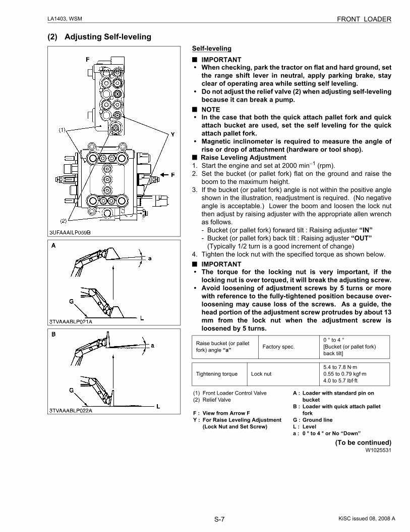
S-7
LA1403, WSM FRONT LOADER
(2) Adjusting Self-levelingSelf-leveling
IMPORTANT• When checking, park the tractor on flat and hard ground, set
the range shift lever in neutral, apply parking brake, stayclear of operating area while setting self leveling.
• Do not adjust the relief valve (2) when adjusting self-levelingbecause it can break a pump.NOTE
• In the case that both the quick attach pallet fork and quickattach bucket are used, set the self leveling for the quickattach pallet fork.
• Magnetic inclinometer is required to measure the angle ofrise or drop of attachment (hardware or tool shop).
Raise Leveling Adjustment1. Start the engine and set at 2000 min−1 (rpm).2. Set the bucket (or pallet fork) flat on the ground and raise the
boom to the maximum height.3. If the bucket (or pallet fork) angle is not within the positive angle
shown in the illustration, readjustment is required. (No negativeangle is acceptable.) Lower the boom and loosen the lock nutthen adjust by raising adjuster with the appropriate allen wrenchas follows.- Bucket (or pallet fork) forward tilt : Raising adjuster “IN”- Bucket (or pallet fork) back tilt : Raising adjuster “OUT”
(Typically 1/2 turn is a good increment of change)4. Tighten the lock nut with the specified torque as shown below.
IMPORTANT• The torque for the locking nut is very important, if the
locking nut is over torqued, it will break the adjusting screw.• Avoid loosening of adjustment screws by 5 turns or more
with reference to the fully-tightened position because over-loosening may cause loss of the screws. As a guide, thehead portion of the adjustment screw protrudes by about 13mm from the lock nut when the adjustment screw isloosened by 5 turns.
(To be continued)W1025531
Raise bucket (or pallet fork) angle “a” Factory spec.
0 ° to 4 °[Bucket (or pallet fork) back tilt]
Tightening torque Lock nut5.4 to 7.8 N·m0.55 to 0.79 kgf·m4.0 to 5.7 lbf·ft
(1) Front Loader Control Valve(2) Relief Valve
F : View from Arrow FY : For Raise Leveling Adjustment
(Lock Nut and Set Screw)
A : Loader with standard pin on bucket
B : Loader with quick attach pallet fork
G : Ground lineL : Levela : 0 ° to 4 ° or No “Down”
KiSC issued 08, 2008 A
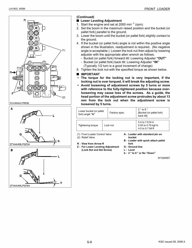
S-8
LA1403, WSM FRONT LOADER
(Continued) Lower Leveling Adjustment
1. Start the engine and set at 2000 min−1 (rpm).2. Set the boom in the maximum raised position and the bucket (or
pallet fork) parallel to the ground.3. Lower the boom until the bucket (or pallet fork) slightly contact to
the ground.4. If the bucket (or pallet fork) angle is not within the positive angle
shown in the illustration, readjustment is required. (No negativeangle is acceptable.) Loosen the lock nut then adjust by loweringadjuster with the appropriate allen wrench as follows.- Bucket (or pallet fork) forward tilt: Lowering Adjuster “OUT”- Bucket (or pallet fork) back tilt: Lowering Adjuster “IN”
(Typically 1/2 turn is a good increment of change)5. Tighten the lock nut with the specified torque as shown below.
IMPORTANT• The torque for the locking nut is very important, if the
locking nut is over torqued, it will break the adjusting screw.• Avoid loosening of adjustment screws by 5 turns or more
with reference to the fully-tightened position because over-loosening may cause loss of the screws. As a guide, thehead portion of the adjustment screw protrudes by about 13mm from the lock nut when the adjustment screw isloosened by 5 turns.
W1026467
Lower bucket (or pallet fork) angle “b” Factory spec.
2 ° to 6 °[Bucket (or pallet fork) back tilt]
Tightening torque Lock nut5.4 to 7.8 N·m0.55 to 0.79 kgf·m4.0 to 5.7 lbf·ft
(1) Front Loader Control Valve(2) Relief Valve
R : View from Arrow RZ : For Lower Leveling Adjustment
(Lock Nut and Set Screw)
A : Loader with standard pin on bucket
B : Loader with quick attach pallet fork
G : Ground lineL : Levelb : 2 ° to 6 ° or No “Down”
KiSC issued 08, 2008 A
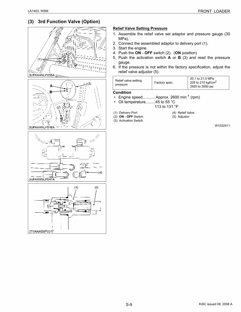
S-9
LA1403, WSM FRONT LOADER
(3) 3rd Function Valve (Option)Relief Valve Setting Pressure1. Assemble the relief valve set adaptor and pressure gauge (30
MPa).2. Connect the assembled adaptor to delivery port (1).3. Start the engine.4. Push the ON - OFF switch (2). (ON position)5. Push the activation switch A or B (3) and read the pressure
gauge.6. If the pressure is not within the factory specification, adjust the
relief valve adjustor (5).
Condition• Engine speed............Approx. 2600 min-1 (rpm)• Oil temperature.........45 to 55 °C
113 to 131 °F
W1032411
Relief valve setting pressure Factory spec.
20.1 to 21.0 MPa205 to 215 kgf/cm2
2920 to 3050 psi
(1) Delivery Port(2) ON - OFF Switch(3) Activation Switch
(4) Relief Valve(5) Adjustor
KiSC issued 08, 2008 A
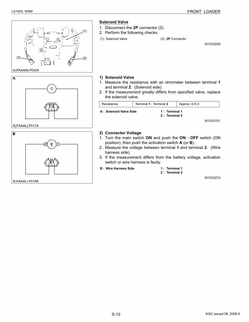
S-10
LA1403, WSM FRONT LOADER
Solenoid Valve1. Disconnect the 2P connector (2).2. Perform the following checks.
W1033058
1) Solenoid Valve1. Measure the resistance with an ohmmeter between terminal 1
and terminal 2. (Solenoid side)2. If the measurement greatly differs from specified valve, replace
the solenoid valve.
W1033151
2) Connector Voltage1. Turn the main switch ON and push the ON - OFF switch (ON
position), then push the activation switch A (or B).2. Measure the voltage between terminal 1 and terminal 2. (Wire
harness side)3. If the measurement differs from the battery voltage, activation
switch or wire harness is faulty.
W1033274
(1) Solenoid Valve (2) 2P Connector
Resistance Terminal 1 - Terminal 2 Approx. 4.8 Ω
A : Solenoid Valve Side 1 : Terminal 12 : Terminal 2
B : Wire Harness Side 1 : Terminal 12 : Terminal 2
KiSC issued 08, 2008 A
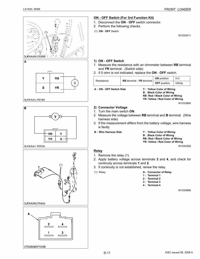
S-11
LA1403, WSM FRONT LOADER
ON - OFF Switch (For 3rd Function Kit)1. Disconnect the ON - OFF switch connector.2. Perform the following checks.
W1033411
1) ON - OFF Switch1. Measure the resistance with an ohmmeter between RB terminal
and YR terminal. (Switch side)2. If 0 ohm is not indicated, replace the ON - OFF switch.
W1033865
2) Connector Voltage1. Turn the main switch ON.2. Measure the voltage between RB terminal and B terminal. (Wire
harness side)3. If the measurement differs from the battery voltage, wire harness
is faulty.
W1034392
Relay1. Remove the relay (1).2. Apply battery voltage across terminals 3 and 4, and check for
continuity across terminals 1 and 2.3. If continuity is not established, renew the relay.
W1034866
(1) ON - OFF Switch
Resistance RB terminal - YR terminalON position 0 Ω
OFF position Infinity
A : ON - OFF Switch Side Y : Yellow Color of WiringB : Black Color of WiringRB :Red / Black Color of WiringYR :Yellow / Red Color of Wiring
B : Wire Harness Side Y : Yellow Color of WiringB : Black Color of WiringRB :Red / Black Color of WiringYR :Yellow / Red Color of Wiring
(1) Relay A : Connector of Relay1 : Terminal 12 : Terminal 23 : Terminal 34 : Terminal 4
KiSC issued 08, 2008 A
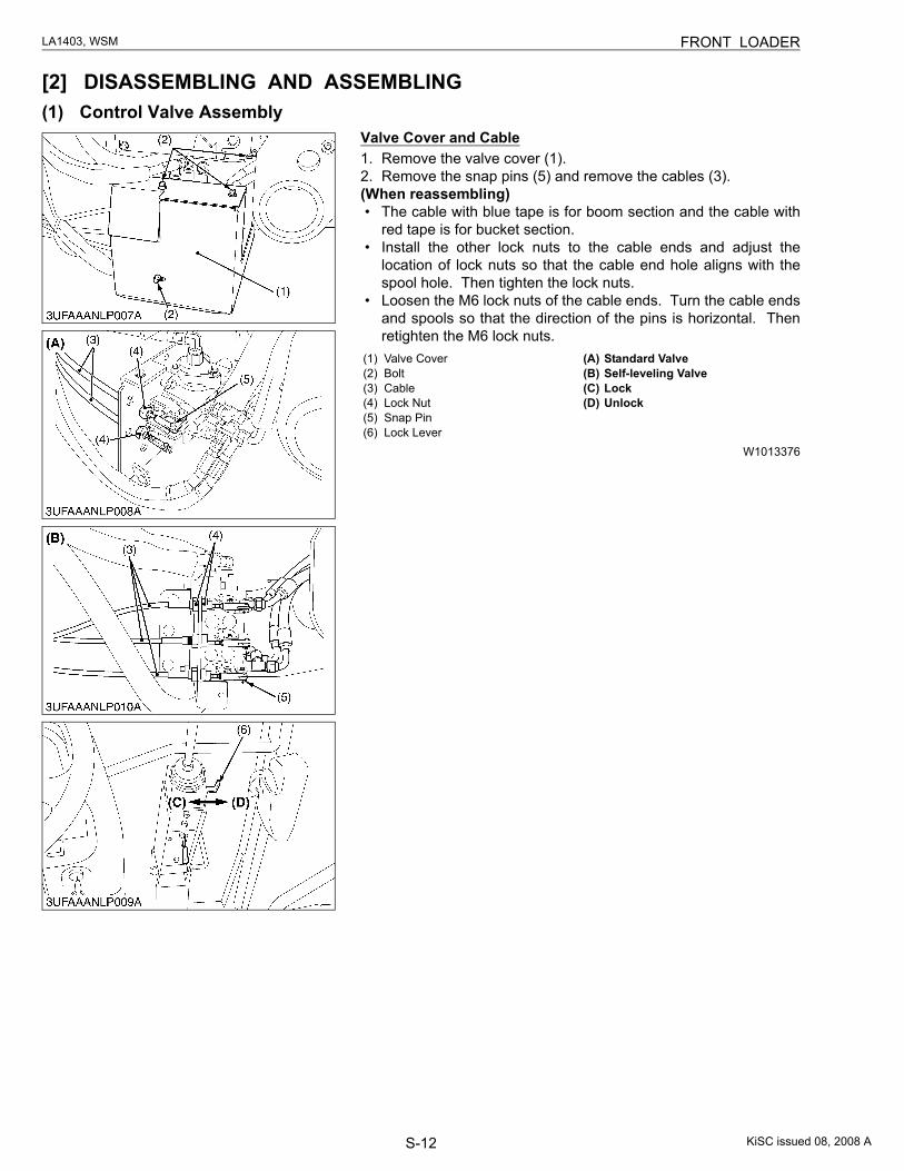
S-12
LA1403, WSM FRONT LOADER
[2] DISASSEMBLING AND ASSEMBLING(1) Control Valve Assembly
Valve Cover and Cable1. Remove the valve cover (1).2. Remove the snap pins (5) and remove the cables (3).(When reassembling)• The cable with blue tape is for boom section and the cable with
red tape is for bucket section.• Install the other lock nuts to the cable ends and adjust the
location of lock nuts so that the cable end hole aligns with thespool hole. Then tighten the lock nuts.
• Loosen the M6 lock nuts of the cable ends. Turn the cable endsand spools so that the direction of the pins is horizontal. Thenretighten the M6 lock nuts.
W1013376
(1) Valve Cover(2) Bolt(3) Cable(4) Lock Nut(5) Snap Pin(6) Lock Lever
(A) Standard Valve(B) Self-leveling Valve(C) Lock(D) Unlock
KiSC issued 08, 2008 A
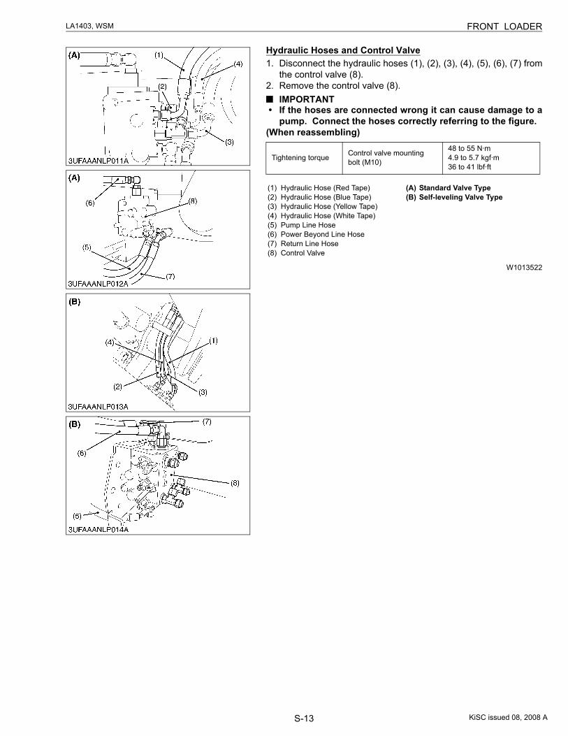
S-13
LA1403, WSM FRONT LOADER
Hydraulic Hoses and Control Valve1. Disconnect the hydraulic hoses (1), (2), (3), (4), (5), (6), (7) from
the control valve (8).2. Remove the control valve (8).
IMPORTANT• If the hoses are connected wrong it can cause damage to a
pump. Connect the hoses correctly referring to the figure.(When reassembling)
W1013522
Tightening torque Control valve mounting bolt (M10)
48 to 55 N·m4.9 to 5.7 kgf·m36 to 41 lbf·ft
(1) Hydraulic Hose (Red Tape)(2) Hydraulic Hose (Blue Tape)(3) Hydraulic Hose (Yellow Tape)(4) Hydraulic Hose (White Tape)(5) Pump Line Hose(6) Power Beyond Line Hose(7) Return Line Hose(8) Control Valve
(A) Standard Valve Type(B) Self-leveling Valve Type
KiSC issued 08, 2008 A
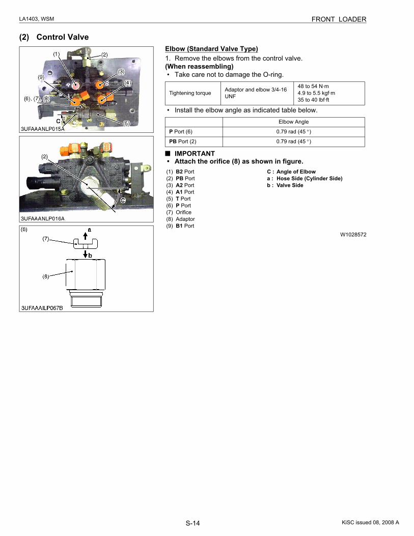
S-14
LA1403, WSM FRONT LOADER
(2) Control ValveElbow (Standard Valve Type)1. Remove the elbows from the control valve.(When reassembling)• Take care not to damage the O-ring.
• Install the elbow angle as indicated table below.
IMPORTANT• Attach the orifice (8) as shown in figure.
W1028572
Tightening torque Adaptor and elbow 3/4-16 UNF
48 to 54 N·m4.9 to 5.5 kgf·m35 to 40 lbf·ft
Elbow Angle
P Port (6) 0.79 rad (45 °)
PB Port (2) 0.79 rad (45 °)
(1) B2 Port(2) PB Port(3) A2 Port(4) A1 Port(5) T Port(6) P Port(7) Orifice(8) Adaptor(9) B1 Port
C : Angle of Elbowa : Hose Side (Cylinder Side)b : Valve Side
KiSC issued 08, 2008 A
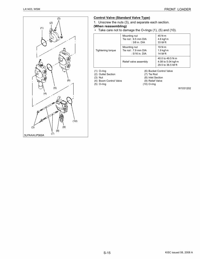
S-15
LA1403, WSM FRONT LOADER
Control Valve (Standard Valve Type)1. Unscrew the nuts (3), and separate each section.(When reassembling)• Take care not to damage the O-rings (1), (5) and (10).
W1031202
Tightening torque
Mounting nutTie rod : 9.5 mm DIA : 3/8 in. DIA
45 N·m4.6 kgf·m33 lbf·ft
Mounting nutTie rod : 7.9 mm DIA : 5/16 in. DIA
19 N·m1.9 kgf·m14 lbf·ft
Relief valve assembly40.0 to 49.5 N·m4.08 to 5.04 kgf·m29.5 to 36.5 lbf·ft
(1) O-ring(2) Outlet Section(3) Nut(4) Boom Control Valve(5) O-ring
(6) Bucket Control Valve(7) Tie Rod(8) Inlet Section(9) Relief Valve
(10) O-ring
KiSC issued 08, 2008 A
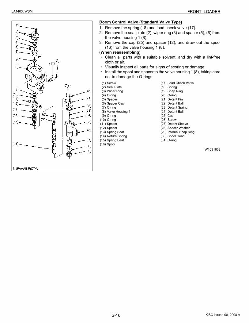
S-16
LA1403, WSM FRONT LOADER
Boom Control Valve (Standard Valve Type)1. Remove the spring (18) and load check valve (17).2. Remove the seal plate (2), wiper ring (3) and spacer (5), (6) from
the valve housing 1 (8).3. Remove the cap (25) and spacer (12), and draw out the spool
(16) from the valve housing 1 (8).(When reassembling)• Clean all parts with a suitable solvent, and dry with a lint-free
cloth or air.• Visually inspect all parts for signs of scoring or damage.• Install the spool and spacer to the valve housing 1 (8), taking care
not to damage the O-rings.
W1031632
(1) Screw(2) Seal Plate(3) Wiper Ring(4) O-ring(5) Spacer(6) Spacer Cap(7) O-ring(8) Valve Housing 1(9) O-ring
(10) O-ring(11) Spacer(12) Spacer(13) Spring Seat(14) Return Spring(15) Spring Seat(16) Spool
(17) Load Check Valve(18) Spring(19) Snap Ring(20) O-ring(21) Detent Pin(22) Detent Ball(23) Detent Spring(24) Detent Ball(25) Cap(26) Screw(27) Detent Sleeve(28) Spacer Washer(29) Internal Snap Ring(30) Spool Head(31) O-ring
KiSC issued 08, 2008 A
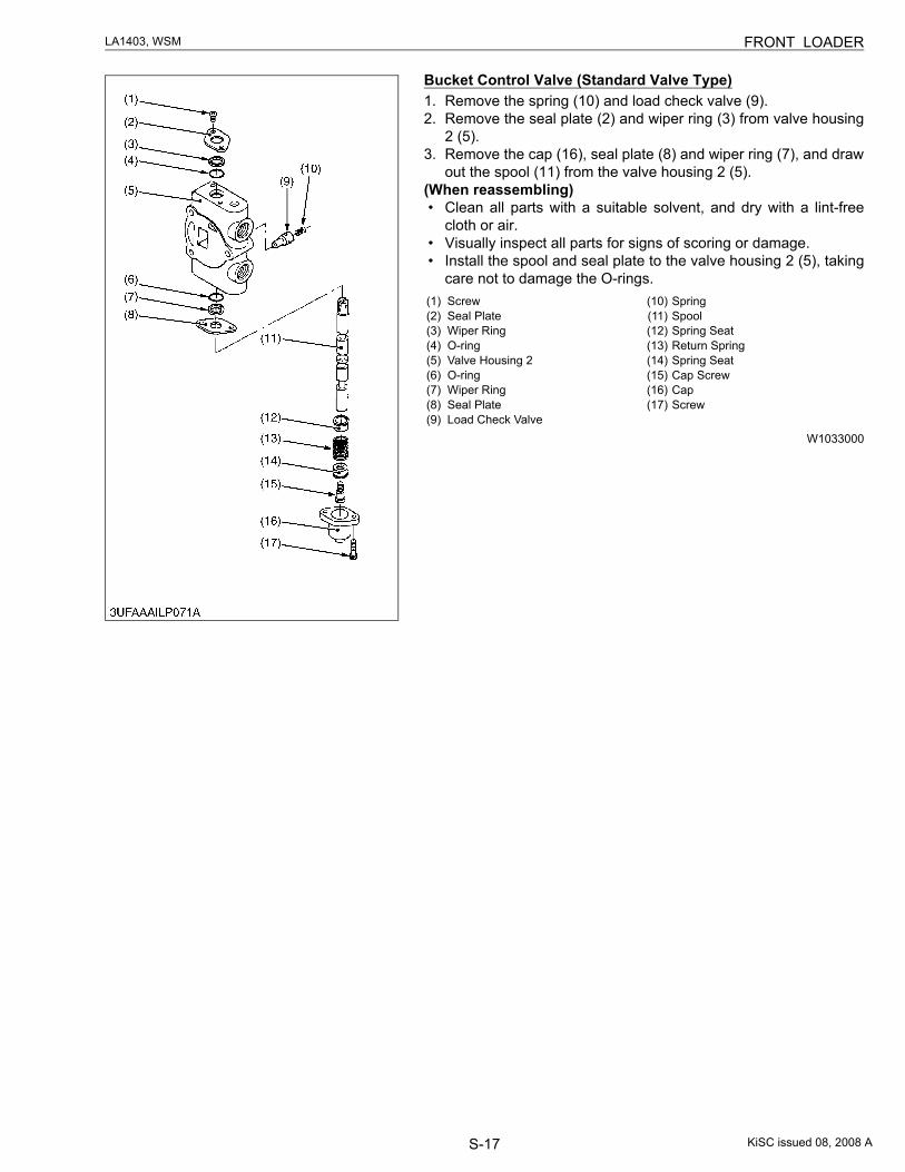
S-17
LA1403, WSM FRONT LOADER
Bucket Control Valve (Standard Valve Type)1. Remove the spring (10) and load check valve (9).2. Remove the seal plate (2) and wiper ring (3) from valve housing
2 (5).3. Remove the cap (16), seal plate (8) and wiper ring (7), and draw
out the spool (11) from the valve housing 2 (5).(When reassembling)• Clean all parts with a suitable solvent, and dry with a lint-free
cloth or air.• Visually inspect all parts for signs of scoring or damage.• Install the spool and seal plate to the valve housing 2 (5), taking
care not to damage the O-rings.
W1033000
(1) Screw(2) Seal Plate(3) Wiper Ring(4) O-ring(5) Valve Housing 2(6) O-ring(7) Wiper Ring(8) Seal Plate(9) Load Check Valve
(10) Spring(11) Spool(12) Spring Seat(13) Return Spring(14) Spring Seat(15) Cap Screw(16) Cap(17) Screw
KiSC issued 08, 2008 A
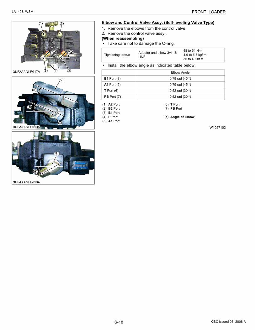
S-18
LA1403, WSM FRONT LOADER
Elbow and Control Valve Assy. (Self-leveling Valve Type)1. Remove the elbows from the control valve.2. Remove the control valve assy..(When reassembling)• Take care not to damage the O-ring.
• Install the elbow angle as indicated table below.
W1027102
Tightening torque Adaptor and elbow 3/4-16 UNF
48 to 54 N·m4.9 to 5.5 kgf·m35 to 40 lbf·ft
Elbow Angle
B1 Port (3) 0.79 rad (45 °)
A1 Port (5) 0.79 rad (45 °)
T Port (6) 0.52 rad (30 °)
PB Port (7) 0.52 rad (30 °)
(1) A2 Port(2) B2 Port(3) B1 Port(4) P Port(5) A1 Port
(6) T Port(7) PB Port
(a) Angle of Elbow
KiSC issued 08, 2008 A
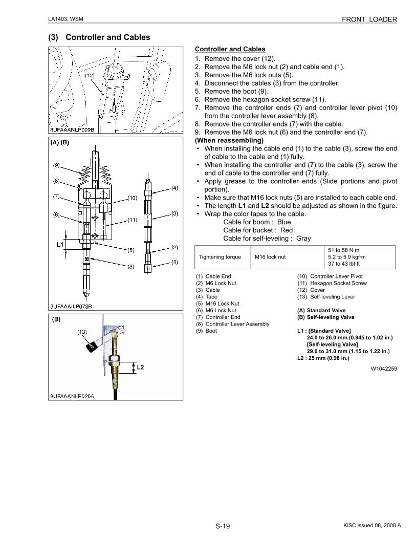
S-19
LA1403, WSM FRONT LOADER
(3) Controller and CablesController and Cables1. Remove the cover (12).2. Remove the M6 lock nut (2) and cable end (1).3. Remove the M6 lock nuts (5).4. Disconnect the cables (3) from the controller.5. Remove the boot (9).6. Remove the hexagon socket screw (11).7. Remove the controller ends (7) and controller lever pivot (10)
from the controller lever assembly (8).8. Remove the controller ends (7) with the cable.9. Remove the M6 lock nut (6) and the controller end (7).(When reassembling)• When installing the cable end (1) to the cable (3), screw the end
of cable to the cable end (1) fully.• When installing the controller end (7) to the cable (3), screw the
end of cable to the controller end (7) fully.• Apply grease to the controller ends (Slide portions and pivot
portion).• Make sure that M16 lock nuts (5) are installed to each cable end.• The length L1 and L2 should be adjusted as shown in the figure.• Wrap the color tapes to the cable.
Cable for boom : Blue Cable for bucket : Red Cable for self-leveling : Gray
W1042259
Tightening torque M16 lock nut51 to 58 N·m5.2 to 5.9 kgf·m37 to 43 lbf·ft
(1) Cable End(2) M6 Lock Nut(3) Cable(4) Tape(5) M16 Lock Nut(6) M6 Lock Nut(7) Controller End(8) Controller Lever Assembly(9) Boot
(10) Controller Lever Pivot(11) Hexagon Socket Screw(12) Cover(13) Self-leveling Lever
(A) Standard Valve(B) Self-leveling Valve
L1 : [Standard Valve]24.0 to 26.0 mm (0.945 to 1.02 in.)[Self-leveling Valve]29.0 to 31.0 mm (1.15 to 1.22 in.)
L2 : 25 mm (0.98 in.)
KiSC issued 08, 2008 A
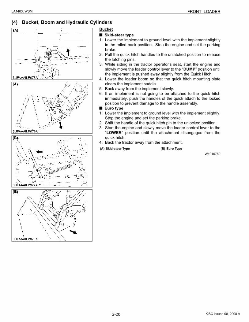
S-20
LA1403, WSM FRONT LOADER
(4) Bucket, Boom and Hydraulic CylindersBucket
Skid-steer type1. Lower the implement to ground level with the implement slightly
in the rolled back position. Stop the engine and set the parkingbrake.
2. Pull the quick hitch handles to the unlatched position to releasethe latching pins.
3. While sitting in the tractor operator’s seat, start the engine andslowly move the loader control lever to the “DUMP” position untilthe implement is pushed away slightly from the Quick Hitch.
4. Lower the loader boom so that the quick hitch mounting plateclears the implement saddle.
5. Back away from the implement slowly.6. If an implement is not going to be attached to the quick hitch
immediately, push the handles of the quick attach to the lockedposition to prevent damage to the handle assembly.
Euro type1. Lower the implement to ground level with the implement slightly.
Stop the engine and set the parking brake.2. Shift the handle of the quick hitch pin to the unlocked position.3. Start the engine and slowly move the loader control lever to the
“LOWER” position until the attachment disengages from thequick hitch.
4. Back the tractor away from the attachment.
W1016780(A) Skid-steer Type (B) Euro Type
KiSC issued 08, 2008 A
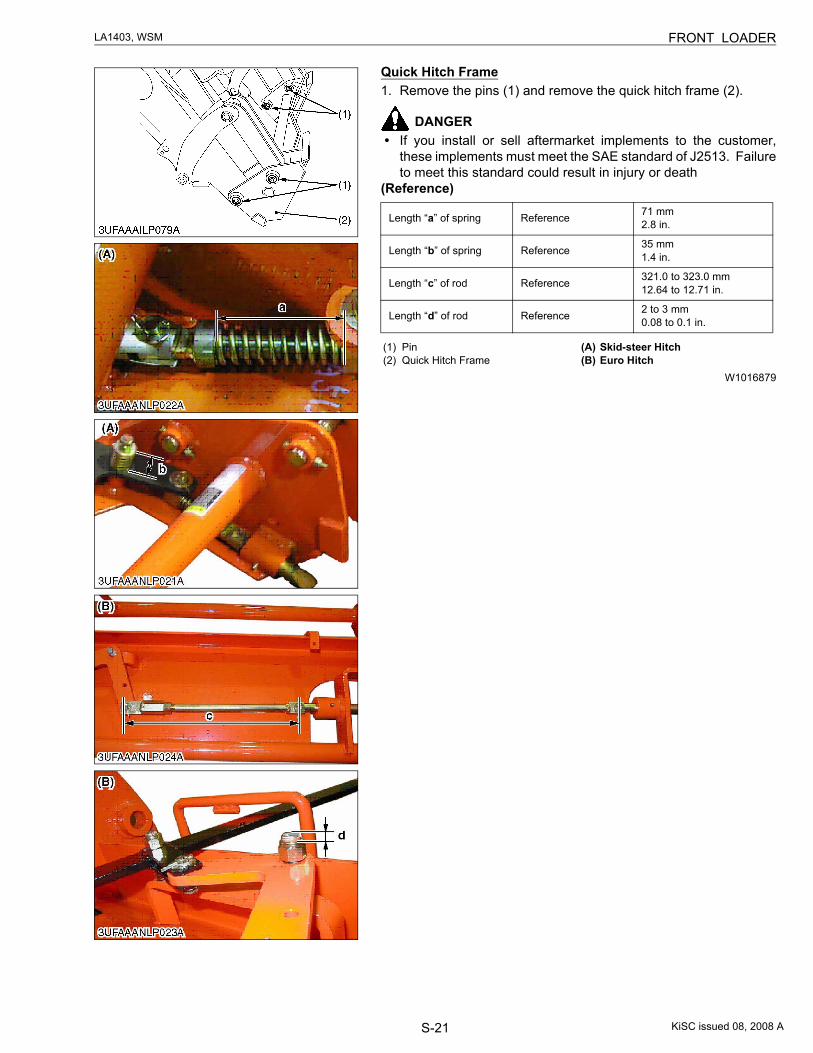
S-21
LA1403, WSM FRONT LOADER
Quick Hitch Frame1. Remove the pins (1) and remove the quick hitch frame (2).
DANGER• If you install or sell aftermarket implements to the customer,
these implements must meet the SAE standard of J2513. Failureto meet this standard could result in injury or death
(Reference)
W1016879
Length “a” of spring Reference 71 mm2.8 in.
Length “b” of spring Reference 35 mm1.4 in.
Length “c” of rod Reference 321.0 to 323.0 mm12.64 to 12.71 in.
Length “d” of rod Reference 2 to 3 mm0.08 to 0.1 in.
(1) Pin(2) Quick Hitch Frame
(A) Skid-steer Hitch(B) Euro Hitch
KiSC issued 08, 2008 A
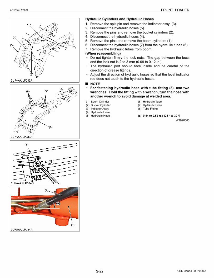
S-22
LA1403, WSM FRONT LOADER
Hydraulic Cylinders and Hydraulic Hoses1. Remove the split pin and remove the indicator assy. (3).2. Disconnect the hydraulic hoses (5).3. Remove the pins and remove the bucket cylinders (2).4. Disconnect the hydraulic hoses (4).5. Remove the pins and remove the boom cylinders (1).6. Disconnect the hydraulic hoses (7) from the hydraulic tubes (6).7. Remove the hydraulic tubes from boom.(When reassembling)• Do not tighten firmly the lock nuts. The gap between the boss
and the lock nut is 2 to 3 mm (0.08 to 0.12 in.).• The hydraulic port should face inside and be careful of the
direction of grease fittings.• Adjust the direction of hydraulic hoses so that the level indicator
rod does not touch to the hydraulic hoses.NOTE
• For fastening hydraulic hose with tube fitting (8), use twowrenches. Hold the fitting with a wrench, turn the hose withanother wrench to avoid damage at welded area.
W1026603
(1) Boom Cylinder(2) Bucket Cylinder(3) Indicator Assy.(4) Hydraulic Hose(5) Hydraulic Hose
(6) Hydraulic Tube(7) Hydraulic Hose(8) Tube Fitting
(a) 0.44 to 0.52 rad (25 ° to 30 °)
KiSC issued 08, 2008 A
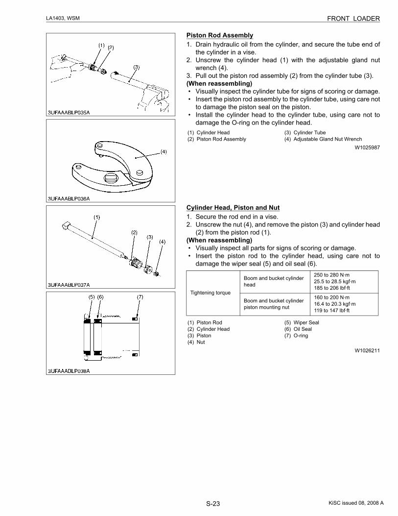
S-23
LA1403, WSM FRONT LOADER
Piston Rod Assembly1. Drain hydraulic oil from the cylinder, and secure the tube end of
the cylinder in a vise.2. Unscrew the cylinder head (1) with the adjustable gland nut
wrench (4).3. Pull out the piston rod assembly (2) from the cylinder tube (3).(When reassembling)• Visually inspect the cylinder tube for signs of scoring or damage.• Insert the piston rod assembly to the cylinder tube, using care not
to damage the piston seal on the piston.• Install the cylinder head to the cylinder tube, using care not to
damage the O-ring on the cylinder head.
W1025987
Cylinder Head, Piston and Nut1. Secure the rod end in a vise.2. Unscrew the nut (4), and remove the piston (3) and cylinder head
(2) from the piston rod (1).(When reassembling)• Visually inspect all parts for signs of scoring or damage.• Insert the piston rod to the cylinder head, using care not to
damage the wiper seal (5) and oil seal (6).
W1026211
(1) Cylinder Head (2) Piston Rod Assembly
(3) Cylinder Tube(4) Adjustable Gland Nut Wrench
Tightening torque
Boom and bucket cylinder head
250 to 280 N·m25.5 to 28.5 kgf·m185 to 206 lbf·ft
Boom and bucket cylinder piston mounting nut
160 to 200 N·m16.4 to 20.3 kgf·m119 to 147 lbf·ft
(1) Piston Rod (2) Cylinder Head (3) Piston(4) Nut
(5) Wiper Seal(6) Oil Seal(7) O-ring
KiSC issued 08, 2008 A
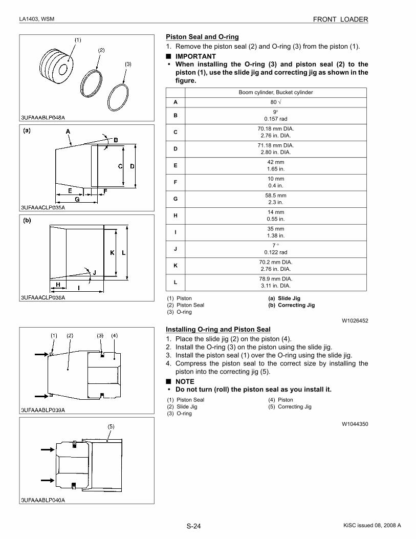
S-24
LA1403, WSM FRONT LOADER
Piston Seal and O-ring1. Remove the piston seal (2) and O-ring (3) from the piston (1).
IMPORTANT• When installing the O-ring (3) and piston seal (2) to the
piston (1), use the slide jig and correcting jig as shown in thefigure.
W1026452
Installing O-ring and Piston Seal1. Place the slide jig (2) on the piston (4).2. Install the O-ring (3) on the piston using the slide jig.3. Install the piston seal (1) over the O-ring using the slide jig.4. Compress the piston seal to the correct size by installing the
piston into the correcting jig (5).NOTE
• Do not turn (roll) the piston seal as you install it.
W1044350
Boom cylinder, Bucket cylinder
A 80 √
B 9°0.157 rad
C 70.18 mm DIA.2.76 in. DIA.
D 71.18 mm DIA.2.80 in. DIA.
E 42 mm1.65 in.
F 10 mm0.4 in.
G 58.5 mm2.3 in.
H 14 mm0.55 in.
I 35 mm1.38 in.
J 7 °0.122 rad
K 70.2 mm DIA.2.76 in. DIA.
L 78.9 mm DIA.3.11 in. DIA.
(1) Piston(2) Piston Seal(3) O-ring
(a) Slide Jig(b) Correcting Jig
(1) Piston Seal(2) Slide Jig(3) O-ring
(4) Piston(5) Correcting Jig
KiSC issued 08, 2008 A
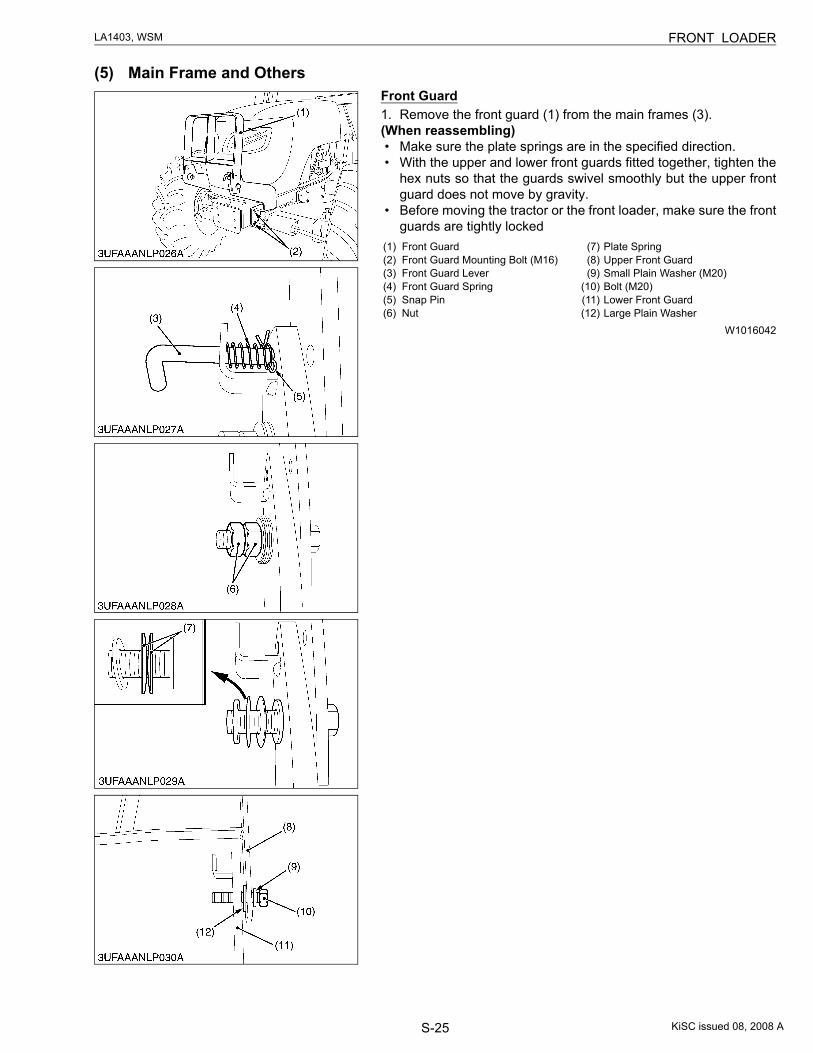
S-25
LA1403, WSM FRONT LOADER
(5) Main Frame and OthersFront Guard1. Remove the front guard (1) from the main frames (3).(When reassembling)• Make sure the plate springs are in the specified direction.• With the upper and lower front guards fitted together, tighten the
hex nuts so that the guards swivel smoothly but the upper frontguard does not move by gravity.
• Before moving the tractor or the front loader, make sure the frontguards are tightly locked
W1016042
(1) Front Guard(2) Front Guard Mounting Bolt (M16)(3) Front Guard Lever(4) Front Guard Spring(5) Snap Pin(6) Nut
(7) Plate Spring(8) Upper Front Guard(9) Small Plain Washer (M20)
(10) Bolt (M20)(11) Lower Front Guard(12) Large Plain Washer
KiSC issued 08, 2008 A
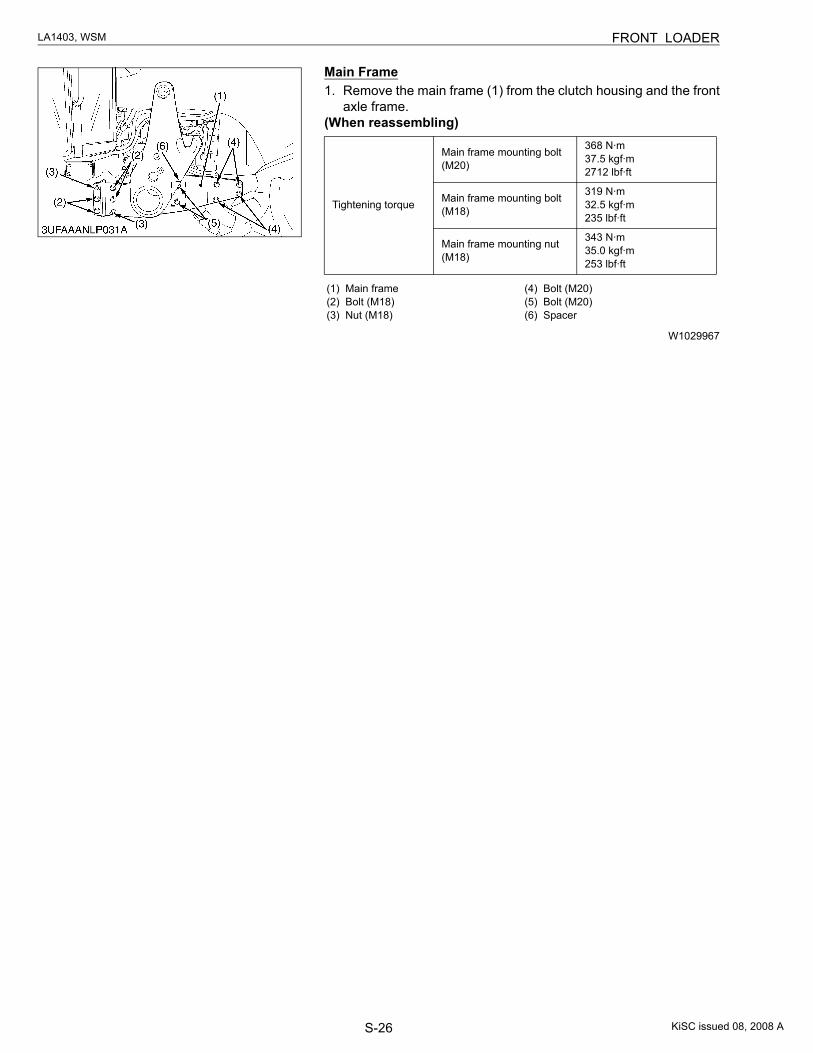
S-26
LA1403, WSM FRONT LOADER
Main Frame1. Remove the main frame (1) from the clutch housing and the front
axle frame.(When reassembling)
W1029967
Tightening torque
Main frame mounting bolt (M20)
368 N·m37.5 kgf·m2712 lbf·ft
Main frame mounting bolt (M18)
319 N·m32.5 kgf·m235 lbf·ft
Main frame mounting nut (M18)
343 N·m35.0 kgf·m253 lbf·ft
(1) Main frame(2) Bolt (M18)(3) Nut (M18)
(4) Bolt (M20)(5) Bolt (M20)(6) Spacer
KiSC issued 08, 2008 A
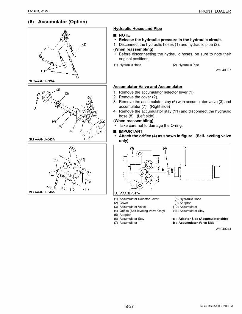
S-27
LA1403, WSM FRONT LOADER
(6) Accumulator (Option)Hydraulic Hoses and Pipe
NOTE• Release the hydraulic pressure in the hydraulic circuit.
1. Disconnect the hydraulic hoses (1) and hydraulic pipe (2).(When reassembling)• Before disconnecting the hydraulic hoses, be sure to note their
original positions.
W1040027
Accumulator Valve and Accumulator1. Remove the accumulator selector lever (1).2. Remove the cover (2).3. Remove the accumulator stay (6) with accumulator valve (3) and
accumulator (7). (Right side)4. Remove the accumulator stay (11) and disconnect the hydraulic
hose (8). (Left side).(When reassembling)• Take care not to damage the O-ring.
IMPORTANT• Attach the orifice (4) as shown in figure. (Self-leveling valve
only)
W1040244
(1) Hydraulic Hose (2) Hydraulic Pipe
(1) Accumulator Selector Lever(2) Cover(3) Accumulator Valve(4) Orifice (Self-leveling Valve Only)(5) Adaptor(6) Accumulator Stay(7) Accumulator
(8) Hydraulic Hose(9) Adaptor
(10) Accumulator(11) Accumulator Stay
a : Adaptor Side (Accumulator side)b : Accumulator Valve Side
KiSC issued 08, 2008 A
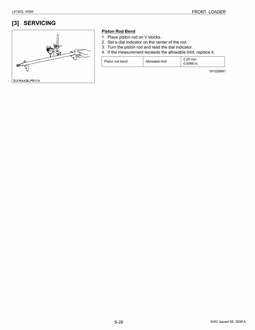
S-28
LA1403, WSM FRONT LOADER
[3] SERVICINGPiston Rod Bend1. Place piston rod on V blocks.2. Set a dial indicator on the center of the rod.3. Turn the piston rod and read the dial indicator.4. If the measurement exceeds the allowable limit, replace it.
W1028881
Piston rod bend Allowable limit 0.25 mm0.0098 in.
KiSC issued 08, 2008 A
Printed in Japan 2008. 07, S, EI, EI, e Code No.9Y111-00882 2007. 06, S, EI, EI, eKUBOTA Corporation
EDITOR:KUBOTA FARM & INDUSTRIAL MACHINERY SERVICE, LTD.64, ISHIZU-KITAMACHI, SAKAI-KU, SAKAI-CITY, OSAKA, 590-0823, JAPANPHONE : (81)72-241-1129FAX : (81)72-245-2484E-mail : [email protected]


![PRODUCT DATA 2000 kg [4400 lbs] 2600 kg [5730 lbs]](https://static.fdocuments.in/doc/165x107/62904abb5686e004a324a0b6/product-data-2000-kg-4400-lbs-2600-kg-5730-lbs.jpg)