LA PAZ COUNTY PUBLIC WORKS STANDARDS VOLUME II ...
869
LA PAZ COUNTY PUBLIC WORKS STANDARDS VOLUME II SPECIFICATIONS BOOK 1
Transcript of LA PAZ COUNTY PUBLIC WORKS STANDARDS VOLUME II ...

LA PAZ COUNTYPUBLIC WORKS STANDARDS
VOLUME II
SPECIFICATIONS
BOOK 1

INTRODUCTION
The Public Works Standards for La Paz County areintended to provide a consistent policy for the orderlydevelopment of improvements within the County. ThisVolume II, contains the Following County specifications:
• General Conditions
• Earthwork
• Roadway and related work
• Traffic Control, Right-Of-Way Development and Incidentals
• Structures and Masonry
• Pipework
• Material Specifications
A companion document, Volume I, contains Public WorksConstruction Standards for La Paz County.
These Standard and Specifications are prepared to fulfillthe need for uniform rules governing Public Worksconstruction performed for La Paz County and other publicagencies in La Paz County.

TABLE OF CONTENTS VOLUME II
SPECIFICATIONS
Section Title
100 . General Conditions
101.Abbreviations and Definitions
102.Bidding Requirements and Conditions
103.Award and Execution of Contract
104.Scope of Work
105.Control of Work
106.Control of Materials
107.Legal Relations and Responsibility to the Public
108.Commencement, Prosecution and Progress
109.Measurement and Payment

TABLE OF CONTENTS VOLUME II
SPECIFICATIONS
200.Earthwork
201 .Clearing and Grubbing
202.Removal of Structures and Obstructions
204.Earthwork
205.Roadway Excavation
210.Borrow
211.Fill and Embankment Construction
218.Subgrade Preparation
225.Watering
227.Dust Palliative

TABLE OF CONTENTS VOLUME II
SPECIFICATIONS
300.Roadway and Related Work
302.Grading Roadway for Pavement
310.Untreated Base
315.Bituminous Prime Coat
320.Road-Mixing Surfacing
321.Asphaltic Concrete Pavement
322.Asphaltic Concrete overlay
329.Tack Coat
330.Chip Seal Coat
333.Fog Seal Coats
334.Preservative Seal for Asphaltic Concrete
336.Pavement Matching and surface Replacement
340.Concrete Curb, Gutter, sidewalk, Driveway, Alley Entrances and Pavement Border
352. Cement Treated Base

TABLE OF CONTENTS VOLUME II
SPECIFICATIONS
360. Exposed Aggregate Sidewalk

TABLE OF CONTENTS VOLUME II
SPECIFICATIONS
400.Traffic Control, Right-of-Way Develmnt Incidentals
401.Traffic Control
402.Construction Surveying and Layout
403.Mobilization
405.Monuments
406.Relocating Water Meters and Boxes
407.Adjusting Frame and Covers and Valve & Water Meter Boxes
408.Relocate and Adjust Private Mail Boxes
410.Precast Safety Curbs
413.Miscellaneous Metals
415.Flexible Metal Guardrail
420.Chain Link Fences
423.Bank Protection (Riprap)
424.Parkway Grading

TABLE OF CONTENTS VOLUME II
SPECIFICATIONS
425.Top Soil
430.Landscaping and Planting
440.Sprinkler Irrigation System Installation
442.Damp Proofing and Water Proofing Concrete Surfaces
443.Protective Coating
445.Disinfecting Water Lines
447.Dewatering
451.Traffic Control
452.Traffic Signal Loop Detectors
457.Raised Pavement Markers
460.Preformed Plastic Pavement Marking
462.Permanent Pavement Markings
470.Ceramic Pavement Markings

TABLE OF CONTENTS VOLUME II
SPECIFICATIONS
492.Demolition
495.Remove and Replace Existing Fences

TABLE OF CONTENTS VOLUME II
SPECIFICATIONS
500.Structures and Masonry
502.Structural Excavation and Backfill
505.Concrete Structures
507.Concrete Joints and Water Stops
510.Concrete Block Masonry
511.Brick Masonry
518.Steel Reinforcement
525.Pneumatically Placed Mortar
532.Concrete Catch Basins
545.Pump Station
556.Precast Prestressed Concrete Members

TABLE OF CONTENTS VOLUME II
SPECIFICATIONS
600.Pipework
601.Trench Excavation, Backfilling and Compaction
602.Boring and Casing
605.Subdrainage
610.Water Line Construction
612.Force Main Pipeline Construction
615.Sewer Line Construction
618.Reinforced Concrete Pipeline Construction
621.Corrugated Metal Pipe and Arches
625.Manhole Construction and Drop Sewer Connections
630.Tapping Sleeve and Valve
631.Water Service Taps and Meter Connections
640.Piping
645.Valves and Water Work Specialties
650.Water Main Lowering

TABLE OF CONTENTS VOLUME II
SPECIFICATIONS
700.Material Specifications
701.Rock, Gravel and Sand
702.Base Materials
705.Portland Cement Treated Base
710.Asphaltic Concrete
711.Paving Asphalt
712.Liquid Asphalt
713.Emulsified Asphalts
716.Cover Material "Chips"
718.Preservative Seal
725.Portland Cement Concrete
726.Concrete Curing Materials
727.Steel Reinforcement
729.Expansion Joint Filler
734.Reinforced Concrete Low Head Pressure Pipe

TABLE OF CONTENTS VOLUME II
SPECIFICATIONS
735.Reinforced Concrete Pipe
736.Non-Reinforced Concrete Pipe
743.Vitrified Clay Pipe
744.ABS Truss Pipe and Fittings
745.PVC Sewer Pipe and Fittings
746.PVC Pressure Pipe and Fittings
747.Precast Concrete Manholes
748.Steel Pipe and Fittings
749.Tapping Sleeve
750.Iron Water Pipe and Fittings
751.Water Service Fittings
753.Galvanized Pipe and Fittings
754.Copper Pipe, Tubing and Fittings
756.Fire Hydrants

TABLE OF CONTENTS VOLUME II
SPECIFICATIONS
757.Sprinkler Irrigation System
759.Valves for Water Lines - Gate and Butterfly
760.Coating Corrugated Metal Pipe and Arches
761.Structural Plate Pipe, Arches and Pipe Arches
765.Rubber Gaskets for Concrete Pipe
767.Valves for Pump Stations
770.Structural and Rivet Steel, Rivets, Bolts, Pins andAnchor Bolts
771.Galvanizing
772.Chain Link
775.Brick and Concrete Block
776.Masonry Mortar and Grout
778.Lumber
779.Wood Preservatives
785.Steel Castings
786.Bronze Castings

TABLE OF CONTENTS VOLUME II
SPECIFICATIONS
787.Gray Iron Castings
790.Paint
791.Polyethylene Protective Wrap
792.Dust Palliative
795.Landscape Material

PART 100
GENERAL CONDITIONS
SECTION TITLE
101. Abbreviations and Definitions
102. Bidding Requirements and Conditions
103. Award and Execution of Contract
104. Scope of Work
105. Control of Work
106. Control of Materials
107. Legal Relations and Responsibility to thePublic
108. Commencement, Prosecution and Progress
109. Measurement and Payment
PART 200
EARTHWORK
SECTION TITLE
201 Clearing and Grubbing
202 Removal of Structures and Obstructions
204 Earthwork
205 Roadway Excavation
210 Borrow
211 Fill and Embankment Construction
218 Subgrade Preparation
225 Watering
227 Dust Palliative

PART 300
ROADWAY AND RELATED WORK
SECTION TITLE
302 Grading Roadway for Pavement
310 Untreated Base
315 Bituminous Prime Coat
320 Road-Mixed Surfacing
321 Asphaltic Concrete Pavement
322 Asphaltic Concrete Overlay
329 Tack Coat
330 Chip Seal Coat
333 Fog Seal Coats
334 Preservative Seal for Asphaltic Concrete
336 Pavement Matching and Surface Replacement
340 Concrete Curb, Gutter, Sidewalk, Driveway, Alley Entrances and Pavement Border
352 Cement Treated Base
360 Exposed Aggregate Sidewalk

PART 400
TRAFFIC CONTROL, RIGHT-OF-WAY DEVELOPMENT ANDINCIDENTALS
SECTION TITLE
401 Traffic Control
402 Construction Surveying and Layout
403 Mobilization
405 Monuments
406 Relocating Water Meters and Boxes
407 Adjusting Frame and Covers and Valve & Water Meter Boxes
408 Relocate and Adjust Private Mail Boxes
410 Precast Safety Curbs
413 Miscellaneous Metals
415 Flexible Metal Guardrail
420 Chain Link Fences
423 Bank Protection (Riprap)
424 Parkway Grading
425 Top Soil
430 Landscaping and Planting
440 Sprinkler Irrigation System Installation

PART 400
TRAFFIC CONTROL, RIGHT-OF-WAY DEVELOPMENT ANDINCIDENTALS
442 Damp Proofing and Water Proofing Concrete Surfaces
443 Protective Coating
445 Disinfecting Water Lines
447 Dewatering
451 Traffic Control
452 Traffic Signal Loop Detectors
457 Raised Pavement Markers
460 Preformed Plastic Pavement Marking
462 Permanent Pavement Markings
470 Ceramic Pavement Markings
492 Demolition
495 Remove and Replace Existing Fences

PART 400
TRAFFIC CONTROL, RIGHT-OF-WAY DEVELOPMENT ANDINCIDENTALS

PART 500
STRUCTURES AND MASONRY
SECTION TITLE
502 Structural Excavation and Backfill
505 Concrete Structures
507 Concrete Joints and Water Stops
510 Concrete Block Masonry
511 Brick Masonry
518 Steel Reinforcement
525 Pneumatically Placed Mortar
532 Concrete Catch Basins
545 Pump Station
556 Precast Prestressed Concrete Members

PART 600
PIPEWORK
SECTION TITLE
601 Trench Excavation, Backfilling andCompaction
602 Boring and Casing
605 Subdrainage
610 Water Line Construction
612 Force Main Pipeline Construction
615 Sewer Line Construction
618 Reinforced Concrete Pipeline Construction
621 Corrugated Metal Pipe and Arches
625 Manhole Construction and Drop SewerConnections
630 Tapping Sleeve and Valve
631 Water Service Taps and Meter Connections
640 Piping
645 Valves and Water Work Specialties
650 Water Main Lowering

PART 700
MATERIALSROCK, GRAVEL, AND SAND
SECTION TITLE
700. Material Specifications
701. Rock, Gravel and Sand
702. Base Materials
703. Portland Cement Treated Base
710. Asphaltic Concrete
711. Paving Asphalt
712. Liquid Asphalt
713. Emulsified Asphalts
716. Cover Material "Chips"
718. Preservative Seal
725. Portland Cement Concrete
726. Concrete Curing Materials
727. Steel Reinforcement
729. Expansion Joint Filler
734. Reinforced Concrete Low Head PressurePipe
735. Reinforced Concrete Pipe
736. Non-Reinforced Concrete Pipe

PART 700
MATERIALSROCK, GRAVEL, AND SAND
743. Vitrified Clay Pipe
744. ABS Truss Pipe and Fittings
745. PVC Sewer Pipe and Fittings
746. PVC Pressure Pipe and Fittings
747. Precast Concrete Manholes
748. Steel Pipe and Fittings
749. Tapping Sleeve
750. Iron Water Pipe and Fittings
751. Water Service Fittings
753. Galvanized Pipe and Fittings

GENERAL CONDITIONSSECTION 101
ABBREVIATIONS
101-1
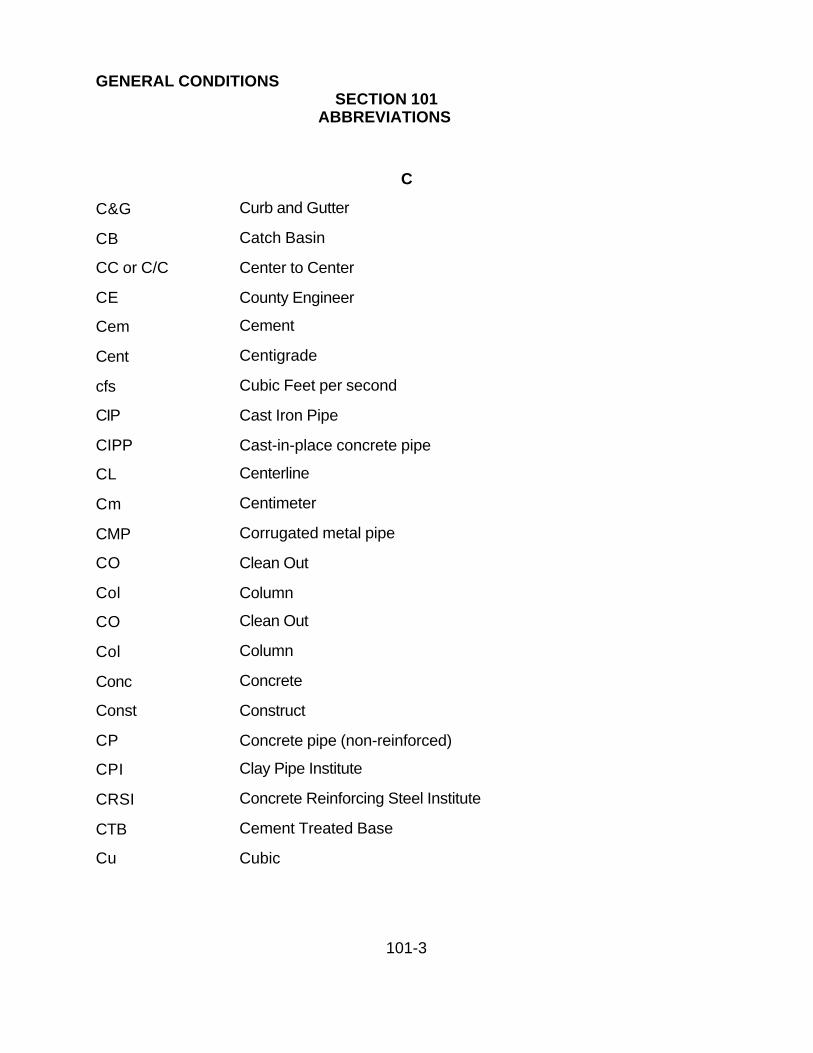
101.1 ABBREVIATIONS:
Wherever the following abbreviations are used in these specifications, construction
standards or on the plans, they are to be construed the same as the respective
expressions represented.
A
AA American Association of Nurserymen
ASHTO American Association of State Highway and Transportation Officials
AB Aggregate Base
ABC Aggregate base course
AC Asphalt cement or concrete
ACB Asphalt concrete base
ACI American Concrete Institute
ACPA American Concrete Pipe Association
ACWS Asphalt concrete wearing surface
ADOT Arizona Department of Transportation
AEC Arizona Electric Code
AFRB Arizona Fire Rating Bureau
AGC Associated General Contractors of America, Inc.
Agg Aggregate
Ahd Ahead
AIA American Institute of Architects
AIEE American Institute of Electrical Engineers
AISC American Institute of Steel Construction
ANSI American National Standards Institute
APA American Plywood Association

GENERAL CONDITIONSSECTION 101
ABBREVIATIONS
101-2
Approx Approximate
APWA American Public Works Association
ARS Arizona Revised Statutes
ASCE American Society of Civil Engineers
ASME American Society of Mechanical Engineers
Asph Asphalt
ASTM American Society for Testing Materials
Ave Avenue
AWG American Wire Gage
AWPA American Wood Preservers Association
AWSC American Welding Society Code
AWWA American Water Works Association
B
BC Beginning of curve
BCR Beginning of curb return
Beg Beginning
Blvd Boulevard
BM Bench Mark or Board Measure
Brg Bearing
BST Bituminous Surface Treatment
BTB Bituminous Treated Base
BTU British Thermal Units
BVC Beginning of vertical curve
GENERAL CONDITIONSSECTION 101
ABBREVIATIONS
101-3
C
C&G Curb and Gutter
CB Catch Basin
CC or C/C Center to Center
CE County Engineer
Cem Cement
Cent Centigrade
cfs Cubic Feet per second
CIP Cast Iron Pipe
CIPP Cast-in-place concrete pipe
CL Centerline
Cm Centimeter
CMP Corrugated metal pipe
CO Clean Out
Col Column
CO Clean Out
Col Column
Conc Concrete
Const Construct
CP Concrete pipe (non-reinforced)
CPI Clay Pipe Institute
CRSI Concrete Reinforcing Steel Institute
CTB Cement Treated Base
Cu Cubic

GENERAL CONDITIONSSECTION 101
ABBREVIATIONS
101-4
D
Deg Degree
DF Douglas Fir
DG Decomposed granite
Dia Diameter
Dim Dimension
DIP Ductile Iron Pipe
Div Division
Dwy Driveway
E
E East
Ea Each
Ease Easement
EC End of Curve
ECR End of curb return
Elev Elevation
Equa or Eq Equation
EVC End of vertical curve
Ex or Exist Existing
F
F Fahrenheit
F&C Frame & Cover
FH Fire Hydrant

GENERAL CONDITIONSSECTION 101
ABBREVIATIONS
101-5
FHWA Federal Highway Administration
Fl El Floor Elevation
FL or F Floor line or flow line
Fnd Found
Fps Feet per second
FS Finished surface
FSS Federal Specifications and Standards
Ft Foot or feet
G
G Gutter
Galv Galvanized
gpm Gallons per minute
H
H High or height
Hdwl Headwall
Horiz Horizontal
Hwy Highway
I
ICA Industrial Commission of Arizona
ID Improvement District or inside diameter
IEEE Institute of Electrical and Electronic Engineers
In Inch
Inv Invert

GENERAL CONDITIONSSECTION 101
ABBREVIATIONS
101-6
Inv. Elev Invert Elevation
IP Iron Pipe
IPS Iron Pipe Size
Irrig Irrigation
L
L Length
Lb Pound
LF Linear Feet
Lin Linear
Long Longitudinal
Lt Left
LPC La Paz County
M
Max Maximum
Meas Measured
MH Manhole
MHF&C Manhole frame and cover
Min Minutes or minimum
Misc Miscellaneous
Mm Millimeter
Mon Monolithic or monument
MUTCD Manual on Uniform Traffic Control Devices

GENERAL CONDITIONSSECTION 101
ABBREVIATIONS
101-7
N
N North
NBS National Bureau of Standards
NCPI National Clay Pipe Institute
NE Northeast
NEC National Electric Code
NEMA National Electrical Manufacturer's Association
NFPA National Fire Protection Association
No Number
NPI Non pay item
NSC National Safety Council
NSF National Sanitation Foundation
NW Northwest
O
OD Outside diameter
OSHA Occupational Safety and Health Administration
Oz Ounces
P
PC Point of curvature
PCA Portland Cement Association
PCC Portland Cement Concrete or point of compound curve
PI Point of intersection or plastic index
PL Property of line

GENERAL CONDITIONSSECTION 101
ABBREVIATIONS
101-8
POT Point on Tangent
PP Power Pole
PPM Parts per million
PRC Point of reverse curve
Prop Proposed or property
psf Pounds per square foot
psi Pounds per square inch
PT Point of Tangency
PVC Polyvinyl Chloride
Pvmt Pavement
PWD Public Works Director or The Designated Representative
Q
Q Rate of flow
R
R Radius
RC Reinforced concrete
RCP Reinforced concrete pipe
Rd Road
Rdwy Roadway
Reinf Reinforced, Reinforcing
Ret Wall Retaining Wall
RGRCP Rubber Gasket Reinforced Concrete Pipe
rpm Revolutions Per Minute

GENERAL CONDITIONSSECTION 101
ABBREVIATIONS
101-9
Rt Right
R/W Right-of-Way
S
S South or slope
SAE Society of Automotive Engineers
San Sanitary
SC Spiral to Curve
SCCP Steel Cylinder Concrete Pipe
SD Storm drain or Sewer District
SE Southeast
Sec Seconds
Sect Section
Spec Specification
SPR Simplified Practice Recommendation
Sq Ft Yd Square Foot, Yard
SS Sanitary sewer
St Street
Sta Station
Std Standard
Struct Structure or structural
SW Southwest

GENERAL CONDITIONSSECTION 101
ABBREVIATIONS
101-10
T
Tan. Tangent
Tel Telephone
Temp Temporary
TH Test hole
TP Telephone pole
Trans Transition
TS Traffic signal or Tangent to spiral
TSC Traffic signal conduit
Typ Typical
U
UBC Uniform Building Code
UL Underwriter's Laboratories Inc.
UPC Uniform Plumbing Code
USC&GS United States Coast and Geodetic Survey
USGS United States Geological Survey
V
V Velocity of flow
VC Vertical curve
VCP Vitrified clay pipe
Vert Vertical

GENERAL CONDITIONSSECTION 101
ABBREVIATIONS
101-11
W
W West or width
WI Wrought iron
Wt Weight
Y
Yd Yard
OTHER ABBREVIATIONS
' Feet or minutes
" inches or seconds
o degrees
% percent
# number or pound
@ at
/ per
= equals

GENERAL CONDITIONSSECTION 101
ABBREVIATIONS
101-12
101.2 GENERAL DEFINITIONS AND TERMS:
Whenever in these Specifications, Construction Standards, plans or in any document of
instruction where these Specifications govern, the following terms or pronouns are
used, the intent and meaning shall be:
ADDENDUM: A supplement to any of the contract documents issued, in writing, after
advertisement of but prior to the opening bids for a contract.
ADVERTISEMENT: The public announcement inviting bids for work to be performed or
materials to be furnished.
AWARD: The formal action of accepting a proposal.
BIDDER: Any individual, firm or corporation, qualified as herein provided, legally
submitting a proposal for the work contemplated, acting directly or through an
authorized representative.
BIDDING SCHEDULE: The prepared schedule, included as part of the proposal,
containing the estimated quantities of the pay items for which unit bid prices are invited.
The schedule shall contain time charts as accepted by the LPC PWD.
CALENDAR DAY: Every day shown on the calendar.
CALL FOR BID: The standard form inviting proposals or bids.

GENERAL CONDITIONSSECTION 101
ABBREVIATIONS
101-13
CAREFUL AND PRUDENT MANNER: Means conducting excavation in such a way
that when it approaches the underground facility located and marked by the owner or
operator, by stakes, paint or in some customary manner, the exact location is manually
determined, and the uncovered facility is supported and protected.
CERTIFICATIONS: A document stating that the material or item supplied complies and
meets in all respects with the cited specification, as per Section 106.4.
CHANGE ORDER: A written order issued by the PWD to the Contractor to make
changes in the work or to perform extra work, and setting forth conditions for payment
and/or adjustment in time of completion. Requires La Paz County Board of Supervisors
approval.
CODE AND/OR REGULATION: Those rules and statements adopted by a governing
agency.
COMPLETION AND/OR CONTRACT TIME: The number of calendar days for
completion of the work, including authorized time extensions. In case a calendar date
of completion is shown in the proposal in lieu of the number of calendar days, the
contract shall be completed by that date. The time within which an act is to be done
shall be computed by excluding the first and including the last day; and if the last day be
Sunday or a legal holiday, that shall be excluded. Any changes to the submitted time
schedule require approval of the PWD.

GENERAL CONDITIONSSECTION 101
ABBREVIATIONS
101-14
CONFLICTING UTILITY LINE: An existing utility line, shown or not shown on the plans,
is a conflicting line when any part falls within the trench widths or within the dimensions,
as shown on the plans, for structures or appurtenances. Conflict resolutions are the
responsibility of the Contractor and the impacted utility company. LPC shall be held
harmless for money and time required for resolution.
CONSTRUCTION PROJECT: The erection, installation, remodeling, alteration of
projects upon, under or over the ground. This shall include, but is not limited to
buildings, roadways, utility pipes, lines, poles, streets, drainage and flood control
facilities, or other structures.
CONSTRUCTION STANDARDS: Drawings approved that show the dimensions and
detail requirements of construction within the agencies jurisdiction. The La Paz County
Construction Standards are bound within the Public Works Standards publication and is
available from the La Paz County Public Works Department, 1112 Joshua Ave., Suite
#207, Parker, AZ.
CONSULTING ENGINEER/CONSULTANT: The firm, corporation, partnership or
individual who provides professional engineering services to a developer, or a
Contracting agency. They may prepare reports, plans and specification and provide
construction management on projects.

GENERAL CONDITIONSSECTION 101
ABBREVIATIONS
101-15
CONTINGENT BID: This is a bid item which is likely, but not certain, to occur during the
course of work. If La Paz County determines that this work is required, the Contractor
will accomplish the work and payment will be made based on the contingent unit bid
price included in the proposal. Since the quantity listed in the proposal is primarily for
bid comparison, the amount of work required by La Paz County may vary.
CONTRACT: The written agreement obligating the parties, including but not limited to,
covering the performance of the work and the furnishing of labor, equipment and
materials and the basis of payment. The Contract includes the advertisement, addenda,
performance bond, payment bond, certificate of insurance, proposal, plans, general
conditions, specifications, construction standards, standard specifications, special
provisions, contract supplementary agreements, and all written requirements which
reasonably could be required to insure the proper completion of the work in a
substantial and acceptable manner including authorized extensions there of, all of which
constitutes one instrument.
CONTRACT DOCUMENTS: All the integral documents of the Contract, including but
not limited to advertisement, addenda, performance bond, payment bond, certificate of
insurance, proposal, plans, general conditions, specifications, special provisions,
contract supplementary agreements, and all written requirements which reasonably
could be required to insure the proper completion of the work in a substantial and
acceptable manner. Notice of award, notice to proceed, and schedules shall be
included as a contract document when the contract is approved by the LPC Board of
Supervisors.

GENERAL CONDITIONSSECTION 101
ABBREVIATIONS
101-16
CONTRACTING AGENCY: The legal entity that has contracted for the performance of
the work or for whom the work is being performed. The party of the first part.
CONTRACTOR: The party of the second part who undertakes to execute the work,
acting directly or through an authorized agent.
COUNTY: La Paz County organized and existing under and by virtue of the laws of the
State of Arizona.
COUNTY CLERK: The duly authorized Clerk of the Board of who performs the duties
of the Clerk for the Contracting Agency.
DAYS: Unless otherwise designated, days will be understood to mean calendar days.
DIRECTOR OF PUBLIC WORKS: The official representative and agent of the Board of
Supervisors, and his designated representative.
EMERGENCY: That condition as determined by the County Emergency Services
Director which will or is threatening to the public health, safety or welfare.
ENGINEER: The County Engineer duly authorized by the Director of Public Works to
act for LPC Public Works.

GENERAL CONDITIONSSECTION 101
ABBREVIATIONS
101-17
EQUIPMENT (Construction): All machinery and equipment with the necessary
supplies for upkeep and maintenance necessary for the proper construction and
acceptable completion of work. Includes material or articles used in equipping a facility
as furnishings or apparatus to fulfill a functional design.
EXTRA WORK: Work, including materials, for which no price agreement is contained in
the contract and which is deemed necessary for the proper completion of the work.
FIELD ORDER: An order issued by La Paz County Public Works Department to the
Contractor to make minor changes, clarifications and provide supplemental instruction
to the work. If the work involves adjustments to payment or time of completion, a
written supplemental agreement is to follow the issuance of a field order.
GENERAL CONDITIONS: The conditions and requirements pertaining to the method
and manner of performing the work, quality and quantities of materials to be furnished
and the measurement and payment of same.
INSPECTOR: An authorized representative of La Paz County assigned to make
detailed inspection of any work performed and material furnished by the Contractor.
LABORATORY: Laboratories authorized by La Paz County to test materials and work
involved in the Contract.
MAJOR ITEM: An item on the bidding schedule whose total cost is greater than 5
percent of the total contract price.

GENERAL CONDITIONSSECTION 101
ABBREVIATIONS
101-18
MATERIALS: Any substance specified in the project, equipment and other material
used or consumed in the performance of the work.
NON PAY ITEM: An item of work for which no separate payment will be made under the
proposal, but which must be included as an incidental cost for payment on an
associated item included in the proposal.
NOTICE OF AWARD: A letter from La Paz County advising the Contractor they have
accepted the proposal.
NOTICE TO PROCEED: A directive issued by La Paz County authorizing the
Contractor to start the work required in the Contract.
LA PAZ COUNTY: The County acting through its legally constituted officials, officers or
employees.
PAY ITEM: A detail of work as specified as a bid item in the proposals bid schedule.
PAYMENT BOND: The security provided by the Contractor for the protection of
claimants, supplying labor and materials to the Contractor or Subcontractors.
PERFORMANCE BOND: The security provided by the Contractor for the protection of
La Paz County and conditioned upon the faithful performance of the contract in
accordance with the plans, specifications and conditions therein.
GENERAL CONDITIONSSECTION 101
ABBREVIATIONS
101-19
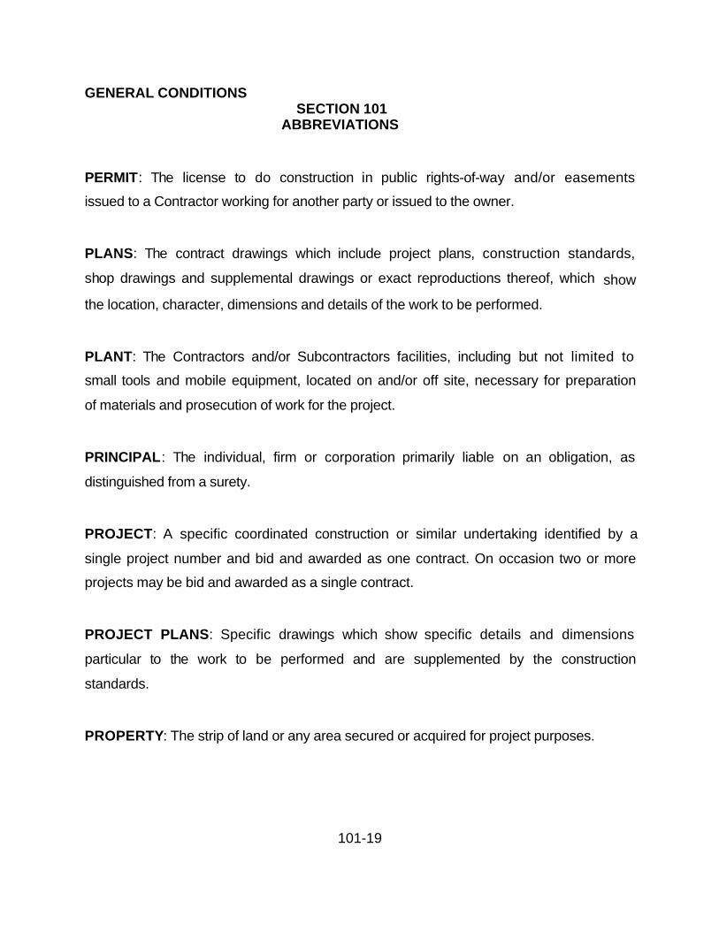
PERMIT: The license to do construction in public rights-of-way and/or easements
issued to a Contractor working for another party or issued to the owner.
PLANS: The contract drawings which include project plans, construction standards,
shop drawings and supplemental drawings or exact reproductions thereof, which show
the location, character, dimensions and details of the work to be performed.
PLANT: The Contractors and/or Subcontractors facilities, including but not limited to
small tools and mobile equipment, located on and/or off site, necessary for preparation
of materials and prosecution of work for the project.
PRINCIPAL: The individual, firm or corporation primarily liable on an obligation, as
distinguished from a surety.
PROJECT: A specific coordinated construction or similar undertaking identified by a
single project number and bid and awarded as one contract. On occasion two or more
projects may be bid and awarded as a single contract.
PROJECT PLANS: Specific drawings which show specific details and dimensions
particular to the work to be performed and are supplemented by the construction
standards.
PROPERTY: The strip of land or any area secured or acquired for project purposes.

GENERAL CONDITIONSSECTION 101
ABBREVIATIONS
101-20
PROPOSAL: The offer of the bidder for the work when properly made out on forms
containing the bidding schedule and properly submitted, signed and guaranteed.
PROPOSAL FORMS: The approved form on which the La Paz County requires bids to
be prepared and submitted for the work.
PROPOSAL GUARANTEE: The security furnished with a bid to guarantee the bidder
will enter into the contract if his bid is accepted.
PROPOSAL PAMPHLET: The pamphlet pertaining to a specific project, containing
proposal and bid schedule, contract, bond forms, certificate of insurance, and other
information necessary for and pertinent to the preparation of the proposal or bid.
REFERENCED DOCUMENTS: On all work authorized by La Paz County, any
referenced documents in the specification, i.e.: bulletins, standards, rules, methods of
analysis or test. Codes and specifications of other agencies, engineering societies or
industrial associations, refer to the latest edition thereof, including amendments, which
are in effect and published at the time of advertising for bids or the issuing of a permit
for the work.
RIGHT-OF-WAY: A general term denoting land, property, or interest therein, usually in
a strip, acquired for or devoted to a street, highway, or other public use.
ROAD, ALSO KNOWN AS A STREET: A general term denoting a public way for
vehicular travel.

GENERAL CONDITIONSSECTION 101
ABBREVIATIONS
101-21
ROADWAY: The portion of the right-of-way intended primarily for vehicular traffic.
Including all appurtenant structures and other features necessary for proper drainage
and protection. Where curbs exist, it is that portion of the Right of Way between the
faces of the curbs.
SEWER: Usually a closed pipeline that transports waste or storm water toward points of
discharge.
SHOP DRAWINGS: Drawings or reproduction of drawings, detailing, fabrication and
erection of structural elements, false work and forming for structures, fabrication of
reinforcing steel, pipe layouts, installed equipment and installation of systems or any
other supplementary plans or similar data, which the Contractor is required to submit for
approval.
SPECIAL PROVISIONS: The special conditions, additions and/or requirements or
revisions of the plans and specifications applicable to the work to cover conditions
peculiar to the project under consideration.
SPECIFICATIONS: The descriptions, provisions, and requirements for a project
contained in a book and termed Specifications supplemented by special provisions
pertaining to method and manner of performing the work; quality and quantities of
materials to be furnished; and, the measurement and payment of same.
STANDARD SPECIFICATIONS: A book of approved specifications pertaining to the
method and manner of performing work, for general application and repetitive use.

GENERAL CONDITIONSSECTION 101
ABBREVIATIONS
101-22
STORM DRAIN: Any pipeline, sewer or conduit including appurtenance intended for the
reception and transport of storm water.
STRUCTURE: Bridges, retaining walls, box culverts, large headwalls, vaults, pump
stations, inlet and outlet structures, buildings, and other features which may be
encountered in the work are considered structures. Catch basins, drop inlets, and
manholes are handled separately in these specifications.
SUBCONTRACTOR: Those having direct contracts with the Contractor.
SUBMITTAL: Those shop drawings, stress sheets, certifications, erection plans,
equipment installation plans, catalog cuts, and similar data requiring submittals for
approval by La Paz County to ensure quality control.
SUPERINTENDENT: The Contractor's authorized representative in charge of the work.
SUPPLEMENTAL DRAWINGS: Drawings that show detailing and clarification that
supplement the project plans prepared by the Engineer.
SUPPLEMENTARY AGREEMENT: A written agreement executed by the Contractor
and La Paz County covering alterations to the project.
SUPPLEMENTARY GENERAL CONDITIONS: Requirements, or revisions, to the
Standard General Conditions.

GENERAL CONDITIONSSECTION 101
ABBREVIATIONS
101-23
SURETY: The corporate body who is bound with and for the Contractor, and is primarily
liable for payment of debts pertaining to acceptable performance for the work
contracted.
TITLES OR HEADINGS: The titles or headings of the sections and subsections herein
are intended for convenience of reference and shall not be considered as having any
bearing on their interpretation.
UNDERGROUND FACILITIES: Any item buried or placed below ground for use in
connection with the storage or conveyance of water, sewage, electrical, telephone or
telegraphic communications, oil, gas or other substances, and shall include, but not be
limited to pipes, sewers, conduits, cables, valves, lines, wires, manholes, attachments
and those portions of poles and their attachments below ground.
UTILITY: To include but not be limited to pipe lines, conduits, ducts, transmission lines,
overhead or underground wires, railroads, storm drains, sanitary sewers, irrigation
facilities, street lighting, traffic signals, and fire alarm systems, and appurtenances of
public utilities, ownership maybe public or private solely for their own use or use of their
customers which are operated or maintained in, on, under, over or across public right-
of-way or public/private easements.
WORK : Any or all of the improvements aforementioned and authorized involving the
construction, demolition, reconstruction, and/or repair relating to labor, services,
incidental expenses, and materials necessary or incidental therein.

101-24
WORKING DAY: calendar day, exclusive of Saturdays, Sundays and recognized legal
holidays.
101.3 BY OR TO PUBLIC WORKS DIRECTOR:
Any actions directed to the Contractor by the County of La Paz shall require
approval/disapproval comments by the Public Works Director prior to formal action by
the County Board of Supervisors.

GENERAL CONDITIONS
SECTION 102BIDDING REQUIREMENTS AND CONDITIONS
102-1
102.1 ELIGIBILITY AND PREFERENCE: the provisions of Section 34-241 of the
Arizona Revised Statutes shall govern the employment of Contractors and
Subcontractors on Public Works.
102.2 CONTENTS Of PROPOSAL PAMPHLET: The Proposal Pamphlet supplied with
the specifications contains the proposal and bidding schedule, contract, bond forms and
certificate of insurance forms together with the advertisement for bids and any other
papers (except large plans and specifications) pertinent to the contract. The standard
specifications, construction standards, plans, specifications, construction details,
general conditions, special provisions, and all supplementary documents are essential
parts of the contract, and a requirement occurring in one is as binding as though
occurring in all. They are intended to be complementary and to describe and provide
for a complete work. In case of discrepancy or conflict, standard specifications and
construction standards and plans will govern over; special provisions will govern over
standard specifications, construction standards, general conditions, and supplemental
general conditions.
Each and every provision of law and clause required by law to be inserted in the
contract shall be deemed to be inserted herein, and the Contract shall be read and
enforced as though it were included herein.
102.3 COPIES OF STANDARD SPECIFICATIONS AND CONSTRUCTION
STANDARDS: Copies of standard specifications and construction standards are
available for a nominal fee.
102.4 INTERPRETATION OF QUANTITIES IN BIDDING SCHEDULE: The quantities
appearing in the proposal are approximate only and are to be used for the comparison

GENERAL CONDITIONS
SECTION 102BIDDING REQUIREMENTS AND CONDITIONS
102-2
of bids. Payment to the Contractor will be made only for the actual quantities of work
performed and accepted in accordance with the bid price in the proposal. After the
contract is awarded the quantities of work listed by any pay item, or all pay items, may
be adjusted without invalidating the unit bid price.
102.5 EXAMINATION OF PLANS, SPECIAL PROVISIONS AND SITE OF WORK: La
Paz County shall prepare plans and special provisions in accordance with acceptable
engineering standards, giving such directions as will enable any competent Contractor
to carry them out.
The bidder shall examine the site of the proposed work and all documents pertaining to
the work. It is mutually agreed the submission of a proposal shall be considered prima
facie evidence the bidder has made such examination and is familiar with the character,
quality and quantity of the work to be performed and material to be furnished.
Logs of test holes, ground water levels, and any accompanying soil reports as furnished
by La Paz County are furnished for general information only. The field conditions so set
forth shall not constitute a representation or warranty, expressed or implied, that such
conditions are actually existent. Bidders shall make their own investigations and form
their own estimates of the site conditions.
After the submission of the proposal, no complaint or claim that there was any
misunderstanding as to the quantities, conditions or nature of the work will be
entertained.
102.6 PREPARATION OF PROPOSAL: The bidder shall submit a proposal on the
forms obtained from La Paz County. The bidder shall specify a unit bid price and

GENERAL CONDITIONS
SECTION 102BIDDING REQUIREMENTS AND CONDITIONS
102-3
extension in words, figures or both, whichever is required, for each pay item where units
and approximate quantities are given.
The proposal total will be obtained by adding the extension amount or lump sum
indicated for the individual pay items. If there is a conflict between words and figures,
the words shall apply. If there is a conflict between the unit bid price and the extension
for a particular pay item, the unit bid price shall govern. In either case, La Paz County
shall correct the discrepancy in accordance with the above procedure and the corrected
proposal total will apply.
In addition, the following shall be completed by the bidder on the proposal:
(A) Acknowledge receipt of and agreement that the proposal is based on the listed
Addenda received with and/or after receipt of the proposal pamphlet.
(B) Listing of bidders and subcontractors complete with Arizona State Contractor's
license Number and Classification.
(C) Signatures in ink and attested or witnessed as applicable. If the proposal is
made by an individual, the name and post office address must be shown. If made by a
firm or partnership, the name and post office address of each member of the firm or
partnership must be shown. If made by a corporation the proposal must show the name
of the State under the laws of which the corporation was chartered and if a foreign
corporation, who has authority to do business in Arizona, the names, titles and business
addresses of the President, Secretary and Treasurer must be shown, and evidence of
the authority of the signing officer to submit a proposal on behalf of the corporation shall
be submitted or be on file with the Department.

GENERAL CONDITIONS
SECTION 102BIDDING REQUIREMENTS AND CONDITIONS
102-4
102.7 SALES AND OTHER TAXES: The bid shall be for all work to be performed. La
Paz County will not pay any additional sums such as sales, business or transaction
privilege taxes.
102.8 SUBCONTRACTORS’ LIST: When required, the List of Subcontractors form will
be attached to the proposal pamphlet. The bidder shall submit the form with the
proposal, listing the firm name and business address of each specialty subcontractor to
whom he proposes to subcontract any portion of the work. Only one name shall be
listed for each category.
102.9 IRREGULAR PROPOSALS: Proposals will be considered irregular and may be
rejected for the following reasons:
(A) If the proposal is on a form other than that furnished by La Paz County; or if the
form is altered or any part thereof is detached.
(B) If there are unauthorized additions, statements, conditional or alternate bids, or
irregularities of any kind.
(C) If the bidder adds any provisions reserving the right to accept or reject an award,
or to enter into a contract pursuant to an award.
(D) If the proposal does not contain a unit price for each pay item listed except in the
case of authorized alternate pay items.
(E) If, when required, the bidder fails to accomplish and submit the List of
Subcontractors' form.

GENERAL CONDITIONS
SECTION 102BIDDING REQUIREMENTS AND CONDITIONS
102-5
102.10 PROPOSAL GUARANTEE: No proposal will be read unless accompanied by a
proposal guarantee in the form and amount stated in the advertisement. A Company or
companies providing surety bonds shall be duly licensed and possess a certificate of
authority to transact surety business in the State of Arizona. The guarantee shall be
made payable to La Paz County as a guarantee the bidder, if awarded the contract, will
execute the contract documents and furnish the required bonds and certificates of
insurance, to be forfeited if the Contractor fails or refuses to enter into a contract as
required by the bid documents.
102.11 SUBMISSION OF PROPOSAL : The proposal and guarantee shall be submitted
in a sealed envelope. The outside, lower right-hand corner of which shall be marked as
follows:
Bid for
To be opened at
Proposals will be received until the hour and date set for the opening thereof and must
be by that time in the hands of the Clerk of the Board.
102.12 WITHDRAWAL OR REVISION OF PROPOSAL: Any bidder may withdraw or
revise a proposal after it has been deposited with La Paz County, provided the request
is received, in writing or by telegram, before the time specified for opening proposals or
as stipulated herein.
102.13 PUBLIC OPENING OF PROPOSALS: Proposals will be opened and read
publicly at the time and place specified in the Advertisement/Call for Bids or any

GENERAL CONDITIONS
SECTION 102BIDDING REQUIREMENTS AND CONDITIONS
102-6
Addenda. Bidders, their authorized agents and other interested parties are invited to be
present.
When proposals for more than one project are to be opened at the same time, any
bidder may, after the time set for opening proposals, request to withdraw the second or
succeeding proposal prior to the opening of proposals for that project. Should this
occur, there would be a brief delay in the opening of proposals to permit the bidder to
submit the request. Upon receipt of the bidder's written request, by La Paz County, the
proposal will be returned unopened.
102.14 DISQUALIFICATION OF BIDDERS: Either of the following reasons may be
considered as being sufficient for the disqualification of a bidder and the rejection of the
proposal:
(A) Receipt of more than one proposal for the same work from an individual,
partnership or corporation under or different names.
(B) Evidence of collusion among bidders or assistance from any officer of La Paz
County, or of any Department thereof.
102.15 PROJECT PLANS FOR SUCCESSFUL BIDDER: Unless otherwise specified
herein, the successful bidder may obtain one complete set of project plans and
specifications from La Paz County, at no cost.

GENERAL CONDITIONS
SECTION 103AWARD AND EXECUTION OF CONTRACT
103-1
103.1 CONSIDERATION OF PROPOSALS: After proposals for the work have been
opened and read as provided in these specifications, the respective totals will be
checked and compared by La Paz County. The basis of comparison will be to verify the
accuracy of the total proposal by checking the extensions and additions. The results of
such comparison will be considered public information.
The right is reserved to award the contract to the lowest and/or best responsible bidder,
or to reject all proposals and re-advertise.
In case all proposals are rejected, any subsequent changes, additions, addenda, or new
sets of plans and special provisions will be provided to all purchasers of the first issue of
the plans and special provisions at no additional charge: Out-of-town bidders will pay
shipping charges.
103.2 RETURN OF PROPOSAL GUARANTEE: All proposal guarantees, except those
of: the two lowest responsible bidders will be returned immediately following the opening
and validating of proposals. The retained proposal guarantee, or guarantees, will be
returned after the contract documents have been executed by all parties and required
bonds are filed with La Paz County.
103.3 AWARD OF CONTRACT: La Paz County, through its duly authorized body, will
award the contract to the lowest and/or best responsible bidder.
No proposal shall be withdrawn for a period of 50 days after opening without consent of
La Paz County. Federally assisted projects, or other projects award of which is
conditioned on the approval of an agency not under the control of La Paz County,
GENERAL CONDITIONS
SECTION 103AWARD AND EXECUTION OF CONTRACT
103-2
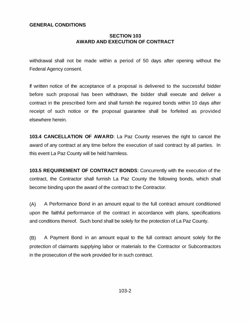
withdrawal shall not be made within a period of 50 days after opening without the
Federal Agency consent.
If written notice of the acceptance of a proposal is delivered to the successful bidder
before such proposal has been withdrawn, the bidder shall execute and deliver a
contract in the prescribed form and shall furnish the required bonds within 10 days after
receipt of such notice or the proposal guarantee shall be forfeited as provided
elsewhere herein.
103.4 CANCELLATION OF AWARD: La Paz County reserves the right to cancel the
award of any contract at any time before the execution of said contract by all parties. In
this event La Paz County will be held harmless.
103.5 REQUIREMENT OF CONTRACT BONDS: Concurrently with the execution of the
contract, the Contractor shall furnish La Paz County the following bonds, which shall
become binding upon the award of the contract to the Contractor.
(A) A Performance Bond in an amount equal to the full contract amount conditioned
upon the faithful performance of the contract in accordance with plans, specifications
and conditions thereof. Such bond shall be solely for the protection of La Paz County.
(B) A Payment Bond in an amount equal to the full contract amount solely for the
protection of claimants supplying labor or materials to the Contractor or Subcontractors
in the prosecution of the work provided for in such contract.

GENERAL CONDITIONS
SECTION 103AWARD AND EXECUTION OF CONTRACT
103-3
Each bond shall include a provision allowing the prevailing party in a suit on such bond
to recover as a part of judgment such reasonable attorney's fees as may be fixed by a
judge of the court.
Each such bond shall be executed by a surety company or companies duly authorized
to do business in the State of Arizona. The bonds shall be made payable and
acceptable to La Paz County. The bonds shall be written or countersigned by an
authorized representative of the surety who is either a resident of the State of Arizona or
whose principal office is maintained in this State, as required by law, and the bonds
shall have attached thereto a certified copy of Power of Attorney of the signing official.
103.6 CONTRACTOR'S INSURANCE:
103.6.1 General: The Contractor shall agree to carry all insurance which may be
required by Federal and State Laws, County Ordinances, Regulations and Codes.
Neither the Contractor nor any subcontractor shall commence work under a contract
until La Paz County has approved the insurance. The entire project covered by the
contract will be at the Contractor's risk until final acceptance by La Paz County.
Concurrently with the execution of the contract, the Contractor shall furnish La Paz
County the following:
(A) Public Liability and Property Damage Insurance: The Contractor shall provide
and maintain, during the life of the contract, General Liability, Automobile Liability and
Worker's Compensation Insurance as follows:

GENERAL CONDITIONS
SECTION 103AWARD AND EXECUTION OF CONTRACT
103-4
Type of Insurance Minimum Limits of LiabilityGeneral Liability $1,000,000 Combined single Limit --Comprehensive Form
Premises/Operations
Underground Explosion and CollapseHazard
Exclusions Deleted (Where applicable)
Products/Completed Operations
Contractual
Independent Contractors(OCP)
Broad Form Property Damage
Personal Injury With Exclusion
C DeletedAutomobile Liability $1,000,000 Combined Single Limit
Owned
Hired
Non-OwnedExcess Liability As requiredUmbrella FormWorkers Compensation & Employers'
Liability
Statutory Limits
Builder Risk/Course of Construction As required

GENERAL CONDITIONS
SECTION 103AWARD AND EXECUTION OF CONTRACT
103-5
La Paz County shall have no responsibility of liability for such insurance coverage.
The Contractor shall furnish a Certificate of Insurance on a form approved by La Paz
County. The Certificate shall be issued by an insurance company authorized to transact
business in the State of Arizona or be named on the list of Unauthorized Insurers
maintained by the Arizona Department of Insurance. Insurance coverage shall not
expire until all the work has been completed and the project has been accepted by La
Paz County. If an insurance policy does expire during the life of the contract, the
Contractor shall provide a renewal certificate of the required insurance coverage to La
Paz County not less than thirty (30) days prior to the expiration date.
(B) Worker’s Compensation and Employer's Liability: A Letter of Certification, from
the Industrial Commission of Arizona, that the Contractor is insured by the State
Compensation Fund or is an authorized by the Arizona Department of Insurance to
provide Workmen's Compensation and Employer's Liability Insurance in the State of
Arizona.
(C) Builders Risk/Course of Construction: When the project includes construction of
a new building or addition to an existing building, the Contractor shall also obtain
insurance coverage for at least, as a minimum the perils of fire, extended coverage,
vandalism and malicious mischief for the full amount of the contract. The Contractor
shall be responsible for any deductibles, mutual waiver of subrogation and any co-
insurance for the construction that is the subject of this contract.
(D) Additional Insured: La Paz County, it’s officers, agents and employees shall be
named as insured on policies listed in (A) and (C) and this shall also be indicated on the

GENERAL CONDITIONS
SECTION 103AWARD AND EXECUTION OF CONTRACT
103-6
Certificates of Insurance issued to La Paz County. The Contractor's coverage shall be
primary for any and all losses arising out of the performance of this contract.
103.7 INDEMNIFICATION OF LA PAZ COUNTY AGAINST LIABILITY:
The Contractor agrees to indemnify and save harmless La Paz County, the Director of
Public Works, consulting and/or contract engineers and assistants and any jurisdiction
or agency issuing permits for any work included in the project, their officers, agents and
representatives from all suits, including attorney's fees and costs of litigation, of the
work done in fulfillment of the construction of the improvement under the terms of this
contract or on account of any act, claim or amount arising or recovered under the
Workmen's Compensation Law, or arising out of the failure of the Contractor or those
acting under the Contractor to conform to any statues, ordinance, regulation, law or
court decree. It is the intent of the parties of this contract that La Paz County shall, in all
instances, be indemnified against all liability, losses and damages of any nature
whatever for or on account of any injuries to or death of persons or damages to or
destruction of property belonging to any person arising out of or in any way connected
with the performance of this contract, regardless of whether or not the liability, loss or
damage is caused by or alleged to be caused in part by the negligence, gross
negligence or fault of the indemnity. It is agreed that the Contractor will be responsible
for primary loss investigation, defense and judgment costs where this contract of
indemnity applies.
103.8 EXECUTION AND APPROVAL OF CONTRACT: The Contractor shall execute
and return the contract to La Paz County within 10 calendar days after the date of
award of the contract. If objections to the award are received, the signing shall occur
within 5 days after any hearing over rules and objections. La Paz County will approve

GENERAL CONDITIONS
SECTION 103AWARD AND EXECUTION OF CONTRACT
103-7
and execute the contract within 10 calendar days following receipt of signed contract
and acceptable bonds and certificates of insurance.
No contract shall be considered in effect until it has been fully executed by all parties
concerned, bonds and Certificate of Ins. have been filed with La Paz County.
Information relative to the execution of contract documents may be obtained from La
Paz County Department of Public Works.
103.9 FORFEITURE OF PROPOSAL GUARANTEES: If the Contractor fails or refuses
to enter into the contract, within the time stated, then La Paz County may declare a
forfeiture of his proposal guarantee as liquidated damages for failure to enter into the
contract.
103.10 NOTICE TO PROCEED: La Paz County shall issue the Contractor a written
notice to proceed after contract execution has been effected. Any activity started by the
Contractor prior to receipt of the notice to proceed shall be at the Contractor’s risk and
expense.

GENERAL CONDITIONS
SECTION 104SCOPE OF WORK
104-1
104.1 WORK TO BE DONE:
104.1.1 GENERAL: The Contractor shall perform all work as may be necessary to
complete the contract in a satisfactory and acceptable manner in full compliance with
the plans, specifications and terms of the contract.
Unless other specified in the special provisions, the Contractor shall furnish all labor,
materials, equipment, transportation, utilities, services and facilities required to perform
all work for the construction of the project within the time specified.
104.1.2 MAINTENANCE OF TRAFFIC: The Contractor's traffic control operations shall
be in ac-cordance with the Manual on Uniform Traffic Control Devices and/or policies of
the appropriate public agency having jurisdiction over the project. These operations
shall cause no unnecessary inconvenience to the public and public access rights shall
be considered at all times. Unless otherwise authorized in the specifications or on a
temporary basis by the Public Works Director, traffic shall be permitted to pass through
the work area. The Contractor shall coordinate with the commercial and public sectors
involved in the collection and removal of trash and garbage so adequate services are
maintained.
Safe and adequate pedestrian and vehicular access shall be provided and maintained
to fire hydrants, commercial and industrial establishments, churches, schools, parking
lots, motels, hospitals, fire stations, police stations, and establishments of a similar
nature. Access to residential properties shall be in accordance with Section 107 "Legal
Relations and Responsibility to the Public".

GENERAL CONDITIONS
SECTION 104SCOPE OF WORK
104-2
Grading operations, pipeline and roadway excavation and fill construction shall be
conducted and maintained in such a manner as to provide a reasonably satisfactory and
safe surface for vehicular and pedestrian traffic. When rough grading is completed, the
roadbed shall be brought to and maintained in a reasonably smooth condition,
satisfactory and safe for vehicular traffic at the posted speed limit. Pedestrian walkways
shall be provided and maintained in a like manner. The Contractor shall accomplish any
additional grading operations and/or repairs, including barricade replacement or repairs
during working and non-working periods which, in the opinion of the Public Works
Director, are required.
In the event of abnormal weather conditions, such as windstorms, rainstorms, etc., the
Contractor shall immediately inspect his work area and take all necessary actions to
insure that public access, safety and adequate barricading is maintained. This activity
will occur regardless of time of day, day of week, weekend, or holiday.
The Contractor shall provide a Traffic Control Plan to the Public Works Director for
review and approval prior to construction on arterial and collector roadways.
Acceptance by the Public Works Director will make the plan a part of the Contract.
The Contractor shall provide the Public Works Director, the Sheriff, and the Arizona
Department of Public Safety with emergency phone numbers of all representatives.
104.1.3 CLEANUP AND DUST CONTROL: Throughout all phases of construction,
including suspension of work, and until final acceptance of the project, the Contractor
shall keep the work area clean and free from rubbish, excess materials and debris
generated by construction activities. This is to include 24 hours a day seven days a
week including weekends and holidays.

GENERAL CONDITIONS
SECTION 104SCOPE OF WORK
104-3
The Contractor shall take whatever steps, procedures or means required to prevent any
dust nuisance due to his construction operations. The dust control measures shall be
maintained at all times to the satisfaction of the Public Works Director and in
accordance with the requirements of the La Paz County Health Department plus the
A.D.E.Q. PM10 Program. Dust control will be 24 hours a day seven days a week
including weekends and holidays.
Failure of the Contractor to comply with the Public Works Director's cleanup and dust
control orders shall result in an order to suspend work until the condition is corrected.
No additional compensation or time will be allowed as a result of such suspension and
the Public Works Director has the authority to take such other measures as shall be
necessary to remedy the situation.
104.2 ALTERATION OF WORK:
FINAL CLEANING UP: Before final acceptance, all private or public property and
grounds occupied by the Contractor in connection with the work shall be cleaned of all
rubbish, excess materials, temporary structures and equipment, and all parts of the
work area shall be left in an acceptable condition.
104.2.1 BY LA PAZ COUNTY: La Paz County reserves the right at any time during the
progress of the work make alterations in the details of construction and increases or
decreases in quantities as may be found necessary or desirable. Such alterations and
changes shall not invalidate the contract nor release the surety. The Contractor agrees
to perform the work as if it had been a part of the original contract. The Public Works
Director will issue Change Orders to cover unforeseen circumstances that make it
impossible to carry out the work in accordance with the original contract plans and

GENERAL CONDITIONS
SECTION 104SCOPE OF WORK
104-4
specifications. If the alterations or changes made by La Paz County increases or
decreases the total cost of the contract, or the total cost of any major item by more than
20 percent, then either party may request an adjustment in payment in accordance with
Section 109.
104.2.2 DUE TO PHYSICAL CONDITIONS:
(A) Should the Contractor encounter or discover unknown conditions during the
process of the work, differing materially from those ordinarily encountered and generally
provided for in the contract, the Public Works Director shall be notified in writing. The
Public Works Director will investigate the condition(s). If condition(s) differ and cause
an increase or decrease in the cost or time required for performance of the contract an
equitable adjustment will be negotiated and the contract modified. Failure to notify the
Public Works Director of conditions described above may be cause to reject any claims
for additional monies and/or time.
(B) Material used in the project that contains moisture in an amount considered
excessive by the Public Works Director shall be removed and shall be aerated to the
extent required by the Public Works Director before compaction is effected. No
measurement or direct payment for the removal and aeration of aforementioned
material will be made.
(C) After the work has been started any saturation of material caused by irrigation
water, storm drainage, weather or similar causes will be considered as within the
responsibility of the Contractor.
104.2.3 DUE TO EXTRA WORK: The Contractor shall perform unforeseen work, for
which there is no unit bid price in the proposal, whenever it is deemed necessary or

GENERAL CONDITIONS
SECTION 104SCOPE OF WORK
104-5
desirable by the Public Works Director in order to fully complete the work as
contemplated. Such work shall be governed by all applicable provisions set forth in
Section 109.
Should the Contractor claim that any instructions received involve extra work under the
contract, he shall give the Public Works Director written notice within 48 hours after
receipt of such instructions before proceeding to execute the work, except in
emergencies endangering life or property. No claim shall be valid unless written notice
is given.
If this extra work is performed by others, the Contractor agrees to cooperate fully with
the other source accomplishing the work and agrees this action shall not invalidate the
contract or release the surety.
104.2.4 AT THE CONTRACTOR'S REQUEST: Changes in the plans or specifications,
which do not materially affect and are not detrimental to the work or to the interests of
La Paz County may be granted to facilitate the work. Requests shall be in writing and
submitted to the Public Works Director for approval. These changes when resulting in a
saving to the Contractor will be made at an equitable reduction in cost to La Paz
County.
104.2.5 DUE TO THE FAILURE OF THE CONTRACTOR TO PROPERLY MAINTAIN
THE PROJECT:
(A) If the Contractor fails to provide adequate maintenance of traffic or cleanup and
Dust control, or to correct deficiencies resulting from abnormal weather conditions, the

GENERAL CONDITIONS
SECTION 104SCOPE OF WORK
104-6
Public Works Director has the authority to suspend the work wholly, or in part, until this
condition has been corrected.
(B) If the Contractor fails to comply with the Public Works Director's written order to
provide adequate maintenance of traffic, cleanup, dust control, or to correct deficiencies
resulting from abnormal weather conditions, the Public Works Director has the authority
to have this work accomplished by other sources and charged back to the Contractor.
(C) The Contractor agrees to cooperate fully with the other source accomplishing the
work and agrees action shall not invalidate the Contract or release the surety.

GENERAL CONDITIONS
SECTION 105CONTROL OF WORK
105-1
105.1 AUTHORITY OF THE PUBLIC WORKS DIRECTOR: The work shall be done
under the direct supervision of the Public Works Director and will decide all questions
which may arise as to the quality and acceptability of materials furnished and work
performed and as to the rate of progress of the work; all questions which may arise as
to the interpretation of the plans and specifications; all questions as to the acceptable
fulfillment of the Contract on the part of the Contractor. The Public Works Director's
estimates and decisions shall be final and conclusive. In case any question should
arise, relative to the Contract Documents, the determination or decision of the Public
Works Director shall be a condition precedent to the right of the Contractor to receive
final approval of the work being questioned under the Contract. Any changes to monies
and/or time shall be approved by the Public Works Director for final approval by the La
Paz County Board of Supervisors.
In giving instructions, the Public Works Director may make minor changes in the work,
not involving extra work and not inconsistent with the purpose of the work, except in
emergencies endangering life or property.
The Public Works Director will suspend the work wholly or in part due to the failure of
the Contractor; to correct conditions unsafe for the workers or the general public; for
failure to carry out provisions of the contract; for failure to carry out orders; for such
periods as he may deem necessary due to unsuitable weather; for conditions
considered unsuitable for the prosecution of the work or for any other condition or
reason deemed to be in the public interest. This action will not be suitable for
negotiations by the Contractor for an increase in monies (delay time) or increase in time
constraints.

GENERAL CONDITIONS
SECTION 105CONTROL OF WORK
105-2
105.2 SHOP DRAWINGS AND SUBMITTALS: Plans are to show details of all
structures, utilities, lines, elevations, grades, typical cross sections, and location and
design of all work.
The Contractor shall submit for review and obtain approval of shop drawings. Shop
drawings are to supplement the plans as necessary to adequately control the work.
Shop drawings for structures and utilities shall be furnished by the Contractor and shall
consist of such detailed plans as may be required to adequately control the work and
are not included in the plans furnished by La Paz County. They shall include stress
sheets, shop drawings, erection plans, false-work plans, cofferdam plans, bending
diagrams for reinforcing steel, computations, pipe work layouts, system installation
plans, equipment installation plans or similar data and any other supplemental data
required to adequately control the work.
Drawings, detailed plans, diagrams etc. shall not be prepared until the elevations,
lengths, geometric, etc. have been verified with the Public Works Director.
Drawings for false-work, shoring, soldier piles, and other major temporary support
structures shall be prepared by and bear the seal and signature of a licensed,
Professional Civil or Structural Public Works Director. Minor support structures are
exempt from this requirement.
The Contractor shall submit for review and obtain approval of product data on all
manufactured equipment & material items including material lists, catalog data,
description of all parts showing type of materials, dimensions and conformance to
specifications.

GENERAL CONDITIONS
SECTION 105CONTROL OF WORK
105-3
On all construction, the Contractor shall submit for review and obtain approval of
material and product catalog data. Where product data is not supplied, a Certification of
Compliance shall be submitted for review and approved in accordance with Section
106.3 of the General Conditions. On concrete and asphalt mixes, mix designs shall be
submitted and approved before construction begins.
The Contractor shall submit three (3) copies of each certification, shop drawings,
product data or mix design to the Public Works Director for review in accordance with
this condition and the individual specifications. Each submittal shall be numbered
sequentially and shall be submitted in a timely manner so as to cause no delay in the
work schedule. The contractor shall certify, by stamp or letter, that he has reviewed and
approved the submittal and that it conforms to the requirements of the contract
documents. If this certification is not included, the submittal will be returned without
action.
At the time of each submittal, the Contractor shall define and delineate in writing,
separate from the certification, any deviations from the contract documents. If the
Public Works Director accepts this deviation, he will authorize the deviation by issuing a
change order or if the deviation is minor by endorsement to the letter.
The Public Works Director will review and return the submittals. The review will be only
for conformance with the design concept of the work and for compliance with the
information contained in the contract documents. The review of a specific item, as
such, will not indicate review of the assembly in which the item functions. Review by
the Public Works Director will not relieve the Contractor from responsibility for any
errors or omissions in the submittals nor from his responsibility for complying with the

GENERAL CONDITIONS
SECTION 105CONTROL OF WORK
105-4
contract documents. The only exception is deviations accepted in accordance with the
preceding paragraph.
If the submittal is acceptable, two (2) copies checked "Approved” will be returned to the
Contractor.
If the submittal is acceptable with minor corrections made by the Public Works Director,
two (2) copies checked "Furnish as Corrected" will be returned by the Contractor.
If the Public Works Director determines that the submittal requires correction or is to be
rejected, two (2) copies checked "Rejected" and/or "Revise and Resubmit" will be
returned to the Contractor. The Contractor will revise the information and resubmit
copies.
The copy stamped "Approved or Furnish as Corrected", returned to the Contractor, will
become a part of the contract documents and will be kept at the job site. Any work
done prior to the receipt of this approval will be at the Contractor's risk and expense.
105.3 CONFORMITY WITH PLANS AND SPECIFICATIONS: All work performed and
all materials furnished shall be in conformity with the lines, elevations, grades, cross
sections, dimensions and material requirements, including tolerances, shown on the
plans or indicated in the specifications.
In the event the Public Works Director finds the materials or the finished product in
which the materials are used not in conformity with the plans and specifications, the
Public Works Director shall then make a determination if the work shall be accepted and
remain in place. The Public Works Director will document the basis of acceptance by

GENERAL CONDITIONS
SECTION 105CONTROL OF WORK
105-5
contract modification which will provide for an appropriate adjustment in the contract
price for the work or materials as deemed necessary.
In the event the Public Works Director finds the materials, or the finished product in
which the materials are used, or the work performed are not in conformity with the plans
and specifications and have resulted in an inferior or unsatisfactory product, the work or
materials shall be removed and replaced or otherwise corrected by the Contractor at no
additional cost to La Paz County.
In all instances wherein the items and/or specifications require installation or
construction in accordance with either manufacturers' or suppliers' recommendations
and/or instructions, said recommendations and/or instructions shall be submitted with
the applicable portion clearly marked for approval prior to the commencement of work
on that item or portions of the contract.
105.4 DEVIATIONS FROM PLANS OR SPECIFICATIONS: No deviation from the
approved Plans, Specifications or approved working drawings will be permitted without
written order of the Public Works Director, the order shall be in the form of a
Supplementary Agreement (Change Order) or (Field Order).
105.5 COORDINATION OF PLANS AND SPECIFICATIONS: The Contractor shall take
no advantage of any apparent error or omission in the plans or specifications. In the
event the Contractor discovers such an error or omission, he shall immediately notify
the Public Works Director. The Public Works Director will make corrections and
interpretations deemed necessary for fulfilling the intent of the plans and specifications.
In case of discrepancy or conflict, standard specifications, and construction standards
will govern over plans; Special Provisions will govern over Standard Specifications,

GENERAL CONDITIONS
SECTION 105CONTROL OF WORK
105-6
Specifications, Construction Standards, general conditions and supplementary general
conditions; and figured dimensions shall govern over scaled dimensions.
105.6 COOPERATION OF CONTRACTOR: The Contractor will be supplied with a
minimum of one complete set of approved plans and special provisions, one set of
which the Contractor shall keep available on the work site at all times.
The Contractor shall give the work the constant attention necessary to facilitate the
progress thereof, and shall cooperate with the Public Works Director, inspectors, and
other contractors in every way possible.
The Contractor shall at all times be present at the work in person or represented by a
competent superintendent authorized to receive and fulfill instructions from the Public
Works Director and shall supervise and direct the work irrespective of the amount of
work sublet. Instructions and information given by the Public Works Director to the
Contractor's superintendent shall be considered as having been given to the Contractor.
(A) All phases of the project such as concrete work, pipe work, etc., shall be under
the direct supervision of a foreman or his designated representative on the site who
shall have authority to accept instructions, with respect to that particular phase of the
project, and take action required to properly carry out the work.
(B) In the event of noncompliance with the above, the Public Works Director may
require the contractor to stop work on that part of the project until the required
supervision is present.
GENERAL CONDITIONS
SECTION 105CONTROL OF WORK
105-7
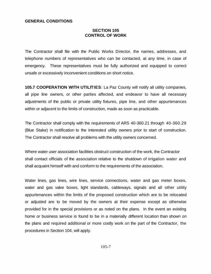
The Contractor shall file with the Public Works Director, the names, addresses, and
telephone numbers of representatives who can be contacted, at any time, in case of
emergency. These representatives must be fully authorized and equipped to correct
unsafe or excessively inconvenient conditions on short notice.
105.7 COOPERATION WITH UTILITIES: La Paz County will notify all utility companies,
all pipe line owners, or other parties affected, and endeavor to have all necessary
adjustments of the public or private utility fixtures, pipe line, and other appurtenances
within or adjacent to the limits of construction, made as soon as practicable.
The Contractor shall comply with the requirements of ARS 40-360.21 through 40-360.29
(Blue Stake) in notification to the interested utility owners prior to start of construction.
The Contractor shall resolve all problems with the utility owners concerned.
Where water user association facilities obstruct construction of the work, the Contractor
shall contact officials of the association relative to the shutdown of irrigation water and
shall acquaint himself with and conform to the requirements of the association.
Water lines, gas lines, wire lines, service connections, water and gas meter boxes,
water and gas valve boxes, light standards, cableways, signals and all other utility
appurtenances within the limits of the proposed construction which are to be relocated
or adjusted are to be moved by the owners at their expense except as otherwise
provided for in the special provisions or as noted on the plans. In the event an existing
home or business service is found to be in a materially different location than shown on
the plans and required additional or more costly work on the part of the Contractor, the
procedures in Section 104, will apply.

GENERAL CONDITIONS
SECTION 105CONTROL OF WORK
105-8
It is understood and agreed that the Contractor has considered in the proposal all of the
permanent and temporary utility appurtenances in their present or relocated positions as
shown on the plans and that no additional compensation will be allowed for any delays,
inconvenience, or damage sustained by him due to any interference from the said utility
appurtenance or the operation of moving them. If delays are encountered because
utility owners have not relocated or adjusted their facilities, the contract time will be
adjusted in accordance with Section 108.
It shall be the responsibility of the Contractor to ascertain the need for bracing or
shoring of utility poles during the construction of the project and no additional
compensation will be allowed for such bracing or shoring.
In general, the contract will indicate various utility items, certain of which are to be
relocated or adjusted by the utility owner and others by the Contractor. Any work
performed by the Contractor for any utility company, separate from the contract, shall be
paid for by the utility company and will not be part of the La Paz County contract.
105.7.1 Notifications Requirement in the Event of Any Damage to or Dislocation of
Underground Facilities: In the event of any damage to or dislocation of any
underground facility, the Contractor responsible for the excavation operation shall
immediately notify the owner of such facility and shall not attempt to repair any facility,
except those intended for the conveyance or storage of water and sewage. The
excavation shall be left open until the arrival of representatives of the owner. The owner
will dispatch its representative promptly to examine the underground facility and, if
necessary, make repairs.

GENERAL CONDITIONS
SECTION 105CONTROL OF WORK
105-9
105.7.2 Work within a Railroad Right of Way: When a railroad right of way in included
in the work, the Contractor shall:
(A)Comply with the rules and regulations of the railroad company relative to the
required manner of constructing said portion of the work; and shall perform the work so
as not to endanger or interfere with the safe operation of the track(s) and property of the
railroad company and of the traffic moving on such track(s).
(B)Carry the kinds and amounts of insurance and bonds required by the railroad
company for the period of time in which work is performed on or adjacent to the railroad
company's property, and until such work has been satisfactorily completed and all tools,
equipment and materials have been removed from the railroad company's property and
such property is left in a clean and presentable condition.
(C) Contact the Railroad Company at least 48 hours in advance of performing any
construction within the right of way of any track(s).
105.8 COOPERATION BETWEEN CONTRACTORS: La Paz County reserves the right
at any time to contract for and perform other or additional work on or near the work
covered by the contract.
When separate contracts are let within the limits of any one project, each Contractor
shall conduct his work so as not to interfere with or hinder the progress or completion of
the work being performed by other Contractors. Contractors working on the same
project shall cooperate with each other as directed.

GENERAL CONDITIONS
SECTION 105CONTROL OF WORK
105-10
Each Contractor involved shall assume all liability, financial or otherwise, in connection
with his contract and shall protect and save harmless La Paz County from any and all
damages or claims that may arise because of inconvenience, delay, or loss experienced
by him because of the presence and operations of other contractors working within the
limits of the same project.
The Contractor shall arrange his work and shall place and dispose of the materials
being used so as not to interfere with the operations of the other contractors within the
limits of the same project. He shall join his work with that of others in an acceptable
manner and shall perform it in proper sequence to that of the others.
La Paz County will not honor any claim for extra compensation due to delays, extra
work, or extension of time caused by any other contractors working within the limits of
the same project.
105.9 CONSTRUCTION STAKES, LINES, AND GRADES: The Public Works Director
will provide property control or a control line and a benchmark. These stakes and
markings are to be used as a basis from which construction lines and grades will be set
to perform the work.
Unless noted otherwise in the Special Conditions, the Contractor with La Paz County
approval will employ an Arizona registered professional engineer to set the construction
stakes for establishing lines, grades, elevation control and supply the Public Works
Director with a copy of all cut or fill sheets. All new right-of-way monuments and lines
shall be established by a registered land surveyor. A submittal is to be provided to the
Public Works Director by the Contractor that shows detail and method of staking in
accordance with Specification 402.3.

GENERAL CONDITIONS
SECTION 105CONTROL OF WORK
105-11
The Contractor shall perform the work in accordance with stakes and markers, and shall
be charged with full responsibility for conformity and agreement of the work with the
plans and specifications.
The Public Works Director may check the Contractor's construction stakes to verify
conformance to plans and specifications.
105.10 DUTIES OF INSPECTOR: Inspectors employed by La Paz County shall be
authorized to check all construction stakes and to inspect all work done and materials
furnished. Inspection may extend to all or any part of the work and to the preparation,
fabrication or manufacture of the materials to be used. The inspector will not be
authorized to alter or waive the provisions of the contract. The inspector will not be
authorized to issue instructions contrary to the plans and specifications or to act as
foreman for the Contractor.
The inspector will, however, have the authority to reject work or materials until any
questions at issue can be referred to and decided by the Public Works Director.
105.11 INSPECTION OF WORK: Inspection of the work by the Public Works Director or
authorized representative, shall not be considered as direct control of the individual
worker and his work. The direct control shall be solely the responsibility of the
Contractor's foreman and superintendent.
The Public Works Director shall be permitted to inspect all materials, and each part or
detail of the work at any time for the purpose of expediting and facilitating the progress
of the work. The Public Works Director shall be furnished with such information and
assistance by the Contractor as is required to make a complete and detailed inspection,

GENERAL CONDITIONS
SECTION 105CONTROL OF WORK
105-12
including removal or uncovering portions of the finished work as the Public Works
Director may direct.
Any work done or materials used without supervision and inspection by an authorized
La Paz County representative may be ordered removed and replaced at no additional
cost to La Paz County. Failure to reject any defective work or materials shall not in any
way prevent later rejection when such defect is discovered nor obligate the Public
Works Director to final acceptance.
When any unit of government or political subdivision has a legal interest in the work
covered by the contract, its respective representatives shall have the right to inspect the
work. Such inspection shall in no sense make any unit of government or political
subdivision a party to the contract, and shall in no way interfere with the rights of either
party to the contract.
105.12 REMOVAL OF UNACCEPTABLE AND UNAUTHORIZED WORK:
Unacceptable work, whether the result of poor workmanship, use of defective materials,
damage through carelessness or any other cause, found to exist prior to the final
acceptance of the work, shall be removed immediately and replaced in an acceptable
manner.
No work shall be done without lines and grades having been provided. Work done
contrary to the instructions of Public Works Director, work done beyond the lines shown
on the plans, or as given, or any extra work done without authority, will be considered
as unauthorized and will not be paid for under provisions of the contract. Work so done
may be ordered removed or replaced at no additional cost to La Paz County.

GENERAL CONDITIONS
SECTION 105CONTROL OF WORK
105-13
105.13 MAINTENANCE DURING CONSTRUCTION : The Contractor shall maintain the
work during construction and until the project is accepted. This maintenance shall
constitute continuous and effective work prosecuted day by day, with adequate
equipment and forces to the end so that roadways and construction is kept in
satisfactory conditions at all times.
All cost of maintenance work during construction and before the project is accepted
shall be included in the unit bid price on the various pay items.
105.14 FAILURE TO MAINTAIN ROADWAY OR CONSTRUCTION: If the Contractor,
at any time, fails to perform maintenance during construction, the Public Works Director
will immediately notify the Contractor of such noncompliance. If the Contractor fails to
remedy unsatisfactory maintenance within 24 hours after receipt of such notice, the
Public Works Director may immediately proceed to maintain the project. The entire cost
of this maintenance will be deducted from monies due or to become due the Contractor
on his contract.
105.15 PARTIAL USE OR OCCUPANCY: Should an urgent or unforeseen need occur,
the Contractor agrees to allow La Paz County use or occupy a unit or portion of the
project, such as a structure, utility service, or a section of road or pavement, prior to
final acceptance.
Prior to such use or occupancy La Paz County and the Contractor will accomplish a
partial acceptance inspection, with agreement on a revised construction schedule,
responsibilities for maintenance of the partial acceptance and continued construction of
the original project to final acceptance, payments, and other requirements.

GENERAL CONDITIONS
SECTION 105CONTROL OF WORK
105-14
105.16 ACCEPTANCE:
A) PARTIAL ACCEPTANCE: If at any time during the prosecution of the project
the Contractor substantially completes a unit or portion of the project, such as
a structure, utility service, or a section of road or pavement, he may request
the Public Works Director to make final inspection of that work. If the Public
Works Director finds, upon inspection, that the work has been satisfactorily
completed in compliance with the contract he may accept the work as being
completed and the Contractor may be relieved of further responsibility for that
work. Such partial acceptance shall in no way void or alter any terms of the
contract.
(B) FINAL ACCEPTANCE: Upon due notice from the Contractor of presumptive
completion of the entire project, the Public Works Director will make an
inspection. If all construction provided for and contemplated by the contract is
found completed to his satisfaction that inspection shall constitute the final
inspection and the Public Works Director will make the final acceptance. The
Contractor will be notified in writing of this acceptance as of the date of the
final inspection.
If, however, the inspection discloses any work, in whole or in part, as being
unsatisfactory, the Public Works Director will give the Contractor the necessary
instructions for correction of same, and the Contractor shall immediately comply with
and execute such instructions. Upon correction of the work, another inspection will be
made which shall constitute the final inspection provided the work has been
satisfactorily completed. In such event, the Public Works Director will make the final
acceptance and notify the Contractor in writing of this acceptance as of the date of the
final inspection.

GENERAL CONDITIONS
SECTION 105CONTROL OF WORK
105-15
GENERAL CONDITIONS
SECTION 106CONTROL OF MATERIALS
106-1
106.1 SOURCE OF MATERIALS AND QUALITY: All construction materials to be used
on the work or incorporated into the work, equipment, plant, tools, appliances or
methods to be used on the work shall be subject to the inspection and approval or
rejection of the Public Works Director.
The materials used on the work shall meet all quality requirements of the contract. In
order to expedite the inspection and testing of materials, the Contractor shall notify the
Public Works Director of his proposed source of materials prior to delivery. At the
option of the Public Works Director, materials may be approved at the source of supply
before delivery is started. If it is found after trial that sources of supply for previously
approved materials do not produce specified products the Contractor shall furnish
materials from other sources.
Unless otherwise noted, all materials used in the project shall be new and unused.
Additionally, any new materials used in this project that are damaged during the
construction of the project and prior to final acceptance, as determined by the Public
Works Director, shall be replaced by the Contractor with new material at no additional
cost to La Paz County.
106.2 TESTS AND ACCEPTANCE OF MATERIALS: Some material will be sampled
and tested as specified in the specifications and defined as normal tests and all
materials to be incorporated in the work are subject to sampling, testing and approval,
and samples furnished shall be representative of the materials to be used. The Public
Works Director may select samples, or may require that samples be delivered by the
Contractor to a laboratory designated by the Public Works Director.

GENERAL CONDITIONS
SECTION 106CONTROL OF MATERIALS
106-2
La Paz County will pay for the initial or normal test required by the Public Works
Director to guard against unsuitable materials or defective workmanship. Additional
tests, required due to failure of the initial or normal test(s), shall be paid for by the
Contractor. The Public Works Director will approve the laboratory, which will
accomplish the additional testing.
The procedures and methods used to sample and test materials will be determined by
the Public Works Director. Unless otherwise specified, samples and tests will be made
in accordance with standard methods of ASTM, which are in effect and published at the
time of advertising for bids.
The laboratory responsible for the test shall furnish at least two copies of the test results
to La Paz County, one copy to the Contractor, and one copy to the appropriate material
supplier.
106.3 CERTIFICATIONS:
(A) General: Prior to the use of any material the Contractor shall submit to the
Public Works Director a Certificate of Compliance or Certificate of Analysis on all
construction material products to be used on the project in accordance with Section 105
of these special conditions.
The Public Works Director may permit the use of certain materials or manufactured
assemblies prior to sampling and testing if accompanied by a Certificate of Compliance,
as herein specified.

GENERAL CONDITIONS
SECTION 106CONTROL OF MATERIALS
106-3
(B) Certificate of Compliance: The Certificate of Compliance shall contain the
following information:
(1) Project number to which the material is consigned.
(2) Name of Contractor to whom the material is supplied.
(3) Kind of material supplied.
(4) Quantity of material represented, such as lot, batch, etc.
(5) Means of material identification, such as label lot number, marking.
(6) Statement that the material complies in all respects with the specific requir
ement
s o f
t h e
c i t e d
specifi
cation
s.
(7) The original signature of a person having legal authority to bind the manufacturer
or supplier of the material. A reproduction is not acceptable. The signature shall
be notarized.
The person signing the certificate shall be in one of the following categories:

GENERAL CONDITIONS
SECTION 106CONTROL OF MATERIALS
106-4
(a) An officer of a corporation.
(b) A partner in a business partnership or an owner.
(c) A general manager.
(d) Any person having been given the authority by one of the above.
This must accompany the certificate of compliance in writing.
Each of the first six items specified above, shall be provided by the firm or organization
that is certifying the material prior to the signing as defined in item seven, and all of the
first six shall be in one type style or handwriting. No certificate will be accepted that has
been altered, added to, or changed in any way after the authorized original signature of
the person that has legal authority to bind the firm or organization has been affixed to be
original certificate. Materials or assemblies will not be incorporated into the project
without a valid certificate of compliance or proper testing.
Materials or assemblies used on the basis of a Certificate of Compliance may be
sampled and tested at any time and if found not in conformity with the requirements of
the plans and the specifications will be subject to rejection whether in place or not.
La Paz County reserves the right to refuse to permit the use of material on the basis of
a Certificate of Compliance.
106.4 ITEMS OF SPECIAL MANUFACTURER: At the preconstruction conference, the
Contractor shall furnish the Public Works Director a list of all items of special
manufacture or items which are or may be in short supply which will be incorporated
into the work. Items of special manufacture shall include, but shall not be limited to,

GENERAL CONDITIONS
SECTION 106CONTROL OF MATERIALS
106-5
materials and equipment for traffic signal and lighting systems, steel bridge members,
precast, prestressed concrete bridge members, structural components, compressors,
pumps, sewage treatment plants, water treatment plants, electrical control centers, and
materials related thereto.
The items of special manufacture which have been agreed upon by the Public Works
Director and the Contractor shall be ordered by the Contractor promptly so that they will
be available as required and will not delay the work.
The Contractor shall advise the Public Works Director about the dates of the orders and
the dates that the items are expected to be received.
If there is any delay in the prosecution of the work because of any delay in the delivery
of items of special manufacture, an extension of the contract time will only be granted in
accordance with the provisions of section 108 if the Public Works Director is completely
satisfied that the Contractor has made every effort to obtain the items in a timely
manner.
106.5 PLANT INSPECTION: The Public Works Director may undertake the inspection
of materials at the source. In this event, the following conditions shall be met:
A) The Public Works Director shall have the cooperation and assistance of the
Contractor and the producer with whom he has contracted for materials.
(B) The Public Works Director shall have full entry at all times to such parts of the

GENERAL CONDITIONS
SECTION 106CONTROL OF MATERIALS
106-6
plant as may concern the manufacture or production of the materials being
furnished.
It is understood that La Paz County reserves the right to retest all materials, prior to
their use in the work, upon delivery.
106.6 TRADE NAMES AND SUBSTITUTIONS: Plans and specifications may contain
references to equipment, materials or patented processes by manufacturer, trade name,
make or catalog number. Such references shall be regarded as establishing a standard
of quality, finish, appearance, and performance or as indicating a selection based upon
compatibility with existing equipment or materials. It shall not be construed as limiting
the selection to a specified item or source.
The use of an alternate or substitute, item or source will be permitted, subject to the
following:
(A) No consideration will be given a request for substitution prior to award of the
contract.
(B) After the award, and to permit consideration and approval without delaying the
work, the Contractor shall submit a written request for substitution. The request
shall include all information necessary for proof of quality and suitability for
substitution. The Contractor shall submit samples when required.

GENERAL CONDITIONS
SECTION 106CONTROL OF MATERIALS
106-7
(C) The Public Works Director will evaluate the information submitted, perform tests
when necessary and make comparisons. The Public Works Director will then
make the final decision as to the acceptability of the proposed substitution.
106.7 STORAGE OF MATERIALS: The Contractor shall provide storage facilities and
exercise such measures as will insure the preservation of the quality and fitness of all
materials and/or equipment to be used in the work. Stored materials and/or equipment,
even though approved before storage, may again be inspected prior to their use in the
work. Stored items shall be located so as to facilitate their prompt inspection. That
portion of the property easements not required for the project may be used for storage
purposes, when approved by the Public Works Director. Any additional storage area
required must be provided by the Contractor. Private property shall not be used for
storage purposes without written permission of the owner or lessee. If requested by the
Public Works Director copies of such written permission shall be made available.
106.8 HANDLING MATERIALS: All materials and/or equipment shall be handled in
such a manner as to preserve their quality and fitness for the work.
106.9 UNACCEPTABLE MATERIALS: All materials and/or equipment not conforming
to the requirements of the specifications, whether in place or not, may be rejected.
Rejected materials and/or equipment shall be removed immediately from the site of
work unless otherwise permitted by the Public Works Director. No rejected material
and/or equipment, the defects of which have been subsequently corrected, shall be
used until approved in writing by the Public Works Director.

GENERAL CONDITIONS
SECTION 106CONTROL OF MATERIALS
106-8
106.10 FURNISHED MATERIALS: Materials and/or equipment furnished by La Paz
County will be delivered or made available to the Contractor as indicated in the special
provisions. The cost of handling and placing shall be considered as included in the
contract price for the pay item with which they are used.
The Contractor will be held responsible for all materials and/or equipment accepted by
him and will make good any shortages, deficiencies and damages which may occur
after such acceptance.
106.11 WARRANTIES AND GUARANTIES: The Contractor shall obtain such
manufacturer's or producer's warranties or guaranties on all items, materials, electrical
or mechanical equipment consistent with those provided as customary trade practice.
The form in which such warranties or provision that they are subject to transfer to La
Paz County and shall be accompanied by proper validation of such fact. Transfer of
warranties or guaranties shall occur at the time of final acceptance of the work.
In addition, a Contractor's warranty or guaranty shall be furnished providing for
satisfactory in-service operation of the mechanical and electrical equipment and related
components for a period of one year following project acceptance.
Should any defect develop during this one-year period, the malfunction or defect shall
be corrected by and at the expense of the Contractor, including all labor, material and
associated costs.

GENERAL CONDITIONS
SECTION 107LEGAL RELATIONS AND RESPONSIBILITY TO PUBLIC
107-1
107.1 LAWS TO BE OBSERVED: The Contractor shall stay informed about all Federal
and State laws, County and City ordinances, regulations, codes and all orders and
decrees of bodies or tribunals having any jurisdiction or authority, which in any way
affect the conduct of the work. Contractor shall observe and comply with all laws,
ordinances, regulations, codes, orders and decrees; and shall protect and indemnify La
Paz County and its representatives against any claim or liability arising from or based
on the violation of such, whether by himself or his employees.
The attention of the Contractor is directed to the provisions of the following sections of
the Arizona Revised Statues:
(A) ARS 23-373. Contracts negotiated between public contractors and public
employers shall contain the following contractual provisions:
In connection with the performance of work under this contract, the Contractor agrees
not to discriminate against any employee or applicant for employment because of race,
religion, color or national origin. The aforesaid provision shall include, but not be limited
to, the following: Employment, upgrading, termination, rates of pay or other forms of
compensation, and selection for training, including apprenticeship. The Contractor
agrees to post hereafter in conspicuous places, available for employees and applicants
for employment, notices to provide by the contracting officer setting forth the provision
of the nondiscrimination clause.
The Contractor further agrees to insert the foregoing provision in all subcontracts,
except subcontracts for standard commercial supplies or raw materials.

GENERAL CONDITIONS
SECTION 107LEGAL RELATIONS AND RESPONSIBILITY TO PUBLIC
107-2
(B) When Federal-aid funds are used on a project, the prevailing basic hourly wage
rates and fringe benefit payments, as determined by the Secretary of Labor
pursuant to the provisions of the Davis-Bacon Act, shall be the minimum wages
paid to the described classes of laborers and mechanics employed to perform
the contract.
(C) ARS 40-360.22 Excavations: determining location of underground facilities;
providing information. This statute requires that no person shall begin excavating
before the location and marking are complete or the excavator is notified that
marking is unnecessary and requires that upon notification, the owner of the
facility shall respond as promptly as practical, but in no event later than two
working days. The "Blue Stake Center" (1-800-Stake It) was formed to provide a
more efficient method of compliance with this statue.
(D) ARS 40-360.23 Making excavations in careful, prudent manner; liability for
negligence. This statue states that obtaining information as required does not
excuse any person making any excavation from doing so in a careful and prudent
manner nor shall it excuse such persons from liability for any damage or injury
resulting from his negligence.
(E) ARS 40-360.28 Civil penalty; liability. If the owner or operator fails to locate, or
incorrectly locates the underground facility, pursuant to this article, the owner or
operator becomes liable for resulting damages, costs and expenses to the
injured party.
(F) ARS 32-2313 Business license; business name; branch office registration;
renewal. No person partnership, corporation or association shall engage in the

GENERAL CONDITIONS
SECTION 107LEGAL RELATIONS AND RESPONSIBILITY TO PUBLIC
107-3
business of general pest or weed control without being duly licensed/certified by
the Structural Pest Control Board.
This section is applicable to an excavation made during an emergency which involves
danger to life, health or property if reasonable precautions are taken to protect
underground facilities.
107.2 PERMITS: Permits, bonding and insurance requirements shall be as required by
La Paz County's statutes, codes, ordinances or regulations.
It is the duty of the Contractor to determine that all necessary permits have been
obtained. The Contractor shall, at their own expense, obtain all the required permits.
In all cases, the Contractor or the person supervising the authorized work shall notify
the appropriate permit agency so as to ensure proper inspection by the agency
concerned.
107.3 PATENTED DEVICES, MATERIALS AND PROCESSES: If the Contractor
employs any design, device, material, or process covered by letters of patent or
copyright, they shall provide for such use by suitable legal agreement with the patentee
or owner. The Contractor and the surety shall indemnify and save harmless La Paz
County, any affected third party or political subdivision from any and all claims for
infringement by reason of the use of any such patented design, device, material or
process, or any trademark or copyright, and shall indemnify La Paz County for any
costs, expenses, and damages which it may be obligated to pay by reason of any
infringement, at any time during the prosecution or after the completion of the work.

GENERAL CONDITIONS
SECTION 107LEGAL RELATIONS AND RESPONSIBILITY TO PUBLIC
107-4
107.4 ARCHAEOLOGICAL REPORTS: Attention is directed to Sections 41-844 and
41-846 of the Arizona Revised Statutes. In view of the above, it shall be a provision of
every contract that when archaeological features are encountered or unearthed in an
excavation, the Contractor shall report promptly to the Director of the Arizona State
Museum and La Paz County. The Contractor will be allowed extra time as appropriate
in accordance with the provisions of Section 108.
107.5 SAFETY, HEALTH AND SANITATION PROVISIONS: The Contractor shall
provide and maintain in a neat, sanitary condition such accommodations for the use of
his employees as may be necessary to comply with the requirements and regulations of
the Arizona State Department of Health or as specified by the La Paz County Health
Department Sanitary Code.
The Contractor shall provide devices, protective equipment, and take any needed
actions necessary to protect the life and health of employees on the job, to protect the
public, and to protect property in performance of the work covered by the contract.
Precaution shall be exercised by the Contractor at all times for the protection of persons
(including employees) and property. The Contractor shall comply with the provisions of
all applicable laws, pertaining to such protection including all Federal and State
occupational safety and health acts, and standards and regulations promulgated
thereunder.
107.5.1 Asbestos Materials : If asbestos materials are encountered during any
remodeling work, the Contractor will take the appropriate safety and health precautions
and promptly notify the Public Works Director. An extension of Contract time may be
granted in accordance with Section 108.

GENERAL CONDITIONS
SECTION 107LEGAL RELATIONS AND RESPONSIBILITY TO PUBLIC
107-5
107.5.2 Paint Containing Lead: Paint and similar surface coating materials that contain
lead compounds and in which the lead content exceeds 0.06 percent of the total weight
of the non-volatile content of the paint or the weight of the dried paint film is declared a
banned hazardous product and will not be used. (Consumer Product Safety Act Part
1303 dated 9-1-77).
107.6 PUBLIC CONVENIENCE AND SAFETY: The Contractor shall at all times so
conduct the work as to assure the least possible obstruction to traffic and adjacent
residents. The safety, convenience, and the protection of persons and property, the
general public and residents along the street, highway, and areas adjacent to the work
area shall be provided for by the Contractor.
107.7 BARRICADES AND WARNING SIGNS: The Contractor shall provide, erect, and
maintain all necessary barricades, suitable and sufficient lights, danger signals, signs
and other traffic control devices, and shall take all necessary precautions for the
protection of the work and safety of the public. Roads, partially or fully closed to traffic,
shall be protected by effective barricades, and obstructions shall be illuminated during
hours of darkness. Suitable warning signs shall be provided to properly control and
direct traffic in accordance with the current edition of the Manual of Uniform Traffic
Control Device.
The Contractor shall erect warning signs in advance of any place on the project where
operations may interfere with the use of the road by traffic, and at all intermediate points
where the new work crosses or coincides with an existing road. Such warning signs
shall be constructed and erected in accordance with the current edition of the Manual of
Uniform Traffic Control Devices (MUTCD).

GENERAL CONDITIONS
SECTION 107LEGAL RELATIONS AND RESPONSIBILITY TO PUBLIC
107-6
107.8 USE OF EXPLOSIVES: The use of explosives or blasting agents is controlled by
the Uniform Fire Code, which is generally administered by the Fire Department. The
Contractor shall obtain a special permit from the Fire Department for the use of
explosives. A copy of this permit shall be delivered to the Public Works Director prior to
the use of explosives.
Explosives shall be transported, stored, handled and used in accordance with the
provisions and requirements of all applicable laws, ordinances and regulations. Work
shall be done in accordance with recommendations of the AGC Manual of Accident
Prevention in Construction and the Institute of Makers of Explosives.
The approval by the Public Works Director for the use of explosives shall not relieve the
Contractor from his responsibilities. When explosives are used the Contractor shall:
(A) Exercise the utmost care not to endanger life or damage property.
(B) Be responsible for any and all damages resulting from their use.
(C) Furnish and erect special signs to warn the public of his blasting operations.
They shall be located and maintained so as to be clearly evident to the public
during all critical periods of blasting operations.
(D) Notify each public utility company, having structures adjacent to the work, of his
intention to use explosives. Such notice shall be given sufficiently in advance to
enable the companies to advise the Contractor of any precautions that should be
taken to protect their structures from damage.
GENERAL CONDITIONS
SECTION 107LEGAL RELATIONS AND RESPONSIBILITY TO PUBLIC
107-7
(E) Make a survey of adjacent properties, before commencing blasting operations,
locating on drawings and by photographs all existing cracks and damages to
structures. A copy shall be filed with the Public Works Director, including a report
of any property owners who refused to cooperate and permit entry and
inspection.
(F) Blasting mats shall be used at all times and shall be in good repair. Steel mats
shall not be allowed within 2,000 feet of power lines.
(G) Blasting shall be accomplished in such a manner that nearby houses and
buildings will be safe from rocks and other projectiles and the Contractor shall be
held responsible for any damage to life and property. The Contractor at the time
of firing shall station men along the road at a sufficient distance from the blasting
operations to flag down vehicles.
La Paz County reserves the right to order the discontinuance of blasting operations at
any time.
107.9 PROTECTION AND RESTORATION OF PROPERTY AND LANDSCAPE: The
Contractor shall be responsible for the preservation of all public and private property
and shall carefully protect from disturbance or damage all land monuments and property
marks until the Public Works Director has witnessed or otherwise referenced their
location and shall not move them until directed.
The Contractor shall be responsible for all damage or injury to property of any
character, during the prosecution of the work, resulting from any act, omission, neglect,
or misconduct in his manner or method of executing the work, or at any time due to

GENERAL CONDITIONS
SECTION 107LEGAL RELATIONS AND RESPONSIBILITY TO PUBLIC
107-8
defective work or materials, and said responsibility will not be released until the project
shall have been completed and accepted.
When or where any direct or indirect damage or injury is done to public or private
property by or on account of any act, omission, neglect, or misconduct in the execution
of the work, or in consequence of the non-execution thereof by the Contractor, he shall
restore, at no cost to La Paz County, such property to a condition similar or equal to that
existing before such damage or injury was done, by repairing, rebuilding, or otherwise
restoring as may be directed, or he shall make good such damage or injury in an
acceptable manner.
The Contractor shall not dump spoil or waste material on private property without first
obtaining from the owner written permission for such dumping.
Access to private property shall be maintained to keep inconvenience to the property
owner to a minimum. Prior to any construction in front of driveways the Contractor
shall notify the property owner 24 hours in advance. Inconvenience caused by
construction across driveways and sidewalks shall be kept to a minimum by restoring
the serviceability as soon as possible. If it is necessary to leave open excavation for a
long period of time the Contractor shall provide structurally adequate steel plates to
bridge the excavation.
107.10 CONTRACTOR’S RESPONSIBILITY FOR WORK: The Contractor shall
properly guard, protect, and take every precaution necessary against injury or damage
to all finished or partially finished work, by the action of the elements or from any other
cause until the entire project is completed and accepted by the Public Works Director.
The Contractor shall rebuild, repair, restore, and make good all injuries or damages to

GENERAL CONDITIONS
SECTION 107LEGAL RELATIONS AND RESPONSIBILITY TO PUBLIC
107-9
any portion of the work before final acceptance at no cost to La Paz County. Partial
payment for completed portions of the work shall not release the Contractor from such
responsibility.
In case of suspension of the work for any cause whatever, the Contractor shall be
responsible for the project and shall take such precautions as may be necessary to
prevent damage to the project and shall erect any necessary temporary structures,
signs, or other facilities at no cost to La Paz County.
107.11 CONTRACTOR’S RESPONSIBILITY FOR UTILITY PROPERTY AND
SERVICES: It shall be the responsibility of the Contractor to verify the existence and
location of all underground utilities. Omission from, or the inclusion of, utility locations of
the plans is not to be considered as the non-existence of, or a definite location of,
existing underground utilities.
At points where the Contractor's operations are adjacent to properties of utility firms or
other property, damage to which might result in considerable expense, loss, or
inconvenience, work shall not commence until all arrangements necessary for the
protection thereof have been made.
It shall be the Contractor's responsibility to provide three days notice to all appropriate
governmental agencies and utility companies prior to starting work affecting their area of
concern.
The Contractor shall cooperate with the owners of any underground or overhead utilities
in their removal and re-arrangement operations in order that these operations may
progress in a reasonable manner, that duplication of work may be reduced to a

GENERAL CONDITIONS
SECTION 107LEGAL RELATIONS AND RESPONSIBILITY TO PUBLIC
107-10
minimum, and that services rendered by those parties will not be unnecessarily
interrupted.
If any utility service is interrupted as a result of accidental breakage, the Contractor shall
promptly notify the proper authority and shall cooperate with the said authority in the
restoration of service. No work shall be undertaken around fire hydrants until provisions
for continued service have been approved by the local fire authority.
The Contractor shall expose all underground utilities and structures which might
interfere with the construction of the project, in order to permit survey location prior to
construction.
The Contractor shall assume full responsibility for damages to any underground
facility/utility as a result of failing to obtain information as to its location, failing to
excavate in a careful, prudent manner or failing to take measures for protection of the
facilities/utilities due to his operation. The Contractor is liable to the owner of the
underground facility/utility for the total cost of the repair.
107.12 PREVENTION OF AIR AND NOISE POLLUTION: The Contractor shall control,
reduce, remove or prevent air pollution in all its forms, including air contaminants, in the
performance of the Contractor's work.
The Contractor shall comply with the applicable requirements of Title 36-Public Health
Safety, Chapter 6, Article 8, Air Pollution, and Chapter 14, Article 1, Air Pollution of the
Arizona Revised Statutes and with the Arizona Administrative Rules and Regulations for
Air Pollution Control, Chapters 3 and 4, adopted by the Arizona Department of Health
Services pursuant to the authority granted by the Statutes.
GENERAL CONDITIONS
SECTION 107LEGAL RELATIONS AND RESPONSIBILITY TO PUBLIC
107-11
The Contractor shall comply with all local sound control and noise level rules,
regulations and ordinances which apply to any work performed pursuant to the contract.
Each internal combustion engine used for any purpose on the work or related to the
work shall be equipped with a muffler of a type recommended by the manufacturer. No
internal combustion engine shall be operated on the work without its muffler in good
working condition.
107.13 FURNISHING RIGHT-OF-WAY: La Paz County will provide right-of-way and
property for all work in advance of construction. Any exceptions will be indicated in the
special provisions.
107.14 PERSONAL LIABILITY OF PUBLIC OFFICIALS: In carrying out any provisions
of these specifications, or in exercising any power or authority granted to them by or
within the scope of the contract, there shall be no liability upon La Paz County, Public
Works Director, or their authorized representatives, either personally or as officials of La
Paz County, it being understood that in all such matters they act solely as agents and
representatives of La Paz County.
107.15 NO WAIVER OF LEGAL RIGHTS: Upon completion of the work, La Paz County
will conduct a final inspection and notify the Contractor of acceptance. Such final
acceptance, however, shall not preclude or stop La Paz County from correcting any
measurement, estimate, or certificate made before or after completion of the work, nor
shall La Paz County be precluded or stopped from recovering from the Contractor or his
surety, or both, such overpayment as it may sustain, or by failure on the part of the
Contractor to fulfill his obligations under the contract. A waiver on the part of La Paz

GENERAL CONDITIONS
SECTION 107LEGAL RELATIONS AND RESPONSIBILITY TO PUBLIC
107-12
County of any breach of any part of the contract shall not be held to be a waiver of any
other or subsequent breach.
The Contractor, without prejudice to the terms of the contract and in addition to any
specific remedy provided La Paz County in the contract documents, shall be liable to La
Paz County for latent defects, fraud or such gross mistakes as may amount to fraud, or
as regards La Paz County's rights under any warranty or guarantee or remedy required
by law.
GENERAL CONDITIONS
SECTION 108COMMENCEMENT, PROSECUTION, AND PROGRESS
108-1
108.1 PRE-CONSTRUCTION CONFERENCE: After award of a contract and prior to the
issuance of the Notice to Proceed, a pre-construction conference will be held. The time
and place will be established by the Public Works Director. A representative of the
Contractor will be required to provide the following information:
(A) Names and emergency telephone numbers of key personnel involved in the
project.
(B) Have present at the meeting the person who will be doing construction staking
with written outline detailing the method of staking, marking stakes, grade control
and other operations.
(C) Verification of all subcontractors and major suppliers proposed for use on the
project.
(D) A construction progress schedule showing the estimated time for start and
completion of the major items of work.
(E) A traffic control plan if required.
(F) A de-watering plan if required.
(G) Shop drawing and product data submittal list.
(H) List of items of special manufacture and short supply.

GENERAL CONDITIONS
SECTION 108COMMENCEMENT, PROSECUTION, AND PROGRESS
108-2
108.2 NOTICE TO PROCEED: After the pre-construction conference and permits are
received, a notice to proceed will be issued by La Paz County.
Neither the Contractor nor any Subcontractor shall commence work on a project prior to
receipt of the written Notice to Proceed from La Paz County. The Contractor shall
commence work as soon as practicable after the starting date specified in the Notice to
Proceed. All work under the contract shall be completed within the number of calendar
days stated in the proposal, plus extensions, beginning with the day following the
starting date specified in the Notice to Proceed.
The Contractor shall notify the Public Works Director 24 hours in advance of the time
and place where work will begin.
108.3 SUBLETTING OF CONTRACT: The Contractor shall not sublet, sell, transfer,
assign or otherwise dispose of the contract or contracts, or of his right, title, or interest
therein, without written consent of La Paz County.
Subcontracts shall be in accordance with and the Contractor shall be bound by the
following provisions:
(A) All subcontracts shall be subject to the approval of the Public Works Director.
(B) All subcontracts shall be in writing and shall provide that all work to be performed
thereunder shall be performed in accordance with the terms of the contract.
(C) Subcontractors shall conform to the regulations governing employment of labor.

GENERAL CONDITIONS
SECTION 108COMMENCEMENT, PROSECUTION, AND PROGRESS
108-3
(D) The subcontracting of any portion of the work will in no way release the
Contractor of his liability under the contract and bonds.
(E) On all contracts for roadway construction or roadway maintenance, the
Contractor shall perform, with his own organization, work amounting to not less
than fifty (50) percent of the total contract cost.
108.4 CORRESPONDENCE TO THE CONTRACTOR: A written notice, to the
Contractor from La Paz County, shall be considered delivered and the service thereof
completed, when said notice is posted, by certified mail to the said Contractor at his last
given address, or delivered in person to the Contractor or his authorized representative
on the work.
108.5 CONTRACTOR’S CONSTRUCTION SCHEDULE: The Contractor, at the pre-
construction conference shall furnish the Public Works Director a construction schedule
for approval. In the event the schedule does not meet the necessary program schedule,
as determined by La Paz County, Contractor may be required to resubmit a schedule
that shall conform to an approved program of construction operation. The right to direct
the sequence of the work is a function vested solely in the Public Works Director and
the construction schedule, when approved, shall not be changed, without the written
consent of the Public Works Director. The orderly procedure of all work to be performed
shall be the full responsibility of the Contractor. The schedule shall be a part of the
contract documents upon approval by the Public Works Director.
108.6 LIMITATIONS OF OPERATIONS: The Contractor shall conduct the work at all
times in such a manner and sequence that will ensure the least interference with traffic
and inconvenience to the public. The Public Works Director may require the Contractor

GENERAL CONDITIONS
SECTION 108COMMENCEMENT, PROSECUTION, AND PROGRESS
108-4
to finish a section on which work is in progress before work is started on any additional
sections if the opening of such section is essential to public convenience.
All traffic affected by the construction will be regulated in accordance with the current
edition of the Manual of Uniform Traffic Control Devices.
Except in emergencies endangering life or property, written permission shall be
obtained from the Public Works Director to perform any work after regular working
hours, on weekends, or legal holidays. Prior to the start of such work, the Contractor
shall arrange with the Public Works Director for the continuous or periodical inspection
of the work, surveys and tests of materials, when necessary.
If, in the opinion of the Public Works Director, the Contractor has fallen behind the
approved progress schedule, the Contractor shall take such steps as may be required
by the Public Works Director, including but not limited to, increasing the number of
personnel, shifts, and/or overtime operations, days of work, and/or amount of
construction equipment until such time as the work is back on schedule. Contractor
shall submit for approval no later than the time of submittal of the next request for partial
payment, such supplementary schedule or schedules as may be deemed necessary to
demonstrate the manner in which the approved rate of progress will be regained, all at
no additional cost to La Paz County.
108.7 CHARACTER OF WORKERS; METHODS AND EQUIPMENT: The Contractor
shall at all times employ sufficient labor and equipment for prosecuting the several
classes of work to full completion in the manner and time required by the specifications.

GENERAL CONDITIONS
SECTION 108COMMENCEMENT, PROSECUTION, AND PROGRESS
108-5
All workers shall be competent and have sufficient skill, knowledge and experience in
their class of work and in the operation of equipment required to perform all work
properly and satisfactorily.
Any person employed by the Contractor or any Subcontractor who, in the opinion of the
Public Works Director, does not perform his work in a proper and skillful manner or is
intemperate or disorderly shall, at the written request of the Public Works Director, be
removed from the work by the Contractor or Subcontractor employing such person, and
shall not be employed again in any portion of the work without the approval of the Public
Works Director. The Contractor or Subcontractor shall keep La Paz County harmless
from damages or claims for compensation that may occur in the enforcement of this
section.
Should the Contractor or Subcontractor fail to remove such person as required above,
or fail to furnish suitable and sufficient personnel for the proper prosecution of the work,
the Public Works Director may suspend the work by written notice until such orders are
complied with.
All equipment which is proposed to be used on the work shall be of sufficient size and in
such mechanical condition as to meet the requirements of the work and to produce a
satisfactory quality of work. Equipment used on any portion of the project shall be such
that it will not damage property adjacent to the work area.
When the methods and equipment to be used by the Contractor in accomplishing the
construction are not prescribed, the Contractor is free to use any methods or equipment
that he demonstrates to the satisfaction of the Public Works Director and will
accomplish the work in conformity with the requirements of the specifications.

GENERAL CONDITIONS
SECTION 108COMMENCEMENT, PROSECUTION, AND PROGRESS
108-6
When the specifications state the construction shall be performed by the use of certain
methods and equipment, such methods and equipment shall be used unless others are
authorized by the Public Works Director. If the Contractor desires to use a method or
type of equipment other than those specified, Contractor may request authority from the
Public Works Director to do so. The request shall be in writing and shall include a full
description of the methods and equipment proposed to be used and an explanation of
the reasons for desiring to make the change. If approval is given, it will be on the
condition that the Contractor will be fully responsible for producing construction work in
conformity with the specifications. If, after trial use of the substituted methods or
equipment, the Public Works Director determines the work produced does not meet the
specifications, the Contractor shall discontinue the use of the substitute method or
equipment and shall complete the remaining construction with the specified methods
and equipment. The Contractor shall remove the deficient work and replace it with work
of specified quality, or take such other corrective action as the Public Works Director
may direct. No change will be made in basis of payment for the construction items
involved nor in contract time as a result of authorizing a change in methods or
equipment under these provisions.
108.8 TEMPORARY SUSPENSION OF WORK: The Public Works Director shall have
authority to suspend the work wholly or in part by written order for such period or
periods as he may deem necessary due to the failure on the part of the Contractor to
carry out orders given or to perform any or all provisions of the Contract.
When under suspension, the work shall be put in proper and satisfactory condition,
carefully covered and properly protected as directed. In all cases of suspension of
construction operations the work shall not again be resumed until authorized by written
order of the Public Works Director.

GENERAL CONDITIONS
SECTION 108COMMENCEMENT, PROSECUTION, AND PROGRESS
108-7
108.9 DETERMINATION AND EXTENSION OF CONTRACT TIME: The number of
calendar days allowed for the completion of the work included in the contract will be as
stated in the proposal and will be known as the contract time.
When the contract time is on a calendar day basis it shall consist of the number of
calendar days specified, including all weekends and legal holidays. All calendar days
elapsing between the effective dates of any written notice from the Public Works
Director to suspend work and to resume work following suspensions, not the fault of the
Contractor, shall be excluded.
When the contract completion time is a fixed calendar date, it shall be the date on which
all work on the project shall be completed and meet final inspection.
If the Contractor finds it impossible to complete the work within the contract time as
specified or as extended, Contractor shall submit a written request to the Public Works
Director for an extension of time setting forth therein the reasons which he believes will
justify the granting of his request. The Contractor's plea that insufficient time was
specified is not a valid reason for extension of time. If the Public Works Director finds
the work was delayed because of conditions beyond the control and through no fault of
the Contractor, an extension of time for completion may be issued. The extended time
for completion shall be in full force and as though it were the original time for
completion.
108.10 GUARANTEE AND WARRANTY PROVISIONS: The Contractor shall
guarantee the work against defective workmanship or materials for a period of 1 year
from the date of its final acceptance under the contract, ordinary wear and tear and
unusual abuse or neglect excepted.

GENERAL CONDITIONS
SECTION 108COMMENCEMENT, PROSECUTION, AND PROGRESS
108-8
Any omission on the part of the Public Works Director to condemn defective work or
materials at the time of construction shall not be deemed an acceptance, and the
Contractor will be required to correct defective work or materials at any time before final
acceptance and within 1 year thereafter.
Should any defects develop within 1 year from the date of final acceptance due to faults
in workmanship or materials the Contractor shall, within 14 calendar days of receipt of
written notice from La Paz County, begin making the necessary repairs to the
satisfaction of the Public Works Director. Work shall include the repair or replacement of
other work or materials damaged or affected by making the above repairs or corrective
work, all at no additional cost to La Paz County.
If defects develop which are determined by the Public Works Director to be an
emergency, the Public Works Director shall notify the Contractor, via the most
expeditious means, regarding the nature and condition of the defects. In turn, the
Contractor shall immediately dispatch necessary forces to correct the defect or the
emergency condition. If the Contractor, in an initial action, resolves the emergency
condition but not the defect, a letter as discussed above will follow and normal
procedures for corrections will be employed. If immediate or appropriate action,
satisfactory to the Public Works Director, is not taken by the Contractor, or if the
Contractor cannot be contacted, the Public Works Director will deploy necessary forces
to correct and/or secure the deficiency.
Costs of the Public Works Director's action shall be paid by the Contractor and/or his
bonding agency. Should it later be determined the defects requiring such emergency
action are not the responsibility of the Contractor, the Contractor will be paid for all costs
incurred as a result of these demands in accordance with Subsection 109.5. Such

GENERAL CONDITIONS
SECTION 108COMMENCEMENT, PROSECUTION, AND PROGRESS
108-9
action by the Public Works Director will not relieve the Contractor of the guarantees
required by this section or elsewhere in the Contract Documents.
In case of work, materials, or equipment for which written warranties are required by the
special provisions, the Contractor shall provide or secure from the appropriate
Subcontractor or supplier such warranties shall not relieve the Contractor from any
obligation assumed under any other provisions of the contract. The warranties and
guarantees provided in this subsection of the contract documents shall be in addition to
and not in limitation of any other warranties, guarantees or remedies required by law.
108.11 FAILURE TO COMPLETE ON TIME: For each and every day that work shall
remain incomplete after the time specified for completion of the work in the proposal, or
as adjusted by the Public Works Director, the sum per calendar day shown in the
following table, unless otherwise specified in the proposal form, may be deducted from
monies due to or to become due to the Contractor, not as a forfeit or penalty but as
liquidated damages. This sum is fixed and agreed upon between the parties because
the actual loss to La Paz County and to the public caused by delay in completion will be
impractical and extremely difficult to ascertain and determine.
Permitting the Contractor to continue and finish the work or any part of it after the time
fixed for its completion, or after the date to which the time fixed for its completion may
have been extended, will in no way operate as a waiver on the part of La Paz County of
any of its rights under the contract.

GENERAL CONDITIONS
SECTION 108COMMENCEMENT, PROSECUTION, AND PROGRESS
108-10
SCHEDULE OF LIQUIDATED DAMAGES
From
More Than
To and
Including
Calendar Day
or Fixed Date
$ 0 $ 25,000 $ 210.00
25,000 50,000 250.00
50,000 100,000 280.00
100,000 500,000 430.00
500,000 1,000,000 570.00
1,000,000 2,000,000 710.00
2,000,000 5,000,000 1,070.00
108.12 FORFEITURE AND DEFAULT OF CONTRACT: It is further agreed by the
Contractor that if Contractor:
(A) Fails to begin the work under the contract within a reasonable time, or

GENERAL CONDITIONS
SECTION 108COMMENCEMENT, PROSECUTION, AND PROGRESS
108-11
(B) Fails to perform the work with sufficient workers and equipment or with sufficient
materials to assure the prompt completion of said work, or
(C) Performs the work unsuitably or neglects or refuses to remove materials or to
perform anew such work as may be rejected as unacceptable and unsuitable, or
(D) Discontinues the prosecution of work, or
(E) Fails to resume work which has been discontinued within a reasonable time after
notice to do so, or
(F) At any time colluded with any party or parties, or
(G) Allows any final judgment to stand against him unsatisfied for a period of 14
calendar days, or
(H) For any cause whatsoever, fails to carry on the work in an acceptable manner,
the Public Works Director will give notice in writing to the Contractor and the
surety of such delay, neglect, or default, and advise them the work must be
resumed immediately.
If the Contractor or surety, within a period of 14 calendar days after such notice, has
proceeded in accordance therewith, then La Paz County will, upon written notification
from the Public Works Director of the fact of such delay, neglect or default and the
Contractor's failure to comply with such notice, have full power and authority without
violating the contract to take the prosecution of the work out of the hands of the
Contractor. La Paz County may appropriate or use any or all materials and equipment

GENERAL CONDITIONS
SECTION 108COMMENCEMENT, PROSECUTION, AND PROGRESS
108-12
on the ground as may be suitable and acceptable and may enter into an agreement for
the completion of said contract according to the terms and provisions thereof, or use
such other methods as in the opinion of the Public Works Director will be required for
the completion of said contract in an acceptable manner.
All cost and charges incurred by La Paz County, together with the cost of completing
the work under contract, will be deducted from any monies due or which may become
due said Contractor. If such expense exceeds the sum which would have been payable
under the contract, then the Contractor and the surety shall be liable and shall pay to La
Paz County the amount of such excess.
108.13 TERMINATION OF CONTRACT: La Paz County may terminate the contract or
a portion thereof if conditions encountered during the progress of the work make it
impossible or impracticable to proceed with the work; or if a local or national emergency
exists.
When contracts, or any portion thereof, are terminated before completion of all work in
the contract, adjustments in the amount bid for the pay items will be made on the actual
quantity of work performed and accepted, or as mutually agreed for pay items of work
partially completed or not started. No claim for loss of anticipated profits will be
considered.
Termination of the contract or any portion thereof shall not relieve the Contractor of his
responsibilities for the completed work nor the surety of its obligation for and concerning
any just claims arising out of the work performed.

GENERAL CONDITIONS
SECTION 109MEASUREMENTS AND PAYMENTS
109-1
109.1 MEASUREMENT OF QUANTITIES: All work completed under the contract will be
measured by the Public Works Director according to United States standard measures.
The methods of measurement and computation to be used in determination of
quantities of materials furnished and of work performed under the contract will be those
methods generally recognized as conforming to good Public Works Director practice.
A station, when used as a definition or term of measurement, will be 100 linear feet.
Unless otherwise specified, longitudinal measurements will be made along the grade
line.
Unless otherwise specified, transverse measurements for area computations will be the
neat dimensions shown on the plans or ordered in writing by the Public Works Director.
The term ton will mean the short ton consisting of 2,000 pounds avoirdupois.
Unless otherwise specified, structures will be measured according to neat lines shown
on the plans or as altered to fit field conditions.
In computing volumes of excavation or fill, the average end area method or other
acceptable methods as determined by the Public Works Director will be used.
Volumes will be computed at 60oF using ASTM D-1250 for Asphalt or ASTM D-633 for
Tars.

GENERAL CONDITIONS
SECTION 109MEASUREMENTS AND PAYMENTS
109-2
Lumber will be measured by the thousand board foot measure actually used in the
work. Measurement will be based on nominal widths and thickness and the extreme
length of each piece.
The term lump sum, when used as a pay item, will mean complete payment for the work
described.
Sundry items which have a basis for measurement and payment herein and which are
incidental to or required in the construction of the work but are not included as items in
the bid schedule shall be considered an integral part of the contract, and all labor,
materials, etc. required for such items shall be furnished by the Contractor and the cost
of same included in the unit price bid.
109.2 SCOPE OF PAYMENT: Measurement and payment for pay items in the proposal
will be as indicated in the applicable standard specification or in the special provisions.
When payment is specified to be made on the basis of weight, the weighing shall be
done on certified platform scales sealed by the State Inspector as defined by ARS
Sections 44-2112 and 44-2116. The Contractor shall furnish the Public Works Director
with duplicate Weighmaster's Certificates showing the actual net weights together with
the information required by ARS Section 44-2142. La Paz County will accept the
certificates as evidence of the weight delivered.
Payment for the various items in the proposal will be made at the unit price bid in the
proposal, and shall be compensation in full for furnishing all labor, materials, equipment
and appurtenances necessary to complete the work in a satisfactory manner as shown
on the plans and as required in the specifications, with all connections, testing, and

GENERAL CONDITIONS
SECTION 109MEASUREMENTS AND PAYMENTS
109-3
related work completed. Each item, fixture, piece of equipment, etc., shall be complete
with all necessary connections and appurtenances, for the satisfactory use and
operation of said item. No additional payment will be made for work related to any item
unless specifically called for in the proposal.
This compensation shall also cover all risk, loss, damage or expense of whatever
character arising out of the nature of the work or the prosecution thereof, subject the
provisions of Section 107.
109.3 ASSIGNMENT OF PAYMENTS: The Contractor shall not assign payments of a
contract or any portion thereof without approval of surety and written consent of La Paz
County.
Claims for monies due or to become due the Contractor may be assigned to a bank,
trust company, or other financing institution, and may thereafter be further assigned and
reassigned to any such institution. Any such assignment or reassignment may be made
to one party as agent or trustee for two or more parties participating in such financing.
Any assignment of money shall be subject to all proper set off and withholdings in favor
of La Paz County and to all deductions provided for in these specifications.
109.4 COMPENSATION FOR ALTERATION OF WORK:
109.4.1 By La Paz County:
(A) For a decrease greater than 20 percent in either the total cost of the contract or
the total cost of a major item and when a reasonable cost analysis supports an
increase in the prorated share of fixed cost chargeable to this item in total, an
GENERAL CONDITIONS
SECTION 109MEASUREMENTS AND PAYMENTS
109-4
increase adjustment in the monies due the Contractor may be made. This
adjusted compensation will not exceed 80 percent of the original extended unit
bid price. This does not apply to items labeled as contingent bid item in the bid
proposal.
B) For an increase greater than 20 percent, any adjustment made will only apply to
that cost in excess of 120 percent of the original bidding schedule. If either party
presents a reasonable cost analysis that shows a change in the pro rata share of
fixed costs chargeable to this item in total, an increase or decrease adjustment
will be made. This increase or decrease adjustment will be made on such basis
as is necessary to cover a reasonable estimate of cost, plus an allowance, not to
exceed 15 percent, for overhead and profit. If the parties are unable to reach an
agreement, the Public Works Director has the authority to order the excess work
done on an actual cost basis as specified in Section 109, Subsection "ACTUAL
COST WORK".
(C) For either an increase or decrease in cost, no claim shall be made by the
Contractor for any loss of anticipated profits.
109.4.2 Due to Physical Conditions:
(A) If the Public Works Director, after the investigation of site conditions, agrees that
they materially differ from those indicated in the contract and would cause an
increase in the Contractor's bid cost of accomplishing the work, new unit bid
prices or a lump sum cost (for the additional work only) may be negotiated. If the
parties are unable to reach an agreement on price, the Public Works Director has
the authority to order this additional work accomplished on an actual cost basis

GENERAL CONDITIONS
SECTION 109MEASUREMENTS AND PAYMENTS
109-5
as specified herein.
(B) If the Public Works Director, after his investigation of site conditions, finds that
these conditions do not materially differ from those indicated in the contract, the
Public Works Director has the authority to order the work to be accomplished at
the original bid price(s).
109.4.3 Due to Extra Work: If the contractor can present valid, factual evidence,
satisfactory to the Public Works Director that the work in question is an item not
provided for in the contract as awarded then a unit bid price or lump sum cost, for this
item only, may be negotiated. If the parties are unable to reach an agreement on price
or cost, the Public Works Director has the authority to order the extra work
accomplished on an actual cost basis as specified herein.
109.4.4 Made at the Contractor's Request: Any alterations, if approved, will be at a
reduced or no additional cost to La Paz County.
109.4.5 Due to Failure of Contractor to Properly Maintain the Project:
(A) For any suspension of work during normal working hours due to failure of the
Contractor to properly maintain the project, there will be no additional
compensation or time allowed.
(B) If the Public Works Director provides the Contractor with a written order to
provide adequate maintenance of traffic, adequate cleanup, adequate dust
control or to correct deficiencies resulting from abnormal weather conditions and
the Contractor fails to comply in the time frame specified, La Paz County may

GENERAL CONDITIONS
SECTION 109MEASUREMENTS AND PAYMENTS
109-6
have the work accomplished by other sources.
La Paz County will deduct the cost of accomplishing the work from monies due or
to become due to the Contractor. Computation of the cost will be in accordance
with Subsection 109.5.4.2.
109.4.6 Allowable Mark-Ups: Only the allowable mark-ups as defined in Subsection
109.5 shall be allowed. Additional compensation for other items shall not be considered
or allowed.
109.5 ACTUAL COST WORK: The compensation for actual cost work performed by the
Contractor (Subcontractor) shall be determined by the Public Works Director in the
following manner.
109.5.1 Equipment: For all equipment, the use of which has been authorized by the
Public Works Director, except for small tools and manual equipment, the Contractor will
be paid in accordance with the Rental Rates Bluebook published by the
Nielson/Dataquest Inc. Unless prior written agreement has been made, La Paz County
will pay move in/move out costs and standby equipment rates.
109.5.2 Material: For all material, accepted by the Public Works Director and used in
the work, the Contractor will be paid the actual cost of such material including
transportation cost, to which total cost will be added a sum equal to 15 percent thereof.
109.5.3 Labor: For all labor and for the foreman, when working in direct supervision of
the project, the Contractor will be paid.

GENERAL CONDITIONS
SECTION 109MEASUREMENTS AND PAYMENTS
109-7
(A) The actual wages paid plus the current percentage thereof as determined by the
District which is deemed to cover the Contractor's cost incurred as a result of
payment imposed by State or Federal Law and payments that are made to, or on
behalf of, the worker other than the actual wage. Actual wage is defined as the
required current hourly wage paid to the labor classification concerned and does
not include any fringe benefits or dislocation allowances. If the Contractor is not
required to pay fringe benefits an equitable deduction will be made.
(B) For the first $50,000 of labor cost computed under paragraph (1) above, the
Contractor will be paid an amount equal to (15%) fifteen percent for overhead
and profit.
(C) For all labor cost computed under paragraph (A) above, in excess of $50,000 but
not exceeding $100,000, the Contractor will be paid an amount equal to (12%)
twelve percent for overhead and profit.
(D) For any labor cost computed under paragraph (A) above, in excess of $100,000,
the Contractor will be paid an amount equal to (10%) ten percent for overhead
and profit.
109.5.4 Work Performed By Subcontractors or Other Sources:
109.5.4.1 Work Performed by Subcontractors: If it is determined by the Public Works
Director that portions of the Actual Cost Work to be performed requires specialized
labor or equipment not normally used by the Contractor and such work is then
authorized to be performed by a subcontractor(s), the subcontractor(s) will be paid by
the Contractor in accordance with the actual cost work procedures outlined herein. The

GENERAL CONDITIONS
SECTION 109MEASUREMENTS AND PAYMENTS
109-8
Contractor will be paid by La Paz County the full amount of the subcontract(s) plus the
following percentages for administration and supervision.
(A) For the first $10,000.00 accumulated total of work performed by subcontractors
(less mark-up for overhead and profit), the Contractor will be paid an amount
equal to 10 percent of the accumulated total for administration and supervision.
If the accumulated total is $3,000 or less, the Contractor will paid $300 for
administration and supervision.
(B) For all change order work in excess of $10,000 accumulated total performed by
subcontractors (less mark-up for overhead and profi t), the Contractor will be paid
an amount equal to 5 percent of the accumulated total for administration and
supervision.
109.5.4.2. Work Performed by Other Sources: If La Paz County has work performed
by other sources, in accordance with Subsection 109.4.5 (B), La Paz County will
deduct, from monies due or to become due to the Contractor, the full amount of the cost
of accomplishing the work by other sources plus the following percentages for
administration and supervision:
(A) For the first $10,000 accumulated total of work performed by other sources, La
Paz County will deduct an amount equal to 10 percent of the accumulated total
for administration and supervision. If the accumulated total is $3,000 or less, La
Paz County will deduct $300 for administration and supervision.
(B) For all work in excess of $10,000 accumulated total performed by other sources,
La Paz County will deduct an amount equal to 5 percent of the accumulated total

GENERAL CONDITIONS
SECTION 109MEASUREMENTS AND PAYMENTS
109-9
for administration and supervision.
109.5.5 Documentation:
A) Except in emergency situations, La Paz County will not be liable for any Actual
Cost Work performed by the Contractor prior to written authorization by the
Public Works Director or prior to full execution of a written agreement by all
parties concerned.
(B) Payment for work performed on an actual cost basis will not be made until the
Contractor has furnished the Public Works Director, on forms agreed to by La
Paz County, duplicate itemized statements of such work, including
subcontractor(s) costs, detailed as follows:
1. Name, classification, date, daily hours, total hours, rate and extension for
each laborer and foreman.
2. Designation, dates, daily hours, total hours, rental rates and extension for
each unit of equipment, and machinery.
3. Quantities of material, prices, extension, and transportation cost on a daily
basis. These charges shall be substantiated by vendor vouchers.
(C) The Public Works Director will compare records with the statement furnished by
the Contractor, resolving any differences and making the required adjustments.
This statement when agreed upon and signed by both parties, shall be the basis
of payment for the work performed.

GENERAL CONDITIONS
SECTION 109MEASUREMENTS AND PAYMENTS
109-10
109.5.6 Bonds and Insurance: The Contractor shall be paid for the actual cost plus
(10%) ten percent for the administrative cost when the Contractor can provide evidence
of payment for premiums on required payment and performance bonds, premiums on
railroad and/or airport extended liability insurance, and premiums for property damage
and/or public liability insurance. No duplication of payment for Contractor's costs
included will be allowed.
109.5.7 Authority of Public Works Director: The Public Works Director is in charge of
Actual Cost Work and has the authority to direct which labor and equipment will be
used, to suspend operations, and to refuse to pay for any labor or equipment which is
not doing productive work.
109.6 PAYMENT FOR WORK ON PROJECTS:
109.6.1 Partial Payments: Partial Payments: La Paz County will make a partial
payment to the Contractor on the basis of an estimate prepared by the Contractor or
Public Works Director for work completed through the last day of the preceding calendar
month. Payment will be within 14 calendar days after the estimate has been certified
and approved by the Public Works Director and received by the owner.
La Paz County will retain 10 percent of all estimates as a guarantee for complete
performance of the contract in accordance with ARS Section 34-221, unless the
Contractor elects to deposit securities in accordance with ARS Section 34-221-B,
Paragraph 5.
When the Contractor is fifty percent completed, one-half of the amount retained shall be
paid to the Contractor provided there is satisfactory progress on the contract and there

GENERAL CONDITIONS
SECTION 109MEASUREMENTS AND PAYMENTS
109-11
is no specific cause or claim requiring a greater amount to be retained. After the
contract is fifty percent completed, no more than five percent of the amount of any
subsequent progress payments made under the contract will be retained providing the
Contractor is making satisfactory progress on the project. Except that, if at any time La
Paz County determines satisfactory progress is not being made, ten- percent retention
shall be reinstated for all progress payments made under the contract subsequent to the
determination.
Any material or equipment which will become an integral part of the completed project
will be considered for partial payment in the Contractor's monthly progress payments.
The intent of making partial payments is to provide the Contractor payment for direct
material or equipment purchased. The purpose is to minimize the effect of escalating
costs by procuring key materials. It is not the intent to apply for all materials but only
those meeting the following conditions:
(1) A total value of all items requested for payment must be greater than $20,000.
No payment will be processed until the material or equipment has been
observed, reviewed or verified by a La Paz County representative. Only the
material or equipment meting the requirements of the plans and specifications
will be paid. Payment for material or equipment does not constitute final
acceptance.
(2.) Materials or equipment must be stored or stockpiled either on site, in a
warehouse, or secured storage area. The Contractor assumes all responsibility
for protection of these materials or equipment and shall insure them to cover loss
or damage to same without additional liability or added costs to the Agency for
providing this security, insurance and storage.

GENERAL CONDITIONS
SECTION 109MEASUREMENTS AND PAYMENTS
109-12
(3) The Contractor will provide access to the storage area or warehouse upon
request of La Paz County’s representative for the purpose of verifying the
inventory of items paid for under this section. None of the materials or
equipment paid for under this section will be removed from the storage site until
incorporated into the work of the project. The storage site shall be within the
general geographical area of the project.
(4) The Contractor shall provide a paid invoice and/or lien waiver for items paid for
under this section. La Paz County will not pay more than the invoice price for the
item or items, less retention.
(5) The Public Works Director may exclude individual payment requests, which in the
Public Works Director's judgment do not warrant storage and prepayment under
the intent of this section.
109.6.2 Final Payment: When the project has been accepted as provided in Section
105, and within 30 calendar days after final inspection of the work completed under the
contract, the Public Works Director will render to La Paz County and the Contractor, a
final estimate which will show the amount of work performed and accepted under the
contract. All prior estimates and partial payments will be subject to correction in the
final estimate for payment.
Within sixty (60) calendar days after final acceptance, La Paz County will pay the
Contractor all amounts due him under the contract, except that before final payment will
be made, the Contractor shall satisfy La Paz County by affidavit that all bills for labor
and materials incorporated in the work have been paid. The Contractor's Affidavit may
be obtained from the Public Works Director Office of La Paz County.

GENERAL CONDITIONS
SECTION 109MEASUREMENTS AND PAYMENTS
109-13
If payment will be longer that sixty (60) days after final completion and acceptance, La
Paz County will provide the Contractor specific written findings for reasons justifying the
delay in payment.
The acceptance of the project and the making of the final payment shall not constitute a
waiver by La Paz County of any claims arising from faulty or defective work appearing
after the completion or from failure of the Contractor to comply with the requirements of
the contract documents.
*Not applicable to Improvement District Projects.
109.7 PAYMENT FOR DELAY:
The procedures contained in this Subsection shall not be construed to void any
provision of the contract which require notice of delays, provides for negotiation of other
procedures for settlement or provide for liquidated damages.
109.7.1 Failure to Locate or Incorrect Location of Utilities: ARS 40-360.26 states
"that if the owner or operator fails to locate or incorrectly locates the underground
facility, pursuant to this article, the owner or operator becomes liable for resulting
damages, costs and expense to the injured party." La Paz County will deny any claims
for damages or delays if another owner or operator is at fault.
109.7.2 La Paz County Delays: ARS 34-221 states "A contract for the procurement of
construction shall include a provision which provides for negotiations between La Paz
County and the Contractor for the recovery of damages related to expenses incurred by
the Contractor for a delay for which the La Paz County is responsible, which is

GENERAL CONDITIONS
SECTION 109MEASUREMENTS AND PAYMENTS
109-14
unreasonable under the circumstances and which was not within the contemplation of
the parties to the contract."
Compensation for such damages will be negotiated as follows:
(A) The Public Works Director shall be satisfied that the Contractor has made every
reasonable effort to prosecute the work despite any delays encountered or
revisions in the Contractor's scheduling of work.
(B) The Compensation paid to the Contractor shall be in accordance with Section
109.
109.7.3 Extension of Contract Time: For any such delays, the contract time will be
adjusted in accordance with Subsection 108.7.

EARTHWORK
SECTION 201CLEARING AND GRUBBING
201-1
201.1 DESCRIPTION:
Unless otherwise specified clearing and grubbing shall consist of removing trees,
stumps, brush, roots, rubbish, debris, and other undesirable and objectionable material
from the site and right-of-way and other areas as may be specified, and hauling and
disposal of the material off the site. Clearing and grubbing shall be performed in
advance of grading operations.
201.2 PRESERVATION OF PROPERTY:
Existing improvements, adjacent property, utilities and other facilities, and trees and
plants not to be removed, shall be protected from injury or damage resulting from the
Contractor's operations, see these Specification, Section 107. Barricades for existing
facilities to remain shall be erected by the Contractor to any clearing operation and shall
consist of 4 to 6 foot wire or wood fencing supported by posts on 10 to 12 foot intervals
and located as directed by the Public Works Director. If existing improvements or
utilities are damaged during construction they shall be repaired or replaced at the
Contractor's expense.
201.3 DUST CONTROL:
The Contractor shall apply a dust palliative to those areas causing dust as a result of
the construction operation or traffic. The frequency of the dust palliative shall be
enough to eliminate all dust from the project. In addition, the Contractor shall apply
palliative when directed by the Public Works Director.

EARTHWORK
SECTION 201CLEARING AND GRUBBING
201-2
201.4 CONSTRUCTION METHODS:
The construction site and areas within the right-of-way and areas on each side of the
roadway from centerline to the toe of an embankment, the top of a cut slope, the slope
rounding limit or to a line 10 feet outside the edge of the surfaced area, whichever is
greater, but not beyond the limits of the right-of-way, shall be cleared of all trees,
stumps, brush, roots, rubbish, debris and other objectionable matter, except as follows:
The Contractor shall notify property owners that small trees and shrubs within the street
right-of-way are to be removed so that the individual property owner may transplant said
trees and shrubs, if he so wishes. If the property owner indicates that he does not wish
to save these small trees and shrubs, the Contractor may proceed with removal as
specified here. The property owner should be given a minimum of 20 days to move the
trees.
All trees and shrubs found suitable for improvement and beautification, which will not
interfere with excavation or embankment or cause disintegration of the improvements
shall not be disturbed. In any event, the Contractor shall avoid, as far as practicable,
injury to shrubbery, vines, plants, grasses and other vegetation growing outside of the
clearing limits. The dragging and the piling of materials of various kinds and the
performing of other work which may be injurious to vegetation shall, in so far as
practicable, be confined to areas which have no vegetation or which will be covered by
embankment or disturbed by excavation during grading operations.
For the full width of all watercourses within the site and the right-of-way lines, no stump,
root or other obstruction shall be left higher than the natural stream bed.
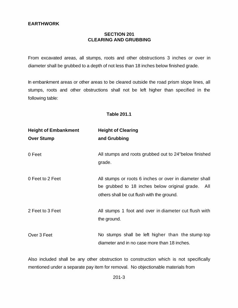
EARTHWORK
SECTION 201CLEARING AND GRUBBING
201-3
From excavated areas, all stumps, roots and other obstructions 3 inches or over in
diameter shall be grubbed to a depth of not less than 18 inches below finished grade.
In embankment areas or other areas to be cleared outside the road prism slope lines, all
stumps, roots and other obstructions shall not be left higher than specified in the
following table:
Table 201.1
Height of Embankment Height of Clearing
Over Stump and Grubbing
0 Feet All stumps and roots grubbed out to 24"below finished
grade.
0 Feet to 2 Feet All stumps or roots 6 inches or over in diameter shall
be grubbed to 18 inches below original grade. All
others shall be cut flush with the ground.
2 Feet to 3 Feet All stumps 1 foot and over in diameter cut flush with
the ground.
Over 3 Feet No stumps shall be left higher than the stump top
diameter and in no case more than 18 inches.
Also included shall be any other obstruction to construction which is not specifically
mentioned under a separate pay item for removal. No objectionable materials from

EARTHWORK
SECTION 201CLEARING AND GRUBBING
201-4
clearing or grubbing operations will be allowed in fills. Cavities left below subgrade
elevation by removal of stumps or roots shall be carefully backfilled and compacted in
accordance with specification herein entitled "Fill and Embankment Construction".
Tree branches extending over the roadway, which hang within 12 feet of the profile,
grade or that restrict sight distance shall be cut off close to the trunk or stem of the tree
in a neat and workmanlike manner. The Contractor shall remove tree branches as
directed by the Public Works Director, in such a manner that the tree will present a
balanced appearance. Scars resulting from the removal of branches shall be treated
with a heavy coat of an approved tree sealant.
All tree trunks, stumps, brush, limbs, roots, vegetation and other debris removed in
clearing and grubbing shall be removed to locations outside of the right-of-way, or
otherwise disposed of so as to leave the construction project site and adjacent areas in
a neat and finished condition, free from unsightly debris. All burning shall be done
under permit and shall be done at such a manner as to prevent the fire from spreading
to or damaging areas adjoining the project site.
201.5 REMOVAL AND DISPOSAL OF SALVAGEABLE ITEMS:
Items and materials of salvage value as determined by the Public Works Director,
unless incorporated in the new work, shall remain the property of La Paz County and
shall be stored in adjacent areas as directed by the Public Works Director. Such items
and materials shall be carefully removed and in such a manner as to permit reuse.

EARTHWORK
SECTION 201CLEARING AND GRUBBING
201-5
201.6 METHOD OF MEASUREMENT:
(A) If the proposal includes separate estimate of quantities for the removal of trees,
the tree will be classified by size as follows:
(1) Trees 12 inches or less in diameter at 2-foot above the original ground
surface will be included in the bid price for clearing and grubbing or
excavation and therefore, no additional compensation will be allowed.
(2) Trees greater than 12 inches in diameter at 2-foot above the original
ground will be included as separate bid item and payment will be made at
the unit bid price quoted in the proposal.
(B) Measurement for clearing and grubbing shall be in accordance with the terms of
the contract and shall be based as set forth in the proposal.
201.7 BASIS OF PAYMENT:
(A) CLEARING AND GRUBBING:
Unless otherwise provided in the special provisions or bid proposal, no payment will be
made for clearing and grubbing as such; the cost thereof shall be included in the bid
price for the construction or installation of the items to which said clearing and grubbing
are incidental or appurtenant.

EARTHWORK
SECTION 201CLEARING AND GRUBBING
201-6
(B) REMOVAL AND DISPOSAL OF TREES:
If the proposal includes separate estimates of quantity for removal and disposal of trees,
payment for removal of trees will be on a unit price for each tree measured and
removed, in accordance with the above classifications, at the unit price stipulated in the
proposal.
EARTHWORK
SECTION 202REMOVAL OF STRUCTURES AND OBSTRUCTIONS
202-1
202.1 DESCRIPTION:
Except for public and private utility company underground and overhead facilities,
pipelines and other appurtenances, Removal of Structures and Obstructions shall
consist of the removal, wholly or in part, and satisfactory disposal off the site of all
structures and obstructions within the construction site and right-of-way which have not
been designated to remain. Salvaging designated materials shall be included.
202.2 REMOVAL AND DISPOSAL OF SALVAGEABLE:
Items and materials of salvage as determined by the Public Works Director, unless
incorporated in the new work, shall remain the property of La Paz County and shall be
stored in adjacent areas as directed by the Public Works Director. Such items and
materials shall be carefully removed and in such a manner as to permit reuse.
202.3 PRESERVATION OF PROPERTY:
Existing improvements, adjacent property, utilities and other facilities, trees and plants
not to be removed, shall be protected from injury or damage resulting from the
Contractor's operations. See these Specifications, Section 107.
If the plans do not show existing improvements to be removed, existing structures,
pavement, sidewalks, curbs, gutters and other existing improvements that are to
become an integral part of the planned improvements shall be considered to mean that
such designated improvements are to remain even though not specifically noted to
remain.

EARTHWORK
SECTION 202REMOVAL OF STRUCTURES AND OBSTRUCTIONS
202-2
202.4 CONSTRUCTION METHODS:
The Contractor shall raze, remove and dispose of all structures and obstructions as
required and shown on the plans including, but not limited to, the following; buildings,
sheds, walls, slabs, foundations, inlets, catch basins, culverts, headwalls, trash racks,
bridges, piers, abutments, retaining walls, irrigation structures, standpipes, manholes,
valves, ditch lining, pipelines, tanks, pool lining, posts, poles, columns, signs, fences,
gates, planters, concrete and A.C. pavement, sprinkler systems, mail boxes, curbs,
gutters, sidewalks, driveways, feed pens, corrals, cattle guards.
Holes, cavities, trenches or depressions left by the removal of structures or obstructions
shall be backfilled with acceptable material to the grade required in accordance with the
requirements of standard specification entitled "Fill and Embankment Construction".
Blasting or other operations necessary for the removal of an existing structure or
obstruction, which may damage new construction, shall be completed prior to placing
the new work.
202.5 REMOVAL OF BRIDGES, CULVERTS AND OTHER DRAINAGE
STRUCTURES:
Bridges, culverts and other drainage structures in use by traffic shall not be removed
until satisfactory arrangements have been made to accommodate traffic.
EARTHWORK
SECTION 202REMOVAL OF STRUCTURES AND OBSTRUCTIONS
202-3
202.6 REMOVAL OF PIPE:
All pipe to be removed and either salvaged or re-laid shall be carefully removed and
every precaution taken to avoid breaking or damaging the pipes. The pipe shall be
stored when necessary so that there will be no loss or damage before relaying. The
Contractor will be required to replace sections lost from storage or damage by
negligence or by the use of improper methods in their removal.
202.7 REMOVAL OF CONCRETE PAVEMENT, SIDEWALKS, SLABS, CURBS,
GUTTERS & FOOTINGS:
The removal of concrete pavement, sidewalks, driveways, miscellaneous slabs, curbs,
gutters etc., shall include the breaking or cutting as necessary for removal and the
hauling and disposing of all debris.
When a portion of the concrete sidewalk, driveway or slab is to be removed to other
than an existing joint, a joint with a minimum depth of one inch shall be sawed so that a
neat edge remains after the removal of the concrete. Sidewalks shall be removed to a
distance required to maintain a maximum slope of one inch per foot for the replaced
portions of the sidewalk and all driveways shall be removed to a distance as required to
match standard details.
202.8 RELOCATION OF FENCES, WALLS AND IMPROVEMENTS OWNED BY
OTHERS:
It shall be the Contractor's responsibility to contact all property owners, who have
improvements within the site and right-of-way that must be moved to clear for
EARTHWORK
SECTION 202REMOVAL OF STRUCTURES AND OBSTRUCTIONS
202-4
construction, at least 20 days prior to any construction in that area. If the property
owners do not remove the improvement, the Contractor shall do so, and relocate the
fence or wall in accordance with the plans or special conditions and rebuilt equal to or
better in quality than existing. Existing materials are to be reused where not damaged
in the process of removal. The Contractor is to furnish any additional material
necessary.
The Contractor shall remove existing fencing, wall and improvements in such manner
as to prevent damage and shall reconstruct the improvement at the locations specified
by the Public Works Director. When completed, the improvement shall be in proper
alignment and plumb and all wire taut, where used and shall be in all respects equal in
service-ability to the original improvement.
202.9 MISCELLANEOUS REMOVALS ANY OTHER WORK:
This work shall include, but is not limited to, the following where called for in the plans or
in the special conditions. Any other miscellaneous removal not listed or not shown on
the plans will be considered incidental and no additional payment will be made.
(A) Mailboxes in the way of construction are to be removed, temporarily reset
and permanently reset after construction. Any mailbox damaged is to be
replaced by the Contractor.
(B) Traffic control signs or any other signs in the way of construction are to be
removed, temporarily reset, as necessary or as directed by the Public
Works Director, and permanently reset after completion of construction.
Any damaged signs are to be replaced by the Contractor.

EARTHWORK
SECTION 202REMOVAL OF STRUCTURES AND OBSTRUCTIONS
202-5
(C) Sprinkler systems owned by others are to be plugged before removal at
that portion within the project property limits.
(D) Existing berms on the site that control irrigation or water flows from
adjacent properties are to be reconstructed as directed by the Public
Works Director.
202.10 METHOD OF MEASUREMENT:
Removal of Structures and Obstructions will be measured on a lump sum basis except
that when the bidding schedule contains specific items under this section on a unit
basis, measurement will be made by the unit specified in the bidding schedule.
When removal of pipe is specified by an item, the length of pipe removed will be
measured by multiplying the number of commercial lengths removed, or fractions
thereof, by the nominal laying length, or by measuring parallel to the centerline of the
pipe in place, prior to removal, if practicable.
202.11 BASIS OF PAYMENT:
The accepted quantities of Removal and/or Relocation of Structures and Obstructions
will be paid for at the contract lump sum price, which price shall be full compensation for
removing, disposing or relocating of the obstructions in accordance with the contract
and proposal.
Specific obstruction items, including pipe, specified for relocation and/or removal and
disposal under unit price pay items will be paid for at the contract unit price per unit
EARTHWORK
SECTION 202REMOVAL OF STRUCTURES AND OBSTRUCTIONS
202-6
specified in the proposal, which price shall be full compensation for such items,
including excavation and subsequent backfill incidental to their removal. The price shall
also include salvage of materials removed, their custody, preservation, storage on site,
and disposal as provided herein.
There will be no separate payment for excavating for Removal of Structures and
Obstructions.

EARTHWORK
SECTION 204EARTHWORK
204-1
204.1 DESCRIPTION:
The work under this section shall consist of performing all operations necessary to
excavate all materials, regardless of character and sub-surface conditions from the
construction site; to strip topsoil when specified; to excavate drainage and irrigation
ditches, channels, basins, and water ways; to excavate all materials except for pipeline,
roadway and structure excavation; to excavate borrow material for use as specified; to
construct embankments, levees and other facilities; to backfill holes, pits and other
depressions; to remove and replace unsuitable material; to excavate and grade,
driveways and connections; to construct dikes and berms; to apply water for
compaction; to compact; to roll and to remove and haul excess material as shown on
the plans and to perform all earthwork necessary to bring the sites to the required grade
and cross section as specified herein and as directed by the Public Works Director.
204.2 PRESERVATION OF PROPERTY:
Operations shall be conducted in such a manner that existing facilities, utilities, and
other facilities, which are to remain in place, will not be damaged. The Contractor, at
his expense, shall furnish and install sheet piling, cribbing, bulkheads, shores or
whatever materials may be necessary to adequately support material carrying such
facilities, or to support the facilities themselves and shall maintain such supports until
they are no longer needed. Temporary pavements, facilities, utilities and installations
shall also be protected until they are no longer required. When temporary supports and
other protective means are no longer required, they shall be removed and disposed of
by the Contractor.

EARTHWORK
SECTION 204EARTHWORK
204-2
204.3 LINE AND GRADE:
Earthwork shall be constructed to line and grade stakes. Adequate staking shall be
accurately located to allow the Contractor to perform the earthwork as per the plans.
Maintenance of the survey points and stakes shall be the sole responsibility of the
Contractor until completion of the work.
204.4 DUST CONTROL:
The Contractor shall apply sprinkled water and dust palliatives to those areas causing
dust as a result of the construction operation and traffic. The frequency of water
sprinkling shall be determined by the Public Works Director.
204.5 STRIPPING:
When stripping is indicated on the plans or specified in the special provisions, the
Contractor shall strip the soil from the designated areas to the depths shown or
specified or as directed by the Public Works Director.
The material obtained from stripping operations shall be disposed of away from the site
unless otherwise specified, shown on the plans or authorized by the Public Works
Director.
Soil loosened below the stripping depth specified or designated by the Public Works
Director, shall be compacted. Soil removed below stripping depth shall be replaced with
approved material and compacted up to the designated grade. All such filling and
compacting shall be done by the Contractor at no additional cost to La Paz County.

EARTHWORK
SECTION 204EARTHWORK
204-3
204.6 EXCAVATION:
All excavation shall be finished to a reasonably smooth and uniform surface and in
reasonably close conformity to the lines, grades, dimensions and cross sections shown
on the project plans or established by the Public Works Director.
Excavation in open cut for lined channels may be made so as to place concrete directly
against the excavated surfaces providing the faces of the excavation are firm and
unyielding; are such as will stand or can be made to stand without sloughing and are, at
all points outside the concrete lines shown on the plans.
Excavation to provide a subgrade for lined channels, or subdrainage material, shall be
to the lines indicated on the plans; and excavation made below subgrade shall be
backfilled and compacted to a uniform density of not less than 90 percent or, if
approved by the Public Works Director, with concrete or other materials being placed.
However, no payment will be made for such over excavation or material used for
backfill.
Where it becomes necessary to excavate beyond normal lines of excavation in order to
remove boulders or other interfering objects, the voids remaining after the removal of
such boulders or interfering objects shall be backfilled as specified below, or as
otherwise approved by the Public Works Director.
(A) When the void is below the subgrade for reinforced concrete channel, it shall be
filled with a suitable material as approved by the Public Works Director, and compacted
to a uniform density of not less than 90 percent. With the approval of the Public Works
Director, concrete of the same mix as used in the concrete channel, may be used.

EARTHWORK
SECTION 204EARTHWORK
204-4
(B) When the void is in the side of the excavation, it shall be filled, with suitable material
as approved by the Public Works Director, placed in the manner and to the same
uniform density as the backfill in the vicinity of the void. With the approval of the Public
Works Director, concrete of the same mix as used in the concrete channel may be
used. If concrete is placed prior to lining, a lower grade concrete may be used only if
approved by the Public Works Director.
It shall be understood that the removal of boulders or other interfering objects and the
backfilling of voids caused by such removals shall be done by the Contractor at no
additional cost to La Paz County. The cost of such work shall be included in the prices
bid for the various items of work.
If during the progress of excavation, material is encountered, which, in the opinion of the
Public Works Director, is unsuitable for subgrade for a concrete channel to be
constructed on, the Public Works Director may direct the Contractor to excavate beyond
the lines shown on the plans. However, the suitability of subgrade shall be determined
by the Public Works Director on the basis of its ability to withstand the load the
proposed channel and not upon the capacity to withstand the loads which may placed
upon it by the Contractor's equipment.
Materials used for work performed by the Contractor to stabilize the subgrade so it will
withstand loads which may be placed upon it by his equipment, shall be accomplished
by the Contractor at no additional cost to La Paz County.
All suitable material removed from excavation shall be used as far as practicable in the
construction of embankments and other designated areas.

EARTHWORK
SECTION 204EARTHWORK
204-5
No excavated material shall be wasted without the approval of the Public Works
Director. Wasted material shall be disposed of by the Contractor in a manner approved
by the Public Works Director.
When excavation is made in rock, the excavated area shall be over excavated to a
minimum of one half foot below grade. The over excavated area shall be filled with
embankment material and finished in accordance with the requirements of these
specifications.
204.7 SLOPES:
Earth slopes shall be finished to within 3 inches of grade and to reasonably smooth
surfaces and shall be free of all debris and loose material.
All shattered or loosened material shall be removed from rock cut slopes. Adjustment in
slopes shall be made, as directed by the Public Works Director, to avoid injury to
standing trees, marring weathered rock or to harmonize with existing landscape
features.
The transition of such adjusted slopes shall be gradual. At the intersections of cuts and
fills, slopes shall be adjusted and warped to flow into each other or into the natural
ground surfaces without noticeable break.
Except in solid rock, the intersection of cut slopes with the ground surfaces shall be
rounded as shown on the project plans. Rock that is disintegrated to such an extent
that it will work and handle as earth, shall be considered as earth overlaying a rock cut
and shall be rounded above the rock in the same manner as earth slopes.

EARTHWORK
SECTION 204EARTHWORK
204-6
Where directed by the Public Works Director, the top six inches of topsoil, including duff,
within the limits of the rounding, shall be removed and windrowed outside of the
rounding limits. After completion of the rounding of the slope, the windrowed materials
shall be uniformly spread over the rounded area.
204.8 SHORING:
Where necessary, all trenches and other excavations shall be properly sheeted and
braced, to furnish acceptable working conditions. The bracing shall be so arranged as
not place any stress on portions of the completed work until the general construction
thereof has proceeded far enough to provide ample strength. Any damage to structures
occurring through settlements, water or earth pressures, slides, caves, or other causes,
due to failure or lack of sheeting or bracing, or improper bracing, or through negligence
or fault of the Contractor in any other manner shall be repaired by the Contractor at the
Contractor’s expense.
204.9 BLASTING:
Over shooting or any method of blasting that might cause damage to the existing
facilities or structures, or that might be dangerous or destructive to adjacent property or
landscape will not be permitted. In any event, the Contractor shall provide and install
suitable guards and barricades for adjacent trees, shrubbery, pole lines or other objects;
the purpose being to prevent damage rather than to control the amount of damage.
When controlled blasting is specified, all blasting in connection with excavation shall be
performed in accordance with requirements of these specifications utilizing pre-splitting

EARTHWORK
SECTION 204EARTHWORK
204-7
methods when the design slope is steeper than 3/4 to one and when cut slopes have a
depth greater than 15 feet.
Prior to any blasting operations that requires controlled blasting, the Contractor shall
furnish a written statement setting forth details and materials he proposes to use in
connection with pre-splitting operations. If the results obtained are satisfactory in
relation to the character of the material being pre-split, the procedures shall be
continued. Otherwise, the details of the operation to be modified in a written statement
of the modifications and shall be furnished to the Public Works Director.
The amount of explosives used, the method of loading and method of stemming shall
be modified until the results obtained in pre-splitting operations are satisfactory in
relation to the character or the material being pre-split.
Drill holes for pre-splitting shall be spaced at centers not exceeding three feet and shall
be drilled as near to the design slope lines and as parallel to one another as possible.
Pre-drilling and pre-splitting to depths greater than one lift (approximately 20 feet) will
be permitted only if satisfactory hole alignment is maintained.
Explosive charges placed in slope-drilled holes shall be uniformly spaced along the
length of hole and shall be as light as possible to effect clean splitting of the rock along
the plane of the slope and to reduce to a minimum the fracturing of the remaining rock
face or cut.
Loading of slope-drilled holes shall be by string charges so connected that all charges in
a hole and all holes in the designated section are exploded simultaneously. Explosives
for pre-splitting shall be detonated at least several milliseconds in advance of primary

EARTHWORK
SECTION 204EARTHWORK
204-8
blasting. Primary blasting shall be accomplished by means of millisecond delay
excavation blasting methods.
204.10 FILL AND BACKFILL:
Unless otherwise specified in the special provisions, material obtained from the project
excavations may be presumed to be suitable for use as fill or backfill provided that all
organic material, rubbish, debris, and other objectionable material is first removed.
However, stone, broken portland cement concrete and bituminous type pavement
obtained from the project excavations will be permitted in the backfill or fill with the
limitations as specified in Section 211. All fill and embankment construction shall
conform to the requirements of the specification entitled "Fill and Embankment
Construction". Unless otherwise specified in the special provisions, the density of fills
and backfills shall be at least 90 percent.
204.11 GRADING:
All work shall be constructed to the lines and grades as shown on the plans and may
not vary by more than 0.04 of a foot above or below grade.
Grading of unlined channels, ditches, levees and access roads shall conform to the
following tolerances:
(A) A vertical tolerance of none above and 3 inches below the specified grade will be
allowed on:
(1) Channel and ditch bottom

EARTHWORK
SECTION 204EARTHWORK
204-9
(2) Channel and ditch side slopes in both cut and fill
(3) Levee and access road side slopes in cut
(B) A vertical tolerance of none below and 3 inches above the specified grade will be
allowed on:
(1) Top surfaces of levee and access roads in both cut and fill
(2) Levee and access road side slopes in fill
Regardless of the construction tolerance specified, excavation and grading shall be
performed so that finished surfaces are in uniform planes with no abrupt breaks in the
surface.
Construction tolerances specified above for grading are solely for purposes of field
control.
204.12 UNSUITABLE MATERIAL:
Material below the natural ground surface in embankment areas and below the grade in
excavation areas that is unsuitable for the planned use shall be excavated and disposed
of as directed by the Public Works Director.
When suitable material is removed and disposed of, the resulting space shall be filled
with material suitable for the planned use. Such suitable material shall be placed and
compacted in accordance with embankment compaction requirements herein.

EARTHWORK
SECTION 204EARTHWORK
204-10
204.13 SURPLUS MATERIAL:
Unless otherwise specified in the special provisions, after all fill and embankment
construction has been completed, surplus excavated material shall be removed from the
job site and disposed of by the Contractor in a manner satisfactory to the Public Works
Director and in accordance with the requirements of the Special Conditions. Shortages
of material caused by the premature disposal of any material by the Contractor shall be
replaced by the Contractor without compensation.
204.14 TESTING:
Density tests shall be determined by ASTM D-2922 and D-3017 with the percent of
density adjusted in accordance with the rock correction procedure for maximum density
determination, in accordance with Figure 204.1 to compensate for the rock content
larger than that which will pass a No. 4 sieve. A minimum of one test shall be taken on
each layer and every 300 feet.
204.15 METHOD OF MEASUREMENT:
Measurement shall be in accordance with the terms of the contract and shall be based
as set forth in the proposal.
204.16 BASIS OF PAYMENT:
If provided for in the proposal, payment for earthwork will be made in conformity with the
terms of the contract, for each site this specification applies to, and will be based on unit
prices and/or lump sums as set forth in the proposal. Such payment shall include full

EARTHWORK
SECTION 204EARTHWORK
204-11
compensation for furnishing all labor, materials, tools and equipment, and doing all work
required to complete the job in conformity with the plans and specifications.

EARTHWORK
SECTION 205ROADWAY EXCAVATION
205-1
205.1 DESCRIPTION:
The work under this section shall consist of performing all operations necessary to
excavate and grade all types of materials, regardless of character and sub-surface
conditions, from the roadway or adjacent thereto; to backfill holes, pits and other
depressions within the roadway area; to remove and replace unsuitable material; to
excavate and grade road approaches, driveway entrances, turnouts, parking areas, cut
ditches adjacent to the roadway, to apply water for compaction, to compact, to roll and
to remove and haul excess material as shown on the plans and to perform all earthwork
necessary to bring the right-of-way to the required grade and cross section as specified
herein and as directed by the Public Works Director.
Roadway excavation will not include trench excavation or structural excavation when
these items are designated as separate items of work in the bidding schedule.
205.2 PROJECT OF EXISTING FACILITIES:
Operations shall be conducted as such that existing highway facilities, utilities, railroad
tracks and other non-highway facilities which are to remain in place will not be
damaged. The Contractor, at his expense, shall furnish and install sheet piling, cribbing,
bulkheads, shores or whatever materials may be necessary to adequately support
material carrying such facilities, or to supports until they are no longer needed.
Temporary pavements, facilities, utilities and installations shall also be protected until
they are no longer required. When temporary supports and other protective means are
no longer required, they shall be removed and disposed of by the Contractor.

EARTHWORK
SECTION 205ROADWAY EXCAVATION
205-2
205.3 LINE AND GRADE:
Earthwork shall be constructed to line and grade stakes. Adequate staking shall be
accurately located to allow the Contractor to perform the earthwork as per the plans.
Maintenance of the survey points and stakes shall be the sole responsibility of the
Contractor until completion of the work.
205.4 DUST CONTROL:
The Contractor shall keep dust to a minimum and apply dust palliatives to the areas
causing dust as a result of the construction operation and traffic. The frequency of
water sprinkling shall be determined by the Public Works Director.
205.5 BORROW:
Any necessary borrow of material shall conform to the standard specifications herein
entitled "Borrow".
205.6 FILL AND EMBANKMENT AND COMPACTION:
The placement and compaction of fill and embankment shall conform to the standard
specification herein entitled "Fill & Embankment".
205.7 EXISTING PAVEMENT:
All existing pavement shall be removed as designated on the project plans. Where new
asphaltic concrete is to match existing bituminous surfaces, the edges of the existing
EARTHWORK
SECTION 205ROADWAY EXCAVATION
205-3
bituminous surfaces abutting the new paving shall be either saw cut or wheel cut to a
minimum depth of 1 1/2 inches to form a neat true line with straight vertical edges free
from irregularities. Should the Contractor elect to wheel cut the edges, the cutter wheel
shall be adequate for the work, in the opinion of the Public Works Director, to produce
the desired result. If at the time of removing any portion of the existing roadway,
in-place materials from which the new subgrade is to be constructed contain an excess
of moisture, so that the required compaction cannot be obtained with reasonable and
customary aeration and manipulation, the Public Works Director will determine the
cause of such condition and will determine whether the material shall be further aerated
or removed and replaced. Excess moisture caused by irrigation water, storm drainage,
weather, breakage of mains, or other similar cause will be considered the responsibility
of the Contractor.
205.8 EXCAVATION:
All roadway excavation shall be finished to a reasonably smooth and uniform surface
and shall not vary by more than 0.04 foot above or below the grade established and in
reasonable close conformity to the lines, dimensions and cross sections shown on the
project plans or established by the Public Works Director; however, in rock, the surface
of the excavation shall not vary by more than 0.08 of a foot above or below the grade
established by the Public Works Director.
All suitable excavated material shall be used as far as practicable in the construction of
embankments and in other designated areas.

EARTHWORK
SECTION 205ROADWAY EXCAVATION
205-4
No excavated material shall be wasted without the approval of the Public Works
Director. Wasted material shall be disposed of by the Contractor in a manner approved
by the Public Works Director.
During construction, the roadway shall be maintained in a well-drained condition at all
times.
The top six inches of the subgrade shall be compacted to a density of not less than 95
percent of the maximum density, except that when asphaltic concrete or portland
cement concrete is to be placed directly on subgrade, the required density shall be 100
percent of the maximum density.
When excavation is made in rock, the excavated area shall be over excavated to a
minimum of one half foot below grade. The over excavated area shall be filled with
embankment material and finished in accordance with the requirements of these
specifications.
205.9 SLOPES:
Excavation slopes shall be finished in conformance with the lines and grades shown on
the plans. Debris and loose material shall be removed. When completed, the average
plane of the slopes shall conform to the slopes indicated on the plans and no point on
the completed slopes shall vary from the designated plane by more than 6 inches
measured at right angles to the slope, except where excavation is in rock no point shall
vary more that 2 feet from the designated plane of the slope. In no case shall any
portion of the slope encroach on the roadbed.

EARTHWORK
SECTION 205ROADWAY EXCAVATION
205-5
Tops of excavation slopes and ends of excavations shall be rounded as shown on the
plans and these quantities will not be included in the quantities of excavation to be paid
for. This work will be considered as a part of finishing slopes and no additional
compensation will be allowed therefore.
Embankment slopes shall be finished in conformance with lines and grades shown on
the plans. When completed, the average plane of slopes shall conform to slopes
indicated on the plans and no point on the completed slopes shall vary from the
designated plane by more than 6 inches measured at right angles to the slope.
205.10 SLIDES AND SLIPOUTS:
Material outside the planned roadway or ditch slopes which in the opinion of the Public
Works Director is unstable and constitutes potential slides, material which has come
into the roadway or ditch, and material which has slipped out of new or old
embankments shall be excavated to designated lines or slopes either by benching or in
such manner as directed by the Public Works Director. Such material shall be used in
the construction of the embankments or disposed of as directed by the Public Works
Director.
The removal and disposal of slide and slipout material as specified above, not resulting
from overshooting as specified above, will not be paid for at the contract prices for
roadway excavation; however, if due to the character of the work, the removal and
disposal of such material is not properly compensable at the contract prices for roadway
excavation, the work may be paid for as extra work provided that Contractor requests in
writing such payment prior to performing any such work.

EARTHWORK
SECTION 205ROADWAY EXCAVATION
205-6
Only those quantities of slide or slipout material which are actually removed as ordered
by the Public Works Director will be paid for.
205.11 CONTROLLED BLASTING:
When controlled blasting is specified, all blasting in connection with roadway excavation
shall be performed in accordance with the requirements of these specifications, utilizing
pre-splitting methods when the design slope is greater than 15 feet, or as indicated on
the plans.
Prior to any blasting operations that require controlled blasting, the Contractor shall
furnish a written statement setting forth the details and materials he proposes to use in
connection with pre-splitting operations. If the results obtained using the proposed
method are satisfactory in relation to the character of the material being pre-split, the
procedures shall be continued. Otherwise, the details of the operation shall be modified
and a written statement of the explosives used, the method of loading and the method
of stemming shall be modified until the results obtained in pre-splitting operations are
satisfactory in relation to the character of the material being pre-split.
Drill holes for pre-splitting shall be spaced at centers not exceeding three feet and shall
be drilled as near to the design slope lines and as parallel to one another as possible.
Pre-drilling and pre-splitting to depths greater than one lift (approximately 20 feet) will
be permitted only if satisfactory hole alignment is maintained.
Explosive charges placed in slope-drilled holes shall be uniformly spaced along the
length of hole and shall be as light as possible to effect clean splitting of the rock along
the plane of the slope and to minimize the fracturing of the remaining rock face or cut.

EARTHWORK
SECTION 205ROADWAY EXCAVATION
205-7
Loading of slope-drilled holes shall be by string charges connected so that all charges in
a hole and all holes in the designated section are exploded simultaneously. Explosives
for pre-splitting shall be detonated at least several milliseconds in advance of primary
blasting. Primary blasting shall be accomplished by means of milliseconds delay
excavation blasting methods.
205.12 OVERSHOOTING:
Overshooting or any method of blasting that might cause damage to the roadway
section or highway structures, or that might be dangerous or destructive to adjacent
property or landscape will not be permitted. In any event, the Contractor shall provide
and install suitable protection for adjacent trees, shrubbery, pole lines or other objects,
the purpose being to prevent damage rather that to control the amount of damage.
Material outside the authorized cross section, which may be shattered or loosened
because of blasting, shall be removed by the Contractor at no additional cost to La Paz
County. The Contractor shall discontinue any method of blasting, which in the opinion
of the Public Works Director is hazardous to the general public or destructive to property
or to natural features.
205.13 UNSUITABLE MATERIAL:
Material shall be considered unsuitable for fill, subgrade, shoulders and other uses if it
contains organic matter, soft spongy earth, or other matter of such nature that
compaction to the specified density is unobtainable.

EARTHWORK
SECTION 205ROADWAY EXCAVATION
205-8
Material that is unsuitable for the intended use shall be excavated and removed from
the site or otherwise disposed of as directed by the Public Works Director.
The removal and disposal of such unsuitable material will be paid for as roadway
excavation.
205.14 SURPLUS MATERIAL:
Unless otherwise shown on the plans, specified in the special provisions, or approved
by the Public Works Director, no surplus excavated material shall be disposed of within
the right-of-way. The Contractor shall make all arrangements for disposal of the
material at off-site locations as may be approved by the Public Works Director, and shall
upon request, file with the Public Works Director the written consent of the owner of the
property upon which he intends to dispose of such material.
If the quantity of surplus material as shown on the plans or specified in the special
provisions, that quantity shown or specified is approximate only. The Contractor shall
satisfy himself that there is sufficient material available for the completion of the
embankments before disposing of any indicated surplus material inside or outside the
right-of-way. Any shortage of material caused by premature disposal of surplus material
by the Contractor shall be replaced by the Contractor without compensation.
205.15 RELATIVE COMPACTION & TESTING:
Unless otherwise provided in the plans or special provisions, all areas shall be
thoroughly compacted to a uniform density of not less than the stated densities when
tested and determined by ASTM D-2922 and D-3017 with percent of density adjusted in

EARTHWORK
SECTION 205ROADWAY EXCAVATION
205-9
accordance with the rock correction procedure for maximum density determination, in
accordance with Figure 204.1 to compensate for the rock content larger than that which
will pass a No. 4 sieve. A minimum of one test shall be taken on each layer and every
500 feet.
205.16 HAULING:
When hauling is done over highways or city streets, the loads shall comply with legal
load requirements, all material shall be removed from shelf areas of vehicles in order to
eliminate spilling of material, and loads shall be watered or covered to eliminate dust.
205.16 METHOD OF MEASUREMENT:
Roadway excavation will be measured by the cubic yard in the original space occupied
and the volume of material removed will be computed in cubic yards by the average end
area method.
Roadway excavation originating outside of the neat lines of cut slopes as a result of
necessary blasting operations will be measured in cubic yards and the quantity to be
allowed for payment will be the volume in cubic yards determined in the following
manner: The areas of cut faces that result from the blasting of roadway excavation,
which faces are determined to be cut substantially to or beyond the slope line, will be
measured in square yards and multiplied by 0.4 yards.

EARTHWORK
SECTION 205ROADWAY EXCAVATION
205-10
205.17 BASIS OF PAYMENT:
When provided for in the bid schedule the accepted quantities of roadway excavation,
measured as provided above, will be paid for at the contract unit price per cubic yard.
The price shall include full compensation for the work completed, including slope
rounding, blasting, hauling, stockpiling, placing embankment, disposal of surplus and
unsuitable material, and the preparation of the subgrade in accordance with the
requirements of these specifications.
Payment for removal of slides that are not deemed to be the result of carelessness on
the part of the Contractor will be made in accordance with the requirements of Section
104 of these Specifications.
No adjustment to the contract unit price will be made because of increased excavation
quantities resulting from the removal of unsuitable material.

EARTHWORK
SECTION 210BORROW
210-1
210.1 DESCRIPTION:
The work under this section shall consist of performing all operations necessary to
supply and provide borrow material, obtain all permits and approvals, pay all costs,
excavate and transport all material, process material as required, deposit, place and
compact material in accordance with line and grade as shown on the plans and as
directed by the Public Works Director.
210.2 LOCAL BORROW:
Local borrow shall consist of material excavated and used in the construction of fills or
for use as selected material or for other construction purposes. Local borrow shall be
obtained by widening cuts or by excavating from other sources outside the planned or
authorized cross section within the right-of-way and within the limits of the project.
Local borrow shall be excavated to the lines and grades established by the Public
Works Director.
210.3 IMPORTED BORROW:
Imported borrow shall consist of material required for construction and unless otherwise
designated in the special provisions, the Contractor shall make his own arrangements
for obtaining imported borrow and he shall pay all costs involved. Imported borrow shall
be obtained from sources indicated on the plans, designated in the special provisions,
or approved by the Public Works Director.

EARTHWORK
SECTION 210BORROW
210-2
The material shall be free from wood, vegetation or other deleterious matter. The
maximum size of this material shall not be greater than 2/3 the compacted thickness of
the course placed in the subgrade.
The Contractor shall notify the Public Works Director sufficiently in advance of opening
any material sites so that cross section elevations and measurements of the ground
surface after stripping may be taken and sufficient time for testing the material will be
allowed. No imported borrow shall be removed from material site before all local borrow
has been used on the project.
Borrow pits shall be excavated to regular lines to permit accurate measurement; depth
of excavation throughout the areas of borrow pits shall be as uniform as practicable and
the side slope shall be dressed to such slope as may be directed, leaving the borrow pit
area in a clean and safe condition.
210.4 PLACING AND COMPACTING:
Local borrow and imported borrow shall be placed and compacted as specified in
specification entitled "Fill and Embankment Construction".
The Contractor shall satisfy himself that there is sufficient space available in fill locations
for placing any excavated material, before placing borrow. Any excess excavation
which develops as a result of placing borrow in advance of completing excavations shall
be disposed of by the Contractor at no additional cost to La Paz County in accordance
with the provisions in Section 204 of these Specifications and a corresponding reduction
in the quantity of borrow to be paid for will be made, for which the Contractor will have
no claim for compensation.

EARTHWORK
SECTION 210BORROW
210-3
210.5 METHODS OF MEASUREMENT:
When specifically provided for in the proposal, quantities of borrow will be measured by
the cubic yard in the original space occupied and the volume of material removed will be
computed in cubic yards by the average end area method.
Material excavated at the borrow site and not used on the work will be deducted from
the computed quantities and will not be paid for.
210.6 BASIS OF PAYMENT:
When specifically provided for in the proposal, quantities of borrow excavation will be
paid for at the contract unit price per cubic yard. Such price shall include excavating,
sloping and cleaning of borrow area, hauling, depositing, spreading and compacting the
material complete in place, and disposal of surplus material, unless an alternate basis of
payment is stipulated in the proposal.

EARTHWORK
SECTION 211FILL AND EMBANKMENT CONSTRUCTION
211-1
211.1 DESCRIPTION:
Fill construction shall consist of constructing embankments except as may otherwise be
specified, including the preparation of the areas upon which they are to be placed, the
construction of dikes and levees, the placing and compacting of approved material
within areas where unsuitable material has been removed and the placing and
compacting of material in holes, pits, and other depressions.
211.2 PLACING:
Rocks, broken concrete or other solid materials, which are larger than 4 inches in
greatest dimension shall not be placed in fill areas where piles are to be placed or
driven.
When fill is to be made and compacted on hillsides or where new fill is to be compacted
against existing fill or where embankment is built 1/2 width at a time, the slopes of
original hillsides and old or new fills shall be benched a minimum of 4 feet horizontally
as the fill is placed. A new bench shall be started wherever the vertical cut of the next
lower bench intersects the existing ground. Material thus cut out shall be recompacted
along with the new embankment material by the Contractor at no additional cost to La
Paz County, unless the width of the bench required exceeds 4 feet, in which case the
excavated material in excess of 4 feet will be measured and paid for as excavation.
Clods or hard lumps of earth of 6 inches in greatest dimension shall be broken up
before compacting the material in embankment, except as provided in the following
paragraph:

EARTHWORK
SECTION 211FILL AND EMBANKMENT CONSTRUCTION
211-2
When the fill material includes large rocky material or hard lumps, such as hardpan or
cemented gravel which cannot be broken readily, such material shall be well distributed
throughout the fill. Sufficient earth or other fine material shall be placed around the
larger material as it is deposited so as to fill the interstices and produce a dense,
compact fill. However, such material shall not be placed within 2 feet of the finished
grade of the fill.
211.3 COMPACTING:
Fill shall be constructed in compacted layers of uniform thickness and each layer shall
be compacted in accordance with the requirements herein specified with the following
exception:
Where fills are to be constructed across low, swampy ground which will not support the
weight of hauling equipment, the lower part of the embankment may be constructed by
dumping successive loads of suitable material in a uniformly distributed layer of a
thickness not greater than that necessary to support the equipment while placing
subsequent layers, after which the remainder of the embankment shall be constructed
in layers and compacted as specified.
Unless specified herein, or in the special provisions, the construction of dikes, the
placing and compacting of approved material within the right-of-way where unsuitable
material has been removed, and the filling of holes, pits and other depressions within
the right-of-way, shall conform to all of the requirements herein specified for compacting
fills. Trenches, holes, depressions and pits outside of areas where fills are to the
constructed shall be graded to provide a presentable and well-drained area.

EARTHWORK
SECTION 211FILL AND EMBANKMENT CONSTRUCTION
211-3
Areas over which fills are to be placed shall be cleared and scarified to a depth of 6
inches to provide a bond between the existing ground and the material to be deposited
thereon. Unless otherwise specified, the original ground area upon which fills are to be
constructed shall be compacted to a uniform density of not less than 95 percent.
The loose thickness of each layer of fill material before compacting shall not exceed 8
inches, except as provided in the following paragraph for rocky material. Each layer
shall be compacted in accordance with the following requirements: to a uniform density
of not less than 90 percent, except that where a new or widened roadway or dike and
appurtenances are required, density of the upper 2 feet and when the fill is within 2 feet
of the above shall be not less than 95 percent.
When fill material contains by volume over 25 percent of rock larger than 6 inches in
greatest dimension, the fill below a plane 3 feet below finished grade may be
constructed in layers of a loose thickness before compaction, not exceeding the
maximum size of rock in the material but not exceeding 3 feet in thickness.
The interstices around the rock in each layer shall be filled with earth or other fine
material and compacted. Broken portland cement concrete and bituminous type
pavement obtained from the project excavations will be permitted in the fill with the
following limitations:
(A) The maximum dimension of any piece used shall be 6 inches.
(B) Pieces larger than 4 inches shall not be placed within 12 inches of any
structure.

EARTHWORK
SECTION 211FILL AND EMBANKMENT CONSTRUCTION
211-4
(C) Pieces larger than 2 1/2 inches shall not be placed within 12 inches of the
subgrade for paving.
(D) Nesting of pieces will not be permitted.
At the time of compaction, the moisture content of fill material shall be such that the
specified relative compaction will be obtained and the fill be firm and unyielding. Fill
material, which contains excessive moisture, shall not be compacted until the material is
dry enough to obtain the required relative compaction. Full compensation for any
additional work involved in drying fill material to the required moisture content shall be
considered as included in the contract price paid and no additional compensation will be
allowed therefore.
Embankments shall be constructed so that each layer shall have a cross fall of at least
2 percent but no more than 5 percent.
211.4 TESTS:
Unless otherwise provided in the plans or special provisions, the fill shall be thoroughly
compacted to not less than the stated densities when tested and determined by ASTM
D-2922 and D-3017 with the percent of density adjusted in accordance with the rock
correction procedure for maximum density determination, in accordance with Standard
Figure A to compensate for the rock content larger than that which will pass a No. 4
sieve. A minimum of one test shall be taken on each layer and every 500 feet.

EARTHWORK
SECTION 211FILL AND EMBANKMENT CONSTRUCTION
211-5
211.5 MEASUREMENT:
The quantities of fill material used to construct embankments or dikes will be those of
the completed bid item, in place, within the limits of the dimensions shown on the plans.
The Engineer will compute the quantities of fill by a method, which in his opinion is best
suited to obtain an accurate determination.
211.6 PAYMENT:
When specifically provided for in the proposal, quantities of fill construction will be paid
for at the contract unit price per cubic yard of fill as stipulated in the proposal. Such
price shall include placing, compaction and all related work as specified above, unless
an alternate basis of payment is stipulated in the proposal.
Unless otherwise provided for in the special provisions, no payment will be made for fill
material to replace unsuitable material or to fill holes, pits and other depressions. The
cost thereof shall be included in the price bid for the construction of the items to which
such fill is incidental or appurtenant.

EARTHWORK
SECTION 218SUBGRADE PREPARATION
218-1
218.1 DESCRIPTION:
This section shall govern the preparation of natural, or excavated areas prior to the
placement of aggregate material for pavement matching and surface replacement, prior
to the placement of concrete, curbs and gutters, pavement border, driveway entrances,
sidewalks, concrete linings, other slab type concrete construction and prior to aggregate
base material surfacing except grading for roadways. It shall include removal and
disposal of pavement, excavation, removal and disposal of excess and unsuitable
material, furnishing and placing of fill material, all grading, shaping, hauling, wetting and
compacting of materials, rolling and other operations necessary to construct the
subgrade to the lines and grades shown on the plans and in accordance with these
standards.
218.2 ROAD EXCAVATION/AND EARTHWORK:
Roadway excavation shall conform to the specification entitled "Roadway Excavation".
Earthwork shall conform to specification entitled "Earthwork".
218.3 LINE AND GRADE:
Subgrade preparation shall be built in accordance with line and grade stakes placed at a
minimum every 25 feet in an offset line parallel to the edge of the improvement.
218.4 FILL AND EMBANKMENT:
The placement and compaction of fill and embankment shall conform with the
requirements of the specification entitled "Fill and Embankment Construction".

EARTHWORK
SECTION 218SUBGRADE PREPARATION
218-2
218.5 PREPARATION OF SUBGRADE:
With the exception of areas where compacted fills have been constructed as specified
in Section 211 of these Specifications, the areas where new construction is required,
the moisture content shall be brought to that required for compaction by the drying of
existing material. The material shall then be compacted to the specified relative density.
218.6 RELATIVE COMPACTION AND TESTING:
The subgrade shall be scarified and loosened to a depth of 6 inches. When fill material
is required, a layer of approximately 3 inches may be spread and compacted with the
subgrade material to provide a better bond. The top 6" of the subgrade areas shall
achieve a uniform soil structure having density of 90% when tested in accordance with
ASTM D-2922 and D-3017 with the percent of density adjusted in accordance with the
rock correction procedure for maximum density determination, in accordance with
Figure 204.1 to compensate for the rock content larger than that which will pass a No. 4
sieve. A minimum of one test shall be taken every 500 feet and a minimum of one test
per site.
218.7 SUBGRADE TOLERANCES:
Subgrade upon which sidewalk, curb and gutter, driveways, or other structures are to be
directly placed shall not vary more than 1/4 inch from the specified grade and
cross-section and be graded so that the finished surface is a uniform plane with no
abrupt breaks. The surface of the subgrade shall be finished to a reasonably smooth
and uniform surface and in reasonably close conformity to the lines, grades, dimensions
and cross section shown on the project plans. The finished surface of the subgrade

EARTHWORK
SECTION 218SUBGRADE PREPARATION
218-3
shall not vary by more than 0.04 of a foot above or below the grade established by the
Public Works Director except when Portland Cement Concrete Pavement or Asphaltic
Concrete are placed directly on the subgrade it shall not vary by more than 0.04 foot
above or 0.02 foot below the established grade.
218.8 PROTECTION OF FACILITIES:
Work shall be conducted in such a manner that existing facilities, utilities, and other
improvements, which are to remain in place, will not be damaged. Any improvements
damaged will be replaced by the Contractor.
The Contractor shall exercise extreme caution to prevent debris from falling into
manholes or other structures. In the event that debris should fall into a structure it shall
immediately be removed.
218.9 METHOD OF MEASUREMENT:
No measurement will be made for subgrade preparation unless otherwise provided for
in the special provisions or proposal.
218.10 BASIS OF PAYMENT:
The cost for subgrade preparation will be included in the price bid for this item of
construction to which subgrade preparation is done for and is incidental unless
otherwise provided for in the special conditions.

EARTHWORK
SECTION 225WATERING
225-1
225.1 DESCRIPTION:
Watering shall consist of furnishing, hauling and applying all water required in
construction, including embankments, constructing subgrade, placement of screened
gravel and crushed surfacing and shall be applied.
225.2 WATER SUPPLY:
The Contractor shall develop or obtain an adequate water supply and furnish all water
required for the work.
The Contractor shall make arrangements for and provide all necessary water for his
construction operation and domestic use at his own expense.
If the Contractor purchases water from a water utility at a fire hydrant on or near the
project, all arrangements shall be made by him at his own expense and payment made
direct to the water utility as agreed upon.
The Contractor shall use only those hydrants designated by the water utility in charge of
water distribution and in strict accordance with its requirements for hydrant use.
The Contractor shall furnish all connections, wrenches, valves and small tools that may
be necessary to meet the requirements of the water utility pertaining to hydrant use.

EARTHWORK
SECTION 225WATERING
225-2
225.3 CONSTRUCTION EQUIPMENT:
The tank truck and/or trailer shall meet all safety and licensing regulations. The use of
pressure pumps and spray bars on all sprinkling equipment used on the roadway will be
required. The use of gravity flow spray bars and splash plates will not be permitted.
225.4 MEASUREMENT:
No measurement will be made of water, unless otherwise provided for in the special
provisions or proposal.
225.5 PAYMENT:
The cost of watering will be included in the price bid for the construction operation to
which such watering is incidental or appurtenant, unless otherwise provided for in the
special provisions or proposal.

EARTHWORK
SECTION 227DUST PALLIATIVE
227-1
227.1 DESCRIPTION:
The work under this section shall consist of applying all water required for the control of
dust as considered necessary for the safety and convenience of the public, for the
reduction of the dust nuisance to adjacent property, for the allaying of dust in crusher
and pit operations and on roads used to haul materials.
227.2 CONSTRUCTION REQUIREMENTS:
The use of pressure pumps and spray bars on all sprinkling equipment used for the
application of dust palliative will be required. The use of gravity flow spray bars and
splash plates will not be permitted.
When it is required that chemical additives be mixed with the water for the suppression
of dust, the additive shall conform with the requirements of Section 792. The cost of
such chemical additives and the cost of adding them to the water, unless a separate bid
item is included in the proposal, will be paid for in accordance with the provisions of
Section 109.5, "Actual Cost Work".
Unless otherwise permitted by the Public Works Director, at least one mobile unit with a
minimum capacity of 1,000 gallons shall be available for applying water on the project at
all times.
227.3 METHOD OF MEASUREMENT:
When specifically provided for in the proposal, measurement shall be in accordance
with the terms of the contract and be based as set forth in the proposal.

EARTHWORK
SECTION 227DUST PALLIATIVE
227-2
227.4 BASIS OF PAYMENT:
Payment for dust palliative will be made in conformity with the terms of the proposal.

ROADWAY AND RELATED WORK
SECTION 302GRADING ROADWAY FOR PAYMENT
302-1
302.1 DESCRIPTION:
The work under this section shall consist of removing and disposal of pavement,
excavating, removal and disposal of excess and unsuitable material, furnishing and
placing fill material, and all grading, shaping and compacting of materials necessary to
construct the subgrade to the lines and grades shown on the plans and as depicted by
the new pavement section specified and in accordance with the requirements of these
specifications.
302.2 EXISTING PAVEMENT:
All existing pavement shall be removed as designated on the project plans. Where new
asphaltic concrete is to match existing bituminous surfaces, the edges of the existing
bituminous surfaces abutting the new paving shall be either saw-cut or wheel cut to a
minimum depth of 1-1/2 inches to form a neat true line with straight vertical edges free
from irregularities. Should the Contractor elect to wheel cut the edges, the cutter wheel
shall be adequate for the work, in the opinion of the Public Works Director, to produce
the desired result.
If at the time of removing any portion of the existing roadway, in-place materials from
which the new subgrade is to be constructed contains an excess of moisture, so that the
required compaction cannot be obtained with reasonable and customary aeration and
manipulation, the Public Works Director will determine the cause of such condition and
will determine whether the material shall be further aerated or removed and replaced.
Excess moisture caused by irrigation water, storm drainage, weather, breakage of
mains, or other similar causes will be considered as within the responsibility of the
Contractor.

ROADWAY AND RELATED WORK
SECTION 302GRADING ROADWAY FOR PAYMENT
302-2
302.3 EXCAVATION AND GRADING:
Excavation and grading shall conform to Section 205.
302.4 LINE AND GRADE CONTROL:
Roadway grading shall be built in accordance with line and grade controls established
by means of line and grade stakes placed every 50 feet minimum, in lines parallel to the
centerline of the roadway.
302.5 PROTECTION OF EXISTING IMPROVEMENTS:
The Contractor shall exercise extreme caution to prevent debris from falling into
manholes or other structures. In the event that debris should fall in a structure, it shall
immediately be removed. The Contractor shall exercise care to prevent gouges and
damage to concrete curbs, gutters and other improvements. Any improvements
damaged shall be replaced.
302.6 PREPARATION OF SUBGRADE:
With the exception of areas where compacted fills have been constructed as specified
in the specification entitled "Fill and Embankment Construction" in the areas where new
construction is required, the moisture content shall be brought to that required for
compaction by the addition of water, by the addition and blending of dry suitable
material or by the drying of existing material. The material shall then be compacted to
the specified relative density.

ROADWAY AND RELATED WORK
SECTION 302GRADING ROADWAY FOR PAYMENT
302-3
302.7 RELATIVE COMPACTION AND TESTING:
The subgrade shall be scarified and loosened to a depth of 6 inches. When fill material
is required, a layer of approximately 3 inches may be spread and compacted with the
subgrade material to provide a better bond. The subgrade cut and fill areas shall be
constructed to achieve a uniform soil structure having a density not less than 95 percent
of maximum density when tested in accordance with ASTM D-2922 and D-3017, with
the percent of density adjusted in accordance with the rock correction procedures for
maximum density determination Standard Figure A, to compensate for the rock content
larger than that which will pass a No. 4 sieve. One compaction test shall be performed
per 500 feet of roadway with at least one test per street.
302.8 SUBGRADE TOLERANCES:
The surfaces of the subgrade shall be finished to a reasonably smooth and uniform
surface and in reasonably close conformity to the lines, grades, dimensions and cross
section shown on the project plans or established by the Public Works Director. The
finished surface of the subgrade shall not vary by more than 0.04 of a foot above or
below the grade established by the Public Works Director.
302.9 GRADING OPERATION:
The Contractor's grading operation will proceed in an orderly sequence and shall be
followed directly with the placement of base course. At no time shall the Contractor's
total grading operations precede the placement of base course by more than 1,200 feet
without specific written approval of the Public Works Director. At the end of each day's
operation, the first lift of base course shall have been placed to within a maximum

ROADWAY AND RELATED WORK
SECTION 302GRADING ROADWAY FOR PAYMENT
302-4
distance of 300 feet behind the finished subgrade area. Drop-offs on opposite sides of
the pavement at the same time will not be allowed.
302.10 GRADING OF AREAS NOT TO BE PAVED:
Areas where grade only is called for on the plans shall be graded to meet the tolerances
for the subgrade where sub-base or base material is to be placed. The surface shall be
constructed to a straight grade from the finished pavement elevations shown on the
plans to the elevation of the existing ground at the extremities of the area to be graded.
302.11 METHOD OF MEASUREMENT:
Measurement of grading roadway for pavement will be made by the square yard of the
area between curbs and gutters prepared and subsequently covered with a base,
asphaltic concrete or portland cement concrete; however, when raised median islands
are constructed, the area occupied by these islands will be included in the area
measured for payment. Where the new pavement is not bounded by curb and gutter
and additional shoulder work is necessary to construct the typical section shown in the
project plans, such work shall be considered as included in the cost of the contract bid
item "Grading Roadway for Pavement".
302.12 BASIS OF PAYMENT:
The accepted quantities of grading roadway for pavement, measured as provided
above, will be paid for at the contract unit price per square yard for the work complete
as specified herein and as shown on the project plans.

ROADWAY AND RELATED WORK
SECTION 310UNTREATED BASE
310-1
310.1 DESCRIPTION:
The work under this section shall consist of furnishing placing and compacting
aggregate bases in accordance with the details shown on the project plans and the
requirements of these specifications.
310.2 MATERIAL:
Untreated base, i.e., select or aggregate base course, shall conform to the requirements
of Section 702 unless the use of a different type of material is specifically authorized in
the special provisions.
310.3 PREPARATION OF SUBGRADE:
Prior to constructing the aggregate base course, the previously constructed subgrade
shall be cleaned of all foreign substances. The subgrade shall be inspected by the
Public Works Director for conformance to the requirements specified in "Subgrade
Preparation" and/or "Grading Roadway for Pavement".
310.4 LINE AND GRADE CONTROL:
Untreated base shall be built in accordance with line and grade stakes placed a
minimum of every 50 feet in lines parallel to the centerline of the area to be paved and
spaced so that string lines may be stretched between the stakes.

ROADWAY AND RELATED WORK
SECTION 310UNTREATED BASE
310-2
310.5 PLACING AND COMPACTION:
Untreated base shall have water added to it and shall be mixed and processed to
produce a uniform blend of material before final placement. After processing, the
material shall be placed and spread on the prepared subgrade or subbase in a uniform
layer or layers not to exceed six inches in compacted depth, unless otherwise approved
in writing by the Public Works Director. The quantity of water applied shall be that
amount which will assure proper compaction resulting in a relative density of not less
than 100 percent in accordance with the requirements of subsection 205.15 and 310.6
of these standard specifications. Care shall be exercised in connection with watering
operations to avoid wetting the subgrade or any lower base course to detrimental
extent.
Upon completion, the base surface shall be true, even and uniform conforming to the
grade and cross-section specified.
310.6 SAMPLING AND TESTING:
Samples of non-compacted base material shall be taken at the locations and in the
manner directed by the Public Works Director. The Contractor shall allow said samples
to be taken. A test shall be taken of each material to determine gradation, percent
passing the No. 200 sieve and the P.I.
If, in the opinion of the Public Works Director, there is a question as to the character of
the fraction passing the No. 200 sieve, he shall have the right to have an appropriate
qualitative analysis of said material at the Contractor's expense.
ROADWAY AND RELATED WORK
SECTION 310UNTREATED BASE
310-3
Untreated base may vary not more than 1/2 inch above or below required grade and
cross-section.
The number of tests required shall be a minimum of one (1) for each location and one
for each 1,000 tons of each aggregate material used.
A minimum of one compaction test shall be taken every 500 feet and a minimum of one
test per site.
310.7 DEFICIENCY:
When, in the opinion of the Public Works Director, there is reason to believe that a
deficiency in thickness or an excess of plasticity exists, cores will be taken in the same
pattern as that defined in Section 321. If the base has been covered or it is otherwise
impractical to correct the deficiency, the following corrective measures shall be taken by
the Contractor at no additional cost to La Paz County:
Type Deficiency Corrective Measure
I 1/2" or more but less Place asphalt chip seal using coated chips inthan 1" in thickness accordance with Section 330 for the full
roadway width over the area involved but fornot less than 660 feet in length.
II 1" or more in thickness Place an additional asphalt concrete overlay,TypeE-3/8 of half the thickness of the deficiency or the fullroadway width over the area involved, not less than660 feet in length.
III A plasticity index of 5 Place an asphalt concrete overlay 1/2 inch in thickness over the same total area as required forType I and II.

ROADWAY AND RELATED WORK
SECTION 310UNTREATED BASE
310-4
IV A plasticity index of Remove deficient material from affected areaover 7 and replace with material complying with the
specifications.
310.8 MAINTENANCE:
The finished base course shall be maintained by the Contractor in a condition
satisfactory to the Public Works Director until the asphaltic concrete surfacing is placed.
310.9 MEASUREMENT:
This item will be measured by the square yard complete in place.
310.10 PAYMENT:
The amount of completed and accepted work, measured as provided above, will be paid
for at the contract price for "Aggregate Base Course", which price shall include full
compensation for furnishing all labor, materials, tools, equipment, compaction, water
and incidental expenses necessary to complete the work as shown on the plans and as
specified herein.
Payment is not to include cuts for untreated base used in pavement matching and
surface replacement. Payment for untreated base used for that work is to be charged to
the pavement matching and surface replacement pay item.

ROADWAY AND RELATED WORK
SECTION 315BITUMINOUS PRIME COAT
315-1
315.1 DESCRIPTION:
Bituminous prime coat shall consist of furnishing bituminous material and applying this
bituminous material to a prepared base course, in accordance with these specifications.
315.2 MATERIALS:
Bituminous material shall conform to the requirements of Section 712 of these
Specifications for the type and grade specified.
315.3 CONSTRUCTION METHODS:
315.3.1 Preparation of Surface: The surface on which the bituminous prime coat is to
be placed shall be uniformly smooth and firm and reasonably true to grades and
cross-sections as shown on the plans, and shall be so maintained throughout the period
of placing the prime coat. In no event shall a prime coat be placed on a soft, uneven
base. Any holes, depressions or irregularities shall be repaired by the removal of all
loose and unsuitable material and replacement by suitable material, which shall be
compacted to produce a dense surface conforming to the adjacent area. Uniformity of
surface texture is of the utmost importance.
When required, the surface on which the prime coat is to be placed shall be lightly
bladed, watered and compacted immediately prior to the application of bituminous
material. For extremely dry areas, a light application of water may be required prior to
the application of bituminous material.

ROADWAY AND RELATED WORK
SECTION 315BITUMINOUS PRIME COAT
315-2
315.3.2 Application of Bituminous Material: The approximate quantity of bituminous
material to be used will be specified; however, the exact amount used will be
determined by the Public Works Director at the time of application. The bituminous
material shall be uniformly applied to the prepared surface at the rate so designated and
in one application.
The application of bituminous material and distributing equipment shall conform to the
requirements of Section 330.
When it is deemed necessary, areas having excess bituminous material shall be blotted
with material as directed.
When it is directed, the surface of the completed prime coat shall be rolled with a
pneumatic-tired roller.
315.3.3 Maintenance of Surface: Traffic shall be kept off the bituminous material until
it has penetrated the base or subgrade and cured sufficiently.
The integrity of the prime coat shall be maintained at all times until the next course is
placed or until final acceptance. In the event traffic has caused holes or breaks in the
surface, such holes or breaks shall be satisfactorily repaired by the Contractor.
315.4 MEASUREMENT:
The accepted quantities of bituminous material for bituminous prime coat will be
measured by the ton undiluted for the bituminous material used.
No measurement or direct payment will be made for rolling.

ROADWAY AND RELATED WORK
SECTION 315BITUMINOUS PRIME COAT
315-3
315.5 PAYMENT:
(A) Payment for the bituminous material will be on the basis of the price bid per ton,
undiluted, complete in place based on certified weight slips supplied by each truck driver
on each delivery and placement on the site.
(B) Payment for furnishing, applying and removing blotter material will be paid for as an
extra work item.

ROADWAY AND RELATED WORK
SECTION 320ROAD-MIX SURFACING
320-1
320.1 DESCRIPTION:
Road-mixed surfacing shall consist of a mixture of mineral aggregate and bituminous
binder mixed on the roadbed or other area, spread and compacted on a prepared
subgrade or base course in conformity with the lines, grades and dimensions shown on
the plans or typical cross-section, or as specified in the special provisions.
320.2 MATERIALS:
Materials shall conform to the requirements of Sections 710 and 712 of these
Specifications for the type and grade specified on the special provisions.
320.3 PRIME COAT:
When a prime coat is required it shall be applied as specified in Section 315 of these
Specifications.
320.4 SPREADING AGGREGATE:
The mineral aggregate shall be deposited in a windrow along one side of the roadbed or
other approved area by means of approved spreader box equipped with a readily
adjustable strike-off device or other suitable equipment. The maximum lift for blade
mixing and laying shall not exceed 1 cubic yard per running foot. If the mineral
aggregate is delivered to the roadbed in separate sizes, each size of aggregate shall be
spread in a windrow of the required quantity for that size of material, after which the
windrows of various sizes shall be blended into one windrow along side of the roadbed.

ROADWAY AND RELATED WORK
SECTION 320ROAD-MIX SURFACING
320-2
The aggregate shall be so spread that the windrows will be uniform and equal in size
and will contain the proper quantity of material to provide surfacing of the required width
and thickness. Care shall be exercised to prevent the aggregate from becoming mixed
with earth or shoulder material. Preparatory to applying the liquid asphalt, a portion of
the material from the windrow shall be spread uniformly over 1/2 the width of the
roadbed.
Unless permitted by the Public Works Director, no more aggregate shall be spread on
any one day than can be mixed with liquid asphalt within 72 hours. If traffic conditions
require, the Public Works Director may require spread or flattened windrows.
320.5 APPLICATION OF LIQUID ASPHALT:
The temperature of the liquid asphalt, when applied, shall be in accordance with Section
712, and 16 to 22 gallons shall be applied for each cubic yard of road-mix material, in
not less than 2 approximately equal applications.
Unless otherwise approved by the Public Works Director, no liquid asphalt shall be
spread when weather conditions are unsuitable, or when the moisture content of the
mineral aggregate exceeds 3 percent by weight of the dry aggregate. When the
aggregate is unusually porous, the permissible moisture content may be increased and
liquid asphalt spread at the discretion of the Public Works Director, when laboratory
tests indicate that such increased moisture content will not produce an unstable mixture.
Liquid asphalt shall be prevented from spraying upon adjacent pavements, structures,
guard rails, guide posts, culvert markers, trees and shrubbery, adjacent property and

ROADWAY AND RELATED WORK
SECTION 320ROAD-MIX SURFACING
320-3
improvements and other highway improvements or facilities not specifically mentioned
herein, or that portion of the traveled way being used by traffic.
320.6 MIXING:
Immediately following each successive application of liquid asphalt, the surfacing
material shall be thoroughly mixed by means of a blade. After the final application, the
material shall be bladed into a windrow and the windrow bladed back and forth between
the center and the edge of the area to be surfaced with a heavy blade grader having a
wheel base not less than 16 feet long, until a satisfactory mixture of uniform appearance
is obtained.
Should the mixture show an excess or deficiency of liquid asphalt, or uneven distribution
thereof, prior to spreading and compacting, the condition shall be corrected by adding
mineral aggregate or liquid asphalt, as the need may be and remixing the material to
produce a satisfactory mixture. If necessary, all compressed masses of material shall
be broken up.
After mixing, the material shall be placed in a windrow prior to spreading.
After the material has been mixed as above specified all of the mixed material shall be
bladed into a single windrow in the center of the roadbed and the entire mass of treated
material turned not less than 4 complete times by blading first to one side of the road
and then to the other.
In lieu of mixing the material as above specified, a road-mixing machine or any
equipment other than that required above may be employed which will produce a

ROADWAY AND RELATED WORK
SECTION 320ROAD-MIX SURFACING
320-4
completed mixture equal to that which would be produced by means above specified.
The Public Works Director reserves the right to order the use of any equipment
discontinued which, in his opinion, fails to produce a satisfactory mixture.
Road-mixing machines shall be of the pug mill or auger type or other suitable equipment
capable of picking up the loosened material completely from the roadbed, leaving
practically no loose material on the ground, and which will introduce the liquid asphalt
through a metering device at the time of mixing. The machine shall be equipped with
the positive control of the amount of liquid asphalt introduced into the mix that can be
readily adjusted to changes in grading of the road material.
The rate of movement of the machine along the roadway, the amount of material mixed
and the amount of mixing shall be so regulated that a uniform mixture of unchanging
appearance is obtained and all particles of aggregate are thoroughly coated with liquid
asphalt. Before mixing on the roadbed the loosened material shall be placed in
windrows or in a blanket of uniform cross-section and of such size that all the material in
the windrow or blanket can be passed through the mixing machine at each mixing
operation. Sufficient material, as determined by the Public Works Director, shall be
placed in windrows or in a blanket in advance of mixing.
No mixed material shall be spread and compacted until the mixture has been approved
by the Public Works Director.
The amount of material mixed on any one day shall not be more than can be spread
and compacted on the following day, except that when directed by the Public Works
Director mixed material shall remain in the windrow for a longer period.

ROADWAY AND RELATED WORK
SECTION 320ROAD-MIX SURFACING
320-5
Mixing the liquid asphalt with the mineral aggregate prior to delivery on the roadbed will
be permitted, provided that the complete mixture is uniform in character and the same
consistency with respect to grading, asphalt content and moisture as that specified for
road-mixing.
Liquid asphalt added to mineral aggregate at a central mixing plant shall be accurately
weighed by means of dial scales or other approved weighing devices. Liquid asphalt
added to mineral aggregate in a traveling mixing plant shall be accurately measured by
means of meters or other approved measuring device. Weighing or measuring liquid
asphalt being added to mineral aggregate at mixing plants in accordance with the above
specified methods shall be for the purpose of properly proportioning the material and
not for determining the pay quantities of liquid asphalt.
320.7 SPREADING AND COMPACTION:
Spreading shall be in increments not exceeding 1 inch in thickness.
Rolling shall be continuous throughout the spreading operations until all the loose
material has been laid and consolidated.
Segregation of coarse or fine particles shall be avoided and the surfacing as spread
shall be free from lumps or pockets of coarse or fine material. Segregated materials or
lumps shall be remixed by blading.
After spreading on the roadbed, should the moisture content of the mixture exceed 3
percent it shall be reduced by blading and reblading the mixture and allowing it to dry
before the final spreading. Should blading and reblading of the mixture fail to reduce

ROADWAY AND RELATED WORK
SECTION 320ROAD-MIX SURFACING
320-6
the moisture content below that above specified, the mixture shall be scarified, turned
and re-spread until the moisture content does not exceed 3 percent by weight of the dry
aggregate, with the exception, however, that in certain special cases when the mineral
aggregate is unusually porous, the permissible moisture content may be increased at
the discretion of the Public Works Director, when laboratory tests indicate that such
increase will not result in an unstable mixture.
During blading and rolling, all lumps or compressed masses of the mixture shall be
remixed and again rolled. On completion of the blading operations all loose stones shall
be swept to the outside of the surfaced area and incorporated with the shoulder material
or picked up and disposed of.
The edges of the completed surfacing shall be trimmed uniformly to the required
cross-section and width before the shoulders are finally rolled and shaped.
The completed surface, when ready for acceptance, shall be thoroughly compacted,
smooth and even, true to grade and cross-section, and free from ruts, humps,
depressions or inequalities. When a 10-foot straightedge is laid on the finished surface
and parallel with the centerline of the road, the surface shall vary in no place more than
1/8 inch from the lower edge of the straightedge.
Should pneumatic-tired rollers be used, the final finishing shall be accomplished with a
tandem roller. Sufficient blading and rolling equipment shall be furnished.
Where shown on the plans or specified in the special provisions, road-mixed material
shall be placed and compacted around spillway assemblies, drop inlets and manholes
outside the area to be surfaced, upon road approaches and connections, over gutter,

ROADWAY AND RELATED WORK
SECTION 320ROAD-MIX SURFACING
320-7
ditch and dike areas, and over other areas, to the thickness shown on the plans or
ordered by the Public Works Director.
At locations where the surfacing is to be placed over areas inaccessible to the required
spreading and compacting equipment or over areas where the use of required
spreading and compacting equipment would be impractical, the mixed material may be
spread and compacted by other methods when approved or so ordered by the Public
Works Director. Road-mixed surfacing placed on road approaches and connections
shall be placed to the thickness and as specified for surfacing to be placed on the
roadbed.
320.8 COMPACTION AND TESTING:
After final rolling, the finished surface course shall have a density of at least 92 percent
compaction of the theoretical maximum density possible to obtain with the same
materials in like proportions when computed without voids by specific gravity tests. One
compaction test per 500 linear feet of roadway with at least one test per street shall be
performed.
320.9 MEASUREMENT:
Road mixed surface will be measured by the square yard, using plans dimensions,
unless otherwise specified.

ROADWAY AND RELATED WORK
SECTION 320ROAD-MIX SURFACING
320-8
320.10 PAYMENT:
The accepted quantities of road mixed surface, measured as provided in subsection
320.9, will be paid for at the contract unit price. The price bid per square yard shall
include the furnishing of all labor, materials, tools, compaction, asphalt and the dressing
of the subgrade, or base course necessary to complete the work.

ROADWAY AND RELATED WORK
SECTION 321ASPHALTIC CONCRETE PAVEMENT
321-1
321.1 DESCRIPTION:
The work under this section shall consist of furnishing all materials, mixing at a plant,
hauling and placing a mixture of an aggregate material and an asphalt cement to form a
pavement surface and/or base course or curb or to be used for other specified
purposes, placed previously prepared base in accordance with the project plans and the
requirements of these specifications.
321.2 MATERIALS AND MANUFACTURE:
Materials and manufacture shall conform with Section 710 of these Specifications for
the type specified.
321.3 WEATHER AND MOISTURE CONDITIONS:
Asphaltic concrete shall be placed only when the surface is dry and when the
atmospheric temperature in the shade is 40oF or above. No asphaltic concrete shall be
placed when the weather is foggy, rainy or when the base on which the material is to be
placed contains moisture in excess of the optimum. Asphaltic concrete shall be placed
only when the Public Works Director determines that weather conditions are suitable.
321.4 APPLICATION OF TACK COAT:
A tack coat shall be applied to all existing and to each new course of bituminous
surfaces prior to the placing of a succeeding layer of bituminous mixed material. The
tack coat may be deleted when a succeeding layer of asphaltic concrete is being

ROADWAY AND RELATED WORK
SECTION 321ASPHALTIC CONCRETE PAVEMENT
321-2
applied over a freshly laid course that has been subjected to very little traffic when
approved by the Public Works Director.
The application of the tack coat shall comply with Section 329 of these Specifications.
The grade of emulsified asphalt shall be SS-1h as specified in Section 713.
The same material that is specified above for the tack coat shall be applied to the
vertical surfaces of existing pavements, curbs and gutters against which asphaltic
concrete is to be placed.
The surface to be covered may require repair or patching as directed by the Public
Works Director.
321.5 PLACING, SPREADING, AND FINISHING:
Asphaltic concrete shall be delivered and placed at a temperature no higher than
necessary for placing, finishing and spreading, but shall be high enough to accomplish
this work. Tarpaulins shall be furnished and used to cover all loads during
transportation if difficulties in spreading, finishing or compacting, as determined by the
Public Works Director, are experienced and the temperature of the mixture taken at a
point 6 inches below the exposed top surface is below 200oF at the point of delivery in
the truck. No free treating fluid shall be present in the truck bodies at the time of
asphaltic concrete loading. Diesel fuel shall not be used as a treating fluid.
The handling of the completed mixture shall at all times be such as to prevent
segregation, and the material as spread shall be free from areas of excess coarse, or
fine material. Float rock developed in the process of raking shall be placed on an

ROADWAY AND RELATED WORK
SECTION 321ASPHALTIC CONCRETE PAVEMENT
321-3
underlying course or otherwise disposed of. In no case shall it be scattered over the
surface of a final course.
Placing shall begin on pavement at points farthest from the source of supply, and
progress continuously toward the source of supply, unless otherwise ordered by the
Public Works Director, and no more than 1/2 day's delivery to the project shall be placed
in any one lane in advance of the other lanes. The end of each lane shall be staggered
in relation to the adjacent lane.
At locations where the mixture is to be placed over areas inaccessible to the required
spreading or compacting equipment or over areas where the use of the required
spreading and compacting equipment would not be practicable, the mixture may be
spread or compacted by other methods as approved by the Public Works Director.
321.5.1 Base Preparation: The base prepared by the Contractor, on which the
asphaltic concrete is to be placed shall be smooth, firm and true to grade and
cross-section as shown on the plans and shall be so maintained throughout the period
of placing asphaltic concrete. If necessary, in order to obtain the above specified base
condition and if ordered by the Public Works Director, a leveling course of asphaltic
concrete compacted in layers not exceeding 2 inches in thickness or aggregate base
shall be spread to level irregularities such as dips, depressions and sags. All
irregularities, such as humps or high spots, shall be removed in order to provide a
smooth base of uniform grade and cross-section, so that subsequent surfacing will be of
uniform thickness.

ROADWAY AND RELATED WORK
SECTION 321ASPHALTIC CONCRETE PAVEMENT
321-4
No additional compensation will be allowed for furnishing and placing these materials,
and full compensation for all materials and for all work incidental to the correcting of
irregularities will be considered as included in the contract price for asphaltic concrete.
321.5.2 Spreading and Finishing Equipment: Self-propelled mechanical spreading
and finishing equipment shall be provided with a screed or strike-off assembly capable
of distributing not less than the full width of a traffic lane. The term screed includes any
strike off device operated by tamping or vibrating action which is effective without
tearing, shoving or gouging the mixture and which produces a course with a uniform
texture and density for the full width being paved. Screeds shall be adjustable as to
height and crown and shall be equipped with a controlled heating device for use when
required. The forward speed of operation of self-propelled mechanical spreading and
finishing equipment shall be so regulated that no irregularities will result in the surface
texture or smoothness of the mat due to excessive forward speed of the spreading
machine. The forward speed of operation shall not exceed 55 feet per minute unless
the Contractor can demonstrate to the satisfaction of the Public Works Director that
higher speeds will not affect the smoothness of the mat.
Self-propelled mechanical spreading and finishing equipment shall be equipped with a
control system capable of automatically maintaining the screed elevation as specified
herein.
The control system shall be automatically actuated from either a reference line or
surface through a system of mechanical sensors or sensor directed mechanisms or
devices which will maintain the paver screed at a predetermined transverse slope and
at the proper elevation to obtain the required surface. When directed, the transverse
slope control system shall be made inoperative and the screed shall be controlled by

ROADWAY AND RELATED WORK
SECTION 321ASPHALTIC CONCRETE PAVEMENT
321-5
sensor directed automatic mechanisms which will independently control the elevation of
each end of the screed from reference lines or surfaces.
The controls shall be capable of working in conjunction with any of the following
attachments:
(A) Ski-type device of not less than 30 feet in length.
(B) Taut stringline or wire set to grade.
(C) Short ski or shoe.
The Contractor shall furnish the long ski, the short ski or shoe and all required stakes
and wire required for 5000 feet of taut stringline. Should the automatic control system
become inoperative during the day's work, the Contractor may be permitted to finish that
day's work using manual controls; however, work shall not be resumed thereafter until
the automatic control system has been made operative.
When trucks are backed into the paver, it shall be in such a manner that the paver will
not be jarred excessively or moved out of line and the trucks shall be securely attached
to the paver during spreading and finishing.
When the Public Works Director deems that the automatic screed control operation is
not practical under a particular set of conditions, he may order the use of manual control
in lieu thereof. However, the machine shall be equipped with the automatic device.

ROADWAY AND RELATED WORK
SECTION 321ASPHALTIC CONCRETE PAVEMENT
321-6
Motor graders shall have a wheelbase of not less than 16 feet and be equipped with a
blade not less than 12 feet long. Motor graders shall be free from appreciable lost
motion in the blade control.
Use of spreader boxes will be permitted only under certain conditions, such as in alleys
and on narrow paving projects where it is not practical to use a standard blade or
laydown machine.
321.5.3 Leveling Course: A leveling course shall be used when specified, or as
directed in writing by the Public Works Director, to bring existing pavement to a uniform
grade prior to placing an overlay or other course.
After the prime coat or tack coat has been applied, the leveling course mixture shall be
spread to the proper width and to such depth as will compact to the required thickness.
Actual quantities of the mixture required will be determined by the Public Works
Director.
The distance to which a leveling course may be spread in advance of covering it with
the following course shall be as ordered by the Public Works Director.
The leveling course material shall be placed in layers, 2 inches maximum thickness,
prior to finishing, by a motor grader, by means of approved spreader boxes equipped
with readily adjustable strike-off blades or by means of self-propelled spreading
equipment.
Finishing by means of a motor grader shall be done in accordance with the following:

ROADWAY AND RELATED WORK
SECTION 321ASPHALTIC CONCRETE PAVEMENT
321-7
The leveling course shall be placed with a self-propelled pneumatic-tired blade grader
equipped with an automatic leveling device capable of accurately maintaining the
transverse slope of the blade at a pre-set angle. In lieu of this, the Contractor shall be
permitted to use any method at his discretion as long as the finished surface does not
vary from the designed surface by more than the amount specified below.
The placing of the leveling course shall be for not less than 1/2 the street or roadway
width at a time and for the longest practical length for any one lay, preferably not less
than 1,200 feet.
The spreading of the leveling course in any one lane in this 1/2 width shall not proceed
in advance of the adjacent lane to the extent that cooling of material will not permit
proper manipulation with the motor grader.
A pneumatic-tired roller shall be operated concurrently with the operation of the blade
during the laydown of the leveling course. Finishing by means of self-propelled
mechanical spreading and finishing equipment shall be done in accordance with the
following:
In order to obtain a smooth surface, manipulation of controls of the paver shall be at a
minimum. Unless otherwise permitted by the Public Works Director, adjustments shall
not be made in less than 50-foot intervals and any adjustment shall not result in a
change in thickness of the pavement in excess of 1/8 inch, except where the machine is
equipped with electronic grade controls.
Finishing by means of approved spreader box shall be done in accordance with the
following:

ROADWAY AND RELATED WORK
SECTION 321ASPHALTIC CONCRETE PAVEMENT
321-8
In order to obtain a smooth surface, manipulation of controls of the spreader box shall
be held to a minimum.
Trucks shall be backed into the spreader box in such a manner that the spreader box
will not be jarred excessively or moved out of line and the trucks shall be securely
attached to the spreader box during spreading and finishing.
Rolling shall be accomplished by use of a pneumatic-tired roller and shall proceed
concurrently with the laydown of the leveling course.
The leveling course shall be thoroughly compacted, smooth and true to grade and
cross-section and free from ruts, humps, depressions or irregularities. An acceptable
surface shall not vary more than 1/2 inch from the lower edge of a 25-foot straightedge
when the straightedge is placed parallel to the centerline of the roadway. The
straightedge shall be furnished by the Contractor and shall be constructed of such
lightweight materials that it can be handled by the inspector without assistance.
When deviations in excess of the above tolerance are found in humps or depressions
they shall be corrected to meet the specified tolerance. Materials and work necessary
to correct such deviations shall be at no additional cost to La Paz County.
321.5.4 Asphaltic Concrete Base and Surface Course: Asphaltic concrete base and
surface courses shall be spread and finished by means of self-propelled mechanical
spreading and finishing equipment as described and specified above, except that base
course material may be laid with a motor grader, if approved in writing by the Public
Works Director. The compacted thickness of layers placed shall not exceed 4 inches for

ROADWAY AND RELATED WORK
SECTION 321ASPHALTIC CONCRETE PAVEMENT
321-9
base course or 2 inches for surface course except as otherwise provided in the plans
and specifications if approved in writing by the Public Works Director.
The cross section of the asphaltic concrete pavement shall be in accordance with La
Paz County Construction Standards 2-010 through 2-090 and 2-100 as specified on the
plans.
When more than one course is placed, longitudinal joints of each course shall be
staggered not less than 6 inches with relation to the longitudinal joints of the underlying
course.
Before a surface course is placed adjacent to cold transverse construction joints, such
joints shall be trimmed to a vertical face by cutting the material back for its full depth so
as to expose a fresh surface. The joint formed when the fresh mixture is placed shall be
dense and well sealed. The transverse surface joints shall be tested with a 25-foot
straightedge and shall conform to the requirements herein for surface smoothness. An
approved joint heater shall be used on cold transverse or longitudinal joints where
conditions are such that it is deemed necessary by the Public Works Director. The joint
heater shall be capable of heating the joint to a minimum temperature of 200oF for a
minimum depth of 1/4 inch at a speed commensurate with that of the laydown machine.
If it is deemed necessary by the Public Works Director to seal the joints, a light coat of
asphalt emulsion shall be applied to the exposed edge before the joint is made.
Sufficient rolling equipment shall be furnished to compact and finish satisfactorily the
amount of mixture being placed. A minimum of 2 rollers and 2 operators shall be
provided for production of 150 tons or less per hour where the thickness of layer to be

ROADWAY AND RELATED WORK
SECTION 321ASPHALTIC CONCRETE PAVEMENT
321-10
placed is over 1 inch. Where the thickness of lift to be placed is 1 inch or less, the
minimum pieces of rolling equipment shall be 3 rollers consisting of 1 smooth wheel and
2 pneumatic rollers, and 3 operators, unless otherwise directed by the Public Works
Director. In all cases 1 additional roller and operator shall be provided for each
additional 100 tons or fractional part thereof, per hour. All rollers shall be operated
continuously from the breakdown through finish rolling.
In lieu of smooth steel wheel and pneumatic rollers specified herein, the Contractor may
utilize one (1) vibratory steel wheel compactor in compaction of asphaltic concrete for
production of 325 tons or less per hour. In all cases, one (1) additional vibratory roller
and operator shall be provided for each additional 300 tons, or fractional part thereof,
per hour. Vibratory steel wheel compactor shall be self-propelled, with a minimum
weight of 8 tons, equipped with an automatic device capable of properly moistening the
wheel or wheels without adding an excess of water or other approved material.
Vibratory compactor shall be operated with the larger wheel in the forward position.
Rolling procedures, surface tolerance and compactive results when utilizing vibratory
compactor shall be as specified herein.
The 6 inch strip adjacent to the area on which future material is to be laid shall not be
rolled until such material has been placed but shall not be left unrolled more than 2
hours after being placed, unless the 6 inch unrolled strip is first heated with a joint
heater.
After the first strip or width has been compacted, the second width shall be placed,
finished, and compacted as provided for the first width, except that rolling shall be
extended to include the 6 inches of the first width not previously completed.

ROADWAY AND RELATED WORK
SECTION 321ASPHALTIC CONCRETE PAVEMENT
321-11
All rollers used in compaction of asphaltic concrete shall be self-propelled and
reversible, with a minimum weight of 8 tons. All rollers shall be equipped with an
automatic device or devices capable of properly dispensing an approved releasing
agent on the wheels to prevent the wheels from picking up the asphaltic concrete.
Diesel fuel shall not be used as a releasing agent.
A releasing agent to prevent pick-up by the roller wheels shall be used as approved by
the Public Works Director. This is a non-pay item. Pneumatic-tired rollers for use in
breakdown rolling shall be equipped with skirt-type devices mounted around the tires so
that the temperature of the tires will be maintained during the rolling process.
Pneumatic-tired rollers shall be of the 2 axle tandem type, having a rolling width of not
less than 5 feet. All tires shall be of the same size and shall have treads satisfactory to
the Public Works Director. The roller shall be so constructed that the operating weight
per tire shall not be less than 2,000 pounds and the tires shall be spaced so that the
entire gap between adjacent tires will be covered by the tread of the following tire.
Except as otherwise specified, each tire shall be inflated to 90 psi and at all times the air
pressure in each tire shall not vary more than 5 psi from the specified pressure.
There shall be 1 pneumatic-tired roller and 1 smooth-wheel power roller on the project
at all times. The required rollers shall be on the project and in acceptable operating
condition, prior to the placement of any asphalt material.
Breakdown rolling shall begin as soon as the mixture will bear the roller without undue
displacement. Rolling shall be longitudinal, overlapping on successive trips by at least

ROADWAY AND RELATED WORK
SECTION 321ASPHALTIC CONCRETE PAVEMENT
321-12
1/2 but not more than 3/4 the width of the rear wheels. Alternate trips of the roller shall
be of slightly different lengths. The motion of the roller shall at all times be slow enough
to avoid displacement of the mixture. Final compaction and finish rolling shall be done
by means of a tandem power roller. Rolling shall continue until the specific gravity of
the compacted mixture is not less than 95 percent of the specific gravity of specimens
composed of the same materials in similar proportions or composed of the same
mixture compacted in the laboratory by the 75 blow method of ASTM D-1559.
At any place not accessible to the roller, the mixture shall be thoroughly compacted with
tampers and finished, where necessary, with a hot smoothing iron to provide a uniform
and smooth layer over the entire area compacted in this manner.
The completed surfacing shall be thoroughly compacted, smooth and true to grade and
cross-section and free from ruts, humps, depressions or irregularities.
An acceptable surface shall not vary more than 1/4 inch from the lower edge of a 25-
foot straightedge when the straightedge is placed parallel to the centerline of the
roadway. The straightedge shall be furnished by the Contractor and shall be acceptable
to the Public Works Director.
When deviations in excess of the above tolerance are found, humps or depressions
shall be corrected to meet the specified tolerance or shall be cut out along neat straight
lines and replaced with fresh hot mixture and thoroughly compacted to conform with and
bond to the surrounding area. Materials and work necessary to correct such deviations
shall be at no additional cost to La Paz County.

ROADWAY AND RELATED WORK
SECTION 321ASPHALTIC CONCRETE PAVEMENT
321-13
In order to alleviate the problem of raveling resulting from oil drippings between wheel
paths of automobiles adjacent to stop lights, the surface of the Open Grade G-3/8
course shall be made denser by an application of sand at each traffic signal or stop sign
on a major street.
The sand application shall be in the amount of 10 to 15 pounds per square yard, and
shall be applied immediately after initial rolling of the Open Grade G-3/8 course and
then rolled, concurrent with final rolling. The application shall extend through the
intersection for the full width, and for 200 feet on each side of the centerline of the
intersecting street. Throughout other areas a light application of 2 to 3 pounds of sand
shall be applied, after final rolling, to minimize pickup by traffic. The grading for sand
shall be as follows:
TABLE 321-1
Sieve Size Percent Passing
No. 4 100%
No. 8 90-100%
No. 30 40-75%
No. 20 0-10%
321.5.5 Preservative Seal: An asphaltic concrete preservative seal shall be used on all
new asphaltic concrete pavements and shall comply with Section 334. The Public

ROADWAY AND RELATED WORK
SECTION 321ASPHALTIC CONCRETE PAVEMENT
321-14
Works Director will make a field determination and provide the actual application rate or
delete the requirement. This seal is not required for pavement matching and surface
replacement over pipe trenches, etc., unless specified in the special provisions.
321.6 TESTING:
In order to determine the gradation and asphalt cement percent of the asphaltic
concrete paving mix, a minimum of one sample for each site and each 1,000 ton on
each of the binder and surface course mix shall be taken and tested according to ASTM
Designation D2172. Sampling shall be done during the laydown operation. Compaction
test shall be taken every 500 feet of roadway with at least one test per street and in
accordance with ASTM D-2950.
The specific gravity of specimens composed of the same materials in similar proportions
or composed of the same mixture compacted in the laboratory shall be by the 75 blow
method of ASTM D-1559.
321.7 CORRECTIVE REQUIREMENTS FOR DEFICIENCIES:
When in option of the Public Works Director, there is reason to believe that the
pavement may be deficient in thickness, cores will be taken by the Public Works
Director at random locations, with 1 core for every 500 feet of lineal distance, with a
minimum of 1 core between intersecting streets or portions there of for each strip of
paver width. When a deficiency of more than 1/4 inch is found, 2 additional cores will
be taken not closer than 100 feet apart nor closer than 100 feet to the original core, and
the average of these 3 cores will be used to determine the amount of the deficiency.
Further cores may be taken by the Contractor if he so chooses, to determine the limits

ROADWAY AND RELATED WORK
SECTION 321ASPHALTIC CONCRETE PAVEMENT
321-15
of the deficiency, and shall be at no additional cost to La Paz County but shall not be
used in determining the average thickness of the pavement. Thickness of the cores
shall be determined by average caliper measurement. Where pavement thickness is
deficient by 1/4 inch or less, it will be paid for at contract price.
Where the pavement is deficient in thickness by more than 1/4 inch but not more than
1/2 inch, as directed by the Public Works Director either payment will be reduced in
accordance with Table 321-2 or the pavement shall be overlaid with a minimum 3/8"
thick in the affected areas.
TABLE 321-2
Specified Mat Thickness Reduction in Payment
1" 50%
1-1/2" 33%
2" 25%
2-1/2" 20%
3" or over 17%
When the deficiency of the pavement thickness exceeds 1/2 inch, the pavement shall
be overlaid on the area affected, but in no case less than one City block or 660 feet
whichever is less in length, for the full width of pavement, with a new mat of material

ROADWAY AND RELATED WORK
SECTION 321ASPHALTIC CONCRETE PAVEMENT
321-16
specified by the Public Works Director, equal in thickness to the deficiency but not less
than 1/2 inch in any instance. This is to be done at no additional cost to La Paz County.
When the pavement is deficient in thickness by more than 1/4 inch, all coring done to
establish this premise shall be at the expense of the Contractor.
When, in the opinion of the Public Works Director, there is reason to believe that the
compaction of the mixture is deficient, cores will be taken in the same pattern as that
defined here in of this subsection, except that the figure 1 percent will be substituted for
1/4 inch, and tested for specific gravity.
Where the specific gravity is deficient by 1 percent point or less, it will be paid for at the
contract price.
Where the specific gravity is deficient by more than 1 percent point, and the Contractor
is unable to correct the deficiency, payment will be reduced as follows:
TABLE 321-3
Deviation Below Reduction in
Specification Payment
2% points 2%
2 to 3% points 5%
3 to 5% points 10%

ROADWAY AND RELATED WORK
SECTION 321ASPHALTIC CONCRETE PAVEMENT
321-17
When the deviation is more than 5 percent points, the Contractor shall place a 1/4" thick
minimum overlay over the area involved but for not less than one City block or 660 feet
whichever is less.
When the asphalt cement content exceeds the limits established in Section 710, 2
additional core tests will be made for each deficient test taken, and the average of all 3
tests made shall be used to determine the asphalt cement content.
When the asphalt cement content is in excess of that permitted, the Contractor shall
remove any areas of bleeding, but in no case less than the specified roller width, as
directed by the Public Works Director, and replace the affected material with new
material meeting the specification requirements for the mix type involved. This shall be
done, any time within a period of 1 year until the bleeding has been corrected, at no
additional cost to La Paz County.
Should the stability of the mix be effected by the excess asphalt cement to such an
extent that the pavement is displaced under normal traffic loads, within a period of 1
year, the areas affected shall be removed and replaced with new material, at no
additional cost to La Paz County.
When the asphalt cement content is from 0.0 to 0.2 percent points, weight of the total
mixed material less than the minimum permitted in Section 710, payment to the
Contractor for asphaltic concrete pavement will be reduced as follows:
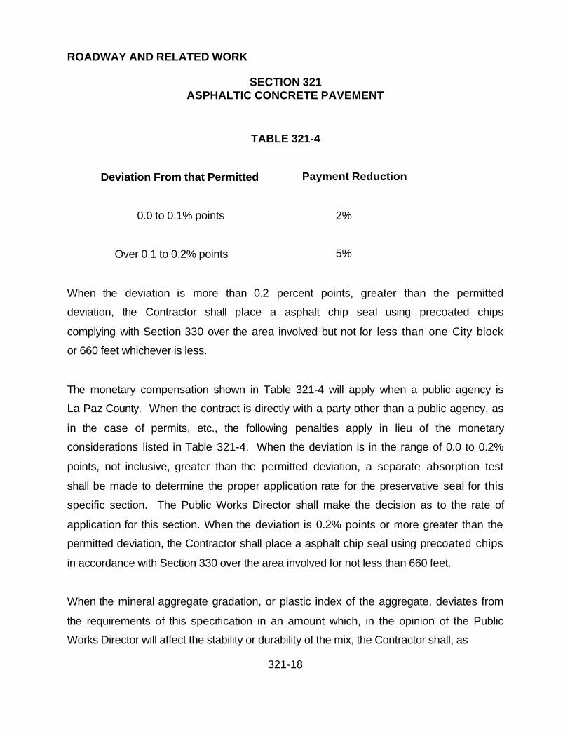
ROADWAY AND RELATED WORK
SECTION 321ASPHALTIC CONCRETE PAVEMENT
321-18
TABLE 321-4
Deviation From that Permitted Payment Reduction
0.0 to 0.1% points 2%
Over 0.1 to 0.2% points 5%
When the deviation is more than 0.2 percent points, greater than the permitted
deviation, the Contractor shall place a asphalt chip seal using precoated chips
complying with Section 330 over the area involved but not for less than one City block
or 660 feet whichever is less.
The monetary compensation shown in Table 321-4 will apply when a public agency is
La Paz County. When the contract is directly with a party other than a public agency, as
in the case of permits, etc., the following penalties apply in lieu of the monetary
considerations listed in Table 321-4. When the deviation is in the range of 0.0 to 0.2%
points, not inclusive, greater than the permitted deviation, a separate absorption test
shall be made to determine the proper application rate for the preservative seal for this
specific section. The Public Works Director shall make the decision as to the rate of
application for this section. When the deviation is 0.2% points or more greater than the
permitted deviation, the Contractor shall place a asphalt chip seal using precoated chips
in accordance with Section 330 over the area involved for not less than 660 feet.
When the mineral aggregate gradation, or plastic index of the aggregate, deviates from
the requirements of this specification in an amount which, in the opinion of the Public
Works Director will affect the stability or durability of the mix, the Contractor shall, as

ROADWAY AND RELATED WORK
SECTION 321ASPHALTIC CONCRETE PAVEMENT
321-19
directed by the Public Works Director, either; remove the asphaltic concrete and replace
it with material which meets the requirements of this specification, or place an additional
mat of such thickness and gradation as required by the Public Works Director which will
correct the deficiency.
The above corrective work, due to deviations from the requirements for mineral
aggregate, shall be done at no additional cost to La Paz County.
321.8 CURBS:
Asphaltic concrete curbs when required on the plans, shall he placed by an approved
extrusion type machine. In the event the Contractor wishes to utilize a template, which
varies from the cross-section shown on the plans, such change must meet the approval
of the Public Works Director. Mineral aggregate shall be Dense Grade E-3/8, except
that the asphalt cement content shall not be more than 7-1/2 percent or less than 7
percent by weight of the total mixture. One percent by weight of the total mixture shall
consist of a granulated synthetic resin stiffener, Lexite or equal, complying with the
following characteristics:
Softening Point (Ring & Ball) ASTM D-2398 210oF minimum
Acid Number ASTM D-465 Less than 1.00
Saponifiable matter ASTM D-464 Less than 1%
Iodine Number ASTM D-29 175-185

ROADWAY AND RELATED WORK
SECTION 321ASPHALTIC CONCRETE PAVEMENT
321-20
321.9 MEASUREMENT:
(A) Asphaltic concrete pavement will be measured by the square yard, computed to the
nearest 0.5 or square yard, of the area actually paved as allowed above, which shall
include the required quantities of mineral aggregates, filler material, asphalt cement and
sand. Measurement shall include construction of intersections, roadways, streets or
other miscellaneous surfaces indicated on the plans or as directed by the Public Works
Director.
The bid price per square yard for asphaltic concrete shall include the cost of the asphalt
cement in the percentages as specified in Section 710.
(B) Asphaltic concrete curbs will be measured by the linear foot, parallel to the base or
foundation, unless otherwise specified.
(C) Preservative seal for asphaltic concrete pavement will be measured by the ton
diluted, unless otherwise indicated in the special provisions.
321.10 PAYMENT:
(A) The asphaltic concrete measured as provided above, will be paid for at the contract
price per square yard, of thickness specified which price shall be full compensation for
the item complete, as herein described and specified.
(B) Payment for tack coat will be by the ton diluted, based on the rate of application as
directed by the Public Works Director.

ROADWAY AND RELATED WORK
SECTION 321ASPHALTIC CONCRETE PAVEMENT
321-21
(C) The quantities of preservative seal, measured as provided above will be paid for at
the contract bid price per gallon diluted or as specified, which price shall be full
compensation for the item complete as herein described or as specified.
Payment for asphaltic concrete curbs will be at the contract unit price bid per linear foot,
which price shall be full compensation for the curb complete in place, including all
necessary labor, equipment and material.
Payment is not to include costs for asphaltic concrete pavement used in pavement
matching and surface replacement. Payment for asphaltic concrete pavement used for
that work is to be charged to the pavement matching and surface replacement pay item.
Except as otherwise specified in the special provisions, no separate payment will be
made for work necessary to construct miscellaneous items or surfaces of asphaltic
concrete.

ROADWAY AND RELATED WORK
SECTION 322ASPHALTIC CONCRETE OVERLAY
322-1
322.1 DESCRIPTION:
Asphaltic concrete overlay consists of the placing and compaction of plant mix asphaltic
concrete over existing asphaltic concrete paving. The thickness of the overlay shall be
as shown on the plans or as specified in the special provisions. Preliminary preparation
of existing surfaces will be required. With the exception of those which have been
preheated and remixed only, existing surfaces shall receive a tack coat.
322.2 MATERIALS:
The tack coat, asphaltic concrete mix and transportation of the mix shall be as specified
in Sections 710 and 321 of these Specifications, except for the maximum size of
aggregate and percentage of binder which shall be as specified in the following
paragraph.
322.3 ASPHALTIC CONCRETE:
The aggregate gradation and percentage of asphalt binder shall be in accordance with
Section 710 using Type D-1/2 for overlay more than 1 inch in thickness and Type E-3/8
for overlay 1 inch or less in thickness, unless otherwise shown or specified in the
special provisions.

ROADWAY AND RELATED WORK
SECTION 322ASPHALTIC CONCRETE OVERLAY
322-2
322.4 PREPARATION OF SURFACES:
Except when they have been preheated and remixed, surfaces shall be prepared as
follows:
Before placing asphaltic concrete overlay, severely raveled areas or cracked areas that
are depressed more than 3/4 inch from the adjoining pavement shall be cut out and
patched at least 48 hours prior to the resurfacing operation. Over-asphalted areas or
rough high spots shall be removed by burning or blading. Large shrinkage cracks shall
be filled with asphalt sealing compound acceptable to the Public Works Director. The
entire surface shall be cleaned with a power broom. Raveled areas that do not require
removing shall be cleaned by hand brooming. The above are incidental, and the cost
thereof shall be included in the bid items.
After surfaces have been prepared to the satisfaction of the Public Works Director, they
shall receive a tack coat as specified in Section 321. Traffic will not be permitted over
surfaces which have received a tack coat. When the overlay is to extend onto the
concrete gutter, the gutter shall be thoroughly cleaned of loose dust and cement
particles and shall be tack coated.
322.5 CONSTRUCTION METHODS:
Placing and rolling of the asphaltic concrete and the smoothness of the surface shall be
as specified in Section 321. Compaction and testing shall be in accordance with
Section 321.
322.6 MANHOLES:

ROADWAY AND RELATED WORK
SECTION 322ASPHALTIC CONCRETE OVERLAY
322-3
Manholes shall be built up and the frames set flush with the finished surface of the new
paving and tops of valve boxes, clean-outs and other existing structures shall be
adjusted to finish grade. In the event the base course and original paving have been
removed or disturbed in order to build up the manhole, they shall be replaced with
approved materials which shall be thoroughly compacted. The asphaltic concrete
around the manhole frame shall be completed and made flush with the adjacent
overlay.
322.7 MEASUREMENT AND PAYMENT:
Measurement and payment for tack coat and asphaltic concrete overlay will be as
specified in Section 321 of these Specifications except as noted above.

ROADWAY AND RELATED WORK
SECTION 329TACK COAT
329-1
329.1 DESCRIPTION:
Tack coat for bituminous paved surfaces shall consist of the application of emulsified
asphalt as specified in Section 713 of these Specifications.
329.2 PREPARATION OF SURFACE:
Immediately before applying the bituminous material, the area to be surfaced shall be
cleaned of dirt and other objectionable material. In urban areas, the surface shall be
cleaned with a self-propelled pick-up sweeper. In rural areas, power brooms may be
used. When necessary, cleaning shall be supplemented by hand brooms.
The bituminous material shall not be applied until an inspection of the surface has been
made by the Public Works Director and he has determined that it is suitable.
329.3 APPLICATION:
Tack coat shall be diluted in the proportion of 50 percent water and 50 percent emulsion
and applied at the rate of 0.05 to 0.10 gallons per square yard. Application shall be
made in advance of subsequent construction as ordered by the Public Works Director.
The Public Works Director may either reduce the rate to be applied or eliminate the use
of tack coat in any part of the work if, in his judgment, the bituminous mixed material to
be placed will be effectively bonded to the underlying surface.

ROADWAY AND RELATED WORK
SECTION 329TACK COAT
329-2
329.4 EQUIPMENT:
Tack coat shall be applied by distributor trucks designed equipped, maintained and
operated in accordance with Section 330. Hand spray by means of hose or bar through
a gear pump or air tank shall be acceptable for resurface work corners or tacking of
vertical edges. Care shall be taken to provide uniform coverage. Equipment that
performs unsatisfactory shall be removed from the job.
329.5 PROTECTION FOR ADJACENT PROPERTY:
Care shall be taken to prevent the spraying of asphalt emulsion on adjacent pavements,
including that portion of the pavement being used for traffic, on structures, guard rails,
guide posts, markers, trees, shrubs and property of all kinds.
329.6 MEASUREMENT:
Bituminous emulsion that is diluted prior to application will be measured by the ton of
diluted material. Any conversion from volumetric quantities shall be in accordance with
Section 713.
329.7 PAYMENT:
When provided for in the bid schedule, payment for the emulsified bituminous tack coat
will be by the ton; diluted, complete-in-place based on certified weigh slips supplied by
each truck driver on each delivery and placement on the site.

ROADWAY AND RELATED WORK
SECTION 330ASPHALT CHIP SEAL
330-1
330.1 DESCRIPTION:
This work shall consist of the application of a bituminous material followed by the
application of a cover material.
330.2 MATERIALS:
330.2.1 Asphalt: The type of grade of the bituminous material will be specified in the
contract documents.
Paving grade asphalt shall meet the requirements of Section 711.
Liquid grade asphalt shall meet the requirements of Section 712.
Emulsified asphalt shall meet the requirements of Section 713.
330.2.2 Aggregate: The cover material (chips) shall meet the requirements of Section
716. Gradation of the chips shall be as specified in Table 716-1 or Table 716-2.
The Contractor shall submit a minimum 75 pound sample of cover material to the Public
Works Director at least 10 calendar days prior to beginning application of cover
material, for testing.
330.3 TIME OF APPLICATION AND WEATHER CONDITIONS:
Chip seal shall not be applied for at least 7 days after completion of new bituminous
paving.

ROADWAY AND RELATED WORK
SECTION 330ASPHALT CHIP SEAL
330-2
The chip seal shall be placed only when the roadway surface is dry and there is no
imminent threat of rain. The ambient temperature must be at least 60oF and rising.
Chip seal coat shall be placed between the dates shown: March 15 to May 31 and
September 1 to November 15.
330.4 CONSTRUCTION METHODS:
330.4.1 Preparation of surfaces: Immediately before applying the bituminous material,
the area to be surfaced shall be cleaned of dirt and other objectionable material. In
urban areas, the surface shall be cleaned with a self-propelled pickup sweeper. In rural
areas, power brooms may be used. When necessary, cleaning shall be supplemented
by hand brooms.
The bituminous material shall not be applied until an inspection of the surface has been
made by the Public Works Director and he has determined that it is suitable.
For chip seals using paving grade asphalt as the binder, a bituminous tack coat shall be
applied prior to sealing. The tack coat shall comply with Section 329. The exact rate
shall be determined by the Public Works Director.
330.4.2 Application of Bituminous Material: The bituminous material shall be applied
as soon as possible after preparation of surfaces. At the time of application,
temperatures of the asphalt shall be within the ranges specified in the following tables
and in Sections 711, 712 and 713 for each specific asphalt type. The Public Works
Director may require a specific temperature within the ranges.

ROADWAY AND RELATED WORK
SECTION 330ASPHALT CHIP SEAL
330-3
TABLE 330-1
APPLICATION TEMPERATURE OF PAVING ASPHALTS
Grade of Distributor Application
Paving Asphalts Temperature, Degrees F
Min. Max.
AC-40 325 375
AC-30 300 350
AC-20 300 350
AC-10 250 345
AC-5 260 325
TABLE 330-2
APPLICATION TEMPERATURES OF LIQUID ASPHALTS
Grade of Distributor Application
Paving Asphalts Temperature, Degrees F
Min. Max.
70 105 175
250 140 225
800 175 255
3000 215 290

ROADWAY AND RELATED WORK
SECTION 330ASPHALT CHIP SEAL
330-4
TABLE 330-3
APPLICATION TEMPERATURE OF EMULSIFIED ASPHALTS
Grade of Distributor Application
Paving Asphalts Temperature, Degrees F
Min. Max.
RS-1, CRS-1, CRS-1h 75 140
RS-2, CRS-2, CRS-2h 125 185
SS-1, CSS-1 75 130
SS-1h, CSS-1h 75 130
The quantity of liquid or emulsified asphalt will be between the range of 0.20 and 0.40
gals/sq. yd. The quantity of paving grade asphalt will be between the range of 0.17 and
0.31 gals/sq. yd. The exact rate of application will be determined by the Public Works
Director.
The bituminous material shall be placed using a distributor as specified in Section 330.
Application methods shall insure that a uniform distribution is obtained over the area to
be sealed.
The chips shall be spread before the bituminous material sets. The maximum distance
that the bituminous material is applied in advance of the chips will be determined by the
Public Works Director.

ROADWAY AND RELATED WORK
SECTION 330ASPHALT CHIP SEAL
330-5
The surfaces of structures, trees and shrubbery adjacent to the areas being seal coated
shall be protected in such a manner as to prevent their being spattered with bituminous
material or marred. The Contractor shall be responsible for all damage to such
structures or landscaping.
330.4.3 Application of cover material: Immediately following the application of the
bituminous material, the chips shall be spread with a self-propelled mechanical
spreader. The chip spreading equipment shall be capable of applying a uniform
application of cover material. The self-propelled requirement may be waived for
projects under 10,000 sq. yds.
At the time of application, pre-coated aggregate shall be within the temperature range of
250oF and 350oF measured at a point 6 to 12 inches below the top of the load.
At the time of application, uncoated chips shall not contain moisture in excess of a
saturated surface dry condition when liquid or paving grade asphalt are used as the seal
coat binder.
At the time of application, chips shall be surface wet but free from running water when
emulsified asphalt is used as the seal coat binder.
The precise application rate for cover material will be determined by the Public Works
Director within the ranges of 15 to 25 lbs./sq. yd. for the 1/4 in. size and 20 to 30 lbs./sq.
yd. for the 3/8 in. size.

ROADWAY AND RELATED WORK
SECTION 330ASPHALT CHIP SEAL
330-6
When so directed by the Public Works Director and within 48 hours after application of
the pre-coated chips, all chipped surfaces on major streets shall receive a flush coat in
accordance to Section 333. The exact rate of application shall be as directed by the
Public Works Director.
330.4.4 Rolling: Immediately following the application of the cover material, the surface
shall be rolled with self-propelled pneumatic-tired rollers. Three coverages shall be
made with a pneumatic roller. Each roller shall carry a minimum of 5000 pounds on
each wheel and a minimum of 60 psi in each tire. The roller shall not travel in excess of
12 miles per hour. A minimum of 3 self-propelled pneumatic rollers shall be required for
projects over 10,000 sq. yds. On projects under 10,000 sq. yds., one roller may be
used provided it performs the same number of cover-ages.
330.4.5 Joints: All joints shall be constructed as approved by the Public Works Director
such that there be a uniform application of cover material and bituminous material.
330.4.6 Surplus Aggregate Removal: Surplus aggregate shall be removed from the
surface using methods specified in subsection 330.4.1 and stockpiled in the location
indicated on the plans or as directed by the Public Works Director. In no event shall
surplus aggregate be left on the pavement for more than 1 day (24 hours).
330.4.7 Distributing Equipment: Distributor trucks shall be of the pressure type with
insulated tanks. Gravity distributors will not be permitted.
Spray bars and extensions shall be of the full circulating type. The spray bar shall be
adjustable to permit varying height above the surface to be treated.

ROADWAY AND RELATED WORK
SECTION 330ASPHALT CHIP SEAL
330-7
The nozzle spacing, center to center, shall not exceed 6 inches. The valves shall be
operated so that one or all valves may be quickly opened or closed in one operation.
The valves which control the flow from the nozzles shall be of a positive acting design
so as to provide a uniform, unbroken spread of bituminous material on the surface.
The distributor shall be equipped with devices and charts to provide for accurate, rapid
determination and control of the amount of bituminous material being applied. The
distributor shall be equipped with a tachometer of the auxiliary wheel type registering
speed in feet per minute. The distributor shall also be equipped with pressure gauges
and an accurate thermometer for determination of the temperature of bituminous
material. The spreading equipment shall be designed so that uniform application of a
bituminous material can be applied in controlled amounts ranging from 0.05 to 2.0
gallons per square yard. Transverse variation rate shall not exceed ten (10) percent of
the specified application rate. The distributor shall be equipped with a nose and nozzle
attachment to be used for spotting skipped areas and areas inaccessible to the
distributor. Distributor and booster tanks shall be maintained as to prevent dripping of
bituminous material from any part of the equipment.
Equipment that fails to perform satisfactorily shall be removed from the job.
330.5 TRAFFIC:
Traffic will not be permitted on the surface until the cover aggregate has set. Traffic
control shall be in accordance with Section 401.
When using paving grade or liquid grade asphalt chip seal, the speed limit must be
maintained at 25 mph for all equipment and traffic until the cover material is swept.

ROADWAY AND RELATED WORK
SECTION 330ASPHALT CHIP SEAL
330-8
When using emulsified asphalt chip seals, only emergency or local access traffic will be
allowed until the seal coat has had time to set.
330.6 MEASUREMENT:
Certified weight slips of all material shall be delivered to the Public Works Director
before the materials are applied. Certified weight slips of any material being weighed
back in for credit shall be delivered to the Public Works Director the next day.
330.7 PAYMENT:
Quantities of materials for this work will be paid for at the contract unit price.
(A) Asphalt Cement, Liquid Asphalt, Emulsion, Diluted Emulsion - Ton.
(B) Chips, less moisture - Ton.
There will be no payment for materials not placed in accordance with this specification.

ROADWAY AND RELATED WORK
SECTION 333FOG SEAL COATS
333-1
333.1 DESCRIPTION:
Fog seal coats on bituminous paved surfaces shall consist of the application of
emulsified asphalt and a sand blotter when necessary.
333.2 TIME OF APPLICATION AND WEATHER CONDITIONS:
Fog seal coats on new pavements shall be applied within 24 hours. This time restriction
may be extended by the Public Works Director.
Emulsified asphalt shall not be applied when the surface is wet or when there is a threat
of rain. The ambient temperature shall be at least 50oF and rising and the application
shall cease when the temperature is 55oF and falling.
333.3 MATERIALS:
333.3.1 Emulsified Asphalt: Unless otherwise specified in the special provisions,
emulsified asphalt may be a grade SS-1h, CSS-1h, or CQSH, as specified in Section
713. The emulsified asphalt shall be diluted in proportions of 50% water and 50%
emulsified asphalt.
333.3.2 Sand Blotter: The sand shall be as specified in Section 701 and shall be
graded in accordance with following sieve analysis:

ROADWAY AND RELATED WORK
SECTION 333FOG SEAL COATS
333-2
TABLE 333
Percentage Passing
Sieve size (by weight)
3/8" 100%
No. 4 90 - 100%
No. 200 0 - 12%
333.4 TESTS, TEST REPORTS AND CERTIFICATIONS:
Asphalt emulsion shall meet requirements of Section 713.
Test reports and certifications shall be as specified in Section 711.
333.5 PREPARATION OF SURFACES:
Immediately before applying the emulsion to the area to be surfaced shall be cleaned of
dirt and loose material by means of power brooms, or pick-up brooms supplemented by
hand brooms, if necessary. The fog seal shall not be applied until an inspection of the
surfaces has been made by the Public Works Director and he has determined that the
surfaces are suitable.
333.6 APPLICATION OF ASPHALT EMULSION:
The diluted material shall be well mixed before application. It shall be applied by a
distributor track equipped with fog nozzles at the approximate rate of 0.10 gallon per

ROADWAY AND RELATED WORK
SECTION 333FOG SEAL COATS
333-3
square yard. The exact rate shall be as directed by the Public Works Director. The
distributor truck shall be as specified in Section 330.
333.7 SAND BLOTTER:
A sand blotter shall be applied as directed by the Public Works Director where there is
an excess of asphalt emulsion. After the treated area has been opened to traffic, any
excess asphalt emulsion that comes to the surface shall be immediately covered with
additional sand.
333.8 PROTECTION FOR ADJACENT PROPERTY:
Care shall be taken to prevent the spraying of asphalt emulsion on adjacent pavements,
including that portion of the pavement being used for traffic, on structures, guard rails,
guide posts, markers, trees, shrubs and property of all kinds.
333.9 PROTECTION OF TREATED SURFACE:
The treated surface shall be protected by barricades until the asphalt emulsion will not
be picked up by traffic. Traffic control shall be in accordance with Section 401 of these
Specifications.
333.10 MEASUREMENT AND PAYMENT:
(A) Payment for asphalt emulsion in place will be by the ton, diluted, complete in place
based on certified weight slips supplied to the Public Works Director by each truck
driver on each delivery.

ROADWAY AND RELATED WORK
SECTION 333FOG SEAL COATS
333-4
(B) Payment for furnishing and applying sand blotter in place will be paid for by the ton
complete in place based on certified weight slips supplied to the Public Works Director
by each truck driver on each delivery.

ROADWAY AND RELATED WORK
SECTION 334PRESERVATIVE SEAL FOR ASPHALTIC CONCRETE
334-1
334.1 DESCRIPTION:
The asphaltic concrete preservative seal shall be composed of a petroleum resinoid
base uniformly emulsified with water.
Preservative seal shall be on all new asphaltic concrete pavement construction except
when deleted by the Public Works Director or contract documents.
Preservative seal is not required where asphaltic concrete pavement is replaced over
trenches, pavement cuts, or other similar pavement repairs.
334.2 MATERIALS:
The preservative seal shall be as specified in Section 718 of these Specifications.
334.3 CONSTRUCTION METHODS:
The material shall be diluted in the proportion of 50 percent water and 50 percent
petroleum resin-oil emulsion. The diluted material applied to the newly constructed
asphaltic concrete surface shall be at the rate of .05 to .10 gallon per square yard. The
actual amount shall be determined by tests on the pavement. Distribution equipment
shall be in accordance with Section 330.
The application on residential streets shall be made within 1 week after the placing of
the asphaltic concrete surface course. Application on major streets or residential
streets subject to heavy traffic shall be made within 24 hours after the placing of the

ROADWAY AND RELATED WORK
SECTION 334PRESERVATIVE SEAL FOR ASPHALTIC CONCRETE
334-2
asphaltic concrete surface course. The Public Works Director may authorize limited
extensions of these periods in order to meet essential conditions.
Before opening a treated area to traffic, it shall be checked for slipperiness on the
surface. If the treated portion of the roadway must be opened to traffic prior to the
disappearance of slipperiness, the surface shall be sanded with a minimum of 1-1/2
pounds per square yard of sand to eliminate this slippery condition. No more sand shall
be used than necessary and the amount specified shall not be increased without prior
approval of the Public Works Director. All approaches to high volume signalized inter-
sections shall be lightly sanded before opening to prevent pick up by waiting vehicles.
Sand blotter shall comply with Section 333.
334.4 MEASUREMENT:
Preservative seal for asphaltic concrete will be measured by the ton diluted unless
otherwise indicated in the special provisions.
334.5 PAYMENT:
Payment will be based on certified weight slips supplied to the Public Works Director by
each driver on each delivery.
(A) Payment will be made by the ton for preservative seal complete in place. Payment
shall be full compensation for this preservative seal complete and in place, including
furnishing, hauling and placing the material and all other work incidental thereto for
which specific pay items are not provided in the proposal.

ROADWAY AND RELATED WORK
SECTION 334PRESERVATIVE SEAL FOR ASPHALTIC CONCRETE
334-3
(B) Sand blotter will be paid by the ton.
ROADWAY AND RELATED WORK
SECTION 336PAVEMENT MATCHING AND SURFACING REPLACEMENT
336-1
336.1 DESCRIPTION:
That portion of roads, streets, alleys, driveways and other areas where the surfacing
has been damaged, broken into or has been removed by construction activities or to be
widened or matched in connection with an improvement, it shall be resurfaced as shown
on the plans and applicable standard details, in accordance with this specification
and/or the special provisions.
Asphaltic concrete pavement replacement shall be constructed in accordance with the
requirements of La Paz County Construction Standard Detail 5-070, Type A or B, and
as indicated on the plans and as required by Sections 321 and 710.
ABC or decomposed granite surface replacement shall be constructed in accordance
with the requirements of La Paz County Construction Standard Detail 5-070, Type C,
and as indicated on the plans and in Section 702.
Concrete pavement surface replacement shall be in accordance with the details as
shown on the construction plans.
Temporary pavement replacement shall be constructed as required below.
Pavements and concrete to be matched by new construction adjacent to or at the ends
of a project shall be saw cut in accordance with these specifications and where shown
on the plans.
Pavement and surfacing replacement within Arizona Highway rights-of-way shall be
constructed in accordance with their permits and/or specification requirements.

ROADWAY AND RELATED WORK
SECTION 336PAVEMENT MATCHING AND SURFACING REPLACEMENT
336-2
336.2 MATERIALS AND CONSTRUCTION METHODS:
Materials and construction methods used in the replacement of pavement and surfacing
shall conform to the requirements of all applicable standard details and specifications,
latest revisions.
336.2.1 Pavement Widening or Extensions: Existing pavements which are to be
matched by pavement widening or pavement extension shall be trimmed to a neat true
line with straight vertical edges free from irregularities with a saw specifically designed
for this purpose. The minimum depth of cut shall be 1-1/2 inches or D/4, whichever is
greater.
The existing pavement shall be cut and trimmed after placement of required ABC and
just prior to placement of asphaltic concrete for pavement widening or extension, and
the trimmed edges shall be painted with a light coating of asphalt cement or emulsified
asphalt immediately prior to constructing the new abutting asphaltic concrete
pavements. No extra payment shall be provided for these items and all costs incurred
in performing this work shall be incidental to the widening or pavement extension.
336.2.2 Pavement or Concrete to be Removed: Existing asphalt pavement or
concrete to be removed for trenches or for other underground construction or repairs
shall be cut by a device capable of making a neat, straight and smooth cut without
damaging adjacent pavement that is not to be removed. The Public Works Director's
decision as to the acceptability the cutting device and manner of operation shall be final.
If saw cutting only is to be utilized, it will be so specified in the plans or special
provisions.

ROADWAY AND RELATED WORK
SECTION 336PAVEMENT MATCHING AND SURFACING REPLACEMENT
336-3
Pavement replacement for cuts on major arterials and essentially parallel to the street
centerline and greater than 50 feet in length shall be two course pavement
replacements as hereinafter specified. For cuts greater than 600 feet in length the
entire area shall then be fog sealed in accordance with Section 333 or as otherwise
specified. This seal shall extend from the edge of pavement or lip of gutter to the street
centerline except that on residential streets less than 36 feet face to face of curb or
where the pavement patch straddles the centerline, the entire width of street shall be
sealed.
Pavement replacement for cuts parallel to the street centerline less than 50 feet in
length, transverse cuts, bell holes and similar small areas shall match gradation and
thickness of the existing pavement. These one course pavement patches shall be
compacted with a vibratory roller to the same density specified for asphaltic concrete
pavements.
Concrete replacement shall conform to the applicable standard construction detail.
In lieu of cutting pipe trenches across driveways, curbs and gutters, sidewalks, alley
entrances and other types of pavements the Contractor may, when approved by the
Public Works Director, elect to tunnel or bore under such structures and pavements.
336.2.3 Temporary Pavement Replacement: Temporary pavement replacement as
required in Section 601 may be with cold-mix asphaltic concrete of an MC-70 or
MC-250 oil, with a minimum thickness of 2 inches, using aggregate grading in
accordance with Section 710. The amount of liquid asphalt required will be 5.0 to 6.0
percent.

ROADWAY AND RELATED WORK
SECTION 336PAVEMENT MATCHING AND SURFACING REPLACEMENT
336-4
Temporary pavement replacement shall be used in lieu of immediate placement of
single course permanent replacement or the first course of two course pavement
replacement only on transverse lines such as spur connections to inlets, driveways,
road crossings, etc., when required by the Public Works Director, by utilities or others
who subcontract their permanent pavement replacement, under special prior
arrangement or for emergency conditions where it may be required by the Public Works
Director. Temporary pavement replacement shall be placed during the same shift in
which the backfill to be covered is completed.
Rolling of the temporary pavement replacement shall conform to the following:
(A) Initial or breakdown rolling shall be followed by rolling with a pneumatic-tired roller.
Final compaction and finish rolling shall be done by means of a tandem power roller.
(B) On small areas or where equipment specified above is not available or is
impractical, the Public Works Director will approve the use of small vibrating rollers or
vibrating plate type compactors, provided comparable compaction is obtained.
The surface of the temporary pavement shall be finished off flush with the adjacent
pavement.
336.2.4 Permanent Pavement Replacement: Laying of single course or the base
course of the asphaltic concrete pavement replacement where a two course
replacement is applicable shall never be more than 600 feet behind the ABC placed for
the pavement replacement.

ROADWAY AND RELATED WORK
SECTION 336PAVEMENT MATCHING AND SURFACING REPLACEMENT
336-5
The trench must be compacted to its required density in accordance with Section 601;
ABC, when required must be placed in accordance with Sections 218 and 702; or
concrete, when required must be placed in accordance with Sections 505 and 725, prior
to the placement of the asphaltic concrete.
Single course replacement shall consist of Type D-1/2 or C-3/4 dense grade mixes
placed and finished as directed by the Public Works Director.
The base course of two course A.C. pavement replacement shall consist of Type C-3/4
dense graded asphaltic concrete material in accordance with Section 710.
Where the base course is to be placed with non-compactive equipment, it shall be not
less than 2 inches in thickness and the material shall be immediately rolled with a
pneumatic-tired roller. The surface course shall be of sufficient depth to provide the
total required compacted thickness of the two courses, but not more than 1 inch. Where
the trench is 6 feet or more in width all courses, single or both courses of the two course
pavement replacement shall be laid with a self-propelled compacting spreading
equipment. When the trench is from 6 to 8 feet in width the self-propelled compacting
spreading equipment shall not be wider than 8 feet. All courses, except the surface
course, shall be of a compacted thickness of not less than 1-1/2 inches.
The surface course shall consist of either Type E-3/8 dense graded or Type G-3/8 open
graded asphaltic concrete material in accordance with Section 710 as specified by the
Public Works Director to match the existing surface. The surface course shall not be
placed sooner than 2 weeks after the base course, except where the trench crosses a
signalized intersection. In this case the surface course shall be placed within 48 hours
or the crossing pavement replacement shall be single course as specified above.

ROADWAY AND RELATED WORK
SECTION 336PAVEMENT MATCHING AND SURFACING REPLACEMENT
336-6
Placement of the surface course is to be by means which will result in a surface texture
satisfactory to the Public Works Director and flush with the existing pavement.
Where deep lift asphaltic concrete (asphaltic concrete base and asphaltic concrete
wearing course) exists, the base course replacement shall be made in lifts not
exceeding 6 inches in compacted thickness to within 1/2 inch of the finish grade.
336.3 TYPES AND LOCATIONS OF PAVEMENT AND SURFACING
REPLACEMENT:
Normally, the type of pavement replacement and backfill required will be noted on the
plans or specified in other portions of the contract documents and construction will be in
accordance with Construction Standard 5-070. This detail requires that 12-inch "T" Top
be utilized.
If a type is not noted on the plans or specified in the special provisions, the following
criteria will govern:
Type A pavement replacement, including the "T" Top, will he utilized on all streets and
road excavation other than on major arterials.
Type B pavement replacement will be utilized on excavations in major arterials roads.
Type C pavement replacement will be utilized to match existing ABC or decomposed
granite roadways.
Concrete pavement replacement will be utilized to match existing concrete surfacing.

ROADWAY AND RELATED WORK
SECTION 336PAVEMENT MATCHING AND SURFACING REPLACEMENT
336-7
Where a longitudinal trench is partly in pavement, the pavement shall be replaced to the
outside edge of the existing pavement, on a straight line, as indicated on the plans.
Measurements for payment shall be from the inner limit of pay width allowed below, to
the outside edge of the existing pavement as defined herein.
Where no part of a trench is in pavement, surfacing replacement will only be specified
where existing surfacing materials have been removed.
When a trench cut is in aggregate surfaced area, the surfacing replacement shall be of
a like type and depth as the existing material, compacted to the densities required in
Section 601.
336.4 MEASUREMENT:
Measurement for payment of Type A and Type B pavement replacement will be by the
square yard upon actual field measurement of area replaced. The entire pavement
structure including subgrade preparation, aggregate base, concrete and asphaltic
concrete is to be included in the payment. The maximum calculations and payment for
trench work is to be based upon pay widths listed below:
(A) In computing pay quantities for Types A and B pavement replacements, the product
of the length of pavement or surface replacement measured along the centerline of the
trench and the Maximum pay width listed below will be used:
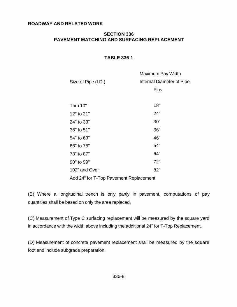
ROADWAY AND RELATED WORK
SECTION 336PAVEMENT MATCHING AND SURFACING REPLACEMENT
336-8
TABLE 336-1
Maximum Pay Width
Size of Pipe (I.D.) Internal Diameter of Pipe
Plus
Thru 10" 18"
12" to 21" 24"
24" to 33" 30"
36" to 51" 36"
54" to 63" 46"
66" to 75" 54"
78" to 87" 64"
90" to 99" 72"
102" and Over 82"
Add 24" for T-Top Pavement Replacement
(B) Where a longitudinal trench is only partly in pavement, computations of pay
quantities shall be based on only the area replaced.
(C) Measurement of Type C surfacing replacement will be measured by the square yard
in accordance with the width above including the additional 24" for T-Top Replacement.
(D) Measurement of concrete pavement replacement shall be measured by the square
foot and include subgrade preparation.
ROADWAY AND RELATED WORK
SECTION 336PAVEMENT MATCHING AND SURFACING REPLACEMENT
336-9
(E) When special provisions allow deviations from the trench widths specified in Section
601, the above allowed pay widths for pavements remove replacement may be altered
where so specified.
(F) Measurement of all pavement and surfacing replacement shall be made along the
finished surface of the ground to the nearest foot and, where stated, shall be computed
to the nearest square yard.
336.5 PAYMENT:
Direct payment for the type of pavement or surfacing replacement will be made in
accordance to the proposal. It will include the entire pavement structure including
subgrade preparation, aggregate base, concrete and asphaltic concrete surfacing.
Payment for temporary pavement replacement shall be included in the cost of the
excavation.

ROADWAY AND RELATED WORK
SECTION 340CONCRETE CURB, GUTTER, SIDEWALK, DRIVEWAYS, ALLEY ENTRANCE AND
PAVEMENT BORDER
340-1
340.1 DESCRIPTION:
The work under this section shall consist of furnishing all materials and constructing
portland cement concrete curb, curb and gutter, pavement border, cross gutters,
sidewalk, driveway, alley entrances and medians at the locations shown on the project
plans in accordance with the details shown on the plans, County construction standards
and the requirements of these specifications.
340.2 MATERIALS:
Concrete shall be Class B, conforming to the applicable requirements of Section 725 of
these Specifications.
Expansion joints filler shall comply with Section 729.
Curing compound shall comply with Section 726.
340.3 LINE AND GRADE:
Concrete construction under this section shall be built in accordance with line and grade
stakes placed every 25 feet minimum in an offset line parallel to the edge of the
improvement.

ROADWAY AND RELATED WORK
SECTION 340CONCRETE CURB, GUTTER, SIDEWALK, DRIVEWAYS, ALLEY ENTRANCE AND
PAVEMENT BORDER
340-2
340.4 CONSTRUCTION METHODS:
Existing pavements and concrete, that are joined by new construction, shall be cut in
accordance with Section 601.
The subgrade shall be constructed and compacted true to grades and lines shown on
the plans and as specified in Section 218. All soft or unsuitable material shall be
removed to a depth of not less than 6 inches below subgrade elevation and replaced
with material satisfactory to the Public Works Director. When the Public Works Director
determines that the existing subgrade consists of soils with swelling characteristics, the
moisture content shall be brought as close as possible to the optimum required for
compaction. This shall be done by the addition of water, by the addition and blending of
dry suitable material or by the drying of existing material. The subgrade shall then be
compacted to a relative density as specified in Section 218.
Material displaced in the construction shall not be placed on the base and/or surfacing
material already in place on the roadway nor shall the excavated material be placed in
such a manner as to interfere with access to property or traffic flow in the street.
Concrete curb and gutter shall be constructed in accordance with La Paz County
Construction Standards 3-120, 3-130, 3-140 and 3-150, as specified on the plans.
Pavement border shall be constructed in accordance with La Paz County Construction
Standard 3-160.

ROADWAY AND RELATED WORK
SECTION 340CONCRETE CURB, GUTTER, SIDEWALK, DRIVEWAYS, ALLEY ENTRANCE AND
PAVEMENT BORDER
340-3
Concrete sidewalks and sidewalk ramps shall be constructed in accordance with La Paz
County Construction Standards 3-270 and 3-280.
Driveway entrances shall be constructed in accordance with La Paz County
Construction Standards 3-210, 3-220 and 3-225, as applicable.
Alley entrances shall be constructed in accordance with La Paz County Construction
Standard 3-050.
Cross gutters shall be constructed in accordance with La Paz County Construction
Standards 3-170 and 3-180.
Medians shall be constructed in accordance with La Paz County Construction Standard
3-110.
Concrete sidewalks and driveways which are necessarily disturbed by construction shall
be removed to a distance required to maintain a slope as indicated by standard details
or not to exceed 1 inch per foot where sidewalks are concerned. Sawcutting is required
at the match lines and payment will be made under the respective pay items as
provided in the proposal.
Concrete curbs, gutters, pavement border and sidewalks shall be constructed by the
conventional use of forms, or may be constructed by means of an appropriate machine
approved by the Public Works Director.

ROADWAY AND RELATED WORK
SECTION 340CONCRETE CURB, GUTTER, SIDEWALK, DRIVEWAYS, ALLEY ENTRANCE AND
PAVEMENT BORDER
340-4
If machines designed specifically for such work and approved by the Public Works
Director are used, the results must be equal to or better than that produced by the use
of forms. If the results are not satisfactory to the Public Works Director, the use of the
machine shall be discontinued and the Contractor shall make necessary repairs at his
own expense. All applicable requirements of construction by use of forms shall apply to
the use of machines.
Forms conforming to the dimensions of the curb, gutter, pavement border, sidewalk,
driveway and alley entrance shall be carefully set to line and grade, and securely staked
in position. The forms and subgrade shall be watered immediately in advance of
placing concrete.
Forms shall be thoroughly cleaned each time they are used, and shall be coated with a
light oil, or other releasing agent of a type which will not discolor the concrete. The
concrete shall be thoroughly spaded away from the forms so that there will be no rock
pockets next to the forms. The concrete may be compacted by mechanical vibrators
approved by the Public Works Director. Tamping or vibrating shall continue until the
mortar flushes to the surface and the coarse aggregate is below the concrete surface.
Expansion joints, unless otherwise specified, shall be constructed in accordance with
the construction standard of the appropriate agency, in a straight line and vertical plane
perpendicular to the longitudinal line of the sidewalk or curb and gutter, except in cases
of curved alignment, when they will be constructed along the radial lines of the curve.
They shall be constructed to the full depth and width of the concrete and shall match the
joints in the adjacent pavement sidewalk or curb and gutter. Joints shall be constructed

ROADWAY AND RELATED WORK
SECTION 340CONCRETE CURB, GUTTER, SIDEWALK, DRIVEWAYS, ALLEY ENTRANCE AND
PAVEMENT BORDER
340-5
at all radius points, driveways, alley entrances and at adjoining structures with a
maximum interval of 50 feet between joints.
Contraction joints, unless otherwise specified, shall be constructed in accordance with
the standard details of the appropriate agency, in a straight line and vertical plane
perpendicular to the longitudinal line of the sidewalk or curb and gutter, except in cases
of curved alignment when they will be constructed along the radial lines of the curb.
They shall be constructed to a depth of 1", and at 10' intervals on sidewalk widths of five
feet and 8' intervals on sidewalks of 4' width.
Sidewalk score marks, at least 1/2 inch deep, are required every 4 feet or every 5 feet
matching the width of the sidewalk.
All edges shall be shaped with a suitable tool so formed as to round the edges to a
radius as indicated on the standard details.
The front face form shall not be removed before the concrete has taken the initial set
and has sufficient strength to carry its own weight, gutter forms and rear forms shall not
be removed until concrete has hardened sufficiently to prevent damage to the edges.
Special care shall be taken to prevent any damage. Any portion of concrete damaged
while stripping forms shall be repaired or if the damage is severe, replaced at no
additional cost to La Paz County. The face, top back, and flow line of the curb and
gutter shall be tested with a 10-foot straightedge or curve template, longitudinally along
the surface. Any deviation in excess of 1/4 inch shall be corrected at no additional cost
to La Paz County.

ROADWAY AND RELATED WORK
SECTION 340CONCRETE CURB, GUTTER, SIDEWALK, DRIVEWAYS, ALLEY ENTRANCE AND
PAVEMENT BORDER
340-6
The surface of concrete sidewalk shall be tested with a 5-foot straightedge. Any
deviation in excess of 1/8 inch shall be corrected at no additional cost to La Paz County.
When required by the Public Works Director, gutters having a slope of 0.8 foot per
hundred feet or less, or where unusual or special conditions cast doubt on the capability
of the gutters to drain, they shall be water tested. Water testing shall consist of
establishing flow in the length of gutter to be tested by supplying water from a hydrant,
tank truck or other source. One hour after the supply of water is shut off, the gutter
shall be inspected for evidence of ponding or improper shape. In the event water is
found ponded in the gutter to a depth greater than 1/2 inch, or on the adjacent asphalt
pavement, the defect or defects shall be corrected in a manner acceptable to the Public
Works Director without additional cost to La Paz County.
Any section of the work deficient in depth or not conforming to the plans or
specifications shall be removed and replaced by the Contractor at no additional cost to
La Paz County.
Finishing and curing of the concrete shall be done in the manner specified in Section
505.
The Contractor shall stamp his name and year on all work done by him, on each end of
the curb, gutter, or sidewalk. The letters shall not be less than 3/4 inch in height.
ROADWAY AND RELATED WORK
SECTION 340CONCRETE CURB, GUTTER, SIDEWALK, DRIVEWAYS, ALLEY ENTRANCE AND
PAVEMENT BORDER
340-7
340.5 TESTING:
Testing of concrete construction shall be performed in accordance with specification
entitled "Portland Cement Concrete".
340.6 BACKFILLING:
Unless otherwise specified, the Contractor shall backfill behind the curbs or sidewalks
with soil native to the area to the lines and grades shown on the plans.
340.7 MEASUREMENT:
(A) Concrete curbs and gutters and pavement border of the various types shown on the
plans and in the proposal, will be measured along gutter flow line deleting inlets, catch
basins, etc., by the lineal foot to the nearest foot for each type, complete in place.
(B) Concrete sidewalks, driveways, alley entrances, medians, valley gutters and aprons
will be measured to the nearest square foot complete in place. When concrete
sidewalk, driveways, alley and driveway aprons, valley gutters, and other concrete
surfaces are cut during trenching operations, the square foot measurement for payment
will be in accordance with Section 336.
340.8 PAYMENT:
Payment for the above named items will be made in accordance with the unit prices or
lump sums as set forth in the proposal. Such payment shall include full compensation

ROADWAY AND RELATED WORK
SECTION 340CONCRETE CURB, GUTTER, SIDEWALK, DRIVEWAYS, ALLEY ENTRANCE AND
PAVEMENT BORDER
340-8
for furnishing all labor, material, tools and equipment and accomplishing all work in
conformance with the contract documents.

ROADWAY AND RELATED WORK
SECTION 352CEMENT TREATED BASE
352-1
352.1 DESCRIPTION:
Cement treated base shall consist of furnishing and mixing aggregate, cement and
water, and spreading, compacting and curing the mixture in accordance with the details
shown on the construction plans and the requirements of this section.
352.2 MATERIAL:
352.2.1 Aggregate: The aggregate for cement treated base shall conform to the
requirements of Section 701 except the plasticity of the material passing the No. 40
sieve shall not exceed 5 and the grading shall be as follows:
TABLE 352-1
Sieve Size Percentage by Weight Passing
Screen
1-1/2" 100
No. 4 40-70
No. 40 30 Max
No. 200 0-15

ROADWAY AND RELATED WORK
SECTION 352CEMENT TREATED BASE
352-2
352.2.2 Portland Cement and Water: Portland cement and water shall conform to the
requirements of Section 725.
352.2.3 Bituminous Material for Curing Seal: Bituminous material for curing seal shall
be Liquid Asphalt Grade MC-250 or MC-800 conforming to the requirements of
AASHTO M-82.
352.2.4 Mix Design: The Contractor shall determine the mix proportions and shall
furnish cement treated base conforming to the requirements specified herein. The job-
mix design along with the supporting test results shall be submitted to the Public Works
Director and approval shall be obtained prior to incorporating any of the material into the
work.
The brand of cement and the location of the aggregate source shall be included with the
job-mix design data. A new mix design shall be submitted for approval any time the
Contractor requests a change in materials or proportioning of the materials from that
given in the approved mix designs.
The cement treated base shall attain a minimum compressive strength of 500 pounds
per square inch in seven days.
352.3 GENERAL:
When the mixing of cement treated base in a stationary mixer is required, it will be so
specified. Otherwise, cement treated base may be mixed in either a traveling plant or in
a stationary plant, at the option of the Contractor.

ROADWAY AND RELATED WORK
SECTION 352CEMENT TREATED BASE
352-3
If the cement treated aggregate is mixed in a central plant, it shall not contain moisture
in excess of 1 percent above or below optimum at the time of delivery on the grade.
Certain types of transit mixers will not discharge such material unless it is greatly in
excess of optimum moisture. Use of such mixers will not be permitted.
If the material is mixed in place, the machine or combination of machines used shall be
capable of thoroughly mixing the cement and aggregate, when using the granular
material specified, in a single pass. No lift thickness shall exceed 8 inches. If the
thickness is in excess of 8 inches, it shall be mixed in 2 separate lifts of equal thickness.
352.4 CONSTRUCTION METHODS:
Mixing of materials, regardless of the type of mixer used or method employed, shall be
continued until the cement and water are evenly distributed throughout the aggregate,
and a mixture of uniform appearance is obtained.
The amount of water used shall be that required to give optimum moisture content. A
portion of the required water may be added to the aggregate prior to the addition of
cement.
The amount of Portland cement used shall conform to the approved mix design.
After spreading, the cement treated base shall be compacted to a density of at least 95
percent of the maximum density as determined by ASTM D-2922 and D-3017 with
adjustment for rock correction. A compaction test shall be performed every 500 feet.

ROADWAY AND RELATED WORK
SECTION 352CEMENT TREATED BASE
352-4
After compaction, the surface of the cement treated base course shall not deviate at any
point more than 3/8" inch from the lower edge of a 10-foot straightedge laid parallel to
the centerline of the roadway.
A construction joint shall be made at the end of each day's construction by trimming the
end of the compacted mixture to a straight vertical plane, parallel to the centerline of the
roadway and with the vertical edge in thoroughly compacted material.
Cement shall not be added to more material than will be mixed, compacted and sealed
that same day. Cement treated base shall not be mixed or placed when either the
aggregate or subgrade is frozen. The air temperature shall be at least 40oF in the
shade and rising at the time of mixing.
In areas which are inaccessible to the mixing, spreading or compacting equipment
designated herein, other methods and equipment acceptable to the Public Works
Director may be utilized.
The mixed material shall not remain undisturbed on the subgrade for more than 30
minutes and not more than 3 hours shall elapse between the time water is added to the
mixture and final compaction is accomplished.
The mixed materials shall be spread for the full width of the base under construction,
either by one spreader or by several spreaders operating in a staggered position across
the subgrade, unless permission is granted to do part-width construction. Should
permission be granted for part-width construction, not more than 30 minutes shall
elapse between the times of placing the material in adjacent lanes at any location and
the longitudinal joint against which additional mixed material is to be placed shall be

ROADWAY AND RELATED WORK
SECTION 352CEMENT TREATED BASE
352-5
trimmed to a straight vertical plane parallel to the centerline of the roadway. Trimming
shall be done in such a manner as to cause the least possible loosening of the
compacted base material and to leave no loose material on the subgrade. The material
cut away in trimming may be used in the construction of the shoulders or the adjacent
lanes if approved, or shall be disposed of in a satisfactory manner.
During mixing, spreading and compacting and until the application of the curing seal,
any moisture lost by evaporation shall be replaced by the addition of water by means of
a light fog or fine spray.
The mixed base materials shall be covered as soon as possible after final compaction
and shall be cured in accordance with this section.
352.5 TRAVELING PLANT MIXING:
352.5.1 Placing Aggregate: The aggregate to be treated shall be placed on the
roadway either as a uniform layer which, when compacted, will produce a base of the
depth and width shown on the plans or as one or more windrows which, when spread,
will yield a uniform a uniform layer which will compact to the prescribed dimensions. If
the aggregate is placed in one or more windrows, a windrow sizer will be required. The
number and size of the windrows may vary, depending on the width and depth of
treatment and on the capacity of the machine, but regardless of size, the windrow shall
be uniform in cross-section and shall not be larger than can be handled by the plant.
Care shall be exercised during the placement of the aggregate to prevent segregation of
the fine and coarse portion of the aggregate.

ROADWAY AND RELATED WORK
SECTION 352CEMENT TREATED BASE
352-6
351.4.2 Placing Cement: Cement shall be added to the uniform layer or windrow of
aggregate by means of mechanized equipment which will spread the cement in correct
and uniform quantities. For any section of roadway, the quantity of cement placed by
mechanical spreaders shall not deviate more than 10 percent from the computed
quantity for the section. When cement is applied to a windrow, the top of the windrow
shall be slightly trenched to retain the spread of cement. If winds cause a loss of spread
cement, spreading operations shall be halted until such winds subside and, at the first
indication of losses, prompt action shall be taken to avoid further losses. If cement
losses are deemed excessive, the deficient quantity shall be furnished and added in the
proper amount by the Contractor at no additional cost to La Paz County.
352.5.3 Mixing: Mixing shall be accomplished by means of an approved single pass
traveling mixing machine or combination of machines, of the pug or auger type. The
machine shall be so constructed that the device for picking up or mixing the aggregate
can be controlled and during the mixing operations it shall be set to mix the aggregate,
cement and water to the design depth without cutting into or disturbing the subgrade, or
picking up any material other than that material to be processed. The machine shall be
equipped so that water may be introduced at the time of mixing through a metering
device which will accurately and uniformly control and measure the amount of water
being used.
The cement and aggregate shall be mixed in the machine simultaneously with the
adding, through the machine, of additional water required.
The material shall be spread immediately after mixing, in reasonably close conformity to
the lines, grades and dimensions established or shown on the plans.
ROADWAY AND RELATED WORK
SECTION 352CEMENT TREATED BASE
352-7
352.5.4 Stationary Plant Mixing: If the stationary plant method of mixing is employed,
the aggregate, cement and water shall be mixed at a central plant using either a batch
pug mill type or a continuous type mixer. Dead areas in the mixer, in which the material
does not move or is not sufficiently agitated, shall be corrected, either by a reduction in
the weight of materials or by other adjustments.
352.5.5 Batch Mixing: If a batch pug mill type mixer is used, the aggregate and cement
shall be proportioned by batch weights. Cement shall be weighed on separate scales
from the aggregate batching scales.
The weight of the charge in a batch mixer shall not exceed that which will permit
complete mixing of all materials. The period of mixing shall not be less than 30 seconds
from the time all materials are in the mixer. Water may be proportioned by volume or by
weight.
352.5.6 Continuous Mixing: If a continuous type mixer is used, the materials shall be
proportioned by volume.
The continuous type mixer shall be equipped with metering devices and feeders that will
introduce the cement, aggregate and water into the mixer in the specified proportions.
The water pump shall be equipped with a means of varying the rate of delivery. The
metering devices and feeders shall be interlocked and so synchronized as to maintain a
constant ratio of cement and water to the aggregate.
The rate of feed to a continuous type mixer shall not exceed that which will permit
complete mixing of all the material.

ROADWAY AND RELATED WORK
SECTION 352CEMENT TREATED BASE
352-8
352.5.7 Spreading: The treated material shall be transported from the plant to the
prepared subgrade in approved equipment.
The surface on which the material is to be placed shall be thoroughly moistened and
kept moist, but not excessively wet, until covered by the material.
Plant mixed cement treated base shall be spread by approved spreader boxes or
finishing machines. The machines shall be constructed and operated so as to produce
a layer of uniform density and cross-section and in sufficient quantity to provide a
compacted base reasonably conforming to the lines, grades and cross-sections
established or shown on the plans.
352.5.8 Compacting: Initial compaction shall begin immediately after mixing and
spreading. Successive passes of compacting equipment shall overlap the previous pass
by at least 25 percent of its width. Following initial compaction and before final
compaction, the treated material shall be bladed with a motor grader or a planing
machine to obtain a surface reasonably true to the lines, grades and cross-section
established or shown on the plans. During and immediately following the shaping
operations, if required, the Contractor shall lightly scarify the surface with a nail drag or
other approved equipment to prevent the formation of surface compaction planes.
Extreme care shall be exercised by the Contractor during blading operations so that no
more material than is necessary is disturbed and so that this operation can be
completed as quickly as possible. Material thus cut shall be disposed of if so directed.
Compaction shall proceed without interruption, except as stated above, until the
required degree of compaction is obtained.

ROADWAY AND RELATED WORK
SECTION 352CEMENT TREATED BASE
352-9
352.6 INVERTED SECTION:
Where the cement treated base is to be covered by aggregate base course to prevent
shrinkage crack reflection and overloading of the cement treated base, the minimum
thickness of the aggregate base shall be 4 inches, unless otherwise specified in the
special provisions. The Contractor shall keep the compacted cement treated base
continuously moist until overlaid with the aggregate base course or the surfacing. The
aggregate base course, may be placed as soon as the cement treated base has been
compacted. A cement treated section may be opened to all traffic immediately after
placement and compaction of the surfacing. In order to provide for free internal
drainage of the aggregate base course overlying the cement treated base, it shall be
non-plastic and the percentage of material passing the No. 200 sieve shall not exceed
8. The cement treated base shall be held back approximately 1 foot from each curb
line.
352.7 CURING:
The cement treated base materials shall be covered as soon as possible after final
compaction with a bituminous curing seal. Application shall be by means of a pressure
distributor truck in accordance with the requirements of this section. The approximate
quantity of bituminous material to be used shall be as specified.
After the bituminous curing seal has been applied, the cement treated base course shall
be kept free of all equipment and traffic for a period of 7 days or until it will not pick up
under traffic. Curing seal shall conform to the requirements of Section 352.2.3.

ROADWAY AND RELATED WORK
SECTION 352CEMENT TREATED BASE
352-10
When the construction plans call for 4 or more inches of aggregate base course over
the cement treated base, the aggregate base course may be used as the curing seal in
lieu of a bituminous curing seal. The aggregate base course shall be placed as per
Section 352.6.
Distributor trucks shall be of the pressure type with insulated tanks. The use of gravity
distributors will not be permitted.
Spray bars shall have a minimum length of 9 feet and shall be of the full circulating type.
The spray bar shall be adjustable to permit varying height above the surface to be
treated.
The distance center to center of the nozzles shall not exceed 6 inches. The valves shall
be operated by levers so that one or all valves may be quickly opened or closed in one
operation. The valves which control the flow from nozzles shall be of a positive acting
design so as to provide a uniform unbroken spread of bituminous material on the
surface. The distributor shall be equipped with devices and charts to provide for
accurate and rapid determination and control of the amount of bituminous material
being applied and with a tachometer of the auxiliary wheel type reading speed in feet
per minute.
The spreading equipment shall be so designed and articulated that uniform application
of a bituminous material, in controlled amounts, may be made ranging from 0.05 to 2.0
gallons per square yard of surface and with a range of pressure from 25 to 75 psi. If a
spray bar extension is used to cover a greater width, it shall be of the full circulating
type. The distributor shall be equipped with a hose and nozzle attachment to be used
for spotting skipped areas and areas inaccessible to the distributor. The distributor shall

ROADWAY AND RELATED WORK
SECTION 352CEMENT TREATED BASE
352-11
also be equipped with pressure gauges and an accurate thermometer for determination
of the temperature of bituminous material. Distributor and booster tanks shall be so
maintained at all times as to prevent dripping of bituminous material from any part of the
equipment.
The Public Works Director reserves the right to order the discontinuance of use of
equipment which fails to produce a satisfactory distribution of asphalt in accordance
with the specification.
352.8 DEFICIENCY:
When there is reason to believe a deficiency in thickness exists in the cement treated
base, cores will be taken in the same manner as that defined in Section 321. If the
base has been covered or it is otherwise impractical to correct the deficiency of 1/2 inch
or more in thickness, the corrective measure listed in the table in Section 310.7 for type
II deficiency shall be taken by the Contractor at no additional cost to La Paz County.
352.9 METHOD OF MEASUREMENT:
Cement treated base will be measured by the square yard.
352.10 BASIS OF PAYMENT:
The accepted quantities of cement treated base, measured as provided above, will be
paid for at the contract unit price for the cement treated base mixture complete in place,
including bituminous curing seal when required. Except that an adjustment will be made

ROADWAY AND RELATED WORK
SECTION 352CEMENT TREATED BASE
352-12
to the bid item price for any section of cement treated base found deficient in
accordance with Table 352-2.
TABLE 352-2
Seven Day Compressive Strength (pounds per
square inch) Bid Item Price Adjustment
500 or More 0
450 to 499 -$1.50
400 to 449 -$3.25
350 to 399 -$5.00
Less than 350 -$7.00*
* Material represented by sections attaining seven-day compressive strengths with a
value less than 350 psi will be evaluated as to acceptance. The Public Works Director
will determine if the material can be left in place. Cement treated base allowed to
remain in place will be subject to the bid item price adjustment. Cement treated base
not allowed to remain in place shall be replaced at the Contractor's expense.

ROADWAY AND RELATED WORK
SECTION 360EXPOSED AGGREGATE SIDEWALK
360-1
360.1 DESCRIPTION:
Exposed aggregate sidewalk consists of placing a concrete slab with exposed
aggregate in the surface of the finished concrete. This exposed aggregate paving is
designed for decorative or pedestrian use only. It should not be used in areas subject
to vehicular traffic.
360.2 MATERIAL:
360.2.1 Concrete: Concrete shall be Class A per Section 725 with a maximum slump of
3 inches.
360.3 CONSTRUCTION PROCEDURE:
The contractor shall construct a sample panel 3 feet by 3 feet utilizing his proposed
method of exposing the aggregate for inspection and approval prior to actual
construction. When approved, this panel shall be used as a standard for the remainder
of the work.
After the slab has been placed, screeded and darbied, the aggregate shall be exposed
so that the entire surface is even and uniform. The surface shall be reworked so that
the aggregate will be embedded just beneath the surface. The concrete shall
completely surround and lightly cover the aggregate leaving no holes or voids.
A non-staining surface retarder will be applied to provide a surface penetration of at
least 1/8 inch and the surface will be lightly screeded to ensure penetration. The
surface will be covered with a protective material for the period of time recommended by

ROADWAY AND RELATED WORK
SECTION 360EXPOSED AGGREGATE SIDEWALK
360-2
the retarder manufacturer. After this time has elapsed, the upper, retarded layer of
concrete will be removed using a water jet stream and a brush. The protective cover
will be replaced and the concrete allowed to cure. After curing, the surface hall be
cleaned and a silicone seal applied.
Expansion and contraction joints shall be constructed in accordance with LPCPW
specifications, section 340.
360.4 MEASUREMENT AND PAYMENT:
Measurement will be by the square foot. Payment will be made at the unit bid price per
square foot. This price shall be full compensation for all labor, material, tools and
equipment required to complete the work.

TRAFFIC CONTROL, RIGHT-OF-WAY DEVELOPMENT, AND INCIDENTALS
SECTION 401TRAFFIC CONTROL
401-1
401.1 DESCRIPTION
Traffic control shall consist of traffic control devices, flaggers and /or pilot cars. All
traffic control devices, the application of traffic control measures and traffic regulation in
these specifications are to supplement and are not intended to delete any of the
provisions of the Manual on Uniform Traffic Control Devices (MUTCD) or any State,
County, or Local supplements to these Uniform Standard Specifications.
401.2 TRAFFIC CONTROL DEVICES:
The contractor shall provide for the adequate protection of all vehicular and pedestrian
traffic and workmen, through any portion of the work where construction operations
interfere with, obstruct or create a hazard to the normal movement of traffic.
The name of the contractor's employee who is responsible for implementing, monitoring
and altering, as necessary, the traffic control plan shall be made known to the local law
enforcement agency of jurisdiction. The contractor's designee shall also be available at
any time to respond to calls involving damage to barricades, lights, signs and other
devices resulting from vandalism, traffic accident or other causes.
If the Public Works Director determines proper provisions for safe traffic control are not
being provided or maintained, the Public Works Director may order suspension of the
work until the proper level of traffic control is achieved. In cases of serious or willful
disregard for safety of the public or his employees by the Contractor, the Public Works
Director may proceed forthwith to place the traffic control measures in proper condition
and deduct the cost thereof from monies due or becoming due the contractor.

TRAFFIC CONTROL, RIGHT-OF-WAY DEVELOPMENT, AND INCIDENTALS
SECTION 401TRAFFIC CONTROL
401-2
All contractor's personnel, equipment, machinery, tools and supplies shall be kept clear
of active traffic lanes, except as necessary for the prosecution of the work. The
contractor shall promptly remove any material or debris that is spilled or tracked onto
the traveled roadway as a result of the prosecution of the work. Any materials, vehicles
and parked equipment or stored materials within 30 feet of the edge of a traveled way
shall be removed. Equipment may be parked and materials may be stored in the right-
of-way only at locations approved by the Public Works Director.
Any devices provided under this section which are lost, stolen, destroyed or are deemed
unacceptable by the Public Works Director, shall be replaced by the contractor.
Traffic control devices shall consist of providing, erecting, and maintaining necessary
and adequate devices for the protection of the work, the workers and the public.
(A) Temporary traffic control devices shall be used to guide traffic through construction
areas. They include but are not limited to traffic cones to channelize traffic, portable
barricades for warning, vertical panel channelizing devices to divert traffic, lighting
devices between the hours of sunset and sunrise, and pilot cars.
(B) Advance warning devices shall be used to alert the motorist of an obstruction in the
roadway. They include diamond-shaped signs, flags, and flasher type high level
warning devices mounted 8 feet above the roadway. Any device, or sign, shall be in
compliance with MUTCD and shall not be unreadable or in a state of disrepair.
(C) All traffic control devices shall be kept clean, free from dirt, mud and roadway grime.

TRAFFIC CONTROL, RIGHT-OF-WAY DEVELOPMENT, AND INCIDENTALS
SECTION 401TRAFFIC CONTROL
401-3
(D) All traffic control devices including warning lights shall be kept in good working order
or be replaced.
401.3 FLAGGERS, PILOT CARS:
Providing sufficient flaggers, uniformed off-duty law enforcement officers or pilot cars to
expedite safe passage of vehicular traffic shall be at the expense of the Contractor.
401.4 TRAFFIC CONTROL MEASURES:
The application of all traffic control measures shall be based primarily upon the
conditions existing at the time that such measures are deemed necessary. Prior to the
start of work that would interrupt the normal flow of traffic, sufficient and adequate
devices and measures shall be provided and erected as approved by the Public Works
Director. These devices shall be immediately removed when no longer needed.
401.5 GENERAL TRAFFIC REGULATIONS:
A traffic lane shall be a minimum of 10 feet of clear street width with a safe motor
vehicle operating speed of at least 25 miles per hour.
An intersection shall be all of the area within the right of way intersecting streets plus
300 feet beyond the edge of the intersected right of way on all legs of the intersection.
A minimum of two traffic lanes, one for each direction, shall be maintained open to
traffic at all times on all major streets.

TRAFFIC CONTROL, RIGHT-OF-WAY DEVELOPMENT, AND INCIDENTALS
SECTION 401TRAFFIC CONTROL
401-4
All existing traffic lanes on major streets shall be maintained open to traffic at signalized
intersections between the hours of 7:00 AM to 9:00 AM and 4:00 PM to 6:00 PM
weekdays unless otherwise specified in the special provisions.
All work that enters or crosses a major street must be done at times other than 7:00 AM
to 9:00 AM and 4:00 PM to 6:00 PM unless otherwise specified in the special
provisions.
Local access shall be maintained to all properties on the project at all possible times.
When local access cannot be maintained, the Contractor must notify the affected
property owner at least 24 hours in advance and restore access as soon as possible.
A traffic lane shall not be considered as satisfactorily open to traffic unless it is paved
with hot mix or cold mix asphalt paving if surrounded by or adjacent to existing
pavement. Where pavement did not previously exist or where all of the existing
pavement has been removed, a traffic lane shall not be considered as satisfactorily
open to traffic unless it is graded reasonably smooth and maintained dust free.
Arrangements for partial or complete street closure permits shall be approved by the
Public Works Director. An advance notice of 48 hours for major streets and 24 hours for
local streets and alleys is required. It shall be the contractor's responsibility to notify all
emergency service agencies (i.e. Police and Fire Departments, etc.) of all street
closures and re-openings.
The Contractor shall provide and maintain all necessary traffic controls to protect and
guide traffic for all work in the construction area.

TRAFFIC CONTROL, RIGHT-OF-WAY DEVELOPMENT, AND INCIDENTALS
SECTION 401TRAFFIC CONTROL
401-5
The Contractor shall maintain all existing and temporary STOP, YIELD, and street name
signs erect, clean, and in full view of the intended traffic at all times. If these signs
interfere with construction, the Contractor shall temporarily relocated the signs away
from construction but still in full view of the intended traffic and shall notify the Public
Works Director of his actions.
The Contractor shall reset all STOP, YIELD and street names signs to permanent
locations.
Existing traffic signs shall be maintained by the Contractor until such time as
construction renders them obsolete. At that time the Contractor shall remove signs and
posts without damage and deliver them as directed by Contract Special Provisions. The
Contractor will reinstall all traffic signs.
The Contractor shall install CONSTRUCTION ZONE SPEED LIMIT signs in the
construction area. The Contractor shall maintain the signs erect, clean, and in full view
of the intended traffic at all times. Should the signs interfere with construction, the
Contractor shall relocate the signs as necessary.
The Contractor shall make arrangements with the Local Sanitation Department in order
for refuse collection service to be on normal schedule. Special traffic regulations will be
listed in the special provisions.
TRAFFIC CONTROL, RIGHT-OF-WAY DEVELOPMENT, AND INCIDENTALS
SECTION 401TRAFFIC CONTROL
401-6
401.6 TRAFFIC CONTROL PLAN:
When a traffic control plan is included in the project plans, this plan shall govern when
approved by the Public Works. If no traffic control plan is provided or if the contractor
desires to deviate from the provisions for maintaining traffic as described in this section,
the Contractor shall submit to the Public Works Director a proposed sequence of
operations and a compatible method of maintaining traffic. The proposal shall be
submitted early enough to allow at least two weeks for review and approval before use
of the proposed traffic control plan.
The Contractor’s traffic control and safety plan, along with his work schedule and actual
operations, shall be such that no condition that is considered to be unsafe shall exist.
401.7 MEASUREMENT:
Measurement will be by lump sum for all traffic control required for completion of the
project.
401.8 PAYMENT:
Payment will be made in percent segments of the project duration; i.e. a 12 month
project will be paid in 12 segments less the appropriate retainage.
If no separate pay item is provided for flaggers, off duty officers and pilot car, then it
shall be included in the lump sum for traffic control.

TRAFFIC CONTROL, RIGHT-OF-WAY DEVELOPMENT, AND INCIDENTALS
SECTION 402CONSTRUCTION SURVEYING AND LAYOUT
402-1
402.1 DESCRIPTION:
The work under this section shall consist of furnishing all materials, personnel, and
equipment necessary to perform all surveying, staking, construction layout, property
boundary and right-of-way monuments, centerline monuments, establishment of pit
boundaries, laying out of haul roads, and verification of the accuracy of existing control
points which have been provided. Included in this work shall be all calculations required
for the satisfactory completion of the project, including pipeline cut sheets, grade and
drain, overlay, safety, landscape, rest areas, structures, surfacing projects, or
combinations thereof, in conformance with the plans and these specifications. The work
shall include establishing and marking `As-built' elevations on structures and bridges.
The work shall be done under the direction of a registered professional Public Works
Director employed by the Contractor. All right-of-way monuments and lines shall be
established by a registered land surveyor, employed by the Contractor.
The Contractor is to provide all survey monuments as required.
Pay quantity items shall be submitted by the Contractor and verified by the Public
Works Director.
When utility adjustments are a part of the contract, the Contractor shall perform all
layout work and set all control points, stakes and references necessary for carrying out
all such adjustments.

TRAFFIC CONTROL, RIGHT-OF-WAY DEVELOPMENT, AND INCIDENTALS
SECTION 402CONSTRUCTION SURVEYING AND LAYOUT
402-2
402.2 MATERIALS, PERSONNEL AND EQUIPMENT:
Materials and equipment shall include, but shall not necessarily be limited to, vehicles
for transporting personnel and equipment, properly adjusted and accurate survey
equipment, straightedges, stakes, flagging, and all other devices necessary for
checking, marking, establishing and maintaining lines, grades and layout to perform the
work called for in the contract. The Contractor shall furnish professional personnel to
perform the survey work and layout.
Right of way and centerline monuments shall conform to Specification Section 405.
The Contractor shall furnish all traffic control, including flagging for survey and staking
operations. Traffic control shall be in accordance with the requirements of Section 401.
La Paz County will furnish field books for use by the Contractor for recording survey
data and field notes. These books shall be available for inspection by the Public Works
Director at any time and shall become the property of La Paz County upon completion
of the work.
402.3 SUBMITTAL:
The Contractor shall provide a written outline detailing the method of staking, marking of
stakes, grade control for various operations, referencing, structure control, and any
other procedures and controls necessary for survey completion. A part of this outline
shall also be a schedule which will show the sequencing of the survey and layout work
throughout the course of the contract listing a percentage of completion for each month.

TRAFFIC CONTROL, RIGHT-OF-WAY DEVELOPMENT, AND INCIDENTALS
SECTION 402CONSTRUCTION SURVEYING AND LAYOUT
402-3
402.4 CONSTRUCTION REQUIREMENTS:
Control points for establishing construction survey control and bench marks for
establishing the proper elevations of the work are provided on the plans.
Each control point and benchmark provided shall be referenced by the Contractor and
protected through out the project. Control points shall be present at construction
completion. Control points and benchmarks are to be checked for accuracy.
After the Contractor has verified the accuracy of the control points established by the
Public Works Director, the Contractor shall set all stakes including, but not necessarily
limited to centerline stakes, offset, curb lines and grade stakes, stakes for pipelines,
under drains, clearing, paved gutter, guardrail, fence, right-of-way monuments,
centerline monuments, blue tops for subgrade, subbase and base courses; control
points for bridges, bridge piers, structures abutments, footings, pipe cutoff, pipe layout,
pier caps, bridge seats, bridge beams, girder profiles and screen elevations;
supplemental bench marks and permanent as-built elevation marks as well as all other
horizontal or vertical controls necessary for complete and accurate layout and
construction of the work.
If errors are discovered during the verification process, and control points do not agree
with the geometric shown in the plans, the Contractor shall promptly notify the Public
Works Director in writing, and explain the problem in detail. The Public Works Director
will advise the Contractor of any corrective actions which may be deemed necessary.

TRAFFIC CONTROL, RIGHT-OF-WAY DEVELOPMENT, AND INCIDENTALS
SECTION 402CONSTRUCTION SURVEYING AND LAYOUT
402-4
The Contractor shall be responsible for the proper layout and accuracy of all property
markers and right-of-way monuments which are required by the project plans.
Structure sites shall be accurately profiled and cross-sections, and structure control
points shall be set and checked to assure the proper construction or installation of each
structure. Profiles shall be approved by the Public Works Director prior to constructing
or installing each structure. All profile survey data shall be entered in furnished field
books and preserved as a permanent project record.
The Contractor shall exercise care in the preservation of monuments, stakes,
references and bench marks and shall reset them when any are damaged, lost
displaced or removed.
On all projects, the centerline layout for the final surface course shall be established by
instrument survey by the Contractor and shall serve as marks for permanent traffic
centerline striping. On projects requiring Contractor striping, points of 50 foot intervals
shall be set for each traffic lane, crossroad, ramp, frontage road or any other area
where striping will be required.
On projects where traffic is being carried through the work zone, pavements shall be
marked for traffic centerline delineation before the end of each work shift. Marks shall
be nominal 12 inch by 4 inch strips of reflective tape. This tape shall be furnished by
the Contractor and applied to the surface at 40 foot intervals.
Any discrepancies in grade, alignment, earthwork quantities, locations or dimensions
detected by the Contractor shall immediately be brought to the attention of the Public

TRAFFIC CONTROL, RIGHT-OF-WAY DEVELOPMENT, AND INCIDENTALS
SECTION 402CONSTRUCTION SURVEYING AND LAYOUT
402-5
Works Director. No changes in the project plans will be allowed without the approval of
the Public Works Director.
La Paz County reserves the right to make inspections and random checks of any
portion of the staking and layout work. If, in the Public Works Director's opinion, the
work is not being performed in a manner that will assure proper controls and accuracy,
any or all of the staking and layout work shall be redone at no additional cost to La Paz
County.
If any portion of the Contractor's staking and layout work is ordered redone, resulting in
additional rechecking by La Paz County, La Paz County shall be reimbursed for all
costs for additional checking. The amount of such cost will be deducted from the
Contractor's monthly estimate.
Inspection of the Contractor's layout by the Public Works Director and the acceptance of
all or any part of it shall not relieve the Contractor of his responsibility to secure the
proper dimensions, grades and elevations of the several parts of the work.
402.5 METHOD OF MEASUREMENT:
Construction surveying and layout will be measured as a single complete unit of work. If
a separate pay item is provided, then two, three and four person survey parties will be
measured by the hour to the nearest half-hour.

TRAFFIC CONTROL, RIGHT-OF-WAY DEVELOPMENT, AND INCIDENTALS
SECTION 402CONSTRUCTION SURVEYING AND LAYOUT
402-6
402.6 BASIS OF PAYMENT:
Payment for all construction surveying and layout will be by the lump sum and will be
made as follows:
The approved schedule showing the sequencing and percentage of the survey and
layout work, as submitted under subsection 402.3, shall be the basis on which monthly
progress payments shall be made. This schedule shall be subject to periodic review, at
the request of either party, if the survey and layout work lags or accelerates. If
necessary the schedule will be revised to reflect changes in survey and layout progress.
When approved, the revised schedule will become the basis of payment.
If additional staking and layout are required as a result of increased work assigned by
the Public Works Director, payment will be made at the respective predetermined unit
prices specified in the Contract Special Conditions. The Public Works Director will be
the sole judge as to whether the additional work shall be performed by the Contractor or
by other forces.
When provided for in the bid schedule, the amount per hour for a two, three or four
person survey party includes the cost of all work necessary to complete the extra work.
No payment will be made for the resetting of stakes, references, benchmarks, and other
survey control.

TRAFFIC CONTROL, RIGHT-OF-WAY DEVELOPMENT, AND INCIDENTALS
SECTION 403MOBILIZATION
403-1
403.1 DESCRIPTION:
The work under this section shall consist of preparatory work and operations, including
but not limited to, the movement of personnel, equipment, supplies and incidentals to
the project site; the establishment of an office, buildings and other facilities necessary
for work on the project, and for all other work and operations that must be performed
and costs incurred prior to beginning work on the various items on the project site.
403.2 METHOD OF MEASUREMENT:
Mobilization will be measured for payment by the lump sum as a single complete unit of
work.
403.3 BASIS OF PAYMENT:
Payment for mobilization, measured as provided above, will be made at the contract
lump sum price, which shall be full compensation for supplying and furnishing all
materials, facilities and services and performing all the work involved as specified
herein.
The total sum of all payment shall not exceed the original contract amount bid for
mobilization, regardless of the fact the contractor may have, for any reason, shut down
his work on the project or moved his equipment away from the project and back again,
or if the Public Works Director orders a shut down/delay for any reason.

TRAFFIC CONTROL, RIGHT-OF-WAY DEVELOPMENT, AND INCIDENTALS
SECTION 403MOBILIZATION
403-2
The adjustment provisions in Section 104 and the retention of funds provisions in
Section 109 shall not apply to the item of mobilization.
When other contract items are adjusted as provided in Section 104, and if the costs
applicable to such item of work include mobilization costs, such mobilization costs will
be considered as recovered by the contractor in the lump sum price paid for
mobilization, and will be excluded from consideration in determining compensation
under Section 104.
When mobilization is not included as a contract item, full compensation for any
necessary mobilization required will be considered as included in the prices paid for the
various contract items involved and no additional compensation will be paid.

TRAFFIC CONTROL RIGHT-OF-WAY DEVELOPMENT AND INCIDENTALS
SECTION 405MONUMENTS
1
405.1 DESCRIPTION:
This work shall consist of furnishing and installing portland property boundary and
right-of-way monuments and centerline survey monuments in concrete at the locations
shown on the plans and as directed by the Public Works Director. Monuments for
subdivisions and roads are to be placed as required in Construction Standard 4-020.
Monuments shall conform to the La Paz County Construction Standard details or details
shown on the plans.
405.2 MATERIALS:
The concrete portion of monuments shall be constructed in accordance with the
requirements of Sections 725 and 786.
Concrete shall be Class B.
Brass caps for survey monuments will be furnished by the Contractor unless otherwise
specified in the special provisions and conform to the La Paz County Construction
Standard 4-080. Frame and covers will be furnished by the Contractor and conform to
the La Paz County Construction Standard 4-050 or 4-060.
Three copies of Product Data shall be submitted and approval obtained from the Public
Works Director before installation.

TRAFFIC CONTROL RIGHT-OF-WAY DEVELOPMENT AND INCIDENTALS
SECTION 405MONUMENTS
2
405.3 CONSTRUCTION:
In constructing precast monuments, the forms shall not be removed until after the
concrete has hardened. Monuments that are warped will be rejected. The exposed
surface of the finished monuments shall be uniform, of even texture, and shall be free
from holes, cracks and chipped edges. The precast monuments shall not be transported
to the work site until the concrete has cured.
Cast in place monuments shall be cast in drilled holes without the use of forms.
Brass caps shall be placed in survey monuments before the concrete block has
acquired its initial set and shall be firmly bedded in the concrete. The concrete block
shall be so located that, the reference point will fall within a 1 inch circle in the center of
the brass cap.
405.4 INSTALLATION:
Right-of-way monuments shall be set firmly and vertically in the ground to a depth of at
least 3 feet.
The tops of survey monument covers shall be set 1/8" below the pavement surface.
Survey monuments shall be set in position after the final course of asphalt concrete.

TRAFFIC CONTROL RIGHT-OF-WAY DEVELOPMENT AND INCIDENTALS
SECTION 405MONUMENTS
3
405.5 MEASUREMENT AND PAYMENT:
If a separate pay item is provided for in the proposal, measurement and payment for
monuments will be made on the basis of the prices bid for each type and shall include
full compensation for furnishing all labor, materials for each type, tools, equipment and
incidentals, and for doing all the work involved in constructing the monuments, complete
in place, including asphalt seal and necessary excavation and backfill, as shown on the
plans or as directed by the Public Works Director.

TRAFFIC CONTROL, RIGHT-OF-WAY DEVELOPMENT, AND INCIDENTALS
SECTION 406RELOCATING WATER METERS AND BOXES
406-1
406.1 SCOPE:
The Contractor shall furnish all labor, material and equipment necessary to relocate
water meters and meter boxes as shown on the drawings and in accordance with La
Paz County Construction Standard 5-150.
406.2 GENERAL:
The work shall include the extension or shortening of the existing water service lines in
and out of the right of way and the relocation and replacement if necessary of the water
box and the relocation of the water meter so that water can be restored to the customer.
406.3 MATERIALS:
New piping material shall be either copper tubing TYPE K and conform to ASTM
Designation B-88 latest revision or as defined on water service connection detail as
shown on the drawings.
Water meter boxes when required to be replaced, shall be in accordance with La Paz
County Construction Standards 5-151 through 5-154, as applicable or as shown on the
drawing.
All fittings shall conform to La Paz County Construction Standards No. 5-150.

TRAFFIC CONTROL, RIGHT-OF-WAY DEVELOPMENT, AND INCIDENTALS
SECTION 406RELOCATING WATER METERS AND BOXES
406-2
406.4 CONSTRUCTION METHODS:
Water meters shall be relocated to behind sidewalk but within right of way. They shall
be adjusted to grade to match finished grade.
The Contractor shall coordinate all water service interruptions with the appropriate water
utility and shall and notify in writing all water users forty-eight (48) hours in advance of
any and all interruptions of their water service. Water service interruptions shall be
done on Tuesday, Wednesday and Thursday, between 9:00 A.M. and 4:00 P.M.
406.5 MEASUREMENT AND PAYMENT:
406.5.1 Measurement: This item will be measured as the actual number of water
meters and boxes relocated.
406.5.2 Payment: The amount of completed and accepted work, measured as provided
above, will be paid for at the contract price for "Relocating Water Meters and Boxes",
which price shall be full compensation for all labor, material, and incidentals necessary
to complete the work as shown on the drawings and as specified herein.

TRAFFIC CONTROL, RIGHT-OF-WAY DEVELOPMENT, AND INCIDENTALS
SECTION 407ADJUSTING FRAME & COVERS, VALVE BOXES AND WATER METER BOXES
407-1
407.1 DESCRIPTION:
The Contractor shall furnish all labor, materials, and equipment necessary to adjust all
frame & covers and valve boxes as indicated on the plans in accordance with La Paz
County Construction Standards or as designated by the Public Works Director after the
finished coarse of pavement or concrete. The frames shall be set to finished grades.
The Contractor may elect to remove old frames, covers and valve boxes and to install
new frames and/or boxes without any additional cost to La Paz County, in accordance
with construction standards.
407.2 ADJUSTING FRAMES:
The Contractor shall loosen frames in such a manner that existing monuments, clean
outs or valve boxes will not be disturbed or manholes damaged. Debris shall not be
permitted to enter sanitary or storm sewer conduits. All loose material and debris shall
be removed from the excavation and the interiors of structures prior to resetting frames.
Frames shall be set 1/8 inch below finished pavement grade and shall, be firmly blocked
in place with masonry or metal supports. Spaces between the frame and the old seat
shall be sealed on the inside to prevent any concrete from entering the hand hole or
manhole. Class B concrete shall be placed around and under the frames to provide a
seal and properly seat the frame at the required elevation and slope. Concrete shall be
struck off flush with the top of the existing pavement or in accordance with the standard
details.
TRAFFIC CONTROL, RIGHT-OF-WAY DEVELOPMENT, AND INCIDENTALS
SECTION 407ADJUSTING FRAME & COVERS, VALVE BOXES AND WATER METER BOXES
407-2
407.3 ADJUSTING VALVE AND WATER METER BOXES:
Valve boxes shall be adjusted to the new elevations indicated on the plans and in La
Paz County Construction Standards.
Adjustable cast iron boxes shall, if possible, be brought to grade by adjustment of the
upper movable section. Any excavated area shall be filled with Class B concrete to the
level of the existing pavement.
Concrete pipe valve boxes shall be adjusted to grades by installing a cast iron valve box
and cover in accordance with construction standards.
In areas where the existing valve box is a water meter frame and cover, the adjustment
to the new elevation shall be made by installing a new frame and cover in accordance
with the standard detail for installation of valve boxes.
Where existing frame and covers can be salvaged and are acceptable by the Public
Works Director adjustment of existing valve boxes to the new elevation can be done
and will be acceptable instead of providing new frame and covers.
Water meter boxes shall be adjusted so they are flush with sidewalks if located in
sidewalks or are 1" above finished grade if located in parkways. All adjusted boxes
shall meet the La Paz County Construction Standards. If existing boxes do not, they
are to be replaced.

TRAFFIC CONTROL, RIGHT-OF-WAY DEVELOPMENT, AND INCIDENTALS
SECTION 407ADJUSTING FRAME & COVERS, VALVE BOXES AND WATER METER BOXES
407-3
407.4 MEASUREMENT:
The quantities measured will be the actual number of frame & covers, valve boxes and
meter boxes of each type, adjusted and accepted.
407.5 PAYMENT:
The quantities, as determined above will be paid for at the contract price per unit of
measurement respectively, for each of the particular items listed in the proposal. The
payment shall be compensation in full for all materials, labor, equipment and incidentals
necessary to complete the work.

TRAFFIC CONTROL, RIGHT-OF-WAY DEVELOPMENT, AND INCIDENTALS
SECTION 408RELOCATE AND ADJUST PRIVATE MAIL BOXES
408-1
408.1 SCOPE:
The contractor shall furnish all labor, materials, and equipment necessary to relocate
and adjust private mailboxes within street right-of-way where necessary to clear
construction.
408.2 CONSTRUCTION METHOD:
The contractor shall contact the U.S. Postal Service, serving the area prior to any
construction and ascertain the rules and regulations for mail delivery and private
mailboxes and the requirements for temporary relocation during construction.
At least 15 calendar days prior to the start of construction the contractor shall notify the
affected property owners and/or resident on whose property the private mail boxes are
adjacent to and within the right-of-way, so that adequate time may be afforded to those
parties who so desire to remove and temporarily relocate the mail boxes during
construction.
If at the end of the 14 days, the owner has not relocated or made arrangements to
relocate the conflicting mailbox to a temporary location, the contractor shall, in
accordance with the applicable U.S. Postal regulations, remove and temporarily
relocate the mail box, exercising care and caution during the operation.
As soon as possible after completion of construction of the new roadway the contractor
shall reconstruct the mail boxes to their original state or design at/or near the locations
TRAFFIC CONTROL, RIGHT-OF-WAY DEVELOPMENT, AND INCIDENTALS
SECTION 408RELOCATE AND ADJUST PRIVATE MAIL BOXES
408-2
prescribed on the project plans detail and in accordance with the requirements of the
U.S. Postal regulations.
408.3 MATERIAL:
Existing materials are to be reused where not damaged in the process of removal. The
contractor is to furnish any additional material necessary in accordance with the U.S.
Postal Service regulations.
408.4 MEASUREMENT AND PAYMENT:
408.4.1 Measurement: This item will be measured as the actual number of mail boxes,
in place before relocating, necessary to be relocated to clear the construction area.
408.4.2 Payment: The amount of completed and accepted work, measured as provide
above, will be paid for at the contract price for "Relocate and Adjust Private Mail Boxes",
which price shall be full compensation for all labor, material, and incidentals necessary
to complete the work as shown on the drawings and as specified herein.

TRAFFIC CONTROL, RIGHT-OF-WAY DEVELOPMENT, AND INCIDENTALS
SECTION 410PRECAST SAFETY CURBS
410-1
410.1 DESCRIPTION:
This work shall consist of furnishing and installing precast safety curbs as shown on
standard details or as detailed on the plans.
410.2 MATERIALS:
Portland cement concrete shall be Class A, conforming to the applicable requirements
of Section 725.
Steel reinforcing shall conform to the requirements of Section 727. The dimensions of
the precast curb shall be as indicated on the plans and standard details.
Dowels shall conform to ASTM A-615 plain, intermediate grade, 1/2 inch round by 24
inches.
Mastic may be either a fiberized mastic cement or an epoxy cement. The Contractor
shall submit 3 copies of the product data to the Public Works Director which indicates
the type of mastic and manufacturer's recommended procedures for use. Approval is to
be obtained before manufacture.
410.3 SUBMITTAL:
Three copies of Product Data along with certificate of compliance shall be submittal and
approval obtained from the Public Works Director before installation. Three certified

TRAFFIC CONTROL, RIGHT-OF-WAY DEVELOPMENT, AND INCIDENTALS
SECTION 410PRECAST SAFETY CURBS
410-2
copies of mill test reports of each heat from which the rail element is formed shall be
furnished to the Public Works Director.
410.4 CONSTRUCTION METHOD:
Back of safety curbs shall be set at the property line unless otherwise shown on the
plans. Curbs shall be kept a minimum distance of 5 feet from driveways.
Precast safety curb installed on natural earth or gravel surfaces shall be secured in
place with a minimum of 2 steel dowels through each curb. A minimum 12 inch diameter
by 12 inches deep Class B concrete cylinder or approved equal shall be poured in place
around each dowel.
Precast safety curb installed on portland cement concrete or asphalt concrete surfaces
shall be bedded in a continuous layer of mastic cement under its complete base area
and secured with a minimum of 2 steel dowels driven through the safety curb.
Dowels shall extend into the sub-surface and/or concrete cylinder a minimum of 18
inches. When installed, the top of each dowel shall be flush with the top of the safety
curb.
410.5 MEASUREMENT:
Measurement will be the number of safety curbs furnished and installed, complete in
place.

TRAFFIC CONTROL, RIGHT-OF-WAY DEVELOPMENT, AND INCIDENTALS
SECTION 410PRECAST SAFETY CURBS
410-3
410.6 PAYMENT:
The accepted quantity of safety curb measured as provided above will be paid for at the
contract unit price for each installation complete in place.
The contract unit price paid for each type of installation as noted below and on the bid
schedule shall include full compensation for furnishing all labor, materials and
equipment and installing safety curbs complete in place.
(A) Safety curbs installed on natural earth or gravel.
(B) Safety curbs installed on portland cement concrete.
(C) Safety curbs installed on asphalt concrete.

TRAFFIC CONTROL RIGHT-OF-WAY DEVELOPMENT AND INCIDENTALS
SECTION 413MISCELLANEOUS METAL
413-1
413.1 DESCRIPTION:
The Contractor shall furnish all the material, labor & equipment and install and construct
all miscellaneous metal to make a complete job including all grates and grilles as shown
on the plans and as shown in County Construction Standards and as specified herein.
413.2 MATERIAL:
Components not sized on the plans or in La Paz County Construction Standards shall
be proportioned to provide ample strength and stiffness for the loads expected. All steel
shall meet the requirements of ASTM A36. All cast iron shall meet the requirements of
ASTM A48. All pipe for handrails shall conform to the requirements of ASTM-A-53. All
steel fasteners shall be zinc coated in accordance with ASTM A153.
413.3 SUBMITTAL:
Before fabrication 3 copies of shop drawings shall be submitted to the Public Works
Director approval. Shop drawings shall indicate the materials, type, size, connections,
dimensions, coatings, welding, and other details. Fabrication and installation shall be in
accordance with the approved shop drawings.

TRAFFIC CONTROL RIGHT-OF-WAY DEVELOPMENT AND INCIDENTALS
SECTION 413MISCELLANEOUS METAL
413-2
413.4 CONSTRUCTION:
413.4.1 General:
(A). Dimensions: The Contractor shall field verify all dimensions, locations, and
elevations of anchors, bolts, plates, openings, and other miscellaneous metal items and
be responsible for their proper fit. All items shall be straight and true to dimensions.
For structures on curves, either horizontal or vertical, the unit shall conform closely to
the curvature of the structure.
(B). Coordination: Schedule and coordinate work with other trades to avoid delays,
errors, and omissions.
(C). Fasteners: Fasteners shall be concealed where practical. All bolts shall be
countersunk, properly sized, and of proper length to permit full thread in the nut and
project not more than 1/4 inch beyond the nut. Provide lock washers at all nuts and nick
the bolt to prevent loosening. All welds shall be smooth and regular, solid, and
homogenous throughout and free from pits, slag, scale, and other defects. Joints
exposed to weather shall be made watertight with gaskets or continuous welding. All
welds in exposed finished work shall be ground smooth.
(D). Holes: All holes shall be drilled or punched with clean, true lines and surfaces.
(E). Galvanizing: Where galvanized or zinc coated is called for, it shall be hot dipped
in accordance with the specifications of the American Hot Dip Galvanizers Association
and standard specification #771.

TRAFFIC CONTROL RIGHT-OF-WAY DEVELOPMENT AND INCIDENTALS
SECTION 413MISCELLANEOUS METAL
413-3
(F). Castings: All castings shall be free of warp, gas and pit holes, and other defects
that might impair strength or appearance.
(G). Welding: Welding shall be performed by the electric arc process and shall be
done in conformance with Specifications of the American Welding Society as modified
by AISC Specifications. All butt welds on exposed surfaces shall be ground flush with
adjacent surfaces.
413.4.2 Grating: Unless provided for otherwise on the project plans grating shall
conform to the following:
(A).1 STEEL. Steel grating shall be galvanized, rectangular pressure lock type.
Bearing bars shall be not less than 3/16 inch thick with a minimum depth of 1 inch and
spaced not greater than 1 3/16 inches on center. Crossbars shall be 3/4 inch by 1/8
inch spaced 4 inches on center.
(A).2 ALUMINUM. Aluminum grating shall be Type 6063 aluminum, rectangular
pressure lock type. Bearing bars shall be not less than 3/16 inch thick with a minimum
depth of 1 1/4 inches and spaced not greater than 1 3/16 inches on center. Crossbars
shall be 3/4 inch by 1/8 inch spaced 4 inches on center.
(A).3 FIBERGLASS. Fiberglass grating shall be square mesh or T bar type composed
of polyester resins and continuous glass fibers with integral grit safety surface. Grating
shall meet ASTM E84 tunnel test for fire retardancy, have a Class I flame rating with a
flame spread rate of less than 25. Grating shall be not less than 1 1/2 inches thick with
all components corrosion resistant.

TRAFFIC CONTROL RIGHT-OF-WAY DEVELOPMENT AND INCIDENTALS
SECTION 413MISCELLANEOUS METAL
413-4
(B). DESIGN LOADING. Gratings shall be designed for a uniform load of 250 pounds
per square foot with a deflection of not more than 1/160 of the span, unless otherwise
shown.
(C). SUPPORTS. Gratings shall be supported on all four sides by an angle of the same
material as the grating. Angle supports shall be securely anchored. Where the support
angle extends across an opening, the support angle shall be supplemented with a
structural channel. Channel shall be of the same material as the grating and not less
than 3 inches in depth.
(D). BANDING. Edges and openings in the gratings shall be banded with a bar equal to
the bearing bar.
(E). SETTING. Gratings shall be set flush with the finished surface and the gratings
shall be of uniform depth in any one area. Gratings shall be secured to their supports by
removable anchors.
413.4.3 Ladders: Unless provided for otherwise on the project plans, ladders are to be
fabricated aluminum and conform to standard dimensions, spacing and anchoring.
Ladders shall be equal to those manufactured by Tri-Tech Inc.
413.4.4 Covers And Frames: Covers and frames for access openings shall be cast
iron, steel, or mill finish aluminum of the size, type, and style noted on the plans. All
hardware for aluminum access doors shall be Type 316 stainless steel.

TRAFFIC CONTROL RIGHT-OF-WAY DEVELOPMENT AND INCIDENTALS
SECTION 413MISCELLANEOUS METAL
413-5
413.4.5 Railings: Unless otherwise provided for in the project plans, railings shall
conform to the following:
(A). TYPE
(A).1 STEEL. Steel railing shall be 1 1/2 inch Schedule 40 pipe of the size and shape
shown with all joints welded and ground smooth. The completed unit shall be
galvanized.
(A).2 ALUMINUM. Aluminum railings shall be Type 6063-T5 or T6 extruded
aluminum, 1 1/2 inch Schedule 40 pipe as per the Aluminum Alloy Association Standard
for handrails. All fittings shall be one piece, extrusion machined to final shapes for a
tight, flush fit. All fasteners shall be Type 305 stainless steel, set flush or hidden.
Railings shall be a brush satin anodized 215R1 finish.
(A).3 STAINLESS STEEL. Stainless steel railings shall be Type 304, 1 1/2 inch
Schedule 10 pipe. All fittings shall be machined to final shapes for a tight, flush fit. All
fasteners shall be Type 305 stainless steel, set flush or hidden. Railings shall have a
brush satin finish.
(B). WEEP HOLES. Provide weep holes at all posts, gates, and where recommended
by the manufacturer. Location and size of holes shall be as recommended by the
manufacturer.
(C). ANCHORING. Railings shall be anchored as shown on the plans and meet all
local, state and OSHA requirements.

TRAFFIC CONTROL RIGHT-OF-WAY DEVELOPMENT AND INCIDENTALS
SECTION 413MISCELLANEOUS METAL
413-6
(D). EXPANSION. Provide for expansion of rails where and as recommended by the
manufacturer.
(E). CHAINS. Chains, where shown, shall be a double row of 1/4 inch, Type 304, all
welded stainless steel. Chains shall come complete with stainless steel swivel safety
snap at each end and a stainless steel eye bolt anchored to the railing or wall.
413.4.6 Trash Racks: Trash racks shall be built according to the project plans of steel
conforming to ASTM A-36 and be galvanized. The racks shall be fastener in
accordance with the plans and in such a way as to provide adequate support alignment
and rigidity.
413.4.7 Structural Shapes:
(A). LINTELS. Lintels shall have not less than 8 inch bearing on each side of the
opening, where possible.
(B). OTHER. All structural shapes other than lintels shall be as required to complete
the work. All anchors, connections, bearing plates, and fabrication details shall be
standard, unless otherwise noted.
413.4.8 Access Door: Access doors shall be furnished and installed as required on the
plans and be a minimum of 36" x 36" Flygt access door complete with steel hardware
throughout or approved equal. Door leaf shall be 1/4 inch aluminum diamond pattern
plate reinforced to withstand a live load of 300 pounds per square foot. Channel frame
shall be 1/4 inch aluminum with an anchor flange around the perimeter. A 1-1/2 inch

TRAFFIC CONTROL RIGHT-OF-WAY DEVELOPMENT AND INCIDENTALS
SECTION 413MISCELLANEOUS METAL
413-7
drainage coupling shall be located in the front right corner of the channel frame. Drain
piping shall be extended to outside of pump structure. Locking and latching device shall
consist of a recessed hasp covered by a hinged lid flush with surface. Factory finish
shall be mill finish with bituminous coating applied to exterior of the frame.
Manufacturer shall guarantee against defects in material or workmanship for a period of
10 years. Door shall be provided with a padlock with a master interchangeable cylinder.
413.5 ERECTION AND FASTENING:
The metal work shall be carefully erected, true to line and grade. Parts, balusters, and
ladders shall be vertical and parallel with deviation from the vertical for the full height of
the unit not exceeding 1/8 inch. All metal work shall be properly anchored & attached to
provide secure rigidity and support for its use. Appropriate type and numbers of
fasteners shall be used to provide the support, rigidity and over stressing.
413.6 PROTECTIVE COATINGS AND PAINTING:
(A). PAINTING: All shop fabricated miscellaneous metals except aluminum and
stainless steel shall receive a shop coat of paint before being delivered to the job site
and all surfaces as defined on the drawings and these specifications shall be painted in
accordance with standard spec. #443. All abraded areas, welds, or holes drilled in the
field shall be coated with zone rich paint.
(B). ALUMINUM. All aluminum in contact with concrete, masonry, or dissimilar metals
shall be isolated by coating the contact surfaces with a bituminous material. Care shall
be utilized to keep bituminous coating from coming in contact with caulking.

TRAFFIC CONTROL RIGHT-OF-WAY DEVELOPMENT AND INCIDENTALS
SECTION 413MISCELLANEOUS METAL
413-8
413.7 MEASUREMENT & PAYMENT:
Unless provided for otherwise in the proposal, no separate measurement or payment
will be provided for miscellaneous metals. The cost of these items of work shall be
included in the unit or pay item miscellaneous metals are appurtenant and incidental
there to.

TRAFFIC CONTROL, RIGHT-OF-WAY DEVELOPMENT, AND INCIDENTALS
SECTION 415FLEXIBLE METAL GUARDRAIL
415-1
415.1 DESCRIPTION:
This work shall consist of constructing metal beam guard railing, at the location and in
accordance with the details shown on the plans and as specified in the special
provisions.
415.2 SUBMITTAL:
Three copies of Product Data along with certificate of compliance shall be submittal and
approval obtained from the Public Works Director before installation. Three certified
copies of mill test reports of each heat from which the rail element is formed shall be
furnished to the Public Works Director.
415.3 MATERIALS AND CONSTRUCTION:
Materials and construction for the railings shall conform to the following requirements:
The rail elements, terminal sections, bolts, nuts and other fittings shall conform to the
specifications of AASHTO M-180, except as modified in this specification. The edges
and center of the rail element shall contact each post or block. Rail element joints shall
be lapped not less than 12 1/2 inches and bolted. The rail metal shall be open hearth,
electric furnace, or basic oxygen steel and, in addition to conforming to the
requirements of AASHTO M-180, shall withstand a cold bend, without cracking, of 180
degrees around a mandrel of a diameter equal to 2 1/2 times the thickness of the plate.
The ends of each length of railing shall be fitted with terminal sections.

TRAFFIC CONTROL, RIGHT-OF-WAY DEVELOPMENT, AND INCIDENTALS
SECTION 415FLEXIBLE METAL GUARDRAIL
415-2
Workmanship shall be equivalent to good commercial practice and all edges, bolt holes
and surfaces shall be free of torn metal, buns, sharp edges and protrusions.
Bolts shall have shoulders of such shape as will prevent the bolts from turning.
The rail element shall have full bearing at joints. When the radius of curvature is 150
feet or less, the rail element shall be shaped in the shop.
Unless otherwise specified the rail elements, terminal sections, bolts, nuts, and other
fittings shall be galvanized in accordance with Section 771.
Posts, including blocks, shall be construction grade, Douglas Fir, free of heart center.
The posts and blocks shall be pressure treated after fabrication with oil borne
pentachlorophenol, or coppernaphthenate, as provided in Section 779.
The posts shall be firmly placed in the ground. The space around posts shall be
backfilled with selected earth, free of rock, placed in layers approximately 4 inches thick
and each layer shall be moistened and thoroughly compacted.
Posts shall be placed at equal intervals as shown on the plans.
The bolted connection of the rail element to the post shall withstand a 5,000 pound pull
at right angles to the line of the railing. The metal work shall be fabricated in the shop,
and no punching, cutting or welding will be permitted in the field. Rail elements shall be

TRAFFIC CONTROL, RIGHT-OF-WAY DEVELOPMENT, AND INCIDENTALS
SECTION 415FLEXIBLE METAL GUARDRAIL
415-3
lapped so that the exposed ends will not face approaching traffic. Terminal sections
shall be installed in accordance with the manufacturer's recommendations.
Surplus excavated material remaining after the guard railing has been constructed shall
be disposed of.
Railing parts furnished under these specifications shall be interchangeable with similar
parts regardless of source.
415.4 PAINTING:
All metal surfaces of the guardrails shall have a zinc chromate prime coat and two coats
of white enamel. The exposed portions of the wood posts shall have a wood primer and
two coats of finish paint. Materials and application shall be as specified in Sections 790
and 443. Colors shall be as directed by the Public Works Director.
415.5 MEASUREMENT:
The railing will be measured by the linear foot from end to end along the face of the
railing including terminal sections.
415.6 PAYMENT:
Payment for furnishing materials and installing guard rails complete, in place, including
excavation and backfill for posts and painting will be made on the basis of the price bid
per linear foot, unless an alternate basis of payment is specified in the proposal.

TRAFFIC CONTROL, RIGHT-OF-WAY DEVELOPMENT, AND INCIDENTALS
SECTION 420CHAIN LINK FENCES
420-1
420.1 DESCRIPTION:
This work shall consist of constructing chain link fences at the locations shown on the
plans in accordance with the La Paz County Construction Standard 3-320, the details
shown on the plans, and as provided in these specifications and the special provisions
420.2 MATERIALS:
Chain link fence material shall conform to the requirements of Section 772. Portland
cement concrete shall conform to the requirements of Section 725.
420.3 CONSTRUCTION METHODS:
420.3.1 Fence Construction: Before any fence is installed, the Contractor shall submit
to the Public Works Director, for approval, shop drawings showing the details of all
fittings and gates proposed to be furnished.
Posts shall be spaced at not more than 10 foot intervals, measured from center to
center of posts, and shall be placed in a vertical position.
Changes in line or grade where the angle of deflection is 30 degrees or more shall be
considered as corner and slope points, respectively, and corner or slope posts shall be
installed at these points.
All posts shall be set in Class B concrete footings, which footings shall be crowned at
the top to shed water. Footings for line posts for 60 inch fabric or less shall not be less

TRAFFIC CONTROL, RIGHT-OF-WAY DEVELOPMENT, AND INCIDENTALS
SECTION 420CHAIN LINK FENCES
420-2
than 30 inches deep and 8 inches in diameter, and footings for line posts for fabric more
than 60 inches shall not be less than 36 inches deep and 8 inches in diameter. All other
footings, unless otherwise indicated on the plans or in the special provisions, shall be
not less than 36 inches deep and 12 inches in diameter.
End, corner, slope and gate posts shall be braced to the midpoint of the nearest line
post or posts with horizontal braces used as compression members and the said line
posts trussed from the brace back to the bottom of the end, corner, slope or gate post
with 3/8 inch steel truss rods with turnbuckles used as tension members.
Unless otherwise specified all fence shall be installed with a top rail and a bottom
tension wire and the post tops shall be secured to the post by bolts or rivets. When the
top rail is omitted, a top and bottom tension wire shall be used.
The fabric shall be placed on the outward facing side of the posts and shall be installed
so that the top edge projects above the top rail of the fence to form a knuckled or
barbed projection. The fabric shall be stretched taut and securely fastened to the posts,
the top rail, and the bottom tension wire. The tension wire shall be installed on a straight
grade between posts by excavating the high points of ground and in no case will filling
of depression be permitted. Unless otherwise specified the bottom of the fence shall be
on a line approximately 2 inches above the ground surface.
The fabric shall be fastened to end, corner, slope and gate posts with 3/16 inch x 3/4
inch high carbon steel tension bars and not less than 12 gage x 1 inch steel tension bar
bands spaced at 16 inch intervals; and to line posts, top rail and tension wire with 11
gage or heavier tie wires or metal bands. Tie wires or metal bands shall be placed on

TRAFFIC CONTROL, RIGHT-OF-WAY DEVELOPMENT, AND INCIDENTALS
SECTION 420CHAIN LINK FENCES
420-3
line posts at intervals of approximately 16 inches, and on top rail and tension wire at
intervals of approximately 18 inches.
Barbed wire shall be installed on the fence only when specifically required by the plans
or special provisions. When required, it shall be installed on extension arms of a type
specified under Section 772.
420.3.2 Construction of Gates: The widths of any gates to be installed will be
indicated on the plans or in the special provisions. Gates in which the width of the leaf is
greater than 6 feet shall be constructed with an internal horizontal or vertical stiffener of
the same diameter as the frame; the frame shall be trussed with a 3/8 inch adjustable
tension rod. Gates in which the width of the leaf is 6 feet or less will not require a
stiffener and will require only 1 truss rod.
The corners of gate frames shall be fastened together and reinforced with a fitting
designed for the purpose or by welding. All welds shall be ground smooth.
Chain link fence fabric shall be attached to the gate frame by the use of tension bars
and tie wires as specified for fence construction, and suitable tension connectors
spaced at approximately 16 inch intervals.
The swing gates shall be hung by at least 2 steel or malleable iron hinges, so designed
as to securely clamp to the gate post and permit the gate to be swung back against the
fence.

TRAFFIC CONTROL, RIGHT-OF-WAY DEVELOPMENT, AND INCIDENTALS
SECTION 420CHAIN LINK FENCES
420-4
Semi-cantilever gates shall be provided with a combination steel or malleable iron catch
and locking attachment of approved design, and shall be subject to approval of the
Contracting Agency Stops to hold gates open and a center rest with catch shall be
provided on all double drive gates and on all other gates where required.
420.3.3 Repair of Damage Coating: Welds made after galvanizing shall be ground
smooth, then wire brushed to remove loose or burned zinc coating, after which the
cleaned areas shall be repaired to the satisfaction of the Public Works Director in
accordance with Section 771. Repairs to abraded or otherwise damaged zinc coating
shall be made in a similar manner.
420.4 MEASUREMENT:
Chain link fence shall be measured on the fence line along the bottom strain wire from
center to center of end posts, deducting the widths of gates and openings.
420.5 PAYMENTS:
(A) The price bid and paid per linear foot for chain link fence shall include full
compensation for furnishing all labor, materials, tools, and equipment, and doing all the
work involved in constructing the fence complete in place as specified on the plans, and
in the special provisions, except for furnishing and installing gates.
(B) Gates will be paid for at the unit price bid for each size of gate required by the
plans or special provisions, which price shall include full compensation for furnishing the
gates, together with all necessary gate posts, fittings and hardware, and doing all the

TRAFFIC CONTROL, RIGHT-OF-WAY DEVELOPMENT, AND INCIDENTALS
SECTION 420CHAIN LINK FENCES
420-5
work involved in installing the gates complete in place as specified. If double gates are
required, each double gate will be paid for at the unit price bid and such unit price shall
include furnishing and installing both leaves.
Full compensation for clearing the line of the fence and disposing of the resulting
material, excavating high points in the existing ground between posts, excavating and
furnishing and placing concrete footings, connecting new fences to structures and
existing fences, and any other related work shall be considered as included in the price
bid per linear foot of fence and no additional allowance will be made therefore.

TRAFFIC CONTROL RIGHT-OF-WAY DEVELOPMENT AND INCIDENTALS
SECTION 423BANK PROTECTION (RIP RAP)
423-1
423.1 DESCRIPTION:
The work under this section shall consist of furnishing all materials and constructing
bank protection in accordance with the details shown on the plans and the requirements
of these specifications and La Paz County Construction Standard 5-390.
Bank protection shall be dumped RIP RAP, grouted RIP RAP, wire tied RIP RAP, RIP
RAP in wire baskets or gabions, and other typed of bank protection and shall be
constructed at the locations and as detailed on the project plans.
423.2 SAMPLING:
The Contractor shall provide a sample of rock of at least one ton, meeting the gradation
specified. The sample shall remain at the construction site and be a part of the finished
RIP RAP covering. This sample shall be used as a frequent reference for judging the
gradation of the RIP RAP supplied. Any difference of opinion between the Public Works
Director and the Contractor shall be resolved by comparing the sample to the rock
supplied.

TRAFFIC CONTROL RIGHT-OF-WAY DEVELOPMENT AND INCIDENTALS
SECTION 423BANK PROTECTION (RIP RAP)
423-2
423.3 MATERIALS:
423.3.1 Rock:
(A) General:
Rock shall be sound and durable, free from clay or shale seams, cracks or other
structural defects and shall have a specific gravity of at least 2.40. Rock used to
construct dumped RIP RAP shall be angular in shape. Rock used to construct other
typed of bank protection may be rounded stones or boulders. Rock shall have a least
dimension not less than one-third of its greatest dimension and a gradation in
reasonable conformity with that shown herein for the various types of bank protection.
Control of the gradation will be by visual inspection.
When a source of rock is designated, it shall be the Contractor's responsibility to
negotiate for the material, obtain the right-of-way and pay all cost, royalties and
damages.
The source from which the stone will be obtained shall be selected well in advance of
the time when it will be required in the work. The acceptability of the stone will be
determined by the Public Works Director. If testing is required, suitable samples of
stone shall be taken in the presence of the Public Works Director at least 25 days in
advance of the time when it will be required in the work.
The acceptability of the stone will be determined by the Public Works Director. If testing
is required, suitable samples of stone shall be taken in the presence of the Public Works

TRAFFIC CONTROL RIGHT-OF-WAY DEVELOPMENT AND INCIDENTALS
SECTION 423BANK PROTECTION (RIP RAP)
423-3
Director at least 25 days in advance of the time when its use is expected to begin. The
approval of some rock fragments from a particular quarry site shall not be construed as
constituting the approval of all rock fragments taken from that quarry.
(B) Grouted RIP RAP:
Gradation of the rock for grouted RIP RAP shall be if not specified on the plans weigh
not less than 10 pounds and at least 50 percent of the rock shall weight not less than
100 pounds.
(C) Wire Tied RIP RAP:
Rock for wire tied RIP RAP shall be well graded with at least 95 percent, by weight,
exceeding the least dimension of the wire mesh opening. The maximum size stone,
measured normal to the mat, shall not exceed the mat thickness.
(D) Dumped RIP RAP:
Gradation of the rock for dumped RIP RAP shall be as specified above in grouted RIP
RAP.
(E) Gabions:
Rock for gabions shall be well graded, varying in size from four to eight inches.
TRAFFIC CONTROL RIGHT-OF-WAY DEVELOPMENT AND INCIDENTALS
SECTION 423BANK PROTECTION (RIP RAP)
423-4
(F) RIP RAP (Slope Mattress):
Rock for slope mattress shall be well graded with 70 percent by weight, exceeding four
inches. The maximum dimension of a single stone shall not exceed the least dimension
of the gabion.
(G) Rail Bank Protection:
Rock used to construct rail bank protection shall be as specified in the special
provisions or as shown on the plans.
423.3.2 Metal Items:
(A) Wire Fabric:
Welded wire fabric shall be galvanized and shall conform to the requirements of
AASHTO M 55, except that the minimum weight of the zinc coating shall be 0.15 of an
ounce per square foot of actual surface.
Woven wire fabric shall conform to the requirements of ASTM A 116, except that the
minimum weight of zinc coating shall be 0.3 of an ounce per square foot or ASTM A
585, Class 1.
Wire fabric shall be of the gauge, spacing, pattern, and dimensions shown on the plans.
The selvedge on each sheet of mesh shall be galvanized steel wire two gauges heavier
than that used in the body of the mesh.

TRAFFIC CONTROL RIGHT-OF-WAY DEVELOPMENT AND INCIDENTALS
SECTION 423BANK PROTECTION (RIP RAP)
423-5
(B) Miscellaneous Fittings and Hardware:
Miscellaneous fittings and hardware shall be of the type and size provided by the
manufacturer of the major item to which they apply and shall be galvanized in
accordance with the requirements of AASHTO M 232.
(C) Tie Wires:
Tie wires shall be of good commercial quality and the gauge shall be as shown on the
project plans, except that the minimum weight of the zinc coating shall be 0.30 of an
ounce per square foot. At the option of the Contractor, hogs rings may be used on
gabions in lieu of tie wires.
(D) Steel Cable:
Steel cable shall be zinc-coated steel structural wire rope conforming to the
requirements of ASTM A 475, Utilities Grade, Type 1 for the diameter shown on the
plans.
(E) Railroad Rail:
Railroad rails may be new or used. If used rails are furnished, they shall be free from
rust and equal to at least 95 percent of the original section.

TRAFFIC CONTROL RIGHT-OF-WAY DEVELOPMENT AND INCIDENTALS
SECTION 423BANK PROTECTION (RIP RAP)
423-6
(F) Soil Anchor Stakes:
Soil anchor stakes shall be steel and of the length called for the plans. When not
specified to be railroad rails, the following items may be used: crane rails with a weight
of at least 40 pounds per linear foot, two inch diameter steel pipe conforming to the
requirements of ASTM A 120, or 3" X 3" X 3/8" structural steel angles conforming to the
requirements of ASTM A 36. Used rails, pipe or angles may be used provided the
material is not rusted or damaged to the extent that the strength of the item is reduced
to less than 90 percent of new item of the same type and nominal size.
423.3.3 Bedding Material: Bedding material shall consist of granular material having
maximum dimension of two inches and shall be free of clay or organic material.
423.3.4 Grout: Grout shall consist of one part portland cement, three parts fine
aggregate and one-fifth part hydrated lime, by volume. These materials shall be
thoroughly dry mixed and sufficient water shall be added to provide a mixture of thick
workable consistency.
Portland cement, fine aggregate and water shall conform to the requirements of Section
725 and as herein specified. The aggregate may be pit runs material, at least 80
percent of which shall pass a 1 1/2 inch square mesh screen. Separating aggregates
by primary sizes will not be required. Hydrated lime shall conform to the requirements of
ASTM C 207, Type N.
Grout that has been mixed more than one hour shall not be used. Retempering of grout
will not be permitted.

TRAFFIC CONTROL RIGHT-OF-WAY DEVELOPMENT AND INCIDENTALS
SECTION 423BANK PROTECTION (RIP RAP)
423-7
423.3.5 Filter Fabric: Filter fabric shall conform to the requirements of AASHTO M 288.
423.3.6 Sacked Concrete: Sacked concrete shall be utility concrete Class C, except
that the minimum cement content shall be 376 pounds per cubic yard; the slump shall
be from three to five inches; and the aggregate shall conform to the following gradation.
Sieve Size Percent Passing
2 inch 100
1/4 inch 45-89
No. 200 0-12
Sacks for sacked concrete RIP RAP shall be made of at least ten ounce burlap and
shall be approximately 19 1/2 inches X 36 inches measured inside the seams when the
sack is laid flat, with an approximate capacity of 1.25 cubic feet. Sound, reclaimed
sacks may be used.
423.4 CONSTRUCTION REQUIREMENTS:
423.4.1 General: Areas on which bank protection is to be constructed shall be cleared,
grubbed, and excavated or backfilled in accordance with requirement of the appropriate
sections of Division II to produce a ground surface in reasonable conformance with the
lines and grades shown on the project plans or established by the Public Works
Director.
Placement through water will not be permitted.

TRAFFIC CONTROL RIGHT-OF-WAY DEVELOPMENT AND INCIDENTALS
SECTION 423BANK PROTECTION (RIP RAP)
423-8
423.4.2 Filter Fabric: When filter fabric is required, it shall be placed in the manner and
at the locations shown on the project plans. The surface to receive the fabric shall be
free of obstructions, depressions and debris. The filter shall be loosely laid and not
placed in a stretched condition.
The strips shall be placed to provide a minimum 24 inches of overlap for each joint. On
horizontal joints, the uphill strip shall overlap the downhill strip. On vertical joints, the
upstream strip shall overlap the downstream strip. The fabric shall be protected at all
times during construction from extensive exposure to sunlight.
When the maximum size of the rock to be placed on filter fabric exceeds 18 inches, the
fabric shall be protected during the placement of the rock by a layer of bedding material.
The bedding material shall be spread uniformly on the fabric to a depth of four inches
and shall be free of mounds, dips or windows. Compaction of the bedding material will
not be required.
Rock shall be carefully placed on the bedding material and filter fabric in such a manner
which will produce a reasonably well graded mass with a minimum amount of voids and
with the larger rock evenly distributed throughout the mass.
423.4.3 Dumped RIP RAP: The rock shall be placed to its specified thickness in one
operation and in a manner which will produce a reasonably well graded mass with a
minimum amount of voids and with the larger rock evenly distributed throughout the
mass.

TRAFFIC CONTROL RIGHT-OF-WAY DEVELOPMENT AND INCIDENTALS
SECTION 423BANK PROTECTION (RIP RAP)
423-9
No method of placing the rock that will cause segregation will be allowed. Hand placing
or rearranging of individual rock may be necessary to obtain the specified results.
423.4.4 Wire-tied RIP RAP: After installation of the lower portion of the wire mesh, rock
shall be placed in accordance with the requirements of Subsection 423.4.3.
After placement of the rock, the upper portion of the wire mesh shall be placed, laced,
and tied in accordance with the details shown on the project plans.
423.4.5 Grouted RIP RAP: Rock for grouted RIP RAP shall be placed in accordance
with the requirements of Subsection 423.4.3. The stones shall be thoroughly moistened
and any excess of fines shall be sluiced to the underside of the stone blanket before
grouting.
The grout may be delivered to the place of final deposit by any means that will insure
uniformity and prevent segregation of the grout. If penetration of grout is not obtained
by gravity flow into the interstices, the grout shall spaded or rodded to completely fill the
voids in the stone blanket. Pressure grouting shall not unseat the stones; and during
placing by this method, the grout shall be spaded or rodded into the voids.
Penetration of the grout shall be to the depth specified on the project plans. When a
rough surface is specified, stone shall be brushed until from one-fourth to one-half of the
depth of the maximum size stone is exposed. For a smooth surface, grout shall fill the
interstices to within a 1/2 inch of the surface.

TRAFFIC CONTROL RIGHT-OF-WAY DEVELOPMENT AND INCIDENTALS
SECTION 423BANK PROTECTION (RIP RAP)
423-10
Grout shall not be placed when the descending air temperature falls below 40 degrees
F. nor until the ascending air temperature rises above 35 degrees F. Temperatures
shall be taken in the shade away from artificial heat.
423.4.6 Slope Mattress RIP RAP: The mattress bed shall be excavated to the width,
line and grade as shown on the plans. The mattress shall be founded on this bed and
laid to the lines and dimensions required.
Excavation for toe or cut-off walls shall be made to the neat lines of the wall.
Mattresses shall be fabricated in such a manner that the sides, ends, lid and
diaphragms can be assembled at the construction site into rectangular units of the
specified sizes. Mattresses are to be woven into a single unit or one edge of these
members connected to the base section of the unit in such a manner that strength and
flexibility at the point of connection is at least equal to that of the mesh.
All perimeter edges of the mattresses are to be securely selvedged or bound so that the
joints formed by tying the selvedges have at least the same strength as the body of the
mesh.
Mattresses shall be placed to conform with the details shown on the project plans.
Stone shall be placed in close contact within the unit so that maximum fill is obtained.
The units may be filled by machine with sufficient hand work to accomplish the
requirements of this specification.
Slope mattresses shall be filled with at least two layers of stone.

TRAFFIC CONTROL RIGHT-OF-WAY DEVELOPMENT AND INCIDENTALS
SECTION 423BANK PROTECTION (RIP RAP)
423-11
Before the mattress units are filled the longitudinal and lateral edge surfaces of
adjoining units shall be tightly connected by means of wire ties placed every four inched
or by a spiral tie having a complete loop every four inches. The lid edges of each unit
shall be connected in a similar manner adjacent units. The slope mattress shall be
anchored as shown on the project plans. Each anchor stake shall be fastened to the
cover mesh with a tie wire.
423.4.7 Gabions: The gabion bed shall be excavated to the width, line and grade as
shown on the plans. The gabions shall be founded on this bed and laid to the lines and
dimensions required.
Excavation for toe or cut-off walls shall be made to the neat lines of the wall.
Gabions shall be fabricated in such a manner that the sides, ends, lid and diaphragms
can be assembled at the construction site into rectangular units of the specified sizes.
Gabions are to be of single unit construction, the base ends and sides either to woven
into a single unit or one edge of these members connected to the base section of the
unit in such a manner that strength and flexibility at the point of connection is at least
equal to that of the mesh.
Where the length of the gabion exceeds its horizontal width the gabion is to be equally
divided by diaphragms, of the same mesh and gauge as the body of the gabions, into
cells whose length does not exceed the horizontal width. The gabion shall be furnished
with the necessary diaphragms secured in proper position on the base section in such a
manner that no additional tying at this juncture will be necessary.

TRAFFIC CONTROL RIGHT-OF-WAY DEVELOPMENT AND INCIDENTALS
SECTION 423BANK PROTECTION (RIP RAP)
423-12
All perimeter edges of gabions are to be securely selvedged or bound so that the joints
formed by tying the selvedges have at least the same strength as the body of the mesh.
Gabions shall be placed to conform with the project plan details. Stone shall be placed
in close contact in the unit so that maximum fill is obtained. The units may be filled by
machine with sufficient hand work to accomplish requirements of this specification.
The exposed face or faces shall be hand-placed using selected stones to prevent
bulging of the gabion cell and to improve appearance. Each cell shall be filled in three
lifts.
Two connecting tie wires shall be placed as shown on the project plans between each
lift in each cell. Care shall be taken to protect the vertical panels and diaphragms from
being bent during filling operations.
The last lift of stone in each cell shall be level with the top of the gabion in order to
properly close the lid and provide an even surface for the next course.
All gabion units shall be tied together each to its neighbor along all contacting edges in
order to form a continuous connecting structure.
Empty gabions stacked on filled gabions shall be laced to the filled gabion at the front,
side and back.
423.4.8 Sacked Concrete RIP RAP: The sacks shall be filled with concrete, loosely
packed so as to leave room for folding or tying at the top. Approximately one cubic foot

TRAFFIC CONTROL RIGHT-OF-WAY DEVELOPMENT AND INCIDENTALS
SECTION 423BANK PROTECTION (RIP RAP)
423-13
of concrete shall be placed in each sack Immediately after filling, the sacks shall be
placed according to the details shown on the project plans and lightly trampled to cause
them to conform with the earth face and with adjacent sacks in place.
The first two courses shall provide a foundation of double thickness. The first
foundation course shall consist of a double row of stretchers laid level and adjacent to
each other in a neatly trimmed trench. The trench shall be cut back into slope a
sufficient distance to enable proper subsequent placement of the RIP RAP. The second
course shall consist of a row of headers placed directly above the double row of
stretchers. The third and remaining courses shall consist of stretchers and shall be
placed in such a manner that joints in succeeding courses are staggered.
All dirt and debris shall be removed from the top of the sacks before the next course is
laid thereon. Stretchers shall be placed so that the folded ends will not be adjacent.
Headers shall be placed with the folds toward the earth face. Not more than four
vertical courses of sacks shall be placed in any tier until initial set has taken place in the
first course of any such tier.
When there will not be proper bearing or bond for the concrete because of delays in
placing succeeding layers of sacks, a small trench shall be excavated back of the row of
sacks already in place, and the trench shall be filled with fresh concrete before the next
layer of sacks is laid. The size of the trench and the concrete used for this purpose
shall be approved by the Public Works Director. The Public Works Director may require
header courses at any level to provide additional stability to the RIP RAP.

TRAFFIC CONTROL RIGHT-OF-WAY DEVELOPMENT AND INCIDENTALS
SECTION 423BANK PROTECTION (RIP RAP)
423-14
Stacked concrete RIP RAP shall be cured by being covered with a blanket of wet earth
or by being sprinkled with a fine spray of water every two hours during the daytime for a
period of four days.
423.4.9 Rail Bank Protection: Excavation, where required for rock fill, shall be
performed in reasonably close conformity to the lines and grades established or shown
on the plans.
Rails shall be driven at the locations and to the minimum penetrations shown on the
plans. Driving equipment shall be capable of developing sufficient energy to drive the
rails to the specified minimum penetration and be approved by the Public Works
Director.
If hard material is encountered during driving before minimum penetration is reached
and it has been demonstrated to the satisfaction of the Public Works Director that
additional attempts at driving would result in damage to the rails, the Public Works
Director may order additional work to be performed, such as jetting or drilling, in order
that minimum penetration may be obtained or he may order the minimum penetration to
be reduced as required by the conditions encountered. The Public Works Director’s
order will not increase cost to La Paz County.
Wire fabric shall be securely fastened to the rails, placed in the trenches and laid on the
slopes. The rock backfill shall then be carefully place so as not displace the wire fabric
or rails. The wire fabric shall entirely enclose the rock backfill.

TRAFFIC CONTROL RIGHT-OF-WAY DEVELOPMENT AND INCIDENTALS
SECTION 423BANK PROTECTION (RIP RAP)
423-15
The completed rock fill shall be backfilled as necessary and the waste material disposed
of as directed by the Public Works Director.
423.5 METHOD OF MEASUREMENT:
(A) RIP RAP, except gabions and sacked concrete will be measured by the square
yard of protection constructed by computing the surface area measured parallel to the
protection surface and the thickness of the RIP RAP as specified on the plans.
(B) RIP RAP (gabions) will be measured by the cubic yard by computing the volume
of the rock filled wire baskets used.
(C) RIP RAP (sacked concrete) will be measured by the square yard of concrete
placed in the completed work. The measurement will be based on a three course
thickness.
(D) Rail bank protection will be measured by the linear foot. Measurement will be
made from top of rail to top of rail (longest rail where rails of two or more lengths are
used) and the distance measured will be from end rail to end rail.
Where two parallel rows of vertical rails are used, the measurement for payment will be
the average of the distance along two rows. Rail bank protection will be measured
along the bank protection control line from end rail to end rail.

TRAFFIC CONTROL RIGHT-OF-WAY DEVELOPMENT AND INCIDENTALS
SECTION 423BANK PROTECTION (RIP RAP)
423-16
423.6 BASIS OF PAYMENT:
The accepted quantities of RIP RAP and rail bank protection, measured as provided
above, will be paid for at the contract unit price, which shall be full compensation for the
work complete in place, including excavation, preparing the ground area, furnishing and
installing the rock, filter fabric, bedding material, metal items, concrete, sacks and grout.
Materials, labor and equipment necessary to perform additional work such as jetting or
drilling, as specified in this section, will be paid for in accordance with the provisions of
Section 109.

TRAFFIC CONTROL RIGHT-OF-WAY DEVELOPMENT AND INCIDENTALS
SECTION 424PARKWAY GRADING
424-1
424.1 DESCRIPTION:
This grading shall include all work necessary to bring the surface of the parkway,
between the back of curbs or edge of roadway to the right-of-way line, to the grade and
cross-sections shown on the plans. It shall include median islands between divided
roadways.
424.2 ROUGH GRADING:
Fill material shall contain no rocks over 3 inches in diameter, broken concrete, or debris
of any nature.
Backfill behind curbs and along the edges of the sidewalk shall be made immediately
upon the completion of those items. The parking area shall be graded at a variable
slope from 1 inch below the sidewalk to meet the existing surface at the right of way.
424.3 FINE GRADING:
The finished surface shall be free from stone and all debris and be true to grade and
cross-sections after compaction to not less than 85% of maximum density, as
determined by test methods specified in Section 218.
Where existing parkways are planted in grass, flowers, or shrubs and the level is
somewhat above the top of the curb, or sidewalk, the parkway shall be graded back on

TRAFFIC CONTROL RIGHT-OF-WAY DEVELOPMENT AND INCIDENTALS
SECTION 424PARKWAY GRADING
424-2
a 4:1 slope from the edge of curb or sidewalk, with the least possible damage to the
planted area.
424.4 MEASUREMENT AND PAYMENT:
Unless otherwise provided in the special provisions or proposal, no measurement and
payment will be made for parkway grading as such; the cost thereof shall be included in
the price bid for construction or installation of the items to which such grading is
incidental or appurtenant.

TRAFFIC CONTROL RIGHT-OF-WAY DEVELOPMENT AND INCIDENTALS
SECTION 425TOPSOILS
425-1
425. 1 DESCRIPTION:
This work shall consist of furnishing and hauling topsoil from an approved source and
placing the topsoil as shown on the plans, in accordance with this specification and
special provisions.
425.2 MATERIALS:
Topsoil shall conform to the requirements of these Specifications Section 795.
425.3 CONSTRUCTION METHODS:
Prior to the excavation of topsoil, all grass, weeds, brush, stumps, loose rocks and other
objectionable material shall be removed from the surface of the area from which the
topsoil is to be removed.
The topsoil source shall be excavated in such a manner that all material excavated will
be of the same composition and structure throughout.
Topsoil shall be spread over the areas and to the depths as specified, and shall be
water settled.
After the topsoil has been spread, stumps, roots and other objectionable matter shall be
removed from the surface of the area and disposed of in a matter satisfactory to the
Engineer.

TRAFFIC CONTROL RIGHT-OF-WAY DEVELOPMENT AND INCIDENTALS
SECTION 425TOPSOILS
425-2
425.4 MEASUREMENT:
Unless otherwise specified, topsoil shall be measured by the square yard with the given
thickness in place after watering and settling.
425.5 PAYMENT:
The quantities measured as provided above, will be paid for at the contract unit price
per square yard for furnishing and placing topsoil, which price shall be full compensation
for the item complete, as described and specified.

TRAFFIC CONTROL RIGHT-OF-WAY DEVELOPMENT AND INCIDENTALS
SECTION 430LANDSCAPING AND PLATING
430-1
430.1 DESCRIPTION:
This section shall govern the preparation and planting of landscape areas required in
the Plans or Specifications. Materials will be in accordance with these Specifications
Section 795.
Existing utilities and improvements not designated for removal shall be protected in
place. Any damages will be repaired by the Contractor at no additional cost to La Paz
County.
Unless otherwise provided, walls, curbs, planter boxes, irrigation systems, and other
improvements shall be constructed after rough grading has been completed and prior to
finish grading.
430.2 GENERAL:
Landscape or planting areas shall not be cultivated when they are so wet as to cause
excessive compaction or so dry as to cause excessive dust or the formation of large
clods.
Prior to any grading the areas shall be cleared and grubbing in accordance with these
Specifications entitled, "Clearing and Grubbing".

TRAFFIC CONTROL RIGHT-OF-WAY DEVELOPMENT AND INCIDENTALS
SECTION 430LANDSCAPING AND PLATING
430-2
Finish grade for these areas shall not vary more than 1 inch from the specified grade
and cross-section and shall be a smooth uniform surface, free of any abrupt grade
changes or depressions. Unless otherwise specified, finish grade below adjacent
paving, curbs, or headers shall be 1 inch for lawn and granite areas and 3 inches for
planting areas.
Unless otherwise specified, in-place soil will be prepared and conditioned for utilization
as topsoil. If imported topsoil is specified or has to be used, the existing soil, before
subgrade, shall be scarified to a depth of 6 inches prior to placing the topsoil and the
thickness of the topsoil layer shall be at least 6 inches.
All landscape and planting areas, except those intended for lawns, shall be treated with
a pre-emergent control, such as "Dacthal" or equal, applied in accordance with the
manufacturer's recommendations.
430.3 LAWN AREAS:
430.3.1 Preparation of In-Place Soil: After clearing and grubbing has been completed,
the existing surface shall be scarified and cultivated to a minimum depth of 8 inches;
then brought to finish grade. During the operation, debris, including all stones over 1
inch in any dimensions, shall be removed and disposed of off-site.
After clearing and grabbing and initial cultivation has been completed, chemical
fertilizer, 16-20-0 composition, shall be mechanically spread over the entire area at an
average rate of 10 pounds per 1000 square feet. After spreading, the fertilizer shall be

TRAFFIC CONTROL RIGHT-OF-WAY DEVELOPMENT AND INCIDENTALS
SECTION 430LANDSCAPING AND PLATING
430-3
cultivated into the top six inches of soil using suitable equipment. The resulting soil shall
be in a friable condition, suitable for planting.
The Public Works Director shall inspect and approve the area prior to seeding.
430.3.2 Seeding: If a bermuda summer lawn has not been established during its
normal planting season, April through September, then rye grass (Sodium Multifolium)
seed will be planted.
The rate of seeding shall be 3 1/2 pounds of bermuda seed or 15 pounds of rye seed
per 1000 square feet. Seeding is to be uniformly applied in two directions.
After seeding has been completed, the entire area shall be rolled with a lawn roller for
leveling and seed retention. Immediately after rolling, the area shall be watered until the
soil is wet to a depth of 2 inches.
The Contractor shall provide the necessary safeguards to protect the planted areas
from damage by erosion or trespass. Any damaged areas or any areas, greater than 2
feet in diameter, which fail to show a good stand shall be reworked and replanted until
an acceptable stand of grass is obtained.
430.3.3 Maintenance: The Contractor shall be responsible for maintenance of the lawn
areas until they are accepted by La Paz County. This shall include watering, mowing,
weeding and removal of all debris for a minimum of 30 days from first watering.
TRAFFIC CONTROL RIGHT-OF-WAY DEVELOPMENT AND INCIDENTALS
SECTION 430LANDSCAPING AND PLATING
430-4
430.4 DECOMPOSED GRANITE AREA:
Decomposed granite shall be in accordance with Section 795. The Contractor shall
confirm that a sufficient quantity is available so that the entire area will be of the same
composition and appearance and shall furnish a sample to the Public Works Director for
approval as to color.
After preliminary grading is completed and the area has been cleared and grabbed, a
pre-emergent control, such as Dacthal, or equal, shall be applied over the entire area, in
accordance with the manufacturer's recommendations. In flat areas, a 10 mm black
polyethylene film shall be placed prior to spreading the granite.
The decomposed granite shall be evenly distributed over the area with a minimum
depth of 2 inches. Finish grading will be accomplished and the granite will be lightly
watered and then compacted to an extent satisfactory to the Public Works Director.
After compaction, a second treatment with the pre-emergent control will be
accomplished.
430.5 TREE, SHRUB, AND GROUND COVER PLANTING:
The species, sizes, the manner in which to be furnished, and the approximate number
are as shown in the plant list. The quantities, as listed, are approximate and the
Contractor shall furnish and install all plant material necessary to complete the plantings
as shown on the landscape plan. Change order adjustment will be made for unit price
proposals, but not for lump sum proposals.

TRAFFIC CONTROL RIGHT-OF-WAY DEVELOPMENT AND INCIDENTALS
SECTION 430LANDSCAPING AND PLATING
430-5
430.5.1 Substitutions: All requests for substitutions must be submitted in writing to La
Paz County prior to commencement of work on the project. The Contractor shall not
take any further action concerning his request until a written approval or denial is
received from La Paz County. Plants of kinds other than those indicated on the plant list
will be considered by La Paz County only upon submission of proof that the specified
plant is not reasonably procurable in the local region. Substitutions will resemble the
specified plant in regards to appearance, ultimate height, shape, habit of growth, and
general soil requirement.
Substitution of a larger size of the same specie may be made by the Contractor without
written approval. La Paz County will not be responsible for any additional costs incurred
by the Contractor; either for the additional cost of the plants or for any additional
planting costs.
430.5.2 Plant Inspection Prior to Delivery to the Project Site: Prior to delivery of any
species to the project site, the Contractor shall make the necessary arrangement with
the Public Works Director for an inspection of the plant material at the off-site location.
Any plants found to be unsuitable in growth or condition or which are not true to name
shall be removed and replaced with acceptable plants. This action will not increase cost
to La Paz County.
430.5.3 Plant Protection After Delivery to the Project Site: Plants transported to the
site shall be planted as soon as possible. During any interim storage period, they shall
not be exposed to excessive sun or drying winds. Any stock, that in the opinion of the

TRAFFIC CONTROL RIGHT-OF-WAY DEVELOPMENT AND INCIDENTALS
SECTION 430LANDSCAPING AND PLATING
430-6
Public Works Director, has deteriorated due to exposure or has been damaged during
transporting, will be removed and replaced at the Contractor's expense.
430.5.4 Plant Location: The Contractor shall stake out the location of planting areas
and plantings pit prior to any excavation. After to the Public Works Director's approval,
minor relocations may be accomplished at this time to avoid unsuitable conditions, such
as utilities, rocky areas, poor soil, etc.
429.4.5 Ground Cover Areas: The planting beds shall be brought to finish grade
before spreading the fertilizer or conditioning material specified. Fertilizing and
conditioning material shall be mechanically spread at a uniform rate over the entire bed
area. After spreading, this material shall be uniformly cultivated into the upper 6 inches
of soil using suitable equipment. The resulting soil shall be in a friable condition suitable
for planting.
A pre-emergent control application is required prior to planting.
Ground cover shall be planted in moist soil with the spacing as indicated on the plans.
Each plant shall be planted with its proportionate amount of soil so as to minimize root
disturbance. After planting, the area shall be raked to restore a smooth finish grade and
to provide drainage. Watering will begin immediately.
The Contractor is responsible for maintaining these areas until acceptance by La Paz
County. Maintenance will include protection from trespass or damage, weeding,
watering, and removal of all debris. 1t may be necessary to install a protective fence or
barrier around these areas until growth is assured.

TRAFFIC CONTROL RIGHT-OF-WAY DEVELOPMENT AND INCIDENTALS
SECTION 430LANDSCAPING AND PLATING
430-7
430.5.6 Shrub and Tree Pits: Planting pits shall be approximately circular with a
diameter and depth at least twice the size of the plant ball or container. It must be large
enough to permit handling and planting without injury or breakage of the root ball or root
system. Unless otherwise specified, the excavated soil will be conditioned and used as
prepared soil mix for backfill. Plants will not be allowed to stand in these pits without
watering.
Prepared soil mix shall consist of one part organic soil conditioner (Section 795), two
parts excavated soil and one pound of gypsum and four ounces of soil sulphur per tree
or one-half pound of gypsum and two ounces of soil sulphur per shrub. The backfill shall
be produced by thoroughly combining these components into a homogeneous mixture.
The Contractor shall notify the Public Works Director prior to mixing prepared soil so
that he may observe the mixing process. In addition, during backfilling, slow release
fertilizer tablets, Agriform 21 gram tablets with a 20-10-5 analysis, shall be added in the
following quantities:
For one-gallon container 1 tablet
For five-gallon container 2 tablets
For fifteen-gallon container 4 tablets
For twenty-four inch or larger box 6 tablets
All containers shall be opened and removed in such a manner that the roots of the plant
are not damaged. Balled plants wrapping shall be loosened or cut back after the plant is
positioned in the pit.

TRAFFIC CONTROL RIGHT-OF-WAY DEVELOPMENT AND INCIDENTALS
SECTION 430LANDSCAPING AND PLATING
430-8
A layer of prepared soil mix shall be placed in the pit and the plant shall be set
approximately in the center of the hole with the root crown at its natural growing depth
with respect to finish grade. The plant shall be faced so as to present the best
appearance and relationship to adjacent plants or structures. It shall be rigidly
constrained until backfilling with prepared soil mix and slow release fertilizer tablets is
completed. The backfill will be thoroughly settled by tamping and watering so that all
voids are filled.
Trees shall be supported by tree stakes with a top tie placed for maximum support and
a second tie placed midway between top tie and ground level.
After planting, the plants shall be pruned.
430.6 HEADER INSTALLATION:
Headers shall be installed at the location and grades as shown on the plans prior to
planting operations. Stakes shall be located at corners and at intervals not to exceed 5
feet and shall be driven to slightly below the top of the header. Headers shall be nailed
to the stakes with two nails, clinched 1/2 inch. Splice plates shall be used at butt joint;
centered on the joint and nailed with four nails.
430.7 CLEAN UP:
Any debris or other material dropped onto paved or graded area during excavation or
hauling operation shall be promptly removed and these areas shall be kept neat and

TRAFFIC CONTROL RIGHT-OF-WAY DEVELOPMENT AND INCIDENTALS
SECTION 430LANDSCAPING AND PLATING
430-9
clean at all times. Upon completion of planting operation, all remaining soil, stones, and
other debris shall be removed from the site and disposed of to the satisfaction of the
Public Works Director.
430.8 PLANT GUARANTEE AND MAINTENANCE:
The Contractor shall insure that all plant materials are in a sound, healthy, vigorous
condition free from insects, bark abrasions, or other objectionable disfigurements and
shall immediately replace any plant which is unacceptable at any time up to and
including final acceptance of the project or completion of the plant establishment period
whichever occurs later. When the termination of the plant establishment period extends
beyond the final acceptance date for the project, this additional period of time for plant
establishment may be considered as a special warranty period within the standard
1-year guarantee period and the Public Works Director may authorize final payment in
accordance with Section 109. The Contractor shall maintain all landscaped areas on a
continuous basis as they are completed during the course of work and until final project
acceptance or the termination of the plant establishment period, whichever occurs later.
Maintenance shall include keeping the landscape areas free of debris and weeding and
cultivating the planted areas at intervals acceptable to the Public Works Director. The
Contractor shall provide adequate personnel to accomplish the required maintenance.
Pruning and restaking of plants shall be as approved by the Public Works Director.

TRAFFIC CONTROL RIGHT-OF-WAY DEVELOPMENT AND INCIDENTALS
SECTION 430LANDSCAPING AND PLATING
430-10
430.9 PLANT ESTABLISHMENT PERIOD:
The Contractor shall request an inspection by the Public Works Director whenever
substantial completion of the planting and related work has been accomplished. After
this initial inspection, and subject to his approval of the work, the Public Works Director
will issue a written field notification to the Contractor setting the effective, beginning date
for plant establishment. The plant establishment period shall be for a period of 60
calendar days, but is subject to extension by the Public Works Director if the landscape
areas are improperly maintained, appreciable plant replacement is required, or other
corrective work becomes necessary.
At final project acceptance or at the end of the plant establishment period, a final
acceptance inspection of the planted areas will be made by the Public Works Director.
430.10 MEASUREMENT AND PAYMENT:
Measurement and payment shall be a lump sum or unit price in accordance with the
proposal.
430.11 PAYMENT:
The lump sum or unit prices established on the bidding schedule shall be full
compensation for furnishing all labor, material, tools, and equipment and for performing
all work necessary to complete the landscaping operation to include planting of trees,
shrubs, and ground cover.

TRAFFIC CONTROL RIGHT-OF-WAY DEVELOPMENT AND INCIDENTALS
SECTION 440SPRINKLER IRRIGATION SYSTEM INSTALLATION
440-1
440.1 GENERAL:
The Contractor shall furnish all the necessary labor, materials, and equipment required
to complete the installation of the automatic sprinkler irrigation system providing full
coverage to all plants and shrubs in accordance with the project plans. Unless
otherwise specified, the automatic sprinkler irrigation system layout as shown on the
plans shall be considered schematic. The Contractor shall lay out the entire system
using stakes to indicate the location of the various components. Preliminary plan
adjustments to conform to actual site condition shall be accomplished and approved by
the Public Works Director prior to any actual work being performed. Utility connections,
both water and electrical, shall be as shown on the plans or as designated by the utility
concerned. Unless specifically exempted in the plans or specifications, the Contractor
shall pay all costs concerned in providing these services.
Prior to the acceptance of the project, the Contractor shall furnish the Public Works
Director 4 copies of the manufacturer's instruction and maintenance manual for each
component or group of components to include parts listings and source of supply.
Prior to final inspection, the Contractor shall submit one set of corrected, as-built
drawings showing the location of all pipe, valves, wiring, and utility services.
All permits for installation or construction of any of the work included under this section,
which are required by legally constituted authorities having jurisdiction, shall be obtained
and paid for by the Contractor, each at the proper time. He shall also arrange for and
TRAFFIC CONTROL RIGHT-OF-WAY DEVELOPMENT AND INCIDENTALS
SECTION 440SPRINKLER IRRIGATION SYSTEM INSTALLATION
440-2
pay all costs in connection with any inspections and examinations required by these
authorities.
440.2 TRENCH EXCAVATION AND BACKFILL:
Trenches and other excavations shall be sized to accommodate the irrigation system
components, conduit, and other required facilities. Additional space shall be provided to
assure proper installation and access for inspection. Unless otherwise specified, the
minimum depth of cover over pipelines and conduits shall be as follows:
(A) Electrical conduit -- 18 inches
(B) Water lines continuously pressurized -- 18 inches
(C) Lateral sprinkler lines -- 12 inches
(D) Plastic lines under pavement -- 24 inches
The bottom of trenches shall be true to grade and free of protruding stones, roots or
other matter which would prevent proper bedding of pipe or other facilities.
Trenches and excavations shall be backfilled so that the specified thickness of topsoil is
restored to the upper part of the trench. Compaction shall be in accordance with
Section 218.

TRAFFIC CONTROL RIGHT-OF-WAY DEVELOPMENT AND INCIDENTALS
SECTION 440SPRINKLER IRRIGATION SYSTEM INSTALLATION
440-3
Water settling of trench backfill will not be permitted unless approved by the Public
Works Director.
440.3 PIPE INSTALLATION:
(A) General. Pipe fittings shall be installed in accordance with the manufacturer's
recommendations and these specifications. The Contractor shall furnish the
manufacturer's printed installation instructions before pipe installation.
Pipe shall be bedded in at least 2 inches of finely graded native soil or sand to provide a
firm, uniform bearing. After laying, the pipe shall be surrounded with additional finely
graded native soil or sand to at least 2 inches over the top of the pipe. Trench backfill,
sufficient to anchor the pipes, may be deposited before the pipeline pressure testing,
except that joints shall remain exposed until satisfactory completion of testing.
When two or more pipelines are installed in the same trench, they shall be separated by
a minimum horizontal clear distance of 6 inches and they shall be installed so that each
pipeline, valve, or other pipeline component may be serviced or replaced without
disturbing the other.
Piping under concrete or asphalt shall normally be installed by jacking, boring, or
hydraulic driving. When any cutting or removal of asphalt and/or concrete work is
necessary it shall be saw cut in accordance with Section 601. Permission to cut asphalt
and/or concrete shall be obtained from the Public Works Director. Where piping on the
drawings is shown under paved areas, but running parallel and adjacent to planted

TRAFFIC CONTROL RIGHT-OF-WAY DEVELOPMENT AND INCIDENTALS
SECTION 440SPRINKLER IRRIGATION SYSTEM INSTALLATION
440-4
areas, the intent of the drawings is to install the piping in the planted area. Disturbed
asphalt and/or concrete shall be repaired by the Contractor at no additional cost to La
Paz County.
When plastic to steel pipe connectors are required, these connections shall be
accomplished first. A non-hardening, non-oil base pipe compound or liquid teflon shall
be used on the male threads only. The joint shall be hand-tightened with final tightening
as necessary to prevent leaks accomplished with a strap wrench.
Threads shall be cut with clean sharp dies and shall conform to American Standards
Association Specification B2.
Joints shall be made with a non-toxic non-hardening joint compound applied to the male
threads only.
(B) When wrapped pipe is specified, joints and connectors shall not be wrapped until
completion of the pressure test.
(C) Plastic Pipe. Plastic pipe shall be cut square, externally chamfered approximately
10-15 degrees, and all burrs and fins removed. It shall be joined utilizing threaded
fittings or socket type, solvent welded fittings. Schedule 80 pipe only will be used for
threaded joints. Field threading will be accomplished in the same manner as specified
for steel pipe, except that a plug will be installed in the bore of the pipe prior to threading
to prevent distortion. Threaded pipe joints shall be made using teflon tape on the male
threads. Solvent will not be used for threaded joints. Threaded joints shall be band

TRAFFIC CONTROL RIGHT-OF-WAY DEVELOPMENT AND INCIDENTALS
SECTION 440SPRINKLER IRRIGATION SYSTEM INSTALLATION
440-5
tightened with final tightening as necessary to prevent leaks with a strap wrench.
Solvent welded joints shall be made in accordance with ASTM D-2855, and the type of
solvent recommended by the pipe manufacturer shall be used. Solvent shall be applied
to the pipe ends in such a manner that no material is deposited on the interior surface or
forced into the interior of the pipe during insertion. Excess solvent on the exterior of the
joint shall be wiped clean immediately after assembly.
The pipe shall be protected from damage during assembly. All vises shall have padded
jaws and only strap wrenches shall be used. Any plastic pipe which has been nicked,
scarred, or otherwise damaged shall be removed and replaced. Care shall be
exercised so that stresses on a previously made joint are avoided. Movement of the
pipe following assembly, such as lowering the pipe into the trench, shall not occur prior
to the set time recommended by the manufacturer of the solvent cement used.
The plastic pipe will be snaked from side to side within the trench so as to provide
approximately 1 foot of slack per each 100 feet of pipe.
The pipeline will not be exposed to water for at least 12 hours after the last solvent
welded joint has been made.
440.4 VALVES, VALVE BOXES, AND SPECIAL EQUIPMENT INSTALLATION:
Valves, backflow preventers, pressure regulators and related accessories shall be
furnished and installed as specified.

TRAFFIC CONTROL RIGHT-OF-WAY DEVELOPMENT AND INCIDENTALS
SECTION 440SPRINKLER IRRIGATION SYSTEM INSTALLATION
440-6
All valves and other equipment shall be installed in a normal upright position unless
otherwise recommended by the manufacturer, and shall be readily accessible for
operation, maintenance and replacement. Sectional control valves shall not be located
within range of sprinklers they control.
Gate valves and sectional control valves shall be installed below ground. Gate valves
shall be housed in a covered concrete or plastic box that will permit access for
servicing. Sectional control valves shall be equipped with a sleeve and cap centered on
the valve stem.
Quick-coupler valves and garden valves projecting above grade shall be installed a
minimum of 3 feet from curbs, pavement and walks. In non-irrigated areas, quick
coupler valves shall be set flush with finish grade, and in irrigated areas at or just above
water level. They shall be installed on a double swing joint riser assembly. Garden
valves shall be set 12 inches above finish grade, and shall be installed on a galvanized
riser. In non-irrigated areas all valve boxes, valve access sleeves, and caps shall be
set to finish grade, and in irrigated areas set adjacent to curbs, sidewalks or pavement
at or just above water level. Valves shall be set at sufficient depth to provide clearance
between the cover and the cap, valve handle, or key when the valve is in the fully open
position. Backflow preventers shall be provided with pipe supports and the accessories
necessary to properly secure the assembly. All backflow preventers shall be assembled
with pipe, fittings, and risers of galvanized steel.

TRAFFIC CONTROL RIGHT-OF-WAY DEVELOPMENT AND INCIDENTALS
SECTION 440SPRINKLER IRRIGATION SYSTEM INSTALLATION
440-7
440.5 SPRINKLER HEAD INSTALLATION AND ADJUSTMENT:
In accordance with the requirements of Subsection 440.7 all mains and laterals,
including risers, shall be flushed and pressure tested before installing sprinkler heads.
A water coverage test shall be performed after the sprinkler heads are installed.
(A) Location, Elevation and Spacing. Sprinkler head spacing shall not exceed the
maximum shown on the drawings or recommended by the manufacturer. They shall be
installed with at least 4 inches clearance from adjacent vertical elements projecting
above grade such as walls, planter boxes, curbs and fences. Bubbler heads shall be
installed a minimum of 2 inches above finish grade. The Public Works Director will
notify the Contractor in writing when the planted beds are sufficiently planted and settled
to make the necessary adjustments to the bubbler heads. Any adjustments are to be
made within sixty (60) calendar days after this notification is received and at no
additional cost to La Paz County.
(B) Riser Assembly. A top outlet riser assembly shall consist of a pipe riser threaded
into a top outlet ell or tee installed in the lateral supply line. Double-swing joint and
single-swing joint riser assemblies shall utilize a horizontal 6-inch pipe nipple threaded
into a side outlet ell or tee installed in the lateral supply line. For a double-swing joint, 3
ells shall be used in the remaining assembly ahead of the vertical riser pipe. For a
single-swing joint, one ell shall be used.
(C) Sprinkler Head Adjustment. After all sprinkler heads are installed and the irrigation
system is operating, each section or unit shall be adjusted and balanced, with all section

TRAFFIC CONTROL RIGHT-OF-WAY DEVELOPMENT AND INCIDENTALS
SECTION 440SPRINKLER IRRIGATION SYSTEM INSTALLATION
440-8
control valves fully open to obtain uniform and adequate coverage. Sprinkler heads
having adjustable pin nozzles or orifices shall have the pins adjusted to provide
adequate distribution of water over the coverage pattern. The Contractor shall
substitute larger or smaller nozzle cores in non-adjustable sprinkler heads as
necessary.
440.6 AUTOMATIC CONTROL SYSTEM INSTALLATION:
The Contractor shall install a complete automatic irrigation control system including the
automatic controller, remote control valves and wiring, and all necessary accessories
and utility service connection including the junction box and any work required from the
stub-out provided by the power company.
The automatic controller shall be installed outside of the coverage pattern of the
irrigation system at the location designated in the contract documents. The foundation
for the controller shall be Class C concrete of the size shown on the plan or
recommended by the manufacturer. The control components in the controller shall be
fused and the chassis shall be grounded. The controller shall be installed in a steel
security cabinet with metal hasp and padlocks unless the controller is to be placed
within a building or walled enclosure.
Remote control valves shall be compatible with the automatic controller. The valve is to
be housed in a plastic box with locking cover, and it shall be installed with at least a
6-inch clearance below the plastic cover. The box shall be set to finish grade in
non-irrigated areas and adjacent to curbs, sidewalks or pavement at or just above high
water elevation in irrigated areas.

TRAFFIC CONTROL RIGHT-OF-WAY DEVELOPMENT AND INCIDENTALS
SECTION 440SPRINKLER IRRIGATION SYSTEM INSTALLATION
440-9
All service wiring shall be installed in rigid conduit from the service point to the controller
at the minimum depth specified in Subsection 440.2. A separate disconnect switch or
combination meter socket, as required, shall be installed between the source of power
and the controller. The minimum service wire shall be No. 12 AWG copper 600 volt
type, TWH or larger as required by the contract documents or controller manufacturer.
Wire splices shall be located only in specified pull boxes and shall be made with a
packaged kit approved for underground use. Pull boxes shall be plastic with locking
covers set to proper elevations on a 12-inch layer of crushed rock or washed gravel.
All wiring issuing from the controller shall be direct burial installed in main or lateral
waterline trenches wherever practicable. The wiring shall be bundled and secured to
the lower quadrant of the irrigation pipeline at 10 foot intervals with plastic electrical
tape. Sufficient slack shall be left in the wiring or tubing to provide for expansion and
contraction. When the control wiring or tubing cannot be installed in a pipe trench, it
shall be installed a minimum of 18 inches below finish grade.
All pilot or "hot" wires are to be of one color and all common wires are to be of another
color.
Unless otherwise required, all control wiring shall be direct burial Type UF, No. 14 AWG
copper. Splices in control wire shall be made in accordance with the requirements for
service wire. Sufficient slack shall be left at each splice and point of connection in pull
boxes and valve boxes so that in case of repair the valve bonnet or splice may be
brought to the surface without disconnecting the wire. No splices shall be permitted
under pavement.
TRAFFIC CONTROL RIGHT-OF-WAY DEVELOPMENT AND INCIDENTALS
SECTION 440SPRINKLER IRRIGATION SYSTEM INSTALLATION
440-10
All wiring shall be tested for continuity, open circuits, and unintentional grounds prior to
connecting the equipment.
Upon completion of the work the control system shall be in operating condition with an
operational chart mounted within the controller cabinet.
440.7 FLUSHING AND TESTING:
After completion and prior to the installation of any terminal fittings, the entire pipeline
system shall be thoroughly flushed to remove all foreign material. After flushing, the
following tests shall be conducted in the sequence listed below. All equipment,
materials, and labor necessary to perform the tests shall be furnished by the Contractor
and all tests shall be conducted in the presence of the Public Works Director.
(A) Pipeline Pressure Test. A water pressure test shall be performed on all pressure
mains and laterals before any couplings, fittings, valves, and the like are concealed. All
open ends shall be capped after the water is turned into the lines in such a manner that
all air will be expelled. Pressure mains shall be tested with all control valves to lateral
lines closed. After the pressure main test, all valves shall be opened to test lateral lines.
The constant test pressure and the duration of the test are as follows:
Mains . . . . . . . . . . . . . . . . . . . . . . . . 6 hours at 125 psi
Laterals . . . . . . . . . . . . . . . . . . . . . . 2 hours at 100 psi
(B) Sprinkler Coverage Test. The coverage test shall be performed after sprinkler
heads have been installed and shall demonstrate that each section or unit in the

TRAFFIC CONTROL RIGHT-OF-WAY DEVELOPMENT AND INCIDENTALS
SECTION 440SPRINKLER IRRIGATION SYSTEM INSTALLATION
440-11
irrigation system is balanced to provide uniform and adequate coverage of the areas
serviced. The Contractor shall correct any deficiencies in the system.
(C) Operational Test. The performance of all components of the automatic control
system shall be evaluated for manual and automatic operation.
During the maintenance period specified and at least 9 days prior to final acceptance,
the Contractor shall set the controller on automatic operation and the system shall
operate satisfactorily during this period. All necessary repairs, replacement and
adjustment shall be made until all equipment, electrical work, controls and
instrumentation are functioning in accordance with the contract documents.
440.8 MEASUREMENT:
Measurement shall be lump sum or unit price in accordance with the proposal.
440.9 PAYMENT:
Payment shall be lump sum or unit prices established in the proposal and shall be full
compensation for furnishing all labor, materials, tools and equipment, and performing all
work necessary to complete the sprinkler irrigation system described or specified in the
contract documents.

TRAFFIC CONTROL RIGHT-OF-WAY DEVELOPMENT AND INCIDENTALS
SECTION 442DAMP PROOFING AND WATERPROOFING
CONCRETE SURFACES
1
442.1 DESCRIPTION:
The work under this section shall consist of furnishing all materials, labor, equipment
and perform all necessary work to damp proof concrete surfaces or waterproof concrete
structures and joints at the locations shown on the project plans and in accordance with
the requirements of the plans and these specifications.
442.2 MATERIALS:
442.2.1 General Requirements: The materials furnished by the contractor to
dampproof or waterproof concrete structures as shown on the plans shall conform to the
requirements of this section unless otherwise specified on the project plans or in the
special provisions. Certificates of Compliance shall be submitted.
Product data and a Certificate of Compliance shall be submitted and approval obtained
before use of the material.
All materials shall be delivered in the original packages bearing the manufacturer's
brand and label. The kind of saturant used on the fabric shall be indicated. Materials
shall be delivered on the work site a sufficient time before they are to be used to permit
testing and analyzing. The fabric shall be stored in a dry place, and the rolls shall not
be stored on end.

TRAFFIC CONTROL RIGHT-OF-WAY DEVELOPMENT AND INCIDENTALS
SECTION 442DAMP PROOFING AND WATERPROOFING
CONCRETE SURFACES
2
442.2.2 Prime Coats: When tar is to be furnished for the mop coats, a creosote primer
conforming to the requirements of AASHTO M 121 shall be used.
When asphalt is to be furnished for the mop coats, an asphaltic primer conforming to
the requirements of AASHTO M 116 shall be used.
442.2.3 Mop Coats: When the fabric to be furnished is saturated with tar, a tar which
conforms to the requirements of AASHTO M 118, TYPE II, shall be used for the mop
coats.
When the fabric to be furnished is saturated with asphalt, an asphalt which conforms to
the requirements of AASHTO M 115, TYPE III, shall be used for the mop coats.
442.2.4 Fabric: Fabric shall be a bituminized cotton fabric conforming to the
requirements of AASHTO M 117.
442.3 CONSTRUCTION REQUIREMENTS:
442.3.1 General: Bituminous coats shall not be applied in wet weather nor when the
ambient temperature is below 50 degrees F. Concrete shall be dry and clean before the
prime coat is applied. If bituminous material is used for curing, it may also serve as a
priming coat, except that additional primer may be necessary before application of the
mop coat. The material for mop coats shall be heated as necessary to aid application,
but not above 250 degrees F. for tar or 350 degrees F. for asphalt.

TRAFFIC CONTROL RIGHT-OF-WAY DEVELOPMENT AND INCIDENTALS
SECTION 442DAMP PROOFING AND WATERPROOFING
CONCRETE SURFACES
3
The bitumen shall be heated in kettles equipped with armored thermometers, and
stirred frequently.
Primer shall be allowed to cure properly before applying the mop coat. The primer shall
be applied without heating at the approximate rate of one gallon per 100 square feet of
surface with a three or four knot roofing brush. If asphalt primer is too thick to allow
easy brushing, the materials may be thinned by the addition of a small quantity of
gasoline or naptha.
Work shall be so regulated that at the end of the day all fabric that has been applied will
have received a mop coat.
Concrete surfaces not to be dampproofed or water proofed shall be protected from the
spilling or otherwise marring of the surface with the bituminous materials.
442.3.2 Dampproofing: Concrete surfaces to be dampproofed shall be given either an
asphalt primer and an asphalt mop coat or a creosote primer and a tar mop coat.
In the use of either method, each coat shall be applied uniformly, fully covering the
surface, and shall be thoroughly worked into the surface.
After the primer has cured, the mop coat shall be applied at the rate of approximately 50
pounds per 100 square feet of surface to obtain a thickness of approximately 5/64 inch
for the dampproof coating.
TRAFFIC CONTROL RIGHT-OF-WAY DEVELOPMENT AND INCIDENTALS
SECTION 442DAMP PROOFING AND WATERPROOFING
CONCRETE SURFACES
4
Within the areas to be treated, all expansion or construction joints that are not protected
with metal seals and which will be covered with earth in the completed structure shall be
protected with a single layer or strip of bituminized cotton fabric not less 12 inches in
width. The fabric shall be laid evenly over the joints and in a fresh mopping of asphalt or
tar. The fabric shall be pressed into place and shall be smooth and free of creases.
Joints in the fabric shall lap 12 inches. After placing, the fabric shall be sealed with a
mop coat.
Sections dampproofed shall be protected against mechanical injury and high
temperature as soon as possible after application and until final acceptance of the work.
442.3.3 Membrane Waterproofing:
(A) Surface Preparation: Waterproofing may be used in conjunction with slab
protection, sheet metal seals or other protective devices.
Surfaces of concrete to be waterproofed shall be smooth and free from projections
which might injure the waterproofing membrane. The surfaces shall be cleaned of dust,
dirt, grease and loose particles or any foreign substances and shall be dry prior to
placing waterproofing.
The use of compressed air may be required in order to remove dust and loose dirt from
corners and joints. Damp surfaces may be dried by covering with a layer of hot sand.

TRAFFIC CONTROL RIGHT-OF-WAY DEVELOPMENT AND INCIDENTALS
SECTION 442DAMP PROOFING AND WATERPROOFING
CONCRETE SURFACES
5
The sand shall remain in place one or two hours, after which it shall be removed from
enough surface to allow the work to proceed.
After the surfaces of concrete to be waterproofed have been thoroughly cleaned and
prior to the first hot mop coat, one coat of primer shall be applied. The primer shall be
thoroughly worked into the concrete to give a uniform coating.
(B) Application of Membrane: Two or three-ply membrane waterproofing, as specified
on the project plans, shall be applied after the primer has cured.
Two-ply membrane waterproofing for the protection of footing construction joints or
other designated areas shall consist of two layers of bituminized cotton fabric and three
mop coats, placed alternately over the concrete surface previously treated with one coat
of primer.
Three-ply membrane waterproofing for the protection of decks and sides of structures or
other designated areas shall consist of three layers of bituminized cotton fabric and four
mop coats, placed alternately over the concrete surface previously treated with one coat
of primer.
The layers of the treated cotton fabric shall be laid so that all edges will lap at least two
inches. The lines of lap shall in every case be broken with that of the preceding layer of
membrane. Each strip shall be laid in a fresh hot mop coat and when the specified
number of layers has been laid, the entire surface shall be mopped. If practicable, the

TRAFFIC CONTROL RIGHT-OF-WAY DEVELOPMENT AND INCIDENTALS
SECTION 442DAMP PROOFING AND WATERPROOFING
CONCRETE SURFACES
6
laying of the fabric shall begin at the lowest part of the surface to be waterproofed. The
surface shall be completely covered with heavy mop coat before the strip of fabric is put
down. The mopping shall be so done that there will be no air bubbles, pockets or spots
where the surface shows through. As soon as a strip of fabric has been laid, it shall be
pressed into the coat to eliminate air bubbles. Creases in the fabric shall be smoothed
out carefully by pulling the fabric. The top mopping shall be of such thickness and be so
applied as to seal and cover the fabric completely.
Waterproofing shall be free from punctures, pockets or folds.
Special care shall be taken so that the fabric is completely sealed down at the laps.
The waterproofing membrane shall be continuous and unbroken.
At joints in the membrane, the laps shall be at least 12 inches. The fabric for making
the lap shall be left unmopped until the joint is completed.
On horizontal surfaces, not less than four gallons in each mop coat shall be used for
each 100 square feet of surface, and on vertical surfaces, not less than five gallons in
each mop coat shall be used for each 100 square feet of surface.
Expansion and contraction joints shall be covered with membrane waterproofing as
required by the plans.

TRAFFIC CONTROL RIGHT-OF-WAY DEVELOPMENT AND INCIDENTALS
SECTION 442DAMP PROOFING AND WATERPROOFING
CONCRETE SURFACES
7
Sections waterproofed shall be protected against mechanical injury, high temperature
and chemical action, as soon as possible after application and until final acceptance of
the work.
442.4 METHOD OF MEASUREMENT:
The project plans will show the estimated quantity of surface area to be dampproofed
and/or waterproofed and the contractor shall assure himself that this estimated quantity
is substantially correct.
442.5 BASIS OF PAYMENT:
No direct payment will be made for Dampproofing and Waterproofing Concrete
Surfaces. The cost of furnishing and applying all materials shall be considered as
included in the contract price paid for the concrete structure treated.

TRAFFIC CONTROL RIGHT-OF-WAY DEVELOPMENT AND INCIDENTALS
SECTION 443PROTECTIVE COATING
443-1
443.1 DESCRIPTION:
This work shall consist of furnishing all labor, equipment and materials necessary to
provide protective coatings including preparation of surfaces, shop coating of paint or
applications of other shop protective coatings, field coats and protections, and all other
related work in accordance with these specifications and the plans.
443.2 MATERIALS:
Materials used are as specified herein and as specified in these specifications Section
790.
443.3 SUBMITTALS:
Submit the following for obtaining approval before any protective coating or painting.
Manufacturers product data sheets shall show the following:
A. Percent solids by volume.
B. Minimum and maximum recommended dry-film thickness per each coat.
C. Recommended surface preparation.
D. Recommended thinner.

TRAFFIC CONTROL RIGHT-OF-WAY DEVELOPMENT AND INCIDENTALS
SECTION 443PROTECTIVE COATING
443-2
E. Statement verifying that the specified shop coat or prime coat is
recommended by the manufacturer for use with the specified intermediate
and finished coats.
F. Application instructions including recommended method and temperatures
G. Curing requirements and instructions.
H. Color swatches.
I. Certificate of compliance stating that materials provided meets the
requirements of these specifications.
PREPARATION OF SURFACES:
443.4.1 General: All surfaces which are to be painted or treated shall first be thoroughly
cleaned of all dust, dirt, moisture, grease, form oil, rust or any other deleterious material
before the paint is applied. All surfaces to be painted must be clean and dry as
determined by sight or touch.
Rust, welding slag, and mill scale shall be removed from metal surfaces by
wire-brushing, chipping, or sand blasting. Grease or oil shall be removed from all
surfaces by thoroughly wiping the surfaces with mineral spirits or xylol. Except xylol
shall be used for surfaces which require coal tar coatings.

TRAFFIC CONTROL RIGHT-OF-WAY DEVELOPMENT AND INCIDENTALS
SECTION 443PROTECTIVE COATING
443-3
All surfaces shall be scraped clean and free of mortar droppings and spatter. All
surfaces shall have the dust removed from them by wiping before and between paint
coats.
Manual or powered wire brushes, hand scraping tools, power grinders or sandpaper
shall be used to remove all dirt, loose rust, mill scale, or paint which is not firmly bonded
to the surfaces. Blast cleaning shall be sufficient to give the surface the appearance of
unpolished sandcast aluminum and shall leave all surfaces with a dense, uniform
anchor pattern of not less than one mil, as measured with an approved surface profile
comparator.
Abrasives used for blast cleaning shall be clean dry sand, mineral, grit, steel shot, or
steel grit and shall be graded to produce satisfactory results. The use of other
abrasives will not be permitted.
When blast cleaning is being performed near machinery, all journals, bearings, motors
and moving parts shall be sealed against entry of abrasive dust.
Blast cleaned surfaces shall be primed or treated the same day blast cleaning is done.
If cleaned surfaces rust or are contaminated with foreign material before painting is
accomplished, they shall be recleaned by the Contractor at his expense.
All surfaces of new steel or other metals which are to be painted shall be blast cleaned.
443.4.2 Steel: Surface preparation for painting steel shall conform to the surface
preparation specifications of the Steel Structures Painting Council.

TRAFFIC CONTROL RIGHT-OF-WAY DEVELOPMENT AND INCIDENTALS
SECTION 443PROTECTIVE COATING
443-4
Unless otherwise specified the commercial blast method shall be used.
443.4.3 Galvanized Surfaces:
(A) Hand Cleaning: Concrete spatter, heavy grease, and other foreign matter shall be
removed from galvanized surfaces by hand scraping or wire brushing.
(B) Solvent Cleaning: After hand cleaning, all galvanized surfaces shall be cleaned by
the solvent cleaning procedures prescribed under steel above to remove oil, grease and
other detrimental foreign matter.
(C) Pretreatment: After hand solvent cleaning, the cleaned areas shall then be painted
by brushing on at least 1 full coat of paint No. 1. The second coat shall be applied within
24 hours after the primer is applied.
443.4.4 Iron Surfaces: In addition to general preparation all slag burrs, mill scale and
other objectionable surface irregularities shall be removed by wire-brushing, chipping or
sand blasting before cleaning.
443.4.5 Wood Surfaces: Wood surfaces shall be prepared for painting by removing all
cracked or peeled paint, loose chalky paint, dirt, and other foreign matter by wire
brushing, scraping, sanding, or other approved means immediately prior to painting. All
surfaces shall be wiped or dry brushed to remove any dust or chalky residue that may
result from cleaning operations. All wood designated to be painted shall be thoroughly
dry before paint is applied.

TRAFFIC CONTROL RIGHT-OF-WAY DEVELOPMENT AND INCIDENTALS
SECTION 443PROTECTIVE COATING
443-5
443.4.6 Concrete And Masonry Surfaces: All required repair of concrete shall be
performed, all protruding surface irregularities shall be removed, and joints where
mortar is loose or missing shall be repointed with a 1:1 cement-sand grout. Sand used
in the grout shall all pass a No. 50 screen. New concrete and masonry and freshly
sack-rubbed surfaces shall be aged at least 3 weeks before application of any paint
system.
Surfaces to be treated shall be cleaned until they are free of dirt, excess mortar, loose
particles, and any other foreign material. Hosing with clean water may be employed to
remove dirt. Grease and oil stains shall be removed by solvent washing, followed by
caustic or detergent cleaning and thorough rinsing with clear water. Wax-base curing
compound shall be removed by sandblasting. Glaze, laitance, or efflorescence shall be
removed and the surface etched by the application of a 10 percent water solution of
muriatic acid to the affected area. The acid-etching solution shall remain on the surface
for at least 5 minutes or until the bubbling stops after which the treated surface shall be
washed with fresh water and scrubbed briskly with stiff bristle brush during the wash.
Rinse thoroughly with clear water after scrubbing and allow to dry before painting. In
the event that one application of acid does not thoroughly clean the surface, the process
shall be repeated until the surfaces is properly etched. A properly etched surface will be
slightly granular and free from any glaze. The surfaces shall be allowed to dry
thoroughly before application of the paint. The surfaces shall be damp (saturated
surface dry) for the first coats of all latex materials.
443.4.7 Repainting Surfaces: When repainting existing surfaces, the method of
cleaning will be steam cleaning. Areas not designated for repainting which are
TRAFFIC CONTROL RIGHT-OF-WAY DEVELOPMENT AND INCIDENTALS
SECTION 443PROTECTIVE COATING
443-6
damaged as a result of the Contractor's operations shall be repaired at the expense of
Contractor.
All dirt, grease, loose chalky paint or other foreign material which has accumulated on
previously painted surfaces shall be removed with a steam cleaning apparatus prior to
all other phases of cleaning. It is not intended that sound paint be removed by this
process.
After steam cleaning, any paint which has become loose, curled, lifted or loses its bond
to the preceding coat or coats shall be removed to sound paint or metal surface by the
Contractor at Contractor’s expense.
A detergent shall be added to the feed water of the steam generator or applied to the
surface to be cleaned. The detergent shall be of such composition and shall be added
in such quantity that the specified cleaning is accomplished.
Any residue, detergent or other foreign material which may accumulate on cleaned
surfaces shall be removed by flushing with fresh water.
Steam cleaning shall not be performed more than two weeks prior to starting painting
operations or other phases of cleaning.
Subsequent painting shall not be performed until the cleaned surfaces are thoroughly
dry and in no case in less than 24 hours after cleaning.
TRAFFIC CONTROL RIGHT-OF-WAY DEVELOPMENT AND INCIDENTALS
SECTION 443PROTECTIVE COATING
443-7
443.5 APPLICATION METHODS:
Painting shall be done in a neat and professional manner. Paint shall be applied either
by brush, roller, or spray methods.
If brushes are used, they shall have sufficient body and length of bristle to spread the
paint in a uniform coat. In general, the primary movement of the brush shall be such as
to fill thoroughly all irregularities in the surface, after which the coating shall be
smoothed by a series of parallel strokes. Paint shall be evenly spread and thoroughly
brushed out. If a considerable amount of brush marks appear, it will be considered that
the paint has been improperly applied. If rollers are used they shall be of a type that do
not leave a stippled texture in the paint film.
On all surfaces which are inaccessible for brushing, the paint shall be applied by spray
or by sheepskin daubers especially constructed for the purpose.
If spray methods are used, the operator shall be thoroughly experienced. Runs, sags,
thin areas in the paint coat, or skips and holidays shall be considered as evidence the
work is unsatisfactory and the Contractor may be required to apply the remainder of the
paint by brush.
A water trap shall be furnished and installed on all equipment used in spray painting.
Mechanical mixers shall be used to mix the paint. The paint shall be mixed a sufficient
length of time, prior to use. To thoroughly mix the pigment and vehicle together paint
shall be kept thoroughly mixed while being applied.

TRAFFIC CONTROL RIGHT-OF-WAY DEVELOPMENT AND INCIDENTALS
SECTION 443PROTECTIVE COATING
443-8
443.6 PROTECTION AGAINST DAMAGE:
The Contractor shall provide protective devices as necessary to prevent damage to the
work and to other property or persons from all cleaning and painting operations.
Paint or paint stains which result in an unsightly appearance on surfaces not designated
to be painted shall be removed or obliterated.
All painted surfaces that are marred or damaged as a result of the Contractor's
operations shall be repaired with materials and to a condition equal to that of the paint
coating specified herein. This action will be at no cost to La Paz County.
Upon completion of all painting operations the surfaces shall be cleaned.
443.7 SAFETY PRECAUTIONS:
The following safety precautions shall be observed in addition to those prescribed by
law in Section 107.
The applicable sections of NACE, a manual for painter safety.
443.8 APPLICATION:
443.8.1 General: No painting shall be done immediately after a rain or during rainy
weather, over dew, or when the temperature is below 50 degrees Fahrenheit. No

TRAFFIC CONTROL RIGHT-OF-WAY DEVELOPMENT AND INCIDENTALS
SECTION 443PROTECTIVE COATING
443-9
painting shall be done under dusty conditions. If fresh paint is damaged by the
elements it shall be redone by the Contractor at his expense.
Where one coat of the same colored paint is to be applied over another, the first coat
shall be tinted slightly different so that coat can readily be distinguished from the next
coat. Where bituminous or coal tar coatings are applied, the first coat of two-coat work,
or the middle coat of three-coat work, shall be distinguished by adding sufficient
aluminum powder to show a difference.
New metal shall be painted a minimum of one shop coat (prime coat) and two field
coats. Suction spots between coats shall be touched up, and additional coats shall be
provided as required to produce a finished surface of solid, even color, free from
defects. Damaged paint or scratched painted surfaces shall be sanded smooth before
repainting. Sanding and repainting shall be done to such a degree and in such a
manner that all evidence of the scratches or damages are obscured.
Where rates of application are herein, 1 gallon of unthinned paint as originally furnished
by the manufacturer shall cover the same square feet of area specified by the
manufacturer whether applied by spray gun, roller, brush or other means.
Where paint film thicknesses are specified herein, they shall govern over rates
application per square feet of area. Additional coats of paint shall be added if
necessary to bring the total thickness up to not less than that specified. No holidays
shall be left. Particular care shall be used to assure that the specified coverage is
secured on the edges and corners of all surfaces. Additional brush coats shall be
applied if necessary to cover the edges and corners. The Contractor shall control and

TRAFFIC CONTROL RIGHT-OF-WAY DEVELOPMENT AND INCIDENTALS
SECTION 443PROTECTIVE COATING
443-10
check the dry film thickness of the coatings on metal surfaces with a correctly calibrated
thickness meter and shall check for holidays with a low-voltage holiday detector. The
Public Works Director may use the Contractor's meter and detector for additional
checking.
Additional coats of paint shall not be applied until the paints underneath are thoroughly
dry. Drying time for any paint shall be at least as long as recommended by the
manufacturer in his published literature. All paint shall be allowed to dry at least 24
hours before application of another coat. Twenty-four hours drying time between coats
of paint does not mean putting one coat on in the afternoon and starting the next coat
the following morning. Excessive time or exposure between coats shall not occur in
cases where excessive time or exposure between coats will impair the bond between
coats.
Skips, holidays, and thin areas or other deficiencies in any 1 coat of paint shall be
corrected before the succeeding coat is applied.
The surface of the paint coat being covered shall be free of any deleterious material
before any additional paint is applied.
Drop cloths and other covering shall be placed at all times to protect concrete, slabs,
floors and other surfaces from paint spatter and droppings. Articles which are not to be
painted shall be masked off or removed completely. All work shall be done in a
professional manner, leaving the finished surfaces free from drops, ridges, waves,
holidays, laps and brush marks.
TRAFFIC CONTROL RIGHT-OF-WAY DEVELOPMENT AND INCIDENTALS
SECTION 443PROTECTIVE COATING
443-11
After a facility is complete that has exposed metal, all parts and components shall be
painted and match each other with the same color and tint.
It is the intent of this specification that the following list of items shall not be painted.
Each of these items shall be masked or protected from paint or damage resulting from
painter's work.
Aluminum surfaces including handrails, stairs and grating.
Encased piping or conduit.
Buried pipe, unless otherwise specified.
Electrical cable in trays.
Galvanized cable trays.
Anodized surfaces.
Brass, bronze, stainless steel, rubber, or chrome items.
Grease fittings.
Names plates and serial number plates.
Concrete floors, slabs, or walkways.
Concrete pump bases.
Concrete pipe supports.
Fencing.
Roofing.
Glass.
Metal letter.
Stainless steel.
TRAFFIC CONTROL RIGHT-OF-WAY DEVELOPMENT AND INCIDENTALS
SECTION 443PROTECTIVE COATING
443-12
The following list of equipment shall receive its final finish coats at the factory, unless
specified otherwise, and shall be protected against damage during transit, storage and
erection. These shall be finished as shown on the construction drawings or as specified
in the section covering the particular equipment. Damaged areas must be refinished as
the original.
Motor control center.
Electrical panels and fixtures.
Control panels.
Gauges.
Upon completion of the painting, the Contractor shall remove all masking, all surplus
materials, rubbish and completely remove spattered paint from hardware, concrete
surfaces, piping and equipment. Any damaged places in painted surfaces shall be
repaired.
443.9 PAINT MIXING:
Prepare multiple-component coatings using all of the contents of the container for each
component as packaged by the paint manufacturer. Do not use partial batches. Do not
use multiple-component coatings that have been mixed beyond their pot life. Provide
small quantity kits for touch-up painting and for painting other small areas. Mix only the
components specified and furnished by the paint manufacturer. Do not intermix
additional components for reasons of color or otherwise, even within the same generic
type of coating. No thinning will be allowed.

TRAFFIC CONTROL RIGHT-OF-WAY DEVELOPMENT AND INCIDENTALS
SECTION 443PROTECTIVE COATING
443-13
443.10 SHOP PROTECTIVE COATING:
Shop protecting coating shall be performed to the extent and as required under these
Specifications. If not there particularized, it is intended generally that all manufactured
parts and fabricated metal surfaces shall be given a minimum of one protective coat of
paint, varnish or rust preventive material which shall be compatible with and is
acceptable to the approved manufacturer of the herein specified field paint.
443.11 BURIED METALS:
Non-exposed metals, which shall be painted as follows, shall include pipe, fittings,
valves, and similar items not otherwise covered. Metals encased in concrete need not
to be painted.
Thoroughly clean of all rust, grease, dirt, moisture, and other deleterious substances in
accordance with the section entitled "preparation of surfaces".
443.11.1 All interior and exterior steel or cast iron surfaces of all valves and all
waterworks specialities and assemblies shall be shop coated prior to delivery to the job
site.
443.11.2 All interior ferrous surfaces exposed to fluid flow shall be epoxy coated to a
minimum dry film thickness of 6 mils. Epoxy coatings shall be factory applied by an
electrostatic or thermosetting process in accordance with manufacturer's printed
instructions. The epoxy materials used shall be 100% powder epoxy or liquid epoxy
that conforms to the requirements of AWWA C550-81, and to the prevailing

TRAFFIC CONTROL RIGHT-OF-WAY DEVELOPMENT AND INCIDENTALS
SECTION 443PROTECTIVE COATING
443-14
requirements of the Food and Drug Administration and of the Environmental Protection
Agency.
443.11.3 All exterior ferrous surfaces, except finished or bearing surfaces, shall be
factory coated with two of asphaltic varnish conforming to Federal Specification
TT-V-51c, or shall be epoxy coated as required above for interior surfaces.
443.11.4 All buried steel and iron shall be shop coated with one of the following
systems:
(A). Wrap with cold-applied coal-tar tape conforming to AWWA C209. Minimum
thickness of tape shall be 50 mils. Apply tape with manufacturer's recommended prime
coat. Tape shall be Tapecoat 20, Protecto-Wrap 110, or equal.
(B). Wrap with hot-applied coal-tar tape conforming to AWWA C203, Section 3.
Minimum thickness of tape shall be 50 mils. Apply tape with manufacturer's
recommended prime coat. Tape shall be Tapecoat 20, Protecto-Wrap 110, pr equal.
(C). Coat with coal-tar epoxy having a minimum volume solids of 68% (ASTM-D2697)
Clean surface and apply a prime coat of Ameron 78HB< 16 mils; Tnemec 46H-413, 16
mils; Porter 7080, 16 mils; or equal. Apply a top coat 16 mils thick of same material.
443.11.5 Before backfilling, all couplings, steel flanges, bolts nuts, anchor bolts and
rods, bolting of all flanged valves, and all exposed steel and iron shall receive one (1)
field brush coat of Tnemec 46H-413 Hi-Build Tneme-Tar coal tar epoxy applied at a rate

TRAFFIC CONTROL RIGHT-OF-WAY DEVELOPMENT AND INCIDENTALS
SECTION 443PROTECTIVE COATING
443-15
that will provide a minimum dry film thickness of not less than 20 mils. The coating shall
be without flaw when covered with earth backfill.
442.10.6 All buried galvanized pipe and fittings shall be protected from corrosion by the
application of a tight fitting, extruded or wrapped coating. Coating shall be not less than
0.030 inches in thickness at any point.
Extruded coatings shall be of polyethylene or polyvinyl chloride, coat tar or asphalt tape.
Protecto Wrap No. 200 Safe-t-Clad FOS No. 655, Tapecoat, Trantex asphalt tape.
Protecto Wrap No.900, Scotchrap No. 50 or approved equal Tape shall be edge lapped
no less than 1/4 inch.
443.11.7 Aluminum surfaces in contact with concrete shall receive one brush coat of
Tnemec 46H413, Hi-Build Tnemec-Tar applied at a rate that will provide a minimum dry
film thickness of not less than 16 mils.
443.11.8 Cement Mortar Exterior Coating: When specified on the plans or in the
specifications, steel pipe including flanged and welded joints that are to be buried, are to
receive a cement-mortar coating on the exterior of the pipe, and fittings in accordance
with AWWA Standard C205. Pipe is to receive a shop coating of cement coating and all
joints are to receive a field coating of cement mortar in accordance with appendix A3 of
AWWA Standard C205 except that the joint coating shall be reinforced with wire fabric
furred from the metal surface. The cement shall be Type V portland cement rather than
type 1 and II as specified in AWWA C205. All cement shall meet the applicable
requirements of ANSI/ASTM C150.

TRAFFIC CONTROL RIGHT-OF-WAY DEVELOPMENT AND INCIDENTALS
SECTION 443PROTECTIVE COATING
443-16
443.11.9 Polyethylene Corrosion Protection: Domestic water line construction that
uses buried steel or iron pipe with valves and water work specialities, shall be protected
from corrosion by encasement in a polyethylene protective wrapping referred to
polywrap. The polywrap shall be in accordance with standard specification 610.5.
443.12 EXPOSED METALS:
Exposed metals, other than structural steel and machinery shall be painted as follows,
includes pipe, fittings, valves, gratings, brackets, strap anchors, support angles, valve
and pipe supports, boxes and similar items not otherwise covered.
Thoroughly clean of all rust, grease, dirt, moisture, and any other deleterious
substances in accordance with section entitled "Preparation of Surfaces".
443.12.1 The interior and exterior steel or cast iron surfaces of all valves and all water
work specialities and assemblies shall be shop coated prior to delivery to the job site.
443.12.2 All interior ferrous surfaces exposed to fluid flow shall be epoxy coated to a
minimum dry film thickness of 6 mils. Epoxy coatings shall be factory applied by an
electrostatic or thermosetting process in accordance with the manufacturer's printed
instructions. The epoxy materials used shall be 100% powder epoxy or liquid epoxy
that conforms to the requirements of the Food and Drug Administration Protection
Agency.

TRAFFIC CONTROL RIGHT-OF-WAY DEVELOPMENT AND INCIDENTALS
SECTION 443PROTECTIVE COATING
443-17
443.12.3 All exterior ferrous surfaces, except finished or bearing surfaces, shall be
factory coated with two coats of asphaltic varnish conforming to Federal Specification
TT-V-51c, or shall be epoxy coated as required above for interior surfaces.
443.12.4 Bare ferrous metal surfaces shall receive one coat of Tnemec 20-1255
Pota-Pox Primer (Sand Beige) applied at a rate that will provide a minimum dry film
thickness of 4 to 6 mils.
443.12.5 Cast iron or ductile iron surfaces which have been coated with a shop coat of
epoxy coal-tar or varnish shall be given one coat of Tnemec 20-1255 Pota-Pox Primer
(Sand Beige) applied at a rate that will provide a minimum dry film thickness of 4 to 6
mils.
443.12.6 Galvanized, sherardized, or copper surface shall be solvent washed followed
by one coat of Tnemec 20-1255 Pota-Pox Primer (Sand Beige) applied at a rate that will
provide a minimum dry film thickness of 4 to 6 mils.
443.12.7 After the surfaces have been prepared as in any of cases 443.12.4, 443.12.5
or 443.12.6 above, the final finish shall be tow coats of Tnemec Series 71
Endura-Shield applied at a rate that will provide a minimum dry film thickness of 1.5 to
2.5 mils per coat. Brush, roller or spray application will be acceptable.
Loose handles, wrenches, operating keys. etc., for valves shall be painted along with
the valves.

TRAFFIC CONTROL RIGHT-OF-WAY DEVELOPMENT AND INCIDENTALS
SECTION 443PROTECTIVE COATING
443-18
Color for all exposed metal surfaces shall be a warm beige Color 2001 as shown on
Tnemec Master Color Card. Generally, piping less than 1/2 inch in size shall be painted
the same as the surface or piece of equipment to which it is attached.
443.12.8 Exposed plastic pipe shall be sanded or roughened and primed with one (1)
coat of Tnemec Series 77W Chem-Prime. Final finish shall two (2) coats of Tnemec,
Series 2, and Tnemec-Gloss.
443.12.9 Fencing, Corrugated Metal Pipe and wire that is galvanized, shall be left
unpainted. Areas of galvanized coating damaged due to welding after fabrication or
handling shall be prepared as specified in there specifications and then painted with 2
coats of No. 11 paint.
443.12.10 Metal Guard Rail when specified is to be painted with 2 coats of No. 11 paint.
443.13 STRUCTURAL STEEL:
442.12.1 Paint: Unless otherwise required on the plans or in the special provisions,
the paints to be applied to structural steel surfaces shall consist of a shop prime coat, as
specified in Section 515, a second coat, and a finish coat. The total dry film thickness of
the prime and second coat shall be not less than 3 mils. The dry thickness of the paint
will be measured in place with a calibrated magnetic film thickness gauge.
Excessively thick coats of paint will not be permitted. The thickness of each coat shall
be limited to that which will result in uniform drying throughout the paint film.

TRAFFIC CONTROL RIGHT-OF-WAY DEVELOPMENT AND INCIDENTALS
SECTION 443PROTECTIVE COATING
443-19
Unless specified otherwise on the plans or in the special provisions, the paint coat shall
be as specified for general use on structural steel in Section 790. Succeeding coats of
paint, not otherwise materially different in color, shall have carbon black mixed into the
paint in accordance with Section 790 to produce a perceptible color difference between
the paint coat being applied and the preceding coat.
443.13.2 Cleaning: After erection and riveting or welding, all surfaces of structural steel
which will be exposed to air in the completed structure and the repainting of existing
steel structures where partial cleaning is required, the method of cleaning will be as
specified in the special provisions.
Any damage to should paint on areas not designated for treatment shall be repaired.
443.13.3 Application of Paint: Painting of structural steel, except for shop applied
prime coats and sections which will be inaccessible after erection as described below,
shall be done after erection unless otherwise specified in the special provisions.
Requests to do any additional painting prior to erection shall be submitted by the
Contractor and approved by the Public Works Director in writing before such work is
started. Painting prior to erection will be limited to a prime coat of paint, except that
surfaces exposed to the atmosphere which would be inaccessible for painting after
erection shall be painted the full number of coats prior to erection. Any deficiencies in
the prime coat of paint, or any second coat shall be corrected prior to the application of
the finish coat of paint.
The surface of the paint coat being covered shall be free from moisture, dust, grease, or
any other deleterious material which would prevent the bond of the succeeding coat. In

TRAFFIC CONTROL RIGHT-OF-WAY DEVELOPMENT AND INCIDENTALS
SECTION 443PROTECTIVE COATING
443-20
spot painting, any old paint which lifts after application of the touch-up coat, shall be
removed by scraping and the area repainted before application of the next coat.
The finish coat shall not be applied until the required total film thickness of the
undercoats of paint, as described above is obtained.
Open seams at contact surfaces of built-up members which would retain moisture shall
be caulked with red lead paste before applying the second coat of paint.
Except for another bolt assemblies, steel embedded in concrete need not to be painted.
Anchor bolt assemblies shall be painted or dipped with 1 coat of paint prior to
installation.
With the exception of abutting chord and column splices and column and truss shoe
bases, machines finished surfaces shall be coated with a rust inhibitor which can be
easily removed. Surfaces of iron and steel castings which have been machine finished
shall be painted with a coat of shop paint.
443.14 MACHINERY:
Prior to installation, all surfaces of machinery exposed to the atmosphere which are
subject to corrosion and are normally painted, shall be painted with 2 coats of paint.
Unless otherwise specified, after installation of the machinery, such surfaces shall be
painted with a finish coat. All coats shall be as specified for structural steel.

TRAFFIC CONTROL RIGHT-OF-WAY DEVELOPMENT AND INCIDENTALS
SECTION 443PROTECTIVE COATING
443-21
443.15 SUBMERGED METAL:
Submerged metal includes those metal which will be submerged in water similar to
piping in a pump station. After the surface is cleaned a shop coat is to be put on all
pipe, fittings and water work specialities similar to what is required of exposed metals.
After all bolts, flanges, coupling and other fasteners have been tightened, a two coat
minimum system of Kopper's Bitumastic 300-W, Ameron 78HB, Tnemec 46H-413,
Porter target 7080, or approved equal coating system be place on the parts to a
minimum thickness of 16 mils.
443.16 EXPOSED WOOD SURFACES:
The surface shall be prepared as specified herein and painted with Paint No. 6 or 7.
The number of coats of paint will be specified in the special provisions.
When permitted in writing by the Public Works Director, the prime coat of paint may be
applied prior to erection. After the prime coat has dried and the timber is in place, all
cracks, checks, nail holes, etc., shall be puttied flush with the surface and allowed to dry
before the second coat is applied.
443.17 TESTING:
Paint and paint materials may be sampled and tested prior to use. Tests shall be
conducted in accordance with methods specified by ASTM or by methods set forth in
Federal Standard 141. Lots or batches of paint of proprietary brand, as defined in
Section 790 which have been approved, may be used without further testing.

TRAFFIC CONTROL RIGHT-OF-WAY DEVELOPMENT AND INCIDENTALS
SECTION 443PROTECTIVE COATING
443-22
Measure coating thickness specified for metal surfaces with a magnetic-type dry film
thickness gage. Provide dry-film thickness gage as manufactured by Mikrotest or
Elcometer. Check each coat for the correct dry-film thickness. Do not measure within
eight hours after application of the coating.
443.18 MEASUREMENT & PAYMENT:
Unless provided for in the special conditions, no separate pay item will be included in
the proposal, nor direct payment made for painting and protective coating. The cost of
these features of work shall be included in the unit or pay item painting and protective
coating and appurtenant and incidental there to.

TRAFFIC CONTROL RIGHT-OF-WAY DEVELOPMENT AND INCIDENTALS
SECTION 445DISINFECTING WATER MAINS
445-1
445.1 CLEANING AND TREATING PIPE:
The interior of all pipe and fittings shall be kept as free as possible of all dirt and foreign
material at all times, until the pipe is placed in the new line.
If the pipe contains dirt not removed during the flushing operation, the interior of the
pipe shall be cleaned and swabbed with a .005 to .010 percent chlorine solution.
445.2 LAYING PIPE:
If the Contractor cannot install the pipe in the trench without getting earth into it, the
Public Works Director will require a heavy, tightly woven canvas bag of suitable size be
placed over each end of the pipe and left there until the connection is to be made to the
adjacent pipe.
At the close of each day's work the end of the last laid section of pipe shall be plugged,
capped, or tightly closed to prevent the entry of foreign material of any nature.
445.3 PREVENTING TRENCH WATER FROM ENTERING PIPE:
At times when pipe laying is not in progress, the open ends of the pipe shall be closed
by a watertight plug. Joints of all pipe in the trench shall be completed before the work
is stopped. If water is in the trench, the seal shall remain in place until the trench is
pumped dry.
TRAFFIC CONTROL RIGHT-OF-WAY DEVELOPMENT AND INCIDENTALS
SECTION 445DISINFECTING WATER MAINS
445-2
445.4 PACKING MATERIAL FOR CAST IRON PIPE:
Only such packing materials as are included in the list of acceptable materials in AWWA
C-600 for installation of cast iron water main, shall be used. The packing materials shall
be handled in such a manner as to avoid contamination, and shall be dry when placed
in the joints. All such materials shall be free of oil, tar, or greasy substances, except
that treated paper packing material, jute, cement, or sulphur compound caulking will not
be permitted.
445.5 FLUSHING COMPLETED PIPELINES:
A) Preliminary Flushing: All mains 12 inches and smaller shall be flushed, prior to
chlorination, as thoroughly as possible with the water pressure and outlets available.
Flushing shall be done after the pressure test has been made. It must be understood
that flushing removes only the lighter solids and cannot be relied upon to remove heavy
material allowed to get into the main during laying. It is difficult to flush mains over 12
inches in diameter, so in such instances the requirements above, must be rigidly
adhered to.
Heavy duty, factory bushed, tapped couplings, with corporation stops shall be located at
all high points in the lines to allow the air to be removed prior to testing the waterlines
and at disinfection points as may be required. Field taps will not be permitted.
The couplings, at high points and disinfection points, shall be left exposed during
backfilling until the testing is complete. Couplings and corporation stops shall be left on
the mains upon completion of water mains.

TRAFFIC CONTROL RIGHT-OF-WAY DEVELOPMENT AND INCIDENTALS
SECTION 445DISINFECTING WATER MAINS
445-3
(B) Valve Damage by Foreign Material: Unless proper care and thorough inspection
are practiced during the laying of water mains, small stones, pieces of concrete,
particles of metal, or other foreign material may gain access to mains newly laid or
repaired. If it is believed that such foreign material(s) may be in the main, all hydrants
on the line shall be thoroughly flushed and carefully inspected after flushing to see that
the entire valve operating mechanism of each hydrant is in good condition.
445.6 CHLORINE RESIDUAL:
Before being placed in service, all new mains and repaired portions of, or extensions to
existing mains shall be chlorinated so that a chlorine residual of not less than 10 ppm
remains in the water after 24 hours standing in the pipe.
445.7 METHODS OF APPLYING CHLORINE:
Any of the following methods of application of chlorine (arranged in order of preference)
may be used:
Liquid chlorine gas-water mixture.
Direct chlorine feed.
Calcium or sodium hypochlorite and water mixture.

TRAFFIC CONTROL RIGHT-OF-WAY DEVELOPMENT AND INCIDENTALS
SECTION 445DISINFECTING WATER MAINS
445-4
445.8 APPLICATION OF LIQUID CHLORINE:
A chlorine gas-water mixture shall be applied by means of a solution-feed chlorinating
device or the dry gas may be fed directly through proper devices for regulating the rate
of flow and providing effective diffusion of the gas into the water within the pipe being
treated. Chlorinating devices for feeding solutions of the chlorine gas or of the gas itself
must provide means for preventing the backflow of water into the cylinder.
445.9 CHLORINE-BEARING COMPOUNDS IN WATER:
A mixture of water and a chlorine-bearing compound of known chlorine content may be
substituted for liquid chlorine.
(A) Compounds to be Used: The chlorine-bearing compounds that may be used are:
Calcium hypochlorite*, and sodium hypochlorite**.
(B) Preparation of Mixture: High-test calcium hypochlorite must be prepared as a water
mixture for introduction into the water mains. The powder should first be made into a
paste and then thinned to approximately a 1 percent chlorine solution (10,000 ppm).
The preparation of a 1 percent chlorine solution requires the following proportions of
powder to water:
*Comparable to commercial products known as HTH, Perchloron, and Pittchlor.
**Known commercially as liquid laundry bleach.

TRAFFIC CONTROL RIGHT-OF-WAY DEVELOPMENT AND INCIDENTALS
SECTION 445DISINFECTING WATER MAINS
445-5
Amount Quantity
of of Water
Product Compound (Gallons)
High-test calcium hypochlorite 1lb. 7.50
(65-70% CI)
Liquid laundry bleach (5.25% CI) 1-2 pts. 12.6
445.10 POINT OF APPLICATION:
The point of application of the chlorinating agent is at the beginning of the pipeline
extension or any valved section of it and through a corporation stop inserted in the top
of the newly laid pipe. The water injector for delivering the chlorine-bearing water into
the pipe shall be supplied from a tap on the pressure side of the gate valve controlling
the flow into the pipeline extension.
445.11 RATE OF APPLICATION:
Water from the existing distribution system or other source of supply shall be controlled
so the rate of flow shall not exceed 500 gpm through a suitable measuring device into
the newly laid pipeline during the application of chlorine. The rate of chlorine solution
flow shall be in such proportion to the rate of water entering the pipe that the chlorine
dose applied to the water entering the newly laid pipe shall produce at least 10 ppm of
residual chlorine after 24 hours standing in the pipe. This may be expected with an
application of 50 ppm, although some conditions may require more.

TRAFFIC CONTROL RIGHT-OF-WAY DEVELOPMENT AND INCIDENTALS
SECTION 445DISINFECTING WATER MAINS
445-6
On lines 12 inches in diameter or less, determination of the rate of flow of water into the
line to be treated may be made by starting with the line full of water and measuring the
rate of discharge at a hydrant located at the end of the pipe farthest away from the point
of chlorine application.
For lines larger than 12 inches in diameter, the disinfection operation is generally
started with the line empty.
Measurement of the flow of water into and out of all lines shall be made by means of a
pitot gage, current type meter, or other approved device.
445.12 PREVENTING REVERSE FLOW:
Valves shall be manipulated so that the strong chlorine solution in the line being treated
will not flow back into the line supplying the water. Check valves shall be used to
accomplish this.
445.13 RETENTION PERIOD:
Treated water shall be retained in the pipe long enough to destroy all non-spore forming
bacteria. This period should be at least 24 hours and should produce no less than 10
ppm residual chlorine at the extreme end of the line at the end of the retention period.
NOTE: If the circumstances are such that less than a 24 hour retention period must be
used, the chlorine concentration shall be increased to 100 ppm. Under these
conditions, special care should be taken to avoid attack on pipes, valves, hydrants and

TRAFFIC CONTROL RIGHT-OF-WAY DEVELOPMENT AND INCIDENTALS
SECTION 445DISINFECTING WATER MAINS
445-7
other appurtenances.
445.14 CHLORINATING VALVES AND HYDRANTS:
In the process of chlorinating newly laid pipe, all valves or other appurtenances shall be
operated while the pipeline is filled with the chlorinating agent.
445.15 FINAL FLUSHING, SAMPLING AND TESTING:
Following chlorination, all treated water shall be thoroughly flushed from the newly laid
pipeline at its extremities until the replacement water throughout its length shall, upon
testing, be proved comparable in quality to the water served to the public from the
existing water system. This satisfactory quality of water delivered by the new main shall
continue for a period of at least 2 full days as demonstrated by laboratory examination
of samples taken from a tap located and installed in such a way as to prevent outside
contamination. Such samples for laboratory examination shall not be taken until flushing
of the pipe shall have reduced the residual chlorine to 0.6 ppm or less throughout its
length. Samples shall never be taken from an unsterilized hose or fire hydrant, because
such samples will seldom meet bacteriological standards.
La Paz County Health Department will perform sampling for tests of new water mains.
It shall be the Contractor’s responsibility to coordinate with the Health Department for
these tests.
Waterlines up to but less than 150 feet in length require one sampling riser installed
near the end; lines 150 feet to 300 feet in length, two sampling risers, one near each
TRAFFIC CONTROL RIGHT-OF-WAY DEVELOPMENT AND INCIDENTALS
SECTION 445DISINFECTING WATER MAINS
445-8
end of the line; lines 300 to 3,000 feet in length, a minimum of three sampling risers.
Two samples shall be taken on separate days at each sampling location.
A certified laboratory shall issue reports to the Public Works Director. Contractor shall
not contact the lab. If there is need for test results before written reports are submitted,
such information shall be obtained only from the certified laboratory. All expenses for
this activity shall be borne by the Contractor.
445.16 REPETITION OF CHLORINATION PROCEDURE:
Should the initial treatment fail to result in the conditions specified above, the original
chlorination procedure shall be repeated until satisfactory results are obtained.
445.17 MEASUREMENT AND PAYMENT:
No separate pay item shall be contained in the proposal for disinfecting water mains.
This operation shall be included in the price bid for the water mains, installed complete
in place, as specified in the proposal.

TRAFFIC CONTROL RIGHT-OF-WAY DEVELOPMENT AND INCIDENTALS
SECTION 447DEWATERING
447-1
447.1 DESCRIPTION:
The Contractor shall properly dispose of all water entering the excavation or other parts
of the work, whether the water be surface water or ground water. Water shall be
disposed of in a manner that will not cause damage to public, private property,
constitute a nuisance or menace to the public, and shall comply with any and all
Federal/State regulations, laws, mandates, and/or policies.
447.2 EQUIPMENT:
The Contractor shall furnish, install and operate pumps, points, pipes, appliances and
equipment of sufficient capacity and quantity and so located as to keep all excavations
and accesses free from water while work is in progress, during weekends and holidays.
447.3 CONSTRUCTION METHODS:
Dewatering shall be installed and operated prior to any excavation activity and shall
continue throughout the time of work in that area until all construction has been
installed, inspected, completed and approved by the Public Works Director.
Interruption, equipment failure or any other malfunction of the dewatering process that
causes the uncompleted construction to be flooded, shall be reason to reject that work
entirely. Dewatering equipment shall be manned and operated in a safe and protected
condition at all times.
No construction of any type shall be placed upon or against saturated material. Backfill
over new construction shall be clean, dry and in suitable condition to obtain proper

TRAFFIC CONTROL RIGHT-OF-WAY DEVELOPMENT AND INCIDENTALS
SECTION 447DEWATERING
447-2
compaction. Any extra excavation required is to be included and a part of the item. No
concrete or masonry footings, foundations, or floors shall be laid in water, nor shall
water be allowed to rise over them until the concrete or mortar has set at least 24 hours.
Water shall not be allowed to rise unequally against walls for period of 14 days.
Written permission shall be secured from the Public Works Director before locating any
wells, well points, or drain lines for the purposes of dewatering within the limits of a
structure foundation. The Public Works Director shall have the right to require that any
dewatering well, line or trench drain left in place within the structure foundation limits be
filled with Class C concrete or grout at no cost to the La Paz County.
Water disposal sites shall not interfere with surrounding property, traffic flow, farming or
other neighboring public or private use. The disposal site shall be returned to its original
or improved condition after use.
447.4 PERMISSIONS:
Before a dewatering discharge pipeline plan is submitted, the Contractor shall provide
the Public Works Director a letter of approval from the entity or person where water is to
be disposed. Discharge sites are to be returned to original improved conditions.
447.5 DEWATERING DISCHARGE PIPELINE PLAN:
The Contractor shall submit a dewatering discharge pipeline plan showing pipeline
routes and discharge area.

TRAFFIC CONTROL RIGHT-OF-WAY DEVELOPMENT AND INCIDENTALS
SECTION 447DEWATERING
447-3
447.6 CLEANUP:
All areas used for dewatering operation including disposal sites & pipelines shall be
restored to the condition before used.
447.7 MEASUREMENT:
Dewatering for structure construction will be measured as a lump sum unit.
Dewatering for pipeline construction will be measured by the linear foot.
447.8 PAYMENT:
Payment for dewatering will be made at the contract unit price for dewatering for a
structure and dewatering pipeline construction which price shall be full compensation for
all labor, materials, equipment and incidentals necessary to complete the work in
accordance with the plans and as specified herein.
TRAFFIC CONTROL RIGHT-OF-WAY DEVELOPMENT AND INCIDENTALS
SECTION 451 TRAFFIC CONTROL
451-1
451.1 DESCRIPTION:
Traffic control specifications measurement and payment shall be in conformance with Arizona
Department of Transportation Specifications for Road & Bridge Construction, 2000 Edition,
Section 701 inclusive.

TRAFFIC CONTROL RIGHT-OF-WAY DEVELOPMENT AND INCIDENTALS
SECTION 451 TRAFFIC CONTROL
451-2
Reimbursement rates specified in Section 701, shall be as follows:
SECTION 701 - MAINTENANCE AND PROTECTION OF TRAFFIC:
701-4.02 (B) Elements of Work (Complete-in-Place):
The elements of work listed under this subsection will be measured for payment upon the
satisfactory completion of the initial installation or obliteration.
Elements of Work
Unit
Rate($)
Specialty Sign (High Intensity Reflective Sheeting)
Sq. Ft.
10.00 Specialty Sign (Std. Intensity Reflective Sheeting)
Sq. Ft.
7.25
Preformed Pavement Marking (Taped Line) (Type II)
L. Ft.
1.60 Preformed pavement Marking (Taped Line) (Type III)
L. Ft.
.80
Temporary Pavement Marking (Painted Line)
L. Ft.
.13 Obliterate Pavement Marking
L. Ft.
.50
Obliterate Pavement Legends
Each
10.00 Obliterate Pavement Arrows
Each
20.00
Delineator (Std. Dwg. 4-M-4.01)
Each
27.00 Reflective Raised Pavement Marker (Temporary)
Each
4.00
Reflective Raised Pavement Marker (Permanent) (Used as Temporary)
Each
4.50
Non-reflective Raised Pavement Marker (Temporary)
Each
2.50
Remove Pavement Marker
Each
.10 Chip Seal Pavement Marker (Single Capped)
Each
2.00

TRAFFIC CONTROL RIGHT-OF-WAY DEVELOPMENT AND INCIDENTALS
SECTION 451 TRAFFIC CONTROL
451-3
Chip Seal Pavement Marker (Double Capped) Each 3.00
701-4.02 (C) Elements of Work (In Use):
The elements of work listed under this subsection will be measured from the point at which the
element is put into active use on the project until the element is no longer required:
Element of Work
Unit Rate ($)
Temporary Concrete Barrier (In Use)
L.Ft./Day
.05
Impact Attenuation Device (Sand Barrel)
Ea./Day
.05 Impact Attenuation Device (Energy Absorbing Terminal) (In Use)
Ea./Day
1.00
Impact Atten. Dev. (Truck Mounted)
Hour
27.00
Flashing Arrow Panel
Hour
5.00 Pilot Truck
Hour
6.36
Relocation Service, Truck
Hour
9.00 Flagger
Hour
20.20
Flagger (Uniformed Police Officer)
Hour
27.11 Official Police Vehicle
Hour
2.50
Truck Driver: Pilot, Reloc. Svcs.
Hour
15.24 Truck Mount Atten. Devices, Relo. Serv., Barricade Setter
Hour
10.93
Maintain Changeable Message Board
Hour
1.45 Vertical Panels
Ea./Day
.50
Tabular Marker
Ea./Day
.35 Barricade (Type II)
Ea./Day
.50
Barricade (Type III)
Ea./Day
. 75 Flashing Warning Light (Type A)
Ea./Day
.25
Flashing Warning Light (Type B)
Ea./Day
2.50

TRAFFIC CONTROL RIGHT-OF-WAY DEVELOPMENT AND INCIDENTALS
SECTION 451 TRAFFIC CONTROL
451-4
Steady -Burn Warning Light (Type C) Ea./Day .80 High Inten. Reflective Sheeting, Sm. sign (Less than 10 Sq. Ft.)
Ea./Day
1.10
High Inten. Reflective Sheeting, Med. Sign (10-16 Sq. Ft.)
Ea./Day
1.30 High Inten. Reflective Sheeting, Lg. Sign (More than 16 Sq. Ft.)
Ea./Day
1.50
Std. Inten. Reflective Sheeting, Sm. Sign (Less than 10 Sq. Ft.)
Ea./Day
.50 Std. Inten. Reflective Sheeting, Med. Sign (10-16 Sq. Ft.)
Ea./Day
.65
Std. Inten. Reflec. Sheeting, Lg. Sign (More than 16 Sq. Ft.)
Ea./Day
1.00 Embedded Sign Posts
Ea./Day
0.10
Portable Sign Stand (Spring Type)
Ea./Day
2.10 Port. Sign Stand (9 Sq. Ft. or More)
Ea./Day
1.00
Port. Sign Stand (Under 9 Sq. Ft.) Ea./Day
.70
High Level Flag Tree Ea./Day
.80
Traffic Cones, 28 inch Ea./Day
.40
Drum (18_ X 36_) Ea./Day
1.20

TRAFFIC CONTROL RIGHT-OF-WAY DEVELOPMENT AND INCIDENTALS
SECTION 452TRAFFIC SIGNAL LOOP DETECTORS
452-1
452.1 SCOPE:
The Contractor shall furnish all labor, material, equipment, tools and services necessary
for removal and installation of traffic signal loop detectors, as shown on the drawings
and as specified herein.
452.2 GENERAL:
The work shall include the removal and replacement of existing traffic loop detectors
and the installation of new traffic loop detector pursuant to applicable Arizona
Department of Transportation Standards and Specifications.
452.3 MATERIALS:
Per A.D.O.T. Sections 730 and 735 of 1990 standard specifications for Road and Bridge
Construction.
452.4 CONSTRUCTION REQUIREMENTS:
Per A.D.O.T. standard specification 730 and 735, and standard drawings T.S. 7-1.
452.5 MEASUREMENT AND PAYMENT:
452.5.1 Measurement: This item will be measured as a unit for each type of detector
furnished and installed.

TRAFFIC CONTROL RIGHT-OF-WAY DEVELOPMENT AND INCIDENTALS
SECTION 452TRAFFIC SIGNAL LOOP DETECTORS
452-2
452.5.2 Payment: The amount of completed and accepted work, measured as provided
above, will be paid for at the contract unit price for each traffic loop detector complete in
place, which price shall be full compensation for the work described and specified
herein and on the plans.
TRAFFIC CONTROL RIGHT-OF-WAY DEVELOPMENT AND INCIDENTALS
SECTION 457RAISED PAVEMENT MARKERS
457-1
457.1 DESCRIPTION:
The work under this section shall consist of cleaning and preparing the pavement
surface, furnishing all materials, equipment, tools and labor and placing raised
pavement markers of the type specified at the locations and in accordance with the
details shown on the plans and the requirements of these specifications.
457.2 MATERIALS
457.2.1 General: Certificates conforming to the requirements of Subsection 106 may be
submitted in lieu of same.
457.2.2 Reflective Pavement Markers: Reflective pavement markers shall be of the
following type:
Type C Clear, red
Type D Yellow, two-way
Type E Clear, yellow
Type G Clear, one-way
Type H Yellow, one-way
Reflective pavement markers shall be of the prismatic reflector type consisting of a
molded methyl methacrylate shell conforming to Federal Specification L-P-380, Type I,
Class 3, filled with a mixture of an inert thermosetting compound and filler material. The
exterior surface of the shell shall be smooth and shall contain one or two methyl
methacrylate prismatic reflector faces of the color specified.

TRAFFIC CONTROL RIGHT-OF-WAY DEVELOPMENT AND INCIDENTALS
SECTION 457RAISED PAVEMENT MARKERS
457-2
When illuminated by an automobile headlight, the color of the reflectors shall be an
approved clear, yellow or red as designated. Reflectors not meeting the required color
may be rejected.
Reflective pavement markers will be tested for compressive strength and for abrasion
resistance.
The strength by compressive loading shall be at least 2,000 pounds.
After the lens surface has been abraded, the specific intensity of each clear reflecting
surface shall be not less than the following:
Reflective Specific Intensity
Clear Yellow Red
0 Degrees Incidence 3.01 1.8 0.75
20 Degrees Incidence 1.2 0.72 0.30
457.30 Construction Requirements
The portion of the highway to which the markers are to be attached shall be free of dirt,
existing painted lines, curing compound, grease, oil, moisture, loose or unsound layers
and any other material which could adversely affect the bond of the adhesive. The
method of cleaning the pavement surface and removal of detrimental material is subject
to approval by the Engineer and shall include sweeping and the use of high-pressure air
spray. On portland cement concrete pavement and old asphaltic concrete pavements,

TRAFFIC CONTROL RIGHT-OF-WAY DEVELOPMENT AND INCIDENTALS
SECTION 457RAISED PAVEMENT MARKERS
457-3
cleaning shall be accomplished by sandblasting, followed by sweeping and/or air
blowing. Newly placed asphaltic concrete pavement need not be sandblasted unless, in
the opinion of the Engineer, the surface is contaminated with materials that would
adversely affect the bond of the adhesive.
The adhesive shall be placed uniformly on the cleaned pavement surface in an amount
sufficient to result in complete coverage of the area of contact of the markers, with no
voids present and with a slight excess after the markers have been placed. The
markers shall be placed in position and pressure applied until firm contact is made with
the pavement. The markers shall be protected against impact until the adhesive has set
to the degree acceptable to the Engineer.
Excess adhesive on the pavement and on the exposed surfaces of the markers shall be
immediately removed. Thinners or solvents which may be detrimental to either the
markers or the bond provided by the adhesive shall not be used in removing excess
adhesive.
Markers shall not be installed when the temperature of the pavement surface or the
atmosphere is less that 40 degrees Fahrenheit, when the relative humidity is 80 percent
or higher or when the pavement surface is not dry.
All markers shall be installed in such manner that the reflective face of the markers is
perpendicular to a line parallel to the roadway centerline. Pavement markers shall not
be installed over longitudinal or transverse joints of the pavement surface.

TRAFFIC CONTROL RIGHT-OF-WAY DEVELOPMENT AND INCIDENTALS
SECTION 457RAISED PAVEMENT MARKERS
457-4
457.35 Bituminous Adhesive
The bituminous adhesive for pavement markers shall be a hot-melt adhesive
manufactured by one of the following approved manufactures:
Signal Products Division
Amerace Corporation
7542 N. Natchez Avenue
Niles, Illinois 60648
or
Crafco, Incorporated
6975 West Crafco Way
Chandler, Arizona 85226
Materials by manufactures other than those listed above may be used but must be
approved prior to use.
457.40 Method of Measurement
Pavement markers will be measured as a unit for each marker furnished and placed.

TRAFFIC CONTROL RIGHT-OF-WAY DEVELOPMENT AND INCIDENTALS
SECTION 457RAISED PAVEMENT MARKERS
457-5
457.50
The accepted quantities of pavement markers, measured as provided above, will be
paid for at the contract unit price for the type designated in the bidding schedule,
complete in place, including adhesive and surface preparation.

TRAFFIC CONTROL RIGHT-OF-WAY DEVELOPMENT AND INCIDENTALS
SECTION 460PREFORMED PLASTIC PAVEMENT MARKING
460-1
460.1 DESCRIPTION:
The work under this section shall consist of furnishing all materials, preparing the
pavement surface and applying preformed reflectorized pavement marking tape, arrows
and legends to the pavement marking tape, arrows and legends to the pavement in
accordance with the details shown on the project plans and the requirements of these
specifications.
Preformed pavement marking tape, arrows and legends shall be limited to the following
applications:
(A) Preformed Pavement Markings - Type I (Permanent):
Type I shall be a general purpose high durability retroreflective pliant polymer film for
preformed striping and markings to be used for finished permanent markings. Type I
shall be capable of performing as specified herein when subjected to high traffic
volumes and severe wear conditions such as repeated shear action from crossover or
encroachment on edge and channelization lines, starting, stopping and turning
movements.

TRAFFIC CONTROL RIGHT-OF-WAY DEVELOPMENT AND INCIDENTALS
SECTION 460PREFORMED PLASTIC PAVEMENT MARKING
460-2
460.2 MATERIALS:
460.2.1 Preformed Pavement Markings - Type I (Permanent):
(A) General:
Certificates of Compliance conforming to the requirements of Subsection 106.05 shall
be submitted.
Type I preformed plastic pavement marking material shall consist of all homogeneous,
extruded, pre-fabricated white or yellow thermoplastic film of specified thickness and
width that shall be capable of being affixed to nonbleeding bituminous or portland
cement concrete. It shall contain reflective glass beads uniformly distributed throughout
the entire cross section and bonded to the top surface of the material. The preformed
plastic film shall be weather resistant and through normal traffic wear shall show no
appreciable fading, lifting or shrinkage or significant tearing, roll back or other signs of
poor adhesion throughout the useful life of the marking.
When extruded, the plastic film without adhesive shall be a minimum of 0.060 of an inch
thick. The plastic film as supplied shall be of good appearance, free of cracks and
discolorations and the edges shall be clean-cut and well defined.
The plastic film may be supplied complete with a precoated, factory applied pressure
sensitive adhesive backed with a protective release paper or it may be furnished with
separate adhesive as recommended by the manufacturer. Whether the adhesive is
precoated or supplied separately, the adhesive shall be such as to allow the plastic film

TRAFFIC CONTROL RIGHT-OF-WAY DEVELOPMENT AND INCIDENTALS
SECTION 460PREFORMED PLASTIC PAVEMENT MARKING
460-3
to be repositioned on the pavement surface to which it is applied before permanently
fixing it in its final position with a downward pressure.
A list of approved manufacturers and distributors for Type I (permanent) preformed
pavement marking material may be found in the Special Provisions.
(B) Composition Requirement:
The preformed plastic pavement marking material shall consist of the following
components:
Minimum Percent by Weight
Resins and Plasticizers 20
Pigments 30
Reflective Glass Beads 20
(C) Physical Requirements:
(1) Color:
The pigments shall be selected and blended to provide a white or yellow
marking film which conforms to standard highway colors throughout the
expected life of the film.

TRAFFIC CONTROL RIGHT-OF-WAY DEVELOPMENT AND INCIDENTALS
SECTION 460PREFORMED PLASTIC PAVEMENT MARKING
460-4
(2) Bend Test:
The plastic film shall be sufficiently flexible so that at a temperature of 78-
82 degrees F. an unmounted piece of material (without adhesive and
paper backing), three inches by six inches in six, may be bent over a one
inch mandrel until the end faces are parallel and one inch apart without
showing any fracture lines in the uppermost surface.
(3) Tensile Strength:
The plastic film (without adhesive or paper backing) shall have a minimum
tensile strength of 40 psi when a specimen six inches long by one inch
wide is tested in accordance with he requirements of ASTM D-638. The
rate of pull of the test shall be 0.25 of an inch per minute. The test shall
be conducted at a temperature between 70 and 80 degrees F. The
elongation shall be no greater than 75 percent.
(4) Plastic Pull Test:
A six inch long by one inch wide section of the plastic film (without
adhesive and paper backing) shall support a dead load weight of four
pounds for not less than five minutes at a temperature between 70 and 80
degrees F.

TRAFFIC CONTROL RIGHT-OF-WAY DEVELOPMENT AND INCIDENTALS
SECTION 460PREFORMED PLASTIC PAVEMENT MARKING
460-5
(5) Abrasion Resistance:
The plastic film shall have a maximum loss in weight of 0.25 grams in 500
revolutions when abraded according to federal Test Method Standard No.
141, Method 6192, using H-18 calibrate wheels with 1,000 gram load on
each wheel
460.3 Chemical Requirements:
The Contractor shall install preformed pavement markings at the locations shown on the
project plans, as specified in the special provisions. Preformed marking tape shall be
applied manually or with the tape applicators approved by the tape manufacturer. All
markings shall be applied in accordance with he manufacturer’s recommendations and
as specified herein. Preformed pavement markings shall not be applied over other
markings or old paint unless specified in the project plans or directed by the Public
Works Director.
Preformed pavement markings shall be applied to surfaces that are free of moisture and
thoroughly cleaned of loose, foreign or other material that may adversely affect bonding.
The Contractor shall remove all dirt, dust, grease, oil or other detrimental material from
the road surface. Newly placed surfaces need not be cleaned unless the surface has
become contaminated to the extent that cleaning is necessary to provide proper
bonding. Preformed pavement markings shall be applied immediately after the surface
has been prepared or as soon as possible after placement and completion of new
pavement. At the time of application, the road surface temperature shall not be less
than 60 degrees F. and the pavement surface shall be absolutely dry. For temporary

TRAFFIC CONTROL RIGHT-OF-WAY DEVELOPMENT AND INCIDENTALS
SECTION 460PREFORMED PLASTIC PAVEMENT MARKING
460-6
markings, the weather conditions noted above may be waived to obtain a traffic stripe
prior to allowing traffic to traverse the roadway.
The Contractor shall use butt splices only and shall not overlap the marking material.
All markings shall be thoroughly tamped with approved mechanical tampers.
The Contractor shall immediately correct all misalignments. The misaligned portions
shall be removed and reinstalled in accordance with these specifications. All areas
marked with preformed marking tape shall be ready for traffic immediately after
application.
Temporary pavement markings shall be maintained and replaced when necessary by
the Contractor until they are covered with the next overlay course or are removed
because they are no longer applicable. The temporary pavement markings shall be
removed immediately, when no longer needed for traffic control or when the temporary
pavement markings will be in conflict with the succeeding traffic pattern. This removal
includes the removal of pronounced markings caused by the adhesive across lanes,
transitions or markings caused by the adhesive across lanes, transitions or tapers.
Removable temporary marking material shall not be burned or ground off. Preformed
pavement markings shall be removed by methods recommended by the manufacturer
and approved by the Public Works Director. Residual adhesive, ghosting, shadows or
pavement scarring which might cause confusion during darkness or adverse weather
conditions shall be removed immediately by the Contractor.
The application of preformed pavement markings shall be in accordance with the
recommendations of the manufacturer of the material and the specifications; however,

TRAFFIC CONTROL RIGHT-OF-WAY DEVELOPMENT AND INCIDENTALS
SECTION 460PREFORMED PLASTIC PAVEMENT MARKING
460-7
minor changes will be allowed if such are shown to produce an equal or better
application. Failure to satisfactorily adhere to the pavement or to be satisfactorily
removable shall be reason for disallowing the use of any particular type of marking
material. Approval for use of any type of marking material is subject to satisfactory
performance under traffic. Any failure during the time the material is scheduled to
perform shall be repaired immediately by the Contractor. Continued failure of a material
to perform shall be cause for disallowing further use of that particular manufacturer's
material.
Failure of materials, inadequate marking characteristics or any other confusing or
unsafe condition in a construction work zone will not be tolerated. Any condition where
the safety of workmen or the traveling public might be endangered shall be remedied
immediately by the Contractor.
460.4 Method of Measurement:
Measurement of preformed pavement marking arrows and legends will be made for
each arrow or legend, as shown on the plans, furnished and applied in accordance with
the requirements specified herein and on the plans.
Measurement of preformed pavement marking lines will be made by the linear foot
along the center line of the pavement line and will be based on a four inch wide stripe.
Measurement for pavement lines with a plan width greater or less than the basic four
inches will be made by the following method:
Plan Width of Striping (inches) x Linear feet
4 (inches)

TRAFFIC CONTROL RIGHT-OF-WAY DEVELOPMENT AND INCIDENTALS
SECTION 460PREFORMED PLASTIC PAVEMENT MARKING
460-8
460.5 Basis of Payment:
The accepted quantities of preformed pavement markings, measured as provided
above, will be paid for at the contract unit price for the type specified in the bidding
schedule, which price shall be full compensation for the item, complete in place,
including necessary pavement cleaning.

TRAFFIC CONTROL RIGHT-OF-WAY DEVELOPMENT AND INCIDENTALS
SECTION 462PERMANENT PAVEMENT MARKINGS
462-1
462.1 Description:
The work under this section shall consist of cleaning and preparing the pavement
surface, furnishing all materials and applying white or yellow, water-borne, lead-free,
rapid-dry traffic paint and reflective glass beads at the locations and in accordance with
the details shown on the plans, MUTCD, the requirements of these specifications, or as
directed by the Public Works Director.
462.2 Materials:
462.2.01 Pavement Marking Paint:
(A) General:
All materials used in the formulation of the pavement marking paint shall meet the
requirements herein specified.
Certificates of Compliance conforming to the requirements of Subsection 106.2 shall be
submitted for each lot or batch of paint prior to its use.
(B) Composition Requirements:
The pavement marking paint shall be a ready-mixed one component, water-borne lead-
free traffic line paint, of the correct color, to be applied to either asphaltic or portland
cement concrete pavement. The composition of the paint shall be determined by the
manufacturer. It will be the manufacturer’s responsibility to produce a pigmented water-

TRAFFIC CONTROL RIGHT-OF-WAY DEVELOPMENT AND INCIDENTALS
SECTION 462PERMANENT PAVEMENT MARKINGS
462-2
borne paint containing all the necessary co-solvents, dispersant, wetting agents,
preservatives and all other additives, so that the paint shall retain its viscosity, stability
and all the properties as specified herein. The manufacturer shall certify that the
product does not contain mercury, lead, hexavalent, chromium, toluene, chlorinated
solvents, hydrolyzable chlorine derivatives, ethylene-bases glycol ethers and their
acetates, nor any carcinogen, as defined in 29 CFR 1910.1200. Lead content shall not
exceed 0.06 percent by weight of the dry film, and the test for chromium content shall
be negative.
No glass beads will be allowed in the pavement marking plan. Glass beads will be
applied after the paint has been applied.
(C) Manufacturing Formulations:
The manufacturer shall formulate the pavement marking paint in a consistent manner.
The formulation of the paint shall be determined by the manufacturer. It will be the
manufacturer’s responsibility to formulate paint which will meet the quantative and
qualitative requirements of this specification.
(D) Quantitative Requirements of Mixed Paints:
White YellowPigment:
Percent by weight, ASTM D3723,allowable variation fromQualifying sample +2.0 +2.0

TRAFFIC CONTROL RIGHT-OF-WAY DEVELOPMENT AND INCIDENTALS
SECTION 462PERMANENT PAVEMENT MARKINGS
462-3
Non-Volatile Content:Percent by weight, ASTM D2369,allowable variation fromqualifying sample +2.0 +2.0
Viscosity:Kreb Units at 77/ F. +1/ F.,ASTM D562 70-85 70-85
Weight per Gallon:Pounds at 77/ F. + 1/ F.,ASTM D1475, allowable variationfrom qualifying sample +0.3 +0.03
Vehicle Composition:Vehicle Infrared Spectra, ASTM D2621,allowable variation fromqualifying sample None None
pH:ASTM E70, allowable variationfrom qualifying sample +1.0 +1.0
Fineness of Dispersion:HEGMAN, minimum, ASTM D1210 3.0 3.0
Volatile Organic Compounds:Pounds per gallon of paint,maximum, ASTM D3960according to 7.1.2. 2.1 2.1
Flash Point:Degrees F., Minimum, ASTM D93Method A 100 100
Dry time to No Pick Up:With no beads, minutes, maximumASTM D711 10 10

TRAFFIC CONTROL RIGHT-OF-WAY DEVELOPMENT AND INCIDENTALS
SECTION 462PERMANENT PAVEMENT MARKINGS
462-4
Dry Through Time:Minutes, ASTM D1640 exceptno thumb pressure is used whenthumb is rotated 90 degrees on paint film 20 20
Flexibility:TT-P-1952B Pass Pass
(E) Qualitative Requirements:
(1) Color of Yellow Paint:
The color of the yellow paint shall closely match Federal Standard 595b, Color
No. 33538. The color shall be checked visually, and will be checked against
Tristimulus Values for the color according to Federal Test Method Standard No.
141.
(2) Dry Opacity:
Dry opacity for the paint will be determined using a black-white Leneta Chart,
Form 2c Opacity and a Photovolt 577 Reflectance Meter or equal. Using a 10 Mil
(0.25 mm) gap doctor blade, a film of paint is drawn down, covering both black
and white portions of the chart. The film shall be allowed to dry 24 hours. After
calibrating the Reflectance Meter according to the manufacturer’s instructions,
measure the reflectance over the white and black portions with the green
Tristimulus filter. Dry opacity is calculated as follows:
Reflectance over black/reflectance over white = Dry Opacity

TRAFFIC CONTROL RIGHT-OF-WAY DEVELOPMENT AND INCIDENTALS
SECTION 462PERMANENT PAVEMENT MARKINGS
462-5
Dry Opacity for both with and yellow paint shall be a minimum 0.90.
(3) Yellowness Index:
Yellowness Index for white paint will be determined as described for opacity, only
use a 15 mil (0.4 mm) gap doctor blade to draw down the paint. After 24 hours
for drying, measure the reflectance of the paint film, using the green, blue and
amber Tristimulus filters. Calculate the Yellowness Index as follows:
Yellowness Index= Amber-Blue x 100
Green
Yellowness Index for the white paint shall be a maximum of 10.
(4) Reflectance:
Reflectance for both white and yellow paint will determined using the same 15 mil
draw down film as for the Yellowness Index. For white paint the same sample
may be utilized for both the Yellowness Index and Reflectance. Measure the
reflectance of the paint film, using the green Tristimulus filter. Reflectance for
the white paint shall be a minimum of 85. Reflectance for the yellow paint shall
range from 42 to 59, inclusive.

TRAFFIC CONTROL RIGHT-OF-WAY DEVELOPMENT AND INCIDENTALS
SECTION 462PERMANENT PAVEMENT MARKINGS
462-6
(5) UV Color Durability:
UV Color Durability shall be determined using QUV Weatherometer, with Ultra
Violet Light and Condensate Exposure according to ASTM F53, for 300 hours
total. The repeating cycle shall be 4 hours condensate exposure at 60/ followed
by 4 hours condensate exposure at 40/ C. After 300 hours of exposure, the
Yellowness Index for white paint shall not exceed 12, and yellow paint must
closely approximate Federal Standard 595b, Color No. 33538.
(6) Static Heat Stability:
To determine static heat stability for the paint, place 1 pint (1/2 liter) of paint in a
sealed can and heat in an air circulation oven at 120/ F. + 1/ F. according to
ASTM D562. The viscosity measured must be in the range from 68 to 90,
inclusive. Also, check for any signs of instability.
(7) Heat-Shear Stability:
To determine heat-shear stability for the paint, one pint (1/2 liter) of the paint is
sheared in a Waring Blender at high speed to 150/ F. The blender should have
a tight fitting lid taped onto it to minimize volatile loss. When the paint reaches
150/ F, stop the blender and immediately pour the paint into a sample can and
apply a cover ti seal the can. Let the paint cool overnight and examine for jelling
or other signs of instability. Measure viscosity in Kreb Units at 77/ F. +1/ F.
according to ASTM D562. The viscosity measured must be in the range from 68

TRAFFIC CONTROL RIGHT-OF-WAY DEVELOPMENT AND INCIDENTALS
SECTION 462PERMANENT PAVEMENT MARKINGS
462-7
to 95 inclusive. If not within the upper limit, run total solids on the sheared paint
and adjust solids, if necessary, by adding water to reach the original solids
content. If the solids content required adjustment, again check the viscosity of
the paint. The viscosity must be in the range form 68 to 95 inclusive.
(8) Scrub Resistance:
Scrub Resistance will be determined according to ASTM D2486. Use an
appropriate doctor blade to provide a dry film thickness of 3 to 4 milw. Allow the
paint to cure for 24 hours. Perform the scrub resistance test at 77/ F. + 1/ F. and
50 + 5% humidity. Record the number of cycles to remove the paint film. The
number of cycles recorded must be a minimum of 800.
(9) Spraying Properties:
The paint shall be applied at a 15 ,o;s wet film thickness in the field. The paint
shall show the following properties at ambient temperatures of 50/ F. to 100/ F.
with a paint spray temperature of 150/F., maximum, and 6 to 8 lbs. of post-
applied glass beads per gallon of paint. Beads shall conform to Subsection 462-
2.02 of these Specifications.
(a) Dry to a no track condition in 5 minutes or less when the line is crossed
over in a passing maneuver with a standard sized automobile.
(b) Produce a clean-cut smooth line with no overspray or puddling.

TRAFFIC CONTROL RIGHT-OF-WAY DEVELOPMENT AND INCIDENTALS
SECTION 462PERMANENT PAVEMENT MARKINGS
462-8
(c) Paint shall accept glass beads so that the spheres shall be embedded into
the paint film to a depth of 50% of their diameter.
(d) Paint when heated to the temperature necessary to obtain the specified
dry time, shall show no evidence of instability such as viscosity increase, jelling
or poor spray application.
(10) Freeze-Thaw Properties:
The paint viscosity or consistency shall not change significantly when the paint is
tested for resistance to five cycles of freeze-thaw according to ASTM D2243.
(11) Road Service Rating:
Test stripes of the paint shall be applied transversely across the road. 4 inches in
width and approximately 12 ft. long at a location approved by the Public Works
Director. Wet film thickness of the test stripes shall be approximately 15 mils as
determined according to ASTM D4414 and ASTM D713 prior to test stripe
application. To aid in obtaining the correct film thickness, a length of roofing
paper placed by the side of the road can be used. Place a rigid metal test panel
on the roofing paper in the path of a test line. Immediately after the test line is
applied by the striper, measure the wet film thickness. If not satisfactory, adjust
the spray pressure and repeat until the target wet film thickness is attained. It is
important that no glass beads be present that would give a false wet film
thickness. When the wet film thickness is correct, apply a test line across a tared

TRAFFIC CONTROL RIGHT-OF-WAY DEVELOPMENT AND INCIDENTALS
SECTION 462PERMANENT PAVEMENT MARKINGS
462-9
metal test panel. After this, apply another test line across a different torn metal
test panel, this time also adding the beads. These samples are necessary to
determine the initial bead retention.
Glass beads conforming to the requirements of Subsection 708-2.02 of the
standard specification (moisture proof type) will be applied after the paint has
been applied, but during the same striping operation at a rate such that the initial
bead retention on the test line is a minimum of 6 lbs. of beads per gallons of wet
paint. The initial bead retention will be determined analytically by the ADOT
Laboratory concurrently with determination of the dry paint thickness utilizing torn
metal test panels. The paint shall accept the glass beads so that the spheres are
embedded into the paint film to a depth of 50% of their diameter. Test stripes will
be observed for a period of 180 days from date of application. Paints will
evaluated for wear according to ASTM D821.
After 180 days of service, on a scale of 0 to 10, paints must have a rating of No.
7 or better to be acceptable. All rating will be taken in the wheel track area.
Glass beads shall show no more than a 30% loss after 180 days of test. This will
be determined by taking close-up photographs of the paint film and by count,
determining the average bead loss.

TRAFFIC CONTROL RIGHT-OF-WAY DEVELOPMENT AND INCIDENTALS
SECTION 462PERMANENT PAVEMENT MARKINGS
462-10
(12) Workmanship:
Paint shall be free from foreign materials, such as dirt, sand, fibers from bags, or
other material capable of clogging screens, valves, pumps, and other equipment
used in a paint striping apparatus.
The paint pigment shall be well ground and properly dispersed, with minimum
resistance to the sidewise manual motion of a paddle across the bottom of the
container, to form a smooth uniform product of the proper consistency. If the
paint cannot be easily redispersed, due to excessive pigment settlement as
described above, or due to any other cause, the paint shall be considered unfit
for use. The paint shall retain all specified properties under normal storage
conditions for 8 months after acceptance and delivery. The contractor shall be
responsible for all costs and transportation charges incurred in replacing paint
that is unfit for use. The properties of any replacement paint, as specified herein,
shall remain satisfactory for 8 months from the date of acceptance and delivery.
(F) Manufacturing Requirements:
(1) Inspection:
The manufacturer of the paint shall advise the Public Works Director when paint
is to be manufactured and shall furnish the Public Works Director free access to
all parts of the plant involved in the paint manufacture and shall furnish the Public
Works Director free access to all parts of the plant involved in the paint

TRAFFIC CONTROL RIGHT-OF-WAY DEVELOPMENT AND INCIDENTALS
SECTION 462PERMANENT PAVEMENT MARKINGS
462-11
manufacture and shall furnish every reasonable facility for sampling both the
paint and the raw materials during the process of manufacturing.
All materials used in formulation shall meet the requirements herein specified.
All manufactured paint shall be prepared at the factory ready for application.
When paint is shipped to a distributor or paint applicator who will store the paint
prior to its use, the distributor or paint applicator shall furnish the Public Works
Director free access to all parts of the facility where paint is stored and shall
furnish every reasonable facility for sampling the paint.
Paint shall normally be sampled at the place of storage either at a warehouse or
on the site prior to application of the paint. Application of the paint will not be
permitted until the paint has been approved by the Public Works Director. It is
the Contractor’s responsibility to notify the Public Works Director a minimum of
14 working days prior to any traffic painting operation and to allow access at the
time for paint sampling at the storage location.
A minimum of one paint sample shall be obtained from each lot of paint.
(2) Testing:
All tests will be conducted in accordance with the latest test methods of the
American Society for Testing and Materials, Federal Test Method Standard No.

TRAFFIC CONTROL RIGHT-OF-WAY DEVELOPMENT AND INCIDENTALS
SECTION 462PERMANENT PAVEMENT MARKINGS
462-12
141, and methods in use by Materials Group, Highways Division, and the Arizona
Department of Transportation as specified herein.
Evidence of adulteration or improper formulation shall be cause for rejection.
(3) Packaging:
All shipping containers for paint must comply with the Department of
Transportation Code of Federal Regulations, Hazardous Materials and
Regulation Board, Reference 49 CFR. The container and lids must be lined with
a suitable coating so as to prevent attack by the paint or by agents in the air
space above the paint. The lining must not come off the container or lid as skins.
Containers shall be colored white, including lids, and containers shall have an
identifying band of the appropriate color around and within the top one third of
the container.
All containers shall be properly sealed with suitable gaskets and shall show no
evidence of leakage and shall remain in satisfactory condition for a period of 12
months after delivery to a distributor or paint applicator. The Contractor shall be
held responsible for all costs and transportation charges incurred in replacing
paint and containers.

TRAFFIC CONTROL RIGHT-OF-WAY DEVELOPMENT AND INCIDENTALS
SECTION 462PERMANENT PAVEMENT MARKINGS
462-13
(4) Marking:
All containers of paint shall be labeled showing the manufacturer’s name, date of
manufacture, paint color, product code, manufacturer’s batch number, and
quality or weight of paint on both the side of the container and also the lid.
Containers shall be clearly marked or labeled Rapid or Fast Dry lead-free Water-
Borne Traffic Paints.
All containers of paint shall be labeled to indicate that the contents fully comply
with all rules and regulations concerning air pollution control in the State of
Arizona.
The manufacturer of the paint shall be responsible for proper shipping labels with
reference to whether the contents are toxic, corrosive, flammable, etc., as
outlined in the Code of Federal Regulations, Hazardous Materials and
Regulations Board, Reference 49CFR.
(5) Unused Paint:
Disposal of unused quantities of traffic paint shall be the responsibility of the
contractor and must meet all applicable Federal regulations for waste disposal.
Paint which is saved to be used later shall be packaged as specified previously
and shipped to a storage location. Unused paint must be identified on the
container. Unused paint may be utilized on a future project if the paint still
conforms to all specifications contained herein.
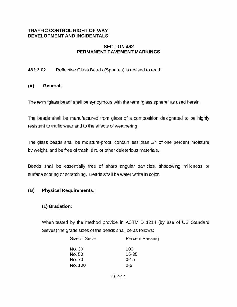
TRAFFIC CONTROL RIGHT-OF-WAY DEVELOPMENT AND INCIDENTALS
SECTION 462PERMANENT PAVEMENT MARKINGS
462-14
462.2.02 Reflective Glass Beads (Spheres) is revised to read:
(A) General:
The term “glass bead” shall be synoymous with the term “glass sphere” as used herein.
The beads shall be manufactured from glass of a composition designated to be highly
resistant to traffic wear and to the effects of weathering.
The glass beads shall be moisture-proof, contain less than 1/4 of one percent moisture
by weight, and be free of trash, dirt, or other deleterious materials.
Beads shall be essentially free of sharp angular particles, shadowing milkiness or
surface scoring or scratching. Beads shall be water white in color.
(B) Physical Requirements:
(1) Gradation:
When tested by the method provide in ASTM D 1214 (by use of US Standard
Sieves) the grade sizes of the beads shall be as follows:
Size of Sieve Percent Passing
No. 30 100No. 50 15-35No. 70 0-15No. 100 0-5

TRAFFIC CONTROL RIGHT-OF-WAY DEVELOPMENT AND INCIDENTALS
SECTION 462PERMANENT PAVEMENT MARKINGS
462-15
(2) Roundness:
When tested by the method provided in ASTM D-1155 (Procedure B except
paragraphs (F) and (G) are deleted) beads retained on any screen specified in
the gradation requirements should contain a minimum of 75 % true spheres.
(3) Index of Refraction:
When tested by a liquid immersion method at a temperature of 25 degrees C, the
beads shall have an index of refraction of 1.50 to 1.57.
(4) Specific Gravity:
The specific gravity of the beads shall be in the range 2.40-2.60 when tested in
accordance with the following procedures:
Place 100grams in an oven at 110 C for 1 hour.
Remove beads and place in desiccation until the sample is cool.
Remove approximately 60 grams of beads from the desiccate and weight the
sample accurately.
Pour the beads slowly in a clean 100 ml graduated cylinder containing 50 ml of
isopropyl alcohol. Make certain that air is not entrapped among the beads.

TRAFFIC CONTROL RIGHT-OF-WAY DEVELOPMENT AND INCIDENTALS
SECTION 462PERMANENT PAVEMENT MARKINGS
462-16
The total volume, minus 50, will give the volume of the beads.
Calculate the specific gravity as follows:
Specific Gravity = Weight of sample
Volume of the Sample
(5) Chemical Stability:
Beads which show any tendency toward decomposition, including surface
etching when exposed to atmospheric conditions, moisture dilute acids, or alkalis
or paint film constituents, may be required to demonstrate satisfactory
reflectance behavior, prior to acceptance, under such tests as may be
prescribed.
(C) Moisture Proofing:
All glass beads shall have a moisture-proof overlay consisting of water repellent
material applied during the process of bead manufacture. The beads so treated shall
not absorb moisture in storage and shall remain free of clusters and lumps and shall
flow freely from dispensing and testing equipment.
The beads shall pass the tests for water repellent and free flow using the following
equipment:

TRAFFIC CONTROL RIGHT-OF-WAY DEVELOPMENT AND INCIDENTALS
SECTION 462PERMANENT PAVEMENT MARKINGS
462-17
(1) Test bag:
The bag used is approximately 10 ½ inches x 17 ½ inches after sewing. The
material used in the construction of the bag is unbleached cotton sheeting with a
thread count of 48 x 48. The material before sewing is approximately 18 inches x
22 inches. The cloth is folded in half lengthwise and stitched into shape of an “L”
with short side left open at the top. The material can be obtained from selected
manufactures of cloth and paper packaging. The finished bag may also be
obtained from the manufacturer of the glass beads.
Newly fabricated bags must be thoroughly washed with hot water and detergent
and rinsed before use to remove the sizing which may be present in the cloth.
Subsequent to the initial washing, the bags need only be rinsed clean of beads
from previous tests and dried thoroughly before use.
(2) Funnel:
The funnel is a standard laboratory funnel with a top opening diameter of 125
mm. And 150 mm. stem length. The inside diameter of the stem is between 9
and 10 mm. This funnel is available from most laboratory glassware supply
houses. (Corning No. 6100 or equal).
(3) Ring Stand and Clamp.
(4) Balance accurate to 0.1 grams.

TRAFFIC CONTROL RIGHT-OF-WAY DEVELOPMENT AND INCIDENTALS
SECTION 462PERMANENT PAVEMENT MARKINGS
462-18
(5) Distilled water.
MOISTURE TESTING PROCEDURE:
Glass beads shall be tested for compliance to specification requirements. Testing shall
be conducted at standard conditions of temperatures (25 + degree C) and humidity (50
+ 5 percent R. H.) And shall consist of the following procedure or an approved alternate:
Weight 900.0 grams of glass beads into a clean, dry, flat-bottomed pan.
Dry beads at 150 degrees C for two hours.
Cool beads to room temperature (25 + 1 degree C) in a desiccate.
Using the clean, pre-washed bag described under apparatus section, turn the bag
inside-out so that the sewn seam and seam-allowance are on the outside.
Quantitatively transfer the beads into the inverted cotton bag.
Grasp the gathered top of the bag with one hand and lower the bag into a container of
distilled water until the beads are approximately one inch below the water level. The
container shall be of such dimensions that the bag does not contact the bottom or sides
during immersion. Each bag shall be immersed individually. Do not allow one bag to
contact another if multiple test are run.

TRAFFIC CONTROL RIGHT-OF-WAY DEVELOPMENT AND INCIDENTALS
SECTION 462PERMANENT PAVEMENT MARKINGS
462-19
Remove the bag after 30 seconds of immersion time.
Cradle the bottom of the bag uniformly in the palm of one hand and twist the top neck of
the bag until the twisted bag is compressed firmly against the beads. Twist until excess
water no longer drips from the bag.
After the excess water has been squeezed from the bag, allow the bag to unwind.
Gather the top of the bag and clamp. Suspending the bag on a ring stand or other
support such that the bottom or sides of bag do not contact the support.
After a standing time of 2 hours at room temperature (25 degrees + 1 degrees C),
remove bag from support. Mix sample thoroughly by holding the bottom seam
allowance in one hand and gathered neck of the bag in the other, invert bag and shake
up and down 5 times.
Transfer the sample into a clean, dry funnel of the type described under apparatus.
APPLICATION: The first paragraph of the Standard Specifications is modified to add:
Painting shall not be performed when the atmospheric temperature is below 50/ F
temperature during the drying period. Water-borne paints shall not be applied if rain is
expected within one hour of its application. Water-borne paint shall not be heated to a
temperature greater than 150/ F. to accelerate drying.

TRAFFIC CONTROL RIGHT-OF-WAY DEVELOPMENT AND INCIDENTALS
SECTION 470CERAMIC PAVEMENT MARKINGS
470-1
Description:
The work under this item shall consist of furnishing all labor, equipment and materials
necessary to install ceramic pavement markings for the use of stop bars and
crosswalks.
Construction Requirements:
The portion of the highway markers are installed shall be free of dirt, existing painted
lines, curing compound, grease, oil, moisture, loose or unsound layers and any other
material which could adversely affect the bond of the adhesive. The method of milling
the asphaltic concrete to recess the tiles flush with the pavement surface shall include
the use of high- pressure air spray. The milling equipment shall be capable of removing
the existing asphaltic concrete by means of grinding to a controlled grade and line within
0.01 foot or the recommended removal depth to accommodate the specified tile. The
removal shall be accomplished in a manner which does not destroy the integrity of any
asphaltic concrete pavement and shall not result in contamination of the milled asphaltic
concrete by the underlying base material.
The adhesive shall be placed uniformly on the cleaned pavement surface in an amount
sufficient to result in complete coverage of the area of contact of the markers, with no
voids present. A perimeter coat of the adhesive shall be applied all around the
recessed sides of the markers. The markers shall be protected against impact until the
adhesive has set a minimum of 4 hours from the last marker set.

TRAFFIC CONTROL RIGHT-OF-WAY DEVELOPMENT AND INCIDENTALS
SECTION 470CERAMIC PAVEMENT MARKINGS
470-2
Excess adhesive on the pavement, and on the exposed surfaces of the markers, shall
be immediately removed. Thinners or solvents which may be detrimental to either the
markers or the bond provided by the adhesive shall not be used in removing excess
adhesive.
Markers shall not be installed when the temperature of the atmosphere is less than 6
degrees C, when the relative humidity is 80 percent or higher, when the temperature is
below the dew point, or when the pavement surface is not dry.
25% (1 in 4) of the markers shall be retroflectivized on the front rank of the stop bars.
Pedestrian crosswalks shall be 25% retroflectivized on the approaching one half of the
front rank on the first line.
Material:
The following is an approved ceramic marking material:
Ceramic Surfacing Laminate, Style SB3, Recessed Mounted
This product has been approved by ADOT Traffic Control Products Evaluation
Committee (TCPEC) for highway use. The pavement marker shall have a textured
white finish and retain 50% of the minimum directional reflectivity, as defined within
ADOT spec.706 (75 min), after 8 months of installation. The installer shall provide a 5
year warranty for the materials and labor.
TRAFFIC CONTROL RIGHT-OF-WAY DEVELOPMENT AND INCIDENTALS
SECTION 470CERAMIC PAVEMENT MARKINGS
470-3
Supplier Information: Safeline Industries
P. O. Box 6506
Yuma, AZ 85366-6506
520-317-9087
Adhesive shall be a 2-part epoxy as recommended by the supplier.
Method of Measurement:
Ceramic Pavement Markings will be measured by the linear foot along the centerline of
the pavement marking and will be based on a one (1) foot wide stripe as shown in the
plans. Measurement for pavement lines with a plan width greater or less than the basic
one foot will be made by proportioning the unit bid price.
Basis of Payment:
The accepted quantities for Ceramic Pavement Markings, measured as provided above,
will be paid for at the contract unit price, which price shall be full compensation for the
work, complete in place, as specified and described herein, and as shown on the project
plans.

TRAFFIC CONTROL RIGHT-OF-WAY DEVELOPMENT AND INCIDENTALS
SECTION 492DEMOLITION
492-1
492.1 Description:
The work under this section shall include demolition and cleaning of all improvements
and obstacles on the site that are above the natural ground line including, but not limited
to, buildings, sheds, structures, fences, abandoned equipment and supplies, trees,
debris and all items that exist on the site.
492.2 Submittals:
The Contractor is to provide a schedule and sequence of his work, and a method to
control dust during the demolition. The Contractor is to provide a copy of all required
permits and a schedule for disconnecting utilities.
492.3 General Requirement:
492.3.1 Permits and Fees: The Contractor shall obtain and pay for any required dust
control permits. The Contractor shall obtain all required demolition work permits
491.2.2 Dust and Debris Control: The Contractor shall prevent the spread of dust
and debris to adjacent property and avoid the creation of a nuisance or hazard in the
surrounding area. The Contractor shall sweep the sidewalk as often as necessary.
492.3.3 Regulatory and Safety Requirements: The Contractor shall comply with all
applicable Federal, State, and Local demolition hauling and disposal regulations. Safety
requirements shall conform with the applicable American National Standards Institute

TRAFFIC CONTROL RIGHT-OF-WAY DEVELOPMENT AND INCIDENTALS
SECTION 492DEMOLITION
492-2
(ANSI), Section A10.6 "Demolition Operation-Safety requirements" and the applicable
Safety Standards of the Occupational Safety and Health Administration (OSHA) and the
Arizona Department of Environmental Quality (ADEQ). Asbestos inspection, handling
and removal shall conform to the Environmental Protection Agency (EPA) and, but not
limited to, the Asbestos Hazard Emergency Response Act (AHERA).
492.3.4 Trees: Trees on the project site shall be removed as part of this work. Trees
may be cut down at ground surface level.
492.4 Material and Equipment
The Contractor shall provide all material and proper and adequate equipment to perform
the work.
492.5 Construction Methods
492.5.1 Utility Disconnect: La Paz County shall notify all serving utilities and arrange
for disconnect and removal to the property line. Meters shall be removed by the
responsible utility. The Contractor shall proceed with demolition work after being
cleared by the utility companies.
492.5.2 Salvage: Items that are not the property of a utility company, shall be removed
by the Contractor.

TRAFFIC CONTROL RIGHT-OF-WAY DEVELOPMENT AND INCIDENTALS
SECTION 492DEMOLITION
492-3
492.5.3 Demolition: The Contractor shall remove all existing structures, buildings,
sheds, fences, posts, fences, utility lines, abandoned equipment plus items that exist on
the site above natural ground level. The Contractor shall provide barricades in
accordance with local regulations and requirements, and as specified herein. The
Contractor shall keep streets, roads, and sidewalks clean and free of debris.
492.5.4 Explosives and Burning: Explosives and burning are prohibited.
492.5.5 Disposal of Materials: The Contractor shall promptly remove all materials and
debris resulting from demolition work and disposal shall be in a legal manner. The
Contractor shall transport debris preventing spillage on public streets and roads.
Hauling and disposal shall comply with Federal, State and Local regulations. Tipping
and disposal fees charged at the Landfill will be paid directly by the Contractor and shall
be included in this bid.
492.6 Measurement and Payment: Measurement shall be by each separate lot in
accordance with the bid proposal. Payment shall be by the contract unit price to provide
demolition for all items on each lot which price shall be full compensation for furnishing
all labor, material, equipment, tools and fees to perform work necessary to complete the
demolition.

TRAFFIC CONTROL RIGHT-OF-WAY DEVELOPMENT AND INCIDENTALS
SECTION 495REMOVE AND REPLACE EXISTING FENCES
495-1
495.1 SCOPE:
The Contractor shall furnish all labor, materials and equipment necessary to remove
and replace fences within the street right-of-way as noted in the special provisions.
495.2 GENERAL:
At least 15 days prior to any construction in that area the Contractor shall be
responsible for contacting all property owners having fences that must be moved to
clear for construction. If the property owners do not remove the fences, the Contractor
shall do so in accordance with the requirements of the special provisions.
495.3 MATERIALS:
Existing materials shall be reused if not damaged in the process of removal. The
Contractor is to furnish any additional material required to fulfill the special provisions.
495.4 CONSTRUCTION:
The Contractor shall remove existing fencing and posts to prevent damage and shall
reconstruct fences at the locations specified. When completed the fence shall be in
proper alignment with the post, plumb, and all wire taut.

TRAFFIC CONTROL RIGHT-OF-WAY DEVELOPMENT AND INCIDENTALS
SECTION 495REMOVE AND REPLACE EXISTING FENCES
495-2
495.5 MEASUREMENT AND PAYMENT:
(A) Measurement: This item will be measured by the linear foot of fence, in place, for all
fences necessary to be removed and relocated to clear the construction area.
(B) Payment: The amount of completed and accepted work measured as provided
above will be paid for at the contract price for "Remove and Replace Existing Fences"
which payment shall be full compensation for removal and replacing of all fences; and
for all labor, materials, tools, equipment and incidentals necessary to complete the work
as shown on the plans and specified herein.
The Contractor will provide temporary fences during period of time required for fence
construction. The temporary fence will be constructed to provide security and contain
pets within the yard.

STRUCTURES AND MASONRY
SECTION 502STRUCTURE EXCAVATION AND BACKFILL
502-1
502.1 DESCRIPTION:
Structure excavation shall consist of excavation and removal of all material necessary to
construct foundations for bridges, retaining walls, box culverts, large head walls, vaults,
pump stations, inlets, outlets and other structures and other excavations designated in
the plans or in these specifications.
Structure backfill shall consist of furnishing material plus placing and compacting backfill
material around structures to the lines designated in the plans/specifications.
Structure excavation and backfill shall include the furnishing of all materials, labor and
equipment.
502.2 LINE AND GRADE:
Structure excavation shall be constructed to line and grade stakes. Adequate staking
shall be accurately located to allow the Contractor to perform the work as per the plans.
Maintenance of the survey points and stakes shall be the sole responsibility of the
Contractor.
502.3 SHORING:
Where necessary, excavations shall be properly sheeted and braced, to furnish
acceptable working conditions. The bracing shall be so arranged as not to place any
stress on portions of the completed work until the general construction has proceeded
far enough to provide ample strength. Any damage to structures occurring through
STRUCTURES AND MASONRY
SECTION 502STRUCTURE EXCAVATION AND BACKFILL
502-2
settlements, water or earth pressures, slides, caves or other causes, due to failure or
lack of sheeting or bracing or improper bracing or through negligence or fault of the
Contractor shall be repaired by the Contractor at the Contractor’s own expense.
502.4 EXCAVATION:
The required excavation shall be performed in conformity to the lines, grades and cross
sections as shown on the plans.
The sides of excavations shall be sloped as required by soil conditions to stabilize the
sides for safe working conditions. Such excavation shall be limited to the amount
considered necessary for safety, in accordance with State of Arizona OSHA Safety and
Health Standards for the Construction Industry (Latest Edition).
When structure footings, concrete box culverts or other structures are to rest on an
excavated surface other than rock and no piles are used, care shall be taken to protect
the surface from water and to not disturb the bottom of the excavation. If material in the
bottom of the excavation is disturbed, or is removed for the Contractor's convenience,
the foundation shall be restored by the Contractor to a condition at least equal to the
undisturbed foundation.
When undisturbed original material at the planned grade of the excavation is
determined to be unsuitable material, the material shall be removed and the resulting
excavation backfilled with structure backfill material.

STRUCTURES AND MASONRY
SECTION 502STRUCTURE EXCAVATION AND BACKFILL
502-3
When structures are to rest upon rock, the rock shall be fully uncovered and the surface
shall be removed to a depth sufficient to expose sound rock. The rock shall be roughly
leveled, or cut to steps, and shall be roughened. Seams in the rock shall be grouted
under pressure or treated and the cost shall be paid for as extra work.
Where rock, or other unyielding material is encountered the yielding material shall be
removed for a minimum depth of two feet below grade and replaced with structure
backfill.
When structures are to be supported on piles excavations shall be completed to the
bottom of the footings before any piles are drilled or driven. When swell or subsidence
results from driving piles, the Contractor shall, at the Contractor’s expense, excavate or
backfill with suitable material to the grade of the bottom of the footings as shown on the
project plans.
When during the course of the structural excavation material is removed in excess of
requirements the Contractor shall backfill the excavated area in accordance with the
requirements for structure backfill as specified herein and no compensation will be
made for the additional material or work required.
Excavated material which is not suitable for, or not used as structure backfill, shall be
utilized either for the construction of embankment or removed from the site.
Suitable materials from structure excavation may be used in the construction of the
embankment, other purposes shown on the project plans or specified in the special
provisions.

STRUCTURES AND MASONRY
SECTION 502STRUCTURE EXCAVATION AND BACKFILL
502-4
502.5 TESTING AND INSPECTION BEFORE PLACEMENT OF CONCRETE:
Prior to placing concrete or masonry and after all excavation is completed, the area
shall be inspected and approved by the Public Works Director. After it has been
compacted to a uniform density of 95% or more of maximum density as determined by
ASTM D-2922 and D-3017 using standard Figure A for rock correction. A minimum of
one test shall be performed for each structure.
Structural backfill shall not be placed until the structure footing or other portion of the
structure, or facility, has been inspected by the Public Works Director and approved for
backfilling.
502.6 REMOVAL OF WATER:
The Contractor shall provide and maintain ample means and devices with which to
promptly remove and properly dispose of all water entering the excavations or any part
of the work. Dewatering shall be accomplished in accordance with Section 447 and as
specified in the plans and specifications/special provisions.
502.7 BLASTING:
All blasting operations shall be in accordance with Section 204.

STRUCTURES AND MASONRY
SECTION 502STRUCTURE EXCAVATION AND BACKFILL
502-5
502.8 STRUCTURE BACKFILL:
Structure backfill material shall be selected from site excavations or be provided by the
Contractor. It shall not contain frozen lumps, stones larger than three inches in
diameter, chunks of clay or other objectionable material. Backfill material to be used for
metal piles, or similar items of metal, shall have a value of resistivity not less than 3000
ohm-cm or the value shown on the project plans, whichever is less. Backfill material
shall have a pH value between 6.0 and 9.0, inclusive. Test for pH, percent passing, or
resistivity, shall be before backfilling operation starts.
Structure backfill material shall conform to the following gradation:
Sieve Size Percent Passing
3 inch 100
3/4 inch 60-100
No. 8 35- 80
No. 200 0-12
The plasticity index shall not exceed 12 when tested in accordance with the
requirements of AASHTO T-90.

STRUCTURES AND MASONRY
SECTION 502STRUCTURE EXCAVATION AND BACKFILL
502-6
502.9 USE OF SLURRY:
As an alternate to the material requirements of Structural Backfill, the Public Works
Director may allow material conforming to the following requirements to be used in a
slurry mixture in situations where the slurry will be confined by free-draining soils:
Sieve Size Percent Passing
1 inch 100
1-1/2 inch 90-100
No. 8 35- 80
No. 200 0- 12
The plasticity index shall not exceed 8, or less than 1, when tested in accordance with
the requirements of AASHTO T-90.
502.10 PLACEMENT OF BACKFILL:
All earth material which has loosened or collapsed into the excavation from the adjacent
ground and all trash, forms and loose large rock shall be removed from the excavation
before backfill is placed.
Backfill material shall not be placed against the back of concrete abutments, concrete
retaining walls or cast-in-place concrete structures until the concrete has developed its
full design strength.

STRUCTURES AND MASONRY
SECTION 502STRUCTURE EXCAVATION AND BACKFILL
502-7
Backfill material shall not be placed against concrete structures not designed to retain
earth loads until the concrete has attained a minimum compressive strength of 2,000 psi
and in no case less than 72 hours.
Unless otherwise shown on the plans or designated in the special provisions, minor
structures such as catch basins or other structures which are furnished as precast
structures shall be placed on a layer of structure backfill at least six inches in depth.
The layer shall have been shaped to fit the bottom surface of the precast unit and
compacted to a density of not less than 100 percent of the maximum density. At the
time the unit is placed the moisture content of the layer shall be at or near the optimum
moisture. After the unit has been initially set in place and checked for line and grade, it
shall be removed and any defects in its bearing area shall be corrected by trimming and
by placing and compacting similarly moistened structure backfill. The process of
removal, correction and replacement shall continue until the imprint of the unit on the
bearing area indicates essentially uniform contact and the unit is in reasonable
conformity with the lines and grades shown on the project plans.
Where a structure is located within a paved area, all backfill material above finished
subgrade elevation shall conform to the requirements of the typical pavement section of
the same elevations.
Backfill compacted by pneumatic, or mechanical tamping devices, shall be placed in
layers not more than eight inches in depth before compaction. Backfill placed as a
slurry shall be placed in uniform horizontal layers not exceeding four feet in depth. The
maximum water content of the slurry mixture shall be 35 gallons of water per ton of
backfill material.

STRUCTURES AND MASONRY
SECTION 502STRUCTURE EXCAVATION AND BACKFILL
502-8
Aggregate slurry shall be thoroughly mixed in a mixer. The slurry shall be compacted
with internal vibrators.
502.11 COMPACTION OF BACKFILL:
All structural backfill in any existing or proposed street or where any portion of the
backfill is within 2 feet of the above shall be compacted to the minimum density
specified in Table 601-2, for Type I.
All other structural backfill shall be compacted to the minimum density of 95%. One test
minimum per each four foot of backfill on each structure.
502.12 MEASUREMENT AND PAYMENT:
No payment will be made for structure excavation and backfill. The cost shall be
included in the price bid for the construction, or installation, of the items in which
excavation and backfill are incidental or appurtenant.

STRUCTURES AND MASONRY
SECTION 505CONCRETE STRUCTURES
505-1
505.1 DESCRIPTION:
The work shall consist of furnishing all materials, labor, equipment, supplies plus
performing all work necessary to construct concrete bridges, culverts, catch basins,
retaining walls, abutments, piers, footings, foundations, vaults, pump stations and
similar structures in accordance with the plans and specifications.
505.2 MATERIALS & RELATED WORK:
Concrete shall conform to the requirements of Section 725. Reinforcing steel shall
conform to the requirements of Sections 518 and 727. Mortar shall conform to the
requirements of Section 776. Expansion joint filler shall conform to Section 729.
Concrete curing materials shall conform to Section 726. Concrete joints and water
stops shall conform to Section 507. Dampproofing and waterproofing concrete surfaces
shall conform to Section 442.
505.3 SUBMITTALS:
Prior to the start of forming, the Contractor shall submit three (3) sets of shop drawings
of the reinforcing steel and the attachment of any equipment to the concrete structures
direct to the Public Works Director for approval.
505.4 EXCAVATION AND BACKFILL:
All excavation and backfill work shall be in accordance with Section 502.
STRUCTURES AND MASONRY
SECTION 505CONCRETE STRUCTURES
505-2
505.5 SUBGRADE FOR CONCRETE STRUCTURES:
Each subgrade upon which concrete is placed shall be firm and free from water. Ground
water shall be kept several inches below subgrade until the concrete has set. When the
subgrade is in dry earth, it shall be moistened with water from a spray nozzle
immediately before concrete is placed.
When the design details for the project provide for the construction of filter or drain
material consisting of gravel or combination of gravel and sand, which material
becomes subgrade for concrete, the placing of steel reinforcement and pouring of
concrete shall follow the placing of the filter or drain material as closely as practical.
The filter or drain material shall be kept dewatered to the extent necessary to prevent
any portion of concrete materials being carried away before the concrete has attained
its final set. No payment will be made for the work required to keep such materials
dewatered.
When concrete is to rest on rock, the rock shall be fully uncovered. The surface of the
rock shall be removed to a depth sufficient to expose sound rock. Bedrock shall be
roughly leveled off or cut to approximately horizontal and vertical steps. Seams in the
rock shall be grouted and the base for structures shall be slush grouted.
505.6 SHORING:
Shoring shall be accordance with Section 502.

STRUCTURES AND MASONRY
SECTION 505CONCRETE STRUCTURES
505-3
505.7 DEWATERING:
Dewatering shall be in accordance with Section 447.
505.8 LINE AND GRADE:
Structures shall be constructed to line and grade stakes. Adequate staking shall be
accurately located to allow the Contractor to perform the work as per the plans.
Maintenance of the survey points and stakes shall be the sole responsibility of the
Contractor.
505.9 FORMS:
Forms shall be of suitable material and of type, size, shape, quality and strength to
enable construction as designed. The forms shall be true to line and grade, mortar tight
and sufficiently rigid to resist any appreciable amount of springing out of shape during
placing of the concrete. The responsibility for their adequacy shall rest with the
Contractor. All dirt, chips, sawdust, nails and other foreign matter shall be completely
removed from forms before any concrete is deposited. The surfaces of forms shall be
smooth and free from irregularities, dents, sags and holes that would appreciably
deface the finished surface. Forms previously used shall be thoroughly cleaned of all
dirt, mortar and foreign matter before being reused, and the reuse of forms shall be
subject to the approval of the Public Works Director. Before concrete is placed in forms,
all inside surfaces of the forms shall be thoroughly treated with an approved releasing
agent that will leave no objectionable film on the surface of the forms that can be

STRUCTURES AND MASONRY
SECTION 505CONCRETE STRUCTURES
505-4
absorbed by the concrete. Care shall be exercised that no releasing agent is deposited
on previously placed concrete.
Forms for all surfaces that will not be completely enclosed or hidden below the
permanent surface of the ground shall be made of surfaced lumber or material which
will provide a surface at least equally satisfactory. Any lumber or material which
becomes badly checked or warped prior to placing concrete shall be rejected.
Forms for all exposed surfaces of bridges, viaducts, over crossings and similar
structures shall be constructed of plywood or an approved equal. Plywood for forms
shall be exterior type, of the grade Concrete-Form Exterior, conforming to the
specifications of the NBS, Commercial Standards, latest edition. Plywood shall be
furnished and placed in 48 inch widths and in uniform lengths of not less than 96 inches,
except where the dimension of the member formed is less than the specified panel
dimension. Plywood shall be placed with the grain of the outer plies in the direction of
the span. Where plywood is attached directly to the studding or joints, the panels shall
be not less than 5/8 inch thick and the studdings or joints shall be spaced not more than
12 inches, center to center. Plywood less than 5/8 inch thick, otherwise conforming to
the requirements specified, may be used with a continuous backing of 3/4 inch
sheathing. All form panels shall be placed in a neat, symmetrical pattern with the
horizontal joints level and continuous.
Wood forms for copings and curbs shall have a thickness of not less than 1-5/8 inches
and a width of not less than the full depth of coping or curb.

STRUCTURES AND MASONRY
SECTION 505CONCRETE STRUCTURES
505-5
Unless otherwise shown on the plans, all sharp edges shall be chamfered with 3/4 inch
triangular fillets. Forms for curved surfaces shall be constructed and placed so the
finished surface will not deviate appreciably from the arc of the curve.
Forms shall be constructed that portions, where finishing is required, may be removed
without disturbing portion of forms to remain.
Forms for girders and slabs shall be cambered as required by plans/specifications.
Forms shall be constructed so the form marks will conform to the general lines of the
structure.
Form clamps or bolts shall be used to fasten forms. The use of twisted wire loop ties to
hold forms in position will not be permitted, nor shall wooden spreaders be used.
Clamps or bolts shall be of sufficient strength and number to prevent spreading of the
forms. They shall be of such type that they can be entirely removed or cut back 1 inch
below the finished surface of the concrete. Forms for outside surfaces shall be
constructed with stiff wales at right angles to the studs and all form clamps shall extend
through and fasten such wales, all based on the rate of concrete pour.
The Contractor may pour such portions of the concrete for the structure directly against
the side of the excavation or sheathing without the use of outside forms, provided the
following conditions are met.

STRUCTURES AND MASONRY
SECTION 505CONCRETE STRUCTURES
505-6
(A) If concrete is poured directly against the sides of the excavation, the faces of the
excavation must be firm and compact and be able to stand without sloughing off and be
at all points outside the concrete lines shown on the plans.
(B) If concrete is poured against sheathing, such sheathing shall be closely fitted and
shall be outside of the concrete lines shown on the plans. Those surfaces against
which the concrete is to be poured shall be faced with building paper. All sheathing
shall be removed, but not until either at least 7 days after placing concrete or until the
concrete has attained a strength in compression of not less than 2,000 psi. Care shall
be used in pulling sheathing to avoid damaging the concrete. Voids left by the removal
of sheathing, piles and/or similar sheathing supports shall be backfilled with material
having a sand equivalent of not less than 30 and consolidated by jetting as directed by
the Public Works Director. If field conditions, or the type of sheathing or methods of
construction used by the Contractor, are such to make the removal of sheathing
impracticable then the portion of the sheathing against which concrete has been poured
may be left in place.
Regardless of the method used in pouring concrete without outside forms the following
stipulations shall prevail:
(A) The reinforcing steel shall be accurately set and held firmly in place.
(B) No direct payment will be made for building paper, sheeting, qunite, or concrete
placed outside of concrete lines shown on the plans. The cost thereof shall be
absorbed in the prices bid for the various items of work.

STRUCTURES AND MASONRY
SECTION 505CONCRETE STRUCTURES
505-7
(C) The Contractor shall assume all risks of damage to the work, or to existing
improvements, due to any reason that may be attributed to the method of construction
outlined above.
505.10 FALSEWORK:
All falsework shall be designed and constructed to provide the necessary rigidity and to
support the loads. Falsework for the support of a superstructure shall be designed to
support the loads that would be imposed if the entire superstructure were poured at one
time.
All falsework, staging, walkways, forms, ladders, cofferdams and similar accessories
shall equal or exceed the minimum applicable safety requirements of Section 107.
Compliance with such requirements shall not relieve the Contractor from full
responsibility for the adequacy and safety of said items.
Falsework shall be founded upon a solid footing safe against undermining and protected
from softening. When the falsework is supported on timber piles, the piles shall be
driven to a bearing value as determined by the formula specified in Section 501, equal
to the total calculated pile loading. The maximum calculated pile loading should not
exceed 20 tons.
Falsework and forms shall be so constructed as to produce in the finished structure the
lines and grades indicated on the plans. Suitable jacks or wedges shall be used in
connection with the falsework to set the forms to grade or camber shown on the plans
or to take up any settlement in the form work either before or during the placement of

STRUCTURES AND MASONRY
SECTION 505CONCRETE STRUCTURES
505-8
concrete. Single wedges for this purpose will not be permitted; it being required that all
such wedges be in pairs to insure uniform bearing. Dead load deflection in stringers
and joints will be compensated for by varying the depths of the joists or by using varying
depth nailing strips.
Arch centering shall be removed uniformly and gradually, beginning at the crown and
working toward the springing, to permit the arch to take its load slowly and evenly.
Centering for adjacent arch spans shall be struck simultaneously.
Falsework under any continuous unit or rigid frame shall be struck simultaneously; the
supporting supports being released gradually and uniformly, starting at the center and
working both ways towards the supports.
505.10.1 Falsework Design: Falsework shall be designed by the Contractor to carry all
loads and pressures, which may be applied to it. The construction loads to be applied
are as follows:
Tunnel centering -- 100 percent of the concrete load where concrete is placed by
pumping. Forms shall be so constructed to provide adequate relief for excessive pump
pressure.
All other structures -- a live load of 30 pounds per square foot of horizontal area.
Transverse and longitudinal bracing -- a horizontal force equal to 2 percent of the
vertical load.

STRUCTURES AND MASONRY
SECTION 505CONCRETE STRUCTURES
505-9
The unit stresses for wood falsework shall be those recommended in the West Coast
Lumbermen's Association's standard grading and dressing rules increased 25 percent
for short time loading.
Falsework may be bolted or spiked at the option of the Contractor, but the use of bolts
and spikes shall not be combined in the same connection. The allowable spacing and
connection values of bolts and spikes shall be in accordance with the national design
specifications for stress-grade lumber and its fastenings as recommended by National
Lumber Manufacturers Association except that an additional allowance of 25 percent for
temporary use shall be added to the connection values for bolts and spikes.
Ends of columns bearing on wedges shall be tied in both directions by grits.
Unit stresses for steel falsework shall be in accordance with the requirements of the
specifications for design, fabrication and erection of structural steel for buildings of the
AISC.
505.11 PLACING REINFORCEMENT:
Reinforcing bars shall be accurately placed as shown on the plans and in accordance
with Section 727 and shall be firmly and securely held in position by wiring at all
intersections with wire not smaller than No. 16 gage and by using concrete or metal
chairs, spacers, metal hangers, supporting wires and other approved devices of
sufficient strength to resist crushing under full load. Wooden supports shall not be
used.

STRUCTURES AND MASONRY
SECTION 505CONCRETE STRUCTURES
505-10
Placing bars on layers of fresh concrete as the work progresses and adjusting bars
during the placing of concrete shall not be permitted. Before placing in the forms, all
reinforcing steel shall be thoroughly cleaned of mortar, oil, dirt, loose mill scale, loose or
thick rust and coatings of any character that would destroy or reduce the bond. No
concrete shall be deposited until the placing of the reinforcing steel has been inspected
and approved.
Bundle bars shall be tied together at not more than 6 foot centers.
505.11.1 Splicing: Splices of bars shall be made only where shown on the plans.
Where bars are spliced they shall be lapped at least 30 diameters, unless otherwise
shown on the plans.
Welding of reinforcing steel will not be permitted.
505.11.2 Bending Reinforcement: Bends and hooks in bars shall be made in the
manner prescribed in the ACI, Manual of Standard Practice.
Bars shall not be bent nor straightened in a manner that will injure the material. Bars
with kinks or unspecified bends shall not be used.
505.11.3 Welded Wire Fabric: Welded wire fabric shall he held firmly in place and
spliced not less than 2 meshes.

STRUCTURES AND MASONRY
SECTION 505CONCRETE STRUCTURES
505-11
505.12 INSPECTION:
During forming and reinforcing bar installation safe and suitable ladders and scaffolds
shall be provided to permit access to all portions of the work for inspection. Before
placing any concrete for the structure, the Contractor shall notify the Public Works
Director that he is ready to pour concrete and obtain approval from the Public Works
Director.
Concrete sampling and testing shall conform to Section 725.
505.13 PLACING CONCRETE:
Where a schedule for placing concrete is shown on the plans, no deviation will be
permitted.
The placing of concrete for a given pour shall start at the low point and shall proceed
upgrade.
With the exception of concrete placed in slope paving, aprons and concrete placed
under water, all concrete shall be compacted by means of high frequency internal
vibrators of a type, size and number appropriate for the placement. The number of
vibrators employed shall be ample to consolidate the incoming concrete to a proper
degree within 15 minutes after it is deposited in the forms. At least 2 vibrators shall be
available at the site of the structure in which more than 25 cubic yards of concrete is to
be placed. The vibrators shall not be attached to or held against the forms or the
reinforcing steel. The locations, manner and duration of the application of the vibrators

STRUCTURES AND MASONRY
SECTION 505CONCRETE STRUCTURES
505-12
shall be such as to secure maximum consolidation of the concrete without causing
segregation of the mortar and coarse aggregate, and without causing water or cement
paste to flush to the surface. Fresh concrete shall be spread in horizontal layers as
practicable and the thickness of the layers shall not be greater than can be satisfactorily
consolidated with the vibrators. If additional concrete is to be placed, care shall be
taken to remove all laitance and to roughen the surfaces of the concrete to insure that
fresh concrete is deposited upon sound concrete surfaces. Layers of concrete shall not
be tapered off in wedge-shaped slopes, but shall be built with square ends and level
tops.
Mixed concrete, after being deposited, shall be consolidated until all voids are filled and
free mortar appears on the surface. The concrete shall be placed as nearly as possible
in its final position and the use of vibrators for extensive shifting of the mass of fresh
concrete will not be permitted.
Fresh concrete shall not be permitted to fall from a height greater than 6 feet without the
use of adjustable length pipes or elephant trunks.
The use of approved external vibrators for compacting concrete shall be permitted when
the concrete is inaccessible for adequate compaction provided the forms are
constructed sufficiently rigid to resist displacement or damage from external vibration.
During the placing of concrete, care shall be taken that methods of compaction used will
result in a surface of even texture free from voids, water or air pockets, and that the
coarse aggregate is forced away from the forms in order to leave a mortar surface.
Spades or broad-tined forks shall be used to produce the desired results.

STRUCTURES AND MASONRY
SECTION 505CONCRETE STRUCTURES
505-13
Wherever chutes are used they shall be laid at such inclination as will allow the flow of
concrete of such consistency as required. The use of additional water in mixing the
concrete to promote free flow in chutes of low inclination shall not be allowed.
Where necessary, in order to prevent segregation, chutes shall be provided with baffle
boards or a reversed section at the outlet.
Columns shall be poured through pipes of adjustable length and not less than 6 inches
in diameter.
Horizontal members or sections shall not be placed until the concrete in the supporting
vertical members or sections has been consolidated and a minimum 2 hour period has
elapsed to permit shrinkage to occur.
Walkways shall be provided along each side and for the full length of bridge structures
outside the deck area. These walkways shall be of sufficient width, and so constructed
as to provide for the support of the bridges from which the longitudinal floats specified
are to be operated. Inspection walkways and access thereto shall be provided under
the deck forms between each pair of girders and outside of each outside girder for the
full length of the bridge structure. The walkways shall be not more than 8 feet below the
concrete to be inspected.
505.13.1 JOINTS AND WATERSTOPS: Joints and waterstops shall be constructed at
the locations specified on the project plans and in accordance with Section 507.

STRUCTURES AND MASONRY
SECTION 505CONCRETE STRUCTURES
505-14
505.13.2 ADVERSE WEATHER CONCRETING:
(A) Hot Weather Concreting: Hot weather is defined as any combination of high ambient
temperature, low relative humidity and wind velocity which would tend to impair the
quality of fresh concrete. These effects become more pronounced as wind velocity
increases. Since last minute improvisations are rarely successful, preplanning and
coordination of all phases of the work shall be required to minimize these adverse
effects.
As an absolute minimum, the Contractor shall ensure the following measures are taken:
1. An ample supply of water, hoses and fog nozzles are available at the site.
2. Spare vibrators are on hand in the ratio of one spare vibrator for each three in use.
3. Preplanning has been accomplished to ensure prompt placement, consolidation,
finishing and curing of the concrete.
4. Concrete temperature on arrival should be approximately 60oF and in any event shall
not exceed 90oF. The use of cold water and ice is recommended.
5. The subgrade is moist, but free of standing water.
6. Fog spray is utilized to cool the forms and steel.
STRUCTURES AND MASONRY
SECTION 505CONCRETE STRUCTURES
505-15
Under extreme conditions of high ambient temperature, exposure to the direct rays of
the sun, low relative humidity and wind, even strict adherence to these measures may
not produce the quality desired and it may be necessary to restrict concrete placement
to early morning only. If this decision is made then particular attention shall be directed
to the curing process since the concrete will be exposed to severe thermal stresses due
to temperature variation; heat of hydration plus midday sun radiation versus nighttime
cooling.
(B) Cold Weather Concreting: Concrete shall not be placed on frozen ground, nor shall
it be placed when the ambient temperature is below 40oF, unless adequate means are
used to heat the aggregate and/or water and satisfactory means have been taken for
protecting and heating the concrete during the curing period.
(C) Wet Weather Concreting: Placing of concrete shall be discontinued when the
quantity of rainfall is such as to cause a flow or wash to the surface. Any concrete
already placed and partially cured shall be covered to prevent dimpling. A construction
joint will be installed prior to shut down.
(D) Replacement of Damaged or Defective Concrete: All concrete which has been
damaged or is defective, shall be replaced by the Contractor at no cost to La Paz
County.
(E) Recommended Reference:
1. ACI-305 Hot Weather Concreting
2. ACI-306 Cold Weather Concreting
3. ACI-308 Recommended Practices for Curing Concrete

STRUCTURES AND MASONRY
SECTION 505CONCRETE STRUCTURES
505-16
505.14 CONCRETE DEPOSITED UNDER WATER:
When conditions render it impossible or inadvisable to debater excavation before
placing concrete, the Contractor shall deposit under water, by means of a trim or
underwater bottom dump bucket, a layer of concrete of sufficient thickness to thoroughly
seal the cofferdam. To prevent segregation the concrete shall be carefully placed in a
compact mass and shall not be disturbed after being deposited. Water shall be
maintained in a still condition at the point of deposit.
A tremie shall consist of a watertight tube having a diameter of not less than 10 inches
with a hopper at the top. The tube shall be equipped with a device that will close the
discharge end and prevent water from entering the tube while charging the tube with
concrete. The tremie shall be supported so as to permit free movement of the
discharge end over the entire top surface of the work and to permit rapid lowering to
retard or stop the flow of concrete. The discharge end shall be closed at the start of the
work to prevent water entering the tube and shall be entirely sealed at all times except
when concrete is being placed. The tremie tube shall be kept full of concrete.
When a batch is dumped into the hopper the flow of concrete shall be induced by
slightly raising the discharge end always keeping it in the deposited concrete.
The flow shall be continuous until the work is completed and the resulting concrete seal
shall be monolithic and homogeneous.
The underwater bucket shall have an open top and the bottom doors shall open freely
and outward when tripped. The bucket shall be completely filled and slowly lowered to
STRUCTURES AND MASONRY
SECTION 505CONCRETE STRUCTURES
505-17
avoid backwash and shall not be dumped until it rests on the surface upon which the
concrete is to be deposited. After discharge, the bucket shall be raised slowly until well
above the concrete.
Concrete deposited in water shall have 10 percent extra cement added.
505.15 CURING:
After the completion of the specified finishing operations and as the condition of the
concrete will permit, without danger of consequent damage all exposed surfaces shall
either be sprinkled with water, covered with earth, sand or burlap; sprayed with a curing
compound or sealed with a material conforming with Section 726. All concrete for
bridge structures shall be water cured.
Concrete that is water cured shall be kept wet for at least 10 days after being placed
and be covered with at least 2 layers of not lighter than 7 ounce burlap, except that
handrail, base rail, railing posts, tops of walls and similar parts of the structure, if water
cured, shall be covered with burlap as above prescribed, immediately following the
finishing treatment specified therefor.
The covering shall not be removed in less than 4 days. Roadway areas, floors, slabs,
curbs, walks and the like, that are water cured, should be covered with sand to a depth
of at least 2 inches, in lieu of the burlap as specified above, as soon as the condition of
the concrete will allow. The covering shall remain wet and in place until the concrete
covered is at least 10 days old.

STRUCTURES AND MASONRY
SECTION 505CONCRETE STRUCTURES
505-18
When a sprayed impervious membrane is used it shall be applied under pressure
through a spray nozzle in a manner and quantity as to entirely cover and seal all
exposed surfaces of the concrete with a uniform film. To ensure complete coverage the
membrane shall be applied in two applications for a total coverage of 150 square feet
per gallon. The membrane shall not be applied to any surface until all the finishing
operations have been completed; such surfaces being kept damp, until the membrane
is applied. All surfaces on which a bond is required, such as construction joints, shear
planes, reinforcing steel and the like, shall be adequately covered and protected before
starting the application of the sealing medium in order to prevent any of the membrane
from being deposited thereon; and any such surface with which the seal may have
come in contact shall immediately thereafter be cleaned. Care shall be exercised to
avoid and prevent any damage to the membrane seal during the curing period. Should
the seal be broken or damaged before the expiration of 10 days after the placing of the
concrete, the break shall be immediately repaired by the application of an additional
impervious membrane over the damaged area.
If any forms are removed earlier than 10 days after the placing of the concrete, the
surface exposed shall be immediately sprayed with a coating of the membrane seal or
kept continuously wet by the use of burlap or other suitable means until the concrete
has cured for at least 10 days.
When tops of walls are cured by the membrane sealing method, the side forms (except
metal forms), shall be kept wet for the 10 days following the placing of the concrete.
If due to weather conditions there is a chance of the fresh concrete checking or cracking
prior to the commencement of the curing operations, the concrete shall be kept damp,

STRUCTURES AND MASONRY
SECTION 505CONCRETE STRUCTURES
505-19
but not wet, by means of an indirect fine spray of water until danger of the checking or
cracking is past or until the curing operations are started in the particular area affected.
Since hot weather leads to rapid drying of concrete, protection and curing are critical.
Water curing should be used wherever it is practical and shall be continuous to avoid
volume changes due to alternation of wetting and drying. The need for adequate
continuous curing is greatest during the first few hours after placement of concrete in
hot weather.
505.16 FINISHING CONCRETE:
Immediately after the removal of forms all concrete surfaces shall be finished in
accordance with the requirements specified below.
All surfaces scheduled to be covered with backfill shall be finished so as to be free of
open and rough spaces.
All surfaces that will remain exposed in the completed work shall be finished so as to be
free of open and rough spaces, depressions or projections. All angles and fillets shall
be sharp and true and the finished surface shall present a pleasing appearance of
uniform color.
All top surfaces of walls, abutments, piers, etc., shall be finished to a smooth surface
and shall be cured by an approved method.

STRUCTURES AND MASONRY
SECTION 505CONCRETE STRUCTURES
505-20
If rock pockets or honeycomb are of such an extent and character as to affect the
strength of the structure and to endanger the steel reinforcement the Public Works
Director shall declare the concrete defective and require the removal and replacement
of that portion of the structure affected by the Contractor at no additional cost to La Paz
County.
If finishing operations are not carried out as set forth below, all placing of concrete shall
stop until satisfactory arrangements are made by the Contractor to promptly correct
defective finishing work and to carry out finishing operations as specified.
One of the classes of finish as specified shall be applied to the various surfaces as set
forth under applicability of finishes.
505.16.1 Finishing Fresh Concrete in Bridge Decks: Upon placing the deck to a
uniform and true surface, screed supports shall be removed from the surface and any
necessary hand finishing shall be accomplished in areas where the screed supports
have been removed.
After the floating, as specified above, is completed; the concrete surface shall be
textured with a burlap drag or a drag boom.
The finished surface will be tested with a 10 foot straightedge furnished by the
Contractor. The testing will be accomplished by holding the straightedge in contact with
the deck surface and parallel to the centerline. The surface shall not vary more than 1/8
inch from the lower edge of the straightedge. Areas showing high spots of more than
1/8 inch shall be corrected by cutting or planing. The cutting or planing machine shall

STRUCTURES AND MASONRY
SECTION 505CONCRETE STRUCTURES
505-21
be a rotary type, equipped with an adjustable cutter and having a minimum wheelbase
of 10 feet. Areas showing low spots of more than 1/8 inch shall be filled with an
approved mixture of sand, cement and epoxy. The mixture shall firmly adhere to the
surface and shall match the surrounding concrete. All areas corrected shall not show
deviations in excess of 1/8 inch when tested with a 10 foot straightedge.
505.16.2 Finishing Fresh Concrete in Sidewalks and Bridge Sidewalks: After the
concrete has been placed and spread between the forms, it shall be thoroughly worked
until all the coarse aggregate is below the surface and the mortar comes to the top.
Concrete may be consolidated by means of mechanical vibrators.
The surface shall be struck off and worked to grade and cross section with a wood float.
A mechanical finishing machine that will consolidate the concrete and strike off and
finish the surface may be used provided the machine produces a sidewalk equal to or
better in all respects than that produced by the methods specified herein.
The surface shall be sweat finished by means of a steel trowel or light broom finished.
The sidewalks shall be marked and edged with the proper tools to form the joints,
marking and edges shown on the plans.
505.16.3 Finishing Green Concrete:
(A) Class I Finish -- All bolts, wires and rods shall be clipped and recessed. All holes,
honeycomb, rock pockets and other surface imperfections shall be cleaned out,

STRUCTURES AND MASONRY
SECTION 505CONCRETE STRUCTURES
505-22
thoroughly moistened and carefully patched with mortar. Mortar shall be composed of 1
part of cement and 2 parts of fine sand. A portion of the required cement for mortar
shall be white as required to match the color of the surrounding concrete.
(B) Class II Finish -- The surface shall be patched and pointed as specified above for
Class I Finish and then promptly covered with polyethylene film, wet burlap or wet
cotton mats. If polyethylene film is used, the film shall be held securely to the surface by
means of weights, adhesive or other suitable means. Only white polyethylene film for
covering will be acceptable.
When the mortar used in patching and pointing has set sufficiently, the surface shall be
uncovered and thoroughly rubbed with either a float or a carborundum stone until the
surface is covered with a lather. Cork, wood or rubber floats shall be used only on
surfaces sufficiently green to work up such lather, otherwise a carborundum stone shall
be used. During the rubbing process, a thin grout composed of 1 part cement and 1
part of fine sand may be used to facilitate producing a satisfactory lather; however, this
grout shall not be used in quantities sufficient to cause a plaster coating to be left on the
finished surface. A portion of the required cement for grout shall be white as required to
match the color of the surrounding concrete. Rubbing shall continue until irregularities
are removed and there is no excess material. At the time a light dust appears, the
surface shall be brushed or sacked. Brushing or sacking shall be carried in one
direction so as to produce a uniform texture.
(C) Class III Finish -- The surface shall be treated as specified above under Class II
Finish except that after brushing, the surface shall again be securely covered with
polyethylene film, wet burlap or wet cotton mats. In not less than 1 day nor more than 4

STRUCTURES AND MASONRY
SECTION 505CONCRETE STRUCTURES
505-23
days, the surface shall be uncovered and rubbed with a carborundum stone. This
rubbing shall continue until the entire surface is of a smooth texture and uniform color.
During the process, the use of a thin mixture of equal parts of sand and cement with
water will be permitted. At the time a light dust appears, the surface shall be brushed or
sacked, care being taken to carry this brushing in one direction so as to produce a
uniform texture.
505.16.4 Finishing Hardened Concrete: If for reasons beyond the control of the
Contractor more than 6 days have elapsed between the time of placing concrete and
the time of the removal of forms, the concrete shall be considered as hardened. Prior to
finishing hardened concrete, the surface shall be covered with burlap or cotton mats
and kept wet for a period of at least 1 hour. Finishing shall be identical to the respective
requirements for Class I, Class II and Class III Finish for green concrete, except that the
use of a mechanically operated carborundum stone will be required for Class II and
Class III Finishes.
505.16.5 Applicability of Finishes:
(A) Surfaces requiring Class I Finish -- All formed structures that are to be covered by
backfill and those surfaces that are normally not in view of either vehicular or pedestrian
traffic such as the surfaces on the inside of barrels of culverts, the under surfaces of
decks, surfaces of concrete girders, piers and abutment walls.
(B) Surfaces requiring Class II Finish -- All exposed surfaces of headwalls, wing walls,
deck edges on culverts, end of piers on bridges and culverts, vaults, pump stations,
retaining walls and those vertical surfaces under highway grade separation structures

STRUCTURES AND MASONRY
SECTION 505CONCRETE STRUCTURES
505-24
that are exposed to view of the traveling public, including piers and pier caps, the
outside face of outside girders and other similar surfaces.
When surfaces of uniform texture and appearance are obtained through the use of first
class metal forms, paper tubing or the use of special form coatings and the use of
special care, such surfaces may be excluded from the surfaces requiring Class II Finish.
(C) Surfaces requiring Class III Finish for bridge structures --All formed or finished
surfaces above the surface of the deck on the roadway side of the handrail and the
outside vertical surfaces from the top of handrail and dado to the lower edge of the
chamfer at the bottom of the deck.
505.17 REMOVAL OF FORMS:
The falsework supporting any span of a continuous or rigid frame structure subject to
bending stress, shall not be released until after the last concrete placed in the span and
in the adjoining spans, excluding concrete above the deck slab, has attained a
compressive strength of not less than twice the design unit stress, or 21 days after the
concrete is placed, whichever occurs first.
Stairway riser forms shall be removed and the finish of the steps completed on the day
the concrete is placed. Metal stairway treads, if required by the plans, shall be installed
immediately after the steps have been placed.
Side forms for beams, girders, columns, railings or other members wherein the forms do
not resist dead load bending shall be removed not more than 24 hours after placing

STRUCTURES AND MASONRY
SECTION 505CONCRETE STRUCTURES
505-25
concrete. Where finishing is required satisfactory arrangements shall be made to cure
and protect the concrete thus exposed.
Side forms for arch rings, columns and piers shall be removed before the members of
the structure which they support are poured or placed so the quality of the concrete may
be inspected. Such forms shall be constructed so they may be removed without
disturbing other forms which resist direct load or bending stress.
Forms and shoring for box and arch sections of sewers and storm drains may be
removed as follows:
(A) Forms for open channel walls -- 16 hours.
(B) Outside forms of box sections and inside wall forms of box sections which do not
support the slab forms -- 16 hours.
(C) Arch sections in open cut -- 12 hours.
(D) Slab forms for box sections:
(1) Type II Cement -- 48 hours or 6 hours per foot of span between supports,
whichever is greater.
(2) Type III Cement -- 24 hours or 3 hours per foot of span between supports,
whichever is greater.

STRUCTURES AND MASONRY
SECTION 505CONCRETE STRUCTURES
505-26
(3) Type V Cement -- 56 hours or 7 hours per foot of span between supports,
whichever is greater.
The periods of time at which the Contractor may remove forms, as set forth above, are
permissive only and subject to the Contractor's assuming all risks that may be involved
in such removals. At his option, except for surfaces to be finished, the Contractor may
leave the forms in place for longer periods than required.
505.18 DAMPPROOFING AND WATERPROOFING:
Dampproofing and waterproofing shall be in accordance with the plans and Section 442
of these specifications.
505.19 EQUIPMENT AND MATERIAL:
All equipment and materials furnished for the structure shall conform to the
requirements on the plans or the special conditions.
505.20 MEASUREMENT AND PAYMENT:
Payment for portland cement concrete structures will be made in conformity with the
terms of the contract and will be based on unit prices and/or lump sums as set forth in
the proposal. Such payment shall include full compensation for furnishing all labor,
materials, tools and equipment, preparation of subgrade for placing of concrete,
furnishing and placement of steel, curing, waterstops, waterproofing, dewatering, and

STRUCTURES AND MASONRY
SECTION 505CONCRETE STRUCTURES
505-27
doing all work required to construct the structures in conformity with the plans and
specifications.
Where concrete is scheduled for payment on the basis of cubic yards, the calculation of
the quantity of concrete for payment will be made only to the neat lines of the structures
as shown on the plans and on the basis of the concrete having the specified lengths,
breadths and thicknesses. However, all concrete shall be placed to line and grade
within such tolerances which are reasonable and acceptable for the type of work
involved.
The quantity of such concrete will be calculated considering the mortar used to cover
construction joints as being concrete and no deductions will be made for rounded or
beveled edges, space occupied by reinforcing steel, metal inserts or openings 5 square
feet or less in area. The cost of cement used in mortar for covering construction joints,
patching or other uses in the structure being constructed, in excess of that required for
the design mix of the adjacent concrete, shall be absorbed in the item of work of which
said mortar is a part.
The quantity of reinforcing steel, when scheduled as a separate item, will be calculated
for payment on the basis of the number of each type bar actually placed in accordance
with the plans. The weight will be calculated using the theoretical lengths of bars placed
and the unit weight per linear foot specified in ASTM A-305.

STRUCTURES AND MASONRY
SECTION 507CONCRETE JOINTS AND WATERSTOPS
507-1
507.1 DESCRIPTION:
The work shall consist of furnishing all materials labor, equipment, supplies and perform
all work necessary to install construction and expansion joints, PVC water stops,
premolded joint filler, joint sealant, bond breaker tape, preformed control joints, backing
rod, steel expansion joint dowels and joint sealants in accordance with the plans,
standards, specifications, and special provisions.
507.2 RELATED WORK:
Mortar shall conform to the requirements of Section 776. Expansion joint filler shall
conform to Section 729.
507.3 SUBMITTALS:
Contractor shall submit manufacturer's literature, catalog data and statement of
compliance with referenced standards and specifications for materials specified herein.
Contractor shall submit material samples of waterstops and premolded filler.
Contractor shall provide technical data sheets for the personnel and La Paz County
covering joint preparation, priming and sealant materials application.

STRUCTURES AND MASONRY
SECTION 507CONCRETE JOINTS AND WATERSTOPS
507-2
507.4 MATERIALS:
507.4.1 PVC Waterstop:
A. Waterstops shall be extruded from a PVC compound and shall be lock-rib,
center-bulb or flat-strip type as manufactured by B.F. Goodrich Company, Kirkhill
Rubber Company, Green Streak Plastic Products Company or equal.
B. Waterstops shall be of the dimensions and profile shown on the drawings.
C. The basic resin of the material shall be a PVC resin plastic, containing
nonmigrating-type plasticizers, and shall not be appreciably affected by alkali, acids, or
saltwater. All material shall be virgin material; do not use reworked PVC or other
substitute.
507.4.2 Joint Sealant for Concrete Structures: The joint sealant shall be a two-part,
gray, nonstaining, nonsagging, polyurethane sealant, which cures at ambient
temperature to a firm, flexible, resilient, tear-resistant rubber. Sealant shall be PRC
270, Multi-Chem MC287, Sikaflex 2C or equal.

STRUCTURES AND MASONRY
SECTION 507CONCRETE JOINTS AND WATERSTOPS
507-3
TECHNICAL REQUIREMENTS
Consistency Gun grade
Tack Free Time 24 hours at 750 and 50% R.H.
Pot Life 1 to 3 Hours
Hardness 30 Shore A, + /-5
Elongation 650%
Tensile Strength, ASTM D 142 200 psi
Peel Strength on Concrete No loss of bond after 24 hours at 150%elongation
Temperature Service Range -400F to +1750F
Immersion in water Continuous
507.4.3 Bond Breaker Tape: Bond breaker tape shall be an adhesive-backed glazed
butyl or polyethylene tape which will adhere to the premolded joint material or concrete
surface. The tape shall be the same width as the joint. The tape shall be compatible
with the sealant.
507.4.4 Premolded Joint Filler: Joint filler shall be preformed, nonextruded type
constructed of closed-cell neoprene conforming to ASTM D 1752, Type I, as
manufactured by W. R. Grace Company of Cambridge, Massachusetts; W. R.
Meadows, Inc., Elgin, Illinois; or an approved equal.

STRUCTURES AND MASONRY
SECTION 507CONCRETE JOINTS AND WATERSTOPS
507-4
507.5 CONSTRUCTION METHODS:
Except as otherwise specified herein concrete joints and water stops shall be
constructed at the locations and in accordance with the project plans.
507.5.1 Construction Joints: Construction joints - Except under emergency
conditions, construction joints shall be planned and located in advance of placing
concrete. All construction joints shall be perpendicular to the principal lines of stress
and in general located at points of minimum shear and movement.
Construction joints shall be keyed, unless otherwise detailed. Form keyways shall be
beveled strips or boards placed at right angles to the direction of shear. Except where
otherwise shown on the drawings or specified, keyways shall be at least 1-1/2 inches in
depth over at least 25% of the area of the section.
When it is necessary to make a joint because of an emergency (an interval of 45
minutes between two consecutive batches of concrete shall constitute cause for an
emergency) reinforcing dowels shall be furnished and placed across the joint. Dowels
are to be embedded 48 bar diameters each side of the joint. Size and number of
dowels shall match reinforcing in the structure. Furnishing and placing such reinforcing
steel shall be at the Contractor's expense.
After placing concrete is completed at the construction joint and before placing fresh
concrete, the exposed reinforcing steel and the entire surface of the construction joint
shall be thoroughly cleaned of surface laitance, curing compound and other materials
foreign to the concrete and clean, coarse aggregate shall be exposed. Surfaces of

STRUCTURES AND MASONRY
SECTION 507CONCRETE JOINTS AND WATERSTOPS
507-5
concrete that has been in place for eight hours or more shall be cleaned by abrasive
blast methods. Surfaces of concrete that has been in place for less than eight hours
may be cleaned with air and water jets provided that surfaced laitance and curing
compound is removed.
After the concrete surface has been treated as specified, it shall be cleaned of all dust
and abrasive material.
All horizontal construction joints or those on slight slopes, shall be covered with Class D
mortar as specified in Section 776. The mortar shall be spread uniformly and worked
thoroughly into all irregularities of the surface. The water-cement ratio of the mortar in
place shall not exceed that of the concrete to be placed, and the consistency of the
mortar shall be suitable for placing and working.
507.5.2 Expansion and Contraction Joints: Expansion and contraction joints in the
concrete structures shall be formed where shown on the plans. In general, such joints
shall have smooth abutting surfaces. Painted or separated and sealed as detailed on
the plans. No reinforcement shall be extended through the joints except where
specifically noted or detailed on the plans. Concrete or mortar shall not be permitted to
lap these joints in such a manner as to affect a tie or bond that would later promote
spalling.
Provide expansion joints with continuous edge reservoirs, which shall be filled with a
joint sealant. The material used for forming the reservoirs shall be in place until
immediately before the grooves are cleaned and filled with joint sealant. After removing
edge forms from the reservoir, remove grout, loose concrete and fines; then sandblast

STRUCTURES AND MASONRY
SECTION 507CONCRETE JOINTS AND WATERSTOPS
507-6
the slots. Allow the reservoirs to become thoroughly dry, then blow out the reservoirs
and immediately prime and fill with the expansion joint sealant and backup materials.
The primer used shall be supplied by the same manufacturer supplying the joint sealant.
Application criteria for the sealant materials, such as temperature and moisture
requirements and primer cure time, shall be in accordance with the recommendations of
the sealant manufacturer.
Masking tape shall be applied along the edges of the exposed surface of the exposed
joints. Trowel the joints smooth with a tuck pointing tool wiped with a solvent
recommended by the sealant spillage.
Where premolded filler is specified joints shall be installed as shown on the plans.
Concrete shall be attached with a bonding agent recommended by the joint sealant and
joint filler manufacturer for compatibility. Expansion joint guards shall be in accordance
with plans.
Plates, angles or other structural shapes provided as expansion guards for open joints
shall be fabricated at the shop to conform to the section of the concrete slabs.
These guards shall comply with the details shown on the project plans.
507.5.3 Water Stops: Water stops of rubber or plastic, shall be placed in accordance
with the details shown on the project plans. Where movement at the joint is provided
for, the water stops shall be of a type permitting such movement without injury. They
shall be spliced, welded or soldered to form continuous watertight joints.

STRUCTURES AND MASONRY
SECTION 507CONCRETE JOINTS AND WATERSTOPS
507-7
Construct forms for construction joints shall be constructed in a manner to prevent injury
to waterstops. Waterstops shall be held securely in position in the construction joints by
wire ties. Continuous construction and expansion joints in hydraulic structures.
Field splices shall be made with a thermostatically controlled heating iron in
conformance with the manufacturer's current recommendations. At least 10 minutes
shall be allowed before pulling or straining the new splice in any way. The finished
splices shall provide a cross section that is dense and free of porosity with tensile
strength of not less than 80% of the unspliced materials.
507.6 MEASUREMENT & PAYMENT:
No payment will be made for concrete joints and waterstops; the cost thereof shall be
included in the price bid for the construction or installation of the items to which the work
is incidental or appurtenant.

STRUCTURES AND MASONRY
SECTION 510CONCRETE BLOCK MASONRY
510-1
510.1 DESCRIPTION:
The work consists of furnishing all materials labor, equipment, supplies and tools to
perform work necessary to construct concrete block masonry walls and units including
excavation, placing footings, placing reinforcing grouting, back filling and all associated
work in accordance with plans and County Construction Standards.
510.2 MATERIALS:
All materials for concrete block masonry shall conform to the requirements of Sections
775 and 776.
510.3 EXCAVATION AND COMPACTION:
All excavation for footings or related work shall be in accordance with Section 601.
510.4 CONSTRUCTION:
Proper masonry units shall be used to provide for all windows, doors, bond beams,
lintels, pilasters, etc. with a minimum of unit cutting. Where masonry unit cutting is
necessary, all cuts shall be neat and regular. Edges exposed in the finished work shall
be cut with a power driven abrasive saw.
Where no bond pattern is shown, the wall shall be laid up in a straight uniform course
with a regular running bond and alternate header joints in vertical alignment.

STRUCTURES AND MASONRY
SECTION 510CONCRETE BLOCK MASONRY
510-2
Intersecting masonry walls and partitions shall be bonded by staggering the joints to
form a masonry bond and the use of 1/4 inch minimum diameter ties at 24 inches o.c.
maximum.
Where stack bond is indicated on the plans, approved metal ties shall be provided
horizontally at 24 inches o.c. maximum.
Where masonry facing is a part of wall construction metal ties shall be furnished and
installed.
Mortar joints shall be straight, clean and uniform in thickness. Horizontal and vertical
joints shall be approximately 3/8 inch thick with full mortar coverage on the face shells
and shall have vertical joints buttered for a thickness equal to the face shell of the block.
These joints shall be shoved tightly, to ensure the mortar bonds to both blocks.
Slushing or grouting of a joint shall not be permitted, nor shall a joint be made by
working in mortar after the units have been laid.
Exposed walls shall have joints tooled with a round bar, or V-shaped bar to produce a
dense, slightly concave surface well bonded to the block at the edges. Tooling shall be
done when the mortar is partially set but still sufficiently plastic to bond. All tooling shall
be done with a tool that compacts the mortar, pressing the excess mortar out of the joint
rather than dragging it out.
If it is necessary to move a block to open a joint, the block shall be removed from the
wall, cleaned and set in fresh mortar.

STRUCTURES AND MASONRY
SECTION 510CONCRETE BLOCK MASONRY
510-3
510.5 PLACING REINFORCING STEEL:
Reinforcing steel shall be placed as indicated on the plans. Splices shall be lapped a
minimum of 40 diameters, except that dowels other than column dowels need to be
lapped only 30 diameters. Column dowels shall lap 50 diameters. Outside horizontal
steel shall lap around comers 40 diameters, and be carried through columns unless
otherwise shown on the plans. Inside horizontal steel shall extend as far as possible
and bend into corner core. A dowel shall be provided in the foundation for each vertical
bar. Bending of dowels to fit openings will not be permitted and, where required, new
dowels shall be installed by drilling and grouting. All lap joints shall be wired.
Vertical cores containing steel shall be filled solid with grout, and thoroughly rodded.
Where knockout blocks are used, steel shall be erected and wired in place before 3
courses have been laid. Vertical cores at steel locations shall be filled as construction
progresses.
Where knockout blocks are not used, vertical cores at steel locations shall be filled in
lifts of not more than 4 feet. The maximum height of a pour shall be 8 feet. Cores shall
be cleaned of debris and mortar and shall have reinforcing steel held straight in place.
Inspection and clean out holes shall be provided at the bottom of each core to be filled.
Reinforcing steel shall be inspected prior to placing grout.

STRUCTURES AND MASONRY
SECTION 510CONCRETE BLOCK MASONRY
510-4
510.6 BLOCK WALLS:
Non-retaining concrete block walls shall be constructed in accordance with La Paz
County Construction Standard 3-310.
510.7 CURING:
Newly constructed masonry shall be kept damp for at least 5 days with a nozzle
regulated fog spray sufficient to moisten faces of the masonry but not of such quantity
as to cause water to flow down over the masonry.
510.8 MORTAR AND GROUT:
Mortar and grout used for concrete block masonry shall conform to Section 776.
510.9 MEASUREMENT & PAYMENT:
Measurement and payment for concrete block masonry will be by the linear foot for
walls or be by lump sum price for the structure of which the masonry is a part, unless
another basis for payment is included in the proposal.

STRUCTURES AND MASONRY
SECTION 511BRICK MASONRY
511-1
511.1 MATERIALS:
Brick masonry shall be constructed of brick conforming to Section 775 and cement
mortar conforming to Section 776.
511.2 BRICKLAYING:
The amount of wetting will depend on the rate of absorption of the brick at the time of
laying. When being laid, the brick shall have suction sufficient to hold the mortar and to
delete the excess water from grout and shall be sufficiently damp so the mortar will
remain plastic enough to permit the brick to be leveled and plumbed after being laid
without breaking the mortar bond.
Brick work shall be plumb, level, straight and true to the dimensions shown on the
plans. Such work shall start at a least important corner of wall. All pattern work, bonds
or special details indicated on the plans shall be accurately and uniformly executed.
Face bonding shall be as shown on the plans and shall be a running bond for standard
size brick and approximately 1/3 bond for oversize brick and approximately 1/4 bond for
modular brick. All bed and head joints shall be solidly filled with mortar at the time of
laying.
The plans the thickness of mortar joints shall be uniformly 1/2 inch.
Face bricks shown to be laid in stack bond shall have the center lines of vertical joints
plumb and the brick laid equidistant from the center line with not more than 1/8 inch
STRUCTURES AND MASONRY
SECTION 511BRICK MASONRY
511-2
variation in the width of these joints. The brick in each separate stack shall not vary
more than 1/8 inch in length, but the separate stacks may vary in width of stacks.
When mortar has slightly stiffened the Contractor shall solidly the fill with mortar in
interstices between bricks, between bricks and other materials, and fill all line pin holes.
Jointing and tooling shall be done before mortar has stiffened.
Masonry to be plastered shall have all mortar joints trowel cut flush.
Masonry to be painted and not shown to be tooled or raked shall have all joints carefully
and evenly struck with a trowel.
Masonry to be left exposed without paint or plaster shall have all mortar joints carefully
and evenly tooled with a metal jointing tool. Masonry shown or indicated to have raked
joints shall have the joints raked out 3/8 inch deep, tooled with a flat jointing tool, and
brushed with a stiff non-metallic brush. Sack-rubbing or wiping finished masonry with
rags shall not be permitted.
511.3 PROTECTION:
Sills, ledges, offsets, and other materials shall be protected from droppings of mortar
during construction. The tops of all unfinished masonry shall be protected from rain by
using water-repellent covering such as roofing felt or tar paper.
The surfaces of wall, piers shall be protected from mortar droppings or splashes at
scaffold heights.

STRUCTURES AND MASONRY
SECTION 511BRICK MASONRY
511-3
511.4 CURING:
Finished masonry shall not be wetted, except when exposed to extreme hot weather or
hot wind and then only by using a nozzle regulated fog spray sufficient to dampen the
face but not of such quantity to cause water to flow down over the masonry.
511.5 REINFORCED GROUTED BRICK MASONRY:
Mortar in all bed joints shall be held back 1/4 inch from edges of brick adjacent to grout
space or shall be beveled back and upward from grout space. The thickness of head
and bed joints shall be as herein specified or shown. Head joints specified or shown to
be less than 5/8 inch thick, shall be solid filled with mortar as brick are laid. Head joints
5/8 inch or more in thickness may have mortar sufficient to form dams to retain the
grout. Bed joints shall not be deeply furrowed with the trowel. All brick shall be shoved
at least 1/2 inch into place. One outer tier shall be not more than 12 inches before
grouting, but the other tier shall be not more than 4 inches high before placing the grout.
Grout shall be thoroughly agitated and mixed to eliminate segregation before being
placed. Interior grout spaces shall be filled with grout and immediately puddled or
swished with a stick or rod (not a trowel) sufficiently to allow the grout to flow into all
interstices between the bricks and to fully encase the reinforcing steel. Grouting shall
be done from the inside face of exterior masonry. If any grout contacts the finished
masonry, it shall be immediately removed and the surface cleaned.
In masonry which is more than 2 tiers in thickness, including pilasters and column, the
interior shall be of whole or half bricks placed into grout with not less than 3/4 inch of
grout surrounding each brick or half brick. Except at the finish course, all grout shall be

STRUCTURES AND MASONRY
SECTION 511BRICK MASONRY
511-4
stopped 1-1/2 inches below the top of both outer tiers. Where necessary to stop off a
longitudinal run of masonry, it shall be done only by racking back 1/2 brick length in
each course and stopping grout 2 inches back of the rack. Toothing shall not be
permitted.
Reinforcing steel shall be accurately placed in strict accordance with the plans and
notes thereon. Vertical steel shall be held firmly in proper position. When necessary
this shall be done by means of frames or other suitable devices. Horizontal steel should
be placed as the work progresses.
511.6 MEASUREMENT AND PAYMENT:
Payment for brick masonry shall be included in the lump sum price for the structure the
masonry is a part unless another basis for payment is included in the proposal.

STRUCTURES AND MASONRY
SECTION 518STEEL REINFORCEMENT
518-1
518.1 DESCRIPTIONS:
The work under this section shall consist of fabricating, furnishing and placing steel
reinforcement of the quality, coating, type, size, shape and quantity designated in
accordance with the details shown on the project plans and the requirements of these
specifications.
518.2 MATERIAL:
Steel reinforcing bars, wire and welded wire fabric shall conform to the requirements of
Section 727.
518.3 SUBMITTAL:
Prior to the placement of steel reinforcement, the Contractor shall submit 3 copies of
shop drawings to the Public Works Director and obtain approval. When the project
plans show a bar list and bending diagram, the Contractor shall carefully check the
schedule against the details in advance of ordering materials. The shop drawings are to
show all lap splices and bends.
When bar bending diagrams are not shown on the project plans, shop drawings and
lists showing the bending of reinforcement bars shall be included in the submittal by the
Contractor to the Public Works Director. Approval shall not relieve the Contractor of
responsibility for the correctness of such drawings and lists.

STRUCTURES AND MASONRY
SECTION 518STEEL REINFORCEMENT
518-2
Any discrepancy or error found by the Contractor in checking a bar list or bending
diagram shown on the project plans or in preparing shop drawings or list shall be
reported immediately to the Public Works Director and the discrepancy or error shall be
corrected in advance of fabrication and delivery of materials.
518.4 CONSTRUCTION METHODS:
Steel reinforcement shall be protected at all times from damage. When placed in the
work, all reinforcement shall be free of dirt, oil, paint and grease. Rust, surface
irregularities or mill scale should not be cause for rejection, provided the weight,
dimensions, cross-sectional area and tensile properties of a manually wire brushed test
specimen are not less than the requirements of these specifications.
When bending is required, it shall be done without the use of heat and bars having
cracks or splits at the bends will be rejected. Grade 40 bars which are No. 8 and larger
and all sizes of Grade 60 bars shall not be rebent at the same location. Grade 40 which
are size No. 7 and smaller may be rebent once at the same location.
Reinforcement shall be accurately fabricated and placed as shown on the plans and
shall be firmly held in place by wire ties at all intersections and splices with 16 gauge or
heavier tie wires and with precast mortar blocks of ferrous metal chairs, spacers, metal
hangers, supporting wires, or other approved supports, at the spacing necessary to
maintain the specified clearance of the reinforcing steel. The use of pebbles, broken
stone, concrete masonry blocks, brick, metal pipe or wood blocks shall not be permitted
for the purpose of spacing or support. Where reinforcement spacing is less than 12

STRUCTURES AND MASONRY
SECTION 518STEEL REINFORCEMENT
518-3
inches in each direction alternate intersections may be tied. Tack welding of
reinforcement shall not be permitted.
The following tolerances shall be allowed when placing, tying and supporting reinforcing
steel:
A) In slabs and beams, horizontal bars shall be within 1/4 inch, measured vertically,
of the position indicated on the plans.
B) In slabs or walls, long runs of bars should vary up two inches in spacing,
however, the specified number of bars shall be placed.
C) No concrete shall be placed until reinforcement in the member has been
inspected and approved. Reinforcement which does not conform to the above
tolerances shall be adjusted or repaired prior to concrete placement.
Reinforcement to be encased in the concrete of a bridge shall be epoxy coated.
Reinforcement that is to be partially within the bridge deck concrete, but extends into
other structural elements, shall not require coating on that part which is to be outside
the bridge deck concrete.
518.5 SPLICING AND LAPPING:
All reinforcement shall be furnished in the full lengths indicated on the project plans.
Splicing of bars, except as shown on the plans will not be permitted. Splices shall be
staggered as far as possible. The type and method of splices or connections shall be
approved.

STRUCTURES AND MASONRY
SECTION 518STEEL REINFORCEMENT
518-4
The Contractor may use either lap splices, full welded splices or mechanical
connections for reinforcement bars up to and including bar size No. 11. Where the bar
size exceeds No. 11, full welded splices or mechanical connections shall be used.
Welded splices shall not be used on epoxy-coated bars to cause any heating of the
coating. All exterior surfaces of positive connectors for epoxy-coated bars shall have
the same coating as the bar.
In lapped splices, the bars shall be placed in contact with one another and wired
together in such a manner as to maintain a clearance of not less than the minimum
clear distance to other bars and the minimum distance to the surface of the concrete.
Lap lengths shall be as shown on the plans or a minimum of 40 bar diameters.
A full welded splice is a splice where the bars are butted and welded to develop, in
tension, at least 125 percent of the specified yield strength of the bar. Test
requirements shall be as specified in AWS D 12.1. Welding shall be performed in
accordance with the requirements the American Welding Society (AWS) structural
welding code AWS D1.1-80.
A mechanical connection is a connection where the bars are connected to develop, in
tension or compression at least 125 percent of the specified yield strength of the bar.
Mechanical splices shall be made in accordance with the manufacturer's
recommendations. The Contractor shall make three test splices of each size he intends
to splice. Two of the test splices shall be tension tested to 125 percent of the specified
yield strength of the bar and one splice shall be tested to destruction by an approved
laboratory and certified reports of the test shall be submitted to the Public Works

STRUCTURES AND MASONRY
SECTION 518STEEL REINFORCEMENT
518-5
Director for approval. Field splices shall be subject to visual inspection and splices
chosen at random by the Public Works Director shall be removed and tested to 125
percent of specified yield strength. Samples shall be at least 42 inches long with the
splice at mid-length.
Sheets of welded wire fabric or bar mat reinforcement shall overlap each other
sufficiently to maintain a uniform strength and shall be securely fastened at the ends
and edges. The edge lap shall not be less than one mesh width.
518.6 EPOXY-COATED REINFORCEMENT:
518.6.1 General: The requirements of this subsection for epoxy-coated reinforcement
are in addition to the previous requirements which apply to uncoated reinforcement.
518.6.2 Field Operations - Epoxy Coated Bar Reinforcement: All handling systems
for coated bars shall have padded contact areas for the bars, wherever possible. All
bundling bands shall be padded and all bundles shall be lifted with a strong back,
multiple supports or a platform bridge so as to prevent bar to bar abrasion from sags in
the bar bundle. The bars or bundles shall not be dropped or dragged.
Chairs, tie wires, and other devices used to support, position, or fasten the
reinforcement shall be made of, or coated with, a dielectric material.

STRUCTURES AND MASONRY
SECTION 518STEEL REINFORCEMENT
518-6
The Contractor shall be required to field repair damaged areas of the coating, and to
replace items exhibiting severely damaged coatings. The material used for field repair
shall be that supplied by the coating applicator.
Field repair shall be required wherever the area of coating damage exceeds two percent
of the surface area of the bar in a one foot length and the damaged spot is larger than
1/4 inch by 1/4 inch. Field repair shall not be allowed on bars which have severely
damaged coatings. A severely damaged coating is defined as a coating which has a
total damaged area greater than five percent of the surface area reinforcing bar.
A reinforcing bar having a coating determined by the Public Works Director to be
severely damaged shall not be incorporated in the work and it shall be removed from
the work site. All such bars shall be replaced in kind by the Contractor at no additional
cost to La Paz County.
518.7 DOWEL PLACEMENT:
Dowel placement shall consist of drilling or coring dowel holes, furnishing and placing
setting materials and placing steel metal dowels in accordance with the details shown
on the plans and the requirements of the specifications.
The diameter of dowel holes shall be 1/4 inch larger than the diameter of the dowels to
be placed and the depth of the holes shall be as shown on the plans.
Setting materials shall be an approved epoxy adhesive unless otherwise specified on
the plans.
STRUCTURES AND MASONRY
SECTION 518STEEL REINFORCEMENT
518-7
The minimum tensile pull out strength of the dowel anchorage shall be as specified on
the plans.
The Contractor shall submit details of the anchorage system prior to dowel placement.
518.8 METHOD OF MEASUREMENT:
518.8.1 General: No measurement for payment will be made for steel reinforcement,
whether coated, or uncoated, as required, which is included in precast or a concrete
item listed in the bidding schedule as a unit to be paid for at a lump sum price.
Steel reinforcement that is required on the plans to be epoxy-coated for use in bridge
concrete and is partially within the deck and projects into other structural elements shall
be included in the measurement and payment for Reinforcing Steel (Epoxy-Coated).
The Contractor shall be required to coat only that part of the reinforcement that is
contained in a deck.
In those cases where steel reinforcing is a separate pay item it will be measured as a
lump sum item or by the pound, as listed in the bidding schedule. Epoxy-coated
reinforcement will be measured separate from uncoated reinforcement.
Dowel placement will not be measured.
518.8.2 Lump Sum Basis: The project plans will show an estimated net weight of
reinforcing steel required for the work. This quantity shall be considered as
approximate only. It shall be the responsibility of the bidder to determine the exact

STRUCTURES AND MASONRY
SECTION 518STEEL REINFORCEMENT
518-8
quantities of all reinforcing steel required, by computations based upon the details and
notes shown on the project plans. It is understood that the quantities of all reinforcing
steel required for the work shall be furnished by the Contractor, including samples for
testing. Measurement of the quantity furnished will be made either when an alteration in
the work is ordered or when evidence shows a reason to believe the actual quantity of
reinforcing steel varies from the total quantity shown on project plans by three percent
or more. When an alteration in the work is ordered the actual quantity of reinforcing
steel will be computed by the Public Works Director and the amount of the increase or
decrease will be measured by the pound.
518.8.3 Pound Basis: Reinforcing Steel will be measured in pounds based on the total
computed weight for the size and lengths of bars, wire, or welded wire fabric as shown
in the plans.
The weight of bars will be calculated from weights shown in Table 518-1.
TABLE 518-1
Deformed Bar Weight - Pounds Nominal Designation Number Per linear Foot Diameter, Inches
3 0.376 0.3754 0.668 0.5005 1.043 0.6256 1.052 0.7507 2.044 0.8758 2.670 1.0009 3.400 1.12810 4.303 1.27011 5.313 1.41014 7.650 1.69318 13.600 2.257

STRUCTURES AND MASONRY
SECTION 518STEEL REINFORCEMENT
518-9
Note: The nominal diameter of a deformed bar is equivalent to the diameter of a plain
round bar having the same weight per foot as the deformed bar. Bar numbers are
based on the number of eighths of an inch included in the nominal diameter of the bars.
The weight of welded wire fabric will be computed from the theoretical weight of plain
wire of the corresponding gauge. If the weight per square foot is shown on the plans,
that weight will be used.
In measurement of the weight of epoxy-coated steel reinforcement, no addition to or
deduction from the weights shown on Table 518-1 will be made because of additional
requirements for blast cleaning and epoxy coating.
When laps are made for splices other than those shown on the plans for the
convenience of the Contractor, the extra steel will not be included in the measurement
for payment.
The measurement of samples for testing will be the weight in pounds of the samples or
the weight in pounds of the full length of reinforcing steel bars supplied for sampling
purposes when sampling is done at the construction site.
518.9 BASIS OF PAYMENT:
When a bid item is provided for in the proposal the accepted quantities of reinforcing
steel of the type shown in the bidding schedule, measured as provided above, shall be
paid for at the contract lump sum price, or the contract unit price per pound, complete in
place.

STRUCTURES AND MASONRY
SECTION 518STEEL REINFORCEMENT
518-10
The lump sum price, or unit price per pound, shall also include the cost of chairs,
supports, fasteners, connections, tie wire and any splices not specifically shown on the
plans. The substitution of larger bars than those specified, or splices not shown on the
plans, payment will be made only for the amount of steel which would have been
required if the specified size and length has been used.
No measurement, or direct payment, shall be allowed for furnishing and placing dowels
that are required to replace existing reinforcing damaged steel as a consequence of
Contractor's operations.

STRUCTURES AND MASONRY
SECTION 525 PNEUMATICALLY PLACED MORTAR
525-1
525.1 DESCRIPTION:
The work under this section shall consist of furnishing pneumatically placing materials by
means of suitable equipment and competent operators.
525.2 DRY MIX PROCESS:
The dry mix process shall consist of thoroughly mixing a proportional combination of fine
aggregate and portland cement and conveying the mixture through a delivery hose to a special
nozzle where water is added and combined with the dry ingredients prior to discharge. The
nozzle water ring shall be cleaned daily.
The fine aggregate shall be material sand conforming to ASTM C-33, with Gradation No. 1 as
shown in Table 525.1 and with not less than 3 percent or more than 7 percent moisture by
weight.
Portland cement and mixing water shall conform to the requirements of Section 725.
The dry mix shall consist of 1 part portland cement and 4.5 parts of fine aggregate by weight.
Machine mixing will be required.
525.3 WET PROCESS:

STRUCTURES AND MASONRY
SECTION 525 PNEUMATICALLY PLACED MORTAR
525-2
The wet process shall consist of premixing by mechanical methods a proportional combination
of portland cement aggregate and water required to produce mortar or concrete and
conveying this mortar or concrete through the delivery hose to the special
nozzle where additional compressed air is added prior to discharge. The air ports in the
nozzle shall be cleaned daily.
The portland cement concrete used for the Wet Mix Process shall conform to Section 725 and
shall be Class A (3,000 psi). In no event shall a slump greater than 4 inches be used. As the
work approaches the vertical, the maximum slump shall not exceed 1 inch.
The fine and coarse aggregate shall conform to ASTM C-33 using one of the three
graduations shown in Table 525.1. Gradation No. 1 will be used.
TABLE 525.1
(A.C.I. TABLE 2.2.1)
Percent by Weight Passing Individual Sieves
Sieve Size
Gradation No. 1
Gradation No. 2
Gradation No. 3
3/4 in. B
--
100
1/2 in. B
100
80-95
3/8 in. 100
90-100
70-95
No. 4 95-100
70-85
50-70

STRUCTURES AND MASONRY
SECTION 525 PNEUMATICALLY PLACED MORTAR
525-3
No. 8 80-100 50-70 35-55 No. 16
50-85
35-55
20-40
No. 30 25-60
20-35
10-30
No. 50 10-30
8-20
5-17
No. 100 2-10
2-10
2-10
* Batch fine and coarse aggregates separately to avoid segregation.
525.4 REINFORCING STEEL:
Reinforcing steel bars or welded-wire fabric shall conform to Section 727 and shall be 6 x 6 -
W 1.4 x 1.4 welded wire fabric. Reinforcement shall be placed as closely as possible to the
center of the mortar.
525.5 EQUIPMENT:
Prior to the start of construction, the Contractor shall demonstrate his equipment, materials,
and operators are capable of providing a finished structure in accordance with the
specifications. For this demonstration, the Contractor shall provide test panels, 30 inches by
30 inches, with a depth the same as the structure, but not less than 4 inches.
A separate panel shall be provided for each shooting position to be used (overhead, slope
and/or slab) and one half of each panel shall contain reinforcement as used in the structure.
Cores will be taken for visual inspection and compressive strength tests. The Public Works
Director has authority to accept, or reject, equipment, materials, and/or operators based on
the evaluation.

STRUCTURES AND MASONRY
SECTION 525 PNEUMATICALLY PLACED MORTAR
525-4
525.6 SURFACE PREPARATION:
The surface on which the mortar is to be placed shall be compacted and true to line and grade
as required by the plans and specifications. The surface shall be uniformly moistened so
water will not be drawn from the freshly-placed mortar. Placement of the mix shall not start until
the temperature is 35oF and rising and shall stop when the temperature is 40oF and falling.
525.7 FORMS AND GROUND WIRES:
Forms shall be plywood, or other suitable material, true to line and grade, sufficiently rigid to
resist deflection during mortar placement.
Ground, or gauging wires, shall be installed where necessary to establish the thickness and
finish lines of the structure.
525.8 JOINTS:
Construction joints shall be tapered to a shallow edge not more than one inch thick over a
width of approximately one foot except where the joint will be subjected to compressive stress.
In this case, square joints shall be constructed. Joints shall be thoroughly cleaned and wetted
prior to any additional application.
Control joints shall be installed according to the plans. Reinforcement shall not extend across
control joints.
525.9 FINISHING:

STRUCTURES AND MASONRY
SECTION 525 PNEUMATICALLY PLACED MORTAR
525-5
The natural gun finish shall be provided.
525.10 CURING
Curing shall be accomplished using Type 2 compound as specified in Section 726.
Application rate shall be not less than one tenth of a gallon per square yard. Section 505.13.2,
"Adverse Weather Concreting" is applicable.
525.11 TESTING:
Tests to determine the quality of the mortar shall be performed by a certified laboratory during
the course of work. Test panels shall be prepared by the Contractor.
Test panels shall be at least 12 inches square and as deep as the structure, but not less than 4
inches. Cores shall be taken from the panel for visual and compressive strength tests. The
minimum compressive strength at the end of 28 days shall be 3,000 psi.
The Public Works Director may allow the use of 6 inch by 12 inch hardware cloth cylinders for
testing in lieu of the test panels.
All rebound pockets and mortar defective in the compressive strength test shall be cut out and
replaced.
525.12 MEASUREMENT AND PAYMENT:

STRUCTURES AND MASONRY
SECTION 525 PNEUMATICALLY PLACED MORTAR
525-6
Payment for pneumatically-placed mortar will be made at the unit price per square yard or the
lump sum price as set forth in the proposal. Such payment shall be full compensation for
furnishing all labor, tools, equipment, and work in conformance with the plans and
specifications.

STRUCTURES AND MASONRY
SECTION 532CONCRETE CATCH BASINS
532-1
532.1 DESCRIPTION:
The work includes furnishing all materials, labor, and equipment to perform work
necessary to construct cast in place reinforced concrete catch basins includes curb
inlets, access openings, grate, and grate frame as shown on the plans and in
accordance with County construction standards. This includes excavations regardless
of the material encountered, or any necessary changes in depth due to unforeseen
underground obstruction. Also, included shall be compacted backfill and other
necessary operations to complete the work to the lines and grades indicated on the
drawings and as specified herein.
532.2 MATERIALS:
Portland cement concrete shall be Class "A" and shall conform with the requirements of
Section 725.
Reinforcing steel shall conform with the requirements of Sections 518 and 727.
All structural steel shall be ASTM A36.
All welding shall conform to the standard specifications for welded highway and railway
bridges of the American Welding Society.

STRUCTURES AND MASONRY
SECTION 532CONCRETE CATCH BASINS
532-2
532.3 SUBMITTALS:
Prior to forming, the Contractor shall prepare shop drawings and submit them for
approval. The drawings shall show complete fabrication, reinforcing steel layout and
how attachments are anchored.
The Contractor shall submit three (3) sets of prints of the completed and checked
drawings and obtain approval. The fabrication of any material prior to approval of the
drawings shall be at the Contractor's risk.
The approval of the drawings will be general and such approval will not relieve the
Contractor of any responsibility for the correctness of the drawings or for errors in
fabrication or field correctness.
532.4 LINES AND GRADE:
The catch basin shall conform to the lines and grades shown on the plans and meet
adjacent sidewalk, road, finished grades, curb and gutter surfaces with no offset greater
than 1/8 inch. The inlet gutter grades and pipe grades shall be as shown on the plans
or as established by the Engineer.
532.5 CONSTRUCTION METHODS:
532.5.1 Basin Standards: As specified on the plans, catch basins shall be constructed
in accordance with County Construction Standards 5-225 through 5-290.

STRUCTURES AND MASONRY
SECTION 532CONCRETE CATCH BASINS
532-3
531.4.2 Excavating and Backfilling: Excavating and backfilling work shall be
performed in accordance with Section 601. Excavation for the structure shall be made
to the lines and elevations shown on the plans. Backfilling shall commence subsequent
to approval of the outside structure.
532.5.3 Concrete Work: Concrete work construction on catch basins shall be in
accordance with Section 505. All material under the structure shall be firm and solid.
The walls of catch basins may be poured directly against the earth, provided a
satisfactory excavation is made true to the lines as shown on the drawings. In any
event, the back form shall be carried to a depth of at least 1 foot below the finished
ground line.
It is preferred that the structure be monolithic, without cold joints, however, if the
Contractor elects to pour in two sections, the joint shall be made at the top the footing,
and the footing poured to full depth and size before the wall forms are placed. The
bond at the cold joint shall be in accordance with Section 507.
The top of all walls around the inlets shall receive a smooth trowel finish and the edges
shall be neatly rounded.
Catch basins shall have troweled inverts to eliminate water from standing in bottom.
Concrete curing shall be in accordance with Section 726.
The catch basin seats and frames shall be constructed and set true to line and grade.

STRUCTURES AND MASONRY
SECTION 532CONCRETE CATCH BASINS
532-4
When specified on the project plans, aprons shall be constructed in accordance with the
details shown on the plans. Aprons shall be constructed from portland cement concrete
or from asphaltic concrete as shown.
Performed bituminous joint fill shall be installed where the catch basin concrete will
meet new or existing concrete curb or pavement.
532.5.4 Frame, Grates & Covers: Grates, frames, access openings and curb
openings shall be constructed in accordance with the plans.
The access covers and catch basin grates and frames shall be fabricated and installed
so that the bearing surfaces of the grates and access covers shall rest securely on the
bearing surfaces of the frames.
532.5.5 Metal Finishing: All structural members and assemblies shall receive one
shop coat of prime paint and one field coat of a paint in accordance with Section 790.
532.6 MEASUREMENT AND PAYMENT:
532.6.1 Measurement: This item will be measured as a unit for each catch basin
completed in place including frame, grates and access covers.
532.6.2 Payment: The amount of completed and accepted work, measured as
provided above, shall be paid for at the contract unit price. The price shall be full
compensation for all labor, materials and incidentals necessary to complete the work as
shown on the drawings and as specified herein.

STRUCTURES AND MASONRY
SECTION 545PUMP STATION
545-1
545.1 DESCRIPTION:
The work includes furnishing all materials, labor, equipment, supplies, and tools to
perform all work necessary to construct a storm water pump station with a precast
concrete pipe wet well. The work includes excavation, backfilling, site grading,
surfacing, concrete slabs, inlet pipe connection, wet well barrel, top slab with access
covers, liquid level sensors, discharge pipe, couplings, values, painting, other
appurtenances, and incidentals as detailed on the plans to provide a complete and
operational pump station.
545.2 SUBMITTAL:
Submit three (3) copies of manufacturer's literature, catalog date and statement of
compliance with referenced standards and specifications for materials specified herein
to the Public Works Director for approval.
545.3 MATERIALS:
The wet well barrel shall be precast reinforced concrete pipe meeting the requirements
of ASTM C-76 and ASTM C-655. Wet well pipe shall be cast in one length. Openings
in the wet well for piping shall be cut in the field and sealed in accordance with the
plans.
Pipe and fittings are to be either steel in accordance with Section 748, or be ductile iron
in accordance with Section 750, for fittings to be manufactured of Class 125 ductile iron,

STRUCTURES AND MASONRY
SECTION 545PUMP STATION
545-2
cement lined. All fittings shall be flange type. All steel pipe below ground shall have an
exterior mortar coating.
Gate valves, check valves, air and vacuum valves shall be in accordance with Section
767 and the project plans.
Discharge flow from the system shall be measured with a flow meter, Macrometer or
equal. Flow rate indicator shall be in gallons per minute and register shall be in acre
feet.
545.4 CONSTRUCTION METHODS:
545.4.1 Site Work: Excavation and backfill for the pump station wet well shall be in
accordance with Section 502, Site grading shall be in accordance with Section 218,
Aggregate base material is to be placed over the site and to the thickness in
accordance with the plans and Section 310. The site shall be enclosed with chain link
fencing and masonry block wall in accordance with the plans and standard
specifications.
545.4.2 Wet Well: The wet well base shall be constructed of cast-in-place reinforced
concrete and in accordance with the plans. Anchor bolts shall be accurately set for
pump discharge base.
The Contractor shall furnish and install 316 stainless steel anchor bolts for each of the
submersible pumps. The anchor bolts shall be furnished with 316 stainless steel

STRUCTURES AND MASONRY
SECTION 545PUMP STATION
545-3
washers and nuts. The anchor bolts shall be heavy duty as manufactured by Flygt or
an approved equal. Bolts shall be installed with adequate projection.
To be water tight the barrel shall be set plumb and sealed tight with grout. Holes for
piping shall be cut after the barrel has been set permanently in place. The holes shall
be slightly larger than the pipe diameter to allow for grout seal. All openings shall be
grout sealed after pipe installation.
The wet well top slab shall be precast concrete or cast-in-place concrete with specified
access frame and cover and other openings. The exterior of the wet well shall be
waterproofed before backfilling in accordance with Section 442.
In accordance with the plans, the Contractor shall furnish and install designated Flygt
pumps or approved equal, access frames and covers, each complete with upper guide
pipe holder and safety hooks. Each cover shall be provided with a recessed tilt-up
access handle, padlock hasp and padlock. The padlock shall be a Master Lock keyed
to the County system.
Frames shall be securely placed and mounted above each pump as shown on the
contract drawings. Frames shall be provided with sliding nut rails to attach the
accessories required. Lower guide pipe holders shall be integral with the discharge
connection. Guide pipes shall be 3 inches nominal diameter Schedule 40 galvanized
steel pipe. The guide pipes shall not support any portion of the weight of the pump.
Steps or a ladder shall be provided inside the wet well in accordance with the plans.

STRUCTURES AND MASONRY
SECTION 545PUMP STATION
545-4
545.4.3 Pumps: Pumps complete with electrical motors and accessories shall be
furnished and installed by the Contractor in the manner shown on the project drawings
and in accordance with the specifications.
All pumps shall be set at the proper elevations, location, alignment and leveled. Pumps
and motors shall be carefully mounted and secured on prepared concrete bases. All
piping shall be brought to the pump connections in such a manner as to prevent the
possibility of any loads or stresses being applied to pump connections.
Pumps shall never be forced on their foundation to accommodate piping. Piping shall
be securely installed to prevent vibration separation.
545.4.4 Piping and Fittings: Piping and fittings includes the inlet pipe connection to
the wet well and the pump discharge lines from the pump to a point where it connects
onto existing pipe or to the point where the metal discharge pipe connects to other pipe
after any manifold.
Pipe shall be installed at the locations indicated on the contract drawings. Where not
detailed, exposed pipe shall be installed in straight, horizontal and vertical runs, parallel
to the axis of the structure.
Discharge pipe shall be of the size and type shown and specified and shall be in
accordance with Section 640.
545.4.5 Valves: The installation of valves shall conform to the details shown on the
contract drawings and as specified in Section 645.

STRUCTURES AND MASONRY
SECTION 545PUMP STATION
545-5
545.4.6 Painting: All exposed metals above ground and on the inside of the wet pit
pump structure, including pumps and motors, shall be painted in accordance with
Section 443.
545.4.7 Trash Racks: Trash rack grating shall be built and installed in accordance with
the plans and conform to Section 770.
545.5 TESTING:
545.5.1 Discharge Piping: The discharge piping shall be tested for leaks in the
following manner:
1. Supply enough water to wet well to allow pump to be run.
2. Close gate valve in discharge line approximately half way.
3. Start pump and gradually close gate valve while observing system for leaks.
Gate valve shall be closed to approximately 3/4 shut to complete test.
4. Should leaks be observed, they shall be corrected and the test repeated
until no leaks occur.
545.5.2 Wet Well: After installation of wet well and all piping connections, it shall be
tested with water for leaks. Plug all openings and fill to top with water furnished by
Contractor. Allow to soak for four hours before beginning test. Begin test at that time
with water level at the top and run the test for four hours. No leakage shall be evident at

STRUCTURES AND MASONRY
SECTION 545PUMP STATION
545-6
the end of the test with allowance made for evaporation. Any leakage indicated shall be
corrected, followed by another test until no leakage is indicated.
If dewatering is required to construct the station, when the dewatering equipment has
been shutdown and before the dewatering equipment has been removed, the wet well
shall be observed for 48 hours for infiltration leaks. Should any leakage be observed
the site shall be dewatered again, the leaks repaired and the wet well once again
monitored for 48 hours for leaks. This procedure shall be repeated until there is no
leakage observed.
545.5.3 Field Testing Pumps: After the pumps have been installed, the pumping
equipment shall be lined up, tested and adjusted by a qualified representative of the
pump manufacturer under the entire range of operating conditions as set forth in these
specifications and shall be left in first-class condition, ready for continuous and
satisfactory operation. The Contractor shall furnish all supplies for the field testing,
including water, a portable electric generator, bulk heads, if necessary to operate and
test the pumps and the services of the manufacturer's representative. The
manufacturer shall provide a formal test procedure and forms for recording voltage,
current and other significant parameters.
545.5.4 Electrical: All electrical work shall be installed in accordance with all applicable
electrical codes, specifications herein and the details shown on the contract drawings.
The Contractor shall furnish and install a packaged pump control system to
automatically operate the pumps with variations of water levels in the wet well. A high

STRUCTURES AND MASONRY
SECTION 545PUMP STATION
545-7
water level alarm light shall also be provided. The control system shall be in
accordance with the specifications contained herein.
545.6 MEASUREMENT AND PAYMENT:
The pumping station shall be measured as a lump sum, including wet well inlet pipe
connection, wet well with top slab and access doors, pump discharge piping, connection
to PVC pipe, check and gate valves, flex couplings, pipe supports and brackets, liquid
level sensors, excavation, pipe work, concrete work, site work, painting, other
appurtenances and incidentals necessary to make a complete job. The amount of
completed and accepted work, measured as a unit will be paid for at the contract unit
price for "Pumping Station" which price shall be full compensation for all labor,
materials, equipment and incidentals necessary to complete the work in accordance
with the plans, specifications and provide for a completed station ready to use.

STRUCTURES AND MASONRY
SECTION 556PRECAST PRESTRESSED CONCRETE MEMBERS
556-1
556.1 DESCRIPTION:
This work shall consist of furnishing and placing precast prestressed concrete members
in accordance with the details shown on the plans and as provided in these
specifications and the special provisions.
This work shall include the manufacture, transportation and storage of girders, slabs,
piling and other structural members of precast prestressed concrete and shall include
the placing of all precast prestressed concrete members, except piling which shall be
placed as provided for concrete piling.
The members shall be furnished complete including all concrete, prestressing steel, bar
reinforcing steel, and incidental materials in connection therewith.
Prestressing may be performed by either pre-tensioning or post tensioning methods.
The method of prestressing to be used shall be optional with the Contractor, subject to
the requirements provided in these specifications.
556.2 SUBMITTALS:
Prior to casting any members to be prestressed, the Contractor shall submit to the
Public Works Director complete details of the method, materials, and equipment
purposed for use in the prestressing operations, including any additions, or
rearrangement, of reinforcing steel from that shown on the plans. Such details shall
outline the method and sequence of stressing and shall include complete specifications
and details of the prestressing steel and anchoring devices anchoring stresses, type of
enclosures and all other data of the prestressing steel in the members, pressure

STRUCTURES AND MASONRY
SECTION 556PRECAST PRESTRESSED CONCRETE MEMBERS
556-2
grouting materials and equipment. For any rearrangement of prestressing tendons the
stress calculations shall be submitted for approval by the Public Works Director.
556.3 CONCRETE:
Concrete construction shall conform to the provisions in Section 505.
The Contractor shall be responsible for furnishing concrete for prestressed members
which contains not less than 611 nor more than 752 lbs., of cement per cubit yard of
concrete, which is workable and which conforms to the strength requirements specified.
Batch proportions shall be determined by the Contractor.
The compressive strength of the concrete will be determined from concrete test
cylinders cured under conditions similar to those affecting the member.
The use of admixtures for the purpose of producing high strength at an early date shall
be subject to the approval of the Public Works Director. In no case shall calcium
chloride or any additive containing calcium chloride be used in concrete for prestressed
construction.
Concrete shall not be deposited in the forms until the Public Works Director has
inspected the placing of the reinforcement, enclosures, anchorages and prestressing
steel.
The concrete shall be vibrated internally or externally or both, as required to consolidate
the concrete. The vibrating shall be done with care and in such a manner that
displacement of reinforcement, enclosures and prestressing steel will be avoided.

STRUCTURES AND MASONRY
SECTION 556PRECAST PRESTRESSED CONCRETE MEMBERS
556-3
Holes for anchor bars and for diaphragm dowels which pass through the member,
openings for connection rods, recesses for grout and holes for railing bolts shall be
provided in the members in accordance with the details shown on the plans. Where
diaphragm dowels do not pass through the member, the dowels should be anchored in
the member by embedment in the concrete or by means of an approved threaded
insert.
Forms for interior cells or voids in the members shall be constructed of a material that
will resist breakage or deformation during the placing of concrete and will not materially
increase the weight of the member.
Forms should be removed when the concrete is not damaged and adequate curing is
provided. The members shall be properly supported to prevent dead load bending at all
times prior to initial tensioning. After prestressing, the members shall be handled or
supported at, or near, the final bearing points for storage.
The members shall be supported in transporting in a manner that will allow reasonable
conformity to the proper bearing points with consideration for the limitations of adequate
hauling equipment. At all times members shall be handled or supported securely in an
upright position, avoiding tipping or racking.
Lifting devices shall not project above the surface of the member after erection unless
they will be embedded in a subsequent concrete pour, have a minimum concrete cover
of 2 inches and do not interfere with the placement of reinforcing steel or concrete.
The steam curing method may be used for curing precast prestressed concrete
members in lieu of water curing. Steam curing shall conform to the following provisions:

STRUCTURES AND MASONRY
SECTION 556PRECAST PRESTRESSED CONCRETE MEMBERS
556-4
(A) After placement of the concrete, members shall be held for a minimum 2-hour
presteaming period. The initial application of the steam shall be from 2 to 4 hours after
the final placement of concrete to allow the initial set of the concrete to take place.
(B) All exposed surfaces of the members shall be kept wet continuously during the
holding and curing period.
(C) The steam shall be saturated below pressure and shall be distributed uniformly over
all exposed surfaces of the member and shall not impinge on the exposed concrete
surfaces.
(D) The steam hood shall be equipped with temperature recording devices that will
furnish an accurate continuous permanent record of the temperatures under the hood
during the curing period.
(E) During application of the steam the ambient air temperature shall increase at a rate
not to exceed 40oF per hour until a maximum temperature of from 140oF to 160oF is
reached. The maximum temperature shall be held until the concrete has reached the
desired strength.
556.4 PRESTRESSING STEEL:
Prestressing steel shall be high-tensile wire conforming to ASTM A-421, high-tensile
wire strand conforming to ASTM A-416, or high-tensile strength alloy bars conforming to
the following requirements:

STRUCTURES AND MASONRY
SECTION 556PRECAST PRESTRESSED CONCRETE MEMBERS
556-5
High-tensile strength alloy bars shall be thermal stress relieved to produce a suitable
metallurgical structure and shall be individually proof-tested during the process of
manufacturing to a minimum of 90 percent of the manufacturer's minimum guaranteed
ultimate strength. The mechanical properties of the completed bars shall be as follows:
Regular Grade Special GradeUltimate tensile strength psi. min 145,000 160,000Yield strength, measured by the 0.7 percentextension under load method, psi. minimum
130,000 140,000
Elongation in 20 bar diameters after rupture,percent, minimum
4.0 4.0
Reduction of area, percent, min. 25.0 20.0Modulus of elasticity at 70 percent of themanufacturer's minimum guaranteed strengthpsi. min.
25X106 25X106
Diameter tolerances shall conform to ASTM A-29.
Bars of different ultimate strength shall not be used interchangeably in the same
member.
In handling and shipping bars, every care shall be taken to avoid bending, injury from
deflection, scraping or overstressing of the bars. All damaged bars will be rejected.
All wire and strand to be post-tensioned shall be:
(A) Protected from corrosion during shipping by a factory treatment or processing.
(B) Protected against abrasion during shipment and handling.
STRUCTURES AND MASONRY
SECTION 556PRECAST PRESTRESSED CONCRETE MEMBERS
556-6
Wires shall be arranged to produce equal stress in all wire of wire groups or parallel lay
cables that are to be stressed simultaneously or when necessary to ensure proper
positioning in the enclosures.
Where wires are to be button-headed, the buttons shall be cold formed symmetrically
about the axes of the wires and shall develop the full strength of the wire. No cold
forming process shall be used that causes indentations in the wire.
When the button-headed wire assembly is tested as a unit in tension at least 90 percent
of the failures at, or above, the minimum guaranteed ultimate strength of the wire shall
occur in the wire and not in the buttons.
All prestressing steel shall be protected against rust and other corrosion and damage
and shall be free of all dirt, scale and pits due to rust, oil, grease, and other deleterious
substances when finally encased in concrete or grouted in the member.
556.5 ANCHORAGES AND DISTRIBUTION:
All post tensioned prestressing steel shall be secured at the ends by means of approved
anchoring devices. The anchors shall be of such nature that they will not kink, neck
down or otherwise damage the prestressing steel.
The load from the anchoring device shall be distributed to the concrete by means of
approved devices that will effectively distribute the load to the concrete.
Anchoring devices for all post-tensioned prestressing steel shall be of the permanent
type.

STRUCTURES AND MASONRY
SECTION 556PRECAST PRESTRESSED CONCRETE MEMBERS
556-7
Where the end of a post-tensioned assembly shall not be covered by concrete, the
anchoring devices shall be recessed so that the ends of the prestressing steel and all
parts except tendons of the anchoring devices shall be at least 2 inches inside of the
end surface of the members, unless a greater embedment is shown on the plans.
Following post-tensioning, the recesses shall be filled with grout and finished flush.
When headed wires are used, the outside edge of any hold for prestressing wire
through a stressing washer or through an unthreaded bearing ring or plate shall not be
less than 1/4 inch from the root of the thread of the washer or from the edge of the ring
or plate.
Distribution plates or assemblies shall conform to the following requirements:
(A) The final unit compressive stress on the concrete directly underneath the plate or
assembly shall not exceed 3,000 psi and a suitable grillage of reinforcing steel shall be
used in the stressed area.
(B) Bending stresses in the plates or assemblies induced by the pull of the prestressing
steel shall not exceed design working stress, as determined by the Public Works
Director, in the anchorage plate when 100 percent of the ultimate load is applied.
(C) Materials and workmanship shall conform to the requirements in Section 515.

STRUCTURES AND MASONRY
SECTION 556PRECAST PRESTRESSED CONCRETE MEMBERS
556-8
556.6 ENCLOSURES:
Enclosures for prestressing steel shall be metallic and mortar-tight and shall be
accurately placed at the locations shown on the plans.
In lieu of metallic enclosures, openings for prestressing steel should be formed by
means of cores or ducts composed of rubber or other suitable material that can be
removed prior to installing prestressing steel.
All enclosures, openings, or anchorage assemblies shall be provided with pipes, or
other suitable connections, for the injection of grout after prestressing.
556.7 PRESTRESSING:
All prestressing tendons shall be tensioned by the use of equipment allowing actual
elongation to be measured directly and using a hydraulic ram equipped with an accurate
method of determining the tensioning force applied. One of the following methods shall
be used; a gauge measuring the internal hydraulic pressure in the ram or force exerted
by the ram; a spring-type dynamometer used with the tensioning force applied directly;
or an electronic load cell used with the tensioning force applied directly. Readings taken
from any one of these gauges shall be converted to actual tensioning forces through the
use of calibrated values taken from a certified chart from a recent calibration. All
gauges shall be of sufficient size and adequately made to allow accurate readings of a
load in increments of 1 percent of the total capacity of the ram used, not to exceed 2
percent of the tensioning force.

STRUCTURES AND MASONRY
SECTION 556PRECAST PRESTRESSED CONCRETE MEMBERS
556-9
The force in each tendon as obtained from the calibrated value shall be compared with
the tensioning force obtained from calculating the modulus of elasticity, cross-sectional
area and length of tendon for the actual net elongation measured directly. When there
is a difference between the values in excess of 5 percent, final anchorage of the tendon
shall be delayed until the reason for the discrepancy is found and appropriate correction
is made to reduce the difference to 5 percent or less. Within the allowable difference,
final anchorage shall be made when the required tensioning force is obtained according
to the elongation used in pretensioning and according to the corrected gauge reading in
post-tensioning.
The tensioning of prestressing steel in any post-tensioned member and the cutting or
releasing, of prestressing steel in any pretensioned member shall not be performed until
tests on concrete cylinders indicate the concrete in the member has attained a
compressive strength of not less than the value shown on the plans for transfer
strength.
A portion of the total prestressing force should be applied to a member when the
strength of the concrete in the member is less than the value shown on the plans and
the member may then be moved. Approval of partial prestressing and moving shall not
relieve the Contractor of full responsibility for successfully constructing the members.
The cutting and releasing of prestressing steel in pretensioned members shall be
performed in an order that lateral eccentricity of prestress will be a minimum. The
prestressing steel shall be cut off flush with the end of the member and the exposed
ends of the prestressing steel shall be heavily coated with roofing asphalt or coal tar.

STRUCTURES AND MASONRY
SECTION 556PRECAST PRESTRESSED CONCRETE MEMBERS
556-10
Post-tensioning shall not be permitted until it is proven the prestressing steel is free and
unbonded in the enclosure.
The tensioning process, as applied to post-tensioned members, shall be conducted that
the tension being applied and the elongation of the prestressing steel may be measured
at all times. A record shall be kept of gauge pressures and elongations and shall be
submitted to the Public Works Director for approval.
Draped prestressing steel in post-tensioned members shall be tensioned by
simultaneous jacking at each end of the assembly, except where low frictional forces
permit tensioning from one.
Determination of the jacking stresses shall be supported by calculations or both
calculations and field tests, prepared by the Contractor. The Contractor shall submit his
calculations to the Public Works Director for approval. Prior to making field tests the
Contractor shall submit details of proposed gauges and load devices for determining the
jacking load at each end of the test prestressing unit. The stress at the center will be
calculated from the average of the end test loads. Jacking stresses within 2 percent of
the specified values will be considered satisfactory.

STRUCTURES AND MASONRY
SECTION 556PRECAST PRESTRESSED CONCRETE MEMBERS
556-11
The following friction coefficients shall be used in calculating friction losses. K
represents the wobble of the ducts, and U represents the curvature in draped cables:
Type of Steel Type of Duct K U
Bright metal wire or strand Bright metal 0.002 0.30
Galvanized 0.0015 0.25
Bright metal bars Bright metal 0.0003 0.20
Galvanized 0.0002 0.15
The maximum temporary tensile stress (jacking stress) in prestressing steel shall not
exceed 75 percent of the ultimate tensile strength of the prestressing steel. The
prestressing steel shall be anchored at stresses (initial stress) that will result in the
ultimate retention of working forces of not less than those shown on the plans but in no
case shall the initial stress exceed 70 percent of the ultimate tensile strength of the
prestressing steel.
556.7 BONDING AND GROUTING:
Post-tensioned prestressing steel shall be bonded to the concrete by pressure grouting
the enclosures or openings.
All prestressing steel to be bonded to the concrete shall be free of scale and pits due to
rust, dirt, oil, grease and other deleterious substances.

STRUCTURES AND MASONRY
SECTION 556PRECAST PRESTRESSED CONCRETE MEMBERS
556-12
Grouting equipment shall be capable of grouting to a pressure of at least 100 psi. The
grouting shall consist of neat cement and water conforming to the provisions in Section
725. The grout shall completely fill the enclosure or opening.
All enclosures or openings shall be clean and free of all foreign materials that would
impair bonding of the grout. Each enclosure or opening shall be thoroughly flushed out
with water and blown out with air or cleaned by other approved methods immediately
prior to grouting.
After post-tensioned prestressing steel has been pressure grouted, the member shall
not be moved or otherwise disturbed until at least 24 hours have elapsed.
556.9 SAMPLES FOR TESTING:
Sampling and testing shall conform to the specifications of ASTM A-416 and A-421 as
provided in this specification.
Samples from each size and each lot of prestressing steel wires and bars, from each
manufactured reel of prestressing steel strand and from each lot of anchorage
assemblies and bar couplers to be used shall be furnished for testing.
All wire, or bars, of each size from each mill lot and all strand from each manufactured
reel to be shipped to the site shall be assigned an individual lot number and shall be
tagged in such a manner that each lot can be accurately identified at the job site. Each
lot of anchorage assemblies and bar couplers to be installed at the site shall be likewise
identified. All unidentified prestressing steel, anchorage assemblies or bar couplers
received at the site will be rejected.
STRUCTURES AND MASONRY
SECTION 556PRECAST PRESTRESSED CONCRETE MEMBERS
556-13
The following samples of material and tendons, shall be furnished by the Contractor to
the Public Works Director well in advance of anticipated use:
(A) For wire or strand one 7 foot long sample shall be furnished for each heat or reel
and for bars one 6 foot long sample shall be furnished for each heat.
(B) If the prestressing tendon is to be prefabricated, one completely fabricated
prestressing tendon 5 feet in length for each size of tendon shall be furnished, including
anchorage assemblies. If the prestressing tendon is to be assembled at the job site,
sufficient wire or strand and end fittings to make up one complete prestressing tendon 5
feet in length for each size of tendon shall be furnished, including anchorage
assemblies.
(C) If the prestressing tendon is a bar, one 6 foot length complete with one end
anchorage shall be furnished and in addition if couplers are to be used with the bars two
3 foot lengths of bar equipped with one coupler and fabricated to fit the coupler shall be
furnished.
Prestressing systems previously tested and approved need not be furnished as
complete tendon samples, provided there is no change whatsoever in the material,
design or details previously approved. Shop drawings shall contain an identification of
the project on which approval was obtained, otherwise sampling will be necessary.
For prefabricated tendons, the Contractor shall give the Public Works Director at least
10 days notice before commencing the installation of end fittings or the heading of
wires. The Public Works Director will inspect all end fitting installations and wire

STRUCTURES AND MASONRY
SECTION 556PRECAST PRESTRESSED CONCRETE MEMBERS
556-14
headings while such fabrication is in progress at the plant and will arrange for all
required testing of the material to be shipped to the site.
No prefabrication tendon shall be shipped to the site without first having been released
by the Public Works Director and each tendon shall be tagged before shipment for
identification purposes at the site. All unidentified tendons received at the site will be
rejected.
Job site or site as referred to herein shall be considered to mean the location where the
members are to be manufactured whether at the project site or a removed casting yard.
The release of any material by the Public Works Director shall not preclude subsequent
rejection if the material is damaged in transit or later damaged or found to be defective.
556.10 HANDLING:
Extreme care shall be exercised in handling, storing, moving and erecting precast
prestressed concrete members to avoid twisting, racking or other distortion that would
result in cracking or damage to the members. Precast prestressed members shall be
handled, transported and erected in an upright position and the points of support and
directions of the reactions with respect to the member shall be approximately the same
during transportation and storage as when the member is in its final position.
Precast prestressed concrete members shall be placed in the structure in the conformity
with the plans and special provisions for the structure to be constructed.

STRUCTURES AND MASONRY
SECTION 556PRECAST PRESTRESSED CONCRETE MEMBERS
556-15
Precast prestressed concrete piling shall be placed in accordance with the provisions
for concrete piling.
556.11 MEASUREMENT AND PAYMENT:
Precast prestressed concrete members, except piling, will be paid for at the contract
price or prices for furnishing and erecting precast prestressed concrete members of the
various types and lengths set forth in the proposal.
The contract price paid for furnishing the member shall include full compensation for
furnishing all labor, materials, tools, equipment, incidentals and for doing all work
involved in constructing and furnishing the member at the site of the work complete in
place as shown on the plans and as specified.
Partial payment will be allowed for members which are in the stockpile at the
manufacturer's plant.

PIPEWORK
SECTION 601TRENCH EXCAVATION, BACKFILLING, AND COMPACTION
601-1
601.1 DESCRIPTION:
The work in this section consists of furnishing labor, equipment, materials and
performing operations in connection with the excavation and backfilling of trenches in
accordance with the plans and the requirements of these Construction Standards.
Excavation for appurtenance structures, such as manholes, small headwalls, cutoff
walls, small vaults, valve boxes, catch basins, wall footings, etc., shall be deemed to be
in the category of trench excavation.
601.2 EXCAVATION:
601.2.1 General: The Contractor shall perform excavations to the depths indicated on
the plans and including excavation ordered by the Public Works Director of compacted
backfill for the purpose of making density tests on the lower portion of the lift.
All excavation shall be open cut unless otherwise shown on the plans.
TABLE 601-1
Maximum Width At Top Of Minimum WidthPipe Greater Than Each Springline
Size Of Pipe (I.D.) O.D. Of Barrel Each Side of Pipe
Less than 18" 16" 6"18" to 24" inclusive 19" 7-1/2"27" to 39" inclusive 22" 9"42" to 60" inclusive 1/2 O.D. 12"Over 60" 36" 12"

PIPEWORK
SECTION 601TRENCH EXCAVATION, BACKFILLING, AND COMPACTION
601-2
601.2.2 Trench Widths: Trenches for other than cast-in-place concrete pipe shall
conform to the following dimensions, unless otherwise specified in the special
provisions, or indicated on the plans.
The width of the trench shall not be greater than the maximum indicated above, at and
below the level of the top of the pipe. The width of the trench above that level is to be
made as wide as necessary for sheeting, bracing, and proper installation of the work.
If the maximum trench width as specified above is exceeded at the top of the pipe, the
Contractor shall provide, at no additional cost to La Paz County the necessary
additional load bearing capacity by means of bedding, having a higher bedding factor
than that specified, higher strength pipe, a concrete cradle, cap or encasement or by
other means approved in writing by the Public Works Director.
601.2.3 Trench Grade: Alignment and elevation stakes shall be furnished to the
Contractor at set intervals and agreed upon offsets. On water main projects, elevation
stakes will be furnished only when deemed necessary by the Public Works Director.
When elevation stakes are furnished, the Public Works Director shall furnish the
Contractor with cut sheets.
For pipe 12 inches or greater in diameter, the Contractor shall excavate and provide an
initial granular bedding at least 4 inches or 1/12 times the O.D. of the pipe, whichever is
greater. The bedding material shall be placed at a uniform density with minimum
compaction and fine graded as specified.
Bell, or coupling holes, shall be dug after the trench bottom has been graded. The
holes shall be of sufficient width to provide ample room for caulking, banding, or bolting.

PIPEWORK
SECTION 601TRENCH EXCAVATION, BACKFILLING, AND COMPACTION
601-3
Holes shall be excavated as necessary to permit accurate work in the making of the
joints and to ensure the pipe will rest upon the prepared bottom of the trench and not be
supported by any portion of the joint.
Depressions for joints, other than bell-and-spigot, shall be made in accordance with the
recommendations of the joint manufacturer for that particular joint.
601.2.4 Fine Grading: The bottom of the trench shall be accurately graded to provide
uniform bearing and support for each section of the pipe at every point along its entire
length, except for portions of the pipe where it is necessary to excavate for bells and for
proper sealing of pipe joints.
601.2.5 Over Excavation: Except at locations where excavation of rock from the
bottom of the trench is required, care shall be taken not to excavate below the depth
indicated.
Unauthorized excavation below the specified grade line shall be refilled at the
Contractor's expense with ABC material compacted to a uniform density of not less than
95 percent of the maximum density as determined by ASTM D-2922 and D-3017. See
Section 211 of the Standard Specifications for rock correction.
Whenever rock is encountered in the trench bottom, it shall be over excavated to a
minimum depth of six inches below the O.D. of the pipe. This over excavation shall be
filled with granular material placed with the minimum possible compaction.

PIPEWORK
SECTION 601TRENCH EXCAVATION, BACKFILLING, AND COMPACTION
601-4
Exception:
When unsuitable soil incapable of supporting the pipe is encountered, the Contractor
will notify the Public Works Director and a field determination will be made as to the
depth of over excavation and the granular fill required.
601.2.6 Excavation for Manholes, Valves, Inlets, Catch Basins and Other
Accessories: The Contractor should excavate to place the concrete structure directly
against the excavated surface, provided the faces of the excavation are firm and
unyielding and are at points outside the structure lines shown on the plans. If the native
material will not stand without sloughing, or if precast structures are used, the
Contractor shall over excavate to place the structure and this over excavation shall be
backfilled with the same material required for the adjoining pipe line trench and
compacted per Table 601.2.
Any excavation below the elevation indicated for the foundation of any structure shall be
filled with ABC and compacted to at least 95% at the expense of the Contractor.
601.2.7 Pavement and Concrete Cutting and Removal: Where trenches lie within
the portland cement concrete section of streets, alleys, driveways, sidewalks, etc., such
concrete shall be saw cut to neat vertical, true lines, or in a method that the adjoining
surface shall not be damaged. The minimum depth of cut shall be 1-1/2 inches or 1/4 of
the thickness, whichever is greater.
Asphalt pavement shall be clean-cut, with approved equipment and by approved
methods in accordance with the requirements of Section 336.

PIPEWORK
SECTION 601TRENCH EXCAVATION, BACKFILLING, AND COMPACTION
601-5
Ripping or rooting shall not be permitted outside limits of cuts. Surfacing materials
removed shall be hauled from the job site immediately and shall not be permitted in the
backfill.
601.2.8 Grading and Stockpiling: Grading in the vicinity of trench excavation shall be
controlled to prevent surface water from flowing into the trenches. Any water
accumulated in the trenches shall be removed by pumping.
During excavation, material suitable for backfilling shall be piled in an orderly manner at
a sufficient distance back from the edges of trenches to avoid overloading and to pevent
slides or cave-ins. Material unsuitable for backfilling, or excess material, shall be
hauled from the job site and disposed of by the Contractor.
The Contractor shall, prior to final acceptance of the work, submit a letter to the Public
Works Department stating the location of each disposal site for all excess or unsuitable
material, and certify the property owner's permission has been obtained for the disposal
of the materials.
If plans and/or special provisions provide for segregation of topsoil from underlying
material for purposes of backfill then the material shall not be mixed.
601.2.9 Shoring and Sheeting: The Contractor shall do such trench bracing,
sheathing or shoring necessary to perform and protect the excavation as required for
safety and conformance to governing laws. The bracing, sheathing, or shoring shall not
be removed in one operation but shall be done in successive stages to prevent
overloading of the pipe during backfilling operations. The cost of the bracing, sheathing,

PIPEWORK
SECTION 601TRENCH EXCAVATION, BACKFILLING, AND COMPACTION
601-6
shoring, and the removal of same, and excavation of slopes if necessary shall be
included in the unit price bid per foot for the pipe.
All shoring and sheeting deemed necessary to protect the excavation and to safeguard
employees shall be installed. See Section 107.
601.2.10 Open Trench: The maximum length of open trench shall not exceed 600 feet
in the aggregate at any one location.
Any excavated area shall be considered open trench until all ABC for pavement
replacement has been placed and compacted. Pipe laying may be carried on at more
than one location and the restrictions on open trench apply to each location.
Trenches across streets shall be completely backfilled as soon as possible after pipe
laying.
Substantial steel plates with adequate trench bracing shall be used to bridge across
trenches at street crossings where trench backfill and temporary patches have not been
completed during regular work hours. Safe and convenient passage for pedestrians
shall be provided. The Public Works Director may designate a passage to be provided
at any point he deems necessary. Access to hospitals, fire stations, and fire hydrants
shall be maintained at all times.
601.3 PROTECTION OF EXISTING UTILITIES:
601.3.1 Utilities: Unless otherwise shown on the plans or stated in the specifications,
all utilities, both underground or overhead, shall be maintained in continuous service

PIPEWORK
SECTION 601TRENCH EXCAVATION, BACKFILLING, AND COMPACTION
601-7
throughout the entire contract period. The Contractor shall be responsible and liable for
any damages to, or interruption, of service caused by the construction.
If the Contractor desires to simplify the operation by temporarily or permanently
relocating or shutting down any utility or appurtenance, arrangements shall be made
and agreements with the owner shall be in writing and the Contractor shall be
responsible for all costs associated with the relocation, shutdown, or reconstruction. All
property shall be reconstructed as soon as possible in its original or new location and to
a condition at least as good as its previous condition. This cycle of relocation,
shutdown, or reconstruction shall be subject to inspection and approval by the Public
Works Director and the owner of the utility.
The Contractor shall be entirely responsible for safeguarding and maintaining all
conflicting utilities that are shown on the plans (Sections 105 and 107 of these
specifications apply). This includes overhead wires and cables and their supporting
poles whether they are inside or outside of the open trench. If, in the course of work, a
conflicting utility line not shown on the plans is discovered, the Public Works
Department shall negotiate with the owner for relocation, relocate the utility, change the
alignment and grade of the trench or declare the conflict as "extra work" to be
accomplished by the Contractor in accordance with Section 104.
601.3.2 Irrigation Ditches, Pipes and Structures: The Contractor shall contact the
owners of all irrigation facilities and make arrangements for necessary construction
clearances and/or dry-up periods.

PIPEWORK
SECTION 601TRENCH EXCAVATION, BACKFILLING, AND COMPACTION
601-8
All irrigation ditches, dikes, headgates, pipe, valves, checks, etc., damaged or removed
by the Contractor, shall be restored to their original condition or better, by the Contractor
at no additional cost to La Paz County.
601.3.3 Building, Foundations and Structures: Where trenches are located adjacent
to buildings, foundations, and structures, the Contractor shall take all necessary
precautions against damage to them. The Contractor shall be liable for any damage
caused by the construction.
Water settling of backfill material in trenches adjacent to structures shall not be
permitted.
601.3.4 Permanent Pipe Supports: Permanent pipe supports for the various types
and sizes of sewer, water and utility lines shall conform to the Standard Details or the
details shown on the plans. Such pipe supports shall be erected at the locations shown
on the plans.
601.3.5 Electronic, Telephonic, Telegraphic, Electrical, Oil and Gas Lines: These
underground facilities shall be adequately supported by the Contractor. Support for
plastic pipes shall be continuous along the bottom of the pipe. Support for metal pipe
and electrical conduit should be continuous. Nylon webbing should be used for
suspension at no greater than ten-foot intervals.
The Contractor shall avoid damaging the plastic pipe, pipeways or conduits during
trench backfilling and during foundation and bedding placement.
PIPEWORK
SECTION 601TRENCH EXCAVATION, BACKFILLING, AND COMPACTION
601-9
There shall be no measurement or payment for this work. The Contractor shall include
all associated costs in the unit bid price for the conduit installation.
601.4 FOUNDATION, BEDDING, BACKFILLING AND COMPACTION:
601.4.1 Foundation: The material upon which the conduit or structure is to be placed
shall be accurately finished to the grade or dimensions shown on the plans. The bottom
portion of the trench shall be brought to grade so the conduit or structure shall be in
continuous contact with the material on which it is being placed. If rocky or unsuitable
soil is encountered, Subsection 601.2.5 applies.
601.4.2 Bedding: Bedding shall consist of select material-type B, Aggregate Base, or
granular material containing no pieces larger than 1-1/2 inches and free of broken
concrete, broken pavement, wood, or other deleterious material. Open graded rock
shall not be used.
Bedding for P.V.C. or other plastic type piping shall be sand. The bedding material shall
be placed 6” from the trench bottom and to a point 12 inches above the top of pipe.
Where mechanical compaction is used, the moisture content shall be such that the
specified compaction can be obtained. The first lift shall be 8 inches or 2/3 of the
distance to the springline whichever is greater. Succeeding lifts shall not exceed 2 feet
loose and extreme care shall be taken to prevent damage to, or movement of, the
conduit by the compaction equipment.
601.4.3 Backfill: Backfill shall be sound earthen material free from broken concrete,
broken pavement, wood, or other deleterious material. Unless otherwise specified, this

PIPEWORK
SECTION 601TRENCH EXCAVATION, BACKFILLING, AND COMPACTION
601-10
may be native material with no piece larger than 8 inches, select material, or aggregate
base course. Under pavement, parking lots, sidewalks, etc., pieces larger than 3 inches
shall not be used in the final 12 inches below the pavement subgrade.
Where mechanical compaction is used, backfill shall be placed in lifts and shall not
exceed a depth greater than an 8” lift. The Contractor shall provide a geotechnical
analysis of soils to be compacted. The analysis shall include recommendations for
compaction.
Backfill around utilities exposed during trench excavation shall be placed in accordance
with 601.4.2.
601.4.4 Compaction Densities: The trench backfill shall be thoroughly compacted to
not less than the densities per Table 601-2 when tested and determined by ASTM
D-2922 and D-3017. Percentage of density to be adjusted in accordance with rock
correction procedure on Figure 601.1.
The density required shall depend on the type shown on the plans and/or called for in
the special provisions. Density required for each type is as follows: Compaction tests
shall be taken for each four foot of trench depth with one test per pavement cut, 300
feet in Type I and II locations, and one test per structure in Type III locations.
601.4.5 Compaction Methods: Water consolidation by jetting shall be accomplished
with a 1-1/2" pipe of sufficient length to reach the bottom of the lift being settled with
adequate hose attached and a water pressure of not less than 30 psi. All jetting shall
be accomplished transversely across the trench at intervals of not more than 6 feet with
the jetting locations on one side of the trench offset to the jetting locations on the other

PIPEWORK
SECTION 601TRENCH EXCAVATION, BACKFILLING, AND COMPACTION
601-11
side of the trench. The entire lift shall be leveled and completely saturated working from
the top to the bottom.
When jetting is used as the consolidation method on conduit bedding, the Contractor
shall be entirely responsible for establishing each lift depth to avoid floating the conduit
being placed and shall make any repair or replacement at no cost to La Paz County.
However, for conduit larger than 24 inches I.D. the first lift shall not exceed the
springline of the conduit.
Flooding shall not be acceptable as a water consolidation method.
Where jetting is utilized and the surrounding material does not permit proper drainage,
the Contractor shall provide, at the Contractors expense, a sump and a pump at the
downstream end to remove the accumulated water.
The use of water consolidation by jetting shall not relieve the Contractor from the
responsibility to make a determination that such methods shall not result in damage to
existing improvements. The Contractor shall be responsible for any damage incurred.
Where water consolidation jetting shall not be permitted, or does not result in adequate
compaction, the backfill material shall be compacted with hand and/or mechanical work
methods using equipment such as rollers, pneumatic tamps, hydro-hammers or other
approved devices which result in the required density without injury to pipe or related
structures.
Where Type I backfill is required, water consolidation jetting shall not be permitted for
non-granular material.

PIPEWORK
SECTION 601TRENCH EXCAVATION, BACKFILLING, AND COMPACTION
601-12
601.4.6 Specifications for Granular Material: For purposes of this specification
granular material shall mean material for which the sum of the plasticity index and the
percent of the material passing a No. 200 sieve shall not exceed 23. The plasticity
index shall be tested in accordance with AASHTO T-90.
601.4.7 Rights-Of-Way Belonging to Others: Backfill and compaction for irrigation
lines for trenches in State of Arizona and La Paz County rights-of-way outside the limits
of La Paz County shall be accomplished in accordance with appropriate permits and/or
specifications.
601.4.8 Test Holes: Written logs recording the boring of test holes are noted but shall
not constitute a part of the contract and are included for the Contractor's convenience
only. It is not intended to imply that the character of the material is the same as that
shown on the logs at any point other than that where the boring locations. The
Contractor shall perform geo- technical analysis for the characteristics and amount of
rock, gravel, sand, silt, clay and water to be encountered in the work to be performed.
601.4.9 Foundation and Bedding for Electronic, Telephonic, Telegraphic,
Electrical, Oil and Gas Lines: Foundation and bedding for these underground
facilities shall be native material, or sand, which conforms to the grading requirement of
ASTM C-33 for fine aggregate. When backfill material consists of aggregate base
course, crushed stone, or other material containing stones, only sand will be used for
foundation and bedding. The foundation depth shall be six inches and bedding depth
shall be one foot above the top of the facility. Compaction will be in accordance with
Section 601.4.4.

PIPEWORK
SECTION 601TRENCH EXCAVATION, BACKFILLING, AND COMPACTION
601-13
601.5 PAVEMENT REPLACEMENT AND SURFACE RESTORATION:
601.5.1 Grading: The Contractor shall do such grading in the area adjacent to
backfilled trenches and structures as necessary to leave the area in a neat and
satisfactory condition.
601.5.2 Restoring Surface: All streets, alleys, driveways, sidewalks, curbs, or other
surfaces which is broken or damaged, by the installation of the new work shall be
resurfaced in kind or as specified to the satisfaction of the Public Works Director in
accordance with Section 336.
601.5.3 Cleanup: The job site shall be left in a neat and acceptable condition. Excess
soil, concrete, etc., shall be removed from the premises.
601.5.4 Temporary Pavement: The Contractor shall install temporary asphalt
pavement, or the first course of permanent pavement replacement in accordance with
Section 336 immediately after the backfilling and compaction of trenches have been
completed. Except as otherwise provided in Section 336, the preliminary pavement
shall be maintained in a safe and reasonably smooth condition until required backfill
compaction is obtained and final pavement replacement is ordered by the Public Works
Director. Temporary paving removed shall be hauled from the job site and disposed of
by the Contractor at no additional cost to La Paz County.
601.6 MEASUREMENT AND PAYMENT:
No pay item shall be included in the proposal, or direct payment made, for trench
excavation, backfilling, compaction, or placement of temporary pavement. The cost of
these features of the work shall be included in the unit price bid per linear foot for
furnishing and installing pipe.

PIPEWORK
SECTION 601TRENCH EXCAVATION, BACKFILLING, AND COMPACTION
601-14
TABLE 601-2
MINIMUM DENSITY REQUIRED
Backfill Type
Location From Surface To 2'Below Surface
From 2'BelowSurface To1' AboveTop of Pipe
Form 1' AboveTop of Pipe ToBottom of Trench
I Under any existing orproposed pavement curb,gutter, sidewalk, or suchconstruction included in thecontract, or when any partof the trench excavation iswithin 2' of the above.
100% for granular95% for non-granular
95% 95%
II On any utility easementstreet, road, or alley right-of-way outside limits of (1).
85% 85% 95%
III Around any structures orexposed utilities.
95% In all cases.
Note: The type required will generally be shown on the plans and the plans will govern.
If there is a conflict between plans and specifications or special provisions, the above
shall prevail. If there is a conflict between ASHTO or other regulations, AASHTO and
(or) the regulations shall apply.
A consideration in determining the backfill types, as shown on the plans, is based on the
trench widths as shown in the Contract Documents. If these trench widths increase
beyond those widths referred to above and fall within the 2-foot limit of paved surfaces
and other improvements due to construction exigencies, the backfill designation for that
portion within the 2-foot limit of such improvements shall be Type I even though Type II
backfill may be shown on the plans.

PIPEWORK
SECTION 602BORING AND CASING
602-1
602.1 DESCRIPTION:
The work under this section includes furnishing all labor, material and equipment as
required to perform a separate boring and casing operation in accordance with the
plans and specifications.
In the performance of the work, the Contractor shall comply with the lawful requirements
of the La Paz County, owners of public utilities, and any other facilities which might be
endangered by boring and casing operations.
602.2 MATERIAL:
The Contractor shall be responsible for determining the required thickness of the steel
liner plate, or steel casting, in accordance with the manufacturer's recommendations.
Minimum thickness is given on the plans.
The inside diameter of the steel liner plate or steel casing shall be a minimum of 12
inches larger than the largest outside diameter of the carrier pipe or the size indicated
on the plans, whichever is greater. No part of the plates, or flanges, shall be allowed to
extend inside this net diameter. It shall be the responsibility of the Contractor to
increase such dimension where necessary to provide placement room for pipe bells or
to provide adequate space for grout placement.
602.3 SUBMITTALS:
Before starting operations the Contractor shall submit 3 copies to the Public Works
Director, for approval, detailed shop drawing of the jacking pit bracing, the casing, the

PIPEWORK
SECTION 602BORING AND CASING
602-2
jacking head, the carrier pipe installation method, and the bracing to prevent carrier pipe
flotation and shifting.
602.4 ALIGNMENT & GRADE:
The tolerances allowed for the alignment and grade of carrier pipe shall be the same as
if it was being installed in a trench in accordance with Section 610, 612, 615 and 618.
Final grade of the carrier pipe shall be that which is shown on the plans.
602.5 CONSTRUCTION METHODS:
602.5.1 Jacking Operation: Approach trenches for boring and casing operations shall
be shored as required to safeguard existing substructure and surface improvements
and to protect against ground movement in the vicinity of the jack supports.
The casing shall consist of welded steel pipe (ASTM A-283 Grade C). Shop and field
joints shall be butt welded. Fabrication and welding shall be in accordance with AWWA
C-200. Weld or hydrostatic testing shall not be required.
The leading edge of the casing shall be equipped with a steel jacking head securely
anchored to prevent any wobble or alignment variation during the jacking operation.
Excavation shall not be made in advance of the jacking head and every effort shall be
made to avoid any loss of earth outside of the jacking head. Excavated material shall
be removed from the casing as excavation progresses and accumulation of material
within the casing shall not be permitted.

PIPEWORK
SECTION 602BORING AND CASING
602-3
Once the jacking operation has started it shall be continued around the clock until the
specified limits have been reached.
On steel casing 36 inches or larger (I.D.) grout connections shall be provided at a
maximum spacing of 10 feet. Upon completion of the jacking operation all voids around
the outside face of the steel casing shall be filled by grouting. Grouting equipment and
material shall be on the job site before the jacking operations are completed so grouting
may be started immediately. Grout shall be placed by means of pumps capable of
pumps capable of pressures up to 100 p.s.i. Grouting pressure shall be controlled to
approximately 10 psi so as to avoid movement of the ground around the steel casing.
After grouting has been completed, the grouting connections will be closed with
threaded steel plugs.
Steel casing smaller than 36 inches (I.D.) shall not require outside grouting unless
caving or earth movement occurs.
602.6 DEWATERING:
Dewatering shall be accomplished in accordance with Section 447 of these
Specifications. All water encountered during the jacking operation shall be disposed of
by the Contractor and shall not damage public or private property or create a nuisance
or health problem. The cost of furnishing pumps, pipes and equipment for dewatering
will be considered incidental to the work and no additional payment will be made.

PIPEWORK
SECTION 602BORING AND CASING
602-4
602.7 CARRIER PIPE PLACEMENT:
Carrier pipe, larger than 24 inches (I.D.), shall be placed using pipes, or rails, for
alignment and grade. Carrier pipe, 24 inches I.D. or less, should be placed using pipes,
rails or wooden skids, at the Contractor's option. It shall be the Contractor's
responsibility to obtain the required alignment and grade for the carrier pipe and to
ensure the carrier pipe does not draw or rest on the casing or liner plate.
After the carrier pipe has been placed and securely blocked to prevent shifting or
flotation, the entire remaining annular space shall be filled with grout. After grouting has
been completed each end of the casing shall be sealed with an 8" wide brick and mortar
plug.
If the Contractor is not ready to place the carrier pipe immediately following completion
of the jacking or tunneling operation, the ends shall be protected with temporary
bulkheads. The approach trench shall be backfilled in accordance with Section 601 and
336.
After completion of the grouting operation, the Contractor shall remove all loose and
disturbed material in the approach trench and backfill the trench in accordance with
Section 601 and 336.
602.8 MEASUREMENT AND PAYMENT:
602.8.1 Measurement: This item shall be measured by the linear foot for the various
sizes of steel casing involved.

PIPEWORK
SECTION 602BORING AND CASING
602-5
602.8.2 Payment: The amount of completed and accepted work, measured as
provided above, will be paid for at the Contractor unit price per linear foot which shall be
full compensation for labor, material and incidentals necessary to complete the work as
shown on the drawings and as specified herein.
Payment shall be made at the unit bid price per linear foot. The payment shall be full
compensation for furnishing labor, material, tools and equipment required for the
successful completion of the jacking or tunneling operation, including carrier pipe
placement. No pay item shall be included in the proposal, or direct payment made, for
trench excavation, backfilling, compaction, or placement of temporary pavement. The
cost of these features of the work shall be included in the unit price bid per linear foot for
furnishing and laying pipe.
PIPEW0RK
SECTION 605SUBDRAINAGE
605-1
605.1 DESCRIPTION:
The subdrainage system shall be constructed in accordance with the notes and details
shown on the plans and the applicable provisions of the specifications except as
modified in the special provisions.
605.2 CONCRETE:
All concrete placed in drainage structures, subdrain outlets, pipe collars, and similar
features of the subdrainage system shall conform to the applicable provisions of Section
725.
605.3 SUBDRAINAGE PIPE:
Subdrainage pipe, both perforated and non-perforated, shall be either bell and spigot
concrete, bell and spigot vitrified clay, corrugated metal pipe or P.V.C. pipe as shown on
the plans, or specified in the special provisions. However, if the particular kind of pipe is
not shown on the plans nor specified in the special provisions, subdrainage pipe shall
be concrete pipe of at least standard strength quality and shall conform to the
requirements of Section 736. Vitrified clay pipe shall conform to the requirements of
Section 743. P.V.C. pipe shall conform to the requirements of Section 745. Corrugated
metal pipe shall conform to the requirements of Section 760.
605.3.1 Pipe Joints: Unless the pipe joints are a self-aligning type, the bottom half of
the bell joint shall be filled with mortar to securely hold the pipe in alignment and to bring
PIPEW0RK
SECTION 605SUBDRAINAGE
605-2
the inner surface of abutting pipes flush and even. Where a tight joint for
non-perforated pipe is required, the bell joint shall be completely filled with mortar.
605.4 SUBDRAINAGE MANHOLES:
Subdrainage manholes, including inlets, outlets, flap gates, gate boxes and drop steps,
shall comply with the requirements of the plans and the special provisions.
605.5 FILTER MATERIALS:
The filter materials shall be placed within the limits shown on the plans. The
compositions of the filter materials shall conform to one of the following grading
requirements:
The materials used shall conform to requirements for concrete aggregates in Section
701; however, the requirements for grading and reactivity, as stated therein, shall not
apply. The minimum bulk specific gravity shall be 2.50, by ASTM C-127.

PIPEW0RK
SECTION 605SUBDRAINAGE
605-3
TABLE 605-1
Filter Material Grading - % Passing
Screen or TYPESieve Size F1 F2 F3
3/4" 100 1003/8" 100 80 - 100 70 - 100No. 4 90 - 100 60 - 85 45 - 75No. 8 75 - 90 45 - 70 30 - 60No. 16 55 - 80 30 - 55 20 - 45No. 30 30 - 60 15 - 40 10 - 30No. 50 10 - 40 5 - 20 0 - 15No. 100 0 - 15 0 - 10 0 - 5No. 200 0 - 5 0 - 5
605.6 PLACEMENT:
605.6.1 General: The excavated subgrade shall be kept free of surface water: Mud
holes, ruts, or soft spots, due to the Contractor's operations, shall be repaired at no
additional cost to La Paz County.
Filter and drain material shall be placed around the drainage pipe to provide even
support throughout the entire length of the pipe and to permit the installed pipe to lay
upon true alignment and grade. The minimum thickness of filter material surrounding
the pipe shall be 6 inches.
Filter material shall be spread to a depth sufficient to obtain the required thickness after
compaction and shall be uniform and true to the line and grades indicated on the plans.

PIPEW0RK
SECTION 605SUBDRAINAGE
605-4
The surface under sloped bank lining or invert shall not show any variation or departure
greater than 1/2 inch from the testing edge of a 10 foot straightedge. Ridges and
humps shall be regraded, depressions filled, compacted, and tested for straightness
until grading is accomplished within the tolerance specified. No relative density will be
required.
Pipe damaged during placement or compaction shall be replaced by the Contractor at
no additional cost to La Paz County. The Contractor shall exercise due care to prevent
water from surface drainage or other sources, mud, muck or debris, from running into
the filter material both during and after its placement, until the lining, backfill or structure
placed thereon is completed or set. The Contractor shall provide and operate drainage
sumps and pumps to prevent any such saturations of the filter materials.
605.6.2 Under Sloped Bank Lining: The portions of filter materials which become
subgrade for sloped bank lining shall be compacted by 4 passes of a small roller
weighing not less than 600 pounds and 20 pounds per inch of roller width.
605.6.3 Under Invert: Those portions of filter materials which become subgrade for
channel invert linings shall be compacted by 2 passes of a smooth-wheeled roller
lapping 1 foot each pass or by use of manually-operated hand tampers.
605.6.4 In Trenches and Along Heels of Walls or Sides of Structures: The filter
materials shall be placed in 1 foot lifts and compacted by hand-held tamping or vibrating
equipment.

PIPEW0RK
SECTION 605SUBDRAINAGE
605-5
605.7 TESTS OF THE SUBDRAINAGE SYSTEM:
Two separate tests shall be made on each subdrain line by the Contractor to ensure the
proper functioning of the subdrainage system.
Each test shall be conducted in the presence of the Public Works Director and shall
consist of the flushing of the subdrain line with sufficient water to develop a flow of 5
cubic feet per minute out of the end of the line being tested, as measured by approved
measuring equipment furnished by the Contractor.
When a channel invert slab is required, the first test of each completed section of the
subdrain system shall be performed immediately prior to the placement of reinforcing
steel for the channel invert slab and the second test shall be performed after completion
of the channel invert work. Manholes shall be cleared of all debris prior to beginning the
second test.
Final acceptance of the subdrainage system will be made only if the discharge is of
uniform flow and of adequate quantity. Any necessary clearing of drain lines to meet
the above requirements shall be performed by the Contractor at no additional cost to La
Paz County.
All costs involved in the performance of the tests, including the furnishing of labor,
equipment and material shall be included in the prices bid for the items under which the
subdrainage system is to be constructed.

PIPEW0RK
SECTION 605SUBDRAINAGE
605-6
605.8 PAYMENT:
Payment for the work included in this specification will be made on the basis of the lump
sum or unit prices stipulated in the proposal, unless the payment for subdrainage work
is included in the cost for other improvements. Such payment shall include full
compensation for furnishing labor, tools, equipment, and materials for performing the
work involved.
PIPEWORK
SECTION 610WATER LINE CONSTRUCTION
610-1
610.1 DESCRIPTION:
The work under this section shall consist of providing all labor, equipment, tools, parts,
waterline materials, and other items required to perform all operations in connection
with waterline construction. Including excavation, trenching, hauling, installation of
waterline, providing all fittings, bolts, connector, couplings, valves, protective wrap,
thrust blocks, vaults, blow-off valves, locator wire, furnishing, placing and compacting
backfill, testing and disinfecting waterline and appurtenances in accordance with the
project plans and specifications. The construction of all water lines shall conform to
applicable County Construction Standards and details, except as otherwise required on
the plans or as modified in the special provisions.
610.2 MATERIALS:
All pipe for water lines shall be of the classes shown on the plans or as specified below.
(A) 4 inch through 16 inch pipe shall be P.V.C., ductile iron or cast iron, except where a
particular material is specified. All pipe shall be Class 150 unless otherwise specified.
(B) Pipe larger than 16 inches may be either ductile iron or reinforced concrete water
pipe, steel cylinder pretensioned type, unless an additional option is provided in the
special provisions.
Cast iron water pipe and fittings shall conform to Section 750 of these specifications.
Ductile iron water pipe and fittings shall conform to Section 750. P.V.C. water pipe and
fittings shall conform to Section 746. Reinforced water pipe, steel cylinder type and
fittings shall conform to AWWA C303.

PIPEWORK
SECTION 610WATER LINE CONSTRUCTION
610-2
All gate and butterfly valves shall be in accordance with Section 759.
Polyethylene protective wrap shall be in accordance with Section 791.
All fire hydrants are to conform to Section 756.
Couplings used to join the pipe to flange valve adapters shall be Dresser Style 38,
Smith Blair 411 or an approved equal.
Joints and fitting shall conform to Sections 745, 746, 748, 750 and 754.
610.3 SUBMITTALS:
The Contractor shall submit 3 copies of all product data for materials to be used to the
Public Works Director for approval before installation.
610.4 CONSTRUCTION METHODS:
610.4.1 Pipe Work: Trench excavation and backfilling and compaction shall be in
accordance with the requirements of Section 601. Backfilling may be accomplished as
soon as the pipeline has been installed to the satisfaction of the Public Works Director.
A maximum of 1,000 feet of trench may be left open at any one time. All pipe shall be
delivered, handled and installed in accordance with the manufacturer's
recommendations and/or applicable provisions of AWWA standards for installation of
the various types of water mains specified, insofar as such recommendations and
provisions are not in variance with the standard specifications and details.

PIPEWORK
SECTION 610WATER LINE CONSTRUCTION
610-3
Where waterlines are to be constructed in new subdivisions, or in conjunction with street
repaving projects, the streets shall be pre-graded to within 6 inches of the new street
subgrade prior to trenching, or cut stakes shall be set for trenching.
All waterlines are to be located in accordance with County Construction Standards 5-
160 through 5-190. All water mains in major streets shall have a minimum cover of 42
inches over the top of the pipe. Water mains in other locations shall have a minimum
cover over the top of the pipe as follows:
(A) 36 inches for mains smaller than 12 inches.
(B) 42 inches for mains 12 inches and larger.
Cover for water mains will be measured from existing or proposed finished grade of
pavement or from natural ground, whichever is deeper.
Pipe shall be laid up-grade with the socket or bell ends of the pipe up-grade. Pipe shall
be laid to the plans line and grade, with uniform bearing under the full length of the
barrel of the pipe. Suitable excavation shall be made to receive the socket or bell end
of the pipe, which shall not bear upon the subgrade or bedding. The spigot end shall be
inserted to the proper depth of the socket as indicated by the home mark. Pipe shall be
laid to line and grade as shown on the plans. Any pipe which is not in true alignment or
grade or shows any undue settlement after laying shall be taken up and relayed at the
Contractor's expense.

PIPEWORK
SECTION 610WATER LINE CONSTRUCTION
610-4
No water main shall be deflected, either vertically or horizontally, in excess of that
recommended by the manufacturer of the pipe or coupling, without the appropriate use
of bends or offsets.
If adjustments of the position of a length of pipe is required after it has been laid, it shall
be removed and rejoined as for a new pipe.
Every precaution shall be taken to prevent foreign material from entering the pipe while
it is being placed in the line. When pipe laying is not in progress, the open ends of the
pipe line shall be closed by a watertight plug.
All corporation stops used for testing and chlorination shall be left in the pipe line with
the stop closed and all connecting pipe removed.
P.V.C. pipe shall be installed in accordance with AWWA C-900, except pipe and fittings
shall be in accordance with Section 746.
Cast iron pipe shall be installed in accordance with AWWA C-600, except pipe and
fittings shall be in accordance with Section 750.
Ductile iron pipe shall be installed in accordance with this specification and pipe and
fittings shall be in accordance with Section 750.

PIPEWORK
SECTION 610WATER LINE CONSTRUCTION
610-5
610.4.2 Polyethylene Corrosion Protection:
(1) General: Where called for in the plans all cast and ductile iron, pipe, valves and
fittings shall be protected from corrosion by encasement in a polyethylene protective
wrapping referred to hereafter as polywrap. The polywrap shall provide a continuous
barrier between the pipe and surrounding bedding and backfill.
(2) Installation: The polyethylene tubing shall be cut into lengths approximately 2 feet
longer than the pipe sections. With the pipe suspended from the center, the tube shall
be slipped over the spigot end and bunched up between the point of support and the
spigot end. After the pipe is installed into the bell of the adjacent pipe the pipe shall be
lowered to the trench bottom and the supporting sling removed from the center of the
pipe. The pipe shall then be raised at the bell end enough to allow the tube to be
slipped along the full length of the barrel with enough left at each end to overlap the
adjoining pipe about 1 foot. A shallow bell hole must be made at each joint to facilitate
installation of the polywrap.
The bunched-up polywrap shall be pulled from the preceding length of pipe, slipped
over the end of the new length of pipe, and secured in place with one circumferential
turn of tape plus enough overlap to assure firm adhesion. The end of the polywrap shall
be slipped from the new pipe section over the end of the first wrap until it overlaps the
joint at the end of the preceding length of pipe and tape it in place.
The loose wrapping on the barrel of the pipe shall be pulled snugly around the barrel of
the pipe and excess material folded over the top of the pipe and the folds held in place
by means of short strips of adhesive tape, at about 3 foot intervals along the pipe.
PIPEWORK
SECTION 610WATER LINE CONSTRUCTION
610-6
Rips, punctures or other damage to the tube shall be repaired with the adhesive tape or
pieces of tube material secured with tape.
Bends and reducers in the line shall be covered with polyethylene in the same manner
as pipe.
Valves, tees, crosses and outlets shall be wrapped with flat sheets of the same material.
The sheets shall be passed under valves and brought up around the body to the stem.
Edges shall be brought together, folded twice and secured with the adhesive tape.
610.4.3 Valves and Valve Boxes: Valves shall be installed in accordance with AWWA
C-600 or AWWA C-603 modified as follows:
Just before installation in the trench, valves shall be fully opened and closed to check
the action and a record made of the number of turns required to fully open or close the
valve. For valves 16 inches and larger, a member of the water utility shall be present to
check the action and record the number of turns. The inside of all valves shall then be
thoroughly cleaned and the valve installed.
Valves three inches and larger in size shall be supported by concrete anchor blocks, in
accordance with the County Construction Standard 5-110. Valves larger than eight
inches shall be anchored to the block with tie rods. Valves 16 inches and larger in size
along with their bypass valves, shall be supported on concrete slabs and/or concrete
piers, as indicated on the plans.

PIPEWORK
SECTION 610WATER LINE CONSTRUCTION
610-7
Concrete supports shall be provided under valves in vaults and shall be constructed an
inch low, then grouted with non-shrink grout. Adjustable pipe supports shall be as
indicated on the plans.
Valve box cover and frames shall be installed over all buried valves in accordance with
County Construction Standards 5-210 and 5-220.
Standard couplings or matching joints shall be used when more than one length of riser
pipe is required or when two or more pieces are joined, to form the valve box riser. The
valve box riser shall be plumb, centered over valve operating nut and be free of dirt and
debris. Install operation nut extension on all valves where the operating nut is 18 inches
or more below grade.
610.4.4 Vaults: Construction shall consist of furnishing all materials and constructing
vaults complete in place, as detailed on the plans and as shown in County Construction
Standards, including foundation, walls, cast iron steps, frames, covers and any
incidentals thereto, as shown on the plans.
Vaults shall be constructed of reinforced concrete conforming to Section 505 and
masonry construction in accordance with Section 510. Vaults shall be kept moist for 7
days before backfilling.
610.4.5 Fire Hydrants: Fire hydrants shall be installed to provide proper height and
setback at locations shown on the plans and in accordance with the County
Construction Standard 5-120.

PIPEWORK
SECTION 610WATER LINE CONSTRUCTION
610-8
All hydrants shall be installed on a gravel pit drain and shall stand plumb, with the 4-1/2"
pumper nozzle facing the curb. Hydrants shall be installed with all of break-off spool
exposed above established or proposed finished grade. Hollow end of bolts to point
down.
Fire hydrant heads and all exposed portions of spools shall be repainted with high gloss
heavy duty enamel prior to acceptance.
If paint is chipped, scuffed, or otherwise damaged during handling and installation, the
Contractor shall touch up the spots.
Where there is no curb, the fire hydrant is to be protected with guard posts in
accordance with County Construction Standard 5-103.
All hydrants must be flushed and left in good working condition with the control valve
open.
610.4.6 Separation of Water and Sewer: When a sewer crosses a waterline 2 feet or
more vertical and 5 feet horizontal extra protection shall not be required. When a sewer
crosses a waterline less than the aforementioned, the sewer shall be constructed of
ductile iron pipe with leaded or mechanical joints and the sewer shall be encased in
concrete at 6 inch minimum thickness. A waterline shall not be installed under a sewer
line.
610.4.7 Blow-Off Valve: Blow-off valves are to be installed where indicated on the
plans and in accordance with County Construction Standard 5-140.

PIPEWORK
SECTION 610WATER LINE CONSTRUCTION
610-9
610.4.8 Locator Wires: A number 12 gauge, plastic coated, soft copper wire shall be
placed directly on the top of the main line pipe for its entire length. The wire shall be
placed near but not in contact with metal fittings or valves in the line.
610.4.9 Connection To Existing Mains: Existing pipe to which connections are to be
made shall be exposed by the Contractor to permit field changes in line, grade or
fittings, if necessary.
All connections to existing mains shall be constructed according to the plans.
Valves connecting new work to the existing system shall be kept closed at all times.
If it is necessary to obtain water from a utility system, clearance shall be obtained from
the water company. Valves shall not be operated until such clearance is obtained.
After disinfected samples and pressure tests have been completed and the new work
passes the bacteriological tests, the new line shall then be deemed acceptable. Branch
lines and tie-in valves shall be closed.
When shutdown of an existing water main is necessary, the Contractor shall make
application and pay the required charges to the water company. A conference between
the Contractor's representative, Public Works Director and water company personnel
shall establish the time and procedures to ensure that the shutdown will be for the
shortest possible time. If necessary to minimize inconvenience to customers,
shutdowns may be scheduled during other than normal working hours. The water
supply to some customers, such as hospitals, shall not be shut off at any time.

PIPEWORK
SECTION 610WATER LINE CONSTRUCTION
610-10
Provisions to furnish a continuous supply of water to hospitals and other selected
establishments shall be required. After the procedures and time for a shutdown are
agreed upon, it shall be the Contractor's responsibility to notify all customers in advance
that the water will be turned off. When possible, customers shall be notified 24 hours in
advance and in no case, except in emergency, shall notification be less than 30
minutes. Notification shall be in writing, giving the reason for the shutdown and the time
and duration the water service will be shut off.
The Water Company shall close existing valves, but shall not guarantee a bone-dry
shutdown.
610.4.10 Water Service and Meter Connections: Water service and meter
connections shall be constructed at the locations shown on the plans and in accordance
with Section 631.
610.4.11 Tapping Sleeves and Valves: Tapping sleeves and valves shall be
constructed at locations shown on the plans and in accordance with Section 630.
610.4.12 Fire Line Service Connections: Fire line service connections shall be
installed in accordance with the project plans and in accordance with these
specifications.
610.4.13 Couplings, Joints, Gaskets and Flanges:
(1) Couplings: The couplings used to join the pipe to flanged valve adapters shall be
Dresser Style 38, Smith-Blair 411 or an approved equal.

PIPEWORK
SECTION 610WATER LINE CONSTRUCTION
610-11
(2) Joints: The joints and fitting shall conform to Sections 745, 748, 750 and 754.
(3) Bolts and Nuts:
(a) For pipe 12 inches and smaller: Bolts and nuts for use in field connections, or
for connecting fittings, shall be carbon steel equivalent to ASTM A-307. Grade B,
with cadmium plating in accordance with ASTM A-165 except the minimum
thickness of the plating shall be .00020 inches. Cadmium plated bolts shall have
Class 2A threads and the nuts shall have Class 2B threads. All bolt diameters
shall normally be 1/8 inch smaller than the bolt hole diameter. High strength,
heat treated cast iron tee-head bolts with hexagon nuts, all in accordance with
the strength requirements of AWWA C-111, may be used in lieu of the cadmium
plated bolts and nuts for jointing mechanical joint cast iron or ductile iron pipe
and fittings only.
(b) For pipe 16 inches and larger: All bolts and nuts on flanges for valves and
flexible couplings shall be carbon steel equivalent to ASTM A-307, Grade B. Bolt
diameters shall be 1/8 inch smaller than the bolt hole diameters.
(c) Bolted joints shall be protected as follows: Following installation and before
backfilling, all couplings, steel flanges, bolts, nuts, anchor bolts, rods, bolting of
all flanged valves and all exposed steel shall be protected from corrosion by
either of the two methods outlined below at the Contractor's option.
PIPEWORK
SECTION 610WATER LINE CONSTRUCTION
610-12
Method 1: Below ground installations shall be coated with a NO-OX-ID "A" with a film of
not less than 1/32 inch thick and then coated with cement mortar not less than 1 inch
thickness. Before backfilling, cement mortar shall be composed of 1 part cement, ASTM
C-150, Type II, low alkali, to 3 parts sand. Before applying the cement mortar coating,
the area to be protected shall be covered with a layer of 2 x 2 inch No. 14 gauge welded
wire fabric, firmly wired in place or,
Method 2: Below ground installations shall be protected by the application of hot
coal-tar enamel. The coal-tar enamel shall be in accordance with AWWA C-203 and
shall be applied to the top part of the pipe or fittings by daubers for at least 2 coats for a
total minimum thickness of 1/16 inch. The coal-tar for under side of the pipe flanges or
fittings shall be applied by the pan or cocoon method, as described below and in AWWA
Manual M-11, Steel Pipe.
Pan Method: The coating pan shall be securely anchored in place on the underside of
the pipe and straddling the connection to be coated. The pan shall be wide enough for
the entire connection to be coated.
Hot coal-tar enamel shall be poured into the pan, from one side only, until the pan is
completely filled. The drain plug or valve, shall be opened and the excess coal-tar
drained out. The pan shall be removed. Details of the coating pan and corresponding
dimensions are given in AWWA Manual M-11.
The upper portion of the connection and all remaining exposed steel pipe, shall be
coated by the use of a dauber. The coal-tar coating shall be applied in at least 2 coats

PIPEWORK
SECTION 610WATER LINE CONSTRUCTION
610-13
or a minimum thickness of 1/16 inch. The daubers and method of application conform
to AWWA C-203. No thinning will be allowed.
Cocoon Method: The cocoon shall be formed by placing glass fiber cloth, or roofing
paper of the proper width, around the underside of the connection and adjacent
exposed steel pipe. The edges of the cocoon shall be securely fastened to the pipe.
Backfill shall be lightly placed to the springline and the top of the cocoon shall be
opened and laid back on the filled area and hot coal-tar enamel shall be poured, from
one side only, until the cocoon is completely filled. The loose backfill prevents rupture
of the cocoon. The upper portion of the connection and remaining exposed steel pipe
shall be coated as above.
(4) Gaskets: Gaskets for pipe lines shall be one piece full faced gaskets from one-ply
clothe inserted SBR rubber material. Gaskets for flanges 20 inch and smaller shall be
from 1/16 inch thick material. Gaskets for flanges 24 inches and larger shall be from 1/8
inch thick material. Gasket material shall be M-109 as manufactured by Manville
Corporation or an approved equal. Physical characteristics of the rubber compound
shall meet ASTM D-2000, Class 4AA805A13.
(5) Flanges: Cast iron flanges shall conform to AWWA C-110 as to material, diameter,
thickness, drilling, etc. Steel flanges shall be ring or hub type and shall conform to
AWWA C-207, Class D. All flanges shall be drilled and have flange diameters and bolt
circles conforming to AWWA C-110, except bolt holes will be 1/8 inch larger than the
bolts given for the various sizes. All bolts shall be as specified above and all flanges
shall have a flat facing.

PIPEWORK
SECTION 610WATER LINE CONSTRUCTION
610-14
610.4.14 Blocking and Thrust Blocks: All pipe lines, valves and fittings 16 inches and
smaller in diameter shall be blocked with concrete thrust blocks in accordance with
County Construction Standards. Thrust block areas for pipe, valves and fittings larger
than 16 inches in diameter shall be calculated for each size pipe, valve and fitting to be
installed and shown on the plans.
Thrust block areas shall be calculated on the basis of Class 150 pipe tested at 188 psi
bearing against undisturbed 3,000 psf soil.
If soil or pressure conditions other than those stated above are encountered, the thrust
block areas shall be calculated and submitted for approval. The areas stipulated in the
standard details are minimum and shall not be decreased.
610.5 TESTING:
All pipelines shall be tested for water tightness by subjecting each section to hydrostatic
tests in accordance with applicable provisions of AWWA C-600, except as modified
below and shall consist of pressure and leakage tests. The Contractor shall provide all
vents, piping, plugs, bulkheads, valves, bracing, blocking, pump, including measuring
device and all other equipment necessary for making the tests and shall pay for water
used in the tests.
610.5.1 Pressure Tests: All pipe lines shall be tested for water tightness by subjecting
each section to a pressure test and measured at the lowest end of the section under
test. The test pressure shall be at least 125 percent of the class rating for the pipe
under test. The duration of each pressure test shall be at least 2 hours. Each section
PIPEWORK
SECTION 610WATER LINE CONSTRUCTION
610-15
of a new line between sectionalizing valves, or between the last sectionalizing valve and
the end of the project, shall be tested separately - as required in AWWA C-600 and/or
as modified in these specifications, except that any such section less than 500 feet in
length may be tested with the adjacent section. Both sections of line shall have the
same pipe class rating. No section greater than 1/2 mile in total pipe length shall be
tested without special written permission of the Public Works Director.
The test may be made before or after backfilling. However, if mechanical compaction is
to be used in the backfilling operations as spelled out in AWWA C-600, the test shall not
be made until the backfilling is completed and compacted. All connections, blowoffs
and hydrants and valves shall be tested with the main as far as is practicable. If the
pressure test fails then the pipe shall be exposed and leaks repaired. Backfill and
compaction shall be re-accomplished. All work shall be at Contractor’s expense.
The test section shall be slowly filled with potable water and all air shall be vented from
the line. The rate of filling shall be as determined by the project specifications or special
provisions. While the test section is under test pressure, a visual inspection for leaks
shall be made along the pipe line. All visible leaks shall be repaired. The pressure test
shall not begin until the pipe has been filled with water for at least 24 hours to allow for
absorption.
610.5.2 Leakage Tests: Leakage tests shall be made after pressure test has been
satisfactorily completed and all backfilling and compaction is completed to top of trench.
The Contractor shall furnish the necessary apparatus and assistance to conduct the
test.

PIPEWORK
SECTION 610WATER LINE CONSTRUCTION
610-16
The duration of each leakage test shall be at least 2 hours. To pass the leakage test,
the leakage from the pipe line shall not exceed the leakage allowed by the following
formula:
ND (P)1/2
L = --------
4500
L = allowable leakage in gallon per hour.
N = number of joints in the pipe line being tested, the "N" being the standard
length of pipe furnished divided into the length being tested, with no
allowance for joints at branches, blowoff, fittings, etc.
D = nominal diameter of pipe in inches.
P = average observed test pressure of the pipe being tested, equal to at least
100 percent of the class rating of pipe being tested, in psi gauge, based
on the elevation of the lowest point in the line or section under test and
corrected to the elevation of the test gauge.
Should the test on any section of the pipe line show leakage greater than specified
above, the Contractor shall locate and repair the defective pipe, fittings or joint until the
leakage is within the specified allowance of 2 hour duration.

PIPEWORK
SECTION 610WATER LINE CONSTRUCTION
610-17
Leakage is defined as the quantity of water necessary to be supplied into the pipe line
section under test to maintain the specified leakage test pressure after the pipe line has
been filled with water and all air expelled. All repairs and retests if required shall be
made at the Contractor's expense.
Connections to the existing pipelines or existing valves shall not be made until after the
section of new construction has satisfactorily passed the hydrostatic tests.
Cast iron and Ductile pipe used in conjunction with other types of pipe shall be tested to
the other type of pipe's standards. High pressure systems of all cast iron or Ductile iron
will be tested in accordance with AWWA C-600, Section 4.1.
610.5.3 Deflection: Installed pipe shall be tested to ensure the vertical deflections for
plastic pipe does not exceed the maximum allowable deflection. Maximum allowable
deflections shall be governed by the requirements stated herein and shall nominally be:
1) 3 percent of the maximum average ID for ABS or PVC Composite Pipe.
2) For all plastic pipe other than ABS or PVC Composite Pipe, the percentage listed of
the maximum average ID.
Nominal Pipe Size Percentage
Up to and including 12" 5.0
Over 12" and including 30" 4.0
Over 30" 3.0

PIPEWORK
SECTION 610WATER LINE CONSTRUCTION
610-18
The maximum average ID shall be equal to the average OD per applicable ASTM
standard minus two minimum wall thicknesses per applicable ASTM standards.
Manufacturing and other tolerances shall not be considered for determining maximum
allowable deflections.
Deflection tests are to be performed not sooner than 30 days after completion of
placement and densification of backfill. The pipe shall be cleaned and inspected for
offsets and obstructions prior to testing.
610.6 DISINFECTING WATER LINES:
After pressure testing and before placing in service, all water lines shall be disinfected.
Disinfection shall be accomplished in accordance with Section 445. All valves in the
lines being disinfected shall be opened and closed several times during the 24 hour
period of disinfection.
610.7 PAVEMENT AND SURFACING REPLACEMENT:
Pavement and surfacing replacement shall be in accordance with the requirements of
Section 336. A smooth and dust free riding service shall be mandatory for all trenches
for the duration of the trenches not being replaced. The Contractor shall be responsible
for all expenses for maintaining the trench cover seven days a week, including holidays,
twenty four hours a day.

PIPEWORK
SECTION 610WATER LINE CONSTRUCTION
610-19
610.8 CLEANUP:
When testing, chlorination, compaction, pavement replacement, and cleanup do not
follow pipe laying in an orderly manner, the Public Works Director shall have the right to
close down trenching and pipe laying until these operations are adequately advanced.
610.9 MEASUREMENT AND PAYMENT:
610.9.1 Pipe: (1) Measurement of all pipe shall be by the linear feet of pipe installed,
measured along the centerline of the pipe, through all valves and fittings, from the
centerline of the fittings, or centerline of valves on ends of pipe, to the centerline of
fittings, centerline of valves on ends of pipe, or to the end of pipe for all through runs of
pipe. Measurement shall be to the nearest foot.
Measurement of branch line pipe shall start at the centerline of valve at connection to
the main. Branches of tees that are valved and capped shall not be measured.
(2) Payment shall be at the unit price bid per linear foot of each type and size of pipe
specified in the proposal. Payment shall be compensation in full for furnishing and
installing the pipe and all fittings, specials, adapters, bolts, connectors, etc., complete in
place, as called for on the plans and/or on the standard details and shall include all
costs of excavation, removal of obstructions, shoring and bracing, bedding, backfilling,
compaction, installation of locator wire, installation of polyethylene protection, testing,
disinfecting, connections to existing lines or works.

PIPEWORK
SECTION 610WATER LINE CONSTRUCTION
610-20
610.9.2 Water Service Taps and Meter Connections: Measurement and payment for
this item shall be provided for in accordance with Section 631.
610.9.3 Concrete Thrust Blocks: Concrete thrust blocks and anchors for all pipe 16
inch and larger shall be measured by the cubic yard(s) of concrete placed, as required
on the plans. Payment will be made at the unit price bid per cubic yard and shall be
compensation in full for excavation, form work, placing and finishing concrete,
reinforcing, backfilling and compaction, pavement and/or surfacing replacement
required in excess of pay width(s) allowed in Section 336. All thrust blocks and anchors
for 6 inch and smaller pipe shall be included in the linear foot cost of the pipe.
610.9.4 Valve and valve boxes: Measurement shall be by each valve and its valve
box installed of the various size valves. Payment shall be made by the unit price bid for
each size of valve in accordance with the bid schedule and shall be full compensation
for each unit complete in place including labor, materials, equipment and incidentals
necessary to complete the work.
610.9.5 Fire Hydrants, Blow Off Valve and Vaults: Measurement shall be for each
unit installed. Payment shall be at the unit price bid for the installation of each item
complete in place and in operating condition. The 6 inch pipe and fittings, required for
making the connection from the main line to a hydrant, shall be paid for as pipe length.
610.9.6 Pavement and/or Surfacing Replacement: Measurement and payment for
pavement and/or surfacing replacement shall be in accordance with Section 336, except
as otherwise established in this specification. Failure to maintain trenches in a safe and
smooth condition prior to replacement shall result in this payment being considered for
performance bond execution. La Paz County shall have the right to have the
PIPEWORK
SECTION 610WATER LINE CONSTRUCTION
610-21
replacement performed at the Contractor’s expense. Public input and sensitivity to road
conditions shall require La Paz County to act swiftly in road and/or surface replacement.

PIPEWORK
SECTION 612FORCE MAIN PIPELINE CONSTRUCTION
612-1
612.1 DESCRIPTION:
The work under this section shall consist of providing labor, equipment, tools, parts,
materials, and all other work and materials required to complete operations in
connection with force main pipeline construction including excavation, trenching,
hauling, installing force main pipeline, providing and installing all fittings, bolts,
connectors, couplings, valves, protective wrap, thrust blocks, vaults, air release/vacuum
valves and locator wire, furnishing, placing and compacting backfill, testing and
appurtenances in accordance with the project plans and these specifications.
612.2 MATERIALS:
All pipe for force main pipeline shall be of the class and type shown on the plans.
Except as otherwise provided, 4" through 20" diameter pipe shall be P.V.C. and in
accordance with Section 746. All pipe shall be Class 150, unless otherwise provided.
Steel cylinder pipe and fittings shall conform to AWWA C303. Fittings for P.V.C. pipe
shall be in accordance with Section 750.
Gate valves shall conform to Section 759. Air/Vacuum valve shall conform to Section
767. Couplings shall conform to Dresser Style 38, Smith-Blair 411 or approved equal.
612.3 CONSTRUCTION METHODS:
612.3.1 Delivery and Temporary Storage of Pipe: Pipe shall be stored at the
installation site and shall be uniformly supported. Scratching the pipe surface shall be

PIPEWORK
SECTION 612FORCE MAIN PIPELINE CONSTRUCTION
612-2
avoided. Stack shall not be higher than 4 feet and shall not be stacked with weight on
bells. Pipes shall be covered to protect from sunlight.
612.3.2 Pipe Layout for Curved Alignment: Pipe lengths shall be bent for curved
alignment but no smaller than a radius curve of:
Pipe Diameter Minimum Curve Radius
4 inch 400 feet
6 inch 600 feet
8 inch 800 feet
10 inch 1000 feet
12 inch 1,200 feet
612.3.3 Handling Pipe: Pipe shall be hoisted with mechanical equipment using cloth
belt slings or continuous fiber ropes avoiding scratching the pipe. Chain shall not be
used. Pipes up to 12 inches in diameter shall be lowered by rolling on two ropes
controlled by snubbing. Pipes up to 8 inches in diameter shall be lifted by hand.
612.3.4 Excavation and Backfilling: Trench excavating, backfilling and trench
compacting shall be in accordance with Section 601 and the following:
(A) Backfill materials in the zone between the trench bottom and to a point 12 inches
above the top of the pipe shall be sand. Compacting shall be by means of vibratory
equipment, by hand tamping. Backfill shall be applied in layers having a maximum
thickness of 8 inches. Successive layers shall not be added until the previous layer is
compacted to 95% relative compaction per ASTM D-1557.

PIPEWORK
SECTION 612FORCE MAIN PIPELINE CONSTRUCTION
612-3
(B) Compacting material placed within 12 inches of the outer surface of the pipe shall be
by hand tamping only.
(C) High impact equipment shall not be used.
612.3.5 Pipe Installation: All force mains shall have a minimum cover of 42 inches.
Pipe shall be laid to plan lines and grade with a uniform bearing under the full length of
the barrel of the pipe. Suitable excavation shall be made to receive the socket, or bell
end, of the pipe.
The spigot and bell, or bell coupling, shall be dirt free and slide together without
displacing the rubber ring. The pipe section shall be layed with the bell coupling facing
the direction of laying.
The rubber ring shall be inserted into the groove of the bell in the trench before joining
the pipes. The groove shall be clean. The ring shall be completely seated and in the
correct direction.
The spigot shall be lubricated over the taper up to the full insertion mark with the
lubricant supplied by the pipe manufacturer. If the lubricated pipe end touches dirt, the
pipe end shall be cleaned and lubricant reapplied.
The spigot shall be inserted into the bell and shall be forced slowly into position.
The rubber ring shall be checked to ensure it has not left the groove during assembly.
A feeler gauge shall be passed around the completed joint.

PIPEWORK
SECTION 612FORCE MAIN PIPELINE CONSTRUCTION
612-4
Any pipe which is not in true alignment, or demonstrates undue settlement after laying,
shall be taken up and relaid at the Contractor's expense.
All pipe shall be protected during handling against impact shocks and free falls.
Damaged, defective pipe, or fittings shall not be installed. Pipe shall be kept clean. The
interior of the pipe shall be cleared of all dirt and other materials.
When work is not in progress, open ends of the pipe and fittings shall be securely
closed to the satisfaction of the Public Works Department. Water, earth or other
substance shall not be allowed to enter the pipe or fittings.
Pipe shall be cut by the Contractor for making closures, connections to fittings and to
structures. The cost of this work shall be included in the price bid per linear foot of pipe.
Field closures shall be made in accordance with the pipe manufacturer's
recommendations.
612.3.6 Polyethylene Wrapping: Iron pipe and fittings installed underground shall be
protected from corrosion by encasement in a polyethylene protective wrapping as per
Section 791. The wrapping shall provide a continuous barrier between the pipe, fittings,
and the surrounding bedding and backfill.
612.3.7 Blocking: All force main fittings shall be blocked with concrete thrust blocks in
accordance with details shown on the plans and in accordance with La Paz County
Construction Standard 5-100.

PIPEWORK
SECTION 612FORCE MAIN PIPELINE CONSTRUCTION
612-5
612.4 VALVES AND VALVE BOXES:
Valves shall be installed in accordance with AWWA C-600 or AWWA C-603 modified as
follows:
Just before installation in the trench, valves shall be fully opened and closed to check
the action and a record made of the number of turns required to fully open or close the
valve. For valves 16 inches and larger, the Public Works Department shall be present
to check the action and record the number of turns. The inside of all valves shall be
cleaned and the valve installed.
Valves 3 inches and larger in size shall be supported by concrete anchor blocks.
Valves larger than 8 inches shall be anchored to the block with tie rods.
Valves 16 inches and larger in size, shall be supported on concrete slabs and/or
concrete piers. Concrete supports shall be provided under valves in vaults and shall be
constructed an inch low then grouted with non-shrink grout. Adjustable pipe supports
shall be as indicated on the plans.
Valve box cover and frame shall be installed over buried valves in accordance with La
Paz County Standards.
Standard couplings, or matching joints, shall be used when more than one length of
riser pipe is required or when two or more pieces are joined to form the valve box riser.
The valve box riser shall be plumb and centered over the valve operating nut and be
free of dirt and debris. An operation nut extension shall be installed on all valves having
the operating nut 18 inches or more below grade.

PIPEWORK
SECTION 612FORCE MAIN PIPELINE CONSTRUCTION
612-6
612.5 DRAIN LINE AND VALVE:
Drain line and valves are to be installed where indicated and in accordance with the
details on the plans.
612.6 CONNECTION TO EXISTING FACILITIES:
Existing facilities, to which connections are to be made, shall be exposed by the
Contractor as directed by the Public Works Department, to permit field changes in line,
grade or fittings. All connections to existing facilities shall be constructed according to
the plans.
612.7 AIR VACUUM/RELEASE VALVES:
Air vacuum/release valves shall be installed as indicated and in accordance with details
on the plans. The equipment shall conform to Section 767.
612.8 LOCATOR WIRE:
A number 12 gauge, plastic coated, soft copper wire shall be placed directly on the top
of the force main pipe for its entire length. The wire shall be placed near, but not in
contact with, metal fittings or valves on the line.
612.9 COUPLINGS, JOINTS, GASKETS AND FLANGES:
612.9.1 Couplings: The couplings used to join the pipe to flanged valve adapters shall
be Dresser Style 38, Smith-Blair 411 or an approved equal.

PIPEWORK
SECTION 612FORCE MAIN PIPELINE CONSTRUCTION
612-7
612.9.2 Joints: The joints and fittings shall conform to Sections 746 and 750.
612.9.3 Bolts and Nuts:
(A) For pipe 12 inches and smaller: bolts and nuts for use in field connections or for
connecting fittings shall be carbon steel equivalent to ASTM A-307. Grade B,
with cadmium plating in accordance with ASTM A-165 except that the minimum
thickness of the plating shall be .00020 inches.
Cadmium plated bolts shall have Class 2A threads and the nuts used with them
shall have Class 2B threads. All bolt diameters shall normally be 1/8 inch smaller
than the bolt hole diameter. High strength, heat treated cast iron tee-head bolts
with hexagon nuts, in accordance with the strength requirements of AWWA C-
111, may be used in lieu of the cadmium plated bolts and nuts for jointing
mechanical joint cast iron or ductile iron pipe and fittings only.
(B) For pipe 16 inches and larger: all bolts and nuts on flanges for valves and
flexible couplings shall be carbon steel equivalent to ASTM A-307, Grade B.
Bolt diameters shall normally be 1/8 inch smaller than the bolt hole diameters.
(C) Bolted joints shall be protected as follows: following installation and before
backfilling, all couplings, steel flanges, bolts, nuts, anchor bolts and rods, bolting
of all flanged valves and all exposed steel shall be protected from corrosion by
either of the two methods outlined below.
Method 1: Below ground installations shall be coated with NO-OX-ID "A" with a film of
not less than 1/32 inch thick and coated with cement mortar not less than 1 inch

PIPEWORK
SECTION 612FORCE MAIN PIPELINE CONSTRUCTION
612-8
thickness. Before backfilling cement mortar shall be composed of 1 part cement, ASTM
C-150, Type II, low alkali, to 3 parts sand. Before application of the cement mortar
coating the area to be protected shall be covered with a layer of 2 X 2 inch No. 14
gauge welded wire fabric, firmly wired in place.
Method 2: Below ground installations shall be protected by the application of hot coal-
tar enamel. The coal-tar enamel shall be in accordance with AWWA C-203 and shall be
applied to the top part of the pipe, and fittings, by daubers for at least 2 coats for a total
minimum thickness of 1/16 inch. The coal tar for the undersides of the pipe flanges and
fittings shall be applied by the pan, or cocoon, method as described below and in
AWWA Manual M-11, Steel Pipe.
Pan Method: The coating pan shall securely anchored in place on the underside of the
pipe and straddling the connection to be coated. The pan shall be wide enough for the
entire connection to be coated.
Hot coal-tar enamel shall be poured into the pan, from one side only, until the pan is
completely filled. The drain plug or valve, shall be opened and the excess coal tar
drained out. The pan shall be removed. Details of the coating pan and corresponding
dimensions are given in AWWA Manual M-11.
The upper portion of the connection and all remaining exposed steel pipe, shall be
coated by the use of a dauber. The coal-tar coating shall be applied in at least 2 coats
for a minimum thickness of 1/16 inch. The daubers and method of application shall
conform to AWWA C-203. Thinning shall not be allowed.

PIPEWORK
SECTION 612FORCE MAIN PIPELINE CONSTRUCTION
612-9
Cocoon Method: The cocoon shall be formed by placing the proper width glass fiber
cloth, or roofing paper, around the underside of the connection and adjacent exposed
steel pipe. The edges of the cocoon shall be securely fastened to the pipe. Backfill shall
be lightly placed to the spring line and the top of the cocoon shall be opened and laid
back on the filled area. Hot coal-tar enamel shall be poured, from one side only, until
the cocoon is completely filled. The loose backfill prevents rupture of the cocoon. The
upper portion of the connection and remaining exposed steel pipe shall be coated as
above.
612.9.4 Gaskets: Gaskets for pipelines shall be one piece full-faced gaskets from one-
ply cloth inserted SBR rubber material. Gaskets for flanges 20 inches and smaller shall
be from 1/16 inch thick material. Gaskets for flanges 24 inches and larger shall be from
1/8 inch thick material. Gasket material shall be M 109 as manufactured by Manville
Corporation or an approved equal. Physical characteristics of the rubber compound
shall meet ASTM D-2000, Class 4AA805A13.
612.9.5 Flanges: Cast iron flanges shall conform to AWWA C-110 for diameter,
thickness, drilling, etc. Steel flanges shall be ring or hub type and shall conform to
AWWA C-207, Class D. Flanges shall be drilled and have flange diameters and bolt
circles conforming to AWWA C-110, bolt holes shall be 1/8 inch larger than the bolts
given for the various sizes. All bolts shall be as specified above and all flanges shall
have a flat facing.
612.10 TESTING:
All pipelines shall be tested for water tightness by subjecting each section to hydrostatic
tests in accordance with applicable provisions of AWWA C-60 and shall consist of

PIPEWORK
SECTION 612FORCE MAIN PIPELINE CONSTRUCTION
612-10
pressure, leakage tests and deflection testing. The Contractor shall provide all vents,
piping, plugs, bulkheads, valves, bracing, blocking, pump, including measuring device
and all other equipment necessary for making the tests and shall pay for the water used
in the tests.
612.10.1 Pressure Tests: All pipelines shall be tested for water tightness by subjecting
each section to a pressure test and shall be measured at the lowest end of the section
under test. The test pressure shall be at least 125 percent of class rating of the pipe
under test. The duration of each pressure test shall be at least 2 hours. Each section
of a new line between sectionalizing valves or between the last sectionalizing valve and
the end of the project shall be tested separately as required in AWWA C-600 and/or as
modified in these specifications. Any section less than 500 feet in length shall be tested
with the adjacent section with both sections of line having the same pipe class rating.
Sections greater than 1/2 mile in total pipe length shall not be tested without permission
of the Public Works Director.
The test may be made before or after backfilling. However, if mechanical compaction is
to be used in the backfilling operations as spelled out in AWWA C-600, the test shall not
be made until the backfilling is completed and compacted. All connections, blowoffs
and hydrants and valves shall be tested with the main as far as is practicable.
The test section shall be slowly filled with potable water and all air shall be vented from
the line. The rate of filling shall be as determined by the specifications/special
provisions. While the test section is under test pressure, a visual inspection for leaks
shall be made along the pipe line with all visible leaks repaired. The pressure test shall
not begin until the pipe has been filled with water for at least 24 hours to allow for
absorption.
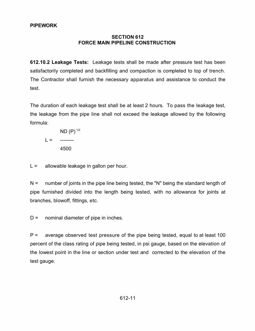
PIPEWORK
SECTION 612FORCE MAIN PIPELINE CONSTRUCTION
612-11
612.10.2 Leakage Tests: Leakage tests shall be made after pressure test has been
satisfactorily completed and backfilling and compaction is completed to top of trench.
The Contractor shall furnish the necessary apparatus and assistance to conduct the
test.
The duration of each leakage test shall be at least 2 hours. To pass the leakage test,
the leakage from the pipe line shall not exceed the leakage allowed by the following
formula:
ND (P) 1/2
L = --------
4500
L = allowable leakage in gallon per hour.
N = number of joints in the pipe line being tested, the "N" being the standard length of
pipe furnished divided into the length being tested, with no allowance for joints at
branches, blowoff, fittings, etc.
D = nominal diameter of pipe in inches.
P = average observed test pressure of the pipe being tested, equal to at least 100
percent of the class rating of pipe being tested, in psi gauge, based on the elevation of
the lowest point in the line or section under test and corrected to the elevation of the
test gauge.
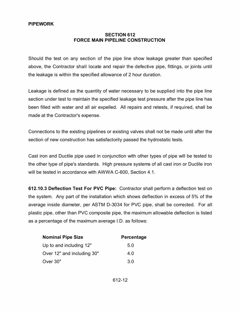
PIPEWORK
SECTION 612FORCE MAIN PIPELINE CONSTRUCTION
612-12
Should the test on any section of the pipe line show leakage greater than specified
above, the Contractor shall locate and repair the defective pipe, fittings, or joints until
the leakage is within the specified allowance of 2 hour duration.
Leakage is defined as the quantity of water necessary to be supplied into the pipe line
section under test to maintain the specified leakage test pressure after the pipe line has
been filled with water and all air expelled. All repairs and retests, if required, shall be
made at the Contractor's expense.
Connections to the existing pipelines or existing valves shall not be made until after the
section of new construction has satisfactorily passed the hydrostatic tests.
Cast iron and Ductile pipe used in conjunction with other types of pipe will be tested to
the other type of pipe's standards. High pressure systems of all cast iron or Ductile iron
will be tested in accordance with AWWA C-600, Section 4.1.
612.10.3 Deflection Test For PVC Pipe: Contractor shall perform a deflection test on
the system. Any part of the installation which shows deflection in excess of 5% of the
average inside diameter, per ASTM D-3034 for PVC pipe, shall be corrected. For all
plastic pipe, other than PVC composite pipe, the maximum allowable deflection is listed
as a percentage of the maximum average I.D. as follows:
Nominal Pipe Size Percentage
Up to and including 12" 5.0
Over 12" and including 30" 4.0
Over 30" 3.0

PIPEWORK
SECTION 612FORCE MAIN PIPELINE CONSTRUCTION
612-13
The maximum average ID shall be equal to the average OD per applicable ASTM
standard minus two minimum wall thicknesses per applicable ASTM standards.
Manufacturing and other tolerances shall not be considered for determining maximum
allowable deflections.
Deflection tests shall be performed not earlier than 30 days after completion of
placement and densification of backfill. The pipe shall be cleaned and inspected for
offsets and obstructions prior to testing.
If after acceptance, but prior to the terminations of the warranty period, the La Paz
County determines that the deflection has exceeded 7½% of the average inside
diameter, then that portion of the installation shall be corrected by the contractor at no
cost to La Paz County.
612.11 CLEANING:
Force mains shall be swabbed, flushed with water, or subjected to a combination of
these methods in order to leave the pipeline clean and free from debris, garbage,
rubbish, stones, deposits and other foreign materials.
612.12 MEASUREMENT AND PAYMENT:
612.12.1 Pipe:
(1) Measurement of all pipe shall be by the linear foot of pipe installed. Measurements
shall be along the centerline of the pipe, from the centerline of valves or fittings to the
ends of pipe. Measurement shall be to the nearest foot.

PIPEWORK
SECTION 612FORCE MAIN PIPELINE CONSTRUCTION
612-14
(2) Payment shall be at the unit price bid per linear foot of each type and size of pipe
called for in the proposal. Payments shall be compensation in full for furnishing and
installing the pipe and all fittings, specials, adapters, bolts, connectors, etc., for the
pipeline complete in place, as called for on the plans and shall include all costs of
excavation, removal of obstructions, shoring and bracing, bedding, backfilling,
compaction, installation of locator wire, installation of polyethylene protection, testing,
connections to existing lines or structures covered in the pay items.
612.12.2 Thrust Blocks: Payments for thrust blocks and anchors for pipe 16 inches
and smaller pipe shall be included in the linear foot cost of the pipe.
612.12.3 Valves, Valve Boxes and Air Vacuum/Release Valves:
(1) Measurement shall be by the various sizes of each valve and its valve box installed.
(2) Payment shall be made by the unit price bid for each size of valve in accordance
with the bid schedule and shall be full compensation for each unit complete in place
including all labor, materials, equipment and all incidentals necessary to complete the
work.
612.12.4 Drain Line and Valve:
(1) Measurement shall be by each complete unit in place including pipe, connection to
mainline, valve and valve box.
(2) Payment shall be made by unit price bid in accordance with the bid schedule and
shall be full compensation for the complete unit in place.

PIPEWORK
SECTION 612FORCE MAIN PIPELINE CONSTRUCTION
612-15
612.12.5 Pavement and/or Surface Replacement: Measurement and pavement for
pavement and/or surface replacement shall be in accordance with Section 336.
612.12.6 Connection to Existing Facilities: All measurement and payment for
connection to existing facilities shall be included in the linear foot cost of the pipe.

PIPEWORK
SECTION 615SEWER LINE CONSTRUCTION
615-1
615.1 DESCRIPTION:
The construction, or extension of sanitary sewer lines shall conform to applicable
standard specifications and details, except as otherwise required on the plans or as
modified in the special provisions.
615.2 MATERIAL:
Concrete pipe shall conform to Section 734 or 735 as specified. Vitrified clay pipe shall
conform to Section 743. PVC pipe and fittings shall conform to Section 745.
615.3 CONSTRUCTION INSTALLATION:
615.3.1 Excavation: Excavation of trenches shall be accomplished in accordance with
Section 601.
The Contractor shall furnish the Public Works Department alignment and elevation
stakes at agreed upon intervals and offsets together with cut sheets showing the
difference in elevation from the top of the stakes to the flowline of the pipe.
The trench shall be dry when the fine grading of the bottom of the trench is
accomplished. Before placement of pipe the fine grade shall be carefully checked by
use of a string line, laser beam or other means so when the pipes in final position it will
be true to line and grade, +0.05 feet for 8 inches through 12 inches, +0.10 feet for 15
inches and larger.

PIPEWORK
SECTION 615SEWER LINE CONSTRUCTION
615-2
For PVC pipe installation the width of trench as listed in Table 601-1 or as given in the
contract documents may be increased to provide sufficient space for the installation of
fittings or for compaction of the bedding. The adjusted maximum width at the top of the
pipe must be approved by the Public Works Department. Any adjustment of the trench
width to accomplish the above shall be done at no additional cost to La Paz County.
615.3.2 Laying Pipe: Pipe shall be of the type, class and size called for on the plans.
All pipe shall be protected during handling, against impact shocks and free falls.
Damaged or defective pipe shall not be installed in the work. Pipe shall be kept clean
as the work progresses. The interior of the pipe shall be cleaned of all dirt and debris
materials.
The laying of the pipe shall be in finished trenches free from water, or debris, and shall
commence at the lowest point, with the spigot ends pointing in the direction of the flow.
Each pipe shall be laid firmly and true to line and grade to form a close concentric joint
with the adjoining pipe and to prevent sudden offsets of the flow line. Any adjustment to
line and grade shall be made by scraping away or filling in under the body of the pipe.
Wedging or blocking under the pipe ends shall not be allowed.
The alignment and grade of each length of pipe shall be checked after setting by
measurement from the stringline or laser beam target.
When work is not in progress, open ends of the pipe and fittings shall be securely
closed so no water, earth, or debris will enter the pipe or fittings.
PVC pipe and fittings shall be installed in accordance with ASTM 2321. The bedding
shall be placed in two lifts. The first lift will be from the bottom of the trench to the

PIPEWORK
SECTION 615SEWER LINE CONSTRUCTION
615-3
spring line of the pipe. The second lift will be from the spring line to one foot above the
top of pipe. Separate inspections will be required on each lift. The Contractor shall
place the first lift in a manner that ensures uniform support under the haunches and
proper alignment of the pipe. If called for on the plans, sanitary sewers shall be
concrete encased. When sewer lines infringe upon the area of a waterline, extra
protection shall be provided in accordance with County Construction Standard 5-060.
615.3.3 Fittings: All fittings shall conform to the requirements of the pipe specifications
and shall be located as shown on the plans in accordance with the details.
615.3.4 Jointing: Prior to making pipe joints, all surfaces of the portions of the pipes to
be joined shall be cleaned, dried and prepared in accordance with the manufacturer's
recommendations. The joints shall then be carefully centered and completed.
Trenches shall be kept water-free during the installation of joints and couplings.
The joint and coupling materials shall be as specified in the appropriate pipe sections
and shall be installed in accordance with the manufacturer's recommendations. Cement
mortar joints shall NOT be permitted in sanitary sewer construction.
615.4 SANITARY SEWER HOUSE CONNECTION:
When the construction of sanitary sewer connection taps are called for in the plans, they
shall be constructed in accordance with County Construction Standard 5-020 and the
project plans.

PIPEWORK
SECTION 615SEWER LINE CONSTRUCTION
615-4
The location of the service tap for each property shall be in the downstream 1/3 of the
lot or as requested by the property owner. Sewer service taps shall not be covered until
they have been plugged and marked in accordance with standard details and their
location has been recorded by the Public Works Department.
615.5 SANITARY SEWER CLEANOUTS:
The cleanouts shall be constructed at locations shown on the plans.
615.6 MANHOLES:
Manholes shall be constructed to conform with the requirements of the plans, Section
625 of these specifications.
615.7 BACKFILLING:
Backfilling and compaction shall be done in accordance with Section 601.
615.8 TESTING:
As the pipe laying progresses and after partial backfilling, the interior of the sewer or
pipeline shall be visually inspected for alignment and grade, by means of artificial or
reflected light. Necessary corrections shall be made by the Contractor at his expense.
Storm sewer pipelines shall be subject to test for leakage after the lines have been
partially backfilled, in accordance with the following:
A) Approximately 20 percent of the length of lines will be tested as specified below.
If test made indicate that the work is being done satisfactorily and the lines are

PIPEWORK
SECTION 615SEWER LINE CONSTRUCTION
615-5
tight, the Public Works Department may waive tests on the other parts of the
lines or call for spot tests, to ensure proper construction. The maximum length of
pipe allowed to be tested at one time shall be 500 feet.
B) The Public Works Department reserves the right to require testing of the entire
installation. The cost of testing shall be borne by the Contractor and sections
showing excess leakage shall be repaired by the Contractor at the Contractor’s
expense. All visual leaks shall be repaired by the Contractor at the Contractor’s
expense.
615.8.1 Low Pressure Air Test:
Testing shall be accomplished by the means of "Low Pressure Air Testing". Tests may
be conducted by the Contractor or an independent testing firm. However, acceptance
tests shall be made only in the presence of the Public Works Department.
Test Procedure:
1. Before testing, the pipe shall be thoroughly cleaned.
2. The Contractor shall seal off the section of pipe to be tested at each manhole
connection. Test plugs shall be securely braced within the manholes.
3. A minimum of two connecting hoses to link the air inlet test plug with an above
ground test monitoring panel shall be provided.
a. One hose is to induce air thru the test plug and into the test chamber.

PIPEWORK
SECTION 615SEWER LINE CONSTRUCTION
615-6
b. The second hose is for the purpose of monitoring the test pressure from
within the enclosed pipe.
4. UNDER NO CIRCUMSTANCES ARE WORKERS TO BE ALLOWED IN THE
CONNECTING MANHOLES WHILE A PRESSURE TEST IS BEING CONDUCTED.
5. Air shall be added slowly into the test section. After an internal pressure of 4.0 PSI is
obtained, allow internal air temperature to stabilize.
6. After the stabilization period, the internal air pressure shall be adjusted to 3.5 PSI, the
air shall be disconnected and timing shall begin.
7. Refer to the air test table to determine the length of time (minutes). The section
under test shall sustain air and not lose in excess of 1 PSI as monitored by the test
gauge.
8. Sections determined to have lost 1 PSI or less during the test period shall have
passed the leakage test. Those sections losing in excess of 1 PSI during the test period
shall not have passed the leakage test.
9. Appropriate repairs shall then be completed and the line shall be retested for
acceptance at the Contractor’s expense.

PIPEWORK
SECTION 615SEWER LINE CONSTRUCTION
615-7
TABLE 615
AIR TEST
Minimum Test Time for Various Pipe Sizes
Nominal T (time) Nominal T (time)
Pipe size, in. min/100 ft. Pipe size, in. Min/100 ft.
3 0.2 21 3.0
4 0.3 24 3.6
6 0.7 27 4.2
8 1.2 30 4.8
10 1.5 33 5.4
12 1.8 36 6.0
15 2.1 39 6.6
18 2.4 42 7.3
(a) The table shows the required test time, T, in minutes/100 ft. of pipe for each nominal
pipe size. Test times are for an 1.0-psi (7-kPa) pressure drop from 3.5 to 2.5 psi (24 to
17 kPa). Table has been established using the formulas contained in the appendix.
(b) If the section of line to be tested includes more than one pipe size, calculate the test
time for each size and add the test times to arrive at the total test time for the section.
(c) It is not necessary to hold the test for the whole period when it is evident the rate of
air loss is less than the allowable.

PIPEWORK
SECTION 615SEWER LINE CONSTRUCTION
615-8
615.8.2 Hydrostatic Test: Exfiltration Testing (water):
Sanitary sewer testing by means of exfiltration should only be considered when low
pressure air testing cannot be used and only with the approval of the Public Works
Department.
Testing Procedure:
1. The Contractor shall furnish all equipment for testing.
2. The Contractor shall seal off the downstream end of the line and fill with water to a
minimum head of 4' in a stand pipe at the high end.
3. A period of at least one hour shall be allowed for absorption time before making the
test.
4. A suitable meter or method of measuring the quantity of water used shall be
necessary.
5. The allowable water loss for sanitary sewers shall not exceed 0.5 gallons per hour
per 100 feet of pipe per inch of diameter of pipe under a minimum test head of 4 feet
above the top of the pipe at the upper end.
615.8.3 Deflection Test for PVC Pipe: In addition to the tests prescribed above, the
Contractor shall perform a deflection test on the system. Any part of the installation
which shows deflection in excess of 5% of the average inside diameter as per ASTM
3034 shall be corrected at the Contractor’s expense.

PIPEWORK
SECTION 615SEWER LINE CONSTRUCTION
615-9
After acceptance, but prior to the termination of the warranty period, the Public Works
Department may test the long term deflection of the sewer. If the Public Works
Department determines the deflection has exceeded 7-1/2% of the average inside
diameter, that portion of the installation shall be corrected by the Contractor at no cost
to La Paz County.
615.9 PAVEMENT AND SURFACING REPLACEMENT:
Pavement and surfacing replacement shall be done in accordance with Section 336.
615.10 CLEANUP:
The Public Works Department shall have the right to close down forward trenching and
pipe laying where testing, backfill, compaction, cleanup, and road replacement does not
follow in an orderly manner.
615.11 MEASUREMENT AND PAYMENT:
615.11.1 Sewer Pipe and Fittings: (Vitrified clay, cast iron, P.V.C. and other approved
types of pipe.)
(A) Measurement shall be made horizontally thru manholes and fittings and from
centerline to centerline of structures, for the various types and sizes of pipe called for on
the plans and in the proposal.
(B) Payment for the various sizes and types of pipe shall be made in accordance with
the bid schedule at the unit price bid per linear foot and shall be compensation in full for

PIPEWORK
SECTION 615SEWER LINE CONSTRUCTION
615-10
furnishing and installing the pipe and fittings complete in place, as specified, including
excavation, removal of obstructions, backfilling, water settling, compaction, sheeting
and bracing, and testing.
615.11.2 Sanitary Sewer Service Taps:
(A) Measurement shall be the number of taps installed.
(B) Payment shall be made at the unit price bid and shall be compensation in full for
furnishing and installing pipe and fittings complete in place, as specified and called for
on the plans and standard details, including all costs of excavation, removal of
obstructions, shoring and bracing, backfilling, compaction, and testing.
615.11.3 Sanitary Sewer Cleanouts:
(A) Measurement shall be the number of cleanouts installed.
(B) Payment shall be made at the unit price bid and shall be compensation in full for
furnishing and installing pipe, fittings and frame and cover as called for on the plans and
in accordance with the standard details.
615.11.4 Sanitary Sewer Encasement or Infringement Protection:
(A) Measurement shall be by the linear foot complete in place.
(B) Payment shall be made by the contract unit price bid and shall be full compensation
for furnishing and installing all pipe, fittings, concrete, steel and pavement replacement

PIPEWORK
SECTION 615SEWER LINE CONSTRUCTION
615-11
as called for in the plans and in accordance with the County Construction Standards.
615.11.5 Manholes: Measurement and payment shall be in accordance with Section
625.

PIPEWORK
SECTION 618CONCRETE PIPELINE CONSTRRCUTION
618-1
618.1 DESCRIPTION:
This section shall consist of all labor, equipment, furnishing pipe and materials in
connection with the installation of concrete pipe. Primarily for storm sewer purposes
including excavation, trenching, hauling, installation of pipe, furnishing, placing and
compacting backfill materials and appurtenances in accordance with plans and
specification.
618.2 MATERIALS:
618.2.1 Pipe: Pipe shall be of the type, class and size shown on the plans or in the
special provisions.
Gravity storm sewer pipe shall be reinforced concrete pipe conforming to Section 735.
Pipe for low head storm sewer construction shall be reinforced concrete pipe in
accordance with Section 734. The minimum cover from the top of the pipe to the
finished grade shall be 2 feet. Class of pipe is to be determined from plans and
specifications.
The concrete pipe, specials, joints, gaskets, and testing shall be as indicated on the
plans except or as modified by special provisions.
618.2.2 Specials: A special is defined as a piece of pipe other than a normal full length
straight section, and includes but is not limited to sections with outlets, closure pieces,
wyes, tees, bends, adapter sections, manhole shafts and shall be provided as indicated
on the plans. Specials shall be made equal in strength, diameter and other physical
characteristics to the standard straight pipe lengths by the use of extra concrete, extra

PIPEWORK
SECTION 618CONCRETE PIPELINE CONSTRRCUTION
618-2
reinforcing, or steel items. Drawings of specials shall be submitted to the Public Works
Department for approval prior to fabrication. Specials shall be used on all outlets,
branches, connections, manholes, etc. when using pressurized pipe.
618.2.3 Rubber Gasket Joints: When rubber gasket pipe is used the joint shall be
sealed with a continuous ring gasket made of a special composition rubber and cross
section as to fill the recess provided for it. The gasket shall be the sole element
depended upon to make the joint watertight and shall have smooth surfaces, free from
pits, blisters, porosity, and other imperfections, and conform to Section 765.
618.2.4 Tongue and Groove Joints: Mortar, or grout, shall consist of 1 part portland
cement and 2 parts sand, by volume. The quantity of water in the mixture shall be
sufficient to produce a soft workable mortar, but in no case exceed a water cement
weight ratio of 0.53. Where outside joints are made by the diaper method, the grout
shall be composed of 1 part cement to 3 parts sand and shall be mixed to the
consistency of thick cream. The sand shall conform to the section entitled "Rock Gravel
and Sand" and the cement shall conform to the section entitled "Portland Cement
Concrete".
618.2.5 Care of Pipe And Materials: All pipe and materials shall be manufactured,
handled, loaded, shipped unloaded, and laid undamaged and in a sound condition for
the completed work. Repairs on damaged pipe shall be made to the satisfaction of the
Public Works Department, otherwise they shall be rejected and shall be replaced with
an equal pipe or special in acceptable condition. Rubber gaskets shall be stored in a
cool, dark place until ready for use. The gaskets shall not be exposed to direct sunlight
for a time greater than needed for normal installation.

PIPEWORK
SECTION 618CONCRETE PIPELINE CONSTRRCUTION
618-3
618.3 SUBMITTALS:
Prior to fabricating, the Contractor shall submit for approval three (3) sets of shop
drawings. Approval shall be obtained before construction and manufacturing. In
addition, submittals shall consist of:
(A) Shop drawings, in accordance with the General Conditions.
(B) Submit manufacturer's affidavit of compliance with the cited standards, e.g.,
ASTM C-361 for low head pressure pipe.
(C) Submit tabulated layout schedule including:
(1) Order of installation and closures.
(2) Pipe invert station and elevation at each change of grade and alignment.
(3) Elements of curves and bends, both in horizontal and vertical alignment
including elements of the resultant true angular deflections in cases of combined
curvature.
(4) Pipe internal diameter, wall thickness and design internal head.
(5) Locations of bulkheads for field hydrostatic testing of pipeline.
(6) Locations of closures for length adjustment and for construction
convenience.

PIPEWORK
SECTION 618CONCRETE PIPELINE CONSTRRCUTION
618-4
(7) Locations of manholes and other points of access for placement of mortar
lining at field joints and removal of test bulkheads.
(8) Locations of valves and other mechanical equipment.
(D) Details of specials.
(E) Joint details.
(F) Test reports on shop testing performed as per the applicable ASTM standards.
(G) Details of bulkheads and of their method of attachment to pipeline.
(H) Certificate that cement complies with the applicable ASTM standard and
designating type.
(I) Mill test reports on each heat from which the steel is rolled.
(J) Test reports on physical properties of rubber used in gaskets.
(K) A shoring plan for excavations deeper than 6 feet.
618.4 CONSTRUCTION METHODS:
618.4.1 Excavation: Excavation, bedding, backfilling, compaction or consolidation of
backfill and bedding of trenches shall be accomplished in accordance with Section 601.

PIPEWORK
SECTION 618CONCRETE PIPELINE CONSTRRCUTION
618-5
The Contractor shall over-excavate the trench and fill with select material as required
and as shown on the project plans.
618.4.2 Trench Width: Where the cover over the top of the pipe is less than 10 feet,
the maximum trench width is unrestricted. The pay width, however, for pavement
replacement shall remain in accordance with Section 336. For pipe, with 10 feet or
more cover, the maximum trench width shall be as required by Section 601.
618.4.3 Pipe Laying: The laying of the pipe shall be in finished trenches free from
water, or debris, and shall be commenced at the lowest point, with the spigot ends
pointing in the direction of the flow. Each pipe shall be laid firmly and true to line and
grade to form a close concentric joint with the adjoining pipe and to prevent sudden
offsets of the flowline. Any adjustment to line and grade shall be made by scraping
away or filling in under the body of the pipe, never by wedging or blocking under the
pipe ends.
Variation from prescribed alignment and grade shall not exceed 0.10 foot and the rate of
departure from or return to established grade or alignment shall be no more than 1 inch
in 10 feet of pipeline. For closures and deflection angles greater than 10 degrees, joints
shall be made by use of a concrete collar, per standard details.
Pipe shall be kept clean at all times as work progresses. The interior of the pipe shall
be cleaned of all dirt and superfluous materials of every description. The type of pipe
joint shall be as specified on the plans.

PIPEWORK
SECTION 618CONCRETE PIPELINE CONSTRRCUTION
618-6
When work is not in progress open ends of the pipe and fittings shall be securely closed
with caps or plugs to ensure water, earth or other substance will not enter the pipe or
fittings.
Whenever the end of a pipeline remains unjoined to an existing pipe or structure, it shall
be closed by a stopper of concrete and brick tightly sealed in place.
Mortar for connection pipe joints shall be as herein defined.
618.4.4 Concrete Cradle Bedding: Where concrete bedding is shown on the plans or
called for in the Special Conditions, the lower exterior part of the pipe shall be bedded in
a continuous cradle constructed of Class "C" concrete (2,000 psi) having a minimum
thickness under the pipe of 1/4 the inside diameter and extending up the sides of the
pipe for a height equal to 1/4 the outside diameter. If the excavation is in reasonable
sound rock, the minimum thickness under the pipe may be reduced from 1/4 the inside
diameter to 6 inches. The cradle shall have a width at least equal to the outside
diameter plus 8 inches and shall be constructed monolithically without horizontal
construction joints.
618.4.5 Openings In Non-Pressurized Pipeline: Connections to the concrete pipe
that require openings to be cut into the pipe for outlets and branch connections, shall be
full size, within 1 inch of the outside diameter of the connecting pipe or fitting. The
openings shall be cut in the pipes either before or after the pipes are laid. After the
pipes are laid the cuts shall not be made until the joint mortar is thoroughly cured.

PIPEWORK
SECTION 618CONCRETE PIPELINE CONSTRRCUTION
618-7
All connections shall be cut to fit closely and shall be strongly cemented to the line with
bonding mortar. Where possible, both the inside and outside of the joint shall be
brushed smooth.
618.4.6 Openings in Pressurized Pipeline: All connections, outlets, manhole,
branches, etc. required on new construction of pressurized pipe shall be a special.
When specified on the plans, jointing of a fitting or connection to an existing pipe shall
consist of a welded splice of the wire cage of the jointing pipes and the construction of a
mortar collar 2-1/2 inches thicker than the pipe wall and overlapping each pipe wall at
least 4 inches. The collar shall be reinforced with 2 x 2 inch 12 gauge welded wire
fabric, top and bottom, continuous around the joint. Both pipes at the connection shall
be free from cracks and the interior of both pipes at the joint shall be smooth.
618.4.7 Delivery: The pipe shall be placed in the order in which it is to be installed and
secure it from rolling.
618.4.8 Long Radius Curves and Vertical Curves:
(1) For curved alignment, the Contractor shall use straight or beveled pipe of normal or
1/2 normal lengths pulled partially open on one side of the joint or use pipes with a bend
of up to 5 degrees next to the joint ring. Design pipes with a bend in excess of 5
degrees as specials.
(2) The Contractor shall not pull a joint more than 1/2 of the watertight extensibility
provided by the bell and spigot design.

PIPEWORK
SECTION 618CONCRETE PIPELINE CONSTRRCUTION
618-8
618.4.9 Installing Buried Piping:
(1) The Contractor shall inspect each pipe and special before the buried pipe or fitting
is lowered into the trench and shall inspect the interior and exterior protective coating
and patched damaged areas in the field with material recommended by the pipe
manufacturer. The Contractor shall clean the ends of the pipe thoroughly and remove
foreign matter and dirt from inside of the pipe and keep the pipe clean during and after
laying.
(2) The Contractor shall handle pipe in such manner as to avoid any physical damage
to the pipe. Do not drop or dump pipe into trenches.
(3) The Contractor shall handle laying of the pipe shall commence at the lowest points
with the spigot end pointing in the direction of the flow.
(4) The Contractor shall when installing piping in trenches, do not deviate more than 1
inch from line or 1/4 inch from grade. Measure for grade at the pipe invert.
(5) The Contractor shall grade the bottom of the trench to the line and grade to which
the pipe is to be laid, with allowance for pipe thickness. Remove hard spots that would
prevent a uniform thickness of bedding. Before laying each section of pipe, check the
grade with a straightedge and correct any irregularities found. The trench bottom shall
form a continuous and uniform bearing and support for the pipe at every point between
joints.
(6) The Contractor shall, at the location of each joint, dig bell holes in the bottom of the
trench and at the slides to permit visual inspection of the entire joint.

PIPEWORK
SECTION 618CONCRETE PIPELINE CONSTRRCUTION
618-9
(7) The Contractor shall provide and maintain means and devices at all times to
remove and dispose of all water entering the trench during the process of pipe laying.
Keep the trench dry until the pipe laying and jointing are completed.
(8) The Contractor shall, when pipe laying is not in progress, including the noon hours,
close the open ends of the pipe. Do not permit trench water, animals or foreign material
to enter the pipe.
(9) The Contractor shall, where the shaped foundation is made in compacted fill,
provide a minimum of 6 inches of compacted fill beneath the pipe. Tamp compacted fill
material in 6 inch layers around the pipe for the remainder of the lower 37% of the
outside diameter of the pipe. Compact fill material to at least 95% relative compaction.
Then place fill material to the top of the pipe on each side in layers not exceeding 6
inches in thickness.
(10) The Contractor shall, when backfilling of pipe shall follow closely behind the pipe
laying, such that all installed pipe is immediately backfilled to a point which is at least 1
foot above the top of the pipe.
(11) The Contractor's shall protect the pipe from flotation and from other shifts in
alignment and grade throughout the project construction process. Any pipe which is
displaced or shifted from its intended location or grade shall be removed and relaid by
the Contractor at no additional cost to La Paz County.
618.5 MANHOLES:
Manholes shall be constructed in accordance with Section 625.

PIPEWORK
SECTION 618CONCRETE PIPELINE CONSTRRCUTION
618-10
618.6 JUNCTION STRUCTURES:
Special pipeline junction structures shall be constructed as shown on the plans and in
accordance with Section 505, "Concrete Structures".
618.7 JACKING PIPE:
At locations where jacking is required, the storm drain line shall be installed by jacking
to the lengths indicated on the plans. The methods and equipment used in jacking
reinforced concrete pipe conduit shall be optional with the Contractor, provided that the
proposed method is first approved in writing by the Public Works Department.
Approval, however, shall in no way relieve the Contractor of the responsibility for
damages of any nature which might occur as a result of the methods used.
Only workers experienced in the operation of jacking concrete conduit shall be used.
The driving ends of the conduit shall be properly protected and the conduit shall be
driven true to alignment and grade. The deviation from true line and grade at any single
point within the jacked portion shall be limited to 0.5 feet horizontal deviation from line
and +0.2 feet vertical deviation from grade.
Any section of conduit which show signs of failure shall be rejected and replaced with a
new section of precast conduit or with a cast-in-place section. In this respect it shall be
understood that where pipe is specified on the drawings to be jacked into place the
jacked pipe shall be reinforced concrete of the strength specified in these specifications
and the design of such pipe is based upon super-imposed loads and not upon loads
which may be placed upon the pipe as a result of jacking operation. Any increase in
PIPEWORK
SECTION 618CONCRETE PIPELINE CONSTRRCUTION
618-11
pipe strength required to withstand jacking loads shall be the responsibility of the
Contractor. The reinforcing shall be circular and of either single or double cage design.
Spacer blocks shall be placed in the inside circular space which will allow sufficient
width for point mortaring when jacking is completed and to equalize pressures during
jacking. Three grout holes per 8-foot section of pipe shall be made during
manufacturing.
Double rubber gaskets and band type joints shall be provided for 36 inch diameter and
larger pipe.
One hole shall be made on the top midway between the ends. Two additional holes,
each approximately 1.5 feet from each end and approximately midway between the
springline and top on opposite sides shall be made.
Where the nature of the soil, or the structure the conduit being jacked is such that there
is increased danger of a cave-in or damage to said structure, the method of jacking the
conduit shall be as specified below:
The leading section of conduit shall be equipped with a jacking head securely anchored
thereto to prevent any wobble or alignment variation during jacking operations.
Excavation shall be carried out entirely within the jacking head and no excavation in
advance shall be permitted. Every effort shall be made to avoid any loss of earth
outside of the jacking head. Excavated material shall be removed from the conduit as
excavation progresses, and accumulation of material within the conduit shall not be
permitted. Upon completion of the jacking operations, all voids around the outside face
of the conduit shall be filled by grouting through each of the previously constructed grout

PIPEWORK
SECTION 618CONCRETE PIPELINE CONSTRRCUTION
618-12
holes. The grout shall be a mixture of one part cement to three parts sand and a
mixture by volume.
618.8 TESTING OF PIPE:
618.8.1 Exfiltration Test: Unless excessive ground water is encountered, each section
of sewer, between the two successive structures, shall be tested by closing the lower
end of the sewer to be tested and the inlet sewer into the upper structure with stoppers
and filling the pipe and structures with water to a point 4 feet above the invert of the
sewer in the upper structure. Allowable leakage shall be computed by the formula:
The leakage per 100 feet of length, as determined by an hour test, shall not exceed
0.35 gallon per hour per inch of inner diameter of the pipe.
In performing a hydrostatic test, the water in the pipe and standpipe shall be maintained
at the 4.0 level as noted above for a period of at least 2 hours. Any individual leaks
showing up during this 2 hour period shall be repaired.
If the leakage, as shown by the test, is greater than allowed by the formula, the pipe
shall be overhauled and, if necessary, relaid until the joints shall hold satisfactorily. If
the leakage is less than allowed, the Contractor shall stop any individual leaks that may
be observed.
618.8.2 Infiltration Test: If, in the construction of a section of the sewer between
structures, excessive ground water is encountered, the test for leakage described above
shall not be used, but instead the end of the sewer at the upper structure shall be
closed sufficiently to prevent the intrusion of water and pumping of ground water shall

PIPEWORK
SECTION 618CONCRETE PIPELINE CONSTRRCUTION
618-13
be discontinued for at least 3 days, after which the section shall be tested for infiltration.
The infiltration shall not exceed 0.35 gallon per hour per inch of diameter per 100 feet of
main sewer being tested. The length of connections entering the section shall not be
included. Should the infiltration be less than the specified amount, the Contractor shall
stop any individual leaks that may be observed.
All tests shall be completed before the street or trench is resurfaced.
The above hydrostatic tests do not apply to the catch basin leads.
All labor, tools, material, appliances and bulkheads required for making the test shall be
supplied by the Contractor.
618.9 MEASUREMENT:
618.9.1: Pipe shall be measured by the linear foot parallel to the central axis of the
pipeline and shall include the length of fittings.
618.9.2: Tees, wyes other branches and specials shall be measured as pipe along the
central axis of the pipes to the point of intersection of said central axes. Pipe reducers
shall be measured as pipe of the larger diameter along the central axis.
618.9.3: Pipe stubs and their plug shall be measured as each unit complete in place.
618.9.4: Jacked pipe shall be measured at the ground surface and shall be the number
of linear feet of ground surface undisturbed by the cut and cover construction on either

PIPEWORK
SECTION 618CONCRETE PIPELINE CONSTRRCUTION
618-14
end of the jacked section. Measurement shall include the actual linear feet of pipe
jacked.
618.10 PAYMENT:
Payment shall be made at the contract unit price as established in the proposal for each
item and shall be compensation in full for the complete installation in place including all
labor, materials, equipment and all incidentals necessary to complete the installation.

PIPEWORK
SECTION 621CORRUGATED METAL PIPE AND ARCHES
621-1
621.1 DESCRIPTION:
This section covers plain galvanized, bituminous coated and bituminous coated and
paved galvanized corrugated metal pipe for use in storm sewers. The pipe shall be of
the specified, and shall be manufactured in accordance with the requirements of the
stated specifications. Corrugated metal pipe shall conform to AASHTO M-36 and
M-190.
621.2 MATERIALS:
The types of pipe and fabrication shall be in accordance with Section 760.
All helically-wound corrugated metal pipe shall have a marking system which shall
provide a quick external visual check of diameter variations during and after the
manufacturing process.
621.3 INSTALLATION:
621.3.1 Excavation: Excavation, bedding and backfill shall be in accordance with
Section 601.
621.3.2 Pipe Laying: No pipe shall be laid without the presence of an inspector. Each
pipe shall be carefully inspected immediately before it is laid and defective pipe shall be
rejected. Pipe lines shall be laid to the grades and alignment indicated on the drawings.
Variation from prescribed grade and alignment shall not exceed 0.10 foot, and the rate
of departure from or return to established grade or alignment shall be no more than 1
inch in 10 feet. Proper facilities shall be provided for lowering sections of pipe into

PIPEWORK
SECTION 621CORRUGATED METAL PIPE AND ARCHES
621-2
trenches. All pipes, elliptical or round, as well as pipe arches requiring bituminous
coating and/or pavement shall be equipped with lifting lugs as required and shall have
connecting bands designed to provide positive connection without damaging the coating
on the pipe or pipe arch.
All field repairs to the bituminous coating or paving shall be made with asbestos
reinforced bituminous mastic: Flintkote C-13-C4, Inertol Hotmastic (black), Pioneer
Kooler Seal or an approved equal.
Corrugated metal pipe and/or pipe arches shall be laid with separate section joined
together in a manner that the joint space shall not exceed 1/2 inch, with the outside laps
of circumferential joints pointing upstream and with longitudinal laps on the side.
Elliptical pipe shall be installed so the major or minor axis, shall be indicated by suitable
markings on the top of each end of the pipe sections, coincides with the survey
alignment of the trench excavation. Any metal in the joints which is not thoroughly
protected shall be coated with bituminous mastic. During the installation, the pipe shall
be handled with care so as not to damage the bituminous coating. Coupling band bolts
and damaged areas of the coupling bands and pipe shall be given a coating of
bituminous mastic as specified above prior to placing the backfill. Pipe on which the
bituminous coating or paving has been damaged to such extent that satisfactory field
repairs cannot be made, as determined by the Public Works Department, shall be
rejected and replaced at no additional cost to La Paz County.
621.3.3 Joints: Before the connecting band is placed around the pipe, the ends of the
pipe that will be beneath the band, shall be coated with bituminous mastic or, if of
suitable design, fitted with circular rubber gaskets to provide a watertight joint. The band
shall be tightened evenly, keeping equal tension on the bolts. If mastic is used, tension

PIPEWORK
SECTION 621CORRUGATED METAL PIPE AND ARCHES
621-3
shall be maintained over an interval of time until the flow of mastic terminates. The joint
shall remain uncovered over a period designated by the Public Works Department and
before covering the joint the nuts shall be tested for tightness. If the nut has a tendency
to loosen its grip on the bolt, it shall be tightened again and remain uncovered until a
tight, permanent joint can be obtained. Prior to backfilling around the joint, bolts, lugs
and nuts shall be given a coating of bituminous mastic. The annular space between
abutting pipe sections shall be filled with bituminous mastic after jointing.
621.3.4 Pipe Elongation: The standard details shall control as to conditions under
which pipe must be elongated. Pipe shall be elongated 5 + 1/2 percent of the nominal
diameter to take advantage of the build-up of side support as it settles back toward a full
round shape under the backfill load. The method or technique for obtaining and
releasing the elongation shall be optional to the Contractor. Under no circumstances
shall the vertical diameter of the pipe at any point along the pipe section, after backfill
and compaction is completed, be less than the nominal diameter of the pipe or more
than 5 percent greater than the nominal diameter of the pipe as shown on the plans or
specified elsewhere in this specification. Any damage done as a result of strutting shall
be repaired at no additional cost to La Paz County. Strutting of pipe shall be pre-
approved by the Public Works Department.
621.3.5 Cutting: The Contractor shall be prohibited from using conventional welding
torches in cutting full lined CMP. Pipe shall either be sawcut or cut with special cutting
tools which will not expose the pipe to a fire hazard. Connections shall be shop
fabricated to prevent any exposure to fire hazard.
621.3.6 Repair of Damage to Coatings: Corrugated metal pipe shall be carefully
handled at all times to prevent damage to the asphalt or spelter coating or asphalt

PIPEWORK
SECTION 621CORRUGATED METAL PIPE AND ARCHES
621-4
paving. Each length of pipe shall be carefully inspected immediately prior to placing in
the trench to ascertain that no damage has been done to the exterior coating that will be
concealed when the pipe is placed. Any damage to the spelter coating shall be repaired
in accordance with Section 771. Any damage to the asphalt coating or asphalt paving
shall be repaired to the satisfaction of the Public Works Department with bituminous
mastic as specified above or rejected.
621.4 TEST SPECIMENS:
All tests on the bituminous coating shall be made on samples secured from pipe
delivered or from the coating and lining facility of the pipe fabricator at the time the pipe
is being coated.
Compliance with these specifications as set forth, shall be the responsibility of the
Contractor. Three certified copies of test results indicating compliance shall be
furnished for each lot or shipment prior to delivery of the material to the Contractor.
621.5 MEASUREMENT:
Measurement of corrugated metal pipe shall be the number of lineal feet of pipe,
measured horizontally, from end to end of pipe through manholes and specials. At
changes in diameter the measurement shall be to center of manhole or special.
621.6 PAYMENT:
Payment shall be made at the contract unit price bid per linear foot, to the nearest foot,
for each size and type of pipe and shall be compensation in full for furnishing and

PIPEWORK
SECTION 621CORRUGATED METAL PIPE AND ARCHES
621-5
installing the corrugated metal pipe as specified, including removal of obstructions,
excavation, backfilling, compacting, testing and all incidental costs not specifically
covered in other items in the proposal.
PIPEWORK
SECTION 625MANHOLE CONSTRUCTION AND DROP SEWER CONNECTIONS
625-1
625.1 DESCRIPTION:
625.1.1 Sewer Manholes: Construction shall consist of furnishing all materials and
constructing manholes complete in place in conformance with La Paz County
Construction Standards and as detailed, including manhole bases, walls, steps,
manhole frames and covers and any incidentals thereto, at locations shown on the
plans.
625.1.2 Drop Sewer Connections: Construction shall consist of furnishing all
materials in constructing drop sewer connections complete in place in conformance with
La Paz County Construction Standards and as detailed, including foundations,
encasements, pipe and any incidentals thereto, at locations shown on the plans.
625.2 MATERIALS:
Materials to be used shall conform with the following:
A) Bricks for manholes shall conform to the requirements of Section 775.
B) Cement mortar for manholes shall conform to the requirements of Class D,
Section 776.
C) Concrete for manholes shall conform to requirements of Class A and for drop
sewer connection shall conform to the requirements of Class C, Section 725.
D) Precast manhole sections shall conform to the requirements of Section 747 and
the requirements of the La Paz County Construction Standards.

PIPEWORK
SECTION 625MANHOLE CONSTRUCTION AND DROP SEWER CONNECTIONS
625-2
E) Pipe used in manholes or drop sewer connection shall conform to the applicable
pipe specifications of the job.
F) Manhole frames and covers shall conform to the requirements of Section 787
and cast in accordance with the construction standards.
G) Manhole steps shall conform to the La Paz County Construction Standards with
plastic manhole steps, conforming to OSHA and ASTM C-487 requirements and
steel manhole steps, being completely encapsulated in corrosion resistant rubber
and conform to OSHA and ASTM C-478 requirements. The manufacturer shall
furnish the Public Works Department a certification indicating conformance.
625.3 CONSTRUCTION METHODS:
625.3.1 General: Manholes shall be constructed using brick, precast concrete sections,
or cast in place concrete with manhole steps, cast iron frames and covers, in
accordance with La Paz County Construction Standards and as specified in the project
plans. The invert channels shall be smooth and semicircular in shape, conforming to
the inside of the adjacent sewer sections. Changes in direction of flow shall be made
with a smooth curve, having a radius as large as the manhole will permit. Changes in
size and grade of the channels shall be made gradually and evenly.
625.3.2 Manhole Bases: The excavation shall be made cylindrical to a diameter
sufficient in size to permit sheeting if necessary and leave room for bricks to be laid and
the outside plaster coat properly applied, or the precast concrete sections/forms may be
properly assembled.

PIPEWORK
SECTION 625MANHOLE CONSTRUCTION AND DROP SEWER CONNECTIONS
625-3
Manhole bases shall be constructed of Class A concrete to the dimensions indicated on
the drawings and details. Projecting ends of the sewer and pipe stubs shall be
adequately supported to prevent displacement from line, or grade, during the
construction of the base. All manholes shall have the invert shaped as indicated on the
plans and details to provide an adequate channel between the inlet and outlet pipes.
The entire surface of the manhole invert including channels and shelves shall be steel
troweled to a smooth, dense surface.
625.3.3 Inverts: It is intended that all inverts of junction manholes be shaped while the
manholes are under construction. The Contractor shall have the choice of continuing
the pipe through the manhole, building the invert and later removing the pipe above the
midpoint of the pipe (in which case he will be required to patch and smooth up with
cement mortar). All inverts shall follow the grades of pipe entering the manholes. The
entire surface of the manhole invert, including channels and shelves, shall be steel
troweled to a smooth dense surface.
Where laterals are entering the manholes located over a large trunk, or main sewer at
an elevation above the main invert shelf, an invert shall be shaped above the main
invert shelf to the flow line of the lateral. This requirement applies to cases where the
elevation of the lateral invert is above, at, or below the crown of the main sewer.
All grades through manholes shall conform to the grade of the pipe entering and leaving
the manhole.
625.3.4 Manhole Shafts: Precast manhole sections shall be set in a bed of mortar to
make a watertight joint and shall be neatly pointed on the inside and shall be set
perfectly plumb. Sections of various heights shall be used in order to bring the top of

PIPEWORK
SECTION 625MANHOLE CONSTRUCTION AND DROP SEWER CONNECTIONS
625-4
the manhole ring and cover to the elevation established by the plans. The precast
concrete manhole rings shall be joined with a minimum thickness of 1/2 inch of mortar.
Precast manhole sections, or brickwork, shall not be laid upon a concrete base less
than 24 hours after the foundation has been poured. Brick work shall not be laid in
water and shall not allow water to stand, or run, on any brick work until the mortar has
set. Where new work is joined to existing unfinished work, the contact surfaces of the
latter shall be thoroughly cleaned and moistened.
Bricks shall be thoroughly moistened prior to placing and shall be laid in full cement
mortar beds. At least every fourth course shall be a header course. The horizontal
cross section of the manhole shall be circular. An oval, or egg-shaped section, shall not
be permitted. A double row-lock course of brick in the manhole wall shall be arched
over the top half of the circumference of all inlet and outlet pipes. The brick manholes
shall be plastered outside with 1/2 inch of cement mortar as shown on the standard
details. Inside of the brick wall shall be neatly pointed. The plaster coat shall be cured
with a liquid membrane-forming compound conforming to Section 726.
625.3.5 Frame and Covers: The frame and cover shall be set to within 1/4" below
finished roadway surface and firmly anchored to the manhole rings with cement mortar.
Class B Portland Cement Concrete to a depth of 6 inches and to a width (as shown in
the details) and shall be applied around the frame with the surface receiving a broom
finish. No traffic shall be permitted to travel over the concrete for 2 days.
Adjusting rings shall be joined with a minimum thickness of 1/2" of Portland Cement
Mortar as defined in the Section "Manhole Shafts".
PIPEWORK
SECTION 625MANHOLE CONSTRUCTION AND DROP SEWER CONNECTIONS
625-5
All machined surfaces on the frame and cover shall require the cover to lie flat in any
position within the frame and have a uniform bearing through its entire circumference.
Any frame and cover which creates any noise when passed over by automobiles shall
be replaced.
Where frames and covers for new manholes are to be set in new bituminous mix, or
asphaltic concrete surfaces, they shall not be set until the roadway has been surfaced.
Where a bituminous seal coat, or asphaltic concrete finishing course, is to be placed on
the new surfacing, the frames and covers shall be set after the surface course has been
completed and prior to the placement of the seal coat or the finishing course.
Steel plates shall be placed over the manhole prior to surfacing operations. After
surfacing operations are completed, the steel plates shall be removed and the frames
and covers set in concrete at the proper elevation so the cover will be flush with the
adjacent finished surface. Care shall be taken to ensure the base and surfacing
materials are not disturbed beyond the edges of the plate. Concrete and reinforcing
steel shall be placed around the frame as detailed on the plans. The concrete shall be
protected during the curing period.
Backfilling shall be done in accordance with the requirements for trench backfilling as
stated in Section 601.
625.3.6 Drop Sewer Connections: Drop sewer connections shall be constructed in
conformance with La Paz County Construction Standards and the project plans.
Backfilling shall be done in accordance with the requirements for trench backfilling, as
stated in Section 601.

PIPEWORK
SECTION 625MANHOLE CONSTRUCTION AND DROP SEWER CONNECTIONS
625-6
625.4 TESTING:
Where groundwater is high, infiltration into the manhole shall be observed. Each
manhole shall be tested for exfiltration by filling to the top. The maximum rate of
infiltration and exfiltration is 0.1 gal. per hour per vert. foot. Manholes showing leakage
greater than that allowed shall be repaired by the Contractor at the Contractor’s
expense.
625.5 MEASUREMENT:
Measurement of manholes shall be by type (brick or precast) and per each manhole
installed, complete in place, regardless of depth.
Measurement will be per each drop sewer connection installed.
625.6 PAYMENT:
Payment shall be made at the unit price bid for each type of manhole and shall be
compensation in full for furnishing and installing manhole, complete, with formed invert,
concrete bases, ladder rungs, cast iron frame and cover, excavation and backfill, paving
cut replacement in excess of the applicable pay widths authorized in Section 336 in
conformance with the plans and specifications.
Payment shall be made at the unit price bid each and shall be compensation in full for
furnishing and installing sewer drop connections, concrete encasement, excavation,
backfilling, water settling, compaction, sheeting and bracing, removal of obstructions,

PIPEWORK
SECTION 625MANHOLE CONSTRUCTION AND DROP SEWER CONNECTIONS
625-7
paving cut replacement, in excess of the applicable pay widths authorized in Section
336, testing in conformance with the plans and specifications.

PIPEWORK
SECTION 630TAPPING SLEEVE AND VALVE
630-1
630.1 DESCRIPTION:
This section consists of furnishing materials and performing the work necessary to
install tapping sleeves and valves on pipelines at locations shown on the plans and in
conformance with the specifications and details. The work includes excavation,
backfilling, compaction, field connections of tapping sleeve and valves, protective wrap,
thrust blocks and appurtenances.
630.2 MATERIAL:
Tapping sleeve shall conform to Section 758.
Gate valves shall conform to Section 759.
Bolts and nuts shall conform to the requirements of Section 610.
Polyethylene wrap shall conform to Section 791.
Valve box and cover shall be in accordance with La Paz County Construction Standards
5-210 and 5-220.
630.3 SUBMITTALS:
The Contractor shall submit 3 copies to Public Works Department for approval before
installation of products submitted data shall include manufacturer's catalog data and
details, material lists, detail construction sheets showing all valve and water work
components with dimensions, description of materials and applicable specifications.
PIPEWORK
SECTION 630TAPPING SLEEVE AND VALVE
630-2
630.4 CONSTRUCTION METHODS:
Trenching, excavation, backfilling and compaction shall be in accordance with Section
601.
Tapping sleeves shall be placed a minimum of 36 inches from a pipe joint.
Before assembly, pipe barrel shall be cleaned thoroughly to provide a smooth, hard
surface for the sleeve. Tapping sleeves and valve shall be well supported
independently of the pipe before tap is made. The sleeve shall be supported from
behind and under with concrete thrust blocks in accordance with La Paz County
Construction Standards. Blocking shall extend to undisturbed ground. The valve shall
be firmly attached to the sleeve with all bolts securely tightened. Tap shall be made
after 24 hours of construction of thrust blocks.
Tapping sleeves where the water is confined to the immediate area of the tap opening
shall be Kennedy Square Seal, Rich-Corey improved or approved equal.
The outlet half of each sleeve shall be fitted with a continuous gasket of a circular cross
section permanently cemented into a groove surrounding the outlet opening. The back
half of each sleeve shall be fitted with elastomeric pads, a metal shoe, or other
approved device for developing adequate pressure on the aforementioned gasket to
prevent leakage at any pressure within the design capacity of the pipe.
If required, the actual wet taps shall be made by the utility using their tapping machine,
after the Contractor has installed the tapping sleeve and valve. The Contractor shall
make the excavation a sufficient size to allow the field crews room to perform the
PIPEWORK
SECTION 630TAPPING SLEEVE AND VALVE
630-3
necessary work. The Contractor shall pay the utility the established fees for these
services.
The Contractor shall pay the established shutdown charge to the utility any time it is
necessary to shut off valves and take a section of a water main out of service. No valve
in the existing system shall be operated by the Contractor.
A valve box and cover shall be installed in accordance with La Paz County Construction
Standards 5-210 and 5-220.
630.5 TESTING:
The tapping sleeve and valve shall be tested with the attached pipe.
630.6 MEASUREMENT AND PAYMENT:
630.6.1 Measurement: Measurement shall be by the unit for each of the various sizes
of tapping sleeve and valve, including valve boxes and covers.
630.6.2 Payment: Payment shall be made at the unit price bid and shall be
compensation in full for the complete installation in place including labor, materials, and
equipment necessary to complete the installation. The compensation shall also include
the cost of necessary pavement replacement in excess of the pay widths allowed in
Section 336 for pavement replacement over pipe trenches.

PIPEWORK
SECTION 631WATER SERVICE TAPS AND METER CONNECTIONS
631-1
631.1 DESCRIPTION:
This section consists of furnishing all material and performing all work to install water
services at the locations shown on the plans and in conformance with these
specifications and details. The work includes excavation, backfilling, compaction,
connection of service to main waterline, installation of pipeline, valves, meter box and
appurtenances.
631.2 MATERIALS:
All water service connections shall be constructed of Type K copper tubing or Polyvinyl
Chloride Pipe.
Copper pipe, tubing and fittings shall conform with Section 754. PVC pipe shall conform
with Section 746.
All fittings and service clamps shall be in accordance with La Paz County Construction
Standard Detail 5-150.
Meter boxes shall conform to the La Paz County Construction Standard Details 5-151
through 5-154.
PIPEWORK
SECTION 631WATER SERVICE TAPS AND METER CONNECTIONS
631-2
631.3 CONSTRUCTION:
631.3.1
(A) General: The water service connection shall include the tap on the main, the
corporation stop, the saddle (if applicable), service pipe, appurtenant fittings, the curb
stop, meter box and meter box cover. Water meter boxes shall be installed in
accordance with standard details as to line and grade. Upon acceptance, the La Paz
County shall be responsible for damage to water meter boxes and covers until such
time as the meters are installed by the utility company.
After the installation and acceptance of the water main, meter service and pipe
connections, the water meter will be installed by the utility company upon proper
application and payment of prevailing fees.
(B) Standards: Except as otherwise specified all work shall be done in accordance with
Sections 601 and 610 and La Paz County Construction Standard 5-150.
(C) Excavation and Backfill: The backfilling and compaction may be done as soon as
the service line is installed, except backfilling and compaction shall not be completed
around the corporation stop at the main water line until after inspection and recording of
all tap locations. The trench bottom shall be smooth and free of sharp objects. The
minimum width of trench for water service pipe shall be 3 inches. The minimum depth
of service pipe shall be 30 inches below the finished paving elevation.
(D) Service Taps: 1-1/2 inch and smaller service taps to new mains may be made with
a saddle, tapped coupling, or direct tap in accordance with the following provisions:

PIPEWORK
SECTION 631WATER SERVICE TAPS AND METER CONNECTIONS
631-3
(1) The Contractor may use heavy tapped couplings for meter service
connections on all sizes of pipe including the 3 inch in cul-de-sac streets.
(2) Bronze corporation stops shall be installed in the tapped couplings prior to
pressure testing or disinfection of the water main.
(3) In subdivisions saddles shall not be required for 6 inch pipe and larger.
(4) At the Contractor's option, saddles may be used on all 6 inch pipe and
larger.
(5) All service connections on major and collector streets shall be made with
saddles or heavy duty tapped couplings, regardless of the water main size
or service pipe size.
(6) All taps on pipe smaller than 6 inches shall be made by either a saddle or
heavy tapped coupling with bronze insert.
(7) Direct taps shall be made by the use of a corporation stop with tapered
AWWA machine thread.
(8) All wet taps shall be made by the Mueller Type B-100 tapping machine or
approved equal.
(9) A sharp tapping bit shall be used in order to obtain clean sharp threads.

PIPEWORK
SECTION 631WATER SERVICE TAPS AND METER CONNECTIONS
631-4
(10) In general, each tapping tool should be resharpened or discarded after
making 6 taps.
(11) All copper service pipe, which is attached to metallic water mains, shall be
insulated at the corporation stop with a dielectric insulator. 12) The
minimum distance between taps, saddles and tapped coupling shall be 3
feet.
(E) Pavement replacement shall be in accordance with Section 336.
631.3.2 Connect existing meter to new waterline: When plans call for connections
from a new water main to an existing water meter, the work shall include new copper
pipe or polyethylene pipe and fittings except as follows:
(A) Wrapped galvanized pipe shall be used to connect, or extend, existing
galvanized service pipe. Type K soft copper pipe or tubing shall be used to connect, or
extend, existing copper service pipe.
(B) When the existing main is not abandoned and the existing meter is to be
connected to the new line, the corporation stop at the old main shall be closed and the
abandoned service line cut 6 inches from the old main.
(C) Taps and service connections to the new main shall not be made until after
testing and disinfection is completed and approved.
(D) Meter service piping may be installed by drilling (in place of open cut
construction).

PIPEWORK
SECTION 631WATER SERVICE TAPS AND METER CONNECTIONS
631-5
631.9.3 Relocation of Water Meter and Box: When called for on the plans, the meter
and box shall be relocated by the Contractor. Existing meters shown on the plans shall
be located and installed in accordance with the standard details.
Water meter boxes, which are broken during construction, shall be replaced by the
Contractor at no additional cost to La Paz County. Existing meter boxes, which are
already broken prior to the start of construction, shall be replaced by the Contractor. All
water meter boxes shall conform to the standard details.
631.4 TESTING:
Before the service taps are made, the water mains shall be pressure, leakage tested,
and disinfected in accordance with Sections 610 and 445. After service taps are made
and service lines installed, corporation stops shall be left open. The service pipe shall
be tested by being subjected to normal main line pressure. Both ends of the service
pipe shall be left exposed until after inspecting and recording all tap locations.
631.5 CLEANUP AND COMPLETION:
Upon completion and acceptance of all phases of the water main and meter service
lines the Contractor shall release the new subdivision water system to the utility
company for final operation and maintenance. All interior valves and corporation stops
shall be left in an open position and with all meter curb stops and valves at the
connections to existing mains shall be left in a closed position.

PIPEWORK
SECTION 631WATER SERVICE TAPS AND METER CONNECTIONS
631-6
631.6 INSPECTION:
The Contractor shall provide an as-built plan and provide a record of the locations for all
water service connections prior to the connections being covered up. The as-built plan
shall give the station of each service tap. The station shall be continuous for each
street and shall begin at the street intersection, or property line, at the end of the block.
631.7 SERVICE OVER 2 INCHES:
On water lines that are in service, all service taps larger than 2 inches shall be made by
the utility company after an application and payment of prevailing fees.
631.8 SERVICE ON EXISTING MAINS:
Where a parcel is served by existing water mains, only authorized personnel of the
utility company shall install the service connections upon proper application and
payment of prevailing fees.
631.9 MEASUREMENT:
Measurement shall be by the unit complete in place, as follows:
631.9.1 Water Service Tap and Meter Connection: This shall include a complete
service, 1-1/2 inch or smaller, service saddle corporation stop, the service pipe, angle
stop and meter box and cover complete in place.

PIPEWORK
SECTION 631WATER SERVICE TAPS AND METER CONNECTIONS
631-7
631.9.2 Connection of Existing Meter and Service to New Waterline: This shall
include a new connection to the new water main, necessary fittings and service pipe to
accomplish the new connection measured as one unit, complete.
631.10 PAYMENT:
Payment shall be made at the unit price bid and shall be full compensation for the
complete installation in place including labor, materials, equipment and tools necessary
to complete the installation. The compensation shall include the cost of necessary
pavement replacement in excess of the pay widths allowed in Section 336 for pavement
replacement over pipe trenches.

PIPEWORK
SECTION 640PIPING
640-1
640.1 DESCRIPTION:
The Contractor shall furnish all materials, labor, and equipment and shall properly
connect in place, all piping, fittings, specials, sleeves, etc. necessary for the proper
completion of the work in accordance with project plans.
640.2 MATERIAL:
640.2.1 Welded Steel Pipe: Steel pipe, and any flexible couplings for steel pipe, shall
be in accordance with Section 748.
640.2.2 Iron Pipe and Any Fittings: Iron pipe and any fittings shall conform to the
requirements in Section 750.
640.2.3 Galvanized Pipe and Any Fittings: Galvanized pipe and fittings shall be in
accordance with Section 753.
640.2.4 Copper Pipe, Tubing and Any Fittings: Copper pipe, tubing and fittings shall
be in accordance with Section 754.
640.3 SUBMITTALS:
The Contractor shall submit to Public Works Department (3) three sets of completely
detailed and dimensioned drawings to scale for piping and fittings proposed. Pipe or
fittings shall not be delivered to the site of the work prior to the approval of such
drawings. The Contractor shall submit material lists and, when using manufactured
items, shall submit the literature for approval prior to delivery.

PIPEWORK
SECTION 640PIPING
640-2
640.4 CONSTRUCTION METHODS:
640.4.1 General: Exposed pipe shall be installed in straight, horizontal and vertical
runs, parallel to the axes of the structures, unless a drainage slope is specified.
Exposed piping shall not be erected until all equipment to which the pipe is to be
attached has been installed and it can be determined where piping and fittings shall be
located to make a neat, efficient arrangement. Pipes that are run in groups shall be
neatly spaced and kept parallel throughout the length of the run.
The drawings shall be taken as diagrammatic for piping not shown in detail. Sizes,
types and classes of piping, and locations are indicated and shown on the plans. It is
not intended to show every offset and fitting or every structural difficulty that will be
encountered during the installation of the work. The alignment of pipes shall be varied
from that indicated on the drawings without extra expense to La Paz County, where
necessary to avoid structural or mechanical difficulties or to avoid the work of any other
trades. The Contractor shall furnish such parts and pieces as may be necessary to
complete the fixtures and apparatus in accordance with the best practice of the trade
and approved by the Public Works Department.
If the Contractor desires to change any of the piping layouts shown on the detail
drawings. The Contractor shall submit to Public Works Department for approval, the
reasons for the change accompanied with detailed proposed layouts.
Pipe work shall be suspended and/or supported in a manner to prevent sagging or over
stressing of the pipe or its connections and to prevent the transfer of loads and strains
to any equipment. The drawings show the location of some of the hangers and

PIPEWORK
SECTION 640PIPING
640-3
supports, but do not locate all that may be necessary. All pipe work shall be supported,
or suspended as necessary to meet the requirements above.
Pipe supports shall be fabricated and located under the discharge pipes as shown on
the drawings. The vertical pipe support shall be provided with a screw-type threaded
adjustment, or post jack, by which the support can be snugged up so it fully supports
the discharge pipe. The metal work making up the support yoke shall be painted the
same as the rest of the discharge pipe assembly. The base shall be constructed of
2,500 psi concrete.
All pipes unable to resist axial tension shall be properly blocked wherever the pipelines
changes direction, changes size, or terminates. Exposed pipe shall be blocked or tied.
Buried pipe shall have concrete kick blocks cast against undisturbed vertical earth
banks of the size shown on the drawings, or if not indicated, shall be sized so as to give
bearing against undisturbed vertical earth banks sufficient to absorb the thrust from line
test pressure. All blocking and ties shown on the drawings shall be installed without
exception.
Pipes through floors, or foundation pads, shall be installed in sleeves or thimbles built
into the concrete or masonry as indicated on the drawings. Ends of sleeves shall be
flush with surfaces of concrete or masonry. Installation shall be while placing concrete.
The Contractor shall provide seepage rings on wall pipes and sleeves passing through
concrete walls and shall be watertight. Wall thickness shall be the same as the pipe
wall thickness when connecting to steel pipe.

PIPEWORK
SECTION 640PIPING
640-4
Wall flanges shall be in the form of a steel wall collar welded to the steel sleeve or
penetration. Welded wall collars shall be cut from 1/4 inch steel ring. The collar shall
be attached to a steel wall pipe, or sleeve, with full circle, 3/16 inch fillet welds. Welding
procedures shall be in accordance with ANSI B31.3, Chapter V.
All pipes shall be protected during handling against impact shocks and free falls. No
damaged, or defective pipe, or fittings shall be installed in the work. Pipe shall be kept
clean at all times and as the work progresses, the interior of the pipe shall be cleaned of
all dirt and debris of every description.
When work is not in progress, open ends of the pipe and fittings shall be securely
closed. Water, earth, etc, or other substances shall not enter the pipe or fittings.
Fitting and joint type size and class shall be as shown on the drawings or as specified in
the special conditions.
Any excavation, or trenching, shall be accomplished in accordance with Section 601.
When pipe of any type is to be encased in concrete, the encasement shall provide a
minimum of six inches of concrete coverage completely around the pipe. The concrete
shall fill the bottom of the trench from bank to bank when encasement is not formed and
it shall be reinforced with four continuous longitudinal No. 5 deformed bars, one in each
corner of the encasement. The length of encasement shown on the drawings or
specified shall be considered the minimum length and the encasement shall terminate
at either end within 18 inches of a joint in the pipe.

PIPEWORK
SECTION 640PIPING
640-5
When pipe is being buried, grade the bottom of the trench to the line and grade to which
the pipe is to be laid allowing for pipe thickness. Hard spots that would prevent a
uniform thickness of bedding shall be removed. Check the grade with a straightedge
and irregularities shall be corrected. The trench bottom shall form a continuous and
uniform bearing and support the pipe at every point between joints.
The trench shall be kept in a dewatered condition during pipe laying. Removal of water
shall comply with these specifications.
When pipe laying is not in progress, including the noon hour, the open ends of pipe
shall be closed. Trench water, animals, or debris shall not enter the pipe.
640.4.2 Iron Pipe And Fittings: Installation of pipe shall be in accordance with Section
610.4 of these specifications.
Cast iron and ductile iron pipe shall be carefully handled during loading, unloading and
installation. Pipe shall not be dropped from cars, or trucks, to the ground. All pipe shall
be carefully lowered to the ground by mechanical means. In shipping, pipe and fittings
shall be blocked in such a manner to prevent damage to castings or cement lining.
Any broken, or chipped, lining shall be carefully patched to the satisfaction of Public
Works Department. When it is impossible to repair broken, or damaged, lining in pipe
because of its size, the pipe shall be rejected as unfit for use. Pipe shall not be dropped
or pounded to fit grade.
Iron pipe and fittings installed underground shall be protected from corrosion by
encasement in a polyethylene protective wrapping in accordance with Section 610.5 of

PIPEWORK
SECTION 640PIPING
640-6
these specifications. The wrapping shall provide a continuous barrier between the pipe,
fittings and the surrounding bedding and backfill.
When specified, joints shall be made with flexible couplings, flanged coupling adapters,
uniflange adapters, flanges joints or with mechanical joints. Mechanical joint pipelines
shall have flanges for valve and other connections.
Buried bolts and nuts shall receive one (1) brush coat of Tnemec 46H-413 Hi-Build
Tneme-Tar coal tar epoxy applied at a rate that will provide a minimum dry film
thickness of not less than twenty (20) mils. The coating shall be without flaw when
covered with earth backfill.
Flange bolts shall be cut and finished to project not more than 1/4 inch beyond outside
face of nut after joint is assembled. Gaskets for flanged joints shall be full faced
gaskets in accordance with Section 610.12 (D).
640.4.3 Galvanized Pipe And Fittings: Installation of galvanized pipe shall be in
accordance with standard practices of the industry. All fittings shall be screw on and
shall be 150 psi banded, galvanized malleable iron. Unions are to be galvanized
malleable iron with brass, or ground seat, and shall be located on each side of a valve,
or other fixture, and at locations as necessary to repair, or replace sections, of the pipe
system. All pipe cuts shall be squared and threads shall not be wiry, rough, or chewed.
Pipe dope shall be applied to the male threads before joining. All fittings shall be
screwed into the pipe a minimum of 3/4 of the thread depth of the fitting and until tight.

PIPEWORK
SECTION 640PIPING
640-7
Pipe shall be installed in neat, straight rows and supported at close enough intervals to
support weight and to avoid sagging. Use clevis, or roll hangers, on pipe larger than 1
inch diameter and anchor as required.
Buried galvanized pipe and fittings shall be protected from corrosion by the application
of a tight fitting, extruded, or wrapped coating. Coating shall be not less than 0.030
inches in thickness at any point. Extruded coatings shall be of polyethylene or polyvinyl
chloride, Extrucoat or equal. Wrapped coatings shall be of polyethylene, polyvinyl
chloride, coal tar, or asphalt tape. Protecto Wrap No. 200 Safe-t-Clad FOS No.655,
Tapecoat, Trantex VID-10 or E-12, Polyken No. 900, Scotchwrap No. 50 or approved
equal. Tape shall not be edge lapped less than 1/4 inch.
640.4.4 Steel Pipe And Fittings: The welded steel pipe, fittings, flanges, and
equipment shall be assembled and erected as shown on the drawings. For above
ground installations the Contractor shall furnish and install temporary supports and
bracing as may be required to support the discharge piping in place during installation.
Sleeve-type couplings shall be installed in accordance with the coupling manufacturer's
instructions. Pipe shall be installed without springing, forcing, or stressing the pipe or
any adjacent connecting valves and equipment.
Flanged piping shall connect at the proper orientation without distortion. Springing of
the pipe to fit, heating the pipe for elongation, expansion or bending, tensioning flange
bolts more than others, force-fitting with hammers, and similar practices shall be
prohibited. Flange bolts shall slip freely into place by hand. If the proper fit is not
obtained, the piping shall be altered by methods approved for standard shop practice.
Machined flanges shall be used where necessary for changes in pipeline grade.
Lubricate bolts with graphite and oil prior to installation.

PIPEWORK
SECTION 640PIPING
640-8
Assembly and erection of welded pipe and fittings shall conform to the following:
A. Field welding shall be in accordance with AWWA-C206.
B. Beveled ends for butt-welding shall conform to ANSI B16.25. Slag shall be
removed by chipping or grinding. Surfaces shall be clean of paint, oil, rust, scale,
slag and other material detrimental to welding.
C. The minimum number of passes for welded joints shall as follows:
Steel Cylinder Minimum Number of PassesThickness for Welds(inch)______________________ _________________________Less than 0.1875 10.1875 through 0.25 2Greater than 0.25 3
Welds shall be full circumferential.
D. The shielded metal arc welding (SMAW) process shall be used for welding.
E. Welding preparation shall comply with ANSI B31.3, paragraph 328.4. Limitations
on imperfections in welds shall conform to the requirements in ANSI B31.3,
Tables 341.3.2A and 341.3.2B, and Paragraph 341.4 for visual examination.
F. Welds shall be identified in accordance with ANSI B31.3, Paragraph 328.5.

PIPEWORK
SECTION 640PIPING
640-9
G. Each layer of deposited weld metal shall be cleaned prior to depositing the next
layer of weld metal, including the final pass, by a power-driven wire brush.
H. Welding electrodes shall comply with AWS A5.1 or A5.5.
I. Any pipe welds that require ultrasonic testing shall be in accordance with
ANSI/AWS D1.1 latest revisions.
Flexible couplings shall be of gasketed, sleeve-type with a diameter to properly fit the
pipe. They shall be steel, Dresser Style 38, Rockwell Type 411, Baker Series 200 or
equal. Each coupling shall consist of a steel gasket and sufficient steel bolts to properly
compress the gaskets. The middle ring wall thickness shall be equal to the wall
thickness of the pipe and shall be not less than 10 inches long. The welded seam at the
end of each coupled steel pipe shall be ground smooth for approximately 12 inches.
Couplings shall be entered on pipe ends. Pipe stops shall be omitted. Couplings shall
be provided with lug harnesses.
Buried steel piping shall be coated with one of the following systems:
1. Cold-applied coal-tar tape conforming to AWWA C209. Minimum thickness of tape
shall be 35 mils. Tape shall be applied with manufacturer's prime coat. Tape shall be
Tapecoat CT, Protecto-Wrap 200 or equal.
2. Hot-applied coal-tar tape conforming to AWWA C203, Section 3. Minimum thickness
of tape shall be 50 mils. Apply tape with manufacturer's recommended prime coat.
Tape shall be Tapecoat 20, Protecto-Wrap 110, or equal.

PIPEWORK
SECTION 640PIPING
640-10
3. Coal-tar epoxy having a minimum volume solids of 68% (ASTM-D2697) Clean
surface and apply a prime coat of Ameron 78HB <16mils; Tnemec 46H-413, 16 mils;
Porter 7080, 16 mils; or equal. Apply a top coat 16 mils thick of same material.
640.4.5 Copper Pipe, Tubing and Fittings: Copper pipe and tubing shall be installed
in neat, straight runs, supported at close enough intervals to avoid sagging. Details
shown on the drawings shall be followed. Cuts shall be made with a tubing cutter, or
with a 32-tooth hacksaw and shall be square. The inside of the pipe, or tubing shall be
reamed and burrs removed from the outside. The end of the pipe or tubing shall be
held downward so chips or filings cannot fall inside. If necessary, a sizing tool shall be
used to correct any distortion.
Fittings shall be solder type forged or wrought copper. The outside surface of the end
of the pipe and the inside surface of solder fittings shall be cleaned with steel wool until
the metal is bright. Soldering flux shall be applied to the cleaned surfaces of pipe and
fittings in a thin, uniform, and complete coating. After the pipe has been inserted in the
fitting as far as it will go, the fitting shall be twisted on the pipe to help spread the flux
uniformly. The fitting shall be heated until it reaches the correct temperature to melt the
solder. The flame shall then be removed and the solder applied to the edge of the
fitting, or to the solder hole in the fitting, one and the joint completely filled with solder.
When the solder has congealed to a plastic state, the excess metal shall be removed
with a cloth or brush. Joints shall not be quenched after soldering.
Flaring shall be done with a flare block and yoke type screw feed flaring tool. After
removing the tubing from the block, both surfaces of the flare shall be inspected for
splits, cracks or other imperfections. Imperfect flares shall not be used. While
assembling the fittings, all contacting surfaces shall be thoroughly cleaned. Tubing shall

PIPEWORK
SECTION 640PIPING
640-11
not be sprung into place and connections shall seat freely before sleeve nuts are
tightened.
Copper pipe connected to ferrous pipe, valves, or other noncopper items shall be
connected by means of dielectric, insulating unions, or fittings, as manufactured by
Mueller Company or equal. When making connections to meters, or other devices
having iron pipe size threaded fittings, special thread to tube adapters shall be used.
Such adapters shall be Crawford Fitting Company "Swagelok", Hoke "Gyrolok", or
equal.
640.5 TESTING:
After piping has been placed, each run shall be tested to the design pressure of the pipe
by the Contractor and tests shall be continued until all leaks have been made tight.
Leaks shall be made tight before final acceptance of the work by tightening, renewing
packing, or replacing materials. Caulking shall not be permitted. The Contractor shall
furnish all necessary meters, gauges, water, bulkheads, other materials and appliances
necessary to conduct the tests as herein required.
Pipe to be encased in concrete shall be tested before the concrete is cured. Pipe to be
buried shall be tested before the joints are covered.
After the test has been completed, the Contractor shall carefully drain the line of all
water to prevent freezing. The Contractor shall demonstrate to the satisfaction of Public
Works Department that all piping is absolutely clean and clear of any dirt, all chips,
shavings or debris.

PIPEWORK
SECTION 640PIPING
640-12
640.6 PAINTING & PROTECTIVE COATING:
Field and shop painting work of unprotected fittings and accessories shall be in
accordance with Section 472.
640.7 MEASUREMENT AND PAYMENT:
A. Measurement - Items specified in this section shall be an integral part of the unit and
are to be incorporated therein.
B. Payment - No separate payment shall be made for items specified in this section.
Payment shall be included in units as shown in the Contract Bid Schedule.

PIPEWORK
SECTION 645VALVE AND WATERWORKS SPECIAL TIES
645-1
645.1 DESCRIPTION:
The Contractor shall furnish and install all valves and waterworks specialties in
accordance with the project plans and these specifications.
645.2 MATERIALS:
645.2.1 Gate and butterfly valves shall be in accordance with the requirements of the
project plans, La Paz County Construction Standards and Section 759.
645.2.2 Check and Air relief valves shall be in accordance with the requirements of the
project plans and Section 759.
645.2.3 Sluice gates shall be in accordance with the requirements of the project plans
and construction specifications.
645.2.4 Flow meters shall be in accordance with the requirements of the project plans
and construction specifications.
645.2.5 Cock valves, pressure gauges and other water work items shall be in
accordance with the project plans and construction specifications.
645.2.6 Couplings shall be in accordance with the requirements of the project plans and
construction specifications.

PIPEWORK
SECTION 645VALVE AND WATERWORKS SPECIAL TIES
645-2
645.3 SUBMITTALS:
The Contractor shall submit to the Public Works Department for approval, before
installation, three (3) copies of shop drawings, manufacturer's catalog data and detail
construction sheets showing all valve parts, description of materials and specifications
(such as AWWA or ASTM) showing valve dimensions including placement length.
645.4 CONSTRUCTION METHOD:
645.4.1 General: The size, type and other pertinent information for valves and water
work specialties shall be identified in the County Construction Standards or on the
project plans. The valve or specialty item shall be placed in the location as shown on
the plans.
645.4.2 Bolting And Gaskets: Flanged unit nuts and bolts for above ground
installations, shall be standard hexagonal head machine bolts and hexagonal nuts
conforming to ASTM Designation A307, Grade B. Bolt diameters shall be 1/8 inch
smaller than the bolt hole diameters.
Flanged unit nuts and bolts for buried installations of shall be standard hexagonal head
machine bolts and hexagonal nuts conforming to ASTM Designation A307, Grade B
with cadmium plating in accordance with ASTM Designation A165, except that the
minimum thickness of the plating shall be 0.00020 inches. Cadmium plated bolts shall
have Class 2A threads and the nuts used with them shall have Class 2B threads. All
bolt diameters shall be 1/8 inch smaller than the bolt hole diameters.

PIPEWORK
SECTION 645VALVE AND WATERWORKS SPECIAL TIES
645-3
Gaskets for pipe lines shall be one piece full faced gaskets from one-ply cloth inserted
SBR rubber material. Gaskets for flanges 20 inches and smaller shall be from 1/16 inch
thick material. Gaskets for flanges 24 inches and larger shall be from 1/8 inch thick
material. Gasket material shall be J-M 109 as manufactured by Johns-Manville
Corporation or an approved equal. Physical characteristics of the rubber compound
shall meet ASTM D-2000, Class 4AA805A13.
645.4.3 Installation: Installation of waterwork components shall be in accordance with
project plans, in proper alignment, grade, and support. Bolts shall be tightened and all
components firmly secured. Installation shall conform to the requirements of Section
640.4.1 of these specifications. Operating hand wheels or levers, operating nuts and
wrenches shall be provided for all valves.
For sluice gates, the gate shall operate without vibration when erected. Binding, or
other problems shall not be allowed. Adequate anchor bolts in the concrete shall be
placed and adequate support of the rails shall be provided.
645.4.4 Testing: Valves and components shall be tested at the same time the
connecting pipe lines are tested. Repair, or replace, any leakage problem and retest.
For sluice gates, they shall be water tight when closed.
645.4.5 Protective Coatings: All buried valves and water work specialties shall be
protected as specified in Section 640. Valves and waterwork specialties unprotected
shall be painted in accordance with Section 443.
645.4.6 Measurement: Measurement shall be in accordance with the terms of the
contract and shall be based as set forth in the proposal.

PIPEWORK
SECTION 645VALVE AND WATERWORKS SPECIAL TIES
645-4
645.4.7 Payment: Payment for valves and waterworks specialties shall be made in
conformity with the contract and shall be based on the unit prices and/or lump sums as
set forth in the proposal. Payment shall be full compensation for furnishing all labor,
materials, tools, equipment and performing all work required to install PVC pipe in
conformity with the plans and specifications.

PIPEWORK
SECTION 650WATER MAIN LOWERING
650-1
650.1 DESCRIPTION:
The Contractor shall furnish all labor, materials, tools, equipment, and perform all work
necessary to lower, or raise water mains, in accordance with the plans and the
specifications.
650.2 MATERIALS:
All materials shall conform to Section 746, 748 or 750 as indicated on the plans.
Concrete shall conform to Section 725.
650.3 CONSTRUCTION METHODS:
Trenching and related work shall conform to Specification 601.
Water line construction shall conform to Specification 610.
All work on water lines shall be coordinated with the utility company owning the water
line.
650.4 MEASUREMENT:
This item will be measured by the linear foot along the center of the pipeline from
beginning to end of relocated section.

PIPEWORK
SECTION 650WATER MAIN LOWERING
650-2
650.5 PAYMENT:
Payment for this item shall be at the contract unit price for various sizes and types of
water main lowerings. The payment shall be full compensation for excavation,
backfilling compaction, dewatering, water, shoring, and labor, materials, equipment and
incidentals necessary to complete the work as shown on the plans and specified herein.

MATERIAL SPECIFICATIONS
SECTION 701ROCK, GRAVEL, AND SAND
701-1
701.1 GENERAL:
The following specifications shall be the specifications for crushed rock, gravel, sand
and quarry stone. Sampling and sieve analysis shall be performed in accordance with
ASTM D-75 and ASTM C-136. Sand equivalents shall be determined in accordance
with AASHTO T-176. The liquid limit and plasticity index shall be determined in
accordance with applicable ASTM specifications.
701.2 CRUSHED ROCK AND GRAVEL:
Rock and gravel shall be clean, hard, sound, durable, uniform in quality and free of any
detrimental quantities of soft, friable, thin, elongated or laminated pieces, disintegrated
material, organic matter, oil, alkali, or other deleterious substance.
The loss by abrasion in the Los Angeles abrasion machine, determined as prescribed in
ASTM C-131, Grading A, shall not exceed 10 percent, by weight, after 100 revolutions
nor 40 percent after 500 revolutions.
701.2.1 Crushed Rock: Crushed rock shall consist of the product obtained by crushing
rock, stone or gravel so that at least 50 percent by weight of aggregate retained on the
No. 4 sieve for 3/4 inch or larger maximum sizes and 50 percent retained on the No. 8
sieve for maximum sizes less than 3/4 inch shall consist of particles which have at least
one rough, angular surface produced by crushing. All material that will pass a grizzly
with bars spaced 15 inches apart, clear opening, shall be crushed during production.
The gradation of crushed rock shall comply with ASTM D-448.

MATERIAL SPECIFICATIONS
SECTION 701ROCK, GRAVEL, AND SAND
701-2
701.2.2 Gravel: Material designated herein as gravel shall be composed entirely of
particles that are either fully or partially rounded and water-worn. Crushed rock
obtained by crushing rock which exceeds ASTM D-448 maximum gradation sizes may
be combined provided it is uniformly distributed throughout and blended with the gravel.
The quality and gradation requirements shall be as stated in this specification.
701.3 SAND:
Sand shall be a fine granular material produced by the crushing of rock, gravel, or
naturally produced by disintegration of rock and shall be free of organic material, mica,
loam, clay and other deleterious substances to be in compliance with project
specifications.
701.3.1 Sand for Asphaltic Concrete Pavement: Sand for asphaltic concrete
pavement shall comply with AASHTO M-29 except that grading requirements shall be
deleted and shall have a minimum sand equivalent of not less than 50 and shall be
non-plastic when tested in accordance with AASHTO T-89 and T-90.
701.3.2 Sand for Portland Cement Concrete, Mortar and Plaster: The sand shall be
thoroughly and uniformly washed and shall be free from oil and deleterious substances.
The average value of sand equivalent determined on 3 successive samples shall not be
less than 70. No individual sample shall have a sand equivalent less than 65.

MATERIAL SPECIFICATIONS
SECTION 701ROCK, GRAVEL, AND SAND
701-3
The size and grading of sand to be used in cement concrete, mortar and plaster shall be
in conformance with the following requirements:
Concrete: ASTM C-33
Mortar: ASTM C-144
Plaster: ASTM C-35
701.3.3 Coarse Aggregate for Portland Cement Concrete: Coarse aggregate shall
conform to ASTM C-33 grading size No. 467, 57, 67, and 7.
701.3.4 Aggregate for Masonry Grout: The size and grading of the fine or coarse
aggregate to be used in masonry grout shall conform with ASTM C-404.
701.4 QUARRY STONE:
701.4.1 General: Quarry stone shall be angular, sound, durable, hard, resistant to
abrasion, free from laminations, weak cleavages, undesirable weathering, leaching,
exfoliation tendencies, and slaking and will not disintegrate from the action of air, water,
or the conditions to be met in handling and placing. Stone shall be clean and free from
deleterious impurities, including alkali, earth, clay, refuse, and adherent coatings.
Suitable tests and/or service records shall be used to determine the acceptability of the
stone. Tests the material may be subjected to include petrographic analysis, X-ray
diffraction, specific gravity, absorption, abrasion, rock drop, soundness, wetting, and
drying.

MATERIAL SPECIFICATIONS
SECTION 701ROCK, GRAVEL, AND SAND
701-4
701.4.2 Test Requirements: Quarry stone shall meet the following requirements:
(A) Apparent specific gravity: 2.65 minimum.
(B) Breakdown:
Rock drop breakdown: 5 percent maximum.
Abrasion breakdown at 1000 revolutions: 40 percent maximum.
Breakdown after 10 cycles of wetting
and drying: 5 percent maximum.
Solubility in water, breakdown, or softening: None.
701.4.3 Test Methods: Test methods for quarry stone shall be as follows:
(A) Apparent specific gravity per ASTM C-127.
(B) Abrasion characteristics to be determined by either Rock Drop Test or Los
Angeles Rattler, ASTM C-131, as required on the plans or the special provisions.
(1) Standard Rock Drop Test. Tests shall be made on groups of 5 accurately
weighed sizes of rocks: No. 1, ranging from 75 to 100 lbs.; No. 2, 100 to 125
lbs.; No. 3, 125 to 150 lbs.; No. 4, 150 to 175 lbs.; No. 5, 175 to 225 lbs.
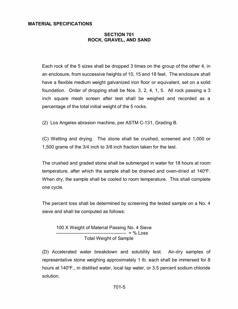
MATERIAL SPECIFICATIONS
SECTION 701ROCK, GRAVEL, AND SAND
701-5
Each rock of the 5 sizes shall be dropped 3 times on the group of the other 4, in
an enclosure, from successive heights of 10, 15 and 18 feet. The enclosure shall
have a flexible medium weight galvanized iron floor or equivalent, set on a solid
foundation. Order of dropping shall be Nos. 3, 2, 4, 1, 5. All rock passing a 3
inch square mesh screen after test shall be weighed and recorded as a
percentage of the total initial weight of the 5 rocks.
(2) Los Angeles abrasion machine, per ASTM C-131, Grading B.
(C) Wetting and drying. The stone shall be crushed, screened and 1,000 or
1,500 grams of the 3/4 inch to 3/8 inch fraction taken for the test.
The crushed and graded stone shall be submerged in water for 18 hours at room
temperature, after which the sample shall be drained and oven-dried at 140oF.
When dry, the sample shall be cooled to room temperature. This shall complete
one cycle.
The percent loss shall be determined by screening the tested sample on a No. 4
sieve and shall be computed as follows:
100 X Weight of Material Passing No. 4 Sieve-------------------------------------------- = % Loss
Total Weight of Sample
(D) Accelerated water breakdown and solubility test. Air-dry samples of
representative stone weighing approximately 1 lb. each shall be immersed for 8
hours at 140oF., in distilled water, local tap water, or 3.5 percent sodium chloride
solution.
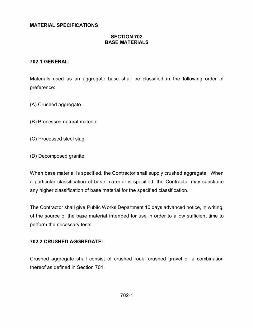
MATERIAL SPECIFICATIONS
SECTION 702BASE MATERIALS
702-1
702.1 GENERAL:
Materials used as an aggregate base shall be classified in the following order of
preference:
(A) Crushed aggregate.
(B) Processed natural material.
(C) Processed steel slag.
(D) Decomposed granite.
When base material is specified, the Contractor shall supply crushed aggregate. When
a particular classification of base material is specified, the Contractor may substitute
any higher classification of base material for the specified classification.
The Contractor shall give Public Works Department 10 days advanced notice, in writing,
of the source of the base material intended for use in order to allow sufficient time to
perform the necessary tests.
702.2 CRUSHED AGGREGATE:
Crushed aggregate shall consist of crushed rock, crushed gravel or a combination
thereof as defined in Section 701.

MATERIAL SPECIFICATIONS
SECTION 702BASE MATERIALS
702-2
702.2.1 Soundness: The percentage of wear of crushed aggregate to be used as base
shall be in accordance with Section 701, except that Grading B of ASTM C-131 shall be
used. The percentage of wear of the material shall not exceed 40 after 500 revolutions.
702.2.2 Grading: The aggregate shall be well graded when tested in
accordance with ASTM C-136 and C-117. The percentage composition by weight
shall be within the following limits:
TABLE 702
Percentage by Weight Passing Sieve
Sieve Sizes
(Square Openings)
Type A Type B Aggregate
Base
3" 100
1-½" 100
1-c" 100
No. 4 30-75 30-70 38-65
No. 8 20-60 20-60 25-60
No. 30 10-40 10-40 10-40
No. 200 0-12 0-12 *3-12
P.I. MAX 5 5 *5
* Except as required in Section 312.5 for inverted section and does not apply to
Processed Steel Slag.

MATERIAL SPECIFICATIONS
SECTION 702BASE MATERIALS
702-3
702.3 PROCESSED NATURAL MATERIAL:
702.3.1 General: Processed natural material shall consist of hard, durable fragments of
stone or gravel and a filler of sand or other finely divided mineral matter. It shall be free
from an excess of soft, or disintegrated pieces, alkali, adobe, vegetable matter, loam or
other deleterious substances.
702.3.2 Physical Requirements: When sampled and tested in accordance with
standard test methods, the aggregate shall meet the following requirements:
(A) Percentage of Wear: When tested in accordance with ASTM C-131, the percentage
of wear shall not exceed 40 percent after 500 revolutions.
(B) Plasticity Index: When tested in accordance with AASHTO T-90, the plasticity index
shall not be more than 5.
(C) Liquid Limit: When tested in accordance with AASHTO T-89, the liquid limit shall
not be more than 25 percent.
702.3.3 Crushed Material: Crushed material is not required, but may be incorporated
in the finished product.
702.3.4 Grading: The aggregate shall conform to the sieve analysis in this
specification except that the least dimension of the maximum particle size shall not
exceed 2/3 of the compacted thickness of the specified lift being placed.

MATERIAL SPECIFICATIONS
SECTION 702BASE MATERIALS
702-4
702.4 DECOMPOSED GRANITE:
Decomposed granite shall be any granitoid igneous rock which has been weathered in
place and which have as principal constituents, granular fragments of quartz and
feldspar. It may also contain fragments of granitic rock not yet broken down into the
component minerals. This material shall remain stable when saturated with water.
Particles larger than 3 inches shall not be broken in the process of rolling and tamping
during construction. Broken products shall not be used.
Decomposed granite shall conform to the following requirements:
(A) When tested in accordance with this specification not more than 20 percent shall
pass the No. 200 mesh sieve.
(B) The P.I. of material passing the No. 200 sieve prior to testing shall not be less than 3
nor greater than 10.
702.4.1 Preparation of Test Specimens: A quantity of sufficient size to have a dry
weight of 15 pounds shall be selected and dried to a constant weight at a temperature
between 215oF and 230oF. Fifteen pounds of this material shall then be subjected to
500 revolutions in a Los Angeles abrasion machine, as described in Section 701.
Nothing shall be placed in the drum other than the material to be tested.
The material subjected to the breakdown shall be tested in accordance with ASTM
C-117 to determine the percentage of material finer than a No. 200 mesh sieve by
washing.
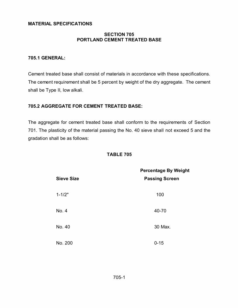
MATERIAL SPECIFICATIONS
SECTION 705PORTLAND CEMENT TREATED BASE
705-1
705.1 GENERAL:
Cement treated base shall consist of materials in accordance with these specifications.
The cement requirement shall be 5 percent by weight of the dry aggregate. The cement
shall be Type II, low alkali.
705.2 AGGREGATE FOR CEMENT TREATED BASE:
The aggregate for cement treated base shall conform to the requirements of Section
701. The plasticity of the material passing the No. 40 sieve shall not exceed 5 and the
gradation shall be as follows:
TABLE 705
Percentage By Weight
Sieve Size Passing Screen
1-1/2" 100
No. 4 40-70
No. 40 30 Max.
No. 200 0-15

MATERIAL SPECIFICATIONS
SECTION 705PORTLAND CEMENT TREATED BASE
705-2
705.3 PORTLAND CEMENT AND WATER:
Portland cement and water shall conform to the requirements of Section 725.
705.4 COMPRESSIVE STRENGTH OF CEMENT TREATED BASE:
The minimum compressive strength at 7 days shall not be less than 500 psi when
tested in accordance with ASTM D-1633.
705.5 BITUMINOUS MATERIAL FOR CURING SEAL:
Bituminous material for curing seal shall conform to the requirements of Section 712 or
713 for the type specified.

MATERIAL SPECIFICATIONS
SECTION 710ASPHALTIC CONCRETE
710-1
710.1 GENERAL:
Asphaltic concrete shall consist of a mixture of paving asphalt and mineral aggregate
and shall be mixed at a central mixing plant in the proportions hereinafter specified to
provide a homogeneous and workable mixture.
Asphaltic concrete is designated as Type A 1-1/2” Base Course; Type B Single or Base
Course; Type C ¾” Single Course; Type D ½” Single or Surface Course; Type E 3/8”
Surface Course of Dense Graded Mixes; Type F 1-1/2” Base Course and Type G 3/8”
Surface Course of Open Graded Mixes.
710.2 MATERIAL:
710.2.1 Asphalt: The asphalt to be mixed with mineral aggregate shall be paving
grade asphalt conforming to Section 711 and shall be AC-10 to AC-40 specified in the
special provisions.
710.2.2 Aggregate: Coarse and fine aggregates shall conform to the applicable
requirements of Section 701.
Coarse aggregate shall be material retained on the No. 4 sieve and fine aggregate shall
be material passing the No. 4 sieve.
Blending sand shall be clean, hard, and sound material. Either naturally occurring sand,
or crushed fines, shall allow for acceptance of an asphalt coating. The exact grading
requirements shall meet the requirements of the specified mix design.

MATERIAL SPECIFICATIONS
SECTION 710ASPHALTIC CONCRETE
710-2
710.2.3 Mineral Filler and Anti-Stripping Agent:
(A) Mineral filler shall conform to the requirements of AASHTO M-17. The mineral filler
shall be dry hydrated lime conforming to the requirements of ASTM C-207 Type N or
portland cement conforming to Section 725. The amount of mineral filter to be used
shall be in the mix design and shall be approximately 1.5 percent by weight of the
mineral aggregate. The method of adding the mineral filler shall result in the aggregate
being uniformly coated. The mineral filler shall uniformly distributed without loss or
waste within the material prior to adding the asphalt to the mixture.
(B) When aggregate is subject to stripping, as determined by one of the three
procedures below, (all three tests must be run), dry hydrated lime conforming to the
requirements of ASTM C-207 Type N, portland cement conforming to Section 725, or
other approved anti-strip agent shall be added. Hydrated lime and portland cement
shall be added in accordance with Section 710.2.3.
(1) A test sample of the paving mixture shall be prepared. The test sample shall
be spread out in a loose, thin layer and allowed to air for 24 hours before testing.
A suitable size sample (approximately 1/2 contents of a one quart container)
shall be tested by placing it in a glass jar with a tight screw cap. The sample
shall be completely covered with distilled water at room temperature. The jar and
contents shall be allowed to stand for a period of 24 hours.
The sample shall then be vigorously shaken for a period of 15 minutes. The
sample of mixture shall be examined for stripping.

MATERIAL SPECIFICATIONS
SECTION 710ASPHALTIC CONCRETE
710-3
(2) The sample shall comply to ASTM D-1075 with a minimum dry strength of
250 psi and a 70 percent retained wet strength.
(3) The sample shall comply to ASTM D-1664 Standard Test Method for coating
and stripping of bitumen-aggregate mixtures.
710.2.4 Combined Aggregates: The combined aggregates sampled after all
processing, without the addition of asphalt and mineral filler, shall conform to the
following quality requirements.
A) The ratio of the percentage of aggregate by weight passing the No. 30 sieve, to
that passing No. 8 sieve, shall not exceed 65 percent in all dense graded asphalt
concrete mixes.
B) The ratio of the percentage of aggregate by weight passing the No. 30 sieve, to
that passing No. 8 sieve, shall not exceed 65 percent in all dense graded asphalt
concrete mixes.
C) At least 75 percent by weight of the aggregate retained on the No. 8 sieve shall
consist of particles which have at least one rough, angular surface produced by
crushing.
710.2.5 Job-Mix Formula: Work shall not be started on the project, or any mixture
accepted until the Contractor has submitted samples of the materials intended for use
and the Contractor has submitted a satisfactory mix design formula based upon tests of
the materials furnished. The mix design shall be prepared under the direct supervision

MATERIAL SPECIFICATIONS
SECTION 710ASPHALTIC CONCRETE
710-4
of a professional engineer experienced in the development of mix designs and mix
design testing. The formula shall indicate the definite percentage for each sieve fraction
of aggregate and for bituminous cement including the intended temperature of the
completed mixture at the time it is discharged from the mixer. The material furnished
shall conform to the approved mix design formula within the tolerances specified herein.
Job-Mix Tolerances
Aggregate passing sieve No. 4 and larger + 6 percent
Aggregate passing sieves No. 8 and 30 + 6 percent
Aggregate passing sieve No. 200 + 2 percent
Temperature of mixing and placing + 25oF
The tolerances used in conjunction with the mix design formula shall require the
resulting gradation to be within the specification limits. The amount of liquid asphalt, by
weight, to be added to the different gradations of the mineral aggregate shall be as
specified and determined by the mix design formula. The amount specified shall be
within the following range of the percentages of the total mixed material:
Mix Description Percentage of Asphalt Range
A 1-1/2" 4.0 to 5.0B 1", C 3/4" 5.0 to 6.0D 1/2", E 3/8" 5.5 to 6.5F 1-1/2" 4.5 to 6.0G 3/8" 6.0 to 7.0
The allowable tolerance in percentage of asphalt cement content from that percentage
specified by the Contractors professional engineer, when sampled and tested in
accordance with AASHTO T-164 and T-168, shall be plus or minus 0.4 percent.

MATERIAL SPECIFICATIONS
SECTION 710ASPHALTIC CONCRETE
710-5
After the mix design formula has been approved and the mixing plant selected, the
Contractor shall not change the mix design or utilize additional mixing plants without
approval of the Public Works Department.
710.2.6 Testing: All three stripping tests for aggregate and a gradation analysis of the
combined aggregate for each coarse shall be performed before paving work starts. Any
corrections necessary, as indicated from the test results, shall be made before
pavement production starts. If stripping occurs, the aggregate shall be rejected or an
anti-stripping agent shall be added as noted in Section 710.2.3B. The stripping test
shall be performed in accordance with Section 710.2.3. Gradation analysis shall be
performed in accordance with ASTM C136 and C117.
The stripping tests shall remain valid for a period of 60 days. If the asphaltic concrete
placement has not been completed within the 60 day time period, new stripping test
shall be taken for each remaining lift.
710.3 COMPOSITION AND GRADING:
The gradation of the combined aggregates shall conform to the requirements indicated
in the following tabulations. The percentages shown are based on the weight of dry
aggregate.

MATERIAL SPECIFICATIONS
SECTION 710ASPHALTIC CONCRETE
710-6
TABLE 710-1
MINERAL AGGREGATE - PERCENTAGE BY WEIGHT PASSING
TYPEDENSE GRADED MIXES
TYPEOPEN GRADED
MIXES
SIEVE
SIZE
BASE
COURSE
SINGLE COURSE
OR BASE COURSE
SINGLE
COURSE
SINGLE OR
SURFACE
COURSE
SURFACE
COURSE
BASE
COURSE
SURFACE
COURSE
A 1-1/2 B 1 C 3/4 D 1/2 E 3/8 F 1-1/2 G 3/8
1-1/2" 100 100 100
1" 80-100 100 100 100 50-90
3/4"70-95 80-100 90-100 97-100 50-90
½" -- 65-85 75-100 85-1003/8" 50-65 55-75 65-90 70-90 100 100No. 4 35-50 40-60 45-70 50-75 65-85 0-20 25-70No. 8 25-40 25-45 30-55 35-65 45-70 0-10No. 30 10-25 10-30 15-35 20-40 20-40No. 100 – 5-15No. 200 2-8 2-8 2-8 2-8 3-8 0-5 0-4
710.4 STORING, DRYING AND SCREENING AGGREGATES:
710.4.1 Stockpiling (Cold Feed Separation): Aggregate for dense graded mixes shall
be separated and stockpiled into 2 or more sizes of aggregate. If the mineral aggregate
is separated into 2 sizes, one stockpile, or bunker, shall contain material which has a
minimum of 80 percent passing a No. 4 sieve and the other stockpile, or bunker, shall
contain material with a minimum of 80 percent retained on the No. 4 sieve. If the
mineral aggregate is separated into more than 2 sizes, at least 2 of the stockpiles, or
bunkers, shall comply with the above.

MATERIAL SPECIFICATIONS
SECTION 710ASPHALTIC CONCRETE
710-7
The gradation analysis of the cold feed stockpiles, or bunkers, for the duration of the
project shall not deviate from the gradation as determined at the beginning of the project
by more than the following tolerances:
Stockpile Tolerances
Aggregate passing 3/4", 3/8", No. 4, No. 8 & No. 30 + 10 Percent
Aggregate passing No. 200 + 4 Percent
Material added to the stockpiles, or bunkers, during the progress of the project shall
comply with the above requirement, however, the resulting gradation shall be within the
specification limits.
In placing materials in storage, or moving them from storage to the drier, any method
that may cause segregation, degradation, contamination, or the combining of materials
of different gradings that results in any stockpile, or bunker, failing to meet the
requirements shall be require the material to be reprocessed or wasted at the
Contractor’s expense.
710.4.2 Drying and Heating: The mixing plant shall be provided with accurate
mechanical means for feeding the aggregates from the stockpiles, or bunkers, into the
drier at a rate resulting in a uniform production and temperature.
Feeders should be of the apron belt, reciprocating plate, vibrating type, or tip gate and
shall have accurate and separate adjustments. These adjustments shall be capable of

MATERIAL SPECIFICATIONS
SECTION 710ASPHALTIC CONCRETE
710-8
being locked in any position and the feeders shall be capable of delivering the required
aggregate in the proper proportions.
Drying shall continue until the moisture content is not greater than 0.75 percent. The
aggregate shall not be heated beyond the lowest temperature necessary for proper
drying, mixing, spreading, and compacting.
The drier shall be provided with a calibrated heat indicating device to determine the
temperature of the aggregate leaving the drier. The heat indicating device shall be
accurate to the nearest 10oF and shall be installed creating a fluctuation of 10oF in the
aggregate temperature will be shown by the heat indicating device within one minute.
The drier shall be equipped with an approved type of dust collector system capable of
removing excess dust from the aggregate and wasting the material collected and
returning it uniformly to the mixer. The dust collector shall comply with the ADEQ Air
Pollution Control Rules and Regulations and applicable State laws or local ordinances.
710.5 BIN SEPARATION:
After being dried and in advance of mixing with asphalt, the mineral aggregate shall be
separated into 3 or more sizes and stored in separate bins.
All mineral aggregate for mixes A 1-1/2, B 1 and C 3/4, Dense Graded, shall be
separated into 3 or more bins as follows:
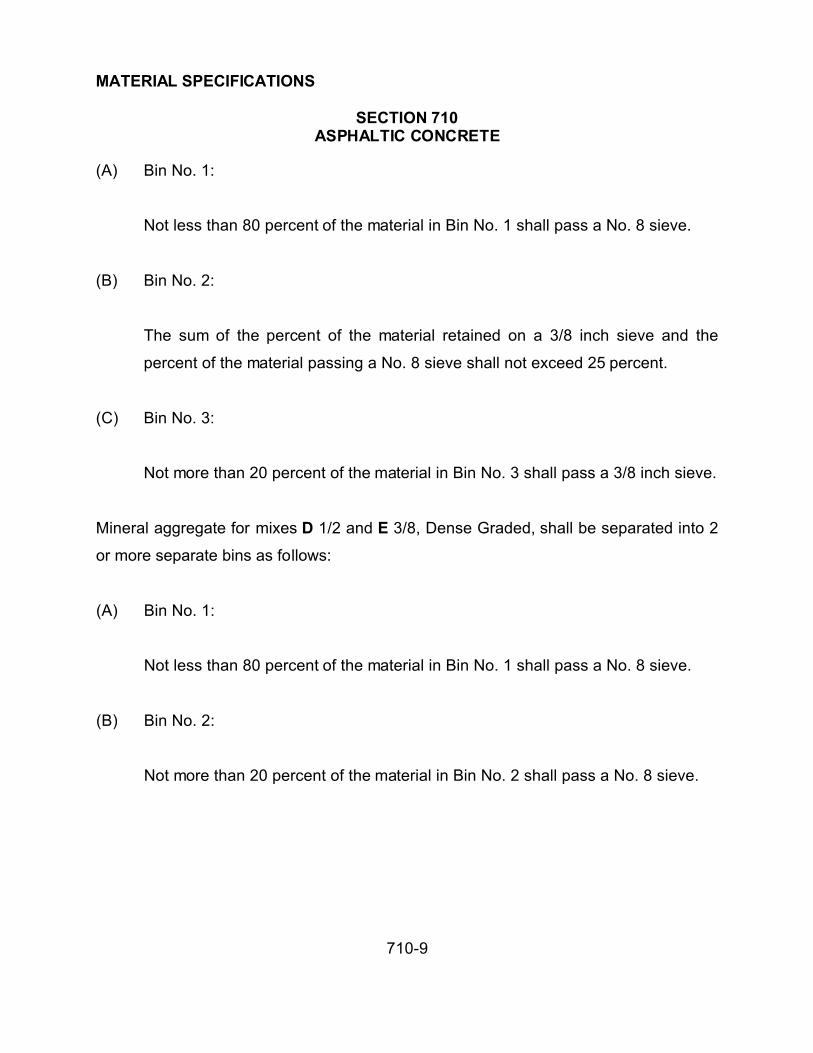
MATERIAL SPECIFICATIONS
SECTION 710ASPHALTIC CONCRETE
710-9
(A) Bin No. 1:
Not less than 80 percent of the material in Bin No. 1 shall pass a No. 8 sieve.
(B) Bin No. 2:
The sum of the percent of the material retained on a 3/8 inch sieve and the
percent of the material passing a No. 8 sieve shall not exceed 25 percent.
(C) Bin No. 3:
Not more than 20 percent of the material in Bin No. 3 shall pass a 3/8 inch sieve.
Mineral aggregate for mixes D 1/2 and E 3/8, Dense Graded, shall be separated into 2
or more separate bins as follows:
(A) Bin No. 1:
Not less than 80 percent of the material in Bin No. 1 shall pass a No. 8 sieve.
(B) Bin No. 2:
Not more than 20 percent of the material in Bin No. 2 shall pass a No. 8 sieve.

MATERIAL SPECIFICATIONS
SECTION 710ASPHALTIC CONCRETE
710-10
Mineral aggregate for mixes F 1-1/2 and G 3/8, Open Graded shall be separated into 2
or more separate bins as follows:
(A) Bin No. 1:
Not less than 85 percent of the material in Bin No. 1 shall pass a No. 8 sieve.
(B) Bin No. 2:
Not more than 15 percent of the material in Bin No. 2 shall pass a No. 8 sieve.
Corrective actions for compliance shall be by drawing the bin and rescreening the
material. If there is evidence of fine material hanging on the sides of the fine bin, the fine
bin shall vibrate the side walls of the bin while the plant is operating. A positive signal
system shall be provided to indicate the low level of material in each bin. Each bin shall
be provided with an overflow chute to prevent spilling into adjacent bins and to waste
excess material from the bin. The intermingling of material between bins shall not be
permitted. The composite analysis of the bins shall comply with the grading limits
required for the size mineral aggregate in the mix design.
710.6 GENERAL MIXING:
The mineral aggregate and asphalt shall be mixed at a central mixing batch plant,
continuous plant mixing, or drum type mixing.

MATERIAL SPECIFICATIONS
SECTION 710ASPHALTIC CONCRETE
710-11
The Public Works Department reserves the right to discontinue the use of any drying,
proportioning, or mixing equipment which fails to produce a satisfactory mix.
Filler material, if required, shall be added separately and in a thoroughly dry condition.
Heating of filler material shall not be required.
The amount of filler material to be used shall be as specified and shall be accurately
proportioned by weight or by volumetric methods.
The amount of asphalt to be added to the mineral aggregate shall be as specified.
The temperature of the mineral aggregate shall not be higher than necessary for
spreading and finishing at the time of adding the paving asphalt and in no case shall the
temperature for the Dense Graded Mixes exceed 325oF, nor shall it exceed 250oF for
Open Graded Mixes.
Asphalt shall be added to the mineral aggregate at a temperature conforming to the
range of temperature specified in Section 711.
Thermometric equipment shall be provided near the charging valve to indicate the
temperature of the asphalt.
Scales shall be certified as to accuracy and sealed annually by the Sealer of Weights
and Measures. Each scale installation shall be provided with certified weights as
follows:

MATERIAL SPECIFICATIONS
SECTION 710ASPHALTIC CONCRETE
710-12
The Contractor shall provide not less than 20 certified weights, each weighing 50
pounds, in checking scales used on the project. Each weight shall be numbered and
show the corresponding certified weight. The scales and weights shall remain the
property of the Contractor and no payment shall be made for their use.
The asphalt concrete manufacturer shall make alternations as necessary to the
equipment to enable the Sealer of Weights and Measures to conveniently check,
calibrate, and seal the aggregate and asphalt scales used in the production of asphalt
concrete.
Scales shall be located where the plant operator and the plant inspector have an
unobstructed view of the indicating or registering devices. They shall indicate the true
net weight without the application of any factor. The dial for dial type scales shall not be
less than 12 inches in diameter and the figures thereon shall be clearly legible.
710.7 BATCH MIXING:
710.7.1 General Requirements: The mixer shall be of the twin-shaft pug mill type and
shall be operated at the speed recommended by the manufacturer. It shall be equipped
with paddles of sufficient size and number to deliver a thorough and uniform mixture.
Should the paddles, or other parts of the pug mill, become worn to such extent they
adversely affect the quality of the mixing, or allow leakage from the discharge gate, they
shall be promptly replaced.
The amount of material that may be mixed per batch shall not exceed the rated capacity
of the plant.

MATERIAL SPECIFICATIONS
SECTION 710ASPHALTIC CONCRETE
710-13
Dead areas in the mixer shall be corrected either by a reduction in the volume of
materials or by other adjustments.
All boxes, hoppers, buckets, or similar receptacles used for weighing mineral aggregate,
filler material, and asphalt, as well as all scales used in batching materials shall be
insulated against the vibration, or movement, of the rest of the plant, so the error in
weighing, with the entire plant operating, will not exceed 2 percent for any setting nor 1-
1/2 percent for any batch.
Dial heads, or readout devices, shall be mounted separate from batch plant or tower
supports.
710.7.2 Aggregate: The aggregate scales shall be either multiple beam, or spring-less
dial type, having a capacity exceeding 1-1/2 times the total amount of materials to be
weighed in one operation. Each scale graduation shall be approximately 1/1000 of the
total capacity of the scale.
710.7.3 Asphalt: For mixers with a manufacturer's rated capacity of 4,000 pounds or
less, the asphalt shall be measured by weight in a heated insulated bucket suspended
from a springless dial scale system having a capacity of not more than 500 pounds with
one pound gradations. For mixers with a manufacturer's rated capacity of more than
4,000 pounds, the scale system shall have a capacity of not more than 1,000 pounds
with one pound gradations.
Asphalt shall be introduced into the mixer by means of a distributing pan fixed to the
side of the mixer, by gravity distribution along the center of the mixer parallel to the

MATERIAL SPECIFICATIONS
SECTION 710ASPHALTIC CONCRETE
710-14
mixer shafts or by pressure spraying. The pan shall be equipped with movable vanes to
allow flow of asphalt to be directed across the width of the pan as desired. The vanes
shall be equipped with a means of quick adjustment and a positive lock to prevent
shifting.
710.7.4 Filler Material: Filler material shall be introduced into the mixer through the
weight box or through the center of the mixer.
710.7.5 Mixing: The entire batch shall be continuously mixed until all the materials are
thoroughly blended into on homogeneous mass. The maximum mixing time for any one
batch shall be as hereinafter specified for that particular type mix. The time of mixing a
batch shall begin on the charging stroke of the weigh hopper dumping mechanism and
shall end when discharge from the mixer has started. The mixer shall be equipped with
a time lock mechanism which locks the mixer discharge gate for the mixing period and
activates an indicator light, or bell, which shall be used in signaling the end of the mixing
time. The time lock and indicator light, or lights, shall be actuated by the charging
stroke of the weigh hopper charging mechanism. There shall be provided an interlock
and indicator light to provide for the dry mixing time for the introduction of filler which
shall be a minimum of 4 seconds and not more than 15 seconds.
The mixer platform shall be of ample size for a safe and convenient access to the mixer
and other equipment. Mixer and weigh-box housing shall be provided with hinged gates
of ample size to permit ready sampling of the discharge of aggregates from each of the
plant bins.
Access shall be provided for convenient and accurate sampling of the mixture.

MATERIAL SPECIFICATIONS
SECTION 710ASPHALTIC CONCRETE
710-15
710.8 CONTINUOUS MIXING:
710.8.1 General Requirements: In addition to the general aforementioned
requirements, continuous mixing of the materials shall conform to the following:
(A) No asphalt concrete shall be produced until the plant has been calibrated. When
there is a change in the weight per cubic foot of the aggregate, the plant shall be
recalibrated.
(B) The maximum rate of production shall not exceed the manufacturer's
recommendations.
710.8.2 Storage Bins: Storage bins shall be equipped with overflow chutes for each
compartment. If there is evidence of fine material hanging on the sides of the fine bin,
the fine bin shall be equipped with a vibrating unit. A positive signal system shall be
provided to indicate the low level of material in each bin. As the level of material in any
one bin approaches the strike off capacity of the feed gate, the device will automatically
close down the feed of all materials to the mixer. Openings in the partitions between
the bins shall not be permitted.
710.8.3 Feeder: The correct proportions of each aggregate size and filler material shall
be drawn from the storage bins by an approved type of continuous feeder. The feeder
shall supply the correct amount of aggregate and filler material in proportion to the
asphalt. The proportion of each size shall be separately adjusted. The continuous
feeder for the aggregate should be actuated by mechanical or electrical methods.

MATERIAL SPECIFICATIONS
SECTION 710ASPHALTIC CONCRETE
710-16
Mechanical driven aggregate feeders shall be directly connected with the drive on the
asphalt pump.
Electrical driven aggregate feeders shall be actuated from the same circuit that serves
the motor driving the asphalt pump. Electricity for operating the plants equipped with
electrically driven feeders shall be actuated from the same circuit that serves the motor
driving the asphalt pump. Electricity for operating the plants equipped with electrically
actuated aggregate feeders shall not vary in frequency in excess of one cycle or in
voltage in excess of 10 percent. The drive shaft on the feeder shall be equipped with a
revolution counter reading to one-hundredth of a revolution.
710.8.4 Asphalt Pump: The asphalt pump shall be a positive displacement type pump.
The use of a pressure relief valve shall not be permitted. The plant shall be equipped
with an indicating meter between the pump and spray, and the meter shall be in good
working condition and accurately record the gallons of material pumped. All pipe, bins,
fittings, and meter shall be steam jacketed.
The asphalt storage system shall be equipped with a device for automatic plant cut-off
when the intake of the positive displacement pump is not working under positive
pressure.
A by-pass shall be installed between the pump and the spray bar to divert the flow of
asphalt into an auxiliary container of not less than 25 gallon capacity for checking rate of
pump delivery.

MATERIAL SPECIFICATIONS
SECTION 710ASPHALTIC CONCRETE
710-17
710.8.5 Discharge Hopper: The material from the mixer shall be discharged into a
hopper assuring segregation of the mixture shall be at a minimum.
710.8.6 Facilities for Sampling: Continuous mixing plants shall be equipped with 3 or
more sampling hoppers. These shall be placed for the discharge from each aggregate
feeder to be diverted into each hopper while the feeders are in full operation. The
weight of the hoppers shall be determined by means of a springless dial or a beam type
scale.
The area around the hoppers shall be kept free of all aggregate and debris. The
contractor shall furnish all labor required in handling the hoppers, weighing the
materials, and disposing of all excess materials.
Methods shall be provided for convenient and accurate sampling of the mixture as it
leaves the mixer.
If the results obtained indicate uniform proportioning of the aggregate from the bins are
not being delivered, the operations shall cease until corrections have been made.
710.9 DRUM MIXING:
710.9.1 General Requirements: The drum mix plant shall be capable of producing a
thorough and uniform mixture. The production of the drum mix plant shall be governed
by the rate required for a uniform mixture.

MATERIAL SPECIFICATIONS
SECTION 710ASPHALTIC CONCRETE
710-18
No asphaltic concrete shall be accepted until the plant has been calibrated. When tests
indicate material produced is not in conformance with the approved job mix design,
asphalt concrete shall not be used until the plant has been recalibrated.
710.9.2 Aggregate Delivery System: An automatic plant shut-off shall be installed for
bin shut off when empty. Provisions shall be provided for sampling the full flow of
materials from the cold feed. The cold feed shall be weighed continuously. The
weighing system shall have an accuracy of 0.5 percent. The plant shall provide weight
control of the cold aggregate feed by use of a belt scale which shall automatically
regulate the feed gate and permit instant correction of variations in load. The cold feed
flow shall be automatically coupled with the asphalt flow to maintain the required
proportions of each material. Provisions shall be made for introducing the moisture
content of the cold feed aggregates into the belt weighing signal and correcting wet
aggregate weight to dry aggregate weight.
Screens that oversize particles or lumps of aggregate shall be installed in the feeder
mechanism between the bins and the dryer drum.
Dry weight of the aggregate flow shall be displayed digitally in appropriate units of
weight by time and automatically totaled.
710.9.3 Additive Delivery Systems: Metering shall be provided to allow the proper
amount of additives into the mix. Delivery systems shall be accurate to plus or minus
one percent. The additive flow shall be displayed digitally in appropriate units of weight
time shall be totaled.

MATERIAL SPECIFICATIONS
SECTION 710ASPHALTIC CONCRETE
710-19
710.9.4 Thermometric Equipment: A recording thermometer shall be located to
indicate the temperature of the bituminous material in storage. The plant shall be
equipped with approved recording thermometers or pyrometers at the discharge chute
of the drum mixer.
710.9.5 Asphalt Delivery System: The drum mixer plant shall be equipped with a
positive displacement asphalt pump and an indicating meter between the pump and
spray to monitor the proper amount of asphalt being introduced into the mix when
displaced digitally in appropriate units of volume or weight. The asphalt delivery shall
be interlocked with the aggregate weight and accurate to plus or minus one percent.
The asphalt delivery system shall be equipped with automatic plant cut-off devices
when the intake of the positive displacement pump is not working under positive
pressure.
A suitable by-pass shall be installed between the pump and the spray bar to divert the
flow of asphalt.
710.9.6 Temporary Storage of Bituminous Mixture: Use of surge bins or storage
bins for temporary storage of hot bituminous mixtures shall be permitted when:
A) The bituminous mixture is stored in insulated and heated storage bins for a
period of time not to exceed 12 hours, provided an inert gas atmosphere is maintained
in the bin during the storage period.

MATERIAL SPECIFICATIONS
SECTION 710ASPHALTIC CONCRETE
710-20
B) If it is determined there is an excessive amount of heat loss, segregation and/or
oxidation of the mixture due to temporary storage, use of surge bins, or storage bins,
shall be discontinued and the stored product shall be waste.
710.10 GENERAL REQUIREMENTS:
A temperature indicating device reading to 500 degrees F. and accurate to 5 degrees F.
shall be fixed in the asphalt line, or storage tank.
The temperature of the mixture discharged into the hauling vehicles shall not vary more
than 30 degrees F. The discharge end of the asphalt binder circulating pipe shall be
maintained below the surface of the asphalt binder in the storage tank to prevent
discharging hot bituminous binder into open air. The Contractor shall provide a suitable
sampling outlet in the asphalt feed lines connecting the plant storage tanks to the
asphalt weighing system or spray bar. The sampling device shall consist of a 1/2 inch
or 3/4 inch valve constructed in such a manner that a one gallon sample may be
withdrawn slowly at any time during plant operations. The valve shall be maintained in
good condition. If it fails to function properly, the valve shall be replaced. The sampling
device shall be placed in a location readily accessible and in an area free of dangerous
obstructions. A drainage receptacle shall be provided for flushing the devices prior to
sampling.
The beds of trucks used to haul asphalt concrete mixtures shall be coated with a light
film of distillate, or light oil, before loading. If, in the opinion of the plant inspector, there
is an excessive amount of oil on the beds, the truck driver shall be required to raise the
bed of the truck and drain off the excessive amount of oil.
Mixtures shall be delivered to the site of the work without segregation of the ingredients
and within the temperature range specified in Section 321.

MATERIAL SPECIFICATIONS
SECTION 711PAVING ASPHALT
711-1
711.1 GENERAL:
Asphalt shall be produced from crude asphalt petroleum or a mixture of refined liquid
asphalt and refined solid asphalt. The asphalt shall be free any residues obtained by
the artificial distillation of coal, coal tar, or paraffin oil and shall be homogeneous and
free from water.
711.2 TESTING REQUIREMENTS:
Paving asphalt shall be classified by viscosity and shall conform to the requirements set
forth in table 711.1.

MATERIAL SPECIFICATIONS
SECTION 711PAVING ASPHALT
711-2
TABLE 711-1
ASTM D-3381
Table 1 - Requirements for Asphalt Cement, Viscosity Graded at 140° F (60° C).
NOTE 2 - Grading based on original asphalt.
NOTE 2 - If difficulty is less than 100, material will be accepted if ductility at 60° F
(15.5°C) is minimum at a pull rate of c cm min.
Test
Viscosity Grade
AC-2.5 AC-5 AC-10 AC-20 AC-30** AC-40
Viscosity, 140°F (60°C)P 250+50 500+100 1000+20 2000+400 3000+600 4000+80
Viscosity, 275°F (1355°C),
min,cSt
80 110 150 210 250 300
Penetration, 77°F (25°C),
100g/ 5 s. min.
200 120 70 40 30 20
Flash point, Cleveland open
cup , min. Degrees F
325
(163)
350
(177)
425
(219)
450
(232)
450
(232)
450
(232)
Solubility in trichloroethylene,
min.%
99.0 99.0 99.0 99.0 99.0 99.0
Test pm residue from thin film
oven test; Viscosity, 140°F
1250 2500 5000 10,000 15,000 20,000
Ductility, 77°F (25°C), 5
cm/min. min. cm
100 100 100 75 60 45
** ASTM D-3381 Table 11

MATERIAL SPECIFICATIONS
SECTION 711PAVING ASPHALT
711-3
711.3 TEST REPORT AND CERTIFICATION:
At the time of delivery of each shipment of asphalt, the supplier supplying the material
shall deliver to the purchaser 3 certified copies of the test report which shall indicate the
name of the refinery and supplier, type and grade of asphalt delivered, date and point of
delivery, quantity delivered, delivery ticket number, purchase order number, and results
of the above specified tests. The test report shall be signed by an authorized
representative of the supplier certifying that the product delivered conforms to the
specifications for the type and grade indicated.
Until the certified test reports and samples of the material have been checked by the
Engineer, that material will be only tentatively accepted by the Contracting Agency.
Final acceptance will be dependent upon the determination of the Engineer that the
material involved fulfills the requirements prescribed. The certified test reports and the
testing required in connection with the reports shall be at no additional cost to the
Contracting Agency.
711.4 TEMPERATURES:
Unless otherwise specified in these specifications or in the special provisions, the
various grades of paving asphalt shall be applied within the temperature range indicated
in Table 711-2. The exact temperature shall be determined by the Engineer.
At no time, after loading into a tank car or truck for transportation from the refinery to the
purchaser, shall the temperature of the paving asphalt be raised above 400 degrees F.

MATERIAL SPECIFICATIONS
SECTION 711PAVING ASPHALT
711-4
TABLE 711-2
APPLICATION TEMPERATURE OF PAVING ASPHALTS
Grade of
Material
Minimum Maximum Minimum Maximum
AC-40 275 325 300 390
AC-30 275 325 300 370
AC-20 275 325 295 360
AC-10 275 325 250 345

MATERIAL SPECIFICATIONS
SECTION 712LIQUID ASPHALT
712-1
712.1 GENERAL:
Liquid asphalt shall consist of either natural crude refined asphalt petroleum, or a
residual product thereof.
The liquid asphalt shall be medium curing product designed by the letters MC, and shall
consist of a paving asphalt conforming to the provisions in Section 711, fluxed or
blended with a kerosene type solvent.
The asphalt shall not be heated during the process of its manufacture or during
construction to prevent injury through the formation of carbonized particles.
712.2 TEST REQUIREMENTS:
Liquid asphalt shall consist of materials specified above and shall conform to the
requirements set forth in Table 712-1.
712.3 TEST REPORTS AND CERTIFICATIONS:
Test reports and certifications shall be furnished in accordance with Section 711.
712.4 CONVERSION OF QUANTITIES:
In accordance with ASTM D-1250 when pay quantities of liquid asphalt are determined
from volumetric measurements, the volumetric measurement, at any temperature, shall
be reduced to the volume the material would occupy at 60 degrees F. In converting
volume to weight the computations shall be based on the data contained in Table 712-2.

MATERIAL SPECIFICATIONS
SECTION 712LIQUID ASPHALT
712-2
TABLE 712-1
AASHTO M-82
MC-30 MC-70 MC-250 MC-800 MC-3000
Min. Max. Min. Max. Min. Max. Min. Max. Min. Max
Kinematic Viscosity at
60°C (140°F)
centistokes
30 60 70 140 250 500 800 1600 3000 6000
Flash point (Tab. open-
cup), degrees C° (F)
38
(100)
....... 38
(100)
........
.
66
(150)
66
(150)
66
(150)
Water percent 0.2 0.2 0.2 0.2 0.2
Distillation test Distillate
percentage by volume of
total distil late to 360°C
(680°F)
to 225°C (437°F)
to 260°C (500°F)
to 315°C (600°F)
...
40
75
25
70
93
0
20
65
20
60
90
0
15
60
10
55
87
...
0
45
...
35
80
...
0
15
...
15
75
Residue from distillationto 360°C (680°F)
Volume percentage of
sample by difference
50
... 55 ... 67 ... 75 ... 80 ...
Tests on residue from
distillation: Absolute
viscosity at 60°C
(140°F) poises Ductility,
5 cm/cm , c.m . Solubility
in Trichloroethylene,
percent
300
100
99.0
1200
...
...
300
100
99.0
1200
...
...
300
100
99.0
1200
...
...
300
100
99.0
1200
...
...
300
100
99.0
1200
...
...

MATERIAL SPECIFICATIONS
SECTION 712LIQUID ASPHALT
712-3
TABLE 712-1A
ASTM D-2026
Requirements for Cutback Asphalt (Slow-Curing Type)
NOTE - If the ductility at 77°F (25°C) is less than 100, the material will be acceptable if
its ductility at 60°F (15.5°C).
Designation
SC-70 SC-250 SC-800 SC-3000
Min. Max. Min. Max. Min. Max. Min. Max.
Kinomatic viscosity at
140°F (60°C). Cst 70 140 250 500 800 1600 3000 6000
Flash point (Clevelandopen cup), °F (°C)
150(66)...
175(79) ...
200(93) ...
225(107) ...
Distillation lost: Total
distillate to 680°F
(360°C), volume % 10 30 4 20 2 12 ... 5
Solubility in
trichloroethylene, % 99.0 ... 99.0 ... 99.0 ... 99.0 ...
Kinomatic viscosity on
distillation residue at
140°F (60°C), St 4 70 8 100 20 160 40 350
Asphalt residue:
Residue of 100
penetration, % Ductility
of 100 penetration
residue at 77°F (25°C), 50 ... 60 ... 70 ... 80 ...
Water, % ... 0.5 ... 0.5 ... 0.5 ... 0.5
TABLE 712-2
Grade of Materials Gals. Per Ton at 60
Degrees F.
Lbs. Per Gals. at 60
Degrees F.
70 253 790
250 249 803
800 245 816
2000 241 830

MATERIAL SPECIFICATIONS
SECTION 713EMULSIFIED ASPHALTS
713-1
713.1 GENERAL:
Emulsified asphalts shall be composed of a paving asphalt base uniformly emulsified
with water and an emulsifying or stabilizing agent It shall be homogeneous throughout
and if stored shall show no separation of ingredients within 30 days after delivery.
Emulsified asphalt shall be classified as quick setting, rapid setting, medium setting or
slow setting in either anionic or cationic emulsions.
Emulsified asphalt shall be specified as follows:
A) Penetration type and high viscosity type emulsion shall be designated by the letters
RS-Rapid Setting.
B) Mixing type emulsion shall be designated by the letters SS-Slow Setting, MS-Medium
Setting and QS-Quick Setting.
713.2 TESTING REQUIREMENTS:
The emulsified asphalt shall conform to the requirements set forth in Table 713-1 and
the latest amendments specified by AASHTO.
713.3 TESTS REPORT AND CERTIFICATION:
Test reports and certifications shall be made in accordance with Section 711.

MATERIAL SPECIFICATIONS
SECTION 713EMULSIFIED ASPHALTS
713-2
TABLE 1
REQUIREMENTS FOR ANIOMIC EMULSIFIED ASPHALT
Type Rapid Setting Medium Setting Slow Setting
Grade RS -1 RS-2h MS-1 MS-2 MS-2h SS -1 SS-1h
Min/ Max Min/Max Min/Max
.
Min/ Max Min/ Max Min/ Max Min/ Max
Tests on emmissions
Viscosity, Saybolt
Pu rol at 77°F (25°C)s .
20 100 20 100 100 20 100 20 100
Viscosity, Saybolt
Pu rol at 122°F (25°C)s 75 400
Settlement, 24 hours
day, percent
1 1 1 1 1 1 1
Dumulsib ility, 35 mi.
0.2 N. CaC1, percent 60 60
Coating ability and
water resistance ..........
Coating, dry and
agg regate .................... Good Good Good
Coating, after spraying Fair Fair Fair
Coating, wet
agg regate .................... Fair Fair Fair
Coating, after spraying Fair Fair Fair
Cement m ixing test,
percent ........................
2.0 2.0
Sieve test, percent ....... 0.10 0.10 0.10 0.10 0.10 0.10 0.10
Residue by distillation,
percent ........................ 55 63 55 65 65 57 57
Tests on residue from
distillation test:
Penetration 77 °F
(25°C), 100g. 5 s ........
100 200 40
90
100 200 100 200 40 90 100 200 40 90
Ductility, 77°F9
(25°C), 5 cm/min. cm .. 40 40 40 40 40 40 40
Solubility in
trichloroethylene, % ..... 97 .5 97.5 97.5 97.5 97.5 97.50 97.5

MATERIAL SPECIFICATIONS
SECTION 713EMULSIFIED ASPHALTS
713-3
713.4 TEMPERATURES
The various grades of emulsified asphalt shall be applied at temperatures within the
limits specified below. If necessary emulsified asphalt shall be reheated. After loading
into a tank car or truck for transportation to the work site, the temperature of the
emulsion shall not be above the maximum temperature shown in Table 713-2. During
reheating operations, the emulsified asphalt shall be agitated to prevent localized
overheating. Emulsified asphalt shall not be permitted to cool to a temperature of less
than 40°.
TABLE 713-2
APPLICATION TEMPERATURE OF EMULSIFIED ASPHALT
Grade of Emulsified Minimum °F. Maximum °F
RS-1, MS-1, SS-1h, CSS-1, 70° F 140° F
RS-2, MS-2, MS-2h, CRS-1, 125° F 185° F
Emulsified asphalt shall be heated by a method to ensure steam or hot oils will not be
introduced directly into the emulsified.
713.5 CONVERSION OF QUANTITIES:
When pay quantities of emulsified asphalt are determined from volumetric
measurements, the volumetric measurement at any temperature shall be reduced to the
volume the material would occupy at 60 degrees F. in accordance with ASTM D-1250.
In converting volume to weight, the computations shall be based on the following data:

MATERIAL SPECIFICATIONS
SECTION 713EMULSIFIED ASPHALTS
713-4
TABLE 713-3
Grade of Material Gals. Per Ton at 60° F Lbs. Per Gal. at 60° F
All grades 240 8.33

MATERIAL SPECIFICATIONS
SECTION 716COVER MATERIAL
716-1
716.1 GENERAL:
Cover material (chips) shall consist of aggregate spread in conjunction with a
bituminous or asphalt-rubber seal coat.
716.2 STONE CHIPS:
716.2.1 General: The stone chips shall be crushed rock as per La Paz County Section
701.
716.2.2 Tests: The chips' weight loss shall not exceed 40 percent at 500 revolutions
when tested in accordance with ASTM C-131.
The chips shall not show a loss in excess of 12 percent when tested in accordance with
AASHTO T-104 (Sodium Sulfate Soundness).
A minimum of 75 percent of the material, by weight, retained on the No. 8 sieve, shall
have at least one fractured face produced by the crushing operation.

MATERIAL SPECIFICATIONS
SECTION 716COVER MATERIAL
716-2
716.2.3 Gradation: When tested in accordance ASTM C-136 and C-117, gradation
shall comply:
TABLE 716-1
For Low Volume Traffic Only
Sieve Size Percent Passing
½” 100
d” 97/100
¼” 70/100
#8 0-5
#200 0-2
TABLE 716-2
For High Volume Traffic
Sieve Size Percent Passing
¾” 100
½” 97/100
d” 70/100
¼” 0/10
#8 0-5
#200 0-2

MATERIAL SPECIFICATIONS
SECTION 716COVER MATERIAL
716-3
716.3 PRECOATED CHIPS:
The aggregate shall be heated and precoated with asphalt cement as specified in
Section 711. The quantity of bituminous material shall not be more than 0.50 percent of
the combined weight of the bituminous material and the aggregate.
The precoating shall be done in a pug mill mixing facility for a minimum of 30 seconds
or until the asphalt coat all aggregate, which ever time frame is greater. A drum mix
plant may be used and the end result shall produce a uniform, dust free project.
716.4 UNCOATED CHIPS:
When liquid or paving grade asphalt is used as the bituminous binder, the uncoated
chips shall not contain moisture in excess of a saturated surface dry condition.
When emulsified asphalt is used as the bituminous binder, the uncoated chips shall be
surface wet but free from running water.
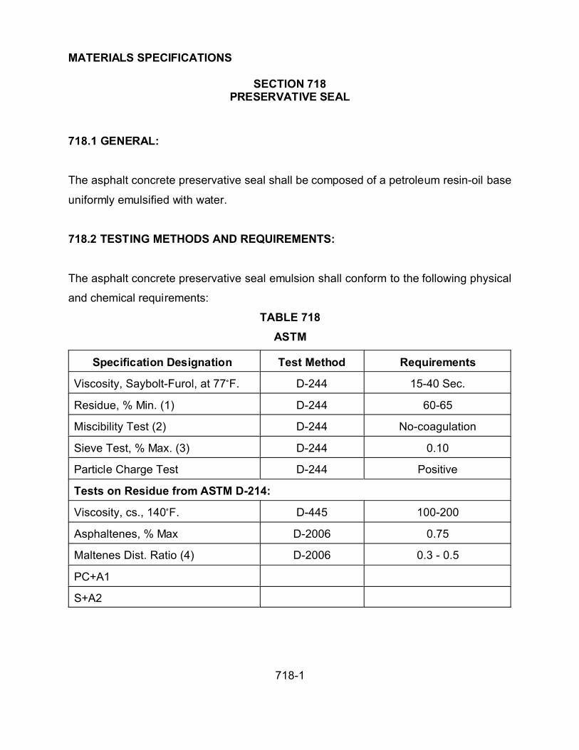
MATERIALS SPECIFICATIONS
SECTION 718PRESERVATIVE SEAL
718-1
718.1 GENERAL:
The asphalt concrete preservative seal shall be composed of a petroleum resin-oil base
uniformly emulsified with water.
718.2 TESTING METHODS AND REQUIREMENTS:
The asphalt concrete preservative seal emulsion shall conform to the following physical
and chemical requirements:
TABLE 718
ASTM
Specification Designation Test Method Requirements
Viscosity, Saybolt-Furol, at 77/F. D-244 15-40 Sec.
Residue, % Min. (1) D-244 60-65
Miscibility Test (2) D-244 No-coagulation
Sieve Test, % Max. (3) D-244 0.10
Particle Charge Test D-244 Positive
Tests on Residue from ASTM D-214:
Viscosity, cs., 140/F. D-445 100-200
Asphaltenes, % Max D-2006 0.75
Maltenes Dist. Ratio (4) D-2006 0.3 - 0.5
PC+A1
S+A2

MATERIALS SPECIFICATIONS
SECTION 718PRESERVATIVE SEAL
718-2
(1) ASTM D-244 modified evaporation test for percent of residue is made by heating a
50 gram sample to 300°F. until foaming ceases, then cool immediately and calculate
results.
(2) Test procedure identical with ASTM D-244 except that 0.02 normal calcium chloride
solution shall be used in place of distilled water.
(3) Test procedure identical with ASTM D-244 except that distilled water shall be used
in place of 2 percent sodium oleate solution.
(4) In the maltenes distribution ratio test by ASTM D-2006.
PC = Polar Compounds A1 = First Acidaffins
A2 = Second Acidaffins S = Saturates

MATERIAL SPECIFICATIONS
SECTION 725PORTLAND CEMENT CONCRETE
725-1
725.1 GENERAL:
Portland cement concrete shall be composed of Portland cement, Portland Pozzolan
cement, Pozzolonic Materials, fine and coarse aggregates, water, and specified
admixtures.
The materials used for concrete shall be in accordance with these specifications.
Weighing and metering devices used for proportioning materials shall fulfill requirements
for accuracy and tolerance as prescribed by the Weights and Measures Division of the
State of Arizona and shall be sealed and certified. This certification shall not be over 12
months old and shall be renewed prior to project commencement. When portable
plants are set up at a new location, the scales and scale assembly shall be inspected
and certified regardless of when the scales were last tested. The Public Works
Department may require the Contractor to perform a scale check with certified weights
furnished by the Contractor and/or may order the scale re-certified.
725.1.1 Classes of Concrete:
TABLE 725
Classes and Master Limits of Concrete
Min. Compressive Strength (1)
Class of Concrete Min. Cement Content Lbs. At 14 Days P.S.I. At 28 Days P.S.I.
AA 600 3,200 4,000
A 520 2,400 3,000
B 470 2,000 2,500
C 420 1,600 2,000

MATERIAL SPECIFICATIONS
SECTION 725PORTLAND CEMENT CONCRETE
725-2
(1) As tested in accordance with ASTM C-39. Maximum slump 5 inches when tested in
accordance with ASTM C-143.
Class AA concrete shall be used as specified.
Class A concrete shall be used for concrete structures, either reinforced or
non-reinforced, and for concrete pavements.
Class B concrete may be used for curbs, gutters and sidewalks.
Class C concrete may be used for thrust blocks, encasements, and fill of over
excavations.
725.2 PORTLAND CEMENT:
Cement to be used shall be Portland cement, conforming with the requirements of
ASTM C-150. Type II, low alkali, or Portland Pozzolan Cement, conforming with the
requirements of ASTM C-595, Type IP (MS), low alkali, shall be used when high early
strength is specified in the special provisions. Type V cement (ASTM C-150) shall be
specified for use in concrete which will be exposed to contact with soil or water
containing water soluble sulfates (as S04) in concentration greater than 0.20% by
weight of soil or 1500 PPM in solutions. Pozzolonic materials shall not be used as a
directly added ingredient in concrete in combination with Portland Pozzolan Cement.
Cement shall be sampled and tested as prescribed in applicable ASTM specifications.
The Contractor shall obtain and deliver to the Public Works Department a certification of
compliance signed by the cement manufacturer, identifying the cement and stating the
MATERIAL SPECIFICATIONS
SECTION 725PORTLAND CEMENT CONCRETE
725-3
cement delivered to the batching site complies with the specifications. When requested
by the Public Works Department, the Contractor shall furnish 3 copies of the
certification. The cost of furnishing tested cement shall be considered as included in the
contract bid price.
When suitable facilities, as recommended by the Concrete Plant Manufacturer's Bureau
are available for handling and weighing bulk cement, the facilities shall be used.
Otherwise the cement shall be delivered in original unopened sacks that have been
filled at the mill and bear the name or brand of the manufacturer. The type of cement
and the weight of cement contained in each sack shall be plainly marked.
Cement shall be stored to permit ready access for the purpose of inspection and
identification. Storage shall be suitably protected against damage by contamination or
moisture. Any lot of bulk cement delivered to the site showing evidence of
contamination, shall be removed from the site.
A brand of cement shall not be mixed with any other brand, or type.
Cement used in the manufacture of concrete shall be the same brand unless otherwise
approved by the Public Works Department.
725.2.1 Pozzolonic Materials: Pozzolonic materials to be used in concrete shall
conform to the requirements of ASTM C-618 for Class N or Class F.
If an approved pozzolonic material is used, 15 percent by weight of the Table 725
minimum Portland cement requirement shall be replaced. The replacement ratio shall
be 1.2 pounds of pozzolan per pound of replaced Portland cement.

MATERIAL SPECIFICATIONS
SECTION 725PORTLAND CEMENT CONCRETE
725-4
Pozzolans shall be sampled and tested as prescribed in ASTM C-618 and ASTM C-311.
The Contractor shall obtain and deliver to the Public Works Department a certification of
compliance signed by the Pozzolan supplier identifying the Pozzolan and certifying the
Pozzolan delivered to the batching site complies with applicable specifications. The
cost of furnishing tested Pozzolan shall be considered as included in the contract bid
price.
Pozzolan material shall be handled and stored in the same manner as Portland cement.
When facilities for handling bulk Pozzolan are not available, the Pozzolan shall be
delivered in original unopened sacks bearing the name and brand of the supplier, the
type and source of the Pozzolan, and the weight contained in each sack plainly marked
thereon.
A Pozzolan shall not be mixed with any other brand or type. Pozzolan used in the
manufacture of concrete for any individual structure shall be of the same type and from
the same source.
725.3 AGGREGATES:
Aggregates shall be crushed rock, gravel, a combination thereof, and sand conforming
to the requirements prescribed in Section 701. Prior to the delivery of the aggregates,
the Contractor will be required to furnish samples for testing, and shall notify the Public
Works Department as to when and where they will be available. Thereafter, additional
required samples and certified testing shall be at the expense of the Contractor.
Samples shall be taken in the presence of the Public Works Department.

MATERIAL SPECIFICATIONS
SECTION 725PORTLAND CEMENT CONCRETE
725-5
Methods causing the segregation, degradation, or the combining of materials of different
grading shall not be used.
725.4 AGGREGATE GRADING:
Aggregates for each batch of concrete to be prepared shall be combined from materials
separately stored in the various sizes and gradations as prescribed in Section 701. The
relative proportions of each aggregate used shall be as required to meet the provisions
of this specification and shall be the responsibility of the Contractor.
Aggregates that are proportioned by volume shall be measured in containers of known
capacity. Regardless of the method employed, either by weight or volume, each
individually stored size of aggregate shall be proportioned separately.
The maximum size of the aggregate shall not be larger than one-fifth of the narrowest
dimension between forms or larger than 3/4 of the minimum clear spacing between
reinforcing bars.
725.5 WATER:
The amount of water shall vary in accordance with the percentage of free moisture in
the material and the requirements of the finishing of the aggregate.
The equipment for measuring and supplying water in the mixer shall be so constructed
and arranged that the amount of water to be added to the mixture can be measured, in
gallons or by weight, positively and that the predetermined quantity of water required
can be discharged rapidly in one operation into the mixing drum without dribbling.

MATERIAL SPECIFICATIONS
SECTION 725PORTLAND CEMENT CONCRETE
725-6
Tanks or other equipment for measuring and discharging water into the mixer shall be
sufficiently accurate that the amount of water delivered to the mixer for the batch shall
not vary more than 1 percent from the required quantity. Adequate means for
determining and checking the accuracy of the equipment shall be provided.
The water used for mixing with concrete shall be potable and free from oil, vegetable
matter, other deleterious substances, and shall comply with:
Prestressed concrete water shall not contain chlorides calculated as sodium chloride in
excess of 1,000 parts per million sulfates calculated as sodium sulfate in excess of
1,000 Parts per million or any sulfates calculated as sulfate in excess of 1,000 parts per
million. Water shall not contain an amount of impurities that will cause a change in the
time of setting of Portland cement of more than 25 percent or a reduction in the
compressive strength of Portland cement mortar of more than 5 percent compared to
results obtained with distilled water.
725.6 ADMIXTURES:
Admixtures of any type, except as otherwise specified, shall not be used.
If an air entrainment agent is specified, the amount used shall be limited to the amount
of entrained air by volume and shall not be more than six (6%) percent. Air-entraining
agents complying with AASHTO M-154 or ASTM C-260 shall be permitted as long as
strength specifications are in compliance. Any admixture shall be measured accurately
through mechanical means into each batch by equipment and in a method approved by
specifications. Any admixtures used shall be included in the bid price.

MATERIAL SPECIFICATIONS
SECTION 725PORTLAND CEMENT CONCRETE
725-7
725.7 PROPORTIONING:
All proportioning equipment shall comply with the standards of the Concrete Plant
Manufacturer's Bureau and the certification requirements of the Arizona Rock Products
Association. The proportioning shall consist of combining the specified sizes of
aggregates, each stored in a separate bin with cement, Pozzolonic Materials, and water
as herein provided. Weight hoppers shall be charged from bins located directly over the
weigh hoppers or from conveyor belts. When conveyor belts are used, there shall be a
separate belt for each size of aggregate.
Bulk cement shall be weighed in an individual hopper and shall be kept separate from
the aggregates until the batch ingredients are released for discharge. The cement
hopper shall be attached to a separate scale for individual weighing.
All Pozzolan that is to be incorporated into the concrete as a separate ingredient shall
be weighed. When the cement scales are used for weighing both cement and
Pozzolan, the cement shall be weighed first. If separate scales are provided, they shall
be accurate to + 0.3 percent of the scale capacity.
Scales utilized in the proportioning device shall be of the springless dial-type or of the
multiple-beam type.
The dial shall be of such size and so arranged that it may be read easily from the
operating platform.
The multiple beam type scales shall be provided with an indicator operated by the main
beam which will give positive visible evidence of weight. The indicator shall be

MATERIAL SPECIFICATIONS
SECTION 725PORTLAND CEMENT CONCRETE
725-8
designed to operate during the addition of the last 400 pounds of any weighing. The
over travel of the indicator hand shall be at least 1/3 of the loading travel. Indicators
shall be protected against moisture and dust.
Weighing equipment shall be as recommended by the Concrete Plant Manufacturer's
Bureau and be insulated against vibration or movement of other operating equipment in
the plant. When the entire plant is running, the scale reading at cutoff shall not vary
from the weight designated by more than 1 percent for cement, Pozzolan or Cement
Pozzolan, 1-1/2 percent for any size of aggregate, or 1 percent for the total aggregate in
any batch.
When proportioned at a central mixing plant there shall be an approved moisture meter,
accurate within 1/2 percent, installed to indicate the moisture in the fine aggregate.
725.8 MIX DESIGN SUBMITTAL:
A Concrete Mix Design for each type of concrete used shall submitted by the Contractor
15 days before and approval obtained before any concrete work commences. If an
approved mix design is on file from the designated concrete supplier, a letter from the
Contractor shall be submitted to the Public Works Department requesting use of the
approved design and approval shall be obtained before performing any concrete work.
725.9 MIXING:
Machine mixing will be required in all cases. Hand mixing shall be permitted only to the
extent necessary. Regardless of the method employed, mixing shall commence
immediately after the cement is placed in contact with the aggregates.

MATERIAL SPECIFICATIONS
SECTION 725PORTLAND CEMENT CONCRETE
725-9
The temperature of materials, as charged in the mixer, shall not exceed 90oF. When
the atmospheric temperature at the time of placing concrete is less than 40oF, the
temperature of the concrete, as placed, shall not be less than 60oF.
All concrete mixers shall provide a thoroughly and properly mixed concrete causes
ingredients to be uniformly distributed.
725.9.1 Paving and Stationary Mixers: Paving and stationary mixers shall comply
with the standards of the Concrete Plant Manufacturer's Bureau and the certification
requirements of the Arizona Rock Products Association. They shall be equipped with
an accurate automatic timing device so designed and constructed as to lock the
discharge lever before aggregate, cement, and Pozzolan enter the drum, and release
such lever only after the specified mixing time has elapsed. The regulation of the
setting of said device shall be inspected by the Public Works Department. Water
control equipment, as described in this specification, shall be provided with the concrete
mixer.
Mixers shall be maintained in a proper and serviceable working condition. Any integral
part or component out of order, or becomes worn to such extent as to detrimentally
affect the quality of mixing, shall be repaired or replaced.
The proper proportions of aggregate, cement, Pozzolan, and water for each batch of
concrete shall be placed in the mixer and shall be mixed for a period of not less than 50
seconds after all materials are in the drum.
The rotating speed at which the mixer shall be operated shall conform to that
recommended by the manufacturer.

MATERIAL SPECIFICATIONS
SECTION 725PORTLAND CEMENT CONCRETE
725-10
The total volume of materials mixed in any one batch shall not exceed the water level
capacity of the mixer or the manufacturer's catalog rated capacity of the mixer.
725.9.2 Transit Mixers: Transit mixers shall be high quality equipment and meet the
requirements of the Truck Mixer Manufacturer's Bureau and the certification
requirements of the Arizona Rock Products Association. Ready mix concrete shall
comply with ASTM C-94.
The total elapsed time between the addition of water at the batch plant and depositing
the completed mix shall not exceed 90 minutes. Each mixer and agitator shall have
attached, in a prominent place, a metal plate or plates installed by the manufacturer.
The plate shall plainly mark the capacity of the drum in terms of the volume of mixed
concrete and the speed of rotation for the agitating and mixing speeds of the mixing
drum or blades.
Each mixer shall have an identification number painted on the truck in such a location
that it can be easily read from the batching platform.
The total volume of materials introduced into the mixer for mixing purposes shall not
exceed the manufacturer's guaranteed mixing capacity. If the concrete so mixed does
not meet the uniformity requirements of this section, the amount of materials charged
into the mixer shall be reduced. The batch not meeting the requirements shall be
rejected at the Contractor’s expense.
The rotating speed for operating the mixer shall conform to that recommended by the
manufacturer.

MATERIAL SPECIFICATIONS
SECTION 725PORTLAND CEMENT CONCRETE
725-11
The total volume of materials mixed in any one batch shall not exceed the water level
capacity of the mixer or the manufacturer's catalog rated capacity of the mixer.
Each batch of concrete placed in the mixer shall be mixed for not less than 70 or more
than 100 revolutions of the drum or blades, at the speed designated by the
manufacturer. Additional mixing shall be at the agitating speed designated by the
manufacturer of the equipment. The revolving of the drum shall be continuous until the
concrete is completely emptied from the drum. Before any portion of the materials for
any batch of concrete is placed therein, the drum of the mixer shall be completely
emptied of the previously mixed batch.
At the time of delivery to the job site, the Public Works Department shall be provided
with a legible weigh master's certificate (delivery ticket) which shall contain the following
information:
1) Date and Truck Number.
2) Name of the Supplier.
3) Name of the Contractor.
4) Specific designation of job (name and location).
5) Number of cubic yards in the batch.
6) Type of cement.
7) Type of Pozzolan, if any.
8) Time the transit mixer is loaded.
9) Amount of water added at the jobsite at request of receiver, and his signature orinitials.

MATERIAL SPECIFICATIONS
SECTION 725PORTLAND CEMENT CONCRETE
725-12
10) Suppliers' mix design code number.
11) Type and amount of admixture, if any.
12) Serial number of the ticket.
The type, capacity, and manner for operation of the mixing and transporting equipment
for ready-mix concrete shall conform to the current Standards for Operation of Truck
Mixers and Agitators of the National Ready-Mixed Concrete Association and the Truck
Mixer and Agitators Standards of the Truck Mixer Manufacturer's Bureau. Water shall
not be added to the batch during transit. Additional water may be added at the point of
discharge to adjust slump providing the slump after such water addition does not
exceed the maximum allowed by these specifications and that water so added is mixed
into the batch for a minimum of 30 additional revolutions at mixing speed. Loss of
cement mortar during discharge which would be of sufficient amount to affect the
homogeneity of the concrete shall be cause for rejection of the load. The Contractor
shall be responsible for all concrete to which water is added at the job site. Rejection
of any quantity shall be at the Contractor’s expense.
725.9.3 Hand Mixed Concrete: Hand mixed concrete shall be prepared on a
watertight level platform in batches not exceeding 1/3 cubic yard each. Hand mixed
concrete shall comply with the concrete specifications or shall be rejected at the
Contractor’s expense.
725.9.4 Drybatched Unmixed Concrete: Dry batched unmixed concrete shall require
an accurate automatic batch weight recorder to record the quantities of cement,
aggregate, and water batched into the containers. The weight of cement shall be
recorded on either a separate chart from the aggregate or on the same chart using a
separate needle. The recorder shall produce an autographic readable record on a

MATERIAL SPECIFICATIONS
SECTION 725PORTLAND CEMENT CONCRETE
725-13
visible chart of the weights of each of the materials batched. After batching, the needle
on the chart shall return to zero. The chart scale shall be such that the major portion of
the chart is used to record the total weights of the aggregates, water, and the cement.
The date of batching, the container number, and the batching certificate number shall
be recorded on the recorder chart at the time of batching. The recorder charts, or
copies thereof, shall become the property of La Paz County and shall be submitted to
the Public Works Department upon request.
All dry batched unmixed concrete delivered to the job site shall be stored in containers
so constructed that the cement cannot co-mingle with the water and aggregate within
the container.
The contents of the container shall be discharged into a mixer at the job site. Following
discharge of the first container into the mixer, the mixer shall be operated at mixing
speeds during the discharge of the remaining containers. After the contents of the last
container have been discharged into the mixer, the concrete shall be mixed as specified
for transit mixer, drum, or turbine type mixers.
Any spillage of cement, aggregate, water or admixture during the filling, transporting, or
discharging of the container, shall be cause for rejection of the container and the
contents of the mixer if any portion of the rejected container is discharged into the
mixer.

MATERIAL SPECIFICATIONS
SECTION 725PORTLAND CEMENT CONCRETE
725-14
725.10 LOADING AND TRANSPORTATION OF MATERIALS AND MIXED
CONCRETE:
Compartments used for the purpose of transporting proportioned aggregates, bulk
cement, or mixed concrete shall be suitably constructed and adequately protected to
prevent loss or leakage of the contents during transit or charging.
725.11 TESTS:
Concrete specimens for compression tests shall be taken in the field by a representative
of the Public Works Department in accordance with ASTM C-172 and C-31 or AASHTO
T-23.
Concrete samples shall be taken from the middle 50 percent of the batch in an
uninterrupted stream from the chute directly into a wheelbarrow or similar equipment. If
excessive slump is suspected, a controlling slump test may be made from any portion of
the batch, except for the approximate 5 percent on each end of the discharge. If
excessive slump is verified, a set of cylinders for compressive strength shall be taken
from the batch. The rate of discharge of the batch shall be regulated by the rate of
revolutions of the drum and not by the size of the gate opening. Specimens for
compression tests shall be stored in the field and protected from vibration and other
disturbances for a minimum of 18 hours and maximum of 76 hours. A maximum
storage period would be involved where weekends or holidays are involved. Cylinders
stored in the field for the maximum period shall have the same validity as cylinders that
have been stored overnight and brought in the following day.

MATERIAL SPECIFICATIONS
SECTION 725PORTLAND CEMENT CONCRETE
725-15
No fewer than 4 cylinder specimens shall be extracted per each 30 cubic yards for each
grade of concrete. Specimens will be tested in a laboratory designated by the Public
Works Department in accordance with ASTM C-39 at the expense of La Paz County.
Two cylinders shall be tested at 14 days. If their strength meets or exceeds the
minimum 14-day requirements, La Paz County shall accept the concrete. The Public
Works Department may test the other two cylinders at 28 days or discard them at 60
days.
If the strength does not meet the 14-day requirement, the Contractor shall schedule and
pay for two cores to be taken on the 28th day, from the area of concrete represented by
the cylinders. The Public Works Department shall be present when the coring is
accomplished or additional cores will be required.
The Public Works Department shall test the remaining two cylinders on the 28th day. If
this test meets or exceeds the 28-day minimum compressive strength requirement, La
Paz County shall accept the concrete and the Contractor may cancel the scheduled
coring.
If the 28-day cylinder test does not meet the minimum 28-day compressive strength
requirement, the cores will be tested in accordance with ASTM C-42 in a laboratory
designated by La Paz County. If the cores meet or exceed the minimum 28-day
strength, the concrete will be accepted by La Paz County.
If the strength of the 28-day cylinders and the strength of the cores, as calculated in
accordance with ASTM C-42, are deficient, the Contractor shall remove all of the
concrete represented by the failing test specimens. If the Contractor believes that the
deficient concrete was confined to a single batch, the Contractor may immediately cut a

MATERIAL SPECIFICATIONS
SECTION 725PORTLAND CEMENT CONCRETE
725-16
minimum of 4 additional cores, two on either side of the affected batch. The cores
would be compared with the minimum specified compressive strength. All coring done
to establish this premise shall be at the expense of the Contractor. Evaluation of the
cores shall be by the Public Works Department and the Public Works Department’s
decision shall be final.
725.12 ACCEPTANCE:
Concrete represented by a strength test of at least 95% of the required 28-day
compressive strength will be acceptable. All concrete failing to meet the requirement
shall be rejected, removed, and replaced by the Contractor at the Contractor's expense.
When concrete is accepted on the basis of strength tests of less than 100% of the
required minimum 28-day compressive strength, an adjustment in the contract unit price
shall be made for the quantity of concrete represented by such strength tests in
accordance with the following schedule:
Adjustment in Contract Unit Price for Strength Deficiency
Percent Of Specified Minimum
28-Day Compressive Strength Percent of Concrete Unit
Attained (Nearest 1%) Price Allowed
100% or greater 100
98-99 90
96-97 85
95 80

MATERIAL SPECIFICATIONS
SECTION 726CONCRETE CURING MATERIALS
726-1
726.1 GENERAL:
Curing materials shall consist of waterproof paper, polyethylene film, or liquid
membrane-forming compounds. Application to fresh concrete shall inhibit moisture loss
and reduce temperature rise during the curing period. Curing materials and methods
shall be approved by the Public Works Department prior to use. Wet coverings such as
burlap, cotton mats, or other moisture-retaining fabrics may be required by special
provisions.
726.2 MATERIALS:
The following specifications shall apply:
(A) Waterproof paper, or polyethylene film shall conform with AASHTO M-171.
(B) Liquid membrane-forming compounds shall conform with AASHTO M-148. Type I
compound with either a Class A or Class B vehicle shall be used for concrete
structures, except bridge decks. Type 2 compound, with either a Class A or Class B
vehicle shall be used for Portland cement concrete pavement, bridge decks, and
approach slabs.
(C) Burlap cloth made from jute or kenaf shall conform to AASHTO M-182. Cotton mats
shall conform to AASHTO M-73 "Specification for Cotton Mats for Curing Concrete."

MATERIAL SPECIFICATIONS
SECTION 727STEEL REENFORCEMENT
727-1
727.1 GENERAL:
The following specifications shall be the requirements for bar reinforcement, wire
reinforcement, and wire mesh reinforcement. The reinforcement shall conform to the
dimensions and details indicated on the plans. Before being placed in any concrete
work the metal reinforcement shall be thoroughly cleaned of all loose rust, mill scale,
mortar, oil, dirt, or coating of any character.
Reinforcing steel shall not be accepted under this specification until it has been
approved by the Public Works Department. When required by the Public Works
Department, the Contractor shall furnish a spot sample taken on the project and notify
the Public Works Department as to availability. Samples shall be furnished at the
expense of the Contractor but the cost of any testing that may be required shall be
borne by La Paz County. Samples shall be taken in the presence of the Public Works
Department. The Contractor shall furnish 3 certified mill test reports, or certificates of
compliance, for each heat, or size of steel, which can be clearly identified with the lot.
When such information has been furnished, placing of the steel shall not be held up until
the results of the spot samples have been received. All reinforcing steel bars shall be
deformed intermediate grade 40 billet steel conforming with ASTM A-615 and the
shapes shall conform with ASTM A-670. In testing bar reinforcement, the theoretical
cross-sectional area shall be used in all computations.
Bending of steel shall conform to the requirements of ACI-318.
The various grades of steel shall not be used interchangeably in structures.

MATERIAL SPECIFICATIONS
SECTION 727STEEL REENFORCEMENT
727-2
727.2 WIRE REINFORCEMENT:
Wire reinforcement shall fulfill requirements prescribed in ASTM A-82.
727.3 WIRE MESH REINFORCEMENT:
Mesh reinforcements shall conform to ASTM A-185. The gage of the wire and the
dimension of the mesh shall be specified in the special provisions or shown on the
plans. The wire mesh reinforcement shall be constructed to retain its original shape and
form during handling. The effective cross-sectional area of the metal shall be equal to
that specified or indicated on the plans.
727.4 WIRE TIES:
Wire for ties shall be black, annealed, and not lighter than 16 gauge.

MATERIAL SPECIFICATIONS
SECTION 729EXPANSION JOINT FILLER
729-1
729.1 PREMOLDED JOINT FILLER:
Expansion joint filler material shall consist of premolded strips of a durable resilient
compound and comply with ASTM D-1751, D-1752 or D-2628.
729.2 POUR TYPE JOINT FILLERS:
Pour type joint fillers shall comply with ASTM D-1850, D-1190, D-1854.
Asphalt latex joint filler shall consist of asphalt latex emulsion and sodium fluosilicate
furnished in separate containers and mixed on the site. The emulsion shall consist, by
volume, of 60 parts AR-1000 asphalt conforming to the requirements of Section 711, 40
parts of synthetic latex, GRS-Type 4, and 5 to 10 parts of sodium fluosilicate, half
strength. The emulsion and sodium fluosilicate shall not be mixed until the joint is ready
to be filled. The amount of sodium fluosilicate to be mixed with the emulsion shall be
approximately 3 to 5 percent by weight of the emulsion. The joint to be filled shall be
thoroughly cleaned and shall have a dry surface.
The sealing compound shall consist of paving asphalt, Grade AR-1000 conforming to
the provisions of Section 711, emulsified with rubber latex in the presence of a suitable
emulsifying agent. Rubber latex designated as GRS-Type 4, or any other approved
type, shall contain 40 percent solids.
The resulting emulsion shall consist of a minimum of 55 percent of paving asphalt and a
minimum of 36 percent of rubber latex.

MATERIAL SPECIFICATIONS
SECTION 729EXPANSION JOINT FILLER
729-2
TABLE 729
ASPHALT-LATEX EMULSION JOINT SEALING COMPOUND
Specification
Designation
Test Method Limits Remarks
Furol Viscosity
at 77° F.
AASHTO T-72 50-250 seconds Before adding gelling agent.
Sieve Test AASHTO T-59 1% Maximum Before adding gelling agent.
Penetration at
77°F.
AASHTO D-217 50-250 The penetration test is made on aspecimen prepared by stirring 5% of
sodium fluosilicate into the asphalt
latex emulsion in a 6 ounce deep
ointment can. The specimen is then
allowed to stand in the air at a
temperature of 77°F. + 2° for a
period of 30 minutes and is then
penetrated with a grease cone
under a total load of 150 grams.
Elastic ity 70% After addition of 5% of sodium
fluosilicate and curing for 24 hours
at 100°F. + 2°, the specimen shall
have an elastic recovery of not less
than 70%.
Dehydration Loss 30%
maximum
Twenty-five grams of emulsion,
prior to adding the gelling agent, is
place in an 8 ounce flat ointment
can and dehydrated in a suitable
oven maintained at a temperature of
200°F.+ 2° for a period of 24 hours.
Time of Set 15-60 minutes After mixing the emulsion with 1%
of 4% by weight of powered sodium
fluosilicate the emulsion shall
harden or develop a set in form 16
to 60 minu tes, under f ie ld
conditions.

MATERIAL SPECIFICATIONS
SECTION 729EXPANSION JOINT FILLER
729-3
729.3 TEST REPORT AND SHIPMENT CERTIFICATE:
Each shipment shall be accompanied by a certificate in triplicate certifying the material
complies with specifications and the certificate shall be delivered to the Public Works
Department. The certificate shall show the shipment number for the entire lot of
material contained in the shipment and shall show a list identifying each individual
container by the supplier's batch number. Each container shall be clearly marked.
729.4 APPLICATION:
Emulsion types shall not be subjected to a temperature below 40/F. Prior to application,
the material may be warmed to permit proper pouring of the joints. The method of
heating shall be controlled to avoid overheating of any part of the container, or mixture,
and emulsions shall not be heated to a temperature greater than 130/F.
Joints and cracks shall be cleaned by hand, or mechanical means, in advance of
pouring the filler material. When new pavement has been cured by the Pigmented
Sealing Compound Method, the joints and cracks shall be thoroughly scrubbed.
All joints and cracks shall be surface dry before application of the joint sealer. Sealer
shall not be placed during unsuitable weather, when the atmospheric temperature is
below 50/F., or when weather conditions indicate that the temperature may fall to 32/F.
within 24 hours.
The joints and cracks shall be filled in a neat and workmanlike manner by means of a
cornucopia pot or an approved device.

MATERIAL SPECIFICATIONS
SECTION 734REINFORCED CONCRETE LOW HEAD PRESSURE PIPE
734-1
734.1 GENERAL:
This section covers reinforced concrete pipe and associated materials to be used to
convey pressurized groundwater and stormwater. Materials are defined as a piece of
pipe shorter than a full length section. This includes, but is not limited to, elbows,
manhole sections, short pieces, reducers, adapter sections with special ends, sections
with outlets, etc.
734.2 PIPE SPECIFICATION:
Reinforced concrete pipe and materials shall be manufactured and tested in
conformance with the requirements of ASTM C-361.
734.3 SUBMITTAL:
The Contractor shall submit to the Public Works Department 3 copies of a tabulated
layout schedule and product data sheet including joint and pipe details with sizes and
dimensions.
The Contractor shall submit for approval details of the shape and size of the gaskets.
The Supplier shall submit certified test results, in triplicate, showing the physical
properties used in the manufacture of gaskets. The pipe manufacturer shall supply a
cement mill certificate in triplicate for each load of cement delivered, showing the
specification, type, chemical analysis, and quantity. On stockpiled pipe the
manufacturer shall certify the cement used meets specifications. The pipe
manufacturer shall certify in writing the cement content of the concrete complies with

MATERIAL SPECIFICATIONS
SECTION 734REINFORCED CONCRETE LOW HEAD PRESSURE PIPE
734-2
the specification as to yield per cubic yard of concrete poured. All submittals shall be to
the Public Works Department for review and approval.
Certification by the manufacturer assuring pipe meets the specifications shall be
required. All tests shall be required in accordance with applicable specifications and
standards. The compression and hydrostatic test results shall be required. Certification
shall state the pipe meets the minimum internal pressures as specified in the bid
schedule. Three certified copies shall be submitted for approval before delivery to the
Public Works Department.
734.4 MATERIALS:
Materials shall not be used in the manufacturing of the pipe or materials other than
water, portland cement, mineral aggregate and steel used in manufacturing pipe
conforming to ASTM C-361, with the following conditions:
734.4.1 Cement: Shall comply with ASTM C-150, Type V. The pipe manufacturer shall
supply a cement mill certificate in triplicate for each load of cement delivered, showing
the specification, type, chemical analysis, and quantity. In lieu of the above, on
stockpiled pipe the manufacturer shall certify that the type of cement used meets this
specification. The pipe manufacturer shall also certify in writing that the cement content
of the concrete complies with the specifications as to yield per cubic yard of concrete
poured.
Satisfactory facilities shall be provided for identifying, inspecting, and sampling cement
at the mill, the warehouse, and the point of delivery. La Paz County shall have the right
to inspect the cement and obtain samples for testing at any of these points.

MATERIAL SPECIFICATIONS
SECTION 734REINFORCED CONCRETE LOW HEAD PRESSURE PIPE
734-3
Cement shall be stored in weathertight, dry, well ventilated structures approved by the
Public Works Department.
If the temperature of the cement exceeds 150°F., it shall be stored until cooled to that
temperature.
734.4.2 Water Cement Ratio: Concrete shall have a water cement ratio no higher than
0.5 percent by weight.
734.4.3 Concrete Admixtures: The pipe manufacturer shall certify in writing that
calcium chloride or admixture containing calcium chloride has not been used in the
manufacture of the pipe. The pipe manufacturer shall certify to the brand and chemical
content of any admixtures used.
734.4.4 Steel Reinforcement: The pipe manufacturer shall supply three copies of mill
certificates showing heat numbers, chemical analysis, and physical tests on reinforcing
steel. In lieu of the above, on stockpiled pipe the manufacturer shall certify that the type
of steel used meets this specification. The number of steel wraps shall not be less than
5 percent below that shown on the shop drawing for any one pipe.
734.4.5 Joints: The joints of concrete pipe shall be O-ring rubber gasket joints
conforming to ASTM C-361 except the composition and properties of the rubber gaskets
shall be as follows:
All rubber gaskets shall be extruded, or molded, and cured to be dense, homogeneous,
and free from porosity and other imperfections. The tolerance for any diameter

MATERIAL SPECIFICATIONS
SECTION 734REINFORCED CONCRETE LOW HEAD PRESSURE PIPE
734-4
measured at any cross section shall be + 1/34 2 inch. All gaskets shall be
manufactured
from a synthetic rubber compound. The compound shall contain not less than 60
percent by volume of first grade synthetic rubber and shall contain no deleterious
substances, and shall conform to the following conditions:
Physical Properties Value
Tensile strength, Min. psi 2300
Elongation at break, Min % 425
Shore durometer hardness, Type A. (1) 40-60
Compression set Max% of original Deflection (2) 20
Accelerated aging maximum % of original 15
Decrease in tensile strength - decrease in elongation 20
Liquid immersion, maximum % weight increase 5
Ozone Resistance No visible cracking in accordance
with Method D 1149.
1. Pipe manufacturer shall select valve suitable to type of joint.

MATERIAL SPECIFICATIONS
SECTION 734REINFORCED CONCRETE LOW HEAD PRESSURE PIPE
734-5
2. Use Method B, except disc shall be 1/2 " long section of rubber gasket stock.
It is the intent of these specifications to ensure the gasket container shall be a
preformed rectangular groove constructed to ensure when two pipes are joined together
the rubber gasket shall be compressed and for all practical purposes substantially fill
and be largely confined within the rectangular groove.
3. Pipe sections shall be supplied with an adequate number of ring gaskets and
lubricant.
734.5 MANUFACTURER'S QUALIFICATIONS AND EQUIPMENT REQUIREMENTS:
The manufacturer shall be competent to manufacture the type, size and quality of pipe;
in addition shall have satisfactory curing and storage facilities and satisfactory financial
resources.
Calibration of Cement and Aggregate Scales: The pipe manufacturer shall make
whatever alterations necessary to enable the State Inspector of Weights and Measures
to check, calibrate and seal the aggregate and cement scales used in pipe production.
734.6 CURING OF PIPE:
734.6.1 Steam Curing: The manufacturer shall provide adequate steam plant, piping,
enclosures, and other facilities for curing the pipe. The enclosures shall be such that
the temperature is maintained continuously between 110 and 150 F.

MATERIAL SPECIFICATIONS
SECTION 734REINFORCED CONCRETE LOW HEAD PRESSURE PIPE
734-6
734.6.2 Curing of the pipe and specials shall not commence until the concrete has
attained its initial set, but in any event not sooner than 1 hour nor later than 8 hours
after placing of the concrete. Rate of rise of temperature shall not exceed 30/ per hour.
734.6.3 Water Curing: The pipe shall be kept moist during daylight hours. The pipe,
including the ends, shall be covered with burlap for the first 3 days, except that, if the
pipe is kept constantly and completely wet with fog sprays during the daylight hours, the
burlap covering may be omitted. If the manufacturer fails to proceed immediately with
the required water curing the Contractor shall seal the surfaces of the concrete, except
joint surfaces that are to be grouted, with an approved, white pigmented sealing
compound in accordance with AASHTO M-148, Type 2.
734.6.4 Membrane Curing: Membrane curing shall not be used as a method in the
curing of pipe.
734.7 TEST AND ACCEPTANCE:
734.7.1 Basis of Acceptance: The basis of acceptance for the reinforced concrete
shall be in accordance with ASTM C-361 by the method stated in the special provision
and as amended herein. However, the purchaser may at his option, make concrete
cylinder tests for the purpose of determining release dates for shipment of the pipe and
for information in regard to general quality of the concrete.
734.7.2 Segregation of Material: The slump of the concrete mix shall not exceed 4
inches to preclude excessive segregation of the materials used and shall be
proportioned for a homogeneous concrete mixture of quality and the pipe will conform to
the tests and design requirements.

MATERIAL SPECIFICATIONS
SECTION 734REINFORCED CONCRETE LOW HEAD PRESSURE PIPE
734-7
734.7.3 Honeycomb, Cracks and Blisters: Porous or honeycomb concrete areas 6
inches or less diameter may be removed and repaired. Pipe having defects or repairs
greater than 6 inches in diameter, shall be rejected.
Any crack exceeding 1 foot in length that goes completely through the pipe, shall not be
considered acceptable whether repaired or not, except that a singe end crack that does
not exceed the depth of the joint as measured from the end to the inside shoulder shall
be acceptable.
Any crack that is .01 inch in width for 1/16 inch in depth or deeper, for a length of 1 foot
or more and continues as a hairline crack down to the reinforcing steel for over 1/2 the
length of the pipe shall be rejected.
A single continuous hairline crack which does not extend to the reinforcing steel and not
excess of .01 inch in width for a distance of 1 foot is acceptable without repair. This
type of crack, longer than 1 foot shall be repaired.
Repairs shall be made by filling the defect with epoxy under pressure or by chipping out
a V-section to the full depth of the defect and repairing with an approved patching
compound. The composition of the patching compound shall be furnished to the Public
Works Department for approval.
All pipe joints having blisters involving less than 1/4 the interior surface area shall be
repaired by removing all loose material and exposing the hollow area and replacing with
fresh concrete properly bonded with an acceptable bonding agent, and curing the repair
with membrane coating. Blisters with larger areas shall be rejected.

MATERIAL SPECIFICATIONS
SECTION 734REINFORCED CONCRETE LOW HEAD PRESSURE PIPE
734-8
Painting of pipe, or portion of pipe, with grout to cover defects, minor or major, shall not
be permitted.
734.7.4 Testing: During the fabrication of the pipe, concrete cylinders shall be made
from a representative sample of the concrete. A set of cylinders shall consist of three.
A minimum of one set shall be made for each day's production.
The cylinders shall be made according to ASTM C-31 where pipe is manufactured with
concrete that has enough slump for the material to be hand rodded.
All shipments of reinforced concrete pressure pipe manufactured within or outside of the
continental limits of the United States of America shall be tested within the United
States at the manufacturer's plant or at an approved testing laboratory.
734.8 MARK: The trade name, specification designation, nominal size and class,
designated pressures or head shall be stamped and plainly marked. In addition, they
shall be marked with the hydrostatic test pressure and date of manufacture.

MATERIAL SPECIFICATIONS
SECTION 735REINFORCED CONCRETE PIPE
735-1
735.1 GENERAL:
This section covers reinforced concrete pipe and related structures intended to be used
for conveyance of sewage, industrial waste, storm, and irrigation water.
The size, type, and D-load of the concrete pipe to be furnished shall be as shown on the
plans, or as specified under the item of work for the project. Pipe shall be installed by
the open-cut method of construction.
When specified in the special provisions, three sets of pipe line layout drawings shall be
furnished to the Public Works Department prior to the manufacture of the concrete pipe.
Catch basin connector pipe need not be included in the pipe line layout; however, pipe
stubs shall be included. In lieu of including catch basin connector pipe in the pipe
layout, a list of catch basin connector pipes shall accompany the layout. The connector
pipe list shall contain the following information:
(A) Size and D-load of pipe.
(B) Station at which pipe joins main line.
(C) Number of section of pipe, length of section, type of sections (straight, horizontal
bevel, vertical bevel, etc.).

MATERIAL SPECIFICATIONS
SECTION 735REINFORCED CONCRETE PIPE
735-2
(D) All pipe installed in tunnels shall be ASTM C-76, Class III. Pipe stronger than that
specified may be furnished at the Contractor's option and expense, provided such pipe
conforms in all other respects to the applicable provisions of the specifications.
Whatever struts or other protective methods proved necessary to furnish and install the
pipe to meet the limitation of cracks shall be provided and maintained throughout pipe
handling and transportation.
735.2 QUALITY:
Reinforced concrete pipe shall be manufactured and tested in conformance with the
requirements of ASTM C-76. All reinforced concrete pipe less than 36-inch inside
diameter shall include an area of reinforcing steel in the bell not less than the area
required for the circumferential reinforcement in the wall of the pipe.
735.3 CURVES, BENDS AND CLOSURES:
Horizontal and vertical long-radius curves shall be formed by bevel adapters or by
beveling the straight pipe joint. The bevel of the pipe shall not exceed 5 degrees and
the total angular deflection, for beveled pipe, shall not exceed 10 degrees. Small
angular changes may be made with straight pipe provided that the joint opening does
not exceed 3/4 inch. Short radius curves and closures shall be formed with fabricated
specials; however, the angular deflection of any segment of the fabricated section shall
not exceed 10 degrees.
735.4 MATERIALS:

MATERIAL SPECIFICATIONS
SECTION 735REINFORCED CONCRETE PIPE
735-3
No materials shall be used in the manufacturing of the pipe other than water, portland
cement, mineral aggregates and steel used in manufacturing pipe conforming to ASTM
C-76, with the following exception:
A) Cement shall comply with ASTM C-150, Type II, low alkali. The pipe manufacturer
shall supply a cement mill certificate in triplicate for each load of cement delivered,
showing the specification, type, chemical analysis, and quantity. In lieu of the above, on
stockpiled pipe the manufacturer shall certify the type of cement used meets this
specification. The pipe manufacturer shall also certify in writing the cement content of
the concrete complies with the specifications as to yield per cubic yard of concrete
poured.
Satisfactory facilities shall be provided for identifying, inspecting, and sampling cement
at the mill, the warehouse, and the job site of the work. The Public Works Department
shall have the right to inspect the cement and obtain samples for testing at any of these
points.
Cement shall be stored in weathertight, dry, well-ventilated structures approved by the
Public Works Department.
Cement containing lumps shall be rejected and shall be removed from the site of work.
If the temperature of the cement exceeds 150/F., the concrete shall be stored until
cooled.
(A) Mixture: The proportion of portland cement in the mixture shall be not less than 564
lbs. per cubic yard of concrete.

MATERIAL SPECIFICATIONS
SECTION 735REINFORCED CONCRETE PIPE
735-4
(B) Concrete Admixtures: The pipe manufacturer shall certify in writing that calcium
chloride, or admixture containing calcium chloride, has not been used in the
manufacture of the pipe. The pipe manufacturer shall certify the brand and chemical
content of admixtures.
(C) Steel Reinforcement: The pipe manufacturer shall supply 3 copies of mill
certificates showing heat numbers, chemical analysis, and physical tests on reinforcing
steel. On stockpiled pipe the manufacturer shall certify the type of steel used meets
specifications. The area of steel used shall be the same as that shown on the shop
drawing.
(D) Rubber Gaskets shall comply with Section 765.
735.5 MANUFACTURER'S QUALIFICATIONS AND EQUIPMENT REQUIREMENTS:
The manufacturer shall be competent to manufacture the type, size and quality of pipe.
The manufacturer shall have satisfactory curing and storage facilities, plus satisfactory
financial resources.
Calibration of Cement and Aggregate Scales: The pipe manufacturer shall make
adjustments necessary to the equipment to enable the State Inspector of Weights and
Measures to check, calibrate, and seal the aggregate and cement scales used in pipe
production.
735.6 CURING OF PIPE:

MATERIAL SPECIFICATIONS
SECTION 735REINFORCED CONCRETE PIPE
735-5
(A) Steam Curing: The manufacturer shall provide adequate steam plant, piping,
enclosures, and other facilities for curing the pipe. The enclosures shall be such that
the temperature is maintained continuously between 110° and 150°F.
(B) Curing the pipe shall not commence until the concrete has attained its initial set, but
not sooner than 1 hour or later than 8 hours after placing of the concrete. The rate of
temperature rising shall not exceed 30° per hour.
(C) Water Curing: The pipe shall be kept moist during daylight hours. The pipe,
including the ends, shall be covered with burlap for the first 3 days, except that, if the
pipe is kept constantly and completely wet with fog sprays during the daylight hours, the
burlap covering may be omitted. If the manufacturer fails to proceed immediately with
the required water curing the surfaces of the concrete, except joint surfaces that are
grouted, shall be sealed with an approved, white pigmented sealing compound in
accordance with Section 726.
735.7 TESTS AND ACCEPTANCE:
(A) Basis of Acceptance: The basis of acceptance for the reinforced concrete pipe shall
be in accordance with ASTM C-76 by the method stated in the special provision and as
amended herein. However, the purchaser may, make concrete cylinder tests for the
purpose of determining release dates for shipment of the pipe and for information in
regard to general quality of the concrete.
(B) Segregation of Material: The slump of the concrete mix shall not exceed 4 inches
and shall be proportioned resulting in a homogeneous concrete mixture.

MATERIAL SPECIFICATIONS
SECTION 735REINFORCED CONCRETE PIPE
735-6
(C) A pipe has failed the D-load test when the opening crack exceeds .01 inch for a
distance of 1 foot when measured at close intervals. These measurements shall be
taken within the 1 foot measured span only where the crack line is parallel to the axis of
the pipe. The intent of the test is to measure the crack opening under stress.
(D) Porous, or honeycomb concrete areas, 6 inches or less in diameter shall be
removed and repaired. Pipe having defects, or repairs, greater than 6 inches in
diameter shall be rejected.
(E) Any crack exceeding 1 foot in length that goes completely through the pipe shall be
rejected.
(F) Any crack that is .01 inch in width for one-sixteenth inch in depth, or deeper, for a
length of 1 foot, or more, and continues as a hairline crack down to the reinforcing steel
for over 1/2 the length of the pipe shall be rejected.
G) A single continuous hairline crack which does not extend to the reinforcing steel and
not in excess of .01 inch in width for a distance of 1 foot shall be acceptable without
repair. This type of crack, longer than 1 foot shall be repaired.
(H) Repairs shall be made by filling the defect with epoxy under pressure or by chipping
out a V-section to the full depth of the defect and repairing with an approved patching
compound. The composition of the patching compound shall be furnished to the Public
Works Department for approval.

MATERIAL SPECIFICATIONS
SECTION 735REINFORCED CONCRETE PIPE
735-7
(I) The words regarding rejection and repairability in the above paragraphs shall apply
when the crack occurs after loading of the pipe in the trench with backfill. Cracks wider
than .01 inch shall be assumed to indicate overstress of the steel. In such case, the
defective portion of the installation shall be replaced. All corrective measures and
replacement shall be at the expense of the Contractor.
(J) Blisters: All pipe joints having blisters involving less than 1/4 the interior surface area
shall be repaired by removing loose material and exposing the hollow area and
replacing with fresh concrete properly bonded and curing the repair with a membrane
coating. Blisters with larger areas shall not be considered to be repairable and shall be
rejected.
(K) Painting of pipe, or portion of pipe, with grout to cover defects, minor or major, shall
not be permitted.
(L) Where the modified or special design method, under ASTM C-76 is approved,
acceptance on the basis of material tests and inspection of manufactured pipe for
defects and imperfections shall be as stated in ASTM C-76, and as amended herein.
However, one joint of each size and D-load shall be selected by the Public Works
Department for test purposes, and shall be tested for strength by the 3 edge bearing
method, ASTM C-497, with the results being used for confirmation of the submitted
design for this D-load. If the pipe section tested fails in compression or shear before
reaching the D-load specified, the test shall be considered a failure. Additional sections
of the same diameter size and class shall be tested as specified above until the load
MATERIAL SPECIFICATIONS
SECTION 735REINFORCED CONCRETE PIPE
735-8
requirements are met for the D-load strength. This test procedure shall be
accomplished only once per manufacture. Placing of reinforcing steel in the test section
of pipe to control shear cracks shall not be permitted.
Requirements regarding defects shall be the same as stated above for standard pipe.
Concrete test requirements specified under compression tests of ASTM C-76 shall be
amended in part to read as follows: "The average of any 5 consecutive strength tests of
the laboratory-cured specimens shall be equal to or greater than the specified strength
set forth in Tables III, IV, or V, and not more than 20 percent of the strength tests shall
have values less than the specified strength. If more than 20 percent have values less
than the specified strength, the lot represented shall be considered to be defective and
rejected. In no case shall any cylinder tested fall below 80 percent of the specified
design strength. If any one cylinder falls below 80 percent of the specified design
strength, then the entire production represented by that cylinder shall be rejected.
During the fabrication of the pipe, concrete cylinders shall be made from a
representative sample of the concrete. Concrete cylinders and slump tests shall be
made by the Public Works Department. A set of cylinders shall consist of three. A
minimum of one set shall be made for each day's production.
In vibrated and spun pipe, where the slump of the concrete approaches 0, the cylinders
shall be made as follows:
Fill the cylinder can in 3 equal layers. Each layer shall be vibrated and assisted by
rodding, or other mechanical contrivance, simultaneously until the moisture comes to
the surface. Care shall be taken to ensure the material is not over vibrated causing

MATERIAL SPECIFICATIONS
SECTION 735REINFORCED CONCRETE PIPE
735-9
segregation. When the moisture rises to the surface of the third layer, it shall be struck
off and leveled. The cap shall be put on the cylinder and marked for identification. It
shall then be steam cured in the same manner as the pipe, at the conclusion of which,
the cylinders shall be brought into the laboratory for standard moist curing until the
prescribed time for the compressive test.
The cylinders shall be made according to ASTM C-31 where the pipe is manufactured
with concrete that has enough slump for the material to be hand rodded.
735.8 DOWNGRADING OF PIPE:
For the purpose of these specifications, downgrade pipe shall be defined as pipe which
is to be used under loads less than that for which they have been designed.
735.9 SANITARY SEWER PIPE:
Sewer pipe shall meet the requirements of ASTM C-76, reinforced concrete pipe having
O-ring Rubber Gasket Joints with an interior lining of plastic liner plate in accordance
with Section 741.
(A) Pipe Design: The wall thickness and the amount of circumferential reinforcement
shall not be less than that required for the D-load indicated on the plans and required by
the specifications. The calculations for wall thickness and amount of steel area per foot
of pipe, having concrete lining, shall be for a pipe 2 inches larger in internal diameter
than that specified on the plans. The additional concrete lining shall not be considered
in the calculation for the area of steel required, nor in any of the load calculations.

MATERIAL SPECIFICATIONS
SECTION 735REINFORCED CONCRETE PIPE
735-10
D-load class of pipe and the date poured shall be plainly marked inside each pipe
section. Specific approval shall be obtained, prior to submitting a bid, to decrease the
cover over the reinforcing steel at the joint should the steel interfere with the rubber
gasket in the groove at the spigot end.
(B) Pipe Construction: Tamped or packed head pipe shall not be allowed. Pipe having
concrete lining shall have the internal diameters indicated on the plans, measured to the
inside of the additional 1 inch of covering. The various sizes of pipe shall be
centrifugally spun. Pipe having plastic liner plate shall be vibrocast to 1/2 inch tolerance
to match the unlined pipe of the D-load indicated on the plans.
(C) Test and Acceptance: In addition to the statements above, any crack that goes
completely through the pipe, regardless of length of crack, is not considered acceptable
whether repaired or not. A single end crack that does not exceed the depth of the joint
as measured from the end to the inside shoulder is acceptable.
735.10 ACCEPTANCE MARK:
The Public Works Department may, at the place of manufacture, indicate his
acceptance of the pipe for delivery to the job by marking the pipe. Such acceptance,
however, shall not be considered a final acceptance.
If the pipe is subsequently rejected, the mark placed thereon by the Public Works
Department shall be defaced.
MATERIAL SPECIFICATIONS
SECTION 736NON-REINFORCEMENT CONCRETE PIPE
736-1
736.1 GENERAL:
This section covers size and classes of the non-reinforced concrete pipe to be furnished
which shall be as shown on the plans, or as specified under the appropriate item of
work for the project.
Strength classes of non-reinforced concrete shall be as identified in ASTM C-14, Class
1 non-reinforced concrete pipe, Class 2 non-reinforced concrete pipe, or Class 3 non-
reinforced concrete pipe.
Class 3 non-reinforced concrete pipe shall be used unless plans and specifications
reflect a different product.
736.2 MATERIALS:
Materials used in manufacturing the pipe shall be as specified in ASTM C-14, with the
following conditions:
Cement shall conform to ASTM C-150, Type II, low alkali. Samples and testing shall
conform to the methods designated therein. The pipe manufacturer shall supply a
cement mill certificate, in triplicate, for each load of cement delivered, showing the
specification, type, chemical analysis, and quantity. On stockpiled pipe the manufacturer
shall certify that the type of cement used meets this specification. Satisfactory facilities
shall be provided for identifying, inspecting, and sampling cement at the mill, the
warehouse, and the site of the work. The Public Works Department shall have the right
to inspect the cement and obtain samples for testing at any of these points. The
cement shall be stored in a weathertight, dry, well ventilated structure. Cement

MATERIAL SPECIFICATIONS
SECTION 736NON-REINFORCEMENT CONCRETE PIPE
736-2
salvaged by cleaning cement sacks shall not be used in the work. Cement containing
lumps shall be rejected and shall be removed from the site of the work. If the
temperature of the cement exceeds 150°F., the concrete shall be stored until cooled to
150°.
736.3 PIPE JOINTS:
The joints shall be either tongue and groove mortared joints or O-ring rubber gaskets
joints. Tongue and groove, non-centering joints, shall be mortared inside and grouted
outside. Grouting of the outside joints shall be by the diapering method. Mortaring and
grouting of joints shall be required on O-ring rubber gasket joints. Self-centering joints
shall be mortared in accordance with Subsection 736.3.1.
736.3.1 Cement Mortar Joints: (A) The mortar, or grout, shall consist of 1 part
portland cement and 2 parts sand, by volume. The quantity of water in the mixture shall
be sufficient to produce a soft workable mortar, but shall not exceed a water-cement
weight ratio of 0.53. When outside joints are made by the diaper method, the grout
shall be composed of 1 part cement to 3 parts sand and shall be mixed to the
consistency of thick cream. The sand shall conform to Section 701, and the cement
shall conform to Section 725.
(B) The pipe ends shall be thoroughly cleaned and wetted with water before the mortar
or grout is placed. No backfilling around the joints shall be done until the joints have
been fully inspected and approved.
(C) Mortar joints shall be cured by keeping them wet for 3 days or by using a curing
compound.

MATERIAL SPECIFICATIONS
SECTION 736NON-REINFORCEMENT CONCRETE PIPE
736-3
736.3.2 Rubber Gasket Joints: Rubber gaskets shall comply with Section 765.
736.4 CURVES, BENDS AND CLOSURES:
Horizontal and vertical long-radius curves shall be formed by slight deflection at the
joints, provided that the maximum joint opening caused by such deflection shall not
exceed 3/4 inch. Short radius curves shall be formed by straight pipe in which the joints
are beveled. The bevel of the pipe shall not exceed 5 degrees, and the total angular
deflection for beveled pipe shall not exceed 10 degrees at any joint.
736.5 CARE OF PIPE AND MATERIALS:
All pipe and materials shall be manufactured, handled, loaded, shipped and unloaded
undamaged and in sound condition. Care shall be exercised to protect the ends of pipe.
Damaged pip and materials shall not be used in the work and shall be replaced with an
equal pipe. Rubber gaskets shall be stored in a cool, dark place until ready for use.
736.6. TESTS:
Before pipe is delivered to the job site test pipes shall meet the requirements of the
hydrostatic pressure test and the loading test described in ASTM C-14. The test shall
be made at the point of manufacture and certified submittals shall be issued to the
Public Works Department.

MATERIAL SPECIFICATIONS
SECTION 743VITRIFIED CLAY PIPE
743-1
743.1 GENERAL
This section covers vitrified clay pipe, 30 inch diameter or less, which shall be extra
strength in accordance with the requirements set forth in ASTM C-700. Pipe larger than
30 inches shall be of the type specified in the Special Provisions.
743.2 MANUFACTURING REQUIREMENTS:
743.2.1 Shape: Pipe ends shall be square with the longitudinal axis, and sockets shall
be true, circular, and concentric with the barrel of the pipe.
The ends of the pipe shall be formed allowing the pipes when laid together with the
joints make a continuous and uniform line of pipe shall have a smooth and regular
interior surface.
743.2.2 Stoppers, Branches, Ends: Stoppers shall be used in branch pipes that are to
be left unconnected. Stoppers for branch pipes having flexible compression joints may
be either clay discs with flexible compression joints, factory applied, that will match with
the branch joint; or, a resilient material of controlled design and dimensions for matching
with the branch pipe. Wooden stoppers shall not be accepted.
Branches shall be manufactured and furnished with connections of the sizes specified.
"T" branches shall have their axis perpendicular to the longitudinal axis of the pipe. "Y"
branches shall have their axis at the proper degree specified from the longitudinal axis
of the pipe measured from the socket end.

MATERIAL SPECIFICATIONS
SECTION 743VITRIFIED CLAY PIPE
743-2
All branches shall terminate in sockets. The barrel of the branch shall be of sufficient
length to allow a proper joint when the connecting pipe is inserted in the branch socket.
743.2.3 Imperfections: The following imperfections in a pipe or fitting shall be cause
for rejection:
(A) Any surface fire crack in the ends of the spigot, or bell, which exceeds 1 inch in
length.
(B) Any piece broken from the bell end of the pipe or fittings.
743.2.4 Certification: A certificate from the manufacturer shall be furnished certifying
the pipe meets the requirements of this specification, and shall include test reports for
the hydrostatic pressure test and the loading test herein specified.
743.3 TESTS:
In addition to the required tests at the manufacturer's plant, the Public Works
Department’s representative may select specimens at random at the point of delivery or
at the job site. Tests on these specimens shall be performed at a local testing facility
under the supervision of the Public Works Department's representative. The cost of
such supervision will be borne by La Paz County and all other costs shall be borne by
the Contractor.
When the pipe is subjected to an internal hydrostatic pressure of 10 psi for the time
shown in the following table, the accumulated moisture on the exterior surface shall not
run down the sides in such quantity that will exceed 10 milliliters.

MATERIAL SPECIFICATIONS
SECTION 743VITRIFIED CLAY PIPE
743-3
TABLE 743-1
TABLE OF TESTING TIME FOR PIPES
Thickness of Wall Test Time Minutes
Up to and including 1 7
Over 1 and including 11/2 9
Over 1-1/2 and including 2 12
Over 2 and including 2-1/2 15
Over 2-1/2 and including 3 18
Over 3 21
The loading test shall conform to ASTM C-301 for 3-edge bearing and shall be applied
to all specimens selected for testing.
743.4 IDENTIFICATION MARKS:
Pipe and fittings shall be clearly marked with the name, or trademark, of the
manufacturer, a code number identifying production control, plant location, and extra
strength designation.
743.5 JOINTS:
Acceptable joints shall be flexible compression type for bell and spigot pipe or flexible
compression couplings for plain-end pipe.
Compression joints and couplings shall conform to the requirements of ASTM C-425.
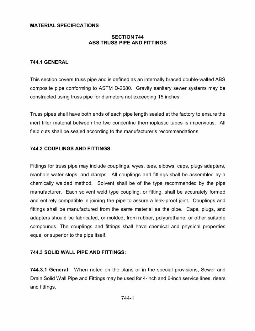
MATERIAL SPECIFICATIONS
SECTION 744ABS TRUSS PIPE AND FITTINGS
744-1
744.1 GENERAL
This section covers truss pipe and is defined as an internally braced double-walled ABS
composite pipe conforming to ASTM D-2680. Gravity sanitary sewer systems may be
constructed using truss pipe for diameters not exceeding 15 inches.
Truss pipes shall have both ends of each pipe length sealed at the factory to ensure the
inert filler material between the two concentric thermoplastic tubes is impervious. All
field cuts shall be sealed according to the manufacturer's recommendations.
744.2 COUPLINGS AND FITTINGS:
Fittings for truss pipe may include couplings, wyes, tees, elbows, caps, plugs adapters,
manhole water stops, and clamps. All couplings and fittings shall be assembled by a
chemically welded method. Solvent shall be of the type recommended by the pipe
manufacturer. Each solvent weld type coupling, or fitting, shall be accurately formed
and entirely compatible in joining the pipe to assure a leak-proof joint. Couplings and
fittings shall be manufactured from the same material as the pipe. Caps, plugs, and
adapters should be fabricated, or molded, from rubber, polyurethane, or other suitable
compounds. The couplings and fittings shall have chemical and physical properties
equal or superior to the pipe itself.
744.3 SOLID WALL PIPE AND FITTINGS:
744.3.1 General: When noted on the plans or in the special provisions, Sewer and
Drain Solid Wall Pipe and Fittings may be used for 4-inch and 6-inch service lines, risers
and fittings.

MATERIAL SPECIFICATIONS
SECTION 744ABS TRUSS PIPE AND FITTINGS
744-2
744.3.2 Material: Sewer and Drain Solid Wall Pipe shall be manufactured of virgin ABS
compound as specified in ASTM D-1788, Types I and IV, excepting that the minimum
heat deflection temperature (ASTM D-648) shall be 180/F.
744.3.3 Strength: Test samples of pipe, 6 inches long, shall be cut from full length
sections and tested by the method outlined in ASTM D-2412. The pipe shall be
deflected at least 35 percent without failure and the stiffness at 5 percent deflection
shall equal, or exceed, the value listed in Table I after the test samples have been
immersed in a 5 percent solution by weight of sulfuric acid and n-Heptain for a period of
24 hours prior to testing. A failure shall be a rupture of the pipe wall.
The stiffness factor should be computed by the method outlined in ASTM D-2412 or by
dividing the load in lbs/linear inch by the deflection in inches and 5 percent deflection
(F/<delta>Y in Table 1).
TABLE 1
Minimum Stiffness Requirements
Nominal Size F/<delta>Y 2.5% min.
4" 55 lb./in.2
6" 55 lb./in.2
744.3.4 Couplings and Fittings: All couplings and fittings shall be assembled by a
chemically welded method. Each solvent weld type coupling or fitting shall be
accurately formed and entirely compatible with the Sewer and Drain Solid Wall Pipe to
assure a leak proof joint. Couplings and fittings shall be manufactured from the same
material as the pipe. Caps, plugs and adapters may be fabricated or molded from

MATERIAL SPECIFICATIONS
SECTION 744ABS TRUSS PIPE AND FITTINGS
744-3
rubber, polyurethane or other suitable compounds. The couplings and fittings shall
have chemical and physical properties equal or superior to the pipe itself.
744.4 MANHOLE CONNECTIONS:
A clamp gasket, or approved equivalent method, shall be provided at manhole entry, or
connection, to reduce infiltration and exfiltration. Where precast manholes are used,
entrance holes shall be large enough to allow for proper grouting around the manhole
gasket.
744.5 CERTIFICATION:
A certificate from the manufacturer shall be furnished attesting the pipe meets the
requirements of ASTM D-2680.
744.6 IMPERFECTIONS:
Any imperfections which adversely affect the performance of the pipe or joints shall be
cause for rejection.
744.7 INSTALLATION AND TESTING:
Truss pipe shall be installed in accordance with applicable provisions of Section 615. In
addition to the tests prescribed in Section 615 a deflection test on all or any part of the
line may be required. Any pipe which shows deflection in excess of 5% shall be rejected
and replaced at the Contractor's expense.

MATERIAL SPECIFICATIONS
SECTION 745PVC SEWER PIPE AND FITTINGS
745-1
745.1 GENERAL:
This section covers the requirements of polyvinyl chloride (PVC) plastic sewer pipe and
fittings for gravity flow sewers and building connections. Fittings, couplings and joints
for the pipe are included as part of this section.
745.2 MATERIALS:
745.2.1 Pipe and Fittings: Pipe with a nominal diameter of 4" inch through 15" inch
shall conform to the requirements of ASTM D 3034-SDR 35. Pipe with diameters from
18" inch through 24" inch shall conform to ASTM F679.
745.2.2 Caps and Plugs: Caps and plugs for building connections should be molded,
or fabricated from rubber, polyurethane, or other suitable compound.
745.2.3 Gaskets: Rubber gaskets shall be manufactured from a synthetic elastomer
and shall comply in all respects with the physical requirements specified in ASTM
D3212.
745.2.4 Lubricant: The lubricant used for assembly shall not have detrimental affects
on the gasket or pipe.
745.2.5 Solvent Cement Joints: The assembly of joints shall be in accordance with
ASTMD-2855.

MATERIAL SPECIFICATIONS
SECTION 745PVC SEWER PIPE AND FITTINGS
745-2
745.3 Submittals: The following shall be mandatory submittals:
1. Information in accordance with the General Conditions.
2. Affidavits of compliance with ASTM D3034 or ASTM F679.
3. Dimensioned cross sections of the bell and barrel of the pipe. The bell maximum
outside diameter and its minimum wall thickness at the same location shall be
shown.
4. Copies of the following manufacturer required tests conducted on project pipe:
a. Stiffness of pipe.
b. Flattening resistance of pipe.
c. Drop impact test.
d. Record of additional tests after test sample failure
745.4 JOINING SYSTEMS:
Joints for the piping system and fittings shall consist of an integral bell gasketed joint
designed so that when assembled, the elastomeric gasket located within the bell is
compressed radially on the pipe or fitting spigot to form a positive seal. The joint shall
be designed to prevent displacement of the gasket from the joint during assembly and
when in service.

MATERIAL SPECIFICATIONS
SECTION 745PVC SEWER PIPE AND FITTINGS
745-3
All pipe shall have a home mark on the spigot end to indicate proper penetration when
the joint is made.
The bell and spigot configurations for the fittings shall be compatible to those used for
the pipe.
Joints shall provide a permanent seal against exfiltration and infiltration. All surfaces of
the joint shall be smooth and free of any imperfections.
The assembly of the joints shall be in accordance with the pipe manufacturer's
recommendations.
745.5 FITTINGS:
Fittings for PVC pipe includes elbows, wyes, tee wyes, double bell couplings, plugs,
caps adapters, increasers and others. Fittings shall be manufactured in accordance
with applicable standards.
745.5.1 Manhole Connections: A manhole adapter gasket shall be provided at
manhole entry, or connection, to prevent infiltration and exfiltration. Where precast
manholes are used, entrance holes shall be large enough to allow for proper grouting
around the manhole ring.
745.6 IMPERFECTIONS:
Any imperfections shall be cause for rejection.

MATERIAL SPECIFICATIONS
SECTION 745PVC SEWER PIPE AND FITTINGS
745-4
745.7 MARKING:
Pipe and fittings, at 5 foot intervals shall be marked to identify manufacturer's name,
trademark, and code, nominal pipe size, the PVC cell classification and ASTM
specification compliance.

MATERIAL SPECIFICATIONS
SECTION 746PVC PRESSURE PIPE AND FITTINGS
746-1
746.1 GENERAL:
This section covers the requirements of polyvinyl chloride (PVC) plastic pressure pipe
utilized to construct water lines and force main pipelines under pressure. Fittings,
couplings and joints for the pipe shall be included as part of these specifications.
746. 2 Material:
746.2.1 Pipe: Pipe from nominal diameter of 4" thru 12" shall conform to the requirements
of AWWA C900, material compound meets ASTM D1784, cell class 12454B, Class 150
meeting requirements of DR18.
A. Elastomeric Seal: The pipe shall be integral bell gasketed provided with
gaskets meeting requirements of ASTM F477.
B. Gasket Joint Assembly: The gasket joint assembly shall meet the requir
ement
s o f
ASTM
D3139
.
746.2.2 Pipe: Pipe from nominal diameter of 14" through 36" shall conform to AWWA
C905, material compound meets ASTM D1784, cell class 12434B, with an established
hydrostatic design basis of 4000 psi.

MATERIAL SPECIFICATIONS
SECTION 746PVC PRESSURE PIPE AND FITTINGS
746-2
A. Elastomeric Seal: The pipe shall be integral bell gasketed provided with
gaskets meeting requirements of ASTM F477.
B. Gasket Joint Assembly: The gasket joint assembly shall have an integrally
thickened bell meeting ASTM D3139 as measured in accordance with ASTM
D2122.
746.2.2 Fittings: Fittings shall conform to AWWA C110 with a minimum pressure rating
of 250 psi. Bells shall be sized specifically for OD of cast iron equivalent PVC pipe
including rubber-ring retaining groove.
746.2.4 Flanges: Flanges on outlets of fittings shall be Class 125 per ANSI B16.1.
746.2.5 Lining and Coating for Fittings:
1. Cement-mortar lined fittings shall be provided per AWWA Cl04. Lining
thickness shall conform to ASTM C 150, Type V.
2. Fittings shall be coated per Section 472.11.
746.3 SUBMITTALS:
1. Submit information in accordance with the General Conditions.
2. Provide affidavit of compliance with AWWA C900 or C905.

MATERIAL SPECIFICATIONS
SECTION 746PVC PRESSURE PIPE AND FITTINGS
746-3
3. Submit fully dimensioned cross section of the bell and barrel of the pipe.
Show the bell maximum outside diameter in the pressurized area and its
minimum wall thickness.
4. Submit copies of the following manufacturer required tests conduced on
project pipe:
A. Quick-burst strength of pipe and couplings.
B. Flattening resistance of pipe.
C. Record of additional tests after test sample failure.
5. Submit manufacturer's literature of gray iron and ductile-iron fittings including
dimensions, thickness, weight, coating, lining and a statement of inspection
and compliance with the acceptance tests of AWWA C110.
746.4 PRODUCT MARK:
Pipe shall be marked at 5-foot intervals and each coupling shall be marked to identify the
nominal diameter, the OD base (Cast-iron or steel pipe (IPS)), the material code for pipe,
and couplings, the dimension ratio number, AWWA C900, C905 and suitability of the
material for potable water service (NSF in the United States.)

MATERIAL SPECIFICATIONS
SECTION 747PRECAST CONCRETE MANHOLES
747-1
747.1 GENERAL:
This section covers precast concrete manholes sections which shall be constructed as
defined herein and in accordance with Construction Standard 5-030 or as noted on the
plans. The manhole sections shall be constructed of precast eccentric, or concentric,
concrete manhole units as required for the project. Manholes shall be built with steps.
747.2 MATERIALS:
Concrete shall be Class A (Type II - low alkali) and conform to the requirements of
Standard Specification No. 725. Steel reinforcement for the precast units shall be in
accordance with ASTM C-478. Steps shall be polypropylene and in accordance with
Construction Standard No. 5-045.
747.3 PRECAST MANHOLES SECTIONS:
Precast concrete manhole sections shall be manufactured in a plant designed for the
process. Concrete shall be compacted by vibration in steel forms. All units shall
conform to the size, shape, form and details as required by specifications and as
necessary to complete the project work. In the walls of the reinforced precast
manholes, steel reinforcement shall be in accordance with the ASTM C-478 latest
revision. Steps shall extend 5" horizontally from inside wall surface, and spaced
vertically on 16" centers except in the top and bottom sections of the assembled
manhole. The lowest step in the assembled manhole shall not exceed 18" above the
shelf and the top step in the cone shall not exceed 30" below the top of the C.I. Cover.
MATERIAL SPECIFICATIONS
SECTION 747PRECAST CONCRETE MANHOLES
747-2
747.4 CERTIFICATION:
The supplier shall provide the Public Works Department a letter of certification, before
final payment, attesting the materials meet the specifications. Test reports shall be
provided when required.

MATERIAL SPECIFICATIONS
SECTION 748STEEL PIPE AND FITTINGS
748-1
748.1 GENERAL:
This section covers 4 inch and larger steel pipe and fittings used in conjunction with
pump station or other installations that require bends and connections for distribution
systems that carry water under pressure.
748.2 PIPE:
Steel pipe shall be black carbon steel and conforming to the requirement of ASTM A-53
Type E or S, Grade A or B, or ASTM A135. Pipe shall be standard weight per ANSI
B36.10 and a minimum 0.375 inches wall thickness for 12" inch pipe and above or as
specified on the plans.
748.3 JOINTS:
Joints for buried pipe shall be butt-welded.
Joints for above ground or exposed pipe larger than 4" shall be flanged or butt-welded
as shown on the plans.
748.4 FITTINGS:
Fittings for buried pipe shall be flanged or butt-welded and fittings for above ground or
exposed pipe shall be flanged. Welding fittings for steel pipe 6-inches and smaller in
size shall be butt-welded fittings of seamless carbon steel conforming to ASTM A-234,
Grade A or B as to material and conforming to ANSI B-16.9 as to dimensions where
established. Standard weight fittings shall be used with standard weight pipe. Welding

MATERIAL SPECIFICATIONS
SECTION 748STEEL PIPE AND FITTINGS
748-2
fittings for pipe larger than 6-inches shall be butt-welded fittings in accordance with
ANSI B-16.9, except that they may be light wall, light weight or light gauge provided the
wall thickness is at least the same wall thickness as the pipe with which used. Welding
fittings may be made up of sections of pipe welded together. Fittings made up of
sections of pipe welded together shall be made of pipe of at least the same wall
thickness as the pipe with which used; and bends shall be miter bends with radius the
same as corresponding butt-welding fittings. Forty-five degree bends shall be 4-piece
construction. Welding of these made-up fittings shall be in accordance with AWWA
Standard C206.
Flanged fittings of cast iron for steel pipelines shall be governed by ANSI B16.1, Class
125. Flanged fittings of steel shall be made up from sections of steel pipe, as used on
either side of the fittings, with attached steel flanges, all in accordance with AWWA
Standard C208 or as detailed on the drawings. Drawing details govern over
corresponding details in referenced specifications.
748.5 FLANGES:
Flanges shall be in complete accordance with the minimum requirements of ANSI B16.5
and ASTM A181, I or II, forged carbon steel flanges, 150 pound.
Bolting, facing, threading, and dimensions shall be as given in the respective
specifications listed. Slip-on flanges shall be attached to the pipe by back and face
welds as shown in AWWA Standard C107. Welding neck flanges shall be single welded
from the outside. Field welding shall be in accordance with AWWA Standard C206.
Flanges shall be attached before any required linings or coatings are applied. Where

MATERIAL SPECIFICATIONS
SECTION 748STEEL PIPE AND FITTINGS
748-3
cap screws or stud bolts are required, flanges shall be provided with threaded holes to
receive such screws and bolts.
Full face or flat ring gaskets of 1/16-inch thick Granite, or equal shall be used.
748.6 BOLTS AND NUTS:
Bolts and nuts for buried flanges, flanges located outdoors above ground, flanges
located in open vaults and structures, and submerged flanges shall be Type 304
stainless steel conforming to ASTM A N193, Grade B8, for bolts and ASTM A 194,
Grade 8, for nuts. Bolts and nuts larger than 1-1/8 inches shall be steel, ASTM A 307,
Grade B, with cadmium plating, ASTM A 165, Type NS>.
Washers shall be provided for each nut. Washers shall be of the same material as the
nuts.
748.7 GASKETS:
A. Gaskets shall be fullface, 1/16 inch thick, and shall be one of the following
nonasbestos materials:
1. Cloth-inserted rubber. Products: Manville No. 109, John Crane Co. Style
777, or equal. Gaskets shall be suitable for a pressure of 350 p.s.i. at a
temperature of 180 degrees F.

MATERIAL SPECIFICATIONS
SECTION 748STEEL PIPE AND FITTINGS
748-4
2. Acrylic or aramid fiber bound with nitrile. Products: Garlock "Bluegard,"
Klinger "Klingersil C4400," or equal. Gaskets shall be suitable for a water
pressure of 500 psi at a temperature of 400 degrees F.
748.8 FABRICATION:
A. Beveled ends for butt-welding shall conform to ANSI B16.25. Surfaces shall be
clean of paint, oil, rust, scale, slag, and other material detrimental to welding.
B. Fabrication shall comply with ANSI B31.3, Chapter V.
C. The minimum number of passes for welded joints shall be as follows:
Steel Cylinder Thickness (inch) Minimum Number of Passes for welds
Less than 0.1875 1
0.1875 through 0.25 2
Greater than 0.25 3
Welds shall be full circumferential.
D. The shielded metal arc welding (SMAW) process shall be used for welding.
E. Welding preparation shall comply with ANSI B31.3, paragraph 328.4. Limitations
on imperfections in welds shall conform to the requirements in ANSI B31.3,
tables 341.3.2A and 341.3.2B, and paragraph 341.4 for visual examination.
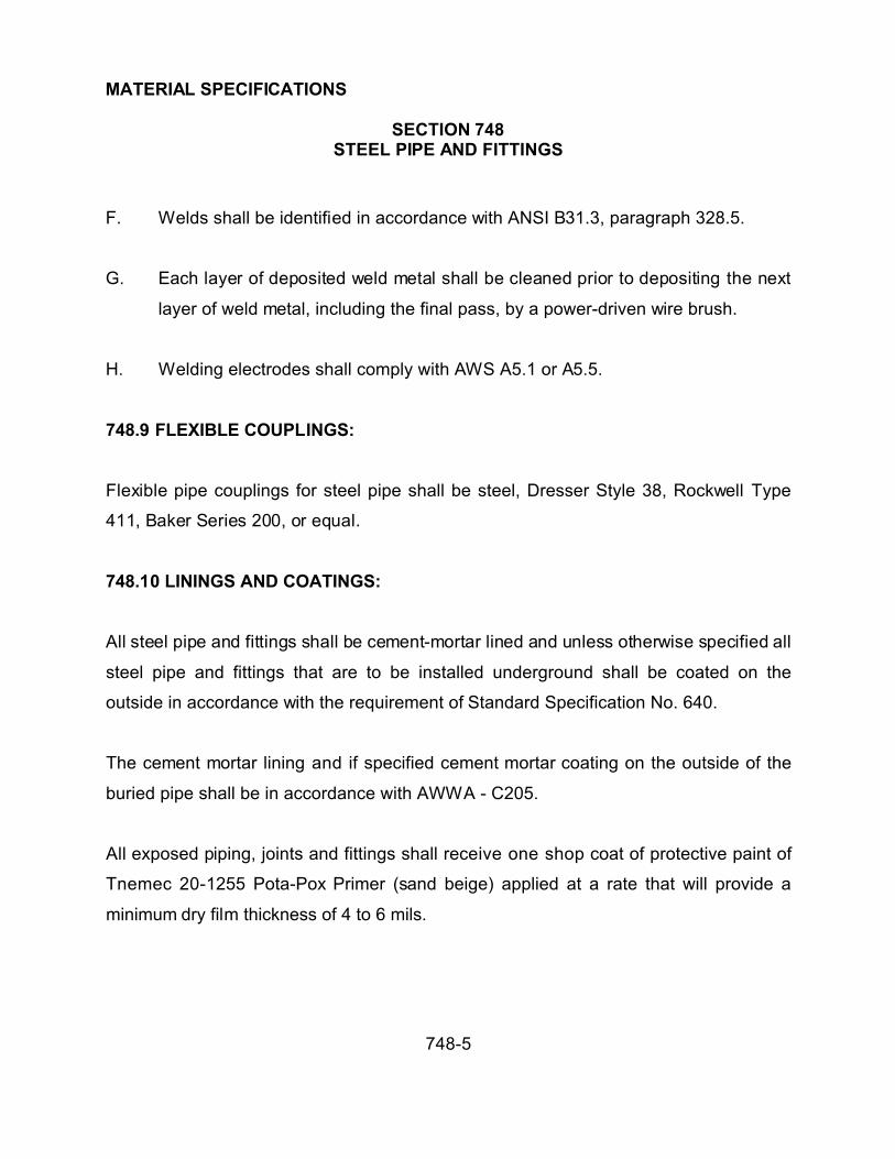
MATERIAL SPECIFICATIONS
SECTION 748STEEL PIPE AND FITTINGS
748-5
F. Welds shall be identified in accordance with ANSI B31.3, paragraph 328.5.
G. Each layer of deposited weld metal shall be cleaned prior to depositing the next
layer of weld metal, including the final pass, by a power-driven wire brush.
H. Welding electrodes shall comply with AWS A5.1 or A5.5.
748.9 FLEXIBLE COUPLINGS:
Flexible pipe couplings for steel pipe shall be steel, Dresser Style 38, Rockwell Type
411, Baker Series 200, or equal.
748.10 LININGS AND COATINGS:
All steel pipe and fittings shall be cement-mortar lined and unless otherwise specified all
steel pipe and fittings that are to be installed underground shall be coated on the
outside in accordance with the requirement of Standard Specification No. 640.
The cement mortar lining and if specified cement mortar coating on the outside of the
buried pipe shall be in accordance with AWWA - C205.
All exposed piping, joints and fittings shall receive one shop coat of protective paint of
Tnemec 20-1255 Pota-Pox Primer (sand beige) applied at a rate that will provide a
minimum dry film thickness of 4 to 6 mils.

MATERIALS SPECIFICATIONS
SECTION 749TAPPING SLEEVE
749-1
749.1 GENERAL:
This section covers the requirements for materials used to perform a tapped connection
under pressure and includes replacing the valve on an existing water pipe line.
749.2 MATERIAL:
749.2.1 Tapping Sleeve: Tapping Sleeves shall be of extra heavy construction to provide
resistance to line pressures. They shall be constructed in two halves for assembly around
the main to be tapped. Walls of castings shall be extra heavy and reinforced for extra
strength.
The branch outlet shall have a flanged face for bolting to the tapping valve.
The inside diameter of the outlet branch shall be sufficiently larger than the nominal size
cutters of the tapping machine.
Tapping sleeves shall be either the type water is allowed to circulate between the sleeve
and the outside surface of the pipe, or the type water is confined to the area immediately
surrounding the tap opening. Sleeves shall be used on the type and size of pipe designed
and dimensioned for the particular sleeve.
Sleeves of the first type, approved gaskets shall be provided to form water tight joints
along the entire length of the sleeve. The circumferential joints at the ends of these
sleeves shall be sealed with caulking or mechanical joints. These joints shall conform to
the requirements set forth in AWWA C-111 pertaining to dimensions, clearances,
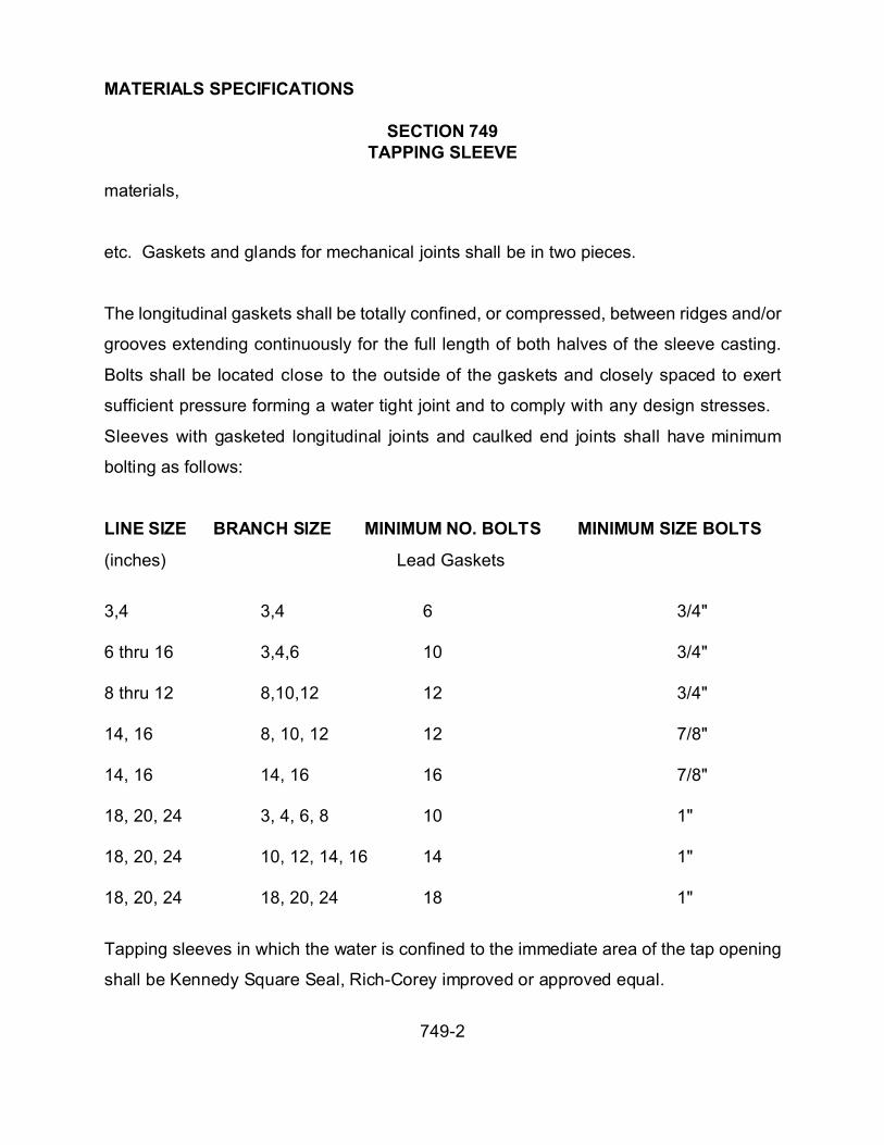
MATERIALS SPECIFICATIONS
SECTION 749TAPPING SLEEVE
749-2
materials,
etc. Gaskets and glands for mechanical joints shall be in two pieces.
The longitudinal gaskets shall be totally confined, or compressed, between ridges and/or
grooves extending continuously for the full length of both halves of the sleeve casting.
Bolts shall be located close to the outside of the gaskets and closely spaced to exert
sufficient pressure forming a water tight joint and to comply with any design stresses.
Sleeves with gasketed longitudinal joints and caulked end joints shall have minimum
bolting as follows:
LINE SIZE BRANCH SIZE MINIMUM NO. BOLTS MINIMUM SIZE BOLTS
(inches) Lead Gaskets
3,4 3,4 6 3/4"
6 thru 16 3,4,6 10 3/4"
8 thru 12 8,10,12 12 3/4"
14, 16 8, 10, 12 12 7/8"
14, 16 14, 16 16 7/8"
18, 20, 24 3, 4, 6, 8 10 1"
18, 20, 24 10, 12, 14, 16 14 1"
18, 20, 24 18, 20, 24 18 1"
Tapping sleeves in which the water is confined to the immediate area of the tap opening
shall be Kennedy Square Seal, Rich-Corey improved or approved equal.

MATERIALS SPECIFICATIONS
SECTION 749TAPPING SLEEVE
749-3
The outlet half of each sleeve shall be fitted with a continuous gasket and permanently
cemented into a groove surrounding the outlet opening. The back half of each sleeve shall
be fitted with elastomeric pads or a metal shoe for developing adequate pressure on the
gasket to prevent leakage within the design capacity of the pipe.
749.2.2: Tapping Valves: Tapping valves shall be identical in construction with the
specifications for gate valves. A tapping sleeve is considered an integral part of a tapping
assembly and shall have openings adequate for the valve. Tapping valves shall have
ends and seat rings with the proper size to permit the use of full size cutters. The inlet end
of the tapping valve shall be flanged for bolting to the tapping sleeve. The face of the
flanged end shall have a raised lip to fit the recessed grooved surface of the tapping
sleeve. The flanged end shall be in accordance with the latest revision of MSS SP-60.
The tapping valve shall have the discs and seat ring constructed allowing the inside
diameter of the rings to be at least 3/16" larger than the nominal size of the valve and the
discs.

MATERIAL SPECIFICATIONS
SECTION 750IRON WATER PIPE AND FITTINGS
750-1
750.1 GENERAL:
This section covers cast iron and ductile iron water pipe which shall be cement mortar
lined and coal tar coated in accordance with AWWA C-104.
750.2 CAST IRON WATER PIPE:
Cast iron water pipe shall be designed in accordance with AWWA C-101.
Cast iron water pipe should be designed for either 18/40 or 21/45 physicals and shall
conform to AWWA C-106 or AWWA C-108.
Cast iron, or water pipe, shall be designed to meet an internal pressure of 150 psi,
external cover of 5 feet, and Standard Laying Condition B.
Cast iron pipe shall be at nominal 18 foot lengths.
750.3 DUCTILE IRON WATER PIPE:
Ductile iron water pipe shall be designed in accordance with AWWA C-150 and shall be
manufactured in accordance with AWWA C-151 and be cement mortar lined. The class
shall be as designated in the plans or special provisions. Ductile Iron water pipe below
12" shall have a minimum wall thickness of Class 50. Pipe 12" and above shall have a
minimum wall thickness of Class 52.

MATERIAL SPECIFICATIONS
SECTION 750IRON WATER PIPE AND FITTINGS
750-2
750.4 JOINT REQUIREMENTS:
Push-on joints for cast iron or ductile iron water pipe shall conform to AWWA C-111 and
shall include synthetic rubber gaskets and lubricant.
Mechanical joints for cast iron, or ductile iron water pipe, shall conform to AWWA C-111
and shall include cast iron glands, synthetic rubber gaskets, and T-head bolts and nuts.
Flanged joints for cast iron, or ductile iron water pipe, shall be class 125 and as detailed
on the plans or in the special provisions.
750.5 FITTINGS:
Iron fittings shall be either Gray-Iron or Ductile-Iron conforming to AWWA C-110 or
AWWA C-153 with a minimum pressure rating of 250 psi. Flanged ends shall conform
to AWWA C-110. Push-on and mechanical joints ends shall conform to AWWA C-111.
Fittings shall be cement mortar lined and coal-tar coated in accordance with AWWA
C-104.

MATERIAL SPECIFICATIONS
SECTION 751WATER SERVICE FITTING
751-1
751.1 GENERAL:
All water service fittings shall conform to the Public Works Construction Standard 5-150
and this section.
751.2 MATERIAL:
Water service fittings, including stops, shall be cast of high grade bronze conforming to
the requirements of ASTM Standard Specification B-62.
Corporation stops and curb stops shall have a full bore waterway at the full diameter of the
designated size. All nuts, washers and contact surfaces shall be faced to a true fit. All
tapers shall be carefully ground and shall not allow leakage under hydrostatic test. All
stops shall be installed in a neat and workmanlike manner. The thickness of metal shall
equal the axis of the circular way. All burrs on the inside of stops shall be carefully
removed leaving a clean and smooth waterway. The following fittings have been approved
for use.
Note: Approvals shall not be exclusive if a similar device is comparable and equal then
a request supported by the appropriate information and data shall be submitted to the
Public Works Department.

MATERIAL SPECIFICATIONS
SECTION 751WATER SERVICE FITTING
751-2
Corporation Stops
Manufacturer Plastic Services Copper Services
Jones J-3402 J-1500
Ford F-1001 F-600
Angle Stops
Jones J-4202 J-4201
Ford KUP-3W KUT-3W
Service Saddles
Jones J-979
Baker KUP-3W
Ford
Curb Stop
Jones 3/4” J-182
1” J-206

MATERIAL SPECIFICATIONS
SECTION 753GALVANIZED PIPE AND FITTINGS
753-1
753.1 GENERAL:
This section covers galvanized pipe which shall be new galvanized welded, or seamless
steel pipe, conforming to the requirements of ASTM A-120 standard weight, schedule
40.
753.2 CORROSION PROTECTION:
Buried galvanized pipe and fittings shall be protected from corrosion by the application
of a tight fitting, extruded or wrapped coating. Coating shall be not less than 0.030
inches in thickness at any point. Extruded coatings shall be of polyethylene or polyvinyl
chloride, Extrucoat or equal. Wrapped coatings shall be of polyethylene, polyvinyl
chloride, coal tar or asphalt tape. Protecto Wrap No. 200, Safe-t-Clad FOS No. 655,
Tapecoat, Trantex VID-10 or E-12, Polyken No. 900, Scotchrap No. 50 or an approved
equal tape shall be edge lapped no less than 1/4 inch.
753.3 FITTINGS:
All fittings for screwed galvanized pipes shall be 150 psi, banded, galvanized malleable
iron screwed fittings.
753.4 VALVES:
Valves on galvanized pipelines shall be all bronze, double disc, nonrising stem with
wheel handle on top, such as Jones, J37-3 or equal, with bodies, bonnets, yokes and
wedges made of material conforming to ASTM B-62.

MATERIAL SPECIFICATIONS
SECTION 754COPPER PIPE, TUBING, AND FITTINGS
754-1
754.1 PIPES AND TUBING:
This section covers copper pipe and tubing which shall be new seamless copper pipes
and tubes, designed for underground water services, plumbing purposes, etc. They
shall conform to all the requirements of ASTM B-88, Type K.
Pipe or tubing shall be made of copper free from cuprous oxide, as determined by
microscopic examination at a magnification of 75 diameters.
Type K tubing, when furnished in coils, shall be annealed after coiling.
754.2 FITTINGS:
Fittings used in connection with copper pipe or tubing, shall be copper or bronze fittings
as manufactured by Jones, Mueller, or approved equal, as shown on standard details.

MATERIAL SPECIFICATIONS
SECTION 756FIRE HYDRANTS
756-1
756.1 GENERAL:
This section covers fire hydrants furnished by the Contractor which shall comply with
AWWA C-502.
756.2 SUBMITTALS AND GUARANTEES:
Prior to delivery of hydrants the Contractor shall submit:
1. A catalog cut and materials list for approval showing construction and
dimensions of hydrants to be provided.
2. A written guarantee from the manufacturer stating the hydrant meets the
friction loss requirements of AWWA Specification C-502, and the guarantee for
delivery through steamer nozzle shall be for 2 1/2 psi maximum pressure drop
when delivering 600 gpm.
3. A written guarantee from the manufacturer stating the hydrant is constr
u c t ed
ensuri
ng the
v a l ve
s t e m
s h a l l
not be
b e n t
w h e n

MATERIAL SPECIFICATIONS
SECTION 756FIRE HYDRANTS
756-2
t h e
hydra
nt is
b roke
n off
at the
breaki
n g
flange.
756.3 HYDRANTS:
Fire hydrants shall be dry barrel Corey or Mueller Improved Type. The inside diameter
of the barrel shall be a minimum of 7 inches and the diameter of the main valve seat
opening shall be not less than 5 inches. The entire valve assembly shall be effectively
sealed against moisture. The net watering area of the barrel and shoe at the smallest
part, exclusive of the inlet connection and the main valve opening, shall not be less than
190 percent of the net opening of the main valve operating nut shall turn left to open.
All interior ferrous surfaces of the shoe exposed to fluid flow shall be epoxy coated to a
minimum dry thickness of 6 mils. Epoxy coatings shall be factory applied by an
electrostatic, or thermosetting, process in accordance with the manufacturer's printed
instructions. The epoxy materials used shall be 100% powder epoxy or a liquid epoxy
conforming to the requirements of AWWA C550, to the prevailing requirements of the
Food and Drug Administration, and the Environmental Protection Agency.
Style of inlet connections shall be bell or mechanical joint with accessories, gland, bolts,
gaskets and shall have a 6 inch diameter inlet connection. Facing of the main valve
MATERIAL SPECIFICATIONS
SECTION 756FIRE HYDRANTS
756-3
against seats shall be synthetic rubber or balata. The top of the stem or bonnet, shall
be equipped with an O-ring seal. Hydrants shall be constructed to allow extension
sections, in multiples of 6 inches, with rod and coupling, can be added to increase barrel
length. The hose and steamer nozzle connections shall match the standard size and
threads per inch. Operating and outlet nozzle cap nuts shall be of solid pentagonal
shape.
Each nozzle cap shall be fitted with chain and gasket. The pentagon shall measure
fifteen-sixteenths to thirty-one thirty-seconds inch on side, 1-1/2 inch from point to flat.
All barrels above ground shall have a prime coat and painted with two coats of fire
hydrant yellow paint. Hydrants shall be constructed so that the standpipe can be
rotated to at least 8 different positions and the center of the lowest nozzle shall have a
ground clearance of not less than 15 inches.
756.4 MANUFACTURER:
The hydrant shall be dry barrel, waterous, Pacer WB-67, American Darling Improved
Mueller Type or approved equal conforming to these specifications. The manufacturer
shall guarantee that the hydrant is so constructed that the valve stem will not be bent
when hydrant is damaged or broken at or near the grade level. A safety breaking flange
or thimble, shall be provided. The friction loss must be guaranteed, by the
manufacturer, to satisfy Table 756-1.
TABLE 756-1
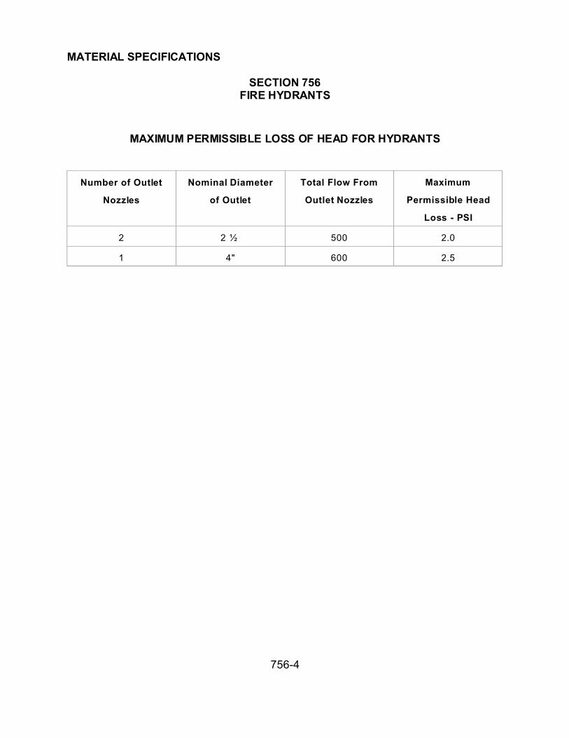
MATERIAL SPECIFICATIONS
SECTION 756FIRE HYDRANTS
756-4
MAXIMUM PERMISSIBLE LOSS OF HEAD FOR HYDRANTS
Number of Outlet
Nozzles
Nominal Diameter
of Outlet
Total Flow From
Outlet Nozzles
Maximum
Permissible Head
Loss - PSI
2 2 ½ 500 2.0
1 4" 600 2.5

MATERIALS SPECIFICATIONS
SECTION 757SPRINKLER IRRIGATION SYSTEM
757-1
757.1 GENERAL:
All materials and fittings shall be new, of the manufacturer's most current design, and
shall bear the appropriate National Association seal of approval, for example, NSF, UL,
etc. Similar units shall be procured from the same manufacturer and internal parts shall
be common and interchangeable. Parts listing and source of supply for replacement
parts shall be submitted to the Public Works Department.
757.2 PIPE AND FITTINGS:
The type of pipe material and fittings shall be as designated on the plans or in the
special provisions.
757.2.1 Steel Pipe: Steel pipe shall be newly galvanized, standard weight, Schedule
40 conforming with Section 753.
757.2.2 Plastic Pipe: Plastic pipe shall be rigid, unplasticized polyvinyl chloride, PVC
1120 or 1220, with an SDR of 26 or less, complying with ASTM D-1785. Schedule 40
pipe shall be used for the continuous pressurized run on the supply side of Control
Valves when the pipe size is 3 inches or less. Class 315 shall be used for sizes larger
then 3 inches on the supply side of the control valve. PVC 1120 to 1220, SDR 26,
pressure rated at not less than 125 psi shall be used on the discharge side of all control
valves.

MATERIALS SPECIFICATIONS
SECTION 757SPRINKLER IRRIGATION SYSTEM
757-2
757.1.3 Pipe Fittings and Couplings:
(A) Steel Pipe Fittings and Couplings -- Steel pipe fittings and couplings shall be
galvanized, malleable iron, screwed fittings or couplings, conforming with
Section 753.
(B) Plastic Pipe Fittings and Couplings -- Plastic pipe fittings and couplings shall be
either threaded type or Slip fitting tapered socket solvent weld type. Schedule
80 pipe shall be used for threaded joints. Tapered solvent weld fittings may be
either Schedule 80 or Schedule 40 and shall be equal to or greater than the
Schedule and Pressure Rating of the plastic pipe being joined. Tapered fittings
shall be sized to ensure a dry, unsoftened taper cannot be inserted more than
halfway into the socket. Plastic saddles and flange fittings shall not be
permitted.
(C) Copper Pipe Fittings and Couplings -- Copper pipe fittings and couplings shall
conform with Section 754.
757.2.4 Solvent Cement: The solvent cement shall be a solution of Type 1, Grade 1,
unplasticized, polyvinyl chloride molding or extrusion compound as specified in
ASTM D-1784, or an equivalent PVC resin. The cement shall be free flowing
and shall not contain lumps, microscopic undissolved particles or any foreign
matter that will adversely affect the ultimate joint strength. It shall not show
stratification or separation that cannot be removed by stirring. Container
labeling shall be in accordance with ASTM D-2564.

MATERIALS SPECIFICATIONS
SECTION 757SPRINKLER IRRIGATION SYSTEM
757-3
757.3 VALVES AND VALVE BOXES:
757.3.1 General: Valves shall be of the size, type, and capacity designated on the
plans or in the special provisions and shall comply with the requirements
specified herein.
All valves except garden valves shall be capable of satisfactory performance at a
working pressure of 200 psi. Valves shall be designed to permit disassembly to
replace sealing components without removal of the valve body from the
pipeline.
757.3.2 Gate Valves: Gate valves in size two inches and smaller shall be all bronze
double disc wedge type with integral taper seats and non-rising stem. Sizes two
and one-half inches and larger shall be iron body, brass trimmed, with the other
features the same as for the two inch. Section 753 applies.
757.3.3 Manual Control Valves: Manual control valves shall be brass or bronze, and
shall be straight or angle pattern glove valves, full opening, key operated with
replaceable compression disc and ground joint union on the discharge end.
757.3.4 Electrical Remote Control Valves: Remote control valves shall be electrically
operated, designed for a 24 volt, 60 cycle system. They shall be brass or
bronze with accurately machined valve seat surfaces, equipped for flow control
adjustment, and with the capability for manual operation. They shall be easily
disassembled for repair and the internal parts shall be easily accessible for
service even when installed in the line.

MATERIALS SPECIFICATIONS
SECTION 757SPRINKLER IRRIGATION SYSTEM
757-4
The internal valve shall be a normally closed, diaphragm type with slow opening and
closing action for protection against surge pressures. Actuation shall be by an
encapsulated type solenoid with the solenoid shunt band, tube, and plunger of stainless
steel for corrosion protection. A removable and cleanable strainer shall be
provided at the control chamber inlet to prevent debris from entering the
solenoid operating section.
757.3.5 Garden Valves: Except for the handle garden valves shall be brass or bronze.
They shall have a replaceable compression disc, and shall be 3/4 inch straight-
nosed, key operated, and pressure rated for operation at 150 psi.
757.3.6 Quick-Coupling Valves and Assemblies: Quick-coupling valves shall be
brass or bronze with built-in flow control and self-closing valve and supplied in
3/4-inch size. When a quick-coupler assembly is specified, it shall consist of the
valve, quick-coupler connection and hose swivel. Keys and hose swivel ells
shall be furnished as specified on the plans.
757.3.7 Valve Boxes: Valve boxes shall have bolted locking covers and shall be
molded, noncorrosive plastic. Applicable ASTM references: D-638, D-356.
757.4 BACKFLOW PREVENTER ASSEMBLY:
The backflow preventer assembly shall consist of pressure type or reduced pressure
type backflow preventer. The unit and associated components shall conform to
the governing code requirements and as shown on the plans. It shall be equal
in quality and performance to a "Surgical Mechanical Research, Inc. P-711"

MATERIALS SPECIFICATIONS
SECTION 757SPRINKLER IRRIGATION SYSTEM
757-5
type. An atmosphere backflow preventer shall be champion 362 or equal.
Pressure backflow preventer shall be SMR P-711 or equal.
757.5 SPRINKLER EQUIPMENT:
Sprinkler heads, bubbler heads and spray nozzles shall be of the types and sizes as
shown on the plans. All major components shall be brass, bronze, stainless
steel, or high impact plastic.
Equipment of one type with similar flow characteristics shall be from the same
manufacturer and shall bear the manufacturer's name and identification code in
a position where they can be identified after installation.
Fixed head sprinklers shall have a one-piece housing with provisions for interior parts
replacement. Pop-up sprinklers shall be designed to rise at least 2 inches
during operation. Full or part circle sprinklers shall be interchangeable in the
same housing.
Bubbler heads shall be of corrosion-resistant, durable bodies, injection molded out of
cycolac, and tapped for 1/2" I.P.S. threads. The bubbler shall be fully
adjustable from 0 to 5 gallons per minute and shall have a minimum discharge
of 1.7 gallons per minute under pressure of 15 pounds per square inch and a
minimum discharge of 2.4 gallons per minute under pressure of 30 pounds per
square inch supplied at the head. The bubbler heads shall require a tool, such
as a screwdriver, to make flow adjustments.

MATERIALS SPECIFICATIONS
SECTION 757SPRINKLER IRRIGATION SYSTEM
757-6
757.6 ELECTRICAL MATERIAL:
All equipment and material shall comply with the requirements of the governing code
and shall be listed by Underwriters' Laboratories, Inc.
757.6.1 Conduit: Conduit shall be galvanized steel conforming to Section 753.
757.6.2 Conductors: Service line conductors shall be supplied in the size shown on
the plans and shall be THW 600 volts insulation rating conforming to ASTM D-
734. Low voltage control conductors shall be Type UF No. 14 AWG copper
and shall be UL approved for direct burial installation.
757.6.3 Electro-Mechanical Controller: The control unit shall be fully automatic, with
provisions for manual operation, sized to accommodate the number of stations
or control valves included in the system and designated on the plans or in the
Special Provisions. Outdoor models shall be housed in a vandal-resistant,
weatherproof enclosure which has a locking cover.
The unit shall require a standard 117 volt, 60 cycle input and provide a 26.5 volt, 60
cycle output and shall incorporate a 14-day programming capability. The unit
shall have a "Master On-Off" switch which will deactivate the controller but
allow the day and hour clocks to continue operation.
In addition, it shall include a resettable circuit breaker for unit protection.

MATERIALS SPECIFICATIONS
SECTION 757SPRINKLER IRRIGATION SYSTEM
757-7
Each station timing dial shall have an "Omit" or "Off' position and incremental dial
settings for timing controls up to 30 minutes.

MATERIAL SPECIFICATIONS
SECTION 759VALVES FOR WATERLINE AND PIPELINES
759-1
759.1 GENERAL:
This section covers requirements for gate and butterfly valves; check valves, and air
release and vacuum valves for installations on pipeline construction.
759.2 SUBMITTALS:
For valves 12 inches and smaller, the Contractor shall furnish the manufacturer's
standard data and catalogues for the items being furnished:
For valves larger than 12 inches, the Contractor shall furnish shop drawings and
technical data required for evaluating and approving each type of valve, tapping sleeve
and valve and butterfly valve. This information shall include complete details,
dimensions, weights, diameter of stems, alloy for all valve pans and any information that
may be required to assemble, install, operate and maintain the valve.
When it is doubtful that a manufacturer's product conforms to specifications, La Paz
County reserves the right to require submittal of more complete information before
approving the above items.
The name of the manufacturer, the year of manufacture, the size of the valve, model
number and rated working pressure, shall be cast on the body of each valve.
La Paz County may test 10 percent of each type and size of valve furnished. Failure of
any of the valves tested to meet these specifications shall be deemed sufficient cause
to reject the entire lot delivered.

MATERIAL SPECIFICATIONS
SECTION 759VALVES FOR WATERLINE AND PIPELINES
759-2
759.3 MATERIALS, GENERAL:
All interior ferrous valve surfaces exposed to fluid flow shall be epoxy coated to a
minimum dry film thickness of 6 mils. Epoxy coatings shall be factory applied by an
electrostatic or thermosetting process in accordance with the manufacturer's printed
instructions. The epoxy materials used shall be 100% powder epoxy or liquid epoxy
that conforms to the requirements of AWWA C550-81 and to the prevailing
requirements of the Food and Drug Administration and of the Environmental Protection
Agency.
All exterior ferrous valve surfaces, except finished or bearing surfaces, shall be factory
coated with two coats of asphaltic varnish conforming to Federal Specification TT-V-51
c or shall be epoxy coated as required above for interior surfaces.
Bronze for all interior valve parts shall contain not more than 6% zinc.
759.3 GATE VALVES 3" through 12":
All valves shall conform to the latest revisions of AWWA C-500 or C-509, supplemented
as follows:
A. Valves shall be iron body resilient seated solid wedge gate valves with a cast iron
wedge, designed to work equally well with pressure on either side of the gate.
Valves shall be of the non-rising stem type and shall be left hand opening,
counter-clockwise.

MATERIAL SPECIFICATIONS
SECTION 759VALVES FOR WATERLINE AND PIPELINES
759-3
B. Bronze for all interior pads of valves shall contain not more than 6 percent zinc if
made from cast bronze, or must conform to Copper Development Association
#67600 if made from bar stock material.
C. Valves on water mains shall be hub-end or have Ring-Tite or Fluid-Tite bells for
Class 150 LPVC pipe or mechanical joints conforming to AWWA C-111 or Titon
joints for cast iron pipe.
D. Valves attached to side outlets shall be flanged and unless otherwise noted have
2 inch square operating nuts.
E. By-pass valves shall be flanged.
F. Valves in blow-off lines shall be flanged.
G. Valves in fire hydrant lines shall have hub-ends or mechanical joint ends.
H. Valves in air release and vacuum relief lines shall be flanged or screwed as
shown on the plans.
I. Valves 12 inches and smaller, shall be equipped with O-ring packing.
J. Valves, 2 inches and smaller, shall be Jones, Ford, Hayes, Mueller or an
approved equal, and shall be threaded.

MATERIAL SPECIFICATIONS
SECTION 759VALVES FOR WATERLINE AND PIPELINES
759-4
759.3.2: Gate Valves: Valves 16-inches and larger shall be double disc gate valves, in
accordance with AWWA C-500 except as hereinafter modified. When called for on the
plans, there shall be by-passes for valves 16-inches and larger.
Valves shall have bevel gears with 2 inch square operating nuts. The gears and stuffing
box shall be enclosed in a watertight cast iron case, for operation in a buried location.
Bolts, nuts, studs, etc., used with the gear case, shall conform to the requirements for
Bonnet Bolting in AWWA C-500. The case shall be filled with grease at the factory.
Valves shall be for operation in a horizontal position. The valve ends shall be flanged.
Valves shall be equipped with bronze tracks, rollers and scrapers, for operation in a
horizontal position.
By-pass valves shall be furnished with each valve, mounted in position A as indicated in
AWWA C-500. By-pass valve sizes shall be as follows:
TABLE 759-1
Gate Valve By-Pass Valve
Diameter in Inches Diameter in Inches
16 to 20 3
24 to 30 4
36 to 42 6
48 8

MATERIAL SPECIFICATIONS
SECTION 759VALVES FOR WATERLINE AND PIPELINES
759-5
759.3.3 Tapping Sleeve Valves: Tapping valves shall be identical in construction with
the specifications for gate valves. Tapping sleeves are considered an integral part of a
tapping sleeve and valve assembly and shall have openings the same as the valve.
Tapping valves shall have ends and seat rings of sufficient size to permit the use of full
size cutters of either the Mueller or the Smith type tapping machines. Tapping sleeve
valves shall be flanged on one end to fit the tapping sleeve and the other end shall be
hub-end or mechanical joint.
The tapping valve shall have the discs and seat ring constructed allowing the inside
diameter of the rings to be at least 3/16 inch larger than the nominal size of the valve.
The seat rings shall be bronze and shall have a minimum seating surface area equal to
that of a standard gate valve and the discs shall be proportionately larger to match.
759.3.4 Butterfly Valves 3" inches through 12": This specification generally
describes valves and operator assemblies designed for underground service, as
manufactured by Dresser Industries, B-I-F Industries Incorporated, Henry Pratt
Company, Allis Chalmers Manufacturing Company or approved equal.
Where material or equipment is designated on the plans by trade or manufacturer's
name, it is so designated primarily to establish standards of quality, finish, appearance
and performance.
All specific requirements of this specification must be adhered to and necessary
modifications shall be made in the product specified by the trade name, type or model of
manufacturer's equipment to make it conform to all specific requirements of this
specification.

MATERIAL SPECIFICATIONS
SECTION 759VALVES FOR WATERLINE AND PIPELINES
759-6
The valves shall be in accordance with AWWA C-504, Class 150-B except on modified
herein:
1. Valve ends may be the thin type or wafer type and shall be installed between
flanges drilled in conformance with ASA B 16.1-125 or may be flanged both ends
or the valves may have bell ends with rubber gaskets for cast iron pipe or
asbestos cement pipe conforming to the type of pipe being used.
2. Valves shall be designed for buried service with the valve shaft in a horizontal
position and the operating shaft vertical.
3. Valves shall be left-hand-opening, counter-clockwise unless shown otherwise on
the plans.
4. Discs shall be Ni-Resist, ASTM A-436, Type I or cast iron, ASTM A-48, Class 40,
in accordance with the following variations:
A. Cast iron disc may be used providing the rubber seat ring is contained on
the bronze ring contained in the body of the valve.
B. Ni-Resist disc may be used where the rubber seat is contained in the
valve body.
C. Valves with rubber seats in the valve body should have cast iron discs
with a Type 304 stainless steel or bronze edge seating surface retained on
the edge of the disc.

MATERIAL SPECIFICATIONS
SECTION 759VALVES FOR WATERLINE AND PIPELINES
759-7
Shafts and disc shaft fasteners shall be constructed of Type 304, stainless steel,
completely sealed from the line fluid. Valve shafts completely sealed from the line fluid
should be of high strength steel with all other metal parts in contact with the line fluid to
by Type 304 stainless steel.
Valves with rubber seated mounts in the body shall have the rubber either bonded or
mechanically retained in it's final position. Rubber sets which are on the disc edge shall
be retained by a clamping ring and screws. Clamping ring and screws shall be made of
18-8 stainless steel, Type 304 or bronze conforming to ASTM B-61 or ASTM B-143.
Manual operators shall have AWWA 2 inch square operating nuts and shall require at
least 2 turns per inch diameter to rotate the disc 90 degrees. Operators shall accept a
minimum of 300 ft. lbs. input torque on stops at ends of travel without damage to valve
or operator. The operator torque rating shall equal, or exceed, the valves shown in
Table I of AWWA C-504 for the valve class specified.
All interior ferrous surfaces exposed to fluid flow shall be epoxy coated to a minimum
dry film thickness of 6 mils.
The epoxy materials used shall be 100% powder epoxy or liquid epoxy that conforms to
the requirements AWWA C550-81 and to the prevailing requirements of the Food and
Drug Administration and the Environmental Protection Agency.
All exterior ferrous surfaces, except finished or bearing surfaces, shall be factory coated
with 2 coats of asphaltic varnish conforming to Federal Specification TT-V-51 c, or shall
be epoxy coated as required for interior surfaces.

MATERIAL SPECIFICATIONS
SECTION 759VALVES FOR WATERLINE AND PIPELINES
759-8
759.3.5 Butterfly Valves 16" inches and larger: Valves shall be in accordance with
AWWA C-504 latest revision as modified:
1. Valve body shall be of cast iron or ductile iron with connecting ends one or a
combination of: Flanged (Short Body), mechanical joint or ACP Hub End.
2. Valves shall be Class 150-B unless otherwise specified.
3. When requested the manufacturer shall furnish records of tests specified in
AWWA C-504.
4. Shaft seal should be O-ring seal, V-type packing or pull down packing.
5. The valve disc should be either cast iron or ductile iron.
6. Valves and operators shall be for direct burial installation.
7. Valves shall be furnished with manual operators and 2" square operating nut.
Operator torque rating shall be calculated in accordance with AWWA C-504.
8. Valves shall open when turning the operating nut counter-clockwise.
9. Valves shall be installed with valve shaft in a horizontal position and the
operating shaft vertical.

MATERIAL SPECIFICATIONS
SECTION 759VALVES FOR WATERLINE AND PIPELINES
759-9
10. All interior ferrous surfaces exposed to fluid flow shall be epoxy coated to a
minimum dry film thickness of 6 mils. Epoxy coatings shall be factory applied by
an electrostatic or thermosetting process in accordance with the manufacturer's
printed instructions. The epoxy materials used shall be 100% powder epoxy or
liquid epoxy that conforms to the requirements of AWWA C-550 and to the
prevailing requirements of the Food and Drug Administration and the
Environmental Protection Agency.
11. All exterior ferrous surfaces, except finished or bearing surfaces, shall be factory
coated with tow coats of asphaltic varnish conforming to Federal Specification
TT-V-51C or shall be epoxy coated as required for interior surfaces.
759.3.6 Check Valves: The check valve shall be a rubber flapper swing check valve
and have a heavily constructed cast iron body and cover. The body shall be long
pattern design with integrally cast-on end flanges. The flapper shall be Buna-N-having
an "O" ring seating edge and shall be internally reinforced with steel.
Flapper shall be captured between the body and the body cover in a manner to permit
the flapper to flex from closed to full open position during flow through the valve.
Flapper shall be easily removed without the need to remove the valve from the line.
Check valves shall have full pipe size flow area. Seating surface shall be on a 45
degree angle requiring the flapper to travel only 35 degrees from closed to full open
position.
Buna-N flapper shall be hi-strength coated fabric-coated both sides with 70 duro and
molded internally.
MATERIAL SPECIFICATIONS
SECTION 759VALVES FOR WATERLINE AND PIPELINES
759-10
Materials of construction shall be certified in writing to conform to ASTM specifications
as follows:
1. Body & cover: Cast iron
2. Flapper: Buna-N
Valve shall be APCO series 100 rubber flapper swing check valve as manufactured by
Valve and Primer Corp., Schaumburg, Illinois or equal.
759.3.7 Combined Air Relief/Vacuum Valve: A Combination Air Valve shall be
equivalent to the single body, double orifice Model No. 147C combination air valve as
manufactured by APCO Valve and Primer Corp., Schaumburg, Illinois. Valve shall allow
large volumes of air to escape out the large orifice when filling a pipeline and closes
when liquid enters the valve. During a large orifice closure, the small air release orifice
shall open to allow small pockets of air to escape automatically and independently from
the large orifice. The large orifice shall also allow large volumes of air to enter during
pipeline drainage to break the vacuum. The body inlet shall be baffled to protect the
lower float from direct forces of rushing air and water to prevent premature valve shut
off. The top large orifice plug or float shall be protected in a similar manner for the
same purpose.
The Buna-N seat shall be fastened to the valve cover, without distortion, for drop tight
shut off. The floats shall be heavy stainless steel, hermetically sealed; designed to
withstand 1000 psi. The top plug or float shall be center guided through hex bushings
for positive shut off.

MATERIAL SPECIFICATIONS
SECTION 759VALVES FOR WATERLINE AND PIPELINES
759-11
Valve shall have cast iron body and cover with Buna-N seat. The float and all other
internal parts shall be stainless steel. Valve exterior shall be painted with Red Oxide
Phenolic Primer paint. Inlet and outlet shall be N.P.T. threaded per ANSI B2.1 pipe
threads.

MATERIAL SPECIFICATIONS
SECTION 760COATING CORRUGATED METAL PIPE AND ARCHES
760-1
760.1 GENERAL:
This section covers corrugated metal pipe, pipe arches, and connectors to be used or
furnished and shall be manufactured and inspected in conformance AASHTO M-36, and
as hereinafter specified. The size, type, and gauge of the pipe to be furnished shall be
as shown on the plans or standard details.
760.2 MATERIALS:
Corrugated metal products shall be plain galvanized conforming to AASHTO M-36 as
modified herein.
The types of bituminous coated pipe shall be as specified by the standard details or
special provisions. In addition to the types listed in AASHTO M-190 there shall be a
Type D.
Type D: Coated and Smooth Lined Pipe -- The pipe shall be uniformly coated on the
outside as required for Type A pipe. In addition, the pipe shall be paved on the inside
for the entire periphery with a bituminous material. The bituminous paving material shall
be applied to assure a smooth interior will be formed throughout and all corrugations
filled. The pavement shall have a minimum thickness of 1/8 inch above the crest of the
corrugations.
760.3 BASE METAL, SPELTER AND FABRICATION:
The nominal pipe diameter shall meet the tolerances of this specification. Elliptical Pipe,
when specified, shall be shaped after fabrication and coating have been completed.

MATERIAL SPECIFICATIONS
SECTION 760COATING CORRUGATED METAL PIPE AND ARCHES
760-2
In lieu of corrugations as specified in AASHTO M-36 corrugations should be 3 inches
from center to center, with a depth of not less than 1 inch.
Helically Corrugated Metal Pipe: The pipe shall be fabricated from flat sheets in coils.
The base metal, spelter coating, method of sampling, accepted brands of metal, sheet
manufacturer's certified analysis and guarantee, workmanship, marking, inspection and
rejection, shall meet the requirements of AASHTO M-36. Structures furnished shall be
either full circle, or pipe-arch in accordance with Table 4 of AASHTO M-36, or as shown
on the plans. The pipe dimensions shall conform to AASHTO M-36 in all respects,
except that the corrugations shall be helical instead of annular. The thickness of the
galvanized metal shall be in accordance with standard details. Pipe with helical
corrugations shall have a continuous lock or welded seam extending from end to end of
each length of pipe. The seams shall be fabricated to assure they will not affect the
shape or nominal diameter of the pipe and to ensure an element of weakness in the
pipe is not created.
760.4 COUPLING BANDS:
Watertight joints shall be fabricated for corrugated metal pipe by the use of galvanized
couplers or connecting bands, bituminous coated, with each band overlapping by at
least 2 inches. Corrugated coupling bands shall be constructed and connected as
specified in AASHTO M-36, except as otherwise required herein. Dimple type coupling
bands shall be manufactured by Garland Steel Company, American Bridge Company,
Republic Steel Company, or shall be of an approved equivalent design and quality
conforming to the above requirements. The couplers or bands shall be manufactured of
material 2 gages lighter than the gage specified for the pipe material, shall have
corrugations or dimples to match the pipe corrugations or may be flat, and shall be

MATERIAL SPECIFICATIONS
SECTION 760COATING CORRUGATED METAL PIPE AND ARCHES
760-3
fastened with bolts. Dimpled coupling bands shall be 10-1/2 inches wide for diameters
12 through 60 inches, and 17 inches wide for diameters above 60 through 96 inches.
The 10-1/2 inch wide bands shall have 2 rows of dimples of not less than 7 dimples per
row, and the 17 inch wide bands shall have 4 rows of dimples of not less than 7 dimples
per row. The dimple arrangement shall be such that a maximum spread can be
attained. The shape of the dimple shall be such that it shall, in general, conform to the
standard pipe corrugation. The connecting angles for dimpled coupling bands may be
riveted as for standard corrugated coupling bands, or may have slotted angles. The
bands shall be attached by means of 1/2 inch nominal diameter carriage bolts. Two
bolts are required for pipes up to 36 inches in diameter, 3 bolts for 36 through 60 inch
diameters and 5 bolts for pipes above 60 inches in diameter. Plain flat coupling bands
shall have the same width and number of bolts as specified above. Flat coupling bands
having a single circumferential corrugation rolled in each edge to match a similar
corrugation in the end of each pipe should be 10-1/2 inches wide regardless of pipe
diameter and shall be fastened with 2 bolts.
760.5 PERMISSIBLE VARIATIONS IN DIMENSION:
Plain galvanized and Type A pipes: The internal diameter of 12 through 24 inch pipe
shall not vary more than +1.5 percent from the design diameter. The internal diameter
of 27 through 108 inch shall not vary more than +1 percent or 3/8 inch, whichever is
greater from the design diameter.
Type D pipe: The design diameter of the metal pipe before paving shall be the diameter
shown on the plans plus 1/4 inch.

MATERIAL SPECIFICATIONS
SECTION 761STRUCTURAL PLATE PIPE, ARCHES, AND PIPE ARCHES
761-1
761.1 GENERAL:
This section covers structural plate pipe, arches, and pipe arches and shall be of the
sizes, gauges, and dimensions designated on the plans or in the special provision.
761.2 MATERIALS:
Plates, nuts and bolts shall conform to the specifications of AASHTO M-167.
Galvanized surfaces which are damaged shall be repaired at the Contractor’s expense
in accordance with the provisions in Section 771.
Bituminous coating shall conform to the provisions of AASHTO M-190.
Damaged bituminous coatings shall be repaired at the Contractor expense by applying
bituminous material conforming to AASHTO M-190.
761.3 IDENTIFICATION:
The gages of structural plates shall be identified on the plans in accordance with the
following:
Each installation shall be designated by size and by symbol indicating the number and
gauge of plates required. Thus, (412-18) shall be used to designate an installation for 1
plate length composed of 4, 12 gauge plates and 1, 8 gauge plate, the heaviest to be
placed in the invert.

MATERIAL SPECIFICATIONS
SECTION 761STRUCTURAL PLATE PIPE, ARCHES, AND PIPE ARCHES
761-2
761.4 DISTORTION:
In advance of placing backfill material around circular structural plate pipes, the pipe
shall be distorted.
Distortion should be performed either at the fabricating shop or in the field.
If the plates are distorted in the fabricating shop, the plates shall be distorted to provide
an increase in the vertical diameter of the pipe, after assembly, of approximately 5
percent for the full length. Plates shall be marked to assure they will be placed in
proper position.
If the pipes are distorted in the field then the method of distortion shall conform to the
details shown on the plans. The vertical diameter shall be increased to the approximate
percentages listed in the following table throughout that portion of the pipe between
shoulder lines.
A. Pipes using 1 or 3 gauge top and side plates -- 1 percent
B. Pipes using 5 or 7 gauge top and side plates -- 2 percent
C. Pipes using 8, 10, or 12 gauge top and side plates -- 3 percent
D. Between the shoulder lines and the outer ends of the pipe the distortion may
decrease uniformly to zero.

MATERIAL SPECIFICATIONS
SECTION 765RUBBER GASKETS FOR CONCRETE PIPE
765-1
765.1 GASKETS FOR LOW HEAD PRESSURE CONCRETE PIPE:
Gaskets for low head pressure concrete pipe which shall be in accordance with
Specification 734.4
765.2 GASKETS FOR GRAVITY SANITARY SEWER PIPE:
The joints of sanitary sewer concrete pipe shall be O-ring rubber gasket joints
conforming to ASTM C-361, except the composition and properties of the rubber
gaskets shall be as follows:
All rubber gaskets shall be extruded, or molded, and cured in such a manner as to be
dense, homogeneous, free from porosity, and other imperfections. The tolerance for
any diameter measured at any cross section shall be + one-thirty-second inch. All
gaskets shall be manufactured from a synthetic rubber compound in which the
elastomer shall be chloroprene (ASTM-SAE Designation TYPE SC). The compound
shall not contain less than 50 percent by volume of neoprene, shall not contain
deleterious substances, and shall conform to the following requirements:

MATERIAL SPECIFICATIONS
SECTION 765RUBBER GASKETS FOR CONCRETE PIPE
765-2
TABLE 765
RUBBER GASKETS
Physical Properties Value Method of Test
Tensile strength, Min. psi 1500 ASTM D-412
Elongation at break, Min.% 425 ASTM D-412
Shore durometer hardness, Type A, (1) 40-60 ASTM D-2240
Compression set, Max.% of originaldeflection, (2) 20 ASTM D-395
Accelerated aging, tensile strength,%, (3) 80 ASTM D-572
Max. increase over original shoreduromerter value after accelerated 8 ASTM D-2240
Specific gravity 0.95-1.45 ASTM D-297 ± 0.05
(1) Pipe manufacturer shall select value suitable to type of joint.
(2) Use Method B, except disc shall be 1/2 inch long section of rubber gasket stock.
(3) Percent of tensile strength, after aging by the oxygen-pressure chamber (96 hours,
158 +1.8°F, 300 +15 p.s.i.), of the tensile strength before aging.

MATERIAL SPECIFICATIONS
SECTION 765RUBBER GASKETS FOR CONCRETE PIPE
765-3
Gasket containers shall be a preformed rectangular groove constructed allowing 2
pipes, when joined together, the rubber gasket shall be compressed and for all practical
purposes substantially fill and be largely confined within the rectangular groove.
765.3 GASKETS FOR GRAVITY STORMSEWER IRRIGATION AND DRAINAGE
PIPE:
The gasket shall be the sole element depended upon to make the joint watertight, and
shall have smooth surfaces, free from pits, blisters porosity, and other imperfections.
The rubber compound shall not contain less than 60% by volume of first grade synthetic
rubber. The remainder of the compound shall consist of pulverized fillers free from
rubber substitutes, reclaimed rubber, and deleterious substances. The compound shall
meet the following physical requirements when tested in accordance with appropriate
ASTM Specifications:
(1) Tensile strength of the compound shall be at least 2,100 psi ASTM D-412.
(2) Elongation at Rupture shall be at least 400%, ASTM D-412.
(3) Shore Durometer Hardness shall be Type A. Value *40-60, ASTM D-
2240.
(4) Cold Flow: The percentage shall not exceed 20. The determination shall
be made in accordance with Method B ASTM D-395 with the following
exception; the disc shall be 1/2" thick and the diameter shall be that of the
rubber gasket. The gaskets shall not be exposed to direct sunlight for a
time greater than needed to accomplish normal installation.

MATERIAL SPECIFICATIONS
SECTION 765RUBBER GASKETS FOR CONCRETE PIPE
765-4
(5) Specific gravity shall be consistent within +0.05 and shall be between 0.95
and 1.45, ASTM D-297.
765.4 SUBMITTALS:
The Contractor shall submit certified test results, in triplicate, to the Public Works
Department showing the physical properties of the materials used in the manufacture of
all gaskets.

MATERIAL SPECIFICATIONS
SECTION 767VALVES FOR PUMP STATIONS
767-1
GENERAL:
This specification specifies materials for valves used in stormwater pump station
applications when installations are above ground or in vaults or structures.
767.2 MANUAL GATE VALVES:
Manual gate valves shall comply with the requirements of AWWA- C500 supplemented
as follows:
Valves shall be iron bodied, solid bronze internal working parts, parallel faced, bottom
wedging double-discs and O -ring seals. The minimum designated water working
pressure shall be 200 psi. Bronze for internal working parts, including stems, shall not
contain more than 2% aluminum nor more than 7% zinc. Bronze shall be ASTM B 62
(85-5-5-5) bronze, and the stem bronze shall have a minimum stencil strength of 60,000
psi, a minimum yield strength of 30,000 psi and a minimum of 10% elongation in 2
inches. Body bolts shall be Type 304 or Type 316 stainless steel, ASTM A 276. Valves
shall be left hand opening, counter-clockwise with an arrow indicator. Valve shall be of
the non-rising stem type with hand wheel operator, flanged joint ends conforming to
ANSI Specification B16.1, Class 125. Valve shall have a stuffing box of an "O-ring"
type.
Unless otherwise stated in the detailed value specifications, packing, O-rings, and
gaskets shall be one of the following non-asbestos materials:

MATERIAL SPECIFICATIONS
SECTION 767VALVES FOR PUMP STATIONS
767-2
A. Teflon
B. Kevlar aramid fiber.
C. Acrylic or aramid fiber bound by nitrile. Products: Garlock "Bluegard",
"Klinger", "Klingersil C4400," or equal.
D. Buna-N (nitrile.)
Valves shall have the year cast, the name of the manufacturer, and the size of the valve
cast or molded onto the valve body, bonnet, or shown on a permanently attached plate.
Valves shall be Clow AWWA gate valve, MUELLER Series A2380 or equal.
Valves, 2 inches and smaller, shall be Jones, Ford, Hayes, Mueller or an approved
equal and shall be threaded. All bronze, standard, double-disc, non rising stem valves
with wheel handles.
All interior ferrous surfaces exposed to fluid flow shall be epoxy coated to a minimum
dry film thickness of 6 mils. Epoxy coatings shall be factory applied by an electrostatic
or thermosetting process in accordance with the manufacturer's printed instructions.
The epoxy materials used shall be 100% of AWWA C550-81 and comply to the
prevailing requirements of the Food and Drug Administration and the Environmental
Protection Agency.
All exterior ferrous surfaces, except finished or bearing surfaces, shall be factory coated
with two coats of asphaltic varnish conforming to Federal Specification TT-V-51 C or
MATERIAL SPECIFICATIONS
SECTION 767VALVES FOR PUMP STATIONS
767-3
shall be epoxy coated as required for interior surfaces. A finish coat of paint shall be
applied to match adjacent piping in accordance with protective coating spec.
Bolts, nuts and gaskets for flanged valves shall be in accordance with Section 645.
Installation of valves in horizontal runs of pipe having centerline elevations 4'-6" or less
shall be above the floor with their operating stems horizontal.
767.3 CHECK VALVES:
Check valves shall be of swing type and shall meet the material requirements of AWAA
specification C508. The valve shall be iron body, bronze mounted, single gate for non-
shock working pressure 175 psi 2"-12", 150 psi 14"-24" and hydrostatically tested at
double the working pressure. Ends shall be flanged. All working parts shall be bronze
to bronze or bronze to stainless steel. When there is no flow through the line, the gate
shall hang lightly against the seat. It shall have a bronze face gate.
The valve shall be so constructed that by simply unbolting and lifting of the cover and
the internal working parts may easily be removed and replaced without removing the
valve from the line. The valve shall be furnished with outside lever and adjustable
spring. Check valves shall be suitable for mounting in horizontal lines or vertical lines
when water flow is up. Check valves shall have stainless steel hinge pin. The hinge pin
shall operate in bronze support bearings (2"-12") or babbitt support bearings (14"-24").
Exterior painting of ferrous surfaces shall conform to section 5, paragraph 510.2 of
these specifications.

MATERIAL SPECIFICATIONS
SECTION 767VALVES FOR PUMP STATIONS
767-4
Bolts, nuts and gaskets for flanged valves shall be in accordance with specification No.
645. Check valves shall be Clow List 115 or equal.
767.4 AIR/VACUUM VALVE
Valves shall release air and shall release vacuum automatically. An air release on the
discharge side of the submersible pumps shall be controlled by the use of an air release
valve assembly installed with gate valves and miscellaneous blow-off piping as shown
on the contract drawings or at a minimum, piping to discharge releases on the ground.
Each air release valve shall be constructed with a cast iron body and cover, an inlet
connection and an outlet connection. The float shall be stainless steel with a Buna-N
rubber seat. Valves shall be constructed for a maximum working pressure of 150 psi.
The largest air release orifice shall be provided to ensure performance at the actual
working pressures in the pipelines. Valve may be either flanged or screwed.
Air release on water mains shall be controlled by the use of an air release valve
assemble as shown on the plans. Air release valves shall be of the flanged or screwed
type and shall be similar and equal; to Apco, Crispin or Simplex.
Vacuum and Air Relief shall be controlled by a vacuum relief valve on the air release
valve and the valve shall be of the same manufacture or may be a combination
air/vacuum valve assembly similar and equal to Apco, Crispin or Simplex.
Valve shall be painted.

MATERIAL SPECIFICATIONS
SECTION 770STRUCTURAL AND RIVET STEEL, RIVETS, BOLTS,
PINS, AND ANCHOR BOLTS
770-1
770.1 GENERAL:
This section covers steel which shall conform to the requirements of ASTM A-36.
Report of Tests: Before fabrication, the Contractor shall furnish the Public Works
Department a certified mill report in triplicate, for each identifiable melt of steel, or iron,
from which the material is to be fabricated. The report shall include the chemical and
physical tests required by the ASTM specifications.
Additional Tests: The Public Works Department reserves the right to require additional
mill and laboratory tests. The number of such additional tests shall be limited as
follows. Failure of the material to comply with the ASTM requirements, more tests shall
be made.
A. Structural steel, 1 complete test for each heat or each 10 tons of
identifiable stock. Rivets, 1 complete test for each size. Bolts, 1 complete
test for each lot.
B: Identifiable stock is material for which authentic records of the chemical
and physical properties are available.
C: Test specimens shall be furnished, cut, and machined in accordance with
the ASTM specifications for the material to be tested. Test specimens s h a l l
be furnished and machined by the Contractor at no additional cost to the Public
Works Department.

MATERIAL SPECIFICATIONS
SECTION 770STRUCTURAL AND RIVET STEEL, RIVETS, BOLTS,
PINS, AND ANCHOR BOLTS
770-2
D: Mill Tolerances: Rolling and cutting tolerances, permissible variations in
weight and dimensions, defects and imperfections shall not exceed the
limits for structural steel contained in ASTM A-6.
E: Stock Material: To allow time for sampling and testing when the
Contractor proposes to use material already in stock, the Contractor shall
notify the Public Works Department of the intention at least 10 days in
advance of beginning fabrication.
770.2 STRUCTURAL STEEL:
Stock Materials: The Contractor shall select the material to be used from stock. The
Contractor shall furnish 3 certified mill reports for each of the heat numbers. Two
samples shall be taken by a representative of the Public Works Department from each
heat number, one for the tension test and one for the coldbend test. If the heat
numbers cannot be identified, the representative of the Public Works Department shall
select random test specimens from the unidentifiable heats. The number of such test
specimens shall be at the discretion of the Public Works Department. The cost of all
tests on stock material shall be borne by the Contractor.
High Strength Low-Alloy Structural Steel: The material shall conform to the
requirements of ASTM A-242, A-440, A-441, A-374, A-375 or A-446 Grades C, D, or E.
Copper Bearing Structural Steel: Copper bearing structural steel shall conform to the
requirements of ASTM A-36, A-245, A-570, A-440, or A-446 as specified in the special
provisions.

MATERIAL SPECIFICATIONS
SECTION 770STRUCTURAL AND RIVET STEEL, RIVETS, BOLTS,
PINS, AND ANCHOR BOLTS
770-3
770.3 RIVETS:
Stock Material: Rivets taken from identifiable stock shall be accepted by the Public
Works Department in accordance with this specification.
Rivets from unidentifiable stock, for which authentic records of the chemical and
physical properties are not available shall not be used.
High-Strength Structural Rivet Steel: The material shall conform to the requirements of
ASTM A-502.
Structural Rivet Steel: The material shall conform to the requirements of ASTM A-502.
The test specimen shall be bent upon itself when performing the bend test.
770.4 BOLTS:
Unfinished Bolts: The bolts shall have square heads and square nuts. The bolts shall
be long enough to extend entirely through the nut but not more than 1/4 inch beyond.
Washers shall not be furnished unless specified.
Steel bolts shall conform to the requirements of ASTM A-307. Steel manufactured by
the acid Bessemer process shall not be used.
High Strength Bolts: High strength bolts shall conform to the provisions of the
specification for the design, fabrication and erection of structural steel for buildings of
the AISC.

MATERIAL SPECIFICATIONS
SECTION 770STRUCTURAL AND RIVET STEEL, RIVETS, BOLTS,
PINS, AND ANCHOR BOLTS
770-4
770.5 ANCHOR BOLTS:
Anchor bolts shall be manufactured from steel conforming to ASTM A-36 or A-307.
770.6 MILD-STEEL FORGINGS FOR STRUCTURAL PURPOSES:
Steel forgings shall be made from steel of forging quality and shall conform to the
requirements of ASTM A-235. They shall be Class C forgings with a maximum carbon
content of 0.35 percent and shall be given a thorough annealing. The metal shall have a
minimum Brinnel hardness number of 130, and a maximum of 190, when tested in
accordance with ASTM E-10.

MATERIALS SPECIFICATIONS
SECTION 771GALVANIZING
771-1
771.1 GENERAL:
This section covers galvanized materials which shall be hot-dip galvanized and the
weight and uniformity of coating determined in accordance with the standard
specifications in the following table.
TABLE 771
GALVANIZING SPECIFICATIONS
Wt. of Coating Oz./Sq. Ft.(Min.)
ASTM Spec.
Corrugated Metal Pipe A-444 1.80
Flat Steel or Iron Sheets A-525 1.25
Iron or Steel Wire A-116 .80
Chain Link Fabric A-392 1.20
Barbed Wire A-121 .50
Steel Pipe Rails A-53 1.80
Structural Shapes, TieRods, Ornamental Iron Railings,Handrails,Manhole and Catch BasinStepsand Curb Armor
A-123 2.00
Bolts, Nuts, Washers,Anchor Bolts, PackingSpools, Gray Ironand Malleable IronCastingsand Steel Castings
A-153 1.25

MATERIALS SPECIFICATIONS
SECTION 771GALVANIZING
771-2
771.2 WORKMANSHIP:
The galvanizing shall be applied to assure the spelter will not peel off. The finished
product shall be free from blisters and excess spelter. The coating shall be even,
smooth, and uniform throughout. Machine work, die work, cutting, punching, bending,
welding, drilling, thread cutting and other fabricating shall be accomplished prior to
galvanizing. No member out of alignment shall be galvanized. All members (nuts,
bolts, washers, etc.) shall be galvanized before a structural unit is assembled. All
uncoated spots, damaged coatings due to poor workmanship, rough handling, or related
reason shall be rejected.
771.3 TEST COUPONS:
Test coupons for determining the quality of the galvanizing shall be wired to the
materials to be galvanized before immersion in such a manner as to represent the
amount of coating deposited on the materials.
771.4 REPAIR OF GALVANIZED SURFACES:
Unless otherwise specified, where galvanized surfaces are field or shop cut, broken,
burned or abraded, thus breaking the galvanizing, the locations thus damaged shall
berepaired to the satisfaction of the Public Works Department with zinc dust-zinc oxide
coating conforming to AASHTO M-36.

MATERIALS SPECIFICATIONS
SECTION 772CHAIN LINK FENCING
772-1
772.1 GENERAL:
This section covers chain link fencing. Materials shall be new and the Contractor, shall
submit to the Public Works Department, a certificate of inspection stating the posts, rails
and braces have been manufactured, sampled, tested and inspected and meet the
requirements.
772.2 POSTS, RAILS AND BRACES:
Posts, rails and braces shall be constructed in conformance with types A,B or C below.
The posts and rails in this section shall cover fencing up to 12 feet in height with post
spacing not to exceed 10 feet. The nominal outside dimensions and minimum weights
shall be in accordance with Table 772. The manufacturer or his representative, shall
legibly mark each length of pipe by rolling, stamping, or stenciling, identifying the
product by product name, ASTM standard, and the county of manufacture.
Type A: Pipe shall be black steel, welded or seamless hot-dipped zinc coated,
manufactured in conformance to ASTM F-1083, plain end, standard weight (schedule
40). The hot-dipped zinc coating (galvanized) shall be applied both inside and outside
with not less than 1.8 oz.s. per square foot ± 0.1 oz,s.
Type B: Steel used in the manufacturing of the pipe shall be hot-rolled strip steel in
compliance with ASTM F-569 having a minimum yield strength of 50,000 psi. The pipe
shall be manufactured by electric welded cold-formed process per ASTM A-669. The
exterior surface shall be triple coated and the interior surface shall be single coated per
ASTM F-1234. The triple coated external surface shall be hot-dipped zinc coated
(galvanized) having a weight of not less than 1.0 oz.s. per square foot ±0.1 oz.s.,

MATERIALS SPECIFICATIONS
SECTION 772CHAIN LINK FENCING
772-2
followed by a chromate conversion coating, having a weight not less than 1.05 micro
ounces per square foot ± 0.353 micro ounces (30 micrograms per square inch ± 15
micrograms) and an acrylic coating shall have a thickness of 0.0005 inches ± 0.0002
inches. The internal surface shall be coated with a zinc base paint having a 90% zinc
powder loading and shall have a minimum thickness of 0.0005 inches.
Type C: Steel used in the manufacturing of the pipe shall be strip steel in compliance
with ASTM A-446 Grade D shall have a minimum yield strength of 50,000 pse. Both
sides of the strip shall be hot-dipped zinc coated (galvanized) per ASTM A-525 and
shall have the weight of not less than 1.0 oz. per square foot ± 0.1 oz. The zinc coating
shall form the first coat of a triple coated external surface and the final coat of the
interior surface. The pipe shall be manufactured by electric welded cold formed process
per ASTM A-669. After manufacturing, the final two external coatings shall be a
chromate conversion and shall have a weight of not less than 1.05 micro ounces per
square inch ± 0.353 micro ounces (30 micrograms per square inch ± 15 micrograms)
and an acrylic coating shall have a thickness of 0.0005 inches ± 0.0002 inches.

MATERIALS SPECIFICATIONS
SECTION 772CHAIN LINK FENCING
772-3
TABLE 772
USE FENCE
HEIGHT
(Feet)
AISC/NPS
DESIGNATIO
N NOMINAL
DIAMETER
(Inches)
OUTSIDE
DIAMETER
(Inches)
Weight
(Lb/Lf Minimum)
TYPE
ASchedule
40
TYPE
B & C
FENCE POSTS
End, Corner, Slope, Pull
and Strain Posts
Less than 6 2 2.375 3.65 3.12
6 and over but
less than 9
2 ½ 2.875 5.79 4.64
9 and over but
not over 12
3 ½ 4,000 9.11 6.56
Line Posts Less than 6 1 ½ 1,900 2.72 2.28
6 and over but
less than 9
2 2.375 3.65 3.12
9 and over but
not over 12
2 ½ 2.875 5.79 4.64
GATE POSTS
Single swing gates 6 feet
or less in width or double
swing gates 12 feet or
less
less than 6 2 2.375 3.65 3.12
6 and over but
not over 12
3 ½ 4,000 9.11 6.56
Single swing gates over 6
feet but not over 13 feet
3 ½ 4,000 9.11 6.56
Single swing gates over
13 feet but not over 36
feet in width
6 6.625 18.97
Single swing gates over
18 feet in width of double
swing gates over 36 feet
in width.
8 8.625 28.55
OTHER MEMBERS
Top Rail and Braces 1 ¼ 1.666 2.27 1.84
Frame for Gates 1 ½ 1.900 2.72 2.28
Stiffners for gates 1 ¼ 1.666 2.27 1.84

MATERIALS SPECIFICATIONS
SECTION 772CHAIN LINK FENCING
772-4
All unit weights shall be subject to the standard mill tolerance of ±5 percent.
Posts shall be fitted with tops designed to fit securely over the posts and carry a top rail
when specified. They shall have a total length of not less than the depth of the concrete
footings plus the length required above ground. When top rails are not required, pipe
posts shall be fitted with suitable caps. H-Section posts shall not require caps.
The top rail shall be furnished in random lengths of approximately 20 feet as required.
772.3 CHAIN LINK FABRIC:
Chain link fabric shall conform to the requirements of ASTM A-392 (Zinc-Coated) or
ASTM A-191 (Aluminum-Coated.) The coating process shall leave the fabric completely
free of barbs, icicles or other projections which might be hazardous. The wire used in
the manufacture of the fabric shall be 11 gage for all fence 60 inches or less in height
and shall be 9 gage for all fence over 60 inches in height.
All chain link fabric shall be woven into approximately 2 inch mesh. Fabric 60 inches or
greater in width shall have a twisted and barbed finish on both edges. Barbing shall be
done by cutting the wire on the bias.
772.4 TENSION WIRES AND FABRIC TIES:
Tension wires shall be at least 7 gage galvanized coil spring steel wire per ASTM A-
824. Ties used to fasten the fabric to posts, rails, and gate frames shall not be smaller
than 11 gage galvanized steel, 6 gage aluminum wire, or approved non-corrosive metal
bands.

MATERIALS SPECIFICATIONS
SECTION 772CHAIN LINK FENCING
772-5
Tension bars used in fastening fabric to end and corner posts and gate frames shall be
galvanized high carbon steel bars and shall not be smaller than three-sixteenths inch x
3/4 inch.
772.5 TRUSS OR TENSION RODS:
Truss, or tension rods, used in trussing gate frames and line posts adjacent to end,
corner, slope or gate posts shall be adjustable 3/8 inch diameter galvanized steel rod.
When used in trussing line posts, adjustment shall be provided by means of a
galvanized turnbuckle or other suitable tightening devices.
772.6 FITTINGS:
Fittings shall conform to ASTM F-626. Fittings, hardware, nuts and belts shall be
galvanized.
Couplings to connect the individual lengths of top rail shall be of the outside sleeve type
at least 7 inches long. The bore of the sleeves shall be sufficiently true to maintain
adjacent lengths of rail in alignment.
Extension arms for barbed wire on pipe posts shall be of 13 gauge steel or heavier,
single piece construction and a type that may be attached to the tops of the posts.
Extension arms for barbed wire on H-Section posts shall be of the bent post type.
Extension arms shall carry 3 wires at approximately 5-1/2 inch centers in a plane
approximately 45 degrees from the vertical, inclined as shown on the plans.

MATERIALS SPECIFICATIONS
SECTION 772CHAIN LINK FENCING
772-6
772.7 BARBED WIRE:
Barbed wire shall be 4 point pattern, composed of 2 strands of 12-1/2 gage galvanized
steel wire with barbs spaced 5 inches apart and shall conform to ASTM A-121.
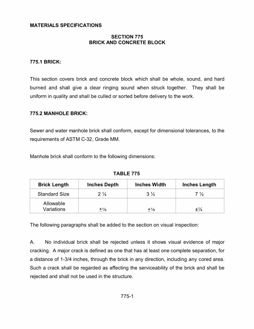
MATERIALS SPECIFICATIONS
SECTION 775BRICK AND CONCRETE BLOCK
775-1
775.1 BRICK:
This section covers brick and concrete block which shall be whole, sound, and hard
burned and shall give a clear ringing sound when struck together. They shall be
uniform in quality and shall be culled or sorted before delivery to the work.
775.2 MANHOLE BRICK:
Sewer and water manhole brick shall conform, except for dimensional tolerances, to the
requirements of ASTM C-32, Grade MM.
Manhole brick shall conform to the following dimensions:
TABLE 775
Brick Length Inches Depth Inches Width Inches Length
Standard Size 2 ¼ 3 ½ 7 ½
AllowableVariations +c +c ±¼
The following paragraphs shall be added to the section on visual inspection:
A. No individual brick shall be rejected unless it shows visual evidence of major
cracking. A major crack is defined as one that has at least one complete separation, for
a distance of 1-3/4 inches, through the brick in any direction, including any cored area.
Such a crack shall be regarded as affecting the serviceability of the brick and shall be
rejected and shall not be used in the structure.

MATERIALS SPECIFICATIONS
SECTION 775BRICK AND CONCRETE BLOCK
775-2
B. Fifty bricks may be sampled at random intervals from any cube for visual
inspection. Of the 50 sampled, 45 must pass visual inspection for major cracks. Should
less than 45 pass, the cube of brick shall be rejected and the brick shall not be used in
the structure.
775.3 BUILDING BRICK:
Building brick shall conform to the requirements of ASTM C-62, Grade MW.
775.4 FACING BRICK:
Facing brick shall conform to the requirements of ASTM C-216, Grade MW, Type FBS.
The size, color, and texture shall be as specified on the plans or as approved by the
Engineer.
775.5 MORTAR, GROUT AND PLASTER:
The class shall be specified in the special provisions and conform to Section 776.
775.6 CONCRETE BLOCK:
Masonry units shall conform to ASTM C-90 for Grade N-1 (1000 psi) units with the
following modifications:
Units shall be fully cured and shall have been made not less than 28 days prior to
delivery.

MATERIALS SPECIFICATIONS
SECTION 775BRICK AND CONCRETE BLOCK
775-3
Moisture content at time of delivery shall not exceed 30 percent of the minimum
absorption value of the units, and Contractor shall provide any protection deemed
necessary to maintain units in this condition until time of use.
The linear change from saturated to cool oven dry shall not exceed .0072 inches per
linear foot or .06 of 1 percent.
Masonry units shall be made with sand-gravel aggregate or lightweight aggregate at the
Contractor's option. All units used in the work shall be of one type. Lightweight
aggregates for use in concrete masonry units shall be restricted to expanded clay,
expanded shale, scoria, volcanic cinders, pumice or a combination thereof and shall
conform to ASTM C-331.
Size of units shall be as indicated on the plans.
The Contractor shall submit for approval to the Public Works Department, at the site,
not less than 5 samples of units to show the full variance of texture and full range of
color. Units used in the work shall match the approved samples. These samples shall
be tested for strength.
775.6.1 Mortar and Grout: Mortar and grout used for concrete block construction shall
conform to Section 776.

MATERIALS SPECIFICATIONS
SECTION 776MASONRY MORTAR AND GROUT
776-1
776.1 GENERAL:
This section covers masonry mortar and grout. Masonry mortar and grout shall consist
of a mixture of cementious material and aggregate with sufficient water added to bring
the resulting mixture to the desired consistency.
Table 776-1 and 776-2 indicates the average compressive strength that shall be
obtained when the cementious material, aggregate, and water (the required amount to
provide a flow of 110 +5 percent) are combined in the proportion shown in Table 776-3
and 776-4.
The mortar or grout to be used shall be designated by class in the special provisions
and the correct proportions of cementious materials and aggregate shall be combined
with the minimum amount of water to provide a workable mixture.
Retempering of the mortar or grout shall not be a standard practice.

MATERIALS SPECIFICATIONS
SECTION 776MASONRY MORTAR AND GROUT
776-2
TABLES 776-1 & 776-2
MASONRY MORTAR AND GROUT COMPRESSIVE STRENGTH
Type CompressiveStrength 28 Days
(p.s.i.)
Type CompressiveStrength 28 Days
(p.s.i.)
A 5500 Fine Grout 2500
B 5000 Course Grout 2500
C 4000
D 3000
M 2500
S 1800
TABLE 776-3
MASONRY MORTAR PROPORTIONS BY VOLUME
Type Portland Cement Hydrated Lime Aggregate ASTMC-144
A 1 0 1
B 1 0 1 ½
C 1 0 2
D 1 0 1 1/2
M 1 ¼ 1¼ to 3
0 1 ½ 2 ¼ to 3
*Masonry Cement Type S may be substituted for the cementious material. Priorapproval of the Public Works Department shall be required.

MATERIALS SPECIFICATIONS
SECTION 776MASONRY MORTAR AND GROUT
776-3
TABLE 776-4
GROUT FOR REINFORCED MASONRY PROPORTIONS BY VOLUME
FOR FIELD BATCHING
Type Portland Cement Fine Aggregate(ASTM C-404)
CoarseAggregate
(ASTM C-404)
Fine Grout 1 2 1/4 to 3 0
Coarse Grout 1 2 1/2 1 to 2
776.2 PORTLAND CEMENT:
The cement used shall conform with Section 725. For volumetric proportioning an
unopened sack of cement weighing 94 pounds shall be considered as having a 1 cubic
foot volume.
In proportioning the cement, it shall be measured loose, without shaking or compacting,
in measuring devices of certified capacity.
776.3 AGGREGATE:
The aggregate used shall conform with Section 701. Any change of source after
approval shall be considered sufficient cause for rejection of work.
In proportioning the aggregate, it shall be measured damp, loose without shaking or
compacting, in measuring devices of certified capacity.

MATERIALS SPECIFICATIONS
SECTION 776MASONRY MORTAR AND GROUT
776-4
776.4 MASONRY CEMENT:
Masonry cement shall conform to ASTM C-91 with the exception that the average
compressive strength shall not be less than 2500 psi at 28 days.
776.5 HYDRATED LIME:
Hydrated lime shall conform to ASTM C-207, Type S.
776.6 WATER:
The water shall conform to Section 725.
776.7 ADMIXTURES:
Admixtures, unless prescribed in the special provisions, shall not be used without prior
approval of the Public Works Department.
776.8 TESTS:
776.8.1 Mortar: If in the opinion of the Public Works Department there is sufficient
cause to question the quality of the mortar being utilized, random field test shall be
performed in accordance with ASTM C-780 Annex A-1 and A-6. For this area, the
penetration of the cone penetrometer shall be correlating to a flow of 110 +5 percent is
40 +3 mm.

MATERIALS SPECIFICATIONS
SECTION 776MASONRY MORTAR AND GROUT
776-5
776.8.2 Grout: If required, tests shall be performed in accordance with Uniform
Building Code Standard No. 24-23 Section 24.2301.

MATERIAL SPECIFICATIONS
SECTION 778LUMBER
778-1
778.1 GENERAL:
This section covers lumber. Lumber shall be Douglas Fir or graded pine and shall be
selected as to grade and shall conform in all particulars to the standard grading and
dressing rules of the West Coast Lumber Inspection Bureau.
Plywood shall not be less than 3 ply, manufactured and graded in accordance with the
standard grading rules of the APA.
Lumber for uses listed shall not be lower than the following grades:
(A) Permanent Construction, such as bridges
and culverts.
Select Structural, for beams and stringers;
Construction, for balance of structure.
(B) Minor permanent construction, such as
fences, guard rails and posts, pavement
headers, bulkheads, retaining structures, etc.
Construction.
(C) Falsework and studs, and wales for
formwork.
Construction, for framing, beam s or timbers
(D) Form sheeting for nonshowing surfaces of
concrete.
Standard, for boards; shiplap; or any grade of
plywood.
(E) Form sheeting for showing surfaces of
ornamental concrete.
C and Better Industrial clear; concrete form grad
of plywood; or overlay plywood.
(F) Form sheeting for curved soffits of bridge &
tunnel arches, plastered or unplastered.
Select Merchantable, board; concrete form
grade of plywood; or overlay plywood.
(G) Soffits of beam s and girders and slabs
between beams and girders; for beam and girder
sides, except ornamental concrete; and for
headwalls or endwalls of culverts or covered
conduits.
Concrete form grade of plywood or overlay
plywood.
(H) Form sheeting for showing surfaces of
channel wal ls or interior surfaces, except floors;
for covered conduit and all other showing
surfaces not specified above.
Tongue and groove flooring equal to C and
Better flat grain; concrete form grade of plywood;
or overlay plywood.
(I) All other lumber. Construction.

MATERIAL SPECIFICATIONS
SECTION 778LUMBER
778-2
778-2 REDWOOD:
Redwood lumber shall be selected as to grade and shall conform in all particulars to the
standard specifications for grades of California Redwood of the California Redwood
Association.
Redwood lumber for the uses listed shall not be lower than the following grades:
Uses Grade
(A) Bridges, culverts, and guardrail Dense Structural posts.
(B) All other Redwood Lumber. Foundation.
778.3 GRADE MARKING:
Lumber. Each piece of lumber shall bear an official grade mark which shall be the grade
mark adopted by one of the following associations:
(A) For Douglas Fir and Pine: The West Coast Lumber Inspection Bureau or other
agency.
(B) For Redwood: The California Redwood Association.
Plywood: Each sheet of plywood shall bear the official stamp of the APA stating the
grading of the sheet.

MATERIAL SPECIFICATIONS
SECTION 779WOOD PRESERVATIVES
779-1
779.1 GENERAL:
This section covers wood preservatives and shall consist of treating lumber, timber, and
piling. Lumber, timber, and piling to be treated shall conform to the requirements of the
AWPA.
Prior to treatment, lumber to be treated shall be cut to size and framed prior to
treatment. Where it is necessary to meet definite dimensions shown on the plans an
allowance for shrinkage in the sizes of lumber shall be made by the Contractor.
779.2 OIL TYPE PRESERVATIVE TREATMENT:
Preservatives shall be creosote, creosote-coal tar solutions, creosote petroleum
solutions, or pentachlorophenol in petroleum oils, conforming to AWPA specifications.
Treatment: Operations shall conform to the applicable requirements of the AWPA
specifications.
The amount of preservative to be retained and the treating process to be used for the
various types of service shall conform to the appropriate AWPA specification.
Incising: Timber to be treated that is 3 inches or more in nominal thickness and 4
inches or more in nominal width shall be incised before treatment. If the thickness is
less than 4 inches, the material should be incised on the wide faces only; otherwise, all
4 faces shall be incised.

MATERIAL SPECIFICATIONS
SECTION 779WOOD PRESERVATIVES
779-2
779.3 WATER BORNE SALT PRESERVATIVES TREATMENT:
Preservatives shall conform to the requirements of AWPA specifications and restricted
to the following preservatives:
Chromated Zinc Chloride (CZC)
Tanalith (Wolman Salts)
Ammoniacal Copper Arsenite (Chemonite)
Chromated Zinc Arsenate (Boliden Salt)
Chromated Copper Arsenate (Erdalith)
779.4 FIELD TREATMENT OF CUT SURFACES:
After plant treatment, when sawing or drilling is necessary, the cut surfaces shall be
thoroughly brushed with 2 coats of the same preservative in conformance with AWPA
specification. In all instances maximum protection requirement specified shall be met.

MATERIAL SPECIFICATIONS
SECTION 785STEEL CASTINGS
785-1
785.1 GENERAL:
This section covers steel casting wheels which shall be true to pattern in form and
dimension and free from pouring faults, sponginess, cracks, blowholes, or defects that
affects the service value of the casting.
Blowholes shall not have a depth sufficient to affect the strength of the castings. Minor
defects not impairing the strength of a casting may, with the approval of the Public
Works Director, be welded by a certified welder and after welding the castings shall be
annealed. Castings which have been welded without the approval of the Public Works
Department shall be rejected.
785.2 FINISH:
The dimensions of the finished castings shall not be less than the specified dimensions.
Castings shall not be more than 7-1/2 percent overweight.
The bearing surfaces of rockers and rocker plates shall be machined to the dimensions
shown on the plans. The final surface shall be produced by a finishing cut. They shall
be straight, smooth, and free from flaws.
Chemical analysis shall be performed in accordance with ASTM E-30.
785.3 TEST SPECIMENS:
Test coupons from tension test pieces shall be attached to the castings. If, in the
opinion of the manufacturer, the design of the casting is such that test coupons should

MATERIAL SPECIFICATIONS
SECTION 785STEEL CASTINGS
785-2
not be attached thereon, the test coupons shall be cast attached to separate cast
blocks. Sufficient coupons shall be cast to represent each lot with additional specimens
for use in case retests should be required. A lot shall be considered as all castings in a
melt which constitute part or all of a heat-treatment charge.
Coupons shall remain attached until after completion of the annealing process. Where
test coupons are cast separately from the castings, a representative of the Public Works
Department shall be present at the time of pouring to identify both coupons and
castings. Coupons cast separately from the castings shall not be detached from the
block until identified.
The test coupons shall be of such size that test specimens can be machined to
dimensions as specified in the ASTM procedure. When a specimen on machining
appears faulty and a true sample of the lot of castings to which it belongs, the
representative of the Public Works Department shall substitute another coupon of the lot
in question. Test specimens shall be furnished and machined by the Contractor at no
additional cost to La Paz County.
785.4 RETESTS:
If the results of the physical test for any lot do not conform to the requirements
specified, the manufacturer may reheat-treat such lot. Representative coupons shall be
reheat-treated with the lot to serve as retest specimens.
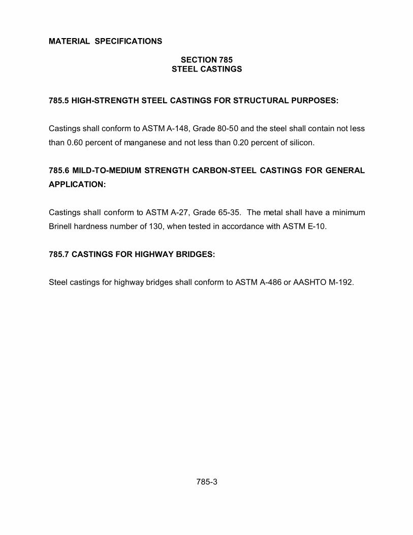
MATERIAL SPECIFICATIONS
SECTION 785STEEL CASTINGS
785-3
785.5 HIGH-STRENGTH STEEL CASTINGS FOR STRUCTURAL PURPOSES:
Castings shall conform to ASTM A-148, Grade 80-50 and the steel shall contain not less
than 0.60 percent of manganese and not less than 0.20 percent of silicon.
785.6 MILD-TO-MEDIUM STRENGTH CARBON-STEEL CASTINGS FOR GENERAL
APPLICATION:
Castings shall conform to ASTM A-27, Grade 65-35. The metal shall have a minimum
Brinell hardness number of 130, when tested in accordance with ASTM E-10.
785.7 CASTINGS FOR HIGHWAY BRIDGES:
Steel castings for highway bridges shall conform to ASTM A-486 or AASHTO M-192.

MATERIAL SPECIFICATIONS
SECTION 786BRONZE CASTINGS
786-1
786.1 GENERAL:
This section covers bronze castings which shall be true to pattern in form and
dimensions and free from defects that would affect the service value of the casting.
Chemical analysis shall be made in accordance with ASTM E-54.
786.2 PHYSICAL PROPERTIES:
Expansion and bearing plates shall conform to the physical properties as required in
ASTM B-22, for alloy C castings.
The physical test shall be performed on coupons cast integrally with the casting, as
described in ASTM B-208, double keel block test bar. The coupons shall remain
attached during all heating and cooling cycles to which the casting is subjected.
786.3 WORKMANSHIP:
Castings shall be sound, clean, and free from blowholes, porous places, cracks, and
other defects.
Castings that show injurious defects revealed by machine operations shall be rejected
and shall be replaced by the Contractor without charge.
No welding or patching of defects in castings shall be permitted. Any such welding or
patching performed shall be rejected.
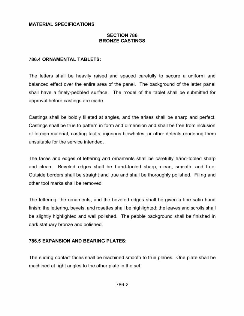
MATERIAL SPECIFICATIONS
SECTION 786BRONZE CASTINGS
786-2
786.4 ORNAMENTAL TABLETS:
The letters shall be heavily raised and spaced carefully to secure a uniform and
balanced effect over the entire area of the panel. The background of the letter panel
shall have a finely-pebbled surface. The model of the tablet shall be submitted for
approval before castings are made.
Castings shall be boldly filleted at angles, and the arises shall be sharp and perfect.
Castings shall be true to pattern in form and dimension and shall be free from inclusion
of foreign material, casting faults, injurious blowholes, or other defects rendering them
unsuitable for the service intended.
The faces and edges of lettering and ornaments shall be carefully hand-tooled sharp
and clean. Beveled edges shall be band-tooled sharp, clean, smooth, and true.
Outside borders shall be straight and true and shall be thoroughly polished. Filing and
other tool marks shall be removed.
The lettering, the ornaments, and the beveled edges shall be given a fine satin hand
finish; the lettering, bevels, and rosettes shall be highlighted; the leaves and scrolls shall
be slightly highlighted and well polished. The pebble background shall be finished in
dark statuary bronze and polished.
786.5 EXPANSION AND BEARING PLATES:
The sliding contact faces shall be machined smooth to true planes. One plate shall be
machined at right angles to the other plate in the set.

MATERIAL SPECIFICATIONS
SECTION 787GRAY IRON CASTINGS
787-1
787.1 GENERAL:
This section covers gray iron castings which shall be true to pattern in form and
dimension and free from pouring faults, sponginess, cracks, blowholes, or other defects
in locations affecting their strength and value for the service intended. Castings shall be
filleted boldly at angles, and the rises shall be sharp and true.
Before the castings are removed from the foundry, they shall be cleaned and the parting
lines, gates, and risers ground flush.
787.2 TEST SPECIMENS:
Test coupons shall be cast separately of the castings, using a mold as described in
ASTM A-48.
Two test coupons are required for each melt poured. Additional coupons shall be cast
for use as replacements or in case a retest is required.
A representative of the Public Works Department shall reject and have replaced
specimens which show obvious lack of continuity of metal or if the machining is
defective.
The manufacturer shall machine the tension specimens to the dimension specified for
specimen B of ASTM A-48, at no additional cost to La Paz County.
When approved by the Public Works Department, transverse tests may be made in lieu
of tensile tests. If approved, the castings shall meet the requirements of ASTM A-48.
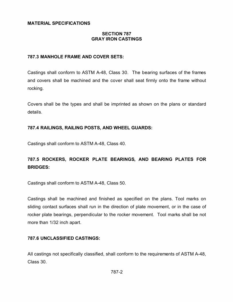
MATERIAL SPECIFICATIONS
SECTION 787GRAY IRON CASTINGS
787-2
787.3 MANHOLE FRAME AND COVER SETS:
Castings shall conform to ASTM A-48, Class 30. The bearing surfaces of the frames
and covers shall be machined and the cover shall seat firmly onto the frame without
rocking.
Covers shall be the types and shall be imprinted as shown on the plans or standard
details.
787.4 RAILINGS, RAILING POSTS, AND WHEEL GUARDS:
Castings shall conform to ASTM A-48, Class 40.
787.5 ROCKERS, ROCKER PLATE BEARINGS, AND BEARING PLATES FOR
BRIDGES:
Castings shall conform to ASTM A-48, Class 50.
Castings shall be machined and finished as specified on the plans. Tool marks on
sliding contact surfaces shall run in the direction of plate movement, or in the case of
rocker plate bearings, perpendicular to the rocker movement. Tool marks shall be not
more than 1/32 inch apart.
787.6 UNCLASSIFIED CASTINGS:
All castings not specifically classified, shall conform to the requirements of ASTM A-48,
Class 30.

MATERIAL SPECIFICATIONS
SECTION 787GRAY IRON CASTINGS
787-3
787.7 ASPHALTUM COATING:
Castings shall be painted or dipped in commercial-quality asphaltum paint.

MATERIAL SPECIFICATIONS
SECTION 790PAINT
790-1
790.1 GENERAL:
This section covers paint which shall be homogeneous, free of contaminants, and of a
consistency suitable for the intended use. Finished paint shall be well-ground and the
pigment shall be properly dispersed in the vehicle according to the requirements of the
paint; and this dispersion shall be of such nature that the pigment does not settle
appreciably, does not cake or thicken in the container, or become granular or curdled.
Paint and paint materials shall be delivered to the job site in new, unopened air-tight
containers, appropriately identified with the manufacturer's name, date of manufacture,
type of paint or paint material, specifications paint number, and lot or batch number.
The container shall have a formula label.
No paint shall be used until at least 7 days have elapsed from the date of manufacture.
790.2 PROPRIETARY BRANDS:
For the purpose of this specification, proprietary brands of paint and paint materials
shall be construed to mean paint or paint materials conforming to the requirements of
this specification and produced for distribution and consumption through regular
wholesale and retail outlets. Whenever paint or paint materials are designated on the
plans or special provision by a manufacturer's name or catalog reference, any
proprietary brand of equal quality shall be permitted, subject to the approval of the
Public Works Department. Information required by the Public Works Department as
proof of the comparative quality shall be furnished by the Contractor.

MATERIAL SPECIFICATIONS
SECTION 790PAINT
790-2
790.3 PAINT COATS:
The first coat of paint applied to an unpainted surface shall be called the prime coat.
The paint applied to field connections, welds, rivets, and all damaged or defectively
painted or rusty areas on a prime coated surface shall be called a touch-up coat. The
paint applied over the prime coat and touch-up coat shall be called the second coat.
The final coat of paint shall be called the finish coat.
790.4 MATERIALS:
Materials shall conform to the requirements of reference specifications indicated for the
material.
The Contractor shall furnish a certification from the manufacturer that the material
conforms with:
(A) Vehicles: Specifications:
Raw Linseed Oil ASTM D-234
Boiled Linseed Oil ASTM D-260
Water-Resistant Spar Varnish Navy Department Specification 52V20
Alkyd Resin TT-R-266C
Driers ASTM D-600, Class A or Class B asapplicable
Xylene TT-X-916B, Grade A
Turpentine (shall be used in paints fortimber)
ASTM D-13, Gum Spirits
Petroleum Spirits (Mineral Spirits) ASTM D-235

MATERIAL SPECIFICATIONS
SECTION 790PAINT
790-3
(B) Pigments: Specifications:
Carbonblack TT-P-343 Form 1, Class B
Lampblack ASTM D-209
Red Lead ASTM D-83
Titanium Dioxide, Non-extended ASTM D-476, Type II, Class II
Titanium Dioxide, Extended (TitaniumCalcium, Rutile)
ASTM D-476
Titanium Dioxide TT-P422, Type III, C
White Lead Basic Carbonate ASTM D-81
Zinc Yellow (Zinc Chromate) ASTM D-478, Type II
Zinc Oxide ASTM D-79
Iron Blue TT-P-385
Iron Oxide Yellow TT-P-458-A
Iron Oxide Orange ASTM D-84
Hansa Orange MIL-H-10330
Organic Green Gold DuPont YT 562-D or equal, specificgravity 161 ± 0.05
Chromium Oxide, Green Graphite TT-P-347
Graphite shall be natural amorphous material (American product) which shall not
contain less than 35 percent or more than 45 percent graphite carbon. The remainder
shall be insoluble siliceous material containing a total of not more than 5 percent
calcium and magnesium carbonate and sulfate. The pigment shall be ground to a
fineness that not less than 97 percent shall pass a No. 325 sieve. The graphite paste
shall be made by grinding the pigment in pure raw linseed oil in the following
proportions:
Amorphous Graphite....................................68.0 percent
Linseed Oil.....................................................32.0 percent

MATERIAL SPECIFICATIONS
SECTION 790PAINT
790-4
(C) Inert Materials Specifications
Diatomaceous Silica ASTM D-604, Type A
Magnesium Silicate ASTM D-605
790.5 MIXED PAINTS:
All mixed paints shall be machine-mixed and shall consist of the pigment of the required
fineness and composition, ground to the desired paste consistency in pure raw or boiled
linseed oil, to which shall be added the remainder of the vehicle to make paint
conforming to the required formula.
Paint which has hardened and thickened in the container that it cannot be readily
broken up to a smooth uniform paint of good brushing consistency shall be rejected.
All materials used in mixed paints shall conform to the requirements as herein specified.
The paint shall be produced to a satisfactory workable consistency conforming to one of
the following formulas for paint as required on the plans or in the special provisions. All
percentages shown shall be by weight.
Any of the following paints which are too thick to have a satisfactory workable
consistency shall be thinned with a suitable thinner from the group of thinners herein
specified. Gasoline shall not be used as a thinner.
Fineness of grind for enamel shall conform to Hegman 7 minimum.

MATERIAL SPECIFICATIONS
SECTION 790PAINT
790-5
The following paints shall conform to the latest ADOT Standard Specifications for Road
and Bridge Construction. All paints, except Paint No. 10 (Aluminum), shall be shipped
ready for use.
When Paint No. 1 is specified, it may be Paint No. 1-A or Paint No. 1-B. Paint No. 1-D
shall be used only when specifically designated.
Paint Number Type
1-A (Red Lead -- Linseed Oil)
1-B (Red Lead -- Alkyd Resin)
1-D (Zinc Chromate)
4 (Dull Black)
5 (Jet Black)
6 (Black – For Timber Primer Only)
7 (White -- For Timber Primer Only)
8 (White)
9 (Light Grey)
10 (Aluminum)
11 (White Enamel)
15 (Zinc)

MATERIAL SPECIFICATIONS
SECTION 791POLYETHYLENE PROTECTIVE WRAPPING
791-1
791.1 GENERAL: This section covers all cast and ductile iron, pipe, valves and fittings
which shall be protected from corrosion by encasement in a polyethylene protective
wrapping referred to hereafter as polywrap. Although not intended to be a completely
air and water tight enclosure, the polywrap shall provide a continuous barrier between
the pipe and surrounding bedding and backfill.
791.2 Materials: The polywrap shall be of virgin polyethylene, not less that 8 mils in
thickness, formed into tubes or sheets as required. Naturally pigmented material should
be used where exposure to ultra violet light shall be less than 48 hours. Otherwise, the
material shall be pigmented with 2 to 2 1/2 percent of well dispersed carbon black with
stabilizers.
The polywrap shall be secured as specified with 2 inch wide pressure sensitive plastic
tape not less than 10 mils thick. Tape shall be Scotchrap No. 50, Polyken No. 900,
Tapecoat CT, Johns-Manville No. V-10 Trantex or approved equal.
The minimum tube size for each pipe diameter shall be as listed below:

MATERIAL SPECIFICATIONS
SECTION 791POLYETHYLENE PROTECTIVE WRAPPING
791-2
TABLE 791-1
Polywrap Flat Tube Width (Inches)
Nominal Pipe Diameter
(inches)
Case Iron or Ductile Iron
With Pus-on Joints
Cast Iron or Ductile Iron
With Mechanical Joints
4 14 16
6 17 20
8 21 24
10 25 27
12 29 30
14 33 34
16 37 37
18 41 41
20 45 45
24 53 53

MATERIAL SPECIFICATIONS
SECTION 792DUST PALLIATIVE
792-1
792.1 GENERAL:
This section covers dust palliative. Since the establishment of grades shall not normally
be required prior to the application of this palliative, and since there is always the
possibility La Paz County shall grade in this area, La Paz County shall not assume any
responsibility for the maintenance of this work. The Contractor shall be responsible for
obtaining satisfactory results within the limits of the materials and the requirements of
these specifications.
Sufficient grading shall be done prior to treatment to provide reasonable drainage.
792.2 TYPE AND APPLICATION OF MATERIALS:
(A) Petroleum Resinous Type:
The material shall be a light yellow emulsion. Coherex or approved equal, suitable for
use as an agglomerant for soil particles. The emulsion shall contain 60 +3 percent of a
thermoplastic resinous petroleum fraction characterized by the following properties:
ASTM
SpecificationDesignation
ASTM Test Method Requirements
Viscosity, SUS at 1000 F.Sec
D-88 6,000 min.
Residue, % D-95 60 + 3
Flash Point, CO, 0F. D-92 400 min.
Specific Gravity D-1298 1.00 min.
MATERIAL SPECIFICATIONS
SECTION 792DUST PALLIATIVE
792-2
The emulsion shall be stable, i.e., shall not break when stored in clean closed
containers at ordinary temperatures, excluding freezing or boiling, for a minimum of 3
months. It shall be miscible with water in all proportions, including a ratio of 1 part
emulsion to 5 parts water. The sequestering agents shall make the preparation stable
against hard water, thus permitting dilution of the emulsion with all types of water. The
emulsion shall be non-corrosive to metal containers. The materials shall penetrate into
the soil surface and shall not form a skin at the surface or form a crusted surface.
Immediately after compacting, the 1 to 5 diluted emulsion shall be applied in 1 to 3
applications, as required, at a rate of approximately 0.17 gallons per square yard per
application. The material shall be applied by means of a thoroughly cleaned bituminous
distributor.
(B) Lignin Based Types:
Lignin sulfonates, a residual co-product of wood pulping by the sulfite process in the
manufacture of cellulose products. This material should be supplied in either the
granulated solid or liquid form, liquid form to contain 50 + percent lignin solids by weight.
The application rate shall ensure the residual lignin solids constitute approximately 1
percent by weight of the soil being treated. One gallon of 50 +2 percent solids lignin
sulfonate concentrate* usually results in the required residual content for a soil volume
of 1 square yard 6 inches deep.
*Lignin sulfonates are usually diluted to 10 to 25 percent solids before application.
Application of this material shall be by either a pressure type water sprinkling truck or an
asphalt distributor; however, the same precautions to prevent contamination of adjacent
MATERIAL SPECIFICATIONS
SECTION 792DUST PALLIATIVE
792-3
objects shall be required as applying an asphalt base product. For other than skin
treatments, multiple applications and some scarifying and blading may be necessary.

MATERIAL SPECIFICATIONS
SECTION 795LANDSCAPE MATERIAL
795-1
795.1 GENERAL:
This section covers material used for landscaping purposes which shall be in
conformance with this Section.
The common and scientific names of plants shall conform to the approved names in
Standard Plants Names (SPN) or its successor, American Association of Nurserymen
(ASN). For identification and inspection, durable, legible labels, bearing the plant's
name in water-resistant ink, shall be attached to all nursery stock or container of stock
delivered to the project site.
795.2 TOPSOIL:
Topsoil shall be a fertile, friable soil and obtained from well-drained aerable land, and
shall be free from nut grass, refuse, roots, heavy clay, clods, noxious weeds or any
other material toxic to plant growth. At least 10 days prior to delivery of topsoil to the
site, the Contractor shall furnish the Public Works Department, at no additional cost,
with a soil sample from each source for analysis and tests.
To be acceptable the PH factor shall not exceed 8.0 or be lower than 5.5. Soluble salts
shall not exceed 1500 PPM. The plasticity index shall be in the range of 3 and 15
inclusive, and it shall contain approximately 1-1/2%, by dry weight, of organic matter
either natural or added. Gradation shall be in accordance with the table shown below:

MATERIAL SPECIFICATIONS
SECTION 795LANDSCAPE MATERIAL
795-2
Sieve Size Percent Passing
1" 100
½" 95-100
No. 4 90-100
No. 10 70-100
No. 200 15-70
795.3 SOIL FERTILIZING MATERIAL:
Fertilizing material shall comply with the applicable requirements of the State
Agricultural Code. All fertilizing material shall be packaged, first grade, commercial
quality products identified as to source, type of material, weight and manufacturer's
guarantee analysis. It shall not contain toxic ingredients or fillers in quantities harmful to
human life, animals or plants. It shall be delivered in unopened containers and shall
have the chemical analysis as specified in the plans or specifications. Material which
has become caked or otherwise damaged shall be rejected.
Slow release fertilizer pills for ground cover beds shall be Agriform 18-6-12 (+ iron, or
equal).
795.4 ORGANIC SOIL CONDITIONERS:
Soil conditioners shall consist of a ground or processed wood product derived from
redwood, ground or shredded fir, redwood or ponderosa bark. It shall have a nitrogen
content of 1%, a PH not exceeding 7.5, and organic matter shall be no less than 85%.
Its gradation shall be at least 85% passing the 1/4-inch screen. In addition, it shall be
treated with a non-toxic agent so as to be hygroscopic.

MATERIAL SPECIFICATIONS
SECTION 795LANDSCAPE MATERIAL
795-3
When manure is used as a soil conditioner, it shall be the product of yard fed cattle, free
of weed seeds, straw or any other inert material and aged at least 3 months. This
manure shall have been processed by grinding and screening and shall be of a
consistency for ease of spreading with a mechanical spreader.
795.5 CHEMICAL SOIL CONDITIONER:
Chemical soil conditioners such as soil sulfur, gypsum or iron additive shall be
commercially approved brands designated for agricultural use. Material which has
become caked or otherwise damaged shall be rejected.
795.6 SEEDS:
Seeds shall be fresh, clean seeds, premixed to the specified proportion. They shall be
delivered to the site in original, unopened containers bearing the dealer's guaranteed
analysis and germination percentage. They shall have a certificate, a stamp, or a
release sealed by an agricultural engineer.
795.7 PLANTS, TREES, AND SHRUBS:
795.7.1 General: All landscape stock shall be grown in nurseries approved by the
State Department of Agriculture. They shall have a growth habit normal to the specie.
Stock shall be sound, healthy, and vigorous; free from insect pests, sun scald,
excessive bark abrasions and other objectionable disfigurements. They shall have
normal, well-developed branch systems and vigorous, fibrous root systems which are
neither root nor pot-bound and are free of kinked or girdling roots.

MATERIAL SPECIFICATIONS
SECTION 795LANDSCAPE MATERIAL
795-4
All stock shall have been grown in pots, cans, tubs, or boxes for a minimum of three
months and a maximum of one year. They shall have sufficient roots to hold earth
together after removal from the containers. This earth shall be free from noxious weeds
including bermuda grass.
Stock shall be inspected and approved by the Public Works Department at the
Contractor storage site prior to delivery to the project.
795.7.2 Flatted Plants: Flatted plants shall be grown and remain in the flats until
transported to the project site. The soil and spacing of the plants in the flats shall
ensure the minimum disturbance of the root system at transplanting.
795.7.3 Trees: Trees shall be of the specified height, spread and caliper and shall
stand erect without support. The height shall be measured from the root crown to the
last division of the terminal leader with the branches in a normal position and the caliper
shall be measured 12 inches above the crown roots. For palm trees only, the height
shall be measured from the ground line to the base of the growing bud.
795.7.4 Shrubs: Shrubs shall be of the specified type, height, and spread. They shall
be selected from high quality, well-shaped nursery stock.
795.8 MISCELLANEOUS MATERIAL:
795.8.1 Headers and Stakes: Lumber for landscaping shall be construction heart,
rough-sawn redwood in the sizes specified; splicing shall not be permitted. Stake used
with header boards shall be 2 x 4 inches, pointed and at least 18 inches long.

MATERIAL SPECIFICATIONS
SECTION 795LANDSCAPE MATERIAL
795-5
795.8.2 Tree Stakes: Tree stakes shall be 2 x 2 inch redwood posts, free of knots,
reasonably straight, and of sufficient length to properly support the tree.
795.8.3 Tie Wires: Tie wire shall be No. 12 AWG zinc coated wire. The cover for this
wire shall be 1/2 inch garden hose.
794.7.4 Decomposed Granite: Decomposed granite shall be as per Section 702.4
with the following additions: It shall be "Desert Gold" in color. A thirty pound sample
shall be submitted to the Public Works Department for approval prior to use. The
decomposed granite shall not contain lumps or balls of clay, caliche, organic matter or
calcareous coating. The Contractor shall assure that sufficient quantity is available from
a single source to complete the contract. Gradation for Type A and Type B shall be as
shown in the table below:
TYPE A TYPE B
¾” Minus Seive Granite Percent ¾" Sized Granite PercentSieve Size Passing Sieve Size
1" 100 1' 100
¾” 95-100 ¾” 90-100
½ 85-100 d” 0-20
No. 4 60-80
No. 40 10-20
No. 200 0-5

MATERIAL SPECIFICATIONS
SECTION 795LANDSCAPE MATERIAL
795-6
795.5 Submittal: The contractor shall submit to the Public Works Department three
copies of written certifications assuring plants are the species, varieties, and size
specified.

MATERIAL SPECIFICATIONSSECTION 748
STEEL PIPE AND FITTINGS
748-1
748.1 GENERAL:
This section covers 4 inch and larger steel pipe and fittings used in conjunction with pump
station or other installations that require bends and connections for distribution systems
that carry water under pressure.
748.2 PIPE:
Steel pipe shall be black carbon steel and conforming to the requirement of ASTM A-53
Type E or S, Grade A or B, or ASTM A135. Pipe shall be standard weight per ANSI
B36.10 and a minimum 0.375 inches wall thickness for 12" inch pipe and above or as
specified on the plans.
748.3 JOINTS:
Joints for buried pipe shall be butt-welded.
Joints for above ground or exposed pipe larger than 4" shall be flanged or butt-welded as
shown on the plans.
748.4 FITTINGS:
Fittings for buried pipe shall be flanged or butt-welded and fittings for above ground or
exposed pipe shall be flanged. Welding fittings for steel pipe 6-inches and smaller in size
shall be butt-welded fittings of seamless carbon steel conforming to ASTM A-234, Grade
A or B as to material and conforming to ANSI B-16.9 as to dimensions where established.

MATERIAL SPECIFICATIONSSECTION 748
STEEL PIPE AND FITTINGS
748-2
Standard weight fittings shall be used with standard weight pipe. Welding fittings for pipe
larger than 6-inches shall be butt-welded fittings in accordance with ANSI B-16.9, except
that they may be light wall, light weight or light gauge provided the wall thickness is at
least the same wall thickness as the pipe with which used. Welding fittings may be made
up of sections of pipe welded together. Fittings made up of sections of pipe welded
together shall be made of pipe of at least the same wall thickness as the pipe with which
used; and bends shall be miter bends with radius the same as corresponding butt-welding
fittings. Forty-five degree bends shall be 4-piece construction. Welding of these made-up
fittings shall be in accordance with AWWA Standard C206.
Flanged fittings of cast iron for steel pipelines shall be governed by ANSI B16.1, Class
125. Flanged fittings of steel shall be made up from sections of steel pipe, as used on
either side of the fittings, with attached steel flanges, all in accordance with AWWA
Standard C208 or as detailed on the drawings. Drawing details govern over
corresponding details in referenced specifications.
748.5 FLANGES:
Flanges shall be in complete accordance with the minimum requirements of ANSI B16.5
and ASTM A181, I or II, forged carbon steel flanges, 150 pound.
Bolting, facing, threading, and dimensions shall be as given in the respective
specifications listed. Slip-on flanges shall be attached to the pipe by back and face welds
as shown in AWWA Standard C107. Welding neck flanges shall be single welded from
the outside. Field welding shall be in accordance with AWWA Standard C206. Flanges
shall be attached before any required linings or coatings are applied. Where cap screws

MATERIAL SPECIFICATIONSSECTION 748
STEEL PIPE AND FITTINGS
748-3
or stud bolts are required, flanges shall be provided with threaded holes to receive such
screws and bolts.
Full face or flat ring gaskets of 1/16-inch thick Granite, or equal shall be used.
748.6 BOLTS AND NUTS:
Bolts and nuts for buried flanges, flanges located outdoors above ground, flanges located
in open vaults and structures, and submerged flanges shall be Type 304 stainless steel
conforming to ASTM A N193, Grade B8, for bolts and ASTM A 194, Grade 8, for nuts.
Bolts and nuts larger than 1-1/8 inches shall be steel, ASTM A 307, Grade B, with
cadmium plating, ASTM A 165, Type NS>.
Washers shall be provided for each nut. Washers shall be of the same material as the
nuts.
748.7 GASKETS:
A. Gaskets shall be fullface, 1/16 inch thick, and shall be one of the following
nonasbestos materials:
1. Cloth-inserted rubber. Products: Manville No. 109, John Crane Co. Style 777, or
equal. Gaskets shall be suitable for a pressure of 350 psi at a temperature of 180
degrees F.

MATERIAL SPECIFICATIONSSECTION 748
STEEL PIPE AND FITTINGS
748-4
2. Acrylic or aramid fiber bound with nitrile. Products: Garlock "Bluegard," Klinger
"Klingersil C4400," or equal. Gaskets shall be suitable for a water pressure of 500 psi at a
temperature of 400 degrees F.
748.8 FABRICATION:
A. Beveled ends for butt-welding shall conform to ANSI B16.25. Surfaces shall be
clean of paint, oil, rust, scale, slag, and other material detrimental to welding.
B. Fabrication shall comply with ANSI B31.3, Chapter V.
C. The minimum number of passes for welded joints shall be as follows:
Steel Cylinder Thickness (inch) Minimum Number of Passes for welds
Less than 0.1875 1
0.1875 through 0.25 2
Greater than 0.25 3
Welds shall be full circumferential.
D. The shielded metal arc welding (SMAW) process shall be used for welding.
MATERIAL SPECIFICATIONSSECTION 748
STEEL PIPE AND FITTINGS
748-5
E. Welding preparation shall comply with ANSI B31.3, paragraph 328.4. Limitations
on imperfections in welds shall conform to the requirements in ANSI B31.3, tables
341.3.2A and 341.3.2B, and paragraph 341.4 for visual examination.
F. Welds shall be identified in accordance with ANSI B31.3, paragraph 328.5.
G. Each layer of deposited weld metal shall be cleaned prior to depositing the next
layer of weld metal, including the final pass, by a power-driven wire brush.
H. Welding electrodes shall comply with AWS A5.1 or A5.5.
748.9 FLEXIBLE COUPLINGS:
Flexible pipe couplings for steel pipe shall be steel, Dresser Style 38, Rockwell Type 411,
Baker Series 200, or equal.
748.10 LININGS AND COATINGS:
All steel pipe and fittings shall be cement-mortar lined and unless otherwise specified all
steel pipe and fittings that are to be installed underground shall be coated on the outside
in accordance with the requirement of Standard Specification No. 640.
The cement mortar lining and if specified cement mortar coating on the outside of the
buried pipe shall be in accordance with AWWA - C205.

MATERIAL SPECIFICATIONSSECTION 748
STEEL PIPE AND FITTINGS
748-6
All exposed piping, joints and fittings shall receive one shop coat of protective paint of
Tnemec 20-1255 Pota-Pox Primer (sand beige) applied at a rate that will provide a
minimum dry film thickness of 4 to 6 mils.
SECTION 749
TAPPING SLEEVE
749.1 GENERAL:
This section covers the requirements for materials used to perform a tapped connection
under pressure and includes replacing the valve on an existing water pipe line.
749.2 MATERIAL:
749.2.1 Tapping Sleeve: Tapping Sleeves shall be of extra heavy construction to provide
resistance to line pressures. They shall be constructed in two halves for assembly around
the main to be tapped. Walls of castings shall be extra heavy and reinforced for extra
strength.
The branch outlet shall have a flanged face for bolting to the tapping valve.
The inside diameter of the outlet branch shall be sufficiently larger than the nominal size
cutters of the tapping machine.

MATERIAL SPECIFICATIONSSECTION 748
STEEL PIPE AND FITTINGS
748-7
Tapping sleeves shall be either the type water is allowed to circulate between the sleeve
and the outside surface of the pipe, or the type water is confined to the area immediately
surrounding the tap opening. Sleeves shall be used on the type and size of pipe designed
and dimensioned for the particular sleeve.
Sleeves of the first type, approved gaskets shall be provided to form water tight joints
along the entire length of the sleeve. The circumferential joints at the ends of these
sleeves shall be sealed with caulking or mechanical joints. These joints shall conform to
the requirements set forth in AWWA C-111 pertaining to dimensions, clearances,
materials, etc. Gaskets and glands for mechanical joints shall be in two pieces.
The longitudinal gaskets shall be totally confined, or compressed, between ridges and/or
grooves extending continuously for the full length of both halves of the sleeve casting.
Bolts shall be located close to the outside of the gaskets and closely spaced to exert
sufficient pressure forming a water tight joint and to comply with any design stresses.
Sleeves with gasketed longitudinal joints and caulked end joints shall have minimum
bolting as follows:
LINE SIZE BRANCH SIZE MINIMUM NO. BOLTS MINIMUM SIZE BOLTS

MATERIAL SPECIFICATIONSSECTION 748
STEEL PIPE AND FITTINGS
748-8
(inches) Lead Gaskets
3,4 3,4 6 3/4"
6 thru 16 3,4,6 10 3/4"
8 thru 12 8,10,12 12 3/4"
14, 16 8, 10, 12 12 7/8"
14, 16 14, 16 16 7/8"
18, 20, 24 3, 4, 6, 8 10 1"
18, 20, 24 10, 12, 14, 16 14 1"
18, 20, 24 18, 20, 24 18 1"
Tapping sleeves in which the water is confined to the immediate area of the tap opening
shall be Kennedy Square Seal, Rich-Corey improved or approved equal.
The outlet half of each sleeve shall be fitted with a continuous gasket and permanently
cemented into a groove surrounding the outlet opening. The back half of each sleeve
shall be fitted with elastomeric pads or a metal shoe for developing adequate pressure on
the gasket to prevent leakage within the design capacity of the pipe.

MATERIAL SPECIFICATIONSSECTION 748
STEEL PIPE AND FITTINGS
748-9
749.2.2: Tapping Valves: Tapping valves shall be identical in construction with the
specifications for gate valves. A tapping sleeve is considered an integral part of a tapping
assembly and shall have openings adequate for the valve. Tapping valves shall have
ends and seat rings with the proper size to permit the use of full size cutters. The inlet
end of the tapping valve shall be flanged for bolting to the tapping sleeve. The face of the
flanged end shall have a raised lip to fit the recessed grooved surface of the tapping
sleeve. The flanged end shall be in accordance with the latest revision of MSS SP-60.
The tapping valve shall have the discs and seat ring constructed allowing the inside
diameter of the rings to be at least 3/16" larger than the nominal size of the valve and the
discs.
MATERIALS SPECIFICATIONSSECTION 750
IRON WATER PIPE AND FITTINGS
750-1
750.1 GENERAL:
This section covers cast iron and ductile iron water pipe which shall be cement mortar
lined and coal tar coated in accordance with AWWA C-104.
750.2 CAST IRON WATER PIPE:
Cast iron water pipe shall be designed in accordance with AWWA C-101.
Cast iron water pipe should be designed for either 18/40 or 21/45 physicals and shall
conform to AWWA C-106 or AWWA C-108.
Cast iron, or water pipe, shall be designed to meet an internal pressure of 150 psi,
external cover of 5 feet, and Standard Laying Condition B.
Cast iron pipe shall be at nominal 18 foot lengths.
750.3 DUCTILE IRON WATER PIPE:
Ductile iron water pipe shall be designed in accordance with AWWA C-150 and shall be
manufactured in accordance with AWWA C-151 and be cement mortar lined. The class
shall be as designated in the plans or special provisions. Ductile Iron water pipe below
12" shall have a minimum wall thickness of Class 50. Pipe 12" and above shall have a
minimum wall thickness of Class 52.
750.4 JOINT REQUIREMENTS:

MATERIALS SPECIFICATIONSSECTION 750
IRON WATER PIPE AND FITTINGS
750-2
Push-on joints for cast iron or ductile iron water pipe shall conform to AWWA C-111 and
shall include synthetic rubber gaskets and lubricant.
Mechanical joints for cast iron, or ductile iron water pipe, shall conform to AWWA C-111
and shall include cast iron glands, synthetic rubber gaskets, and T-head bolts and nuts.
Flanged joints for cast iron, or ductile iron water pipe, shall be class 125 and as detailed
on the plans or in the special provisions.
750.5 FITTINGS:
Iron fittings shall be either Gray-Iron or Ductile-Iron conforming to AWWA C-110 or
AWWA C-153 with a minimum pressure rating of 250 psi. Flanged ends shall conform
to AWWA C-110. Push-on and mechanical joints ends shall conform to AWWA C-111.
Fittings shall be cement mortar lined and coal-tar coated in accordance with AWWA
C-104.