La Condesa Private Railroad Car - BCWRR
156
La Condesa Private Railroad Car The La Condessa was built as an AT&SF (Santa Fe) café observation car 1512 in 1926, one of five built that year. In Santa Fe service the car was used in short distance service where a full size dinner car and lounge car was not needed. It was used for runs such as Oakland to Barstow, Denver to La Junta, Colorado and San Diego to Los Angeles. The interior had a lounge at the platform end with seating for 20 people. Next was a writing desk on one side of the car against the bathroom wall. In the middle of the car was the dinning area with 3 tables having seating for 4 people each and 3 tables across from them with seating for 2 people each. Next to the dinning area was the pantry and kitchen for food preparation. In 1959 Santa Fe sold the car to Redfield (Tad) Finlay Jr. who made the car into a Private Varnish by removing the dinning pantry & kitchen area and making the area into 3 bedrooms and a small kitchen area. The car was named the La Margarita del Oro and was u sed as the end car of the Finlay Fun Time Tours train till it was replaced by another car. In 1974 in the car was sold to Mr. Gordon Crosthwait and he remained the car “La Condesa”. The car was run in charters service until the early 1990’s. Mr. Crosthwait was one of the founders of the “American Association of Private Railroad Car Owners” while owning this car. The car was first based in Fresno then later moved to Anaheim. In the early 1990’s Mr. Crosthwait started to upgrade the car to meet the new Amtrak Private Car standards in a long slow process. In June of 2006 Mr. Crothwait donated the car to the “San Luis Obispo Railroad Museum”. In February 2007 Mr. Crosthwait passed away knowing that he had found a loving home for his car. The San Luis Obispo Museum will be moving the car to the museum property near the San Luis Obispo railroad station in the future and putting back the Santa Fe interior and finish bringing it up to current Amtrak standards. For information on the San Luis Obispo Railroad Museum go to www.slorrm.com.
Transcript of La Condesa Private Railroad Car - BCWRR

La Condesa Private Railroad Car
The La Condessa was built as an AT&SF (Santa Fe) café observation car 1512 in 1926, one of five built that year. In Santa Fe service the car was used in short distance service where a full size dinner car and lounge car was not needed. It was used for runs such as Oakland to Barstow, Denver to La Junta, Colorado and San Diego to Los Angeles. The interior had a lounge at the platform end with seating for 20 people. Next was a writing desk on one side of the car against the bathroom wall. In the middle of the car was the dinning area with 3 tables having seating for 4 people each and 3 tables across from them with seating for 2 people each. Next to the dinning area was the pantry and kitchen for food preparation. In 1959 Santa Fe sold the car to Redfield (Tad) Finlay Jr. who made the car into a Private Varnish by removing the dinning pantry & kitchen area and making the area into 3 bedrooms and a small kitchen area. The car was named the La Margarita del Oro and was u sed as the end car of the Finlay Fun Time Tours train till it was replaced by another car. In 1974 in the car was sold to Mr. Gordon Crosthwait and he remained the car “La Condesa”. The car was run in charters service until the early 1990’s. Mr. Crosthwait was one of the founders of the “American Association of Private Railroad Car Owners” while owning this car. The car was first based in Fresno then later moved to Anaheim. In the early 1990’s Mr. Crosthwait started to upgrade the car to meet the new Amtrak Private Car standards in a long slow process. In June of 2006 Mr. Crothwait donated the car to the “San Luis Obispo Railroad Museum”. In February 2007 Mr. Crosthwait passed away knowing that he had found a loving home for his car. The San Luis Obispo Museum will be moving the car to the museum property near the San Luis Obispo railroad station in the future and putting back the Santa Fe interior and finish bringing it up to current Amtrak standards. For information on the San Luis Obispo Railroad Museum go to www.slorrm.com.

History of “La Condesa”
This car was built for the Santa Fe Railroad by the Pullman Company in 1926 as car number 1512, lot #4986, specification # 1040. It was one of five cars built as café-observation cars. It was built with 24 lounge seats and 18 dining room seats using tables that sat two or four. The lounge contained a writing desk and chair as well as a single section which could be made into a lower berth. This was presumably for the steward, where the rest of the crew slept is anybodies guess. Because of this configuration, the car could and did function as a diner, lounge, and in view of the large open platform, as an observation car. As far as we know the car continued in this configuration for it’s entire service life. Sometime, possibly around 1940, air conditioning was added to the car. It ran extensively on the Santa Fe train “The Scout” as the only amenity afforded the coach passengers. It was modernized in the late 50’s and retired some time in the late 60’s. A sister car, in almost the original configuration, still exists today at Campo, CA. The “La Condesa” and a sister car were purchased by Mr. Tad Finley, possibly around 1966. He made some major renovations to the car. He completely removed the kitchen, pantry and dining room, and installed a permanent partition between the former kitchen and pantry. He converted the kitchen into a double bedroom by installing a crosswise convertible sofa and a lengthwise upper berth. Also a “combolet” was added. This “combination” unit was apparently removed from a prewar lightweight car and contains a fold out toilet, a fold down sink, and a medicine cabinet. It is complete with it’s own lighting and shaver outlet. The former icebox in this room was converted into a large closet. The pantry was also converted into a double bedroom. In this room a lengthwise convertible sofa and an upper berth were installed. A standard railroad “through the floor” toilet was added as was a sink and small closet. Two thirds of the dining room was converted into another double bedroom. It had a fixed double bed, a “combolet”, and a desk. Since it was the largest bedroom on the car with two large windows, it was used exclusively by the Finley’s and was designated “Bedroom F”. In order to do this and provide a hallway around this bedroom one of the old ice boxes was removed and the passageway placed on one side of the car. Formally passengers passed through the center of the dining room. The remaining ice box was converted into a shower. The former ice loading hatch for this ice box was covered with glass giving this shower the unique feature of having a skylight! Mr. Finley added a small kitchen on one side of the remaining one third of the dining room and a “card table”.

The lunge was redone in red flock wallpaper and painted red and gold. A small piano was also added. The writing desk was removed and a wet bar installed in this space. Also added at this time to the underside of the car were two small generator sets and a fuel tank. the steam activated air conditioning was dismantled and some of it’s components were used for the installation of a more modern AC system using Freon refrigerant. Mr. Finley called the car “La Marguerita De Oro”, and used it along with several other cars for his “Finley Fun Time Tours” trips. It was on one of thse trips to Mexico in 1968 or 1969 that Gordon Crosswaith first became acquainted with the car. It seems that he was apparently quite enamored with the car and it’s features. Mr. Finley sold the car to Gordon in 1969. Gordon made several improvements to the car. He started by replacing the two small generator sets with two larger units and a larger fuel tank. With Bill Farmer’s help modifications to the electrical system were also made to accommodate these generators. Gordon ran the car for several years. The early trips were mostly on the SP top Reno NV, although it was seen occasionally in Bakersfield on the S Fe. This was before Amtrak’s requirements forced it’s temporary retirement in 1990. In 1989 work commenced on refurbishing and improving the car. Extensive modifications to the car’s electrical, plumbing and heating systems were made during this hiatus. Repairs to the car body and other rusted out areas was also done at this time. A new toilet system was installed along with a holding tank.

La Condesa Mechanical Systems Summary
I commenced working on La Condesa in April of 1989. The first job that we tackled was to remove and replace as much of the old interior electrical wiring as we could. The location of all of the interior electrical conduits was documented along with all junction boxes and pull boxes. As the new wires were pulled in, we recorded each circuit’s function and distribution. Spare wires for future applications were also installed. The main electrical conduit runs down the center of the ceiling. It runs from the circuit breaker (CB) panel at the Steward’s section to the open platform of the car. Due to the installation of the air conditioning, a portion of this conduit had to be rerouted around the air conditioning (AC) unit to the bathroom side of the car and then back to the center of the lounge ceiling. The old fuse panel was removed and a new CB panel installed. This CB panel is in one of the lower lockers at the Steward’s section. As originally built, this locker contained the main switch panel for all of the car’s lighting. It also included switches for the four fans located in the lounge and dining areas before the installation of the air conditioning. See Fig. 1. We started at the old switch/fuse panel in the lower locker near the Steward’s section. Three 1-1/4” conduits run from this panel up to a large junction box near the ceiling. From this box conduits went in several different directions. See Figs. 2 and 2A. See Figures 3 & 4 for diagrams of some of this wiring distribution as it proceeds from the main junction box towards the OBS end of the car. Fig. 5 shows the conduits that run to the forward (or old kitchen end) of the car. Fig. 6 is a continuation of some of that wiring. Fig. 7 is the conduit layout in the space above the OBS platform ceiling. This area is accessible though a hatch in the platform ceiling. Fig. 8 is an additional diagram of the lounge/OBS ceiling and wall outlet wiring. Figs. 9 to 16 are schematic wiring diagrams for all the various circuits contained in the Steward’s circuit breaker panel. Fig. 17 is a layout of the Steward’s circuit breaker panel. There are three more circuit breaker panels on the car, in the main electric locker, to be described later. One of the early projects that we tackled was to rebuild the old water cooler locker. This is the small locker to the left of the general toilet door. See Fig. 18. The upper part of this locker contains the old, but still working, air conditioner controls. Directly below these controls is the 32 volt DC control and meter panel. As could be expected, the entire bottom of this locker was rusted out. While we were at it, we added a 1220 colt duplex outlet to the bathroom.
Air conditioning
Perhaps a word would be in order regarding the air conditioning system. Mr. Finely tried to retain much of the old steam ejector air conditioning system when he modified the car. The blower fan inside the car still has a 32 volt DC motor. The condenser fan, up in the space above the bathroom and section seat, also has a 32 volt DC motor. The compressor however has a 240 volt AC motor. As you can see, it is a mix of two systems. The AC system, unfortunately, uses

Freon 12, now banned as a refrigerant. The compressor is a Carrier model 5F20. This is a two cylinder unit of about 3 tons capacity. Maximum RPM is 17590 and the drive pulley must rotate clockwise. If this compressor is run in the wrong direction, the oil pump will not work! In order to make this system work, a 32 volt DC power supply was necessary. Fig. 19 is the schematic diagram of this power supply. Fig. 20 is the 32 volt distribution layout and Fig. 21 is the actual wiring diagram. The 32 volt DC power supply is located under the car in a locker that is beneath the bathroom. The P/N J box indicated in Fig. 21 is a large Pile National junction box that is also under the car and located behind the AC compressor. The two 4 gauge wires, numbers 12 and 13, shown in this diagram run to the bottom of the Steward’s locker and were for the train line connector at the forward end of the car. This connection has not been hooked up. There are also two 6 gauge wires, numbers 21 and 22, which run to the 120 volt lighting selector switch. Why this was done I am not sure, but I think that it was to provide 32 volts DC to the lights from another car, via the train line, should both of the car’s generators fail. There is a 120 volt selector switch in the main electric locker on the car. This switch provides power to the 120 volt CB panel, PANEL 3. 120 volt power can be obtained from two sources, the 240 volt to 120 volt transformers or from a 120 volt connector under the car. If 240 volts is not available, then the car can be lighted by using this under-car connection. There is a 32 volt DC position on this switch added for emergency lighting. See Fig. 41. Fig. 22 is the schematic diagram for the AC control system as drawn by Bill Farmer in 1988. As you can see, it uses the old Steam Ejector panel for the interior fan control and to turn on the condenser fan motor. Through a series of other relays, it will also turn on the compressor motor. Bill Farmer did most of the original wiring on the car. There is a separate folder containing his original drawings. We did a test run of the AC in Sept. 07. It runs, but needs some more Freon. We also checked to insure that the compressor was running in the correct direction. Fig. 23 shows two photos of the air conditioning condenser unit that is located above the bathroom/section part of the car. It is accessible through a roof hatch. The small copper pipe with the two nozzles on it is the water spray piping. During very hot days a water spray was used to aid in improving the efficiency of the AC system. The valve for this spray system is located near the floor on the left hand side of the kitchen supply locker. We also did some extensive repairs to the steel in this upper condenser compartment. We added some baffles and repositioned the air filters to prevent rain water from entering the car. Note the old water stains behind the bar. It should also be noted that there are two roof hatches that have to be opened for the condenser unit to operate properly, before using the AC. They need to be motorized. For now there is a wire loop on the roof hatch to secure them in an open position. In Fig. 24 are two photos of some work that was done on the upper berth in BRM A. We enclosed some exposed sheet metal work and added two doors to the locker above this berth. The upper berth in this room needs to have the left and right chains that support this berth shortened. The two large spring assemblies that counter balance the weight of this berth were not mounted in the proper location. They are too low and not positioned back far enough. As a result, the weight of this berth and its occupant is supported by the berth ladder and not the chains. The spring assemblies each have a stop that should engage when the berth is in the lowered position. Because of the improper location of the retractable springs, the chain does not fully extend to the stop position. As a result, the berth is held in position by either the curtain support rod assembly or
the berth ladder. If the ladder is in p0lace, the weight of the occupant is borne by the ladder and curtain rod support. If the ladder is removed the entire weight must be supported by the curtain rod assembly, which is not designed for this task. Damage to the rod assembly will occur. The hot water heater is located under the car in its own compartment. See Fig. 25. It operates from a 240 volt circuit. One of the jobs that we tackled, and which turned out to be quite a major undertaking, was to replace all of the rotted wood and steel under one of the old ice boxes. This ice box had been removed during Mr. Finley’s renovation of the car. Its former location is now part of the hallway around BRM C. Both of the ice boxes that were on the car developed leaks over the years and this constant wetness damaged the supporting wood and steel. As we got into this project, it just continued to grow. There was more damage than we had suspected. Not only was the flooring rotted but parts of the side sheets were badly rusted as well. We started at the old ice box location and removed all of the damaged material. We eventually ended up with a large hole in the floor. See Fig, 26. The side sheets of the car as well as the bottoms of the pier panels were also in bad shape. See Fig. 27. We even needed to replace a two foot section of the 5” “C” channel under the car. See the folder marked “Mechanical Prints” for more details as to all that was repaired. As we continued with this project, we realized that the damaged area was much larger than anticipated. The flooring under the Steward’s electric cabinet, which was just behind the old ice box, was also compromised. See Fig. 28. The damage extended inboard as far as the door to BRM C. The board shown in Fig. 28 is the new replacement 2 ¾” by 2 ¾” beam to support the flooring. Note the rusted out floor over the center sill and the new replacement steel. (Middle and bottom photos) See the next three pages for more details on the replacement flooring. The wood floor under the other ice box, now the shower, also needed replacing but we elected to do that later. The outside wall of the car that was next to the old ice box also needed some repair. See Fig. 29 for some before and after photos. While we were at it, we removed all of the old steam heating pipes from this hallway. New electric baseboard heating units were installed as were conduits for heating, electrical outlets, and call bells, etc. We started at the kitchen and worked our way toward the front of the car. We will discuss more about the wiring and conduit layout later. After the ice box area was fixed, we then moved on to the forward hall of the car near the doorway. the flooring at this door, by the old kitchen, was also found to be in bad shape. Fig. 30 shows this hallway renovation near the forward door and the door to BRM A. The ½” conduit, shown on the floor, is for the forward door bell. In Fig. 31 are some more photos of this work. Fig. 31A is a floor plan showing the new work. We noticed, while doing this work that the forward door to the car would not close completely. This was due to rust forcing the door jam outward. This problem was particularly bad on the right side. We replaced the lower half of this door jam with new steel, see Figs. 30, 32, and 32A. The upper photo in Fig. 33 shows the new plywood floor that was installed in front of the door to BRM C. It also shows the new steel skirt installed at the bottom of the shower. The bottom

left photo shows the new electrical conduits brought into the lower compartment of the Steward’s electric locker and the new 5” box. Note the large 2” main conduit. The bottom two photos also show the plywood added, by Mr. Finley, to reduce the size of the old dining room passageway and create a new doorway for BRM C. Note the old original curved partition. After we finished the interior wall at the old ice box, see Fig. 29, we proceeded up into the ceiling to repair the old ice loading chute. See Fig. 34. The old ice chute is clearly seen in the top photo. The newly repaired side wall can be seen to the left. After painting and adding insulation, the ceiling was enclosed. See lower photo. At one point in time we proceeded to patch all of the holes in the steel floor of the car. This is the 1/8” thick steel sheet that can be seen from under the car. It is mounted above the center sill, the C channel, the outer C Channel and the cross bearers. It covers the entire floor of the car from one end to the other and supports the wood floor. While we were at it, we extended the toilet and sink drains for BRM C. Fig. 35 shows some of this work as well as some of the new electrical conduits that were also added. See Fig. 36 for a rough layout of these conduits. One ½” conduit was brought up, into the car, and into the lower compartment of the Steward’s electrical locker. More information on the under car conduits will be provided later. Fig.37 shows some of the electrical conduits added during the floor renovation. Note the pier panel repairs. This was necessary because the bottom 4” of several of the vertical wall girders, or pier panels, were completely rusted out. Fig. 38 shows the start of the radiator and conduit installation. The top photo shows one end of the special brackets that were made up. These were used to support one end of the electric baseboard radiators. This picture is at the kitchen radiator location. Two ½” conduits were run from the large electric locker near the kitchen to the forward end of the car. One is for power and the other one is for the call bells and telephone lines, a communication conduit in other words. The middle photo is one of the 5” box that is used to connect the communication conduit to another ½” conduit that crosses over to the opposite side of the car and terminates in a box in BRM C. More about this later. This conduit is under the wood floor of the car. To the extreme right, in the middle photo, is another 5” electrical box. See Fig. 39. This box, which is connected into the power conduit, has a ¾” branch conduit that goes under the hallway and connects to the 5” box in the lower compartment of the Steward’s locker. See Fig. 33, lower left photo. We used this conduit to connect the hall heaters to the wall thermostat that is in the hallway. From this 5” box, a second ¾” conduit continues to cross over to the opposite side of the car. This conduit was put in for possible future use, and is under the wood floor. It is from this 5” box that we have ½” conduit that passes through the floor to the under car conduits. See Figs. 35 and 36. It was used to connect to the hall thermostat, see Fig. 39A. The bottom photo in Fig. 38 is of the installation of a 500 watt electric heater under the window in the Steward’s section. It also shows the 5” box for the communication conduits.
Electric

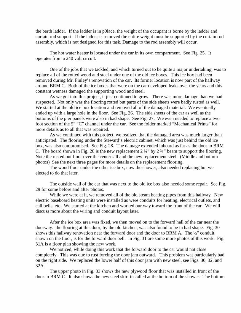
We did some extensive rewiring of the under car conduits. As we did this, we made diagrams to show where all of the conduits were located and where they originated and terminated. Then we documented each and every wire that was in these conduits. See Fig. 40 for an idea as to the under car conduit layout. The next 10 pages document all of these wires, which ones are in each conduit, and what is each wire’s function. Several of these pages show the routing of some of the more important circuits. Also there is a a list of the spare wires that we pulled in for future applications. The main electric locker (near the kitchen) has three circuit breaker panels and a large box containing four switches. See Fig. 41. The top two CB panels, #1 and #2, are also shown in Figs. 41A and 41B. These panels are 240 volt three phase. Panel #1 is for the lighting, appliances, and some heating circuits. Panel #2 is for the air conditioning and some more heating circuits. Not all of the CB positions have been utilized; we pulled in many extra wires for future use. These unused circuits are: stove, air pump, water and sanitation tank freeze protection, Diesel engine block heaters, and one side of the lounge heating. The bottom two circuit breakers in Panel #2 are for the lounge heating. They are powered by a relay, which in turn, is controlled by the lounge thermostat. We will expand on this when we discuss the heating circuits. The 120 volt CB Panel #3 is normally powered by two 240 to 1209 volt single phase transformers. A 3 KVA transformer is for the appliances and is designated transformer A. A 2 KVA transformer is for the lighting and is designated transformer B. The 120 volt CB panel is split between these two transformers. See Figs. 42 & 42A for the designated circuits and some of the wire identification. Some of the wire colors used at the Steward’s CB panel is on the next page. The wiring colors for the two transformers are also shown. As you can see, there are a total of four CB panels on the car. There are four selector switches on the switch panel box in the main electric locker, see Fig. 41. Each one of the CB panels (#1, #2 & #3) has a power selector switch associated with it. These switches select which power source will be used to provide power to that panel. The two 240 volt panels, #1 and #2, use a three position switch to obtain their input power. There are three different sources, Generator #1, Generator #2, and Standby/Shore power (STBY). See Fig. 43 for the wiring of these switches. When we began to install the HEP on the car, we decided that it would be easier to add a two position, three phase master switch in series with the standby wires rather than change the two selector switches for panels #1 and #2. This is a large switch in the upper right corner of the switch box. The purpose of this switch is to select either HEP or STBY power. See Figs. 44 and 44A for the wiring diagrams. As mentioned previously the 120 volt CB panel, PANEL #3, can obtain power from three different sources. The selector switch for this panel is a four position switch. See Fib. 45. In the extreme right hand position, this switch will provide power from the 120 volt under-car receptacle. This receptacle is located next to the AC compressor. In the next position, power will be obtained from the 240 to 120 volt transformers. The third position, or center position, is the OFF. The last position, on the extreme left, is for the 32 volt train line connection.

There is a small panel, in the main electric locker, to the right of CB Panel #1, which should be explained. See Fig. 46. 12 volts DC is required in order to operate the call bell system. We elected to obtain this supply voltage from the Diesel generator starter batteries. The top most switch is used to select from which generator battery the power will be obtained, A or B. The second switch is used to direct the output of a small battery charger to either of the generator batteries. It also will turn on this charger. We felt that a small battery charger, that could be used to maintain the batteries during periods of non-use of the generators, would be a good idea. We have not yet installed this battery charger. The next switch, moving down to panel, is to turn on the air conditioner heater. This is actually a small circuit breaker rather than a switch. This is for a small heating element under the AC compressor used to keep the oil warm. The bottom two switches are small circuit breakers used to provide protection for the wiring to the two panel voltmeters. These voltmeters are positioned on the generator control panel located in the kitchen. In each of the two 240 volt CB panels there are ammeter shunts. This was provided so that the three phase current drawn by each panel can be observed. There are switches on the generator control panel to activate the various meters. See Fig. 46A for the wiring of this panel, and Figs. 46B and 46C for more wiring information.
Call Bells
The call bell system for La Condesa as originally designed had 12 call “stations”. The lounge was divided up into 8 “stations”, four on each side. There were also four additional call bell buttons for the rear door., writing desk, toilet, and the section seats. As such, the annunciator display box has 12 “drops”. Whenever any call bell button was pressed, a small metal “drop”, with a number or a letter on it, would drop down into view at the display box. A bell would also ring to ensure the Porter’s attention. This “drop”, with its number or letter, would then indicate the location, on the car, of the person who rang the bell, hence the name call bell. The lounge had numbers 1 to 8, with numbers 1 and 2 on opposite sides, nearest the open platform. The letter “P” was for the platform door, “T” FOR THE TOILET, “s” FOR THE SECTION SEATS, AND “d” FOR THE WRITING DESK. The section seats have two call bell buttons, one for each seat, but they both cause the same “S” indicator to drop. Since Mr. Finley added three bedrooms to the car, we had to modify the annunciator system to accommodate these changes. We did this by combining the 8 lounge “stations” into four. See Figs. 47, 47A, 47 B, and 47C for more information. This then freed up four “drops” for other uses. We used three of them for the bedrooms and added a call bell button at the forward door. There is a terminal strip that connects some of the annunciator wires to the new call bell wires and it is located on the ceiling of the small locker to the left of the kitchen locker. See Fig. 48. The call bell wires for BRMs B and C are in the bedroom side communications conduit. While we were doing all of this new wiring, we added extra wires for possible future use. At the main electric locker, there are some of these extra wires. See Fig. 48A. There is a two wire shielded cable that runs to the forward door. This cable could be used for a possible future intercom at the forward door. There is also an extra three wire cable that crosses over to the annunciator terminal strip, currently not sued. We also ran in an extra three wire cable to the forward door. There are also four other unconnected wires in the main electrical locker which should be discussed. The purple and blue wires are from the battery charger switch, previously described, and

can be used to turn on this charger. These wires are in series with the charger switch and are connected whenever the battery charger switch is placed in either the A or B position. The black wire is for the positive charger output and the white wire is the negative return. The communication wiring at BRM A is shown in Figs. 49 and 49A. We pulled all of the wires into a junction box located in the corner locker of that room. The distribution of these wires and the spare wires is shown. Figs. 49B and 49C show more of the hall side communications wiring. Fig. 50 shows the hall side conduit layout for the power and communications. One project that we undertook was to replace all of the plumbing in the car. We did not complete this job, but we did change out all of the plumbing from the kitchen to BRM A. More on this later. While we were at it, we also put in a communication conduit on the bedroom side of the car. See Fig. 51. This conduit contains four cables, a 6 wire telephone line, a three wire call bell line, a three wire shielded spare line, and a two wire spare line. See Fig. 51A for more details. To summarize, the call bell wires for BRM A are in the hall side conduit and the call bell wires for BRMS B & C are in the bedroom side conduit.
Heating
The master plan for the heating is shown in Fig. 52. We planned on a total connected load of 15,000 watts. All of the heating elements have been installed except for the general toilet and the bedroom side of the lounge. The next three pages show our design work. See Fig. 41A and you will note that there are a total of six circuit breakers for heating. The overhead CB has not been hooked up. The kitchen heat DB and the forward hall CB are in the top box, Panel #1. The remaining four are all in the next box, Panel #2. We tried to split the heating load between the two generators. The bottom two CBs in Panel #2 are not connected to the main bus bars in this box. We split them off so that they could be energized by a thermostatically controlled relay. This relay is mounted in Panel #2 and operated by the lounge thermostat located on the hall side wall of the lounge. Fig. 53 shows the layout of the bedroom heaters and the power conduit. Each bedroom has its own thermostat. We added one 120 volt outlet in BRMs A & B and two in BRM C. See Fig. 53A for the wiring diagram. Note that the three wires from the Stewards CB panel are for the kitchen refrigerator outlet. How these wires get there, I don’t remember.
Plumbing
As mentioned before, we removed all of the old plumbing from the kitchen to BRM A. This was necessary because Mr. Finley has used galvanized pipe in several locations and we wanted to add a few things. See Fig. 54 for the work done in BRM A. The top photo is of the space used for the location of the new baseboard heater. This is after we had removed all of the old piping and cleaned up the outside wall of the car. We used “unistrut” to mount the new pipes and conduits. As mentioned previously, we also added two ½” conduits to this side of the car for power and communications. We started out new plumbing at the toilet in this room. This middle photo in Fig. 54 is after we installed the electric heater using homemade brackets. It should be mentioned that we installed two ½” hot water pipes. This was so that we could install a circulating pump in the hot water lines to keep these pipes hot and in that way save water. One pipe is the feed and the other the return. They are looped together at the toilet. With

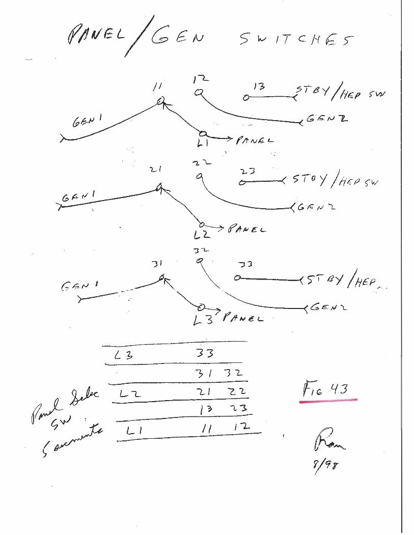
this arrangement, passengers w2ould not have to let this water run until it got hot at their sink. A thermostat and 120 volt outlet for this room were installed in the armrest of the sofa seat. We also put in a ½” copper line for an air supply to all of the toilets for future installation of “Microphor” toilets. The bottom photo is of the left side of the heater near the sofa seat. To reiterate, the top pipe is the air supply, the next two are the hot water lines, the fourth pipe is for cold water and the bottom pipe is the power conduit. See Fig. 54AS for a schematic representation. Not shown is the finished job with the radiator cover in place. Fig. 55 is of the installation of BRM B. The top photo shows all of the piping in the area that is now behind the “Microphor” toilet. The tap off connections to the air line and cold water pipe are visible. To the left is a small 500 watt heater, mounted also with specially made brackets. The next photo shows the left side of this heater where it abuts the closet wall. The hot and cold water pipe fittings for the sink are protruding through the board used for mounting the radiator cover. The sink drain pipe is in front of the heater. Fig. 55A is a schematic diagram of this room. A thermostat and 120 volt outlet were added to the wall near the sofa seat. In Fig. 56 the piping is shown as it traverses the bottom of the small closet in BRM B. The top photo is before we installed the cover, which is shown in the bottom photo. Note the small electrical box on the right side,. This is for the call bell connection for this room and is connected into the communications conduit. The “Wiremold” conduit shown on the left in the bottom photo is for the hall thermostat connection. The “hall” indicated in the drawings is actually the space in front of the shower. Fig. 57 shows the work done there. In the top photo, the right hand wall is that of BRM B. The four pipes and two conduits are shown as they exit BRM B. On the left you can see the old shower pipes. They are the ones going up in the photo. Also shown is the 4” electrical box that we added in the power conduit line. A ½” conduit from this box goes under the car and a ¾” conduit connects to the electric box in the lower part of the Steward’s locker. This conduit was previously mentioned, see Fig. 33 lower left photo, as a spare conduit to cross over from one side of the car to the other. In the middle photo one of the new floor support beams that we added is visible. The bottom photo is a more detailed view of this area near the 4” box. Also shown are the new water lines to the shower, complete with shut off valves. The top photo in Fig. 58 is after we installed the 500 watt heater. The bottom photo is of the almost complete installation. The thermostat for this heater is located on the wall to the right. See Fig. 58A for more details. We then moved on into BRM C where we encountered several problems. The top photo in Fig. 59 is what we uncovered when we removed the flooring near the old ice box, now the shower. As can be seen, the ice water seeping from this former ice box rusted out quite an area of the steel sub-flooring. The bottom photo is of the same area but also shows the old piping arrangement to the sink and toilet in this room. The wood flooring can be seen as well as the perpendicular cross beams. Finley’s people just notched the flooring to accommodate the piping. The top photo in Fig. 60 is of the repaired area next to the old ice box, complete with new cross beams. We were able to get the p0iping through the shower area by using the old steam line passageway along the outer wall of the car. The black area next to the repaired section is of the old steel sub-floor that was covered with tar, by Pullman, before the insulation was put in. The old insulation was in the form of batts that were also tarred and then were nailed to small black wooded strips that ran across the car.

The middle photo shows the initial work of installing the plumbing for the sink and toilet in this room. The area next to the shower has been completed and new plywood and insulation installed. The black area where the new pipes are is again the old steel sub-floor. The small black wood strips shown are those used for holding the old insulation in. Also shown is the small electrical junction box installed in the communication line and the larger 4” box installed in the power conduit. Note that the cold water pipe has now been increased in size to ¾”. The bottom photo is of the completed installation of the crossover piping. The pipes are installed beneath the floor but on top of the white insulation. Shut off valves for these three pipes were also installed. In Fig. 61 are shown more of the plumbing and wiring details. A new plywood floor has been installed over the crossover piping. The lower photo shows the 1000 watt heater installed, attain using custom made brackets. We also installed two 120 volt wall outlets in this room and a jack for the telephone. See Fig. 61A for a schematic diagram. Fig. 62 shows the piping to the “combolet” in this room. The top photo is of the area occupied by the desk before the flooring was put back. The middle photo is after the flooring was replace. The bottom photo is of the outside wall of BRM C after the radiator covers were installed. Note the trap door for reaching the shut off valves. We next moved on to the kitchen. The top photo in Fig. 63 is of the piping beneath the kitchen sink. The bottom photo is of the piping behind the stove. The small pipe in the upper portion of this photo is the gas line to the stove. We had to move all of the pipes away from the wall of the car in order to get into the locker, which was the next location for the plumbing. Fig. 63A is a piping diagram for the kitchen and the adjacent closet. The closet or locker next to the kitchen stove is where we ended our plumbing job. Fig. 64 is a photo of where we left off. The main water feed for the car comes up through the floor in a ¾” brass threaded pipe. We added a shut off valve into our ¾” copper feed line. We also added a tap off for a pressure gauge, which was mounted on the wall above the stove. This gauge will read the actual water pressure. A tap off was also added into the air line and a second gauge was mounted next to the first one. This gauge will read the air pressure to the toilets. Our ½” hot water feed line was temporarily connected to the old brass hot water line as it comes from the general toilet,. We included a shut off valve in this line and it is the stainless steel flexible pipe shown in the photo. We naturally capped the hot water return line. The communication conduit was connected to the rest of the system. See Fig. 51A. The power conduit has not been connected since we elected to bring all of the necessary wiring up through the 4” box shown in Fig. 57. Fig. 64A may be of some help in locating the various pipes. Figs. 65 and 65A show the installation of the “Microphor” toilet in BRM B. The top photo, in Fig. 65, is after we plugged the old toilet drain hole that went through the floor. The black PVC pipe is the new drain. The middle photo is after we installed the wood frame from the old toilet housing, the toilet itself, and all of the air and water lines. We wanted to utilize the old toilet housing as much as possible. The air sequencing valve with its multiple colored hoses can be seen against the back wall. The red knob protruding from the wood housing is to shut off the water supply in the event of a failure of the sequencing valve to shut off the water. The bottom photo is another view of the installation. We wanted to preserve the old toilet’s unique pull up knob feature to flush so we had to mount the actual flush knob near the floor. Note its location on the floor near the end of the radiator grill. The air pressure regulator and oiler are located on the left side wall.

Fig. 65A is after the shroud was installed and the old original seat. The upholstered seat is in the upright position. Also shown is the sanitation holding tank that was fabricated for the car. This tank was custom made to fit where the old propane locker was on the car. This location is directly beneath the shower. The tank has a capacity of about 138 gallons. There are four 1 ½” threaded openings for the four eventual toilets. There are two 2” drain holes, one on each end, a clean out plug on the front, and a vent hole in the back. One of the drain holes has been plumbed with two shut off valves and a discharge outlet. The piping is such that a second discharge outlet can be run to the opposite side of the car. The tank was hung using the four original brackets from the old locker and adding two newly fabricated ones. Since this sanitation tank is directly under the shower, we had to repair the wood beneath the shower before installing the tank. Fig. 66 shows the underside of the shower before restoration. The round tube in the center is the old ice box drain, now the shower drain. This drain had to be routed around the new holding tank. The photo shows some of the rotted wood. A new ½” conduit is on the right. The photo was taken before the floor repair work in BRM C was completed, so you can see right into BRM C. The blue object is a tank vacuum cleaner in this bedroom. See Figs. 66A and 66B for more details.
Water Raising System
All railroad cars used air pressure to bring the water from the under car tank up into the car. The old water raising system used a governor and a reducing valve to accomplish this. We had to replace these units due to leaks. See Fig. 68 for more details of the old valves that Pullman had installed. Someone may be able to rebuild them. Fig. 67 shows the new repiping of the air system in one end of the water tank. We replaced the old reducing valve with one manufactured by Wilkerson and the governor valve with one by Teel. Air from the air brake system goes through the governor valve and then to the APW (Air Pressure Water) reservoir. This pressure will be at whatever the train line brake pressure is, usually 110 psi for a passenger train. The governor is usually set for 60 psi. In this way, if the brake pipe pressure is less than 60 psi, the valve remains closed. Only when the pressure exceeds 60 psi, will the valve open. This is to prevent the water raising system from bleeding off the brake pipe when it is below 60 psi. Air from the APW tank was piped to the reducing valve and then to the water tank. The reducing valve was set to maintain a pressure of 30 psi on the water tank. While we were at it, we added a line to go up into the car for the air supply for the toilets and a line into the locker under the main toilet for a future air pump installation. In Fig. 67 the black item with the handle, which is on the left, is the governor valve. The regulated is on the right with the gauge on the top. We added three air gauges, one to measure the brake pipe pressure, one to indicate the APW tank pressure, and one for the water tank pressure. The wires shown in the water tank housing are for the eventual installation of the water tank protection heaters, the kitchen stove, and for the kitchen outlets. See the first page after Fig. 40 for more details. In Fig. 68 and the flowing pages are shown the old governor and reducing valves.
Amtrak HEP Modifications

In a separate envelope are some pictures of the HEP, MU, and the 27 pt connector locations. Dimensions for these connectors are also included. Figure 101 shows “gauge showing where HEP location should be OBS end”. Figure 102 shows “gauge showing where HEP location should be OBS end”. Figure 103 shows “gauge shows location of HEP connector forward end of car left side”. Figure 104 shows “HEP location forward end”. Figure 105 shows “HEP location right side forward end”. Figure 106 shows “required HEP location forward end”. Figure 107 shows “possible HEP location forward end”. Figure 108 shows “M.U. & 27 point location OBS end”. Figure 109 shows “test fit for M.U. Connector”. Figure 110 shows “test Fit for 27 point connector”. Figures 111 – 116 show Amtrak HEP specifications.
Final Thoughts Some last thoughts and ideas. The old steam pipes need to be removed from the bedroom side of the lounge and replaced with an electric heater, wiring for this is already in place. The plumbing needs to be continued into the general toilet and then to the bar area and a new toilet installed. An air pump should be added and piped into the water raising system for more convenience in getting running water in the car. HEP wiring and the step down transformers also need to be added. MU and communication 27 point wiring is up to you. The platform steps need to be removed and all of the accumulated rust removed. Several of the bolts that hold the steps to the car have already fractured.


![Map of Chapultepec, Condesa and Polanco - [Metropolis 2015]metropolis2015.unam.mx/pdf/condesainglespw.pdf · Map of Chapultepec, Condesa and Polanco. ... Av. Michoacán (14) ... M.](https://static.fdocuments.in/doc/165x107/5bc4455b09d3f274118b8355/map-of-chapultepec-condesa-and-polanco-metropolis-2015-map-of-chapultepec.jpg)