L42110EN Spindl-Gard SG-1/SG-2 System Operation ... Spindl-Gard SG-1 and SG-2 Systems L42110 1.3.2.2...
37
Spindl-Gard ® SG-1/SG-2 System Operation & Service Instructions
Transcript of L42110EN Spindl-Gard SG-1/SG-2 System Operation ... Spindl-Gard SG-1 and SG-2 Systems L42110 1.3.2.2...

Spindl-Gard® SG-1/SG-2 System Operation & Service Instructions


L42110Spindl-Gard SG-1 and SG-2 Systems
TABLE OF CONTENTS
Section/Para Page
1 Introduction ..................................................................... 1-1
1.1 Purpose of Manual ............................................................ 1-1
1.2 Spindl-Gard Overview ....................................................... 1-1
1.3 SG-1 Components and Operation Overview ....................... 1-1
1.4 SG-2 Components and Operation Overview ....................... 1-4
2 Installation Guidelines..................................................... 2-1
2.1 General ............................................................................. 2-1
2.2 SG-1 System Installation ................................................... 2-1
2.3 SG-2 System Installation ................................................... 2-6
3 System Startup and Operation ........................................ 3-1
3.1 General ............................................................................. 3-1
3.2 System Filling and Bleeding .............................................. 3-1
3.3 Daily Start-Up ................................................................... 3-5
3.4 Operation .......................................................................... 3-6
3.5 Shutdown ......................................................................... 3-6
4 Troubleshooting ............................................................... 4-1
4.1 General ............................................................................. 4-1
4.2 Troubleshooting SG-1 Components ................................... 4-1
4.3 Troubleshooting SG-2 Components ................................... 4-2
5 Parts Ordering Information ............................................. 5-1
5.1 General ............................................................................. 5-1
5.2 SG-1 Spray Nozzle ............................................................ 5-2
5.3 Mixing Tee ........................................................................ 5-4
5.4 Nozzle Adapter .................................................................. 5-5
5.5 Easy to Replace Nozzle Adapter ........................................ 5-6
LIST OF ILLUSTRATIONS
Item Page
1-1 SG-1 System .................................................................... 1-2
1-2 SG-2 System .................................................................... 1-5
2-1 Spindl-Gard Installation .................................................... 2-2
2-2 Typical Spray Nozzle Installation ....................................... 2-3
Item Page
2-3 SG-1 Typical Machining Head Modification ....................... 2-4
2-4 Reversing Seals ................................................................ 2-4
2-5 Pump and Header Installation ........................................... 2-5
2-6 Nozzle Tube Applications .................................................. 2-6
2-7 Nozzle Tube Installation .................................................... 2-7
2-8 Mixing Tee ........................................................................ 2-8
2-9 Air Flow Switch Installation ............................................... 2-9
2-10 Air Flow Switch and Mixing Tees ................................... 2-10
3-1 Filling Secondary Divider Valves Supply Tubes .................. 3-3
3-2 Bleeding Secondary Divider Valves ................................... 3-3
3-3 Bleeding Pump-Supplied Master Divider Valve .................. 3-4
3-4 Bleeding Header-Supplied Master Divider Valve ................ 3-4
3-5 Typical Indicator Pin and Cycle Switch .............................. 3-5
4-1 Spray Nozzle .................................................................... 4-3
4-2 Mixing Tee ........................................................................ 4-3
5-1 Spray Nozzle Parts Identification ....................................... 5-3
5-2 Missing Tee ...................................................................... 5-4
5-3 Nozzle Adapter ................................................................. 5-5
5-4 Easy to Replace Nozzle Adapter ........................................ 5-6
LIST OF TABLES
4-1 System Troubleshooting ................................................... 4-2
5-1 Standard System Components ......................................... 5-1
5-2 SG-1 Components ............................................................ 5-1
5-3 SG-2 Components ............................................................ 5-1
5-4 Spray Nozzle (Figure 5-1) Parts List .................................. 5-3
5-5 Mixing Tee (Figure 5-2) Parts List ..................................... 5-4
5-6 Nozzle Adapter (Figure 5-3) Parts List ............................... 5-5
5-7 Easy to Replace Nozzle Adapter (Figure 5-4) Parts List ..... 5-6

1-1
Spindl-Gard SG-1 and SG-2 Systems L42110
1.1 PURPOSE OF MANUAL
1.1.1 This manual is designed for users of Spindl-Gard systems designated SG-1 (for multi-spindle heads) and SG-2 (for precision spindles). Procedures and instructions are pro vided for installation, start-up, operation, troubleshooting and maintenance. Although the components and assemblies used will vary between different systems there are common rules and procedures which apply to any installation.
1.1.2 The SG-1 and SG-2 systems use many similar com-ponents and some procedures discussed in the manual apply to both types of systems. If procedures differ between the systems, the procedures are covered separately to allow the user to quickly locate the specific area of concern. A table of contents is provided at the start of each section to allow for quick and easy reference.
1.1.3 Refer to Bulletin L20110 for additional SG-1 and SG-2 system and product specifications.
1.2 SPINDL-GARD OVERVIEW
Spindl-Gard was developed to lubricate single and multi-spindle machining heads. A unique spray nozzle utilized with other Spindl-Gard components provides precise amounts of oil to a specific bearing surface. Oil is applied at the proper frequency and in the right quantity to meet the lubrication requirements, keeping bearings, gears, shafts and seals run ning cool. Spindl-Gard provides full protection without over-or under-lubing.
1.3 SG-1 COMPONENTS AND OPERATION OVERVIEW
1.3.1 General. SG-1 utilizes a standard Trabon pump package (typically, Graco’s Modu-Flo® series), a Model MSP lubricant divider valve with cycle indicator switch, Maxi-Monitor® controller, and various fluid line accessories. (See Figure 1-1.) In some cases, the machine controller will be used in lieu of the Maxi-Monitor controller. Each shot of lubricant from the pump is distributed by the divider valve to the appropriate lube point. Depending upon machining head design, some bearings may receive lubricant directly from the divider valve while others, including gears, may receive lubricant from spray nozzles located in the gear cavity. Pressure switches may be used to monitor air pressure in the machining head. By using the feedback features of the divider valve, it is possible to monitor lubricant and pressure delivery status to all points at all times. An SG-1 circuit is shown in Figure 1-1.
1.3.2 SG-1 Components
1.3.2.1 General. Paragraphs 1.3.2.2 through 1.3.2.9 pro vide a brief description of components used in typical SG-1 systems. See Section 5, parts ordering information, for corre sponding part numbers.
SECTION 1INTRODUCTION
1.1.PURPOSE OF MANUAL ...................................................... 1-1
1.2. SPINDL-GARD OVERVIEW .............................................. 1-1
1.3.SG-1 COMPONENTS AND OPERATION OVERVIEW .............. 1-1
1.3.1 General ................................................................. 1-1
1.3.2 SG-1 Components ................................................. 1-1
1.3.3 SG-1 Operation ..................................................... 1-3
1.4.SG-2 COMPONENTS AND OPERATION OVERVIEW .............. 1-4
1.4.1 General ................................................................. 1-4
1.4.2 SG-2 Components ................................................. 1-4
1.4.3 SG-2 Operation ..................................................... 1-4
OPERATION AND SERVICE INSTRUCTIONS

Spindl-Gard SG-1 and SG-2 Systems
1-2
L42110
Figure 1-1. SG-1 System

1-3
Spindl-Gard SG-1 and SG-2 Systems L42110
1.3.2.2 Controller. Several means of control are available for the SG-1. Operation can be controlled by signals from user’s machine control or by one of several controllers avail able from Graco as follows:
WMP Maxi-Monitor• ®: This microprocessor-based con troller can be used to schedule and initiate lube cycles on a machine cycle or time basis as well as to relay fault conditions.
Solid-State Timer: This solid-state timer can be •used to initiate lube cycles on a time basis. A built-in memory retains the cycle time for 1-1/2 hours during power failure or machine shutdown to resume from the point where it was suspended.
Flexi-Monitor: Utilizing the latest solid-state •programmable control technology, the Flexi-Monitor controls complex multiple-zone lubrication systems. Not only does the Flexi-Monitor control lubrication cycles, but it can monitor and report every aspect of the lubrication system; including temperature, vibration, fluid flow, pressure, and system operating status.
1.3.2.3 Pump Package. Several types of pump packages are available to supply oil to the Spindl-Gard system. Most applications use a Modu-Flo series pump package equipped with a reservoir sized to the system requirements. This series of pumps may either be pneumatic- or hydraulic-powered and is available in different lube output capabilities to fit the specific requirements of each system.
1.3.2.4 Filter. A 10-micron filter placed in the outlet line of the pump provides filtration of oil entering the system. A final ten-micron oil filter at the divider valve inlet provides the final filtration before oil enters the divider valve.
1.3.2.5 Divider Valve. This valve meters the precise amount of oil required for each Spindl-Gard nozzle or terminating lube point. The divider valve consists of stackable sections, each of which can provide oil to one or two lube points. The sections can be arranged to provide metered oil to up to sixteen lube points. A valve section can be supplied with a cycle indicator pin to provide visual indication that the divider valve is cycling. The indicator pin can also be used to actuate a cycle switch which then provides a signal to the system controller.
1.3.2.6 Cycle Switch. The cycle switch is a limit switch which is actuated by the movement of the cycle indicator pin. If a blockage occurs in a lube line, the divider valve will not cycle and the cycle switch will not be actuated. If the switch is not actuated within a set time period, the controller pro vides a warning signal.
1.3.2.7 Proximity Switch. The proximity switch is a proximity-type sensor which is attached to the valve section of the divider valve and senses the movement of the divider valve piston during cycling. The proximity switch provides a signal that is used to monitor the system in the same manner as the cycle switch.
1.3.2.8 Spindl-Gard Spray Nozzle. The basic nozzle can be installed in heads with walls up to 1-3/4 inches (44.4 mm) thick. It has separate 1/8 inch NPT inlet ports for air and oil. Nozzle design and system air pressure (15 psi (1 bar) at noz zle inlet) combine to provide a 60 degree conical spray pat tern.
1.3.2.9 Soft-Seat Check Valve. This valve, installed at the bearing point, prevents oil drainage of the oil lines and pre vents air from entering the oil lines. An optional use is installing the check valve at the lube inlet of the spray nozzle.
1.3.2.10 2-psi Relief Valve. Installed at the lowest point of the machining head gear cavity, this valve serves the following functions:
It maintains a positive internal head pressure to •prevent coolant and other contaminants from entering the head.
By relieving at 2 psi, it prevents build-up of •excessive pressure which could interfere with proper oil disper sion.
It keeps the gear cavity dry by providing a simple •means to drain off oil that would otherwise collect.
1.3.2.11 Pressure Switch. An optional 1-psi pressure switch mounted to the machine head can be used to detect changes in air pressure within the machining head cavity due to broken air lines, clogged spray nozzles or worn seals.
1.3.3 SG-1 Operation
NOTE: Refer to Figure 1-1 for item numbers refer enced in the descriptive paragraphs below.
1.3.3.1 The pump (1), and controller (3) are mounted on an easily accessible part of the machine. The controller ener gizes the pump at predetermined intervals to supply lubricant to the system. The divider valve (7) with cycle switch or prox imity switch (4) supplies lubricant to either spray nozzles or terminating lube points. The cycling of the divider valve is monitored by the controller through an electrical signal gen erated by either the cycle switch or proximity switch. A pump failure, power failure, loss of lubricant, plugged or crushed lube line, or broken supply line would prevent the cycle switch or proximity switch from producing the required signal to the controller, which would register a fault condition.
1.3.3.2 The spray nozzle (9), supplied with constant clean dry air (approximately 40 ºF (4.4 ºC) dewpoint, 5-micron absolute filtration, at 15 psi (1 bar)), pressurizes the machin ing head and supplies intermittent lube in the form of a spray to the gears and bearings in the machine head cavity. Air consumption is 0.6 scfm (17 sclm) per nozzle. A relief valve (10) inserted at the lowest point of each machining spindle cavity maintains positive air pressure at 2 psi (0.14 bar). It also provides a simple means to drain off any collected oil in the machine head
Spindl-Gard SG-1 and SG-2 Systems
1-4
L42110
cavity. Soft-seat check valves (8) must be installed at the end of any line coming out of the divider valve that will be delivering oil directly to terminating lube points. These checks prevent oil drainage from, or air entrance into, the oil lines.
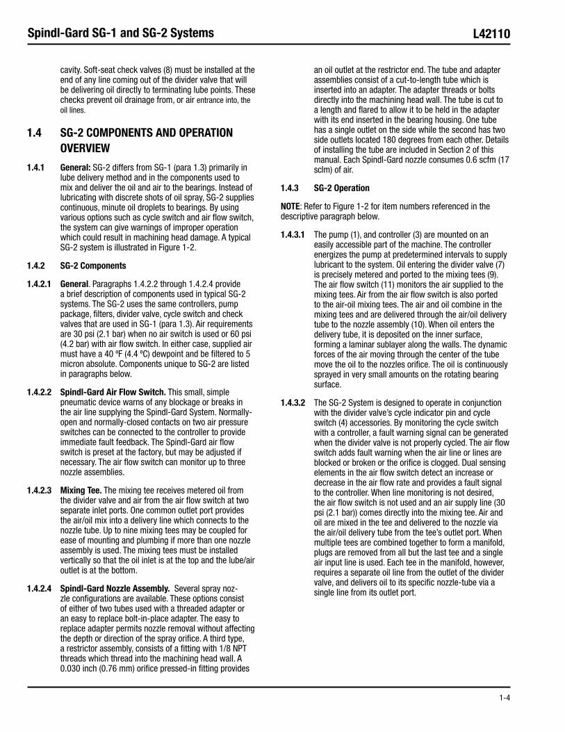
1.4 SG-2 COMPONENTS AND OPERATION OVERVIEW
1.4.1 General: SG-2 differs from SG-1 (para 1.3) primarily in lube delivery method and in the components used to mix and deliver the oil and air to the bearings. Instead of lubricating with discrete shots of oil spray, SG-2 supplies continuous, minute oil droplets to bearings. By using various options such as cycle switch and air flow switch, the system can give warnings of improper operation which could result in machining head damage. A typical SG-2 system is illustrated in Figure 1-2.
1.4.2 SG-2 Components
1.4.2.1 General. Paragraphs 1.4.2.2 through 1.4.2.4 pro vide a brief description of components used in typical SG-2 systems. The SG-2 uses the same controllers, pump pack age, filters, divider valve, cycle switch and check valves that are used in SG-1 (para 1.3). Air requirements are 30 psi (2.1 bar) when no air switch is used or 60 psi (4.2 bar) with air flow switch. In either case, supplied air must have a 40 ºF (4.4 ºC) dewpoint and be filtered to 5 micron absolute. Components unique to SG-2 are listed in paragraphs below.
1.4.2.2 Spindl-Gard Air Flow Switch. This small, simple pneumatic device warns of any blockage or breaks in the air line supplying the Spindl-Gard System. Normally-open and normally-closed contacts on two air pressure switches can be connected to the controller to provide immediate fault feedback. The Spindl-Gard air flow switch is preset at the fac tory, but may be adjusted if necessary. The air flow switch can monitor up to three nozzle assemblies.
1.4.2.3 Mixing Tee. The mixing tee receives metered oil from the divider valve and air from the air flow switch at two separate inlet ports. One common outlet port provides the air/oil mix into a delivery line which connects to the nozzle tube. Up to nine mixing tees may be coupled for ease of mounting and plumbing if more than one nozzle assembly is used. The mixing tees must be installed vertically so that the oil inlet is at the top and the lube/air outlet is at the bottom.
1.4.2.4 Spindl-Gard Nozzle Assembly. Several spray noz-zle configurations are available. These options consist of either of two tubes used with a threaded adapter or an easy to replace bolt-in-place adapter. The easy to replace adapter permits nozzle removal without affecting the depth or direc tion of the spray orifice. A third type, a restrictor assembly, consists of a fitting with 1/8 NPT threads which thread into the machining head wall. A 0.030 inch (0.76 mm) orifice pressed-in fitting provides
an oil outlet at the restrictor end. The tube and adapter assemblies consist of a cut-to-length tube which is inserted into an adapter. The adapter threads or bolts directly into the machining head wall. The tube is cut to a length and flared to allow it to be held in the adapter with its end inserted in the bearing housing. One tube has a sin gle outlet on the side while the second has two side outlets located 180 degrees from each other. Details of installing the tube are included in Section 2 of this manual. Each Spindl-Gard nozzle consumes 0.6 scfm (17 sclm) of air.
1.4.3 SG-2 Operation
NOTE: Refer to Figure 1-2 for item numbers refer enced in the descriptive paragraph below.
1.4.3.1 The pump (1), and controller (3) are mounted on an easily accessible part of the machine. The controller ener gizes the pump at predetermined intervals to supply lubricant to the system. Oil entering the divider valve (7) is precisely metered and ported to the mixing tees (9). The air flow switch (11) monitors the air supplied to the mixing tees. Air from the air flow switch is also ported to the air-oil mixing tees. The air and oil combine in the mixing tees and are delivered through the air/oil delivery tube to the nozzle assembly (10). When oil enters the delivery tube, it is deposited on the inner surface, forming a laminar sublayer along the walls. The dynamic forces of the air moving through the center of the tube move the oil to the nozzles orifice. The oil is continuously sprayed in very small amounts on the rotating bearing surface.
1.4.3.2 The SG-2 System is designed to operate in conjunc tion with the divider valve’s cycle indicator pin and cycle switch (4) accessories. By monitoring the cycle switch with a controller, a fault warning signal can be generated when the divider valve is not properly cycled. The air flow switch adds fault warning when the air line or lines are blocked or broken or the orifice is clogged. Dual sensing elements in the air flow switch detect an increase or decrease in the air flow rate and provides a fault signal to the controller. When line moni toring is not desired, the air flow switch is not used and an air supply line (30 psi (2.1 bar)) comes directly into the mixing tee. Air and oil are mixed in the tee and delivered to the noz zle via the air/oil delivery tube from the tee’s outlet port. When multiple tees are combined together to form a mani fold, plugs are removed from all but the last tee and a single air input line is used. Each tee in the manifold, however, requires a separate oil line from the outlet of the divider valve, and delivers oil to its specific nozzle-tube via a single line from its outlet port.

1-5
Spindl-Gard SG-1 and SG-2 Systems L42110
/(1-6 Blank)
Figure 1-2. SG-2 System

2-1
Spindl-Gard SG-1 and SG-2 Systems L42110
2.1 GENERAL
2.1.1 In order to specify the correct components for any particular system, a design process was completed by either plant personnel or a Graco® distributor representative. The design process determined the type and placement of nozzles, identified location of bearings, and of divider valve sizes. Obtaining the information from the design process makes installing the system easier and may help avoid confusion.
2.1.2 Installation of some system components requires drilling and tapping of the machining head walls.
CAUTION: A set of machining head prints should be used to ensure that no internal compo nents are damaged during this procedure.
2.2 SG-1 SYSTEM INSTALLATION
2.2.1 General: Paragraphs 2.2.2 through 2.2.8 discuss the installation and mounting of components of SG-1 systems. Paragraphs 2.2.9 and 2.2.10 discuss the final pneumatic and lube line connec tions which complete the installation process. The informa tion provided in these paragraphs is designed to apply to all applications. For information on the specific system, refer to information obtained from the design process. For reference during the following paragraphs, Figure 2-1 shows a sample machining head with some of the SG-1 components mount ed. Actual mounting position of most components will vary between systems.
2.2.2 Spray Nozzle Installation
2.2.2.1 The spray nozzle used in SG-1 systems has a 1-12 UNF thread along the portion that threads into the machining head walls. A locknut is used to secure the nozzle in position once the nozzle is properly positioned in the wall. Figure 2-2 shows SG-1 sample installations with the machine head mounted in a horizontal and vertical orientation.
2.2.2.2 The procedure for installing the spray nozzle is as follows:
Mark the location of spray nozzle installation as a. determined during system design.
CAUTION: Before drilling into walls, obtain machining head prints to locate internal components. Avoid striking gears, bearings or shafts during drilling.
Drill a 0.922 inch (23.42 mm) hole in spray nozzle b. location.
Tap hole to 1-12 UNF.c.
Make sure locknut and thread seal are installed d. on spray nozzle. Thread spray nozzle into tapped hole until the spray tip is at the required depth. The required depth will vary between Systems but is generally designed to provide the widest expanse of coverage possible with the 60 degree spray pattern. Make sure that the spray nozzle will not contact any gears when installed.
SECTION 2INSTALLATION GUIDELINES
2.1 GENERAL .......................................................................... 2-1
2.2 SG-1 SYSTEM INSTALLATION ............................................ 2-1
2.2.1 General ................................................................. 2-1
2.2.2 Spray Nozzle Installation........................................ 2-2
2.2.3 Terminating Lube Point Preparation ....................... 2-4
2.2.4 Relief Valve Installation .......................................... 2-4
2.2.5 Divider Valve Installation ........................................ 2-4
2.2.6 Pump Package and Header Installation .................. 2-5
2.2.7 Pneumatic Control Package Installation ................. 2-5
2.2.8 Electrical Requirements ......................................... 2-5
2.2.9 Pneumatic Connections ......................................... 2-5
2.2.10 Lube Line Connections ........................................ 2-5
2.3 SG-2 SYSTEM INSTALLATION ............................................ 2-6
2.3.1 General ................................................................. 2-6
2.3.2 Nozzle Tube Installation ......................................... 2-6
2.3.3 Air/Oil Mixing Tee ................................................... 2-7
2.3.4 Divider Valve Installation ........................................ 2-8
2.3.5 Air Flow Switch Installation .................................... 2-8
2.3.6 Pump Package and Header Installation .................. 2-9
2.3.7 Pneumatic Control Package Installation ................. 2-9
2.3.8 Electrical Requirements ......................................... 2-9
2.3.9 Pneumatic Connections ......................................... 2-9
2.3.10 Lube Line Connections ...................................... 2-10
OPERATION AND SERVICE INSTRUCTIONS

2-2
Spindl-Gard SG-1 and SG-2 Systems L42110
With spray nozzle installed at required depth, e. tighten locknut to keep the nozzle in position. Make sure air and lube ports on top and sides of spray nozzle are not obstructed by machining head components.
If optional soft-seat check valve is used on the f. spray nozzle, install check valve in lube port on top of nozzle.
2.2.3 Terminating Lube Point Preparation
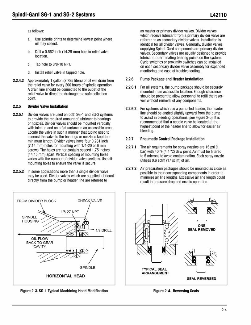
2.2.3.1 Some bearings located at the ends of shafts may be recessed too far in the wall for the spray pattern to provide adequate lubrication. For these cases, lubricant is provided directly to the bearing from the divider valve. It may be nec essary to drill passageways to reach these lubrication points. Figure 2-3 shows a typical machined passageway. In the example shown, the front bearing would not be exposed to lubricant from the spray nozzle. By drilling access holes to the bearing and providing a 1/8-27 NPSF hole for a soft-seat check valve, a line directly from the divider valve can supply the bearing with the proper amount of lubricant. Information from the design process should locate any bearings which need this treatment.
2.2.3.2 All inward-facing lip seals on the shaft should be reversed to face outward. Reversing the inward-facing seal reduces the possibility of contaminants entering the head. Figure 2-4 shows a typical seal arrangement on a vertical spindle shaft. Horizontal shafts require the same treatment.
NOTE:
If only one lip seal is used on a shaft, the seal •must face outward. Removal of one lip seal is only permitted if two seals are used in the equipment. Retaining springs must always be used.
If shaft is equipped with labyrinth or bronze seals, •extra air flow may be required to make up for excessive air loss. Contact a Graco representative for special proce dures if labyrinth or bronze seals are used.
2.2.4 Relief Valve Installation
2.2.4.1 A 2 psi (0.14 bar) relief valve is installed at the lowest point of the machining head gear cavity. The relief valve has a male inlet thread and a female outlet thread, both 3/8 NPT. The procedure for installing the relief valve is
Figure 2-1. Spindl-Gard Installation

2-3
Spindl-Gard SG-1 and SG-2 Systems L42110
Figure 2-2. Typical Spray Nozzle Installation
HORIZONTAL HEAD APPLICATION
VERTICAL HEAD APPLICATION
2-4
Spindl-Gard SG-1 and SG-2 Systems L42110
as follows:
Use spindle prints to determine lowest point where a. oil may collect.
Drill a 0.562 inch (14.29 mm) hole in relief valve b. location.
Tap hole to 3/8-18 NPT.c.
Install relief valve in tapped hole.d.
2.2.4.2 Approximately 1 gallon (3.785 liters) of oil will drain from the relief valve for every 200 hours of spindle operation. A drain line should be connected to the outlet of the relief valve to direct the drainage to a safe collection point.
2.2.5 Divider Valve Installation
2.2.5.1 Divider valves are used on both SG-1 and SG-2 sys tems to provide the required amount of lubricant to bearings or nozzles. Divider valves should be mounted vertically with inlet up and on a flat surface in an accessible area. Locate the valve in such a manner that tubing used to connect the valve to the bearings or nozzle is kept to a minimum length. Divider valves have four 0.281 inch (7.14 mm) holes for mounting with 1/4-20 or 6 mm screws. The holes are hori zontally spaced 1.75 inches (44.45 mm) apart. Vertical spac ing of mounting holes varies with the number of divider valve sections. Use all mounting holes to ensure the valve is secure.
2.2.5.2 In some applications more than a single divider valve may be used. Divider valves which are supplied lubricant directly from the pump or header line are referred to
as mas ter or primary divider valves. Divider valves which receive lubricant from a primary divider valve are referred to as sec ondary divider valves. Installation is identical for all divider valves. Generally, divider valves supplying Spindl-Gard com ponents are primary divider valves. Secondary valves are usually designed to provide lubricant to terminating bearing points on the system. Cycle switches or proximity switches can be installed on each secondary divider valve assembly for expanded monitoring and ease of troubleshooting.
2.2.6 Pump Package and Header Installation
2.2.6.1 For all systems, the pump package should be securely mounted in an accessible location. Enough clear ance should be present to allow personnel to refill the reser-voir without removal of any components.
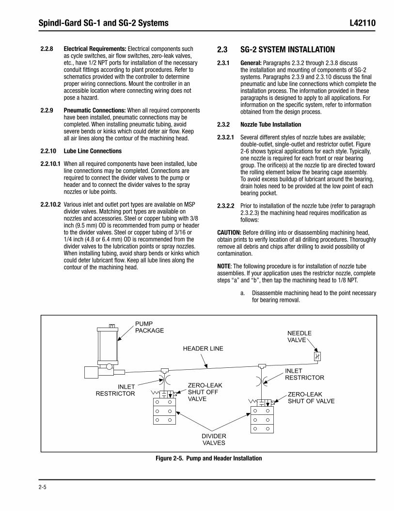
2.2.6.2 For systems which use a pump-fed header, the header line should be angled slightly upward from the pump to assist in bleeding operations (see Figure 2-5). It is recom mended that a needle valve be located at the highest point of the header line to allow for easier air bleeding.
2.2.7 Pneumatic Control Package Installation
2.2.7.1 The air requirements for spray nozzles are 15 psi (1 bar) with 40 ºF (4.4 ºC) dew point. Air must be filtered to 5 microns to avoid contamination. Each spray nozzle utilizes 0.6 scfm (17 sclm) of air.
2.2.7.2 Air preparation packages should be mounted as close as possible to their corresponding components in order to minimize air line lengths. Excessive air line length could result in pressure drop and erratic operation.
Figure 2-3. SG-1 Typical Machining Head Modification Figure 2-4. Reversing Seals
2-5
Spindl-Gard SG-1 and SG-2 Systems L42110
2.2.8 Electrical Requirements: Electrical components such as cycle switches, air flow switches, zero-leak valves, etc., have 1/2 NPT ports for installation of the necessary conduit fittings according to plant procedures. Refer to schematics provided with the con troller to determine proper wiring connections. Mount the controller in an accessible location where connecting wiring does not pose a hazard.
2.2.9 Pneumatic Connections: When all required components have been installed, pneu matic connections may be completed. When installing pneu matic tubing, avoid severe bends or kinks which could deter air flow. Keep all air lines along the contour of the machining head.
2.2.10 Lube Line Connections
2.2.10.1 When all required components have been installed, lube line connections may be completed. Connections are required to connect the divider valves to the pump or header and to connect the divider valves to the spray nozzles or lube points.
2.2.10.2 Various inlet and outlet port types are available on MSP divider valves. Matching port types are available on nozzles and accessories. Steel or copper tubing with 3/8 inch (9.5 mm) OD is recommended from pump or header to the divider valves. Steel or copper tubing of 3/16 or 1/4 inch (4.8 or 6.4 mm) OD is recommended from the divider valves to the lubrication points or spray nozzles. When installing tub ing, avoid sharp bends or kinks which could deter lubricant flow. Keep all lube lines along the contour of the machining head.
2.3 SG-2 SYSTEM INSTALLATION
2.3.1 General: Paragraphs 2.3.2 through 2.3.8 discuss the installation and mounting of components of SG-2 systems. Paragraphs 2.3.9 and 2.3.10 discuss the final pneumatic and lube line connec tions which complete the installation process. The informa tion provided in these paragraphs is designed to apply to all applications. For information on the specific system, refer to information obtained from the design process.
2.3.2 Nozzle Tube Installation
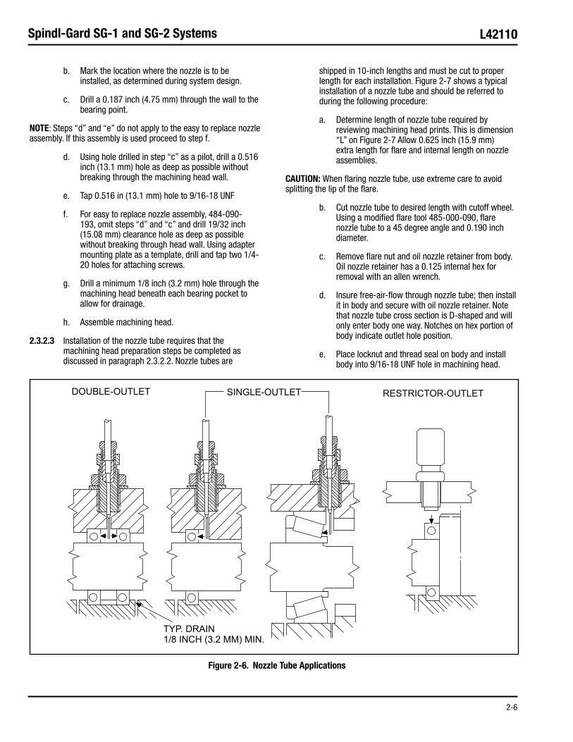
2.3.2.1 Several different styles of nozzle tubes are available; double-outlet, single-outlet and restrictor outlet. Figure 2-6 shows typical applications for each style. Typically, one noz zle is required for each front or rear bearing group. The ori fice(s) at the nozzle tip are directed toward the rolling ele ment below the bearing cage assembly. To avoid excess buildup of lubricant around the bearing, drain holes need to be provided at the low point of each bearing pocket.
2.3.2.2 Prior to installation of the nozzle tube (refer to para graph 2.3.2.3) the machining head requires modification as follows:
CAUTION: Before drilling into or disassembling machining head, obtain prints to verify location of all drilling procedures. Thoroughly remove all debris and chips after drilling to avoid possibility of contamina tion.
NOTE: The following procedure is for installation of nozzle tube assemblies. If your applica tion uses the restrictor nozzle, complete steps “a” and “b”, then tap the machining head to 1/8 NPT.
Disassemble machining head to the point necessary a. for bearing removal.
Figure 2-5. Pump and Header Installation
2-6
Spindl-Gard SG-1 and SG-2 Systems L42110
Mark the location where the nozzle is to be b. installed, as determined during system design.
Drill a 0.187 inch (4.75 mm) through the wall to the c. bearing point.
NOTE: Steps “d” and “e” do not apply to the easy to replace nozzle assembly. If this assembly is used proceed to step f.
Using hole drilled in step “c” as a pilot, drill a 0.516 d. inch (13.1 mm) hole as deep as possible without breaking through the machining head wall.
Tap 0.516 in (13.1 mm) hole to 9/16-18 UNFe.
For easy to replace nozzle assembly, 484-090-f. 193, omit steps “d” and “c” and drill 19/32 inch (15.08 mm) clearance hole as deep as possible without breaking through head wall. Using adapter mounting plate as a template, drill and tap two 1/4-20 holes for attaching screws.
Drill a minimum 1/8 inch (3.2 mm) hole through the g. machining head beneath each bearing pocket to allow for drainage.
Assemble machining head.h.
2.3.2.3 Installation of the nozzle tube requires that the machining head preparation steps be completed as discussed in paragraph 2.3.2.2. Nozzle tubes are
shipped in 10-inch lengths and must be cut to proper length for each instal lation. Figure 2-7 shows a typical installation of a nozzle tube and should be referred to during the following procedure:
Determine length of nozzle tube required by a. reviewing machining head prints. This is dimension “L” on Figure 2-7 Allow 0.625 inch (15.9 mm) extra length for flare and internal length on nozzle assemblies.
CAUTION: When flaring nozzle tube, use extreme care to avoid splitting the lip of the flare.
Cut nozzle tube to desired length with cutoff wheel. b. Using a modified flare tool 485-000-090, flare noz zle tube to a 45 degree angle and 0.190 inch diame ter.
Remove flare nut and oil nozzle retainer from body. c. Oil nozzle retainer has a 0.125 internal hex for removal with an allen wrench.
Insure free-air-flow through nozzle tube; then install d. it in body and secure with oil nozzle retainer. Note that nozzle tube cross section is D-shaped and will only enter body one way. Notches on hex portion of body indicate outlet hole position.
Place locknut and thread seal on body and install e. body into 9/16-18 UNF hole in machining head.
Figure 2-6. Nozzle Tube Applications

2-7
Spindl-Gard SG-1 and SG-2 Systems L42110
Thread body into machining head until nozzle tube outlet(s) is/are at correct depth. Make sure notch on body is directed toward bearing location.
Secure body in place with locknut.f.
Install flare nut on body for safekeeping. Flare nut g. is used during lube line installation discussed in paragraph 2.3.10.
2.3.3 Air/Oil Mixing Tee
2.3.3.1 One air/oil mixing tee is required for each nozzle used in an SG-2 system. Each mixing tee is equipped with a single 0.281 inch (7.14 mm) mounting hole. If more than one mixing tee is used, tie rods are available to couple up to four mixing tees together in a single manifold unit.
CAUTION: If an air flow switch is used at a given application, only three mixing tees may be coupled with tie rods. If more than three mixing tees are provided air from a single air flow switch, the pressure differential caused by a blocked or broken air line may not be great enough to actuate the switch.
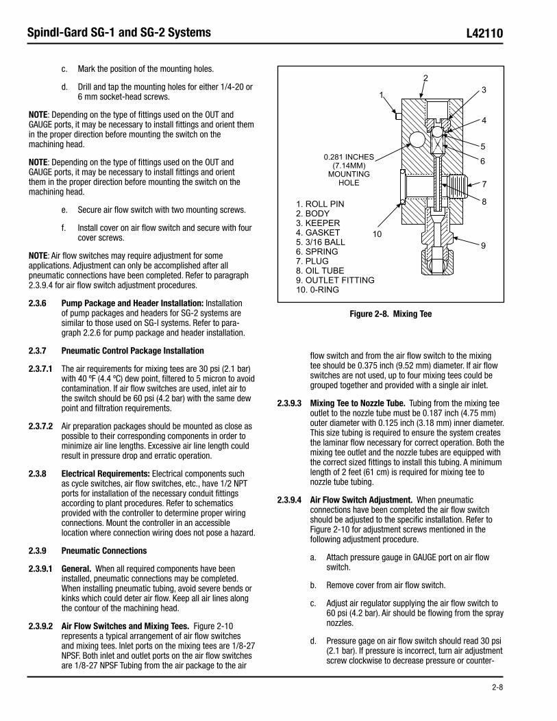
2.3.3.2 Figure 2-8 shows a sectional view of the mixing tee. For installation, the lube inlet should always be positioned at the top. This allows the oil to flow through oil tube (8) and properly enter outlet fitting (9) where air is mixed with the oil to create the laminar flow in the air/oil delivery tube. Air and lube inlet ports are 1/8-27 NPSF. If mixing tees are to be grouped together, remove plugs (7) from all but the last tee. Roll pin (1) ensures that all tees are aligned while o-ring (10) provides proper sealing for grouped tees.
2.3.3.3 The air/oil delivery tube requires 0.125 inch (3.18 mm) internal diameter and a minimum length of 2 feet (61 cm) of tubing from the outlet fitting to the nozzle tube.
NOTE:
The outlet fitting used on mixing tees is specially •designed to provide proper air/oil flow through the tube. Outlet fitting must not be replaced with standard commercial fittings.
The air/oil delivery tube requires a 45 degree •inverted flare to seal properly in the nozzle tube assembly.
Use only Graco-supplied nut on outlet fitting. Do not •use compression fittings.
Always install an external check valve at the lube •inlet of the mixing tee.
2.3.4 Divider Valve Installation: Installation of divider valves for SG-2 systems are similar to those used on SG-1 systems. Refer to paragraph 2.2.5 for SG-1 divider valve installation.
2.3.5 Air Flow Switch Installation
2.3.5.1 The air flow switch monitors air flow to the mixing tees. If an air line becomes plugged or broken, the decrease or increase of air flow causes an increase or decrease of air pressure. Pressure switches mounted in the air flow switch enclosure detect the varied pressure and provide a fault sig nal to the system controller.
2.3.5.2 One air flow switch can monitor up to three nozzle assemblies. The switch should be positioned to keep the dis tance between the air flow switches and the nozzle assem blies to a minimum. Air flow switches are equipped with two 0.281 inch (7.14 mm) mounting holes. Remove the top cover to gain access to the mounting holes. Figure 2-9 shows the air flow switch with cover removed. The GAUGE port, locat ed on the side of the unit, may be connected to a gauge to allow visual monitoring of the air pressure or as an alternate air inlet. This port is factory-shipped with an 1/8-27 NPT plug installed. Remove the plug to install a gauge. If this port is used as an alternate air inlet, plug the hole marked AIR INLET.
2.3.5.3 Installation procedures for the air flow switch are as follows:
Remove top cover to gain access to the two a. mounting holes.
Position the air flow switch in a location protecting it b. from coolant spray.
Figure 2-7. Nozzle Tube Installation
2-8
Spindl-Gard SG-1 and SG-2 Systems L42110
Mark the position of the mounting holes.c.
Drill and tap the mounting holes for either 1/4-20 or d. 6 mm socket-head screws.
NOTE: Depending on the type of fittings used on the OUT and GAUGE ports, it may be nec essary to install fittings and orient them in the proper direction before mounting the switch on the machining head.
NOTE: Depending on the type of fittings used on the OUT and GAUGE ports, it may be nec essary to install fittings and orient them in the proper direction before mounting the switch on the machining head.
Secure air flow switch with two mounting screws.e.
Install cover on air flow switch and secure with four f. cover screws.
NOTE: Air flow switches may require adjustment for some applications. Adjustment can only be accomplished after all pneumatic con nections have been completed. Refer to paragraph 2.3.9.4 for air flow switch adjust ment procedures.
2.3.6 Pump Package and Header Installation: Installation of pump packages and headers for SG-2 systems are similar to those used on SG-l systems. Refer to para-graph 2.2.6 for pump package and header installation.
2.3.7 Pneumatic Control Package Installation
2.3.7.1 The air requirements for mixing tees are 30 psi (2.1 bar) with 40 ºF (4.4 ºC) dew point, filtered to 5 micron to avoid contamination. If air flow switches are used, inlet air to the switch should be 60 psi (4.2 bar) with the same dew point and filtration requirements.
2.3.7.2 Air preparation packages should be mounted as close as possible to their corresponding components in order to minimize air line lengths. Excessive air line length could result in pressure drop and erratic operation.
2.3.8 Electrical Requirements: Electrical components such as cycle switches, air flow switches, etc., have 1/2 NPT ports for installation of the nec essary conduit fittings according to plant procedures. Refer to schematics provided with the controller to determine prop er wiring connections. Mount the controller in an accessible location where connection wiring does not pose a hazard.
2.3.9 Pneumatic Connections
2.3.9.1 General. When all required components have been installed, pneumatic connections may be completed. When installing pneumatic tubing, avoid severe bends or kinks which could deter air flow. Keep all air lines along the contour of the machining head.
2.3.9.2 Air Flow Switches and Mixing Tees. Figure 2-10 represents a typical arrangement of air flow switches and mixing tees. Inlet ports on the mixing tees are 1/8-27 NPSF. Both inlet and outlet ports on the air flow switches are 1/8-27 NPSF Tubing from the air package to the air
flow switch and from the air flow switch to the mixing tee should be 0.375 inch (9.52 mm) diameter. If air flow switches are not used, up to four mixing tees could be grouped together and provided with a single air inlet.
2.3.9.3 Mixing Tee to Nozzle Tube. Tubing from the mixing tee outlet to the nozzle tube must be 0.187 inch (4.75 mm) outer diameter with 0.125 inch (3.18 mm) inner diameter. This size tubing is required to ensure the system creates the laminar flow necessary for correct operation. Both the mixing tee outlet and the nozzle tubes are equipped with the correct sized fittings to install this tubing. A minimum length of 2 feet (61 cm) is required for mixing tee to nozzle tube tubing.
2.3.9.4 Air Flow Switch Adjustment. When pneumatic connections have been completed the air flow switch should be adjusted to the specific installation. Refer to Figure 2-10 for adjustment screws mentioned in the following adjustment procedure.
Attach pressure gauge in GAUGE port on air flow a. switch.
Remove cover from air flow switch.b.
Adjust air regulator supplying the air flow switch to c. 60 psi (4.2 bar). Air should be flowing from the spray nozzles.
Pressure gage on air flow switch should read 30 psi d. (2.1 bar). If pressure is incorrect, turn air adjustment screw clockwise to decrease pressure or counter-
Figure 2-8. Mixing Tee

2-9
Spindl-Gard SG-1 and SG-2 Systems L42110
clockwise to increase pressure.
Adjust switch A to detect a low pressure (high flow e. or broken line) condition. Switch A is factory set to actuate when pressure on gauge falls to 23 psi (1.56 bar). Turning adjustment screw clockwise increases actuating point, counterclockwise decreases.
Adjust switch B to detect a high pressure (low flow f. or blocked line) condition. Switch B is factory set to actuate when pressure on gauge rises to 37 psi (2.52 bar). Turning adjustment screw clockwise increases actuating point; counterclockwise decreases.
2.3.10 Lube Line Connections
2.3.10.1 When all required components have been installed lubricant connections may be completed. Connections are required to connect the divider valves to the pump or header and to connect the divider valves to the mixing tees.
2.3.10.2 Various inlet and outlet port types are available on MSP divider valves. Matching port types are available on
mixing tees and accessories. Steel or copper tubing with 3/8 inch (9.5 mm) OD is recommended from the pump or header to the divider valves. Steel or copper tubing of 3/16 or 1/4 inch (4.8 or 6.4 mm) OD is recommended from the divider valves to the lubrication points or mixing tee. Steel or copper tube of 3/16 inch OD x 0.030-0.032 wall (4.8 x 0.79 mm), 24 inch (609.6 mm) minimum length is required between the mixing tee and nozzle. When installing tubing, avoid sharp bends or kinks which could deter lubricant flow. Keep all tub ing runs along the contour of the machining head.
Figure 2-9. Air Flow Switch Installation

2-10
Spindl-Gard SG-1 and SG-2 Systems L42110
Figure 2-10. Air Flow Switch and Mixing Tees


3-1
Spindl-Gard SG-1 and SG-2 Systems L42110
3.1 GENERAL
3.1.1 This section contains information used to start and operate a typical Spindl-Gard system. The areas of coverage are as follows:
System filling and bleeding procedures, which •describe how to remove air from any Spindl-Gard system. Refer to paragraph 3.2.
Daily start-up procedures for SG-1 and SG-2. Refer •to paragraph 3.3.
Operation of SG-1 and SG-2 system. Refer to •paragraph 3.4.
Shutdown procedures for SG-1 or SG-2. Refer to •paragraph 3.5.
3.1.2 Proper start-up and operation of any Spindl-Gard sys tem depends upon correct installation of the system components. Refer to Section 2 for installation guidelines. Incor rectly sized tubing or improperly installed components can have adverse effects on a Spindl-Gard system.
3.2 SYSTEM FILLING AND BLEEDING
3.2.1 General
3.2.1.1 To ensure air-free operation of the system, all supply tubing and divider valves must be filled with oil before system start-up. Typically, a system receives oil in one of two ways as follows:
Oil from a supply pump is delivered to a master •divider valve which delivers to either a secondary divider valve, to the dispensing nozzle, or to terminating lube points.
A supply pump provides oil to a header which •feeds one or more master divider valves which may provide oil to either secondary dividers, dispensing nozzles or terminating lube points. In this case the master divider valves are usually equipped with a zero-leak valve to allow independent lubrication of each area receiving lubricant.
3.2.1.2 The filling and bleeding operation is separated into several major procedures as follows:
Initial Adjustments (para 3.2.2)•
Bleeding Secondary Divider Valves (para 3.2.3)•
Bleeding Pump-Supplied Master Divider Valve (para •3.2.4)
Bleeding Header-Supplied Master Divider (para •3.2.5)
Verification of Properly Bled System (para 3.2.6)•
3.2.1.3 All procedures require the use of a hand pump or other similar type of oil supply to fill the various system components. Make sure that the hand pump is filled with clean oil filtered to 10 microns. Make sure oil used for system fill ing is the same as that used for lubrication purposes.
SECTION 3SYSTEM START-UP AND OPERATION
3.1 GENERAL ........................................................................... 3-1
3.2 SYSTEM FILLING AND BLEEDING........................................ 3-1
3.2.1 General ................................................................. 3-1
3.2.2 Initial Adjustments ................................................. 3-2
3.2.3 Bleeding Secondary Divider Valves ........................ 3-2
3.2.4 Bleeding Pump-Supplied Master Divider Valve ....... 3-4
3.2.5 Bleeding Header-Supplied Master Divider Valve ..... 3-4
3.2.6 Verification ............................................................ 3-5
3.3 DAILY START-UP ................................................................ 3-5
3.3.1 General ................................................................. 3-5
3.3.2 Start-up Procedure, SG-1 ...................................... 3-5
3.3.3 Start-up Procedure, SG-2 ...................................... 3-5
3.4 OPERATION ........................................................................ 3-6
3.4.1 General ................................................................. 3-6
3.4.2 Output Adjustment ................................................. 3-6
3.5 SHUTDOWN ....................................................................... 3-6
OPERATION AND SERVICE INSTRUCTIONS

3-2
Spindl-Gard SG-1 and SG-2 Systems L42110
3.2.2 Initial Adjustments: Proper filling and bleeding of the system requires that the pneumatic and electric power be supplied to the compo nents. The system needs to be cycled to complete the bleeding operation, described in paragraphs 3.2.3 through 3.2.5. Verify that the following requirements exist:
For SG-1 systems, verify that a dedicated air •regulator supplies the spray nozzle and the regulator is set at 15 psi (1 bar) on systems without an air flow switch or 30 psi (2.1 bar) on systems with an air flow switch.
NOTE: If labyrinth or bronze seals are used on spindles with SG-1 systems, an additional air purge line may be required to maintain 2 psi internal head pressure. Contact a Graco representative for recommended pressures.
For SG-2 systems, verify that a dedicated air •regulator supplies the mixing tee and the regulator is set at 30 psi (2.1 bar) on systems without an air flow switch or 60 psi (4.2 bar) on systems with an air flow switch.
For pneumatic-operated systems, make sure air is •available to the supply pump and the pressure is set according to pump specifications.
For all systems, check the controller to verify it is •set to the proper cycling times, usually 15 minute intervals. Make sure power is present at the controller and any zero-leak valves used in the system. Manually operate the controller to verify that proper signals are being sent and the desired valves are energized.
Check setting of air flow switch (if used). Refer •to Sec tion 2 for air flow switch adjustment procedures.
3.2.3 Bleeding Secondary Divider Valves
3.2.3.1 Procedures for bleeding secondary divider valves are the same for both SG-1 and SG-2 systems. On many instal-lations, a secondary divider valve is not used or is used to supply lube points other than those relating to the Spindl-Gard system. The first requirement in bleeding secondary divider valves is to fill all supply lines from the secondary divider valves to the lubrication point. Refer to Figure 3-1 during the following procedures:
Loosen lube line at check valves located at a. each spray nozzle (Point A), mixing tee (Point B) or bearing (Point C) which is supplied by the secondary manifold.
Remove plug or performance indicator from the b. indicator port adjacent to each outlet tube of the secondary manifold.
Install a lube fitting in the open indicator port and c. attach hand pump to the fitting.
Cycle hand pump until air-free lubricant is d. dispensed from the lube line (Point A, B or C). Tighten lube line at Points A, B or C.
Remove hand pump and lube fittings at indicator e. ports of secondary divider valve and loosely install plug. Do not tighten plug.
Repeat steps “a” through “e” at all indicator ports f. of the secondary divider valve.
3.2.3.2 When all supply lines have filled with oil per para graph 3.2.3.1, the secondary divider valve itself may be bled. Refer to Figure 3-2 during the following procedure:
Remove indicator port plug or performance a. indicator from master divider valve outlet adjacent to the out let supplying the secondary divider valve.
Install a lube fitting in the indicator port of master b. divider valve and attach hand pump to fitting.
Cycle hand pump until air-free lubricant is c. dispensed from loosened indicator port plugs on the secondary divider valves.
Tighten all indicator port plugs or performance d. indicators at the indicator ports on the secondary divider valves.
Repeat steps “a” through “d” at all indicator ports e. of the master divider valve. When complete, loosely install plugs in indicator ports. Do not tighten plugs.
Refer to paragraph 3.2.4 or 3.2.5 to bleed master f. divider valves supplied by a pump or header respec tively.
3.2.4 Bleeding Pump-Supplied Master Divider Valve
3.2.4.1 This procedure for bleeding a pump-supplied master divider valve should be followed only after bleeding of sec ondary valves and lube points have been completed as dis cussed in paragraph 3.2.3. Figure 3-3 represents a typical pump and master divider valve installation with reference points relating to the procedure.
3.2.4.2 The procedure for bleeding pump-supplied master divider valves is as follows:
Apply air and/or electrical requirements to pump. a. (Refer to paragraph 3.2.2.)
Fill reservoir and bleed pump.b.
NOTE: Plugs or indicators in indicator ports should be loose, as per step “e”, paragraph 3.2.3.2.
Operate pump until master divider valve cycles c. several times and air-free oil appears at the loosened indicator port plugs.
Tighten all plugs or performance indicators at d. indi cator ports of master divider valve.

3-3
Spindl-Gard SG-1 and SG-2 Systems L42110
Figure 3-1. Filling Secondary Divider Valve Supply Tubes
Figure 3-2. Bleeding Secondary Divider Valve
3-4
Spindl-Gard SG-1 and SG-2 Systems L42110
3.2.5 Bleeding Header-Supplied Master Divider Valve
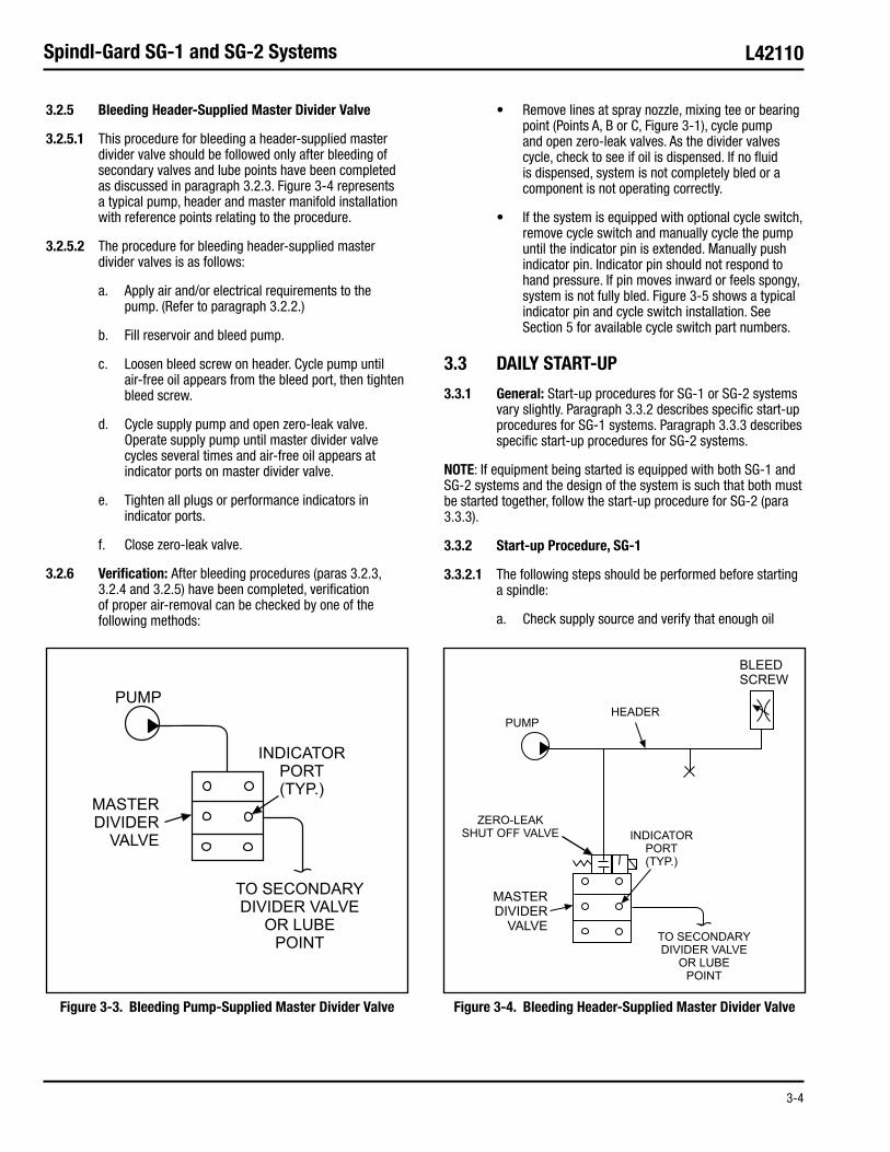
3.2.5.1 This procedure for bleeding a header-supplied mas ter divider valve should be followed only after bleeding of secondary valves and lube points have been completed as discussed in paragraph 3.2.3. Figure 3-4 represents a typi cal pump, header and master manifold installation with refer ence points relating to the procedure.
3.2.5.2 The procedure for bleeding header-supplied master divider valves is as follows:
Apply air and/or electrical requirements to the a. pump. (Refer to paragraph 3.2.2.)
Fill reservoir and bleed pump.b.
Loosen bleed screw on header. Cycle pump until c. air-free oil appears from the bleed port, then tighten bleed screw.
Cycle supply pump and open zero-leak valve. d. Operate supply pump until master divider valve cycles several times and air-free oil appears at indicator ports on master divider valve.
Tighten all plugs or performance indicators in e. indicator ports.
Close zero-leak valve.f.
3.2.6 Verification: After bleeding procedures (paras 3.2.3, 3.2.4 and 3.2.5) have been completed, verification of proper air-removal can be checked by one of the following methods:
Remove lines at spray nozzle, mixing tee or bearing •point (Points A, B or C, Figure 3-1), cycle pump and open zero-leak valves. As the divider valves cycle, check to see if oil is dispensed. If no fluid is dispensed, system is not completely bled or a component is not operating correctly.
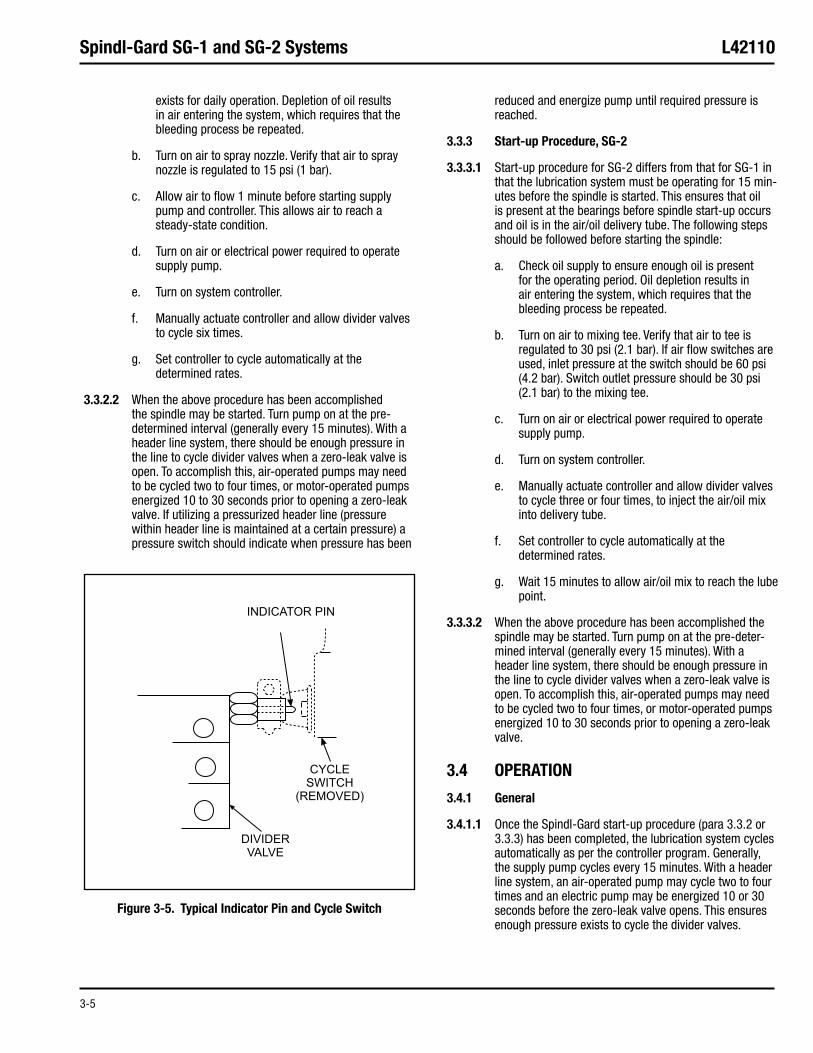
If the system is equipped with optional cycle switch, •remove cycle switch and manually cycle the pump until the indicator pin is extended. Manually push indicator pin. Indicator pin should not respond to hand pressure. If pin moves inward or feels spongy, system is not fully bled. Figure 3-5 shows a typical indicator pin and cycle switch installation. See Section 5 for available cycle switch part numbers.
3.3 DAILY START-UP
3.3.1 General: Start-up procedures for SG-1 or SG-2 systems vary slightly. Paragraph 3.3.2 describes specific start-up procedures for SG-1 systems. Paragraph 3.3.3 describes specific start-up procedures for SG-2 systems.
NOTE: If equipment being started is equipped with both SG-1 and SG-2 systems and the design of the system is such that both must be started together, follow the start-up pro cedure for SG-2 (para 3.3.3).
3.3.2 Start-up Procedure, SG-1
3.3.2.1 The following steps should be performed before starting a spindle:
Check supply source and verify that enough oil a.
Figure 3-3. Bleeding Pump-Supplied Master Divider Valve Figure 3-4. Bleeding Header-Supplied Master Divider Valve
3-5
Spindl-Gard SG-1 and SG-2 Systems L42110
exists for daily operation. Depletion of oil results in air entering the system, which requires that the bleeding process be repeated.
Turn on air to spray nozzle. Verify that air to spray b. nozzle is regulated to 15 psi (1 bar).
Allow air to flow 1 minute before starting supply c. pump and controller. This allows air to reach a steady-state condition.
Turn on air or electrical power required to operate d. supply pump.
Turn on system controller.e.
Manually actuate controller and allow divider valves f. to cycle six times.
Set controller to cycle automatically at the g. determined rates.
3.3.2.2 When the above procedure has been accomplished the spindle may be started. Turn pump on at the pre-determined interval (generally every 15 minutes). With a header line system, there should be enough pressure in the line to cycle divider valves when a zero-leak valve is open. To accomplish this, air-operated pumps may need to be cycled two to four times, or motor-operated pumps energized 10 to 30 seconds prior to opening a zero-leak valve. If utilizing a pressurized header line (pressure within header line is main tained at a certain pressure) a pressure switch should indi cate when pressure has been
reduced and energize pump until required pressure is reached.
3.3.3 Start-up Procedure, SG-2
3.3.3.1 Start-up procedure for SG-2 differs from that for SG-1 in that the lubrication system must be operating for 15 min-utes before the spindle is started. This ensures that oil is pre sent at the bearings before spindle start-up occurs and oil is in the air/oil delivery tube. The following steps should be fol lowed before starting the spindle:
Check oil supply to ensure enough oil is present a. for the operating period. Oil depletion results in air entering the system, which requires that the bleeding process be repeated.
Turn on air to mixing tee. Verify that air to tee is b. regulated to 30 psi (2.1 bar). If air flow switches are used, inlet pressure at the switch should be 60 psi (4.2 bar). Switch outlet pressure should be 30 psi (2.1 bar) to the mixing tee.
Turn on air or electrical power required to operate c. supply pump.
Turn on system controller.d.
Manually actuate controller and allow divider valves e. to cycle three or four times, to inject the air/oil mix into delivery tube.
Set controller to cycle automatically at the f. determined rates.
Wait 15 minutes to allow air/oil mix to reach the lube g. point.
3.3.3.2 When the above procedure has been accomplished the spindle may be started. Turn pump on at the pre-deter-mined interval (generally every 15 minutes). With a header line system, there should be enough pressure in the line to cycle divider valves when a zero-leak valve is open. To accomplish this, air-operated pumps may need to be cycled two to four times, or motor-operated pumps energized 10 to 30 seconds prior to opening a zero-leak valve.
3.4 OPERATION
3.4.1 General
3.4.1.1 Once the Spindl-Gard start-up procedure (para 3.3.2 or 3.3.3) has been completed, the lubrication system cycles automatically as per the controller program. Generally, the supply pump cycles every 15 minutes. With a header line system, an air-operated pump may cycle two to four times and an electric pump may be energized 10 or 30 seconds before the zero-leak valve opens. This ensures enough pres sure exists to cycle the divider valves.
Figure 3-5. Typical Indicator Pin and Cycle Switch
3-6
Spindl-Gard SG-1 and SG-2 Systems L42110
3.4.1.2 While no steps are required to operate the lube sys tem, personnel should be aware of any indication of system faults as indicated by the system controller. If a fault occurs, the spindle should be shutdown immediately to avoid bearing damage. Section 4 of this manual contains troubleshooting procedures for the Spindl-Gard system.
CAUTION: Operation of the spindle without proper lubrication may result in serious spindle damage.
3.4.2 Output Adjustment
CAUTION: Before attempting to adjust output by changing air pressure at spray nozzle (SG-1) or mixing tee (SG-2), contact a Graco distributor representative or Graco. A substantial deviation from rec ommended air pressure requirements (20% or more) may result in incorrect sys tem operation which could cause spindle damage.
Output of SG-1 and SG-2 systems do not generally require adjustment. Precise output is determined during the design process and, in most cases, will remain constant. However, factors such as different speed requirements or machining head changes may require lubricant output modifications. Contact a Graco distributor representative or Graco for correct methods to vary the output from the original setting.
3.5 SHUTDOWN: When the spindle is turned off, lubrication is no longer required at the bearings. Turn the controller off to prevent the supply pump from cycling and adding more lubricant. How ever, maintain air pressure on the spray nozzle or mixing tee for 5 to 10 minutes after spindle shutdown. The continuing air pressure maintains internal head pressure and helps pre vent introduction of contaminants or coolant.
CAUTION: Maintaining air pressure beyond 10 min utes in a SG-2 system with the controller off could result in drying of the air/oil deliv ery tube. This would result in inadequate lubrication at the next machine start-up.

4-1
Spindl-Gard SG-1 and SG-2 Systems L42110
4.1 GENERAL
4.1.1 Troubleshooting on Spindl-Gard systems should be performed from a top-down viewpoint. Starting at the pumps, working down to the divider valves and finally to the spray nozzles on SG-1 systems or the mixing tees and nozzle tubes on SG-2 systems. As a rule, the nozzles, mixing tees and air flow switches associated with the pneumatic portion of a Spindl-Gard system will cause little trouble, due to the few moving parts and large orifices. Finely-filtered lubricant and air keeps a system problem-free for a longer period of time.
4.1.2 Many of the problems that occur with a Spindl-Gard system can be avoided by following installation guidelines. Other useful brochures for troubleshooting and maintenance procedures are:
Bulletin L41500. This pocket-sized card contains •installa tion and troubleshooting tips useful for any system using pumps and divider valves.
Bulletin L30101. This brochure provides •instructions on how to locate a blockage in systems using divider valves.
4.1.3 Table 4-1 provides typical problems, causes and corrective actions associated with any Spindl-Gard system. Paragraphs 4-2 and 4-3 discuss troubleshooting components specific to SG-1 and SG-2 systems.
NOTE: If a Graco-supplied controller is not used and the control of the system is pro vided by the in-house controller make sure that the controller is properly programmed.
4.2 TROUBLESHOOTING SG-1 COMPONENTS
4.2.1 General: To assist in troubleshooting components of the SG-1 system, an overview of the spray nozzle and machining head pres sure are discussed in paragraphs 4.2.2 and 4.2.3.
4.2.2 SG-1 Spray Nozzle: As shown in Figure 4-1, the spray nozzle has a built-in piston and o-ring which acts as a check valve, opening only when the divider valves cycle. As the valves cycle, oil pressure opens the check valve and enters the chamber where air dis tributes the oil into the spray pattern. A defective check valve could allow the oil from the supplying tubes to leak into the spray nozzle even when the divider valve is not cycling. This could cause a void, resulting in an improper amount of lubricant being dispensed.
4.2.3 Machining Head Pressure: Pressure switches may be mounted on the spindle head to monitor air pressure in the head. An increase or decrease in pressure indicates improper air flow through the spray noz zle. Variations of pressure may be caused by blocked or bro ken air lines, a clogged spray nozzle or an incorrectly adjust ed air supply.
4.3 TROUBLESHOOTING SG-2 COMPONENTS
4.3.1 General: To assist in troubleshooting components of the SG-2 system, an overview of the air flow switch, mixing tee and nozzle tubes are discussed in paragraphs 4.3.2. and 4.3.3.
4.3.2 Nozzle Tube: The nozzle tube has no moving components. The only prob lem area is the orifice, which can become blocked if dirty oil is used in the system. Proper lubricant filtration minimizes this problem.
4.3.3 Mixing Tee: As shown in Figure 4-2, the mixing tee has a built in keeper and ball which act as a check valve, opening only when the divider valve cycles. As the valve cycles, oil pressure opens the check valve and allows oil to enter an oil tube leading to the outlet fitting. The flow of incoming air carries the oil in a laminar layer along the walls of the air/oil delivery tube. If either the keeper or ball are defective, oil from the supplying tube could leak into the mixing tee even when the divider valve is not cycling. This could cause a void, resulting in an improper amount of lubricant being dispensed.
SECTION 4TROUBLESHOOTING
4.1 GENERAL ........................................................................... 4-1
4.2 TROUBLESHOOTING SG-1 COMPONENTS .......................... 4-1
4.2.1 General ................................................................. 4-1
4.2.2 SG-1 Spray Nozzle ................................................ 4-1
4.2.3 Machining Head Pressure ...................................... 4-2
4.3 TROUBLESHOOTING SG-2 COMPONENTS .......................... 4-2
4.3.1 General ................................................................. 4-2
4.3.2 Nozzle Tube ........................................................... 4-3
4.3.3 Mixing Tee ............................................................. 4-3
4.3.4 Air Flow Switch ..................................................... 4-3
OPERATION AND SERVICE INSTRUCTIONS

4-2
Spindl-Gard SG-1 and SG-2 Systems L42110
4.3.4 Air Flow Switch
4.3.4.1 It the system is equipped with an air flow switch, air provided to the switch should be set at 60 psi (4.2 bar).
When the mixing tee and nozzle tubes are functioning cor rectly and the system was installed properly, the pressure at the outlet and gauge ports of the switch should be 30 psi (2.1 bar). An increase or decrease in this pressure indicates a blocked or broken downstream air passage. Decrease in pressure is normally caused by an air leak at the pneumatic connection at the mixing tee. A rise in pressure could be caused by outlet ports in the mixing tee or nozzle tube being blocked. Blockage of this type would likely be caused by improper filtering of the pneumatic or oil circuits.
4.3.4.2 Air pressure could also rise if the outlet fitting on the mixing tee was replaced with an incorrect fitting. The fitting supplied with the tee is specifically designed to accept the orifice of the oil tube and must not be substituted.
4.3.4.3 If air flow switches are not used, the pressure at the air inlet on the mixing tee should be 30 psi (2.1 bar). Without an air flow switch to detect rise or fall in pressure, no indica tion of a defect would be given. Temperature probes may be mounted near the bearings to sense the rise in temperature which occurs with improper lubrication.
TABLE 4-1 SYSTEM TROUBLESHOOTINGProblem Probable Cause Corrective Action
Cycle times increase in lengthA. Leaking fitting or tubes1. Tighten all fittings and check tubes for 1. cracks or leaks
Supple pump is worn2. Repair supply pump2.
Pressure spikes or slight pressure rises B. detected at pump pressure gauge or performance indicators
Air volume supplied to pump is too high1. Add air restrictor to air inlet of air solenoid1.
Air is present in system2. Bleed pump and remaining system, refer to 2. section 3-2
Partial blockage exists in system3. Replace all lube filters., verify that lubricant 3. used is clean and check for blockage in system, refer to brochure L30101
Contaminated lubricant system4. Flush system of contaminated lubricant, 4. refill with clean, filtered lubricant
Partial blockage in divider valve5. Clean divider valve of any contaminants5.
Low or subnormal pressure detected at C. pump pressure gauge
Air supply to pump is set to low1. Adjust pump air pressure to designed 1. specification
Leaking fittings or tubes in main supply 2. lube line
Tighten all fittings and check tubes for 2. cracks or leaks
Blown rupture disc at pump3. Replace rupture disc and determine area of 3. blockage, refer to brochure L30101
Pump is air bound4. Bleed pump of air and check reservoir level4.
Periodic red fault lights appear on controllerD. One of problem A, B or C above are present1. Refer to above corrective actions1.
No lights appear on controllerE. Controller fuse is blown1. Replace fuse, proceed1.
Short exists in wiring2. Check connections of improper wiring2.

4-3
Spindl-Gard SG-1 and SG-2 Systems L42110
/(4-4 Blank)
Figure 4-1. Spray Nozzle Figure 4-2. Mixing Tee
5-1
Spindl-Gard SG-1 and SG-2 Systems L42110
5.1 GENERAL
This section provides part numbers for components used in SG-1 and SG-2 systems. Most components are available only as assemblies. Individual parts of these components can not be ordered. Table 5-1 lists standard system compo nents and where additional information can be found. Tables 5-2 and 5-3 list the components and part numbers of SG-1 and SG-2 systems. For further information regarding Spindl-Gard components, refer to Bulletin L20110. Where compo nents can be disassembled and individual parts ordered, a reference is made to the pertinent paragraph.
SECTION 5PARTS ORDERING INFORMATION
5.1 GENERAL ........................................................................... 5-1
5.2 SG-1 SPRAY NOZZLE ......................................................... 5-2
5.2.1 General ................................................................. 5-2
5.2.2 Spray Nozzle Disassembly Procedure .................... 5-2
5.2.3 Spray Nozzle Assembly Procedure ......................... 5-2
5.2.4 Spray Nozzle Parts List .......................................... 5-3
5.3 MIXING TEE ........................................................................ 5-4
5.4 NOZZLE ADAPTER .............................................................. 5-5
5.5 EASY TO REPLACE NOZZLE ADAPTER................................. 5-6
OPERATION AND SERVICE INSTRUCTIONS
TABLE 5-2 SG-1 COMPONENTSDescription Part No. Old Part No.
Divider Valve Inlet Filter 563091 473-000-234
Relief Valve, 2 psi (0.14 bar) 564337 463-300-156
Soft Seat Check Valve 563048 463-001-535
Spray Nozzle (para 5-2) 563128 484-095-030
Pressure Switch, 1 psi (0.07 bar) 558888 492-140-597
TABLE 5-3 SG-2 COMPONENTSDescription Part No. Old Part No.
Air Flow Switch w/Lights 564348 484-095-095
Divider Valve Inlet Filter/Check 564326 463-001-605
Zero Leak Inlet Restrictor – 463-410-170
End Outlet Nozzle 563994 435-702-275
Mixing Tee (para 5-3) 563129 484-095-050
Mixing Tee Outlet Fitting 560256 435-702-281
Nozzle Tube Adapter (para 5-4) 563127 484-090-075
Nozzle Tube Adapter (Easy to Replace) – 484-090-193
Nozzle Tube (One Side Outlet) 560477 484-090-089
Nozzle Tube (Two Side Outlet) 560478 484-090-090
Restrictor Orifice 562994 435-702-275
Soft Seat Check Valve 563048 463-001-535
Table 5-1 Standard System ComponentsComponents Bulletin No.
MSP Divider Valve L10102
Modu-Flo Pump Packages
General L12000
Maintenance L42000
Solid State Timer L14521
WMP Maxi-Monitor
General L14750
Installation L14752
10 micron In-line Filter L15200
Moisture Resistant Cycle Switch L10102
Proximity Switch (Brad Harrison)
3-Pin Connection L10102
5-Pin Connection L10102
Zero Leak Shut Off Valve
Bare Wire Connection L10104
Attached w/Brad Harrison Cable L10104

5-2
Spindl-Gard SG-1 and SG-2 Systems L42110
5.2 SG-1 SPRAY NOZZLE
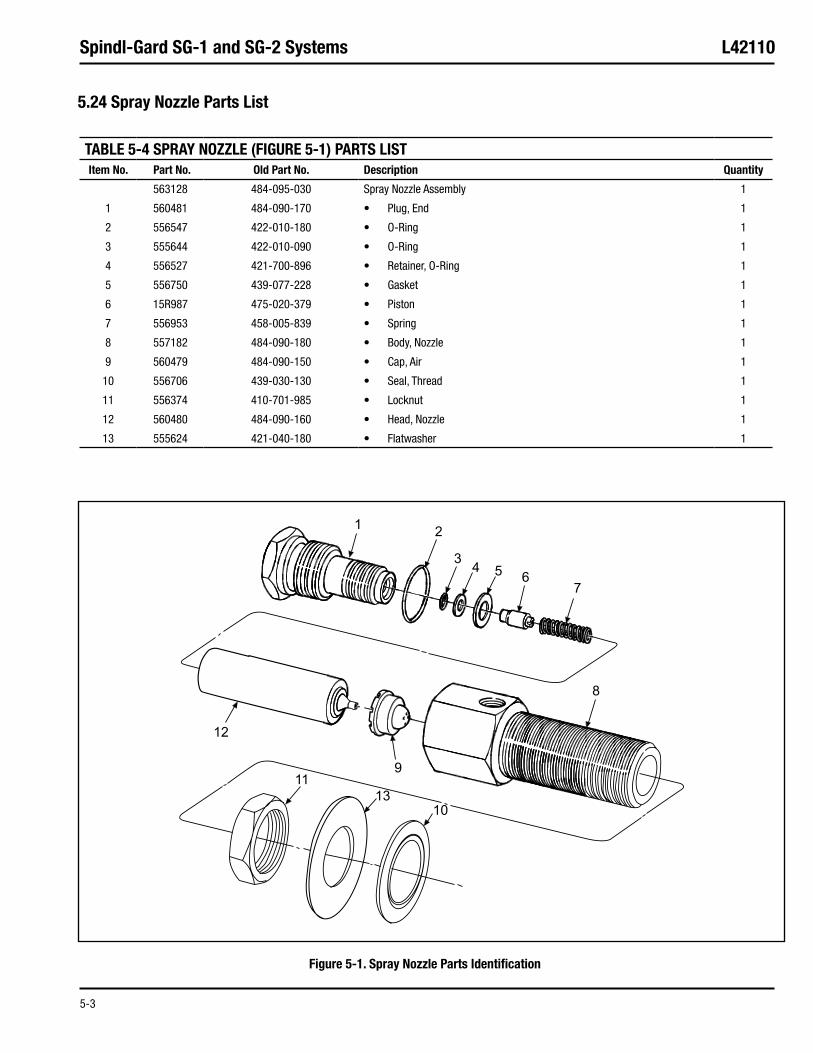
5.2.1 General: The SG-1 spray nozzle can be disassembled and individual parts can be ordered. Disassembly and assembly procedure are provided in paragraphs 5.2.2 and 5.2.3. Figure 5-1 locat ed after the assembly procedure, shows an exploded view of the spray nozzle with the associated part numbers.
5.2.2 Spray Nozzle Disassembly Procedure
Turn off pneumatic air and lube systems.a.
Remove pneumatic and lube connections at spray b. nozzle.
CAUTION: Distance between exposed part of spray nozzle assembly and machining head should be measured and noted to within 0.032 inch (0.81 mm). This measurement is necessary for assembly procedures. Failure to measure and note this distance may result in component damage caused by ineffective lubrication.
Measure and note distance between exposed part c. of spray nozzle assembly and machining head hous ing.
CAUTION: Extreme care should be taken to prevent contamination from entering through the machine housing during disassembly. Fail ure to prevent contamination from entering may result in serious component damage.
Loosen locknut (11, Figure 5-1) and remove spray d. nozzle assembly from machining head lubrication port. Remove and discard thread seal (10) from nozzle body (8).
Remove end plug (1) with attached nozzle head (12) e. from nozzle body (8).
Remove nozzle head (12) from end plug (1), to f. remove o-ring (3), o-ring retainer (4), gasket (5), pis ton (6) and spring (7). Discard o-ring and gasket.
Remove and discard o-ring (2) from end plug (1).g.
Remove air cap (9) from nozzle body (8).h.
5.2.3 Spray Nozzle Assembly Procedure
CAUTION: Extreme care should be taken to prevent contamination from entering through the machine housing during assembly. Failure to prevent contamination from entering may result in component damage.
Install new o-ring (2, Figure 5-1) onto end plug (1).a.
Insert new o-ring (3), o-ring retainer (4) and piston b. (6) into end plug (1).
Insert spring (7) and new gasket (5) into nozzle c. head (12).
NOTE: Ensure spring (7) is properly seated in nozzle head (12) and on piston (6) before tightening end plug (1).
Thread end plug (1) into nozzle head (12) and d. tighten.
Place air cap (9) in nozzle body (8).e.
Thread end plug (1) with assembled parts into f. nozzle body (8) and tighten.
Install locknut (11), washer (13) and new thread g. seal (10) onto nozzle body (8).
Thread spray nozzle assembly into machining head h. lubrication port until the distance between the top of the spray nozzle and machine head housing is equal to that measured during disassembly.
Position thread seal (10) snug against machining i. head. Tighten locknut (11).
Install pneumatic and lube connections on spray j. nozzle.
Turn on air and lube system. Check spray nozzle for k. leaks.
5-3
Spindl-Gard SG-1 and SG-2 Systems L42110
Figure 5-1. Spray Nozzle Parts Identification
5.24 Spray Nozzle Parts List
TABLE 5-4 SPRAY NOZZLE (FIGURE 5-1) PARTS LISTItem No. Part No. Old Part No. Description Quantity
563128 484-095-030 Spray Nozzle Assembly 1
1 560481 484-090-170 Plug, End• 1
2 556547 422-010-180 O-Ring• 1
3 555644 422-010-090 O-Ring• 1
4 556527 421-700-896 Retainer, O-Ring• 1
5 556750 439-077-228 Gasket• 1
6 15R987 475-020-379 Piston• 1
7 556953 458-005-839 Spring• 1
8 557182 484-090-180 Body, Nozzle• 1
9 560479 484-090-150 Cap, Air• 1
10 556706 439-030-130 Seal, Thread• 1
11 556374 410-701-985 Locknut• 1
12 560480 484-090-160 Head, Nozzle• 1
13 555624 421-040-180 Flatwasher• 1

5-4
Spindl-Gard SG-1 and SG-2 Systems L42110
5.3 MIXING TEE
Figure 5-2. Mixing Tee
TABLE 5-5 MIXING TEE (FIGURE 5-2) PARTS LISTItem No. Part No. Old Part No. Description Quantity
563129 484-095-050 Mixing Tee 1
1 557485 510-364-000 Roll Pin, 3/32 diameter x 7/32 in.• 1
2 560471 484-060-118 Body, Not Replaceable• 1
3 557408 509-252-001 Keeper• 1
4 557412 509-258-001 Gasket• 1
5 556331 401-070-060 Ball, 3/16 in.• 1
6 557410 509-253-010 Spring• 1
7 557349 503-485-000 Plug, 1/8 in Pipe• 1
8 560476 484-090-080 Tube, Oil, Not Replaceable• 1
9 560256 435-702-281 Fitting, Outlet• 1
10 555647 422-010-130 O-Ring, -013• 1

5-5
Spindl-Gard SG-1 and SG-2 Systems L42110
5.4 NOZZLE ADAPTER
Figure 5-3. Nozzle Adapter
TABLE 5-6 NOZZLE ADAPTER (FIGURE 5-3) PARTS LISTItem No. Part No. Old Part No. Description Quantity
484-090-075 Nozzle Adapter 1
1 484-090-077 Body• 1
2 435-702-273 Flare Nut, Inverted, 3/16 in.• 1
3 484-090-076 Retainer, Nozzle• 1
4 410-420-060 Nut, Hex, Jam, 9/16-18• 1
5 439-030-090 Seal, Thread• 1
5-6
Spindl-Gard SG-1 and SG-2 Systems L42110
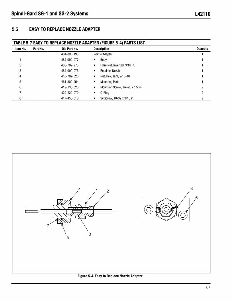
5.5 EASY TO REPLACE NOZZLE ADAPTER
Figure 5-4. Easy to Replace Nozzle Adapter
TABLE 5-7 EASY TO REPLACE NOZZLE ADAPTER (FIGURE 5-4) PARTS LISTItem No. Part No. Old Part No. Description Quantity
484-090-193 Nozzle Adapter 1
1 484-090-077 Body• 1
2 435-702-273 Flare Nut, Inverted, 3/16 in.• 1
3 484-090-076 Retainer, Nozzle• 1
4 410-702-026 Nut, Hex, Jam, 9/16-18• 1
5 461-300-954 Mounting Plate• 1
6 419-130-020 Mounting Screw, 1/4-20 x 1/2 in.• 2
7 422-220-070 O-Ring• 2
8 417-450-010 Setscrew, 10-32 x 3/16 in.• 2


All written and visual data contained in this document are based on the latest product information available at the time of publication. Graco reserves the right to make changes at any time without notice.
Contact us today!To receive product information or talk with a Graco representative, call 800-533-9655 or visit us online at www.graco.com.
©2006-2009 Graco Inc. Form No. L42110 Rev. B 6/09 Printed in U.S.A. All other brand names or marks are used for identification purposes and are trademarks of their respective owners. All written and visual data contained in this document are based on the latest product information available at the time of publication. Graco reserves the right to make changes at any time without notice.