L300P Series Variable Frequency Drives - Fan & Pump ... · Output frequency Output current Rotation...
32
Transcript of L300P Series Variable Frequency Drives - Fan & Pump ... · Output frequency Output current Rotation...

Hitachi’s L300P Series Variable Fre Increased Energy Savings for Your
AUTOMATIC ENERGY-SAVING FUNCTION
With its Automatic Energy-saving Function, the L300P delivers “real-time” energy-saving operation for your fan and pump applications. The function insures that motor operates at minimum current in response to the torque required by the load.
ENHANCED INPUT/OUTPUT TERMINALSThree relay output terminals are provided as standard for flexible interface to external control systems.
ANALOG OUTPUT MONITORIn addition to PWM monitor(FM), programmable analog output monitors are also available for both voltage(0-10VDC) and current(4-20mA) at AM and AMI terminals of the L300P.
INTELLIGENT INPUT/OUTPUT TERMINAL SYSTEMThe L300P features an intelligent control terminal system, which allows necessary drive I/O functions to be freely programmed. Input terminals can be selected for either sink or source type logic.
EASY- TO-USE OPERATOR PANEL
Output frequencyOutput currentRotation directionProcess variable, PID feedbackIntelligent input terminal status
INTELLIGENT RELAY OUTPUTS
NO contact X 2 NO-NC contact X 1
AL212C 12A 11C 11A AL0 AL1
L300P's digital operator panel supports various monitoring functions.
Cumulative power-on timeTrip eventTrip historyWarning code
Intelligent output terminal statusScaled output frequencyOutput voltagePowerCumulative RUN time
Example of Energy Savings (Fan)
Operation by Inlet vane and damper
Operation by v/f control
Operation by Automatic Energy-saving Function
Amount of energy to be saved
Pow
er C
onsu
mpt
ion
Frequency
[Sink type logic]
CM1
FW
L300P
P24
FWL300P
[Source type logic]
Upper SystemUpper System +Power Supply
1
WIDE RANGE OF APPLICATION SPECIFIC FUNCTIONS WIDE RANGE OF APPLICATION SPECIFIC FUNCTIONS

quency Drive DeliversFan and Pump Applications!
CONTENTS
Hitachi Inverter L300P
Hitachi Inverter L300P
Ease of Operation
Global Standards
High-performance
Easy Maintenance
Compact Size
FEATURES
STANDARD SPECIFICATIONS
DIMENSIONS
OPERATION and PROGRAMMING
FUNCTION LIST
TERMINALS
PROTECTIVE FUNCTIONS
CONNECTING DIAGRAM
CONNECTING TO PLC
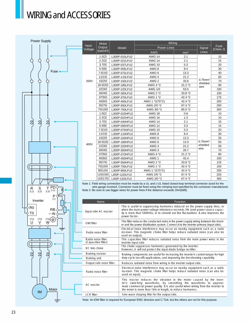
WIRING and ACCESSORIES
ACCESSORIES
FOR COMPACT PANEL
TORQUE CHARACTERISTICS, DERATING DATA
FOR CORRECT OPERATION
1 - 4
5 - 7
8 - 11
12
13 - 16
17 - 18
19
20 - 21
22
23
24 - 26
27
28
29 - 30
2
FOR OPTIMAL OPERATION FOR OPTIMAL OPERATION PAGE
Hitachi variable frequency drives (inverters) in this brochure are produced at the factory registered under the ISO 14001 standard for environmental management system and the ISO 9001 standard for inverter quality management system.
ISO 14001EC97J1095
ISO 9001JQA-1153

Eliminates control rewiring when field replacing the L300P.
The L300P’s compact size helps economize panel space.Installation area is reduced by approximately 30% from that of our previous series.(Comparison of 11kW (15HP))
You can select frequently used commands and store them for fast reference.
RS485 is provided as standard for ASCII serial communication.
Optional PC drive configuration software which runs on Windows® Operating System.
Output frequency can be controlled by the integral potentiometer provided as standard on the OPE-SR.The OPE-SR can be removed for remote control, and has an easy-to-see 4-digit display and LEDs to indicate the unit being monitored (i.e. frequency, amps, power, etc.). A multilingual operator (English, French, German, Italian, Spanish, and Portuguese) with copy function (SRW-0EX) and a digital operator without potentiometer (OPE-S) are also available as options.
3
EASY-REMOVABLECOOLING FANAND DC BUS CAPACITOR
REMOVABLE CONTROLCIRCUIT TERMINALS
EASE OF OPERATION WITH DIGITAL OPERATOR (OPE-SR)
USER SELECTION OFCOMMAND FUNCTIONS(“Quick Menu”)
BUILT-IN RS485
PROGRAMMING SOFTWARE
Cooling fan(s) and DC bus capaci-tors can be easily changed in the field. A fan ON/OFF function can be activated to provide longer cooling fan life.
Control Circuit Terminals

EMI filters to meet European EMC (EN61800-3, EN55011) and low-voltage directive (EN50178) are available for system conformance.
CE, UL, c-UL, C-Tick approvals.
Standard enclosure protection for the L300P is IP20 (NEMA1*). For IP54 (NEMA12), please contact Hitachi sales office.
MODEL NAME INDICATION
Series NameVersion number
U:UL version for North AmericaE:CE version for Europe
L :3-phase 200V ClassH:3-phase 400V Class
F:With Digital Operator
Power Source
Applicable Motor Capacity
L300P - 015 L F U 2
4
EMI FILTER
HARMONICS MITIGATION
CONFORMITY TO GLOBALSTANDARDS
NETWORK COMPATIBILITYThe L300P can communicate with DeviceNet™, PROFIBUS®, LONWORKS®, Modbus® RTU*1, and Ethernet™*2 with communication options.*1, *2: Being planned
*NEMA 1 applies up to 30kW. An optional wire-entry conduit box is required for 37kW to 75kW models to meet NEMA 1 rating.
Windows is a registered trademark of Microsoft Corp. in the U.S. and other countries.DeviceNet is a trademark of Open DeviceNet Vendor Association.PROFIBUS is a registered trademark of Profibus Nutzer Organization.
Disturbance voltage of the main circuit power supply and of the control circuit power supply has been improved by approximately 15dB( V) and 20dB( V) respectively compared to our previous model(J300), resulting in significant reductions to noise interference with sensors and other peripheral devices.
REDUCED NOISE FROM MAINCIRCUIT POWER SUPPLY ANDCONTROL CIRCUIT POWER SUPPLY
CONTROL OF VOLTAGE OFMICRO SERGE
11(15) L300P-110LFU2 L300P-110HFU2/E2
15(20) L300P-150LFU2 L300P-150HFU2/E2
18.5(25) L300P-185LFU2 L300P-185HFU2/E2
22(30) L300P-220LFU2 L300P-220HFU2/E2
30(40) L300P-300LFU2 L300P-300HFU2/E2
MODEL CONFIGURATION
Applicable Motor Capacityin kW (HP) 3-phase 200V class 3-phase 400V class
1.5(2) L300P-015LFU2 L300P-015HFU2/E2
2.2(3) L300P-022LFU2 L300P-022HFU2/E2
3.7(5) L300P-037LFU2 L300P-040HFU2/E2
5.5(7.5) L300P-055LFU2 L300P-055HFU2/E2
7.5(10) L300P-075LFU2 L300P-075HFU2/E2
37(50) L300P-370LFU2 L300P-370HFU2/E2
45(60) L300P-450LFU2 L300P-450HFU2/E2
55(75)
75(100) L300P-750HFU2/E2
90(125) L300P-900HFU2/E2
110(150) L300P-1100HFU2/E2
132(175) L300P-1320HFU2/E2
L300P-550LFU2 L300P-550HFU2/E2
L300P-750LFU2IMPROVEMENT OF ENVIRONMENTThe printed circuit board inside an inverter is varnish coating specification as standard.
20
40
60
80
100
0 .2 .3 .5 .7 1 5 7 10 30203
J300-055LFUL300P-055LFU2
40
60
70
80
90
100
0 .2 .3 .5 .7 1 5 7 10 20 30Frequency(MHz)
Frequency(MHz)
J300 series
J300 series
L300P series
L300P series
J300-220LFU
Disturbance voltage of the main circuit power supply(It does not comply with European EMC directive. To meet the EMC directive, please use an EMI filter.)
Disturbance voltage of the control circuit power supply(Disturbance voltage of terminal L or CM1)
Dist
urba
nce
volta
ge [d
B(µV
)]Di
stur
banc
e vo
ltage
[dB(
µV)]
L300P-220LFU2
Terminals for the connection of a DC Reactor are provid-ed as standard for harmonics suppression.
Suppressing the motor terminal voltage less than 2xE [V]by improving the control method of PWM output.Input voltage:400VAC(In the case)Motor terminal voltage:1,131V(400VX√2X2)

5
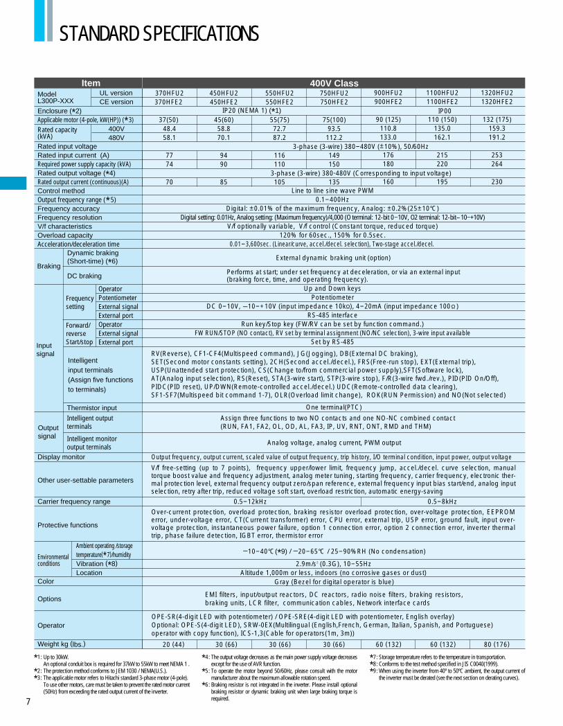
STANDARD SPECIFICATIONS
ModelL300P-XXX
Enclosure (*2)Applicable motor (4-pole, kW(HP)) (*3)Rated capacity (kVA) Rated input voltageRated input current (A)Required power supply capacity (kVA)Rated output voltage (*4)Rated output current (continuous)(A)Control methodOutput frequency range (*5)Frequency accuracyFrequency resolutionV/f characteristicsOverload capacityAcceleration/deceleration time
Braking
Inputsignal
Intelligent input terminals(Assign five functions to terminals)
Thermistor input
Intelligent output terminals
Intelligent monitor output terminals
Outputsignal
Display monitor
Other user-settable parameters
Carrier frequency range
Protective functions
Ambient operating /storage temperature(*7)/humidityVibration (*8)Location
Color
Operator
Weight kg (lbs.)
Options
Environmentalconditions
Item 200V Class
Up to 30kW. An optional conduit box is required for 37kW to 55kW to meet NEMA 1 . The protection method conforms to JEM 1030 / NEMA(U.S.). The applicable motor refers to Hitachi standard 3-phase motor (4-pole).To use other motors, care must be taken to prevent the rated motor current (50Hz) from exceeding the rated output current of the inverter.
The output voltage decreases as the main power supply voltage decreases except for the use of AVR function.To operate the motor beyond 50/60Hz, please consult with the motor manufacturer about the maximum allowable rotation speed. Braking resistor is not integrated in the inverter. Please install optional braking resistor or dynamic braking unit when large braking torque is required.
Storage temperature refers to the temperature in transportation. Conforms to the test method specified in JIS C0040(1999). When using the inverter from 40º to 50ºC ambient, the output current of the inverter must be derated (see the next section on derating curves).
110LFU2—
11(15) 15.2 18.2
4822
44
30 (66)30 (66)20 (44)12 (26.4)12 (26.4)12 (26.4)5 (11)5 (11)
150LFU2—
15(20) 20.024.1
6430
58
185LFU2—
18.5(25)25.230.3
8037
73
220LFU2—
22(30)29.435.3
9444
85
300LFU2—
30(40)39.146.9
12460
113
370LFU2—
37(50) 48.458.1
15474
140
450LFU2—
45(60)58.570.2
18690
169
550LFU2—
55(75)72.787.2
231110
210
50 (110)
750LFU2—
75(100)93.5112.2
297150
270
OperatorPotentiometerExternal signalExternal portOperatorExternal signalExternal port
Dynamic braking (Short-time) (*6)
DC braking
Frequency setting
Forward/reverseStart/stop
UL versionCE version
200V240V
IP20 (NEMA 1) (*1)
3-phase (3-wire) 200-240V (±10%), 50/60Hz
3-phase (3-wire) 200-240V (Corresponding to input voltage)
Line to line sine wave PWM0.1-400Hz
Digital: ±0.01% of the maximum frequency, Analog: ±0.2%(25±10°C)Digital setting: 0.01Hz, Analog setting: (Maximum frequency)/4,000 (O terminal: 12-bit 0–10V, O2 terminal: 12-bit-10–+10V)
V/f optionally variable, V/f control (Constant torque, reduced torque)120% for 60sec., 150% for 0.5sec.
0.01-3,600sec. (Linear/curve, accel./decel. selection), Two-stage accel./decel.
Up and Down keysPotentiometer
DC 0-10V, –10-+10V (input impedance 10k ), 4-20mA (input impedance 100 )RS-485 interface
Run key/Stop key (FW/RV can be set by function command.)FW RUN/STOP (NO contact), RV set by terminal assignment (NO/NC selection), 3-wire input available
Set by RS-485
External dynamic braking unit (option) Built-in BRD circuit(optional resistor)
RV(Reverse), CF1-CF4(Multispeed command), JG(Jogging), DB(External DC braking),SET(Second motor constants setting), 2CH(Second accel./decel.), FRS(Free-run stop), EXT(External trip), USP(Unattended start protection), CS(Change to/from commercial power supply),SFT(Software lock), AT(Analog input selection), RS(Reset), STA(3-wire start), STP(3-wire stop), F/R(3-wire fwd./rev.), PID(PID On/Off), PIDC(PID reset), UP/DWN(Remote-controlled accel./decel.) UDC(Remote-controlled data clearing), SF1-SF7(Multispeed bit command 1-7), OLR(Overload limit change), ROK(RUN Permissive) and NO(Not selected)
Performs at start; under set frequency at deceleration, or via an external input (braking force, time, and operating frequency).
Assign three functions to two NO contacts and one NO-NC combined contact(RUN, FA1, FA2, OL, OD, AL, FA3, IP, UV, RNT, ONT RMD and THM)
Output frequency, output current, scaled value of output frequency, trip history, I/O terminal condition, input power, output voltage
EMI filters, input/output reactors, DC reactors, radio noise filters, braking resistors, braking units, LCR filter, communi-cation cables, Network interface cards
0.5-12kHz
Altitude 1,000m or less, indoors (no corrosive gases or dust)
*1:
*2:
*3:
*4:
*5:
*6:
*7:
*8:
*9:
5.9m/s2 (0.6G), 10-55Hz 2.9m/s2 (0.3G), 10-55Hz
Blue Gray (Bezel for digital operator is blue)
Over-current protection, overload protection, braking resistor overload protection, over-voltage protection, EEPROM error, under-voltage error, CT(Current transformer) error, CPU error, external trip, USP error, ground fault, input over-voltage protection, instantaneous power failure, option 1 connection error, option 2 connection error, inverter thermal trip, phase failure detection, IGBT error, thermistor error
V/f free-setting (up to 7 points), frequency upper/lower limit, frequency jump, accel./decel. curve selection, manual torque boost value and frequency adjustment, analog meter tuning, starting frequency, carrier frequency, electronic ther-mal protection level, external frequency output zero/span reference, external frequency input bias start/end, analog input selection, retry after trip, reduced voltage soft start, overload restriction, automatic energy-saving
OPE-SR(4-digit LED with potentiometer) / OPE-SRE(4-digit LED with potentiometer, English overlay)Optional: OPE-S(4-digit LED), SRW-0EX(Multilingual (English,French, German, Italian, Spanish, and Portuguese)operator with copy function), ICS-1,3(Cable for operators(1m, 3m))
–10-40°C(*9) / –20-65°C / 25-90%RH (No condensation)
Analog voltage, analog current, PWM output
One terminal(PTC)
015LFU2—
1.5(2)2.53.1
8.33
7.5
022LFU2—
2.2(3)3.64.3
124.4
10.5
037LFU2—
3.7(5)5.76.8
187.4
16.5
055LFU2—
5.5(7.5)8.39.9
2611
24
075LFU2—
7.5(10)11
13.3
3515
32
3.5 (7.7) 3.5 (7.7) 3.5 (7.7) 3.5 (7.7) 5 (11)

6
ModelL300P-XXX
Enclosure (*2)Applicable motor (4-pole, kW(HP)) (*3)Rated capacity (kVA) Rated input voltageRated input current (A)Required power supply capacity (kVA)Rated output voltage (*4)Rated output current (continuous)(A)Control methodOutput frequency range (*5)Frequency accuracyFrequency resolutionV/f characteristicsOverload capacityAcceleration/deceleration time
Braking
Inputsignal
Intelligent input terminals(Assign five functions to terminals)
Thermistor input
Intelligent output terminals
Intelligent monitor output terminals
Outputsignal
Display monitor
Other user-settable parameters
Carrier frequency range
Protective functions
Ambient operating /storage temperature(*7)/humidityVibration (*8)Location
Color
Operator
Weight kg (lbs.)
Options
Environmentalconditions
Item 400V Class
Up to 30kW. An optional conduit box is required for 37kW to 55kW to meet NEMA 1 . The protection method conforms to JEM 1030 / NEMA(U.S.). The applicable motor refers to Hitachi standard 3-phase motor (4-pole).To use other motors, care must be taken to prevent the rated motor current (50Hz) from exceeding the rated output current of the inverter.
The output voltage decreases as the main power supply voltage decreases except for the use of AVR function.To operate the motor beyond 50/60Hz, please consult with the motor manufacturer about the maximum allowable rotation speed. Braking resistor is not integrated in the inverter. Please install optional braking resistor or dynamic braking unit when large braking torque is required.
Storage temperature refers to the temperature in transportation. Conforms to the test method specified in JIS C0040(1999). When using the inverter from 40º to 50ºC ambient, the output current of the inverter must be derated (see the next section on derating curves).
110HFU2110HFE2
11(15)
15.2 18.2
2422
22
12 (26.4)12 (26.4)12 (26.4)5 (11)5 (11)
185HFU2185HFE2
18.5(25)25.630.7
4137
37
220HFU2220HFE2
22(30)29.735.7
4744
43
300HFU2300HFE2
30(40)39.447.3
6360
57
OperatorPotentiometerExternal signalExternal portOperatorExternal signalExternal port
Dynamic braking (Short-time) (*6)
DC braking
Frequency setting
Forward/reverseStart/stop
UL versionCE version
400V480V
IP20 (NEMA 1) (*1)
3-phase (3-wire) 380-480V (±10%), 50/60Hz
3-phase (3-wire) 380-480V (Corresponding to input voltage)
Line to line sine wave PWM0.1-400Hz
Digital: ±0.01% of the maximum frequency, Analog: ±0.2%(25±10°C)Digital setting: 0.01Hz, Analog setting: (Maximum frequency)/4,000 (O terminal: 12-bit 0–10V, O2 terminal: 12-bit-10–+10V)
V/f optionally variable, V/f control (Constant torque, reduced torque)120% for 60sec., 150% for 0.5sec.
0.01-3,600sec. (Linear/curve, accel./decel. selection), Two-stage accel./decel.
Up and Down keysPotentiometer
DC 0-10V, –10-+10V (input impedance 10k ), 4-20mA (input impedance 100 )RS-485 interface
Run key/Stop key (FW/RV can be set by function command.)FW RUN/STOP (NO contact), RV set by terminal assignment (NO/NC selection), 3-wire input available
Set by RS-485
External dynamic braking unit (option) Built-in BRD circuit(optional resistor)
RV(Reverse), CF1-CF4(Multispeed command), JG(Jogging), DB(External DC braking),SET(Second motor constants setting), 2CH(Second accel./decel.), FRS(Free-run stop), EXT(External trip), USP(Unattended start protection), CS(Change to/from commercial power supply),SFT(Software lock), AT(Analog input selection), RS(Reset), STA(3-wire start), STP(3-wire stop), F/R(3-wire fwd./rev.), PID(PID On/Off), PIDC(PID reset), UP/DWN(Remote-controlled accel./decel.) UDC(Remote-controlled data clearing), SF1-SF7(Multispeed bit command 1-7), OLR(Overload limit change), ROK(RUN Permissive) and NO(Not selected)
Performs at start; under set frequency at deceleration, or via an external input (braking force, time, and operating frequency).
Assign three functions to two NO contacts and one NO-NC combined contact(RUN, FA1, FA2, OL, OD, AL, FA3, IP, UV, RNT, ONT RMD and THM)
Output frequency, output current, scaled value of output frequency, trip history, I/O terminal condition, input power, output voltage
EMI filters, input/output reactors, DC reactors, radio noise filters, braking resistors, braking units, LCR filter, communi-cation cables, Network interface cards
0.5-12kHz
Altitude 1,000m or less, indoors (no corrosive gases or dust)
*1:
*2:
*3:
*4:
*5:
*6:
*7:
*8:
*9:
5.9m/s2 (0.6G), 10-55Hz
Blue
Over-current protection, overload protection, braking resistor overload protection, over-voltage protection, EEPROM error, under-voltage error, CT(Current transformer) error, CPU error, external trip, USP error, ground fault, input over-voltage protection, instantaneous power failure, option 1 connection error, option 2 connection error, inverter thermal trip, phase failure detection, IGBT error, thermistor error
V/f free-setting (up to 7 points), frequency upper/lower limit, frequency jump, accel./decel. curve selection, manual torque boost value and frequency adjustment, analog meter tuning, starting frequency, carrier frequency, electronic ther-mal protection level, external frequency output zero/span reference, external frequency input bias start/end, analog input selection, retry after trip, reduced voltage soft start, overload restriction, automatic energy-saving
OPE-SR(4-digit LED with potentiometer) / OPE-SRE(4-digit LED with potentiometer, English overlay)Optional: OPE-S(4-digit LED), SRW-0EX(Multilingual (English,French, German, Italian, Spanish, and Portuguese)operator with copy function), ICS-1,3(Cable for operators(1m, 3m))
–10-40°C(*9) / –20-65°C / 25-90%RH (No condensation)
Analog voltage, analog current, PWM output
One terminal(PTC)
150HFU2150HFE2
15(20) 20.024.1
3230
29
015HFU2015HFE2
1.5(2)2.63.1
4.23
3.8
022HFU2022HFE2
2.2(3)3.64.4
5.84.4
5.3
040HFU2040HFE2
4.0(5)5.97.1
9.58
8.6
055HFU2055HFE2
5.5(7.5)8.39.9
1311
12
075HFU2075HFE2
7.5(10)11
13.3
1815
16
3.5 (7.7) 3.5 (7.7) 3.5 (7.7) 3.5 (7.7) 5 (11)
7
STANDARD SPECIFICATIONS
ModelL300P-XXX
Enclosure (*2)Applicable motor (4-pole, kW(HP)) (*3)Rated capacity (kVA) Rated input voltageRated input current (A)Required power supply capacity (kVA)Rated output voltage (*4)Rated output current (continuous)(A)Control methodOutput frequency range (*5)Frequency accuracyFrequency resolutionV/f characteristicsOverload capacityAcceleration/deceleration time
Braking
Inputsignal
Intelligent input terminals(Assign five functions to terminals)
Thermistor input
Intelligent output terminals
Intelligent monitor output terminals
Outputsignal
Display monitor
Other user-settable parameters
Carrier frequency range
Protective functions
Ambient operating /storage temperature(*7)/humidityVibration (*8)Location
Color
Operator
Weight kg (lbs.)
Options
Environmentalconditions
Item 400V Class
Up to 30kW. An optional conduit box is required for 37kW to 55kW to meet NEMA 1 . The protection method conforms to JEM 1030 / NEMA(U.S.). The applicable motor refers to Hitachi standard 3-phase motor (4-pole).To use other motors, care must be taken to prevent the rated motor current (50Hz) from exceeding the rated output current of the inverter.
The output voltage decreases as the main power supply voltage decreases except for the use of AVR function.To operate the motor beyond 50/60Hz, please consult with the motor manufacturer about the maximum allowable rotation speed. Braking resistor is not integrated in the inverter. Please install optional braking resistor or dynamic braking unit when large braking torque is required.
Storage temperature refers to the temperature in transportation. Conforms to the test method specified in JIS C0040(1999). When using the inverter from 40º to 50ºC ambient, the output current of the inverter must be derated (see the next section on derating curves).
30 (66)30 (66)20 (44)
370HFU2370HFE2
37(50) 48.458.1
7774
70
450HFU2450HFE2
45(60)58.870.1
9490
85
550HFU2550HFE2
55(75)72.787.2
116110
105
30 (66)
750HFU2750HFE2
75(100)93.5112.2
149150
135
OperatorPotentiometerExternal signalExternal portOperatorExternal signalExternal port
Dynamic braking (Short-time) (*6)
DC braking
Frequency setting
Forward/reverseStart/stop
UL versionCE version
400V480V
Line to line sine wave PWM0.1-400Hz
Digital: ±0.01% of the maximum frequency, Analog: ±0.2%(25±10°C)Digital setting: 0.01Hz, Analog setting: (Maximum frequency)/4,000 (O terminal: 12-bit 0–10V, O2 terminal: 12-bit-10–+10V)
V/f optionally variable, V/f control (Constant torque, reduced torque)120% for 60sec., 150% for 0.5sec.
0.01-3,600sec. (Linear/curve, accel./decel. selection), Two-stage accel./decel.
Up and Down keysPotentiometer
DC 0-10V, –10-+10V (input impedance 10k ), 4-20mA (input impedance 100 )RS-485 interface
Run key/Stop key (FW/RV can be set by function command.)FW RUN/STOP (NO contact), RV set by terminal assignment (NO/NC selection), 3-wire input available
Set by RS-485
External dynamic braking unit (option)
RV(Reverse), CF1-CF4(Multispeed command), JG(Jogging), DB(External DC braking),SET(Second motor constants setting), 2CH(Second accel./decel.), FRS(Free-run stop), EXT(External trip), USP(Unattended start protection), CS(Change to/from commercial power supply),SFT(Software lock), AT(Analog input selection), RS(Reset), STA(3-wire start), STP(3-wire stop), F/R(3-wire fwd./rev.), PID(PID On/Off), PIDC(PID reset), UP/DWN(Remote-controlled accel./decel.) UDC(Remote-controlled data clearing), SF1-SF7(Multispeed bit command 1-7), OLR(Overload limit change), ROK(RUN Permission) and NO(Not selected)
Performs at start; under set frequency at deceleration, or via an external input (braking force, time, and operating frequency).
Assign three functions to two NO contacts and one NO-NC combined contact(RUN, FA1, FA2, OL, OD, AL, FA3, IP, UV, RNT, ONT, RMD and THM)
Output frequency, output current, scaled value of output frequency, trip history, I/O terminal condition, input power, output voltage
EMI filters, input/output reactors, DC reactors, radio noise filters, braking resistors, braking units, LCR filter, communication cables, Network interface cards
Altitude 1,000m or less, indoors (no corrosive gases or dust)
*1:
*2:
*3:
*4:
*5:
*6:
*7:
*8:
*9:
2.9m/s2 (0.3G), 10-55Hz
Gray (Bezel for digital operator is blue)
Over-current protection, overload protection, braking resistor overload protection, over-voltage protection, EEPROM error, under-voltage error, CT(Current transformer) error, CPU error, external trip, USP error, ground fault, input over-voltage protection, instantaneous power failure, option 1 connection error, option 2 connection error, inverter thermal trip, phase failure detection, IGBT error, thermistor error
V/f free-setting (up to 7 points), frequency upper/lower limit, frequency jump, accel./decel. curve selection, manual torque boost value and frequency adjustment, analog meter tuning, starting frequency, carrier frequency, electronic ther-mal protection level, external frequency output zero/span reference, external frequency input bias start/end, analog input selection, retry after trip, reduced voltage soft start, overload restriction, automatic energy-saving
OPE-SR(4-digit LED with potentiometer) / OPE-SRE(4-digit LED with potentiometer, English overlay)Optional: OPE-S(4-digit LED), SRW-0EX(Multilingual (English,French, German, Italian, Spanish, and Portuguese)operator with copy function), ICS-1,3(Cable for operators(1m, 3m))
–10-40°C(*9) / –20-65°C / 25-90%RH (No condensation)
Analog voltage, analog current, PWM output
One terminal(PTC)
900HFU2900HFE2
90 (125)110.8133.0
176180
160
1100HFU21100HFE2
110 (150)135.0162.1
215220
195
1320HFU21320HFE2
132 (175)159.3191.2
253264
230
0.5-8kHz
60 (132) 60 (132) 80 (176)
0.5-12kHz
IP20 (NEMA 1) (*1) IP00
3-phase (3-wire) 380-480V (±10%), 50/60Hz
3-phase (3-wire) 380-480V (Corresponding to input voltage)

8
L300P-075-150LFU2, 075-150HFE2, 075-150HFU2
DIMENSIONS
40(1
.57)
LFU2、HFU2 type(055LFU2、HFU2)Conduit box to meet NEMA1 rating
75(2.95)
70(2
.76)
LFU2、HFU2 typeConduit box to meet NEMA1 rating
80(3.15)
Exhaust
Air intake
Wall
79( 3
.11)
170(
6.69
)
80(3.15)24.5(0.97)
82( 3
.23)
203(7.99)
210(8.27)
7(0.28)
189(7.44)
246(
9.69
)
260(
10.2
4)
189(7.44)
7(0.
28) 17
0(6.
69)
2- 7( 0.28)
3- 25( 0.98)Wiring hole
[Unit:mm (inch)]Inches for reference only
L300P-015-055LFU2015-055HFU2015-055HFE2
Exhaust
Air intake
Wall
241(
9.49
)
164(
6.46
)79
(3.1
1)
255(
10.0
4)
150(5.91)
80(3.15)25(0.98)
130(5.12)6(0.24)
7(0.28
)
140(
5.51
)
143(5.63)
130(5.12)
69(2
.72)
Wiring Hole
Digital Operator
3- 20( 0.78)
2- 6 ( 0.24)
[Unit:mm (inch)]Inches for reference only
Digital Operator
8.5(
0.33
)8.
5(0.
33)

9
DIMENSIONS
147(
5.79
)LFU2、HFU2 typeConduit box to meet NEMA1 rating
104(4.09)
L300P-185-300LFU2, 185-300HFE2, 185-300HFU2
L300P-370LFU2, 370HFE2, 370HFU2
Exhaust
Air intake
Wall
79( 3
.11)
80(3.15)24.5(0.97)
8.5(
0.33
)
273(
10.7
5)
83( 3
.27)
7(0.28)
244(9.61)
45(1.77) 80(3.15)
9.5( 0
.37) 190(
7.48
)229(9.02)
390(
15.3
5)
376(
14.8
0)
250(9.84)
2- 7( 0.28)229(9.02)
4- 29.5( 1.16)Wiring hole
[Unit:mm (inch)]Inches for reference only
[Unit:mm (inch)]Inches for reference only
2-10(0.39)
310(12.20)
265(10.43)
195
(7.6
8)
540
(21.
26)
510
(20.
08)
2- 10 ( 0.39)
145(
5.71
)
175(
6.89
)
Wall
Conduit box to meet NEMA1 rating (Optional)
Air intake
Exhaust
8.5(
0.33
)
74(2.91)
79( 3
.11)
271(
10.6
7)
Digital Operator
Digital Operator

10
L300P-750LFU2
700
(27.
56)
670
(26.
38)
480(18.90)
380(14.96)
8.5(0.33)
2-12 (0.47)
2 12(0.47 )
160(
6.30
)
250
(9.8
4)
Wall
Air intake
Exhaust
Conduit box to meet NEMA 1 rating (Optional)
190(
7.48
)
104(4.09)
L300P-450-550LFU2, 450-750HFE2, 450-750HFU2
[Unit:mm (inch)]Inches for reference only
[Unit:mm (inch)]Inches for reference only
550
(21.
65)
520
(20.
47)
390(15.35)
300(11.81)
2- 12( 0.47)
2-12(0.47)
250
( 9.8
4)
155(
6.01
)
Wall
Air intake
Exhaust
8.5(
0.33
)
185(
7.28
)
Conduit box to meet NEMA1 rating (Optional)
90(3.54)
Digital Operator32.5(1.28) 80(3.15)
79( 3
.11)
277(
10.9
1)79
( 3.1
1)35
2(13
.87)
Digital Operator125(4.92) 80(3.15)

11
DIMENSIONS
L300P-900HFE2, HFU2 -1100HFE2, HFU2
L300P-1320HFE2, HFU2
Exhaust
Air intake
740
(29.
13)
710
(27.
95)
2-12 (0.47)
270
(10.
63)
Wall
8.5 (0.33)
Exhaust
Air intake
Wall
270(
10.6
3)
390(15.35)300(11.81)
2-12(0.47)
670(
26.3
8)
700(
27.5
6)8.5(0.33)
380 (14.76)480 (18.90)
[Unit:mm (inch)]Inches for reference only
[Unit:mm (inch)]Inches for reference only
2- 12( 0.47)
Digital Operator32.5(1.28) 80(3.15)
62.5(2.46) 80(3.15)
79( 3
.11)
357(
14.0
6)
79( 3
.11)
480(
18.9
1)
Digital Operator
2 12(0.47 )

12
OPERATION and PROGRAMMING
Shows drive's status.
Press to run the motor.
Press to stop the drive or reset an alarm.
Lights when the power input to the drive is ON.
Indicates the unit associated with the parameter display.
Press to write the new value to the EEPROM.
Press up or down to sequence through parameters and functions shown on the display, and increment/decrement values.
Press to set or monitor a parameter value.
Parameter Display Power LED
Display Unit LEDs
Potentiometer
Store Key
Up/Down Keys
Monitor LEDs
RUN Key
STOP/RESET Key
Function Key
Displays frequency, motor cur-rent, rotational speed of the motor, and an alarm code.
L300P Series can be easily operated with the digital operator (OPE-SR) provided as standard. The Digital operator can also be detached and used for remote-control. A multilingual (English, French, German Italian, Spanish, and Portuguese) operator with copy function (SRW-0EX) or a digital operator without potentiometer(OPE-S) is also available as an option.(For US version, OPE-SRE (English overlay with potentiometer) is provided as standard.)
(1) or the value previously monitored is displayed.
(1) or the value previously monitored is displayed.
(2)The motor runs at the frequency set by the potentiometer. (3)The motor stops.
(2)Function code appears. (3) appears.
(5) appears. (6)Preset value is displayed. (7)Newly set value is displayed.(8)Returns to and the setting is complete.
(4) or the code number set in the end of last setting is displayed.
(1) or the value previously monitored is displayed.
1. Setting the maximum output frequency
2. Running the motor(by potentiometer)
3. Monitoring output current value(Output frequency monitor)
FUNC STR
MIN MAX
Hz
V
A
%
POWER
ALARM
RUN
PRGkW
FUNC
MIN MAX
Hz
V
A
%
POWER
ALARM
RUN
PRGkW
FUNC
MIN MAX
Hz
V
A
%
POWER
ALARM
RUN
PRGkW
MIN MAX
Hz
V
A
%
POWER
ALARM
RUN
PRGkW
MIN MAX
Hz
V
A
%
POWER
ALARM
RUN
PRGkW
MIN MAX
Hz
V
A
%
POWER
ALARM
RUN
PRGkW
MIN MAX
Hz
V
A
%
POWER
ALARM
RUN
PRGkW
MIN MAX
Hz
V
A
%
POWER
ALARM
RUN
PRGkW
MIN MAX
Hz
V
A
%
POWER
ALARM
RUN
PRGkW
MIN MAX
Hz
V
A
%
POWER
ALARM
RUN
PRGkW
MIN MAX
Hz
V
A
%
POWER
ALARM
RUN
PRGkW
MIN MAX
Hz
V
A
%
POWER
ALARM
RUN
PRGkW
MIN MAX
Hz
V
A
%
POWER
ALARM
RUN
PRGkW
MIN MAX
Hz
V
A
%
POWER
ALARM
RUN
PRGkW
MIN MAX
Hz
V
A
%
POWER
ALARM
RUN
PRGkW
Power on
Power on
Power on
Press until appears.
Pressto set desired value.
Press
until
appears.
Press key.
Press key. Press key.
Press keyto store the value.
*To run the motor, go back to monitor mode or basic setting mode.
Press key to stop the motor.Press key and turn the potentiometer clockwise.
Press key. Press key.
(2)Function code appears. (3) appears.(4)Output current value is displayed.
Press
until appears.
FUNC
FUNC
FUNC
FUNC
STR
FUNCSTR STR FUNC STR
FUNC STR
FUNC STR FUNC STR
FUNC STRFUNC STR
FUNC STR
FUNC STR
FUNC STRFUNC STR
FUNC STRFUNC STR
STOPRESETRUN

13
Code NameDefault Setting
-FE(CE)
-FE(CE)
-FU2(UL)Run-timeSetting
Run-time Data Edit(Enabled at b031)Description
Code Name Default Setting-FU2(UL)
Run-timeSetting
Run-time Data Edit(Enabled at b031)Description
d001
d002
d003
d004
d005
d006
d007
d013
d014
d016
d017
d080
d081
d086
d090
F001
F002
F202
F003
F203
F004
A---
b---
C---
H---
P---
U---
A001A002A003A203A004A204A005A006A011A012A013A014A015A016A019A020A220
A038
A039
Output frequency monitor
Output current monitor
Motor rotational direction monitor
Process variable (PV), PID feedback monitor
Intelligent input terminal status
Intelligent output terminal status
Scaled output frequency monitor
Output voltage monitor
Power monitor
Cumulative RUN time monitor
Cumulative power-on time monitor
Trip count monitor
Trip monitor 1-6
Warning monitor
Output frequency setting
Acceleration time (1) setting
Acceleration time (1) setting for second motor
Deceleration time (1) setting
Deceleration time (1) setting for second motor
Motor rotational direction setting
A Group: Standard functions
b Group: Fine tuning functions
C Group: Intelligent terminal functions
H Group: Motor constants functions
P Group: Expansion card functions
U Group: User-selectable menu functions
FUNCTION LIST
Monitoring Functions and Main Profile Parameters
A Group: Standard Functions
0.00-99.99/100.0-400.0Hz
0.0-999.9A
F(Forward) / o(Stop) / r(Reverse)
0.00-99.99/100.0-999.9/1000.-9999./1000-9999/ 100- 999(10,000-99,900)
0.00-99.99/100.0-999.9/1000.-9999./1000-3996(10,000-39,960)
0.0-600.0V
0.0-999.9kW
0.-9999./1000-9999/ 100- 999 (10,000-99,900)hr
0.-9999./1000-9999/ 100- 999 (10,000-99,900)hr
0.-9999./1000-6553(10,000-65,530)
Displays trip event information
Warning code
0.0, Starting frequency to maximum frequency / maximum frequency for second motor
0.01-99.99/100.0-999.9/1000.-3600. sec.
0.01-99.99/100.0-999.9/1000.-3600. sec.
0.01-99.99/100.0-999.9/1000.-3600. sec.
0.01-99.99/100.0-999.9/1000.-3600. sec.
00(Forward) / 01 (Reverse)
Exp
ande
d F
unct
ion
Mon
itor
Mod
eB
asic
Set
ting
Ana
log
Inpu
t Set
ting
Mul
tispe
ed a
nd J
oggi
ng F
requ
ency
Set
ting
–
–
–
–
–
–
–
–
–
–
–
–
–
–
0.00Hz
30.00s
30.00s
30.00s
30.00s
00
–
–
–
–
–
–
–
–
–
–
–
–
–
–
0.00Hz
60.00s
60.00s
60.00s
60.00s
00
–
–
–
–
–
–
–
–
–
–
–
–
–
–
–
–
–
–
–
–
–
–
–
–
–
–
–
–
Set
ting
Mod
e
(Example) Terminal FW, 2 and 1 : ON Terminal 5, 4, and 3 : OFF
(Example) Terminal 12 and 11 : ON AL :OFF
Frequency source setting
Run command source setting
Base frequency setting
Base frequency setting for second motor
Maximum frequency setting
Maximum frequency setting for second setting
AT selection
O2 selection
O-L input active range start frequency
O-L input active range end frequency
O-L input active range start voltage
O-L input active range end voltage
O-L input start frequency enable
External frequency filter time constant
Multispeed operation selection
Multispeed frequency setting (0)
Multispeed frequency setting (0) for second motor
Multispeed frequency setting (1-15)
Jog frequency setting
Jog stop mode
00(Potentiometer) / 01(Terminals) / 02(Operator) / 03(RS485) / 04 (Expansion card 1) / 05(Expansion card 2)
01(Terminals) / 02(Operator) / 03(RS485) / 04 (Expansion card 1) / 05(Expansion card 2)
30.00Hz-Maximum frequency
30.00Hz-Maximum frequency for second motor
30.00-400.0Hz
30.00-400.0Hz
00(Selection between O and OI at AT) / 01(Selection between O and O2 at AT)
00(Independent) / 01(Only positive) / 02(Both positive and negative)
0.00-400.0Hz
0.00-400.0Hz
0.-100.%
0.-100.%
00(External frequency output zero reference) / 01(0Hz)
1.-30. (Sampling time = 2 msec.)
00(Binary: up to 16-stage speed at 4 terminals) / 01(Bit: up to 6-stage speed at 5 terminals)
0.00, Starting frequency to maximum frequency
0.00, Starting frequency to maximum frequency for second motor
0.00, Starting frequency to maximum frequency
0.00, Starting frequency to 9.99Hz
00(Free-run stop/disable during RUN) / 01(Deceleration to stop/ disable during RUN) / 02(DC braking to stop/ disable during RUN) / 03(Free-run stop/ enable during RUN) / 04(Deceleration to stop/ enable during RUN) / 05(DC braking to stop/ enable during RUN)
A021 IA035
010150.50.50.50.0000
0.000.000.
100.018.00
0.000.00
0.00
1.00
00
010160.60.60.60.0000
0.0060.00
0.100.018.00
0.000.00
0.00
1.00
00
= Allowed= Not permitted[ ]
= Allowed= Not permitted[ ]
FW
5 4 3 2 1
ONOFF
AL 12 11
ONOFF
14
-FE(CE)Code Name Default Setting
-FU2(UL)Run-time
SettingRun-time Data Edit(Enabled at b031)Description
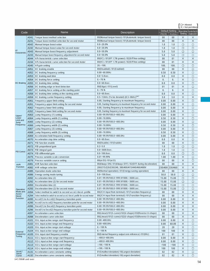
A041
A241
A042
A242
A043
A243
A044
A244
A045
A051
A052
A053
A054
A055
A056
A057
A058
A059
A061
A261
A062
A262
A063
A064
A065
A066
A067
A068
A069
A070
A071
A072
A073
A074
A075
A076
A081
A082
A085
A086
A092
A292
A093
A293
A094
A294
A095
A295
A096
A296
A097
A098
A101
A102
A103
A104
A105
A111
A112
A113
A114
A131
A132
V/f Characteristic
DC Braking
Upper/Lower Limit and Jump Frequency
PID Control
Operation Mode and Accel./ Decel. Function
External Frequency Tuning
Torque boost method selection
Torque boost method selection for second motor
Manual torque boost value
Manual torque boost value for second motor
Manual torque boost frequency adjustment
Manual torque boost frequency adjustment for second motor
V/f characteristic curve selection
V/f characteristic curve selection for second motor
V/f gain setting
DC braking enable
DC braking frequency setting
DC braking wait time
DC braking force setting
DC braking time setting
DC braking edge or level detection
DC braking force setting at the starting point
DC braking time setting at the starting point
DC braking carrier frequency setting
Frequency upper limit setting
Frequency upper limit setting for second motor
Frequency lower limit setting
Frequency lower limit setting for second motor
Jump frequency (1) setting
Jump frequency width (1) setting
Jump frequency (2) setting
Jump frequency width (2) setting
Jump frequency (3) setting
Jump frequency width (3) setting
Acceleration hold frequency setting
Acceleration stop time setting
PID function enable
PID proportional gain
PID integral gain
PID differential gain
Process variable scale conversion
Process variable source setting
AVR function selection
AVR voltage selection
Operation mode selection
Energy saving mode tuning
Acceleration time (2)
Acceleration time (2) for second motor
Deceleration time (2)
Deceleration time (2) for second motor
Select method to switch to second accel./ decel. profile
Select method to switch to second accel./ decel. profile for second motor
Accel(1) to Accel(2) frequency transition point
Accel(1) to Accel(2) frequency transition point for second motor
Decel(1) to Decel(2) frequency transition point
Decel(1) to Decel(2) frequency transition point for second motor
Acceleration curve selection
Deceleration curve selection
OI-L input active range start frequency
OI-L input active range end frequency
OI-L input active range start voltage
OI-L input active range end voltage
OI-L input start frequency enable
O2-L input active range start frequency
O2-L input active range end frequency
O2-L input active range start voltage
O2-L input active range end voltage
Acceleration curve constants setting
Deceleration curve constants setting
00(Manual torque boost) / 01(Automatic torque boost)
00(Manual torque boost) / 01(Automatic torque boost)
0.0-20.0%
0.0-20.0%
0.0-50.0%
0.0-50.0%
00(VC) / 01(VP 1.7th power) / 02(V/f free-setting)
00(VC) / 01(VP 1.7th power) / 02(V/f free-setting)
20.-100.
00(Disabled) / 01(Enabled)
0.00-60.00Hz
0.0-5.0sec.
0.-70.%
0.0-60.0sec.
00(Edge) / 01(Level)
0.-70.%
0.0-60.0sec.
0.5-12kHz (To be derated) 0.5-8kHz(*1)
0.00, Starting frequency to maximum frequency
0.00, Starting frequency to maximum frequency for second motor
0.00, Starting frequency to maximum frequency
0.00, Starting frequency to maximum frequency for second motor
0.00-99.99/100.0-400.0Hz
0.00-10.00Hz
0.00-99.99/100.0-400.0Hz
0.00-10.00Hz
0.00-99.99/100.0-400.0Hz
0.00-10.00Hz
0.00-99.99/100.0-400.0Hz
0.0-60.0sec.
00(Disable) / 01(Enable)
0.2-5.0
0.0-3600.0sec.
0.0-100.0sec.
0.01-99.99%
00(at OI) / 01(at O)
00(Always ON) / 01(Always OFF) / 02(OFF during deceleration)
200/215/220/230/240, 380/400/415/440/460/480V
00(Normal operation) / 01(Energy-saving operation)
0.0-100.0sec.
0.01-99.99/100.0-999.9/1000.-3600.sec.
0.01-99.99/100.0-999.9/1000.-3600.sec.
0.01-99.99/100.0-999.9/1000.-3600.sec.
0.01-99.99/100.0-999.9/1000.-3600.sec.
00(2CH input from terminal) / 01(Transition frequency)
00(2CH input from terminal) / 01(Transition frequency)
0.00-99.99/100.0-400.0Hz
0.00-99.99/100.0-400.0Hz
0.00-99.99/100.0-400.0Hz
0.00-99.99/100.0-400.0Hz
00(Linear)/ 01(S-curve)/ 02(U-shape)/ 03(Reverse U-shape)
00(Linear)/ 01(S-curve)/ 02(U-shape)/ 03(Reverse U-shape)
0.00-400.0Hz
0.00-400.0Hz
0.-100.%
0.-100.%
00(External frequency output zero reference) / 01(0Hz)
–400.0-400.0Hz
–400.0-400.0Hz
–100.-100.%
–100.-100.%
01(Smallest deviation)-10(Largest deviation)
01(Smallest deviation)-10(Largest deviation)
00001.01.05.05.00000
100.00
0.500.00.
0.0010.
0.03.0
0.000.000.000.000.000.500.000.500.000.500.000.0001.01.00.0
1.000000
230/40000
50.015.0015.0015.0015.00
0000
0.000.000.000.000000
0.000.0020
10001
0.000.00–1001000202
00001.01.05.05.00101
100.00
0.500.00.
0.0010.
0.03.0
0.000.000.000.000.000.500.000.500.000.500.000.0001.01.00.0
1.000000
230/46000
50.015.0015.0015.0015.00
0000
0.000.000.000.000000
0.0060.00
2010001
0.000.00–1001000202
AVR Function
Accel./Decel. Curve
= Allowed= Not permitted[ ]
(*1) 90kW and over

15(*1) 90kW and over
b001
b002b003b004b005b006b007
b013b213b015b016b017b018b019b020
b023
b026
b034
b036b037b080b081b082b083
b085b086b087b088b090b091b092b095b096b098b099b100b101b102b103b104b105b106b107b108b109b110b111b112b113
B Group : Fine Tuning Functions
Restart after InstantaneousPower Failure
Electronic Thermal
Software Lock
Others
Selection of automatic restart mode
Allowable instantaneous power failure timeTime delay enforced before motor restartInstantaneous power failure and under-voltage trip enableNumber of restarts after instantaneous power failure and under-voltage tripPhase loss detection enableRestart frequency setting
Electronic thermal characteristicsElectronic thermal characteristics for second motorFree-setting electronic thermal frequency (1)Free-setting electronic thermal current (1)Free-setting electronic thermal frequency (2)Free-setting electronic thermal current (2)Free-setting electronic thermal frequency (3)Free-setting electronic thermal current (3)
Deceleration rate at overload restriction
Deceleration rate at overload restriction (2)
RUN/ power-on warning time
Reduced voltage soft start selectionFunction code display restrictionAM terminal analog meter adjustmentFM terminal analog meter adjustmentStart frequency adjustmentCarrier frequency setting
Country code for initializationFrequency scaling conversion factorSTOP key enableResume on free-run stop cancellation modeDynamic braking usage ratioStop mode selectionCooling fan controlDynamic braking controlDynamic braking activation levelThermistor for thermal protection controlThermistor for thermal protection level settingFree-setting V/f frequency (1)Free-setting V/f voltage (1)Free-setting V/f frequency (2) Free-setting V/f voltage (2) Free-setting V/f frequency (3) Free-setting V/f voltage (3) Free-setting V/f frequency (4) Free-setting V/f voltage (4) Free-setting V/f frequency (5) Free-setting V/f voltage (5)Free-setting V/f frequency (6) Free-setting V/f voltage (6)Free-setting V/f frequency (7)Free-setting V/f voltage (7)
0.3-25.0sec. 0.3-100.0sec. 00(Disable) / 01(Enable) / 02(Disable during stop and ramp to stop) 00(16 times) / 01(Always restart) 00(Disable) / 01(Enable) 0.00-99.99/100.0-400.0Hz
00(Reduced torque) / 01(Constant torque) / 02(V/f free-setting)00(Reduced torque) / 01(Constant torque) / 02(V/f free-setting)0.-400.Hz0.0-1000.A0.-400.Hz0.0-1000.A0.-400.Hz0.0-1000.A
0.10-30.00
0.–9999./1000–6553(10,000–65,5300)hr (Output to intelligent terminal)
00(Short)-06(Long) 00(All) / 01(Utilized functions) / 02(User-selected functions only) 0-2550-2550.10-9.99Hz 0.5-12.0kHz (To be derated) 0.5-8kHz(*1)
00(Japanese version) / 01(European version) / 02(North American version) 0.1-99.9 00(Enable) / 01(Disable) 00(Restart at 0Hz) / 01(Resume operation after frequency matching) 0.0-100.0% 00(Deceleration and stop) / 01(Free-run stop) 00(Fan is always ON) / 01(Fan is ON during RUN including 5min. afetr power-on and stop)00(Disable) / 01(Enable during run) / 02(Enable during stop) 330-380/660-760V 00(Disable) / 01(PTC enable) / 02(NTC enable) 0.0-99990.-Free-setting V/f frequency (2) 0.0-800.0V 0.-Free-setting V/f frequency (3) 0.0-800.0V 0.-Free-setting V/f frequency (4) 0.0-800.0V 0.-Free-setting V/f frequency (5) 0.0-800.0V 0.-Free-setting V/f frequency (6) 0.0-800.0V 0.-Free-setting V/f frequency (7) 0.0-800.0V 0.-400.Hz 0.0-800.0V
00
1.01.0000001
0.00
01010.
0.00.
0.00.
0.0
1.00
1.00
0.
0600
18060
0.503.0
011.000000.0000000
360/72000
30000.00.00.00.00.00.00.00.00.00.00.00.00.00.0
Overload Restriction
Free-setting V/f pattern
00(Alarm output after trip, automatic restart disable) / 01(Restart at 0Hz) / 02(Re-sume operation after frequency matching) / 03(Resume previous frequency after frequency matching, then decelerate to stop and display trip information)
0.50*rated current-1.50*rated currentOverload restriction setting (2)
0.50*rated current-1.50*rated current
00(All parameters except b031 are locked when SFT from terminal is on) / 01(All parameters except b031 and output frequency F001 are locked when SFT from terminal is on) / 02(All parameters except b031 are locked) / 03(All parameters except b031 and output fre-quency F001 are locked) / 10(Run-time data edit mode)
Software lock mode selectionb031
b012
b212
Level of electronic thermal setting
Level of electronic thermal setting for second motor
0.20*rated current-1.20*rated current
0.20*rated current-1.20*rated current
Rated current
Rated current
00(Disable) / 01(Enable during accel./constant speed) / 02(Enable during constant speed) 01
Rated current*
1.20
Rated current*
1.20
b021 Overload restriction operation mode
Overload restriction settingb022
0.10-30.00
00(Disable) / 01(Enable during accel./ constant speed) / 02(Enable at constant speed)b024
b025
01
01
Overload restriction operation mode (2)
b035 Rotational direction restriction 00(Enable for both directions) / 01(Enable for forward) / 02(Enable for reverse) 00
00(Trip history clear) / 01(Parameter initialization) / 02(Trip history clear and parameter initialization) 00
00
1.01.0000001
0.00
00000.
0.00.
0.00.
0.0
15.00
1.00
0.
0600
18060
0.503.0
021.000000.0000000
360/72000
30000.00.00.00.00.00.00.00.00.00.00.00.00.00.0
Rated current
Rated current
01
Rated current*
1.20
01
01
00
00
-FE(CE)Code Name Default Setting
-FU2(UL)Run-time
SettingRun-time Data Edit(Enabled at b031)Description
= Allowed= Not permitted[ ]
b084 Initialization mode
Rated current*
1.10

16(*1) For UL version only (*2) 90kW and over
-FE(CE)Code Name Default Setting
-FU2(UL)Run-time
SettingRun-time Data Edit(Enabled at b031)Description
C011C012C013C014C015C019
C027C028C029C031C032C036C040C041C042C043C044C061C070C071C072C073C074C075C078C081C082C083C085C086C087C088C091C101
C102
C103C121C122C123
H003H203H004H204H006H206
P001P002P031P044P045P046P047P048P049
U001 I
U012
C Group: Intelligent Terminal Functions
H Group: Motor Constants Functions
P Group: Expansion Card Functions
U Group: User-selectable Menu Functions
Intelligent Input Terminal Setting
Intelligent Input Terminal State Setting
Intelligent Output Terminal State and Output Level setting
Serial Communi-cation
Analog Meter Setting
Terminal (1) active stateTerminal (2) active stateTerminal (3) active stateTerminal (4) active stateTerminal (5) active stateTerminal FW active state
FM signal selectionAM signal selection AMI signal selection Terminal (11) active stateTerminal (12) active stateAlarm relay terminal active stateOverload signal output modeOverload level settingArrival frequency setting for accelerationArrival frequency setting for decelerationPID deviation level settingElectronic thermal warning level settingData command methodCommunication speed selectionNode allocationCommunication data length selectionCommunication parity selectionCommunication stop bit selectionCommunication wait timeO input span calibration OI input span calibrationO2 input span calibrationThermistor input tuningAM terminal offset tuningAMI terminal meter tuningAMI terminal offset tuningDebug mode enableUP/DOWN memory mode selection
Reset mode selection
Restart frequency after resetO input zero calibrationOI input zero calibrationO2 input zero calibration
00(NO) / 01(NC) 00(NO) / 01(NC)00(NO) / 01(NC)00(NO) / 01(NC)00(NO) / 01(NC)00(NO) / 01(NC)
00(NO) / 01(NC)00(NO) / 01(NC)00(NO) / 01(NC)00(During accel./decel) / 01(At constant speed)0.00*rated current-2.00*rated current 0.00-99.99/100.0-400.0Hz 0.00-99.99/100.0-400.0Hz 0.0-100.0% 0.-100.% 02(Operator) / 03(RS485) / 04 (Expansion card 1) / 05(Expansion card 2)03(2400bps) / 04(4800bps) / 05(9600bps) / 06(19200bps)1.-32. 7(7-bit) / 8(8-bit)00(No parity) / 01(Even) / 02(Odd) 1(1-bit) / 2(2-bit)0.-1000.msec. 0.- 9999./1000- 6553(10,000-65,530)0.- 9999./1000- 6553(10,000-65,530) 0.- 9999./1000- 6553(10,000-65,530)0.0-1000. 0.0-10.0V 0.-255. 0.-20.0mA 00(No display) / 01(Display) 00(Clear previous frequency) / 01(Keep previous frequency)
00(Restart at 0Hz) / 01(Resume operation after frequency matching) 0.- 9999./1000- 6553(10,000-65,530)0.- 9999./1000- 6553(10,000-65,530) 0.- 9999./1000- 6553(10,000-65,530)
000000000000
000000000101
Rated current0.00.03.08002041. 7001
0.0Factory setFactory setFactory set
1050.080
Factory set0000
00
00Factory setFactory setFactory set
Intelligent Output Terminal Setting
01(RV:Reverse) / 02(CF1:Multipeed(1)) / 03(CF2:Multispeed(2)) / 04(CF3:Multi-speed(3)) / 05(CF4:Multispeed(4)) / 06(JG:Jogging) / 07(DB:External DC braking) / 08(SET:Second motor constants setting) / 09(2CH:Second accel./decel.) / 11(FRS:Free-run stop) / 12(EXT:External trip) / 13(USP:Unattended start protection) / 14(CS:Change to/from commercial power supply) / 15(SFT:Software lock) / 16(AT:Analog input selection) /18(RS:Reset) / 20(STA:3-wire start) / 21(STP:3-wire hold) / 22(F/R:3-wire fwd./rev.) / 23(PID:PID On/Off) / 24(PIDC:PID reset) / 27(UP:Remote-controlled accel.) / 28(DWN:Remote-controlled decel.) / 29(UDC:Remote-controlled data clearing) / 31(OPE:Operator control) / 32(SF1:Multi-speed bit command(1) / 33(SF2:Multispeed bit command(2) / 34(SF3:Multispeed bit command(3) / 35(SF4:Multispeed bit command(4) / 36(SF5:Multispeed bit com-mand(5) / 37(SF6:Multispeed bit command(6) / 38(SF7:Multispeed bit command(7) / 39(OLR:Overload limit change)/ 49(ROK: RUN permissive)(*1) / 255(NO:Not selected)
00(RUN:Run signal) / 01(FA1:Frequency arrival signal (at the set frequen-cy))/ 02(FA2:Frequency arrival signal (at or above the set frequency)) / 03(OL:Overload advance notice signal) / 04(OD:Output deviation for PID control) / 05(AL:Alarm signal) / 06(FA3:Frequency arrival signal (only at the set frequency)) / 08(IP:Instantaneous power failure signal) / 09(UV:Under-voltage signal)/ 11(RNT:RUN time over) / 12(ONT:Power-on time over) / 13(THM:Thermal alarm) / 27(RMD: Operator RUN command signal)(*1)
User selected functions
Motor capacityMotor capacity for second motorMotor poles settingMotor poles setting for second motorMotor stabilization constantMotor stabilization constant for second motor
Terminal (5) function
Terminal (3) function
Operation mode on Expansion card 1 errorOperation mode on Expansion card 2 errorAccel/deccel time input selectionDeviceNet comm watchdog timerInverter action on DeviceNet comm errorDeviceNet polled I/O:Output instance numberDeviceNet polled I/O:Input instance numberInput action on DeviceNet idle modeMotor poles setting for RPM
00
01
00
Others
00(Output frequency) / 01(Output current) / 03(Digital output frequency-only at C027) / 04(Output voltage) / 05(Power) / 06(Thermal load ratio) / 07(LAD fre-quency)
00(Cancel trip state when reset signal turns ON) / 01(Cancel trip state when reset signal turns OFF) / 02(Cancel trip state when reset signal turns ON(En-able during trip state))
Terminal (2) function
C005
C003
C002
C001
C021
C022
Terminal (11) function
Terminal (12) function
Terminal (1) function
Terminal (4) function
18
000001000000
000000000101
Rated current0.00.03.08002041. 7001
0.0Factory setFactory setFactory set
1050.080
Factory set0000
00
00Factory setFactory setFactory set
00
01
00
18
1616
1303
02 02
0.20-75.0(kW) -160(kW)(*2)
0.20-75.0(kW) -160(kW)(*2)
2/4/6/82/4/6/80.-255.0.-255.
00(Trip) / 01(Continuous operation) 00(Trip) / 01(Continuous operation)00(operation)/01(option1)/02(option2)0.00-99.99s00(trip)/01(trip after deceleration stop)/02(invalid)/03(free-run)/04(deceleration stop)20,21,10070,71,10100(trip)/01(trip after deceleration stop)/02(invalid)/03(free-run)/04(deceleration stop)0-38(even only)00(Output freq.forced to 0Hz; 500ms wait to recover)/01(Output forced 0Hz; no wait to recover)/02(Output freq.forced to max.freq.A004)/03(Output ferq.forced to A020/A220)
no / d001-P002
C004
Factory setFactory set
44
100.100.
Factory setFactory set
44
100.100.
000000
1.00012171010
00
000000
1.00012171010
00
no no
= Allowed= Not permitted[ ]
01 01
C026 Alarm relay terminal function 05 05
P050 Output frequency on analog reference signal loss

17
R(L1)
(+1)
(L2)
(+)
(L3)
(-)
(T1)
(RB)
(T2)
(G) (G)(L1) (L2) (L3) (+1) (+) (-) (T1) (T2) (T3)
(G)
(T3)
(G)(R0) (T0)
(R0) (T0)
S T U
PD P N RBR0 T0
V W
Terminal Arrangement
Screw Diameter and Terminal Width
Terminal Arrangement
015-055 LFU2, HFU2, HFE2
R S T PD P N U V W
R0 T0185-370LFU2185-750HFE2, HFU2
Screw diameter
Terminal width (mm)
Model
R0,T0 Terminals
015-037 LFU2HFE2/HFU2
M4
13
055LFU2HFE2/HFU2
M5
13
075LFU2HFE2/HFU2
M5
17.5
110-150LFU2HFE2/HFU2
M6
17.5
185LFU2,185-370HFE2/HFU2
M6
18
220-370LFU2,450-750HFE2/HFU2
M8
23
750LFU2,1320HFE2/HFU2
M10
40
450-550LFU2
M10
35
900-1100HFE2/HFU2
M10
29
M4
9
W
W:Terminal width
L O OI AMI P24 PLC CM1 12C 12A 11C 11A AL0
H O2 AM FM TH FW 5 4 3 2 1 AL1
AL2
Screw diameter M3, Terminal width 6.4mm
TERMINALS
All models
Main Circuit Terminals
R(L1), S(L2), T(L3)
U(T1), V(T2), W(T3)
PD(+1), P(+)
P(+), RB(RB)
P(+), N(-)
(G)
R0(R0), T0(T0)
Terminal Symbol Terminal Name
Main power supply input terminals
Inverter output terminals
DC reactor connection terminals
External braking resistor connection terminals
External braking unit connection terminals
Ground connection terminal
Control power supply input terminals
Main Circuit Terminals
Control Circuit Terminals
Terminal Description
R(L1)
(+1)
(L2)
(+)
(L3)
(-)
(T1)
(RB)
(T2)
(L1) (L2) (L3) (+1) (+) (-) (T1) (T2) (T3)
(G)
(T3)
(G) (R0) (T0)
(R0) (T0)
S T U
PD P N RB R0 T0
V W
110-150HFE2, 075-150HFU2/LFU2
R S T PD P N U V W
R0 T0220, 300, 450, 550, 750LFU2900-1320HFE2/HFU2
(G) (G)
*For ground screw of 200, 300, 450, 550 LFU2, M6 is used. For 900-1320HFE/HFU2, M8 is used.
18
Control Circuit Terminals
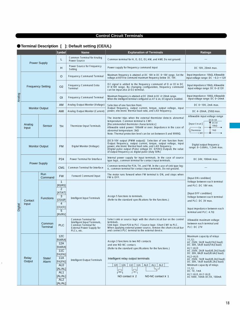
Terminal Description [ ]: Default setting (CE/UL)
Symbol Name Explanation of Terminals Ratings
Maximum capacity of relays 11,12:AC 250V, 5A(R load)/1A(I load) DC 30V, 5A(R load)/1A(I load)AL1-AL0: AC 250V, 2A(R load)/0.2A(I load) DC 30V, 8A(R load)/0.6A(I load)AL2-AL0:AC 250V, 1A(R load)/0.2A(I load)DC 30V, 1A(R load)/0.2A(I load)Minimum capacity of relays11,12:DC 1V, 1mAAL1-AL0, AL2-AL0: AC100V, 10mA DC5V, 100mA
Power Supply
Frequency Setting
Monitor Output
Monitor Output
Power Supply
Contact Input
Relay Output
Run Command
Functions
Common Terminal
State/Alarm
Common Terminal for Analog Power Source
Power Source for Frequency Setting
Frequency Command Terminal
Frequency Command Extra Terminal
Frequency Command Terminal
Analog Output Monitor (Voltage)
Analog Output Monitor (Current)
Digital Monitor (Voltage)
Power Terminal for Interface
Ana
log
Dig
ital
Common terminal for H, O, O2, OI, AM, and AMI. Do not ground.
Input impedance: 10kΩ, Allowable input voltage range: DC -0.3-+12V
DC 10V, 20mA max.
Input impedance:10kΩ, Allowableinput voltage range: DC 0-±12V
Maximum frequency is attained at DC 10V in DC 0-10V range. Set the voltage at A014 to command maximum frequency below DC 10V.
O2 signal is added to the frequency command of O or OI in DC 0-±10V range. By changing configuration, frequency command can be input also at O2 terminal.
Maximum frequency is attained at DC 20mA in DC 4-20mA range. When the intelligent terminal configured as AT is on, OI signal is enabled.
Selection of one function from: Output frequency, output current, torque, output voltage, input power, electronic thermal load ratio, and LAD frequency.
[DC0-10V output (PWM output)] Selection of one function from: Output frequency, output current, torque, output voltage, input power, electronic thermal load ratio, and LAD frequency.[Digital pulse output (Pulse voltage DC 0/10V)] Outputs the value of output frequency as digital pulse (duty 50%)
Internal power supply for input terminals. In the case of source type logic, common terminal for contact input terminals.
The motor runs forward when FW terminal is ON, and stops when FW is OFF.
Common Terminal for InterfaceCommon terminal for P24, TH, and FM. In the case of sink type log-ic, common terminal for contact input terminals. Do not ground.
Select sink or source logic with the short-circuit bar on the control terminals. Sink logic: Short P24 to PLC / Source logic: Short CM1 to PLC. When applying external power source, remove the short-circuit bar and connect PLC terminal to the external device.
Forward Command Input
Intelligent Input Terminals
Intelligent Output Terminals
Common Terminal for Intelligent Input Terminals, Common Terminal for External Power Supply for PLCs, etc.
Assign 5 functions to terminals.(Refer to the standard specifications for the functions.)
Assign 3 functions to two NO contacts and one NO-NC contact.(Refer to the standard specifications for the functions.)
Power supply for frequency command input
Input impedance: 100Ω, Allowable input voltage range: DC 0-24mA
DC 0-10V, 2mA max.
DC 4-20mA, 250Ω max.
Digital output frequency range: 0-3.6kHz, 1.2mA max.
DC 24V, 100mA max.
[Input ON condition]Voltage between each terminal
and PLC: DC 18V min.
[Input OFF condition] Voltage between each terminal
and PLC: DC 3V max.
Input impedance between each terminal and PLC: 4.7Ω
Allowable maximum voltage between each terminal and PLC: DC 27V
1[RS/RS]
2[AT/AT]
3[CF2/USP]
4[CF1/CF1]
5[RV/RV]
12C[RUN/RUN]
12A[RUN/RUN]
11C[FA1/FA1]
11A[FA1/FA1]
AL0[AL/AL]
AL1[AL/AL]
AL2[AL/AL]
P24
CM1
FW
FM
L
H
O2
O
OI
AM
AMI
PLC
Analog Input
Sensor
Allowable input voltage rangeDC0-5V
DC5V10kΩ
1kΩ
[ Input Circuit ]
ThermistorTH
CM1
The inverter trips when the external thermistor detects abnormal temperature. Common terminal is CM1. [Recommended thermistor characteristics] Allowable rated power: 100mW or over. Impedance in the case of abnormal temperature: 3k Note: Thermal protection level can be set between 0 and 9999 .
Thermistor Input TerminalsTH
Intelligent relay output terminals
NO contact X 2 NO-NC contact X 1
12C 12A 11C 11A AL0 AL1 AL2

19
PROTECTIVE FUNCTIONS
NameDisplay on digital operator
Display on remoteoperator/copy unit
Cause(s)
Over-current protection
Overload protection(*1)
Braking resistor overload protection
Over-voltage protection
EEPROM error(*2)
Under-voltage error
CT(Current transformer) error
CPU error
External trip
USP error
Ground fault
Input over-voltage protection
Instantaneous power failure
Expansion card 1 connection error
Expansion card 2 connection error
Inverter thermal trip
Missing phase
IGBT error
Thermistor error
Out of operation due to under-voltage
An error has been detected in an expantion card or at its connecting terminals.
One of three lines of 3-phase power supply is missing.
While at constant speed
During deceleration
During acceleration
Others
(*1)You can clear the error by pressing the Start / Reset key 10 seconds after the trip occurred.(*2)If an EEPROM error occurs, be sure to confirm the parameter data values are still correct.
When the built-in EEPROM memory has problems due to noise or excessive temper-ature, the inverter trips and turns off its output.
When a malfunction in the built-in CPU has occurred, the inverter trips and turns off its output.
When a signal to an intelligent input terminal configured as EXT has occurred, the inverter trips and turns off its output.
The inverter is protected by the detection of ground faults between the inverter output and the motor during power-up tests. This feature protects the inverter only.
When the input voltage is higher than the specified value, it is detected 60 seconds after power-up and the inverter trips and turns of its output.
When instantaneous over-current has occurred, the inverter trips and turns off its output to protect main circuit element.
When the thermistor inside the motor detects temperature higher than the specified value, the inverter trips and turns off its output.
When the DC bus voltage exceeds a threshold, due to regenerative energy from the motor, the inverter trips and turns off its output.
When a motor overload is detected by the electronic thermal function, the inverter trips and turns off its output.
The inverter output was short-circuited, or the motor shaft is locked or has a heavy load. These conditions cause excessive current for the inverter, so the inverter output is turned off.
When the regenerative braking resistor exceeds the usage time allowance or an over-voltage caused by the stop of the BRD function is detected, the inverter trips and turns off its output.
A decrease of internal DC bus voltage below a threshold results in a control circuit fault. This condition can also generate excessive motor heat or cause low torque. The inverter trips and turns off its output.
If a strong source of electrical interference is close to the inverter or abnormal operations occur in the built-in CT(Current transformer), the inverter trips and turns off its output.
An error occurs when power is cycled while the inverter is in RUN mode if the Unattended Start Protection (USP) is enabled. The inverter trips and does not go into RUN mode until the error is cleared.
When power is cut for more than 15msec., the inverter trips and turns off its output. If power failure contin-ues, the error will be cleared. The inverter restarts if it is in RUN mode when power is cycled.
When the inverter internal temperature is higher than the specified value, the thermal sensor in the inverter module detects the higher temperature of the power devices and trips, turning off the inverter output.
Gate array error Communication error has occured between CPU and gate array.
Due to insufficient voltage, the inverter has turned off its output and been trying to restart. If it fails to restart, it goes into the under-voltage error.
How to access the details about the present fault
Status at trip pointError codeOutput frequency at trip point
Motor current at trip point
Voltage between P(+) and N(–) at trip point
Cumulative inverter operation (run) time at trip point
Cumulative power-on time at trip point
OC.Drive
ERR1****
OC.Drive
OC.Accel
Over.C
Over.L
OL.BRD
Over.V
EEPROM
Under.V
CT
CPU1
EXTERNAL
USP
GND.Flt.
OV.SRC
Inst.P-F
OP1 0-9
OP2 0-9
OH FIN
GA
PH.Fail
IGBT
TH
UV.WAIT
–
–

20
CONNECTING DIAGRAM
200V-240V±10%50/60Hz±5%
Short-circuit bar
Forward command
Intelligentinput terminals(5 terminals)
Thermistor
DC0-10V(12-bit)
DC0-10V(8-bit)
DC4-20mA(8-bit)
(G)
DC–10–+10V(12-bit)
Current input 4-20mA(12-bit)
Analog input
Analog output
FM Monitor output(PWM)
RS485Serial communication port
Intelligent output terminals
DC link choke
IM
Removable terminals
L300PR(L1)
S (L2)
T (L3)
R0
P24
PLCCM1
FW
5
4
3
1
FM
CM1
O2
OI
L
AM
AMI
10k
10k
100
TH
H
O
T0
SN
RP
SN
SP
12C
12A
11C
P
RB
P
RB
N Braking resistor (RB)
11A
AL2
AL1
AL0
N N
P
AL1
Dynamic braking unit (BRD)
AL2
RB
R1
R2
RB
P
(+1)PD
(T3)W
(T2)V
(T1)U
DC24V
DC10V
- +
Terminal NameCommon
FW, 1, 2, 3, 4, 5P24
FM, THCM1
H, O, O2, OI, AM, AMIL
AL1AL2
AL1AL2
RBP
RBP
(+)
(-)
(Inve
rter)
(To
oper
atin
g c
ircui
t)
For 18.5kW(25HP) and over
For up to 15kW(20HP)
In case of 400V class,place a transformer for operating circuitto receive 200V.
Option
Customer wiring(Outside the inverter)
SOURCE TYPE LOGIC
Frequencysetting device500-2k
R
T(J51)(*2)(*2)Remove connection with J51
when RoTo power is supplied externally
Control power source

21
Short-circuit bar
Forward command
Intelligentinput terminals
Thermistor
DC0-10V(12-bit)
DC0-10V(8-bit)
DC4-20mA(8-bit) (G)
DC–10–+10V(12-bit)
Current input 4-20mA(12-bit)
Analog input
Analog output
RS485Serial communication port
Intelligent output terminals
DC link choke
IM
Removable terminals
L300P
P24
PLC
FW
5
4
3
2
1
FM
CM1
O2
OI
L
AM
AMI
10k
10k
100
TH
H
O
SN
RP
SN
SP
12C
12A
11C
P
RB
P
RB
N Braking resistor (RB)
11A
AL2
AL1
AL0
N N
P
AL1
Dynamic braking unit (BRD)
AL2
RB
R1
R2
RB
P
(+1)PD
(T3)W
(T2)V
(T1)U
DC24V
DC10V
- +
Terminal NameCommon
FW, 1, 2, 3, 4, 5, FM, THCM1
H, O, O2, OI, AM, AMIL
AL1AL2
AL1AL2
RBP
RBP
(+)
(-)
(Inve
rter)
(To
oper
atin
g c
ircui
t)
For 18.5kW(25HP) and over
For up to 15kW(20HP)
In case of 400V class,place a transformer for operating circuitto receive 200V.
Option
Customer wiring(Outside the inverter)
SINK TYPE LOGIC
Frequencysetting device500-2k
200V-240V±10%50/60Hz±5%
R(L1)
S (L2)
T (L3)
R0T0
R
T(J51)(*2)(*2)Remove connection with J51
when RoTo power is supplied externally
Control power source

22
CONNECTING TO PLC
Hitachi EH-150 series PLC Output Module EH-YT16
L300P Hitachi EH-150 series PLC Output Module EH-YTP16
L300P
Hitachi EH-150 series PLC Output Module EH-YT16
L300P Hitachi EH-150 series PLC Output Module EH-YTP16
L300P
(1) Sink type logic (2) Source type logic
1. USING INTERNAL POWER SUPPLY OF THE INVERTER
(1) Sink type logic (2) Source type logic
2. USING EXTERNAL POWER SUPPLY
(Note:Place short-circuit bar between PLC and CM1 instead of P24 and PLC.)
(Note:Be sure to turn on the inverter after turning on the PLC and its external power supply to prevent the parameters in the inverter from being modified.)
(Note:Remove short-circuit bar between P24 and PLC.) (Note:Remove short-circuit bar between P24 and PLC.)
S
FW
5
1
P24
PLC
DC24V
+- -
COM CM1
COM
FW
5
1
P24
PLC
DC24V
+
S CM1
S
FW
5
1
P24
PLC
DC24V
+
COM CM1
COM
FW
5
1
P24
PLC
DC24V
+
S CM1
DC24V+-
- -
DC24V
+-
23
Note 1: Field wiring connection must be made by a UL and c-UL listed closed-loop terminal connector sized for the wire gauge involved. Connector must be fixed using the crimping tool specified by the connector manufacturer. Note 2: Be sure to use bigger wires for power lines if the distance exceeds 20m(66ft).R
R0
T0
S T
U V W
PD
P
RBN
IM
Fuse
Power Supply
Motor
Inverter
(L1) (L2) (L3)
(T1) (T2) (T3)
(+1)
(-)
(+)
This is useful in suppressing harmonics induced on the power supply lines, or when the main power voltage imbalance exceeds 3% (and power source capac-ity is more than 500kVA), or to smooth out line fluctuations. It also improves the power factor.
This filter reduces the conducted noise in the power supply wiring between the invert-er and the power distribution system. Connect it to the inverter primary (input side).Electrical noise interference may occur on nearby equipment such as a radio receiver. This magnetic choke filter helps reduce radiated noise (can also be used on output).This capacitive filter reduces radiated noise from the main power wires in the inverter input side.The choke suppresses harmonics generated by the inverter. However, it will not protect the input diode bridge rectifier.
Braking components are useful for increasing the inverter's control torque for high duty-cycle (on-off) applications, and improving the decelerating capability.
Electrical noise interference may occur on nearby equipment such as a radio receiver. This magnetic choke filter helps reduce radiated noise (can also be used on input).
Reduces radiated noise from wiring in the inverter output side.
This reactor reduces the vibration in the motor caused by the inver-ter's switching waveforms, by smoothing the waveforms to approxi-mate commercial power quality. It is also useful when wiring from the inverter to the motor is more than 10m in length, to reduce harmonics.
Sine wave shaping filter for the output side.LCR filter
Input side AC reactor
EMI filter
Radio noise filter
Radio noise filter(Capacitive filter)
DC link choke
Output side noise filter
Radio noise filter
AC reactor
Braking resistor
Braking unit
Name Function
1.5(2)
2.2(3)
3.7(5)
5.5(8)
7.5(10)
11(15)
15(20)
18.5(25)
22(30)
30(40)
37(50)
45(60)
55(75)
75(100)
1.5(2)
2.2(3)
3.7(5)
5.5(8)
7.5(10)
11(15)
15(20)
18.5(25)
22(30)
30(40)
37(50)
45(60)
55(75)
75(100)
90(125)
110(150)
132(175)
L300P-015LFU2L300P-022LFU2L300P-037LFU2L300P-055LFU2L300P-075LFU2L300P-110LFU2L300P-150LFU2L300P-185LFU2L300P-220LFU2L300P-300LFU2L300P-370LFU2L300P-450LFU2L300P-550LFU2L300P-750LFU2L300P-015HFU2L300P-022HFU2L300P-040HFU2L300P-055HFU2L300P-075HFU2L300P-110HFU2L300P-150HFU2L300P-185HFU2L300P-220HFU2L300P-300HFU2L300P-370HFU2L300P-450HFU2L300P-550HFU2L300P-750LFU2L300P-900LFU2L300P-1100LFU2L300P-1320LFU2
AWG 14AWG 14AWG 10AWG 8AWG 6AWG 4AWG 2
AWG 4 *2AWG 1/0AWG 2 *2AWG 1 *2
AWG 1 *2(75°C)AWG 2/0 *2 AWG 3/0 *2
AWG 18AWG 16AWG 14AWG 12AWG 10AWG 8AWG 6AWG 6AWG 4AWG 3
AWG 4 *2AWG 1
AWG 2 *2AWG 1 *2
AWG 1 *2(75°C)AWG 2/0 *2 AWG 2/0 *2
2.12.15.38.4
13.321.233.6
21.2 *253.5
33.8 *242.4 *242.4 *267.4 *285.0 *2
0.81.32.13.35.38.4
13.313.321.226.7
21.2 *242.4
33.8 *242.4 *242.4 *267.4 *267.4 *2
0.75mm2
shielded wire
0.75mm2
shielded wire
1015203040607090
1001501752002503001010151520303550507080
100125150200225300
MotorOutput (kW(HP))
Model
200V
400V
Input Voltage
Wiring
Power Lines SignalLines
Fuse(Class J)
AWG mm2
WIRING and ACCESSORIES
Note: An EMI filter is required for European EMC directive and C-Tick, but the others are not for this purpose.

24
OPERATOR
CABLE FOR OPERATORREMOTE OPERATOR SRW-0EX(Optional)
ACCESSORIES
Potentiometer Remote Control Copy FunctionInstallation in L300P
(Standard for L300P)(OPE-SRE: Standard for L300P UL version)
Model
OPE-S
OPE-SR/SRE
SRW-0EX
ICS-1
ICS-3
Cable Length
1m (3.3ft)
3m (9.8ft)
Model
Multilingual
[Unit:mm (inch)]Inches for reference only
*OPE-SRE: English overlay
80(3.15)
59(2
.32)
2(0.
08)26.5(1.04)
18(0
.71)
18(0.71)
2- 4(0.16)
79(3
.11)
1 2
STOP/RESET
FUNC STR
RUN
PRG
RUNHz
VkW
A
%
ALARM
POWER
13( 0
.51)
8(0.3
1)
(*)
DIMENSIONS
L
3m (9.8ft)
1m (3.3ft)
ICS-3
ICS-1
123(
4.84
)
103(
4.06
)2 (
0.0
8)
26.5(1.04)
18( 0
.71)
18(0.7 1)
2- 4( 0.16)
80(3.15)
6.5(
0.26
)10
3(4.
06)
13(0
.51)
8(0.
31)
STOP/RESETREV RUNFWD RUN
0 1 2 3
STRFUNMON
REMT READ COPY
COPY
RUNPRGPOWER
ALARM
OPE-S(R) SRW-0EX ICS-1, 3(Cables for OPE-S/SR/SRE and SRW-0EX)
Mounting holes
*Potentiometer is installed only in ORE-SR/SRE.
Mounting holes
Model Name Cable Length
2-M3 depth5(Reverse side)
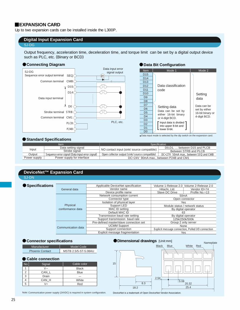
25
Output frequency, acceleration time, deceleration time, and torque limit can be set by a digital output device such as PLC, etc. (Binary or BCD)
Up to two expansion cards can be installed inside the L300P.EXPANSION CARD
Sequence error output terminal
Common terminal
D15
D14
D0
Strobe terminal
RY
Common terminal
SEQ
CMB
STRB
CM1
PLCB
P24B
PLC, etc.
Data input errorsignal outputSJ-DG
Data input terminal
Connecting Diagram
Standard Specifications
Data Bit ConfigurationItemD15
Mode 1 Mode 2
D14
Data classificationcode
Settingdata
Setting data
Data input mode is selected by the dip switch on the expansion card.
D13D12D11D10D9D8
D3D2D1D0
D7D6D5D4
Data can be set by either 16-bit binary or 4-digit BCD.
Data can be set by either 16-bit binary or 4-digit BCD.
*
Item Specification
Input NO contact input (sink/ source compatible)D0,D1, … between D15 and PLCB
Between STRB and PLCBDC+27V 50mA max., between SEQ and CMBOpen collector output (sink/ source compatible)
DC+24V 90mA max., between P24B and CM1Output
Power supply
Data setting signalStrobe signal
Sequence error signal (Data input error signal)Power supply for interface
Specifications
Dimensional drawings
No12345
Signal Cable color
V-CAN_LDrain
CAN_HV+
Note: Communication power supply (24VDC) is required in system configuration.
Cable connection
20.3225.4
5.082.54
Black
8.3
15
18.2
Blue White RedNameplate
General data
Physical conformance data
Communication data
Applicable DeviceNet specificationVendor name
Device profile nameNetwork consumption current
Connector typeIsolation of physical layer
Support LEDMAC ID settingDefault MAC ID
Transmission baud rate settingSupport transmission baud rate
Pre-defined master/slave connection setUCMM Support
Support connectionExplicit message fragmentation
Volume 1-Relesse 2.0 Volume 2-Relesse 2.0Hitachi, Ltd. Vendor ID=74
Slave DC Drive Profile No.=1350mA
Open connectorYes
Module status / network status
63By digital operator
By digital operator125k/250k/500k
Group 2 only serverNone
Explicit message connection, Polled I/O connectionYes
[Unit:mm]
Digital Input Expansion CardSJ-DG
DeviceNet™ Expansion CardSJ-DN
DeviceNet is a trademark of Open DeviceNet Vendor Association.
Connector specifications
Phoenix Contact MSTB 2.5/5-ST-5.08AU
Input data is divided into upper 8-bit and lower 8-bit.
Manufacturer Model Code
BlackBlue–
WhiteRed

26
Dimensional drawings [Unit: mm]
PROFIBUS® Expansion CardSJ-PBT
LONWORKS® Expansion CardSJ-LW
Specifications
Dimensional drawings [Unit: mm]
No
123456
Signal name Function
NET-ANET-BShieldNET-ANET-BShield
NET-A input connectionNET-B input connectionCable shield connectionNET-A input connectionNET-B input connectionCable shield connection
Note: PROFIBUS is a registered trademark of Profibus Nutzer Organization.
Cable connection
Variable Speed Drive (Order no. 3.072)RS-485Open connector (6 poles)GSD fileVPC3+ (Made by Profichip)100m at 12Mbps, 1200m at 9.6kbps(No rooter used for both conditions)126 (Rooter used), 32(No rooter used)Yes (Bus topology termination enable)9.6kbps to 12Mbps (Baud rate auto-detecting function equipped)Master/slaveFieldbus ON/Off-lineFieldbus diagnosisCommunication Status
Support profileTransmission method
Connector typeSupport fileASIC chip
Maximum bus lengthMaximum number of connectable nodes
Termination supportSupport baud rate
Communication specification
Support LED
Connector specifications
Phoenix Contact MC 1.5/6-ST-3.81
No
1
Signal name Function
2
3
Shield
NET-A
NET-B
Cable shield connection
NET-A input connection
NET-B input connection
Note: Network function must be supported by the software of the inverter used with SJ-DN, SJ-PBT, or SJ-LW.For the detail, please contact Hitachi sales office.
LONWORKS is a registered trademark of Echelon Corporation
Cable connection
Manufacturer Model Code
Specifications
Variable Speed DriveFTT-10A (Free Topology Twisted Pair Transceiver)Open connector
0000-Node Object6010-Variable Speed Motor Drive
XIFTMPN3120FE5M2700m500m32,385
78kbps (Fixed)Pier to Pier
FT (Free topology termination enable)NO (Termination disable)BUS (Bus topology termination enable)
Power /InverterLON diagnosis/ ServiceCommunication Status
Device ClassTransmission method
Connector type
Support file
LonMark Object Support
Neuron ChipMax. bus length
Max. length between nodes Max. nodes number
Termination support
Support LED
Support transmission baudrateData type
Connector specifications
Phoenix Contact MC 1.5/3-ST-3.81
Manufacturer Model Code
7.62
12.22
3.812.3
6.6
11.1
15.5
19.05
23.65
3.812.3
6.6
11.1
15.5
1 2 3 4 5 6

27
FOR COMPACT PANELHeat accumulation in the panel can be reduced by arranging inverter heat sink outside.
Model W
L300P-075–150LFU2, HFU2 -110–150HFE2
L300P-015–055LFU2, HFU2/E2
L300P-185-300LFU2, HFU2/E2L300P-370LFU2, HFU2/E2
L300P-750LFU2L300P-900–1100HFU2/E2
L300P-1320HFU2/E2
146
206
249320
400
490400490
W1130
189
229300
380
510420510
H280
285
415524
550
710710750
H1260
265
395505
520
670690710
ScrewM6
M6
M6M8
M10
M10M10M10
d62
82
8392
102.7
131141137
[Unit: mm]Panel cutout
L300P-450–550LFU2, HFU2/E2 -450–750HFU2/E2
W1
H1
4-Screw
H
W
L300P-370LFU2, HFU2/E2 L300P-075–150LFU2, HFU2 -110–150HFE2
L300P-015–055LFU2,HFU2/E2 L300P-185–300LFU2, HFU2/E2
L300P-450–550LFU2 -450–750HFU2/E2
L300P-750LFU2 L300P-900–1100HFU2/E2 L300P-1320HFU2/E2
Panel insideExhaust
Airintake
FP-3(For the top and the bottom of the inverter)
Panel inside
Exhaust
Airintake
FP-4(For the sides of the inverter)
FP-4(For the top and the bottom of the inverter)
Panel inside
Exhaust
Air intake
FP-2(For the top and the bottom of the inverter)
ExhaustPanelinside
Air intake
FP-1(For the top and the bottom of the inverter)
Panel inside
Exhaust
Airintake
FP-5(For the sides of the inverter)
FP-5(For the top and the bottom of the inverter)
d
Exhaust
Panelinside
Air intake
FP-6(For the sides of the inverter)
FP-6(For the top and the bottom of the inverter)
d
Exhaust
Panelinside
Airintake
FP-7(For the side of the inverter)
FP-7(For the top and the bottom of the inverter)
d
ExhaustPanelinside
Airintake
FP-8(For the side of the inverter)
FP-9(For the top andthe bottom of the inverter)
d
dd
d
d

28
The L300P series can be used at ambient temperature of –10 C to 50 C.However, when using at 40 C or over, derating is required.
TORQUE CHARACTERISTICS
Typical torque performance based on V/f pattern (top) is shown below.
DERATING DATA
V
(Hz)f
V/f pattern
100(%)
1 – 501 – 60
100120
150
130125
10095908075
5045
25
00 1 6 10 20 30 40 50 60 70 80 90 100 110 120
6 25 50 75 100
(Continuous operating torque)
(Base frequency 60Hz)
(Base frequency 50Hz)
Maximum torque(for short time period, maximum torque boosting)
Frequency (Hz)O
utpu
t tor
que
(%)
100
90
80
70
6055
10.5 2 3 4 5 6 7 8 9 10 11 12
015–220HFU2/E2450,550HFU2/E2
100
90
80
70
6055
10.5 2 3 4 5 6 7 8 9 10 11 12
110HFU2/E2150HFU2/E2
100
90
80
70
6055
10.5 2 3 4 5 6 7 8 9 10 11 12
(1)Ambient temperature 40°C
100
90
80
70
60
5510.5 2 3 4 5 6 7 8 9 10 11 12
015–150LFU2
185LFU2
450LFU2
370LFU2
550LFU2
(2)Ambient temperature 50°C
(200V class)
(200V class)
220LFU2
300, 750LFU2 750HFU2/E2
900HFU2/E2
450LFU2
015-075LFU2
370HFU2/E2
1100, 1320HFU2/E2
300HFU2/E2
220LFU2370LFU2550LFU2
300LFU2
750LFU2
185HFU2/E–220HFU2/E2450HFU2/E2
370HFU2/E2
750HFU2/E2
300HFU2/E2
Out
put c
urre
nt
( Rat
io to
the
ratin
g: %
)
Carrier frequency (kHz)
Out
put c
urre
nt
( Rat
io to
the
ratin
g: %
)
Carrier frequency (kHz)
(400V class)
(400V class)
Out
put c
urre
nt
( Rat
io to
the
ratin
g: %
)
Carrier frequency (kHz)
Out
put c
urre
nt
( Rat
io to
the
ratin
g: %
)
Carrier frequency (kHz)
110LFU2
150LFU2
185LFU2
550HFU2/E
900HFU2/E2 015–075HFU2/E2
1100, 1320HFU2/E2

29
FOR CORRECT OPERATION
The overspeed endurance of a general-purpose motor is 120% of the rated speed for 2 minutes (JIS C4,004). For operation at higher than 60Hz, it is required to examine the allowable torque of the motor, useful life of bearings, noise, vibration, etc. In this case, be sure to consult the motor manufacturer as the maximum allowable rpm differs depending on the motor capacity, etc.
The torque characteristics of driving a general-purpose motor with an inverter differ from those of driving it using commer-cial power (starting torque decreases in particular). Carefully check the load torque characteristic of a connected machine and the driving torque characteristic of the motor.
An inverter-driven general-purpose motor heats up quickly at lower speeds. Consequently, the continuous torque level(output) will decrease at lower motor speeds. Carefully check the torque characteristics vs speed range requirements.
When run by an inverter, a general-purpose motor generates noise slightly greater than with commercial power.
When run by an inverter at variable speeds, the motor may generate vibration, especially because of (a) unbalance of the rotor including a connected machine, or (b) resonance caused by the natural vibration frequency of a mechanical system. Particularly, be careful of (b) when operating at variable speeds a machine previously fitted with a constant speed motor. Vibration can be minimized by (1) avoiding resonance points using the frequency jump function of the inverter, (2) using a tire-shaped coupling, or (3) placing a rubber shock absorber beneath the motor base.
Under continued, low-speed operation, oil lubrication can deteriorate in a power transmission mechanism with an oil-type gear box (gear motor) or reducer. Check with the motor manufacturer for the permissible range of continuous speed. To operate at more than 60 Hz, confirm the machine’s ability to withstand the centrifugal force generated.
Operating frequency
Torque characteristics
Noise
Vibration
Motor loss and temperature increase
Power transmission mechanism
The allowable rotation range of continuous drive varies depending on the lubrication method or motor manufacturer. (Par-ticularly in case of oil lubrication, pay attention to the low frequency range.)
For use of a brake-equipped motor, be sure to connect the braking power supply from the primary side of the inverter.
There are different kinds of pole-change motors (constant output characteristic type, constant torque characteristic type, etc.), with different rated current values. In motor selection, check the maximum allowable current for each motor of a different pole count. At the time of pole changing, be sure to stop the motor.
The rated current of a submersible motor is significantly larger than that of the general-purpose motor. In inverter selection, be sure to check the rated current of the motor. Also see: Application to the 400V-class motor.
Inverter drive is not suitable for a safety-enhanced explosion-proof type motor. The inverter should be used in combination with a pressure-proof explosion-proof type motor.*Explosion-proof verification is not available for L300P Series. For explosion-proof operation, use other series of motors.
In most cases, the synchronous (MS) motor and the high-speed (HFM) motor are designed and manufactured to meet the specifications suitable for a connected machine. As to proper inverter selection, consult the manufacturer.
Gear motor
Brake-equipped motor
Submersible motor
Explosion-proof motor
Synchronous (MS) motorHigh-speed (HFM) motor
Pole-change motor
Single-phase motor
Application to Motors [Application to general-purpose motors]
Run or stop of the inverter must be done with the keys on the operator panel or through the control circuit terminals. Do not operate by installing a electromagnetic contactor (Mg) in the main circuit. When the protective function is operating or the power supply stops, the motor enters the free run stop state. When an emergency stop is required or when the motor should be kept stopped, use of a mechanical brake should be considered.
A max. 400Hz can be selected on the L300P Series. However, a two-pole motor can attain up to approx. 24,000 rpm, which is extremely dangerous. Therefore, carefully make selection and settings by checking the mechanical strength of the motor and connected machines. Consult the motor manufacturer when it is necessary to drive a standard (general-purpose) motor above 60 Hz.
Run/Stop
Emergency motor stop
High-frequency operation
Notes on Use [Drive]
[Application to special motors]
[Application to the 400V-class motor]
A system applying a voltage-type PWM inverter with IGBT may have surge voltage at the motor terminals resulting from the cable constants including the cable length and the cable laying method. Depending on the surge current magnification, the motor coil insulation may be degraded. In particular, when a 400V-class motor is used, a longer cable is used, and critical loss can occur, take the following countermeasures: (1) install the LCR filter between the inverter and the motor, (2) install the AC reactor between the inverter and the motor, or(3) enhance the insulation of the motor coil.
[Installation location and operating environment]
Avoid installation in areas of high temperature, excessive humidity, or where moisture can easily collect, as well as areas that are dusty, subject to corrosive gasses, mist of liquid for grinding, or salt. Install the inverter away from direct sunlight in a well-ventilated room that is free of vibration. The inverter can be operated in the ambient temperature range from –10 to 50°C. (Carrier frequency and output current must be reduced in the range of 40 to 50°C.)
A single-phase motor is not suitable for variable-speed operation by an inverter drive. Therefore, use a three-phase motor.

30
(1)Be sure to connect main power wires with R(L1), S(L2), and T(L3) (input) terminals and motor wires to U(T1), V(T2), and W(T3) terminals (output). (Incorrect connection will cause an immediate failure.)(2)Be sure to provide a grounding connection with the ground terminal ( ).
When an electromagnetic contactor is installed between the inverter and the motor, do not perform on-off switching during running operation.
When used with standard applicable output motors (Hitachi standard three-phase squirrel-cage four-pole motors), the L300P Series does not need a thermal relay for motor protection due to the internal electronic protective circuit. A thermal relay, however, should be used: during continuous running outside a range of 30 to 60 Hz. for motors exceeding the range of electronic thermal adjustment (rated current). when several motors are driven by the same inverter; install a thermal relay for each motor. The RC value of the thermal relay should be more than 1.1 times the rated current of the motor. Where the wiring length is 10 m or more, the thermal relay tends to turn off readily. In this case, provide an AC reactor on the output side or use a current sensor.
Install a circuit breaker on the main power input side to protect inverter wiring and ensure personal safety. Choose an inverter-compatible circuit breaker. The conventional type may malfunction due to harmonics from the inverter. For more information, consult the circuit breaker manufacturer.
The wiring distance between the inverter and the remote operator panel should be 20 meters or less. When this distance is exceeded, use CVD-E (current-voltage converter) or RCD-E (remote control device). Shielded cable should be used on the wiring. Beware of voltage drops on main circuit wires. (A large voltage drop reduces torque.)
Wiring connections
Thermal relay
Wiring between inverter and motor
Installing a circuit breaker
Wiring distance
Earth leakage relay
Phase advance capacitor
Electro-magnetic contactor
Notes on Peripheral Equipment Selection
(1) High-frequency components are included in the input/output of the inverter main circuit, and they may cause interference in a transmitter, radio, or sensor if used near the inverter. The interference can be minimized by attaching noise filters (option) in the inverter circuitry. (2) The switching action of an inverter causes an increase in leakage current. Be sure to ground the inverter and the motor.
Lifetime of Primary Parts
Because a smoothing capacitor deteriorates as it undergoes internal chemical reaction, it should normally be replaced every five years. Be aware, however, that its life expectancy is considerably shorter when the inverter is subjected to such adverse factors as high temperatures or heavy loads exceeding the rated current of the inverter. The approximate lifetime of the capacitor is as shown in the figure at the right when it is used 12 hours daily (according to the “Instructions for Periodic Inspection of General-Purpose Inverter” (JEMA)).Also, such moving parts (cooling fan) should be replaced. Maintenance inspection and parts replacement must be performed by only specified trained personnel.
In the following examples involving a general-purpose inverter, a large peak current flows on the main power supply side, and may destroy the converter module. Where such situations are foreseen or the connected equipment must be highly reli-able, install an AC reactor between the power supply and the inverter. Also, where influence of indirect lightning strike is pos-sible, install a lightning conductor.(A) The unbalance factor of the power supply is 3% or higher. (Note)(B) The power supply capacity is at least 10 times greater than the inverter capacity (the power supply capacity is 500 kVA or more).(C) Abrupt power supply changes are expected. Examples: (1) Several inverters are interconnected with a short bus. (2) A thyristor converter and an inverter are interconnected with a short bus. (3) An installed phase advance capacitor opens and closes.In cases (A), (B) and (C), it is recommended to install an AC reactor on the main power supply side.Note: Example calculation with VRS = 205V, VST = 201V, VTR = 200V VRS : R-S line voltage, VST : S-T line voltage, VTR : T-R line voltage
An inverter run by a private power generator may overheat the generator or suffer from a deformed output voltage waveform of the generator. Generally, the generator capacity should be five times that of the inverter (kVA) in a PWM control system, or six times greater in a PAM control system.
Installation of an AC reactor on theinput side
Using a private power generator
[Main power supply]
Max. line voltage (min.) – Mean line voltageMean line voltage
202
Before use, be sure to read through the Instruction Manual to insure proper use of the inverter. Note that the inverter requires electrical wiring; a trained specialist should carry out the wiring.The inverter in this catalog is designed for general industrial applications. For special applications in fields such as aircraft, outer space, nuclearpower, electrical power, transport vehicles, clinics, and underwater equipment, please consult with us in advance. For application in a facility where human life is involved or serious losses may occur, make sure to provide safety devices to avoid a serious accident.The inverter is intended for use with a three-phase AC motor. For use with a load other than this, please consult with us.
Precaution for Correct Usage
High-frequency Noise and Leakage Current
Do not use a capacitor for power factor improvement between the inverter and the motor because the high-frequency components of the inverter output may overheat or damage the capacitor
If the earth leakage relay (or earth leakage breaker) is used, it should have a sensitivity level of 15 mA or more (per inverter).
205 – 202= ————————————— X 100 = ————— X 100 = 1.5 (%)
Unbalance factor of voltage = ——————————————————————— X 100
VRS – (VRS + VST + VTR )/3(VRS + VST + VTR )/3
50
40
30
Am
bien
t tem
pera
ture
( °C
)
2.5 5 10Capacitor lifetime (years)
Information in this brochure is subject to change without notice.

Printed in Japan(H) SM-E232U 1006