L30041 Rev 9/07 - Henry & Wright Manual/Haldex_Installation_Manual...The Haldex PLC Select 2M is...
66
Installation/Service Manual for 2S/1M - 4S/2M (2S/2M) Systems $ 7.00 PLC Select ABS (2M) PLC Select ABS (1M) Installation Guide L30041 Rev 9/07
Transcript of L30041 Rev 9/07 - Henry & Wright Manual/Haldex_Installation_Manual...The Haldex PLC Select 2M is...

Installation/Service Manual for2S/1M - 4S/2M (2S/2M) Systems
$ 7.00
PLC Select ABS (2M) PLC Select ABS (1M)
InstallationGuide
L30041 Rev 9/07

Page 1 Rev. 5.0
Page
1
2
3
4 - 5
6 - 11
1213
14 - 15
16
17
18
19
20
21
22
23 - 24
2526
27 - 28
29
30
31
32
33
34
35
36
37
38
39 - 40
41 - 42
43 - 45
46 - 50
51
52
53
54 - 58
Section
Table of Contents.....................................................................................................................
Safety Notice............................................................................................................................
General Operation of PLC Select 1M and 2M..........................................................................
Wheel End Installation..............................................................................................................
Wheel Speed Sensor Installation Configurations 1M and 2M Systems....................................
PLC Select ABS (1M) Installation Manual for 2S/1M Systems............................................
PLC Select 1M - System Components.....................................................................................
PLC Select 1M - ECU/Valve Units OverView............................................................................
PLC Select 1M and 2M Valve Orientation.................................................................................
PLC Select 1M - Installation Overview (4 Port FFABS Systems 2/S1M)..................................
PLC Select 1M - Installation Overview (6 Port ABS System 2S/1M)........................................
PLC Select 1M - PLC Select FFABS 2S/1M (Plumbing Schematic).........................................
PLC Select 1M - PLC Select 6 Port ABS 2S/1M (Plumbing Schematic) ..................................
PLC Select 1M - ABS Power Cord - Pin Out - 1M ECU OverView............................................
PLC Select 1M - 2S/1M System Wiring....................................................................................
PLC Select 1M - Speed Sensor Cable Routing.........................................................................
PLC Select ABS (2M) Installation Manual for 4S/2M Systems............................................
PLC Select 2M - System Components......................................................................................
PLC Select 2M - ECU/Valve Units Overview.............................................................................
PLC Select 2M - Installation Overview (FFABS System 4S/2M)...............................................
PLC Select 2M - Installation Overview (ABS Relay System 4S/2M).........................................
PLC Select 2M - PLC Select FFABS 4S/2M (Plumbing Schematic) (Side-By-Side)................
PLC Select 2M - PLC Select 2 Port ABS 4S/2M (Plumbing Schematic) (Side-By-Side).........
PLC Select 2M - PLC Select FFABS 4S/2M (Plumbing Schematic) (Axle-By-Axle)................
PLC Select 2M - PLC Select 2 Port ABS 4S/2M (Plumbing Schematic) (Axle-By-Axle).........
PLC Select 2M - PLC Select 2M ECU Overview.......................................................................
PLC Select 2M - 4S/2M System Wiring (Side-By-Side)...........................................................
PLC Select 2M - 4S/2M System Wiring (Axle-By-Axle)...........................................................
PLC Select 2M - 4S/2M System Wiring Information..................................................................
PLC Select 2M - Speed Sensor Cable Routing.........................................................................
Testing and Diagnostic Tools:PLC Select 1M - 2M End of line Testing/Road Testing..............................................................
Diagnostic Tools PLC PC Diagnostic........................................................................................
Diagnostic Tools - Blink Code Diagnostics................................................................................
Info Center Information:Info Center Manual L31158 “Reference”...................................................................................
Tire Scale Factor Chart:PLC Select 1M - 2M Tire Scale Factor Chart............................................................................
PLC Select 1M - 2M Diagnostics:PLC Select 1M - 2M Troubleshooting ABS Warning Light........................................................
PLC Select 1M - 2M Diagnostics Codes...................................................................................
Table of Contents
Page 2 Rev. 5.0
This installation manual describes the correct installation procedures for the Haldex PLC
Select 1M and 2M for trailers. The PLC Select 1M and 2M may be used with either Drum
or Disc Brakes. Care must be taken during each phase of the installation in order to ensure
the system is installed correctly.
Safety First !
Please follow your company’s safety procedures when you install this equipment. Be sure that you understand all instructions before you begin.
Note: Remove all air pressure and electrical power from the brake system before beginning work.
IMPORTANT NOTICE
The data listed herein is correct to the best of Haldex’s knowledge and belief, having beencompiled from reliable and official sources of information. However, HALDEX CAN NOT ASSUME ANY RESPONSIBILITY for possible error or misapplication of the product. Final determination of the suitability of the products for the use contemplated by the Buyer is thesole responsibility of the Buyer. Haldex shall have no responsibility in connection with this suitability.
All rights reserved.
Material may only be reproduced with written permission of Haldex.
Safety Notice:
IMPORTANT NOTICE
The description and specifications contained in this Installation/Service Manual are current atthe time of printing. Haldex Brake Products Corp. reserves the right to discontinue or modifyits models and/or procedure and to change specifications at any time without notice.
Page 3 Rev. 5.0
The Haldex PLC Select 1M and 2M are the newest ECU platforms in the PLC family of Trailer ABS
products and is the latest offering in the state-of-art PLC Select concept.
As with other ABS systems, PLC Select 1M and 2M are designed to use electronic management of
service braking to avoid wheel lock-up, during all types of braking conditions, and on all road surface
conditions, to improve control and stability of a braking trailer to permit air brake compliance with
FMVSS 121.
The primary components of Haldex ABS are the ECU (Electronic Control Unit), ABS Modulator Valves
(solenoid operated air valves), wheel speed sensor (Sensors), and Exciter Rings (exciter).
The inductive sensors are mounted at the designated wheel ends in conjunction with exciter (notched
rings). The ECU reads electric impulses generated from the rotating exciter, as the wheels turn.
The ECU is designed to recognize when the rate of wheel speed deceleration is approaching
wheel-lock (no longer rotating) which would result in skidding. During a braking event, the ECU
continuously monitors the rate of deceleration so that it can automatically intervene into the
operation of the ABS Modulator Valve(s) to maintain stability during braking:
- When the rate of deceleration approaches wheel-lock the ECU sends electrical
signals to the ABS Modulator Valve(s) to reduce air pressure to the service brake
chambers which reduces braking (to maximize stability);
- When the rate of deceleration returns to a level above the wheel-lock threshold the
ECU sends electrical signals to the ABS Modulator Valve(s) to increase pressure to the
service brake chambers which increases braking.
- This iterative process of decreasing and increasing braking takes place in
milliseconds and continues as long as the deceleration rate is in jeopardy of wheel-lock
to help assure vehicle stability.
The Haldex PLC Select 1M is positioned as a 2S/1M system for Semi-Trailers and Dollies using
2 Sensors and 1 Modulator (ABS Valve).
Note: Haldex recommends our 2S/1M SLH product as a more cost effective solution to meet
minimum FMVSS121 requirements for Semi-Trailer and Dollies, and in most applications can provide
comparable performance as 2M systems.
The Haldex PLC Select 2M is positioned as a 4S/2M system using 4 Sensor and 2 Modulators (ABS
Valves). Although it can be used for 2S/2M applications, Haldex recommends our 2S/1M SLH
product as comparable performance and more economical.
Although a 4S/2M is only required for Full Trailers to comply with FMVSS 121 it can provide improved
performance in certain applications, and we encourage you to consult your Haldex representative
for a recommendation to fit your specific application needs and/or preferences. All other braked
Semi-Trailer and Dollies comply with FMVSS 121 using a 2S/1M system.
FMVSS 121 specifies that “Blue Wire” (J560 connector) be allocated as “permanent power” for ABS
operation. In the event of a failure or malfunction of the permanent power circuit the ABS system will
operate on power from the stoplight circuit (i.e. when the brakes are applied). If the power fails in both
circuits the ABS system reverts to a standard braking system.
General Operation of PLC Select 1M and 2M
Page 4 Rev. 5.0
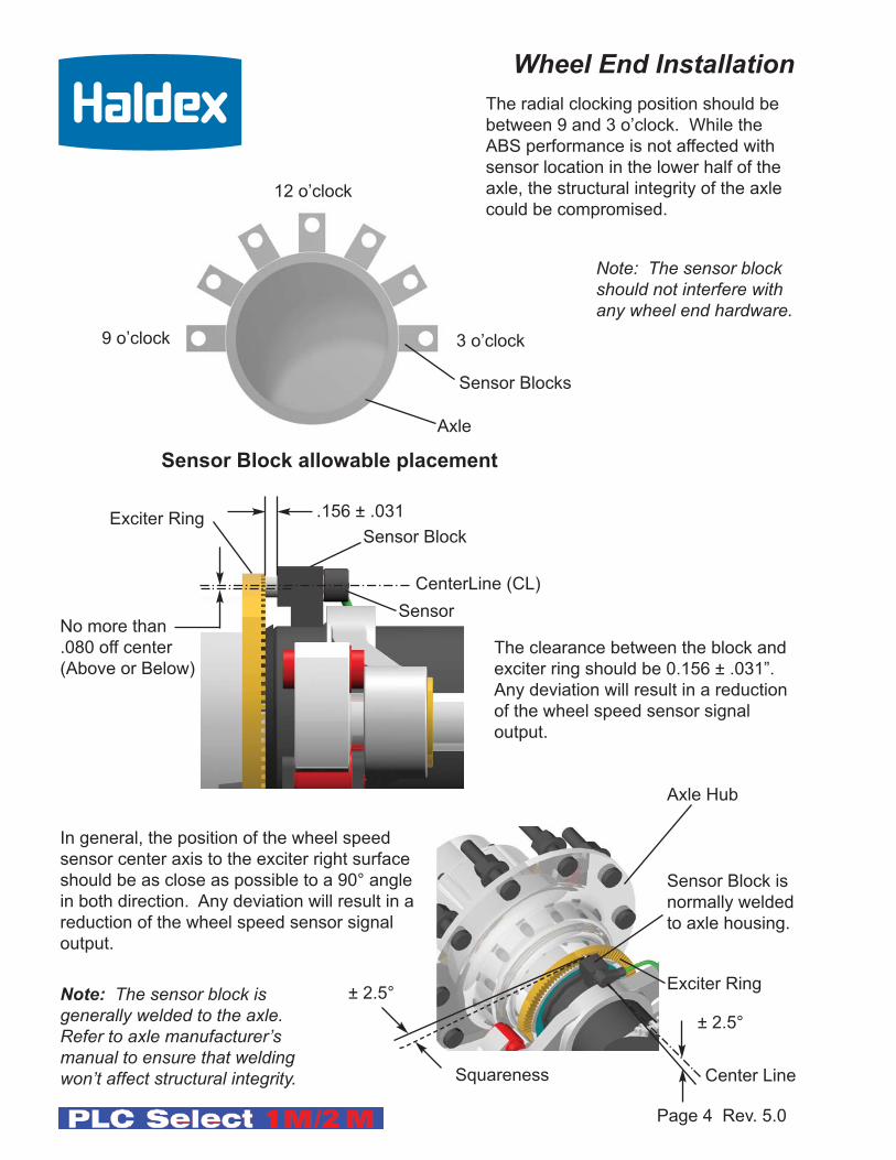
.156 ± .031
CenterLine (CL)
No more than
.080 off center
(Above or Below)
Exciter RingSensor Block
Sensor
Axle
Sensor Blocks
3 o’clock9 o’clock
12 o’clock
Sensor Block allowable placement
± 2.5°
± 2.5°
The clearance between the block and
exciter ring should be 0.156 ± .031”.
Any deviation will result in a reduction
of the wheel speed sensor signal
output.
The radial clocking position should be
between 9 and 3 o’clock. While the
ABS performance is not affected with
sensor location in the lower half of the
axle, the structural integrity of the axle
could be compromised.
Note: The sensor blockshould not interfere withany wheel end hardware.
In general, the position of the wheel speed
sensor center axis to the exciter right surface
should be as close as possible to a 90° angle
in both direction. Any deviation will result in a
reduction of the wheel speed sensor signal
output.
Note: The sensor block is generally welded to the axle. Refer to axle manufacturer’s manual to ensure that welding won’t affect structural integrity.
Sensor Block is
normally welded
to axle housing.
Axle Hub
Exciter Ring
Wheel End Installation
Squareness Center Line

Page 5 Rev. 5.0
1. Heat the exciter ring uniformly to approximately 350° F.
2. Place the exciter ring on the machined area of the axle hub.
3. Make sure the exciter ring fits squarely on the machined
surface.
4. When the exciter ring cools, it will shrink fit onto the hub.
5. Make sure the exciter ring fits tightly onto the machined area
and does not slip.
6.00 Dia
Max. Seal
Bore
6.501 Dia
6.499 Dia
.530/.470125
.06 Radius
.03 x 15° ChamferHub
Hub
Exciter Ring
80 Tooth
Use a wire brush to
clean area on hub
before mounting the
exciter ring.
Ensure that the exciter ring fits
squarely against the shoulder.
Wheel End Installation Cont.
Exciter Ring Machining
Exciter Ring Installation
100 Tooth
Note: Some application with small wheel/tires may require 80 tooth exciters.Reference “Tire Scale Factor Chart” on page 52.

Page 6 Rev. 5.0
Wheel Speed Sensor Installation2S/1M Configurations
Sensors should be installed on the axle that locks first when the trailer isunloaded. Recommended locations are shown below. The 1A sensorshould be installed on the curb side, and the 1B sensor should be installedon the road side of the trailer. Make sure sensors are pushed firmlyagainst the exciter rings.
Multi-Axle Trailers (4 or 6 Port Valves)
Spring Suspension
Dollies and Single Axle Trailers (2 or 6 Ports Valve)
Spring SuspensionSpring Suspension
Air SuspensionAir Suspension
(CurbSide)
(RoadSide)
(CurbSide)
(RoadSide)
(CurbSide)
(RoadSide)
(CurbSide)
(RoadSide)
1A
1B
1A
1B
1A
1B
1A
1B
(CurbSide)
(RoadSide)
(CurbSide)
(RoadSide)
1A
1B
Legend:1A
1B
“For Dollies, Single Axle Trailers, and Steer Axles, Haldex recommends the A8 ECU configuration”
King Pin
Speed Sensor
ECU with ABS Valve
Page 7 Rev. 5.0
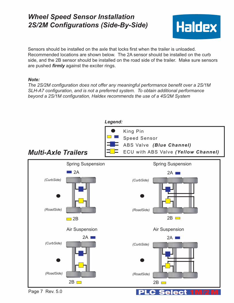
Wheel Speed Sensor Installation2S/2M Configurations (Side-By-Side)
Sensors should be installed on the axle that locks first when the trailer is unloaded.
Recommended locations are shown below. The 2A sensor should be installed on the curb
side, and the 2B sensor should be installed on the road side of the trailer. Make sure sensors
are pushed firmly against the exciter rings.
Note:The 2S/2M configuration does not offer any meaningful performance benefit over a 2S/1MSLH-A7 configuration, and is not a preferred system. To obtain additional performance beyond a 2S/1M configuration, Haldex recommends the use of a 4S/2M System
Multi-Axle TrailersSpring SuspensionSpring Suspension
Air SuspensionAir Suspension
(CurbSide)
(RoadSide)
(CurbSide)
(RoadSide)
(CurbSide)
(RoadSide)
(CurbSide)
(RoadSide)
2A
2B
2A
2B
2A
2B
2A
2B
King Pin
Speed Sensor
ABS Valve (Blue Channel)ECU with ABS Valve (Yellow Channel)
Legend:

Page 8 Rev. 5.0
Multi-Axle Trailers
The placement of the sensors at the wheel end is an important consideration. Incorrect
installation of the sensors and exciter will result in poor or no ABS operation. The “yellow
markings” sensors, connections and axle locations must go to the yellow ABS valve as shown
below. The same holds true for the “blue markings” valve.
On a 4S/2M Side-By-Side configuration, the (blue modulator) lead must be connected to the valve that controls the Curb Side wheel ends and are sensed by the blue sensors(3A and 2A). The (yellow valve) cable lead must be connected to the valve that controls the Road Side wheel ends and is sensed by the yellow sensors (3B and 2B).
The schematic below shows the proper placement of the sensors and valve leads (the king pin
indicates the front of the trailer). Make sure sensors are pushed firmly against the exciter
rings.
Wheel Speed Sensor Installation4S/2M Configurations (Side-By-Side)
Spring SuspensionSpring Suspension
Air SuspensionAir Suspension
(CurbSide)
(RoadSide)
(CurbSide)
(RoadSide)
(CurbSide)
(RoadSide)
(CurbSide)
(RoadSide)
3A
3B
2A
2B
2A
2B
2A
2B
2A
2B
3A
3B
3A
3B
3A
3B
King Pin
Speed Sensor
ABS Valve (Blue Channel)ECU with ABS Valve (Yellow Channel)
Legend:

Page 9 Rev. 5.0
Wrong
(CurbSide)
(RoadSide)
(CurbSide)
(RoadSide)
(CurbSide)
(RoadSide)
3A
3B
Lift Axle
CorrectCorrect
Lift AxleLift Axle
2A
2B
On 4S/2M Side-By-Side installation, the sensed wheels “3A” and “3B” can be used on a lift
axle. The sensed wheels “2A” and “2B” must remain on the ground at all times.
Note: Indirectly controlled axles (axles without sensors, but controlled by ABS valves) may belifted regardless of the configuration. Make sure sensors are pushed firmly against the exciterrings.
Direct axle has ABS Sensors. Indirect axle has no sensors but is ABS modulated by an ABSvalve.
3A
3B
2A
2B
3A
3B
2A
2B
Lift Axle
Wheel Speed Sensor Installation4S/2M (Side-By-Side) Lift Control:
Correct
(CurbSide)
(RoadSide)
Lift Axle
3A
3B
2A
2B
King Pin
Speed Sensor
ABS Valve (Blue Channel)ECU with ABS Valve (Yellow Channel)
Legend:
Page 10 Rev. 5.0
Multi-Axle TrailersSpring SuspensionSpring Suspension
Air SuspensionAir Suspension
(CurbSide)
(RoadSide)
(CurbSide)
(RoadSide)
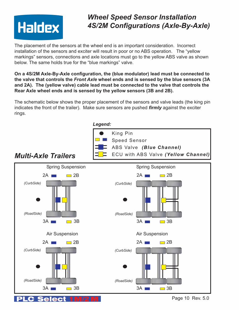
Wheel Speed Sensor Installation4S/2M Configurations (Axle-By-Axle)
The placement of the sensors at the wheel end is an important consideration. Incorrect
installation of the sensors and exciter will result in poor or no ABS operation. The “yellow
markings” sensors, connections and axle locations must go to the yellow ABS valve as shown
below. The same holds true for the “blue markings” valve.
On a 4S/2M Axle-By-Axle configuration, the (blue modulator) lead must be connected to
the valve that controls the Front Axle wheel ends and is sensed by the blue sensors (3A
and 2A). The (yellow valve) cable lead must be connected to the valve that controls the
Rear Axle wheel ends and is sensed by the yellow sensors (3B and 2B).
The schematic below shows the proper placement of the sensors and valve leads (the king pin
indicates the front of the trailer). Make sure sensors are pushed firmly against the exciter
rings.
2B
3B
2A
3A
2B
3B
2A
3A
(CurbSide)
(RoadSide)
(CurbSide)
(RoadSide)
2B
3B
2A
3A
2B
3B
2A
3A
King Pin
Speed Sensor
ABS Valve (Blue Channel)ECU with ABS Valve (Yellow Channel)
Legend:
Page 11 Rev. 5.0
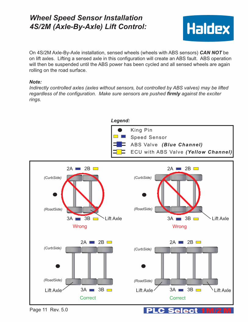
Wheel Speed Sensor Installation4S/2M (Axle-By-Axle) Lift Control:
WrongWrong
(CurbSide)
(RoadSide)
(CurbSide)
(RoadSide)
(CurbSide)
(RoadSide)
(CurbSide)
(RoadSide)
2A
3A
Lift Axle
CorrectCorrect
Lift Axle
Lift AxleLift Axle
2B
3B
On 4S/2M Axle-By-Axle installation, sensed wheels (wheels with ABS sensors) CAN NOT be
on lift axles. Lifting a sensed axle in this configuration will create an ABS fault. ABS operation
will then be suspended until the ABS power has been cycled and all sensed wheels are again
rolling on the road surface.
Note:Indirectly controlled axles (axles without sensors, but controlled by ABS valves) may be liftedregardless of the configuration. Make sure sensors are pushed firmly against the exciterrings.
2A
3A
2B
3B
2A
3A
2B
3B
2A
3A
2B
3B
Lift Axle
King Pin
Speed Sensor
ABS Valve (Blue Channel)ECU with ABS Valve (Yellow Channel)
Legend:


Installation/Service Manualfor
2S/1M Systems
PLC Select ABS (1M)
Page 12 Rev. 5.0

PLC Info Center
90° Degree Sensor and
Sensor Extension
Sensor Block Clip
PLC PC Diagnostics Kit
(PC not included)
Haldex Supplied Items
Haldex Diagnostic Tools
Required / Optional Supplier Section
ABS Light2-Port Valve
Software
6-Port Valve
J1708/PLC
Adapter
7-way Diagnostic
Interface Cable
Trailer ABS Power Cable
Page 13 Rev. 5.0
FFABS Valve
PLC Select 1M(Valves)
Trailer Brake Control Valve
(Haldex TBCV or RT4)
Tie Strap
3-Way Clip Sensor Hose Clip
Recommended Installation Aids
Sensor
Extension
Retainer Clip
PLC Select 1M System Components“See Haldex Trailer ABS Service Components Catalog L20243
for additional information on Haldex ABS Products”

Page 14 Rev. 5.0
(2 Port) FFABS Valve
Service Brake Delivery
Emergency/SupplySpring Brake Delivery
Spring Brake Delivery
Service Brake Delivery
SolenoidService/Control Port
PLC Select 1M ECU
Tighten nipple (torque 50 ft. lb.)
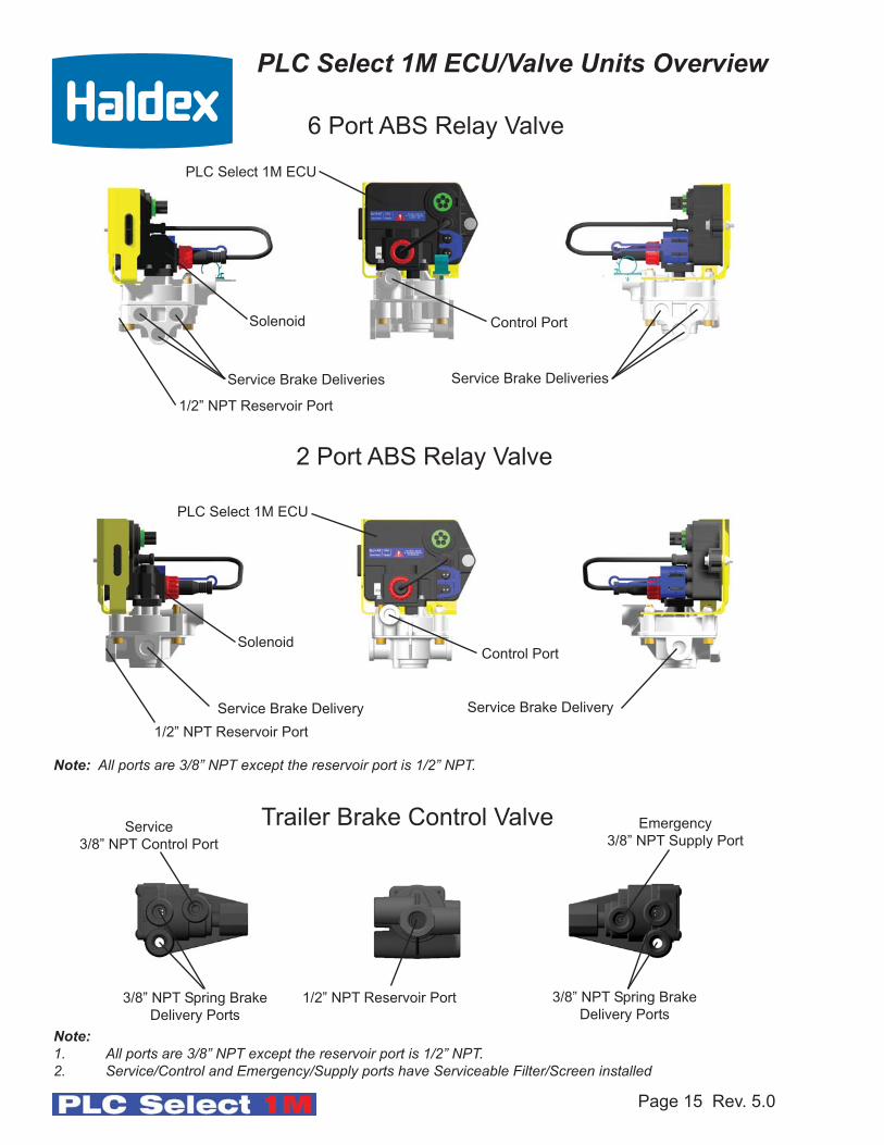
PLC Select 1M ECU/Valve Units Overview
Service Brake Exhaust
Spring Brake
Exhaust
Reservoir Port (1/2” and 3/4” NPT)
Jam Nut (torque 30 ft. lb.)
Notes: - (4) Port FFABS Valve is the most commonly used for Tandem Axle Trailers.
- All ports are 3/8” NPT except reservoir nipple (1/2” and 3/4” NPT).
- Service/Control and Emergency/Supply ports have serviceable filter/screen installed.
Page 15 Rev. 5.0
Control Port
Service Brake Delivery Service Brake Delivery
PLC Select 1M ECU
1/2” NPT Reservoir Port
2 Port ABS Relay Valve
Solenoid
Control Port
Service Brake Deliveries Service Brake Deliveries
PLC Select 1M ECU
1/2” NPT Reservoir Port
6 Port ABS Relay Valve
Solenoid
Note:1. All ports are 3/8” NPT except the reservoir port is 1/2” NPT.2. Service/Control and Emergency/Supply ports have Serviceable Filter/Screen installed
PLC Select 1M ECU/Valve Units Overview
Trailer Brake Control Valve Emergency
3/8” NPT Supply PortService
3/8” NPT Control Port
Note: All ports are 3/8” NPT except the reservoir port is 1/2” NPT.
3/8” NPT Spring Brake
Delivery Ports1/2” NPT Reservoir Port3/8” NPT Spring Brake
Delivery Ports

1. Install fittings into valve. Sealant is not required on plastic threads or on fittings that
go into plastic. DO NOT use teflon tape on fittings. It can break off and contaminate
the air system.
2. For plastic ports, hand tighten fittings then rotate 1 to 1-1/2 additional turns. The
maximum torque valve allowed is 210 in-lb.
3. Install valve nipple into reservoir port. Use 7/8” wrench to tighten the nipple.
4. Using a 1-1/2” wrench on the jam nut, while holding the nipple with the 7/8” wrench.
(see detail below).
5. Attach hoses to appropriate brake chambers. Use liquid thread sealant sparingly on all
fittings (Loctite PST565 or equivalent).
Note: If frame mounted follow same procedure for valve orientation.Valve solenoid on a 2-port relay, 6-port relay or FFABS must be facing up when the trailer is in normal operation or service/ABS performace could be effected
PLC Select 1M & 2M Valve Orientation
Page 16 Rev. 5.0
Typical tank mount valve orientation
UP
Tighten nipple (torque 50 ft. lb.)
Use 7/8” WrenchJam Nut (torque 30 ft. lb.)
Use 1-1/2” Wrench
The ABS Valve Solenoid must be installed toward the top of the trailer
GROUND

These are the general components that make up the Haldex PLC Select 1M. The PLC Select
1M can be used on Single, Tandem, and Tri-Axle vehicles. For other configurations contact
Haldex Engineering Support.
(4 Port FFABS System) Plumbing 2S/1M
Page 17 Rev. 5.0
Blue = Service/Control
Red =Emergency/Supply
5-Way ABS
Power Connector
PLC Select 1M (FFABS)
PLC Select 1M Installation Overview
Note: The slider chassis is shown upside down in figure below

(6 Port ABS System) Plumbing 2S/1M(Trailer Brake Control Valve is required)
Page 18 Rev. 5.0
These are the general components that make up the Haldex PLC Select 1M. When an ABS
Relay Valve is used, a Trailer Brake Control Valve is required such as Haldex (TBCV) or
(RT-4) valve. The PLC Select 1M can be used on Single, Tandem, and Tri-Axle vehicles. For
other configurations contact Haldex Engineering Support.
Blue = Service/Control
Red =Emergency/Supply
5-Way ABS
Power Connector
PLC Select
(6 Port ABS Valve)
Trailer Brake
Control Valve
(TBCV)
PLC Select 1M Installation Overview
Note: The slider chassis is shown upside down in figure below
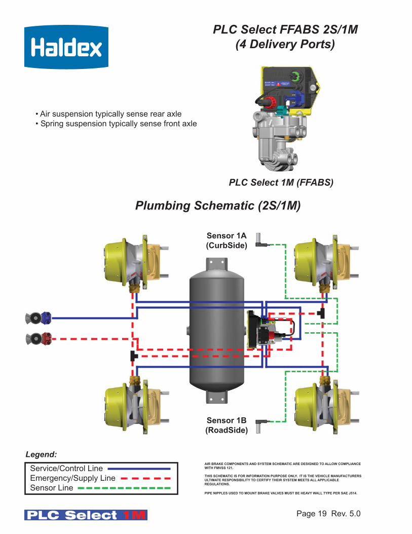
PLC Select FFABS 2S/1M(4 Delivery Ports)
Page 19 Rev. 5.0
PLC Select 1M (FFABS)
Legend:Service/Control Line
Emergency/Supply Line
Sensor Line
Sensor 1A
(CurbSide)
Sensor 1B
(RoadSide)
Plumbing Schematic (2S/1M)
AIR BRAKE COMPONENTS AND SYSTEM SCHEMATIC ARE DESIGNED TO ALLOW COMPLIANCE
WITH FMVSS 121.
THIS SCHEMATIC IS FOR INFORMATION PURPOSE ONLY. IT IS THE VEHICLE MANUFACTURERS
ULTIMATE RESPONSIBILITY TO CERTIFY THEIR SYSTEM MEETS ALL APPLICABLE
REGULATIONS.
PIPE NIPPLES USED TO MOUNT BRAKE VALVES MUST BE HEAVY WALL TYPE PER SAE J514.
• Air suspension typically sense rear axle
• Spring suspension typically sense front axle

Page 20 Rev. 5.0
PLC Select 6 Port ABS 2S/1M with Trailer Brake Control Valve
PLC Select(6 Port ABS Valve)
Trailer Brake Control Valve(TBCV)
Sensor 1A
(CurbSide)
Sensor 1B
(RoadSide)
Legend:
Service/Control Line
Emergency/Supply Line
Sensor Line
Plumbing Schematic (2S/1M)
AIR BRAKE COMPONENTS AND SYSTEM SCHEMATIC ARE DESIGNED TO ALLOW COMPLIANCE
WITH FMVSS 121.
THIS SCHEMATIC IS FOR INFORMATION PURPOSE ONLY. IT IS THE VEHICLE MANUFACTURERS
ULTIMATE RESPONSIBILITY TO CERTIFY THEIR SYSTEM MEETS ALL APPLICABLE
REGULATIONS.
PIPE NIPPLES USED TO MOUNT BRAKE VALVES MUST BE HEAVY WALL TYPE PER SAE J514.
• Air suspension typically sense rear axle
• Spring suspension typically sense front axle
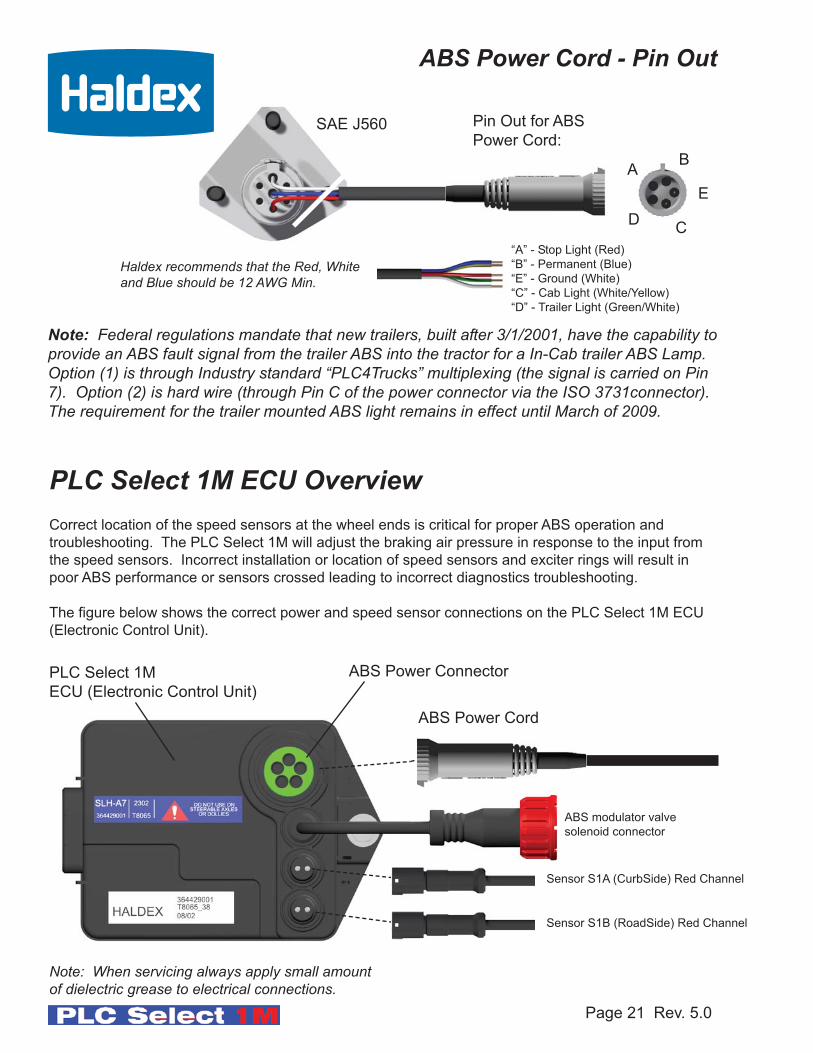
Pin Out for ABS
Power Cord:
“A” - Stop Light (Red)
“B” - Permanent (Blue)
“E” - Ground (White)
“C” - Cab Light (White/Yellow)
“D” - Trailer Light (Green/White)
B
D
E
C
A
Haldex recommends that the Red, Whiteand Blue should be 12 AWG Min.
Correct location of the speed sensors at the wheel ends is critical for proper ABS operation and
troubleshooting. The PLC Select 1M will adjust the braking air pressure in response to the input from
the speed sensors. Incorrect installation or location of speed sensors and exciter rings will result in
poor ABS performance or sensors crossed leading to incorrect diagnostics troubleshooting.
The figure below shows the correct power and speed sensor connections on the PLC Select 1M ECU
(Electronic Control Unit).
Page 21 Rev. 5.0
ABS Power Cord
Sensor S1A (CurbSide) Red Channel
Sensor S1B (RoadSide) Red Channel
PLC Select 1M
ECU (Electronic Control Unit)
PLC Select 1M ECU Overview
Note: When servicing always apply small amount of dielectric grease to electrical connections.
ABS Power Connector
ABS Power Cord - Pin Out
SAE J560
Note: Federal regulations mandate that new trailers, built after 3/1/2001, have the capability toprovide an ABS fault signal from the trailer ABS into the tractor for a In-Cab trailer ABS Lamp.Option (1) is through Industry standard “PLC4Trucks” multiplexing (the signal is carried on Pin7). Option (2) is hard wire (through Pin C of the power connector via the ISO 3731connector).The requirement for the trailer mounted ABS light remains in effect until March of 2009.
ABS modulator valve
solenoid connector

2S/1M System Wiring - PLC Select
Solenoid Connection
hand tighten collar firmly
Note: Cover all exposed connectionsbefore painting
ABS Power Connection
S1B (RoadSide)
Red Channel
S1A (CurbSide)
Red Channel
ABS Light (mounted on RoadSide of
trailer, at the rear). LED ABS lamp is
acceptable.
Apply dielectric grease toall electrical connections
7-Way Wiring
SAEJ560
*Distance of ABS Light from Red
rear clearance side marker light is
5.9” inches to 23” inches max. LED
lamp are acceptable.
Page 22 Rev. 5.0
Exciter Ring
Exciter Ring
(S1A) Top
(S1B) Bottom
Only the ABS power cord should be routed
through the support clip.The ABS Power Cord
is secured to the bracket and is secured with a
tie strap
Tie Strap
ECU Sensor Retainer Clip
Page 23 Rev. 5.0
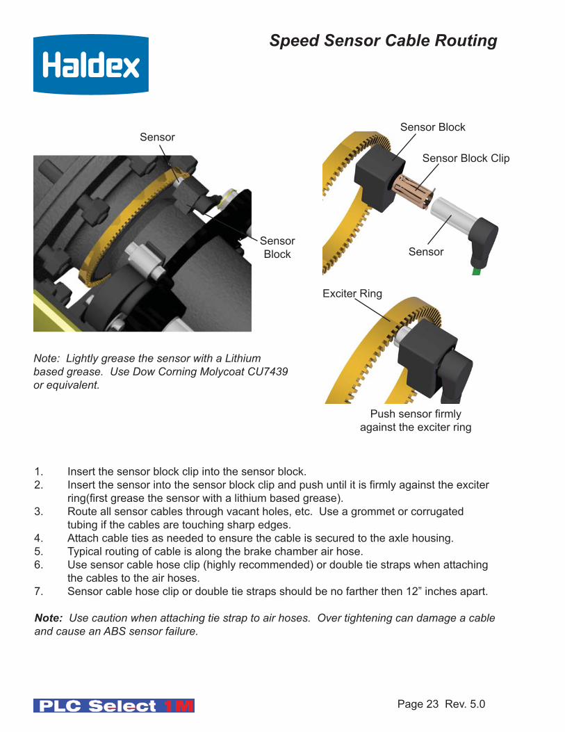
Speed Sensor Cable Routing
Sensor
Sensor
Block
1. Insert the sensor block clip into the sensor block.
2. Insert the sensor into the sensor block clip and push until it is firmly against the exciter
ring(first grease the sensor with a lithium based grease).
3. Route all sensor cables through vacant holes, etc. Use a grommet or corrugated
tubing if the cables are touching sharp edges.
4. Attach cable ties as needed to ensure the cable is secured to the axle housing.
5. Typical routing of cable is along the brake chamber air hose.
6. Use sensor cable hose clip (highly recommended) or double tie straps when attaching
the cables to the air hoses.
7. Sensor cable hose clip or double tie straps should be no farther then 12” inches apart.
Note: Use caution when attaching tie strap to air hoses. Over tightening can damage a cableand cause an ABS sensor failure.
Push sensor firmly
against the exciter ring
Sensor
Sensor Block Clip
Exciter Ring
Note: Lightly grease the sensor with a Lithiumbased grease. Use Dow Corning Molycoat CU7439or equivalent.
Sensor Block
Page 24 Rev. 5.0
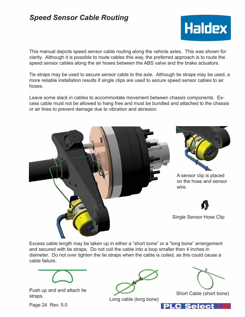
Speed Sensor Cable Routing
This manual depicts speed sensor cable routing along the vehicle axles. This was shown for
clarity. Although it is possible to route cables this way, the preferred approach is to route the
speed sensor cables along the air hoses between the ABS valve and the brake actuators.
Tie straps may be used to secure sensor cable to the axle. Although tie straps may be used, a
more reliable installation results if single clips are used to secure speed sensor cables to air
hoses.
Leave some slack in cables to accommodate movement between chassis components. Ex-
cess cable must not be allowed to hang free and must be bundled and attached to the chassis
or air lines to prevent damage due to vibration and abrasion.
Excess cable length may be taken up in either a “short bone” or a “long bone” arrangement
and secured with tie straps. Do not coil the cable into a loop smaller then 4 inches in
diameter. Do not over tighten the tie straps when the cable is coiled, as this could cause a
cable failure.
Short Cable (short bone)
Long cable (long bone)
Push up and and attach tie
straps.
A sensor clip is placed
on the hose and sensor
wire.
Single Sensor Hose Clip

Page 25 Rev. 5.0
Installation/Service Manualfor
4S/2M (2S/2M) Systems
PLC Select ABS (2M)
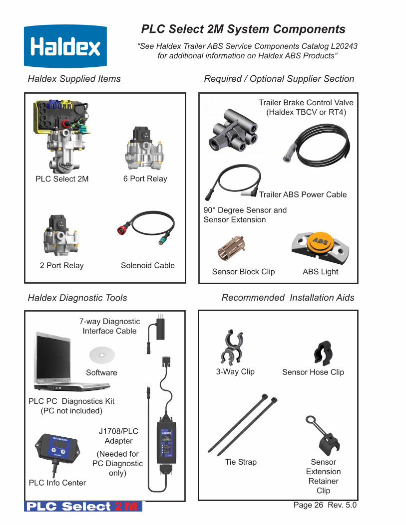
PLC Info Center
Sensor Block Clip
PLC PC Diagnostics Kit
(PC not included)
3-Way Clip Sensor Hose Clip
Haldex Supplied Items
Haldex Diagnostic Tools Recommended Installation Aids
Required / Optional Supplier Section
ABS Light
Page 26 Rev. 5.0
PLC Select 2M
Software
6 Port Relay
2 Port Relay Solenoid Cable
J1708/PLC
Adapter
7-way Diagnostic
Interface Cable
Trailer ABS Power Cable
(Needed for
PC Diagnostic
only)
Sensor
Extension
Retainer
Clip
Trailer Brake Control Valve
(Haldex TBCV or RT4)
Tie Strap
“See Haldex Trailer ABS Service Components Catalog L20243for additional information on Haldex ABS Products”
PLC Select 2M System Components
90° Degree Sensor and
Sensor Extension

Page 27 Rev. 5.0
Spring Brake Delivery
Spring Brake Delivery
Control Port
Emergency/Supply
Service Brake Deliveries
Service Brake Deliveries
PLC Select 2M ECU
Reservoir Port
Tighten nipple (torque 50 ft. lb.)
4 Port FFABS Valve
Solenoid Control Port
Tighten jam nut (torque 30 ft. lb.)
Notes: - (2) Port FFABS Valve is the most commonly used for Tandem Axle Trailers.
- All ports are 3/8” NPT except reservoir nipple (1/2” or 3/4” NPT).
- Service/Control and Emergency/Supply ports have serviceable filter/screen installed.
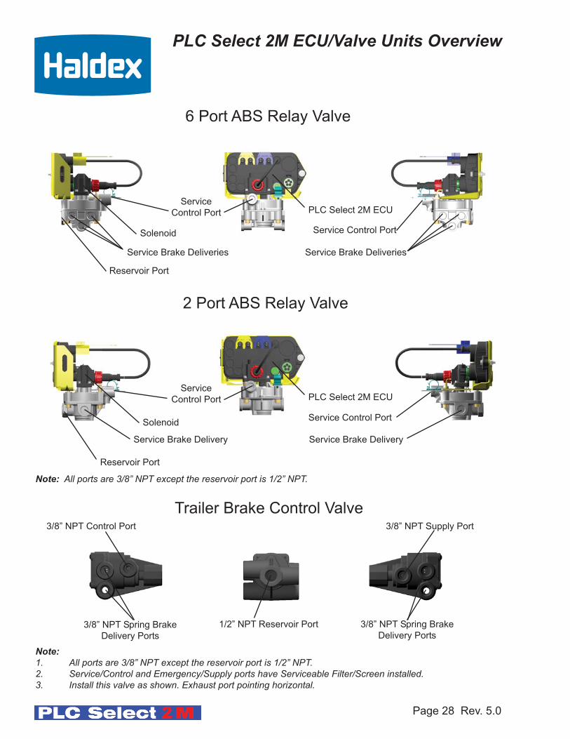
PLC Select 2M ECU/Valve Units Overview
Spring Brake Exhaust
Service Brake Exhaust
3/8” NPT Spring Brake
Delivery Ports
Page 28 Rev. 5.0
Service
Control Port
Service Brake Delivery Service Brake Delivery
PLC Select 2M ECU
Reservoir Port
2 Port ABS Relay Valve
Solenoid
Service
Control Port
Service Brake Deliveries Service Brake Deliveries
PLC Select 2M ECU
Reservoir Port
6 Port ABS Relay Valve
Solenoid
Service Control Port
Service Control Port
PLC Select 2M ECU/Valve Units Overview
Trailer Brake Control Valve
1/2” NPT Reservoir Port
3/8” NPT Supply Port
3/8” NPT Spring Brake
Delivery Ports
3/8” NPT Control Port
Note:1. All ports are 3/8” NPT except the reservoir port is 1/2” NPT.2. Service/Control and Emergency/Supply ports have Serviceable Filter/Screen installed.3. Install this valve as shown. Exhaust port pointing horizontal.
Note: All ports are 3/8” NPT except the reservoir port is 1/2” NPT.
Page 29 Rev. 5.0
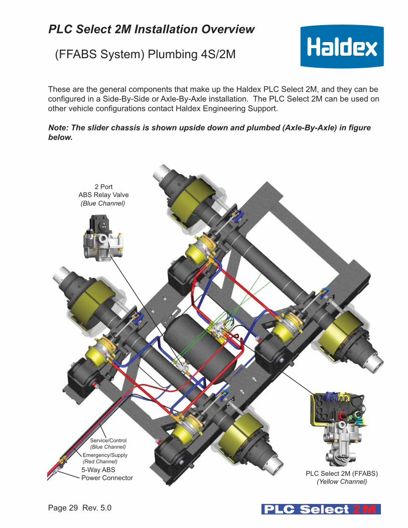
Service/Control
(Blue Channel)Emergency/Supply
(Red Channel)5-Way ABS
Power Connector
These are the general components that make up the Haldex PLC Select 2M, and they can be
configured in a Side-By-Side or Axle-By-Axle installation. The PLC Select 2M can be used on
other vehicle configurations contact Haldex Engineering Support.
Note: The slider chassis is shown upside down and plumbed (Axle-By-Axle) in figurebelow.
(FFABS System) Plumbing 4S/2M
PLC Select 2M (FFABS)
(Yellow Channel)
2 Port
ABS Relay Valve
(Blue Channel)
PLC Select 2M Installation Overview

Page 30 Rev. 5.0
Service/Control
(Blue Channel)Emergency/Supply
(Red Channel)5-Way ABS
Power Connector
These are the general components that make up the Haldex PLC Select 2M, and they can be
configured in a Side-By-Side or Axle-By-Axle installation. The PLC Select 2M can be use on
other vehicle configurations contact Haldex Engineering Support. When an ABS Relay Valve
is used, a Trailer Brake Control Valve is required such as a Haldex TBCV or RT4 Valve.
Note: The slider chassis is shown upside down and plumbed (Axle-By-Axle) in figurebelow.
PLC Select 2M (ABS Relay Valve)
(Yellow Channel)
(ABS Relay System) Plumbing 4S/2M(Trailer Brake Control Valve is required)
Trailer Brake
Control Valve
(TBCV)
2 Port
ABS Relay Valve
(Blue Channel)
PLC Select 2M Installation Overview
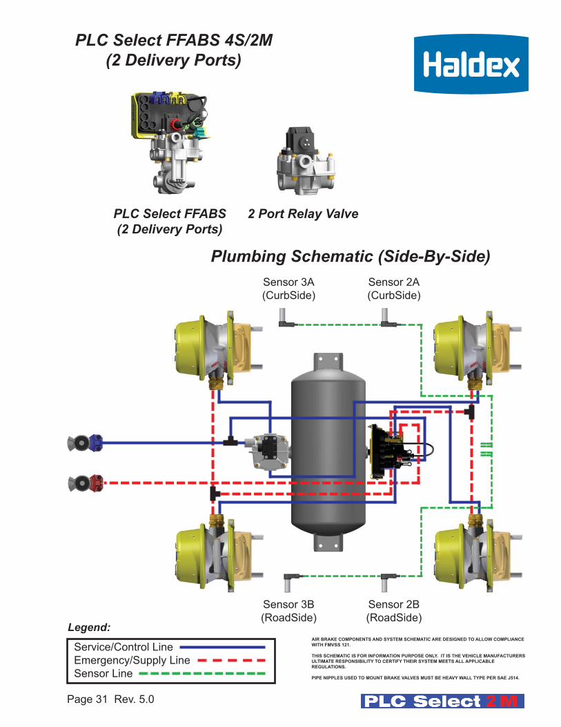
PLC Select FFABS 4S/2M(2 Delivery Ports)
Page 31 Rev. 5.0
PLC Select FFABS(2 Delivery Ports)
2 Port Relay Valve
Plumbing Schematic (Side-By-Side)Sensor 2A
(CurbSide)
Sensor 2B
(RoadSide)Legend:
Service/Control Line
Emergency/Supply Line
Sensor Line
Sensor 3A
(CurbSide)
Sensor 3B
(RoadSide)
AIR BRAKE COMPONENTS AND SYSTEM SCHEMATIC ARE DESIGNED TO ALLOW COMPLIANCE
WITH FMVSS 121.
THIS SCHEMATIC IS FOR INFORMATION PURPOSE ONLY. IT IS THE VEHICLE MANUFACTURERS
ULTIMATE RESPONSIBILITY TO CERTIFY THEIR SYSTEM MEETS ALL APPLICABLE
REGULATIONS.
PIPE NIPPLES USED TO MOUNT BRAKE VALVES MUST BE HEAVY WALL TYPE PER SAE J514.
Page 32 Rev. 5.0
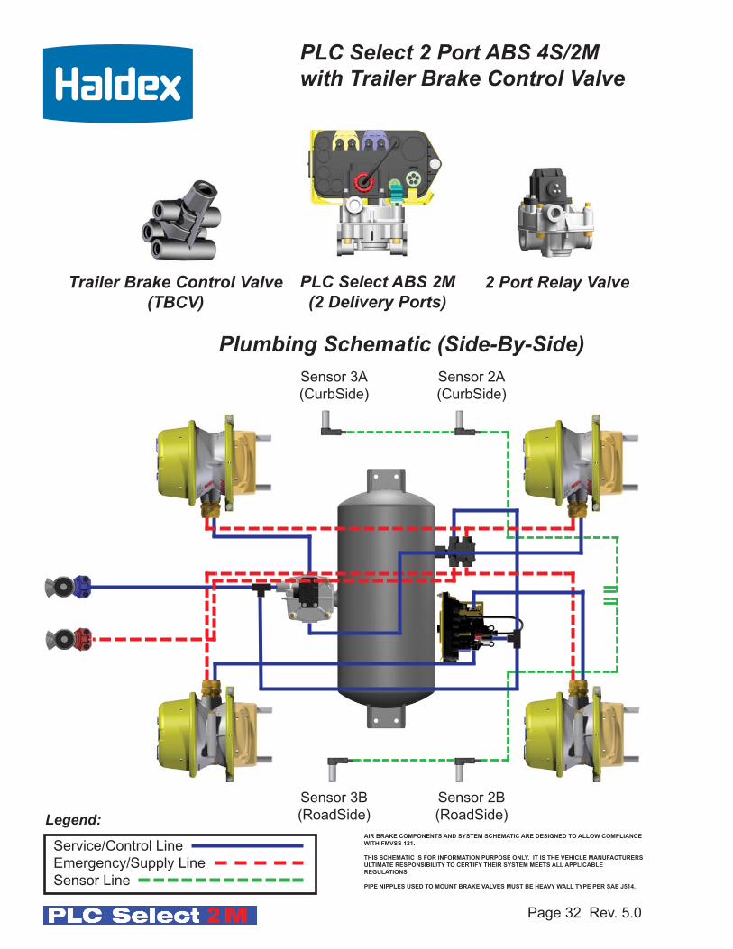
PLC Select 2 Port ABS 4S/2M with Trailer Brake Control Valve
PLC Select ABS 2M (2 Delivery Ports)
2 Port Relay ValveTrailer Brake Control Valve(TBCV)
Sensor 2A
(CurbSide)
Sensor 2B
(RoadSide)Legend:
Service/Control Line
Emergency/Supply Line
Sensor Line
Sensor 3A
(CurbSide)
Sensor 3B
(RoadSide)
Plumbing Schematic (Side-By-Side)
AIR BRAKE COMPONENTS AND SYSTEM SCHEMATIC ARE DESIGNED TO ALLOW COMPLIANCE
WITH FMVSS 121.
THIS SCHEMATIC IS FOR INFORMATION PURPOSE ONLY. IT IS THE VEHICLE MANUFACTURERS
ULTIMATE RESPONSIBILITY TO CERTIFY THEIR SYSTEM MEETS ALL APPLICABLE
REGULATIONS.
PIPE NIPPLES USED TO MOUNT BRAKE VALVES MUST BE HEAVY WALL TYPE PER SAE J514.

PLC Select FFABS 4S/2M(2 Delivery Ports)
Page 33 Rev. 5.0
PLC Select FFABS(2 Delivery Ports)
2 Port Relay Valve
Plumbing Schematic (Axle-By-Axle)Sensor 2B
(CurbSide)
Sensor 3B
(RoadSide)Legend:
Service/Control Line
Emergency/Supply Line
Sensor Line
Sensor 2A
(CurbSide)
Sensor 3A
(RoadSide)
AIR BRAKE COMPONENTS AND SYSTEM SCHEMATIC ARE DESIGNED TO ALLOW COMPLIANCE
WITH FMVSS 121.
THIS SCHEMATIC IS FOR INFORMATION PURPOSE ONLY. IT IS THE VEHICLE MANUFACTURERS
ULTIMATE RESPONSIBILITY TO CERTIFY THEIR SYSTEM MEETS ALL APPLICABLE
REGULATIONS.
PIPE NIPPLES USED TO MOUNT BRAKE VALVES MUST BE HEAVY WALL TYPE PER SAE J514.

Page 34 Rev. 5.0
PLC Select 2 Port ABS 4S/2M with Trailer Brake Control Valve
PLC Select ABS 2M (2 Delivery Ports)
2 Port Relay ValveTrailer Brake Control Valve(TBCV)
Sensor 2B
(CurbSide)
Sensor 3B
(RoadSide)Legend:
Service/Control Line
Emergency/Supply Line
Sensor Line
Sensor 2A
(CurbSide)
Sensor 3A
(RoadSide)
Plumbing Schematic (Axle-By-Axle)
AIR BRAKE COMPONENTS AND SYSTEM SCHEMATIC ARE DESIGNED TO ALLOW COMPLIANCE
WITH FMVSS 121.
THIS SCHEMATIC IS FOR INFORMATION PURPOSE ONLY. IT IS THE VEHICLE MANUFACTURERS
ULTIMATE RESPONSIBILITY TO CERTIFY THEIR SYSTEM MEETS ALL APPLICABLE
REGULATIONS.
PIPE NIPPLES USED TO MOUNT BRAKE VALVES MUST BE HEAVY WALL TYPE PER SAE J514.

Page 35 Rev. 5.0
Sensor
S3B
(Yellow)
Sensor
S2B
(Yellow)
Sensor
S3A
(Blue)
Sensor
S2A
(Blue)
ABS Power Connector
Modulator Valve Solenoid Cable
(Yellow Channel)PLC Select 2M
Electronic Control Unit (ECU)
“Most compact package offers the best ABS solution for 4S/2M application”
ABS Power Cable
PLC Select 2M ECU Overview
Correct location of the speed sensors at the wheel ends is critical for proper ABS operation. The PLC
Select 2M will adjust the braking air pressure in response to the input from the speed sensors.
Incorrect installation or location of speed sensors and exciter rings will result in poor ABS performance
or sensors crossed leading to incorrect diagnostic troubleshooting. In the figure above shows the cor-
rect power and speed sensor connections on the PLC Select 4S/2M ECU (Electronic Control Unit)
“See Haldex Trailer ABS Service Components Catalog L20243 for sensor extensions if shortsensors are used”.
Modulator Valve Solenoid Cable
(Blue Channel)
(Not Used with 2S/1M Configuration)
Verify connection locking tab is facing downward and secure. If cable can be removed without releasing locking tab, verify connector orientation.
Locking Tab Tab locked in position
“Sensors S2A and S3A are Not Used with 2S/1M
Configuration”
7-Way Wiring
Page 36 Rev. 5.0
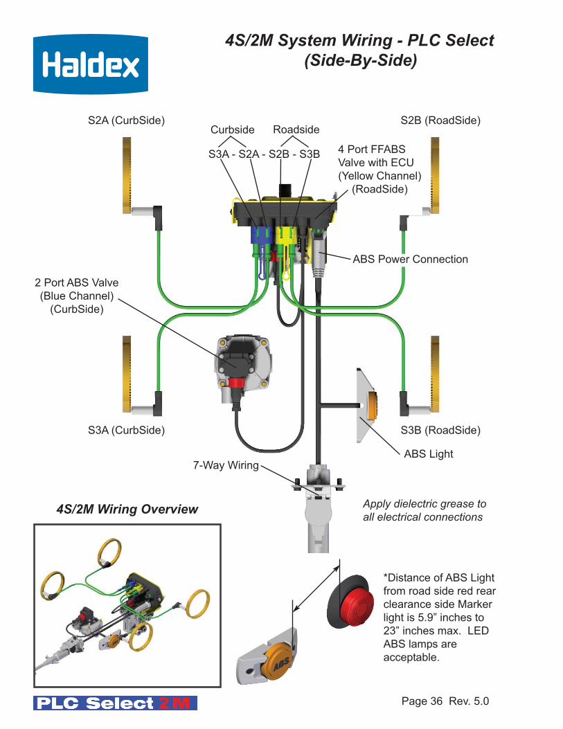
S2A (CurbSide) S2B (RoadSide)
S3A (CurbSide) S3B (RoadSide)
Apply dielectric grease toall electrical connections
4S/2M System Wiring - PLC Select(Side-By-Side)
ABS Light
4 Port FFABS
Valve with ECU
(Yellow Channel)
(RoadSide)
2 Port ABS Valve
(Blue Channel)
(CurbSide)
*Distance of ABS Light
from road side red rear
clearance side Marker
light is 5.9” inches to
23” inches max. LED
ABS lamps are
acceptable.
4S/2M Wiring Overview
S3A - S2A - S2B - S3B
ABS Power Connection
Curbside Roadside
7-Way Wiring
Page 37 Rev. 5.0
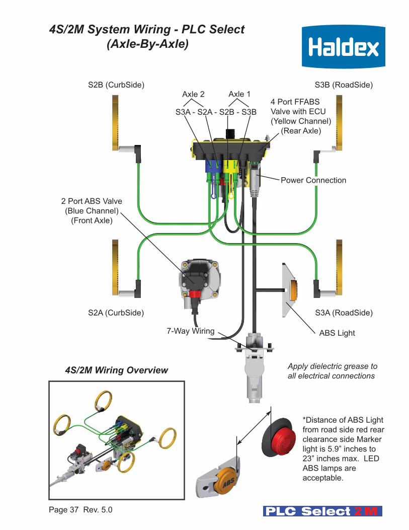
S2B (CurbSide) S3B (RoadSide)
S2A (CurbSide) S3A (RoadSide)
Apply dielectric grease toall electrical connections
4S/2M System Wiring - PLC Select(Axle-By-Axle)
ABS Light
4 Port FFABS
Valve with ECU
(Yellow Channel)
(Rear Axle)
2 Port ABS Valve
(Blue Channel)
(Front Axle)
*Distance of ABS Light
from road side red rear
clearance side Marker
light is 5.9” inches to
23” inches max. LED
ABS lamps are
acceptable.
4S/2M Wiring Overview
S3A - S2A - S2B - S3B
Power Connection
Axle 2 Axle 1
Page 38 Rev. 5.0
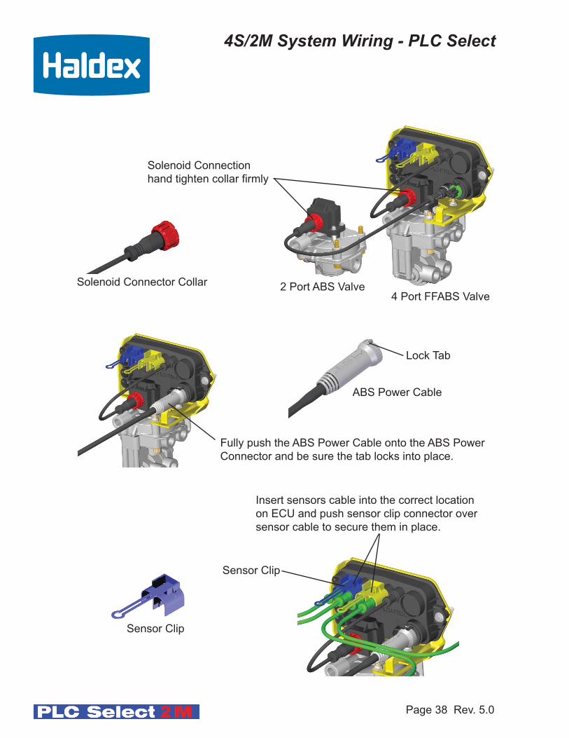
4S/2M System Wiring - PLC Select
Solenoid Connection
hand tighten collar firmly
Fully push the ABS Power Cable onto the ABS Power
Connector and be sure the tab locks into place.
Insert sensors cable into the correct location
on ECU and push sensor clip connector over
sensor cable to secure them in place.
2 Port ABS Valve4 Port FFABS Valve
Sensor Clip
Sensor Clip
ABS Power Cable
Lock Tab
Solenoid Connector Collar

Page 39 Rev. 5.0
Speed Sensor Cable Routing
Sensor
Sensor Block
Sensor
Block
1. Insert the sensor clip into the sensor block.
2. Insert the sensor into the sensor clip and push until it is firmly against the exciter ring
(first grease the sensor with a lithium based grease).
3. Route all sensor cables through vacant holes, etc. Use a grommet or corrugated
tubing when the cables are touching sharp edges.
4. Attach cable ties as needed to ensure the cable is secured to the axle housing.
5. Typical routing of cable is along the brake chamber air hose.
6. Use sensor cable clip (highly recommended) or double tie straps when attaching the
cables to the air hoses.
7. Sensor cable clip or double tie straps should be no closer than 6” inches and no
farther then 12” inches apart.
Note: Use caution when attaching tie strap to air hoses. Over tightening can damage a cableand cause an ABS sensor failure.
Push sensor firmly
against the exciter ring
Sensor
Sensor Block Clip
Exciter Ring
Note: Lightly grease the sensor with a Lithiumbased grease. Use Dow Corning Molycoat CU7439or equivalent.
Page 40 Rev. 5.0
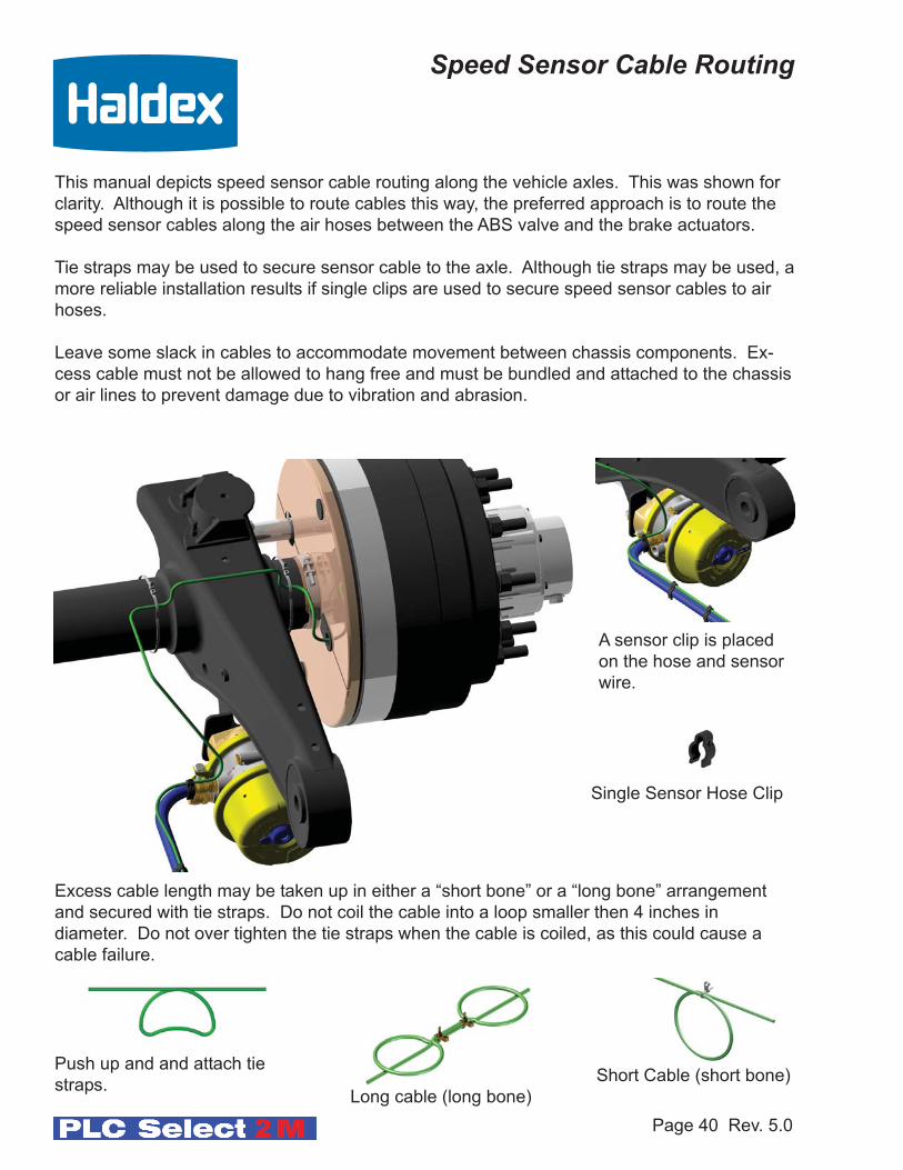
Speed Sensor Cable Routing
This manual depicts speed sensor cable routing along the vehicle axles. This was shown for
clarity. Although it is possible to route cables this way, the preferred approach is to route the
speed sensor cables along the air hoses between the ABS valve and the brake actuators.
Tie straps may be used to secure sensor cable to the axle. Although tie straps may be used, a
more reliable installation results if single clips are used to secure speed sensor cables to air
hoses.
Leave some slack in cables to accommodate movement between chassis components. Ex-
cess cable must not be allowed to hang free and must be bundled and attached to the chassis
or air lines to prevent damage due to vibration and abrasion.
Excess cable length may be taken up in either a “short bone” or a “long bone” arrangement
and secured with tie straps. Do not coil the cable into a loop smaller then 4 inches in
diameter. Do not over tighten the tie straps when the cable is coiled, as this could cause a
cable failure.
Short Cable (short bone)
Long cable (long bone)
Push up and and attach tie
straps.
A sensor clip is placed
on the hose and sensor
wire.
Single Sensor Hose Clip

Note: If the ABS Light never illuminates or stays illuminated during the ABS check, refer to Troubleshooting Section on page 53 of this manual.
Page 41 Rev. 5.0
Test Equipment:
12 VDC power source (Do Not use a battery charger), power cable with a Packard 5 pin
male power connection, an ABS test light attached, and shop air.
Chassis Test/End Of Line ABS Check:
Procedure:
1. Charge the Emergency/Supply and Service/Control air systems.
2. Apply power source to 7-Way receptacle (permanent power).
3. The ABS Valve(s) should “blow down” first. You will hear a brief shot of air from
each valve. The Blue Channel (remote valve) should blow down first followed by the
Yellow Channel (ECU valve) (for a 2S/1M system the Yellow Channel valve only).
4. The ABS light should illuminate for about 3 seconds and then turn off.
5. Using a Info Center or PC verify correct sensor placement by spinning each
wheel end one at a time. Refer to pages 6 - 11 for correct placement. Axle-By-Axle,
or Side-By-Side. Refer to L31158 for Info Center instructions.6. When using a PC in conjunction with Haldex PC diagnostics, information such as the
name of the Inspector, the date inspected, or the trailer VIN can be stored in the
ABS ECU.
Installation Test:This step will ensure the ABS system is functioning properly,
before the chassis is assembled to the trailer.
End of Line Testing/Road TestingPLC Select 1M - 2M
Page 42 Rev. 8.0
Road Test - PLC Select 2M:
Procedure:
1. Connect a tractor to the trailer and charge the trailer’s air tanks.
2. Turn on the start switch and ensure that the Warning Light comes on briefly, then
goes out.
3. Pull the trailer at a speed above 6 mph, make a brake application and hold until the
tractor-trailer has come to a complete stop.
4. Verify that the ABS Warning Light has remained OFF. If the light remained OFF,
the system is functioning properly.
5. If the ABS system detected an error during the stop, the Warning Light will be ON. If
the ABS Warning Light never comes ON when the start switch is turned ON, then refer
to the,“No ABS Warning Light Illumination” section on page 53 of this manual. If the
ABS Warning Light stays ON with the start switch on, refer to the “ABS Warning
Light Stays on permanently” section on page 53 of this manual.
Notes:
1. Disconnect power from the ABS system before testing or making any repairs.
2. Most ABS problems are related to:a. Cut or abraded wiresb. Corroded connector, or terminalsc. Connector terminals not latched or seated correctly to mating assembliesd. Excessive sensor air gap, sensor clip retention, or wheel bearing end playe. Verify sufficient power at the ABS Power Cable (12 - 15V).
3. After making any repairs go to the “Diagnostic Tools” section of this manual (see pages 44 - 45 to confirm that the fault is corrected. If fault codes 11 - 16 or 21 - 26has occurred the Warning Light will remain on with a code 07 when repowered until the problem has been corrected. The vehicle must be driven above 6 MPH for the ABS to recognize the problem has been corrected. Then the light will turn off.
End of Line Testing/Road TestingPLC Select 1M - 2M

Diagnostics Tools
PLC Info Center
PLC PC Diagnostics Kit
(PC not included)
J1708/PLC
Adapter
SAE 560
7-way Diagnostic
Interface Cable
Blink Codes
Page 43 Rev. 5.0

Page 44 Rev. 5.0
(1) Blink Codes:
ABS fault codes can be accessed using the ABS light without the use of any other tools. The
blink code “Simple Fault Mode” can be activated by pressing on the brake pedal to activate
the trailer brakes and switching ignition power ON, OFF, ON in 1 second intervals. See Blink
Code information on pages 46 - 50.
(2) PLC Info Center:
The PLC Info Center has a screen that can display ABS fault codes plus a number of other
functions. The PLC Info Center only needs to be connected to vehicle permanent power and
ground. (A diagnostic Interface Cable is included to accommodate this connection). An
optional SAE 560 7-Way Diagnostic Interface Cable is also available.
Available functions include:
1. View active fault code(s) (2 digit code) and fault occurrence count.
2. View stored fault code(s) and fault occurrence count.
3. Clear stored fault code(s).
4. View wheel speed sensor identification corresponding to each individual wheel
when rotated.
5. View sensor and valve configuration code.
6. View ABS ECU type and serial number.
7. Energize valve solenoid(s).
8. Odometer
a) View Odometer, Tire Scale Factor, (Miles or Kilometer), Service Interval,
and Trip Distance.
b) Program Tire Scale Factor (miles or kilometers), and Service Interval.
Reference PLC Info Center Instruction Manual L31158.
PLC Info Center
Diagnostic Tools
SAE 560
7-Way Diagnostic
Interface Cable
Haldex provides (3) Methods for ABS Diagnostics:
1. Blink Codes
2. PLC Info Center
3. PLC PC Diagnostics

Page 45 Rev. 5.0
PC Diagnostics Kit
(PC not included)
9 to 25
Way Cable
Optional SAE 560 7-Way
Diagnostic Interface Cable
ABS
PC Diagnostic
Software
J1708/PLC
Adapter
PLC PC Diagnostics displays the most information. Available functions include all the
functions of the PLC Info Center as well as:
1. View ABS ECU Part Number.
2. Save ABS diagnostic results for a print out of test verification.
3. Read/Write Trailer and or Service data internally to ABS ECU
Minimum requirements: Pentium II, 32 MB Ram, 233 MHz, Windows 95B, RS232 9 pin
com port
Note: PLC Info Center and PLC PC Diagnostics are not compatible with older generations of ABS manufactured prior to March 2001.
“Reference PC Diagnostic Instruction Manual L31154”.
Diagnostic Tools
PLC
Interface Cable
(3) PLC PC Diagnostic:

Mode Description Permanent Power Cycles (1 second ON / 1 second OFF) with service brakes applied.
1 Simple/Wheel Speed Mode ON, off, ON
2 Active Faults Mode ON, off, ON, off, ON
3 Stored Faults / Clear Mode ON, off, ON, off, ON, off, ON
4 Configuration Mode ON, off, ON, off, ON, off, ON, off, ON
5 Odometer Mode ON, off, ON, off, ON, off, ON, off, ON
There are 4 Blink Code Modes:
Procedure for Blink Code Diagnostics:
1. The trailer must be stationary.
2. The trailer must be connected to a DC-power supply (10-15 volts). Do not use a
battery charger.
3. Constant power (10-15 volts) must be provided to the stoplight circuit (apply trailer service
brakes).
4. Permanent power must be cycled on and off (trailer auxiliary circuit) at 1 second intervals
to reach the desired mode (shown above). If a power source other than a truck is useda switch must be used to simulate a truck start switch.
Note: Stoplight and Permanent power must be independent for blink code troubleshooting. IfPermanent power is required for your brake lights to operate, then the blink codediagnostics will not function.
Procedure Notes:
1. Once a blink mode is entered that mode can only be terminated by completely disconnecting
all trailer power sources.
2. All modes repeat endlessly. Each repeat is separated by 10 seconds of continuous
light energization.
3. All codes are separated by 2 seconds of light OFF.
4. Stored fault codes are followed by an occurrence count which display a blink rate twice
as fast as the fault code blink rate.
Mode 1 - Simple Mode Diagnostics:
This mode has a abbreviated list of fault codes that will display. Fault codes are grouped to simplify the
diagnostics. Up to 3 active codes will be display at one time. These faults need to be repaired before
other active faults can be displayed. See Simple Mode Faults Code Table on next page.
Page 46 Rev. 5.0
Blink Code Diagnostics
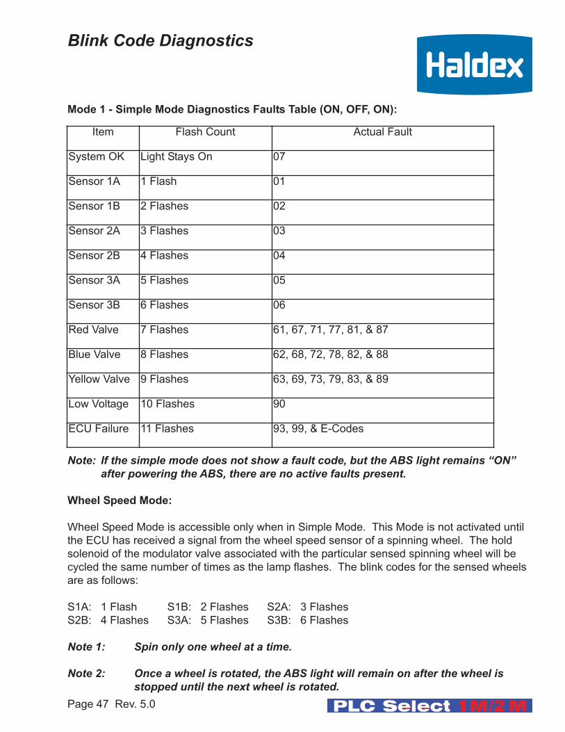
Item Flash Count Actual Fault
System OK Light Stays On 07
Sensor 1A 1 Flash 01
Sensor 1B 2 Flashes 02
Sensor 2A 3 Flashes 03
Sensor 2B 4 Flashes 04
Sensor 3A 5 Flashes 05
Sensor 3B 6 Flashes 06
Red Valve 7 Flashes 61, 67, 71, 77, 81, & 87
Blue Valve 8 Flashes 62, 68, 72, 78, 82, & 88
Yellow Valve 9 Flashes 63, 69, 73, 79, 83, & 89
Low Voltage 10 Flashes 90
ECU Failure 11 Flashes 93, 99, & E-Codes
Mode 1 - Simple Mode Diagnostics Faults Table (ON, OFF, ON):
Note: If the simple mode does not show a fault code, but the ABS light remains “ON” after powering the ABS, there are no active faults present.
Wheel Speed Mode:
Wheel Speed Mode is accessible only when in Simple Mode. This Mode is not activated until
the ECU has received a signal from the wheel speed sensor of a spinning wheel. The hold
solenoid of the modulator valve associated with the particular sensed spinning wheel will be
cycled the same number of times as the lamp flashes. The blink codes for the sensed wheels
are as follows:
S1A: 1 Flash S1B: 2 Flashes S2A: 3 Flashes
S2B: 4 Flashes S3A: 5 Flashes S3B: 6 Flashes
Note 1: Spin only one wheel at a time.
Note 2: Once a wheel is rotated, the ABS light will remain on after the wheel isstopped until the next wheel is rotated.
Page 47 Rev. 5.0
Blink Code Diagnostics

Mode 2 - Active Faults Mode (ON, OFF, ON, OFF, ON):
In this mode the ABS light displays a numerical fault code sequence for each existing fault, up
to nine fault codes at a time. The nine faults must be repaired before additional active faults
can be displayed. The blink codes used in the Active Fault Mode are related to the Haldex
standard fault codes and are shown on pages 54 - 58.
Example: Fault code “23” is indicated by the light flashing ON twice for one half second each time - followed by two seconds of light off followed bythree 1/2 second flashes.
Mode 3 - Stored (Passive) Faults/Clear Mode (ON, OFF, ON, OFF, ON, OFF, ON):
In this mode the ABS light displays a numerical fault code sequence for each stored fault. All
stored faults (not currently active) are displayed in this mode. The light will display up to nine
passive stored faults at a time. The most recent stored fault is displayed last. The blink codes
used in the Passive Stored Fault Mode are related to the Haldex
standard fault codes and are shown on page 54 - 58.
Clearing Stored Codes (Mode 3):
The passive stored fault codes may be cleared by switching ignition power OFF, ON
OFF, ON while the brakes are applied during 10 seconds of light energization that occur
prior to each repeat of the fault code blink sequence. The light will flash rapidly for 10
seconds to show that the fault(s) are being erased.
Stored Mode Fault Occurrences (Mode 3):
The fault code blink sequence is followed by the occurrence count for that fault in
Passive Mode. The occurrence count is displayed after each pair of fault code flashes
in order to differentiate between the code and its occurrence count. Blink code rate
twice as fast as the fault code blink rate.
Page 48 Rev. 5.0
Blink Code Diagnostics
Page 49 Rev. 5.0
Blink Code Diagnostics
Stored Fault Mode Notes (Mode 3):
1. A “zero” for codes such as “01” is indicated by a two second light “ON” condition.
All other digits are indicated by a half second light “ON” condition.
Example: Fault code “23” is indicated by the light flashing ON twice for one half
second each time - followed by two seconds of light off followed by
three 1/2 second flashes. The third flash is the occurrence count and as
1/4 second flashes.
2. There is a two second light “OFF” delay between the digits in each code.
3. Code 07 (system OK, vehicle at rest) is displayed as a continuous light “ON”
condition.
Mode 4 - Configuration Mode (ON, OFF, ON, OFF, ON, OFF, ON, OFF, ON):
This Mode displays Configuration and Auxiliary Codes. The Configuration Code is displayed
prior to Auxiliary Codes. The tables on page 50 show a list of Configuration Codes and a list
of Auxiliary Codes which supported by Blink Codes. Auxiliary Codes are displayed low to high.
Each blink code digit will refer to a digit in the Haldex configuration codes.
Clear Configuration Mode:
The configuration codes may be cleared by switching Permanent power
OFF, ON, OFF, ON while the brakes are applied during the 10 seconds of light
energization that occurs prior to each repeat of the fault code blink sequence.
The light will flash rapidly for 10 seconds to indicate that the configuration has
been erased from the ECU’s memory. The ECU will then store its full configuration
on the next power up.

Page 50 Rev. 5.0
Blink Code Diagnostics
Item Blinks Description
A0 1 Not Applicable
A1 2 Not Applicable
A2 3 Not Applicable
A3 4 Not Applicable
A4 5 No load sense valve - momentarily displayed when power is applied
A5 6 Not Applicable
A6 7 Not Applicable
A7 8 SLH programming for yellow valve channel (red valve is 2S/1M)
A8 9 MSLH programming for yellow valve channel (red valve is 2S/1M)
Config Code Blinks Function Axle Lifted Sensor Used Modulators Used
CO 1 2S/1M S1A S1B Red
C1 2 2S/2M S2A S2B Blue, Yellow
C2 3 4S/2M S3A S2A S2B S3B Blue, Yellow
C3 4 4S/2M 2 or 3 (S3A) S2A S2B (S3B) Blue, Yellow
Mode 5 - Odometer Mode (6 ONS)
This mode displays the odometers.
Example: 4364.7 miles (4 on/off 1/2 sec flashes, 3 on/off 1/2 sec flashes, 6 on/off 1/2
sec flashes, 4 on/off 1/2 sec flashes, then 2 1/4 sec flashes) if set for miles, 1 1/4 sec
flash if set for kms

Page 51 Rev. 5.0
INFO CENTER INSTRUCTION See Info Center Manual L31158
Info Center - DiagnosticFault Code List
Info Center is a diagnostic tool used for readout of fault codes and odometer as well as other
information within the ABS Electronic Control Unit (ECU).
The Info Center is normally connected to the ECU’s power source. While the ECU is powered
from its normal sources, information is transferred to the Info Center on the permanent power
circuit. A Diagnostic Interface cable is included with the PLC Info Center.
Info Center can be used in conjunction with our premium “PLC Select PLUS” ABS Platform.
Contact Haldex Brake Products for further details.
Trailer
Tire
Scaling Factor
100T (miles)Scaling Factor
100T (km)Scaling Factor
80T (miles)Scaling Factor
80T (km)
0T Smallest Tire215/75R17.5
8R17.5
275/65R17.5HC
8.5R17.5
245/70R17.5
235/75R17.5
225/70R19.5
8.25R15
9R17.5HC
10R17.5
265/70R19.5
285/70R19.5
100T Smallest Tire305/70R19.5
11R17.5HC
10.00R15TR
255/70R22.5
275/70R22.5
10R22.5
9.00R20
295/75R22.5
285/75R24.5
295/80R22.5
11R22.5
10.00R20
315/80R22.5
80T Largest Tire11.00R20
305/75R24.5
11R24.5
10.00R22
12.00R20
425/65R22.5
11.00R22
100T Largest Tire
580574
568
566
566
545
520
519
518
504
503
501
491
488
488
478
478
472
471
466
391
360357
353
352
352
339
323
323
322
313
313
313
312
305
303
303
297
297
294
293
290
243
579
543
538
527
524
523
523
521
495
495
490
483
470
459
454
453
453
436
416
415
414
403
402
402
401
383
391
360338
334
328
326
325
325
324
308
308
304
300
293
286
283
282
282
271
259
258
258
251
250
250
249
244
243
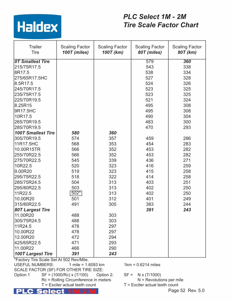
*Factory Tire Scale Set At 502 Rev/Mile.
USEFUL NUMBERS: 1 mile = 1.6093 km 1km = 0.6214 miles
SCALE FACTOR (SF) FOR OTHER TIRE SIZE:
Option 1 SF = (1000/Rc) x (T/100) Option 2: SF = N x (T/1000)
Rc = Rolling Circumference in meters N = Revolutions per mile
T = Exciter actual teeth count T = Exciter actual teeth count
Page 52 Rev. 5.0
PLC Select 1M - 2M Tire Scale Factor Chart
502*

Page 53 Rev. 5.0
ABS Warning Light Stays On Permanently:
Upon power up of the ABS system (Permanent or Stoplight Power), the ABS Warning Light
should come ON for about 3 seconds then go OFF. If the Light stays ON, it may be caused by
improper light wiring, or by a fault in the ABS system or the ABS system.
1. Check for diagnostic fault code. If anything other than an “07” is displayed, review the
“Troubleshooting” section of this manual (page 54 - 58) for possible solutions. After
the problem is repaired, clear all stored faults.
2. If an “07” is displayed but there was a 11 -16 or 21 - 26 stored in memory, then correct
the problem and drive the trailer above 6 mph to get the ABS Light to turn OFF.
3. If there are no stored faults and an “07” is displayed, and the ABS Light is still ON,
then the ABS Light is mis-wired. Remove the main wire harness 5 pin connector at the
ECU and verify continuity between pin “D” (Refer to ABS Power Cord - Pin Out page
21) and trailer light. The remaining light wire must be grounded to the trailer chassis or
connected to the SAE J560 7-Way connector ground wire. Check for continuity
between the ABS Light wire and ground. Repair as necessary and retest.
4. If no “blow down” of the solenoid occurs when power is applied or the diagnostic tool
has nothing on the display, check power on the blue or red wire of the 7-Way connector
as well as the ABS Power Cord.
No ABS Warning Light Illumination:
1. Check the bulb to verify that it is functional. If not functional, replace it.
2. Verify that there is power to the ECU. Disconnect the main wire harness 5 pin
connector and check for B+ (positive power) between either stop light or permanent
power and ground (Refer to ABS Power Cord - Pin Out page 21) The voltage drop
between the SAE J560 7-Way and the ECU should not exceed 2 volts. If no power
exists at either stoplight or permanent power in reference to ground then check
continuity from these pins to the SAE J560 7-Way connector red and blue circuits.
Make necessary repairs and retest.
3. If the problem is still present, remove the main wire harness 5 pin connector at the
ECU and verify continuity between pin “D” (Refer to ABS Power Cord - Pin Out page
21) and the light. The remaining light wire must be grounded to the trailer chassis or
connected to the SAE J560 7-Way connector ground wire. Check for continuity
between the ABS light wire and ground. Repair as necessary and retest.
Troubleshooting ABS Warning LightPLC Select 1M - 2M

Page 54 Rev. 5.0
Code Explanation: Possible Causes: PLC
Select
1M
PLC
Select
2M
00 System OK (with vehicle greater than 6 mph) ABS is operational Displays “00” greater
than 6 mph. X X
01 Red channel wheel speed sensor wiring S1A
has an Open or Short circuit. Indicates a wheel speed sensor or its wiring
has short or open circuit. Disconnect the
relevant sensor and measure the
resistance between the two pins in the
sensor connector housing.
The Ohmmeter reading for the sensor
should be between 980 and 2350 Ohm(.98K and 2.35 K Ohm)
If sensor extensions are used verify
extension continuity and connections. The
sensors should be replaced if this is not the
case.
X
02 Red channel wheel speed sensor wiring S1B
has an Open or Short circuit. X
03 Blue channel wheel speed sensor wiring S2A
has an Open or Short circuit. X
04 Yellow channel wheel speed sensor wiring S2B
has an Open or Short circuit. X
05 Blue channel wheel speed sensor wiring S3A
has an Open or Short circuit. X
06 Yellow channel wheel speed sensor wiring S3B
has an Open or Short circuit. X
07 System OK (No Active Fault) ABS ECU is fully operational. Displays “07”
greater then 6 mph with no faults and
vehicle stationary.X X
11 Red channel speed sensor S1A, has low
sensor output. Sensor is worn or not properly
adjusted, wiring open or short circuit, wheel
bearing not properly adjusted (these faults
will only occur at speeds greater than
6 mph). Measure the AC voltage at the
sensor in question while rotating the wheel
at a rate of about one revolution every two
seconds. The output should be at least
200 millivolts (0.2 Vac). If this is not the
case, push in the sensor until it touches the
exciter and rotate the wheel again. If this
doesn’t correct the problem, then the
sensor and spring clip should be replaced.
If sensor extensions are used verify
extension continuity and connections. The
sensors should be replaced if this is not the
case.
Replace exciter verify all exciters are the
same number of teeth.
X
12 Red channel speed sensor S1B, has low
sensor output. X
13 Blue channel speed sensor S2A, has low
sensor output. X
14 Yellow channel speed sensor S2B, has low
sensor output. X
15 Blue channel speed sensor S3A, has low
sensor output. X
16 Yellow channel speed sensor S3B gap too
large. Gap should be kept to a minimum. X
20 Incorrect exciter (tone) ring used.
X X
PLC Select 1M - 2M Diagnostics Codes

Code Explanation: Possible Causes: PLC
Select
1M
PLC
Select
2M
21 Red channel wheel speed sensor S1A has an
erratic output voltage. Loose sensor, connection, bracket or
exciter, damaged exciter, sensor is not
properly adjusted or has worn cable
insulation, or worn spring clip, wheel
bearing failure, wheel bearing is not
properly adjusted (these faults will only
occur at speeds greater than 6 mph).
Measure the AC voltage at the sensor in
question while rotating the wheel at a rate
of about one revolution every two seconds.
The output should be at least
200 millivolts (0.2 Vac).
If this is not the case, push in the
sensor until it touches the exciter and
rotate the wheel again. If this doesn’t
correct the problem. then the sensor
should be replaced.
Verify tire and wheel size is large enough
for 100 teeth exciter ring. If these faults
re-occur at the same speed, inspect exciter
ring for damage
.
Smaller wheels and tires require 80 teeth
exciter rings. Reference Tire Scale Factor
Chart.
X
22 Red channel wheel speed sensor S1B has an
erratic output voltage. X
23 Blue channel wheel speed sensor S2A has an
erratic output voltage. X
24 Yellow channel wheel speed sensor S2B has an
erratic output voltage. X
25 Blue channel wheel speed sensor S3A has an
erratic output voltage. X
26Yellow channel wheel speed sensor S3B has an
erratic output voltage.X
30 Auxiliary channel 0 fault (digital channel 0) I/O
PLC Select 2M (ABS Auxiliary Codes)
Note:These Codes are only used with PLC Select 2M Plus ABS that supports trailer Auxiliaries
Auxiliary Channel has an open circuit orthe ECU (Electronic Control Unit) has auxiliary device connected and should not.
31 Auxiliary channel 1 fault (digital channel 1) I/O
32 Auxiliary channel 2 fault (digital channel 2) I/O
33 Auxiliary channel 3 fault (digital channel 3) input
only
34 Auxiliary channel 4 fault (digital channel 1) input
only
35 Auxiliary channel 5 fault (digital channel 2) input
only
37 Light signaled by external device
X X
Page 55 Rev. 5.0
PLC Select 1M - 2M Diagnostics Codes
Code Explanation: Possible Causes: PLC
Select
1M
PLC
Select
2M
40 Sensor wiring crossed across an axle Slow brake release, foundation brake
mechanical faults, dry bearings, broken
return spring, restricted piping. Modulator
fault. Check for kinks and blockage etc.
Incorrect piping, wiring. For a 2M System,
verify the sensors and valve configuration is
correct (See Side-By-Side and
Axle-By-Axle configurations).
X X
41 Slow wheel recovery on Red valve channel.
X42 Slow wheel recovery on Blue valve channel.
X
43 Slow wheel recovery on Yellow valve channel.X
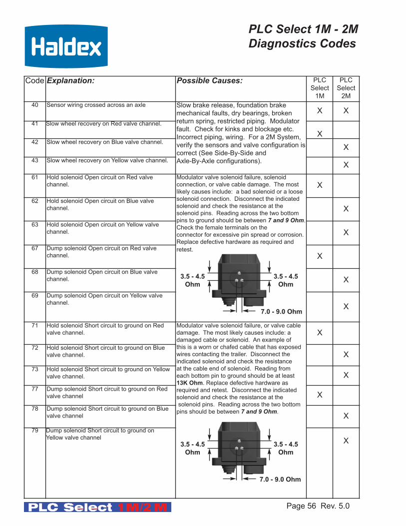
61 Hold solenoid Open circuit on Red valve
channel.
Modulator valve solenoid failure, solenoid
connection, or valve cable damage. The most
likely causes include: a bad solenoid or a loose
solenoid connection. Disconnect the indicated
solenoid and check the resistance at the
solenoid pins. Reading across the two bottom
pins to ground should be between 7 and 9 Ohm.
Check the female terminals on the
connector for excessive pin spread or corrosion.
Replace defective hardware as required and
retest.
X
62 Hold solenoid Open circuit on Blue valve
channel. X
63 Hold solenoid Open circuit on Yellow valve
channel. X
67 Dump solenoid Open circuit on Red valve
channel. X
68 Dump solenoid Open circuit on Blue valve
channel. X
69 Dump solenoid Open circuit on Yellow valve
channel.X
71 Hold solenoid Short circuit to ground on Red
valve channel.
Modulator valve solenoid failure, or valve cable
damage. The most likely causes include: a
damaged cable or solenoid. An example of
this is a worn or chafed cable that has exposed
wires contacting the trailer. Disconnect the
indicated solenoid and check the resistance
at the cable end of solenoid. Reading from
each bottom pin to ground should be at least
13K Ohm. Replace defective hardware as
required and retest. Disconnect the indicated
solenoid and check the resistance at the
solenoid pins. Reading across the two bottom
pins should be between 7 and 9 Ohm.
X
72 Hold solenoid Short circuit to ground on Blue
valve channel. X
73 Hold solenoid Short circuit to ground on Yellow
valve channel. X
77 Dump solenoid Short circuit to ground on Red
valve channel X
78 Dump solenoid Short circuit to ground on Blue
valve channel X
79 Dump solenoid Short circuit to ground on
Yellow valve channelX
Page 56 Rev. 5.0
PLC Select 1M - 2M Diagnostics Codes
3.5 - 4.5
Ohm
7.0 - 9.0 Ohm
3.5 - 4.5
Ohm
3.5 - 4.5
Ohm
7.0 - 9.0 Ohm
3.5 - 4.5
Ohm

Code Explanation: Possible Causes: PLC
Select
1M
PLC
Select
2M
80 Output leakage or poor insulation on any of
the valve channels
Modulator valve solenoid failure or valve cable
damage. Indicates that the solenoid or its cable
has a short circuit to B+ (positive 12 volts). The
most likely cause is a damage cable or solenoid.
Disconnect the indicated solenoid and check the
resistance at the cable end. Reading from each
bottom pin to ground should be at least
13K Ohm. Disconnect the indicated solenoid and
check the resistance at the solenoid pins. Read-
ing across the two bottom pins should be
between 7 and 9 Ohm.
X X
81 Hold solenoid short circuit to B+ on Red
valve channel X
82 Hold solenoid short circuit to B+ on Blue
valve channel X
83 Hold solenoid short circuit to B+ on Yellow
valve channel X
87 Dump solenoid out shorted on B+ on Red
valve channel. X
88 Dump solenoid out shorted on B+ on Blue
valve channel. X
89 Dump solenoid out shorted on B+ on Yellow
valve channel. X
90 Low supply voltage fault. Does Not latch.
Is not stored in memory
Verify +12 VDC power source. Do Not Use
Battery Charger as Power Supply. ECU
minimum operating voltage is 8.5 VDC.X X
91 No internal ABS ECU solenoid voltage
available
Verify permanent power is present.
X X
92 Power input over voltage fault. Verify +12 VDC power source. Do Not Use
Battery Charger as Power Supply. ECU
maximum operating voltage is 16.0 VDC.X X
93 Short circuit on ABS ECU internal relay.
ECU Failure
X X
99 ABS Corrupt Memory
X X
9A ABS Corrupt Memory
X X
Page 57 Rev. 5.0
PLC Select 1M - 2M Diagnostics Codes
3.5 - 4.5
Ohm
7.0 - 9.0 Ohm
3.5 - 4.5
Ohm
Code Explanation: Possible Causes: PLC
Select
1M
PLC
Select
2M
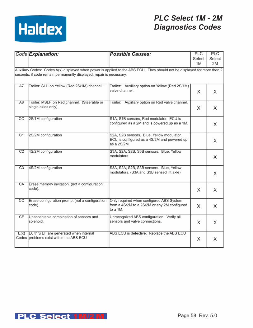
A7 Trailer: SLH on Yellow (Red 2S/1M) channel. Trailer: Auxiliary option on Yellow (Red 2S/1M)
valve channel. X X
A8 Trailer: MSLH on Red channel. (Steerable or
single axles only).
Trailer: Auxiliary option on Red valve channel.
X X
CO 2S/1M configuration S1A, S1B sensors, Red modulator. ECU is
configured as a 2M and is powered up as a 1M. X
C1 2S/2M configuration S2A, S2B sensors. Blue, Yellow modulator.
ECU is configured as a 4S/2M and powered up
as a 2S/2M.X
C2 4S/2M configuration S3A, S2A, S2B, S3B sensors. Blue, Yellow
modulators. X
C3 4S/2M configuration S3A, S2A, S2B, S3B sensors. Blue, Yellow
modulators. (S3A and S3B sensed lift axle) X
CA Erase memory invitation. (not a configuration
code). X X
CC Erase configuration prompt (not a configuration
code).
Only required when configured ABS System
from a 4S/2M to a 2S/2M or any 2M configured
to a 1M.X X
CF Unacceptable combination of sensors and
solenoid.
Unrecognized ABS configuration. Verify all
sensors and valve connections. X X
E(x)
Codes
E0 thru EF are generated when internal
problems exist within the ABS ECU
ABS ECU is defective. Replace the ABS ECU
X X
Auxiliary Codes: Codes A(x) displayed when power is applied to the ABS ECU. They should not be displayed for more then 2
seconds; if code remain permanently displayed, repair is necessary.
Page 58 Rev. 5.0
PLC Select 1M - 2M Diagnostics Codes
Notes:
Page 59 Rev. 5.0

Notes:
Page 60 Rev. 5.0

Notes:
Page 61 Rev. 5.0

Notes:
Page 62 Rev. 5.0

www.hbsna.comwww.haldex.comCommercial Vehicle Systems
©2007, This material may contain Haldextrademarks and third party trademarks, tradenames, corporate logos, graphics and emblemswhich are the property of their respective com-panies. The contents of this document may notbe copied, distributed, adapted or displayedfor commercial purposes or otherwise withoutprior written consent from Haldex.
ItalyHaldex Italia SRLBiassono (Milan)Tel.: +39 039 471 702Fax: +39 039 27 54 309E-Mail: [email protected]
PolandHaldex Sp. z.o.o.PraszkaTel.: +48 34 350 11 00Fax: +48 34 350 11 11E-Mail: [email protected]
RussiaOOO Haldex RUSMoscowTel.: + 7 495 747 59 56Fax: +7 495 786 39 70E-Mail: [email protected]
South KoreaHaldex Korea Ltd.SeoulTel.: +82 2 2636 7545Fax: +82 2 2636 7548E-Mail: [email protected]
SpainHaldex España S.A.Parets del Valles (Barcelona)Tel.: +34 93 573 10 30Fax: +34 93 573 07 28E-Mail: [email protected]
SwedenHaldex Brake Products ABLandskronaTel.: +46 418 47 60 00Fax: +46 418 47 60 01E-Mail: [email protected]
United KingdomHaldex Ltd.Newton AycliffeTel.: +44 1325 310 110Fax: +44 1325 311 834E-Mail: [email protected]
Haldex Brake Products Ltd.RedditchTel.: +44 1527 499 499Fax: +44 1527 499 500E-Mail: [email protected]
USAHaldex Brake Products Corp.Kansas City, MOTel.: +1 816 891 2470Fax: +1 816 891 9447E-Mail: [email protected]
AustriaHaldex Wien Ges.m.b.H.ViennaTel:: +43 1 8 65 16 40Fax: +43 1 8 65 16 40 27E-Mail: [email protected]
BelgiumHaldex N.V./S.A.Balegem (Ghent)Tel.: +32 9 363 90 00Fax: +32 9 363 90 09E-Mail: [email protected]
BrazilHaldex do Brasil Ind. e Com, Ltda.São PauloTel.: +55 11 213 55 000Fax: +55 11 503 49 515E-Mail: [email protected]
CanadaHaldex LtdGuelph, OntarioTel.: +1 519 826 7723Fax :+1 519 826 9497E-Mail: [email protected]
ChinaHaldex International Trading Co. Ltd.ShanghaiTel.: +86 21 5240 0338Fax: +86 21 5240 0177E-Mail: [email protected]
FranceHaldex Europe SASWeyersheim (Strasbourg)Tel.: +33 3 88 68 22 00Fax: +33 3 88 68 22 09E-Mail: [email protected]
GermanyHaldex Brake Products GmbHHeidelbergTel.: +49 6221 7030Fax: +49 6221 703400E-Mail: [email protected]
HungaryHaldex Hungary Kft.SzentlörinckátaTel.: +36 29 631 300Fax: +36 29 631 301E-Mail: [email protected]
IndiaHaldex India LimitedNasikTel.: +91 253 2380094Fax +91 253 2380729E-Mail: [email protected]
L30041 US Rev. 9/07 CM
Haldex offers proprietary vehicle technology so-lutions to the global vehicle industry within spe-cific niches. We focus on products to improvesafety, the environment and vehicle dynamics.
We are enhancing our competitive capabilitiesand building long-term customer relationshipsthrough high performance, low total costs to thecustomer through the product’s service life, ethi-cal business practices and commitment to long-term partnerships. Haldex operations aredivided into four business areas: CommercialVehicle Systems, Hydraulic Systems, GarphyttanWire and Traction Systems.