L2 VLAN User Guide - Packet Architects AB VLAN User Guide Revision a1af031 ... 8 entry Learning FIFO...
93
Packet Architects AB L2 VLAN User Guide Revision a1af031 September 1, 2016 c Packet Architects AB.
Transcript of L2 VLAN User Guide - Packet Architects AB VLAN User Guide Revision a1af031 ... 8 entry Learning FIFO...
Packet Architects AB
L2 VLAN User Guide
Revision a1af031September 1, 2016 c©Packet Architects AB.
2 Packet Architects AB
Contents
1 Overview 11
2 Packet Processing 15
2.1 Ingress Packet Processing . . . . . . . . . . . . . . . . . . . . . . . . . . . . . . . . . . . 15
2.2 Egress Packet Processing . . . . . . . . . . . . . . . . . . . . . . . . . . . . . . . . . . . 16
2.3 Port Numbering Table . . . . . . . . . . . . . . . . . . . . . . . . . . . . . . . . . . . . . 16
2.4 Forwarding Entries . . . . . . . . . . . . . . . . . . . . . . . . . . . . . . . . . . . . . . . 17
2.4.1 Hashing Function . . . . . . . . . . . . . . . . . . . . . . . . . . . . . . . . . . . 18
2.5 Learning Unit . . . . . . . . . . . . . . . . . . . . . . . . . . . . . . . . . . . . . . . . . 20
2.6 Age Unit . . . . . . . . . . . . . . . . . . . . . . . . . . . . . . . . . . . . . . . . . . . . 20
2.7 Spanning Tree . . . . . . . . . . . . . . . . . . . . . . . . . . . . . . . . . . . . . . . . . 20
2.8 Determine the final portmask . . . . . . . . . . . . . . . . . . . . . . . . . . . . . . . . . 21
2.9 Software Access to Forwarding Tables and Age Tables . . . . . . . . . . . . . . . . . . . . 21
2.10 Mirroring . . . . . . . . . . . . . . . . . . . . . . . . . . . . . . . . . . . . . . . . . . . . 21
3 VLAN Processing 23
3.1 Assignment of VID . . . . . . . . . . . . . . . . . . . . . . . . . . . . . . . . . . . . . . 24
3.2 VLAN operations . . . . . . . . . . . . . . . . . . . . . . . . . . . . . . . . . . . . . . . 24
4 Classification 27
4.1 Order of Classification . . . . . . . . . . . . . . . . . . . . . . . . . . . . . . . . . . . . . 27
4.2 Classification On The DA MAC Address ranges . . . . . . . . . . . . . . . . . . . . . . . 28
4.3 First Classification Table . . . . . . . . . . . . . . . . . . . . . . . . . . . . . . . . . . . 28
4.4 Second Classification Table . . . . . . . . . . . . . . . . . . . . . . . . . . . . . . . . . . 28
4.5 Reason To Cpu . . . . . . . . . . . . . . . . . . . . . . . . . . . . . . . . . . . . . . . . 28
5 Protocol Type Packet Filtering 29
6 Buffer Memory Resource Limiters 31
6.1 Resource Limiter: Egress Port and Priority . . . . . . . . . . . . . . . . . . . . . . . . . . 31
6.1.1 Unicast Limits . . . . . . . . . . . . . . . . . . . . . . . . . . . . . . . . . . . . . 31
6.1.2 Multicast Limits . . . . . . . . . . . . . . . . . . . . . . . . . . . . . . . . . . . . 31
6.1.3 Default Settings . . . . . . . . . . . . . . . . . . . . . . . . . . . . . . . . . . . . 32
6.1.4 Drop Counters . . . . . . . . . . . . . . . . . . . . . . . . . . . . . . . . . . . . . 32
7 Strict Priority Scheduler 33
7.1 Determine a packets Queue Priority . . . . . . . . . . . . . . . . . . . . . . . . . . . . . 33
8 Queue Management 35
8.1 Disable Scheduling To Port . . . . . . . . . . . . . . . . . . . . . . . . . . . . . . . . . . 35
8.2 Disable Queueing To Port . . . . . . . . . . . . . . . . . . . . . . . . . . . . . . . . . . . 35
8.3 Drain Port . . . . . . . . . . . . . . . . . . . . . . . . . . . . . . . . . . . . . . . . . . . 35
8.4 Redirect . . . . . . . . . . . . . . . . . . . . . . . . . . . . . . . . . . . . . . . . . . . . 35
3
CONTENTS
9 Multicast BroadCast Storm Control 379.1 Multicast Packet . . . . . . . . . . . . . . . . . . . . . . . . . . . . . . . . . . . . . . . . 379.2 Operation . . . . . . . . . . . . . . . . . . . . . . . . . . . . . . . . . . . . . . . . . . . 379.3 Default Settings . . . . . . . . . . . . . . . . . . . . . . . . . . . . . . . . . . . . . . . . 37
10 Packet To And From The CPU port 3910.1 Packet From CPU Port . . . . . . . . . . . . . . . . . . . . . . . . . . . . . . . . . . . . 3910.2 Packet Filtering To The CPU Port . . . . . . . . . . . . . . . . . . . . . . . . . . . . . . 3910.3 Packet To The CPU Port . . . . . . . . . . . . . . . . . . . . . . . . . . . . . . . . . . . 40
11 Core Interface Description 4311.1 Clock, Reset and Initialization interface . . . . . . . . . . . . . . . . . . . . . . . . . . . 4311.2 Packet Interface . . . . . . . . . . . . . . . . . . . . . . . . . . . . . . . . . . . . . . . . 4411.3 Configuration Interface . . . . . . . . . . . . . . . . . . . . . . . . . . . . . . . . . . . . 45
12 Configuration Interface 4712.1 Request Types . . . . . . . . . . . . . . . . . . . . . . . . . . . . . . . . . . . . . . . . . 4712.2 Reply Types . . . . . . . . . . . . . . . . . . . . . . . . . . . . . . . . . . . . . . . . . . 4712.3 Transaction Identifier . . . . . . . . . . . . . . . . . . . . . . . . . . . . . . . . . . . . . 4812.4 Accumulator Accesses . . . . . . . . . . . . . . . . . . . . . . . . . . . . . . . . . . . . . 48
13 Register and Table Mapping 5113.1 Address Space For Tables and Registers . . . . . . . . . . . . . . . . . . . . . . . . . . . 5113.2 Byte Order . . . . . . . . . . . . . . . . . . . . . . . . . . . . . . . . . . . . . . . . . . . 5113.3 Register and Table Overview . . . . . . . . . . . . . . . . . . . . . . . . . . . . . . . . . 5213.4 Core Information . . . . . . . . . . . . . . . . . . . . . . . . . . . . . . . . . . . . . . . . 54
13.4.1 Core Version . . . . . . . . . . . . . . . . . . . . . . . . . . . . . . . . . . . . . . 5413.5 Egress Packet Processing . . . . . . . . . . . . . . . . . . . . . . . . . . . . . . . . . . . 54
13.5.1 Egress Port Packet Type Filter . . . . . . . . . . . . . . . . . . . . . . . . . . . . 5413.5.2 Egress Port Table . . . . . . . . . . . . . . . . . . . . . . . . . . . . . . . . . . . 5513.5.3 Egress Queue To PCP And CFI/DEI Mapping Table . . . . . . . . . . . . . . . . 5613.5.4 Egress Port Configuration . . . . . . . . . . . . . . . . . . . . . . . . . . . . . . . 5613.5.5 Egress Ethernet Types for VLAN tags . . . . . . . . . . . . . . . . . . . . . . . . 5713.5.6 Disable CPU tag on CPU Port . . . . . . . . . . . . . . . . . . . . . . . . . . . . 57
13.6 Flow Control . . . . . . . . . . . . . . . . . . . . . . . . . . . . . . . . . . . . . . . . . . 5813.6.1 Source Port Counter 0 . . . . . . . . . . . . . . . . . . . . . . . . . . . . . . . . 5813.6.2 Source Port Counter 1 . . . . . . . . . . . . . . . . . . . . . . . . . . . . . . . . 5813.6.3 Source Port Counter 2 . . . . . . . . . . . . . . . . . . . . . . . . . . . . . . . . 5813.6.4 Source Port Counter 3 . . . . . . . . . . . . . . . . . . . . . . . . . . . . . . . . 5813.6.5 Source Port Counter 4 . . . . . . . . . . . . . . . . . . . . . . . . . . . . . . . . 5913.6.6 Source Port Counter 5 . . . . . . . . . . . . . . . . . . . . . . . . . . . . . . . . 5913.6.7 Source Port Counter 6 . . . . . . . . . . . . . . . . . . . . . . . . . . . . . . . . 5913.6.8 Source Port Counter 7 . . . . . . . . . . . . . . . . . . . . . . . . . . . . . . . . 5913.6.9 Source Port Counter 8 . . . . . . . . . . . . . . . . . . . . . . . . . . . . . . . . 6013.6.10 Maximum Buffer Utilization Turn On Limit . . . . . . . . . . . . . . . . . . . . . 6013.6.11 Maximum Buffer Utilization Turn Off Limit . . . . . . . . . . . . . . . . . . . . . 6013.6.12 Port Turn On Pause Limit . . . . . . . . . . . . . . . . . . . . . . . . . . . . . . 6013.6.13 Port Turn Off Pause Limit . . . . . . . . . . . . . . . . . . . . . . . . . . . . . . 61
13.7 Ingress Packet Processing . . . . . . . . . . . . . . . . . . . . . . . . . . . . . . . . . . . 6113.7.1 Source Port Table . . . . . . . . . . . . . . . . . . . . . . . . . . . . . . . . . . . 6113.7.2 VLAN Table . . . . . . . . . . . . . . . . . . . . . . . . . . . . . . . . . . . . . . 6213.7.3 VLAN PCP To Egress Queue Mapping Table . . . . . . . . . . . . . . . . . . . . 6313.7.4 L2 Multicast Table . . . . . . . . . . . . . . . . . . . . . . . . . . . . . . . . . . 6313.7.5 L2 DA Hash Lookup Table . . . . . . . . . . . . . . . . . . . . . . . . . . . . . . 6413.7.6 L2 Destination Table . . . . . . . . . . . . . . . . . . . . . . . . . . . . . . . . . 6413.7.7 L2 Aging Table . . . . . . . . . . . . . . . . . . . . . . . . . . . . . . . . . . . . 6413.7.8 MPLS Exp Field To Egress Queue Mapping Table . . . . . . . . . . . . . . . . . . 65
4 Packet Architects AB
CONTENTS
13.7.9 IP TOS Field To Egress Queue Mapping Table . . . . . . . . . . . . . . . . . . . 6513.7.10 Enable enqueue to ports and queues . . . . . . . . . . . . . . . . . . . . . . . . . 6513.7.11 Egress Low Priority Resource Limiter . . . . . . . . . . . . . . . . . . . . . . . . . 6613.7.12 Egress High Priority Resource Limiter . . . . . . . . . . . . . . . . . . . . . . . . 6613.7.13 Low Priority Unicast Occupancy Limit . . . . . . . . . . . . . . . . . . . . . . . . 6613.7.14 High Priority Unicast Occupancy Limit . . . . . . . . . . . . . . . . . . . . . . . . 6713.7.15 Low Priority Multicast Occupancy Limit . . . . . . . . . . . . . . . . . . . . . . . 6713.7.16 High Priority Multicast Occupancy Limit . . . . . . . . . . . . . . . . . . . . . . . 6713.7.17 Forward From CPU . . . . . . . . . . . . . . . . . . . . . . . . . . . . . . . . . . 6713.7.18 Egress Spanning Tree State . . . . . . . . . . . . . . . . . . . . . . . . . . . . . . 6813.7.19 Force Untagged VLAN Packet To Specific Egress Queue . . . . . . . . . . . . . . 6813.7.20 Link Aggregate . . . . . . . . . . . . . . . . . . . . . . . . . . . . . . . . . . . . 6813.7.21 Link Aggregate Hash Weights . . . . . . . . . . . . . . . . . . . . . . . . . . . . 6913.7.22 Ingress Ethernet Types for VLAN tags . . . . . . . . . . . . . . . . . . . . . . . . 6913.7.23 L2 Aging Collision Table . . . . . . . . . . . . . . . . . . . . . . . . . . . . . . . 6913.7.24 Force Unknown PPPoE Packet To Specific Egress Queue . . . . . . . . . . . . . . 7013.7.25 Ingress Port Packet Type Filter . . . . . . . . . . . . . . . . . . . . . . . . . . . . 7013.7.26 Ingress First ACL Result Operation Entries . . . . . . . . . . . . . . . . . . . . . . 7113.7.27 Ingress Second ACL Result Operation Entries . . . . . . . . . . . . . . . . . . . . 7213.7.28 Send to CPU . . . . . . . . . . . . . . . . . . . . . . . . . . . . . . . . . . . . . 7213.7.29 L2 Lookup Collision Table . . . . . . . . . . . . . . . . . . . . . . . . . . . . . . 7313.7.30 Reserved Destination MAC Address Range . . . . . . . . . . . . . . . . . . . . . . 7313.7.31 Reserved Source MAC Address Range . . . . . . . . . . . . . . . . . . . . . . . . 7413.7.32 Ingress First ACL Match Data Entries . . . . . . . . . . . . . . . . . . . . . . . . 7513.7.33 Ingress Second ACL Match Data Entries . . . . . . . . . . . . . . . . . . . . . . . 7813.7.34 Learning Enable . . . . . . . . . . . . . . . . . . . . . . . . . . . . . . . . . . . . 8113.7.35 Age Enable . . . . . . . . . . . . . . . . . . . . . . . . . . . . . . . . . . . . . . 8113.7.36 Time to Age . . . . . . . . . . . . . . . . . . . . . . . . . . . . . . . . . . . . . . 8113.7.37 Learning And Aging Software Access Control . . . . . . . . . . . . . . . . . . . . 8113.7.38 MBSC Configuration . . . . . . . . . . . . . . . . . . . . . . . . . . . . . . . . . 8213.7.39 MBSC Current Size . . . . . . . . . . . . . . . . . . . . . . . . . . . . . . . . . . 8213.7.40 MBSC Enable . . . . . . . . . . . . . . . . . . . . . . . . . . . . . . . . . . . . . 8213.7.41 MBSC Status . . . . . . . . . . . . . . . . . . . . . . . . . . . . . . . . . . . . . 83
13.8 Shared Buffer Memory . . . . . . . . . . . . . . . . . . . . . . . . . . . . . . . . . . . . 8313.8.1 Buffer Free . . . . . . . . . . . . . . . . . . . . . . . . . . . . . . . . . . . . . . . 8313.8.2 Drain Port . . . . . . . . . . . . . . . . . . . . . . . . . . . . . . . . . . . . . . . 8313.8.3 Output Disable . . . . . . . . . . . . . . . . . . . . . . . . . . . . . . . . . . . . 8413.8.4 Redirect . . . . . . . . . . . . . . . . . . . . . . . . . . . . . . . . . . . . . . . . 8413.8.5 Egress Port Resource Management . . . . . . . . . . . . . . . . . . . . . . . . . . 8413.8.6 Egress Queue Resource Management . . . . . . . . . . . . . . . . . . . . . . . . . 85
13.9 Statistics . . . . . . . . . . . . . . . . . . . . . . . . . . . . . . . . . . . . . . . . . . . . 8513.9.1 Drain Port Drop . . . . . . . . . . . . . . . . . . . . . . . . . . . . . . . . . . . . 8513.9.2 Serial to Parallel Overflow Drop . . . . . . . . . . . . . . . . . . . . . . . . . . . 8513.9.3 Serial to Parallel Broken Drop . . . . . . . . . . . . . . . . . . . . . . . . . . . . 8613.9.4 Egress Packet Filtering Drop . . . . . . . . . . . . . . . . . . . . . . . . . . . . . 8613.9.5 Ingress Packet Filtering Drop . . . . . . . . . . . . . . . . . . . . . . . . . . . . . 8613.9.6 Ingress First ACL Drop . . . . . . . . . . . . . . . . . . . . . . . . . . . . . . . . 8613.9.7 Ingress Second ACL Drop . . . . . . . . . . . . . . . . . . . . . . . . . . . . . . . 8713.9.8 Empty Mask Drop . . . . . . . . . . . . . . . . . . . . . . . . . . . . . . . . . . . 8713.9.9 L2 Flag Drop . . . . . . . . . . . . . . . . . . . . . . . . . . . . . . . . . . . . . 8713.9.10 MBSC Drop . . . . . . . . . . . . . . . . . . . . . . . . . . . . . . . . . . . . . . 8713.9.11 Reserved MAC Address Drop . . . . . . . . . . . . . . . . . . . . . . . . . . . . . 8813.9.12 Egress Spanning Tree Drop . . . . . . . . . . . . . . . . . . . . . . . . . . . . . . 8813.9.13 Egress Port Overuse Drop with Low Priority . . . . . . . . . . . . . . . . . . . . . 8813.9.14 Egress Port Overuse Drop with High Priority . . . . . . . . . . . . . . . . . . . . 8813.9.15 Multicast Overuse Drop with Low Priority . . . . . . . . . . . . . . . . . . . . . . 8913.9.16 Multicast Overuse Drop with High Priority . . . . . . . . . . . . . . . . . . . . . . 89
5 Packet Architects AB
CONTENTS
13.9.17 Ingress Spanning Tree Drop: Listen . . . . . . . . . . . . . . . . . . . . . . . . . 8913.9.18 Ingress Spanning Tree Drop: Learning . . . . . . . . . . . . . . . . . . . . . . . . 8913.9.19 Ingress Spanning Tree Drop: Blocking . . . . . . . . . . . . . . . . . . . . . . . . 9013.9.20 VLAN Member Drop . . . . . . . . . . . . . . . . . . . . . . . . . . . . . . . . . 9013.9.21 Minimum Allowed VLAN Drop . . . . . . . . . . . . . . . . . . . . . . . . . . . . 9013.9.22 Maximum Allowed VLAN Drop . . . . . . . . . . . . . . . . . . . . . . . . . . . . 9013.9.23 Not Learnt . . . . . . . . . . . . . . . . . . . . . . . . . . . . . . . . . . . . . . . 9113.9.24 Buffer Overflow Drop . . . . . . . . . . . . . . . . . . . . . . . . . . . . . . . . . 9113.9.25 Buffer Broken Drop . . . . . . . . . . . . . . . . . . . . . . . . . . . . . . . . . . 9113.9.26 Egress Port Disabled Drop . . . . . . . . . . . . . . . . . . . . . . . . . . . . . . 91
14 FlexSwitch Configuration 9314.1 Ingress Packet Processing Application Code . . . . . . . . . . . . . . . . . . . . . . . . . 9314.2 Egress Packet Processing Application Code . . . . . . . . . . . . . . . . . . . . . . . . . 93
6 Packet Architects AB
List of Figures
1.1 Switch Core Overview . . . . . . . . . . . . . . . . . . . . . . . . . . . . . . . . . . . . . 11
2.1 Forwarding Entries Overview . . . . . . . . . . . . . . . . . . . . . . . . . . . . . . . . . 182.2 Determine final portmask . . . . . . . . . . . . . . . . . . . . . . . . . . . . . . . . . . . 22
3.1 VLAN Operations Overview . . . . . . . . . . . . . . . . . . . . . . . . . . . . . . . . . . 233.2 VLAN Packet Operations . . . . . . . . . . . . . . . . . . . . . . . . . . . . . . . . . . . 25
4.1 Classification with Multiple Hits . . . . . . . . . . . . . . . . . . . . . . . . . . . . . . . 27
7.1 Egress Queue Priority Selection Diagram . . . . . . . . . . . . . . . . . . . . . . . . . . . 34
9.1 Token bucket Illustration . . . . . . . . . . . . . . . . . . . . . . . . . . . . . . . . . . . 38
10.1 Packet from CPU with CPU tag . . . . . . . . . . . . . . . . . . . . . . . . . . . . . . . 4010.2 Packet to CPU with CPU tag . . . . . . . . . . . . . . . . . . . . . . . . . . . . . . . . . 40
11.1 Core Initialization . . . . . . . . . . . . . . . . . . . . . . . . . . . . . . . . . . . . . . . 4411.2 Sending and Receiving packets (without error) . . . . . . . . . . . . . . . . . . . . . . . . 4511.3 Sending and Receiving packets (with error) . . . . . . . . . . . . . . . . . . . . . . . . . 4511.4 Halted transmit packet . . . . . . . . . . . . . . . . . . . . . . . . . . . . . . . . . . . . 45
12.1 Completion time, even to the same register, may vary . . . . . . . . . . . . . . . . . . . . 4712.2 Two outstanding read accesses . . . . . . . . . . . . . . . . . . . . . . . . . . . . . . . . 4812.3 Read from a wide register . . . . . . . . . . . . . . . . . . . . . . . . . . . . . . . . . . . 4812.4 Write to a wide register . . . . . . . . . . . . . . . . . . . . . . . . . . . . . . . . . . . . 49
13.1 Address space usage by tables . . . . . . . . . . . . . . . . . . . . . . . . . . . . . . . . 51
7
LIST OF FIGURES
8 Packet Architects AB
List of Tables
2.1 Port Numbering Table . . . . . . . . . . . . . . . . . . . . . . . . . . . . . . . . . . . . . 16
10.1 From CPU tag format . . . . . . . . . . . . . . . . . . . . . . . . . . . . . . . . . . . . . 3910.2 To CPU tag format . . . . . . . . . . . . . . . . . . . . . . . . . . . . . . . . . . . . . . 4110.3 Reason for packet to CPU table . . . . . . . . . . . . . . . . . . . . . . . . . . . . . . . 41
11.1 Clock and Reset interfaces . . . . . . . . . . . . . . . . . . . . . . . . . . . . . . . . . . 4311.2 Packet RX interface . . . . . . . . . . . . . . . . . . . . . . . . . . . . . . . . . . . . . . 4411.3 Packet TX interface . . . . . . . . . . . . . . . . . . . . . . . . . . . . . . . . . . . . . . 4411.4 The signals for an instance of the configuration interface . . . . . . . . . . . . . . . . . . 4611.5 Configuration interfaces for this core . . . . . . . . . . . . . . . . . . . . . . . . . . . . . 46
13.1 Network Byte Order Table . . . . . . . . . . . . . . . . . . . . . . . . . . . . . . . . . . 52
9

LIST OF TABLES
10 Packet Architects AB
Chapter 1
Overview
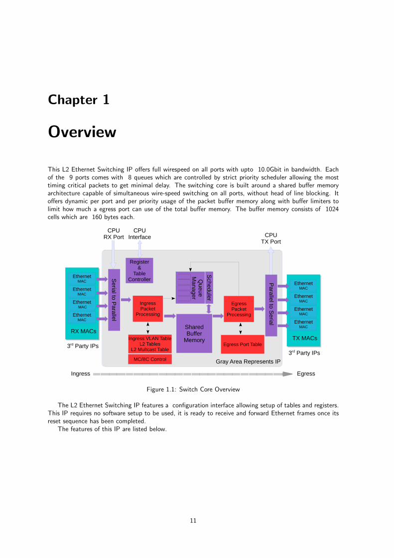
This L2 Ethernet Switching IP offers full wirespeed on all ports with upto 10.0Gbit in bandwidth. Eachof the 9 ports comes with 8 queues which are controlled by strict priority scheduler allowing the mosttiming critical packets to get minimal delay. The switching core is built around a shared buffer memoryarchitecture capable of simultaneous wire-speed switching on all ports, without head of line blocking. Itoffers dynamic per port and per priority usage of the packet buffer memory along with buffer limiters tolimit how much a egress port can use of the total buffer memory. The buffer memory consists of 1024cells which are 160 bytes each.
Ingress Egress
Register&
TableController
IngressPacket
Processing
3rd Party IPs
Ethernet1G/10G MAC
Ethernet40G MAC
Ethernet100G MAC
Interlaken100G+ MAC
EthernetMAC
EthernetMAC
EthernetMAC
EthernetMAC
TX MACs3rd Party IPs
Ethernet1G/10G MAC
Ethernet40G MAC
Ethernet100G MAC
Interlaken100G+ MAC
EthernetMAC
Ethernet MAC
EthernetMAC
EthernetMAC
RX MACs
Serial to P
arall el
Parallel to S
eri al
Queue
Manage r
Schedu ler
Ingress VLAN TableL2 Tables
L2 Multcast Table
SharedBuffer
Memory
CPUInterface
CPURX Port CPU
TX Port
MC/BC Control
EgressPacket
Processing
Gray Area Represents IP
Egress Port Table
Figure 1.1: Switch Core Overview
The L2 Ethernet Switching IP features a configuration interface allowing setup of tables and registers.This IP requires no software setup to be used, it is ready to receive and forward Ethernet frames once itsreset sequence has been completed.
The features of this IP are listed below.
11
CHAPTER 1. OVERVIEW
Feature Overview
• 9 x 10.0Gigabit Ethernet ports
• Full wirespeed on all ports and all Ethernet frame sizes
• Store and Forward shared memory architecture
• Support for Jumbo frames of up to 9.6K byte frame sizes
• Passes all mesh tests with all packet sizes up to 16K bytes
• Full support for queue managment operations from configuration interface
• Input and Output mirroring
• Link aggregation
• Two ACLs with 32 entry and 8 entry each, available for L2 and L3 fields
• Reserved MAC ranges for source MAC addresses and destination MAC addresses
• VLAN operations(push,pop,swap,pop all) on both ingress and egress
• 4K entry L2 MAC table, hash based 4-way
• 4K entry VLAN table
• 8 entry CAM to solve hash collisions
• 4K entry L2 multicast table
• Automatic aging and wire-speed learning of L2 addresses. Does not require any CPU/softwareintervention
• Spanning tree support, ingress and egress checks
• 8 entry Learning FIFO used by learning engine
• 1310720 bits shared packet buffer memory for all ports divided into 1024 cells each of 160 bytessize
• 8 priority queues per egress port
• Configurable mapping of egress queue from IP TOS, MPLS exp/tc or a packets VLANs PCP bits.
• Strict Priority Scheduler
• Resource counters with configurable limits per egress port, egress queue and multicast in buffermemory
• configuration interface for accessing configuration and status registers/tables in IP
• Switching IPs 9 ports can be connected to any ports in the FPGA
• Flow control 802.3 utilizing Xilinx MACs pause handling, easy to adapt to other MACs pause handling
• Multicast/Broadcast storm control - packet or bandwidth based per egress port setting
12 Packet Architects AB
CHAPTER 1. OVERVIEW
A Packets Way Through The IP
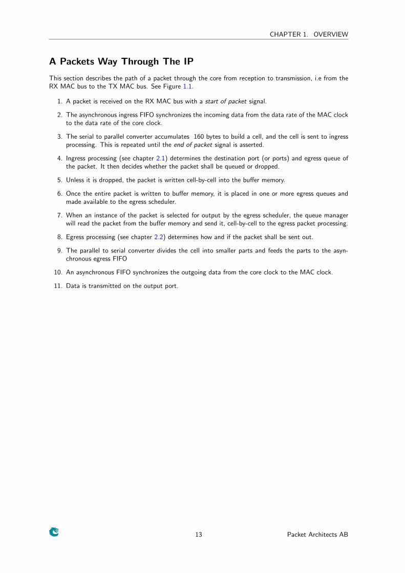
This section describes the path of a packet through the core from reception to transmission, i.e from theRX MAC bus to the TX MAC bus. See Figure 1.1.
1. A packet is received on the RX MAC bus with a start of packet signal.
2. The asynchronous ingress FIFO synchronizes the incoming data from the data rate of the MAC clockto the data rate of the core clock.
3. The serial to parallel converter accumulates 160 bytes to build a cell, and the cell is sent to ingressprocessing. This is repeated until the end of packet signal is asserted.
4. Ingress processing (see chapter 2.1) determines the destination port (or ports) and egress queue ofthe packet. It then decides whether the packet shall be queued or dropped.
5. Unless it is dropped, the packet is written cell-by-cell into the buffer memory.
6. Once the entire packet is written to buffer memory, it is placed in one or more egress queues andmade available to the egress scheduler.
7. When an instance of the packet is selected for output by the egress scheduler, the queue managerwill read the packet from the buffer memory and send it, cell-by-cell to the egress packet processing.
8. Egress processing (see chapter 2.2) determines how and if the packet shall be sent out.
9. The parallel to serial converter divides the cell into smaller parts and feeds the parts to the asyn-chronous egress FIFO
10. An asynchronous FIFO synchronizes the outgoing data from the core clock to the MAC clock.
11. Data is transmitted on the output port.
13 Packet Architects AB
CHAPTER 1. OVERVIEW
14 Packet Architects AB
Chapter 2
Packet Processing
The packet forwarding is done by the ingress packet processing. This switching core has both ingress andegress packet processing. The packet processing is done in the following order:
2.1 Ingress Packet Processing
The ingress packet processing is done as soon as the packet enters the switch. The packet is not sent tothe buffer memory until the egress destination queue is known.
1. Extract the MAC SA,DA and higher protocol from the incoming packet.
2. Check if the packet is from the CPU port (the highest numbered port) and has a extra CPU tag.If true, remove the CPU tag and extract the CPU tags fields for destination ports and destinationqueue.
3. Determine if the packet has a single VLAN,dual VLAN and if it is a known L3 protocol such as IPv4,IPv6, MPLS or encapsulated in a PPPoE frame.
4. Check if the packet has a reserved destination MAC and if so then do the operations which is setupin Reserved Destination MAC Address Range
5. Check if packet is multicast packet with DA = 0xff:ff:ff:ff:ff:ff or the broadcast bit (=Bit 40) in theDA is set to one. If either of the above is true, the packet is broadcast to all VLAN member ports.
6. Check the ingress port filter and drop packet if they are not allowed on the source port. The filteris described in Ingress Port Packet Type Filter
7. Do the first and second ingress classification. The fields which shall be compared is located in IngressFirst ACL Match Data Entries and Ingress Second ACL Match Data Entries while the resultand the operation to be carried out is specified in Ingress First ACL Result Operation Entriesand in Ingress Second ACL Result Operation Entries.
8. Check the packet’s DA to determine if it is a BPDU (DA MAC = 01:80:c2:00:00:00)or Rapid SpanningTree Protocol BPDU packet (DA MAC = 01:00:0C:CC:CC:CD) or matching the customized CPUMAC address. This packet shall be sent to the CPU port if the corresponding CPU port filtering ruleis enabled in Send to CPU.
9. The VID for the packet by looking at the Source Port Table. The VID can be selected from thepackets outermost VLAN header or from the source port table.If an incoming packet does not havea VLAN tag then a default VLAN tag is used from the source port table.
10. The source port table allows a packet VLAN operation which allows a packet to add, remove , swapthe incoming packets VLAN headers.
11. Do the ingress VLAN lookup on the packets determined VID. A number of VLAN operations can bedone on the packet per VLAN. The packet is verified that it is allowed to enter this VLAN otherwiseit is dropped and a counter is updated.
15
CHAPTER 2. PACKET PROCESSING
12. Check the incoming source port’s spanning tree state. This is specified in the ingress table SourcePort Table.
13. The packets source address plus GID and port information is sent to the learning engine.
14. Assign the egress queue by looking at the packet fields along with the assignment according section7.1.
15. Check if the source port shall be mirrored to another port, by reading out the corresponding entryin the Source Port Table, and if so then add this port to destination portmask.
16. Do the destination address lookup in the L2 DA Hash Lookup Table, which can return a singledestination port or multiple egress ports (if the destination address points to a multicast entry). Ifthe DA lookup fails then the packet is flooded to all the members of the packets VLAN.
17. For all egress ports which the packet is destined for, check the egress spanning tree state in EgressSpanning Tree State. Remove the ports which the packet is not allowed to be sent out on.
18. If the packet is a multicast or broadcast then the Multicast BroadCast Storm control is asked tocheck if there is too much multicast / broadcast traffic.
19. Check if any of the egress ports are exceeding their shared memory allocation limits. If the packetis a unicast then the current buffer level is checked against the Low Priority Unicast OccupancyLimit or High Priority Unicast Occupancy Limit depending on the assigned egress queue priorityof the packet. If the packet is a multicast packet (A packet going to multiple ports) then the LowPriority Multicast Occupancy Limit or High Priority Multicast Occupancy Limit is consulteddepending on the assigned egress queue priority of the packet.
20. Before a packet is allowed to be queued on a egress port the egress port filtering is applied to eachegress port. The filtering is described in Egress Port Packet Type Filter.
2.2 Egress Packet Processing
The egress packet processing is done with respect to egress port operations. Before the packet is transmittedout, the Egress Port Configuration is checked which allows for new VLAN operations on the packet.There is support to disable the port which means packets to the port will be scheduled but nothing actuallyis sent out from the port, the queues on the port will be emptied but no packets will be sent to the MAC.
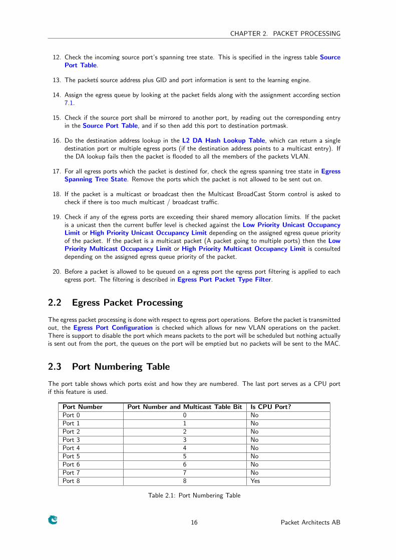
2.3 Port Numbering Table
The port table shows which ports exist and how they are numbered. The last port serves as a CPU portif this feature is used.
Port Number Port Number and Multicast Table Bit Is CPU Port?Port 0 0 NoPort 1 1 NoPort 2 2 NoPort 3 3 NoPort 4 4 NoPort 5 5 NoPort 6 6 NoPort 7 7 NoPort 8 8 Yes
Table 2.1: Port Numbering Table
16 Packet Architects AB
CHAPTER 2. PACKET PROCESSING
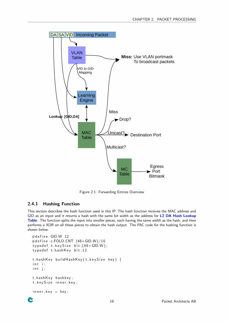
2.4 Forwarding Entries
To forward a packet inside this core the following steps are performed:
1. The Destination Address (DA) from the incoming Ethernet frame is extracted
2. The Virtual LAN Identifier (VID) is assigned by following the rules which has been setup in theSource Port Table
3. The VLAN Table is looked up to determine the Global IDentifer (GID)
4. The GID and DA is hashed into a 10 bit address see 2.4.1
5. The generated hash address used to read out the L2 Destination Table at four places in parallel
6. The GID and DA is compared with all the entries inside the L2 Lookup Collision Table
7. If any of the tables contains the correct GID and DA this entry is choosen as a hit.
8. The correctspoding memory entry inside L2 Destination Table is read out and used as the answerentry for the lookup.
9. If the L2 Destination Table has the uc bit set to zero then the L2 Multicast Table is used to readout the address pointed to by the destPort or mcAddr
10. If the there was no hit the packet is flooded to all the membership ports of the entry in the VLANTable.
The process in shown in the figure 2.1.
17 Packet Architects AB
CHAPTER 2. PACKET PROCESSING
Incoming PacketDA SA
MACTable
MCTable
Miss: Use VLAN portmask To broadcast packets
Multicast?
Unicast? Destination Port
EgressPort
Bitmask
LearningEngine
VLANTable
VID
Miss
VID to GIDMapping
Lookup: [GID,DA]Drop?
Figure 2.1: Forwarding Entries Overview
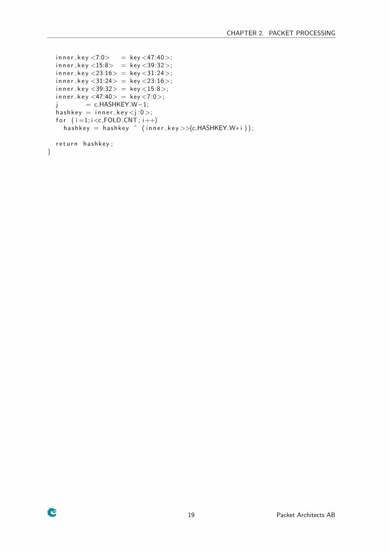
2.4.1 Hashing Function
This section describes the hash function used in this IP. The hash function receives the MAC address andGID as an input and it returns a hash with the same bit width as the address for L2 DA Hash LookupTable. The function splits the input into smaller pieces, each having the same width as the hash, and thenperforms a XOR on all these pieces to obtain the hash output. The PAC code for the hashing function isshown below.
#d e f i n e GID W 12#d e f i n e c FOLD CNT (48+GID W)/10t y p e d e f t k e y S i z e b i t :(48+GID W ) ;t y p e d e f t hashKey b i t : 1 2
t hashKey bu i ldHashKey ( t k e y S i z e key ) {i n t i ;i n t j ;
t hashKey hashkey ;t k e y S i z e i n n e r k e y ;
i n n e r k e y = key ;
18 Packet Architects AB
CHAPTER 2. PACKET PROCESSING
i n n e r k e y <7:0> = key <47:40>;i n n e r k e y <15:8> = key <39:32>;i n n e r k e y <23:16> = key <31:24>;i n n e r k e y <31:24> = key <23:16>;i n n e r k e y <39:32> = key <15:8>;i n n e r k e y <47:40> = key <7:0>;j = c HASHKEY W−1;hashkey = i n n e r k e y <j :0 > ;f o r ( i =1; i<c FOLD CNT ; i ++)
hashkey = hashkey ˆ ( i n n e r k e y >>(c HASHKEY W∗ i ) ) ;
r e t u r n hashkey ;}
19 Packet Architects AB
CHAPTER 2. PACKET PROCESSING
2.5 Learning Unit
The IP has a dedicated learning unit in hardware, which is tasked with learning L2 MAC addresses asentries in the L2 DA Hash Lookup Table. The L2 DA Hash Lookup Table has been implemented asfour parallel tables of equal sizes and these are called hash buckets.The learning unit receives an extractedL2 MAC address, the source port and a hash address, generated as per section 2.4.1 above, from theincoming packet. This information is then used as an index to update the L2 DA Hash Lookup Tableby looking for a free position, at an index equal to the hash address, in either of the hash buckets.
Additionally, the learning engine updates the L2 Destination Table with the source port for thecorresponding MAC entry. The engine can be turned on or off using the Learning Enable register. Evenif learning is enabled, whether a particular entry gets learnt or not, is affected by the ingress spanning treestate. If the spt field of Source Port Table, corresponding to the packet’s source port, is Blocking orListening then the packet will not be learnt. Again, if the packet was a hit in any of the classification oringress filtering rules it will not be learnt either.
The Not Learnt counter gives the number of entries that were not learnt due to an overflow of a fifoin the learning engine. This gives an insight into the learning engine’s internal state.
2.6 Age Unit
The aging functionality will age out existing entries in the L2 DA Hash Lookup Table which have notbeen hit in a period of time. This unit uses the L2 Aging Table to determine if an entry has been hit ornot. The register Age Enable can be used to toggle the aging functionality on or off. The Age unit hassettings on how many clock cycles it will wait before it starts to age out entries, configurable via the theTime to Age register. The age-timeout (in cycles) is the sum of Time to Age and the depth of the L2Destination Table.
The hit bit of entries in the L2 Aging Table are updated every time a packet hits a corresponding entryin the L2 DA Hash Lookup Table. It should also be noted that all new entries written to the L2 AgingTable are initialised with their hit bit as high so as to prevent them from being aged out immediately. Ifan entry has been hit, or has been initialized in the previous age-timeout cycles, the entry is updated asvalid, without a hit. In the next age-timeout cycles if that same entry is not hit, it is marked as invalidand the entry can be considered to be aged out. An aged out entry can be learned again.
The static bit of entries in the L2 Aging Table can be used to mark entries that the user does notwant to be aged out. The procedure for setting up static L2 entries is described below.
• Generate the 10 bit hash of the desired MAC address using the same hash function as described insection 2.4.1.
• Append two bits at the MSB of the hash, which will reflect the chosen bucket number. The bucketnumber is used to distinguish between the four parallel L2 tables.
• Use the configuration interface described in chapter 12 to issue writes to the L2 DA Hash LookupTable, the L2 Aging Table and the L2 Destination Table, using the address derived in the previousstage.
2.7 Spanning Tree
The spt field of Source Port Table, can be configured for each source port. Similarly, the stpState inthe Egress Spanning Tree State can be configured for each egress port. There are a number of stateswhich these fields can have, Disabled(0), Blocking(1), Listening(2), Learning(3) and Forwarding(4). Thecorresponding values of the spt field are indicated above in parenthesis. A packet from the CPU can besent out on a egress port by setting the Forward From CPU even though the spanning tree state says itis not allowed.
20 Packet Architects AB
CHAPTER 2. PACKET PROCESSING
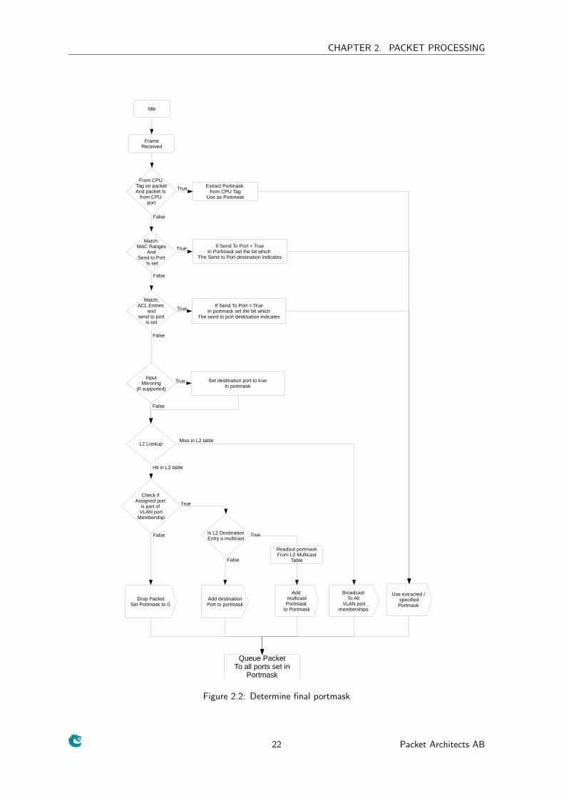
2.8 Determine the final portmask
The portmask is a bitmask, equal to the size of the number of ports in bits, which indicates to which portsa packet shall be sent out on. Since a packet goes through multiple lookups and some of them can resultin a destination port this section shows how the final portmask is determined. The final portmask takesboth packet filtering described in chapter 5 and the Classification described in chapter 4 into accound todetermine the final outcome.
This is shown in figure 2.2.
1. If the packet contains a CPU tag which contains a portmask, then this portmask is used. Theexception to this rule is if any of the ACL or ingress or egress filtering drops the packet.
2. The packets destination address is checked with the mac ranges. If the mac ranges is hit then theportmask is determined if the mac ranges has a send to CPU bit set.
3. The first and second ACL classification engies are looked up to determine if there is any send to CPUor send to port instructions set. If this is the case then the packet is sent to the destination ports.
4. The L2 MAC destination lookup is done. A L2 lookup can result in either a single destination portor multiple ports depending on if the packet is a unicast or multicast.
5. Depending on the packet type and the packet filtering setup rules the ports which are not allowedto send out the packet is removed from the final portmask.
2.9 Software Access to Forwarding Tables and Age Tables
The learning engine, the age engine and the hit engine constantly will update the forwarding tables suchas L2 DA Hash Lookup Table, the L2 Destination Table and the L2 Aging Table. Therefore beforeany update to these three tables can be accessed by software through the CPU interace, each of the unitsshall be deactivated. If not doing so might cause the switch act non-deterministic.
The related register for this operation is Learning And Aging Software Access Control with threefields. The three units are deactivated by setting all bits to 1 in this register, and the register needs to bereset to 0 again once the software completed forwarding tables updates.
2.10 Mirroring
The IP allows input and output mirroring. The input mirroring allows all traffic on a input port to be sentout on any port. If multiple ports are transmitting to the same egress port, a mix of packets from themirrored port and the normal traffic will be sent out. The input mirroring functionality can be enabledper source port, using the inputMirrorEnabled field of the relevant source port entry in the Source PortTable. The ports that are mirrored to, per source port, can be configured using the destInputMirror fieldof the entries in the Source Port Table.
Output mirroring allows the user to select an egress port to be mirrored, enabled using the outputMir-rorEnabled field of the relevant egress port entry in the Egress Port Table. All its traffic will be sentout on the mirrored egress port, which is set up in the destOutputMirror field of the corresponding entryin the Egress Port Table. Mirrored packets will be counted as multicast packets since they are sent outon multiple egress ports. Egress resource limits for multicast packets, configurable in the Low PriorityMulticast Occupancy Limit and High Priority Multicast Occupancy Limit, will be used to limit thistraffic.
21 Packet Architects AB
CHAPTER 2. PACKET PROCESSING
Idle
FrameReceived
L2 Lookup
Broadcast To All
VLAN portmemberships
Add multicast
Portmask to Portmask
Add destinationPort to portmask
Drop PacketSet Portmask to 0.
Check if Assigned port
is part of VLAN port
Membership
Is L2 DestinationEntry a multicast
False
True
True
Readout portmaskFrom L2 Multicast
TableFalse
Match:MAC Ranges
AndSend to Port
Is set
From CPU Tag on packetAnd packet Is
from CPU port
Extract Portmask from CPU Tag
Use as Portmask
If Send To Port = TrueIn Portmask set the bit which
The Send to Port destination indicates
True
True
Match:ACL Entries
andsend to port
is set
If Send To Port = TrueIn portmask set the bit which
The send to port destination indicates
True
False
False
False
InputMirroring
(If supported)
Set destination port to true In portmask
True
False
Queue PacketTo all ports set in
Portmask
Use extracted / specifiedPortmask
Hit in L2 table
Miss in L2 table
Figure 2.2: Determine final portmask
22 Packet Architects AB
Chapter 3
VLAN Processing
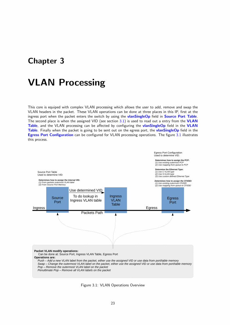
This core is equiped with complex VLAN processing which allows the user to add, remove and swap theVLAN headers in the packet. These VLAN operations can be done at three places in this IP, first at theingress port when the packet enters the switch by using the vlanSingleOp field in Source Port Table.The second place is when the assigned VID (see section 3.1) is used to read out a entry from the VLANTable, and the VLAN processing can be affected by configuring the vlanSingleOp field in the VLANTable. Finally when the packet is going to be sent out on the egress port, the vlanSingleOp field in theEgress Port Configuration can be configured for VLAN processing operations. The figure 3.1 illustratesthis process.
SourcePort
IngressVLANTable
EgressPort
Source Port TableUsed to determine VID:
Determines how to assign the internal VID: (1) From packets outermost VLAN label (2) From Source Port Memory
Use determined VID
To do lookup in Ingress VLAN table
Packet VLAN modify operations: Can be done at: Source Port, Ingress VLAN Table, Egress PortOperations are:
Push – Add a new VLAN label from the packet, either use the assigned VID or use data from port/table memorySwap – Change the outermost VLAN label on the packet, either use the assigned VID or use data from port/table memoryPop – Remove the outermost VLAN label on the packetPenultimate Pop – Remove all VLAN labels on the packet
Egress Port ConfigurationUsed to determine VID:
Determines how to assign the PCP: (1) Use existing outermost PCP (2) Use mapping from queue to PCP
Determine the Ethernet Type: (1) Use C-VLAN type (2) Use S-VLAN type (3) Use custom defined Ethernet Type
Determines how to assign the CFI/DEI: (1) Use existing outermost CFI/DEI (2) Use mapping from queue to CFI/DEI
Packets PathIngress Egress
Figure 3.1: VLAN Operations Overview
23
CHAPTER 3. VLAN PROCESSING
3.1 Assignment of VID
All packets entering the switch will be assigned a VID which is used to lookup the VLAN Table. Theassignment of this VID is done either from the packet’s outermost VLAN or from the Source Port Table,and this is configurable via the vidSel field in the VLAN Table. In the latter case, the assigned VID hasthe same value as the defaultVid field in the Source Port Table.
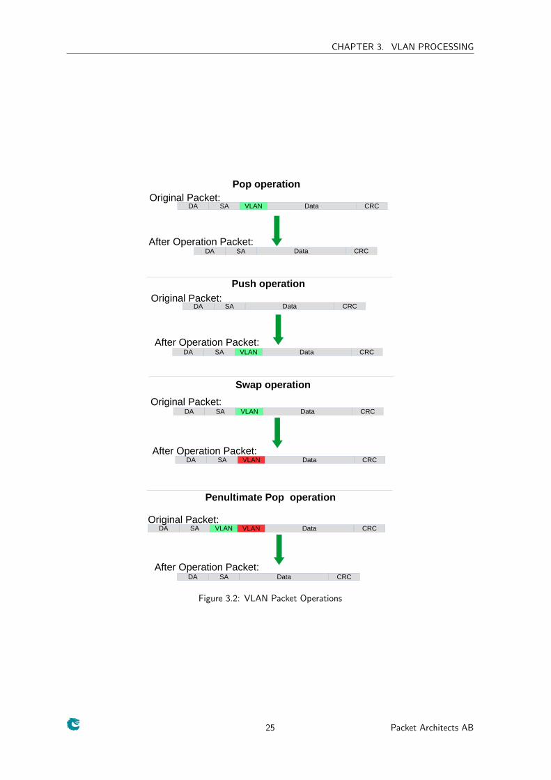
3.2 VLAN operations
There are a number of operations which can be done on the packet’s VLAN headers and they are listed inthe table below.
• Pop - The outermost VLAN label on the packet is removed
• Push - A new VLAN header is added to the packet. The selection of each of the VLAN fields suchas vid, pcp and dei/cfi bits are configurable. These fields can come either from the packet or fromthe table.
• Swap - The outermost VLAN identifier will be replaced by a VID or data from the table entry. Italso allows swapping of certain fields such as the pcp bits and the cfi/dei bit.
• Penultimate Pop - All VLAN labels are removed from the packet.
Figure 3.2 shows the effect of these operations on a packet.
24 Packet Architects AB
CHAPTER 3. VLAN PROCESSING
DA SA VLAN Data CRC
Pop operation
DA SA Data CRC
Original Packet:
After Operation Packet:
DA SA VLAN Data CRC
Push operation
DA SA Data CRCOriginal Packet:
After Operation Packet:
DA SA VLAN Data CRC
Swap operation
Original Packet:
After Operation Packet:
DA SA VLAN Data CRC
DA SA
VLAN
Data CRC
Penultimate Pop operation
Original Packet:
After Operation Packet:
DA SA VLAN Data CRC
Figure 3.2: VLAN Packet Operations
25 Packet Architects AB
CHAPTER 3. VLAN PROCESSING
26 Packet Architects AB
Chapter 4
Classification
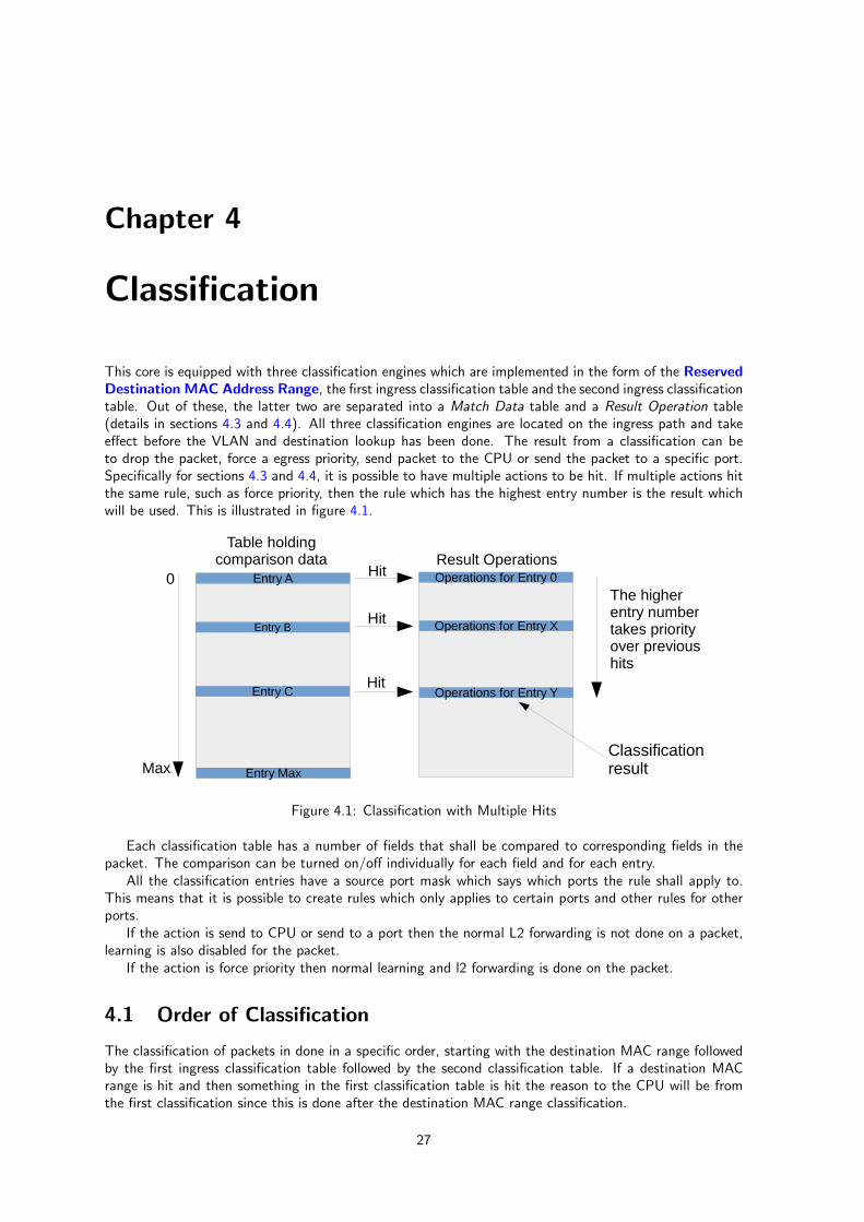
This core is equipped with three classification engines which are implemented in the form of the ReservedDestination MAC Address Range, the first ingress classification table and the second ingress classificationtable. Out of these, the latter two are separated into a Match Data table and a Result Operation table(details in sections 4.3 and 4.4). All three classification engines are located on the ingress path and takeeffect before the VLAN and destination lookup has been done. The result from a classification can beto drop the packet, force a egress priority, send packet to the CPU or send the packet to a specific port.Specifically for sections 4.3 and 4.4, it is possible to have multiple actions to be hit. If multiple actions hitthe same rule, such as force priority, then the rule which has the highest entry number is the result whichwill be used. This is illustrated in figure 4.1.
Entry A
Entry B
Entry C
Table holding comparison data Result Operations
Operations for Entry Y
Operations for Entry X
Operations for Entry 0
The higherentry numbertakes priorityover previoushits
Hit0
Max Entry Max
Hit
Hit
Classification result
Figure 4.1: Classification with Multiple Hits
Each classification table has a number of fields that shall be compared to corresponding fields in thepacket. The comparison can be turned on/off individually for each field and for each entry.
All the classification entries have a source port mask which says which ports the rule shall apply to.This means that it is possible to create rules which only applies to certain ports and other rules for otherports.
If the action is send to CPU or send to a port then the normal L2 forwarding is not done on a packet,learning is also disabled for the packet.
If the action is force priority then normal learning and l2 forwarding is done on the packet.
4.1 Order of Classification
The classification of packets in done in a specific order, starting with the destination MAC range followedby the first ingress classification table followed by the second classification table. If a destination MACrange is hit and then something in the first classification table is hit the reason to the CPU will be fromthe first classification since this is done after the destination MAC range classification.
27
CHAPTER 4. CLASSIFICATION
4.2 Classification On The DA MAC Address ranges
The packet processing allows a user to setup filters which allows the incoming packets to be sent to theCPU based on destination MAC address as ranges. An option to drop the packet is also available. ThesendToCpu option allows the packet to be sent to the CPU, and when activated, this will override normalL2 forwarding and send the packet to only the CPU port. This can be setup in Reserved DestinationMAC Address Range. Since the classification engines are located prior to the normal L2 processingengine, all packets with a DA MAC within the specified range, irrespective of their eligibility for broadcast,shall be affected by the Reserved Destination MAC Address Range.
4.3 First Classification Table
The first classification table is comprised of the Ingress First ACL Match Data Entries and the IngressFirst ACL Result Operation Entries. The former consists of fields like daMac which will be comparedagainst the incoming packet’s corresponding field (in this example, the destination MAC address) to de-termine if the packet should be affected by this classification engine. In addition, the Ingress First ACLMatch Data Entries also consists of fields such as compareDaMac which, when set high, activate thecorresponding matching criteria. When an incoming packet is matched against all the fields of an entry inthe Ingress First ACL Match Data Entries that are enabled, the matching index is used to lookup theIngress First ACL Result Operation Entries. The entry in this Result Operation table will determinehow the packet is going to be processed.
4.4 Second Classification Table
The second classification table comprises of the Ingress Second ACL Match Data Entries and theIngress First ACL Result Operation Entries. It functions in the same way as 4.3 with an added saMacfield in the corresponding Match Data table.
4.5 Reason To Cpu
Each of the above classification engines has the possibility to send the packet to the CPU. If one is hit andand sends the packet to the CPU then a CPU tag will be added to the packet. The CPU tag will containa identifier, reason to CPU field, which allows the software to determine which entry was hit and whichtable was hit.
28 Packet Architects AB
Chapter 5
Protocol Type Packet Filtering
This chapter gives an overview of the filtering options available on both ingress and egress. These kindof filtering allows different types of packets to be accepted or dropped. Example of packet types are areService VLAN tagged, Customer VLAN tagged , IPv4, IPv6, MPLS and Broadcast.
There are two filters, The first filter is applied at the source port as packets enter the IP and this isdescribed in Ingress Port Packet Type Filter. Secondly, as the packet is ready to be queued, the EgressPort Packet Type Filter is applied for each egress port which the packet is to be queued onto.
The Egress Port Packet Type Filter and Ingress Port Packet Type Filter is setup unique for eachingress and egress port. A packet of a certain type can be allowed to enter on a certain ingress port butthis does not mean it is allowed to transmit such a frame.
In addition to the egress port packet type filter there is also a source port filter on the egress port. Thisallows a user to setup whether packets from a certain source port are sent out on an egress port.
The outcome of the filtering options are either to drop a packet or to allow a packet. Packets whichare dropped due to ingress or egress filtering are recorded in the drop counters.
For the egress drop counter to be updated all egress ports have to be filtered out. If one instance ofthe packet is not filtered out then the drop counter will not be updated.
The filtering on both the ingress and egress is done by extracting the Ethernet type fields and certainfields inside the packet.
29
CHAPTER 5. PROTOCOL TYPE PACKET FILTERING
30 Packet Architects AB
Chapter 6
Buffer Memory Resource Limiters
The shared buffer memory may provide different kind of resource limiters according to user requirementsand this core features one based on packet priorities for each egress port. The resource limiter granularityis cells, and there are 1024 cells of 160 bytes each available in the buffer memory.
Thus, a 1600 byte packet will occupy 10.0 cells in the buffer memory. A packet longer than n cellsbut shorter than(n+1) cells will require (n+1) cells for storage. For example, a 161-byte packet will usetwo cells.
6.1 Resource Limiter: Egress Port and Priority
The switching core has 8 egress priority queues per egress port. Before the packets are put into any queue,the resource limiter checks if the buffer memory has room for more packets. If the limits are exceeded thenincoming packets will be dropped.
The purpose of the resource limiter in this core is to enable packets with highest priority to pass throughas much as possible. By means of dividing all packets to two brackets where the higher bracket containspackets with highest priority and the lower bracket for the rest, separate occupancy limits on the twobrackets can be setup either for unicasts or multicasts.
6.1.1 Unicast Limits
For each egress port, the lower bracket limit is set to drop packets before the higher bracket limit starts todrop packets (lower bracket limit < higher bracket limit). This means that on an overloaded egress portthe low priority packets will start to be dropped before the highest priority packets starts to drop. 1
Neither limiter will be activated until a total buffer memory occupancy level has been reached respec-tively. When the switch is in an uncongested situation this will allow a queue to grow beyond the queuelimit and avoid drops. This would not punish high priority traffic as there is plenty of room in the buffermemory.
However, since the packets will still be accepted when the occupancy is limit-1 and there is a time lagbetween the resource limiter and the packets being written to the buffer memory, the absolute maximumamount of unicast data that an egress port may have queued for transmission is actually above the limit(In the worst case the overload could be several maximum size packets). If those extra cells fill up thebuffer memory, the resource limiter will not operate as expected and instead the buffer memory will blockall incoming packets mercilessly.
6.1.2 Multicast Limits
A multicast packet is any packet which is going to be sent to multiple egress ports. The multicast resourcelimiter is invoked under the same condition as the unicast limiter. After it is activated, two limits can beconfigured for both higher and lower brackets as well. Since unicast packets and multicast packets sharethe same buffer memory but counted separately, how to setup those limits should be considered properlybased on real scenarios.
1If the last accepted packet is larger than the difference in limits, the higher bracket limit may be reached as well thus thehighest priority packets will be blocked and dropped.
31
CHAPTER 6. BUFFER MEMORY RESOURCE LIMITERS
6.1.3 Default Settings
The following registers related to the resource limiter can be configured and the default values are as such:
• Egress Low Priority Resource Limiter: The default value is half of the buffer memory size i.e.512 cells.
• Low Priority Unicast Occupancy Limit: The default value is 204 cell, calculated under the as-sumption that half of egress ports are congested and the buffer memory is evenly occupied by allcongested ports. Within each congested port the lower bracket is limited by half of its space.
• Low Priority Multicast Occupancy Limit: The default value is 512 cells thus drop starts once thelimiter is activated.
• Egress High Priority Resource Limiter: The default value is set to when 3/4 of the buffer memoryhas been occupied i.e. 768 cells.
• High Priority Unicast Occupancy Limit: The default value is 306 cells, calculated under theassumption that half of egress ports are congested and the buffer memory is evenly occupied by allcongested ports. Within each congested port the higher bracket is limited by 3/4 of its space.
• High Priority Multicast Occupancy Limit: The default value is 768 cells thus drop starts oncethe limiter is activated.
6.1.4 Drop Counters
Four drop counters are included for the resource limiter while half of them count for unicast drops and restfor multicast drops.
• Egress Port Overuse Drop with Low Priority
• Egress Port Overuse Drop with High Priority
• Multicast Overuse Drop with Low Priority
• Multicast Overuse Drop with High Priority
32 Packet Architects AB
Chapter 7
Strict Priority Scheduler
The IP uses a strict priority scheduler which always serves the highest queue priority (0) first and if this isempty it will move on to the next priority. This can cause starvation on the lower queues if the packet arealways of the highest priority.
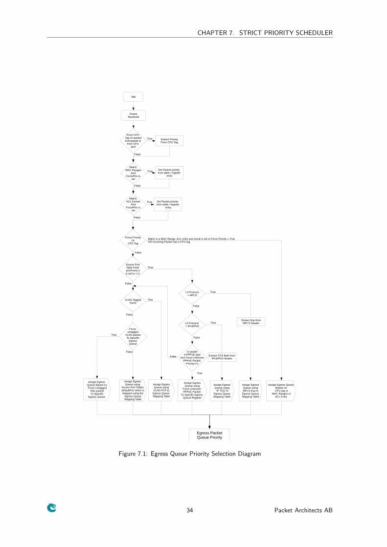
7.1 Determine a packets Queue Priority
A packets fields is extracted and if the packet has a known protocol type such as IPv4 or IPv6, this willthen be used to determine the egress queue priority as described in diagram 7.1.
The MAC Ranges is defined in register Reserved Destination MAC Address Range. The mappingfrom the TOS byte, all 8 bits, to egress queue is described in IP TOS Field To Egress Queue MappingTable while the MPLS is mapped in the MPLS Exp Field To Egress Queue Mapping Table. The forceunknown PPPoE register is Force Unknown PPPoE Packet To Specific Egress Queue.
33
CHAPTER 7. STRICT PRIORITY SCHEDULER
Egress PacketQueue Priority
Idle
FrameReceived
Force PriorityOr
CPU Tag
Assign Egress Queue Based on:CPU tag or
MAC Ranges orACL Entry
Assign EgressQueue usingMPLS Exp to
Egress QueueMapping Table
Assign EgressQueue using IP TOS To
Egress QueueMapping Table
Assign EgressQueue using
Force Unknown PPPoE Packet
To Specific Egress Queue Register
Assign EgressQueue usingVLAN PCP to
Egress Queue Mapping Table
Assign Egress Queue using
Source Port Tables defaultPrio which isMapped using the
Egress QueueMapping Table
Source PortTable Field prioFromL3is set to ==1
VLAN Taggedframe
L3 Protocol= MPLS
L3 Protocol = IPv4/IPv6
Match in a MAC Range, ACL entry and result is set to Force Priority = TrueOR incoming Packet had a CPU tag
True
True
True
TrueExtract Exp fromMPLS Header
Extract TOS Byte fromIPv4/IPv6 Header
Is packetA PPPoE type
And Force UnknownPPPoE Packet
Priority==1
True
False
False
False
False
False
Match:MAC Ranges
AndForcePrio is
set
From CPU Tag on packetAnd packet Is
from CPU port
Extract PriorityFrom CPU Tag
False
Set Packet priority from table / register
entry
True
True
Match:ACL Entries
AndForcePrio is
set
Set Packet priority from table / register
entry
True
False
False
False
Assign Egress Queue Based on Force Untagged
Vlan packetTo Specific
Egress Queue
Force untagged
VLAN packetTo Specific
EgressQueue
False
True
Figure 7.1: Egress Queue Priority Selection Diagram
34 Packet Architects AB
Chapter 8
Queue Management
This core featues a set of queue managment operations which can be used by the CPU to monitor, directand disable queues and ports. The size of the queues can be readout by using the Egress Port ResourceManagement and Egress Queue Resource Management which tells how many cells and packets arequeued on an egress port. From this status the CPU can take active actions to determine what the coreshall do with the packets on the ports. The four operations possible are described below.
8.1 Disable Scheduling To Port
The Disable Egress Packet Scheduling is used to disable the core from scheduling a new packet for trans-mission on a specific port and queue. This is setup in register Output Disable. This allows per-queuegranularity of what packets gets scheduled on a specific port. The packets are still kept in the queues untilthe port or queue is enabled again.
8.2 Disable Queueing To Port
The Disable Queueing To Port function allows the user to setup so that a specific queue on a specific portshall not accept packets. Once the corresponding bit in the Enable enqueue to ports and queues iscleared, no new packets will be queued to an egress queue. New packets entering the switch, which weredestined to this specific queue, will be dropped.
8.3 Drain Port
The Drain Port functionality is used to drop all packets which in all queues on one specific port. Thisallows the user to clear all packets which have been queued on a port. The register Drain Port is used tocontrol this functionality. Statistics for this operation is collected in the Drain Port Drop counter.
8.4 Redirect
The Redirect operation is used to direct one port’s packets (fromEgressPort) to another port (toEgressPort).All packets destined to the fromEgressPort port will instead be transmitted on the toEgressPort. Thepackets destined to toEgressPort that were not redirected will also be transmitted on the port thus thetwo packet streams will be mixed on the port. Resource counting is done prior to redirect. The registerRedirect is used to control this functionality.
35
CHAPTER 8. QUEUE MANAGEMENT
36 Packet Architects AB
Chapter 9
Multicast BroadCast Storm Control
The multicast/broadcast storm control unit (MBSC) is used to make sure that a switch does not overfloodthe network with too much multicast/broadcast traffic.
The block can be turned on/off for individual egress ports by using the MBSC Enable bitmask, whichactivates the functionality for the ports which have a high signal in the corresponding bit position of thisregister. The MBSC Status is a bit mask on the total number of ports. Each bit set in the status meansthat the corresponding port is allowed to transmit. Each cleared bit means that the port should stoptransmitting packets. So a status of 110 means Port 0 of a 3 port switch should stop transmitting packets.
9.1 Multicast Packet
A multicast packet is a packet which is going to be sent to multiple ports. This can be because of that al2 entry points to a l2 multicast entry which has several bits set to one or that a packet is input or outputmirrored.
9.2 Operation
All settings to this block are accessible using the configuration interface and the settings for each egress portcan be set up individually. Each port has a corresponding Token Bucket which can count either in termsof number of packets or the size of packets using the packetOrBytes field of the MBSC Configurationregister. The user can set up the Capacity of the token bucket in the bucketCapacity field, the numberof tokens initially in the bucket as initialSize field and the rate at which tokens fill the bucket (Number oftokens/Number of clock cycles = tokenIn/cyclesIn). A minimum number of tokens (minTokens field) isrequired to be available in the bucket for the corresponding port to transmit data.
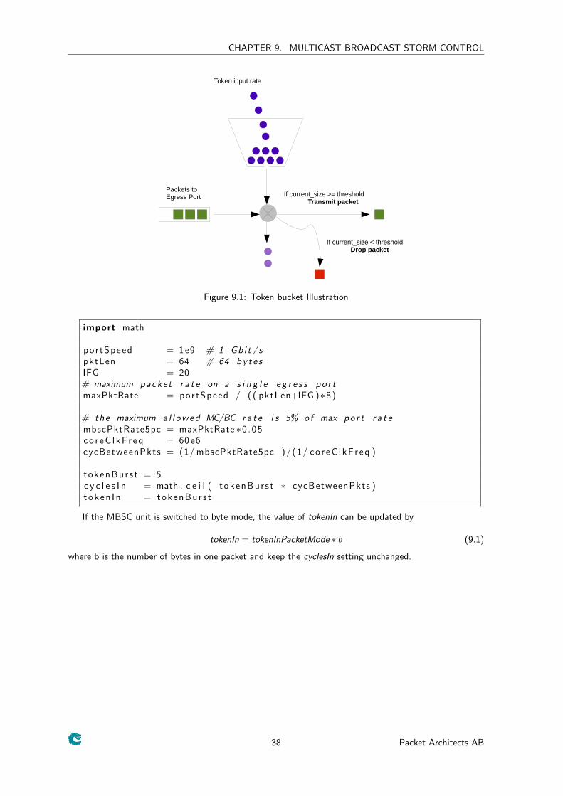
The token bucket operation is illustrated in Figure 9.1. Once there are enough tokens in the bucket,packets are allowed to pass. Once packets have passed the bucket, their size or their number, is decrementedfrom the bucket. If packet based operation is selected then the bucket current size is decremented by one.Once a bucket’s size drops below the threshold, all multicast packets will be dropped in that egress port.
9.3 Default Settings
By default this block allows maximum 5% of the traffic to be multicast/broadcast at packet size of 64bytes and the token is counted per packet. By calculating the packet rate inside the core, the token fill inrate can be obtained accordingly. The default is calculated like this:
37
CHAPTER 9. MULTICAST BROADCAST STORM CONTROL
Token input rate
If current_size < thresholdDrop packet
If current_size >= thresholdTransmit packet
Packets to Egress Port
Figure 9.1: Token bucket Illustration
import math
p o r t S p e e d = 1 e9 # 1 G b i t / spktLen = 64 # 64 b y t e sIFG = 20# maximum p a c k e t r a t e on a s i n g l e e g r e s s p o r tmaxPktRate = p o r t S p e e d / ( ( pktLen+IFG )∗8 )
# th e maximum a l l o w e d MC/BC r a t e i s 5% o f max p o r t r a t embscPktRate5pc = maxPktRate ∗0 . 0 5c o r e C l k F r e q = 60 e6cycBetweenPkts = (1/ mbscPktRate5pc ) / ( 1 / c o r e C l k F r e q )
t o k e n B u r s t = 5c y c l e s I n = math . c e i l ( t o k e n B u r s t ∗ cycBetweenPkts )t o k e n I n = t o k e n B u r s t
If the MBSC unit is switched to byte mode, the value of tokenIn can be updated by
tokenIn = tokenInPacketMode ∗ b (9.1)
where b is the number of bytes in one packet and keep the cyclesIn setting unchanged.
38 Packet Architects AB
Chapter 10
Packet To And From The CPU port
The highest port number, in this case port 8 , has support for a special CPU tag in the packet header.The tag in packets sent to CPU port can determine which port the packet shall be sent to. Packets sentfrom the CPU port have a tag which allows the software stack to determine where the packet came fromand the reason why it was sent to the CPU port.
10.1 Packet From CPU Port
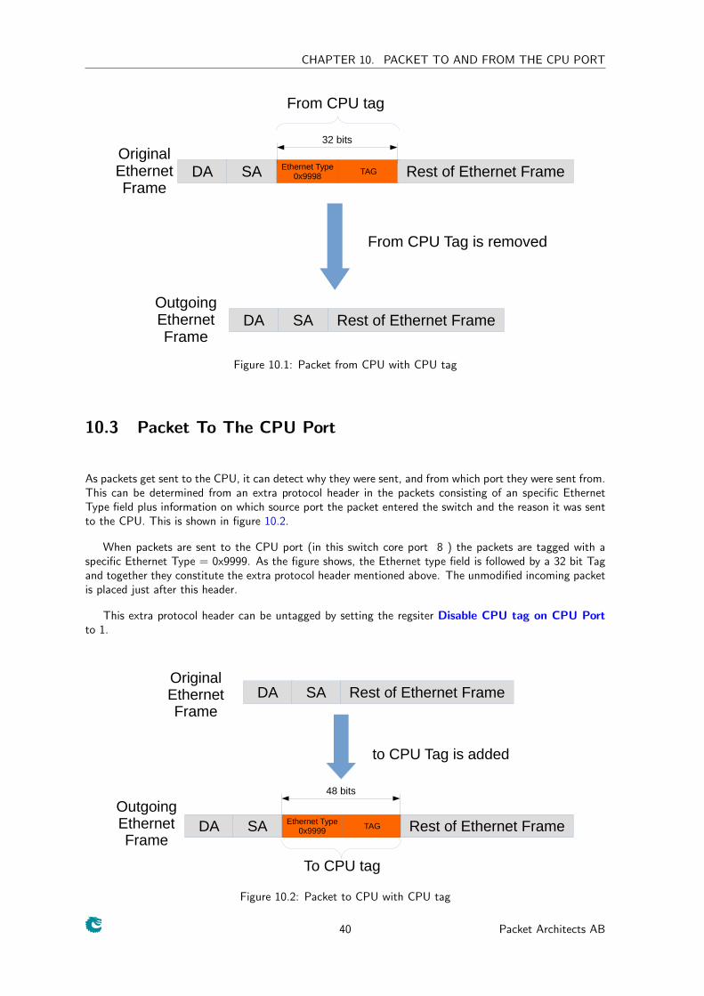
Packets sent from the CPU are normally processed as any other packet that enters the switch and thedestination port is then determined by the L2 lookup. When the CPU needs to direct a packet to a specificport, bypassing the normal L2 lookup, it is accomplished by adding a protocol header consisting of a specificEthernet type followed by an information field that directs the packet to specific ports.
Byte Number Contents of Byte1 Bits [ 2 :0] specified which egress queue packet shall
use on egress ports.0 [ 8 :0] port bitmask. Bit 0 is port number 0, bit 1 is
port number 1 and so on.
Table 10.1: From CPU tag format
To bypass the normal packet processing when packets are sent from the CPU port (in this switch coreport 8 ) the packets shall be tagged with an extra protocol header consisting of a specific Ethernet Type =0x9998 followed by a 16 bit field (CPU Tag) encoded as the table 10.1 below specifies. The switching corewill remove the extra protocol header and send out the packet on the ports requested by the destinationport mask in the protocol header. This is shown in the figure 10.1.
The CPU Tag field contains a port mask that encodes one or more ports to send out the packet on.If multiple bits are set in the port mask then the packet is treated as a multicast packet in the resourcelimiters and will be sent out on all ports with corresponding bit set.
10.2 Packet Filtering To The CPU Port
According to the fine granularity of which packets get transmitted to the CPU port, this can be controlledin the register Send to CPU. For unicast, the switch is possible to choose if BPDU packets or floodedpackets 1 can reach the CPU port. Meanwhile, there is an unique CPU MAC address mechanism can beturned on in parallel which is located the Send to CPU register.
Once it is enabled, one customized destination MAC address setup in the register Send to CPU isbound to the CPU port directly and the CPU port is not visiable for other unicasts unless certain registersare configured to do so.
1packets to a destination MAC address that not learned
39
CHAPTER 10. PACKET TO AND FROM THE CPU PORT
DA SA Ethernet Type0x9998
TAG
From CPU tag
Rest of Ethernet FrameOriginalEthernetFrame
DA SA Rest of Ethernet FrameOutgoingEthernetFrame
From CPU Tag is removed
32 bits
Figure 10.1: Packet from CPU with CPU tag
10.3 Packet To The CPU Port
As packets get sent to the CPU, it can detect why they were sent, and from which port they were sent from.This can be determined from an extra protocol header in the packets consisting of an specific EthernetType field plus information on which source port the packet entered the switch and the reason it was sentto the CPU. This is shown in figure 10.2.
When packets are sent to the CPU port (in this switch core port 8 ) the packets are tagged with aspecific Ethernet Type = 0x9999. As the figure shows, the Ethernet type field is followed by a 32 bit Tagand together they constitute the extra protocol header mentioned above. The unmodified incoming packetis placed just after this header.
This extra protocol header can be untagged by setting the regsiter Disable CPU tag on CPU Portto 1.
DA SA Ethernet Type0x9999
TAG
To CPU tag
Rest of Ethernet Frame
OriginalEthernetFrame
DA SA Rest of Ethernet Frame
OutgoingEthernetFrame
to CPU Tag is added
48 bits
Figure 10.2: Packet to CPU with CPU tag
40 Packet Architects AB
CHAPTER 10. PACKET TO AND FROM THE CPU PORT
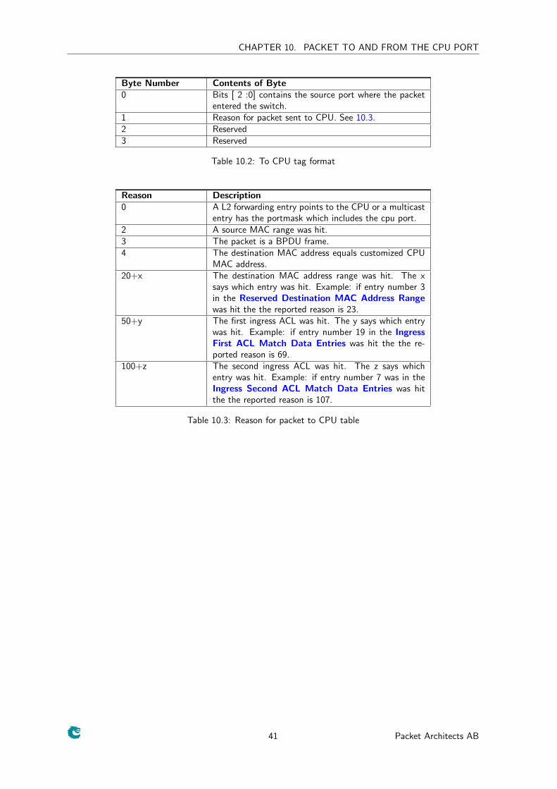
Byte Number Contents of Byte0 Bits [ 2 :0] contains the source port where the packet
entered the switch.1 Reason for packet sent to CPU. See 10.3.2 Reserved3 Reserved
Table 10.2: To CPU tag format
Reason Description0 A L2 forwarding entry points to the CPU or a multicast
entry has the portmask which includes the cpu port.2 A source MAC range was hit.3 The packet is a BPDU frame.4 The destination MAC address equals customized CPU
MAC address.20+x The destination MAC address range was hit. The x
says which entry was hit. Example: if entry number 3in the Reserved Destination MAC Address Rangewas hit the the reported reason is 23.
50+y The first ingress ACL was hit. The y says which entrywas hit. Example: if entry number 19 in the IngressFirst ACL Match Data Entries was hit the the re-ported reason is 69.
100+z The second ingress ACL was hit. The z says whichentry was hit. Example: if entry number 7 was in theIngress Second ACL Match Data Entries was hitthe the reported reason is 107.
Table 10.3: Reason for packet to CPU table
41 Packet Architects AB
CHAPTER 10. PACKET TO AND FROM THE CPU PORT
42 Packet Architects AB
Chapter 11
Core Interface Description
This chapter describes the interfaces to the core. An input is an input to the core, and an output is a signaldriven by the core. In analogy reception refers to packets to the core and transmission means packets fromthe core.
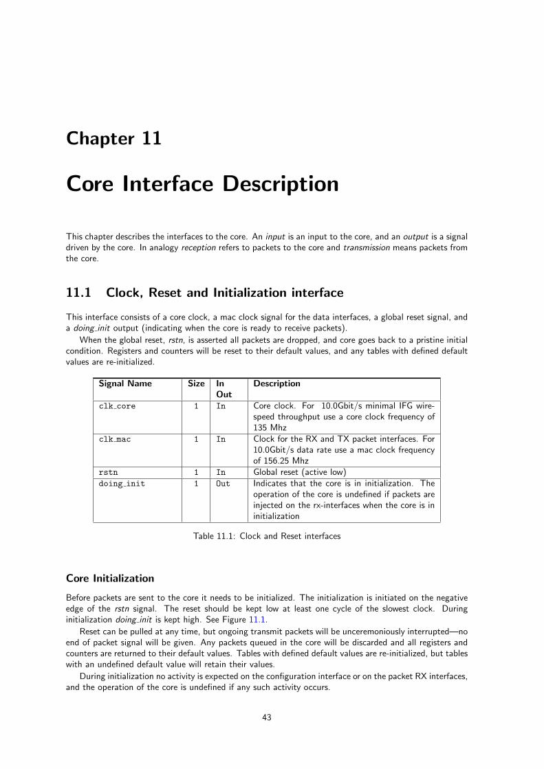
11.1 Clock, Reset and Initialization interface
This interface consists of a core clock, a mac clock signal for the data interfaces, a global reset signal, anda doing init output (indicating when the core is ready to receive packets).
When the global reset, rstn, is asserted all packets are dropped, and core goes back to a pristine initialcondition. Registers and counters will be reset to their default values, and any tables with defined defaultvalues are re-initialized.
Signal Name Size InOut
Description
clk core 1 In Core clock. For 10.0Gbit/s minimal IFG wire-speed throughput use a core clock frequency of135 Mhz
clk mac 1 In Clock for the RX and TX packet interfaces. For10.0Gbit/s data rate use a mac clock frequencyof 156.25 Mhz
rstn 1 In Global reset (active low)doing init 1 Out Indicates that the core is in initialization. The
operation of the core is undefined if packets areinjected on the rx-interfaces when the core is ininitialization
Table 11.1: Clock and Reset interfaces
Core Initialization
Before packets are sent to the core it needs to be initialized. The initialization is initiated on the negativeedge of the rstn signal. The reset should be kept low at least one cycle of the slowest clock. Duringinitialization doing init is kept high. See Figure 11.1.
Reset can be pulled at any time, but ongoing transmit packets will be unceremoniously interrupted—noend of packet signal will be given. Any packets queued in the core will be discarded and all registers andcounters are returned to their default values. Tables with defined default values are re-initialized, but tableswith an undefined default value will retain their values.
During initialization no activity is expected on the configuration interface or on the packet RX interfaces,and the operation of the core is undefined if any such activity occurs.
43
CHAPTER 11. CORE INTERFACE DESCRIPTION
clk core
rstn
doing init
Figure 11.1: Core Initialization
11.2 Packet Interface
There are 9 packet interfaces, or ports for short, each divided into a reception part and a transmissionpart. The ports are numbered from 0 to 8 . Each direction of a packet interface consists of first, last,valid bytes and data fields. The transmit direction has an additional halt field, to allow the receiving endto contol the data rate transmitted from the core.
Pin Function Size Direction Descriptionrx iN[69] last 1 In End-of-packet flag for ingress port N. The last
field is also used to signal broken packets. For acorrectly transmitted packet last is asserted forthe last data transaction of the packet. If lastis set high when valid bytes is zero, the packetis marked as broken, and will be dropped by thecore.
rx iN[68] first 1 In Start-of-packet flag for ingress port N.rx iN[67:64] valid bytes 2 In Indicates the number of valid data bytes for
ingress port N. For all transactions where lastis not high, this shall be equal to the data widthin bytes.
rx iN[63
:0]
data 64 In Packet data for ingress port N.
Table 11.2: Packet RX interface
Pin Function Size Direction Descriptiontx oN[69] last 1 Out End-of-packet flag for egress port N. For a cor-
rectly transmitted packet last is asserted for thelast data transaction of the packet. If last is sethigh when valid bytes is zero, the packet shallbe dropped or terminated with an error by theMAC.
tx oN[68] first 1 Out Start-of-packet flag for ingress port N.tx oN[67:64] valid bytes 2 Out Indicates the number of valid data bytes for
egress port N. For all transactions where lastis not high, this will be equal to the data widthin bytes.
tx oN[63
:0]
data 64 Out Packet data for egress port N.
tx haltN halt 1 In Interrupt the data transmission from egress portN.
Table 11.3: Packet TX interface
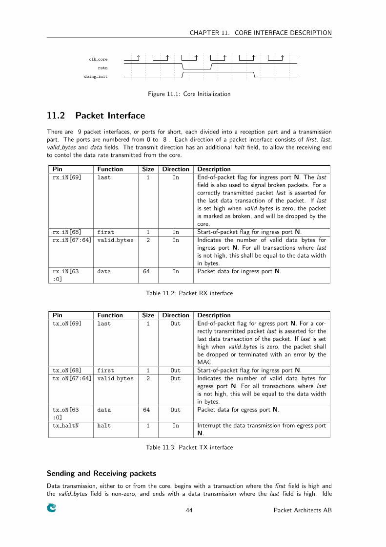
Sending and Receiving packets
Data transmission, either to or from the core, begins with a transaction where the first field is high andthe valid bytes field is non-zero, and ends with a data transmission where the last field is high. Idle
44 Packet Architects AB
CHAPTER 11. CORE INTERFACE DESCRIPTION
transactions—where valid bytes, first and last are all zero—are allowed at any time, but unless haltedthere will be no idle transactions on the transmission interfaces other than between packets.
By default, the core has a short packet size limit of 60 bytes, which means if the FCS is not passedto the core, the acceptable minimum packet size is 64 bytes. All packets below the short limit will bemercilessly dropped in the core at the earliest convenience. According to different use cases, the shortpacket limit can be adjusted and it is possible to enable a long packet limit as well.
Broken packets
A packet ending with last set high and valid bytes set to zero is considered a broken packet. Brokenpackets received by the core will never be output on the egress ports, but will be dropped at the earliestconvenience. Depending on the length of a broken packet the drop will be counted either in the Serial toParallel Broken Drop or Buffer Broken Drop counters.
clk mac
rx/tx first pX
rx/tx last pX
rx/tx data px DATA1 D2 D3 D4 D5 DLAST
rx/tx validbytes pX All bytes valid > 0
Figure 11.2: Sending and Receiving packets (without error)
clk mac
rx/tx first pX
rx/tx last pX
rx/tx data px DATA1 D2 D3 D4 D5 DLAST
rx/tx validbytes pX All bytes valid == 0
Figure 11.3: Sending and Receiving packets (with error)
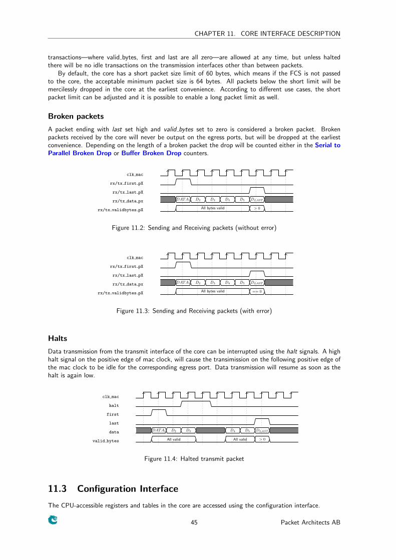
Halts
Data transmission from the transmit interface of the core can be interrupted using the halt signals. A highhalt signal on the positive edge of mac clock, will cause the transimission on the following positive edge ofthe mac clock to be idle for the corresponding egress port. Data transmission will resume as soon as thehalt is again low.
clk mac
halt
first
last
data DATA1 D2 D3 D4 D5 DLAST
valid bytes All valid All valid > 0
Figure 11.4: Halted transmit packet
11.3 Configuration Interface
The CPU-accessible registers and tables in the core are accessed using the configuration interface.
45 Packet Architects AB
CHAPTER 11. CORE INTERFACE DESCRIPTION
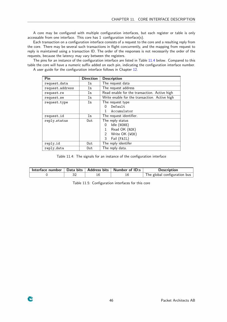
A core may be configured with multiple configuration interfaces, but each register or table is onlyaccessable from one interface. This core has 1 configuration interface(s).
Each transaction on a configuration interface consists of a request to the core and a resulting reply fromthe core. There may be several such transactions in flight concurrently, and the mapping from request toreply is maintained using a transaction ID. The order of the responses is not necessarily the order of therequests, because the latency may vary between the registers.
The pins for an instance of the configuration interface are listed in Table 11.4 below. Compared to thistable the core will have a numeric suffix added on each pin, indicating the configuration interface number.
A user guide for the configuration interface follows in Chapter 12.
Pin Direction Descriptionrequest data In The request datarequest address In The request addressrequest re In Read enable for the transaction. Active highrequest we In Write enable for the transaction. Active highrequest type In The request type
0 Default
1 Accumulator
request id In The request identifier.reply status Out The reply status
0 Idle (NONE)1 Read OK (ROK)2 Write OK (WOK)3 Fail (FAIL)
reply id Out The reply identiferreply data Out The reply data.
Table 11.4: The signals for an instance of the configuration interface
Interface number Data bits Address bits Number of ID:s Description0 32 16 16 The global configuration bus
Table 11.5: Configuration interfaces for this core
46 Packet Architects AB
Chapter 12
Configuration Interface
The configuration interface is used for monitoring the core and for configuration of internal registers andtables. The pins of one such interface can be seen in Table 11.4 above.
12.1 Request Types
Requests can be either read or write. Asserting the read- and write-enables concurrently is not supported.Reads and writes can be of DEFAULT or ACCUMULATOR type, although registers and tables where the datawidth is less than or equal to the configuration interface data width support only the DEFAULT type. Thepurpose of the ACCUMULATOR request type is to access data that is wider than the bus without the risk ofdata inconsistency.
Requests for registers which exceed the bus width are discussed in more detail in Section 12.4 below.
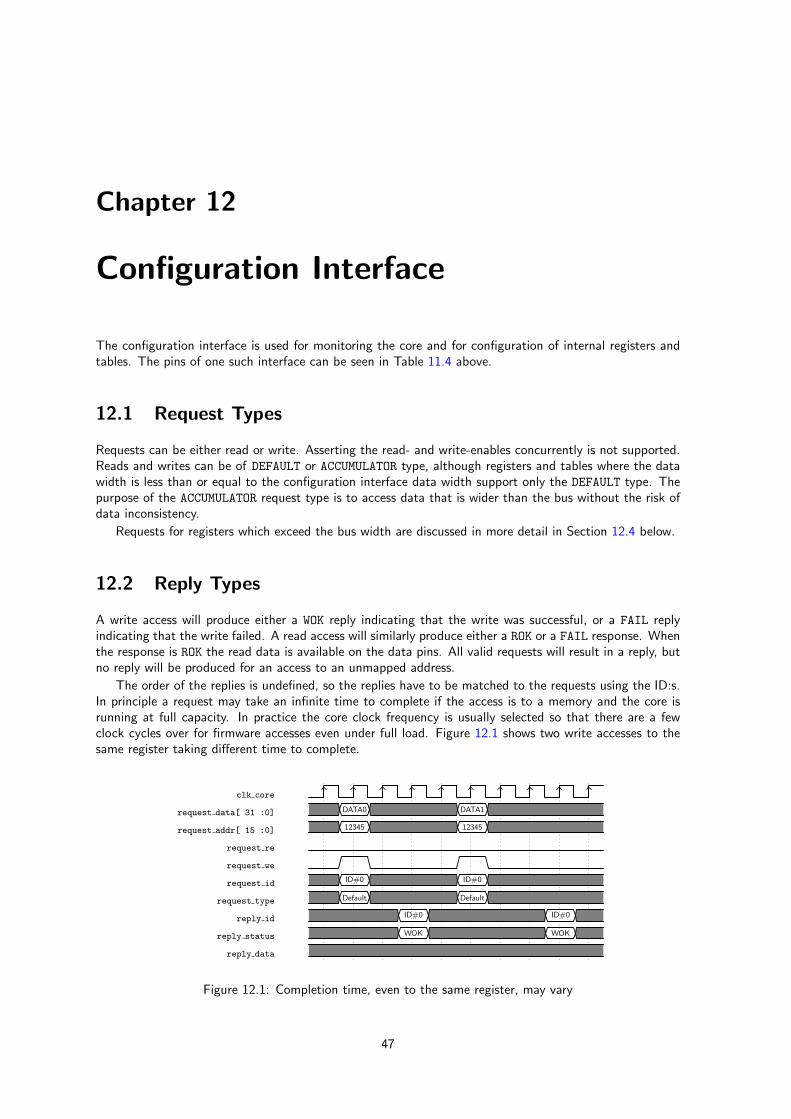
12.2 Reply Types
A write access will produce either a WOK reply indicating that the write was successful, or a FAIL replyindicating that the write failed. A read access will similarly produce either a ROK or a FAIL response. Whenthe response is ROK the read data is available on the data pins. All valid requests will result in a reply, butno reply will be produced for an access to an unmapped address.
The order of the replies is undefined, so the replies have to be matched to the requests using the ID:s.In principle a request may take an infinite time to complete if the access is to a memory and the core isrunning at full capacity. In practice the core clock frequency is usually selected so that there are a fewclock cycles over for firmware accesses even under full load. Figure 12.1 shows two write accesses to thesame register taking different time to complete.
clk core
request data[ 31 :0] DATA0 DATA1
request addr[ 15 :0] 12345 12345
request re
request we
request id ID#0 ID#0
request type Default Default
reply id ID#0 ID#0
reply status WOK WOK
reply data
Figure 12.1: Completion time, even to the same register, may vary
47
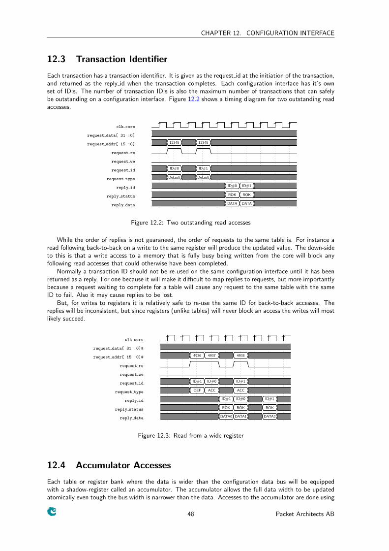
CHAPTER 12. CONFIGURATION INTERFACE
12.3 Transaction Identifier
Each transaction has a transaction identifier. It is given as the request id at the initiation of the transaction,and returned as the reply id when the transaction completes. Each configuration interface has it’s ownset of ID:s. The number of transaction ID:s is also the maximum number of transactions that can safelybe outstanding on a configuration interface. Figure 12.2 shows a timing diagram for two outstanding readaccesses.
clk core
request data[ 31 :0]
request addr[ 15 :0] 12345 12345
request re
request we
request id ID#0 ID#1
request type Default Default
reply id ID#0 ID#1
reply status ROK ROK
reply data DATA DATA
Figure 12.2: Two outstanding read accesses
While the order of replies is not guaraneed, the order of requests to the same table is. For instance aread following back-to-back on a write to the same register will produce the updated value. The down-sideto this is that a write access to a memory that is fully busy being written from the core will block anyfollowing read accesses that could otherwise have been completed.
Normally a transaction ID should not be re-used on the same configuration interface until it has beenreturned as a reply. For one because it will make it difficult to map replies to requests, but more importantlybecause a request waiting to complete for a table will cause any request to the same table with the sameID to fail. Also it may cause replies to be lost.
But, for writes to registers it is relatively safe to re-use the same ID for back-to-back accesses. Thereplies will be inconsistent, but since registers (unlike tables) will never block an access the writes will mostlikely succeed.
clk core
request data[ 31 :0]#
request addr[ 15 :0]# 4936 4937 4938
request re
request we
request id ID#1 ID#0 ID#1
request type DEF ACC ACC
reply id ID#1 ID#0 ID#1
reply status ROK ROK ROK
reply data DATA0 DATA1 DATA2
Figure 12.3: Read from a wide register
12.4 Accumulator Accesses
Each table or register bank where the data is wider than the configuration data bus will be equippedwith a shadow-register called an accumulator. The accumulator allows the full data width to be updatedatomically even tough the bus width is narrower than the data. Accesses to the accumulator are done using
48 Packet Architects AB
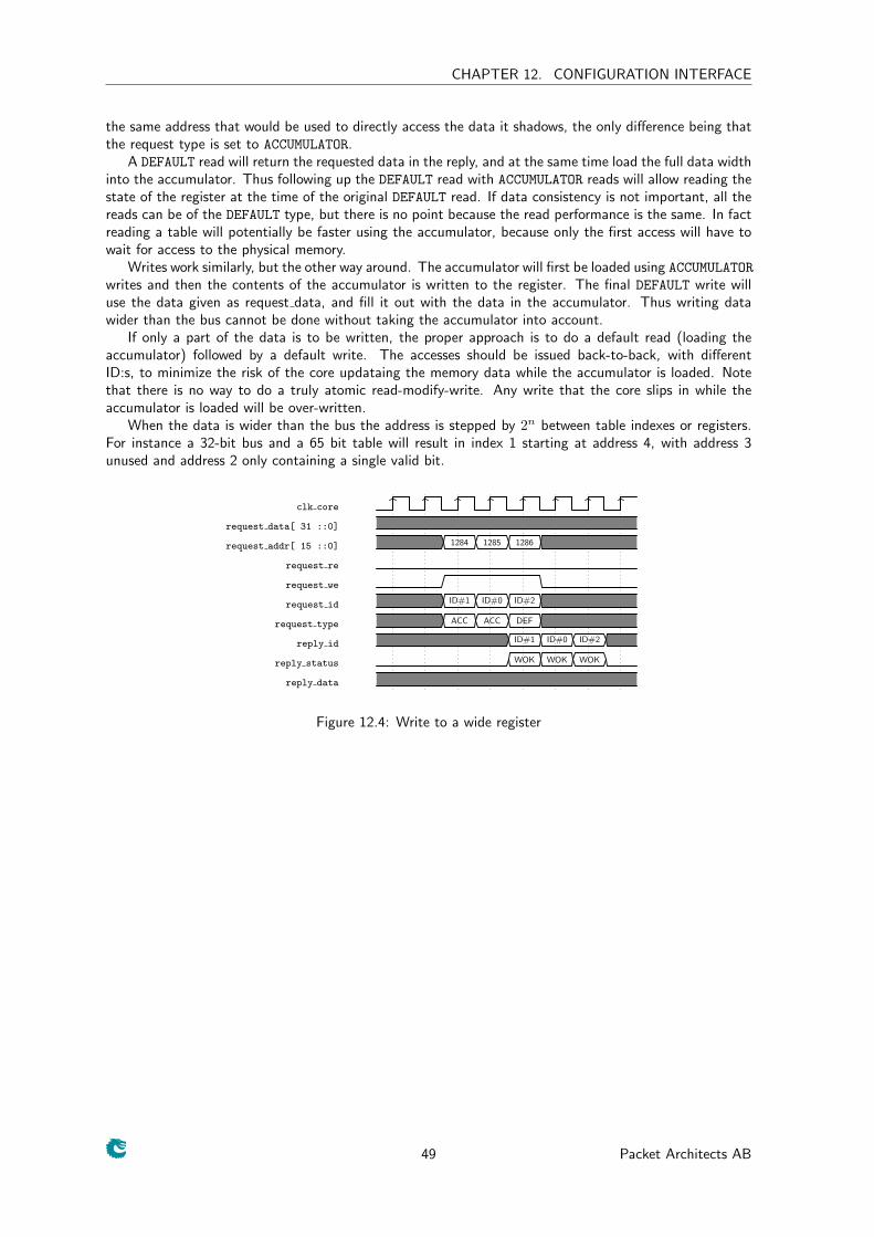
CHAPTER 12. CONFIGURATION INTERFACE
the same address that would be used to directly access the data it shadows, the only difference being thatthe request type is set to ACCUMULATOR.
A DEFAULT read will return the requested data in the reply, and at the same time load the full data widthinto the accumulator. Thus following up the DEFAULT read with ACCUMULATOR reads will allow reading thestate of the register at the time of the original DEFAULT read. If data consistency is not important, all thereads can be of the DEFAULT type, but there is no point because the read performance is the same. In factreading a table will potentially be faster using the accumulator, because only the first access will have towait for access to the physical memory.
Writes work similarly, but the other way around. The accumulator will first be loaded using ACCUMULATOR
writes and then the contents of the accumulator is written to the register. The final DEFAULT write willuse the data given as request data, and fill it out with the data in the accumulator. Thus writing datawider than the bus cannot be done without taking the accumulator into account.
If only a part of the data is to be written, the proper approach is to do a default read (loading theaccumulator) followed by a default write. The accesses should be issued back-to-back, with differentID:s, to minimize the risk of the core updataing the memory data while the accumulator is loaded. Notethat there is no way to do a truly atomic read-modify-write. Any write that the core slips in while theaccumulator is loaded will be over-written.
When the data is wider than the bus the address is stepped by 2n between table indexes or registers.For instance a 32-bit bus and a 65 bit table will result in index 1 starting at address 4, with address 3unused and address 2 only containing a single valid bit.
clk core
request data[ 31 ::0]
request addr[ 15 ::0] 1284 1285 1286
request re
request we
request id ID#1 ID#0 ID#2
request type ACC ACC DEF
reply id ID#1 ID#0 ID#2
reply status WOK WOK WOK
reply data
Figure 12.4: Write to a wide register
49 Packet Architects AB
CHAPTER 12. CONFIGURATION INTERFACE
50 Packet Architects AB
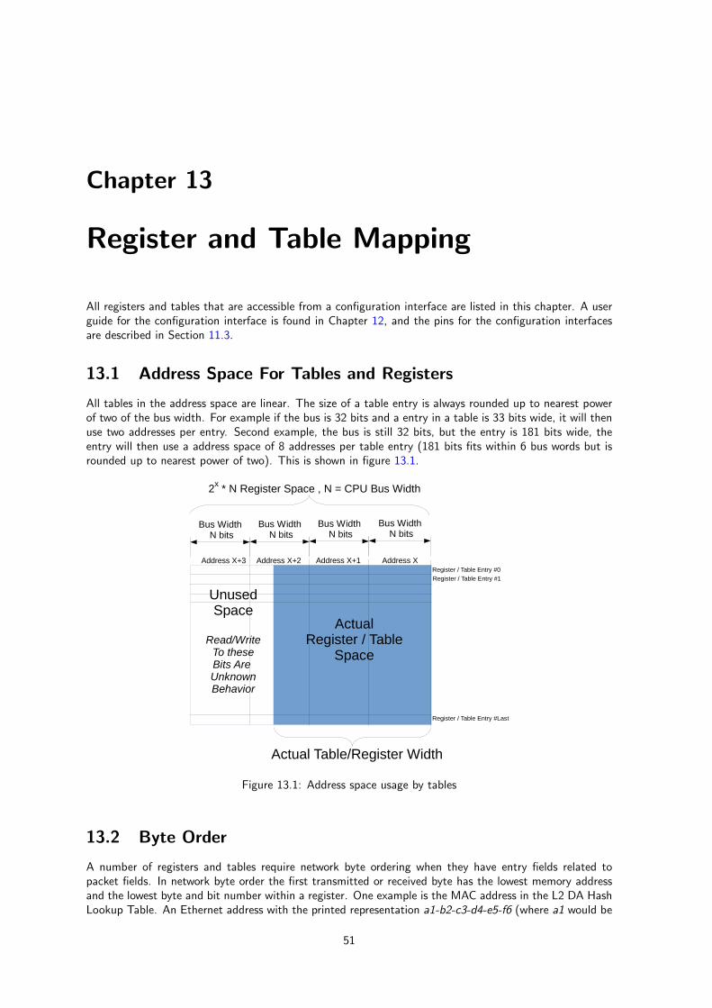
Chapter 13
Register and Table Mapping
All registers and tables that are accessible from a configuration interface are listed in this chapter. A userguide for the configuration interface is found in Chapter 12, and the pins for the configuration interfacesare described in Section 11.3.
13.1 Address Space For Tables and Registers
All tables in the address space are linear. The size of a table entry is always rounded up to nearest powerof two of the bus width. For example if the bus is 32 bits and a entry in a table is 33 bits wide, it will thenuse two addresses per entry. Second example, the bus is still 32 bits, but the entry is 181 bits wide, theentry will then use a address space of 8 addresses per table entry (181 bits fits within 6 bus words but isrounded up to nearest power of two). This is shown in figure 13.1.
Bus Width N bits
Bus Width N bits
Bus Width N bits
Bus Width N bits
UnusedSpace
Read/WriteTo theseBits Are UnknownBehavior
ActualRegister / Table
Space
Actual Table/Register Width
2x * N Register Space , N = CPU Bus Width
Register / Table Entry #0
Register / Table Entry #1
Register / Table Entry #Last
Address XAddress X+1Address X+2Address X+3
Figure 13.1: Address space usage by tables
13.2 Byte Order
A number of registers and tables require network byte ordering when they have entry fields related topacket fields. In network byte order the first transmitted or received byte has the lowest memory addressand the lowest byte and bit number within a register. One example is the MAC address in the L2 DA HashLookup Table. An Ethernet address with the printed representation a1-b2-c3-d4-e5-f6 (where a1 would be
51
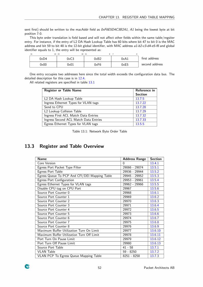
CHAPTER 13. REGISTER AND TABLE MAPPING
sent first) should be written to the macAddr field as 0xF6E5D4C3B2A1, A1 being the lowest byte at bitposition 7-0.
This byte order translation is field based and will not affect other fields within the same table/regsiterentry. For instance, if the entry of L2 DA Hash Lookup Table has 60 bits where bit 47 to bit 0 is the MACaddress and bit 59 to bit 48 is the 12-bit global identifier, with MAC address a1-b2-c3-d4-e5-f6 and globalidentifier equals to 1, the entry will be represented as:
0781516232431
0xD4 0xC3 0xB2 0xA1 first address
0x00 0x01 0xF6 0xE5 second address
One entry occupies two addresses here since the total width exceeds the configuration data bus. Thedetailed description for this case is in 12.4.
All related registers are specified in table 13.1
Register or Table Name Reference inSection
L2 DA Hash Lookup Table 13.7.5Ingress Ethernet Types for VLAN tags 13.7.22Send to CPU 13.7.28L2 Lookup Collision Table 13.7.29Ingress First ACL Match Data Entries 13.7.32Ingress Second ACL Match Data Entries 13.7.33Egress Ethernet Types for VLAN tags 13.5.5
Table 13.1: Network Byte Order Table
13.3 Register and Table Overview
Name Address Range SectionCore Version 0 13.4.1Egress Port Packet Type Filter 29066 - 29074 13.5.1Egress Port Table 29936 - 29944 13.5.2Egress Queue To PCP And CFI/DEI Mapping Table 29945 - 29952 13.5.3Egress Port Configuration 29953 - 29961 13.5.4Egress Ethernet Types for VLAN tags 29962 - 29966 13.5.5Disable CPU tag on CPU Port 29967 13.5.6Source Port Counter 0 29968 13.6.1Source Port Counter 1 29969 13.6.2Source Port Counter 2 29970 13.6.3Source Port Counter 3 29971 13.6.4Source Port Counter 4 29972 13.6.5Source Port Counter 5 29973 13.6.6Source Port Counter 6 29974 13.6.7Source Port Counter 7 29975 13.6.8Source Port Counter 8 29976 13.6.9Maximum Buffer Utilization Turn On Limit 29977 13.6.10Maximum Buffer Utilization Turn Off Limit 29978 13.6.11Port Turn On Pause Limit 29979 13.6.12Port Turn Off Pause Limit 29980 13.6.13Source Port Table 41 - 58 13.7.1VLAN Table 59 - 8250 13.7.2VLAN PCP To Egress Queue Mapping Table 8251 - 8258 13.7.3
52 Packet Architects AB
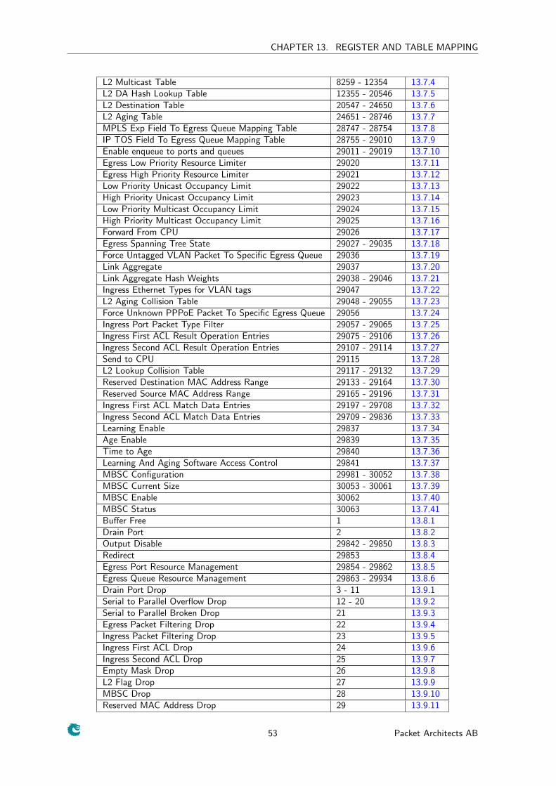
CHAPTER 13. REGISTER AND TABLE MAPPING
L2 Multicast Table 8259 - 12354 13.7.4L2 DA Hash Lookup Table 12355 - 20546 13.7.5L2 Destination Table 20547 - 24650 13.7.6L2 Aging Table 24651 - 28746 13.7.7MPLS Exp Field To Egress Queue Mapping Table 28747 - 28754 13.7.8IP TOS Field To Egress Queue Mapping Table 28755 - 29010 13.7.9Enable enqueue to ports and queues 29011 - 29019 13.7.10Egress Low Priority Resource Limiter 29020 13.7.11Egress High Priority Resource Limiter 29021 13.7.12Low Priority Unicast Occupancy Limit 29022 13.7.13High Priority Unicast Occupancy Limit 29023 13.7.14Low Priority Multicast Occupancy Limit 29024 13.7.15High Priority Multicast Occupancy Limit 29025 13.7.16Forward From CPU 29026 13.7.17Egress Spanning Tree State 29027 - 29035 13.7.18Force Untagged VLAN Packet To Specific Egress Queue 29036 13.7.19Link Aggregate 29037 13.7.20Link Aggregate Hash Weights 29038 - 29046 13.7.21Ingress Ethernet Types for VLAN tags 29047 13.7.22L2 Aging Collision Table 29048 - 29055 13.7.23Force Unknown PPPoE Packet To Specific Egress Queue 29056 13.7.24Ingress Port Packet Type Filter 29057 - 29065 13.7.25Ingress First ACL Result Operation Entries 29075 - 29106 13.7.26Ingress Second ACL Result Operation Entries 29107 - 29114 13.7.27Send to CPU 29115 13.7.28L2 Lookup Collision Table 29117 - 29132 13.7.29Reserved Destination MAC Address Range 29133 - 29164 13.7.30Reserved Source MAC Address Range 29165 - 29196 13.7.31Ingress First ACL Match Data Entries 29197 - 29708 13.7.32Ingress Second ACL Match Data Entries 29709 - 29836 13.7.33Learning Enable 29837 13.7.34Age Enable 29839 13.7.35Time to Age 29840 13.7.36Learning And Aging Software Access Control 29841 13.7.37MBSC Configuration 29981 - 30052 13.7.38MBSC Current Size 30053 - 30061 13.7.39MBSC Enable 30062 13.7.40MBSC Status 30063 13.7.41Buffer Free 1 13.8.1Drain Port 2 13.8.2Output Disable 29842 - 29850 13.8.3Redirect 29853 13.8.4Egress Port Resource Management 29854 - 29862 13.8.5Egress Queue Resource Management 29863 - 29934 13.8.6Drain Port Drop 3 - 11 13.9.1Serial to Parallel Overflow Drop 12 - 20 13.9.2Serial to Parallel Broken Drop 21 13.9.3Egress Packet Filtering Drop 22 13.9.4Ingress Packet Filtering Drop 23 13.9.5Ingress First ACL Drop 24 13.9.6Ingress Second ACL Drop 25 13.9.7Empty Mask Drop 26 13.9.8L2 Flag Drop 27 13.9.9MBSC Drop 28 13.9.10Reserved MAC Address Drop 29 13.9.11
53 Packet Architects AB
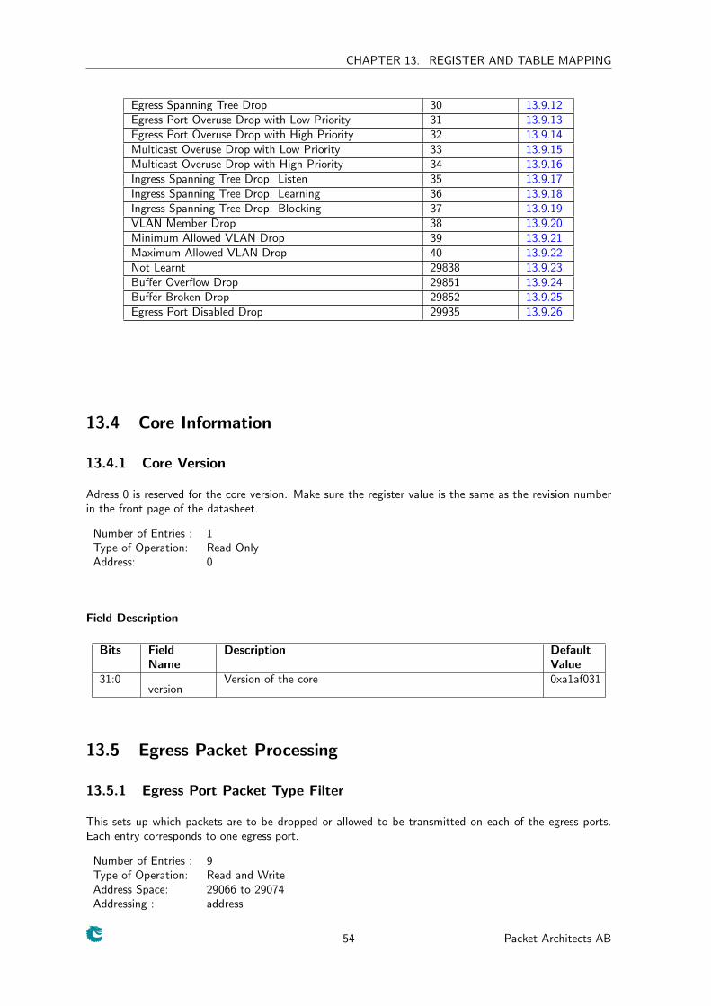
CHAPTER 13. REGISTER AND TABLE MAPPING
Egress Spanning Tree Drop 30 13.9.12Egress Port Overuse Drop with Low Priority 31 13.9.13Egress Port Overuse Drop with High Priority 32 13.9.14Multicast Overuse Drop with Low Priority 33 13.9.15Multicast Overuse Drop with High Priority 34 13.9.16Ingress Spanning Tree Drop: Listen 35 13.9.17Ingress Spanning Tree Drop: Learning 36 13.9.18Ingress Spanning Tree Drop: Blocking 37 13.9.19VLAN Member Drop 38 13.9.20Minimum Allowed VLAN Drop 39 13.9.21Maximum Allowed VLAN Drop 40 13.9.22Not Learnt 29838 13.9.23Buffer Overflow Drop 29851 13.9.24Buffer Broken Drop 29852 13.9.25Egress Port Disabled Drop 29935 13.9.26
13.4 Core Information
13.4.1 Core Version
Adress 0 is reserved for the core version. Make sure the register value is the same as the revision numberin the front page of the datasheet.
Number of Entries : 1Type of Operation: Read OnlyAddress: 0
Field Description
Bits FieldName
Description DefaultValue
31:0version
Version of the core 0xa1af031
13.5 Egress Packet Processing
13.5.1 Egress Port Packet Type Filter
This sets up which packets are to be dropped or allowed to be transmitted on each of the egress ports.Each entry corresponds to one egress port.
Number of Entries : 9Type of Operation: Read and WriteAddress Space: 29066 to 29074Addressing : address
54 Packet Architects AB
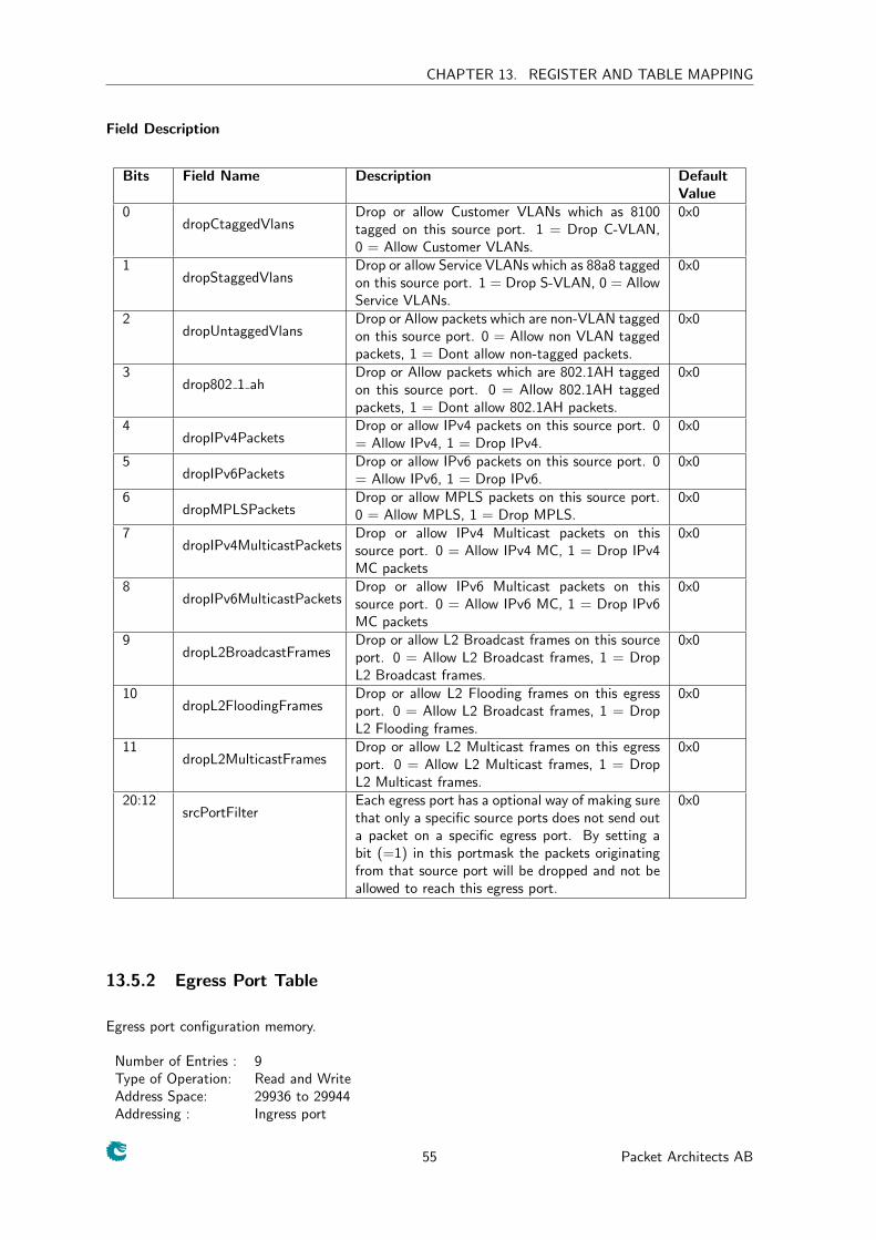
CHAPTER 13. REGISTER AND TABLE MAPPING
Field Description
Bits Field Name Description DefaultValue
0dropCtaggedVlans
Drop or allow Customer VLANs which as 8100tagged on this source port. 1 = Drop C-VLAN,0 = Allow Customer VLANs.
0x0
1dropStaggedVlans
Drop or allow Service VLANs which as 88a8 taggedon this source port. 1 = Drop S-VLAN, 0 = AllowService VLANs.
0x0
2dropUntaggedVlans
Drop or Allow packets which are non-VLAN taggedon this source port. 0 = Allow non VLAN taggedpackets, 1 = Dont allow non-tagged packets.
0x0
3drop802 1 ah
Drop or Allow packets which are 802.1AH taggedon this source port. 0 = Allow 802.1AH taggedpackets, 1 = Dont allow 802.1AH packets.
0x0
4dropIPv4Packets
Drop or allow IPv4 packets on this source port. 0= Allow IPv4, 1 = Drop IPv4.
0x0
5dropIPv6Packets
Drop or allow IPv6 packets on this source port. 0= Allow IPv6, 1 = Drop IPv6.
0x0
6dropMPLSPackets
Drop or allow MPLS packets on this source port.0 = Allow MPLS, 1 = Drop MPLS.
0x0
7dropIPv4MulticastPackets
Drop or allow IPv4 Multicast packets on thissource port. 0 = Allow IPv4 MC, 1 = Drop IPv4MC packets
0x0
8dropIPv6MulticastPackets
Drop or allow IPv6 Multicast packets on thissource port. 0 = Allow IPv6 MC, 1 = Drop IPv6MC packets
0x0
9dropL2BroadcastFrames
Drop or allow L2 Broadcast frames on this sourceport. 0 = Allow L2 Broadcast frames, 1 = DropL2 Broadcast frames.
0x0
10dropL2FloodingFrames
Drop or allow L2 Flooding frames on this egressport. 0 = Allow L2 Broadcast frames, 1 = DropL2 Flooding frames.
0x0
11dropL2MulticastFrames
Drop or allow L2 Multicast frames on this egressport. 0 = Allow L2 Multicast frames, 1 = DropL2 Multicast frames.
0x0
20:12srcPortFilter
Each egress port has a optional way of making surethat only a specific source ports does not send outa packet on a specific egress port. By setting abit (=1) in this portmask the packets originatingfrom that source port will be dropped and not beallowed to reach this egress port.
0x0
13.5.2 Egress Port Table
Egress port configuration memory.
Number of Entries : 9Type of Operation: Read and WriteAddress Space: 29936 to 29944Addressing : Ingress port
55 Packet Architects AB
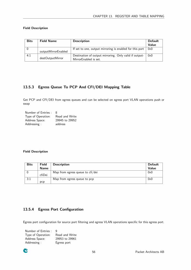
CHAPTER 13. REGISTER AND TABLE MAPPING
Field Description
Bits Field Name Description DefaultValue
0outputMirrorEnabled
If set to one, output mirroring is enabled for this port 0x0
4:1destOutputMirror
Destination of output mirroring. Only valid if output-MirrorEnabled is set.
0x0
13.5.3 Egress Queue To PCP And CFI/DEI Mapping Table
Get PCP and CFI/DEI from egress queues and can be selected on egress port VLAN operations push orswap
Number of Entries : 8Type of Operation: Read and WriteAddress Space: 29945 to 29952Addressing : address
Field Description
Bits FieldName
Description DefaultValue
0cfiDei
Map from egress queue to cfi/dei 0x0
3:1pcp
Map from egress queue to pcp 0x0
13.5.4 Egress Port Configuration
Egress port configuration for source port filtering and egress VLAN operations specific for this egress port.
Number of Entries : 9Type of Operation: Read and WriteAddress Space: 29953 to 29961Addressing : Egress port
56 Packet Architects AB
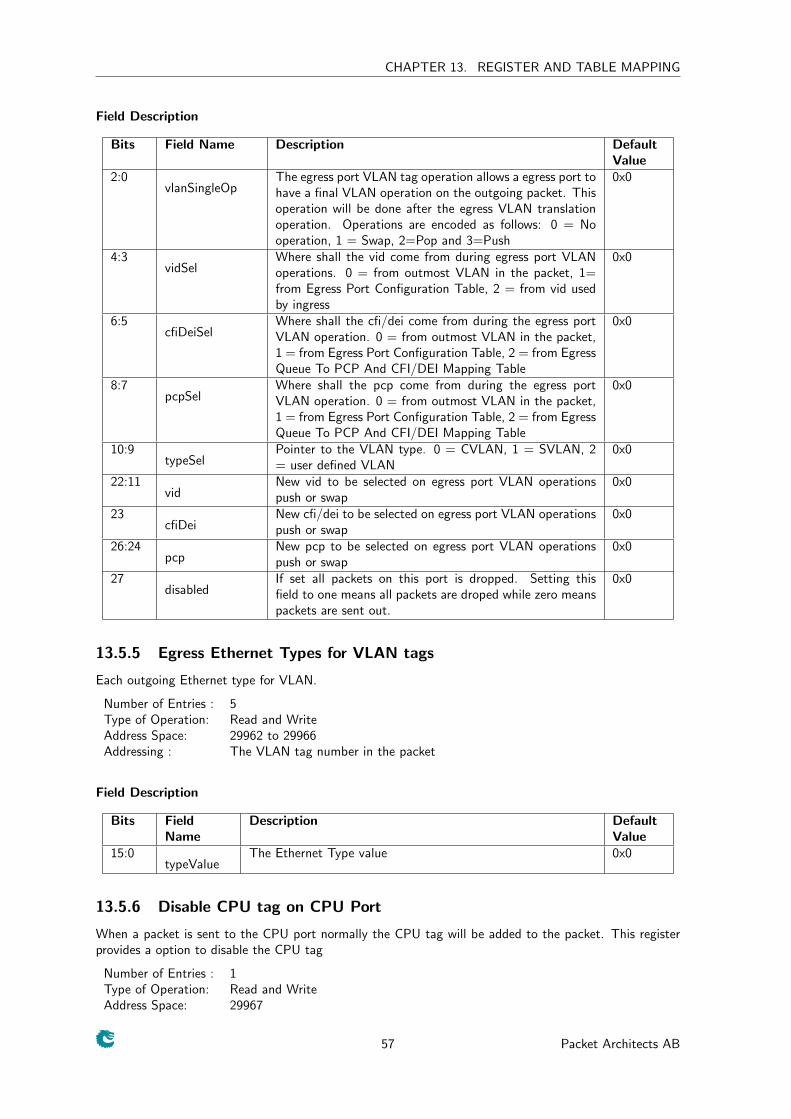
CHAPTER 13. REGISTER AND TABLE MAPPING
Field Description
Bits Field Name Description DefaultValue
2:0vlanSingleOp
The egress port VLAN tag operation allows a egress port tohave a final VLAN operation on the outgoing packet. Thisoperation will be done after the egress VLAN translationoperation. Operations are encoded as follows: 0 = Nooperation, 1 = Swap, 2=Pop and 3=Push
0x0
4:3vidSel
Where shall the vid come from during egress port VLANoperations. 0 = from outmost VLAN in the packet, 1=from Egress Port Configuration Table, 2 = from vid usedby ingress
0x0
6:5cfiDeiSel
Where shall the cfi/dei come from during the egress portVLAN operation. 0 = from outmost VLAN in the packet,1 = from Egress Port Configuration Table, 2 = from EgressQueue To PCP And CFI/DEI Mapping Table
0x0
8:7pcpSel
Where shall the pcp come from during the egress portVLAN operation. 0 = from outmost VLAN in the packet,1 = from Egress Port Configuration Table, 2 = from EgressQueue To PCP And CFI/DEI Mapping Table
0x0
10:9typeSel
Pointer to the VLAN type. 0 = CVLAN, 1 = SVLAN, 2= user defined VLAN
0x0
22:11vid
New vid to be selected on egress port VLAN operationspush or swap
0x0
23cfiDei
New cfi/dei to be selected on egress port VLAN operationspush or swap
0x0
26:24pcp
New pcp to be selected on egress port VLAN operationspush or swap
0x0
27disabled
If set all packets on this port is dropped. Setting thisfield to one means all packets are droped while zero meanspackets are sent out.
0x0
13.5.5 Egress Ethernet Types for VLAN tags
Each outgoing Ethernet type for VLAN.
Number of Entries : 5Type of Operation: Read and WriteAddress Space: 29962 to 29966Addressing : The VLAN tag number in the packet
Field Description
Bits FieldName
Description DefaultValue
15:0typeValue
The Ethernet Type value 0x0
13.5.6 Disable CPU tag on CPU Port
When a packet is sent to the CPU port normally the CPU tag will be added to the packet. This registerprovides a option to disable the CPU tag
Number of Entries : 1Type of Operation: Read and WriteAddress Space: 29967
57 Packet Architects AB
CHAPTER 13. REGISTER AND TABLE MAPPING
Field Description
Bits FieldName
Description DefaultValue
0disable
When set to one (=1) the CPU port will no longer append aCPU Tag to the packet going to the CPU port.
0x0
13.6 Flow Control
13.6.1 Source Port Counter 0
Number of cells which is in the buffer memory for source port 0
Number of Entries : 1Type of Operation: Read OnlyAddress: 29968
Field Description
Bits FieldName
Description DefaultValue
10:0cells
Cells on this source port 0x0
13.6.2 Source Port Counter 1
Number of cells which is in the buffer memory for source port 1
Number of Entries : 1Type of Operation: Read OnlyAddress: 29969
Field Description
Bits FieldName
Description DefaultValue
10:0cells
Cells on this source port 0x0
13.6.3 Source Port Counter 2
Number of cells which is in the buffer memory for source port 2
Number of Entries : 1Type of Operation: Read OnlyAddress: 29970
Field Description
Bits FieldName
Description DefaultValue
10:0cells
Cells on this source port 0x0
13.6.4 Source Port Counter 3
Number of cells which is in the buffer memory for source port 3
Number of Entries : 1Type of Operation: Read OnlyAddress: 29971
58 Packet Architects AB
CHAPTER 13. REGISTER AND TABLE MAPPING
Field Description
Bits FieldName
Description DefaultValue
10:0cells
Cells on this source port 0x0
13.6.5 Source Port Counter 4
Number of cells which is in the buffer memory for source port 4
Number of Entries : 1Type of Operation: Read OnlyAddress: 29972
Field Description
Bits FieldName
Description DefaultValue
10:0cells
Cells on this source port 0x0
13.6.6 Source Port Counter 5
Number of cells which is in the buffer memory for source port 5
Number of Entries : 1Type of Operation: Read OnlyAddress: 29973
Field Description
Bits FieldName
Description DefaultValue
10:0cells
Cells on this source port 0x0
13.6.7 Source Port Counter 6
Number of cells which is in the buffer memory for source port 6
Number of Entries : 1Type of Operation: Read OnlyAddress: 29974
Field Description
Bits FieldName
Description DefaultValue
10:0cells
Cells on this source port 0x0
13.6.8 Source Port Counter 7
Number of cells which is in the buffer memory for source port 7
Number of Entries : 1Type of Operation: Read OnlyAddress: 29975
59 Packet Architects AB
CHAPTER 13. REGISTER AND TABLE MAPPING
Field Description
Bits FieldName
Description DefaultValue
10:0cells
Cells on this source port 0x0
13.6.9 Source Port Counter 8
Number of cells which is in the buffer memory for source port 8
Number of Entries : 1Type of Operation: Read OnlyAddress: 29976
Field Description
Bits FieldName
Description DefaultValue
10:0cells
Cells on this source port 0x0
13.6.10 Maximum Buffer Utilization Turn On Limit
When this total buffer memory size is reached in the buffer memory all ports shall send out pause frames
Number of Entries : 1Type of Operation: Read and WriteAddress: 29977
Field Description
Bits FieldName
Description DefaultValue
10:0cells
Turn on limit 0x0
13.6.11 Maximum Buffer Utilization Turn Off Limit
When this total buffer memory size is reached in the buffer memory all ports shall be unpaused, except forthose ports which are still using more than the PON size
Number of Entries : 1Type of Operation: Read and WriteAddress: 29978
Field Description
Bits FieldName
Description DefaultValue
10:0cells
Turn off limit 0x0
13.6.12 Port Turn On Pause Limit
When a port has this number of cells(or more) in the buffer memory and is not paused it shall pause theport
Number of Entries : 1Type of Operation: Read and WriteAddress: 29979
60 Packet Architects AB
CHAPTER 13. REGISTER AND TABLE MAPPING
Field Description
Bits FieldName
Description DefaultValue
10:0cells
The turn on pause limit. 0x400
13.6.13 Port Turn Off Pause Limit
When a port has this number of cells(or less) in the buffer memory and is currently paused it shall un-pausethe port
Number of Entries : 1Type of Operation: Read and WriteAddress: 29980
Field Description
Bits FieldName
Description DefaultValue
10:0cells
The turn off pause limit. 0x400
13.7 Ingress Packet Processing
13.7.1 Source Port Table
Source port configuration.
Number of Entries : 9Number of Addresses per Entry : 2Type of Operation: Read and WriteAddress Space: 41 to 58Addressing : Ingress port
61 Packet Architects AB
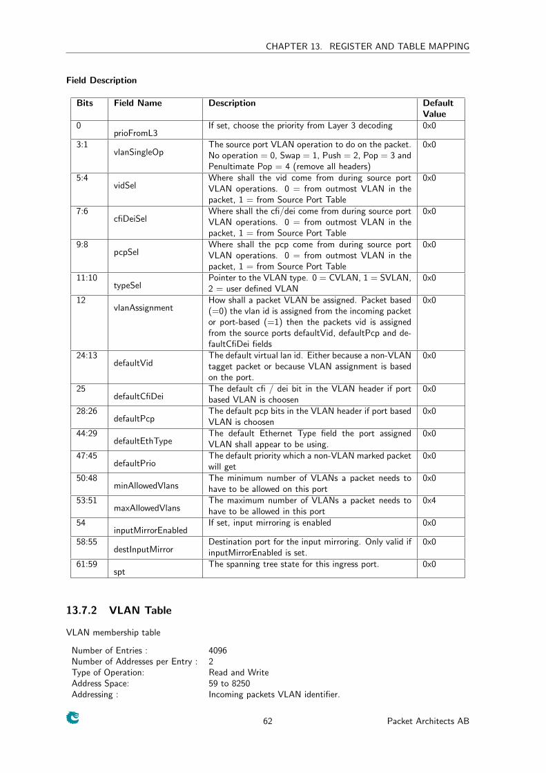
CHAPTER 13. REGISTER AND TABLE MAPPING
Field Description
Bits Field Name Description DefaultValue
0prioFromL3
If set, choose the priority from Layer 3 decoding 0x0
3:1vlanSingleOp
The source port VLAN operation to do on the packet.No operation = 0, Swap = 1, Push = 2, Pop = 3 andPenultimate Pop = 4 (remove all headers)
0x0
5:4vidSel
Where shall the vid come from during source portVLAN operations. 0 = from outmost VLAN in thepacket, 1 = from Source Port Table
0x0
7:6cfiDeiSel
Where shall the cfi/dei come from during source portVLAN operations. 0 = from outmost VLAN in thepacket, 1 = from Source Port Table
0x0
9:8pcpSel
Where shall the pcp come from during source portVLAN operations. 0 = from outmost VLAN in thepacket, 1 = from Source Port Table
0x0
11:10typeSel
Pointer to the VLAN type. 0 = CVLAN, 1 = SVLAN,2 = user defined VLAN
0x0
12vlanAssignment
How shall a packet VLAN be assigned. Packet based(=0) the vlan id is assigned from the incoming packetor port-based (=1) then the packets vid is assignedfrom the source ports defaultVid, defaultPcp and de-faultCfiDei fields
0x0
24:13defaultVid
The default virtual lan id. Either because a non-VLANtagget packet or because VLAN assignment is basedon the port.
0x0
25defaultCfiDei
The default cfi / dei bit in the VLAN header if portbased VLAN is choosen
0x0
28:26defaultPcp
The default pcp bits in the VLAN header if port basedVLAN is choosen
0x0
44:29defaultEthType
The default Ethernet Type field the port assignedVLAN shall appear to be using.
0x0
47:45defaultPrio
The default priority which a non-VLAN marked packetwill get
0x0
50:48minAllowedVlans
The minimum number of VLANs a packet needs tohave to be allowed on this port
0x0
53:51maxAllowedVlans
The maximum number of VLANs a packet needs tohave to be allowed in this port
0x4
54inputMirrorEnabled
If set, input mirroring is enabled 0x0
58:55destInputMirror
Destination port for the input mirroring. Only valid ifinputMirrorEnabled is set.
0x0
61:59spt
The spanning tree state for this ingress port. 0x0
13.7.2 VLAN Table
VLAN membership table
Number of Entries : 4096Number of Addresses per Entry : 2Type of Operation: Read and WriteAddress Space: 59 to 8250Addressing : Incoming packets VLAN identifier.
62 Packet Architects AB
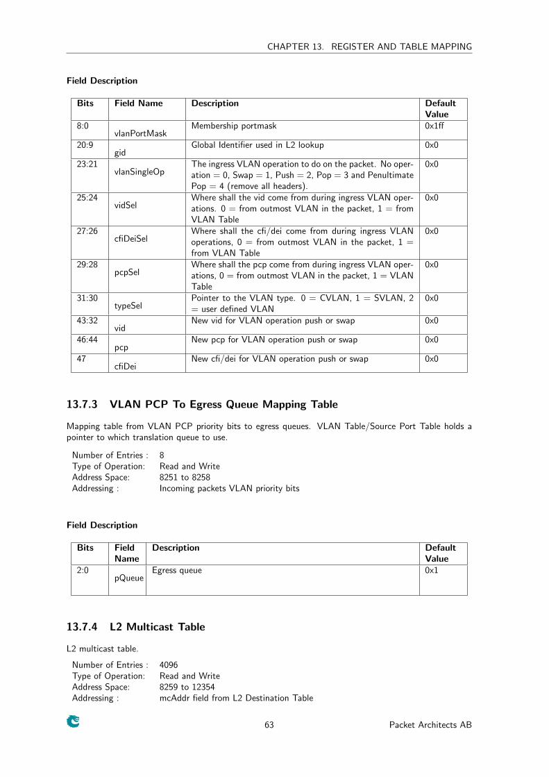
CHAPTER 13. REGISTER AND TABLE MAPPING
Field Description
Bits Field Name Description DefaultValue
8:0vlanPortMask
Membership portmask 0x1ff
20:9gid
Global Identifier used in L2 lookup 0x0
23:21vlanSingleOp
The ingress VLAN operation to do on the packet. No oper-ation = 0, Swap = 1, Push = 2, Pop = 3 and PenultimatePop = 4 (remove all headers).
0x0
25:24vidSel
Where shall the vid come from during ingress VLAN oper-ations. 0 = from outmost VLAN in the packet, 1 = fromVLAN Table
0x0
27:26cfiDeiSel
Where shall the cfi/dei come from during ingress VLANoperations, 0 = from outmost VLAN in the packet, 1 =from VLAN Table
0x0
29:28pcpSel
Where shall the pcp come from during ingress VLAN oper-ations, 0 = from outmost VLAN in the packet, 1 = VLANTable
0x0
31:30typeSel
Pointer to the VLAN type. 0 = CVLAN, 1 = SVLAN, 2= user defined VLAN
0x0
43:32vid
New vid for VLAN operation push or swap 0x0
46:44pcp
New pcp for VLAN operation push or swap 0x0
47cfiDei
New cfi/dei for VLAN operation push or swap 0x0
13.7.3 VLAN PCP To Egress Queue Mapping Table
Mapping table from VLAN PCP priority bits to egress queues. VLAN Table/Source Port Table holds apointer to which translation queue to use.
Number of Entries : 8Type of Operation: Read and WriteAddress Space: 8251 to 8258Addressing : Incoming packets VLAN priority bits
Field Description
Bits FieldName
Description DefaultValue
2:0pQueue
Egress queue 0x1
13.7.4 L2 Multicast Table
L2 multicast table.
Number of Entries : 4096Type of Operation: Read and WriteAddress Space: 8259 to 12354Addressing : mcAddr field from L2 Destination Table
63 Packet Architects AB
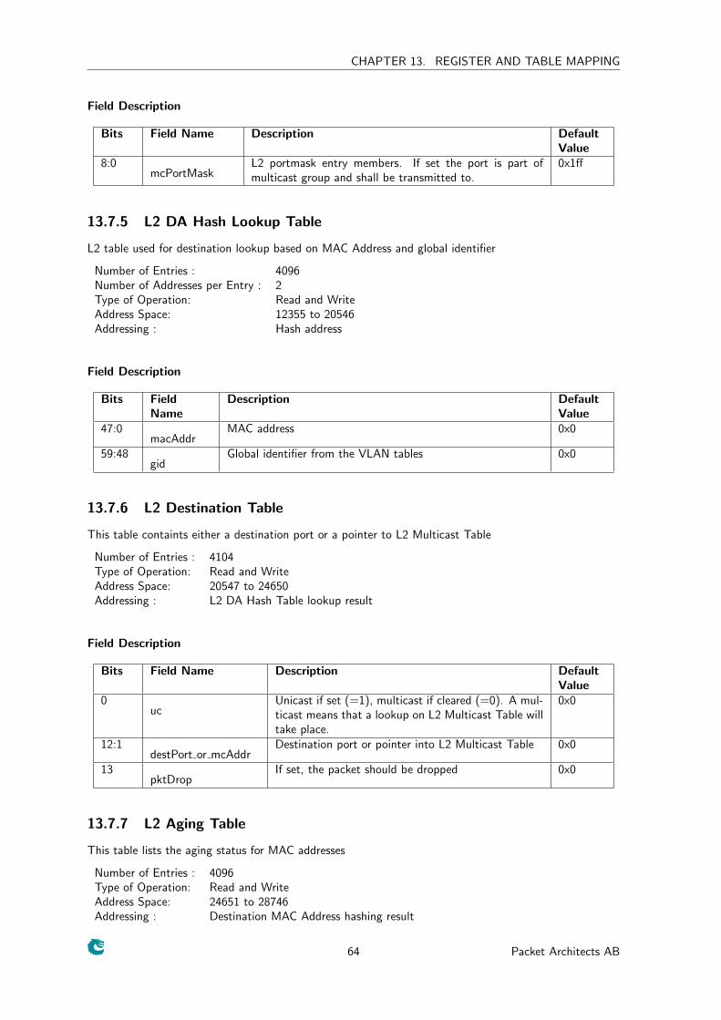
CHAPTER 13. REGISTER AND TABLE MAPPING
Field Description
Bits Field Name Description DefaultValue
8:0mcPortMask
L2 portmask entry members. If set the port is part ofmulticast group and shall be transmitted to.
0x1ff
13.7.5 L2 DA Hash Lookup Table
L2 table used for destination lookup based on MAC Address and global identifier
Number of Entries : 4096Number of Addresses per Entry : 2Type of Operation: Read and WriteAddress Space: 12355 to 20546Addressing : Hash address
Field Description
Bits FieldName
Description DefaultValue
47:0macAddr
MAC address 0x0
59:48gid
Global identifier from the VLAN tables 0x0
13.7.6 L2 Destination Table
This table containts either a destination port or a pointer to L2 Multicast Table
Number of Entries : 4104Type of Operation: Read and WriteAddress Space: 20547 to 24650Addressing : L2 DA Hash Table lookup result
Field Description
Bits Field Name Description DefaultValue
0uc
Unicast if set (=1), multicast if cleared (=0). A mul-ticast means that a lookup on L2 Multicast Table willtake place.
0x0
12:1destPort or mcAddr
Destination port or pointer into L2 Multicast Table 0x0
13pktDrop
If set, the packet should be dropped 0x0
13.7.7 L2 Aging Table
This table lists the aging status for MAC addresses
Number of Entries : 4096Type of Operation: Read and WriteAddress Space: 24651 to 28746Addressing : Destination MAC Address hashing result
64 Packet Architects AB
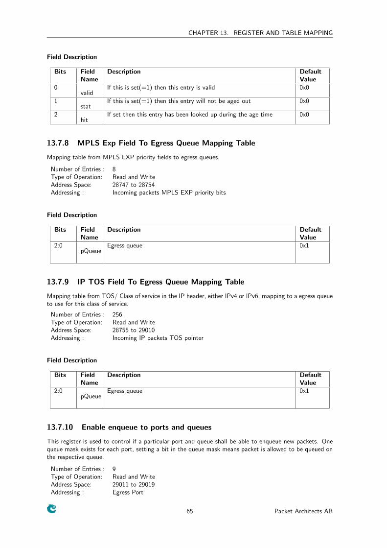
CHAPTER 13. REGISTER AND TABLE MAPPING
Field Description
Bits FieldName
Description DefaultValue
0valid
If this is set(=1) then this entry is valid 0x0
1stat
If this is set(=1) then this entry will not be aged out 0x0
2hit
If set then this entry has been looked up during the age time 0x0
13.7.8 MPLS Exp Field To Egress Queue Mapping Table
Mapping table from MPLS EXP priority fields to egress queues.
Number of Entries : 8Type of Operation: Read and WriteAddress Space: 28747 to 28754Addressing : Incoming packets MPLS EXP priority bits
Field Description
Bits FieldName
Description DefaultValue
2:0pQueue
Egress queue 0x1
13.7.9 IP TOS Field To Egress Queue Mapping Table
Mapping table from TOS/ Class of service in the IP header, either IPv4 or IPv6, mapping to a egress queueto use for this class of service.
Number of Entries : 256Type of Operation: Read and WriteAddress Space: 28755 to 29010Addressing : Incoming IP packets TOS pointer
Field Description
Bits FieldName
Description DefaultValue
2:0pQueue
Egress queue 0x1
13.7.10 Enable enqueue to ports and queues
This register is used to control if a particular port and queue shall be able to enqueue new packets. Onequeue mask exists for each port, setting a bit in the queue mask means packet is allowed to be queued onthe respective queue.
Number of Entries : 9Type of Operation: Read and WriteAddress Space: 29011 to 29019Addressing : Egress Port
65 Packet Architects AB
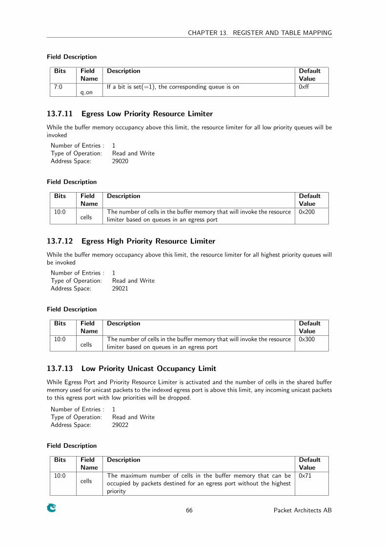
CHAPTER 13. REGISTER AND TABLE MAPPING
Field Description
Bits FieldName
Description DefaultValue
7:0q on
If a bit is set(=1), the corresponding queue is on 0xff
13.7.11 Egress Low Priority Resource Limiter
While the buffer memory occupancy above this limit, the resource limiter for all low priority queues will beinvoked
Number of Entries : 1Type of Operation: Read and WriteAddress Space: 29020
Field Description
Bits FieldName
Description DefaultValue
10:0cells
The number of cells in the buffer memory that will invoke the resourcelimiter based on queues in an egress port
0x200
13.7.12 Egress High Priority Resource Limiter
While the buffer memory occupancy above this limit, the resource limiter for all highest priority queues willbe invoked
Number of Entries : 1Type of Operation: Read and WriteAddress Space: 29021
Field Description
Bits FieldName
Description DefaultValue
10:0cells
The number of cells in the buffer memory that will invoke the resourcelimiter based on queues in an egress port
0x300
13.7.13 Low Priority Unicast Occupancy Limit
While Egress Port and Priority Resource Limiter is activated and the number of cells in the shared buffermemory used for unicast packets to the indexed egress port is above this limit, any incoming unicast packetsto this egress port with low priorities will be dropped.
Number of Entries : 1Type of Operation: Read and WriteAddress Space: 29022
Field Description
Bits FieldName
Description DefaultValue
10:0cells
The maximum number of cells in the buffer memory that can beoccupied by packets destined for an egress port without the highestpriority
0x71
66 Packet Architects AB
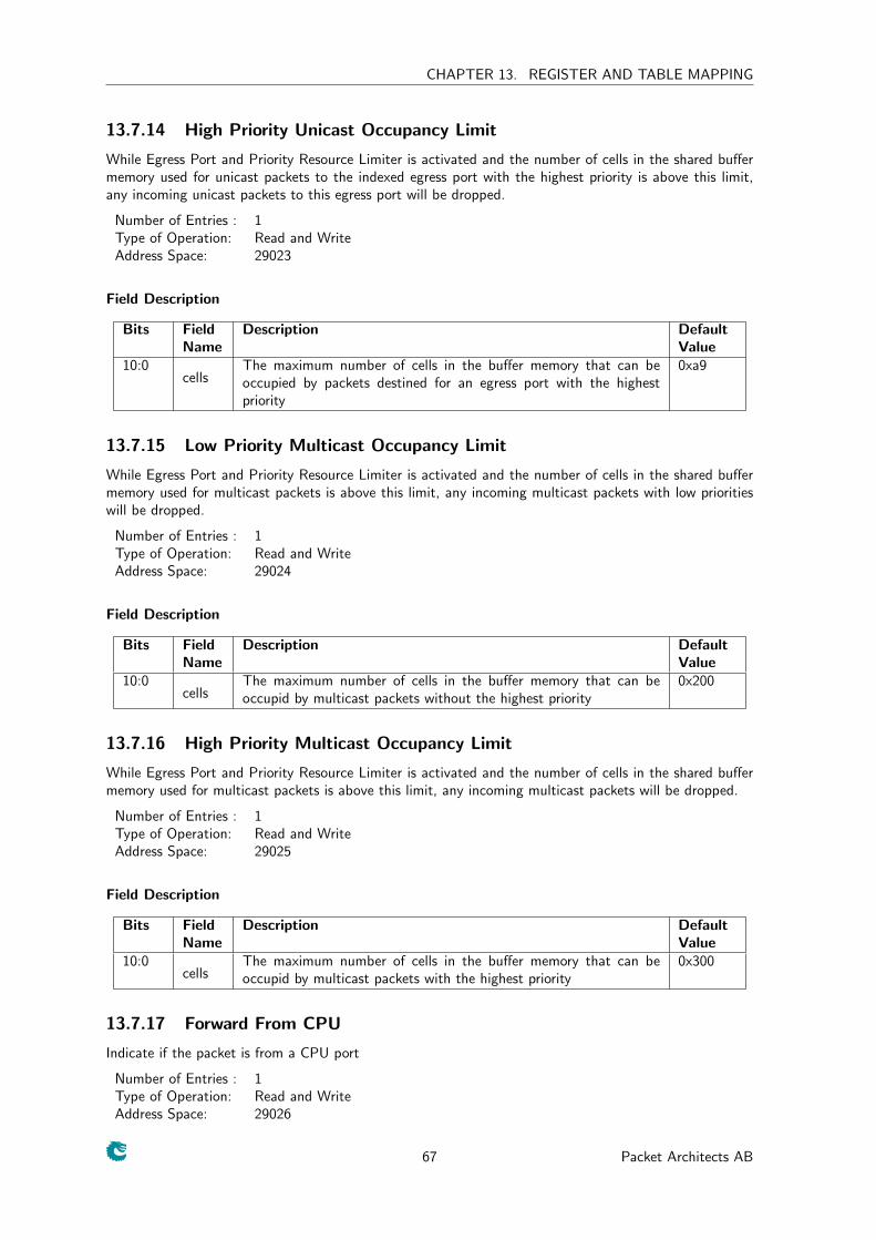
CHAPTER 13. REGISTER AND TABLE MAPPING
13.7.14 High Priority Unicast Occupancy Limit
While Egress Port and Priority Resource Limiter is activated and the number of cells in the shared buffermemory used for unicast packets to the indexed egress port with the highest priority is above this limit,any incoming unicast packets to this egress port will be dropped.
Number of Entries : 1Type of Operation: Read and WriteAddress Space: 29023
Field Description
Bits FieldName
Description DefaultValue
10:0cells
The maximum number of cells in the buffer memory that can beoccupied by packets destined for an egress port with the highestpriority
0xa9
13.7.15 Low Priority Multicast Occupancy Limit
While Egress Port and Priority Resource Limiter is activated and the number of cells in the shared buffermemory used for multicast packets is above this limit, any incoming multicast packets with low prioritieswill be dropped.
Number of Entries : 1Type of Operation: Read and WriteAddress Space: 29024
Field Description
Bits FieldName
Description DefaultValue
10:0cells
The maximum number of cells in the buffer memory that can beoccupid by multicast packets without the highest priority
0x200
13.7.16 High Priority Multicast Occupancy Limit
While Egress Port and Priority Resource Limiter is activated and the number of cells in the shared buffermemory used for multicast packets is above this limit, any incoming multicast packets will be dropped.
Number of Entries : 1Type of Operation: Read and WriteAddress Space: 29025
Field Description
Bits FieldName
Description DefaultValue
10:0cells
The maximum number of cells in the buffer memory that can beoccupid by multicast packets with the highest priority
0x300
13.7.17 Forward From CPU
Indicate if the packet is from a CPU port
Number of Entries : 1Type of Operation: Read and WriteAddress Space: 29026
67 Packet Architects AB
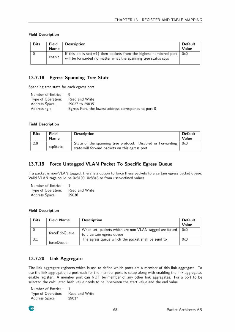
CHAPTER 13. REGISTER AND TABLE MAPPING
Field Description
Bits FieldName
Description DefaultValue
0enable
If this bit is set(=1) then packets from the highest numbered portwill be forwarded no matter what the spanning tree status says
0x0
13.7.18 Egress Spanning Tree State
Spanning tree state for each egress port
Number of Entries : 9Type of Operation: Read and WriteAddress Space: 29027 to 29035Addressing : Egress Port, the lowest address corresponds to port 0
Field Description
Bits FieldName
Description DefaultValue
2:0stpState
State of the spanning tree protocol. Disabled or Forwardingstate will forward packets on this egress port
0x0
13.7.19 Force Untagged VLAN Packet To Specific Egress Queue
If a packet is non-VLAN tagged, there is a option to force these packets to a certain egress packet queue.Valid VLAN tags could be 0x8100, 0x88a8 or from user-defined values.
Number of Entries : 1Type of Operation: Read and WriteAddress Space: 29036
Field Description
Bits Field Name Description DefaultValue
0forcePrioQueue
When set, packets which are non-VLAN tagged are forcedto a certain egress queue
0x0
3:1forceQueue
The egress queue which the packet shall be send to 0x0
13.7.20 Link Aggregate
The link aggregate registers which is use to define which ports are a member of this link aggregate. Touse the link aggregation a portmask for the member ports is setup along with enabling the link aggregatesenable register. A member port can NOT be member of any other link aggregates. For a port to beselected the calculated hash value needs to be inbetween the start value and the end value
Number of Entries : 1Type of Operation: Read and WriteAddress Space: 29037
68 Packet Architects AB
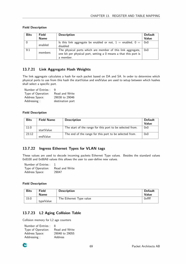
CHAPTER 13. REGISTER AND TABLE MAPPING
Field Description
Bits FieldName
Description DefaultValue
0enabled
Is this link aggregate be enabled or not, 1 = enabled, 0 =disabled
0x0
9:1members
The physical ports which are member of this link aggregate,one bit per physical port, setting a 0 means a that this port isa member.
0x0
13.7.21 Link Aggregate Hash Weights
The link aggregate calculates a hash for each packet based on DA and SA. In order to determine whichphysical ports to use from this hash the startValue and endValue are used to setup between which hashesshall select a specific port.
Number of Entries : 9Type of Operation: Read and WriteAddress Space: 29038 to 29046Addressing : destination port
Field Description
Bits Field Name Description DefaultValue
11:0startValue
The start of the range for this port to be selected from. 0x0
23:12endValue
The end of the range for this port to be selected from. 0x0
13.7.22 Ingress Ethernet Types for VLAN tags
These values are used to decode incoming packets Ethernet Type values. Besides the standard values0x8100 and 0x88A8 values this allows the user to user-define new values.
Number of Entries : 1Type of Operation: Read and WriteAddress Space: 29047
Field Description
Bits FieldName
Description DefaultValue
15:0typeValue
The Ethernet Type value 0xffff
13.7.23 L2 Aging Collision Table
Collision memory for L2 age counters
Number of Entries : 8Type of Operation: Read and WriteAddress Space: 29048 to 29055Addressing : Address
69 Packet Architects AB
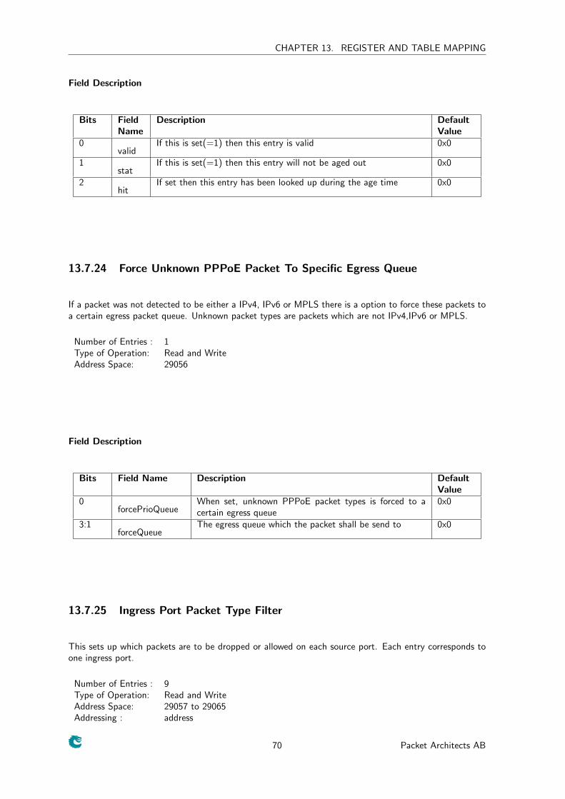
CHAPTER 13. REGISTER AND TABLE MAPPING
Field Description
Bits FieldName
Description DefaultValue
0valid
If this is set(=1) then this entry is valid 0x0
1stat
If this is set(=1) then this entry will not be aged out 0x0
2hit
If set then this entry has been looked up during the age time 0x0
13.7.24 Force Unknown PPPoE Packet To Specific Egress Queue
If a packet was not detected to be either a IPv4, IPv6 or MPLS there is a option to force these packets toa certain egress packet queue. Unknown packet types are packets which are not IPv4,IPv6 or MPLS.
Number of Entries : 1Type of Operation: Read and WriteAddress Space: 29056
Field Description
Bits Field Name Description DefaultValue
0forcePrioQueue
When set, unknown PPPoE packet types is forced to acertain egress queue
0x0
3:1forceQueue
The egress queue which the packet shall be send to 0x0
13.7.25 Ingress Port Packet Type Filter
This sets up which packets are to be dropped or allowed on each source port. Each entry corresponds toone ingress port.
Number of Entries : 9Type of Operation: Read and WriteAddress Space: 29057 to 29065Addressing : address
70 Packet Architects AB
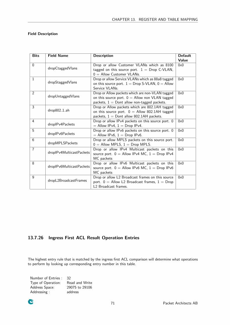
CHAPTER 13. REGISTER AND TABLE MAPPING
Field Description
Bits Field Name Description DefaultValue
0dropCtaggedVlans
Drop or allow Customer VLANs which as 8100tagged on this source port. 1 = Drop C-VLAN,0 = Allow Customer VLANs.
0x0
1dropStaggedVlans
Drop or allow Service VLANs which as 88a8 taggedon this source port. 1 = Drop S-VLAN, 0 = AllowService VLANs.
0x0
2dropUntaggedVlans
Drop or Allow packets which are non-VLAN taggedon this source port. 0 = Allow non VLAN taggedpackets, 1 = Dont allow non-tagged packets.
0x0
3drop802 1 ah
Drop or Allow packets which are 802.1AH taggedon this source port. 0 = Allow 802.1AH taggedpackets, 1 = Dont allow 802.1AH packets.
0x0
4dropIPv4Packets
Drop or allow IPv4 packets on this source port. 0= Allow IPv4, 1 = Drop IPv4.
0x0
5dropIPv6Packets
Drop or allow IPv6 packets on this source port. 0= Allow IPv6, 1 = Drop IPv6.
0x0
6dropMPLSPackets
Drop or allow MPLS packets on this source port.0 = Allow MPLS, 1 = Drop MPLS.
0x0
7dropIPv4MulticastPackets
Drop or allow IPv4 Multicast packets on thissource port. 0 = Allow IPv4 MC, 1 = Drop IPv4MC packets
0x0
8dropIPv6MulticastPackets
Drop or allow IPv6 Multicast packets on thissource port. 0 = Allow IPv6 MC, 1 = Drop IPv6MC packets
0x0
9dropL2BroadcastFrames
Drop or allow L2 Broadcast frames on this sourceport. 0 = Allow L2 Broadcast frames, 1 = DropL2 Broadcast frames.
0x0
13.7.26 Ingress First ACL Result Operation Entries
The highest entry rule that is matched by the ingress first ACL comparison will determine what operationsto perform by looking up corresponding entry number in this table.
Number of Entries : 32Type of Operation: Read and WriteAddress Space: 29075 to 29106Addressing : address
71 Packet Architects AB
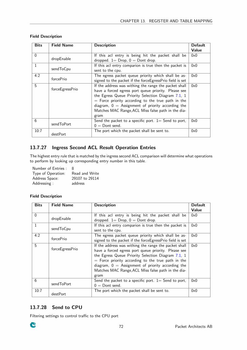
CHAPTER 13. REGISTER AND TABLE MAPPING
Field Description
Bits Field Name Description DefaultValue
0dropEnable
If this acl entry is being hit the packet shall bedropped. 1= Drop, 0 = Dont drop.
0x0
1sendToCpu
If this acl entry comparion is true then the packet issent to the cpu.
0x0
4:2forcePrio
The egress packet queue priority which shall be as-signed to the packet if the forceEgressPrio field is set
0x0
5forceEgressPrio
If the address was withing the range the packet shallhave a forced egress port queue priority. Please seethe Egress Queue Priority Selection Diagram 7.1, 1= Force priority according to the true path in thediagram, 0 = Assignment of priority according theMatches MAC Range,ACL Miss false path in the dia-gram
0x0
6sendToPort
Send the packet to a specific port. 1= Send to port,0 = Dont send.
0x0
10:7destPort
The port which the packet shall be sent to. 0x0
13.7.27 Ingress Second ACL Result Operation Entries
The highest entry rule that is matched by the ingress second ACL comparison will determine what operationsto perform by looking up corresponding entry number in this table.
Number of Entries : 8Type of Operation: Read and WriteAddress Space: 29107 to 29114Addressing : address
Field Description
Bits Field Name Description DefaultValue
0dropEnable
If this acl entry is being hit the packet shall bedropped. 1= Drop, 0 = Dont drop.
0x0
1sendToCpu
If this acl entry comparion is true then the packet issent to the cpu.
0x0
4:2forcePrio
The egress packet queue priority which shall be as-signed to the packet if the forceEgressPrio field is set
0x0
5forceEgressPrio
If the address was withing the range the packet shallhave a forced egress port queue priority. Please seethe Egress Queue Priority Selection Diagram 7.1, 1= Force priority according to the true path in thediagram, 0 = Assignment of priority according theMatches MAC Range,ACL Miss false path in the dia-gram
0x0
6sendToPort
Send the packet to a specific port. 1= Send to port,0 = Dont send.
0x0
10:7destPort
The port which the packet shall be sent to. 0x0
13.7.28 Send to CPU
Filtering settings to control traffic to the CPU port
72 Packet Architects AB
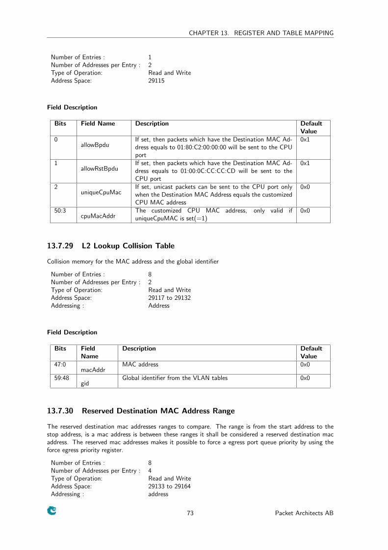
CHAPTER 13. REGISTER AND TABLE MAPPING
Number of Entries : 1Number of Addresses per Entry : 2Type of Operation: Read and WriteAddress Space: 29115
Field Description
Bits Field Name Description DefaultValue
0allowBpdu
If set, then packets which have the Destination MAC Ad-dress equals to 01:80:C2:00:00:00 will be sent to the CPUport
0x1
1allowRstBpdu
If set, then packets which have the Destination MAC Ad-dress equals to 01:00:0C:CC:CC:CD will be sent to theCPU port
0x1
2uniqueCpuMac
If set, unicast packets can be sent to the CPU port onlywhen the Destination MAC Address equals the customizedCPU MAC address
0x0
50:3cpuMacAddr
The customized CPU MAC address, only valid ifuniqueCpuMAC is set(=1)
0x0
13.7.29 L2 Lookup Collision Table
Collision memory for the MAC address and the global identifier
Number of Entries : 8Number of Addresses per Entry : 2Type of Operation: Read and WriteAddress Space: 29117 to 29132Addressing : Address
Field Description
Bits FieldName
Description DefaultValue
47:0macAddr
MAC address 0x0
59:48gid
Global identifier from the VLAN tables 0x0
13.7.30 Reserved Destination MAC Address Range
The reserved destination mac addresses ranges to compare. The range is from the start address to thestop address, is a mac address is between these ranges it shall be considered a reserved destination macaddress. The reserved mac addresses makes it possible to force a egress port queue priority by using theforce egress priority register.
Number of Entries : 8Number of Addresses per Entry : 4Type of Operation: Read and WriteAddress Space: 29133 to 29164Addressing : address
73 Packet Architects AB
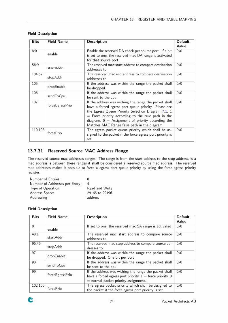
CHAPTER 13. REGISTER AND TABLE MAPPING
Field Description
Bits Field Name Description DefaultValue
8:0enable
Enable the reserved DA check per source port. If a bitis set to one, the reserved mac DA range is activatedfor that source port
0x0
56:9startAddr
The reserved mac start address to compare destinationaddresses to
0x0
104:57stopAddr
The reserved mac end address to compare destinationaddresses to
0x0
105dropEnable
If the address was within the range the packet shallbe dropped.
0x0
106sendToCpu
If the address was within the range the packet shallbe sent to the cpu
0x0
107forceEgressPrio
If the address was withing the range the packet shallhave a forced egress port queue priority. Please seethe Egress Queue Priority Selection Diagram 7.1, 1= Force priority according to the true path in thediagram, 0 = Assignment of priority according theMatches MAC Range false path in the diagram
0x0
110:108forcePrio
The egress packet queue priority which shall be as-signed to the packet if the force egress port priority isset
0x0
13.7.31 Reserved Source MAC Address Range
The reserved source mac addresses ranges. The range is from the start address to the stop address, is amac address is between these ranges it shall be considered a reserved source mac address. The reservedmac addresses makes it possible to force a egress port queue priority by using the force egress priorityregister.
Number of Entries : 8Number of Addresses per Entry : 4Type of Operation: Read and WriteAddress Space: 29165 to 29196Addressing : address
Field Description
Bits Field Name Description DefaultValue
0enable
If set to one, the reserved mac SA range is activated 0x0
48:1startAddr
The reserved mac start address to compare sourceaddresses to
0x0
96:49stopAddr
The reserved mac stop address to compare source ad-dresses to
0x0
97dropEnable
If the address was within the range the packet shallbe dropped. One bit per port
0x0
98sendToCpu
If the address was within the range the packet shallbe sent to the cpu
0x0
99forceEgressPrio
If the address was withing the range the packet shallhave a forced egress port priority, 1 = force priority, 0= normal packet priority assignment.
0x0
102:100forcePrio
The egress packet priority which shall be assigned tothe packet if the force egress port priority is set
0x0
74 Packet Architects AB
CHAPTER 13. REGISTER AND TABLE MAPPING
13.7.32 Ingress First ACL Match Data Entries
All packets entering the switch will be subjected to the ACL filering. This allows custom packet processingto be done for certain selected packets. Each of the fields has a valid bit saying if in each entry thecomaprison for this shall be included or not.
Number of Entries : 32Number of Addresses per Entry : 16Type of Operation: Read and WriteAddress Space: 29197 to 29708Addressing : address
75 Packet Architects AB
CHAPTER 13. REGISTER AND TABLE MAPPING
76 Packet Architects AB

CHAPTER 13. REGISTER AND TABLE MAPPING
Field Description
Bits Field Name Description DefaultValue
8:0ports
For which ports should this filter rule apply. 0x0
9compareDaMac
In this acl entry shall the DA Mac address be com-pared. 1 = include the DA MAC in the comparison,0 = dont include the DA Mac in the comparison
0x1
57:10daMac
The Destination MAC address to be compared 0x0
58compareSaMac
In this acl entry shall the SA Mac address be com-pared. 1 = include the SA MAC in the comparison, 0= dont include the SA Mac in the comparison
0x1
106:59saMac
The source MAC address to be compared 0x0
107compareCvlan
In this acl entry shall the C-VLAN identifier be com-pared. 1 = include the C-VLAN identifier in the com-parison, 0 = dont include the C-VLAN identifier inthe comparison
0x1
119:108cVlan
The C-VLAN identifier to be compared 0x0
120compareSvlan
In this acl entry shall the S-VLAN identifier be com-pared. 1 = include the S-VLAN identifier in the com-parison, 0 = dont include the S-VLAN identifier in thecomparison
0x1
132:121sVlan
The S-VLAN identifier to be compared 0x0
133compareEthType
In this acl entry shall the Ethernet Type after a po-tential SVLAN or CCLAN identifier be compared. 1= include the Ethernet identifier in the comparison, 0= dont include the Ethernet Type in the comparison
0x1
149:134ethType
The Ethernet type identifier to be compared 0x0
150compareFirstByte
In this acl entry shall the first byte after the EthernetType be compared. 1 = include the first byte in thecomparison, 0 = dont include the first byte in thecomparison
0x1
158:151firstByte
The byte to be compared 0x0
159compareTosByte
In this acl entry shall the TOS byte from the IP headerbe compared. 1 = include the TOS byte in the com-parison, 0 = dont include the TOS byte in the com-parison
0x1
167:160tosByte
The TOS identifier to be compared 0x0
168compareExpBits
In this acl entry shall the EXP bits in the first MPLSlabel be compared. 1 = include the Exp bits in thecomparison, 0 = dont include the EXP in the com-parison
0x1
171:169exp
The EXP bits to be compared 0x0
172compareSaIP
In this acl entry shall the source address (SA) in theIP packet be compared. 1 = include the IP SA inthe comparison, 0 = dont include the SA IP in thecomparison
0x1
173typeOfSaIP
Is this comparison a IPv4 or IPv6. 1= IPv4 address,which located on the lower 32 bits from bit 0 to 31,0 = IPv6 address.
0x1
301:174sa
The IP source address to compare. If to be used as aIPv4 address the use bits 31:0.
0x0
302compareDaIP
In this acl entry shall the destination address (DA) inthe IP packet be compared. 1 = include the IP DAin the comparison, 0 = dont include the DA IP in thecomparison
0x1
303typeOfDaIP
Is this comparison a IPv4 or IPv6. 1= IPv4 address,which located on the lower 32 bits from bit 0 to 31,0 = IPv6 address.
0x1
431:304da
The IP destination address to compare. If to be usedas a IPv4 address the use bits 31:0.
0x0
77 Packet Architects AB
CHAPTER 13. REGISTER AND TABLE MAPPING
13.7.33 Ingress Second ACL Match Data Entries
All packets entering the switch will be subjected to the ACL filering. This allows custom packet processingto be done for certain selected packets. Each of the fields has a valid bit saying if in each entry thecomaprison for this shall be included or not.
Number of Entries : 8Number of Addresses per Entry : 16Type of Operation: Read and WriteAddress Space: 29709 to 29836Addressing : address
78 Packet Architects AB

CHAPTER 13. REGISTER AND TABLE MAPPING
79 Packet Architects AB
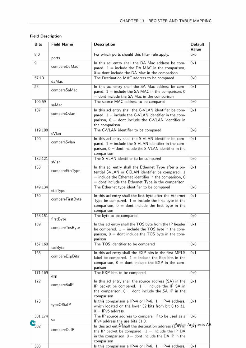
CHAPTER 13. REGISTER AND TABLE MAPPING
Field Description
Bits Field Name Description DefaultValue
8:0ports
For which ports should this filter rule apply. 0x0
9compareDaMac
In this acl entry shall the DA Mac address be com-pared. 1 = include the DA MAC in the comparison,0 = dont include the DA Mac in the comparison
0x1
57:10daMac
The Destination MAC address to be compared 0x0
58compareSaMac
In this acl entry shall the SA Mac address be com-pared. 1 = include the SA MAC in the comparison, 0= dont include the SA Mac in the comparison
0x1
106:59saMac
The source MAC address to be compared 0x0
107compareCvlan
In this acl entry shall the C-VLAN identifier be com-pared. 1 = include the C-VLAN identifier in the com-parison, 0 = dont include the C-VLAN identifier inthe comparison
0x1
119:108cVlan
The C-VLAN identifier to be compared 0x0
120compareSvlan
In this acl entry shall the S-VLAN identifier be com-pared. 1 = include the S-VLAN identifier in the com-parison, 0 = dont include the S-VLAN identifier in thecomparison
0x1
132:121sVlan
The S-VLAN identifier to be compared 0x0
133compareEthType
In this acl entry shall the Ethernet Type after a po-tential SVLAN or CCLAN identifier be compared. 1= include the Ethernet identifier in the comparison, 0= dont include the Ethernet Type in the comparison
0x1
149:134ethType
The Ethernet type identifier to be compared 0x0
150compareFirstByte
In this acl entry shall the first byte after the EthernetType be compared. 1 = include the first byte in thecomparison, 0 = dont include the first byte in thecomparison
0x1
158:151firstByte
The byte to be compared 0x0
159compareTosByte
In this acl entry shall the TOS byte from the IP headerbe compared. 1 = include the TOS byte in the com-parison, 0 = dont include the TOS byte in the com-parison
0x1
167:160tosByte
The TOS identifier to be compared 0x0
168compareExpBits
In this acl entry shall the EXP bits in the first MPLSlabel be compared. 1 = include the Exp bits in thecomparison, 0 = dont include the EXP in the com-parison
0x1
171:169exp
The EXP bits to be compared 0x0
172compareSaIP
In this acl entry shall the source address (SA) in theIP packet be compared. 1 = include the IP SA inthe comparison, 0 = dont include the SA IP in thecomparison
0x1
173typeOfSaIP
Is this comparison a IPv4 or IPv6. 1= IPv4 address,which located on the lower 32 bits from bit 0 to 31,0 = IPv6 address.
0x1
301:174sa
The IP source address to compare. If to be used as aIPv4 address the use bits 31:0.
0x0
302compareDaIP
In this acl entry shall the destination address (DA) inthe IP packet be compared. 1 = include the IP DAin the comparison, 0 = dont include the DA IP in thecomparison
0x1
303typeOfDaIP
Is this comparison a IPv4 or IPv6. 1= IPv4 address,which located on the lower 32 bits from bit 0 to 31,0 = IPv6 address.
0x1
431:304da
The IP destination address to compare. If to be usedas a IPv4 address the use bits 31:0.
0x0
80 Packet Architects AB
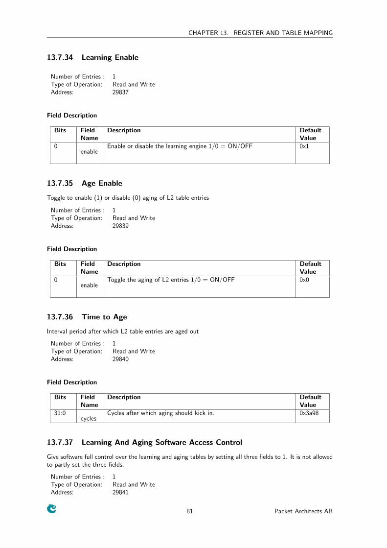
CHAPTER 13. REGISTER AND TABLE MAPPING
13.7.34 Learning Enable
Number of Entries : 1Type of Operation: Read and WriteAddress: 29837
Field Description
Bits FieldName
Description DefaultValue
0enable
Enable or disable the learning engine 1/0 = ON/OFF 0x1
13.7.35 Age Enable
Toggle to enable (1) or disable (0) aging of L2 table entries
Number of Entries : 1Type of Operation: Read and WriteAddress: 29839
Field Description
Bits FieldName
Description DefaultValue
0enable
Toggle the aging of L2 entries 1/0 = ON/OFF 0x0
13.7.36 Time to Age
Interval period after which L2 table entries are aged out
Number of Entries : 1Type of Operation: Read and WriteAddress: 29840
Field Description
Bits FieldName
Description DefaultValue
31:0cycles
Cycles after which aging should kick in. 0x3a98
13.7.37 Learning And Aging Software Access Control
Give software full control over the learning and aging tables by setting all three fields to 1. It is not allowedto partly set the three fields.
Number of Entries : 1Type of Operation: Read and WriteAddress: 29841
81 Packet Architects AB
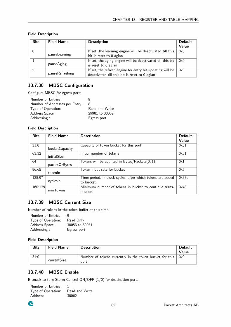
CHAPTER 13. REGISTER AND TABLE MAPPING
Field Description
Bits Field Name Description DefaultValue
0pauseLearning
If set, the learning engine will be deactivated till thisbit is reset to 0 agian
0x0
1pauseAging
If set, the aging engine will be deactivated till this bitis reset to 0 agian
0x0
2pauseRefreshing
If set, the refresh engine for entry bit updating will bedeactivated till this bit is reset to 0 agian
0x0
13.7.38 MBSC Configuration
Configure MBSC for egress ports
Number of Entries : 9Number of Addresses per Entry : 8Type of Operation: Read and WriteAddress Space: 29981 to 30052Addressing : Egress port
Field Description
Bits Field Name Description DefaultValue
31:0bucketCapacity
Capacity of token bucket for this port 0x51
63:32initialSize
Initial number of tokens 0x51
64packetOrBytes
Tokens will be counted in Bytes/Packets(0/1) 0x1
96:65tokenIn
Token input rate for bucket 0x5
128:97cyclesIn
Time period, in clock cycles, after which tokens are addedto bucket.
0x38c
160:129minTokens
Minimum number of tokens in bucket to continue trans-mission.
0x48
13.7.39 MBSC Current Size
Number of tokens in the token buffer at this time.
Number of Entries : 9Type of Operation: Read OnlyAddress Space: 30053 to 30061Addressing : Egress port
Field Description
Bits Field Name Description DefaultValue
31:0currentSize
Number of tokens currently in the token bucket for thisport
0x0
13.7.40 MBSC Enable
Bitmask to turn Storm Control ON/OFF (1/0) for destination ports
Number of Entries : 1Type of Operation: Read and WriteAddress: 30062
82 Packet Architects AB
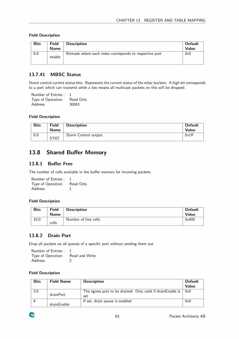
CHAPTER 13. REGISTER AND TABLE MAPPING
Field Description
Bits FieldName
Description DefaultValue
8:0enable
Bitmask where each index corresponds to respective port 0x0
13.7.41 MBSC Status
Storm control current status bits. Represents the current status of the mbsc buckets. A high bit correspondsto a port which can transmit while a low means all multicast packets on this will be dropped.
Number of Entries : 1Type of Operation: Read OnlyAddress: 30063
Field Description
Bits FieldName
Description DefaultValue
8:0STAT
Storm Control output 0x1ff
13.8 Shared Buffer Memory
13.8.1 Buffer Free
The number of cells available in the buffer memory for incoming packets.
Number of Entries : 1Type of Operation: Read OnlyAddress: 1
Field Description
Bits FieldName
Description DefaultValue
10:0cells
Number of free cells 0x400
13.8.2 Drain Port
Drop all packets on all queues of a specific port without sending them out
Number of Entries : 1Type of Operation: Read and WriteAddress: 2
Field Description
Bits Field Name Description DefaultValue
3:0drainPort
The egress port to be drained. Only valid if drainEnable isset
0x0
4drainEnable
If set, drain queue is enabled 0x0
83 Packet Architects AB
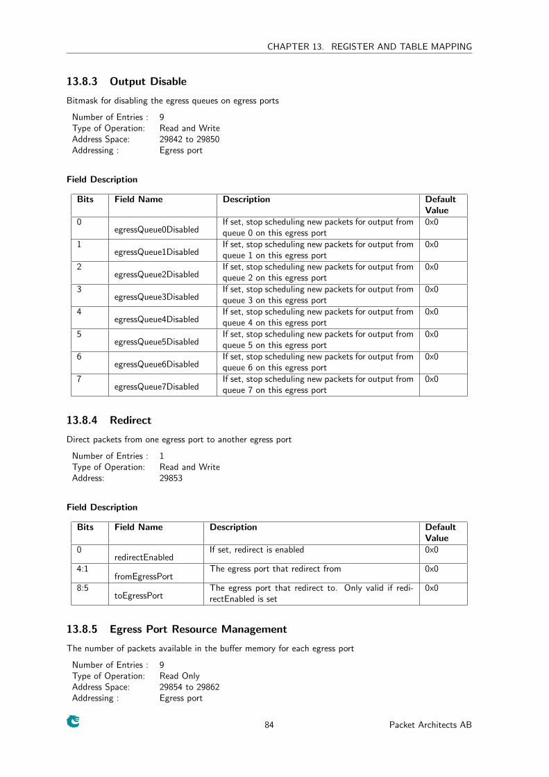
CHAPTER 13. REGISTER AND TABLE MAPPING
13.8.3 Output Disable
Bitmask for disabling the egress queues on egress ports
Number of Entries : 9Type of Operation: Read and WriteAddress Space: 29842 to 29850Addressing : Egress port
Field Description
Bits Field Name Description DefaultValue
0egressQueue0Disabled
If set, stop scheduling new packets for output fromqueue 0 on this egress port
0x0
1egressQueue1Disabled
If set, stop scheduling new packets for output fromqueue 1 on this egress port
0x0
2egressQueue2Disabled
If set, stop scheduling new packets for output fromqueue 2 on this egress port
0x0
3egressQueue3Disabled
If set, stop scheduling new packets for output fromqueue 3 on this egress port
0x0
4egressQueue4Disabled
If set, stop scheduling new packets for output fromqueue 4 on this egress port
0x0
5egressQueue5Disabled
If set, stop scheduling new packets for output fromqueue 5 on this egress port
0x0
6egressQueue6Disabled
If set, stop scheduling new packets for output fromqueue 6 on this egress port
0x0
7egressQueue7Disabled
If set, stop scheduling new packets for output fromqueue 7 on this egress port
0x0
13.8.4 Redirect
Direct packets from one egress port to another egress port
Number of Entries : 1Type of Operation: Read and WriteAddress: 29853
Field Description
Bits Field Name Description DefaultValue
0redirectEnabled
If set, redirect is enabled 0x0
4:1fromEgressPort
The egress port that redirect from 0x0
8:5toEgressPort
The egress port that redirect to. Only valid if redi-rectEnabled is set
0x0
13.8.5 Egress Port Resource Management
The number of packets available in the buffer memory for each egress port
Number of Entries : 9Type of Operation: Read OnlyAddress Space: 29854 to 29862Addressing : Egress port
84 Packet Architects AB
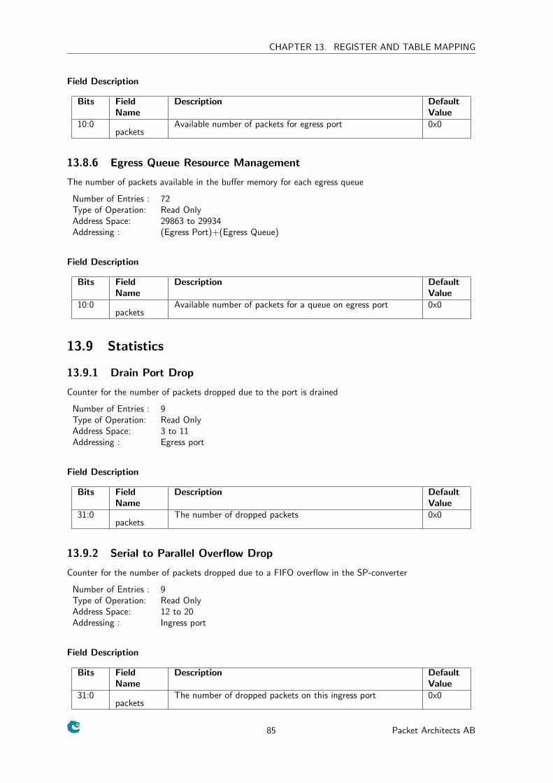
CHAPTER 13. REGISTER AND TABLE MAPPING
Field Description
Bits FieldName
Description DefaultValue
10:0packets
Available number of packets for egress port 0x0
13.8.6 Egress Queue Resource Management
The number of packets available in the buffer memory for each egress queue
Number of Entries : 72Type of Operation: Read OnlyAddress Space: 29863 to 29934Addressing : (Egress Port)+(Egress Queue)
Field Description
Bits FieldName
Description DefaultValue
10:0packets
Available number of packets for a queue on egress port 0x0
13.9 Statistics
13.9.1 Drain Port Drop
Counter for the number of packets dropped due to the port is drained
Number of Entries : 9Type of Operation: Read OnlyAddress Space: 3 to 11Addressing : Egress port
Field Description
Bits FieldName
Description DefaultValue
31:0packets
The number of dropped packets 0x0
13.9.2 Serial to Parallel Overflow Drop
Counter for the number of packets dropped due to a FIFO overflow in the SP-converter
Number of Entries : 9Type of Operation: Read OnlyAddress Space: 12 to 20Addressing : Ingress port
Field Description
Bits FieldName
Description DefaultValue
31:0packets
The number of dropped packets on this ingress port 0x0
85 Packet Architects AB
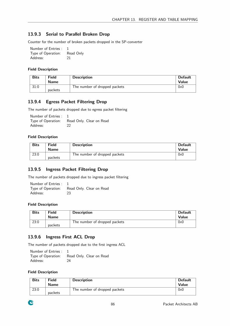
CHAPTER 13. REGISTER AND TABLE MAPPING
13.9.3 Serial to Parallel Broken Drop
Counter for the number of broken packets dropped in the SP-converter
Number of Entries : 1Type of Operation: Read OnlyAddress: 21
Field Description
Bits FieldName
Description DefaultValue
31:0packets
The number of dropped packets 0x0
13.9.4 Egress Packet Filtering Drop
The number of packets dropped due to egress packet filtering
Number of Entries : 1Type of Operation: Read Only. Clear on ReadAddress: 22
Field Description
Bits FieldName
Description DefaultValue
23:0packets
The number of dropped packets 0x0
13.9.5 Ingress Packet Filtering Drop
The number of packets dropped due to ingress packet filtering
Number of Entries : 1Type of Operation: Read Only. Clear on ReadAddress: 23
Field Description
Bits FieldName
Description DefaultValue
23:0packets
The number of dropped packets 0x0
13.9.6 Ingress First ACL Drop
The number of packets dropped due to the first ingress ACL
Number of Entries : 1Type of Operation: Read Only. Clear on ReadAddress: 24
Field Description
Bits FieldName
Description DefaultValue
23:0packets
The number of dropped packets 0x0
86 Packet Architects AB
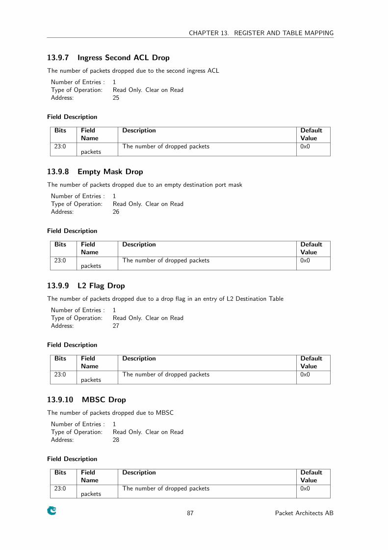
CHAPTER 13. REGISTER AND TABLE MAPPING
13.9.7 Ingress Second ACL Drop
The number of packets dropped due to the second ingress ACL
Number of Entries : 1Type of Operation: Read Only. Clear on ReadAddress: 25
Field Description
Bits FieldName
Description DefaultValue
23:0packets
The number of dropped packets 0x0
13.9.8 Empty Mask Drop
The number of packets dropped due to an empty destination port mask
Number of Entries : 1Type of Operation: Read Only. Clear on ReadAddress: 26
Field Description
Bits FieldName
Description DefaultValue
23:0packets
The number of dropped packets 0x0
13.9.9 L2 Flag Drop
The number of packets dropped due to a drop flag in an entry of L2 Destination Table
Number of Entries : 1Type of Operation: Read Only. Clear on ReadAddress: 27
Field Description
Bits FieldName
Description DefaultValue
23:0packets
The number of dropped packets 0x0
13.9.10 MBSC Drop
The number of packets dropped due to MBSC
Number of Entries : 1Type of Operation: Read Only. Clear on ReadAddress: 28
Field Description
Bits FieldName
Description DefaultValue
23:0packets
The number of dropped packets 0x0
87 Packet Architects AB
CHAPTER 13. REGISTER AND TABLE MAPPING
13.9.11 Reserved MAC Address Drop
The number of packets dropped due to MAC address being in the reserved address range
Number of Entries : 1Type of Operation: Read Only. Clear on ReadAddress: 29
Field Description
Bits FieldName
Description DefaultValue
23:0packets
The number of dropped packets 0x0
13.9.12 Egress Spanning Tree Drop
The number of packets dropped due to a fail in egress spanning tree check
Number of Entries : 1Type of Operation: Read Only. Clear on ReadAddress: 30
Field Description
Bits FieldName
Description DefaultValue
23:0packets
The number of dropped packets 0x0
13.9.13 Egress Port Overuse Drop with Low Priority
The number of packets dropped due to insufficient free space in the buffer memory when a low priorityunicast packet comes in
Number of Entries : 1Type of Operation: Read Only. Clear on ReadAddress: 31
Field Description
Bits FieldName
Description DefaultValue
23:0packets
The number of dropped packets 0x0
13.9.14 Egress Port Overuse Drop with High Priority
The number of packets dropped due to insufficient free space in the buffer memory when a high priorityunicast packet comes in
Number of Entries : 1Type of Operation: Read Only. Clear on ReadAddress: 32
Field Description
Bits FieldName
Description DefaultValue
23:0packets
The number of dropped packets 0x0
88 Packet Architects AB
CHAPTER 13. REGISTER AND TABLE MAPPING
13.9.15 Multicast Overuse Drop with Low Priority
The number of packets dropped due to insufficient free space in the buffer memory when a low prioritymulticast packet comes in
Number of Entries : 1Type of Operation: Read Only. Clear on ReadAddress: 33
Field Description
Bits FieldName
Description DefaultValue
23:0packets
The number of dropped packets 0x0
13.9.16 Multicast Overuse Drop with High Priority
The number of packets dropped due to insufficient free space in the buffer memory when a high prioritymulticast packet comes in
Number of Entries : 1Type of Operation: Read Only. Clear on ReadAddress: 34
Field Description
Bits FieldName
Description DefaultValue
23:0packets
The number of dropped packets 0x0
13.9.17 Ingress Spanning Tree Drop: Listen
The number of packets dropped due to ingress spanning tree check
Number of Entries : 1Type of Operation: Read Only. Clear on ReadAddress: 35
Field Description
Bits FieldName
Description DefaultValue
23:0packets
The number of dropped packets 0x0
13.9.18 Ingress Spanning Tree Drop: Learning
The number of packets dropped due to ingress spanning tree check
Number of Entries : 1Type of Operation: Read Only. Clear on ReadAddress: 36
Field Description
Bits FieldName
Description DefaultValue
23:0packets
The number of dropped packets 0x0
89 Packet Architects AB
CHAPTER 13. REGISTER AND TABLE MAPPING
13.9.19 Ingress Spanning Tree Drop: Blocking
The number of packets dropped due to ingress spanning tree check
Number of Entries : 1Type of Operation: Read Only. Clear on ReadAddress: 37
Field Description
Bits FieldName
Description DefaultValue
23:0packets
The number of dropped packets 0x0
13.9.20 VLAN Member Drop
The number of packets dropped due to not a VLAN member
Number of Entries : 1Type of Operation: Read Only. Clear on ReadAddress: 38
Field Description
Bits FieldName
Description DefaultValue
23:0packets
The number of dropped packets 0x0
13.9.21 Minimum Allowed VLAN Drop
The number of packets dropped due to insufficient VLAN tags
Number of Entries : 1Type of Operation: Read Only. Clear on ReadAddress: 39
Field Description
Bits FieldName
Description DefaultValue
23:0packets
The number of dropped packets 0x0
13.9.22 Maximum Allowed VLAN Drop
The number of packets dropped due to too many VLAN tags
Number of Entries : 1Type of Operation: Read Only. Clear on ReadAddress: 40
Field Description
Bits FieldName
Description DefaultValue
23:0packets
The number of dropped packets 0x0
90 Packet Architects AB
CHAPTER 13. REGISTER AND TABLE MAPPING
13.9.23 Not Learnt
Number of Entries : 1Type of Operation: Read OnlyAddress: 29838
Field Description
Bits FieldName
Description DefaultValue
31:0entries
Entries not learnt due to fifo full 0x0
13.9.24 Buffer Overflow Drop
Counter for the number of packets dropped due to the shared buffer memory being full.
Number of Entries : 1Type of Operation: Read Only. Clear on ReadAddress: 29851
Field Description
Bits FieldName
Description DefaultValue
23:0packets
The number of dropped packets 0x0
13.9.25 Buffer Broken Drop
Counter for the number of broken packets dropped in the shared buffer memory.
Number of Entries : 1Type of Operation: Read Only. Clear on ReadAddress: 29852
Field Description
Bits FieldName
Description DefaultValue
23:0packets
The number of dropped packets 0x0
13.9.26 Egress Port Disabled Drop
The number of packets dropped due to egress port disabled
Number of Entries : 1Type of Operation: Read Only. Clear on ReadAddress: 29935
Field Description
Bits FieldName
Description DefaultValue
23:0packets
The number of dropped packets 0x0
91 Packet Architects AB

CHAPTER 13. REGISTER AND TABLE MAPPING
92 Packet Architects AB
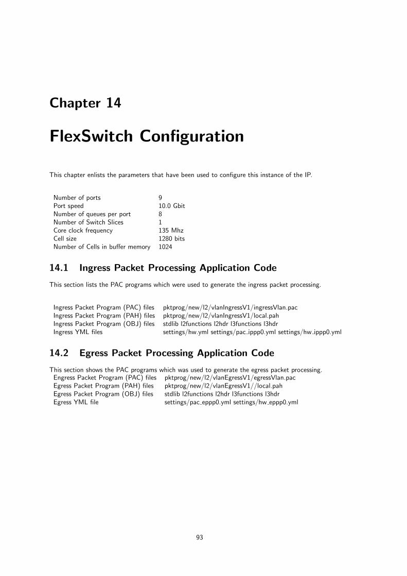
Chapter 14
FlexSwitch Configuration
This chapter enlists the parameters that have been used to configure this instance of the IP.
Number of ports 9Port speed 10.0 GbitNumber of queues per port 8Number of Switch Slices 1Core clock frequency 135 MhzCell size 1280 bitsNumber of Cells in buffer memory 1024
14.1 Ingress Packet Processing Application Code
This section lists the PAC programs which were used to generate the ingress packet processing.
Ingress Packet Program (PAC) files pktprog/new/l2/vlanIngressV1/ingressVlan.pacIngress Packet Program (PAH) files pktprog/new/l2/vlanIngressV1/local.pahIngress Packet Program (OBJ) files stdlib l2functions l2hdr l3functions l3hdrIngress YML files settings/hw.yml settings/pac ippp0.yml settings/hw ippp0.yml
14.2 Egress Packet Processing Application Code
This section shows the PAC programs which was used to generate the egress packet processing.Engress Packet Program (PAC) files pktprog/new/l2/vlanEgressV1/egressVlan.pacEgress Packet Program (PAH) files pktprog/new/l2/vlanEgressV1//local.pahEgress Packet Program (OBJ) files stdlib l2functions l2hdr l3functions l3hdrEgress YML file settings/pac eppp0.yml settings/hw eppp0.yml
93