L011-58 Rev E0 - fh-co.com · L011-58 (Rev E0, 2016-01-07) Contains ... CRW ™ stereotactic system...
70
FHC, Inc. 1201 Main Street Bowdoin, ME 04287 Fax +1-207-666-8292 www.fh-co.com 24 hour technical service: 1-800-326-2905 (US & Can) +1-207-666-8190 FHC Europe (TERMOBIT PROD srl) 42A Barbu Vacarescu Str, 3rd Fl Bucharest 020281 Sector 2 Romania FHC Latin America Calle 6 Sur Cra 43 A-200 Edificio LUGO oficina 1406 Medellín-Colombia www.fh-co.com Navigator WayP ™ int Directions For Use Software Version 4.2 L011-58 (Rev E0, 2016-01-07) Contains directions for the following product: 66-WP-NV(4.2)
Transcript of L011-58 Rev E0 - fh-co.com · L011-58 (Rev E0, 2016-01-07) Contains ... CRW ™ stereotactic system...

FHC, Inc.1201 Main StreetBowdoin, ME 04287Fax +1-207-666-8292www.fh-co.com
24 hour technical service:1-800-326-2905 (US & Can)+1-207-666-8190
FHC Europe (TERMOBIT PROD srl)42A Barbu Vacarescu Str, 3rd FlBucharest 020281 Sector 2Romania
FHC Latin AmericaCalle 6 Sur Cra 43 A-200Edifi cio LUGO ofi cina 1406Medellín-Colombia
www.fh-co.com
NavigatorWayP ™int
Directions For UseSoftware Version 4.2
L011-58 (Rev E0, 2016-01-07)
Contains directions for the following product:66-WP-NV(4.2)


Symbols, Trademarks, Copyright, and Disclaimer.......................................................................................................4
Compatibility, System Requirements, and System Maintenance and Repair..............................................................5
User Authentication, Data Storage, Backup Procedures, Software Licensing, and Intended Use..............................6
Warnings.....................................................................................................................................................................7
CT and MRI Scanning Protocols
Introduction and Recommended Scan Protocols.........................................................................................................8
Patient Preparation, Scanning Requirements, Scan Review, and Scan Storage........................................................9
Functional Overview
Preoperative Module: Plan a new patient using microTargeting™ Platform...............................................................10
Preoperative Module: Plan a new patient using Leksell® or CRW® frame.................................................................11
Intraoperative Module: Working intraoperatively with microTargeting™ Platform......................................................12
Intraoperative Module: Working Intraoperatively with Leksell® or CRW® frame.........................................................13
Starting Navigator......................................................................................................................................................14
Preoperative Quick Start Guide
Planning a Case for microTargeting™ Platforms.......................................................................................................15
Registering the Atlas.........................................................................................................................................25
Optional Automatic Plan Generation.................................................................................................................29
Planning a Case for Leksell® and CRW® Stereotactic Frames..................................................................................35
Registering the Atlas.........................................................................................................................................42
Optional Automatic Plan Generation.................................................................................................................46
Visualizing and Modifying Frame Coordinates.................................................................................................47
Intraoperative Quick Start Guide
Working Intraoperatively with microTargeting™ Platforms........................................................................................49
Intraoperative Recordings...............................................................................................................................53
Drop Implant.....................................................................................................................................................56
Implant Stimulation...........................................................................................................................................57
Working Intraoperatively with Leksell® and CRW® Frames.......................................................................................58
Intraoperative Recordings................................................................................................................................62
Drop Implant.....................................................................................................................................................64
Implant Stimulation..........................................................................................................................................65
Generating a Report..................................................................................................................................................65
Connecting to PACS..................................................................................................................................................67
MER Streaming from Guideline 4000™ Software.....................................................................................................68
Disposal and Contact Information..............................................................................................................................70
Table of Contents

4 WayPoint™ Navigator Directions for Use
Symbols
WARNING / Caution, consult documents
Manufacturer
Catalog number
Serial number
European Conformity. This symbol means that the device fully complies with Council Directive 93/42/EEC.
Authorized representative in the European community
In reference to “Rx only” symbol; this applies to USA audiences only
Caution- Federal law (USA) restricts this device to sale by or on the order of a physician
Read usage instructions
Temperature limitation: Storage conditions are between 0°C - 40°C (32°F - 104°F)
Instructions for end of life disposal
c
j
n
Tradenames and Trademarks
WayPoint™ and microTargeting™ are trademarks of FHC, Inc..STarFix™ and STarFixtures™ are trademarks of STarFix, Inc.
This document and parts thereof must not be reproduced or copied by any means without the express written consent of Neurotargeting, LLC. The contents of this document may not be used for any unauthorized purpose, and contravention of copyright will be prosecuted. WayPoint™ Navigator, and the intellectual property it contains, are the property of FHC, Inc., Neurotargeting, LLC, and Vanderbilt University, and may not be copied, disassembled or reproduced in any way without permission of their respective owners.
Rx only
0°C+32°F
40°C+104°F
Disclaimer
FHC, Inc. does not accept liability for injury or damage to equipment that may result from misuse of the WayPoint™ Navigator software or of the microTargeting™ Platforms which it produces.
Neither Neurotargeting, LLC nor Vanderbilt University accept any liability for injury or damage to equipment that may result from the use of the WayPoint™ Navigator.
Copyright © 2016 FHC, Inc., Vanderbilt University, and Neurotargeting, LLCThis software is subject to copyright protection. Unauthorized reproduction or distribution may lead to substantial damages, penalties and sanctions.

L011-58 Rev. E0, 2016-01-07 5
System Requirements
Compatibility
The software is compatible with the following stereotactic systems:WayPoint™ microTargeting™ Platform:
WayPoint™ Navigator software requires use of WayPoint™ Anchors (4mm and 5mm without post).
The following Platforms are compatible with Navigator: WP unilateral, WP 2h2h unilateral, WP 2h2h bilateral, WP 2h2b bilateral, WP epilepsy (grid).
CRW™ stereotactic system by Integra Radionics™, Inc.: you should refer to the documentation provided by Integra Radionics™, Inc. for details on proper use of the system.
Leksell® stereotactic system (Coordinate Frame G) by Elekta: you should refer to the documentation provided by the Elekta for details on proper use of the system.
The software is compatible with the following intraoperative recording systems:Guideline 4000 LP+™ by FHC, Inc.: Refer to the Guideline 4000 LP+™ Directions for Use
The software is compatible with the following lead models (please refer to the Manufacturer for details):Medtronic: 3389, 3387, 3391St. Jude Medical: 6142, 6143, 6144, 6145, 6146, 6147, 6148, 6149
System Maintenance and Repair
Handling Considerations• The WayPoint™ Navigator workstation is not designed for sterilization.• Do not drop the WayPoint™ Navigator workstation.
Maintenance• The WayPoint™ Navigator workstation must be inspected each year by an FHC authorized representative.
Contact FHC for more information on Service Agreements.
Repair• All FHC products are unconditionally guaranteed against defects in workmanship for one year from the date of
shipment, provided they have been exposed to normal and proper use.• Should service or repair be required, please contact FHC at 1-800-326-2905 (US & Canada) or +1-207-666-8190
for return instructions.
Following are the recommended hardware requirements:CPU: Intel I7 or equivalent, 3.4+ GHz, 4 GB RAMDisk Space: 6 GBGraphics Card: 1 GB of VRAMMonitor Resolution: 1920x1080Connection: USB 2.0 or greaterOS: Windows 7 (SP2+)
Following are the minimum requirements:CPU: Intel Core 2 Duo or equivalent, 2.93+ GHz, 2 GB RAMDisk Space: 3 GB, Integrated Graphics ProcessorMonitor Resolution: 1152x864Connection: USB 2.0 or greaterOS: Windows XP(SP3) or Windows 7 (SP2+)
6 WayPoint™ Navigator Directions for Use
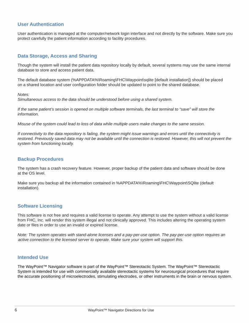
User Authentication
User authentication is managed at the computer/network login interface and not directly by the software. Make sure you protect carefully the patient information according to facility procedures.
Data Storage, Access and Sharing
Though the system will install the patient data repository locally by default, several systems may use the same internal database to store and access patient data.
The default database system (%APPDATA%\Roaming\FHC\Waypoint\sqlite [default installation]) should be placed on a shared location and user confi guration folder should be updated to point to the shared database.
Notes: Simultaneous access to the data should be understood before using a shared system.
If the same patient’s session is opened on multiple software terminals, the last terminal to “save” will store the information.
Misuse of the system could lead to loss of data while multiple users make changes to the same session.
If connectivity to the data repository is failing, the system might issue warnings and errors until the connectivity is restored. Previously saved data may not be available until the connection is restored. However, this will not prevent the system from functioning locally.
Backup Procedures
The system has a crash recovery feature. However, proper backup of the patient data and software should be done at the OS level.
Make sure you backup all the information contained in %APPDATA%\Roaming\FHC\Waypoint\SQlite (default installation).
Software Licensing
This software is not free and requires a valid license to operate. Any attempt to use the system without a valid license from FHC, Inc. will render this system illegal and not clinically approved. This includes altering the operating system date or fi les in order to use an invalid or expired license.
Note: The system operates with stand-alone licenses and a pay-per-use option. The pay-per-use option requires an active connection to the licensed server to operate. Make sure your system will support this.
Intended Use
The WayPoint™ Navigator software is part of the WayPoint™ Stereotactic System. The WayPoint™ Stereotactic System is intended for use with commercially available stereotactic systems for neurosurgical procedures that require the accurate positioning of microelectrodes, stimulating electrodes, or other instruments in the brain or nervous system.

L011-58 Rev. E0, 2016-01-07 7
WarningsFederal law (USA) restricts microTargeting™ Platforms to sale by or on the order of a physician.
The WayPoint™ Navigator software requires use of WayPoint™ Anchors or other FHC, Inc. approved anchor/marker system devices. Use with other components or systems is not authorized.
The WayPoint™ Navigator software provides no diagnostic function.
Do not load third party software onto the WayPoint™ Navigator planning station.
The WayPoint™ Navigator must be operated by a person that has been trained by an FHC, Inc.. authorized representative and has read and understood the Directions For Use (DFU).
The WayPoint™ Navigator must be installed by an FHC, Inc.. authorized representative.
Discontinue use of the WayPoint™ Navigator should any damage or erratic function become evident.
Prior to the fi rst surgery, use of the WayPoint™ Navigator should be validated by using a Platform phantom. If the phantom does not appear accurate, please contact FHC, Inc.. immediately.
Frame phantoms should be utilized for each procedure to ensure accurate targeting. Always verify the created platform is built with all parts connected with no parts thinning or twisted. Platform feet must all be properly aligned with their corresponding anchors.
The WayPoint™ Navigator software may be used only with one of these specifi c frames: microTargeting™ Platform, FHC Inc; CRW®, Radionics™; Leksell® G-Frame, Elekta.
Platform legs must not pass through patient anatomy.
The data provided by the CranialVault™ Atlas embedded in the WayPoint™ Navigator software is solely for information. The atlas quality is directly dependent on imaging quality. While the software will warn you for potential misuse of the data, it remains the sole responsibility of you to check the validity of the data before using it.
The quality of the atlas registration may be affected if the reference MRI image used is acquired after surgery or contains tumors.
The primary MRI image for use with the atlas registration should be one that contains no leads, such as a Preoperative MRI.
The primary CT image sets should contain a range of data at least 15 cm long starting from just under the nose towards the top of the head.
For FHC STarFix™ Platform users, the system labeling shall state that CT image sets should contain a range of data that contains the anchors.
For Leksell® and CRW® frames user, the CT image sets should contain a range of data that contains the frame localizer N-Bars.
Missing CT slices may affect the extraction of anchors and locators.
Very fi ne resolution image sets may slow down system performance and may not be able to be loaded due to memory constraints.
Image and atlas registration quality may be affected by patient movement during scan, brain shift, and air in the brain.
The WayPoint™ Navigator is not safe to use in or near an MRI machine.

8 WayPoint™ Navigator Directions for Use
Introduction
The WayPoint™ Navigator Software is a software application for planning and performing deep brain stimulation (DBS) procedures. The WayPoint™ software application will provide you access to one or more modular components, each of which will be dedicated to a specifi c function of the surgical procedure.
The software allows for visualization of patient-specifi c brain anatomy, lead and electrode location, an activation map based on stimulation parameter settings, and target maps indicating the statistical likelihood of therapeutic effect based on historical DBS patient outcomes. The patient-specifi c information accuracy is based on preoperative data set and depends on the use of the proper imaging sequences as described in this document. The patient-specifi c information may differ from the reality for different reasons including brain shift during the procedure, or use of poor or old MRI sequences.
The WayPoint™ Navigator Software does not replace clinical judgment. All DBS plans and lead placement remains solely at the neurosurgeon’s discretion.
To avoid unexpected loss of data, periodically save session fi les to a backup folder or removable media.
Depending on options and licenses, access to some features could be disabled.
CT and MRI Scanning ProtocolsNote: These protocols indicate recommended best practices and are not intended to replace the referring surgeon’s spe-cifi c instructions.
Proper operation of WayPoint™ Navigator requires CT & MRI scans that are acquired with specifi c characteristics which are stored in a compatible format. Accurate planning is based on these key principles
• The target area may be 100 slices or more from the area of the anchors at the top of the head, and the anchors may be 25 or more slices from each other. Motionless scans are required for targeting accuracy, therefore, the patient must be still during the entire imaging process.
• The scanner technician should always check the quality of the scan images for displaced slices indicating movement.
Recommended Scan Protocols
CT
Axial T1 MRI
Axial T2 MRI
T2
whole headslices ≤1.25 mm thickno gantry angle
whole headslices ≤1mm thickno gantry angle
Flared, if desired, encompassing target areaslices 1-2mm thick no gantry angle
Confi rm target location with surgeon prior to T2 scan. (Targeting the STN, GPi, or VIM may require scans from the lower part of the ear to the middle of the forehead.)
Slices ≤1.25 mmContiguous slices equal spacing
Slices ≤1mm*Contiguous slices equal spacing(*up to 2mm can be used)

L011-58 Rev. E0, 2016-01-07 9
Patient Preparation
• Align the patient’s head axially in the scanner, to ensure a gantry angle of zero.
• Secure the patient’s head to the headrest with tape. Towels may be used to pad the head and to help prevent movement. Be careful not to disturb the anchors/headframe bars.
• Secure the patient’s arms and use pillows or restraints on other parts of the body to make the patient comfortable and relaxed, and to limit movement.
• Inform the patient of the importance of holding still, as the accuracy of the procedure depends on a good scan. The surgeon may recommend light sedation if needed.
Scanning Requirements
• Single pass, slice by slice; or
• Single spiral image acquisition
Note: multiple pass images can have gaps or other problems with slice thickness that can affect accuracy or targeting.
microTargeting™ Platform CT scan should start 2.5 cm above the anchors and end 2.5 cm past the target. (The extra space on top and bottom ensures there is no distortion and allows the search algorithm to work.)
Frame CT scan needs to start just below the top ring of the frame and end just above the bottom ring of the frame. This will prevent artifact from impeding the registration of the CT and MRI.
Field of view should include the entire head, but should not be too large. Standard stereotactic frame head protocols are often too large, causing unnecessary time in the scanner, large scan fi les, and less resolution.
Note: If CT will be the only scan used for planning, set kVp and mA for best tissue discrimination.
Scan Review (with patient present)
1. Prepare a 3-D reconstruction of the scans and inspect quality. Streaking, blurring, and rotated slices will require a re-scan of the patient.
2. Ensure the titanium anchors/frame bars are plainly visible and stand out from the bone by setting up the CT for best anchor/frame visibility.
Note for new sites: It is good practice to allow the surgeon to review the fi rst few scans for suitability prior to the patient leaving the hospital or the scan area.
Scan Storage
• Prepare the digital image data in uncompressed DICOM format according to the surgeon’s instructions. (Do not use jpg or bmp formats.)
• Store scans on a CD-R, CD-RW, or DVD. Do not use MagnetoOptical Disks.
• CT and MRI scans must be loaded in one folder (not in multiple folders with smaller scan sections).
• Disk should be given to the surgeon as soon as possible to allow for planning.
10 WayPoint™ Navigator Directions for Use
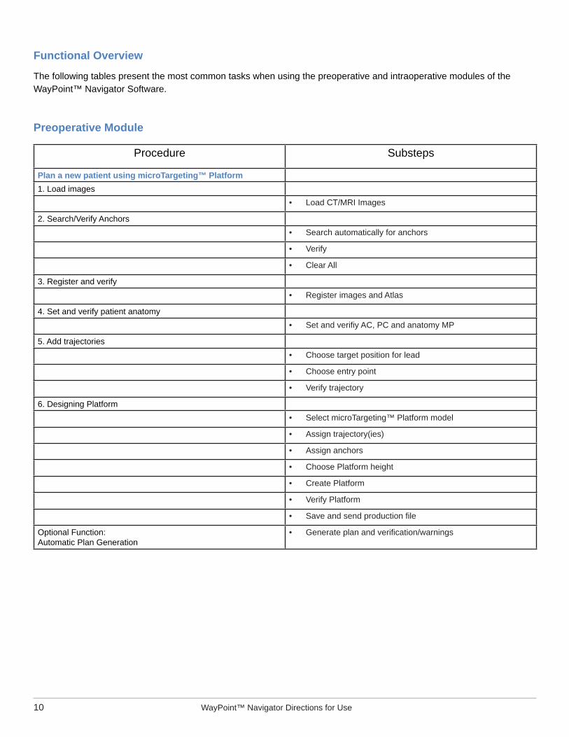
Functional Overview
The following tables present the most common tasks when using the preoperative and intraoperative modules of the WayPoint™ Navigator Software.
Preoperative Module
Procedure Substeps
Plan a new patient using microTargeting™ Platform1. Load images
• Load CT/MRI Images
2. Search/Verify Anchors• Search automatically for anchors
• Verify
• Clear All
3. Register and verify• Register images and Atlas
4. Set and verify patient anatomy• Set and verifi y AC, PC and anatomy MP
5. Add trajectories• Choose target position for lead
• Choose entry point
• Verify trajectory
6. Designing Platform• Select microTargeting™ Platform model
• Assign trajectory(ies)
• Assign anchors
• Choose Platform height
• Create Platform
• Verify Platform
• Save and send production fi le
Optional Function:Automatic Plan Generation
• Generate plan and verifi cation/warnings

L011-58 Rev. E0, 2016-01-07 11
Preoperative Module
Procedure Substeps
Plan a new patient using Leksell® or CRW® frame1. Load images
• Load CT/MRI Images
2. Localize frame localizer/N-Bars• Search automatically for N-Bars
• Verify
• Clear All
3. Register and verify• Register images and Atlas
4. Set and verify patient anatomy• Set and verify AC, PC, and anatomy MP
5. Add trajectories• Choose target position for lead
• Choose entry point
• Verify trajectory
6. Adjust & Get frame coordinates

12 WayPoint™ Navigator Directions for Use
Intraoperative Module
Procedure Substeps
Working intraoperatively with microTargeting™ Platform1. Load plan2. Set up trajectory
• Select trajectory
• Select path(s)
• Set starting depth
3. Connect to Guideline 4000 LP+™ system• Connect with proper cable• Confi gure IP & port number on WPN• Confi gure IP & port number on Guideline 4000 LP+™ system• Start streaming data
4. Intraoperative MER acquisition• Right click cell in data table
• Select “Start MER”
• Close connection when fi nished
5. Intraoperative Stimulation• Right click data table
• Select “Start Stimulation”• Enter parameters and record patient’s response(s)
6. Place Lead• Right click ocell in data table• Select “Drop Implant”• Select lead model• Select, label, and confi rm position• Perform implant stimulation
7. Create report and save surgery• Click “Save,” set fi lename, and confi rm• Generate report

L011-58 Rev. E0, 2016-01-07 13
Intraoperative Module
Procedure Substeps
Working Intraoperatively with Leksell® or CRW® frames1. Load plan2. Set up trajectory
• Select trajectory
• Select path(s)
• Set starting depth
3. Connect to Guideline 4000 LP+™ system• Connect with proper cable• Confi gure IP & port number on WPN• Confi gure IP & port number on Guideline 4000 LP+™ system• Start streaming data
4. Intraoperative MER acquisition• Right click on cell in data table
• Select “Start MER”
• Close connection when done
5. Intraoperative Stimulation• Right click on data table
• Select “Start Stimulation”• Enter parameters and record patient”s response(s)
6. Place Lead• Right click on cell in data table• Selct “Drop Implant”• Select lead model• Select, label, and confi rm position• Perform implant stimulation
7. Create report and save surgery• Click “Save,” set fi lename, and confi rm• Generate report

14 WayPoint™ Navigator Directions for Use
Starting NavigatorWayPoint™ Navigator software must be installed before following the steps in guide.
Upon opening the WayPoint™ Navigator software, you are presented with the module selection screen. Available modules are determined by your license. Choose a module to begin.
You are then presented with the frame selection screen. Available frames are determined by your license. Choose desired frame.

L011-58 Rev. E0, 2016-01-07 15
Preoperative Quick Start Guide
Planning a Case for microTargeting™ Platforms
After selecting the frame, the Patient Management panel opens.
Click “Add New Patient.” You may either create the new patient from “Existing Record” or from “Image/PACS.” A dialog box opens where you may enter some patient information (a valid MRN is required). Click “OK.” The new patient record appears in the “Patients” table. You may edit by clicking on the “Edit” link for the patient record. To delete a patient record, select the patient in the table and click the trash icon above the “Patients” table. You will have to confi rm your action.

16 WayPoint™ Navigator Directions for Use
Select the patient record and add a new plan for this patient. Click “Add New Plan.” The “Plan Information” dialog opens. Enter the “Surgery Date” and other information if available. Click “OK.” The new plan appears in the “Plan for” table. You may edit by clicking on the “Edit” link for the plan. You may add multiple plans for a patient. To delete a plan, select the plan in the table and click the trash icon above the “Plan for” table. You will have to confi rm your action. Now you are ready to start creating the plan for the patient. Select the plan and click “Start Plan.”
1. Loading Images
The following procedure explains how to select, preview, and load images, and applies only to images saved to a local directory on your personal or networked computer.
A. Load New Scans
1. Click “Load File,” to open previously saved plans or load new scans for a plan.
2. Click “Load Primary CT” or “Load Primary MRI” option. A Load Scan dialog opens. Browse the studies and select the correct one. Then click “Load.” The loaded scans will appear in the “Load Scan” dialog.

L011-58 Rev. E0, 2016-01-07 17
3. When a set of images is selected, slices may be visualized on the “Slices” tab. Click on one slice to zoom the single image.
Select a set of images and click “Load” to load the images in the session. If desired, repeat this process for one or two secondary scan studies (CT or MR).

18 WayPoint™ Navigator Directions for Use
B. Load Saved Scans
Click the “Load Plan…” option. An Open Plan dialog opens. The dialog shows a history of plans. Select the correct plan then click “Load,” or choose “Load From” to browse for a plan. PWS and ZIP fi les require that scans exist where they were during planning. PAK fi les contain copies of source images and are recommended if plans are transferred to another location.
When scans are loaded, they are shown in the 2D/3D Display windows.
2. Localization of Anchors
Searching for anchors may be done automatically or manually. A CT image must be displayed as the primary scan study to access the anchor search.
A. Automatic Search
Click “Search for Anchors” and choose the “Search Automatically for” option. Choose the anchor type.
A dialog message will state the number of anchors that the software. This is a prompt for proceeding to the verifi cation process (see below).

L011-58 Rev. E0, 2016-01-07 19
If any anchors are not found automatically, select the manual “Pick up Seed and Search …” method to add them.
If the system fi nds the anchor, it may require adjustment and verifi cation.
B. Manual Search
Click “Search for Anchors” and choose the “Pick up Seed and Search...” option. The software will prompt you to move the cursor to an anchor site (top center of the anchor head) and click a button to search for a specifi ed anchor type.
When positioned correctly, click “Next.”

20 WayPoint™ Navigator Directions for Use
The marked anchor will be displayed in green on the 2D/3D Display views. For the best visual display of anchors, check in the 2D Display panel the “Point Projection.” Repeat the steps for all anchors.
If no anchor is found, you may manually add the anchor by clicking on the anchor tip in the CT image, and then clicking “Add Manually.” Anchor location/orientation may be adjusted using the left mouse click to drag the anchor, and the right mouse click to rotate the anchor.
C. Verify Anchors
The verifi cation process will begin immediately during the automatic search for anchors, but it may be started manually at any time by clicking “Search for Anchors...” and choosing the “Verify...” option.
Each anchor located will be outlined in purple for verifi cation. The software view will be changed to the plane of the displayed anchor for easier verifi cation.

L011-58 Rev. E0, 2016-01-07 21
With the selection tool active, left click in the panels to move the anchor”s location point. Right click to rotate the anchor.
When well adjusted, click “Next >>” to verify the next anchor. The number of anchor is shown on the top of the menu (small gray/blue rectangles). The selected one is shown in blue.
D. Adjustment
The plane of the displayed anchor will adjust to the new location or orientation settings and be redrawn. Do not manually toggle the display orientation or move to a different slice during this process. Adjust the purple outline as needed to line up with the anchor in the CT image.
All anchors marked are displayed in green in the Display views.

22 WayPoint™ Navigator Directions for Use
3. Register Scans
When a secondary scan study is loaded, the software prompts you to register it. You may register the images immediately or choose to register after all of the images have loaded.
Note: All scan studies MUST be loaded and registered with the primary CT before proceeding to the next step (setting patient anatomy).
With the Primary CT and the secondary scan displayed (selected in the 2D Display panel), click “Register Scans” and select the “Register All Images Automatically” option.
Choose the images to register and click “OK.” Note: The atlas may be registered at this time if desired.
The system begins to align the images. When fi nished, an information box opens. You must verify the result of the registration.
L011-58 Rev. E0, 2016-01-07 23
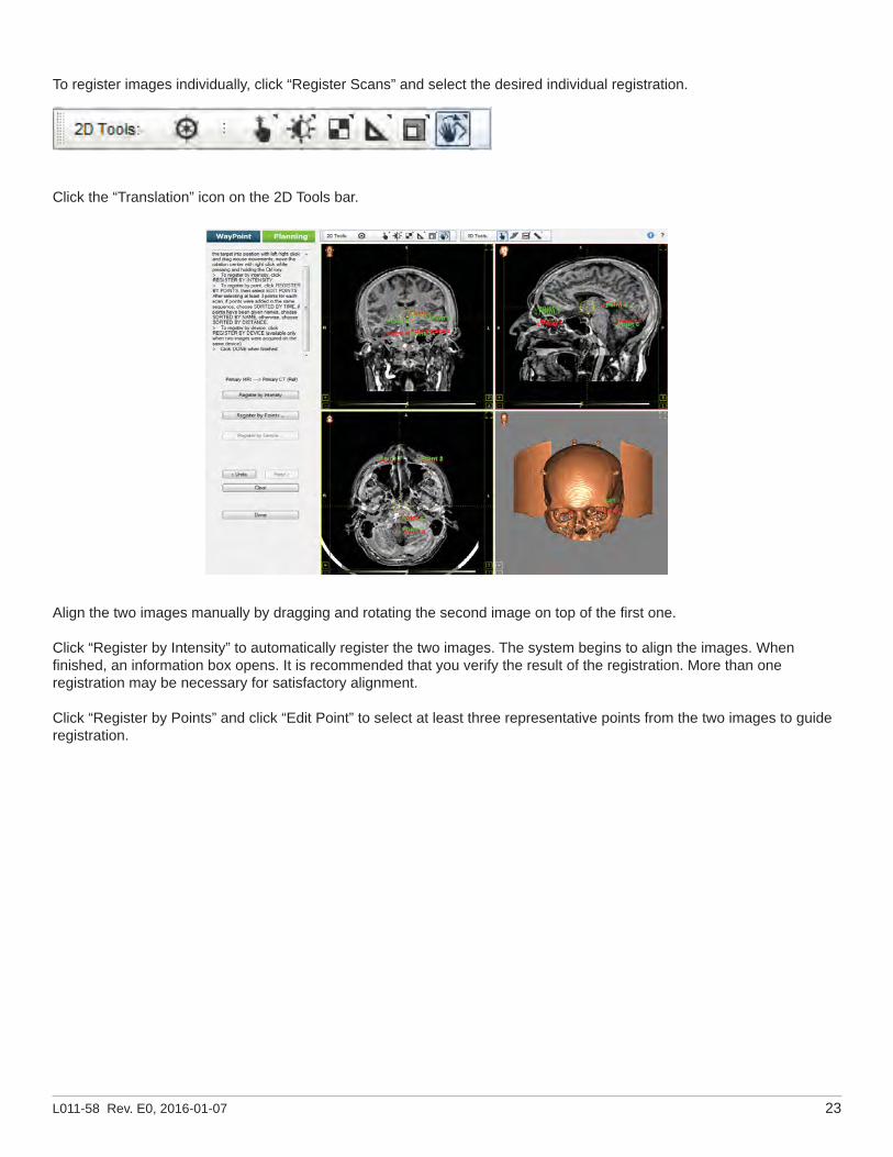
To register images individually, click “Register Scans” and select the desired individual registration.
Click the “Translation” icon on the 2D Tools bar.
Align the two images manually by dragging and rotating the second image on top of the fi rst one.
Click “Register by Intensity” to automatically register the two images. The system begins to align the images. When fi nished, an information box opens. It is recommended that you verify the result of the registration. More than one registration may be necessary for satisfactory alignment.
Click “Register by Points” and click “Edit Point” to select at least three representative points from the two images to guide registration.
24 WayPoint™ Navigator Directions for Use
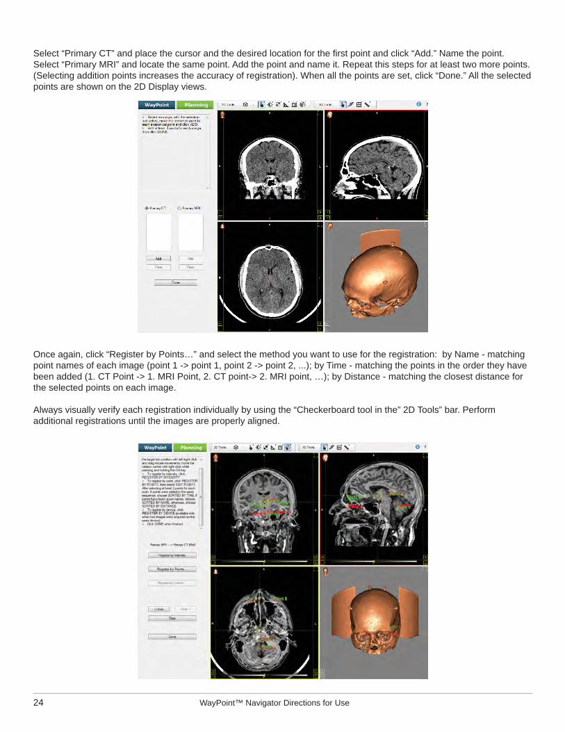
Select “Primary CT” and place the cursor and the desired location for the fi rst point and click “Add.” Name the point. Select “Primary MRI” and locate the same point. Add the point and name it. Repeat this steps for at least two more points. (Selecting addition points increases the accuracy of registration). When all the points are set, click “Done.” All the selected points are shown on the 2D Display views.
Once again, click “Register by Points…” and select the method you want to use for the registration: by Name - matching point names of each image (point 1 -> point 1, point 2 -> point 2, ...); by Time - matching the points in the order they have been added (1. CT Point -> 1. MRI Point, 2. CT point-> 2. MRI point, …); by Distance - matching the closest distance for the selected points on each image.
Always visually verify each registration individually by using the “Checkerboard tool in the” 2D Tools” bar. Perform additional registrations until the images are properly aligned.

L011-58 Rev. E0, 2016-01-07 25
Registering the Atlas
The software includes an atlas that contains anatomical structures, electrophysiological maps, and fi ber tracts. The atlas may be fi t to the patient undergoing the plan through a process called registration. The process will best align the atlas objects to the patient by using the information from the MRI reference image. The process may be done through a combination of rigid and non-rigid registration and may be manually adjusted.
The information provided by the atlas is shown solely for informational purposes and should always be checked by you. Moreover, the electrophysiological data contained in the atlas is based on a large population of patients and represents trends seen in this population. Data may not match an individual patient.
Note: The quality of the registration is directly related to the quality of the image used as the primary MRI image.
The recommended primary MRI should be a MRI T1 without contrast with a resolution around 1x1x1mm3.
The primary MRI resolution should not be more than 2x2x2mm3 in order to use the atlas.
The primary MRI should not have leads or artifacts such as tumors in the region of interest.
The use of the atlas with images that do not adhere to this recommendations may cause errors in the matching process.
This software has parameters to safeguard against misregistration of the atlas and should prompt you if any is detected. Never trust blindly information provided by the atlas.
Quality of the atlas registration is automatically checked against multiple criteria. If a potential misregistration that remains in an acceptable range is detected, a message will alert you. When a large error is detected, the atlas will automatically be reset until you reviews the images or modifi es the registrations.
Select “MRI->Atlas registration” in the registration menu. Check “Global registration” for prealignment of the atlas with the patient and check “Local” for non-rigid registration of the patient onto the atlas. Then click “Register.”
Use “Show: Deformed MRI/Structures/Grid” as well as the checkerboard tool to verify the registration quality.
If there is a risk of poor registration you will receive a warning (predicted points at a distance greater than 3mm from default). If the registration is unacceptable, the registration will be discarded automatically (predicted points at a distance greater than 6mm from the default).

26 WayPoint™ Navigator Directions for Use
A. Automatically Set Points
If the images were registered to the atlas during the registration step, you will be given the option to preliminarily set anatomical points based on the atlas.
Click “Yes” and the system will locate the anatomic points. Always verify that the points have been set correctly. During verifi cation, you will be able to adjust the position of the points if necessary.
B. Manually Set PointTo set the AC, move the cursor to the AC position then click “Set.”
To set the PC, move the cursor to the PC position then click “Set.”
To set the medial plane, click and drag the AC–PC frame”s upper vertical axis into alignment with the patient”s middle plane then click “Done.”
Once AC, PC, and middle plane reference are set, they may be verifi ed or modifi ed by using the “Set Patient Anatomy” menu options.
4. Set Patient Anatomical Landmarks (AC-PC)
In this process, Anterior Commissure (AC), Posterior Commissure (PC) and a mid-plane reference are set sequentially.Click “Set Patient Anatomy” and click the “Set...” option to begin the process of setting patient anatomical points.

L011-58 Rev. E0, 2016-01-07 27
5. Trajectories
In this process Target, Entry, and Trajectory Name are set sequentially.
A. Add Trajectories
Click “Add Trajectories” and choose the “Add...” option.
B. Set Target
Select the target type. Choose the target point by clicking the desired target location, then click “Set.”
Choice of one of the anatomical regions listed under the “Default Positions:” may be facilitated by the dropdown menu.

28 WayPoint™ Navigator Directions for Use
The slices may be panned without moving the entry. The entry point is indicated by the drawn trajectory line and not necessarily by the crosshairs of the reference lines.
Note: Utilize AC–PC frame or trajectory alignment display orientation options to verify a good trajectory path through anatomy. “Undo” and “Redo” buttons allow a number of maydidate entry sites to be evaluated.
D. Trajectory Name
Type in a descriptive trajectory name. Then click “Done.”
E. Modifi cation
Once Target, Entry, and Trajectory Name are set, they may be verifi ed or modifi ed using the options “Modify Target...” or Modify Entry…” under the “Add Trajectories” menu. To access this option select the entry or target point and right click the mouse.
F. Additional Trajectories
These may be added by repeating the above steps or by choosing “Add Trajectories” and selecting the “Mirror” option to bilaterally mirror a selected trajectory with respect to the midplane. Trajectories are listed under the “Add Trajectories” menu.
C. Choose Entry Point
Click the desired entry, and then click “Set.” The entry may also be set and the angle values of the trajectory adjusted by clicking “Update” and then clicking “Set.”

L011-58 Rev. E0, 2016-01-07 29
Optional Automatic Plan Generation
This optional feature allows you to skip steps 3 through 5 of this section.
1. Click “Load File.”2. Click “Generate Plan” button. You will be prompted to verify the plan generation.
3. Choose a target and click “OK.” This will begin generating the plan. Upon completion, the software will display a message notifying you how the predictions should be used and that verifi cation is required.
4. Click “OK.” This will display registration, anatomy, and trajectories for verifi cation.
Note: This software has parameters that safeguard against predictions that are outside reasonable possibility. If targets are preselected outside these parameters, a warning will appear to alert you that the target is beyond the threshold and that he must therefore proceed with caution. If the target is beyond the warning threshold, the preselected targets will be discarded and the software will prompt you to select the target manually.

30 WayPoint™ Navigator Directions for Use
6-7. Select and Design Platform Model
A. Choose Platform Model
Set the views to show primary CT as the fi rst image in the 2D Display panel, and then use the Select Platform Model menu to choose a platform model compatible with the type, number, and orientation of implanted anchors. A thumbnail representation of the chosen model is displayed in the left menu.
Click “Design Platform...”
B. Create Platform
Click the “Create Platform” option to have anchors, trajectories, and platform height assigned automatically and to initiate the creation of the platform virtual model. The number of anchors and trajectories must be compatible with the platform model to use the auto assignments. A dialog box opens. It asks to confi rm to auto assignment of the anchors and trajectories.
Select the height of the platform and click “OK”

L011-58 Rev. E0, 2016-01-07 31
A new information box opens asking to confi rm that anatomy points, anchors, and trajectories have been verifi ed before creating the platform. If they have been verifi ed, click “OK.” If they have not, click “Maycel” and proceed to verifi cation.
To assign an anchor manually, select one from the 3D Display Window. The anchor’s color changes to purple.
Then right click the correspondent anchor in the list of anchors to be assigned and click “Assign Current Anchor.”
To assign a trajectory manually, select from the list that appears beneath the “Add Trajectories…” button. Then right click the “Trajectory:—”and click “Assign Current Trajectory.”
To assign manually the height of the platform, right click “Height:—.” A dropdown options opens. Select the desired height.
If desired, the anchors, trajectories, and platform height may be assigned manually by clicking the appropriate option beneath the “Design Platform...” button.

32 WayPoint™ Navigator Directions for Use
Note: Assigning anchors and trajectories manually may be necessary if the proper number of anchors or trajectories does not match the selected model.

L011-58 Rev. E0, 2016-01-07 33
C. Verify Platform
Verify that the platform feet rest squarely on the anchors. The software will display each anchor, in turn, with the platform design drawn in the views. The display orientation must not be toggled and the displayed slice must not be panned during this process.
All platform feet must be properly aligned with their corresponding anchors. This verifi cation will be required before you may save the production fi le.
Note: Always verify that all of the created platform’s all parts connected and that no parts have thinned or twisted.
The designed platform is displayed in the 3D views and appears outlined in red in the 2D view panels. The software will ask you to verify the platform. Click “Yes” to continue.

34 WayPoint™ Navigator Directions for Use
8. Saving File
After you have verifi ed the platform design, click “Save File…” This may be used to save a plan at any point during the planning.
Select “Save Plan” if the plan fi le and image fi les will remain in their current location on the planning computer. A platform information dialog box opens and auto-fi lls the patient’s name. Enter the surgeon name, facility, date of surgery and notes if desired. Then click “OK.”
Select “Pack Plan” if the plan fi le and image fi les must be moved together to a different location. Images are copied and included in the “Pack Plan” option.
Note: “Save plan” may be done anytime during the planning process.
A. Saving and Sending Production File
For the microTargeting™ Platform, saving a production fi le allows the platform model to be sent to the manufacturer for frame construction.
Click the “Save File...” button and choose the “Save as Production File” option. A platform information dialog box opens. The patient’s name is automatically entered into the dialog. A descriptive trajectory name, which will be printed on the physical device, must be entered. Surgeon name, facility, and surgical date must be entered to ensure the device is built and delivered correctly. Then click “OK.”
A dialog box opens to inform you that the fi le has been created but has not sent to FHC.
Click “Yes.” A new dialog box will open giving two options to send the fi le.
The production fi le must be sent to the manufacturer no fewer than four business days prior to intended delivery.
B. Switch to Intraoperative Navigation Workspace
Once the plan has been saved, you may switch to the Intraoperative workspace by clicking “Save File...” and choosing “Go to Intraoperative Module.”

L011-58 Rev. E0, 2016-01-07 35
On selecting a frame, the Patient Management panel opens.
Click “Add New Patient.” You may either create the new patient from “Existing Record” or from “Image/PACS.” A dialog box opens in which you may enter patient information (a valid MRN is required).
Click “OK.” The new patient record appears in the “Patients” table. You may edit the record by clicking on the “Edit” link for the patient record. To delete a patient record, select the patient in the table and click the trash icon above the “Patients” table. You will have to confi rm your action.
Select the patient record and add a new plan for this patient. Click “Add New Plan.” The “Plan Information” dialog opens. Enter the “Surgery Date” and other information if available.
Click “OK.” The new plan appears in the “Plan for” table. You may edit by clicking on the “Edit” link for the plan. You may add multiple plans for a patient. To delete a plan, select the plan in the table and click the trash icon above the “Plan for” table. You will have to confi rm your action.
Now you are ready to start creating the plan for the patient. Select the plan and click “Start Plan.”
Planning a Case for Leksell® and CRW® Stereotactic Frames

36 WayPoint™ Navigator Directions for Use
1. Loading Images
The following procedure explains how to select, preview, and load images, and applies only to images saved to a local directory on your personal or networked computer. Click “Load File” to open previously saved plans or load new scans for a plan.
When a set of images is selected, slices may be visualized on the “Slices” tab. Click one slice to zoom on the single image.
Select a set of images and click Load to load the images in the session.
If desired, repeat this process for one or two secondary scan studies (CT or MR).
A. Load New Scans
Click “Load Primary CT” or “Load Primary MRI” option. A Load Scan dialog opens. Browse for the correct study then click “Load.” The loaded scans will appear in the “Load Scan” dialog.
L011-58 Rev. E0, 2016-01-07 37
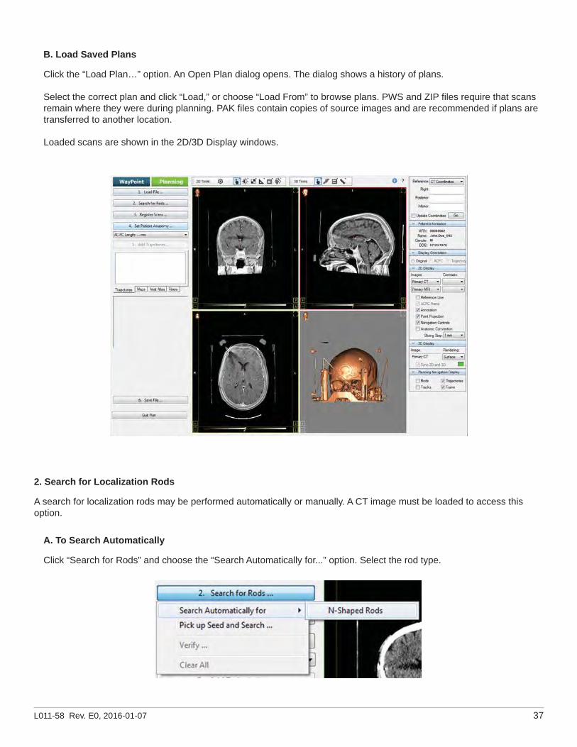
B. Load Saved Plans
Click the “Load Plan…” option. An Open Plan dialog opens. The dialog shows a history of plans.
Select the correct plan and click “Load,” or choose “Load From” to browse plans. PWS and ZIP fi les require that scans remain where they were during planning. PAK fi les contain copies of source images and are recommended if plans are transferred to another location.
Loaded scans are shown in the 2D/3D Display windows.
2. Search for Localization Rods
A search for localization rods may be performed automatically or manually. A CT image must be loaded to access this option.
A. To Search Automatically
Click “Search for Rods” and choose the “Search Automatically for...” option. Select the rod type.

38 WayPoint™ Navigator Directions for Use
The program will search automatically, and a dialog message will state the mean squared error (MSE) of the extraction before proceeding to the verifi cation process (see below).
B. To Search Manually
Click “Search for Rods” and choose the “Pick up Seed and Search...” option.
Choose seed points for the rods by selecting each rod in order, starting from the right posterior rod (for Leksell®) or the thick rod (for CRW®). Be sure to check the sides of the CT image to verify right-left orientation. First click a rod on the CT image to place the cursor crosshair. Then click the “Add Points” button to save to the seed point list. Make sure the seed point is added to the list before moving to the next rod. Continue until all rods have seed points.

L011-58 Rev. E0, 2016-01-07 39
The Leksell® frame localizer extraction (A), the CRW® BRWLF localizer (B) and CRW® Luminant localizer (C) are pictured below.
Click “Search for...” to use the seed points to extract the rods from the rest of the image.
You may choose to use the semiautomatic method (using both seed points and image intensity) or the fully manual method (using only the seed points).
The program will search for the rods and a dialog message will state the mean squared error (MSE) of the extraction before proceeding to the verifi cation. Click “Yes.”
A B C
C. Verify Rods
The verifi cation process will begin immediately following rod extraction. As the program scrolls through the slices, visually verify that the green circles align with the rods in the image.

40 WayPoint™ Navigator Directions for Use
The verifi cation may be reviewed again at any time by clicking “Verify.” When the rods are properly extracted, click “Done.”
The rods are displayed in green on the Display windows (to see then be sure to check “Rods” under the Planning Navigation Display panel).
3. Register Scans
When a secondary scan study is loaded, the software prompts you to register it. You may register the images immediately or choose to register all images after all images are loaded.
Note: All scan studies MUST be loaded and registered with the primary CT before proceeding to the next step (setting patient anatomy).
With the Primary CT and the secondary scan displayed (selected in the 2D Display panel),

L011-58 Rev. E0, 2016-01-07 41
Click “Register Scans ...” and select the “Register All Images Automatically” option.
Choose the images to register and click “OK.”
Note: The atlas may be registered at this time if desired.
The system begins to align the images. When alignment is complete, an information box opens. It requests a registration result.
A. To Register Images Individually
Click “Register Scans” and select the desired individual registration.

42 WayPoint™ Navigator Directions for Use
To automatically register the two images by intensity, click “Register by Intensity.”
To choose representative points from the two images for guiding registration, click “Register by Points.”
Always visually verify each registration individually by using the “Checkerboard tool in the 2D Tools” bar. Perform additional registrations until the images are properly aligned.
Registering the Atlas
The software contains an atlas containing anatomical structures, electrophysiological maps, and fi ber tracts. The atlas may be fi t to the patient undergoing the plan through a process called registration. The process will best align the atlas objects to the patient by using the information from the MRI reference image. The process may be completed through a combination of rigid and non-rigid registration and may be manually adjusted.
The information provided by the atlas is shown for information only. You must always check it. Moreover, the electrophysiological data contain in the atlas is based on a large population of patients and represents trends seen in this population. The data from the atlas may not match the patient, depending on multiple criteria.
Note: The quality of the registration is directly related to the quality of the image used as the primary MRI image.
The recommended primary MRI is a MRI T1 without contrast and with a resolution about 1x1x1mm3.
The primary MRI resolution should not be more than 2x2x2mm3 in order to use the atlas.
The primary MRI should not have leads or artifacts such as tumors in the region of interest.
The use of the atlas with images that do not conform to the above specifi cations may cause errors in the matching process.
This software has parameters to safeguard against misregistration of the atlas and should prompt you if any is detected. Never trust blindly information provided by the atlas.
Quality of the atlas registration is automatically checked according to multiple criteria. If a potential misregistration that remains in an acceptable range is detected a message will be prompted to you. When a large error is detected, the atlas will automatically be reset until you reviews the images or adapt the registrations.

L011-58 Rev. E0, 2016-01-07 43
4. Set Patient Anatomical Landmarks (AC-PC)
Click “Set Patient Anatomy” and click the “Set...” option to begin the process of setting patient anatomical points.
A. Set Points Automatically
If the images were registered to the atlas during the registration step, you will be given the option to preliminarily set anatomical points according to the atlas.
Click “Yes” and the system will locate the anatomic points. Always verify that the points have been set correctly. During verifi cation, you will be able to adjust the position of the points if necessary.
B. Set Points Manually
To set the AC, move the cursor to the AC then click “Set.”
To set the PC, move the cursor to the PC then click “Set.”
To set the medial plane, click and drag the AC–PC frame’s upper vertical axis into alignment with the patient’s middle plane then click “Done.”
Once AC, PC, and middle plane reference are set, they may be verifi ed or modifi ed by using the “Set Patient Anatomy” menu options.

44 WayPoint™ Navigator Directions for Use
5. Trajectories
In this process Target, Entry, and Trajectory Name are set sequentially.
B. Set Target
Select the target type. Choose the target point by clicking the desired target location, then click “Set.”
Choosing one of the anatomical regions listed under the “Default Positions” dropdown menu may facilitate choice of a target.
C. Choose Entry Point
Choose the entry point by clicking the desired entry. Then click “Set.” The entry may also be set by adjusting the angle values of the trajectory, clicking “Update,” and then clicking “Set.”
A. Add Trajectories
Click “Add Trajectories” and choose the “Add...” option.

L011-58 Rev. E0, 2016-01-07 45
Note that slices may be panned without moving the entry. The entry point is indicated by the drawn trajectory line and not necessarily by the cross hairs of the reference lines.
Note: Utilize AC–PC frame or trajectory alignment display orientation options to verify a good trajectory path through anatomy. “Undo” and “Redo” buttons allow a number of candidate entry sites to be evaluated.
D. Trajectory Name
Type in a descriptive trajectory name and then click “Done.”
E. Modifi cation
Once Target, Entry, and Trajectory Name are set, they may be verifi ed or modifi ed using the options “Modify Target...” or “Modify Entry…” under the “Add Trajectories” menu.
F. Additional Trajectories
Additional trajectories may be added by repeating the above steps, or by choosing “Add Trajectories” and selecting the “Mirror” option to bilaterally mirror a selected trajectory with respect to the midplane. Trajectories are listed under the “Add Trajectories” menu.

46 WayPoint™ Navigator Directions for Use
Optional Automatic Plan Generation
This optional feature allows you to skip steps 3 through 5 of this section.
1. Click “Load File.”2. Click “Generate Plan” button. You will be prompted to verify the plan generation.
3. Choose a target and click “OK.” This will begin generating the plan. Upon completion, the software will display a message notifying you how the predictions should be used and that verifi cation is required.
4. Click “OK.” This will display registration, anatomy, and trajectories for verifi cation.
Note: This software has parameters that safeguard against predictions that are outside reasonable possibility. If targets are preselected outside these parameters, a warning will appear to alert you that the target is beyond the threshold and that he must therefore proceed with caution. If the target is beyond the warning threshold, the preselected targets will be discarded and the software will prompt you to select the target manually.
L011-58 Rev. E0, 2016-01-07 47
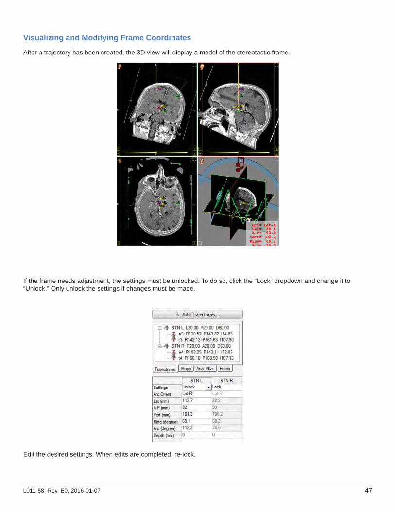
Visualizing and Modifying Frame Coordinates
After a trajectory has been created, the 3D view will display a model of the stereotactic frame.
If the frame needs adjustment, the settings must be unlocked. To do so, click the “Lock” dropdown and change it to “Unlock.” Only unlock the settings if changes must be made.
Edit the desired settings. When edits are completed, re-lock.

48 WayPoint™ Navigator Directions for Use
6. Saving a File
1. After verifying the platform design, click “Save File…” This may be used to save a plan at any point during the planning.
2. Use the “Save Plan” choice if the plan fi le and image fi les are to remain in their current location on the planning computer.
3. Choose “Pack Plan” if the plan fi le and image fi les must be moved together to a different location. Copies of the images are made and included in the “Pack Plan” option.

L011-58 Rev. E0, 2016-01-07 49
Intraoperative Quick Start Guide
Working Intraoperatively with microTargeting™ Platforms
The WayPoint™ Navigator software offers the same basic user image interface in the Intraoperative module as is used in the Preoperative module. The guidance interface on the left side of the screen is divided into 4 different tabs: Tracks, Data Entry, Implants, and Atlas. You may navigate through each of them at any time.
1. Load Plan
In the Preoperative module planning sessions may be ported directly to the Intraoperative module by clicking the “Save...” button and choosing the “Go to Intraoperative Module” option.
Start WayPoint™ Navigator. Select the Intraoperative Module, and select microTargeting™ Platfom module.

50 WayPoint™ Navigator Directions for Use
In the “Patient Manager” are listed the sessions saved from the Preoperative module. Click the patient record. The plan saved appears in the “Plan for:” section. Select the plan and click “Start Plan.” Select the scans to be loaded. Click “OK.” The Intraoperative workspace window opens. Scans are displayed in the 2D and 3D Display views.
If the patient is not listed in the “Patients:” list, click “Add New Patient” and “from Image/PACS” from the Intra-op home screen.
The Intraoperative workspace opens. Click “Plan…” and “Load….” Click “Load From…” and navigate in the fi le manager to locate the plan on the computer or network place. Select the plan saved and click “Open.” A Load Plan File dialog opens. Select the scans to be loaded, click “OK.” Scans are displayed in the 2D and 3D Display views.
Note: You must load a plan with at least one image. Images must have initially been loaded in the Preoperative module.

L011-58 Rev. E0, 2016-01-07 51
2. Using the Tracks Tab
The “Navigation GUI” is the map and grid guide under the Tracks tab that shows you potential tracks/paths for lead implantation.
The Path grid has a scale 0-5 mm on each direction (A, P, L, and M). “Trajectory:” lists the trajectories defi ned in the Preoperative module. “Path:” lists the trajectory paths. “Hub:” allows creating a new trajectory quickly with predefi ned offset of the target or entry point. Check/uncheck the “Path Aid” checkbox, shown/hide the atlas structures on the path grid guide.
The initial trajectory (defi ned in the Preoperative Module) is highlighted in the center of a green circle (active Ben-Gun) on the path grid guide.
In the Planning Navigation Display panel, check “Trajectories” and “Tracks” to view the trajectories and potential tracks in the 2D and 3 D Display views.
B. Track Tip Information
Below the grid guide, information about the track tip location is displayed.
Select a potential trajectory path.
Choose the step size for measuring depth between subsequent stimulation measurements by using the “Step” dropdown menu. This value is used in the Data Entry tab.
Choose the depth of the track tip using the “Depth” box.
Coordinates of the tip in the selected track are displayed in the different stereotactic coordinate systems (CT, MC, AC and PC).
In a Display view, scroll the cursor up or down. The depth and coordinates will be updated according to the step selected.
A. Trajectory Selection
To create a new potential path, select a trajectory (from those defi ned in the Preoperative module) from the dropdown menu labeled “Trajectory.” Use the Hub Offset menu to select any combination of hub offsets allowed by the FHC”s system. The new path will have either its target or entry point offset by 6 mm(for the target) or 3 (for the entry) mm.
To create a parallel path to the initial path, use the Ben-Gun templates (circles on the grid). The selected trajectory path is represented by a highlighted dot at the center of the green circle. Select any other dot (small black circle) on any other gray circle. Each circle has 5 dots connected. The center dot is 2mm away from the other 4 dots. Clicking a possible track will show a red dot on the grid, and will show the selected potential path in the 2D and 3D views. To save a potential path, double-click its dot. Saved paths are visible on the grid at the center of its circle as small red x and label. It may be selected using the “Path:” dropdown menu.
To select more than one track at once, right click on a dot, and the 5 connected dots in the circle will be highlighted.

52 WayPoint™ Navigator Directions for Use
A. Set Track Step
Right click anywhere in the data entry table and select the “Set Track Step” option to choose the desired step size for data entry (in mm).
B. Labels
Right clicking on a cell and choosing the “Label...” option will mark the cell as part of an anatomical region. Multiple cells may be labeled at once by highlighted adjacent cells. Right click the lower-right highlighted cell and choose a label.
3. Using the Data Entry Tab
The data entry tab provides an interface for collecting data related to the current position of the track tip (highlighted in orange). Choose from available trajectories and paths using the two dropdown menus immediately below the tabs. Right-click any cell in the data entry table to bring up the options for data entry (detailed below).

L011-58 Rev. E0, 2016-01-07 53
Intraoperative Recordings
A. Microelectrode Recordings (MER)
If using an MER system for data collection, right click the data entry table in the location where MER collection will begin. Clicking the “MER...” option will open a dialog that allows streamed or manual data collection.
The data entered or streamed automatically from the MER system will then be displayed as 2D and 3D histogram along the trajectories.
Note: See page 67 for instructions on setting up an MER streaming connection with the Guideline 4000 LP+.

54 WayPoint™ Navigator Directions for Use
B. Stimulation Recordings
To record stimulation fi ndings/effects, right click in the data entry table at the stimulation site.
Choose the “Stim...” option. The Stimulation window opens. Enter the setting and observed results data (settings, symptoms, mood, side effects, and notes) of the stimulation.
After entering stimulation data, click “Save and start new” to save the current entries and begin the new stimulation. Repeat as needed.
Stimulation Legend:

L011-58 Rev. E0, 2016-01-07 55
Outcomes with minimal side effects are shown in green. Side effects of greater severity are shown in red.
C. Somatotopy Recording
To record somatotopic data, right-click in the data entry table at the relevant location. Choose “Soma...” The “Somatotopy” window opens. Enter the observations during the stimulations or MER.
56 WayPoint™ Navigator Directions for Use
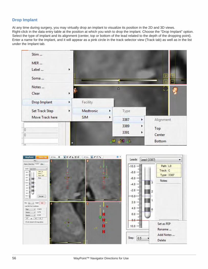
Drop Implant
At any time during surgery, you may virtually drop an implant to visualize its position in the 2D and 3D views. Right-click in the data entry table at the position at which you wish to drop the implant. Choose the “Drop Implant” option. Select the type of implant and its alignment (center, top or bottom of the lead related to the depth of the dropping point). Enter a name for the implant, and it will appear as a pink circle in the track selector view (Track tab) as well as in the list under the Implant tab.

L011-58 Rev. E0, 2016-01-07 57
4. Using the Implants Tab
When an implant is dropped at a specifi c location, it will appear in the “implants view.” The view shows the implant and depth markings to indicate relative position of the implant to the target in millimeters.
Implant Stimulation
On the lead display panel, click “Stimulate.” The Stimulation window opens.
Record stimulation details as they are performed. Enter the setting and observed results data (charge on electrodes, settings, symptoms, mood, side effects and notes) of the stimulation. After entering stimulation data, click “Save and start new” to save the current entries and begin the new stimulation. Repeat as needed.
Right-click the lead display panel.
A pop-up menu opens. It gives you the option of deleting, renaming, or adding notes to the implant.
Before an implant is locked in its fi nal position, it may be moved along the trajectory with the mouse scroll-wheel in the 2D or 3D Display views or by using the depth entry.
After all potential implant locations have been explored, a fi nal electrode placement (FEP) must be chosen by right clicking on an implant in the lead display panel and selecting “Set as FEP.” This locks the lead in position and it maynot be moved. The FEP should be chosen based on all the stimulations performed and data gathered, including the 3D side effect visualizations to assist in locating the lead.
5. Saving the Surgery Session
In the “Plan...” menu, select “Save...” or “Pack...” to save the session at any point during the surgery.
Use the “Save...” option if the plan fi le and image fi les will remain in their current location on the planning computer. Choose the “Pack...” option if the plan fi le and image fi les must be moved together to a different location. Copies of the images are made and included in the “Pack Plan” option.

58 WayPoint™ Navigator Directions for Use
Working Intraoperatively with Leksell®/CRW® Frames
The WayPoint™ Navigator software offers the same basic user image interface in the Intraoperative module as it exists in the Preoperative module. The guidance interface on the left side of the screen is divided into 4 different tabs: Tracks, Data Entry, Implants, and Atlas. You may navigate through each of them at any time.
1. Load Plan
In the Preoperative module, planning sessions may be ported directly to the Intraoperative module by clicking the “Save...” button and choosing the “Go to Intraoperative Module” option.
Start WayPoint™ Navigator and select the Intraoperative module. Then select Leksell® or CRW® module.
In the “Patient Management,” click “Add New Patient,” and select “From Image/PACS.” The Intraoperative workspace opens. Click “Plan...,” and select “Load….” Click “Load From....” Locate the plan on the computer/network and click “Open.” The “Load Plan File” dialog opens. Select the scans to be loaded and click “OK.”

L011-58 Rev. E0, 2016-01-07 59
If a plan has been saved in the Intraoperative module, it will appear in the list of patients in the Patient Management.
Click the patient record. The saved plan appears in the “Plan for:” section. Select the plan and click “Start Plan.” Upload the scans. The Intraoperative workspace window opens.
Note: You must load a plan with at least one image. Images must be loaded for the fi rst time in the Preoperative module.
2. Using the Tracks Tab
The “Navigation GUI” is the map and grid guide under the Tracks tab that shows you potential tracks for lead implantation.
The Path grid has a scale of 0-5 mm on each direction (AC, PC, L, and M). Click the - and + on the bottom left corner to zoom in and out the view on the grid guide. “Trajectory:” lists the trajectories defi ned in the Preoperative module. “Path:” lists the trajectory paths. “Use Ben-Gun:” allows the visualization of the fi ve potential tracks in a Ben-Gun system. Check/uncheck the “Path Aid” checkbox, shown/hide the atlas structures on the path grid guide.
The initial trajectory (defi ned in the Preoperative Module) is highlighted in the center of the path grid guide.
In the Planning Navigation Display panel, check “Trajectories” and “Tracks” to view the trajectories and potential tracks in the 2D and 3 D Display views.
60 WayPoint™ Navigator Directions for Use
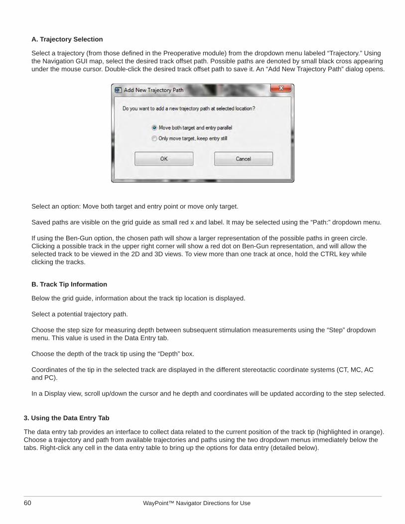
A. Trajectory Selection
Select a trajectory (from those defi ned in the Preoperative module) from the dropdown menu labeled “Trajectory.” Using the Navigation GUI map, select the desired track offset path. Possible paths are denoted by small black cross appearing under the mouse cursor. Double-click the desired track offset path to save it. An “Add New Trajectory Path” dialog opens.
Select an option: Move both target and entry point or move only target.
Saved paths are visible on the grid guide as small red x and label. It may be selected using the “Path:” dropdown menu.
If using the Ben-Gun option, the chosen path will show a larger representation of the possible paths in green circle. Clicking a possible track in the upper right corner will show a red dot on Ben-Gun representation, and will allow the selected track to be viewed in the 2D and 3D views. To view more than one track at once, hold the CTRL key while clicking the tracks.
B. Track Tip Information
Below the grid guide, information about the track tip location is displayed.
Select a potential trajectory path.
Choose the step size for measuring depth between subsequent stimulation measurements using the “Step” dropdown menu. This value is used in the Data Entry tab.
Choose the depth of the track tip using the “Depth” box.
Coordinates of the tip in the selected track are displayed in the different stereotactic coordinate systems (CT, MC, AC and PC).
In a Display view, scroll up/down the cursor and he depth and coordinates will be updated according to the step selected.
3. Using the Data Entry Tab
The data entry tab provides an interface to collect data related to the current position of the track tip (highlighted in orange). Choose a trajectory and path from available trajectories and paths using the two dropdown menus immediately below the tabs. Right-click any cell in the data entry table to bring up the options for data entry (detailed below).

L011-58 Rev. E0, 2016-01-07 61
A. Set Track Step
Right-click anywhere in the data entry table and select the “Set Track Step” option to choose the desired step size for data entry (in mm).
B. Labels
To mark a cell as part of an anatomical region, right-click the cell and choose the “Label...” option. Multiple cells may be labeled at once by highlighted adjacent cells. Right-click the lower-right highlighted cell and choose a label.

62 WayPoint™ Navigator Directions for Use
Intraoperative Recordings
A. Microelectrode Recordings (MER)
If you are using an MER system for data collection, right-click the data entry table in the location where MER collection will begin. Clicking the “MER...” option will bring up a dialog that allows streamed or manual data collection.
The data entered or streamed automatically from the MER system will then be displayed as 2D and 3D histogram along the trajectories.
Note: The system is compatible with the Guideline 4000 LP+™ system. See page 67 for set-up details.

L011-58 Rev. E0, 2016-01-07 63
B. Stimulation Recordings
To record stimulation fi ndings or effects, right-click in the data entry table at the location of the stimulation. Select “Stim...” The Stimulation window opens. Enter the setting and observed results data (settings, symptoms, mood, side effects and notes) of the stimulation.
After entering stimulation data, click “Save and start new” to save the current entries and begin a new stimulation. Repeat as needed.
Outcomes with minimal side effects are shown in green; more severe side effects are shown in red.
C. Somatotopy Recording
When recording somatotopic data, right-click in the data entry table at the relevant location. Choose the “Soma...” option, a dialog allowing data entry for each somatotopic recording opens.

64 WayPoint™ Navigator Directions for Use
Drop Implant
At any time during a surgery, you may virtually drop an implant to visualize its position in the 2D and 3D views. Right click in the data entry table at the position at which you wish to drop the implant and choose the “Drop Implant” option. Select the type of implant and its alignment (center, top or bottom of the lead related to the depth of the dropping point). Enter a name for the implant, and it will appear as a red circle in the track selector view (Track tab) as well as in the list under the Implant tab.
4. Using the Implants tab
When an implant is dropped at a specifi c location, it will appear in the “implants view.”
The view shows the implant and depth markings to indicate relative position of the implant to “the target in millimeters.
Right-click the lead display panel. A pop-up menu opens to give you the option of deleting, renaming, or adding notes to the implant.
Before an implant is locked in its fi nal position, it may be moved along the trajectory with the mouse scroll-wheel in the 2D or 3D Display views or using the depth entry.
After all potential implant locations have been explored, a fi nal electrode placement (FEP) must be chosen by right clicking on an implant in the lead display panel and selecting “Set as FEP.” This locks the lead in position and it may not be moved. The FEP should be chosen on the basis of all simulations performed and data gathered, including the 3D side effect visualizations for assistance in locating a lead.

L011-58 Rev. E0, 2016-01-07 65
Implant Stimulation
On the lead display panel, click “Stimulate.” The Stimulation window will open.
Record stimulation details as they are performed. Enter the settings and observed results data (charge on electrodes, settings, symptoms, mood, side effects and notes) of the stimulation. After entering stimulation data, click “Save and start new” to save the current entries and begin the new stimulation. Repeat as needed.
5. Saving the Surgery Session
In the “Plan...” menu, select “Save...” or “Pack...” to save the session at any point during the surgery.
Use the “Save...” option if the plan fi le and image fi les will remain in their current location on the planning computer. Choose the “Pack...” option if the plan fi le and image fi les must be moved together to a different location. Images are copied and included in the “Pack Plan” option.
Generating a Report
In the “Plan...” menu, select the “Generate Report” option. Fill in surgery information accordingly, and click “OK.”
Select the name and location for the report fi le and click “Save.” The report in a PDF fi le opens.

66 WayPoint™ Navigator Directions for Use

L011-58 Rev. E0, 2016-01-07 67
Connecting to PACS
WayPoint Navigator™ enables users to load patient scans to a hospital’s Patient Archiving and Communication System (PACS). To retrieve images from PACS, select the PACS radio button in the “Load Scan” window. See the fi gure below for the settings.
Click on PACS radio button to arrive at this page
Select folder where to store retrieved PACS images
Enter Host Name, host AE and port DICOM for streaming data. ALL OF THIS INFORMATION MUST BE OBTAINED FROM HOSPITAL DICOM ADMINSTRATORS.Once this window is
correctly populated, create and start listener script.
Client Application Entity (AE) is a UNIQUE identifi er that needs to be provided to the hospital IT services department so that they may service requests from this SW application. Indicate a port for handling incoming data. Port 104, which is reserved for handling DICOM data, is a recommended for this.

68 WayPoint™ Navigator Directions for Use
MER Streaming from Guideline 4000 LP+™ Software
The WayPoint Navigator™ also enables users to stream MER information from Guideline 4000 LP+™ software via a TCP/IP connection. Users are encouraged to verify that the two laptops are communicating by performing a ping test prior to any attempt at streaming data.
To perform ping test, open the command window. If the ping is to issue from the WayPoint Navigator™ laptop, enter “ping” followed by the Guideline 4000 LP+™ laptop’s IP address. If the ping is to issue from the Guideline 4000 LP+™ laptop, enter “ping” followed by the WayPoint™ Navigator laptop’s IP address.
Users are encouraged to confi rm that all data packets transmitted by the host have been successfully received.The fi gure below shows users how to set up MER communications with the Guideline 4000 LP+™ application.
To begin streaming data, right-click anywhere in the table and select MER.
Enter IP address of the Guideline 4000 LP+™ machine. Ensure that it is set to a static IP and confi rm communication between WayPoint™ Navigator and Guideline4000 LP+™ laptops with a ping test prior to any attempted data streaming.
Click “Start Data Streaming” to start streaming MER info from the Guideline 4000 LP+™ application (NOTE: If MFR equals zero, no data will be populated)
Choose Guideline from drop-down menu to stream from Guideline 4000 LP+™
Ensure the port number matches the streaming source of the Guideline 4000 LP+™ application. Also verify that TCP/IP is enabled and “Send waveforms” checkbox isdisabled in the Guideline 4000 LP+™ application.

L011-58 Rev. E0, 2016-01-07 69
Select the side the drive is associated with.
Map the channels to the appropriate drives and select the stream checkbox to enable streaming.
Set distance to target as appropriate.

70 WayPoint™ Navigator Directions for Use
Contact Information
FHC Corporate and Manufacturing1201 Main StreetBowdoin, ME 04287+1-207-666-8190 (or 1-800-326-2905 toll free in US and Mayada)
FHC Europe(TERMOBIT PROD srl)42A Barbu Vacarescu Str, 3rd FlBucharest 020281 Sector 2Romania
FHC Latin AmericaCalle 6 Sur Cra 43 A-200Edifi cio LUGO Ofi cina 1406Medellín, Colombia
NEUROTARETING LLC204 Fairmont CtNashville, TN 37212+1-615-692-1219
Disposal
End of Life DisposalIn order to be environmentally responsible, the WayPoint™ Navigator should not be disposed of in a landfi ll or with municipal waste. FHC, Inc. will gladly recycle the WayPoint™ Navigator once it has reached its end of life in an environmentally responsible manner. Please contact your local FHC representative for instructions on where to return the WayPoint™ Navigator.