l «X fa/sx · STRUCTURAL STUDY OF TEXAS CABLE-SUPPORTED BRIDGES HAER No. TX-104 Texas Historic...
141
STRUCTURAL STUDY OF TEXAS CABLE-SUPPORTED BRIDGES HAER No. TX-104 Texas Historic Bridges Recording Project II Spanning Paluxy River at County Rt. 149; Spanning San Saba River at County , , Rd. 112; Spanning Paluxy River. 'T/teC! Austin T"E^V 7^/ty|S*Het»*County l *=*• Texas «X fa/sx WRITTEN HISTORICAL AND DESCRIPTIVE DATA HISTORIC AMERICAN ENGINEERING RECORD National Park Service U.S. Department of the Interior 1849 C St. NW Washington, DC 20240 iWitu* 4JUn&Ut &JL*.. unitfilJ
Transcript of l «X fa/sx · STRUCTURAL STUDY OF TEXAS CABLE-SUPPORTED BRIDGES HAER No. TX-104 Texas Historic...

STRUCTURAL STUDY OF TEXAS CABLE-SUPPORTED BRIDGES HAER No. TX-104 Texas Historic Bridges Recording Project II Spanning Paluxy River at County Rt. 149; Spanning San Saba River at County , , Rd. 112; Spanning Paluxy River. 'T/teC! Austin T"E^V
7^/ty|S*Het»*County l *=*• Texas «X fa/sx
WRITTEN HISTORICAL AND DESCRIPTIVE DATA
HISTORIC AMERICAN ENGINEERING RECORD National Park Service
U.S. Department of the Interior 1849 C St. NW
Washington, DC 20240
iWitu* 4JUn&Ut &JL*.. unitfilJ

TUX
fflSTORIC AMERICAN ENGINEERING RECORD
STRUCTURAL STUDY OF TEXAS CABLE-SUPPORTED BRIDGES HAER No. TX-104
Location: Texas Department of Transportation, Austin, Travis County, Texas.
Abstract: This report studies the structural behavior of three cable-supported bridge forms used in Texas between approximately 1870 and 1940. The study is centered on a specific surviving example of each bridge type. The three bridges are: (1) the Bluff Dale Bridge of 1890—a 140' span cable-stayed bridge, (2) the Beveridge Bridge of 1896—a 140' span parabolic cable suspension bridge, and (3) the Rock Church Bridge of circa 1917—a 110' span parabolic suspension bridge with diagonal stays. The bridges represent examples of a rich tradition of vernacular cable-supported bridge design and construction in Texas. Each of the three bridges has unique features compared to modern realizations of the same bridge forms.
The structural behavior of each bridge type is examined using both analytical models and the finite element method. The analytical models are used to study the fundamental behavior of each bridge system through simplified representations of each bridge form. The finite element models are used to examine the detailed behavior of each bridge as it survives, as well as certain plausible structural variations, through models specific to each bridge.
All three bridges were designed with approximate or empirical methods and each exhibits a varying degree of technical understanding of structural behavior. The Bluff Dale Bridge is the most innovative of the three—the bridge's cable-stayed form is itself unusual for the late nineteenth century and its use of continuous cable stays effectively limits the axial tension transferred to the truss. The horizontal deck cables do not significantly contribute to the capacity of the bridge to carry gravity loads but likely facilitated construction. The Beveridge Bridge is a well-executed, although somewhat typical, example of a deck- stiffened suspension bridge. The original truss, which no longer survives, would be considered excessively stiff by modern standards, but nevertheless was an effective means of limiting
$ *& , 4i~£»"J*l-«_«£» &M^t±i&ijL*.i.~-* J&L& . ._ AfiXi. *_.-..

STRUCTURAL STUDY OF TEXAS CABLE-SUPPORTED BRIDGES HAERNo.TX-104
(Page 2)
live load deformations of the bridge. The design of the bridge relies on the parabolic cable to support a portion of the applied loads, and therefore demonstrates an overall understanding of load distribution in a stiffened suspension bridge, consistent with the engineering practice of the late nineteenth century. The details of the design method used for the Beveridge Bridge remain undocumented. The design of the Rock Church Bridge includes inclined stays in an attempt to limit live load deformations of the parabolic cable and unstiffened deck. However, the bridge lacks a deck system capable of reacting the horizontal force components of the stays and a method of pretensioning the stays. These shortcomings render the stay system ineffective in limiting deformations of the bridge. Hie behavior of the stayed-parabolic bridge form was not well understood during the early twentieth century and the Rock Church bridge is the least mature engineering design of the three bridges
Engineers: Stephen G. Buonopane, P.E., and Dario A. Gasparini, P.E.,
August 2000
Project Information: This document was prepared as a part of the Texas Historic Bridges Recording Project performed during the summer of 2000 by the Historic American Engineering Record (HAER). The project was sponsored by the Texas Department of Transportation (TxDOT), Environmental Affairs Division.
For further documentation on the Bluff Dale Bridge (1890) in Erath County, see HAER No. TX-36.
For further documentation on the Beveridge Bridge (1896) in San Saba County, see HAER No. TX-46.
For further documentation on the Rock Church Bridge (c. 1917) in Hood County, see HAER No. TX-81.
. JE +~)k*aiLj&LAtor^..-^&iLrEi ■*_ -Wic^^-AtAOu? Am^'. IJLiuiH.
STRUCTURAL STUDY OF TEXAS CABLE-SUPPORTED BRIDGES HAERNo.TX-104
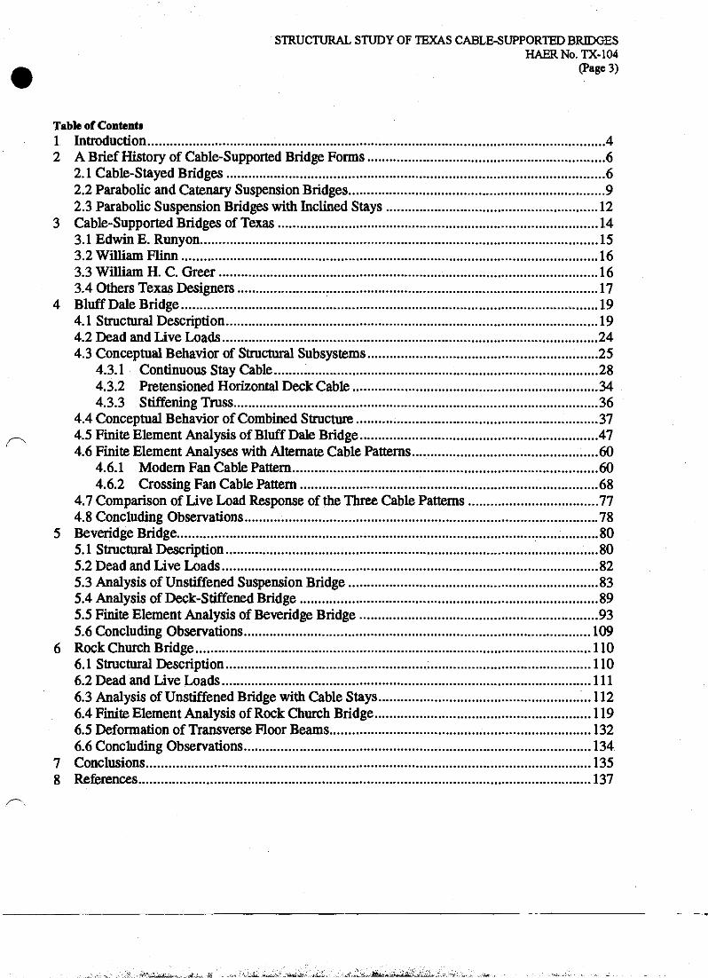
(Page 3)
Table of Contents 1 Introduction 4 2 A Brief History of Cable-Supported Bridge Forms 6
2.1 Cable-Stayed Bridges 6 2.2 Parabolic and Catenary Suspension Bridges 9 2.3 Parabolic Suspension Bridges with Inclined Stays 12
3 Cable-Supported Bridges of Texas 14 3.1 Edwin E. Runyon 15 3.2 William Flinn 16 3.3 William H. C Greer 16 3.4 Others Texas Designers 17
4 Bluff Dale Bridge 19 4.1 Structural Description 19 4.2 Dead and Live Loads 24 4.3 Conceptual Behavior of Structural Subsystems 25
4.3.1 Continuous Stay Cable 28 4.3.2 Pretensioned Horizontal Deck Cable 34 4.3.3 Stiffening Truss 36
4.4 Conceptual Behavior of Combined Structure 37 4.5 Finite Element Analysis of Bluff Dale Bridge 47 4.6 Finite Element Analyses with Alternate Cable Patterns 60
4.6.1 Modern Fan Cable Pattern 60 4.6.2 Crossing Fan Cable Pattern 68
4.7 Comparison of Live Load Response of the Three Cable Patterns 77 4.8 Concluding Observations 78
5 Beveridge Bridge 80 5.1 Structural Description 80 5.2 Dead and Live Loads 82 5.3 Analysis of Unstiffened Suspension Bridge 83 5.4 Analysis of Deck-Stiffened Bridge 89 5.5 Finite Element Analysis of Beveridge Bridge 93 5.6 Concluding Observations 109
6 Rock Church Bridge 110 6.1 Structural Description 110 6.2 Dead and Live Loads Ill 6.3 Analysis of Unstiffened Bridge with Cable Stays ...112 6.4 Finite Element Analysis of Rock Church Bridge 119 6.5 Deformation of Transverse Floor Beams 132 6.6 Concluding Observations 134
7 Conclusions 135 8 References 137
;WJH. >iL-i^-^_., l*a:'ja;-:' .^iiu^L-.

STRUCTURAL STUDY OF TEXAS CABLE-SUPPORTED BRIDGES HAERNo.TX-104
(Page 4)
1 INTRODUCTION Cable-supported bridges are simple structural forms in which the physical arrangement of
the tension elements are often a direct visual map of the flow of forces in the structure. Because of their simplicity and efficient use of materials, cable-supported bridges are today built with the most advanced engineering and construction methods available, and are often used for long spans. Yet at an earlier period in their development, the simplicity of cable-supported bridges allowed bridge builders to experiment with various forms and cable arrangements based largely on practical experience and local tradition. In the latter half of the twentieth century modern engineering analysis and structural design has contributed to the homogeneity of cable-supported bridge forms and the disappearance of the varied, vernacular bridge forms prevalent during the nineteenth and early twentieth century.
Recent historical research has identified a rich tradition of vernacular cable-supported bridge forms built in Texas between the years of about 1870 and 1940. These cable-supported bridges provide a unique opportunity to study local engineering traditions and innovations in vernacular cable-supported bridge forms, many of which were developed outside the influence of the more prominent trends in bridge design. Nevertheless these vernacular bridges can be equally innovative and historically significant. This study will examine three cable-supported bridge forms used in Texas and will focus on one specific bridge of each type:
(1) Cable-stayed bridge—Bluff Dale Bridge (1890)
(2) Parabolic cable suspension bridge—Beveridge Bridge (1896)
(3) Parabolic cable bridge with inclined stays—Rock Church Bridge (circa 1917)
The three bridge types are illustrated in Figure 1.1. These bridge forms and bridges will be examined in the context of the history and
engineering development of similar bridges in the United States and worldwide. Each of the bridge forms, and certain relevant structural variations, will be studied with modern engineering analyses to assess their overall behavior and to evaluate the effects of unique structural features. Simplified, non-dimensional analytical models will be used to reveal the fundamental behavior of each structural system and the properties that have major influences on their behavior. Each of the bridge forms will also be analyzed using the finite element method, which models the bridge component-by-component to reproduce its structural behavior.
-* 'V^Ub^nififLl&H .**£&*. rfL^._ At -Vb^dB -JOAUUU- 4*>4l&&i* HiL^ „ ^tf^*i>-'tft.^rf«i^J>MBr/iflMli -Iflrnij...

STRUCTURAL STUDY OF TEXAS CABLE-SUPPORTED BRIDGES HAERNo.TX-104
(Page 5)
(a) Cable-Stayed—Bluff Dale Bridge (1890)
(b) Parabolic Cable—Beveridge Bridge (1896)
(c) Parabolic Cable with Stays—Rock Church Bridge (circa 1917)
Figure 1.1. Three Cable-Supported Bridge Forms
WJnt jsuum, i»a«y*uj,j^Ji » iT J M i I'jrtiii jf.*-.. itg. ■**— ...- _ fc j_ t _ „#

STRUCTURAL STUDY OF TEXAS CABLE-SUPPORTED BRIDGES HAERNo.TX-104
(Page 6)
2 A BRIEF HISTORY OF CABLE-SUPPORTED BRIDGE FORMS
The development of cable-supported bridges from primitive structures made of natural materials to engineered structures of iron and steel occurred primarily during the nineteenth century. During this time a wide variety of cable-supported forms were proposed and built; their history and development are closely intertwined. The parabolic suspension bridge was certainly the most common cable-supported bridge type, and to provide additional stiffness to parabolic bridges some designers included stiffening trusses, inclined stays, or both. The pure cable-stayed bridge did not become a common form until after 1950, but since that time has emerged as one of the most popular bridge forms.
To clearly distinguish the three cable-supported bridge forms discussed in this report, and to parallel the three individual bridges studied in later sections, the history of each of the three bridge forms is discussed in a separate section below. This historical division is largely arbitrary and the development of all cable-supported bridge forms will be seen to be closely intertwined.
2.1 Cable-Stayed Bridges The cable-stayed bridge is among the oldest bridge forms with examples from several non-
Western, ancient cultures surviving through descriptions and drawings. Some authors have suggested that the concept originated from the rigging of booms on ancient sailing ships. The 1617 drawing from Machinae Novae by Faustus Verantius, perhaps based on French military bridges, is an oft-cited early example of the cable-stayed concept, although its direct influence on later cable-stayed bridges in Europe remains largely undocumented. The form of the modern cable-stayed bridge has been traced to bridges built primarily in Germany, the British Isles, and France, beginning in the late eighteenth and early nineteenth centuries. In 1784, the German carpenter C. T. Ldscher built a 105' span in Fribourg with diagonal stays of timber, beginning the German tradition of the cable-stayed form. Another early German stayed bridge was built in 1824 over the River Saale with a span of 256', but it collapsed in 1825 under the load of a crowd of people.1
Ted Ruddock's recent study of early cable-supported bridges in Scotland and Ireland identifies twelve bridges built between 1816 and 1834, at least eight of which were pure cable- stayed forms. The earliest of these is the Galashiels Wire Bridge of 1816, a 11 l'-Iong footbridge with a "crossing fan" cable pattern built by a woolen cloth manufacturer, Richard Lees. This bridge was inspired by written accounts of the wire-cable suspension structure by White and Hazard over the Falls of the Schuylkill in Philadelphia in 1816.2 Other early stayed bridges in
*M. S. Troitsky, Cable-Stayed Bridges, 2nd ed. (New York: Van Nostrand Rcinhold Co., 1988), 2, 5, 9; H. J. Hopkins, A Span of Bridges (New York: Praeger Publishers, 1970), 176; Walter Podolny, Jr. and John B. Scalzi. Construction and Design of Cable-Supported Bridges (New York: John Wiley & Sons, 1976), 5, Rene" Walther, Bernard Houriet, Walmar Isler, Pierre Moi'a, and Jean-Francois Klein. Cable-Stayed bridges, 2nd ed. (London: Thomas Telford, 1999), 7-8.
The Schuylkill Bridge would be considered a parabolic cable bridge, while the Galashiels is purely a stayed form. The unusual cable pattern of the Galashiels Bridge is similar to the "crossing fan" pattern used in some of the early Runyon-Flinn Bridges; see Section 4.1.
•^.idL,a3L^2x% . . - rt^'.tj,. &.' . _- -i:<- . V».-ife. .>:1**^t. .■tfffi*!'^"-- Jii—L- . , „'"k$£l*± ^Je&Ljj*J&**JiM^^*.^±-j

STRUCTURAL STUDY OF TEXAS CABLE-SUPPORTED BRIDGES HAERNo.TX-104
(Page 7)
Scotland include the King's Meadow Bridge of 1817, a 110' span supported by wire stays, and the first Dryburgh Abbey Bridge of 1817, a 260* span using chains constructed from 12' long wrought iron bars. The Dryburgh Abbey Bridge was severely damaged in a storm in 1818 and later rebuilt using a parabolic chain, possibly supplemented with chain stays.3 Other early cable- stayed bridges in England include the 1837 Twerton Bridge (120' main span) built by Thomas Motley, combining a harp cable arrangement with vertical suspenders. The 106* span of the Manchester Ship Canal Bridge is essentially identical in form to the modern fan pattern cable- stayed bridge. Variations on the cable-stayed form include proposals by Hatley in 1840 for a harp cable arrangement and by Clive in 1843 for a multiple fan cable pattern, although no bridges built on these systems have been documented 4
In 1821, the French architect Poyet proposed a fan pattern cable-stayed bridge with high towers, although no bridges are known to have been built on his model.5 The eminent French engineer Claude L. M. H. Navier in 1823 published YnsRapport... et memoire sur lesponts suspendus, which included descriptions of existing bridges in Europe and the United States and theoretical analysis of cable-supported forms. Navier's work focuses primarily on suspension bridges with parabolic or catenary chains and cables, but does include some approximate analytical work on cable-stayed forms. Navier concluded that the catenary or parabolic suspension bridge is preferable to the cable-stayed since the flexibility of the suspension bridge allows it to change shape with applied live loads.6 Navier's work had wide influence on bridge designers in both Europe and the United States and his conclusions regarding the cable-stayed form may have influenced the limited use of the cable-stayed bridge form during the second half of the nineteenth century. Not until the turn of the nineteenth century did the cable-stayed form re-emerge in France. In 1899, Gisclard proposed a stayed bridge with shallow inclined cables near the deck to receive the horizontal force from the sloping stayed cables, and in 1907 the 512' span of the Cassagne Bridge was built using this concept. In 1903, Arnodin, the designer of several hybrid parabolic stayed bridges, also built a fan pattern stayed bridge in Nantes. In 1925, Leinekugel le Coq designed a 367' span, fan pattern stayed bridge in which the horizontal
3 Ted Ruddock, "Blacksmith Bridges in Scotland and Ireland, 1816-1834," in Proceedings of an International Conference on Historic Bridges to Celebrate the 150th Anniversary of the Wheeling Suspension Bridge (Morgantown, West Virginia: West Virginia University Press, 1999), 135-138. The commonly reproduced image of the second Dryburgh Abbey Bridge with a parabolic chain and two inclined stays is based on an etching from Navier (1823). This image has also mistakenly been used to represent the first Dryburgh Abbey Bridge, which was purely a stayed form.
4 Thomas Motley, "On a Suspension Bridge Over the Avon, Twerton," The Civil Engineer and Architect's Journal 1 (1838): 350; Troitsky,. 9, date of bridge not cited.
3 Troitsky, 6-7.
6 Navier (1823), Art. 147 ff. Navier's conclusion in favor of the parabolic form is based primarily on qualitative observations of the performance of the early stayed and parabolic bridges, mostly those in England. Navier completes a quantitative comparison of the two systems based on the quantity of materials, or cost, but concludes the two systems are essentially equal.
■'--•>fiii*iji»-;i-.,j> M~i-i.r,Si! "..,-. .<ii,.. vi^^i^:^.:ifea^^C*i,2, , -. .i.-'^uils^'^Siki^d^Mii^^ii-fA
STRUCTURAL STUDY OF TEXAS CABLE-SUPPORTED BRIDGES HAERNo.TX-104
(Page 8)
component of the stay cable force was reacted as compression in the bridge deck, in a manner similar to most modern stayed bridges.7
In 1926, Torroja, the Spanish master of reinforced concrete, built the Tempul Aqueduct, a 200' main span with a single stay from each tower. The stay cables of this bridge were pretensioned by vertically jacking the saddles at the tops of the towers.8 This bridge is the first known example of the application of both high tensile strength steel cables and pretensioning, two critical innovations that have allowed cable-stayed bridges to be used for modern long spans. In 1938, the German engineer Dischinger designed a catenary suspension bridge with inclined stays and a main span of 1345' for railway traffic near Hamburg over the Elbe River. Although Dischinger's proposals were for combined catenary-stayed systems, his work is generally cited as the beginning of the modern era of the cable-stayed bridge. Dischinger published an important series of articles in the German technical periodical Bauingenieur that demonstrated the ability of high strength steel cable stays subjected to a significant level of pretension to provide both static and dynamic stiffness. Following World War II, Dischinger designed the Stromsund Bridge in Sweden, completed in 1955 with a main span of 600*. At the same time many cable- stayed bridges, both vehicular and pedestrian, were being designed and built as part of the war reconstruction in Germany; the most notable of these being the group of three bridges over the Rhine in Diisseldorf, planned in 1952 and completed in 1958,1969 and 1973. A cable-stayed bridge has a high degree of static indeterminacy, and therefore requires the solution of a large system of simultaneous equations for a complete and detailed analysis of a its behavior. Conceptually, the formulation of such equations was possible, but a method of solution was simply not practical until the development of computer-based structural analysis in the 1950s. The history of the development of the modern cable-stayed forms beyond the 1950s has been well documented by other authors.9
Beyond the well-known development of the modern cable-stayed form as summarized above, local traditions of cable-stayed bridge construction have been identified in many areas of the world. A discussion of a 1972 paper on the development of cable-stayed bridges included photographs of mid-nineteenth century examples, one from South Africa and one from Singapore. The earliest cable-stayed bridge proposal in the United States may be the swing bridge patented by King in 1864. In Texas, a rich tradition of cable-supported bridges, including early stayed forms from the years 1870 to 1940 has been recently identified. These bridges will be discussed in more detail in Section 3 and the remainder of this report. Other unique stayed bridges in the United States include an unnamed swing span in Louisiana (circa 1929), and the
7 Walther etal., 9-10; Troitsky, 14-17.
8 Eduardo Torroja, The Structures of Eduardo Torroja (New York: F.W. Dodge, 1958), 48-51; Walther et al„ 10.
'Troitsky, 17-19; Walther etal., 10-12; Fritz Leovfowdt, Brticken Bridges (Cambridge, Mass.: MTT Press, 1984), 257ff.; Niels J. Gimsing, Cable-Supported Bridges, 2nd ed. (New York: John Wiley & Sons, 1997); Podolny and Scalzi.
4 •-,&.■*£.«tf t... n a»k..-.a» . j,^ <S^2J~JS*Z&1I jbm&t^r&JZ^ .-arfJia. J»faJ..nJai.S?.-g—. .,,,.

STRUCTURAL STUDY OF TEXAS CABLE-SUPPORTED BRIDGES HAERNo.TX-104
(Page 9)
South Myrtle Creek Bridge, Coos River Bridge and Quinault River Bridge (circa 1953), all in the state of Washington.10
In some cases these vernacular examples may have been influenced by the more well- known bridges. Nevertheless, the choice of the cable-stayed form by vernacular bridge designers shows that they were consciously responding to design and engineering challenges with innovative and efficient solutions, in similar ways to their more prominent counterparts working in the rich climate of technological inquiry of nineteenth century Europe. Such vernacular cable- stayed bridges continue to be rediscovered worldwide as interest in the form is spurred by the current trends in long span bridges. Certainly it is reasonable to expect that, with diligent historical research, there are many more vernacular, pioneering cable-stayed bridges to be brought to light, especially in such countries as France, England and Germany where the more well-known bridges once stood as examples of the possibilities of the cable-stayed form.
2.2 Parabolic and Catenary Suspension Bridges Like the cable-stayed form, the parabolic or catenary suspension bridge has its roots in
ancient bridges constructed in many areas of the world. Faustus Verantius illustrated a military bridge with a catenary and vertical suspenders of rope in his \6\1 Machinae Novae. The Western tradition of the parabolic or catenary bridge form can be traced to bridges built in England and the United States during the early nineteenth century. The American pioneer James Finley combined a stiff wooden truss railing with suspension chains of iron bars in his bridge over Jacob's Creek in Pennsylvania circa 1801, the earliest example of the deck stiffened form.11 In 1816, White and Hazard were the first to use iron wires, rather than chains, for a suspension foot bridge with a span of 407' at Schuylkill Falls. This bridge had no continuous stiffening truss but instead a small kingpost truss of about 150' centered on the span and four guy wires attached directly to the deck and anchored at various points on shore.
In England, the suspension bridges of the early nineteenth century were characterized by the use of catenary suspension chains or cables, unstiffened decks, and in some cases supplementary diagonal stays. Recent research on the early development of the suspension bridge in Britain has revealed an 1814 proposal by Telford for a wire cable suspension bridge at Runcom, including construction and testing of a scale model. The Dryburgh Abbey Bridge was reconstructed in 1818 with a parabolic chain and perhaps diagonal stays. Other notable
10 Thomas C. Kavanagh, "Historical Development of Cable-Stayed Bridges," Journal of the Structural Division 99, No. ST7 (1973): 1669-72; U.S. Patent No. 45,051, November 15,1864; Podolny and Scalzi, 21-23; Historic American Engineering Record (HAER), National Park Service, U.S. Department of the Interior, "Chow Chow Suspension Bridge" (Quinault River Bridge) HAER No. WA-5.
11 Hopkins, 177 ff; Some uncertainty exists to the actual date of Finley's first bridge. For a more complete historical study of Finley, see Eda Kranakis, Constructing a Bridge:An Exploration of Engineering Culture, Design, and Research in Nineteenth-century France and America (Cambridge, Mass.: MTT Press, 1997).
12 Charles Peterson, "TTie Spider Bridge, a Curious Work at the Falls of the Schuylkill," Canal History and Technology Proceedings 5 (22 Mar. 1986): 243-59.
Z..i&L£jv...±". tt&l*.,.-•&!.. ;_ .^[.. KLJA*. i-u^i^J:, .'■w»h^;- -IULA^-. . - ■-•'^'-- ^iV.?Tfife^*-^JJ?2L:^^>-.>*. ;.;...,'---,$. -"OVl
STRUCTURAL STUDY OF TEXAS CABLE-SUPPORTED BRIDGES HAERNo.TX-104
(Page 10)
unstiffened bridges are Samuel Brown's Union Bridge of 1820 with a 449* unstiffened main span and Thomas Telford's Menai Straits Bridge of 1826 with a 580' main span.13
The French engineer Navier studied the early English bridges and published the first mathematical analysis of the unstiffened suspension bridge under the action of both dead and live loads. His analyses demonstrated that vertical deflections can be reduced with a large dead load and a shallow cable sag.14 Navier's design for the Pont d'Invalides in Paris reflects his findings with a shallow cable sag of only 33' over the span of 558' (a ratio of 1:17) and a heavy deck structure with no longitudinal stiffening truss.
In the years following Navier's work, several early unstiffened suspension bridges experienced excessive vertical deflection and undulation, often associated with wind storms.15
Samuel Brown's Brighton Chain Pier was damaged by wind in 1833 and again in 1836. The Menai Straits Bridge suffered damage in windstorms in 1826,1836 and 1839 resulting in various repairs and the eventual addition of a stiffening truss. In reconstructing the Montrose Bridge, which had collapsed in 1830 while heavily loaded by a crowd, James Rendel added a lO'-deep timber stiffening truss, and he became a strong proponent of the use of deck stiffening to prevent wind-induced motion of suspension bridges. Engineers also continued to explore other solutions to provide vertical and dynamic stiffness to cable-supported bridges, such as the purely stayed form (see Section 2.1), or supplementary diagonal stays (see Section 2.3).16
During the same period, the engineering challenge of providing vertical stiffness to suspension bridges was being played out in the United States through the careers of Charles Ellet, Jr. and John A. Roebling. Ellet had been educated in part at the Ecole des Ponts et
13 Roland A. Paxton, "Early Development of the Long Span Suspension Bridge in Britain, 1810-1840," in Proceedings of an International Conference on Historic Bridges to Celebrate the 150th Anniversary of the Wheeling Suspension Bridge (Morgantown, West Virginia: West Virginia University Press, 1999), 181-82; Hopkins, 185 ff.
14 Stephen G. Buonopane and David P. Billington, "Theory and History of Suspension Bridge Design from 1823 to 1940," Journal of Structural Engineering 119 (1993): 954-77. Mathematicians previously had solved the problem of the cable under applied dead loads only. Navier was the first to include the effect of a concentrated live load.
1 Previous authors have incorrectly cited the Union Bridge as damaged by wind based on an unsubstantiated reference by Tyrrell; see Hopkins, 181. The Dryburgh Abbey Bridge is also often cited as a parabolic suspension bridge damaged by wind. However, the first Dryburgh Abbey Bridge, damaged in 1818, was purely a stayed form. Its replacement, a parabolic suspension bridge, survived for at least thirty years and no record of its destruction has survived; see Ruddock, 138.
16 Russell (1841), Hopkins (1970), 183; David P. Billington and George Deodatis, "Performance of the Menai Straits Bridge Before and After Reconstruction," in Restructuring: America and Beyond (New York: American Society of Civil Engineers, 1995), 1536-49; J. M. Rendel, "Memoir of the Montrose Suspension Bridge," The Civil Engineer and Architect's Journal 4 (Oct. 1841): 355-6, Paxton, 185-186 and addendum. For a discussion of many forms for stiffening suspension bridges, seeDario A. Gasparini, Justin M. Spivey, Stephen G. Buonopane and Thomas E. Bootbby, "Stiffening Suspension Bridges," in Proceedings of an International Conference on Historic Bridges to Celebrate the 150th Anniversary of the Wheeling Suspension Bridge (Morgantown, West Virginia: West Virginia University Press, 1999), 105-16.
• S-.LaJ^iiSLi*.... Jffiik,:-&-' . J.»... <«LJ£i.'.;-i^s2.. _■««**».•- *£-!-. ■ ^,"j^i-s</£_iS8iuffidaiii£ii'L.>ALi

STRUCTURAL STUDY OF TEXAS CABLE-SUPPORTED BRIDGES HAERNo.TX-104
(Page 11)
Chaussees in Paris from 1830 to 1832 and returned to the United States to build several unstiffened suspension bridges.17 Ellet's greatest achievement was the 1010' span of the Wheeling Suspension Bridge completed in 1849, but it too was severely damaged in a windstorm of 1854. Meanwhile, John A. Roebling advocated the use not only of a substantial stiffening truss, but also the diagonal stays that became synonymous with the Roebling name (see Section 2.3). Roebling's final two designs—the 1867 Cincinnati Suspension Bridge and the 1883 Brooklyn Bridge (modified and completed by his son Washington)—featured both a stiffened deck and the cable stay system.19
In the latter half of the nineteenth century, the first significant theoretical developments since Navier's work of 1823 began to appear in European literature. These developments would ultimately have a strong influence on the emergence of the deck-stiffened form and the disappearance of alternate stiffening methods for major, long-span suspension bridges. In 1858, William Rankine proposed an approximate theory for the deck-stiffened suspension bridge, inspired by the success of Roebling* s Niagara Bridge and the experimental work of Peter Barlow.20 However, the approximate nature of Rankine's theory resulted in large errors even for moderate spans (on the order of 200'), thereby limiting its usefulness in design at a time when the longest suspension spans were already over 1000'. In 1888, Josef Melan published the linear Elastic Theory, which properly accounted for the relative stiffness of truss and parabolic cable. Its application in practice resulted in bridges with extremely heavy stiffening trusses, such as the Williamsburg Bridge of 1903. More importantly, the existence of a mathematical theory for the deck stiffened form had the effect of discouraging the exploration of alternative stiffening systems for major bridges.21
In 1888, Melan also extended the Elastic Theory to include the effects of non-linear deformation of the cable and deck system. This improved method is known as the Deflection Theory, and it was further developed and published in its modern form in 1906. At first, the application of this theory resulted in modest increases in main span length and significant savings of material in the stiffening truss. However, American designers of the early twentieth century soon recognized that the Deflection Theory removed entirely the lower bound for required deck stiffness, ultimately reintroducing the unstiffened suspension span at a scale far beyond those built in England a century earlier. The George Washington Bridge of 1935, designed by Othmar Ammann, has a main span of 3500* and stood with very little vertical deck stiffness until 1962, when the lower deck was added. This new generation of long-span,
17 See Kemp (1999) for a discussion of Ellet's entire career as well as the "Wheeling Suspension Bridge" HAER No. WV-2.
18 Kemp (1999), pp. 23-24.
19 For further documentation see "Cincinnati Suspension Bridge," HAER No. OH-28. and for further documentation on the Brooklyn Bridge see "Brooklyn Bridge," HAER No. NY-18.
20 Rankine (1882).
21 See Buonopane and Billington (1993) for a discussion of the development of various theories of the suspension bridge and their effects on bridge design. See also Pugsley (1968) for a complete mathematical treatment of all (he theories.
^x&^-'-j&'-.Zr*-.^- -.. •-j^-i..-\'if-^ j, Zt;>i:..-..~^;i:.&L: ix^&xs, -■&aA*fer* I <£a£LL*. .-.'J^:^:^^-*^'^-^*^^.

STRUCTURAL STUDY OF TEXAS CABLE-SUPPORTED BRIDGES HAERNo.TX-104
(Page 12)
unstiffened suspension bridges was punctuated in 1940 by the dramatic wind-induced failure of the Tacoma Narrows Bridge, in a manner eerily similar to the Brighton Pier and Wheeling bridges before it. The collapse of the Tacoma Narrows Bridge resulted in a reintroduction of the stiffening truss for suspension bridges, and the development of new concepts in bridge design such as aerodynamic design of bridge decks and damping mechanisms.
2.3 Parabolic Suspension Bridges with Inclined Stays The development of the suspension bridge with inclined stays is closely intertwined with
the development of the of the pure stayed and parabolic forms discussed in Sections 2.1 and 2.2. The second Dryburgh Abbey Bridge (1818) is perhaps the earliest bridge to combine a parabolic cable with inclined stays, which have one end attached to the top of a bridge tower and the other to the bridge deck.22 Samuel Brown also considered inclined stays for his Trinity Pier but they were never included in the built structure.23 Navier described the second Dryburgh Bridge and the Trinity Pier, but provided no analytical discussion of this combined form as he did for the unstiffened suspension bridge and cable-stayed forms. Navier's recommendation of the unstiffened suspension bridge may have contributed to the less frequent use of the stayed- parabolic form during the first half of the nineteenth century in Europe and the United States.
As for the pure cable-stayed system, the stayed-parabolic system can have a high degree of static indeterminacy, and therefore, formulation of an analytical system of equations to describe the behavior of a stayed-parabolic bridge, as well as the solution of those equations, was not feasible for engineers in the nineteenth century. Even if an efficient combination of parabolic and stay cables could have been theorized and designed, adjusting the lengths of the diagonal stays and vertical suspenders to distribute loads between the two systems would have required advanced construction techniques—this remains a challenge even today.
In the United States, John A. Roebling reintroduced the use of cable stays combined with a parabolic cable in the Monongahela Bridge of 1847 (8 spans of 188' each). The inclined stays reduced the deformations due to unbalanced live loadings. Roebling used inclined stays on all of his other road and rail bridges, and this combined system became the signature of his bridges.24
The success of Roebling's bridges and the popular interest in major suspension bridges, such as the Brooklyn Bridge, contributed to the emergence of the suspension bridge during the second half of the nineteenth century for spans of moderate length. Some local designers even adopted Roebling's use of inclined stays. For example, John W. Shipman built several stayed-parabolic bridges in the Ohio Valley between 1852 and 1876 with spans of 300' to 560', including the Harrison Bridge (1873) and the Franklin Bridge (1873). The design specifications for the
22 Ruddock (1999), pp. 137-138. It is not known if the inclined stays were constructed although they are shown on some contemporary drawings.
23Navicr(1823),pp.44ff.
Roebling did not include inclined stays on his canal aqueducts as the total load remains nearly constant. Canal boats displace their own weight in water so do not add any additional load. The live loads due to draft animals and pedestrians on the towpaths would have been negligible compared to the total load of the structure and water contained within. Similarly, wind loads would have been negligible compared to the total weight of the structure.
S»y..-a „,.. jriM.,..,*!. ...... I^-Ao..i-ii^i«L._»*l««6E -*-" -at1--"- " ■ -^fa-J.-J^SJ.X."..

STRUCTURAL STUDY OF TEXAS CABLE-SUPPORTED BRIDGES HAERNo.TX-104
(Page 13)
Harrison Bridge were written by John A. Roebling's Sons before the contract was awarded to Shipman, and these specifications most likely required the use of inclined stays.23 An 1877 advertisement for the New York Bridge Company, of which Shipman was a partner, included an image of a stayed-parabolic suspension bridge referred to as "the celebrated 'Roebling' Steel Wire Cable Suspension Bridge."26 And in 1878, Shipman's New York Bridge Company completed the stayed-parabolic Red Bridge over the Connecticut River at Turner's Falls, Massachusetts.27 The stayed-parabolic form was also selected by Thomas Griffith for the Waco Bridge in Texas (see Section 3) and the form was imitated by other local builders such as at the Rock Church Bridge (see Section 5).
In Europe, the combination of the parabolic and stayed forms appears to have been used less frequently than in the United States, although some unique stayed-parabolic bridges were proposed and built. Charles Ordish proposed a combined system of a catenary chain and inclined stays as early as 1857.28 In 1868, Ordish and LeFeuvre built the Franz Joseph Bridge in Prague with a parabolic cable and a complex arrangement of stays over the 3 3 0' main span. In 1872, Ordish's Albert Bridge was completed with a 400' span using heavy stays made of solid bars and a very light catenary cable. In France, Arnodin proposed a stayed-parabolic system with inclined stays supporting the area of the deck from the tower to approximately the quarter-point, while the center of the span was supported from vertical suspenders on a parabolic cable. Three bridges designed by Amodin use this system—the 397' span of the Saone River Bridge in Lyons (1888), the Rhone River Bridge in Avignon (1888) and the 778' span of the Bonhomme Bridge in Marbihan (1904). Arnodin's system is essentially identical in appearance to that proposed some fifty years later by Dischinger in 1938. Dischinger's work, however, revealed the advantage of using high strength steel cables with high levels of pretension.
75 Simmons (1999), pp. 82-83.
26 Darnell (1984), p. 42.
71H. Hobart Holly Collection, "Old Red Bridge." Hie exact nature of the relationship between Shipman and the Roebling Company is not well documented and is worthy of future study. In addition to the New York Bridge Co. advertisement that specifically uses the Roebling name, we also know that the Roebling Company supplied the wire rope for both the Franklin Bridge and the Red Bridge. In the case of the Red Bridge, the Roebling Company is explicitly named in the contract as the supplier of wire rope for that bridge.
28 Ordish (1862); Troitsky (1988), pp. 10-11; Walther et al. (1999), pp. 8-9.
frjI.Tnifltimw,^ *£3*, ^,„_j^, Wjfc, *B^mi UBMSl «LL ~ at-J. A- "fc**'-~»ii«lJ3ig''% t „i
STRUCTURAL STUDY OF TEXAS CABLE-SUPPORTED BRIDGES HAERNo.TX-104
(Page 14)
3 CABLE-SUPPORTED BRIDGES OF TEXAS
The previous sections have discussed major trends and developments of the three cable- supported bridge forms in the United States and worldwide. The structural simplicity of cable- supported bridges also resulted in numerous local or vernacular cable-supported bridges built throughout the nineteenth and early twentieth centuries. Jakkula's comprehensive "History of Suspension Bridges..." lists only three suspension bridges in Texas: the Waco Bridge (1869,475' deck-stiffened main span with inclined stays), the Rio Grande Bridge at Hidalgo (1926,450' unstiffened main span) and a pipeline bridge over the Frio River in San Antonio (1934). However, recent research has revealed a rich tradition of vernacular cable-supported bridges in Texas built between approximately the years of 1870 and 1940.29
The earliest documented cable-supported bridge in Texas is the Waco Bridge, completed in 1869 and spanning 475' over the Brazos River.30 The Waco Bridge was designed by Thomas Griffith and used the "Roebling system" of parabolic cables, stiffening trusses and inclined stays. In addition, some of the materials of the bridge were purchased from Roebling Company.31 The career of Thomas Griffith is not well documented, although he is known to have designed at least two other suspension bridges—the 620' Minneapolis Bridge in 1855 and its 675' replacement in 1877.32 Griffith also holds U.S. Patent No. 285,257 (1883) for a suspension bridge made of moderately sized components in order to be readily transportable and easily constructed.33
The construction of the Waco Bridge occurred at a time when much national attention was focused on the construction of the Roebling's Cincinnati and Brooklyn Bridges, which may have influenced the selection of a suspension bridge for the span at Waco. The plans and construction of the Brooklyn Bridge were widely published by the engineering journals from the award of the contract to John Roebling in 1866 until its completion in 1883. The success of the Waco Bridge perhaps contributed to the further use of suspension bridges in Texas, as well as the exploration of other cable-supported forms. Many of the early cable-supported bridges in Texas were constructed from wire and pipe sections, which have the advantage of being easily transported over ground from distant ports or railways. This ease of transport also likely contributed to the choice of cable-supported bridges over truss forms which typically require more prefabrication and transport of larger, heavier components.34 The local development of cable-supported bridge
29 "Bluff Dale Suspension Bridge," HAER No. TX-36, Appendices B,C and D.
30 "Waco Suspension Bridge," HAER No. TX-13; Jakkula (1941) p. 187. The Waco Bridge has since been reconstructed in 1913-14 and 1976 removing some of the original features.
31 "Bluff Dale Suspension Bridge," HAER No. TX-36, p. 5; Walker (1999). Some sources have suggested that Griffith was once an engineer with the Roebling company, although no primary-source evidence is known which supports this claim.
32 "Waco Suspension Bridge," HAER No. TX-13; Jakkula (1941), pp. 155,193.
33 Jakkula (1941), p. 454.
."}*-.-k^aMh^l*.* --■* t&A. ->
STRUCTURAL STUDY OF TEXAS CABLE-SUPPORTED BRIDGES HAERNo.TX-104
(Page 15)
forms in Texas centers around three builders and designers active in the years 1888 to 1915: Runyon, Flinn and Greer.
3.1 Edwin E. Runyon In 1888 Edwin Elijah Runyon of Mountain Spring, Texas, patented a true cable-stayed
bridge form.35 Surviving photographs indicate that at least three bridges were built based on this patent system, of which two survive in part: the Barton Creek Bridge (1890) and the Bluff Dale Bridge (1891).36 These bridges are the earliest documented cable-stayed bridges in the United States and represent a significant development of the cable-stayed form in Texas and the United States. Little is known about Runyon's engineering or technical background or the influences that led him to propose and build cable-stayed bridges. Nevertheless, his designs show an understanding of structural behavior, perhaps largely gained through experience. The engineering studies presented in Section 4 will describe the engineering behavior of these unique bridges and compare it to modern cable-stayed forms.
Runyon had five other patents related to bridge construction. In 1889, U.S. Patent No. 400,874 was issued for a "needle beam," or transverse floor beam, composed of a horizontal pipe chord and a curved lower bowstring of twisted iron wire. This type of beam survives at the Barton Creek and Bluff Dale Bridges. U.S. Patent No. 404,934 was issued in 1889 for a device capable of twisting parallel wire strands in place through the use of a rectangular casting placed between the strands. The twisting of wires removed any slack in the cables and provided some degree of pretensioning, which, as discussed in later sections of this report, is extremely important to the proper functioning of cable-stayed bridge systems. After twisting the cable, the casting was braced against some part of the bridge with an iron rod to prevent unraveling of the cable. The rectangular fittings survive on the needle beams at the Bluff Dale Bridge and, based on photographic evidence, were also used on the main stay cables of the other Runyon bridges. U.S. Patent No. 410,201 was issued in 1889 for a suspension bridge bent built from pipe sections and using tensioned cables for bracing. U.S. Patent No. 446,209 was issued in 1891 for a stayed bridge system with both horizontal and inclined wire cables. U.S. Patent No. 493,788 was issued in 1893 for a trussed bridge railing built with chords and cross-bracing of wire cable tensioned around vertical posts consisting of hollow pipe sections.37
34 Brown (1998).
33 U.S. Patent No. 394,940, December 18,1888. Recent research by Mark Brown has uncovered similar, earlier work in Texas by Joseph Mitchell including a U.S. patent awarded on August 16,1888. The relationship between Mitchell and Runyon is undocumented, although both were active in Texas. In 1889 Mitchell constructed a ISO' cable-stayed bridge over the Whitewater River in Richmond, Indiana; see "Bridges over the Whitewater..." (1899).
36 "Barton Creek Suspension Bridge," HAER No. TX-87 and "Bluff Dale Suspension Bridge," HAER No. TX- 36.
37 For more information on the content of these patents see Brown (1998) and "Bluff Dale Suspension Bridge," HAERNo.TX-36.
,■-,.. - _Jk. ^-J^H^U^hA *^3£&M &-_.__ ia \^Jt^. _hi*4»M. w££V J*—. „ J& ^a & - aJfcb* -^ -&*iJtSL u^u^du -

STRUCTURAL STUDY OF TEXAS CABLE-SUPPORTED BRIDGES HAERNo.TX-104
(Page 16)
3.2 William Flinn
William Flinn of Weatherford, Texas, was a partner in the Runyon Bridge Company and later in the Flinn-Moyer Bridge Company. Between 1890 and 1903, Flinn was involved in the design or construction of at least nineteen bridges of various types, including several cable- supported bridges. In 1899 the Flinn-Moyer Company installed the pipe truss which survives today on the Bluff Dale Bridge.38 In 1896 the Flinn-Moyer Bridge Company built two suspension bridges, both of 140' main span: the Beveridge Bridge over the San Saba River, and the Clear Fork of the Brazos River Bridge.39 These bridges were parabolic cable suspension bridges, deck-stiffened with longitudinal Howe trusses built from hollow pipe sections. Their structural behavior is investigated in Section 5.
Flinn also adapted the form of the Runyon needle beams as a part of the main longitudinal member on a truss bridge. This bridge type uses a longitudinal pipe truss with a bowstring chord of iron or steel wires beneath the deck level, and represents another innovative application of wire cable in bridge structures.40 Flinn's final two bridges, contracted for in 1898, were suspension bridges over the Brazos River in Palo Pinto County. The Brazos Station Bridge had a main span of 300' and the Dark Valley Bridge had two main spans of 250' each, and both included stiffening trusses built from pipe sections.41
3.3 William H.C.Greer During the years 1889 to 1916, William Greer received four patents related to suspension
bridges and built at least seventeen bridges based on some of these patents, operating under the names of the Greer Bridge Company and Western Bridge Company.42 Greer* s first patent (No. 411,499) is for an unstiffened suspension bridge with a parabolic cable, which seems to have no particularly unique or original features, although Greer claimed adjustability of the roadway and a minimum number of parts to reduce materials and labor. Greer's 1910 patent (No. 968,552) added a wooden stiffening truss to the parabolic cable bridge, again not an apparently unique idea in 1910.
The remaining two patents are substantially more interesting. The 1894 patent (No. 513,389) shows a parabolic cable suspension bridge that is stiffened by a zig-zag pattern of diagonal braces between the deck and the parabolic cable. The braces are constructed from solid iron rods and include turnbuckles for tensioning. Greer specifically stated that this system was intended to reduce vertical motions of the main span. Historically, this method of bracing or
38*'Bluff Dale Suspension Bridge," HAER No. TX-36.
39"Beveridge Bridge," HAER No. TX-46; "Decatur Street Bridge " HAER No. TX-64.
40 "Decatur Street Bridge," HAER No. TX-64. This type of bridge is known from a model which survives. The remains of one such bridge have been recently identified but the bridge no longer survives.
41 Palo Pinto County court records (1898,1904).
42 "Choctaw Creek Suspension Bridge," HAER No. TX-85.
..-'/■-- T.V v ".^£- \- ^■Hti^afi^a.^^' i*fty^.,'",2&;--.L ^I:J.V -^i.-ita.">ir*i&2:.._-^«p^-' --i&^J. ■ -'^'s*. ^^ai^^fai^a]^^ >&•.-. J..--_.\
STRUCTURAL STUDY OF TEXAS CABLE-SUPPORTED BRIDGES HAERNo.TX-104
(Page 17)
trussing for stiffening suspension bridges has been infrequently used, although an example from 1828 was identified in Italy.43
The 1912 patent (No. 1,019,458) shows a parabolic bridge cable with two inclined stays extending from the top of the tower to the deck level, and a kingpost truss added at the center of the span. Again Greer cited a reduction in vertical motion as the reason for these features. Although inclined stays had been used elsewhere at this time, Greer used solid iron bars rather than cables for the stays. As will be discussed in Section 6, cable stays must be pretensioned to be effective, whereas solid bars would function with no pretension since they can carry both tension and compression with equal stiffness. The effectiveness of the solid stays to resist compressive forces would be limited by buckling, a function of the unsupported length. Greer clearly showed the stays attached to some of the vertical suspenders, which would aid in preventing such buckling. The kingpost element was constructed of an iron pipe post at mid-span and an iron rod top chord that attached to the deck at two points near the towers and passed over the top of the post. The iron rod was to be pretensioned with a turnbuckle. The kingpost system functioned by supporting concentrated loads near the mid-span and transferring that load to points in the deck near to the inclined stays. By supporting a concentrated load near mid-span, the kingpost system would reduce the deflection in the center of the bridge.44
Details of four Greer bridges from 1915 are documented in the Montague County court documents: the Farmers Creek Bridge (100* main span), the Brushy Creek Bridge (60' main span), the Salt Creek Bridge (70* main span), and the Denton Creek Bridge (60* span)43 All of these parabolic cable suspension bridges have their vertical suspenders spaced only 2' apart, although such spacing was never stated explicitly in his patents. With the lack of a continuous longitudinal stiffening truss, this close spacing would help to reduce the required size of longitudinal stringers. A photograph of the Denton Creek Bridge shows the unusual feature of two inclined braces that run from the base of each tower at the deck level to the parabolic cable at approximately the third-point of the main span. A surviving photograph of the Cherry Street Bridge in Sherman Texas shows the kingpost system. The only known surviving example of a Greer bridge is the Choctaw Creek Bridge of circa 1915 with an unstiffened main span of 120'.
3.4 Others Texas Designers The firm of Mitchell and Pigg also constructed several parabolic cable suspension bridges
in Texas. In 1906 the Brannon Crossing Bridge (440* main span) and the Hightower (Tin Top) Bridge (400* main span) were completed over the Brazos River in Parker County. Both bridges were parabolic cable bridges with 6'-deep stiffening trusses built from pipe sections, very similar to those used by Flinn-Moyer. The Tin Top bridge survived until 1982, when it was destroyed in a storm. Mitchell and Pigg also built the Belknap Bridge (700' main span) and the South Bend
43 Gasparini ct al. (1999), p. 110.
44 One such kingpost bridge survived until the 1940s in Grayson County. See "Choctaw Creek Bridge," HAER O No. TX-85.
45 "Choctaw Creek Bridge," HAER No. TX-85.
.- 3il'li2£jij£.Z3*.... jtS^iV&i'.',■' .tii, ' J».'li;ij«l'i»i.,f-iiasift*, laL^,.. . .'. .-i&^.'^.iSfci^s^.iJi^Wi-Aij

STRUCTURAL STUDY OF TEXAS CABLE-SUPPORTED BRIDGES HAERNo.TX-104
(Page 18)
Bridge (400' main span) over the Brazos River in Young County. These bridges were also parabolic cable suspension bridges with longitudinal stiffening trusses built from pipe sections.46
Two other major suspension bridges built in Texas are the 1928 Roma Bridge, designed by George E. Cole to span the Rio Grande with a 630' main span, and the 1939 Regency Bridge, built by the Austin Bridge Company over the Colorado River with a main span of 340'. Both bridges are unstiffened parabolic cable suspension bridges.47
46 Parker County court records (1905,1906); Young County court records (1908).
47"Regency Suspension Bridge," HAER No. TX-61.
_'■ /-- --'."■ ,: -£-,^\^\&&mtiL&&,.. c . jfiSStu-i. -3&L.L -<j< l&i^it"L.>iiLi,JM..,_-iriF£»^&r:'. **Ll-. . . ^-^.■*L'^a^lS6fi^jrfS!i*^iL;J,^t'fc^J-ii ,"*--- "■?•
STRUCTURAL STUDY OF TEXAS CABLE-SUPPORTED BRIDGES HAERNo.TX-104
(Page 19)
4 BLUFF DALE BRIDGE The Bluff Dale Bridge was originally constructed in 1890 by the Runyon Bridge Company
based on a patented bridge system of Edwin Elijah Runyon.48 Historical photographs of similar bridges suggest that the original Bluff Dale Bridge used a wooden stiffening truss built in a Warren pattern with wooden chords and diagonals, and vertical iron rods used to pretension the truss.49 In 1899 the Flinn-Moyer Bridge Company repaired the bridge and likely installed the Howe-pattern pipe truss which survives today. This and later repairs and a 1935 relocation have resulted in the present state of the structure with wire rope cables, steel I-beam stringers and metal plate floor deck.
4.1 Structural Description The structural system of the Bluff Dale Bridge can be best described as cable-stayed,
although it possesses two unique features that differentiate it from modern cable-stayed forms: continuous inclined stay cables and horizontal deck cables (see Figure 4.1). The structural analyses presented in this report will investigate the behavior of this cable-stayed structural system and assess the effectiveness of its unique features.
The Bluff Dale Bridge has a main span of 140'-0" and side spans of approximately 30'-0" each.50 The spans are supported by a series of cable stays which radiate in a fan pattern from the top of each tower and support transverse floor beams spaced 1O'-O" apart. Each side span is supported by cables at two panel points, and these cables are continuous over the tower to the first two panel points of the main span. The remaining panel points of the main span are supported by a series of continuous stay cables. As shown in Figure 4.1, each continuous stay cable runs inclined from the top of one tower to the end of a floor beam, where it changes direction around a casting and runs horizontally along the deck to the symmetric panel point. It then turns again to run inclined to the top of the opposite tower. Each backstay is composed of the wires of the five continuous stays wrapped together into a single cable. The nature of the backstay anchorage is not known, and the present cable anchorage may not be representative of the original anchorage since the bridge has been relocated.
As originally constructed, the bridge also had at least three horizontal deck cables running longitudinally at the level of the transverse floor beams and spaced across the width of the deck.31 The two outermost cables were clamped to the floor beams, while the interior cable or
^"Barton Creek Suspension Bridge," HAER No. TX-36; Brown (1998); U.S. Patent No. 394,940, December 18,1888.
^"Bluff Dale Suspension Bridge," HAER No. TX-36, photographs TX-36-12 to TX-36-14. See also "Barton Creek Suspension Bridge," HAER No. TX-87.
50"Bluff Dale Suspension Bridge," HAER No. TX-36.
51 The current configuration of the bridge has three cables, although castings are present to accommodate five such cables, as shown on "Bluff Dale Suspension Bridge," HAER No. TX-36 drawing sheet 2 of 5. The Barton Creek Bridge, which has survived with less reconstruction, has only three cables.
1_ 'WAW jgflmma

STRUCTURAL STUDY OF TEXAS CABLE-SUPPORTED BRIDGES HAERNo.TX-104
(Page 20)
cables rested in saddles atop the floor beam with no positive attachment. The original parallel wire cables have been replaced with wire rope. The nature of the anchorage of the horizontal
^^^^^^ ►^►T^^lHHv^
continuous stay cables fixed stay cables
' horizontal deck cable
(a) Cable Systems of the Bluff Dale Bridge
fixed stay cables
(b) Cable System of a Modern Stayed Bridge
Figure 4.1. Exploded Bridge Elevations Showing Cable Stay Systems of the Bluff Dale and a Modern Stayed Bridge
Aife-^'J^tfatai-iji.-. JtSbUVMtrL ,•_. ^w^^ii^."*ji^iia,.:-i*a*ufe[t^£.^i JL

STRUCTURAL STUDY OF TEXAS CABLE-SUPPORTED BRIDGES HAERNo.TX-104
(Page 21)
deck cables is not known. In the bridge's original construction they could have been anchored independently or with the main backstay.
Previous studies of the Bluff Dale Bridge have revealed an alternate stay cable pattern used on similar bridges constructed with the involvement of Runyon or Flinn. Photographs of several unidentified bridges show main span cable stays that change direction around the floor beam casting but immediately return to the opposite tower rather than running horizontally at the deck level.3 This resulting cable arrangement is a "crossing fan" pattern where the fan patterns radiating from each tower overlap one another as shown in Figure 4.2. This cable pattern is not unlike the diagonals of a Bollman truss.53 The original Runyon patent (No. 394,940) shows a bridge with only three panel points in the main span, which when extrapolated for additional panel points could reasonably result in either of the two possible cable arrangement schemes (the Bluff Dale pattern or the crossing fan pattern). With the several reconstructions of the Bluff Dale Bridge, no primary evidence survives to suggest that it was ever built with the crossing fan cable pattern. The only other surviving Runyon cable-stayed bridge, the Barton Creek Bridge, uses a cable pattern with continuous stays similar to that which survives at Bluff Dale. The structural behavior of both the fan pattern of the Bluff Dale Bridge and the crossing fan pattern, used in other Runyon bridges, will be considered in Section 4.5.
easoaS:©^
fixed stay cables
r/^'TO^>>*\^w? ©eisffla©sosso3®
horizontal deck cable
Figure 4.2. Exploded Elevation of a Bluff Dale-Type Bridge with the Crossing Fan Pattern of Cable Stays
52"Bluff Dale Suspension Bridge," HAER No. TX-36 photograph TX-36-14.
3See "Baltimore & Ohio Railroad: Bollman Truss Bridge," HAER No. MD-1 for the best surviving example of a Bollman Truss.
, ...Jat^.^.. flfTim fo.ii^ffllJrtj*-Trtrrftm^7ynir — -

STRUCTURAL STUDY OF TEXAS CABLE-SUPPORTED BRIDGES HAERNo.TX-104
(Page 22)
The surviving longitudinal stiffening truss on the Bluff Dale Bridge is continuous over the full 200,-0" span with support points at the each abutment and at each tower. The truss is constructed in a Howe pattern, built from pipe sections, castings and solid rods with threaded ends. When the bridge was first constructed, the vertical rods were pretensioned by tightening the nuts on each end, thereby producing compression in the diagonal pipe sections. After pretensioning, the joints are capable of transferring both compression and tension, and the truss acts as a unified structural element to resist shear and bending due to the applied loads acting on the bridge. It is simply not possible to determine the original level of pretension, and the analyses performed for this report will assume that the pretension was sufficient to maintain continuity at all joints. In practice, insufficient pretensioning would be evident from examination of the joints and could be rectified by re-tightening the verticals as necessary.54
Dimensions and structural properties of the bridge are summarized in Table 4.1. The original stay cables and horizontal deck cables would have been constructed from parallel wire strands. Although the stays and deck cables have been replaced with modern wire rope, the surviving cables on the transverse floor beams and the lateral bracing beneath the deck are representative of the style of cables that were used throughout the bridge. Based on typical practice at this time, the wires were most likely No. 9 gauge (nominally 0.148 inch diameter), and could have been wrought iron or an early form of steel.55 The gross diameter of the original cables is not known. For the horizontal deck cables, the castings on the floor beams cannot accommodate a cable larger than the 1" diameter wire rope presently in place. For the stay cables, the castings at the ends of the floor beams could have accommodated a larger cable diameter. For this study, the diameters of the stay and deck cables are assumed to be 1 inch, equal to the diameter of the existing wire rope. The cables were tensioned by twisting a casting placed between the wire strands, as patented by Runyon.56 This method would have removed any slack in the cables but is unlikely to have applied a significant pretension.
The true cross-sectional area, or net area, of metal in a parallel strand cable will be somewhat less than the gross area calculated from the overall cable diameter because some space will remain between individual wires. Based on a compilation of data for 35 parallel wire bridge cables from 1844 to 1936, the typical ratio of net area to gross area ranges from about 70 percent to 85 percent.57 For the Regency Bridge (1939), a ratio of 75 percent was measured during its recent rehabilitation.58 Even for modern, tightly-wrapped, parallel strand cables the typical percentage is about 80 percent to 90 percent.39 Since the main cables of the Bluff Dale Bridge
54 See Gasparini and Simmons (1997) for discussion of the technology of truss bridge connections.
55"Contextual Essay on Wire Bridges," HAER No. NJ-132.
36 U.S. Patent No. 404,934, June 11,1889.
57 Cable data are from the Blair Birdsall Collection, PTG-Steinman, Inc.
Personal communication from Charles Walker of Texas Dept. of Transportation; "Regency Suspension Bridge," HAER No. TX-61.
59Gimsing(1997),p.92.
&mM,wd&JL If 7, " fit In ii JXJ»A.*£-»>...-

STRUCTURAL STUDY OF TEXAS CABLE-SUPPORTED BRIDGES HAER No. TX-104
(Page 23)
were simply twisted about themselves and not tightly bound by a wrapping, similar to the floor beam cables that survive, a net area of 70 percent of the gross area is assumed for the analyses; the true percentage may certainly have been different.
Table 4.1. Structural Properties of the Bluff Dale Bridge
Property Value Comments and Sources Overall Dimensions and Loads Main Span 140'-0" HAER No. TX-36, sheet 1 of 5. Side Spans 3(y-0" HAER No. TX-36, sheet 1 of 5, measured values of 30'-4"
and29'-8". Dead Load 140 lb/ft See Table 42. Live Load 10001b See discussion in text. Stay Cables Sag 15'-6" HAER No. TX-36, sheet 2 of 5, estimated to include
saddle. Gross Diameter 1.00" Assumed equal to size of existing wire rope and estimated
based on size of surviving cable saddles. Net Area 0.55 in2 70 percent of gross area, based on typical ratio for parallel
wrought iron wire bridge cables. Equivalent to thirty-two No. 9 gauge (0.148" diameter) wires.
Backstay Net Area 2.75 in2 Formed from wires of five stay cables. Modulus of Elasticity 27x10" psi Typical values for wrought iron. Withey and Aston (1926). Horizontal Deck Cables Total Length 200'-0" HAER No. TX-36, sheet 1 of 5, length between abutments,
neglecting cable from abutment to anchorage. Gross Diameter 1.00" Assumed equal to size of existing wire rope and estimated
based on size of surviving cable saddles. Net Area 0.5498 in2 70 percent of gross area, based on typical ratio for parallel
wrought iron wire bridge cables. Equivalent to thirty-two No. 9 gauge (0.148" diameter) wires.
Pretension Force unknown See discussion in text. Modulus of Elasticity 27x10* psi Typical values for wrought iron. Withey and Aston (1926). Stiffening Truss Chord Area 2.062 in2 HAER No. TX-36, sheet 4 of 5, 2-7/8" OX>. pipe with 1/4"
wall. HAER No. TX-36, sheet 3 of 5, based on 5'-5" out-to-out Depth 62.125" depth.
Area 4.124 in2
Moment of Inertia 3983 in4
Modulus of Elasticity 27xl06psi Typical values for wrought iron, Withey and Aston (1926). Tower Area 12.960 in2 HAER No. TX-36, sheet 4 of 5, two 8-1/2" OX>. pipes
with 1/4" wall. Moment of Inertia 110.4 in4 In-plane. Modulus of Elasticity 27x10s psi Typical values for wrought iron. Withey and Aston (1926).
.f. ri * .r»j{rirnTif , ■. .irf**_i_L.ndfc *. l„fe*nttfck.. J£-L , =

STRUCTURAL STUDY OF TEXAS CABLE-SUPPORTED BRIDGES HAERNo.TX-104
(Page 24)
The wires of the original cables may have been wrought iron or steel and their true metal cannot be ascertained without material testing samples from the surviving wires. For this study, the cables are assumed to be wrought iron with an elastic modulus of 27xl06 psi.60 Steel wires would have had a slightly higher elastic modulus of about 29x106 psi. Since the moduli of steel and wrought iron are similar, the general conclusions drawn here from analyses based on wrought iron are still valid for steel wires, although the exact numerical results would vary somewhat.
The horizontal deck cables were probably placed and pretensioned prior to construction of the truss or deck. Runyon's patent indicates that the deck cables were to be installed prior to the main cables or deck and the current position of the cables in the bridge is consistent with this installation sequence.61 It is not possible to determine the magnitude of the pretension force achieved by twisting the cables without either testing undisturbed cables or conducting experiments on similar cable assemblies. The effect of the level of pretension in the deck cable will be examined in Section 4.4, and, in fact, will be shown to have negligible influence on the overall behavior of the bridge. For this study, where a specific level of pretension must be assumed for analysis, a tension of 10,000 lb will be assumed. For a 1" diameter cable with 70 percent net area, an axial force of 10,000 lb results in a pretension stress of about 18,000 psi.
As discussed in Section 4.1, the original stiffening truss was probably constructed of wood, and replaced by the wrought iron pipe truss during the 1899 renovation. The analyses in this report are based on the properties of the pipe truss, since its member sizes have been accurately determined, while properties of the wood truss would be largely conjectural. However, the analyses do examine the effect of varying the truss stiffness, and the wood truss could be considered simply as a truss of different stiffness. The wrought iron pipe truss is assumed to have an elastic modulus of 27x106 psi.
4.2 Dead and Live Loads Table 4.2 summarizes the dead loads for Bluff Dale Bridge. The flooring was assumed to
be constructed of timber with similar sizes to that of the Rock Church Bridge (see Section 6.1), which survives in its original form. Both the surviving cable pattern and the crossing fan pattern were considered in calculating the dead load, but were found to have a negligible difference in the total dead load.
A concentrated live load of 1000 lb was used for analysis of a two-dimensional model of one half of the bridge. The total live load (2000 lb) approximates the magnitude of single concentrated load that might have been expected when the bridge was constructed. However, the live load is intended primarily to study the distribution of live load among the various parts of the structure rather than to represent the weight of a particular vehicle. For a linear structure, the load effects (displacements and member forces) are directly proportional to the applied load, and therefore the results of analyses based on the 1000 lb live load can be linearly scaled for other
60 Withey and Aston (1926), p. 603.
61 U.S. Patent No. 394,940, December 18,1888.
■J^i * A-Ml

STRUCTURAL STUDY OF TEXAS CABLE-SUPPORTED BRIDGES HAERNo.TX-104
(Page 25)
Table 4.2. Dead Load Summary of the Bluff Dale Bridge
Description Weight Cable Stays 2 sides @ 2292 = 4584 lb
Includes all diagonal cables and backstay All cables assumed 1" gross diameter with 70 percent net area
Deck Cables 32171b Includes longitudinal and diagonal bracing cables All cables assumed 1" gross diameter with 70 percent net area
Pipe Stiffening Truss 2 sides @ 6531 = 13,062 lb Transverse Floor Beams 6220 lb Wood Flooring System 26,250 lb
Assumed seven 3"xl2" longitudinal stringers, 3" thick continuous wood flooring Subtotal 53,333 lb 5 percent allowance for connections and miscellaneous material 26671b Total 56,0001b
Weight per foot for full width of bridge 56,000 lb / 200 ft = 280 lb/ft Weight per foot for 2D model of single plane of bridge 140 lb/ft
Note: unit weight of wrought iron = 485 lb/ft3; unit weight of wood = 30 lb/ft3.
magnitudes of live load. For a structure that responds non-linearly, the load effects are not proportional to the applied load, but some of the analyses performed here will also consider the non-linear effect for other magnitudes of live load.
4.3 Conceptual Behavior of Structural Subsystems The Bluff Dale Bridge may be considered to consist of three structural subsystems:
(1) continuous stay cables,
(2) pretensioned horizontal deck cable, and
(3) longitudinal stiffening truss.
Each structural subsystem is shown in Figure 4.3 with appropriate notation for analysis. This idealization of the bridge is a two-dimensional model of one-half of the bridge. The fixed stays are not considered here because they can be accurately modeled as single, straight cable elements, the behavior of which is well understood. In addition, dead loads are only applied at only two points along the span; a more realistic distribution of the continuous dead load will be used in the finite element analysis of Section 4.5. Physical properties of each component used for analysis have been given in Table 4.1.
»k <-&.J#.*t.*.. ■- » ,se.'r j^tj.j^jteL^tsi, &I*S&IZ&JL.. - VitliTh'* ■#1n*riiliirr'?*"ariiiriii

STRUCTURAL STUDY OF TEXAS CABLE-SUPPORTED BRIDGES HAERNo.TX-104
(Page 26)
Notes: 1. Subscript of displacement u or v indicates node or joint number. 2. Numbers indicate cable segments 1 to 6
(a) Continuous Cable Stay
(b) Pretensioned Horizontal Deck Cable
«A atLt btL, ctLt dtlt
^AJt'E,
i DL = P i
u<
DL+LL =sP
(c) Longitudinal Stiffening Truss
Figure 4.3. Three Subsystems of the Bluff Dale Bridge
. * ~j»*Ai^»^«. , JC*„";„ JA •a*jJ?#ua+L **aZ&i~&*, „ Jife&JL^illiii*daiiifta.3^&ii,-,„ ■»
STRUCTURAL STUDY OF TEXAS CABLE-SUPPORTED BRIDGES HAERNo.TX-104
(Page 27)
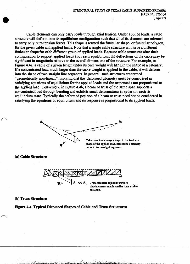
Cable elements can only cany loads through axial tension. Under applied loads, a cable structure will deform into its equilibrium configuration such that all of its elements are oriented to carry only pure tension forces. This shape is termed the funicular shape, or funicular polygon, for the given cable and applied loads. Note that a single cable structure will have a different funicular shape for each different group of applied loads. Because cable structures alter their configuration to support applied loads and reach equilibrium, the deflections of the cable may be significant in magnitude relative to the overall dimensions of the structure. For example, in Figure 4.4a, a cable of a given length under its own weight will hang in the shape of a catenary. If a concentrated load much larger than the cable weight is applied to the cable, it will deform into the shape of two straight line segments. In general, such structures are termed "geometrically non-linear," implying that the deformed geometry must be considered in satisfying equations of equilibrium for the applied loads and the response is not proportional to the applied load. Conversely, in Figure 4.4b, a beam or truss of the same span supports a concentrated load through bending and exhibits small deformations in order to reach its equilibrium state. Typically the deformed position of a beam or truss need not be considered in satisfying the equations of equilibrium and its response is proportional to its applied loads.
Cable structure changes shape to the funicular shape of the applied load, here from a catenary curve to two straight segments.
(a) Cable Structure
^ « Ac Truss structure typically exhibits displacements much smaller than a cable structure.
(b) Truss Structure
Figure 4.4. Typical Displaced Shapes of Cable and Truss Structures
' ^ .^ ._>-'■' ■-'>- -j- '•'&••-£''&■££&, tt^'.li&JZ&J^ -■. '■^S-.^I- , .'. tiii», j'n-ij.SjL,-'-** i^A^M^MMMl^^i: ;.-.& _

STRUCTURAL STUDY OF TEXAS CABLE-SUPPORTED BRIDGES HAERNo.TX-104
(Page 28)
4.3.1 Continuous Stay Cable Consider a single stay cable of span, Ls, as in Figure 4.3a, loaded with equal dead loads,
DL=P, at two joints and an additional live load, LL = (s- l)P, at the second joint. The total loads are P and sP at joints 1 and 2, respectively. This cable structure is geometrically non-linear and its deformed geometry must be considered in the solution. The basic unknowns are the horizontal (uf) and vertical (v/) deflections at each joint. The solution is formulated by applying vertical and horizontal equilibrium equations at each joint and force-elongation relationships for each cable segment.
Figure 4.5 shows the forces acting at joint 2 of the stay cable. The tension forces in the cable can be resolved into vertical and horizontal components using geometric relationships. Since the inclination of the cable segments will depend on the deflections at the joints, so too will the vertical and horizontal components of cable tension. For example, vertical equilibrium at joint 2 results in
sP-N?-N>=0, (4-1)
where the vertical components JVJ and N$ depend on the joint displacements.62 Similar equations can be written for vertical or horizontal equilibrium at each joint.
***** -H2
Applied Load = sP
Nl ■a* »:
*>'
m
1. Axial forces N2md A/3 are oriented in the direction of the cable segments.
2. Axial forces N2 and N3 are decomposed into vertical (y) and horizontal (x) components.
Figure 4.5. Vertical Force Equilibrium at Loaded Point of the Continuous Stay Cable
62 The superscript y refers to the vertical or y-direction. The subscript indicates the segment number of the cable stay.
~:J
... , Jk. r^' ,.,,».,»- ^" --" ■ *-a«g$s<& - *.J&&S£Z

STRUCTURAL STUDY OF TEXAS CABLE-SUPPORTED BRIDGES HAERNo.TX-104
(Page 29)
A second group of equations relating the cable tension of each segment to the j oint displacements are based on the force-elongation behavior of a cable element under pure tension. Figure 4.6 shows a cable of length Zo, area A, and elastic modulus £ If an axial tension of Nis applied, the cable will extend to a length Lf, with its axial elongation, A, given by
' ^ AE (4-2)
For each cable segment, the axial deformation, A, can be decomposed into deformations in the vertical and horizontal directions, thus relating N to u and v. For the case of a cable in the two- dimensional plane with two loaded joints, this solution results in a system of four non-linear equations which must be solved simultaneously to determine the four unknown displacements. It is convenient to express the equations governing the behavior of the cable structure and their solution in terms of a number of non-dimensional parameters.63 Non-dimensionalization of the problem allows for comparison of the behavior across widely different physical scales; for instance, the 140* span of the Bluff Dale Bridge compared to a modern cable-stayed span of 1000' or more. Non-dimensionalization also allows one to easily study the effects of variation in certain properties (parameters) of the structure on its response. Such a parametric study can be especially useful where the values of certain properties are not precisely known; here, for example, the stiffness of the original wooden truss or the true area of the cables. The results of a non-dimensional analysis apply not to a specific structure, but to an entire class of structures whose behavior is governed by the set of non-dimensional equations.
Undeformed cable with zero axial force
A,E
Deformed cable with axial tension =N
f ^ AE
Figure 4.6. Axial Force-Elongation Behavior of a Straight Cable Element
63 A non-dimensional parameter has no physical units, such as inches or pounds, associated with it.
. A._; _JSj^..,*fc_, u ^^.jiua&^-i&Hft&eM^JLi... . iii^

STRUCTURAL STUDY OF TEXAS CABLE-SUPPORTED BRIDGES HAERNo TX-104
(Page 30)
The behavior of the stay cable can be parameterized with the following non-dimensional parameters of the structure:
Live-to-dead load ratio y. = - *— v=v ' (4-3)
f Sag-to-span ratio n = —, (4-4)
P Non-dimensional dead load p . (4-5)
Displacements in the u and v directions are normalized to the span Ls. The length parameters as
bs, and c, are used to locate the load points of the cable (Figure 4.3a). Table 4.3 indicates the values of the parameters based on properties of the Bluff Dale Bridge.
Table 4.3. Non-Dimensional Parameters of Structural Subsystems Based on the Bluff Dale Bridge
Parameter Value Stay Cable Segment Lengths a, 0.286
K 0.428 c, 0.286
Deck Cable Segment Lengths ae 0.350 K 0.300 Ce 0.350
Truss Segment Lengths a, 0.200 b, 0.300 c, 0.200 d, 0.150 e, 0.150
Sag-to-Span Ratio n 0.111 Non-dimensional Dead Load P 9xl(rs
Live-to-Dead Load Ratio r, 0.357 Deck Cable Pretension Strain <T 6.9X10"4
Truss Stiffness a 1.3X10⁻³
Deck Cable-to-Stay Area Ratio K 1.0 Truss-to-Stay Area Ratio K 7.5 Modular Ratio V 1.0
Note: Length parameters are defined in Figure 4.3. Some parameters are listed here for convenience but not required for analysis until later sections.
, h i&Ji&.aai-dfa-J. ^iwr&'L- JH^. at^£^jJWaJ6E..lii^toIj££>^^ra8ahJft yJSi\\\ 'M^^\-fc&iauZ.z&,'j:& ■&***.' -■ Jake- -A. *^ , ^t^^a^. .

STRUCTURAL STUDY OF TEXAS CABLE-SUPPORTED BRIDGES HAERNo.TX-104
(Page 31)
The behavior of the stay cable subsystem is studied by varying the load ratio, ys, and examining the effect on the vertical live toad deflection at each load point. The live load deflection is defined as the additional deflection that occurs due to the application of the live load to the cable system; it is measured from the reference of the cable with dead load already applied. Because the stay cable subsystem is non-linear, the live load deflection must be calculated as the change in deflection between a cable with the total (dead and live) load applied and a cable with only dead load applied. Figure 4.7 shows the live load deflections at both joints 1 and 2 due to a live load at joint 2 as the load ratio, ys, is varied. The other non-dimensional parameters, n and p, are assigned the constant values given in Table 4.3. A positive load ratio indicates a live load directed downwards as due to a typical gravity load; a negative load ratio indicates a live load directed upwards, perhaps as due to aerodynamic uplift. As the load ratio increases in the positive regime, the deflection at the load point increases, but in a non-linear fashion. The slope of the load-deflection diagram, or stiffness, increases as the deflection increases. This effect is termed tension stiffening—as the tension in a cable system increases, its resistance to deformation (stiffness) increases.
-0.60 -0.06 -0.04 -0.02 0.00 0.02 0.04
Live Load Deflection / Span
Figure 4.7. Load-Deflection Behavior of Continuous Stay
■<~ft"JdLj2fJ?*.^ > J£*tH3i. 'J2&1..L-* .t*l< - ^i-l^li • J^i^lij.*' ,JT *£.& >*&::&c *.&2at.i.--i- *.-..

STRUCTURAL STUDY OF TEXAS GABLE-SUPPORTED BRIDGES HAERNo.TX-104
(Page 32)
Figure 4.8 compares the load-deflection behavior for a non-linear stiffening structure to that of a linear structure. A linear structure has a constant stiffness; therefore, any given increment of load is associated with a proportional increment of displacement. In a stiffening structure, as the total displacement increases, a given increment of load corresponds to smaller increments of deflection. Figure 4.7 also shows that the cable stay exhibits a softening response for negative load ratios. That is, as the magnitude of live load increases in a negative sense, the deflection becomes greater. The behavior shown in Figure 4.7 also indicates that for gravity loads (positive load ratios), a decreased load ratio will result in decreased deformations. Since a small load ratio corresponds to the relative magnitude of live to dead loads, it can be achieved not only by decreasing the live load, but also by increasing the dead load of the bridge. Note also that for positive load ratios, the joint at which the live load is applied (joint 2) moves downward (positive displacement) while the opposite joint (joint 1) moves upward (negative displacement).
AFt
b
AFf
AFC
Non-linear, stiffening structure: AF/Au3>AF/A«2
or for a constant A F A u3 < A u2
Linear structure AF/Au, = constant
Aut Au2
Displacement (u)
1 Au3
Figure 4.8. Typical Load-Deflection Behavior of Linear and Stiffening Structures
Vtfl,.-rariLhflrt' „ -i^tifw■ I, Jft' i ,i/r . ^rri.-At., Mi— ■!tJ- i&dma&'f.^

STRUCTURAL STUDY OF TEXAS CABLE-SUPPORTED BRIDGES HABRNo.TX-104
(Page 33)
Figure 4.9 shows the effect of variation in the sag-to-span ratio, «, on the live load displacement. Small sag-to-span ratios result in reduced vertical deflections. Typical ratios for modern bridges are in the range of 0.10 to 0.2S and are primarily determined by considerations of tower height
The value of the non-dimensional dead load parameter, p, has little effect on the behavior
of the stay-cable subsystem and can be considered a constant. In practice, realistic values of p are
limited to a small range. Further, in design of a cable system, the value of p can be easily
controlled by selection of an appropriate cable area;4*.
W3
8
!
-0.04 0.00 0.10 0.20 0.30 0.40 0.50
Sag-to-Span Ratio
Figure 4.9. Effect of Sag-to-Span Ratio on Vertical Deflections of Continuous Stay
... . V jt.1.. Vlt. ■ - ■ ,^^,&.„. JdV k^'ill^A ^fa»k'0d - "P™- "- ■am.i-J-J-J.fe.'^T — -l»r +■■ 1 ^U^^jA,
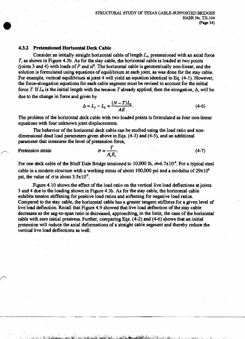
STRUCTURAL STUDY OF TEXAS CABLE-SUPPORTED BRIDGES HAERNo.TX-104
(Page 34)
4.3.2 Pretensioned Horizontal Deck Cable Consider an initially straight horizontal cable of length LCi pretensioned with an axial force
T, as shown in Figure 4.3b. As for the stay cable, the horizontal cable is loaded at two points (joints 3 and 4) with loads of P and sP. The horizontal cable is geometrically non-linear, and the solution is formulated using equations of equilibrium at each joint, as was done for the stay cable. For example, vertical equilibrium at joint 4 will yield an equation identical to Eq. (4-1). However, the force-elongation equations for each cable segment must be revised to account for the initial force T. If Lo is the initial length with the tension T already applied, then the elongation, A, will be due to the change in force and given by
A = L/-^JJL£h. (4.6)
The problem of the horizontal deck cable with two loaded points is formulated as four non-linear equations with four unknown joint displacements.
The behavior of the horizontal deck cable can be studied using the load ratio and non- dimensional dead load parameters given above in Eqs. (4-3) and (4-5), and an additional parameter that measures the level of pretension force,
T Pretension strain o~ = . (4-7)
4^ For one deck cable of the Bluff Dale Bridge tensioned to 10,000 lb, o^6.7xl0"4. For a typical steel cable in a modern structure with a working stress of about 100,000 psi and a modulus of 29xl06
psi, the value of o~is about 3.5xl0"3.
Figure 4.10 shows the effect of the load ratio on the vertical live load deflections at joints 3 and 4 due to the loading shown in Figure 4.3b. As for the stay cable, the horizontal cable exhibits tension stiffening for positive load ratios and softening for negative load ratios. Compared to the stay cable, the horizontal cable has a greater tangent stiffness for a given level of live load deflection. Recall that Figure 4.9 showed that live load deflection of the stay cable decreases as the sag-to-span ratio is decreased, approaching, in the limit, the case of the horizontal cable with zero initial prestress. Further, comparing Eqs. (4-2) and (4-6) shows that an initial pretension will reduce the axial deformations of a straight cable segment and thereby reduce the vertical live load deflections as well.
_.V £t»V...^ Jf .. tS j* -Wit, jfti^.a, HHWj&i.t l£j, „ ■g'-J. tit - Mj.,^l-~*J»jJL;f .

STRUCTURAL STUDY OF TEXAS CABLE-SUPPORTED BRIDGES HAERNo.TX-104
(Page 35)
0.80
-0.60 -0.015 -0.010 -0.005 0.000 0.005 0.010
Live Load Deflection / Span
Figure 4.10. Load-Deflection Behavior of Horizontal Deck Cable
Figure 4.11 shows the effect of the pretension strain, a, on the total deflection of the deck cable at the location of the live load (joint 4). As the level of pretension increases, the vertical deflections decrease and a significant reduction of deflection is possible for pretension strains of approximately 3.5xl0'3, readily achievable with modern high-strength cables and pretensioning techniques. Figure 4.11 also shows the amount of the total deflection at joint 4 which occurs due to the dead load and that due to the live load. Note that in this case, the amount of live load deflection remains nearly constant in the region of practical values of a.
5 ^ --aJlfc^L^ Wf&a Va*Si>*^_ -WWtfS. j J££

STRUCTURAL STUDY OF TEXAS CABLE-SUPPORTED BRIDGES HAERNo.TX-104
(Page 36)
0.010 IT
0.005
0.000
L..r,=°-357. ; p=9xl0"5
F ■ ■ ''■'■■' ■ ■ ■ ■ I i i i i I i i i i
Dead Load. Deflection
■ 111111 ■ i
0.0 0.5 1.0 1.5 2.0 2.5 3.0 3.5 4.0 Pretension Strain (xlO"3)
Figure 4.11. Effect of Initial Tension in Horizontal Deck Cable on Vertical Deflection
4.3.3 Stiffening Truss Consider a stiffening truss of total length Lt, supported at the towers and abutments, as
shown in Figure 4.3c. Whereas a cable structure must change shape to carry the applied loads purely as axial forces, a truss supports vertical loads through internal shear and bending forces. The truss may be analyzed as a linear structure and the small deformations neglected in satisfying equilibrium. Deflections are linearly proportional to the applied loads on the truss. The vertical deflections (normalized to total length, Lt) are given by
v = 54 2\
E,ItJ K, (4-8)
where Pv is a vertical applied load, and Fv is a non-dimensional coefficient dependent upon the length ratios a„ b„ cv d], and e, and the support conditions.64 The term in parentheses may be considered a non-dimensional load parameter for the truss, analogous to Eq. (4-5) for the cable stay. Since the term Fv is a proportionality constant between a non-dimensional deflection and a non-dimensional load, it can be considered a non-dimensional flexibility parameter.
64 For example, in the case of a simply supported beam with a single point load at mid-span, Fv equals 1/48.
., ^^^/-iWi^-.r-itSflw-dS:'"*
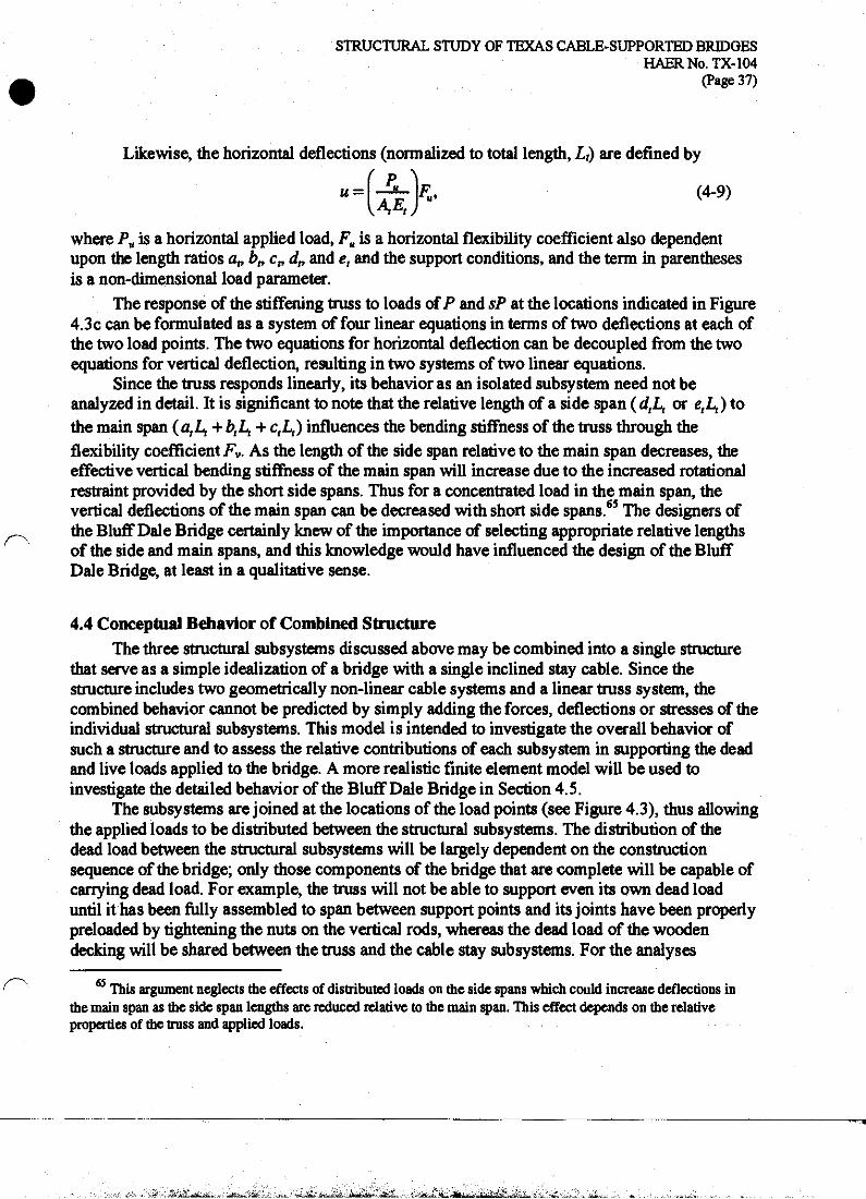
STRUCTURAL STUDY OF TEXAS CABLE-SUPPORTED BRIDGES HAERNo.TX-104
(Page 37)
Likewise, the horizontal deflections (normalized to total length, Lt) are defined by
u- ' P. AEt
«. (4-9)
where Pa is a horizontal applied load, Fu is a horizontal flexibility coefficient also dependent upon the length ratios a,, bn c„ dp and et and the support conditions, and the term in parentheses is a non-dimensional load parameter.
The response of the stiffening truss to loads of P and sP at the locations indicated in Figure 4.3c can be formulated as a system of four linear equations in terms of two deflections at each of the two load points. The two equations for horizontal deflection can be decoupled from the two equations for vertical deflection, resulting in two systems of two linear equations.
Since the truss responds linearly, its behavior as an isolated subsystem need not be analyzed in detail. It is significant to note that the relative length of a side span ( dj^ or etLs) to the main span ( atL, + btL, + CjL,) influences the bending stiffness of the truss through the flexibility coefficient Fv. As the length of the side span relative to the main span decreases, the effective vertical bending stiffness of the main span will increase due to the increased rotational restraint provided by the short side spans. Thus for a concentrated load in the main span, the vertical deflections of the main span can be decreased with short side spans.65 The designers of the Bluff Dale Bridge certainly knew of the importance of selecting appropriate relative lengths of the side and main spans, and this knowledge would have influenced the design of the Bluff Dale Bridge, at least in a qualitative sense.
4.4 Conceptual Behavior of Combined Structure The three structural subsystems discussed above may be combined into a single structure
that serve as a simple idealization of a bridge with a single inclined stay cable. Since the structure includes two geometrically non-linear cable systems and a linear truss system, the combined behavior cannot be predicted by simply adding the forces, deflections or stresses of the individual structural subsystems. This model is intended to investigate the overall behavior of such a structure and to assess the relative contributions of each subsystem in supporting the dead and live loads applied to the bridge. A more realistic finite element model will be used to investigate the detailed behavior of the Bluff Dale Bridge in Section 4.5.
The subsystems are joined at the locations of the load points (see Figure 4.3), thus allowing the applied loads to be distributed between the structural subsystems. The distribution of the dead load between the structural subsystems will be largely dependent on the construction sequence of the bridge; only those components of the bridge that are complete will be capable of carrying dead load. For example, the truss will not be able to support even its own dead load until it has been fully assembled to span between support points and its joints have been properly preloaded by tightening the nuts on die vertical rods, whereas the dead load of the wooden decking will be shared between the truss and the cable stay subsystems. For the analyses
65 This argument neglects the effects of distributed loads on the side spans which could increase deflections in the main span as the side span lengths are reduced relative to the main span. This effect depends on the relative properties of the truss and applied loads.
: - --:-.&. -."■-< :H. \^^-:>:^vtiiLiiifc^fc*-,.4'. ■^fta-i^^^ *■-.- - •^■-;-JaL1* a*-^-^_..-iJu^u^j:,:^-^- -. <j--j^l-^/^-:r^kx^^^^iJ2^/^^^'L.'^_ •-._ m'-*L-

STRUCTURAL STUDY OF TEXAS CABLE-SUPPORTED BRIDGES HAERNo.TX-104
(Page 38)
presented in this report, all of the dead and live loads are assumed to be applied to the completed structure. This assumption will tend to overestimate the stress levels in the truss and underestimate the stress levels in the cables. Note that for the Bluff Dale Bridge the wooden flooring system comprises about fifty percent of the total dead load, while the truss comprises about twenty-five percent (see Table 4.2). For atypical modern cable-stayed bridge, a much larger percentage of the total dead load of the roadway would be contributed by its deck stiffening system.
The joining of the subsystems is expressed mathematically through constraint equations, which require selected degrees of freedom, or deflections, to be equal. However, the choice of constrained degrees of freedom must reflect the true nature of the physical connections on the bridge itself, as the choice of constraints will affect the behavior of the combined structure. Figure 4.12 shows the Bluff Dale Bridge connection at the location where a fixed stay cable attaches to a transverse floor beam. Figure 4.13 shows the Bluff Dale Bridge connection at the location where a continuous stay cable supports a transverse floor beam. Most of the dead and live load reaches the stay cable, deck cable, and truss through the transverse floor beam. Based on the connection detail, it is clear that if the end of the floor beam deflects vertically due to applied loads, the stay cable, deck cable, and truss must have an equal vertical displacement. The total vertical force will be shared amongst the three structural subsystems.
In the horizontal direction, the direct connection of the truss and deck cable to the floor beam will result in axial forces being transferred between the deck cable and the truss chord. Note that the initial tension in the horizontal deck cable is applied before attachment to the floor beam or truss and defined in the model to exist independently of the constraint; only horizontal forces due to the applied dead and live loads are transferred between structural subsystems. As shown in Figure 4.13, the continuous diagonal stay cables of the main span simply pass underneath the casting at the end of the floor beam, and the horizontal component of force in the inclined portion of the stay cable will be equal to that in the horizontal portion of the stay cable, assuming no slip between the cable and casting. In the analysis, in order to prevent transfer of horizontal force from the stay cable to the deck cable and truss, the horizontal degrees of freedom of the stay cable are modeled to be independent of those of the deck cable and truss. This lack of horizontal constraint allows the stay cable joint to have a different horizontal displacement than the corresponding joints of the deck cable and truss. A better, but more complex, model would account for the friction and relative slip between the stay cable and the floor beam casting. Such a level of modeling detail would require complex analysis of the frictional behavior of the wire-casting interface and is well beyond the scope of this study. The combined model of the simplified cable-stayed bridge, with constrained vertical displacements and an independent horizontal degree of freedom for the stay cable joint, will result in an acceptable approximation of the overall behavior of such a bridge and will successfully reveal the fundamental characteristics of its response.
^^&dSLi£^^...^huaSb'l.ti. i r i f'MiiMii- ft^iVTWr? i-i'Mfi^fiF tlJTiifftflftiflfflfe^i'l '"" •'nfrli ' 1<L

STRUCTURAL STUDY OF TEXAS CABLE-SUPPORTED BRIDGES HAERNo.TX-104
(Page 39)
Truss Top Chord
Truss Vertical Rod
Fixed Stay Cable
Transverse Floor Beam
Truss Bottom Chord
Horizontal Deck Cable Casting on End of Floor Beam
Figure 4.12. Fixed Stay Cable Connection of (he Bluff Dale Bridge (Adapted from "Bluff Dale Suspension Bridge," HAER No. TX-36, drawing sheet 4.)
-A'fxlilittJ;^*, .--' rfffi&^-^-Y--.:- ■-■aiL+L,* . -.^s-S&&
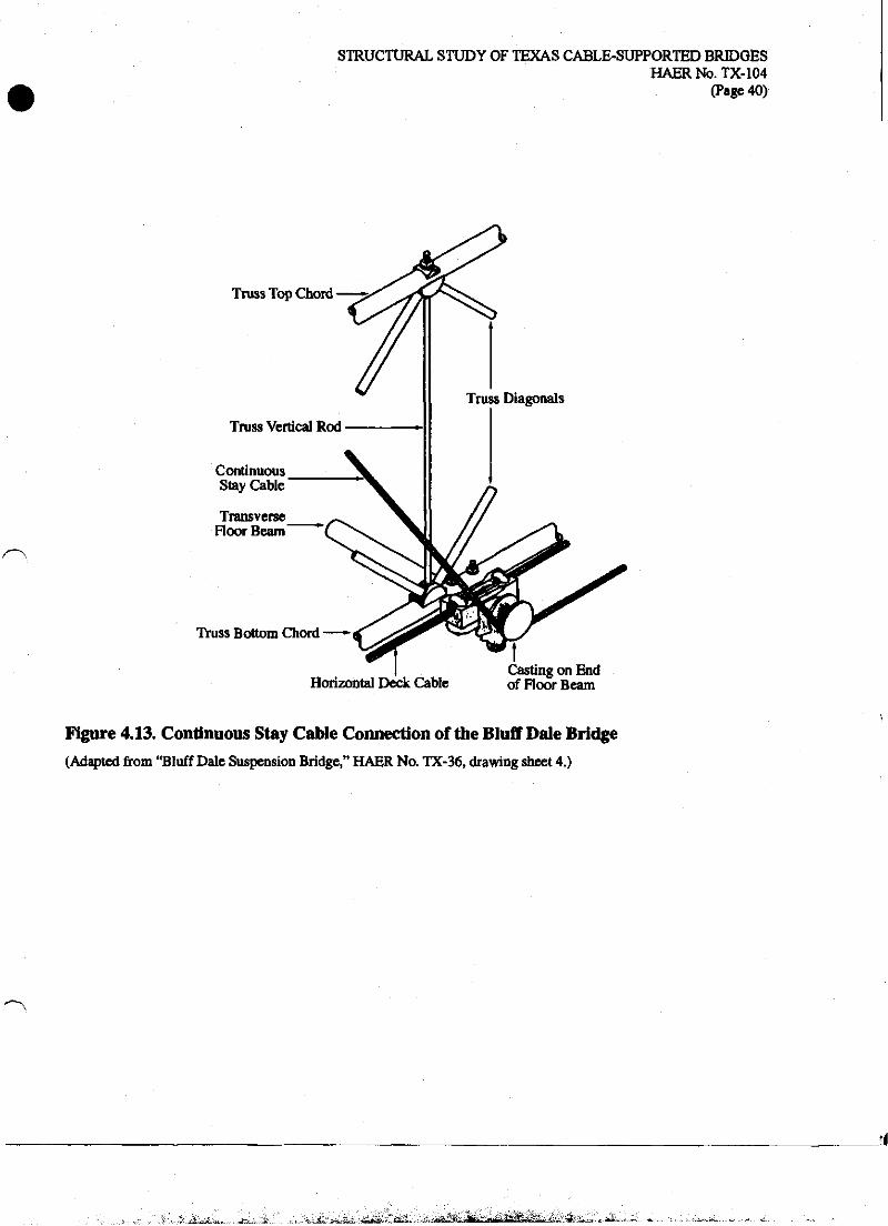
STRUCTURAL STUDY OF TEXAS CABLE-SUPPORTED BRIDGES HAERNo.TX-104
(Page 40)
r-\
Truss Top Chord
Truss Vertical Rod
Continuous Stay Cable
Transverse Floor Beam
Truss Bottom Chord
Horizontal Deck Cable Casting on End of Floor Beam
Figure 4.13. Continuous Stay Cable Connection of the Bluff Dale Bridge (Adapted from "Bluff Dale Suspension Bridge," HAER No. TX-36, drawing sheet 4.)
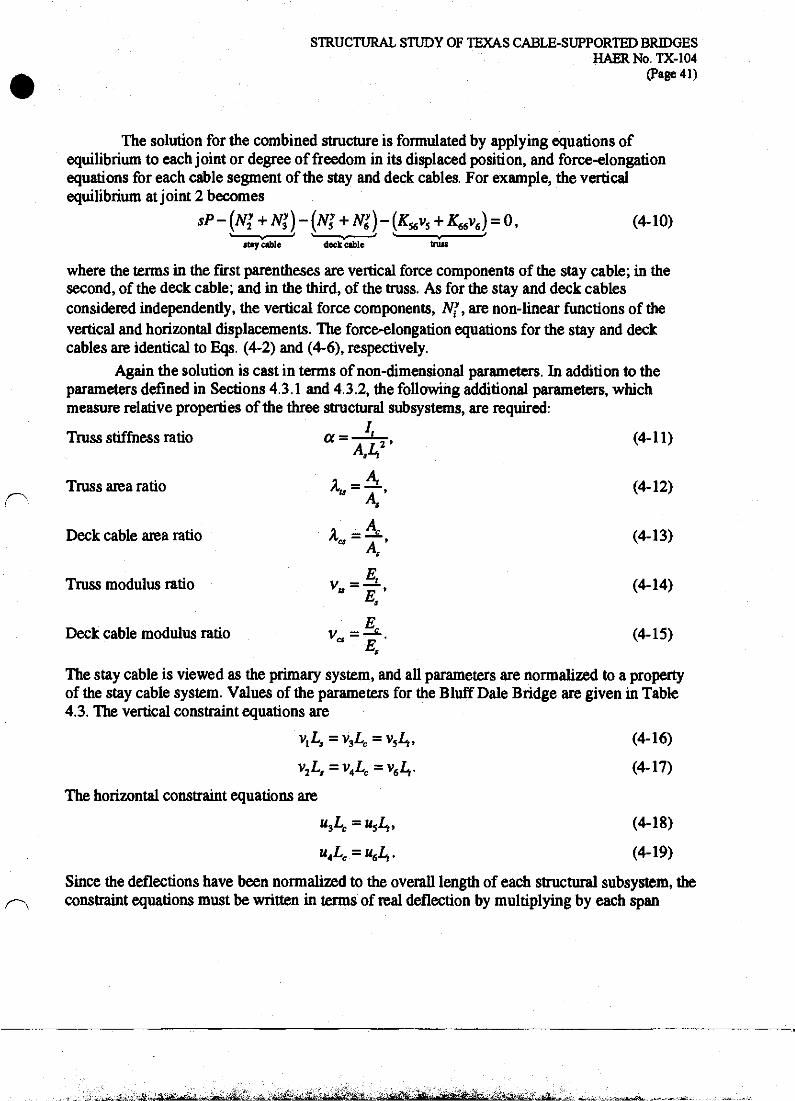
STRUCTURAL STUDY OF TEXAS CABLE-SUPPORTED BRIDGES HAERNo.TX-104
(Page 41)
The solution for the combined structure is formulated by applying equations of equilibrium to each joint or degree of freedom in its displaced position, and force-elongation equations for each cable segment of the stay and deck cables. For example, the vertical equilibrium at joint 2 becomes
SP-(N^Ny3)-(N>+N>)-(K56v5+K^v6) = 0, (4-10)
stay cable deck cable tniw
where the terms in the first parentheses are vertical force components of the stay cable; in the second, of the deck cable; and in the third, of the truss. As for the stay and deck cables considered independently, the vertical force components, N?t are non-linear functions of the vertical and horizontal displacements. The force-elongation equations for the stay and deck cables are identical to Eqs. (4-2) and (4-6), respectively.
Again the solution is cast in terms of non-dimensional parameters. In addition to the parameters defined in Sections 4.3.1 and 4.3.2, the following additional parameters, which measure relative properties of the three structural subsystems, are required:
L Truss stiffness ratio a = A [2, (4-11)
=4. K A.
Truss area ratio \ = —, (4-12) A.
Deck cable area ratio ACJ=-£-, (4-13)
E Truss modulus ratio vtt = —, (4-14)
P Deck cable modulus ratio va - —-. (4-15)
E*
The stay cable is viewed as the primary system, and all parameters are normalized to a property of the stay cable system. Values of the parameters for the Bluff Dale Bridge are given in Table 4.3. The vertical constraint equations are
v^-vA-vA. (4-16)
v2Z,,=v4Lc=v6Z>. (4-17)
The horizontal constraint equations are
"3^ = w5^ (4-18)
u4Lc = u6L,. (4-19)
Since the deflections have been normalized to the overall length of each structural subsystem, the constraint equations must be written in terms of real deflection by multiplying by each span
^.^^■aa^jfc te.*..*.*. ,^g^

STRUCTURAL STUDY OF TEXAS CABLE-SUPPORTED BRIDGES HAERNo.TX-104
(Page 42)
length. The resulting combined structure has six unknown degrees of freedom—uu u2, H3, M4, VU
andv2. Figure 4.14 shows the relationship between the vertical live load deflection at joint 2 and
the load ratio. The line corresponding to or=l .3xl0'3 shows that the truss of the Bluff Dale Bridge adds considerable stiffness to the structure, reducing deflections and resulting in an essentially linear response. With no stiffening truss, the combined structure of a stay and deck cable of equal areas (a =0, XcS-\) exhibits a non-linear stiffening response, but remains substantially less stiff
than the structure with the truss. Finally for a =0 and Xcs =0, the response reduces to that for the stay cable alone as shown in Figure 4.7.
0.80
cM.3xlO"3
060 W AM*7.5
-0.60 0.000 0.001 0.002 0.003 0.004
Live Load Deflection / Span
Figure 4.14. Force-Deflection Behavior of Simplified Cable-Stayed Bridge
A j-i*i.» MM? - «ti ..#!^.4....-&U.>*^,fam^rf,.-_

STRUCTURAL STUDY OF TEXAS CABLE-SUPPORTED BRIDGES HAERNo.TX-104
(Page 43)
Figure 4.15 shows the effectiveness of the truss in reducing the vertical deflections of the combined structure.66 A truss of stiffness parameter 1.3xl0"3' as for Bluff Dale reduces the deflections by a factor of about 8 compared to a structure with no truss. The figure also reveals that stiffness ratios much smaller than those used at Bluff Dale can reduce deflections significantly. For example, to reduce the normalized deflection from 1.2x10"3 by 50 percent to 0.6x10"3 would require a truss stiffness ratio of only 3xl0"5. For large truss stiffness ratios, above about 5X10"4, the effect of additional truss stiffness in reducing deflections becomes much less pronounced. For a pipe truss of a given depth, similar in construction to that of Bluff Dale, the truss stiffness is closely proportional to the chord areas, and thus to the quantity of material in the chords. Therefore, the use of a reduced truss stiffness ratio could result in a significant savings of material. This modern analysis shows that the truss of the Bluff Dale Bridge could have been significantly less stiff with no appreciable increase in live load deflections, although in the 1890s the truss members would have been sized based on an empirical or approximate structural analysis.
0.0015
Iff4 Iff3
Truss Stiffness Ratio
Figure 4.15. Effect of Truss Stiffness Ratio on Vertical Deflections of Simplified Cable- Stayed Bridge
66 Hie horizontal axis is plotted as a logarithmic scale in order to show the change in deflection for small values of a, which would not be easily visible on a linear scale.
<*~*£Z2B*£X& j&aWttJt ^^L. ;, J&L& ■ J^Ju_b d. hJL*

STRUCTURAL STUDY OF TEXAS CABLE-SUPPORTED BRIDGES HAERNo.TX-104
(Page 44)
Figure 4.16 shows that vertical deflections are not significantly affected by the magnitude of pretension in the horizontal deck cable for the combined structure with a stiff truss (OP=
1.3xl0"3). This observation supports the view that the horizontal deck cables were primarily intended to aid in construction and do not significantly contribute to the behavior of the bridge under gravity loads. For the case of a very flexible truss, the magnitude of pretension in the horizontal cable will affect the total vertical deflections of the horizontal cable, and a large pretension can significantly reduce the deflections. Further, for a combined structure of stay and deck cable with only a small dead load, the deck cable can also provide resistance to uplift loads that may slacken the stay cables.
9 CO
g •a I &
0.25
0.20
0.15
0.10
0.05
0.00
r,=0.357
o=1.3xl0"3
r-AB=7.5
__L_ Joint 2
Total Deflection
Live Load Deflection
;p=9xl0"5
11111111 ■ i ■ 111111111111111111111
Dead Load Deflection
0.0 0.5 1.0 1.5 2.0 2.5 3.0 3.5 4.0
Deck Cable Pretension Strain (xlO3)
Figure 4.16. Effect of Initial Tension in Horizontal Deck Cable of Simplified Cable-Stayed Bridge
'.£* •*!>&?JsEjtiLi*,*.-*. **. . ■tii_,3i.. ikwtffc?. L$VI&&A*. ■ ., ;■';■£ --a. &'... .>-faji^-:.hfeS&J'ji 2^&.

STRUCTURAL STUDY OF TEXAS CABLE-SUPPORTED BRIDGES HAERNo.TX-104
(Page 45)
In order to further understand the participation of the three structural subsystems in carrying dead and live loads, two analyses are presented for the simplified model of the cable- stayed bridge with properties indicated in Table 4.3. Figure 4.17. shows the force diagram for the structure loaded with equal dead loads of 1400 lb at each joint (symmetric loading). Under symmetric load, the stay cable carries 42 percent of the vertical load, and the truss about 58 percent. This load distribution is very much dependent upon the use of only a single cable stay in the model. The inclusion of additional cable stays will reduce the bending in the truss and a greater percentage of the load will be carried by the cable stay system, as will be seen in Section 4.5. Figure 4.17 also shows that the horizontal deck cable carries virtually none of the vertical applied load. As an independent structure, the pretensioned deck cable has a greater stiffness than the cable stay, but it requires a large deflection at its loaded joints in order to reorient its straight cable segments so that they could have a significant component of their axial stiffness in the vertical direction. However, the combined structure with the stiff truss is essentially linear in its force-deflection behavior (see Figure 4.14) and is limited to much smaller deflections. Therefore, the horizontal deck cable does not add any significant vertical stiffness to the combined structure. Note also that Figure 4.16 showed that the magnitude of pretension does not effect the vertical deflections of the combined structure, again suggesting that the vertical stiffness of the deck cable is not significant compared to that of the truss and stay cable. The 242,900 in-lb maximum bending moment in the truss occurs at each tower.
Figure 4.18 shows the force diagram for the structure loaded with an additional live load of 1000 lb at joint 2 (asymmetric loading). The stay still carries about 42 percent of the total applied load; the truss, 58 percent; and the horizontal cable, virtually none. The vertical reactions of the stay cable are nearly equal (797 and 798 lb) despite the asymmetric live load of 1000 lb. The stay cable has the funicular shape for two equal point loads and thus possesses greater stiffness for symmetric load conditions. With the presence of the truss, the forces in the stay cable remain nearly symmetric, while the truss carries the remainder of the live load. The peak bending moment in the truss, 435,900 in-lb, occurs at the tower adjacent to the live load and is about 80 percent larger than the moment for the symmetric loading.
^SLmPh^eC.^.^ i. M»..-?3fe~ - .... **>.&.. «i_ -*.* -itnA-ii -,ig;^ itfriii*ti)i!teiitflfl<i3MMiiWir« a? -9~

STRUCTURAL STUDY OF TEXAS CABLE-SUPPORTED BRIDGES HAERNo.TX-104
(Page 46)
587
Stay Cable 1514
Deck Cable 41 Truss *~
r675
1484
DL=1400 DL=1400
1514 \62>
J 0 810 810
Notes: 1. For cable elements, thickness of line is proportional
to axial force. Numbers indicate axial force in lb. Positive values indicate tension.
2. For truss elements, thickness of line is proportional to shear force. Numbers indicate shear force in lb.
587
t 1514 —^-
24
675'
1484
Figure 4.17. Force and Moment Diagrams for Dead Loading of Simplified Cable-Stayed Bridge
Stay Cable
Deck Cable 41 Truss
DL=1400 LL=1000
1597
-1373
Notes: 1. For cable elements, thickness of line is proportional
to axial force. Numbers indicate axial force in lb. Positive values indicate tension.
2. For truss elements, thickness of line is proportional to shear force. Numbers indicate shear force in lb.
2054
1058'
2430
Figure 4.18. Force and Moment Diagrams for Dead and Live Loading of Simplified Cable- Stayed Bridge
v^rfb«Ja£fc«iitai^ ■ .*i£vji*;i ..!&.. -:_ .i'r*.-.' ■te"»Jdii/.J-jfc*i'/.*i..J*ktfi*£&.'.-^ ,-,.-. iZr-'J&Aiv&Li.

STRUCTURAL STUDY OF TEXAS CABLE-SUPPORTED BRIDGES HAERNo.TX-104
(Page 47)
4.5 Finite Element Analysis of Bluff Dale Bridge The previous analytical models of the various components of the Bluff Dale Bridge
structural subsystems and the single-stay simplified model presented in Section 4.4 have provided insight into certain elements of the behavior of the bridge. The behavior of the complete Bluff Dale Bridge, including all of its cable stays, can be analyzed through use of the finite element method. The finite element method models a structure as a number of discrete elements, each of which behaves according to basic equations of structural force and displacement. These elements are joined at nodes, and the displacements at each node are considered the fundamental unknown quantities. These nodal displacements are termed degrees of freedom. For a two-dimensional frame structure, each node has three degrees of freedom—two perpendicular displacements and one rotation. Based on an assembly of elements and nodes, a system of equations defines the overall behavior of the structure by relating nodal displacements to nodal forces through the stiffness matrix of the structure. Once the nodal displacements have been calculated, forces in each element of the structure can be calculated based on force-displacement formulation of the element. Hundreds, or even thousands, of degrees of freedom may be required to analyze a typical structure, and therefore the method relies on the use of a computer software program to facilitate computation.67
Because cable-supported structures often exhibit geometrically non-linear effects due to the tension stiffening already described in Section 4.3.1, the finite element analysis must account for this non-linear behavior. The program MASTAN2 was used for the analyses of all finite element models in this report and is capable of modeling general frames and trusses using beam and truss elements.68 This program was used because of its advanced geometrically non-linear analysis capabilities with incremental loading and equilibrium iterations at each loading increment.
The finite element models of the Bluff Dale Bridge follow the geometry shown in Figure 4.1 and Figure 4.2. The two additional cable arrangements were analyzed for comparison to the Bluff Dale Bridge. The three models may be described as:
(1) Bluff Dale Bridge as extant, with fan pattern cable stays and five continuous stays (Figure 4.1a).
(2) Modem fan pattern of stays, in which all stays are fixed to terminate at the deck. (Figure 4.1b).
(3) Crossing fan pattern of stays, in which stays are continuous but have no horizontal segments (Figure 4.2).
All three models include all of the cable stays and capture the effects of flexibility of the vertical towers and inclined backstays, features which were not included in the simplified model
87 See McGuire et al. (2000) and Cook et al. (1989) for a technical description of the finite element method.
68 Ziemian and McGuire (2000). A beam element carries axial, shear and bending (moment) forces and has three degrees of freedom at each end. A truss element carries axial force only and has one degree of freedom at each end.
STRUCTURAL STUDY OF TEXAS CABLE-SUPPORTED BRIDGES HAERNo.TX-104
(Page 48)
analyzed in Section 4.4. Each finite element model is a two-dimensional representation of one- half of the bridge.
The properties of each type of element are summarized in Table 4.4. The stiffening truss is represented by a line of beam elements positioned at the level of the deck with cross-sectional area and moment of inertia based on the pipe sections of the upper and lower chords and the distance separating them. Although the representation of the truss as a line of beam elements does not explicitly include every diagonal, vertical, or chord member, it does accurately model the axial and bending stiffnesses of the truss, and therefore results in an accurate solution of displacements and forces in the bridge. The model neglects the bending moment in the truss due to the vertical eccentricity between the bending axis of the truss (mid-depth) and the location where the fixed inclined stays transfer their horizontal force component to the truss (lower chord). The truss is assumed to remain properly pretensioned such that all connections are capable of transmitting both tension and compression.
The cable stays are represented by beam elements with a cross-sectional area corresponding to thirty-two No. 9 gauge wires and a small moment of inertia equal to the bending resistance of the thirty-two wires each bending about its own neutral axis. Although a realistic value, this small moment of inertia is intended primarily to aid in numerical stability of the non-linear solution scheme and will not result in any significant portion of load being carried through bending of the cable stays. Similarly, the backstays are assigned a cross-sectional area and a moment of inertia corresponding to 160 No. 9 gauge wires, or a single cable composed of the wires from five cable stays.
The connections between the cable stays and the truss are modeled by short, vertical beam elements with properties selected to allow only certain force components to be transferred. The elements representing the connection between the fixed stay cables and truss are assigned a large cross-sectional area and moment of inertia to constrain the vertical and horizontal deflections to be equal and to allow the transfer of vertical and horizontal forces. No significant moment is carried by these elements because of their short length and their connection to the cable elements, which have extremely small moments of inertia. The elements connecting the continuous stay cables to the truss are assigned a large cross-sectional area but a small moment of inertia to allow the transfer of vertical forces only. This assumption is acceptable as long as the connecting elements remain nearly vertical; that is, the relative horizontal displacement of the truss and cable stay joints remains small. Similarly, the connection between the truss and towers is assigned a large cross-sectional area and small moment of inertia, such that vertical and horizontal forces can be transferred from the truss to the tower, but the bending moment in the truss cannot be transferred to the tower. Ideally, these values of area and moment of inertia would be infinite or zero; the actual values were selected to ensure numerical stability of the non- linear solution scheme.
. .A ■aft. ..jif.-,... . J».. -is . . i»_ V-^t.J-_atf»S.j£ll»tikli m^L, ■ *!■ -T >JI 4fiHr ilftiliijft •*" in

STRUCTURAL STUDY OF TEXAS CABLE-SUPPORTED BRIDGES HAERNo.TX-104
(Page 49)
Table 4.4. Element Properties of Bluff Dale Bridge
Element Area Moment of Inertia (in2) (in4)
Truss 4.123 3982 Cable Stays 0.55 7.5X10*4
Backstays 2.75 3.8xl0'3
Fixed Stay-Truss Connection 1000 1000 Continuous Stay-Truss Connection 1000 0.001 Truss-Tower Connection 1000 0.001
The horizontal deck cable is not included in the finite element model because the simplified analyses in Section 4.4 showed it to be ineffective in carrying vertical load in combination with the stiff truss and stay cables. The horizontal cable will carry some of the. horizontal force component from the fixed stay cables, resulting in a reduction of its initial pretension force. However, based on the relative areas of the cable and truss, most of the horizontal component of the fixed stay cable force will still be carried by the truss.
The actual construction sequence of the Bluff Dale Bridge is not known. The cable tensioning method documented in Runyon's patent (No. 404,934) was likely used for the Bluff Dale Bridge, judging from the surviving fittings on the lateral bracing cables beneath the deck. Cable tensioning that occurred prior to construction of the floor system would have certainly removed any slack in the cables, but it seems unlikely that this cable tensioning system would have worked effectively with the full dead load of the bridge applied. The finite element analyses assume that the tension in the stays is produced by the dead load of the entire bridge, and the full dead load will be applied to the complete structure. This method of analysis, which neglects the incremental construction and loading of the bridge, will result in non-negligible bending moments in the truss due to the dead load. The self-weight of the truss and the flooring system comprise about 70 percent of the total dead load. In practice, pretensioning of the cable stays can be used to reduce this moment. Nevertheless, these dead load bending moments are a reasonable upper bound for dead load stresses in the truss.
The response of the Bluff Dale Bridge to a uniform dead load of 140 lb/ft, applied as a concentrated load of 1400 lb at each panel point, is summarized in Figure 4.19, which shows forces and deflections of the bridge truss.69 The axial force diagram indicates large compression forces in the truss near the towers, between the fixed stay cables, with a maximum value of 3250 lb. In the area of the continuous stays, the truss is under a nearly constant tension of about 1130 lb. The small changes in tension at each stay location are due to the small non-zero moments of inertia of the elements connecting the continuous stays and truss. For an ideal stay-truss connection, which transfers no horizontal force, the tension would remain constant. The distribution of axial forces in the truss is largely dependent on the construction sequence; the
A positive axial force indicates compression in the truss. A positive bending moment indicates tension in the bottom chord and compression in the top chord of the truss. Downward deflections are positive in sign. Moment and deflection diagrams are plotted with an inverted y-axis so that the curve reflects the deflected shape of the bridge.
.-iis-isi-3ii,S. „:.-^;£&„<5!ftiw*i£ii2£iSfii:2
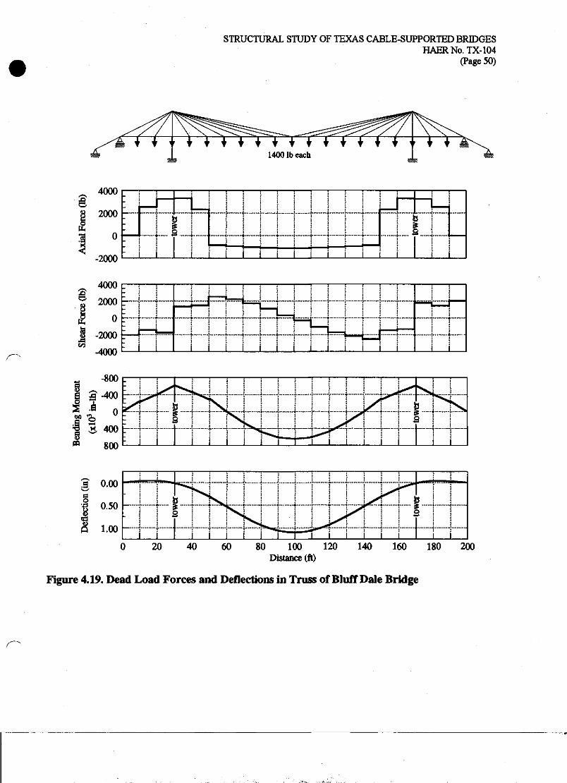
STRUCTURAL STUDY OF TEXAS CABLE-SUPPORTED BRIDGES HAERNo.TX-104
(Page 50)
* * * V + f * 1400 lb each
tt.
4000
2000 I
0
-2000
r :;:::; : : i |
_!
t i .......U i T i \
i
j +
•—
i=U tq
" i i i i i i i i i i i i
-4000
-800 c
800
a o.oo
fi i.oo —|
0 20 40 60 80 100 120 140 160 180 200 Distance (ft)
Figure 4.19. Dead Load Forces and Deflections in Truss of Bluff Dale Bridge

STRUCTURAL STUDY OF TEXAS CABLE-SUPPORTED BRIDGES HAERNo.TX-104
(Page 51)
forces shown assume that the dead load is applied after the entire structure has been constructed. For a modern cable-stayed bridge, the construction sequence and support conditions at the towers and abutments can be used to affect the axial forces in the deck, the result of which would be a uniform shift of the axial force diagram by an constant amount of tension or compression.70 In the shear force diagram, the change in shear at a stay location (magnitude of force associated with each vertical discontinuity) corresponds to the magnitude of vertical force carried by the truss; the remainder of the applied load of 1400 lb is carried by the stay attached at that location. For example, the load points near the center of the truss (between 70' and 130') have changes in shear ranging from 450 to 800 lb, or about 30 percent to 60 percent of the applied load, indicating that the stays are carrying the remaining 40 percent to 70 percent of the applied dead load. The total vertical force carried by the truss can be calculated by adding the magnitudes (including the algebraic sign) of the vertical discontinuities at the four support points. Dividing the load carried in the truss by the total applied dead load shows that overall the truss carries 8 percent of the dead load, and the stay system, 92 percent As was suggested in the analysis of the simplified cable-stayed bridge in Section 4.4, the inclusion of all of the cable stays of the Bluff Dale Bridge results in a much larger portion of the dead load carried by the stay system and much less by the truss.
The analysis of the Bluff Dale Bridge under dead load results in a mid-span deflection of 1.10". If the same dead load were applied to the three-span continuous truss, unsupported by the cable stay system, the mid-span deflection would be 3.10". The positive bending moment at the mid-span was found to be approximately 646,450 in-lb, and the negative bending moment at the towers, -609,250 in-lb for the Bluff Dale Bridge. For the truss alone, the maximum positive bending moment would be 1,704,000 in-lb, and negative, -2,436,000 in-lb. Thus, the cable system of the Bluff Dale Bridge results in a significant reduction in moments and deflections compared to an identical continuous truss with no cable system. Note that the maximum positive and negative moments for the Bluff Dale Bridge are approximately equal, while for the unsupported truss the negative bending moment is about 1.4 times as large as the positive. The truss of the Bluff Dale Bridge, with constant depth and equal chord areas, is a good design for a structure which has positive and negative maximum bending moments of equal magnitude. The maximum combined stress from axial and bending forces will occur at the tower. The negative bending moment of-609,250 in-lb results in a bending stress of 4760 psi. The peak axial compression of 3250 lb results in an additional stress of about 790 psi. The combined stress of 5550 psi is within acceptable limits for wrought iron. The elastic limit, or yield point, of wrought iron typically ranges from 25,000 to 35,000 psi and typical design practice at the turn of the century would have allowed a working stress of perhaps 25 percent of the elastic limit, say about 6000 to 9000 psi.71 For the continuous truss with no cable support, the bending stresses would have been about 20,000 psi, certainly well above a typical design level of the late nineteenth century. Although the designers of the Bluff Dale Bridge were not able to perform the detailed calculations necessary for a complete analysis of the cable-supported truss, they were capable of
70 Podolny and Scalzi (1976), p. 360.
71 Withey and Aston (1926), p. 601.

STRUCTURAL STUDY OF TEXAS CABLE-SUPPORTED BRIDGES HAERNo.TX-104
(Page 52)
proportioned, with the intent that a significant portion of the dead load would be carried by the cable stay system. Some approximate method of distributing load between the truss and stay systems would have been used, although the details of such a method remain undocumented.
Figure 4.20 shows the cable forces due to the dead load and Figure 4.21 indicates the cable numbering scheme for the Bluff Dale Bridge model. In general, the uniformly distributed dead load results in an even distribution of forces between all of the cables, especially the five continuous stay cables (nos. S to 18). The outermost fixed stay cables (nos. 1,4,19,22) have significantly larger tensions than the inner fixed stays (nos. 2,3,20, 21) or any of the continuous stays. This large tension is due to the fixed nature of the connection between the stay and truss, whereby both vertical and horizontal deformations of the truss produce tension in the cable, in contrast to the continuous stay cables where only vertical deflections of the truss produce tension. The inner fixed stays have smaller tensions as these points are adjacent to the support of the tower, which has an extremely small vertical deflection. The maximum tension of 4014 lb corresponds to an axial stress of 7300 psi, an acceptable level for wrought iron wires. The yield stress of wrought iron wire is typically at least 75,000 psi and may be as large as 125,000 psi. This increase in yield stress results from the physical process of drawing the wrought iron into wire.
Notes: 1. Thickness of line is proportional to axial force (except in backstays). 2. Numbers indicate axial force in lb. Positive values indicate tension.
Figure 4.20. Dead Load Axial Forces in Cables of Bluff Dale Bridge

STRUCTURAL STUDY OF TEXAS CABLE-SUPPORTED BRIDGES HAERNo.TX-104
(Page 53)
^F^S&z^ ^0*00^^ ►T^i^£C^ic^io>^
Figure 4.21. Cable Numbers for the Bluff Dale Bridge Model
In order to properly judge the effectiveness of each cable stay, it is necessary to consider the angle of the stay as well as its axial tension. A more shallow stay will require a greater total tension than a steeper stay to support a given vertical load. Table 4.5 lists the vertical component of cable tension for each stay, and Figure 4.21 shows the finite element model of the Bluff Dale Bridge with cable numbers indicated. Since the horizontal segments of the continuous stay cable will have a negligible vertical force component, the ratio of the vertical force component of an inclined stay segment to the applied vertical load may be considered a measure of the efficiency of each stay.72 If no truss were present, this ratio would be 100 percent for each inclined stay. This comparison shows that the outermost fixed stay cables (nos. 4,19) are extremely effective and carry forces much larger than the force of the dead load applied at their end nodes. The continuous stay cables (nos. 5 to 18) carry significantly less force than the applied dead load. However, their effectiveness should not be viewed as poor design because the cable's strength is limited primarily by the large relative stiffness of the truss and shallow slope of the cables.
72 This comparison neglects the influence of tower flexibility.
—J

STRUCTURAL STUDY OF TEXAS CABLE-SUPPORTED BRIDGES HAERNo.TX-104
(Page 54)
Table 4.5. Dead and Live Load Axial Forces in Cables of Bluff Dale Bridge
Cable No.
Cable No.
4 8 17
Angle Jdegl_
Angle
37.78 21.18 12.49
Dead Load Force Ob)
Vertical Force Component
Ob)
> of Applied Load of 14001b'
1 37.78 3229 1978 141.3 2 57.17 1277 1073 76.6 3 57.17 1826 1535 109.6 4 37.78 4014 2459 175.6 5 27.32 2329 1069 76.4 6 0.00 1971 0 0 7 27.32 2329 1069 76.4 8 21.18 2606 942 67.3 9 0.00 2342 0 0 10 21.18 2606 942 67.3 11 17.22 2595 768 54.9 12 0.00 2417 0 0 13 17.22 2595 768 54.9 14 14.48 2323 581 41.5 15 0.00 2220 0 0 16 14.48 2323 581 41.5 17 12.49 1837 397 56.7 18 12.49 1837 397 56.7 19 37.78 4014 2459 175.6 20 57.17 1826 1535 109.6 21 57.17 1277 1073 76.6 22 37.78 3229 1978 141.3
Live Load Force
Vertical Force Component
%of Applied Load of 10001b*
343 184 233
210 67 50
21.0 6.7 10.1
* Percentage of applied load for Cable Nos. 17 and 18 based on one-half the applied load (700 lb or 500 lb) due to symmetry.

<lf
STRUCTURAL STUDY OF TEXAS CABLE-SUPPORTED BRIDGES HAERNo.TX-104
(Page 55)
The effect of live load on the Bluff Dale Bridge is studied through a series of analyses with a 1000 lb load applied at each node along the length of the truss. Since the geometric non- linear behavior for live loads depends on the total force in the cable elements, each live load analysis also includes the full dead load applied simultaneously. The forces and displacements due to the live loads are calculated as the change in force or displacement relative to those resulting from an analysis with dead load only. For a geometrically non-linear structure, the results of a live load analysis are specific to the magnitude of total load. Since the large truss stiffness of the Bluff Dale Bridge results in a nearly linear response, the results of the live load analysis can be scaled for other magnitudes of live load with little error.
Figure 4.22 shows truss forces and displacements for three positions of live load—at the location of the outer fixed stay (50'), near the quarter-point of the main span (70'), and at mid- span (100'). Based on the magnitude of the vertical discontinuities in shear diagrams at the point of load application, the truss carries nearly all of the applied live load; for the 1000 lb live load, the vertical force carried by the truss is 790 lb, 932 lb, and 898 lb, respectively for the three live load positions at 50', 70', and 100'. The maximum positive bending moment always occurs at the point of load application, and the greatest moment of 134,450 in-lb occurs for a live load at mid- span. This moment will increase the stress in the truss by about 1050 psi. In combination with the dead load bending stress of 5050 psi at mid-span, the total stress is 6100 psi, which would be considered within the range of allowable stresses for wrought iron in the late nineteenth century. This stress is well below the yield stress of typical wrought iron. The deflected shapes of the truss show that, due to the continuity of the truss across the tower, the point of maximum deformation does not always occur at the live load location. The maximum additional displacement due to a live load of 1000 lb at mid-span is 0.12", or about 10 percent of the dead load displacement.
^gjable 4jjists vertical force components in the cable stays at the location of the live load and FigureTZTshows the cable forces due to the three live loads considered. In all cases the cable system carries a relatively small portion of the total live load. For the live load positioned at the end of the outer fixed stay (50', no. 4), the two fixed stays (nos. 3 and 4) have large tensions compared to the other stays. For the live load positioned near the quarter-point (70*, no. 8), the fixed stay cables still have the largest tensions, even though the live load is applied at the location of a continuous stay cable. Due to the continuity of the continuous stay cables, each responds in a nearly symmetric manner with nearly equal tensions in its two inclined segments, despite the asymmetric live loading. For the live load at mid-span (100', no. 17), the cable system responds in a relatively uniform manner with the load distributed between all of the cables because the truss distributes the concentrated live load through its bending action.
—:J

STRUCTURAL STUDY OF TEXAS CABLE-SUPPORTED BRIDGES HAERNo.TX-104
(Page 56)
500 r
b »!».., ., . At*-9t. At, jB*..v«LfP^^^.
J L
§ 800
400
fe 0
* -400 c/a ■-m.f^... i
-<- •> (■■
• '-3 ---}--4 ^—{---[^---1 | (* **
ttt4 I T I I EJ i i i i L
£ 0.000
| 0.050
| 0.100
0.150 80 100 120 140 160 180 200
Distance (ft)
Figure 4.22. Live Load Forces and Deflections in Truss of Bluff Dale Bridge

STRUCTURAL STUDY OF TEXAS CABLE-SUPPORTED BRIDGES HAER No. TX-104
(Page 57)
Notes: 1. Thickness of line is proportional to axial force (except in backstays). 2. Numbers indicate axial force in lb. Positive values indicate tension.
Negative values indicate reduction of dead load tension.
(a) Live Load at 50'
Notes: 1. Thickness of line is proportional to axial force (except in backstays). 2. Numbers indicate axial force in lb. Positive values indicate tension.
Negative values indicate reduction of dead load tension.
(b) Live Load at 70*
Figure 4.23. Live Load Axial Forces in Cables of Bluff Dale Bridge

STRUCTURAL STUDY OF TEXAS CABLE-SUPPORTED BRIDGES HAERNo.TX-104
(Page 58)
Figure 4.23. Live Load Axial Forces in Cables of Bluff Dale Bridge (continued)
Notes: 1. Thickness of line is proportional to axial force (except in backstays). 2. Numbers indicate axial force in lb. Positive values indicate tension.
Negative values indicate reduction of dead load tension.
(c) Live Load at 100*
The behavior of the bridge for a live load at any point on the span can be summarized through influence lines that plot response—force in a particular member or displacement at a particular point—versus the location of the live load. Figure 4.24a shows an influence line of the vertical displacement of the truss at the loaded point, and Figure 4.24b an influence line of positive bending moment at the loaded point. In the main span, both displacement and moment increase monotonically as the load moves across the span. The influence line of displacement is qualitatively the same as one for a three-span continuous beam with no cable support, although the cable stay system reduces the magnitude of the displacements.

rs a' 0.06 o
a
STRUCTURAL STUDY OF TEXAS CABLE-SUPPORTED BRIDGES HAERNo.TX-104
(Page 59)
40 50 60 70 Position of Live Load (ft)
(a) Deflection Influence Lines
.s ©
s
03
30 40 50 60 70 Position of Live Load (ft)
(b) Moment Influence Lines
Figure 4.24. Influence Lines of Live Load Deflection and Bending Moment of Bluff Dale Bridge for Three Cable Patterns

STRUCTURAL STUDY OF TEXAS CABLE-SUPPORTED BRIDGES HAERNo.TX-104
(Page 60)
4.6 Finite Element Analyses with Alternate Cable Patterns Two alternate cable patterns—the modern fan pattern (Figure 4. lb) and the crossing fan
pattern (Figure 4.2)—were analyzed for comparison to the extant cable pattern of the Bluff Dale Bridge. The finite element models use the element properties for the Bluff Dale Bridge given in Table 4.4. For the modern fan pattern, the ends of the stays are directly attached to the truss elements such that both vertical and horizontal forces may be transferred between the truss and stay cables, identical to the connection used for the fixed stay cables of the Bluff Dale Bridge model. For the crossing fan pattern, the first two stays on each side of the tower are fixed stay cables, modeled identically to those of the Bluff Dale Bridge. The remaining cable stays are continuous and the stay-truss connection is defined such that only vertical forces can be transferred, resulting in equalization of the horizontal force components in each inclined segment of a single stay.
4.5.1 Modern Fan Cable Pattern Figure 4.25 shows truss forces and deflections for the model with the modern fan pattern
under a uniform dead load of 140 lb/ft. The shear, bending moment, and deflection response are remarkably similar to those shown in Figure 4.19 for the Bluff Dale Bridge. The maximum deflection at mid-span is 1.05", compared to 1.10". The maximum positive moment is 605,580 in- lb and the maximum negative moment is 618,500 in-lb, both within 5 percent of the values for the Bluff Dale Bridge. However, the axial force distribution is significantly different, as each stay cable can transfer its horizontal force component to the truss. Each force transfer is shown by the vertical discontinuity in the axial force diagram. Assuming that the majority of the dead load is applied to the completed stay and truss system, and that the stays cannot be effectively post- tensioned after the dead load is applied, a peak axial tension of 9940 lb will occur at mid-span. This force corresponds to a tensile stress of 2410 psi in each chord of the truss. In combination with a bending stress of about 4800 psi, the maximum dead load stress in the truss chords of 7210 psi is still well below the yield point, and would be considered an acceptable level for late nineteenth century design. Nevertheless, the use of the continuous stay cables in the manner of Bluff Dale Bridge does result in significantly less tension in the truss, and the designers of the Bluff Dale cable system may have been aware of this reduction in tension either through experience or approximate calculation.

STRUCTURAL STUDY OF TEXAS CABLE-SUPPORTED BRIDGES HAERNo.TX-104
(Page 61)
5000
§ 4000
2000
I o I -2000
-4000 '. i i i i i i i i i i i i i i i
-800 r
.a o.oo
S i.oo
^X-ti b ! j i
A ~ i ~ i i
ill
i i
2 !
i i i 0 20 40 60 80 100 120 140 160 180 200
Distance (ft)
Figure 4.25. Dead Load Forces and Deflections in Truss of Bluff Dale-Type Bridge with Modern Fan Cable Pattern
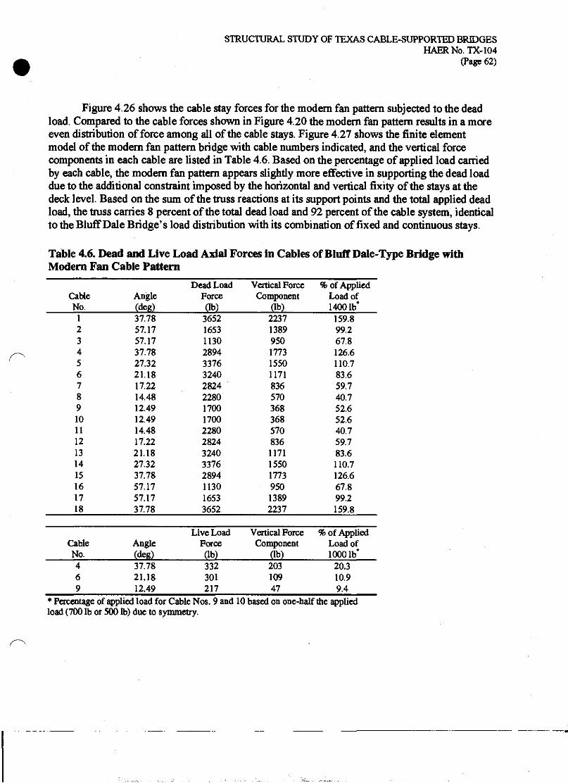
STRUCTURAL STUDY OF TEXAS CABLE-SUPPORTED BRIDGES HAERNo.TX-104
(Page 62)
Figure 4.26 shows the cable stay forces for the modern fan pattern subjected to the dead load. Compared to the cable forces shown in Figure 4.20 the modern fan pattern results in a more even distribution of force among all of the cable stays. Figure 4.27 shows the finite element model of the modern fan pattern bridge with cable numbers indicated, and the vertical force components in each cable are listed in Table 4.6. Based on the percentage of applied load carried by each cable, the modern fan pattern appears slightly more effective in supporting the dead load due to the additional constraint imposed by the horizontal and vertical fixity of the stays at the deck level. Based on the sum of the truss reactions at its support points and the total applied dead load, the truss carries 8 percent of the total dead load and 92 percent of the cable system, identical to the Bluff Dale Bridge's load distribution with its combination of fixed and continuous stays.
Table 4.6. Dead and Live Load Axial Forces in Cables of Bluff Dale-Type Bridge with Modern Fan Cable Pattern
Cable No.
Cable No.
Angle JdegL
37.78 21.18 12.49
Dead Load Force Ob)
Vertical Force Component
Ob)
i of Applied Load of 14001b*
1 37.78 3652 2237 159.8 2 57.17 1653 1389 99.2 3 57.17 1130 950 67.8 4 37.78 2894 1773 126.6 5 27.32 3376 1550 110.7 6 21.18 3240 1171 83.6 7 17.22 2824 836 59.7 8 14.48 2280 570 40.7 9 12.49 1700 368 52.6 10 12.49 1700 368 52.6 11 14.48 2280 570 40.7 12 17.22 2824 836 59.7 13 21.18 3240 1171 83.6 14 27.32 3376 1550 110.7 15 37.78 2894 1773 126.6 16 57.17 1130 950 67.8 17 57.17 1653 1389 99.2 18 37.78 3652 2237 159.8
Live Load Vertical Force % of Applied Angle Force Component Load of (deg) gbj £lb} 10001b'
332 301 217
203 109 47
20.3 10.9 9.4
* Percentage of applied load for Cable Nos. 9 and 10 based on one-half the applied load (700 lb or 500 lb) due to symmetry.

STRUCTURAL STUDY OF TEXAS CABLE-SUPPORTED BRIDGES HAERNo.TX-104
(Page 63)
Notes: 1. Thickness of line is proportional to axial force (except in backstays). 2. Numbers indicate axial force in lb. Positive values indicate tension.
Figure 4.26. Dead Load Axial Forces on Cables of Bluff Dale-Type Bridge with Modern Fan Cable Pattern
Figure 4.27. Cable Numbers for the Bluff Dale-Type Bridge with Modern Fan Cable Pattern

STRUCTURAL STUDY OF TEXAS CABLE-SUPPORTED BRIDGES HAERNo.TX-104
(Page 64)
The response of the truss under a concentrated live load at three different positions is shown in Figure 4.28. Again the shear, bending moment, and deflection behavior for the modern fan pattern are nearly identical to those shown in Figure 4.22 cable for the Bluff Dale Bridge. Based on the shear diagrams, for each live load location about 80 percent of the applied live load is carried by the truss. The peak axial forces in the truss due to the live load with the modern fan cable pattern are approximately three times as large as for the Bluff Dale pattern, but their magnitude is still small compared to the capacity of the wrought iron truss chords.
Figure 4.29 shows the live load cable forces for the modern fan cable pattern. For the live load positioned at the second stay location (50'), the first three stays (nos. 3,4, 5) of the main span carry the majority of the vertical load in the cable system, whereas for the Bluff Dale cable system shown in Figure 4.23, the first two fixed stays (nos. 3,4 in Figure 4.21) carry most of the load while the first continuous stay (no. 5) carries significantly less force. For the live load located at the fourth stay location (70'), again the load is distributed amongst a number of stays near the loaded point (nos. 3 to 7). This distribution of force is due to the bending stiffness of the truss. The cable tensions on the side of the main span opposite the load point are induced by the deflections of the truss, and therefore decrease towards the tower as the vertical deflection decreases. For a live load at mid-span (100'), the force is well distributed among all of the cable stays. For concentrated live loads in the main span, the Bluff Dale cable pattern, with both fixed and continuous stays, results in the fixed stays carrying significantly more of the live load than the continuous stay cables, whereas the modern fan cable pattern results in a more even distribution of force among all of the fixed stays.

STRUCTURAL STUDY OF TEXAS CABLE-SUPPORTED BRIDGES HAERNo.TX-104
(Page 65)
50" 70"
1000 lb each 50' 70'
100*
500 ij-hHJ
J---I i i-bd- ■HHH4—-| i.w.W)i_._.fc.iii..i4—i ^»- -^ * 4
J I l_L £1 B^mrtmfail&tlhtaUR IFT-
;9 x S H. 100
150
j_ | | ; | ym ■^ | rSt^j£ j -j-,..**£i i \ j 4- Q ; -1
J L 1 1 1 i i r 1_J I I L J L
.2 0.050 —
S 0.100 h
?„*-->■" <p" "* I +„-r^..S*... .4™™. .j*CI... -j j 4.
« +—-^-j*- + '■■^■*' f <
..rT...^... ...^.....j,^..... ..* } + » 4............ J. j + 2"'-! T
L 1 i 1 1 J L 80 100 120
Distance (ft) 140 160 180 200
Figure 4.28. Live Load Forces and Deflections in Truss of Bluff Dale-Type Bridge with Modern Fan Cable Pattern

STRUCTURAL STUDY OF TEXAS CABLE-SUPPORTED BRIDGES HAERNo.TX-104
(Page 66)
Notes: 1. Thickness of line is proportional to axial force (except in backstays). 2. Numbers indicate axial force in lb. Positive values indicate tension.
Negative values indicate reduction of dead load tension.
(a) Live Load at 50'
Notes: 1. Thickness of line is proportional to axial force (except in backstays). 2. Numbers indicate axial force in lb. Positive values indicate tension.
Negative values indicate reduction of dead load tension.
(b) Live Load at 70*
Figure 4.29. Live Load Axial Forces in Cables of Bluff Dale-Type Bridge with Modern Fan Cable Pattern

STRUCTURAL STUDY OF TEXAS CABLE-SUPPORTED BRIDGES HAERNo.TX-104
(Page 67)
Figure 4.29. Live Load Axial Forces in Cables of Bluff Dale-Type Bridge with Modern Fan Cable Pattern (continued)
Notes: 1. Thickness of line is proportional to axial force (except in backstays). 2. Numbers indicate axial force in lb. Positive values indicate tension.
Negative values indicate reduction of dead load tension.
(c) Live Load at 100*

STRUCTURAL STUDY OF TEXAS CABLE-SUPPORTED BRIDGES HAERNo.TX-104
(Page 68)
4.5.2 Crossing Fan Cable Pattern Figure 4.30 shows the truss forces and deflections for the crossing fan cable pattern under
dead load. Like the modern fan pattern, the shear, bending moment, and displacement responses with both fixed and continuous stays are nearly identical to those of the Bluff Dale Bridge. The mid-span displacement is 1.19", compared to 1.10" for the Bluff Dale cable arrangement. The maximum positive bending moment at mid-span is 653,690 in-lb, only 1 percent larger than the corresponding bending moment for the Bluff Dale Bridge, and the maximum negative bending moment at the towers is 671,910 in-lb, 10 percent larger than the corresponding bending moment for the Bluff Dale Bridge. The axial force diagram is also nearly identical to that for the Bluff Dale Bridge because in these two cases only the fixed stay cables can transfer horizontal force to the truss.
Figure 4.31 shows the dead load cable forces for the crossing fan pattern. Figure 4.32 shows the finite element model of the modern fan pattern bridge with cable numbers indicated, and the vertical force components in each cable segment are listed in Table 4.7. In this case, both inclined segments of the continuous stays will have a vertical force component; therefore, the percentage of applied load is based on the sum of the vertical force components from each inclined segment of a given continuous cable stay. The cable forces in the crossing fan pattern are typically lower than for the Bluff Dale Bridge, indicating that this cable system is slightly less stiff for uniform loads, resulting in the larger deflections and bending moments. The effectiveness of the crossing fan pattern is limited by the use of cables with shallow slopes. Since the horizontal force component in each segment of a continuous stay must remain constant, the extremely shallow slope in one segment limits the effectiveness of each cable stay as a whole. Based on the sum of the truss reactions at its support points and the total applied dead load, the truss carries 6 percent of the total dead load and the crossing fan pattern cable system 94 percent, slightly different than the load distributions for the Bluff Dale cable pattern and the modern fan pattern.

STRUCTURAL STUDY OF TEXAS CABLE-SUPPORTED BRIDGES HAERNo.TX-104
(Page 69)
£
u-
4000
2000
0
-2000
- n~u i i - § >
4
4
to
- I
i 1 1 ■
] 1 i i i r
-4000
-800 c
800
S I.OO -
0 20 40 60 80 100 120 140 160 180 200 Distance (ft)
Figure 4.30. Dead Load Forces and Deflections in Truss of Bluff Dale-Type Bridge with Crossing Fan Cable Pattern

STRUCTURAL STUDY OF TEXAS CABLE-SUPPORTED BRIDGES HAERNo.TX-104
(Page 70)
Notes: 1. Thickness of line is proportional to axial force (except in backstays). 2. Numbers indicate axial force in lb. Positive values indicates tension.
Figure 4.31. Dead Load Axial Forces in Cables of Bluff Dale-Type Bridge with Crossing Fan Cable Pattern

STRUCTURAL STUDY OF TEXAS CABLE-SUPPORTED BRIDGES HAERNo.TX-104
(Page 71)
>S^HI£CO>I^^eS^
Figure 4.32. Cable Numbers for the Bluff Dale-Type Bridge with Crossing Fan Cable Pattern

STRUCTURAL STUDY OF TEXAS CABLE-SUPPORTED BRIDGES HAERNo.TX-104
(Page 72)
Table 4.7. Dead and Live Load Axial Forces in Cables of Bluff Dale-Type Bridge with Crossing Fan Cable Pattern
Cable Dead Load Vertical Force Vertical Force % of Applied No. Angle Force Component Component Load of
(deg) Ob) (lb) (lb) 14001b 1 37.78 3615 2215 2215 158.2 2 57.17 1409 1184 1184 84.5 3 57.17 2085 1752 1752 125.1 4 37.78 4484 2747 2747 196.2 5 27.32 879 404 6 8.02 632 88
492 35.1
7 21.18 1379 498 8 8.81 1141 175
673 48.1
9 17.22 1702 504 10 9.77 1523 258
762 54.5
11 14.48 1868 467 12 10.97 1773 337
805 57.5
13 12.49 1889 408 14 12.49 1889 408
817 58.4
15 10.97 1773 337 805 57.5 16 14.48 1868 467
17 9.77 1523 258 18 17.22 1702 504
762 54.5
19 8.81 1141 175 20 21.18 1379 498
673 48.1
21 8.02 632 88 22 27.32 879 404
492 35.1
23 37.78 4484 2747 2747 196.2 24 57.17 2085 1752 1752 125.1 25 57.17 1409 1184 1184 84.5 26 37.78 3615 2215 2215 158.2
Live Load Vertical Force Vertical Force % of Applied Cable Angle Force Component Component Load of No. (deg) (lb) Ob) (lb) 10001b
4 37.78 329 202 202 20.2 7 21.18 199 72
99 9.9 8 8.81 174 27 13 12.49 231 50 14 12.49 231 50
100 10.0

STRUCTURAL STUDY OF TEXAS CABLE-SUPPORTED BRIDGES HAERNo.TX-104
(Page 73)
The truss forces and deflections due to three locations of live loads are shown in Figure 4.33. Again the responses are nearly identical to those for the Bluff Dale Bridge and for the modern fan pattern. For each live load location, the truss carries approximately 80 percent of the applied live load, similar to the modern fan cable pattern. The cable forces due to the live loads are shown in Figure 4.34, and the vertical force components for the cables at the live load locations are listed in Table 4.7. For the live load located at the second stay (SO1, no. 4) and fourth stay (70', no. 7), the forces are similar to those for the Bluff Dale Bridge in Figure 4.23—the fixed stays carry the largest tensions and the adjacent continuous stays carry significantly less force. For the crossing fan pattern with a live load at mid-span (1001, no. 13), the fixed stays still carry comparably large tensions, but the continuous stays near the center of the bridge also have relatively large tensions.
As previously discussed in Section 4.1, the crossing fan pattern uses some additional material, but it does not add significantly to the overall dead load of the bridge. With the minimal differences in behavior observed, the primary advantage of the cable arrangement extant at the Bluff Dale Bridge over the crossing fan cable pattern is a savings of material. It is unlikely that the designers of these bridges were capable of quantifying the differences in behavior, but certainly they could have observed that the as-built performance (primarily deflections) of bridges with each cable system was essentially the same. Such a comparison may have contributed to the selection of the cable arrangement extant at the BlufTDale Bridge for this and later bridges. It is possible that advantages or disadvantages of construction methods might have led to the use of a particular cable arrangement, although little is known about the construction methods used on the Bluff Dale and other Runyon bridges.

STRUCTURAL STUDY OF TEXAS CABLE-SUPPORTED BRIDGES HAERNo.TX-104
(Page 74)
50' 70"
1000 lb each 50' 70'
100'
-250
§
IX
£ -400
..*"-(jHj[p=»-» ■* ; «■ [ < •*•
* -i J-Mr-wt?« ~.!J 4. j +mm' -^*- »"4. 4
I ;i i""""i '^""f i i""""i i I
'3£z
*■? -100
s g -50
£ .a 0 ISO o
I—1 50
H ^ 100 CQ 150
'auv<- } *• ■* i * f < + { i
;,in ; JM i ,»*"
.i..^..^.,^....!^....^. j
3*K-^ -ff i j....^j- fi-+
J i i y i L J i L
—-f •> 1-— +. -Tt.^j.^..... j. i j i t....v.jH i. ...jp. i, + ;
' —+ > j ■^^■—j + j—-^^" f «- + }•■•■
j i i i i i L J i L J I 80 100 120 140 160 180 200
Distance (ft)
Figure 4.33. Live Load Forces and Deflections in Truss of Bluff Dale-Type Bridge with Crossing Fan Cable Pattern

STRUCTURAL STUDY OF TEXAS CABLE-SUPPORTED BRIDGES HAERNo.TX-104
(Page 75)
Notes: 1. Thickness of line is proportional to axial force (except in backstays). 2. Numbers indicate axial force in lb. Positive values indicate tension.
Negative values indicate reduction of dead load tension.
(a) Live Load at 50*
Notes: 1. Thickness of line is proportional to axial force (except in backstays). 2. Numbers indicate axial force in lb. Positive values indicate tension.
Negative values indicate reduction of dead load tension.
(b) Live Load at 70'
Figure 4.34. Live Load Axial Forces in Cables of Bluff Dale-Type Bridge with Crossing Fan Cable Pattern
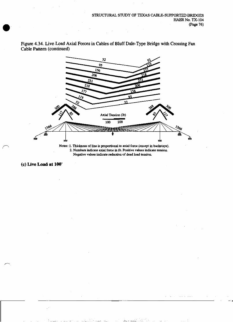
STRUCTURAL STUDY OF TEXAS CABLE-SUPPORTED BRIDGES HAERNo.TX-104
(Page 76)
Figure 4.34. Live Load Axial Forces in Cables of Bluff Dale-Type Bridge with Crossing Fan Cable Pattern (continued)
Notes: 1. Thickness of line is proportional to axial force (except in backstays). 2. Numbers indicate axial force in lb. Positive values indicate tension.
Negative values indicate reduction of dead load tension.
(c) Live Load at 100*
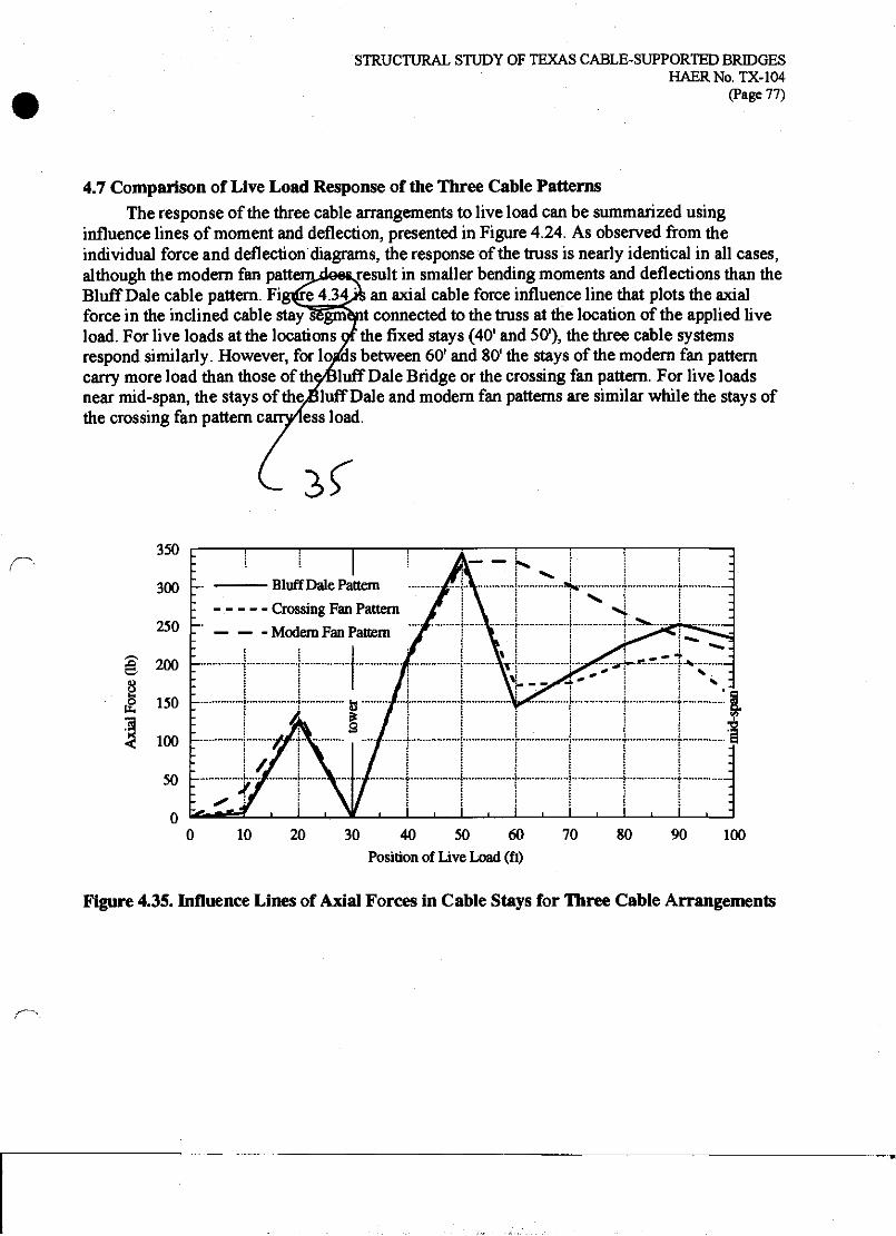
STRUCTURAL STUDY OF TEXAS CABLE-SUPPORTED BRIDGES HAERNo.TX-104
(Page 77)
4.7 Comparison of Live Load Response of the Three Cable Patterns The response of the three cable arrangements to live load can be summarized using
influence lines of moment and deflection, presented in Figure 4.24. As observed from the individual force and deflection diagrams, the response of the truss is nearly identical in all cases, although the modern fan patternjieetresult in smaller bending moments and deflections than the Bluff Dale cable pattern. Figure 4 j4Js an axial cable force influence line that plots the axial force in the inclined cable stay segment connected to the truss at the location of the applied live load. For live loads at the locations or the fixed stays (40' and 50'), the three cable systems respond similarly. However, for losras between 60' and 80' the stays of the modern fan pattern carry more load than those of the^Bluff Dale Bridge or the crossing fan pattern. For live loads near mid-span, the stays of thejjluff Dale and modern fan patterns are similar while the stays of the crossing fan pattern canViess load.
350
300
250
g, 200
ti- 150
100
50
0
Bluff Dale Pattern Crossing Fan Pattern — Modem Fan Pattern
10 20 30 40 50 60 Position of Live Load (ft)
70 80 90 100
Figure 4.35. Influence Lines of Axial Forces in Cable Stays for Three Cable Arrangements

STRUCTURAL STUDY OF TEXAS CABLE-SUPPORTED BRIDGES HAERNo.TX-104
(Page 78)
4.8 Concluding Observations The structural analyses of the Bluff Dale Bridge—simplified analytical models and finite
element models;—were used to understand the overall behavior of the combined structural systems of the Bluff Dale Bridge subjected to both dead and live loads. The analyses also were used to assess the unique structural features of the Bluff Dale Bridge and to compare its behavior to that of similar bridges with alternative cable patterns. Simplified, non-dimensional mathematical models were developed for each of the three structural sub-systems of the bridge and were used to demonstrate the non-linear behavior of cable structures. Finite element models provided detailed analysis of the behavior of the bridge and its response to both dead and live loads.
Two unique features of the Bluff Dale Bridge are the continuous stay cables and the horizontal deck cables. The simplified mathematical analyses confirmed that the deck cables are not effective in carrying vertical gravity loads when combined with a stiff truss. Although the function of the horizontal deck cables as originally intended by Runyon is not known, it is likely that the horizontal deck cables were intended for use during construction of the bridge. The simplified model of the Bluff Dale Bridge also showed that the stay cable primarily carries symmetric components of the applied loads while the truss carries the asymmetric components. An examination of vertical deflections for a range of values of truss stiffnesses suggested that the truss of the Bluff Dale Bridge could have been built using less material in the truss chords with no significant increase in deflections. Comparing the truss bending stresses from the finite element analysis to those of an unsupported truss showed mat the designers of the bridge certainly accounted for the load-carrying capacity of the cable system to relieve some of the applied loads from the truss. The designers' method of analyzing load distribution between the truss and cables is not known, but it would have been an approximate or empirical method.73
The finite element analyses comparing the Bluff Dale Bridge continuous stay pattern to the modern fixed stay pattern showed that the continuous stays significantly reduced the axial tension in the truss near the center of the span. Large axial tensions in the original wooden truss or the Howe pipe truss could have contributed to loosening the connections and would have been considered undesirable in such a truss. In a modern cable-stayed bridge, construction techniques and support conditions are used to control the axial force in the deck and many modem bridges have compressive axial force throughout their length. Such construction techniques were unavailable to Runyon or Flinn. The cable system of the Bluff Dale Bridge may be considered an innovative solution because it keeps the axial tension within the cable system rather then transferring it to the truss. The three different cable patterns considered resulted in somewhat
730nc possible approximate design method for deck-stiffened, cable-supported structures is to design the cable system to carry all of the dead load and to design the truss as an unsupported span for the live loads only. This approximate distribution of dead and live loads for design of cable-supported bridges is hypothetical. The author knows of no direct historical evidence to suggest mat this particular method was used on this, or any other bridge. Nevertheless, this method is attractive due to its simplicity and would result in a conservative design for typical cable-supported bridges. Conceptually, mis method is similar to that used by John A. Roebling to design his parabolic cable suspension aqueducts, in which the suspension cable was designed to support the weight of the water and the wooden trunk was designed to support its own self-weight independent of the cables. Although the construction sequence of the aqueducts would have resulted in a true load distribution different from that assumed in the design. See "The Wire Suspension Aqueduct..." (1845).
STRUCTURAL STUDY OF TEXAS CABLE-SUPPORTED BRIDGES HAERNo.TX-104
(Page 79)
different distributions of axial tensions in the cable systems, but the overall behavior of the bridge under live loads, as shown by the deflection and bending moment influence lines is not significantly affected by the cable pattern. The change from the crossing fan cable pattern used in some of the early Runyon bridges to the cable system used in the Bluff Dale Bridge may be attributed to the resultant savings in cable material.

STRUCTURAL STUDY OF TEXAS CABLE-SUPPORTED BRIDGES HAERNo.TX-104
(Page 80)
5 BE VERIDGE BRIDGE The Beveridge Bridge was originally constructed in 1896 by the Flinn-Moyer Company. It
was one of a group of cable-supported bridges built in Texas with the involvement of William Flinn, including the Bluff Dale Bridge (1890) and the Clear Fork of the Brazos River Bridge (1896).74 A 1938 renovation by the Austin Bridge Company included, at a minimum, reflooring, construction of new handrails, and the placement of new wires in the main cables.
5.1 Structural Description The Beveridge Bridge (1896) stands today as an unstiffened suspension bridge with a main
span of 140* and unsupported side spans of approximately 20' and 30' (see Figure 1. lb). The main span is divided into fourteen equal panels of lO'-O" each.75 Surviving photographic and written evidence suggests that the original Beveridge Bridge included a pipe stiffening truss as the handrail.76 In its present form the bridge has a handrail built from pipe verticals and horizontal parallel wire cables. This existing handrail provides no longitudinal stiffening to the bridge, although some of its components may have been reused from the original pipe truss. The exact dimensions of the original pipe truss are unknown. However, construction of the Beveridge Bridge commenced immediately following the completion of the Clear Fork of the Brazos River Bridge, also built by the Flinn-Moyer Company and the Clear Fork Bridge has an identical main span of 140' with fourteen panels of lO'-O" each, similar construction of the towers, and a pipe stiffening truss.77 Therefore, it is not unreasonable to assume that the original Beveridge Bridge pipe stiffening truss was substantially the same as that of the Clear Fork. This report will consider both configurations of the Beveridge Bridge: (1) the unstiffened form that survives today, and (2) the stiffened form based on the Clear Fork Bridge truss. The relevant structural properties are presented in Table 5.1.
The main suspension cable of the Beveridge Bridge has a 2" diameter and is composed of parallel No. 9 gauge wires (0.148" diameter). It is not known whether the 1938 reconstruction added wires or only replaced broken or corroded wires. The cable clamps which survive today tightly fit the 2" cable, and if they are original, then it is most likely that the cable diameter was not increased during the reconstruction. The analyses presented here assume a cable diameter of 2". As for the parallel wire cables of the Bluff Dale Bridge, the net cable area will be estimated as 70 percent of the gross area, resulting in a net area of 2.20 in2. The elastic modulus of the wires will be assumed to be 27x106 psi, consistent with wrought iron wire.
74"Beveridge Bridge," HAER No. TX-46.
""Beveridge Bridge," HAER No. TX-46, drawings.
76 San Saba Historical Commission (1983); "Beveridge Bridge," HAER No. TX-46.
77 "Clear Fork of Brazos Suspension Bridge," HAER No. TX-64. The towers have since been surrounded by concrete, but surviving photographs show a tripod-type tower. The pipe truss was documented and measured by Texas Dept. of Transportation staff during the 1980s. The field notes are included in "Clear Fork of Brazos River Suspension Bridge," HAER No. TX-64.

STRUCTURAL STUDY OF TEXAS CABLE-SUPPORTED BRIDGES HAERNo.TX-104
(Page 81)
The Beveridge Bridge also includes a single inclined cable stay at each end of the bridge, extending from the top of the tower to the end of the floor beam at the second panel point in the main span (20' from each tower). The existing stay is approximately 0.5" diameter and is a retrofit that uses wire rope. An early photograph of the Clear Fork Bridge shows similar cable stays, and its wires were wrapped together with the wires of the backstay. It is not known if any means was provided to pre-tension the inclined stays. The original intent of the stay cables is not clear, but they may have been used to facilitate construction or to help reduce deflections of the bridge deck due to concentrated live loads. In combination with the relatively stiff truss of the Beveridge Bridge, the stays are not expected to have had a significant effect on the overall behavior of the bridge. In addition, the effectiveness of the stays would be limited by the use of only a single stay, their attachment near the tower, small diameter and lack of means of pre- tensioning. The inclined stays are not considered to be part of the primary structural system of the Beveridge Bridge, and are, therefore, not included in the analyses of the Beveridge Bridge presented in this report. Section 6 will explore the structural behavior of the hybrid stayed- parabolic suspension bridge form in more detail.
Table 5.1. Structural Properties of the Beveridge Bridge
Property Value Comments/Source Overall Dimensions and Loads Main Span 140'-0" Side Spans 20*-0", 30'-0" Dead Load 150 lb/ft Live Load 10001b Main Cable Sag 15'-6" Gross Diameter 2.00"
HAER No. TX-46, sheet 1 of 3. estimated from HAER No. TX-46,1 of 3. See Table 5.2. See discussion in text
Net Area
Modulus of Elasticity
2.20 in2
27xl06psi
HAER No. TX-46,2 of 3. HAER No. TX-46,2 of 3. Original cable size assumed equal to extant size. 1938 reconstruction included either replacement or addition of some of the wires. See HAER No. TX-46. 70 percent of gross area, based on typical ratio for parallel wrought iron wire bridge cables. Equivalent to 128 No. 9 gauge (0.148") wires. Typical values for wrought iron. Withey and Aston (1926).
Stiffening Truss (based on Clear Fork of the Brazos Chord Area 2.062 in2
Depth 63.0" Area 4.124 in2
Moment of Inertia 4096 in4
Modulus 27xl06psi Tower Area 11.192 in2
Moment of Inertia varies Modulus of Elasticity 27x10* psi
Bridge) HAER No. TX-64, 2-7/8" OX>. pipe with 1/4" wall HAERNo.TX-64.
Typical values for wrought iron. Withey and Aston (1926).
HAER No. TX-64, three 5" OD. pipe with 1/4" wall. Varies due to taper of towers. See text. Typical values for wrought iron. Withey and Aston (1926).

STRUCTURAL STUDY OF TEXAS CABLE-SUPPORTED BRIDGES HAERNo.TX-104
(Page 82)
5.2 Dead and Live Loads Table 5.2 summarizes the dead loads of the Beveridge Bridge for both the stiffened and
unstiffened forms. Since the side spans are not suspended, only the main span is considered in calculating the dead loads. For the unstiffened configuration, the weight of the floor system (transverse beams, stringers, and decking) is based on the surviving, in-place components. For the stiffened configuration, the weight of the floor system is based on the Clear Fork Bridge, which has pipe-and-rod needle beams and wooden stringers. The resulting dead loads are 150 lb/ft for the unstiffened form and 156 lb/ft for the stiffened form. For simplicity of analysis and presentation, a dead load of 150 lb/ft will be used for both configurations. For the Bluff Dale Bridge, a concentrated live load of 1000 lb will be used.
Table 5.2. Dead Load Summary of the Beveridge Bridge
Description Weight Main Cables (Includes main span only) 2 sides @ 1041 = 2142 lb
Cable assumed 2" gross diameter with 70 percent net area Suspenders 2 sides @ 358 = 716 lb Floor System as extant 35,583 lb
Includes transverse beams, stringers, lateral bracing, and wood flooring Pipe Handrails as extant 14601b
Floor System based on Clear Fork 29,282 lb Includes transverse beams, stringers, lateral bracing, and wood flooring
Pipe Stiffening Truss based on Clear Fork 9476 lb Dead Load for Unstiffened Form Subtotal 39,901 lb 5 percent allowance for connections and miscellaneous material 1995 lb Total 41,896 lb Weight per foot for full width of bridge 41,896 lb / 140 ft = 300 lb/ft Weight per foot for 2D model of single plane of bridge 150 lb/ft Dead Load for Stiffened Form Subtotal 41,6161b 5 percent allowance for connections and miscellaneous material 2081 lb Total 43,6971b Weight per foot for full width of bridge 43,697 lb / 140 ft = 312 lb/ft Weight per foot for 2D model of single plane of bridge 156 lb/ft Notes: Unit weight of wrought iron - 485 lb/ft3; unit weight of wood = 30 lb/ft3.

STRUCTURAL STUDY OF TEXAS CABLE-SUPPORTED BRIDGES HAERNo.TX-104
(Page 83)
5.3 Analysis of Unstiffened Suspension Bridge The theoretical treatment of the unstiffened suspension bridge was first published by
Navier in 1823, when he considered the case of a single point load at the mid-span of a bridge.78
A later series of anonymous articles in 1860 in the British journal Engineering generalized the solution for a concentrated load at any position on the bridge.79
For a theoretical analysis of an unstiffened suspension bridge, the self-weight, or dead load, is assumed to be distributed uniformly along the horizontal. In practice, this is very nearly true since most of the self-weight is due to the roadway. The axial deformation of the suspenders are also neglected, and thus the vertical displacement of the cable and bridge deck are equal at any given location along the length of the bridge. Further, the cable and deck are assumed to be connected continuously along the length of the bridge (i.e. with very closely spaced suspenders) such that the cable takes the shape of a parabola. A parabola is the funicular shape for a load uniformly distributed along the horizontal. In practice, there will be a discrete number of suspenders and the main cable will form a polygonal shape, closely approximated by a parabola. Finally, the ends of the parabolic cable at the tops of the towers are assumed to be fixed, neglecting the flexibility of the towers and backstays.
Consider a parabolic cable of span L, sag/ and with a uniform dead load, w, as shown in Figure 5.1. The dead load will produce axial tension in the cable. Since the only load on the cable is vertical, the horizontal component of the cable tension will be constant and equal to
H = —. (5-1) 8/
The shape of the cable can be described by a parabola of the form
**>"(T^V + ** + C. (5-2) .2ff/ where the coefficients b and c are determined by enforcing the end conditions at the supports. For the case of end supports at equal elevations (as shown in Figure 5.1) and the origin (x=0, y=0) below the left support at an elevation equal to the lowest point of the cable, the coefficient b=-4f/L and c=f. The unstiffened bridge is a geometrically non-linear structure and therefore its displaced shape must be considered in applying equations of equilibrium. The solution is formulated in a manner similar to that for the stay cable described in Section 4.3.1—vertical equilibrium at the load point and force-elongation of the parabolic cable.
A concentrated live load, P, is located at a distance of rL from the left end of the span, as shown in Figure 5.1. The load P will produce a deflected shape with a discontinuous slope at the
78 Navier (1823); see also Kranakis (1997). ""The Statics of Bridges" (1862,1863). See Buonopane and Billington (1993) for a more complete discussion
of the development of suspension bridge theory.

STRUCTURAL STUDY OF TEXAS CABLE-SUPPORTED BRIDGES HAERNo.TX-104
(Page 84)
-AA li * * * i i i i i * 1 I i i i i f i i i i i ^ i i TT~I
Notes: 1. Numbers indicate cable segments 1 and 2. 2. Uniform load w not shown for clarity.
Figure 5.1. Parabolic Cable with Uniform Dead Load and Concentrated Live Load
load point, but the cable segments between the load point and each support will remain parabolic. The shape of each parabolic segment is still described by Eq. (5-2) where the coefficients b and c must now be determined based on the displaced shape of the cable. The coefficients b are related to the slope of each cable segment at the load point and are denoted b{(v0,TH) and b2(v0,TH), where the subscript 1 indicates the segment of the cable to the left of the live load and 2, the segment to the right of the live load. The parentheses indicate functional dependence; that is, the coefficients bx and b2 depend on the value of the vertical deflection at the load point, v0, and the total horizontal cable tension, TH, due to both the dead and live loads.
Applying vertical equilibrium at the load point, as shown in Figure 5.2, results in P-N?-N>=0,or (5-3)
^-^•fc.(vo.7i)-rH-^(v0,7i) = 0. (5-4)
Since there are two fundamental unknowns, v0 and TH, a second equation relating these unknowns is required. As for the stay cable, the second relationship is derived from the change in length of the cable due to the additional axial tension created by the live load. Since the cable takes the shape of a parabolic curve, the length must be calculated by evaluating an integral along the shape of the curve. Let Z* (v0, TH) represent the length of the i-th parabolic cable segment, which is a function of v0 and TH. The change in length, A, of the cable due to axial elongation from the live load is given by
A={A(vo.r„)+i»(v..r,)}- h(fi,H)= 4(0,H). (5-5)
The term Z, (0, H) is the initial length of the cable under dead load only, and the term Z^ (0, H) is

STRUCTURAL STUDY OF TEXAS CABLE-SUPPORTED BRIDGES HAERNo.TX-104
(Page 85)
V<e N[
xt. Nl
Applied live Load = P
2 ____ — -'""
-JVJ-T.
1. Axial Ibices A^ and N2 are oriented in the direction of the tangent of each cable segment at the point of the applied live load.
2. Axial forces Ni and N2 are decomposed into vertical (y) and norizontal (x) components.
Figure 5.2. Vertical Force Equilibrium at Loaded Point of Parabolic Cable
a different integral evaluated along the curve of the parabolic cable under dead load only. The fundamental unknowns can be found by solving Eqs. (5-4) and (5-5) simultaneously. Once v0 and TH have been calculated, the deflected shape of the cable or bridge deck can be determined based onEq.(5-2).M
Again it is convenient to formulate the equations in terms of the following non- dimensional parameters:
Live-to-dead load ratio
Non-dimensional dead load
Sag-to-span ratio
Total horizontal tension
c- wL
n = — L
wL
(5-7)
(5-8)
(5-9)
The non-dimensional horizontal tension due to dead load alone (equivalent ofH) may be expressed as f0 = l/8«. Table 5.3 gives the values of these parameters for the Beveridge Bridge.
80 See Pugsley (1968) and Buonopane and Billington (1993) for a more detailed discussion of the solution of the unstiffened suspension bridge.

STRUCTURAL STUDY OF TEXAS CABLE-SUPPORTED BRIDGES HAERNb.TX-104
(Page 86)
Table 5.3. Non-Dimensional Parameters of Beveridge Bridge
Parameter Value Sag-to-Span Ratio Live-to-Dead Load Ratio
n y
0.111 0.048
Non-dimensional Dead Load 0* 3.5x10* Truss Stiffness Ratio a 0.053 Modular Ratio V 1.0
Figure 5.3 shows the live load deflections at the load point for a range of load ratios, 7,of an unstiffened cable with a point load at the quarter-point (r-0.25) and mid-span (r=Q.5). Figure 5.3 indicates that the unstiffened suspension bridge is highly non-linear in its response and exhibits tension stiffening for gravity live loads (positive load ratio) and softening for uplift live loads (negative load ratio). For gravity live loads, the deflection for a mid-span load is always less than that for a quarter-point load. In general, because the parabolic cable is the funicular shape for a uniform (symmetric) load, it will respond with greater stiffness for symmetric loads (here, a single point load at the mid-span) than for asymmetric or antisymmetric loads (here, a single point load at the quarter-point). A small load ratio, which for a given live load can be achieved
0.60
0.40 -
.2 0.20 -
0.00 -
-0.20
-0.40
- .25 .50 .......
i j
- --r=0
i /
1 /
1 / 1,1.
if if
——.......... .............^i £- —n=o.in
■ ■* . . . . ■ i i
<*=3.5xl0r4
■ i i 1 i i i
-0.06 -0.04 -0.02 0.00 0.02 0.04 Live Load Deflection / Span
Figure 5.3. Live Load Deflection Behavior of a Parabolic Cable

STRUCTURAL STUDY OF TEXAS CABLE-SUPPORTED BRIDGES HAERNo.TX-104
(Page 87)
with a large dead load, will reduce deflections due to gravity live loads. Navier mathematically demonstrated this fact in 1823, consequently influencing the design of many suspension bridges during the nineteenth century."
Figure 5.4 shows an influence diagram for the vertical displacement at the loaded point for several levels of the load ratio, y. The maximum deflection occurs for a live load at about 7=0.2 and is greater than the deflection a for a live load at r=0.5, again showing that an unstiffened bridge exhibits smaller deflections for loads near the mid-span than for loads near the quarter-point.
0.00 support
0.10 0.20 0.30 Position of Live Load (r)
0.40 0.50 mid-span
Figure 5.4. Influence Lines of Live Load Deflection of a Parabolic Cable
81 Buonopane and Billington (1993).

STRUCTURAL STUDY OF TEXAS CABLE-SUPPORTED BRIDGES HAERNo.TX-104
(Page 88)
Figure 5.5 shows that live load deflections are reduced for unstiffened suspension bridges with small sag-to-span ratios. However, a small sag-to-span ratio will also increase the maximum tension in the cable, requiring a larger cable area. A large cable sag will also require tall towers, which are typically uneconomical. In 1823, Navier showed mathematically that shallow unstiffened suspension bridges can reduce deflections and designed his Pont d'Invalides (1826) accordingly with a ratio of n=\l\l. Modem suspension bridges are typically about w=l/10; the Beveridge Bridge has n=M9,
The non-dimensional dead load, o~, has a minimal effect on the live load deflection. In
practice, the value of a is a function of the allowable stress (or strain) of the suspension cable,
and therefore will not vary widely. A small value of a may be interpreted as providing a cable
area in excess of that required for a given allowable cable stress, in which case some benefit is derived in reduced deflections, although this is not an economical means of reducing deflections.
CO
I
0.016
0.014
0.012
0.010
0.008
0.006
0.004
0.002 -
: r=o.048 r0fe3.5xl(r4
0.000 0.00 0.10 0.20 0.30 0.40 0.50
Sag to Span Ratio
Figure 5.5. Effect of Sag-to-Span Ratio on a Parabolic Cable

STRUCTURAL STUDY OF TEXAS CABLE-SUPPORTED BRIDGES HAERNo.TX-104
(Page 89)
5.4 Analysis of Deck-Stiffened Bridge Unstiffened suspension bridges may exhibit large deflections under typical live loading as
the parabolic cable changes its configuration to support the load. Numerous methods for providing additional stiffness to suspension bridges were proposed and built during the nineteenth and twentieth centuries.82 One common method of adding stiffness to a suspension bridge has been to provide a deck with longitudinal bending stiffness in the form of a truss or girder. Despite frequent use of the deck-stiffened bridge after 18S0 in both Europe and the United States, few theoretical developments had been made beyond the work of Navier on the unstiffened form. In 1888 Josef Mel an developed a linear theory of the stiffened suspension bridge (the Elastic Theory), and in 1906 he published the geometrically non-linear theory (the Deflection Theory) in its modem form. The Elastic Theory is an acceptable approximation for bridges with large deck stiffness, and its use led to the early twentieth-century development of heavily stiffened bridges such as the Williamsburg and Manhattan Bridges. The Deflection Theory allowed bridge designs with drastically reduced deck stiffnesses and led to the slender bridges built between 1920 and 1940.83
The fundamental differential equation for the Deflection Theory of a deck-stiffened suspension bridge can be written84
EI^. = p{x)-±w{x) + {H + h)^>, (5.10) ax H ax
where v{x) is the deflected shape of the bridge deck, p(x) is the live load, w(x) is the dead load, H is the horizontal cable tension due to dead load, h is the horizontal cable tension due to live load, / is the deck stiffness, and £ is the deck modulus. The simpler Elastic Theory, which assumes that the geometry does not change under the live load, is also represented by Eq. (5-10) by neglecting the final term with the second derivative of v(*).M In this report, the Elastic Theory will be discussed as a linear approximation for the non-linear Deflection Theory.
Unlike the case of the unstiffened cable, which could be solved in terms of a single deflection at the loaded point, the equations for a stiffened suspension bridge are formulated in terms of the deflection function, v(x), for all points in the span. The resulting mathematics are somewhat complex, although conceptually the method of solution is similar to that used for the unstiffened span—vertical equilibrium and force-elongation of the cable. Eq. (5-10) may be viewed as an equation of vertical equilibrium at any point x in the span. Eq. (5-10) contains two
KGasparimetal.(1999).
83 See Buonopane and Billington (1993) for a more complete discussion and the effects of the Deflection Theory on bridge design.
84 Timoshenko (1928); Steinman (1929).
M The remaining linear equation i effective load of p(x) - (ft / H)w(x).
85 The remaining linear equation will be seen to be identical to the classical beam bending equation with an
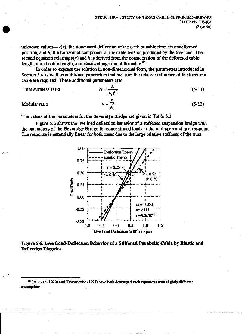
STRUCTURAL STUDY OF TEXAS CABLE-SUPPORTED BRIDGES HAERNo.TX-104
(Page 90)
unknown values—v(x), the downward deflection of the deck or cable from its undeformed position, and h, the horizontal component of the cable tension produced by the live load. The second equation relating v(x) and h is derived from the consideration of the deformed cable length, initial cable length, and elastic elongation of the cable.86
In order to express the solution in non-dimensional form, the parameters introduced in Section 5.4 as well as additional parameters that measure the relative influence of the truss and cable are required. These additional parameters are:
a = -^r, (5-11) Truss stiffness ratio
Modular ratio (5-12)
The values of the parameters for the Beveridge Bridge are given in Table 5.3
Figure 5.6 shows the live load deflection behavior of a stiffened suspension bridge with the parameters of the Beveridge Bridge for concentrated loads at the mid-span and quarter-point. The response is essentially linear for both cases due to the large relative stiffness of the truss.
1.00
0.75
0.50
0.25
0.00
-0.25 r
-0.50
Deflection Theory Elastic Theory
r= 0.25
y-o3o~~ . r-0.25 &0.50
■ ■ ■*
#
a = 0.053 n=0.111 - 0=3.5x10-*
I ■ ■ ■ ■
-1.0 -0.5 0.0 0.5 1.0 1.5 Live Load Deflection (xlO*3) / Span
Figure 5.6. Live Load-Deflection Behavior of a Stiffened Parabolic Cable by Elastic and Deflection Theories
K Steinman (1929) and Timoshenko (1928) have both developed such equations with slightly different assumptions.

STRUCTURAL STUDY OF TEXAS CABLE-SUPPORTED BRIDGES HAERNo.TX-104
(Page 91)
A load at the quarter-point results in a larger deflection than a load at mid-span for a given load ratio because the parabolic cable responds with greater stiffness to symmetric loads. In all cases, the Elastic Theory results in larger deflections than the non-linear Deflection Theory because it does not account for the tension stiffening effect of the main cable.
Figure 5.7 shows influence lines of both deflection and bending moment for a point load moving across the span from support to mid-span with a truss stiffness ratio of Of=0.053. The peak values of both bending moment and deflection occur for a load near the quarter-point. The Deflection Theory solution results in both smaller deflections and bending moments than the Elastic Theory for a live load located at any position along the span. For the Beveridge Bridge with a stiffening truss, the peak deflection is about 0.11", compared with about 5.7" for the unsuffened bridge. The peak moment is 146,800 in-lb which corresponds to a bending stress of only 1156 psi, well below acceptable stresses for wrought iron.
0.10
—
1
action Theory ic Theory
a = 0.053 - r=0.048 n-0.111
o*3.5xl(r4 ; ■ x X, 1 y Deflection
x 1>CL ; 1*
— Moment
iii ■ i ■ i i i < ■ ■ .... . . . .
0.00
0.02 <w *
0.04 g
a 0.06 S
S 0.08 8
1 0.00 support
0.10 0.20 0.30
Position of Live Load (r)
0.40 0.50 mid-span
.0.10
Figure 5.7. Influence Lines of Live Load Deflection and Moment of a Stiffened Parabolic Cable by Elastic and Deflection Theories

STRUCTURAL STUDY OF TEXAS CABLE-SUPPORTED BRIDGES HAERNo.TX-104
(Page 92)
Figure 5.8 and Figure 5.9 examine the effect of the truss stiffness ratio on deflections and moments, respectively, for live loads at the quarter-point and mid-span. The figures also compare the Deflection and Elastic Theory solutions. For values of a greater than about 0.01 (lxlO"2), the Elastic Theory gives an acceptable approximation for the deflections, while for values of a less than 0.01 the solutions diverge rapidly. TTie Deflection Theory solutions converge to the solution of the unstiffened cable as a approaches zero, while the Elastic Theory solutions increase without bound. For truss stiffness ratios below about lxlO"5, the truss has little effect in reducing deflections over an entirely unstiffened span. For truss stiffness ratios greater than about lxlO"3, the slope of the plotted curves are relatively shallow, indicating that an increase in the truss stiffness ratio (achieved by an increase in the amount of material in the truss chords) has a proportionately much smaller effect in reducing deflections. Thus, truss stiffness ratios above about lxlO"3 can be considered an inefficient use of material based on this analysis. The truss stiffness ratio of the Beveridge Bridge (a=0.053) is extremely large compared to twentieth- century bridges, which may have ratios as small as 0.0002 (2xl0'4). The advantage of the non- linear Deflection Theory is also evident in the influence diagram of the truss moment; as the truss stiffness decreases, the moment approaches zero. However for the linear Elastic Theory, the moment is essentially constant below about ce=0.001. This constant moment implies that a bridge designed by the Elastic Theory must have a stiffening truss capable of carrying at least this minimum moment.
CO
o K
53
S o
lO'4 10"3
Truss Stiffness Ratio
Figure 5.8. Effect of Truss Stiffness on Vertical Live Load Deflection of a Stiffened Parabolic Cable by Elastic and Deflection Theories

STRUCTURAL STUDY OF TEXAS CABLE-SUPPORTED BRIDGES HAERNo.TX-104
(Page 93)
0.10
■a o 1-1
2
I o
S? f
ia4 i(r3
Truss Stiffness Ratio
Figure 5.9. Effect of Truss Stiffness on Live Load Moment of a Stiffened Parabolic Cable by Elastic and Deflection Theories
5.5 Finite Element Analysis of Beveridge Bridge A finite element analysis of the Beveridge Bridge is capable of including the effects of the
discrete suspenders, continuity of the truss across the tower supports, and the flexibility of the towers, suspenders and backstays, all of which were neglected by the analytical models considered in Sections S.3 and 5.4. The finite element method itself has been described previously in Section 4.5. Three finite element models were analyzed for the Beveridge Bridge:
(l)Unstiffened,
(2) Stiffened by a truss simply supported at the towers, and
(3) Stiffened by a truss continuous across the tower supports.
The Beveridge Bridge as extant is essentially an unstiffened bridge, although there is substantial historical evidence to suggest that it was originally constructed with a stiffening truss similar to that of the Clear Fork of the Brazos River Bridge. It is possible that the truss was continuous across the tower support, similar to that of the Bluff Dale Bridge, or discontinuous and simply supported, making the side spans structurally independent of the main suspended span. The piers of the Clear Fork of the Brazos Bridge have two parallel pipe supports, suggesting that the truss

STRUCTURAL STUDY OF TEXAS CABLE-SUPPORTED BRIDGES HAERNo.TX-104
(Page 94)
on this bridge may have been discontinuous and simply supported.87 It is possible that these pipes may have only supported the longitudinal timber stringers, with the pipe truss still being continuous across the pier support. At the Beveridge Bridge no evidence survives that would suggest whether or not the truss was continuous or not A continuous truss will provide some benefit in reducing deflections and bending moments in the truss, and the designers of the Beveridge Bridge would have known of such benefit.
Each of the finite element models of the Beveridge Bridge is a two-dimensional representation of one-half the width of the bridge (see Figure 1.1b). Properties of each element are given in Table 5.4. For all three models, the main cable and backstays are represented by beam elements of a cross-sectional area corresponding to 128 No. 9 gauge wires. The cable elements also have a small moment of inertia corresponding to 128 No. 9 gauge wires each bending individually, which is intended primarily to maintain numerical stability of the non- linear solution scheme. Each tower is divided into nineteen beam elements that to reproduce the changing bending stiffness of the tapering, tripod arrangement. At the base of the tower, where the pipes are separated by about 2'-l" on center, the moment of inertia is 1148 in4. At the top of tower the pipes are tangent to one another with a separation of about 5" on center and have a moment of inertia of only 87 in4. For the deck-stiffened models, the truss is represented by a line of beam elements of cross-sectional area and moment of inertia based on the stiffening truss from the Clear Fork of the Brazos River Bridge. Each vertical suspender is defined as an axial force element using pin connections at each end such that no bending moment can be transferred from the truss. The attachment between the truss and the tower is achieved with short length axial force elements that have a large cross-sectional area and pin-connected ends in order to provide vertical and horizontal support, but prevent bending moment in the truss from being transferred into the towers.
Table 5.4. Element Properties of Beveridge Bridge Model
Element Area Moment of Inertia (in2) (in4)
Truss 4.124 4096 Main Cable 2.199 3.0X10⁻³
Suspenders 0.785 0.049 Towers 11.19 87 to 1148 Truss-Tower Connection 1000 0.001
87 "Clear Fork of Brazos River Suspension Bridge," HAER No. TX-64.

STRUCTURAL STUDY OF TEXAS CABLE-SUPPORTED BRIDGES HAERNo.TX-104
(Page 95)
For a stiffened suspension bridge, the dead load is supported primarily by the main cable and results in only small moments in the bridge deck due to bending of the deck between vertical suspenders. In practice, this dead load distribution can be achieved by adjusting the length of the vertical suspenders during construction. The suspenders of the Beveridge Bridge do contain turnbuckles and the profile of the bridge deck may have been adjusted during construction of the bridge. It is not known to what degree any adjustments performed would have relieved the dead load bending moments in the truss. In order to assess the magnitude of the maximum possible deflections and bending moments due to the dead load, an initial analysis was performed with the uniform dead load, applied as a concentrated load of 1500 lb at each node along the main cable (in the case of the unstiffened model) or the deck (in the case of the stiffened models).
Because both the unstiffened and stiffened forms of the bridge exhibit significant geometrically non-linear behavior, analyses for live load effects must include the dead load, which provides significant tension stiffening. As for the Bluff Dale analyses, the forces and deflections due to live load were calculated as the change in force or deflection between an analysis with dead load only and an analysis with both dead and live load. A series of finite element analyses for live load was performed by simultaneously applying the dead load and a concentrated live load of 1000 lb at each panel point.
Figure 5.10 shows the vertical deflections of the unstiffened bridge for the dead load and for live loads near the quarter-point (60') of the main span and at mid-span (100'). The maximum displacement due to dead load is 2.21", although this displacement would have occurred during construction and the profile of the roadway could have been adjusted to remove some or all of this deflection. The maximum deflection for a live load at 60* is 5.19", while for a load at mid- span it is 3.95". The deflections due to the live loads are greater than those due to the dead load because the main cable must exhibit a significant change in shape to carry the live load. Figure 5.11 shows the influence line of displacement for the unstiffened finite element model as well as for the analytical model presented in Section 5.3. This comparison shows that the modeling features specific to the finite element analysis—segmental cable, discrete loading, and flexibilities of towers and backstays—do not have a significant effect on the calculated live load response. Figure 5.12 shows the tension in the main cable and backstays for the dead and live load cases. The maximum dead load cable tension occurs adjacent to the towers and is 25,364 lb, corresponding to an axial stress of 11,530 psi.

STRUCTURAL STUDY OF TEXAS CABLE-SUPPORTED BRIDGES HAERNo.TX-104
(Page 96)
TTf 1500 lb each
a p
&
0.0
1.5 2.0 2.5
—
- 1 - i i ^^^
- , p^-
i i i 20 40 60 80 100 120
Distance (ft)
(a) Dead Load
140 160 180 200
1000 lb each 60' 100*
5 a o
o a
80 100 120 Distance (ft)
(b) Live Load at 60* and 100*
Figure 5.10. Dead and Live Load Deflections of Unstiffened Beveridge Bridge
200

STRUCTURAL STUDY OF TEXAS CABLE-SUPPORTED BRIDGES HAERNo.TX-104
(Page 97)
0.00 tower
0.10 0.20 0.30 Position of Live Load (f)
0.40 0.50 mid-span
Figure 5.11. Influence Line of Vertical Live Load Displacement of Unstiffened Beveridge Bridge
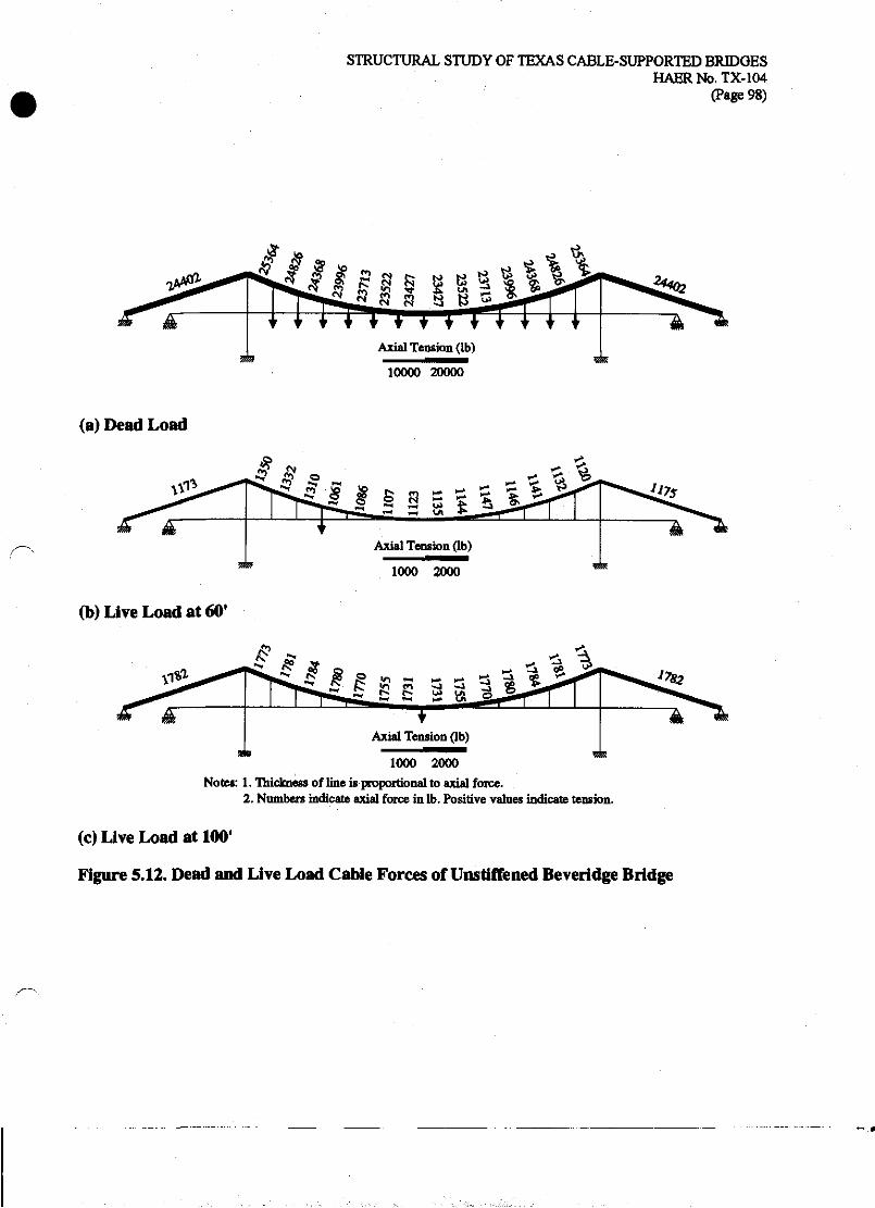
STRUCTURAL STUDY OF TEXAS CABLE-SUPPORTED BRIDGES HAERNo.TX-104
(Page 98)
10000 20000
(a) Dead Load
45 # S
Axial Tension (lb)
1000 2000
(b) Live Load at 60'
1000 2000 Notes: 1. Thickness of line is proportional to axial force.
2. Numbers indicate axial force in lb. Positive values indicate tension.
(c) Live Load at 100*
Figure 5.12. Dead and Live Load Cable Forces of Unstiffened Beveridge Bridge

STRUCTURAL STUDY OF TEXAS CABLE-SUPPORTED BRIDGES HAERNo.TX-104
(Page 99)
Figure 5.13 and Figure 5.14 show the dead load truss forces and displacements for, respectively, the stiffened bridge model with the truss simply supported at the towers (5.13) for the stiffened bridge model with the continuous truss (5.14). The simply supported truss has a maximum deflection of 1.90", and the continuous truss, 1.46". Both deflections are somewhat less than that of the unstiffened case. The maximum positive bending moment at mid-span of the simply supported truss is 713,320 in-lb, resulting in a stress of 5487 psi in the chords of the truss. For the continuous truss, the maximum positive moment is 772,750 in-lb and the maximum negative bending moment at the towers is 1,115,800 in-lb. The moment at the towers results in a stress of 8583 psi in the truss chords. Because the continuous truss is suffer than the simply supported truss, it carries a larger portion of the dead load, creating the larger bending moments. As seen in the axial cable force diagrams in Figure 5.15, the suspender forces for the simply supported truss range from 1251 lb to 1260 lb and are approximately 85 percent of the applied load of 1500 lb at each load point The remaining 15 percent of the applied load, about 225 lb, is carried by the truss in bending. In contrast, for the continuous truss, the suspender forces of 840 lb to 861 lb are only about 57 percent of the applied load, leaving 43 percent of the applied load, or about 650 lb, to be carried by the truss in bending.
Figure 5.16 and Figure 5.17 show forces and deformations for two positions of live load-near the quarter-point (601) and at mid-span (lOO')-for the simply supported and continuous truss models, respectively. Figure 5.18 and Figure 5.19 show cable and suspender axial forces for the simply supported and continuous truss models, respectively. In all cases, nearly all of the 1000 lb applied live load is carried by the truss, as evidenced by the small vertical suspender force at the point of load application. Note also that the suspender forces across the entire span are nearly uniform for a concentrated live load. Since the main cable is the funicular shape for the distributed dead load, it is significantly less stiff than the truss for a concentrated live load. In the unstiffened case, it is necessary for the main cable to alter its shape to the funicular for the total dead plus live load. In the stiffened case, the truss can carry most of the concentrated live load in bending while the main cable remains subjected to a nearly uniformly distributed load.
For the live load at mid-span (100'), the bending moment and deflection for the simply supported and for the continuous truss are similar. For the simply supported truss, the peak deflection is 0.16" and the maximum positive bending moment is 142,500 in-lb. For the continuous truss, the peak deflection is 0.14" and the maximum positive bending moment is 146,000 in-lb. The stiffer continuous truss carries slightly more of the live load than the more flexible simply supported truss. For the live load near the quarter-point (60'), the simply supported and continuous trusses respond differently. The simply supported truss has a peak deflection of 0.13" and a maximum positive bending moment of 165,200 in-lb. The continuous truss has a peak deflection of 0.08" and a maximum positive bending moment of 117,700 in-lb. The negative moment at the tower is 115,200 in-lb.

STRUCTURAL STUDY OF TEXAS CABLE-SUPPORTED BRIDGES HAERNo.TX-104
(Page 100)
VT~T 1500 lb each
-2000
20 40 60 80 100 120 140 160 180 200 Distance (ft)
Figure 5.13. Dead Load Forces and Deflections in Truss of Stiffened Beveridge Bridge with Simply Supported Truss
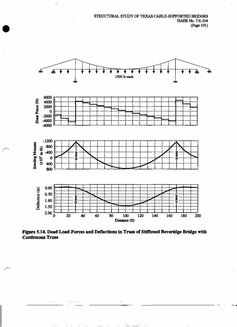
STRUCTURAL STUDY OF TEXAS CABLE-SUPPORTED BRIDGES HAERNb.TX-104
(Page 101)
F~rr 1500 lb each
I 6000 4000
g 2000
tu 0 -2000 -4000 -6000
L_....4- mum -«•"« — + ...—+..■..■.. < ^.. j .... ........{.... j.
p™" .......... 4 ■{- t ■» ; imam h ■*
Z—....+ ™™. ........)........(..,. > 4- t i i +...... I---—--^ : ~~ i i i i i i
* * 400 800
20 40 60 80 100 120 140 160 Distance (ft)
180 200
Figure 5.14. Dead Load Forces and Deflections in Truss of Stiffened Beveridge Bridge with Continuous Truss

STRUCTURAL STUDY OF TEXAS CABLE-SUPPORTED BRIDGES HAERNo.TX-104
<Page 102)
a 8 a a 8 a !Q 8 !Q » » 8
Axial Tension Ob)
10000 20000
(a) Simply Supported Truss
* -* 5 8 - rj m oo ^H
00 00 00 oo
+ + + + + * + + + + + + + Axial Tension (lb)
10000 20000 Notes: 1. Thickness of line is proportional to axial force.
2. Numbers indicate axial force in lb. Positive values indicate tension.
(b) Continuous Truss
Figure 5.15. Dead Load Axial Forces in Cables of Stiffened Beveridge Bridge with Simply Supported and Continuous Truss

STRUCTURAL STUDY OF TEXAS CABLE-SUPPORTED BRIDGES HAERNo.TX-104
(Page 103)
1000 lb each
60' 100*
~ 800 1 « 400
»• 0
I -400
'-• I i £ i
| j m.jtn.1
1 ! —4 —
■ I i j.--* ■r-«r-H ""
r * ........i. . _! ■ 1
~— !
™..„
TrH~™-;:f,K..Ht.."."
1 i J
1 1 1 i"~ i i i
0.000 S 8
^ 0.150 , I : ! * i ; : : : '.«*.«-.-+■™.j,-(*—j...—.,.....—! +
II I I I I I I 0 20 40 60 80 100 120
Distance (ft) 140 160 180 200
Figure 5.16. Live Load Forces and Deflections in Truss of Stiffened Beveridge Bridge with Simply Supported Truss
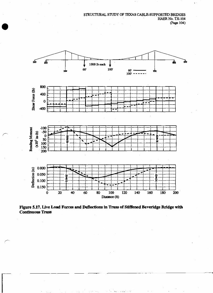
STRUCTURAL STUDY OF TEXAS CABLE-SUPPORTED BRIDGES HAERNo.TX-104
(Page 104)
1000 lb each
60' 100- T
3
U.
800
400
0
-400
-
:..-..- j- .—i—
i
....
.... - ... ■■•""+■"
- .Ht.m
_ i~t*.-1 l.IR.S
i - J ■
i i
| ? 100 f- g ^ 150 * 200
80 100 120 Distance (ft)
Figure 5.17. Live Load Forces and Deflections in Truss of Stiffened Beveridge Bridge with Continuous Truss
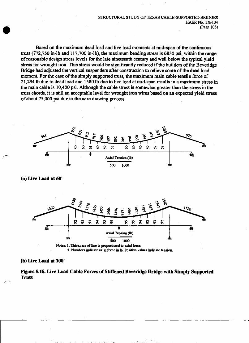
STRUCTURAL STUDY OF TEXAS CABLE-SUPPORTED BRIDGES HAERNo.TX-104
(Page 105)
Based on the maximum dead load and live load moments at mid-span of the continuous truss (772,750 in-lb and 117,700 in-lb), the maximum bending stress is 6850 psi, within the range of reasonable design stress levels for the late nineteenth century and well below the typical yield stress for wrought iron. This stress would be significantly reduced if the builders of the Beveridge Bridge had adjusted the vertical suspenders after construction to relieve some of the dead load moment. For the case of the simply supported truss, the maximum main cable tensile force of 21,294 lb due to dead load and 1580 lb due to live load at mid-span results in a maximum stress in the main cable is 10,400 psi. Although the cable stress is somewhat greater than the stress in the truss chords, it is still an acceptable level for wrought iron wires based on an expected yield stress of about 75,000 psi due to the wire drawing process.
*f £ 0v Q ~H Q ON 00 in « <o « m n
500 1000
(a) Live Load at 60*
* # .3 * U ! 9 g 1
<s m CO ■* wi «o Q\ <^ 0\ Q\ ^K ^K
ft in ■* ro en c* ^ Q\ <^ Q\ ON ^
Axial Tension (lb)
500 1000 Notes: 1. Thickness of line is proportional to axial force.
2. Numbers indicate axial force in lb. Positive values indicate tension.
(b) Live Load at 100'
Figure 5.18. Live Load Cable Forces of Stiffened Beveridge Bridge with Simply Supported Truss
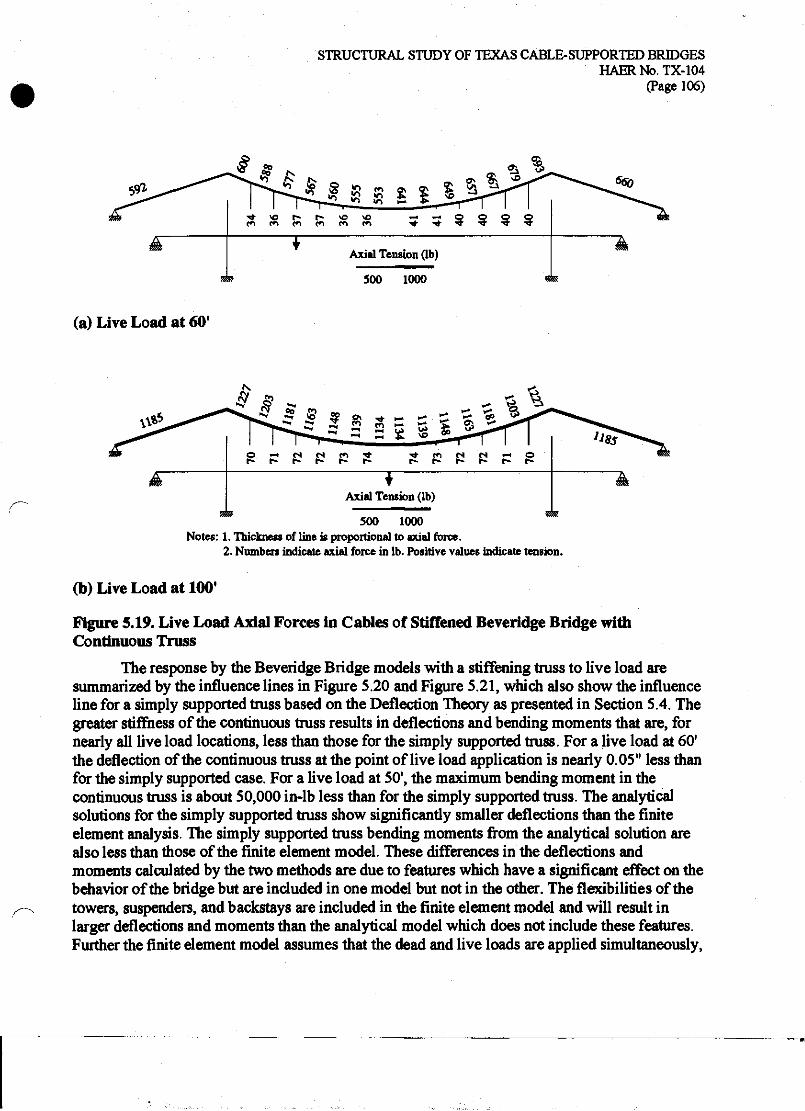
STRUCTURAL STUDY OF TEXAS CABLE-SUPPORTED BRIDGES HAERNo.TX-104
(Page 106)
500 1000
(a) Live Load at 60'
i M S S a - ^3 :s
500 1000 Notes: 1. Thickness of line is proportional to axial force.
2. Numbers indicate axial force in lb. Positive values indicate tension.
(b) Live Load at 100'
Figure 5.19. Live Load Axial Forces in Cables of Stiffened Beveridge Bridge with Continuous Truss
The response by the Beveridge Bridge models with a stiffening truss to live load are summarized by the influence lines in Figure 5.20 and Figure S.21, which also show the influence line for a simply supported truss based on the Deflection Theory as presented in Section S.4. The greater stiffness of the continuous truss results in deflections and bending moments that are, for nearly all live load locations, less than those for the simply supported truss. For a live load at 60' the deflection of the continuous truss at the point of live load application is nearly 0.05" less than for the simply supported case. For a live load at 50', the maximum bending moment in the continuous truss is about 50,000 in-lb less than for the simply supported truss. The analytical solutions for the simply supported truss show significantly smaller deflections than the finite element analysis. The simply supported truss bending moments from the analytical solution are also less than those of the finite element model. These differences in the deflections and moments calculated by the two methods are due to features which have a significant effect on the behavior of the bridge but are included in one model but not in the other. The flexibilities of the towers, suspenders, and backstays are included in the finite element model and will result in larger deflections and moments than the analytical model which does not include these features. Further the finite element model assumes that the dead and live loads are applied simultaneously,

STRUCTURAL STUDY OF TEXAS CABLE-SUPPORTED BRIDGES HAERNo.TX-104
(Page 107)
whereas the analytical model assumes all of the dead load is applied prior to the application of the live load. This difference in load application sequence will result in larger deflections and moments for the finite element model as compared to the analytical model. A more advanced finite element analysis would be required to properly account for the dead load forces in the parabolic cable that exist prior to the application of the live loads.
Based on the finite element analyses, either the continuous or simply supported truss results in deformations and stresses within acceptable limits, but the continuous truss is suffer under both dead and live loads. The additional vertical stiffness provided by the continuity of the truss across the tower supports was known to bridge designers in the late nineteenth century, and it is likely that the designers of the Beveridge Bridge would have taken advantage of the truss continuity. Based on similar continuous truss designs at the Bluff Dale Bridge and Clear Fork of the Brazos Bridge, it is likely that the original truss of the Beveridge Bridge was continuous.
0.00
0.20
FEM with Continuous Truss FEM with Simply Supported Truss Analytical with Simply Supported Truss
-v -^-».—i-
J . L
10 20 30 40 50 60 70 80 90 100 Position of Live Load (ft)
Figure 5.20. Influence Lines of Live Load Deflection of Stiffened Beveridge Bridge with Simply Supported and Continuous Truss

STRUCTURAL STUDY OF TEXAS CABLE-SUPPORTED BRIDGES HAERNo.TX-104
(Page 108)
f 50 .a
s» ^<, 3 100
2
*
150
200
- FEM with Continuous Truss ! * * „ - FEM with Simply Supported Truss - Analytical with Simply Supported Truss . I i I . 1 i I i
j---™-«f-'
10 20 30 40 50 60 70
Position of Live Load (ft)
80 90 100
Figure 5.21. Influence Lines of Live Load Moment of Stiffened Beveridge Bridge with Simply Supported and Continuous Truss

STRUCTURAL STUDY OF TEXAS CABLE-SUPPORTED BRIDGES HAERNo.TX-104
(Page 109)
5.6 Concluding Observations The theoretical and finite element analyses of the Beveridge Bridge explored the behavior
of several possible structural forms of the parabolic cable suspension bridge. The theoretical analyses of the deck-stiffened bridge considered both linear and non-linear solutions and demonstrated the importance of considering the non-linear effects, which result in drastically reduced deflections and moments. Based on a modern non-linear analysis, the truss of the Beveridge Bridge would be considered more stiff than necessary. However, the analyses presented here also revealed that the truss alone would not have been not sufficient to carry all of the dead load and live loads. Thus, the designers of the original truss of the Beveridge Bridge were certainly aware of the distribution of dead live loads between the truss and parabolic cable, and they would have used an approximate or empirical method to distribute the loads and design the components of the bridge. The original design methods used for the Beveridge Bridge are unknown. One possible, and simple, design approach would be to design the parabolic cable to support all of the dead load and to design the truss as an unsuspended span to support only the live load, similar to the design method suggested in Section 4.8 for the Bluff Dale Bridge.
The finite element models added several structural effects not included in the analytical models. The finite element model of the unstiffened bridge was found to closely match the analytical results, while for the stiffened bridge the bending moments and deflections predicted by the analytical models were typically much less than the corresponding values predicted by the finite element models. These differences are due to specific assumptions in the finite element or analytical models, such as the flexibilities of the towers, suspenders, or backstays, and loading sequence. At least some of these features are important considerations in the overall behavior of the bridge.
The finite element models were also used to study the effects of continuity of the stiffening truss over the tower supports. The continuous truss results in smaller deflections than the simply supported truss. For dead loads this reduction is significant, although after completion of the bridge, the deck could have been readjusted using the turnbuckles in the vertical suspenders. For live loads this reduction is generally small. The use of the continuous truss results in negative moments at the tower supports, which for the dead loads are larger than the mid-span positive moments of the simply supported truss. Again, the dead load moments could have been reduced by adjustment of the hangers. For live loads, the negative bending moments at the tower are approximately equal in magnitude to the positive moments at mid-span.
Both the continuous and simply supported trusses result in bending stresses well below typical yield stresses for wrought iron, and the continuous truss results in only a small reduction in live load deflections and moments. Nevertheless, the designers of the Beveridge Bridge would have been aware of the additional vertical stiffness provided by the continuity of the truss, and based on the similar construction of the Bluff Dale and Clear Fork Bridge trusses, it is most likely that the original truss of the Beveridge Bridge was continuous across the towers.

STRUCTURAL STUDY OF TEXAS CABLE-SUPPORTED BRIDGES HAERNo.TX-104
(Page 110)
6 ROCK CHURCH BRIDGE The Rock Church Bridge was constructed in about 1917. The historical study of the bridge
indicates that it was designed and constructed by a bridge company, although the name of the company responsible is no longer known. Some details of the bridge are similar to those used by the Austin Bridge Company.88 Without surviving historical documentation, it is difficult by visual inspection alone to distinguish the original fabric of the bridge from that added by possible later renovations. Certainly all of the wire cables and the towers are original, for they would be difficult to replace without leaving clear visual evidence. The vertical suspenders are most likely original as well. The timber floor system has been replaced, but appears to be in its original configuration. The surviving transverse floor beams of I-beam sections seem out of character with the widespread use of pipe sections on nearby cable-supported bridges, but there is no clear visual evidence to suggest they have been replaced. For this study, the transverse floor beams will be assumed to be original to the bridge. In the present condition of the bridge, the floor beams to which the inclined stays are attached exhibit large transverse deformations resulting in slack, and therefore ineffective, inclined stays (see Section 6.6).
6.1 Structural Description The Rock Church Bridge is an unstiffened suspension bridge with the addition of three
inclined cable stays extending from each tower to the bridge deck. The main span is 1 lO'-O" long with eleven equal panels of lO'-O" each. The bridge has no approach span at its south end. A north approach span of 200'-0" length once existed, but no longer survives. The north approach span was originally supported from below by piers. The backstays of the bridge are anchored approximately 40' from each tower. Three inclined cable stays run from each tower to the second, third, and fourth panel points. The wires of the stay cables are wrapped together with those of the main cable to form the backstay. The structural properties of the Rock Church Bridge are summarized in Table 6.1.
The main cable of the Rock Church Bridge is built from parallel strands of No. 9 gauge (0.148" diameter) wires with a gross diameter of about 2.71". Based on an assumed net area of 70 percent, there are approximately 235 individual wires in each main cable. Each inclined stay is composed of twenty-six No. 9 gauge wires, giving a net area of 0.45 in2. The ends of the stays are formed into loops that are simply wrapped around the ends of the floor beams. There is no surviving evidence that suggests the stays were provided with a means of pretensioning. A horizontal cable, also composed of twenty-six No. 9 gauge wires, runs at the level of the deck passing above the floor beams. The horizontal cable is not attached to the present floor beams, nor is there evidence of previous attachment. If the present I-beams are the result of a repair, then it is possible that the horizontal cable was attached to the original floor beams. As extant, this cable serves no clear structural function, although it could resist uplift forces. On the south end
M"Rock Church Bridge," HAER No. TX-81.

STRUCTURAL STUDY OF TEXAS CABLE-SUPPORTED BRIDGES HAER No. TX-104
(Page 111)
Table 6.1. Structural Properties of the Rock Church Bridge
Property Value Comments/Source Overall Geometry and Loads Main Span HO'-O" Side Span 58'-0" Dead Load 170 lb/ft Live Load 10001b
HAERNo.TX-81. HAERNo.TX-81. See Table 6.2. See discussion in text.
Main Cables Sag Gross Diameter Net Area
Modulus
12'-6" 2.71" 4.038 in2
27x10" psi
HAERNo.TX-81. HAERNo.TX-81. 70 percent of gross area, based on typical ratio for parallel wrought iron wire bridge cables. Equivalent to thirty-two No. 9 gauge (0.148") wires. Typical values for wrought iron. Withcy and Aston (1926).
Stay Cables Net Area Modulus
0.447 in3 Twenty-six No. 9 gauge (0.148") wires. 27x10" psi Typical values for wrought iron. Withey and Aston (1926).
of the bridge, the horizontal cable is embedded within the concrete of the tower base, suggesting that the horizontal cable was installed early in the construction process. The cable emerges from the concrete and enters the ground a short distance beyond the tower. The horizontal cable may be anchored independently from the main cable, or it may continue below grade and be anchored with the main cable. At the north end of the bridge, the horizontal cable continues beyond the tower and joins the main cable just prior to the anchorage. It is not known if the horizontal cable was attached to the north approach span.
The floor system is constructed from timber stringers and wooden decking. The wooden members have been replaced but are likely in the same configuration as the original construction. The bridge has a handrail constructed of vertical and horizontal wrought iron pipe, connected at the intersections with single bolts. With no diagonal members and single-bolt connections, the handrail does not add any vertical bending stiffness to the bridge.
6.2 Dead and Live Loads Table 6.3 summarizes the dead loads of the Rock Church Bridge. Only the main span is
considered in determining the dead load because the north side span was not suspended. The total dead load is approximately 169 lb/ft. As with the previous bridges, a concentrated live load of 1000 lb is used.

STRUCTURAL STUDY OF TEXAS CABLE-SUPPORTED BRIDGES HAERNo.TX-104
(Page 112)
Table 6.3. Dead Load Summary of the Rock Church Bridge
Description Weight Main Cables 2 sides @ 1548 = 30961b
2.71" gross diameter with estimated 70 percent net area Diagonal Stays and Horizontal Deck Cable 2 sides @ 518 = 10361b
Twenty-six No. 9 gauge (0.148") wires Suspenders 2 sides @ 268 = 5361b Pipe Railing 2 sides @ 1870 = 37401b Transverse Floor Beams and Lateral Bracing 41901b Wood Flooring System 22,830 lb Assumed eight 3"xl2" longitudinal stringers, 3" thick continuous wood flooring Subtotal 35,428 lb 5 percent allowance for connections and miscellaneous material 17721b Total 37,200 lb Weight per foot for full width of bridge 37,200 lb /110 ft ■ 338 lb/ft Weight per foot for 2D model of single plane of bridge 169 lb/ft
6.3 Analysis of Unstiffened Bridge with Cable Stays The application of inclined stays to a parabolic cable suspension bridge is only one of a
wide variety of stiffening methods proposed and employed during the nineteenth and twentieth centuries. Compared to the deck-stiffened form, an analytical formulation for a stayed suspension bridge is more complex because each cable stay adds an additional degree of static indeterminacy. Exact analysis of a statically indeterminate structure requires the solution of multiple simultaneous equations. The solution of large systems of simultaneous equations was simply not practical for engineers of the nineteenth and early twentieth centuries. Because of this mathematical complexity, early engineers had few theoretical tools on which to base the design of these bridges and instead relied on approximate methods to distribute loads between the parabolic and inclined stay subsystems. The use of inclined stays combined with a parabolic cable and deck stiffening became the trademark of the Roebling bridges and was adopted for more modest spans by other designers.
Similar to an unstiffened or deck-stiffened suspension bridge, the main cable of a stayed suspension bridge is assumed to take a parabolic shape and to be loaded with a uniformly distributed load along the horizontal. The deflections of the cable and deck are assumed to be equal and the difference between the true segmental cable shape and the assumed parabolic shape is neglected. The cable stays are intended to provide additional stiffness by limiting the deflections of the deck at the points where the stays attach to the deck.
Figure 6.1 shows a stayed suspension bridge with two symmetrically located stays and loaded with a concentrated live load, P, at a distance rL from the left end. Similar to the unstiffened cable, the deflected shape of the cable has a discontinuous slope at the live load location and at each stay location. Between these points the cable remains parabolic in shape due to the dead load. For a suspension bridge with two stays and a single concentrated live load, the
89A paper by Clericetti (1880) appears to be the only substantial attempt to formulate the theory of the stiffened suspension bridge with inclined stays.
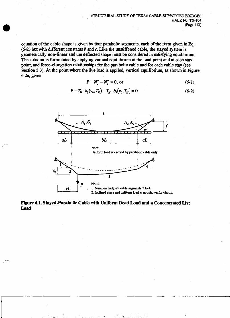
STRUCTURAL STUDY OF TEXAS CABLE-SUPPORTED BRIDGES HAERNo.TX-104
(Page 113)
equation of the cable shape is given by four parabolic segments, each of the form given in Eq. (5-2) but with different constants b and c. Like the unstiffened cable, the stayed system is geometrically non-linear and the deflected shape must be considered in satisfying equilibrium. The solution is formulated by applying vertical equilibrium at the load point and at each stay point, and force-elongation relationships for the parabolic cable and for each cable stay (see Section 5.3). At the point where the live load is applied, vertical equilibrium, as shown in Figure 6.2a, gives
P-N>-N>=0,or (6-1)
P~TH-b2(v0lTH)-TH'b3(v0tTH) = 0. (6-2)
i i i
aL
i i i 111 'i i I 11 i r i i i i TT
bL
TTT
cL
Uniform load w carried by parabolic cable only.
Notes: 1. Numbers indicate cable segments 1 to 4. 2. Inclined stays and uniform load w not shown for clarity.
Figure 6.1. Stayed-Parabolic Cable with Uniform Dead Load and a Concentrated Live Load

STRUCTURAL STUDY OF TEXAS CABLE-SUPPORTED BRIDGES HAERNo.TX-104
(Page 114)
^%J.
iWi>.
Ni*
%
^. JV?
Applied Live Load = P
*Nt
cable seg»^ ?,-- —
1. Axial forces W2 and A^3 are oriented in the direction of the tangent of each cable segment at the point of the applied live load.
2. Axial forces N2 and N$ are decomposed into vertical (y) and horizontal (x) components.
(a) Equilibrium at Load Point
1. Axial forces A^ and N2 are oriented in the direction of the tangent of each cable segment at the point of the stay attachement Axial force Nf is oriented in the direction of the cable stay
2. Axial forces Nl, N2 and Ns are decomposed into vertical (y) and horizontal (x) components.
(b) Equilibrium at Location of Stay
Figure 6.2. Vertical Force Equilibrium at Load Point and at Location of Stay

STRUCTURAL STUDY OF TEXAS CABLE-SUPPORTED BRIDGES HAERNo.TX-104
(Page 115)
Figure 6.2b shows the forces at the location where a stay attaches to the deck. Here vertical equilibrium results in
N>-NZ-Nl=0,or (6-3)
THk{^TH)-TH-b2{vQtTH)~Nys =0t (6-4)
where N* is the vertical force component in the cable stay. The horizontal component of force in the cable stay is assumed to be transferred into the bridge deck with no resulting axial deformation. This assumption results in the stays being more effective than if the true axial stiffness of the bridge deck were accounted for in the analysis. The force-elongation of the parabolic cable is similar to Eq. (5-5), except with four parabolic segments
The term Zj (0, H) is an integral evaluated along the curve of the parabolic cable under dead load only. Finally, the force-elongation of the diagonal stay, similar to Eq. (4-2), is expressed as
A = L,-A,=||. (6-6)
For a bridge with two cable stays and a single concentrated live load, the simultaneous solution of four non-linear equations is required. The fundamental unknown quantities are the three vertical deflections (load point and two stay points) and the total horizontal tension in the parabolic cable.
Again, in order to facilitate study of the effect of variations in bridge properties, the equations are made non-dimensional using the parameters defined in Section 5.3 for the parabolic cable. A new parameter measures the relative areas of the stay and main cable,
Stay area ratio P~~f"- (6-7) 4 Values of the parameters for the Rock Church Bridge are given in Table 6.3
Figure 6.3 shows the non-dimensional load-deflection behavior for point loads at r=0.50 (mid-span) and r=0.15, midway between the support and the cable stay. The structure exhibits tension stiffening for positive load ratios for both locations of live load. Comparison with Figure 5.3 for the unstiffened cable shows that the stays have a small effect in reducing deflections for the live load at mid-span.

STRUCTURAL STUDY OF TEXAS CABLE-SUPPORTED BRIDGES HAERNo.TX-104
(Page 116)
Table 6.3. Non-Dimensional Parameters of Rock Church Bridge
Parameter Value Sag-to-Span Ratio Live-to-Dead Load Ratio
n Y
0.114 0.053
Non-dimensional Dead Load <T 1.72x10* Cable Area Ratio P 0.111 Modular Ratio V 1.0
0.60
0.40 —
•S 0.20 £
0.00 -
-0.20 "
-0.40 -0.06 -0.04 -0.02 0.00 0.02 0.04
Live Load Deflection / Span
Figure 6.3. Live Load-Deflection Behavior of Stayed Parabolic Cable

STRUCTURAL STUDY OF TEXAS CABLE-SUPPORTED BRIDGES HAERNo.TX-104
(Page 117)
Figure 6.4 shows the influence lines of live load displacement for the stayed suspension bridge with a stay area ratio of /H). Ill corresponding to the Rock Church Bridge, as well as for a range of lower stay ratios. The case of fi=Q corresponds to the unstiffened parabolic cable with
no stays. For a live load at r=0.20, where the deflection of an unstiffened span (fi =0) is greatest, the use of a stay with area ratio /? =0.111 reduces the vertical deflection by about 30 percent. The stay has only a minor effect in reducing deflections for live loads located near the center of the bridge, from about r=QAQ to 0.60. The stay is most effective in reducing deflections for live loads positioned within about 10 percent of the span length on either side of the stay (r=0.20 to 0.40). This observation suggests mat multiple stays are necessary to provide an efficient method of reducing deflections.
0.00 support
0.10 0.20 0.30 Position of Live Load (r)
0.40 0.50 mid-span
Figure 6.4. Influence Lines of Live Load Displacement of Stayed a Parabolic Cable

STRUCTURAL STUDY OF TEXAS CABLE-SUPPORTED BRIDGES HAERNo.TX-104
(Page 118)
Figure 6.5 shows the relationship between the stay area ratio and live load deflection for two live load locations. Nearly all of the reduction in deflection occurs for stay areas between about 0.1 percent (10"3) and 10 percent (10"1) of the main cable area. Small stay areas below 0.1 percent are not effective in reducing deflections, while large stay areas above 10 percent are not an efficient use of material, since a large increase in stay area would be required to achieve only a small reduction in deflection. Although the inclined stay cables of the Rock Church bridge were sized by approximate or empirical methods, their area ratio of 0.111 would be judged as an economical size based on this simplified analysis.
1<T2
Cable Area Ratio
Figure 6.5. Effect of Stay Area Ratio on Vertical Displacement of a Stayed Parabolic Cable

STRUCTURAL STUDY OF TEXAS CABLE-SUPPORTED BRIDGES HAERNo.TX-104
(Page 119)
6.4 Finite Element Analysis of Rock Church Bridge The finite element analysis of the Rock Church Bridge will account for the presence of
multiple diagonal stays, discrete vertical suspenders, and the flexibility of the towers and backstays, not included in the analytical models of Section 6.3. In addition, the effect of a small deck bending stiffness can be considered. The Rock Church Bridge has no stiffening truss—the existing railing is not constructed in a manner that can provide vertical bending stiffness. However, the longitudinal timber stringers beneath the deck can add some longitudinal bending stiffness, provided that they are competently spliced at any longitudinal joints. As was demonstrated for the Beveridge Bridge, even a small longitudinal stiffness can provide a measurable reduction in deformation compared to a totally unstiffened span. Two finite element models of the Rock Church Bridge were analyzed:
(1) Deck unstiffened in bending, and
(2) Deck lightly stiffened in bending by longitudinal stringers.
The finite element method has been described previously in Section 4.5. The finite element models are each a two-dimensional representation of one-half the width of the bridge (see Figure 1. lc). In both cases, the deck is assumed to provide axial stiffness based on the cross- sectional area of the longitudinal timber stringers which transfer the horizontal component of the tension in the diagonal stays to the supports. Without this axial stiffness, the diagonal stays cannot be effective (see Section 6.5). In the analytical models of Section 6.3, this axial stiffness was assumed to be infinite. The approach span at the north end of the bridge is assumed to have been supported by intermediate piers, and therefore structurally independent of the suspended span. The horizontal cable at the deck level is not included in the model because it is not attached to the floor beams and would not be effective in carrying dead or live loads.
The properties of each element are summarized in Table 6.4. The bridge deck is modeled by a series of beam elements with an area corresponding to four 3"xl2" wood stringers. The lightly stiffened model uses a moment of inertia also corresponding to four stringers, while the unstiffened model uses a small, non-zero moment of inertia to maintain numerical stability of the non-linear solution scheme. In both models, the elastic modulus of the wood stringers is assumed to be 1.5x10* psi.90 The main cable is composed of beam elements with a cross-sectional area and moment of inertia based on a cable of 23 5 No. 9 gauge wires. Again, the moment of inertia is calculated assuming each wire bends individually about its own axis, and the resulting small moment of inertia is intended primarily to aid the non-linear solution scheme. The vertical
"The modulus of wood varies widely by species ranging between about 600,000 psi and 2,000,000 psi. For these analyses, the important fact is that the modulus of wood is many times less man that of wrought iron or steel.

STRUCTURAL STUDY OF TEXAS CABLE-SUPPORTED BRIDGES HAERNb.TX-104
(Page 120)
Table 6.4. Element Properties of Rock Church Bridge
Element Area Moment of Inertia (in2) (in4)
Main Cable 4.038 5.5x10* Stay Cables 0.447 6.1x10"* Backstay 5.379 7.4xl0'3
Suspenders 0.785 0.049 Towers 11.51 309 Lightly Stiffened Floor Deck 144 1728 Truss-Tower Connection 1000 0.001
suspenders are modeled with truss elements, such that only axial forces are carried. The towers are modeled by beam elements with a cross-sectional area and moment of inertia corresponding to a hollow circular section of 0.25" thickness and 14.9" outside diameter, based on field measurements.
Similar to the Bluff Dale and Beveridge Bridges, the distribution of forces in the Rock Church Bridge due to the dead load depends on the construction sequence and any tensioning of the vertical suspenders or diagonal stays that may have been performed after substantial dead load was in place. The vertical suspenders do include turnbuckles, so the builders could have adjusted the profile of the bridge deck thereby effecting some redistribution of the dead load. The diagonal stays, as they survive today, include no means of tensioning or adjustment. Tension must be present in the stays for them to be of any benefit in the resistance to deformation of the bridge under live loads. In the Rock Church Bridge, it is most likely that the tension in the stays was provided only by the dead load of the bridge. In order to assess the behavior of the bridge for this condition, each finite element model was analyzed with a uniform dead load applied as series of concentrated loads of 1690 lb at each panel point along the deck. The live load response of the Rock Church Bridge was determined by a series of finite element analyses with a single concentrated live load of 1000 lb placed at each panel point on the deck. All live load analyses also included the full dead load, in order to capture the effects of tension stiffening in the geometrically non-linear analysis. The forces and deflections due to live load are calculated from the difference between an analysis with live and dead load and an analysis with dead load only.
Figure 6.6a shows the deflections for the model with an unstiffened deck for the dead load condition. The maximum dead load deflection of 1.9" occurs at mid-span. The diagonal stays located at 20', 30', and 40' limit the deflection at these points to less than 0.5". Figure 6.6b shows the additional deflections due to the live loads. For a live load positioned at a panel point with no cable stay (10* or 50'), the deflections at the loaded point can be as large as 1.50" but the stays still limit the deflections where they are attached. For a live load positioned at a stay location, the live load deflections are extremely small, less than 0.25" across the entire span. Note that the upward (negative) live load deflections shown in Figure 6.6b will not result in slackening of the vertical suspenders, but rather a reduction in the magnitude of dead load tension in the suspenders.

STRUCTURAL STUDY OF TEXAS CABLE-SUPPORTED BRIDGES HAERNo.TX-104
(Page 121)
1690 lb each
50 60 Distance (ft)
70 80 90 100 110
(a) Dead Load
30' 1000 lb each
(b) Live Load
Figure 6.6. Dead and Live Load Deck Deflections in Deck of Rock Church Bridge with Unstiffened Deck
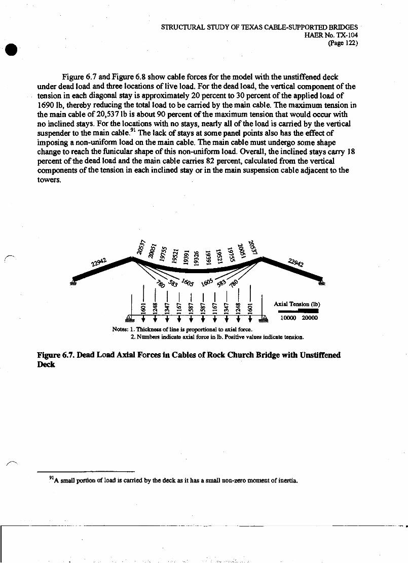
STRUCTURAL STUDY OF TEXAS CABLE-SUPPORTED BRIDGES HAERNo.TX-104
(Page 122)
Figure 6.7 and Figure 6.8 show cable forces for the model with the unstiffened deck under dead load and three locations of live load. For the dead load, the vertical component of the tension in each diagonal stay is approximately 20 percent to 30 percent of the applied load of 1690 lb, thereby reducing the total load to be carried by the main cable. The maximum tension in the main cable of 20,537 lb is about 90 percent of the maximum tension that would occur with no inclined stays. For the locations with no stays, nearly all of the load is carried by the vertical suspender to the main cable.91 The lack of stays at some panel points also has the effect of imposing a non-uniform load on the main cable. The main cable must undergo some shape change to reach the funicular shape of this non-uniform load. Overall, the inclined stays carry 18 percent of the dead load and the main cable carries 82 percent, calculated from the vertical components of the tension in each inclined stay or in the main suspension cable adjacent to the towers.
* # £ § $ s § % I
Axial Tension (lb)
^ 10000 20000
Notes: 1. Thickness of line is proportional to axial force. 2. Numbers indicate axial force in lb. Positive values indicate tension.
Figure 6.7. Dead Load Axial Forces in Cables of Rock Church Bridge with Unstiffened Deck
91A small portion of load is carried by the deck as it has a small non-zero moment of inertia.

(a) Live Load at 10'
(b) Live Load at 30'
STRUCTURAL STUDY OF TEXAS CABLE-SUPPORTED BRIDGES HAERNo.TX-104
(Page 123)
II I I I I I f I PSS ^22 SS% Ov
2 S5^t-r«»n«rt «
A 00 ^ o\ ON **^ Q\ A OO _— ffi r- oo <n v> £ ~H 5\ t» 2 ^ d ^ ■ 'O °^ w -H ts ^
500 1000
Notes: 1. Thickness of line is proportional to axial force. 2. Numbers indicate axial force in lb. Positive values indicate tension.
Negative values indicate reduction of dead load tension.
(c) Live Load at 50*
Figure 6.8. Live Load Axial Forces in Cables of Rock Church Bridge with Unstiffened Deck

STRUCTURAL STUDY OF TEXAS CABLE-SUPPORTED BRIDGES HAERNo.TX-104
(Page 124)
Figure 6.9 shows the deck forces and deflections under dead load for the lightly stiffened deck. The maximum deflection at mid-span is 1.1", compared to 1.9" for the unstiffened case. The bending stiffness of the deck results in a more uniform deflection across the entire deck, with less local deformation at the locations where there are no stays. The maximum bending moment of 82,900 in-lb at mid-span produces a bending stress of 290 psi in the wood stringers, well below allowable stresses for wood. The axial force diagram indicates that the center of the deck is subjected axial tension as large as 4770 lb, resulting in a tensile stress of 34 psi. This tension is largely a result of the assumption that the majority of the dead load is applied after construction of the structural elements of the bridge has been completed.
Figure 6.10 shows the cable forces under dead load for the analysis with the lightly stiffened deck. The suspender forces are nearly uniform; each one carries about 45 percent of the applied dead load of 1690 lb. Even at locations with no stays (10' and 50'), the deck is stiff enough to distribute about half of the applied load to the adjacent stay system. Overall the stiffened deck carries 4 percent of the dead load, the main cable carries 46 percent, and the stay system carries 50 percent, calculated from the vertical components of the tension in each inclined stay or in the main suspension cable adjacent to the towers and the vertical reactions at the end of the deck. Although the lightly stiffened deck carries a small portion of the total dead load, it results in greater overall effectiveness of the stay system.

STRUCTURAL STUDY OF TEXAS CABLE-SUPPORTED BRIDGES HAERNb.TX-104
(Page 125)
1690 lb each
3000 s I -a -3000
-6000
0 r — i *— i + i
It i ; — t —' v f - i * ■
i j I 1 j
s 1000
500
te. 0
1 -500
-1000
— - +- - — (.-....-.........
_. ,—. ......... —j * .........*........... 1
20 30 40 50 60 Distance (ft)
70 80 90 100 110
Figure 6.9. Dead Load Forces and Deflections in Deck of Rock Church Bridge with Lightly Stiffened Deck

STRUCTURAL STUDY OF TEXAS CABLE-SUPPORTED BRIDGES HAERNo.TX-104
(Page 126)
5 s a I s s s 6 * $
Notes: 1. Thickness of line is proportional to axial force. 2. Numbers indicate axial force in lb. Positive values indicate tension.
Figure 6.10. Dead Load Cable Forces of Rock Church Bridge with Lightly Stiffened Deck
Figure 6.11 shows the deck forces and deflections for three live load locations. As for the dead load, the presence of the bending stiffness in the deck significantly reduces the deflections, especially for live loads at locations with no stays. For a live load at 10', the deflection is 0.11", compared to 1.45" for the unstiffened deck. Similarly for a live load at 50', the deflection is 0.24", compared to 1.27" for the unstiffened case. For a live load placed at the location of a stay, the reduction in deflection is somewhat less—0.09" for the lightly stiffened case and 0.15" for the unstiffened. The shear diagram shows that the stiffened deck carries nearly all of the live load for loads placed where no stays exist—97 percent of the 1000 lb load located at 10' and 85 percent of the load at 50', based on the ratio of the magnitude of the vertical discontinuity to the applied load. For the live load at 30* where a stay exists about 48 percent of the load is carried by the lightly stiffened deck. The largest positive live load bending moments of 50,020 in-lb and 48,470 in-lb occur for loads located at 10* and 50', respectively. Combining the moment at 50* with the dead load moment of 82,900 in-lb and assuming no adjustment of the suspenders or stays was performed, results in a total moment of 131,370 in-lb, producing a bending stress of 456 psi in the timber stringers. Typical wood species exhibit bending stresses of 3000 to 5000 psi at their elastic limit and ultimate stresses 1.5 to 2 times larger.92 The stresses in the stringers of the Rock Church Bridge are well below the elastic limit, and the longitudinal timber stringers are sized sufficiently to prevent failure even under live loads significantly larger than 1000 lb.
'Vithey and Aston (1926), pp. 197 ff.
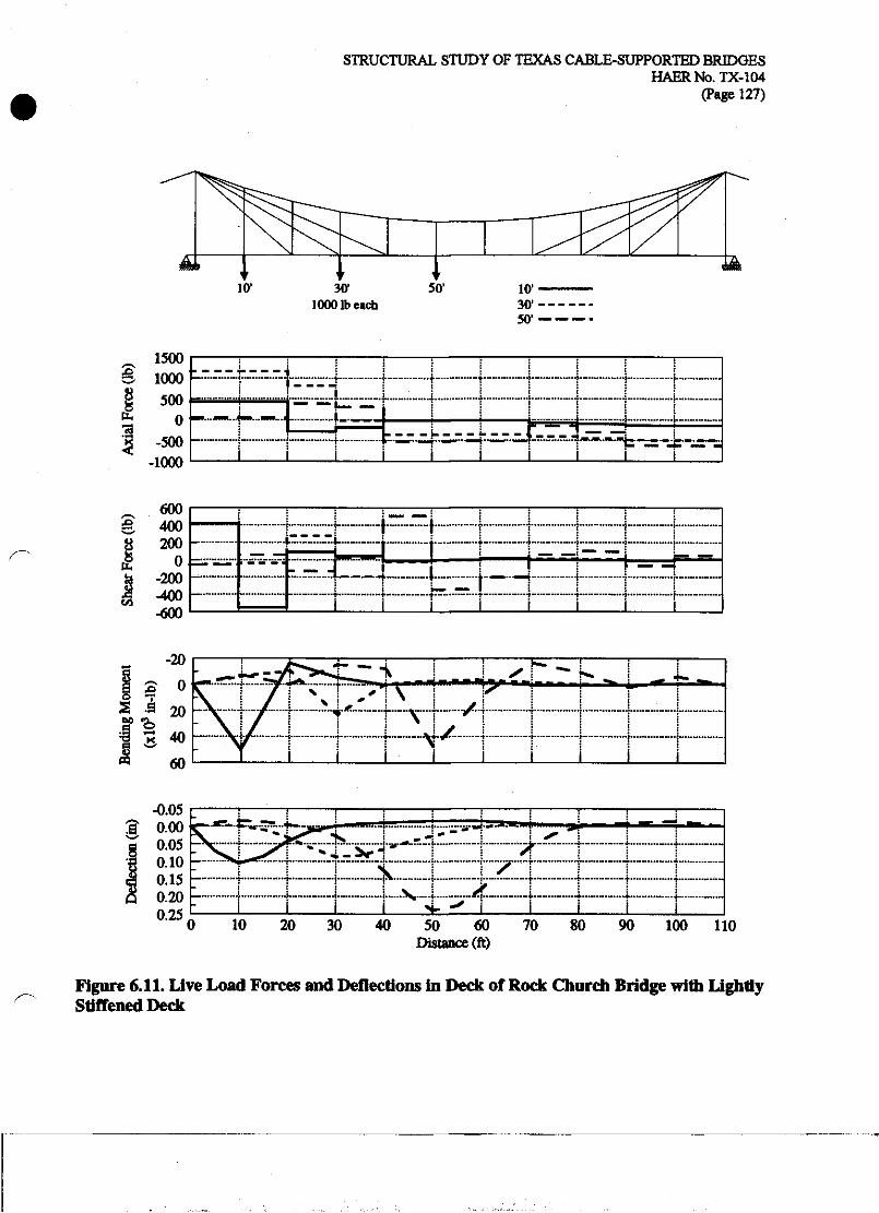
STRUCTURAL STUDY OF TEXAS CABLE-SUPPORTED BRIDGES HAERNo.TX-104
(Page 127)
30' 1000 lb each
_ 1500 S IOOO
500 0
-500 -1000
73
J L
M-H
>*m»IVU^^^^.^.^.hH.^,^H*^a„
£
b
CO
600 400 200
0 -200 -400 -600
i—i
0 10 20 30 40 50 60 Distance (ft)
70 80 90 100 110
Figure 6.11. Live Load Forces and Deflections in Deck of Rock Church Bridge with Lightly Stiffened Deck

STRUCTURAL STUDY OF TEXAS CABLE-SUPPORTED BRIDGES HAERNo.TX-104
(Page 128)
Figure 6.12 shows the cable forces for the three live load cases on the lightly stiffened model. For the live load at 10', where no stay exists, nearly all of the load is carried by the deck. However, the first inclined stay is under a tension of 955 lb, nearly twice as large as for the unstiffened case. For the live load at 30', the lightly stiffened deck distributes the load amongst the Ihree stays, compared to the unstiffened case, where only the center stay carries a significant tension. For the live load at 50', most of the load is carried by the deck and the remainder is transferred to the main cable.
Figure 6.13 shows influence lines of displacement and moment for both cases of deck stiffness. The lightly stiffened deck results in significantly smaller deflections compared to the unstiffened deck. This reduction is partially due to live load being carried directly by the deck, but primarily it is due to the ability of the deck to distribute live load more evenly among the inclined stays.
Figure 6.14 shows influence lines of the axial forces in three stays. Stay 1 is stay attached to the deck at 20' from the tower; Stay 2, at 30'; and Stay 3, at 40'. For the unstiffened deck, each stay carries a large load when the live load is positioned at the location of the stay and very little load when the live load is positioned at other panel points. In contrast, for the lightly stiffened deck, each stay carries the maximum load when the load is positioned at its end, but also carries significant load for live loads placed elsewhere.

STRUCTURAL STUDY OF TEXAS CABLE-SUPPORTED BRIDGES HAERNo.TX-104
(Page 129)
$ 3 <C ~* C* M U
IO
V/ffV* ^ & # 'S *'<J-
S> ^ ^ -* .0 #
sO«>C<-l00000OOvO\O\ ^*1—iMC'l-H^H'—'*—I i-4 —(
(b) Live Load at 30*
500 1000
Notes: 1. Thickness of line is proportional to axial force. 2. Numbers indicate axial force in lb. Positive values indicate tension.
Negative values indicate reduciton of dead load tension.
(c) Live Load at 50*
Figure 6.12. Live Load Axial Forces in Cables of Rock Church Bridge with Lightly Stiffened Deck

STRUCTURAL STUDY OF TEXAS CABLE-SUPPORTED BRIDGES HAERNo.TX-104
(Page 130)
,9.
& 1.00
1.25
1.50 10
O Lightly Stiffened Deck
- -X - - UnstiffenedDeck
20 30 Poistion of Live Load (ft)
40
\ j \ j
50
10 20 30 Poistion of Live Load (ft)
40 50
Figure 6.13. Influence Lines of Live Load Displacement and Bending Moment of Rock Church Bridge with Unstiffened and Lightly Stiffened Decks
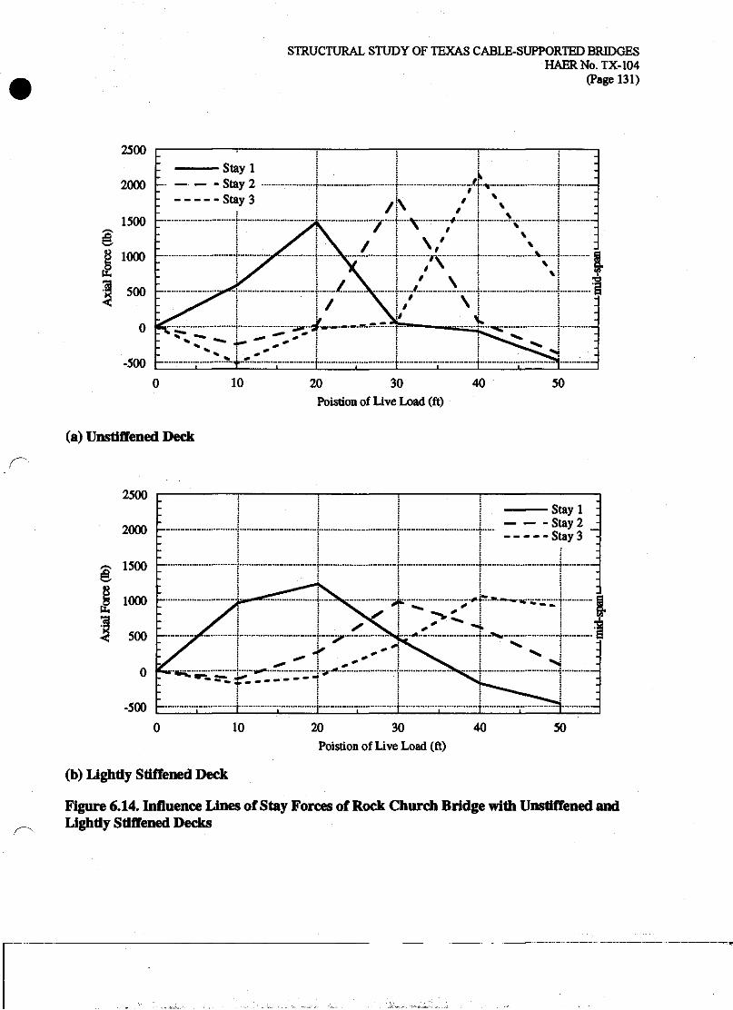
STRUCTURAL STUDY OF TEXAS CABLE-SUPPORTED BRIDGES HAERNo.TX-104
(Page 131)
ft
10 20 30 Poistion of Live Load (ft)
40 50
(a) Unstiffened Deck
§
tL,
10 20 30 40 Poistion of Live Load (ft)
50
(b) Lightly Stiffened Deck
Figure 6.14. Influence Lines of Stay Forces of Rock Church Bridge with Unstiffened and Lightly Stiffened Decks
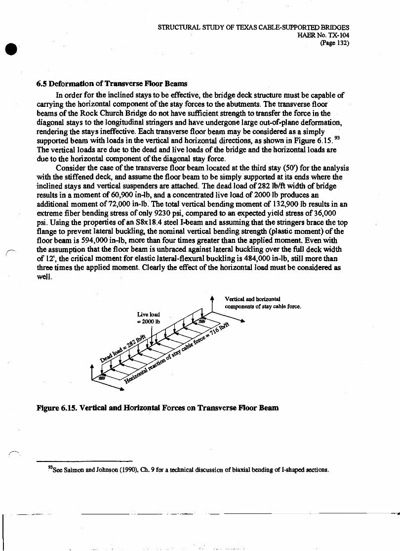
STRUCTURAL STUDY OF TEXAS CABLE-SUPPORTED BRIDGES HAERNo.TX-104
(Page 132)
6.5 Deformation of Transverse Floor Beams In order for the inclined stays to be effective, the bridge deck structure must be capable of
carrying the horizontal component of the stay forces to the abutments. The transverse floor beams of the Rock Church Bridge do not have sufficient strength to transfer the force in the diagonal stays to the longitudinal stringers and have undergone large out-of-plane deformation, rendering the stays ineffective. Each transverse floor beam may be considered as a simply supported beam with loads in the vertical and horizontal directions, as shown in Figure 6.15.n
The vertical loads are due to the dead and live loads of the bridge and the horizontal loads are due to the horizontal component of the diagonal stay force.
Consider the case of the transverse floor beam located at the third stay (SO1) for the analysis with the stiffened deck, and assume the floor beam to be simply supported at its ends where the inclined stays and vertical suspenders are attached. The dead load of 282 lb/ft width of bridge results in a moment of 60,900 in-lb, and a concentrated live load of 2000 lb produces an additional moment of 72,000 in-lb. The total vertical bending moment of 132,900 lb results in an extreme fiber bending stress of only 9230 psi, compared to an expected yield stress of 36,000 psi. Using the properties of an S8xl8.4 steel I-beam and assuming that the stringers brace the top flange to prevent lateral buckling, the nominal vertical bending strength (plastic moment) of the floor beam is 594,000 in-lb, more than four times greater than the applied moment. Even with the assumption that the floor beam is unbraced against lateral buckling over the full deck width of 12', the critical moment for elastic lateral-flexural buckling is 484,000 in-lb, still more than three times the applied moment. Clearly the effect of the horizontal load must be considered as well.
Live load = 2000 lb
Vertical and horizontal components of stay cable force.
Figure 6.15. Vertical and Horizontal Forces on Transverse Floor Beam
93 See Salmon and Johnson (1990), Ch. 9 for a technical discussion of biaxial bending of I-shaped sections.

STRUCTURAL STUDY OF TEXAS CABLE-SUPPORTED BRIDGES HAERNo.TX-104
(Page 133)
Based on the axial cable tensions given in Figure 6.10 and Figure 6.12, the third stay develops a total horizontal force of 4657 lb due to the combined dead and live loads. If this load is transferred equally to the eight stringers beneath the deck the result is an equivalent uniform of load of 716 lb/ft and a maximum horizontal bending moment of 154,656 in-lb. This applied moment is well above the moment of 66,960 in-lb required for first yield of the beam about its weak axis, and even above the weak axis plastic moment of 113,760 in-lb required for full yielding of the cross-section at its mid-span. Thus, insufficient strength for bending in the horizontal direction (weak axis) is the primary shortcoming of the design of the transverse floor beams of the Rock Church Bridge. Once the transverse floor beam undergoes a large lateral deformation, the tension in the inclined stays will be relieved, resulting in the slack stays seen at the Rock Church Bridge.
The deformed floor beams of the Rock Church Bridge also exhibit some rotational or torsional displacement of the cross-section, such that the lower flange of the I-beam is no longer directly below the upper flange. Such a rotational displacement does not typically occur in a beam subjected to pure bending about its weak axis. In the Rock Church Bridge, the rotational displacement is caused by the combined effects of eccentric horizontal support and loading, and simultaneous bending in the vertical direction about the beam's strong axis. The method of connection of the inclined stays to the ends of the floor beams will result in its horizontal force component being applied approximately at mid-depth of the cross-section. However, the timber stringers are attached to the top flange of the transverse floor beams, resulting in some twisting forces in the floor beam as the force is transferred from the inclined stays to the timber stringers. Further, the yielding in the floor beams due to the horizontal bending will reduce the critical lateral buckling strength for the vertical bending. Ultimately the applied vertical moment may exceed the buckling strength, reduced by the yielding, and inelastic lateral buckling will occur. Both of these factors help to explain the torsional deformation observed in the transverse floor beams of the Rock Church Bridge, although neither effect would have manifested itself had the floor beams had sufficient horizontal bending strength. As the bridge stands today, the transverse floor beams are of insufficient lateral bending strength to transfer the horizontal component of the stay force to the longitudinal stringers, and therefore have deformed, making the diagonal stays entirely slack and ineffective.
STRUCTURAL STUDY OF TEXAS CABLE-SUPPORTED BRIDGES HAERNo.TX-104
(Page 134)
6.6 Concluding Observations The structural form of the Rock Church Bridge is a parabolic cable suspension bridge with
inclined stays. In its present state the bridge behaves entirely as an unstiffened parabolic cable suspension bridge because the inclined stays are slack and ineffective. The behavior of this form was studied using a simplified analytical model with a single diagonal stay at each end of the unstiffened suspension span. This simplified model revealed that diagonal stays not only reduce the deflections of the bridge deck for live loads placed at the stay locations, but also for live loads placed elsewhere on the span. A single inclined stay was found to provide a significant reduction in live load deflections for about 10 percent of the span length on each side of the stay. Therefore an effective inclined stay system should include multiple stays, as at the Rock Church Bridge. The influence of the stay area on the live load deflections was considered, and an inclined stay with an area ratio between 0.10 percent and 10 percent of the parabolic cable area was found to be most effective in reducing deflections while maintaining efficient use of the stay material. The designers of the Rock Church Bridge sized the stays by empirical or approximate methods, but their area of 11 percent of the parabolic cable would be considered an efficient use of material based on this approximate analysis.
The finite element models of the Rock Church Bridge provided a more realistic analysis of the behavior of the bridge by including such details as the multiple stays and allowing consideration of the effect of a nominal bending stiffness in the deck. Such a lightly stiffened deck can be achieved with a well-constructed system of under-floor timber stringers and does not necessarily require a substantial stiffening truss. A lightly stiffened deck provides a significant reduction in dead load deflections, but more importantly, it distributes concentrated live loads among multiple stays, thereby increasing the effectiveness of the stay system as a whole. For a live load near mid-span, the lightly stiffened deck with inclined stays reduced the deflection by about 80 percent compared to the deflection of the unstiffened span with inclined stays. Instrumentation and load testing of the Rock Church Bridge would be required to accurately measure the participation of the bending stiffness of the floor system.
The transverse floor beams of the Rock Church Bridge have deflected out of plane, rendering the stay system ineffective. Estimation of the vertical and horizontal loads on the beams from gravity loads and the inclined stays reveals that bending of the floor beams in the weak direction will cause yielding. The deformed state of the floor beams emphasizes the importance of proper connection between the stay system and the deck system. At the Rock Church Bridge, no structural connection exists that would allow the inclined stays to transfer their horizontal force component into the bridge deck.
Based on the surviving fabric of the Rock Church Bridge, it can be considered a less mature engineering design than either the Bluff Dale or Beveridge Bridge. The inclined stay system of the bridge was probably never effective due to the lack of a means to pre-tension the inclined stays and the lack of a well-designed floor system to transfer the horizontal forces of the inclined stays to the abutments.
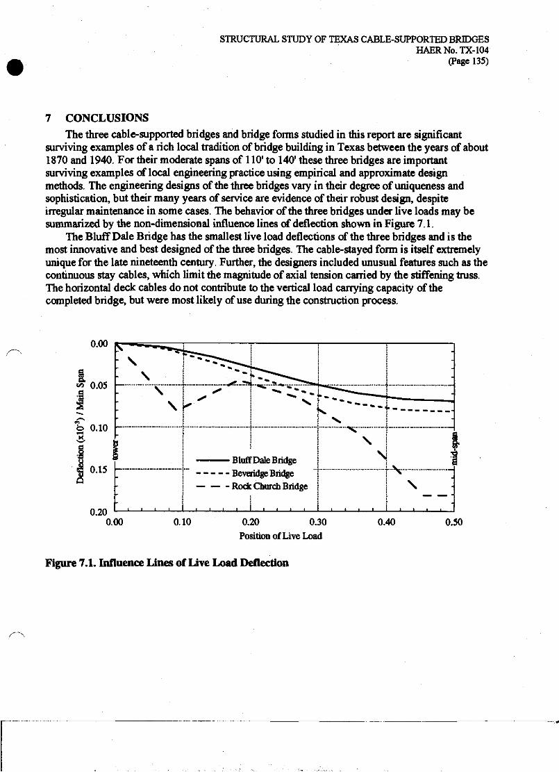
STRUCTURAL STUDY OF TEXAS CABLE-SUPPORTED BRIDGES HAERNo.TX-104
(Page 135)
7 CONCLUSIONS The three cable-supported bridges and bridge forms studied in this report are significant
surviving examples of a rich local tradition of bridge building in Texas between the years of about 1870 and 1940. For their moderate spans of 110* to 140' these three bridges are important surviving examples of local engineering practice using empirical and approximate design methods. The engineering designs of the three bridges vary in their degree of uniqueness and sophistication, but their many years of service are evidence of their robust design, despite irregular maintenance in some cases. The behavior of the three bridges under live loads may be summarized by the non-dimensional influence lines of deflection shown in Figure 7.1.
The Bluff Dale Bridge has the smallest live load deflections of the three bridges and is the most innovative and best designed of the three bridges. The cable-stayed form is itself extremely unique for the late nineteenth century. Further, the designers included unusual features such as the continuous stay cables, which limit the magnitude of axial tension carried by the stiffening truss. The horizontal deck cables do not contribute to the vertical load carrying capacity of the completed bridge, but were most likely of use during the construction process.
0.00
0.15
0.20 0.00
Bluff Dale Bridge Be veridge Bridge Rock Church Bridge
0.10 0.20 0.30 Position of Live Load
0.40 0.50
Figure 7.1. Influence Lines of Live Load Deflection

STRUCTURAL STUDY OF TEXAS CABLE-SUPPORTED BRIDGES HAERNo.TX-104
(Page 136)
The Beveridge Bridge, with its original stiffening truss, would have exhibited live load deflections only slightly larger than the Bluff Dale Bridge. Its design and construction are typical of short span, deck-stiffened suspension bridges of the late nineteenth century. Nevertheless, it is a well-executed example of a suspension bridge with a design that demonstrates solid understanding of the structural behavior of parabolic cable suspension bridges. Its original truss would be considered overly stiff by modern standards, but it is consistent with the engineering practice of the late nineteenth century. The cable system of the Beveridge Bridge uses about one- half of the material used in the Bluff Dale Bridge's system. Thus despite its slightly larger deflections, the Beveridge Bridge could be considered a more efficient design. The similarity in performance, andcontrast in structural form of these two bridges demonstrates two different successful structural solutions to a single engineering challenge.
The Rock Church Bridge uses an inclined cable stay system, rather than a stiffening truss, to limit live load deformations of the parabolic cable bridge. As the bridge survives today, the stay system is not effective, and it is the least mature engineering design of the three bridges. The influence line in Figure 7.1 corresponds to the analysis of the Rock Church Bridge with inclined stays and a lightly stiffened deck. For locations where no stays exist, the deflections are significantly larger than at the stayed locations. The stays include no provision for pretensioning or even removing slack, and the transverse floor beams are not designed to resist the horizontal force component from the inclined stays, resulting in their deflected shape and slackening of the stays. The behavior of the stayed-parabolic system was not well understood during the early twentieth century, and even a proper design presents many difficult construction issues in order to achieve the desired load sharing between the parabolic cable and inclined stays. The Rock Church Bridge may have been built in visual imitation of other stayed-parabolic bridges, such as the Waco Bridge, without a complete understanding of its behavior and the construction techniques required.
All three of these bridges are significant examples of early cable-supported bridge design using a variety of structural forms for short spans. All three structural forms continue today as important cable-supported bridge types. The parabolic cable suspension bridge still remains the longest spanning form in the world. The cable-stayed form has emerged at the end of the twentieth century as an extremely popular form for prominent bridges spanning 1000* to 30001. The parabolic cable suspension bridge with inclined stays is being considered again by long-span bridge engineers for the next generation of record-length cable-supported spans.

STRUCTURAL STUDY OF TEXAS CABLE-SUPPORTED BRIDGES HAERNo.TX-104
(Page 137)
8 REFERENCES Billington, David P. and George Deodatis. "Performance of the Menai Straits Bridge Before and
After Reconstruction." In Restructuring: America and Beyond. New York: American Society of Civil Engineers, 1995,1536-49.
"Bridges Over the Whitewater River at Richmond, Ind." Engineering News. 41, No. 25 (June 22, 1899): 390.
Brown, Mark M. "Nineteenth-Century Cable-Stayed Texas Bridges." In The Fifth Historic Bridges Conference. Columbus, Ohio: Burgess & Niple, Ltd., 1998,38-46.
. To Stephen G. Buonopane, August 24,2000 via electronic mail.
Buonopane, Stephen G., and David P. Billington. "Theory and History of Suspension Bridge Design from 1823 to 1940." Journal of Structural Engineering 119, No. 3 (1993): 954- 77.
Clericetti, Celeste. "The Theory of Modern American Suspension Bridges." Proceedings of the Institute of Civil Engineers (London) LX (1880): 338-59.
Cook, Robert D., David S. Malkus and Michael E. Plesha. Concepts and Applications of Finite Element Analysis. New York: John Wiley & Sons, 1989.
Darnell, Victor C. Directory of American Bridge Building Companies, 1840-1900. Washington D.C.: Society for Industrial Archeology, 1984.
Gasparini, Dario A., and David Simmons. "American Truss Bridge Connections in the Nineteenth Century, Part 1:1829-1850, and Part 0:1850-1900." American Society of Civil Engineers, Journal of Performance of Constructed Facilities 11, No. 3 (1997): 119- 40.
Gasparini, Dario A., Justin M. Spivey, Stephen G. Buonopane and Thomas E. Boothby. "Stiffening Suspension Bridges." In Proceedings of an International Conference on Historic Bridges to Celebrate the 150th Anniversary of the Wheeling Suspension Bridge. Morgantown, West Virginia: West Virginia University Press, 1999,105-16.
Gimsing, Niels J. Cable-Supported Bridges. 2nd ed. New York: John Wiley & Sons, 1997.
Greer, William H.C. "Suspension Bridge." U.S. Patent No. 411,499 (September 24,1889).
. "Suspension Bridge." U.S. Patent No. 513,389 (January 23,1894).
. "Suspension Bridge." U.S. Patent No. 968,552 (August 30,1910).
. "Suspension Bridge." U.S. Patent No. 1,019,458 (March 5,1912).
Holly, H. Hobart, Collection of. Boston Society of Civil Engineers Section, Boston, Massachusetts.
Hopkins, H.J. A Span of Bridges. New York: Praeger Publishers, 1970.
STRUCTURAL STUDY OF TEXAS CABLE-SUPPORTED BRIDGES HAERNo.TX-104
(Page 138)
Jakkula, Arne A. "A History of Suspension Bridges in Bibliographical Form." Bulletin of the Agricultural and Mechanical College of Texas, 4th series, 12, No. 7 (July 1,1941).
Kavanagh, Thomas C. "Historical Development of Cable-Stayed Bridges." Journal of the Structural Division 99, No. ST7 (1973): 1669-72.
Kemp, Emory. "Charles EUet, Jr. and the Wheeling Suspension Bridge." In Proceedings of an International Conference on Historic Bridges to Celebrate the 150th Anniversary of the Wheeling Suspension Bridge. Morgantown, West Virginia: West Virginia University Press, 1999,15-32.
King, Z. "Improvement in the Construction of Bridges," U.S. Patent No. 45,051 (November 15, 1864).
Kranakis, Eda. Constructing A Bridge. Cambridge, Mass.: MIT Press, 1997.
Leonhardt, Fritz. Brilcken Bridges. Cambridge, Mass.: MIT Press, 1984.
McGuire, William, Richard H. Gallagher and Ronald D. Ziemian. Matrix Structural Analysis. 2nd ed. New York: John Wiley & Sons, 2000.
Motague County. Court records, vol. H (1915): 275-6,279-80,284-5.
Motley, Thomas. "On a Suspension Bridge Over the Avon, Twerton." The Civil Engineer and Architect's Journal 1, No. 14 (1838): 350.
Navier, Claude L.M.H. Rapport a Monsieur Becquey et mSmoire sur les ponts suspendus. Paris: Imprimene Royal, 1823.
Ordish, R.M. "Suspension Bridges." [Letter to] The Engineer (London) 14 (August 29,1862): 125-6.
Palo Pinto County. Court records, vol. E (1898): 180-2; (1904): 562-7.
Parker County. Court records, vol. 4 (1905): 312-7.
Paxton, Roland A. "Early Development of the Long Span Suspension Bridge in Britain, 1810- 1840." In Proceedings of an International Conference on Historic Bridges to Celebrate the 150th Anniversary of the Wheeling Suspension Bridge. Morgantown, West Virginia: West Virginia University Press, 1999,179-90.
Peterson, Charles. 'The Spider Bridge, a Curious Work at the Falls of the Schuylkill." Canal History and Technology Proceedings 5 (March 22,1986): 243-59.
Podolny, Walter Jr. "Cable-Stayed Bridges." Engineering Journal of the American Institute of Steel Construction (First Quarter, 1974): 1-11.
Podolny, Walter Jr. and John F, Fleming. "Historical Development of Cable-Stayed Bridges." Journal of the Structural Division 98, No. ST9 (1972): 2079-95.
Podolny, Walter Jr. and John B. Scalzi. Construction and Design of Cable-Supported Bridges. New York: John Wiley & Sons, 1976.
Pugsley, Sir Alfred. The Theory of Suspension Bridges. London: Edward Arnold, 1968.

STRUCTURAL STUDY OF TEXAS CABLE-SUPPORTED BRIDGES HAERNo.TX-104
(Page 139)
Rankine, William J. M. A Manual of Applied Mechanics. 10th ed. London: Charles Griffin and Co., 1882.
Rendel, J.M. "Memoir of the Montrose Suspension Bridge." The Civil Engineer and Architect's Journal 4, No. 50 (October 1841): 355-6.
Ruddock, Ted. "Blacksmith Bridges in Scotland and Ireland, 1816-1834/' In Proceedings of an International Conference on Historic Bridges to Celebrate the 150th Anniversary of the Wheeling Suspension Bridge. Morgantown, West Virginia: West Virginia University Press, 1999,133-46.
Runyon, Elijah Edwin. "Suspension-Bridge." U.S. Patent No. 394,940 (December 18,1888).
. "Needle-Beam for Bridges." U.S. Patent No. 400,874 (April 2,1889).
. "Device for Twisting Wire Cables of Suspension Bridges." U.S. Patent No. 404,934 (June 11,1889).
. "Bent for Suspension Bridges." U.S. Patent No. 410,201 (September 3,1889).
. "Suspension-Bridge." U.S. Patent No. 446,209 (February 10,1891).
. "Side Rail for Suspension-Bridges." U.S. Patent No. 493,788 (March 21,1893).
Russell, John Scott. "On the Vibration of Suspension Bridges and Other Structures; and the Means of Preventing Injury from this Cause." Reprint in F.B. Farquharson. "Aerodynamic Stability of Suspension Bridges." Report by The Structural Research Laboratory, Univ. of Washington, June 1949.
Salmon, Charles G. and John E. Johnson. Steel Structures. 3rd ed. New York: Harper Collins, 1990.
San Saba Historical Commission. San Saba County History. San Saba, Texas: San Saba Historical Commission, 1983.
Sayenga, Donald. "A History of Wrought-Iron Wire Suspension Bridge Cables." In Proceedings of an International Conference on Historic Bridges to Celebrate the 150th Anniversary of the Wheeling Suspension Bridge. Morgantown, West Virginia: West Virginia University Press, 1999,59-72.
Simmons, David A. "'Light, Aerial Structures of Modern Engineering*: Early Suspension Bridges in the Ohio Valley." In Proceedings of an International Conference on Historic Bridges to Celebrate the 150th Anniversary of the Wheeling Suspension Bridge. Morgantown, West Virginia: West Virginia University Press, 1999,73-86.
'The Statics of Bridges—The Suspension Chain." The Civil Engineer and Architect's Journal 25, (1863): 47-50,70-1,171-3,236-7.
Steinman, David B. A Practical Treatise on Suspension Bridges. 2nd ed. revised. New York: John Wiley & Sons, 1929.
"Suspension Bridges by Roebling." Blair Birdsall Collection, PTG-Steinman, Inc., New York City.n.d.

STRUCTURAL STUDY OF TEXAS CABLE-SUPPORTED BRIDGES HAERNo.TX-104
(Page 140)
Timoshenko, Stephen. "The Stiffness of Suspension Bridges." Proceedings of the American Society of Civil Engineers. (May 1928).
Torroja, Eduardo. The Structures ofEduardo Torroja. New York: F.W. Dodge, 1958.
Troitsky, M.S. Cable-Stayed Bridges. 2nd ed. New York: Van Nostrand Reinhold Co., 1988.
Tyrrell, Henry Grattan. Bridge Engineering. Chicago: by author, 1911.
Historic American Engineering Record (HAER), National Park Serrvice, U.S. Department of the Interior. "Baltimore and Ohio Railroad: Bollman Truss Bridge," HAER No. MD-1. Prints and Photographs Division, Library of Congress.
."Contextual Essay on Wire Bridges " HAER No. NJ-132.
,"Lower Bridge at English Center," HAER No. PA-461.
,"Bluff Dale Suspension Bridge," HAER No. TX-36.
,"Beveridge Bridge," HAER No. TX-46.
, "Regency Suspension Bridge," HAER No. TX-61
,"Clear Fork of the Brazos Suspension Bridge," HAER No. TX-64.
_,"Rock Church Bridge," HAER No. TX-81.
.."Choctaw Creek Suspension Bridge," HAER No. TX-85,
.."Barton Creek Bridge," HAER No. TX-87.
_,"Chow Chow Suspension Bridge (Quinault River Bridge)," HAER No. WA-5,
Walker, Charles E. "Rehabilitation of the Regency Suspension Bridge." In Proceedings of the Texas Section of the American Society of Civil Engineers (September 1999).
.To Stephen G. Buonopane, June, 2000.
Walther, Rene\ Bernard Houriet, Walmar Isler, Pierre MoJa, and Jean-Francois Klein. Cable- Stayed bridges. 2nd ed. London: Thomas Telford, 1999.
"The Wire Suspension Aqueduct over the Allegheny River, at Pittsburgh." Journal of the Franklin Institute (3rd series) 10 (1845): 306-9.
Withey, M.O. and James Aston. Johnson's Materials of Construction, edited by F.E. Turneaure. 6th ed. New York: John Wiley & Sons, 1926.
Young County. Court records, vol. 6 (1908): 320-1.
Ziemian, Ronald D. and William McGuire. MASTAN2. Version 1.0. Distributed by John Wiley & Sons, 2000.