L-MAG Electromagnetic Flow meter Standard MODBUS ... · communication network, host can collect...
28
L-MAG Electromagnetic Flow meter Standard MODBUS Communication Protocol (Version number:LMAGMODRTUV77) 2012-10-1
Transcript of L-MAG Electromagnetic Flow meter Standard MODBUS ... · communication network, host can collect...
L-MAG Electromagnetic Flow meter Standard
MODBUS Communication Protocol
(Version number:LMAGMODRTUV77)
2012-10-1

L-MAG Electromagnetic Flowmeter Standard MODBUS Communication Protocol
目录
1. Introduction.......................................................................................................... - 3 -
2. L-mag network structure and wiring................................................................... - 3 -
3. RTU frame format of modbus protocol ............................................................... - 4 -
1) ...................................................................... - 4 - Master order frame structure
2) ................................................................... - 4 - Slave response frame structure
4. Code definition of MODBUS protocol order ...................................................... - 5 -
5. MODBUS register definition of electromagnetic flowmeter .............................. - 6 -
1) ...................... - 6 - MODBUS register definition of electromagnetic flowmeter
2) ......................................................................... - 6 - PLC address set illustration
6. Communication data analysis ............................................................................. - 8 -
1) .............................................................................. - 8 - Read instantaneous flow
2) ........................................................................ - 9 - Read instantaneous velocity
3) ................................................................................. - 10 - Read cumulative flow
4) .................................................................... - 11 - Read instantaneous flow unit
5) ................................................. - 11 - Read the unit of the total amount of flow
6) ....................................................................................... - 11 - Read alarm status
7. Application examples ......................................................................................... - 12 -
1) ......................................................... - 12 - MODBUS example program with C
2) Communication example of MODBUS debugging software MODUBS
poll……...…………………………………………………………………….- 14
-
3) Communication example of MODBUS debugging software modscan32..-15-
4) .......................................... - 18 - Communication example of “KingView 6.53”
5) .................................................... - 22 - Communication example of “力控 6.1”
6) ............................................................... - 25 - MCGS communication example
Remark: The routine of this protocol’s application example only provide reference. Some parameters in the routine are different from the address definition of MODBUS
- 1 -

L-MAG Electromagnetic Flowmeter Standard MODBUS Communication Protocol
register. Please subject to the address definition of MODBUS register.
- 2 -
L-MAG Electromagnetic Flowmeter Standard MODBUS Communication Protocol
1. Introduction
L-mag electromagnetic flowmeter has the standard MODBUS communication
interface supporting baud rate 1200, 2400, 4800, 9600, 19200. Through MODBUS
communication network, host can collect instantaneous flow, instantaneous velocity
and accumulative flow.
L-mag electromagnetic flowmeter uses serial port parameters: 1 start bit, 8 data
bits, 1 stop bit, none parity bit.
L-mag electromagnetic flowmeter MODBUS communication port uses electric
isolation mode in physical structure. The isolation voltage is 1500V and it owns ESD
protection. Thus it can overcome various interferences from industrial scene to ensure
the reliability service of communication network.
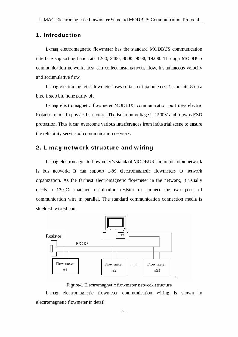
2. L-mag network structure and wiring
L-mag electromagnetic flowmeter’s standard MODBUS communication network
is bus network. It can support 1-99 electromagnetic flowmeters to network
organization. As the farthest electromagnetic flowmeter in the network, it usually
needs a 120 matched termination resistor to connect the two ports of
communication wire in parallel. The standard communication connection media is
shielded twisted pair.
Resistor
Flow meter
#1
Flow meter
#2
Flow meter
#99
Figure-1 Electromagnetic flowmeter network structure
L-mag electromagnetic flowmeter communication wiring is shown in
electromagnetic flowmeter in detail.
- 3 -
L-MAG Electromagnetic Flowmeter Standard MODBUS Communication Protocol
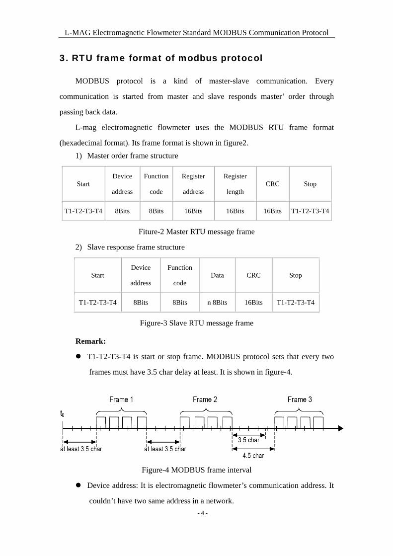
3. RTU frame format of modbus protocol
MODBUS protocol is a kind of master-slave communication. Every
communication is started from master and slave responds master’ order through
passing back data.
L-mag electromagnetic flowmeter uses the MODBUS RTU frame format
(hexadecimal format). Its frame format is shown in figure2.
1) Master order frame structure
Start Device
address
Function
code
Register
address
Register
length CRC Stop
T1-T2-T3-T4 8Bits 8Bits 16Bits 16Bits 16Bits T1-T2-T3-T4
Fiture-2 Master RTU message frame
2) Slave response frame structure
Start Device
address
Function
code Data CRC Stop
T1-T2-T3-T4 8Bits 8Bits n 8Bits 16Bits T1-T2-T3-T4
Figure-3 Slave RTU message frame
Remark:
T1-T2-T3-T4 is start or stop frame. MODBUS protocol sets that every two
frames must have 3.5 char delay at least. It is shown in figure-4.
Figure-4 MODBUS frame interval
Device address: It is electromagnetic flowmeter’s communication address. It
couldn’t have two same address in a network.
- 4 -
L-MAG Electromagnetic Flowmeter Standard MODBUS Communication Protocol
Function code: It is set by MODBUS protocol. L-mag electromagnetic
flowmeter uses the function code 4 which realize the collecting function
through reading input register.
Register address and register number: The start address of register which
restore data. Register number is the number that is used to store data.
Slave response data: Byte number and N bytes data.
They are all shown in MODBUS protocol in detail.
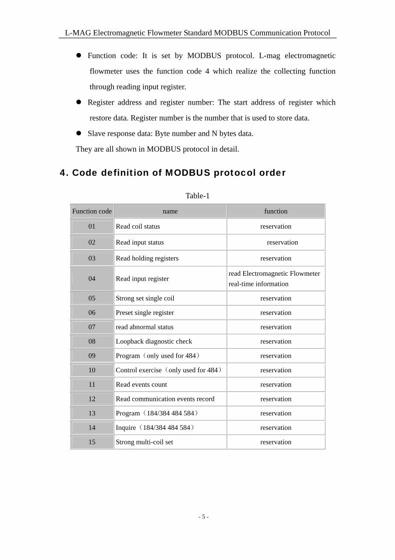
4. Code definition of MODBUS protocol order
Table-1
Function code name function
01 Read coil status reservation
02 Read input status reservation
03 Read holding registers reservation
04 Read input register read Electromagnetic Flowmeter
real-time information
05 Strong set single coil reservation
06 Preset single register reservation
07 read abnormal status reservation
08 Loopback diagnostic check reservation
09 Program(only used for 484) reservation
10 Control exercise(only used for 484) reservation
11 Read events count reservation
12 Read communication events record reservation
13 Program(184/384 484 584) reservation
14 Inquire(184/384 484 584) reservation
15 Strong multi-coil set reservation
- 5 -
L-MAG Electromagnetic Flowmeter Standard MODBUS Communication Protocol
5. MODBUS register definition of electromagnetic
flowmeter
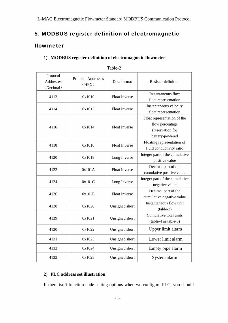
1) MODBUS register definition of electromagnetic flowmeter
Table-2
Protocol
Addresses
(Decimal)
Protocol Addresses
(HEX) Data format Resister definition
4112 0x1010 Float Inverse Instantaneous flow
float representation
4114 0x1012 Float Inverse Instantaneous velocity
float representation
4116 0x1014 Float Inverse
Float representation of the
flow percentage
(reservation for
battery-powered
4118 0x1016 Float Inverse Floating representation of
fluid conductivity ratio
4120 0x1018 Long Inverse Integer part of the cumulative
positive value
4122 0x101A Float Inverse Decimal part of the
cumulative positive value
4124 0x101C Long Inverse Integer part of the cumulative
negative value
4126 0x101E Float Inverse Decimal part of the
cumulative negative value
4128 0x1020 Unsigned shortInstantaneous flow unit
(table-3)
4129 0x1021 Unsigned shortCumulative total units
(table-4 or table-5)
4130 0x1022 Unsigned short Upper limit alarm
4131 0x1023 Unsigned short Lower limit alarm
4132 0x1024 Unsigned short Empty pipe alarm
4133 0x1025 Unsigned short System alarm
2) PLC address set illustration
If there isn’t function code setting options when we configure PLC, you should
- 6 -
L-MAG Electromagnetic Flowmeter Standard MODBUS Communication Protocol
add 3 in front of register address when you use function code 04. If PLC register
address’s basic address is from 1, you should add 1 to original address when
configuring register address.
Example: L-mag electromagnetic flowmeter MODBUS register address is
4112(0x1010) and MODBUS function code is 4. So PLC register address is 34113.
The detailed configuration is seen in example chapter 2.
3) Address configuration illustration of KingView software
There isn’t option of configuring function code. Different drivers have different
configuration methods.
Take PLC- Modicon-MODBUS (RTU) driver for a example. You should add 8 in
front of register address when using function code 04. KingView register address’s
basic address is 1, so the original address should be added 1 when configuring
KingView register address.
L-mag electromagnetic flowmeter MODBUS register address is 4112(0x1010)
and MODBUS function code is 4. So PLC register address is 84113.
The detailed configuration is seen in example chapter 4.
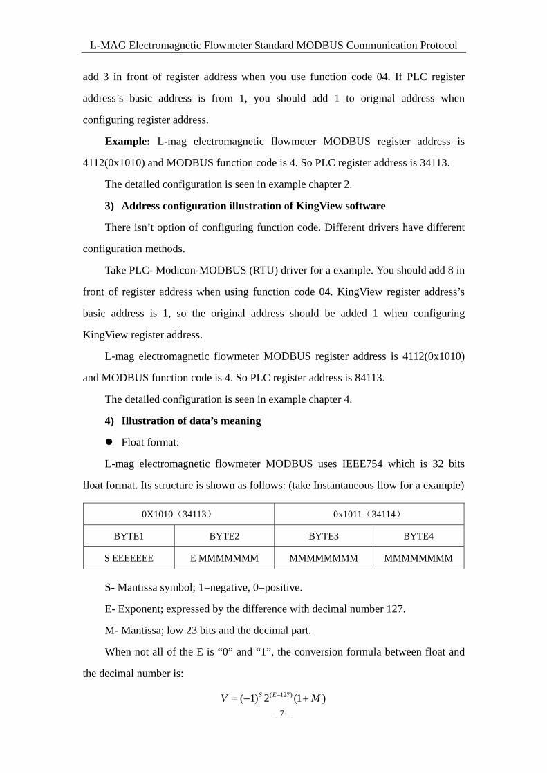
4) Illustration of data’s meaning
Float format:
L-mag electromagnetic flowmeter MODBUS uses IEEE754 which is 32 bits
float format. Its structure is shown as follows: (take Instantaneous flow for a example)
0X1010(34113) 0x1011(34114)
BYTE1 BYTE2 BYTE3 BYTE4
S EEEEEEE E MMMMMMM MMMMMMMM MMMMMMMM
S- Mantissa symbol; 1=negative, 0=positive.
E- Exponent; expressed by the difference with decimal number 127.
M- Mantissa; low 23 bits and the decimal part.
When not all of the E is “0” and “1”, the conversion formula between float and
the decimal number is:
( 127)( 1) 2 (1 )S EV M - 7 -
L-MAG Electromagnetic Flowmeter Standard MODBUS Communication Protocol
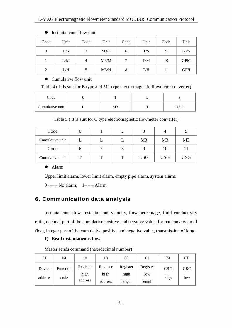
Instantaneous flow unit
Code Unit Code Unit Code Unit Code Unit
0 L/S 3 M3/S 6 T/S 9 GPS
1 L/M 4 M3/M 7 T/M 10 GPM
2 L/H 5 M3/H 8 T/H 11 GPH
Cumulative flow unit
Table 4 ( It is suit for B type and 511 type electromagnetic flowmeter converter)
Code 0 1 2 3
Cumulative unit L M3 T USG
Table 5 ( It is suit for C type electromagnetic flowmeter converter)
Code 0 1 2 3 4 5
Cumulative unit L L L M3 M3 M3
Code 6 7 8 9 10 11
Cumulative unit T T T USG USG USG
Alarm
Upper limit alarm, lower limit alarm, empty pipe alarm, system alarm:
0 ------ No alarm; 1------ Alarm
6. Communication data analysis
Instantaneous flow, instantaneous velocity, flow percentage, fluid conductivity
ratio, decimal part of the cumulative positive and negative value, format conversion of
float, integer part of the cumulative positive and negative value, transmission of long.
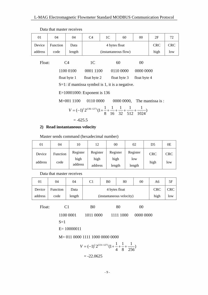
1) Read instantaneous flow
Master sends command (hexadecimal number)
01 04 10 10 00 02 74 CE
Device
address
Function
code
Register
high
address
Register
high
address
Register
high
length
Register
low
length
CRC
high
CRC
low
- 8 -
L-MAG Electromagnetic Flowmeter Standard MODBUS Communication Protocol
Data that master receives
01 04 04 C4 1C 60 00 2F 72
Device
address
Function
code
Data
length
4 bytes float
(instantaneous flow)
CRC
high
CRC
low
Float: C4 1C 60 00
1100 0100 0001 1100 0110 0000 0000 0000
float byte 1 float byte 2 float byte 3 float byte 4
S=1: if mantissa symbol is 1, it is a negative.
E=10001000: Exponent is 136
M=001 1100 0110 0000 0000 0000, The mantissa is :
1 (136 127) 1 1 1 1 1( 1) 2 (1 )
8 16 32 512 1024V
= -625.5
2) Read instantaneous velocity
Master sends command (hexadecimal number)
01 04 10 12 00 02 D5 0E
Device
address
Function
code
Register
high
address
Register
high
address
Register
high
length
Register
low
length
CRC
high
CRC
low
Data that master receives
01 04 04 C1 B0 80 00 A6 5F
Device
address
Function
code
Data
length
4 bytes float
(instantaneous velocity)
CRC
high
CRC
low
Float: C1 B0 80 00
1100 0001 1011 0000 1111 1000 0000 0000
S=1
E= 10000011
M= 011 0000 1111 1000 0000 0000
1 (131 127) 1 1 1( 1) 2 (1 )
4 8 256V
= -22.0625
- 9 -
L-MAG Electromagnetic Flowmeter Standard MODBUS Communication Protocol
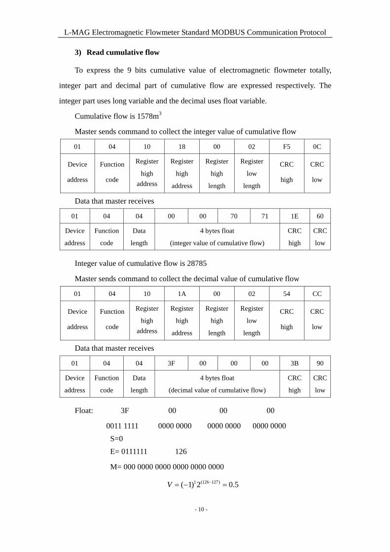
3) Read cumulative flow
To express the 9 bits cumulative value of electromagnetic flowmeter totally,
integer part and decimal part of cumulative flow are expressed respectively. The
integer part uses long variable and the decimal uses float variable.
Cumulative flow is 1578m3
Master sends command to collect the integer value of cumulative flow
01 04 10 18 00 02 F5 0C
Device
address
Function
code
Register
high
address
Register
high
address
Register
high
length
Register
low
length
CRC
high
CRC
low
Data that master receives
01 04 04 00 00 70 71 1E 60
Device
address
Function
code
Data
length
4 bytes float
(integer value of cumulative flow)
CRC
high
CRC
low
Integer value of cumulative flow is 28785
Master sends command to collect the decimal value of cumulative flow
01 04 10 1A 00 02 54 CC
Device
address
Function
code
Register
high
address
Register
high
address
Register
high
length
Register
low
length
CRC
high
CRC
low
Data that master receives
01 04 04 3F 00 00 00 3B 90
Device
address
Function
code
Data
length
4 bytes float
(decimal value of cumulative flow)
CRC
high
CRC
low
Float: 3F 00 00 00
0011 1111 0000 0000 0000 0000 0000 0000
S=0
E= 0111111 126
M= 000 0000 0000 0000 0000 0000
1 (126 127)( 1) 2 0.5V
- 10 -
L-MAG Electromagnetic Flowmeter Standard MODBUS Communication Protocol
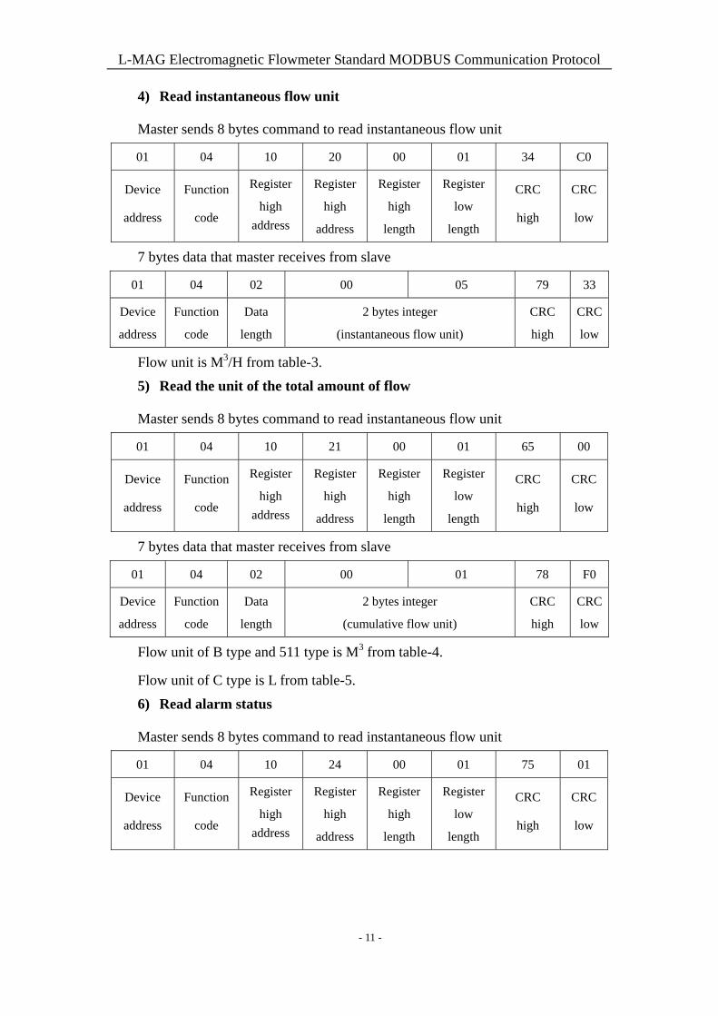
4) Read instantaneous flow unit
Master sends 8 bytes command to read instantaneous flow unit
01 04 10 20 00 01 34 C0
Device
address
Function
code
Register
high
address
Register
high
address
Register
high
length
Register
low
length
CRC
high
CRC
low
7 bytes data that master receives from slave
01 04 02 00 05 79 33
Device
address
Function
code
Data
length
2 bytes integer
(instantaneous flow unit)
CRC
high
CRC
low
Flow unit is M3/H from table-3.
5) Read the unit of the total amount of flow
Master sends 8 bytes command to read instantaneous flow unit
01 04 10 21 00 01 65 00
Device
address
Function
code
Register
high
address
Register
high
address
Register
high
length
Register
low
length
CRC
high
CRC
low
7 bytes data that master receives from slave
01 04 02 00 01 78 F0
Device
address
Function
code
Data
length
2 bytes integer
(cumulative flow unit)
CRC
high
CRC
low
Flow unit of B type and 511 type is M3 from table-4.
Flow unit of C type is L from table-5.
6) Read alarm status
Master sends 8 bytes command to read instantaneous flow unit
01 04 10 24 00 01 75 01
Device
address
Function
code
Register
high
address
Register
high
address
Register
high
length
Register
low
length
CRC
high
CRC
low
- 11 -
L-MAG Electromagnetic Flowmeter Standard MODBUS Communication Protocol
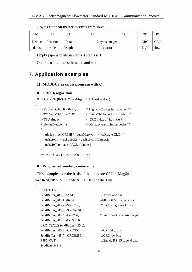
7 bytes data that master receives from slave
01 04 02 00 01 78 F0
Device
address
Function
code
Data
length
2 bytes integer
(alarm)
CRC
high
CRC
low
Empty pipe is in alarm status if status is 1.
Other alarm status is the same and so on.
7. Application examples
1) MODBUS example program with C
CRC16 algorithm:
INT16U CRC16(INT8U *puchMsg, INT16U usDataLen)
{
INT8U uchCRCHi = 0xFF; /* High CRC bytes initialization */
INT8U uchCRCLo = 0xFF; /* Low CRC bytes initialization */
INT8U uIndex; /* CRC index of the cycle */
while (usDataLen--) /* Message transmission buffer */
{
uIndex = uchCRCHi ^ *puchMsg++; /* calculate CRC */
uchCRCHi = uchCRCLo ^ auchCRCHi[uIndex];
uchCRCLo = auchCRCLo[uIndex];
}
return (uchCRCHi << 8 | uchCRCLo);
}
Program of sending commands
This example is on the basis of that the core CPU is Mag64
void Read_InPut(INT8U Addr,INT16U Start,INT16U Len)
{
INT16U CRC;
SendBuffer_485[0]=Addr; //Device address
SendBuffer_485[1]=0x04; //MODBUS function code
SendBuffer_485[2]=Start/256; //Start is register address
SendBuffer_485[3]=Start%256;
SendBuffer_485[4]=Len/256; //Len is reading register length
SendBuffer_485[5]=Len%256;
CRC=CRC16(SendBuffer_485,6);
SendBuffer_485[6]=CRC/256; //CRC high bits
SendBuffer_485[7]=CRC%256; //CRC low bits
R485_OUT; //Enable RS485 to send data
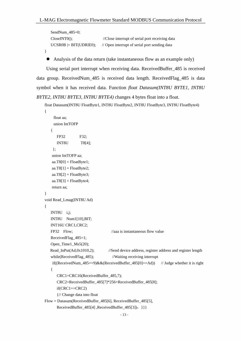
SendLen_485=8;
- 12 -
L-MAG Electromagnetic Flowmeter Standard MODBUS Communication Protocol
SendNum_485=0;
CloseINT0(); //Close interrupt of serial port receiving data
UCSR0B |= BIT(UDRIE0); // Open interrupt of serial port sending data
}
Analysis of the data return (take instantaneous flow as an example only)
Using serial port interrupt when receiving data. ReceivedBuffer_485 is received
data group. ReceivedNum_485 is received data length. ReceivedFlag_485 is data
symbol when it has received data. Function float Datasum(INT8U BYTE1, INT8U
BYTE2, INT8U BYTE3, INT8U BYTE4) changes 4 bytes float into a float.
float Datasum(INT8U FloatByte1, INT8U FloatByte2, INT8U FloatByte3, INT8U FloatByte4)
{
float aa;
union IntTOFP
{
FP32 F32;
INT8U T8[4];
};
union IntTOFP aa;
aa.T8[0] = FloatByte1;
aa.T8[1] = FloatByte2;
aa.T8[2] = FloatByte3;
aa.T8[3] = FloatByte4;
return aa;
}
void Read_Lmag(INT8U Ad)
{
INT8U i,j;
INT8U Num1[10],BIT;
INT16U CRC1,CRC2;
FP32 Flow; //aaa is instantaneous flow value
ReceivedFlag_485=1;
Open_Time1_Ms5(20);
Read_InPut(Ad,0x1010,2); //Send device address, register address and register length
while(ReceivedFlag_485); //Waiting receiving interrupt
if((ReceivedNum_485==9)&&(ReceivedBuffer_485[0]==Ad)) // Judge whether it is right
{
CRC1=CRC16(ReceivedBuffer_485,7);
CRC2=ReceivedBuffer_485[7]*256+ReceivedBuffer_485[8];
if(CRC1==CRC2)
{// Change data into float
Flow = Datasum(ReceivedBuffer_485[6], ReceivedBuffer_485[5],
ReceivedBuffer_485[4] ,ReceivedBuffer_485[3]);}}}
- 13 -
L-MAG Electromagnetic Flowmeter Standard MODBUS Communication Protocol
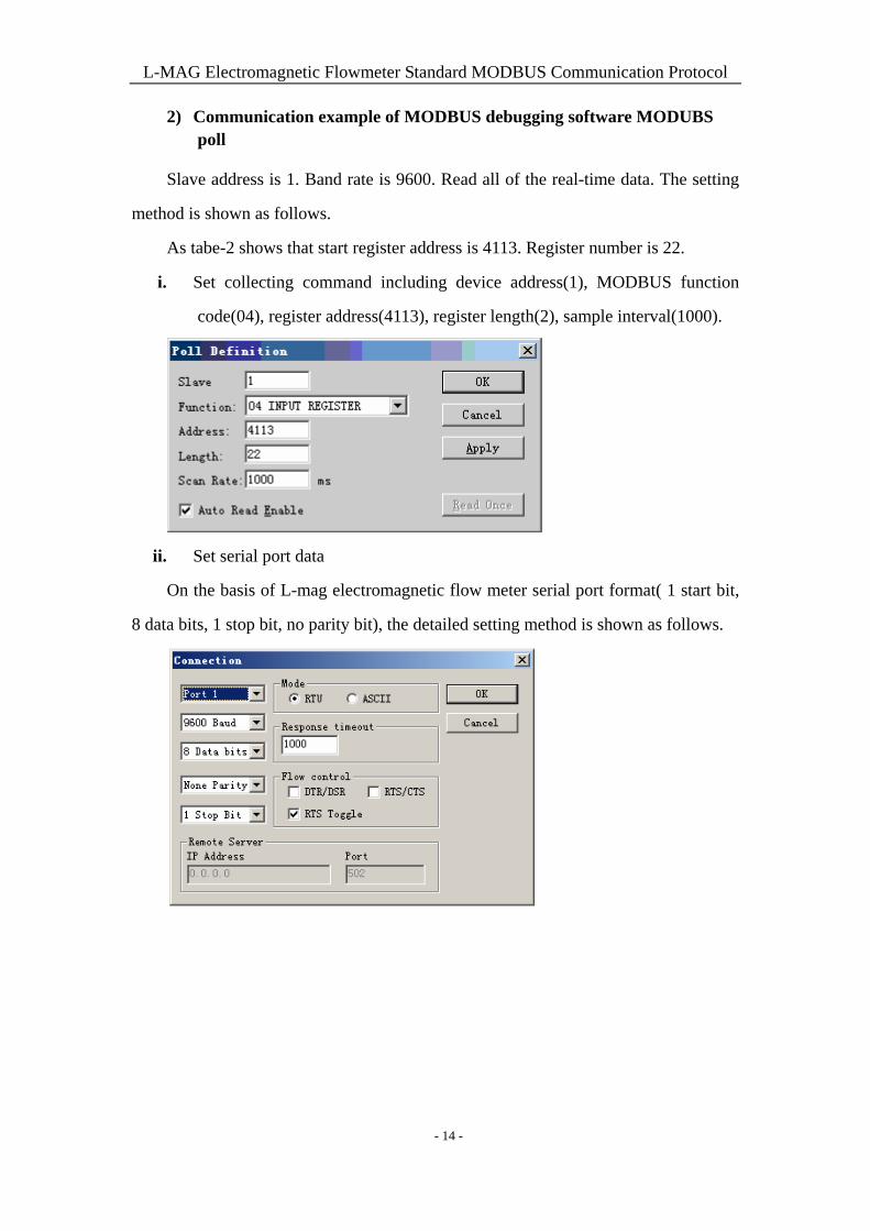
2) Communication example of MODBUS debugging software MODUBS poll
Slave address is 1. Band rate is 9600. Read all of the real-time data. The setting
method is shown as follows.
As tabe-2 shows that start register address is 4113. Register number is 22.
i. Set collecting command including device address(1), MODBUS function
code(04), register address(4113), register length(2), sample interval(1000).
ii. Set serial port data
On the basis of L-mag electromagnetic flow meter serial port format( 1 start bit,
8 data bits, 1 stop bit, no parity bit), the detailed setting method is shown as follows.
- 14 -
L-MAG Electromagnetic Flowmeter Standard MODBUS Communication Protocol
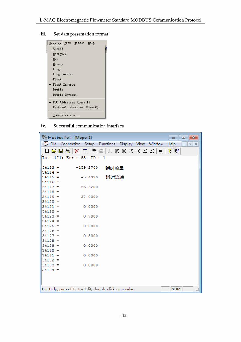
iii. Set data presentation format
iv. Successful communication interface
- 15 -
L-MAG Electromagnetic Flowmeter Standard MODBUS Communication Protocol
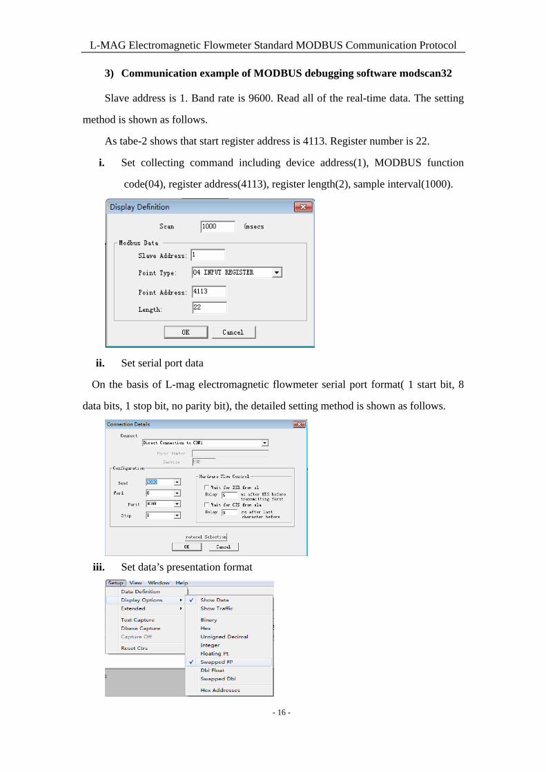
3) Communication example of MODBUS debugging software modscan32
Slave address is 1. Band rate is 9600. Read all of the real-time data. The setting
method is shown as follows.
As tabe-2 shows that start register address is 4113. Register number is 22.
i. Set collecting command including device address(1), MODBUS function
code(04), register address(4113), register length(2), sample interval(1000).
ii. Set serial port data
On the basis of L-mag electromagnetic flowmeter serial port format( 1 start bit, 8
data bits, 1 stop bit, no parity bit), the detailed setting method is shown as follows.
iii. Set data’s presentation format
- 16 -
L-MAG Electromagnetic Flowmeter Standard MODBUS Communication Protocol
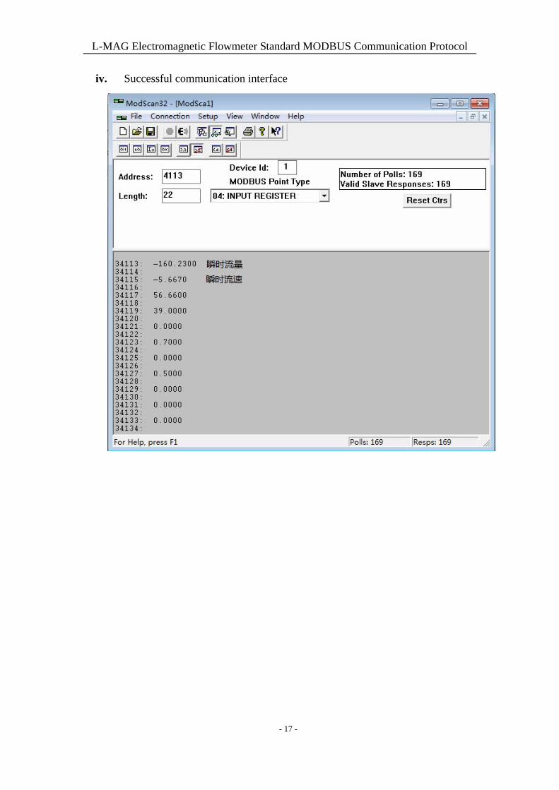
iv. Successful communication interface
- 17 -
L-MAG Electromagnetic Flowmeter Standard MODBUS Communication Protocol
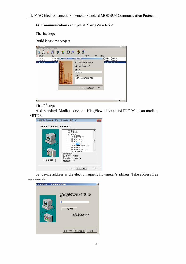
4) Communication example of “KingView 6.53”
The 1st step:
Build kingview project
The 2nd step: Add standard Modbus device,KingView device list-PLC-Modicon-modbus
(RTU)。
Set device address as the electromagnetic flowmeter’s address. Take address 1 as an example
- 18 -
L-MAG Electromagnetic Flowmeter Standard MODBUS Communication Protocol
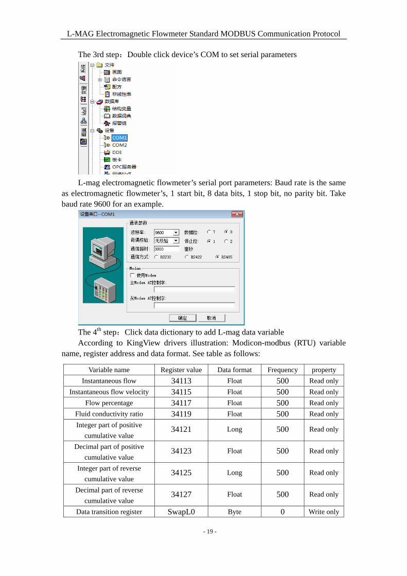
The 3rd step:Double click device’s COM to set serial parameters
L-mag electromagnetic flowmeter’s serial port parameters: Baud rate is the same
as electromagnetic flowmeter’s, 1 start bit, 8 data bits, 1 stop bit, no parity bit. Take baud rate 9600 for an example.
The 4th step:Click data dictionary to add L-mag data variable According to KingView drivers illustration: Modicon-modbus (RTU) variable
name, register address and data format. See table as follows:
Variable name Register value Data format Frequency property
Instantaneous flow 34113 Float 500 Read only
Instantaneous flow velocity 34115 Float 500 Read only
Flow percentage 34117 Float 500 Read only
Fluid conductivity ratio 34119 Float 500 Read only
Integer part of positive
cumulative value 34121 Long 500 Read only
Decimal part of positive
cumulative value 34123 Float 500 Read only
Integer part of reverse
cumulative value 34125 Long 500 Read only
Decimal part of reverse
cumulative value 34127 Float 500 Read only
Data transition register SwapL0 Byte 0 Write only
- 19 -
L-MAG Electromagnetic Flowmeter Standard MODBUS Communication Protocol
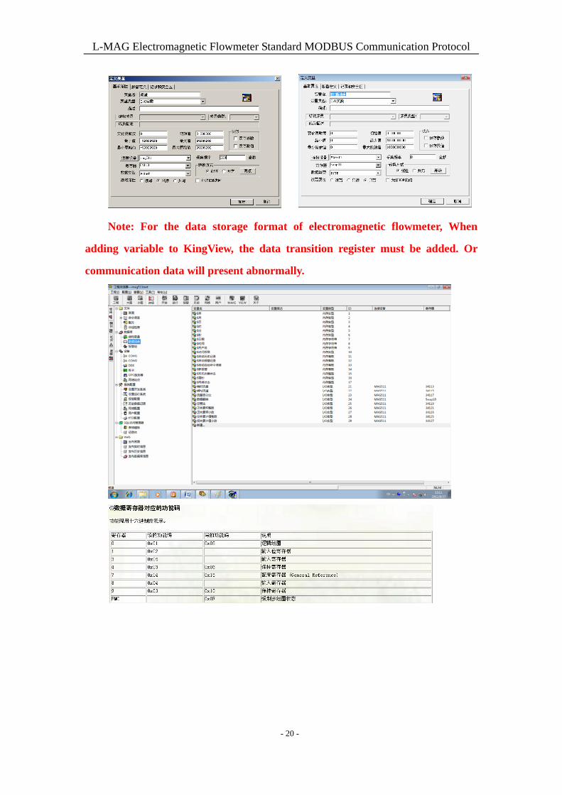
Note: For the data storage format of electromagnetic flowmeter, When
adding variable to KingView, the data transition register must be added. Or
communication data will present abnormally.
- 20 -
L-MAG Electromagnetic Flowmeter Standard MODBUS Communication Protocol
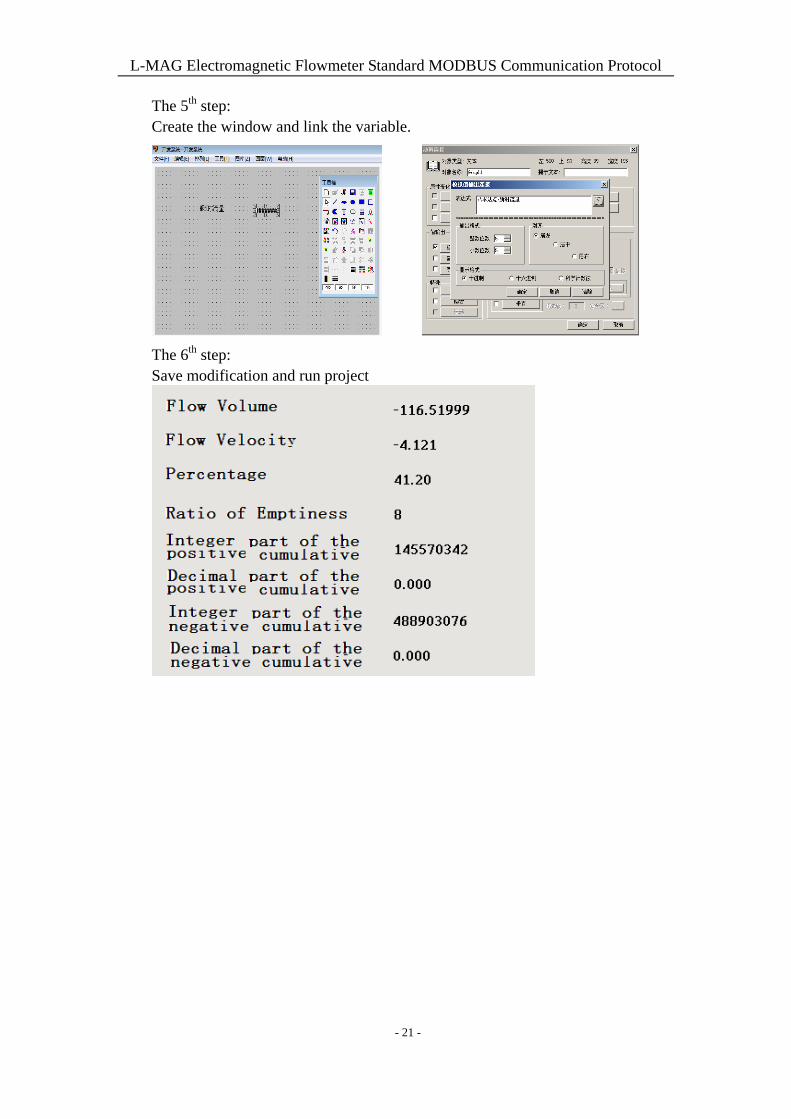
The 5th step: Create the window and link the variable.
The 6th step: Save modification and run project
- 21 -

L-MAG Electromagnetic Flowmeter Standard MODBUS Communication Protocol
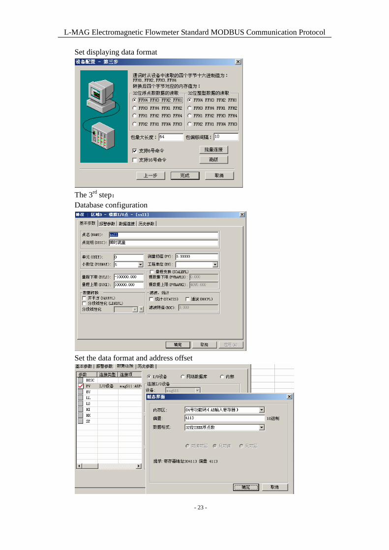
5) Communication example of “力控 6.1”
The 1st step: Build a project
The 2nd step: IO port device configuration chooses IO device-Modbus- standard
Modbus-Modbus(RTU serial port)
Choose serial port
- 22 -
L-MAG Electromagnetic Flowmeter Standard MODBUS Communication Protocol
Set displaying data format
The 3rd step: Database configuration
Set the data format and address offset
- 23 -
L-MAG Electromagnetic Flowmeter Standard MODBUS Communication Protocol
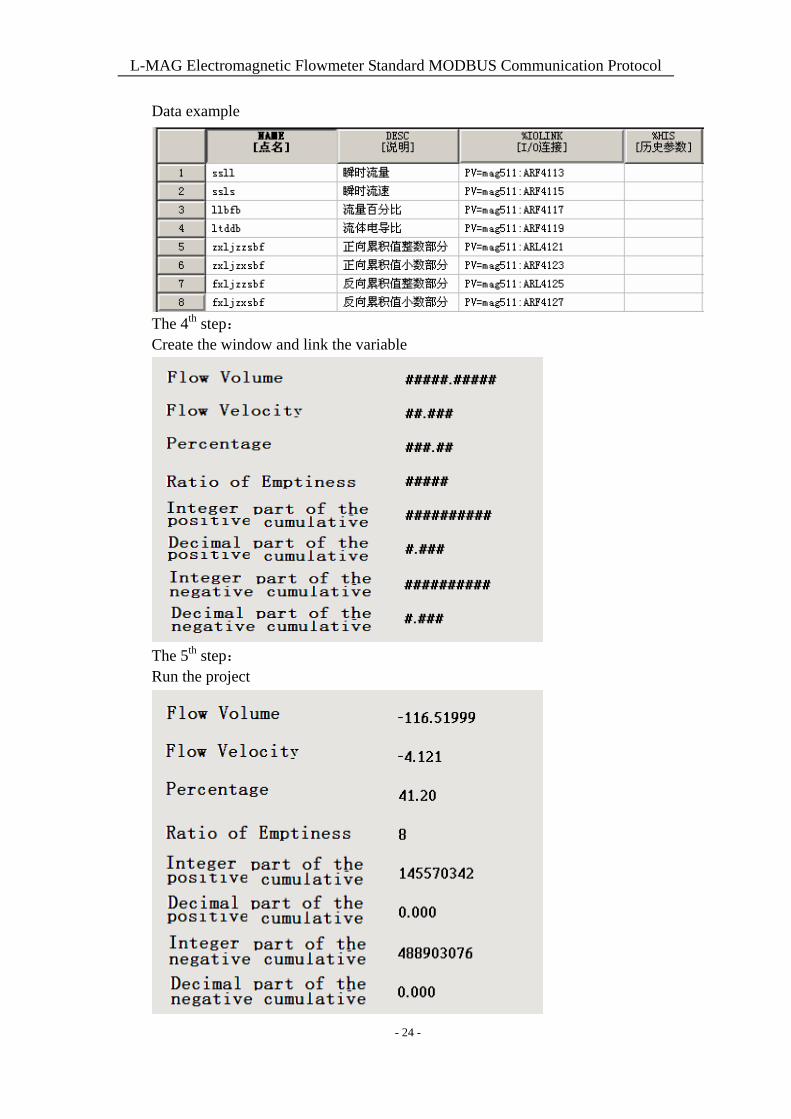
Data example
The 4th step: Create the window and link the variable
The 5th step: Run the project
- 24 -

L-MAG Electromagnetic Flowmeter Standard MODBUS Communication Protocol
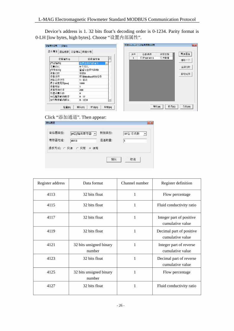
6) MCGS communication example
Using guide: The 1st step: Create a project and it will appear window as follows. Then choose “设备窗口”,
double click it.
Choose “设备工具箱”. Click “设备管理” and then add “通用串口父设备” and
“标准 MODBUSRTU 设备” to project.
Choose “通用串口父设备 0” and “设备 0”.
- 25 -
L-MAG Electromagnetic Flowmeter Standard MODBUS Communication Protocol
Device’s address is 1. 32 bits float’s decoding order is 0-1234. Parity format is 0-LH [low bytes, high bytes]. Choose “设置内部属性”.
Click “添加通道”. Then appear:
Register address Data format Channel number Register definition
4113 32 bits float 1 Flow percentage
4115 32 bits float 1 Fluid conductivity ratio
4117 32 bits float 1 Integer part of positive
cumulative value
4119 32 bits float 1 Decimal part of positive
cumulative value
4121 32 bits unsigned binary
number
1 Integer part of reverse
cumulative value
4123 32 bits float 1 Decimal part of reverse
cumulative value
4125 32 bits unsigned binary
number
1 Flow percentage
4127 32 bits float 1 Fluid conductivity ratio
- 26 -
L-MAG Electromagnetic Flowmeter Standard MODBUS Communication Protocol
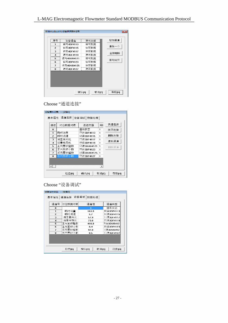
Choose “通道连接”
Choose “设备调试”
- 27 -