L LL a aa s ss eee r rr w ww ooo l ll f ff · L LL a aa s ss eee r rr w ww ooo l ll f ff FX ......
11
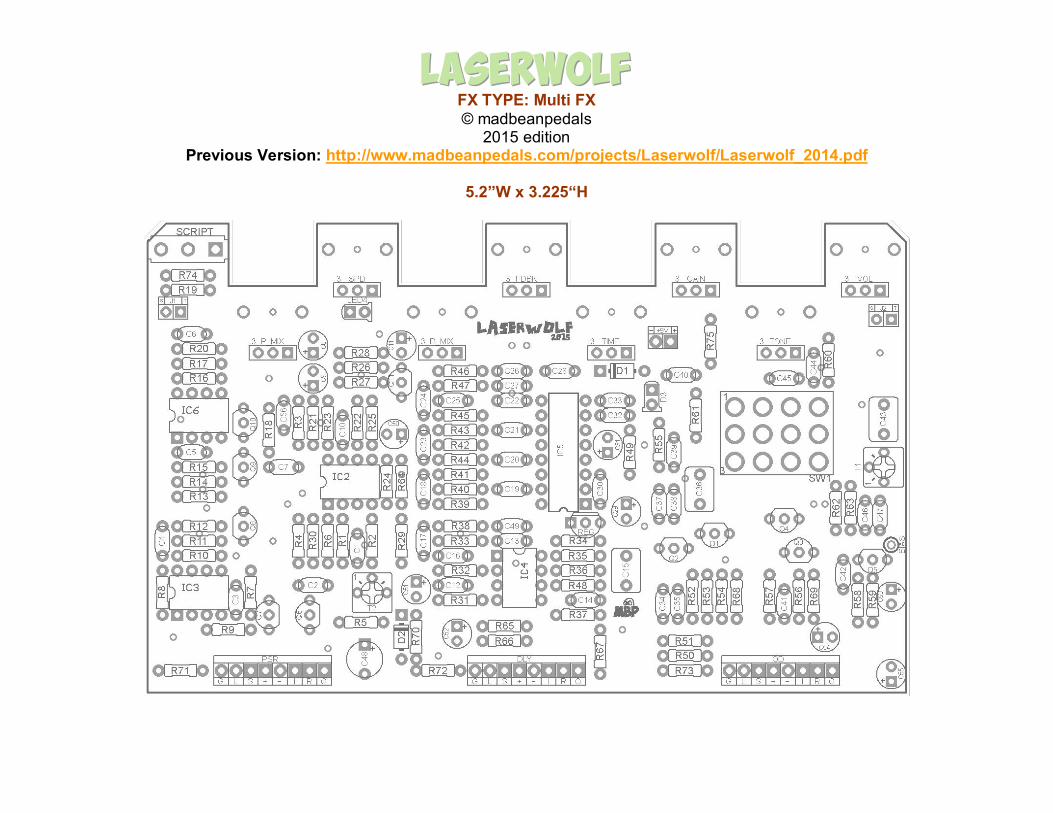
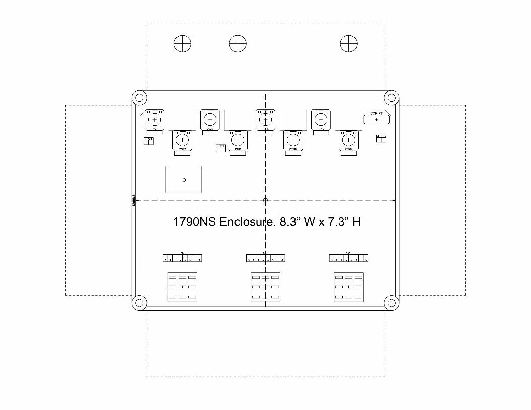
L L a a s s e e r r w wo o l l f f FX TYPE: Multi FX © madbeanpedals 2015 edition Previous Version: http://www.madbeanpedals.com/projects/Laserwolf/Laserwolf_2014.pdf 5.2”W x 3.225“H
Transcript of L LL a aa s ss eee r rr w ww ooo l ll f ff · L LL a aa s ss eee r rr w ww ooo l ll f ff FX ......
L L La a as s se e er r rw w wo o ol l lf f f FX TYPE: Multi FX © madbeanpedals
2015 edition Previous Version: http://www.madbeanpedals.com/projects/Laserwolf/Laserwolf_2014.pdf
5.2”W x 3.225“H
2
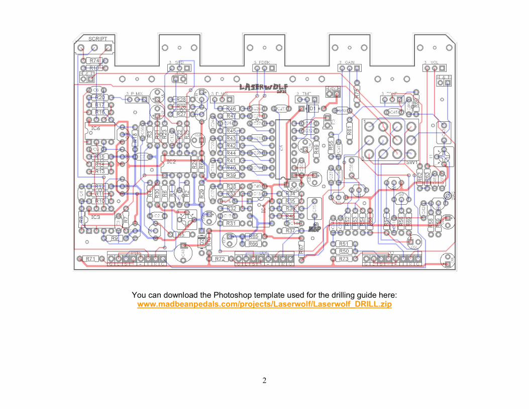
You can download the Photoshop template used for the drilling guide here: www.madbeanpedals.com/projects/Laserwolf/Laserwolf_DRILL.zip
3
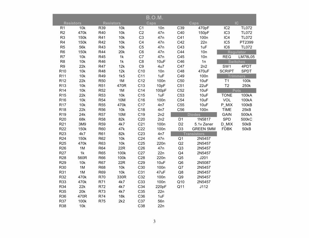
R1 10k R39 10k C1 10n C39 470pF IC2 TL072 R2 470k R40 10k C2 47n C40 150pF IC3 TL072 R3 150k R41 10k C3 47n C41 100n IC4 TL072 R4 150k R42 10k C4 47n C42 22n IC5 PT2399 R5 56k R43 10k C5 47n C43 1uF IC6 TL072 R6 150k R44 20k C6 47n C44 10n R7 10k R45 1k C7 47n C45 10n REG LM78L05 R8 10k R46 1k C8 10uF C46 1n R9 22k R47 12k C9 4u7 C47 2n2 SW1 4PDT R10 10k R48 12k C10 10n C48 470uF SCRIPT SPDT R11 10k R49 1k5 C11 1uF C49 100n R12 22k R50 1M C12 100n C50 10uF T1 100k R13 10k R51 470R C13 10pF C51 22uF T2 250k R14 10k R52 1M C14 100pF C52 10uF R15 22k R53 10k C15 1uF C53 10uF TONE 100kA R16 10k R54 10M C16 100n C54 10uF VOL 100kA R17 10k R55 470k C17 4n7 C55 10uF P_MIX 100kB R18 22k R56 10k C18 4n7 C56 100n TIME 25kB R19 24k R57 10M C19 2n2 GAIN 500kA R20 68k R58 82k C20 2n2 D1 1N5817 SPD 500kC R21 3M9 R59 4k7 C21 100n D2 5.1v Zener D_MIX 50kB R22 150k R60 47k C22 100n D3 GREEN 5MM FDBK 50kB R23 4k7 R61 82k C23 4n7 R24 150k R62 10k C24 47n Q1 2N5457 R25 470k R63 10k C25 220n Q2 2N5457 R26 1M R64 22R C26 47n Q3 2N5457 R27 1k R65 100k C27 22n Q4 2N5457 R28 560R R66 100k C28 220n Q5 J201 R29 10k R67 22R C29 10uF Q6 2N5087 R30 1M R68 10k C30 100n Q7 2N5457 R31 1M R69 10k C31 47uF Q8 2N5457 R32 470k R70 330R C32 100n Q9 2N5457 R33 470k R71 4k7 C33 100n Q10 2N5457 R34 22k R72 4k7 C34 220pF Q11 J112 R35 20k R73 4k7 C35 22n R36 470R R74 18k C36 1uF R37 100k R75 2k2 C37 56n R38 10k C38 22n
Resistors Caps Caps B.O.M.
Diodes
Transistors
IC
Regulator
Switches
Trimmers
Pots
Resistors
4
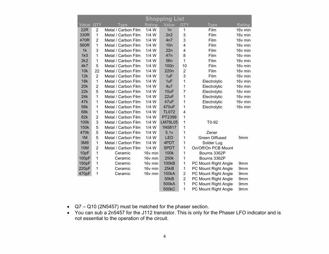
Value QTY Type Rating Value QTY Type Rating 22R 2 Metal / Carbon Film 1/4 W 1n 1 Film 16v min 330R 1 Metal / Carbon Film 1/4 W 2n2 3 Film 16v min 470R 2 Metal / Carbon Film 1/4 W 4n7 3 Film 16v min 560R 1 Metal / Carbon Film 1/4 W 10n 4 Film 16v min 1k 3 Metal / Carbon Film 1/4 W 22n 4 Film 16v min 1k5 1 Metal / Carbon Film 1/4 W 47n 8 Film 16v min 2k2 1 Metal / Carbon Film 1/4 W 56n 1 Film 16v min 4k7 5 Metal / Carbon Film 1/4 W 100n 10 Film 16v min 10k 22 Metal / Carbon Film 1/4 W 220n 2 Film 16v min 12k 2 Metal / Carbon Film 1/4 W 1uF 3 Film 16v min 18k 1 Metal / Carbon Film 1/4 W 1uF 1 Electrolytic 16v min 20k 2 Metal / Carbon Film 1/4 W 4u7 1 Electrolytic 16v min 22k 5 Metal / Carbon Film 1/4 W 10uF 7 Electrolytic 16v min 24k 1 Metal / Carbon Film 1/4 W 22uF 1 Electrolytic 16v min 47k 1 Metal / Carbon Film 1/4 W 47uF 1 Electrolytic 16v min 56k 1 Metal / Carbon Film 1/4 W 470uF 1 Electrolytic 16v min 68k 1 Metal / Carbon Film 1/4 W TL072 4 82k 2 Metal / Carbon Film 1/4 W PT2399 1 100k 3 Metal / Carbon Film 1/4 W LM78L05 1 T092 150k 5 Metal / Carbon Film 1/4 W 1N5817 1 470k 5 Metal / Carbon Film 1/4 W 5.1v 1 Zener 1M 5 Metal / Carbon Film 1/4 W LED 1 Green Diffused 5mm 3M9 1 Metal / Carbon Film 1/4 W 4PDT 1 Solder Lug 10M 2 Metal / Carbon Film 1/4 W SPDT 1 On/Off/On PCB Mount 10pF 1 Ceramic 16v min 100k 1 Bourns 3362P 100pF 1 Ceramic 16v min 250k 1 Bourns 3362P 150pF 1 Ceramic 16v min 100kB 1 PC Mount Right Angle 9mm 220pF 1 Ceramic 16v min 25kB 1 PC Mount Right Angle 9mm 470pF 1 Ceramic 16v min 100kA 2 PC Mount Right Angle 9mm
50kB 2 PC Mount Right Angle 9mm 500kA 1 PC Mount Right Angle 9mm 500kC 1 PC Mount Right Angle 9mm
Shopping List
• Q7 – Q10 (2N5457) must be matched for the phaser section. • You can sub a 2n5457 for the J112 transistor. This is only for the Phaser LFO indicator and is
not essential to the operation of the circuit.
Overview
The Laserwolf is the first madbeanpedals multieffect project. It is an attempt to replicate some of the coveted tones off the first few Van Halen albums. EVH famously used few effects straight into his Marshall amps to achieve what we all know as the “brown sound”. While I don’t claim the Laserwolf copies this sound exactly it will at least get you in the ballpark…probably the same inning, too!
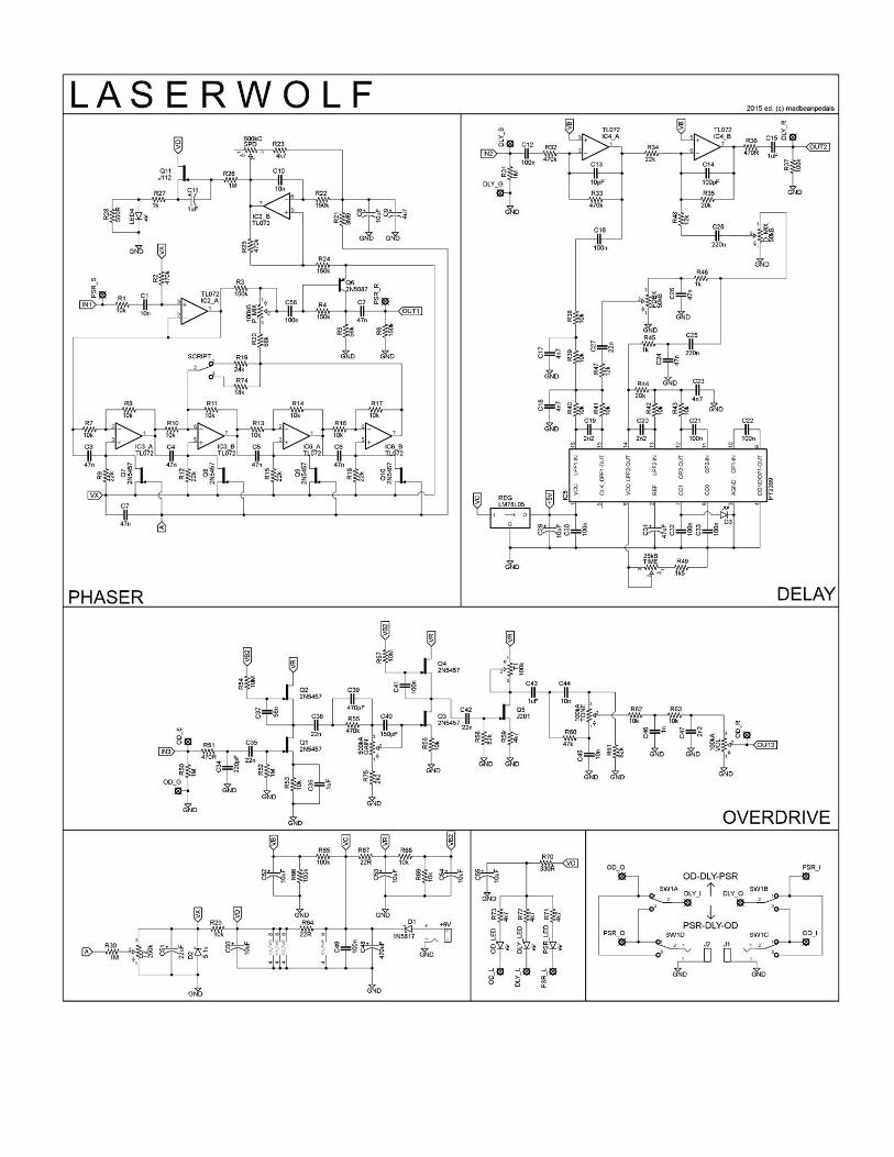
The Laserwolf has three effect components: a phaser, a delay and an overdrive. The Phaser is a Phase 90 with a couple of extra mods. The delay is a standard PT2399based delay voiced for degrading repeats. The overdrive is a mashup of the BSIABII and the Wampler® Pinnacle™ (both being very similar).
The signal path can be altered via a 4PDT switch, as well. This offers the option of PhaserDelay Overdrive or OverdriveDelayPhaser (in series). Each effect can be turned on and off via the stomp switches. The reason for the order switching is that the PhaserDelayOverdrive option is most similar to how EVH used his effects; a Phase90 into an Echoplex into his amp. The second option, OverdriveDelayPhaser is closer to how guitar players arrange pedals on a pedalboard (overdrive before modulation or delay). Ideally, we might want a third option of OverdrivePhaserDelay but this would require yet another switch in an already complex build. However, the two existing options offer plenty of vareity and they do indeed sound different from one another.
Controls
OD Section: Vol, Tone and Gain. Delay Section: Mix, Feedback and Delay. Phaser Section: Speed, Mix and “Script”.
The OD and Delay controls are selfexplanatory. The Feedback control on the delay will go into self oscillation when turned up. You can modify where it does this by changing the value of R47. Lower values will result in earlier oscillation. A high enough value will prevent the delay from selfoscillating altogether.
The Phaser controls require explaining. The Speed control is obvious; down is slow and up is fast. You should use the CTaper (reverse audio) listed. A Btaper will work but most of the speed changes will only happen in the last 1/3 of the rotation with it.
The Mix control is not standard. Fully counterclockwise is the standard Phase 90 effect. As you turn the Mix control up, the effect slowly changes into vibrato instead of phase. The vibrato works best at medium speeds; too slow and you do not get much of an effect, and too fast the phase and vibrato sound pretty much the same.
Finally, the “Scipt” switch gives three options: two levels of phase feedback or no feedback (middle position). R19 and R74 set the amount of feedback level. I just picked what I liked in this circuit, but feel free to socket those resistors and play with them. Don’t go too low on the resistor values or you will just get a noisy mess. If you do not want feedback options, simply leave the switch off. Or, if you prefer just one feedback option use an On/On SPDT instead and leave R74 empty.
8
4PDT
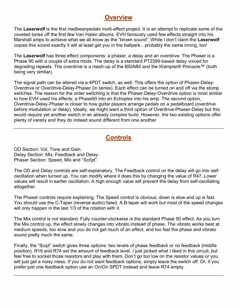
The general lack of a small profile PCBmounted 4PDT makes for a less than ideal combination of component footprints in the Laserwolf. The 4PDT toggle is really tall which causes the 9mm pots to hang further away from the enclosure when everything is soldered onto the PCB. It will require you to put a bit of pressure on the PCB to get the threads of the pots to clear the drill holes on your enclosure; not very much…just a little. I would avoid overtightening the nuts on the pots to keep the pressure to a minimum. Fingertight plus a little more should be enough to hold everything in place.
Alternatively, you could simply not push the 9mm pots all the way flush to the PCB to give them some extra height to match the 4PDT. A simple spacer underneath the pots when soldering would make this a relatively straightforward task.
You can omit the 4PDT if you do not want to have the order switching option by soldering jumpers between the middle row of pads to either of the outside rows.
PhaserDelayOverdrive (Up Position) OverdriveDelayPhaser (Down Position)
Wiring
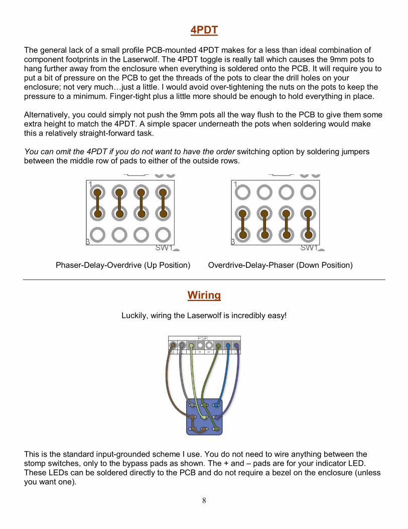
Luckily, wiring the Laserwolf is incredibly easy!
This is the standard inputgrounded scheme I use. You do not need to wire anything between the stomp switches, only to the bypass pads as shown. The + and – pads are for your indicator LED. These LEDs can be soldered directly to the PCB and do not require a bezel on the enclosure (unless you want one).
9
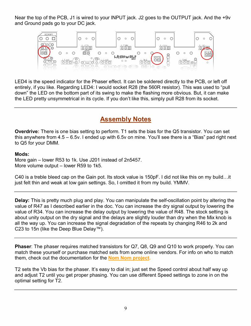
Near the top of the PCB, J1 is wired to your INPUT jack. J2 goes to the OUTPUT jack. And the +9v and Ground pads go to your DC jack.
LED4 is the speed indicator for the Phaser effect. It can be soldered directly to the PCB, or left off entirely, if you like. Regarding LED4: I would socket R28 (the 560R resistor). This was used to “pull down” the LED on the bottom part of its swing to make the flashing more obvious. But, it can make the LED pretty unsymmetrical in its cycle. If you don’t like this, simply pull R28 from its socket.
Assembly Notes
Overdrive: There is one bias setting to perform. T1 sets the bias for the Q5 transistor. You can set this anywhere from 4.5 – 6.5v. I ended up with 6.5v on mine. You’ll see there is a “Bias” pad right next to Q5 for your DMM.
Mods: More gain – lower R53 to 1k. Use J201 instead of 2n5457. More volume output – lower R59 to 1k5.
C40 is a treble bleed cap on the Gain pot. Its stock value is 150pF. I did not like this on my build…it just felt thin and weak at low gain settings. So, I omitted it from my build. YMMV.
Delay: This is pretty much plug and play. You can manipulate the selfoscillation point by altering the value of R47 as I described earlier in the doc. You can increase the dry signal output by lowering the value of R34. You can increase the delay output by lowering the value of R48. The stock setting is about unity output on the dry signal and the delays are slightly louder than dry when the Mix knob is all the way up. You can increase the signal degradation of the repeats by changing R46 to 2k and C23 to 15n (like the Deep Blue Delay™).
Phaser: The phaser requires matched transistors for Q7, Q8, Q9 and Q10 to work properly. You can match these yourself or purchase matched sets from some online vendors. For info on who to match them, check out the documentation for the Nom Nom project.
T2 sets the Vb bias for the phaser. It’s easy to dial in; just set the Speed control about half way up and adjust T2 until you get proper phasing. You can use different Speed settings to zone in on the optimal setting for T2.
10
Testing
Take your time. This is a very complicated build. The combination of many parts, switching and just the shear size of it will make it one of the more challenging DIY projects you’ve attempted. The good news is if you follow all the instructions it will fire right up….mine worked the first time without any hassle. This is rare!
Since you are a thorough builder, I know you will be testing this thing out before wiring it all up and dropping it in an enclosure. I know this because you are a dedicated madbeaner and follow the “rock it before you box it” mantra like the religious doctrine it attempts to be. But, this project must be tested a little differently. You should check the functionality BEFORE soldering in the 4PDT switch. Once that switch it soldered in, you pretty much have to solder the stomp switches for it to work 100%. My suggestion is to assemble everything then wire up the +9v jack, and the S and R pads of each bypass. This is all you need to use on your testing rig. Connect the +9v/ground wires to your testing rig, then use the S (send) and R (return) wires on each effect to test them individually. Once you confirm each one is behaving, go ahead and solder that 4PDT and do the final assembly. As long as you follow the wiring instructions I do not think it is necessary to test it further before putting the entire rig in your enclosure (unless you really want to).
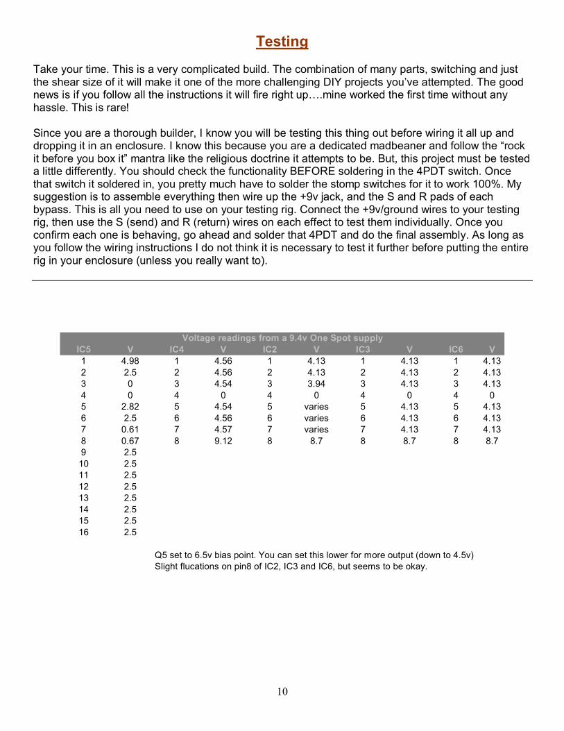
IC5 V IC4 V IC2 V IC3 V IC6 V 1 4.98 1 4.56 1 4.13 1 4.13 1 4.13 2 2.5 2 4.56 2 4.13 2 4.13 2 4.13 3 0 3 4.54 3 3.94 3 4.13 3 4.13 4 0 4 0 4 0 4 0 4 0 5 2.82 5 4.54 5 varies 5 4.13 5 4.13 6 2.5 6 4.56 6 varies 6 4.13 6 4.13 7 0.61 7 4.57 7 varies 7 4.13 7 4.13 8 0.67 8 9.12 8 8.7 8 8.7 8 8.7 9 2.5 10 2.5 11 2.5 12 2.5 13 2.5 14 2.5 15 2.5 16 2.5
Q5 set to 6.5v bias point. You can set this lower for more output (down to 4.5v) Slight flucations on pin8 of IC2, IC3 and IC6, but seems to be okay.
Voltage readings from a 9.4v One Spot supply
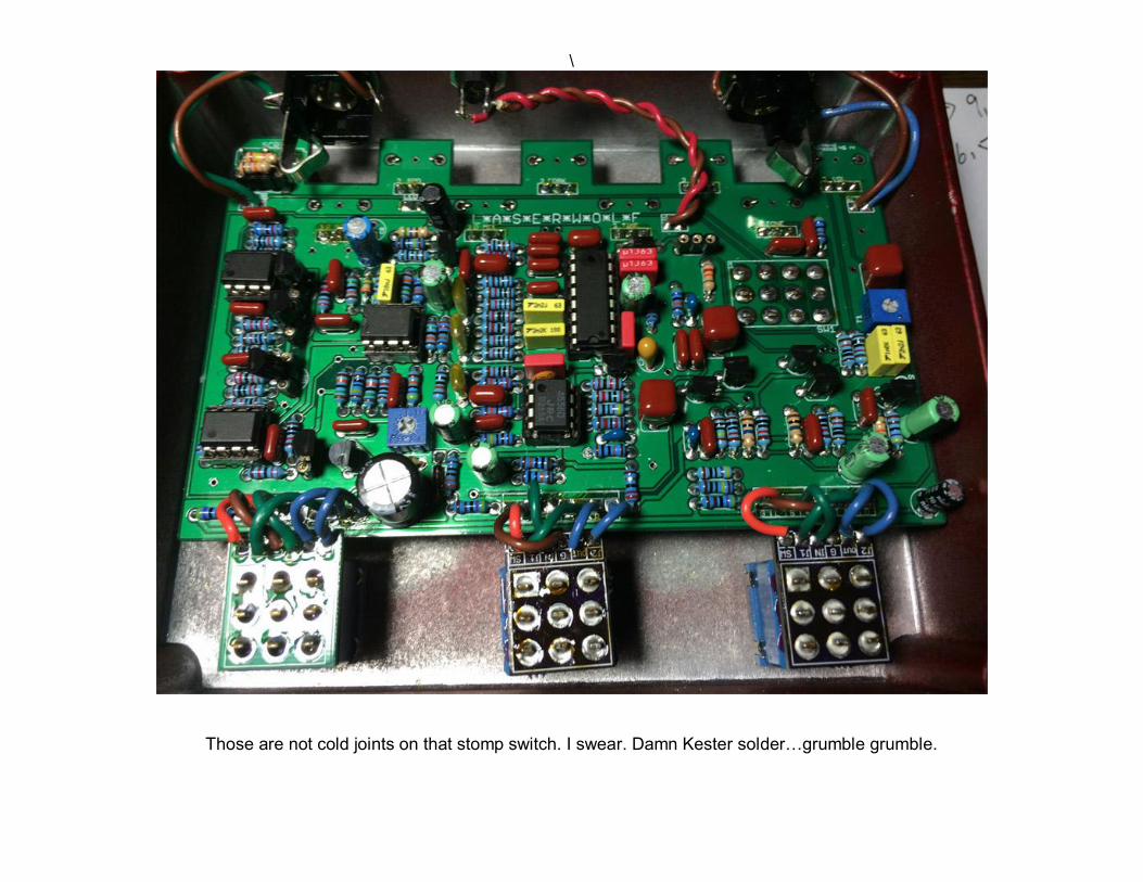
\
Those are not cold joints on that stomp switch. I swear. Damn Kester solder…grumble grumble.