L-force 9400 Servo Drives - Lenzedownload.lenze.com/TD/E94AxHE__Servo Drives 9400... · L Software...
679
L Software Manual L-force 9400 Servo Drives 9400 HighLine V01.37 Parameter setting & configuration
Transcript of L-force 9400 Servo Drives - Lenzedownload.lenze.com/TD/E94AxHE__Servo Drives 9400... · L Software...
L
Software Manual
L-force 9400 Servo Drives
9400 HighLine V01.37
Parameter setting & configuration
2 DMS-Version 1.6 EN - 09/2006 - TD05/TD14/TD19 L
Copyright
© 2006 Lenze Drive Systems GmbH. All rights reserved.
Imprint
Lenze Drive Systems GmbH
Postfach 10 13 52, 31763 Hameln, Germany
Phone: ++49 (0)5154 / 82-0
Fax: ++49 (0)5154 / 82-2111
E-mail: [email protected]
Copyright information
All texts, photos and graphics contained in this documentation are subject to copyright protection. No part of this documentation may be copied or made available to third parties without the explicit written approval of Lenze Drive Systems GmbH.
Liability
All information given in this documentation has been carefully selected and tested for compliance with the hardware and software described. Nevertheless, discrepancies cannot be ruled out. We do not accept any responsibility or liability for any damage that may occur. Required correction will be included in updates of this documentation.
Depending on the software version of the controller, the screenshots in this documentation may differ from the »Engineer« representation.
L Firmware 1.37 - 09/2006 3
9400 HighLine | Parameter setting & configurationContents
Contents
1 About this Manual . . . . . . . . . . . . . . . . . . . . . . . . . . . . . . . . . . . . . . . . . . . . . . . . . . . . . . . . . . . . . . . . 16
1.1 Conventions used . . . . . . . . . . . . . . . . . . . . . . . . . . . . . . . . . . . . . . . . . . . . . . . . . . . . . . . . . . . . . . . 16
1.2 Terminology used . . . . . . . . . . . . . . . . . . . . . . . . . . . . . . . . . . . . . . . . . . . . . . . . . . . . . . . . . . . . . . . 17
1.3 Definition of notes used . . . . . . . . . . . . . . . . . . . . . . . . . . . . . . . . . . . . . . . . . . . . . . . . . . . . . . . . . 18
2 Introduction . . . . . . . . . . . . . . . . . . . . . . . . . . . . . . . . . . . . . . . . . . . . . . . . . . . . . . . . . . . . . . . . . . . . . . 19
2.1 Parameter setting, configuring or programming? . . . . . . . . . . . . . . . . . . . . . . . . . . . . . . . . . 19
2.1.1 Technology applications . . . . . . . . . . . . . . . . . . . . . . . . . . . . . . . . . . . . . . . . . . . . . . . . . 20
2.1.2 Basic functionalities . . . . . . . . . . . . . . . . . . . . . . . . . . . . . . . . . . . . . . . . . . . . . . . . . . . . . 20
2.2 Communicating with the controller . . . . . . . . . . . . . . . . . . . . . . . . . . . . . . . . . . . . . . . . . . . . . . 21
2.2.1 Going online via diagnostic adapter . . . . . . . . . . . . . . . . . . . . . . . . . . . . . . . . . . . . . . 21
2.2.2 Going online via system bus (CAN on board) . . . . . . . . . . . . . . . . . . . . . . . . . . . . . . 24
2.2.3 Use of other communication interfaces . . . . . . . . . . . . . . . . . . . . . . . . . . . . . . . . . . . 24
2.3 Signal types & scaling . . . . . . . . . . . . . . . . . . . . . . . . . . . . . . . . . . . . . . . . . . . . . . . . . . . . . . . . . . . 25
3 Commissioning . . . . . . . . . . . . . . . . . . . . . . . . . . . . . . . . . . . . . . . . . . . . . . . . . . . . . . . . . . . . . . . . . . . 26
3.1 Notes on commissioning using the keypad . . . . . . . . . . . . . . . . . . . . . . . . . . . . . . . . . . . . . . . 27
3.2 Test commissioning . . . . . . . . . . . . . . . . . . . . . . . . . . . . . . . . . . . . . . . . . . . . . . . . . . . . . . . . . . . . . 28
3.3 Initial commissioning . . . . . . . . . . . . . . . . . . . . . . . . . . . . . . . . . . . . . . . . . . . . . . . . . . . . . . . . . . . 29
3.4 Standard set-up . . . . . . . . . . . . . . . . . . . . . . . . . . . . . . . . . . . . . . . . . . . . . . . . . . . . . . . . . . . . . . . . . 31
3.5 Controller replacement . . . . . . . . . . . . . . . . . . . . . . . . . . . . . . . . . . . . . . . . . . . . . . . . . . . . . . . . . . 32
3.6 Motor replacement. . . . . . . . . . . . . . . . . . . . . . . . . . . . . . . . . . . . . . . . . . . . . . . . . . . . . . . . . . . . . . 33
4 Drive interface . . . . . . . . . . . . . . . . . . . . . . . . . . . . . . . . . . . . . . . . . . . . . . . . . . . . . . . . . . . . . . . . . . . . 34
4.1 LED status displays . . . . . . . . . . . . . . . . . . . . . . . . . . . . . . . . . . . . . . . . . . . . . . . . . . . . . . . . . . . . . . 34
4.2 Parameter setting . . . . . . . . . . . . . . . . . . . . . . . . . . . . . . . . . . . . . . . . . . . . . . . . . . . . . . . . . . . . . . . 35
4.2.1 Machine parameters. . . . . . . . . . . . . . . . . . . . . . . . . . . . . . . . . . . . . . . . . . . . . . . . . . . . . 35
4.2.1.1 Mains voltage . . . . . . . . . . . . . . . . . . . . . . . . . . . . . . . . . . . . . . . . . . . . . . . . . 36
4.2.1.2 Gearbox ratio. . . . . . . . . . . . . . . . . . . . . . . . . . . . . . . . . . . . . . . . . . . . . . . . . . 37
4.2.1.3 Motor mounting direction. . . . . . . . . . . . . . . . . . . . . . . . . . . . . . . . . . . . . . 38
4.2.1.4 Configuration feedback . . . . . . . . . . . . . . . . . . . . . . . . . . . . . . . . . . . . . . . . 38
4.2.1.5 Unit/application unit . . . . . . . . . . . . . . . . . . . . . . . . . . . . . . . . . . . . . . . . . . 39
4.2.1.6 Traversing range. . . . . . . . . . . . . . . . . . . . . . . . . . . . . . . . . . . . . . . . . . . . . . . 40
4.2.1.7 Feed constant . . . . . . . . . . . . . . . . . . . . . . . . . . . . . . . . . . . . . . . . . . . . . . . . . 42
4.2.2 Monitoring of the device utilisation. . . . . . . . . . . . . . . . . . . . . . . . . . . . . . . . . . . . . . . 43
4.2.3 Parameter for status display . . . . . . . . . . . . . . . . . . . . . . . . . . . . . . . . . . . . . . . . . . . . . 43
4.3 Monitoring of external events . . . . . . . . . . . . . . . . . . . . . . . . . . . . . . . . . . . . . . . . . . . . . . . . . . . 44
4.4 Set/remove controller inhibit . . . . . . . . . . . . . . . . . . . . . . . . . . . . . . . . . . . . . . . . . . . . . . . . . . . . 44
9400 HighLine | Parameter setting & configurationContents
4 Firmware 1.37 - 09/2006 L
4.5 Device states. . . . . . . . . . . . . . . . . . . . . . . . . . . . . . . . . . . . . . . . . . . . . . . . . . . . . . . . . . . . . . . . . . . . 45
4.5.1 Status "initialisation active" . . . . . . . . . . . . . . . . . . . . . . . . . . . . . . . . . . . . . . . . . . . . . . 46
4.5.2 Status "Safe torque off active" . . . . . . . . . . . . . . . . . . . . . . . . . . . . . . . . . . . . . . . . . . . . 46
4.5.3 State "Device is ready to switch on" . . . . . . . . . . . . . . . . . . . . . . . . . . . . . . . . . . . . . . . 47
4.5.4 State "Device is switched on" . . . . . . . . . . . . . . . . . . . . . . . . . . . . . . . . . . . . . . . . . . . . . 48
4.5.5 State "Operation" . . . . . . . . . . . . . . . . . . . . . . . . . . . . . . . . . . . . . . . . . . . . . . . . . . . . . . . . 49
4.5.6 State "Warning active" . . . . . . . . . . . . . . . . . . . . . . . . . . . . . . . . . . . . . . . . . . . . . . . . . . . 49
4.5.7 State "Warning locked active" . . . . . . . . . . . . . . . . . . . . . . . . . . . . . . . . . . . . . . . . . . . . 49
4.5.8 State "Quick stop by trouble" . . . . . . . . . . . . . . . . . . . . . . . . . . . . . . . . . . . . . . . . . . . . . 50
4.5.9 Status"Trouble active" . . . . . . . . . . . . . . . . . . . . . . . . . . . . . . . . . . . . . . . . . . . . . . . . . . . 50
4.5.10 State "Fault active" . . . . . . . . . . . . . . . . . . . . . . . . . . . . . . . . . . . . . . . . . . . . . . . . . . . . . . 50
4.5.11 State "System fault active" . . . . . . . . . . . . . . . . . . . . . . . . . . . . . . . . . . . . . . . . . . . . . . . 51
4.6 Controller commands . . . . . . . . . . . . . . . . . . . . . . . . . . . . . . . . . . . . . . . . . . . . . . . . . . . . . . . . . . . 52
4.6.1 Overview of device commands . . . . . . . . . . . . . . . . . . . . . . . . . . . . . . . . . . . . . . . . . . . 53
4.6.2 Status display for device command . . . . . . . . . . . . . . . . . . . . . . . . . . . . . . . . . . . . . . . 54
4.6.3 Start/stop application . . . . . . . . . . . . . . . . . . . . . . . . . . . . . . . . . . . . . . . . . . . . . . . . . . . 56
4.6.4 Load Lenze setting . . . . . . . . . . . . . . . . . . . . . . . . . . . . . . . . . . . . . . . . . . . . . . . . . . . . . . . 56
4.6.5 Save parameter set . . . . . . . . . . . . . . . . . . . . . . . . . . . . . . . . . . . . . . . . . . . . . . . . . . . . . . 57
4.6.6 Load parameter set . . . . . . . . . . . . . . . . . . . . . . . . . . . . . . . . . . . . . . . . . . . . . . . . . . . . . . 57
4.6.7 Activate application . . . . . . . . . . . . . . . . . . . . . . . . . . . . . . . . . . . . . . . . . . . . . . . . . . . . . 58
4.6.8 Save selected application . . . . . . . . . . . . . . . . . . . . . . . . . . . . . . . . . . . . . . . . . . . . . . . . 58
4.6.9 Activate/archive parameter set. . . . . . . . . . . . . . . . . . . . . . . . . . . . . . . . . . . . . . . . . . . 59
4.7 System block "LS_DriveInterface" . . . . . . . . . . . . . . . . . . . . . . . . . . . . . . . . . . . . . . . . . . . . . . . . 60
4.7.1 Status signals . . . . . . . . . . . . . . . . . . . . . . . . . . . . . . . . . . . . . . . . . . . . . . . . . . . . . . . . . . . 63
5 Motor interface . . . . . . . . . . . . . . . . . . . . . . . . . . . . . . . . . . . . . . . . . . . . . . . . . . . . . . . . . . . . . . . . . . . 64
5.1 Initial commissioning . . . . . . . . . . . . . . . . . . . . . . . . . . . . . . . . . . . . . . . . . . . . . . . . . . . . . . . . . . . 65
5.1.1 Read the motor data out of the controller . . . . . . . . . . . . . . . . . . . . . . . . . . . . . . . . . 66
5.1.2 Select motor in the »Engineer« motor catalog . . . . . . . . . . . . . . . . . . . . . . . . . . . . . 66
5.1.3 Display/edit motor data in the »Engineer« . . . . . . . . . . . . . . . . . . . . . . . . . . . . . . . . 67
5.1.4 Accept/adapt route data . . . . . . . . . . . . . . . . . . . . . . . . . . . . . . . . . . . . . . . . . . . . . . . . . 69
5.1.5 Parameterise motor encoder . . . . . . . . . . . . . . . . . . . . . . . . . . . . . . . . . . . . . . . . . . . . . 70
5.1.6 Set rotor displacement angle . . . . . . . . . . . . . . . . . . . . . . . . . . . . . . . . . . . . . . . . . . . . . 71
5.1.7 Optimise the switching performance of the inverter . . . . . . . . . . . . . . . . . . . . . . . 73
5.1.8 Set motor parameters. . . . . . . . . . . . . . . . . . . . . . . . . . . . . . . . . . . . . . . . . . . . . . . . . . . . 75
5.1.9 Define currents and speed limits . . . . . . . . . . . . . . . . . . . . . . . . . . . . . . . . . . . . . . . . . 78
5.1.10 Select switching frequency . . . . . . . . . . . . . . . . . . . . . . . . . . . . . . . . . . . . . . . . . . . . . . . 79
5.1.11 Optimise current controller . . . . . . . . . . . . . . . . . . . . . . . . . . . . . . . . . . . . . . . . . . . . . . 81
5.1.11.1 Correction of the leakage inductance via saturation characteristic 82
5.1.11.2 Example for determining the saturation characteristic . . . . . . . . . . . 84
L Firmware 1.37 - 09/2006 5
9400 HighLine | Parameter setting & configurationContents
5.2 Extended commissioning . . . . . . . . . . . . . . . . . . . . . . . . . . . . . . . . . . . . . . . . . . . . . . . . . . . . . . . . 87
5.2.1 Optimise speed controller . . . . . . . . . . . . . . . . . . . . . . . . . . . . . . . . . . . . . . . . . . . . . . . . 88
5.2.2 Set current setpoint filter . . . . . . . . . . . . . . . . . . . . . . . . . . . . . . . . . . . . . . . . . . . . . . . . 90
5.2.3 Optimise phase controller . . . . . . . . . . . . . . . . . . . . . . . . . . . . . . . . . . . . . . . . . . . . . . . . 92
5.2.4 Optimise the response to setpoint changes by means of the torque feedforward control . . . . . . . . . . . . . . . . . . . . . . . . . . . . . . . . . . . . . . . . . . . . . . . . . . . . . . . . . . . . . . . .93
5.3 Signal flow. . . . . . . . . . . . . . . . . . . . . . . . . . . . . . . . . . . . . . . . . . . . . . . . . . . . . . . . . . . . . . . . . . . . . . 95
5.4 Parameter setting . . . . . . . . . . . . . . . . . . . . . . . . . . . . . . . . . . . . . . . . . . . . . . . . . . . . . . . . . . . . . . . 97
5.4.1 Motor monitoring (I²xt) . . . . . . . . . . . . . . . . . . . . . . . . . . . . . . . . . . . . . . . . . . . . . . . . . . 98
5.4.1.1 Example for entry of the characteristic for asynchronous servo motor101
5.4.1.2 Example for entry of the characteristic for synchronous servo motor 102
5.4.2 Special characteristic for motor temperature sensor . . . . . . . . . . . . . . . . . . . . . . . 103
5.4.3 Motor temperature monitoring . . . . . . . . . . . . . . . . . . . . . . . . . . . . . . . . . . . . . . . . . . 103
5.5 System block "LS_MotorInterface" . . . . . . . . . . . . . . . . . . . . . . . . . . . . . . . . . . . . . . . . . . . . . . . 104
6 Encoder evaluation. . . . . . . . . . . . . . . . . . . . . . . . . . . . . . . . . . . . . . . . . . . . . . . . . . . . . . . . . . . . . . . . 108
6.1 Signal flow. . . . . . . . . . . . . . . . . . . . . . . . . . . . . . . . . . . . . . . . . . . . . . . . . . . . . . . . . . . . . . . . . . . . . . 109
6.2 Parameter setting . . . . . . . . . . . . . . . . . . . . . . . . . . . . . . . . . . . . . . . . . . . . . . . . . . . . . . . . . . . . . . . 110
6.2.1 Controller configuration . . . . . . . . . . . . . . . . . . . . . . . . . . . . . . . . . . . . . . . . . . . . . . . . . 111
6.2.2 System with motor encoder . . . . . . . . . . . . . . . . . . . . . . . . . . . . . . . . . . . . . . . . . . . . . . 112
6.2.3 System with motor encoder and position encoder . . . . . . . . . . . . . . . . . . . . . . . . . 113
6.2.4 Use external position encoder. . . . . . . . . . . . . . . . . . . . . . . . . . . . . . . . . . . . . . . . . . . . 114
6.3 System block "LS_Feedback" . . . . . . . . . . . . . . . . . . . . . . . . . . . . . . . . . . . . . . . . . . . . . . . . . . . . . 115
7 I/O terminals . . . . . . . . . . . . . . . . . . . . . . . . . . . . . . . . . . . . . . . . . . . . . . . . . . . . . . . . . . . . . . . . . . . . . 116
7.1 Overview . . . . . . . . . . . . . . . . . . . . . . . . . . . . . . . . . . . . . . . . . . . . . . . . . . . . . . . . . . . . . . . . . . . . . . . 116
7.2 Analog inputs . . . . . . . . . . . . . . . . . . . . . . . . . . . . . . . . . . . . . . . . . . . . . . . . . . . . . . . . . . . . . . . . . . . 117
7.2.1 Terminal assignment/electrical data. . . . . . . . . . . . . . . . . . . . . . . . . . . . . . . . . . . . . . 117
7.2.2 Parameter setting . . . . . . . . . . . . . . . . . . . . . . . . . . . . . . . . . . . . . . . . . . . . . . . . . . . . . . . 118
7.2.3 Reconfiguring analog input 1 as a current input . . . . . . . . . . . . . . . . . . . . . . . . . . . 118
7.2.4 System block "LS_AnalogInput". . . . . . . . . . . . . . . . . . . . . . . . . . . . . . . . . . . . . . . . . . . 119
7.3 Analog outputs . . . . . . . . . . . . . . . . . . . . . . . . . . . . . . . . . . . . . . . . . . . . . . . . . . . . . . . . . . . . . . . . . 120
7.3.1 Terminal assignment/electrical data. . . . . . . . . . . . . . . . . . . . . . . . . . . . . . . . . . . . . . 120
7.3.2 Parameter setting . . . . . . . . . . . . . . . . . . . . . . . . . . . . . . . . . . . . . . . . . . . . . . . . . . . . . . . 121
7.3.3 System block "LS_AnalogOutput" . . . . . . . . . . . . . . . . . . . . . . . . . . . . . . . . . . . . . . . . . 122
7.4 Digital inputs . . . . . . . . . . . . . . . . . . . . . . . . . . . . . . . . . . . . . . . . . . . . . . . . . . . . . . . . . . . . . . . . . . . 123
7.4.1 Terminal assignment/electrical data. . . . . . . . . . . . . . . . . . . . . . . . . . . . . . . . . . . . . . 123
7.4.2 Parameter setting . . . . . . . . . . . . . . . . . . . . . . . . . . . . . . . . . . . . . . . . . . . . . . . . . . . . . . . 123
7.4.3 System block "LS_DigitalInput" . . . . . . . . . . . . . . . . . . . . . . . . . . . . . . . . . . . . . . . . . . . 124
9400 HighLine | Parameter setting & configurationContents
6 Firmware 1.37 - 09/2006 L
7.5 Digital outputs . . . . . . . . . . . . . . . . . . . . . . . . . . . . . . . . . . . . . . . . . . . . . . . . . . . . . . . . . . . . . . . . . . 125
7.5.1 Terminal assignment/electrical data. . . . . . . . . . . . . . . . . . . . . . . . . . . . . . . . . . . . . . 125
7.5.2 Parameter setting . . . . . . . . . . . . . . . . . . . . . . . . . . . . . . . . . . . . . . . . . . . . . . . . . . . . . . . 125
7.5.3 System block "LS_DigitalOutput" . . . . . . . . . . . . . . . . . . . . . . . . . . . . . . . . . . . . . . . . . 126
7.6 Monitoring function "State bus" . . . . . . . . . . . . . . . . . . . . . . . . . . . . . . . . . . . . . . . . . . . . . . . . . 127
7.6.1 Detecting the current status . . . . . . . . . . . . . . . . . . . . . . . . . . . . . . . . . . . . . . . . . . . . . 128
7.6.2 Setting the state bus to the status "Error" . . . . . . . . . . . . . . . . . . . . . . . . . . . . . . . . . 128
7.7 Touch probe detection. . . . . . . . . . . . . . . . . . . . . . . . . . . . . . . . . . . . . . . . . . . . . . . . . . . . . . . . . . . 129
7.7.1 Actual value interpolation (principle) . . . . . . . . . . . . . . . . . . . . . . . . . . . . . . . . . . . . . 130
7.7.2 Dead time compensation . . . . . . . . . . . . . . . . . . . . . . . . . . . . . . . . . . . . . . . . . . . . . . . . 131
7.7.3 System block "LS_TouchProbe1...8" . . . . . . . . . . . . . . . . . . . . . . . . . . . . . . . . . . . . . . . 132
7.7.4 System block "LS_TouchProbeMotor" . . . . . . . . . . . . . . . . . . . . . . . . . . . . . . . . . . . . . 133
7.7.5 System block "LS_TouchProbeLoad". . . . . . . . . . . . . . . . . . . . . . . . . . . . . . . . . . . . . . . 133
7.8 System bus "CAN on board". . . . . . . . . . . . . . . . . . . . . . . . . . . . . . . . . . . . . . . . . . . . . . . . . . . . . . 134
8 Safety engineering . . . . . . . . . . . . . . . . . . . . . . . . . . . . . . . . . . . . . . . . . . . . . . . . . . . . . . . . . . . . . . . . 135
8.1 Integration into the application . . . . . . . . . . . . . . . . . . . . . . . . . . . . . . . . . . . . . . . . . . . . . . . . . . 136
8.2 Selecting the required safety module. . . . . . . . . . . . . . . . . . . . . . . . . . . . . . . . . . . . . . . . . . . . . 136
8.3 Control word of the safety module SM3xx . . . . . . . . . . . . . . . . . . . . . . . . . . . . . . . . . . . . . . . . 137
8.4 Status information of the SM3xx safety module . . . . . . . . . . . . . . . . . . . . . . . . . . . . . . . . . . 138
8.5 System block "LS_SafetyModule". . . . . . . . . . . . . . . . . . . . . . . . . . . . . . . . . . . . . . . . . . . . . . . . . 139
9 Basic drive functions . . . . . . . . . . . . . . . . . . . . . . . . . . . . . . . . . . . . . . . . . . . . . . . . . . . . . . . . . . . . . . 140
9.1 General information . . . . . . . . . . . . . . . . . . . . . . . . . . . . . . . . . . . . . . . . . . . . . . . . . . . . . . . . . . . . 140
9.1.1 Conditions for the use of the basic functions . . . . . . . . . . . . . . . . . . . . . . . . . . . . . . 140
9.1.2 Internal state machine . . . . . . . . . . . . . . . . . . . . . . . . . . . . . . . . . . . . . . . . . . . . . . . . . . . 141
9.1.2.1 "Initialisation" status. . . . . . . . . . . . . . . . . . . . . . . . . . . . . . . . . . . . . . . . . . . 142
9.1.2.2 Status "Controller not ready" . . . . . . . . . . . . . . . . . . . . . . . . . . . . . . . . . . . 142
9.1.2.3 Status "drive in standstill" . . . . . . . . . . . . . . . . . . . . . . . . . . . . . . . . . . . . . . 142
9.1.2.4 Status "Drive is stopped" . . . . . . . . . . . . . . . . . . . . . . . . . . . . . . . . . . . . . . . 143
9.1.2.5 Status "Manual jog active" . . . . . . . . . . . . . . . . . . . . . . . . . . . . . . . . . . . . . 143
9.1.2.6 Status "Homing active". . . . . . . . . . . . . . . . . . . . . . . . . . . . . . . . . . . . . . . . . 143
9.1.2.7 Status "Positioning active" . . . . . . . . . . . . . . . . . . . . . . . . . . . . . . . . . . . . . 143
9.1.2.8 Status "Setpoint follower active". . . . . . . . . . . . . . . . . . . . . . . . . . . . . . . . 144
9.1.2.9 Status "Quick stop active" . . . . . . . . . . . . . . . . . . . . . . . . . . . . . . . . . . . . . . 144
9.1.2.10 Status "Error" . . . . . . . . . . . . . . . . . . . . . . . . . . . . . . . . . . . . . . . . . . . . . . . . . . 144
9.1.2.11 Interrupting/replacing states . . . . . . . . . . . . . . . . . . . . . . . . . . . . . . . . . . . 145
9.1.2.12 Priorities . . . . . . . . . . . . . . . . . . . . . . . . . . . . . . . . . . . . . . . . . . . . . . . . . . . . . . 145
9.1.3 Requesting control via a basic function . . . . . . . . . . . . . . . . . . . . . . . . . . . . . . . . . . . 146
L Firmware 1.37 - 09/2006 7
9400 HighLine | Parameter setting & configurationContents
9.2 Standard stop. . . . . . . . . . . . . . . . . . . . . . . . . . . . . . . . . . . . . . . . . . . . . . . . . . . . . . . . . . . . . . . . . . . 148
9.2.1 Parameter setting . . . . . . . . . . . . . . . . . . . . . . . . . . . . . . . . . . . . . . . . . . . . . . . . . . . . . . . 149
9.2.2 Behaviour of the function (example) . . . . . . . . . . . . . . . . . . . . . . . . . . . . . . . . . . . . . . 150
9.2.3 System block "LS_Stop" . . . . . . . . . . . . . . . . . . . . . . . . . . . . . . . . . . . . . . . . . . . . . . . . . . 151
9.3 Quick stop . . . . . . . . . . . . . . . . . . . . . . . . . . . . . . . . . . . . . . . . . . . . . . . . . . . . . . . . . . . . . . . . . . . . . . 152
9.3.1 Parameter setting . . . . . . . . . . . . . . . . . . . . . . . . . . . . . . . . . . . . . . . . . . . . . . . . . . . . . . . 152
9.3.2 Activating/Deactivating quick stop . . . . . . . . . . . . . . . . . . . . . . . . . . . . . . . . . . . . . . . 154
9.3.3 System block "LS_quick stop" . . . . . . . . . . . . . . . . . . . . . . . . . . . . . . . . . . . . . . . . . . . . . 155
9.4 Manual jog . . . . . . . . . . . . . . . . . . . . . . . . . . . . . . . . . . . . . . . . . . . . . . . . . . . . . . . . . . . . . . . . . . . . . 156
9.4.1 Parameter setting . . . . . . . . . . . . . . . . . . . . . . . . . . . . . . . . . . . . . . . . . . . . . . . . . . . . . . . 156
9.4.1.1 Smooth start and quick stop of the drive . . . . . . . . . . . . . . . . . . . . . . . . 157
9.4.1.2 Second manual speed . . . . . . . . . . . . . . . . . . . . . . . . . . . . . . . . . . . . . . . . . . 157
9.4.2 Executing manual jog . . . . . . . . . . . . . . . . . . . . . . . . . . . . . . . . . . . . . . . . . . . . . . . . . . . . 158
9.4.2.1 Manual jog in positive/negative direction . . . . . . . . . . . . . . . . . . . . . . . 159
9.4.2.2 Manual jog to limit position . . . . . . . . . . . . . . . . . . . . . . . . . . . . . . . . . . . . 160
9.4.2.3 Retracting of an activated limit switch . . . . . . . . . . . . . . . . . . . . . . . . . . 161
9.4.3 System block "LS_ManualJog" . . . . . . . . . . . . . . . . . . . . . . . . . . . . . . . . . . . . . . . . . . . . 162
9.5 Homing. . . . . . . . . . . . . . . . . . . . . . . . . . . . . . . . . . . . . . . . . . . . . . . . . . . . . . . . . . . . . . . . . . . . . . . . . 164
9.5.1 Parameter setting . . . . . . . . . . . . . . . . . . . . . . . . . . . . . . . . . . . . . . . . . . . . . . . . . . . . . . . 165
9.5.1.1 Homing mode . . . . . . . . . . . . . . . . . . . . . . . . . . . . . . . . . . . . . . . . . . . . . . . . . 165
9.5.1.2 Home position & target position. . . . . . . . . . . . . . . . . . . . . . . . . . . . . . . . 169
9.5.1.3 Second homing speed. . . . . . . . . . . . . . . . . . . . . . . . . . . . . . . . . . . . . . . . . . 170
9.5.1.4 Homing to end stop. . . . . . . . . . . . . . . . . . . . . . . . . . . . . . . . . . . . . . . . . . . . 171
9.5.1.5 Connection of reference switch . . . . . . . . . . . . . . . . . . . . . . . . . . . . . . . . . 171
9.5.1.6 Touch probe interface configuration . . . . . . . . . . . . . . . . . . . . . . . . . . . . 171
9.5.2 Executing homing . . . . . . . . . . . . . . . . . . . . . . . . . . . . . . . . . . . . . . . . . . . . . . . . . . . . . . . 172
9.5.2.1 Setting reference search/setting reference directly . . . . . . . . . . . . . . 173
9.5.2.2 Loading home position via input . . . . . . . . . . . . . . . . . . . . . . . . . . . . . . . . 173
9.5.2.3 Resetting home position . . . . . . . . . . . . . . . . . . . . . . . . . . . . . . . . . . . . . . . 173
9.5.3 System block "LS_Homing" . . . . . . . . . . . . . . . . . . . . . . . . . . . . . . . . . . . . . . . . . . . . . . . 174
9.6 Positioning . . . . . . . . . . . . . . . . . . . . . . . . . . . . . . . . . . . . . . . . . . . . . . . . . . . . . . . . . . . . . . . . . . . . . 176
9.6.1 Parameter setting . . . . . . . . . . . . . . . . . . . . . . . . . . . . . . . . . . . . . . . . . . . . . . . . . . . . . . . 176
9.6.2 Carrying out positioning . . . . . . . . . . . . . . . . . . . . . . . . . . . . . . . . . . . . . . . . . . . . . . . . . 177
9.6.2.1 Starting positioning. . . . . . . . . . . . . . . . . . . . . . . . . . . . . . . . . . . . . . . . . . . . 178
9.6.2.2 Aborting/interrupting positioning . . . . . . . . . . . . . . . . . . . . . . . . . . . . . . 178
9.6.2.3 Continuing an interrupted positioning process . . . . . . . . . . . . . . . . . . 178
9.6.2.4 Activating override. . . . . . . . . . . . . . . . . . . . . . . . . . . . . . . . . . . . . . . . . . . . . 179
9.6.3 System block "LS_Positioner" . . . . . . . . . . . . . . . . . . . . . . . . . . . . . . . . . . . . . . . . . . . . . 180
9400 HighLine | Parameter setting & configurationContents
8 Firmware 1.37 - 09/2006 L
9.7 Position follower . . . . . . . . . . . . . . . . . . . . . . . . . . . . . . . . . . . . . . . . . . . . . . . . . . . . . . . . . . . . . . . . 183
9.7.1 Signal flow . . . . . . . . . . . . . . . . . . . . . . . . . . . . . . . . . . . . . . . . . . . . . . . . . . . . . . . . . . . . . . 184
9.7.2 Parameter setting . . . . . . . . . . . . . . . . . . . . . . . . . . . . . . . . . . . . . . . . . . . . . . . . . . . . . . . 186
9.7.2.1 Setpoint interpolation . . . . . . . . . . . . . . . . . . . . . . . . . . . . . . . . . . . . . . . . . 187
9.7.2.2 Inversion of the direction of rotation. . . . . . . . . . . . . . . . . . . . . . . . . . . . 187
9.7.3 Activating setpoint interface . . . . . . . . . . . . . . . . . . . . . . . . . . . . . . . . . . . . . . . . . . . . . 188
9.7.4 System block "LS_PositionFollower" . . . . . . . . . . . . . . . . . . . . . . . . . . . . . . . . . . . . . . 189
9.8 Speed follower . . . . . . . . . . . . . . . . . . . . . . . . . . . . . . . . . . . . . . . . . . . . . . . . . . . . . . . . . . . . . . . . . . 190
9.8.1 Signal flow . . . . . . . . . . . . . . . . . . . . . . . . . . . . . . . . . . . . . . . . . . . . . . . . . . . . . . . . . . . . . . 191
9.8.2 Parameter setting . . . . . . . . . . . . . . . . . . . . . . . . . . . . . . . . . . . . . . . . . . . . . . . . . . . . . . . 192
9.8.2.1 Setpoint interpolation . . . . . . . . . . . . . . . . . . . . . . . . . . . . . . . . . . . . . . . . . 193
9.8.2.2 Inversion of the direction of rotation. . . . . . . . . . . . . . . . . . . . . . . . . . . . 193
9.8.3 Activating setpoint interface . . . . . . . . . . . . . . . . . . . . . . . . . . . . . . . . . . . . . . . . . . . . . 194
9.8.4 System block "LS_SpeedFollower" . . . . . . . . . . . . . . . . . . . . . . . . . . . . . . . . . . . . . . . . 195
9.9 Torque follower . . . . . . . . . . . . . . . . . . . . . . . . . . . . . . . . . . . . . . . . . . . . . . . . . . . . . . . . . . . . . . . . . 196
9.9.1 Signal flow . . . . . . . . . . . . . . . . . . . . . . . . . . . . . . . . . . . . . . . . . . . . . . . . . . . . . . . . . . . . . . 196
9.9.2 Parameter setting . . . . . . . . . . . . . . . . . . . . . . . . . . . . . . . . . . . . . . . . . . . . . . . . . . . . . . . 197
9.9.2.1 Setpoint interpolation . . . . . . . . . . . . . . . . . . . . . . . . . . . . . . . . . . . . . . . . . 197
9.9.2.2 Inversion of the direction of rotation. . . . . . . . . . . . . . . . . . . . . . . . . . . . 197
9.9.3 Activating setpoint interface . . . . . . . . . . . . . . . . . . . . . . . . . . . . . . . . . . . . . . . . . . . . . 198
9.9.4 System block "LS_TorqueFollower" . . . . . . . . . . . . . . . . . . . . . . . . . . . . . . . . . . . . . . . 199
9.10 Limiter. . . . . . . . . . . . . . . . . . . . . . . . . . . . . . . . . . . . . . . . . . . . . . . . . . . . . . . . . . . . . . . . . . . . . . . . . . 200
9.10.1 Parameter setting . . . . . . . . . . . . . . . . . . . . . . . . . . . . . . . . . . . . . . . . . . . . . . . . . . . . . . . 201
9.10.1.1 Software limit positions . . . . . . . . . . . . . . . . . . . . . . . . . . . . . . . . . . . . . . . . 202
9.10.1.2 Hardware limit positions (limit switch). . . . . . . . . . . . . . . . . . . . . . . . . . 204
9.10.1.3 Limitations . . . . . . . . . . . . . . . . . . . . . . . . . . . . . . . . . . . . . . . . . . . . . . . . . . . . 205
9.10.1.4 Limited speed . . . . . . . . . . . . . . . . . . . . . . . . . . . . . . . . . . . . . . . . . . . . . . . . . 207
9.10.2 Control word of the safety module . . . . . . . . . . . . . . . . . . . . . . . . . . . . . . . . . . . . . . . 208
9.10.3 System block "LS_Limiter" . . . . . . . . . . . . . . . . . . . . . . . . . . . . . . . . . . . . . . . . . . . . . . . . 209
L Firmware 1.37 - 09/2006 9
9400 HighLine | Parameter setting & configurationContents
9.11 Brake control . . . . . . . . . . . . . . . . . . . . . . . . . . . . . . . . . . . . . . . . . . . . . . . . . . . . . . . . . . . . . . . . . . . 211
9.11.1 Parameter setting . . . . . . . . . . . . . . . . . . . . . . . . . . . . . . . . . . . . . . . . . . . . . . . . . . . . . . . 212
9.11.1.1 Operating mode . . . . . . . . . . . . . . . . . . . . . . . . . . . . . . . . . . . . . . . . . . . . . . . 213
9.11.1.2 Signal configuration . . . . . . . . . . . . . . . . . . . . . . . . . . . . . . . . . . . . . . . . . . . 213
9.11.1.3 Standstill monitoring . . . . . . . . . . . . . . . . . . . . . . . . . . . . . . . . . . . . . . . . . . 214
9.11.1.4 Brake activation in automatic operation . . . . . . . . . . . . . . . . . . . . . . . . 215
9.11.1.5 Brake time response . . . . . . . . . . . . . . . . . . . . . . . . . . . . . . . . . . . . . . . . . . . 217
9.11.1.6 Torque feedforward control . . . . . . . . . . . . . . . . . . . . . . . . . . . . . . . . . . . . 219
9.11.2 Mode 0: Brake control is switched off . . . . . . . . . . . . . . . . . . . . . . . . . . . . . . . . . . . . . 222
9.11.3 Mode 1/11: Direct control of the brake . . . . . . . . . . . . . . . . . . . . . . . . . . . . . . . . . . . 222
9.11.4 Mode 2/12: Automatic control of the brake . . . . . . . . . . . . . . . . . . . . . . . . . . . . . . . 223
9.11.4.1 Behaviour at pulse inhibit . . . . . . . . . . . . . . . . . . . . . . . . . . . . . . . . . . . . . . 224
9.11.4.2 Process when brake is released . . . . . . . . . . . . . . . . . . . . . . . . . . . . . . . . . 225
9.11.4.3 Process when brake is closed . . . . . . . . . . . . . . . . . . . . . . . . . . . . . . . . . . . 226
9.11.5 Grinding the brake. . . . . . . . . . . . . . . . . . . . . . . . . . . . . . . . . . . . . . . . . . . . . . . . . . . . . . . 227
9.11.6 Carry out brake test. . . . . . . . . . . . . . . . . . . . . . . . . . . . . . . . . . . . . . . . . . . . . . . . . . . . . . 229
9.11.7 System block "LS_Brake" . . . . . . . . . . . . . . . . . . . . . . . . . . . . . . . . . . . . . . . . . . . . . . . . . 231
10 Technology applications (TAs) . . . . . . . . . . . . . . . . . . . . . . . . . . . . . . . . . . . . . . . . . . . . . . . . . . . . . . 233
10.1 Overview . . . . . . . . . . . . . . . . . . . . . . . . . . . . . . . . . . . . . . . . . . . . . . . . . . . . . . . . . . . . . . . . . . . . . . . 233
10.2 Commissioning using the »Engineer« . . . . . . . . . . . . . . . . . . . . . . . . . . . . . . . . . . . . . . . . . . . . 235
10.2.1 Parameterise application. . . . . . . . . . . . . . . . . . . . . . . . . . . . . . . . . . . . . . . . . . . . . . . . . 236
10.2.2 Parameterise signal combinations . . . . . . . . . . . . . . . . . . . . . . . . . . . . . . . . . . . . . . . . 237
10.2.3 Configure application . . . . . . . . . . . . . . . . . . . . . . . . . . . . . . . . . . . . . . . . . . . . . . . . . . . . 239
10.2.4 Networking via standardised ports . . . . . . . . . . . . . . . . . . . . . . . . . . . . . . . . . . . . . . . 240
9400 HighLine | Parameter setting & configurationContents
10 Firmware 1.37 - 09/2006 L
11 Standard TAs . . . . . . . . . . . . . . . . . . . . . . . . . . . . . . . . . . . . . . . . . . . . . . . . . . . . . . . . . . . . . . . . . . . . . 241
11.1 Introduction . . . . . . . . . . . . . . . . . . . . . . . . . . . . . . . . . . . . . . . . . . . . . . . . . . . . . . . . . . . . . . . . . . . . 242
11.1.1 Application examples . . . . . . . . . . . . . . . . . . . . . . . . . . . . . . . . . . . . . . . . . . . . . . . . . . . . 242
11.2 TA "Actuator – speed" . . . . . . . . . . . . . . . . . . . . . . . . . . . . . . . . . . . . . . . . . . . . . . . . . . . . . . . . . . . 244
11.2.1 Basic signal flow . . . . . . . . . . . . . . . . . . . . . . . . . . . . . . . . . . . . . . . . . . . . . . . . . . . . . . . . . 245
11.2.2 Assignment of the I/O terminals. . . . . . . . . . . . . . . . . . . . . . . . . . . . . . . . . . . . . . . . . . 246
11.2.2.1 Setpoint and control signals . . . . . . . . . . . . . . . . . . . . . . . . . . . . . . . . . . . . 246
11.2.2.2 Actual value and status signals . . . . . . . . . . . . . . . . . . . . . . . . . . . . . . . . . 247
11.2.3 Machine parameters. . . . . . . . . . . . . . . . . . . . . . . . . . . . . . . . . . . . . . . . . . . . . . . . . . . . . 249
11.2.4 Speed setpoint conditioning. . . . . . . . . . . . . . . . . . . . . . . . . . . . . . . . . . . . . . . . . . . . . . 250
11.2.4.1 Change-over to fixed setpoint . . . . . . . . . . . . . . . . . . . . . . . . . . . . . . . . . . 251
11.2.4.2 Setpoint inversion . . . . . . . . . . . . . . . . . . . . . . . . . . . . . . . . . . . . . . . . . . . . . 252
11.2.4.3 Speed ramp generator . . . . . . . . . . . . . . . . . . . . . . . . . . . . . . . . . . . . . . . . . 253
11.2.5 Speed follower . . . . . . . . . . . . . . . . . . . . . . . . . . . . . . . . . . . . . . . . . . . . . . . . . . . . . . . . . . 255
11.2.6 Manual jog . . . . . . . . . . . . . . . . . . . . . . . . . . . . . . . . . . . . . . . . . . . . . . . . . . . . . . . . . . . . . . 256
11.2.7 Quick stop. . . . . . . . . . . . . . . . . . . . . . . . . . . . . . . . . . . . . . . . . . . . . . . . . . . . . . . . . . . . . . . 257
11.2.8 Limiter . . . . . . . . . . . . . . . . . . . . . . . . . . . . . . . . . . . . . . . . . . . . . . . . . . . . . . . . . . . . . . . . . . 258
11.2.9 Brake control . . . . . . . . . . . . . . . . . . . . . . . . . . . . . . . . . . . . . . . . . . . . . . . . . . . . . . . . . . . . 259
11.2.10 Signal configuration of drive and motor interface . . . . . . . . . . . . . . . . . . . . . . . . . 261
11.2.11 Signal configuration of the output ports . . . . . . . . . . . . . . . . . . . . . . . . . . . . . . . . . . 262
11.2.12 Application error messages. . . . . . . . . . . . . . . . . . . . . . . . . . . . . . . . . . . . . . . . . . . . . . . 264
11.3 TA "Actuator – torque" . . . . . . . . . . . . . . . . . . . . . . . . . . . . . . . . . . . . . . . . . . . . . . . . . . . . . . . . . . 265
11.3.1 Basic signal flow . . . . . . . . . . . . . . . . . . . . . . . . . . . . . . . . . . . . . . . . . . . . . . . . . . . . . . . . . 266
11.3.2 Assignment of the I/O terminals. . . . . . . . . . . . . . . . . . . . . . . . . . . . . . . . . . . . . . . . . . 267
11.3.2.1 Setpoint and control signals . . . . . . . . . . . . . . . . . . . . . . . . . . . . . . . . . . . . 267
11.3.2.2 Actual value and status signals . . . . . . . . . . . . . . . . . . . . . . . . . . . . . . . . . 268
11.3.3 Machine parameters. . . . . . . . . . . . . . . . . . . . . . . . . . . . . . . . . . . . . . . . . . . . . . . . . . . . . 270
11.3.4 Torque setpoint conditioning. . . . . . . . . . . . . . . . . . . . . . . . . . . . . . . . . . . . . . . . . . . . . 271
11.3.4.1 Setpoint inversion . . . . . . . . . . . . . . . . . . . . . . . . . . . . . . . . . . . . . . . . . . . . . 272
11.3.4.2 Ramp generator . . . . . . . . . . . . . . . . . . . . . . . . . . . . . . . . . . . . . . . . . . . . . . . 272
11.3.5 Speed limit value conditioning . . . . . . . . . . . . . . . . . . . . . . . . . . . . . . . . . . . . . . . . . . . 273
11.3.5.1 Change-over to fixed setpoint . . . . . . . . . . . . . . . . . . . . . . . . . . . . . . . . . . 274
11.3.5.2 Speed ramp generator . . . . . . . . . . . . . . . . . . . . . . . . . . . . . . . . . . . . . . . . . 275
11.3.6 Torque follower . . . . . . . . . . . . . . . . . . . . . . . . . . . . . . . . . . . . . . . . . . . . . . . . . . . . . . . . . 277
11.3.7 Manual jog . . . . . . . . . . . . . . . . . . . . . . . . . . . . . . . . . . . . . . . . . . . . . . . . . . . . . . . . . . . . . . 278
11.3.8 Quick stop. . . . . . . . . . . . . . . . . . . . . . . . . . . . . . . . . . . . . . . . . . . . . . . . . . . . . . . . . . . . . . . 279
11.3.9 Limiter . . . . . . . . . . . . . . . . . . . . . . . . . . . . . . . . . . . . . . . . . . . . . . . . . . . . . . . . . . . . . . . . . . 280
11.3.10 Brake control . . . . . . . . . . . . . . . . . . . . . . . . . . . . . . . . . . . . . . . . . . . . . . . . . . . . . . . . . . . . 281
11.3.11 Signal configuration of drive and motor interface . . . . . . . . . . . . . . . . . . . . . . . . . 283
11.3.12 Signal configuration of the output ports . . . . . . . . . . . . . . . . . . . . . . . . . . . . . . . . . . 284
11.3.13 Application error messages. . . . . . . . . . . . . . . . . . . . . . . . . . . . . . . . . . . . . . . . . . . . . . . 286
L Firmware 1.37 - 09/2006 11
9400 HighLine | Parameter setting & configurationContents
12 TAs for interconnection via electrical shaft . . . . . . . . . . . . . . . . . . . . . . . . . . . . . . . . . . . . . . . . . . . 287
12.1 Introduction . . . . . . . . . . . . . . . . . . . . . . . . . . . . . . . . . . . . . . . . . . . . . . . . . . . . . . . . . . . . . . . . . . . . 288
12.1.1 Synchronisation of the drives via a master angle . . . . . . . . . . . . . . . . . . . . . . . . . . 288
12.1.2 Virtual master/real master . . . . . . . . . . . . . . . . . . . . . . . . . . . . . . . . . . . . . . . . . . . . . . . 289
12.1.3 Transmission of the master angle . . . . . . . . . . . . . . . . . . . . . . . . . . . . . . . . . . . . . . . . 290
12.1.4 Speed or angular synchronism?. . . . . . . . . . . . . . . . . . . . . . . . . . . . . . . . . . . . . . . . . . . 291
12.1.5 Rail or cascade structure? . . . . . . . . . . . . . . . . . . . . . . . . . . . . . . . . . . . . . . . . . . . . . . . . 291
12.1.6 Master or actual value transfer? . . . . . . . . . . . . . . . . . . . . . . . . . . . . . . . . . . . . . . . . . . 291
12.1.7 Absolute or relative master angle processing? . . . . . . . . . . . . . . . . . . . . . . . . . . . . . 292
12.1.8 Functions with synchronisation via the electrical shaft. . . . . . . . . . . . . . . . . . . . . 292
12.1.9 Application examples . . . . . . . . . . . . . . . . . . . . . . . . . . . . . . . . . . . . . . . . . . . . . . . . . . . . 293
12.2 TA "Electronic gearbox" . . . . . . . . . . . . . . . . . . . . . . . . . . . . . . . . . . . . . . . . . . . . . . . . . . . . . . . . . . 297
12.2.1 Basic signal flow . . . . . . . . . . . . . . . . . . . . . . . . . . . . . . . . . . . . . . . . . . . . . . . . . . . . . . . . . 298
12.2.2 Assignment of the I/O terminals. . . . . . . . . . . . . . . . . . . . . . . . . . . . . . . . . . . . . . . . . . 299
12.2.2.1 Setpoint and control signals . . . . . . . . . . . . . . . . . . . . . . . . . . . . . . . . . . . . 299
12.2.2.2 Actual value and status signals . . . . . . . . . . . . . . . . . . . . . . . . . . . . . . . . . 300
12.2.3 Machine parameters. . . . . . . . . . . . . . . . . . . . . . . . . . . . . . . . . . . . . . . . . . . . . . . . . . . . . 301
12.2.3.1 Master axis (master shaft). . . . . . . . . . . . . . . . . . . . . . . . . . . . . . . . . . . . . . 302
12.2.3.2 Slave axis (machine axis) . . . . . . . . . . . . . . . . . . . . . . . . . . . . . . . . . . . . . . . 303
12.2.4 Selection of master value source and output . . . . . . . . . . . . . . . . . . . . . . . . . . . . . . 305
12.2.4.1 Master value source: Virtual master . . . . . . . . . . . . . . . . . . . . . . . . . . . . 306
12.2.4.2 Master value source: Digital frequency input . . . . . . . . . . . . . . . . . . . . 307
12.2.4.3 Master value source: Bus system . . . . . . . . . . . . . . . . . . . . . . . . . . . . . . . 307
12.2.5 Operating mode "Electronic gearbox" . . . . . . . . . . . . . . . . . . . . . . . . . . . . . . . . . . . . . 308
12.2.5.1 Master value processing. . . . . . . . . . . . . . . . . . . . . . . . . . . . . . . . . . . . . . . . 309
12.2.5.2 Virtual clutch . . . . . . . . . . . . . . . . . . . . . . . . . . . . . . . . . . . . . . . . . . . . . . . . . . 310
12.2.5.3 Master value trimming. . . . . . . . . . . . . . . . . . . . . . . . . . . . . . . . . . . . . . . . . 311
12.2.5.4 Setpoint conditioning . . . . . . . . . . . . . . . . . . . . . . . . . . . . . . . . . . . . . . . . . . 312
12.2.6 "Homing" mode . . . . . . . . . . . . . . . . . . . . . . . . . . . . . . . . . . . . . . . . . . . . . . . . . . . . . . . . . 313
12.2.7 "Manual jog" mode . . . . . . . . . . . . . . . . . . . . . . . . . . . . . . . . . . . . . . . . . . . . . . . . . . . . . . 315
12.2.8 "Positioning" mode" . . . . . . . . . . . . . . . . . . . . . . . . . . . . . . . . . . . . . . . . . . . . . . . . . . . . . 316
12.2.9 Following error monitoring. . . . . . . . . . . . . . . . . . . . . . . . . . . . . . . . . . . . . . . . . . . . . . . 318
12.2.10 Quick stop. . . . . . . . . . . . . . . . . . . . . . . . . . . . . . . . . . . . . . . . . . . . . . . . . . . . . . . . . . . . . . . 319
12.2.11 Limiter . . . . . . . . . . . . . . . . . . . . . . . . . . . . . . . . . . . . . . . . . . . . . . . . . . . . . . . . . . . . . . . . . . 320
12.2.12 Brake control . . . . . . . . . . . . . . . . . . . . . . . . . . . . . . . . . . . . . . . . . . . . . . . . . . . . . . . . . . . . 322
12.2.13 Signal configuration of drive and motor interface . . . . . . . . . . . . . . . . . . . . . . . . . 324
12.2.14 Signal configuration of the output ports . . . . . . . . . . . . . . . . . . . . . . . . . . . . . . . . . . 325
12.2.15 Application error messages. . . . . . . . . . . . . . . . . . . . . . . . . . . . . . . . . . . . . . . . . . . . . . . 327
12.2.16 Step by step: Electrical shaft via system bus (CAN) . . . . . . . . . . . . . . . . . . . . . . . . . 328
9400 HighLine | Parameter setting & configurationContents
12 Firmware 1.37 - 09/2006 L
12.3 TA "Synchronism with mark synchronisation". . . . . . . . . . . . . . . . . . . . . . . . . . . . . . . . . . . . . 332
12.3.1 Basic signal flow . . . . . . . . . . . . . . . . . . . . . . . . . . . . . . . . . . . . . . . . . . . . . . . . . . . . . . . . . 334
12.3.2 Assignment of the I/O terminals. . . . . . . . . . . . . . . . . . . . . . . . . . . . . . . . . . . . . . . . . . 335
12.3.2.1 Setpoint and control signals . . . . . . . . . . . . . . . . . . . . . . . . . . . . . . . . . . . . 335
12.3.2.2 Actual value and status signals . . . . . . . . . . . . . . . . . . . . . . . . . . . . . . . . . 336
12.3.3 Machine parameters. . . . . . . . . . . . . . . . . . . . . . . . . . . . . . . . . . . . . . . . . . . . . . . . . . . . . 337
12.3.3.1 Master axis (master shaft). . . . . . . . . . . . . . . . . . . . . . . . . . . . . . . . . . . . . . 338
12.3.3.2 Slave axis (machine axis) . . . . . . . . . . . . . . . . . . . . . . . . . . . . . . . . . . . . . . . 339
12.3.4 Selection of master value source and output . . . . . . . . . . . . . . . . . . . . . . . . . . . . . . 341
12.3.4.1 Master value source: Virtual master . . . . . . . . . . . . . . . . . . . . . . . . . . . . 342
12.3.4.2 Master value source: Digital frequency input . . . . . . . . . . . . . . . . . . . . 343
12.3.4.3 Master value source: Bus system . . . . . . . . . . . . . . . . . . . . . . . . . . . . . . . 343
12.3.5 "Synchronism" mode" . . . . . . . . . . . . . . . . . . . . . . . . . . . . . . . . . . . . . . . . . . . . . . . . . . . . 344
12.3.5.1 Master value processing. . . . . . . . . . . . . . . . . . . . . . . . . . . . . . . . . . . . . . . . 345
12.3.5.2 Mark synchronisation (master value) . . . . . . . . . . . . . . . . . . . . . . . . . . . 346
12.3.5.3 Virtual clutch . . . . . . . . . . . . . . . . . . . . . . . . . . . . . . . . . . . . . . . . . . . . . . . . . . 348
12.3.5.4 Master value trimming. . . . . . . . . . . . . . . . . . . . . . . . . . . . . . . . . . . . . . . . . 349
12.3.5.5 Setpoint conditioning . . . . . . . . . . . . . . . . . . . . . . . . . . . . . . . . . . . . . . . . . . 350
12.3.5.6 Mark synchronisation (setpoint) . . . . . . . . . . . . . . . . . . . . . . . . . . . . . . . . 351
12.3.6 "Homing" mode . . . . . . . . . . . . . . . . . . . . . . . . . . . . . . . . . . . . . . . . . . . . . . . . . . . . . . . . . 353
12.3.7 "Manual jog" mode . . . . . . . . . . . . . . . . . . . . . . . . . . . . . . . . . . . . . . . . . . . . . . . . . . . . . . 355
12.3.8 "Positioning" mode" . . . . . . . . . . . . . . . . . . . . . . . . . . . . . . . . . . . . . . . . . . . . . . . . . . . . . 356
12.3.9 Quick stop. . . . . . . . . . . . . . . . . . . . . . . . . . . . . . . . . . . . . . . . . . . . . . . . . . . . . . . . . . . . . . . 358
12.3.10 Limiter . . . . . . . . . . . . . . . . . . . . . . . . . . . . . . . . . . . . . . . . . . . . . . . . . . . . . . . . . . . . . . . . . . 359
12.3.11 Brake control . . . . . . . . . . . . . . . . . . . . . . . . . . . . . . . . . . . . . . . . . . . . . . . . . . . . . . . . . . . . 361
12.3.12 Signal configuration of drive and motor interface . . . . . . . . . . . . . . . . . . . . . . . . . 363
12.3.13 Signal configuration of the output ports . . . . . . . . . . . . . . . . . . . . . . . . . . . . . . . . . . 364
12.3.14 Application error messages. . . . . . . . . . . . . . . . . . . . . . . . . . . . . . . . . . . . . . . . . . . . . . . 366
L Firmware 1.37 - 09/2006 13
9400 HighLine | Parameter setting & configurationContents
13 TAs for positioning tasks . . . . . . . . . . . . . . . . . . . . . . . . . . . . . . . . . . . . . . . . . . . . . . . . . . . . . . . . . . . 367
13.1 Introduction . . . . . . . . . . . . . . . . . . . . . . . . . . . . . . . . . . . . . . . . . . . . . . . . . . . . . . . . . . . . . . . . . . . . 368
13.1.1 Application examples . . . . . . . . . . . . . . . . . . . . . . . . . . . . . . . . . . . . . . . . . . . . . . . . . . . . 369
13.2 TA "Multi-purpose positioning" . . . . . . . . . . . . . . . . . . . . . . . . . . . . . . . . . . . . . . . . . . . . . . . . . . 371
13.2.1 Basic signal flow . . . . . . . . . . . . . . . . . . . . . . . . . . . . . . . . . . . . . . . . . . . . . . . . . . . . . . . . . 372
13.2.2 Assignment of the I/O terminals. . . . . . . . . . . . . . . . . . . . . . . . . . . . . . . . . . . . . . . . . . 373
13.2.2.1 Setpoint and control signals . . . . . . . . . . . . . . . . . . . . . . . . . . . . . . . . . . . . 373
13.2.2.2 Actual value and status signals . . . . . . . . . . . . . . . . . . . . . . . . . . . . . . . . . 374
13.2.3 Basic settings. . . . . . . . . . . . . . . . . . . . . . . . . . . . . . . . . . . . . . . . . . . . . . . . . . . . . . . . . . . . 375
13.2.3.1 Machine parameters . . . . . . . . . . . . . . . . . . . . . . . . . . . . . . . . . . . . . . . . . . . 375
13.2.3.2 Traversing range. . . . . . . . . . . . . . . . . . . . . . . . . . . . . . . . . . . . . . . . . . . . . . . 376
13.2.3.3 Position control . . . . . . . . . . . . . . . . . . . . . . . . . . . . . . . . . . . . . . . . . . . . . . . . 377
13.2.4 Program flow. . . . . . . . . . . . . . . . . . . . . . . . . . . . . . . . . . . . . . . . . . . . . . . . . . . . . . . . . . . . 378
13.2.4.1 Overview of action types . . . . . . . . . . . . . . . . . . . . . . . . . . . . . . . . . . . . . . . 379
13.2.4.2 Action type "Homing" . . . . . . . . . . . . . . . . . . . . . . . . . . . . . . . . . . . . . . . . . . 382
13.2.4.3 Action type "Positioning" . . . . . . . . . . . . . . . . . . . . . . . . . . . . . . . . . . . . . . . 384
13.2.4.4 Action type "Variable branching" . . . . . . . . . . . . . . . . . . . . . . . . . . . . . . . 385
13.2.4.5 Sequencer inputs . . . . . . . . . . . . . . . . . . . . . . . . . . . . . . . . . . . . . . . . . . . . . . 386
13.2.4.6 Sequencer outputs. . . . . . . . . . . . . . . . . . . . . . . . . . . . . . . . . . . . . . . . . . . . . 386
13.2.4.7 Parameter setting of the program flow in the Engineer . . . . . . . . . . 388
13.2.4.8 Control of the sequence table . . . . . . . . . . . . . . . . . . . . . . . . . . . . . . . . . . 389
13.2.5 Profile data management . . . . . . . . . . . . . . . . . . . . . . . . . . . . . . . . . . . . . . . . . . . . . . . . 390
13.2.5.1 Profile parameters . . . . . . . . . . . . . . . . . . . . . . . . . . . . . . . . . . . . . . . . . . . . . 390
13.2.5.2 Variable tables. . . . . . . . . . . . . . . . . . . . . . . . . . . . . . . . . . . . . . . . . . . . . . . . . 393
13.2.5.3 Positioning modes . . . . . . . . . . . . . . . . . . . . . . . . . . . . . . . . . . . . . . . . . . . . . 395
13.2.5.4 Touch probe positioning . . . . . . . . . . . . . . . . . . . . . . . . . . . . . . . . . . . . . . . 397
13.2.5.5 "Teach" function . . . . . . . . . . . . . . . . . . . . . . . . . . . . . . . . . . . . . . . . . . . . . . . 398
13.2.6 Speed/acceleration override. . . . . . . . . . . . . . . . . . . . . . . . . . . . . . . . . . . . . . . . . . . . . . 399
13.2.7 Following error monitoring. . . . . . . . . . . . . . . . . . . . . . . . . . . . . . . . . . . . . . . . . . . . . . . 400
13.2.8 Manual jog . . . . . . . . . . . . . . . . . . . . . . . . . . . . . . . . . . . . . . . . . . . . . . . . . . . . . . . . . . . . . . 401
13.2.9 Quick stop. . . . . . . . . . . . . . . . . . . . . . . . . . . . . . . . . . . . . . . . . . . . . . . . . . . . . . . . . . . . . . . 402
13.2.10 Limiter . . . . . . . . . . . . . . . . . . . . . . . . . . . . . . . . . . . . . . . . . . . . . . . . . . . . . . . . . . . . . . . . . . 403
13.2.11 Brake control . . . . . . . . . . . . . . . . . . . . . . . . . . . . . . . . . . . . . . . . . . . . . . . . . . . . . . . . . . . . 405
13.2.12 Signal configuration of drive and motor interface . . . . . . . . . . . . . . . . . . . . . . . . . 407
13.2.13 Signal configuration of the output ports . . . . . . . . . . . . . . . . . . . . . . . . . . . . . . . . . . 408
13.2.14 Application error messages. . . . . . . . . . . . . . . . . . . . . . . . . . . . . . . . . . . . . . . . . . . . . . . 410
9400 HighLine | Parameter setting & configurationContents
14 Firmware 1.37 - 09/2006 L
13.3 TA "Table positioning" . . . . . . . . . . . . . . . . . . . . . . . . . . . . . . . . . . . . . . . . . . . . . . . . . . . . . . . . . . . 411
13.3.1 Basic signal flow . . . . . . . . . . . . . . . . . . . . . . . . . . . . . . . . . . . . . . . . . . . . . . . . . . . . . . . . . 412
13.3.2 Assignment of the I/O terminals. . . . . . . . . . . . . . . . . . . . . . . . . . . . . . . . . . . . . . . . . . 413
13.3.2.1 Setpoint and control signals . . . . . . . . . . . . . . . . . . . . . . . . . . . . . . . . . . . . 413
13.3.2.2 Actual value and status signals . . . . . . . . . . . . . . . . . . . . . . . . . . . . . . . . . 414
13.3.3 Control of the program flow via predefined ports. . . . . . . . . . . . . . . . . . . . . . . . . . 415
14 Oscilloscope . . . . . . . . . . . . . . . . . . . . . . . . . . . . . . . . . . . . . . . . . . . . . . . . . . . . . . . . . . . . . . . . . . . . . . 416
14.1 Technical data . . . . . . . . . . . . . . . . . . . . . . . . . . . . . . . . . . . . . . . . . . . . . . . . . . . . . . . . . . . . . . . . . . 416
14.2 Function description . . . . . . . . . . . . . . . . . . . . . . . . . . . . . . . . . . . . . . . . . . . . . . . . . . . . . . . . . . . . 417
14.3 User interface. . . . . . . . . . . . . . . . . . . . . . . . . . . . . . . . . . . . . . . . . . . . . . . . . . . . . . . . . . . . . . . . . . . 418
14.3.1 Oscilloscope toolbar . . . . . . . . . . . . . . . . . . . . . . . . . . . . . . . . . . . . . . . . . . . . . . . . . . . . . 418
14.3.2 Oscilloscope function bar . . . . . . . . . . . . . . . . . . . . . . . . . . . . . . . . . . . . . . . . . . . . . . . . 419
14.3.3 Oscillograph. . . . . . . . . . . . . . . . . . . . . . . . . . . . . . . . . . . . . . . . . . . . . . . . . . . . . . . . . . . . . 419
14.3.4 Vertical settings . . . . . . . . . . . . . . . . . . . . . . . . . . . . . . . . . . . . . . . . . . . . . . . . . . . . . . . . . 419
14.3.5 Status bar . . . . . . . . . . . . . . . . . . . . . . . . . . . . . . . . . . . . . . . . . . . . . . . . . . . . . . . . . . . . . . . 419
14.3.6 Trigger/cursor settings. . . . . . . . . . . . . . . . . . . . . . . . . . . . . . . . . . . . . . . . . . . . . . . . . . . 420
14.3.7 Horizontal settings . . . . . . . . . . . . . . . . . . . . . . . . . . . . . . . . . . . . . . . . . . . . . . . . . . . . . . 420
14.3.8 Recording settings . . . . . . . . . . . . . . . . . . . . . . . . . . . . . . . . . . . . . . . . . . . . . . . . . . . . . . . 420
14.4 Operation . . . . . . . . . . . . . . . . . . . . . . . . . . . . . . . . . . . . . . . . . . . . . . . . . . . . . . . . . . . . . . . . . . . . . . 421
14.4.1 Selecting the variables to be recorded. . . . . . . . . . . . . . . . . . . . . . . . . . . . . . . . . . . . . 421
14.4.2 Selecting the recording time/sample rate . . . . . . . . . . . . . . . . . . . . . . . . . . . . . . . . . 422
14.4.3 Selecting the trigger condition . . . . . . . . . . . . . . . . . . . . . . . . . . . . . . . . . . . . . . . . . . . 422
14.4.4 Starting recording . . . . . . . . . . . . . . . . . . . . . . . . . . . . . . . . . . . . . . . . . . . . . . . . . . . . . . . 424
14.4.5 Adjusting the representation . . . . . . . . . . . . . . . . . . . . . . . . . . . . . . . . . . . . . . . . . . . . . 424
14.4.6 Reading individual measured values . . . . . . . . . . . . . . . . . . . . . . . . . . . . . . . . . . . . . . 426
14.5 Data records . . . . . . . . . . . . . . . . . . . . . . . . . . . . . . . . . . . . . . . . . . . . . . . . . . . . . . . . . . . . . . . . . . . . 427
14.5.1 Saving/exporting a data record. . . . . . . . . . . . . . . . . . . . . . . . . . . . . . . . . . . . . . . . . . . 427
14.5.2 Loading/importing a data record . . . . . . . . . . . . . . . . . . . . . . . . . . . . . . . . . . . . . . . . . 428
14.5.3 Deleting data record in the project. . . . . . . . . . . . . . . . . . . . . . . . . . . . . . . . . . . . . . . . 429
14.5.4 Overlay function. . . . . . . . . . . . . . . . . . . . . . . . . . . . . . . . . . . . . . . . . . . . . . . . . . . . . . . . . 429
14.5.5 Copying data record to clipboard . . . . . . . . . . . . . . . . . . . . . . . . . . . . . . . . . . . . . . . . . 430
14.6 Variables of the motor control (oscilloscope signals) . . . . . . . . . . . . . . . . . . . . . . . . . . . . . . 431
L Firmware 1.37 - 09/2006 15
9400 HighLine | Parameter setting & configurationContents
15 Diagnostics & error analysis . . . . . . . . . . . . . . . . . . . . . . . . . . . . . . . . . . . . . . . . . . . . . . . . . . . . . . . . 433
15.1 Drive diagnostics with the »Engineer«. . . . . . . . . . . . . . . . . . . . . . . . . . . . . . . . . . . . . . . . . . . . 433
15.2 Drive diagnostics via keypad/bus system . . . . . . . . . . . . . . . . . . . . . . . . . . . . . . . . . . . . . . . . . 434
15.3 Logbook . . . . . . . . . . . . . . . . . . . . . . . . . . . . . . . . . . . . . . . . . . . . . . . . . . . . . . . . . . . . . . . . . . . . . . . . 436
15.3.1 Function description . . . . . . . . . . . . . . . . . . . . . . . . . . . . . . . . . . . . . . . . . . . . . . . . . . . . . 437
15.3.2 Filtering logbook entries . . . . . . . . . . . . . . . . . . . . . . . . . . . . . . . . . . . . . . . . . . . . . . . . . 437
15.3.3 Reading logbook entries . . . . . . . . . . . . . . . . . . . . . . . . . . . . . . . . . . . . . . . . . . . . . . . . . 438
15.4 Monitoring . . . . . . . . . . . . . . . . . . . . . . . . . . . . . . . . . . . . . . . . . . . . . . . . . . . . . . . . . . . . . . . . . . . . . 439
15.4.1 Setting the error response. . . . . . . . . . . . . . . . . . . . . . . . . . . . . . . . . . . . . . . . . . . . . . . . 439
15.5 Maloperation of the drive. . . . . . . . . . . . . . . . . . . . . . . . . . . . . . . . . . . . . . . . . . . . . . . . . . . . . . . . 442
15.6 Error messages of the operating system . . . . . . . . . . . . . . . . . . . . . . . . . . . . . . . . . . . . . . . . . . 443
15.6.1 Format of the error numbers saved in the fault memory . . . . . . . . . . . . . . . . . . . 443
15.6.1.1 Response . . . . . . . . . . . . . . . . . . . . . . . . . . . . . . . . . . . . . . . . . . . . . . . . . . . . . . 444
15.6.1.2 Instance-ID . . . . . . . . . . . . . . . . . . . . . . . . . . . . . . . . . . . . . . . . . . . . . . . . . . . . 444
15.6.1.3 Module ID . . . . . . . . . . . . . . . . . . . . . . . . . . . . . . . . . . . . . . . . . . . . . . . . . . . . . 445
15.6.1.4 Error ID. . . . . . . . . . . . . . . . . . . . . . . . . . . . . . . . . . . . . . . . . . . . . . . . . . . . . . . . 445
15.6.1.5 Example for bit coding of the error number . . . . . . . . . . . . . . . . . . . . . 446
15.6.2 Reset of error message . . . . . . . . . . . . . . . . . . . . . . . . . . . . . . . . . . . . . . . . . . . . . . . . . . . 447
15.6.3 Error list. . . . . . . . . . . . . . . . . . . . . . . . . . . . . . . . . . . . . . . . . . . . . . . . . . . . . . . . . . . . . . . . . 448
16 Parameter reference. . . . . . . . . . . . . . . . . . . . . . . . . . . . . . . . . . . . . . . . . . . . . . . . . . . . . . . . . . . . . . . 537
16.1 Structure of the parameter descriptions . . . . . . . . . . . . . . . . . . . . . . . . . . . . . . . . . . . . . . . . . . 537
16.1.1 Data type . . . . . . . . . . . . . . . . . . . . . . . . . . . . . . . . . . . . . . . . . . . . . . . . . . . . . . . . . . . . . . . 537
16.1.2 Parameters with read-only access . . . . . . . . . . . . . . . . . . . . . . . . . . . . . . . . . . . . . . . . 538
16.1.3 Parameters with write access . . . . . . . . . . . . . . . . . . . . . . . . . . . . . . . . . . . . . . . . . . . . 539
16.1.3.1 Parameters with setting range . . . . . . . . . . . . . . . . . . . . . . . . . . . . . . . . . 539
16.1.3.2 Parameters with selection list . . . . . . . . . . . . . . . . . . . . . . . . . . . . . . . . . . 539
16.1.3.3 Parameters with bit-code setting . . . . . . . . . . . . . . . . . . . . . . . . . . . . . . . 540
16.1.3.4 Parameters with subcodes . . . . . . . . . . . . . . . . . . . . . . . . . . . . . . . . . . . . . 541
16.1.4 Parameter attributes . . . . . . . . . . . . . . . . . . . . . . . . . . . . . . . . . . . . . . . . . . . . . . . . . . . . 542
16.2 Abbreviations used in parameter & selection texts. . . . . . . . . . . . . . . . . . . . . . . . . . . . . . . . 543
16.3 Parameter list . . . . . . . . . . . . . . . . . . . . . . . . . . . . . . . . . . . . . . . . . . . . . . . . . . . . . . . . . . . . . . . . . . . 543
16.4 Attribute table . . . . . . . . . . . . . . . . . . . . . . . . . . . . . . . . . . . . . . . . . . . . . . . . . . . . . . . . . . . . . . . . . . 648
17 Index . . . . . . . . . . . . . . . . . . . . . . . . . . . . . . . . . . . . . . . . . . . . . . . . . . . . . . . . . . . . . . . . . . . . . . . . . . . . 658
Your opinion is important to us. . . . . . . . . . . . . . . . . . . . . . . . . . . . . . . . . . . . . . . . . . . . . . . . . . . . . . . . . 679
9400 HighLine | Parameter setting & configurationAbout this ManualConventions used
16 Firmware 1.37 - 09/2006 L
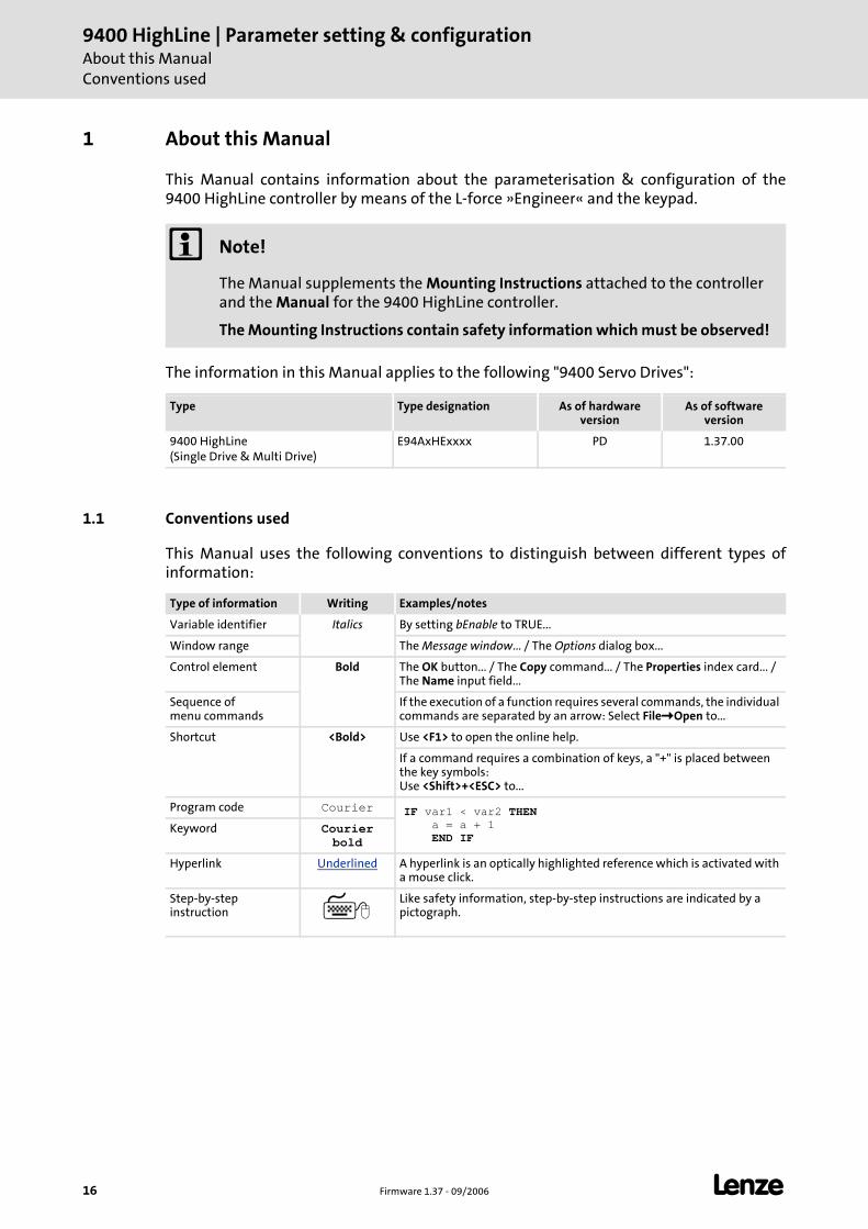
1 About this Manual
This Manual contains information about the parameterisation & configuration of the 9400 HighLine controller by means of the L-force »Engineer« and the keypad.
The information in this Manual applies to the following "9400 Servo Drives":
1.1 Conventions used
This Manual uses the following conventions to distinguish between different types of information:
Note!
The Manual supplements the Mounting Instructions attached to the controller and the Manual for the 9400 HighLine controller.
The Mounting Instructions contain safety information which must be observed!
Type Type designation As of hardware version
As of software version
9400 HighLine(Single Drive & Multi Drive)
E94AxHExxxx PD 1.37.00
Type of information Writing Examples/notes
Variable identifier Italics By setting bEnable to TRUE...
Window range The Message window... / The Options dialog box...
Control element Bold The OK button... / The Copy command... / The Properties index card... / The Name input field...
Sequence of menu commands
If the execution of a function requires several commands, the individual commands are separated by an arrow: Select File Open to...
Shortcut <Bold> Use <F1> to open the online help.
If a command requires a combination of keys, a "+" is placed between the key symbols: Use <Shift>+<ESC> to...
Program code Courier IF var1 < var2 THEN a = a + 1 END IF
Keyword Courier bold
Hyperlink Underlined A hyperlink is an optically highlighted reference which is activated with a mouse click.
Step-by-step instruction
Like safety information, step-by-step instructions are indicated by a pictograph.
L Firmware 1.37 - 09/2006 17
9400 HighLine | Parameter setting & configurationAbout this ManualTerminology used
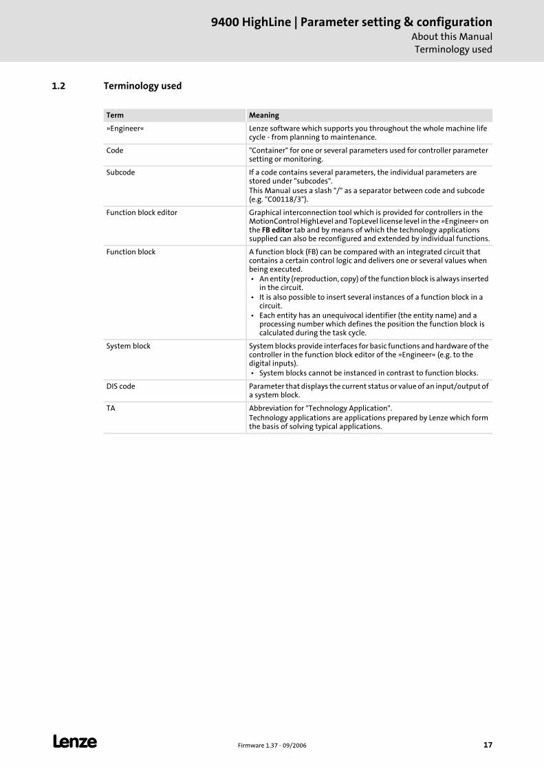
1.2 Terminology used
Term Meaning
»Engineer« Lenze software which supports you throughout the whole machine life cycle - from planning to maintenance.
Code "Container" for one or several parameters used for controller parameter setting or monitoring.
Subcode If a code contains several parameters, the individual parameters are stored under "subcodes".This Manual uses a slash "/" as a separator between code and subcode (e.g. "C00118/3").
Function block editor Graphical interconnection tool which is provided for controllers in the MotionControl HighLevel and TopLevel license level in the »Engineer« on the FB editor tab and by means of which the technology applications supplied can also be reconfigured and extended by individual functions.
Function block A function block (FB) can be compared with an integrated circuit that contains a certain control logic and delivers one or several values when being executed. • An entity (reproduction, copy) of the function block is always inserted
in the circuit. • It is also possible to insert several instances of a function block in a
circuit. • Each entity has an unequivocal identifier (the entity name) and a
processing number which defines the position the function block is calculated during the task cycle.
System block System blocks provide interfaces for basic functions and hardware of the controller in the function block editor of the »Engineer« (e.g. to the digital inputs). • System blocks cannot be instanced in contrast to function blocks.
DIS code Parameter that displays the current status or value of an input/output of a system block.
TA Abbreviation for "Technology Application".Technology applications are applications prepared by Lenze which form the basis of solving typical applications.
9400 HighLine | Parameter setting & configurationAbout this ManualDefinition of notes used
18 Firmware 1.37 - 09/2006 L
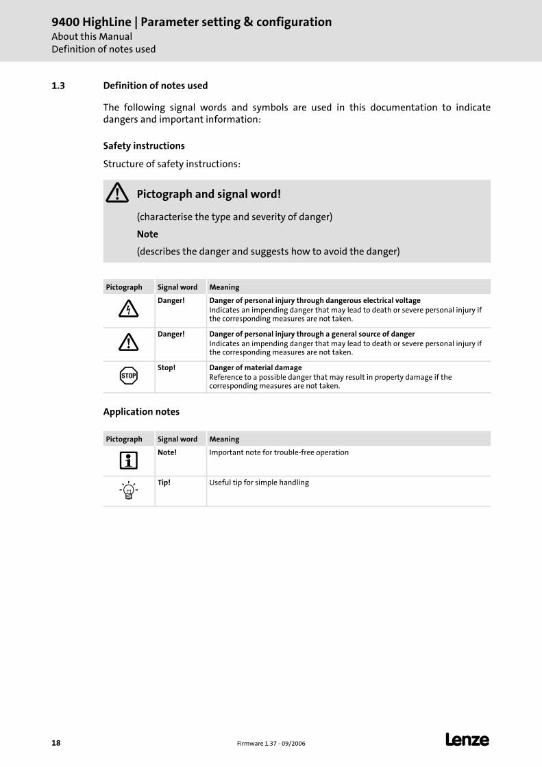
1.3 Definition of notes used
The following signal words and symbols are used in this documentation to indicate dangers and important information:
Safety instructions
Structure of safety instructions:
Application notes
Pictograph and signal word!
(characterise the type and severity of danger)
Note
(describes the danger and suggests how to avoid the danger)
Pictograph Signal word Meaning
Danger! Danger of personal injury through dangerous electrical voltageIndicates an impending danger that may lead to death or severe personal injury if the corresponding measures are not taken.
Danger! Danger of personal injury through a general source of dangerIndicates an impending danger that may lead to death or severe personal injury if the corresponding measures are not taken.
Stop! Danger of material damageReference to a possible danger that may result in property damage if the corresponding measures are not taken.
Pictograph Signal word Meaning
Note! Important note for trouble-free operation
Tip! Useful tip for simple handling
L Firmware 1.37 - 09/2006 19
9400 HighLine | Parameter setting & configurationIntroduction
Parameter setting, configuring or programming?
2 Introduction
The basis of every L-force application is an easy and quick parameter setting of prepared technology applications and solutions*.
This chapter contains basic information on the runtime software model of L-force and how you can establish very easily an online connection between PC and controller for parameter setting with the »Engineer«.
At the end of this chapter you will find an overview of the different signal types & scalings which serve to process physical values (e.g. speed or position) within the application.
* In preparation!
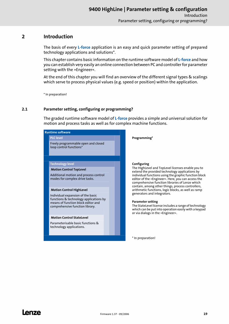
2.1 Parameter setting, configuring or programming?
The graded runtime software model of L-force provides a simple and universal solution for motion and process tasks as well as for complex machine functions.
Runtime software
PLC level Programming*
Freely programmable open and closed loop control functions*
Technology level ConfiguringThe HighLevel and TopLevel licenses enable you to extend the provided technology applications by individual functions using the graphic function block editor of the »Engineer«. Here, you can access the comprehensive function libraries of Lenze which contain, among other things, process controllers, arithmetic functions, logic blocks, as well as ramp generators and integrators. Parameter settingThe StateLevel license includes a range of technology which can be put into operation easily with a keypad or via dialogs in the »Engineer«.
Motion Control TopLevel
Additional motion and process control modes for complex drive tasks.
Motion Control HighLevel
Individual expansion of the basic functions & technology applications by means of function block editor and comprehensive function library.
Motion Control StateLevel
Parameterisable basic functions & technology applications.
* In preparation!
9400 HighLine | Parameter setting & configurationIntroductionParameter setting, configuring or programming?
20 Firmware 1.37 - 09/2006 L
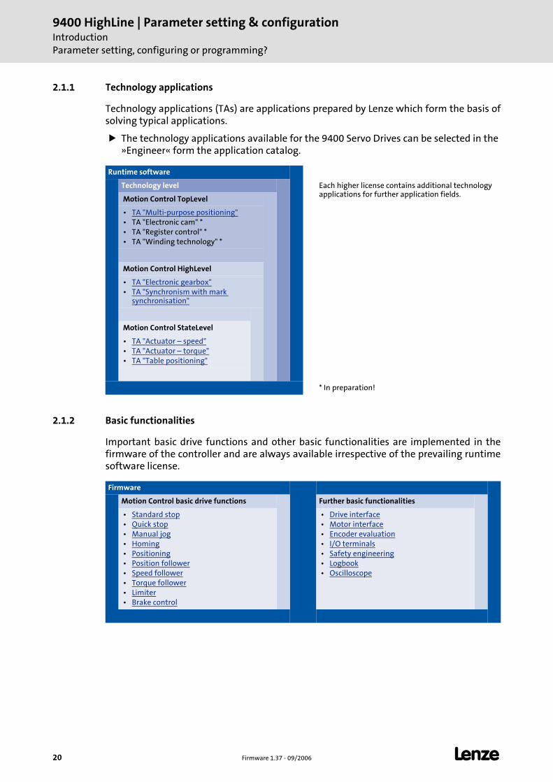
2.1.1 Technology applications
Technology applications (TAs) are applications prepared by Lenze which form the basis of solving typical applications.
The technology applications available for the 9400 Servo Drives can be selected in the »Engineer« form the application catalog.
2.1.2 Basic functionalities
Important basic drive functions and other basic functionalities are implemented in the firmware of the controller and are always available irrespective of the prevailing runtime software license.
Runtime software
Technology level Each higher license contains additional technology applications for further application fields.
Motion Control TopLevel
• TA "Multi-purpose positioning" • TA "Electronic cam" * • TA "Register control" * • TA "Winding technology" *
Motion Control HighLevel
• TA "Electronic gearbox" • TA "Synchronism with mark
synchronisation"
Motion Control StateLevel
• TA "Actuator – speed" • TA "Actuator – torque" • TA "Table positioning"
* In preparation!
Firmware
Motion Control basic drive functions Further basic functionalities
• Standard stop • Quick stop • Manual jog • Homing • Positioning • Position follower • Speed follower • Torque follower • Limiter • Brake control
• Drive interface • Motor interface • Encoder evaluation • I/O terminals • Safety engineering • Logbook • Oscilloscope
L Firmware 1.37 - 09/2006 21
9400 HighLine | Parameter setting & configurationIntroduction
Communicating with the controller
2.2 Communicating with the controller
The following interfaces/communication modules can be used to build up communication between PC and controller:
Diagnostic interface X6/Going online via diagnostic adapter
CAN on-board interface/Going online via system bus (CAN on board) ( 24)
Optional interfaces provided by corresponding communication modules in the module receptacles MXI1/MXI2 of the controller.
Tip!
Detailed information about the individual interfaces can be found in the corresponding Communication Manuals.
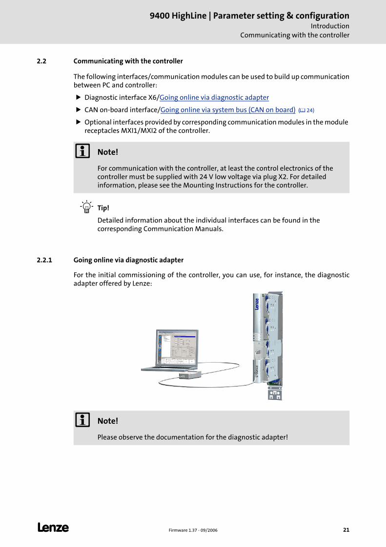
2.2.1 Going online via diagnostic adapter
For the initial commissioning of the controller, you can use, for instance, the diagnostic adapter offered by Lenze:
Note!
For communication with the controller, at least the control electronics of the controller must be supplied with 24 V low voltage via plug X2. For detailed information, please see the Mounting Instructions for the controller.
Note!
Please observe the documentation for the diagnostic adapter!
9400 HighLine | Parameter setting & configurationIntroductionCommunicating with the controller
22 Firmware 1.37 - 09/2006 L
Preconditions:
The diagnostic adapter is connected to diagnostic interface X6 on the controller and to a free USB port on the PC.
The driver required for the diagnostic adapter is installed.
The control electronics of the controller is supplied with 24 V low voltage via plug X2.
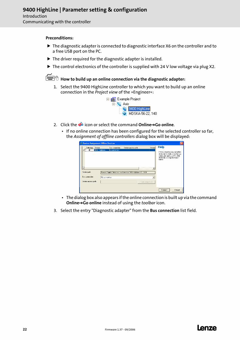
How to build up an online connection via the diagnostic adapter:
1. Select the 9400 HighLine controller to which you want to build up an online connection in the Project view of the »Engineer«:
2. Click the icon or select the command Online Go online.
• If no online connection has been configured for the selected controller so far, the Assignment of offline controllers dialog box will be displayed:
• The dialog box also appears if the online connection is built up via the command Online Go online instead of using the toolbar icon.
3. Select the entry "Diagnostic adapter" from the Bus connection list field.
L Firmware 1.37 - 09/2006 23
9400 HighLine | Parameter setting & configurationIntroduction
Communicating with the controller
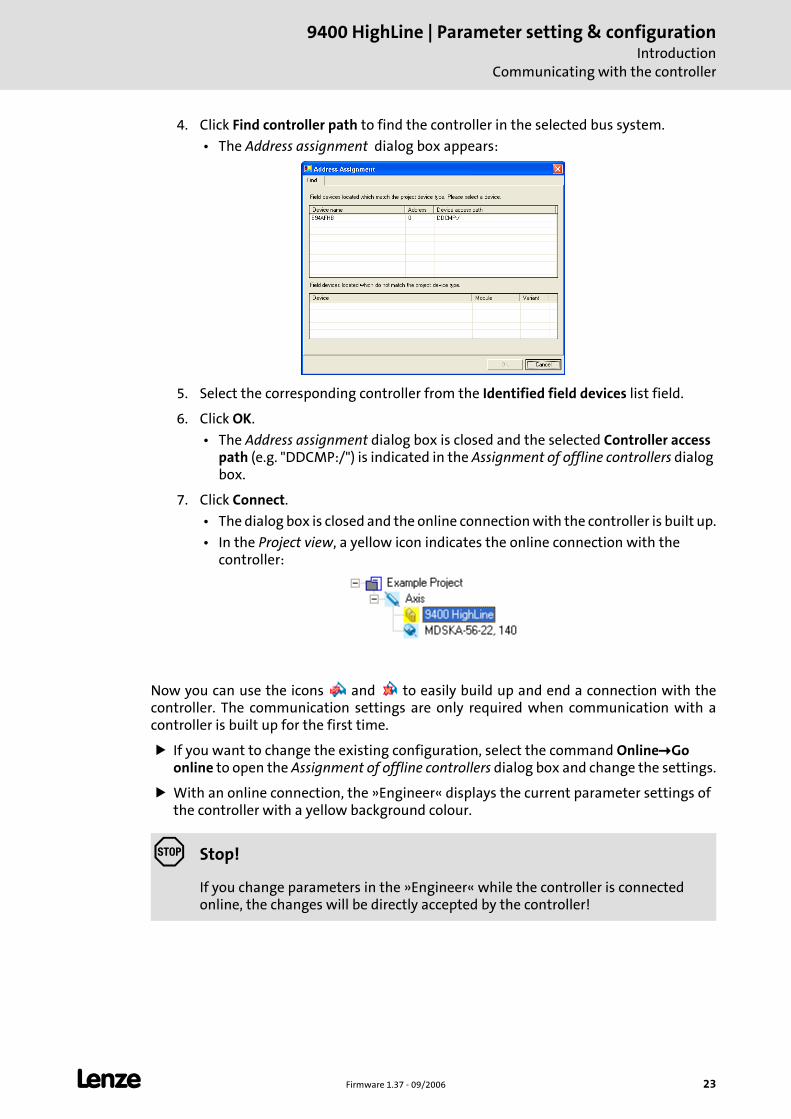
4. Click Find controller path to find the controller in the selected bus system.
• The Address assignment dialog box appears:
5. Select the corresponding controller from the Identified field devices list field.
6. Click OK.
• The Address assignment dialog box is closed and the selected Controller access path (e.g. "DDCMP:/") is indicated in the Assignment of offline controllers dialog box.
7. Click Connect.
• The dialog box is closed and the online connection with the controller is built up.
• In the Project view, a yellow icon indicates the online connection with the controller:
Now you can use the icons and to easily build up and end a connection with the controller. The communication settings are only required when communication with a controller is built up for the first time.
If you want to change the existing configuration, select the command Online Go online to open the Assignment of offline controllers dialog box and change the settings.
With an online connection, the »Engineer« displays the current parameter settings of the controller with a yellow background colour.
Stop!
If you change parameters in the »Engineer« while the controller is connected online, the changes will be directly accepted by the controller!
9400 HighLine | Parameter setting & configurationIntroductionCommunicating with the controller
24 Firmware 1.37 - 09/2006 L
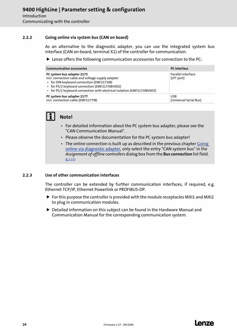
2.2.2 Going online via system bus (CAN on board)
As an alternative to the diagnostic adapter, you can use the integrated system bus interface (CAN on-board, terminal X1) of the controller for communication.
Lenze offers the following communication accessories for connection to the PC:
2.2.3 Use of other communication interfaces
The controller can be extended by further communication interfaces, if required, e.g. Ethernet TCP/IP, Ethernet Powerlink or PROFIBUS-DP.
For this purpose the controller is provided with the module receptacles MXI1 and MXI2 to plug in communication modules.
Detailed information on this subject can be found in the Hardware Manual and Communication Manual for the corresponding communication system.
Communication accessories PC interface
PC system bus adapter 2173 incl. connection cable and voltage supply adapter • for DIN keyboard connection (EMF2173IB) • for PS/2 keyboard connection (EMF2173IBV002) • for PS/2 keyboard connection with electrical isolation (EMF2173IBV003)
Parallel interface (LPT port)
PC system bus adapter 2177 incl. connection cable (EMF2177IB)
USB (Universal Serial Bus)
Note!
• For detailed information about the PC system bus adapter, please see the "CAN Communication Manual".
• Please observe the documentation for the PC system bus adapter!
• The online connection is built up as described in the previous chapter Going online via diagnostic adapter, only select the entry "CAN system bus" in the Assignment of offline controllers dialog box from the Bus connection list field. ( 22)
LFirm
ware 1.37 - 09/2006
25
9400 HighLine | Param
eter setting & configuration
Introdu
ctionSign
al types & scalin
g
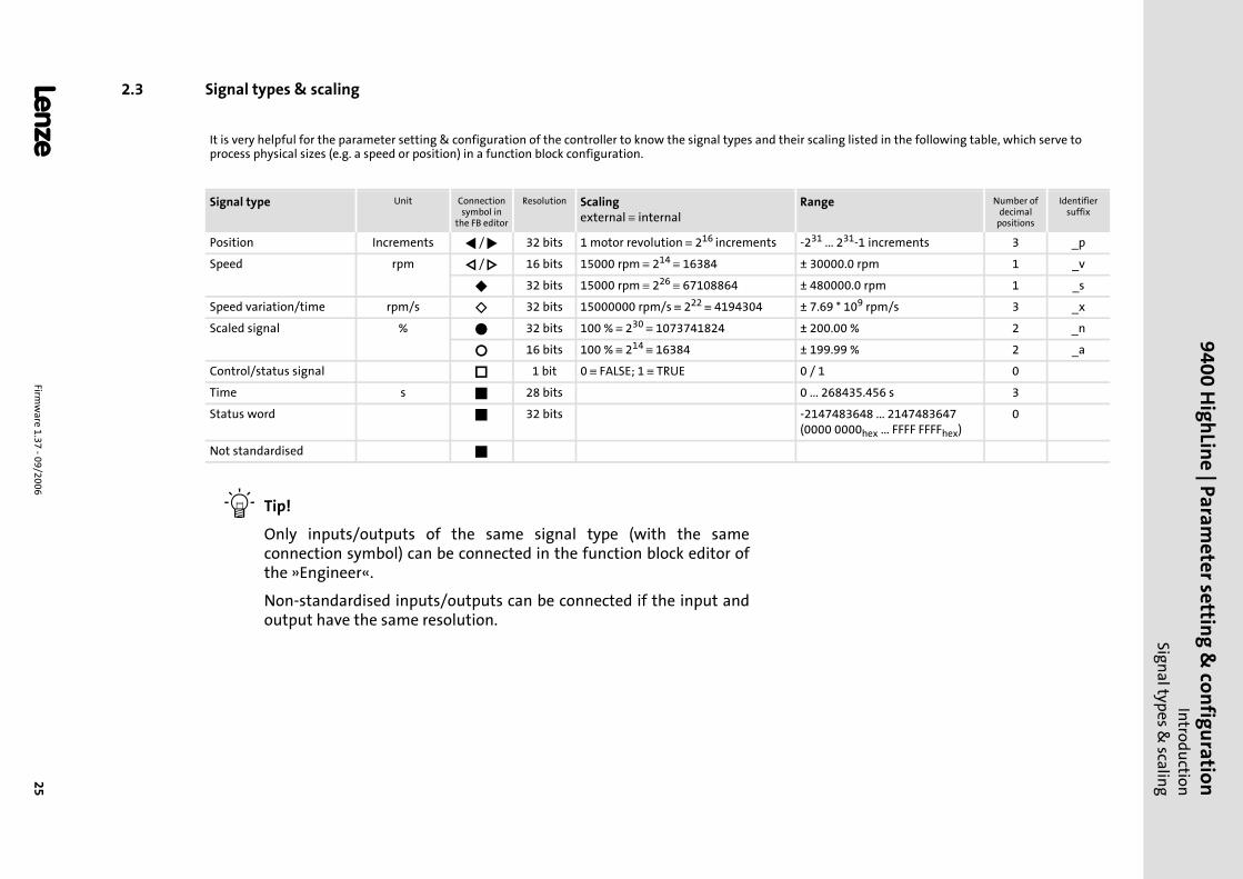
2.3 Signal types & scaling
It is very helpful for the parameter setting & configuration of the controller to know the signal types and their scaling listed in the following table, which serve to process physical sizes (e.g. a speed or position) in a function block configuration.
Signal type Unit Connection symbol in
the FB editor
Resolution Scalingexternal ≡ internal
Range Number of decimal
positions
Identifier suffix
Position Increments / 32 bits 1 motor revolution ≡ 216 increments -231 ... 231-1 increments 3 _p
Speed rpm / 16 bits 15000 rpm ≡ 214 ≡ 16384 ± 30000.0 rpm 1 _v
32 bits 15000 rpm ≡ 226 ≡ 67108864 ± 480000.0 rpm 1 _s
Speed variation/time rpm/s 32 bits 15000000 rpm/s ≡ 222 ≡ 4194304 ± 7.69 * 109 rpm/s 3 _x
Scaled signal % 32 bits 100 % ≡ 230 ≡ 1073741824 ± 200.00 % 2 _n
16 bits 100 % ≡ 214 ≡ 16384 ± 199.99 % 2 _a
Control/status signal 1 bit 0 ≡ FALSE; 1 ≡ TRUE 0 / 1 0
Time s 28 bits 0 ... 268435.456 s 3
Status word 32 bits -2147483648 ... 2147483647(0000 0000hex ... FFFF FFFFhex)
0
Not standardised
Tip!
Only inputs/outputs of the same signal type (with the same connection symbol) can be connected in the function block editor of the »Engineer«.
Non-standardised inputs/outputs can be connected if the input and output have the same resolution.
9400 HighLine | Parameter setting & configurationCommissioning
26 Firmware 1.37 - 09/2006 L
3 Commissioning
This documentation contains detailed information on parameter setting and configuration of the controller. Sequential reading is not required.
In order to get the information relevant for an initial commissioning, this chapter describes different commissioning scenarios which can also be used as a guide through this Manual:
A. Test commissioning ( 28)
– Target: Rotating the motor with as few settings as possible in best time.
B. Initial commissioning ( 29)
– Target: Adapting the controller to electromechanics and control.
C. Standard set-up ( 31)
– Target: Taking over the application and parameter set of an already preconfigured "Engineer" project in several controllers.
D. Controller replacement ( 32)
– Target: Replacing a controller which has failed in a running system by a replacement device using the "old" memory module.
E. Motor replacement ( 33)
– Target: Replacing a motor which has failed in a running system.
L Firmware 1.37 - 09/2006 27
9400 HighLine | Parameter setting & configurationCommissioning
Notes on commissioning using the keypad
3.1 Notes on commissioning using the keypad
For motor with electronic nameplate (ENP)
A display of the route data offered by ENP via keypad is not provided. The route data must be edited and optimised individually.
In order that the motor does not start unintentionally without adjusting the route data, the maximum current in the Lenze setting is set to "0 A" in C00022.
After setting the route data these motor data and the ones read out of the ENP must be stored with mains failure protection on the memory module of the controller (C00002 = "11").
For motor without electronic nameplate (ENP)
The motor and route data must be edited and set individually.
In order that the motor does not start unintentionally without adjusting the route data, the maximum current is set to "0 A" in C00022 as factory adjustment.
After the motor and route data are set, they must be stored with mains failure protection on the memory module of the controller (C00002 = "11").
Commissioning of the application
The application must already be stored on the memory module of the controller. Otherwise, commissioning with keypad only is not possible.
All application parameters which deviated from the factory adjustment, must be edited individually. For this purpose, the project planner must provide a corresponding list (including the motor and route data) for the commissioner.
In case of a standard set-up the rotor position must be adjusted for synchronous motors of a third-party manufacturer and Lenze synchronous motors with Stegmann absolute value encoder.
After the parameters are set, they must be stored with mains failure protection on the memory module of the controller (C00002 = "11").
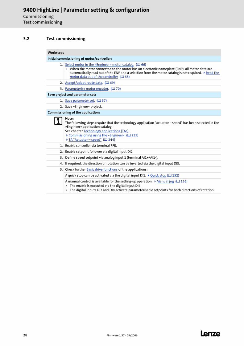
9400 HighLine | Parameter setting & configurationCommissioningTest commissioning
28 Firmware 1.37 - 09/2006 L
3.2 Test commissioning
Worksteps
Initial commissioning of motor/controller:
1. Select motor in the »Engineer« motor catalog. ( 66) • When the motor connected to the motor has an electronic nameplate (ENP), all motor data are
automatically read out of the ENP and a selection from the motor catalog is not required. Read the motor data out of the controller ( 66)
2. Accept/adapt route data. ( 69)
3. Parameterise motor encoder. ( 70)
Save project and parameter set:
1. Save parameter set. ( 57)
2. Save »Engineer« project.
Commissioning of the application:
Note:The following steps require that the technology application "actuator – speed" has been selected in the »Engineer« application catalog.See chapter Technology applications (TAs):
Commissioning using the »Engineer« ( 235) TA "Actuator – speed" ( 244)
1. Enable controller via terminal RFR.
2. Enable setpoint follower via digital input DI2.
3. Define speed setpoint via analog input 1 (terminal AI1+/AI1-).
4. If required, the direction of rotation can be inverted via the digital input DI3.
5. Check further Basic drive functions of the applications:
A quick stop can be activated via the digital input DI1. Quick stop ( 152)
A manual control is available for the setting-up operation. Manual jog ( 156) • The enable is executed via the digital input DI6. • The digital inputs DI7 and DI8 activate parameterisable setpoints for both directions of rotation.
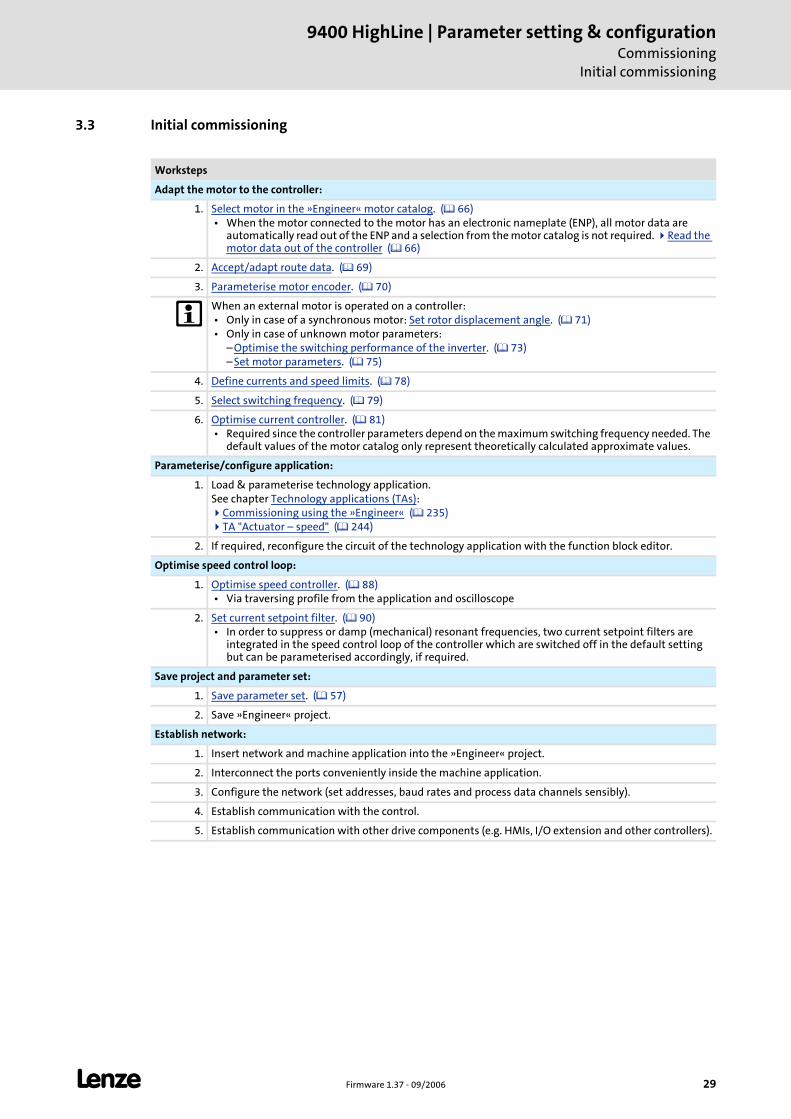
L Firmware 1.37 - 09/2006 29
9400 HighLine | Parameter setting & configurationCommissioning
Initial commissioning
3.3 Initial commissioning
Worksteps
Adapt the motor to the controller:
1. Select motor in the »Engineer« motor catalog. ( 66) • When the motor connected to the motor has an electronic nameplate (ENP), all motor data are
automatically read out of the ENP and a selection from the motor catalog is not required. Read the motor data out of the controller ( 66)
2. Accept/adapt route data. ( 69)
3. Parameterise motor encoder. ( 70)
When an external motor is operated on a controller: • Only in case of a synchronous motor: Set rotor displacement angle. ( 71) • Only in case of unknown motor parameters:
– Optimise the switching performance of the inverter. ( 73) – Set motor parameters. ( 75)
4. Define currents and speed limits. ( 78)
5. Select switching frequency. ( 79)
6. Optimise current controller. ( 81) • Required since the controller parameters depend on the maximum switching frequency needed. The
default values of the motor catalog only represent theoretically calculated approximate values.
Parameterise/configure application:
1. Load & parameterise technology application.See chapter Technology applications (TAs):
Commissioning using the »Engineer« ( 235) TA "Actuator – speed" ( 244)
2. If required, reconfigure the circuit of the technology application with the function block editor.
Optimise speed control loop:
1. Optimise speed controller. ( 88) • Via traversing profile from the application and oscilloscope
2. Set current setpoint filter. ( 90) • In order to suppress or damp (mechanical) resonant frequencies, two current setpoint filters are
integrated in the speed control loop of the controller which are switched off in the default setting but can be parameterised accordingly, if required.
Save project and parameter set:
1. Save parameter set. ( 57)
2. Save »Engineer« project.
Establish network:
1. Insert network and machine application into the »Engineer« project.
2. Interconnect the ports conveniently inside the machine application.
3. Configure the network (set addresses, baud rates and process data channels sensibly).
4. Establish communication with the control.
5. Establish communication with other drive components (e.g. HMIs, I/O extension and other controllers).
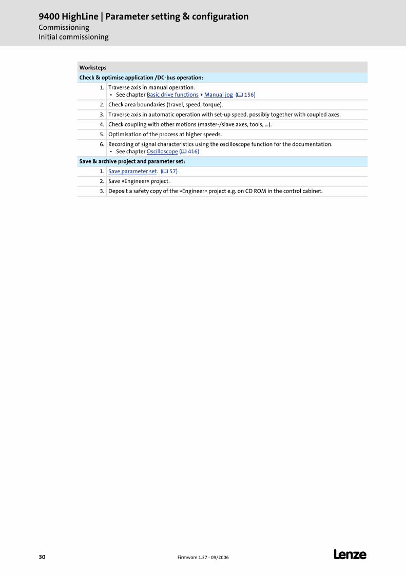
9400 HighLine | Parameter setting & configurationCommissioningInitial commissioning
30 Firmware 1.37 - 09/2006 L
Check & optimise application /DC-bus operation:
1. Traverse axis in manual operation. • See chapter Basic drive functions Manual jog ( 156)
2. Check area boundaries (travel, speed, torque).
3. Traverse axis in automatic operation with set-up speed, possibly together with coupled axes.
4. Check coupling with other motions (master-/slave axes, tools, …).
5. Optimisation of the process at higher speeds.
6. Recording of signal characteristics using the oscilloscope function for the documentation. • See chapter Oscilloscope ( 416)
Save & archive project and parameter set:
1. Save parameter set. ( 57)
2. Save »Engineer« project.
3. Deposit a safety copy of the »Engineer« project e.g. on CD ROM in the control cabinet.
Worksteps
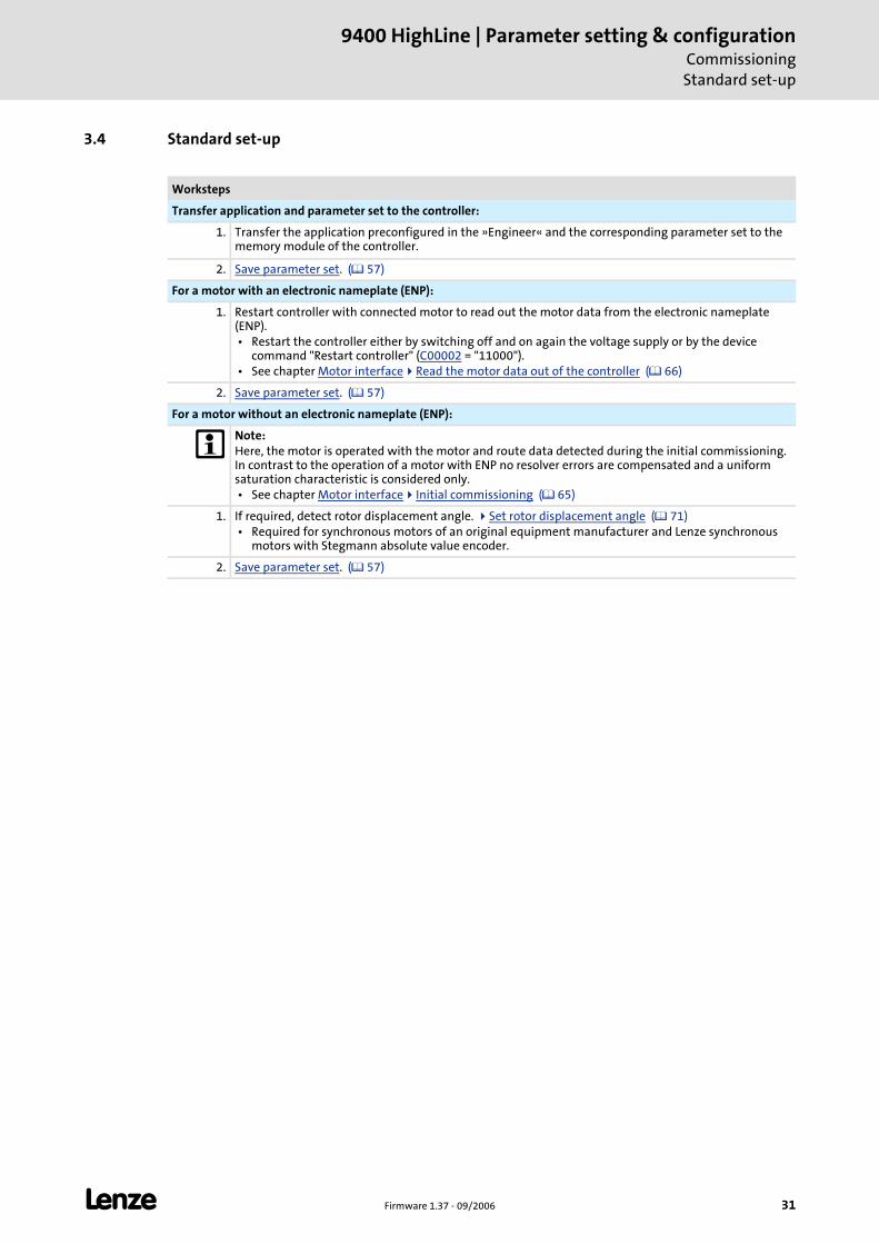
L Firmware 1.37 - 09/2006 31
9400 HighLine | Parameter setting & configurationCommissioningStandard set-up
3.4 Standard set-up
Worksteps
Transfer application and parameter set to the controller:
1. Transfer the application preconfigured in the »Engineer« and the corresponding parameter set to the memory module of the controller.
2. Save parameter set. ( 57)
For a motor with an electronic nameplate (ENP):
1. Restart controller with connected motor to read out the motor data from the electronic nameplate (ENP). • Restart the controller either by switching off and on again the voltage supply or by the device
command "Restart controller" (C00002 = "11000"). • See chapter Motor interface Read the motor data out of the controller ( 66)
2. Save parameter set. ( 57)
For a motor without an electronic nameplate (ENP):
Note:Here, the motor is operated with the motor and route data detected during the initial commissioning. In contrast to the operation of a motor with ENP no resolver errors are compensated and a uniform saturation characteristic is considered only. • See chapter Motor interface Initial commissioning ( 65)
1. If required, detect rotor displacement angle. Set rotor displacement angle ( 71) • Required for synchronous motors of an original equipment manufacturer and Lenze synchronous
motors with Stegmann absolute value encoder.
2. Save parameter set. ( 57)
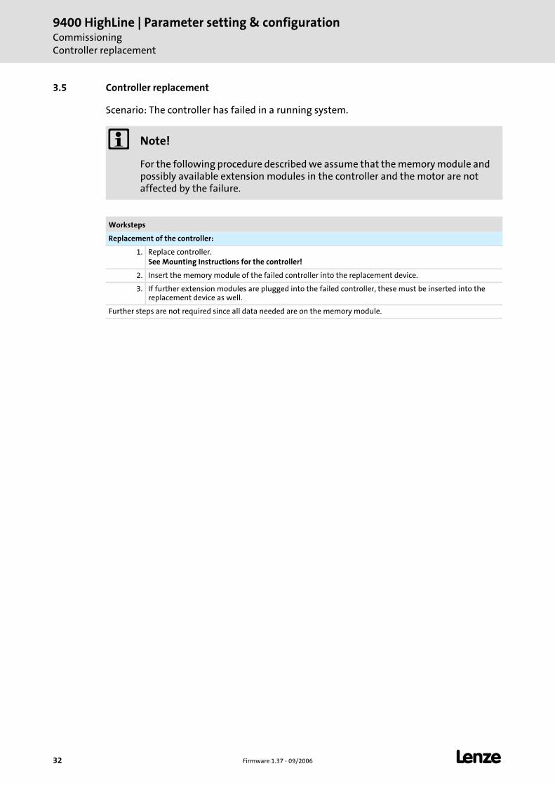
9400 HighLine | Parameter setting & configurationCommissioningController replacement
32 Firmware 1.37 - 09/2006 L
3.5 Controller replacement
Scenario: The controller has failed in a running system.
Note!
For the following procedure described we assume that the memory module and possibly available extension modules in the controller and the motor are not affected by the failure.
Worksteps
Replacement of the controller:
1. Replace controller.See Mounting Instructions for the controller!
2. Insert the memory module of the failed controller into the replacement device.
3. If further extension modules are plugged into the failed controller, these must be inserted into the replacement device as well.
Further steps are not required since all data needed are on the memory module.
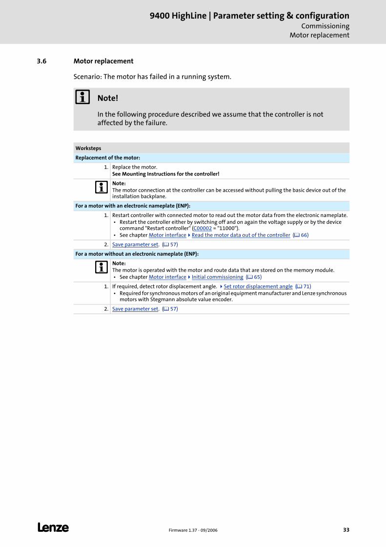
L Firmware 1.37 - 09/2006 33
9400 HighLine | Parameter setting & configurationCommissioning
Motor replacement
3.6 Motor replacement
Scenario: The motor has failed in a running system.
Note!
In the following procedure described we assume that the controller is not affected by the failure.
Worksteps
Replacement of the motor:
1. Replace the motor.See Mounting Instructions for the controller!
Note:The motor connection at the controller can be accessed without pulling the basic device out of the installation backplane.
For a motor with an electronic nameplate (ENP):
1. Restart controller with connected motor to read out the motor data from the electronic nameplate. • Restart the controller either by switching off and on again the voltage supply or by the device
command "Restart controller" (C00002 = "11000"). • See chapter Motor interface Read the motor data out of the controller ( 66)
2. Save parameter set. ( 57)
For a motor without an electronic nameplate (ENP):
Note:The motor is operated with the motor and route data that are stored on the memory module. • See chapter Motor interface Initial commissioning ( 65)
1. If required, detect rotor displacement angle. Set rotor displacement angle ( 71) • Required for synchronous motors of an original equipment manufacturer and Lenze synchronous
motors with Stegmann absolute value encoder.
2. Save parameter set. ( 57)
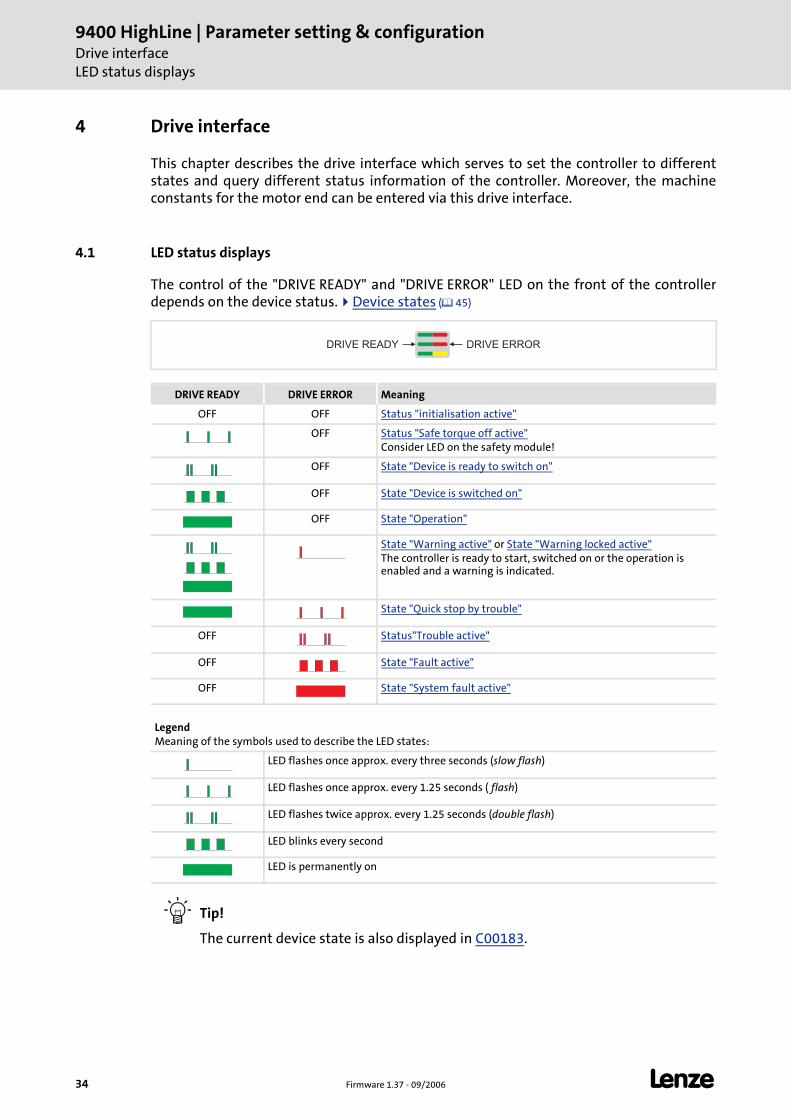
9400 HighLine | Parameter setting & configurationDrive interfaceLED status displays
34 Firmware 1.37 - 09/2006 L
4 Drive interface
This chapter describes the drive interface which serves to set the controller to different states and query different status information of the controller. Moreover, the machine constants for the motor end can be entered via this drive interface.
4.1 LED status displays
The control of the "DRIVE READY" and "DRIVE ERROR" LED on the front of the controller depends on the device status. Device states ( 45)
Tip!
The current device state is also displayed in C00183.
DRIVE READY DRIVE ERROR Meaning
OFF OFF Status "initialisation active"
OFF Status "Safe torque off active"Consider LED on the safety module!
OFF State "Device is ready to switch on"
OFF State "Device is switched on"
OFF State "Operation"
State "Warning active" or State "Warning locked active"The controller is ready to start, switched on or the operation is enabled and a warning is indicated.
State "Quick stop by trouble"
OFF Status"Trouble active"
OFF State "Fault active"
OFF State "System fault active"
LegendMeaning of the symbols used to describe the LED states:
LED flashes once approx. every three seconds (slow flash)
LED flashes once approx. every 1.25 seconds ( flash)
LED flashes twice approx. every 1.25 seconds (double flash)
LED blinks every second
LED is permanently on
DRIVE READY DRIVE ERROR
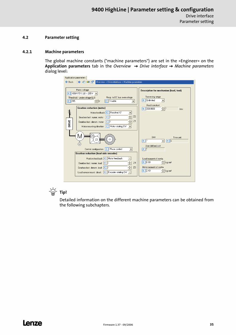
L Firmware 1.37 - 09/2006 35
9400 HighLine | Parameter setting & configurationDrive interface
Parameter setting
4.2 Parameter setting
4.2.1 Machine parameters
The global machine constants ("machine parameters") are set in the »Engineer» on the Application parameters tab in the Overview Drive interface Machine parametersdialog level:
Tip!
Detailed information on the different machine parameters can be obtained from the following subchapters.
9400 HighLine | Parameter setting & configurationDrive interfaceParameter setting
36 Firmware 1.37 - 09/2006 L
4.2.1.1 Mains voltage
Via the Mains voltage list field (C00173) the mains voltage for the drive controller is set.
If you set a mains voltage with adjustable threshold for undervoltage ("LU adjustable"), this undervoltage threshold can be set in the Undervoltage threshold (LU) input field (C00174).
In the Resp. to DC bus overvoltage list field (C00600) the response to the DC-bus overvoltage can be selected.
Tip!
The chapter "Rated data" in the Hardware Manual informs which device type has which permissible device utilisation at which mains voltage and switching frequency.
See also: Monitoring of the device utilisation ( 43)
Note!
Changing the setting in C00173 also affects the permissible device utilisation!
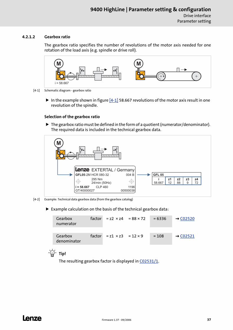
L Firmware 1.37 - 09/2006 37
9400 HighLine | Parameter setting & configurationDrive interface
Parameter setting
4.2.1.2 Gearbox ratio
The gearbox ratio specifies the number of revolutions of the motor axis needed for one rotation of the load axis (e.g. spindle or drive roll).
[4-1] Schematic diagram - gearbox ratio
In the example shown in figure [4-1] 58.667 revolutions of the motor axis result in one revolution of the spindle.
Selection of the gearbox ratio
The gearbox ratio must be defined in the form of a quotient (numerator/denominator). The required data is included in the technical gearbox data.
[4-2] Example: Technical data gearbox data (from the gearbox catalog)
Example calculation on the basis of the technical gearbox data:
Tip!
The resulting gearbox factor is displayed in C02531/1.
MM
i = 58.667
L EXTERTAL / GermanyGFL05-2M HCR 080-32 004 B
295 Nm24/min (50Hz)
i = 58.667GT/40000027
CLP 460 119600500038
GFL 05
i58.667
z39
z112
z288
z472
M
Gearbox factor numerator
= z2 × z4 = 88 × 72 = 6336 C02520
Gearbox factor denominator
= z1 × z3 = 12 × 9 = 108 C02521
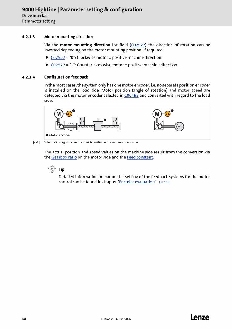
9400 HighLine | Parameter setting & configurationDrive interfaceParameter setting
38 Firmware 1.37 - 09/2006 L
4.2.1.3 Motor mounting direction
Via the motor mounting direction list field (C02527) the direction of rotation can be inverted depending on the motor mounting position, if required:
C02527 = "0": Clockwise motor ≡ positive machine direction.
C02527 = "1": Counter-clockwise motor ≡ positive machine direction.
4.2.1.4 Configuration feedback
In the most cases, the system only has one motor encoder, i.e. no separate position encoder is installed on the load side. Motor position (angle of rotation) and motor speed are detected via the motor encoder selected in C00495 and converted with regard to the load side.
[4-3] Schematic diagram - feedback with position encoder = motor encoder
The actual position and speed values on the machine side result from the conversion via the Gearbox ratio on the motor side and the Feed constant.
Tip!
Detailed information on parameter setting of the feedback systems for the motor control can be found in chapter "Encoder evaluation". ( 108)
Motor encoder
MM� �
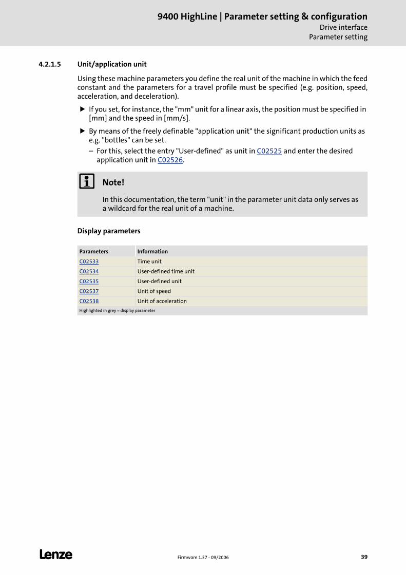
L Firmware 1.37 - 09/2006 39
9400 HighLine | Parameter setting & configurationDrive interface
Parameter setting
4.2.1.5 Unit/application unit
Using these machine parameters you define the real unit of the machine in which the feed constant and the parameters for a travel profile must be specified (e.g. position, speed, acceleration, and deceleration).
If you set, for instance, the "mm" unit for a linear axis, the position must be specified in [mm] and the speed in [mm/s].
By means of the freely definable "application unit" the significant production units as e.g. "bottles" can be set.
– For this, select the entry "User-defined" as unit in C02525 and enter the desired application unit in C02526.
Display parameters
Note!
In this documentation, the term "unit" in the parameter unit data only serves as a wildcard for the real unit of a machine.
Parameters Information
C02533 Time unit
C02534 User-defined time unit
C02535 User-defined unit
C02537 Unit of speed
C02538 Unit of acceleration
Highlighted in grey = display parameter
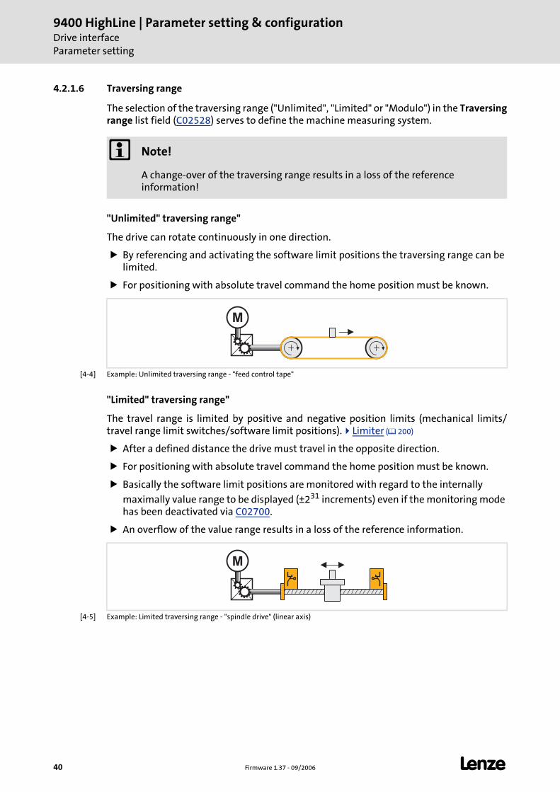
9400 HighLine | Parameter setting & configurationDrive interfaceParameter setting
40 Firmware 1.37 - 09/2006 L
4.2.1.6 Traversing range
The selection of the traversing range ("Unlimited", "Limited" or "Modulo") in the Traversing range list field (C02528) serves to define the machine measuring system.
"Unlimited" traversing range"
The drive can rotate continuously in one direction.
By referencing and activating the software limit positions the traversing range can be limited.
For positioning with absolute travel command the home position must be known.
[4-4] Example: Unlimited traversing range - "feed control tape"
"Limited" traversing range"
The travel range is limited by positive and negative position limits (mechanical limits/travel range limit switches/software limit positions). Limiter ( 200)
After a defined distance the drive must travel in the opposite direction.
For positioning with absolute travel command the home position must be known.
Basically the software limit positions are monitored with regard to the internally
maximally value range to be displayed (±231 increments) even if the monitoring mode has been deactivated via C02700.
An overflow of the value range results in a loss of the reference information.
[4-5] Example: Limited traversing range - "spindle drive" (linear axis)
Note!
A change-over of the traversing range results in a loss of the reference information!
M
M
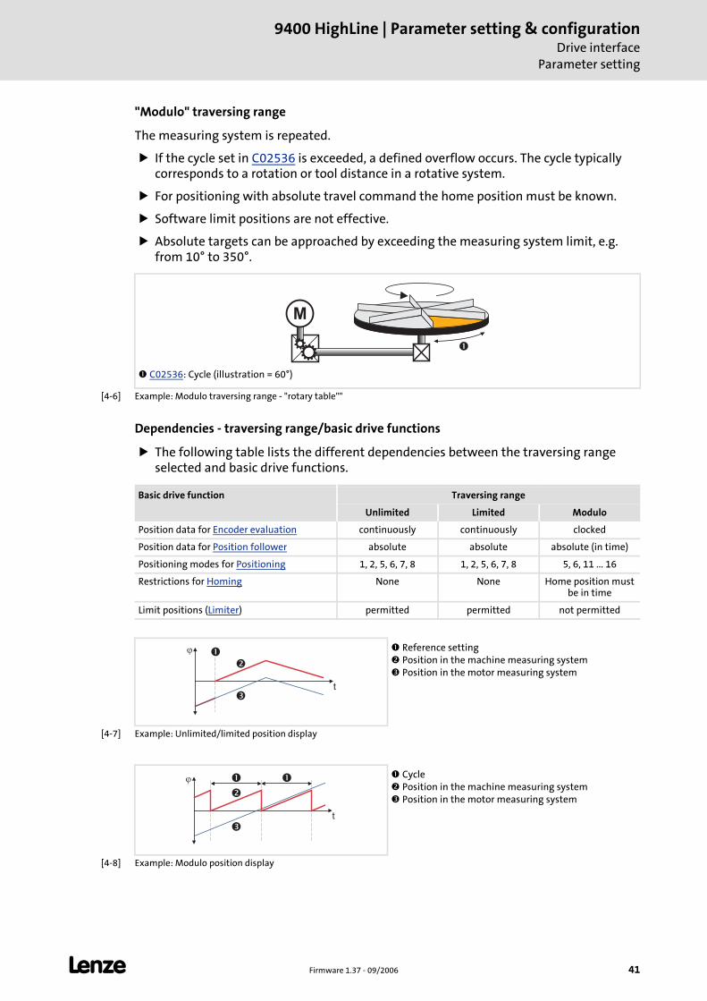
L Firmware 1.37 - 09/2006 41
9400 HighLine | Parameter setting & configurationDrive interface
Parameter setting
"Modulo" traversing range
The measuring system is repeated.
If the cycle set in C02536 is exceeded, a defined overflow occurs. The cycle typically corresponds to a rotation or tool distance in a rotative system.
For positioning with absolute travel command the home position must be known.
Software limit positions are not effective.
Absolute targets can be approached by exceeding the measuring system limit, e.g. from 10° to 350°.
[4-6] Example: Modulo traversing range - "rotary table""
Dependencies - traversing range/basic drive functions
The following table lists the different dependencies between the traversing range selected and basic drive functions.
[4-7] Example: Unlimited/limited position display
[4-8] Example: Modulo position display
C02536: Cycle (illustration = 60°)
M
�
Basic drive function Traversing range
Unlimited Limited Modulo
Position data for Encoder evaluation continuously continuously clocked
Position data for Position follower absolute absolute absolute (in time)
Positioning modes for Positioning 1, 2, 5, 6, 7, 8 1, 2, 5, 6, 7, 8 5, 6, 11 ... 16
Restrictions for Homing None None Home position must be in time
Limit positions (Limiter) permitted permitted not permitted
Reference setting Position in the machine measuring system Position in the motor measuring system
�
�
��
t
Cycle Position in the machine measuring system Position in the motor measuring system
�
�
��
t
�
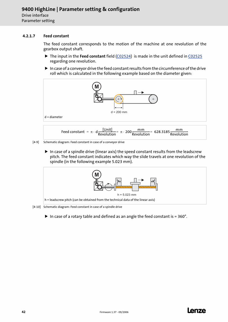
9400 HighLine | Parameter setting & configurationDrive interfaceParameter setting
42 Firmware 1.37 - 09/2006 L
4.2.1.7 Feed constant
The feed constant corresponds to the motion of the machine at one revolution of the gearbox output shaft.
The input in the Feed constant field (C02524) is made in the unit defined in C02525 regarding one revolution.
In case of a conveyor drive the feed constant results from the circumference of the drive roll which is calculated in the following example based on the diameter given:
[4-9] Schematic diagram: Feed constant in case of a conveyor drive
In case of a spindle drive (linear axis) the speed constant results from the leadscrew pitch. The feed constant indicates which way the slide travels at one revolution of the spindle (in the following example 5.023 mm).
[4-10] Schematic diagram: Feed constant in case of a spindle drive
In case of a rotary table and defined as an angle the feed constant is = 360°.
d = diameter
M
d = 200 mm
Feed constant π d [Unit]
Revolution---------------------------- π 200
mmRevolution---------------------------- 628.3185
mmRevolution----------------------------=⋅=⋅=
h = leadscrew pitch (can be obtained from the technical data of the linear axis)
M
h = 5.023 mm
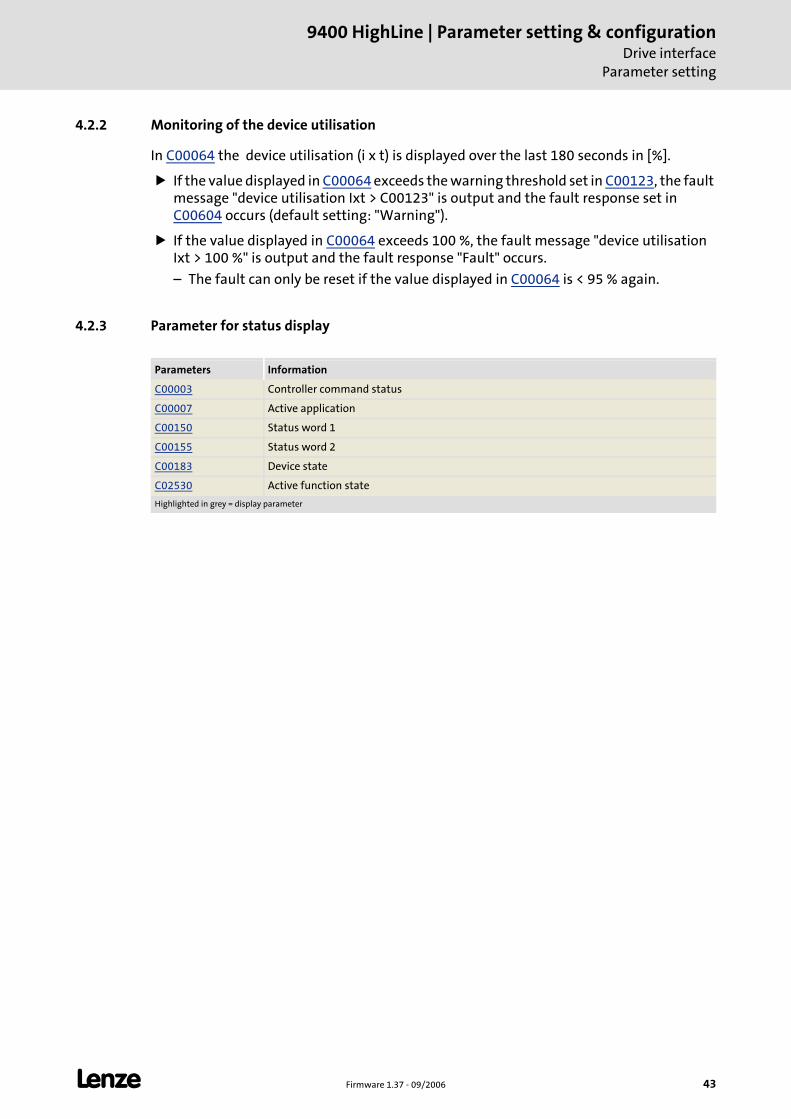
L Firmware 1.37 - 09/2006 43
9400 HighLine | Parameter setting & configurationDrive interface
Parameter setting
4.2.2 Monitoring of the device utilisation
In C00064 the device utilisation (i x t) is displayed over the last 180 seconds in [%].
If the value displayed in C00064 exceeds the warning threshold set in C00123, the fault message "device utilisation Ixt > C00123" is output and the fault response set in C00604 occurs (default setting: "Warning").
If the value displayed in C00064 exceeds 100 %, the fault message "device utilisation Ixt > 100 %" is output and the fault response "Fault" occurs.
– The fault can only be reset if the value displayed in C00064 is < 95 % again.
4.2.3 Parameter for status display
Parameters Information
C00003 Controller command status
C00007 Active application
C00150 Status word 1
C00155 Status word 2
C00183 Device state
C02530 Active function state
Highlighted in grey = display parameter
9400 HighLine | Parameter setting & configurationDrive interfaceMonitoring of external events
44 Firmware 1.37 - 09/2006 L
4.3 Monitoring of external events
Use the input DI_bSetExternError of the system block LS_DriveInterface to monitor external events by means of corresponding logic operations and activate the error message "External error" in the controller.
Parameterising a response to an external error
The controller response to the error message "External error" can be selected under C00581.
Activation of error message "External error".
The error message "External error" is activated by setting the input DI_bSetExternError to TRUE.
After this, the error number for the error message "External error" "0x20750000" (when "Fault" has been selected as response) will be stored in the internal fault memory (C00168).
Reset of error message
The error message "External error" and other active error messages are reset by setting the input DI_bResetError to TRUE.
If the input DI_bSetExternError is still set to TRUE, the reset will not be carried out.
Error messages can only be reset if the cause of the error has been eliminated.
4.4 Set/remove controller inhibit
Setting the controller inhibit inhibits the power stages in the controller and resets the speed/current and position controller of the motor control.
When the controller is inhibited, the status output DI_bCInhActive of the system block LS_DriveInterface is set to TRUE.
The controller can be inhibited by different sources, e.g. using the digital input RFR, the input DI_bSetCInh of the system block LS_DriveInterface or via the device command "Inhibit controller" (C00002 = "41").
The bit code under C00158 shows the source that inhibited the controller.
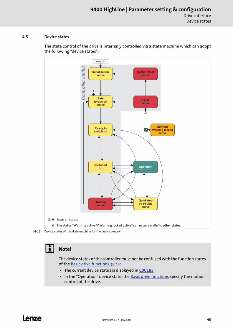
L Firmware 1.37 - 09/2006 45
9400 HighLine | Parameter setting & configurationDrive interface
Device states
4.5 Device states
The state control of the drive is internally controlled via a state machine which can adopt the following "device states":
[4-11] Device states of the state machine for the device control
, From all states
The status "Warning active"/"Warning locked active" can occur parallel to other states.
Co
ntr
oller
inh
ibit
�Ready toswitch on
Initialisationactive
Switchedon Operation
Troubleactive
Quickstopby trouble
active
Power on
�
�
System faultactive
Faultactive
Safetorque off
active
Warning/Warning locked
active
Note!
The device states of the controller must not be confused with the function states of the Basic drive functions. ( 140)
• The current device status is displayed in C00183.
• In the "Operation" device state, the Basic drive functions specify the motion control of the drive.

9400 HighLine | Parameter setting & configurationDrive interfaceDevice states
46 Firmware 1.37 - 09/2006 L
4.5.1 Status "initialisation active"
The controller is in this device state directly after switching on the supply voltage.
In this device status the operating system is initialised.
The application is not yet processed.
The monitoring mode is not yet active.
Communication is not possible yet.
The controller cannot be parameterised yet and no device commands can be executed.
When the device initialisation is completed, the device state is automatically changed to "Safe torque off active".
4.5.2 Status "Safe torque off active"
This device state becomes active when the controller receives the request "Safe torque off".
"Drive is torqueless" (0x00750003) is entered in the logbook.
If there is no request by the safety module, it is changed into the next state "Device is ready to switch on".
LED DRIVE READY LED DRIVE ERROR Display in C00183
OFF OFF 10: Initialisation active
LED DRIVE READY LED DRIVE ERROR Display in C00183
OFF 101: Safe torque off active
Note!
The "Safe torque off active" state is also passed through after errors have been acknowledged (see fig. [4-11]).
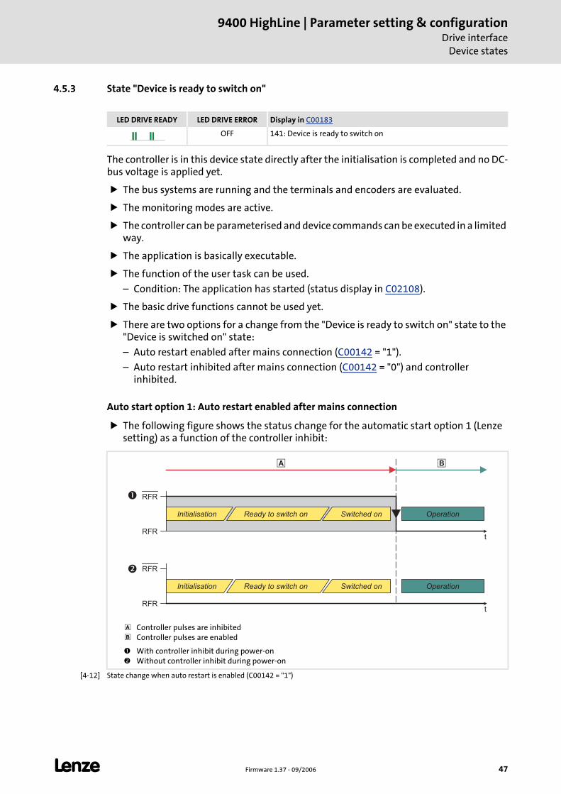
L Firmware 1.37 - 09/2006 47
9400 HighLine | Parameter setting & configurationDrive interface
Device states
4.5.3 State "Device is ready to switch on"
The controller is in this device state directly after the initialisation is completed and no DC-bus voltage is applied yet.
The bus systems are running and the terminals and encoders are evaluated.
The monitoring modes are active.
The controller can be parameterised and device commands can be executed in a limited way.
The application is basically executable.
The function of the user task can be used.
– Condition: The application has started (status display in C02108).
The basic drive functions cannot be used yet.
There are two options for a change from the "Device is ready to switch on" state to the "Device is switched on" state:
– Auto restart enabled after mains connection (C00142 = "1").
– Auto restart inhibited after mains connection (C00142 = "0") and controller inhibited.
Auto start option 1: Auto restart enabled after mains connection
The following figure shows the status change for the automatic start option 1 (Lenze setting) as a function of the controller inhibit:
[4-12] State change when auto restart is enabled (C00142 = "1")
LED DRIVE READY LED DRIVE ERROR Display in C00183
OFF 141: Device is ready to switch on
Controller pulses are inhibitedController pulses are enabled
With controller inhibit during power-onWithout controller inhibit during power-on
RFR�
� �
RFR
RFR
RFR
t
t
�
Initialisation Switched on OperationReady to switch on
OperationInitialisation Switched onReady to switch on
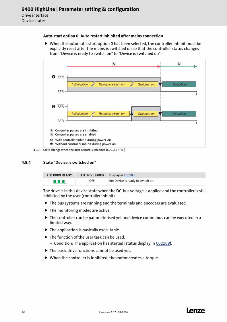
9400 HighLine | Parameter setting & configurationDrive interfaceDevice states
48 Firmware 1.37 - 09/2006 L
Auto-start option 0: Auto restart inhibited after mains connection
When the automatic start option 0 has been selected, the controller inhibit must be explicitly reset after the mains is switched on so that the controller status changes from "Device is ready to switch on" to "Device is switched on":
[4-13] State change when the auto restart is inhibited (C00142 = "0")
4.5.4 State "Device is switched on"
The drive is in this device state when the DC-bus voltage is applied and the controller is still inhibited by the user (controller inhibit).
The bus systems are running and the terminals and encoders are evaluated.
The monitoring modes are active.
The controller can be parameterised yet and device commands can be executed in a limited way.
The application is basically executable.
The function of the user task can be used.
– Condition: The application has started (status display in C02108).
The basic drive functions cannot be used yet.
When the controller is inhibited, the motor creates a torque.
Controller pulses are inhibitedController pulses are enabled
With controller inhibit during power-onWithout controller inhibit during power-on
RFR�
� �
RFR
RFR
RFR
t
t
�
Initialisation Switched on OperationReady to switch on
Initialisation Switched on OperationReady to switch on
LED DRIVE READY LED DRIVE ERROR Display in C00183
OFF 90: Device is ready to switch on.
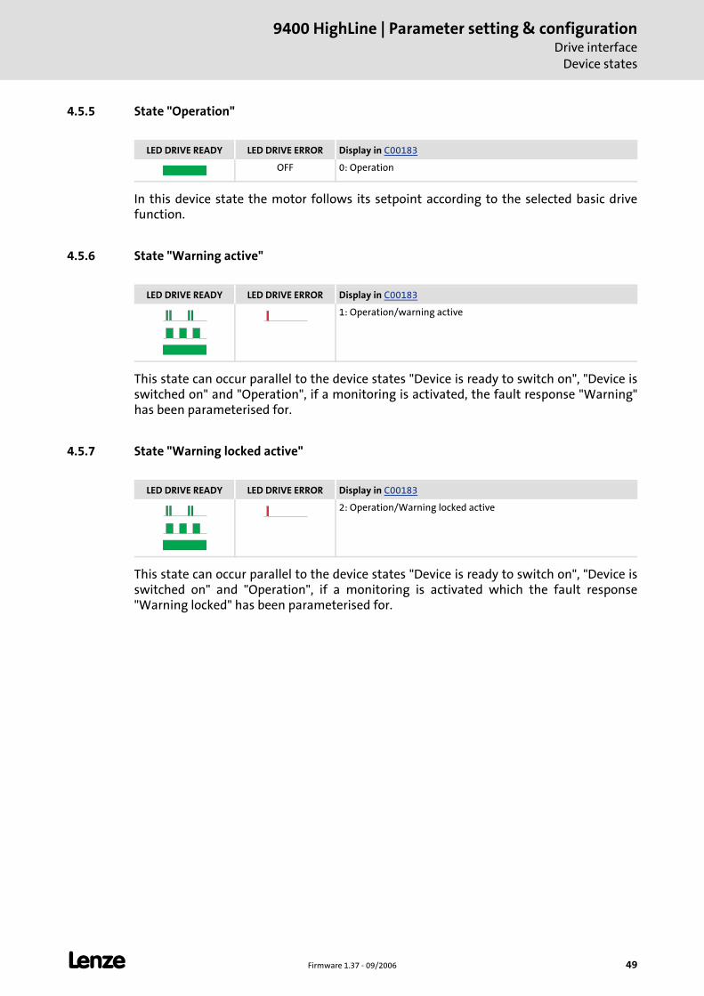
L Firmware 1.37 - 09/2006 49
9400 HighLine | Parameter setting & configurationDrive interface
Device states
4.5.5 State "Operation"
In this device state the motor follows its setpoint according to the selected basic drive function.
4.5.6 State "Warning active"
This state can occur parallel to the device states "Device is ready to switch on", "Device is switched on" and "Operation", if a monitoring is activated, the fault response "Warning" has been parameterised for.
4.5.7 State "Warning locked active"
This state can occur parallel to the device states "Device is ready to switch on", "Device is switched on" and "Operation", if a monitoring is activated which the fault response "Warning locked" has been parameterised for.
LED DRIVE READY LED DRIVE ERROR Display in C00183
OFF 0: Operation
LED DRIVE READY LED DRIVE ERROR Display in C00183
1: Operation/warning active
LED DRIVE READY LED DRIVE ERROR Display in C00183
2: Operation/Warning locked active
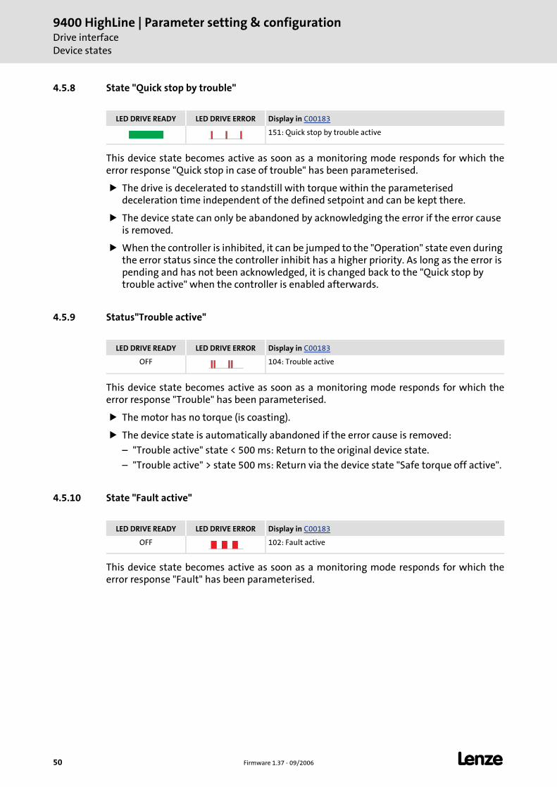
9400 HighLine | Parameter setting & configurationDrive interfaceDevice states
50 Firmware 1.37 - 09/2006 L
4.5.8 State "Quick stop by trouble"
This device state becomes active as soon as a monitoring mode responds for which the error response "Quick stop in case of trouble" has been parameterised.
The drive is decelerated to standstill with torque within the parameterised deceleration time independent of the defined setpoint and can be kept there.
The device state can only be abandoned by acknowledging the error if the error cause is removed.
When the controller is inhibited, it can be jumped to the "Operation" state even during the error status since the controller inhibit has a higher priority. As long as the error is pending and has not been acknowledged, it is changed back to the "Quick stop by trouble active" when the controller is enabled afterwards.
4.5.9 Status"Trouble active"
This device state becomes active as soon as a monitoring mode responds for which the error response "Trouble" has been parameterised.
The motor has no torque (is coasting).
The device state is automatically abandoned if the error cause is removed:
– "Trouble active" state < 500 ms: Return to the original device state.
– "Trouble active" > state 500 ms: Return via the device state "Safe torque off active".
4.5.10 State "Fault active"
This device state becomes active as soon as a monitoring mode responds for which the error response "Fault" has been parameterised.
LED DRIVE READY LED DRIVE ERROR Display in C00183
151: Quick stop by trouble active
LED DRIVE READY LED DRIVE ERROR Display in C00183
OFF 104: Trouble active
LED DRIVE READY LED DRIVE ERROR Display in C00183
OFF 102: Fault active
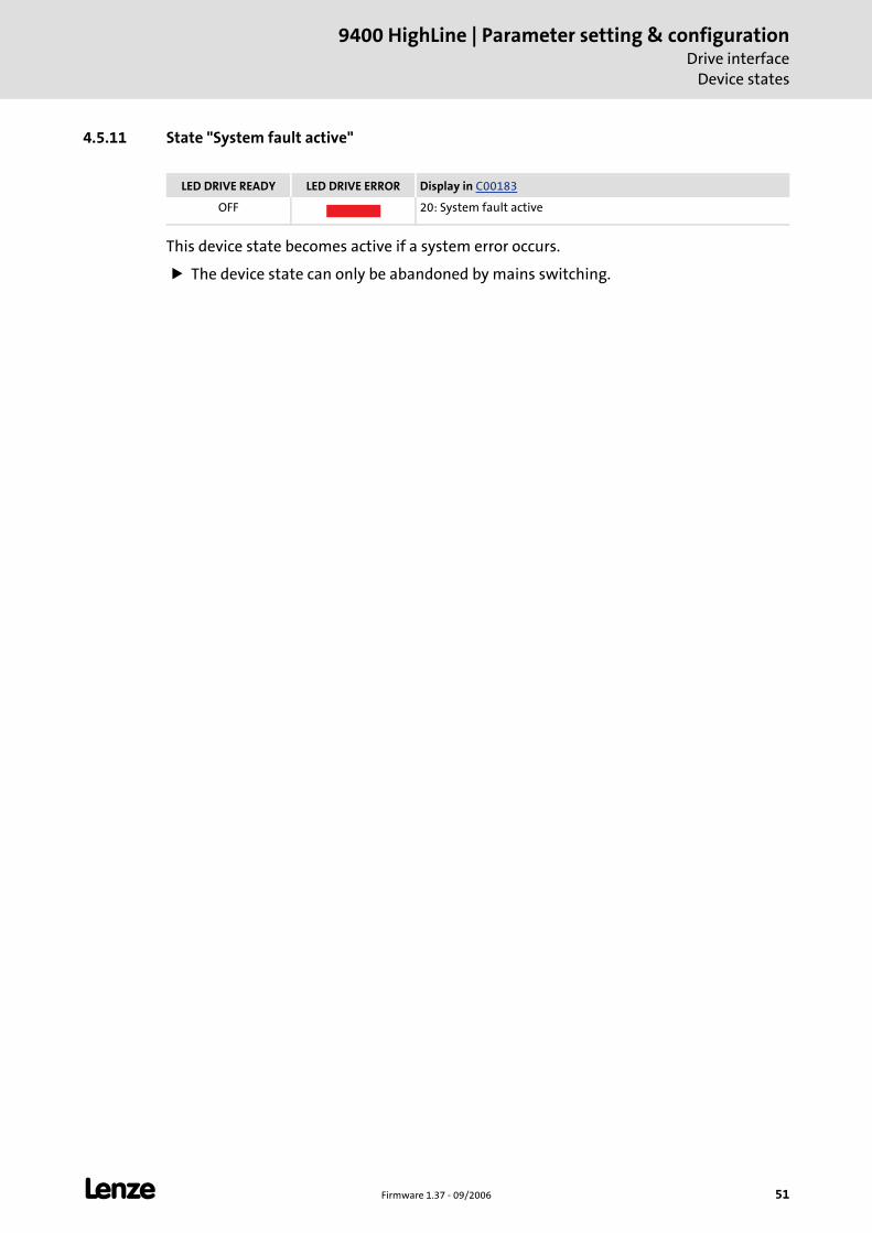
L Firmware 1.37 - 09/2006 51
9400 HighLine | Parameter setting & configurationDrive interface
Device states
4.5.11 State "System fault active"
This device state becomes active if a system error occurs.
The device state can only be abandoned by mains switching.
LED DRIVE READY LED DRIVE ERROR Display in C00183
OFF 20: System fault active
9400 HighLine | Parameter setting & configurationDrive interfaceController commands
52 Firmware 1.37 - 09/2006 L
4.6 Controller commands
Different controller commands are available for project management within the controller. They can be activated under code C00002.
The following subsections describe the most important controller commands for project management and parameter set management in the controller.
With an online connection, the controller commands can be activated from the »Engineer« by selecting the corresponding command in the Parameters tab under C00002. As an alternative, the controller commands can be activated via the keypad.
In C00003 the number and the status of the device command executed last is indicated. Status display for device command ( 54)
Tip!
Many frequently required controller commands (e.g. "Save start parameters") can be executed via the toolbar icons of the »Engineers«.
Note!
Before the supply voltage is switched off after a device command has been transmitted via C00002, it must be checked via C00003 if the device command has been completed successfully!
• The "0x00" status in the lower 16 bits of C00003 means that the device command has been executed successfully.
Note!
Controller commands that can be executed via the toolbar of the »Engineers« always affect the element currently selected in the Project view including all subelements.
• If no controller, but a system module is selected in the Project view, the corresponding controller command will be activated in all lower-level controllers having an online connection with the »Engineer«.
For the commands described in the following subsections, the controller must be selected in the Project view.
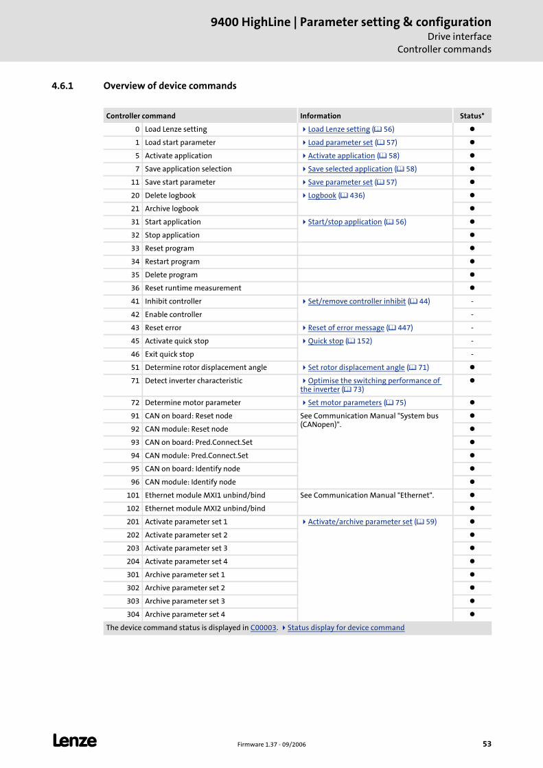
L Firmware 1.37 - 09/2006 53
9400 HighLine | Parameter setting & configurationDrive interface
Controller commands
4.6.1 Overview of device commands
Controller command Information Status*
0 Load Lenze setting Load Lenze setting ( 56)
1 Load start parameter Load parameter set ( 57)
5 Activate application Activate application ( 58)
7 Save application selection Save selected application ( 58)
11 Save start parameter Save parameter set ( 57)
20 Delete logbook Logbook ( 436)
21 Archive logbook
31 Start application Start/stop application ( 56)
32 Stop application
33 Reset program
34 Restart program
35 Delete program
36 Reset runtime measurement
41 Inhibit controller Set/remove controller inhibit ( 44) -
42 Enable controller -
43 Reset error Reset of error message ( 447) -
45 Activate quick stop Quick stop ( 152) -
46 Exit quick stop -
51 Determine rotor displacement angle Set rotor displacement angle ( 71)
71 Detect inverter characteristic Optimise the switching performance of the inverter ( 73)
72 Determine motor parameter Set motor parameters ( 75)
91 CAN on board: Reset node See Communication Manual "System bus (CANopen)".
92 CAN module: Reset node
93 CAN on board: Pred.Connect.Set
94 CAN module: Pred.Connect.Set
95 CAN on board: Identify node
96 CAN module: Identify node
101 Ethernet module MXI1 unbind/bind See Communication Manual "Ethernet".
102 Ethernet module MXI2 unbind/bind
201 Activate parameter set 1 Activate/archive parameter set ( 59)
202 Activate parameter set 2
203 Activate parameter set 3
204 Activate parameter set 4
301 Archive parameter set 1
302 Archive parameter set 2
303 Archive parameter set 3
304 Archive parameter set 4
The device command status is displayed in C00003. Status display for device command
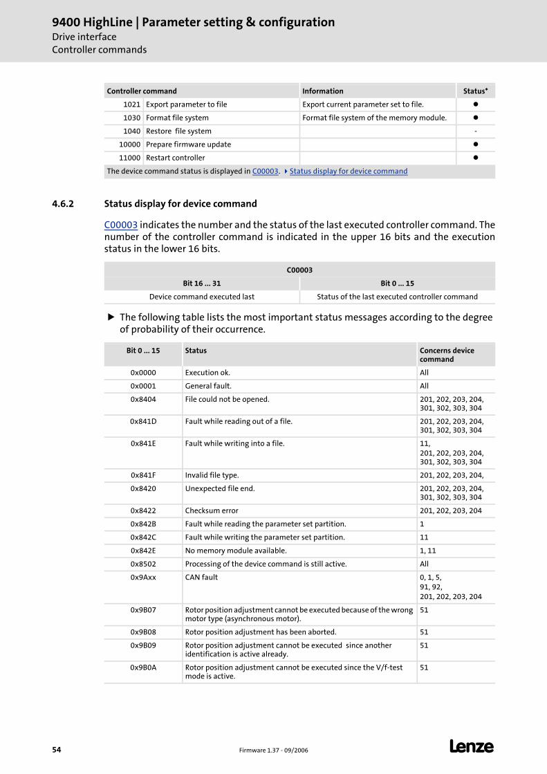
9400 HighLine | Parameter setting & configurationDrive interfaceController commands
54 Firmware 1.37 - 09/2006 L
4.6.2 Status display for device command
C00003 indicates the number and the status of the last executed controller command. The number of the controller command is indicated in the upper 16 bits and the execution status in the lower 16 bits.
The following table lists the most important status messages according to the degree of probability of their occurrence.
1021 Export parameter to file Export current parameter set to file.
1030 Format file system Format file system of the memory module.
1040 Restore file system -
10000 Prepare firmware update
11000 Restart controller
Controller command Information Status*
The device command status is displayed in C00003. Status display for device command
C00003
Bit 16 ... 31 Bit 0 ... 15
Device command executed last Status of the last executed controller command
Bit 0 ... 15 Status Concerns device command
0x0000 Execution ok. All
0x0001 General fault. All
0x8404 File could not be opened. 201, 202, 203, 204, 301, 302, 303, 304
0x841D Fault while reading out of a file. 201, 202, 203, 204, 301, 302, 303, 304
0x841E Fault while writing into a file. 11,201, 202, 203, 204, 301, 302, 303, 304
0x841F Invalid file type. 201, 202, 203, 204,
0x8420 Unexpected file end. 201, 202, 203, 204, 301, 302, 303, 304
0x8422 Checksum error 201, 202, 203, 204
0x842B Fault while reading the parameter set partition. 1
0x842C Fault while writing the parameter set partition. 11
0x842E No memory module available. 1, 11
0x8502 Processing of the device command is still active. All
0x9Axx CAN fault 0, 1, 5,91, 92,201, 202, 203, 204
0x9B07 Rotor position adjustment cannot be executed because of the wrong motor type (asynchronous motor).
51
0x9B08 Rotor position adjustment has been aborted. 51
0x9B09 Rotor position adjustment cannot be executed since another identification is active already.
51
0x9B0A Rotor position adjustment cannot be executed since the V/f-test mode is active.
51
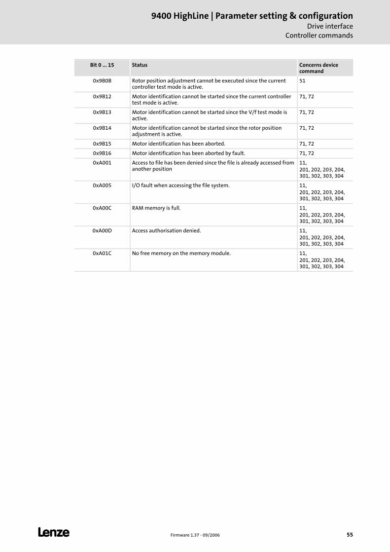
L Firmware 1.37 - 09/2006 55
9400 HighLine | Parameter setting & configurationDrive interface
Controller commands
0x9B0B Rotor position adjustment cannot be executed since the current controller test mode is active.
51
0x9B12 Motor identification cannot be started since the current controller test mode is active.
71, 72
0x9B13 Motor identification cannot be started since the V/f test mode is active.
71, 72
0x9B14 Motor identification cannot be started since the rotor position adjustment is active.
71, 72
0x9B15 Motor identification has been aborted. 71, 72
0x9B16 Motor identification has been aborted by fault. 71, 72
0xA001 Access to file has been denied since the file is already accessed from another position
11,201, 202, 203, 204, 301, 302, 303, 304
0xA005 I/O fault when accessing the file system. 11,201, 202, 203, 204, 301, 302, 303, 304
0xA00C RAM memory is full. 11,201, 202, 203, 204, 301, 302, 303, 304
0xA00D Access authorisation denied. 11,201, 202, 203, 204, 301, 302, 303, 304
0xA01C No free memory on the memory module. 11,201, 202, 203, 204, 301, 302, 303, 304
Bit 0 ... 15 Status Concerns device command
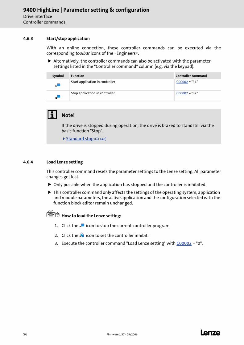
9400 HighLine | Parameter setting & configurationDrive interfaceController commands
56 Firmware 1.37 - 09/2006 L
4.6.3 Start/stop application
With an online connection, these controller commands can be executed via the corresponding toolbar icons of the »Engineers«.
Alternatively, the controller commands can also be activated with the parameter settings listed in the "Controller command" column (e.g. via the keypad).
4.6.4 Load Lenze setting
This controller command resets the parameter settings to the Lenze setting. All parameter changes get lost.
Only possible when the application has stopped and the controller is inhibited.
This controller command only affects the settings of the operating system, application and module parameters, the active application and the configuration selected with the function block editor remain unchanged.
How to load the Lenze setting:
1. Click the icon to stop the current controller program.
2. Click the icon to set the controller inhibit.
3. Execute the controller command "Load Lenze setting" with C00002 = "0".
Symbol Function Controller command
Start application in controller C00002 = "31"
Stop application in controller C00002 = "32"
Note!
If the drive is stopped during operation, the drive is braked to standstill via the basic function "Stop".
Standard stop ( 148)
L Firmware 1.37 - 09/2006 57
9400 HighLine | Parameter setting & configurationDrive interface
Controller commands
4.6.5 Save parameter set
Controller parameter changes made via the »Engineer« or keypad will get lost after mains switching of the controller or loading of another application unless the settings have been explicitly saved with the corresponding controller command in the memory module of the controller.
How to save the starting parameters safe against mains failure in the memory module:
Execute the controller command "Save starting parameter" with C00002 = "11".
4.6.6 Load parameter set
Activation of this controller command reloads the parameter set of the active application from the memory module into the controller. All parameter changes made since the parameter set has been saved last will get lost.
Only possible when the application program has stopped and the controller is inhibited.
How to reload the starting parameters from the memory module:
1. Click the icon to stop the current controller program.
2. Click the icon to set the controller inhibit.
3. Execute the controller command "Load starting parameter" with C00002 = "1".
9400 HighLine | Parameter setting & configurationDrive interfaceController commands
58 Firmware 1.37 - 09/2006 L
4.6.7 Activate application
If the memory module contains several applications, you can use this controller command to activate a different application in the controller.
After mains switching, the preset application will be loaded into the controller.
If after mains switching another application than the one preset by Lenze is to be loaded, it must be activated first and then the application selection must be saved. Save selected application
How to activate a different application:
1. Click the icon to stop the current controller program.
2. Select the number of the application to be activated under C00005.
3. Execute the controller command "Activate application" with C00002 = "5".
• The application with the number set in C00005 is activated. If it is started immediately depends on the automatic start setting selected in C02104.
4.6.8 Save selected application
After mains switching, the controller always loads the preset application, even if a different application has been active before.
Use the controller command "Save selected application" to select the active application as presetting, i.e. the memory module will load this application into the controller after every mains switching.
When the controller command is executed, the parameter set is saved automatically.
Execute the controller command "Save selected application" with C00002 = "7" to select the active application as presetting.
Note!
When the application is activated, the corresponding parameter set 1 is loaded automatically and parameter settings executed before will get lost unless the parameter set was saved before!
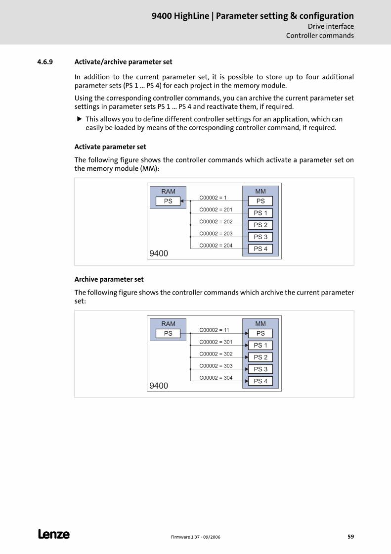
L Firmware 1.37 - 09/2006 59
9400 HighLine | Parameter setting & configurationDrive interface
Controller commands
4.6.9 Activate/archive parameter set
In addition to the current parameter set, it is possible to store up to four additional parameter sets (PS 1 ... PS 4) for each project in the memory module.
Using the corresponding controller commands, you can archive the current parameter set settings in parameter sets PS 1 ... PS 4 and reactivate them, if required.
This allows you to define different controller settings for an application, which can easily be loaded by means of the corresponding controller command, if required.
Activate parameter set
The following figure shows the controller commands which activate a parameter set on the memory module (MM):
Archive parameter set
The following figure shows the controller commands which archive the current parameter set:
PSC00002 = 1
MM
9400
RAM
C00002 = 201
C00002 = 202
C00002 = 203
C00002 = 204
PS 2
PS 1
PS 3
PS 4
PS
PS PS
MM
9400
RAM
C00002 = 301
C00002 = 302
C00002 = 303
C00002 = 304
PS 2
PS 1
PS 3
PS 4
C00002 = 11
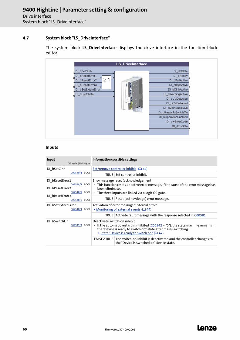
9400 HighLine | Parameter setting & configurationDrive interfaceSystem block "LS_DriveInterface"
60 Firmware 1.37 - 09/2006 L
4.7 System block "LS_DriveInterface"
The system block LS_DriveInterface displays the drive interface in the function block editor.
Inputs
InputDIS code | Data type
Information/possible settings
DI_bSetCInhC02549/1 | BOOL
Set/remove controller inhibit ( 44)
TRUE Set controller inhibit.
DI_bResetError1C02548/1 | BOOL
DI_bResetError2C02548/2 | BOOL
DI_bResetError3C02548/3 | BOOL
Error message reset (acknowledgement) • This function resets an active error message, if the cause of the error message has
been eliminated. • The three inputs are linked via a logic OR gate.
TRUE Reset (acknowledge) error message.
DI_bSetExternErrorC02548/4 | BOOL
Activation of error message "External error".Monitoring of external events ( 44)
TRUE Activate fault message with the response selected in C00581.
DI_bSwitchOnC02549/4 | BOOL
Deactivate switch-on inhibit • If the automatic restart is inhibited (C00142 = "0"), the state machine remains in
the "Device is ready to switch on" state after mains switching. State "Device is ready to switch on" ( 47)
FALSE TRUE The switch-on inhibit is deactivated and the controller changes to the "Device is switched on" device state.
LS_DriveInterface
DI_dnStateDI_bSetCInh
DI_bResetError1
DI_bSetExternError
DI_bSwitchOn
DI_bReadyToSwitchOn
DI_bReady
DI_bFailActive
DI_bImpActive
DI_bCInhActive
DI_bUVDetected
DI_bMainSupplyOk
DI_bWarningActive
DI_bOVDetected
DI_bOperationEnabled
� 1DI_bResetError2
DI_bResetError3
DI_dwErrorCode
DI_AxisData
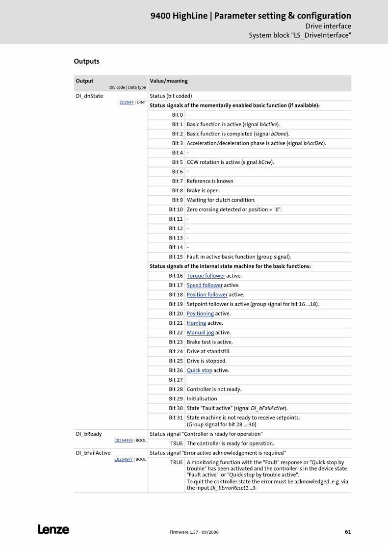
L Firmware 1.37 - 09/2006 61
9400 HighLine | Parameter setting & configurationDrive interface
System block "LS_DriveInterface"
Outputs
OutputDIS code | Data type
Value/meaning
DI_dnStateC02547 | DINT
Status (bit coded)
Status signals of the momentarily enabled basic function (if available):
Bit 0 -
Bit 1 Basic function is active (signal bActive).
Bit 2 Basic function is completed (signal bDone).
Bit 3 Acceleration/deceleration phase is active (signal bAccDec).
Bit 4 -
Bit 5 CCW rotation is active (signal bCcw).
Bit 6 -
Bit 7 Reference is known
Bit 8 Brake is open.
Bit 9 Waiting for clutch condition.
Bit 10 Zero crossing detected or position = "0".
Bit 11 -
Bit 12 -
Bit 13 -
Bit 14 -
Bit 15 Fault in active basic function (group signal).
Status signals of the internal state machine for the basic functions:
Bit 16 Torque follower active.
Bit 17 Speed follower active.
Bit 18 Position follower active.
Bit 19 Setpoint follower is active (group signal for bit 16 ...18).
Bit 20 Positioning active.
Bit 21 Homing active.
Bit 22 Manual jog active.
Bit 23 Brake test is active.
Bit 24 Drive at standstill.
Bit 25 Drive is stopped.
Bit 26 Quick stop active.
Bit 27 -
Bit 28 Controller is not ready.
Bit 29 Initialisation
Bit 30 State "Fault active" (signal DI_bFailActive).
Bit 31 State machine is not ready to receive setpoints.(Group signal for bit 28 ... 30)
DI_bReadyC02549/6 | BOOL
Status signal "Controller is ready for operation"
TRUE The controller is ready for operation.
DI_bFailActiveC02549/7 | BOOL
Status signal "Error active acknowledgement is required"
TRUE A monitoring function with the "Fault" response or "Quick stop by trouble" has been activated and the controller is in the device state "Fault active" or "Quick stop by trouble active".To quit the controller state the error must be acknowledged, e.g. via the input DI_bErrorReset1...3.
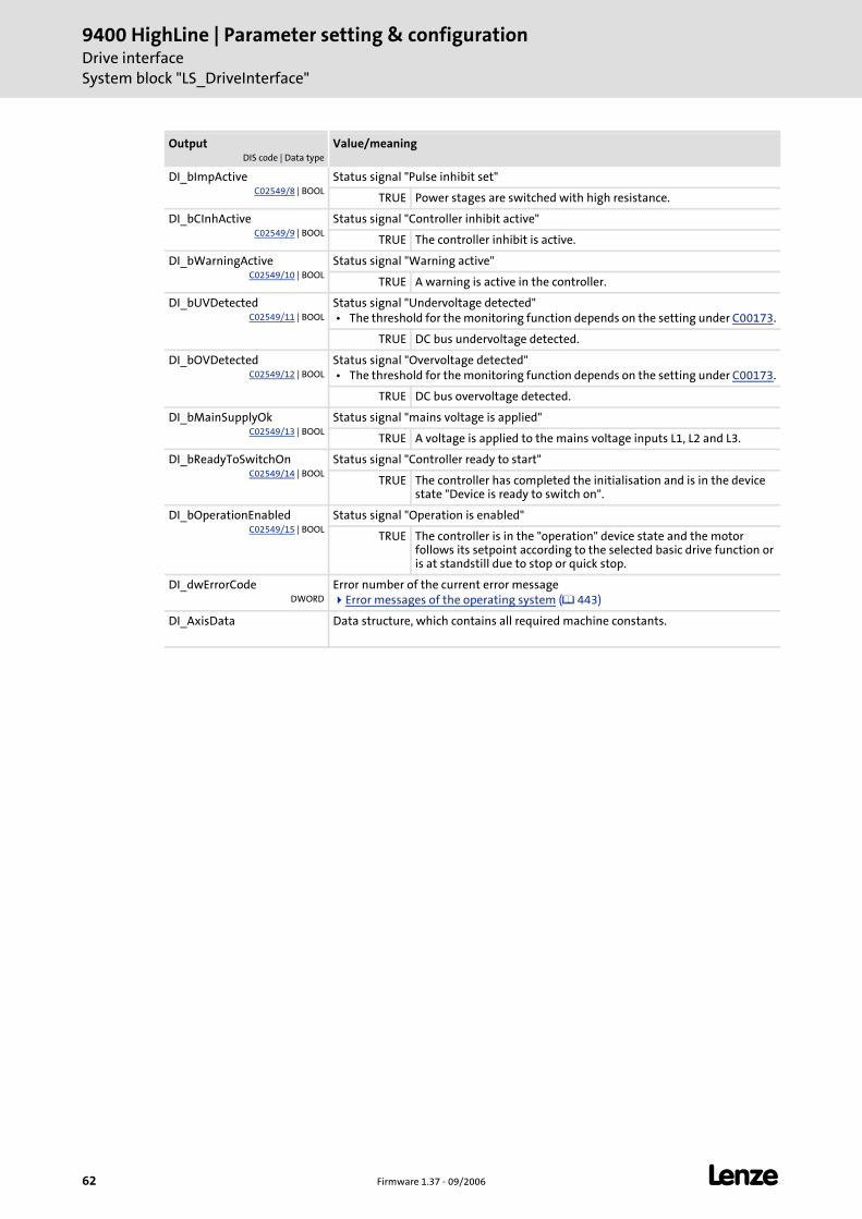
9400 HighLine | Parameter setting & configurationDrive interfaceSystem block "LS_DriveInterface"
62 Firmware 1.37 - 09/2006 L
DI_bImpActiveC02549/8 | BOOL
Status signal "Pulse inhibit set"
TRUE Power stages are switched with high resistance.
DI_bCInhActiveC02549/9 | BOOL
Status signal "Controller inhibit active"
TRUE The controller inhibit is active.
DI_bWarningActiveC02549/10 | BOOL
Status signal "Warning active"
TRUE A warning is active in the controller.
DI_bUVDetectedC02549/11 | BOOL
Status signal "Undervoltage detected" • The threshold for the monitoring function depends on the setting under C00173.
TRUE DC bus undervoltage detected.
DI_bOVDetectedC02549/12 | BOOL
Status signal "Overvoltage detected" • The threshold for the monitoring function depends on the setting under C00173.
TRUE DC bus overvoltage detected.
DI_bMainSupplyOkC02549/13 | BOOL
Status signal "mains voltage is applied"
TRUE A voltage is applied to the mains voltage inputs L1, L2 and L3.
DI_bReadyToSwitchOnC02549/14 | BOOL
Status signal "Controller ready to start"
TRUE The controller has completed the initialisation and is in the device state "Device is ready to switch on".
DI_bOperationEnabledC02549/15 | BOOL
Status signal "Operation is enabled"
TRUE The controller is in the "operation" device state and the motor follows its setpoint according to the selected basic drive function or is at standstill due to stop or quick stop.
DI_dwErrorCodeDWORD
Error number of the current error messageError messages of the operating system ( 443)
DI_AxisData Data structure, which contains all required machine constants.
OutputDIS code | Data type
Value/meaning
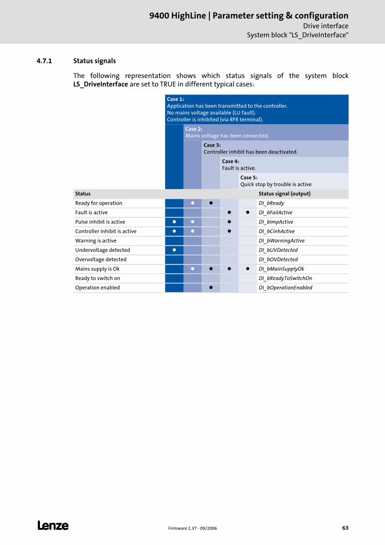
L Firmware 1.37 - 09/2006 63
9400 HighLine | Parameter setting & configurationDrive interface
System block "LS_DriveInterface"
4.7.1 Status signals
The following representation shows which status signals of the system block LS_DriveInterface are set to TRUE in different typical cases:
Case 1:Application has been transmitted to the controller.No mains voltage available (LU fault).Controller is inhibited (via RFR terminal).
Case 2:Mains voltage has been connected.
Case 3:Controller inhibit has been deactivated.
Case 4:Fault is active.
Case 5:Quick stop by trouble is active
Status Status signal (output)
Ready for operation DI_bReady
Fault is active DI_bFailActive
Pulse inhibit is active DI_bImpActive
Controller inhibit is active DI_bCinhActive
Warning is active DI_bWarningActive
Undervoltage detected DI_bUVDetected
Overvoltage detected DI_bOVDetected
Mains supply is Ok DI_bMainSupplyOk
Ready to switch on DI_bReadyToSwitchOn
Operation enabled DI_bOperationEnabled
9400 HighLine | Parameter setting & configurationMotor interface
64 Firmware 1.37 - 09/2006 L
5 Motor interface
This chapter contains information on initial commissioning of the motor and parameter setting of the internal motor control of the controller.
See also: Speed follower ( 190)
Torque follower ( 196)
Position follower ( 183)
Encoder evaluation ( 108)
Note!
To select application-specific setpoints, the motor interface can be extended by appropriate interfaces using the basic functions "Speed follower", "Torque follower" and "Position follower".
The application-specific conditioning of the encoder signals is executed with the basic function "Encoder evaluation".
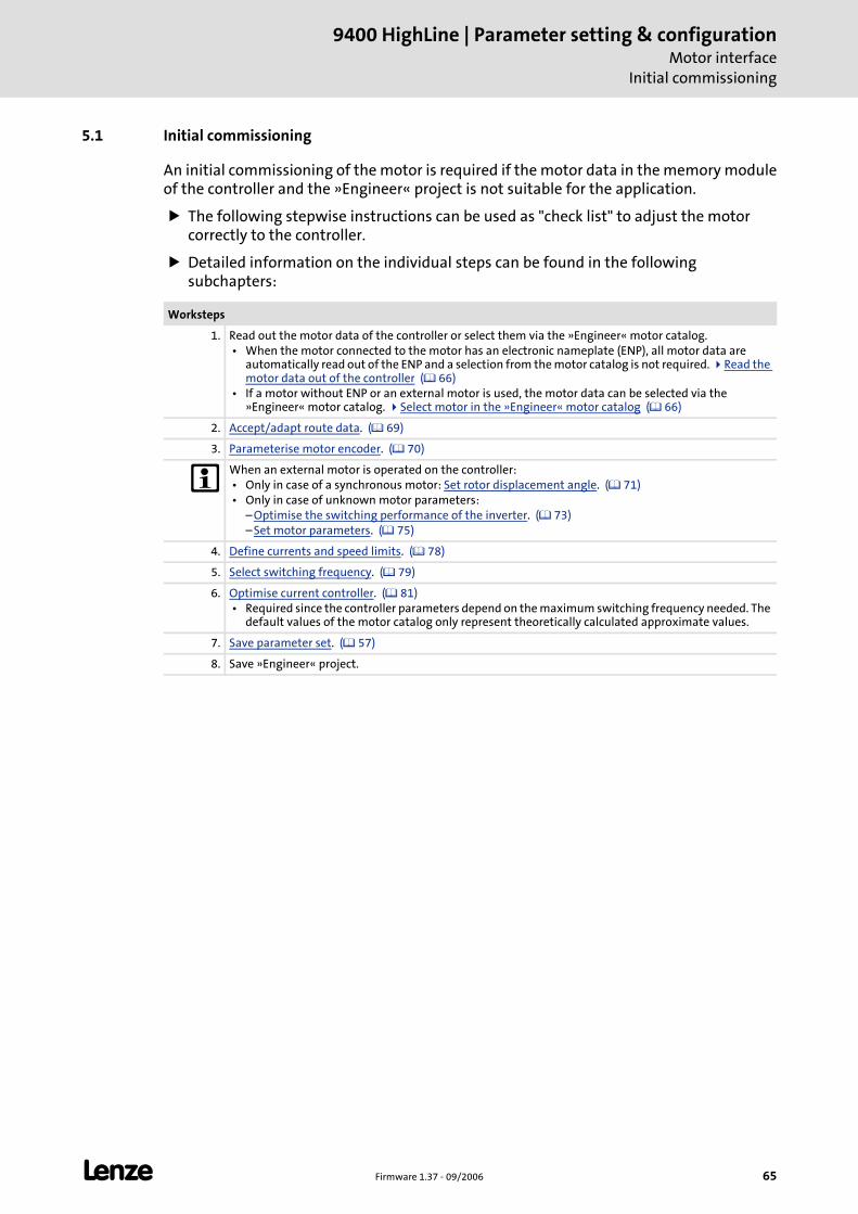
L Firmware 1.37 - 09/2006 65
9400 HighLine | Parameter setting & configurationMotor interface
Initial commissioning
5.1 Initial commissioning
An initial commissioning of the motor is required if the motor data in the memory module of the controller and the »Engineer« project is not suitable for the application.
The following stepwise instructions can be used as "check list" to adjust the motor correctly to the controller.
Detailed information on the individual steps can be found in the following subchapters:
Worksteps
1. Read out the motor data of the controller or select them via the »Engineer« motor catalog. • When the motor connected to the motor has an electronic nameplate (ENP), all motor data are
automatically read out of the ENP and a selection from the motor catalog is not required. Read the motor data out of the controller ( 66)
• If a motor without ENP or an external motor is used, the motor data can be selected via the »Engineer« motor catalog. Select motor in the »Engineer« motor catalog ( 66)
2. Accept/adapt route data. ( 69)
3. Parameterise motor encoder. ( 70)
When an external motor is operated on the controller: • Only in case of a synchronous motor: Set rotor displacement angle. ( 71) • Only in case of unknown motor parameters:
– Optimise the switching performance of the inverter. ( 73) – Set motor parameters. ( 75)
4. Define currents and speed limits. ( 78)
5. Select switching frequency. ( 79)
6. Optimise current controller. ( 81) • Required since the controller parameters depend on the maximum switching frequency needed. The
default values of the motor catalog only represent theoretically calculated approximate values.
7. Save parameter set. ( 57)
8. Save »Engineer« project.
9400 HighLine | Parameter setting & configurationMotor interfaceInitial commissioning | Read the motor data out of the controller
66 Firmware 1.37 - 09/2006 L
5.1.1 Read the motor data out of the controller
If the Lenze motor connected to the controller has an electronic nameplate (ENP), the motor does not need to be selected in the »Engineer« motor catalog.
When the controller is switched on initially, all motor data are automatically read out of the electronic motor nameplate and stored at first temporarily in the controller.
For a permanent acceptance of the motor data, the parameter set must be saved (C00002 = "11").
If there is an online connection between the »Engineer« and the controller, the motor data of the controller can be taken over into the »Engineer« project.
How to read the motor data out of the controller:
1. Establish an online connection between »Engineer« and controller.
2. Go to the Application parameter tab and change to the dialog level Overview Motor.
3. Press the out of controller button.
• Then the motor data are read out of the controller and directly written into the corresponding codes of the »Engineer« project.
5.1.2 Select motor in the »Engineer« motor catalog
If the Lenze motor does not have an electronic nameplate (ENP) or if a motor of a third-party manufacturer is used, select the motor in the »Engineer« via the motor catalog and transfer the motor data to the controller.
If you, when inserting the controller into the project in the dialog step "Other components" put a checkmark in the control field Motor, you can select as a further dialog step the motor for the controller from the motor catalog.
As an alternative you can also insert the motor at a later date into the project via the command Insert component.
Tip!
If you use a motor of a third-party manufacturer, you can at first select a suitable motor concerning the rated data for current, voltage and speed and then adapt the motor data exactly to the existing motor.
Display/edit motor data in the »Engineer« ( 67)
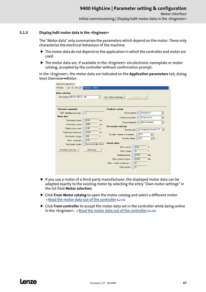
L Firmware 1.37 - 09/2006 67
9400 HighLine | Parameter setting & configurationMotor interface
Initial commissioning | Display/edit motor data in the »Engineer«
5.1.3 Display/edit motor data in the »Engineer«
The "Motor data" only summarises the parameters which depend on the motor. These only characterise the electrical behaviour of the machine.
The motor data do not depend on the application in which the controller and motor are used.
The motor data are, if available in the »Engineer« via electronic nameplate or motor catalog, accepted by the controller without confirmation prompt.
In the »Engineer«, the motor data are indicated on the Application parameters tab, dialog level Overview Motor:
If you use a motor of a third-party manufacturer, the displayed motor data can be adapted exactly to the existing motor by selecting the entry "Own motor settings" in the list field Motor selection.
Click From Motor catalog to open the motor catalog and select a different motor. Read the motor data out of the controller ( 66)
Click From controller to accept the motor data set in the controller while being online in the »Engineer«. Read the motor data out of the controller ( 66)
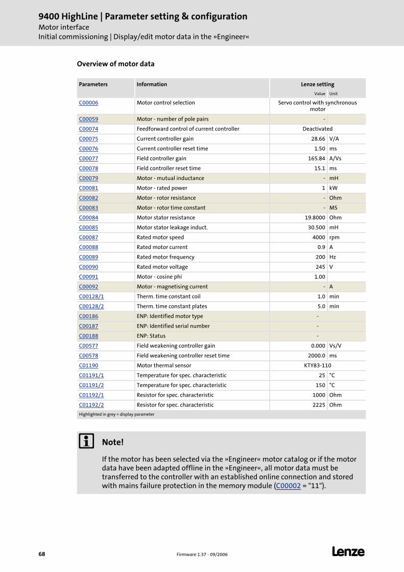
9400 HighLine | Parameter setting & configurationMotor interfaceInitial commissioning | Display/edit motor data in the »Engineer«
68 Firmware 1.37 - 09/2006 L
Overview of motor data
Parameters Information Lenze setting
Value Unit
C00006 Motor control selection Servo control with synchronous motor
C00059 Motor - number of pole pairs -
C00074 Feedforward control of current controller Deactivated
C00075 Current controller gain 28.66 V/A
C00076 Current controller reset time 1.50 ms
C00077 Field controller gain 165.84 A/Vs
C00078 Field controller reset time 15.1 ms
C00079 Motor - mutual inductance - mH
C00081 Motor - rated power 1 kW
C00082 Motor - rotor resistance - Ohm
C00083 Motor - rotor time constant - MS
C00084 Motor stator resistance 19.8000 Ohm
C00085 Motor stator leakage induct. 30.500 mH
C00087 Rated motor speed 4000 rpm
C00088 Rated motor current 0.9 A
C00089 Rated motor frequency 200 Hz
C00090 Rated motor voltage 245 V
C00091 Motor - cosine phi 1.00
C00092 Motor - magnetising current - A
C00128/1 Therm. time constant coil 1.0 min
C00128/2 Therm. time constant plates 5.0 min
C00186 ENP: Identified motor type -
C00187 ENP: Identified serial number -
C00188 ENP: Status -
C00577 Field weakening controller gain 0.000 Vs/V
C00578 Field weakening controller reset time 2000.0 ms
C01190 Motor thermal sensor KTY83-110
C01191/1 Temperature for spec. characteristic 25 °C
C01191/2 Temperature for spec. characteristic 150 °C
C01192/1 Resistor for spec. characteristic 1000 Ohm
C01192/2 Resistor for spec. characteristic 2225 Ohm
Highlighted in grey = display parameter
Note!
If the motor has been selected via the »Engineer« motor catalog or if the motor data have been adapted offline in the »Engineer«, all motor data must be transferred to the controller with an established online connection and stored with mains failure protection in the memory module (C00002 = "11").
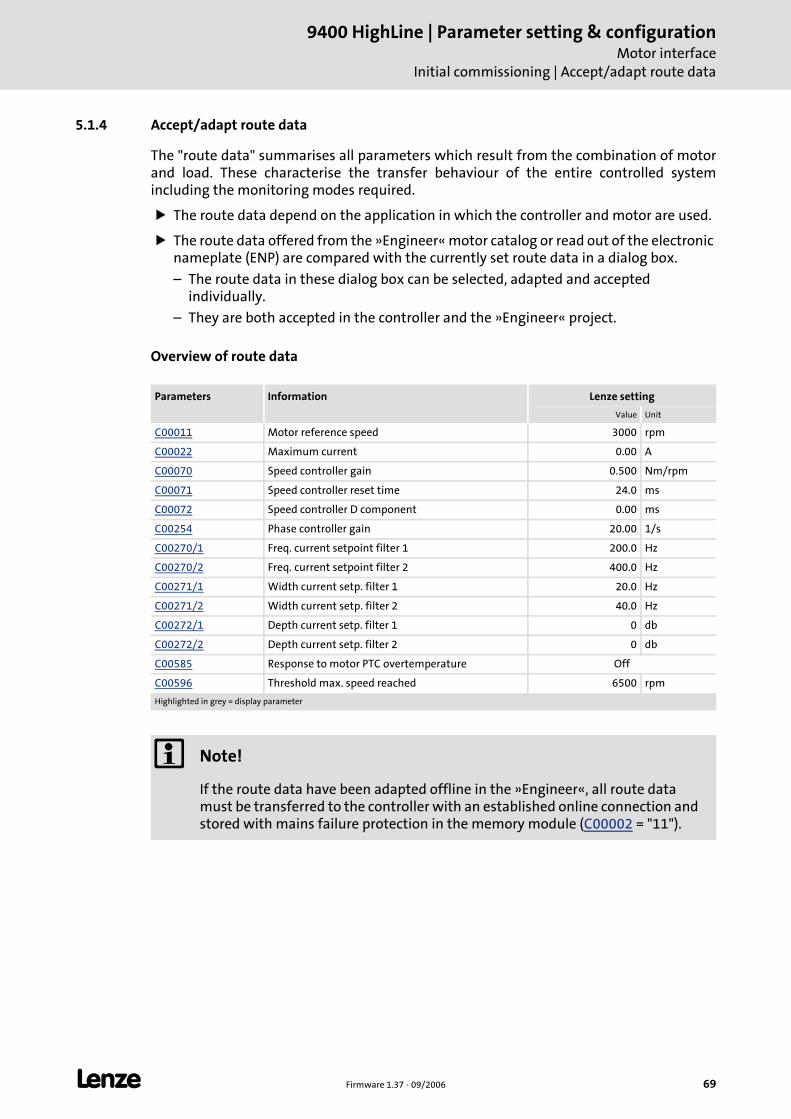
L Firmware 1.37 - 09/2006 69
9400 HighLine | Parameter setting & configurationMotor interface
Initial commissioning | Accept/adapt route data
5.1.4 Accept/adapt route data
The "route data" summarises all parameters which result from the combination of motor and load. These characterise the transfer behaviour of the entire controlled system including the monitoring modes required.
The route data depend on the application in which the controller and motor are used.
The route data offered from the »Engineer« motor catalog or read out of the electronic nameplate (ENP) are compared with the currently set route data in a dialog box.
– The route data in these dialog box can be selected, adapted and accepted individually.
– They are both accepted in the controller and the »Engineer« project.
Overview of route data
Parameters Information Lenze setting
Value Unit
C00011 Motor reference speed 3000 rpm
C00022 Maximum current 0.00 A
C00070 Speed controller gain 0.500 Nm/rpm
C00071 Speed controller reset time 24.0 ms
C00072 Speed controller D component 0.00 ms
C00254 Phase controller gain 20.00 1/s
C00270/1 Freq. current setpoint filter 1 200.0 Hz
C00270/2 Freq. current setpoint filter 2 400.0 Hz
C00271/1 Width current setp. filter 1 20.0 Hz
C00271/2 Width current setp. filter 2 40.0 Hz
C00272/1 Depth current setp. filter 1 0 db
C00272/2 Depth current setp. filter 2 0 db
C00585 Response to motor PTC overtemperature Off
C00596 Threshold max. speed reached 6500 rpm
Highlighted in grey = display parameter
Note!
If the route data have been adapted offline in the »Engineer«, all route data must be transferred to the controller with an established online connection and stored with mains failure protection in the memory module (C00002 = "11").
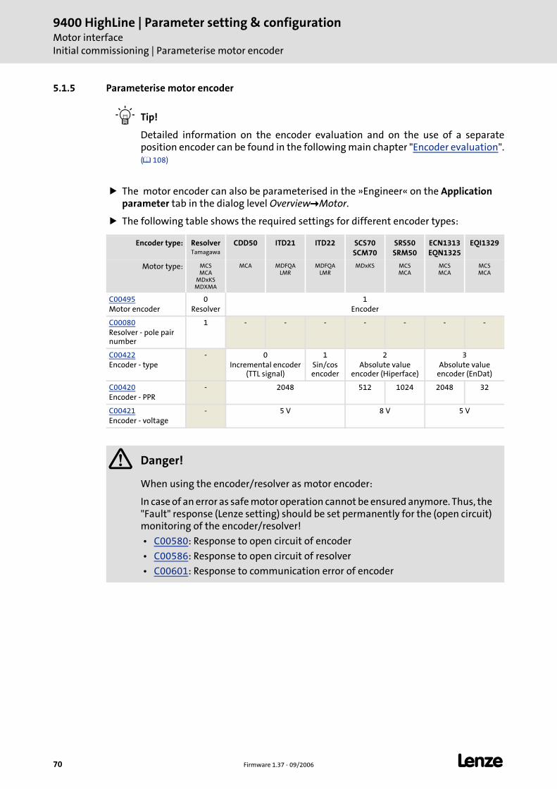
9400 HighLine | Parameter setting & configurationMotor interfaceInitial commissioning | Parameterise motor encoder
70 Firmware 1.37 - 09/2006 L
5.1.5 Parameterise motor encoder
Tip!
Detailed information on the encoder evaluation and on the use of a separate position encoder can be found in the following main chapter "Encoder evaluation". ( 108)
The motor encoder can also be parameterised in the »Engineer« on the Application parameter tab in the dialog level Overview Motor.
The following table shows the required settings for different encoder types:
Encoder type: ResolverTamagawa
CDD50 ITD21 ITD22 SCS70SCM70
SRS50SRM50
ECN1313EQN1325
EQI1329
Motor type: MCSMCA
MDxKSMDXMA
MCA MDFQALMR
MDFQALMR
MDxKS MCSMCA
MCSMCA
MCSMCA
C00495Motor encoder
0Resolver
1Encoder
C00080Resolver - pole pair number
1 - - - - - - -
C00422Encoder - type
- 0Incremental encoder
(TTL signal)
1Sin/cos encoder
2Absolute value
encoder (Hiperface)
3Absolute value
encoder (EnDat)
C00420Encoder - PPR
- 2048 512 1024 2048 32
C00421Encoder - voltage
- 5 V 8 V 5 V
Danger!
When using the encoder/resolver as motor encoder:
In case of an error as safe motor operation cannot be ensured anymore. Thus, the "Fault" response (Lenze setting) should be set permanently for the (open circuit) monitoring of the encoder/resolver!
• C00580: Response to open circuit of encoder
• C00586: Response to open circuit of resolver
• C00601: Response to communication error of encoder
L Firmware 1.37 - 09/2006 71
9400 HighLine | Parameter setting & configurationMotor interface
Initial commissioning | Set rotor displacement angle
5.1.6 Set rotor displacement angle
For the control of permanent-magnet synchronous machines, the rotor angle – the angle between the motor phase U and the field axis of the rotor – must be known.
For Lenze motors the rotor displacement angle for different feedback systems is already set correctly in C00058/1...3.
The device command "Set rotor displacement angle" serves to specify the rotor displacement angle for the current motor encoder activated in C00495 for an external motor (see following instructions).
How to set the rotor displacement angle for an external motor:
1. If the controller is enabled, inhibit the controller, e.g. with the device command "Inhibit controller" (C00002 = "41").
2. Execute device command "Set rotor displacement angle" with C00002 = "51".
The procedure starts with controller enable, if
• a synchronous machine is selected,
• no other identification is active,
• no error (TRIP) has occurred, and
• no test mode is activated.
If one of the above conditions is not met, the procedure is cancelled and the corresponding controller command status is indicated under C00003.
Note: By means of controller inhibit the started procedure can be aborted any time without making a change in C00058.
For detailed information about the procedure, please see the following section "Sequence".
Tip!
For controller enable all sources for controller inhibit must be reset. In C00158 the sources for controller inhibit are displayed in a bit-coded manner.
The status of the controller command activated under C00002 is indicated under C00003.
Note!
Not required if a Lenze motor is operated on the controller!
Note!
During the procedure of setting the rotor displacement angle, the machine must not be braked or blocked.
9400 HighLine | Parameter setting & configurationMotor interfaceInitial commissioning | Set rotor displacement angle
72 Firmware 1.37 - 09/2006 L
Sequence
If all conditions are met, the motor is energised with a direct current corresponding to the lower of the following two values:
The rotor is aligned through the current flow. This is absolutely necessary for the procedure.
To ensure that the torque-neutral axis is not accidentally energised and the rotor stops, a 45° current vector is (electrically) generated for 1 second and then (electrically) switched back to 0° (≡ phase U).
– After this second, you could measure a direct current corresponding to the above-mentioned value in this motor phase.
The next steps of the procedure depend on the feedback system used:
If an absolute value encoder with Hiperface or EnDat protocol is used, the encoder position is set to zero and the procedure is cancelled.
If a resolver or an optical encoder without absolute track is used, the difference between the preselected current angle and the mechanical rotor angle is determined. After this, the current vector is (electrically) turned by another 22.5° and the difference between current angle and rotor angle is determined once again.
– The procedure is repeated 16 times. This corresponds to one electrical revolution. The machine rotates by 360° (mech.)/pole pair number.
– Take the average value of the 16 measurements to compensate for asymmetries.
After successful completion...
...the controller is inhibited automatically and the rotor displacement angle determined for the activated feedback system is set in the corresponding subcode of C00058.
For a permanent acceptance of the set rotor displacement angle, the parameter set must be saved (C00002 = "11").
The device command C00002 = "42" serves to deactivated the controller inhibit automatically set by the procedure.
If an error occurs
If an error occurs during the procedure or the pulse inhibit gets active (e.g. due to short-time undervoltage), the procedure is terminated with controller inhibit without making a change in C00058.
If the machine was braked or blocked during the procedure, this will be recognised at the end of the measurement and no change is made in C00058.
or
2 Rated device current⋅
2 Rated motor current2
----------------------------------------------------⋅
L Firmware 1.37 - 09/2006 73
9400 HighLine | Parameter setting & configurationMotor interface
Initial commissioning | Optimise the switching performance of the inverter
5.1.7 Optimise the switching performance of the inverter
An inverter generates a pulse-width-modulated, three-phase voltage system. Due to the design of the inverter, current-dependent and chopper-frequency-dependent losses inside of the inverter falsify the output voltage. Since the output voltage is not measured, the losses must be compensated by a suitable feedforward control. This is compensated via an inverter error characteristic.
The inverter error characteristic depends, among other things, on the motor cable length and for a motor with unknown motor parameters it must be detected at least once individually with the device command "Detect inverter characteristic" so that a sinusoidal current is ensured for an automatic selection of the motor parameters.
How to determine the inverter error characteristic:
1. If the controller is enabled, inhibit the controller, e.g. with the device command "Inhibit controller" (C00002 = "41").
2. Execute the device command "Determine inverter characteristic" with C00002 = "71".
The procedure starts with controller enable, if
• no other identification is active,
• no error (TRIP) has occurred, and
• no test mode is activated.
If one of the above conditions is not met, the procedure is cancelled and the corresponding controller command status is indicated under C00003.
Note: By means of controller inhibit the started procedure can be aborted any time. Characteristic values already detected are not considered.
For detailed information about the procedure, please see the following section "Sequence".
Tip!
For controller enable all sources for controller inhibit must be reset. In C00158 the sources for controller inhibit are displayed in a bit-coded manner.
The status of the controller command activated under C00002 is indicated under C00003.
Note!
Not required if a Lenze motor is operated on the controller!
For an external motor with unknown motor parameters the optimisation of the inverter switching performance is necessary for the motor parameter setting described in the following chapter. Set motor parameters ( 75)
9400 HighLine | Parameter setting & configurationMotor interfaceInitial commissioning | Optimise the switching performance of the inverter
74 Firmware 1.37 - 09/2006 L
Sequence
If all conditions are met, the motor is energised with a maximum direct current corresponding to the lower of the following two values:
Ideally, the first value should be reached, the second value is to ensure that the load on the machine is not too high during the procedure.
During the procedure, the motor current rises up to the specified maximum value and falls back to "0" to repeat the cycle with a negative current sign.
The maximum value is reached four times.
The chopper frequency is set to 8 kHz, sine-wave modulation. After the procedure, it is reset to the original value.
– If the chopper frequency should be changed later during operation, the characteristic will be adapted to the current chopper frequency.
Presently, the characteristic is only used for the automatic selection of the motor parameters. The use for sensorless control methods is in preparation.
After successful completion...
...the controller is inhibited automatically and the detected characteristic is set in the controller.
For a permanent acceptance of the characteristic, the parameter set must be saved (C00002 = "11").
The device command C00002 = "42" serves to deactivated the controller inhibit automatically set by the procedure.
Tip!
The inverter error characteristic must only be detected again if the controller, motor, or motor cable have changed e.g. due to an exchange.
If an error occurs
If an error occurs during the procedure or the pulse inhibit gets active (e.g. due to short-time undervoltage), the procedure is terminated with controller inhibit and the detected characteristic is not considered.
or
2 Rated device current⋅
2 1.8 Rated motor current⋅ ⋅
L Firmware 1.37 - 09/2006 75
9400 HighLine | Parameter setting & configurationMotor interface
Initial commissioning | Set motor parameters
5.1.8 Set motor parameters
To control an electrical machine, the motor parameters must be known.
The motor parameters for Lenze motors are known and are already set accordingly by selecting them from the »Engineer« motor catalog or reading out the ENP.
The device command "Set motor parameters" serves to set the motor parameters listed in the following table for an external motor automatically unless they are known:
Tip!
The »Engineer« displays an equivalent circuit diagram with these motor parameters when you got to the Application parameter tab in the dialog level Overview Motor and press the button Other motor data....
The representation of the equivalent circuit diagram depends on the motor control selected (C00006).
Requirements
Before the automatic parameter determination is started, the switching performance of the inverter must have been optimised to ensure a sinusoidal current flow.
Optimise the switching performance of the inverter ( 73)
The motor parameters listed in the following table are excluded from the automatic determination and must be adapted to the motor used (see motor nameplate) before the determination.
Note!
Not required if a Lenze motor is operated on the controller!
Parameters Information ASM SM
C00079 Motor - magnetising inductance
C00082 Motor - rotor resistance
C00084 Motor stator resistance
C00085 Motor stator leakage induct.
C00091 Motor - cosine phi
C00092 Motor - magnetising current
Parameters Information
C00081 Motor - rated power
C00087 Rated motor speed
C00088 Rated motor current(The current amount for the procedure is derived from this specification)
C00089 Rated motor frequency
C00090 Rated motor voltage
9400 HighLine | Parameter setting & configurationMotor interfaceInitial commissioning | Set motor parameters
76 Firmware 1.37 - 09/2006 L
How to determine the motor parameters:
1. If the controller is enabled, inhibit the controller, e.g. with the device command "Inhibit controller" (C00002 = "41").
2. Execute the controller command "Determine motor parameters" with C00002 = "72".
The procedure starts with controller enable, if
• no other identification is active,
• no error has occurred, and
• no test mode is activated.
If one of the above conditions is not met, the procedure is cancelled and the corresponding controller command status is indicated under C00003.
Note: By means of controller inhibit the started procedure can be aborted any time without changing the codes for the motor parameters.
For detailed information about the procedure, please see the following section "Sequence".
Tip!
For controller enable all sources for controller inhibit must be reset. In C00158 the sources for controller inhibit are displayed in a bit-coded manner.
The status of the controller command activated under C00002 is indicated under C00003.
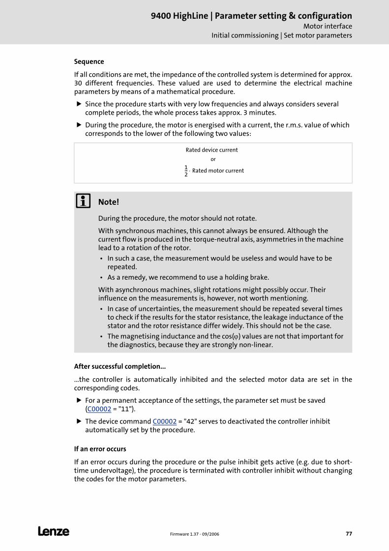
L Firmware 1.37 - 09/2006 77
9400 HighLine | Parameter setting & configurationMotor interface
Initial commissioning | Set motor parameters
Sequence
If all conditions are met, the impedance of the controlled system is determined for approx. 30 different frequencies. These valued are used to determine the electrical machine parameters by means of a mathematical procedure.
Since the procedure starts with very low frequencies and always considers several complete periods, the whole process takes approx. 3 minutes.
During the procedure, the motor is energised with a current, the r.m.s. value of which corresponds to the lower of the following two values:
After successful completion...
...the controller is automatically inhibited and the selected motor data are set in the corresponding codes.
For a permanent acceptance of the settings, the parameter set must be saved (C00002 = "11").
The device command C00002 = "42" serves to deactivated the controller inhibit automatically set by the procedure.
If an error occurs
If an error occurs during the procedure or the pulse inhibit gets active (e.g. due to short-time undervoltage), the procedure is terminated with controller inhibit without changing the codes for the motor parameters.
or
Note!
During the procedure, the motor should not rotate.
With synchronous machines, this cannot always be ensured. Although the current flow is produced in the torque-neutral axis, asymmetries in the machine lead to a rotation of the rotor.
• In such a case, the measurement would be useless and would have to be repeated.
• As a remedy, we recommend to use a holding brake.
With asynchronous machines, slight rotations might possibly occur. Their influence on the measurements is, however, not worth mentioning.
• In case of uncertainties, the measurement should be repeated several times to check if the results for the stator resistance, the leakage inductance of the stator and the rotor resistance differ widely. This should not be the case.
• The magnetising inductance and the cos(ϕ) values are not that important for the diagnostics, because they are strongly non-linear.
Rated device current
12--- Rated motor current⋅
9400 HighLine | Parameter setting & configurationMotor interfaceInitial commissioning | Define currents and speed limits
78 Firmware 1.37 - 09/2006 L
5.1.9 Define currents and speed limits
Maximum current
In C00022 the required maximum current must be set.
In order that the motor does not start unintentionally without adjusting the route data, the maximum current in the Lenze setting is set to "0 A" in C00022.
Moreover the motor limit current set in C00620 must be checked and the error response required for the motor protection must be selected in C00619.
Motor reference speed
In C00011 the reference speed of the motor must be set.
Maximum system speed
Adapt the maximum system speed in C00596 and select the error response required when this speed limit has been reached in C00607.
Note!
When MCS motors are used check if the motor used exceeds the voltage limit in the required operating range up to maximum current/reference speed.
• If so, the reference speed must be reduced to a permissible value.
• Presently the controller does not support a field weakening control for synchronous motors so that an operation at the voltage limit causes an undefined behaviour.
On the part of the application it must be ensured that maximally 100 % of the reference speed set in C00011 are required as speed setpoint.
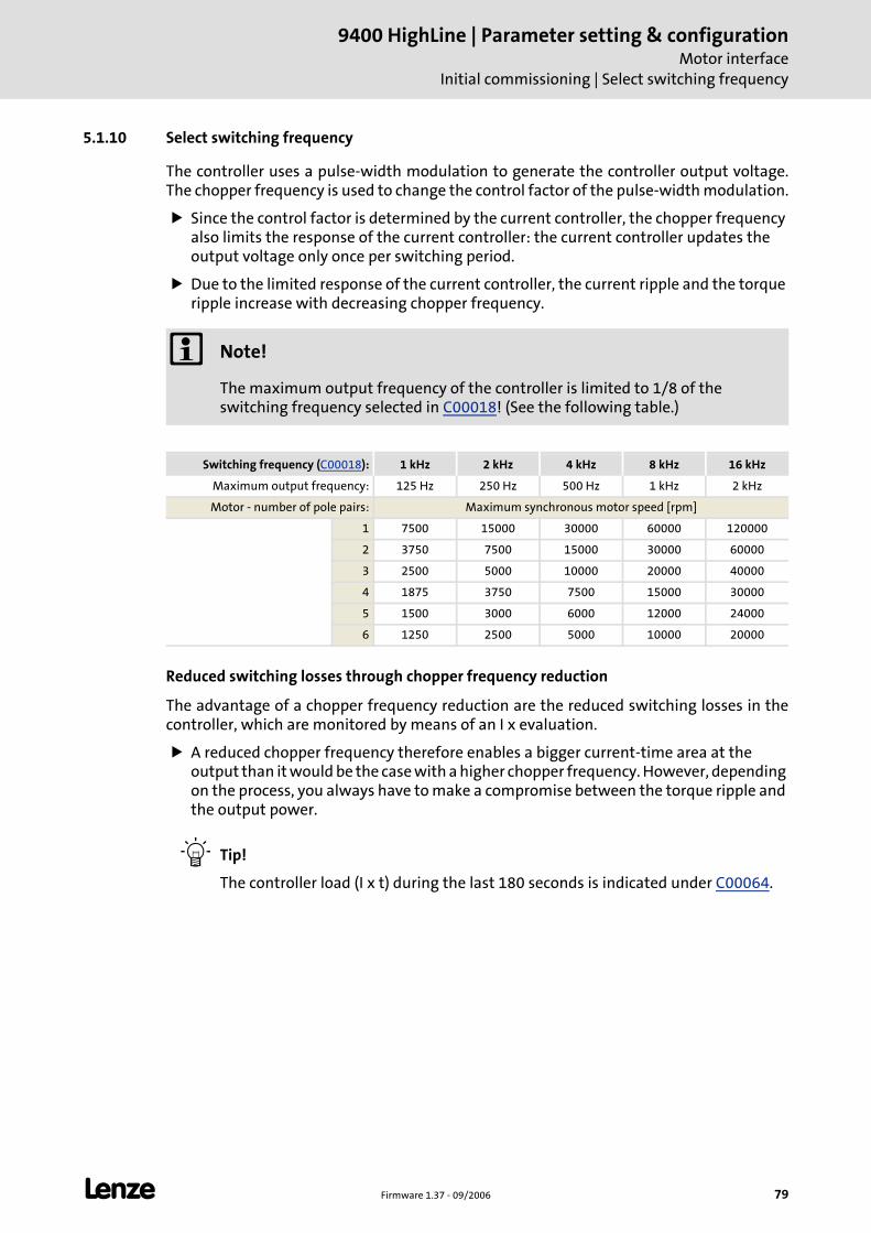
L Firmware 1.37 - 09/2006 79
9400 HighLine | Parameter setting & configurationMotor interface
Initial commissioning | Select switching frequency
5.1.10 Select switching frequency
The controller uses a pulse-width modulation to generate the controller output voltage. The chopper frequency is used to change the control factor of the pulse-width modulation.
Since the control factor is determined by the current controller, the chopper frequency also limits the response of the current controller: the current controller updates the output voltage only once per switching period.
Due to the limited response of the current controller, the current ripple and the torque ripple increase with decreasing chopper frequency.
Reduced switching losses through chopper frequency reduction
The advantage of a chopper frequency reduction are the reduced switching losses in the controller, which are monitored by means of an I x evaluation.
A reduced chopper frequency therefore enables a bigger current-time area at the output than it would be the case with a higher chopper frequency. However, depending on the process, you always have to make a compromise between the torque ripple and the output power.
Tip!
The controller load (I x t) during the last 180 seconds is indicated under C00064.
Note!
The maximum output frequency of the controller is limited to 1/8 of the switching frequency selected in C00018! (See the following table.)
Switching frequency (C00018): 1 kHz 2 kHz 4 kHz 8 kHz 16 kHz
Maximum output frequency: 125 Hz 250 Hz 500 Hz 1 kHz 2 kHz
Motor - number of pole pairs: Maximum synchronous motor speed [rpm]
1 7500 15000 30000 60000 120000
2 3750 7500 15000 30000 60000
3 2500 5000 10000 20000 40000
4 1875 3750 7500 15000 30000
5 1500 3000 6000 12000 24000
6 1250 2500 5000 10000 20000
9400 HighLine | Parameter setting & configurationMotor interfaceInitial commissioning | Select switching frequency
80 Firmware 1.37 - 09/2006 L
Automatic chopper frequency reduction
Under C00018, it is possible to select "variable" chopper frequencies for the controller. With this selection, the controller reduces the chopper frequency depending on the setpoint current.
Depending on the current, the controller switches down to an assigned chopper frequency; the modulation mode remains unchanged.
The switching thresholds are device-dependent (see 9400 Hardware Manual, chapter "Rated data").
If instead of a variable switching frequency a fixed switching frequency has been selected in C00018, no switching frequency changeover takes place. Due to the rotating field frequency range of 0...5 Hz only a lower continuous current and maximum currents can be applied (see 9400 Hardware Manual, chapter "Rated data").
Tip!
With the same load profile, a deactivation due to an excessive controller load (I x t) is more likely with a fixed chopper frequency setting than with a variable setting.
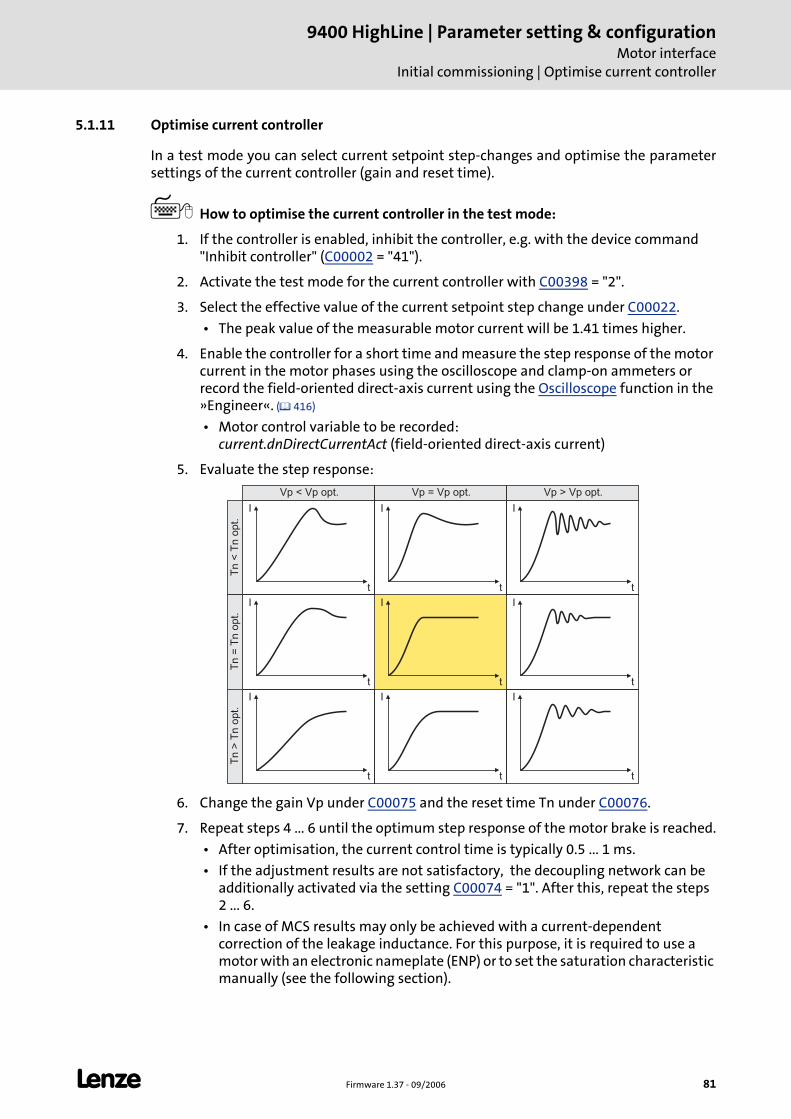
L Firmware 1.37 - 09/2006 81
9400 HighLine | Parameter setting & configurationMotor interface
Initial commissioning | Optimise current controller
5.1.11 Optimise current controller
In a test mode you can select current setpoint step-changes and optimise the parameter settings of the current controller (gain and reset time).
How to optimise the current controller in the test mode:
1. If the controller is enabled, inhibit the controller, e.g. with the device command "Inhibit controller" (C00002 = "41").
2. Activate the test mode for the current controller with C00398 = "2".
3. Select the effective value of the current setpoint step change under C00022.
• The peak value of the measurable motor current will be 1.41 times higher.
4. Enable the controller for a short time and measure the step response of the motor current in the motor phases using the oscilloscope and clamp-on ammeters or record the field-oriented direct-axis current using the Oscilloscope function in the »Engineer«. ( 416)
• Motor control variable to be recorded: current.dnDirectCurrentAct (field-oriented direct-axis current)
5. Evaluate the step response:
6. Change the gain Vp under C00075 and the reset time Tn under C00076.
7. Repeat steps 4 ... 6 until the optimum step response of the motor brake is reached.
• After optimisation, the current control time is typically 0.5 ... 1 ms.
• If the adjustment results are not satisfactory, the decoupling network can be additionally activated via the setting C00074 = "1". After this, repeat the steps 2 ... 6.
• In case of MCS results may only be achieved with a current-dependent correction of the leakage inductance. For this purpose, it is required to use a motor with an electronic nameplate (ENP) or to set the saturation characteristic manually (see the following section).
I
t
I
t
I
t
I
t
I
t
I
t
I
t
I
t
I
t
Vp < Vp opt. Vp = Vp opt. Vp > Vp opt.
Tn
<T
no
pt.
Tn
=T
no
pt.
Tn
>T
no
pt.
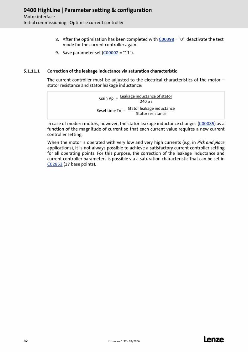
9400 HighLine | Parameter setting & configurationMotor interfaceInitial commissioning | Optimise current controller
82 Firmware 1.37 - 09/2006 L
8. After the optimisation has been completed with C00398 = "0", deactivate the test mode for the current controller again.
9. Save parameter set (C00002 = "11").
5.1.11.1 Correction of the leakage inductance via saturation characteristic
The current controller must be adjusted to the electrical characteristics of the motor – stator resistance and stator leakage inductance:
In case of modern motors, however, the stator leakage inductance changes (C00085) as a function of the magnitude of current so that each current value requires a new current controller setting.
When the motor is operated with very low and very high currents (e.g. in Pick and placeapplications), it is not always possible to achieve a satisfactory current controller setting for all operating points. For this purpose, the correction of the leakage inductance and current controller parameters is possible via a saturation characteristic that can be set in C02853 (17 base points).
Gain Vp Leakage inductance of stator240 μs
--------------------------------------------------------------------------=
Reset time Tn Stator leakage inductanceStator resistance
-------------------------------------------------------------------=
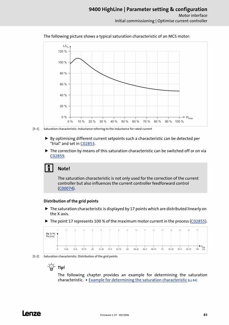
L Firmware 1.37 - 09/2006 83
9400 HighLine | Parameter setting & configurationMotor interface
Initial commissioning | Optimise current controller
The following picture shows a typical saturation characteristic of an MCS motor:
[5-1] Saturation characteristic: Inductance referring to the inductance for rated current
By optimising different current setpoints such a characteristic can be detected per "trial" and set in C02853.
The correction by means of this saturation characteristic can be switched off or on via C02859.
Distribution of the grid points
The saturation characteristic is displayed by 17 points which are distributed linearly on the X axis.
The point 17 represents 100 % of the maximum motor current in the process (C02855).
[5-2] Saturation characteristic: Distribution of the grid points
Tip!
The following chapter provides an example for determining the saturation characteristic. Example for determining the saturation characteristic ( 84)
0 % 10 % 20 % 30 % 40 % 50 % 60 % 70 % 80 % 90 % 100 %
0 %
20 %
40 %
60 %
80 %
100 %
120 %
I/Imax
L/Ln
Note!
The saturation characteristic is not only used for the correction of the current controller but also influences the current controller feedforward control (C00074).
0 6.25 12.5 18.75 25 31.25 37.5 43.75 50 56.25 62.5 68.75 75 81.25 87.5 93.75 100
Imax
VpTn
[V/A][ms]
2 3 4 5 6 7 8 9 10 11 12 13 14 15 16 17
[%]
1
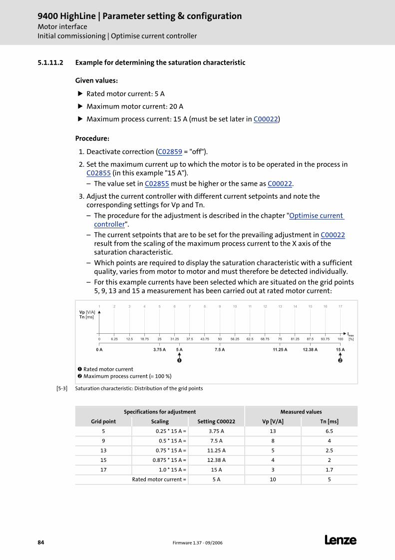
9400 HighLine | Parameter setting & configurationMotor interfaceInitial commissioning | Optimise current controller
84 Firmware 1.37 - 09/2006 L
5.1.11.2 Example for determining the saturation characteristic
Given values:
Rated motor current: 5 A
Maximum motor current: 20 A
Maximum process current: 15 A (must be set later in C00022)
Procedure:
1. Deactivate correction (C02859 = "off").
2. Set the maximum current up to which the motor is to be operated in the process in C02855 (in this example "15 A").
– The value set in C02855 must be higher or the same as C00022.
3. Adjust the current controller with different current setpoints and note the corresponding settings for Vp and Tn.
– The procedure for the adjustment is described in the chapter "Optimise current controller".
– The current setpoints that are to be set for the prevailing adjustment in C00022 result from the scaling of the maximum process current to the X axis of the saturation characteristic.
– Which points are required to display the saturation characteristic with a sufficient quality, varies from motor to motor and must therefore be detected individually.
– For this example currents have been selected which are situated on the grid points 5, 9, 13 and 15 a measurement has been carried out at rated motor current:
[5-3] Saturation characteristic: Distribution of the grid points
Rated motor current Maximum process current (≡ 100 %)
� �
15 A
2 3 4 5 6 7 8 9 10 11 12 13 14 15 16 17
7.5 A3.75 A 11.25 A 12.38 A5 A
0 6.25 12.5 18.75 25 31.25 37.5 43.75 50 56.25 62.5 68.75 75 81.25 87.5 93.75 100
0 A
Imax
[%]
VpTn
[V/A][ms]
1
Specifications for adjustment Measured values
Grid point Scaling Setting C00022 Vp [V/A] Tn [ms]
5 0.25 * 15 A = 3.75 A 13 6.5
9 0.5 * 15 A = 7.5 A 8 4
13 0.75 * 15 A = 11.25 A 5 2.5
15 0.875 * 15 A = 12.38 A 4 2
17 1.0 * 15 A = 15 A 3 1.7
Rated motor current = 5 A 10 5
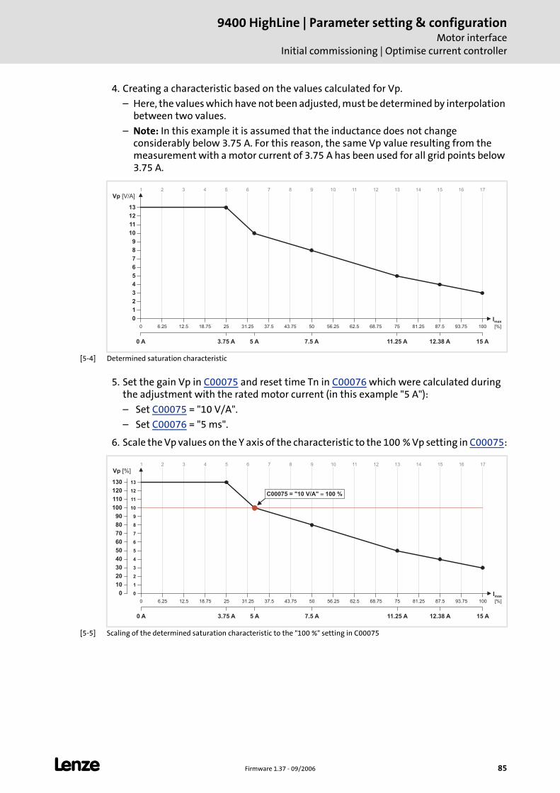
L Firmware 1.37 - 09/2006 85
9400 HighLine | Parameter setting & configurationMotor interface
Initial commissioning | Optimise current controller
4. Creating a characteristic based on the values calculated for Vp.
– Here, the values which have not been adjusted, must be determined by interpolation between two values.
– Note: In this example it is assumed that the inductance does not change considerably below 3.75 A. For this reason, the same Vp value resulting from the measurement with a motor current of 3.75 A has been used for all grid points below 3.75 A.
[5-4] Determined saturation characteristic
5. Set the gain Vp in C00075 and reset time Tn in C00076 which were calculated during the adjustment with the rated motor current (in this example "5 A"):
– Set C00075 = "10 V/A".
– Set C00076 = "5 ms".
6. Scale the Vp values on the Y axis of the characteristic to the 100 % Vp setting in C00075:
[5-5] Scaling of the determined saturation characteristic to the "100 %" setting in C00075
15 A
2 3 4 5 6 7 8 9 10 11 12 13 14 15 16 17
7.5 A3.75 A 11.25 A 12.38 A5 A
0 6.25 12.5 18.75 25 31.25 37.5 43.75 50 56.25 62.5 68.75 75 81.25 87.5 93.75 100
Vp [V/A]
0 A
0
1
2
3
4
5
6
7
8
9
10
11
12
13
1
Imax
[%]
15 A
2 3 4 5 6 7 8 9 10 11 12 13 14 15 16 17
7.5 A3.75 A 11.25 A 12.38 A5 A
0 6.25 12.5 18.75 25 31.25 37.5 43.75 50 56.25 62.5 68.75 75 81.25 87.5 93.75 100
Vp [%]
0 A
0
1
2
3
4
5
6
7
8
9
10
11
12
13
0
10
20
30
40
50
60
70
80
90
100
110
120
130
C00075 = "10 V/A" 100 %�
1
Imax
[%]
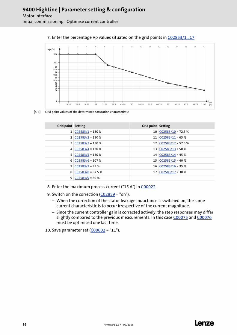
9400 HighLine | Parameter setting & configurationMotor interfaceInitial commissioning | Optimise current controller
86 Firmware 1.37 - 09/2006 L
7. Enter the percentage Vp values situated on the grid points in C02853/1...17:
[5-6] Grid point values of the determined saturation characteristic
8. Enter the maximum process current ("15 A") in C00022.
9. Switch on the correction (C02859 = "on").
– When the correction of the stator leakage inductance is switched on, the same current characteristic is to occur irrespective of the current magnitude.
– Since the current controller gain is corrected actively, the step responses may differ slightly compared to the previous measurements. In this case C00075 and C00076 must be optimised one last time.
10. Save parameter set (C00002 = "11").
2 3 4 5 6 7 8 9 10 11 12 13 14 15 16 17
0 6.25 12.5 18.75 25 31.25 37.5 43.75 50 56.25 62.5 68.75 75 81.25 87.5 93.75 100
Vp [%]
30
40
57.5
65
72.5
80
87.5
95
107
130
5045
35
0
1
Imax
[%]
Grid point Setting Grid point Setting
1 C02583/1 = 130 % 10 C02583/10 = 72.5 %
2 C02583/2 = 130 % 11 C02583/11 = 65 %
3 C02583/3 = 130 % 12 C02583/12 = 57.5 %
4 C02583/4 = 130 % 13 C02583/13 = 50 %
5 C02583/5 = 130 % 14 C02583/14 = 45 %
6 C02583/6 = 107 % 15 C02583/15 = 40 %
7 C02583/7 = 95 % 16 C02583/16 = 35 %
8 C02583/8 = 87.5 % 17 C02583/17 = 30 %
9 C02583/9 = 80 %
L Firmware 1.37 - 09/2006 87
9400 HighLine | Parameter setting & configurationMotor interface
Extended commissioning
5.2 Extended commissioning
After the initial commissioning of the motor, the required technology application can be selected in the »Engineer« and loaded in the controller.
Further information on this can be found in chapter Technology applications (TAs). ( 233)
During operation (with setpoint selection) further steps can be carried out to optimise the motor control.
Detailed information on the individual steps can be found in the following subchapters:
Tip!
To run a typical speed profile for optimising the motor control, you can also use the basic function "manual jog" with suitably adapted manual jog parameters.
Manual jog ( 156)
Worksteps
1. Optimise speed controller. ( 88) • Via running a typical speed profile and recording the ramp response of the speed controller with the
oscilloscope.
2. If the speed controller optimisation did not achieve the intended result:
Set current setpoint filter. ( 90) • In order to suppress or damp (mechanical) resonant frequencies, two current setpoint filters are
integrated in the speed control loop of the controller which are switched off in the default setting but can be parameterised accordingly, if required.
Then readjust the speed controller: Optimise speed controller. ( 88)
3. Optimise phase controller. ( 92) • Via running a typical speed profile and recording the ramp response of the phase controller with the
oscilloscope.
4. Optimise the response to setpoint changes by means of the torque feedforward control. ( 93) • Via running a typical speed profile and recording the inputs and outputs of the speed controller with
the oscilloscope.
5. Save »Engineer« project.
9400 HighLine | Parameter setting & configurationMotor interfaceExtended commissioning | Optimise speed controller
88 Firmware 1.37 - 09/2006 L
5.2.1 Optimise speed controller
The speed controller has been designed as a PID controller.
Gain, reset time & differential gain setting
The proportional gain Vp is selected under C00070:
1. Select the speed setpoint.
2. Increase C00070 until the drive becomes unstable (observe motor noises).
3. Reduce C00070, until the drive becomes stable again.
4. Reduce C00070 to approx. half the value.
Reset time setting
The reset time is selected under C00071:
1. Reduce C00071 until the drive becomes unstable (observe motor noises).
2. Increase C00071 until the drive becomes stable again.
3. Increase C00071 to approx. double the value.
Differential gain setting
The differential gain Td is selected under C00072:
Increase C00072 during operation until an optimum control behaviour is reached.
Adaptation of the speed controller gain
Via the input MI_dnSpeedCtrlAdapt_n of the system block LS_MotorInterface the proportional gain Vp can be changed dynamically during operation:
If the input MI_dnSpeedCtrlAdapt_n has not been assigned:
Vp MI_dnSpeedCtrlAdapt_n [%] C00070⋅=
Vp 100 % C00070 C00070=⋅=
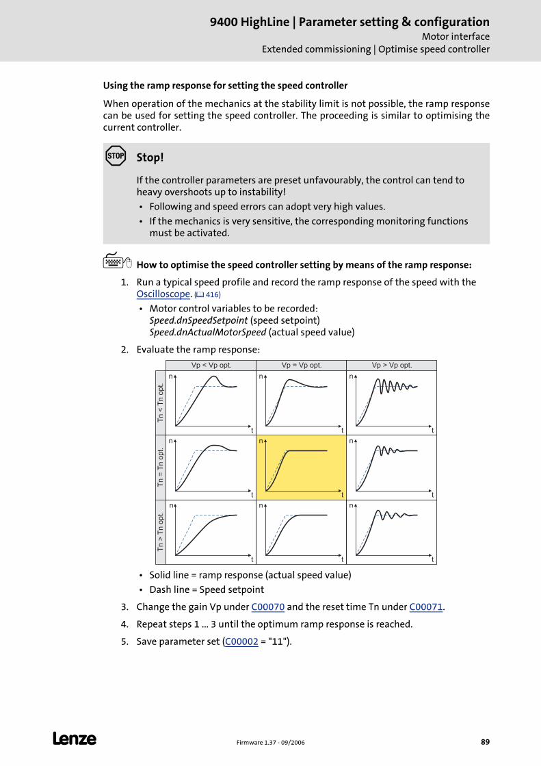
L Firmware 1.37 - 09/2006 89
9400 HighLine | Parameter setting & configurationMotor interface
Extended commissioning | Optimise speed controller
Using the ramp response for setting the speed controller
When operation of the mechanics at the stability limit is not possible, the ramp response can be used for setting the speed controller. The proceeding is similar to optimising the current controller.
How to optimise the speed controller setting by means of the ramp response:
1. Run a typical speed profile and record the ramp response of the speed with the Oscilloscope. ( 416)
• Motor control variables to be recorded: Speed.dnSpeedSetpoint (speed setpoint) Speed.dnActualMotorSpeed (actual speed value)
2. Evaluate the ramp response:
• Solid line = ramp response (actual speed value)
• Dash line = Speed setpoint
3. Change the gain Vp under C00070 and the reset time Tn under C00071.
4. Repeat steps 1 ... 3 until the optimum ramp response is reached.
5. Save parameter set (C00002 = "11").
Stop!
If the controller parameters are preset unfavourably, the control can tend to heavy overshoots up to instability!
• Following and speed errors can adopt very high values.
• If the mechanics is very sensitive, the corresponding monitoring functions must be activated.
n
t
n
t
n
t
n
t
n
t
n
t
n
t
n
t
n
t
Vp < Vp opt. Vp = Vp opt. Vp > Vp opt.
Tn
<T
no
pt.
Tn
=T
no
pt.
Tn
>T
no
pt.
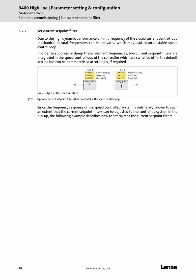
9400 HighLine | Parameter setting & configurationMotor interfaceExtended commissioning | Set current setpoint filter
90 Firmware 1.37 - 09/2006 L
5.2.2 Set current setpoint filter
Due to the high dynamic performance or limit frequency of the closed current control loop mechanical natural frequencies can be activated which may lead to an unstable speed control loop.
In order to suppress or damp these resonant frequencies, two current setpoint filters are integrated in the speed control loop of the controller which are switched off in the default setting but can be parameterised accordingly, if required.
[5-7] Optional current setpoint filters (filter cascade) in the speed control loop
Since the frequency response of the speed controlled system is only rarely known to such an extent that the current setpoint filters can be adjusted to the controlled system in the run-up, the following example describes how to set current the current setpoint filters.
m = Output of the jerk limitation
C00272/1
C00271/1
C00270/1 Frequency [Hz]
Width [Hz]
Depth [dB]
Filter 1
C00272/2
C00271/2
C00270/2 Frequency [Hz]
Width [Hz]
Depth [dB]
Filter 2
m m*
L Firmware 1.37 - 09/2006 91
9400 HighLine | Parameter setting & configurationMotor interface
Extended commissioning | Set current setpoint filter
How to set the current setpoint filters:
1. Adjust the current control loop.
2. In C00071 adjust the reset time of the speed controller to the filter time constant of the speed filter (C00497) and the equivalent time constant of the current control loop: C00071 = 16 * (C00497 + 200 μs)
3. Slowly increase the proportional gain n C00070, until the speed control loop starts to become unstable (noticed acoustically or by measuring the motor current).
4. Measure the oscillation frequency using an oscilloscope (observe current or speed).
5. Set the measured oscillation frequency in C00270/1 as filter frequency.
6. Set "50%" of the filter frequency in C00271/1 as filter width.
• Example: Filter frequency = 200 Hz filter width = 100 Hz.
7. Set "40 dB" in C00272/1 as filter depth.
• If the filter depth is set to "0 dB" (default setting), the filter is not active.
8. Continue to increase the proportional gain in C00070 until the speed control loop starts to become instable again.
• If the oscillation frequency has changed now, readjust the filter frequency by trimming. The use of a second filter is ineffective here.
• If the oscillation frequency remains the same, readjust the filter depth and/or the filter width by trimming (the first reduces the amplitude, the second lets the phase rotates faster).
• Repeat step 8 until the desired behaviour or the limit of a sensible speed controller gain has been reached.
9. Save parameter set (C00002 = "11").
Note!
Readjust the speed controller after setting the current setpoint filter. Optimise speed controller. ( 88)
9400 HighLine | Parameter setting & configurationMotor interfaceExtended commissioning | Optimise phase controller
92 Firmware 1.37 - 09/2006 L
5.2.3 Optimise phase controller
How to optimise the phase controller setting by means of the ramp response:
1. Run a typical speed profile and record the ramp response of the phase controller with the Oscilloscope. ( 416)
• Motor control variables to be recorded: Speed.dnSpeedSetpoint (speed setpoint) Speed.dnActualMotorSpeed (actual speed value) Speed.dnOutputPosCtrl (phase controller output) Position.dnEncounteringError (following error)
2. Adjust the gain Vp of the phase controller under C00254 and repeat oscilloscope recording until the intended following error behaviour is reached and the motor runs sufficiently smoothly during the constant travel phase.
3. Save parameter set (C00002 = "11").
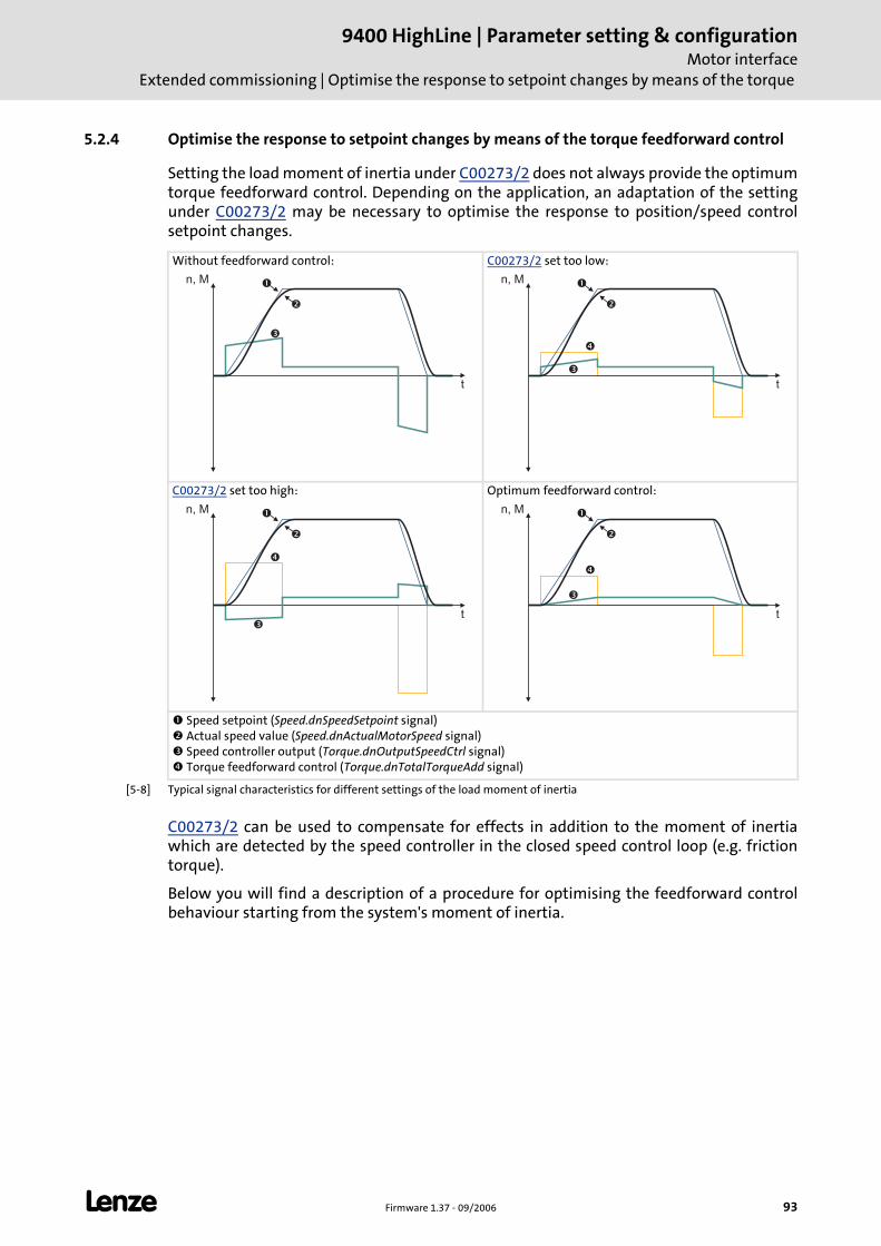
L Firmware 1.37 - 09/2006 93
9400 HighLine | Parameter setting & configurationMotor interface
Extended commissioning | Optimise the response to setpoint changes by means of the torque
5.2.4 Optimise the response to setpoint changes by means of the torque feedforward control
Setting the load moment of inertia under C00273/2 does not always provide the optimum torque feedforward control. Depending on the application, an adaptation of the setting under C00273/2 may be necessary to optimise the response to position/speed control setpoint changes.
[5-8] Typical signal characteristics for different settings of the load moment of inertia
C00273/2 can be used to compensate for effects in addition to the moment of inertia which are detected by the speed controller in the closed speed control loop (e.g. friction torque).
Below you will find a description of a procedure for optimising the feedforward control behaviour starting from the system's moment of inertia.
Without feedforward control: C00273/2 set too low:
C00273/2 set too high: Optimum feedforward control:
Speed setpoint (Speed.dnSpeedSetpoint signal) Actual speed value (Speed.dnActualMotorSpeed signal) Speed controller output (Torque.dnOutputSpeedCtrl signal) Torque feedforward control (Torque.dnTotalTorqueAdd signal)
n, M
t
�
�
�
t
�
�
�
�
n, M
t
�
�
�
�
n, M
t
�
�
�
�
n, M
9400 HighLine | Parameter setting & configurationMotor interfaceExtended commissioning | Optimise the response to setpoint changes by means of the torque
94 Firmware 1.37 - 09/2006 L
How to optimise the torque feedforward control:
1. Run a typical speed profile and record the inputs and outputs of the speed controller with the Oscilloscope. ( 416)
• Motor control variables to be recorded: Speed.dnSpeedSetpoint (speed setpoint) Speed.dnActualMotorSpeed (actual speed value) Torque.dnOutputSpeedCtrl (speed controller output) Torque.dnTotalTorqueAdd (torque feedforward control)
• Application variable to be recorded (if available): L_LdMonitFollowError1.dnFollowErrorIn_p (following error)
It is essential for optimising the response to setpoint changes to monitor the speed controller output (Torque.dnOutputSpeedCtrl) and the torque feedforward control (Torque.dnTotalTorqueAdd). The effect of the feedforward control can also be observed in the following error.
2. Select the signal source required for the torque setpoint (feedforward control path) under C00276.
3. Estimate the mass inertia of the load and set it under C00273/2.
4. Repeat the oscilloscope recording (see step 1).
Now the oscillogram should show that part of the required torque is generated by the feedforward control (Torque.dnTotalTorqueAdd) and the speed controller output signal (Torque.dnOutputSpeedCtrl) should be correspondingly smaller. The resulting following error decreases.
5. Change the setting under C00273/2 and repeat the oscilloscope recording until the intended response to setpoint changes is reached.
• The optimisation could aim at the speed controller being completely relieved (see signal characteristics in Fig. [5-8]).
6. Save parameter set (C00002 = "11").
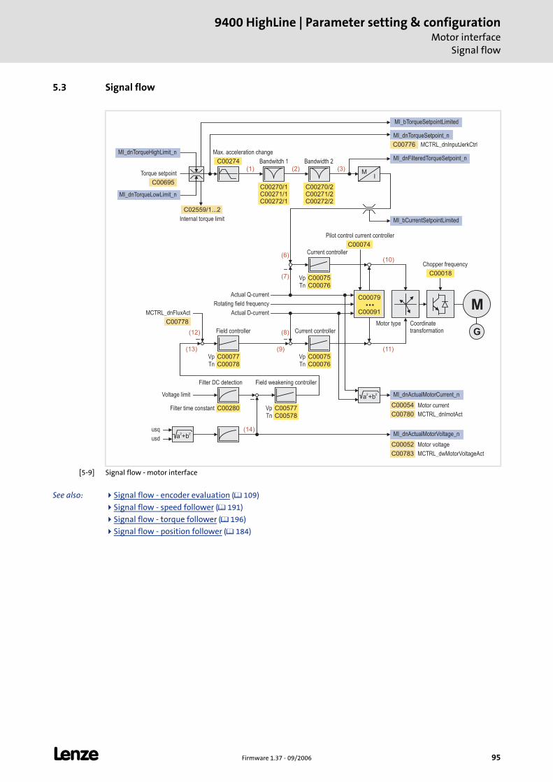
L Firmware 1.37 - 09/2006 95
9400 HighLine | Parameter setting & configurationMotor interface
Signal flow
5.3 Signal flow
[5-9] Signal flow - motor interface
See also: Signal flow - encoder evaluation ( 109)
Signal flow - speed follower ( 191)
Signal flow - torque follower ( 196)
Signal flow - position follower ( 184)
MCTRL_dnInputJerkCtrlC00776
C00274
C00270/1C00271/1C00272/1
C00270/2C00271/2C00272/2
(1) (2) (3)
C02559/1...2
C00695
C00052
MI
a +b2 2
usq
usd
MCTRL_dnFluxAct
C00075
C00077
C00577C00280
C00778
C00783
C00018
C00074
C00079
C00091
(6)
(7)
(10)
(11)(9)
(8)
(13)
(12)
(14)
M
G
Vp
Tn
Vp
Tn
Vp
Tn
Vp
Tn
C00076
C00075
C00076C00078
C00578
MI_dnTorqueHighLimit_n
MI_dnTorqueLowLimit_n
MI_dnTorqueSetpoint_n
MI_dnFilteredTorqueSetpoint_n
MI_bCurrentSetpointLimited
a +b2 2 MI_dnActualMotorCurrent_n
MI_dnActualMotorVoltage_n
MCTRL_dwMotorVoltageAct
MCTRL_dnImotActC00780
C00054
MI_bTorqueSetpointLimited
Max. acceleration change
Bandwitdh 1 Bandwidth 2
Torque setpoint
Current controller
Current controllerField controller
Field weakening controller
Voltage limit
Rotating field frequency
Actual Q-current
Actual D-current
Motor type
Motor voltage
Pilot control current controller
Chopper frequency
Filter DC detection
Internal torque limit
Filter time constant
Coordinatetransformation
Motor current
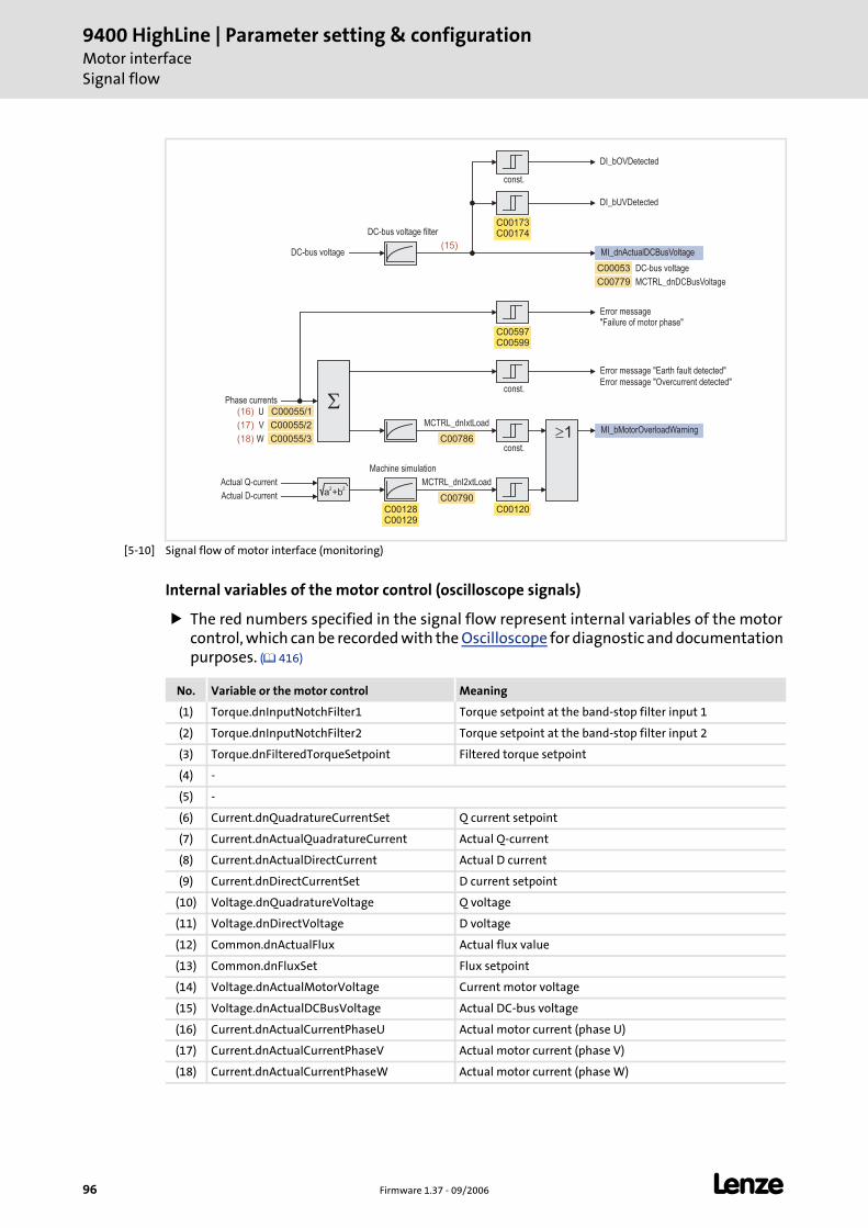
9400 HighLine | Parameter setting & configurationMotor interfaceSignal flow
96 Firmware 1.37 - 09/2006 L
[5-10] Signal flow of motor interface (monitoring)
Internal variables of the motor control (oscilloscope signals)
The red numbers specified in the signal flow represent internal variables of the motor control, which can be recorded with the Oscilloscope for diagnostic and documentation purposes. ( 416)
a +b2 2
�
DI_bOVDetected
DI_bUVDetected
MCTRL_dnIxtLoad
const.
const.
const.
MCTRL_dnI2xtLoad
C00597C00599
C00173C00174
C00128C00129
C00786
C00120
C00790
MCTRL_dnDCBusVoltageC00779
MI_bMotorOverloadWarning
C00053
�1
MI_dnActualDCBusVoltage(15)
C00055/1
C00055/2
C00055/3
U
V
W
(16)
(17)
(18)
Error message"Failure of motor phase"
Error message "Earth fault detected"
DC-bus voltage
DC-bus voltage filter
Phase currents
Machine simulation
DC-bus voltage
Actual Q-current
Actual D-current
Error message "Overcurrent detected"
No. Variable or the motor control Meaning
(1) Torque.dnInputNotchFilter1 Torque setpoint at the band-stop filter input 1
(2) Torque.dnInputNotchFilter2 Torque setpoint at the band-stop filter input 2
(3) Torque.dnFilteredTorqueSetpoint Filtered torque setpoint
(4) -
(5) -
(6) Current.dnQuadratureCurrentSet Q current setpoint
(7) Current.dnActualQuadratureCurrent Actual Q-current
(8) Current.dnActualDirectCurrent Actual D current
(9) Current.dnDirectCurrentSet D current setpoint
(10) Voltage.dnQuadratureVoltage Q voltage
(11) Voltage.dnDirectVoltage D voltage
(12) Common.dnActualFlux Actual flux value
(13) Common.dnFluxSet Flux setpoint
(14) Voltage.dnActualMotorVoltage Current motor voltage
(15) Voltage.dnActualDCBusVoltage Actual DC-bus voltage
(16) Current.dnActualCurrentPhaseU Actual motor current (phase U)
(17) Current.dnActualCurrentPhaseV Actual motor current (phase V)
(18) Current.dnActualCurrentPhaseW Actual motor current (phase W)
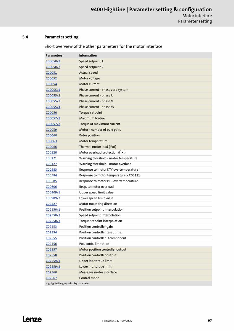
L Firmware 1.37 - 09/2006 97
9400 HighLine | Parameter setting & configurationMotor interface
Parameter setting
5.4 Parameter setting
Short overview of the other parameters for the motor interface:
Parameters Information
C00050/1 Speed setpoint 1
C00050/2 Speed setpoint 2
C00051 Actual speed
C00052 Motor voltage
C00054 Motor current
C00055/1 Phase current - phase zero system
C00055/2 Phase current - phase U
C00055/3 Phase current - phase V
C00055/4 Phase current - phase W
C00056 Torque setpoint
C00057/1 Maximum torque
C00057/2 Torque at maximum current
C00059 Motor - number of pole pairs
C00060 Rotor position
C00063 Motor temperature
C00066 Thermal motor load (I2xt)
C00120 Motor overload protection (I2xt)
C00121 Warning threshold - motor temperature
C00127 Warning threshold - motor overload
C00583 Response to motor KTY overtemperature
C00584 Response to motor temperature > C00121
C00585 Response to motor PTC overtemperature
C00606 Resp. to motor overload
C00909/1 Upper speed limit value
C00909/2 Lower speed limit value
C02527 Motor mounting direction
C02550/1 Position setpoint interpolation
C02550/2 Speed setpoint interpolation
C02550/3 Torque setpoint interpolation
C02553 Position controller gain
C02554 Position controller reset time
C02555 Position controller D component
C02556 Pos. contr. limitation
C02557 Motor position controller output
C02558 Position controller output
C02559/1 Upper int. torque limit
C02559/2 Lower int. torque limit
C02560 Messages motor interface
C02567 Control mode
Highlighted in grey = display parameter
9400 HighLine | Parameter setting & configurationMotor interfaceParameter setting | Motor monitoring (I²xt)
98 Firmware 1.37 - 09/2006 L
See also: Display/edit motor data in the »Engineer« ( 67)
Accept/adapt route data ( 69)
5.4.1 Motor monitoring (I²xt)
The "9400 Servo Drives" are provided with an extended, sensorless thermal I2xt motor monitoring which is based on a mathematical model that calculates a thermal motor utilisation from the detected motor currents.
The calculation considers the speed dependency of the torque (difference between standstill torque and rated torque).
C00066 indicates the calculated motor utilisation in [%].
If the motor exceeds the advance warning threshold set in C00127, the error message "I2t motor overload OC8" is output and the reaction set in C00606 (default setting: "Warning") is activated.
If the switch-off threshold set in C00120 is exceeded, the error message "I2t motor overload OC6" is output and the reaction "Fault" is activated.
Stop!
The I2xt motor monitoring is no full motor protection!
Since the motor utilisation calculated in the thermal model gets lost after mains switching, the following operating states cannot be determined correctly:
• Restarting (after mains switching) of a motor that is already very heated.
• Change of the cooling conditions (e.g. cooling air flow interrupted or too warm).
A full motor protection requires additional measures as e.g. the evaluation of temperature sensors that are situated directly in the winding of thermal contacts.
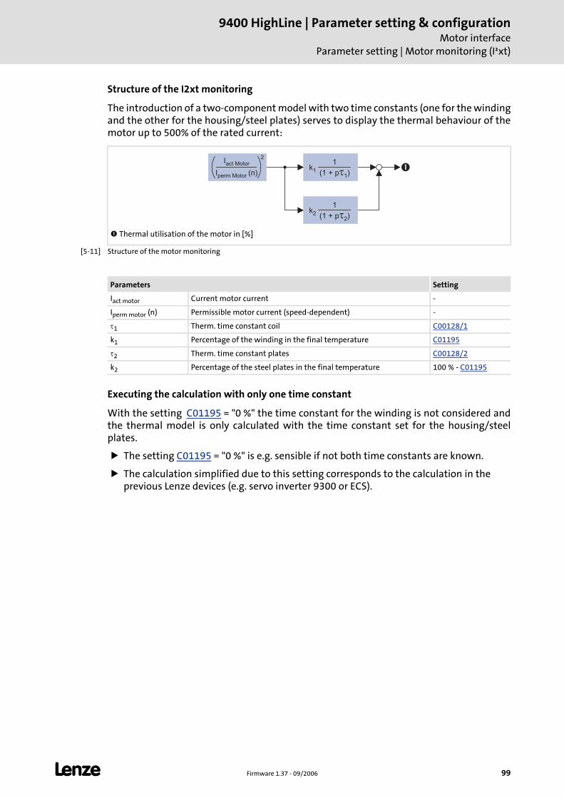
L Firmware 1.37 - 09/2006 99
9400 HighLine | Parameter setting & configurationMotor interface
Parameter setting | Motor monitoring (I²xt)
Structure of the I2xt monitoring
The introduction of a two-component model with two time constants (one for the winding and the other for the housing/steel plates) serves to display the thermal behaviour of the motor up to 500% of the rated current:
[5-11] Structure of the motor monitoring
Executing the calculation with only one time constant
With the setting C01195 = "0 %" the time constant for the winding is not considered and the thermal model is only calculated with the time constant set for the housing/steel plates.
The setting C01195 = "0 %" is e.g. sensible if not both time constants are known.
The calculation simplified due to this setting corresponds to the calculation in the previous Lenze devices (e.g. servo inverter 9300 or ECS).
Thermal utilisation of the motor in [%]
k1
1
(1 + p )�1
k2
1
(1 + p )�2
Iact Motor
Iperm Motor (n)
2
�
Parameters Setting
Iact motor Current motor current -
Iperm motor (n) Permissible motor current (speed-dependent) -
τ1 Therm. time constant coil C00128/1
k1 Percentage of the winding in the final temperature C01195
τ2 Therm. time constant plates C00128/2
k2 Percentage of the steel plates in the final temperature 100 % - C01195
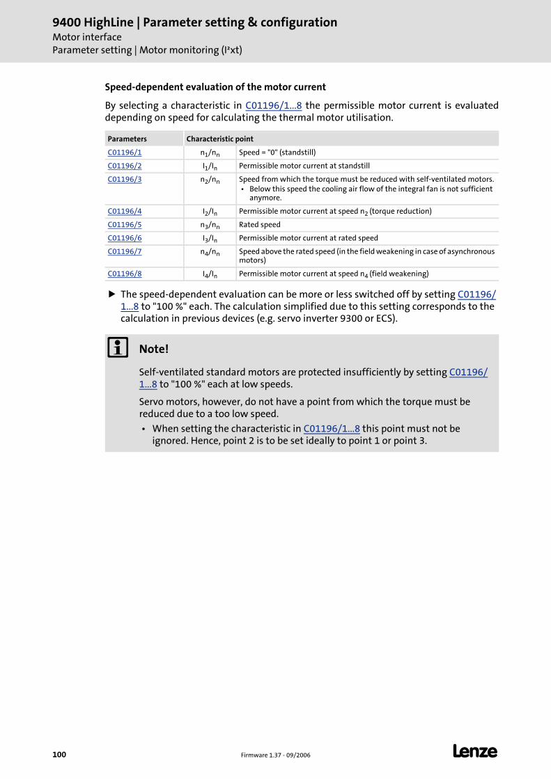
9400 HighLine | Parameter setting & configurationMotor interfaceParameter setting | Motor monitoring (I²xt)
100 Firmware 1.37 - 09/2006 L
Speed-dependent evaluation of the motor current
By selecting a characteristic in C01196/1...8 the permissible motor current is evaluated depending on speed for calculating the thermal motor utilisation.
The speed-dependent evaluation can be more or less switched off by setting C01196/1...8 to "100 %" each. The calculation simplified due to this setting corresponds to the calculation in previous devices (e.g. servo inverter 9300 or ECS).
Parameters Characteristic point
C01196/1 n1/nn Speed = "0" (standstill)
C01196/2 I1/In Permissible motor current at standstill
C01196/3 n2/nn Speed from which the torque must be reduced with self-ventilated motors. • Below this speed the cooling air flow of the integral fan is not sufficient
anymore.
C01196/4 I2/In Permissible motor current at speed n2 (torque reduction)
C01196/5 n3/nn Rated speed
C01196/6 I3/In Permissible motor current at rated speed
C01196/7 n4/nn Speed above the rated speed (in the field weakening in case of asynchronous motors)
C01196/8 I4/In Permissible motor current at speed n4 (field weakening)
Note!
Self-ventilated standard motors are protected insufficiently by setting C01196/1...8 to "100 %" each at low speeds.
Servo motors, however, do not have a point from which the torque must be reduced due to a too low speed.
• When setting the characteristic in C01196/1...8 this point must not be ignored. Hence, point 2 is to be set ideally to point 1 or point 3.
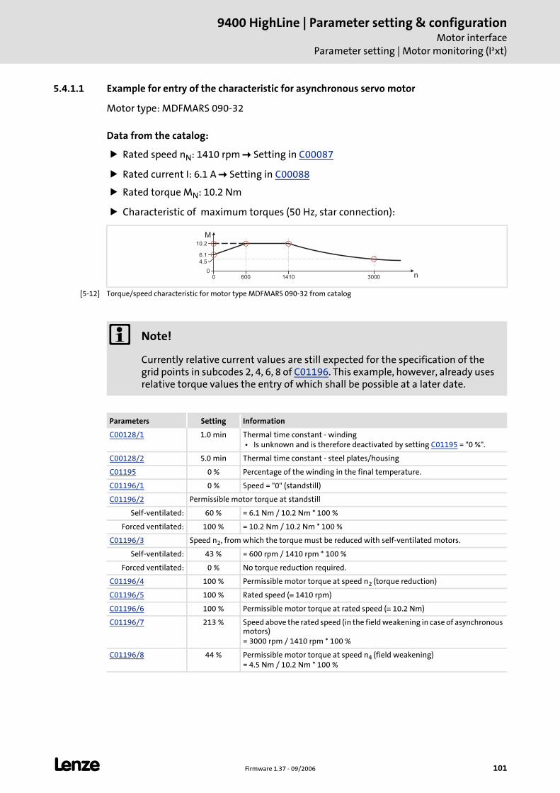
L Firmware 1.37 - 09/2006 101
9400 HighLine | Parameter setting & configurationMotor interface
Parameter setting | Motor monitoring (I²xt)
5.4.1.1 Example for entry of the characteristic for asynchronous servo motor
Motor type: MDFMARS 090-32
Data from the catalog:
Rated speed nN: 1410 rpm Setting in C00087
Rated current I: 6.1 A Setting in C00088
Rated torque MN: 10.2 Nm
Characteristic of maximum torques (50 Hz, star connection):
[5-12] Torque/speed characteristic for motor type MDFMARS 090-32 from catalog
0
6.1
10.2
0 600 1410 3000
M
n
4.5
Note!
Currently relative current values are still expected for the specification of the grid points in subcodes 2, 4, 6, 8 of C01196. This example, however, already uses relative torque values the entry of which shall be possible at a later date.
Parameters Setting Information
C00128/1 1.0 min Thermal time constant - winding • Is unknown and is therefore deactivated by setting C01195 = "0 %".
C00128/2 5.0 min Thermal time constant - steel plates/housing
C01195 0 % Percentage of the winding in the final temperature.
C01196/1 0 % Speed = "0" (standstill)
C01196/2 Permissible motor torque at standstill
Self-ventilated: 60 % = 6.1 Nm / 10.2 Nm * 100 %
Forced ventilated: 100 % = 10.2 Nm / 10.2 Nm * 100 %
C01196/3 Speed n2, from which the torque must be reduced with self-ventilated motors.
Self-ventilated: 43 % = 600 rpm / 1410 rpm * 100 %
Forced ventilated: 0 % No torque reduction required.
C01196/4 100 % Permissible motor torque at speed n2 (torque reduction)
C01196/5 100 % Rated speed (≡ 1410 rpm)
C01196/6 100 % Permissible motor torque at rated speed (≡ 10.2 Nm)
C01196/7 213 % Speed above the rated speed (in the field weakening in case of asynchronous motors)= 3000 rpm / 1410 rpm * 100 %
C01196/8 44 % Permissible motor torque at speed n4 (field weakening)= 4.5 Nm / 10.2 Nm * 100 %
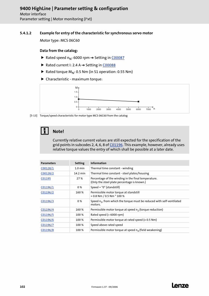
9400 HighLine | Parameter setting & configurationMotor interfaceParameter setting | Motor monitoring (I²xt)
102 Firmware 1.37 - 09/2006 L
5.4.1.2 Example for entry of the characteristic for synchronous servo motor
Motor type: MCS 06C60
Data from the catalog:
Rated speed nN: 6000 rpm Setting in C00087
Rated current I: 2.4 A Setting in C00088
Rated torque MN: 0.5 Nm (in S1 operation: 0.55 Nm)
Characteristic - maximum torque:
[5-13] Torque/speed characteristic for motor type MCS 06C60 from the catalog
0
0.5
1.0
1.5
0 1000 2000 3000 4000 5000 6000 7000
M
n
Note!
Currently relative current values are still expected for the specification of the grid points in subcodes 2, 4, 6, 8 of C01196. This example, however, already uses relative torque values the entry of which shall be possible at a later date.
Parameters Setting Information
C00128/1 1.0 min Thermal time constant - winding
C00128/2 14.2 min Thermal time constant - steel plates/housing
C01195 27 % Percentage of the winding in the final temperature.(Only the steel plate percentage is known.)
C01196/1 0 % Speed = "0" (standstill)
C01196/2 160 % Permissible motor torque at standstill= 0.8 Nm / 0.5 Nm * 100 %
C01196/3 0 % Speed n2, from which the torque must be reduced with self-ventilated motors.
C01196/4 160 % Permissible motor torque at speed n2 (torque reduction)
C01196/5 100 % Rated speed (≡ 6000 rpm)
C01196/6 100 % Permissible motor torque at rated speed (≡ 0.5 Nm)
C01196/7 100 % Speed above rated speed
C01196/8 100 % Permissible motor torque at speed n4 (field weakening)
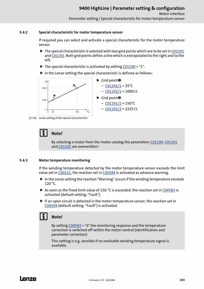
L Firmware 1.37 - 09/2006 103
9400 HighLine | Parameter setting & configurationMotor interface
Parameter setting | Special characteristic for motor temperature sensor
5.4.2 Special characteristic for motor temperature sensor
If required you can select and activate a special characteristic for the motor temperature sensor.
The special characteristic is selected with two grid points which are to be set in C01191 and C01192. Both grid points define a line which is extrapolated to the right and to the left.
The special characteristic is activated by setting C01190 = "1".
In the Lenze setting the special characteristic is defined as follows:
[5-14] Lenze setting of the special characteristic
5.4.3 Motor temperature monitoring
If the winding temperature detected by the motor temperature sensor exceeds the limit value set in C00121, the reaction set in C00584 is activated as advance warning.
In the Lenze setting the reaction "Warning" occurs if the winding temperature exceeds 120 °C.
As soon as the fixed limit value of 150 °C is exceeded, the reaction set in C00583 is activated (default setting: "Fault").
If an open circuit is detected in the motor temperature sensor, the reaction set in C00594 (default setting: "Fault") is activated.
Grid point
– C01191/1 = 25°C
– C01192/1 = 1000 Ω
Grid point
– C01191/2 = 150°C
– C01192/2 = 2225 Ω0
1000
2225
0 150
�
°C25
�
�
Note!
By selecting a motor from the motor catalog the parameters C01190, C01191 and C01192 are overwritten!
Note!
By setting C00583 = "0" the monitoring response and the temperature correction is switched off within the motor control (identification and parameter correction)
This setting is e.g. sensible if no realisable winding temperature signal is available.
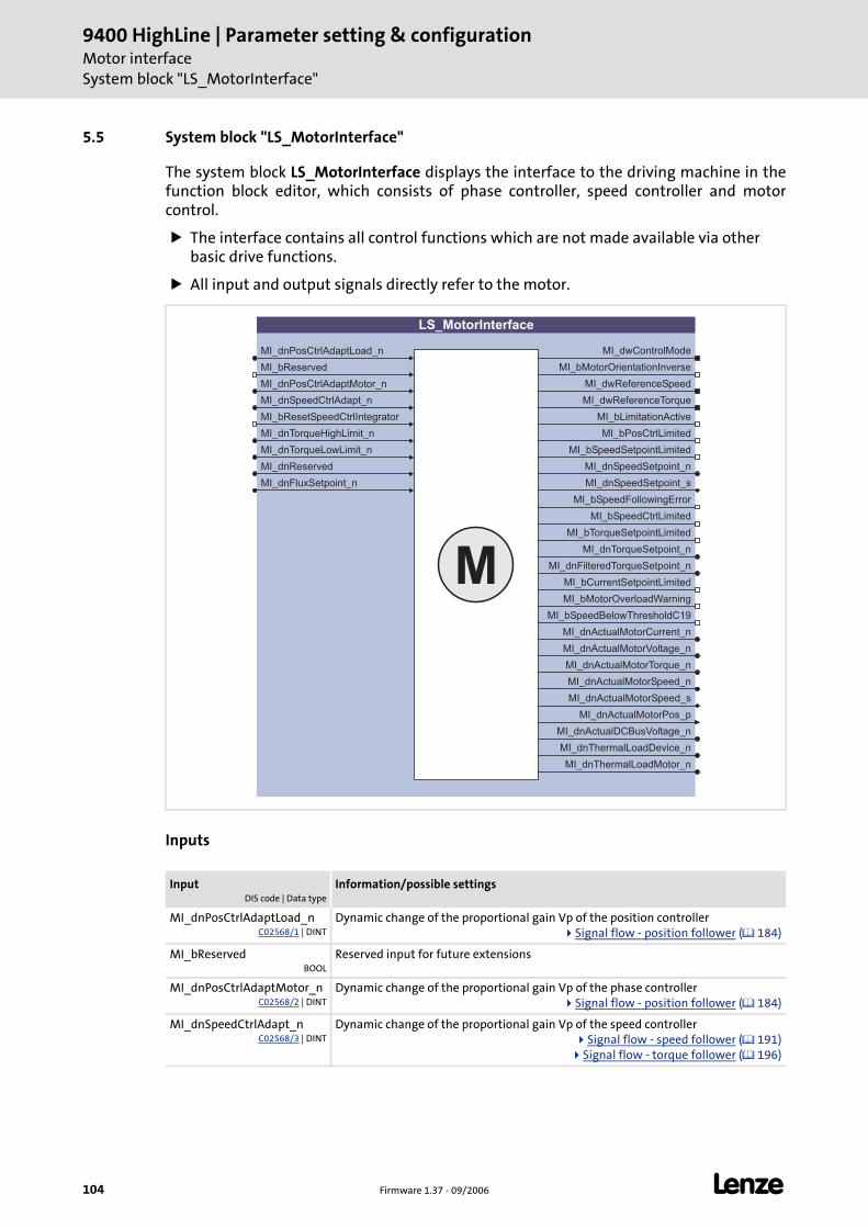
9400 HighLine | Parameter setting & configurationMotor interfaceSystem block "LS_MotorInterface"
104 Firmware 1.37 - 09/2006 L
5.5 System block "LS_MotorInterface"
The system block LS_MotorInterface displays the interface to the driving machine in the function block editor, which consists of phase controller, speed controller and motor control.
The interface contains all control functions which are not made available via other basic drive functions.
All input and output signals directly refer to the motor.
Inputs
InputDIS code | Data type
Information/possible settings
MI_dnPosCtrlAdaptLoad_nC02568/1 | DINT
Dynamic change of the proportional gain Vp of the position controllerSignal flow - position follower ( 184)
MI_bReservedBOOL
Reserved input for future extensions
MI_dnPosCtrlAdaptMotor_nC02568/2 | DINT
Dynamic change of the proportional gain Vp of the phase controllerSignal flow - position follower ( 184)
MI_dnSpeedCtrlAdapt_nC02568/3 | DINT
Dynamic change of the proportional gain Vp of the speed controllerSignal flow - speed follower ( 191)
Signal flow - torque follower ( 196)
LS_MotorInterface
MI_dnPosCtrlAdaptLoad_n
MI_dnPosCtrlAdaptMotor_n
MI_dnSpeedCtrlAdapt_n
MI_bResetSpeedCtrlIntegrator
MI_dnReserved
MI_dnFluxSetpoint_n
MI_dnTorqueLowLimit_n
MI_dwControlMode
MI_bMotorOrientationInverse
MI_dwReferenceSpeed
MI_dwReferenceTorque
MI_bPosCtrlLimited
MI_bSpeedCtrlLimited
MI_bTorqueSetpointLimited
MI_dnTorqueSetpoint_n
MI_dnFilteredTorqueSetpoint_n
MI_bCurrentSetpointLimited
MI_bLimitationActive
MI_dnActualMotorCurrent_n
MI_dnActualMotorVoltage_n
MI_dnActualMotorTorque_n
MI_dnActualMotorSpeed_s
MI_dnActualMotorPos_p
MI_dnActualDCBusVoltage_n
MI_bMotorOverloadWarning
MI_dnActualMotorSpeed_n
M
MI_bReserved
MI_bSpeedSetpointLimited
MI_bSpeedFollowingError
MI_dnSpeedSetpoint_n
MI_dnSpeedSetpoint_s
MI_bSpeedBelowThresholdC19
MI_dnTorqueHighLimit_n
MI_dnThermalLoadDevice_n
MI_dnThermalLoadMotor_n
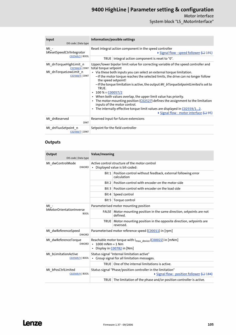
L Firmware 1.37 - 09/2006 105
9400 HighLine | Parameter setting & configurationMotor interface
System block "LS_MotorInterface"
Outputs
MI_-bResetSpeedCtrlIntegrator
C02569/2 | BOOL
Reset integral action component in the speed controllerSignal flow - speed follower ( 191)
TRUE Integral action component is reset to "0".
MI_dnTorqueHighLimit_nC02568/4 | DINT
MI_dnTorqueLowLimit_nC02568/5 | DINT
Upper/lower bipolar limit value for correcting variable of the speed controller and total torque setpoint • Via these both inputs you can select an external torque limitation.
– If the motor torque reaches the selected limits, the drive can no longer follow the speed setpoint!
– If the torque limitation is active, the output MI_bTorqueSetpointLimited is set to TRUE.
• 100 % ≡ C00057/2 • When both values overlap, the upper limit value has priority. • The motor mounting position (C02527) defines the assignment to the limitation
inputs of the motor control. • The internally effective torque limit values are displayed in C02559/1...2.
Signal flow - motor interface ( 95)
MI_dnReservedDINT
Reserved input for future extensions
MI_dnFluxSetpoint_nC02568/7 | DINT
Setpoint for the field controller
OutputDIS code | Data type
Value/meaning
MI_dwControlModeDWORD
Active control structure of the motor control • Displayed value is bit-coded:
Bit 1 Position control without feedback, external following error calculation
Bit 2 Position control with encoder on the motor side
Bit 3 Position control with encoder on the load side
Bit 4 Speed control
Bit 5 Torque control
MI_-bMotorOrientationInverse
BOOL
Parameterised motor mounting position
FALSE Motor mounting position in the same direction, setpoints are not defined.
TRUE Motor mounting position in the opposite direction, setpoints are reversed.
MI_dwReferenceSpeedDWORD
Parameterised motor reference speed (C00011) in [rpm]
MI_dwReferenceTorqueDWORD
Reachable motor torque with Imax_device (C00022) in [mNm] • 1000 mNm ≡ 1 Nm • Display in C00782 in [Nm]
MI_bLimitationActiveC02569/3 | BOOL
Status signal "Internal limitation active" • Group signal for all limitation messages.
TRUE One of the internal limitations is active.
MI_bPosCtrlLimitedC02569/4 | BOOL
Status signal "Phase/position controller in the limitation"Signal flow - position follower ( 184)
TRUE The limitation of the phase and/or position controller is active.
InputDIS code | Data type
Information/possible settings
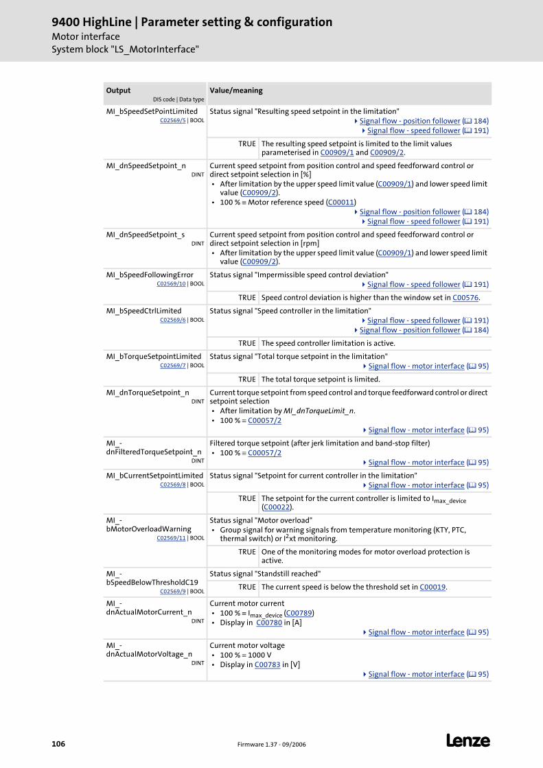
9400 HighLine | Parameter setting & configurationMotor interfaceSystem block "LS_MotorInterface"
106 Firmware 1.37 - 09/2006 L
MI_bSpeedSetPointLimitedC02569/5 | BOOL
Status signal "Resulting speed setpoint in the limitation"Signal flow - position follower ( 184)
Signal flow - speed follower ( 191)
TRUE The resulting speed setpoint is limited to the limit values parameterised in C00909/1 and C00909/2.
MI_dnSpeedSetpoint_nDINT
Current speed setpoint from position control and speed feedforward control or direct setpoint selection in [%] • After limitation by the upper speed limit value (C00909/1) and lower speed limit
value (C00909/2). • 100 % ≡ Motor reference speed (C00011)
Signal flow - position follower ( 184)Signal flow - speed follower ( 191)
MI_dnSpeedSetpoint_sDINT
Current speed setpoint from position control and speed feedforward control or direct setpoint selection in [rpm] • After limitation by the upper speed limit value (C00909/1) and lower speed limit
value (C00909/2).
MI_bSpeedFollowingErrorC02569/10 | BOOL
Status signal "Impermissible speed control deviation"Signal flow - speed follower ( 191)
TRUE Speed control deviation is higher than the window set in C00576.
MI_bSpeedCtrlLimitedC02569/6 | BOOL
Status signal "Speed controller in the limitation"Signal flow - speed follower ( 191)
Signal flow - position follower ( 184)
TRUE The speed controller limitation is active.
MI_bTorqueSetpointLimitedC02569/7 | BOOL
Status signal "Total torque setpoint in the limitation"Signal flow - motor interface ( 95)
TRUE The total torque setpoint is limited.
MI_dnTorqueSetpoint_nDINT
Current torque setpoint from speed control and torque feedforward control or direct setpoint selection • After limitation by MI_dnTorqueLimit_n. • 100 % ≡ C00057/2
Signal flow - motor interface ( 95)
MI_-dnFilteredTorqueSetpoint_n
DINT
Filtered torque setpoint (after jerk limitation and band-stop filter) • 100 % ≡ C00057/2
Signal flow - motor interface ( 95)
MI_bCurrentSetpointLimitedC02569/8 | BOOL
Status signal "Setpoint for current controller in the limitation"Signal flow - motor interface ( 95)
TRUE The setpoint for the current controller is limited to Imax_device (C00022).
MI_-bMotorOverloadWarning
C02569/11 | BOOL
Status signal "Motor overload" • Group signal for warning signals from temperature monitoring (KTY, PTC,
thermal switch) or I2xt monitoring.
TRUE One of the monitoring modes for motor overload protection is active.
MI_-bSpeedBelowThresholdC19
C02569/9 | BOOL
Status signal "Standstill reached"
TRUE The current speed is below the threshold set in C00019.
MI_-dnActualMotorCurrent_n
DINT
Current motor current • 100 % ≡ Imax_device (C00789) • Display in C00780 in [A]
Signal flow - motor interface ( 95)
MI_-dnActualMotorVoltage_n
DINT
Current motor voltage • 100 % ≡ 1000 V • Display in C00783 in [V]
Signal flow - motor interface ( 95)
OutputDIS code | Data type
Value/meaning
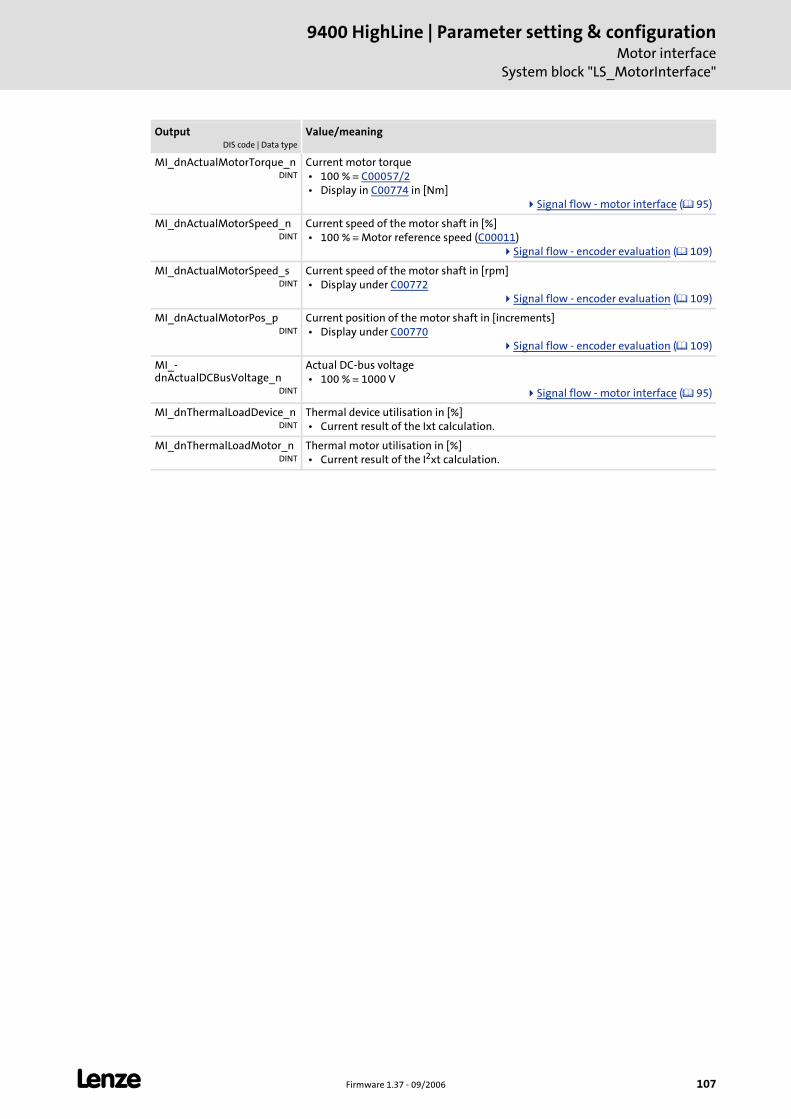
L Firmware 1.37 - 09/2006 107
9400 HighLine | Parameter setting & configurationMotor interface
System block "LS_MotorInterface"
MI_dnActualMotorTorque_nDINT
Current motor torque • 100 % ≡ C00057/2 • Display in C00774 in [Nm]
Signal flow - motor interface ( 95)
MI_dnActualMotorSpeed_nDINT
Current speed of the motor shaft in [%] • 100 % ≡ Motor reference speed (C00011)
Signal flow - encoder evaluation ( 109)
MI_dnActualMotorSpeed_sDINT
Current speed of the motor shaft in [rpm] • Display under C00772
Signal flow - encoder evaluation ( 109)
MI_dnActualMotorPos_pDINT
Current position of the motor shaft in [increments] • Display under C00770
Signal flow - encoder evaluation ( 109)
MI_-dnActualDCBusVoltage_n
DINT
Actual DC-bus voltage • 100 % ≡ 1000 V
Signal flow - motor interface ( 95)
MI_dnThermalLoadDevice_nDINT
Thermal device utilisation in [%] • Current result of the Ixt calculation.
MI_dnThermalLoadMotor_nDINT
Thermal motor utilisation in [%] • Current result of the I2xt calculation.
OutputDIS code | Data type
Value/meaning
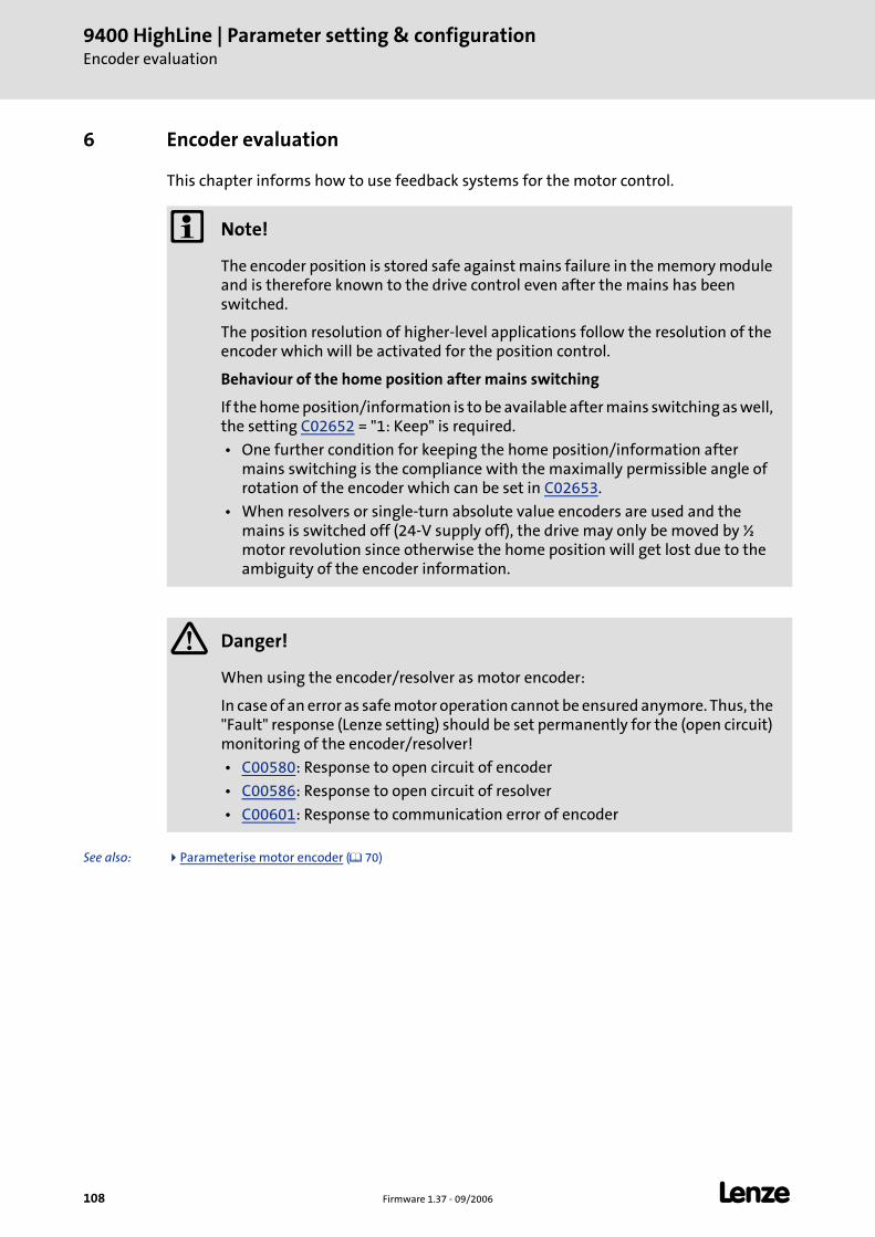
9400 HighLine | Parameter setting & configurationEncoder evaluation
108 Firmware 1.37 - 09/2006 L
6 Encoder evaluation
This chapter informs how to use feedback systems for the motor control.
See also: Parameterise motor encoder ( 70)
Note!
The encoder position is stored safe against mains failure in the memory module and is therefore known to the drive control even after the mains has been switched.
The position resolution of higher-level applications follow the resolution of the encoder which will be activated for the position control.
Behaviour of the home position after mains switching
If the home position/information is to be available after mains switching as well, the setting C02652 = "1: Keep" is required.
• One further condition for keeping the home position/information after mains switching is the compliance with the maximally permissible angle of rotation of the encoder which can be set in C02653.
• When resolvers or single-turn absolute value encoders are used and the mains is switched off (24-V supply off), the drive may only be moved by ½ motor revolution since otherwise the home position will get lost due to the ambiguity of the encoder information.
Danger!
When using the encoder/resolver as motor encoder:
In case of an error as safe motor operation cannot be ensured anymore. Thus, the "Fault" response (Lenze setting) should be set permanently for the (open circuit) monitoring of the encoder/resolver!
• C00580: Response to open circuit of encoder
• C00586: Response to open circuit of resolver
• C00601: Response to communication error of encoder
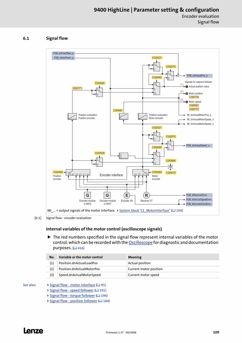
L Firmware 1.37 - 09/2006 109
9400 HighLine | Parameter setting & configurationEncoder evaluation
Signal flow
6.1 Signal flow
[6-1] Signal flow - encoder evaluation
Internal variables of the motor control (oscilloscope signals)
The red numbers specified in the signal flow represent internal variables of the motor control, which can be recorded with the Oscilloscope for diagnostic and documentation purposes. ( 416)
See also: Signal flow - motor interface ( 95)
Signal flow - speed follower ( 191)
Signal flow - torque follower ( 196)
Signal flow - position follower ( 184)
MI_... = output signals of the motor interface. System block "LS_MotorInterface" ( 104)
R
12 0 12 0
G E
1
0
�
�
�
1
0
1
0
FDB_dnPosOffset_p
FDB_bResolverError
FDB_bSinCosSignalError
FDB_bEncoderComError
FDB_dnActualPos_p
FDB_dnActualSpeed_s
MI_dnActualMotorSpeed_n
MI_dnActualMotorSpeed_s
MI_dnActualMotorPos_p
10
4
10
2
1
1
0
4
10
2
1
34
G
3
FDB_dnActPosIn_p
<4
<4
C00770
C00771
C00051
C02529
C00495C00490
C00596
C00579
C02527
C02529
C00497
C02570
C00772
C02527
C02570
C00490
C00490
Encoder modulein MXI2
Encoder modulein MXI1
Resolver X7
Encoder interfacePositionencoder
Position evaluation
Motor encoderPosition encoder
Position evaluation
Motorencoder
Actual position value
Motor position
Motor speed
Signals for setpoint follower
Encoder X8
(1)
(3)
(2)
No. Variable or the motor control Meaning
(1) Position.dnActualLoadPos Actual position
(2) Position.dnActualMotorPos Current motor position
(3) Speed.dnActualMotorSpeed Current motor speed
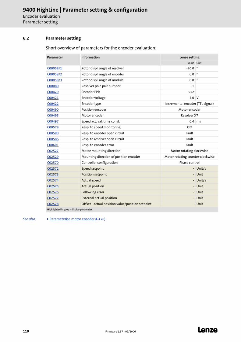
9400 HighLine | Parameter setting & configurationEncoder evaluationParameter setting
110 Firmware 1.37 - 09/2006 L
6.2 Parameter setting
Short overview of parameters for the encoder evaluation:
See also: Parameterise motor encoder ( 70)
Parameter Information Lenze setting
Value Unit
C00058/1 Rotor displ. angle of resolver -90.0 °
C00058/2 Rotor displ. angle of encoder 0.0 °
C00058/3 Rotor displ. angle of module 0.0 °
C00080 Resolver pole pair number 1
C00420 Encoder PPR 512
C00421 Encoder voltage 5.0 V
C00422 Encoder type Incremental encoder (TTL signal)
C00490 Position encoder Motor encoder
C00495 Motor encoder Resolver X7
C00497 Speed act. val. time const. 0.4 ms
C00579 Resp. to speed monitoring Off
C00580 Resp. to encoder open circuit Fault
C00586 Resp. to resolver open circuit Fault
C00601 Resp. to encoder error Fault
C02527 Motor mounting direction Motor rotating clockwise
C02529 Mounting direction of position encoder Motor rotating counter-clockwise
C02570 Controller configuration Phase control
C02572 Speed setpoint - Unit/s
C02573 Position setpoint - Unit
C02574 Actual speed - Unit/s
C02575 Actual position - Unit
C02576 Following error - Unit
C02577 External actual position - Unit
C02578 Offset - actual position value/position setpoint - Unit
Highlighted in grey = display parameter
L Firmware 1.37 - 09/2006 111
9400 HighLine | Parameter setting & configurationEncoder evaluation
Parameter setting
6.2.1 Controller configuration
The device interfaces for the encoder on the motor side and, if available, on the load side are directly assigned to the corresponding control according to the controller configurations selected (C02570):
If only an encoder on the motor side is available, this "motor encoder" provides the actual value signals for the phase/position control and the speed control.
– The motor encoder on the motor side supports the secondary servo control irrespective of the use for position and speed control (commutation).
If an additional encoder is available on the motor side, this "position encoder" exclusively supports the position control, and the controller configuration (C02570) must be set to position control so that the load encoder will be evaluated.
– The starting position of the position encoder can be set via the basic function "Homing".
Phase control (Lenze setting) Position control
Cycle time: 250 μs Application-dependent
Dead time: Smaller dead time in the actual value channel Same dead time for position setpoint and actual position
Note!
When the basic function "Quick stop" is activated, the controller configuration is internally changed over to phase control independent of the setting in C02570.
• If the basic function "Quick stop" is to be used, the gain of the phase controller (C00254) must also be set correctly for the "Position control" controller configuration.
In case of the technology application for the network via the "Electrical shaft" the controller configuration is preset to position control.
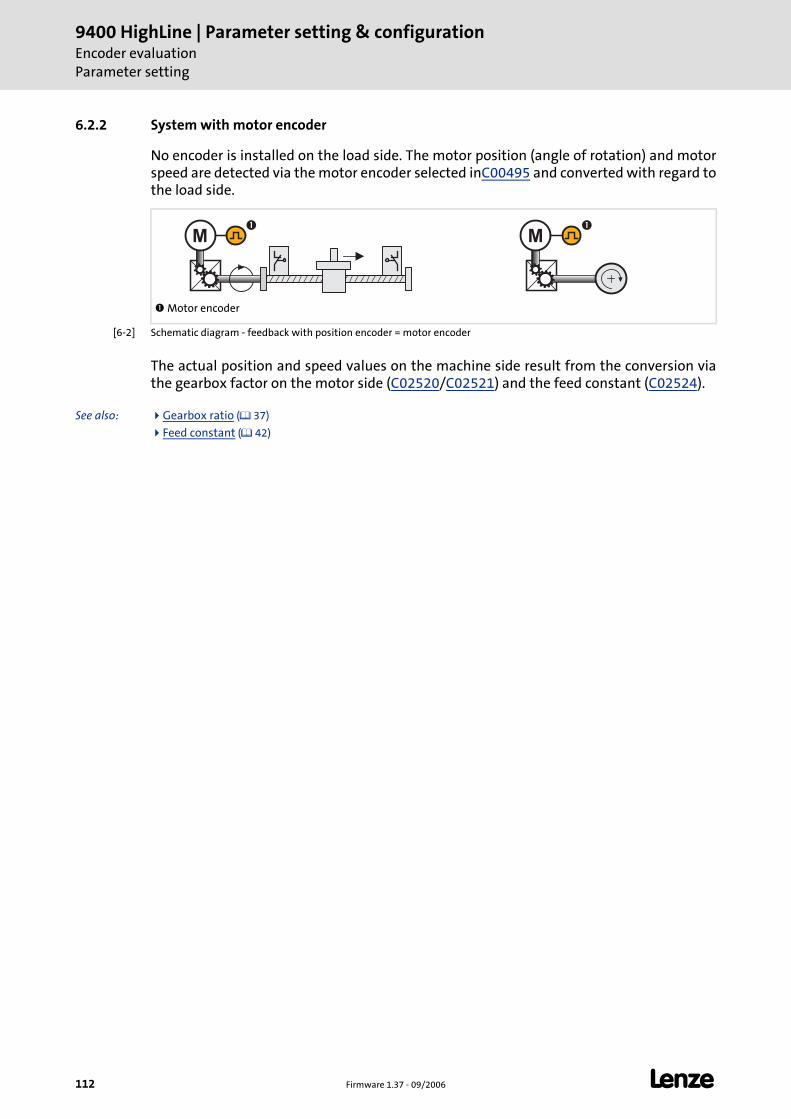
9400 HighLine | Parameter setting & configurationEncoder evaluationParameter setting
112 Firmware 1.37 - 09/2006 L
6.2.2 System with motor encoder
No encoder is installed on the load side. The motor position (angle of rotation) and motor speed are detected via the motor encoder selected inC00495 and converted with regard to the load side.
[6-2] Schematic diagram - feedback with position encoder = motor encoder
The actual position and speed values on the machine side result from the conversion via the gearbox factor on the motor side (C02520/C02521) and the feed constant (C02524).
See also: Gearbox ratio ( 37)
Feed constant ( 42)
Motor encoder
MM� �
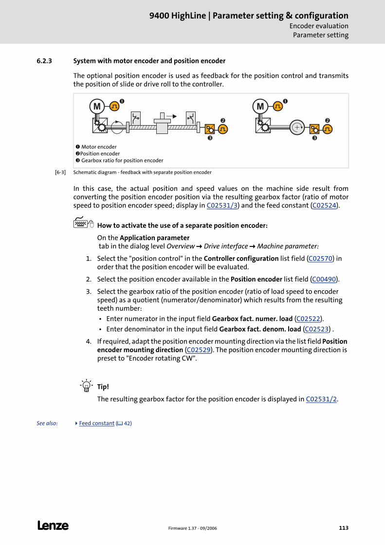
L Firmware 1.37 - 09/2006 113
9400 HighLine | Parameter setting & configurationEncoder evaluation
Parameter setting
6.2.3 System with motor encoder and position encoder
The optional position encoder is used as feedback for the position control and transmits the position of slide or drive roll to the controller.
[6-3] Schematic diagram - feedback with separate position encoder
In this case, the actual position and speed values on the machine side result from converting the position encoder position via the resulting gearbox factor (ratio of motor speed to position encoder speed; display in C02531/3) and the feed constant (C02524).
How to activate the use of a separate position encoder:
On the Application parameter tab in the dialog level Overview Drive interface Machine parameter:
1. Select the "position control" in the Controller configuration list field (C02570) in order that the position encoder will be evaluated.
2. Select the position encoder available in the Position encoder list field (C00490).
3. Select the gearbox ratio of the position encoder (ratio of load speed to encoder speed) as a quotient (numerator/denominator) which results from the resulting teeth number:
• Enter numerator in the input field Gearbox fact. numer. load (C02522).
• Enter denominator in the input field Gearbox fact. denom. load (C02523) .
4. If required, adapt the position encoder mounting direction via the list field Position encoder mounting direction (C02529). The position encoder mounting direction is preset to "Encoder rotating CW".
Tip!
The resulting gearbox factor for the position encoder is displayed in C02531/2.
See also: Feed constant ( 42)
Motor encoderPosition encoder Gearbox ratio for position encoder
MM
�
�
�
�
� �
9400 HighLine | Parameter setting & configurationEncoder evaluationParameter setting
114 Firmware 1.37 - 09/2006 L
6.2.4 Use external position encoder.
The FDB_dnActPosIn_p input of the system block LS_Feedback serves to evaluate an external encoder (CAN, SSI, Profibus).
Via this input an actual position of an external encoder in [increments] can be directly given to the encoder evaluation.
How to activate the use of the external actual position:
On the Application parameter tab in the dialog level Overview Drive interface Machine parameter:
1. Select the "position control" in the Controller configuration list field (C02570) in order that the position encoder will be evaluated.
2. Set "From application" in the list field Position encoder (C00490).
Note!
• Encoder inversion and offset selection FDB_dnPositionOffset_p also affect the external actual position.
• If the use of the external actual position preset via FDB_dnActPosIn_p is activated, a, the "Home position known" status (HM_bHomePosAvailable = TRUE) is automatically set and homing with the basic function "Homing" cannot be activated anymore.
• When the traversing range (C02528) is set to "Modulo", the external actual position value must also be set to modulo (0 … cycle-1).
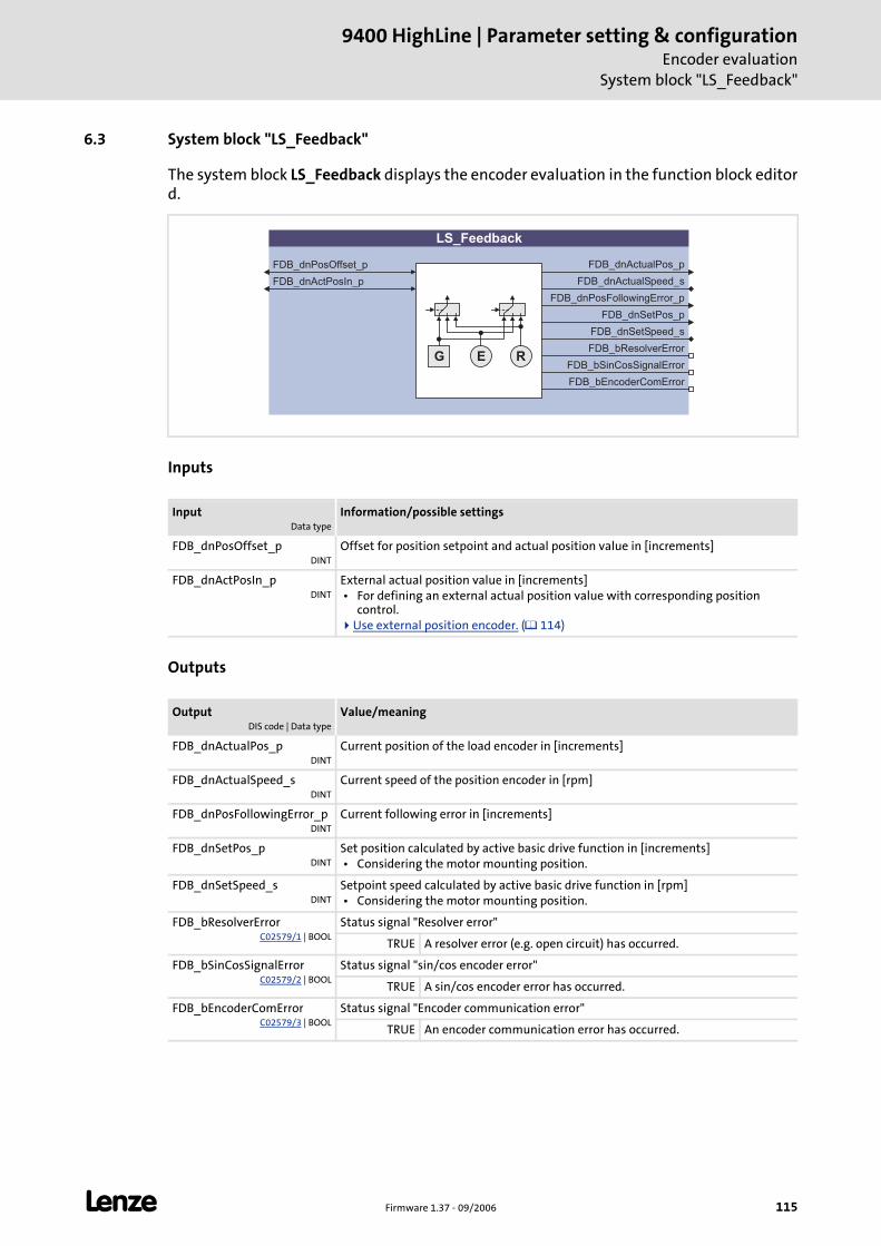
L Firmware 1.37 - 09/2006 115
9400 HighLine | Parameter setting & configurationEncoder evaluation
System block "LS_Feedback"
6.3 System block "LS_Feedback"
The system block LS_Feedback displays the encoder evaluation in the function block editor d.
Inputs
Outputs
InputData type
Information/possible settings
FDB_dnPosOffset_pDINT
Offset for position setpoint and actual position value in [increments]
FDB_dnActPosIn_pDINT
External actual position value in [increments] • For defining an external actual position value with corresponding position
control.Use external position encoder. ( 114)
OutputDIS code | Data type
Value/meaning
FDB_dnActualPos_pDINT
Current position of the load encoder in [increments]
FDB_dnActualSpeed_sDINT
Current speed of the position encoder in [rpm]
FDB_dnPosFollowingError_pDINT
Current following error in [increments]
FDB_dnSetPos_pDINT
Set position calculated by active basic drive function in [increments] • Considering the motor mounting position.
FDB_dnSetSpeed_sDINT
Setpoint speed calculated by active basic drive function in [rpm] • Considering the motor mounting position.
FDB_bResolverErrorC02579/1 | BOOL
Status signal "Resolver error"
TRUE A resolver error (e.g. open circuit) has occurred.
FDB_bSinCosSignalErrorC02579/2 | BOOL
Status signal "sin/cos encoder error"
TRUE A sin/cos encoder error has occurred.
FDB_bEncoderComErrorC02579/3 | BOOL
Status signal "Encoder communication error"
TRUE An encoder communication error has occurred.
LS_Feedback
FDB_dnActualPos_p
FDB_dnActualSpeed_s
FDB_dnPosFollowingError_p
FDB_bResolverError
FDB_bSinCosSignalError
FDB_bEncoderComError
FDB_dnPosOffset_p
RG E
FDB_dnSetPos_p
FDB_dnSetSpeed_s
FDB_dnActPosIn_p
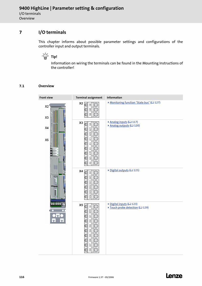
9400 HighLine | Parameter setting & configurationI/O terminalsOverview
116 Firmware 1.37 - 09/2006 L
7 I/O terminals
This chapter informs about possible parameter settings and configurations of the controller input and output terminals.
Tip!
Information on wiring the terminals can be found in the Mounting Instructions of the controller!
7.1 Overview
Front view Terminal assignment Information
Monitoring function "State bus" ( 127)
Analog inputs ( 117) Analog outputs ( 120)
Digital outputs ( 125)
Digital inputs ( 123) Touch probe detection ( 129)
GE
24
ES
B
X2
X3
GA
AO
1A
O2
A1
+A
1-
A1
-A
1R
A2
+A
2-
GO
24
OD
O1
DO
2D
O3
DO
4
X4
X5
GI
RF
RD
I1D
I2D
I3D
I4D
I5D
I6D
I7D
I8
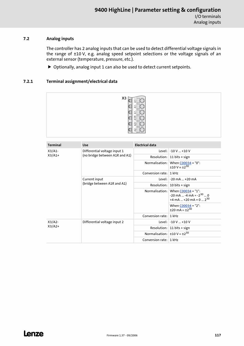
L Firmware 1.37 - 09/2006 117
9400 HighLine | Parameter setting & configurationI/O terminals
Analog inputs
7.2 Analog inputs
The controller has 2 analog inputs that can be used to detect differential voltage signals in the range of ±10 V, e.g. analog speed setpoint selections or the voltage signals of an external sensor (temperature, pressure, etc.).
Optionally, analog input 1 can also be used to detect current setpoints.
7.2.1 Terminal assignment/electrical data
Terminal Use Electrical data
X3/A1-X3/A1+
Differential voltage input 1(no bridge between A1R and A1)
Level: -10 V ... +10 V
Resolution: 11 bits + sign
Normalisation: When C00034 = "0":±10 V ≡ ±230
Conversion rate: 1 kHz
Current input(bridge between A1R and A1)
Level: -20 mA ... +20 mA
Resolution: 10 bits + sign
Normalisation: When C00034 = "1":-20 mA ... -4 mA = -230 ... 0+4 mA ... +20 mA = 0 ... 230
When C00034 = "2":±20 mA ≡ ±230
Conversion rate: 1 kHz
X3/A2-X3/A2+
Differential voltage input 2 Level: -10 V ... +10 V
Resolution: 11 bits + sign
Normalisation: ±10 V ≡ ±230
Conversion rate: 1 kHz
A1
+A
1-
A1
-A
1R
A2
+A
2-
X3
9400 HighLine | Parameter setting & configurationI/O terminalsAnalog inputs
118 Firmware 1.37 - 09/2006 L
7.2.2 Parameter setting
Short overview of parameters for the analog inputs:
7.2.3 Reconfiguring analog input 1 as a current input
Proceed as follows to reconfigure analog input 1 as a current input:
1. Bridge terminals A1R and A1 on terminal strip X3 by means of wiring.
2. Select the corresponding current loop under C00034.
Tip!
In this way, you can implement a 4 ...20 mA current loop, e.g. for speed setpoint selection.
Open-circuit monitoring
Under C00598, you can select an error response to an open circuit for the 4 ...20 mA current loop.
Parameter Information
C00034 Config. analog input 1
C00598 Resp. to open circuit AIN1
C02730/1 AIN1: Gain
C02730/2 AIN2: Gain
C02731/1 AIN1: Offset
C02731/2 AIN2: Offset
C02732/1 AIN1: Dead band
C02732/2 AIN2: Dead band
C02800/1 AIN1: Input signal (-16384 ≡ -100 %, 16383 ≡ 100 %)
C02800/2 AIN2: Input signal (-16384 ≡ -100 %, 16383 ≡ 100 %)
Highlighted in grey = display parameter
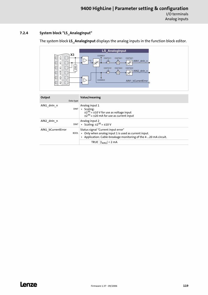
L Firmware 1.37 - 09/2006 119
9400 HighLine | Parameter setting & configurationI/O terminals
Analog inputs
7.2.4 System block "LS_AnalogInput"
The system block LS_AnalogInput displays the analog inputs in the function block editor.
OutputData type
Value/meaning
AIN1_dnIn_nDINT
Analog input 1 • Scaling:
±230 ≡ ±10 V for use as voltage input ±230 ≡ ±20 mA for use as current input
AIN2_dnIn_nDINT
Analog input 2 • Scaling: ±230 ≡ ±10 V
AIN1_bCurrentErrorBOOL
Status signal "Current input error" • Only when analog input 1 is used as current input. • Application: Cable-breakage monitoring of the 4 ...20 mA circuit.
TRUE |IAIN1| < 2 mA
A1
+A
1-
A1
-A
1R
A2
+A
2-
AIN1_dnIn_n
AIN1_bCurrentError
AIN2_dnIn_n
X3
LS_AnalogInput
25
0
C02731/1 C02730/1 C02732/1
C02731/2 C02730/2 C02732/2
C02800/1
C02800/2
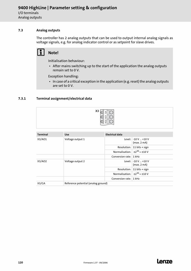
9400 HighLine | Parameter setting & configurationI/O terminalsAnalog outputs
120 Firmware 1.37 - 09/2006 L
7.3 Analog outputs
The controller has 2 analog outputs that can be used to output internal analog signals as voltage signals, e.g. for analog indicator control or as setpoint for slave drives.
7.3.1 Terminal assignment/electrical data
Note!
Initialisation behaviour:
• After mains switching up to the start of the application the analog outputs remain set to 0 V.
Exception handling:
• In case of a critical exception in the application (e.g. reset) the analog outputs are set to 0 V.
Terminal Use Electrical data
X3/AO1 Voltage output 1 Level: -10 V ... +10 V(max. 2 mA)
Resolution: 11 bits + sign
Normalisation: ±230 ≡ ±10 V
Conversion rate: 1 kHz
X3/AO2 Voltage output 2 Level: -10 V ... +10 V(max. 2 mA)
Resolution: 11 bits + sign
Normalisation: ±230 ≡ ±10 V
Conversion rate: 1 kHz
X3/GA Reference potential (analog ground)
GA
AO
1A
O2
X3
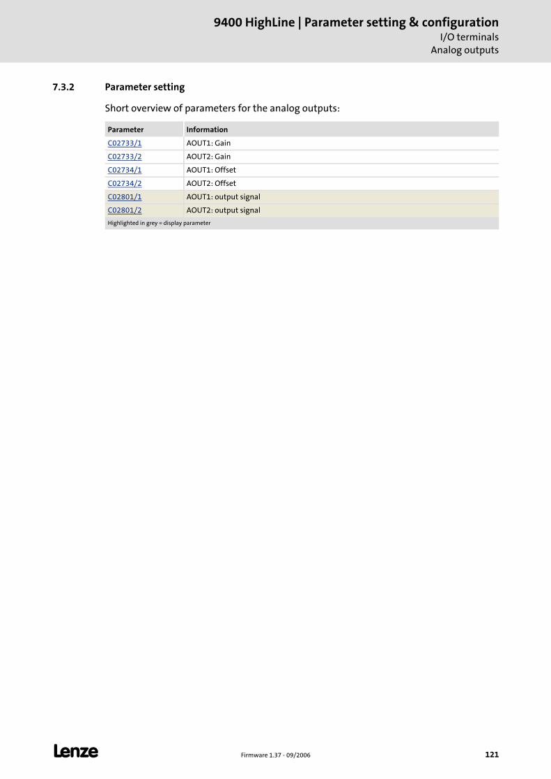
L Firmware 1.37 - 09/2006 121
9400 HighLine | Parameter setting & configurationI/O terminals
Analog outputs
7.3.2 Parameter setting
Short overview of parameters for the analog outputs:
Parameter Information
C02733/1 AOUT1: Gain
C02733/2 AOUT2: Gain
C02734/1 AOUT1: Offset
C02734/2 AOUT2: Offset
C02801/1 AOUT1: output signal
C02801/2 AOUT2: output signal
Highlighted in grey = display parameter
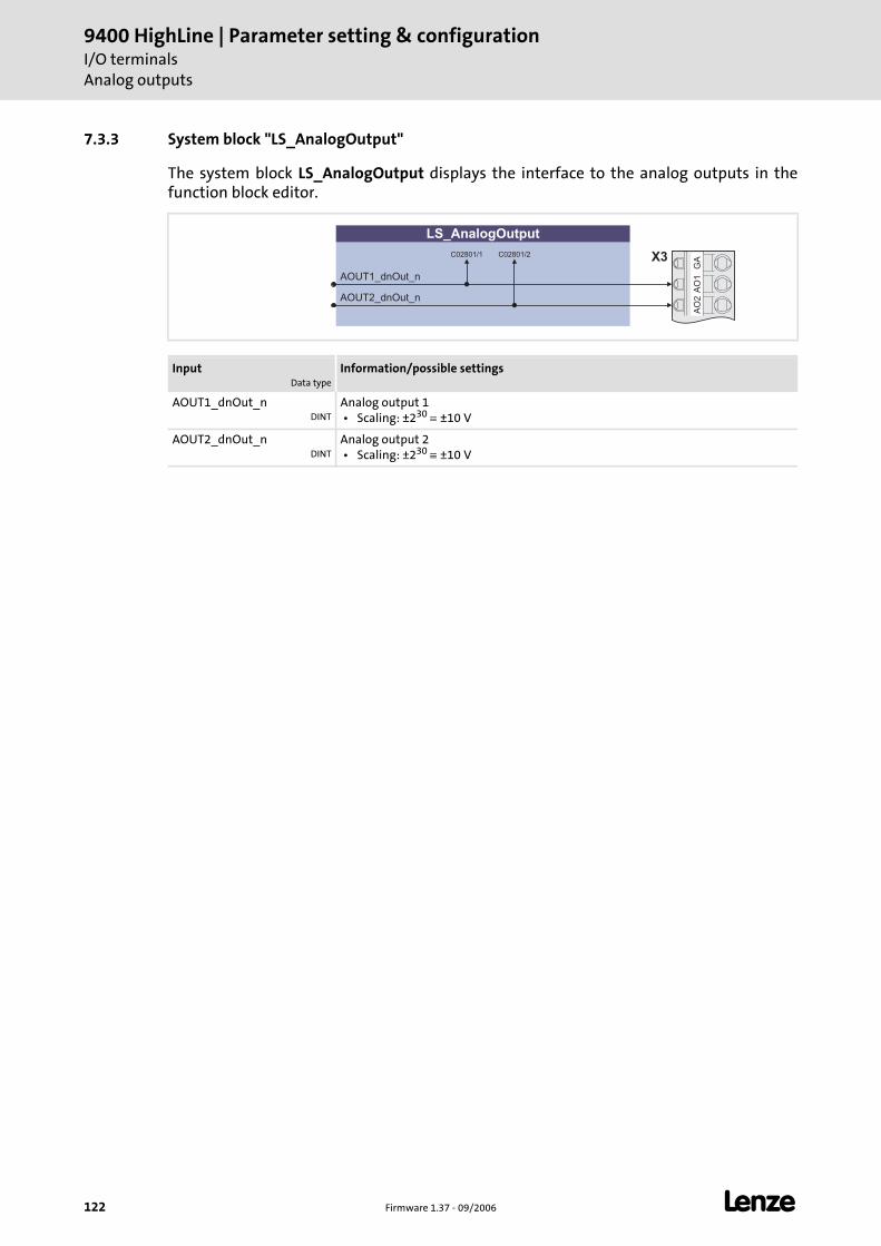
9400 HighLine | Parameter setting & configurationI/O terminalsAnalog outputs
122 Firmware 1.37 - 09/2006 L
7.3.3 System block "LS_AnalogOutput"
The system block LS_AnalogOutput displays the interface to the analog outputs in the function block editor.
InputData type
Information/possible settings
AOUT1_dnOut_nDINT
Analog output 1 • Scaling: ±230 ≡ ±10 V
AOUT2_dnOut_nDINT
Analog output 2 • Scaling: ±230 ≡ ±10 V
LS_AnalogOutput
AOUT1_dnOut_n
AOUT2_dnOut_n
GA
AO
1A
O2
X3C02801/1 C02801/2
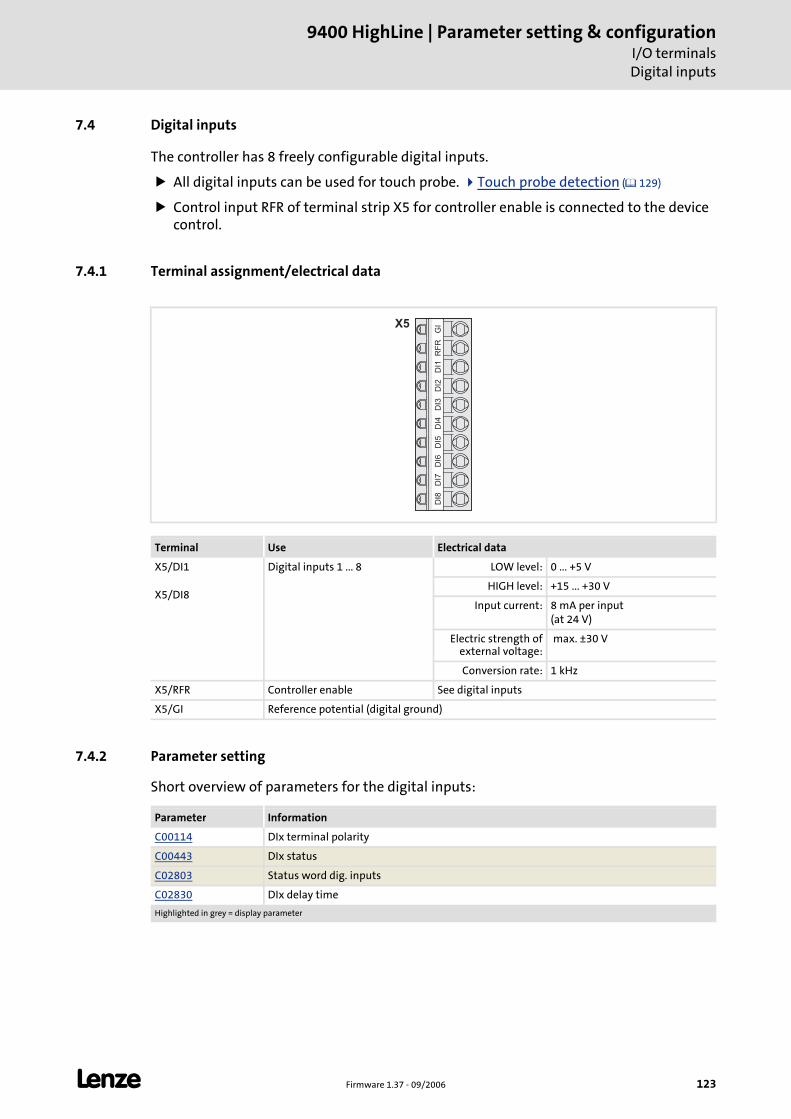
L Firmware 1.37 - 09/2006 123
9400 HighLine | Parameter setting & configurationI/O terminalsDigital inputs
7.4 Digital inputs
The controller has 8 freely configurable digital inputs.
All digital inputs can be used for touch probe. Touch probe detection ( 129)
Control input RFR of terminal strip X5 for controller enable is connected to the device control.
7.4.1 Terminal assignment/electrical data
7.4.2 Parameter setting
Short overview of parameters for the digital inputs:
Terminal Use Electrical data
X5/DI1
X5/DI8
Digital inputs 1 ... 8 LOW level: 0 ... +5 V
HIGH level: +15 ... +30 V
Input current: 8 mA per input(at 24 V)
Electric strength of external voltage:
max. ±30 V
Conversion rate: 1 kHz
X5/RFR Controller enable See digital inputs
X5/GI Reference potential (digital ground)
X5
GI
RF
RD
I1D
I2D
I3D
I4D
I5D
I6D
I7D
I8
Parameter Information
C00114 DIx terminal polarity
C00443 DIx status
C02803 Status word dig. inputs
C02830 DIx delay time
Highlighted in grey = display parameter
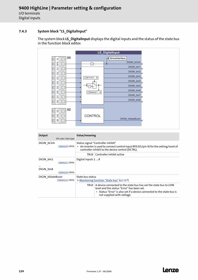
9400 HighLine | Parameter setting & configurationI/O terminalsDigital inputs
124 Firmware 1.37 - 09/2006 L
7.4.3 System block "LS_DigitalInput"
The system block LS_DigitalInput displays the digital inputs and the status of the state bus in the function block editor.
OutputDIS code | data type
Value/meaning
DIGIN_bCInhC00443/9 | BOOL
Status signal "Controller inhibit" • An inverter is used to connect control input RFR (X5/pin 9) for the setting/reset of
controller inhibit to the device control (DCTRL).
TRUE Controller inhibit active
DIGIN_bIn1C00443/1 | BOOL
...DIGIN_bIn8
C00443/8 | BOOL
Digital inputs 1 ... 8
DIGIN_bStateBusInC00443/12 | BOOL
State bus statusMonitoring function "State bus" ( 127)
TRUE A device connected to the state bus has set the state bus to LOW level and the status "Error" has been set. • Status "Error" is also set if a device connected to the state bus is
not supplied with voltage.
LS_DigitalInput
DIGIN_bIn1
DIGIN_bIn2
DIGIN_bIn5
DIGIN_bIn4
DIGIN_bIn3
X5
DIGIN_bIn6
DIGIN_bIn7
DIGIN_bIn8
DIGIN_bCInh
DIGIN_bStateBusIn
1
0
1
C00114/1...8
C00443/1...8
CONTROL
GI
RF
RD
I1D
I2D
I3D
I4D
I5D
I6D
I7D
I8G
E2
4E
SB
X2
DriveInterface
1
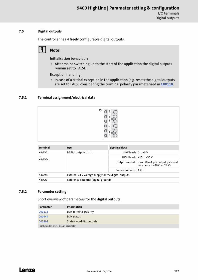
L Firmware 1.37 - 09/2006 125
9400 HighLine | Parameter setting & configurationI/O terminals
Digital outputs
7.5 Digital outputs
The controller has 4 freely configurable digital outputs.
7.5.1 Terminal assignment/electrical data
7.5.2 Parameter setting
Short overview of parameters for the digital outputs:
Note!
Initialisation behaviour:
• After mains switching up to the start of the application the digital outputs remain set to FALSE.
Exception handling:
• In case of a critical exception in the application (e.g. reset) the digital outputs are set to FALSE considering the terminal polarity parameterised in C00118.
Terminal Use Electrical data
X4/DO1...X4/DO4
Digital outputs 1 ... 4 LOW level: 0 ... +5 V
HIGH level: +15 ... +30 V
Output current: max. 50 mA per output (external resistance > 480 Ω at 24 V)
Conversion rate: 1 kHz
X4/24O External 24 V voltage supply for the digital outputs
X4/GO Reference potential (digital ground)
GO
24
OD
O1
DO
2D
O3
DO
4X4
Parameter Information
C00118 DOx terminal polarity
C00444 DOx status
C02802 Status word dig. outputs
Highlighted in grey = display parameter
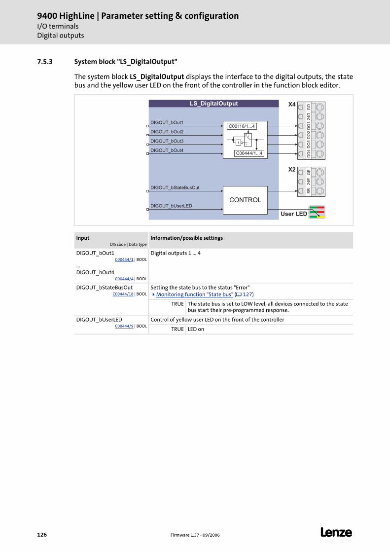
9400 HighLine | Parameter setting & configurationI/O terminalsDigital outputs
126 Firmware 1.37 - 09/2006 L
7.5.3 System block "LS_DigitalOutput"
The system block LS_DigitalOutput displays the interface to the digital outputs, the state bus and the yellow user LED on the front of the controller in the function block editor.
InputDIS code | Data type
Information/possible settings
DIGOUT_bOut1C00444/1 | BOOL
...DIGOUT_bOut4
C00444/4 | BOOL
Digital outputs 1 ... 4
DIGOUT_bStateBusOutC00444/18 | BOOL
Setting the state bus to the status "Error"Monitoring function "State bus" ( 127)
TRUE The state bus is set to LOW level, all devices connected to the state bus start their pre-programmed response.
DIGOUT_bUserLEDC00444/9 | BOOL
Control of yellow user LED on the front of the controller
TRUE LED on
GO
24
OD
O1
DO
2D
O3
DO
4
LS_DigitalOutput
DIGOUT_bOut1
DIGOUT_bStateBusOut
DIGOUT_bOut3
DIGOUT_bOut2
X4
1
0
1
C00118/1...4
DIGOUT_bOut4
DIGOUT_bUserLED
User LED
C00444/1...4
GE
24
ES
B
X2
CONTROL
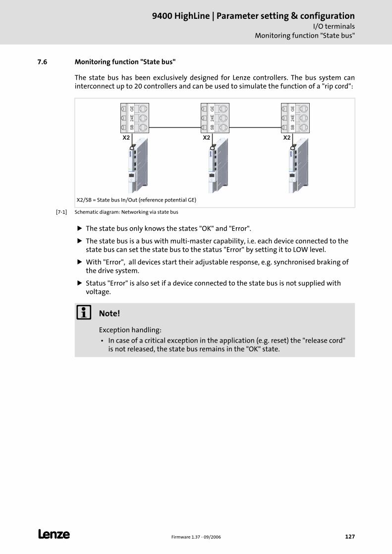
L Firmware 1.37 - 09/2006 127
9400 HighLine | Parameter setting & configurationI/O terminals
Monitoring function "State bus"
7.6 Monitoring function "State bus"
The state bus has been exclusively designed for Lenze controllers. The bus system can interconnect up to 20 controllers and can be used to simulate the function of a "rip cord":
[7-1] Schematic diagram: Networking via state bus
The state bus only knows the states "OK" and "Error".
The state bus is a bus with multi-master capability, i.e. each device connected to the state bus can set the state bus to the status "Error" by setting it to LOW level.
With "Error", all devices start their adjustable response, e.g. synchronised braking of the drive system.
Status "Error" is also set if a device connected to the state bus is not supplied with voltage.
X2/SB = State bus In/Out (reference potential GE)
X2 X2 X2
GE
24
ES
B
GE
24
ES
B
GE
24
ES
B
Note!
Exception handling:
• In case of a critical exception in the application (e.g. reset) the "release cord" is not released, the state bus remains in the "OK" state.
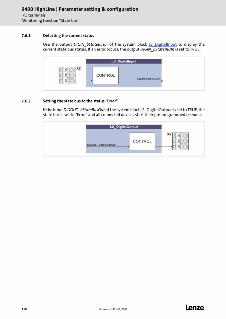
9400 HighLine | Parameter setting & configurationI/O terminalsMonitoring function "State bus"
128 Firmware 1.37 - 09/2006 L
7.6.1 Detecting the current status
Use the output DIGIN_bStateBusIn of the system block LS_DigitalInput to display the current state bus status. If an error occurs, the output DIGIN_bStateBusIn is set to TRUE.
7.6.2 Setting the state bus to the status "Error"
If the input DIGOUT_bStateBusOut of the system block LS_DigitalOutput is set to TRUE, the state bus is set to "Error" and all connected devices start their pre-programmed response.
LS_DigitalInput
DIGIN_bStateBusInCONTROL
GE
24
ES
B
X2
LS_DigitalOutput
DIGOUT_bStateBusOut
GE
24
ES
B
X2
CONTROL
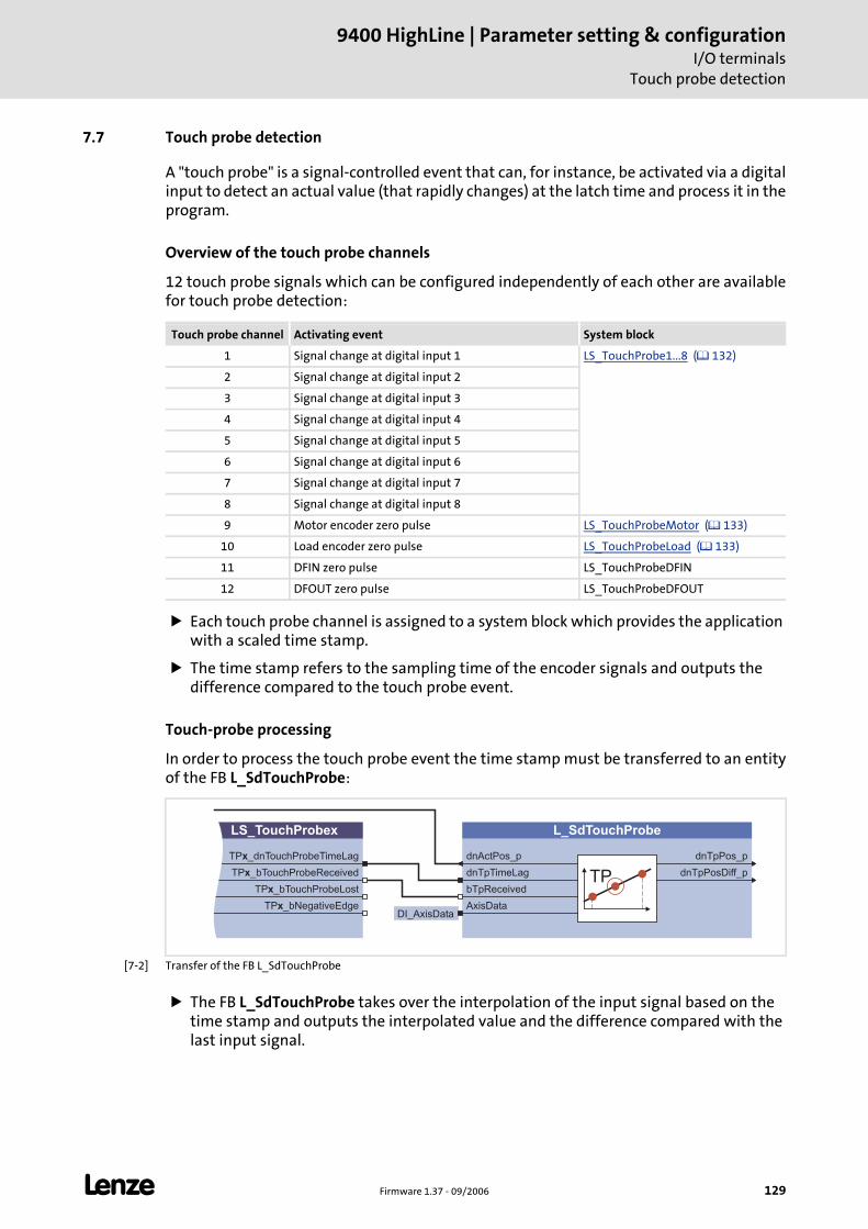
L Firmware 1.37 - 09/2006 129
9400 HighLine | Parameter setting & configurationI/O terminals
Touch probe detection
7.7 Touch probe detection
A "touch probe" is a signal-controlled event that can, for instance, be activated via a digital input to detect an actual value (that rapidly changes) at the latch time and process it in the program.
Overview of the touch probe channels
12 touch probe signals which can be configured independently of each other are available for touch probe detection:
Each touch probe channel is assigned to a system block which provides the application with a scaled time stamp.
The time stamp refers to the sampling time of the encoder signals and outputs the difference compared to the touch probe event.
Touch-probe processing
In order to process the touch probe event the time stamp must be transferred to an entity of the FB L_SdTouchProbe:
[7-2] Transfer of the FB L_SdTouchProbe
The FB L_SdTouchProbe takes over the interpolation of the input signal based on the time stamp and outputs the interpolated value and the difference compared with the last input signal.
Touch probe channel Activating event System block
1 Signal change at digital input 1 LS_TouchProbe1...8 ( 132)
2 Signal change at digital input 2
3 Signal change at digital input 3
4 Signal change at digital input 4
5 Signal change at digital input 5
6 Signal change at digital input 6
7 Signal change at digital input 7
8 Signal change at digital input 8
9 Motor encoder zero pulse LS_TouchProbeMotor ( 133)
10 Load encoder zero pulse LS_TouchProbeLoad ( 133)
11 DFIN zero pulse LS_TouchProbeDFIN
12 DFOUT zero pulse LS_TouchProbeDFOUT
TP _dnTouchProbeTimeLagx
TP _bTouchProbeReceivedx
TP _bTouchProbeLostx
LS_TouchProbex
TP _bNegativeEdgex
dnTpPos_p
dnTpPosDiff_p
L_SdTouchProbe
dnActPos_p
dnTpTimeLag
bTpReceivedTP
AxisDataDI_AxisData
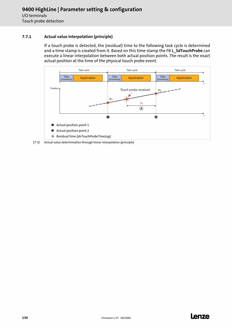
9400 HighLine | Parameter setting & configurationI/O terminalsTouch probe detection
130 Firmware 1.37 - 09/2006 L
7.7.1 Actual value interpolation (principle)
If a touch probe is detected, the (residual) time to the following task cycle is determined and a time stamp is created from it. Based on this time stamp the FB L_SdTouchProbe can execute a linear interpolation between both actual position points. The result is the exact actual position at the time of the physical touch probe event.
[7-3] Actual value determination through linear interpolation (principle)
Actual position point 1
Actual position point 2
Residual time (dnTouchProbeTimeLag)
Dataprocessing
ApplicationData
processingApplication
Dataprocessing
Application
Task cycle Task cycle Task cycle
t
Position
t
�
� �
t1
p1
p2Touch probe received
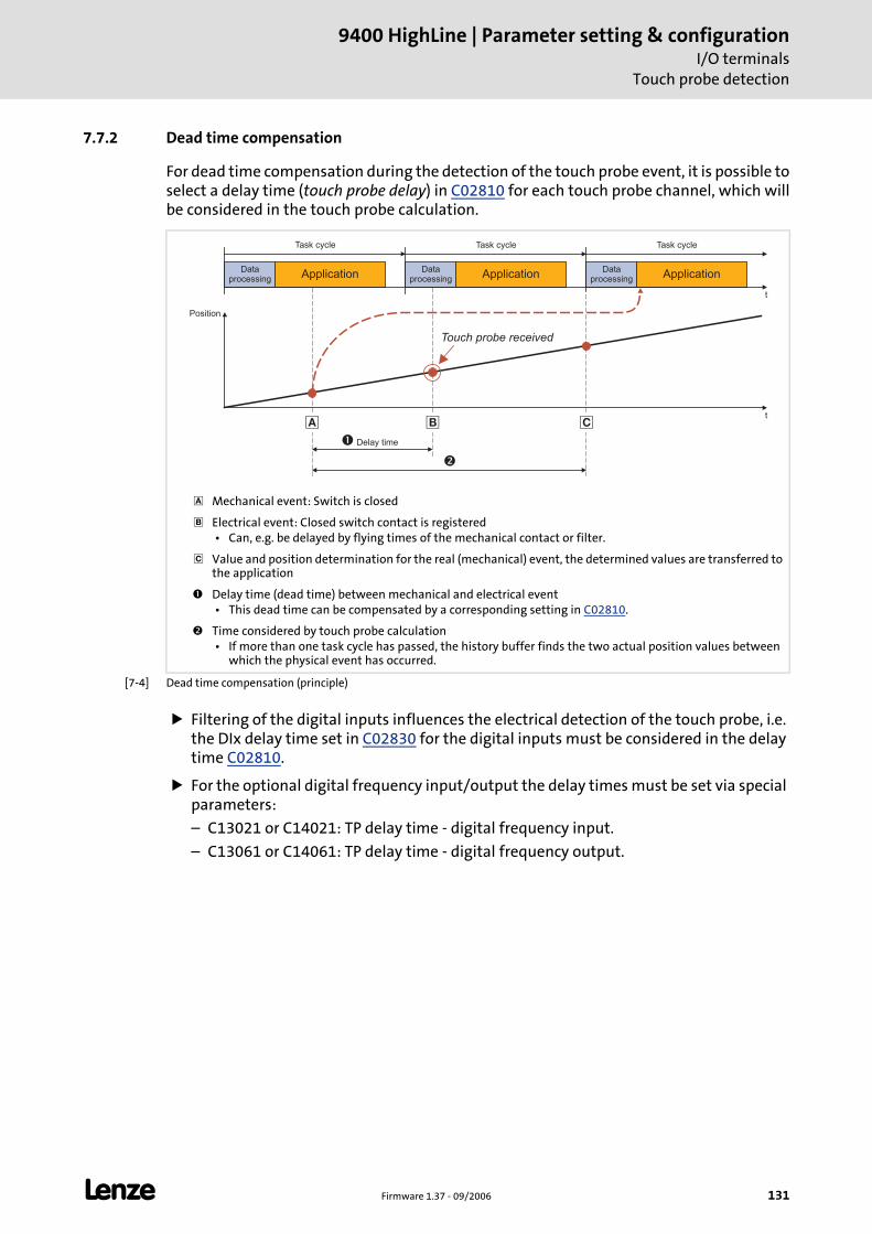
L Firmware 1.37 - 09/2006 131
9400 HighLine | Parameter setting & configurationI/O terminals
Touch probe detection
7.7.2 Dead time compensation
For dead time compensation during the detection of the touch probe event, it is possible to select a delay time (touch probe delay) in C02810 for each touch probe channel, which will be considered in the touch probe calculation.
[7-4] Dead time compensation (principle)
Filtering of the digital inputs influences the electrical detection of the touch probe, i.e. the DIx delay time set in C02830 for the digital inputs must be considered in the delay time C02810.
For the optional digital frequency input/output the delay times must be set via special parameters:
– C13021 or C14021: TP delay time - digital frequency input.
– C13061 or C14061: TP delay time - digital frequency output.
Mechanical event: Switch is closed
Electrical event: Closed switch contact is registered • Can, e.g. be delayed by flying times of the mechanical contact or filter.
Value and position determination for the real (mechanical) event, the determined values are transferred to the application
Delay time (dead time) between mechanical and electrical event • This dead time can be compensated by a corresponding setting in C02810.
Time considered by touch probe calculation • If more than one task cycle has passed, the history buffer finds the two actual position values between
which the physical event has occurred.
Dataprocessing
ApplicationData
processingApplication
Dataprocessing
Application
Task cycle Task cycle Task cycle
t
Position
t
� � �
� Delay time
�
Touch probe received
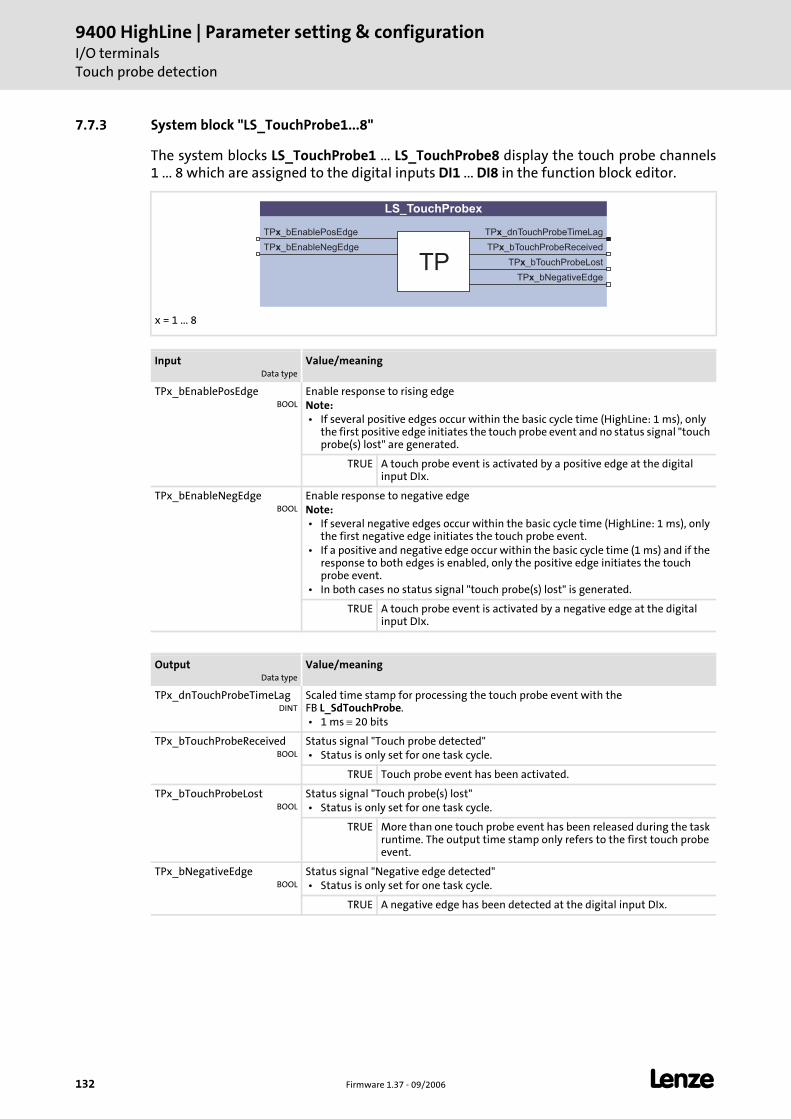
9400 HighLine | Parameter setting & configurationI/O terminalsTouch probe detection
132 Firmware 1.37 - 09/2006 L
7.7.3 System block "LS_TouchProbe1...8"
The system blocks LS_TouchProbe1 ... LS_TouchProbe8 display the touch probe channels 1 ... 8 which are assigned to the digital inputs DI1 ... DI8 in the function block editor.
x = 1 ... 8
InputData type
Value/meaning
TPx_bEnablePosEdgeBOOL
Enable response to rising edgeNote: • If several positive edges occur within the basic cycle time (HighLine: 1 ms), only
the first positive edge initiates the touch probe event and no status signal "touch probe(s) lost" are generated.
TRUE A touch probe event is activated by a positive edge at the digital input DIx.
TPx_bEnableNegEdgeBOOL
Enable response to negative edgeNote: • If several negative edges occur within the basic cycle time (HighLine: 1 ms), only
the first negative edge initiates the touch probe event. • If a positive and negative edge occur within the basic cycle time (1 ms) and if the
response to both edges is enabled, only the positive edge initiates the touch probe event.
• In both cases no status signal "touch probe(s) lost" is generated.
TRUE A touch probe event is activated by a negative edge at the digital input DIx.
OutputData type
Value/meaning
TPx_dnTouchProbeTimeLagDINT
Scaled time stamp for processing the touch probe event with the FB L_SdTouchProbe. • 1 ms ≡ 20 bits
TPx_bTouchProbeReceivedBOOL
Status signal "Touch probe detected" • Status is only set for one task cycle.
TRUE Touch probe event has been activated.
TPx_bTouchProbeLostBOOL
Status signal "Touch probe(s) lost" • Status is only set for one task cycle.
TRUE More than one touch probe event has been released during the task runtime. The output time stamp only refers to the first touch probe event.
TPx_bNegativeEdgeBOOL
Status signal "Negative edge detected" • Status is only set for one task cycle.
TRUE A negative edge has been detected at the digital input DIx.
TP _dnTouchProbeTimeLagx
TP _bTouchProbeReceivedx
TP _bTouchProbeLostx
LS_TouchProbex
TP
TP _bEnablePosEdgex
TP _bNegativeEdgex
TP _bEnableNegEdgex
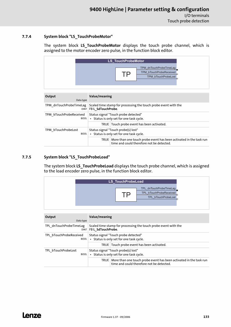
L Firmware 1.37 - 09/2006 133
9400 HighLine | Parameter setting & configurationI/O terminals
Touch probe detection
7.7.4 System block "LS_TouchProbeMotor"
The system block LS_TouchProbeMotor displays the touch probe channel, which is assigned to the motor encoder zero pulse, in the function block editor.
7.7.5 System block "LS_TouchProbeLoad"
The system block LS_TouchProbeLoad displays the touch probe channel, which is assigned to the load encoder zero pulse, in the function block editor.
OutputData type
Value/meaning
TPM_dnTouchProbeTimeLagDINT
Scaled time stamp for processing the touch probe event with the FB L_SdTouchProbe.
TPM_bTouchProbeReceivedBOOL
Status signal "Touch probe detected" • Status is only set for one task cycle.
TRUE Touch probe event has been activated.
TPM_bTouchProbeLostBOOL
Status signal "Touch probe(s) lost" • Status is only set for one task cycle.
TRUE More than one touch probe event has been activated in the task run time and could therefore not be detected.
TPM_dnTouchProbeTimeLag
TPM_bTouchProbeReceived
TPM_bTouchProbeLost
LS_TouchProbeMotor
TP
OutputData type
Value/meaning
TPL_dnTouchProbeTimeLagDINT
Scaled time stamp for processing the touch probe event with the FB L_SdTouchProbe.
TPL_bTouchProbeReceivedBOOL
Status signal "Touch probe detected" • Status is only set for one task cycle.
TRUE Touch probe event has been activated.
TPL_bTouchProbeLostBOOL
Status signal "Touch probe(s) lost" • Status is only set for one task cycle.
TRUE More than one touch probe event has been activated in the task run time and could therefore not be detected.
TPL_dnTouchProbeTimeLag
TPL_bTouchProbeReceived
TPL_bTouchProbeLost
LS_TouchProbeLoad
TP
9400 HighLine | Parameter setting & configurationI/O terminalsSystem bus "CAN on board"
134 Firmware 1.37 - 09/2006 L
7.8 System bus "CAN on board"
The controller has an integrated CANopen system bus interface for process and parameter data exchange between different devices and the connection of additional modules such as distributed terminals, keypads and input devices ("HMIs") and external controls.
In the »Engineer« parameter list or in the keypad, category CAN, you can find the parameters relevant for the CANopen system bus interface classified in different subcategories.
Note!
For detailed information about the CANopen system bus interface, please see the "System bus (CANopen) - CAN on-board 9400" Communication Manual.
L Firmware 1.37 - 09/2006 135
9400 HighLine | Parameter setting & configurationSafety engineering
8 Safety engineering
The 9400 HighLine controllers can be equipped with a safety module. The individual safety module types have a different range of functions to optimally meet different requirements.
"Integrated safety technology" stands for user-related safety functions that are applicable to the protection of persons working with machines and the machine protection.
The motion functions are executed by the controller. The safety modules monitor the reliable observation of limit values and provide safe inputs and outputs. When the limit values are exceeded, the safety modules start control functions for the fault scenario according to EN 60204-1 standard directly in the controller.
The safety functions are suitable for applications according to IEC 61508, SIL 3 and, depending on the module, meet the requirements of EN 954, part 1, up to control category 4.
Note!
For detailed information about the integrated safety technology, please see the Controller Manual for the "9400 Servo Drives" and the Manual for the safety module.
9400 HighLine | Parameter setting & configurationSafety engineeringIntegration into the application
136 Firmware 1.37 - 09/2006 L
8.1 Integration into the application
If a safety function is required, the safety engineering activates a corresponding safe monitoring function. The standstill function, however, is only executed directly in case of the function "Safe torque off" (STO). In case of the other safety functions an action of the controller is required, which is safely monitored. The implementation of the corresponding action (e.g. braking, braking to standstill, holding of the standstill position) must be carried out by the application.
"LS_SafetyModule" system block
For the transmission of the control and status information from the safety module to the application the LS_SafetyModule system block is provided in the function block editor of the »Engineers«.
Basic function "Limiter"
Furthermore the LS_Limiter system block which contains the basic function Limiter" is provided in the function block editor for the connection of safety engineering to the application. ( 200)
The basic function "Limiter" provides a parameter setting surface in the »Engineer« for a comfortable setting of limit positions, limited speeds and limit values and enables the drive to braked selectively after request through the safety module.
General procedure
1. Activation of the safety function on the safety module (e. g. SS1 - safe stop 1). Monitoring starts.
2. The safety module informs the controller via a control word that the safety function has been activated.
3. The application evaluates the control word and starts the required motion sequence (e.g. braking).
8.2 Selecting the required safety module
The safety module expected by the application and the controller is selected in C00214.
In the »Engineer« this setting is carried out automatically by assigning the device module to the controller, i.e., the »Engineer« sets C00214 automatically according to the safety module selected.
If the safety module selected in C00214 does not correspond to the safety module type connected, an error will be activated.
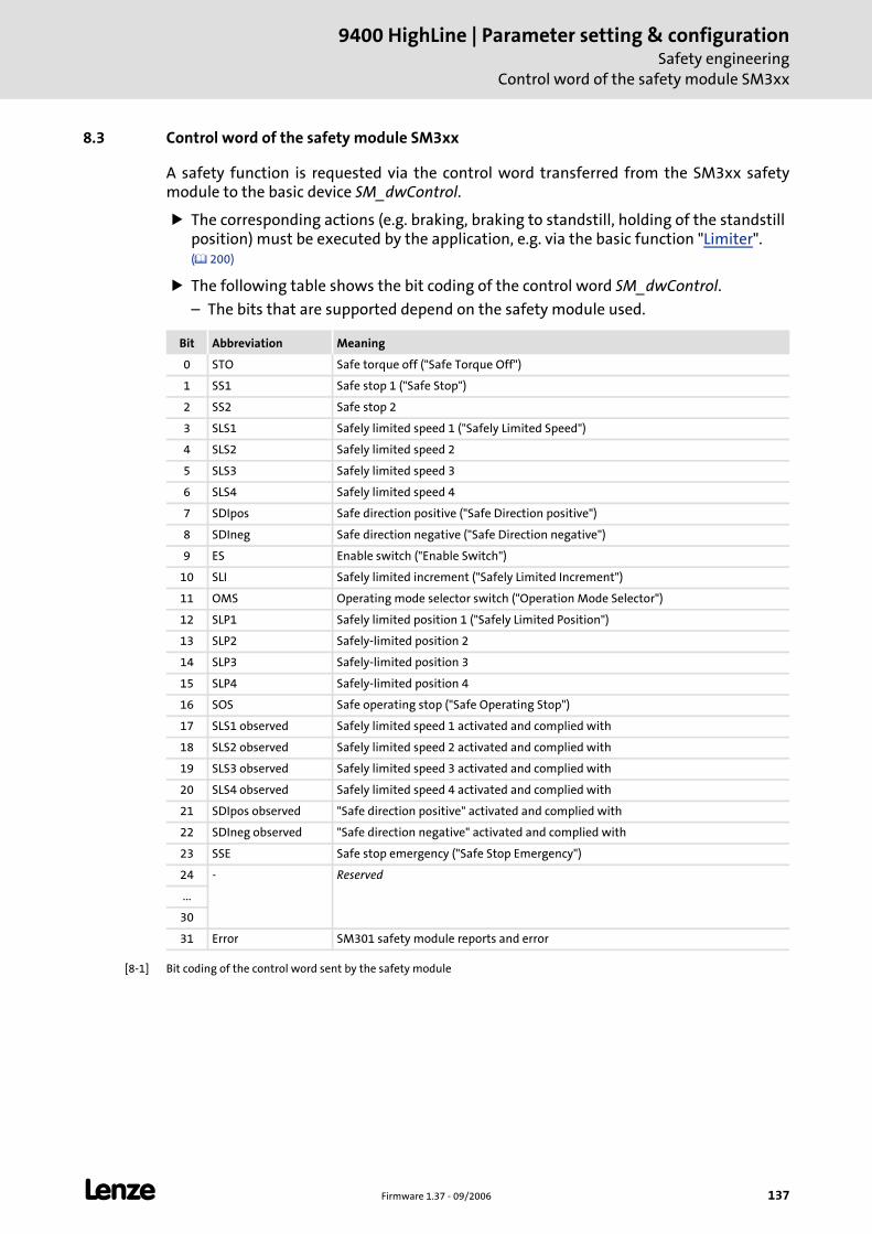
L Firmware 1.37 - 09/2006 137
9400 HighLine | Parameter setting & configurationSafety engineering
Control word of the safety module SM3xx
8.3 Control word of the safety module SM3xx
A safety function is requested via the control word transferred from the SM3xx safety module to the basic device SM_dwControl.
The corresponding actions (e.g. braking, braking to standstill, holding of the standstill position) must be executed by the application, e.g. via the basic function "Limiter". ( 200)
The following table shows the bit coding of the control word SM_dwControl.
– The bits that are supported depend on the safety module used.
[8-1] Bit coding of the control word sent by the safety module
Bit Abbreviation Meaning
0 STO Safe torque off ("Safe Torque Off")
1 SS1 Safe stop 1 ("Safe Stop")
2 SS2 Safe stop 2
3 SLS1 Safely limited speed 1 ("Safely Limited Speed")
4 SLS2 Safely limited speed 2
5 SLS3 Safely limited speed 3
6 SLS4 Safely limited speed 4
7 SDIpos Safe direction positive ("Safe Direction positive")
8 SDIneg Safe direction negative ("Safe Direction negative")
9 ES Enable switch ("Enable Switch")
10 SLI Safely limited increment ("Safely Limited Increment")
11 OMS Operating mode selector switch ("Operation Mode Selector")
12 SLP1 Safely limited position 1 ("Safely Limited Position")
13 SLP2 Safely-limited position 2
14 SLP3 Safely-limited position 3
15 SLP4 Safely-limited position 4
16 SOS Safe operating stop ("Safe Operating Stop")
17 SLS1 observed Safely limited speed 1 activated and complied with
18 SLS2 observed Safely limited speed 2 activated and complied with
19 SLS3 observed Safely limited speed 3 activated and complied with
20 SLS4 observed Safely limited speed 4 activated and complied with
21 SDIpos observed "Safe direction positive" activated and complied with
22 SDIneg observed "Safe direction negative" activated and complied with
23 SSE Safe stop emergency ("Safe Stop Emergency")
24 - Reserved
...
30
31 Error SM301 safety module reports and error
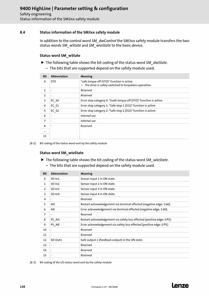
9400 HighLine | Parameter setting & configurationSafety engineeringStatus information of the SM3xx safety module
138 Firmware 1.37 - 09/2006 L
8.4 Status information of the SM3xx safety module
In addition to the control word SM_dwControl the SM3xx safety module transfers the two status words SM_wState and SM_wIoState to the basic device.
Status word SM_wState
The following table shows the bit coding of the status word SM_dwState.
– The bits that are supported depend on the safety module used.
[8-2] Bit coding of the status word sent by the safety module
Status word SM_wIoState
The following table shows the bit coding of the status word SM_wIoState.
– The bits that are supported depend on the safety module used.
[8-3] Bit coding of the I/O status word sent by the safety module
Bit Abbreviation Meaning
0 STO "safe torque off (STO)" function is active. • The drive is safely switched to torqueless operation.
1 - Reserved
2 - Reserved
3 EC_S0 Error stop category 0: "Ssafe torque off (STO)" function is active.
4 EC_S1 Error stop category 1: "Safe stop 1 (SS1)" function is active.
5 EC_S2 Error stop category 2: "Safe stop 2 (SS2)" function is active.
6 - Internal use
7 - Internal use
8 - Reserved
...
15
Bit Abbreviation Meaning
0 SD-In1 Sensor input 1 in ON state.
1 SD-In2 Sensor input 2 in ON state.
2 SD-In3 Sensor input 3 in ON state.
3 SD-In4 Sensor input 4 in ON state.
4 - Reserved
5 AIS Restart acknowledgement via terminal effected (negative edge: 1 0).
6 AIE Error acknowledgement via terminal effected (negative edge: 1 0).
7 - Reserved
8 PS_AIS Restart acknowledgement via safety bus effected (positive edge: 0 1)
9 PS_AIE Error acknowledgement via safety bus effected (positive edge: 0 1)
10 - Reserved
11 - Reserved
12 SD-Out1 Safe output 1 (feedback output) in the ON state.
13 - Reserved
14 - Reserved
15 - Reserved
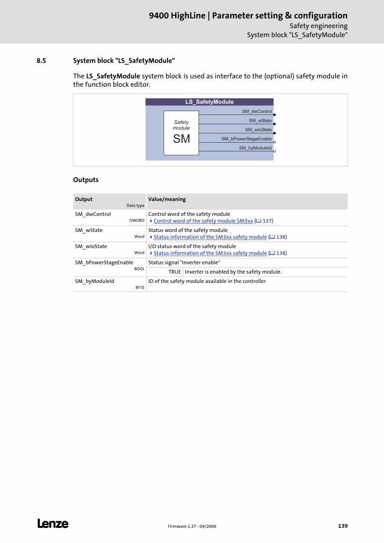
L Firmware 1.37 - 09/2006 139
9400 HighLine | Parameter setting & configurationSafety engineering
System block "LS_SafetyModule"
8.5 System block "LS_SafetyModule"
The LS_SafetyModule system block is used as interface to the (optional) safety module in the function block editor.
Outputs
OutputData type
Value/meaning
SM_dwControlDWORD
Control word of the safety moduleControl word of the safety module SM3xx ( 137)
SM_wStateWord
Status word of the safety moduleStatus information of the SM3xx safety module ( 138)
SM_wIoStateWord
I/O status word of the safety moduleStatus information of the SM3xx safety module ( 138)
SM_bPowerStageEnableBOOL
Status signal "Inverter enable"
TRUE Inverter is enabled by the safety module.
SM_byModuleIdBYTE
ID of the safety module available in the controller
SM_dwControl
SM_wState
SM_wIoState
SM_bPowerStageEnable
SM_byModuleId
LS_SafetyModule
SM
Safetymodule
9400 HighLine | Parameter setting & configurationBasic drive functionsGeneral information
140 Firmware 1.37 - 09/2006 L
9 Basic drive functions
This chapter describes the basic functions of the "Servo Drives 9400".
9.1 General information
Before the basic functions are described in detail, the following subchapter providesgeneral information on how to use the basic functions and the internal state machinewhich controls the execution of the basic functions.
9.1.1 Conditions for the use of the basic functions
Parameter setting, configuring or programming?
The basic functions described in the following chapters can be executed depending on thecontroller type and the available MotionControl license as follows:
Parameter setting by means of »Engineer« or keypad
Configuration in the function block editor of the »Engineers«
Programming according to IEC 61131-3 in the »PLC Designer«1
Parameter setting
Each basic function can be parameterised and executed in the »Engineer« via acorresponding dialog or alternatively via the keypad.
Configuration
The function block editor of the »Engineers« provides an own system block (SB) for eachbasic function which is inserted into the application interconnection and linked with thecorresponding signals to implement the desired functions.
Programming
In the »PLC Designer« the basic functions are also available as separate system blockswhich can be inserted in the control configuration, if required, and be accessed from theIEC 61131-3 program via the corresponding system variables.
1 In preparation
Note!
Ensure that the corresponding system block is called in a cyclic application task.
Basically projects which only contain an unsolicited task and no cyclic task, are not permissible!
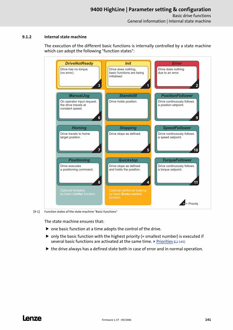
L Firmware 1.37 - 09/2006 141
9400 HighLine | Parameter setting & configurationBasic drive functions
General information | Internal state machine
9.1.2 Internal state machine
The execution of the different basic functions is internally controlled by a state machinewhich can adopt the following "function states":
[9-1] Function states of the state machine "Basic functions"
The state machine ensures that:
one basic function at a time adopts the control of the drive.
only the basic function with the highest priority (= smallest number) is executed if several basic functions are activated at the same time. Priorities ( 145)
the drive always has a defined state both in case of error and in normal operation.
ManualJog
On operator input request,the drive travels atconstant speed.
Homing
Drive travels to hometarget position.
Error
Drive does nothingdue to an error.
Stopping
Drive stops as defined.
Quickstop
Drive stops as definedand holds the position.
SpeedFollower
Drive continuously followsa speed setpoint.
Positioning
Drive executesa positioning command.
DriveNotReady
Drive has no torque(no error).
Standstill
Drive holds position.
Init
Drive does nothing,basic functions are beinginitialised.
Optional limitationby basic function.Limiter
Optional additional brakingby basicfunction.
Brake control
PositionFollower
Drive continuously followsa position setpoint.
TorqueFollower
Drive continuously followsa torque setpoint.
13 2
9
10
114
57
8
6
x = Priority
9400 HighLine | Parameter setting & configurationBasic drive functionsGeneral information | Internal state machine
142 Firmware 1.37 - 09/2006 L
Tip!
In C02530 the currently active function state is displayed.
9.1.2.1 "Initialisation" status
If the controller has completed the device initialisation, the function state "Initialisation" ispassed through.
In the function state "Initialisation", the process data required for processing the basic functions are initialised.
The monitoring mode is not yet active.
The basic functions are not yet processed (e.g. brake control) and cannot yet be parameterised or activated either.
When the basic functions are initialised and no error had occurred, it is automatically changed to the basic state "Drive in standstill".
9.1.2.2 Status "Controller not ready"
In this function state the pulse inhibit is set in the controller, which means that the poweroutput stages are tristated and the drive cannot be controlled.
9.1.2.3 Status "drive in standstill"
This "basic state" is assumed if no other state is active.
The setpoints for speed and acceleration are set to "0".
The drive stands position-controlled.
No error has occurred and quick stop is not active.
Every basic function can be activated out of this state.
Note!
The basic functions "Limiter" and "Brake control" run autonomously, but are able to control the state machine to a certain function state, if required.
The function states are not to be confused with the device states ("Operation", "Fault active", "Device is switched on", etc.) of the controller. Device states
( 45)
L Firmware 1.37 - 09/2006 143
9400 HighLine | Parameter setting & configurationBasic drive functions
General information | Internal state machine
9.1.2.4 Status "Drive is stopped"
This function state is automatically passed through when a basic function is deactivated.
If the drive does is not yet in the standstill state, it is decelerated to standstill via a parameterisable deceleration ramp.
If a basic function is activated during the "stopping", this basic function takes over the control of the drive from the current speed on and the function state "Drive is stopped" is abandoned.
If the drive is at standstill, it is automatically changed to the basic function "Drive in standstill".
9.1.2.5 Status "Manual jog active"
In this function state the drive can be manually directed in CW or CCW rotation ("inchingmode"). Manual jog ( 156)
If the controller knows the home position, the set software limit positions are monitored and, if available, connected travel range limit switches.
"Retracting" from an activated travel range limit switch is also possible.
9.1.2.6 Status "Homing active"
In this function state the home position and the machine measuring system for the drivecan be determined. Homing ( 164)
The home position can be determined by an active homing or reference setting.
A renewed determination of the home position is only required in case of recommissioning or in case of service (e.g. when drive components are exchanged) or after travel command have been executed which reset the reference.
9.1.2.7 Status "Positioning active"
In this function state all positioning types (absolute, relative, modulo, continuous, touchprobe etc.) can be executed. Positioning ( 176)
In the position-controlled mode, the drive executes a time-controlled point-to-point setpoint generation based on the defined motion profile.
9400 HighLine | Parameter setting & configurationBasic drive functionsGeneral information | Internal state machine
144 Firmware 1.37 - 09/2006 L
9.1.2.8 Status "Setpoint follower active"
In this function state the drive directly follows the defined setpoint.
The setpoint can optionally be specified as speed, torque or position via three separate basic functions:
– Speed follower ( 190)
– Torque follower ( 196)
– Position follower ( 183)
9.1.2.9 Status "Quick stop active"
This function state is active if quick stop has been activated by the user. Quick stop ( 152)
The drive is decelerated to standstill irrespective of the defined setpoint within the parameterised deceleration time.
If quick stop is deactivated again by the user, it is changed to a setpoint-generating basic function (e.g. "speed follower"), if requested.
Tip!
Quick stop can also be set as error response for many monitoring functions ("quickstop by trouble"). Detailed information can be found in the chapter "Diagnostics &fault analysis".
The source which activated the quick stop function is shown bit-coded in C00159.
9.1.2.10 Status "Error"
This function state is active if an error has occurred and the controller is in the status "Erroractive" or "Quick stop by trouble active.
The function state can only be abandoned by acknowledging the error if the error is removed.
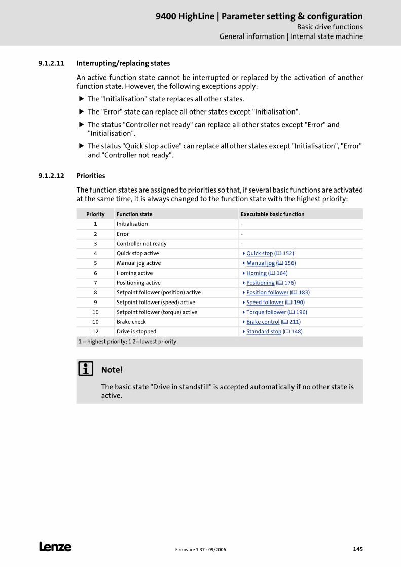
L Firmware 1.37 - 09/2006 145
9400 HighLine | Parameter setting & configurationBasic drive functions
General information | Internal state machine
9.1.2.11 Interrupting/replacing states
An active function state cannot be interrupted or replaced by the activation of anotherfunction state. However, the following exceptions apply:
The "Initialisation" state replaces all other states.
The "Error" state can replace all other states except "Initialisation".
The status "Controller not ready" can replace all other states except "Error" and "Initialisation".
The status "Quick stop active" can replace all other states except "Initialisation", "Error" and "Controller not ready".
9.1.2.12 Priorities
The function states are assigned to priorities so that, if several basic functions are activatedat the same time, it is always changed to the function state with the highest priority:
Priority Function state Executable basic function
1 Initialisation -
2 Error -
3 Controller not ready -
4 Quick stop active Quick stop ( 152)
5 Manual jog active Manual jog ( 156)
6 Homing active Homing ( 164)
7 Positioning active Positioning ( 176)
8 Setpoint follower (position) active Position follower ( 183)
9 Setpoint follower (speed) active Speed follower ( 190)
10 Setpoint follower (torque) active Torque follower ( 196)
10 Brake check Brake control ( 211)
12 Drive is stopped Standard stop ( 148)
1 ≡ highest priority; 1 2≡ lowest priority
Note!
The basic state "Drive in standstill" is accepted automatically if no other state is active.
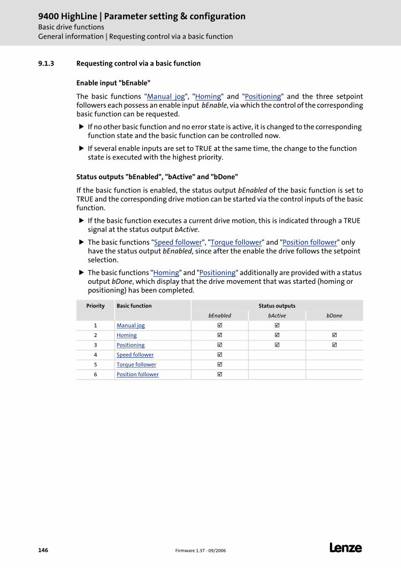
9400 HighLine | Parameter setting & configurationBasic drive functionsGeneral information | Requesting control via a basic function
146 Firmware 1.37 - 09/2006 L
9.1.3 Requesting control via a basic function
Enable input "bEnable"
The basic functions "Manual jog", "Homing" and "Positioning" and the three setpointfollowers each possess an enable input bEnable, via which the control of the correspondingbasic function can be requested.
If no other basic function and no error state is active, it is changed to the corresponding function state and the basic function can be controlled now.
If several enable inputs are set to TRUE at the same time, the change to the function state is executed with the highest priority.
Status outputs "bEnabled", "bActive" and "bDone"
If the basic function is enabled, the status output bEnabled of the basic function is set toTRUE and the corresponding drive motion can be started via the control inputs of the basicfunction.
If the basic function executes a current drive motion, this is indicated through a TRUE signal at the status output bActive.
The basic functions "Speed follower", "Torque follower" and "Position follower" only have the status output bEnabled, since after the enable the drive follows the setpoint selection.
The basic functions "Homing" and "Positioning" additionally are provided with a status output bDone, which display that the drive movement that was started (homing or positioning) has been completed.
Priority Basic function Status outputs
bEnabled bActive bDone
1 Manual jog
2 Homing
3 Positioning
4 Speed follower
5 Torque follower
6 Position follower
L Firmware 1.37 - 09/2006 147
9400 HighLine | Parameter setting & configurationBasic drive functions
General information | Requesting control via a basic function
Re-deactivation the enable of a basic function
When the enable input bEnable of the active basic function is reset to FALSE, the controlinputs of the basic function are inhibited and the status outputs bEnabled, bActive andbDone are reset to FALSE.
When the drive is not at standstill, it is decelerated to standstill within the deceleration time for Standard stop unless another basic function takes over the control of the drive. Here, the active function state is changed to the basic state "Drive in standstill" via the function state "Drive is stopped".
When the enable input of another basic function is set to TRUE, this basic function adopts the control of the drive immediately.

9400 HighLine | Parameter setting & configurationBasic drive functionsStandard stop
148 Firmware 1.37 - 09/2006 L
9.2 Standard stop
The standard stop of the drive will be automatically activated by the internal statemachine if a basic function is deactivated and the drive is not yet in standstill.
The drive is braked to standstill via a parameterisable deceleration ramp.
– While the drive is braked to standstill, the state machine is in the function state "Drive is stopped".
– If meanwhile another basic function is activated, this basic function takes over the control of the drive from the current speed on and the function state "Drive is stopped" is abandoned.
– If the drive is at standstill, it is automatically changed to the basic function "Drive in standstill".
An acceleration phase active at the time of activating the stopping process is considered by the standard stop, i.e. the current acceleration is at first led to "0" with the parameterised S-ramp time before the real deceleration process starts.
If the controller is enabled while the shaft is coasting (controller inhibit and pulse inhibit are deactivated), the drive is braked from the current speed to standstill.
Stop!
The basic functions "Speed follower", "Torque follower" and "Position follower" take over the control of the drive not from the current speed on but with the defined setpoint which may lead to a jerk!
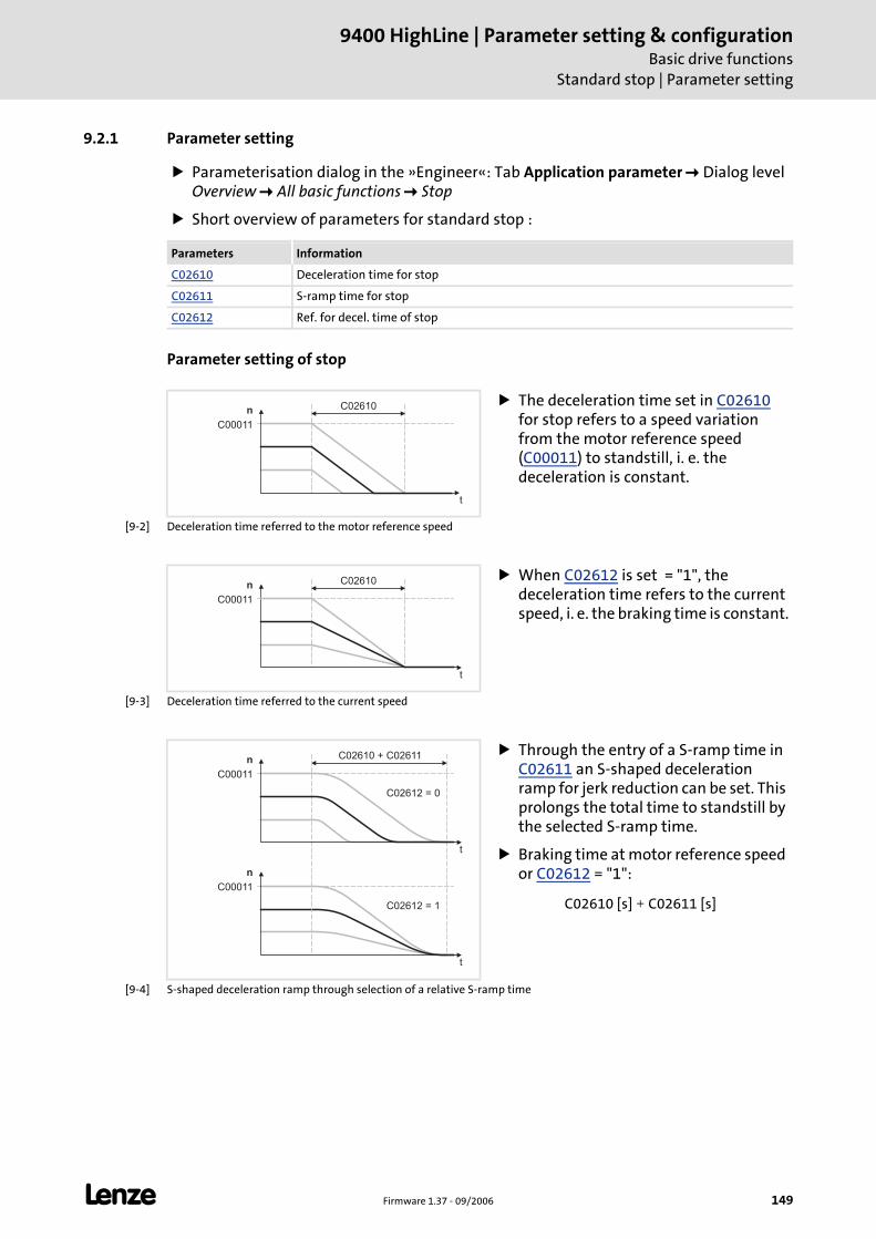
L Firmware 1.37 - 09/2006 149
9400 HighLine | Parameter setting & configurationBasic drive functions
Standard stop | Parameter setting
9.2.1 Parameter setting
Parameterisation dialog in the »Engineer«: Tab Application parameter Dialog level Overview All basic functions Stop
Short overview of parameters for standard stop :
Parameter setting of stop
[9-2] Deceleration time referred to the motor reference speed
[9-3] Deceleration time referred to the current speed
[9-4] S-shaped deceleration ramp through selection of a relative S-ramp time
Parameters Information
C02610 Deceleration time for stop
C02611 S-ramp time for stop
C02612 Ref. for decel. time of stop
The deceleration time set in C02610 for stop refers to a speed variation from the motor reference speed (C00011) to standstill, i. e. the deceleration is constant.
n
t
C00011
C02610
When C02612 is set = "1", the deceleration time refers to the current speed, i. e. the braking time is constant.
C02610n
t
C00011
Through the entry of a S-ramp time in C02611 an S-shaped deceleration ramp for jerk reduction can be set. This prolongs the total time to standstill by the selected S-ramp time.
Braking time at motor reference speed or C02612 = "1":
n
t
C00011
n
t
C00011
C02612 = 0
C02612 = 1
C02610 + C02611
C02610 [s] C02611 [s]+
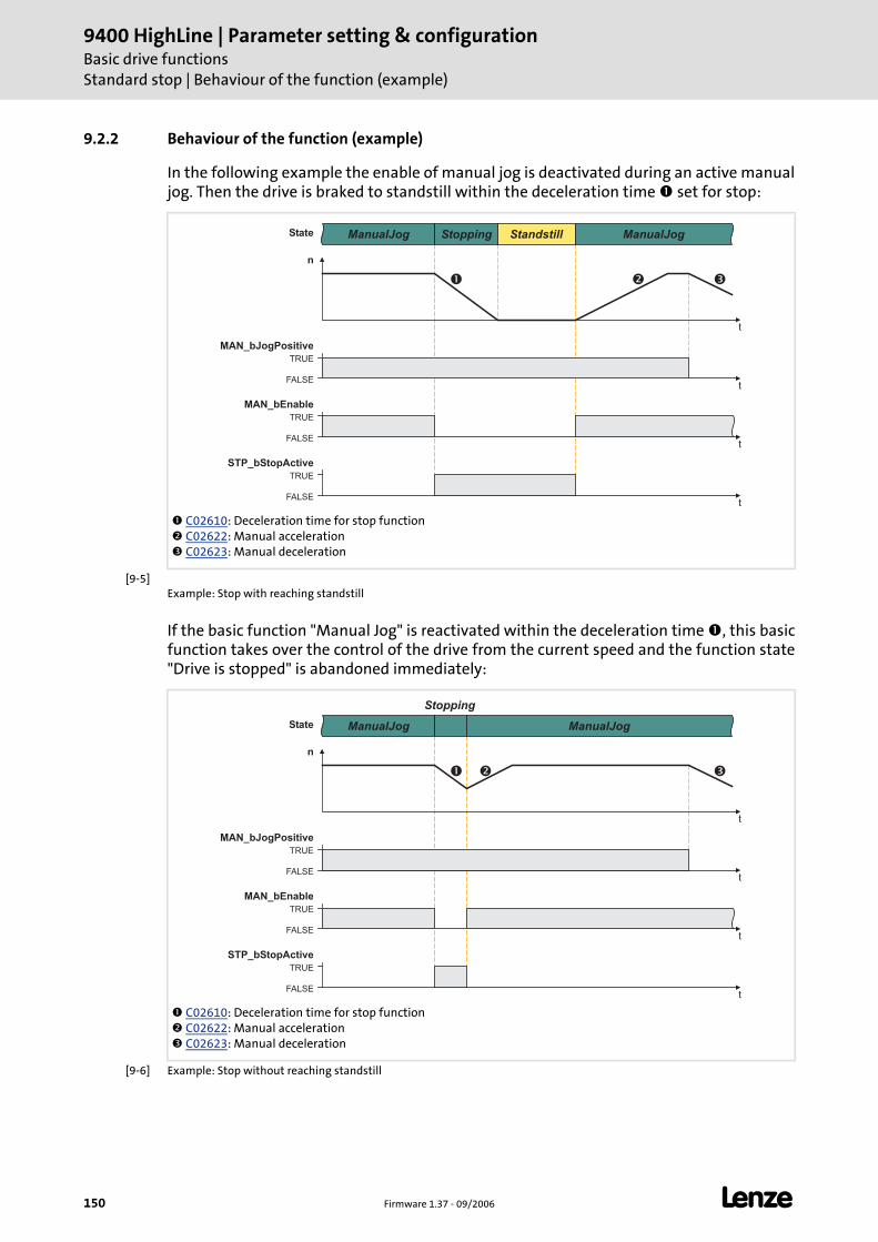
9400 HighLine | Parameter setting & configurationBasic drive functionsStandard stop | Behaviour of the function (example)
150 Firmware 1.37 - 09/2006 L
9.2.2 Behaviour of the function (example)
In the following example the enable of manual jog is deactivated during an active manualjog. Then the drive is braked to standstill within the deceleration time set for stop:
[9-5]Example: Stop with reaching standstill
If the basic function "Manual Jog" is reactivated within the deceleration time , this basicfunction takes over the control of the drive from the current speed and the function state"Drive is stopped" is abandoned immediately:
[9-6] Example: Stop without reaching standstill
C02610: Deceleration time for stop function C02622: Manual acceleration C02623: Manual deceleration
n
t
TRUE
FALSE
MAN_bEnable
t
ManualJog Stopping Standstill ManualJog
TRUE
FALSE
STP_bStopActive
t
TRUE
FALSE
MAN_bJogPositive
t
State
� � �
C02610: Deceleration time for stop function C02622: Manual acceleration C02623: Manual deceleration
n
t
TRUE
FALSE
MAN_bEnable
t
ManualJog
Stopping
ManualJog
TRUE
FALSE
STP_bStopActive
t
TRUE
FALSE
MAN_bJogPositive
t
State
� � �
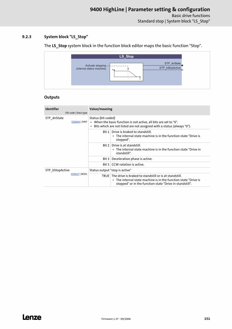
L Firmware 1.37 - 09/2006 151
9400 HighLine | Parameter setting & configurationBasic drive functions
Standard stop | System block "LS_Stop"
9.2.3 System block "LS_Stop"
The LS_Stop system block in the function block editor maps the basic function "Stop".
Outputs
IdentifierDIS code | Data type
Value/meaning
STP_dnStateC02616 | DINT
Status (bit-coded) • When the basic function is not active, all bits are set to "0". • Bits which are not listed are not assigned with a status (always "0").
Bit 1 Drive is braked to standstill. • The internal state machine is in the function state "Drive is
stopped".
Bit 2 Drive is at standstill. • The internal state machine is in the function state "Drive in
standstill".
Bit 3 Deceleration phase is active.
Bit 5 CCW rotation is active.
STP_bStopActiveC02617 | BOOL
Status output "stop is active"
TRUE The drive is braked to standstill or is at standstill. • The internal state machine is in the function state "Drive is
stopped" or in the function state "Drive in standstill".
STP_dnState
STP_bStopActiven
t
LS_Stop
Activate stopping(internal status machine)
9400 HighLine | Parameter setting & configurationBasic drive functionsQuick stop
152 Firmware 1.37 - 09/2006 L
9.3 Quick stop
Compared to the Standard stop quick stop (QSP) is determined for a stop in the case of anerror. If quick stop is activated, the drive is braked to standstill irrespective of the definedsetpoint within the deceleration time set.
Tip!
Quick stop can also be set as error response for many monitoring functions ("quickstop by trouble"). Detailed information can be found in the chapter "Diagnostics &fault analysis".
The source which activated the quick stop function is shown bit-coded in C00159.
9.3.1 Parameter setting
Parameterisation dialog in the »Engineer«: Tab Application parameter dialog level Overview All basic functions Quick stop
Short overview of the parameters for quick stop:
Note!
Through this, superimposed controls (e.g. synchronous or position control) may produce following errors. If several drives execute a coordinated motion, the quick stop function should only be used for the motion master (master drive) in order to maintain the coordination.
Parameters Information
C00105 Quick stop deceleration time
C00106 Quick stop S-ramp time
C00107 Reference for "Quick stop" deceleration time
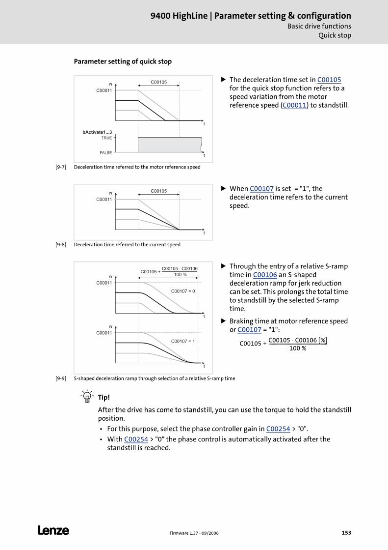
L Firmware 1.37 - 09/2006 153
9400 HighLine | Parameter setting & configurationBasic drive functions
Quick stop
Parameter setting of quick stop
[9-7] Deceleration time referred to the motor reference speed
[9-8] Deceleration time referred to the current speed
[9-9] S-shaped deceleration ramp through selection of a relative S-ramp time
Tip!
After the drive has come to standstill, you can use the torque to hold the standstillposition.
• For this purpose, select the phase controller gain in C00254 > "0".
• With C00254 > "0" the phase control is automatically activated after the standstill is reached.
The deceleration time set in C00105 for the quick stop function refers to a speed variation from the motor reference speed (C00011) to standstill.
n
t
C00011
C00105
TRUE
FALSE
bActivate1...3
t
When C00107 is set = "1", the deceleration time refers to the current speed.
C00105n
t
C00011
Through the entry of a relative S-ramp time in C00106 an S-shaped deceleration ramp for jerk reduction can be set. This prolongs the total time to standstill by the selected S-ramp time.
Braking time at motor reference speed or C00107 = "1":
n
t
C00011
n
t
C00011
C00107 = 0
C00107 = 1
C00105 +C00105 C00106�
100 %
C00105 C00105 C00106 [%]⋅100 %
------------------------------------------------------+
9400 HighLine | Parameter setting & configurationBasic drive functionsQuick stop | Activating/Deactivating quick stop
154 Firmware 1.37 - 09/2006 L
9.3.2 Activating/Deactivating quick stop
Quick stop through the application is activated/deactivated via the three inputsQSP_bActivate1...3 of the system block LS_Quickstop. ( 155)
The three control inputs are linked via a logic OR gate, i.e. in order to activate quick stop, only one of the three inputs must be set to TRUE. To deactivate quick stop, though, all three inputs must be reset to FALSE.
The control inputs can be linked with terminals (digital inputs) and/or process data in the function block editor.
Further options for activating quick stop
Via controller command "Activate quick stop" (C00002 = "45"), e.g. via a corresponding SDO of a higher-level control, an HMI or the »Engineer«.
Via the key at the keypad, unless the Lenze setting of C00469 (assignment of the key) has been changed.
Through the response "quick stop by trouble" parameterised for monitoring.
Note!
In the standard technology applications the control input QSP_bActivate1 is linked with the digital input DI1 in the Lenze setting.
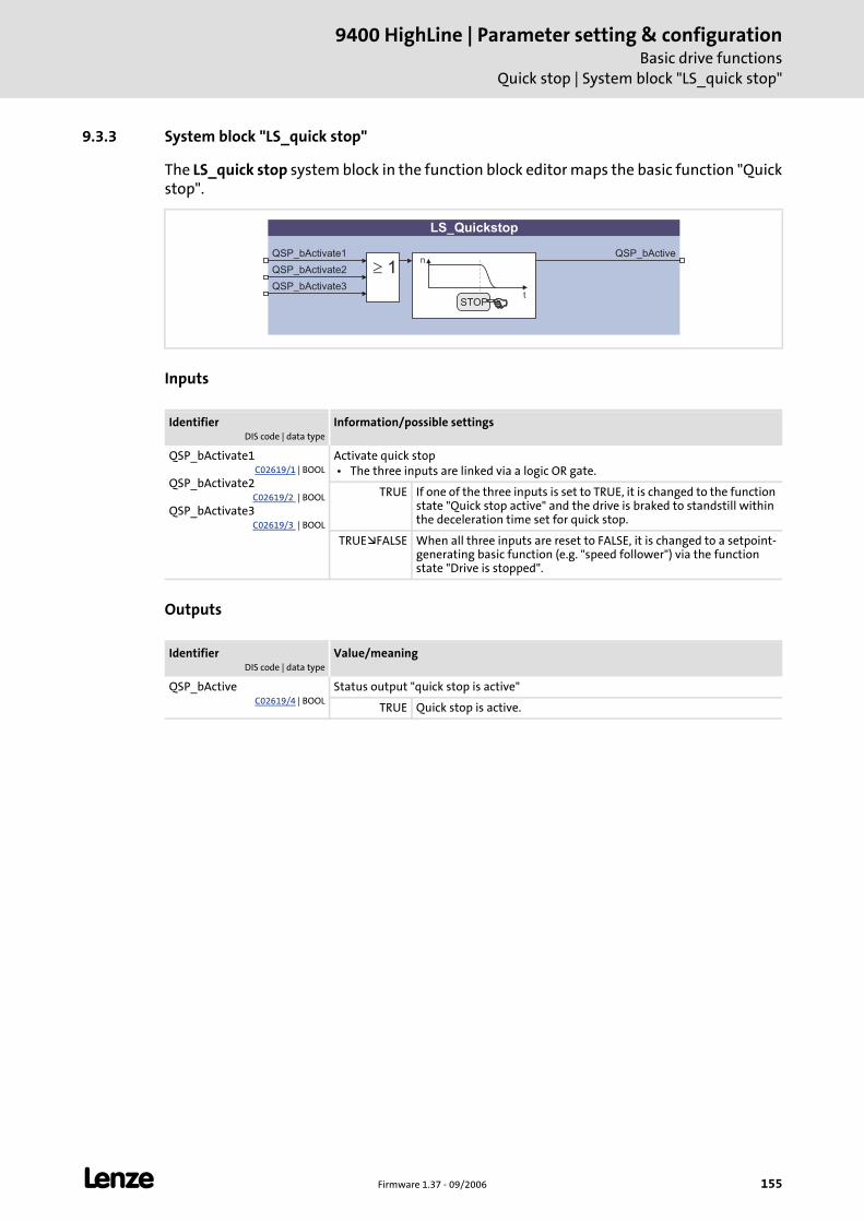
L Firmware 1.37 - 09/2006 155
9400 HighLine | Parameter setting & configurationBasic drive functions
Quick stop | System block "LS_quick stop"
9.3.3 System block "LS_quick stop"
The LS_quick stop system block in the function block editor maps the basic function "Quickstop".
Inputs
Outputs
IdentifierDIS code | data type
Information/possible settings
QSP_bActivate1C02619/1 | BOOL
QSP_bActivate2C02619/2 | BOOL
QSP_bActivate3C02619/3 | BOOL
Activate quick stop • The three inputs are linked via a logic OR gate.
TRUE If one of the three inputs is set to TRUE, it is changed to the function state "Quick stop active" and the drive is braked to standstill within the deceleration time set for quick stop.
TRUE FALSE When all three inputs are reset to FALSE, it is changed to a setpoint-generating basic function (e.g. "speed follower") via the function state "Drive is stopped".
IdentifierDIS code | data type
Value/meaning
QSP_bActiveC02619/4 | BOOL
Status output "quick stop is active"
TRUE Quick stop is active.
LS_Quickstop
QSP_bActivate1 QSP_bActive
STOP
n
t
� 1QSP_bActivate2
QSP_bActivate3
9400 HighLine | Parameter setting & configurationBasic drive functionsManual jog
156 Firmware 1.37 - 09/2006 L
9.4 Manual jog
The basic function "Manual jog" serves to traverse the drive manually, e.g. to clean orexchange the tool.
Optionally, you can change over to a second manual speed during the process.
A "retracting" from operated travel range limit switches is also supported. Then, you can only traverse in the corresponding retracting direction.
9.4.1 Parameter setting
Parameterisation dialog in the »Engineer«: Tab Application parameter dialog level Overview All basic functions Manual jog
Short overview of the parameters for manual jog:
Note!
In the manual mode the travel mode is monitored via limit switches and software limit positions by the basic function "Limiter". ( 200)
Stop!
When the reference is not known and no software limit positions are set, the drive can run into a mechanical limit during the manual jog and machine parts can be destroyed or damaged!
Parameters Information
C02620 Manual jog speed 1
C02621 Manual jog speed 2
C02622 Manual acceleration
C02623 Manual deceleration
C02624 Inaccuracy time of manual traversing
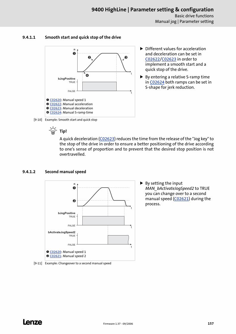
L Firmware 1.37 - 09/2006 157
9400 HighLine | Parameter setting & configurationBasic drive functions
Manual jog | Parameter setting
9.4.1.1 Smooth start and quick stop of the drive
[9-10] Example: Smooth start and quick stop
Tip!
A quick deceleration (C02623) reduces the time from the release of the "Jog key" tothe stop of the drive in order to ensure a better positioning of the drive accordingto one's sense of proportion and to prevent that the desired stop position is notovertravelled.
9.4.1.2 Second manual speed
[9-11] Example: Changeover to a second manual speed
C02620: Manual speed 1 C02622: Manual acceleration C02623: Manual deceleration C02624: Manual S-ramp time
Different values for acceleration and deceleration can be set in C02622/C02623 in order to implement a smooth start and a quick stop of the drive.
By entering a relative S-ramp time in C02624 both ramps can be set in S-shape for jerk reduction.
n
t
TRUE
FALSE
bJogPositive
t
�
�
�
�
C02620: Manual speed 1 C02621: Manual speed 2
By setting the input MAN_bActivateJogSpeed2 to TRUE you can change over to a second manual speed (C02621) during the process.
n
t
TRUE
FALSE
bJogPositive
t
TRUE
FALSE
bActivateJogSpeed2
t
�
�
9400 HighLine | Parameter setting & configurationBasic drive functionsManual jog | Executing manual jog
158 Firmware 1.37 - 09/2006 L
9.4.2 Executing manual jog
Requirements
The controller is in the device state "Operation".
The basic function "manual jog" is part of the active application.
No other basic function is active.
Activation
To request the control via the basic function, the enable input MAN_bEnable in theapplication must be set to TRUE.
If no other basic function is active, it is changed to the function state "Manual jog active" and manual jog can be executed via the control inputs.
A successful change to the function state "Manual jog active" is displayed by a TRUE signal at the status output MAN_bEnabled.
Deactivation
If the enable input MAN_bEnable is reset to FALSE, an active manual jog is reset, i.e. thecontrol inputs for manual jog are inhibited and the drive is braked to standstill within thedeceleration time for Standard stop. ( 148)
The status output MAN_bEnabled is reset to FALSE and a changeover from the active function state "Manual jog active" via the function state "Drive is stopped" back to th basic state "Drive in standstill" is effected.
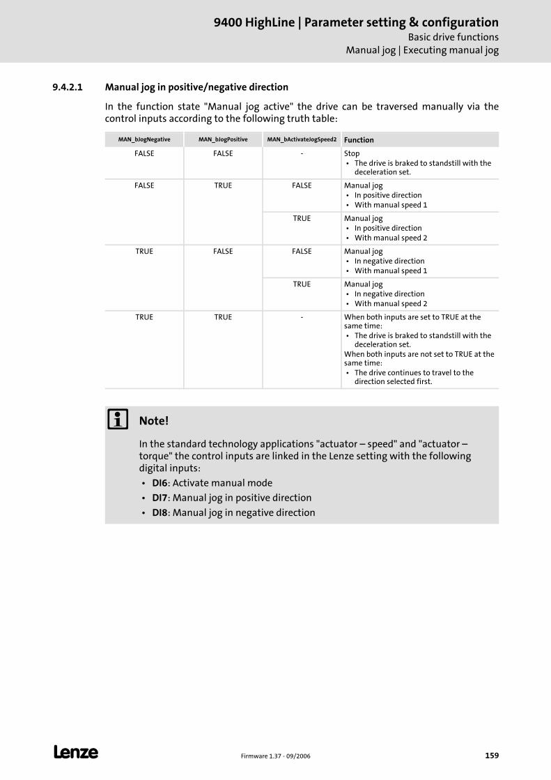
L Firmware 1.37 - 09/2006 159
9400 HighLine | Parameter setting & configurationBasic drive functions
Manual jog | Executing manual jog
9.4.2.1 Manual jog in positive/negative direction
In the function state "Manual jog active" the drive can be traversed manually via thecontrol inputs according to the following truth table:
MAN_bJogNegative MAN_bJogPositive MAN_bActivateJogSpeed2 Function
FALSE FALSE - Stop • The drive is braked to standstill with the
deceleration set.
FALSE TRUE FALSE Manual jog • In positive direction • With manual speed 1
TRUE Manual jog • In positive direction • With manual speed 2
TRUE FALSE FALSE Manual jog • In negative direction • With manual speed 1
TRUE Manual jog • In negative direction • With manual speed 2
TRUE TRUE - When both inputs are set to TRUE at the same time: • The drive is braked to standstill with the
deceleration set.When both inputs are not set to TRUE at the same time: • The drive continues to travel to the
direction selected first.
Note!
In the standard technology applications "actuator – speed" and "actuator – torque" the control inputs are linked in the Lenze setting with the following digital inputs:
• DI6: Activate manual mode
• DI7: Manual jog in positive direction
• DI8: Manual jog in negative direction
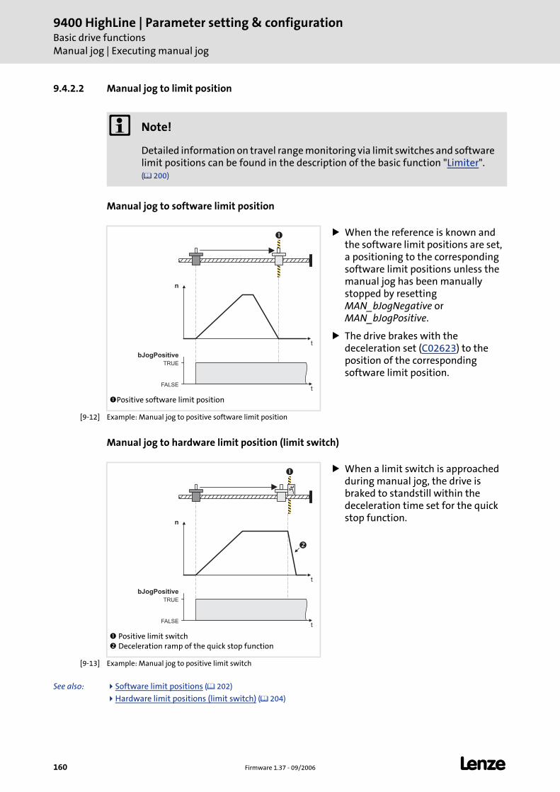
9400 HighLine | Parameter setting & configurationBasic drive functionsManual jog | Executing manual jog
160 Firmware 1.37 - 09/2006 L
9.4.2.2 Manual jog to limit position
Manual jog to software limit position
[9-12] Example: Manual jog to positive software limit position
Manual jog to hardware limit position (limit switch)
[9-13] Example: Manual jog to positive limit switch
See also: Software limit positions ( 202)
Hardware limit positions (limit switch) ( 204)
Note!
Detailed information on travel range monitoring via limit switches and software limit positions can be found in the description of the basic function "Limiter". ( 200)
Positive software limit position
When the reference is known and the software limit positions are set, a positioning to the corresponding software limit positions unless the manual jog has been manually stopped by resetting MAN_bJogNegative or MAN_bJogPositive.
The drive brakes with the deceleration set (C02623) to the position of the corresponding software limit position.
n
t
TRUE
FALSE
bJogPositive
t
�
Positive limit switch Deceleration ramp of the quick stop function
When a limit switch is approached during manual jog, the drive is braked to standstill within the deceleration time set for the quick stop function.
n
t
TRUE
FALSE
bJogPositive
t
�
�
L Firmware 1.37 - 09/2006 161
9400 HighLine | Parameter setting & configurationBasic drive functions
Manual jog | Executing manual jog
9.4.2.3 Retracting of an activated limit switch
By setting MAN_bReleaseLimitSwitch to TRUE a retraction from an activated limit switch ispossible. Travel in the retracting direction until the limit switch is not active anymore.
If, while retracting, a direction is selected additionally via the control inputs MAN_bJogPositive or MAN_bJogNegative towards the retracting direction, the travel is continued even the limit switch has been abandoned until MAN_bJogPositive or MAN_bJogNegative are reset to FALSE.
If the direction is selected against the retracting direction, the drive stops and a corresponding status is output via the status output MAN_dnState of the system block LS_ManualJog.
Tip!
An activated limit switch can also be abandoned by manual jog in retractingdirection via the control inputs MAN_bJogPositive or MAN_bJogNegative.
See also: Hardware limit positions (limit switch) ( 204)
Note!
It can only be retracted from a limit switch if this is still activated, i.e. the corresponding limit switch input of the limiter is still active. Therefore ensure that while travelling towards a limit switch that the trigger mechanics will not be overtravelled by a too high mass or swing so that the limit switch will not be activated by this.
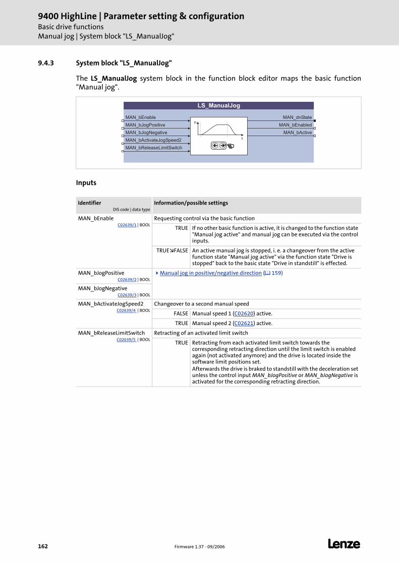
9400 HighLine | Parameter setting & configurationBasic drive functionsManual jog | System block "LS_ManualJog"
162 Firmware 1.37 - 09/2006 L
9.4.3 System block "LS_ManualJog"
The LS_ManualJog system block in the function block editor maps the basic function"Manual jog".
Inputs
IdentifierDIS code | data type
Information/possible settings
MAN_bEnableC02639/1 | BOOL
Requesting control via the basic function
TRUE If no other basic function is active, it is changed to the function state "Manual jog active" and manual jog can be executed via the control inputs.
TRUE FALSE An active manual jog is stopped, i. e. a changeover from the active function state "Manual jog active" via the function state "Drive is stopped" back to the basic state "Drive in standstill" is effected.
MAN_bJogPositiveC02639/2 | BOOL
Manual jog in positive/negative direction ( 159)
MAN_bJogNegativeC02639/3 | BOOL
MAN_bActivateJogSpeed2C02639/4 | BOOL
Changeover to a second manual speed
FALSE Manual speed 1 (C02620) active.
TRUE Manual speed 2 (C02621) active.
MAN_bReleaseLimitSwitchC02639/5 | BOOL
Retracting of an activated limit switch
TRUE Retracting from each activated limit switch towards the corresponding retracting direction until the limit switch is enabled again (not activated anymore) and the drive is located inside the software limit positions set.Afterwards the drive is braked to standstill with the deceleration set unless the control input MAN_bJogPositive or MAN_bJogNegative is activated for the corresponding retracting direction.
LS_ManualJog
MAN_bEnable
MAN_bJogNegative
MAN_bActivateJogSpeed2
MAN_bReleaseLimitSwitch
MAN_bEnabled
MAN_bActive
n
t
��
MAN_bJogPositive
MAN_dnState
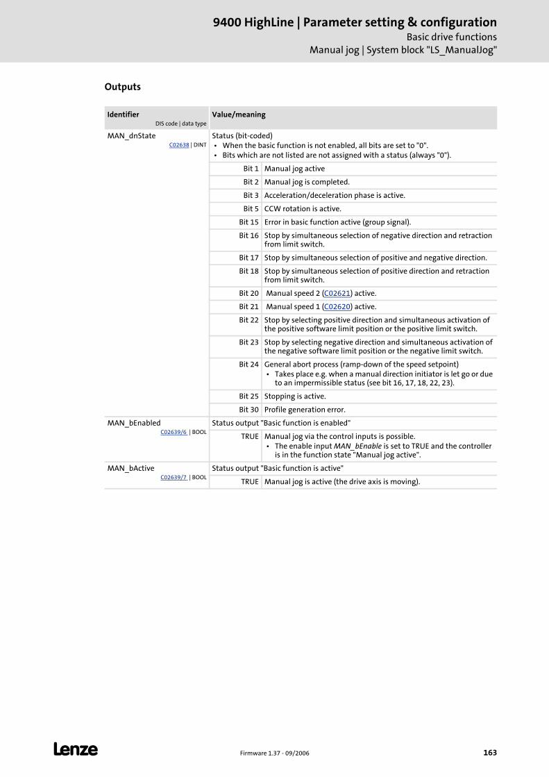
L Firmware 1.37 - 09/2006 163
9400 HighLine | Parameter setting & configurationBasic drive functions
Manual jog | System block "LS_ManualJog"
Outputs
IdentifierDIS code | data type
Value/meaning
MAN_dnStateC02638 | DINT
Status (bit-coded) • When the basic function is not enabled, all bits are set to "0". • Bits which are not listed are not assigned with a status (always "0").
Bit 1 Manual jog active
Bit 2 Manual jog is completed.
Bit 3 Acceleration/deceleration phase is active.
Bit 5 CCW rotation is active.
Bit 15 Error in basic function active (group signal).
Bit 16 Stop by simultaneous selection of negative direction and retraction from limit switch.
Bit 17 Stop by simultaneous selection of positive and negative direction.
Bit 18 Stop by simultaneous selection of positive direction and retraction from limit switch.
Bit 20 Manual speed 2 (C02621) active.
Bit 21 Manual speed 1 (C02620) active.
Bit 22 Stop by selecting positive direction and simultaneous activation of the positive software limit position or the positive limit switch.
Bit 23 Stop by selecting negative direction and simultaneous activation of the negative software limit position or the negative limit switch.
Bit 24 General abort process (ramp-down of the speed setpoint) • Takes place e.g. when a manual direction initiator is let go or due
to an impermissible status (see bit 16, 17, 18, 22, 23).
Bit 25 Stopping is active.
Bit 30 Profile generation error.
MAN_bEnabledC02639/6 | BOOL
Status output "Basic function is enabled"
TRUE Manual jog via the control inputs is possible. • The enable input MAN_bEnable is set to TRUE and the controller
is in the function state "Manual jog active".
MAN_bActiveC02639/7 | BOOL
Status output "Basic function is active"
TRUE Manual jog is active (the drive axis is moving).
9400 HighLine | Parameter setting & configurationBasic drive functionsHoming
164 Firmware 1.37 - 09/2006 L
9.5 Homing
The basic function "Homing" serves to transfer the measuring system to the physicallypossible travel range of the controller.
The reference (e.g. zero position of the drive axis in the machine measuring system) can be defined by reference search or reference setting.
In case of reference search, the drive travels according to the defined homing mode to detect the reference in the measuring system independently.
In case of reference setting in the homing mode "100: Set reference directly" or via control input HM_bLoadHomePos the drive can also be referenced manually when the motor is at standstill. The measuring system is set according to the home position parameterised in C02642 or applied to the input HM_dnHomePos_p.
Note!
The encoder position is stored safe against mains failure in the memory module and is therefore known to the drive control even after the mains has been switched.
Behaviour of the home position after mains switching
If the home position/information is to be available after mains switching as well, the setting C02652 = "1: Keep" is required.
• One further condition for keeping the home position/information after mains switching is the compliance with the maximally permissible angle of rotation of the encoder which can be set in C02653.
• When resolvers or single-turn absolute value encoders are used and the mains is switched off (24-V supply off), the drive may only be moved by ½ motor revolution since otherwise the home position will get lost due to the ambiguity of the encoder information.
A renewed reference setting is only required in case of a renewed commissioning or in case of service (e.g. when drive components are exchanged).
L Firmware 1.37 - 09/2006 165
9400 HighLine | Parameter setting & configurationBasic drive functions
Homing | Parameter setting
9.5.1 Parameter setting
Parameterisation dialog in the »Engineer«: Tab Application parameter dialog level Overview All basic functions Homing
Short overview of the parameters for homing:
9.5.1.1 Homing mode
The zero position, also called reference, can be defined by a reference search or referencesetting:
In case of a reference search the drive travels according to a defined mode to detect the reference independently.
In case of reference setting the reference is manually set when the drive has stopped.
Tip!
A reference search is mainly used for continuous systems or if the traversing rangeor machine cycle of the drive cannot be displayed in the display space of theencoder, e.g. when incremental encoders are used on a motor or single-turnabsolute value encoders or resolvers on geared motors.
Reference setting is usually executed only once during commissioning or in case ofservice (e.g. when drive components are exchanged) and are normally used insystems the machine cycle of which can be displayed in the display space of theencoder, e.g. when multi-turn absolute value encoder or single-turn absolute valueencoders/resolvers are used in a machine cycle on one motor revolution.
Parameters Information
C02528 Traversing range
C02640 Ref. mode
C02642 HM position
C02643 HM target position
C02644 Ref. speed 1
C02645 Home acceleration 1
C02646 Ref. speed 2
C02647 Ref. acceleration 2
C02648 Home S-ramp time
C02649 HM torque limit
C02650 Homing inhibit time
C02651 HM touch probe configuration
C02652 Home position after mains switching
C02653 Max. rot. angle after mains sw.
C02656 Current position
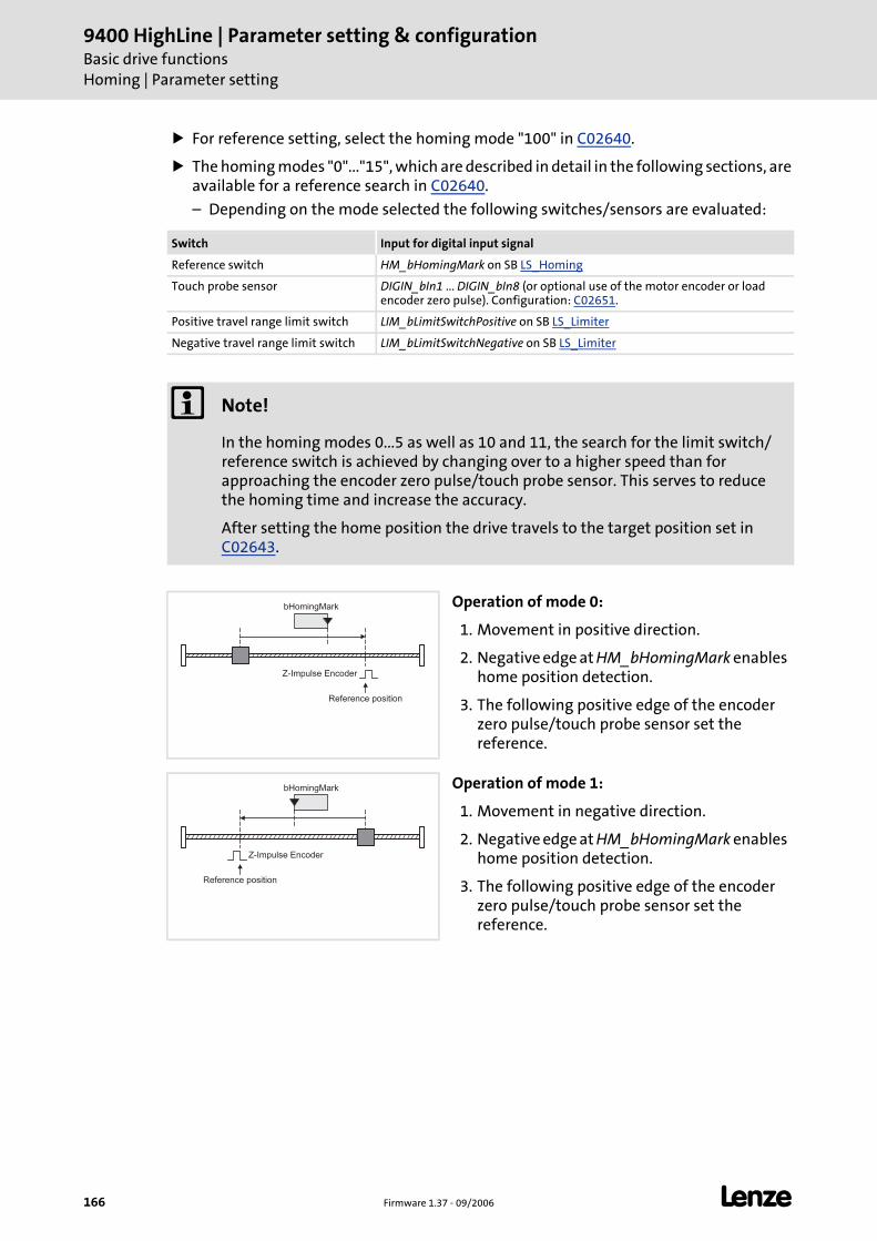
9400 HighLine | Parameter setting & configurationBasic drive functionsHoming | Parameter setting
166 Firmware 1.37 - 09/2006 L
For reference setting, select the homing mode "100" in C02640.
The homing modes "0"..."15", which are described in detail in the following sections, are available for a reference search in C02640.
– Depending on the mode selected the following switches/sensors are evaluated:
Switch Input for digital input signal
Reference switch HM_bHomingMark on SB LS_Homing
Touch probe sensor DIGIN_bIn1 ... DIGIN_bIn8 (or optional use of the motor encoder or load encoder zero pulse). Configuration: C02651.
Positive travel range limit switch LIM_bLimitSwitchPositive on SB LS_Limiter
Negative travel range limit switch LIM_bLimitSwitchNegative on SB LS_Limiter
Note!
In the homing modes 0...5 as well as 10 and 11, the search for the limit switch/reference switch is achieved by changing over to a higher speed than for approaching the encoder zero pulse/touch probe sensor. This serves to reduce the homing time and increase the accuracy.
After setting the home position the drive travels to the target position set in C02643.
Operation of mode 0:
1. Movement in positive direction.
2. Negative edge at HM_bHomingMark enables home position detection.
3. The following positive edge of the encoder zero pulse/touch probe sensor set the reference.
Operation of mode 1:
1. Movement in negative direction.
2. Negative edge at HM_bHomingMark enables home position detection.
3. The following positive edge of the encoder zero pulse/touch probe sensor set the reference.
bHomingMark
Reference position
Z-Impulse Encoder
bHomingMark
Reference position
Z-Impulse Encoder
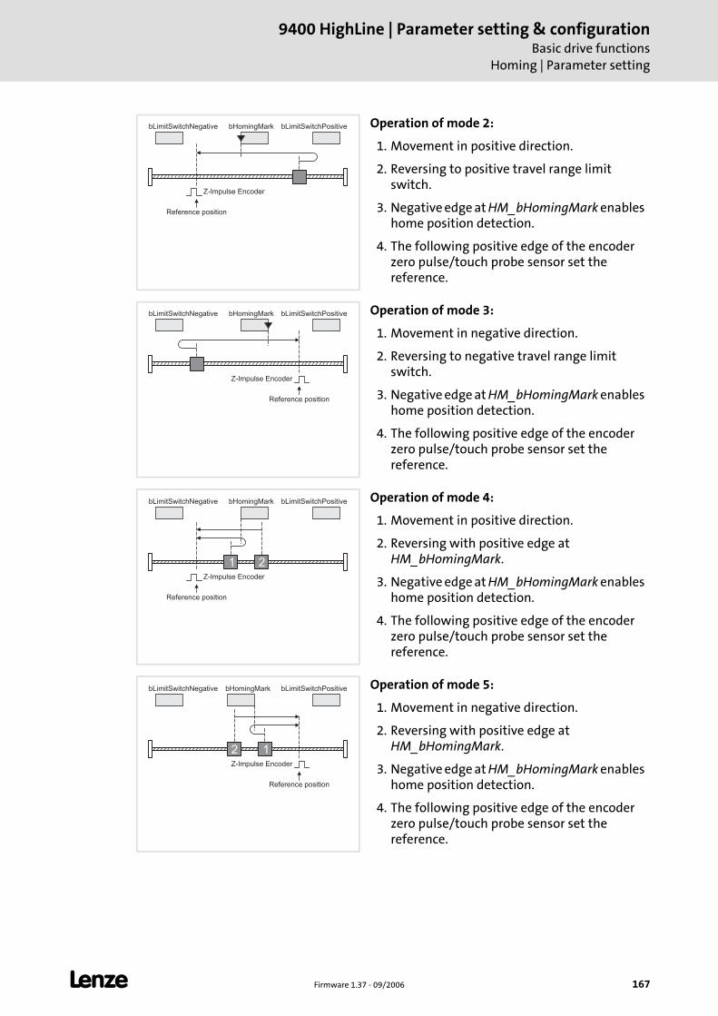
L Firmware 1.37 - 09/2006 167
9400 HighLine | Parameter setting & configurationBasic drive functions
Homing | Parameter setting
Operation of mode 2:
1. Movement in positive direction.
2. Reversing to positive travel range limit switch.
3. Negative edge at HM_bHomingMark enables home position detection.
4. The following positive edge of the encoder zero pulse/touch probe sensor set the reference.
Operation of mode 3:
1. Movement in negative direction.
2. Reversing to negative travel range limit switch.
3. Negative edge at HM_bHomingMark enables home position detection.
4. The following positive edge of the encoder zero pulse/touch probe sensor set the reference.
Operation of mode 4:
1. Movement in positive direction.
2. Reversing with positive edge at HM_bHomingMark.
3. Negative edge at HM_bHomingMark enables home position detection.
4. The following positive edge of the encoder zero pulse/touch probe sensor set the reference.
Operation of mode 5:
1. Movement in negative direction.
2. Reversing with positive edge at HM_bHomingMark.
3. Negative edge at HM_bHomingMark enables home position detection.
4. The following positive edge of the encoder zero pulse/touch probe sensor set the reference.
bHomingMark
Reference position
Z-Impulse Encoder
bLimitSwitchPositivebLimitSwitchNegative
bHomingMark bLimitSwitchPositivebLimitSwitchNegative
Reference position
Z-Impulse Encoder
bHomingMark
Reference position
Z-Impulse Encoder
bLimitSwitchPositivebLimitSwitchNegative
1 2
bHomingMark bLimitSwitchPositivebLimitSwitchNegative
12
Reference position
Z-Impulse Encoder
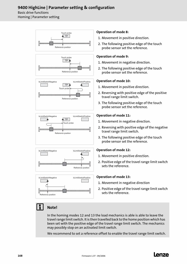
9400 HighLine | Parameter setting & configurationBasic drive functionsHoming | Parameter setting
168 Firmware 1.37 - 09/2006 L
Operation of mode 8:
1. Movement in positive direction.
2. The following positive edge of the touch probe sensor set the reference.
Operation of mode 9:
1. Movement in negative direction.
2. The following positive edge of the touch probe sensor set the reference.
Operation of mode 10:
1. Movement in positive direction.
2. Reversing with positive edge of the positive travel range limit switch.
3. The following positive edge of the touch probe sensor set the reference.
Operation of mode 11:
1. Movement in negative direction.
2. Reversing with positive edge of the negative travel range limit switch.
3. The following positive edge of the touch probe sensor set the reference.
Operation of mode 12:
1. Movement in positive direction.
2. Positive edge of the travel range limit switch sets the reference.
Operation of mode 13:
1. Movement in negative direction
2. Positive edge of the travel range limit switch sets the reference.
Note!
In the homing modes 12 and 13 the load mechanics is able is able to leave the travel range limit switch. It is then travelled back to the home position which has been set with the positive edge of the travel range limit switch. The mechanics may possibly stop on an activated limit switch.
We recommend to set a reference offset to enable the travel range limit switch.
Touch probe
Reference position
TP
Touch probe
Reference position
TP
Touch probe
bLimitSwitchPositivebLimitSwitchNegative
Reference position
TP
Touch probe
bLimitSwitchPositivebLimitSwitchNegative
Reference position
TP
bLimitSwitchPositivebLimitSwitchNegative
Reference position
bLimitSwitchPositivebLimitSwitchNegative
Reference position
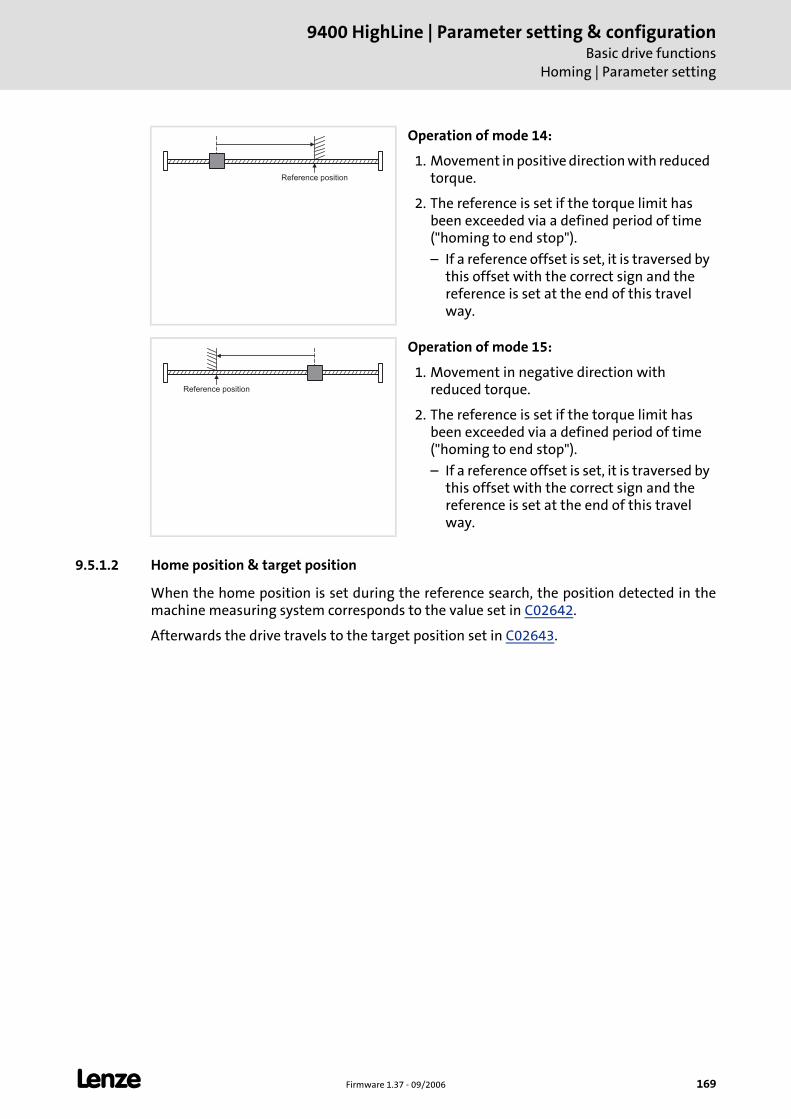
L Firmware 1.37 - 09/2006 169
9400 HighLine | Parameter setting & configurationBasic drive functions
Homing | Parameter setting 9.5.1.2 Home position & target position
When the home position is set during the reference search, the position detected in themachine measuring system corresponds to the value set in C02642.
Afterwards the drive travels to the target position set in C02643.
Operation of mode 14:
1. Movement in positive direction with reduced torque.
2. The reference is set if the torque limit has been exceeded via a defined period of time ("homing to end stop").
– If a reference offset is set, it is traversed by this offset with the correct sign and the reference is set at the end of this travel way.
Operation of mode 15:
1. Movement in negative direction with reduced torque.
2. The reference is set if the torque limit has been exceeded via a defined period of time ("homing to end stop").
– If a reference offset is set, it is traversed by this offset with the correct sign and the reference is set at the end of this travel way.
Reference position
Reference position
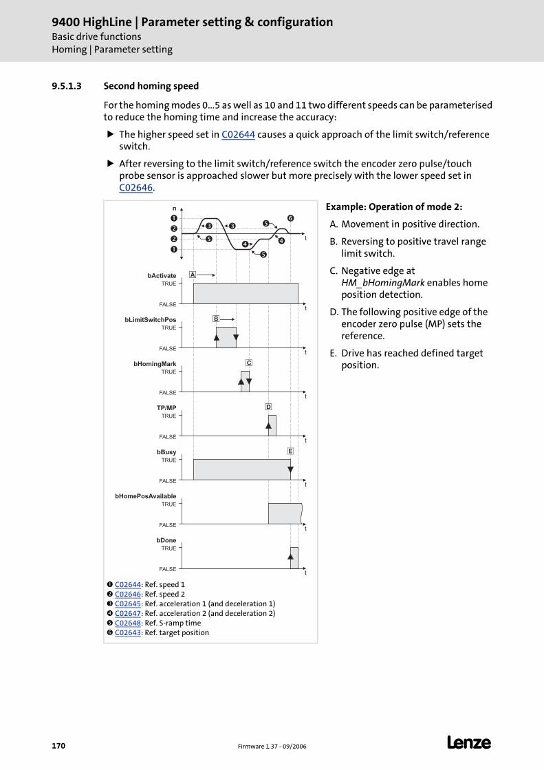
9400 HighLine | Parameter setting & configurationBasic drive functionsHoming | Parameter setting
170 Firmware 1.37 - 09/2006 L
9.5.1.3 Second homing speed
For the homing modes 0...5 as well as 10 and 11 two different speeds can be parameterisedto reduce the homing time and increase the accuracy:
The higher speed set in C02644 causes a quick approach of the limit switch/reference switch.
After reversing to the limit switch/reference switch the encoder zero pulse/touch probe sensor is approached slower but more precisely with the lower speed set in C02646.
C02644: Ref. speed 1 C02646: Ref. speed 2 C02645: Ref. acceleration 1 (and deceleration 1) C02647: Ref. acceleration 2 (and deceleration 2) C02648: Ref. S-ramp time C02643: Ref. target position
Example: Operation of mode 2:
A. Movement in positive direction.
B. Reversing to positive travel range limit switch.
C. Negative edge at HM_bHomingMark enables home position detection.
D. The following positive edge of the encoder zero pulse (MP) sets the reference.
E. Drive has reached defined target position.
n
t
TRUE
FALSE
bActivate
t
��
�
�
�
TRUE
FALSE
bHomingMark
t
TRUE
FALSE
bBusy
t
TRUE
FALSE
bDone
t
TRUE
FALSE
bHomePosAvailable
t
��
�
�
�
�
�
�
�
TRUE
FALSE
bLimitSwitchPos
t
�TRUE
FALSE
TP/MP
t
�
L Firmware 1.37 - 09/2006 171
9400 HighLine | Parameter setting & configurationBasic drive functions
Homing | Parameter setting
9.5.1.4 Homing to end stop
By selecting the homing modes 14 & 15, homing to end stop can be executed as follows:
1. The drive travels with reduced torque in positive direction (mode 14) or negative direction (mode 15).
2. When the drives hits an end stop so that the torque limit set in C02649 is exceeded for the period of time defined in C02650, the reference is set.
– When a reference offset is set, it is traversed by this offset with correct sign.
9.5.1.5 Connection of reference switch
For the homing modes with reference switch, the control input HM_bHomingMark of thesystem block LS_Homing must be connected to the digital input which is connected to thereference switch.
9.5.1.6 Touch probe interface configuration
The touch probe channel to be used for homing with touch probe detection is selected inthe »Engineer« on the Application parameter tab in the overview dialog level. All basicfunctions Homing TP interface.
The setting carried out in this parameterisation dialog directly affects the setting of C02651 ("Ref. touch probe configuration") and vice versa.
For a direct setting of C02651 (e.g. with keypad) the following table lists the decimal values for all possible configurations.
Example: For selecting the touch probe channel "DIGIN 8" and response to only one positive edge, it is required to set the decimal value "16384" in C02651.
SelectionTouch probe channel
Touch probe response
Positive edge Negative edge Both edges
DigIn 1 1 2 3
DigIn 2 4 8 12
DigIn 3 16 32 48
DigIn 4 64 128 192
DigIn 5 256 512 768
DigIn 6 1024 2048 3072
DigIn 7 4096 8192 12288
DigIn 8 16384 32768 49152
Motor encoder zero pulse 65536
Load encoder zero pulse 262144
9400 HighLine | Parameter setting & configurationBasic drive functionsHoming | Executing homing
172 Firmware 1.37 - 09/2006 L
9.5.2 Executing homing
Requirements
The controller is in the device state "Operation".
The basic function "Homing" is part of the active application.
No other basic function is active.
Activation
To request the control via the basic function, the enable input HM_bEnable in theapplication must be set to TRUE.
If no other basic function is active, a changeover to the function state "Homing active" is effected and homing can be executed via the control inputs.
A successful change to the function state "Homing active" is displayed by a TRUE signal at the status output HM_bEnabled.
Deactivation
When the enable input HM_bEnable is reset to FALSE, an active homing is stopped, i.e. thecontrol inputs for homing are inhibited and the drive is braked to standstill within thedeceleration time for stop.
The status output HM_bEnabled is reset to FALSE and a changeover from the active function state "Homing active" via the function state "Drive is stopped" back to th basic state "Drive in standstill" is effected.
L Firmware 1.37 - 09/2006 173
9400 HighLine | Parameter setting & configurationBasic drive functions
Homing | Executing homing
9.5.2.1 Setting reference search/setting reference directly
By setting the control input HM_bActivateHoming to TRUE, the reference search in theselected homing mode is started.
During reference search, the status output HM_bActive is set to TRUE.
When the reference search is completed, the status output HM_bActive is reset to FALSE and the status output HM_bDone is set to TRUE.
When the home position could be detected, the status output HM_bHomePosAvailable is set to TRUE.
9.5.2.2 Loading home position via input
By setting the control input HM_bLoadHomePos to TRUE the "tool position" applied toinput HM_dnHomePos_p is accepted manually as home position with drive at standstill.
9.5.2.3 Resetting home position
By setting the control input HM_bResetHomePos to TRUE the status "Reference known" isreset.
The status outputs HM_bDone and HM_bHomePosAvailable are reset to FALSE.
Note!
In the homing mode "100: Set reference directly" no reference search will be started but the home position set in C02642 will be directly accepted.
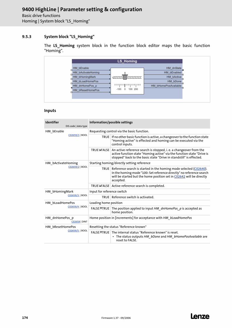
9400 HighLine | Parameter setting & configurationBasic drive functionsHoming | System block "LS_Homing"
174 Firmware 1.37 - 09/2006 L
9.5.3 System block "LS_Homing"
The LS_Homing system block in the function block editor maps the basic function"Homing".
Inputs
IdentifierDIS code | data type
Information/possible settings
HM_bEnableC02659/1 | BOOL
Requesting control via the basic function.
TRUE If no other basic function is active, a changeover to the function state "Homing active" is effected and homing can be executed via the control inputs.
TRUE FALSE An active reference search is stopped, i. e. a changeover from the active function state "Homing active" via the function state "Drive is stopped" back to the basic state "Drive in standstill" is effected.
HM_bActivateHomingC02659/2 | BOOL
Starting homing/directly setting reference
TRUE Reference search is started in the homing mode selected (C02640).In the homing mode "100: Set reference directly" no reference search will be started but the home position set in C02642 will be directly accepted.
TRUE FALSE Active reference search is completed.
HM_bHomingMarkC02659/3 | BOOL
Input for reference switch
TRUE Reference switch is activated.
HM_bLoadHomePosC02659/4 | BOOL
Loading home position
FALSE TRUE The position applied to input HM_dnHomePos_p is accepted as home position.
HM_dnHomePos_pC02658 | DINT
Home position in [increments] for acceptance with HM_bLoadHomePos
HM_bResetHomePosC02659/5 | BOOL
Resetting the status "Reference known"
FALSE TRUE The internal status "Reference known" is reset. • The status outputs HM_bDone and HM_bHomePosAvailable are
reset to FALSE.
LS_Homing
HM_bEnable
HM_bHomingMark
HM_bLoadHomePos
HM_dnHomePos_p
HM_bResetHomePos
HM_dnState
HM_bDone
HM_bHomePosAvailable
0-100 100 200
HM_bActivateHoming HM_bEnabled
HM_bActive
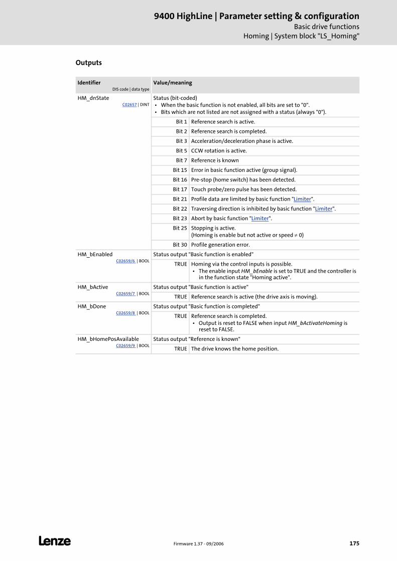
L Firmware 1.37 - 09/2006 175
9400 HighLine | Parameter setting & configurationBasic drive functions
Homing | System block "LS_Homing"
Outputs
IdentifierDIS code | data type
Value/meaning
HM_dnStateC02657 | DINT
Status (bit-coded) • When the basic function is not enabled, all bits are set to "0". • Bits which are not listed are not assigned with a status (always "0").
Bit 1 Reference search is active.
Bit 2 Reference search is completed.
Bit 3 Acceleration/deceleration phase is active.
Bit 5 CCW rotation is active.
Bit 7 Reference is known
Bit 15 Error in basic function active (group signal).
Bit 16 Pre-stop (home switch) has been detected.
Bit 17 Touch probe/zero pulse has been detected.
Bit 21 Profile data are limited by basic function "Limiter".
Bit 22 Traversing direction is inhibited by basic function "Limiter".
Bit 23 Abort by basic function "Limiter".
Bit 25 Stopping is active.(Homing is enable but not active or speed ≠ 0)
Bit 30 Profile generation error.
HM_bEnabledC02659/6 | BOOL
Status output "Basic function is enabled"
TRUE Homing via the control inputs is possible. • The enable input HM_bEnable is set to TRUE and the controller is
in the function state "Homing active".
HM_bActiveC02659/7 | BOOL
Status output "Basic function is active"
TRUE Reference search is active (the drive axis is moving).
HM_bDoneC02659/8 | BOOL
Status output "Basic function is completed"
TRUE Reference search is completed. • Output is reset to FALSE when input HM_bActivateHoming is
reset to FALSE.
HM_bHomePosAvailableC02659/9 | BOOL
Status output "Reference is known"
TRUE The drive knows the home position.
9400 HighLine | Parameter setting & configurationBasic drive functionsPositioning
176 Firmware 1.37 - 09/2006 L
9.6 Positioning
The basic function "Positioning" provides the functions for executing the (travel) profilesand supports an "override" of speed and acceleration.
A profile describes a motion request which can be implemented by the SB LS_Positioner into a rotary motion.
A profile is described via the following profile parameters: Mode (type of positioning), position, speed, acceleration, deceleration, S-ramp time, final speed, standard sequence profile, TP sequence profile, TP window starting and end position and touch probe signal source(s).
9.6.1 Parameter setting
A parameter setting is not required for the basic function "Positioning".
After activating the function, the profile is executed which has been transferred to the basic function via the input POS_ProfileData.
For profiles with touch probe positioning mode (residual path positioning) touch probe is detected implicitly.
Options for selecting the profiles
For specifying as well as storing and managing (travel) profiles, the following functionblocks are available:
Function block Function
L_PosPositionerTable ...serves to file and manage up to 100 (travel) profiles and allows the "teaching" of positions, speed, acceleration/deceleration and S-ramp times. • Another important task of this FB is the conversion of the table values
according to the scaling selected in the SB LS_DriveInterface.
L_PosProfileTable ...serves to file and manage up to four (travel) profiles and allows the "teaching" of target positions. • In contrast to the FB L_PosPositionerTable this FB does not use any
variable tables but the data of the profile parameters are entered directly into the assigned codes.
• Another special feature: When selecting the profile no. 1 as target position, the position applied to input dnExtPos_p.
L_PosProfileInterface ...provides a profile data record for the SB LS_Positioner.
L Firmware 1.37 - 09/2006 177
9400 HighLine | Parameter setting & configurationBasic drive functions
Positioning | Carrying out positioning
9.6.2 Carrying out positioning
Requirements
The controller is in the device state "Operation".
The basic function "Positioning" is part of the active application.
No other basic function is active.
Activation
To request the control via the basic function, the enable input POS_bEnable in theapplication must be set to TRUE.
If no other basic function is active, a changeover to the function state "Positioning active" is effected and positioning can be executed via the control inputs.
A successful change to the function state "Positioning active" is displayed by a TRUE signal at the status output POS_bEnabled.
Deactivation
When the enable input POS_bEnable is reset to FALSE, an active homing is stopped, i.e. thecontrol inputs for positioning are inhibited and the drive is braked to standstill within thedeceleration time for stop.
The status output POS_bEnabled is reset to FALSE and a changeover from the active function state "Positioning active" via the function state "Drive is stopped" back to the basic state "Drive in standstill" is effected.
9400 HighLine | Parameter setting & configurationBasic drive functionsPositioning | Carrying out positioning
178 Firmware 1.37 - 09/2006 L
9.6.2.1 Starting positioning
By setting the control input POS_bStart to TRUE positioning starts.
The (travel) profile is executed which has been transferred to the basic function via the input POS_ProfileData.
9.6.2.2 Aborting/interrupting positioning
By setting the control input POS_bAbort to TRUE, the active positioning can be aborted orinterrupted.
The current profile is not completed but braked to standstill with the deceleration defined in the profile data.
When the control input POS_bAbort is remained on TRUE, a restart or the continuation of an interrupted positioning process is inhibited.
After resetting the control input POS_bAbort to FALSE, a restart or the continuation of an interrupted positioning process is possible again.
9.6.2.3 Continuing an interrupted positioning process
By setting the control input POS_bRestart to TRUE an interrupted positioning process canbe continued if the control input POS_bAbort has been reset again to FALSE.
Distance already covered in a relative positioning process will be considered.
L Firmware 1.37 - 09/2006 179
9400 HighLine | Parameter setting & configurationBasic drive functions
Positioning | Carrying out positioning
9.6.2.4 Activating override
"Override" is the change of profile parameters and their acceptance during the positioningprocess.
When the input POS_bEnableOverride is set to TRUE, a speed and acceleration override occurs according to the override values applied to the inputs POS_dnSpeedOverride_n and POS_dnAccOverride_n.
– The override values represent percentage multipliers with regard to the current profile parameters for speed and acceleration.
– For override values ≤ 1 % a status bit is set.
– Override values ≤ 0 % are set internally to 0 %.
– Changes of the override values are accepted in each cycle.
When the input POS_bEnableOverride is reset to FALSE again, the speeds and accelerations defined via the profile parameters are executed again. The drive is immediately accelerated from the override speed to the speed set in the profile.
Note!
The online change of speed and acceleration is effective from the profile start to the beginning of the deceleration phase. Thus, the deceleration phase cannot be changed via an override!
• In case of an override value of 0 % for speed, the drive is braked to standstill.
• In case of an override value of 0 % for acceleration, no acceleration takes place anymore.
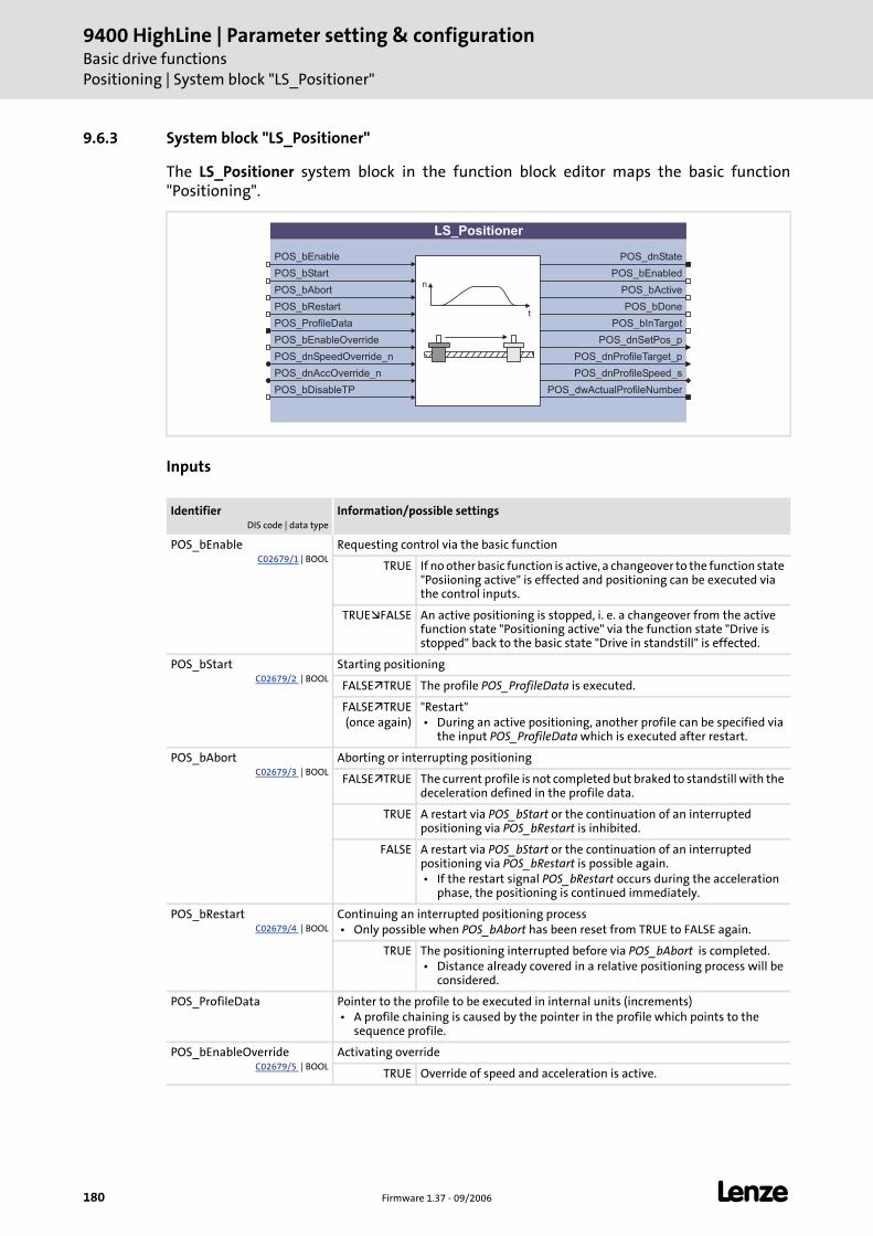
9400 HighLine | Parameter setting & configurationBasic drive functionsPositioning | System block "LS_Positioner"
180 Firmware 1.37 - 09/2006 L
9.6.3 System block "LS_Positioner"
The LS_Positioner system block in the function block editor maps the basic function"Positioning".
Inputs
IdentifierDIS code | data type
Information/possible settings
POS_bEnableC02679/1 | BOOL
Requesting control via the basic function
TRUE If no other basic function is active, a changeover to the function state "Posiioning active" is effected and positioning can be executed via the control inputs.
TRUE FALSE An active positioning is stopped, i. e. a changeover from the active function state "Positioning active" via the function state "Drive is stopped" back to the basic state "Drive in standstill" is effected.
POS_bStartC02679/2 | BOOL
Starting positioning
FALSE TRUE The profile POS_ProfileData is executed.
FALSE TRUE(once again)
"Restart" • During an active positioning, another profile can be specified via
the input POS_ProfileData which is executed after restart.
POS_bAbortC02679/3 | BOOL
Aborting or interrupting positioning
FALSE TRUE The current profile is not completed but braked to standstill with the deceleration defined in the profile data.
TRUE A restart via POS_bStart or the continuation of an interrupted positioning via POS_bRestart is inhibited.
FALSE A restart via POS_bStart or the continuation of an interrupted positioning via POS_bRestart is possible again. • If the restart signal POS_bRestart occurs during the acceleration
phase, the positioning is continued immediately.
POS_bRestartC02679/4 | BOOL
Continuing an interrupted positioning process • Only possible when POS_bAbort has been reset from TRUE to FALSE again.
TRUE The positioning interrupted before via POS_bAbort is completed. • Distance already covered in a relative positioning process will be
considered.
POS_ProfileData Pointer to the profile to be executed in internal units (increments) • A profile chaining is caused by the pointer in the profile which points to the
sequence profile.
POS_bEnableOverrideC02679/5 | BOOL
Activating override
TRUE Override of speed and acceleration is active.
LS_Positioner
POS_bEnable
POS_bStart
POS_bAbort
POS_ProfileData
POS_bEnableOverride
POS_dnSpeedOverride_n
POS_dnState
POS_bActive
POS_bDone
n
tPOS_bRestart
POS_dnAccOverride_n
POS_bDisableTP
POS_bInTarget
POS_dnSetPos_p
POS_dnProfileTarget_p
POS_dnProfileSpeed_s
POS_dwActualProfileNumber
POS_bEnabled
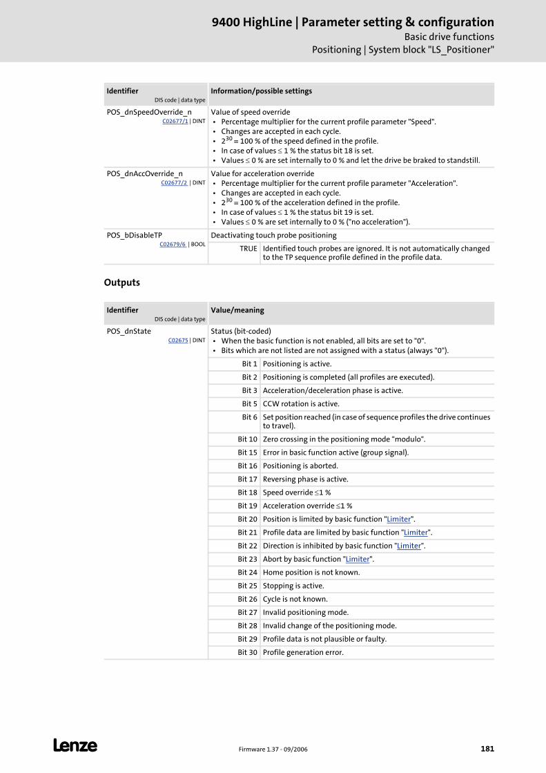
L Firmware 1.37 - 09/2006 181
9400 HighLine | Parameter setting & configurationBasic drive functions
Positioning | System block "LS_Positioner"
Outputs
POS_dnSpeedOverride_nC02677/1 | DINT
Value of speed override • Percentage multiplier for the current profile parameter "Speed". • Changes are accepted in each cycle. • 230 ≡ 100 % of the speed defined in the profile. • In case of values ≤ 1 % the status bit 18 is set. • Values ≤ 0 % are set internally to 0 % and let the drive be braked to standstill.
POS_dnAccOverride_nC02677/2 | DINT
Value for acceleration override • Percentage multiplier for the current profile parameter "Acceleration". • Changes are accepted in each cycle. • 230 ≡ 100 % of the acceleration defined in the profile. • In case of values ≤ 1 % the status bit 19 is set. • Values ≤ 0 % are set internally to 0 % ("no acceleration").
POS_bDisableTPC02679/6 | BOOL
Deactivating touch probe positioning
TRUE Identified touch probes are ignored. It is not automatically changed to the TP sequence profile defined in the profile data.
IdentifierDIS code | data type
Value/meaning
POS_dnStateC02675 | DINT
Status (bit-coded) • When the basic function is not enabled, all bits are set to "0". • Bits which are not listed are not assigned with a status (always "0").
Bit 1 Positioning is active.
Bit 2 Positioning is completed (all profiles are executed).
Bit 3 Acceleration/deceleration phase is active.
Bit 5 CCW rotation is active.
Bit 6 Set position reached (in case of sequence profiles the drive continues to travel).
Bit 10 Zero crossing in the positioning mode "modulo".
Bit 15 Error in basic function active (group signal).
Bit 16 Positioning is aborted.
Bit 17 Reversing phase is active.
Bit 18 Speed override ≤1 %
Bit 19 Acceleration override ≤1 %
Bit 20 Position is limited by basic function "Limiter".
Bit 21 Profile data are limited by basic function "Limiter".
Bit 22 Direction is inhibited by basic function "Limiter".
Bit 23 Abort by basic function "Limiter".
Bit 24 Home position is not known.
Bit 25 Stopping is active.
Bit 26 Cycle is not known.
Bit 27 Invalid positioning mode.
Bit 28 Invalid change of the positioning mode.
Bit 29 Profile data is not plausible or faulty.
Bit 30 Profile generation error.
IdentifierDIS code | data type
Information/possible settings
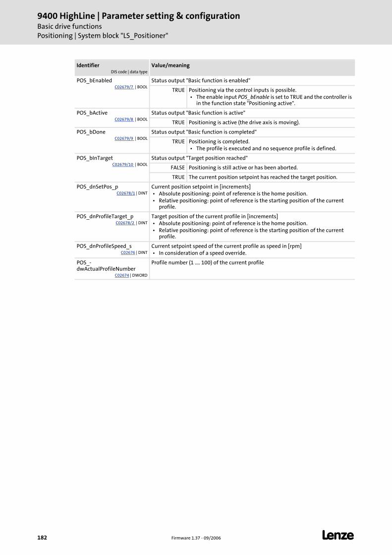
9400 HighLine | Parameter setting & configurationBasic drive functionsPositioning | System block "LS_Positioner"
182 Firmware 1.37 - 09/2006 L
POS_bEnabledC02679/7 | BOOL
Status output "Basic function is enabled"
TRUE Positioning via the control inputs is possible. • The enable input POS_bEnable is set to TRUE and the controller is
in the function state "Positioning active".
POS_bActiveC02679/8 | BOOL
Status output "Basic function is active"
TRUE Positioning is active (the drive axis is moving).
POS_bDoneC02679/9 | BOOL
Status output "Basic function is completed"
TRUE Positioning is completed. • The profile is executed and no sequence profile is defined.
POS_bInTargetC02679/10 | BOOL
Status output "Target position reached"
FALSE Positioning is still active or has been aborted.
TRUE The current position setpoint has reached the target position.
POS_dnSetPos_pC02678/1 | DINT
Current position setpoint in [increments] • Absolute positioning: point of reference is the home position. • Relative positioning: point of reference is the starting position of the current
profile.
POS_dnProfileTarget_pC02678/2 | DINT
Target position of the current profile in [increments] • Absolute positioning: point of reference is the home position. • Relative positioning: point of reference is the starting position of the current
profile.
POS_dnProfileSpeed_sC02676 | DINT
Current setpoint speed of the current profile as speed in [rpm] • In consideration of a speed override.
POS_-dwActualProfileNumber
C02674 | DWORD
Profile number (1 .... 100) of the current profile
IdentifierDIS code | data type
Value/meaning
L Firmware 1.37 - 09/2006 183
9400 HighLine | Parameter setting & configurationBasic drive functions
Position follower
9.7 Position follower
This basic function is used as setpoint interface for position-controlled drives.
The specified position setpoint can either refer to the encoder on the motor side or to the (load) encoder used additionally to detect the machine position. The selection of the encoder configuration serves to adapt the internal control structure accordingly.
Instead of a position setpoint a speed setpoint can be specified as well by a corresponding selection in C02680. Then, the set position is calculated by integrating the speed setpoint based on the current actual position (relative positioning).
As an option, an internal interpolation of the setpoints can be carried out in order to specify setpoints with reduced cycle rates without the drive behaviour being unsteady. The detection of the cycle rate and the synchronisation of the setpoint transfer is carried out automatically.
If the direction of rotation of the motor must be inverted due to the mounting position of the motor or the existing gearbox ratio the use of the control signals can be changed over accordingly via parameter setting.
The speed can also be precontrolled with the position setpoint by a corresponding selection in C02681. Then, the speed is calculated by differentiation of the position setpoint.
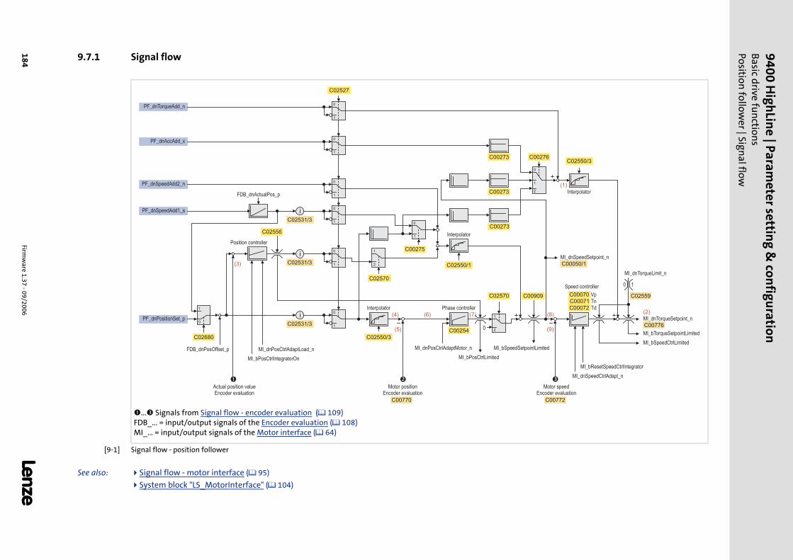
9400 HighLine | Param
eter setting & configuration
Basic drive fu
nction
sPosition
follower | Sign
al flow
184Firm
ware 1.37 - 09/2006
L
9.7.1 Signal flow
[9-1] Signal flow - position follower
See also: Signal flow - motor interface ( 95)
System block "LS_MotorInterface" ( 104)
... Signals from Signal flow - encoder evaluation ( 109) FDB_... = input/output signals of the Encoder evaluation ( 108) MI_... = input/output signals of the Motor interface ( 64)
1
0
2
2
1
1
01
0
PF_dnAccAdd_x
1
0
PF_dnPositionSet_p
1
0
1
0
MI_bSpeedCtrlLimited
MI_bTorqueSetpointLimited
MI_dnTorqueSetpoint_n
MI_bResetSpeedCtrlIntegrator
MI_dnTorqueLimit_n
MI_dnSpeedSetpoint_n
MI_dnSpeedCtrlAdapt_n
PF_dnSpeedAdd2_n
� � �
PF_dnTorqueAdd_n
1
0
1
0
2
1
i
i
i
MI_dnPosCtrlAdaptLoad_n
MI_bPosCtrlIntegratorOn
0
1
FDB_dnActualPos_p
FDB_dnPosOffset_p MI_dnPosCtrlAdaptMotor_n
MI_bPosCtrlLimited
MI_bSpeedSetpointLimited
0 1
PF_dnSpeedAdd1_s
Vp
Tn
Td
0C00254
C00273
C00273
C00276
C00275
C00909 C00070
C00071
C00072
C02531/3
C00770 C00772
C02680 C02550/3
C02570
C00050/1C02550/1
C02570
C02550/3C00273
C02527
C00776
C02556
C02559
C02531/3
C02531/3
Interpolator Phase controller
Interpolator
Speed controller
Interpolator
Position controller
Actual position valueEncoder evaluation
Motor positionEncoder evaluation
Motor speedEncoder evaluation
(3)
(5)
(1)
(4)
(9)
(8)(2)
(6) (7)
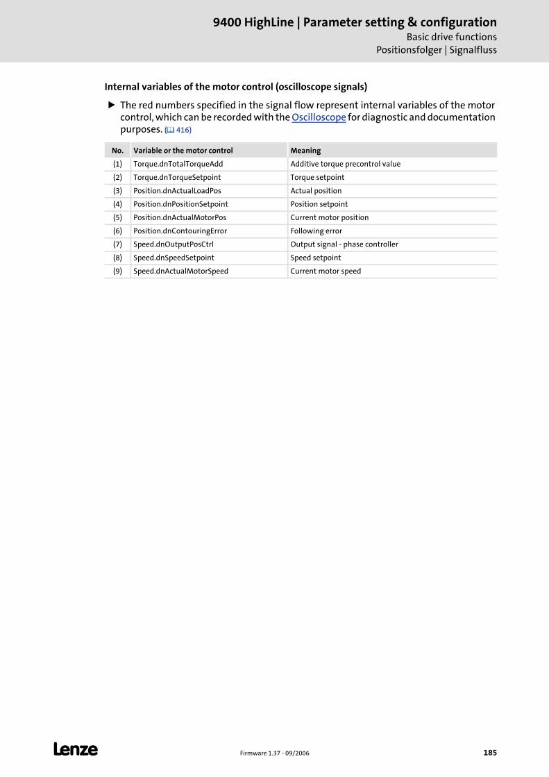
L Firmware 1.37 - 09/2006 185
9400 HighLine | Parameter setting & configurationBasic drive functions
Positionsfolger | Signalfluss
Internal variables of the motor control (oscilloscope signals)
The red numbers specified in the signal flow represent internal variables of the motor control, which can be recorded with the Oscilloscope for diagnostic and documentation purposes. ( 416)
No. Variable or the motor control Meaning
(1) Torque.dnTotalTorqueAdd Additive torque precontrol value
(2) Torque.dnTorqueSetpoint Torque setpoint
(3) Position.dnActualLoadPos Actual position
(4) Position.dnPositionSetpoint Position setpoint
(5) Position.dnActualMotorPos Current motor position
(6) Position.dnContouringError Following error
(7) Speed.dnOutputPosCtrl Output signal - phase controller
(8) Speed.dnSpeedSetpoint Speed setpoint
(9) Speed.dnActualMotorSpeed Current motor speed
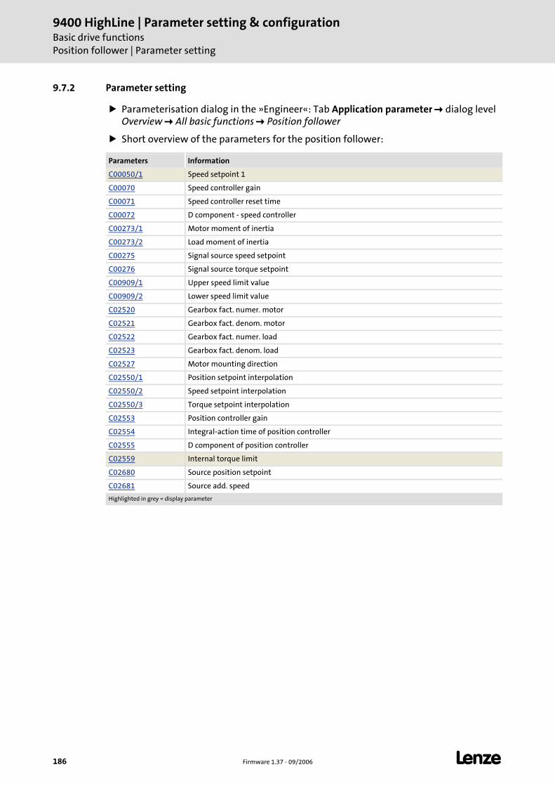
9400 HighLine | Parameter setting & configurationBasic drive functionsPosition follower | Parameter setting
186 Firmware 1.37 - 09/2006 L
9.7.2 Parameter setting
Parameterisation dialog in the »Engineer«: Tab Application parameter dialog level Overview All basic functions Position follower
Short overview of the parameters for the position follower:
Parameters Information
C00050/1 Speed setpoint 1
C00070 Speed controller gain
C00071 Speed controller reset time
C00072 D component - speed controller
C00273/1 Motor moment of inertia
C00273/2 Load moment of inertia
C00275 Signal source speed setpoint
C00276 Signal source torque setpoint
C00909/1 Upper speed limit value
C00909/2 Lower speed limit value
C02520 Gearbox fact. numer. motor
C02521 Gearbox fact. denom. motor
C02522 Gearbox fact. numer. load
C02523 Gearbox fact. denom. load
C02527 Motor mounting direction
C02550/1 Position setpoint interpolation
C02550/2 Speed setpoint interpolation
C02550/3 Torque setpoint interpolation
C02553 Position controller gain
C02554 Integral-action time of position controller
C02555 D component of position controller
C02559 Internal torque limit
C02680 Source position setpoint
C02681 Source add. speed
Highlighted in grey = display parameter
L Firmware 1.37 - 09/2006 187
9400 HighLine | Parameter setting & configurationBasic drive functions
Position follower | Parameter setting
9.7.2.1 Setpoint interpolation
When the setpoint interpolation is activated, the motor control creates intermediatevalues to "smoothly" follow the setpoints which may be transferred from a slower task.
C02550/1 = "1": The motor control follows the position setpoint in interpolated steps.
C02550/2 = "1": The motor control follows the speed setpoint in interpolated steps.
C02550/3 = "1": The motor control follows the torque setpoint in interpolated steps.
9.7.2.2 Inversion of the direction of rotation
Depending on the motor mounting position the direction of rotation can be reversed, ifrequired:
C02527 = "0": Clockwise motor ≡ positive machine direction.
C02527 = "1": Counter-clockwise motor ≡ positive machine direction.
9400 HighLine | Parameter setting & configurationBasic drive functionsPosition follower | Activating setpoint interface
188 Firmware 1.37 - 09/2006 L
9.7.3 Activating setpoint interface
Requirements
The controller is in the device state "Operation".
The basic function "Position follower" is part of the active application.
No other basic function is active.
Activation
To request the control via the basic function, the enable input PF_bEnable in theapplication must be set to TRUE.
If no other basic function is active, it is changed to the function state "Position follower active". Setpoints can now be specified via the corresponding inputs. Signal flow
A successful change to the function state "Position follower" is displayed by a TRUE signal at the status output PF_bEnabled.
Deactivation
When the enable input PF_bEnable is reset to FALSE, the setpoint inputs are inhibited. If thedrive is not at standstill, it is braked to standstill within the deceleration time set for stopunless another basic function takes over the control of the drive.
The status output PF_bEnabled is reset to FALSE and a changeover from the active function state "Position follower active" via the function state "Drive is stopped" back to th basic state "Drive in standstill" is effected.
Stop!
The basic function takes over the control of the drive not from the current speed on but directly with the defined setpoint which may lead to a jerk!
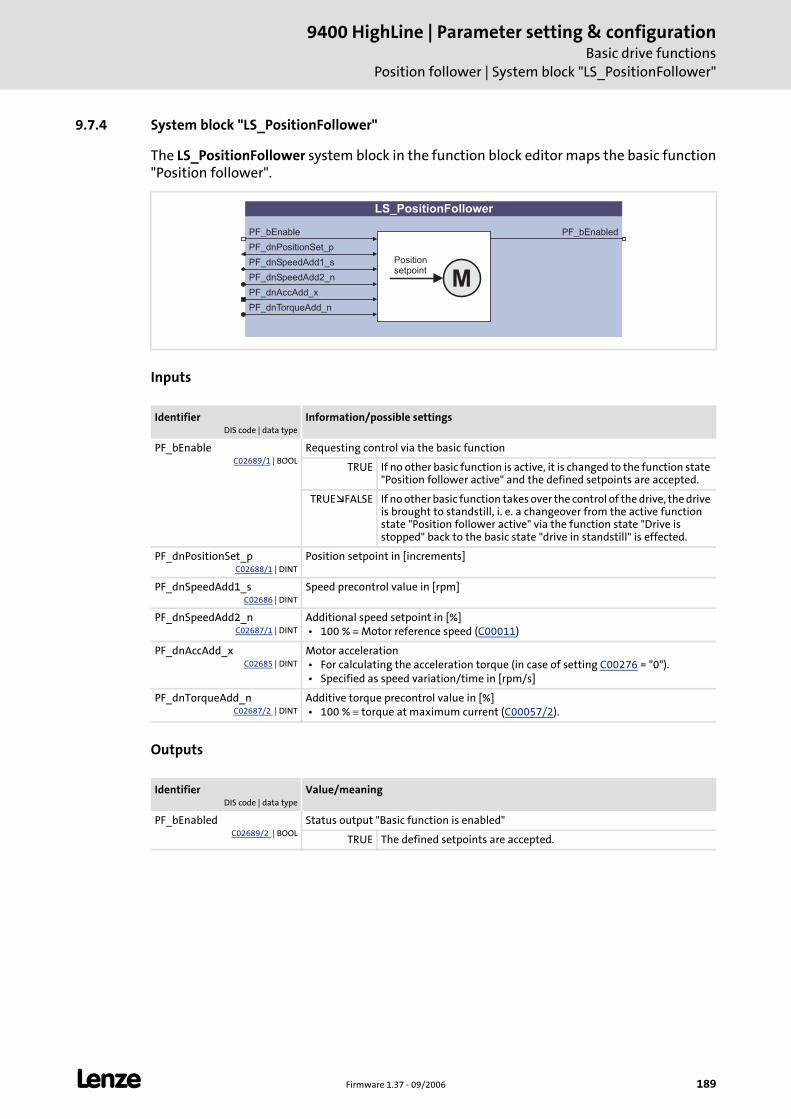
L Firmware 1.37 - 09/2006 189
9400 HighLine | Parameter setting & configurationBasic drive functions
Position follower | System block "LS_PositionFollower"
9.7.4 System block "LS_PositionFollower"
The LS_PositionFollower system block in the function block editor maps the basic function"Position follower".
Inputs
Outputs
IdentifierDIS code | data type
Information/possible settings
PF_bEnableC02689/1 | BOOL
Requesting control via the basic function
TRUE If no other basic function is active, it is changed to the function state "Position follower active" and the defined setpoints are accepted.
TRUE FALSE If no other basic function takes over the control of the drive, the drive is brought to standstill, i. e. a changeover from the active function state "Position follower active" via the function state "Drive is stopped" back to the basic state "drive in standstill" is effected.
PF_dnPositionSet_pC02688/1 | DINT
Position setpoint in [increments]
PF_dnSpeedAdd1_sC02686 | DINT
Speed precontrol value in [rpm]
PF_dnSpeedAdd2_nC02687/1 | DINT
Additional speed setpoint in [%] • 100 % ≡ Motor reference speed (C00011)
PF_dnAccAdd_xC02685 | DINT
Motor acceleration • For calculating the acceleration torque (in case of setting C00276 = "0"). • Specified as speed variation/time in [rpm/s]
PF_dnTorqueAdd_nC02687/2 | DINT
Additive torque precontrol value in [%] • 100 % ≡ torque at maximum current (C00057/2).
IdentifierDIS code | data type
Value/meaning
PF_bEnabledC02689/2 | BOOL
Status output "Basic function is enabled"
TRUE The defined setpoints are accepted.
LS_PositionFollower
PF_bEnable
PF_dnPositionSet_p
PF_dnSpeedAdd1_s
PF_dnSpeedAdd2_n
PF_dnTorqueAdd_n
PF_bEnabled
MPositionsetpoint
PF_dnAccAdd_x
9400 HighLine | Parameter setting & configurationBasic drive functionsSpeed follower
190 Firmware 1.37 - 09/2006 L
9.8 Speed follower
This basic function is used as setpoint interface for speed-controlled drives.
The motor control is automatically changed over to speed control with torque limitation.
As an option, an internal interpolation of the setpoints can be carried out in order to specify setpoints with reduced cycle rates without the drive behaviour being unsteady. The detection of the cycle rate and the synchronisation of the setpoint transfer is carried out automatically.
If the direction of rotation of the motor must be inverted due to the mounting position of the motor or the existing gearbox ratio the use of the control signals can be changed over accordingly via parameter setting.
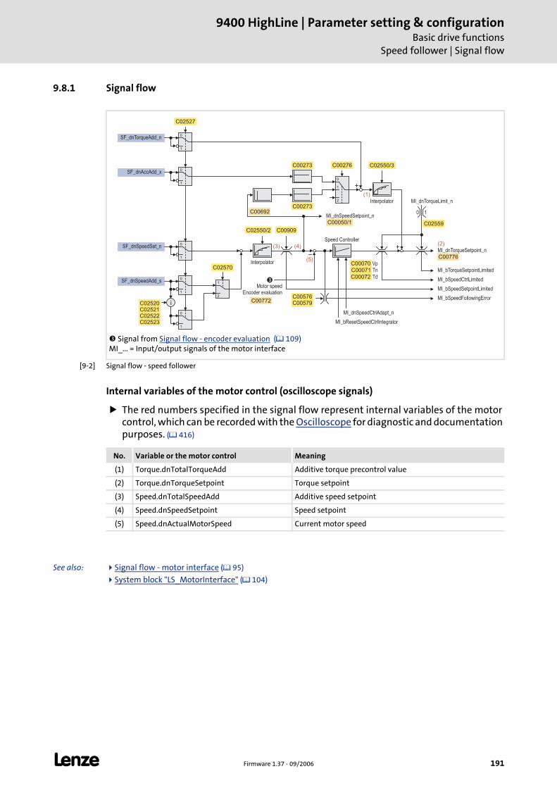
L Firmware 1.37 - 09/2006 191
9400 HighLine | Parameter setting & configurationBasic drive functions
Speed follower | Signal flow
9.8.1 Signal flow
[9-2] Signal flow - speed follower
Internal variables of the motor control (oscilloscope signals)
The red numbers specified in the signal flow represent internal variables of the motor control, which can be recorded with the Oscilloscope for diagnostic and documentation purposes. ( 416)
See also: Signal flow - motor interface ( 95)
System block "LS_MotorInterface" ( 104)
Signal from Signal flow - encoder evaluation ( 109) MI_... = Input/output signals of the motor interface
1
1
0
0
C00909
C00050/1
MI_bSpeedSetpointLimited
MI_bSpeedCtrlLimited
MI_bTorqueSetpointLimited
MI_dnTorqueSetpoint_n
C00776
C02527
SF_dnTorqueAdd_n
SF_dnSpeedSet_n
2
1SF_dnSpeedAdd_s
1
0
2
C00273
C00276
C00070
C02550/2
C02550/3
MI_bResetSpeedCtrlIntegrator
MI_dnSpeedSetpoint_n
MI_dnSpeedCtrlAdapt_n
C00576C00579
MI_bSpeedFollowingError
�
1
0SF_dnAccAdd_x
C00273
1
0
1
0
i
C02570
C02520C02521C02522C02523
MI_dnTorqueLimit_n
0 1
C02559
(1)
(3) (4)
(5)
(2)
C00772
C00692
Vp
Tn
Td
C00071
C00072
Interpolator
Interpolator
Speed Controller
Motor speedEncoder evaluation
No. Variable or the motor control Meaning
(1) Torque.dnTotalTorqueAdd Additive torque precontrol value
(2) Torque.dnTorqueSetpoint Torque setpoint
(3) Speed.dnTotalSpeedAdd Additive speed setpoint
(4) Speed.dnSpeedSetpoint Speed setpoint
(5) Speed.dnActualMotorSpeed Current motor speed
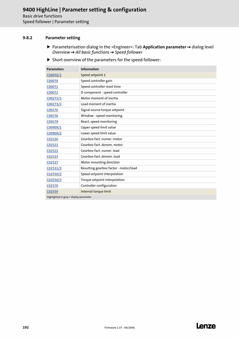
9400 HighLine | Parameter setting & configurationBasic drive functionsSpeed follower | Parameter setting
192 Firmware 1.37 - 09/2006 L
9.8.2 Parameter setting
Parameterisation dialog in the »Engineer«: Tab Application parameter dialog level Overview All basic functions Speed follower
Short overview of the parameters for the speed follower:
Parameters Information
C00050/1 Speed setpoint 1
C00070 Speed controller gain
C00071 Speed controller reset time
C00072 D component - speed controller
C00273/1 Motor moment of inertia
C00273/2 Load moment of inertia
C00276 Signal source torque setpoint
C00576 Window - speed monitoring
C00579 React. speed monitoring
C00909/1 Upper speed limit value
C00909/2 Lower speed limit value
C02520 Gearbox fact. numer. motor
C02521 Gearbox fact. denom. motor
C02522 Gearbox fact. numer. load
C02523 Gearbox fact. denom. load
C02527 Motor mounting direction
C02531/3 Resulting gearbox factor - motor/load
C02550/2 Speed setpoint interpolation
C02550/3 Torque setpoint interpolation
C02570 Controller configuration
C02559 Internal torque limit
Highlighted in grey = display parameter
L Firmware 1.37 - 09/2006 193
9400 HighLine | Parameter setting & configurationBasic drive functions
Speed follower | Parameter setting
9.8.2.1 Setpoint interpolation
When the setpoint interpolation is activated, the motor control creates intermediatevalues to "smoothly" follow the speed and/or torque setpoints which may be transferredfrom a slower task.
C02550/2 = "1": The motor control follows the speed setpoint in interpolated steps.
C02550/3 = "1": The motor control follows the torque setpoint in interpolated steps.
9.8.2.2 Inversion of the direction of rotation
Depending on the motor mounting position the direction of rotation can be reversed, ifrequired:
C02527 = "0": Clockwise motor ≡ positive machine direction.
C02527 = "1": Counter-clockwise motor ≡ positive machine direction.
9400 HighLine | Parameter setting & configurationBasic drive functionsSpeed follower | Activating setpoint interface
194 Firmware 1.37 - 09/2006 L
9.8.3 Activating setpoint interface
Requirements
The controller is in the device state "Operation".
The basic function "Speed follower" is part of the active application.
No other basic function is active.
Activation
To request the control via the basic function, the enable input SF_bEnable in theapplication must be set to TRUE.
If no other basic function is active, it is changed to the function state "Speed follower active" and the motor control is automatically switched to speed control with torque limitation. Setpoints can now be defined via the corresponding inputs. Signal flow
A successful change to the function state "Speed follower active" is displayed by a TRUE signal at the status output SF_bEnabled.
Deactivation
When the enable input SF_bEnable is reset to FALSE, the setpoint inputs are inhibited. If thedrive is not at standstill, it is braked to standstill within the deceleration time set for stopunless another basic function takes over the control of the drive.
The status output SF_bEnabled is reset to FALSE and a changeover from the active function state "Speed follower active" via the function state "Drive is stopped" back to th basic state "Drive in standstill" is effected.
Stop!
The basic function takes over the control of the drive not from the current speed on but directly with the defined setpoint which may lead to a jerk!
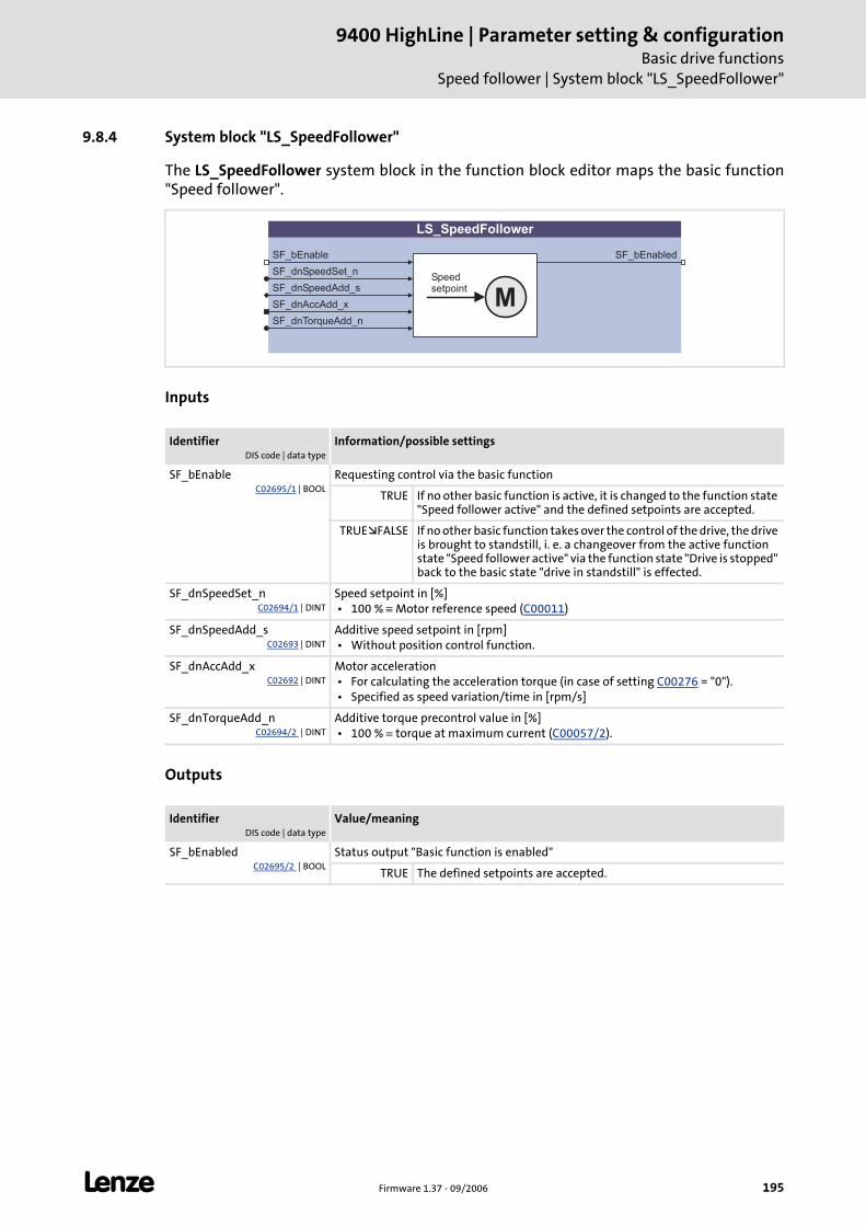
L Firmware 1.37 - 09/2006 195
9400 HighLine | Parameter setting & configurationBasic drive functions
Speed follower | System block "LS_SpeedFollower"
9.8.4 System block "LS_SpeedFollower"
The LS_SpeedFollower system block in the function block editor maps the basic function"Speed follower".
Inputs
Outputs
IdentifierDIS code | data type
Information/possible settings
SF_bEnableC02695/1 | BOOL
Requesting control via the basic function
TRUE If no other basic function is active, it is changed to the function state "Speed follower active" and the defined setpoints are accepted.
TRUE FALSE If no other basic function takes over the control of the drive, the drive is brought to standstill, i. e. a changeover from the active function state "Speed follower active" via the function state "Drive is stopped" back to the basic state "drive in standstill" is effected.
SF_dnSpeedSet_nC02694/1 | DINT
Speed setpoint in [%] • 100 % ≡ Motor reference speed (C00011)
SF_dnSpeedAdd_sC02693 | DINT
Additive speed setpoint in [rpm] • Without position control function.
SF_dnAccAdd_xC02692 | DINT
Motor acceleration • For calculating the acceleration torque (in case of setting C00276 = "0"). • Specified as speed variation/time in [rpm/s]
SF_dnTorqueAdd_nC02694/2 | DINT
Additive torque precontrol value in [%] • 100 % ≡ torque at maximum current (C00057/2).
IdentifierDIS code | data type
Value/meaning
SF_bEnabledC02695/2 | BOOL
Status output "Basic function is enabled"
TRUE The defined setpoints are accepted.
LS_SpeedFollower
SF_bEnable
SF_dnSpeedSet_n
SF_dnSpeedAdd_s
SF_dnTorqueAdd_n
SF_bEnabled
MSpeedsetpoint
SF_dnAccAdd_x
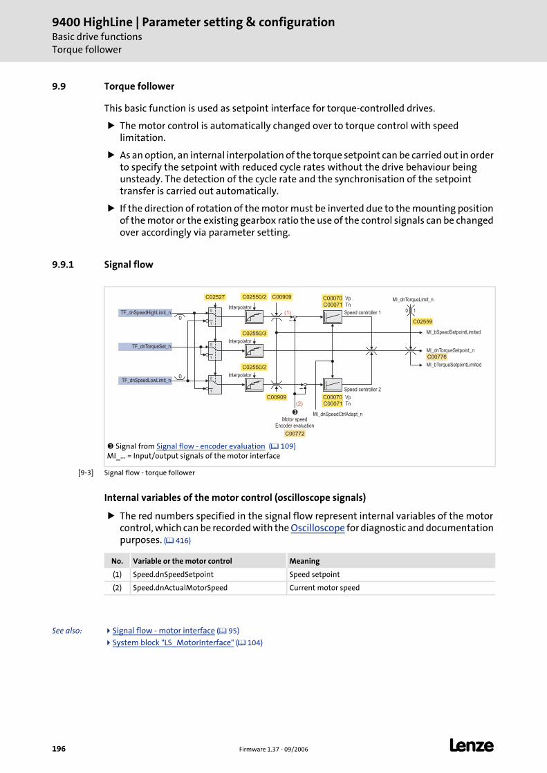
9400 HighLine | Parameter setting & configurationBasic drive functionsTorque follower
196 Firmware 1.37 - 09/2006 L
9.9 Torque follower
This basic function is used as setpoint interface for torque-controlled drives.
The motor control is automatically changed over to torque control with speed limitation.
As an option, an internal interpolation of the torque setpoint can be carried out in order to specify the setpoint with reduced cycle rates without the drive behaviour being unsteady. The detection of the cycle rate and the synchronisation of the setpoint transfer is carried out automatically.
If the direction of rotation of the motor must be inverted due to the mounting position of the motor or the existing gearbox ratio the use of the control signals can be changed over accordingly via parameter setting.
9.9.1 Signal flow
[9-3] Signal flow - torque follower
Internal variables of the motor control (oscilloscope signals)
The red numbers specified in the signal flow represent internal variables of the motor control, which can be recorded with the Oscilloscope for diagnostic and documentation purposes. ( 416)
See also: Signal flow - motor interface ( 95)
System block "LS_MotorInterface" ( 104)
Signal from Signal flow - encoder evaluation ( 109) MI_... = Input/output signals of the motor interface
1
1
0
0
MI_bSpeedSetpointLimited
MI_bTorqueSetpointLimited
MI_dnTorqueSetpoint_n
C00776
C02527
TF_dnSpeedHighLimit_n
TF_dnSpeedLowLimit_n
1
0TF_dnTorqueSet_n
C02550/2
C02550/3
MI_dnSpeedCtrlAdapt_n
LS_MotorInterface
C02550/2 C00909 C00070
C00909
�
0
0
MI_dnTorqueLimit_n
0 1
C02559
(1)
(2)
C00772
Vp
TnC00071
C00070 Vp
TnC00071
Interpolator
Interpolator
Speed controller 2
InterpolatorSpeed controller 1
Motor speedEncoder evaluation
No. Variable or the motor control Meaning
(1) Speed.dnSpeedSetpoint Speed setpoint
(2) Speed.dnActualMotorSpeed Current motor speed
L Firmware 1.37 - 09/2006 197
9400 HighLine | Parameter setting & configurationBasic drive functions
Torque follower | Parameter setting
9.9.2 Parameter setting
Parameterisation dialog in the »Engineer«: Tab Application parameter dialog level Overview All basic functions Torque follower
Short overview of the parameters for the torque follower:
9.9.2.1 Setpoint interpolation
When the setpoint interpolation is activated, the motor control creates intermediatevalues to "smoothly" follow the speed and/or torque setpoints which may be transferredfrom a slower task.
C02550/2 = "1": The motor control follows the speed setpoint in interpolated steps.
C02550/3 = "1": The motor control follows the torque setpoint in interpolated steps.
9.9.2.2 Inversion of the direction of rotation
Depending on the motor mounting position the direction of rotation can be reversed, ifrequired:
C02527 = "0": Clockwise motor ≡ positive machine direction.
C02527 = "1": Counter-clockwise motor ≡ positive machine direction.
Parameters Information
C00050/1 Speed setpoint 1
C00050/2 Speed setpoint 2
C00070 Speed controller gain
C00071 Speed controller reset time
C00909/1 Upper speed limit value
C00909/2 Lower speed limit value
C02527 Motor mounting direction
C02550/2 Speed setpoint interpolation
C02550/3 Torque setpoint interpolation
C02559 Internal torque limit
Highlighted in grey = display parameter

9400 HighLine | Parameter setting & configurationBasic drive functionsTorque follower | Activating setpoint interface
198 Firmware 1.37 - 09/2006 L
9.9.3 Activating setpoint interface
Requirements
The controller is in the device state "Operation".
The basic function "Torque follower" is part of the active application.
No other basic function is active.
Activation
To request the control via the basic function, the enable input T F_bEnable in theapplication must be set to TRUE.
If no other basic function is active, it is changed to the function state "Torque follower active" and the motor control is automatically switched to torque control with speed limitation. Setpoints can now be defined via the corresponding inputs. Signal flow
A successful change to the function state "Torque follower active" is displayed by a TRUE signal at the status output TF_bEnabled.
Deactivation
When the enable input TF_bEnable is reset to FALSE, the setpoint inputs are inhibited. If thedrive is not at standstill, it is braked to standstill within the deceleration time set for stopunless another basic function takes over the control of the drive.
The status output TF_bEnabled is reset to FALSE and a changeover from the active function state "Torque follower active" via the function state "Drive is stopped" back to th basic state "Drive in standstill" is effected.
Stop!
The basic function takes over the control of the drive not from the current speed on but directly with the defined setpoint which may lead to a jerk!
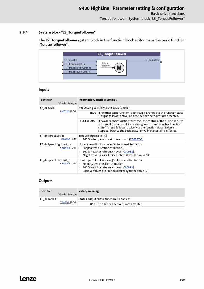
L Firmware 1.37 - 09/2006 199
9400 HighLine | Parameter setting & configurationBasic drive functions
Torque follower | System block "LS_TorqueFollower"
9.9.4 System block "LS_TorqueFollower"
The LS_TorqueFollower system block in the function block editor maps the basic function"Torque follower".
Inputs
Outputs
IdentifierDIS code | data type
Information/possible settings
TF_bEnableC02699/1 | BOOL
Requesting control via the basic function
TRUE If no other basic function is active, it is changed to the function state "Torque follower active" and the defined setpoints are accepted.
TRUE FALSE If no other basic function takes over the control of the drive, the drive is brought to standstill, i. e. a changeover from the active function state "Torque follower active" via the function state "Drive is stopped" back to the basic state "drive in standstill" is effected.
TF_dnTorqueSet_nC02698/1 | DINT
Torque setpoint in [%] • 100 % ≡ torque at maximum current (C00057/2).
TF_dnSpeedHighLimit_nC02698/2 | DINT
Upper speed limit value in [%] for speed limitation • For positive direction of motion. • 100 % ≡ Motor reference speed (C00011). • Negative values are limited internally to the value "0".
TF_dnSpeedLowLimit_nC02698/3 | DINT
Lower speed limit value in [%] for speed limitation • For negative direction of motion. • 100 % ≡ Motor reference speed (C00011). • Positive values are limited internally to the value "0".
IdentifierDIS code | data type
Value/meaning
TF_bEnabledC02699/2 | BOOL
Status output "Basic function is enabled"
TRUE The defined setpoints are accepted.
LS_TorqueFollower
TF_bEnable
TF_dnTorqueSet_n
TF_dnSpeedHighLimit_n
TF_dnSpeedLowLimit_n
TF_bEnabled
MTorquesetpoint
9400 HighLine | Parameter setting & configurationBasic drive functionsLimiter
200 Firmware 1.37 - 09/2006 L
9.10 Limiter
The basic function "Limiter" monitors the travel range limits via limit switches andparameterised software limit positions and can lead the drive to defined limit ranges whenbeing asked accordingly by the safety module.
See also: Safety engineering ( 135)
Note!
In order that the basic function "Limiter", after being asked accordingly by the safety module, can lead the drive to the defined limit ranges before the limits set for the safety module are reached which stops the drive, the limit values for the basic function "Limiter" must be set lower than the limit values for the safety module!
Danger!
The safety is exclusively ensured by the safety module!
When the request for the safety function is cancelled, the drive restarts automatically.
Ensure by external measures that the drive only starts after a confirmation (EN 60204).
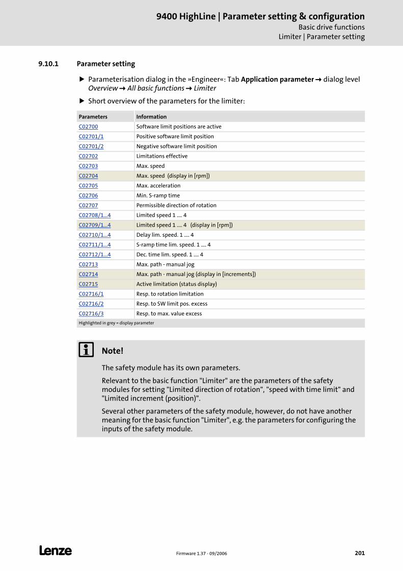
L Firmware 1.37 - 09/2006 201
9400 HighLine | Parameter setting & configurationBasic drive functions
Limiter | Parameter setting
9.10.1 Parameter setting
Parameterisation dialog in the »Engineer«: Tab Application parameter dialog level Overview All basic functions Limiter
Short overview of the parameters for the limiter:
Parameters Information
C02700 Software limit positions are active
C02701/1 Positive software limit position
C02701/2 Negative software limit position
C02702 Limitations effective
C02703 Max. speed
C02704 Max. speed (display in [rpm])
C02705 Max. acceleration
C02706 Min. S-ramp time
C02707 Permissible direction of rotation
C02708/1...4 Limited speed 1 .... 4
C02709/1...4 Limited speed 1 .... 4 (display in [rpm])
C02710/1...4 Delay lim. speed. 1 .... 4
C02711/1...4 S-ramp time lim. speed. 1 .... 4
C02712/1...4 Dec. time lim. speed. 1 .... 4
C02713 Max. path - manual jog
C02714 Max. path - manual jog (display in [increments])
C02715 Active limitation (status display)
C02716/1 Resp. to rotation limitation
C02716/2 Resp. to SW limit pos. excess
C02716/3 Resp. to max. value excess
Highlighted in grey = display parameter
Note!
The safety module has its own parameters.
Relevant to the basic function "Limiter" are the parameters of the safety modules for setting "Limited direction of rotation", "speed with time limit" and "Limited increment (position)".
Several other parameters of the safety module, however, do not have another meaning for the basic function "Limiter", e.g. the parameters for configuring the inputs of the safety module.
9400 HighLine | Parameter setting & configurationBasic drive functionsLimiter | Parameter setting
202 Firmware 1.37 - 09/2006 L
9.10.1.1 Software limit positions
The software limit positions serve to limit the travel range by means of software andprevent that travel commands are executed which would cause an exit of the permissibletravel range.
Note!
The software limit positions are only evaluated and monitored if the drive knows the home position and the software limit positions are active (C02700 = "1").
• When the traversing range is limited (C02528 = "1") the software limit positions are basically monitored with regard to the internal value range that
can be maximally displayed (±231 increments) even if the monitoring mode is deactivated.
• In case of the "Modulo" traversing range (C02528 = "2") the software limit positions are not effective.
The software limit positions are not effective for the basic functions "Speed follower", "Torque follower" and "Position follower".
• When the software limit positions are exceeded, it is only displayed via the status output LIM_dnState.
• If a response is to take place (e.g. "fault" or "quick stop by trouble"), this must be set accordingly in C02716/2.
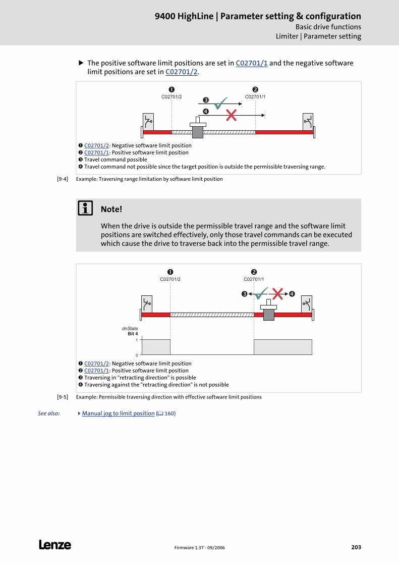
L Firmware 1.37 - 09/2006 203
9400 HighLine | Parameter setting & configurationBasic drive functions
Limiter | Parameter setting
The positive software limit positions are set in C02701/1 and the negative software limit positions are set in C02701/2.
[9-4] Example: Traversing range limitation by software limit position
[9-5] Example: Permissible traversing direction with effective software limit positions
See also: Manual jog to limit position ( 160)
C02701/2: Negative software limit position C02701/1: Positive software limit position Travel command possible Travel command not possible since the target position is outside the permissible traversing range.
�C02701/2
�C02701/1
�
�
Note!
When the drive is outside the permissible travel range and the software limit positions are switched effectively, only those travel commands can be executed which cause the drive to traverse back into the permissible travel range.
C02701/2: Negative software limit position C02701/1: Positive software limit position Traversing in "retracting direction" is possible Traversing against the "retracting direction" is not possible
�C02701/2
�C02701/1
1
0
dnStateBit 4
� �
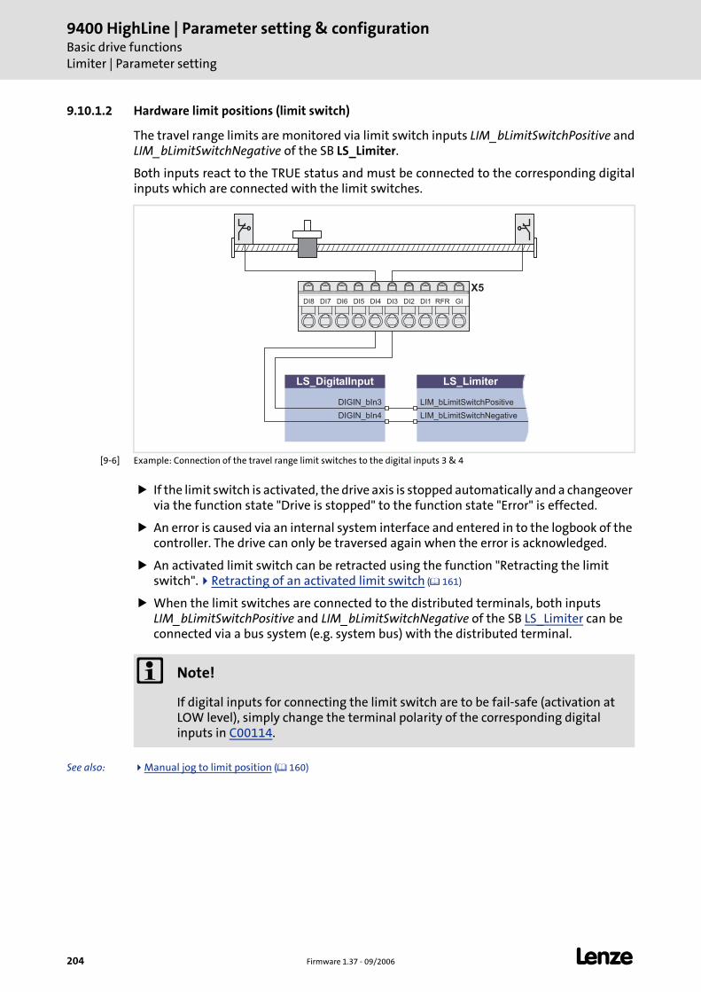
9400 HighLine | Parameter setting & configurationBasic drive functionsLimiter | Parameter setting
204 Firmware 1.37 - 09/2006 L
9.10.1.2 Hardware limit positions (limit switch)
The travel range limits are monitored via limit switch inputs LIM_bLimitSwitchPositive andLIM_bLimitSwitchNegative of the SB LS_Limiter.
Both inputs react to the TRUE status and must be connected to the corresponding digitalinputs which are connected with the limit switches.
[9-6] Example: Connection of the travel range limit switches to the digital inputs 3 & 4
If the limit switch is activated, the drive axis is stopped automatically and a changeover via the function state "Drive is stopped" to the function state "Error" is effected.
An error is caused via an internal system interface and entered in to the logbook of the controller. The drive can only be traversed again when the error is acknowledged.
An activated limit switch can be retracted using the function "Retracting the limit switch". Retracting of an activated limit switch ( 161)
When the limit switches are connected to the distributed terminals, both inputs LIM_bLimitSwitchPositive and LIM_bLimitSwitchNegative of the SB LS_Limiter can be connected via a bus system (e.g. system bus) with the distributed terminal.
See also: Manual jog to limit position ( 160)
X5GIRFRDI1DI2DI3DI4DI5DI6DI7DI8
LS_DigitalInput
DIGIN_bIn4
DIGIN_bIn3
LS_Limiter
LIM_bLimitSwitchPositive
LIM_bLimitSwitchNegative
Note!
If digital inputs for connecting the limit switch are to be fail-safe (activation at LOW level), simply change the terminal polarity of the corresponding digital inputs in C00114.
L Firmware 1.37 - 09/2006 205
9400 HighLine | Parameter setting & configurationBasic drive functions
Limiter | Parameter setting
9.10.1.3 Limitations
Limit values for the basic functions "Manual jog", "Homing" and "Positioning" can be set viathe following parameters:
The parameters depend on the mechanics (e.g. the tool used).
Usually the parameters must be changed when a tool is exchanged, e.g. by means of a recipe management of a superimposed control or via an HMI ("Human Machine Interface").
Parameters Information
C02703 Max. speed • Max. permissible speed that can be driven by the system. • This parameter depends, among other things, by the max. motor speed.
C02705 Max. acceleration • Max. permissible acceleration or deceleration for positioning procedures. • This parameter depends, among other things, on the motor torque and moment of
inertia of the entire mechanics which is driven during the positioning process.
C02706 Min. S-ramp time
C02707 Permissible direction of rotation
C02713 Max. path - manual jog
Note!
In order that the limit values set are effective, "1" must be selected in C02702.
• Irrespective of this setting the speed setpoint is basically limited to the motor reference speed (C00011)!
The limitations are not effective for the basic functions "Speed follower", "Torque follower" und "Position follower"!
• In case of these basic functions only speed and acceleration are monitored.
• When the limit values for speed and acceleration are exceeded, the response parameterised in C02716/3 takes place (Lenze setting: No response).
• Background: The setpoint followers in technology applications which are synchronised via an electrical shaft may not be limited since this may cause the synchronism to get lost. A possible consequence would be a collision of tools.
9400 HighLine | Parameter setting & configurationBasic drive functionsLimiter | Parameter setting
206 Firmware 1.37 - 09/2006 L
Response if limit values are exceeded
When the limit values are switched effectively and a set limit value is exceeded, thefollowing reactions occur:
The setpoints of the active basic function ("Manual jog", "Homing" or "Positioning") are changed (limited).
Via the output LIM_dnState of the SB LS_Limiter a corresponding status is output.
The display parameter C02714 is set to "1" ("limitation is active").
The response parameterised in C02716/3 is activated (Lenze setting: "No response").
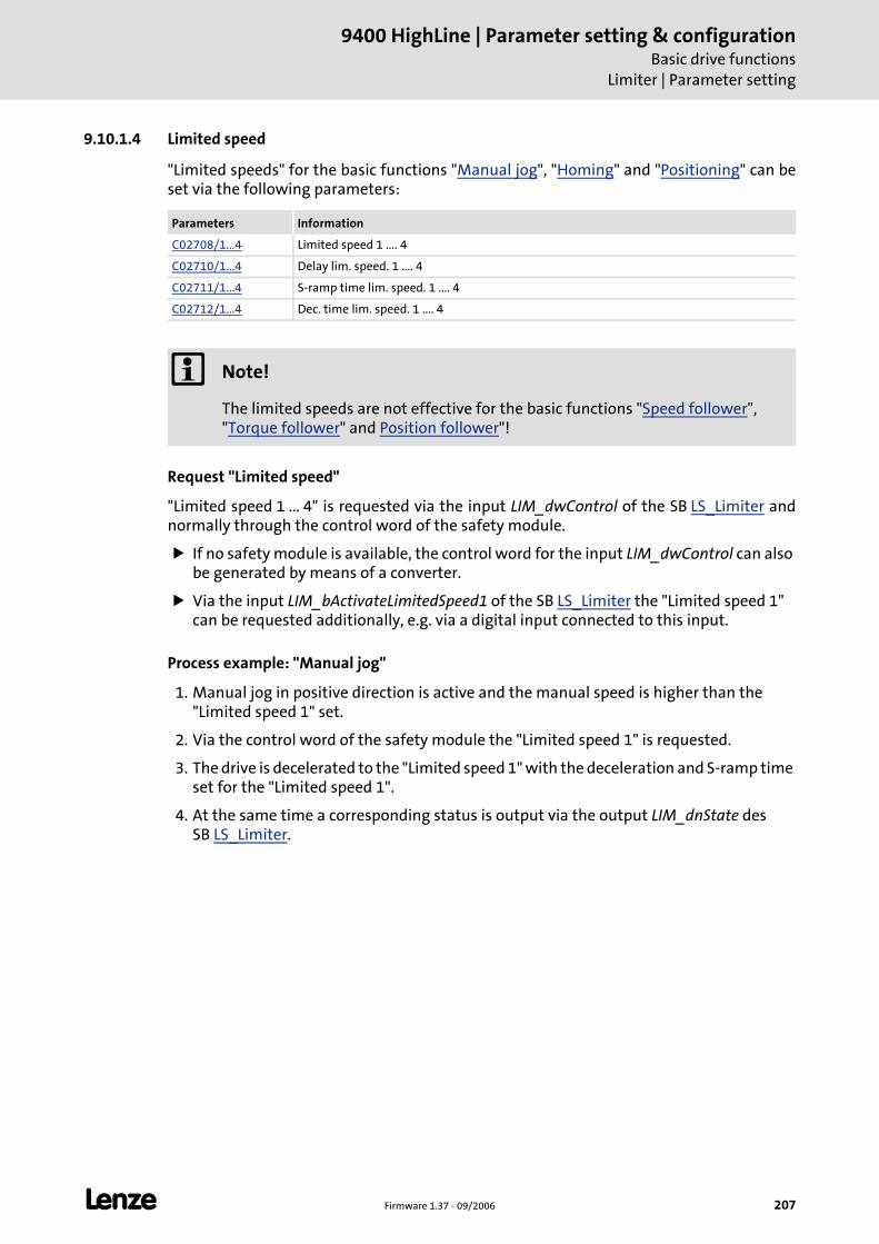
L Firmware 1.37 - 09/2006 207
9400 HighLine | Parameter setting & configurationBasic drive functions
Limiter | Parameter setting
9.10.1.4 Limited speed
"Limited speeds" for the basic functions "Manual jog", "Homing" and "Positioning" can beset via the following parameters:
Request "Limited speed"
"Limited speed 1 ... 4" is requested via the input LIM_dwControl of the SB LS_Limiter andnormally through the control word of the safety module.
If no safety module is available, the control word for the input LIM_dwControl can also be generated by means of a converter.
Via the input LIM_bActivateLimitedSpeed1 of the SB LS_Limiter the "Limited speed 1" can be requested additionally, e.g. via a digital input connected to this input.
Process example: "Manual jog"
1. Manual jog in positive direction is active and the manual speed is higher than the "Limited speed 1" set.
2. Via the control word of the safety module the "Limited speed 1" is requested.
3. The drive is decelerated to the "Limited speed 1" with the deceleration and S-ramp time set for the "Limited speed 1".
4. At the same time a corresponding status is output via the output LIM_dnState des SB LS_Limiter.
Parameters Information
C02708/1...4 Limited speed 1 .... 4
C02710/1...4 Delay lim. speed. 1 .... 4
C02711/1...4 S-ramp time lim. speed. 1 .... 4
C02712/1...4 Dec. time lim. speed. 1 .... 4
Note!
The limited speeds are not effective for the basic functions "Speed follower", "Torque follower" and Position follower"!
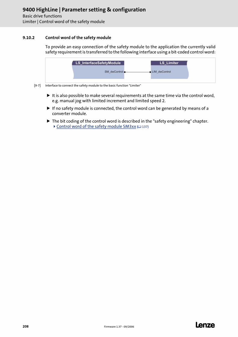
9400 HighLine | Parameter setting & configurationBasic drive functionsLimiter | Control word of the safety module
208 Firmware 1.37 - 09/2006 L
9.10.2 Control word of the safety module
To provide an easy connection of the safety module to the application the currently validsafety requirement is transferred to the following interface using a bit-coded control word:
[9-7] Interface to connect the safety module to the basic function "Limiter"
It is also possible to make several requirements at the same time via the control word, e.g. manual jog with limited increment and limited speed 2.
If no safety module is connected, the control word can be generated by means of a converter module.
The bit coding of the control word is described in the "safety engineering" chapter. Control word of the safety module SM3xx ( 137)
LS_InterfaceSafetyModule
SM_dwControl
LS_Limiter
LIM_dwControl
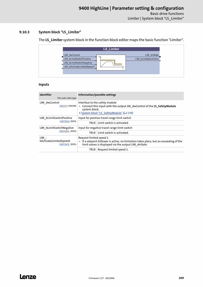
L Firmware 1.37 - 09/2006 209
9400 HighLine | Parameter setting & configurationBasic drive functions
Limiter | System block "LS_Limiter"
9.10.3 System block "LS_Limiter"
The LS_Limiter system block in the function block editor maps the basic function "Limiter".
Inputs
IdentifierDIS code | data type
Information/possible settings
LIM_dwControlC02717 | DWORD
Interface to the safety module • Connect this input with the output SM_dwControl of the LS_SafetyModule
system block.System block "LS_SafetyModule" ( 139)
LIM_bLimitSwitchPositiveC02719/1 | BOOL
Input for positive travel range limit switch
TRUE Limit switch is activated.
LIM_bLimitSwitchNegativeC02719/2 | BOOL
Input for negative travel range limit switch
TRUE Limit switch is activated.
LIM_-bActivateLimitedSpeed1
C02719/3 | BOOL
Request limited speed 1 • If a setpoint follower is active, no limitation takes place, but an exceeding of the
limit values is displayed via the output LIM_dnState.
TRUE Request limited speed 1.
LS_Limiter
LIM_dwControl
LIM_bLimitSwitchPositive
LIM_bLimitSwitchNegative
LIM_dnStaten
tLIM_bActivateLimitedSpeed1
LIM_bLimitationActive
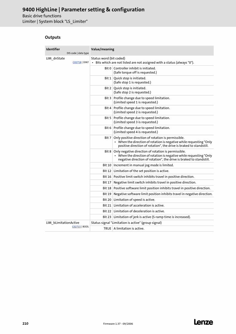
9400 HighLine | Parameter setting & configurationBasic drive functionsLimiter | System block "LS_Limiter"
210 Firmware 1.37 - 09/2006 L
Outputs
IdentifierDIS code | data type
Value/meaning
LIM_dnStateC02718 | DINT
Status word (bit coded) • Bits which are not listed are not assigned with a status (always "0").
Bit 0 Controller inhibit is initiated.(Safe torque off is requested.)
Bit 1 Quick stop is initiated.(Safe stop 1 is requested.)
Bit 2 Quick stop is initiated.(Safe stop 2 is requested.)
Bit 3 Profile change due to speed limitation.(Limited speed 1 is requested.)
Bit 4 Profile change due to speed limitation.(Limited speed 2 is requested.)
Bit 5 Profile change due to speed limitation.(Limited speed 3 is requested.)
Bit 6 Profile change due to speed limitation.(Limited speed 4 is requested.)
Bit 7 Only positive direction of rotation is permissible. • When the direction of rotation is negative while requesting "Only
positive direction of rotation", the drive is braked to standstill.
Bit 8 Only negative direction of rotation is permissible. • When the direction of rotation is negative while requesting "Only
negative direction of rotation", the drive is braked to standstill.
Bit 10 Increment in manual jog mode is limited.
Bit 12 Limitation of the set position is active.
Bit 16 Positive limit switch inhibits travel in positive direction.
Bit 17 Negative limit switch inhibits travel in positive direction.
Bit 18 Positive software limit position inhibits travel in positive direction.
Bit 19 Negative software limit position inhibits travel in negative direction.
Bit 20 Limitation of speed is active.
Bit 21 Limitation of acceleration is active.
Bit 22 Limitation of deceleration is active.
Bit 23 Limitation of jerk is active (S-ramp time is increased).
LIM_bLimitationActiveC02715 | BOOL
Status signal "Limitation is active" (group signal)
TRUE A limitation is active.
L Firmware 1.37 - 09/2006 211
9400 HighLine | Parameter setting & configurationBasic drive functions
Brake control
9.11 Brake control
This basic function is used for wear free control and monitoring of a holding brake whichis connected to the optionally available brake module. As an alternative, the holding brakecan also be controlled and monitored via the digital inputs/outputs.
Intended use
Motor holding brakes are used to stop axes when controller inhibit or pulse inhibit is set.This is particularly important for unbalanced vertical axes.
Stop!
Basically, holding brakes at Lenze motors are not designed for braking during operation. The increased wear resulting from braking during operation may lead to an early destruction of the motor holding brake!
Danger!
Please note that the holding brake is an important element of the safety concept of the entire machine.
Therefore act with caution when commissioning this part of the system!
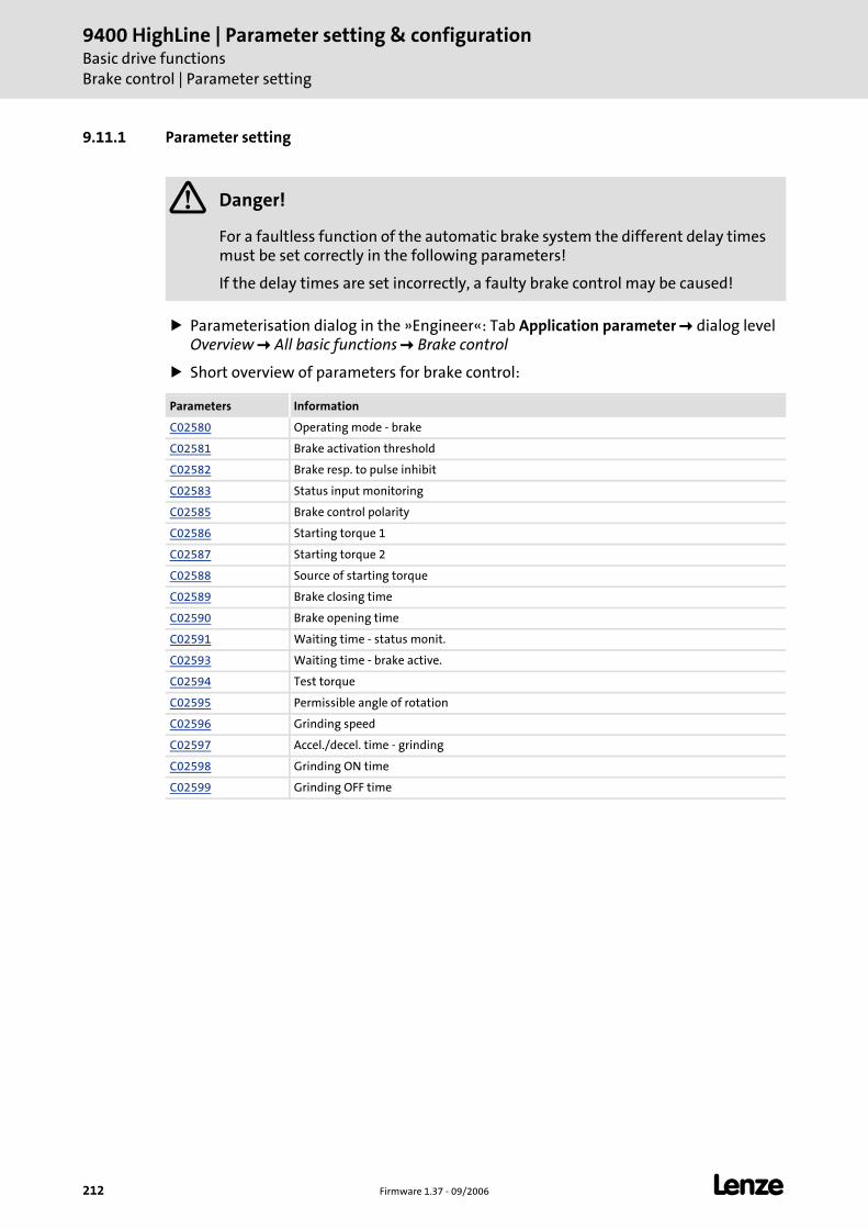
9400 HighLine | Parameter setting & configurationBasic drive functionsBrake control | Parameter setting
212 Firmware 1.37 - 09/2006 L
9.11.1 Parameter setting
Parameterisation dialog in the »Engineer«: Tab Application parameter dialog level Overview All basic functions Brake control
Short overview of parameters for brake control:
Danger!
For a faultless function of the automatic brake system the different delay times must be set correctly in the following parameters!
If the delay times are set incorrectly, a faulty brake control may be caused!
Parameters Information
C02580 Operating mode - brake
C02581 Brake activation threshold
C02582 Brake resp. to pulse inhibit
C02583 Status input monitoring
C02585 Brake control polarity
C02586 Starting torque 1
C02587 Starting torque 2
C02588 Source of starting torque
C02589 Brake closing time
C02590 Brake opening time
C02591 Waiting time - status monit.
C02593 Waiting time - brake active.
C02594 Test torque
C02595 Permissible angle of rotation
C02596 Grinding speed
C02597 Accel./decel. time - grinding
C02598 Grinding ON time
C02599 Grinding OFF time
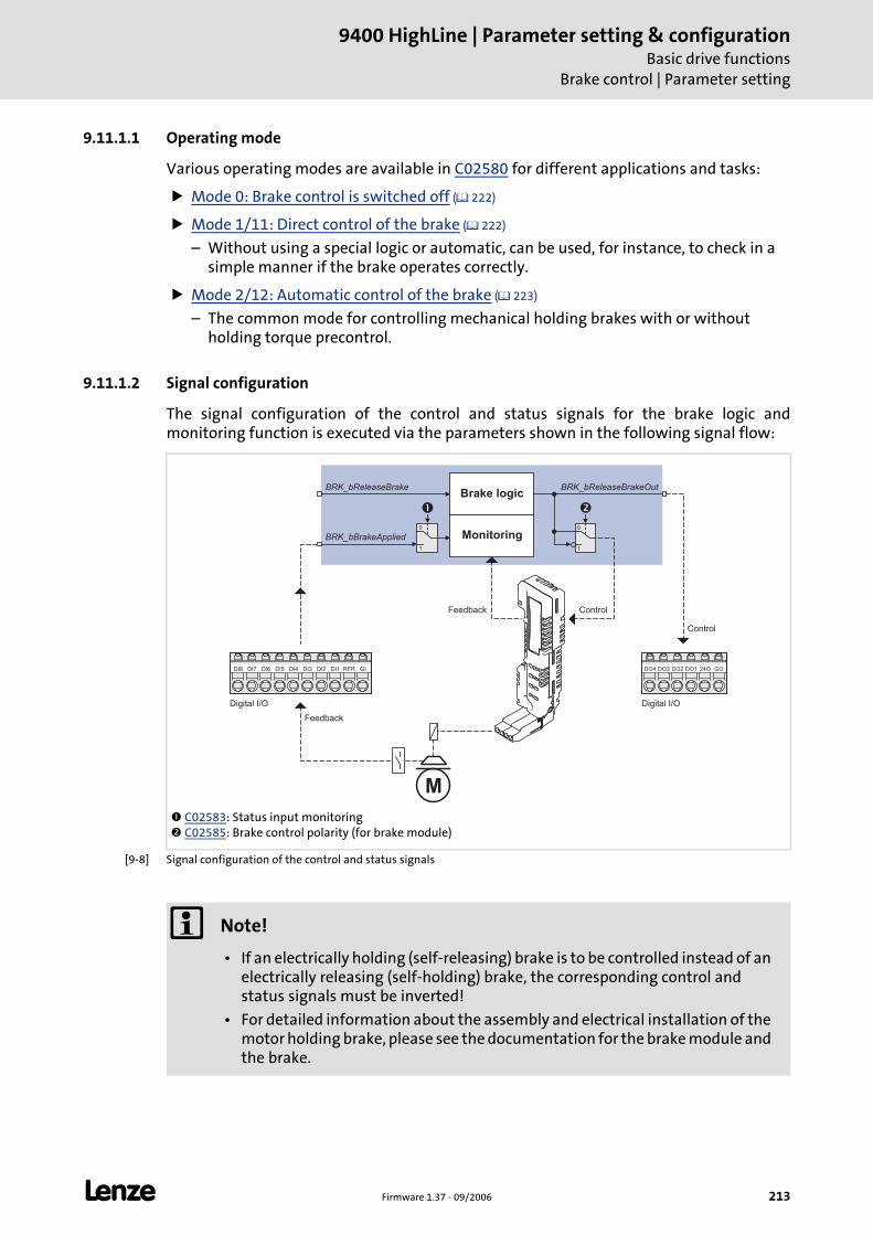
L Firmware 1.37 - 09/2006 213
9400 HighLine | Parameter setting & configurationBasic drive functions
Brake control | Parameter setting
9.11.1.1 Operating mode
Various operating modes are available in C02580 for different applications and tasks:
Mode 0: Brake control is switched off ( 222)
Mode 1/11: Direct control of the brake ( 222)
– Without using a special logic or automatic, can be used, for instance, to check in a simple manner if the brake operates correctly.
Mode 2/12: Automatic control of the brake ( 223)
– The common mode for controlling mechanical holding brakes with or without holding torque precontrol.
9.11.1.2 Signal configuration
The signal configuration of the control and status signals for the brake logic andmonitoring function is executed via the parameters shown in the following signal flow:
[9-8] Signal configuration of the control and status signals
C02583: Status input monitoring C02585: Brake control polarity (for brake module)
Brake logic
1
0
1
0
ControlFeedback
M
Digital I/O
GIRFRDI1DI2DI3DI4DI5DI6DI7DI8
Feedback
GO24ODO1DO2DO3DO4
Digital I/O
Control
�
MonitoringBRK_bBrakeApplied
BRK_bReleaseBrake BRK_bReleaseBrakeOut
�
Note!
• If an electrically holding (self-releasing) brake is to be controlled instead of an electrically releasing (self-holding) brake, the corresponding control and status signals must be inverted!
• For detailed information about the assembly and electrical installation of the motor holding brake, please see the documentation for the brake module and the brake.
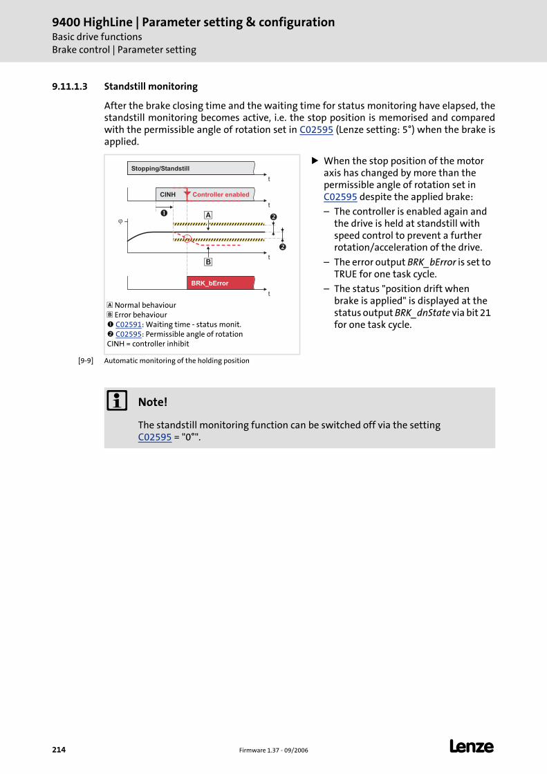
9400 HighLine | Parameter setting & configurationBasic drive functionsBrake control | Parameter setting
214 Firmware 1.37 - 09/2006 L
9.11.1.3 Standstill monitoring
After the brake closing time and the waiting time for status monitoring have elapsed, thestandstill monitoring becomes active, i.e. the stop position is memorised and comparedwith the permissible angle of rotation set in C02595 (Lenze setting: 5°) when the brake isapplied.
[9-9] Automatic monitoring of the holding position
Normal behaviour Error behaviour C02591: Waiting time - status monit. C02595: Permissible angle of rotation
CINH = controller inhibit
When the stop position of the motor axis has changed by more than the permissible angle of rotation set in C02595 despite the applied brake:
– The controller is enabled again and the drive is held at standstill with speed control to prevent a further rotation/acceleration of the drive.
– The error output BRK_bError is set to TRUE for one task cycle.
– The status "position drift when brake is applied" is displayed at the status output BRK_dnState via bit 21 for one task cycle.
t
t
�
BRK_bError
�
�
�
t
�
t
Stopping/Standstill
CINH
�
Controller enabled
Note!
The standstill monitoring function can be switched off via the setting C02595 = "0°".
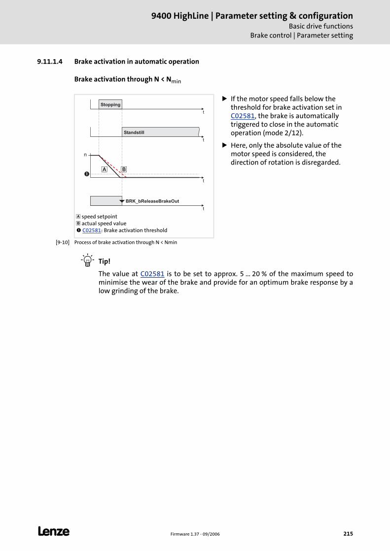
L Firmware 1.37 - 09/2006 215
9400 HighLine | Parameter setting & configurationBasic drive functions
Brake control | Parameter setting
9.11.1.4 Brake activation in automatic operation
Brake activation through N < Nmin
[9-10] Process of brake activation through N < Nmin
Tip!
The value at C02581 is to be set to approx. 5 ... 20 % of the maximum speed tominimise the wear of the brake and provide for an optimum brake response by alow grinding of the brake.
speed setpoint actual speed value C02581: Brake activation threshold
If the motor speed falls below the threshold for brake activation set in C02581, the brake is automatically triggered to close in the automatic operation (mode 2/12).
Here, only the absolute value of the motor speed is considered, the direction of rotation is disregarded.
t
t
�
t
� �
n
Standstill
BRK_bReleaseBrakeOut
t
Stopping
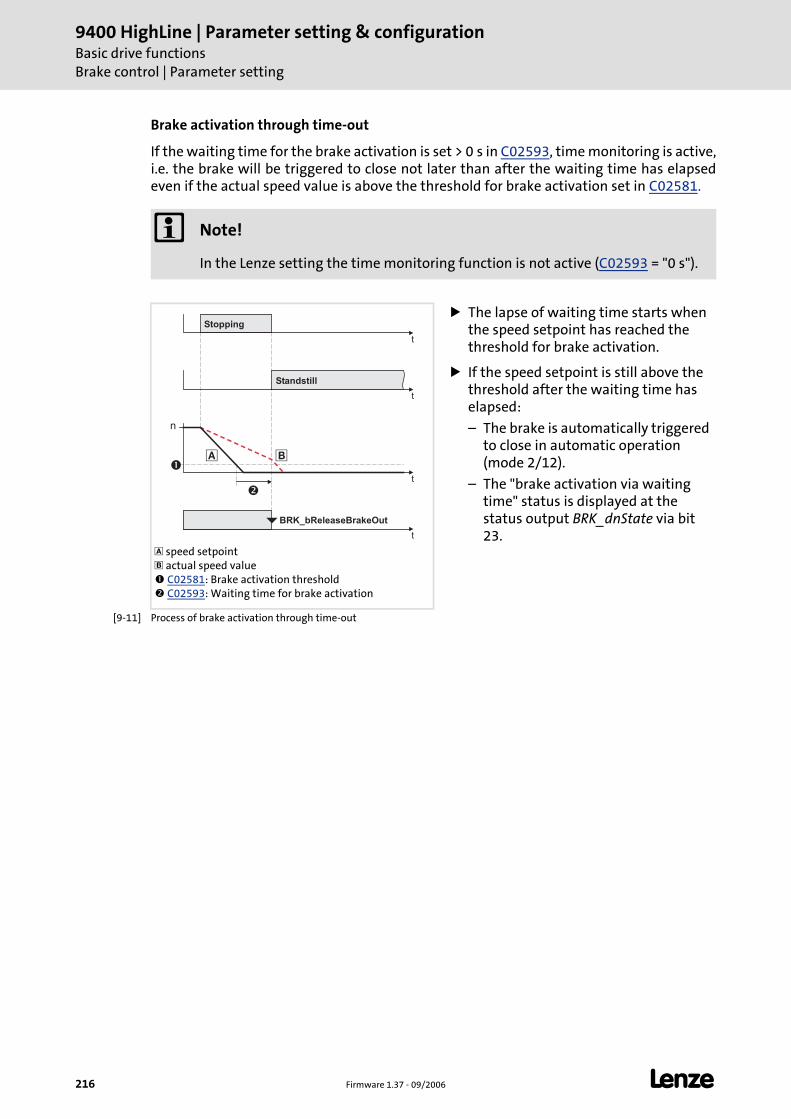
9400 HighLine | Parameter setting & configurationBasic drive functionsBrake control | Parameter setting
216 Firmware 1.37 - 09/2006 L
Brake activation through time-out
If the waiting time for the brake activation is set > 0 s in C02593, time monitoring is active,i.e. the brake will be triggered to close not later than after the waiting time has elapsedeven if the actual speed value is above the threshold for brake activation set in C02581.
[9-11] Process of brake activation through time-out
Note!
In the Lenze setting the time monitoring function is not active (C02593 = "0 s").
speed setpoint actual speed value C02581: Brake activation threshold C02593: Waiting time for brake activation
The lapse of waiting time starts when the speed setpoint has reached the threshold for brake activation.
If the speed setpoint is still above the threshold after the waiting time has elapsed:
– The brake is automatically triggered to close in automatic operation (mode 2/12).
– The "brake activation via waiting time" status is displayed at the status output BRK_dnState via bit 23.
t
t
� �
BRK_bReleaseBrakeOut
n
�
�
t
Standstill
t
Stopping
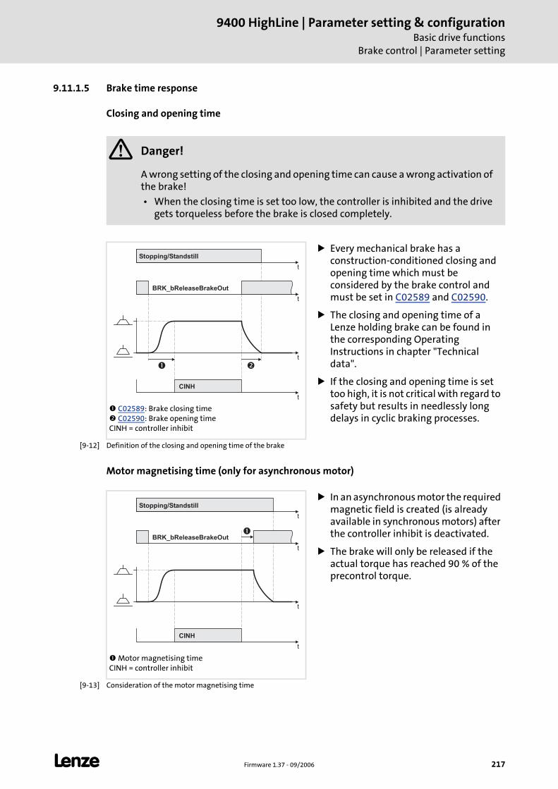
L Firmware 1.37 - 09/2006 217
9400 HighLine | Parameter setting & configurationBasic drive functions
Brake control | Parameter setting
9.11.1.5 Brake time response
Closing and opening time
[9-12] Definition of the closing and opening time of the brake
Motor magnetising time (only for asynchronous motor)
[9-13] Consideration of the motor magnetising time
Danger!
A wrong setting of the closing and opening time can cause a wrong activation of the brake!
• When the closing time is set too low, the controller is inhibited and the drive gets torqueless before the brake is closed completely.
C02589: Brake closing time C02590: Brake opening time
CINH = controller inhibit
Every mechanical brake has a construction-conditioned closing and opening time which must be considered by the brake control and must be set in C02589 and C02590.
The closing and opening time of a Lenze holding brake can be found in the corresponding Operating Instructions in chapter "Technical data".
If the closing and opening time is set too high, it is not critical with regard to safety but results in needlessly long delays in cyclic braking processes.
t
t
� �
t
CINH
t
Stopping/Standstill
BRK_bReleaseBrakeOut
Motor magnetising timeCINH = controller inhibit
In an asynchronous motor the required magnetic field is created (is already available in synchronous motors) after the controller inhibit is deactivated.
The brake will only be released if the actual torque has reached 90 % of the precontrol torque.
t
t
�
t
CINH
t
Stopping/Standstill
BRK_bReleaseBrakeOut
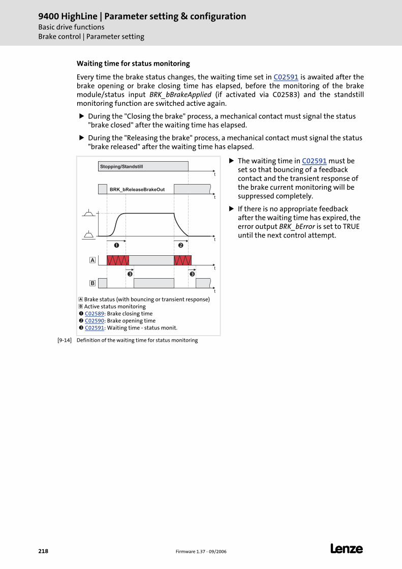
9400 HighLine | Parameter setting & configurationBasic drive functionsBrake control | Parameter setting
218 Firmware 1.37 - 09/2006 L
Waiting time for status monitoring
Every time the brake status changes, the waiting time set in C02591 is awaited after thebrake opening or brake closing time has elapsed, before the monitoring of the brakemodule/status input BRK_bBrakeApplied (if activated via C02583) and the standstillmonitoring function are switched active again.
During the "Closing the brake" process, a mechanical contact must signal the status "brake closed" after the waiting time has elapsed.
During the "Releasing the brake" process, a mechanical contact must signal the status "brake released" after the waiting time has elapsed.
[9-14] Definition of the waiting time for status monitoring
Brake status (with bouncing or transient response) Active status monitoring C02589: Brake closing time C02590: Brake opening time C02591: Waiting time - status monit.
The waiting time in C02591 must be set so that bouncing of a feedback contact and the transient response of the brake current monitoring will be suppressed completely.
If there is no appropriate feedback after the waiting time has expired, the error output BRK_bError is set to TRUE until the next control attempt.
t
�
t
t
�
�
� �
�
t
t
Stopping/Standstill
BRK_bReleaseBrakeOut
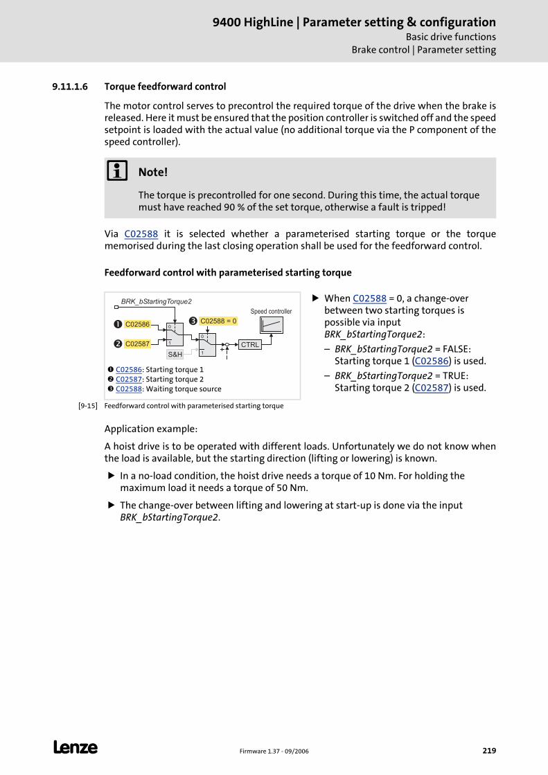
L Firmware 1.37 - 09/2006 219
9400 HighLine | Parameter setting & configurationBasic drive functions
Brake control | Parameter setting
9.11.1.6 Torque feedforward control
The motor control serves to precontrol the required torque of the drive when the brake isreleased. Here it must be ensured that the position controller is switched off and the speedsetpoint is loaded with the actual value (no additional torque via the P component of thespeed controller).
Via C02588 it is selected whether a parameterised starting torque or the torquememorised during the last closing operation shall be used for the feedforward control.
Feedforward control with parameterised starting torque
[9-15] Feedforward control with parameterised starting torque
Application example:
A hoist drive is to be operated with different loads. Unfortunately we do not know whenthe load is available, but the starting direction (lifting or lowering) is known.
In a no-load condition, the hoist drive needs a torque of 10 Nm. For holding the maximum load it needs a torque of 50 Nm.
The change-over between lifting and lowering at start-up is done via the input BRK_bStartingTorque2.
Note!
The torque is precontrolled for one second. During this time, the actual torque must have reached 90 % of the set torque, otherwise a fault is tripped!
C02586: Starting torque 1 C02587: Starting torque 2 C02588: Waiting torque source
When C02588 = 0, a change-over between two starting torques is possible via input BRK_bStartingTorque2:
– BRK_bStartingTorque2 = FALSE: Starting torque 1 (C02586) is used.
– BRK_bStartingTorque2 = TRUE: Starting torque 2 (C02587) is used.
1
0
BRK_bStartingTorque2
C02586�
� C02587
1
0
C02588 = 0�
S&H
CTRL
Speed controller
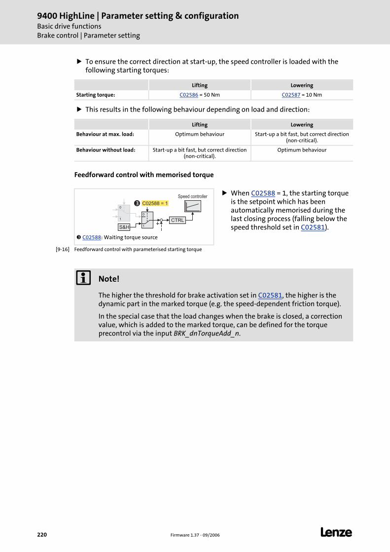
9400 HighLine | Parameter setting & configurationBasic drive functionsBrake control | Parameter setting
220 Firmware 1.37 - 09/2006 L
To ensure the correct direction at start-up, the speed controller is loaded with the following starting torques:
This results in the following behaviour depending on load and direction:
Feedforward control with memorised torque
[9-16] Feedforward control with parameterised starting torque
Lifting Lowering
Starting torque: C02586 = 50 Nm C02587 = 10 Nm
Lifting Lowering
Behaviour at max. load: Optimum behaviour Start-up a bit fast, but correct direction (non-critical).
Behaviour without load: Start-up a bit fast, but correct direction (non-critical).
Optimum behaviour
C02588: Waiting torque source
When C02588 = 1, the starting torque is the setpoint which has been automatically memorised during the last closing process (falling below the speed threshold set in C02581).
1
0
1
0
C02588 = 1
S&H
CTRL
Speed controller
�
Note!
The higher the threshold for brake activation set in C02581, the higher is the dynamic part in the marked torque (e.g. the speed-dependent friction torque).
In the special case that the load changes when the brake is closed, a correction value, which is added to the marked torque, can be defined for the torque precontrol via the input BRK_dnTorqueAdd_n.
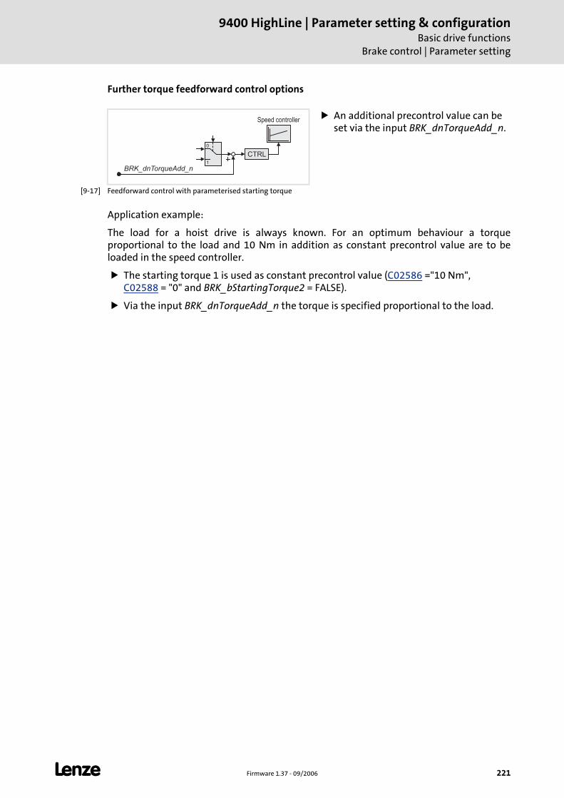
L Firmware 1.37 - 09/2006 221
9400 HighLine | Parameter setting & configurationBasic drive functions
Brake control | Parameter setting
Further torque feedforward control options
[9-17] Feedforward control with parameterised starting torque
Application example:
The load for a hoist drive is always known. For an optimum behaviour a torqueproportional to the load and 10 Nm in addition as constant precontrol value are to beloaded in the speed controller.
The starting torque 1 is used as constant precontrol value (C02586 ="10 Nm", C02588 = "0" and BRK_bStartingTorque2 = FALSE).
Via the input BRK_dnTorqueAdd_n the torque is specified proportional to the load.
An additional precontrol value can be set via the input BRK_dnTorqueAdd_n.
1
0
BRK_dnTorqueAdd_n
CTRL
Speed controller
9400 HighLine | Parameter setting & configurationBasic drive functionsBrake control | Mode 0: Brake control is switched off
222 Firmware 1.37 - 09/2006 L
9.11.2 Mode 0: Brake control is switched off
If the mode 0 is selected in C02580, the brake activation is switched off.
If a brake module is available, it will not be triggered.
The brake monitoring function is not active.
If a fault is reported by the brake control, it will be reset.
The output signals of the system block LS_Brake are reset:
– BRK_dnState = 0
– BRK_bReleaseBrakeOut = FALSE
– BRK_bBrakeReleased = FALSE
– BRK_bError = FALSE
9.11.3 Mode 1/11: Direct control of the brake
If the mode 1 or 11 has been selected in C02580, the brake is directly controlled via theinput BRK_bReleaseBrake.
Tip!
Mode 1/11 can be used to easily check if the brake switches correctly.
At the same time, the selection of the mode defines the type of brake control:
– Mode 1: Direct brake control via brake module.
– Mode 11: Direct brake control via a digital output.
Setting the pulse inhibit or controller inhibit does not influence the output signal.
After the brake has been activated and the brake closing time has elapsed, the controller inhibit is set automatically by the basic function "brake control".
For the operation with the brake module (mode 1) the required polarity for brake control can be set in C02585.
Note!
The mode 0 is preset in the Lenze setting to reach a safe status after mains connection.
L Firmware 1.37 - 09/2006 223
9400 HighLine | Parameter setting & configurationBasic drive functions
Brake control | Mode 2/12: Automatic control of the brake
9.11.4 Mode 2/12: Automatic control of the brake
If the mode 2 or 12 is selected in C02580, the brake is controlled automatically, i.e. ifanother basic function is activated which causes the drive to traverse, the brake is openedautomatically and the operation is enabled. If the corresponding basic function isdeactivated again, the drive is stopped via the basic function "Standard stop" and the brakeis automatically closed again, if speed setpoint and actual speed value fall below the speedthreshold set in C02581.
Tip!
The mode 2/12 is the common mode for brake control.
In this mode, the input BRK_bReleaseBrake is to be set permanently to FALSE. IfBRK_bReleaseBrake = TRUE, the brake is permanently released and the automaticcontrol cannot close the brake.
At the same time, the selection of the mode defines the type of brake control:
– Mode 2: Automatic brake control via brake module.
– Mode 12: Automatic brake control via a digital output.
The brake is also activated automatically if a quick stop is activated in the drive, e.g. via the basic function "Quick stop" or as a response to a fault.
After the brake has been activated automatically and the brake closing time has elapsed, the controller inhibit is set automatically by the basic function "brake control".
For the operation with the brake module (mode 1) the required polarity for brake control can be set in C02585.
9400 HighLine | Parameter setting & configurationBasic drive functionsBrake control | Mode 2/12: Automatic control of the brake
224 Firmware 1.37 - 09/2006 L
9.11.4.1 Behaviour at pulse inhibit
In case of pulse inhibit the brake is applied. This occurs according to the parameter settingin C02582 either immediately (default setting) or delayed when the threshold set for brakeactivation is fallen below, which can be selected to protect the brake if high centrifugalmasses occur.
Activate the brake in any case
When setting C02582 = "0", the brake is triggered to close to prevent the mechanics frombeing damaged.
Only activate the brake below the threshold set for brake activation
When C02582 = "1", the brake remains released until the threshold set in C02581 for brakeactivation has been reached to protect the brake from excessive wear.
Braking is exclusively executed by the friction of the load mechanics.
Only when the motor speed has reached the threshold for brake activation, the brake will be closed.
Note!
Pulse inhibit can be set in the enabled controller e.g. due to a DC overvoltage during brake operation by a wrong dimensioning of the brake resistor.
Stop!
Do not set the threshold for brake activation in C02581 too high to protect the brake from wear.
L Firmware 1.37 - 09/2006 225
9400 HighLine | Parameter setting & configurationBasic drive functions
Brake control | Mode 2/12: Automatic control of the brake
9.11.4.2 Process when brake is released
The following process occurs when a basic function is requested which causes the drive totraverse:
1. The controller inhibit is deactivated.
2. A magnetic field is created in the motor required for the holding torque (is already available in synchronous machines).
3. The precontrol torque is loaded in the speed controller.
4. When the actual torque has reached 90 % of the precontrol torque:
– The output BRK_bReleaseBrakeOut is set to TRUE for releasing the brake.
– Monitoring of the brake module is deactivated temporarily.
– Monitoring of the status input is deactivated temporarily (if switched active via C02583).
– The lapse of brake opening time starts.
5. After the brake opening time has elapsed:
– The output BRK_bBrakeReleased is set to TRUE.
– The requested basic function is enabled.
6. After the additional waiting time set for the status monitoring in C02591 has elapsed:
– Monitoring of the brake module is active again.
– Monitoring of the status input is active again (if switched active via C02583).
9400 HighLine | Parameter setting & configurationBasic drive functionsBrake control | Mode 2/12: Automatic control of the brake
226 Firmware 1.37 - 09/2006 L
9.11.4.3 Process when brake is closed
The following process occurs if the enable of the requested basic function for traversingthe drive is deactivated again:
1. The drive is braked to standstill via the basic function "Standard stop", or also via the basic function "Quick stop".
2. When speed setpoint and actual speed value have fallen below the speed threshold set in C02581:
– The output BRK_bReleaseBrakeOut is set to FALSE for opening the brake.
– The current torque is saved to be used for the feedforward control for the next start, if required.
– Monitoring of the brake module is deactivated temporarily.
– Monitoring of the status input is deactivated temporarily (if switched active via C02583).
– The lapse of brake closing time starts.
3. After the brake closing time has elapsed and the corresponding status change of the status signal:
– The output BRK_bBrakeReleased is reset to FALSE.
– The controller inhibit is activated.
4. After the additional waiting time set for the status monitoring in C02591 has elapsed:
– Monitoring of the brake module is active again.
– Monitoring of the status input is active again (if switched active via C02583).
– Standstill monitoring is activated. Standstill monitoring ( 214)
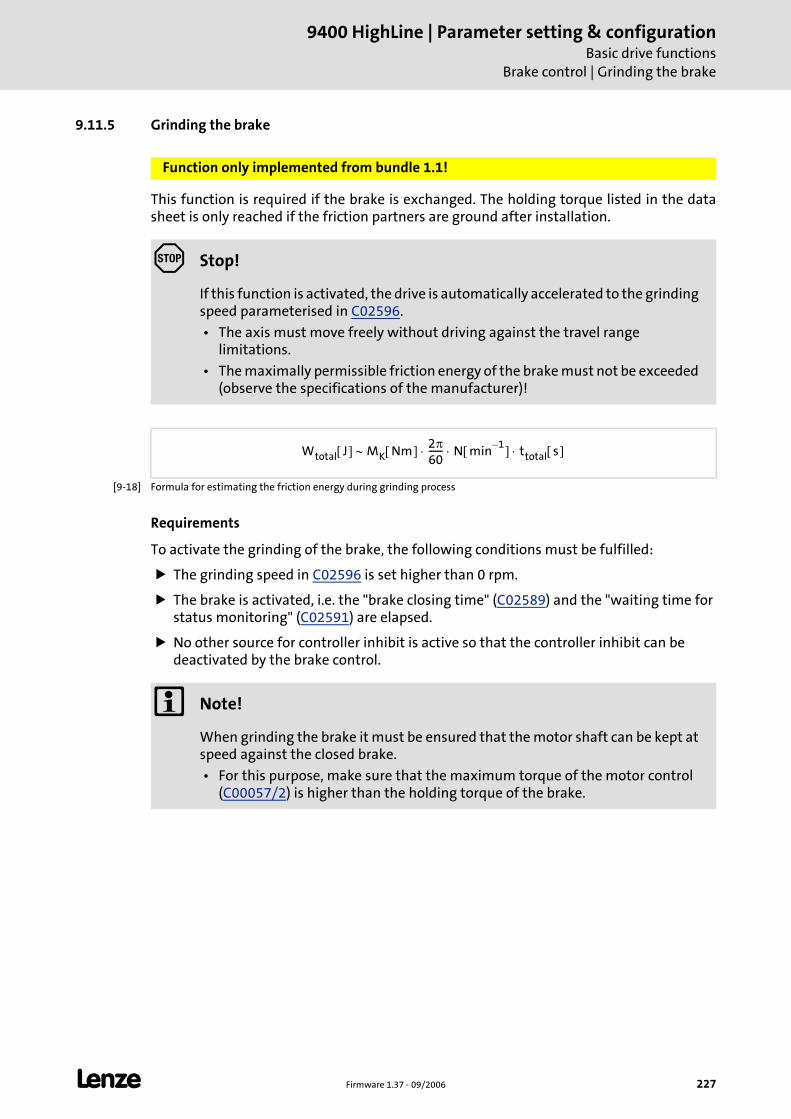
L Firmware 1.37 - 09/2006 227
9400 HighLine | Parameter setting & configurationBasic drive functions
Brake control | Grinding the brake
9.11.5 Grinding the brake
This function is required if the brake is exchanged. The holding torque listed in the datasheet is only reached if the friction partners are ground after installation.
[9-18] Formula for estimating the friction energy during grinding process
Requirements
To activate the grinding of the brake, the following conditions must be fulfilled:
The grinding speed in C02596 is set higher than 0 rpm.
The brake is activated, i.e. the "brake closing time" (C02589) and the "waiting time for status monitoring" (C02591) are elapsed.
No other source for controller inhibit is active so that the controller inhibit can be deactivated by the brake control.
Function only implemented from bundle 1.1!
Stop!
If this function is activated, the drive is automatically accelerated to the grinding speed parameterised in C02596.
• The axis must move freely without driving against the travel range limitations.
• The maximally permissible friction energy of the brake must not be exceeded (observe the specifications of the manufacturer)!
Wtotal J[ ] MK Nm[ ] 2π60------ N min
1–[ ] ttotal s[ ]⋅ ⋅ ⋅∼
Note!
When grinding the brake it must be ensured that the motor shaft can be kept at speed against the closed brake.
• For this purpose, make sure that the maximum torque of the motor control (C00057/2) is higher than the holding torque of the brake.
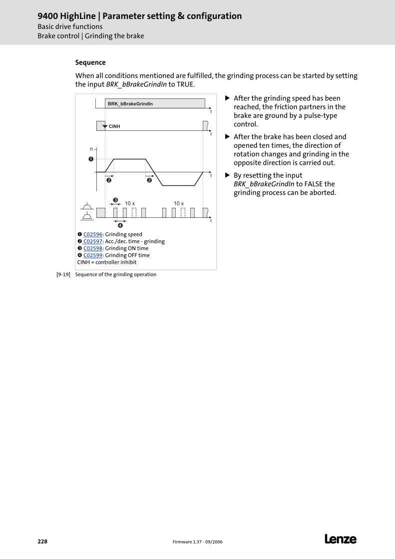
9400 HighLine | Parameter setting & configurationBasic drive functionsBrake control | Grinding the brake
228 Firmware 1.37 - 09/2006 L
Sequence
When all conditions mentioned are fulfilled, the grinding process can be started by settingthe input BRK_bBrakeGrindIn to TRUE.
[9-19] Sequence of the grinding operation
C02596: Grinding speed C02597: Acc./dec. time - grinding C02598: Grinding ON time C02599: Grinding OFF time
CINH = controller inhibit
After the grinding speed has been reached, the friction partners in the brake are ground by a pulse-type control.
After the brake has been closed and opened ten times, the direction of rotation changes and grinding in the opposite direction is carried out.
By resetting the input BRK_bBrakeGrindIn to FALSE the grinding process can be aborted.
t
�
t
�
�
t
t
BRK_bBrakeGrindIn
CINH
n
�
�
10 x 10 x
L Firmware 1.37 - 09/2006 229
9400 HighLine | Parameter setting & configurationBasic drive functions
Brake control | Carry out brake test
9.11.6 Carry out brake test
This function can be used to check the holding torque of the brake.
Tip!
You can carry out this test regularly to early detect defects or wear of the brake ingood time.
Requirements
To activate the brake test, the following conditions must be fulfilled:
The test torque in C02594 is set higher than 0 Nm.
The permissible angle of rotation in C02595 is set higher than 0° and thus standstill monitoring is active. Standstill monitoring ( 214)
The brake is activated, i.e. the "brake closing time" (C02589) and the "waiting time for status monitoring" (C02591) are elapsed.
No other source for controller inhibit is active so that the controller inhibit can be deactivated by the brake control.
Function only implemented from bundle 1.1!
Note!
Due to possible deviations in the torque generation, the test of the holding torque cannot determine the holding torque exactly!
• The generated motor torque can deviate up to ±15 % from the default value depending on temperature.
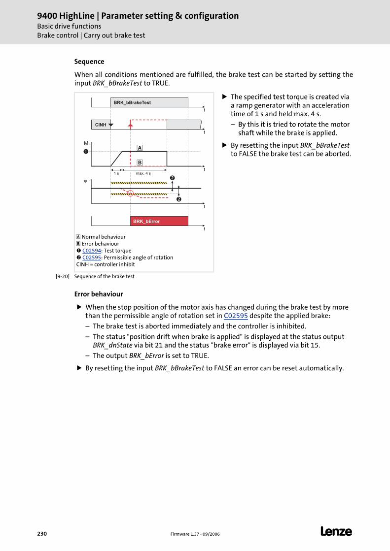
9400 HighLine | Parameter setting & configurationBasic drive functionsBrake control | Carry out brake test
230 Firmware 1.37 - 09/2006 L
Sequence
When all conditions mentioned are fulfilled, the brake test can be started by setting theinput BRK_bBrakeTest to TRUE.
[9-20] Sequence of the brake test
Error behaviour
When the stop position of the motor axis has changed during the brake test by more than the permissible angle of rotation set in C02595 despite the applied brake:
– The brake test is aborted immediately and the controller is inhibited.
– The status "position drift when brake is applied" is displayed at the status output BRK_dnState via bit 21 and the status "brake error" is displayed via bit 15.
– The output BRK_bError is set to TRUE.
By resetting the input BRK_bBrakeTest to FALSE an error can be reset automatically.
Normal behaviour Error behaviour C02594: Test torque C02595: Permissible angle of rotation
CINH = controller inhibit
The specified test torque is created via a ramp generator with an acceleration time of 1 s and held max. 4 s.
– By this it is tried to rotate the motor shaft while the brake is applied.
By resetting the input BRK_bBrakeTest to FALSE the brake test can be aborted.
t
��
�
M
t
�
t
t
BRK_bBrakeTest
CINH
1 s max. 4 s
�
�
t
BRK_bError
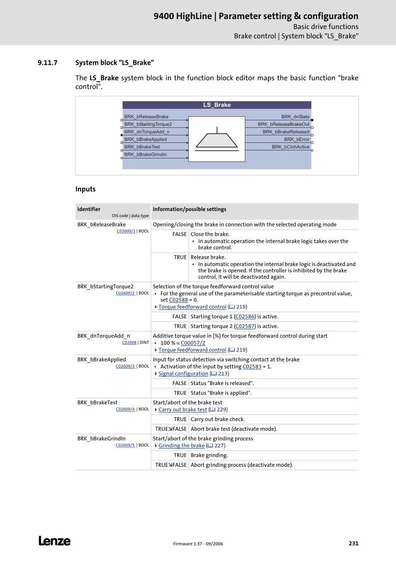
L Firmware 1.37 - 09/2006 231
9400 HighLine | Parameter setting & configurationBasic drive functions
Brake control | System block "LS_Brake"
9.11.7 System block "LS_Brake"
The LS_Brake system block in the function block editor maps the basic function "brakecontrol".
Inputs
IdentifierDIS code | data type
Information/possible settings
BRK_bReleaseBrakeC02609/1 | BOOL
Opening/closing the brake in connection with the selected operating mode
FALSE Close the brake. • In automatic operation the internal brake logic takes over the
brake control.
TRUE Release brake. • In automatic operation the internal brake logic is deactivated and
the brake is opened. If the controller is inhibited by the brake control, it will be deactivated again.
BRK_bStartingTorque2C02609/2 | BOOL
Selection of the torque feedforward control value • For the general use of the parameterisable starting torque as precontrol value,
set C02588 = 0.Torque feedforward control ( 219)
FALSE Starting torque 1 (C02586) is active.
TRUE Starting torque 2 (C02587) is active.
BRK_dnTorqueAdd_nC02608 | DINT
Additive torque value in [%] for torque feedforward control during start • 100 % ≡ C00057/2
Torque feedforward control ( 219)
BRK_bBrakeAppliedC02609/3 | BOOL
Input for status detection via switching contact at the brake • Activation of the input by setting C02583 = 1.
Signal configuration ( 213)
FALSE Status "Brake is released".
TRUE Status "Brake is applied".
BRK_bBrakeTestC02609/4 | BOOL
Start/abort of the brake testCarry out brake test ( 229)
TRUE Carry out brake check.
TRUE FALSE Abort brake test (deactivate mode).
BRK_bBrakeGrindInC02609/5 | BOOL
Start/abort of the brake grinding processGrinding the brake ( 227)
TRUE Brake grinding.
TRUE FALSE Abort grinding process (deactivate mode).
LS_Brake
BRK_bReleaseBrake
BRK_bStartingTorque2
BRK_bBrakeApplied
BRK_bBrakeTest
BRK_dnState
BRK_bReleaseBrakeOut
BRK_bBrakeReleased
BRK_bError
BRK_dnTorqueAdd_n
BRK_bBrakeGrindIn
BRK_bCInhActive
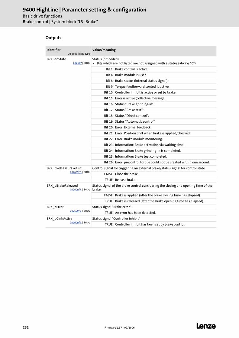
9400 HighLine | Parameter setting & configurationBasic drive functionsBrake control | System block "LS_Brake"
232 Firmware 1.37 - 09/2006 L
Outputs
IdentifierDIS code | data type
Value/meaning
BRK_dnStateC02607 | BOOL
Status (bit-coded) • Bits which are not listed are not assigned with a status (always "0").
Bit 1 Brake control is active.
Bit 4 Brake module is used.
Bit 8 Brake status (internal status signal).
Bit 9 Torque feedforward control is active.
Bit 10 Controller inhibit is active or set by brake.
Bit 15 Error is active (collective message).
Bit 16 Status "Brake grinding-in".
Bit 17 Status "Brake test".
Bit 18 Status "Direct control".
Bit 19 Status "Automatic control".
Bit 20 Error: External feedback.
Bit 21 Error: Position drift when brake is applied/checked.
Bit 22 Error: Brake module monitoring.
Bit 23 Information: Brake activation via waiting time.
Bit 24 Information: Brake grinding-in is completed.
Bit 25 Information: Brake test completed.
Bit 26 Error: precontrol torque could not be created within one second.
BRK_bReleaseBrakeOutC02609/6 | BOOL
Control signal for triggering an external brake/status signal for control state
FALSE Close the brake.
TRUE Release brake.
BRK_bBrakeReleasedC02609/7 | BOOL
Status signal of the brake control considering the closing and opening time of the brake
FALSE Brake is applied (after the brake closing time has elapsed).
TRUE Brake is released (after the brake opening time has elapsed).
BRK_bErrorC02609/8 | BOOL
Status signal "Brake error"
TRUE An error has been detected.
BRK_bCInhActiveC02609/9 | BOOL
Status signal "Controller inhibit"
TRUE Controller inhibit has been set by brake control.
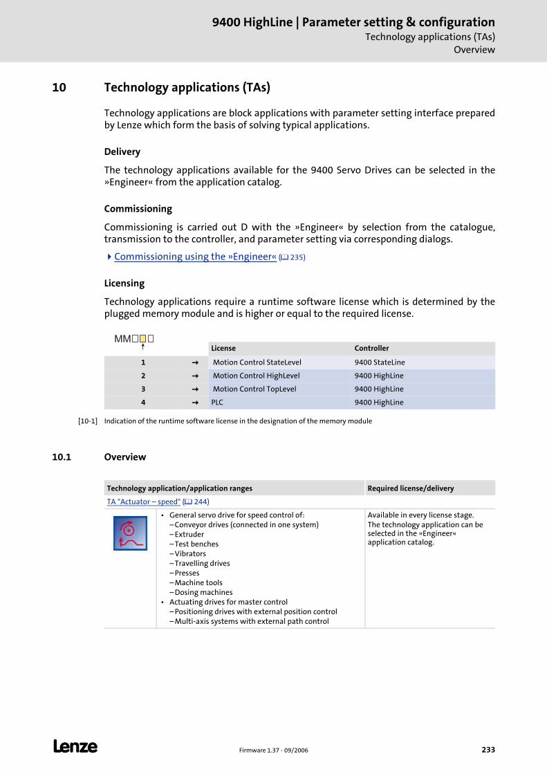
L Firmware 1.37 - 09/2006 233
9400 HighLine | Parameter setting & configurationTechnology applications (TAs)
Overview
10 Technology applications (TAs)
Technology applications are block applications with parameter setting interface prepared by Lenze which form the basis of solving typical applications.
Delivery
The technology applications available for the 9400 Servo Drives can be selected in the »Engineer« from the application catalog.
Commissioning
Commissioning is carried out D with the »Engineer« by selection from the catalogue, transmission to the controller, and parameter setting via corresponding dialogs.
Commissioning using the »Engineer« ( 235)
Licensing
Technology applications require a runtime software license which is determined by the plugged memory module and is higher or equal to the required license.
[10-1] Indication of the runtime software license in the designation of the memory module
10.1 Overview
License Controller
1 Motion Control StateLevel 9400 StateLine
2 Motion Control HighLevel 9400 HighLine
3 Motion Control TopLevel 9400 HighLine
4 PLC 9400 HighLine
MM
Technology application/application ranges Required license/delivery
TA "Actuator – speed" ( 244)
• General servo drive for speed control of:– Conveyor drives (connected in one system)– Extruder– Test benches– Vibrators– Travelling drives– Presses– Machine tools– Dosing machines
• Actuating drives for master control– Positioning drives with external position control– Multi-axis systems with external path control
Available in every license stage.The technology application can be selected in the »Engineer« application catalog.
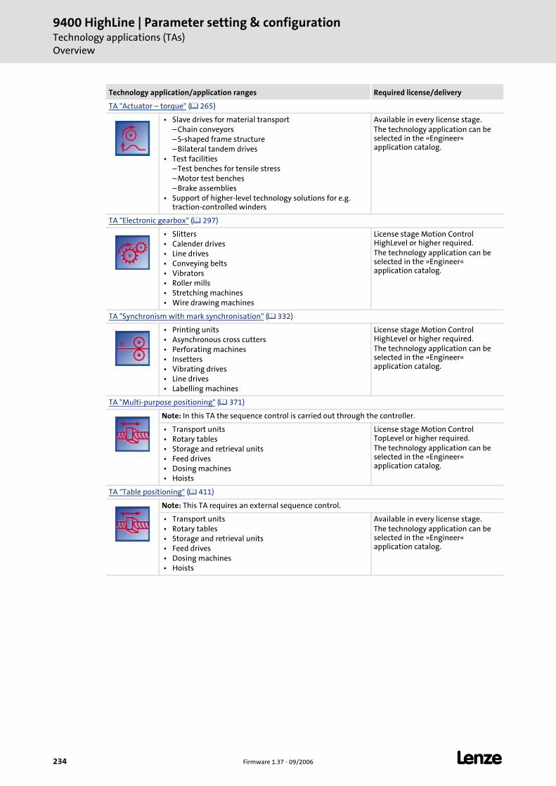
9400 HighLine | Parameter setting & configurationTechnology applications (TAs)Overview
234 Firmware 1.37 - 09/2006 L
TA "Actuator – torque" ( 265)
• Slave drives for material transport– Chain conveyors– S-shaped frame structure– Bilateral tandem drives
• Test facilities– Test benches for tensile stress– Motor test benches– Brake assemblies
• Support of higher-level technology solutions for e.g. traction-controlled winders
Available in every license stage.The technology application can be selected in the »Engineer« application catalog.
TA "Electronic gearbox" ( 297)
• Slitters • Calender drives • Line drives • Conveying belts • Vibrators • Roller mills • Stretching machines • Wire drawing machines
License stage Motion Control HighLevel or higher required.The technology application can be selected in the »Engineer« application catalog.
TA "Synchronism with mark synchronisation" ( 332)
• Printing units • Asynchronous cross cutters • Perforating machines • Insetters • Vibrating drives • Line drives • Labelling machines
License stage Motion Control HighLevel or higher required.The technology application can be selected in the »Engineer« application catalog.
TA "Multi-purpose positioning" ( 371)
Note: In this TA the sequence control is carried out through the controller.
• Transport units • Rotary tables • Storage and retrieval units • Feed drives • Dosing machines • Hoists
License stage Motion Control TopLevel or higher required.The technology application can be selected in the »Engineer« application catalog.
TA "Table positioning" ( 411)
Note: This TA requires an external sequence control.
• Transport units • Rotary tables • Storage and retrieval units • Feed drives • Dosing machines • Hoists
Available in every license stage.The technology application can be selected in the »Engineer« application catalog.
Technology application/application ranges Required license/delivery
L Firmware 1.37 - 09/2006 235
9400 HighLine | Parameter setting & configurationTechnology applications (TAs)
Commissioning using the »Engineer«
10.2 Commissioning using the »Engineer«
Basic procedure
1. Start »Engineer«.
2. Open available project or create a new project.
3. Assign each controller to a technology application from the catalogue.
4. For a project with several interconnected devices:
– Insert network and machine application .
– Make suitable network settings.
– Specialise the predefined ports to concrete interfaces for the devices involved in the network on the Ports tab.
– Interconnect the ports conveniently inside the machine application.
5. Parameterise the application(s).
6. Update devices.
7. Go online.
8. Download application(s) into the controller(s).
9. Confirm Dialog box Start application with Yes, all devices.
10. Confirm Dialog box Enable controller with Yes, all devices.
11. Control application(s) via terminals or network.
Note!
The downloaded application is basically stored in the first application memory location of the controller.
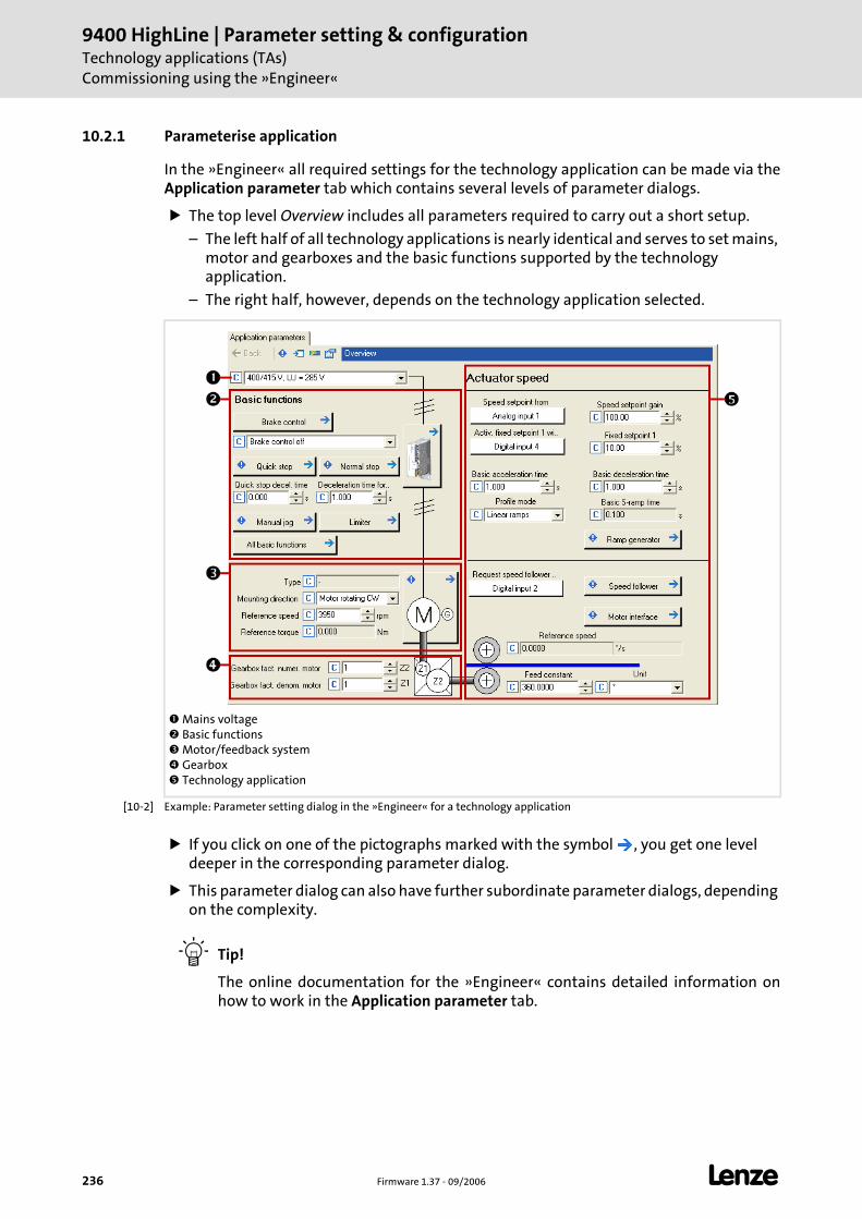
9400 HighLine | Parameter setting & configurationTechnology applications (TAs)Commissioning using the »Engineer«
236 Firmware 1.37 - 09/2006 L
10.2.1 Parameterise application
In the »Engineer« all required settings for the technology application can be made via the Application parameter tab which contains several levels of parameter dialogs.
The top level Overview includes all parameters required to carry out a short setup.
– The left half of all technology applications is nearly identical and serves to set mains, motor and gearboxes and the basic functions supported by the technology application.
– The right half, however, depends on the technology application selected.
[10-2] Example: Parameter setting dialog in the »Engineer« for a technology application
If you click on one of the pictographs marked with the symbol , you get one level deeper in the corresponding parameter dialog.
This parameter dialog can also have further subordinate parameter dialogs, depending on the complexity.
Tip!
The online documentation for the »Engineer« contains detailed information on how to work in the Application parameter tab.
Mains voltage Basic functions Motor/feedback system Gearbox Technology application
L Firmware 1.37 - 09/2006 237
9400 HighLine | Parameter setting & configurationTechnology applications (TAs)
Commissioning using the »Engineer«
10.2.2 Parameterise signal combinations
In order to easily change existing signal combinations between the device interfaces and the application inputs and outputs, parameterisable "multiplexers" are implemented in all technology applications.
From a number of signal sources, each multiplexer combines exactly one with a signal target of the same data type ("combinatorial circuit").
The signal source is selected by setting the "multiplexer parameter" that is firmly assigned to the signal target. Each multiplexer parameter always offers a selection of sensible signal sources only.
Thus, signal combinations can also be changed (e.g. the assignment of the digital inputs and outputs) with the keypad only.
Tip!
The multiplexer parameters are marked by a prefixed "X" in the name and listed in the chapter of the corresponding technology application.
Several options are available for changing the signal combinations which are described in the following sections.
Note!
When you enable the function block editor in the »Engineer» on the FB editor tab, all multiplexers are removed from the interconnection and the currently set signal combinations are replaced by fixed signal combinations!
This process is irreversible!
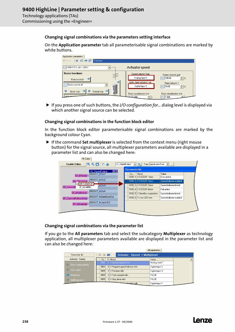
9400 HighLine | Parameter setting & configurationTechnology applications (TAs)Commissioning using the »Engineer«
238 Firmware 1.37 - 09/2006 L
Changing signal combinations via the parameters setting interface
On the Application parameter tab all parameterisable signal combinations are marked by white buttons.
If you press one of such buttons, the I/O configuration for... dialog level is displayed via which another signal source can be selected.
Changing signal combinations in the function block editor
In the function block editor parameterisable signal combinations are marked by the background colour Cyan.
If the command Set multiplexer is selected from the context menu (right mouse button) for the signal source, all multiplexer parameters available are displayed in a parameter list and can also be changed here:
Changing signal combinations via the parameter list
If you go to the All parameters tab and select the subcategory Multiplexer as technology application, all multiplexer parameters available are displayed in the parameter list and can also be changed here:
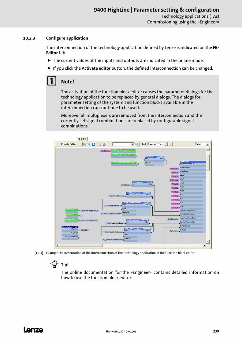
L Firmware 1.37 - 09/2006 239
9400 HighLine | Parameter setting & configurationTechnology applications (TAs)
Commissioning using the »Engineer«
10.2.3 Configure application
The interconnection of the technology application defined by Lenze is indicated on the FB-Editor tab.
The current values at the inputs and outputs are indicated in the online mode.
If you click the Activate editor button, the defined interconnection can be changed.
[10-3] Example: Representation of the interconnection of the technology application in the function block editor
Tip!
The online documentation for the »Engineer« contains detailed information on how to use the function block editor.
Note!
The activation of the function block editor causes the parameter dialogs for the technology application to be replaced by general dialogs. The dialogs for parameter setting of the system and function blocks available in the interconnection can continue to be used.
Moreover all multiplexers are removed from the interconnection and the currently set signal combinations are replaced by configurable signal combinations.
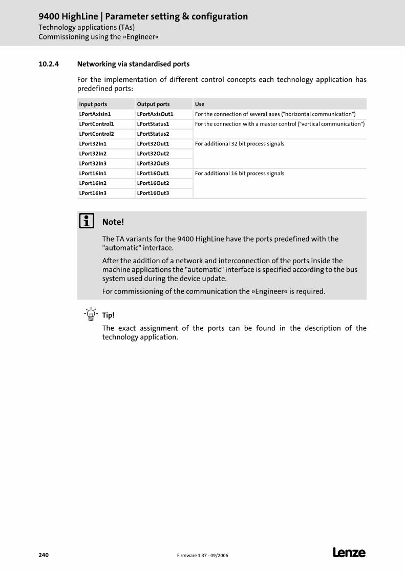
9400 HighLine | Parameter setting & configurationTechnology applications (TAs)Commissioning using the »Engineer«
240 Firmware 1.37 - 09/2006 L
10.2.4 Networking via standardised ports
For the implementation of different control concepts each technology application has predefined ports:
Tip!
The exact assignment of the ports can be found in the description of the technology application.
Input ports Output ports Use
LPortAxisIn1 LPortAxisOut1 For the connection of several axes ("horizontal communication")
LPortControl1 LPortStatus1 For the connection with a master control ("vertical communication")
LPortControl2 LPortStatus2
LPort32In1 LPort32Out1 For additional 32 bit process signals
LPort32In2 LPort32Out2
LPort32In3 LPort32Out3
LPort16In1 LPort16Out1 For additional 16 bit process signals
LPort16In2 LPort16Out2
LPort16In3 LPort16Out3
Note!
The TA variants for the 9400 HighLine have the ports predefined with the "automatic" interface.
After the addition of a network and interconnection of the ports inside the machine applications the "automatic" interface is specified according to the bus system used during the device update.
For commissioning of the communication the »Engineer« is required.
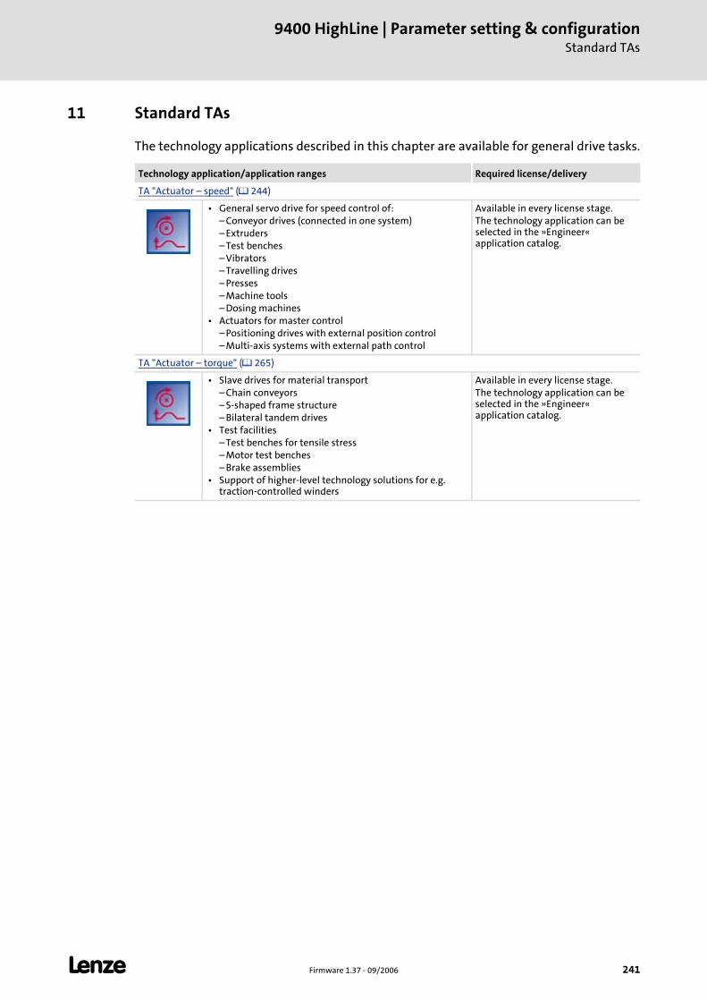
L Firmware 1.37 - 09/2006 241
9400 HighLine | Parameter setting & configurationStandard TAs
11 Standard TAs
The technology applications described in this chapter are available for general drive tasks.
Technology application/application ranges Required license/delivery
TA "Actuator – speed" ( 244)
• General servo drive for speed control of:– Conveyor drives (connected in one system)– Extruders– Test benches– Vibrators– Travelling drives– Presses– Machine tools– Dosing machines
• Actuators for master control– Positioning drives with external position control– Multi-axis systems with external path control
Available in every license stage.The technology application can be selected in the »Engineer« application catalog.
TA "Actuator – torque" ( 265)
• Slave drives for material transport– Chain conveyors– S-shaped frame structure– Bilateral tandem drives
• Test facilities– Test benches for tensile stress– Motor test benches– Brake assemblies
• Support of higher-level technology solutions for e.g. traction-controlled winders
Available in every license stage.The technology application can be selected in the »Engineer« application catalog.
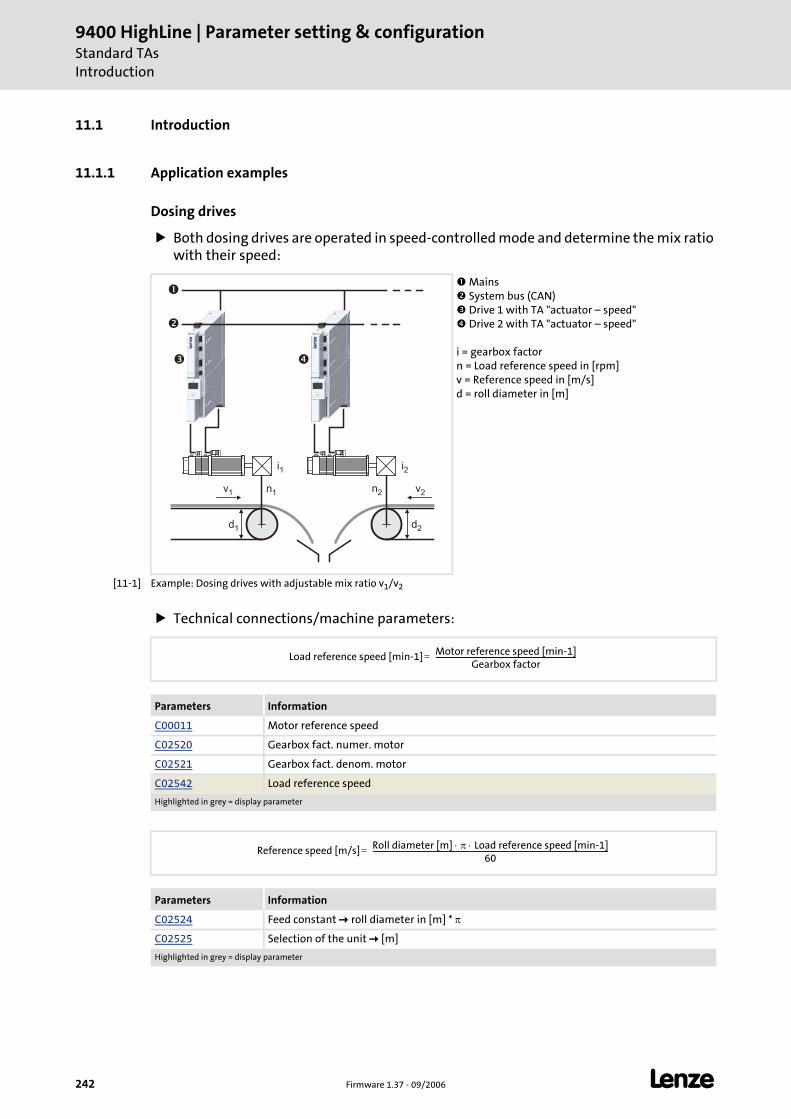
9400 HighLine | Parameter setting & configurationStandard TAsIntroduction
242 Firmware 1.37 - 09/2006 L
11.1 Introduction
11.1.1 Application examples
Dosing drives
Both dosing drives are operated in speed-controlled mode and determine the mix ratio with their speed:
[11-1] Example: Dosing drives with adjustable mix ratio v1/v2
Technical connections/machine parameters:
Mains System bus (CAN) Drive 1 with TA "actuator – speed" Drive 2 with TA "actuator – speed"
i = gearbox factorn = Load reference speed in [rpm]v = Reference speed in [m/s]d = roll diameter in [m]
d1
n1v1
i1
d2
n2
i2
v2
�
�
�
�
Parameters Information
C00011 Motor reference speed
C02520 Gearbox fact. numer. motor
C02521 Gearbox fact. denom. motor
C02542 Load reference speed
Highlighted in grey = display parameter
Parameters Information
C02524 Feed constant roll diameter in [m] * π
C02525 Selection of the unit [m]
Highlighted in grey = display parameter
Load reference speed [min-1] Motor reference speed [min-1]Gearbox factor
-------------------------------------------------------------------------------=
Reference speed [m/s] Roll diameter [m] π Load reference speed [min-1]⋅ ⋅60
-------------------------------------------------------------------------------------------------------------------------------------=
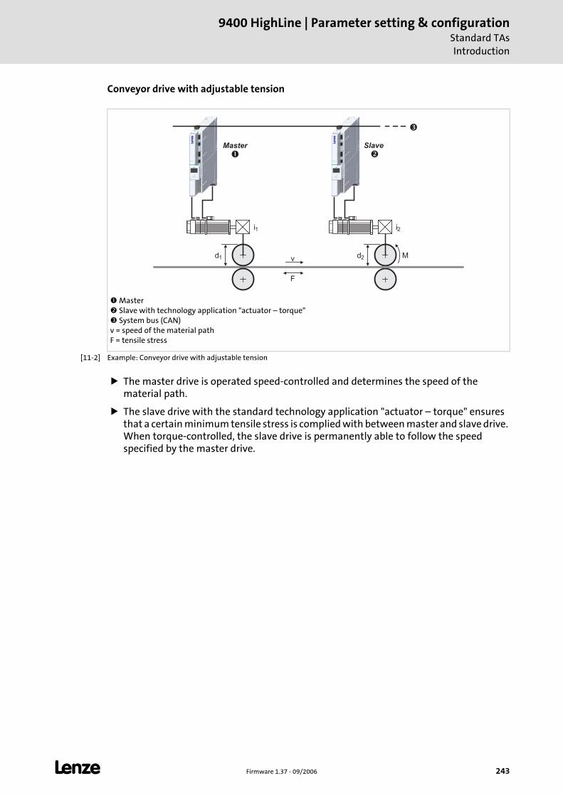
L Firmware 1.37 - 09/2006 243
9400 HighLine | Parameter setting & configurationStandard TAsIntroduction
Conveyor drive with adjustable tension
[11-2] Example: Conveyor drive with adjustable tension
The master drive is operated speed-controlled and determines the speed of the material path.
The slave drive with the standard technology application "actuator – torque" ensures that a certain minimum tensile stress is complied with between master and slave drive. When torque-controlled, the slave drive is permanently able to follow the speed specified by the master drive.
Master Slave with technology application "actuator – torque" System bus (CAN)
v = speed of the material pathF = tensile stress
v
F
M
�
SlaveMaster
��
ii1 2
d1 d2
9400 HighLine | Parameter setting & configurationStandard TAsTA "Actuator – speed"
244 Firmware 1.37 - 09/2006 L
11.2 TA "Actuator – speed"
The technology application "actuator – speed" enables the drive to create a speed to be defined. The speed setpoint can be complied with using a speed controller which adopts the motor torque to the prevailing load situation.
The speed setpoint of the drive can be specified for both directions. The driven machine parts accordingly moves forwards or backwards. As an alternative to the inversion of the setpoint, the change of the direction of movement can be done via the digital input DI3.
After the speed-controlled operation is enabled via the digital input DI2 the acceleration/deceleration of the drive to the setpoint is controlled via a ramp generator based on the current setpoint/actual speed.
The maximum torque of the drive can also be controlled, if required.
Basic drive functions
A quick stop can be activated via the digital input DI1. Quick stop ( 257)
A manual control is provided for the setting-up operation. It is enabled via the digital input DI6. The inputs DI7 and DI8 activate parameterisable setpoints for both directions of rotation. Manual jog ( 256)
The basic function "limiter" enables the travel range to be monitored via limit switches. Limiter ( 258)
When a brake is available the brake control opens and closes the brake. Brake control ( 259)
See also: Basic drive functions ( 140)
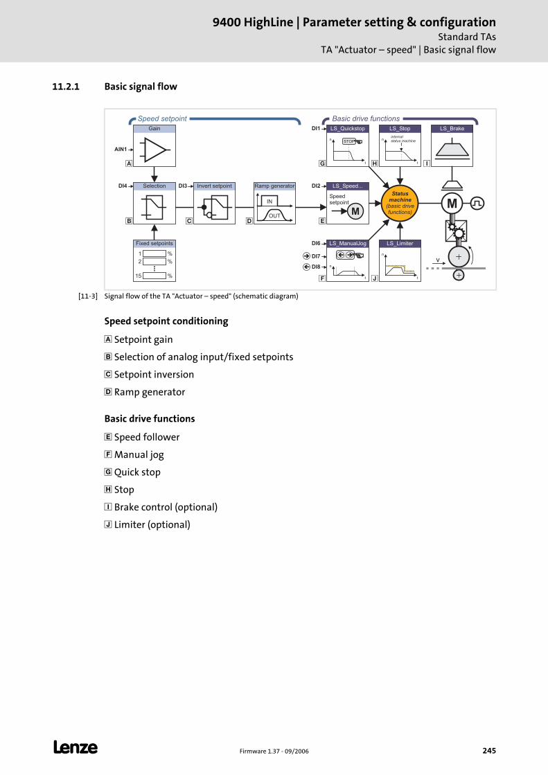
L Firmware 1.37 - 09/2006 245
9400 HighLine | Parameter setting & configurationStandard TAs
TA "Actuator – speed" | Basic signal flow
11.2.1 Basic signal flow
[11-3] Signal flow of the TA "Actuator – speed" (schematic diagram)
Speed setpoint conditioning
Setpoint gain
Selection of analog input/fixed setpoints
Setpoint inversion
Ramp generator
Basic drive functions
Speed follower
Manual jog
Quick stop
Stop
Brake control (optional)
Limiter (optional)
�
�
� �
LS_ManualJog
n
t
��
� �
LS_Brake
n
t
LS_Limiter
n
t
LS_Quickstop
STOP
�
�
Gain
Invert setpointSelection LS_Speed...
M
Speedsetpoint
n
t
LS_Stop
internalstatus machine
DI2
DI6
DI7
DI8
DI1
DI3DI4
OUT
IN
Ramp generator
%1
%2
%15
Fixed setpoints
Statusmachine
(basic drivefunctions)
Speed setpoint Basic drive functions
AIN1
�
�
M
v
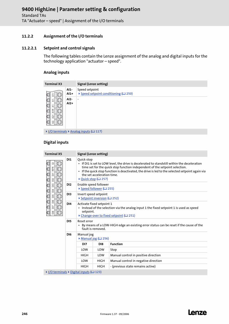
9400 HighLine | Parameter setting & configurationStandard TAsTA "Actuator – speed" | Assignment of the I/O terminals
246 Firmware 1.37 - 09/2006 L
11.2.2 Assignment of the I/O terminals
11.2.2.1 Setpoint and control signals
The following tables contain the Lenze assignment of the analog and digital inputs for the technology application "actuator – speed".
Analog inputs
Digital inputs
Terminal X3 Signal (Lenze setting)
AI1-AI1+
Speed setpointSpeed setpoint conditioning ( 250)
AI2-AI2+
-
I/O terminals Analog inputs ( 117)
Terminal X5 Signal (Lenze setting)
DI1 Quick stop • If DI1 is set to LOW level, the drive is decelerated to standstill within the deceleration
time set for the quick stop function independent of the setpoint selection. • If the quick stop function is deactivated, the drive is led to the selected setpoint again via
the set acceleration time.Quick stop ( 257)
DI2 Enable speed followerSpeed follower ( 255)
DI3 Invert speed setpointSetpoint inversion ( 252)
DI4 Activate fixed setpoint 1 • Instead of the selection via the analog input 1 the fixed setpoint 1 is used as speed
setpoint.Change-over to fixed setpoint ( 251)
DI5 Reset error • By means of a LOW-HIGH edge an existing error status can be reset if the cause of the
fault is removed.
DI6 Manual jogManual jog ( 256)
DI7 DI8 Function
LOW LOW Stop
HIGH LOW Manual control in positive direction
LOW HIGH Manual control in negative direction
HIGH HIGH - (previous state remains active)
I/O terminals Digital inputs ( 123)
A1
+A
1-
A1
-A
1R
A2
+A
2-
GI
RF
RD
I1D
I2D
I3D
I4D
I5D
I6D
I7D
I8
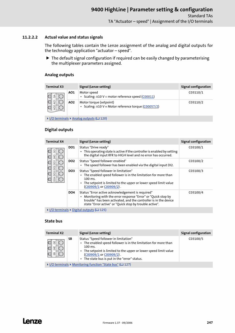
L Firmware 1.37 - 09/2006 247
9400 HighLine | Parameter setting & configurationStandard TAs
TA "Actuator – speed" | Assignment of the I/O terminals
11.2.2.2 Actual value and status signals
The following tables contain the Lenze assignment of the analog and digital outputs for the technology application "actuator – speed".
The default signal configuration if required can be easily changed by parameterising the multiplexer parameters assigned.
Analog outputs
Digital outputs
State bus
Terminal X3 Signal (Lenze setting) Signal configuration
AO1 Motor speed • Scaling: ±10 V ≡ motor reference speed (C00011)
C03110/1
AO2 Motor torque (setpoint) • Scaling: ±10 V ≡ Motor reference torque (C00057/2)
C03110/2
I/O terminals Analog outputs ( 120)
Terminal X4 Signal (Lenze setting) Signal configuration
DO1 Status "Drive ready" • This operating state is active if the controller is enabled by setting
the digital input RFR to HIGH level and no error has occurred.
C03100/1
DO2 Status "Speed follower enabled" • The speed follower has been enabled via the digital input DI2.
C03100/2
DO3 Status "Speed follower in limitation" • The enabled speed follower is in the limitation for more than
100 ms. • The setpoint is limited to the upper or lower speed limit value
(C00909/1 or C00909/2) .
C03100/3
DO4 Status "Error active acknowledgement is required" • Monitoring with the error response "Error" or "Quick stop by
trouble" has been activated, and the controller is in the device state "Error active" or "Quick stop by trouble active".
C03100/4
I/O terminals Digital outputs ( 125)
Terminal X2 Signal (Lenze setting) Signal configuration
SB Status "Speed follower in limitation" • The enabled speed follower is in the limitation for more than
100 ms. • The setpoint is limited to the upper or lower speed limit value
(C00909/1 or C00909/2) . • The state bus is put in the "error" status.
C03100/5
I/O terminals Monitoring function "State bus" ( 127)
GA
AO
1A
O2
GO
24
OD
O1
DO
2D
O3
DO
4G
E2
4E
SB
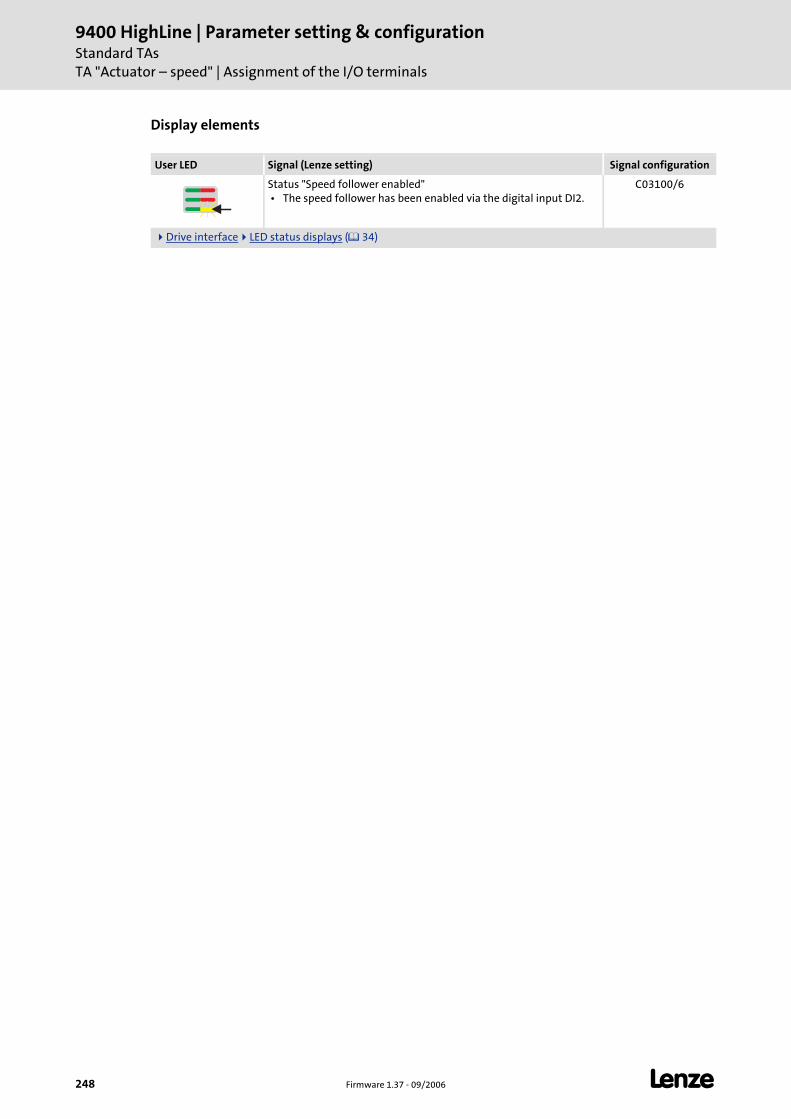
9400 HighLine | Parameter setting & configurationStandard TAsTA "Actuator – speed" | Assignment of the I/O terminals
248 Firmware 1.37 - 09/2006 L
Display elements
User LED Signal (Lenze setting) Signal configuration
Status "Speed follower enabled" • The speed follower has been enabled via the digital input DI2.
C03100/6
Drive interface LED status displays ( 34)
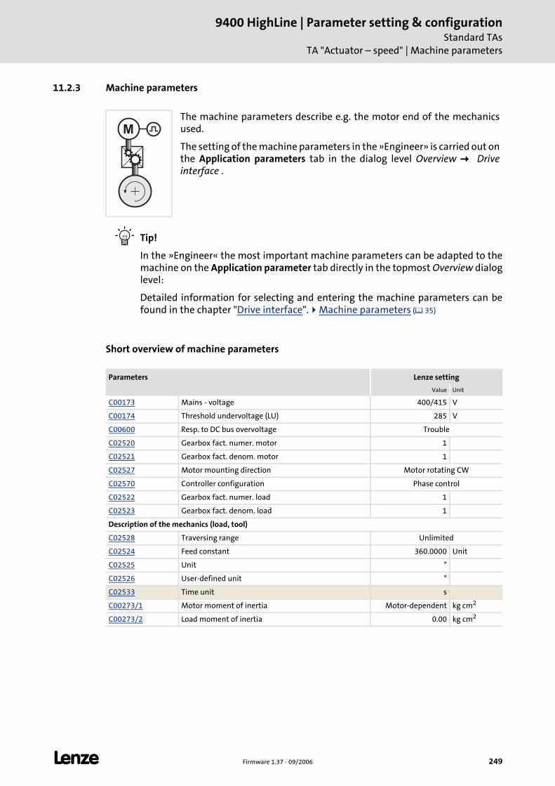
L Firmware 1.37 - 09/2006 249
9400 HighLine | Parameter setting & configurationStandard TAs
TA "Actuator – speed" | Machine parameters
11.2.3 Machine parameters
Tip!
In the »Engineer« the most important machine parameters can be adapted to the machine on the Application parameter tab directly in the topmost Overview dialog level:
Detailed information for selecting and entering the machine parameters can be found in the chapter "Drive interface". Machine parameters ( 35)
Short overview of machine parameters
The machine parameters describe e.g. the motor end of the mechanics used.
The setting of the machine parameters in the »Engineer» is carried out on the Application parameters tab in the dialog level Overview Drive interface .
Parameters Lenze setting
Value Unit
C00173 Mains - voltage 400/415 V
C00174 Threshold undervoltage (LU) 285 V
C00600 Resp. to DC bus overvoltage Trouble
C02520 Gearbox fact. numer. motor 1
C02521 Gearbox fact. denom. motor 1
C02527 Motor mounting direction Motor rotating CW
C02570 Controller configuration Phase control
C02522 Gearbox fact. numer. load 1
C02523 Gearbox fact. denom. load 1
Description of the mechanics (load, tool)
C02528 Traversing range Unlimited
C02524 Feed constant 360.0000 Unit
C02525 Unit °
C02526 User-defined unit °
C02533 Time unit s
C00273/1 Motor moment of inertia Motor-dependent kg cm2
C00273/2 Load moment of inertia 0.00 kg cm2
M
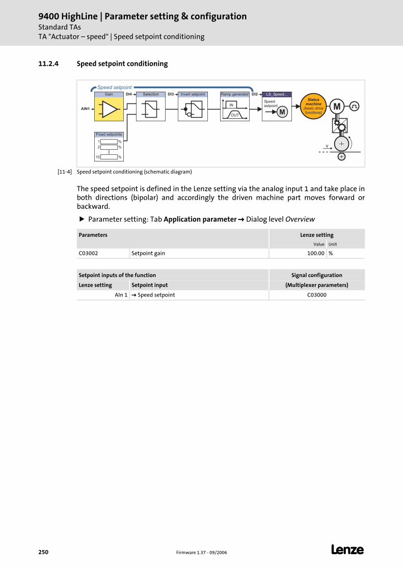
9400 HighLine | Parameter setting & configurationStandard TAsTA "Actuator – speed" | Speed setpoint conditioning
250 Firmware 1.37 - 09/2006 L
11.2.4 Speed setpoint conditioning
[11-4] Speed setpoint conditioning (schematic diagram)
The speed setpoint is defined in the Lenze setting via the analog input 1 and take place in both directions (bipolar) and accordingly the driven machine part moves forward or backward.
Parameter setting: Tab Application parameter Dialog level Overview
Gain Invert setpointSelection LS_Speed...
M
Speedsetpoint
DI2DI3DI4
OUT
IN
Ramp generator
%1
%2
%15
Fixed setpoints
Statusmachine
(basic drivefunctions)
Speed setpoint
AIN1 M
v
Parameters Lenze setting
Value Unit
C03002 Setpoint gain 100.00 %
Setpoint inputs of the function Signal configuration
Lenze setting Setpoint input (Multiplexer parameters)
AIn 1 Speed setpoint C03000
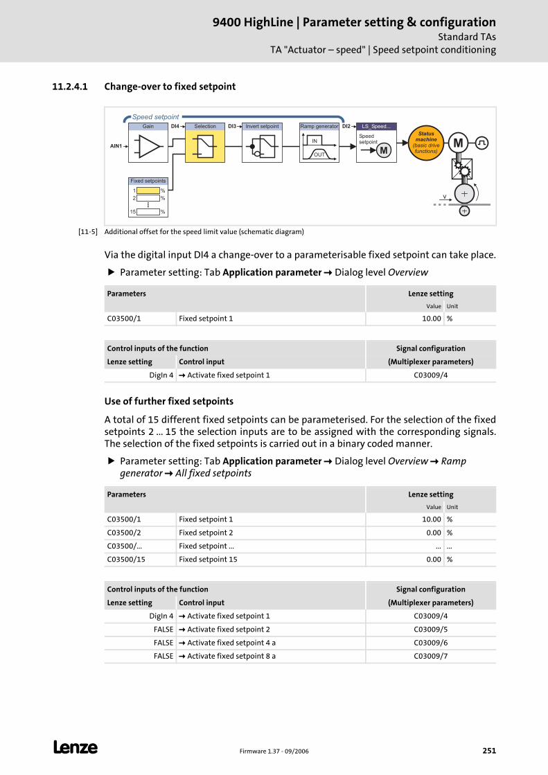
L Firmware 1.37 - 09/2006 251
9400 HighLine | Parameter setting & configurationStandard TAs
TA "Actuator – speed" | Speed setpoint conditioning
11.2.4.1 Change-over to fixed setpoint
[11-5] Additional offset for the speed limit value (schematic diagram)
Via the digital input DI4 a change-over to a parameterisable fixed setpoint can take place.
Parameter setting: Tab Application parameter Dialog level Overview
Use of further fixed setpoints
A total of 15 different fixed setpoints can be parameterised. For the selection of the fixed setpoints 2 ... 15 the selection inputs are to be assigned with the corresponding signals.The selection of the fixed setpoints is carried out in a binary coded manner.
Parameter setting: Tab Application parameter Dialog level Overview Ramp generator All fixed setpoints
Gain Invert setpointSelection LS_Speed...
M
Speedsetpoint
DI2DI3DI4
OUT
IN
Ramp generator
%1
%2
%15
Fixed setpoints
Statusmachine
(basic drivefunctions)
Speed setpoint
AIN1 M
v
Parameters Lenze setting
Value Unit
C03500/1 Fixed setpoint 1 10.00 %
Control inputs of the function Signal configuration
Lenze setting Control input (Multiplexer parameters)
DigIn 4 Activate fixed setpoint 1 C03009/4
Parameters Lenze setting
Value Unit
C03500/1 Fixed setpoint 1 10.00 %
C03500/2 Fixed setpoint 2 0.00 %
C03500/... Fixed setpoint ... ... ...
C03500/15 Fixed setpoint 15 0.00 %
Control inputs of the function Signal configuration
Lenze setting Control input (Multiplexer parameters)
DigIn 4 Activate fixed setpoint 1 C03009/4
FALSE Activate fixed setpoint 2 C03009/5
FALSE Activate fixed setpoint 4 a C03009/6
FALSE Activate fixed setpoint 8 a C03009/7
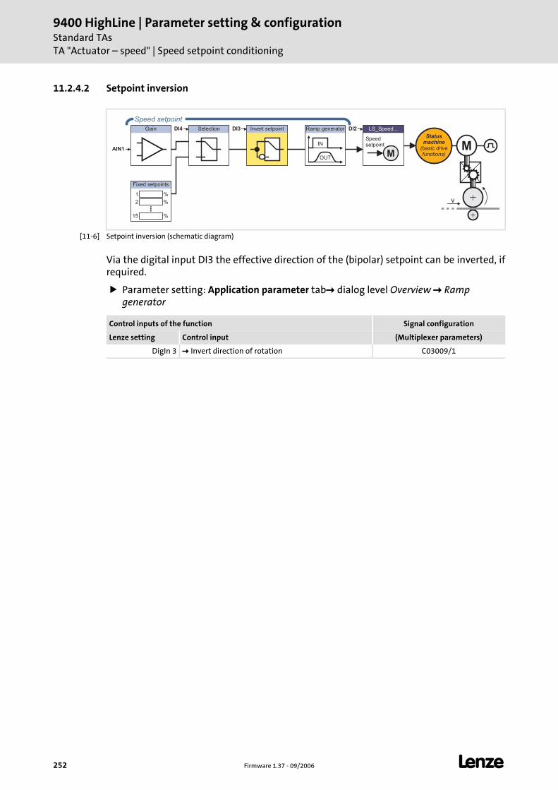
9400 HighLine | Parameter setting & configurationStandard TAsTA "Actuator – speed" | Speed setpoint conditioning
252 Firmware 1.37 - 09/2006 L
11.2.4.2 Setpoint inversion
[11-6] Setpoint inversion (schematic diagram)
Via the digital input DI3 the effective direction of the (bipolar) setpoint can be inverted, if required.
Parameter setting: Application parameter tab dialog level Overview Ramp generator
Gain Invert setpointSelection LS_Speed...
M
Speedsetpoint
DI2DI3DI4
OUT
IN
Ramp generator
%1
%2
%15
Fixed setpoints
Statusmachine
(basic drivefunctions)
Speed setpoint
AIN1 M
v
Control inputs of the function Signal configuration
Lenze setting Control input (Multiplexer parameters)
DigIn 3 Invert direction of rotation C03009/1
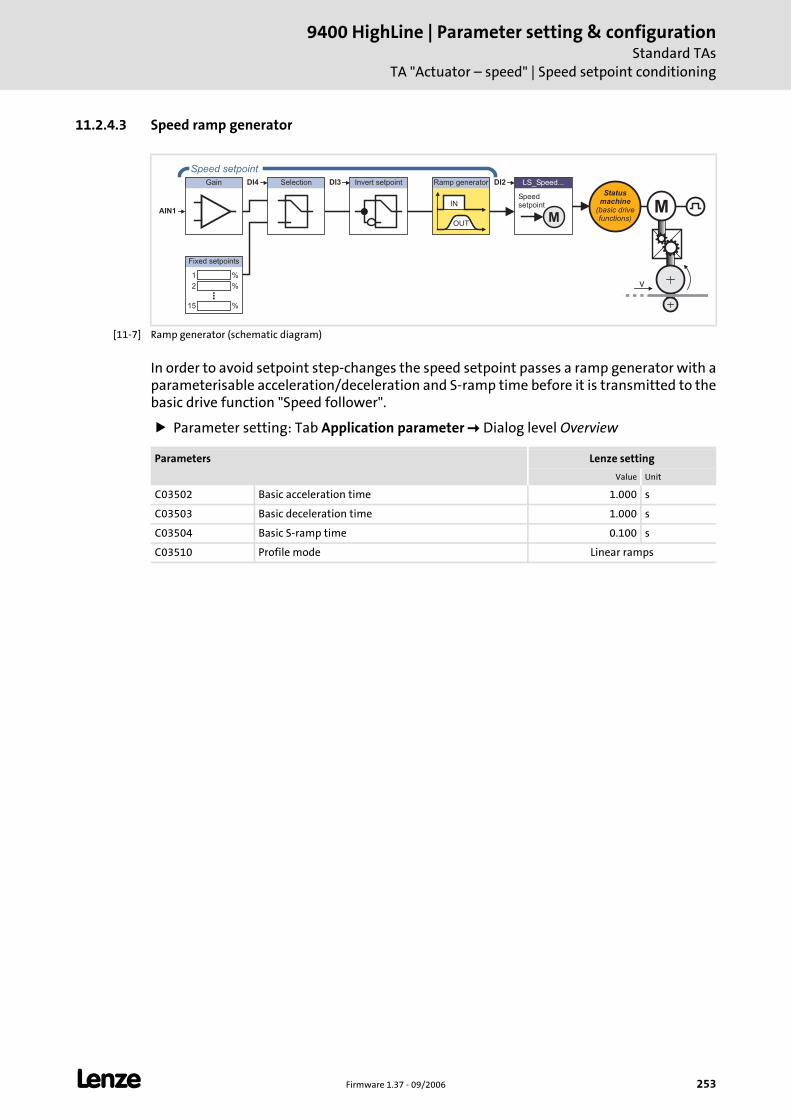
L Firmware 1.37 - 09/2006 253
9400 HighLine | Parameter setting & configurationStandard TAs
TA "Actuator – speed" | Speed setpoint conditioning
11.2.4.3 Speed ramp generator
[11-7] Ramp generator (schematic diagram)
In order to avoid setpoint step-changes the speed setpoint passes a ramp generator with a parameterisable acceleration/deceleration and S-ramp time before it is transmitted to the basic drive function "Speed follower".
Parameter setting: Tab Application parameter Dialog level Overview
Gain Invert setpointSelection LS_Speed...
M
Speedsetpoint
DI2DI3DI4
OUT
IN
Ramp generator
%1
%2
%15
Fixed setpoints
Statusmachine
(basic drivefunctions)
Speed setpoint
AIN1 M
v
Parameters Lenze setting
Value Unit
C03502 Basic acceleration time 1.000 s
C03503 Basic deceleration time 1.000 s
C03504 Basic S-ramp time 0.100 s
C03510 Profile mode Linear ramps

9400 HighLine | Parameter setting & configurationStandard TAsTA "Actuator – speed" | Speed setpoint conditioning
254 Firmware 1.37 - 09/2006 L
Use of further ramp parameter sets
If required, 15 further ramp parameter sets can be parameterised. For the selection of the ramp parameter sets1 ... 15 the selection inputs are to be assigned with the corresponding signals. The selection of the ramp parameter sets is carried out in a binary coded manner.
Parameter setting: TabApplication parameter W Dialog level Overview W Ramp generator W All ramp parameters
Parameters Lenze setting
Value Unit
C03512/1 Acceleration time 1 0.000 s
C03512/... Acceleration time ... ... ...
C03512/15 Acceleration time 15 0.000 s
C03513/1 Deceleration time 1 0.000 s
C03513/... Deceleration time ... ... ...
C03513/15 Deceleration time 15 0.000 s
C03514/1 S-ramp time 1 0.000 s
C03514/... S-ramp time ... ...
C03514/15 S-ramp time 15 0.000 s
Control inputs of the function Signal configuration
Lenze setting Control input (Multiplexer parameters)
FALSE Activate ramp parameter set 1 C03009/8
FALSE Activate ramp parameter set 2 C03009/9
FALSE Activate ramp parameter set 4 C03009/10
FALSE Activate ramp parameter set 8 a C03009/11
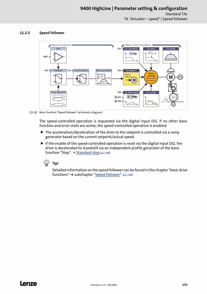
L Firmware 1.37 - 09/2006 255
9400 HighLine | Parameter setting & configurationStandard TAs
TA "Actuator – speed" | Speed follower
11.2.5 Speed follower
[11-8] Basic function "Speed follower" (schematic diagram)
The speed-controlled operation is requested via the digital input DI2. If no other basic function and error state are active, the speed-controlled operation is enabled.
The acceleration/deceleration of the drive to the setpoint is controlled via a ramp generator based on the current setpoint/actual speed.
If the enable of the speed-controlled operation is reset via the digital input DI2, the drive is decelerated to standstill via an independent profile generator of the basic function "Stop". Standard stop ( 148)
Tip!
Detailed information on the speed follower can be found in the chapter "basic drive functions" subchapter "Speed follower". ( 190)
LS_ManualJog
n
t
��
LS_Brake
n
t
LS_Limiter
n
t
LS_Quickstop
STOP
Gain
Invert setpointSelection LS_Speed...
M
Speedsetpoint
n
t
LS_Stop
internalstatus machine
DI2
DI6
DI7
DI8
DI1
DI3DI4
OUT
IN
Ramp generator
%1
%2
%15
Fixed setpoints
Statusmachine
(basic drivefunctions)
Speed setpoint Basic drive functions
AIN1
M
v�
�
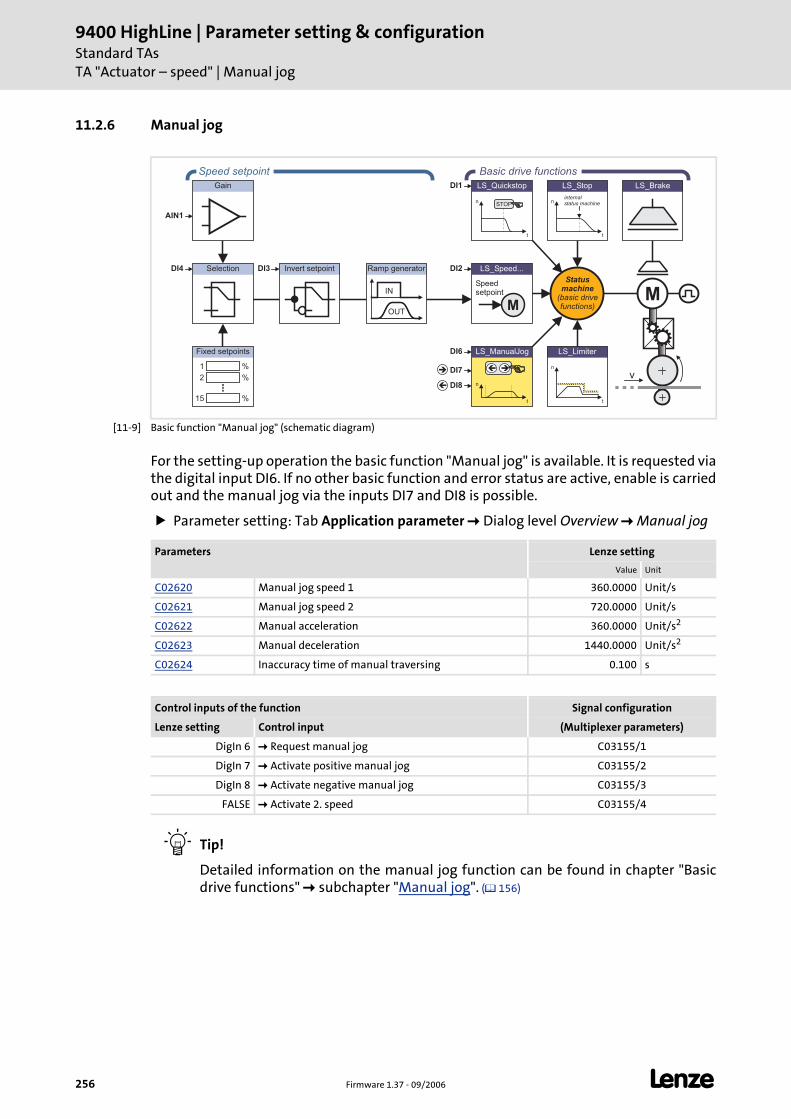
9400 HighLine | Parameter setting & configurationStandard TAsTA "Actuator – speed" | Manual jog
256 Firmware 1.37 - 09/2006 L
11.2.6 Manual jog
[11-9] Basic function "Manual jog" (schematic diagram)
For the setting-up operation the basic function "Manual jog" is available. It is requested via the digital input DI6. If no other basic function and error status are active, enable is carried out and the manual jog via the inputs DI7 and DI8 is possible.
Parameter setting: Tab Application parameter Dialog level Overview Manual jog
Tip!
Detailed information on the manual jog function can be found in chapter "Basic drive functions" subchapter "Manual jog". ( 156)
LS_ManualJog
n
t
��
LS_Brake
n
t
LS_Limiter
n
t
LS_Quickstop
STOP
Gain
Invert setpointSelection LS_Speed...
M
Speedsetpoint
n
t
LS_Stop
internalstatus machine
DI2
DI6
DI7
DI8
DI1
DI3DI4
OUT
IN
Ramp generator
%1
%2
%15
Fixed setpoints
Statusmachine
(basic drivefunctions)
Speed setpoint Basic drive functions
AIN1
M
v�
�
Parameters Lenze setting
Value Unit
C02620 Manual jog speed 1 360.0000 Unit/s
C02621 Manual jog speed 2 720.0000 Unit/s
C02622 Manual acceleration 360.0000 Unit/s2
C02623 Manual deceleration 1440.0000 Unit/s2
C02624 Inaccuracy time of manual traversing 0.100 s
Control inputs of the function Signal configuration
Lenze setting Control input (Multiplexer parameters)
DigIn 6 Request manual jog C03155/1
DigIn 7 Activate positive manual jog C03155/2
DigIn 8 Activate negative manual jog C03155/3
FALSE Activate 2. speed C03155/4
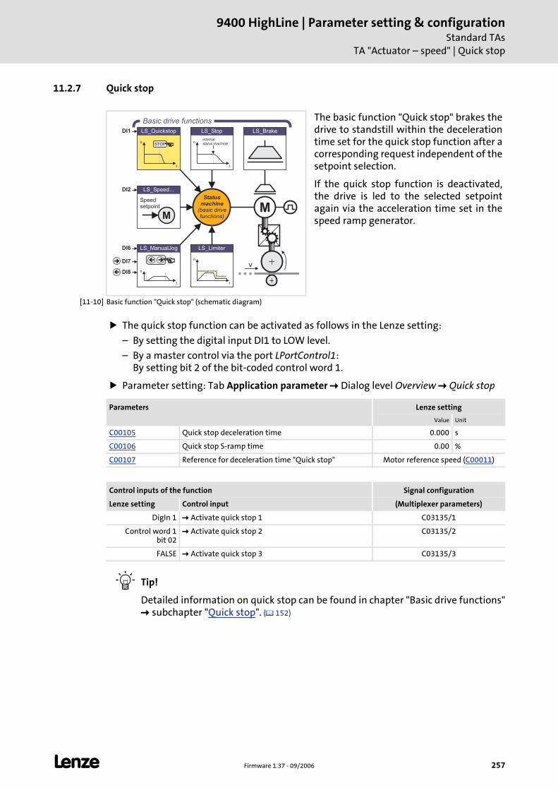
L Firmware 1.37 - 09/2006 257
9400 HighLine | Parameter setting & configurationStandard TAs
TA "Actuator – speed" | Quick stop
11.2.7 Quick stop
[11-10] Basic function "Quick stop" (schematic diagram)
The quick stop function can be activated as follows in the Lenze setting:
– By setting the digital input DI1 to LOW level.
– By a master control via the port LPortControl1: By setting bit 2 of the bit-coded control word 1.
Parameter setting: Tab Application parameter Dialog level Overview Quick stop
Tip!
Detailed information on quick stop can be found in chapter "Basic drive functions" subchapter "Quick stop". ( 152)
The basic function "Quick stop" brakes the drive to standstill within the deceleration time set for the quick stop function after a corresponding request independent of the setpoint selection.
If the quick stop function is deactivated, the drive is led to the selected setpoint again via the acceleration time set in the speed ramp generator.
LS_ManualJog
n
t
��
LS_Brake
n
t
LS_Limiter
n
t
LS_Quickstop
STOP
LS_Speed...
M
Speedsetpoint
n
t
LS_Stop
internalstatus machine
DI2
DI6
DI7
DI8
DI1
Statusmachine
(basic drivefunctions)
Basic drive functions
M
v�
�
Parameters Lenze setting
Value Unit
C00105 Quick stop deceleration time 0.000 s
C00106 Quick stop S-ramp time 0.00 %
C00107 Reference for deceleration time "Quick stop" Motor reference speed (C00011)
Control inputs of the function Signal configuration
Lenze setting Control input (Multiplexer parameters)
DigIn 1 Activate quick stop 1 C03135/1
Control word 1 bit 02
Activate quick stop 2 C03135/2
FALSE Activate quick stop 3 C03135/3

9400 HighLine | Parameter setting & configurationStandard TAsTA "Actuator – speed" | Limiter
258 Firmware 1.37 - 09/2006 L
11.2.8 Limiter
[11-11] Basic function "Limiter" (schematic diagram)
Parameter setting: Tab Application parameter Dialog level Overview Limiter
Tip!
Detailed information on the limiter function can be found in chapter "Basic drive functions" subchapter "Limiter". ( 200)
The basic function "Limiter", where applicable, by means of limit switches monitors travel range limits.
In the case of homing, positioning and manual jog the basic function "Limiter" if required provides for the compliance with kinematic limit values.
LS_ManualJog
n
t
��
LS_Brake
n
t
LS_Limiter
n
t
LS_Quickstop
STOP
LS_Speed...
M
Speedsetpoint
n
t
LS_Stop
internalstatus machine
DI2
DI6
DI7
DI8
DI1
Statusmachine
(basic drivefunctions)
Basic drive functions
M
v�
�
Note!
The parameterised limit values are not effective for the basic functions "Speed follower", "Torque follower" and "Position follower"!
For the exceeding of the limit values an error response can be set.
Parameters Lenze setting
Value Unit
Only for homing, positioning and manual jog
C02702 Limitations effective Deactivated
C02703 Max. speed 3600.0000 Unit/s
C02705 Max. acceleration 3600.0000 Unit/s2
C02706 Min. S-ramp time 100 ms
C02707 Permissible direction of rotation Positive and negative
Control inputs of the function Signal configuration
Lenze setting Control input (Multiplexer parameters)
FALSE Positive limit switch C03150/1
FALSE Negative limit switch C03150/2
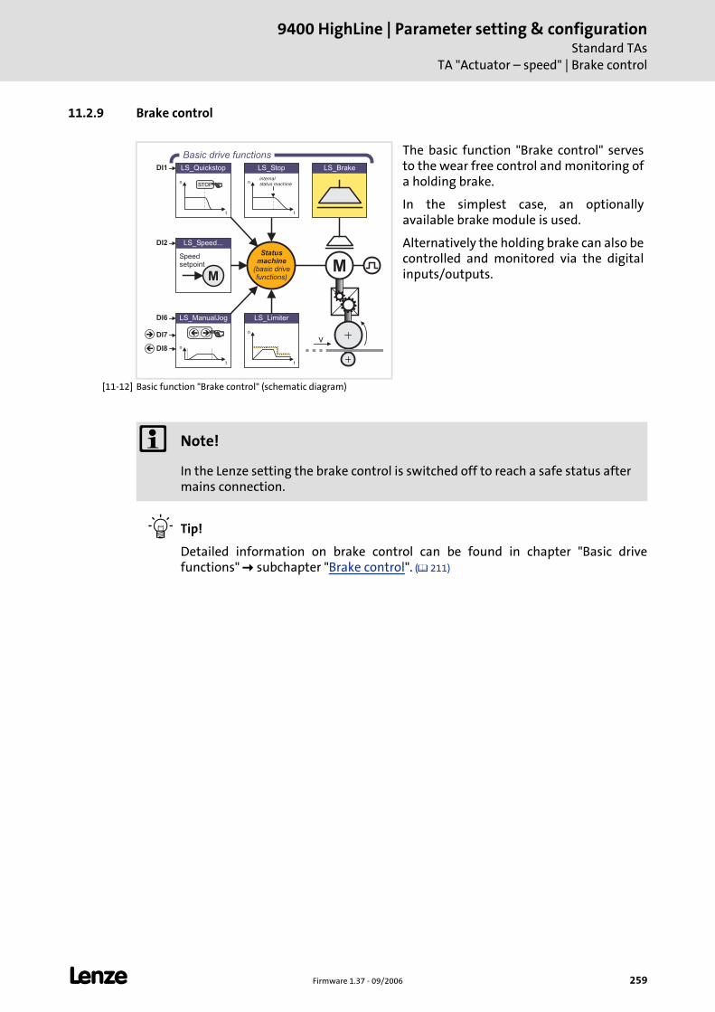
L Firmware 1.37 - 09/2006 259
9400 HighLine | Parameter setting & configurationStandard TAs
TA "Actuator – speed" | Brake control
11.2.9 Brake control
[11-12] Basic function "Brake control" (schematic diagram)
Tip!
Detailed information on brake control can be found in chapter "Basic drive functions" subchapter "Brake control". ( 211)
The basic function "Brake control" serves to the wear free control and monitoring of a holding brake.
In the simplest case, an optionally available brake module is used.
Alternatively the holding brake can also be controlled and monitored via the digital inputs/outputs.
LS_ManualJog
n
t
��
LS_Brake
n
t
LS_Limiter
n
t
LS_Quickstop
STOP
LS_Speed...
M
Speedsetpoint
n
t
LS_Stop
internalstatus machine
DI2
DI6
DI7
DI8
DI1
Statusmachine
(basic drivefunctions)
Basic drive functions
M
v�
�
Note!
In the Lenze setting the brake control is switched off to reach a safe status after mains connection.

9400 HighLine | Parameter setting & configurationStandard TAsTA "Actuator – speed" | Brake control
260 Firmware 1.37 - 09/2006 L
Parameter setting: Tab Application parameter Dialog level Overview Brake control
Parameters Lenze setting
Value Unit
C02580 Operating mode - brake Brake control off
C02581 Brake activation threshold 50 rpm
C02582 Brake resp. to pulse inhibit Activate the brake immediately
C02583 Status input monitoring Not active
C02585 Brake control polarity Not inverted
C02586 Starting torque 1 0.00 Nm
C02587 Starting torque 2 0.00 Nm
C02588 Source of starting torque Starting torque 1/2
C02589 Brake closing time 100 ms
C02590 Brake opening time 100 ms
C02591 Waiting time - status monit. 100 ms
C02593 Waiting time - brake active. 0.000 s
C02594 Test torque 0.00 Nm
C02595 Permissible angle of rotation 5 °
C02596 Grinding speed 100 rpm
C02597 Accel./decel. time - grinding 1.000 s
C02598 Grinding ON time 0.5 s
C02599 Grinding OFF time 0.5 s
Control/setpoint inputs of the function Signal configuration
Lenze setting Control/setpoint input (Multiplexer parameters)
FALSE Open brake (release) C03165/1
FALSE Activate starting torque 2 C03165/2
FALSE Brake status signal C03165/3
FALSE Activate brake test C03165/4
FALSE Grind brake C03165/5
0 % Additional torque C03166

L Firmware 1.37 - 09/2006 261
9400 HighLine | Parameter setting & configurationStandard TAs
TA "Actuator – speed" | Signal configuration of drive and motor interface
11.2.10 Signal configuration of drive and motor interface
If required, the preset signal configuration of the control and setpoint inputs of the drive and motor interface can be easily reconfigured per parameter setting of the assigned multiplexer parameters.
Drive interface
Motor interface
Signal (Lenze setting) Control input Signal configuration
FALSE Set controller inhibit C03130/1
DigIn 5 Reset error 1 C03130/2
Control word 1 bit 07 Reset error 2 C03130/3
FALSE Reset error 3 C03130/4
FALSE Set error C03130/5
Control word 1 bit 00 Switch on drive C03130/6
Signal (Lenze setting) Setpoint input Signal configuration
100 % Upper torque limit value C03141/1
-100 % Lower torque limit value C03141/2
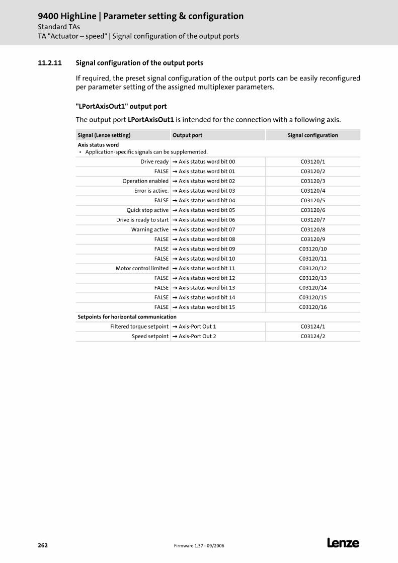
9400 HighLine | Parameter setting & configurationStandard TAsTA "Actuator – speed" | Signal configuration of the output ports
262 Firmware 1.37 - 09/2006 L
11.2.11 Signal configuration of the output ports
If required, the preset signal configuration of the output ports can be easily reconfigured per parameter setting of the assigned multiplexer parameters.
"LPortAxisOut1" output port
The output port LPortAxisOut1 is intended for the connection with a following axis.
Signal (Lenze setting) Output port Signal configuration
Axis status word • Application-specific signals can be supplemented.
Drive ready Axis status word bit 00 C03120/1
FALSE Axis status word bit 01 C03120/2
Operation enabled Axis status word bit 02 C03120/3
Error is active. Axis status word bit 03 C03120/4
FALSE Axis status word bit 04 C03120/5
Quick stop active Axis status word bit 05 C03120/6
Drive is ready to start Axis status word bit 06 C03120/7
Warning active Axis status word bit 07 C03120/8
FALSE Axis status word bit 08 C03120/9
FALSE Axis status word bit 09 C03120/10
FALSE Axis status word bit 10 C03120/11
Motor control limited Axis status word bit 11 C03120/12
FALSE Axis status word bit 12 C03120/13
FALSE Axis status word bit 13 C03120/14
FALSE Axis status word bit 14 C03120/15
FALSE Axis status word bit 15 C03120/16
Setpoints for horizontal communication
Filtered torque setpoint Axis-Port Out 1 C03124/1
Speed setpoint Axis-Port Out 2 C03124/2

L Firmware 1.37 - 09/2006 263
9400 HighLine | Parameter setting & configurationStandard TAs
TA "Actuator – speed" | Signal configuration of the output ports
Output port "LPortStatus1"
The output port LPortStatus1 is intended for the connection with a higher-level control.
Output port "LPortStatus2"
Signal (Lenze setting) Output port Signal configuration
Status word 1
Drive ready Status word 1 bit 00 C03121/1
FALSE Status word 1 bit 01 C03121/2
Operation enabled Status word 1 bit 02 C03121/3
Error is active. Status word 1 bit 03 C03121/4
FALSE Status word 1 bit 04 C03121/5
Quick stop active Status word 1 bit 05 C03121/6
Drive is ready to start Status word 1 bit 06 C03121/7
Warning active Status word 1 bit 07 C03121/8
FALSE Status word 1 bit 08 C03121/9
FALSE Status word 1 bit 09 C03121/10
FALSE Status word 1 bit 10 C03121/11
Motor control limited Status word 1 bit 11 C03121/12
FALSE Status word 1 bit 12 C03121/13
FALSE Status word 1 bit 13 C03121/14
FALSE Status word 1 bit 14 C03121/15
FALSE Status word 1 bit 15 C03121/16
Signal (Lenze setting) Output port Signal configuration
Status word 2
FALSE Status word 2 bit 00 C03122/1
FALSE Status word 2 bit 01 C03122/2
FALSE Status word 2 bit 02 C03122/3
FALSE Status word 2 bit 03 C03122/4
FALSE Status word 2 bit 04 C03122/5
FALSE Status word 2 bit 05 C03122/6
FALSE Status word 2 bit 06 C03122/7
FALSE Status word 2 bit 07 C03122/8
FALSE Status word 2 bit 08 C03122/9
FALSE Status word 2 bit 09 C03122/10
FALSE Status word 2 bit 10 C03122/11
FALSE Status word 2 bit 11 C03122/12
FALSE Status word 2 bit 12 C03122/13
FALSE Status word 2 bit 13 C03122/14
FALSE Status word 2 bit 14 C03122/15
FALSE Status word 2 bit 15 C03122/16
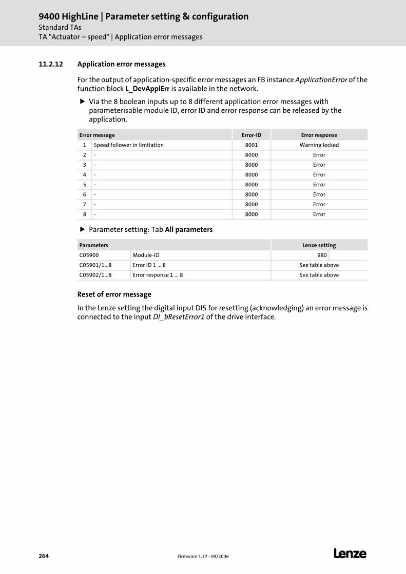
9400 HighLine | Parameter setting & configurationStandard TAsTA "Actuator – speed" | Application error messages
264 Firmware 1.37 - 09/2006 L
11.2.12 Application error messages
For the output of application-specific error messages an FB instance ApplicationError of the function block L_DevApplErr is available in the network.
Via the 8 boolean inputs up to 8 different application error messages with parameterisable module ID, error ID and error response can be released by the application.
Parameter setting: Tab All parameters
Reset of error message
In the Lenze setting the digital input DI5 for resetting (acknowledging) an error message is connected to the input DI_bResetError1 of the drive interface.
Error message Error-ID Error response
1 Speed follower in limitation 8001 Warning locked
2 - 8000 Error
3 - 8000 Error
4 - 8000 Error
5 - 8000 Error
6 - 8000 Error
7 - 8000 Error
8 - 8000 Error
Parameters Lenze setting
C05900 Module-ID 980
C05901/1...8 Error ID 1 ... 8 See table above
C05902/1...8 Error response 1 ... 8 See table above
L Firmware 1.37 - 09/2006 265
9400 HighLine | Parameter setting & configurationStandard TAs
TA "Actuator – torque"
11.3 TA "Actuator – torque"
When the technology application "actuator – torque" is used the drive creates a torque to be specified independent of the motor speed. A superimposed speed limitation prevents the drive from accelerating in an uncontrolled mode. The torque setpoint and torque limit value are the main setpoint values of the application.
The setpoint of the motor torque can be specified for both directions. The drive accordingly acts in a driving or braking way. With a unipolar setpoint the effective direction can be changed via the digital input DI3.
After the enable of the torque-controlled operation via the digital input DI2 the creation of the torque is controlled via a ramp generator starting from the current torque.
The torque limit value to be specified refers to the freely setting direction of rotation with positive torque. Based on the current motor speed the internal speed limit value is also led to the setpoint via a ramp generator after enable.
If the specified speed limit value directly corresponds to the line speed, the internal limit value can be increased by entering an offset in C03008.
The speed limit value in negative direction of rotation equals, according to amount, the limit value for the positive direction of rotation.
If the speed of the drive is inside the limitations, the motor generates the specified torque.
If the positive or negative speed limit value (for CW or CCW rotation) is reached, the drive changes to the speed-controlled operation. The set speed limit values are not exceeded.
Basic drive functions
A quick stop can be activated via the digital input DI1. Quick stop ( 279)
A manual control is provided for the setting-up operation. It is enabled via the digital input DI6. The inputs DI7 and DI8 activate parameterisable setpoints for both directions of rotation. Manual jog ( 278)
The basic function "limiter" enables the travel range to be monitored via limit switches. Limiter ( 258)
When a brake is available the brake control opens and closes the brake. Brake control ( 281)
See also: Basic drive functions ( 140)
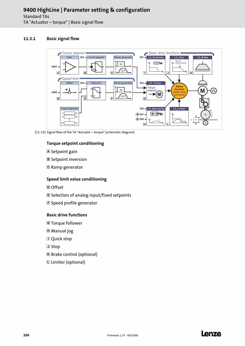
9400 HighLine | Parameter setting & configurationStandard TAsTA "Actuator – torque" | Basic signal flow
266 Firmware 1.37 - 09/2006 L
11.3.1 Basic signal flow
[11-13] Signal flow of the TA "Actuator – torque" (schematic diagram)
Torque setpoint conditioning
Setpoint gain
Setpoint inversion
Ramp generator
Speed limit value conditioning
Offset
Selection of analog input/fixed setpoints
Speed profile generator
Basic drive functions
Torque follower
Manual jog
Quick stop
Stop
Brake control (optional)
Limiter (optional)
Offset
�
� �
�
LS_ManualJog
n
t
��
�
�
LS_Brake
n
t
LS_Limiter
n
t
LS_Quickstop
STOP
�
�
�
Gain Invert setpoint
Selection LS_Torque...
M
Torquesetpoint
n
t
LS_Stop
internalstatus machine
DI2
DI6
DI7
DI8
DI1DI3
DI4
OUT
IN
Ramp generator
%1
%2
%15
Fixed setpoints
OUT
IN
Ramp generator
Statusmachine
(basic drivefunctions)
Torque setpoint Basic drive functions
Speed limit
AIN1
AIN2 M
v
F
�
�
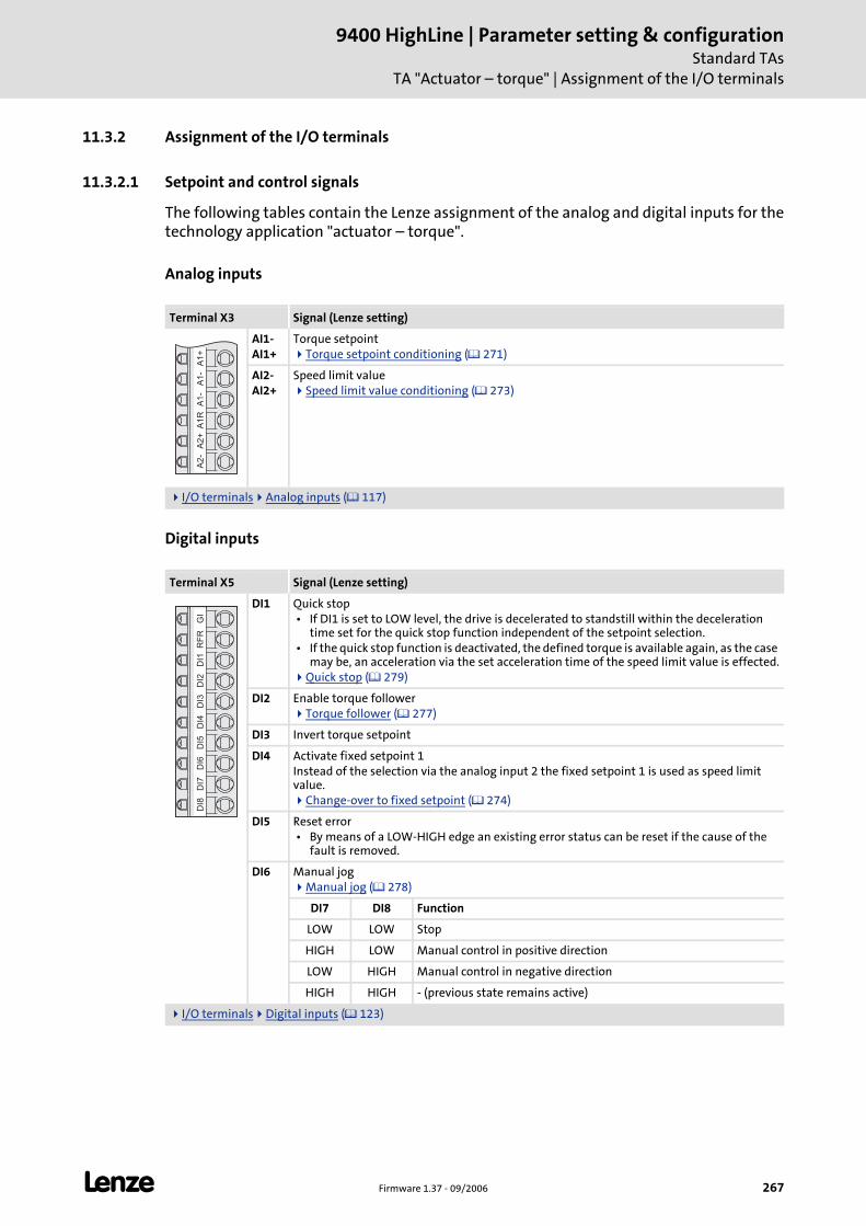
L Firmware 1.37 - 09/2006 267
9400 HighLine | Parameter setting & configurationStandard TAs
TA "Actuator – torque" | Assignment of the I/O terminals
11.3.2 Assignment of the I/O terminals
11.3.2.1 Setpoint and control signals
The following tables contain the Lenze assignment of the analog and digital inputs for the technology application "actuator – torque".
Analog inputs
Digital inputs
Terminal X3 Signal (Lenze setting)
AI1-AI1+
Torque setpointTorque setpoint conditioning ( 271)
AI2-AI2+
Speed limit valueSpeed limit value conditioning ( 273)
I/O terminals Analog inputs ( 117)
Terminal X5 Signal (Lenze setting)
DI1 Quick stop • If DI1 is set to LOW level, the drive is decelerated to standstill within the deceleration
time set for the quick stop function independent of the setpoint selection. • If the quick stop function is deactivated, the defined torque is available again, as the case
may be, an acceleration via the set acceleration time of the speed limit value is effected.Quick stop ( 279)
DI2 Enable torque followerTorque follower ( 277)
DI3 Invert torque setpoint
DI4 Activate fixed setpoint 1Instead of the selection via the analog input 2 the fixed setpoint 1 is used as speed limit value.
Change-over to fixed setpoint ( 274)
DI5 Reset error • By means of a LOW-HIGH edge an existing error status can be reset if the cause of the
fault is removed.
DI6 Manual jogManual jog ( 278)
DI7 DI8 Function
LOW LOW Stop
HIGH LOW Manual control in positive direction
LOW HIGH Manual control in negative direction
HIGH HIGH - (previous state remains active)
I/O terminals Digital inputs ( 123)
A1
+A
1-
A1
-A
1R
A2
+A
2-
GI
RF
RD
I1D
I2D
I3D
I4D
I5D
I6D
I7D
I8
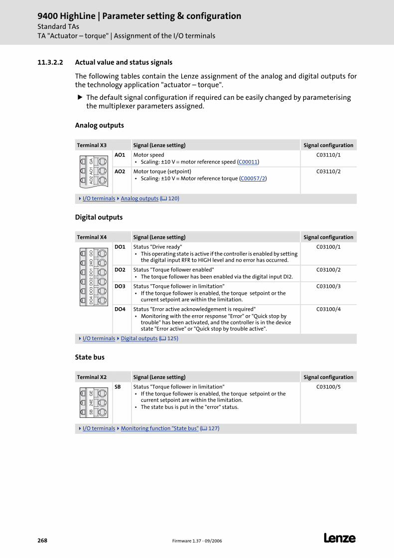
9400 HighLine | Parameter setting & configurationStandard TAsTA "Actuator – torque" | Assignment of the I/O terminals
268 Firmware 1.37 - 09/2006 L
11.3.2.2 Actual value and status signals
The following tables contain the Lenze assignment of the analog and digital outputs for the technology application "actuator – torque".
The default signal configuration if required can be easily changed by parameterising the multiplexer parameters assigned.
Analog outputs
Digital outputs
State bus
Terminal X3 Signal (Lenze setting) Signal configuration
AO1 Motor speed • Scaling: ±10 V ≡ motor reference speed (C00011)
C03110/1
AO2 Motor torque (setpoint) • Scaling: ±10 V ≡ Motor reference torque (C00057/2)
C03110/2
I/O terminals Analog outputs ( 120)
Terminal X4 Signal (Lenze setting) Signal configuration
DO1 Status "Drive ready" • This operating state is active if the controller is enabled by setting
the digital input RFR to HIGH level and no error has occurred.
C03100/1
DO2 Status "Torque follower enabled" • The torque follower has been enabled via the digital input DI2.
C03100/2
DO3 Status "Torque follower in limitation" • If the torque follower is enabled, the torque setpoint or the
current setpoint are within the limitation.
C03100/3
DO4 Status "Error active acknowledgement is required" • Monitoring with the error response "Error" or "Quick stop by
trouble" has been activated, and the controller is in the device state "Error active" or "Quick stop by trouble active".
C03100/4
I/O terminals Digital outputs ( 125)
Terminal X2 Signal (Lenze setting) Signal configuration
SB Status "Torque follower in limitation" • If the torque follower is enabled, the torque setpoint or the
current setpoint are within the limitation. • The state bus is put in the "error" status.
C03100/5
I/O terminals Monitoring function "State bus" ( 127)
GA
AO
1A
O2
GO
24
OD
O1
DO
2D
O3
DO
4G
E2
4E
SB

L Firmware 1.37 - 09/2006 269
9400 HighLine | Parameter setting & configurationStandard TAs
TA "Actuator – torque" | Assignment of the I/O terminals
Display elements
User LED Signal (Lenze setting) Signal configuration
Status "Torque follower enabled" • The torque follower has been enabled via the digital input DI2.
C03100/6
Drive interface LED status displays ( 34)
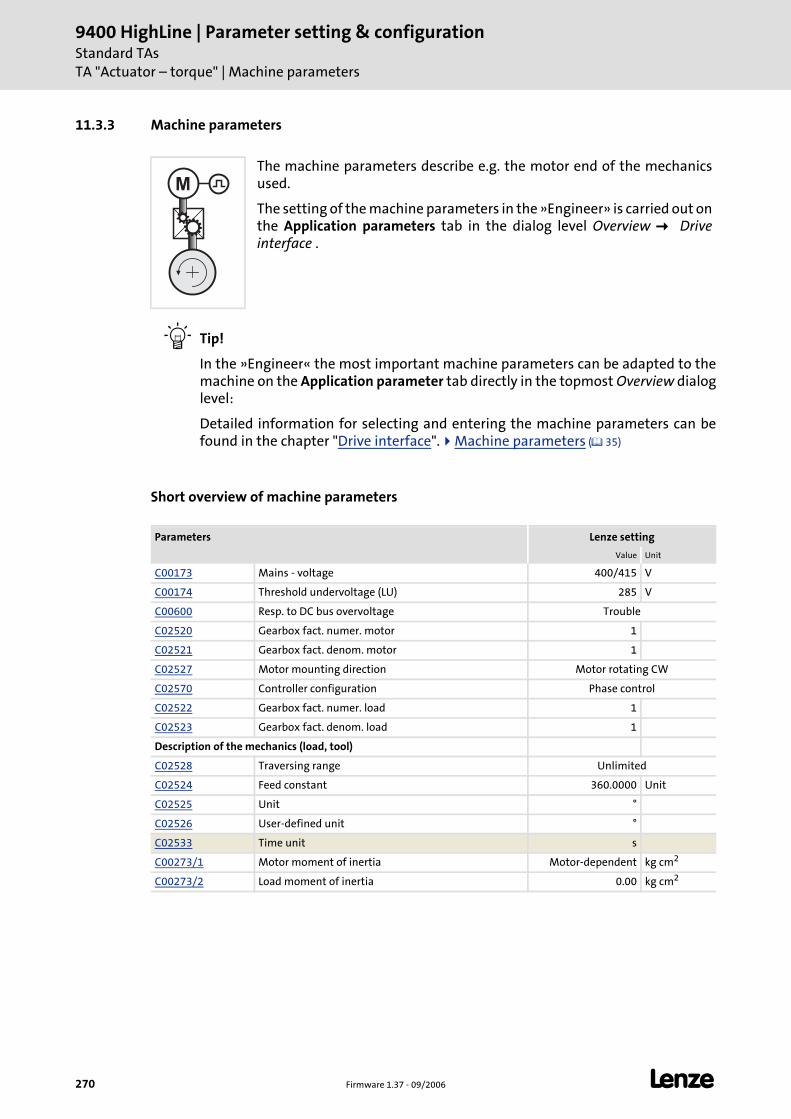
9400 HighLine | Parameter setting & configurationStandard TAsTA "Actuator – torque" | Machine parameters
270 Firmware 1.37 - 09/2006 L
11.3.3 Machine parameters
Tip!
In the »Engineer« the most important machine parameters can be adapted to the machine on the Application parameter tab directly in the topmost Overview dialog level:
Detailed information for selecting and entering the machine parameters can be found in the chapter "Drive interface". Machine parameters ( 35)
Short overview of machine parameters
The machine parameters describe e.g. the motor end of the mechanics used.
The setting of the machine parameters in the »Engineer» is carried out on the Application parameters tab in the dialog level Overview Drive interface .
Parameters Lenze setting
Value Unit
C00173 Mains - voltage 400/415 V
C00174 Threshold undervoltage (LU) 285 V
C00600 Resp. to DC bus overvoltage Trouble
C02520 Gearbox fact. numer. motor 1
C02521 Gearbox fact. denom. motor 1
C02527 Motor mounting direction Motor rotating CW
C02570 Controller configuration Phase control
C02522 Gearbox fact. numer. load 1
C02523 Gearbox fact. denom. load 1
Description of the mechanics (load, tool)
C02528 Traversing range Unlimited
C02524 Feed constant 360.0000 Unit
C02525 Unit °
C02526 User-defined unit °
C02533 Time unit s
C00273/1 Motor moment of inertia Motor-dependent kg cm2
C00273/2 Load moment of inertia 0.00 kg cm2
M
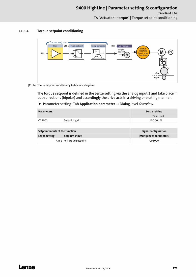
L Firmware 1.37 - 09/2006 271
9400 HighLine | Parameter setting & configurationStandard TAs
TA "Actuator – torque" | Torque setpoint conditioning
11.3.4 Torque setpoint conditioning
[11-14] Torque setpoint conditioning (schematic diagram)
The torque setpoint is defined in the Lenze setting via the analog input 1 and take place in both directions (bipolar) and accordingly the drive acts in a driving or braking manner.
Parameter setting: Tab Application parameter Dialog level Overview
M
Gain Invert setpoint LS_Torque...
M
Torquesetpoint
DI2DI3
OUT
IN
Ramp generator
Statusmachine
(basic drivefunctions)
Torque setpoint
AIN1
v
F
Parameters Lenze setting
Value Unit
C03002 Setpoint gain 100.00 %
Setpoint inputs of the function Signal configuration
Lenze setting Setpoint input (Multiplexer parameters)
AIn 1 Torque setpoint C03000
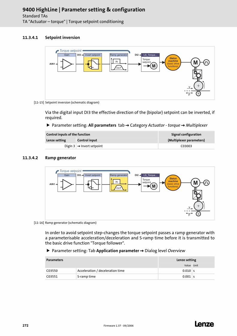
9400 HighLine | Parameter setting & configurationStandard TAsTA "Actuator – torque" | Torque setpoint conditioning
272 Firmware 1.37 - 09/2006 L
11.3.4.1 Setpoint inversion
[11-15] Setpoint inversion (schematic diagram)
Via the digital input DI3 the effective direction of the (bipolar) setpoint can be inverted, if required.
Parameter setting: All parameters tab Category Actuator - torque Multiplexer
11.3.4.2 Ramp generator
[11-16] Ramp generator (schematic diagram)
In order to avoid setpoint step-changes the torque setpoint passes a ramp generator with a parameterisable acceleration/deceleration and S-ramp time before it is transmitted to the basic drive function "Torque follower".
Parameter setting: Tab Application parameter Dialog level Overview
M
Gain Invert setpoint LS_Torque...
M
Torquesetpoint
DI2DI3
OUT
IN
Ramp generator
Statusmachine
(basic drivefunctions)
Torque setpoint
AIN1
v
F
Control inputs of the function Signal configuration
Lenze setting Control input (Multiplexer parameters)
DigIn 3 Invert setpoint C03003
M
Gain Invert setpoint LS_Torque...
M
Torquesetpoint
DI2DI3
OUT
IN
Ramp generator
Statusmachine
(basic drivefunctions)
Torque setpoint
AIN1
v
F
Parameters Lenze setting
Value Unit
C03550 Acceleration / deceleration time 0.010 s
C03551 S-ramp time 0.001 s
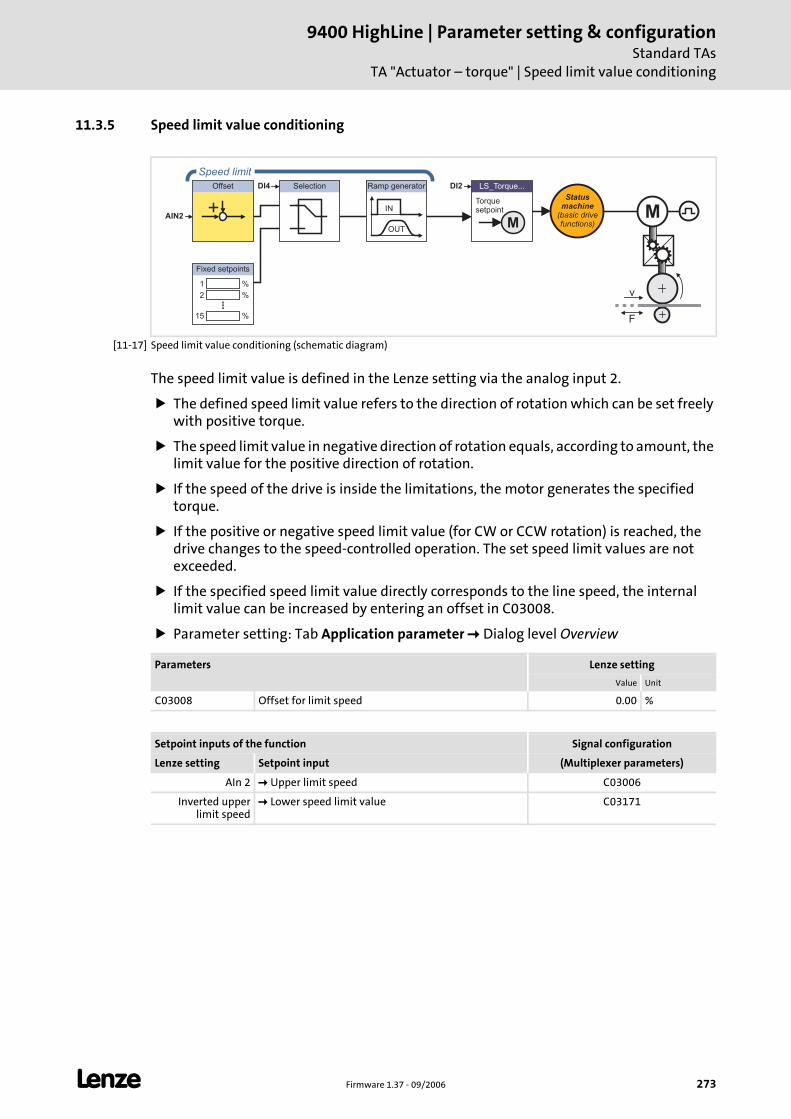
L Firmware 1.37 - 09/2006 273
9400 HighLine | Parameter setting & configurationStandard TAs
TA "Actuator – torque" | Speed limit value conditioning
11.3.5 Speed limit value conditioning
[11-17] Speed limit value conditioning (schematic diagram)
The speed limit value is defined in the Lenze setting via the analog input 2.
The defined speed limit value refers to the direction of rotation which can be set freely with positive torque.
The speed limit value in negative direction of rotation equals, according to amount, the limit value for the positive direction of rotation.
If the speed of the drive is inside the limitations, the motor generates the specified torque.
If the positive or negative speed limit value (for CW or CCW rotation) is reached, the drive changes to the speed-controlled operation. The set speed limit values are not exceeded.
If the specified speed limit value directly corresponds to the line speed, the internal limit value can be increased by entering an offset in C03008.
Parameter setting: Tab Application parameter Dialog level Overview
Offset Selection LS_Torque...
M
Torquesetpoint
DI2DI4
OUT
IN
Ramp generator
%1
%2
%15
Fixed setpoints
Statusmachine
(basic drivefunctions)
Speed limit
AIN2 M
v
F
Parameters Lenze setting
Value Unit
C03008 Offset for limit speed 0.00 %
Setpoint inputs of the function Signal configuration
Lenze setting Setpoint input (Multiplexer parameters)
AIn 2 Upper limit speed C03006
Inverted upper limit speed
Lower speed limit value C03171
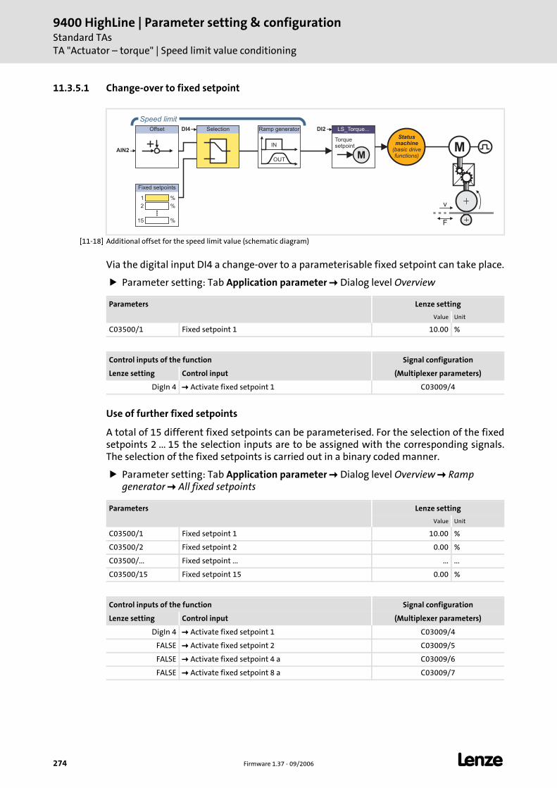
9400 HighLine | Parameter setting & configurationStandard TAsTA "Actuator – torque" | Speed limit value conditioning
274 Firmware 1.37 - 09/2006 L
11.3.5.1 Change-over to fixed setpoint
[11-18] Additional offset for the speed limit value (schematic diagram)
Via the digital input DI4 a change-over to a parameterisable fixed setpoint can take place.
Parameter setting: Tab Application parameter Dialog level Overview
Use of further fixed setpoints
A total of 15 different fixed setpoints can be parameterised. For the selection of the fixed setpoints 2 ... 15 the selection inputs are to be assigned with the corresponding signals.The selection of the fixed setpoints is carried out in a binary coded manner.
Parameter setting: Tab Application parameter Dialog level Overview Ramp generator All fixed setpoints
Offset Selection LS_Torque...
M
Torquesetpoint
DI2DI4
OUT
IN
Ramp generator
%1
%2
%15
Fixed setpoints
Statusmachine
(basic drivefunctions)
Speed limit
AIN2 M
v
F
Parameters Lenze setting
Value Unit
C03500/1 Fixed setpoint 1 10.00 %
Control inputs of the function Signal configuration
Lenze setting Control input (Multiplexer parameters)
DigIn 4 Activate fixed setpoint 1 C03009/4
Parameters Lenze setting
Value Unit
C03500/1 Fixed setpoint 1 10.00 %
C03500/2 Fixed setpoint 2 0.00 %
C03500/... Fixed setpoint ... ... ...
C03500/15 Fixed setpoint 15 0.00 %
Control inputs of the function Signal configuration
Lenze setting Control input (Multiplexer parameters)
DigIn 4 Activate fixed setpoint 1 C03009/4
FALSE Activate fixed setpoint 2 C03009/5
FALSE Activate fixed setpoint 4 a C03009/6
FALSE Activate fixed setpoint 8 a C03009/7
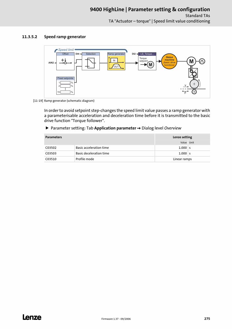
L Firmware 1.37 - 09/2006 275
9400 HighLine | Parameter setting & configurationStandard TAs
TA "Actuator – torque" | Speed limit value conditioning
11.3.5.2 Speed ramp generator
[11-19] Ramp generator (schematic diagram)
In order to avoid setpoint step-changes the speed limit value passes a ramp generator with a parameterisable acceleration and deceleration time before it is transmitted to the basic drive function "Torque follower".
Parameter setting: Tab Application parameter Dialog level Overview
Offset Selection LS_Torque...
M
Torquesetpoint
DI2DI4
OUT
IN
Ramp generator
%1
%2
%15
Fixed setpoints
Statusmachine
(basic drivefunctions)
Speed limit
AIN2 M
v
F
Parameters Lenze setting
Value Unit
C03502 Basic acceleration time 1.000 s
C03503 Basic deceleration time 1.000 s
C03510 Profile mode Linear ramps
9400 HighLine | Parameter setting & configurationStandard TAsTA "Actuator – torque" | Speed limit value conditioning
276 Firmware 1.37 - 09/2006 L
Use of further ramp parameter sets
If required, 15 further ramp parameter sets can be parameterised. For the selection of the ramp parameter sets1 ... 15 the selection inputs are to be assigned with the corresponding signals. The selection of the ramp parameter sets is carried out in a binary coded manner.
Parameter setting: Tab Application parameter Dialog level Overview Ramp generator All ramp parameters
Parameters Lenze setting
Value Unit
C03512/1 Acceleration time 1 0.000 s
C03512/... Acceleration time ... ... ...
C03512/15 Acceleration time 15 0.000 s
C03513/1 Deceleration time 1 0.000 s
C03513/... Deceleration time ... ... ...
C03513/15 Deceleration time 15 0.000 s
C03514/1 S-ramp time 1 0.000 s
C03514/... S-ramp time ... ...
C03514/15 S-ramp time 15 0.000 s
Control inputs of the function Signal configuration
Lenze setting Control input (Multiplexer parameters)
FALSE Activate ramp parameter set 1 C03009/8
FALSE Activate ramp parameter set 2 C03009/9
FALSE Activate ramp parameter set 4 C03009/10
FALSE Activate ramp parameter set 8 a C03009/11
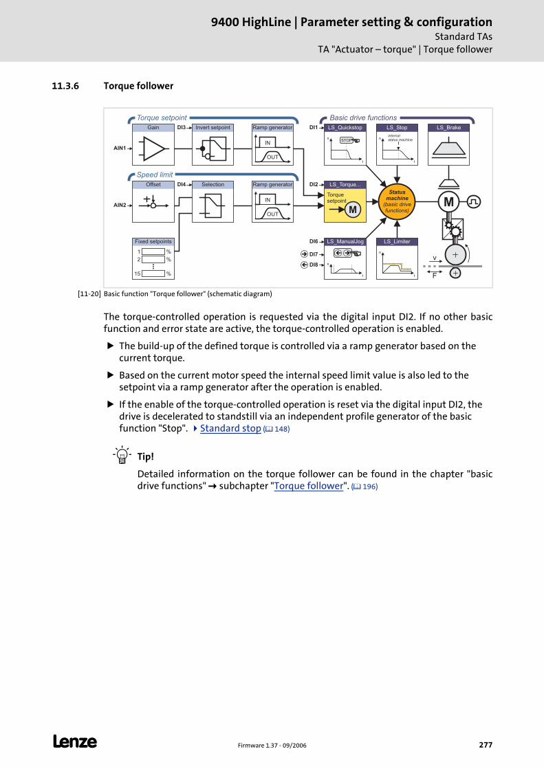
L Firmware 1.37 - 09/2006 277
9400 HighLine | Parameter setting & configurationStandard TAs
TA "Actuator – torque" | Torque follower
11.3.6 Torque follower
[11-20] Basic function "Torque follower" (schematic diagram)
The torque-controlled operation is requested via the digital input DI2. If no other basic function and error state are active, the torque-controlled operation is enabled.
The build-up of the defined torque is controlled via a ramp generator based on the current torque.
Based on the current motor speed the internal speed limit value is also led to the setpoint via a ramp generator after the operation is enabled.
If the enable of the torque-controlled operation is reset via the digital input DI2, the drive is decelerated to standstill via an independent profile generator of the basic function "Stop". Standard stop ( 148)
Tip!
Detailed information on the torque follower can be found in the chapter "basic drive functions" subchapter "Torque follower". ( 196)
Offset
M
LS_ManualJog
n
t
��
LS_Brake
n
t
LS_Limiter
n
t
LS_Quickstop
STOP
Gain Invert setpoint
Selection LS_Torque...
M
Torquesetpoint
n
t
LS_Stop
internalstatus machine
DI2
DI6
DI7
DI8
DI1DI3
DI4
OUT
IN
Ramp generator
%1
%2
%15
Fixed setpoints
OUT
IN
Ramp generator
Statusmachine
(basic drivefunctions)
Torque setpoint Basic drive functions
Speed limit
AIN1
AIN2
v
F
�
�
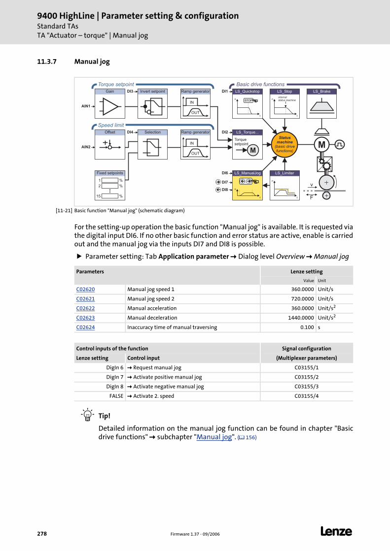
9400 HighLine | Parameter setting & configurationStandard TAsTA "Actuator – torque" | Manual jog
278 Firmware 1.37 - 09/2006 L
11.3.7 Manual jog
[11-21] Basic function "Manual jog" (schematic diagram)
For the setting-up operation the basic function "Manual jog" is available. It is requested via the digital input DI6. If no other basic function and error status are active, enable is carried out and the manual jog via the inputs DI7 and DI8 is possible.
Parameter setting: Tab Application parameter Dialog level Overview Manual jog
Tip!
Detailed information on the manual jog function can be found in chapter "Basic drive functions" subchapter "Manual jog". ( 156)
Offset
LS_ManualJog
n
t
��
LS_Brake
n
t
LS_Limiter
n
t
LS_Quickstop
STOP
Gain Invert setpoint
Selection LS_Torque...
M
Torquesetpoint
n
t
LS_Stop
internalstatus machine
DI2
DI6
DI7
DI8
DI1DI3
DI4
OUT
IN
Ramp generator
%1
%2
%15
Fixed setpoints
OUT
IN
Ramp generator
Statusmachine
(basic drivefunctions)
Torque setpoint Basic drive functions
Speed limit
AIN1
AIN2 M
v
F
�
�
Parameters Lenze setting
Value Unit
C02620 Manual jog speed 1 360.0000 Unit/s
C02621 Manual jog speed 2 720.0000 Unit/s
C02622 Manual acceleration 360.0000 Unit/s2
C02623 Manual deceleration 1440.0000 Unit/s2
C02624 Inaccuracy time of manual traversing 0.100 s
Control inputs of the function Signal configuration
Lenze setting Control input (Multiplexer parameters)
DigIn 6 Request manual jog C03155/1
DigIn 7 Activate positive manual jog C03155/2
DigIn 8 Activate negative manual jog C03155/3
FALSE Activate 2. speed C03155/4
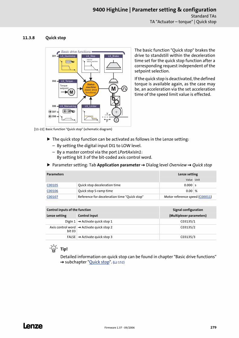
L Firmware 1.37 - 09/2006 279
9400 HighLine | Parameter setting & configurationStandard TAs
TA "Actuator – torque" | Quick stop
11.3.8 Quick stop
[11-22] Basic function "Quick stop" (schematic diagram)
The quick stop function can be activated as follows in the Lenze setting:
– By setting the digital input DI1 to LOW level.
– By a master control via the port LPortAxisIn1: By setting bit 3 of the bit-coded axis control word.
Parameter setting: Tab Application parameter Dialog level Overview Quick stop
Tip!
Detailed information on quick stop can be found in chapter "Basic drive functions" subchapter "Quick stop". ( 152)
The basic function "Quick stop" brakes the drive to standstill within the deceleration time set for the quick stop function after a corresponding request independent of the setpoint selection.
If the quick stop is deactivated, the defined torque is available again, as the case may be, an acceleration via the set acceleration time of the speed limit value is effected.
LS_ManualJog
n
t
��
LS_Brake
n
t
LS_Limiter
n
t
LS_Quickstop
STOP
LS_Torque...
M
Torquesetpoint
n
t
LS_Stop
internalstatus machine
DI2
DI6
DI7
DI8
DI1
Statusmachine
(basic drivefunctions)
Basic drive functions
M
v
F
�
�
Parameters Lenze setting
Value Unit
C00105 Quick stop deceleration time 0.000 s
C00106 Quick stop S-ramp time 0.00 %
C00107 Reference for deceleration time "Quick stop" Motor reference speed (C00011)
Control inputs of the function Signal configuration
Lenze setting Control input (Multiplexer parameters)
DigIn 1 Activate quick stop 1 C03135/1
Axis control word bit 03
Activate quick stop 2 C03135/2
FALSE Activate quick stop 3 C03135/3
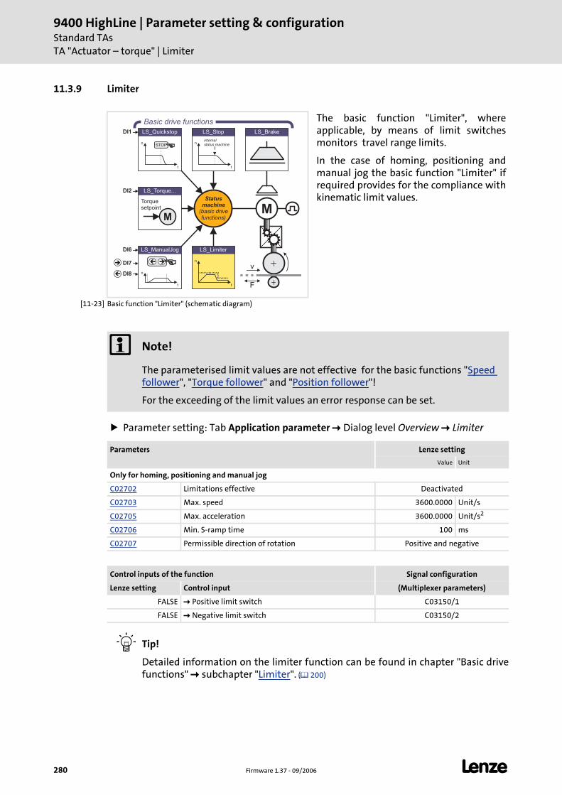
9400 HighLine | Parameter setting & configurationStandard TAsTA "Actuator – torque" | Limiter
280 Firmware 1.37 - 09/2006 L
11.3.9 Limiter
[11-23] Basic function "Limiter" (schematic diagram)
Parameter setting: Tab Application parameter Dialog level Overview Limiter
Tip!
Detailed information on the limiter function can be found in chapter "Basic drive functions" subchapter "Limiter". ( 200)
The basic function "Limiter", where applicable, by means of limit switches monitors travel range limits.
In the case of homing, positioning and manual jog the basic function "Limiter" if required provides for the compliance with kinematic limit values.
LS_ManualJog
n
t
��
LS_Brake
n
t
LS_Limiter
n
t
LS_Quickstop
STOP
LS_Torque...
M
Torquesetpoint
n
t
LS_Stop
internalstatus machine
DI2
DI6
DI7
DI8
DI1
Statusmachine
(basic drivefunctions)
Basic drive functions
M
v
F
�
�
Note!
The parameterised limit values are not effective for the basic functions "Speed follower", "Torque follower" and "Position follower"!
For the exceeding of the limit values an error response can be set.
Parameters Lenze setting
Value Unit
Only for homing, positioning and manual jog
C02702 Limitations effective Deactivated
C02703 Max. speed 3600.0000 Unit/s
C02705 Max. acceleration 3600.0000 Unit/s2
C02706 Min. S-ramp time 100 ms
C02707 Permissible direction of rotation Positive and negative
Control inputs of the function Signal configuration
Lenze setting Control input (Multiplexer parameters)
FALSE Positive limit switch C03150/1
FALSE Negative limit switch C03150/2
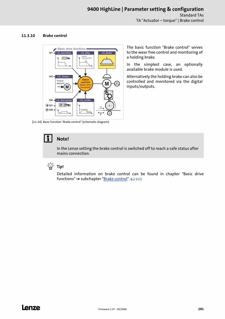
L Firmware 1.37 - 09/2006 281
9400 HighLine | Parameter setting & configurationStandard TAs
TA "Actuator – torque" | Brake control
11.3.10 Brake control
[11-24] Basic function "Brake control" (schematic diagram)
Tip!
Detailed information on brake control can be found in chapter "Basic drive functions" subchapter "Brake control". ( 211)
The basic function "Brake control" serves to the wear free control and monitoring of a holding brake.
In the simplest case, an optionally available brake module is used.
Alternatively the holding brake can also be controlled and monitored via the digital inputs/outputs.
LS_ManualJog
n
t
��
LS_Brake
n
t
LS_Limiter
n
t
LS_Quickstop
STOP
LS_Torque...
M
Torquesetpoint
n
t
LS_Stop
internalstatus machine
DI2
DI6
DI7
DI8
DI1
Statusmachine
(basic drivefunctions)
Basic drive functions
M
v
F
�
�
Note!
In the Lenze setting the brake control is switched off to reach a safe status after mains connection.
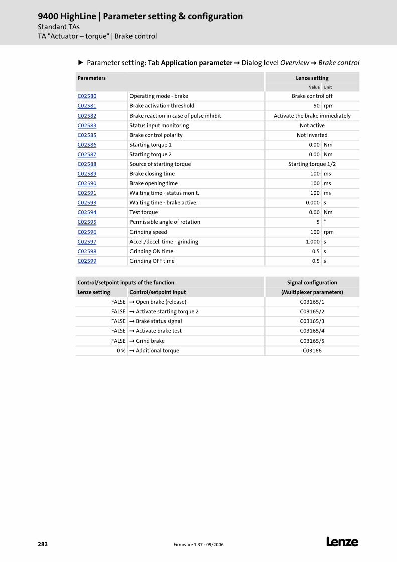
9400 HighLine | Parameter setting & configurationStandard TAsTA "Actuator – torque" | Brake control
282 Firmware 1.37 - 09/2006 L
Parameter setting: Tab Application parameter Dialog level Overview Brake control
Parameters Lenze setting
Value Unit
C02580 Operating mode - brake Brake control off
C02581 Brake activation threshold 50 rpm
C02582 Brake reaction in case of pulse inhibit Activate the brake immediately
C02583 Status input monitoring Not active
C02585 Brake control polarity Not inverted
C02586 Starting torque 1 0.00 Nm
C02587 Starting torque 2 0.00 Nm
C02588 Source of starting torque Starting torque 1/2
C02589 Brake closing time 100 ms
C02590 Brake opening time 100 ms
C02591 Waiting time - status monit. 100 ms
C02593 Waiting time - brake active. 0.000 s
C02594 Test torque 0.00 Nm
C02595 Permissible angle of rotation 5 °
C02596 Grinding speed 100 rpm
C02597 Accel./decel. time - grinding 1.000 s
C02598 Grinding ON time 0.5 s
C02599 Grinding OFF time 0.5 s
Control/setpoint inputs of the function Signal configuration
Lenze setting Control/setpoint input (Multiplexer parameters)
FALSE Open brake (release) C03165/1
FALSE Activate starting torque 2 C03165/2
FALSE Brake status signal C03165/3
FALSE Activate brake test C03165/4
FALSE Grind brake C03165/5
0 % Additional torque C03166
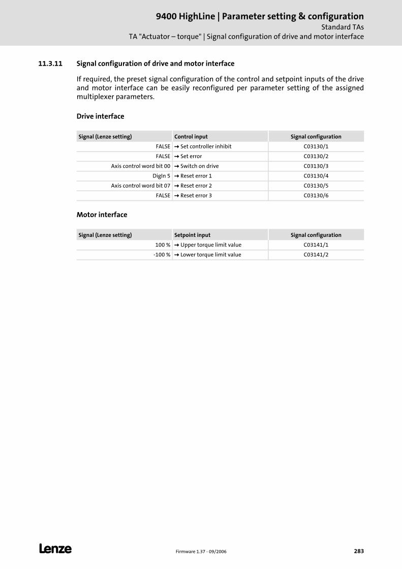
L Firmware 1.37 - 09/2006 283
9400 HighLine | Parameter setting & configurationStandard TAs
TA "Actuator – torque" | Signal configuration of drive and motor interface
11.3.11 Signal configuration of drive and motor interface
If required, the preset signal configuration of the control and setpoint inputs of the drive and motor interface can be easily reconfigured per parameter setting of the assigned multiplexer parameters.
Drive interface
Motor interface
Signal (Lenze setting) Control input Signal configuration
FALSE Set controller inhibit C03130/1
FALSE Set error C03130/2
Axis control word bit 00 Switch on drive C03130/3
DigIn 5 Reset error 1 C03130/4
Axis control word bit 07 Reset error 2 C03130/5
FALSE Reset error 3 C03130/6
Signal (Lenze setting) Setpoint input Signal configuration
100 % Upper torque limit value C03141/1
-100 % Lower torque limit value C03141/2
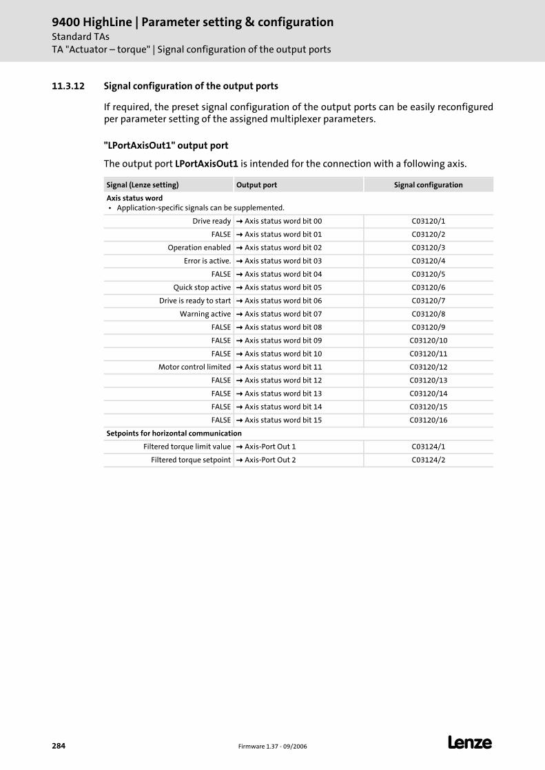
9400 HighLine | Parameter setting & configurationStandard TAsTA "Actuator – torque" | Signal configuration of the output ports
284 Firmware 1.37 - 09/2006 L
11.3.12 Signal configuration of the output ports
If required, the preset signal configuration of the output ports can be easily reconfigured per parameter setting of the assigned multiplexer parameters.
"LPortAxisOut1" output port
The output port LPortAxisOut1 is intended for the connection with a following axis.
Signal (Lenze setting) Output port Signal configuration
Axis status word • Application-specific signals can be supplemented.
Drive ready Axis status word bit 00 C03120/1
FALSE Axis status word bit 01 C03120/2
Operation enabled Axis status word bit 02 C03120/3
Error is active. Axis status word bit 03 C03120/4
FALSE Axis status word bit 04 C03120/5
Quick stop active Axis status word bit 05 C03120/6
Drive is ready to start Axis status word bit 06 C03120/7
Warning active Axis status word bit 07 C03120/8
FALSE Axis status word bit 08 C03120/9
FALSE Axis status word bit 09 C03120/10
FALSE Axis status word bit 10 C03120/11
Motor control limited Axis status word bit 11 C03120/12
FALSE Axis status word bit 12 C03120/13
FALSE Axis status word bit 13 C03120/14
FALSE Axis status word bit 14 C03120/15
FALSE Axis status word bit 15 C03120/16
Setpoints for horizontal communication
Filtered torque limit value Axis-Port Out 1 C03124/1
Filtered torque setpoint Axis-Port Out 2 C03124/2
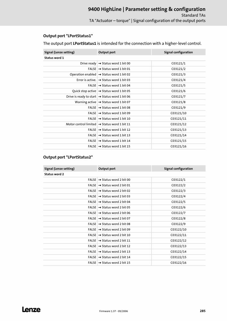
L Firmware 1.37 - 09/2006 285
9400 HighLine | Parameter setting & configurationStandard TAs
TA "Actuator – torque" | Signal configuration of the output ports
Output port "LPortStatus1"
The output port LPortStatus1 is intended for the connection with a higher-level control.
Output port "LPortStatus2"
Signal (Lenze setting) Output port Signal configuration
Status word 1
Drive ready Status word 1 bit 00 C03121/1
FALSE Status word 1 bit 01 C03121/2
Operation enabled Status word 1 bit 02 C03121/3
Error is active. Status word 1 bit 03 C03121/4
FALSE Status word 1 bit 04 C03121/5
Quick stop active Status word 1 bit 05 C03121/6
Drive is ready to start Status word 1 bit 06 C03121/7
Warning active Status word 1 bit 07 C03121/8
FALSE Status word 1 bit 08 C03121/9
FALSE Status word 1 bit 09 C03121/10
FALSE Status word 1 bit 10 C03121/11
Motor control limited Status word 1 bit 11 C03121/12
FALSE Status word 1 bit 12 C03121/13
FALSE Status word 1 bit 13 C03121/14
FALSE Status word 1 bit 14 C03121/15
FALSE Status word 1 bit 15 C03121/16
Signal (Lenze setting) Output port Signal configuration
Status word 2
FALSE Status word 2 bit 00 C03122/1
FALSE Status word 2 bit 01 C03122/2
FALSE Status word 2 bit 02 C03122/3
FALSE Status word 2 bit 03 C03122/4
FALSE Status word 2 bit 04 C03122/5
FALSE Status word 2 bit 05 C03122/6
FALSE Status word 2 bit 06 C03122/7
FALSE Status word 2 bit 07 C03122/8
FALSE Status word 2 bit 08 C03122/9
FALSE Status word 2 bit 09 C03122/10
FALSE Status word 2 bit 10 C03122/11
FALSE Status word 2 bit 11 C03122/12
FALSE Status word 2 bit 12 C03122/13
FALSE Status word 2 bit 13 C03122/14
FALSE Status word 2 bit 14 C03122/15
FALSE Status word 2 bit 15 C03122/16

9400 HighLine | Parameter setting & configurationStandard TAsTA "Actuator – torque" | Application error messages
286 Firmware 1.37 - 09/2006 L
11.3.13 Application error messages
For the output of application-specific error messages an FB instance ApplicationError of the function block L_DevApplErr is available in the network.
Via the 8 boolean inputs up to 8 different application error messages with parameterisable module ID, error ID and error response can be released by the application.
Parameter setting: Tab All parameters
Reset of error message
In the Lenze setting the digital input DI5 for resetting (acknowledging) an error message is connected to the input DI_bResetError1 of the drive interface.
Error message Error-ID Error response
1 Torque follower in limitation 8001 Warning locked
2 - 8000 Error
3 - 8000 Error
4 - 8000 Error
5 - 8000 Error
6 - 8000 Error
7 - 8000 Error
8 - 8000 Error
Parameters Lenze setting
C05900 Module-ID 980
C05901/1...8 Error ID 1 ... 8 See table above
C05902/1...8 Error response 1 ... 8 See table above
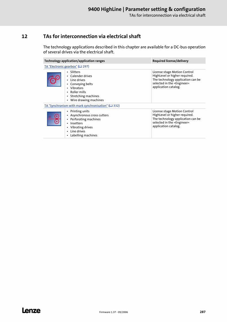
L Firmware 1.37 - 09/2006 287
9400 HighLine | Parameter setting & configurationTAs for interconnection via electrical shaft
12 TAs for interconnection via electrical shaft
The technology applications described in this chapter are available for a DC-bus operation of several drives via the electrical shaft.
Technology application/application ranges Required license/delivery
TA "Electronic gearbox" ( 297)
• Slitters • Calender drives • Line drives • Conveying belts • Vibrators • Roller mills • Stretching machines • Wire drawing machines
License stage Motion Control HighLevel or higher required.The technology application can be selected in the »Engineer« application catalog.
TA "Synchronism with mark synchronisation" ( 332)
• Printing units • Asynchronous cross cutters • Perforating machines • Insetters • Vibrating drives • Line drives • Labelling machines
License stage Motion Control HighLevel or higher required.The technology application can be selected in the »Engineer« application catalog.
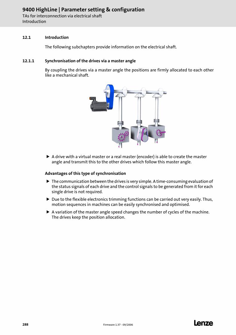
9400 HighLine | Parameter setting & configurationTAs for interconnection via electrical shaftIntroduction
288 Firmware 1.37 - 09/2006 L
12.1 Introduction
The following subchapters provide information on the electrical shaft.
12.1.1 Synchronisation of the drives via a master angle
By coupling the drives via a master angle the positions are firmly allocated to each other like a mechanical shaft.
A drive with a virtual master or a real master (encoder) is able to create the master angle and transmit this to the other drives which follow this master angle.
Advantages of this type of synchronisation
The communication between the drives is very simple. A time-consuming evaluation of the status signals of each drive and the control signals to be generated from it for each single drive is not required.
Due to the flexible electronics trimming functions can be carried out very easily. Thus, motion sequences in machines can be easily synchronised and optimised.
A variation of the master angle speed changes the number of cycles of the machine. The drives keep the position allocation.
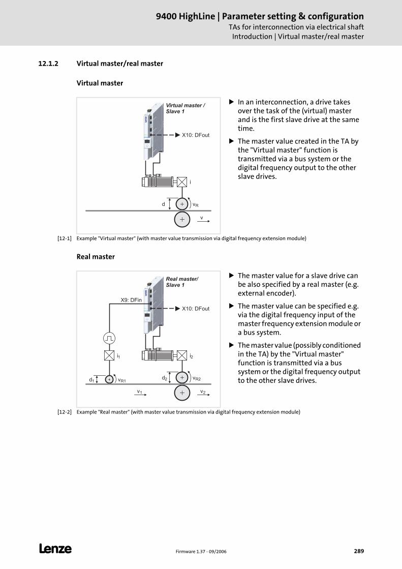
L Firmware 1.37 - 09/2006 289
9400 HighLine | Parameter setting & configurationTAs for interconnection via electrical shaft
Introduction | Virtual master/real master
12.1.2 Virtual master/real master
Virtual master
[12-1] Example "Virtual master" (with master value transmission via digital frequency extension module)
Real master
[12-2] Example "Real master" (with master value transmission via digital frequency extension module)
In an interconnection, a drive takes over the task of the (virtual) master and is the first slave drive at the same time.
The master value created in the TA by the "Virtual master" function is transmitted via a bus system or the digital frequency output to the other slave drives.
d vR
i
v
Virtual master /Slave 1
X10: DFout
The master value for a slave drive can be also specified by a real master (e.g. external encoder).
The master value can be specified e.g. via the digital frequency input of the master frequency extension module or a bus system.
The master value (possibly conditioned in the TA) by the "Virtual master" function is transmitted via a bus system or the digital frequency output to the other slave drives.d v d v
R1R2
12
i1 i2
v1 v2
X10: DFout
Real master/Slave 1
X9: DFin
9400 HighLine | Parameter setting & configurationTAs for interconnection via electrical shaftIntroduction | Transmission of the master angle
290 Firmware 1.37 - 09/2006 L
12.1.3 Transmission of the master angle
The master value/angle can be transmitted via the following transmission media:
Digital frequency
System bus (CAN)
ETHERNET Powerlink (in preparation)
The suitable bus medium is selected according to the criteria listed in the following sections:
Digital frequency (simulation of an incremental encoder)
Rail or cascade structure is possible.
Only relative master value/master angle possible.
Max resolution 16 bits/revolution
Cable length is virtually unlimited but must not exceed 50 m from drive to drive.
Digital frequency extension module is required.
System bus (CAN)
No cascade structure possible.
Optionally absolute or relative master angle transfer possible.
Resolution up to 28 bits/revolution (in preparation; currently 16 bits/revolution).
Cable length is limited (dependent on baud rate, number of nodes and cable cross-section).
– With a baud rate of 500 Kbit/s the total cable length is limited to e.g. 117 metres.
Interface of 9400 HighLine is already integrated. System bus "CAN on board" ( 134)
ETHERNET Powerlink (in preparation)
Rail or cascade structure is possible.
Optionally absolute or relative master angle transfer possible.
Resolution up to 28 bits/revolution.
Cable length is virtually unlimited but must not exceed 100 m from drive to drive.
Additional hardware (communication module ETHERNET Powerlink) is required.
Note!
For detailed information about the CANopen system bus interface, please see the "CAN on-board 9400" Communication Manual.
L Firmware 1.37 - 09/2006 291
9400 HighLine | Parameter setting & configurationTAs for interconnection via electrical shaft
Introduction | Speed or angular synchronism?
12.1.4 Speed or angular synchronism?
The decision whether to use a speed or angular synchronism mainly refers to the TA "Electronic gearbox" ( 297)
Angular synchronism
Use the angular synchronism if the material is not able to absorb any force and no remaining positional variation may be available. Please note that a position controller always causes additional trouble in a track since disturbances and reference value variations must be compensated exactly.
Speed synchronism
Use the speed synchronism if the material is able to absorb force which ensures a better concentricity.
12.1.5 Rail or cascade structure?
Rail structure
All drives obtain the same master value/master angle.
Cascade structure
Each drive obtains its own master value/master angle which is created or merely prepared through the upstream drive.
12.1.6 Master or actual value transfer?
Master value transmission
The master value transfer results in a much quieter machine running. The mark corrections, superimposed control functions and disturbances of the drive, however, do not affect the system.
Actual value transfer
The actual value transfer results in an uneven machine running. Mark corrections, superimposed control functions and disturbances of the leading drive affect the system.
Note!
For detailed information about the ETHERNET Powerlink, please see the "Ethernet" Communication Manual.
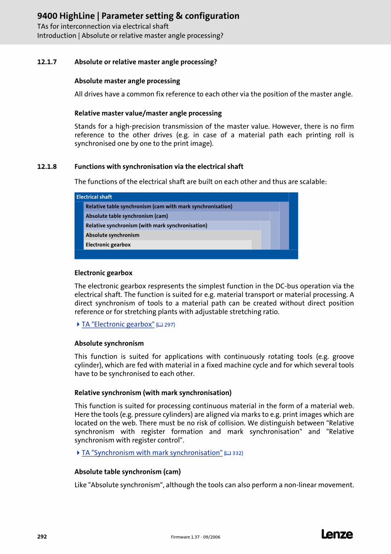
9400 HighLine | Parameter setting & configurationTAs for interconnection via electrical shaftIntroduction | Absolute or relative master angle processing?
292 Firmware 1.37 - 09/2006 L
12.1.7 Absolute or relative master angle processing?
Absolute master angle processing
All drives have a common fix reference to each other via the position of the master angle.
Relative master value/master angle processing
Stands for a high-precision transmission of the master value. However, there is no firm reference to the other drives (e.g. in case of a material path each printing roll is synchronised one by one to the print image).
12.1.8 Functions with synchronisation via the electrical shaft
The functions of the electrical shaft are built on each other and thus are scalable:
Electronic gearbox
The electronic gearbox respresents the simplest function in the DC-bus operation via the electrical shaft. The function is suited for e.g. material transport or material processing. A direct synchronism of tools to a material path can be created without direct position reference or for stretching plants with adjustable stretching ratio.
TA "Electronic gearbox" ( 297)
Absolute synchronism
This function is suited for applications with continuously rotating tools (e.g. groove cylinder), which are fed with material in a fixed machine cycle and for which several tools have to be synchronised to each other.
Relative synchronism (with mark synchronisation)
This function is suited for processing continuous material in the form of a material web. Here the tools (e.g. pressure cylinders) are aligned via marks to e.g. print images which are located on the web. There must be no risk of collision. We distinguish between "Relative synchronism with register formation and mark synchronisation" and "Relative synchronism with register control".
TA "Synchronism with mark synchronisation" ( 332)
Absolute table synchronism (cam)
Like "Absolute synchronism", although the tools can also perform a non-linear movement.
Electrical shaft
Relative table synchronism (cam with mark synchronisation)
Absolute table synchronism (cam)
Relative synchronism (with mark synchronisation)
Absolute synchronism
Electronic gearbox
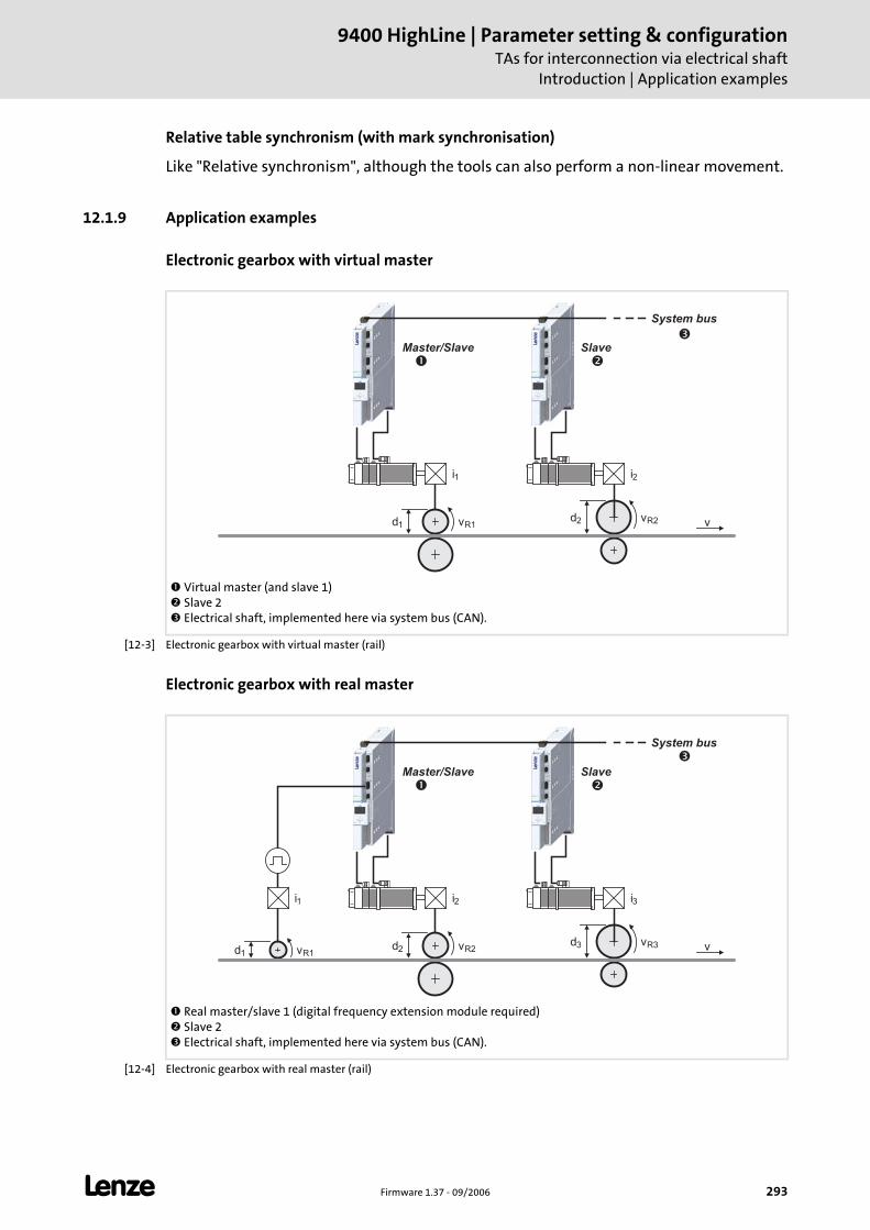
L Firmware 1.37 - 09/2006 293
9400 HighLine | Parameter setting & configurationTAs for interconnection via electrical shaft
Introduction | Application examples
Relative table synchronism (with mark synchronisation)
Like "Relative synchronism", although the tools can also perform a non-linear movement.
12.1.9 Application examples
Electronic gearbox with virtual master
[12-3] Electronic gearbox with virtual master (rail)
Electronic gearbox with real master
[12-4] Electronic gearbox with real master (rail)
Virtual master (and slave 1) Slave 2 Electrical shaft, implemented here via system bus (CAN).
v
i
SlaveMaster/Slave
d vd vR1R2
12
i1 2
��
�
System bus
Real master/slave 1 (digital frequency extension module required) Slave 2 Electrical shaft, implemented here via system bus (CAN).
v
i
SlaveMaster/Slave
d vd v d v
R1R2
R31
23
i1 i2 3
�
�
System bus
�
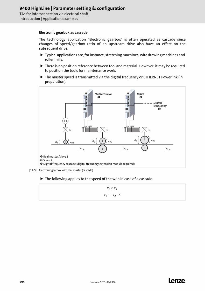
9400 HighLine | Parameter setting & configurationTAs for interconnection via electrical shaftIntroduction | Application examples
294 Firmware 1.37 - 09/2006 L
Electronic gearbox as cascade
The technology application "Electronic gearbox" is often operated as cascade since changes of speed/gearbox ratio of an upstream drive also have an effect on the subsequent drive.
Typical applications are, for instance, stretching machines, wire drawing machines and roller mills.
There is no position reference between tool and material. However, it may be required to position the tools for maintenance work.
The master speed is transmitted via the digital frequency or ETHERNET Powerlink (in preparation).
[12-5] Electronic gearbox with real master (cascade)
The following applies to the speed of the web in case of a cascade:
Real master/slave 1 Slave 2 Digital frequency cascade (digital frequency extension module required)
i
SlaveMaster/Slave
d vd v d v
R1R2
R31
23
i1 i2 3
� �
v1 v2 v3
�
Digitalfrequency
v3 v2>
v3 v2 K⋅=
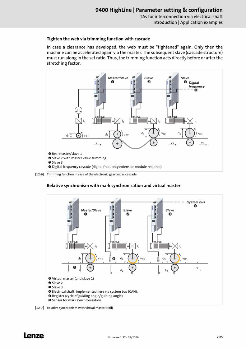
L Firmware 1.37 - 09/2006 295
9400 HighLine | Parameter setting & configurationTAs for interconnection via electrical shaft
Introduction | Application examples
Tighten the web via trimming function with cascade
In case a clearance has developed, the web must be "tightened" again. Only then the machine can be accelerated again via the master. The subsequent slave (cascade structure) must run along in the set ratio. Thus, the trimming function acts directly before or after the stretching factor.
[12-6] Trimming function in case of the electronic gearbox as cascade
Relative synchronism with mark synchronisation and virtual master
[12-7] Relative synchronism with virtual master (rail)
Real master/slave 1 Slave 2 with master value trimming Slave 3 Digital frequency cascade (digital frequency extension module required)
i
SlaveMaster/Slave
d vd v d v
R1R2
R41
24
i1 i2 4
� �
v3 v4
i
Slave
d vR33
3
�
v1
�
Digitalfrequency
Virtual master (and slave 1) Slave 2 Slave 3 Electrical shaft, implemented here via system bus (CAN). Register (cycle of guiding angle/guiding angle) Sensor for mark synchronisation
i
SlaveMaster/Slave
d vR33
i1 3
� �
System bus
v
i
Slave
d vR22
2
�
�
d vR11
a2 a3
�
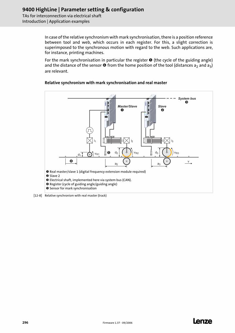
9400 HighLine | Parameter setting & configurationTAs for interconnection via electrical shaftIntroduction | Application examples
296 Firmware 1.37 - 09/2006 L
In case of the relative synchronism with mark synchronisation, there is a position reference between tool and web, which occurs in each register. For this, a slight correction is superimposed to the synchronous motion with regard to the web. Such applications are, for instance, printing machines.
For the mark synchronisation in particular the register (the cycle of the guiding angle) and the distance of the sensor from the home position of the tool (distances a2 and a3) are relevant.
Relative synchronism with mark synchronisation and real master
[12-8] Relative synchronism with real master (track)
Real master/slave 1 (digital frequency extension module required) Slave 2 Electrical shaft, implemented here via system bus (CAN). Register (cycle of guiding angle/guiding angle) Sensor for mark synchronisation
i
Slave
d vd vR1
R31
3
i1 3
�
System bus
v
i
Master/Slave
d vR22
2
�
�
a2 a3
�
�
L Firmware 1.37 - 09/2006 297
9400 HighLine | Parameter setting & configurationTAs for interconnection via electrical shaft
TA "Electronic gearbox"
12.2 TA "Electronic gearbox"
The technology application "Electronic gearbox" serves to implement a synchronism with adjustable stretching ratio between the drives in the system.
The ratio can be freely adjusted, the values are input in the form of a fraction (numerator/denominator) with 32 bit resolution.
The master value can be specified either by a "Virtual master", or via a bus system or the digital frequency extension module. It is selected from the Application parameter tab via the Master value source list field (C03052).
The master value transmission (high speed stability) is preset. The actual values can be transmitted by the corresponding selection in the list fields Master value output (C3054/1, C3054/2, C3197).
Functions
Virtual master with inching, handwheel and reduced speed.
Master value conditioning (master shaft) with master value scaling, stretch factor and reversal of rotation direction.
Virtual clutch with emergency stop and basic speed
Trimming function via profile generator.
Master value conditioning (machine axis/tool) with setpoint scaling.
Additional operating modes for activating the basic drive functions "Homing", "Manual jog (inching)" and "Position override function".
Support of the basic drive functions "Quick stop" and "Limiter".
Following error monitoring.
Optional control of a holding brake.
Note!
The electrical shaft can be implemented with a bus system as e.g. system bus (CAN) or Ethernet Powerlink or via digital frequency transmission.
With regard to the configuration of the digital frequency extension module in the controller, two variants of technology applications are available in the »Engineer« application catalog.
• In the TA variant "Electronic gearbox" the configuration of a digital frequency extension module is expected. Therefore, the TA can provide the function of the electrical shaft either via digital frequency transmission and via a bus system.
• In the TA variant "Electronic gearbox MotionBus" the configuration of a digital frequency extension module is not included and corresponding interfaces are not available in the TA. Thus the function of the electrical shaft with this TA can only be provided via a bus system.
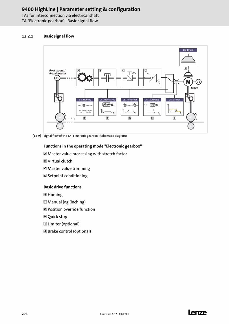
9400 HighLine | Parameter setting & configurationTAs for interconnection via electrical shaftTA "Electronic gearbox" | Basic signal flow
298 Firmware 1.37 - 09/2006 L
12.2.1 Basic signal flow
[12-9] Signal flow of the TA "Electronic gearbox" (schematic diagram)
Functions in the operating mode "Electronic gearbox"
Master value processing with stretch factor
Virtual clutch
Master value trimming
Setpoint conditioning
Basic drive functions
Homing
Manual jog (inching)
Position override function
Quick stop
Limiter (optional)
Brake control (optional)
v
t
v
M
v
Slave
LS_ManualJog
n
t
��
n
t
LS_Positioner
0-100 100 200
LS_Homing
� � �
LS_Brake
n
t
LS_Limiter
n
t
LS_Quickstop
STOP
�
Real master/
Virtual master� � � �
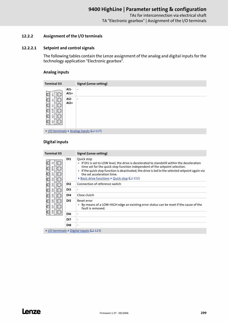
L Firmware 1.37 - 09/2006 299
9400 HighLine | Parameter setting & configurationTAs for interconnection via electrical shaft
TA "Electronic gearbox" | Assignment of the I/O terminals
12.2.2 Assignment of the I/O terminals
12.2.2.1 Setpoint and control signals
The following tables contain the Lenze assignment of the analog and digital inputs for the technology application "Electronic gearbox".
Analog inputs
Digital inputs
Terminal X3 Signal (Lenze setting)
AI1-AI1+
-
AI2-AI2+
-
I/O terminals Analog inputs ( 117)
Terminal X5 Signal (Lenze setting)
DI1 Quick stop • If DI1 is set to LOW level, the drive is decelerated to standstill within the deceleration
time set for the quick stop function independent of the setpoint selection. • If the quick stop function is deactivated, the drive is led to the selected setpoint again via
the set acceleration time.Basic drive functions Quick stop ( 152)
DI2 Connection of reference switch
DI3 -
DI4 Close clutch
DI5 Reset error • By means of a LOW-HIGH edge an existing error status can be reset if the cause of the
fault is removed.
DI6 -
DI7 -
DI8 -
I/O terminals Digital inputs ( 123)
A1
+A
1-
A1
-A
1R
A2
+A
2-
GI
RF
RD
I1D
I2D
I3D
I4D
I5D
I6D
I7D
I8
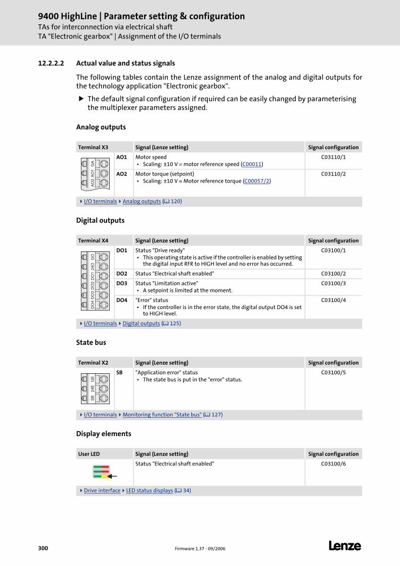
9400 HighLine | Parameter setting & configurationTAs for interconnection via electrical shaftTA "Electronic gearbox" | Assignment of the I/O terminals
300 Firmware 1.37 - 09/2006 L
12.2.2.2 Actual value and status signals
The following tables contain the Lenze assignment of the analog and digital outputs for the technology application "Electronic gearbox".
The default signal configuration if required can be easily changed by parameterising the multiplexer parameters assigned.
Analog outputs
Digital outputs
State bus
Display elements
Terminal X3 Signal (Lenze setting) Signal configuration
AO1 Motor speed • Scaling: ±10 V ≡ motor reference speed (C00011)
C03110/1
AO2 Motor torque (setpoint) • Scaling: ±10 V ≡ Motor reference torque (C00057/2)
C03110/2
I/O terminals Analog outputs ( 120)
Terminal X4 Signal (Lenze setting) Signal configuration
DO1 Status "Drive ready" • This operating state is active if the controller is enabled by setting
the digital input RFR to HIGH level and no error has occurred.
C03100/1
DO2 Status "Electrical shaft enabled" C03100/2
DO3 Status "Limitation active" • A setpoint is limited at the moment.
C03100/3
DO4 "Error" status • If the controller is in the error state, the digital output DO4 is set
to HIGH level.
C03100/4
I/O terminals Digital outputs ( 125)
Terminal X2 Signal (Lenze setting) Signal configuration
SB "Application error" status • The state bus is put in the "error" status.
C03100/5
I/O terminals Monitoring function "State bus" ( 127)
User LED Signal (Lenze setting) Signal configuration
Status "Electrical shaft enabled" C03100/6
Drive interface LED status displays ( 34)
GA
AO
1A
O2
GO
24
OD
O1
DO
2D
O3
DO
4G
E2
4E
SB
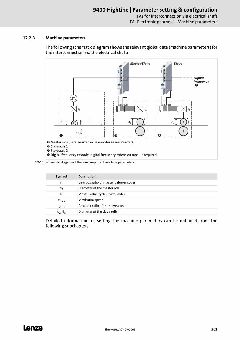
L Firmware 1.37 - 09/2006 301
9400 HighLine | Parameter setting & configurationTAs for interconnection via electrical shaft
TA "Electronic gearbox" | Machine parameters
12.2.3 Machine parameters
The following schematic diagram shows the relevant global data (machine parameters) for the interconnection via the electrical shaft:
[12-10] Schematic diagram of the most important machine parameters
Detailed information for setting the machine parameters can be obtained from the following subchapters.
Master axis (here: master value encoder as real master) Slave axis 1 Slave axis 2 Digital frequency cascade (digital frequency extension module required)
d d1 3
i1 i3
l1
vmax
��
d2
i2
�
SlaveMaster/Slave
Digitalfrequency
�
Symbol Description
i1 Gearbox ratio of master value encoder
d1 Diameter of the master roll
l1 Master value cycle (if available)
vmax Maximum speed
i2, i3 Gearbox ratio of the slave axes
d2, d3 Diameter of the slave rolls
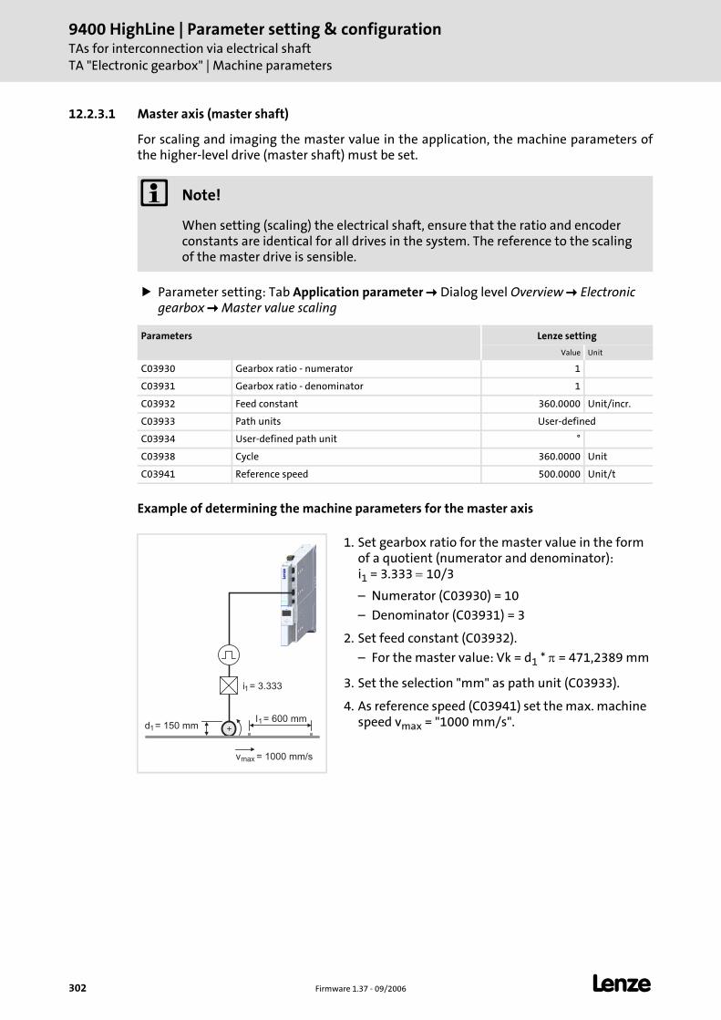
9400 HighLine | Parameter setting & configurationTAs for interconnection via electrical shaftTA "Electronic gearbox" | Machine parameters
302 Firmware 1.37 - 09/2006 L
12.2.3.1 Master axis (master shaft)
For scaling and imaging the master value in the application, the machine parameters of the higher-level drive (master shaft) must be set.
Parameter setting: Tab Application parameter Dialog level Overview Electronic gearbox Master value scaling
Example of determining the machine parameters for the master axis
Note!
When setting (scaling) the electrical shaft, ensure that the ratio and encoder constants are identical for all drives in the system. The reference to the scaling of the master drive is sensible.
Parameters Lenze setting
Value Unit
C03930 Gearbox ratio - numerator 1
C03931 Gearbox ratio - denominator 1
C03932 Feed constant 360.0000 Unit/incr.
C03933 Path units User-defined
C03934 User-defined path unit °
C03938 Cycle 360.0000 Unit
C03941 Reference speed 500.0000 Unit/t
1. Set gearbox ratio for the master value in the form of a quotient (numerator and denominator): i1 = 3.333 = 10/3
– Numerator (C03930) = 10
– Denominator (C03931) = 3
2. Set feed constant (C03932).
– For the master value: Vk = d1 * π = 471,2389 mm
3. Set the selection "mm" as path unit (C03933).
4. As reference speed (C03941) set the max. machine speed vmax = "1000 mm/s".d1
i1
= 150 mm
= 3.333
l1= 600 mm
vmax = 1000 mm/s
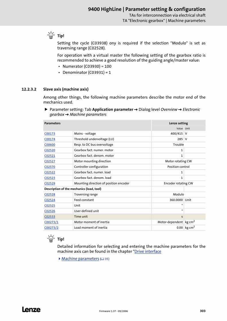
L Firmware 1.37 - 09/2006 303
9400 HighLine | Parameter setting & configurationTAs for interconnection via electrical shaft
TA "Electronic gearbox" | Machine parameters
Tip!
Setting the cycle (C03938) ony is required if the selection "Modulo" is set as traversing range (C02528).
For operation with a virtual master the following setting of the gearbox ratio is recommended to achieve a good resolution of the guiding angle/master value:
• Numerator (C03930) = 100
• Denominator (C03931) = 1
12.2.3.2 Slave axis (machine axis)
Among other things, the following machine parameters describe the motor end of the mechanics used.
Parameter setting: Tab Application parameter Dialog level Overview Electronic gearbox Machine parameters
Tip!
Detailed information for selecting and entering the machine parameters for the machine axis can be found in the chapter "Drive interface
Machine parameters ( 35)
Parameters Lenze setting
Value Unit
C00173 Mains - voltage 400/415 V
C00174 Threshold undervoltage (LU) 285 V
C00600 Resp. to DC bus overvoltage Trouble
C02520 Gearbox fact. numer. motor 1
C02521 Gearbox fact. denom. motor 1
C02527 Motor mounting direction Motor rotating CW
C02570 Controller configuration Position control
C02522 Gearbox fact. numer. load 1
C02523 Gearbox fact. denom. load 1
C02529 Mounting direction of position encoder Encoder rotating CW
Description of the mechanics (load, tool)
C02528 Traversing range Modulo
C02524 Feed constant 360.0000 Unit
C02525 Unit °
C02526 User-defined unit °
C02533 Time unit s
C00273/1 Motor moment of inertia Motor-dependent kg cm2
C00273/2 Load moment of inertia 0.00 kg cm2
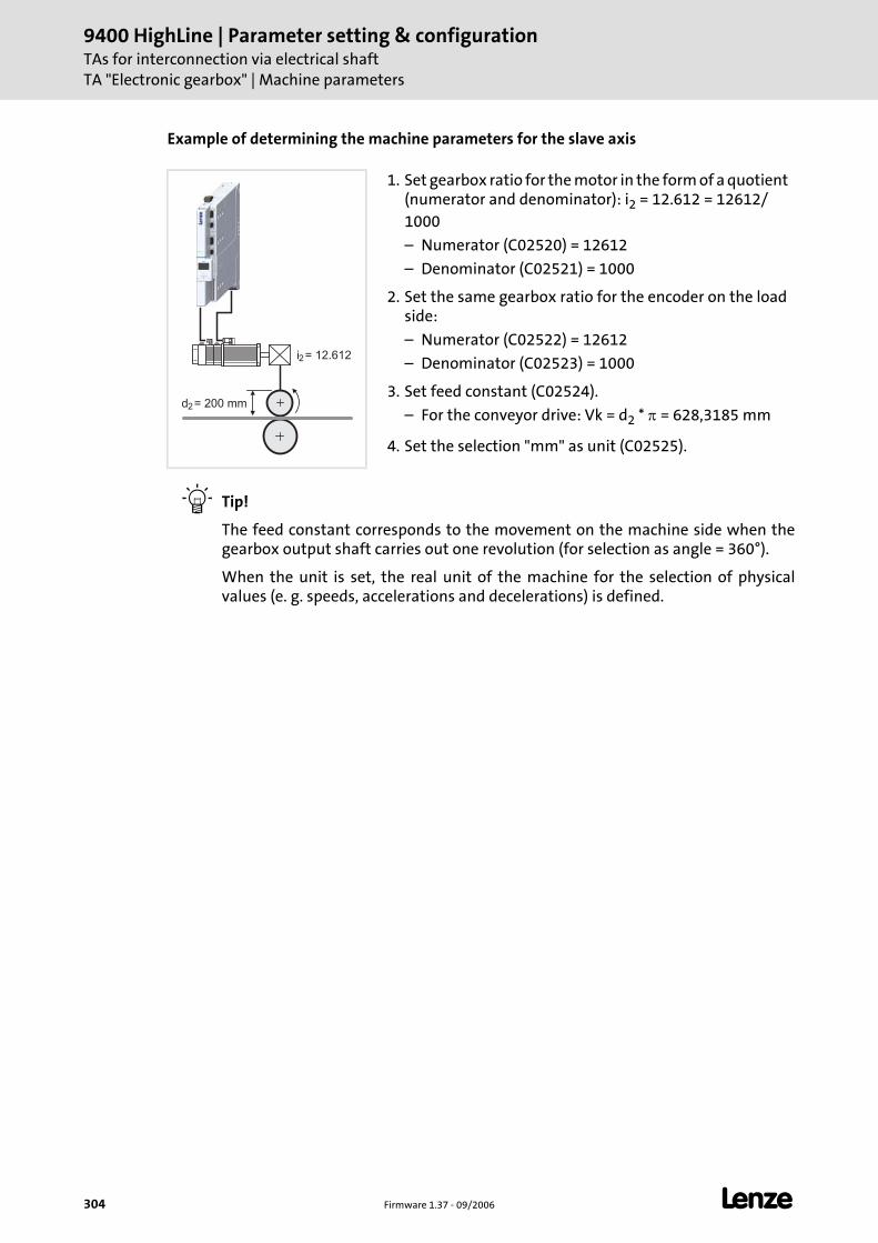
9400 HighLine | Parameter setting & configurationTAs for interconnection via electrical shaftTA "Electronic gearbox" | Machine parameters
304 Firmware 1.37 - 09/2006 L
Example of determining the machine parameters for the slave axis
Tip!
The feed constant corresponds to the movement on the machine side when the gearbox output shaft carries out one revolution (for selection as angle = 360°).
When the unit is set, the real unit of the machine for the selection of physical values (e. g. speeds, accelerations and decelerations) is defined.
1. Set gearbox ratio for the motor in the form of a quotient (numerator and denominator): i2 = 12.612 = 12612/1000
– Numerator (C02520) = 12612
– Denominator (C02521) = 1000
2. Set the same gearbox ratio for the encoder on the load side:
– Numerator (C02522) = 12612
– Denominator (C02523) = 1000
3. Set feed constant (C02524).
– For the conveyor drive: Vk = d2 * π = 628,3185 mm
4. Set the selection "mm" as unit (C02525).
d2
i2
= 200 mm
= 12.612
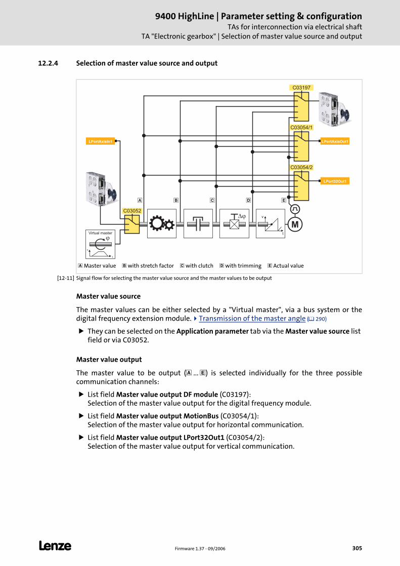
L Firmware 1.37 - 09/2006 305
9400 HighLine | Parameter setting & configurationTAs for interconnection via electrical shaft
TA "Electronic gearbox" | Selection of master value source and output
12.2.4 Selection of master value source and output
[12-11] Signal flow for selecting the master value source and the master values to be output
Master value source
The master values can be either selected by a "Virtual master", via a bus system or the digital frequency extension module. Transmission of the master angle ( 290)
They can be selected on the Application parameter tab via the Master value source list field or via C03052.
Master value output
The master value to be output ( ... ) is selected individually for the three possible communication channels:
List field Master value output DF module (C03197): Selection of the master value output for the digital frequency module.
List field Master value output MotionBus (C03054/1): Selection of the master value output for horizontal communication.
List field Master value output LPort32Out1 (C03054/2): Selection of the master value output for vertical communication.
Master value with stretch factor with clutch with trimming Actual value
v
t
�
�
M
� � �
�
v
t
Virtual master
LPortAxisIn1 LPortAxisOut1
C03054/2
C03197
C03054/1
C03052
LPort32Out1
�
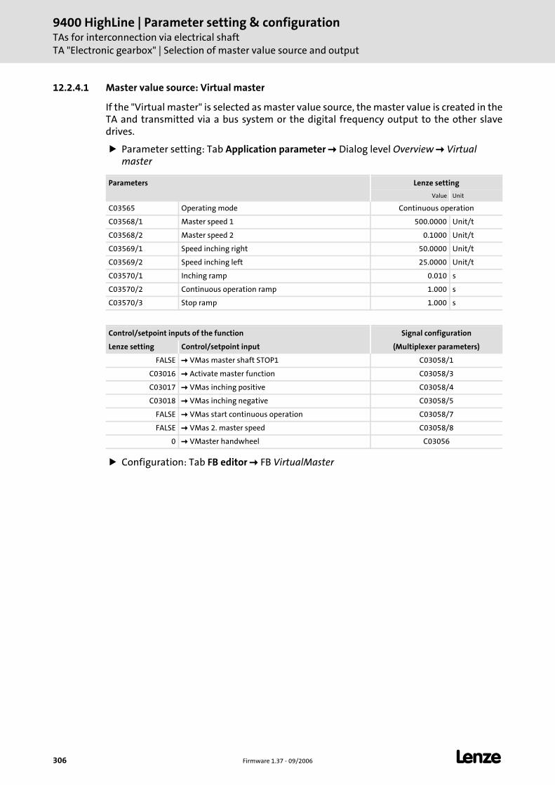
9400 HighLine | Parameter setting & configurationTAs for interconnection via electrical shaftTA "Electronic gearbox" | Selection of master value source and output
306 Firmware 1.37 - 09/2006 L
12.2.4.1 Master value source: Virtual master
If the "Virtual master" is selected as master value source, the master value is created in the TA and transmitted via a bus system or the digital frequency output to the other slave drives.
Parameter setting: Tab Application parameter Dialog level Overview Virtual master
Configuration: Tab FB editor FB VirtualMaster
Parameters Lenze setting
Value Unit
C03565 Operating mode Continuous operation
C03568/1 Master speed 1 500.0000 Unit/t
C03568/2 Master speed 2 0.1000 Unit/t
C03569/1 Speed inching right 50.0000 Unit/t
C03569/2 Speed inching left 25.0000 Unit/t
C03570/1 Inching ramp 0.010 s
C03570/2 Continuous operation ramp 1.000 s
C03570/3 Stop ramp 1.000 s
Control/setpoint inputs of the function Signal configuration
Lenze setting Control/setpoint input (Multiplexer parameters)
FALSE VMas master shaft STOP1 C03058/1
C03016 Activate master function C03058/3
C03017 VMas inching positive C03058/4
C03018 VMas inching negative C03058/5
FALSE VMas start continuous operation C03058/7
FALSE VMas 2. master speed C03058/8
0 VMaster handwheel C03056
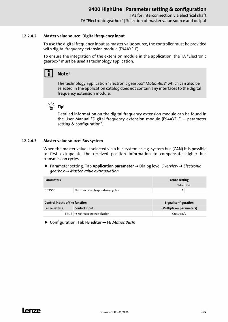
L Firmware 1.37 - 09/2006 307
9400 HighLine | Parameter setting & configurationTAs for interconnection via electrical shaft
TA "Electronic gearbox" | Selection of master value source and output
12.2.4.2 Master value source: Digital frequency input
To use the digital frequency input as master value source, the controller must be provided with digital frequency extension module (E94AYFLF).
To ensure the integration of the extension module in the application, the TA "Electronic gearbox" must be used as technology application.
Tip!
Detailed information on the digital frequency extension module can be found in the User Manual "Digital frequency extension module (E94AYFLF) – parameter setting & configuration".
12.2.4.3 Master value source: Bus system
When the master value is selected via a bus system as e.g. system bus (CAN) it is possible to first extrapolate the received position information to compensate higher bus transmission cycles.
Parameter setting: Tab Application parameter Dialog level Overview Electronic gearbox Master value extrapolation
Configuration: Tab FB editor FB MotionBusIn
Note!
The technology application "Electronic gearbox" MotionBus" which can also be selected in the application catalog does not contain any interfaces to the digital frequency extension module.
Parameters Lenze setting
Value Unit
C03550 Number of extrapolation cycles 1
Control inputs of the function Signal configuration
Lenze setting Control input (Multiplexer parameters)
TRUE Activate extrapolation C03058/9
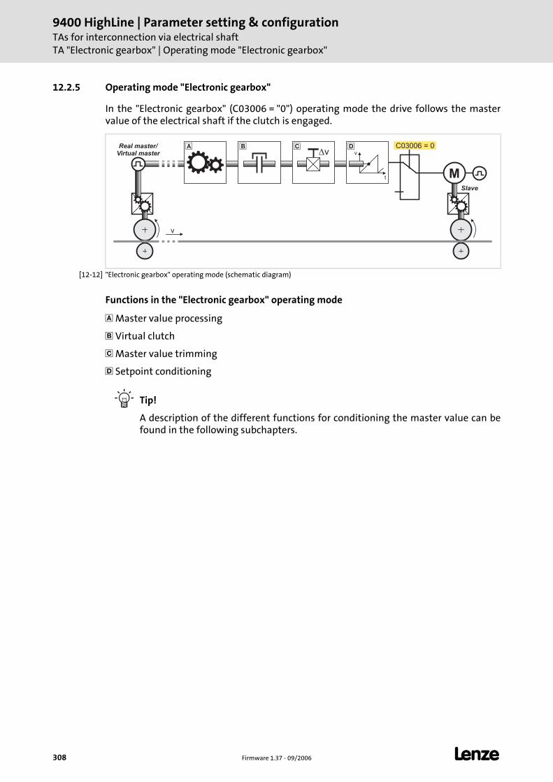
9400 HighLine | Parameter setting & configurationTAs for interconnection via electrical shaftTA "Electronic gearbox" | Operating mode "Electronic gearbox"
308 Firmware 1.37 - 09/2006 L
12.2.5 Operating mode "Electronic gearbox"
In the "Electronic gearbox" (C03006 = "0") operating mode the drive follows the master value of the electrical shaft if the clutch is engaged.
[12-12] "Electronic gearbox" operating mode (schematic diagram)
Functions in the "Electronic gearbox" operating mode
Master value processing
Virtual clutch
Master value trimming
Setpoint conditioning
Tip!
A description of the different functions for conditioning the master value can be found in the following subchapters.
M
v
Slave
Real master/Virtual master v
t
vC03006 = 0� � � �
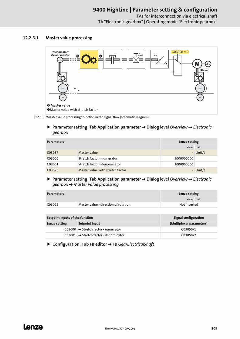
L Firmware 1.37 - 09/2006 309
9400 HighLine | Parameter setting & configurationTAs for interconnection via electrical shaft
TA "Electronic gearbox" | Operating mode "Electronic gearbox"
12.2.5.1 Master value processing
[12-13] "Master value processing" function in the signal flow (schematic diagram)
Parameter setting: Tab Application parameter Dialog level Overview Electronic gearbox
Parameter setting: Tab Application parameter Dialog level Overview Electronic gearbox Master value processing
Configuration: Tab FB editor FB GearElectricalShaft
Master valueMaster value with stretch factor
M
v
Slave
Real master/Virtual master v
t
�C03006 = 0
� �
Parameters Lenze setting
Value Unit
C03957 Master value - Unit/t
C03000 Stretch factor - numerator 1000000000
C03001 Stretch factor - denominator 1000000000
C03673 Master value with stretch factor - Unit/t
Parameters Lenze setting
Value Unit
C03025 Master value - direction of rotation Not inverted
Setpoint inputs of the function Signal configuration
Lenze setting Setpoint input (Multiplexer parameters)
C03000 Stretch factor - numerator C03050/1
C03001 Stretch factor - denominator C03050/2
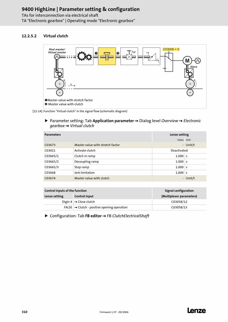
9400 HighLine | Parameter setting & configurationTAs for interconnection via electrical shaftTA "Electronic gearbox" | Operating mode "Electronic gearbox"
310 Firmware 1.37 - 09/2006 L
12.2.5.2 Virtual clutch
[12-14] Function "Virtual clutch" in the signal flow (schematic diagram)
Parameter setting: Tab Application parameter Dialog level Overview Electronic gearbox Virtual clutch
Configuration: Tab FB editor FB ClutchElectricalShaft
Master value with stretch factor Master value with clutch
M
v
Slave
Real master/Virtual master v
t
vC03006 = 0
� �
Parameters Lenze setting
Value Unit
C03673 Master value with stretch factor - Unit/t
C03021 Activate clutch Deactivated
C03665/1 Clutch in ramp 1.000 s
C03665/2 Decoupling ramp 1.000 s
C03665/3 Stop ramp 1.000 s
C03668 Jerk limitation 1.000 s
C03674 Master value with clutch - Unit/t
Control inputs of the function Signal configuration
Lenze setting Control input (Multiplexer parameters)
DigIn 4 Close clutch C03058/12
FALSE Clutch - positive opening operation C03058/13
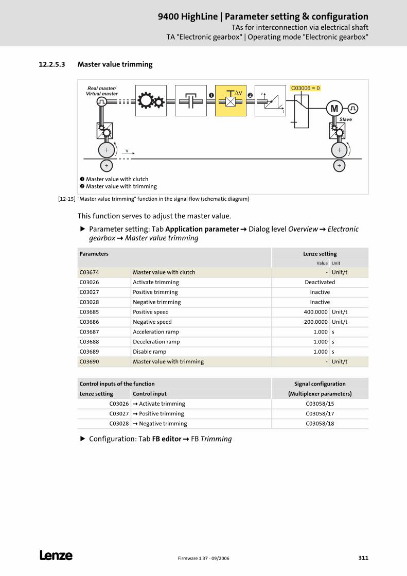
L Firmware 1.37 - 09/2006 311
9400 HighLine | Parameter setting & configurationTAs for interconnection via electrical shaft
TA "Electronic gearbox" | Operating mode "Electronic gearbox"
12.2.5.3 Master value trimming
[12-15] "Master value trimming" function in the signal flow (schematic diagram)
This function serves to adjust the master value.
Parameter setting: Tab Application parameter Dialog level Overview Electronic gearbox Master value trimming
Configuration: Tab FB editor FB Trimming
Master value with clutch Master value with trimming
M
v
Slave
Real master/Virtual master v
t
vC03006 = 0
� �
Parameters Lenze setting
Value Unit
C03674 Master value with clutch - Unit/t
C03026 Activate trimming Deactivated
C03027 Positive trimming Inactive
C03028 Negative trimming Inactive
C03685 Positive speed 400.0000 Unit/t
C03686 Negative speed -200.0000 Unit/t
C03687 Acceleration ramp 1.000 s
C03688 Deceleration ramp 1.000 s
C03689 Disable ramp 1.000 s
C03690 Master value with trimming - Unit/t
Control inputs of the function Signal configuration
Lenze setting Control input (Multiplexer parameters)
C03026 Activate trimming C03058/15
C03027 Positive trimming C03058/17
C03028 Negative trimming C03058/18
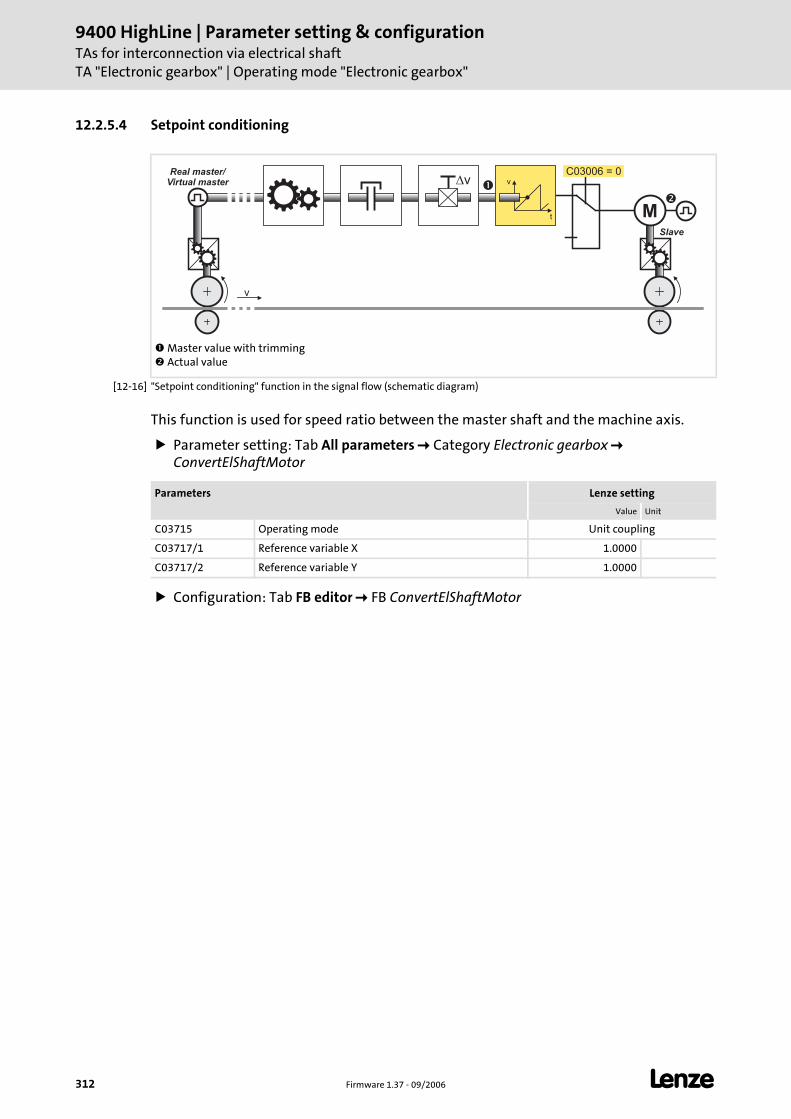
9400 HighLine | Parameter setting & configurationTAs for interconnection via electrical shaftTA "Electronic gearbox" | Operating mode "Electronic gearbox"
312 Firmware 1.37 - 09/2006 L
12.2.5.4 Setpoint conditioning
[12-16] "Setpoint conditioning" function in the signal flow (schematic diagram)
This function is used for speed ratio between the master shaft and the machine axis.
Parameter setting: Tab All parameters Category Electronic gearbox ConvertElShaftMotor
Configuration: Tab FB editor FB ConvertElShaftMotor
Master value with trimming Actual value
M
v
Slave
Real master/Virtual master v
t
vC03006 = 0
�
�
Parameters Lenze setting
Value Unit
C03715 Operating mode Unit coupling
C03717/1 Reference variable X 1.0000
C03717/2 Reference variable Y 1.0000
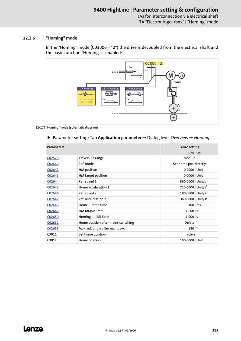
L Firmware 1.37 - 09/2006 313
9400 HighLine | Parameter setting & configurationTAs for interconnection via electrical shaft
TA "Electronic gearbox" | "Homing" mode
12.2.6 "Homing" mode
In the "Homing" mode (C03006 = "2") the drive is decoupled from the electrical shaft and the basic function "Homing" is enabled:
[12-17] "Homing" mode (schematic diagram)
Parameter setting: Tab Application parameter Dialog level Overview Homing
v
t
LS_ManualJog
n
t
��
n
t
LS_Positioner
0-100 100 200
LS_Homing
C03006 = 2
t MSlave
Parameters Lenze setting
Value Unit
C02528 Traversing range Modulo
C02640 Ref. mode Set home pos. directly
C02642 HM position 0.0000 Unit
C02643 HM target position 0.0000 Unit
C02644 Ref. speed 1 360.0000 Unit/s
C02645 Home acceleration 1 720.0000 Unit/s2
C02646 Ref. speed 2 180.0000 Unit/s
C02647 Ref. acceleration 2 360.0000 Unit/s2
C02648 Home S-ramp time 100 ms
C02649 HM torque limit 10.00 %
C02650 Homing inhibit time 1.000 s
C02652 Home position after mains switching Delete
C02653 Max. rot. angle after mains sw. 180 °
C3011 Set home position Inactive
C3012 Home position 100.0000 Unit
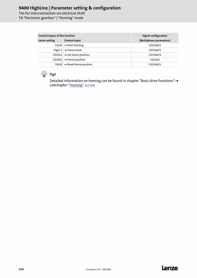
9400 HighLine | Parameter setting & configurationTAs for interconnection via electrical shaftTA "Electronic gearbox" | "Homing" mode
314 Firmware 1.37 - 09/2006 L
Tip!
Detailed information on homing can be found in chapter "Basic drive functions" subchapter "Homing". ( 164)
Control inputs of the function Signal configuration
Lenze setting Control input (Multiplexer parameters)
FALSE Start homing C03160/2
DigIn 2 Home mark C03160/3
C03011 Set home position C03160/4
C03012 Home position C03163
FALSE Reset home position C03160/5
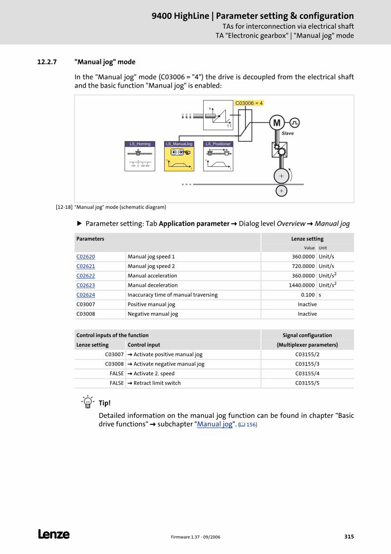
L Firmware 1.37 - 09/2006 315
9400 HighLine | Parameter setting & configurationTAs for interconnection via electrical shaft
TA "Electronic gearbox" | "Manual jog" mode
12.2.7 "Manual jog" mode
In the "Manual jog" mode (C03006 = "4") the drive is decoupled from the electrical shaft and the basic function "Manual jog" is enabled:
[12-18] "Manual jog" mode (schematic diagram)
Parameter setting: Tab Application parameter Dialog level Overview Manual jog
Tip!
Detailed information on the manual jog function can be found in chapter "Basic drive functions" subchapter "Manual jog". ( 156)
v
t
LS_ManualJog
n
t
��
n
t
LS_Positioner
0-100 100 200
LS_Homing
C03006 = 4
t MSlave
Parameters Lenze setting
Value Unit
C02620 Manual jog speed 1 360.0000 Unit/s
C02621 Manual jog speed 2 720.0000 Unit/s
C02622 Manual acceleration 360.0000 Unit/s2
C02623 Manual deceleration 1440.0000 Unit/s2
C02624 Inaccuracy time of manual traversing 0.100 s
C03007 Positive manual jog Inactive
C03008 Negative manual jog Inactive
Control inputs of the function Signal configuration
Lenze setting Control input (Multiplexer parameters)
C03007 Activate positive manual jog C03155/2
C03008 Activate negative manual jog C03155/3
FALSE Activate 2. speed C03155/4
FALSE Retract limit switch C03155/5
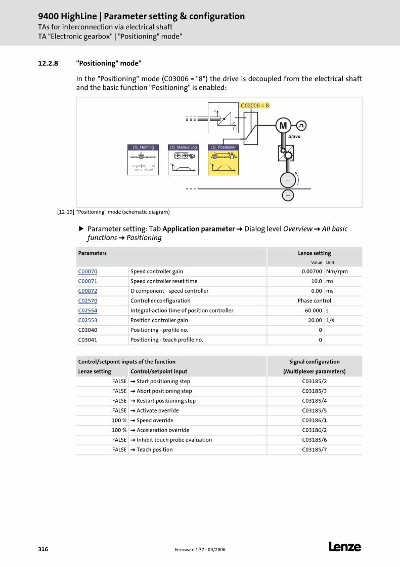
9400 HighLine | Parameter setting & configurationTAs for interconnection via electrical shaftTA "Electronic gearbox" | "Positioning" mode"
316 Firmware 1.37 - 09/2006 L
12.2.8 "Positioning" mode"
In the "Positioning" mode (C03006 = "8") the drive is decoupled from the electrical shaft and the basic function "Positioning" is enabled:
[12-19] "Positioning" mode (schematic diagram)
Parameter setting: Tab Application parameter Dialog level Overview All basic functions Positioning
v
t
LS_ManualJog
n
t
��
n
t
LS_Positioner
0-100 100 200
LS_Homing
C03006 = 8
t MSlave
Parameters Lenze setting
Value Unit
C00070 Speed controller gain 0.00700 Nm/rpm
C00071 Speed controller reset time 10.0 ms
C00072 D component - speed controller 0.00 ms
C02570 Controller configuration Phase control
C02554 Integral-action time of position controller 60.000 s
C02553 Position controller gain 20.00 1/s
C03040 Positioning - profile no. 0
C03041 Positioning - teach profile no. 0
Control/setpoint inputs of the function Signal configuration
Lenze setting Control/setpoint input (Multiplexer parameters)
FALSE Start positioning step C03185/2
FALSE Abort positioning step C03185/3
FALSE Restart positioning step C03185/4
FALSE Activate override C03185/5
100 % Speed override C03186/1
100 % Acceleration override C03186/2
FALSE Inhibit touch probe evaluation C03185/6
FALSE Teach position C03185/7

L Firmware 1.37 - 09/2006 317
9400 HighLine | Parameter setting & configurationTAs for interconnection via electrical shaft
TA "Electronic gearbox" | "Positioning" mode"
Profile data record management
For the profile data record management the FB L_PosProfileTable is used. This FB serves to file and manage up to four (travel) profiles and to "teach" target positions.
A profile describes a motion request which can be implemented by the SB LS_Positioner into a rotary motion.
A profile is described via the following profile parameters: Mode (type of positioning), position, speed, acceleration, deceleration, S-ramp time, standard sequence profile, TP sequence profile and TP selection.
The data of the profile parameters is directly input in the assigned codes:
"Teach" position
When the control input "Teach position" is set to TRUE, the current tool position is saved in the profile the number of which is set in C03041. After the control input is reset to FALSE the position saved last is maintained in the profile.
Profile parameters Unit Profile no. 1 Profile no. 2 Profile no. 3 Profile no. 4
Positioning mode - C03970/1 C03970/2 C03970/3 C03970/4
Position Unit Set position C03971/2 C03971/3 C03971/4
Speed Unit/t C03972/1 C03972/2 C03972/3 C03972/4
Acceleration Unit/t2 C03973/1 C03973/2 C03973/3 C03973/4
Delay Unit/t2 C03974/1 C03974/2 C03974/3 C03974/4
S-ramp time s C03975/1 C03975/2 C03975/3 C03975/4
TP sequence profile - C03976/1 C03976/2 C03976/3 C03976/4
TP selection - C03977/1 C03977/2 C03977/3 C03977/4
Note!
For profile no. 1 the set position of the tool which belongs to the master position is always used as target position.
• Application: Returning the tool e.g. from a maintenance position to the network.
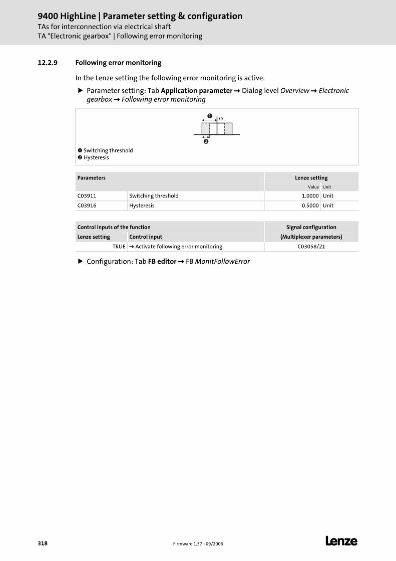
9400 HighLine | Parameter setting & configurationTAs for interconnection via electrical shaftTA "Electronic gearbox" | Following error monitoring
318 Firmware 1.37 - 09/2006 L
12.2.9 Following error monitoring
In the Lenze setting the following error monitoring is active.
Parameter setting: Tab Application parameter Dialog level Overview Electronic gearbox Following error monitoring
Configuration: Tab FB editor FB MonitFollowError
Switching threshold Hysteresis
Parameters Lenze setting
Value Unit
C03911 Switching threshold 1.0000 Unit
C03916 Hysteresis 0.5000 Unit
Control inputs of the function Signal configuration
Lenze setting Control input (Multiplexer parameters)
TRUE Activate following error monitoring C03058/21
��
�
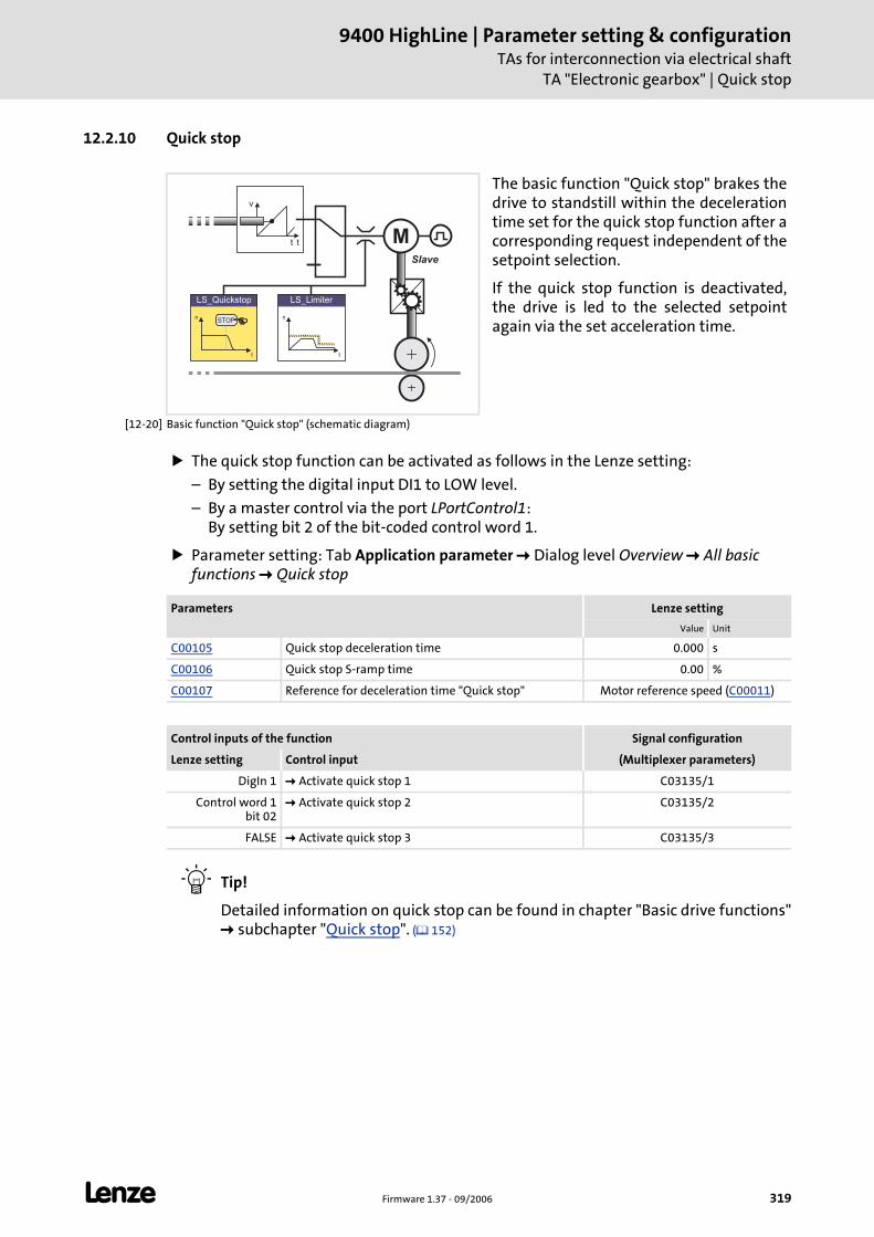
L Firmware 1.37 - 09/2006 319
9400 HighLine | Parameter setting & configurationTAs for interconnection via electrical shaft
TA "Electronic gearbox" | Quick stop
12.2.10 Quick stop
[12-20] Basic function "Quick stop" (schematic diagram)
The quick stop function can be activated as follows in the Lenze setting:
– By setting the digital input DI1 to LOW level.
– By a master control via the port LPortControl1: By setting bit 2 of the bit-coded control word 1.
Parameter setting: Tab Application parameter Dialog level Overview All basic functions Quick stop
Tip!
Detailed information on quick stop can be found in chapter "Basic drive functions" subchapter "Quick stop". ( 152)
The basic function "Quick stop" brakes the drive to standstill within the deceleration time set for the quick stop function after a corresponding request independent of the setpoint selection.
If the quick stop function is deactivated, the drive is led to the selected setpoint again via the set acceleration time.
v
tt MSlave
n
t
LS_Limiter
n
t
LS_Quickstop
STOP
Parameters Lenze setting
Value Unit
C00105 Quick stop deceleration time 0.000 s
C00106 Quick stop S-ramp time 0.00 %
C00107 Reference for deceleration time "Quick stop" Motor reference speed (C00011)
Control inputs of the function Signal configuration
Lenze setting Control input (Multiplexer parameters)
DigIn 1 Activate quick stop 1 C03135/1
Control word 1 bit 02
Activate quick stop 2 C03135/2
FALSE Activate quick stop 3 C03135/3
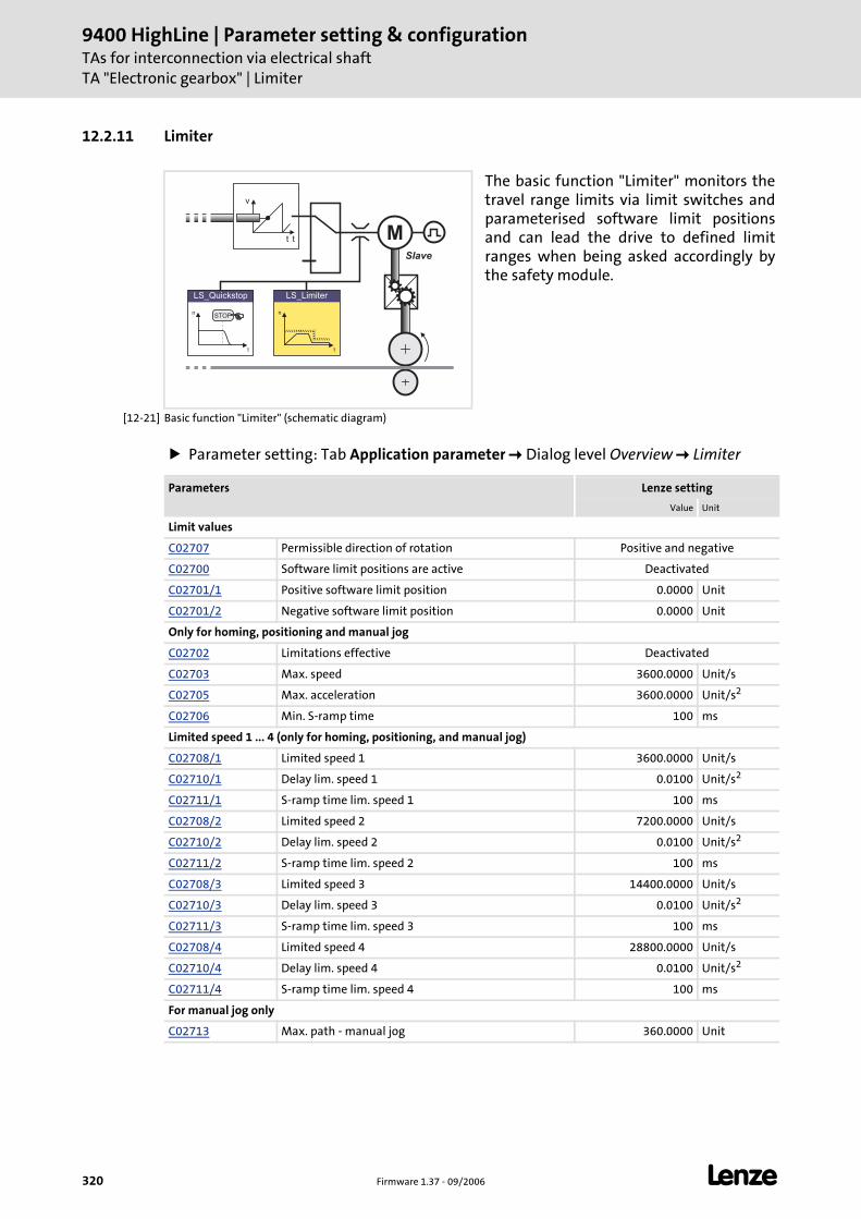
9400 HighLine | Parameter setting & configurationTAs for interconnection via electrical shaftTA "Electronic gearbox" | Limiter
320 Firmware 1.37 - 09/2006 L
12.2.11 Limiter
[12-21] Basic function "Limiter" (schematic diagram)
Parameter setting: Tab Application parameter Dialog level Overview Limiter
The basic function "Limiter" monitors the travel range limits via limit switches and parameterised software limit positions and can lead the drive to defined limit ranges when being asked accordingly by the safety module.
v
tt MSlave
n
t
LS_Limiter
n
t
LS_Quickstop
STOP
Parameters Lenze setting
Value Unit
Limit values
C02707 Permissible direction of rotation Positive and negative
C02700 Software limit positions are active Deactivated
C02701/1 Positive software limit position 0.0000 Unit
C02701/2 Negative software limit position 0.0000 Unit
Only for homing, positioning and manual jog
C02702 Limitations effective Deactivated
C02703 Max. speed 3600.0000 Unit/s
C02705 Max. acceleration 3600.0000 Unit/s2
C02706 Min. S-ramp time 100 ms
Limited speed 1 ... 4 (only for homing, positioning, and manual jog)
C02708/1 Limited speed 1 3600.0000 Unit/s
C02710/1 Delay lim. speed 1 0.0100 Unit/s2
C02711/1 S-ramp time lim. speed 1 100 ms
C02708/2 Limited speed 2 7200.0000 Unit/s
C02710/2 Delay lim. speed 2 0.0100 Unit/s2
C02711/2 S-ramp time lim. speed 2 100 ms
C02708/3 Limited speed 3 14400.0000 Unit/s
C02710/3 Delay lim. speed 3 0.0100 Unit/s2
C02711/3 S-ramp time lim. speed 3 100 ms
C02708/4 Limited speed 4 28800.0000 Unit/s
C02710/4 Delay lim. speed 4 0.0100 Unit/s2
C02711/4 S-ramp time lim. speed 4 100 ms
For manual jog only
C02713 Max. path - manual jog 360.0000 Unit
L Firmware 1.37 - 09/2006 321
9400 HighLine | Parameter setting & configurationTAs for interconnection via electrical shaft
TA "Electronic gearbox" | Limiter
Tip!
Detailed information on the limiter function can be found in chapter "Basic drive functions" subchapter "Limiter". ( 200)
Control inputs of the function Signal configuration
Lenze setting Control input (Multiplexer parameters)
FALSE Positive limit switch C03150/1
FALSE Negative limit switch C03150/2
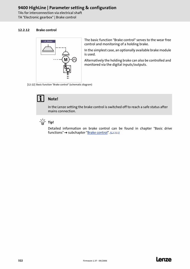
9400 HighLine | Parameter setting & configurationTAs for interconnection via electrical shaftTA "Electronic gearbox" | Brake control
322 Firmware 1.37 - 09/2006 L
12.2.12 Brake control
[12-22] Basic function "Brake control" (schematic diagram)
Tip!
Detailed information on brake control can be found in chapter "Basic drive functions" subchapter "Brake control". ( 211)
The basic function "Brake control" serves to the wear free control and monitoring of a holding brake.
In the simplest case, an optionally available brake module is used.
Alternatively the holding brake can also be controlled and monitored via the digital inputs/outputs.
M
LS_Brake
Note!
In the Lenze setting the brake control is switched off to reach a safe status after mains connection.
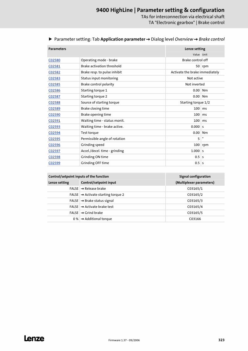
L Firmware 1.37 - 09/2006 323
9400 HighLine | Parameter setting & configurationTAs for interconnection via electrical shaft
TA "Electronic gearbox" | Brake control
Parameter setting: Tab Application parameter Dialog level Overview Brake control
Parameters Lenze setting
Value Unit
C02580 Operating mode - brake Brake control off
C02581 Brake activation threshold 50 rpm
C02582 Brake resp. to pulse inhibit Activate the brake immediately
C02583 Status input monitoring Not active
C02585 Brake control polarity Not inverted
C02586 Starting torque 1 0.00 Nm
C02587 Starting torque 2 0.00 Nm
C02588 Source of starting torque Starting torque 1/2
C02589 Brake closing time 100 ms
C02590 Brake opening time 100 ms
C02591 Waiting time - status monit. 100 ms
C02593 Waiting time - brake active. 0.000 s
C02594 Test torque 0.00 Nm
C02595 Permissible angle of rotation 5 °
C02596 Grinding speed 100 rpm
C02597 Accel./decel. time - grinding 1.000 s
C02598 Grinding ON time 0.5 s
C02599 Grinding OFF time 0.5 s
Control/setpoint inputs of the function Signal configuration
Lenze setting Control/setpoint input (Multiplexer parameters)
FALSE Release brake C03165/1
FALSE Activate starting torque 2 C03165/2
FALSE Brake status signal C03165/3
FALSE Activate brake test C03165/4
FALSE Grind brake C03165/5
0 % Additional torque C03166
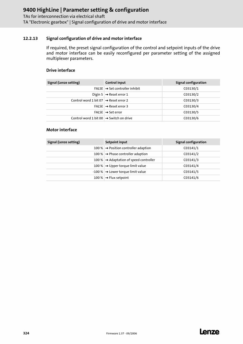
9400 HighLine | Parameter setting & configurationTAs for interconnection via electrical shaftTA "Electronic gearbox" | Signal configuration of drive and motor interface
324 Firmware 1.37 - 09/2006 L
12.2.13 Signal configuration of drive and motor interface
If required, the preset signal configuration of the control and setpoint inputs of the drive and motor interface can be easily reconfigured per parameter setting of the assigned multiplexer parameters.
Drive interface
Motor interface
Signal (Lenze setting) Control input Signal configuration
FALSE Set controller inhibit C03130/1
DigIn 5 Reset error 1 C03130/2
Control word 1 bit 07 Reset error 2 C03130/3
FALSE Reset error 3 C03130/4
FALSE Set error C03130/5
Control word 1 bit 00 Switch on drive C03130/6
Signal (Lenze setting) Setpoint input Signal configuration
100 % Position controller adaption C03141/1
100 % Phase controller adaption C03141/2
100 % Adaptation of speed controller C03141/3
100 % Upper torque limit value C03141/4
-100 % Lower torque limit value C03141/5
100 % Flux setpoint C03141/6
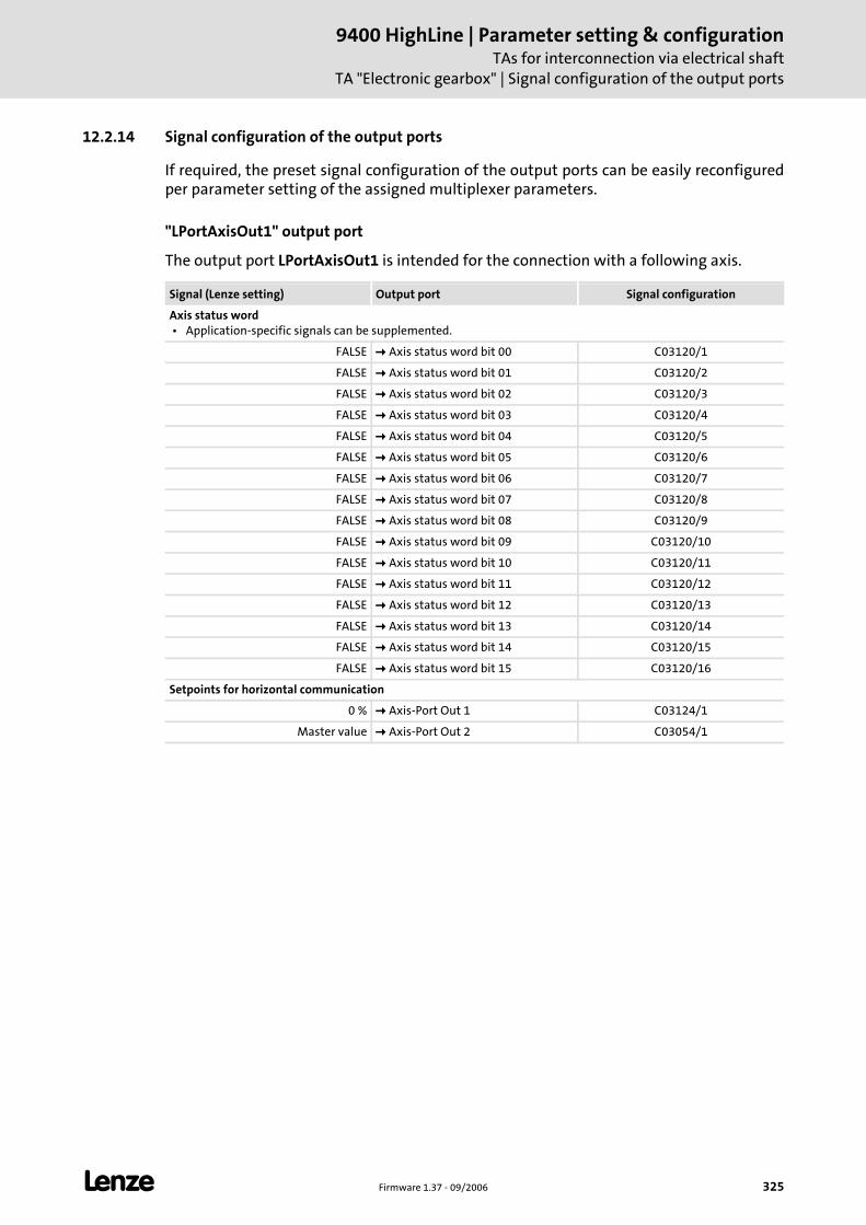
L Firmware 1.37 - 09/2006 325
9400 HighLine | Parameter setting & configurationTAs for interconnection via electrical shaft
TA "Electronic gearbox" | Signal configuration of the output ports
12.2.14 Signal configuration of the output ports
If required, the preset signal configuration of the output ports can be easily reconfigured per parameter setting of the assigned multiplexer parameters.
"LPortAxisOut1" output port
The output port LPortAxisOut1 is intended for the connection with a following axis.
Signal (Lenze setting) Output port Signal configuration
Axis status word • Application-specific signals can be supplemented.
FALSE Axis status word bit 00 C03120/1
FALSE Axis status word bit 01 C03120/2
FALSE Axis status word bit 02 C03120/3
FALSE Axis status word bit 03 C03120/4
FALSE Axis status word bit 04 C03120/5
FALSE Axis status word bit 05 C03120/6
FALSE Axis status word bit 06 C03120/7
FALSE Axis status word bit 07 C03120/8
FALSE Axis status word bit 08 C03120/9
FALSE Axis status word bit 09 C03120/10
FALSE Axis status word bit 10 C03120/11
FALSE Axis status word bit 11 C03120/12
FALSE Axis status word bit 12 C03120/13
FALSE Axis status word bit 13 C03120/14
FALSE Axis status word bit 14 C03120/15
FALSE Axis status word bit 15 C03120/16
Setpoints for horizontal communication
0 % Axis-Port Out 1 C03124/1
Master value Axis-Port Out 2 C03054/1
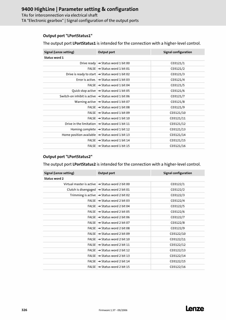
9400 HighLine | Parameter setting & configurationTAs for interconnection via electrical shaftTA "Electronic gearbox" | Signal configuration of the output ports
326 Firmware 1.37 - 09/2006 L
Output port "LPortStatus1"
The output port LPortStatus1 is intended for the connection with a higher-level control.
Output port "LPortStatus2"
The output port LPortStatus2 is intended for the connection with a higher-level control.
Signal (Lenze setting) Output port Signal configuration
Status word 1
Drive ready Status word 1 bit 00 C03121/1
FALSE Status word 1 bit 01 C03121/2
Drive is ready to start Status word 1 bit 02 C03121/3
Error is active. Status word 1 bit 03 C03121/4
FALSE Status word 1 bit 04 C03121/5
Quick stop active Status word 1 bit 05 C03121/6
Switch-on inhibit is active Status word 1 bit 06 C03121/7
Warning active Status word 1 bit 07 C03121/8
FALSE Status word 1 bit 08 C03121/9
FALSE Status word 1 bit 09 C03121/10
FALSE Status word 1 bit 10 C03121/11
Drive in the limitation Status word 1 bit 11 C03121/12
Homing complete Status word 1 bit 12 C03121/13
Home position available Status word 1 bit 13 C03121/14
FALSE Status word 1 bit 14 C03121/15
FALSE Status word 1 bit 15 C03121/16
Signal (Lenze setting) Output port Signal configuration
Status word 2
Virtual master is active Status word 2 bit 00 C03122/1
Clutch is disengaged Status word 2 bit 01 C03122/2
Trimming is active Status word 2 bit 02 C03122/3
FALSE Status word 2 bit 03 C03122/4
FALSE Status word 2 bit 04 C03122/5
FALSE Status word 2 bit 05 C03122/6
FALSE Status word 2 bit 06 C03122/7
FALSE Status word 2 bit 07 C03122/8
FALSE Status word 2 bit 08 C03122/9
FALSE Status word 2 bit 09 C03122/10
FALSE Status word 2 bit 10 C03122/11
FALSE Status word 2 bit 11 C03122/12
FALSE Status word 2 bit 12 C03122/13
FALSE Status word 2 bit 13 C03122/14
FALSE Status word 2 bit 14 C03122/15
FALSE Status word 2 bit 15 C03122/16
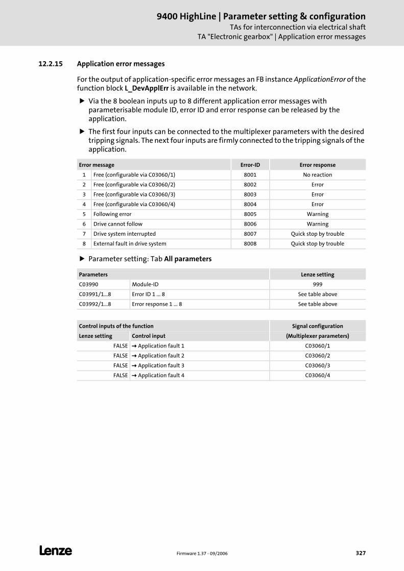
L Firmware 1.37 - 09/2006 327
9400 HighLine | Parameter setting & configurationTAs for interconnection via electrical shaft
TA "Electronic gearbox" | Application error messages
12.2.15 Application error messages
For the output of application-specific error messages an FB instance ApplicationError of the function block L_DevApplErr is available in the network.
Via the 8 boolean inputs up to 8 different application error messages with parameterisable module ID, error ID and error response can be released by the application.
The first four inputs can be connected to the multiplexer parameters with the desired tripping signals. The next four inputs are firmly connected to the tripping signals of the application.
Parameter setting: Tab All parameters
Error message Error-ID Error response
1 Free (configurable via C03060/1) 8001 No reaction
2 Free (configurable via C03060/2) 8002 Error
3 Free (configurable via C03060/3) 8003 Error
4 Free (configurable via C03060/4) 8004 Error
5 Following error 8005 Warning
6 Drive cannot follow 8006 Warning
7 Drive system interrupted 8007 Quick stop by trouble
8 External fault in drive system 8008 Quick stop by trouble
Parameters Lenze setting
C03990 Module-ID 999
C03991/1...8 Error ID 1 ... 8 See table above
C03992/1...8 Error response 1 ... 8 See table above
Control inputs of the function Signal configuration
Lenze setting Control input (Multiplexer parameters)
FALSE Application fault 1 C03060/1
FALSE Application fault 2 C03060/2
FALSE Application fault 3 C03060/3
FALSE Application fault 4 C03060/4
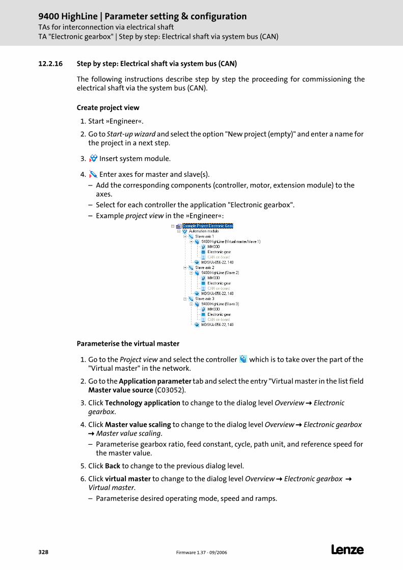
9400 HighLine | Parameter setting & configurationTAs for interconnection via electrical shaftTA "Electronic gearbox" | Step by step: Electrical shaft via system bus (CAN)
328 Firmware 1.37 - 09/2006 L
12.2.16 Step by step: Electrical shaft via system bus (CAN)
The following instructions describe step by step the proceeding for commissioning the electrical shaft via the system bus (CAN).
Create project view
1. Start »Engineer«.
2. Go to Start-up wizard and select the option "New project (empty)" and enter a name for the project in a next step.
3. Insert system module.
4. Enter axes for master and slave(s).
– Add the corresponding components (controller, motor, extension module) to the axes.
– Select for each controller the application "Electronic gearbox".
– Example project view in the »Engineer«:
Parameterise the virtual master
1. Go to the Project view and select the controller which is to take over the part of the "Virtual master" in the network.
2. Go to the Application parameter tab and select the entry "Virtual master in the list field Master value source (C03052).
3. Click Technology application to change to the dialog level Overview Electronic gearbox.
4. Click Master value scaling to change to the dialog level Overview Electronic gearbox Master value scaling.
– Parameterise gearbox ratio, feed constant, cycle, path unit, and reference speed for the master value.
5. Click Back to change to the previous dialog level.
6. Click virtual master to change to the dialog level Overview Electronic gearbox Virtual master.
– Parameterise desired operating mode, speed and ramps.
L Firmware 1.37 - 09/2006 329
9400 HighLine | Parameter setting & configurationTAs for interconnection via electrical shaft
TA "Electronic gearbox" | Step by step: Electrical shaft via system bus (CAN)
Parameterising slave(s)
1. Go to Project view and select the first slave controller .
2. Go to the Application parameter tab and select the entry "Virtual master in the list field Virtual master (C03052).
3. Make the same settings for all other slave controllers.
Establish network
1. Go to Project view and select the system module .
2. Insert network.
– Go to the dialog box Insert network to select the entry "System bus (CAN) from the list field.
– The checkmark in the control field Insert and configure node must be set so that a machine application is inserted in the Project view together with the network.
3. On the Node tab for the inserted network:
– Set node addresses for the controllers according to the DIP switch setting of the CAN address of the memory module.
– Go to Context menu for the master controller (right mouse button) and the select the command Set as master.
4. On the Synchronisation tab for the inserted network:
– Select the master controller as sync source in the list field Node.
– Select all slave controllers as sync receivers by setting the checkmark in the first column Appl..
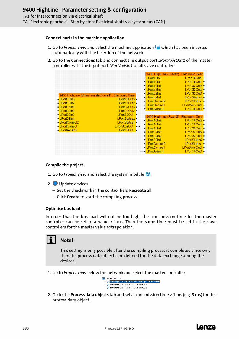
9400 HighLine | Parameter setting & configurationTAs for interconnection via electrical shaftTA "Electronic gearbox" | Step by step: Electrical shaft via system bus (CAN)
330 Firmware 1.37 - 09/2006 L
Connect ports in the machine application
1. Go to Project view and select the machine application which has been inserted automatically with the insertion of the network.
2. Go to the Connections tab and connect the output port LPortAxisOut1 of the master controller with the input port LPortAxisIn1 of all slave controllers.
Compile the project
1. Go to Project view and select the system module .
2. Update devices.
– Set the checkmark in the control field Recreate all.
– Click Create to start the compiling process.
Optimise bus load
In order that the bus load will not be too high, the transmission time for the master controller can be set to a value > 1 ms. Then the same time must be set in the slave controllers for the master value extrapolation.
1. Go to Project view below the network and select the master controller.
2. Go to the Process data objects tab and set a transmission time > 1 ms (e.g. 5 ms) for the process data object.
Note!
This setting is only possible after the compiling process is completed since only then the process data objects are defined for the data exchange among the devices.
L Firmware 1.37 - 09/2006 331
9400 HighLine | Parameter setting & configurationTAs for interconnection via electrical shaft
TA "Electronic gearbox" | Step by step: Electrical shaft via system bus (CAN)
3. Go to Project view and select the first slave controller .
4. Go to the Application parameter and change to the dialog level Electronic gearbox Electronic gearbox Master value extrapolation.
5. Set the number of extrapolation cycles to the same value than the transmission time set before.
– This means: In case of a transmission time of 5 ms set for the master set the number of extrapolation cycles for the slave to the value "5".
6. Make the same settings for all other slave controllers.
Transmit applications to the controller
1. Go online.
2. Download applications in the controller.
3. Confirm Dialog box Save parameter set with Yes, all devices.
4. Confirm Dialog box Start application with Yes, all devices.
5. Confirm Dialog box Enable controller with Yes, all devices.
6. Control applications via terminals or network.
Note!
The downloaded application is basically stored in the first application memory location of the controller.
The preinstalled technology applications on the following memory locations are still available.
9400 HighLine | Parameter setting & configurationTAs for interconnection via electrical shaftTA "Synchronism with mark synchronisation"
332 Firmware 1.37 - 09/2006 L
12.3 TA "Synchronism with mark synchronisation"
The technology application "Synchronism with register formation and mark synchronisation" serves to implement a high-precision angular synchronism between the drives in the system.
Thanks to a free adjustable position resolution of up to 24 bits per motor revolution a very good synchronism result is achieved so that applications with direct drive can be resolved with high precision.
The ratio can be freely adjusted, the values are input in the form of a fraction (numerator/denominator) with 32 bit resolution.
The master value can be specified either by a "Virtual master", or via a bus system or the digital frequency extension module. It is selected from the Application parameter tab via the Master value source list field (C03052).
The master value transmission (high speed stability) is preset. The actual values can be transmitted by the corresponding selection in the list fields Master value output (C3054/1, C3054/2, C3197).
Note!
The electrical shaft can be implemented with a bus system as e.g. system bus (CAN) or Ethernet Powerlink or via digital frequency transmission.
With regard to the configuration of the digital frequency extension module in the controller, two variants of technology applications are available in the »Engineer« application catalog.
• In the TA variant "Synchronism with mark synchronisation" the configuration of a digital frequency extension module is expected. Therefore, the TA can provide the function of the electrical shaft either via digital frequency transmission and via a bus system.
• In the TA variant "Synchronism with mark synchronisation MotionBus" the configuration of a digital frequency extension module is not included and corresponding interfaces are not available in the TA. Thus the function of the electrical shaft with this TA can only be provided via a bus system.
L Firmware 1.37 - 09/2006 333
9400 HighLine | Parameter setting & configurationTAs for interconnection via electrical shaft
TA "Synchronism with mark synchronisation"
Functions
Virtual master with inching, handwheel and reduced speed.
Conditioning of the master value (master shaft) with master value scaling, register generation, stretch factor, reversal of rotation direction, and mark synchronisation via profile generator.
Virtual clutch with emergency stop and basic speed
Trimming function via profile generator.
Conditioning of the setpoint (machine axis/tool) with setpoint scaling, register generation, and mark synchronisation via profile generator.
Additional operating modes for activating the basic drive functions "Homing", "Manual jog (inching)" and "Position override function".
Support of the basic drive functions "Quick stop" and "Limiter".
Following error monitoring.
Optional control of a holding brake.
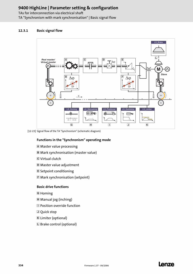
9400 HighLine | Parameter setting & configurationTAs for interconnection via electrical shaftTA "Synchronism with mark synchronisation" | Basic signal flow
334 Firmware 1.37 - 09/2006 L
12.3.1 Basic signal flow
[12-23] Signal flow of the TA "Synchronism" (schematic diagram)
Functions in the "Synchronism" operating mode
Master value processing
Mark synchronisation (master value)
Virtual clutch
Master value adjustment
Setpoint conditioning
Mark synchronisation (setpoint)
Basic drive functions
Homing
Manual jog (inching)
Position override function
Quick stop
Limiter (optional)
Brake control (optional)
v
t
��
M
�
v
� �
Slave
LS_ManualJog
n
t
��
n
t
LS_Positioner
0-100 100 200
LS_Homing
� �
LS_Brake
n
t
LS_Limiter
n
t
LS_Quickstop
STOP
�
Real master/
Virtual master
� �� �
TP TP
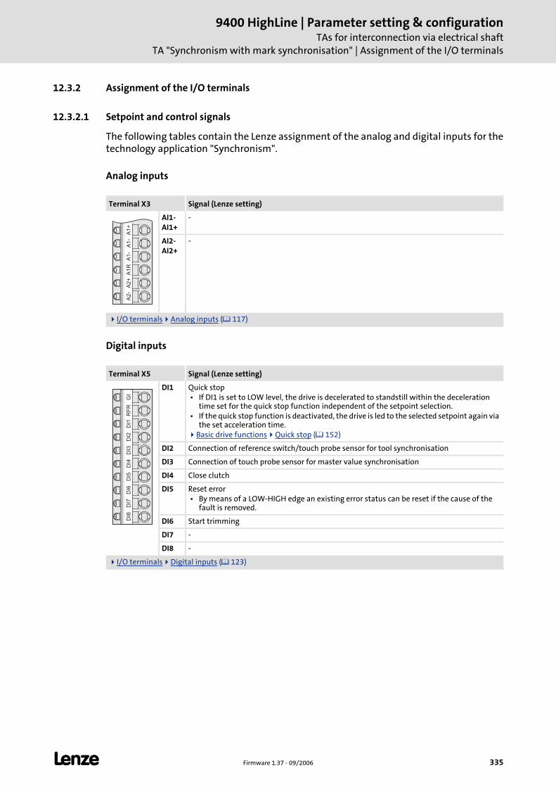
L Firmware 1.37 - 09/2006 335
9400 HighLine | Parameter setting & configurationTAs for interconnection via electrical shaft
TA "Synchronism with mark synchronisation" | Assignment of the I/O terminals
12.3.2 Assignment of the I/O terminals
12.3.2.1 Setpoint and control signals
The following tables contain the Lenze assignment of the analog and digital inputs for the technology application "Synchronism".
Analog inputs
Digital inputs
Terminal X3 Signal (Lenze setting)
AI1-AI1+
-
AI2-AI2+
-
I/O terminals Analog inputs ( 117)
Terminal X5 Signal (Lenze setting)
DI1 Quick stop • If DI1 is set to LOW level, the drive is decelerated to standstill within the deceleration
time set for the quick stop function independent of the setpoint selection. • If the quick stop function is deactivated, the drive is led to the selected setpoint again via
the set acceleration time.Basic drive functions Quick stop ( 152)
DI2 Connection of reference switch/touch probe sensor for tool synchronisation
DI3 Connection of touch probe sensor for master value synchronisation
DI4 Close clutch
DI5 Reset error • By means of a LOW-HIGH edge an existing error status can be reset if the cause of the
fault is removed.
DI6 Start trimming
DI7 -
DI8 -
I/O terminals Digital inputs ( 123)
A1
+A
1-
A1
-A
1R
A2
+A
2-
GI
RF
RD
I1D
I2D
I3D
I4D
I5D
I6D
I7D
I8

9400 HighLine | Parameter setting & configurationTAs for interconnection via electrical shaftTA "Synchronism with mark synchronisation" | Assignment of the I/O terminals
336 Firmware 1.37 - 09/2006 L
12.3.2.2 Actual value and status signals
The following tables contain the Lenze assignment of the analog and digital outputs for the technology application "Synchronism".
The default signal configuration if required can be easily changed by parameterising the multiplexer parameters assigned.
Analog outputs
Digital outputs
State bus
Display elements
Terminal X3 Signal (Lenze setting) Signal configuration
AO1 Motor speed • Scaling: ±10 V ≡ motor reference speed (C00011)
C03110/1
AO2 Motor torque (setpoint) • Scaling: ±10 V ≡ Motor reference torque (C00057/2)
C03110/2
I/O terminals Analog outputs ( 120)
Terminal X4 Signal (Lenze setting) Signal configuration
DO1 Status "Drive ready" • This operating state is active if the controller is enabled by setting
the digital input RFR to HIGH level and no error has occurred.
C03100/1
DO2 Status "Electrical shaft enabled" C03100/2
DO3 Status "Limitation active" • A setpoint is limited at the moment.
C03100/3
DO4 "Error" status • If the controller is in the error state, the digital output DO4 is set
to HIGH level.
C03100/4
I/O terminals Digital outputs ( 125)
Terminal X2 Signal (Lenze setting) Signal configuration
SB "Application error" status • The state bus is put in the "error" status.
C03100/5
I/O terminals Monitoring function "State bus" ( 127)
User LED Signal (Lenze setting) Signal configuration
Status "Electrical shaft enabled" C03100/6
Drive interface LED status displays ( 34)
GA
AO
1A
O2
GO
24
OD
O1
DO
2D
O3
DO
4G
E2
4E
SB

L Firmware 1.37 - 09/2006 337
9400 HighLine | Parameter setting & configurationTAs for interconnection via electrical shaft
TA "Synchronism with mark synchronisation" | Machine parameters
12.3.3 Machine parameters
The following schematic diagram shows the relevant global data (machine parameters) for the interconnection via the electrical shaft:
[12-24] Schematic diagram of the most important machine parameters
Detailed information for setting the machine parameters can be obtained from the following subchapters.
Master axis (here: master value encoder as real master) Slave axis 1 Slave axis 2 Digital frequency cascade (digital frequency extension module required)
d d1 3
i1 i3
l1
vmax
��
d2
i2
�
SlaveMaster/Slave
Digitalfrequency
�
Symbol Description
i1 Gearbox ratio of master value encoder
d1 Diameter of the master roll
l1 Master value cycle (if available)
vmax Maximum speed
i2, i3 Gearbox ratio of the slave axes
d2, d3 Diameter of the slave rolls
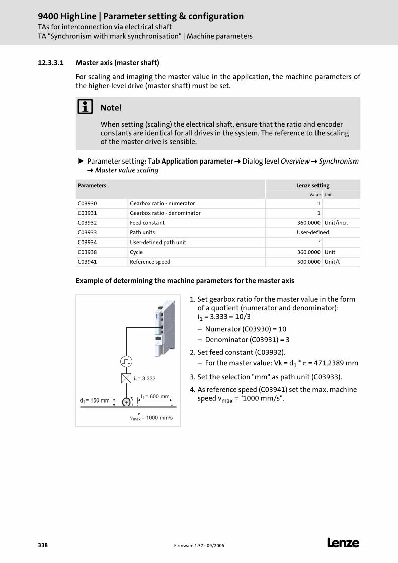
9400 HighLine | Parameter setting & configurationTAs for interconnection via electrical shaftTA "Synchronism with mark synchronisation" | Machine parameters
338 Firmware 1.37 - 09/2006 L
12.3.3.1 Master axis (master shaft)
For scaling and imaging the master value in the application, the machine parameters of the higher-level drive (master shaft) must be set.
Parameter setting: Tab Application parameter Dialog level Overview Synchronism Master value scaling
Example of determining the machine parameters for the master axis
Note!
When setting (scaling) the electrical shaft, ensure that the ratio and encoder constants are identical for all drives in the system. The reference to the scaling of the master drive is sensible.
Parameters Lenze setting
Value Unit
C03930 Gearbox ratio - numerator 1
C03931 Gearbox ratio - denominator 1
C03932 Feed constant 360.0000 Unit/incr.
C03933 Path units User-defined
C03934 User-defined path unit °
C03938 Cycle 360.0000 Unit
C03941 Reference speed 500.0000 Unit/t
1. Set gearbox ratio for the master value in the form of a quotient (numerator and denominator): i1 = 3.333 = 10/3
– Numerator (C03930) = 10
– Denominator (C03931) = 3
2. Set feed constant (C03932).
– For the master value: Vk = d1 * π = 471,2389 mm
3. Set the selection "mm" as path unit (C03933).
4. As reference speed (C03941) set the max. machine speed vmax = "1000 mm/s".d1
i1
= 150 mm
= 3.333
l1= 600 mm
vmax = 1000 mm/s
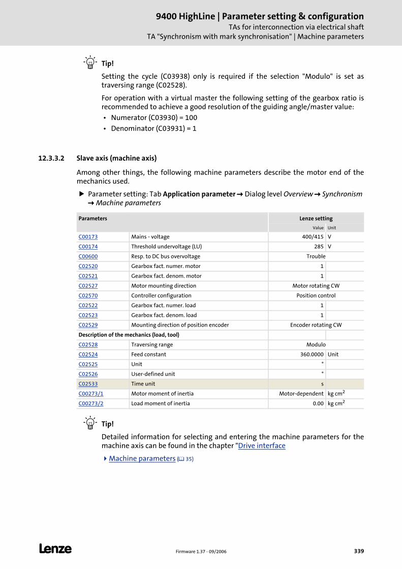
L Firmware 1.37 - 09/2006 339
9400 HighLine | Parameter setting & configurationTAs for interconnection via electrical shaft
TA "Synchronism with mark synchronisation" | Machine parameters
Tip!
Setting the cycle (C03938) only is required if the selection "Modulo" is set as traversing range (C02528).
For operation with a virtual master the following setting of the gearbox ratio is recommended to achieve a good resolution of the guiding angle/master value:
• Numerator (C03930) = 100
• Denominator (C03931) = 1
12.3.3.2 Slave axis (machine axis)
Among other things, the following machine parameters describe the motor end of the mechanics used.
Parameter setting: Tab Application parameter Dialog level Overview Synchronism Machine parameters
Tip!
Detailed information for selecting and entering the machine parameters for the machine axis can be found in the chapter "Drive interface
Machine parameters ( 35)
Parameters Lenze setting
Value Unit
C00173 Mains - voltage 400/415 V
C00174 Threshold undervoltage (LU) 285 V
C00600 Resp. to DC bus overvoltage Trouble
C02520 Gearbox fact. numer. motor 1
C02521 Gearbox fact. denom. motor 1
C02527 Motor mounting direction Motor rotating CW
C02570 Controller configuration Position control
C02522 Gearbox fact. numer. load 1
C02523 Gearbox fact. denom. load 1
C02529 Mounting direction of position encoder Encoder rotating CW
Description of the mechanics (load, tool)
C02528 Traversing range Modulo
C02524 Feed constant 360.0000 Unit
C02525 Unit °
C02526 User-defined unit °
C02533 Time unit s
C00273/1 Motor moment of inertia Motor-dependent kg cm2
C00273/2 Load moment of inertia 0.00 kg cm2
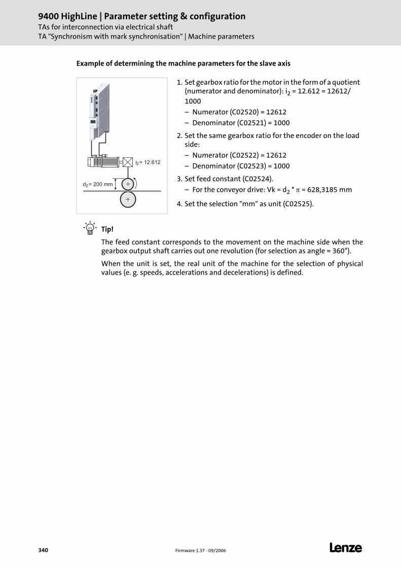
9400 HighLine | Parameter setting & configurationTAs for interconnection via electrical shaftTA "Synchronism with mark synchronisation" | Machine parameters
340 Firmware 1.37 - 09/2006 L
Example of determining the machine parameters for the slave axis
Tip!
The feed constant corresponds to the movement on the machine side when the gearbox output shaft carries out one revolution (for selection as angle = 360°).
When the unit is set, the real unit of the machine for the selection of physical values (e. g. speeds, accelerations and decelerations) is defined.
1. Set gearbox ratio for the motor in the form of a quotient (numerator and denominator): i2 = 12.612 = 12612/1000
– Numerator (C02520) = 12612
– Denominator (C02521) = 1000
2. Set the same gearbox ratio for the encoder on the load side:
– Numerator (C02522) = 12612
– Denominator (C02523) = 1000
3. Set feed constant (C02524).
– For the conveyor drive: Vk = d2 * π = 628,3185 mm
4. Set the selection "mm" as unit (C02525).
d2
i2
= 200 mm
= 12.612
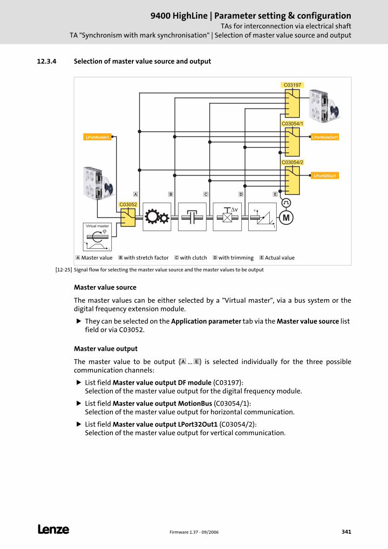
L Firmware 1.37 - 09/2006 341
9400 HighLine | Parameter setting & configurationTAs for interconnection via electrical shaft
TA "Synchronism with mark synchronisation" | Selection of master value source and output
12.3.4 Selection of master value source and output
[12-25] Signal flow for selecting the master value source and the master values to be output
Master value source
The master values can be either selected by a "Virtual master", via a bus system or the digital frequency extension module.
They can be selected on the Application parameter tab via the Master value source list field or via C03052.
Master value output
The master value to be output ( ... ) is selected individually for the three possible communication channels:
List field Master value output DF module (C03197): Selection of the master value output for the digital frequency module.
List field Master value output MotionBus (C03054/1): Selection of the master value output for horizontal communication.
List field Master value output LPort32Out1 (C03054/2): Selection of the master value output for vertical communication.
Master value with stretch factor with clutch with trimming Actual value
v
t
v
�
M
� � �
�
v
t
Virtual master
LPortAxisIn1 LPortAxisOut1
C03054/2
C03197
C03054/1
C03052
LPort32Out1
�
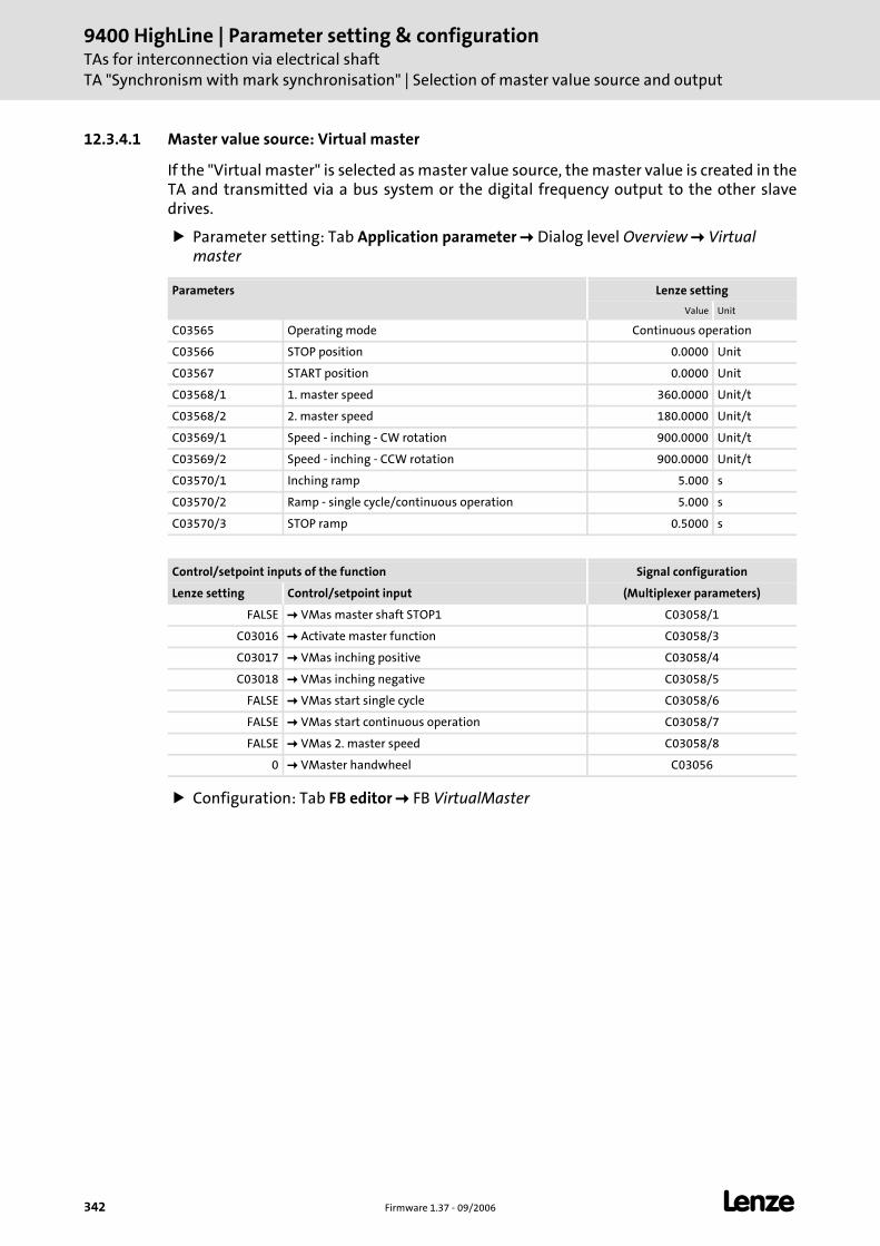
9400 HighLine | Parameter setting & configurationTAs for interconnection via electrical shaftTA "Synchronism with mark synchronisation" | Selection of master value source and output
342 Firmware 1.37 - 09/2006 L
12.3.4.1 Master value source: Virtual master
If the "Virtual master" is selected as master value source, the master value is created in the TA and transmitted via a bus system or the digital frequency output to the other slave drives.
Parameter setting: Tab Application parameter Dialog level Overview Virtual master
Configuration: Tab FB editor FB VirtualMaster
Parameters Lenze setting
Value Unit
C03565 Operating mode Continuous operation
C03566 STOP position 0.0000 Unit
C03567 START position 0.0000 Unit
C03568/1 1. master speed 360.0000 Unit/t
C03568/2 2. master speed 180.0000 Unit/t
C03569/1 Speed - inching - CW rotation 900.0000 Unit/t
C03569/2 Speed - inching - CCW rotation 900.0000 Unit/t
C03570/1 Inching ramp 5.000 s
C03570/2 Ramp - single cycle/continuous operation 5.000 s
C03570/3 STOP ramp 0.5000 s
Control/setpoint inputs of the function Signal configuration
Lenze setting Control/setpoint input (Multiplexer parameters)
FALSE VMas master shaft STOP1 C03058/1
C03016 Activate master function C03058/3
C03017 VMas inching positive C03058/4
C03018 VMas inching negative C03058/5
FALSE VMas start single cycle C03058/6
FALSE VMas start continuous operation C03058/7
FALSE VMas 2. master speed C03058/8
0 VMaster handwheel C03056
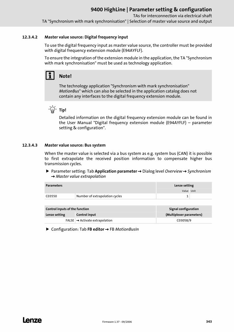
L Firmware 1.37 - 09/2006 343
9400 HighLine | Parameter setting & configurationTAs for interconnection via electrical shaft
TA "Synchronism with mark synchronisation" | Selection of master value source and output
12.3.4.2 Master value source: Digital frequency input
To use the digital frequency input as master value source, the controller must be provided with digital frequency extension module (E94AYFLF).
To ensure the integration of the extension module in the application, the TA "Synchronism with mark synchronisation" must be used as technology application.
Tip!
Detailed information on the digital frequency extension module can be found in the User Manual "Digital frequency extension module (E94AYFLF) – parameter setting & configuration".
12.3.4.3 Master value source: Bus system
When the master value is selected via a bus system as e.g. system bus (CAN) it is possible to first extrapolate the received position information to compensate higher bus transmission cycles.
Parameter setting: Tab Application parameter Dialog level Overview Synchronism Master value extrapolation
Configuration: Tab FB editor FB MotionBusIn
Note!
The technology application "Synchronism with mark synchronisation" MotionBus" which can also be selected in the application catalog does not contain any interfaces to the digital frequency extension module.
Parameters Lenze setting
Value Unit
C03550 Number of extrapolation cycles 1
Control inputs of the function Signal configuration
Lenze setting Control input (Multiplexer parameters)
FALSE Activate extrapolation C03058/9
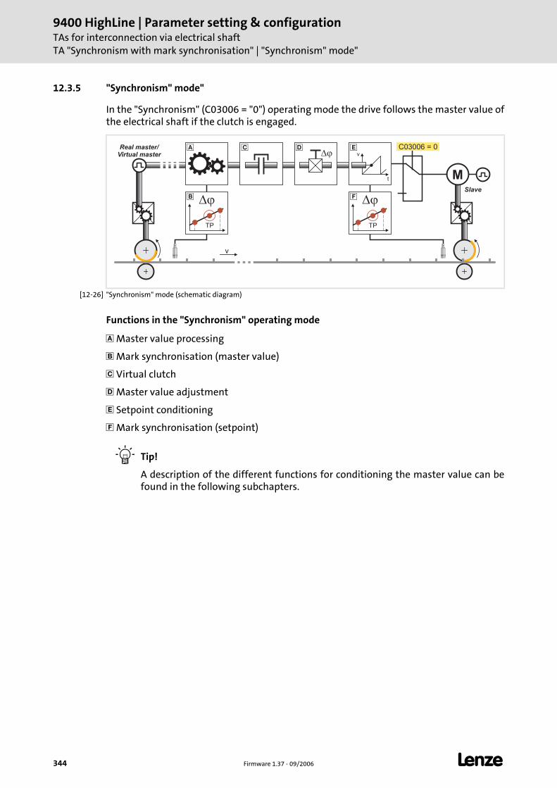
9400 HighLine | Parameter setting & configurationTAs for interconnection via electrical shaftTA "Synchronism with mark synchronisation" | "Synchronism" mode"
344 Firmware 1.37 - 09/2006 L
12.3.5 "Synchronism" mode"
In the "Synchronism" (C03006 = "0") operating mode the drive follows the master value of the electrical shaft if the clutch is engaged.
[12-26] "Synchronism" mode (schematic diagram)
Functions in the "Synchronism" operating mode
Master value processing
Mark synchronisation (master value)
Virtual clutch
Master value adjustment
Setpoint conditioning
Mark synchronisation (setpoint)
Tip!
A description of the different functions for conditioning the master value can be found in the following subchapters.
M
v
Slave
Real master/Virtual master
C03006 = 0v
t
��� � �
� �� �
TP TP
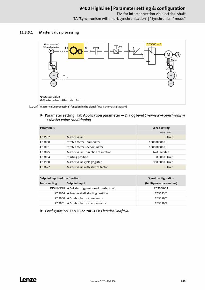
L Firmware 1.37 - 09/2006 345
9400 HighLine | Parameter setting & configurationTAs for interconnection via electrical shaft
TA "Synchronism with mark synchronisation" | "Synchronism" mode"
12.3.5.1 Master value processing
[12-27] "Master value processing" function in the signal flow (schematic diagram)
Parameter setting: Tab Application parameter Dialog level Overview Synchronism Master value conditioning
Configuration: Tab FB editor FB ElectricalShaftVal
Master valueMaster value with stretch factor
M
v
Slave
Real master/Virtual master v
t
vC03006 = 0
� �
Parameters Lenze setting
Value Unit
C03587 Master value - Unit
C03000 Stretch factor - numerator 1000000000
C03001 Stretch factor - denominator 1000000000
C03025 Master value - direction of rotation Not inverted
C03034 Starting position 0.0000 Unit
C03938 Master value cycle (register) 360.0000 Unit
C03672 Master value with stretch factor - Unit
Setpoint inputs of the function Signal configuration
Lenze setting Setpoint input (Multiplexer parameters)
DIGIN CINH Set starting position of master shaft C03058/11
C03034 Master shaft starting position C03053/1
C03000 Stretch factor - numerator C03050/1
C03001 Stretch factor - denominator C03050/2
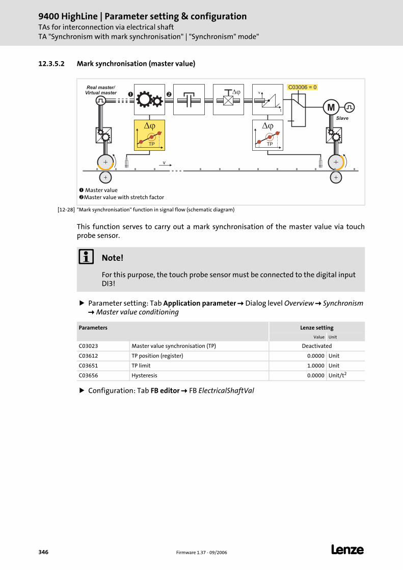
9400 HighLine | Parameter setting & configurationTAs for interconnection via electrical shaftTA "Synchronism with mark synchronisation" | "Synchronism" mode"
346 Firmware 1.37 - 09/2006 L
12.3.5.2 Mark synchronisation (master value)
[12-28] "Mark synchronisation" function in signal flow (schematic diagram)
This function serves to carry out a mark synchronisation of the master value via touch probe sensor.
Parameter setting: Tab Application parameter Dialog level Overview Synchronism Master value conditioning
Configuration: Tab FB editor FB ElectricalShaftVal
Master valueMaster value with stretch factor
� �
M
v
Slave
Real master/Virtual master
C03006 = 0v
t
�
� �
TP TP
Note!
For this purpose, the touch probe sensor must be connected to the digital input DI3!
Parameters Lenze setting
Value Unit
C03023 Master value synchronisation (TP) Deactivated
C03612 TP position (register) 0.0000 Unit
C03651 TP limit 1.0000 Unit
C03656 Hysteresis 0.0000 Unit/t2
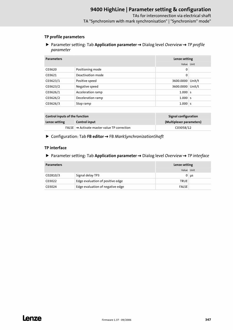
L Firmware 1.37 - 09/2006 347
9400 HighLine | Parameter setting & configurationTAs for interconnection via electrical shaft
TA "Synchronism with mark synchronisation" | "Synchronism" mode"
TP profile parameters
Parameter setting: Tab Application parameter Dialog level Overview TP profile parameter
Configuration: Tab FB editor FB MarkSynchronizationShaft
TP interface
Parameter setting: Tab Application parameter Dialog level Overview TP interface
Parameters Lenze setting
Value Unit
C03620 Positioning mode 0
C03621 Deactivation mode 0
C03623/1 Positive speed 3600.0000 Unit/t
C03623/2 Negative speed 3600.0000 Unit/t
C03626/1 Acceleration ramp 1.000 s
C03626/2 Deceleration ramp 1.000 s
C03626/3 Stop ramp 1.000 s
Control inputs of the function Signal configuration
Lenze setting Control input (Multiplexer parameters)
FALSE Activate master value TP correction C03058/12
Parameters Lenze setting
Value Unit
C02810/3 Signal delay TP3 0 μs
C03022 Edge evaluation of positive edge TRUE
C03024 Edge evaluation of negative edge FALSE
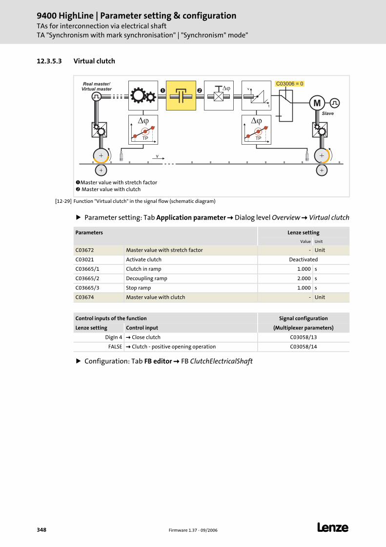
9400 HighLine | Parameter setting & configurationTAs for interconnection via electrical shaftTA "Synchronism with mark synchronisation" | "Synchronism" mode"
348 Firmware 1.37 - 09/2006 L
12.3.5.3 Virtual clutch
[12-29] Function "Virtual clutch" in the signal flow (schematic diagram)
Parameter setting: Tab Application parameter Dialog level Overview Virtual clutch
Configuration: Tab FB editor FB ClutchElectricalShaft
Master value with stretch factor Master value with clutch
� �
M
v
Slave
Real master/Virtual master
C03006 = 0v
t
�
� �
TP TP
Parameters Lenze setting
Value Unit
C03672 Master value with stretch factor - Unit
C03021 Activate clutch Deactivated
C03665/1 Clutch in ramp 1.000 s
C03665/2 Decoupling ramp 2.000 s
C03665/3 Stop ramp 1.000 s
C03674 Master value with clutch - Unit
Control inputs of the function Signal configuration
Lenze setting Control input (Multiplexer parameters)
DigIn 4 Close clutch C03058/13
FALSE Clutch - positive opening operation C03058/14
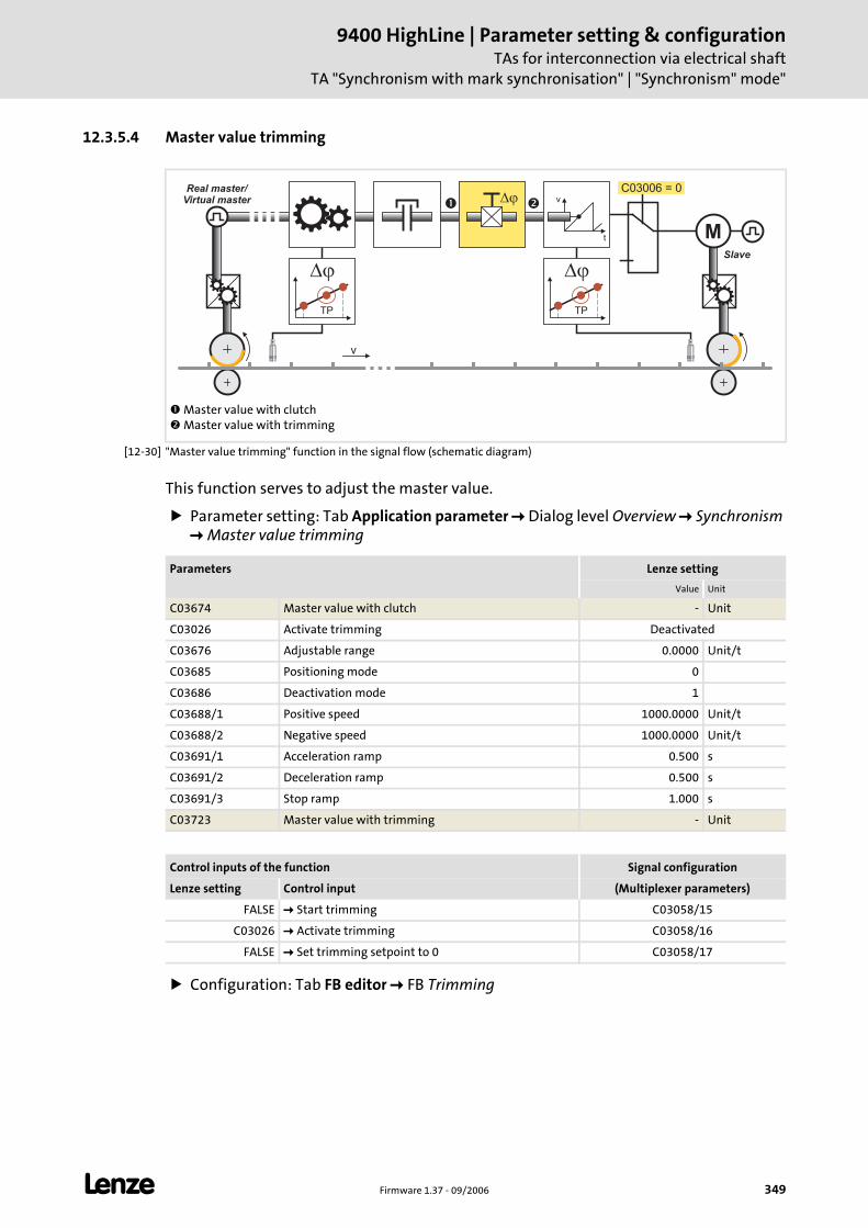
L Firmware 1.37 - 09/2006 349
9400 HighLine | Parameter setting & configurationTAs for interconnection via electrical shaft
TA "Synchronism with mark synchronisation" | "Synchronism" mode"
12.3.5.4 Master value trimming
[12-30] "Master value trimming" function in the signal flow (schematic diagram)
This function serves to adjust the master value.
Parameter setting: Tab Application parameter Dialog level Overview Synchronism Master value trimming
Configuration: Tab FB editor FB Trimming
Master value with clutch Master value with trimming
� �
M
v
Slave
Real master/Virtual master
C03006 = 0v
t
�
� �
TP TP
Parameters Lenze setting
Value Unit
C03674 Master value with clutch - Unit
C03026 Activate trimming Deactivated
C03676 Adjustable range 0.0000 Unit/t
C03685 Positioning mode 0
C03686 Deactivation mode 1
C03688/1 Positive speed 1000.0000 Unit/t
C03688/2 Negative speed 1000.0000 Unit/t
C03691/1 Acceleration ramp 0.500 s
C03691/2 Deceleration ramp 0.500 s
C03691/3 Stop ramp 1.000 s
C03723 Master value with trimming - Unit
Control inputs of the function Signal configuration
Lenze setting Control input (Multiplexer parameters)
FALSE Start trimming C03058/15
C03026 Activate trimming C03058/16
FALSE Set trimming setpoint to 0 C03058/17
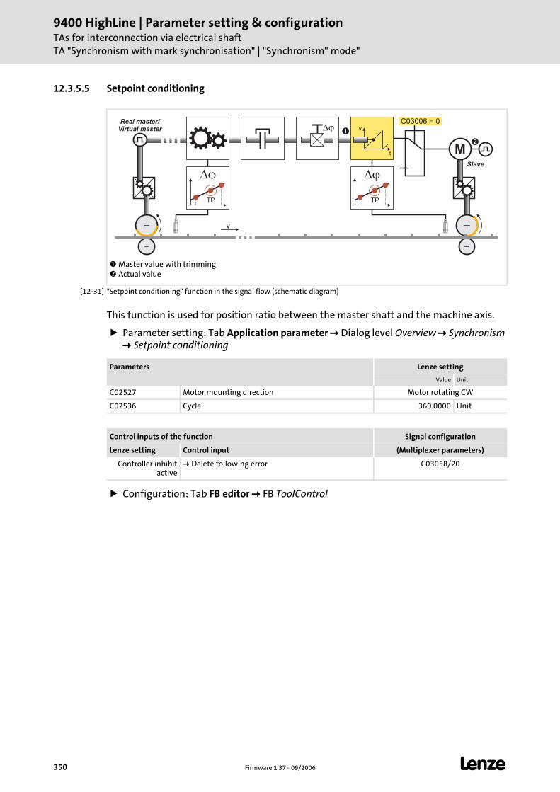
9400 HighLine | Parameter setting & configurationTAs for interconnection via electrical shaftTA "Synchronism with mark synchronisation" | "Synchronism" mode"
350 Firmware 1.37 - 09/2006 L
12.3.5.5 Setpoint conditioning
[12-31] "Setpoint conditioning" function in the signal flow (schematic diagram)
This function is used for position ratio between the master shaft and the machine axis.
Parameter setting: Tab Application parameter Dialog level Overview Synchronism Setpoint conditioning
Configuration: Tab FB editor FB ToolControl
Master value with trimming Actual value
�
�M
v
Slave
Real master/Virtual master
C03006 = 0v
t
�
� �
TP TP
Parameters Lenze setting
Value Unit
C02527 Motor mounting direction Motor rotating CW
C02536 Cycle 360.0000 Unit
Control inputs of the function Signal configuration
Lenze setting Control input (Multiplexer parameters)
Controller inhibit active
Delete following error C03058/20
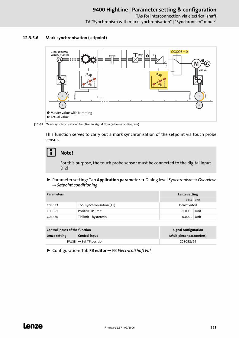
L Firmware 1.37 - 09/2006 351
9400 HighLine | Parameter setting & configurationTAs for interconnection via electrical shaft
TA "Synchronism with mark synchronisation" | "Synchronism" mode"
12.3.5.6 Mark synchronisation (setpoint)
[12-32] "Mark synchronisation" function in signal flow (schematic diagram)
This function serves to carry out a mark synchronisation of the setpoint via touch probe sensor.
Parameter setting: Tab Application parameter Dialog level Synchronism Overview Setpoint conditioning
Configuration: Tab FB editor FB ElectricalShaftVal
Master value with trimming Actual value
�
�M
v
Slave
Real master/Virtual master
C03006 = 0v
t
�
� �
TP TP
Note!
For this purpose, the touch probe sensor must be connected to the digital input DI2!
Parameters Lenze setting
Value Unit
C03033 Tool synchronisation (TP) Deactivated
C03851 Positive TP limit 1.0000 Unit
C03876 TP limit - hysteresis 0.0000 Unit
Control inputs of the function Signal configuration
Lenze setting Control input (Multiplexer parameters)
FALSE Set TP position C03058/24
9400 HighLine | Parameter setting & configurationTAs for interconnection via electrical shaftTA "Synchronism with mark synchronisation" | "Synchronism" mode"
352 Firmware 1.37 - 09/2006 L
TP profile parameters
Parameter setting: Tab Application parameter Dialog level Overview Synchronism TP profile parameter
Configuration: Tab FB editor FB MarkSynchronizationTool
TP interface
Parameter setting: Tab Application parameter Dialog level Overview Synchronism TP interface
Parameters Lenze setting
Value Unit
C03855 Positioning mode 0
C03856 Deactivation mode 0
C03858/1 Positive speed 1000.0000 Unit/t
C03858/2 Negative speed 1000.0000 Unit/t
C03861/1 Acceleration ramp 1.000 s
C03861/2 Deceleration ramp 1.000 s
C03861/3 Stop ramp 1.000 s
Control inputs of the function Signal configuration
Lenze setting Control input (Multiplexer parameters)
FALSE Activate tool TP correction C03058/23
Parameters Lenze setting
Value Unit
C02810/2 Signal delay TP2 0 μs
C03031 Edge evaluation of positive edge TRUE
C03032 Edge evaluation of negative edge FALSE
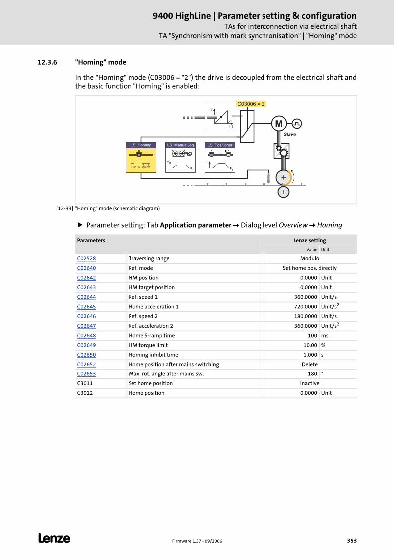
L Firmware 1.37 - 09/2006 353
9400 HighLine | Parameter setting & configurationTAs for interconnection via electrical shaft
TA "Synchronism with mark synchronisation" | "Homing" mode
12.3.6 "Homing" mode
In the "Homing" mode (C03006 = "2") the drive is decoupled from the electrical shaft and the basic function "Homing" is enabled:
[12-33] "Homing" mode (schematic diagram)
Parameter setting: Tab Application parameter Dialog level Overview Homing
v
t
LS_ManualJog
n
t
��
n
t
LS_Positioner
0-100 100 200
LS_Homing
C03006 = 2
t MSlave
Parameters Lenze setting
Value Unit
C02528 Traversing range Modulo
C02640 Ref. mode Set home pos. directly
C02642 HM position 0.0000 Unit
C02643 HM target position 0.0000 Unit
C02644 Ref. speed 1 360.0000 Unit/s
C02645 Home acceleration 1 720.0000 Unit/s2
C02646 Ref. speed 2 180.0000 Unit/s
C02647 Ref. acceleration 2 360.0000 Unit/s2
C02648 Home S-ramp time 100 ms
C02649 HM torque limit 10.00 %
C02650 Homing inhibit time 1.000 s
C02652 Home position after mains switching Delete
C02653 Max. rot. angle after mains sw. 180 °
C3011 Set home position Inactive
C3012 Home position 0.0000 Unit

9400 HighLine | Parameter setting & configurationTAs for interconnection via electrical shaftTA "Synchronism with mark synchronisation" | "Homing" mode
354 Firmware 1.37 - 09/2006 L
Tip!
Detailed information on homing can be found in chapter "Basic drive functions" subchapter "Homing". ( 164)
Control inputs of the function Signal configuration
Lenze setting Control input (Multiplexer parameters)
FALSE Start homing C03160/2
DigIn 2 Home mark C03160/3
C03011 Set home position C03160/4
C03012 Home position C03163
FALSE Reset home position C03160/5
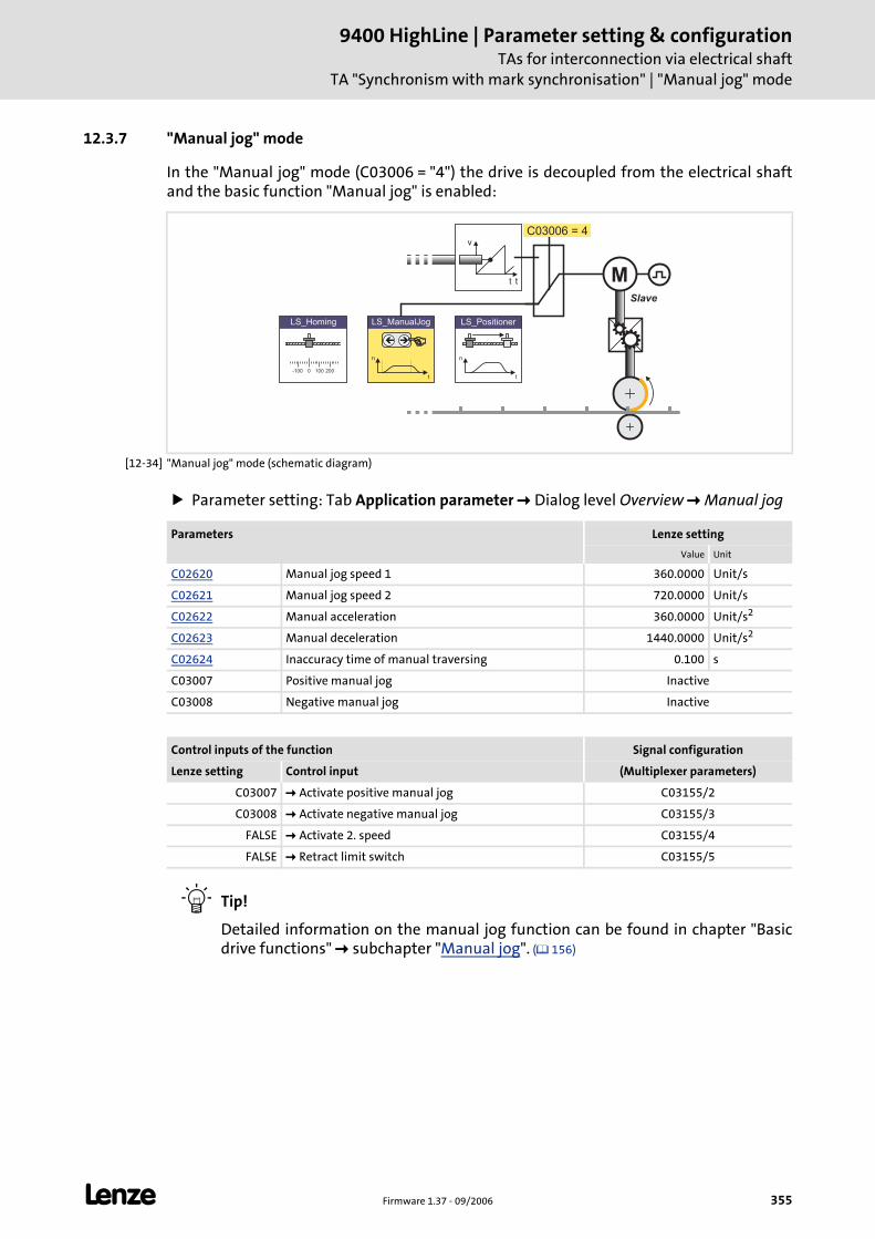
L Firmware 1.37 - 09/2006 355
9400 HighLine | Parameter setting & configurationTAs for interconnection via electrical shaft
TA "Synchronism with mark synchronisation" | "Manual jog" mode
12.3.7 "Manual jog" mode
In the "Manual jog" mode (C03006 = "4") the drive is decoupled from the electrical shaft and the basic function "Manual jog" is enabled:
[12-34] "Manual jog" mode (schematic diagram)
Parameter setting: Tab Application parameter Dialog level Overview Manual jog
Tip!
Detailed information on the manual jog function can be found in chapter "Basic drive functions" subchapter "Manual jog". ( 156)
v
t
LS_ManualJog
n
t
��
n
t
LS_Positioner
0-100 100 200
LS_Homing
C03006 = 4
t MSlave
Parameters Lenze setting
Value Unit
C02620 Manual jog speed 1 360.0000 Unit/s
C02621 Manual jog speed 2 720.0000 Unit/s
C02622 Manual acceleration 360.0000 Unit/s2
C02623 Manual deceleration 1440.0000 Unit/s2
C02624 Inaccuracy time of manual traversing 0.100 s
C03007 Positive manual jog Inactive
C03008 Negative manual jog Inactive
Control inputs of the function Signal configuration
Lenze setting Control input (Multiplexer parameters)
C03007 Activate positive manual jog C03155/2
C03008 Activate negative manual jog C03155/3
FALSE Activate 2. speed C03155/4
FALSE Retract limit switch C03155/5
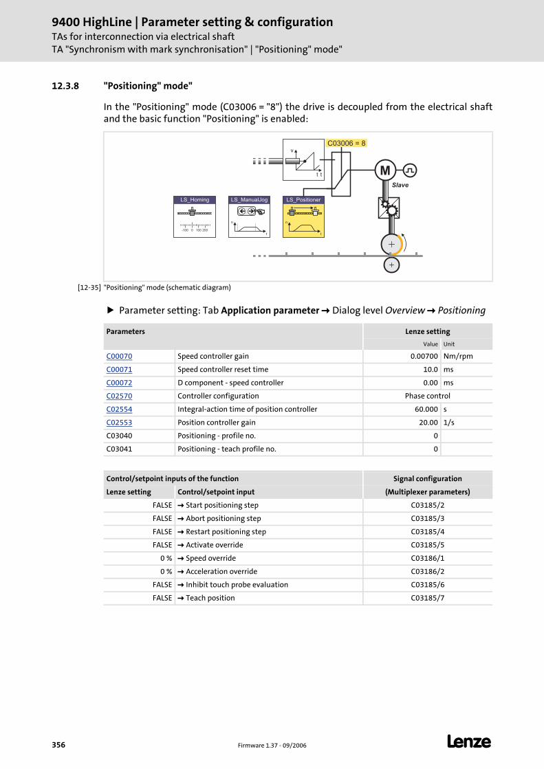
9400 HighLine | Parameter setting & configurationTAs for interconnection via electrical shaftTA "Synchronism with mark synchronisation" | "Positioning" mode"
356 Firmware 1.37 - 09/2006 L
12.3.8 "Positioning" mode"
In the "Positioning" mode (C03006 = "8") the drive is decoupled from the electrical shaft and the basic function "Positioning" is enabled:
[12-35] "Positioning" mode (schematic diagram)
Parameter setting: Tab Application parameter Dialog level Overview Positioning
v
t
LS_ManualJog
n
t
��
n
t
LS_Positioner
0-100 100 200
LS_Homing
C03006 = 8
t MSlave
Parameters Lenze setting
Value Unit
C00070 Speed controller gain 0.00700 Nm/rpm
C00071 Speed controller reset time 10.0 ms
C00072 D component - speed controller 0.00 ms
C02570 Controller configuration Phase control
C02554 Integral-action time of position controller 60.000 s
C02553 Position controller gain 20.00 1/s
C03040 Positioning - profile no. 0
C03041 Positioning - teach profile no. 0
Control/setpoint inputs of the function Signal configuration
Lenze setting Control/setpoint input (Multiplexer parameters)
FALSE Start positioning step C03185/2
FALSE Abort positioning step C03185/3
FALSE Restart positioning step C03185/4
FALSE Activate override C03185/5
0 % Speed override C03186/1
0 % Acceleration override C03186/2
FALSE Inhibit touch probe evaluation C03185/6
FALSE Teach position C03185/7
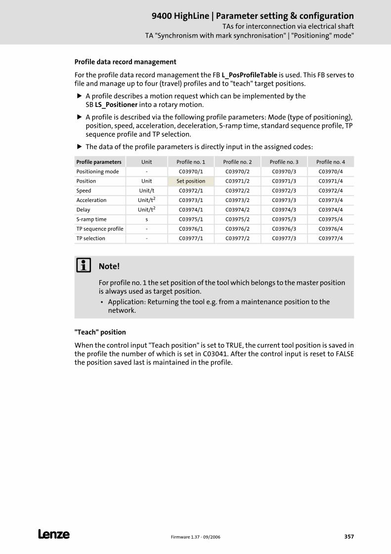
L Firmware 1.37 - 09/2006 357
9400 HighLine | Parameter setting & configurationTAs for interconnection via electrical shaft
TA "Synchronism with mark synchronisation" | "Positioning" mode"
Profile data record management
For the profile data record management the FB L_PosProfileTable is used. This FB serves to file and manage up to four (travel) profiles and to "teach" target positions.
A profile describes a motion request which can be implemented by the SB LS_Positioner into a rotary motion.
A profile is described via the following profile parameters: Mode (type of positioning), position, speed, acceleration, deceleration, S-ramp time, standard sequence profile, TP sequence profile and TP selection.
The data of the profile parameters is directly input in the assigned codes:
"Teach" position
When the control input "Teach position" is set to TRUE, the current tool position is saved in the profile the number of which is set in C03041. After the control input is reset to FALSE the position saved last is maintained in the profile.
Profile parameters Unit Profile no. 1 Profile no. 2 Profile no. 3 Profile no. 4
Positioning mode - C03970/1 C03970/2 C03970/3 C03970/4
Position Unit Set position C03971/2 C03971/3 C03971/4
Speed Unit/t C03972/1 C03972/2 C03972/3 C03972/4
Acceleration Unit/t2 C03973/1 C03973/2 C03973/3 C03973/4
Delay Unit/t2 C03974/1 C03974/2 C03974/3 C03974/4
S-ramp time s C03975/1 C03975/2 C03975/3 C03975/4
TP sequence profile - C03976/1 C03976/2 C03976/3 C03976/4
TP selection - C03977/1 C03977/2 C03977/3 C03977/4
Note!
For profile no. 1 the set position of the tool which belongs to the master position is always used as target position.
• Application: Returning the tool e.g. from a maintenance position to the network.
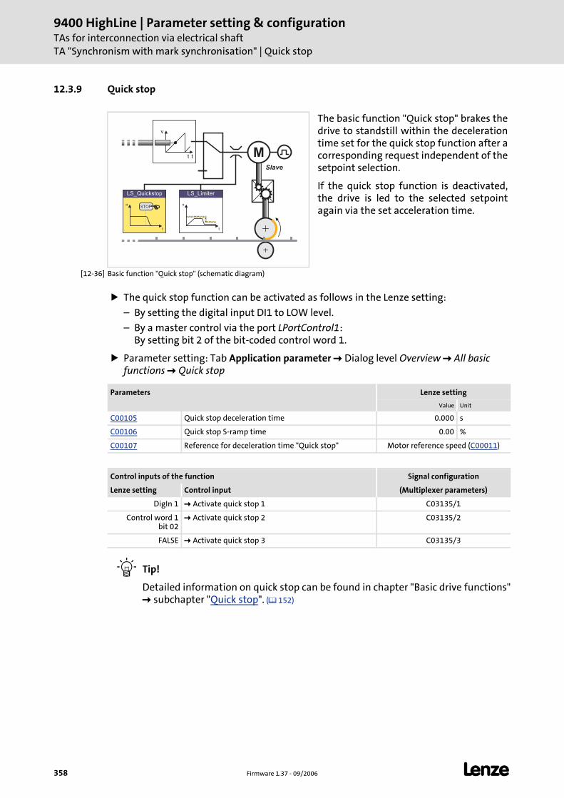
9400 HighLine | Parameter setting & configurationTAs for interconnection via electrical shaftTA "Synchronism with mark synchronisation" | Quick stop
358 Firmware 1.37 - 09/2006 L
12.3.9 Quick stop
[12-36] Basic function "Quick stop" (schematic diagram)
The quick stop function can be activated as follows in the Lenze setting:
– By setting the digital input DI1 to LOW level.
– By a master control via the port LPortControl1: By setting bit 2 of the bit-coded control word 1.
Parameter setting: Tab Application parameter Dialog level Overview All basic functions Quick stop
Tip!
Detailed information on quick stop can be found in chapter "Basic drive functions" subchapter "Quick stop". ( 152)
The basic function "Quick stop" brakes the drive to standstill within the deceleration time set for the quick stop function after a corresponding request independent of the setpoint selection.
If the quick stop function is deactivated, the drive is led to the selected setpoint again via the set acceleration time.
v
tt MSlave
n
t
LS_Limiter
n
t
LS_Quickstop
STOP
Parameters Lenze setting
Value Unit
C00105 Quick stop deceleration time 0.000 s
C00106 Quick stop S-ramp time 0.00 %
C00107 Reference for deceleration time "Quick stop" Motor reference speed (C00011)
Control inputs of the function Signal configuration
Lenze setting Control input (Multiplexer parameters)
DigIn 1 Activate quick stop 1 C03135/1
Control word 1 bit 02
Activate quick stop 2 C03135/2
FALSE Activate quick stop 3 C03135/3
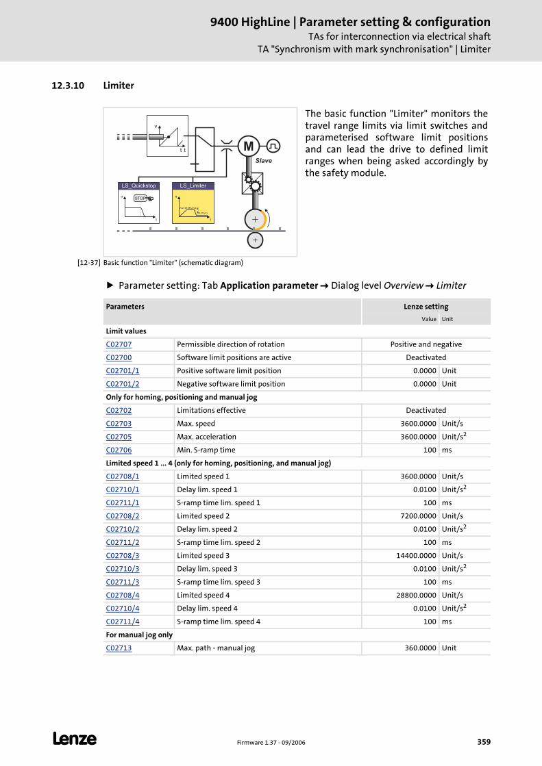
L Firmware 1.37 - 09/2006 359
9400 HighLine | Parameter setting & configurationTAs for interconnection via electrical shaft
TA "Synchronism with mark synchronisation" | Limiter
12.3.10 Limiter
[12-37] Basic function "Limiter" (schematic diagram)
Parameter setting: Tab Application parameter Dialog level Overview Limiter
The basic function "Limiter" monitors the travel range limits via limit switches and parameterised software limit positions and can lead the drive to defined limit ranges when being asked accordingly by the safety module.
v
tt MSlave
n
t
LS_Limiter
n
t
LS_Quickstop
STOP
Parameters Lenze setting
Value Unit
Limit values
C02707 Permissible direction of rotation Positive and negative
C02700 Software limit positions are active Deactivated
C02701/1 Positive software limit position 0.0000 Unit
C02701/2 Negative software limit position 0.0000 Unit
Only for homing, positioning and manual jog
C02702 Limitations effective Deactivated
C02703 Max. speed 3600.0000 Unit/s
C02705 Max. acceleration 3600.0000 Unit/s2
C02706 Min. S-ramp time 100 ms
Limited speed 1 ... 4 (only for homing, positioning, and manual jog)
C02708/1 Limited speed 1 3600.0000 Unit/s
C02710/1 Delay lim. speed 1 0.0100 Unit/s2
C02711/1 S-ramp time lim. speed 1 100 ms
C02708/2 Limited speed 2 7200.0000 Unit/s
C02710/2 Delay lim. speed 2 0.0100 Unit/s2
C02711/2 S-ramp time lim. speed 2 100 ms
C02708/3 Limited speed 3 14400.0000 Unit/s
C02710/3 Delay lim. speed 3 0.0100 Unit/s2
C02711/3 S-ramp time lim. speed 3 100 ms
C02708/4 Limited speed 4 28800.0000 Unit/s
C02710/4 Delay lim. speed 4 0.0100 Unit/s2
C02711/4 S-ramp time lim. speed 4 100 ms
For manual jog only
C02713 Max. path - manual jog 360.0000 Unit
9400 HighLine | Parameter setting & configurationTAs for interconnection via electrical shaftTA "Synchronism with mark synchronisation" | Limiter
360 Firmware 1.37 - 09/2006 L
Tip!
Detailed information on the limiter function can be found in chapter "Basic drive functions" subchapter "Limiter". ( 200)
Control inputs of the function Signal configuration
Lenze setting Control input (Multiplexer parameters)
FALSE Positive limit switch C03150/1
FALSE Negative limit switch C03150/2
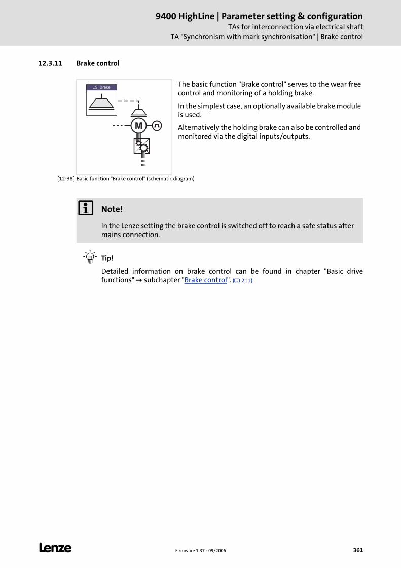
L Firmware 1.37 - 09/2006 361
9400 HighLine | Parameter setting & configurationTAs for interconnection via electrical shaft
TA "Synchronism with mark synchronisation" | Brake control
12.3.11 Brake control
[12-38] Basic function "Brake control" (schematic diagram)
Tip!
Detailed information on brake control can be found in chapter "Basic drive functions" subchapter "Brake control". ( 211)
The basic function "Brake control" serves to the wear free control and monitoring of a holding brake.
In the simplest case, an optionally available brake module is used.
Alternatively the holding brake can also be controlled and monitored via the digital inputs/outputs.
M
LS_Brake
Note!
In the Lenze setting the brake control is switched off to reach a safe status after mains connection.
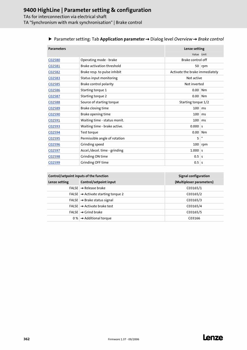
9400 HighLine | Parameter setting & configurationTAs for interconnection via electrical shaftTA "Synchronism with mark synchronisation" | Brake control
362 Firmware 1.37 - 09/2006 L
Parameter setting: Tab Application parameter Dialog level Overview Brake control
Parameters Lenze setting
Value Unit
C02580 Operating mode - brake Brake control off
C02581 Brake activation threshold 50 rpm
C02582 Brake resp. to pulse inhibit Activate the brake immediately
C02583 Status input monitoring Not active
C02585 Brake control polarity Not inverted
C02586 Starting torque 1 0.00 Nm
C02587 Starting torque 2 0.00 Nm
C02588 Source of starting torque Starting torque 1/2
C02589 Brake closing time 100 ms
C02590 Brake opening time 100 ms
C02591 Waiting time - status monit. 100 ms
C02593 Waiting time - brake active. 0.000 s
C02594 Test torque 0.00 Nm
C02595 Permissible angle of rotation 5 °
C02596 Grinding speed 100 rpm
C02597 Accel./decel. time - grinding 1.000 s
C02598 Grinding ON time 0.5 s
C02599 Grinding OFF time 0.5 s
Control/setpoint inputs of the function Signal configuration
Lenze setting Control/setpoint input (Multiplexer parameters)
FALSE Release brake C03165/1
FALSE Activate starting torque 2 C03165/2
FALSE Brake status signal C03165/3
FALSE Activate brake test C03165/4
FALSE Grind brake C03165/5
0 % Additional torque C03166
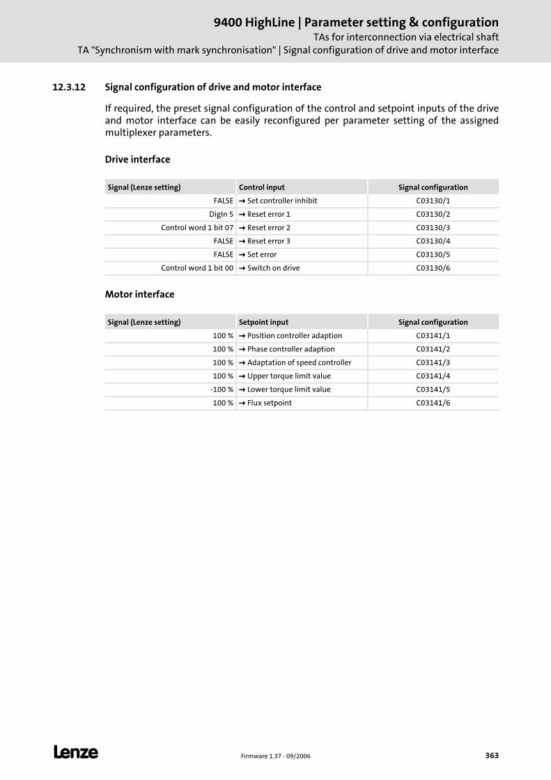
L Firmware 1.37 - 09/2006 363
9400 HighLine | Parameter setting & configurationTAs for interconnection via electrical shaft
TA "Synchronism with mark synchronisation" | Signal configuration of drive and motor interface
12.3.12 Signal configuration of drive and motor interface
If required, the preset signal configuration of the control and setpoint inputs of the drive and motor interface can be easily reconfigured per parameter setting of the assigned multiplexer parameters.
Drive interface
Motor interface
Signal (Lenze setting) Control input Signal configuration
FALSE Set controller inhibit C03130/1
DigIn 5 Reset error 1 C03130/2
Control word 1 bit 07 Reset error 2 C03130/3
FALSE Reset error 3 C03130/4
FALSE Set error C03130/5
Control word 1 bit 00 Switch on drive C03130/6
Signal (Lenze setting) Setpoint input Signal configuration
100 % Position controller adaption C03141/1
100 % Phase controller adaption C03141/2
100 % Adaptation of speed controller C03141/3
100 % Upper torque limit value C03141/4
-100 % Lower torque limit value C03141/5
100 % Flux setpoint C03141/6
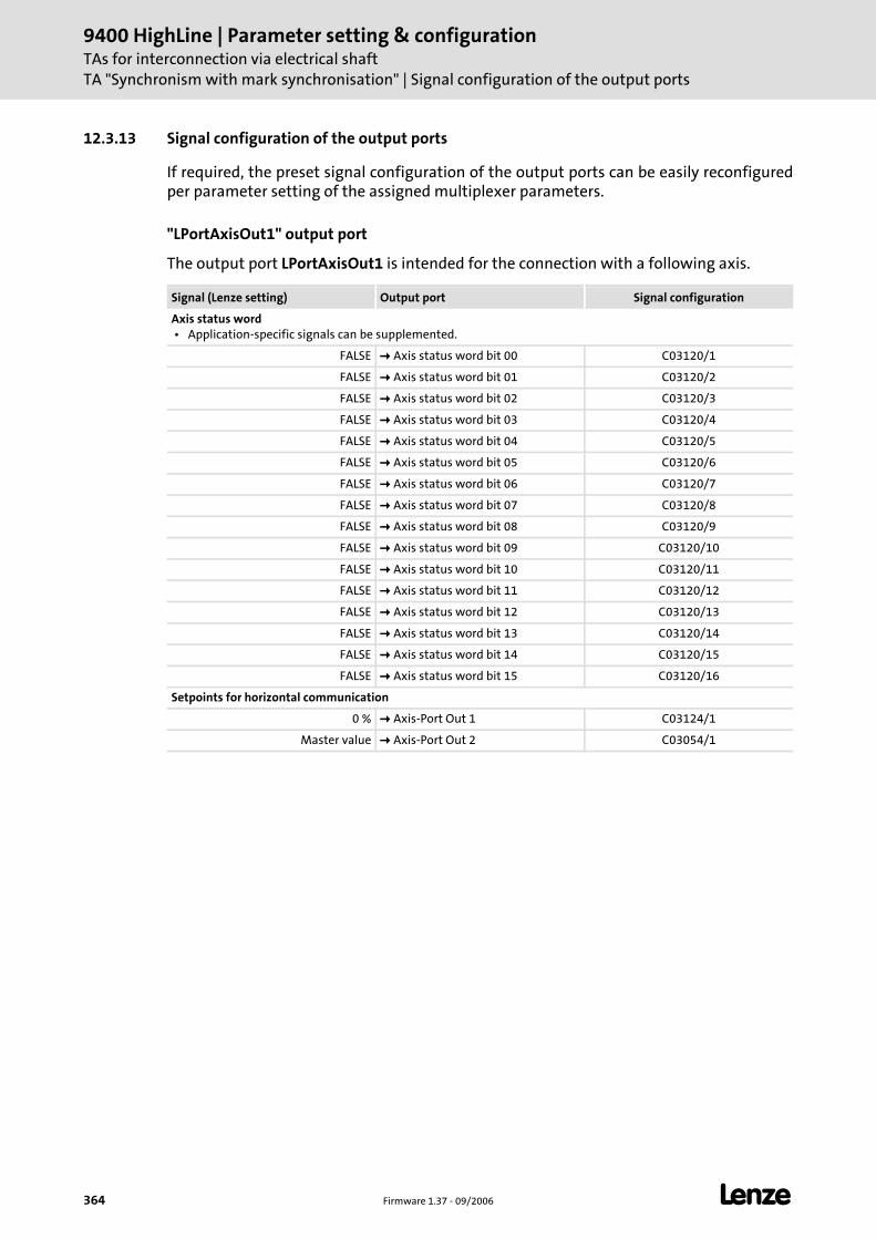
9400 HighLine | Parameter setting & configurationTAs for interconnection via electrical shaftTA "Synchronism with mark synchronisation" | Signal configuration of the output ports
364 Firmware 1.37 - 09/2006 L
12.3.13 Signal configuration of the output ports
If required, the preset signal configuration of the output ports can be easily reconfigured per parameter setting of the assigned multiplexer parameters.
"LPortAxisOut1" output port
The output port LPortAxisOut1 is intended for the connection with a following axis.
Signal (Lenze setting) Output port Signal configuration
Axis status word • Application-specific signals can be supplemented.
FALSE Axis status word bit 00 C03120/1
FALSE Axis status word bit 01 C03120/2
FALSE Axis status word bit 02 C03120/3
FALSE Axis status word bit 03 C03120/4
FALSE Axis status word bit 04 C03120/5
FALSE Axis status word bit 05 C03120/6
FALSE Axis status word bit 06 C03120/7
FALSE Axis status word bit 07 C03120/8
FALSE Axis status word bit 08 C03120/9
FALSE Axis status word bit 09 C03120/10
FALSE Axis status word bit 10 C03120/11
FALSE Axis status word bit 11 C03120/12
FALSE Axis status word bit 12 C03120/13
FALSE Axis status word bit 13 C03120/14
FALSE Axis status word bit 14 C03120/15
FALSE Axis status word bit 15 C03120/16
Setpoints for horizontal communication
0 % Axis-Port Out 1 C03124/1
Master value Axis-Port Out 2 C03054/1
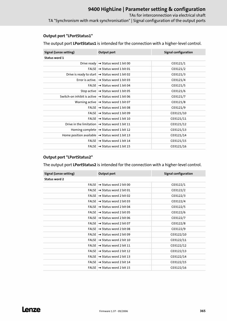
L Firmware 1.37 - 09/2006 365
9400 HighLine | Parameter setting & configurationTAs for interconnection via electrical shaft
TA "Synchronism with mark synchronisation" | Signal configuration of the output ports
Output port "LPortStatus1"
The output port LPortStatus1 is intended for the connection with a higher-level control.
Output port "LPortStatus2"
The output port LPortStatus2 is intended for the connection with a higher-level control.
Signal (Lenze setting) Output port Signal configuration
Status word 1
Drive ready Status word 1 bit 00 C03121/1
FALSE Status word 1 bit 01 C03121/2
Drive is ready to start Status word 1 bit 02 C03121/3
Error is active. Status word 1 bit 03 C03121/4
FALSE Status word 1 bit 04 C03121/5
Stop active Status word 1 bit 05 C03121/6
Switch-on inhibit is active Status word 1 bit 06 C03121/7
Warning active Status word 1 bit 07 C03121/8
FALSE Status word 1 bit 08 C03121/9
FALSE Status word 1 bit 09 C03121/10
FALSE Status word 1 bit 10 C03121/11
Drive in the limitation Status word 1 bit 11 C03121/12
Homing complete Status word 1 bit 12 C03121/13
Home position available Status word 1 bit 13 C03121/14
FALSE Status word 1 bit 14 C03121/15
FALSE Status word 1 bit 15 C03121/16
Signal (Lenze setting) Output port Signal configuration
Status word 2
FALSE Status word 2 bit 00 C03122/1
FALSE Status word 2 bit 01 C03122/2
FALSE Status word 2 bit 02 C03122/3
FALSE Status word 2 bit 03 C03122/4
FALSE Status word 2 bit 04 C03122/5
FALSE Status word 2 bit 05 C03122/6
FALSE Status word 2 bit 06 C03122/7
FALSE Status word 2 bit 07 C03122/8
FALSE Status word 2 bit 08 C03122/9
FALSE Status word 2 bit 09 C03122/10
FALSE Status word 2 bit 10 C03122/11
FALSE Status word 2 bit 11 C03122/12
FALSE Status word 2 bit 12 C03122/13
FALSE Status word 2 bit 13 C03122/14
FALSE Status word 2 bit 14 C03122/15
FALSE Status word 2 bit 15 C03122/16
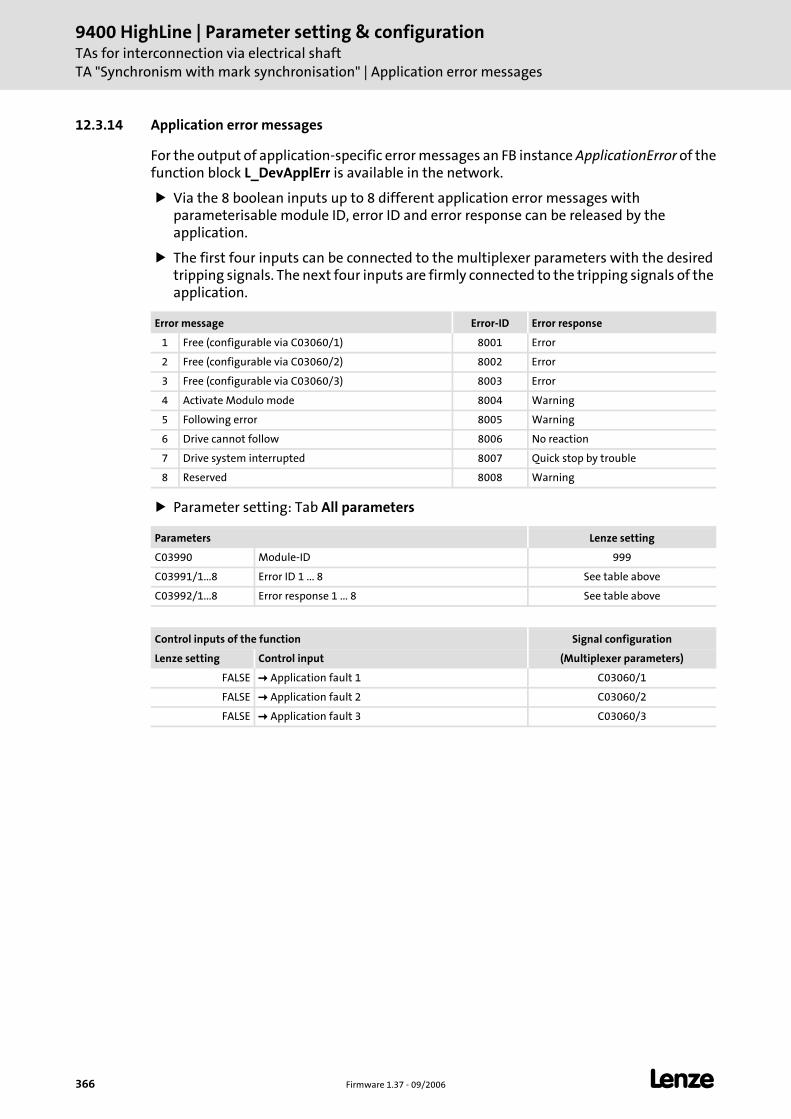
9400 HighLine | Parameter setting & configurationTAs for interconnection via electrical shaftTA "Synchronism with mark synchronisation" | Application error messages
366 Firmware 1.37 - 09/2006 L
12.3.14 Application error messages
For the output of application-specific error messages an FB instance ApplicationError of the function block L_DevApplErr is available in the network.
Via the 8 boolean inputs up to 8 different application error messages with parameterisable module ID, error ID and error response can be released by the application.
The first four inputs can be connected to the multiplexer parameters with the desired tripping signals. The next four inputs are firmly connected to the tripping signals of the application.
Parameter setting: Tab All parameters
Error message Error-ID Error response
1 Free (configurable via C03060/1) 8001 Error
2 Free (configurable via C03060/2) 8002 Error
3 Free (configurable via C03060/3) 8003 Error
4 Activate Modulo mode 8004 Warning
5 Following error 8005 Warning
6 Drive cannot follow 8006 No reaction
7 Drive system interrupted 8007 Quick stop by trouble
8 Reserved 8008 Warning
Parameters Lenze setting
C03990 Module-ID 999
C03991/1...8 Error ID 1 ... 8 See table above
C03992/1...8 Error response 1 ... 8 See table above
Control inputs of the function Signal configuration
Lenze setting Control input (Multiplexer parameters)
FALSE Application fault 1 C03060/1
FALSE Application fault 2 C03060/2
FALSE Application fault 3 C03060/3
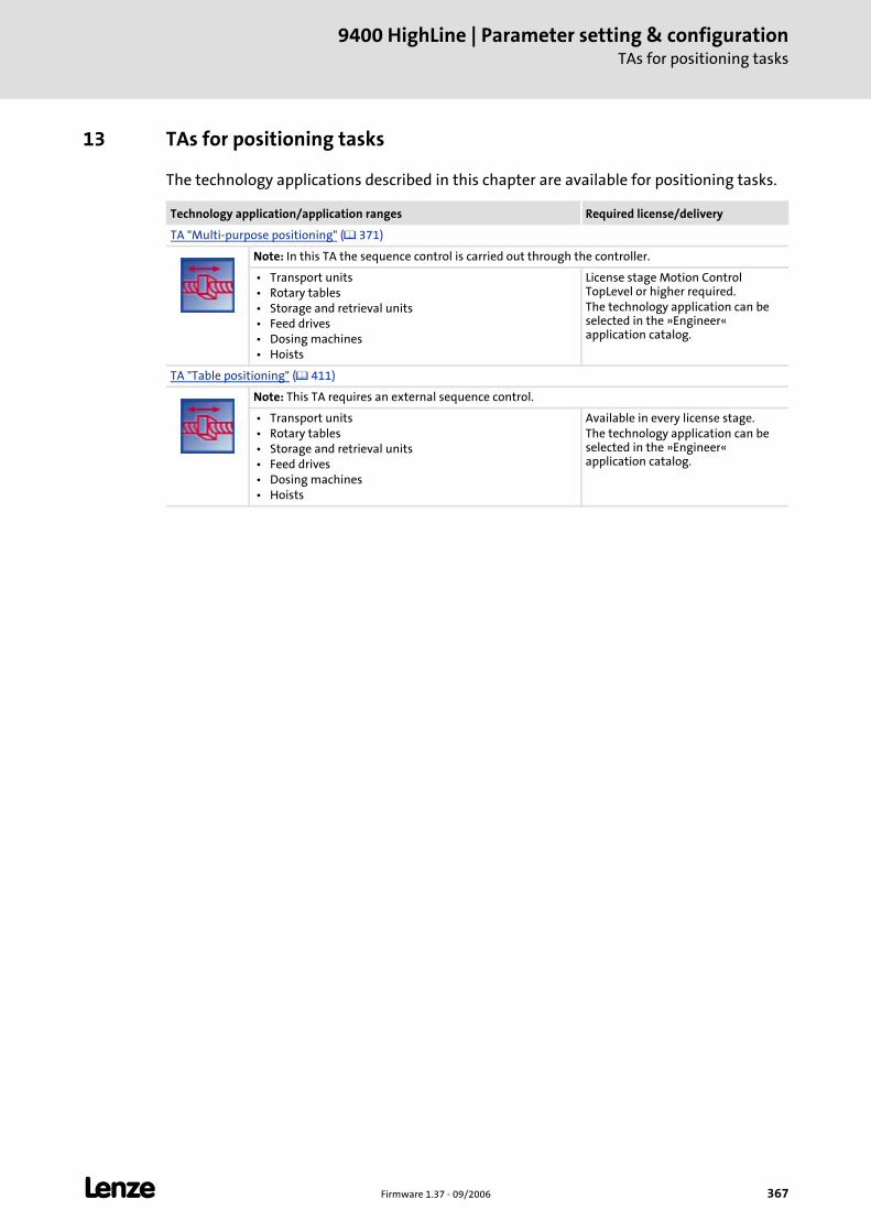
L Firmware 1.37 - 09/2006 367
9400 HighLine | Parameter setting & configurationTAs for positioning tasks
13 TAs for positioning tasks
The technology applications described in this chapter are available for positioning tasks.
Technology application/application ranges Required license/delivery
TA "Multi-purpose positioning" ( 371)
Note: In this TA the sequence control is carried out through the controller.
• Transport units • Rotary tables • Storage and retrieval units • Feed drives • Dosing machines • Hoists
License stage Motion Control TopLevel or higher required.The technology application can be selected in the »Engineer« application catalog.
TA "Table positioning" ( 411)
Note: This TA requires an external sequence control.
• Transport units • Rotary tables • Storage and retrieval units • Feed drives • Dosing machines • Hoists
Available in every license stage.The technology application can be selected in the »Engineer« application catalog.
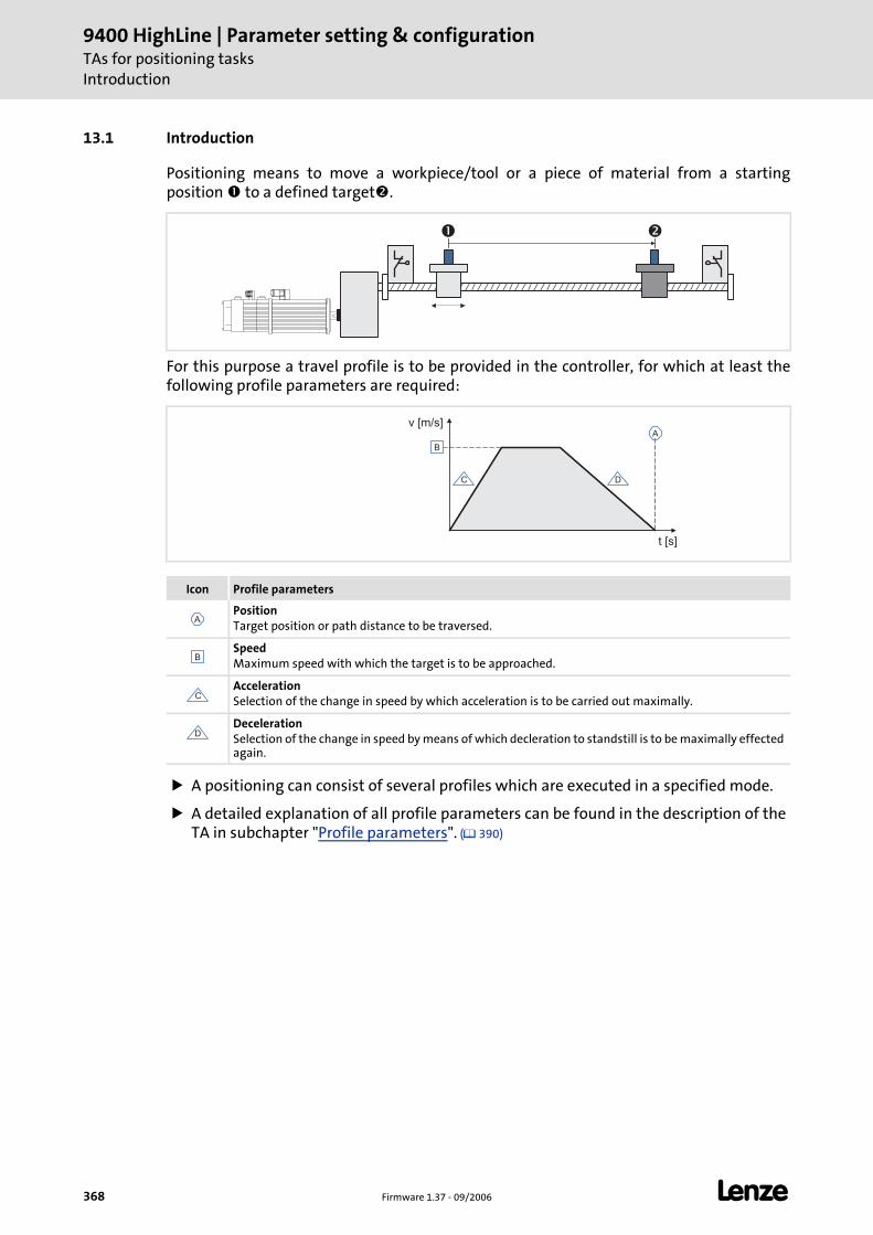
9400 HighLine | Parameter setting & configurationTAs for positioning tasksIntroduction
368 Firmware 1.37 - 09/2006 L
13.1 Introduction
Positioning means to move a workpiece/tool or a piece of material from a starting position to a defined target .
For this purpose a travel profile is to be provided in the controller, for which at least thefollowing profile parameters are required:
A positioning can consist of several profiles which are executed in a specified mode.
A detailed explanation of all profile parameters can be found in the description of the TA in subchapter "Profile parameters". ( 390)
Icon Profile parameters
PositionTarget position or path distance to be traversed.
SpeedMaximum speed with which the target is to be approached.
AccelerationSelection of the change in speed by which acceleration is to be carried out maximally.
DecelerationSelection of the change in speed by means of which decleration to standstill is to be maximally effected again.
� �
v [m/s]
t [s]
A
B
C D
A
B
C
D
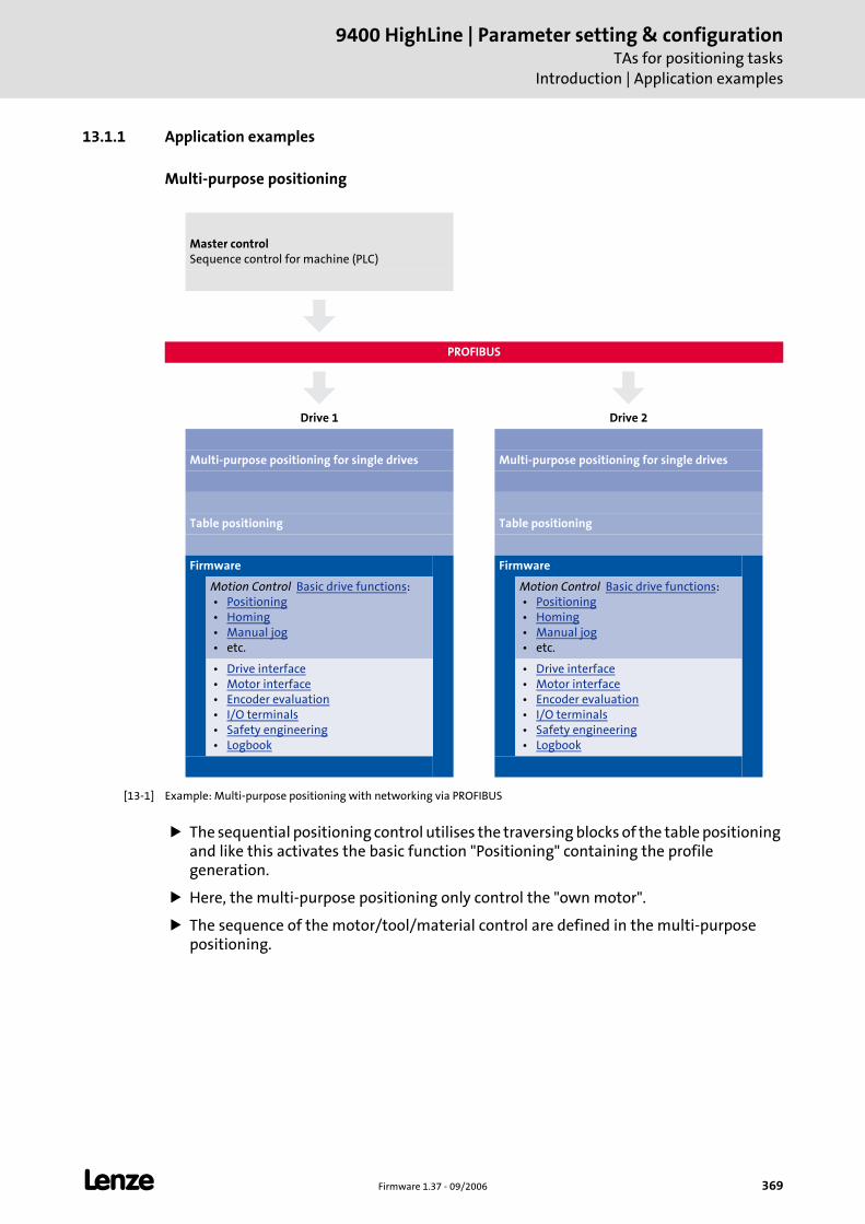
L Firmware 1.37 - 09/2006 369
9400 HighLine | Parameter setting & configurationTAs for positioning tasks
Introduction | Application examples
13.1.1 Application examples
Multi-purpose positioning
[13-1] Example: Multi-purpose positioning with networking via PROFIBUS
The sequential positioning control utilises the traversing blocks of the table positioning and like this activates the basic function "Positioning" containing the profile generation.
Here, the multi-purpose positioning only control the "own motor".
The sequence of the motor/tool/material control are defined in the multi-purpose positioning.
Master controlSequence control for machine (PLC)
PROFIBUS
Drive 1 Drive 2
Multi-purpose positioning for single drives Multi-purpose positioning for single drives
Table positioning Table positioning
Firmware Firmware
Motion Control Basic drive functions: • Positioning • Homing • Manual jog • etc.
Motion Control Basic drive functions: • Positioning • Homing • Manual jog • etc.
• Drive interface • Motor interface • Encoder evaluation • I/O terminals • Safety engineering • Logbook
• Drive interface • Motor interface • Encoder evaluation • I/O terminals • Safety engineering • Logbook
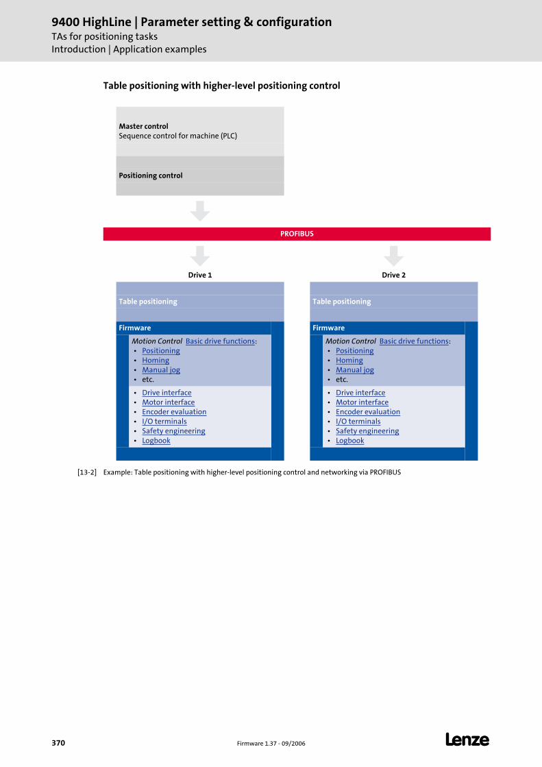
9400 HighLine | Parameter setting & configurationTAs for positioning tasksIntroduction | Application examples
370 Firmware 1.37 - 09/2006 L
Table positioning with higher-level positioning control
[13-2] Example: Table positioning with higher-level positioning control and networking via PROFIBUS
Master controlSequence control for machine (PLC)
Positioning control
PROFIBUS
Drive 1 Drive 2
Table positioning Table positioning
Firmware Firmware
Motion Control Basic drive functions: • Positioning • Homing • Manual jog • etc.
Motion Control Basic drive functions: • Positioning • Homing • Manual jog • etc.
• Drive interface • Motor interface • Encoder evaluation • I/O terminals • Safety engineering • Logbook
• Drive interface • Motor interface • Encoder evaluation • I/O terminals • Safety engineering • Logbook
L Firmware 1.37 - 09/2006 371
9400 HighLine | Parameter setting & configurationTAs for positioning tasks
TA "Multi-purpose positioning"
13.2 TA "Multi-purpose positioning"
The technology application "Multi-purpose positioning" enables the drive to execute parameterisable travel profiles. The program sequence is defined by a sequence table.
Functions
Sequence control for several successive positioning steps with a break and stop functions and different auxiliary functions (e. g. deriving, counting, waiting).
Positioning in different positioning modes
– Point-to-point positioning
– Touch probe positioning (residual path positioning)
– Profile chaining with velocity changeover (overchange)
Homing in different homing modes
Profile data management
– Support of S profiles (jerk limitation)
– Separate setting for acceleration and deceleration
– "Teach" function
Speed-/acceleration override
Path-dependent switching of outputs
Following error monitoring
Support of absolute value encoders
Support of the basic drive functions "Manual jog" and "Quick stop"
Monitoring of travel range limits with the basic drive function "Limiter"
Optional control of a holding brake with the basic drive function "Brake control"
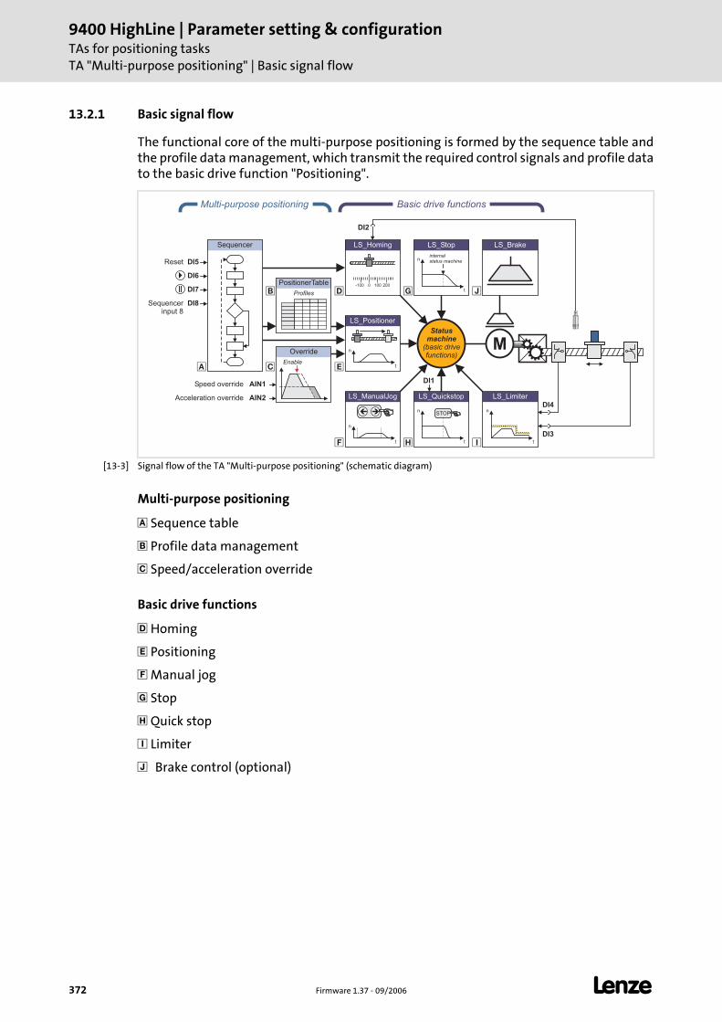
9400 HighLine | Parameter setting & configurationTAs for positioning tasksTA "Multi-purpose positioning" | Basic signal flow
372 Firmware 1.37 - 09/2006 L
13.2.1 Basic signal flow
The functional core of the multi-purpose positioning is formed by the sequence table and the profile data management, which transmit the required control signals and profile data to the basic drive function "Positioning".
[13-3] Signal flow of the TA "Multi-purpose positioning" (schematic diagram)
Multi-purpose positioning
Sequence table
Profile data management
Speed/acceleration override
Basic drive functions
Homing
Positioning
Manual jog
Stop
Quick stop
Limiter
Brake control (optional)
�
� � �
�
�
�
�
DI7
DI6
AIN1
PositionerTable
Profiles
Multi-purpose positioning
Override
Enable
AIN2
Speed override
Acceleration override
Sequencer
LS_ManualJog
n
t
��
LS_Brake
n
t
LS_Limiter
n
t
LS_Quickstop
STOP
n
t
LS_Stop
internalstatus machine
Statusmachine
(basic drivefunctions)
Basic drive functions
M
0-100 100 200
LS_Homing
n
t
LS_Positioner
DI2
DI4
DI3
DI1
DI5Reset
Sequencerinput 8
DI8
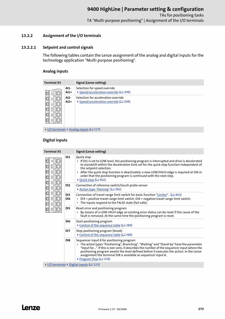
L Firmware 1.37 - 09/2006 373
9400 HighLine | Parameter setting & configurationTAs for positioning tasks
TA "Multi-purpose positioning" | Assignment of the I/O terminals
13.2.2 Assignment of the I/O terminals
13.2.2.1 Setpoint and control signals
The following tables contain the Lenze assignment of the analog and digital inputs for the technology application "Multi-purpose positioning".
Analog inputs
Digital inputs
Terminal X3 Signal (Lenze setting)
AI1-AI1+
Selection for speed overrideSpeed/acceleration override ( 399)
AI2-AI2+
Selection for acceleration overrideSpeed/acceleration override ( 399)
I/O terminals Analog inputs ( 117)
Terminal X5 Signal (Lenze setting)
DI1 Quick stop • If DI1 is set to LOW level, the positioning program is interrupted and drive is decelerated
to standstill within the deceleration time set for the quick stop function independent of the setpoint selection.
• After the quick stop function is deactivated, a new LOW/HIGH edge is required at DI6 in order that the positioning program is continued with the next step.
Quick stop ( 402)
DI2 Connection of reference switch/touch probe sensorAction type "Homing" ( 382)
DI3DI4
Connection of travel range limit switch for basic function "Limiter". ( 403) • DI3 = positive travel range limit switch, DI4 = negative travel range limit switch. • The inputs respond to the FALSE state (fail-safe).
DI5 Reset error and positioning program • By means of a LOW-HIGH edge an existing error status can be reset if the cause of the
fault is removed. At the same time the positioning program is reset.
DI6 Start positioning programControl of the sequence table ( 389)
DI7 Stop positioning program (break)Control of the sequence table ( 389)
DI8 Sequencer input 8 for positioning program • The action types "Positioning", Branching", "Waiting" and "Stand-by" have the parameter
"Input for...". If this is non-zero, it describes the number of the sequencer input where the positioning program awaits the level defined before it executes the action. In the Lenze assignment the terminal DI8 is available as sequencer input 8.
Program flow ( 378)
I/O terminals Digital inputs ( 123)
A1
+A
1-
A1
-A
1R
A2
+A
2-
GI
RF
RD
I1D
I2D
I3D
I4D
I5D
I6D
I7D
I8
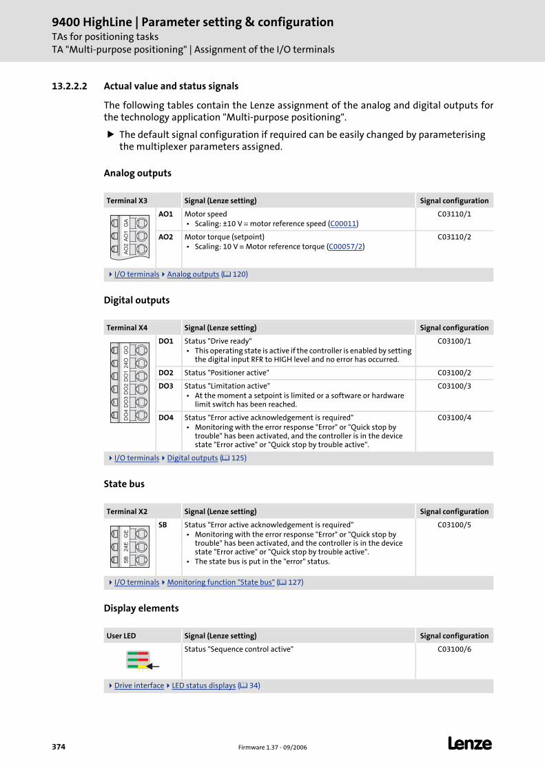
9400 HighLine | Parameter setting & configurationTAs for positioning tasksTA "Multi-purpose positioning" | Assignment of the I/O terminals
374 Firmware 1.37 - 09/2006 L
13.2.2.2 Actual value and status signals
The following tables contain the Lenze assignment of the analog and digital outputs for the technology application "Multi-purpose positioning".
The default signal configuration if required can be easily changed by parameterising the multiplexer parameters assigned.
Analog outputs
Digital outputs
State bus
Display elements
Terminal X3 Signal (Lenze setting) Signal configuration
AO1 Motor speed • Scaling: ±10 V ≡ motor reference speed (C00011)
C03110/1
AO2 Motor torque (setpoint) • Scaling: 10 V ≡ Motor reference torque (C00057/2)
C03110/2
I/O terminals Analog outputs ( 120)
Terminal X4 Signal (Lenze setting) Signal configuration
DO1 Status "Drive ready" • This operating state is active if the controller is enabled by setting
the digital input RFR to HIGH level and no error has occurred.
C03100/1
DO2 Status "Positioner active" C03100/2
DO3 Status "Limitation active" • At the moment a setpoint is limited or a software or hardware
limit switch has been reached.
C03100/3
DO4 Status "Error active acknowledgement is required" • Monitoring with the error response "Error" or "Quick stop by
trouble" has been activated, and the controller is in the device state "Error active" or "Quick stop by trouble active".
C03100/4
I/O terminals Digital outputs ( 125)
Terminal X2 Signal (Lenze setting) Signal configuration
SB Status "Error active acknowledgement is required" • Monitoring with the error response "Error" or "Quick stop by
trouble" has been activated, and the controller is in the device state "Error active" or "Quick stop by trouble active".
• The state bus is put in the "error" status.
C03100/5
I/O terminals Monitoring function "State bus" ( 127)
User LED Signal (Lenze setting) Signal configuration
Status "Sequence control active" C03100/6
Drive interface LED status displays ( 34)
GA
AO
1A
O2
GO
24
OD
O1
DO
2D
O3
DO
4G
E2
4E
SB
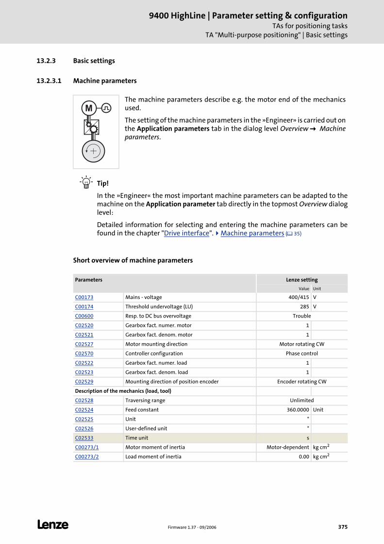
L Firmware 1.37 - 09/2006 375
9400 HighLine | Parameter setting & configurationTAs for positioning tasks
TA "Multi-purpose positioning" | Basic settings
13.2.3 Basic settings
13.2.3.1 Machine parameters
Tip!
In the »Engineer« the most important machine parameters can be adapted to the machine on the Application parameter tab directly in the topmost Overview dialog level:
Detailed information for selecting and entering the machine parameters can be found in the chapter "Drive interface". Machine parameters ( 35)
Short overview of machine parameters
The machine parameters describe e.g. the motor end of the mechanics used.
The setting of the machine parameters in the »Engineer» is carried out on the Application parameters tab in the dialog level Overview Machine parameters.
Parameters Lenze setting
Value Unit
C00173 Mains - voltage 400/415 V
C00174 Threshold undervoltage (LU) 285 V
C00600 Resp. to DC bus overvoltage Trouble
C02520 Gearbox fact. numer. motor 1
C02521 Gearbox fact. denom. motor 1
C02527 Motor mounting direction Motor rotating CW
C02570 Controller configuration Phase control
C02522 Gearbox fact. numer. load 1
C02523 Gearbox fact. denom. load 1
C02529 Mounting direction of position encoder Encoder rotating CW
Description of the mechanics (load, tool)
C02528 Traversing range Unlimited
C02524 Feed constant 360.0000 Unit
C02525 Unit °
C02526 User-defined unit °
C02533 Time unit s
C00273/1 Motor moment of inertia Motor-dependent kg cm2
C00273/2 Load moment of inertia 0.00 kg cm2
M
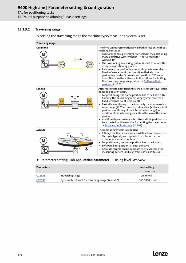
9400 HighLine | Parameter setting & configurationTAs for positioning tasksTA "Multi-purpose positioning" | Basic settings
376 Firmware 1.37 - 09/2006 L
13.2.3.2 Traversing range
By setting the traversing range the machine type/measuring system is set:
Parameter setting: Tab Application parameter Dialog level Overview
Traversing range
Unlimited The drive can traverse optionally in both directions without reaching limitations. • Positionings here generally are effected in the positioning
modes "Relative with/without TP" or "Speed with/without TP".
• The positioning measuring system is reset to zero with every new positioning process.
• By homing, the positioning measuring system receives a fixed reference point (zero point), so that also the positioning modes "Absolute with/without TP"can be used. Then also the software limit positions for limiting the traversing range are provided. Software limit positions ( 202)
Limited After reaching the position limits, the drive must travel in the opposite direction again. • For positioning, the home position has to be known. By
homing, the positioning measuring system receives a fixed reference point (zero point).
• Basically, monitoring to the internally maximum usable value range (±231 increments) takes place (software limit position monitoring of the internal value range). An overflow of the value range results in the loss of the home position.
• Additionally parameterisable software limit positions can be activated on the user side for limiting the travel range.
Software limit positions ( 202)
Modulo The measuring system is repeated. • If the cycles set are exceeded a defined overflow occurs.
The cycle typically corresponds to a rotation or tool distance in a rotative system.
• For positioning, the home position has to be known. • Software limit positions are not effective • Absolute targets can be approached by exceeding the
measuring system limit, e.g. from 10° via 0° to 350°.
Parameters Lenze setting
Value Unit
C02528 Traversing range Unlimited
C02536 Cycle (only relevant for traversing range "Modulo") 360.0000 Unit
M
M
M
�
L Firmware 1.37 - 09/2006 377
9400 HighLine | Parameter setting & configurationTAs for positioning tasks
TA "Multi-purpose positioning" | Basic settings
13.2.3.3 Position control
The dialog level Overview S_Positioner and the subordinated and dialog levels serve to adapt the parameters relevant for the position control, if required.
Parameters Lenze setting
Value Unit
C00254 Phase controller gain 20.00 1/s
C02553 Position controller gain 20.00 1/s
C02556 Pos. contr. limitation 214748.3647 Unit/s
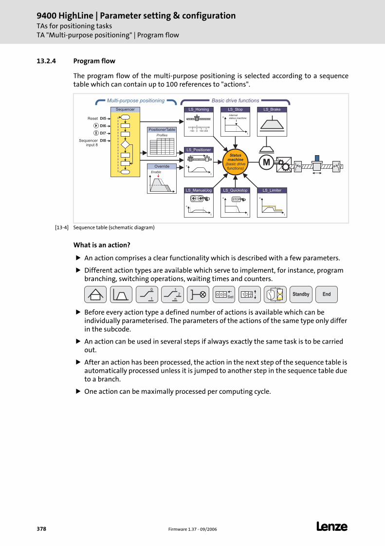
9400 HighLine | Parameter setting & configurationTAs for positioning tasksTA "Multi-purpose positioning" | Program flow
378 Firmware 1.37 - 09/2006 L
13.2.4 Program flow
The program flow of the multi-purpose positioning is selected according to a sequence table which can contain up to 100 references to "actions".
[13-4] Sequence table (schematic diagram)
What is an action?
An action comprises a clear functionality which is described with a few parameters.
Different action types are available which serve to implement, for instance, program branching, switching operations, waiting times and counters.
Before every action type a defined number of actions is available which can be individually parameterised. The parameters of the actions of the same type only differ in the subcode.
An action can be used in several steps if always exactly the same task is to be carried out.
After an action has been processed, the action in the next step of the sequence table is automatically processed unless it is jumped to another step in the sequence table due to a branch.
One action can be maximally processed per computing cycle.
PositionerTable
Profiles
Multi-purpose positioning
Override
Enable
Sequencer
LS_ManualJog
n
t
��
LS_Brake
n
t
LS_Limiter
n
t
LS_Quickstop
STOP
n
t
LS_Stop
internalstatus machine
Statusmachine
(basic drivefunctions)
Basic drive functions
M
0-100 100 200
LS_Homing
n
t
LS_Positioner
DI7
DI6
DI5Reset
Sequencerinput 8
DI8
1
n
2
0
10
Set0 0 1 Standby End3
42
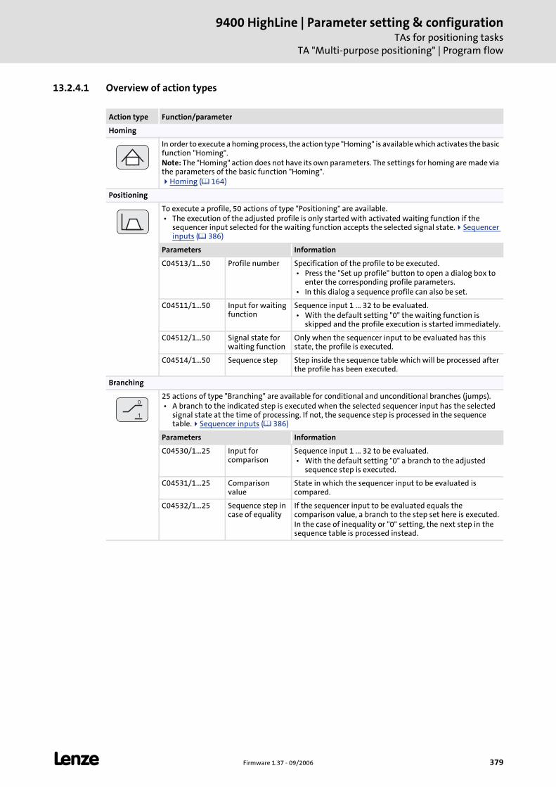
L Firmware 1.37 - 09/2006 379
9400 HighLine | Parameter setting & configurationTAs for positioning tasks
TA "Multi-purpose positioning" | Program flow
13.2.4.1 Overview of action types
Action type Function/parameter
Homing
In order to execute a homing process, the action type "Homing" is available which activates the basic function "Homing".Note: The "Homing" action does not have its own parameters. The settings for homing are made via the parameters of the basic function "Homing".
Homing ( 164)
Positioning
To execute a profile, 50 actions of type "Positioning" are available. • The execution of the adjusted profile is only started with activated waiting function if the
sequencer input selected for the waiting function accepts the selected signal state. Sequencer inputs ( 386)
Parameters Information
C04513/1...50 Profile number Specification of the profile to be executed. • Press the "Set up profile" button to open a dialog box to
enter the corresponding profile parameters. • In this dialog a sequence profile can also be set.
C04511/1...50 Input for waiting function
Sequence input 1 ... 32 to be evaluated. • With the default setting "0" the waiting function is
skipped and the profile execution is started immediately.
C04512/1...50 Signal state for waiting function
Only when the sequencer input to be evaluated has this state, the profile is executed.
C04514/1...50 Sequence step Step inside the sequence table which will be processed after the profile has been executed.
Branching
25 actions of type "Branching" are available for conditional and unconditional branches (jumps). • A branch to the indicated step is executed when the selected sequencer input has the selected
signal state at the time of processing. If not, the sequence step is processed in the sequence table. Sequencer inputs ( 386)
Parameters Information
C04530/1...25 Input for comparison
Sequence input 1 ... 32 to be evaluated. • With the default setting "0" a branch to the adjusted
sequence step is executed.
C04531/1...25 Comparison value
State in which the sequencer input to be evaluated is compared.
C04532/1...25 Sequence step in case of equality
If the sequencer input to be evaluated equals the comparison value, a branch to the step set here is executed.In the case of inequality or "0" setting, the next step in the sequence table is processed instead.
0
1
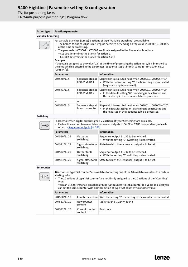
9400 HighLine | Parameter setting & configurationTAs for positioning tasksTA "Multi-purpose positioning" | Program flow
380 Firmware 1.37 - 09/2006 L
Variable branching
For variable branches (jumps) 5 actions of type "Variable branching" are available. • The branch to one of 20 possible steps is executed depending on the value in C03001 ... C03005
at the time or processing. • The parameters C03001 ... C03005 are firmly assigned to the five available actions:
– C03001 determines the branch for action 1.– C03002 determines the branch for action 2, etc.
Example:If C03002 is assigned to the value "15" at the time of processing the action no. 2, it is branched to the step which is entered in the parameter "Sequence step at branch value 15" for action no. 2 (C04554/2).
Parameters Information
C04540/1...5 Sequence step at branch value 1
Step which is executed next when C03001 ... C03005 = "1". • With the default setting "0" the branching is deactivated
(sequence step is processed).
C04541/1...5 Sequence step at branch value 2
Step which is executed next when C03001 ... C03005 = "2". • In the default setting "0", branching is deactivated and
the next step in the sequence table is processed.
... ... ...
C04559/1...5 Sequence step at branch value 20
Step which is executed next when C03001 ... C03005 = "20". • In the default setting "0", branching is deactivated and
the next step in the sequence table is processed.
Switching
In order to switch digital output signals 25 actions of type "Switching" are available. • Each action can set two selectable sequencer outputs to FALSE or TRUE independently of each
other. Sequencer outputs ( 386)
Parameters Information
C04520/1...25 Output A switching
Sequencer output 1 ... 32 to be switched. • With the setting "0" switching is deactivated.
C04521/1...25 Signal state for A switching
State to which the sequencer output is to be set.
C04522/1...25 Output for B switching
Sequencer output 1 ... 32 to be switched. • With the setting "0" switching is deactivated.
C04523/1...25 Signal state for B switching
State to which the sequencer output is to be set.
Set counter
10 actions of type "Set counter" are available for setting one of the 10 available counters to a certain starting value. • The 10 actions of type "Set counter" are not firmly assigned to the 10 actions of the "Counting"
type. • You can use, for instance, an action of type "Set counter" to set a counter to a value and later you
can set the same counter with another action of type "Set counter" to another value.
Parameters Information
C04580/1...10 Counter selection With the setting "0" the setting of the counter is deactivated.
C04581/1...10 New counter content
-2147483648 ... 2147483648
C04582/1...10 Current counter content
Read only
Action type Function/parameter
1
n
2
0Set
0 0
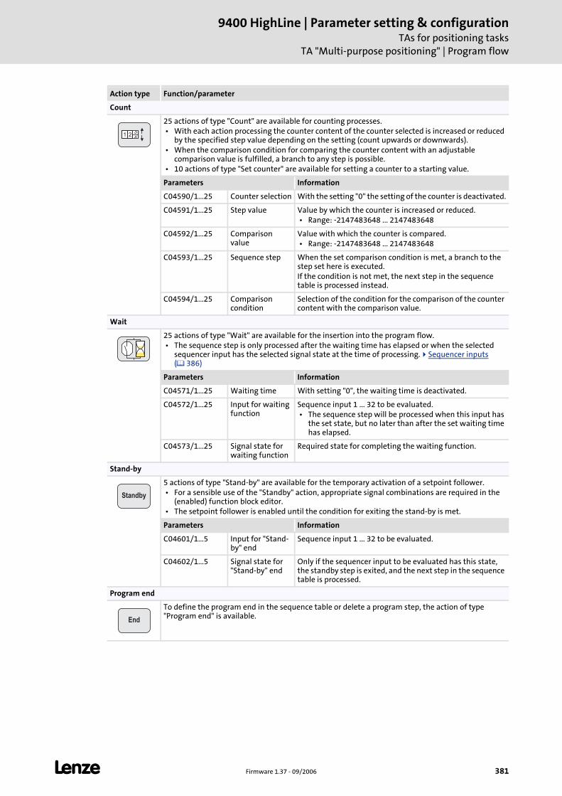
L Firmware 1.37 - 09/2006 381
9400 HighLine | Parameter setting & configurationTAs for positioning tasks
TA "Multi-purpose positioning" | Program flow
Count
25 actions of type "Count" are available for counting processes. • With each action processing the counter content of the counter selected is increased or reduced
by the specified step value depending on the setting (count upwards or downwards). • When the comparison condition for comparing the counter content with an adjustable
comparison value is fulfilled, a branch to any step is possible. • 10 actions of type "Set counter" are available for setting a counter to a starting value.
Parameters Information
C04590/1...25 Counter selection With the setting "0" the setting of the counter is deactivated.
C04591/1...25 Step value Value by which the counter is increased or reduced. • Range: -2147483648 ... 2147483648
C04592/1...25 Comparison value
Value with which the counter is compared. • Range: -2147483648 ... 2147483648
C04593/1...25 Sequence step When the set comparison condition is met, a branch to the step set here is executed.If the condition is not met, the next step in the sequence table is processed instead.
C04594/1...25 Comparison condition
Selection of the condition for the comparison of the counter content with the comparison value.
Wait
25 actions of type "Wait" are available for the insertion into the program flow. • The sequence step is only processed after the waiting time has elapsed or when the selected
sequencer input has the selected signal state at the time of processing. Sequencer inputs ( 386)
Parameters Information
C04571/1...25 Waiting time With setting "0", the waiting time is deactivated.
C04572/1...25 Input for waiting function
Sequence input 1 ... 32 to be evaluated. • The sequence step will be processed when this input has
the set state, but no later than after the set waiting time has elapsed.
C04573/1...25 Signal state for waiting function
Required state for completing the waiting function.
Stand-by
5 actions of type "Stand-by" are available for the temporary activation of a setpoint follower. • For a sensible use of the "Standby" action, appropriate signal combinations are required in the
(enabled) function block editor. • The setpoint follower is enabled until the condition for exiting the stand-by is met.
Parameters Information
C04601/1...5 Input for "Stand-by" end
Sequence input 1 ... 32 to be evaluated.
C04602/1...5 Signal state for "Stand-by" end
Only if the sequencer input to be evaluated has this state, the standby step is exited, and the next step in the sequence table is processed.
Program end
To define the program end in the sequence table or delete a program step, the action of type "Program end" is available.
Action type Function/parameter
134
2
Standby
End
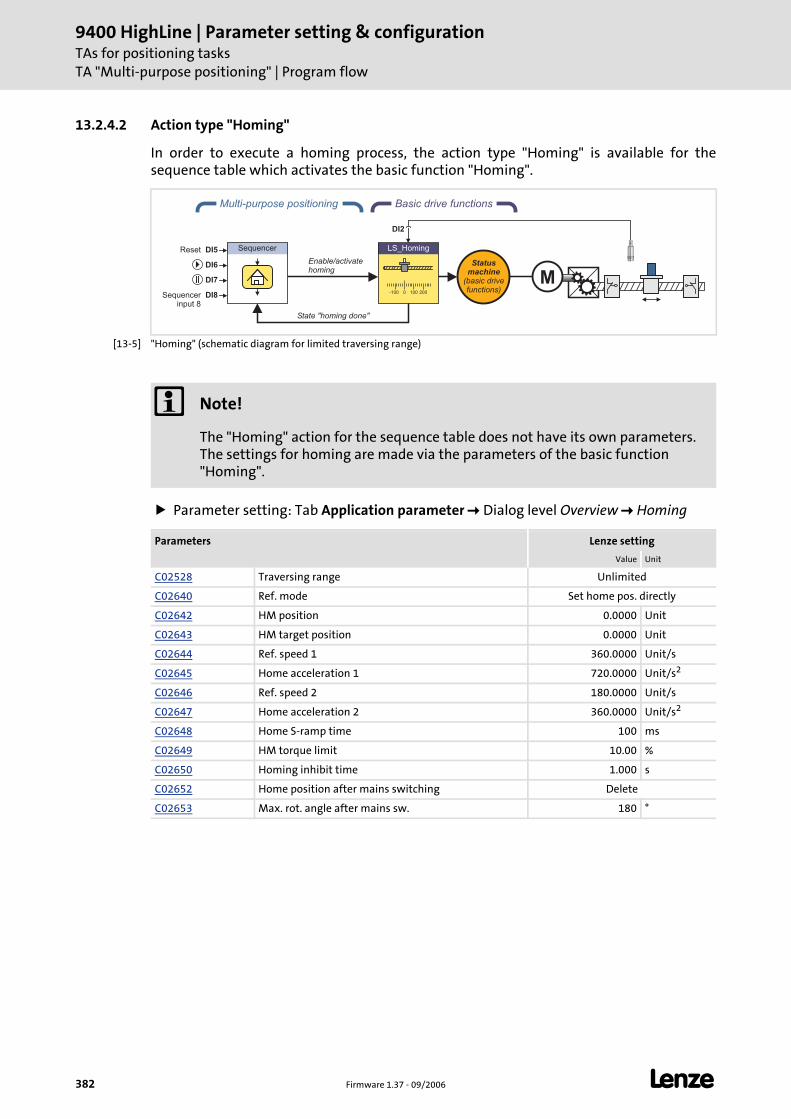
9400 HighLine | Parameter setting & configurationTAs for positioning tasksTA "Multi-purpose positioning" | Program flow
382 Firmware 1.37 - 09/2006 L
13.2.4.2 Action type "Homing"
In order to execute a homing process, the action type "Homing" is available for the sequence table which activates the basic function "Homing".
[13-5] "Homing" (schematic diagram for limited traversing range)
Parameter setting: Tab Application parameter Dialog level Overview Homing
Basic drive functions
0-100 100 200
LS_Homing
Multi-purpose positioning
DI2
Sequencer
Enable/activatehoming
Statusmachine
(basic drivefunctions)
M
State "homing done"
DI7
DI6
DI5Reset
Sequencerinput 8
DI8
Note!
The "Homing" action for the sequence table does not have its own parameters. The settings for homing are made via the parameters of the basic function "Homing".
Parameters Lenze setting
Value Unit
C02528 Traversing range Unlimited
C02640 Ref. mode Set home pos. directly
C02642 HM position 0.0000 Unit
C02643 HM target position 0.0000 Unit
C02644 Ref. speed 1 360.0000 Unit/s
C02645 Home acceleration 1 720.0000 Unit/s2
C02646 Ref. speed 2 180.0000 Unit/s
C02647 Home acceleration 2 360.0000 Unit/s2
C02648 Home S-ramp time 100 ms
C02649 HM torque limit 10.00 %
C02650 Homing inhibit time 1.000 s
C02652 Home position after mains switching Delete
C02653 Max. rot. angle after mains sw. 180 °
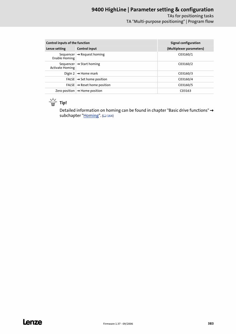
L Firmware 1.37 - 09/2006 383
9400 HighLine | Parameter setting & configurationTAs for positioning tasks
TA "Multi-purpose positioning" | Program flow
Tip!
Detailed information on homing can be found in chapter "Basic drive functions" subchapter "Homing". ( 164)
Control inputs of the function Signal configuration
Lenze setting Control input (Multiplexer parameters)
Sequencer Enable Homing
Request homing C03160/1
Sequencer Activate Homing
Start homing C03160/2
DigIn 2 Home mark C03160/3
FALSE Set home position C03160/4
FALSE Reset home position C03160/5
Zero position Home position C03163
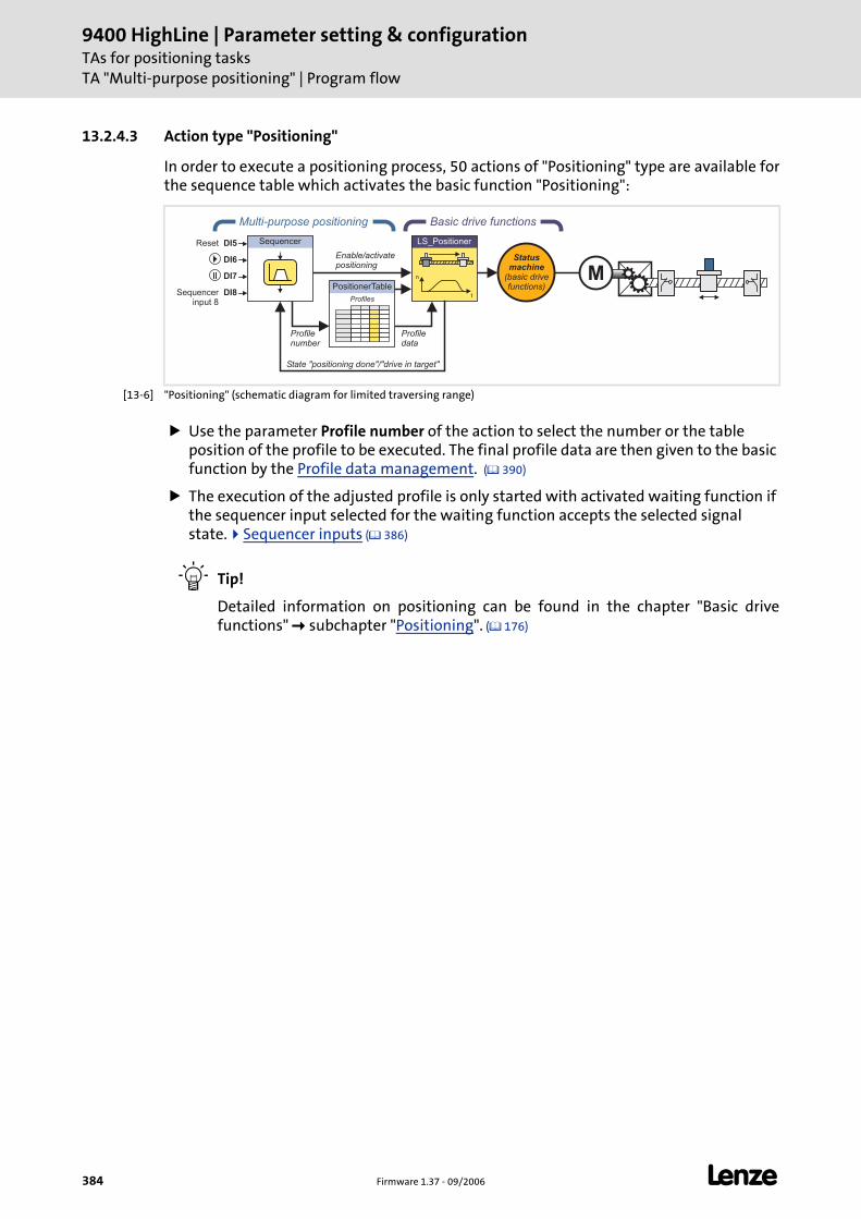
9400 HighLine | Parameter setting & configurationTAs for positioning tasksTA "Multi-purpose positioning" | Program flow
384 Firmware 1.37 - 09/2006 L
13.2.4.3 Action type "Positioning"
In order to execute a positioning process, 50 actions of "Positioning" type are available for the sequence table which activates the basic function "Positioning":
[13-6] "Positioning" (schematic diagram for limited traversing range)
Use the parameter Profile number of the action to select the number or the table position of the profile to be executed. The final profile data are then given to the basic function by the Profile data management. ( 390)
The execution of the adjusted profile is only started with activated waiting function if the sequencer input selected for the waiting function accepts the selected signal state. Sequencer inputs ( 386)
Tip!
Detailed information on positioning can be found in the chapter "Basic drive functions" subchapter "Positioning". ( 176)
Basic drive functionsMulti-purpose positioning
Sequencer
Enable/activatepositioning
n
t
LS_Positioner
PositionerTable
Profiles
Profilenumber
Profiledata
Statusmachine
(basic drivefunctions)
MDI7
DI6
DI5Reset
Sequencerinput 8
DI8
State "positioning done"/"drive in target"
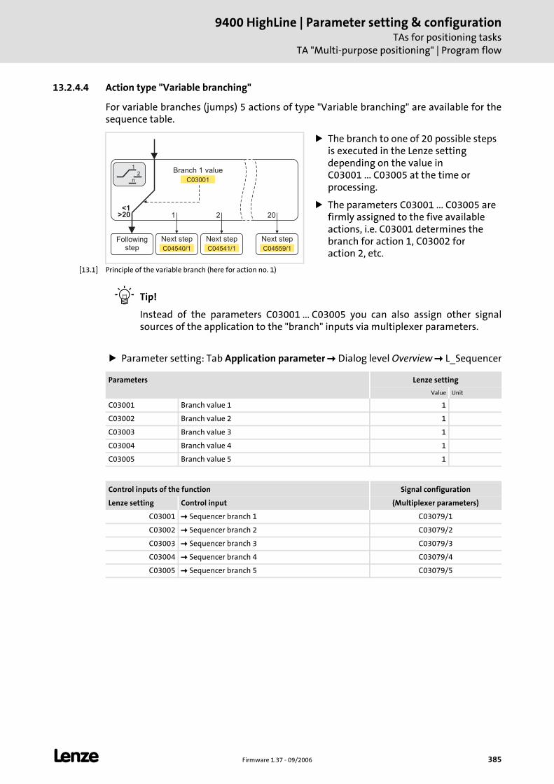
L Firmware 1.37 - 09/2006 385
9400 HighLine | Parameter setting & configurationTAs for positioning tasks
TA "Multi-purpose positioning" | Program flow
13.2.4.4 Action type "Variable branching"
For variable branches (jumps) 5 actions of type "Variable branching" are available for the sequence table.
[13.1] Principle of the variable branch (here for action no. 1)
Tip!
Instead of the parameters C03001 ... C03005 you can also assign other signal sources of the application to the "branch" inputs via multiplexer parameters.
Parameter setting: Tab Application parameter Dialog level Overview L_Sequencer
The branch to one of 20 possible steps is executed in the Lenze setting depending on the value in C03001 ... C03005 at the time or processing.
The parameters C03001 ... C03005 are firmly assigned to the five available actions, i.e. C03001 determines the branch for action 1, C03002 for action 2, etc.
1
n
2
>20 1 2 20
Followingstep
Next step Next step Next step
C04540/1 C04541/1 C04559/1
Branch 1 value
C03001
<1
Parameters Lenze setting
Value Unit
C03001 Branch value 1 1
C03002 Branch value 2 1
C03003 Branch value 3 1
C03004 Branch value 4 1
C03005 Branch value 5 1
Control inputs of the function Signal configuration
Lenze setting Control input (Multiplexer parameters)
C03001 Sequencer branch 1 C03079/1
C03002 Sequencer branch 2 C03079/2
C03003 Sequencer branch 3 C03079/3
C03004 Sequencer branch 4 C03079/4
C03005 Sequencer branch 5 C03079/5
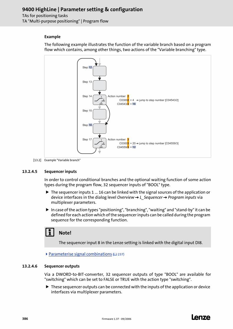
9400 HighLine | Parameter setting & configurationTAs for positioning tasksTA "Multi-purpose positioning" | Program flow
386 Firmware 1.37 - 09/2006 L
Example
The following example illustrates the function of the variable branch based on a program flow which contains, among other things, two actions of the "Variable branching" type.
[13.2] Example "Variable branch"
13.2.4.5 Sequencer inputs
In order to control conditional branches and the optional waiting function of some action types during the program flow, 32 sequencer inputs of "BOOL" type.
The sequencer inputs 1 ... 16 can be linked with the signal sources of the application or device interfaces in the dialog level Overview L_Sequencer Program inputs via multiplexer parameters.
In case of the action types "positioning", "branching", "waiting" and "stand-by" it can be defined for each action which of the sequencer inputs can be called during the program sequence for the corresponding function.
Parameterise signal combinations ( 237)
13.2.4.6 Sequencer outputs
Via a DWORD-to-BIT-converter, 32 sequencer outputs of type "BOOL" are available for "switching" which can be set to FALSE or TRUE with the action type "switching".
These sequencer outputs can be connected with the inputs of the application or device interfaces via multiplexer parameters.
Step 12
Step 13
Step 14
Step 15
Step 16
Step 17
Action number:
C03002
2
= 4
C04543/2 = 16
Action number:
C03003
3
= 20
C04559/3 = 12
1
n
2
1
n
2 � jump to step number [C04543/2]
� jump to step number [C04559/3]
Note!
The sequencer input 8 in the Lenze setting is linked with the digital input DI8.
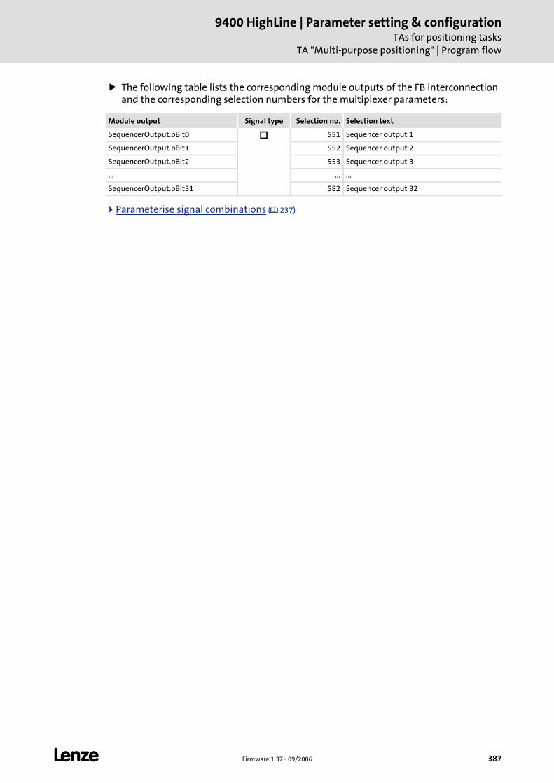
L Firmware 1.37 - 09/2006 387
9400 HighLine | Parameter setting & configurationTAs for positioning tasks
TA "Multi-purpose positioning" | Program flow
The following table lists the corresponding module outputs of the FB interconnection and the corresponding selection numbers for the multiplexer parameters:
Parameterise signal combinations ( 237)
Module output Signal type Selection no. Selection text
SequencerOutput.bBit0 551 Sequencer output 1
SequencerOutput.bBit1 552 Sequencer output 2
SequencerOutput.bBit2 553 Sequencer output 3
... ... ...
SequencerOutput.bBit31 582 Sequencer output 32
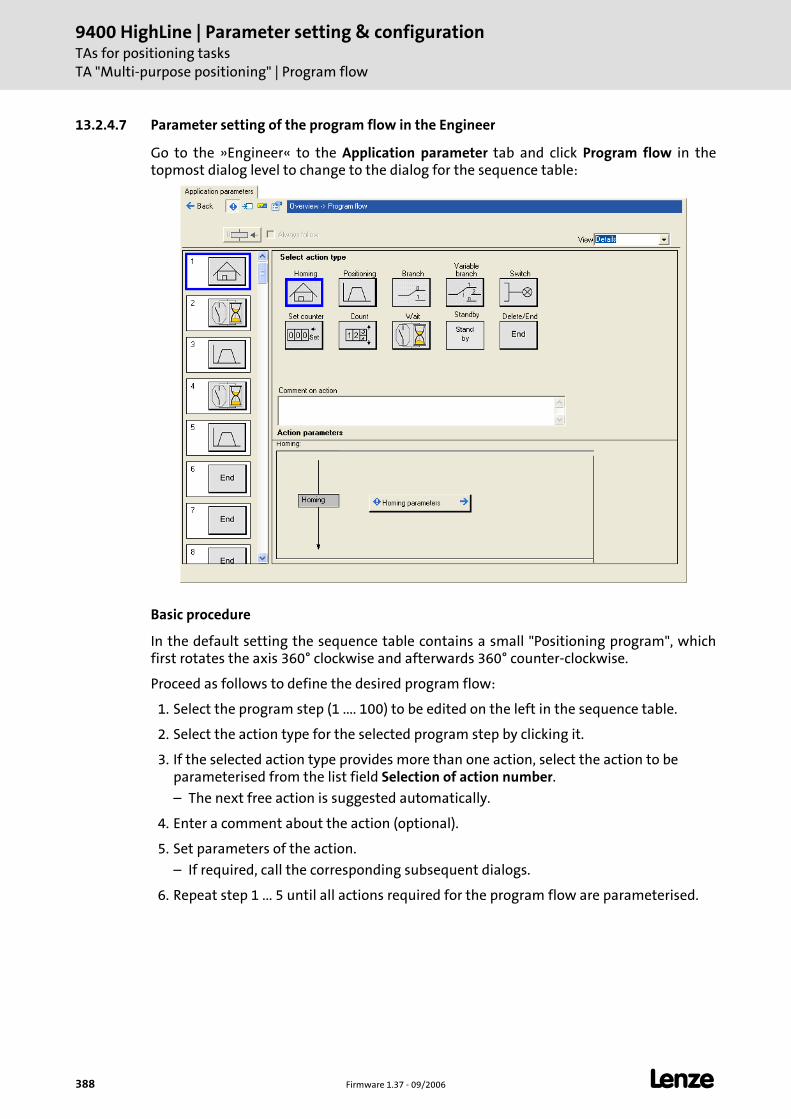
9400 HighLine | Parameter setting & configurationTAs for positioning tasksTA "Multi-purpose positioning" | Program flow
388 Firmware 1.37 - 09/2006 L
13.2.4.7 Parameter setting of the program flow in the Engineer
Go to the »Engineer« to the Application parameter tab and click Program flow in the topmost dialog level to change to the dialog for the sequence table:
Basic procedure
In the default setting the sequence table contains a small "Positioning program", which first rotates the axis 360° clockwise and afterwards 360° counter-clockwise.
Proceed as follows to define the desired program flow:
1. Select the program step (1 .... 100) to be edited on the left in the sequence table.
2. Select the action type for the selected program step by clicking it.
3. If the selected action type provides more than one action, select the action to be parameterised from the list field Selection of action number.
– The next free action is suggested automatically.
4. Enter a comment about the action (optional).
5. Set parameters of the action.
– If required, call the corresponding subsequent dialogs.
6. Repeat step 1 ... 5 until all actions required for the program flow are parameterised.
L Firmware 1.37 - 09/2006 389
9400 HighLine | Parameter setting & configurationTAs for positioning tasks
TA "Multi-purpose positioning" | Program flow
13.2.4.8 Control of the sequence table
A LOW/HIGH edge at the digital input DI6 starts the parameterised program flow if the controller is enabled and no error is pending.
The first step set in C03000 of the sequence table is executed.
By setting the digital input DI7 to HIGH level, the program flow can be stopped, if required (break).
Parameter setting: Tab Application parameter Dialog level Overview L_Sequencer
Note!
In the following cases the program flow is interrupted:
• The controller inhibit is activated.
• Quick stop is activated.
• The drive interface changes to an error status.
If the controller is not inhibited, a shutdown of the drive via the basic function "Quick stop" is effected.
After the interruption is deactivated again (e.g. because an activated quick stop has been deactivated again), a renewed LOW/HIGH edge is required at the digital input DI6 in order that the positioning program can be continued with the sequence step.
Parameters Lenze setting
Value Unit
C03000 Starting step 1
C04504 Jump destination 0
Control inputs of the function Signal configuration
Lenze setting Control input (Multiplexer parameters)
C03000 First step C03079/6
DigIn 6 Sequencer start C03070/1
DigIn 7 Sequencer break C03070/2
Controller inhibitor
Quick stop activeor
Error is active.
Sequencer abort C03070/6
FALSE Sequencer jump C03070/7
DigIn 5 Reset program/error status C03070/8
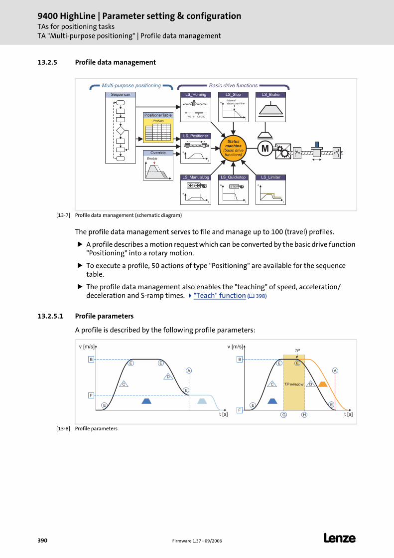
9400 HighLine | Parameter setting & configurationTAs for positioning tasksTA "Multi-purpose positioning" | Profile data management
390 Firmware 1.37 - 09/2006 L
13.2.5 Profile data management
[13-7] Profile data management (schematic diagram)
The profile data management serves to file and manage up to 100 (travel) profiles.
A profile describes a motion request which can be converted by the basic drive function "Positioning" into a rotary motion.
To execute a profile, 50 actions of type "Positioning" are available for the sequence table.
The profile data management also enables the "teaching" of speed, acceleration/deceleration and S-ramp times. "Teach" function ( 398)
13.2.5.1 Profile parameters
A profile is described by the following profile parameters:
[13-8] Profile parameters
PositionerTable
Profiles
Multi-purpose positioning
Override
Enable
Sequencer
LS_ManualJog
n
t
��
LS_Brake
n
t
LS_Limiter
n
t
LS_Quickstop
STOP
n
t
LS_Stop
internalstatus machine
Statusmachine
(basic drivefunctions)
Basic drive functions
M
0-100 100 200
LS_Homing
n
t
LS_Positioner
v [m/s]
t [s]
B
F
E
C
E
D
E
E
A
v [m/s]
t [s]
B
F
E
C
E
D
E
E
A
G H
TP
TP window
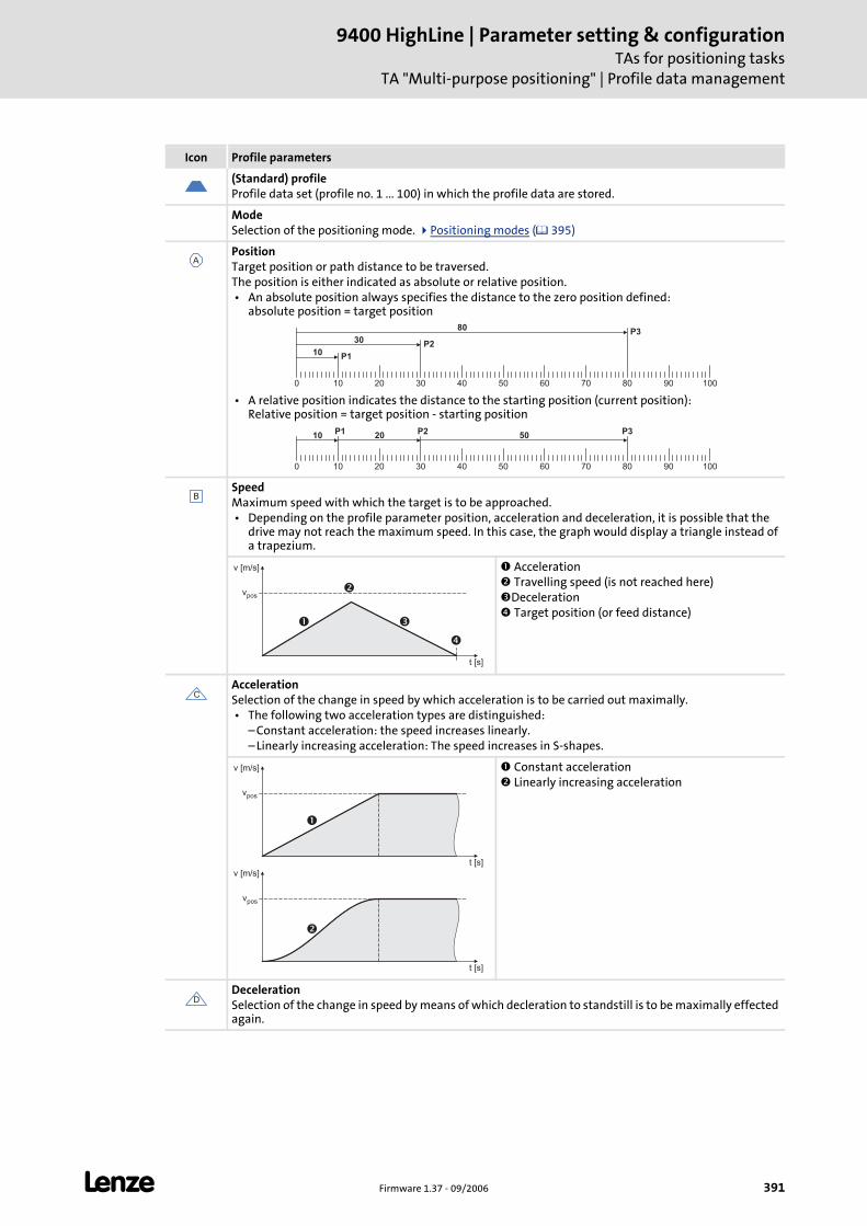
L Firmware 1.37 - 09/2006 391
9400 HighLine | Parameter setting & configurationTAs for positioning tasks
TA "Multi-purpose positioning" | Profile data management
Icon Profile parameters
(Standard) profileProfile data set (profile no. 1 ... 100) in which the profile data are stored.
ModeSelection of the positioning mode. Positioning modes ( 395)
PositionTarget position or path distance to be traversed.The position is either indicated as absolute or relative position. • An absolute position always specifies the distance to the zero position defined:
absolute position = target position
• A relative position indicates the distance to the starting position (current position): Relative position = target position - starting position
SpeedMaximum speed with which the target is to be approached. • Depending on the profile parameter position, acceleration and deceleration, it is possible that the
drive may not reach the maximum speed. In this case, the graph would display a triangle instead of a trapezium.
Acceleration Travelling speed (is not reached here)Deceleration Target position (or feed distance)
AccelerationSelection of the change in speed by which acceleration is to be carried out maximally. • The following two acceleration types are distinguished:
– Constant acceleration: the speed increases linearly.– Linearly increasing acceleration: The speed increases in S-shapes.
Constant acceleration Linearly increasing acceleration
DecelerationSelection of the change in speed by means of which decleration to standstill is to be maximally effected again.
A
10 20 30 40 50 60 70 80 90 100
10
30
80
P1
P2
P3
0
10 20 30 40 50 60 70 80 90 100
10 20 50P3P2P1
0
B
��
�
�
vpos
v [m/s]
t [s]
C
�
�
vpos
vpos
v [m/s]
v [m/s]
t [s]
t [s]
D
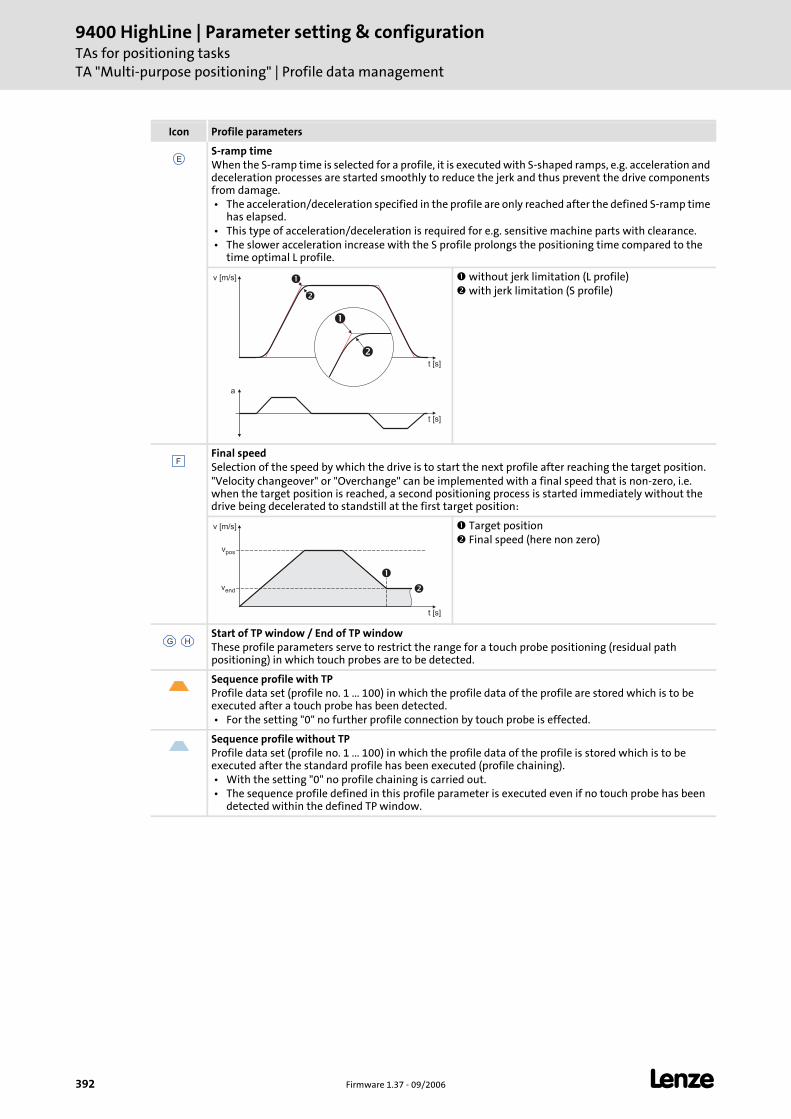
9400 HighLine | Parameter setting & configurationTAs for positioning tasksTA "Multi-purpose positioning" | Profile data management
392 Firmware 1.37 - 09/2006 L
S-ramp timeWhen the S-ramp time is selected for a profile, it is executed with S-shaped ramps, e.g. acceleration and deceleration processes are started smoothly to reduce the jerk and thus prevent the drive components from damage. • The acceleration/deceleration specified in the profile are only reached after the defined S-ramp time
has elapsed. • This type of acceleration/deceleration is required for e.g. sensitive machine parts with clearance. • The slower acceleration increase with the S profile prolongs the positioning time compared to the
time optimal L profile.
without jerk limitation (L profile) with jerk limitation (S profile)
Final speedSelection of the speed by which the drive is to start the next profile after reaching the target position."Velocity changeover" or "Overchange" can be implemented with a final speed that is non-zero, i.e. when the target position is reached, a second positioning process is started immediately without the drive being decelerated to standstill at the first target position:
Target position Final speed (here non zero)
Start of TP window / End of TP windowThese profile parameters serve to restrict the range for a touch probe positioning (residual path positioning) in which touch probes are to be detected.
Sequence profile with TPProfile data set (profile no. 1 ... 100) in which the profile data of the profile are stored which is to be executed after a touch probe has been detected. • For the setting "0" no further profile connection by touch probe is effected.
Sequence profile without TPProfile data set (profile no. 1 ... 100) in which the profile data of the profile is stored which is to be executed after the standard profile has been executed (profile chaining). • With the setting "0" no profile chaining is carried out. • The sequence profile defined in this profile parameter is executed even if no touch probe has been
detected within the defined TP window.
Icon Profile parameters
E
a
�
�
�
�
v [m/s]
t [s]
t [s]
F
�
�
vpos
vend
v [m/s]
t [s]
G H
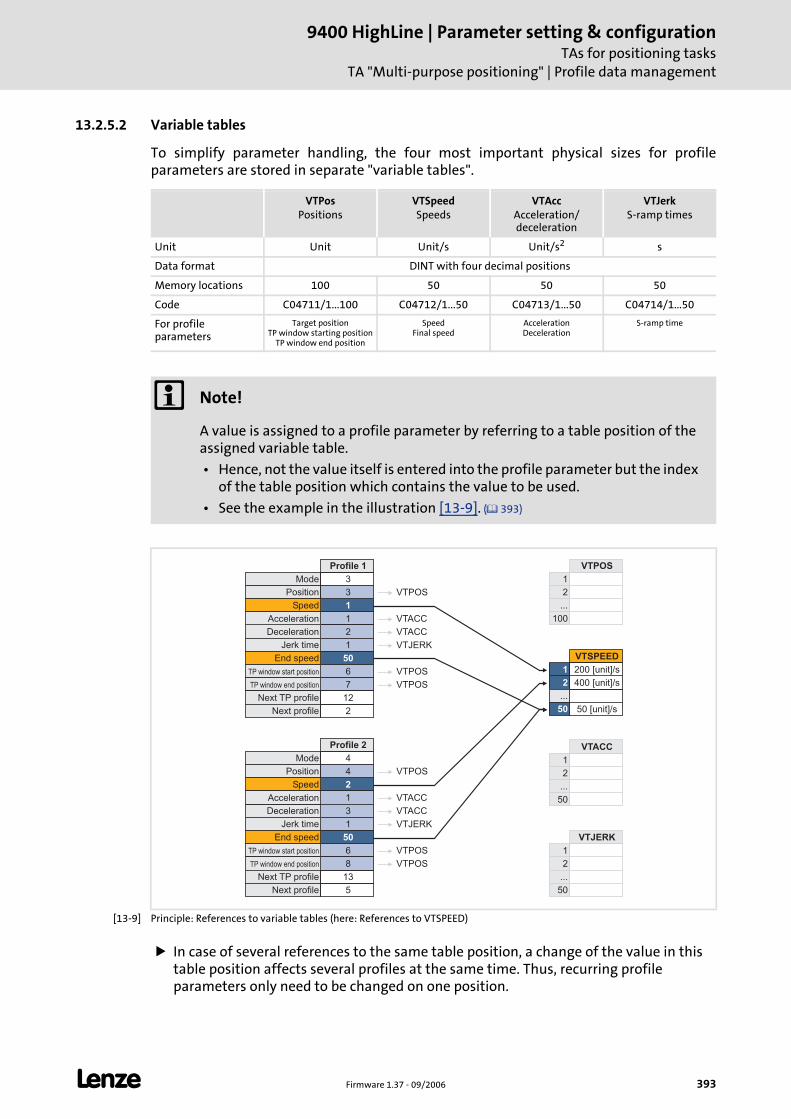
L Firmware 1.37 - 09/2006 393
9400 HighLine | Parameter setting & configurationTAs for positioning tasks
TA "Multi-purpose positioning" | Profile data management
13.2.5.2 Variable tables
To simplify parameter handling, the four most important physical sizes for profile parameters are stored in separate "variable tables".
[13-9] Principle: References to variable tables (here: References to VTSPEED)
In case of several references to the same table position, a change of the value in this table position affects several profiles at the same time. Thus, recurring profile parameters only need to be changed on one position.
VTPosPositions
VTSpeedSpeeds
VTAccAcceleration/deceleration
VTJerkS-ramp times
Unit Unit Unit/s Unit/s2 s
Data format DINT with four decimal positions
Memory locations 100 50 50 50
Code C04711/1...100 C04712/1...50 C04713/1...50 C04714/1...50
For profile parameters
Target positionTP window starting position
TP window end position
SpeedFinal speed
AccelerationDeceleration
S-ramp time
Note!
A value is assigned to a profile parameter by referring to a table position of the assigned variable table.
• Hence, not the value itself is entered into the profile parameter but the index of the table position which contains the value to be used.
• See the example in the illustration [13-9]. ( 393)
Position
Speed
Mode
Profile 1
3
1
1
2
1
50
6
7
12
2
Deceleration
Jerk time
Acceleration
End speed
TP window start position
TP window end position
Next TP profile
Next profile
3
Position
Speed
Mode
Profile 2
4
2
1
3
1
50
6
8
13
5
Deceleration
Jerk time
Acceleration
End speed
TP window start position
TP window end position
Next TP profile
Next profile
4
2
1
VTPOS
...
100
2
1
VTSPEED
200 [unit]/s
400 [unit]/s
50 [unit]/s
...
50
2
1
VTACC
...
50
2
1
VTJERK
...
50
VTPOS
VTACC
VTACC
VTJERK
VTPOS
VTPOS
VTPOS
VTACC
VTACC
VTJERK
VTPOS
VTPOS
9400 HighLine | Parameter setting & configurationTAs for positioning tasksTA "Multi-purpose positioning" | Profile data management
394 Firmware 1.37 - 09/2006 L
If e.g. in case of a profile chaining, several profiles are to be executed with the same speed, the corresponding profile parameters "speed" can all refer to the same table position.
For an easier assignment and identification of the entered values, each table position can be optionally provided with a comment in the »Engineer«.
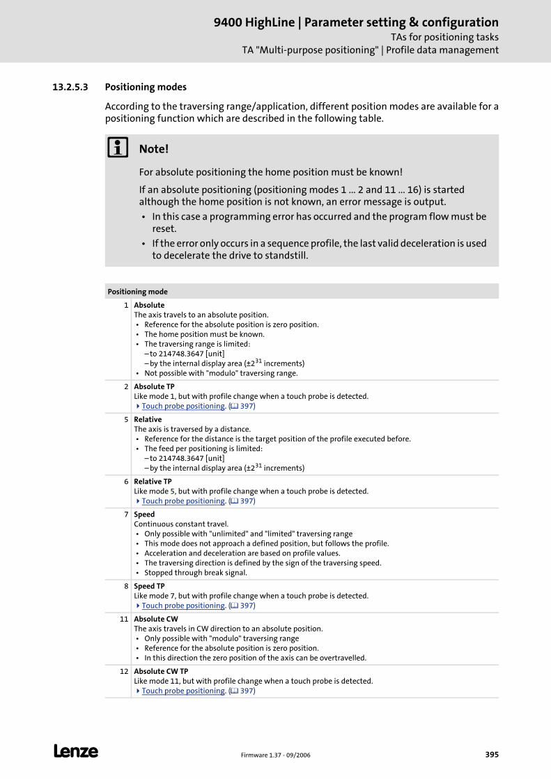
L Firmware 1.37 - 09/2006 395
9400 HighLine | Parameter setting & configurationTAs for positioning tasks
TA "Multi-purpose positioning" | Profile data management
13.2.5.3 Positioning modes
According to the traversing range/application, different position modes are available for a positioning function which are described in the following table.
Note!
For absolute positioning the home position must be known!
If an absolute positioning (positioning modes 1 ... 2 and 11 ... 16) is started although the home position is not known, an error message is output.
• In this case a programming error has occurred and the program flow must be reset.
• If the error only occurs in a sequence profile, the last valid deceleration is used to decelerate the drive to standstill.
Positioning mode
1 AbsoluteThe axis travels to an absolute position. • Reference for the absolute position is zero position. • The home position must be known. • The traversing range is limited:
– to 214748.3647 [unit]– by the internal display area (±231 increments)
• Not possible with "modulo" traversing range.
2 Absolute TPLike mode 1, but with profile change when a touch probe is detected.
Touch probe positioning. ( 397)
5 RelativeThe axis is traversed by a distance. • Reference for the distance is the target position of the profile executed before. • The feed per positioning is limited:
– to 214748.3647 [unit]– by the internal display area (±231 increments)
6 Relative TPLike mode 5, but with profile change when a touch probe is detected.
Touch probe positioning. ( 397)
7 SpeedContinuous constant travel. • Only possible with "unlimited" and "limited" traversing range • This mode does not approach a defined position, but follows the profile. • Acceleration and deceleration are based on profile values. • The traversing direction is defined by the sign of the traversing speed. • Stopped through break signal.
8 Speed TPLike mode 7, but with profile change when a touch probe is detected.
Touch probe positioning. ( 397)
11 Absolute CWThe axis travels in CW direction to an absolute position. • Only possible with "modulo" traversing range • Reference for the absolute position is zero position. • In this direction the zero position of the axis can be overtravelled.
12 Absolute CW TPLike mode 11, but with profile change when a touch probe is detected.
Touch probe positioning. ( 397)
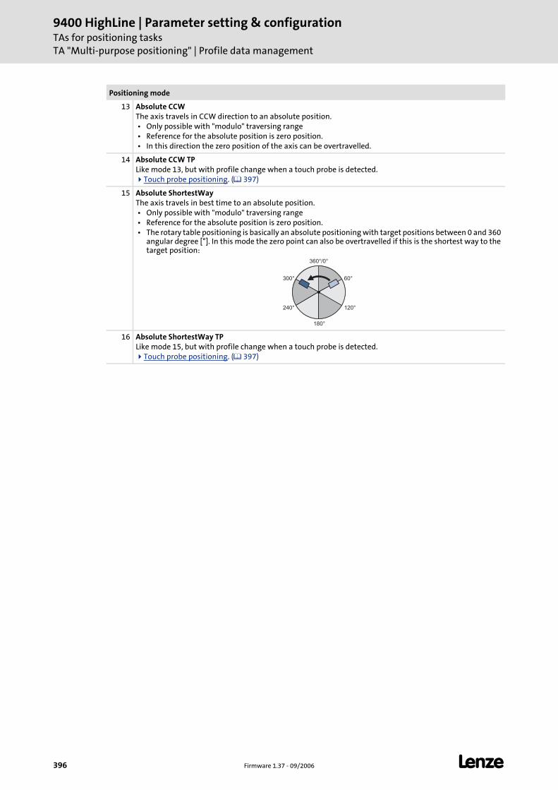
9400 HighLine | Parameter setting & configurationTAs for positioning tasksTA "Multi-purpose positioning" | Profile data management
396 Firmware 1.37 - 09/2006 L
13 Absolute CCWThe axis travels in CCW direction to an absolute position. • Only possible with "modulo" traversing range • Reference for the absolute position is zero position. • In this direction the zero position of the axis can be overtravelled.
14 Absolute CCW TPLike mode 13, but with profile change when a touch probe is detected.
Touch probe positioning. ( 397)
15 Absolute ShortestWayThe axis travels in best time to an absolute position. • Only possible with "modulo" traversing range • Reference for the absolute position is zero position. • The rotary table positioning is basically an absolute positioning with target positions between 0 and 360
angular degree [°]. In this mode the zero point can also be overtravelled if this is the shortest way to the target position:
16 Absolute ShortestWay TPLike mode 15, but with profile change when a touch probe is detected.
Touch probe positioning. ( 397)
Positioning mode
360°/0°
60°
120°
300°
240°
180°
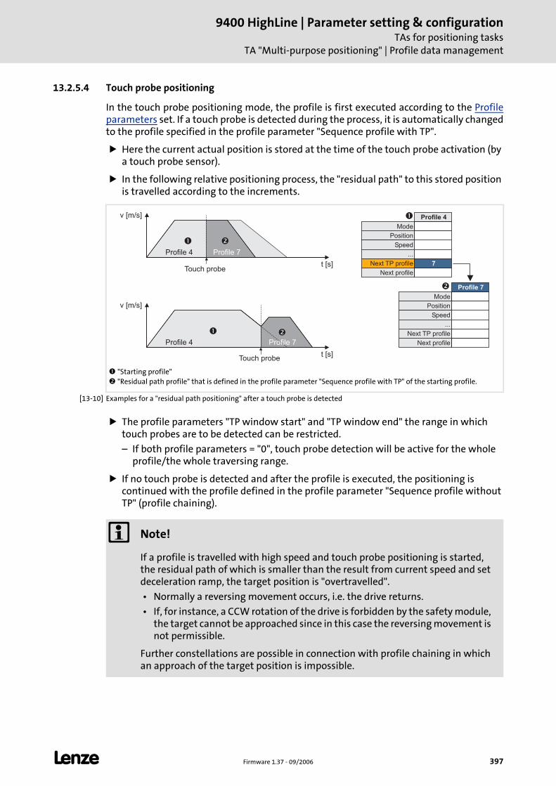
L Firmware 1.37 - 09/2006 397
9400 HighLine | Parameter setting & configurationTAs for positioning tasks
TA "Multi-purpose positioning" | Profile data management
13.2.5.4 Touch probe positioning
In the touch probe positioning mode, the profile is first executed according to the Profile parameters set. If a touch probe is detected during the process, it is automatically changed to the profile specified in the profile parameter "Sequence profile with TP".
Here the current actual position is stored at the time of the touch probe activation (by a touch probe sensor).
In the following relative positioning process, the "residual path" to this stored position is travelled according to the increments.
[13-10] Examples for a "residual path positioning" after a touch probe is detected
The profile parameters "TP window start" and "TP window end" the range in which touch probes are to be detected can be restricted.
– If both profile parameters = "0", touch probe detection will be active for the whole profile/the whole traversing range.
If no touch probe is detected and after the profile is executed, the positioning is continued with the profile defined in the profile parameter "Sequence profile without TP" (profile chaining).
"Starting profile" "Residual path profile" that is defined in the profile parameter "Sequence profile with TP" of the starting profile.
v [m/s]
t [s]
�
Touch probe
t [s]
�
Touch probe
v [m/s]
�
�
Position
Speed
Mode
Profile 4
...
Next TP profile
Next profile
7
Position
Speed
Mode
Profile 7
...
Next TP profile
Next profile
�
�
Profile 4 Profile 7
Profile 4 Profile 7
Note!
If a profile is travelled with high speed and touch probe positioning is started, the residual path of which is smaller than the result from current speed and set deceleration ramp, the target position is "overtravelled".
• Normally a reversing movement occurs, i.e. the drive returns.
• If, for instance, a CCW rotation of the drive is forbidden by the safety module, the target cannot be approached since in this case the reversing movement is not permissible.
Further constellations are possible in connection with profile chaining in which an approach of the target position is impossible.
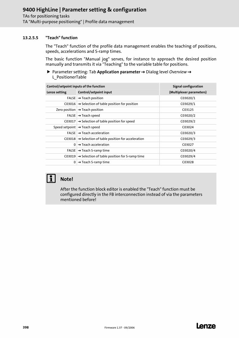
9400 HighLine | Parameter setting & configurationTAs for positioning tasksTA "Multi-purpose positioning" | Profile data management
398 Firmware 1.37 - 09/2006 L
13.2.5.5 "Teach" function
The "Teach" function of the profile data management enables the teaching of positions, speeds, accelerations and S-ramp times.
The basic function "Manual jog" serves, for instance to approach the desired position manually and transmits it via "Teaching" to the variable table for positions.
Parameter setting: Tab Application parameter Dialog level Overview L_PositionerTable
Control/setpoint inputs of the function Signal configuration
Lenze setting Control/setpoint input (Multiplexer parameters)
FALSE Teach position C03020/1
C03016 Selection of table position for position C03029/1
Zero position Teach position C03125
FALSE Teach speed C03020/2
C03017 Selection of table position for speed C03029/2
Speed setpoint Teach speed C03024
FALSE Teach acceleration C03020/3
C03018 Selection of table position for acceleration C03029/3
0 Teach acceleration C03027
FALSE Teach S-ramp time C03020/4
C03019 Selection of table position for S-ramp time C03029/4
0 Teach S-ramp time C03028
Note!
After the function block editor is enabled the "Teach" function must be configured directly in the FB interconnection instead of via the parameters mentioned before!
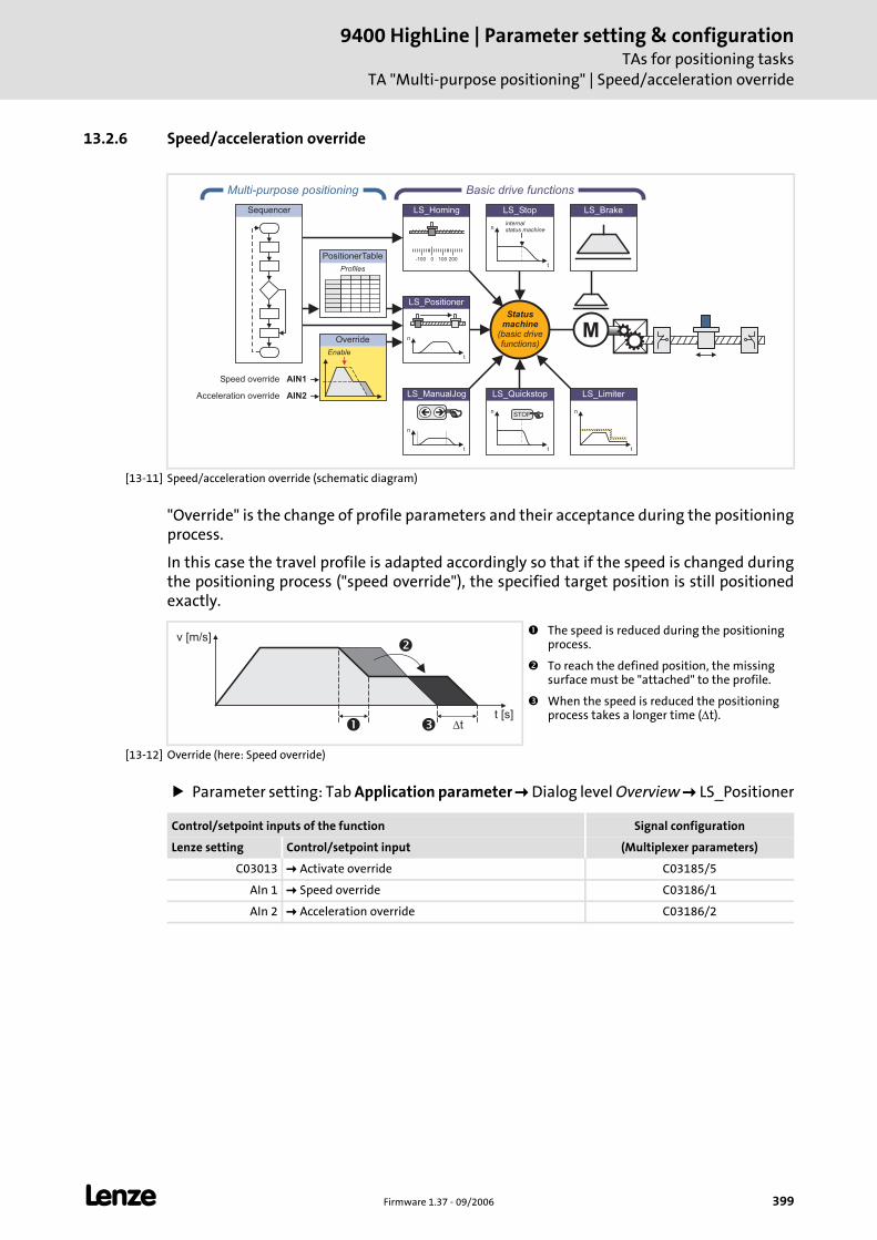
L Firmware 1.37 - 09/2006 399
9400 HighLine | Parameter setting & configurationTAs for positioning tasks
TA "Multi-purpose positioning" | Speed/acceleration override
13.2.6 Speed/acceleration override
[13-11] Speed/acceleration override (schematic diagram)
"Override" is the change of profile parameters and their acceptance during the positioning process.
In this case the travel profile is adapted accordingly so that if the speed is changed during the positioning process ("speed override"), the specified target position is still positioned exactly.
[13-12] Override (here: Speed override)
Parameter setting: Tab Application parameter Dialog level Overview LS_Positioner
AIN1
PositionerTable
Profiles
Multi-purpose positioning
Override
Enable
AIN2
Speed override
Acceleration override
Sequencer
LS_ManualJog
n
t
��
LS_Brake
n
t
LS_Limiter
n
t
LS_Quickstop
STOP
n
t
LS_Stop
internalstatus machine
Statusmachine
(basic drivefunctions)
Basic drive functions
M
0-100 100 200
LS_Homing
n
t
LS_Positioner
The speed is reduced during the positioning process.
To reach the defined position, the missing surface must be "attached" to the profile.
When the speed is reduced the positioning process takes a longer time (Δt).
�
�
� t
v [m/s]
t [s]
Control/setpoint inputs of the function Signal configuration
Lenze setting Control/setpoint input (Multiplexer parameters)
C03013 Activate override C03185/5
AIn 1 Speed override C03186/1
AIn 2 Acceleration override C03186/2
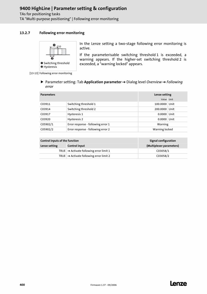
9400 HighLine | Parameter setting & configurationTAs for positioning tasksTA "Multi-purpose positioning" | Following error monitoring
400 Firmware 1.37 - 09/2006 L
13.2.7 Following error monitoring
[13-13] Following error monitoring
Parameter setting: Tab Application parameter Dialog level Overview Following error
Switching threshold Hysteresis
In the Lenze setting a two-stage following error monitoring is active.
If the parameterisable switching threshold 1 is exceeded, a warning appears. If the higher-set switching threshold 2 is exceeded, a "warning locked" appears.
��
�
Parameters Lenze setting
Value Unit
C03911 Switching threshold 1 100.0000 Unit
C03914 Switching threshold 2 200.0000 Unit
C03917 Hysteresis 1 0.0000 Unit
C03920 Hysteresis 2 0.0000 Unit
C05902/1 Error response - following error 1 Warning
C05902/2 Error response - following error 2 Warning locked
Control inputs of the function Signal configuration
Lenze setting Control input (Multiplexer parameters)
TRUE Activate following error limit 1 C03058/1
TRUE Activate following error limit 2 C03058/2
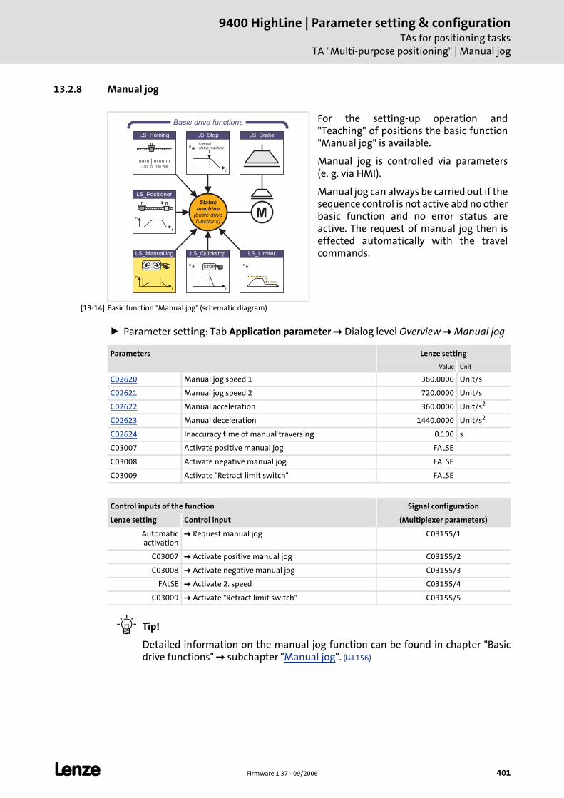
L Firmware 1.37 - 09/2006 401
9400 HighLine | Parameter setting & configurationTAs for positioning tasks
TA "Multi-purpose positioning" | Manual jog
13.2.8 Manual jog
[13-14] Basic function "Manual jog" (schematic diagram)
Parameter setting: Tab Application parameter Dialog level Overview Manual jog
Tip!
Detailed information on the manual jog function can be found in chapter "Basic drive functions" subchapter "Manual jog". ( 156)
For the setting-up operation and "Teaching" of positions the basic function "Manual jog" is available.
Manual jog is controlled via parameters (e. g. via HMI).
Manual jog can always be carried out if the sequence control is not active abd no other basic function and no error status are active. The request of manual jog then is effected automatically with the travel commands.LS_ManualJog
n
t
��
LS_Brake
n
t
LS_Limiter
n
t
LS_Quickstop
STOP
n
t
LS_Stop
internalstatus machine
Statusmachine
(basic drivefunctions)
Basic drive functions
M
0-100 100 200
LS_Homing
n
t
LS_Positioner
Parameters Lenze setting
Value Unit
C02620 Manual jog speed 1 360.0000 Unit/s
C02621 Manual jog speed 2 720.0000 Unit/s
C02622 Manual acceleration 360.0000 Unit/s2
C02623 Manual deceleration 1440.0000 Unit/s2
C02624 Inaccuracy time of manual traversing 0.100 s
C03007 Activate positive manual jog FALSE
C03008 Activate negative manual jog FALSE
C03009 Activate "Retract limit switch" FALSE
Control inputs of the function Signal configuration
Lenze setting Control input (Multiplexer parameters)
Automatic activation
Request manual jog C03155/1
C03007 Activate positive manual jog C03155/2
C03008 Activate negative manual jog C03155/3
FALSE Activate 2. speed C03155/4
C03009 Activate "Retract limit switch" C03155/5
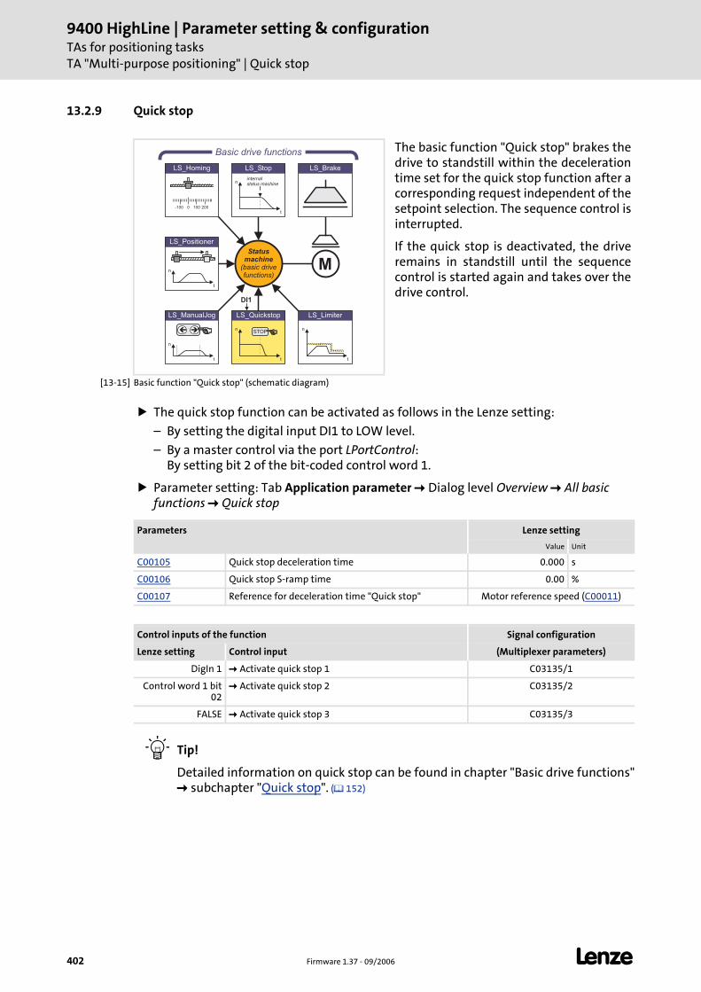
9400 HighLine | Parameter setting & configurationTAs for positioning tasksTA "Multi-purpose positioning" | Quick stop
402 Firmware 1.37 - 09/2006 L
13.2.9 Quick stop
[13-15] Basic function "Quick stop" (schematic diagram)
The quick stop function can be activated as follows in the Lenze setting:
– By setting the digital input DI1 to LOW level.
– By a master control via the port LPortControl: By setting bit 2 of the bit-coded control word 1.
Parameter setting: Tab Application parameter Dialog level Overview All basic functions Quick stop
Tip!
Detailed information on quick stop can be found in chapter "Basic drive functions" subchapter "Quick stop". ( 152)
The basic function "Quick stop" brakes the drive to standstill within the deceleration time set for the quick stop function after a corresponding request independent of the setpoint selection. The sequence control is interrupted.
If the quick stop is deactivated, the drive remains in standstill until the sequence control is started again and takes over the drive control.
LS_ManualJog
n
t
��
LS_Brake
n
t
LS_Limiter
n
t
LS_Quickstop
STOP
n
t
LS_Stop
internalstatus machine
Statusmachine
(basic drivefunctions)
Basic drive functions
M
0-100 100 200
LS_Homing
n
t
LS_Positioner
DI1
Parameters Lenze setting
Value Unit
C00105 Quick stop deceleration time 0.000 s
C00106 Quick stop S-ramp time 0.00 %
C00107 Reference for deceleration time "Quick stop" Motor reference speed (C00011)
Control inputs of the function Signal configuration
Lenze setting Control input (Multiplexer parameters)
DigIn 1 Activate quick stop 1 C03135/1
Control word 1 bit 02
Activate quick stop 2 C03135/2
FALSE Activate quick stop 3 C03135/3
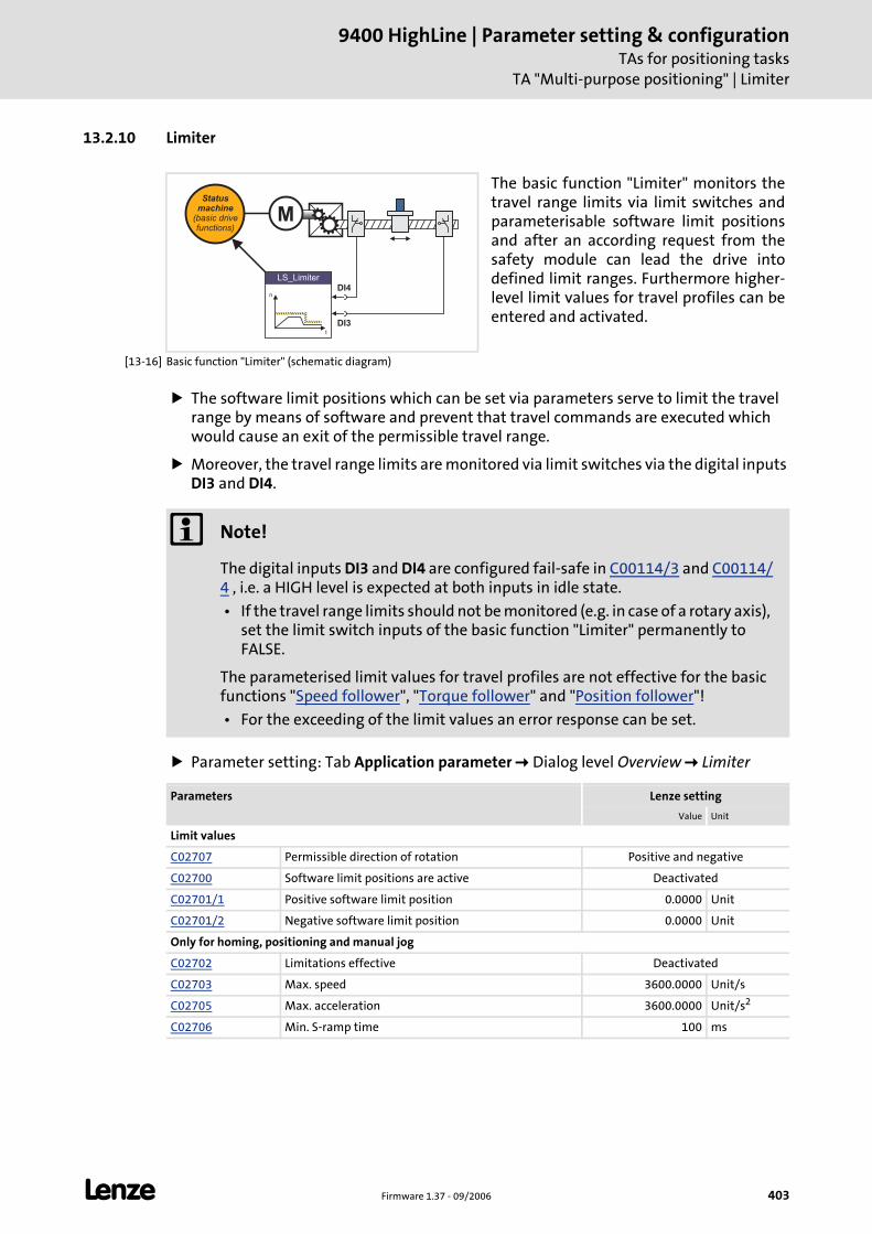
L Firmware 1.37 - 09/2006 403
9400 HighLine | Parameter setting & configurationTAs for positioning tasks
TA "Multi-purpose positioning" | Limiter
13.2.10 Limiter
[13-16] Basic function "Limiter" (schematic diagram)
The software limit positions which can be set via parameters serve to limit the travel range by means of software and prevent that travel commands are executed which would cause an exit of the permissible travel range.
Moreover, the travel range limits are monitored via limit switches via the digital inputs DI3 and DI4.
Parameter setting: Tab Application parameter Dialog level Overview Limiter
The basic function "Limiter" monitors the travel range limits via limit switches and parameterisable software limit positions and after an according request from the safety module can lead the drive into defined limit ranges. Furthermore higher-level limit values for travel profiles can be entered and activated.
n
t
LS_Limiter
Statusmachine
(basic drivefunctions)
M
DI4
DI3
Note!
The digital inputs DI3 and DI4 are configured fail-safe in C00114/3 and C00114/4 , i.e. a HIGH level is expected at both inputs in idle state.
• If the travel range limits should not be monitored (e.g. in case of a rotary axis), set the limit switch inputs of the basic function "Limiter" permanently to FALSE.
The parameterised limit values for travel profiles are not effective for the basic functions "Speed follower", "Torque follower" and "Position follower"!
• For the exceeding of the limit values an error response can be set.
Parameters Lenze setting
Value Unit
Limit values
C02707 Permissible direction of rotation Positive and negative
C02700 Software limit positions are active Deactivated
C02701/1 Positive software limit position 0.0000 Unit
C02701/2 Negative software limit position 0.0000 Unit
Only for homing, positioning and manual jog
C02702 Limitations effective Deactivated
C02703 Max. speed 3600.0000 Unit/s
C02705 Max. acceleration 3600.0000 Unit/s2
C02706 Min. S-ramp time 100 ms
9400 HighLine | Parameter setting & configurationTAs for positioning tasksTA "Multi-purpose positioning" | Limiter
404 Firmware 1.37 - 09/2006 L
Tip!
Detailed information on the limiter function can be found in chapter "Basic drive functions" subchapter "Limiter". ( 200)
For manual jog only
C02713 Max. path -manual jog 360.0000 Unit
Limited speed 1 ... 4 (only for homing, positioning, and manual jog)
C02708/1 Limited speed 1 3600.0000 Unit/s
C02710/1 Delay lim. speed 1 0.0100 Unit/s2
C02711/1 S-ramp time lim. speed 1 100 ms
C02708/2 Limited speed 2 7200.0000 Unit/s
C02710/2 Delay lim. speed 2 0.0100 Unit/s2
C02711/2 S-ramp time lim. speed 2 100 ms
C02708/3 Limited speed 3 14400.0000 Unit/s
C02710/3 Delay lim. speed 3 0.0100 Unit/s2
C02711/3 S-ramp time lim. speed 3 100 ms
C02708/4 Limited speed 4 28800.0000 Unit/s
C02710/4 Delay lim. speed 4 0.0100 Unit/s2
C02711/4 S-ramp time lim. speed 4 100 ms
Control inputs of the function Signal configuration
Lenze setting Control input (Multiplexer parameters)
DigIn 3 Positive limit switch C03150/1
DigIn 4 Negative limit switch C03150/2
Parameters Lenze setting
Value Unit
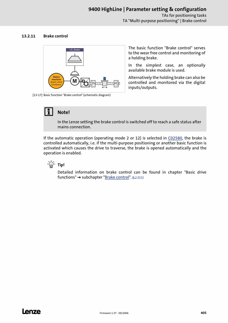
L Firmware 1.37 - 09/2006 405
9400 HighLine | Parameter setting & configurationTAs for positioning tasks
TA "Multi-purpose positioning" | Brake control
13.2.11 Brake control
[13-17] Basic function "Brake control" (schematic diagram)
If the automatic operation (operating mode 2 or 12) is selected in C02580, the brake is controlled automatically, i.e. if the multi-purpose positioning or another basic function is activated which causes the drive to traverse, the brake is opened automatically and the operation is enabled.
Tip!
Detailed information on brake control can be found in chapter "Basic drive functions" subchapter "Brake control". ( 211)
The basic function "Brake control" serves to the wear free control and monitoring of a holding brake.
In the simplest case, an optionally available brake module is used.
Alternatively the holding brake can also be controlled and monitored via the digital inputs/outputs.
Statusmachine
(basic drivefunctions)
M
LS_Brake
Note!
In the Lenze setting the brake control is switched off to reach a safe status after mains connection.

9400 HighLine | Parameter setting & configurationTAs for positioning tasksTA "Multi-purpose positioning" | Brake control
406 Firmware 1.37 - 09/2006 L
Parameter setting: Tab Application parameter Dialog level Overview Brake control
Parameters Lenze setting
Value Unit
C02580 Operating mode - brake Brake control off
C02581 Brake activation threshold 50 rpm
C02582 Brake resp. to pulse inhibit Activate the brake immediately
C02583 Status input monitoring Not active
C02585 Brake control polarity Not inverted
C02586 Starting torque 1 0.00 Nm
C02587 Starting torque 2 0.00 Nm
C02588 Source of starting torque Starting torque 1/2
C02589 Brake closing time 100 ms
C02590 Brake opening time 100 ms
C02591 Waiting time - status monit. 100 ms
C02593 Waiting time - brake active. 0.000 s
C02594 Test torque 0.00 Nm
C02595 Permissible angle of rotation 5 °
C02596 Grinding speed 100 rpm
C02597 Accel./decel. time - grinding 1.000 s
C02598 Grinding ON time 0.5 s
C02599 Grinding OFF time 0.5 s
Control/setpoint inputs of the function Signal configuration
Lenze setting Control/setpoint input (Multiplexer parameters)
FALSE Open brake (release) C03165/1
FALSE Activate starting torque 2 C03165/2
FALSE Brake status signal C03165/3
FALSE Activate brake test C03165/4
FALSE Grind brake C03165/5
0 % Additional torque C03166
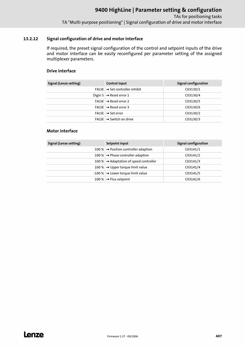
L Firmware 1.37 - 09/2006 407
9400 HighLine | Parameter setting & configurationTAs for positioning tasks
TA "Multi-purpose positioning" | Signal configuration of drive and motor interface
13.2.12 Signal configuration of drive and motor interface
If required, the preset signal configuration of the control and setpoint inputs of the drive and motor interface can be easily reconfigured per parameter setting of the assigned multiplexer parameters.
Drive interface
Motor interface
Signal (Lenze setting) Control input Signal configuration
FALSE Set controller inhibit C03130/1
DigIn 5 Reset error 1 C03130/4
FALSE Reset error 2 C03130/5
FALSE Reset error 3 C03130/6
FALSE Set error C03130/2
FALSE Switch on drive C03130/3
Signal (Lenze setting) Setpoint input Signal configuration
100 % Position controller adaption C03141/1
100 % Phase controller adaption C03141/2
100 % Adaptation of speed controller C03141/3
100 % Upper torque limit value C03141/4
-100 % Lower torque limit value C03141/5
100 % Flux setpoint C03141/6
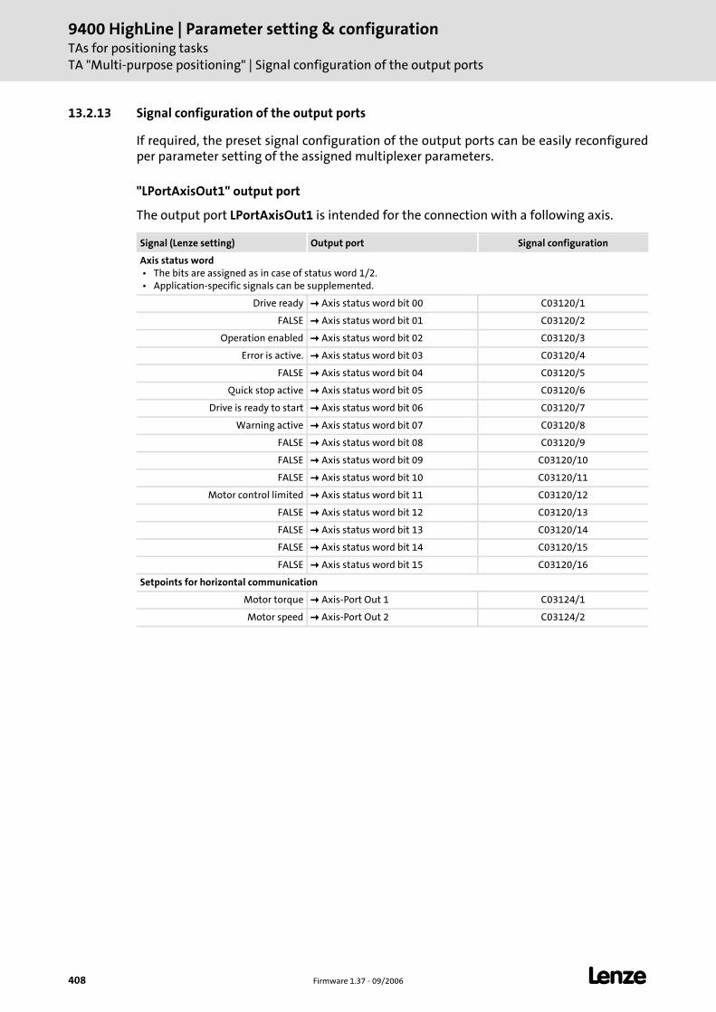
9400 HighLine | Parameter setting & configurationTAs for positioning tasksTA "Multi-purpose positioning" | Signal configuration of the output ports
408 Firmware 1.37 - 09/2006 L
13.2.13 Signal configuration of the output ports
If required, the preset signal configuration of the output ports can be easily reconfigured per parameter setting of the assigned multiplexer parameters.
"LPortAxisOut1" output port
The output port LPortAxisOut1 is intended for the connection with a following axis.
Signal (Lenze setting) Output port Signal configuration
Axis status word • The bits are assigned as in case of status word 1/2. • Application-specific signals can be supplemented.
Drive ready Axis status word bit 00 C03120/1
FALSE Axis status word bit 01 C03120/2
Operation enabled Axis status word bit 02 C03120/3
Error is active. Axis status word bit 03 C03120/4
FALSE Axis status word bit 04 C03120/5
Quick stop active Axis status word bit 05 C03120/6
Drive is ready to start Axis status word bit 06 C03120/7
Warning active Axis status word bit 07 C03120/8
FALSE Axis status word bit 08 C03120/9
FALSE Axis status word bit 09 C03120/10
FALSE Axis status word bit 10 C03120/11
Motor control limited Axis status word bit 11 C03120/12
FALSE Axis status word bit 12 C03120/13
FALSE Axis status word bit 13 C03120/14
FALSE Axis status word bit 14 C03120/15
FALSE Axis status word bit 15 C03120/16
Setpoints for horizontal communication
Motor torque Axis-Port Out 1 C03124/1
Motor speed Axis-Port Out 2 C03124/2

L Firmware 1.37 - 09/2006 409
9400 HighLine | Parameter setting & configurationTAs for positioning tasks
TA "Multi-purpose positioning" | Signal configuration of the output ports
Output port "LPortStatus1"
The output port LPortStatus1 is intended for the connection with a higher-level control.
Output port "LPortStatus2"
Signal (Lenze setting) Output port Signal configuration
Status word 1
Drive ready Status word 1 bit 00 C03121/1
FALSE Status word 1 bit 01 C03121/2
Operation enabled Status word 1 bit 02 C03121/3
Error is active. Status word 1 bit 03 C03121/4
FALSE Status word 1 bit 04 C03121/5
Quick stop active Status word 1 bit 05 C03121/6
Drive is ready to start Status word 1 bit 06 C03121/7
Warning active Status word 1 bit 07 C03121/8
FALSE Status word 1 bit 08 C03121/9
FALSE Status word 1 bit 09 C03121/10
FALSE Status word 1 bit 10 C03121/11
Motor control limited Status word 1 bit 11 C03121/12
FALSE Status word 1 bit 12 C03121/13
FALSE Status word 1 bit 13 C03121/14
FALSE Status word 1 bit 14 C03121/15
FALSE Status word 1 bit 15 C03121/16
Signal (Lenze setting) Output port Signal configuration
Status word 2
FALSE Status word 2 bit 00 C03122/1
FALSE Status word 2 bit 01 C03122/2
FALSE Status word 2 bit 02 C03122/3
FALSE Status word 2 bit 03 C03122/4
FALSE Status word 2 bit 04 C03122/5
FALSE Status word 2 bit 05 C03122/6
FALSE Status word 2 bit 06 C03122/7
FALSE Status word 2 bit 07 C03122/8
FALSE Status word 2 bit 08 C03122/9
FALSE Status word 2 bit 09 C03122/10
FALSE Status word 2 bit 10 C03122/11
FALSE Status word 2 bit 11 C03122/12
FALSE Status word 2 bit 12 C03122/13
FALSE Status word 2 bit 13 C03122/14
FALSE Status word 2 bit 14 C03122/15
FALSE Status word 2 bit 15 C03122/16
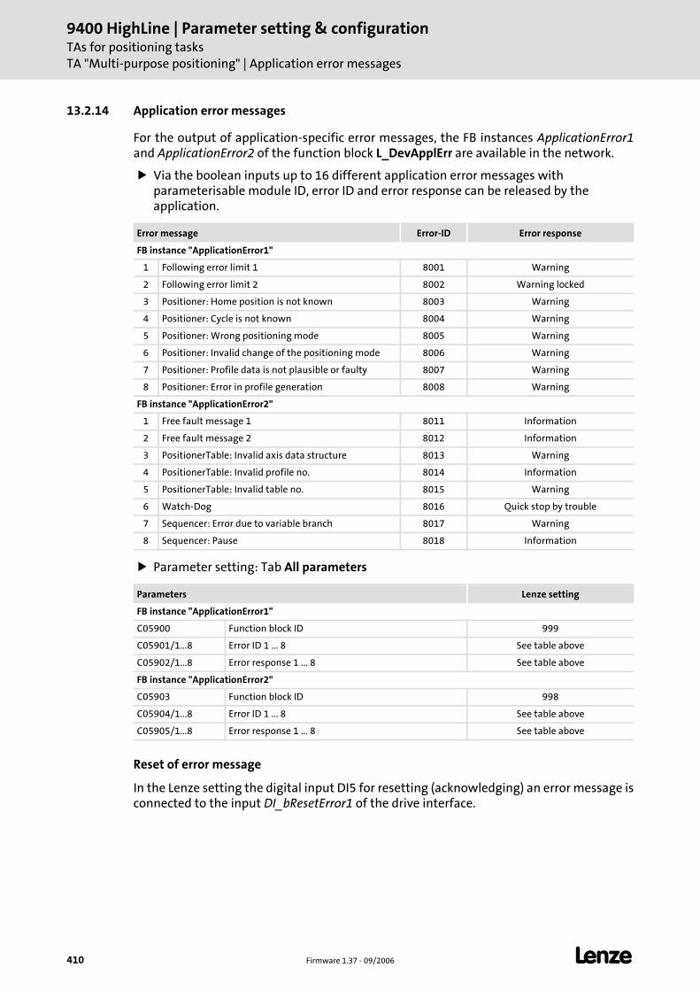
9400 HighLine | Parameter setting & configurationTAs for positioning tasksTA "Multi-purpose positioning" | Application error messages
410 Firmware 1.37 - 09/2006 L
13.2.14 Application error messages
For the output of application-specific error messages, the FB instances ApplicationError1and ApplicationError2 of the function block L_DevApplErr are available in the network.
Via the boolean inputs up to 16 different application error messages with parameterisable module ID, error ID and error response can be released by the application.
Parameter setting: Tab All parameters
Reset of error message
In the Lenze setting the digital input DI5 for resetting (acknowledging) an error message is connected to the input DI_bResetError1 of the drive interface.
Error message Error-ID Error response
FB instance "ApplicationError1"
1 Following error limit 1 8001 Warning
2 Following error limit 2 8002 Warning locked
3 Positioner: Home position is not known 8003 Warning
4 Positioner: Cycle is not known 8004 Warning
5 Positioner: Wrong positioning mode 8005 Warning
6 Positioner: Invalid change of the positioning mode 8006 Warning
7 Positioner: Profile data is not plausible or faulty 8007 Warning
8 Positioner: Error in profile generation 8008 Warning
FB instance "ApplicationError2"
1 Free fault message 1 8011 Information
2 Free fault message 2 8012 Information
3 PositionerTable: Invalid axis data structure 8013 Warning
4 PositionerTable: Invalid profile no. 8014 Information
5 PositionerTable: Invalid table no. 8015 Warning
6 Watch-Dog 8016 Quick stop by trouble
7 Sequencer: Error due to variable branch 8017 Warning
8 Sequencer: Pause 8018 Information
Parameters Lenze setting
FB instance "ApplicationError1"
C05900 Function block ID 999
C05901/1...8 Error ID 1 ... 8 See table above
C05902/1...8 Error response 1 ... 8 See table above
FB instance "ApplicationError2"
C05903 Function block ID 998
C05904/1...8 Error ID 1 ... 8 See table above
C05905/1...8 Error response 1 ... 8 See table above
L Firmware 1.37 - 09/2006 411
9400 HighLine | Parameter setting & configurationTAs for positioning tasks
TA "Table positioning"
13.3 TA "Table positioning"
The technology application "table positioning" enables the drive to execute parameterisable travel profiles. The sequence is controlled by a superimposed control (e.g. PLC).
Functions
Control of the program flow via predefined ports
Positioning in different positioning modes
– Point-to-point positioning
– Touch probe positioning (residual path positioning)
– Profile chaining with velocity changeover (overchange)
Homing in different homing modes
Profile data management
– Support of S profiles (jerk limitation)
– Separate setting for acceleration and deceleration
– "Teach" function
Speed-/acceleration override
Following error monitoring
Support of absolute value encoders
Support of the basic drive functions "Manual jog" and "Quick stop"
Monitoring of travel range limits with the basic drive function "Limiter"
Optional control of a holding brake with the basic drive function "Brake control"
Note!
With the exception of the sequence table, the functionality of the table positioning is identical to the multi-purpose positioning.
The different functions are described in the previous chapter on TA "Multi-purpose positioning". ( 371)
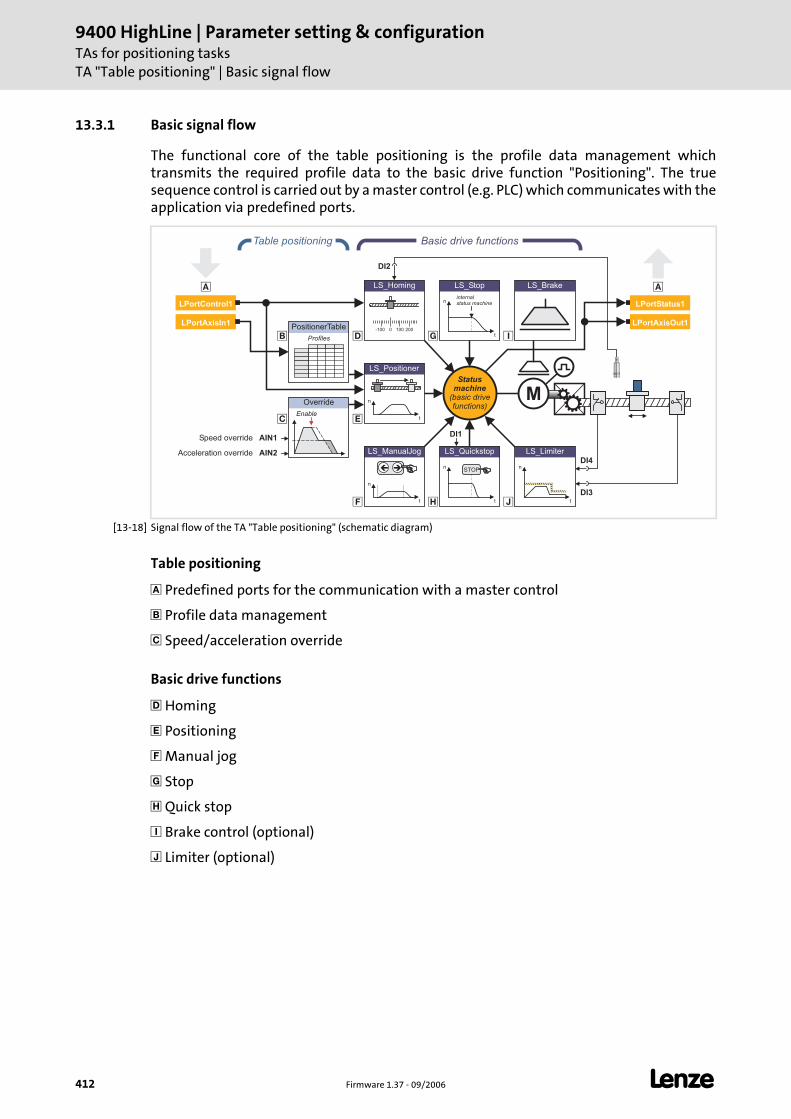
9400 HighLine | Parameter setting & configurationTAs for positioning tasksTA "Table positioning" | Basic signal flow
412 Firmware 1.37 - 09/2006 L
13.3.1 Basic signal flow
The functional core of the table positioning is the profile data management which transmits the required profile data to the basic drive function "Positioning". The true sequence control is carried out by a master control (e.g. PLC) which communicates with the application via predefined ports.
[13-18] Signal flow of the TA "Table positioning" (schematic diagram)
Table positioning
Predefined ports for the communication with a master control
Profile data management
Speed/acceleration override
Basic drive functions
Homing
Positioning
Manual jog
Stop
Quick stop
Brake control (optional)
Limiter (optional)
DI1
�
�
� �
�
�
�
�
AIN1
PositionerTable
Profiles
Table positioning
Override
Enable
AIN2
Speed override
Acceleration override LS_ManualJog
n
t
��
LS_Brake
n
t
LS_Limiter
n
t
LS_Quickstop
STOP
n
t
LS_Stop
internalstatus machine
Statusmachine
(basic drivefunctions)
Basic drive functions
M
0-100 100 200
LS_Homing
n
t
LS_Positioner
DI2
DI4
DI3
LPortControl1
LPortAxisOut1
�
LPortAxisIn1
LPortStatus1
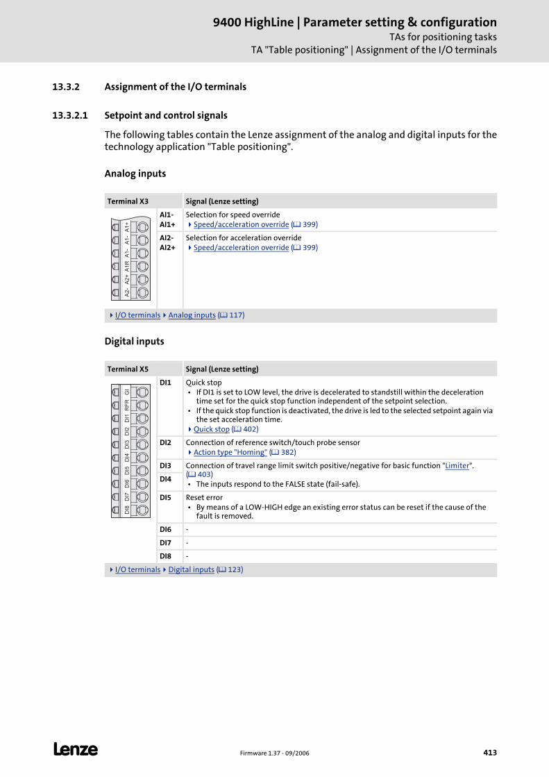
L Firmware 1.37 - 09/2006 413
9400 HighLine | Parameter setting & configurationTAs for positioning tasks
TA "Table positioning" | Assignment of the I/O terminals
13.3.2 Assignment of the I/O terminals
13.3.2.1 Setpoint and control signals
The following tables contain the Lenze assignment of the analog and digital inputs for the technology application "Table positioning".
Analog inputs
Digital inputs
Terminal X3 Signal (Lenze setting)
AI1-AI1+
Selection for speed overrideSpeed/acceleration override ( 399)
AI2-AI2+
Selection for acceleration overrideSpeed/acceleration override ( 399)
I/O terminals Analog inputs ( 117)
Terminal X5 Signal (Lenze setting)
DI1 Quick stop • If DI1 is set to LOW level, the drive is decelerated to standstill within the deceleration
time set for the quick stop function independent of the setpoint selection. • If the quick stop function is deactivated, the drive is led to the selected setpoint again via
the set acceleration time.Quick stop ( 402)
DI2 Connection of reference switch/touch probe sensorAction type "Homing" ( 382)
DI3 Connection of travel range limit switch positive/negative for basic function "Limiter". ( 403) • The inputs respond to the FALSE state (fail-safe).
DI4
DI5 Reset error • By means of a LOW-HIGH edge an existing error status can be reset if the cause of the
fault is removed.
DI6 -
DI7 -
DI8 -
I/O terminals Digital inputs ( 123)
A1
+A
1-
A1
-A
1R
A2
+A
2-
GI
RF
RD
I1D
I2D
I3D
I4D
I5D
I6D
I7D
I8
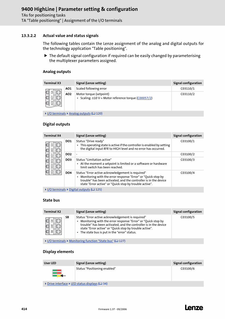
9400 HighLine | Parameter setting & configurationTAs for positioning tasksTA "Table positioning" | Assignment of the I/O terminals
414 Firmware 1.37 - 09/2006 L
13.3.2.2 Actual value and status signals
The following tables contain the Lenze assignment of the analog and digital outputs for the technology application "Table positioning".
The default signal configuration if required can be easily changed by parameterising the multiplexer parameters assigned.
Analog outputs
Digital outputs
State bus
Display elements
Terminal X3 Signal (Lenze setting) Signal configuration
AO1 Scaled following error C03110/1
AO2 Motor torque (setpoint) • Scaling: ±10 V ≡ Motor reference torque (C00057/2)
C03110/2
I/O terminals Analog outputs ( 120)
Terminal X4 Signal (Lenze setting) Signal configuration
DO1 Status "Drive ready" • This operating state is active if the controller is enabled by setting
the digital input RFR to HIGH level and no error has occurred.
C03100/1
DO2 - C03100/2
DO3 Status "Limitation active" • At the moment a setpoint is limited or a software or hardware
limit switch has been reached.
C03100/3
DO4 Status "Error active acknowledgement is required" • Monitoring with the error response "Error" or "Quick stop by
trouble" has been activated, and the controller is in the device state "Error active" or "Quick stop by trouble active".
C03100/4
I/O terminals Digital outputs ( 125)
Terminal X2 Signal (Lenze setting) Signal configuration
SB Status "Error active acknowledgement is required" • Monitoring with the error response "Error" or "Quick stop by
trouble" has been activated, and the controller is in the device state "Error active" or "Quick stop by trouble active".
• The state bus is put in the "error" status.
C03100/5
I/O terminals Monitoring function "State bus" ( 127)
User LED Signal (Lenze setting) Signal configuration
Status "Positioning enabled" C03100/6
Drive interface LED status displays ( 34)
GA
AO
1A
O2
GO
24
OD
O1
DO
2D
O3
DO
4G
E2
4E
SB
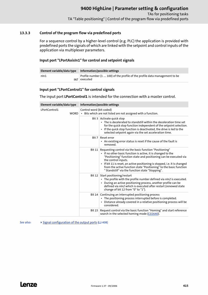
L Firmware 1.37 - 09/2006 415
9400 HighLine | Parameter setting & configurationTAs for positioning tasks
TA "Table positioning" | Control of the program flow via predefined ports
13.3.3 Control of the program flow via predefined ports
For a sequence control by a higher-level control (e.g. PLC) the application is provided with predefined ports the signals of which are linked with the setpoint and control inputs of the application via multiplexer parameters.
Input port "LPortAxisIn1" for control and setpoint signals
Input port "LPortControl1" for control signals
The input port LPortControl1 is intended for the connection with a master control.
See also: Signal configuration of the output ports ( 408)
Element variable/data type Information/possible settings
nIn1INT
Profile number (1 .... 100) of the profile of the profile data management to be executed
Element variable/data type Information/possible settings
LPortControl1WORD
Control word (bit coded) • Bits which are not listed are not assigned with a function.
Bit 3 Activate quick stop • The is decelerated to standstill within the deceleration time set
for the quick stop function independent of the setpoint selection. • If the quick stop function is deactivated, the drive is led to the
selected setpoint again via the set acceleration time.
Bit 7 Reset error • An existing error status is reset if the cause of the fault is
removed.
Bit 11 Requesting control via the basic function "Positioning" • If no other basic function is active, it is changed to the
"Positioning" function state and positioning can be executed via the control inputs.
• If bit 11 is reset, an active positioning is stopped, i.e. it is changed from the active function state "Positioning" to the basic function " Standstill" via the function state "Stopping".
Bit 12 Start positioning/restart • The profile with the profile number defined via nIn2 is executed. • During an active positioning process, another profile can be
defined via nIn2 which is executed after restart (renewed state change of bit 12 from "0" to "1").
Bit 14 Continuing an interrupted positioning process • The positioning process interrupted before is completed. • Distance already covered in a relative positioning process will be
considered.
Bit 15 Request control via the basic function "Homing" and start reference search in the selected homing mode (C02640).
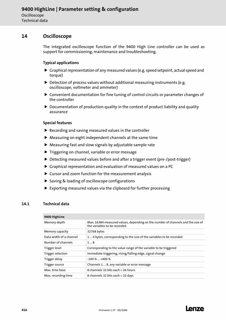
9400 HighLine | Parameter setting & configurationOscilloscopeTechnical data
416 Firmware 1.37 - 09/2006 L
14 Oscilloscope
The integrated oscilloscope function of the 9400 High Line controller can be used as support for commissioning, maintenance and troubleshooting.
Typical applications
Graphical representation of any measured values (e.g. speed setpoint, actual speed and torque)
Detection of process values without additional measuring instruments (e.g. oscilloscope, voltmeter and ammeter)
Convenient documentation for fine tuning of control circuits or parameter changes of the controller
Documentation of production quality in the context of product liability and quality assurance
Special features
Recording and saving measured values in the controller
Measuring on eight independent channels at the same time
Measuring fast and slow signals by adjustable sample rate
Triggering on channel, variable or error message
Detecting measured values before and after a trigger event (pre-/post-trigger)
Graphical representation and evaluation of measured values on a PC
Cursor and zoom function for the measurement analysis
Saving & loading of oscilloscope configurations
Exporting measured values via the clipboard for further processing
14.1 Technical data
9400 HighLine
Memory depth Max. 16384 measured values, depending on the number of channels and the size of the variables to be recorded.
Memory capacity 32768 bytes
Data width of a channel 1 ... 4 bytes, corresponding to the size of the variables to be recorded
Number of channels 1 ... 8
Trigger level Corresponding to the value range of the variable to be triggered
Trigger selection Immediate triggering, rising/falling edge, signal change
Trigger delay -100 % ... +400 %
Trigger source Channels 1 ... 8, any variable or error message
Max. time base 8 channels 32 bits each ≡ 26 hours
Max. recording time 8 channels 32 bits each ≡ 10 days
L Firmware 1.37 - 09/2006 417
9400 HighLine | Parameter setting & configurationOscilloscope
Function description
14.2 Function description
With an online connection to the controller, use the oscilloscope user interface of the »Engineer« to set the trigger condition and the sample rate and select the variables to be recorded.
When the measurement is started, the set parameters are transferred to the controller and checked. If invalid settings are found, the oscilloscope sends an error. Otherwise, the measurement is started.
With an online connection, the measured controller data are transferred to the »Engineer« and graphically represented on the oscilloscope user interface as soon as the measurement has been completed.
Recording variable values
The operating system scans the oscilloscope in fixed 1 ms-cycles, i.e. the oscilloscope can record variable values with a sample rate of max. 1 kHz.
Recording system variable values of the internal motor control
Unlike the variables declared in the application, the system variables of the internal motor control (MCTRL) can also be recorded with a sample rate higher than 1 kHz.
Recording I/O variable values referring to a task
When selecting the variables to be measured, it is possible to indicate a task reference for the variables. If the behaviour of a certain task is to be examined, you can indicate the task reference to exactly record the values valid for the task run-time.
The variable values are recorded during the process output image generation of the task.
Note!
In the servo operating modes, recordings with a time-based resolution of 31.25 μs and 125 μs are not possible!
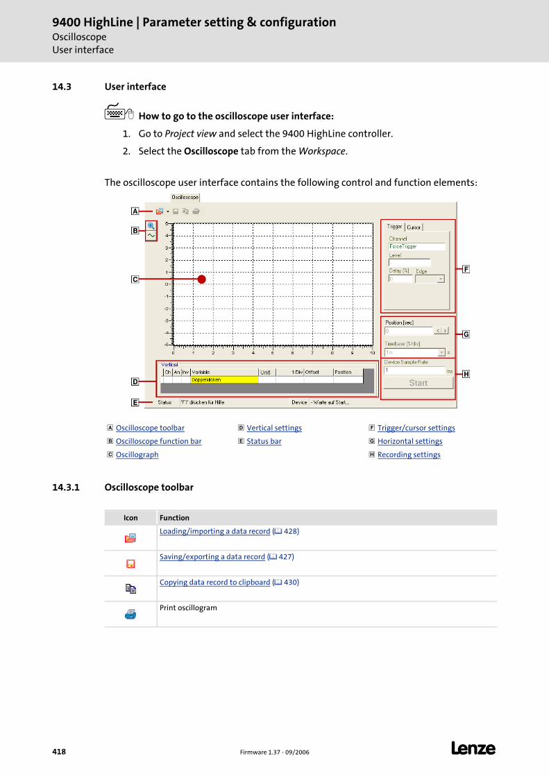
9400 HighLine | Parameter setting & configurationOscilloscopeUser interface
418 Firmware 1.37 - 09/2006 L
14.3 User interface
How to go to the oscilloscope user interface:
1. Go to Project view and select the 9400 HighLine controller.
2. Select the Oscilloscope tab from the Workspace.
The oscilloscope user interface contains the following control and function elements:
14.3.1 Oscilloscope toolbar
Oscilloscope toolbar Vertical settings Trigger/cursor settings
Oscilloscope function bar Status bar Horizontal settings
Oscillograph Recording settings
Icon Function
Loading/importing a data record ( 428)
Saving/exporting a data record ( 427)
Copying data record to clipboard ( 430)
Print oscillogram
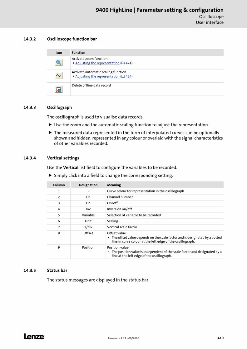
L Firmware 1.37 - 09/2006 419
9400 HighLine | Parameter setting & configurationOscilloscope
User interface
14.3.2 Oscilloscope function bar
14.3.3 Oscillograph
The oscillograph is used to visualise data records.
Use the zoom and the automatic scaling function to adjust the representation.
The measured data represented in the form of interpolated curves can be optionally shown and hidden, represented in any colour or overlaid with the signal characteristics of other variables recorded.
14.3.4 Vertical settings
Use the Vertical list field to configure the variables to be recorded.
Simply click into a field to change the corresponding setting.
14.3.5 Status bar
The status messages are displayed in the status bar.
Icon Function
Activate zoom functionAdjusting the representation ( 424)
Activate automatic scaling functionAdjusting the representation ( 424)
Delete offline data record
Column Designation Meaning
1 - Curve colour for representation in the oscillograph
2 Ch Channel number
3 On On/off
4 Inv Inversion on/off
5 Variable Selection of variable to be recorded
6 Unit Scaling
7 1/div Vertical scale factor
8 Offset Offset value • The offset value depends on the scale factor and is designated by a dotted
line in curve colour at the left edge of the oscillograph.
9 Position Position value • The position value is independent of the scale factor and designated by a
line at the left edge of the oscillograph.
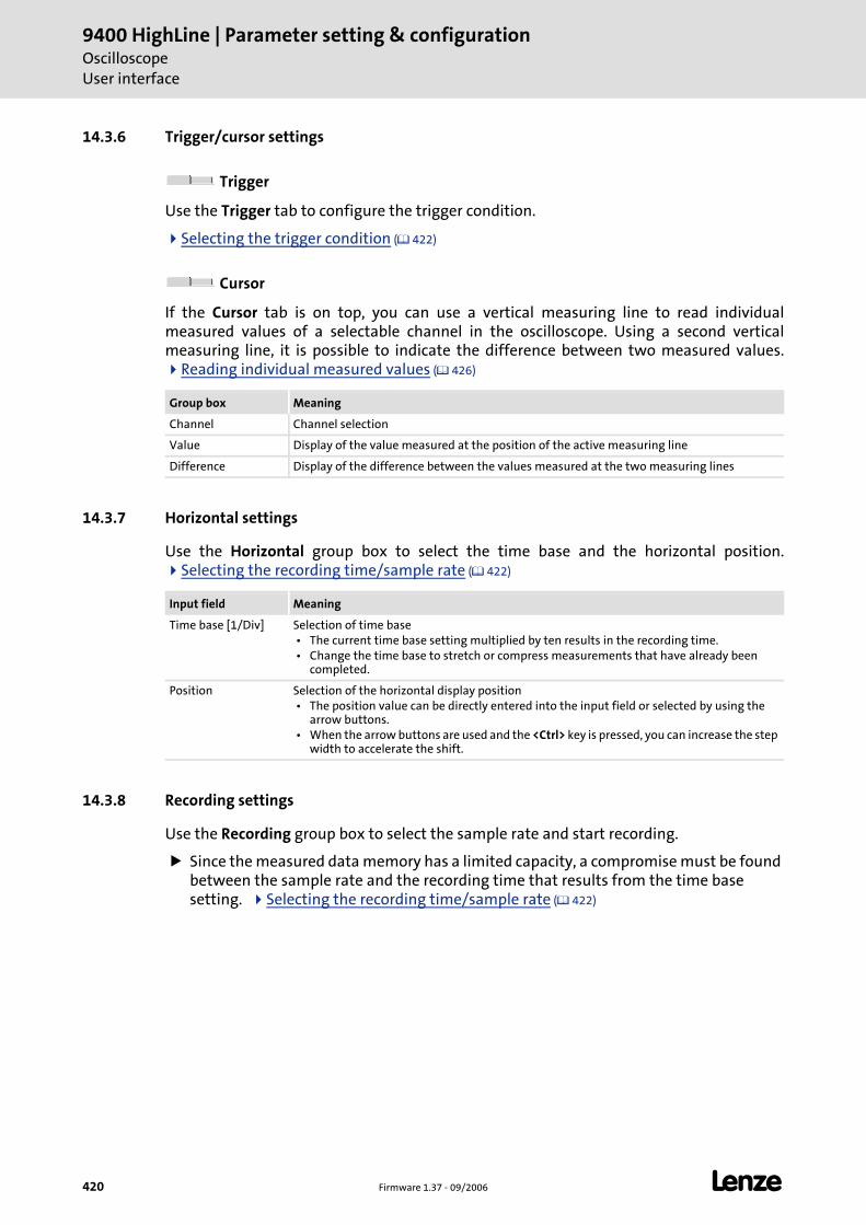
9400 HighLine | Parameter setting & configurationOscilloscopeUser interface
420 Firmware 1.37 - 09/2006 L
14.3.6 Trigger/cursor settings
Trigger
Use the Trigger tab to configure the trigger condition.
Selecting the trigger condition ( 422)
Cursor
If the Cursor tab is on top, you can use a vertical measuring line to read individual measured values of a selectable channel in the oscilloscope. Using a second vertical measuring line, it is possible to indicate the difference between two measured values.
Reading individual measured values ( 426)
14.3.7 Horizontal settings
Use the Horizontal group box to select the time base and the horizontal position. Selecting the recording time/sample rate ( 422)
14.3.8 Recording settings
Use the Recording group box to select the sample rate and start recording.
Since the measured data memory has a limited capacity, a compromise must be found between the sample rate and the recording time that results from the time base setting. Selecting the recording time/sample rate ( 422)
Group box Meaning
Channel Channel selection
Value Display of the value measured at the position of the active measuring line
Difference Display of the difference between the values measured at the two measuring lines
Input field Meaning
Time base [1/Div] Selection of time base • The current time base setting multiplied by ten results in the recording time. • Change the time base to stretch or compress measurements that have already been
completed.
Position Selection of the horizontal display position • The position value can be directly entered into the input field or selected by using the
arrow buttons. • When the arrow buttons are used and the <Ctrl> key is pressed, you can increase the step
width to accelerate the shift.
L Firmware 1.37 - 09/2006 421
9400 HighLine | Parameter setting & configurationOscilloscope
Operation
14.4 Operation
This chapter describes step-by-step how to record the signal characteristics of controller variables and represent, analyse, document and process them in the oscilloscope.
14.4.1 Selecting the variables to be recorded
The oscilloscope supports up to eight channels, i.e. max. eight variables can be recorded in a data record. Use the Vertical group box to select the variables.
How to select a variable for recording:
1. Go to the Variable column in the Vertical group box and double-click in the yellow field to open the Select variable dialog box.
• The dialog box lists all variables declared in the PLC program of the controller and the system variables of the internal motor (MCTRL).
2. Select the variable to be recorded from the list field.
3. Click OK.
• The dialog box is closed and the selection is accepted.
4. Repeat steps 1 ... 3 to select up to seven more variables to be recorded.
Of course, it is any time possible to change or delete a selection later.
How to change a selection:
1. Go to the Vertical group box and double-click the variable to be changed in the Variable column.
2. Select a new variable in the Select variable dialog box.
3. Click OK.
• The dialog box is closed and the selection is accepted.
Note!
In the oscilloscope, settings can only be selected and recording can only be started, when the controller is connected online.
9400 HighLine | Parameter setting & configurationOscilloscopeOperation
422 Firmware 1.37 - 09/2006 L
How to delete a selection:
1. Go to the Vertical group box and double-click the variable to be removed in the Variable column.
2. Click Delete channel in the Select variable dialog box.
• The dialog box is closed and the selection is deleted.
14.4.2 Selecting the recording time/sample rate
How to select the recording time and the sample rate:
1. Go to the Horizontal group box and select the desired time base from the Time base list field.
• The current time base setting multiplied by ten results in the recording time.
• Since the measured data memory of the controller has a limited capacity, usually a comprise is made between sample rate and recording time.
2. Enter the desired sample rate [ms] in the Record group box in the Device sample rate input field.
14.4.3 Selecting the trigger condition
With the trigger condition, you can select when recording is to be started in the controller.
The oscilloscope provides different trigger conditions that can be used to control measured value recording.
Select the corresponding settings in the Trigger tab to define the trigger condition.
Setting Function
Source Selection of trigger source:
Variable The oscilloscope triggers on any variable of the PLC program. • Unlike triggering on a channel, triggering on a variable requires no recording channel.
Channel The oscilloscope triggers on a channel configured in the Vertical table.
System event Triggering is started on occurrence of a selectable controller event (e.g. TRIP, message or warning). • Select a negative trigger delay to record signals prior to occurrence of the event.
Force trigger No trigger condition, recording starts immediately after the start.
Trigger value Value from which on triggering is activated. • The trigger level is not effective for triggering on Boolean variables.
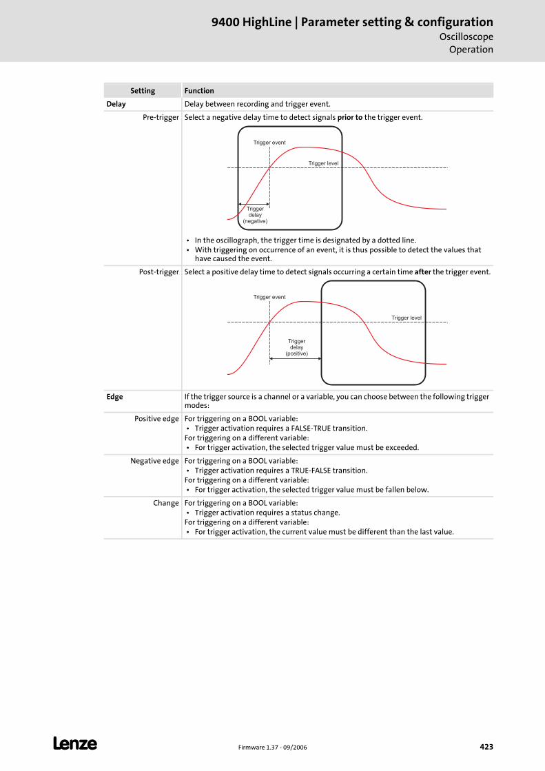
L Firmware 1.37 - 09/2006 423
9400 HighLine | Parameter setting & configurationOscilloscope
Operation
Delay Delay between recording and trigger event.
Pre-trigger Select a negative delay time to detect signals prior to the trigger event.
• In the oscillograph, the trigger time is designated by a dotted line. • With triggering on occurrence of an event, it is thus possible to detect the values that
have caused the event.
Post-trigger Select a positive delay time to detect signals occurring a certain time after the trigger event.
Edge If the trigger source is a channel or a variable, you can choose between the following trigger modes:
Positive edge For triggering on a BOOL variable: • Trigger activation requires a FALSE-TRUE transition.For triggering on a different variable: • For trigger activation, the selected trigger value must be exceeded.
Negative edge For triggering on a BOOL variable: • Trigger activation requires a TRUE-FALSE transition.For triggering on a different variable: • For trigger activation, the selected trigger value must be fallen below.
Change For triggering on a BOOL variable: • Trigger activation requires a status change.For triggering on a different variable: • For trigger activation, the current value must be different than the last value.
Setting Function
Trigger event
Triggerdelay
(negative)
Trigger level
Trigger event
Triggerdelay
(positive)
Trigger level
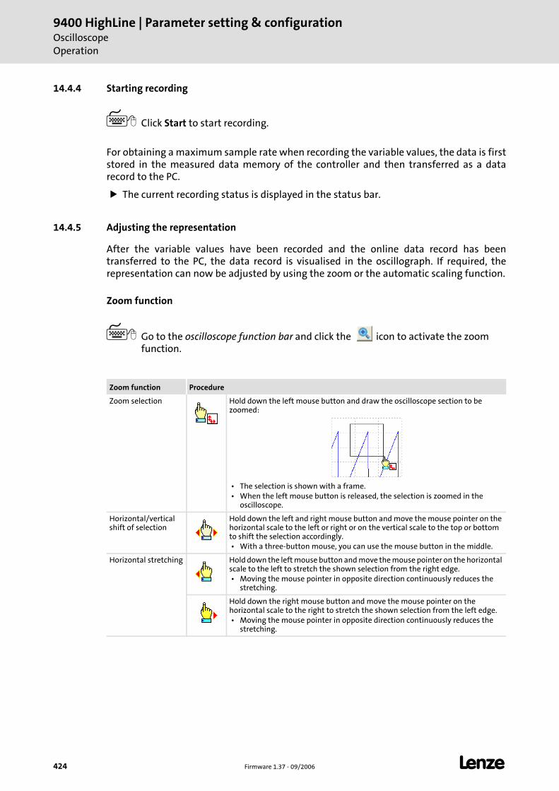
9400 HighLine | Parameter setting & configurationOscilloscopeOperation
424 Firmware 1.37 - 09/2006 L
14.4.4 Starting recording
Click Start to start recording.
For obtaining a maximum sample rate when recording the variable values, the data is first stored in the measured data memory of the controller and then transferred as a data record to the PC.
The current recording status is displayed in the status bar.
14.4.5 Adjusting the representation
After the variable values have been recorded and the online data record has been transferred to the PC, the data record is visualised in the oscillograph. If required, the representation can now be adjusted by using the zoom or the automatic scaling function.
Zoom function
Go to the oscilloscope function bar and click the icon to activate the zoom function.
Zoom function Procedure
Zoom selection Hold down the left mouse button and draw the oscilloscope section to be zoomed:
• The selection is shown with a frame. • When the left mouse button is released, the selection is zoomed in the
oscilloscope.
Horizontal/vertical shift of selection
Hold down the left and right mouse button and move the mouse pointer on the horizontal scale to the left or right or on the vertical scale to the top or bottom to shift the selection accordingly. • With a three-button mouse, you can use the mouse button in the middle.
Horizontal stretching Hold down the left mouse button and move the mouse pointer on the horizontal scale to the left to stretch the shown selection from the right edge. • Moving the mouse pointer in opposite direction continuously reduces the
stretching.
Hold down the right mouse button and move the mouse pointer on the horizontal scale to the right to stretch the shown selection from the left edge. • Moving the mouse pointer in opposite direction continuously reduces the
stretching.
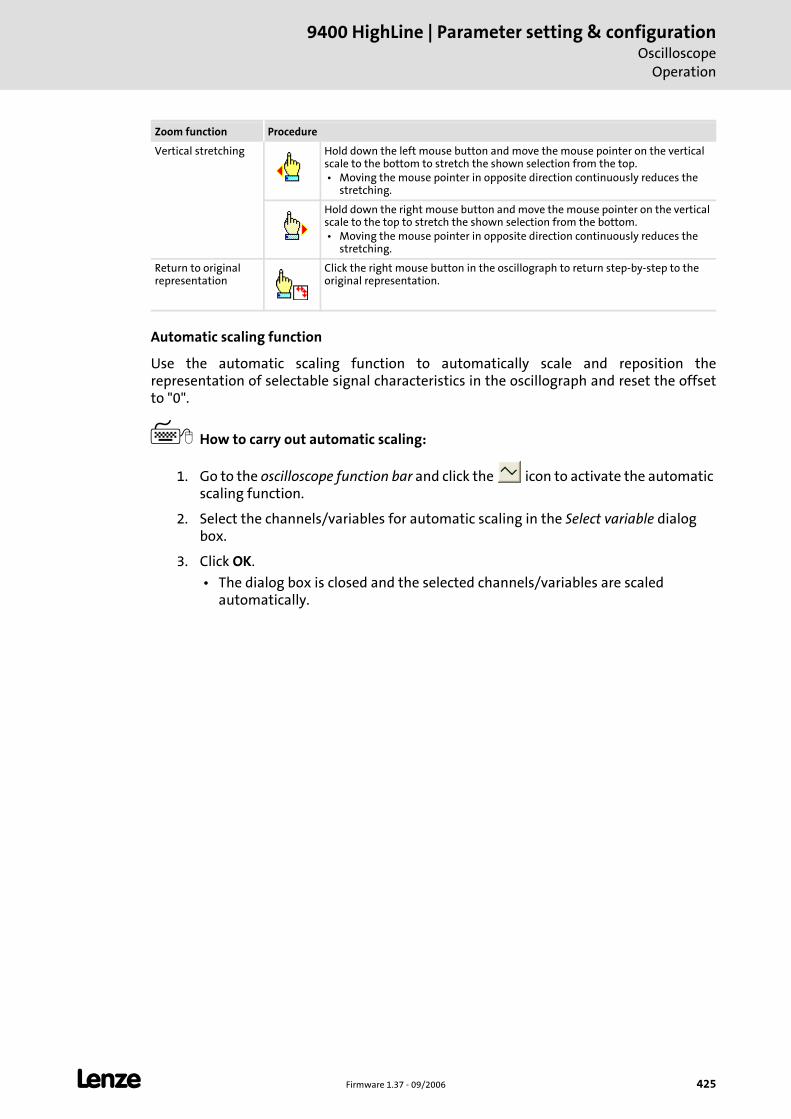
L Firmware 1.37 - 09/2006 425
9400 HighLine | Parameter setting & configurationOscilloscope
Operation
Automatic scaling function
Use the automatic scaling function to automatically scale and reposition the representation of selectable signal characteristics in the oscillograph and reset the offset to "0".
How to carry out automatic scaling:
1. Go to the oscilloscope function bar and click the icon to activate the automatic scaling function.
2. Select the channels/variables for automatic scaling in the Select variable dialog box.
3. Click OK.
• The dialog box is closed and the selected channels/variables are scaled automatically.
Vertical stretching Hold down the left mouse button and move the mouse pointer on the vertical scale to the bottom to stretch the shown selection from the top. • Moving the mouse pointer in opposite direction continuously reduces the
stretching.
Hold down the right mouse button and move the mouse pointer on the vertical scale to the top to stretch the shown selection from the bottom. • Moving the mouse pointer in opposite direction continuously reduces the
stretching.
Return to original representation
Click the right mouse button in the oscillograph to return step-by-step to the original representation.
Zoom function Procedure
9400 HighLine | Parameter setting & configurationOscilloscopeOperation
426 Firmware 1.37 - 09/2006 L
14.4.6 Reading individual measured values
In addition to the zoom and the scaling function, the oscilloscope offers a "cursor function" that can be used to display individual measured values of a selectable channel or the difference between two measured values.
If the Cursor tab is on top, the cursor function is active and two movable vertical measuring lines are shown in the oscillograph.
How to use the cursor function:
1. Select the Cursor tab.
2. Select the channel for which individual measured values are to be indicated from the Channel list field.
3. Hold down the left mouse button and drag the red vertical measuring line to the desired position.
• The active measuring line is represented by a continuous line, the inactive measuring line is indicated by a dotted line.
• If you position the mouse pointer over the inactive measuring line, the measuring line automatically becomes active.
• The value measured at the position of the active measuring line is indicated in the Value group box.
• The difference between the values measured at the two measuring lines is indicated in the Difference group box.
L Firmware 1.37 - 09/2006 427
9400 HighLine | Parameter setting & configurationOscilloscopeData records
14.5 Data records
If several data records are loaded in the oscilloscope at the same time, the data record to be displayed is selected via the list field Data record. There are three types of data records:
Online data record
The online data record is the only data record serving to establish a connection to the target system. When the online data record has established the connection completely, it can communicate with the target system.
In the list field Data record the online data record is marked with a prefixed asterisk (*).
Offline data record
The offline data record is already stored in the project and loaded in the oscilloscope again, or imported from a file.
Merge data record
The merge data record is automatically available in the list field Data record if two or more data records are loaded in the oscilloscope at the same time.
In the merge data record, several characteristics from the currently loaded data records can be laid on top of each other, e.g. to compare signal characteristics from different recordings. Overlay function ( 429)
14.5.1 Saving/exporting a data record
After the variables to be recorded have been selected and the required settings have been entered, you can save the configuration and recording, if already executed, for future use in the project or export them to a file.
How to save the data record in the project:
1. Go to Oscilloscope toolbar and click .
• The Save data record dialog box appears.
2. Enter a name in the Name of the data record to be stored input field.
3. Click Filing in the project.
• The dialog box is closed and the current data record is filed in the project.
Note!
The data record is only saved if the entire project is saved!
9400 HighLine | Parameter setting & configurationOscilloscopeData records
428 Firmware 1.37 - 09/2006 L
How to export the data record to a file:
1. Go to Oscilloscope toolbar and click .
• The Save data record dialog box appears.
2. Enter a name in the Name of the data record to be stored input field.
3. Click the Export to file button.
4. Specify the data record to be stored and the filing folder in the Save as dialog box.
5. Click Save.
• The dialog box is closed and the current data record is saved.
14.5.2 Loading/importing a data record
Configurations/data records already stored can be loaded in the oscilloscope any time again, e.g. for the superposition function.
How to load a data record from the project:
1. Go to Oscilloscope toolbar and click .
• The Load data record dialog box appears.
2. Select the data record to be loaded from the Data record list field.
3. Click Open.
• The dialog box is closed and the selected data record is saved.
• If the configuration to be loaded contains variables that are no longer available in the controller, these variables are automatically removed from the configuration.
How to import a data record from a file:
1. Go to Oscilloscope toolbar and click .
• The Load data record dialog box appears.
2. Click the Import button.
3. Select the file to be imported within the desktop environment from the Open dialog box.
4. Click Open.
• The dialog box is closed and the selected data record is imported.
• If the configuration to be loaded contains variables that are no longer available in the controller, these variables are automatically removed from the configuration.
L Firmware 1.37 - 09/2006 429
9400 HighLine | Parameter setting & configurationOscilloscopeData records
14.5.3 Deleting data record in the project
How to delete a data record to be saved in the project:
1. Go to Oscilloscope toolbar and click .
• The Load data record dialog box appears.
2. Click the data record to be deleted with the right mouse key in the Data record list field to open the Context menu for the data record.
3. Select the Delete data record in the Context menu.
4. Click Abort to close the dialog box again.
14.5.4 Overlay function
The overlay function serves to lay several characteristics from the currently loaded data records on top of each other, e.g. to compare signal characteristics from different recordings.
If two or several data records are loaded in the oscilloscope, e.g. an online data record and a data record saved before in the project, a "merge" data record is available in the Data record list field.
When the merge data record is selected, the desired characteristics can be selected from the loaded data records in the Vertical channel settings group field which are to be overlaid or compared.
If an online data record is used in the merge data record, an update is carried out in the merge data record in case of a renewed recording.
Removing variables from an offline or online data record causes the characteristics in the merge data record to be deleted.
9400 HighLine | Parameter setting & configurationOscilloscopeData records
430 Firmware 1.37 - 09/2006 L
14.5.5 Copying data record to clipboard
For documentation purposes, it is possible to copy the measured data of a data record as a table or, alternatively, the oscilloscope user interface as a picture, to the clipboard for use in other programs.
How to copy measured data or a picture of the user interface to the clipboard:
1. Go to Oscilloscope toolbar and click .
• The Clipboard dialog box appears.
2. Select Curve points if the measured data is to be copied to the clipboard as a table, or select Screen shot if the oscilloscope user interface is to be copied as a picture.
3. Click OK.
• The dialog box is closed and the selected option is copied to the clipboard.
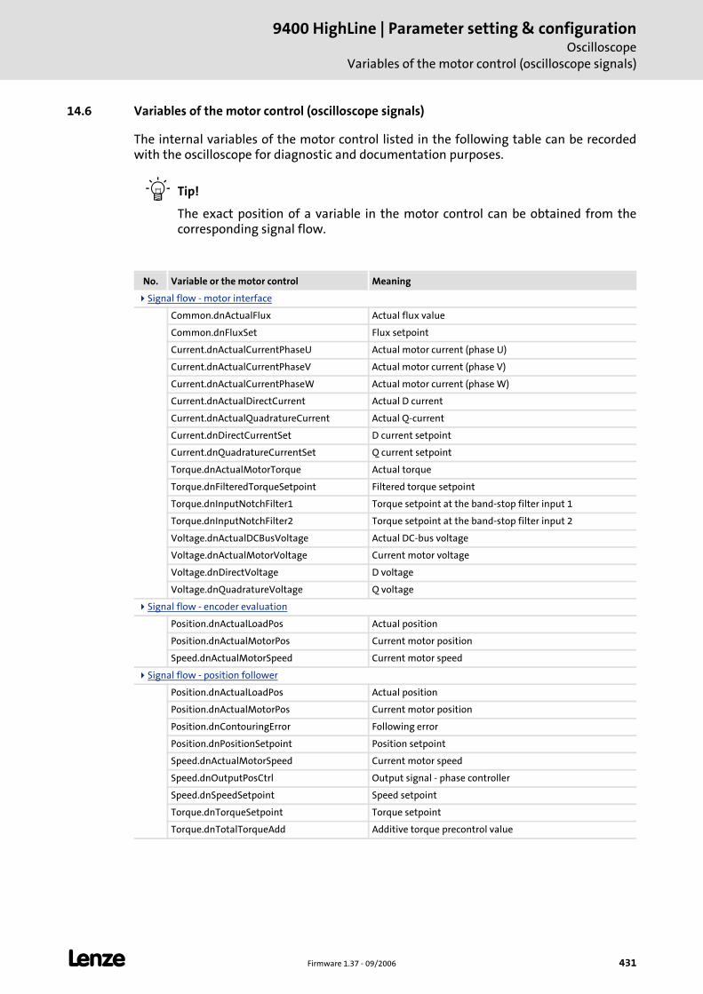
L Firmware 1.37 - 09/2006 431
9400 HighLine | Parameter setting & configurationOscilloscope
Variables of the motor control (oscilloscope signals)
14.6 Variables of the motor control (oscilloscope signals)
The internal variables of the motor control listed in the following table can be recorded with the oscilloscope for diagnostic and documentation purposes.
Tip!
The exact position of a variable in the motor control can be obtained from the corresponding signal flow.
No. Variable or the motor control Meaning
Signal flow - motor interface
Common.dnActualFlux Actual flux value
Common.dnFluxSet Flux setpoint
Current.dnActualCurrentPhaseU Actual motor current (phase U)
Current.dnActualCurrentPhaseV Actual motor current (phase V)
Current.dnActualCurrentPhaseW Actual motor current (phase W)
Current.dnActualDirectCurrent Actual D current
Current.dnActualQuadratureCurrent Actual Q-current
Current.dnDirectCurrentSet D current setpoint
Current.dnQuadratureCurrentSet Q current setpoint
Torque.dnActualMotorTorque Actual torque
Torque.dnFilteredTorqueSetpoint Filtered torque setpoint
Torque.dnInputNotchFilter1 Torque setpoint at the band-stop filter input 1
Torque.dnInputNotchFilter2 Torque setpoint at the band-stop filter input 2
Voltage.dnActualDCBusVoltage Actual DC-bus voltage
Voltage.dnActualMotorVoltage Current motor voltage
Voltage.dnDirectVoltage D voltage
Voltage.dnQuadratureVoltage Q voltage
Signal flow - encoder evaluation
Position.dnActualLoadPos Actual position
Position.dnActualMotorPos Current motor position
Speed.dnActualMotorSpeed Current motor speed
Signal flow - position follower
Position.dnActualLoadPos Actual position
Position.dnActualMotorPos Current motor position
Position.dnContouringError Following error
Position.dnPositionSetpoint Position setpoint
Speed.dnActualMotorSpeed Current motor speed
Speed.dnOutputPosCtrl Output signal - phase controller
Speed.dnSpeedSetpoint Speed setpoint
Torque.dnTorqueSetpoint Torque setpoint
Torque.dnTotalTorqueAdd Additive torque precontrol value
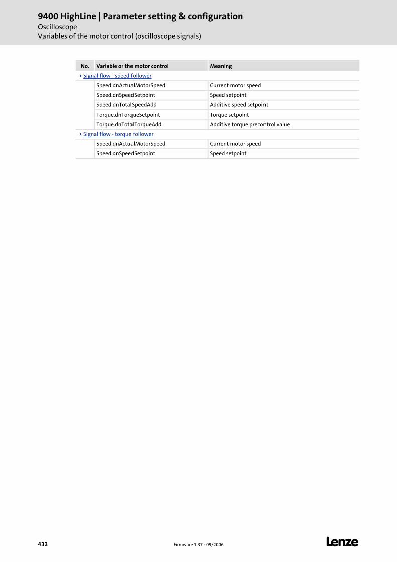
9400 HighLine | Parameter setting & configurationOscilloscopeVariables of the motor control (oscilloscope signals)
432 Firmware 1.37 - 09/2006 L
Signal flow - speed follower
Speed.dnActualMotorSpeed Current motor speed
Speed.dnSpeedSetpoint Speed setpoint
Speed.dnTotalSpeedAdd Additive speed setpoint
Torque.dnTorqueSetpoint Torque setpoint
Torque.dnTotalTorqueAdd Additive torque precontrol value
Signal flow - torque follower
Speed.dnActualMotorSpeed Current motor speed
Speed.dnSpeedSetpoint Speed setpoint
No. Variable or the motor control Meaning
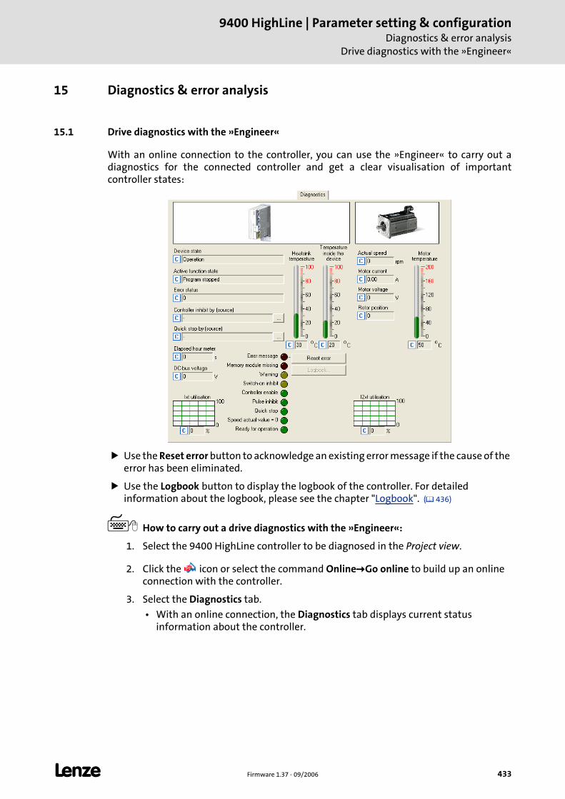
L Firmware 1.37 - 09/2006 433
9400 HighLine | Parameter setting & configurationDiagnostics & error analysis
Drive diagnostics with the »Engineer«
15 Diagnostics & error analysis
15.1 Drive diagnostics with the »Engineer«
With an online connection to the controller, you can use the »Engineer« to carry out a diagnostics for the connected controller and get a clear visualisation of important controller states:
Use the Reset error button to acknowledge an existing error message if the cause of the error has been eliminated.
Use the Logbook button to display the logbook of the controller. For detailed information about the logbook, please see the chapter "Logbook". ( 436)
How to carry out a drive diagnostics with the »Engineer«:
1. Select the 9400 HighLine controller to be diagnosed in the Project view.
2. Click the icon or select the command Online Go online to build up an online connection with the controller.
3. Select the Diagnostics tab.
• With an online connection, the Diagnostics tab displays current status information about the controller.
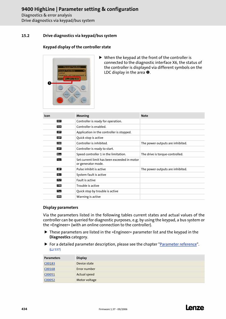
9400 HighLine | Parameter setting & configurationDiagnostics & error analysisDrive diagnostics via keypad/bus system
434 Firmware 1.37 - 09/2006 L
15.2 Drive diagnostics via keypad/bus system
Keypad display of the controller state
Display parameters
Via the parameters listed in the following tables current states and actual values of the controller can be queried for diagnostic purposes, e.g. by using the keypad, a bus system or the »Engineer« (with an online connection to the controller).
These parameters are listed in the »Engineer« parameter list and the keypad in the Diagnostics category.
For a detailed parameter description, please see the chapter "Parameter reference". ( 537)
When the keypad at the front of the controller is connected to the diagnostic interface X6, the status of the controller is displayed via different symbols on the LDC display in the area .
Icon Meaning Note
Controller is ready for operation.
Controller is enabled.
Application in the controller is stopped.
Quick stop is active
Controller is inhibited. The power outputs are inhibited.
Controller is ready to start.
Speed controller 1 in the limitation. The drive is torque-controlled.
Set current limit has been exceeded in motoror generator mode.
Pulse inhibit is active The power outputs are inhibited.
System fault is active
Fault is active
Trouble is active
Quick stop by trouble is active
Warning is active
Parameters Display
C00183 Device state
C00168 Error number
C00051 Actual speed
C00052 Motor voltage
L Firmware 1.37 - 09/2006 435
9400 HighLine | Parameter setting & configurationDiagnostics & error analysis
Drive diagnostics via keypad/bus system
Identification data
The parameters listed in the following table which are entered in the »Engineer« parameter list and in the keypad in the Identification Controller category, serve to display the identification data of the controller:
C00054 Motor current
C00057/1 Maximum torque
C00057/2 Torque at maximum current
C00059 Motor - number of pole pairs
C00060 Rotor position
C00061 Heatsink temperature
C00062 Temperature inside the controller
C00063 Motor temperature
C00064 Controller load (I x t) during the last 180 seconds
C00065 External. 24-V voltage
C00066 Thermal motor load (I2xt)
C00068 Electrolytic capacitor temperature
C00069 CPU temperature
C00178 Time the controller was enabled (elapsed-hour meter)
C00179 Power-up time (power-on time meter)
C00186 ENP: detected motor type
Parameters Display
C00099 Firmware version
C00200 Firmware product type
C00201 Firmware - compile date
C00203/1...9 HW product types
C00204/1...9 HW serial numbers
C00205/1...6 HW descriptions
C00206/1...6 HW manufacturing data
C00208/1...6 HW manufacturer
C00209/1...6 HW countries of origin
C00210/1...6 HW versions
C02113 Program name
Parameters Display
9400 HighLine | Parameter setting & configurationDiagnostics & error analysisLogbook
436 Firmware 1.37 - 09/2006 L
15.3 Logbook
The integrated logbook function of the controller chronologically logs important events within the system and plays an important role for troubleshooting and controller diagnostics.
Events that can be logged
The following events can be logged in the logbook:
Error messages of the operating system ( 443)
Error messages generated by the application
Controller enable
Starting / stopping the application
Loading/saving of parameter sets, loading of the Lenze setting
Transmitting an application or firmware to the controller
Connection/disconnection of the controller
Formatting of the file system
Tip!
Use a parameterisable filter to exclude certain events from logbook entry. Filtering logbook entries ( 437)
Information saved
For each event, the following information are saved in the logbook:
Type of response (e.g. fault, warning or information) to the event
Module that activated the event (e.g. MCTRL or TEMPCONTROL).
Event
Date/time (for memory module with real-time clock)
Value of power-on time meter
Memory depth
The number of possible logbook entries depends on the memory module used:
MM1xx, MM2xx: 7 entries
MM3xx, MM4xx: 439 entries
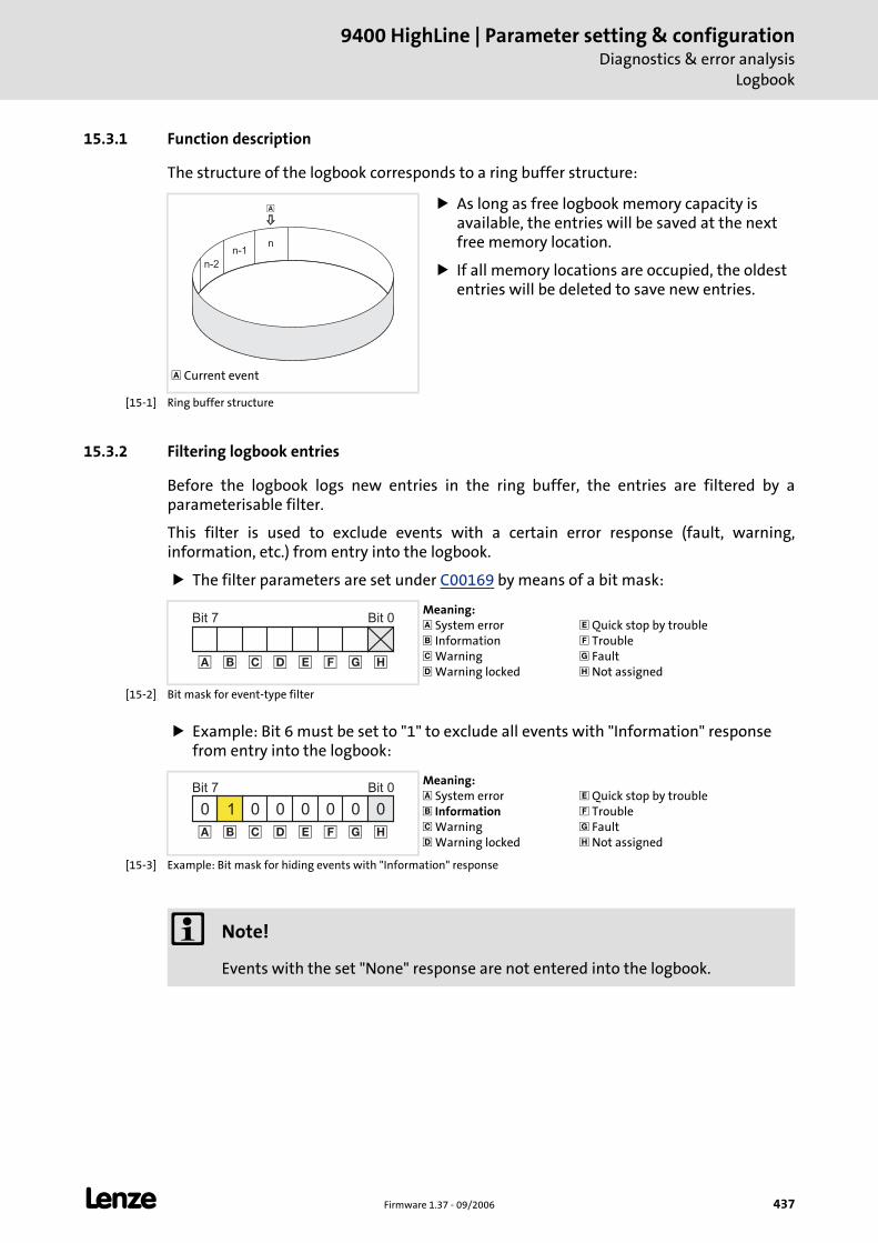
L Firmware 1.37 - 09/2006 437
9400 HighLine | Parameter setting & configurationDiagnostics & error analysis
Logbook
15.3.1 Function description
The structure of the logbook corresponds to a ring buffer structure:
[15-1] Ring buffer structure
15.3.2 Filtering logbook entries
Before the logbook logs new entries in the ring buffer, the entries are filtered by a parameterisable filter.
This filter is used to exclude events with a certain error response (fault, warning, information, etc.) from entry into the logbook.
The filter parameters are set under C00169 by means of a bit mask:
[15-2] Bit mask for event-type filter
Example: Bit 6 must be set to "1" to exclude all events with "Information" response from entry into the logbook:
[15-3] Example: Bit mask for hiding events with "Information" response
Current event
As long as free logbook memory capacity is available, the entries will be saved at the next free memory location.
If all memory locations are occupied, the oldest entries will be deleted to save new entries.
nn-1
n-2
�
Meaning: System error Information Warning Warning locked
Quick stop by trouble Trouble Fault Not assigned
Bit 0Bit 7
��� ���� �
Meaning: System error Information Warning Warning locked
Quick stop by trouble Trouble Fault Not assigned
Bit 0Bit 7
1 0 0 0 0 00
��� ���� �
0
Note!
Events with the set "None" response are not entered into the logbook.
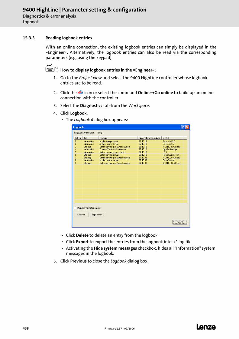
9400 HighLine | Parameter setting & configurationDiagnostics & error analysisLogbook
438 Firmware 1.37 - 09/2006 L
15.3.3 Reading logbook entries
With an online connection, the existing logbook entries can simply be displayed in the »Engineer«. Alternatively, the logbook entries can also be read via the corresponding parameters (e.g. using the keypad).
How to display logbook entries in the »Engineer«:
1. Go to the Project view and select the 9400 HighLine controller whose logbook entries are to be read.
2. Click the icon or select the command Online Go online to build up an online connection with the controller.
3. Select the Diagnostics tab from the Workspace.
4. Click Logbook.
• The Logbook dialog box appears:
• Click Delete to delete an entry from the logbook.
• Click Export to export the entries from the logbook into a *.log file.
• Activating the Hide system messages checkbox, hides all "Information" system messages in the logbook.
5. Click Previous to close the Logbook dialog box.
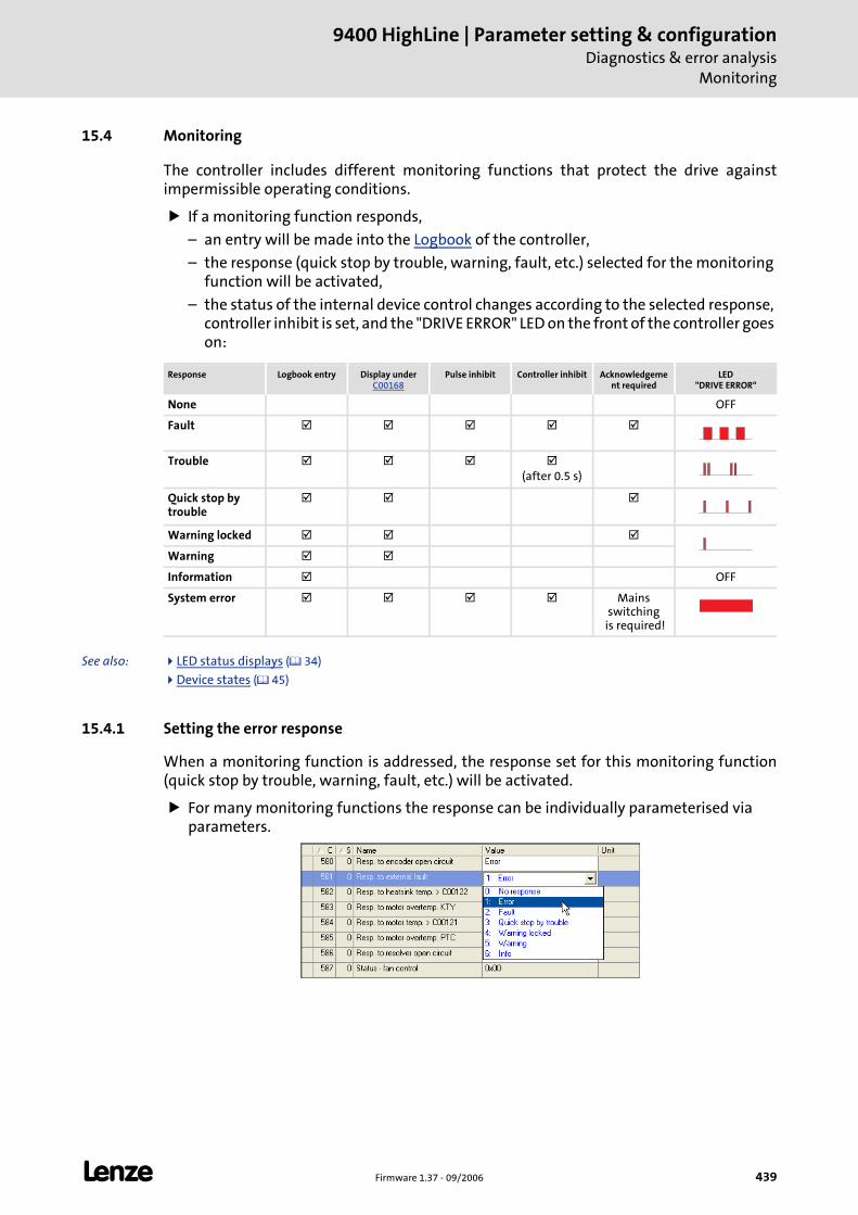
L Firmware 1.37 - 09/2006 439
9400 HighLine | Parameter setting & configurationDiagnostics & error analysis
Monitoring
15.4 Monitoring
The controller includes different monitoring functions that protect the drive against impermissible operating conditions.
If a monitoring function responds,
– an entry will be made into the Logbook of the controller,
– the response (quick stop by trouble, warning, fault, etc.) selected for the monitoring function will be activated,
– the status of the internal device control changes according to the selected response, controller inhibit is set, and the "DRIVE ERROR" LED on the front of the controller goes on:
See also: LED status displays ( 34)
Device states ( 45)
15.4.1 Setting the error response
When a monitoring function is addressed, the response set for this monitoring function (quick stop by trouble, warning, fault, etc.) will be activated.
For many monitoring functions the response can be individually parameterised via parameters.
Response Logbook entry Display under C00168
Pulse inhibit Controller inhibit Acknowledgement required
LED"DRIVE ERROR"
None OFF
Fault
Trouble(after 0.5 s)
Quick stop by trouble
Warning locked
Warning
Information OFF
System error Mains switching
is required!
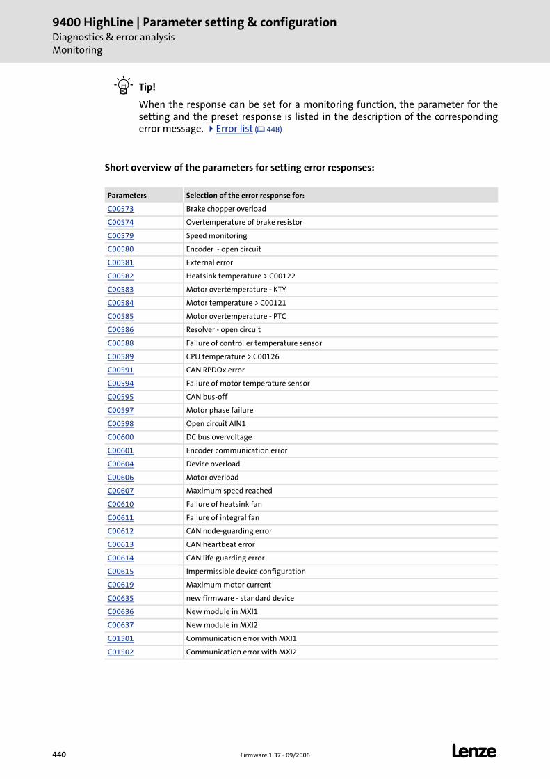
9400 HighLine | Parameter setting & configurationDiagnostics & error analysisMonitoring
440 Firmware 1.37 - 09/2006 L
Tip!
When the response can be set for a monitoring function, the parameter for the setting and the preset response is listed in the description of the corresponding error message. Error list ( 448)
Short overview of the parameters for setting error responses:
Parameters Selection of the error response for:
C00573 Brake chopper overload
C00574 Overtemperature of brake resistor
C00579 Speed monitoring
C00580 Encoder - open circuit
C00581 External error
C00582 Heatsink temperature > C00122
C00583 Motor overtemperature - KTY
C00584 Motor temperature > C00121
C00585 Motor overtemperature - PTC
C00586 Resolver - open circuit
C00588 Failure of controller temperature sensor
C00589 CPU temperature > C00126
C00591 CAN RPDOx error
C00594 Failure of motor temperature sensor
C00595 CAN bus-off
C00597 Motor phase failure
C00598 Open circuit AIN1
C00600 DC bus overvoltage
C00601 Encoder communication error
C00604 Device overload
C00606 Motor overload
C00607 Maximum speed reached
C00610 Failure of heatsink fan
C00611 Failure of integral fan
C00612 CAN node-guarding error
C00613 CAN heartbeat error
C00614 CAN life guarding error
C00615 Impermissible device configuration
C00619 Maximum motor current
C00635 new firmware - standard device
C00636 New module in MXI1
C00637 New module in MXI2
C01501 Communication error with MXI1
C01502 Communication error with MXI2
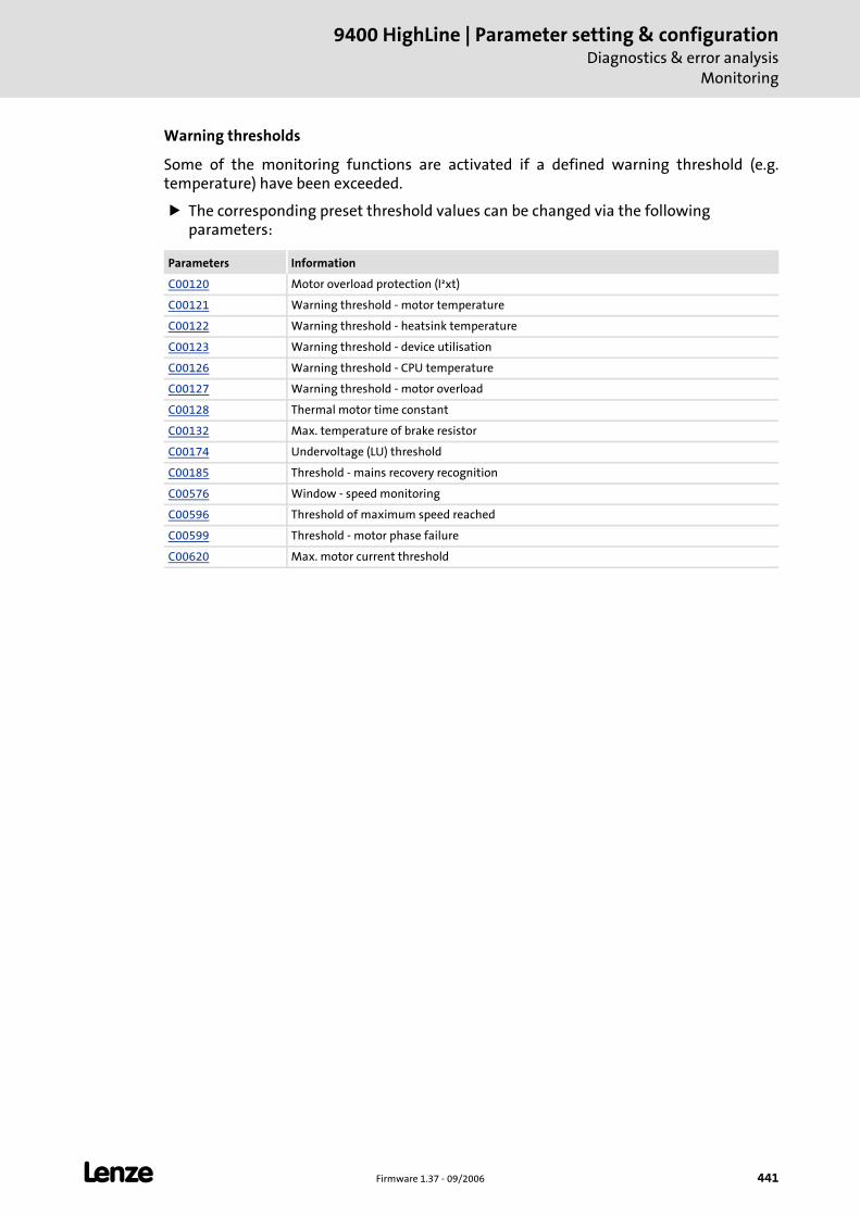
L Firmware 1.37 - 09/2006 441
9400 HighLine | Parameter setting & configurationDiagnostics & error analysis
Monitoring
Warning thresholds
Some of the monitoring functions are activated if a defined warning threshold (e.g. temperature) have been exceeded.
The corresponding preset threshold values can be changed via the following parameters:
Parameters Information
C00120 Motor overload protection (I²xt)
C00121 Warning threshold - motor temperature
C00122 Warning threshold - heatsink temperature
C00123 Warning threshold - device utilisation
C00126 Warning threshold - CPU temperature
C00127 Warning threshold - motor overload
C00128 Thermal motor time constant
C00132 Max. temperature of brake resistor
C00174 Undervoltage (LU) threshold
C00185 Threshold - mains recovery recognition
C00576 Window - speed monitoring
C00596 Threshold of maximum speed reached
C00599 Threshold - motor phase failure
C00620 Max. motor current threshold
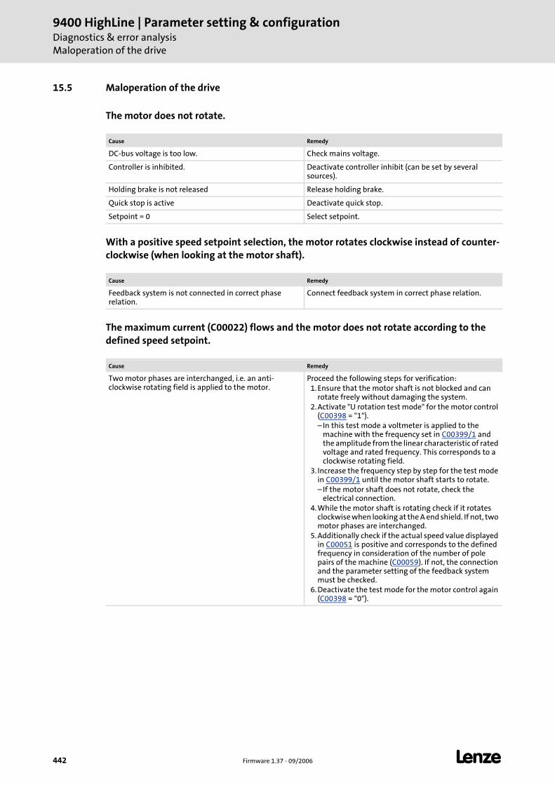
9400 HighLine | Parameter setting & configurationDiagnostics & error analysisMaloperation of the drive
442 Firmware 1.37 - 09/2006 L
15.5 Maloperation of the drive
The motor does not rotate.
With a positive speed setpoint selection, the motor rotates clockwise instead of counter-clockwise (when looking at the motor shaft).
The maximum current (C00022) flows and the motor does not rotate according to the defined speed setpoint.
Cause Remedy
DC-bus voltage is too low. Check mains voltage.
Controller is inhibited. Deactivate controller inhibit (can be set by several sources).
Holding brake is not released Release holding brake.
Quick stop is active Deactivate quick stop.
Setpoint = 0 Select setpoint.
Cause Remedy
Feedback system is not connected in correct phase relation.
Connect feedback system in correct phase relation.
Cause Remedy
Two motor phases are interchanged, i.e. an anti-clockwise rotating field is applied to the motor.
Proceed the following steps for verification:1.Ensure that the motor shaft is not blocked and can
rotate freely without damaging the system.2.Activate "U rotation test mode" for the motor control
(C00398 = "1").– In this test mode a voltmeter is applied to the
machine with the frequency set in C00399/1 and the amplitude from the linear characteristic of rated voltage and rated frequency. This corresponds to a clockwise rotating field.
3. Increase the frequency step by step for the test mode in C00399/1 until the motor shaft starts to rotate.– If the motor shaft does not rotate, check the
electrical connection.4.While the motor shaft is rotating check if it rotates
clockwise when looking at the A end shield. If not, two motor phases are interchanged.
5.Additionally check if the actual speed value displayed in C00051 is positive and corresponds to the defined frequency in consideration of the number of pole pairs of the machine (C00059). If not, the connection and the parameter setting of the feedback system must be checked.
6.Deactivate the test mode for the motor control again (C00398 = "0").
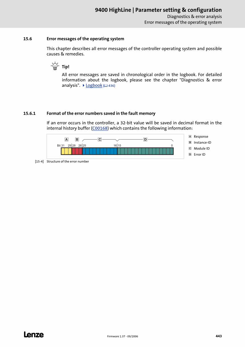
L Firmware 1.37 - 09/2006 443
9400 HighLine | Parameter setting & configurationDiagnostics & error analysis
Error messages of the operating system
15.6 Error messages of the operating system
This chapter describes all error messages of the controller operating system and possible causes & remedies.
Tip!
All error messages are saved in chronological order in the logbook. For detailed information about the logbook, please see the chapter "Diagnostics & error analysis". Logbook ( 436)
15.6.1 Format of the error numbers saved in the fault memory
If an error occurs in the controller, a 32-bit value will be saved in decimal format in the internal history buffer (C00168) which contains the following information:
[15-4] Structure of the error number
Response
Instance-ID
Module ID
Error ID
��� �
Bit 31 1625262829 015
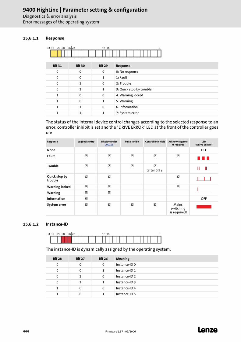
9400 HighLine | Parameter setting & configurationDiagnostics & error analysisError messages of the operating system
444 Firmware 1.37 - 09/2006 L
15.6.1.1 Response
The status of the internal device control changes according to the selected response to an error, controller inhibit is set and the "DRIVE ERROR" LED at the front of the controller goes on:
15.6.1.2 Instance-ID
The instance-ID is dynamically assigned by the operating system.
Bit 31 Bit 30 Bit 29 Response
0 0 0 0: No response
0 0 1 1: Fault
0 1 0 2: Trouble
0 1 1 3: Quick stop by trouble
1 0 0 4: Warning locked
1 0 1 5: Warning
1 1 0 6: Information
1 1 1 7: System error
Response Logbook entry Display under C00168
Pulse inhibit Controller inhibit Acknowledgement required
LED"DRIVE ERROR"
None OFF
Fault
Trouble(after 0.5 s)
Quick stop by trouble
Warning locked
Warning
Information OFF
System error Mains switching
is required!
Bit 31 1625262829 015
Bit 28 Bit 27 Bit 26 Meaning
0 0 0 Instance-ID 0
0 0 1 Instance-ID 1
0 1 0 Instance-ID 2
0 1 1 Instance-ID 3
1 0 0 Instance-ID 4
1 0 1 Instance-ID 5
Bit 31 1625262829 015
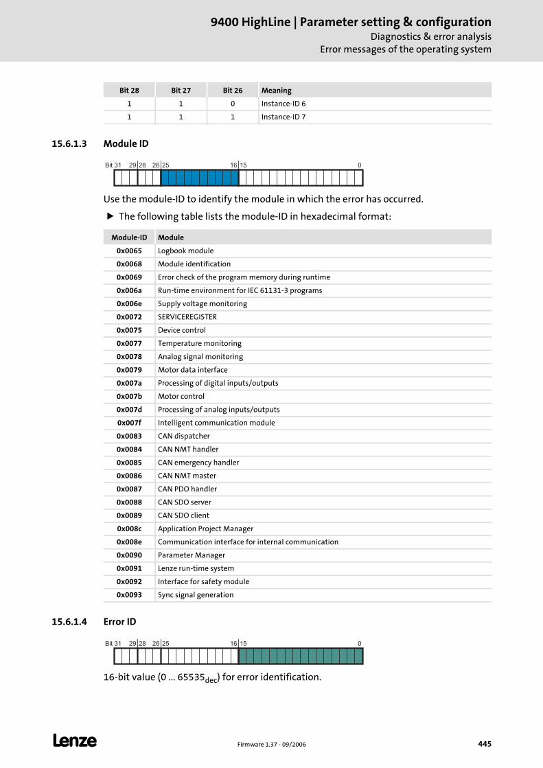
L Firmware 1.37 - 09/2006 445
9400 HighLine | Parameter setting & configurationDiagnostics & error analysis
Error messages of the operating system
15.6.1.3 Module ID
Use the module-ID to identify the module in which the error has occurred.
The following table lists the module-ID in hexadecimal format:
15.6.1.4 Error ID
16-bit value (0 ... 65535dec) for error identification.
1 1 0 Instance-ID 6
1 1 1 Instance-ID 7
Bit 28 Bit 27 Bit 26 Meaning
Module-ID Module
0x0065 Logbook module
0x0068 Module identification
0x0069 Error check of the program memory during runtime
0x006a Run-time environment for IEC 61131-3 programs
0x006e Supply voltage monitoring
0x0072 SERVICEREGISTER
0x0075 Device control
0x0077 Temperature monitoring
0x0078 Analog signal monitoring
0x0079 Motor data interface
0x007a Processing of digital inputs/outputs
0x007b Motor control
0x007d Processing of analog inputs/outputs
0x007f Intelligent communication module
0x0083 CAN dispatcher
0x0084 CAN NMT handler
0x0085 CAN emergency handler
0x0086 CAN NMT master
0x0087 CAN PDO handler
0x0088 CAN SDO server
0x0089 CAN SDO client
0x008c Application Project Manager
0x008e Communication interface for internal communication
0x0090 Parameter Manager
0x0091 Lenze run-time system
0x0092 Interface for safety module
0x0093 Sync signal generation
Bit 31 1625262829 015
Bit 31 1625262829 015
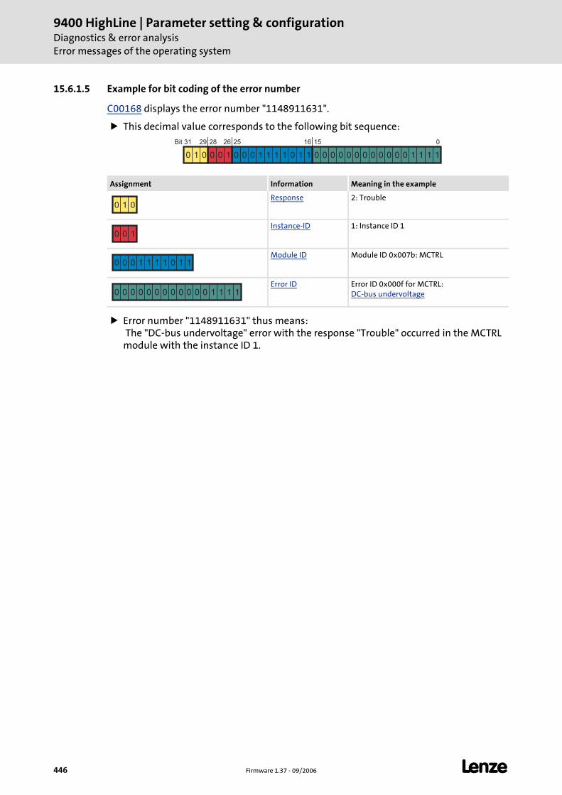
9400 HighLine | Parameter setting & configurationDiagnostics & error analysisError messages of the operating system
446 Firmware 1.37 - 09/2006 L
15.6.1.5 Example for bit coding of the error number
C00168 displays the error number "1148911631".
This decimal value corresponds to the following bit sequence:
Error number "1148911631" thus means: The "DC-bus undervoltage" error with the response "Trouble" occurred in the MCTRL module with the instance ID 1.
Assignment Information Meaning in the example
Response 2: Trouble
Instance-ID 1: Instance ID 1
Module ID Module ID 0x007b: MCTRL
Error ID Error ID 0x000f for MCTRL:DC-bus undervoltage
Bit 31 1625262829 015
0 1 0 0 0 1 0 0 0 1 1 1 1 0 1 1 0 0 0 0 0 0 0 0 0 0 0 0 1 1 1 1
0 1 0
0 0 1
0 0 0 1 1 1 1 0 1 1
0 0 0 0 0 0 0 0 0 0 0 0 1 1 1 1
L Firmware 1.37 - 09/2006 447
9400 HighLine | Parameter setting & configurationDiagnostics & error analysis
Error messages of the operating system
15.6.2 Reset of error message
An error message with the response "Fault", "Trouble", "Quick stop by trouble" or "Warning locked" must be explicitly reset (acknowledged) after the cause of the error has been eliminated.
To reset (acknowledge) a pending error message execute the device command C00002 = "43".
Tip!
With an online connection to the controller, use the Diagnostics tab of the »Engineer« and click Error message reset to reset a pending error message.
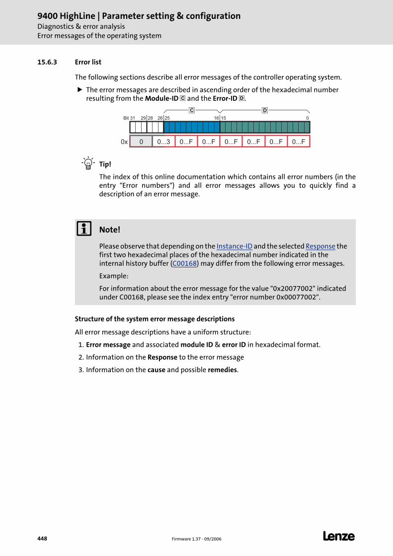
9400 HighLine | Parameter setting & configurationDiagnostics & error analysisError messages of the operating system
448 Firmware 1.37 - 09/2006 L
15.6.3 Error list
The following sections describe all error messages of the controller operating system.
The error messages are described in ascending order of the hexadecimal number resulting from the Module-ID and the Error-ID .
Tip!
The index of this online documentation which contains all error numbers (in the entry "Error numbers") and all error messages allows you to quickly find a description of an error message.
Structure of the system error message descriptions
All error message descriptions have a uniform structure:
1. Error message and associated module ID & error ID in hexadecimal format.
2. Information on the Response to the error message
3. Information on the cause and possible remedies.
Note!
Please observe that depending on the Instance-ID and the selected Response the first two hexadecimal places of the hexadecimal number indicated in the internal history buffer (C00168) may differ from the following error messages.
Example:
For information about the error message for the value "0x20077002" indicated under C00168, please see the index entry "error number 0x00077002".
Bit 31 1625262829 015
0...F0...F0...F0...F0...F0...F0...300x
� �
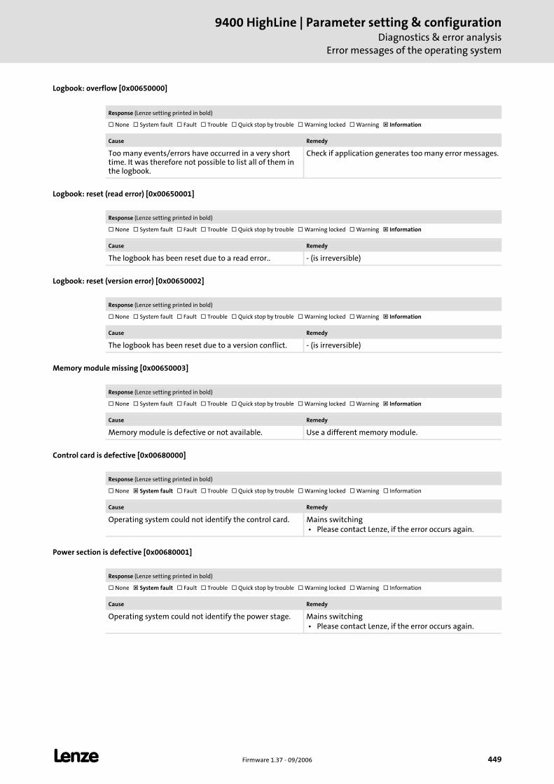
L Firmware 1.37 - 09/2006 449
9400 HighLine | Parameter setting & configurationDiagnostics & error analysis
Error messages of the operating system
Logbook: overflow [0x00650000]
Logbook: reset (read error) [0x00650001]
Logbook: reset (version error) [0x00650002]
Memory module missing [0x00650003]
Control card is defective [0x00680000]
Power section is defective [0x00680001]
Response (Lenze setting printed in bold)
None System fault Fault Trouble Quick stop by trouble Warning locked Warning Information
Cause Remedy
Too many events/errors have occurred in a very short time. It was therefore not possible to list all of them in the logbook.
Check if application generates too many error messages.
Response (Lenze setting printed in bold)
None System fault Fault Trouble Quick stop by trouble Warning locked Warning Information
Cause Remedy
The logbook has been reset due to a read error.. - (is irreversible)
Response (Lenze setting printed in bold)
None System fault Fault Trouble Quick stop by trouble Warning locked Warning Information
Cause Remedy
The logbook has been reset due to a version conflict. - (is irreversible)
Response (Lenze setting printed in bold)
None System fault Fault Trouble Quick stop by trouble Warning locked Warning Information
Cause Remedy
Memory module is defective or not available. Use a different memory module.
Response (Lenze setting printed in bold)
None System fault Fault Trouble Quick stop by trouble Warning locked Warning Information
Cause Remedy
Operating system could not identify the control card. Mains switching • Please contact Lenze, if the error occurs again.
Response (Lenze setting printed in bold)
None System fault Fault Trouble Quick stop by trouble Warning locked Warning Information
Cause Remedy
Operating system could not identify the power stage. Mains switching • Please contact Lenze, if the error occurs again.
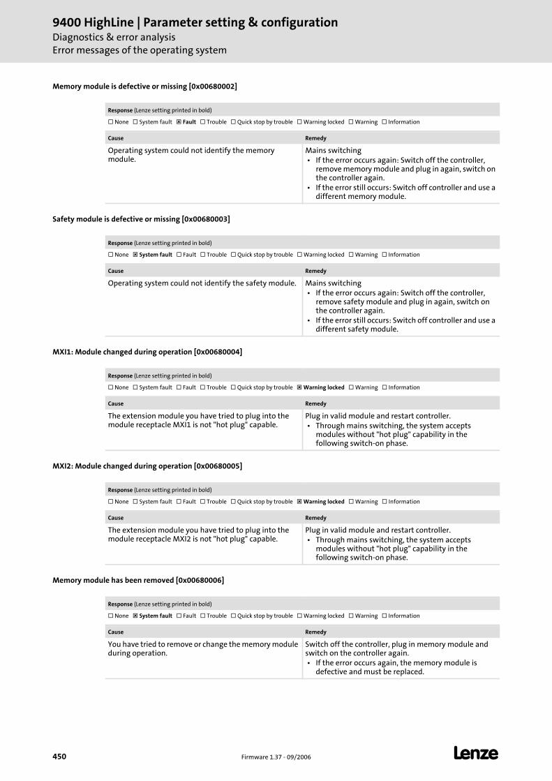
9400 HighLine | Parameter setting & configurationDiagnostics & error analysisError messages of the operating system
450 Firmware 1.37 - 09/2006 L
Memory module is defective or missing [0x00680002]
Safety module is defective or missing [0x00680003]
MXI1: Module changed during operation [0x00680004]
MXI2: Module changed during operation [0x00680005]
Memory module has been removed [0x00680006]
Response (Lenze setting printed in bold)
None System fault Fault Trouble Quick stop by trouble Warning locked Warning Information
Cause Remedy
Operating system could not identify the memory module.
Mains switching • If the error occurs again: Switch off the controller,
remove memory module and plug in again, switch on the controller again.
• If the error still occurs: Switch off controller and use a different memory module.
Response (Lenze setting printed in bold)
None System fault Fault Trouble Quick stop by trouble Warning locked Warning Information
Cause Remedy
Operating system could not identify the safety module. Mains switching • If the error occurs again: Switch off the controller,
remove safety module and plug in again, switch on the controller again.
• If the error still occurs: Switch off controller and use a different safety module.
Response (Lenze setting printed in bold)
None System fault Fault Trouble Quick stop by trouble Warning locked Warning Information
Cause Remedy
The extension module you have tried to plug into the module receptacle MXI1 is not "hot plug" capable.
Plug in valid module and restart controller. • Through mains switching, the system accepts
modules without "hot plug" capability in the following switch-on phase.
Response (Lenze setting printed in bold)
None System fault Fault Trouble Quick stop by trouble Warning locked Warning Information
Cause Remedy
The extension module you have tried to plug into the module receptacle MXI2 is not "hot plug" capable.
Plug in valid module and restart controller. • Through mains switching, the system accepts
modules without "hot plug" capability in the following switch-on phase.
Response (Lenze setting printed in bold)
None System fault Fault Trouble Quick stop by trouble Warning locked Warning Information
Cause Remedy
You have tried to remove or change the memory module during operation.
Switch off the controller, plug in memory module and switch on the controller again. • If the error occurs again, the memory module is
defective and must be replaced.
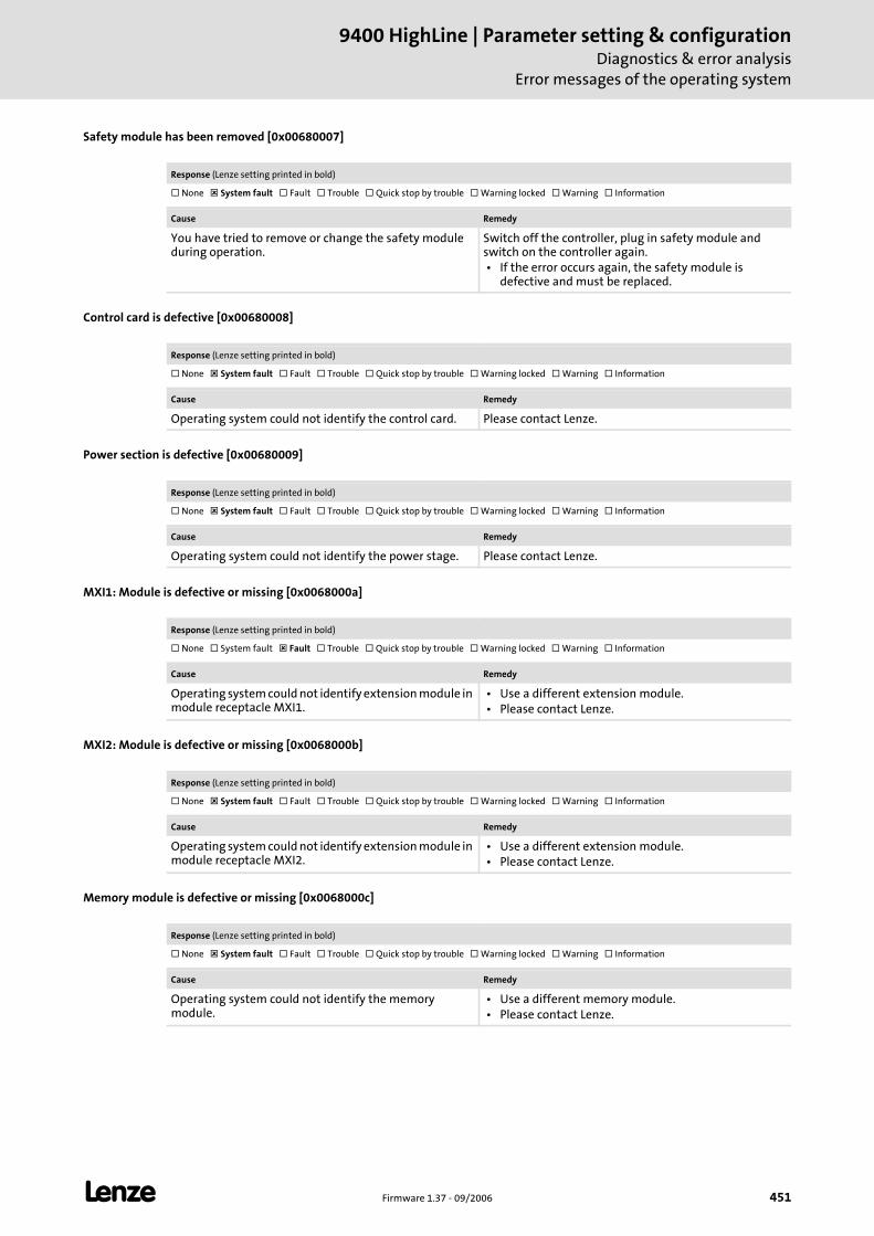
L Firmware 1.37 - 09/2006 451
9400 HighLine | Parameter setting & configurationDiagnostics & error analysis
Error messages of the operating system
Safety module has been removed [0x00680007]
Control card is defective [0x00680008]
Power section is defective [0x00680009]
MXI1: Module is defective or missing [0x0068000a]
MXI2: Module is defective or missing [0x0068000b]
Memory module is defective or missing [0x0068000c]
Response (Lenze setting printed in bold)
None System fault Fault Trouble Quick stop by trouble Warning locked Warning Information
Cause Remedy
You have tried to remove or change the safety module during operation.
Switch off the controller, plug in safety module and switch on the controller again. • If the error occurs again, the safety module is
defective and must be replaced.
Response (Lenze setting printed in bold)
None System fault Fault Trouble Quick stop by trouble Warning locked Warning Information
Cause Remedy
Operating system could not identify the control card. Please contact Lenze.
Response (Lenze setting printed in bold)
None System fault Fault Trouble Quick stop by trouble Warning locked Warning Information
Cause Remedy
Operating system could not identify the power stage. Please contact Lenze.
Response (Lenze setting printed in bold)
None System fault Fault Trouble Quick stop by trouble Warning locked Warning Information
Cause Remedy
Operating system could not identify extension module in module receptacle MXI1.
• Use a different extension module. • Please contact Lenze.
Response (Lenze setting printed in bold)
None System fault Fault Trouble Quick stop by trouble Warning locked Warning Information
Cause Remedy
Operating system could not identify extension module in module receptacle MXI2.
• Use a different extension module. • Please contact Lenze.
Response (Lenze setting printed in bold)
None System fault Fault Trouble Quick stop by trouble Warning locked Warning Information
Cause Remedy
Operating system could not identify the memory module.
• Use a different memory module. • Please contact Lenze.
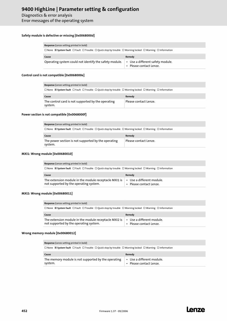
9400 HighLine | Parameter setting & configurationDiagnostics & error analysisError messages of the operating system
452 Firmware 1.37 - 09/2006 L
Safety module is defective or missing [0x0068000d]
Control card is not compatible [0x0068000e]
Power section is not compatible [0x0068000f]
MXI1: Wrong module [0x00680010]
MXI2: Wrong module [0x00680011]
Wrong memory module [0x00680012]
Response (Lenze setting printed in bold)
None System fault Fault Trouble Quick stop by trouble Warning locked Warning Information
Cause Remedy
Operating system could not identify the safety module. • Use a different safety module. • Please contact Lenze.
Response (Lenze setting printed in bold)
None System fault Fault Trouble Quick stop by trouble Warning locked Warning Information
Cause Remedy
The control card is not supported by the operating system.
Please contact Lenze.
Response (Lenze setting printed in bold)
None System fault Fault Trouble Quick stop by trouble Warning locked Warning Information
Cause Remedy
The power section is not supported by the operating system.
Please contact Lenze.
Response (Lenze setting printed in bold)
None System fault Fault Trouble Quick stop by trouble Warning locked Warning Information
Cause Remedy
The extension module in the module receptacle MXI1 is not supported by the operating system.
• Use a different module. • Please contact Lenze.
Response (Lenze setting printed in bold)
None System fault Fault Trouble Quick stop by trouble Warning locked Warning Information
Cause Remedy
The extension module in the module receptacle MXI2 is not supported by the operating system.
• Use a different module. • Please contact Lenze.
Response (Lenze setting printed in bold)
None System fault Fault Trouble Quick stop by trouble Warning locked Warning Information
Cause Remedy
The memory module is not supported by the operating system.
• Use a different module. • Please contact Lenze.
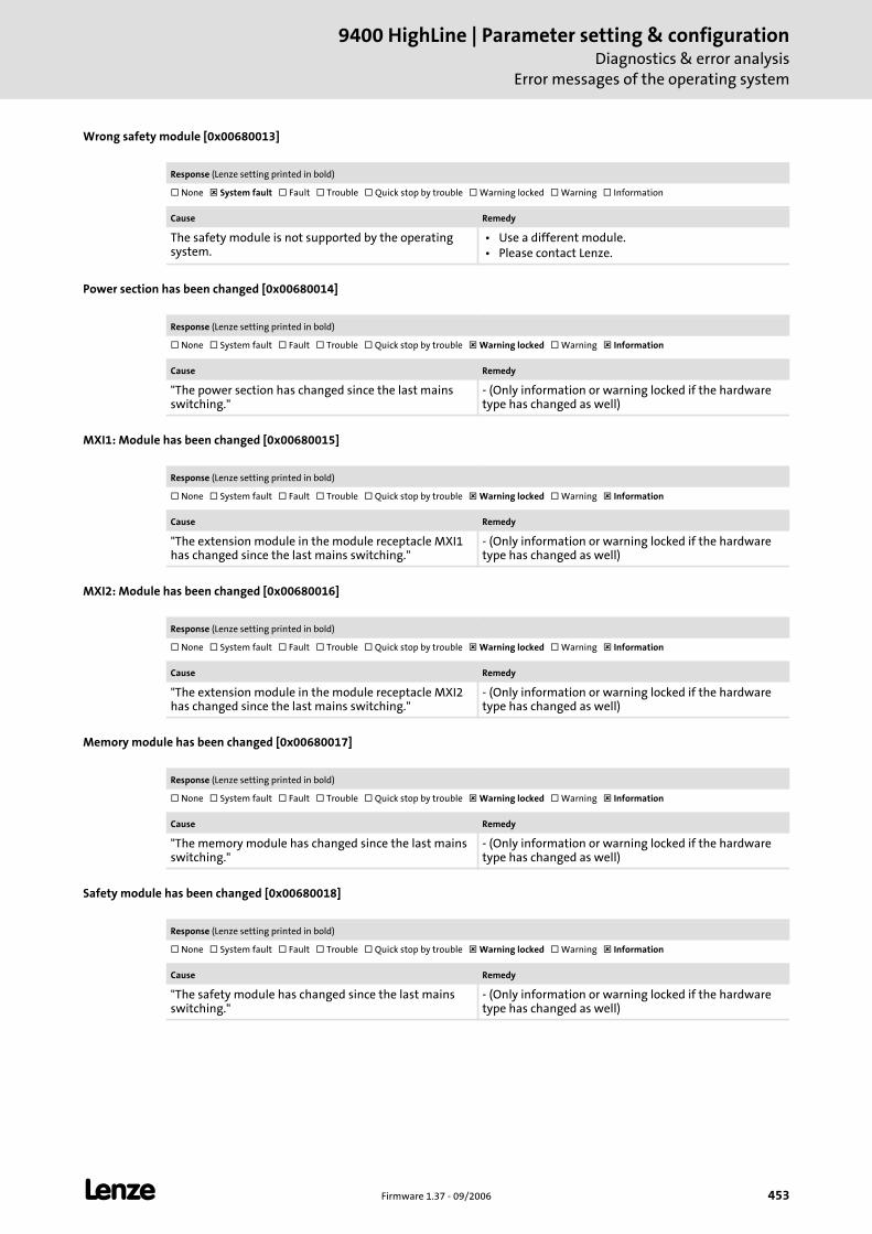
L Firmware 1.37 - 09/2006 453
9400 HighLine | Parameter setting & configurationDiagnostics & error analysis
Error messages of the operating system
Wrong safety module [0x00680013]
Power section has been changed [0x00680014]
MXI1: Module has been changed [0x00680015]
MXI2: Module has been changed [0x00680016]
Memory module has been changed [0x00680017]
Safety module has been changed [0x00680018]
Response (Lenze setting printed in bold)
None System fault Fault Trouble Quick stop by trouble Warning locked Warning Information
Cause Remedy
The safety module is not supported by the operating system.
• Use a different module. • Please contact Lenze.
Response (Lenze setting printed in bold)
None System fault Fault Trouble Quick stop by trouble Warning locked Warning Information
Cause Remedy
"The power section has changed since the last mains switching."
- (Only information or warning locked if the hardware type has changed as well)
Response (Lenze setting printed in bold)
None System fault Fault Trouble Quick stop by trouble Warning locked Warning Information
Cause Remedy
"The extension module in the module receptacle MXI1 has changed since the last mains switching."
- (Only information or warning locked if the hardware type has changed as well)
Response (Lenze setting printed in bold)
None System fault Fault Trouble Quick stop by trouble Warning locked Warning Information
Cause Remedy
"The extension module in the module receptacle MXI2 has changed since the last mains switching."
- (Only information or warning locked if the hardware type has changed as well)
Response (Lenze setting printed in bold)
None System fault Fault Trouble Quick stop by trouble Warning locked Warning Information
Cause Remedy
"The memory module has changed since the last mains switching."
- (Only information or warning locked if the hardware type has changed as well)
Response (Lenze setting printed in bold)
None System fault Fault Trouble Quick stop by trouble Warning locked Warning Information
Cause Remedy
"The safety module has changed since the last mains switching."
- (Only information or warning locked if the hardware type has changed as well)
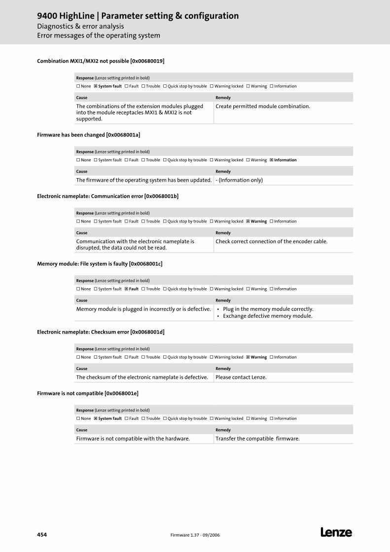
9400 HighLine | Parameter setting & configurationDiagnostics & error analysisError messages of the operating system
454 Firmware 1.37 - 09/2006 L
Combination MXI1/MXI2 not possible [0x00680019]
Firmware has been changed [0x0068001a]
Electronic nameplate: Communication error [0x0068001b]
Memory module: File system is faulty [0x0068001c]
Electronic nameplate: Checksum error [0x0068001d]
Firmware is not compatible [0x0068001e]
Response (Lenze setting printed in bold)
None System fault Fault Trouble Quick stop by trouble Warning locked Warning Information
Cause Remedy
The combinations of the extension modules plugged into the module receptacles MXI1 & MXI2 is not supported.
Create permitted module combination.
Response (Lenze setting printed in bold)
None System fault Fault Trouble Quick stop by trouble Warning locked Warning Information
Cause Remedy
The firmware of the operating system has been updated. - (Information only)
Response (Lenze setting printed in bold)
None System fault Fault Trouble Quick stop by trouble Warning locked Warning Information
Cause Remedy
Communication with the electronic nameplate is disrupted, the data could not be read.
Check correct connection of the encoder cable.
Response (Lenze setting printed in bold)
None System fault Fault Trouble Quick stop by trouble Warning locked Warning Information
Cause Remedy
Memory module is plugged in incorrectly or is defective. • Plug in the memory module correctly. • Exchange defective memory module.
Response (Lenze setting printed in bold)
None System fault Fault Trouble Quick stop by trouble Warning locked Warning Information
Cause Remedy
The checksum of the electronic nameplate is defective. Please contact Lenze.
Response (Lenze setting printed in bold)
None System fault Fault Trouble Quick stop by trouble Warning locked Warning Information
Cause Remedy
Firmware is not compatible with the hardware. Transfer the compatible firmware.
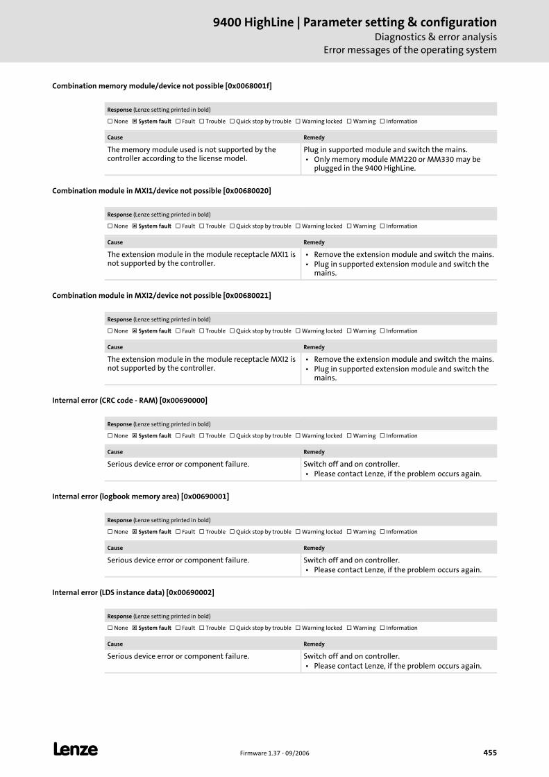
L Firmware 1.37 - 09/2006 455
9400 HighLine | Parameter setting & configurationDiagnostics & error analysis
Error messages of the operating system
Combination memory module/device not possible [0x0068001f]
Combination module in MXI1/device not possible [0x00680020]
Combination module in MXI2/device not possible [0x00680021]
Internal error (CRC code - RAM) [0x00690000]
Internal error (logbook memory area) [0x00690001]
Internal error (LDS instance data) [0x00690002]
Response (Lenze setting printed in bold)
None System fault Fault Trouble Quick stop by trouble Warning locked Warning Information
Cause Remedy
The memory module used is not supported by the controller according to the license model.
Plug in supported module and switch the mains. • Only memory module MM220 or MM330 may be
plugged in the 9400 HighLine.
Response (Lenze setting printed in bold)
None System fault Fault Trouble Quick stop by trouble Warning locked Warning Information
Cause Remedy
The extension module in the module receptacle MXI1 is not supported by the controller.
• Remove the extension module and switch the mains. • Plug in supported extension module and switch the
mains.
Response (Lenze setting printed in bold)
None System fault Fault Trouble Quick stop by trouble Warning locked Warning Information
Cause Remedy
The extension module in the module receptacle MXI2 is not supported by the controller.
• Remove the extension module and switch the mains. • Plug in supported extension module and switch the
mains.
Response (Lenze setting printed in bold)
None System fault Fault Trouble Quick stop by trouble Warning locked Warning Information
Cause Remedy
Serious device error or component failure. Switch off and on controller. • Please contact Lenze, if the problem occurs again.
Response (Lenze setting printed in bold)
None System fault Fault Trouble Quick stop by trouble Warning locked Warning Information
Cause Remedy
Serious device error or component failure. Switch off and on controller. • Please contact Lenze, if the problem occurs again.
Response (Lenze setting printed in bold)
None System fault Fault Trouble Quick stop by trouble Warning locked Warning Information
Cause Remedy
Serious device error or component failure. Switch off and on controller. • Please contact Lenze, if the problem occurs again.
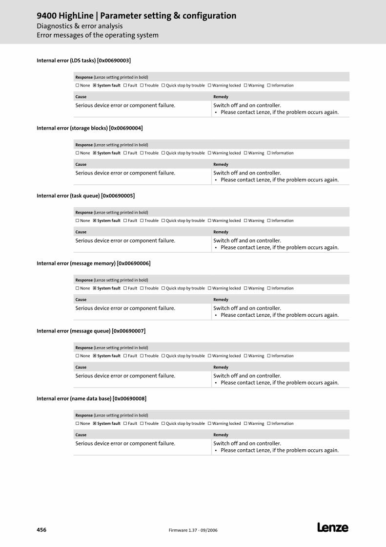
9400 HighLine | Parameter setting & configurationDiagnostics & error analysisError messages of the operating system
456 Firmware 1.37 - 09/2006 L
Internal error (LDS tasks) [0x00690003]
Internal error (storage blocks) [0x00690004]
Internal error (task queue) [0x00690005]
Internal error (message memory) [0x00690006]
Internal error (message queue) [0x00690007]
Internal error (name data base) [0x00690008]
Response (Lenze setting printed in bold)
None System fault Fault Trouble Quick stop by trouble Warning locked Warning Information
Cause Remedy
Serious device error or component failure. Switch off and on controller. • Please contact Lenze, if the problem occurs again.
Response (Lenze setting printed in bold)
None System fault Fault Trouble Quick stop by trouble Warning locked Warning Information
Cause Remedy
Serious device error or component failure. Switch off and on controller. • Please contact Lenze, if the problem occurs again.
Response (Lenze setting printed in bold)
None System fault Fault Trouble Quick stop by trouble Warning locked Warning Information
Cause Remedy
Serious device error or component failure. Switch off and on controller. • Please contact Lenze, if the problem occurs again.
Response (Lenze setting printed in bold)
None System fault Fault Trouble Quick stop by trouble Warning locked Warning Information
Cause Remedy
Serious device error or component failure. Switch off and on controller. • Please contact Lenze, if the problem occurs again.
Response (Lenze setting printed in bold)
None System fault Fault Trouble Quick stop by trouble Warning locked Warning Information
Cause Remedy
Serious device error or component failure. Switch off and on controller. • Please contact Lenze, if the problem occurs again.
Response (Lenze setting printed in bold)
None System fault Fault Trouble Quick stop by trouble Warning locked Warning Information
Cause Remedy
Serious device error or component failure. Switch off and on controller. • Please contact Lenze, if the problem occurs again.
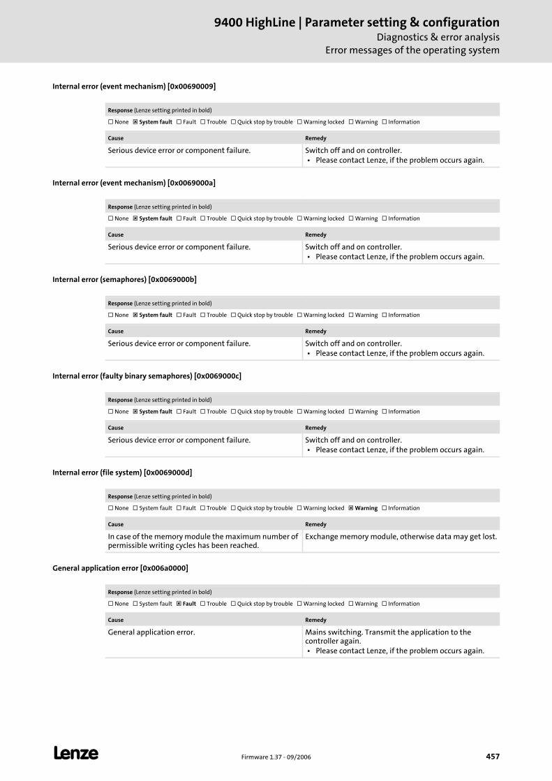
L Firmware 1.37 - 09/2006 457
9400 HighLine | Parameter setting & configurationDiagnostics & error analysis
Error messages of the operating system
Internal error (event mechanism) [0x00690009]
Internal error (event mechanism) [0x0069000a]
Internal error (semaphores) [0x0069000b]
Internal error (faulty binary semaphores) [0x0069000c]
Internal error (file system) [0x0069000d]
General application error [0x006a0000]
Response (Lenze setting printed in bold)
None System fault Fault Trouble Quick stop by trouble Warning locked Warning Information
Cause Remedy
Serious device error or component failure. Switch off and on controller. • Please contact Lenze, if the problem occurs again.
Response (Lenze setting printed in bold)
None System fault Fault Trouble Quick stop by trouble Warning locked Warning Information
Cause Remedy
Serious device error or component failure. Switch off and on controller. • Please contact Lenze, if the problem occurs again.
Response (Lenze setting printed in bold)
None System fault Fault Trouble Quick stop by trouble Warning locked Warning Information
Cause Remedy
Serious device error or component failure. Switch off and on controller. • Please contact Lenze, if the problem occurs again.
Response (Lenze setting printed in bold)
None System fault Fault Trouble Quick stop by trouble Warning locked Warning Information
Cause Remedy
Serious device error or component failure. Switch off and on controller. • Please contact Lenze, if the problem occurs again.
Response (Lenze setting printed in bold)
None System fault Fault Trouble Quick stop by trouble Warning locked Warning Information
Cause Remedy
In case of the memory module the maximum number of permissible writing cycles has been reached.
Exchange memory module, otherwise data may get lost.
Response (Lenze setting printed in bold)
None System fault Fault Trouble Quick stop by trouble Warning locked Warning Information
Cause Remedy
General application error. Mains switching. Transmit the application to the controller again. • Please contact Lenze, if the problem occurs again.
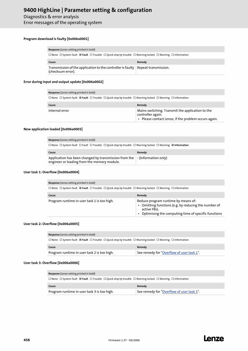
9400 HighLine | Parameter setting & configurationDiagnostics & error analysisError messages of the operating system
458 Firmware 1.37 - 09/2006 L
Program download is faulty [0x006a0001]
Error during input and output update [0x006a0002]
New application loaded [0x006a0003]
User task 1: Overflow [0x006a0004]
User task 2: Overflow [0x006a0005]
User task 3: Overflow [0x006a0006]
Response (Lenze setting printed in bold)
None System fault Fault Trouble Quick stop by trouble Warning locked Warning Information
Cause Remedy
Transmission of the application to the controller is faulty (checksum error).
Repeat transmission.
Response (Lenze setting printed in bold)
None System fault Fault Trouble Quick stop by trouble Warning locked Warning Information
Cause Remedy
Internal error Mains switching. Transmit the application to the controller again. • Please contact Lenze, if the problem occurs again.
Response (Lenze setting printed in bold)
None System fault Fault Trouble Quick stop by trouble Warning locked Warning Information
Cause Remedy
Application has been changed by transmission from the engineer or loading from the memory module.
- (Information only)
Response (Lenze setting printed in bold)
None System fault Fault Trouble Quick stop by trouble Warning locked Warning Information
Cause Remedy
Program runtime in user task 1 is too high. Reduce program runtime by means of: • Omitting functions (e.g. by reducing the number of
active FBs). • Optimising the computing time of specific functions
Response (Lenze setting printed in bold)
None System fault Fault Trouble Quick stop by trouble Warning locked Warning Information
Cause Remedy
Program runtime in user task 2 is too high. See remedy for "Overflow of user task 1".
Response (Lenze setting printed in bold)
None System fault Fault Trouble Quick stop by trouble Warning locked Warning Information
Cause Remedy
Program runtime in user task 3 is too high. See remedy for "Overflow of user task 1".
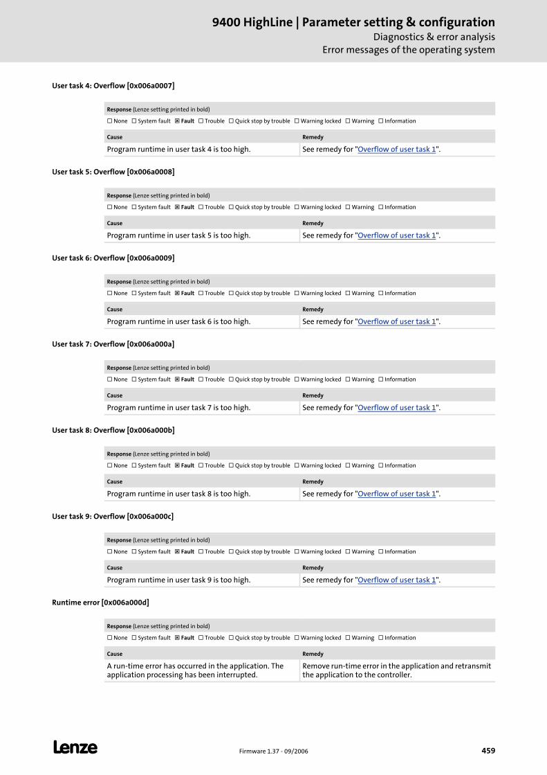
L Firmware 1.37 - 09/2006 459
9400 HighLine | Parameter setting & configurationDiagnostics & error analysis
Error messages of the operating system
User task 4: Overflow [0x006a0007]
User task 5: Overflow [0x006a0008]
User task 6: Overflow [0x006a0009]
User task 7: Overflow [0x006a000a]
User task 8: Overflow [0x006a000b]
User task 9: Overflow [0x006a000c]
Runtime error [0x006a000d]
Response (Lenze setting printed in bold)
None System fault Fault Trouble Quick stop by trouble Warning locked Warning Information
Cause Remedy
Program runtime in user task 4 is too high. See remedy for "Overflow of user task 1".
Response (Lenze setting printed in bold)
None System fault Fault Trouble Quick stop by trouble Warning locked Warning Information
Cause Remedy
Program runtime in user task 5 is too high. See remedy for "Overflow of user task 1".
Response (Lenze setting printed in bold)
None System fault Fault Trouble Quick stop by trouble Warning locked Warning Information
Cause Remedy
Program runtime in user task 6 is too high. See remedy for "Overflow of user task 1".
Response (Lenze setting printed in bold)
None System fault Fault Trouble Quick stop by trouble Warning locked Warning Information
Cause Remedy
Program runtime in user task 7 is too high. See remedy for "Overflow of user task 1".
Response (Lenze setting printed in bold)
None System fault Fault Trouble Quick stop by trouble Warning locked Warning Information
Cause Remedy
Program runtime in user task 8 is too high. See remedy for "Overflow of user task 1".
Response (Lenze setting printed in bold)
None System fault Fault Trouble Quick stop by trouble Warning locked Warning Information
Cause Remedy
Program runtime in user task 9 is too high. See remedy for "Overflow of user task 1".
Response (Lenze setting printed in bold)
None System fault Fault Trouble Quick stop by trouble Warning locked Warning Information
Cause Remedy
A run-time error has occurred in the application. The application processing has been interrupted.
Remove run-time error in the application and retransmit the application to the controller.
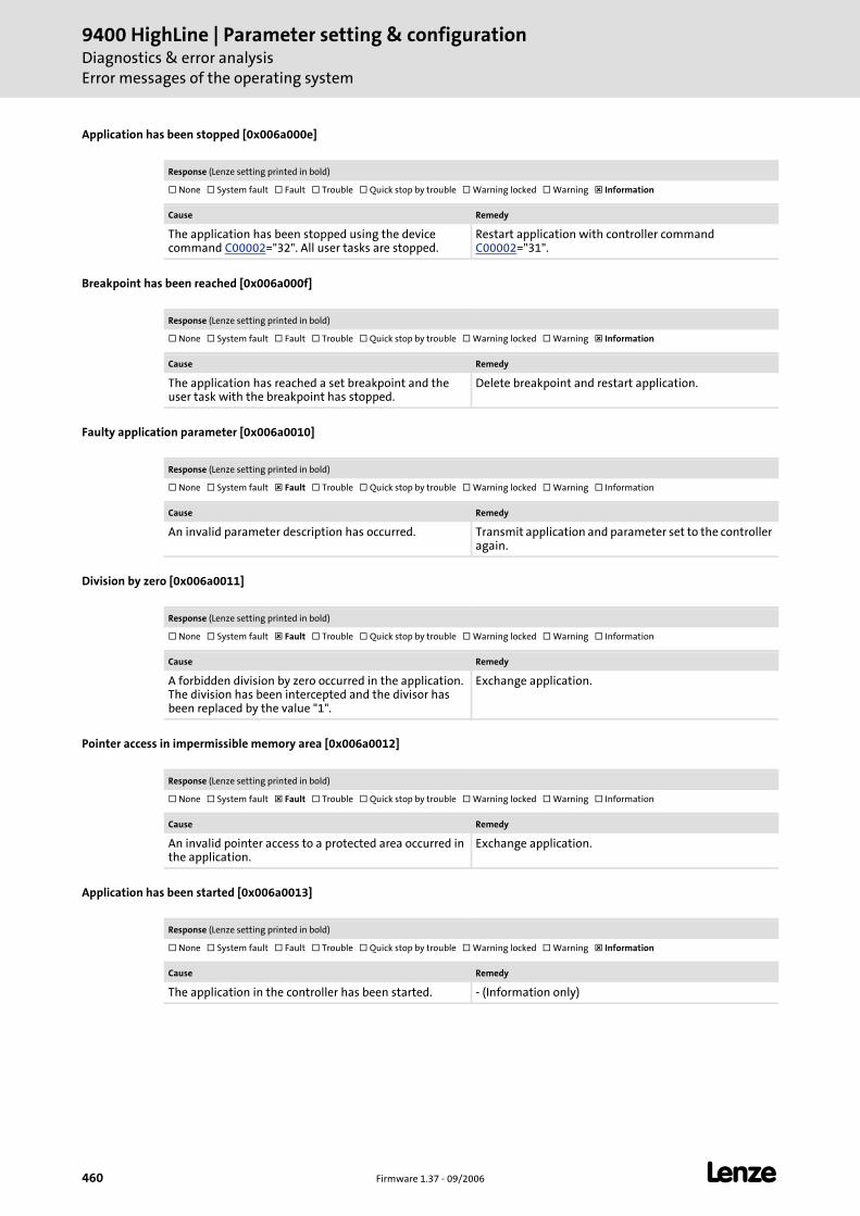
9400 HighLine | Parameter setting & configurationDiagnostics & error analysisError messages of the operating system
460 Firmware 1.37 - 09/2006 L
Application has been stopped [0x006a000e]
Breakpoint has been reached [0x006a000f]
Faulty application parameter [0x006a0010]
Division by zero [0x006a0011]
Pointer access in impermissible memory area [0x006a0012]
Application has been started [0x006a0013]
Response (Lenze setting printed in bold)
None System fault Fault Trouble Quick stop by trouble Warning locked Warning Information
Cause Remedy
The application has been stopped using the device command C00002="32". All user tasks are stopped.
Restart application with controller command C00002="31".
Response (Lenze setting printed in bold)
None System fault Fault Trouble Quick stop by trouble Warning locked Warning Information
Cause Remedy
The application has reached a set breakpoint and the user task with the breakpoint has stopped.
Delete breakpoint and restart application.
Response (Lenze setting printed in bold)
None System fault Fault Trouble Quick stop by trouble Warning locked Warning Information
Cause Remedy
An invalid parameter description has occurred. Transmit application and parameter set to the controller again.
Response (Lenze setting printed in bold)
None System fault Fault Trouble Quick stop by trouble Warning locked Warning Information
Cause Remedy
A forbidden division by zero occurred in the application. The division has been intercepted and the divisor has been replaced by the value "1".
Exchange application.
Response (Lenze setting printed in bold)
None System fault Fault Trouble Quick stop by trouble Warning locked Warning Information
Cause Remedy
An invalid pointer access to a protected area occurred in the application.
Exchange application.
Response (Lenze setting printed in bold)
None System fault Fault Trouble Quick stop by trouble Warning locked Warning Information
Cause Remedy
The application in the controller has been started. - (Information only)
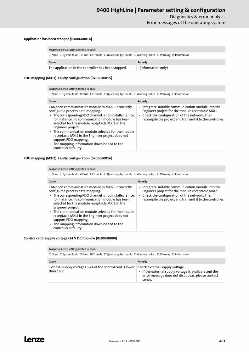
L Firmware 1.37 - 09/2006 461
9400 HighLine | Parameter setting & configurationDiagnostics & error analysis
Error messages of the operating system
Application has been stopped [0x006a0014]
PDO mapping (MXI1): Faulty configuration [0x006a0015]
PDO mapping (MXI2): Faulty configuration [0x006a0016]
Control card: Supply voltage (24 V DC) too low [0x006f0000]
Response (Lenze setting printed in bold)
None System fault Fault Trouble Quick stop by trouble Warning locked Warning Information
Cause Remedy
The application in the controller has been stopped. - (Information only)
Response (Lenze setting printed in bold)
None System fault Fault Trouble Quick stop by trouble Warning locked Warning Information
Cause Remedy
CANopen communication module in MXI1: Incorrectly configured process data mapping. • The corresponding PDO channel is not installed, since,
for instance, no communication module has been selected for the module receptacle MXI1 in the Engineer project.
• The communication module selected for the module receptacle MXI1 in the Engineer project does not support PDO mapping.
• The mapping information downloaded to the controller is faulty.
• Integrate suitable communication module into the Engineer project for the module receptacle MXI1.
• Check the configuration of the network. Then recompile the project and transmit it to the controller.
Response (Lenze setting printed in bold)
None System fault Fault Trouble Quick stop by trouble Warning locked Warning Information
Cause Remedy
CANopen communication module in MXI2: Incorrectly configured process data mapping. • The corresponding PDO channel is not installed, since,
for instance, no communication module has been selected for the module receptacle MXI2 in the Engineer project.
• The communication module selected for the module receptacle MXI2 in the Engineer project does not support PDO mapping.
• The mapping information downloaded to the controller is faulty.
• Integrate suitable communication module into the Engineer project for the module receptacle MXI2.
• Check the configuration of the network. Then recompile the project and transmit it to the controller.
Response (Lenze setting printed in bold)
None System fault Fault Trouble Quick stop by trouble Warning locked Warning Information
Cause Remedy
External supply voltage UB24 of the control card is lower than 18 V.
Check external supply voltage. • If the external supply voltage is available and the
error message does not disappear, please contact Lenze.
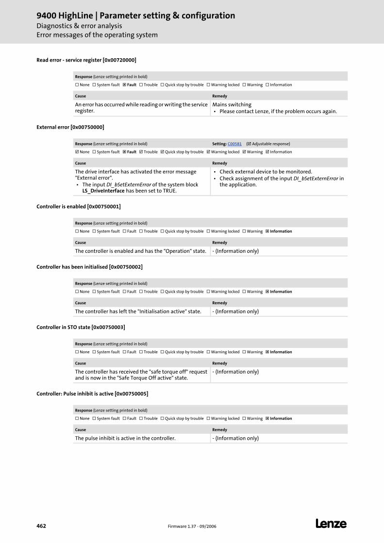
9400 HighLine | Parameter setting & configurationDiagnostics & error analysisError messages of the operating system
462 Firmware 1.37 - 09/2006 L
Read error - service register [0x00720000]
External error [0x00750000]
Controller is enabled [0x00750001]
Controller has been initialised [0x00750002]
Controller in STO state [0x00750003]
Controller: Pulse inhibit is active [0x00750005]
Response (Lenze setting printed in bold)
None System fault Fault Trouble Quick stop by trouble Warning locked Warning Information
Cause Remedy
An error has occurred while reading or writing the service register.
Mains switching • Please contact Lenze, if the problem occurs again.
Response (Lenze setting printed in bold) Setting: C00581 ( Adjustable response)
None System fault Fault Trouble Quick stop by trouble Warning locked Warning Information
Cause Remedy
The drive interface has activated the error message "External error". • The input DI_bSetExternError of the system block
LS_DriveInterface has been set to TRUE.
• Check external device to be monitored. • Check assignment of the input DI_bSetExternError in
the application.
Response (Lenze setting printed in bold)
None System fault Fault Trouble Quick stop by trouble Warning locked Warning Information
Cause Remedy
The controller is enabled and has the "Operation" state. - (Information only)
Response (Lenze setting printed in bold)
None System fault Fault Trouble Quick stop by trouble Warning locked Warning Information
Cause Remedy
The controller has left the "Initialisation active" state. - (Information only)
Response (Lenze setting printed in bold)
None System fault Fault Trouble Quick stop by trouble Warning locked Warning Information
Cause Remedy
The controller has received the "safe torque off" request and is now in the "Safe Torque Off active" state.
- (Information only)
Response (Lenze setting printed in bold)
None System fault Fault Trouble Quick stop by trouble Warning locked Warning Information
Cause Remedy
The pulse inhibit is active in the controller. - (Information only)
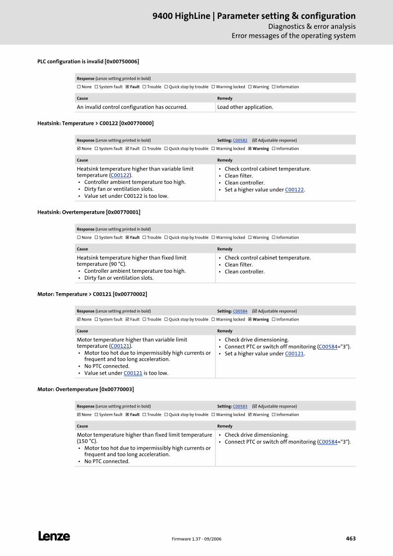
L Firmware 1.37 - 09/2006 463
9400 HighLine | Parameter setting & configurationDiagnostics & error analysis
Error messages of the operating system
PLC configuration is invalid [0x00750006]
Heatsink: Temperature > C00122 [0x00770000]
Heatsink: Overtemperature [0x00770001]
Motor: Temperature > C00121 [0x00770002]
Motor: Overtemperature [0x00770003]
Response (Lenze setting printed in bold)
None System fault Fault Trouble Quick stop by trouble Warning locked Warning Information
Cause Remedy
An invalid control configuration has occurred. Load other application.
Response (Lenze setting printed in bold) Setting: C00582 ( Adjustable response)
None System fault Fault Trouble Quick stop by trouble Warning locked Warning Information
Cause Remedy
Heatsink temperature higher than variable limit temperature (C00122). • Controller ambient temperature too high. • Dirty fan or ventilation slots. • Value set under C00122 is too low.
• Check control cabinet temperature. • Clean filter. • Clean controller. • Set a higher value under C00122.
Response (Lenze setting printed in bold)
None System fault Fault Trouble Quick stop by trouble Warning locked Warning Information
Cause Remedy
Heatsink temperature higher than fixed limit temperature (90 °C). • Controller ambient temperature too high. • Dirty fan or ventilation slots.
• Check control cabinet temperature. • Clean filter. • Clean controller.
Response (Lenze setting printed in bold) Setting: C00584 ( Adjustable response)
None System fault Fault Trouble Quick stop by trouble Warning locked Warning Information
Cause Remedy
Motor temperature higher than variable limit temperature (C00121). • Motor too hot due to impermissibly high currents or
frequent and too long acceleration. • No PTC connected. • Value set under C00121 is too low.
• Check drive dimensioning. • Connect PTC or switch off monitoring (C00584="3"). • Set a higher value under C00121.
Response (Lenze setting printed in bold) Setting: C00583 ( Adjustable response)
None System fault Fault Trouble Quick stop by trouble Warning locked Warning Information
Cause Remedy
Motor temperature higher than fixed limit temperature (150 °C). • Motor too hot due to impermissibly high currents or
frequent and too long acceleration. • No PTC connected.
• Check drive dimensioning. • Connect PTC or switch off monitoring (C00584="3").
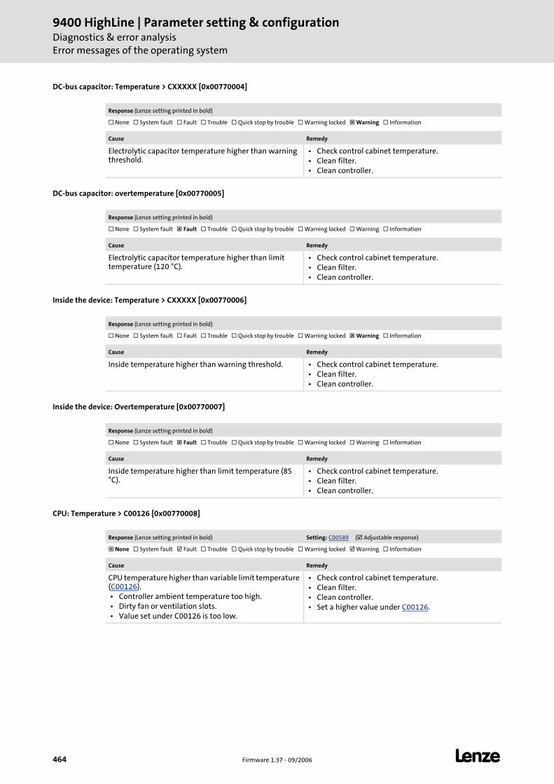
9400 HighLine | Parameter setting & configurationDiagnostics & error analysisError messages of the operating system
464 Firmware 1.37 - 09/2006 L
DC-bus capacitor: Temperature > CXXXXX [0x00770004]
DC-bus capacitor: overtemperature [0x00770005]
Inside the device: Temperature > CXXXXX [0x00770006]
Inside the device: Overtemperature [0x00770007]
CPU: Temperature > C00126 [0x00770008]
Response (Lenze setting printed in bold)
None System fault Fault Trouble Quick stop by trouble Warning locked Warning Information
Cause Remedy
Electrolytic capacitor temperature higher than warning threshold.
• Check control cabinet temperature. • Clean filter. • Clean controller.
Response (Lenze setting printed in bold)
None System fault Fault Trouble Quick stop by trouble Warning locked Warning Information
Cause Remedy
Electrolytic capacitor temperature higher than limit temperature (120 °C).
• Check control cabinet temperature. • Clean filter. • Clean controller.
Response (Lenze setting printed in bold)
None System fault Fault Trouble Quick stop by trouble Warning locked Warning Information
Cause Remedy
Inside temperature higher than warning threshold. • Check control cabinet temperature. • Clean filter. • Clean controller.
Response (Lenze setting printed in bold)
None System fault Fault Trouble Quick stop by trouble Warning locked Warning Information
Cause Remedy
Inside temperature higher than limit temperature (85 °C).
• Check control cabinet temperature. • Clean filter. • Clean controller.
Response (Lenze setting printed in bold) Setting: C00589 ( Adjustable response)
None System fault Fault Trouble Quick stop by trouble Warning locked Warning Information
Cause Remedy
CPU temperature higher than variable limit temperature (C00126). • Controller ambient temperature too high. • Dirty fan or ventilation slots. • Value set under C00126 is too low.
• Check control cabinet temperature. • Clean filter. • Clean controller. • Set a higher value under C00126.
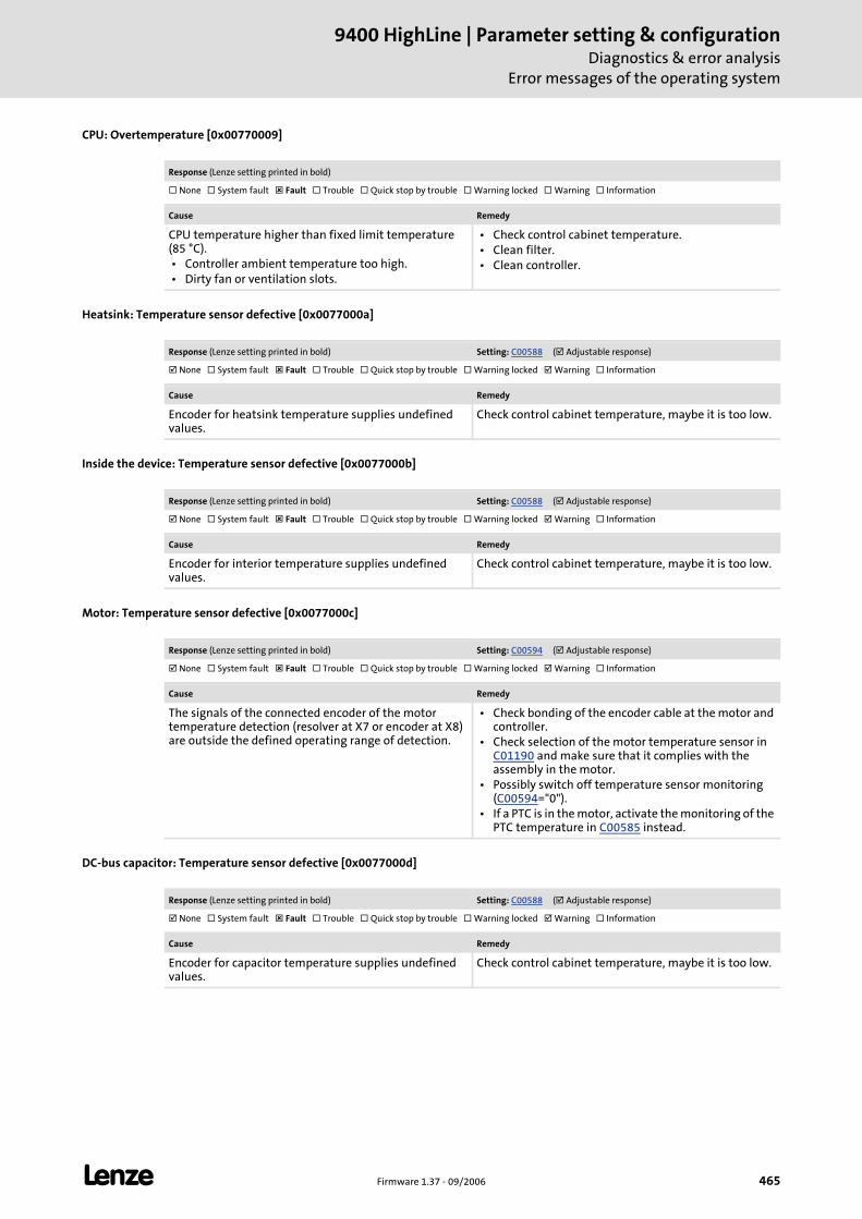
L Firmware 1.37 - 09/2006 465
9400 HighLine | Parameter setting & configurationDiagnostics & error analysis
Error messages of the operating system
CPU: Overtemperature [0x00770009]
Heatsink: Temperature sensor defective [0x0077000a]
Inside the device: Temperature sensor defective [0x0077000b]
Motor: Temperature sensor defective [0x0077000c]
DC-bus capacitor: Temperature sensor defective [0x0077000d]
Response (Lenze setting printed in bold)
None System fault Fault Trouble Quick stop by trouble Warning locked Warning Information
Cause Remedy
CPU temperature higher than fixed limit temperature (85 °C). • Controller ambient temperature too high. • Dirty fan or ventilation slots.
• Check control cabinet temperature. • Clean filter. • Clean controller.
Response (Lenze setting printed in bold) Setting: C00588 ( Adjustable response)
None System fault Fault Trouble Quick stop by trouble Warning locked Warning Information
Cause Remedy
Encoder for heatsink temperature supplies undefined values.
Check control cabinet temperature, maybe it is too low.
Response (Lenze setting printed in bold) Setting: C00588 ( Adjustable response)
None System fault Fault Trouble Quick stop by trouble Warning locked Warning Information
Cause Remedy
Encoder for interior temperature supplies undefined values.
Check control cabinet temperature, maybe it is too low.
Response (Lenze setting printed in bold) Setting: C00594 ( Adjustable response)
None System fault Fault Trouble Quick stop by trouble Warning locked Warning Information
Cause Remedy
The signals of the connected encoder of the motor temperature detection (resolver at X7 or encoder at X8) are outside the defined operating range of detection.
• Check bonding of the encoder cable at the motor and controller.
• Check selection of the motor temperature sensor in C01190 and make sure that it complies with the assembly in the motor.
• Possibly switch off temperature sensor monitoring (C00594="0").
• If a PTC is in the motor, activate the monitoring of the PTC temperature in C00585 instead.
Response (Lenze setting printed in bold) Setting: C00588 ( Adjustable response)
None System fault Fault Trouble Quick stop by trouble Warning locked Warning Information
Cause Remedy
Encoder for capacitor temperature supplies undefined values.
Check control cabinet temperature, maybe it is too low.
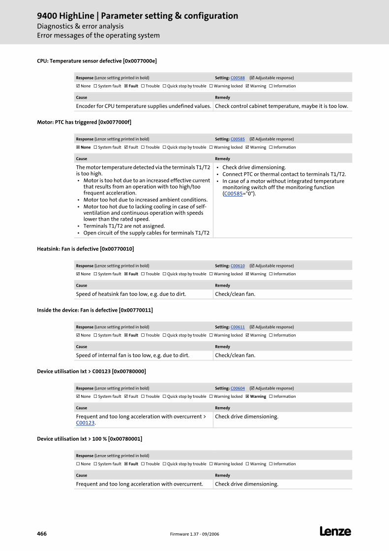
9400 HighLine | Parameter setting & configurationDiagnostics & error analysisError messages of the operating system
466 Firmware 1.37 - 09/2006 L
CPU: Temperature sensor defective [0x0077000e]
Motor: PTC has triggered [0x0077000f]
Heatsink: Fan is defective [0x00770010]
Inside the device: Fan is defective [0x00770011]
Device utilisation Ixt > C00123 [0x00780000]
Device utilisation Ixt > 100 % [0x00780001]
Response (Lenze setting printed in bold) Setting: C00588 ( Adjustable response)
None System fault Fault Trouble Quick stop by trouble Warning locked Warning Information
Cause Remedy
Encoder for CPU temperature supplies undefined values. Check control cabinet temperature, maybe it is too low.
Response (Lenze setting printed in bold) Setting: C00585 ( Adjustable response)
None System fault Fault Trouble Quick stop by trouble Warning locked Warning Information
Cause Remedy
The motor temperature detected via the terminals T1/T2 is too high. • Motor is too hot due to an increased effective current
that results from an operation with too high/too frequent acceleration.
• Motor too hot due to increased ambient conditions. • Motor too hot due to lacking cooling in case of self-
ventilation and continuous operation with speeds lower than the rated speed.
• Terminals T1/T2 are not assigned. • Open circuit of the supply cables for terminals T1/T2
• Check drive dimensioning. • Connect PTC or thermal contact to terminals T1/T2. • In case of a motor without integrated temperature
monitoring switch off the monitoring function (C00585="0").
Response (Lenze setting printed in bold) Setting: C00610 ( Adjustable response)
None System fault Fault Trouble Quick stop by trouble Warning locked Warning Information
Cause Remedy
Speed of heatsink fan too low, e.g. due to dirt. Check/clean fan.
Response (Lenze setting printed in bold) Setting: C00611 ( Adjustable response)
None System fault Fault Trouble Quick stop by trouble Warning locked Warning Information
Cause Remedy
Speed of internal fan is too low, e.g. due to dirt. Check/clean fan.
Response (Lenze setting printed in bold) Setting: C00604 ( Adjustable response)
None System fault Fault Trouble Quick stop by trouble Warning locked Warning Information
Cause Remedy
Frequent and too long acceleration with overcurrent > C00123.
Check drive dimensioning.
Response (Lenze setting printed in bold)
None System fault Fault Trouble Quick stop by trouble Warning locked Warning Information
Cause Remedy
Frequent and too long acceleration with overcurrent. Check drive dimensioning.
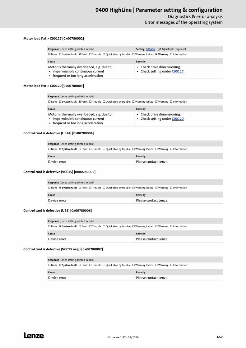
L Firmware 1.37 - 09/2006 467
9400 HighLine | Parameter setting & configurationDiagnostics & error analysis
Error messages of the operating system
Motor load I²xt > C00127 [0x00780002]
Motor load I²xt > C00120 [0x00780003]
Control card is defective (UB24) [0x00780004]
Control card is defective (VCC15) [0x00780005]
Control card is defective (UB8) [0x00780006]
Control card is defective (VCC15 neg.) [0x00780007]
Response (Lenze setting printed in bold) Setting: C00606 ( Adjustable response)
None System fault Fault Trouble Quick stop by trouble Warning locked Warning Information
Cause Remedy
Motor is thermally overloaded, e.g. due to: • impermissible continuous current • frequent or too long acceleration
• Check drive dimensioning. • Check setting under C00127.
Response (Lenze setting printed in bold)
None System fault Fault Trouble Quick stop by trouble Warning locked Warning Information
Cause Remedy
Motor is thermally overloaded, e.g. due to: • impermissible continuous current • frequent or too long acceleration
• Check drive dimensioning. • Check setting under C00120.
Response (Lenze setting printed in bold)
None System fault Fault Trouble Quick stop by trouble Warning locked Warning Information
Cause Remedy
Device error Please contact Lenze.
Response (Lenze setting printed in bold)
None System fault Fault Trouble Quick stop by trouble Warning locked Warning Information
Cause Remedy
Device error Please contact Lenze.
Response (Lenze setting printed in bold)
None System fault Fault Trouble Quick stop by trouble Warning locked Warning Information
Cause Remedy
Device error Please contact Lenze.
Response (Lenze setting printed in bold)
None System fault Fault Trouble Quick stop by trouble Warning locked Warning Information
Cause Remedy
Device error Please contact Lenze.
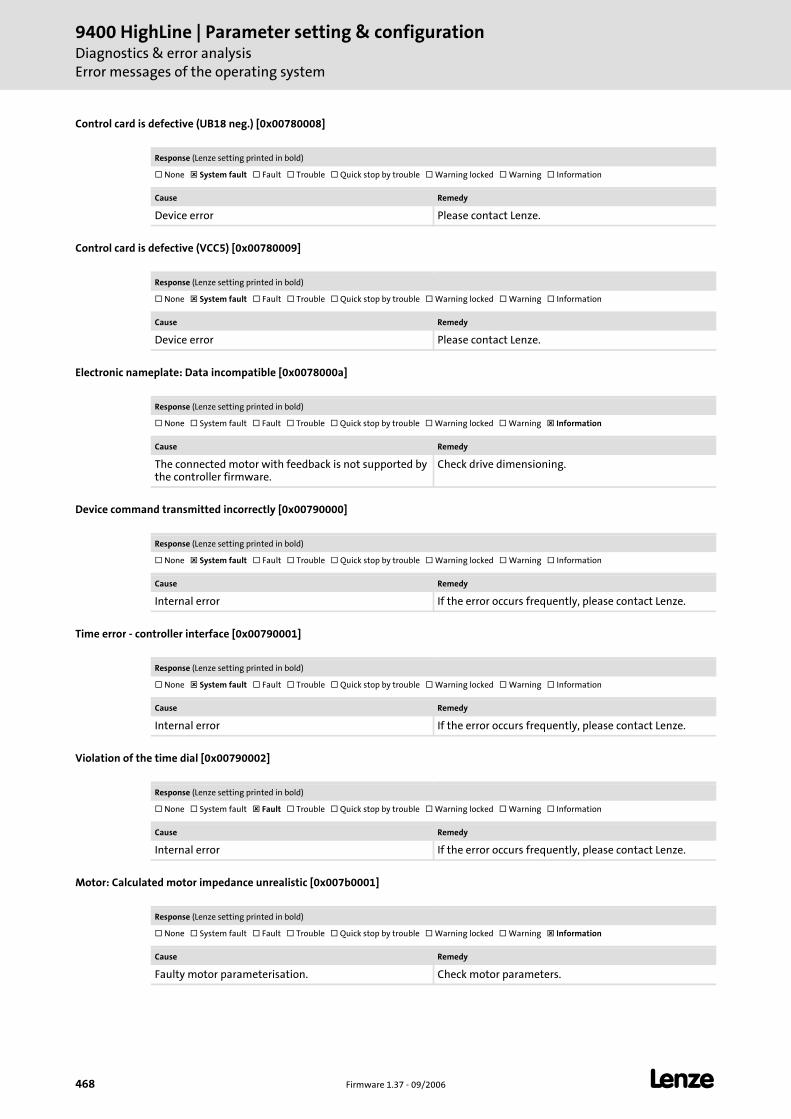
9400 HighLine | Parameter setting & configurationDiagnostics & error analysisError messages of the operating system
468 Firmware 1.37 - 09/2006 L
Control card is defective (UB18 neg.) [0x00780008]
Control card is defective (VCC5) [0x00780009]
Electronic nameplate: Data incompatible [0x0078000a]
Device command transmitted incorrectly [0x00790000]
Time error - controller interface [0x00790001]
Violation of the time dial [0x00790002]
Motor: Calculated motor impedance unrealistic [0x007b0001]
Response (Lenze setting printed in bold)
None System fault Fault Trouble Quick stop by trouble Warning locked Warning Information
Cause Remedy
Device error Please contact Lenze.
Response (Lenze setting printed in bold)
None System fault Fault Trouble Quick stop by trouble Warning locked Warning Information
Cause Remedy
Device error Please contact Lenze.
Response (Lenze setting printed in bold)
None System fault Fault Trouble Quick stop by trouble Warning locked Warning Information
Cause Remedy
The connected motor with feedback is not supported by the controller firmware.
Check drive dimensioning.
Response (Lenze setting printed in bold)
None System fault Fault Trouble Quick stop by trouble Warning locked Warning Information
Cause Remedy
Internal error If the error occurs frequently, please contact Lenze.
Response (Lenze setting printed in bold)
None System fault Fault Trouble Quick stop by trouble Warning locked Warning Information
Cause Remedy
Internal error If the error occurs frequently, please contact Lenze.
Response (Lenze setting printed in bold)
None System fault Fault Trouble Quick stop by trouble Warning locked Warning Information
Cause Remedy
Internal error If the error occurs frequently, please contact Lenze.
Response (Lenze setting printed in bold)
None System fault Fault Trouble Quick stop by trouble Warning locked Warning Information
Cause Remedy
Faulty motor parameterisation. Check motor parameters.
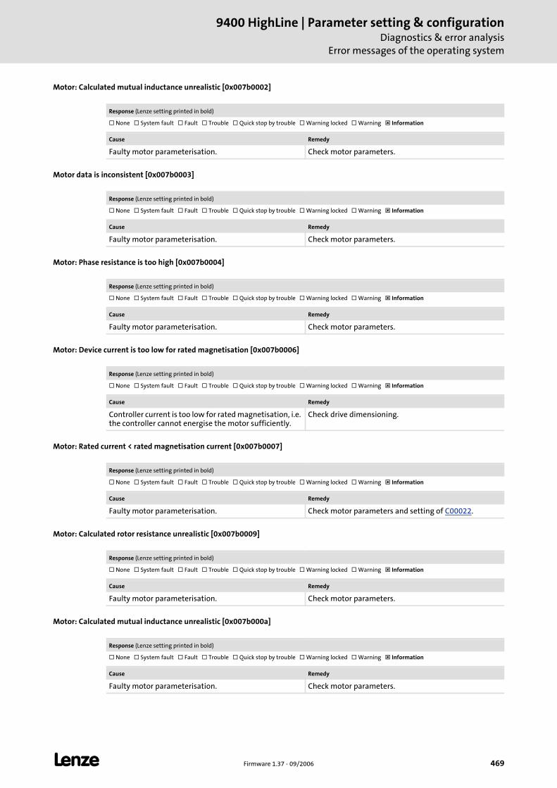
L Firmware 1.37 - 09/2006 469
9400 HighLine | Parameter setting & configurationDiagnostics & error analysis
Error messages of the operating system
Motor: Calculated mutual inductance unrealistic [0x007b0002]
Motor data is inconsistent [0x007b0003]
Motor: Phase resistance is too high [0x007b0004]
Motor: Device current is too low for rated magnetisation [0x007b0006]
Motor: Rated current < rated magnetisation current [0x007b0007]
Motor: Calculated rotor resistance unrealistic [0x007b0009]
Motor: Calculated mutual inductance unrealistic [0x007b000a]
Response (Lenze setting printed in bold)
None System fault Fault Trouble Quick stop by trouble Warning locked Warning Information
Cause Remedy
Faulty motor parameterisation. Check motor parameters.
Response (Lenze setting printed in bold)
None System fault Fault Trouble Quick stop by trouble Warning locked Warning Information
Cause Remedy
Faulty motor parameterisation. Check motor parameters.
Response (Lenze setting printed in bold)
None System fault Fault Trouble Quick stop by trouble Warning locked Warning Information
Cause Remedy
Faulty motor parameterisation. Check motor parameters.
Response (Lenze setting printed in bold)
None System fault Fault Trouble Quick stop by trouble Warning locked Warning Information
Cause Remedy
Controller current is too low for rated magnetisation, i.e. the controller cannot energise the motor sufficiently.
Check drive dimensioning.
Response (Lenze setting printed in bold)
None System fault Fault Trouble Quick stop by trouble Warning locked Warning Information
Cause Remedy
Faulty motor parameterisation. Check motor parameters and setting of C00022.
Response (Lenze setting printed in bold)
None System fault Fault Trouble Quick stop by trouble Warning locked Warning Information
Cause Remedy
Faulty motor parameterisation. Check motor parameters.
Response (Lenze setting printed in bold)
None System fault Fault Trouble Quick stop by trouble Warning locked Warning Information
Cause Remedy
Faulty motor parameterisation. Check motor parameters.
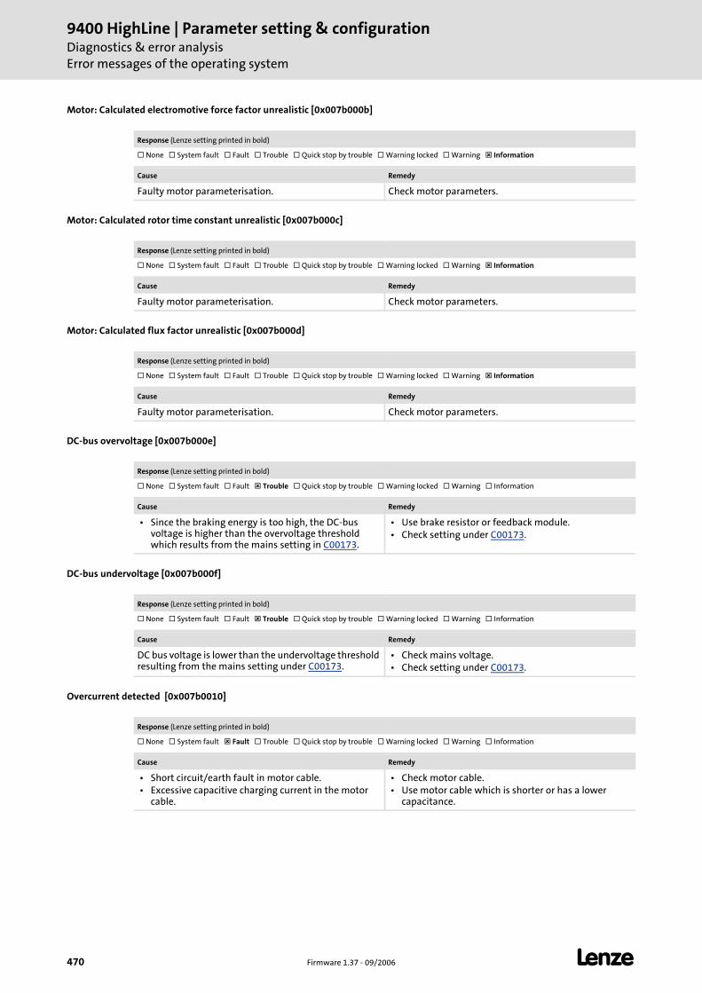
9400 HighLine | Parameter setting & configurationDiagnostics & error analysisError messages of the operating system
470 Firmware 1.37 - 09/2006 L
Motor: Calculated electromotive force factor unrealistic [0x007b000b]
Motor: Calculated rotor time constant unrealistic [0x007b000c]
Motor: Calculated flux factor unrealistic [0x007b000d]
DC-bus overvoltage [0x007b000e]
DC-bus undervoltage [0x007b000f]
Overcurrent detected [0x007b0010]
Response (Lenze setting printed in bold)
None System fault Fault Trouble Quick stop by trouble Warning locked Warning Information
Cause Remedy
Faulty motor parameterisation. Check motor parameters.
Response (Lenze setting printed in bold)
None System fault Fault Trouble Quick stop by trouble Warning locked Warning Information
Cause Remedy
Faulty motor parameterisation. Check motor parameters.
Response (Lenze setting printed in bold)
None System fault Fault Trouble Quick stop by trouble Warning locked Warning Information
Cause Remedy
Faulty motor parameterisation. Check motor parameters.
Response (Lenze setting printed in bold)
None System fault Fault Trouble Quick stop by trouble Warning locked Warning Information
Cause Remedy
• Since the braking energy is too high, the DC-bus voltage is higher than the overvoltage threshold which results from the mains setting in C00173.
• Use brake resistor or feedback module. • Check setting under C00173.
Response (Lenze setting printed in bold)
None System fault Fault Trouble Quick stop by trouble Warning locked Warning Information
Cause Remedy
DC bus voltage is lower than the undervoltage threshold resulting from the mains setting under C00173.
• Check mains voltage. • Check setting under C00173.
Response (Lenze setting printed in bold)
None System fault Fault Trouble Quick stop by trouble Warning locked Warning Information
Cause Remedy
• Short circuit/earth fault in motor cable. • Excessive capacitive charging current in the motor
cable.
• Check motor cable. • Use motor cable which is shorter or has a lower
capacitance.
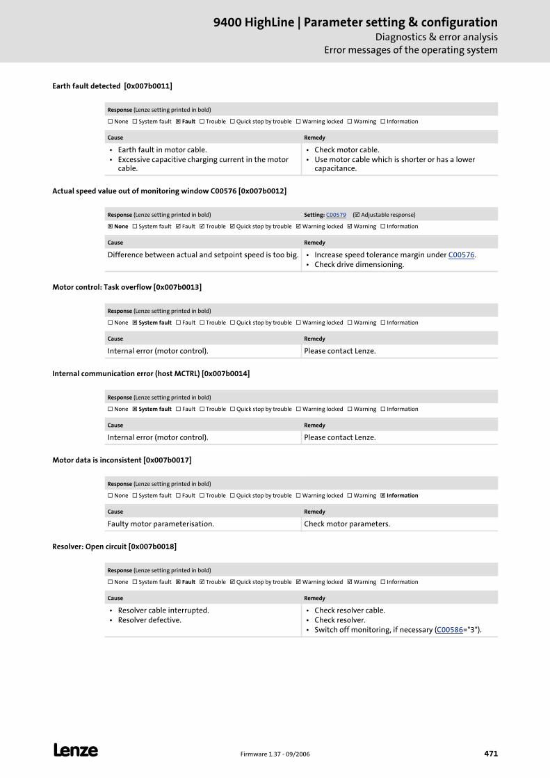
L Firmware 1.37 - 09/2006 471
9400 HighLine | Parameter setting & configurationDiagnostics & error analysis
Error messages of the operating system
Earth fault detected [0x007b0011]
Actual speed value out of monitoring window C00576 [0x007b0012]
Motor control: Task overflow [0x007b0013]
Internal communication error (host MCTRL) [0x007b0014]
Motor data is inconsistent [0x007b0017]
Resolver: Open circuit [0x007b0018]
Response (Lenze setting printed in bold)
None System fault Fault Trouble Quick stop by trouble Warning locked Warning Information
Cause Remedy
• Earth fault in motor cable. • Excessive capacitive charging current in the motor
cable.
• Check motor cable. • Use motor cable which is shorter or has a lower
capacitance.
Response (Lenze setting printed in bold) Setting: C00579 ( Adjustable response)
None System fault Fault Trouble Quick stop by trouble Warning locked Warning Information
Cause Remedy
Difference between actual and setpoint speed is too big. • Increase speed tolerance margin under C00576. • Check drive dimensioning.
Response (Lenze setting printed in bold)
None System fault Fault Trouble Quick stop by trouble Warning locked Warning Information
Cause Remedy
Internal error (motor control). Please contact Lenze.
Response (Lenze setting printed in bold)
None System fault Fault Trouble Quick stop by trouble Warning locked Warning Information
Cause Remedy
Internal error (motor control). Please contact Lenze.
Response (Lenze setting printed in bold)
None System fault Fault Trouble Quick stop by trouble Warning locked Warning Information
Cause Remedy
Faulty motor parameterisation. Check motor parameters.
Response (Lenze setting printed in bold)
None System fault Fault Trouble Quick stop by trouble Warning locked Warning Information
Cause Remedy
• Resolver cable interrupted. • Resolver defective.
• Check resolver cable. • Check resolver. • Switch off monitoring, if necessary (C00586="3").
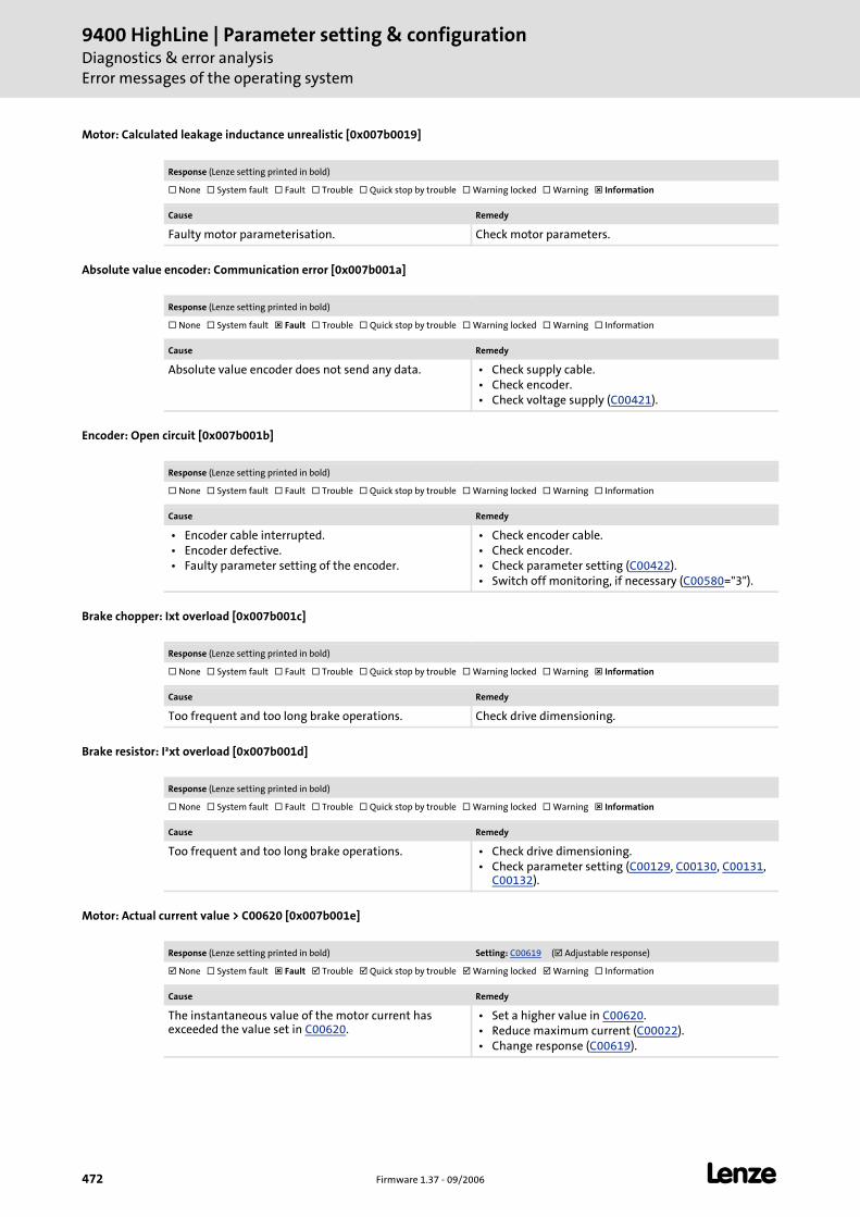
9400 HighLine | Parameter setting & configurationDiagnostics & error analysisError messages of the operating system
472 Firmware 1.37 - 09/2006 L
Motor: Calculated leakage inductance unrealistic [0x007b0019]
Absolute value encoder: Communication error [0x007b001a]
Encoder: Open circuit [0x007b001b]
Brake chopper: Ixt overload [0x007b001c]
Brake resistor: I²xt overload [0x007b001d]
Motor: Actual current value > C00620 [0x007b001e]
Response (Lenze setting printed in bold)
None System fault Fault Trouble Quick stop by trouble Warning locked Warning Information
Cause Remedy
Faulty motor parameterisation. Check motor parameters.
Response (Lenze setting printed in bold)
None System fault Fault Trouble Quick stop by trouble Warning locked Warning Information
Cause Remedy
Absolute value encoder does not send any data. • Check supply cable. • Check encoder. • Check voltage supply (C00421).
Response (Lenze setting printed in bold)
None System fault Fault Trouble Quick stop by trouble Warning locked Warning Information
Cause Remedy
• Encoder cable interrupted. • Encoder defective. • Faulty parameter setting of the encoder.
• Check encoder cable. • Check encoder. • Check parameter setting (C00422). • Switch off monitoring, if necessary (C00580="3").
Response (Lenze setting printed in bold)
None System fault Fault Trouble Quick stop by trouble Warning locked Warning Information
Cause Remedy
Too frequent and too long brake operations. Check drive dimensioning.
Response (Lenze setting printed in bold)
None System fault Fault Trouble Quick stop by trouble Warning locked Warning Information
Cause Remedy
Too frequent and too long brake operations. • Check drive dimensioning. • Check parameter setting (C00129, C00130, C00131,
C00132).
Response (Lenze setting printed in bold) Setting: C00619 ( Adjustable response)
None System fault Fault Trouble Quick stop by trouble Warning locked Warning Information
Cause Remedy
The instantaneous value of the motor current has exceeded the value set in C00620.
• Set a higher value in C00620. • Reduce maximum current (C00022). • Change response (C00619).
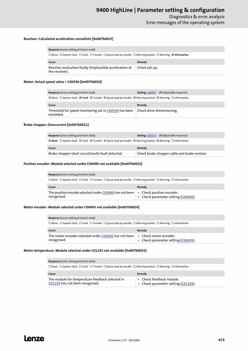
L Firmware 1.37 - 09/2006 473
9400 HighLine | Parameter setting & configurationDiagnostics & error analysis
Error messages of the operating system
Resolver: Calculated acceleration unrealistic [0x007b001f]
Motor: Actual speed value > C00596 [0x007b0020]
Brake chopper: Overcurrent [0x007b0021]
Position encoder: Module selected under C00490 not available [0x007b0023]
Motor encoder: Module selected under C00495 not available [0x007b0024]
Motor temperature: Module selected under C01193 not available [0x007b0025]
Response (Lenze setting printed in bold)
None System fault Fault Trouble Quick stop by trouble Warning locked Warning Information
Cause Remedy
Resolver evaluation faulty (implausible acceleration at the resolver).
Check set-up.
Response (Lenze setting printed in bold) Setting: C00607 ( Adjustable response)
None System fault Fault Trouble Quick stop by trouble Warning locked Warning Information
Cause Remedy
Threshold for speed monitoring set in C00596 has been exceeded.
Check drive dimensioning.
Response (Lenze setting printed in bold) Setting: C00573 ( Adjustable response)
None System fault Fault Trouble Quick stop by trouble Warning locked Warning Information
Cause Remedy
Brake chopper short circuit/earth fault detected. Check brake chopper cable and brake resistor.
Response (Lenze setting printed in bold)
None System fault Fault Trouble Quick stop by trouble Warning locked Warning Information
Cause Remedy
The position encode selected under C00490 has not been recognised.
• Check position encoder. • Check parameter setting (C00490).
Response (Lenze setting printed in bold)
None System fault Fault Trouble Quick stop by trouble Warning locked Warning Information
Cause Remedy
The motor encoder selected under C00495 has not been recognised.
• Check motor encoder. • Check parameter setting (C00495).
Response (Lenze setting printed in bold)
None System fault Fault Trouble Quick stop by trouble Warning locked Warning Information
Cause Remedy
The module for temperature feedback selected in C01193 has not been recognised.
• Check feedback module. • Check parameter setting (C01193).
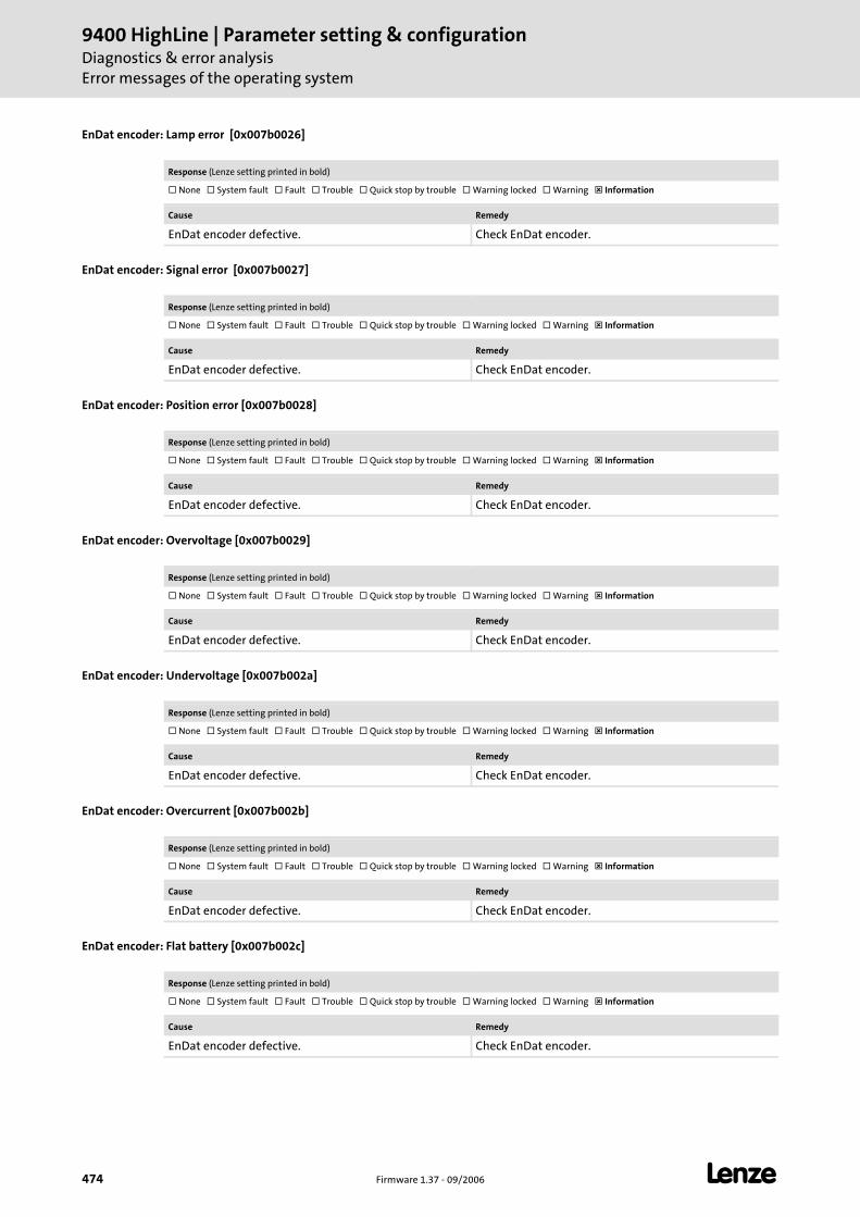
9400 HighLine | Parameter setting & configurationDiagnostics & error analysisError messages of the operating system
474 Firmware 1.37 - 09/2006 L
EnDat encoder: Lamp error [0x007b0026]
EnDat encoder: Signal error [0x007b0027]
EnDat encoder: Position error [0x007b0028]
EnDat encoder: Overvoltage [0x007b0029]
EnDat encoder: Undervoltage [0x007b002a]
EnDat encoder: Overcurrent [0x007b002b]
EnDat encoder: Flat battery [0x007b002c]
Response (Lenze setting printed in bold)
None System fault Fault Trouble Quick stop by trouble Warning locked Warning Information
Cause Remedy
EnDat encoder defective. Check EnDat encoder.
Response (Lenze setting printed in bold)
None System fault Fault Trouble Quick stop by trouble Warning locked Warning Information
Cause Remedy
EnDat encoder defective. Check EnDat encoder.
Response (Lenze setting printed in bold)
None System fault Fault Trouble Quick stop by trouble Warning locked Warning Information
Cause Remedy
EnDat encoder defective. Check EnDat encoder.
Response (Lenze setting printed in bold)
None System fault Fault Trouble Quick stop by trouble Warning locked Warning Information
Cause Remedy
EnDat encoder defective. Check EnDat encoder.
Response (Lenze setting printed in bold)
None System fault Fault Trouble Quick stop by trouble Warning locked Warning Information
Cause Remedy
EnDat encoder defective. Check EnDat encoder.
Response (Lenze setting printed in bold)
None System fault Fault Trouble Quick stop by trouble Warning locked Warning Information
Cause Remedy
EnDat encoder defective. Check EnDat encoder.
Response (Lenze setting printed in bold)
None System fault Fault Trouble Quick stop by trouble Warning locked Warning Information
Cause Remedy
EnDat encoder defective. Check EnDat encoder.
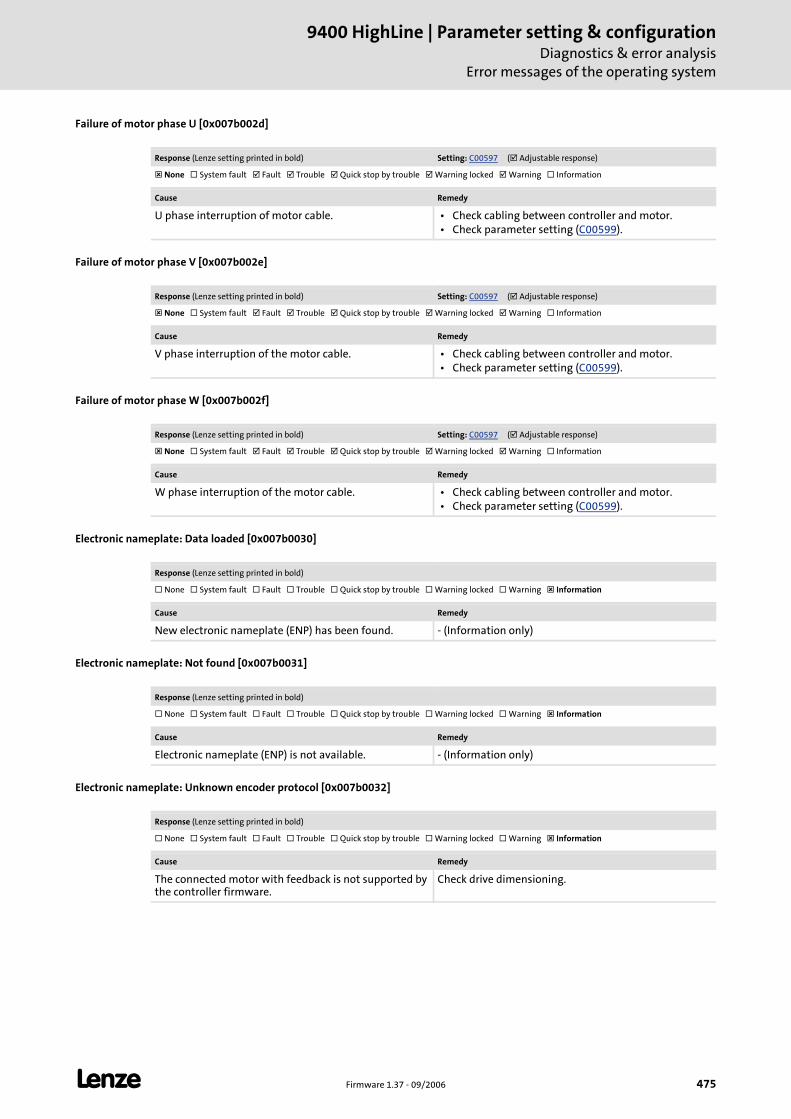
L Firmware 1.37 - 09/2006 475
9400 HighLine | Parameter setting & configurationDiagnostics & error analysis
Error messages of the operating system
Failure of motor phase U [0x007b002d]
Failure of motor phase V [0x007b002e]
Failure of motor phase W [0x007b002f]
Electronic nameplate: Data loaded [0x007b0030]
Electronic nameplate: Not found [0x007b0031]
Electronic nameplate: Unknown encoder protocol [0x007b0032]
Response (Lenze setting printed in bold) Setting: C00597 ( Adjustable response)
None System fault Fault Trouble Quick stop by trouble Warning locked Warning Information
Cause Remedy
U phase interruption of motor cable. • Check cabling between controller and motor. • Check parameter setting (C00599).
Response (Lenze setting printed in bold) Setting: C00597 ( Adjustable response)
None System fault Fault Trouble Quick stop by trouble Warning locked Warning Information
Cause Remedy
V phase interruption of the motor cable. • Check cabling between controller and motor. • Check parameter setting (C00599).
Response (Lenze setting printed in bold) Setting: C00597 ( Adjustable response)
None System fault Fault Trouble Quick stop by trouble Warning locked Warning Information
Cause Remedy
W phase interruption of the motor cable. • Check cabling between controller and motor. • Check parameter setting (C00599).
Response (Lenze setting printed in bold)
None System fault Fault Trouble Quick stop by trouble Warning locked Warning Information
Cause Remedy
New electronic nameplate (ENP) has been found. - (Information only)
Response (Lenze setting printed in bold)
None System fault Fault Trouble Quick stop by trouble Warning locked Warning Information
Cause Remedy
Electronic nameplate (ENP) is not available. - (Information only)
Response (Lenze setting printed in bold)
None System fault Fault Trouble Quick stop by trouble Warning locked Warning Information
Cause Remedy
The connected motor with feedback is not supported by the controller firmware.
Check drive dimensioning.
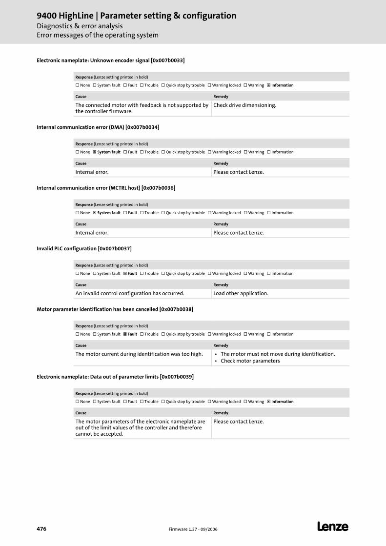
9400 HighLine | Parameter setting & configurationDiagnostics & error analysisError messages of the operating system
476 Firmware 1.37 - 09/2006 L
Electronic nameplate: Unknown encoder signal [0x007b0033]
Internal communication error (DMA) [0x007b0034]
Internal communication error (MCTRL host) [0x007b0036]
Invalid PLC configuration [0x007b0037]
Motor parameter identification has been cancelled [0x007b0038]
Electronic nameplate: Data out of parameter limits [0x007b0039]
Response (Lenze setting printed in bold)
None System fault Fault Trouble Quick stop by trouble Warning locked Warning Information
Cause Remedy
The connected motor with feedback is not supported by the controller firmware.
Check drive dimensioning.
Response (Lenze setting printed in bold)
None System fault Fault Trouble Quick stop by trouble Warning locked Warning Information
Cause Remedy
Internal error. Please contact Lenze.
Response (Lenze setting printed in bold)
None System fault Fault Trouble Quick stop by trouble Warning locked Warning Information
Cause Remedy
Internal error. Please contact Lenze.
Response (Lenze setting printed in bold)
None System fault Fault Trouble Quick stop by trouble Warning locked Warning Information
Cause Remedy
An invalid control configuration has occurred. Load other application.
Response (Lenze setting printed in bold)
None System fault Fault Trouble Quick stop by trouble Warning locked Warning Information
Cause Remedy
The motor current during identification was too high. • The motor must not move during identification. • Check motor parameters
Response (Lenze setting printed in bold)
None System fault Fault Trouble Quick stop by trouble Warning locked Warning Information
Cause Remedy
The motor parameters of the electronic nameplate are out of the limit values of the controller and therefore cannot be accepted.
Please contact Lenze.
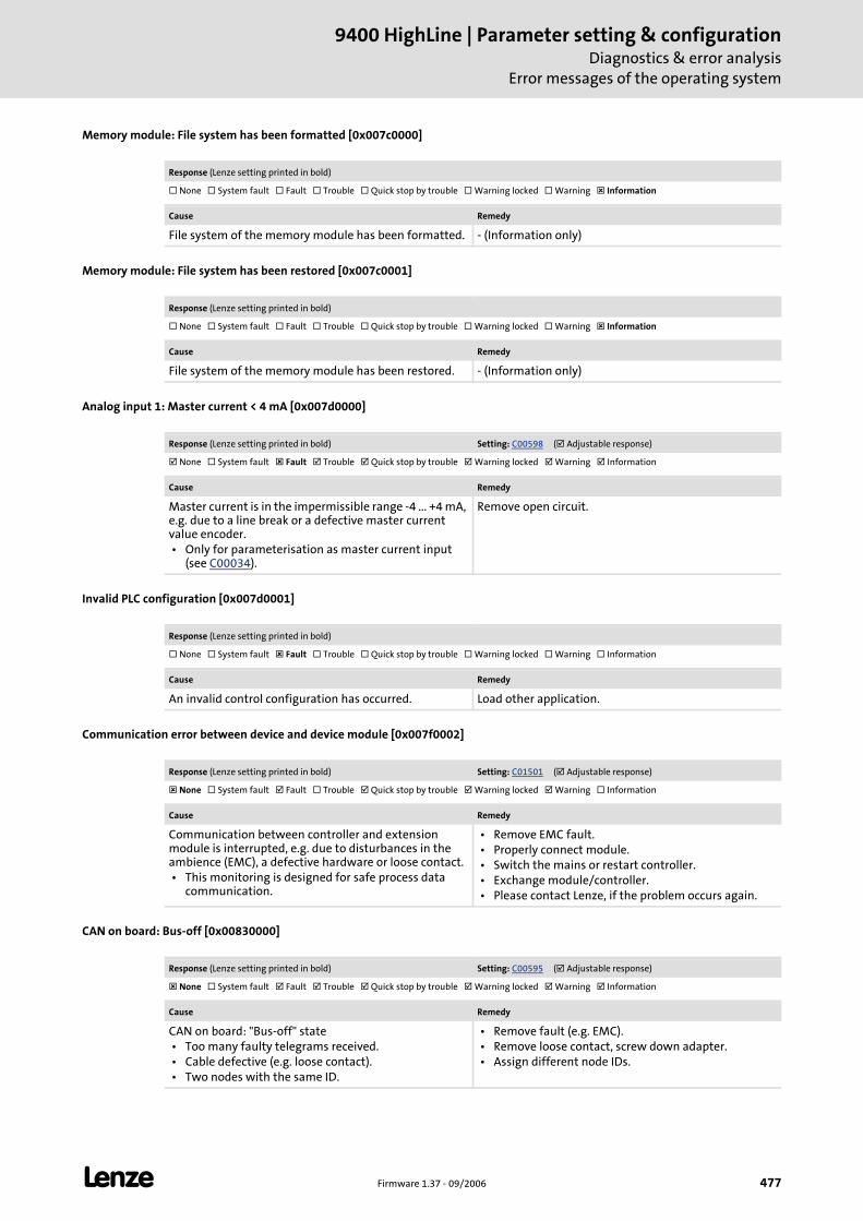
L Firmware 1.37 - 09/2006 477
9400 HighLine | Parameter setting & configurationDiagnostics & error analysis
Error messages of the operating system
Memory module: File system has been formatted [0x007c0000]
Memory module: File system has been restored [0x007c0001]
Analog input 1: Master current < 4 mA [0x007d0000]
Invalid PLC configuration [0x007d0001]
Communication error between device and device module [0x007f0002]
CAN on board: Bus-off [0x00830000]
Response (Lenze setting printed in bold)
None System fault Fault Trouble Quick stop by trouble Warning locked Warning Information
Cause Remedy
File system of the memory module has been formatted. - (Information only)
Response (Lenze setting printed in bold)
None System fault Fault Trouble Quick stop by trouble Warning locked Warning Information
Cause Remedy
File system of the memory module has been restored. - (Information only)
Response (Lenze setting printed in bold) Setting: C00598 ( Adjustable response)
None System fault Fault Trouble Quick stop by trouble Warning locked Warning Information
Cause Remedy
Master current is in the impermissible range -4 ... +4 mA, e.g. due to a line break or a defective master current value encoder. • Only for parameterisation as master current input
(see C00034).
Remove open circuit.
Response (Lenze setting printed in bold)
None System fault Fault Trouble Quick stop by trouble Warning locked Warning Information
Cause Remedy
An invalid control configuration has occurred. Load other application.
Response (Lenze setting printed in bold) Setting: C01501 ( Adjustable response)
None System fault Fault Trouble Quick stop by trouble Warning locked Warning Information
Cause Remedy
Communication between controller and extension module is interrupted, e.g. due to disturbances in the ambience (EMC), a defective hardware or loose contact. • This monitoring is designed for safe process data
communication.
• Remove EMC fault. • Properly connect module. • Switch the mains or restart controller. • Exchange module/controller. • Please contact Lenze, if the problem occurs again.
Response (Lenze setting printed in bold) Setting: C00595 ( Adjustable response)
None System fault Fault Trouble Quick stop by trouble Warning locked Warning Information
Cause Remedy
CAN on board: "Bus-off" state • Too many faulty telegrams received. • Cable defective (e.g. loose contact). • Two nodes with the same ID.
• Remove fault (e.g. EMC). • Remove loose contact, screw down adapter. • Assign different node IDs.
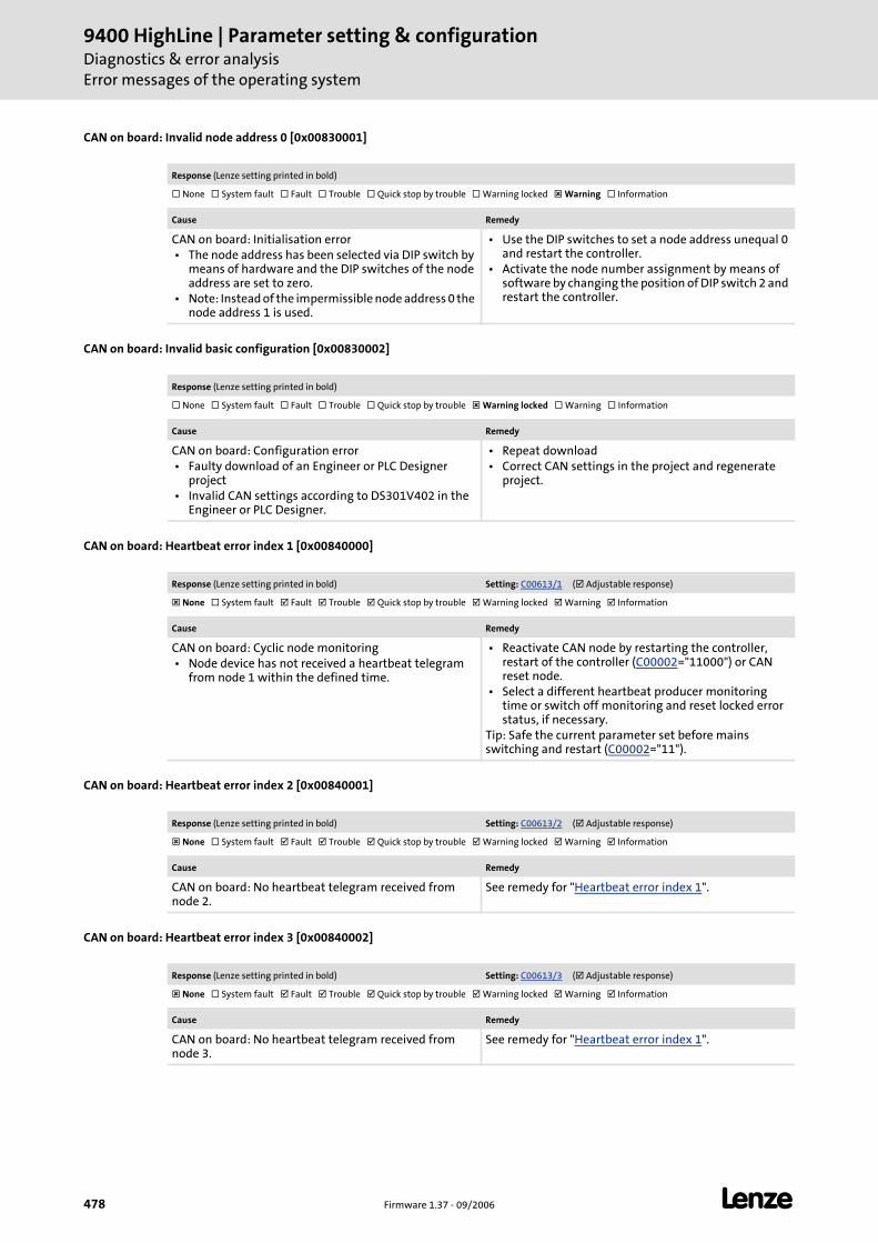
9400 HighLine | Parameter setting & configurationDiagnostics & error analysisError messages of the operating system
478 Firmware 1.37 - 09/2006 L
CAN on board: Invalid node address 0 [0x00830001]
CAN on board: Invalid basic configuration [0x00830002]
CAN on board: Heartbeat error index 1 [0x00840000]
CAN on board: Heartbeat error index 2 [0x00840001]
CAN on board: Heartbeat error index 3 [0x00840002]
Response (Lenze setting printed in bold)
None System fault Fault Trouble Quick stop by trouble Warning locked Warning Information
Cause Remedy
CAN on board: Initialisation error • The node address has been selected via DIP switch by
means of hardware and the DIP switches of the node address are set to zero.
• Note: Instead of the impermissible node address 0 the node address 1 is used.
• Use the DIP switches to set a node address unequal 0 and restart the controller.
• Activate the node number assignment by means of software by changing the position of DIP switch 2 and restart the controller.
Response (Lenze setting printed in bold)
None System fault Fault Trouble Quick stop by trouble Warning locked Warning Information
Cause Remedy
CAN on board: Configuration error • Faulty download of an Engineer or PLC Designer
project • Invalid CAN settings according to DS301V402 in the
Engineer or PLC Designer.
• Repeat download • Correct CAN settings in the project and regenerate
project.
Response (Lenze setting printed in bold) Setting: C00613/1 ( Adjustable response)
None System fault Fault Trouble Quick stop by trouble Warning locked Warning Information
Cause Remedy
CAN on board: Cyclic node monitoring • Node device has not received a heartbeat telegram
from node 1 within the defined time.
• Reactivate CAN node by restarting the controller, restart of the controller (C00002="11000") or CAN reset node.
• Select a different heartbeat producer monitoring time or switch off monitoring and reset locked error status, if necessary.
Tip: Safe the current parameter set before mains switching and restart (C00002="11").
Response (Lenze setting printed in bold) Setting: C00613/2 ( Adjustable response)
None System fault Fault Trouble Quick stop by trouble Warning locked Warning Information
Cause Remedy
CAN on board: No heartbeat telegram received from node 2.
See remedy for "Heartbeat error index 1".
Response (Lenze setting printed in bold) Setting: C00613/3 ( Adjustable response)
None System fault Fault Trouble Quick stop by trouble Warning locked Warning Information
Cause Remedy
CAN on board: No heartbeat telegram received from node 3.
See remedy for "Heartbeat error index 1".

L Firmware 1.37 - 09/2006 479
9400 HighLine | Parameter setting & configurationDiagnostics & error analysis
Error messages of the operating system
CAN on board: Heartbeat error index 4 [0x00840003]
CAN on board: Heartbeat error index 5 [0x00840004]
CAN on board: Heartbeat error index 6 [0x00840005]
CAN on board: Heartbeat error index 7 [0x00840006]
CAN on board: Heartbeat error index 8 [0x00840007]
CAN on board: Heartbeat error index 9 [0x00840008]
Response (Lenze setting printed in bold) Setting: C00613/4 ( Adjustable response)
None System fault Fault Trouble Quick stop by trouble Warning locked Warning Information
Cause Remedy
CAN on board: No heartbeat telegram received from node 4.
See remedy for "Heartbeat error index 1".
Response (Lenze setting printed in bold) Setting: C00613/5 ( Adjustable response)
None System fault Fault Trouble Quick stop by trouble Warning locked Warning Information
Cause Remedy
CAN on board: No heartbeat telegram received from node 5.
See remedy for "Heartbeat error index 1".
Response (Lenze setting printed in bold) Setting: C00613/6 ( Adjustable response)
None System fault Fault Trouble Quick stop by trouble Warning locked Warning Information
Cause Remedy
CAN on board: No heartbeat telegram received from node 6.
See remedy for "Heartbeat error index 1".
Response (Lenze setting printed in bold) Setting: C00613/7 ( Adjustable response)
None System fault Fault Trouble Quick stop by trouble Warning locked Warning Information
Cause Remedy
CAN on board: No heartbeat telegram received from node 7.
See remedy for "Heartbeat error index 1".
Response (Lenze setting printed in bold) Setting: C00613/8 ( Adjustable response)
None System fault Fault Trouble Quick stop by trouble Warning locked Warning Information
Cause Remedy
CAN on board: No heartbeat telegram received from node 8.
See remedy for "Heartbeat error index 1".
Response (Lenze setting printed in bold) Setting: C00613/9 ( Adjustable response)
None System fault Fault Trouble Quick stop by trouble Warning locked Warning Information
Cause Remedy
CAN on board: No heartbeat telegram received from node 9.
See remedy for "Heartbeat error index 1".
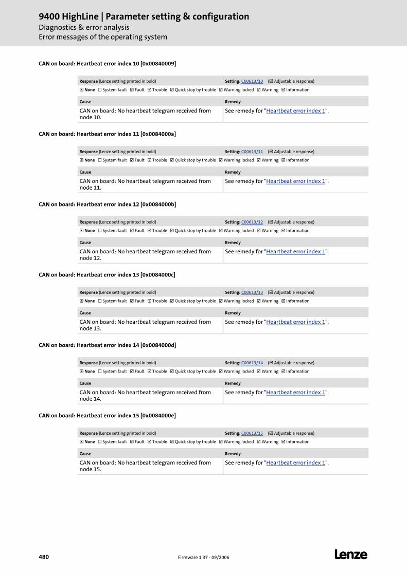
9400 HighLine | Parameter setting & configurationDiagnostics & error analysisError messages of the operating system
480 Firmware 1.37 - 09/2006 L
CAN on board: Heartbeat error index 10 [0x00840009]
CAN on board: Heartbeat error index 11 [0x0084000a]
CAN on board: Heartbeat error index 12 [0x0084000b]
CAN on board: Heartbeat error index 13 [0x0084000c]
CAN on board: Heartbeat error index 14 [0x0084000d]
CAN on board: Heartbeat error index 15 [0x0084000e]
Response (Lenze setting printed in bold) Setting: C00613/10 ( Adjustable response)
None System fault Fault Trouble Quick stop by trouble Warning locked Warning Information
Cause Remedy
CAN on board: No heartbeat telegram received from node 10.
See remedy for "Heartbeat error index 1".
Response (Lenze setting printed in bold) Setting: C00613/11 ( Adjustable response)
None System fault Fault Trouble Quick stop by trouble Warning locked Warning Information
Cause Remedy
CAN on board: No heartbeat telegram received from node 11.
See remedy for "Heartbeat error index 1".
Response (Lenze setting printed in bold) Setting: C00613/12 ( Adjustable response)
None System fault Fault Trouble Quick stop by trouble Warning locked Warning Information
Cause Remedy
CAN on board: No heartbeat telegram received from node 12.
See remedy for "Heartbeat error index 1".
Response (Lenze setting printed in bold) Setting: C00613/13 ( Adjustable response)
None System fault Fault Trouble Quick stop by trouble Warning locked Warning Information
Cause Remedy
CAN on board: No heartbeat telegram received from node 13.
See remedy for "Heartbeat error index 1".
Response (Lenze setting printed in bold) Setting: C00613/14 ( Adjustable response)
None System fault Fault Trouble Quick stop by trouble Warning locked Warning Information
Cause Remedy
CAN on board: No heartbeat telegram received from node 14.
See remedy for "Heartbeat error index 1".
Response (Lenze setting printed in bold) Setting: C00613/15 ( Adjustable response)
None System fault Fault Trouble Quick stop by trouble Warning locked Warning Information
Cause Remedy
CAN on board: No heartbeat telegram received from node 15.
See remedy for "Heartbeat error index 1".
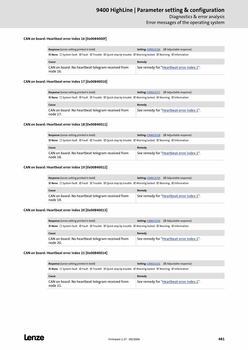
L Firmware 1.37 - 09/2006 481
9400 HighLine | Parameter setting & configurationDiagnostics & error analysis
Error messages of the operating system
CAN on board: Heartbeat error index 16 [0x0084000f]
CAN on board: Heartbeat error index 17 [0x00840010]
CAN on board: Heartbeat error index 18 [0x00840011]
CAN on board: Heartbeat error index 19 [0x00840012]
CAN on board: Heartbeat error index 20 [0x00840013]
CAN on board: Heartbeat error index 21 [0x00840014]
Response (Lenze setting printed in bold) Setting: C00613/16 ( Adjustable response)
None System fault Fault Trouble Quick stop by trouble Warning locked Warning Information
Cause Remedy
CAN on board: No heartbeat telegram received from node 16.
See remedy for "Heartbeat error index 1".
Response (Lenze setting printed in bold) Setting: C00613/17 ( Adjustable response)
None System fault Fault Trouble Quick stop by trouble Warning locked Warning Information
Cause Remedy
CAN on board: No heartbeat telegram received from node 17.
See remedy for "Heartbeat error index 1".
Response (Lenze setting printed in bold) Setting: C00613/18 ( Adjustable response)
None System fault Fault Trouble Quick stop by trouble Warning locked Warning Information
Cause Remedy
CAN on board: No heartbeat telegram received from node 18.
See remedy for "Heartbeat error index 1".
Response (Lenze setting printed in bold) Setting: C00613/19 ( Adjustable response)
None System fault Fault Trouble Quick stop by trouble Warning locked Warning Information
Cause Remedy
CAN on board: No heartbeat telegram received from node 19.
See remedy for "Heartbeat error index 1".
Response (Lenze setting printed in bold) Setting: C00613/20 ( Adjustable response)
None System fault Fault Trouble Quick stop by trouble Warning locked Warning Information
Cause Remedy
CAN on board: No heartbeat telegram received from node 20.
See remedy for "Heartbeat error index 1".
Response (Lenze setting printed in bold) Setting: C00613/21 ( Adjustable response)
None System fault Fault Trouble Quick stop by trouble Warning locked Warning Information
Cause Remedy
CAN on board: No heartbeat telegram received from node 21.
See remedy for "Heartbeat error index 1".
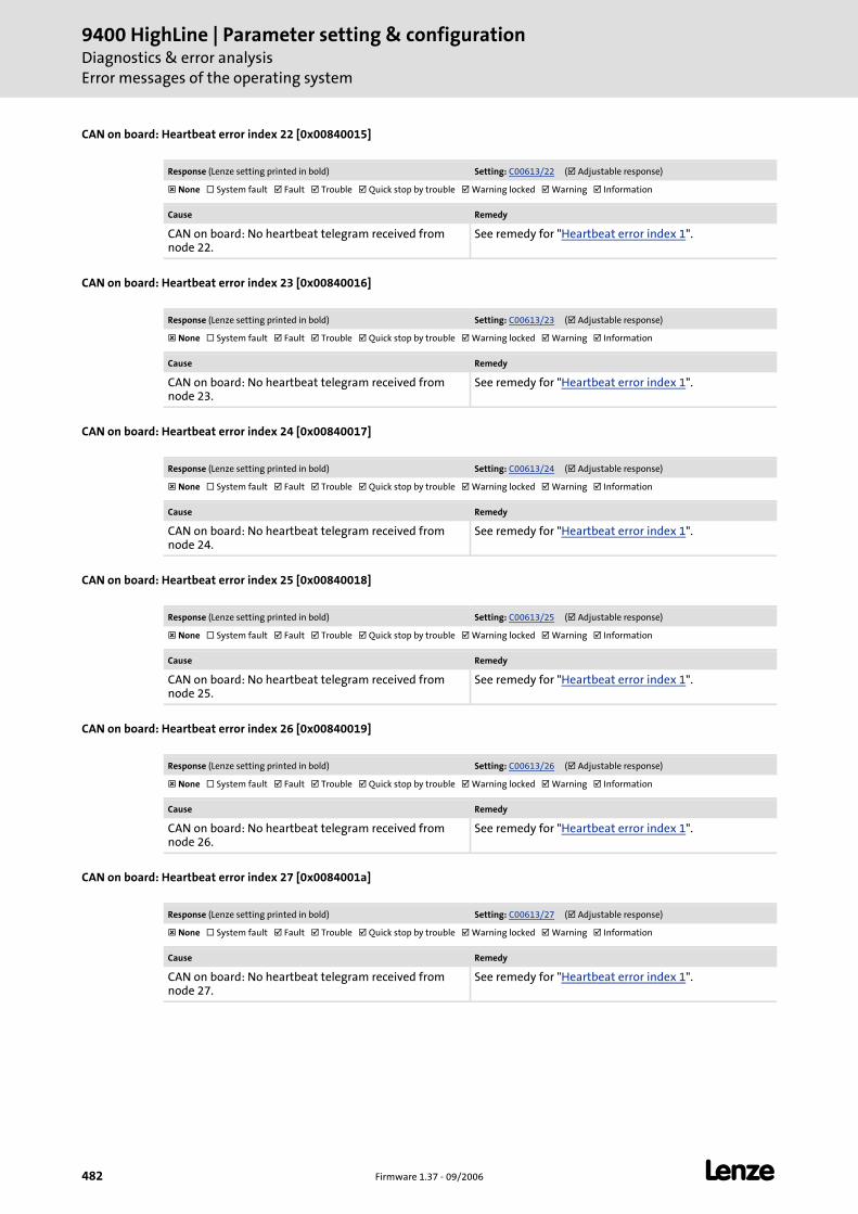
9400 HighLine | Parameter setting & configurationDiagnostics & error analysisError messages of the operating system
482 Firmware 1.37 - 09/2006 L
CAN on board: Heartbeat error index 22 [0x00840015]
CAN on board: Heartbeat error index 23 [0x00840016]
CAN on board: Heartbeat error index 24 [0x00840017]
CAN on board: Heartbeat error index 25 [0x00840018]
CAN on board: Heartbeat error index 26 [0x00840019]
CAN on board: Heartbeat error index 27 [0x0084001a]
Response (Lenze setting printed in bold) Setting: C00613/22 ( Adjustable response)
None System fault Fault Trouble Quick stop by trouble Warning locked Warning Information
Cause Remedy
CAN on board: No heartbeat telegram received from node 22.
See remedy for "Heartbeat error index 1".
Response (Lenze setting printed in bold) Setting: C00613/23 ( Adjustable response)
None System fault Fault Trouble Quick stop by trouble Warning locked Warning Information
Cause Remedy
CAN on board: No heartbeat telegram received from node 23.
See remedy for "Heartbeat error index 1".
Response (Lenze setting printed in bold) Setting: C00613/24 ( Adjustable response)
None System fault Fault Trouble Quick stop by trouble Warning locked Warning Information
Cause Remedy
CAN on board: No heartbeat telegram received from node 24.
See remedy for "Heartbeat error index 1".
Response (Lenze setting printed in bold) Setting: C00613/25 ( Adjustable response)
None System fault Fault Trouble Quick stop by trouble Warning locked Warning Information
Cause Remedy
CAN on board: No heartbeat telegram received from node 25.
See remedy for "Heartbeat error index 1".
Response (Lenze setting printed in bold) Setting: C00613/26 ( Adjustable response)
None System fault Fault Trouble Quick stop by trouble Warning locked Warning Information
Cause Remedy
CAN on board: No heartbeat telegram received from node 26.
See remedy for "Heartbeat error index 1".
Response (Lenze setting printed in bold) Setting: C00613/27 ( Adjustable response)
None System fault Fault Trouble Quick stop by trouble Warning locked Warning Information
Cause Remedy
CAN on board: No heartbeat telegram received from node 27.
See remedy for "Heartbeat error index 1".
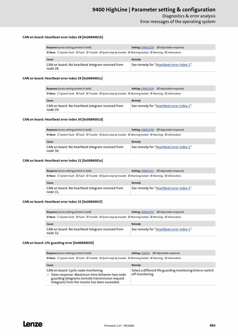
L Firmware 1.37 - 09/2006 483
9400 HighLine | Parameter setting & configurationDiagnostics & error analysis
Error messages of the operating system
CAN on board: Heartbeat error index 28 [0x0084001b]
CAN on board: Heartbeat error index 29 [0x0084001c]
CAN on board: Heartbeat error index 30 [0x0084001d]
CAN on board: Heartbeat error index 31 [0x0084001e]
CAN on board: Heartbeat error index 32 [0x0084001f]
CAN on board: Life guarding error [0x00840020]
Response (Lenze setting printed in bold) Setting: C00613/28 ( Adjustable response)
None System fault Fault Trouble Quick stop by trouble Warning locked Warning Information
Cause Remedy
CAN on board: No heartbeat telegram received from node 28.
See remedy for "Heartbeat error index 1".
Response (Lenze setting printed in bold) Setting: C00613/29 ( Adjustable response)
None System fault Fault Trouble Quick stop by trouble Warning locked Warning Information
Cause Remedy
CAN on board: No heartbeat telegram received from node 29.
See remedy for "Heartbeat error index 1".
Response (Lenze setting printed in bold) Setting: C00613/30 ( Adjustable response)
None System fault Fault Trouble Quick stop by trouble Warning locked Warning Information
Cause Remedy
CAN on board: No heartbeat telegram received from node 30.
See remedy for "Heartbeat error index 1".
Response (Lenze setting printed in bold) Setting: C00613/31 ( Adjustable response)
None System fault Fault Trouble Quick stop by trouble Warning locked Warning Information
Cause Remedy
CAN on board: No heartbeat telegram received from node 31.
See remedy for "Heartbeat error index 1".
Response (Lenze setting printed in bold) Setting: C00613/32 ( Adjustable response)
None System fault Fault Trouble Quick stop by trouble Warning locked Warning Information
Cause Remedy
CAN on board: No heartbeat telegram received from node 32.
See remedy for "Heartbeat error index 1".
Response (Lenze setting printed in bold) Setting: C00614 ( Adjustable response)
None System fault Fault Trouble Quick stop by trouble Warning locked Warning Information
Cause Remedy
CAN on board: Cyclic node monitoring • Slave response: Maximum time between two node
guarding telegrams (remote transmission request telegram) from the master has been exceeded.
Select a different life guarding monitoring time or switch off monitoring.
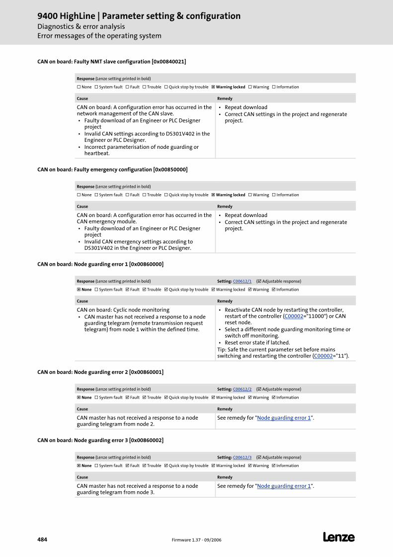
9400 HighLine | Parameter setting & configurationDiagnostics & error analysisError messages of the operating system
484 Firmware 1.37 - 09/2006 L
CAN on board: Faulty NMT slave configuration [0x00840021]
CAN on board: Faulty emergency configuration [0x00850000]
CAN on board: Node guarding error 1 [0x00860000]
CAN on board: Node guarding error 2 [0x00860001]
CAN on board: Node guarding error 3 [0x00860002]
Response (Lenze setting printed in bold)
None System fault Fault Trouble Quick stop by trouble Warning locked Warning Information
Cause Remedy
CAN on board: A configuration error has occurred in the network management of the CAN slave. • Faulty download of an Engineer or PLC Designer
project • Invalid CAN settings according to DS301V402 in the
Engineer or PLC Designer. • Incorrect parameterisation of node guarding or
heartbeat.
• Repeat download • Correct CAN settings in the project and regenerate
project.
Response (Lenze setting printed in bold)
None System fault Fault Trouble Quick stop by trouble Warning locked Warning Information
Cause Remedy
CAN on board: A configuration error has occurred in the CAN emergency module. • Faulty download of an Engineer or PLC Designer
project • Invalid CAN emergency settings according to
DS301V402 in the Engineer or PLC Designer.
• Repeat download • Correct CAN settings in the project and regenerate
project.
Response (Lenze setting printed in bold) Setting: C00612/1 ( Adjustable response)
None System fault Fault Trouble Quick stop by trouble Warning locked Warning Information
Cause Remedy
CAN on board: Cyclic node monitoring • CAN master has not received a response to a node
guarding telegram (remote transmission request telegram) from node 1 within the defined time.
• Reactivate CAN node by restarting the controller, restart of the controller (C00002="11000") or CAN reset node.
• Select a different node guarding monitoring time or switch off monitoring.
• Reset error state if latched.Tip: Safe the current parameter set before mains switching and restarting the controller (C00002="11").
Response (Lenze setting printed in bold) Setting: C00612/2 ( Adjustable response)
None System fault Fault Trouble Quick stop by trouble Warning locked Warning Information
Cause Remedy
CAN master has not received a response to a node guarding telegram from node 2.
See remedy for "Node guarding error 1".
Response (Lenze setting printed in bold) Setting: C00612/3 ( Adjustable response)
None System fault Fault Trouble Quick stop by trouble Warning locked Warning Information
Cause Remedy
CAN master has not received a response to a node guarding telegram from node 3.
See remedy for "Node guarding error 1".
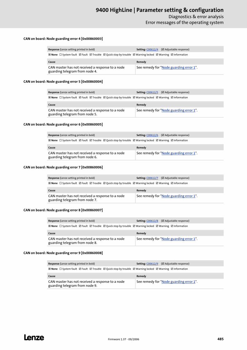
L Firmware 1.37 - 09/2006 485
9400 HighLine | Parameter setting & configurationDiagnostics & error analysis
Error messages of the operating system
CAN on board: Node guarding error 4 [0x00860003]
CAN on board: Node guarding error 5 [0x00860004]
CAN on board: Node guarding error 6 [0x00860005]
CAN on board: Node guarding error 7 [0x00860006]
CAN on board: Node guarding error 8 [0x00860007]
CAN on board: Node guarding error 9 [0x00860008]
Response (Lenze setting printed in bold) Setting: C00612/4 ( Adjustable response)
None System fault Fault Trouble Quick stop by trouble Warning locked Warning Information
Cause Remedy
CAN master has not received a response to a node guarding telegram from node 4.
See remedy for "Node guarding error 1".
Response (Lenze setting printed in bold) Setting: C00612/5 ( Adjustable response)
None System fault Fault Trouble Quick stop by trouble Warning locked Warning Information
Cause Remedy
CAN master has not received a response to a node guarding telegram from node 5.
See remedy for "Node guarding error 1".
Response (Lenze setting printed in bold) Setting: C00612/6 ( Adjustable response)
None System fault Fault Trouble Quick stop by trouble Warning locked Warning Information
Cause Remedy
CAN master has not received a response to a node guarding telegram from node 6.
See remedy for "Node guarding error 1".
Response (Lenze setting printed in bold) Setting: C00612/7 ( Adjustable response)
None System fault Fault Trouble Quick stop by trouble Warning locked Warning Information
Cause Remedy
CAN master has not received a response to a node guarding telegram from node 7.
See remedy for "Node guarding error 1".
Response (Lenze setting printed in bold) Setting: C00612/8 ( Adjustable response)
None System fault Fault Trouble Quick stop by trouble Warning locked Warning Information
Cause Remedy
CAN master has not received a response to a node guarding telegram from node 8.
See remedy for "Node guarding error 1".
Response (Lenze setting printed in bold) Setting: C00612/9 ( Adjustable response)
None System fault Fault Trouble Quick stop by trouble Warning locked Warning Information
Cause Remedy
CAN master has not received a response to a node guarding telegram from node 9.
See remedy for "Node guarding error 1".

9400 HighLine | Parameter setting & configurationDiagnostics & error analysisError messages of the operating system
486 Firmware 1.37 - 09/2006 L
CAN on board: Node guarding error 10 [0x00860009]
CAN on board: Node guarding error 11 [0x0086000a]
CAN on board: Node guarding error 12 [0x0086000b]
CAN on board: Node guarding error 13 [0x0086000c]
CAN on board: Node guarding error 14 [0x0086000d]
CAN on board: Node guarding error 15 [0x0086000e]
Response (Lenze setting printed in bold) Setting: C00612/10 ( Adjustable response)
None System fault Fault Trouble Quick stop by trouble Warning locked Warning Information
Cause Remedy
CAN master has not received a response to a node guarding telegram from node 10.
See remedy for "Node guarding error 1".
Response (Lenze setting printed in bold) Setting: C00612/11 ( Adjustable response)
None System fault Fault Trouble Quick stop by trouble Warning locked Warning Information
Cause Remedy
CAN master has not received a response to a node guarding telegram from node 11.
See remedy for "Node guarding error 1".
Response (Lenze setting printed in bold) Setting: C00612/12 ( Adjustable response)
None System fault Fault Trouble Quick stop by trouble Warning locked Warning Information
Cause Remedy
CAN master has not received a response to a node guarding telegram from node 12.
See remedy for "Node guarding error 1".
Response (Lenze setting printed in bold) Setting: C00612/13 ( Adjustable response)
None System fault Fault Trouble Quick stop by trouble Warning locked Warning Information
Cause Remedy
CAN master has not received a response to a node guarding telegram from node 13.
See remedy for "Node guarding error 1".
Response (Lenze setting printed in bold) Setting: C00612/14 ( Adjustable response)
None System fault Fault Trouble Quick stop by trouble Warning locked Warning Information
Cause Remedy
CAN master has not received a response to a node guarding telegram from node 14.
See remedy for "Node guarding error 1".
Response (Lenze setting printed in bold) Setting: C00612/15 ( Adjustable response)
None System fault Fault Trouble Quick stop by trouble Warning locked Warning Information
Cause Remedy
CAN master has not received a response to a node guarding telegram from node 15.
See remedy for "Node guarding error 1".
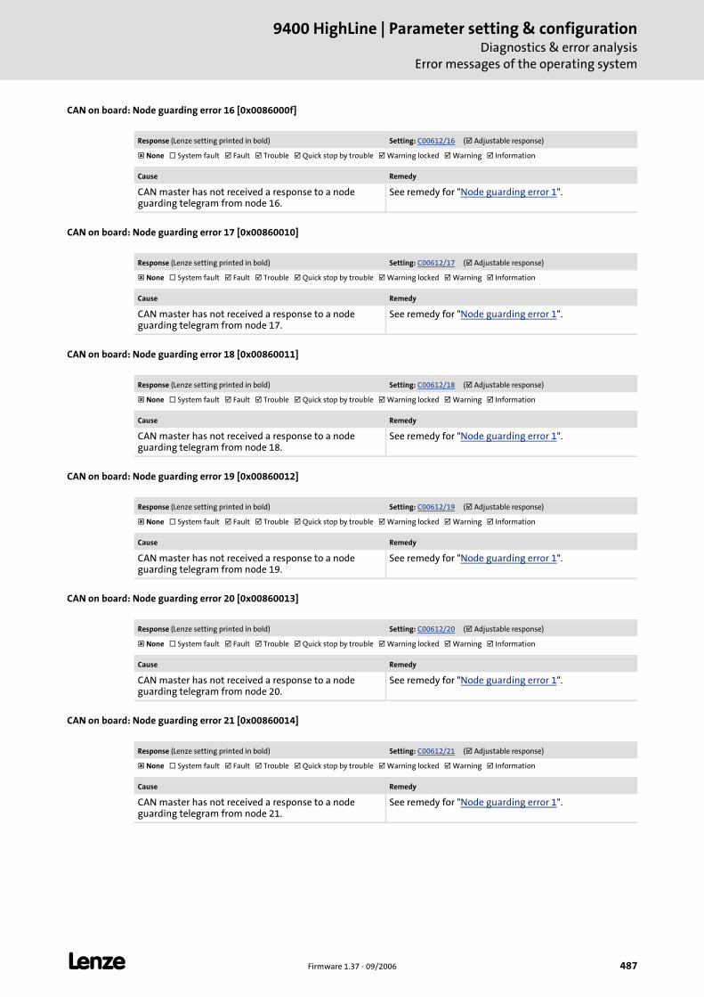
L Firmware 1.37 - 09/2006 487
9400 HighLine | Parameter setting & configurationDiagnostics & error analysis
Error messages of the operating system
CAN on board: Node guarding error 16 [0x0086000f]
CAN on board: Node guarding error 17 [0x00860010]
CAN on board: Node guarding error 18 [0x00860011]
CAN on board: Node guarding error 19 [0x00860012]
CAN on board: Node guarding error 20 [0x00860013]
CAN on board: Node guarding error 21 [0x00860014]
Response (Lenze setting printed in bold) Setting: C00612/16 ( Adjustable response)
None System fault Fault Trouble Quick stop by trouble Warning locked Warning Information
Cause Remedy
CAN master has not received a response to a node guarding telegram from node 16.
See remedy for "Node guarding error 1".
Response (Lenze setting printed in bold) Setting: C00612/17 ( Adjustable response)
None System fault Fault Trouble Quick stop by trouble Warning locked Warning Information
Cause Remedy
CAN master has not received a response to a node guarding telegram from node 17.
See remedy for "Node guarding error 1".
Response (Lenze setting printed in bold) Setting: C00612/18 ( Adjustable response)
None System fault Fault Trouble Quick stop by trouble Warning locked Warning Information
Cause Remedy
CAN master has not received a response to a node guarding telegram from node 18.
See remedy for "Node guarding error 1".
Response (Lenze setting printed in bold) Setting: C00612/19 ( Adjustable response)
None System fault Fault Trouble Quick stop by trouble Warning locked Warning Information
Cause Remedy
CAN master has not received a response to a node guarding telegram from node 19.
See remedy for "Node guarding error 1".
Response (Lenze setting printed in bold) Setting: C00612/20 ( Adjustable response)
None System fault Fault Trouble Quick stop by trouble Warning locked Warning Information
Cause Remedy
CAN master has not received a response to a node guarding telegram from node 20.
See remedy for "Node guarding error 1".
Response (Lenze setting printed in bold) Setting: C00612/21 ( Adjustable response)
None System fault Fault Trouble Quick stop by trouble Warning locked Warning Information
Cause Remedy
CAN master has not received a response to a node guarding telegram from node 21.
See remedy for "Node guarding error 1".
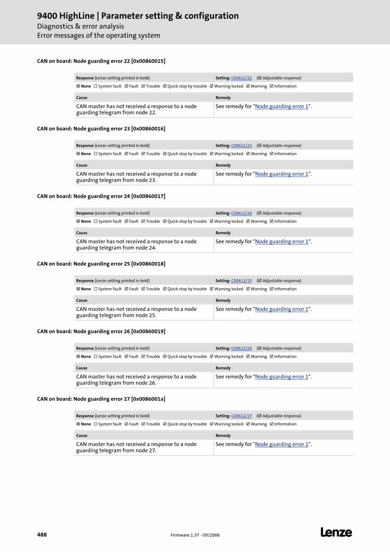
9400 HighLine | Parameter setting & configurationDiagnostics & error analysisError messages of the operating system
488 Firmware 1.37 - 09/2006 L
CAN on board: Node guarding error 22 [0x00860015]
CAN on board: Node guarding error 23 [0x00860016]
CAN on board: Node guarding error 24 [0x00860017]
CAN on board: Node guarding error 25 [0x00860018]
CAN on board: Node guarding error 26 [0x00860019]
CAN on board: Node guarding error 27 [0x0086001a]
Response (Lenze setting printed in bold) Setting: C00612/22 ( Adjustable response)
None System fault Fault Trouble Quick stop by trouble Warning locked Warning Information
Cause Remedy
CAN master has not received a response to a node guarding telegram from node 22.
See remedy for "Node guarding error 1".
Response (Lenze setting printed in bold) Setting: C00612/23 ( Adjustable response)
None System fault Fault Trouble Quick stop by trouble Warning locked Warning Information
Cause Remedy
CAN master has not received a response to a node guarding telegram from node 23.
See remedy for "Node guarding error 1".
Response (Lenze setting printed in bold) Setting: C00612/24 ( Adjustable response)
None System fault Fault Trouble Quick stop by trouble Warning locked Warning Information
Cause Remedy
CAN master has not received a response to a node guarding telegram from node 24.
See remedy for "Node guarding error 1".
Response (Lenze setting printed in bold) Setting: C00612/25 ( Adjustable response)
None System fault Fault Trouble Quick stop by trouble Warning locked Warning Information
Cause Remedy
CAN master has not received a response to a node guarding telegram from node 25.
See remedy for "Node guarding error 1".
Response (Lenze setting printed in bold) Setting: C00612/26 ( Adjustable response)
None System fault Fault Trouble Quick stop by trouble Warning locked Warning Information
Cause Remedy
CAN master has not received a response to a node guarding telegram from node 26.
See remedy for "Node guarding error 1".
Response (Lenze setting printed in bold) Setting: C00612/27 ( Adjustable response)
None System fault Fault Trouble Quick stop by trouble Warning locked Warning Information
Cause Remedy
CAN master has not received a response to a node guarding telegram from node 27.
See remedy for "Node guarding error 1".
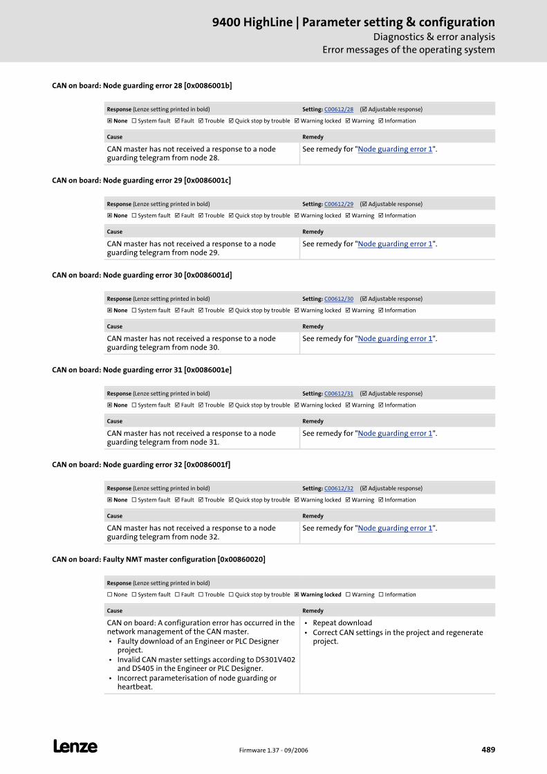
L Firmware 1.37 - 09/2006 489
9400 HighLine | Parameter setting & configurationDiagnostics & error analysis
Error messages of the operating system
CAN on board: Node guarding error 28 [0x0086001b]
CAN on board: Node guarding error 29 [0x0086001c]
CAN on board: Node guarding error 30 [0x0086001d]
CAN on board: Node guarding error 31 [0x0086001e]
CAN on board: Node guarding error 32 [0x0086001f]
CAN on board: Faulty NMT master configuration [0x00860020]
Response (Lenze setting printed in bold) Setting: C00612/28 ( Adjustable response)
None System fault Fault Trouble Quick stop by trouble Warning locked Warning Information
Cause Remedy
CAN master has not received a response to a node guarding telegram from node 28.
See remedy for "Node guarding error 1".
Response (Lenze setting printed in bold) Setting: C00612/29 ( Adjustable response)
None System fault Fault Trouble Quick stop by trouble Warning locked Warning Information
Cause Remedy
CAN master has not received a response to a node guarding telegram from node 29.
See remedy for "Node guarding error 1".
Response (Lenze setting printed in bold) Setting: C00612/30 ( Adjustable response)
None System fault Fault Trouble Quick stop by trouble Warning locked Warning Information
Cause Remedy
CAN master has not received a response to a node guarding telegram from node 30.
See remedy for "Node guarding error 1".
Response (Lenze setting printed in bold) Setting: C00612/31 ( Adjustable response)
None System fault Fault Trouble Quick stop by trouble Warning locked Warning Information
Cause Remedy
CAN master has not received a response to a node guarding telegram from node 31.
See remedy for "Node guarding error 1".
Response (Lenze setting printed in bold) Setting: C00612/32 ( Adjustable response)
None System fault Fault Trouble Quick stop by trouble Warning locked Warning Information
Cause Remedy
CAN master has not received a response to a node guarding telegram from node 32.
See remedy for "Node guarding error 1".
Response (Lenze setting printed in bold)
None System fault Fault Trouble Quick stop by trouble Warning locked Warning Information
Cause Remedy
CAN on board: A configuration error has occurred in the network management of the CAN master. • Faulty download of an Engineer or PLC Designer
project. • Invalid CAN master settings according to DS301V402
and DS405 in the Engineer or PLC Designer. • Incorrect parameterisation of node guarding or
heartbeat.
• Repeat download • Correct CAN settings in the project and regenerate
project.
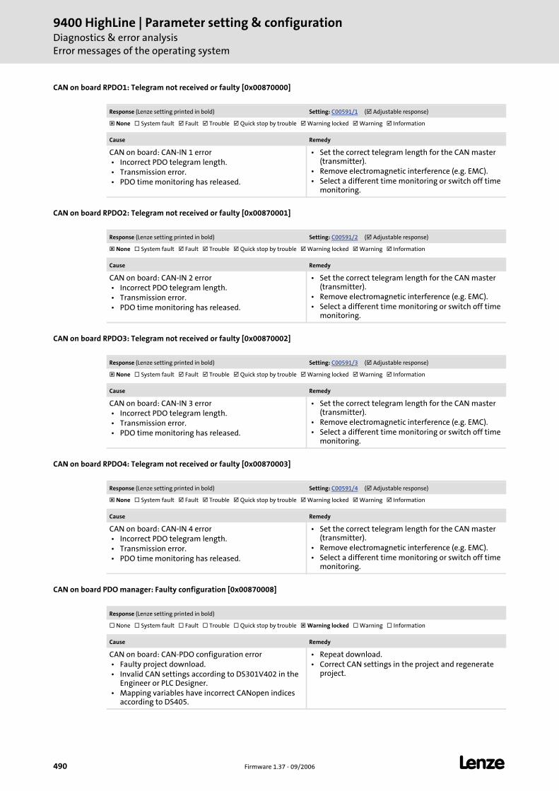
9400 HighLine | Parameter setting & configurationDiagnostics & error analysisError messages of the operating system
490 Firmware 1.37 - 09/2006 L
CAN on board RPDO1: Telegram not received or faulty [0x00870000]
CAN on board RPDO2: Telegram not received or faulty [0x00870001]
CAN on board RPDO3: Telegram not received or faulty [0x00870002]
CAN on board RPDO4: Telegram not received or faulty [0x00870003]
CAN on board PDO manager: Faulty configuration [0x00870008]
Response (Lenze setting printed in bold) Setting: C00591/1 ( Adjustable response)
None System fault Fault Trouble Quick stop by trouble Warning locked Warning Information
Cause Remedy
CAN on board: CAN-IN 1 error • Incorrect PDO telegram length. • Transmission error. • PDO time monitoring has released.
• Set the correct telegram length for the CAN master (transmitter).
• Remove electromagnetic interference (e.g. EMC). • Select a different time monitoring or switch off time
monitoring.
Response (Lenze setting printed in bold) Setting: C00591/2 ( Adjustable response)
None System fault Fault Trouble Quick stop by trouble Warning locked Warning Information
Cause Remedy
CAN on board: CAN-IN 2 error • Incorrect PDO telegram length. • Transmission error. • PDO time monitoring has released.
• Set the correct telegram length for the CAN master (transmitter).
• Remove electromagnetic interference (e.g. EMC). • Select a different time monitoring or switch off time
monitoring.
Response (Lenze setting printed in bold) Setting: C00591/3 ( Adjustable response)
None System fault Fault Trouble Quick stop by trouble Warning locked Warning Information
Cause Remedy
CAN on board: CAN-IN 3 error • Incorrect PDO telegram length. • Transmission error. • PDO time monitoring has released.
• Set the correct telegram length for the CAN master (transmitter).
• Remove electromagnetic interference (e.g. EMC). • Select a different time monitoring or switch off time
monitoring.
Response (Lenze setting printed in bold) Setting: C00591/4 ( Adjustable response)
None System fault Fault Trouble Quick stop by trouble Warning locked Warning Information
Cause Remedy
CAN on board: CAN-IN 4 error • Incorrect PDO telegram length. • Transmission error. • PDO time monitoring has released.
• Set the correct telegram length for the CAN master (transmitter).
• Remove electromagnetic interference (e.g. EMC). • Select a different time monitoring or switch off time
monitoring.
Response (Lenze setting printed in bold)
None System fault Fault Trouble Quick stop by trouble Warning locked Warning Information
Cause Remedy
CAN on board: CAN-PDO configuration error • Faulty project download. • Invalid CAN settings according to DS301V402 in the
Engineer or PLC Designer. • Mapping variables have incorrect CANopen indices
according to DS405.
• Repeat download. • Correct CAN settings in the project and regenerate
project.
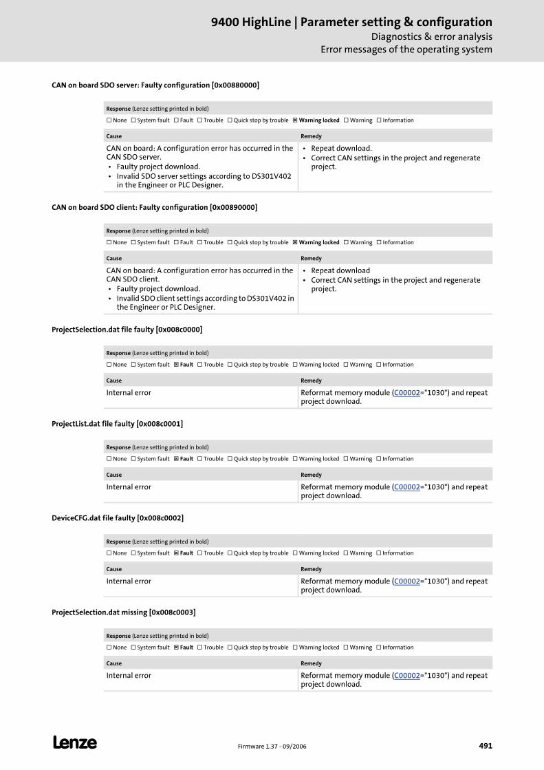
L Firmware 1.37 - 09/2006 491
9400 HighLine | Parameter setting & configurationDiagnostics & error analysis
Error messages of the operating system
CAN on board SDO server: Faulty configuration [0x00880000]
CAN on board SDO client: Faulty configuration [0x00890000]
ProjectSelection.dat file faulty [0x008c0000]
ProjectList.dat file faulty [0x008c0001]
DeviceCFG.dat file faulty [0x008c0002]
ProjectSelection.dat missing [0x008c0003]
Response (Lenze setting printed in bold)
None System fault Fault Trouble Quick stop by trouble Warning locked Warning Information
Cause Remedy
CAN on board: A configuration error has occurred in the CAN SDO server. • Faulty project download. • Invalid SDO server settings according to DS301V402
in the Engineer or PLC Designer.
• Repeat download. • Correct CAN settings in the project and regenerate
project.
Response (Lenze setting printed in bold)
None System fault Fault Trouble Quick stop by trouble Warning locked Warning Information
Cause Remedy
CAN on board: A configuration error has occurred in the CAN SDO client. • Faulty project download. • Invalid SDO client settings according to DS301V402 in
the Engineer or PLC Designer.
• Repeat download • Correct CAN settings in the project and regenerate
project.
Response (Lenze setting printed in bold)
None System fault Fault Trouble Quick stop by trouble Warning locked Warning Information
Cause Remedy
Internal error Reformat memory module (C00002="1030") and repeat project download.
Response (Lenze setting printed in bold)
None System fault Fault Trouble Quick stop by trouble Warning locked Warning Information
Cause Remedy
Internal error Reformat memory module (C00002="1030") and repeat project download.
Response (Lenze setting printed in bold)
None System fault Fault Trouble Quick stop by trouble Warning locked Warning Information
Cause Remedy
Internal error Reformat memory module (C00002="1030") and repeat project download.
Response (Lenze setting printed in bold)
None System fault Fault Trouble Quick stop by trouble Warning locked Warning Information
Cause Remedy
Internal error Reformat memory module (C00002="1030") and repeat project download.
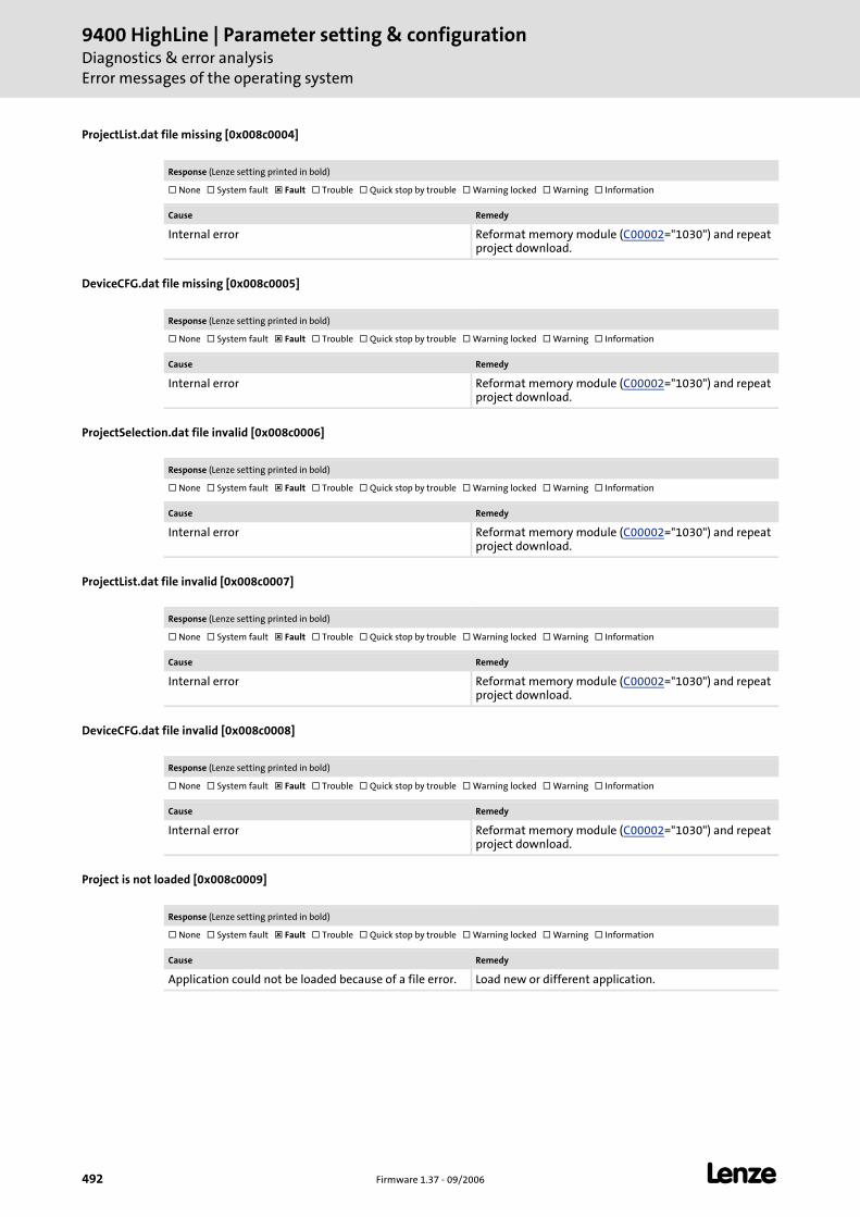
9400 HighLine | Parameter setting & configurationDiagnostics & error analysisError messages of the operating system
492 Firmware 1.37 - 09/2006 L
ProjectList.dat file missing [0x008c0004]
DeviceCFG.dat file missing [0x008c0005]
ProjectSelection.dat file invalid [0x008c0006]
ProjectList.dat file invalid [0x008c0007]
DeviceCFG.dat file invalid [0x008c0008]
Project is not loaded [0x008c0009]
Response (Lenze setting printed in bold)
None System fault Fault Trouble Quick stop by trouble Warning locked Warning Information
Cause Remedy
Internal error Reformat memory module (C00002="1030") and repeat project download.
Response (Lenze setting printed in bold)
None System fault Fault Trouble Quick stop by trouble Warning locked Warning Information
Cause Remedy
Internal error Reformat memory module (C00002="1030") and repeat project download.
Response (Lenze setting printed in bold)
None System fault Fault Trouble Quick stop by trouble Warning locked Warning Information
Cause Remedy
Internal error Reformat memory module (C00002="1030") and repeat project download.
Response (Lenze setting printed in bold)
None System fault Fault Trouble Quick stop by trouble Warning locked Warning Information
Cause Remedy
Internal error Reformat memory module (C00002="1030") and repeat project download.
Response (Lenze setting printed in bold)
None System fault Fault Trouble Quick stop by trouble Warning locked Warning Information
Cause Remedy
Internal error Reformat memory module (C00002="1030") and repeat project download.
Response (Lenze setting printed in bold)
None System fault Fault Trouble Quick stop by trouble Warning locked Warning Information
Cause Remedy
Application could not be loaded because of a file error. Load new or different application.
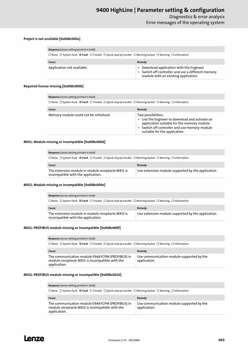
L Firmware 1.37 - 09/2006 493
9400 HighLine | Parameter setting & configurationDiagnostics & error analysis
Error messages of the operating system
Project is not available [0x008c000a]
Required license missing [0x008c000b]
MXI1: Module missing or incompatible [0x008c000d]
MXI2: Module missing or incompatible [0x008c000e]
MXI1: PROFIBUS module missing or incompatible [0x008c000f]
MXI2: PROFIBUS module missing or incompatible [0x008c0010]
Response (Lenze setting printed in bold)
None System fault Fault Trouble Quick stop by trouble Warning locked Warning Information
Cause Remedy
Application not available. • Download application with the Engineer • Switch off controller and use a different memory
module with an existing application.
Response (Lenze setting printed in bold)
None System fault Fault Trouble Quick stop by trouble Warning locked Warning Information
Cause Remedy
Memory module could not be initialised. Two possibilities: • Use the Engineer to download and activate an
application suitable for the memory module. • Switch off controller and use memory module
suitable for the application.
Response (Lenze setting printed in bold)
None System fault Fault Trouble Quick stop by trouble Warning locked Warning Information
Cause Remedy
The extension module in module receptacle MXI1 is incompatible with the application.
Use extension module supported by the application.
Response (Lenze setting printed in bold)
None System fault Fault Trouble Quick stop by trouble Warning locked Warning Information
Cause Remedy
The extension module in module receptacle MXI2 is incompatible with the application.
Use extension module supported by the application.
Response (Lenze setting printed in bold)
None System fault Fault Trouble Quick stop by trouble Warning locked Warning Information
Cause Remedy
The communication module E94AYCPM (PROFIBUS) in module receptacle MXI1 is incompatible with the application.
Use communication module supported by the application.
Response (Lenze setting printed in bold)
None System fault Fault Trouble Quick stop by trouble Warning locked Warning Information
Cause Remedy
The communication module E94AYCPM (PROFIBUS) in module receptacle MXI2 is incompatible with the application.
Use communication module supported by the application.
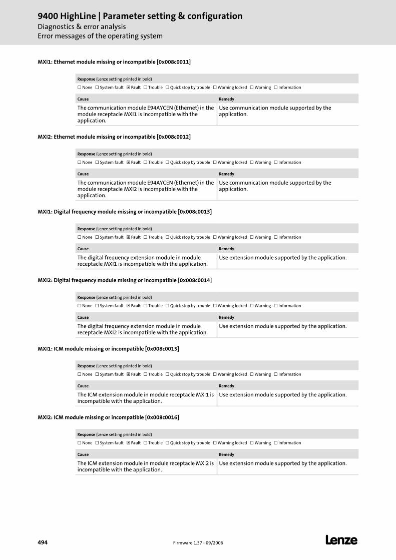
9400 HighLine | Parameter setting & configurationDiagnostics & error analysisError messages of the operating system
494 Firmware 1.37 - 09/2006 L
MXI1: Ethernet module missing or incompatible [0x008c0011]
MXI2: Ethernet module missing or incompatible [0x008c0012]
MXI1: Digital frequency module missing or incompatible [0x008c0013]
MXI2: Digital frequency module missing or incompatible [0x008c0014]
MXI1: ICM module missing or incompatible [0x008c0015]
MXI2: ICM module missing or incompatible [0x008c0016]
Response (Lenze setting printed in bold)
None System fault Fault Trouble Quick stop by trouble Warning locked Warning Information
Cause Remedy
The communication module E94AYCEN (Ethernet) in the module receptacle MXI1 is incompatible with the application.
Use communication module supported by the application.
Response (Lenze setting printed in bold)
None System fault Fault Trouble Quick stop by trouble Warning locked Warning Information
Cause Remedy
The communication module E94AYCEN (Ethernet) in the module receptacle MXI2 is incompatible with the application.
Use communication module supported by the application.
Response (Lenze setting printed in bold)
None System fault Fault Trouble Quick stop by trouble Warning locked Warning Information
Cause Remedy
The digital frequency extension module in module receptacle MXI1 is incompatible with the application.
Use extension module supported by the application.
Response (Lenze setting printed in bold)
None System fault Fault Trouble Quick stop by trouble Warning locked Warning Information
Cause Remedy
The digital frequency extension module in module receptacle MXI2 is incompatible with the application.
Use extension module supported by the application.
Response (Lenze setting printed in bold)
None System fault Fault Trouble Quick stop by trouble Warning locked Warning Information
Cause Remedy
The ICM extension module in module receptacle MXI1 is incompatible with the application.
Use extension module supported by the application.
Response (Lenze setting printed in bold)
None System fault Fault Trouble Quick stop by trouble Warning locked Warning Information
Cause Remedy
The ICM extension module in module receptacle MXI2 is incompatible with the application.
Use extension module supported by the application.
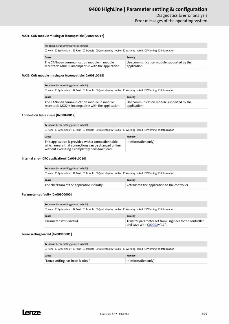
L Firmware 1.37 - 09/2006 495
9400 HighLine | Parameter setting & configurationDiagnostics & error analysis
Error messages of the operating system
MXI1: CAN module missing or incompatible [0x008c0017]
MXI2: CAN module missing or incompatible [0x008c0018]
Connection table in use [0x008c001a]
Internal error (CRC application) [0x008c001d]
Parameter set faulty [0x00900000]
Lenze setting loaded [0x00900001]
Response (Lenze setting printed in bold)
None System fault Fault Trouble Quick stop by trouble Warning locked Warning Information
Cause Remedy
The CANopen communication module in module receptacle MXI1 is incompatible with the application.
Use communication module supported by the application.
Response (Lenze setting printed in bold)
None System fault Fault Trouble Quick stop by trouble Warning locked Warning Information
Cause Remedy
The CANopen communication module in module receptacle MXI2 is incompatible with the application.
Use communication module supported by the application.
Response (Lenze setting printed in bold)
None System fault Fault Trouble Quick stop by trouble Warning locked Warning Information
Cause Remedy
This application is provided with a connection table which means that connections can be changed online without executing a completely new download.
- (Information only)
Response (Lenze setting printed in bold)
None System fault Fault Trouble Quick stop by trouble Warning locked Warning Information
Cause Remedy
The checksum of the application is faulty. Retransmit the application to the controller.
Response (Lenze setting printed in bold)
None System fault Fault Trouble Quick stop by trouble Warning locked Warning Information
Cause Remedy
Parameter set is invalid. Transfer parameter set from Engineer to the controller and save with C00002="11".
Response (Lenze setting printed in bold)
None System fault Fault Trouble Quick stop by trouble Warning locked Warning Information
Cause Remedy
"Lenze setting has been loaded." - (Information only)
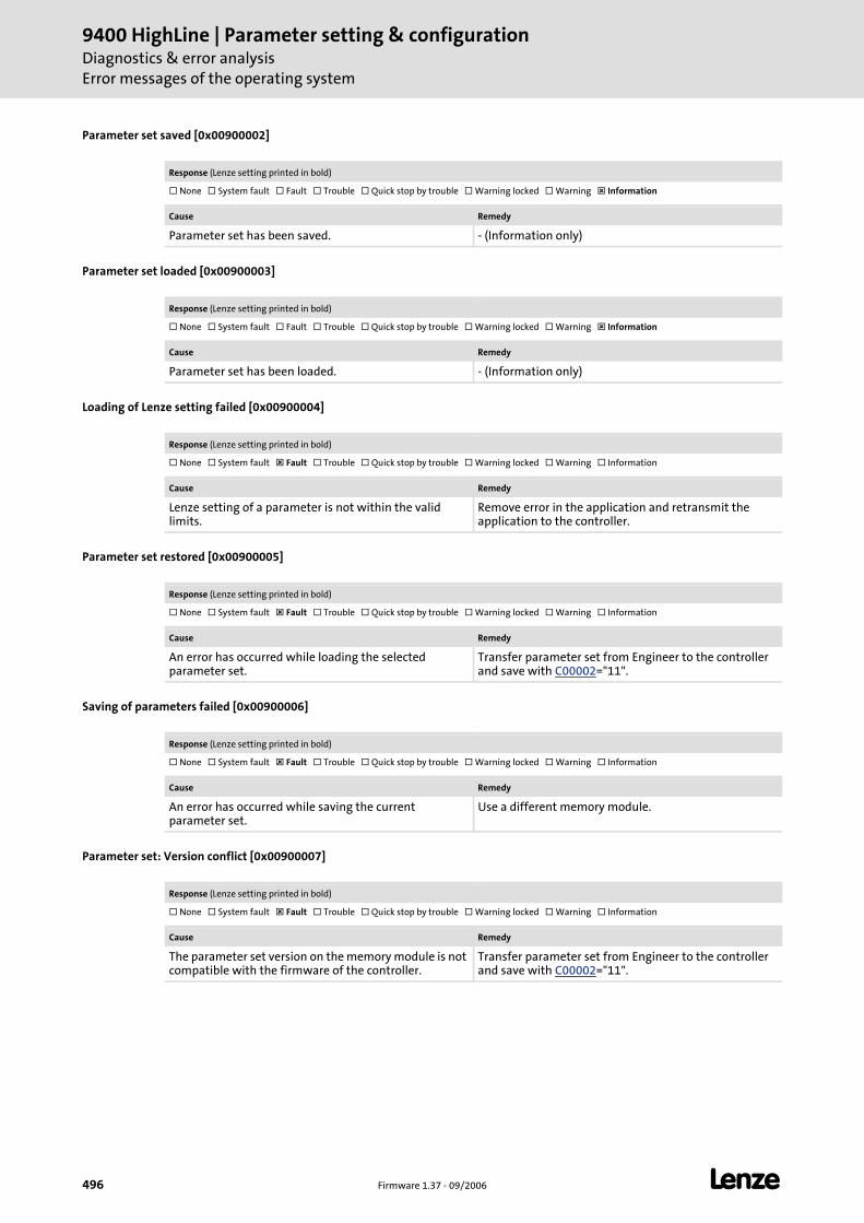
9400 HighLine | Parameter setting & configurationDiagnostics & error analysisError messages of the operating system
496 Firmware 1.37 - 09/2006 L
Parameter set saved [0x00900002]
Parameter set loaded [0x00900003]
Loading of Lenze setting failed [0x00900004]
Parameter set restored [0x00900005]
Saving of parameters failed [0x00900006]
Parameter set: Version conflict [0x00900007]
Response (Lenze setting printed in bold)
None System fault Fault Trouble Quick stop by trouble Warning locked Warning Information
Cause Remedy
Parameter set has been saved. - (Information only)
Response (Lenze setting printed in bold)
None System fault Fault Trouble Quick stop by trouble Warning locked Warning Information
Cause Remedy
Parameter set has been loaded. - (Information only)
Response (Lenze setting printed in bold)
None System fault Fault Trouble Quick stop by trouble Warning locked Warning Information
Cause Remedy
Lenze setting of a parameter is not within the valid limits.
Remove error in the application and retransmit the application to the controller.
Response (Lenze setting printed in bold)
None System fault Fault Trouble Quick stop by trouble Warning locked Warning Information
Cause Remedy
An error has occurred while loading the selected parameter set.
Transfer parameter set from Engineer to the controller and save with C00002="11".
Response (Lenze setting printed in bold)
None System fault Fault Trouble Quick stop by trouble Warning locked Warning Information
Cause Remedy
An error has occurred while saving the current parameter set.
Use a different memory module.
Response (Lenze setting printed in bold)
None System fault Fault Trouble Quick stop by trouble Warning locked Warning Information
Cause Remedy
The parameter set version on the memory module is not compatible with the firmware of the controller.
Transfer parameter set from Engineer to the controller and save with C00002="11".
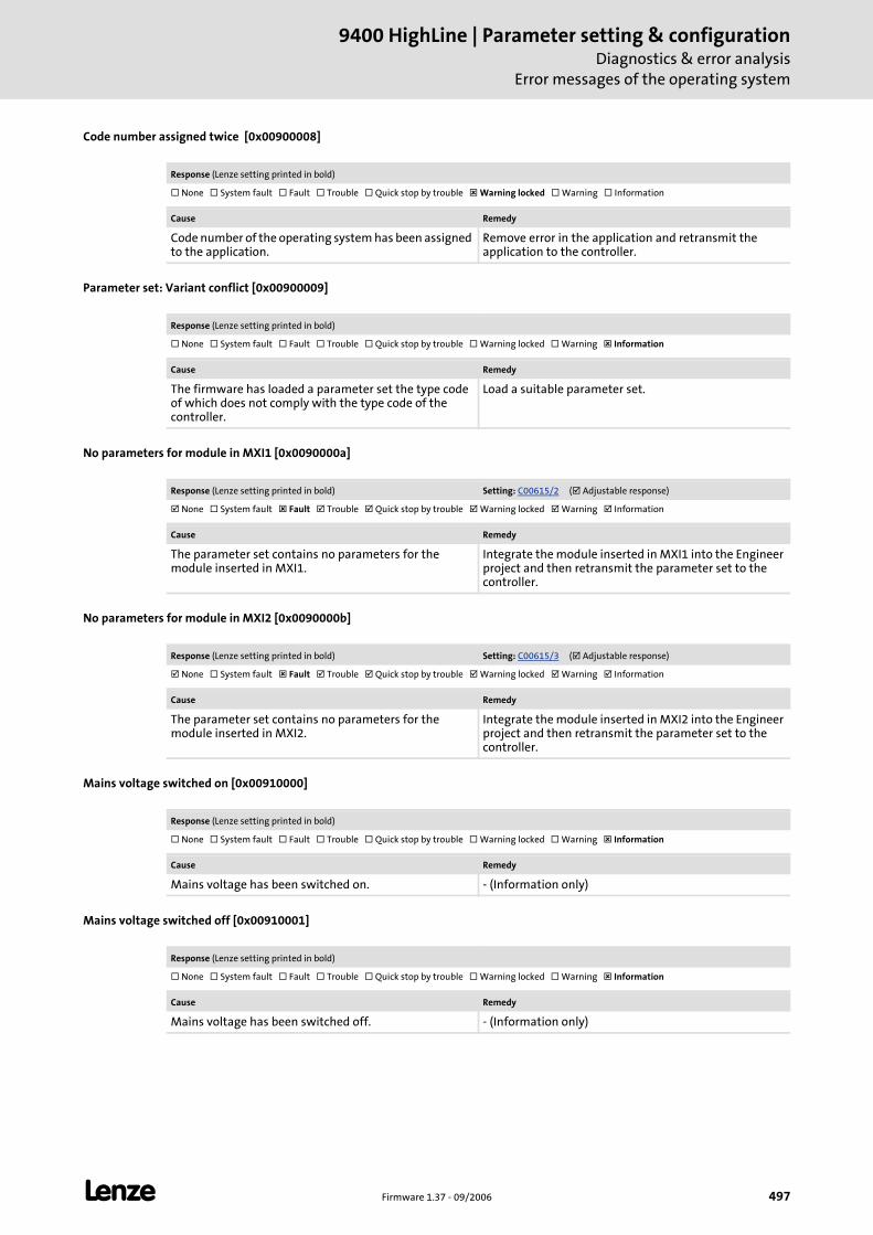
L Firmware 1.37 - 09/2006 497
9400 HighLine | Parameter setting & configurationDiagnostics & error analysis
Error messages of the operating system
Code number assigned twice [0x00900008]
Parameter set: Variant conflict [0x00900009]
No parameters for module in MXI1 [0x0090000a]
No parameters for module in MXI2 [0x0090000b]
Mains voltage switched on [0x00910000]
Mains voltage switched off [0x00910001]
Response (Lenze setting printed in bold)
None System fault Fault Trouble Quick stop by trouble Warning locked Warning Information
Cause Remedy
Code number of the operating system has been assigned to the application.
Remove error in the application and retransmit the application to the controller.
Response (Lenze setting printed in bold)
None System fault Fault Trouble Quick stop by trouble Warning locked Warning Information
Cause Remedy
The firmware has loaded a parameter set the type code of which does not comply with the type code of the controller.
Load a suitable parameter set.
Response (Lenze setting printed in bold) Setting: C00615/2 ( Adjustable response)
None System fault Fault Trouble Quick stop by trouble Warning locked Warning Information
Cause Remedy
The parameter set contains no parameters for the module inserted in MXI1.
Integrate the module inserted in MXI1 into the Engineer project and then retransmit the parameter set to the controller.
Response (Lenze setting printed in bold) Setting: C00615/3 ( Adjustable response)
None System fault Fault Trouble Quick stop by trouble Warning locked Warning Information
Cause Remedy
The parameter set contains no parameters for the module inserted in MXI2.
Integrate the module inserted in MXI2 into the Engineer project and then retransmit the parameter set to the controller.
Response (Lenze setting printed in bold)
None System fault Fault Trouble Quick stop by trouble Warning locked Warning Information
Cause Remedy
Mains voltage has been switched on. - (Information only)
Response (Lenze setting printed in bold)
None System fault Fault Trouble Quick stop by trouble Warning locked Warning Information
Cause Remedy
Mains voltage has been switched off. - (Information only)
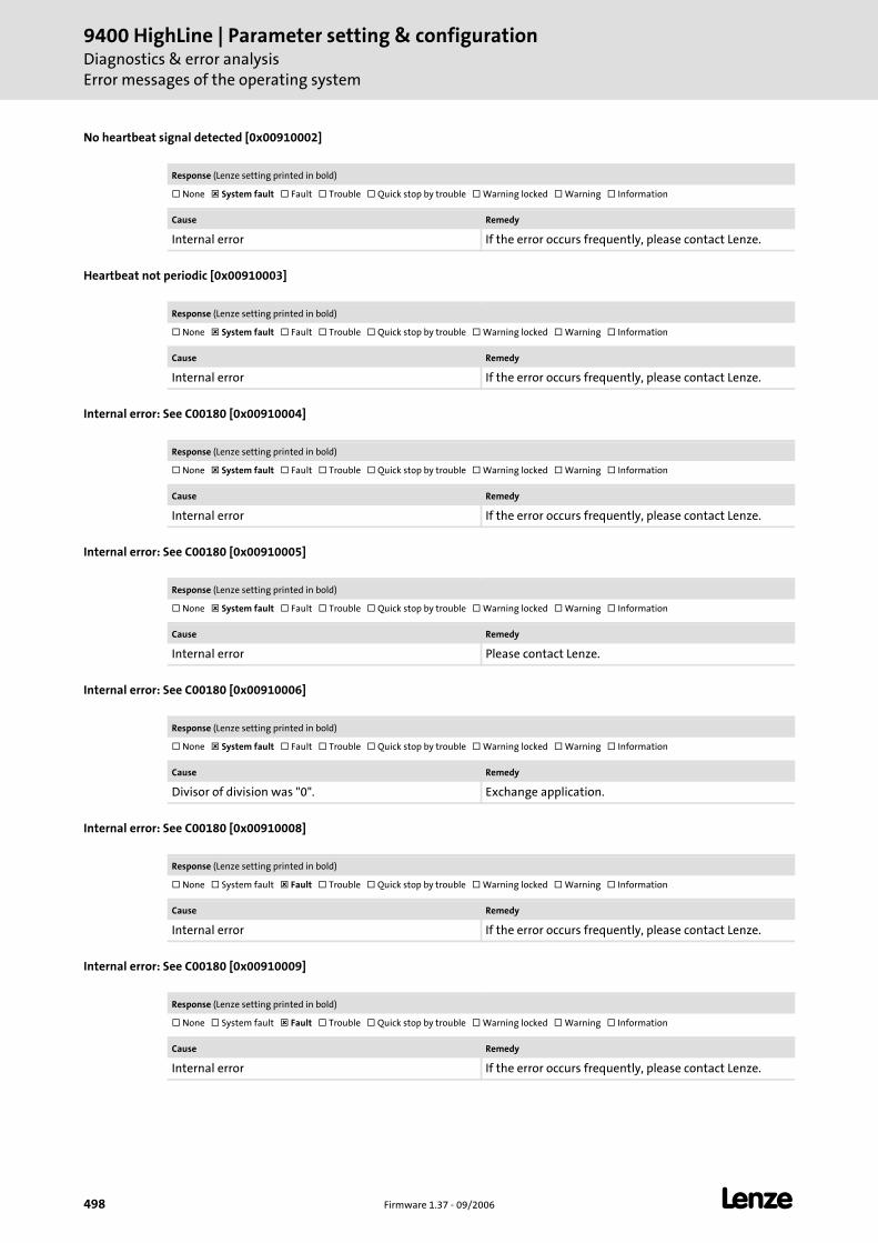
9400 HighLine | Parameter setting & configurationDiagnostics & error analysisError messages of the operating system
498 Firmware 1.37 - 09/2006 L
No heartbeat signal detected [0x00910002]
Heartbeat not periodic [0x00910003]
Internal error: See C00180 [0x00910004]
Internal error: See C00180 [0x00910005]
Internal error: See C00180 [0x00910006]
Internal error: See C00180 [0x00910008]
Internal error: See C00180 [0x00910009]
Response (Lenze setting printed in bold)
None System fault Fault Trouble Quick stop by trouble Warning locked Warning Information
Cause Remedy
Internal error If the error occurs frequently, please contact Lenze.
Response (Lenze setting printed in bold)
None System fault Fault Trouble Quick stop by trouble Warning locked Warning Information
Cause Remedy
Internal error If the error occurs frequently, please contact Lenze.
Response (Lenze setting printed in bold)
None System fault Fault Trouble Quick stop by trouble Warning locked Warning Information
Cause Remedy
Internal error If the error occurs frequently, please contact Lenze.
Response (Lenze setting printed in bold)
None System fault Fault Trouble Quick stop by trouble Warning locked Warning Information
Cause Remedy
Internal error Please contact Lenze.
Response (Lenze setting printed in bold)
None System fault Fault Trouble Quick stop by trouble Warning locked Warning Information
Cause Remedy
Divisor of division was "0". Exchange application.
Response (Lenze setting printed in bold)
None System fault Fault Trouble Quick stop by trouble Warning locked Warning Information
Cause Remedy
Internal error If the error occurs frequently, please contact Lenze.
Response (Lenze setting printed in bold)
None System fault Fault Trouble Quick stop by trouble Warning locked Warning Information
Cause Remedy
Internal error If the error occurs frequently, please contact Lenze.
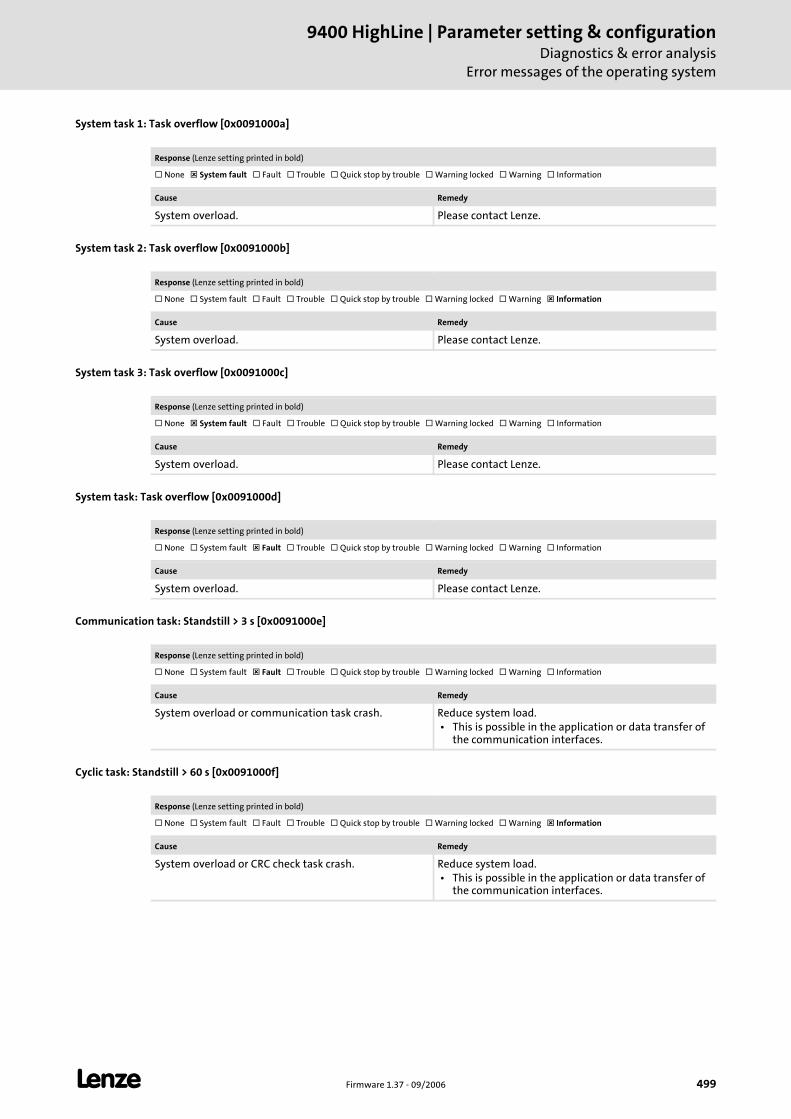
L Firmware 1.37 - 09/2006 499
9400 HighLine | Parameter setting & configurationDiagnostics & error analysis
Error messages of the operating system
System task 1: Task overflow [0x0091000a]
System task 2: Task overflow [0x0091000b]
System task 3: Task overflow [0x0091000c]
System task: Task overflow [0x0091000d]
Communication task: Standstill > 3 s [0x0091000e]
Cyclic task: Standstill > 60 s [0x0091000f]
Response (Lenze setting printed in bold)
None System fault Fault Trouble Quick stop by trouble Warning locked Warning Information
Cause Remedy
System overload. Please contact Lenze.
Response (Lenze setting printed in bold)
None System fault Fault Trouble Quick stop by trouble Warning locked Warning Information
Cause Remedy
System overload. Please contact Lenze.
Response (Lenze setting printed in bold)
None System fault Fault Trouble Quick stop by trouble Warning locked Warning Information
Cause Remedy
System overload. Please contact Lenze.
Response (Lenze setting printed in bold)
None System fault Fault Trouble Quick stop by trouble Warning locked Warning Information
Cause Remedy
System overload. Please contact Lenze.
Response (Lenze setting printed in bold)
None System fault Fault Trouble Quick stop by trouble Warning locked Warning Information
Cause Remedy
System overload or communication task crash. Reduce system load. • This is possible in the application or data transfer of
the communication interfaces.
Response (Lenze setting printed in bold)
None System fault Fault Trouble Quick stop by trouble Warning locked Warning Information
Cause Remedy
System overload or CRC check task crash. Reduce system load. • This is possible in the application or data transfer of
the communication interfaces.
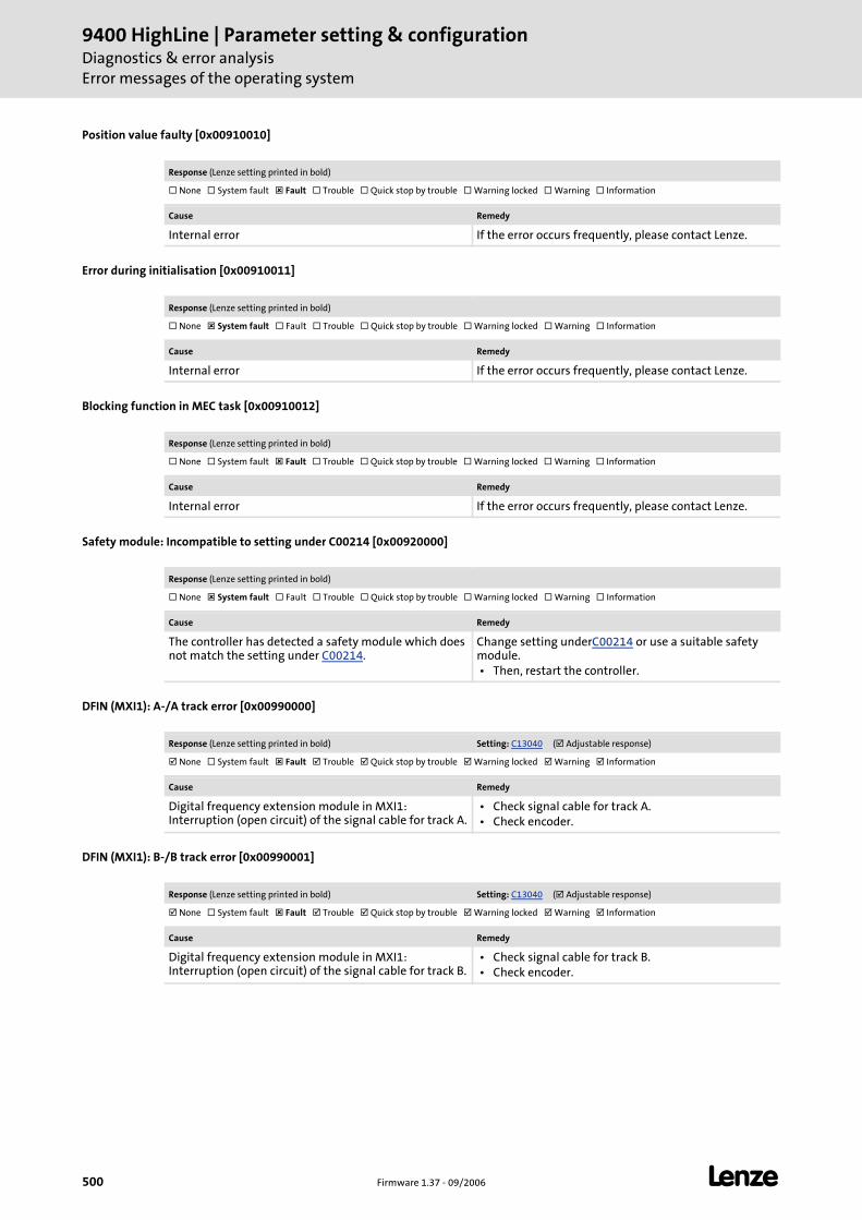
9400 HighLine | Parameter setting & configurationDiagnostics & error analysisError messages of the operating system
500 Firmware 1.37 - 09/2006 L
Position value faulty [0x00910010]
Error during initialisation [0x00910011]
Blocking function in MEC task [0x00910012]
Safety module: Incompatible to setting under C00214 [0x00920000]
DFIN (MXI1): A-/A track error [0x00990000]
DFIN (MXI1): B-/B track error [0x00990001]
Response (Lenze setting printed in bold)
None System fault Fault Trouble Quick stop by trouble Warning locked Warning Information
Cause Remedy
Internal error If the error occurs frequently, please contact Lenze.
Response (Lenze setting printed in bold)
None System fault Fault Trouble Quick stop by trouble Warning locked Warning Information
Cause Remedy
Internal error If the error occurs frequently, please contact Lenze.
Response (Lenze setting printed in bold)
None System fault Fault Trouble Quick stop by trouble Warning locked Warning Information
Cause Remedy
Internal error If the error occurs frequently, please contact Lenze.
Response (Lenze setting printed in bold)
None System fault Fault Trouble Quick stop by trouble Warning locked Warning Information
Cause Remedy
The controller has detected a safety module which does not match the setting under C00214.
Change setting underC00214 or use a suitable safety module. • Then, restart the controller.
Response (Lenze setting printed in bold) Setting: C13040 ( Adjustable response)
None System fault Fault Trouble Quick stop by trouble Warning locked Warning Information
Cause Remedy
Digital frequency extension module in MXI1: Interruption (open circuit) of the signal cable for track A.
• Check signal cable for track A. • Check encoder.
Response (Lenze setting printed in bold) Setting: C13040 ( Adjustable response)
None System fault Fault Trouble Quick stop by trouble Warning locked Warning Information
Cause Remedy
Digital frequency extension module in MXI1: Interruption (open circuit) of the signal cable for track B.
• Check signal cable for track B. • Check encoder.
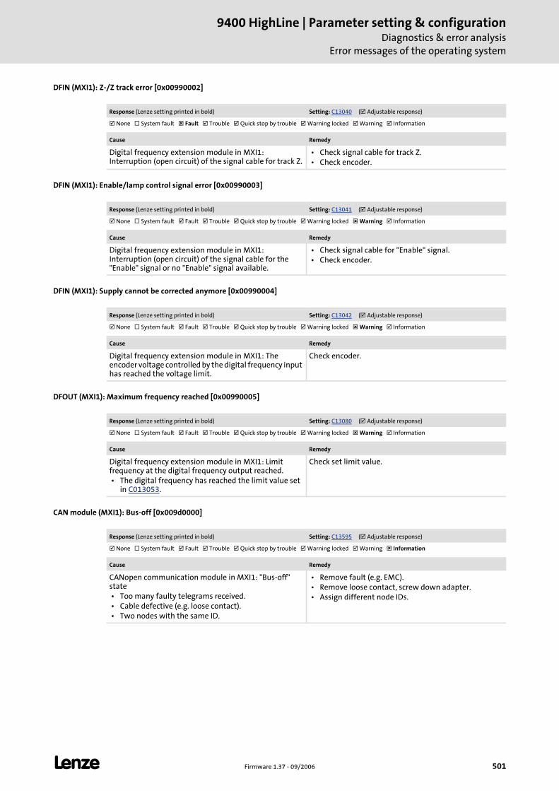
L Firmware 1.37 - 09/2006 501
9400 HighLine | Parameter setting & configurationDiagnostics & error analysis
Error messages of the operating system
DFIN (MXI1): Z-/Z track error [0x00990002]
DFIN (MXI1): Enable/lamp control signal error [0x00990003]
DFIN (MXI1): Supply cannot be corrected anymore [0x00990004]
DFOUT (MXI1): Maximum frequency reached [0x00990005]
CAN module (MXI1): Bus-off [0x009d0000]
Response (Lenze setting printed in bold) Setting: C13040 ( Adjustable response)
None System fault Fault Trouble Quick stop by trouble Warning locked Warning Information
Cause Remedy
Digital frequency extension module in MXI1: Interruption (open circuit) of the signal cable for track Z.
• Check signal cable for track Z. • Check encoder.
Response (Lenze setting printed in bold) Setting: C13041 ( Adjustable response)
None System fault Fault Trouble Quick stop by trouble Warning locked Warning Information
Cause Remedy
Digital frequency extension module in MXI1: Interruption (open circuit) of the signal cable for the "Enable" signal or no "Enable" signal available.
• Check signal cable for "Enable" signal. • Check encoder.
Response (Lenze setting printed in bold) Setting: C13042 ( Adjustable response)
None System fault Fault Trouble Quick stop by trouble Warning locked Warning Information
Cause Remedy
Digital frequency extension module in MXI1: The encoder voltage controlled by the digital frequency input has reached the voltage limit.
Check encoder.
Response (Lenze setting printed in bold) Setting: C13080 ( Adjustable response)
None System fault Fault Trouble Quick stop by trouble Warning locked Warning Information
Cause Remedy
Digital frequency extension module in MXI1: Limit frequency at the digital frequency output reached. • The digital frequency has reached the limit value set
in C013053.
Check set limit value.
Response (Lenze setting printed in bold) Setting: C13595 ( Adjustable response)
None System fault Fault Trouble Quick stop by trouble Warning locked Warning Information
Cause Remedy
CANopen communication module in MXI1: "Bus-off" state • Too many faulty telegrams received. • Cable defective (e.g. loose contact). • Two nodes with the same ID.
• Remove fault (e.g. EMC). • Remove loose contact, screw down adapter. • Assign different node IDs.

9400 HighLine | Parameter setting & configurationDiagnostics & error analysisError messages of the operating system
502 Firmware 1.37 - 09/2006 L
CAN module (MXI1): Invalid node address 0 [0x009d0001]
CAN module (MXI1): Basic configuration invalid [0x009d0002]
CAN module (MXI1): Heartbeat error index 1 [0x009e0000]
CAN module (MXI1): Heartbeat error index 2 [0x009e0001]
CAN module (MXI1): Heartbeat error index 3 [0x009e0002]
Response (Lenze setting printed in bold)
None System fault Fault Trouble Quick stop by trouble Warning locked Warning Information
Cause Remedy
CANopen communication module in MXI1: Initialisation error • The node address has been selected via DIP switch by
means of hardware and the DIP switches of the node address are set to zero.
• Note: Instead of the impermissible node address 0 the node address 1 is used.
• Use the DIP switches to set a node address unequal 0 and restart the controller.
• Activate the node number assignment by means of software by changing the position of DIP switch 2 and restart the controller.
Response (Lenze setting printed in bold)
None System fault Fault Trouble Quick stop by trouble Warning locked Warning Information
Cause Remedy
CANopen communication module in MXI1: Configuration error • Faulty download of an Engineer or PLC Designer
project • Invalid CAN settings according to DS301V402 in the
Engineer or PLC Designer.
• Repeat download • Correct CAN settings in the project and regenerate
project.
Response (Lenze setting printed in bold) Setting: C13613/1 ( Adjustable response)
None System fault Fault Trouble Quick stop by trouble Warning locked Warning Information
Cause Remedy
CANopen communication module in MXI1: Cyclic node monitoring • Node device has not received a heartbeat telegram
from node 1 within the defined time.
• Reactivate CAN node by restarting the controller, restart of the controller (C00002="11000") or CAN reset node.
• Select a different heartbeat producer monitoring time or switch off monitoring and reset locked error status, if necessary.
Tip: Safe the current parameter set before mains switching and restarting the controller (C00002="11").
Response (Lenze setting printed in bold) Setting: C13613/2 ( Adjustable response)
None System fault Fault Trouble Quick stop by trouble Warning locked Warning Information
Cause Remedy
CANopen communication module in MXI1: No heartbeat telegram received from node 2.
See remedy for "Heartbeat error index 1".
Response (Lenze setting printed in bold) Setting: C13613/3 ( Adjustable response)
None System fault Fault Trouble Quick stop by trouble Warning locked Warning Information
Cause Remedy
CANopen communication module in MXI1: No heartbeat telegram received from node 3.
See remedy for "Heartbeat error index 1".

L Firmware 1.37 - 09/2006 503
9400 HighLine | Parameter setting & configurationDiagnostics & error analysis
Error messages of the operating system
CAN module (MXI1): Heartbeat error index 4 [0x009e0003]
CAN module (MXI1): Heartbeat error index 5 [0x009e0004]
CAN module (MXI1): Heartbeat error index 6 [0x009e0005]
CAN module (MXI1): Heartbeat error index 7 [0x009e0006]
CAN module (MXI1): Heartbeat error index 8 [0x009e0007]
CAN module (MXI1): Heartbeat error index 9 [0x009e0008]
Response (Lenze setting printed in bold) Setting: C13613/4 ( Adjustable response)
None System fault Fault Trouble Quick stop by trouble Warning locked Warning Information
Cause Remedy
CANopen communication module in MXI1: No heartbeat telegram received from node 4.
See remedy for "Heartbeat error index 1".
Response (Lenze setting printed in bold) Setting: C13613/5 ( Adjustable response)
None System fault Fault Trouble Quick stop by trouble Warning locked Warning Information
Cause Remedy
CANopen communication module in MXI1: No heartbeat telegram received from node 5.
See remedy for "Heartbeat error index 1".
Response (Lenze setting printed in bold) Setting: C13613/6 ( Adjustable response)
None System fault Fault Trouble Quick stop by trouble Warning locked Warning Information
Cause Remedy
CANopen communication module in MXI1: No heartbeat telegram received from node 6.
See remedy for "Heartbeat error index 1".
Response (Lenze setting printed in bold) Setting: C13613/7 ( Adjustable response)
None System fault Fault Trouble Quick stop by trouble Warning locked Warning Information
Cause Remedy
CANopen communication module in MXI1: No heartbeat telegram received from node 7.
See remedy for "Heartbeat error index 1".
Response (Lenze setting printed in bold) Setting: C13613/8 ( Adjustable response)
None System fault Fault Trouble Quick stop by trouble Warning locked Warning Information
Cause Remedy
CANopen communication module in MXI1: No heartbeat telegram received from node 8.
See remedy for "Heartbeat error index 1".
Response (Lenze setting printed in bold) Setting: C13613/9 ( Adjustable response)
None System fault Fault Trouble Quick stop by trouble Warning locked Warning Information
Cause Remedy
CANopen communication module in MXI1: No heartbeat telegram received from node 9.
See remedy for "Heartbeat error index 1".

9400 HighLine | Parameter setting & configurationDiagnostics & error analysisError messages of the operating system
504 Firmware 1.37 - 09/2006 L
CAN module (MXI1): Heartbeat error index 10 [0x009e0009]
CAN module (MXI1): Heartbeat error index 11 [0x009e000a]
CAN module (MXI1): Heartbeat error index 12 [0x009e000b]
CAN module (MXI1): Heartbeat error index 13 [0x009e000c]
CAN module (MXI1): Heartbeat error index 14 [0x009e000d]
CAN module (MXI1): Heartbeat error index 15 [0x009e000e]
Response (Lenze setting printed in bold) Setting: C13613/10 ( Adjustable response)
None System fault Fault Trouble Quick stop by trouble Warning locked Warning Information
Cause Remedy
CANopen communication module in MXI1: No heartbeat telegram received from node 10.
See remedy for "Heartbeat error index 1".
Response (Lenze setting printed in bold) Setting: C13613/11 ( Adjustable response)
None System fault Fault Trouble Quick stop by trouble Warning locked Warning Information
Cause Remedy
CANopen communication module in MXI1: No heartbeat telegram received from node 11.
See remedy for "Heartbeat error index 1".
Response (Lenze setting printed in bold) Setting: C13613/12 ( Adjustable response)
None System fault Fault Trouble Quick stop by trouble Warning locked Warning Information
Cause Remedy
CANopen communication module in MXI1: No heartbeat telegram received from node 12.
See remedy for "Heartbeat error index 1".
Response (Lenze setting printed in bold) Setting: C13613/13 ( Adjustable response)
None System fault Fault Trouble Quick stop by trouble Warning locked Warning Information
Cause Remedy
CANopen communication module in MXI1: No heartbeat telegram received from node 13.
See remedy for "Heartbeat error index 1".
Response (Lenze setting printed in bold) Setting: C13613/14 ( Adjustable response)
None System fault Fault Trouble Quick stop by trouble Warning locked Warning Information
Cause Remedy
CANopen communication module in MXI1: No heartbeat telegram received from node 14.
See remedy for "Heartbeat error index 1".
Response (Lenze setting printed in bold) Setting: C13613/15 ( Adjustable response)
None System fault Fault Trouble Quick stop by trouble Warning locked Warning Information
Cause Remedy
CANopen communication module in MXI1: No heartbeat telegram received from node 15.
See remedy for "Heartbeat error index 1".

L Firmware 1.37 - 09/2006 505
9400 HighLine | Parameter setting & configurationDiagnostics & error analysis
Error messages of the operating system
CAN module (MXI1): Heartbeat error index 16 [0x009e000f]
CAN module (MXI1): Heartbeat error index 17 [0x009e0010]
CAN module (MXI1): Heartbeat error index 18 [0x009e0011]
CAN module (MXI1): Heartbeat error index 19 [0x009e0012]
CAN module (MXI1): Heartbeat error index 20 [0x009e0013]
CAN module (MXI1): Heartbeat error index 21 [0x009e0014]
Response (Lenze setting printed in bold) Setting: C13613/16 ( Adjustable response)
None System fault Fault Trouble Quick stop by trouble Warning locked Warning Information
Cause Remedy
CANopen communication module in MXI1: No heartbeat telegram received from node 16.
See remedy for "Heartbeat error index 1".
Response (Lenze setting printed in bold) Setting: C13613/17 ( Adjustable response)
None System fault Fault Trouble Quick stop by trouble Warning locked Warning Information
Cause Remedy
CANopen communication module in MXI1: No heartbeat telegram received from node 17.
See remedy for "Heartbeat error index 1".
Response (Lenze setting printed in bold) Setting: C13613/18 ( Adjustable response)
None System fault Fault Trouble Quick stop by trouble Warning locked Warning Information
Cause Remedy
CANopen communication module in MXI1: No heartbeat telegram received from node 18.
See remedy for "Heartbeat error index 1".
Response (Lenze setting printed in bold) Setting: C13613/19 ( Adjustable response)
None System fault Fault Trouble Quick stop by trouble Warning locked Warning Information
Cause Remedy
CANopen communication module in MXI1: No heartbeat telegram received from node 19.
See remedy for "Heartbeat error index 1".
Response (Lenze setting printed in bold) Setting: C13613/20 ( Adjustable response)
None System fault Fault Trouble Quick stop by trouble Warning locked Warning Information
Cause Remedy
CANopen communication module in MXI1: No heartbeat telegram received from node 20.
See remedy for "Heartbeat error index 1".
Response (Lenze setting printed in bold) Setting: C13613/21 ( Adjustable response)
None System fault Fault Trouble Quick stop by trouble Warning locked Warning Information
Cause Remedy
CANopen communication module in MXI1: No heartbeat telegram received from node 21.
See remedy for "Heartbeat error index 1".
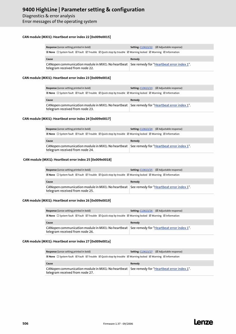
9400 HighLine | Parameter setting & configurationDiagnostics & error analysisError messages of the operating system
506 Firmware 1.37 - 09/2006 L
CAN module (MXI1): Heartbeat error index 22 [0x009e0015]
CAN module (MXI1): Heartbeat error index 23 [0x009e0016]
CAN module (MXI1): Heartbeat error index 24 [0x009e0017]
CAN module (MXI1): Heartbeat error index 25 [0x009e0018]
CAN module (MXI1): Heartbeat error index 26 [0x009e0019]
CAN module (MXI1): Heartbeat error index 27 [0x009e001a]
Response (Lenze setting printed in bold) Setting: C13613/22 ( Adjustable response)
None System fault Fault Trouble Quick stop by trouble Warning locked Warning Information
Cause Remedy
CANopen communication module in MXI1: No heartbeat telegram received from node 22.
See remedy for "Heartbeat error index 1".
Response (Lenze setting printed in bold) Setting: C13613/23 ( Adjustable response)
None System fault Fault Trouble Quick stop by trouble Warning locked Warning Information
Cause Remedy
CANopen communication module in MXI1: No heartbeat telegram received from node 23.
See remedy for "Heartbeat error index 1".
Response (Lenze setting printed in bold) Setting: C13613/24 ( Adjustable response)
None System fault Fault Trouble Quick stop by trouble Warning locked Warning Information
Cause Remedy
CANopen communication module in MXI1: No heartbeat telegram received from node 24.
See remedy for "Heartbeat error index 1".
Response (Lenze setting printed in bold) Setting: C13613/25 ( Adjustable response)
None System fault Fault Trouble Quick stop by trouble Warning locked Warning Information
Cause Remedy
CANopen communication module in MXI1: No heartbeat telegram received from node 25.
See remedy for "Heartbeat error index 1".
Response (Lenze setting printed in bold) Setting: C13613/26 ( Adjustable response)
None System fault Fault Trouble Quick stop by trouble Warning locked Warning Information
Cause Remedy
CANopen communication module in MXI1: No heartbeat telegram received from node 26.
See remedy for "Heartbeat error index 1".
Response (Lenze setting printed in bold) Setting: C13613/27 ( Adjustable response)
None System fault Fault Trouble Quick stop by trouble Warning locked Warning Information
Cause Remedy
CANopen communication module in MXI1: No heartbeat telegram received from node 27.
See remedy for "Heartbeat error index 1".

L Firmware 1.37 - 09/2006 507
9400 HighLine | Parameter setting & configurationDiagnostics & error analysis
Error messages of the operating system
CAN module (MXI1): Heartbeat error index 28 [0x009e001b]
CAN module (MXI1): Heartbeat error index 29 [0x009e001c]
CAN module (MXI1): Heartbeat error index 30 [0x009e001d]
CAN module (MXI1): Heartbeat error index 31 [0x009e001e]
CAN module (MXI1): Heartbeat error index 32 [0x009e001f]
CAN module (MXI1): Life guarding error [0x009e0020]
Response (Lenze setting printed in bold) Setting: C13613/28 ( Adjustable response)
None System fault Fault Trouble Quick stop by trouble Warning locked Warning Information
Cause Remedy
CANopen communication module in MXI1: No heartbeat telegram received from node 28.
See remedy for "Heartbeat error index 1".
Response (Lenze setting printed in bold) Setting: C13613/29 ( Adjustable response)
None System fault Fault Trouble Quick stop by trouble Warning locked Warning Information
Cause Remedy
CANopen communication module in MXI1: No heartbeat telegram received from node 29.
See remedy for "Heartbeat error index 1".
Response (Lenze setting printed in bold) Setting: C13613/30 ( Adjustable response)
None System fault Fault Trouble Quick stop by trouble Warning locked Warning Information
Cause Remedy
CANopen communication module in MXI1: No heartbeat telegram received from node 30.
See remedy for "Heartbeat error index 1".
Response (Lenze setting printed in bold) Setting: C13613/31 ( Adjustable response)
None System fault Fault Trouble Quick stop by trouble Warning locked Warning Information
Cause Remedy
CANopen communication module in MXI1: No heartbeat telegram received from node 31.
See remedy for "Heartbeat error index 1".
Response (Lenze setting printed in bold) Setting: C13613/32 ( Adjustable response)
None System fault Fault Trouble Quick stop by trouble Warning locked Warning Information
Cause Remedy
CANopen communication module in MXI1: No heartbeat telegram received from node 32.
See remedy for "Heartbeat error index 1".
Response (Lenze setting printed in bold) Setting: C13614 ( Adjustable response)
None System fault Fault Trouble Quick stop by trouble Warning locked Warning Information
Cause Remedy
CANopen communication module in MXI1: Cyclic node monitoring • Slave response: Maximum time between two node
guarding telegrams (remote transmission request telegram) from the master has been exceeded.
Select a different life guarding monitoring time or switch off monitoring.
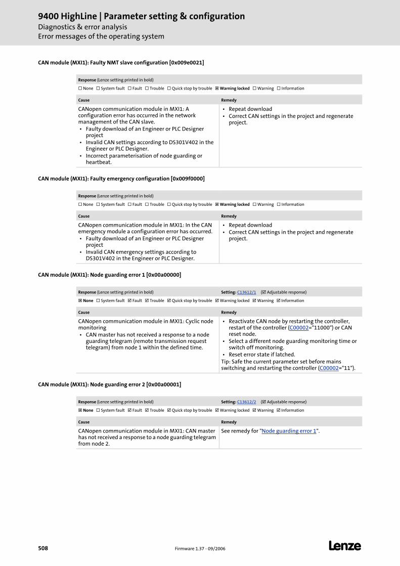
9400 HighLine | Parameter setting & configurationDiagnostics & error analysisError messages of the operating system
508 Firmware 1.37 - 09/2006 L
CAN module (MXI1): Faulty NMT slave configuration [0x009e0021]
CAN module (MXI1): Faulty emergency configuration [0x009f0000]
CAN module (MXI1): Node guarding error 1 [0x00a00000]
CAN module (MXI1): Node guarding error 2 [0x00a00001]
Response (Lenze setting printed in bold)
None System fault Fault Trouble Quick stop by trouble Warning locked Warning Information
Cause Remedy
CANopen communication module in MXI1: A configuration error has occurred in the network management of the CAN slave. • Faulty download of an Engineer or PLC Designer
project • Invalid CAN settings according to DS301V402 in the
Engineer or PLC Designer. • Incorrect parameterisation of node guarding or
heartbeat.
• Repeat download • Correct CAN settings in the project and regenerate
project.
Response (Lenze setting printed in bold)
None System fault Fault Trouble Quick stop by trouble Warning locked Warning Information
Cause Remedy
CANopen communication module in MXI1: In the CAN emergency module a configuration error has occurred. • Faulty download of an Engineer or PLC Designer
project • Invalid CAN emergency settings according to
DS301V402 in the Engineer or PLC Designer.
• Repeat download • Correct CAN settings in the project and regenerate
project.
Response (Lenze setting printed in bold) Setting: C13612/1 ( Adjustable response)
None System fault Fault Trouble Quick stop by trouble Warning locked Warning Information
Cause Remedy
CANopen communication module in MXI1: Cyclic node monitoring • CAN master has not received a response to a node
guarding telegram (remote transmission request telegram) from node 1 within the defined time.
• Reactivate CAN node by restarting the controller, restart of the controller (C00002="11000") or CAN reset node.
• Select a different node guarding monitoring time or switch off monitoring.
• Reset error state if latched.Tip: Safe the current parameter set before mains switching and restarting the controller (C00002="11").
Response (Lenze setting printed in bold) Setting: C13612/2 ( Adjustable response)
None System fault Fault Trouble Quick stop by trouble Warning locked Warning Information
Cause Remedy
CANopen communication module in MXI1: CAN master has not received a response to a node guarding telegram from node 2.
See remedy for "Node guarding error 1".
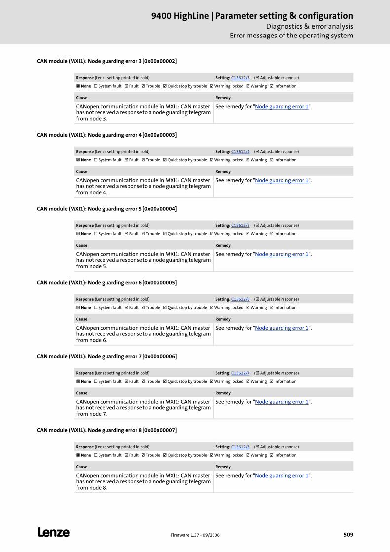
L Firmware 1.37 - 09/2006 509
9400 HighLine | Parameter setting & configurationDiagnostics & error analysis
Error messages of the operating system
CAN module (MXI1): Node guarding error 3 [0x00a00002]
CAN module (MXI1): Node guarding error 4 [0x00a00003]
CAN module (MXI1): Node guarding error 5 [0x00a00004]
CAN module (MXI1): Node guarding error 6 [0x00a00005]
CAN module (MXI1): Node guarding error 7 [0x00a00006]
CAN module (MXI1): Node guarding error 8 [0x00a00007]
Response (Lenze setting printed in bold) Setting: C13612/3 ( Adjustable response)
None System fault Fault Trouble Quick stop by trouble Warning locked Warning Information
Cause Remedy
CANopen communication module in MXI1: CAN master has not received a response to a node guarding telegram from node 3.
See remedy for "Node guarding error 1".
Response (Lenze setting printed in bold) Setting: C13612/4 ( Adjustable response)
None System fault Fault Trouble Quick stop by trouble Warning locked Warning Information
Cause Remedy
CANopen communication module in MXI1: CAN master has not received a response to a node guarding telegram from node 4.
See remedy for "Node guarding error 1".
Response (Lenze setting printed in bold) Setting: C13612/5 ( Adjustable response)
None System fault Fault Trouble Quick stop by trouble Warning locked Warning Information
Cause Remedy
CANopen communication module in MXI1: CAN master has not received a response to a node guarding telegram from node 5.
See remedy for "Node guarding error 1".
Response (Lenze setting printed in bold) Setting: C13612/6 ( Adjustable response)
None System fault Fault Trouble Quick stop by trouble Warning locked Warning Information
Cause Remedy
CANopen communication module in MXI1: CAN master has not received a response to a node guarding telegram from node 6.
See remedy for "Node guarding error 1".
Response (Lenze setting printed in bold) Setting: C13612/7 ( Adjustable response)
None System fault Fault Trouble Quick stop by trouble Warning locked Warning Information
Cause Remedy
CANopen communication module in MXI1: CAN master has not received a response to a node guarding telegram from node 7.
See remedy for "Node guarding error 1".
Response (Lenze setting printed in bold) Setting: C13612/8 ( Adjustable response)
None System fault Fault Trouble Quick stop by trouble Warning locked Warning Information
Cause Remedy
CANopen communication module in MXI1: CAN master has not received a response to a node guarding telegram from node 8.
See remedy for "Node guarding error 1".
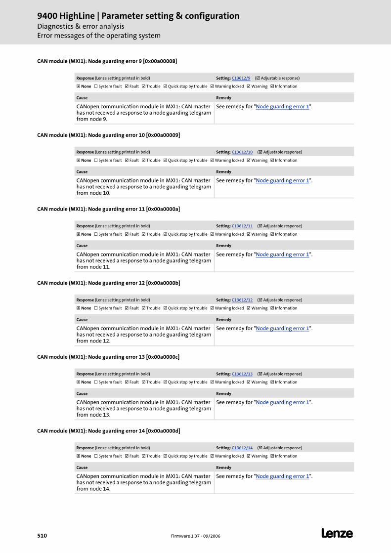
9400 HighLine | Parameter setting & configurationDiagnostics & error analysisError messages of the operating system
510 Firmware 1.37 - 09/2006 L
CAN module (MXI1): Node guarding error 9 [0x00a00008]
CAN module (MXI1): Node guarding error 10 [0x00a00009]
CAN module (MXI1): Node guarding error 11 [0x00a0000a]
CAN module (MXI1): Node guarding error 12 [0x00a0000b]
CAN module (MXI1): Node guarding error 13 [0x00a0000c]
CAN module (MXI1): Node guarding error 14 [0x00a0000d]
Response (Lenze setting printed in bold) Setting: C13612/9 ( Adjustable response)
None System fault Fault Trouble Quick stop by trouble Warning locked Warning Information
Cause Remedy
CANopen communication module in MXI1: CAN master has not received a response to a node guarding telegram from node 9.
See remedy for "Node guarding error 1".
Response (Lenze setting printed in bold) Setting: C13612/10 ( Adjustable response)
None System fault Fault Trouble Quick stop by trouble Warning locked Warning Information
Cause Remedy
CANopen communication module in MXI1: CAN master has not received a response to a node guarding telegram from node 10.
See remedy for "Node guarding error 1".
Response (Lenze setting printed in bold) Setting: C13612/11 ( Adjustable response)
None System fault Fault Trouble Quick stop by trouble Warning locked Warning Information
Cause Remedy
CANopen communication module in MXI1: CAN master has not received a response to a node guarding telegram from node 11.
See remedy for "Node guarding error 1".
Response (Lenze setting printed in bold) Setting: C13612/12 ( Adjustable response)
None System fault Fault Trouble Quick stop by trouble Warning locked Warning Information
Cause Remedy
CANopen communication module in MXI1: CAN master has not received a response to a node guarding telegram from node 12.
See remedy for "Node guarding error 1".
Response (Lenze setting printed in bold) Setting: C13612/13 ( Adjustable response)
None System fault Fault Trouble Quick stop by trouble Warning locked Warning Information
Cause Remedy
CANopen communication module in MXI1: CAN master has not received a response to a node guarding telegram from node 13.
See remedy for "Node guarding error 1".
Response (Lenze setting printed in bold) Setting: C13612/14 ( Adjustable response)
None System fault Fault Trouble Quick stop by trouble Warning locked Warning Information
Cause Remedy
CANopen communication module in MXI1: CAN master has not received a response to a node guarding telegram from node 14.
See remedy for "Node guarding error 1".
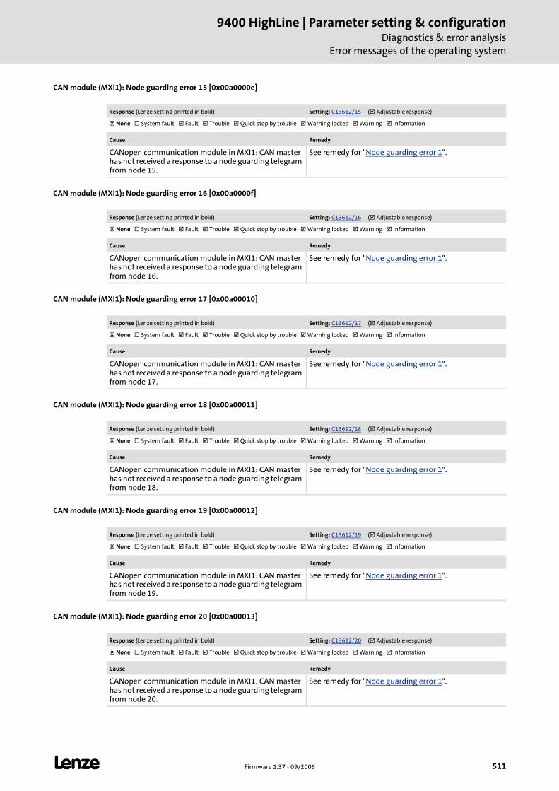
L Firmware 1.37 - 09/2006 511
9400 HighLine | Parameter setting & configurationDiagnostics & error analysis
Error messages of the operating system
CAN module (MXI1): Node guarding error 15 [0x00a0000e]
CAN module (MXI1): Node guarding error 16 [0x00a0000f]
CAN module (MXI1): Node guarding error 17 [0x00a00010]
CAN module (MXI1): Node guarding error 18 [0x00a00011]
CAN module (MXI1): Node guarding error 19 [0x00a00012]
CAN module (MXI1): Node guarding error 20 [0x00a00013]
Response (Lenze setting printed in bold) Setting: C13612/15 ( Adjustable response)
None System fault Fault Trouble Quick stop by trouble Warning locked Warning Information
Cause Remedy
CANopen communication module in MXI1: CAN master has not received a response to a node guarding telegram from node 15.
See remedy for "Node guarding error 1".
Response (Lenze setting printed in bold) Setting: C13612/16 ( Adjustable response)
None System fault Fault Trouble Quick stop by trouble Warning locked Warning Information
Cause Remedy
CANopen communication module in MXI1: CAN master has not received a response to a node guarding telegram from node 16.
See remedy for "Node guarding error 1".
Response (Lenze setting printed in bold) Setting: C13612/17 ( Adjustable response)
None System fault Fault Trouble Quick stop by trouble Warning locked Warning Information
Cause Remedy
CANopen communication module in MXI1: CAN master has not received a response to a node guarding telegram from node 17.
See remedy for "Node guarding error 1".
Response (Lenze setting printed in bold) Setting: C13612/18 ( Adjustable response)
None System fault Fault Trouble Quick stop by trouble Warning locked Warning Information
Cause Remedy
CANopen communication module in MXI1: CAN master has not received a response to a node guarding telegram from node 18.
See remedy for "Node guarding error 1".
Response (Lenze setting printed in bold) Setting: C13612/19 ( Adjustable response)
None System fault Fault Trouble Quick stop by trouble Warning locked Warning Information
Cause Remedy
CANopen communication module in MXI1: CAN master has not received a response to a node guarding telegram from node 19.
See remedy for "Node guarding error 1".
Response (Lenze setting printed in bold) Setting: C13612/20 ( Adjustable response)
None System fault Fault Trouble Quick stop by trouble Warning locked Warning Information
Cause Remedy
CANopen communication module in MXI1: CAN master has not received a response to a node guarding telegram from node 20.
See remedy for "Node guarding error 1".
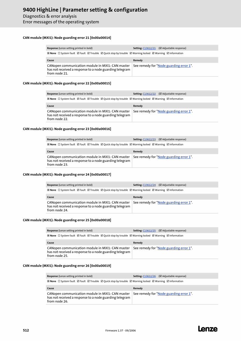
9400 HighLine | Parameter setting & configurationDiagnostics & error analysisError messages of the operating system
512 Firmware 1.37 - 09/2006 L
CAN module (MXI1): Node guarding error 21 [0x00a00014]
CAN module (MXI1): Node guarding error 22 [0x00a00015]
CAN module (MXI1): Node guarding error 23 [0x00a00016]
CAN module (MXI1): Node guarding error 24 [0x00a00017]
CAN module (MXI1): Node guarding error 25 [0x00a00018]
CAN module (MXI1): Node guarding error 26 [0x00a00019]
Response (Lenze setting printed in bold) Setting: C13612/21 ( Adjustable response)
None System fault Fault Trouble Quick stop by trouble Warning locked Warning Information
Cause Remedy
CANopen communication module in MXI1: CAN master has not received a response to a node guarding telegram from node 21.
See remedy for "Node guarding error 1".
Response (Lenze setting printed in bold) Setting: C13612/22 ( Adjustable response)
None System fault Fault Trouble Quick stop by trouble Warning locked Warning Information
Cause Remedy
CANopen communication module in MXI1: CAN master has not received a response to a node guarding telegram from node 22.
See remedy for "Node guarding error 1".
Response (Lenze setting printed in bold) Setting: C13612/23 ( Adjustable response)
None System fault Fault Trouble Quick stop by trouble Warning locked Warning Information
Cause Remedy
CANopen communication module in MXI1: CAN master has not received a response to a node guarding telegram from node 23.
See remedy for "Node guarding error 1".
Response (Lenze setting printed in bold) Setting: C13612/24 ( Adjustable response)
None System fault Fault Trouble Quick stop by trouble Warning locked Warning Information
Cause Remedy
CANopen communication module in MXI1: CAN master has not received a response to a node guarding telegram from node 24.
See remedy for "Node guarding error 1".
Response (Lenze setting printed in bold) Setting: C13612/25 ( Adjustable response)
None System fault Fault Trouble Quick stop by trouble Warning locked Warning Information
Cause Remedy
CANopen communication module in MXI1: CAN master has not received a response to a node guarding telegram from node 25.
See remedy for "Node guarding error 1".
Response (Lenze setting printed in bold) Setting: C13612/26 ( Adjustable response)
None System fault Fault Trouble Quick stop by trouble Warning locked Warning Information
Cause Remedy
CANopen communication module in MXI1: CAN master has not received a response to a node guarding telegram from node 26.
See remedy for "Node guarding error 1".
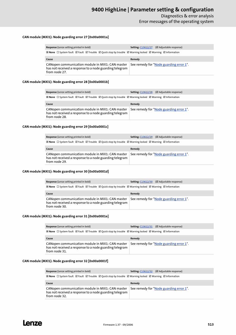
L Firmware 1.37 - 09/2006 513
9400 HighLine | Parameter setting & configurationDiagnostics & error analysis
Error messages of the operating system
CAN module (MXI1): Node guarding error 27 [0x00a0001a]
CAN module (MXI1): Node guarding error 28 [0x00a0001b]
CAN module (MXI1): Node guarding error 29 [0x00a0001c]
CAN module (MXI1): Node guarding error 30 [0x00a0001d]
CAN module (MXI1): Node guarding error 31 [0x00a0001e]
CAN module (MXI1): Node guarding error 32 [0x00a0001f]
Response (Lenze setting printed in bold) Setting: C13612/27 ( Adjustable response)
None System fault Fault Trouble Quick stop by trouble Warning locked Warning Information
Cause Remedy
CANopen communication module in MXI1: CAN master has not received a response to a node guarding telegram from node 27.
See remedy for "Node guarding error 1".
Response (Lenze setting printed in bold) Setting: C13612/28 ( Adjustable response)
None System fault Fault Trouble Quick stop by trouble Warning locked Warning Information
Cause Remedy
CANopen communication module in MXI1: CAN master has not received a response to a node guarding telegram from node 28.
See remedy for "Node guarding error 1".
Response (Lenze setting printed in bold) Setting: C13612/29 ( Adjustable response)
None System fault Fault Trouble Quick stop by trouble Warning locked Warning Information
Cause Remedy
CANopen communication module in MXI1: CAN master has not received a response to a node guarding telegram from node 29.
See remedy for "Node guarding error 1".
Response (Lenze setting printed in bold) Setting: C13612/30 ( Adjustable response)
None System fault Fault Trouble Quick stop by trouble Warning locked Warning Information
Cause Remedy
CANopen communication module in MXI1: CAN master has not received a response to a node guarding telegram from node 30.
See remedy for "Node guarding error 1".
Response (Lenze setting printed in bold) Setting: C13612/31 ( Adjustable response)
None System fault Fault Trouble Quick stop by trouble Warning locked Warning Information
Cause Remedy
CANopen communication module in MXI1: CAN master has not received a response to a node guarding telegram from node 31.
See remedy for "Node guarding error 1".
Response (Lenze setting printed in bold) Setting: C13612/32 ( Adjustable response)
None System fault Fault Trouble Quick stop by trouble Warning locked Warning Information
Cause Remedy
CANopen communication module in MXI1: CAN master has not received a response to a node guarding telegram from node 32.
See remedy for "Node guarding error 1".
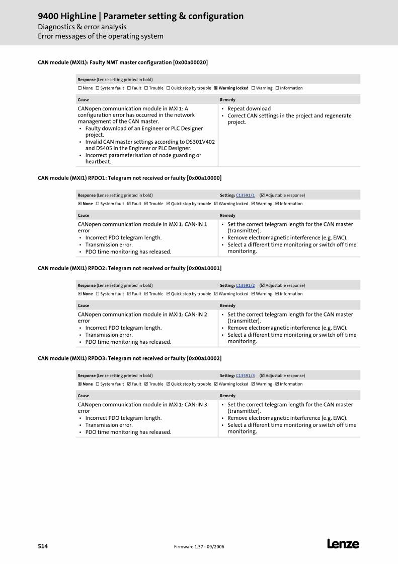
9400 HighLine | Parameter setting & configurationDiagnostics & error analysisError messages of the operating system
514 Firmware 1.37 - 09/2006 L
CAN module (MXI1): Faulty NMT master configuration [0x00a00020]
CAN module (MXI1) RPDO1: Telegram not received or faulty [0x00a10000]
CAN module (MXI1) RPDO2: Telegram not received or faulty [0x00a10001]
CAN module (MXI1) RPDO3: Telegram not received or faulty [0x00a10002]
Response (Lenze setting printed in bold)
None System fault Fault Trouble Quick stop by trouble Warning locked Warning Information
Cause Remedy
CANopen communication module in MXI1: A configuration error has occurred in the network management of the CAN master. • Faulty download of an Engineer or PLC Designer
project. • Invalid CAN master settings according to DS301V402
and DS405 in the Engineer or PLC Designer. • Incorrect parameterisation of node guarding or
heartbeat.
• Repeat download • Correct CAN settings in the project and regenerate
project.
Response (Lenze setting printed in bold) Setting: C13591/1 ( Adjustable response)
None System fault Fault Trouble Quick stop by trouble Warning locked Warning Information
Cause Remedy
CANopen communication module in MXI1: CAN-IN 1 error • Incorrect PDO telegram length. • Transmission error. • PDO time monitoring has released.
• Set the correct telegram length for the CAN master (transmitter).
• Remove electromagnetic interference (e.g. EMC). • Select a different time monitoring or switch off time
monitoring.
Response (Lenze setting printed in bold) Setting: C13591/2 ( Adjustable response)
None System fault Fault Trouble Quick stop by trouble Warning locked Warning Information
Cause Remedy
CANopen communication module in MXI1: CAN-IN 2 error • Incorrect PDO telegram length. • Transmission error. • PDO time monitoring has released.
• Set the correct telegram length for the CAN master (transmitter).
• Remove electromagnetic interference (e.g. EMC). • Select a different time monitoring or switch off time
monitoring.
Response (Lenze setting printed in bold) Setting: C13591/3 ( Adjustable response)
None System fault Fault Trouble Quick stop by trouble Warning locked Warning Information
Cause Remedy
CANopen communication module in MXI1: CAN-IN 3 error • Incorrect PDO telegram length. • Transmission error. • PDO time monitoring has released.
• Set the correct telegram length for the CAN master (transmitter).
• Remove electromagnetic interference (e.g. EMC). • Select a different time monitoring or switch off time
monitoring.
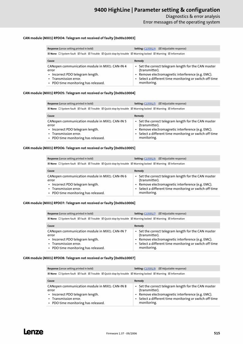
L Firmware 1.37 - 09/2006 515
9400 HighLine | Parameter setting & configurationDiagnostics & error analysis
Error messages of the operating system
CAN module (MXI1) RPDO4: Telegram not received of faulty [0x00a10003]
CAN module (MXI1) RPDO5: Telegram not received or faulty [0x00a10004]
CAN module (MXI1) RPDO6: Telegram not received or faulty [0x00a10005]
CAN module (MXI1) RPDO7: Telegram not received or faulty [0x00a10006]
CAN module (MXI1) RPDO8: Telegram not received or faulty [0x00a10007]
Response (Lenze setting printed in bold) Setting: C13591/4 ( Adjustable response)
None System fault Fault Trouble Quick stop by trouble Warning locked Warning Information
Cause Remedy
CANopen communication module in MXI1: CAN-IN 4 error • Incorrect PDO telegram length. • Transmission error. • PDO time monitoring has released.
• Set the correct telegram length for the CAN master (transmitter).
• Remove electromagnetic interference (e.g. EMC). • Select a different time monitoring or switch off time
monitoring.
Response (Lenze setting printed in bold) Setting: C13591/5 ( Adjustable response)
None System fault Fault Trouble Quick stop by trouble Warning locked Warning Information
Cause Remedy
CANopen communication module in MXI1: CAN-IN 5 error • Incorrect PDO telegram length. • Transmission error. • PDO time monitoring has released.
• Set the correct telegram length for the CAN master (transmitter).
• Remove electromagnetic interference (e.g. EMC). • Select a different time monitoring or switch off time
monitoring.
Response (Lenze setting printed in bold) Setting: C13591/6 ( Adjustable response)
None System fault Fault Trouble Quick stop by trouble Warning locked Warning Information
Cause Remedy
CANopen communication module in MXI1: CAN-IN 6 error • Incorrect PDO telegram length. • Transmission error. • PDO time monitoring has released.
• Set the correct telegram length for the CAN master (transmitter).
• Remove electromagnetic interference (e.g. EMC). • Select a different time monitoring or switch off time
monitoring.
Response (Lenze setting printed in bold) Setting: C13591/7 ( Adjustable response)
None System fault Fault Trouble Quick stop by trouble Warning locked Warning Information
Cause Remedy
CANopen communication module in MXI1: CAN-IN 7 error • Incorrect PDO telegram length. • Transmission error. • PDO time monitoring has released.
• Set the correct telegram length for the CAN master (transmitter).
• Remove electromagnetic interference (e.g. EMC). • Select a different time monitoring or switch off time
monitoring.
Response (Lenze setting printed in bold) Setting: C13591/8 ( Adjustable response)
None System fault Fault Trouble Quick stop by trouble Warning locked Warning Information
Cause Remedy
CANopen communication module in MXI1: CAN-IN 8 error • Incorrect PDO telegram length. • Transmission error. • PDO time monitoring has released.
• Set the correct telegram length for the CAN master (transmitter).
• Remove electromagnetic interference (e.g. EMC). • Select a different time monitoring or switch off time
monitoring.
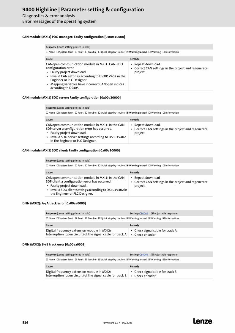
9400 HighLine | Parameter setting & configurationDiagnostics & error analysisError messages of the operating system
516 Firmware 1.37 - 09/2006 L
CAN module (MXI1) PDO manager: Faulty configuration [0x00a10008]
CAN module (MXI1) SDO server: Faulty configuration [0x00a20000]
CAN module (MXI1) SDO client: Faulty configuration [0x00a30000]
DFIN (MXI2): A-/A track error [0x00aa0000]
DFIN (MXI2): B-/B track error [0x00aa0001]
Response (Lenze setting printed in bold)
None System fault Fault Trouble Quick stop by trouble Warning locked Warning Information
Cause Remedy
CANopen communication module in MXI1: CAN-PDO configuration error • Faulty project download. • Invalid CAN settings according to DS301V402 in the
Engineer or PLC Designer. • Mapping variables have incorrect CANopen indices
according to DS405.
• Repeat download. • Correct CAN settings in the project and regenerate
project.
Response (Lenze setting printed in bold)
None System fault Fault Trouble Quick stop by trouble Warning locked Warning Information
Cause Remedy
CANopen communication module in MXI1: In the CAN SDP server a configuration error has occurred. • Faulty project download. • Invalid SDO server settings according to DS301V402
in the Engineer or PLC Designer.
• Repeat download. • Correct CAN settings in the project and regenerate
project.
Response (Lenze setting printed in bold)
None System fault Fault Trouble Quick stop by trouble Warning locked Warning Information
Cause Remedy
CANopen communication module in MXI1: In the CAN SDP client a configuration error has occurred. • Faulty project download. • Invalid SDO client settings according to DS301V402 in
the Engineer or PLC Designer.
• Repeat download • Correct CAN settings in the project and regenerate
project.
Response (Lenze setting printed in bold) Setting: C14040 ( Adjustable response)
None System fault Fault Trouble Quick stop by trouble Warning locked Warning Information
Cause Remedy
Digital frequency extension module in MXI2: Interruption (open circuit) of the signal cable for track A.
• Check signal cable for track A. • Check encoder.
Response (Lenze setting printed in bold) Setting: C14040 ( Adjustable response)
None System fault Fault Trouble Quick stop by trouble Warning locked Warning Information
Cause Remedy
Digital frequency extension module in MXI2: Interruption (open circuit) of the signal cable for track B.
• Check signal cable for track B. • Check encoder.

L Firmware 1.37 - 09/2006 517
9400 HighLine | Parameter setting & configurationDiagnostics & error analysis
Error messages of the operating system
DFIN (MXI2): Z-/Z track error [0x00aa0002]
DFIN (MXI2): Enable/lamp control signal error [0x00aa0003]
DFIN (MXI2): Supply cannot be corrected anymore [0x00aa0004]
DFOUT (MXI2): Maximum frequency reached [0x00aa0005]
CAN module (MXI2): Bus-off [0x00ac0000]
Response (Lenze setting printed in bold) Setting: C14040 ( Adjustable response)
None System fault Fault Trouble Quick stop by trouble Warning locked Warning Information
Cause Remedy
Digital frequency extension module in MXI2: Interruption (open circuit) of the signal cable for track Z.
• Check signal cable for track Z. • Check encoder.
Response (Lenze setting printed in bold) Setting: C14041 ( Adjustable response)
None System fault Fault Trouble Quick stop by trouble Warning locked Warning Information
Cause Remedy
Digital frequency extension module in MXI2: Interruption (open circuit) of the signal cable for the "Enable" signal or no "Enable" signal available.
• Check signal cable for "Enable" signal. • Check encoder.
Response (Lenze setting printed in bold) Setting: C14042 ( Adjustable response)
None System fault Fault Trouble Quick stop by trouble Warning locked Warning Information
Cause Remedy
Digital frequency extension module in MXI2: The encoder voltage controlled by the digital frequency input has reached the voltage limit.
Check encoder.
Response (Lenze setting printed in bold) Setting: C14080 ( Adjustable response)
None System fault Fault Trouble Quick stop by trouble Warning locked Warning Information
Cause Remedy
Digital frequency extension module in MXI2: Limit frequency at the digital frequency output reached. • The digital frequency has reached the limit value set
in C014053.
Check set limit value.
Response (Lenze setting printed in bold) Setting: C14595 ( Adjustable response)
None System fault Fault Trouble Quick stop by trouble Warning locked Warning Information
Cause Remedy
CANopen communication module in MXI2: "Bus-off" state • Too many faulty telegrams received. • Cable defective (e.g. loose contact). • Two nodes with the same ID.
• Remove fault (e.g. EMC). • Remove loose contact, screw down adapter. • Assign different node IDs.
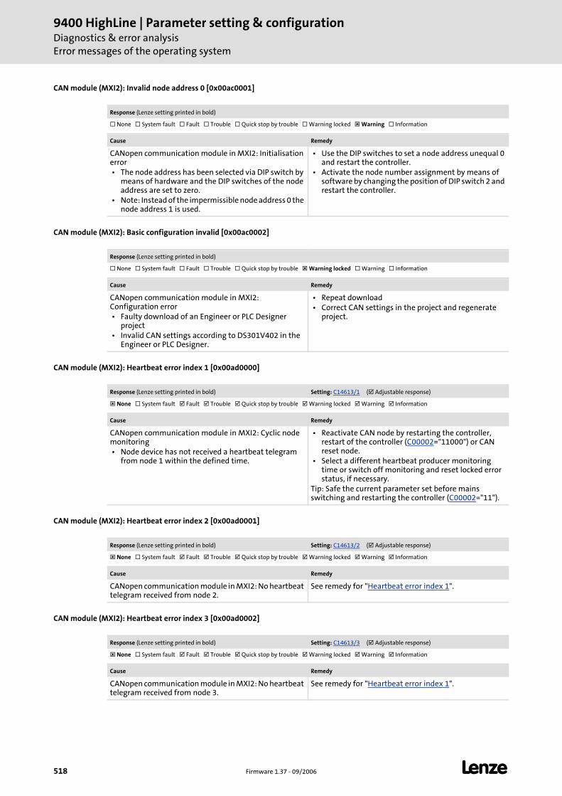
9400 HighLine | Parameter setting & configurationDiagnostics & error analysisError messages of the operating system
518 Firmware 1.37 - 09/2006 L
CAN module (MXI2): Invalid node address 0 [0x00ac0001]
CAN module (MXI2): Basic configuration invalid [0x00ac0002]
CAN module (MXI2): Heartbeat error index 1 [0x00ad0000]
CAN module (MXI2): Heartbeat error index 2 [0x00ad0001]
CAN module (MXI2): Heartbeat error index 3 [0x00ad0002]
Response (Lenze setting printed in bold)
None System fault Fault Trouble Quick stop by trouble Warning locked Warning Information
Cause Remedy
CANopen communication module in MXI2: Initialisation error • The node address has been selected via DIP switch by
means of hardware and the DIP switches of the node address are set to zero.
• Note: Instead of the impermissible node address 0 the node address 1 is used.
• Use the DIP switches to set a node address unequal 0 and restart the controller.
• Activate the node number assignment by means of software by changing the position of DIP switch 2 and restart the controller.
Response (Lenze setting printed in bold)
None System fault Fault Trouble Quick stop by trouble Warning locked Warning Information
Cause Remedy
CANopen communication module in MXI2: Configuration error • Faulty download of an Engineer or PLC Designer
project • Invalid CAN settings according to DS301V402 in the
Engineer or PLC Designer.
• Repeat download • Correct CAN settings in the project and regenerate
project.
Response (Lenze setting printed in bold) Setting: C14613/1 ( Adjustable response)
None System fault Fault Trouble Quick stop by trouble Warning locked Warning Information
Cause Remedy
CANopen communication module in MXI2: Cyclic node monitoring • Node device has not received a heartbeat telegram
from node 1 within the defined time.
• Reactivate CAN node by restarting the controller, restart of the controller (C00002="11000") or CAN reset node.
• Select a different heartbeat producer monitoring time or switch off monitoring and reset locked error status, if necessary.
Tip: Safe the current parameter set before mains switching and restarting the controller (C00002="11").
Response (Lenze setting printed in bold) Setting: C14613/2 ( Adjustable response)
None System fault Fault Trouble Quick stop by trouble Warning locked Warning Information
Cause Remedy
CANopen communication module in MXI2: No heartbeat telegram received from node 2.
See remedy for "Heartbeat error index 1".
Response (Lenze setting printed in bold) Setting: C14613/3 ( Adjustable response)
None System fault Fault Trouble Quick stop by trouble Warning locked Warning Information
Cause Remedy
CANopen communication module in MXI2: No heartbeat telegram received from node 3.
See remedy for "Heartbeat error index 1".

L Firmware 1.37 - 09/2006 519
9400 HighLine | Parameter setting & configurationDiagnostics & error analysis
Error messages of the operating system
CAN module (MXI2): Heartbeat error index 4 [0x00ad0003]
CAN module (MXI2): Heartbeat error index 5 [0x00ad0004]
CAN module (MXI2): Heartbeat error index 6 [0x00ad0005]
CAN module (MXI2): Heartbeat error index 7 [0x00ad0006]
CAN module (MXI2): Heartbeat error index 8 [0x00ad0007]
CAN module (MXI2): Heartbeat error index 9 [0x00ad0008]
Response (Lenze setting printed in bold) Setting: C14613/4 ( Adjustable response)
None System fault Fault Trouble Quick stop by trouble Warning locked Warning Information
Cause Remedy
CANopen communication module in MXI2: No heartbeat telegram received from node 4.
See remedy for "Heartbeat error index 1".
Response (Lenze setting printed in bold) Setting: C14613/5 ( Adjustable response)
None System fault Fault Trouble Quick stop by trouble Warning locked Warning Information
Cause Remedy
CANopen communication module in MXI2: No heartbeat telegram received from node 5.
See remedy for "Heartbeat error index 1".
Response (Lenze setting printed in bold) Setting: C14613/6 ( Adjustable response)
None System fault Fault Trouble Quick stop by trouble Warning locked Warning Information
Cause Remedy
CANopen communication module in MXI2: No heartbeat telegram received from node 6.
See remedy for "Heartbeat error index 1".
Response (Lenze setting printed in bold) Setting: C14613/7 ( Adjustable response)
None System fault Fault Trouble Quick stop by trouble Warning locked Warning Information
Cause Remedy
CANopen communication module in MXI2: No heartbeat telegram received from node 7.
See remedy for "Heartbeat error index 1".
Response (Lenze setting printed in bold) Setting: C14613/8 ( Adjustable response)
None System fault Fault Trouble Quick stop by trouble Warning locked Warning Information
Cause Remedy
CANopen communication module in MXI2: No heartbeat telegram received from node 8.
See remedy for "Heartbeat error index 1".
Response (Lenze setting printed in bold) Setting: C14613/9 ( Adjustable response)
None System fault Fault Trouble Quick stop by trouble Warning locked Warning Information
Cause Remedy
CANopen communication module in MXI2: No heartbeat telegram received from node 9.
See remedy for "Heartbeat error index 1".
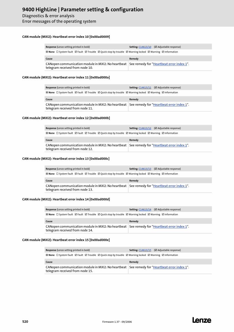
9400 HighLine | Parameter setting & configurationDiagnostics & error analysisError messages of the operating system
520 Firmware 1.37 - 09/2006 L
CAN module (MXI2): Heartbeat error index 10 [0x00ad0009]
CAN module (MXI2): Heartbeat error index 11 [0x00ad000a]
CAN module (MXI2): Heartbeat error index 12 [0x00ad000b]
CAN module (MXI2): Heartbeat error index 13 [0x00ad000c]
CAN module (MXI2): Heartbeat error index 14 [0x00ad000d]
CAN module (MXI2): Heartbeat error index 15 [0x00ad000e]
Response (Lenze setting printed in bold) Setting: C14613/10 ( Adjustable response)
None System fault Fault Trouble Quick stop by trouble Warning locked Warning Information
Cause Remedy
CANopen communication module in MXI2: No heartbeat telegram received from node 10.
See remedy for "Heartbeat error index 1".
Response (Lenze setting printed in bold) Setting: C14613/11 ( Adjustable response)
None System fault Fault Trouble Quick stop by trouble Warning locked Warning Information
Cause Remedy
CANopen communication module in MXI2: No heartbeat telegram received from node 11.
See remedy for "Heartbeat error index 1".
Response (Lenze setting printed in bold) Setting: C14613/12 ( Adjustable response)
None System fault Fault Trouble Quick stop by trouble Warning locked Warning Information
Cause Remedy
CANopen communication module in MXI2: No heartbeat telegram received from node 12.
See remedy for "Heartbeat error index 1".
Response (Lenze setting printed in bold) Setting: C14613/13 ( Adjustable response)
None System fault Fault Trouble Quick stop by trouble Warning locked Warning Information
Cause Remedy
CANopen communication module in MXI2: No heartbeat telegram received from node 13.
See remedy for "Heartbeat error index 1".
Response (Lenze setting printed in bold) Setting: C14613/14 ( Adjustable response)
None System fault Fault Trouble Quick stop by trouble Warning locked Warning Information
Cause Remedy
CANopen communication module in MXI2: No heartbeat telegram received from node 14.
See remedy for "Heartbeat error index 1".
Response (Lenze setting printed in bold) Setting: C14613/15 ( Adjustable response)
None System fault Fault Trouble Quick stop by trouble Warning locked Warning Information
Cause Remedy
CANopen communication module in MXI2: No heartbeat telegram received from node 15.
See remedy for "Heartbeat error index 1".
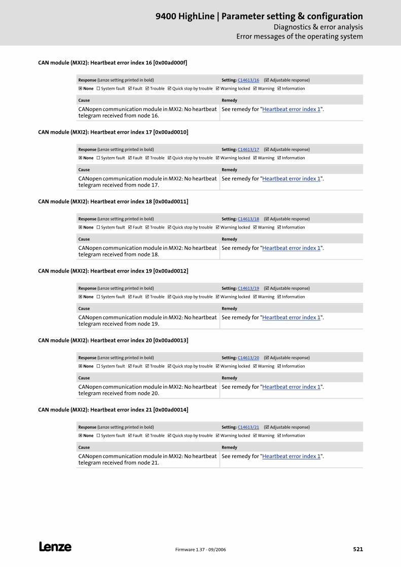
L Firmware 1.37 - 09/2006 521
9400 HighLine | Parameter setting & configurationDiagnostics & error analysis
Error messages of the operating system
CAN module (MXI2): Heartbeat error index 16 [0x00ad000f]
CAN module (MXI2): Heartbeat error index 17 [0x00ad0010]
CAN module (MXI2): Heartbeat error index 18 [0x00ad0011]
CAN module (MXI2): Heartbeat error index 19 [0x00ad0012]
CAN module (MXI2): Heartbeat error index 20 [0x00ad0013]
CAN module (MXI2): Heartbeat error index 21 [0x00ad0014]
Response (Lenze setting printed in bold) Setting: C14613/16 ( Adjustable response)
None System fault Fault Trouble Quick stop by trouble Warning locked Warning Information
Cause Remedy
CANopen communication module in MXI2: No heartbeat telegram received from node 16.
See remedy for "Heartbeat error index 1".
Response (Lenze setting printed in bold) Setting: C14613/17 ( Adjustable response)
None System fault Fault Trouble Quick stop by trouble Warning locked Warning Information
Cause Remedy
CANopen communication module in MXI2: No heartbeat telegram received from node 17.
See remedy for "Heartbeat error index 1".
Response (Lenze setting printed in bold) Setting: C14613/18 ( Adjustable response)
None System fault Fault Trouble Quick stop by trouble Warning locked Warning Information
Cause Remedy
CANopen communication module in MXI2: No heartbeat telegram received from node 18.
See remedy for "Heartbeat error index 1".
Response (Lenze setting printed in bold) Setting: C14613/19 ( Adjustable response)
None System fault Fault Trouble Quick stop by trouble Warning locked Warning Information
Cause Remedy
CANopen communication module in MXI2: No heartbeat telegram received from node 19.
See remedy for "Heartbeat error index 1".
Response (Lenze setting printed in bold) Setting: C14613/20 ( Adjustable response)
None System fault Fault Trouble Quick stop by trouble Warning locked Warning Information
Cause Remedy
CANopen communication module in MXI2: No heartbeat telegram received from node 20.
See remedy for "Heartbeat error index 1".
Response (Lenze setting printed in bold) Setting: C14613/21 ( Adjustable response)
None System fault Fault Trouble Quick stop by trouble Warning locked Warning Information
Cause Remedy
CANopen communication module in MXI2: No heartbeat telegram received from node 21.
See remedy for "Heartbeat error index 1".
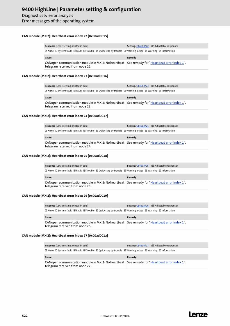
9400 HighLine | Parameter setting & configurationDiagnostics & error analysisError messages of the operating system
522 Firmware 1.37 - 09/2006 L
CAN module (MXI2): Heartbeat error index 22 [0x00ad0015]
CAN module (MXI2): Heartbeat error index 23 [0x00ad0016]
CAN module (MXI2): Heartbeat error index 24 [0x00ad0017]
CAN module (MXI2): Heartbeat error index 25 [0x00ad0018]
CAN module (MXI2): Heartbeat error index 26 [0x00ad0019]
CAN module (MXI2): Heartbeat error index 27 [0x00ad001a]
Response (Lenze setting printed in bold) Setting: C14613/22 ( Adjustable response)
None System fault Fault Trouble Quick stop by trouble Warning locked Warning Information
Cause Remedy
CANopen communication module in MXI2: No heartbeat telegram received from node 22.
See remedy for "Heartbeat error index 1".
Response (Lenze setting printed in bold) Setting: C14613/23 ( Adjustable response)
None System fault Fault Trouble Quick stop by trouble Warning locked Warning Information
Cause Remedy
CANopen communication module in MXI2: No heartbeat telegram received from node 23.
See remedy for "Heartbeat error index 1".
Response (Lenze setting printed in bold) Setting: C14613/24 ( Adjustable response)
None System fault Fault Trouble Quick stop by trouble Warning locked Warning Information
Cause Remedy
CANopen communication module in MXI2: No heartbeat telegram received from node 24.
See remedy for "Heartbeat error index 1".
Response (Lenze setting printed in bold) Setting: C14613/25 ( Adjustable response)
None System fault Fault Trouble Quick stop by trouble Warning locked Warning Information
Cause Remedy
CANopen communication module in MXI2: No heartbeat telegram received from node 25.
See remedy for "Heartbeat error index 1".
Response (Lenze setting printed in bold) Setting: C14613/26 ( Adjustable response)
None System fault Fault Trouble Quick stop by trouble Warning locked Warning Information
Cause Remedy
CANopen communication module in MXI2: No heartbeat telegram received from node 26.
See remedy for "Heartbeat error index 1".
Response (Lenze setting printed in bold) Setting: C14613/27 ( Adjustable response)
None System fault Fault Trouble Quick stop by trouble Warning locked Warning Information
Cause Remedy
CANopen communication module in MXI2: No heartbeat telegram received from node 27.
See remedy for "Heartbeat error index 1".
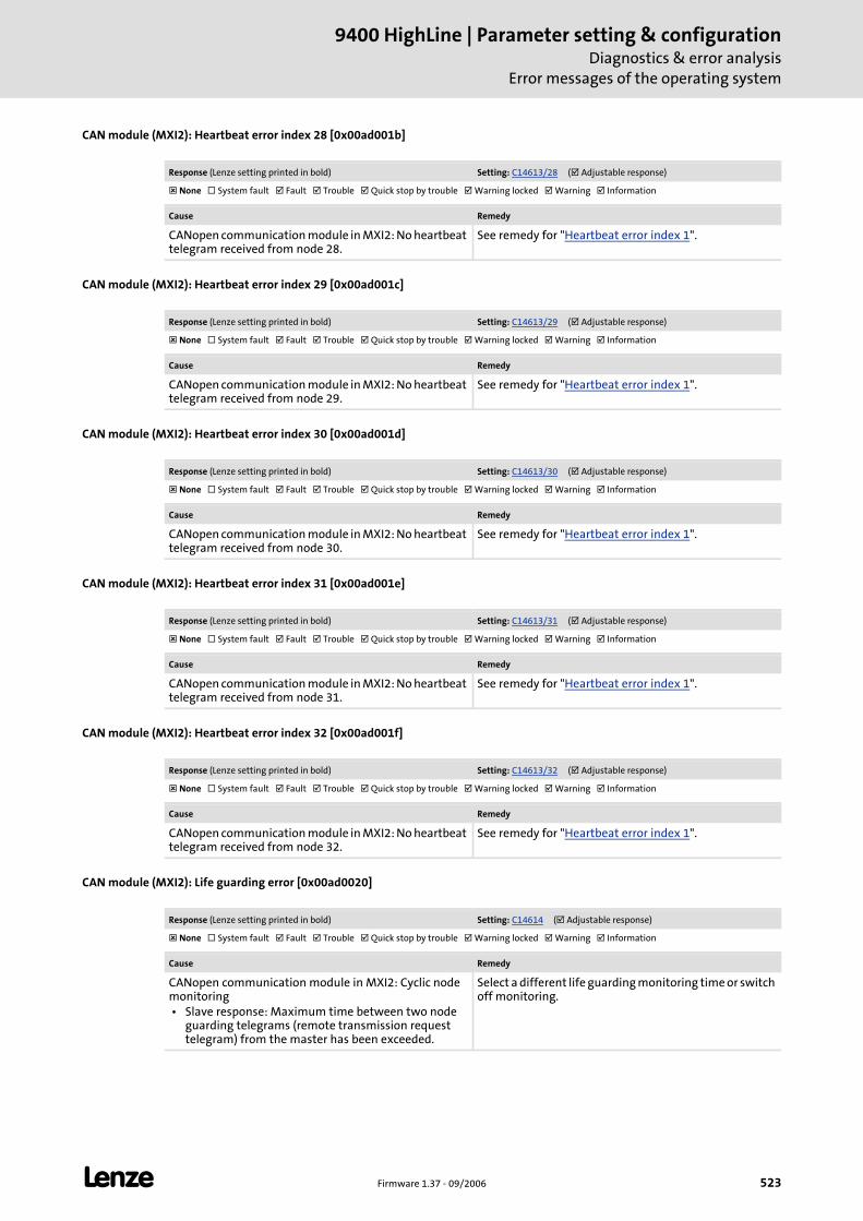
L Firmware 1.37 - 09/2006 523
9400 HighLine | Parameter setting & configurationDiagnostics & error analysis
Error messages of the operating system
CAN module (MXI2): Heartbeat error index 28 [0x00ad001b]
CAN module (MXI2): Heartbeat error index 29 [0x00ad001c]
CAN module (MXI2): Heartbeat error index 30 [0x00ad001d]
CAN module (MXI2): Heartbeat error index 31 [0x00ad001e]
CAN module (MXI2): Heartbeat error index 32 [0x00ad001f]
CAN module (MXI2): Life guarding error [0x00ad0020]
Response (Lenze setting printed in bold) Setting: C14613/28 ( Adjustable response)
None System fault Fault Trouble Quick stop by trouble Warning locked Warning Information
Cause Remedy
CANopen communication module in MXI2: No heartbeat telegram received from node 28.
See remedy for "Heartbeat error index 1".
Response (Lenze setting printed in bold) Setting: C14613/29 ( Adjustable response)
None System fault Fault Trouble Quick stop by trouble Warning locked Warning Information
Cause Remedy
CANopen communication module in MXI2: No heartbeat telegram received from node 29.
See remedy for "Heartbeat error index 1".
Response (Lenze setting printed in bold) Setting: C14613/30 ( Adjustable response)
None System fault Fault Trouble Quick stop by trouble Warning locked Warning Information
Cause Remedy
CANopen communication module in MXI2: No heartbeat telegram received from node 30.
See remedy for "Heartbeat error index 1".
Response (Lenze setting printed in bold) Setting: C14613/31 ( Adjustable response)
None System fault Fault Trouble Quick stop by trouble Warning locked Warning Information
Cause Remedy
CANopen communication module in MXI2: No heartbeat telegram received from node 31.
See remedy for "Heartbeat error index 1".
Response (Lenze setting printed in bold) Setting: C14613/32 ( Adjustable response)
None System fault Fault Trouble Quick stop by trouble Warning locked Warning Information
Cause Remedy
CANopen communication module in MXI2: No heartbeat telegram received from node 32.
See remedy for "Heartbeat error index 1".
Response (Lenze setting printed in bold) Setting: C14614 ( Adjustable response)
None System fault Fault Trouble Quick stop by trouble Warning locked Warning Information
Cause Remedy
CANopen communication module in MXI2: Cyclic node monitoring • Slave response: Maximum time between two node
guarding telegrams (remote transmission request telegram) from the master has been exceeded.
Select a different life guarding monitoring time or switch off monitoring.

9400 HighLine | Parameter setting & configurationDiagnostics & error analysisError messages of the operating system
524 Firmware 1.37 - 09/2006 L
CAN module (MXI2): Faulty NMT slave configuration [0x00ad0021]
CAN module (MXI2): Faulty emergency configuration [0x00ae0000]
CAN module (MXI2): Node guarding error 1 [0x00af0000]
CAN module (MXI2): Node guarding error 2 [0x00af0001]
Response (Lenze setting printed in bold)
None System fault Fault Trouble Quick stop by trouble Warning locked Warning Information
Cause Remedy
CANopen communication module in MXI2: A configuration error has occurred in the network management of the CAN slave. • Faulty download of an Engineer or PLC Designer
project • Invalid CAN settings according to DS301V402 in the
Engineer or PLC Designer. • Incorrect parameterisation of node guarding or
heartbeat.
• Repeat download • Correct CAN settings in the project and regenerate
project.
Response (Lenze setting printed in bold)
None System fault Fault Trouble Quick stop by trouble Warning locked Warning Information
Cause Remedy
CANopen communication module in MXI2: In the CAN emergency module a configuration error has occurred. • Faulty download of an Engineer or PLC Designer
project • Invalid CAN emergency settings according to
DS301V402 in the Engineer or PLC Designer.
• Repeat download • Correct CAN settings in the project and regenerate
project.
Response (Lenze setting printed in bold) Setting: C14612/1 ( Adjustable response)
None System fault Fault Trouble Quick stop by trouble Warning locked Warning Information
Cause Remedy
CANopen communication module in MXI2: Cyclic node monitoring • CAN master has not received a response to a node
guarding telegram (remote transmission request telegram) from node 1 within the defined time.
• Reactivate CAN node by restarting the controller, restart of the controller (C00002="11000") or CAN reset node.
• Select a different node guarding monitoring time or switch off monitoring.
• Reset error state if latched.Tip: Safe the current parameter set before mains switching and restarting the controller (C00002="11").
Response (Lenze setting printed in bold) Setting: C14612/2 ( Adjustable response)
None System fault Fault Trouble Quick stop by trouble Warning locked Warning Information
Cause Remedy
CANopen communication module in MXI2: CAN master has not received a response to a node guarding telegram from node 2.
See remedy for "Node guarding error 1".

L Firmware 1.37 - 09/2006 525
9400 HighLine | Parameter setting & configurationDiagnostics & error analysis
Error messages of the operating system
CAN module (MXI2): Node guarding error 3 [0x00af0002]
CAN module (MXI2): Node guarding error 4 [0x00af0003]
CAN module (MXI2): Node guarding error 5 [0x00af0004]
CAN module (MXI2): Node guarding error 6 [0x00af0005]
CAN module (MXI2): Node guarding error 7 [0x00af0006]
CAN module (MXI2): Node guarding error 8 [0x00af0007]
Response (Lenze setting printed in bold) Setting: C14612/3 ( Adjustable response)
None System fault Fault Trouble Quick stop by trouble Warning locked Warning Information
Cause Remedy
CANopen communication module in MXI2: CAN master has not received a response to a node guarding telegram from node 3.
See remedy for "Node guarding error 1".
Response (Lenze setting printed in bold) Setting: C14612/4 ( Adjustable response)
None System fault Fault Trouble Quick stop by trouble Warning locked Warning Information
Cause Remedy
CANopen communication module in MXI2: CAN master has not received a response to a node guarding telegram from node 4.
See remedy for "Node guarding error 1".
Response (Lenze setting printed in bold) Setting: C14612/5 ( Adjustable response)
None System fault Fault Trouble Quick stop by trouble Warning locked Warning Information
Cause Remedy
CANopen communication module in MXI2: CAN master has not received a response to a node guarding telegram from node 5.
See remedy for "Node guarding error 1".
Response (Lenze setting printed in bold) Setting: C14612/6 ( Adjustable response)
None System fault Fault Trouble Quick stop by trouble Warning locked Warning Information
Cause Remedy
CANopen communication module in MXI2: CAN master has not received a response to a node guarding telegram from node 6.
See remedy for "Node guarding error 1".
Response (Lenze setting printed in bold) Setting: C14612/7 ( Adjustable response)
None System fault Fault Trouble Quick stop by trouble Warning locked Warning Information
Cause Remedy
CANopen communication module in MXI2: CAN master has not received a response to a node guarding telegram from node 7.
See remedy for "Node guarding error 1".
Response (Lenze setting printed in bold) Setting: C14612/8 ( Adjustable response)
None System fault Fault Trouble Quick stop by trouble Warning locked Warning Information
Cause Remedy
CANopen communication module in MXI2: CAN master has not received a response to a node guarding telegram from node 8.
See remedy for "Node guarding error 1".

9400 HighLine | Parameter setting & configurationDiagnostics & error analysisError messages of the operating system
526 Firmware 1.37 - 09/2006 L
CAN module (MXI2): Node guarding error 9 [0x00af0008]
CAN module (MXI2): Node guarding error 10 [0x00af0009]
CAN module (MXI2): Node guarding error 11 [0x00af000a]
CAN module (MXI2): Node guarding error 12 [0x00af000b]
CAN module (MXI2): Node guarding error 13 [0x00af000c]
CAN module (MXI2): Node guarding error 14 [0x00af000d]
Response (Lenze setting printed in bold) Setting: C14612/9 ( Adjustable response)
None System fault Fault Trouble Quick stop by trouble Warning locked Warning Information
Cause Remedy
CANopen communication module in MXI2: CAN master has not received a response to a node guarding telegram from node 9.
See remedy for "Node guarding error 1".
Response (Lenze setting printed in bold) Setting: C14612/10 ( Adjustable response)
None System fault Fault Trouble Quick stop by trouble Warning locked Warning Information
Cause Remedy
CANopen communication module in MXI2: CAN master has not received a response to a node guarding telegram from node 10.
See remedy for "Node guarding error 1".
Response (Lenze setting printed in bold) Setting: C14612/11 ( Adjustable response)
None System fault Fault Trouble Quick stop by trouble Warning locked Warning Information
Cause Remedy
CANopen communication module in MXI2: CAN master has not received a response to a node guarding telegram from node 11.
See remedy for "Node guarding error 1".
Response (Lenze setting printed in bold) Setting: C14612/12 ( Adjustable response)
None System fault Fault Trouble Quick stop by trouble Warning locked Warning Information
Cause Remedy
CANopen communication module in MXI2: CAN master has not received a response to a node guarding telegram from node 12.
See remedy for "Node guarding error 1".
Response (Lenze setting printed in bold) Setting: C14612/13 ( Adjustable response)
None System fault Fault Trouble Quick stop by trouble Warning locked Warning Information
Cause Remedy
CANopen communication module in MXI2: CAN master has not received a response to a node guarding telegram from node 13.
See remedy for "Node guarding error 1".
Response (Lenze setting printed in bold) Setting: C14612/14 ( Adjustable response)
None System fault Fault Trouble Quick stop by trouble Warning locked Warning Information
Cause Remedy
CANopen communication module in MXI2: CAN master has not received a response to a node guarding telegram from node 14.
See remedy for "Node guarding error 1".
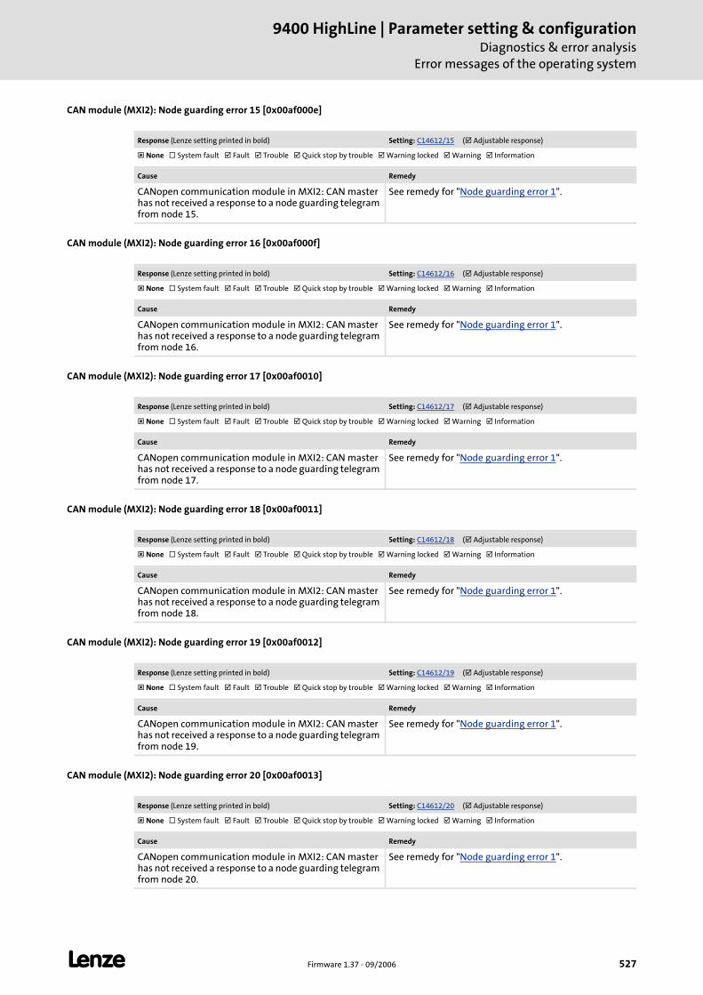
L Firmware 1.37 - 09/2006 527
9400 HighLine | Parameter setting & configurationDiagnostics & error analysis
Error messages of the operating system
CAN module (MXI2): Node guarding error 15 [0x00af000e]
CAN module (MXI2): Node guarding error 16 [0x00af000f]
CAN module (MXI2): Node guarding error 17 [0x00af0010]
CAN module (MXI2): Node guarding error 18 [0x00af0011]
CAN module (MXI2): Node guarding error 19 [0x00af0012]
CAN module (MXI2): Node guarding error 20 [0x00af0013]
Response (Lenze setting printed in bold) Setting: C14612/15 ( Adjustable response)
None System fault Fault Trouble Quick stop by trouble Warning locked Warning Information
Cause Remedy
CANopen communication module in MXI2: CAN master has not received a response to a node guarding telegram from node 15.
See remedy for "Node guarding error 1".
Response (Lenze setting printed in bold) Setting: C14612/16 ( Adjustable response)
None System fault Fault Trouble Quick stop by trouble Warning locked Warning Information
Cause Remedy
CANopen communication module in MXI2: CAN master has not received a response to a node guarding telegram from node 16.
See remedy for "Node guarding error 1".
Response (Lenze setting printed in bold) Setting: C14612/17 ( Adjustable response)
None System fault Fault Trouble Quick stop by trouble Warning locked Warning Information
Cause Remedy
CANopen communication module in MXI2: CAN master has not received a response to a node guarding telegram from node 17.
See remedy for "Node guarding error 1".
Response (Lenze setting printed in bold) Setting: C14612/18 ( Adjustable response)
None System fault Fault Trouble Quick stop by trouble Warning locked Warning Information
Cause Remedy
CANopen communication module in MXI2: CAN master has not received a response to a node guarding telegram from node 18.
See remedy for "Node guarding error 1".
Response (Lenze setting printed in bold) Setting: C14612/19 ( Adjustable response)
None System fault Fault Trouble Quick stop by trouble Warning locked Warning Information
Cause Remedy
CANopen communication module in MXI2: CAN master has not received a response to a node guarding telegram from node 19.
See remedy for "Node guarding error 1".
Response (Lenze setting printed in bold) Setting: C14612/20 ( Adjustable response)
None System fault Fault Trouble Quick stop by trouble Warning locked Warning Information
Cause Remedy
CANopen communication module in MXI2: CAN master has not received a response to a node guarding telegram from node 20.
See remedy for "Node guarding error 1".
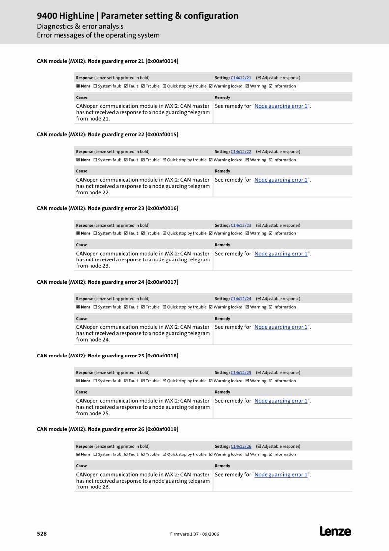
9400 HighLine | Parameter setting & configurationDiagnostics & error analysisError messages of the operating system
528 Firmware 1.37 - 09/2006 L
CAN module (MXI2): Node guarding error 21 [0x00af0014]
CAN module (MXI2): Node guarding error 22 [0x00af0015]
CAN module (MXI2): Node guarding error 23 [0x00af0016]
CAN module (MXI2): Node guarding error 24 [0x00af0017]
CAN module (MXI2): Node guarding error 25 [0x00af0018]
CAN module (MXI2): Node guarding error 26 [0x00af0019]
Response (Lenze setting printed in bold) Setting: C14612/21 ( Adjustable response)
None System fault Fault Trouble Quick stop by trouble Warning locked Warning Information
Cause Remedy
CANopen communication module in MXI2: CAN master has not received a response to a node guarding telegram from node 21.
See remedy for "Node guarding error 1".
Response (Lenze setting printed in bold) Setting: C14612/22 ( Adjustable response)
None System fault Fault Trouble Quick stop by trouble Warning locked Warning Information
Cause Remedy
CANopen communication module in MXI2: CAN master has not received a response to a node guarding telegram from node 22.
See remedy for "Node guarding error 1".
Response (Lenze setting printed in bold) Setting: C14612/23 ( Adjustable response)
None System fault Fault Trouble Quick stop by trouble Warning locked Warning Information
Cause Remedy
CANopen communication module in MXI2: CAN master has not received a response to a node guarding telegram from node 23.
See remedy for "Node guarding error 1".
Response (Lenze setting printed in bold) Setting: C14612/24 ( Adjustable response)
None System fault Fault Trouble Quick stop by trouble Warning locked Warning Information
Cause Remedy
CANopen communication module in MXI2: CAN master has not received a response to a node guarding telegram from node 24.
See remedy for "Node guarding error 1".
Response (Lenze setting printed in bold) Setting: C14612/25 ( Adjustable response)
None System fault Fault Trouble Quick stop by trouble Warning locked Warning Information
Cause Remedy
CANopen communication module in MXI2: CAN master has not received a response to a node guarding telegram from node 25.
See remedy for "Node guarding error 1".
Response (Lenze setting printed in bold) Setting: C14612/26 ( Adjustable response)
None System fault Fault Trouble Quick stop by trouble Warning locked Warning Information
Cause Remedy
CANopen communication module in MXI2: CAN master has not received a response to a node guarding telegram from node 26.
See remedy for "Node guarding error 1".

L Firmware 1.37 - 09/2006 529
9400 HighLine | Parameter setting & configurationDiagnostics & error analysis
Error messages of the operating system
CAN module (MXI2): Node guarding error 27 [0x00af001a]
CAN module (MXI2): Node guarding error 28 [0x00af001b]
CAN module (MXI2): Node guarding error 29 [0x00af001c]
CAN module (MXI2): Node guarding error 30 [0x00af001d]
CAN module (MXI2): Node guarding error 31 [0x00af001e]
CAN module (MXI2): Node guarding error 32 [0x00af001f]
Response (Lenze setting printed in bold) Setting: C14612/27 ( Adjustable response)
None System fault Fault Trouble Quick stop by trouble Warning locked Warning Information
Cause Remedy
CANopen communication module in MXI2: CAN master has not received a response to a node guarding telegram from node 27.
See remedy for "Node guarding error 1".
Response (Lenze setting printed in bold) Setting: C14612/28 ( Adjustable response)
None System fault Fault Trouble Quick stop by trouble Warning locked Warning Information
Cause Remedy
CANopen communication module in MXI2: CAN master has not received a response to a node guarding telegram from node 28.
See remedy for "Node guarding error 1".
Response (Lenze setting printed in bold) Setting: C14612/29 ( Adjustable response)
None System fault Fault Trouble Quick stop by trouble Warning locked Warning Information
Cause Remedy
CANopen communication module in MXI2: CAN master has not received a response to a node guarding telegram from node 29.
See remedy for "Node guarding error 1".
Response (Lenze setting printed in bold) Setting: C14612/30 ( Adjustable response)
None System fault Fault Trouble Quick stop by trouble Warning locked Warning Information
Cause Remedy
CANopen communication module in MXI2: CAN master has not received a response to a node guarding telegram from node 30.
See remedy for "Node guarding error 1".
Response (Lenze setting printed in bold) Setting: C14612/31 ( Adjustable response)
None System fault Fault Trouble Quick stop by trouble Warning locked Warning Information
Cause Remedy
CANopen communication module in MXI2: CAN master has not received a response to a node guarding telegram from node 31.
See remedy for "Node guarding error 1".
Response (Lenze setting printed in bold) Setting: C14612/32 ( Adjustable response)
None System fault Fault Trouble Quick stop by trouble Warning locked Warning Information
Cause Remedy
CANopen communication module in MXI2: CAN master has not received a response to a node guarding telegram from node 32.
See remedy for "Node guarding error 1".
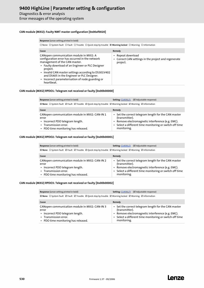
9400 HighLine | Parameter setting & configurationDiagnostics & error analysisError messages of the operating system
530 Firmware 1.37 - 09/2006 L
CAN module (MXI2): Faulty NMT master configuration [0x00af0020]
CAN module (MXI2) RPDO1: Telegram not received or faulty [0x00b00000]
CAN module (MXI2) RPDO2: Telegram not received or faulty [0x00b00001]
CAN module (MXI2) RPDO3: Telegram not received or faulty [0x00b00002]
Response (Lenze setting printed in bold)
None System fault Fault Trouble Quick stop by trouble Warning locked Warning Information
Cause Remedy
CANopen communication module in MXI2: A configuration error has occurred in the network management of the CAN master. • Faulty download of an Engineer or PLC Designer
project. • Invalid CAN master settings according to DS301V402
and DS405 in the Engineer or PLC Designer. • Incorrect parameterisation of node guarding or
heartbeat.
• Repeat download • Correct CAN settings in the project and regenerate
project.
Response (Lenze setting printed in bold) Setting: C14591/1 ( Adjustable response)
None System fault Fault Trouble Quick stop by trouble Warning locked Warning Information
Cause Remedy
CANopen communication module in MXI2: CAN-IN 1 error • Incorrect PDO telegram length. • Transmission error. • PDO time monitoring has released.
• Set the correct telegram length for the CAN master (transmitter).
• Remove electromagnetic interference (e.g. EMC). • Select a different time monitoring or switch off time
monitoring.
Response (Lenze setting printed in bold) Setting: C14591/2 ( Adjustable response)
None System fault Fault Trouble Quick stop by trouble Warning locked Warning Information
Cause Remedy
CANopen communication module in MXI2: CAN-IN 2 error • Incorrect PDO telegram length. • Transmission error. • PDO time monitoring has released.
• Set the correct telegram length for the CAN master (transmitter).
• Remove electromagnetic interference (e.g. EMC). • Select a different time monitoring or switch off time
monitoring.
Response (Lenze setting printed in bold) Setting: C14591/3 ( Adjustable response)
None System fault Fault Trouble Quick stop by trouble Warning locked Warning Information
Cause Remedy
CANopen communication module in MXI2: CAN-IN 3 error • Incorrect PDO telegram length. • Transmission error. • PDO time monitoring has released.
• Set the correct telegram length for the CAN master (transmitter).
• Remove electromagnetic interference (e.g. EMC). • Select a different time monitoring or switch off time
monitoring.

L Firmware 1.37 - 09/2006 531
9400 HighLine | Parameter setting & configurationDiagnostics & error analysis
Error messages of the operating system
CAN module (MXI2) RPDO4: Telegram not received or faulty [0x00b00003]
CAN module (MXI2) RPDO5: Telegram not received or faulty [0x00b00004]
CAN module (MXI2) RPDO6: Telegram not received or faulty [0x00b00005]
CAN module (MXI2) RPDO7: Telegram not received or faulty [0x00b00006]
CAN module (MXI2) RPDO8: Telegram not received or faulty [0x00b00007]
Response (Lenze setting printed in bold) Setting: C14591/4 ( Adjustable response)
None System fault Fault Trouble Quick stop by trouble Warning locked Warning Information
Cause Remedy
CANopen communication module in MXI2: CAN-IN 4 error • Incorrect PDO telegram length. • Transmission error. • PDO time monitoring has released.
• Set the correct telegram length for the CAN master (transmitter).
• Remove electromagnetic interference (e.g. EMC). • Select a different time monitoring or switch off time
monitoring.
Response (Lenze setting printed in bold) Setting: C14591/5 ( Adjustable response)
None System fault Fault Trouble Quick stop by trouble Warning locked Warning Information
Cause Remedy
CANopen communication module in MXI2: CAN-IN 5 error • Incorrect PDO telegram length. • Transmission error. • PDO time monitoring has released.
• Set the correct telegram length for the CAN master (transmitter).
• Remove electromagnetic interference (e.g. EMC). • Select a different time monitoring or switch off time
monitoring.
Response (Lenze setting printed in bold) Setting: C14591/6 ( Adjustable response)
None System fault Fault Trouble Quick stop by trouble Warning locked Warning Information
Cause Remedy
CANopen communication module in MXI2: CAN-IN 6 error • Incorrect PDO telegram length. • Transmission error. • PDO time monitoring has released.
• Set the correct telegram length for the CAN master (transmitter).
• Remove electromagnetic interference (e.g. EMC). • Select a different time monitoring or switch off time
monitoring.
Response (Lenze setting printed in bold) Setting: C14591/7 ( Adjustable response)
None System fault Fault Trouble Quick stop by trouble Warning locked Warning Information
Cause Remedy
CANopen communication module in MXI2: CAN-IN 7 error • Incorrect PDO telegram length. • Transmission error. • PDO time monitoring has released.
• Set the correct telegram length for the CAN master (transmitter).
• Remove electromagnetic interference (e.g. EMC). • Select a different time monitoring or switch off time
monitoring.
Response (Lenze setting printed in bold) Setting: C14591/8 ( Adjustable response)
None System fault Fault Trouble Quick stop by trouble Warning locked Warning Information
Cause Remedy
CANopen communication module in MXI2: CAN-IN 8 error • Incorrect PDO telegram length. • Transmission error. • PDO time monitoring has released.
• Set the correct telegram length for the CAN master (transmitter).
• Remove electromagnetic interference (e.g. EMC). • Select a different time monitoring or switch off time
monitoring.
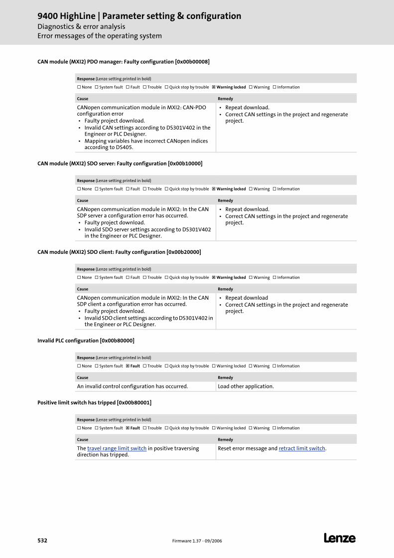
9400 HighLine | Parameter setting & configurationDiagnostics & error analysisError messages of the operating system
532 Firmware 1.37 - 09/2006 L
CAN module (MXI2) PDO manager: Faulty configuration [0x00b00008]
CAN module (MXI2) SDO server: Faulty configuration [0x00b10000]
CAN module (MXI2) SDO client: Faulty configuration [0x00b20000]
Invalid PLC configuration [0x00b80000]
Positive limit switch has tripped [0x00b80001]
Response (Lenze setting printed in bold)
None System fault Fault Trouble Quick stop by trouble Warning locked Warning Information
Cause Remedy
CANopen communication module in MXI2: CAN-PDO configuration error • Faulty project download. • Invalid CAN settings according to DS301V402 in the
Engineer or PLC Designer. • Mapping variables have incorrect CANopen indices
according to DS405.
• Repeat download. • Correct CAN settings in the project and regenerate
project.
Response (Lenze setting printed in bold)
None System fault Fault Trouble Quick stop by trouble Warning locked Warning Information
Cause Remedy
CANopen communication module in MXI2: In the CAN SDP server a configuration error has occurred. • Faulty project download. • Invalid SDO server settings according to DS301V402
in the Engineer or PLC Designer.
• Repeat download. • Correct CAN settings in the project and regenerate
project.
Response (Lenze setting printed in bold)
None System fault Fault Trouble Quick stop by trouble Warning locked Warning Information
Cause Remedy
CANopen communication module in MXI2: In the CAN SDP client a configuration error has occurred. • Faulty project download. • Invalid SDO client settings according to DS301V402 in
the Engineer or PLC Designer.
• Repeat download • Correct CAN settings in the project and regenerate
project.
Response (Lenze setting printed in bold)
None System fault Fault Trouble Quick stop by trouble Warning locked Warning Information
Cause Remedy
An invalid control configuration has occurred. Load other application.
Response (Lenze setting printed in bold)
None System fault Fault Trouble Quick stop by trouble Warning locked Warning Information
Cause Remedy
The travel range limit switch in positive traversing direction has tripped.
Reset error message and retract limit switch.
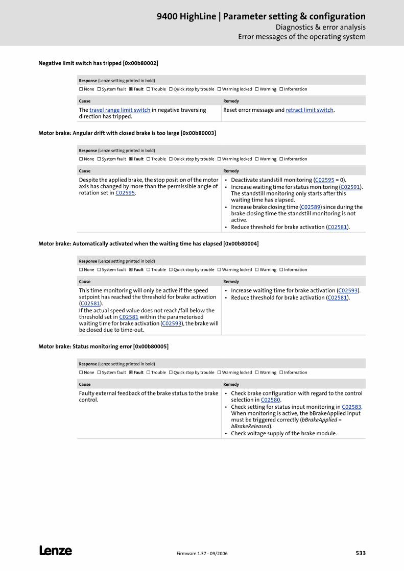
L Firmware 1.37 - 09/2006 533
9400 HighLine | Parameter setting & configurationDiagnostics & error analysis
Error messages of the operating system
Negative limit switch has tripped [0x00b80002]
Motor brake: Angular drift with closed brake is too large [0x00b80003]
Motor brake: Automatically activated when the waiting time has elapsed [0x00b80004]
Motor brake: Status monitoring error [0x00b80005]
Response (Lenze setting printed in bold)
None System fault Fault Trouble Quick stop by trouble Warning locked Warning Information
Cause Remedy
The travel range limit switch in negative traversing direction has tripped.
Reset error message and retract limit switch.
Response (Lenze setting printed in bold)
None System fault Fault Trouble Quick stop by trouble Warning locked Warning Information
Cause Remedy
Despite the applied brake, the stop position of the motor axis has changed by more than the permissible angle of rotation set in C02595.
• Deactivate standstill monitoring (C02595 = 0). • Increase waiting time for status monitoring (C02591).
The standstill monitoring only starts after this waiting time has elapsed.
• Increase brake closing time (C02589) since during the brake closing time the standstill monitoring is not active.
• Reduce threshold for brake activation (C02581).
Response (Lenze setting printed in bold)
None System fault Fault Trouble Quick stop by trouble Warning locked Warning Information
Cause Remedy
This time monitoring will only be active if the speed setpoint has reached the threshold for brake activation (C02581).If the actual speed value does not reach/fall below the threshold set in C02581 within the parameterised waiting time for brake activation (C02593), the brake will be closed due to time-out.
• Increase waiting time for brake activation (C02593). • Reduce threshold for brake activation (C02581).
Response (Lenze setting printed in bold)
None System fault Fault Trouble Quick stop by trouble Warning locked Warning Information
Cause Remedy
Faulty external feedback of the brake status to the brake control.
• Check brake configuration with regard to the control selection in C02580.
• Check setting for status input monitoring in C02583. When monitoring is active, the bBrakeApplied input must be triggered correctly (bBrakeApplied = bBrakeReleased).
• Check voltage supply of the brake module.
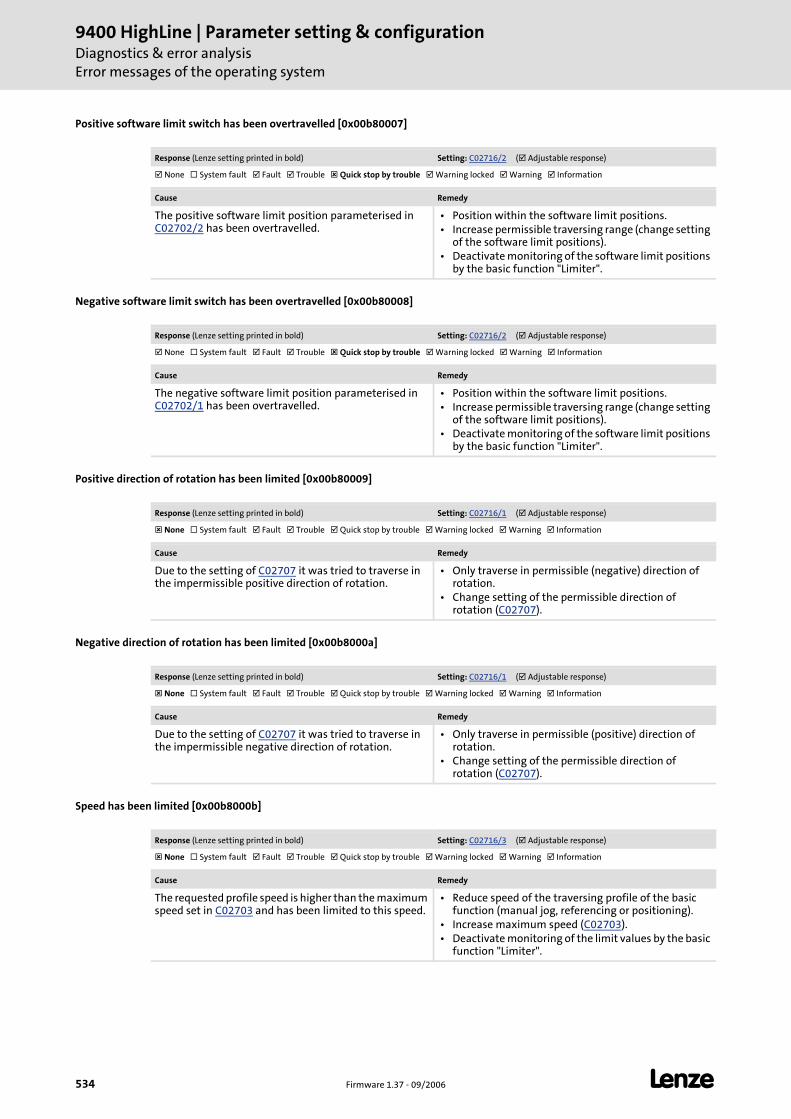
9400 HighLine | Parameter setting & configurationDiagnostics & error analysisError messages of the operating system
534 Firmware 1.37 - 09/2006 L
Positive software limit switch has been overtravelled [0x00b80007]
Negative software limit switch has been overtravelled [0x00b80008]
Positive direction of rotation has been limited [0x00b80009]
Negative direction of rotation has been limited [0x00b8000a]
Speed has been limited [0x00b8000b]
Response (Lenze setting printed in bold) Setting: C02716/2 ( Adjustable response)
None System fault Fault Trouble Quick stop by trouble Warning locked Warning Information
Cause Remedy
The positive software limit position parameterised in C02702/2 has been overtravelled.
• Position within the software limit positions. • Increase permissible traversing range (change setting
of the software limit positions). • Deactivate monitoring of the software limit positions
by the basic function "Limiter".
Response (Lenze setting printed in bold) Setting: C02716/2 ( Adjustable response)
None System fault Fault Trouble Quick stop by trouble Warning locked Warning Information
Cause Remedy
The negative software limit position parameterised in C02702/1 has been overtravelled.
• Position within the software limit positions. • Increase permissible traversing range (change setting
of the software limit positions). • Deactivate monitoring of the software limit positions
by the basic function "Limiter".
Response (Lenze setting printed in bold) Setting: C02716/1 ( Adjustable response)
None System fault Fault Trouble Quick stop by trouble Warning locked Warning Information
Cause Remedy
Due to the setting of C02707 it was tried to traverse in the impermissible positive direction of rotation.
• Only traverse in permissible (negative) direction of rotation.
• Change setting of the permissible direction of rotation (C02707).
Response (Lenze setting printed in bold) Setting: C02716/1 ( Adjustable response)
None System fault Fault Trouble Quick stop by trouble Warning locked Warning Information
Cause Remedy
Due to the setting of C02707 it was tried to traverse in the impermissible negative direction of rotation.
• Only traverse in permissible (positive) direction of rotation.
• Change setting of the permissible direction of rotation (C02707).
Response (Lenze setting printed in bold) Setting: C02716/3 ( Adjustable response)
None System fault Fault Trouble Quick stop by trouble Warning locked Warning Information
Cause Remedy
The requested profile speed is higher than the maximum speed set in C02703 and has been limited to this speed.
• Reduce speed of the traversing profile of the basic function (manual jog, referencing or positioning).
• Increase maximum speed (C02703). • Deactivate monitoring of the limit values by the basic
function "Limiter".
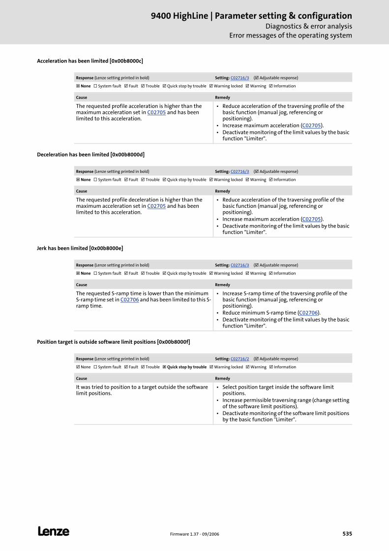
L Firmware 1.37 - 09/2006 535
9400 HighLine | Parameter setting & configurationDiagnostics & error analysis
Error messages of the operating system
Acceleration has been limited [0x00b8000c]
Deceleration has been limited [0x00b8000d]
Jerk has been limited [0x00b8000e]
Position target is outside software limit positions [0x00b8000f]
Response (Lenze setting printed in bold) Setting: C02716/3 ( Adjustable response)
None System fault Fault Trouble Quick stop by trouble Warning locked Warning Information
Cause Remedy
The requested profile acceleration is higher than the maximum acceleration set in C02705 and has been limited to this acceleration.
• Reduce acceleration of the traversing profile of the basic function (manual jog, referencing or positioning).
• Increase maximum acceleration (C02705). • Deactivate monitoring of the limit values by the basic
function "Limiter".
Response (Lenze setting printed in bold) Setting: C02716/3 ( Adjustable response)
None System fault Fault Trouble Quick stop by trouble Warning locked Warning Information
Cause Remedy
The requested profile deceleration is higher than the maximum acceleration set in C02705 and has been limited to this acceleration.
• Reduce acceleration of the traversing profile of the basic function (manual jog, referencing or positioning).
• Increase maximum acceleration (C02705). • Deactivate monitoring of the limit values by the basic
function "Limiter".
Response (Lenze setting printed in bold) Setting: C02716/3 ( Adjustable response)
None System fault Fault Trouble Quick stop by trouble Warning locked Warning Information
Cause Remedy
The requested S-ramp time is lower than the minimum S-ramp time set in C02706 and has been limited to this S-ramp time.
• Increase S-ramp time of the traversing profile of the basic function (manual jog, referencing or positioning).
• Reduce minimum S-ramp time (C02706). • Deactivate monitoring of the limit values by the basic
function "Limiter".
Response (Lenze setting printed in bold) Setting: C02716/2 ( Adjustable response)
None System fault Fault Trouble Quick stop by trouble Warning locked Warning Information
Cause Remedy
It was tried to position to a target outside the software limit positions.
• Select position target inside the software limit positions.
• Increase permissible traversing range (change setting of the software limit positions).
• Deactivate monitoring of the software limit positions by the basic function "Limiter".
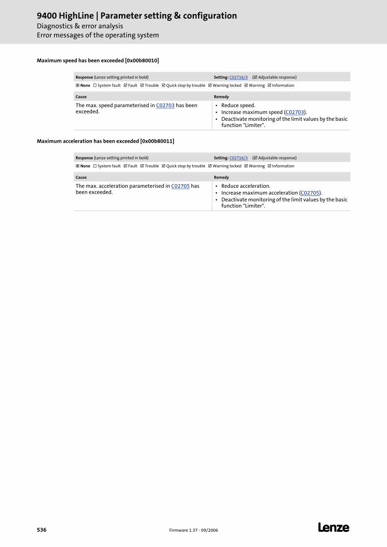
9400 HighLine | Parameter setting & configurationDiagnostics & error analysisError messages of the operating system
536 Firmware 1.37 - 09/2006 L
Maximum speed has been exceeded [0x00b80010]
Maximum acceleration has been exceeded [0x00b80011]
Response (Lenze setting printed in bold) Setting: C02716/3 ( Adjustable response)
None System fault Fault Trouble Quick stop by trouble Warning locked Warning Information
Cause Remedy
The max. speed parameterised in C02703 has been exceeded.
• Reduce speed. • Increase maximum speed (C02703). • Deactivate monitoring of the limit values by the basic
function "Limiter".
Response (Lenze setting printed in bold) Setting: C02716/3 ( Adjustable response)
None System fault Fault Trouble Quick stop by trouble Warning locked Warning Information
Cause Remedy
The max. acceleration parameterised in C02705 has been exceeded.
• Reduce acceleration. • Increase maximum acceleration (C02705). • Deactivate monitoring of the limit values by the basic
function "Limiter".
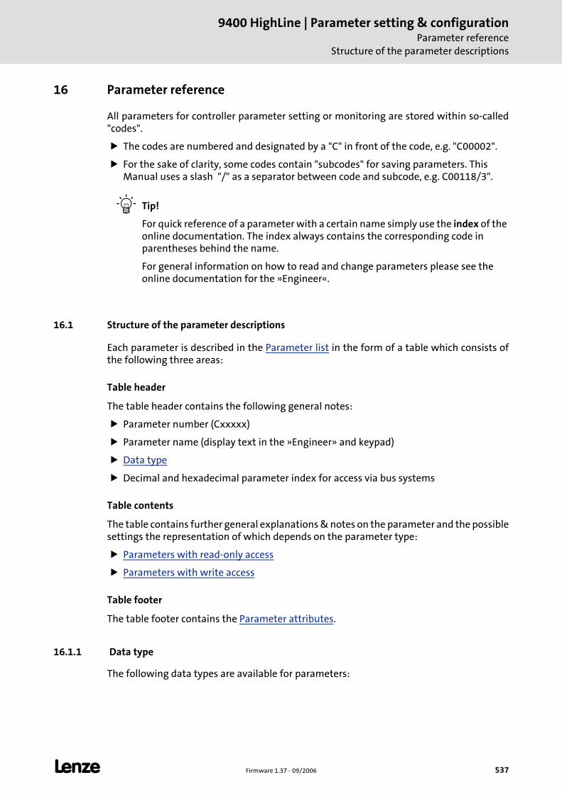
L Firmware 1.37 - 09/2006 537
9400 HighLine | Parameter setting & configurationParameter reference
Structure of the parameter descriptions
16 Parameter reference
All parameters for controller parameter setting or monitoring are stored within so-called "codes".
The codes are numbered and designated by a "C" in front of the code, e.g. "C00002".
For the sake of clarity, some codes contain "subcodes" for saving parameters. This Manual uses a slash "/" as a separator between code and subcode, e.g. C00118/3".
Tip!
For quick reference of a parameter with a certain name simply use the index of the online documentation. The index always contains the corresponding code in parentheses behind the name.
For general information on how to read and change parameters please see the online documentation for the »Engineer«.
16.1 Structure of the parameter descriptions
Each parameter is described in the Parameter list in the form of a table which consists of the following three areas:
Table header
The table header contains the following general notes:
Parameter number (Cxxxxx)
Parameter name (display text in the »Engineer» and keypad)
Data type
Decimal and hexadecimal parameter index for access via bus systems
Table contents
The table contains further general explanations & notes on the parameter and the possible settings the representation of which depends on the parameter type:
Parameters with read-only access
Parameters with write access
Table footer
The table footer contains the Parameter attributes.
16.1.1 Data type
The following data types are available for parameters:
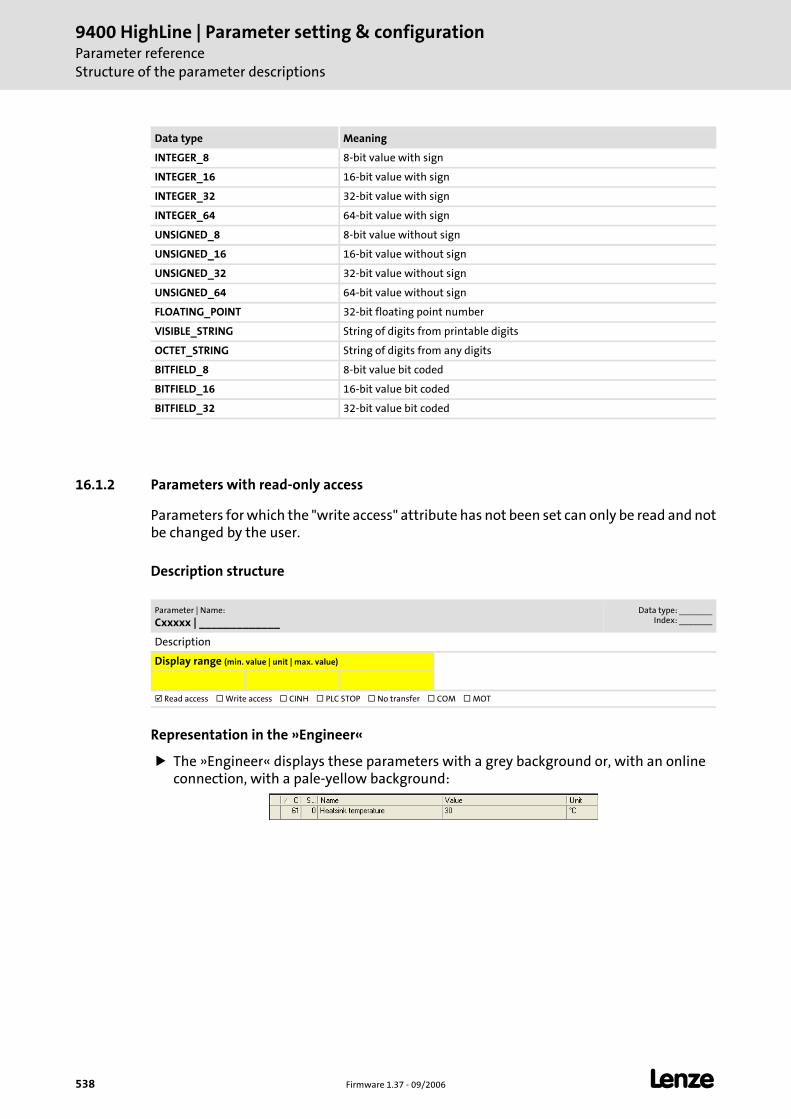
9400 HighLine | Parameter setting & configurationParameter referenceStructure of the parameter descriptions
538 Firmware 1.37 - 09/2006 L
16.1.2 Parameters with read-only access
Parameters for which the "write access" attribute has not been set can only be read and not be changed by the user.
Description structure
Representation in the »Engineer«
The »Engineer« displays these parameters with a grey background or, with an online connection, with a pale-yellow background:
Data type Meaning
INTEGER_8 8-bit value with sign
INTEGER_16 16-bit value with sign
INTEGER_32 32-bit value with sign
INTEGER_64 64-bit value with sign
UNSIGNED_8 8-bit value without sign
UNSIGNED_16 16-bit value without sign
UNSIGNED_32 32-bit value without sign
UNSIGNED_64 64-bit value without sign
FLOATING_POINT 32-bit floating point number
VISIBLE_STRING String of digits from printable digits
OCTET_STRING String of digits from any digits
BITFIELD_8 8-bit value bit coded
BITFIELD_16 16-bit value bit coded
BITFIELD_32 32-bit value bit coded
Parameter | Name:
Cxxxxx | _____________Data type: _______
Index: _______
Description
Display range (min. value | unit | max. value)
Read access Write access CINH PLC STOP No transfer COM MOT
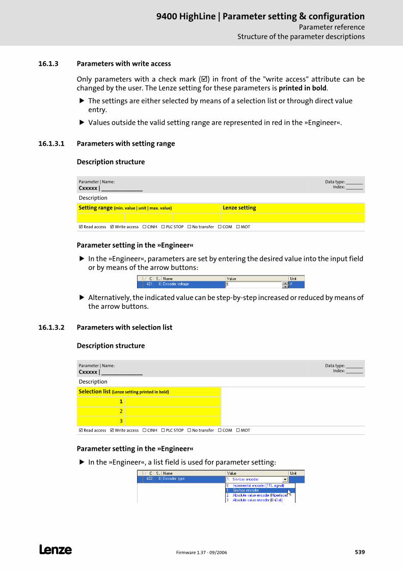
L Firmware 1.37 - 09/2006 539
9400 HighLine | Parameter setting & configurationParameter reference
Structure of the parameter descriptions
16.1.3 Parameters with write access
Only parameters with a check mark ( ) in front of the "write access" attribute can be changed by the user. The Lenze setting for these parameters is printed in bold.
The settings are either selected by means of a selection list or through direct value entry.
Values outside the valid setting range are represented in red in the »Engineer«.
16.1.3.1 Parameters with setting range
Description structure
Parameter setting in the »Engineer«
In the »Engineer«, parameters are set by entering the desired value into the input field or by means of the arrow buttons:
Alternatively, the indicated value can be step-by-step increased or reduced by means of the arrow buttons.
16.1.3.2 Parameters with selection list
Description structure
Parameter setting in the »Engineer«
In the »Engineer«, a list field is used for parameter setting:
Parameter | Name:
Cxxxxx | _____________Data type: _______
Index: _______
Description
Setting range (min. value | unit | max. value) Lenze setting
Read access Write access CINH PLC STOP No transfer COM MOT
Parameter | Name:
Cxxxxx | _____________Data type: _______
Index: _______
Description
Selection list (Lenze setting printed in bold)
1
2
3
Read access Write access CINH PLC STOP No transfer COM MOT
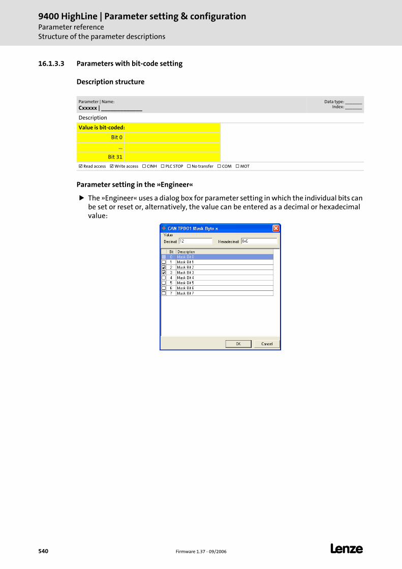
9400 HighLine | Parameter setting & configurationParameter referenceStructure of the parameter descriptions
540 Firmware 1.37 - 09/2006 L
16.1.3.3 Parameters with bit-code setting
Description structure
Parameter setting in the »Engineer«
The »Engineer« uses a dialog box for parameter setting in which the individual bits can be set or reset or, alternatively, the value can be entered as a decimal or hexadecimal value:
Parameter | Name:
Cxxxxx | _____________Data type: _______
Index: _______
Description
Value is bit-coded:
Bit 0
...
Bit 31
Read access Write access CINH PLC STOP No transfer COM MOT
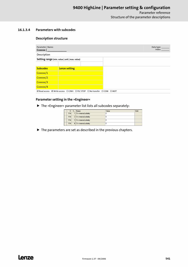
L Firmware 1.37 - 09/2006 541
9400 HighLine | Parameter setting & configurationParameter reference
Structure of the parameter descriptions
16.1.3.4 Parameters with subcodes
Description structure
Parameter setting in the »Engineer«
The »Engineer« parameter list lists all subcodes separately:
The parameters are set as described in the previous chapters.
Parameter | Name:
Cxxxxx | _____________Data type: _______
Index: _______
Description
Setting range (min. value | unit | max. value)
Subcodes Lenze setting
Cxxxxx/1
Cxxxxx/2
Cxxxxx/3
Cxxxxx/4
Read access Write access CINH PLC STOP No transfer COM MOT
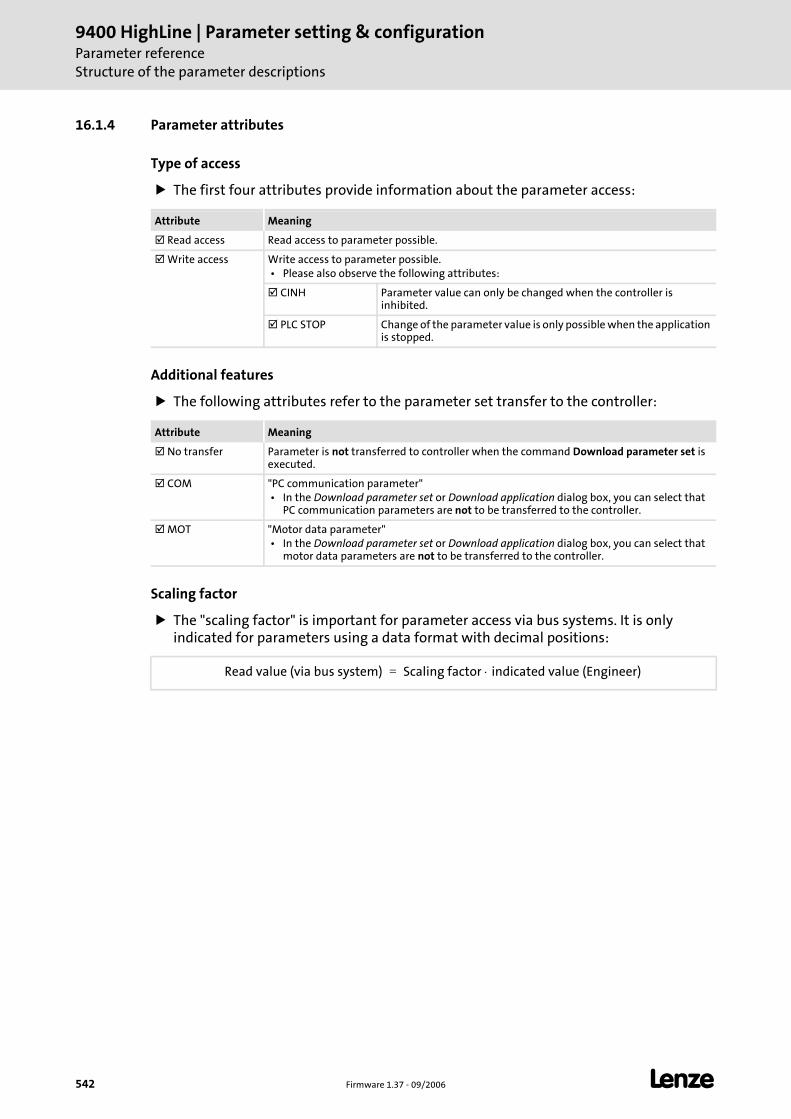
9400 HighLine | Parameter setting & configurationParameter referenceStructure of the parameter descriptions
542 Firmware 1.37 - 09/2006 L
16.1.4 Parameter attributes
Type of access
The first four attributes provide information about the parameter access:
Additional features
The following attributes refer to the parameter set transfer to the controller:
Scaling factor
The "scaling factor" is important for parameter access via bus systems. It is only indicated for parameters using a data format with decimal positions:
Attribute Meaning
Read access Read access to parameter possible.
Write access Write access to parameter possible. • Please also observe the following attributes:
CINH Parameter value can only be changed when the controller is inhibited.
PLC STOP Change of the parameter value is only possible when the application is stopped.
Attribute Meaning
No transfer Parameter is not transferred to controller when the command Download parameter set is executed.
COM "PC communication parameter" • In the Download parameter set or Download application dialog box, you can select that
PC communication parameters are not to be transferred to the controller.
MOT "Motor data parameter" • In the Download parameter set or Download application dialog box, you can select that
motor data parameters are not to be transferred to the controller.
Read value (via bus system) Scaling factor indicated value (Engineer)⋅=
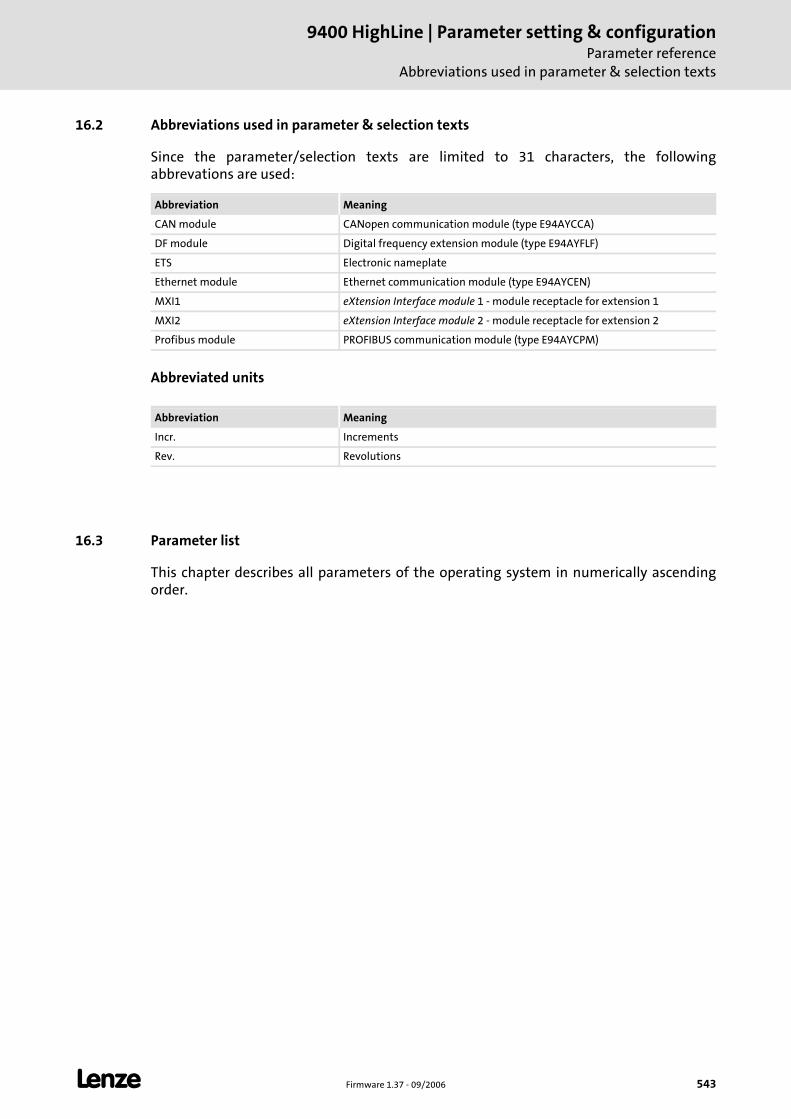
L Firmware 1.37 - 09/2006 543
9400 HighLine | Parameter setting & configurationParameter reference
Abbreviations used in parameter & selection texts
16.2 Abbreviations used in parameter & selection texts
Since the parameter/selection texts are limited to 31 characters, the following abbrevations are used:
Abbreviated units
16.3 Parameter list
This chapter describes all parameters of the operating system in numerically ascending order.
Abbreviation Meaning
CAN module CANopen communication module (type E94AYCCA)
DF module Digital frequency extension module (type E94AYFLF)
ETS Electronic nameplate
Ethernet module Ethernet communication module (type E94AYCEN)
MXI1 eXtension Interface module 1 - module receptacle for extension 1
MXI2 eXtension Interface module 2 - module receptacle for extension 2
Profibus module PROFIBUS communication module (type E94AYCPM)
Abbreviation Meaning
Incr. Increments
Rev. Revolutions
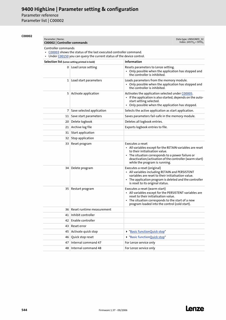
9400 HighLine | Parameter setting & configurationParameter referenceParameter list | C00002
544 Firmware 1.37 - 09/2006 L
C00002Parameter | Name:
C00002 | Controller commandsData type: UNSIGNED_32
Index: 24573d = 5FFDh
Controller commands • C00003 shows the status of the last executed controller command. • Under C00150 you can query the current status of the device control.
Selection list (Lenze setting printed in bold) Information
0 Load Lenze setting Resets parameters to Lenze setting. • Only possible when the application has stopped and
the controller is inhibited.
1 Load start parameters Loads parameters from the memory module. • Only possible when the application has stopped and
the controller is inhibited.
5 Activate application Activates the application selected under C00005. • If the application is also started, depends on the auto-
start setting selected. • Only possible when the application has stopped.
7 Save selected application Selects the active application as start application.
11 Save start parameters Saves parameters fail-safe in the memory module.
20 Delete logbook Deletes all logbook entries.
21 Archive log file Exports logbook entries to file.
31 Start application
32 Stop application
33 Reset program Executes a reset • All variables except for the RETAIN variables are reset
to their initialisation value. • The situation corresponds to a power failure or
deactivation/activation of the controller (warm start) while the program is running.
34 Delete program Executes a reset (original) • All variables including RETAIN and PERSISTENT
variables are reset to their initialisation value. • The application program is deleted and the controller
is reset to its original status.
35 Restart program Executes a reset (warm start) • All variables except for the PERSISTENT variables are
reset to their initialisation value. • The situation corresponds to the start of a new
program loaded into the control (cold start).
36 Reset runtime measurement
41 Inhibit controller
42 Enable controller
43 Reset error
45 Activate quick stop "Basic functionQuick stop"
46 Quick stop reset "Basic functionQuick stop"
47 Internal command 47 For Lenze service only
48 Internal command 48 For Lenze service only
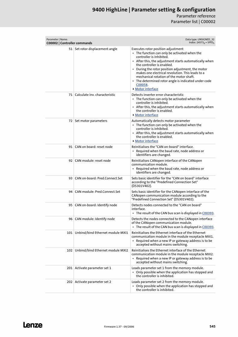
L Firmware 1.37 - 09/2006 545
9400 HighLine | Parameter setting & configurationParameter reference
Parameter list | C00002
51 Set rotor displacement angle Executes rotor position adjustment • The function can only be activated when the
controller is inhibited. • After this, the adjustment starts automatically when
the controller is enabled. • During the rotor position adjustment, the motor
makes one electrical revolution. This leads to a mechanical rotation of the motor shaft.
• The determined rotor angle is indicated under code C00058.
Motor interface
71 Calculate inv. characteristic Detects inverter error characteristic • The function can only be activated when the
controller is inhibited. • After this, the adjustment starts automatically when
the controller is enabled.Motor interface
72 Set motor parameters Automatically detects motor parameter • The function can only be activated when the
controller is inhibited. • After this, the adjustment starts automatically when
the controller is enabled.Motor interface
91 CAN on board: reset node Reinitialises the "CAN on-board" interface. • Required when the baud rate, node address or
identifiers are changed.
92 CAN module: reset node Reinitialises CANopen interface of the CANopen communication module. • Required when the baud rate, node address or
identifiers are changed.
93 CAN on-board: Pred.Connect.Set Sets basic identifier for the "CAN on board" interface according to the "Predefined Connection Set" (DS301V402).
94 CAN module: Pred.Connect.Set Sets basic identifier for the CANopen interface of the CANopen communication module according to the "Predefined Connection Set" (DS301V402).
95 CAN on-board: Identify node Detects nodes connected to the "CAN on board" interface. • The result of the CAN bus scan is displayed in C00393.
96 CAN module: Identify node Detects the nodes connected to the CANopen interface of the CANopen communication module. • The result of the CAN bus scan is displayed in C00393.
101 Unbind/bind Ethernet module MXI1 Reinitialises the Ethernet interface of the Ethernet communication module in the module receptacle MXI1. • Required when a new IP or gateway address is to be
accepted without mains switching.
102 Unbind/bind Ethernet module MXI2 Reinitialises the Ethernet interface of the Ethernet communication module in the module receptacle MXI2. • Required when a new IP or gateway address is to be
accepted without mains switching.
201 Activate parameter set 1 Loads parameter set 1 from the memory module. • Only possible when the application has stopped and
the controller is inhibited.
202 Activate parameter set 2 Loads parameter set 2 from the memory module. • Only possible when the application has stopped and
the controller is inhibited.
Parameter | Name:
C00002 | Controller commandsData type: UNSIGNED_32
Index: 24573d = 5FFDh
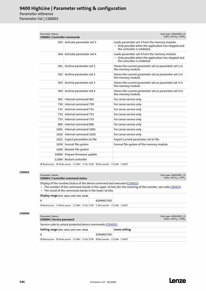
9400 HighLine | Parameter setting & configurationParameter referenceParameter list | C00003
546 Firmware 1.37 - 09/2006 L
C00003
C00004
203 Activate parameter set 3 Loads parameter set 3 from the memory module. • Only possible when the application has stopped and
the controller is inhibited.
204 Activate parameter set 4 Loads parameter set 4 from the memory module. • Only possible when the application has stopped and
the controller is inhibited.
301 Archive parameter set 1 Stores the current parameter set as parameter set 1 in the memory module.
302 Archive parameter set 2 Stores the current parameter set as parameter set 2 in the memory module.
303 Archive parameter set 3 Stores the current parameter set as parameter set 3 in the memory module.
304 Archive parameter set 4 Stores the current parameter set as parameter set 4 in the memory module.
401 Internal command 401 For Lenze service only
730 Internal command 730 For Lenze service only
731 Internal command 731 For Lenze service only
732 Internal command 732 For Lenze service only
733 Internal command 733 For Lenze service only
800 Internal command 800 For Lenze service only
1001 Internal command 1001 For Lenze service only
1020 Internal command 1020 For Lenze service only
1021 Export parameters to file Export current parameter set to file.
1030 Format file system Format file system of the memory module.
1040 Restore file system
10000 Prepare firmware update
11000 Restart controller
Read access Write access CINH PLC STOP No transfer COM MOT
Parameter | Name:
C00002 | Controller commandsData type: UNSIGNED_32
Index: 24573d = 5FFDh
Parameter | Name:
C00003 | Controller command statusData type: UNSIGNED_32
Index: 24572d = 5FFCh
Display of the number/status of the device command last executed (C00002). • The number of the command stands in the upper 16 bits (for the meaning of the number, see code C00002). • The result of the command stands in the lower 16 bits.
Display range (min. value | unit | max. value)
0 4294967295
Read access Write access CINH PLC STOP No transfer COM MOT
Parameter | Name:
C00004 | Service passwordData type: UNSIGNED_32
Index: 24571d = 5FFBh
Service code to unlock protected device commands (C00002).
Setting range (min. value | unit | max. value) Lenze setting
0 4294967295
Read access Write access CINH PLC STOP No transfer COM MOT
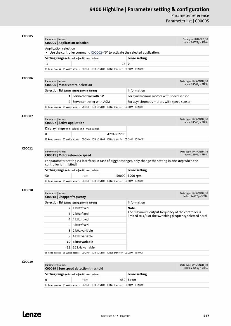
L Firmware 1.37 - 09/2006 547
9400 HighLine | Parameter setting & configurationParameter reference
Parameter list | C00005
C00005
C00006
C00007
C00011
C00018
C00019
Parameter | Name:
C00005 | Application selectionData type: INTEGER_32Index: 24570d = 5FFAh
Application selection • Use the controller command C00002="5" to activate the selected application.
Setting range (min. value | unit | max. value) Lenze setting
-1 16 0
Read access Write access CINH PLC STOP No transfer COM MOT
Parameter | Name:
C00006 | Motor control selectionData type: UNSIGNED_32
Index: 24569d = 5FF9h
Selection list (Lenze setting printed in bold) Information
1 Servo control with SM For synchronous motors with speed sensor
2 Servo controller with ASM For asynchronous motors with speed sensor
Read access Write access CINH PLC STOP No transfer COM MOT
Parameter | Name:
C00007 | Active applicationData type: UNSIGNED_32
Index: 24568d = 5FF8h
Display range (min. value | unit | max. value)
0 4294967295
Read access Write access CINH PLC STOP No transfer COM MOT
Parameter | Name:
C00011 | Motor reference speedData type: UNSIGNED_32
Index: 24564d = 5FF4h
For parameter setting via interface: In case of bigger changes, only change the setting in one step when the controller is inhibited!
Setting range (min. value | unit | max. value) Lenze setting
50 rpm 50000 3000 rpm
Read access Write access CINH PLC STOP No transfer COM MOT
Parameter | Name:
C00018 | Chopper frequencyData type: UNSIGNED_32
Index: 24557d = 5FEDh
Selection list (Lenze setting printed in bold) Information
2 1 kHz fixed Note:The maximum output frequency of the controller is limited to 1/8 of the switching frequency selected here!
3 2 kHz fixed
4 4 kHz fixed
5 8 kHz fixed
8 2 kHz variable
9 4 kHz variable
10 8 kHz variable
11 16 kHz variable
Read access Write access CINH PLC STOP No transfer COM MOT
Parameter | Name:
C00019 | Zero speed detection thresholdData type: UNSIGNED_32
Index: 24556d = 5FECh
Setting range (min. value | unit | max. value) Lenze setting
0 rpm 450 5 rpm
Read access Write access CINH PLC STOP No transfer COM MOT
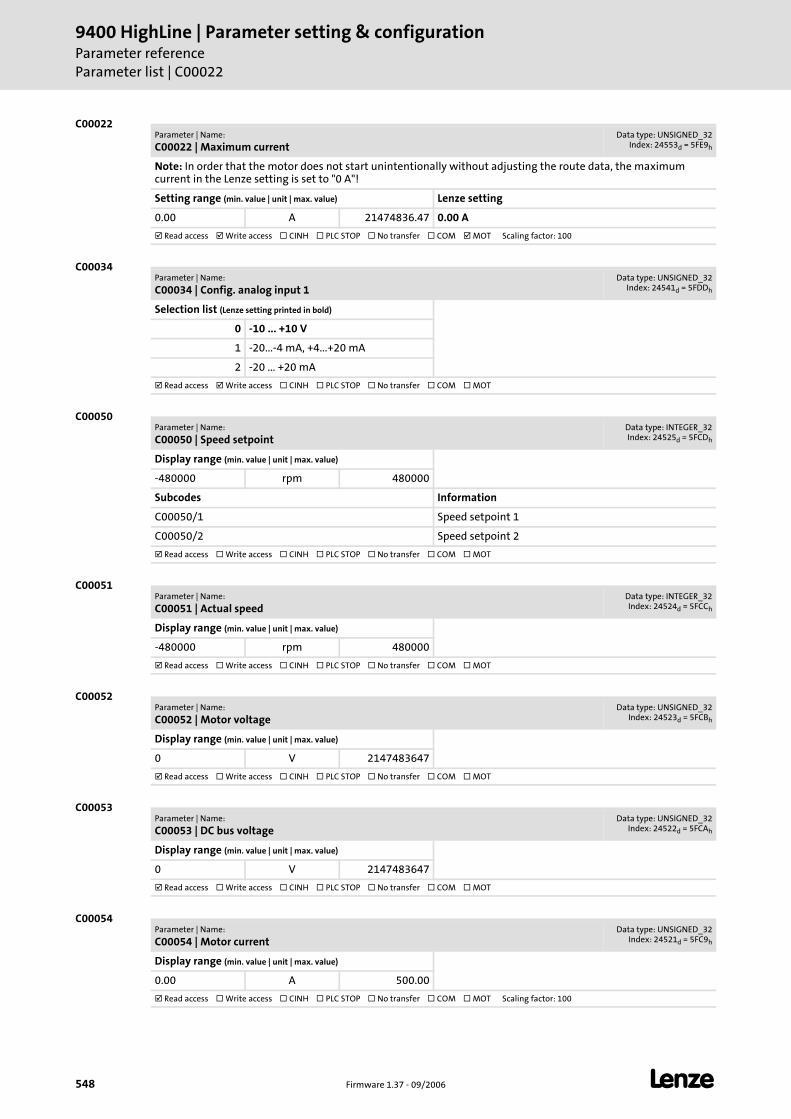
9400 HighLine | Parameter setting & configurationParameter referenceParameter list | C00022
548 Firmware 1.37 - 09/2006 L
C00022
C00034
C00050
C00051
C00052
C00053
C00054
Parameter | Name:
C00022 | Maximum currentData type: UNSIGNED_32
Index: 24553d = 5FE9h
Note: In order that the motor does not start unintentionally without adjusting the route data, the maximum current in the Lenze setting is set to "0 A"!
Setting range (min. value | unit | max. value) Lenze setting
0.00 A 21474836.47 0.00 A
Read access Write access CINH PLC STOP No transfer COM MOT Scaling factor: 100
Parameter | Name:
C00034 | Config. analog input 1Data type: UNSIGNED_32
Index: 24541d = 5FDDh
Selection list (Lenze setting printed in bold)
0 -10 ... +10 V
1 -20...-4 mA, +4...+20 mA
2 -20 ... +20 mA
Read access Write access CINH PLC STOP No transfer COM MOT
Parameter | Name:
C00050 | Speed setpointData type: INTEGER_32Index: 24525d = 5FCDh
Display range (min. value | unit | max. value)
-480000 rpm 480000
Subcodes Information
C00050/1 Speed setpoint 1
C00050/2 Speed setpoint 2
Read access Write access CINH PLC STOP No transfer COM MOT
Parameter | Name:
C00051 | Actual speedData type: INTEGER_32Index: 24524d = 5FCCh
Display range (min. value | unit | max. value)
-480000 rpm 480000
Read access Write access CINH PLC STOP No transfer COM MOT
Parameter | Name:
C00052 | Motor voltageData type: UNSIGNED_32
Index: 24523d = 5FCBh
Display range (min. value | unit | max. value)
0 V 2147483647
Read access Write access CINH PLC STOP No transfer COM MOT
Parameter | Name:
C00053 | DC bus voltageData type: UNSIGNED_32
Index: 24522d = 5FCAh
Display range (min. value | unit | max. value)
0 V 2147483647
Read access Write access CINH PLC STOP No transfer COM MOT
Parameter | Name:
C00054 | Motor currentData type: UNSIGNED_32
Index: 24521d = 5FC9h
Display range (min. value | unit | max. value)
0.00 A 500.00
Read access Write access CINH PLC STOP No transfer COM MOT Scaling factor: 100
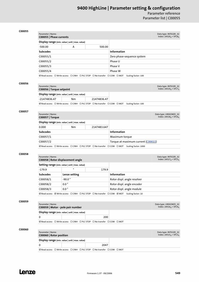
L Firmware 1.37 - 09/2006 549
9400 HighLine | Parameter setting & configurationParameter reference
Parameter list | C00055
C00055
C00056
C00057
C00058
C00059
C00060
Parameter | Name:
C00055 | Phase currentsData type: INTEGER_32Index: 24520d = 5FC8h
Display range (min. value | unit | max. value)
-500.00 A 500.00
Subcodes Information
C00055/1 Zero phase-sequence system
C00055/2 Phase U
C00055/3 Phase V
C00055/4 Phase W
Read access Write access CINH PLC STOP No transfer COM MOT Scaling factor: 100
Parameter | Name:
C00056 | Torque setpointData type: INTEGER_32Index: 24519d = 5FC7h
Display range (min. value | unit | max. value)
-21474836.47 Nm 21474836.47
Read access Write access CINH PLC STOP No transfer COM MOT Scaling factor: 100
Parameter | Name:
C00057 | TorqueData type: UNSIGNED_32
Index: 24518d = 5FC6h
Display range (min. value | unit | max. value)
0.000 Nm 2147483.647
Subcodes Information
C00057/1 Maximum torque
C00057/2 Torque at maximum current (C00022)
Read access Write access CINH PLC STOP No transfer COM MOT Scaling factor: 1000
Parameter | Name:
C00058 | Rotor displacement angleData type: INTEGER_32Index: 24517d = 5FC5h
Setting range (min. value | unit | max. value)
-179.9 ° 179.9
Subcodes Lenze setting Information
C00058/1 -90.0 ° Rotor displ. angle resolver
C00058/2 0.0 ° Rotor displ. angle encoder
C00058/3 0.0 ° Rotor displ. angle module
Read access Write access CINH PLC STOP No transfer COM MOT Scaling factor: 10
Parameter | Name:
C00059 | Motor - pole pair numberData type: UNSIGNED_32
Index: 24516d = 5FC4h
Display range (min. value | unit | max. value)
0 200
Read access Write access CINH PLC STOP No transfer COM MOT
Parameter | Name:
C00060 | Rotor positionData type: INTEGER_32Index: 24515d = 5FC3h
Display range (min. value | unit | max. value)
0 2047
Read access Write access CINH PLC STOP No transfer COM MOT
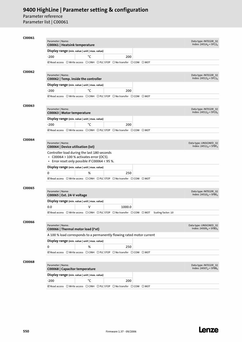
9400 HighLine | Parameter setting & configurationParameter referenceParameter list | C00061
550 Firmware 1.37 - 09/2006 L
C00061
C00062
C00063
C00064
C00065
C00066
C00068
Parameter | Name:
C00061 | Heatsink temperatureData type: INTEGER_32Index: 24514d = 5FC2h
Display range (min. value | unit | max. value)
-200 °C 200
Read access Write access CINH PLC STOP No transfer COM MOT
Parameter | Name:
C00062 | Temp. inside the controllerData type: INTEGER_32Index: 24513d = 5FC1h
Display range (min. value | unit | max. value)
-200 °C 200
Read access Write access CINH PLC STOP No transfer COM MOT
Parameter | Name:
C00063 | Motor temperatureData type: INTEGER_32Index: 24512d = 5FC0h
Display range (min. value | unit | max. value)
-200 °C 200
Read access Write access CINH PLC STOP No transfer COM MOT
Parameter | Name:
C00064 | Device utilisation (Ixt)Data type: UNSIGNED_32
Index: 24511d = 5FBFh
Controller load during the last 180 seconds • C00064 > 100 % activates error (OC5). • Error reset only possible if C00064 < 95 %.
Display range (min. value | unit | max. value)
0 % 250
Read access Write access CINH PLC STOP No transfer COM MOT
Parameter | Name:
C00065 | Ext. 24-V voltageData type: INTEGER_32
Index: 24510d = 5FBEh
Display range (min. value | unit | max. value)
0.0 V 1000.0
Read access Write access CINH PLC STOP No transfer COM MOT Scaling factor: 10
Parameter | Name:
C00066 | Thermal motor load (I²xt)Data type: UNSIGNED_32
Index: 24509d = 5FBDh
A 100 % load corresponds to a permanently flowing rated motor current
Display range (min. value | unit | max. value)
0 % 250
Read access Write access CINH PLC STOP No transfer COM MOT
Parameter | Name:
C00068 | Capacitor temperatureData type: INTEGER_32Index: 24507d = 5FBBh
Display range (min. value | unit | max. value)
-200 °C 200
Read access Write access CINH PLC STOP No transfer COM MOT
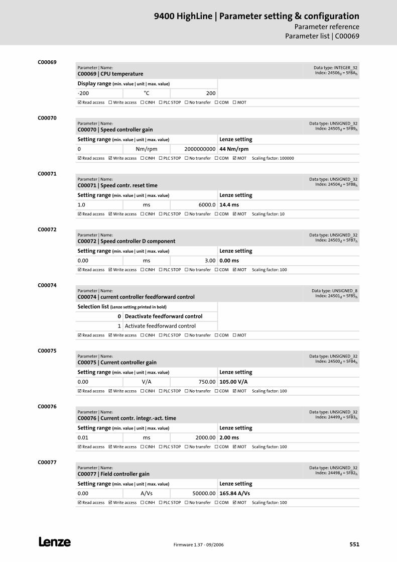
L Firmware 1.37 - 09/2006 551
9400 HighLine | Parameter setting & configurationParameter reference
Parameter list | C00069
C00069
C00070
C00071
C00072
C00074
C00075
C00076
C00077
Parameter | Name:
C00069 | CPU temperatureData type: INTEGER_32Index: 24506d = 5FBAh
Display range (min. value | unit | max. value)
-200 °C 200
Read access Write access CINH PLC STOP No transfer COM MOT
Parameter | Name:
C00070 | Speed controller gainData type: UNSIGNED_32
Index: 24505d = 5FB9h
Setting range (min. value | unit | max. value) Lenze setting
0 Nm/rpm 2000000000 44 Nm/rpm
Read access Write access CINH PLC STOP No transfer COM MOT Scaling factor: 100000
Parameter | Name:
C00071 | Speed contr. reset timeData type: UNSIGNED_32
Index: 24504d = 5FB8h
Setting range (min. value | unit | max. value) Lenze setting
1.0 ms 6000.0 14.4 ms
Read access Write access CINH PLC STOP No transfer COM MOT Scaling factor: 10
Parameter | Name:
C00072 | Speed controller D componentData type: UNSIGNED_32
Index: 24503d = 5FB7h
Setting range (min. value | unit | max. value) Lenze setting
0.00 ms 3.00 0.00 ms
Read access Write access CINH PLC STOP No transfer COM MOT Scaling factor: 100
Parameter | Name:
C00074 | current controller feedforward controlData type: UNSIGNED_8
Index: 24501d = 5FB5h
Selection list (Lenze setting printed in bold)
0 Deactivate feedforward control
1 Activate feedforward control
Read access Write access CINH PLC STOP No transfer COM MOT
Parameter | Name:
C00075 | Current controller gainData type: UNSIGNED_32
Index: 24500d = 5FB4h
Setting range (min. value | unit | max. value) Lenze setting
0.00 V/A 750.00 105.00 V/A
Read access Write access CINH PLC STOP No transfer COM MOT Scaling factor: 100
Parameter | Name:
C00076 | Current contr. integr.-act. timeData type: UNSIGNED_32
Index: 24499d = 5FB3h
Setting range (min. value | unit | max. value) Lenze setting
0.01 ms 2000.00 2.00 ms
Read access Write access CINH PLC STOP No transfer COM MOT Scaling factor: 100
Parameter | Name:
C00077 | Field controller gainData type: UNSIGNED_32
Index: 24498d = 5FB2h
Setting range (min. value | unit | max. value) Lenze setting
0.00 A/Vs 50000.00 165.84 A/Vs
Read access Write access CINH PLC STOP No transfer COM MOT Scaling factor: 100
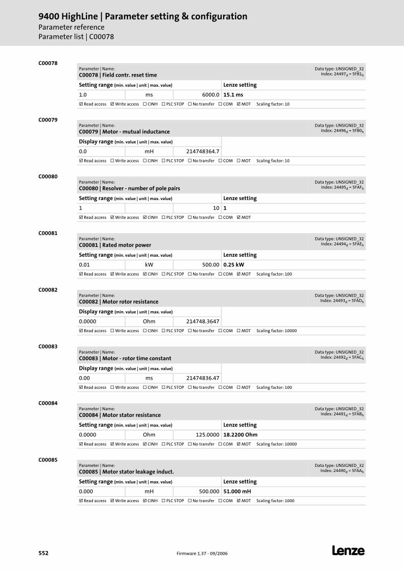
9400 HighLine | Parameter setting & configurationParameter referenceParameter list | C00078
552 Firmware 1.37 - 09/2006 L
C00078
C00079
C00080
C00081
C00082
C00083
C00084
C00085
Parameter | Name:
C00078 | Field contr. reset timeData type: UNSIGNED_32
Index: 24497d = 5FB1h
Setting range (min. value | unit | max. value) Lenze setting
1.0 ms 6000.0 15.1 ms
Read access Write access CINH PLC STOP No transfer COM MOT Scaling factor: 10
Parameter | Name:
C00079 | Motor - mutual inductanceData type: UNSIGNED_32
Index: 24496d = 5FB0h
Display range (min. value | unit | max. value)
0.0 mH 214748364.7
Read access Write access CINH PLC STOP No transfer COM MOT Scaling factor: 10
Parameter | Name:
C00080 | Resolver - number of pole pairsData type: UNSIGNED_32
Index: 24495d = 5FAFh
Setting range (min. value | unit | max. value) Lenze setting
1 10 1
Read access Write access CINH PLC STOP No transfer COM MOT
Parameter | Name:
C00081 | Rated motor powerData type: UNSIGNED_32
Index: 24494d = 5FAEh
Setting range (min. value | unit | max. value) Lenze setting
0.01 kW 500.00 0.25 kW
Read access Write access CINH PLC STOP No transfer COM MOT Scaling factor: 100
Parameter | Name:
C00082 | Motor rotor resistanceData type: UNSIGNED_32
Index: 24493d = 5FADh
Display range (min. value | unit | max. value)
0.0000 Ohm 214748.3647
Read access Write access CINH PLC STOP No transfer COM MOT Scaling factor: 10000
Parameter | Name:
C00083 | Motor - rotor time constantData type: UNSIGNED_32
Index: 24492d = 5FACh
Display range (min. value | unit | max. value)
0.00 ms 21474836.47
Read access Write access CINH PLC STOP No transfer COM MOT Scaling factor: 100
Parameter | Name:
C00084 | Motor stator resistanceData type: UNSIGNED_32
Index: 24491d = 5FABh
Setting range (min. value | unit | max. value) Lenze setting
0.0000 Ohm 125.0000 18.2200 Ohm
Read access Write access CINH PLC STOP No transfer COM MOT Scaling factor: 10000
Parameter | Name:
C00085 | Motor stator leakage induct.Data type: UNSIGNED_32
Index: 24490d = 5FAAh
Setting range (min. value | unit | max. value) Lenze setting
0.000 mH 500.000 51.000 mH
Read access Write access CINH PLC STOP No transfer COM MOT Scaling factor: 1000
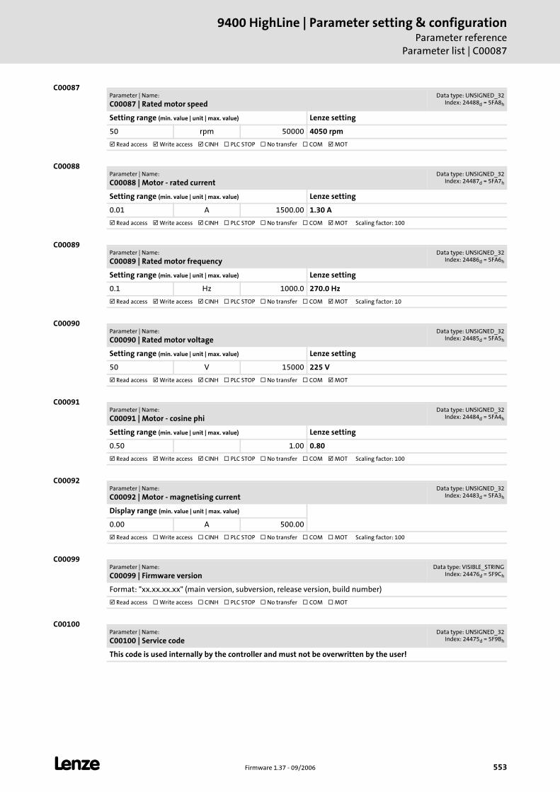
L Firmware 1.37 - 09/2006 553
9400 HighLine | Parameter setting & configurationParameter reference
Parameter list | C00087
C00087
C00088
C00089
C00090
C00091
C00092
C00099
C00100
Parameter | Name:
C00087 | Rated motor speedData type: UNSIGNED_32
Index: 24488d = 5FA8h
Setting range (min. value | unit | max. value) Lenze setting
50 rpm 50000 4050 rpm
Read access Write access CINH PLC STOP No transfer COM MOT
Parameter | Name:
C00088 | Motor - rated currentData type: UNSIGNED_32
Index: 24487d = 5FA7h
Setting range (min. value | unit | max. value) Lenze setting
0.01 A 1500.00 1.30 A
Read access Write access CINH PLC STOP No transfer COM MOT Scaling factor: 100
Parameter | Name:
C00089 | Rated motor frequencyData type: UNSIGNED_32
Index: 24486d = 5FA6h
Setting range (min. value | unit | max. value) Lenze setting
0.1 Hz 1000.0 270.0 Hz
Read access Write access CINH PLC STOP No transfer COM MOT Scaling factor: 10
Parameter | Name:
C00090 | Rated motor voltageData type: UNSIGNED_32
Index: 24485d = 5FA5h
Setting range (min. value | unit | max. value) Lenze setting
50 V 15000 225 V
Read access Write access CINH PLC STOP No transfer COM MOT
Parameter | Name:
C00091 | Motor - cosine phiData type: UNSIGNED_32
Index: 24484d = 5FA4h
Setting range (min. value | unit | max. value) Lenze setting
0.50 1.00 0.80
Read access Write access CINH PLC STOP No transfer COM MOT Scaling factor: 100
Parameter | Name:
C00092 | Motor - magnetising currentData type: UNSIGNED_32
Index: 24483d = 5FA3h
Display range (min. value | unit | max. value)
0.00 A 500.00
Read access Write access CINH PLC STOP No transfer COM MOT Scaling factor: 100
Parameter | Name:
C00099 | Firmware version Data type: VISIBLE_STRING
Index: 24476d = 5F9Ch
Format: "xx.xx.xx.xx" (main version, subversion, release version, build number)
Read access Write access CINH PLC STOP No transfer COM MOT
Parameter | Name:
C00100 | Service codeData type: UNSIGNED_32
Index: 24475d = 5F9Bh
This code is used internally by the controller and must not be overwritten by the user!
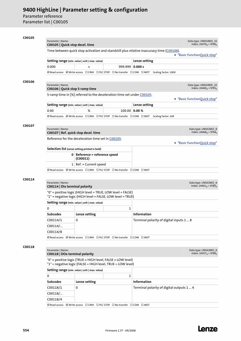
9400 HighLine | Parameter setting & configurationParameter referenceParameter list | C00105
554 Firmware 1.37 - 09/2006 L
C00105
C00106
C00107
C00114
C00118
Parameter | Name:
C00105 | Quick stop decel. timeData type: UNSIGNED_32
Index: 24470d = 5F96h
Time between quick stop activation and standstill plus relative inaccuracy time (C00106). "Basic functionQuick stop"
Setting range (min. value | unit | max. value) Lenze setting
0.000 s 999.999 0.000 s
Read access Write access CINH PLC STOP No transfer COM MOT Scaling factor: 1000
Parameter | Name:
C00106 | Quick stop S-ramp timeData type: UNSIGNED_32
Index: 24469d = 5F95h
S-ramp time in [%] referred to the deceleration time set under C00105. "Basic functionQuick stop"
Setting range (min. value | unit | max. value) Lenze setting
0.00 % 100.00 0.00 %
Read access Write access CINH PLC STOP No transfer COM MOT Scaling factor: 100
Parameter | Name:
C00107 | Ref. quick stop decel. timeData type: UNSIGNED_8
Index: 24468d = 5F94h
Reference for the deceleration time set in C00105. "Basic functionQuick stop"
Selection list (Lenze setting printed in bold)
0 Reference = reference speed (C00011)
1 Ref. = Current speed
Read access Write access CINH PLC STOP No transfer COM MOT
Parameter | Name:
C00114 | DIx terminal polarityData type: UNSIGNED_8
Index: 24461d = 5F8Dh
"0" = positive logic (HIGH level = TRUE, LOW level = FALSE)"1" = negative logic (HIGH level = FALSE, LOW level = TRUE)
Setting range (min. value | unit | max. value)
0 1
Subcodes Lenze setting Information
C00114/1 0 Terminal polarity of digital inputs 1 ... 8
C00114/...
C00114/8
Read access Write access CINH PLC STOP No transfer COM MOT
Parameter | Name:
C00118 | DOx terminal polarityData type: UNSIGNED_8
Index: 24457d = 5F89h
"0" ≡ positive logic (TRUE ≡ HIGH level, FALSE ≡ LOW level)"1" ≡ negative logic (FALSE ≡ HIGH level, TRUE ≡ LOW level)
Setting range (min. value | unit | max. value)
0 1
Subcodes Lenze setting Information
C00118/1 0 Terminal polarity of digital outputs 1 ... 4
C00118/...
C00118/4
Read access Write access CINH PLC STOP No transfer COM MOT
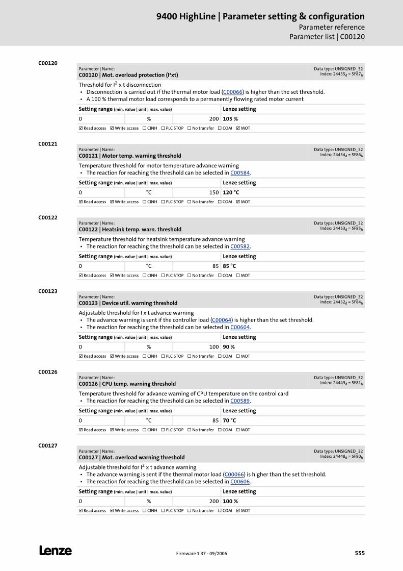
L Firmware 1.37 - 09/2006 555
9400 HighLine | Parameter setting & configurationParameter reference
Parameter list | C00120
C00120
C00121
C00122
C00123
C00126
C00127
Parameter | Name:
C00120 | Mot. overload protection (I²xt)Data type: UNSIGNED_32
Index: 24455d = 5F87h
Threshold for I2 x t disconnection • Disconnection is carried out if the thermal motor load (C00066) is higher than the set threshold. • A 100 % thermal motor load corresponds to a permanently flowing rated motor current
Setting range (min. value | unit | max. value) Lenze setting
0 % 200 105 %
Read access Write access CINH PLC STOP No transfer COM MOT
Parameter | Name:
C00121 | Motor temp. warning thresholdData type: UNSIGNED_32
Index: 24454d = 5F86h
Temperature threshold for motor temperature advance warning • The reaction for reaching the threshold can be selected in C00584.
Setting range (min. value | unit | max. value) Lenze setting
0 °C 150 120 °C
Read access Write access CINH PLC STOP No transfer COM MOT
Parameter | Name:
C00122 | Heatsink temp. warn. thresholdData type: UNSIGNED_32
Index: 24453d = 5F85h
Temperature threshold for heatsink temperature advance warning • The reaction for reaching the threshold can be selected in C00582.
Setting range (min. value | unit | max. value) Lenze setting
0 °C 85 85 °C
Read access Write access CINH PLC STOP No transfer COM MOT
Parameter | Name:
C00123 | Device util. warning thresholdData type: UNSIGNED_32
Index: 24452d = 5F84h
Adjustable threshold for I x t advance warning • The advance warning is sent if the controller load (C00064) is higher than the set threshold. • The reaction for reaching the threshold can be selected in C00604.
Setting range (min. value | unit | max. value) Lenze setting
0 % 100 90 %
Read access Write access CINH PLC STOP No transfer COM MOT
Parameter | Name:
C00126 | CPU temp. warning thresholdData type: UNSIGNED_32
Index: 24449d = 5F81h
Temperature threshold for advance warning of CPU temperature on the control card • The reaction for reaching the threshold can be selected in C00589.
Setting range (min. value | unit | max. value) Lenze setting
0 °C 85 70 °C
Read access Write access CINH PLC STOP No transfer COM MOT
Parameter | Name:
C00127 | Mot. overload warning thresholdData type: UNSIGNED_32
Index: 24448d = 5F80h
Adjustable threshold for I2 x t advance warning • The advance warning is sent if the thermal motor load (C00066) is higher than the set threshold. • The reaction for reaching the threshold can be selected in C00606.
Setting range (min. value | unit | max. value) Lenze setting
0 % 200 100 %
Read access Write access CINH PLC STOP No transfer COM MOT
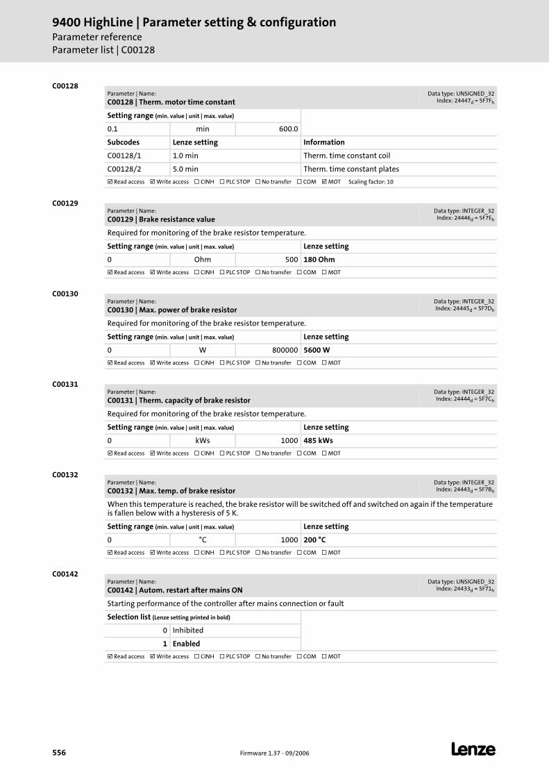
9400 HighLine | Parameter setting & configurationParameter referenceParameter list | C00128
556 Firmware 1.37 - 09/2006 L
C00128
C00129
C00130
C00131
C00132
C00142
Parameter | Name:
C00128 | Therm. motor time constantData type: UNSIGNED_32
Index: 24447d = 5F7Fh
Setting range (min. value | unit | max. value)
0.1 min 600.0
Subcodes Lenze setting Information
C00128/1 1.0 min Therm. time constant coil
C00128/2 5.0 min Therm. time constant plates
Read access Write access CINH PLC STOP No transfer COM MOT Scaling factor: 10
Parameter | Name:
C00129 | Brake resistance valueData type: INTEGER_32
Index: 24446d = 5F7Eh
Required for monitoring of the brake resistor temperature.
Setting range (min. value | unit | max. value) Lenze setting
0 Ohm 500 180 Ohm
Read access Write access CINH PLC STOP No transfer COM MOT
Parameter | Name:
C00130 | Max. power of brake resistorData type: INTEGER_32Index: 24445d = 5F7Dh
Required for monitoring of the brake resistor temperature.
Setting range (min. value | unit | max. value) Lenze setting
0 W 800000 5600 W
Read access Write access CINH PLC STOP No transfer COM MOT
Parameter | Name:
C00131 | Therm. capacity of brake resistorData type: INTEGER_32Index: 24444d = 5F7Ch
Required for monitoring of the brake resistor temperature.
Setting range (min. value | unit | max. value) Lenze setting
0 kWs 1000 485 kWs
Read access Write access CINH PLC STOP No transfer COM MOT
Parameter | Name:
C00132 | Max. temp. of brake resistorData type: INTEGER_32Index: 24443d = 5F7Bh
When this temperature is reached, the brake resistor will be switched off and switched on again if the temperature is fallen below with a hysteresis of 5 K.
Setting range (min. value | unit | max. value) Lenze setting
0 °C 1000 200 °C
Read access Write access CINH PLC STOP No transfer COM MOT
Parameter | Name:
C00142 | Autom. restart after mains ONData type: UNSIGNED_32
Index: 24433d = 5F71h
Starting performance of the controller after mains connection or fault
Selection list (Lenze setting printed in bold)
0 Inhibited
1 Enabled
Read access Write access CINH PLC STOP No transfer COM MOT
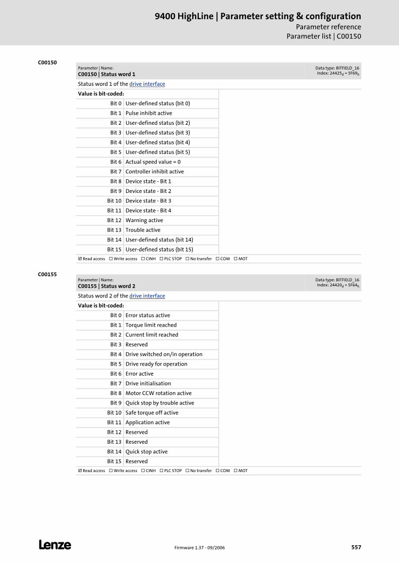
L Firmware 1.37 - 09/2006 557
9400 HighLine | Parameter setting & configurationParameter reference
Parameter list | C00150
C00150
C00155
Parameter | Name:
C00150 | Status word 1Data type: BITFIELD_16Index: 24425d = 5F69h
Status word 1 of the drive interface
Value is bit-coded:
Bit 0 User-defined status (bit 0)
Bit 1 Pulse inhibit active
Bit 2 User-defined status (bit 2)
Bit 3 User-defined status (bit 3)
Bit 4 User-defined status (bit 4)
Bit 5 User-defined status (bit 5)
Bit 6 Actual speed value = 0
Bit 7 Controller inhibit active
Bit 8 Device state - Bit 1
Bit 9 Device state - Bit 2
Bit 10 Device state - Bit 3
Bit 11 Device state - Bit 4
Bit 12 Warning active
Bit 13 Trouble active
Bit 14 User-defined status (bit 14)
Bit 15 User-defined status (bit 15)
Read access Write access CINH PLC STOP No transfer COM MOT
Parameter | Name:
C00155 | Status word 2Data type: BITFIELD_16Index: 24420d = 5F64h
Status word 2 of the drive interface
Value is bit-coded:
Bit 0 Error status active
Bit 1 Torque limit reached
Bit 2 Current limit reached
Bit 3 Reserved
Bit 4 Drive switched on/in operation
Bit 5 Drive ready for operation
Bit 6 Error active
Bit 7 Drive initialisation
Bit 8 Motor CCW rotation active
Bit 9 Quick stop by trouble active
Bit 10 Safe torque off active
Bit 11 Application active
Bit 12 Reserved
Bit 13 Reserved
Bit 14 Quick stop active
Bit 15 Reserved
Read access Write access CINH PLC STOP No transfer COM MOT
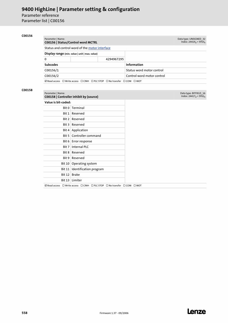
9400 HighLine | Parameter setting & configurationParameter referenceParameter list | C00156
558 Firmware 1.37 - 09/2006 L
C00156
C00158
Parameter | Name:
C00156 | Status/Control word MCTRLData type: UNSIGNED_32
Index: 24419d = 5F63h
Status and control word of the motor interface
Display range (min. value | unit | max. value)
0 4294967295
Subcodes Information
C00156/1 Status word motor control
C00156/2 Control word motor control
Read access Write access CINH PLC STOP No transfer COM MOT
Parameter | Name:
C00158 | Controller inhibit by (source)Data type: BITFIELD_16Index: 24417d = 5F61h
Value is bit-coded:
Bit 0 Terminal
Bit 1 Reserved
Bit 2 Reserved
Bit 3 Reserved
Bit 4 Application
Bit 5 Controller command
Bit 6 Error response
Bit 7 Internal PLC
Bit 8 Reserved
Bit 9 Reserved
Bit 10 Operating system
Bit 11 Identification program
Bit 12 Brake
Bit 13 Limiter
Read access Write access CINH PLC STOP No transfer COM MOT
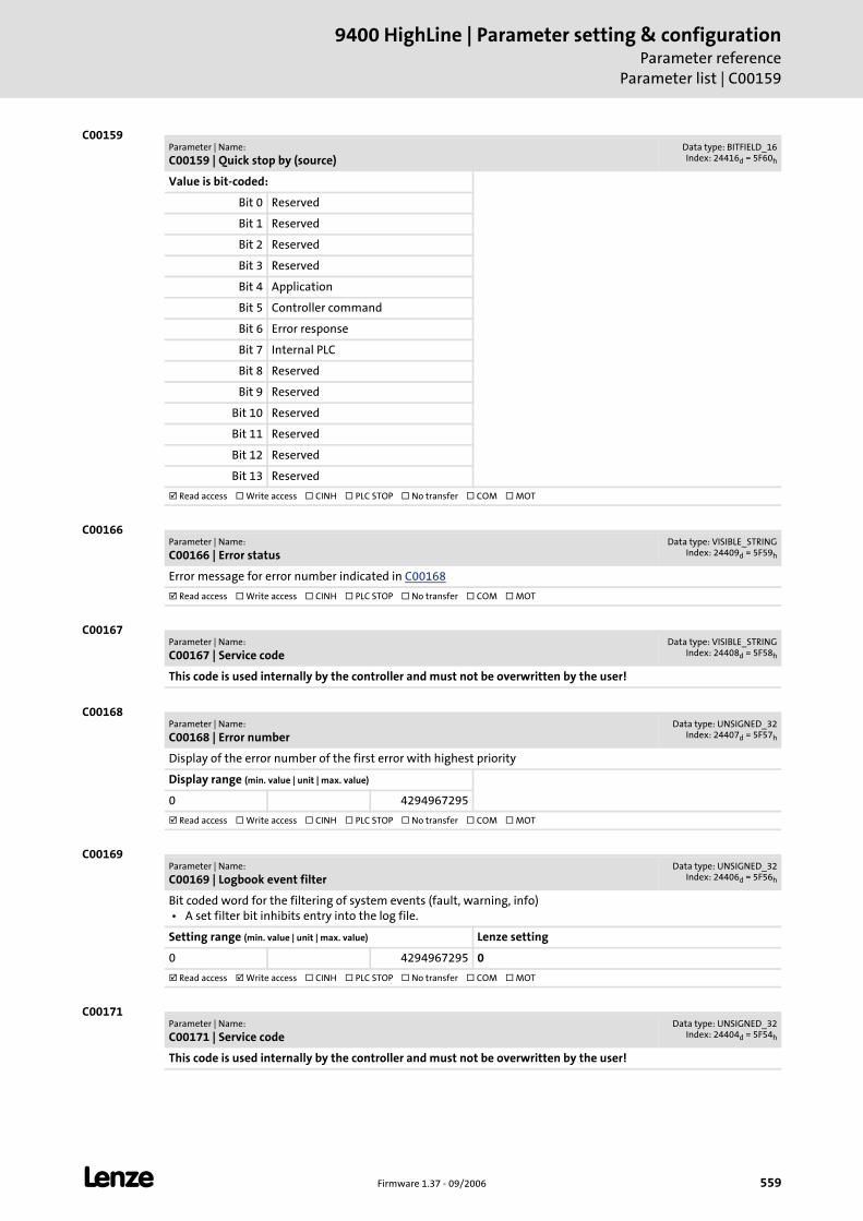
L Firmware 1.37 - 09/2006 559
9400 HighLine | Parameter setting & configurationParameter reference
Parameter list | C00159
C00159
C00166
C00167
C00168
C00169
C00171
Parameter | Name:
C00159 | Quick stop by (source)Data type: BITFIELD_16Index: 24416d = 5F60h
Value is bit-coded:
Bit 0 Reserved
Bit 1 Reserved
Bit 2 Reserved
Bit 3 Reserved
Bit 4 Application
Bit 5 Controller command
Bit 6 Error response
Bit 7 Internal PLC
Bit 8 Reserved
Bit 9 Reserved
Bit 10 Reserved
Bit 11 Reserved
Bit 12 Reserved
Bit 13 Reserved
Read access Write access CINH PLC STOP No transfer COM MOT
Parameter | Name:
C00166 | Error statusData type: VISIBLE_STRING
Index: 24409d = 5F59h
Error message for error number indicated in C00168
Read access Write access CINH PLC STOP No transfer COM MOT
Parameter | Name:
C00167 | Service codeData type: VISIBLE_STRING
Index: 24408d = 5F58h
This code is used internally by the controller and must not be overwritten by the user!
Parameter | Name:
C00168 | Error numberData type: UNSIGNED_32
Index: 24407d = 5F57h
Display of the error number of the first error with highest priority
Display range (min. value | unit | max. value)
0 4294967295
Read access Write access CINH PLC STOP No transfer COM MOT
Parameter | Name:
C00169 | Logbook event filterData type: UNSIGNED_32
Index: 24406d = 5F56h
Bit coded word for the filtering of system events (fault, warning, info) • A set filter bit inhibits entry into the log file.
Setting range (min. value | unit | max. value) Lenze setting
0 4294967295 0
Read access Write access CINH PLC STOP No transfer COM MOT
Parameter | Name:
C00171 | Service codeData type: UNSIGNED_32
Index: 24404d = 5F54h
This code is used internally by the controller and must not be overwritten by the user!
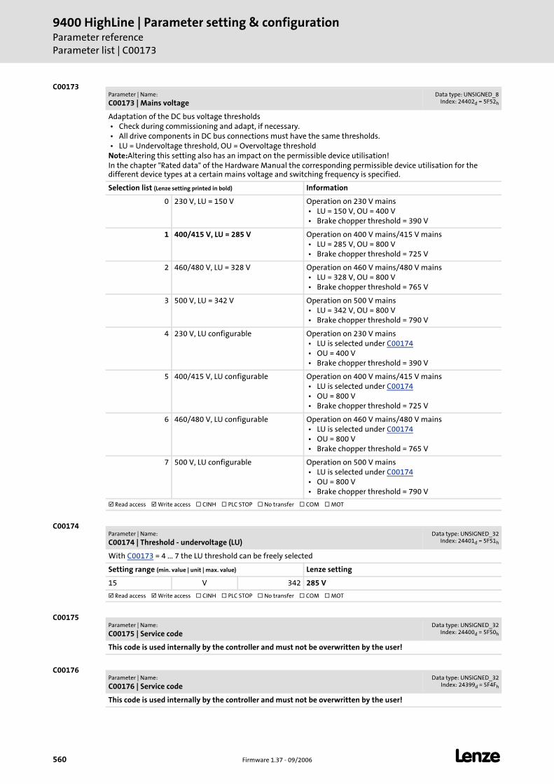
9400 HighLine | Parameter setting & configurationParameter referenceParameter list | C00173
560 Firmware 1.37 - 09/2006 L
C00173
C00174
C00175
C00176
Parameter | Name:
C00173 | Mains voltageData type: UNSIGNED_8
Index: 24402d = 5F52h
Adaptation of the DC bus voltage thresholds • Check during commissioning and adapt, if necessary. • All drive components in DC bus connections must have the same thresholds. • LU = Undervoltage threshold, OU = Overvoltage thresholdNote:Altering this setting also has an impact on the permissible device utilisation!In the chapter "Rated data" of the Hardware Manual the corresponding permissible device utilisation for the different device types at a certain mains voltage and switching frequency is specified.
Selection list (Lenze setting printed in bold) Information
0 230 V, LU = 150 V Operation on 230 V mains • LU = 150 V, OU = 400 V • Brake chopper threshold = 390 V
1 400/415 V, LU = 285 V Operation on 400 V mains/415 V mains • LU = 285 V, OU = 800 V • Brake chopper threshold = 725 V
2 460/480 V, LU = 328 V Operation on 460 V mains/480 V mains • LU = 328 V, OU = 800 V • Brake chopper threshold = 765 V
3 500 V, LU = 342 V Operation on 500 V mains • LU = 342 V, OU = 800 V • Brake chopper threshold = 790 V
4 230 V, LU configurable Operation on 230 V mains • LU is selected under C00174 • OU = 400 V • Brake chopper threshold = 390 V
5 400/415 V, LU configurable Operation on 400 V mains/415 V mains • LU is selected under C00174 • OU = 800 V • Brake chopper threshold = 725 V
6 460/480 V, LU configurable Operation on 460 V mains/480 V mains • LU is selected under C00174 • OU = 800 V • Brake chopper threshold = 765 V
7 500 V, LU configurable Operation on 500 V mains • LU is selected under C00174 • OU = 800 V • Brake chopper threshold = 790 V
Read access Write access CINH PLC STOP No transfer COM MOT
Parameter | Name:
C00174 | Threshold - undervoltage (LU)Data type: UNSIGNED_32
Index: 24401d = 5F51h
With C00173 = 4 ... 7 the LU threshold can be freely selected
Setting range (min. value | unit | max. value) Lenze setting
15 V 342 285 V
Read access Write access CINH PLC STOP No transfer COM MOT
Parameter | Name:
C00175 | Service codeData type: UNSIGNED_32
Index: 24400d = 5F50h
This code is used internally by the controller and must not be overwritten by the user!
Parameter | Name:
C00176 | Service codeData type: UNSIGNED_32
Index: 24399d = 5F4Fh
This code is used internally by the controller and must not be overwritten by the user!
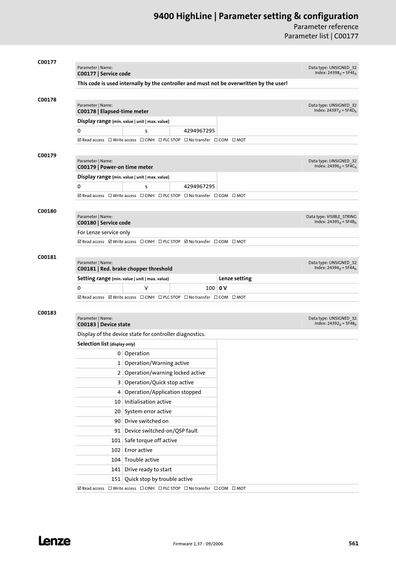
L Firmware 1.37 - 09/2006 561
9400 HighLine | Parameter setting & configurationParameter reference
Parameter list | C00177
C00177
C00178
C00179
C00180
C00181
C00183
Parameter | Name:
C00177 | Service codeData type: UNSIGNED_32
Index: 24398d = 5F4Eh
This code is used internally by the controller and must not be overwritten by the user!
Parameter | Name:
C00178 | Elapsed-time meterData type: UNSIGNED_32
Index: 24397d = 5F4Dh
Display range (min. value | unit | max. value)
0 s 4294967295
Read access Write access CINH PLC STOP No transfer COM MOT
Parameter | Name:
C00179 | Power-on time meterData type: UNSIGNED_32
Index: 24396d = 5F4Ch
Display range (min. value | unit | max. value)
0 s 4294967295
Read access Write access CINH PLC STOP No transfer COM MOT
Parameter | Name:
C00180 | Service codeData type: VISIBLE_STRING
Index: 24395d = 5F4Bh
For Lenze service only
Read access Write access CINH PLC STOP No transfer COM MOT
Parameter | Name:
C00181 | Red. brake chopper thresholdData type: UNSIGNED_32
Index: 24394d = 5F4Ah
Setting range (min. value | unit | max. value) Lenze setting
0 V 100 0 V
Read access Write access CINH PLC STOP No transfer COM MOT
Parameter | Name:
C00183 | Device stateData type: UNSIGNED_32
Index: 24392d = 5F48h
Display of the device state for controller diagnostics.
Selection list (display only)
0 Operation
1 Operation/Warning active
2 Operation/warning locked active
3 Operation/Quick stop active
4 Operation/Application stopped
10 Initialisation active
20 System error active
90 Drive switched on
91 Device switched-on/QSP fault
101 Safe torque off active
102 Error active
104 Trouble active
141 Drive ready to start
151 Quick stop by trouble active
Read access Write access CINH PLC STOP No transfer COM MOT
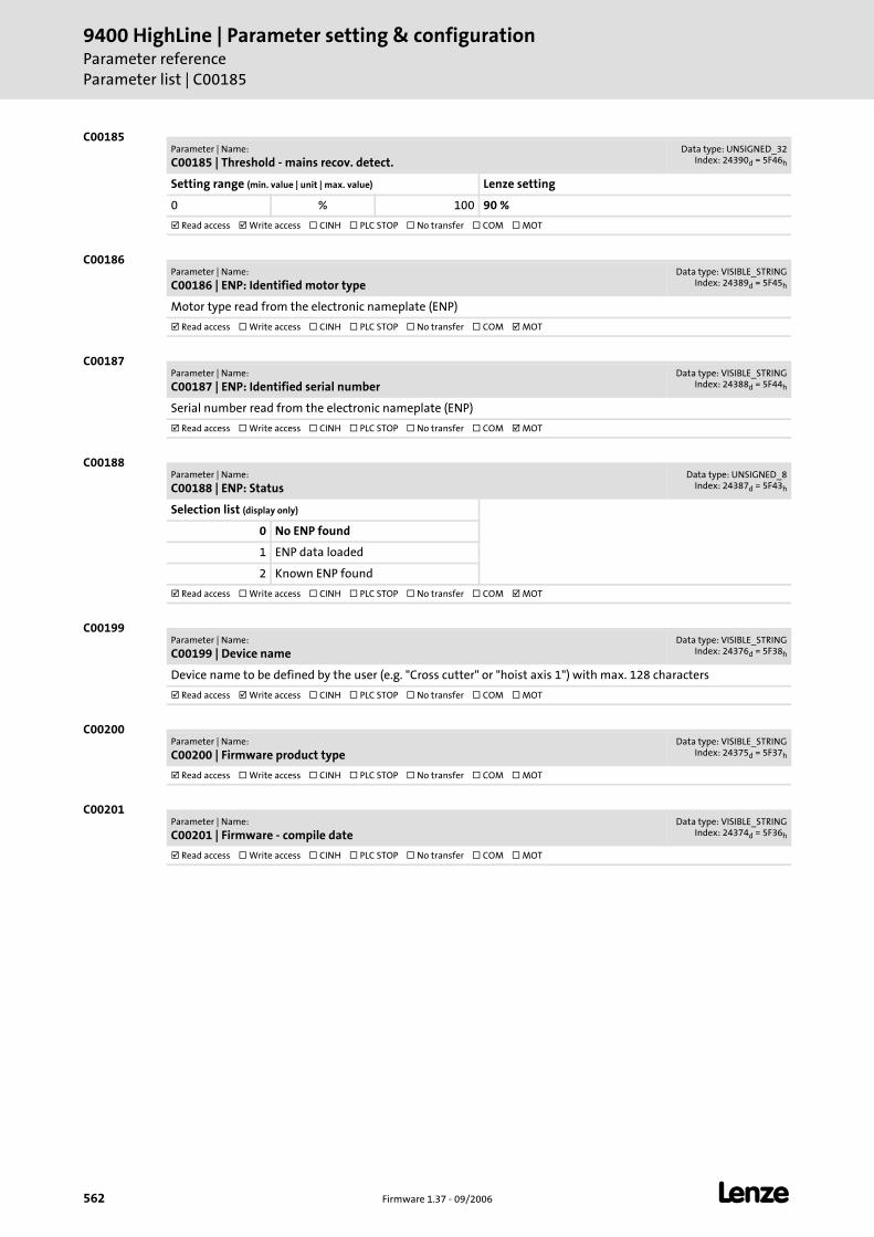
9400 HighLine | Parameter setting & configurationParameter referenceParameter list | C00185
562 Firmware 1.37 - 09/2006 L
C00185
C00186
C00187
C00188
C00199
C00200
C00201
Parameter | Name:
C00185 | Threshold - mains recov. detect.Data type: UNSIGNED_32
Index: 24390d = 5F46h
Setting range (min. value | unit | max. value) Lenze setting
0 % 100 90 %
Read access Write access CINH PLC STOP No transfer COM MOT
Parameter | Name:
C00186 | ENP: Identified motor typeData type: VISIBLE_STRING
Index: 24389d = 5F45h
Motor type read from the electronic nameplate (ENP)
Read access Write access CINH PLC STOP No transfer COM MOT
Parameter | Name:
C00187 | ENP: Identified serial numberData type: VISIBLE_STRING
Index: 24388d = 5F44h
Serial number read from the electronic nameplate (ENP)
Read access Write access CINH PLC STOP No transfer COM MOT
Parameter | Name:
C00188 | ENP: StatusData type: UNSIGNED_8
Index: 24387d = 5F43h
Selection list (display only)
0 No ENP found
1 ENP data loaded
2 Known ENP found
Read access Write access CINH PLC STOP No transfer COM MOT
Parameter | Name:
C00199 | Device nameData type: VISIBLE_STRING
Index: 24376d = 5F38h
Device name to be defined by the user (e.g. "Cross cutter" or "hoist axis 1") with max. 128 characters
Read access Write access CINH PLC STOP No transfer COM MOT
Parameter | Name:
C00200 | Firmware product typeData type: VISIBLE_STRING
Index: 24375d = 5F37h
Read access Write access CINH PLC STOP No transfer COM MOT
Parameter | Name:
C00201 | Firmware - compile dateData type: VISIBLE_STRING
Index: 24374d = 5F36h
Read access Write access CINH PLC STOP No transfer COM MOT
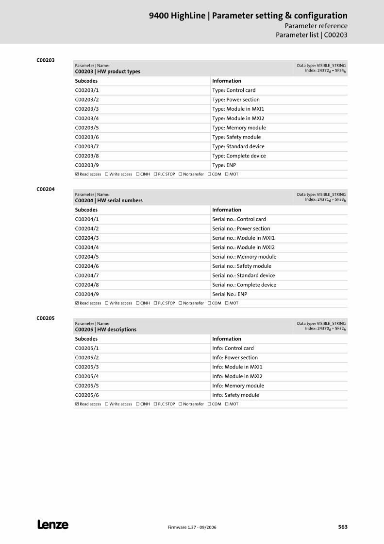
L Firmware 1.37 - 09/2006 563
9400 HighLine | Parameter setting & configurationParameter reference
Parameter list | C00203
C00203
C00204
C00205
Parameter | Name:
C00203 | HW product typesData type: VISIBLE_STRING
Index: 24372d = 5F34h
Subcodes Information
C00203/1 Type: Control card
C00203/2 Type: Power section
C00203/3 Type: Module in MXI1
C00203/4 Type: Module in MXI2
C00203/5 Type: Memory module
C00203/6 Type: Safety module
C00203/7 Type: Standard device
C00203/8 Type: Complete device
C00203/9 Type: ENP
Read access Write access CINH PLC STOP No transfer COM MOT
Parameter | Name:
C00204 | HW serial numbersData type: VISIBLE_STRING
Index: 24371d = 5F33h
Subcodes Information
C00204/1 Serial no.: Control card
C00204/2 Serial no.: Power section
C00204/3 Serial no.: Module in MXI1
C00204/4 Serial no.: Module in MXI2
C00204/5 Serial no.: Memory module
C00204/6 Serial no.: Safety module
C00204/7 Serial no.: Standard device
C00204/8 Serial no.: Complete device
C00204/9 Serial No.: ENP
Read access Write access CINH PLC STOP No transfer COM MOT
Parameter | Name:
C00205 | HW descriptionsData type: VISIBLE_STRING
Index: 24370d = 5F32h
Subcodes Information
C00205/1 Info: Control card
C00205/2 Info: Power section
C00205/3 Info: Module in MXI1
C00205/4 Info: Module in MXI2
C00205/5 Info: Memory module
C00205/6 Info: Safety module
Read access Write access CINH PLC STOP No transfer COM MOT
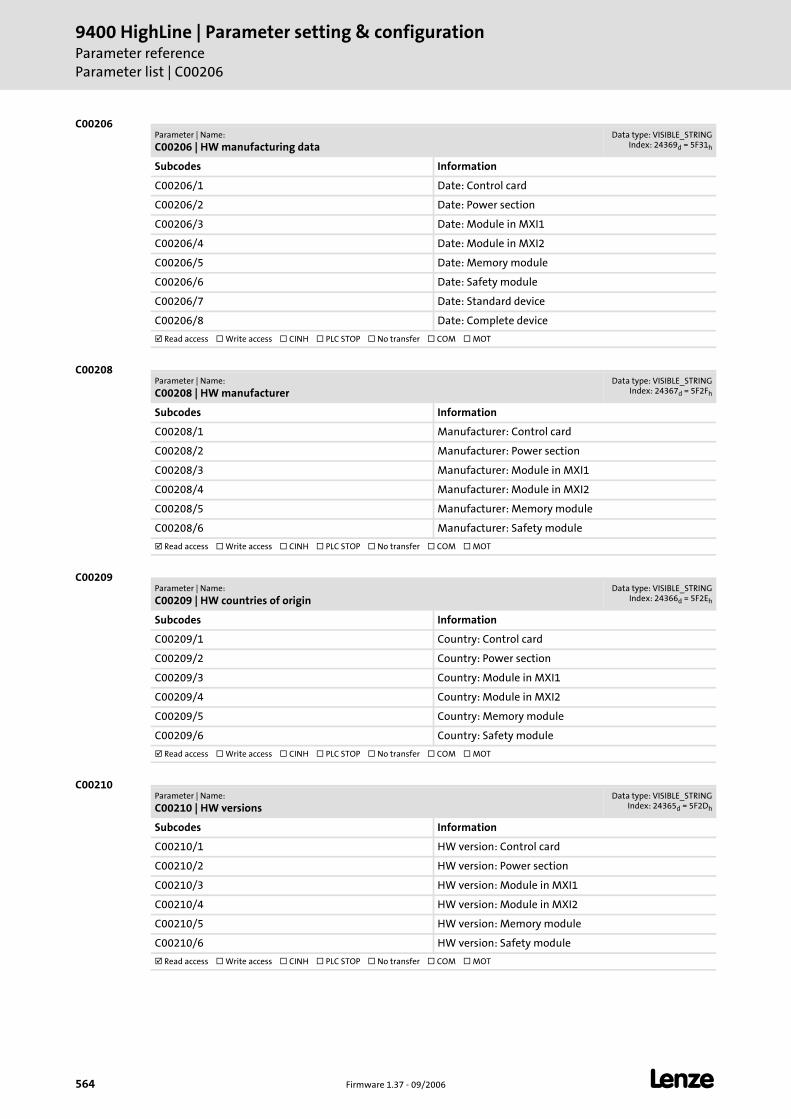
9400 HighLine | Parameter setting & configurationParameter referenceParameter list | C00206
564 Firmware 1.37 - 09/2006 L
C00206
C00208
C00209
C00210
Parameter | Name:
C00206 | HW manufacturing dataData type: VISIBLE_STRING
Index: 24369d = 5F31h
Subcodes Information
C00206/1 Date: Control card
C00206/2 Date: Power section
C00206/3 Date: Module in MXI1
C00206/4 Date: Module in MXI2
C00206/5 Date: Memory module
C00206/6 Date: Safety module
C00206/7 Date: Standard device
C00206/8 Date: Complete device
Read access Write access CINH PLC STOP No transfer COM MOT
Parameter | Name:
C00208 | HW manufacturerData type: VISIBLE_STRING
Index: 24367d = 5F2Fh
Subcodes Information
C00208/1 Manufacturer: Control card
C00208/2 Manufacturer: Power section
C00208/3 Manufacturer: Module in MXI1
C00208/4 Manufacturer: Module in MXI2
C00208/5 Manufacturer: Memory module
C00208/6 Manufacturer: Safety module
Read access Write access CINH PLC STOP No transfer COM MOT
Parameter | Name:
C00209 | HW countries of originData type: VISIBLE_STRING
Index: 24366d = 5F2Eh
Subcodes Information
C00209/1 Country: Control card
C00209/2 Country: Power section
C00209/3 Country: Module in MXI1
C00209/4 Country: Module in MXI2
C00209/5 Country: Memory module
C00209/6 Country: Safety module
Read access Write access CINH PLC STOP No transfer COM MOT
Parameter | Name:
C00210 | HW versionsData type: VISIBLE_STRING
Index: 24365d = 5F2Dh
Subcodes Information
C00210/1 HW version: Control card
C00210/2 HW version: Power section
C00210/3 HW version: Module in MXI1
C00210/4 HW version: Module in MXI2
C00210/5 HW version: Memory module
C00210/6 HW version: Safety module
Read access Write access CINH PLC STOP No transfer COM MOT
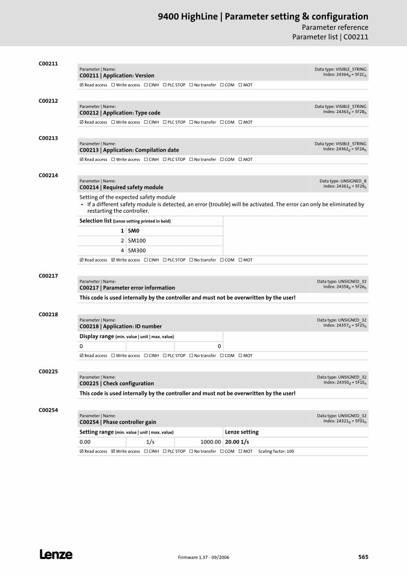
L Firmware 1.37 - 09/2006 565
9400 HighLine | Parameter setting & configurationParameter reference
Parameter list | C00211
C00211
C00212
C00213
C00214
C00217
C00218
C00225
C00254
Parameter | Name:
C00211 | Application: VersionData type: VISIBLE_STRING
Index: 24364d = 5F2Ch
Read access Write access CINH PLC STOP No transfer COM MOT
Parameter | Name:
C00212 | Application: Type codeData type: VISIBLE_STRING
Index: 24363d = 5F2Bh
Read access Write access CINH PLC STOP No transfer COM MOT
Parameter | Name:
C00213 | Application: Compilation dateData type: VISIBLE_STRING
Index: 24362d = 5F2Ah
Read access Write access CINH PLC STOP No transfer COM MOT
Parameter | Name:
C00214 | Required safety moduleData type: UNSIGNED_8
Index: 24361d = 5F29h
Setting of the expected safety module • If a different safety module is detected, an error (trouble) will be activated. The error can only be eliminated by
restarting the controller.
Selection list (Lenze setting printed in bold)
1 SM0
2 SM100
4 SM300
Read access Write access CINH PLC STOP No transfer COM MOT
Parameter | Name:
C00217 | Parameter error informationData type: UNSIGNED_32
Index: 24358d = 5F26h
This code is used internally by the controller and must not be overwritten by the user!
Parameter | Name:
C00218 | Application: ID numberData type: UNSIGNED_32
Index: 24357d = 5F25h
Display range (min. value | unit | max. value)
0 0
Read access Write access CINH PLC STOP No transfer COM MOT
Parameter | Name:
C00225 | Check configurationData type: UNSIGNED_32
Index: 24350d = 5F1Eh
This code is used internally by the controller and must not be overwritten by the user!
Parameter | Name:
C00254 | Phase controller gainData type: UNSIGNED_32
Index: 24321d = 5F01h
Setting range (min. value | unit | max. value) Lenze setting
0.00 1/s 1000.00 20.00 1/s
Read access Write access CINH PLC STOP No transfer COM MOT Scaling factor: 100
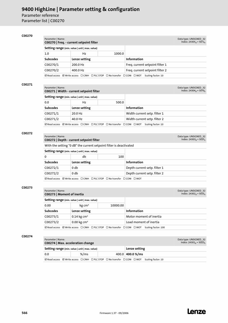
9400 HighLine | Parameter setting & configurationParameter referenceParameter list | C00270
566 Firmware 1.37 - 09/2006 L
C00270
C00271
C00272
C00273
C00274
Parameter | Name:
C00270 | Freq. - current setpoint filterData type: UNSIGNED_32
Index: 24305d = 5EF1h
Setting range (min. value | unit | max. value)
1.0 Hz 1000.0
Subcodes Lenze setting Information
C00270/1 200.0 Hz Freq. current setpoint filter 1
C00270/2 400.0 Hz Freq. current setpoint filter 2
Read access Write access CINH PLC STOP No transfer COM MOT Scaling factor: 10
Parameter | Name:
C00271 | Width - current setpoint filterData type: UNSIGNED_32
Index: 24304d = 5EF0h
Setting range (min. value | unit | max. value)
0.0 Hz 500.0
Subcodes Lenze setting Information
C00271/1 20.0 Hz Width current setp. filter 1
C00271/2 40.0 Hz Width current setp. filter 2
Read access Write access CINH PLC STOP No transfer COM MOT Scaling factor: 10
Parameter | Name:
C00272 | Depth - current setpoint filterData type: UNSIGNED_32
Index: 24303d = 5EEFh
With the setting "0 dB" the current setpoint filter is deactivated
Setting range (min. value | unit | max. value)
0 db 100
Subcodes Lenze setting Information
C00272/1 0 db Depth current setp. filter 1
C00272/2 0 db Depth current setp. filter 2
Read access Write access CINH PLC STOP No transfer COM MOT
Parameter | Name:
C00273 | Moment of inertiaData type: UNSIGNED_32
Index: 24302d = 5EEEh
Setting range (min. value | unit | max. value)
0.00 kg cm² 10000.00
Subcodes Lenze setting Information
C00273/1 0.14 kg cm² Motor moment of inertia
C00273/2 0.00 kg cm² Load moment of inertia
Read access Write access CINH PLC STOP No transfer COM MOT Scaling factor: 100
Parameter | Name:
C00274 | Max. acceleration changeData type: UNSIGNED_32
Index: 24301d = 5EEDh
Setting range (min. value | unit | max. value) Lenze setting
0.0 %/ms 400.0 400.0 %/ms
Read access Write access CINH PLC STOP No transfer COM MOT Scaling factor: 10
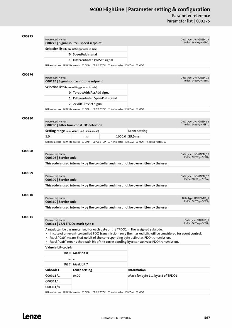
L Firmware 1.37 - 09/2006 567
9400 HighLine | Parameter setting & configurationParameter reference
Parameter list | C00275
C00275
C00276
C00280
C00308
C00309
C00310
C00311
Parameter | Name:
C00275 | Signal source - speed setpointData type: UNSIGNED_16
Index: 24300d = 5EECh
Selection list (Lenze setting printed in bold)
0 SpeedAdd signal
1 Differentiated PosSet signal
Read access Write access CINH PLC STOP No transfer COM MOT
Parameter | Name:
C00276 | Signal source - torque setpointData type: UNSIGNED_16
Index: 24299d = 5EEBh
Selection list (Lenze setting printed in bold)
0 TorqueAdd/AccAdd signal
1 Differentiated SpeedSet signal
2 2x diff. PosSet signal
Read access Write access CINH PLC STOP No transfer COM MOT
Parameter | Name:
C00280 | Filter time const. DC detectionData type: UNSIGNED_32
Index: 24295d = 5EE7h
Setting range (min. value | unit | max. value) Lenze setting
1.0 ms 1000.0 25.0 ms
Read access Write access CINH PLC STOP No transfer COM MOT Scaling factor: 10
Parameter | Name:
C00308 | Service codeData type: UNSIGNED_16
Index: 24267d = 5ECBh
This code is used internally by the controller and must not be overwritten by the user!
Parameter | Name:
C00309 | Service codeData type: UNSIGNED_32
Index: 24266d = 5ECAh
This code is used internally by the controller and must not be overwritten by the user!
Parameter | Name:
C00310 | Service codeData type: UNSIGNED_8
Index: 24265d = 5EC9h
This code is used internally by the controller and must not be overwritten by the user!
Parameter | Name:
C00311 | CAN TPDO1 mask byte xData type: BITFIELD_8
Index: 24264d = 5EC8h
A mask can be parameterised for each byte of the TPDO1 in the assigned subcode. • In case of an event-controlled PDO transmission, only the masked bits will be considered for event control. • Mask "0x0" means that no bit of the corresponding byte activates PDO transmission. • Mask "0xff" means that each bit of the corresponding byte can activate PDO transmission.
Value is bit-coded:
Bit 0 Mask bit 0
... ...
Bit 7 Mask bit 7
Subcodes Lenze setting Information
C00311/1 0x00 Mask for byte 1 ... byte 8 of TPDO1
C00311/...
C00311/8
Read access Write access CINH PLC STOP No transfer COM MOT
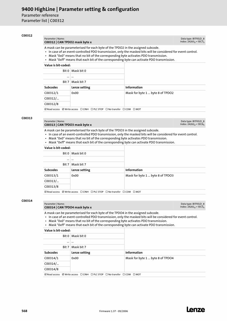
9400 HighLine | Parameter setting & configurationParameter referenceParameter list | C00312
568 Firmware 1.37 - 09/2006 L
C00312
C00313
C00314
Parameter | Name:
C00312 | CAN TPDO2 mask byte xData type: BITFIELD_8
Index: 24263d = 5EC7h
A mask can be parameterised for each byte of the TPDO2 in the assigned subcode. • In case of an event-controlled PDO transmission, only the masked bits will be considered for event control. • Mask "0x0" means that no bit of the corresponding byte activates PDO transmission. • Mask "0xff" means that each bit of the corresponding byte can activate PDO transmission.
Value is bit-coded:
Bit 0 Mask bit 0
... ...
Bit 7 Mask bit 7
Subcodes Lenze setting Information
C00312/1 0x00 Mask for byte 1 ... byte 8 of TPDO2
C00312/...
C00312/8
Read access Write access CINH PLC STOP No transfer COM MOT
Parameter | Name:
C00313 | CAN TPDO3 mask byte xData type: BITFIELD_8
Index: 24262d = 5EC6h
A mask can be parameterised for each byte of the TPDO3 in the assigned subcode. • In case of an event-controlled PDO transmission, only the masked bits will be considered for event control. • Mask "0x0" means that no bit of the corresponding byte activates PDO transmission. • Mask "0xff" means that each bit of the corresponding byte can activate PDO transmission.
Value is bit-coded:
Bit 0 Mask bit 0
... ...
Bit 7 Mask bit 7
Subcodes Lenze setting Information
C00313/1 0x00 Mask for byte 1 ... byte 8 of TPDO3
C00313/...
C00313/8
Read access Write access CINH PLC STOP No transfer COM MOT
Parameter | Name:
C00314 | CAN TPDO4 mask byte xData type: BITFIELD_8
Index: 24261d = 5EC5h
A mask can be parameterised for each byte of the TPDO4 in the assigned subcode. • In case of an event-controlled PDO transmission, only the masked bits will be considered for event control. • Mask "0x0" means that no bit of the corresponding byte activates PDO transmission. • Mask "0xff" means that each bit of the corresponding byte can activate PDO transmission.
Value is bit-coded:
Bit 0 Mask bit 0
... ...
Bit 7 Mask bit 7
Subcodes Lenze setting Information
C00314/1 0x00 Mask for byte 1 ... byte 8 of TPDO4
C00314/...
C00314/8
Read access Write access CINH PLC STOP No transfer COM MOT
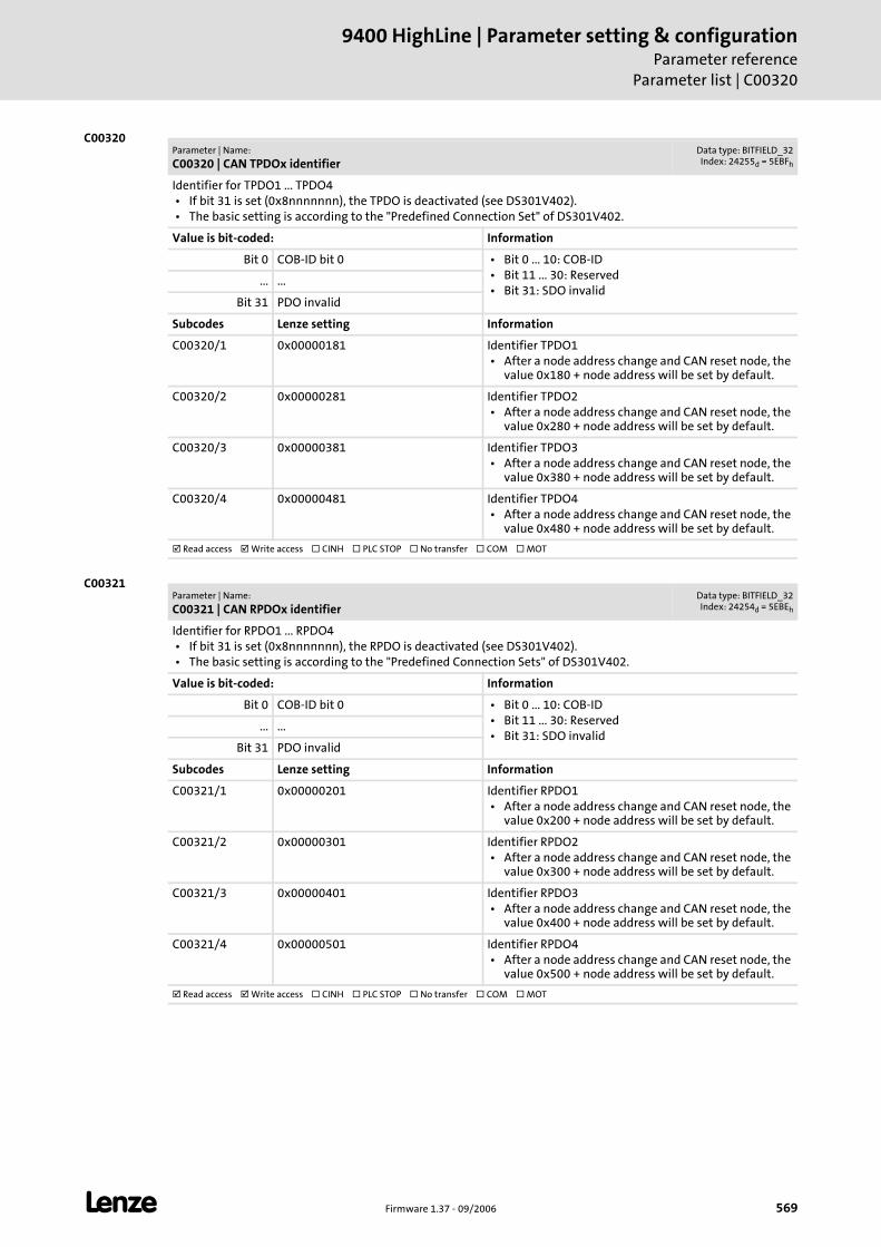
L Firmware 1.37 - 09/2006 569
9400 HighLine | Parameter setting & configurationParameter reference
Parameter list | C00320
C00320
C00321
Parameter | Name:
C00320 | CAN TPDOx identifierData type: BITFIELD_32Index: 24255d = 5EBFh
Identifier for TPDO1 ... TPDO4 • If bit 31 is set (0x8nnnnnnn), the TPDO is deactivated (see DS301V402). • The basic setting is according to the "Predefined Connection Set" of DS301V402.
Value is bit-coded: Information
Bit 0 COB-ID bit 0 • Bit 0 ... 10: COB-ID • Bit 11 ... 30: Reserved • Bit 31: SDO invalid
... ...
Bit 31 PDO invalid
Subcodes Lenze setting Information
C00320/1 0x00000181 Identifier TPDO1 • After a node address change and CAN reset node, the
value 0x180 + node address will be set by default.
C00320/2 0x00000281 Identifier TPDO2 • After a node address change and CAN reset node, the
value 0x280 + node address will be set by default.
C00320/3 0x00000381 Identifier TPDO3 • After a node address change and CAN reset node, the
value 0x380 + node address will be set by default.
C00320/4 0x00000481 Identifier TPDO4 • After a node address change and CAN reset node, the
value 0x480 + node address will be set by default.
Read access Write access CINH PLC STOP No transfer COM MOT
Parameter | Name:
C00321 | CAN RPDOx identifierData type: BITFIELD_32Index: 24254d = 5EBEh
Identifier for RPDO1 ... RPDO4 • If bit 31 is set (0x8nnnnnnn), the RPDO is deactivated (see DS301V402). • The basic setting is according to the "Predefined Connection Sets" of DS301V402.
Value is bit-coded: Information
Bit 0 COB-ID bit 0 • Bit 0 ... 10: COB-ID • Bit 11 ... 30: Reserved • Bit 31: SDO invalid
... ...
Bit 31 PDO invalid
Subcodes Lenze setting Information
C00321/1 0x00000201 Identifier RPDO1 • After a node address change and CAN reset node, the
value 0x200 + node address will be set by default.
C00321/2 0x00000301 Identifier RPDO2 • After a node address change and CAN reset node, the
value 0x300 + node address will be set by default.
C00321/3 0x00000401 Identifier RPDO3 • After a node address change and CAN reset node, the
value 0x400 + node address will be set by default.
C00321/4 0x00000501 Identifier RPDO4 • After a node address change and CAN reset node, the
value 0x500 + node address will be set by default.
Read access Write access CINH PLC STOP No transfer COM MOT
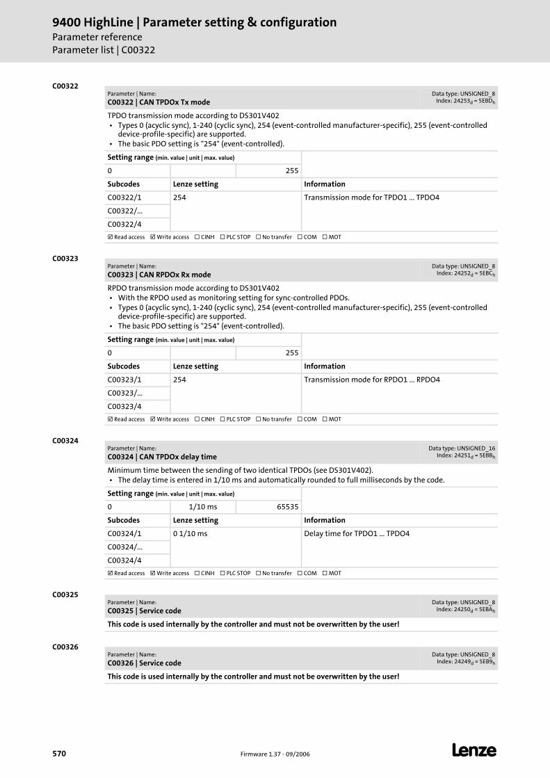
9400 HighLine | Parameter setting & configurationParameter referenceParameter list | C00322
570 Firmware 1.37 - 09/2006 L
C00322
C00323
C00324
C00325
C00326
Parameter | Name:
C00322 | CAN TPDOx Tx modeData type: UNSIGNED_8
Index: 24253d = 5EBDh
TPDO transmission mode according to DS301V402 • Types 0 (acyclic sync), 1-240 (cyclic sync), 254 (event-controlled manufacturer-specific), 255 (event-controlled
device-profile-specific) are supported. • The basic PDO setting is "254" (event-controlled).
Setting range (min. value | unit | max. value)
0 255
Subcodes Lenze setting Information
C00322/1 254 Transmission mode for TPDO1 ... TPDO4
C00322/...
C00322/4
Read access Write access CINH PLC STOP No transfer COM MOT
Parameter | Name:
C00323 | CAN RPDOx Rx modeData type: UNSIGNED_8
Index: 24252d = 5EBCh
RPDO transmission mode according to DS301V402 • With the RPDO used as monitoring setting for sync-controlled PDOs. • Types 0 (acyclic sync), 1-240 (cyclic sync), 254 (event-controlled manufacturer-specific), 255 (event-controlled
device-profile-specific) are supported. • The basic PDO setting is "254" (event-controlled).
Setting range (min. value | unit | max. value)
0 255
Subcodes Lenze setting Information
C00323/1 254 Transmission mode for RPDO1 ... RPDO4
C00323/...
C00323/4
Read access Write access CINH PLC STOP No transfer COM MOT
Parameter | Name:
C00324 | CAN TPDOx delay timeData type: UNSIGNED_16
Index: 24251d = 5EBBh
Minimum time between the sending of two identical TPDOs (see DS301V402). • The delay time is entered in 1/10 ms and automatically rounded to full milliseconds by the code.
Setting range (min. value | unit | max. value)
0 1/10 ms 65535
Subcodes Lenze setting Information
C00324/1 0 1/10 ms Delay time for TPDO1 ... TPDO4
C00324/...
C00324/4
Read access Write access CINH PLC STOP No transfer COM MOT
Parameter | Name:
C00325 | Service codeData type: UNSIGNED_8
Index: 24250d = 5EBAh
This code is used internally by the controller and must not be overwritten by the user!
Parameter | Name:
C00326 | Service codeData type: UNSIGNED_8
Index: 24249d = 5EB9h
This code is used internally by the controller and must not be overwritten by the user!
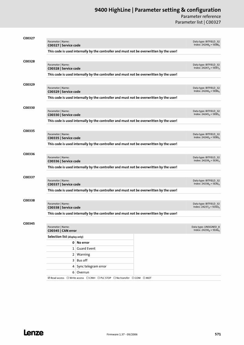
L Firmware 1.37 - 09/2006 571
9400 HighLine | Parameter setting & configurationParameter reference
Parameter list | C00327
C00327
C00328
C00329
C00330
C00335
C00336
C00337
C00338
C00345
Parameter | Name:
C00327 | Service codeData type: BITFIELD_32Index: 24248d = 5EB8h
This code is used internally by the controller and must not be overwritten by the user!
Parameter | Name:
C00328 | Service codeData type: BITFIELD_32Index: 24247d = 5EB7h
This code is used internally by the controller and must not be overwritten by the user!
Parameter | Name:
C00329 | Service codeData type: BITFIELD_32Index: 24246d = 5EB6h
This code is used internally by the controller and must not be overwritten by the user!
Parameter | Name:
C00330 | Service codeData type: BITFIELD_32Index: 24245d = 5EB5h
This code is used internally by the controller and must not be overwritten by the user!
Parameter | Name:
C00335 | Service codeData type: BITFIELD_32Index: 24240d = 5EB0h
This code is used internally by the controller and must not be overwritten by the user!
Parameter | Name:
C00336 | Service codeData type: BITFIELD_32Index: 24239d = 5EAFh
This code is used internally by the controller and must not be overwritten by the user!
Parameter | Name:
C00337 | Service codeData type: BITFIELD_32Index: 24238d = 5EAEh
This code is used internally by the controller and must not be overwritten by the user!
Parameter | Name:
C00338 | Service codeData type: BITFIELD_32Index: 24237d = 5EADh
This code is used internally by the controller and must not be overwritten by the user!
Parameter | Name:
C00345 | CAN errorData type: UNSIGNED_8
Index: 24230d = 5EA6h
Selection list (display only)
0 No error
1 Guard Event
2 Warning
3 Bus off
4 Sync telegram error
6 Overrun
Read access Write access CINH PLC STOP No transfer COM MOT
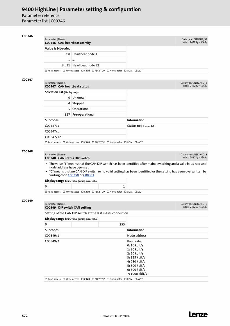
9400 HighLine | Parameter setting & configurationParameter referenceParameter list | C00346
572 Firmware 1.37 - 09/2006 L
C00346
C00347
C00348
C00349
Parameter | Name:
C00346 | CAN heartbeat activityData type: BITFIELD_32Index: 24229d = 5EA5h
Value is bit-coded:
Bit 0 Heartbeat node 1
... ...
Bit 31 Heartbeat node 32
Read access Write access CINH PLC STOP No transfer COM MOT
Parameter | Name:
C00347 | CAN heartbeat statusData type: UNSIGNED_8
Index: 24228d = 5EA4h
Selection list (display only)
0 Unknown
4 Stopped
5 Operational
127 Pre-operational
Subcodes Information
C00347/1 Status node 1 ... 32
C00347/...
C00347/32
Read access Write access CINH PLC STOP No transfer COM MOT
Parameter | Name:
C00348 | CAN status DIP switchData type: UNSIGNED_8
Index: 24227d = 5EA3h
• The value "1" means that the CAN DIP switch has been identified after mains switching and a valid baud rate and node address have been set.
• "0" means that no CAN DIP switch or no valid setting has been identified or the setting has been overwritten by writing code C00350 or C00351.
Display range (min. value | unit | max. value)
0 1
Read access Write access CINH PLC STOP No transfer COM MOT
Parameter | Name:
C00349 | DIP switch CAN setting Data type: UNSIGNED_8
Index: 24226d = 5EA2h
Setting of the CAN DIP switch at the last mains connection
Display range (min. value | unit | max. value)
0 255
Subcodes Information
C00349/1 Node address
C00349/2 Baud rate:0: 10 kbit/s1: 20 kbit/s2: 50 kbit/s3: 125 kbit/s4: 250 kbit/s5: 500 kbit/s6: 800 kbit/s7: 1000 kbit/s
Read access Write access CINH PLC STOP No transfer COM MOT
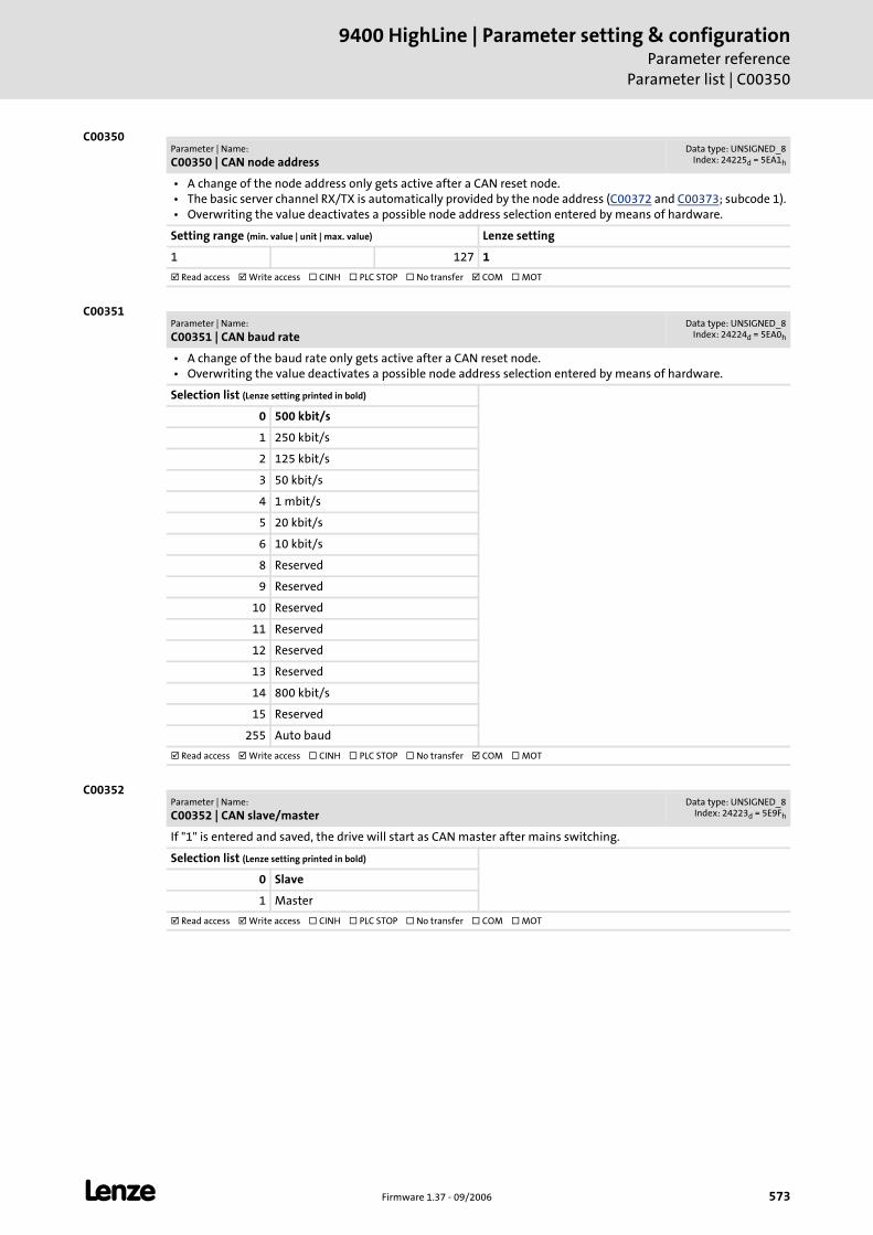
L Firmware 1.37 - 09/2006 573
9400 HighLine | Parameter setting & configurationParameter reference
Parameter list | C00350
C00350
C00351
C00352
Parameter | Name:
C00350 | CAN node addressData type: UNSIGNED_8
Index: 24225d = 5EA1h
• A change of the node address only gets active after a CAN reset node. • The basic server channel RX/TX is automatically provided by the node address (C00372 and C00373; subcode 1). • Overwriting the value deactivates a possible node address selection entered by means of hardware.
Setting range (min. value | unit | max. value) Lenze setting
1 127 1
Read access Write access CINH PLC STOP No transfer COM MOT
Parameter | Name:
C00351 | CAN baud rateData type: UNSIGNED_8
Index: 24224d = 5EA0h
• A change of the baud rate only gets active after a CAN reset node. • Overwriting the value deactivates a possible node address selection entered by means of hardware.
Selection list (Lenze setting printed in bold)
0 500 kbit/s
1 250 kbit/s
2 125 kbit/s
3 50 kbit/s
4 1 mbit/s
5 20 kbit/s
6 10 kbit/s
8 Reserved
9 Reserved
10 Reserved
11 Reserved
12 Reserved
13 Reserved
14 800 kbit/s
15 Reserved
255 Auto baud
Read access Write access CINH PLC STOP No transfer COM MOT
Parameter | Name:
C00352 | CAN slave/masterData type: UNSIGNED_8
Index: 24223d = 5E9Fh
If "1" is entered and saved, the drive will start as CAN master after mains switching.
Selection list (Lenze setting printed in bold)
0 Slave
1 Master
Read access Write access CINH PLC STOP No transfer COM MOT

9400 HighLine | Parameter setting & configurationParameter referenceParameter list | C00356
574 Firmware 1.37 - 09/2006 L
C00356
C00357
C00359
Parameter | Name:
C00356 | CAN TPDOx cycle timeData type: UNSIGNED_16
Index: 24219d = 5E9Bh
TPDO event time from DS301V402. • With a value unequal "0", the TPDO will be sent after the set time without considering the transmission type.
Setting range (min. value | unit | max. value)
0 ms 65535
Subcodes Lenze setting Information
C00356/1 0 ms Cycle time for TPDO1 ... TPDO4
C00356/...
C00356/4
Read access Write access CINH PLC STOP No transfer COM MOT
Parameter | Name:
C00357 | CAN RPDOx monitoring timeData type: UNSIGNED_16
Index: 24218d = 5E9Ah
RPDO event time from DS301V402. • With a value unequal "0", the RPDO will be expected after the set time. • If the RPDO is not received within this time, a parameterisable error message can be activated.
Setting range (min. value | unit | max. value)
0 ms 65535
Subcodes Lenze setting Information
C00357/1 3000 ms Monitoring time for RPDO1 ... RPDO4
C00357/...
C00357/4
Read access Write access CINH PLC STOP No transfer COM MOT
Parameter | Name:
C00359 | CAN statusData type: UNSIGNED_8
Index: 24216d = 5E98h
Selection list (display only)
0 Operational
1 Pre-operational
4 Boot up
5 Stopped
7 Reset
8 INITIALISATION
9 Unknown
10 Autom. baud rate detection active
Read access Write access CINH PLC STOP No transfer COM MOT
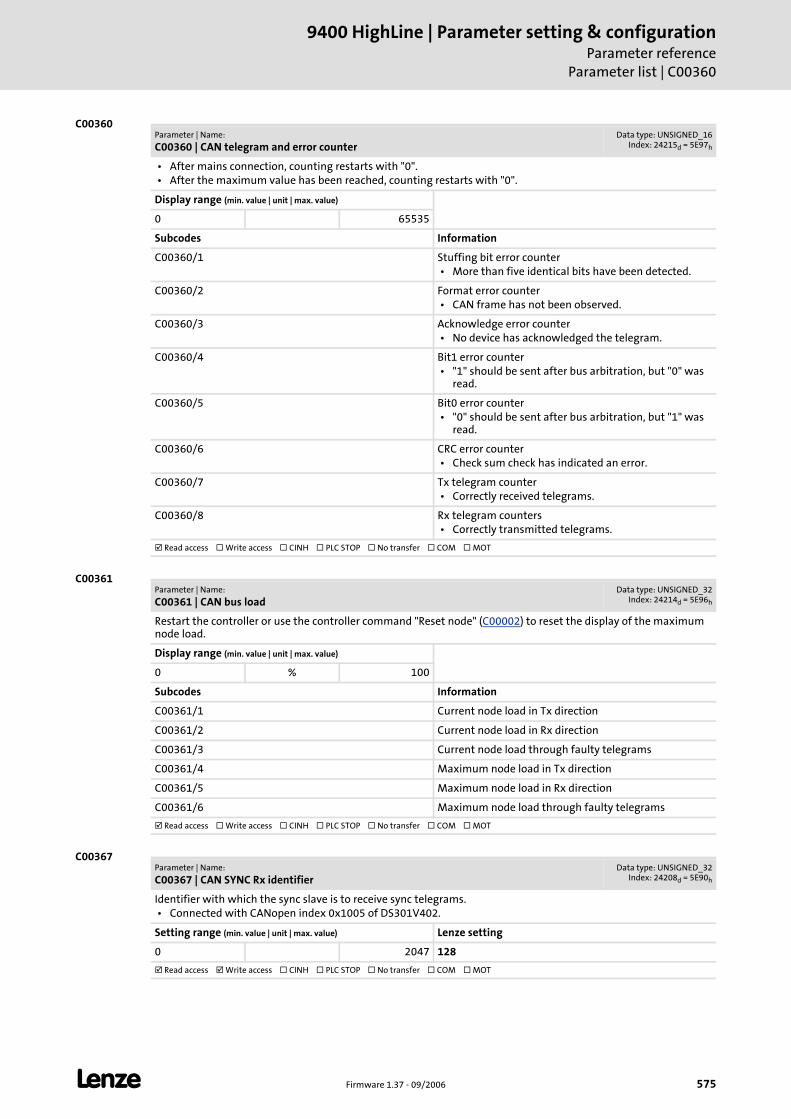
L Firmware 1.37 - 09/2006 575
9400 HighLine | Parameter setting & configurationParameter reference
Parameter list | C00360
C00360
C00361
C00367
Parameter | Name:
C00360 | CAN telegram and error counterData type: UNSIGNED_16
Index: 24215d = 5E97h
• After mains connection, counting restarts with "0". • After the maximum value has been reached, counting restarts with "0".
Display range (min. value | unit | max. value)
0 65535
Subcodes Information
C00360/1 Stuffing bit error counter • More than five identical bits have been detected.
C00360/2 Format error counter • CAN frame has not been observed.
C00360/3 Acknowledge error counter • No device has acknowledged the telegram.
C00360/4 Bit1 error counter • "1" should be sent after bus arbitration, but "0" was
read.
C00360/5 Bit0 error counter • "0" should be sent after bus arbitration, but "1" was
read.
C00360/6 CRC error counter • Check sum check has indicated an error.
C00360/7 Tx telegram counter • Correctly received telegrams.
C00360/8 Rx telegram counters • Correctly transmitted telegrams.
Read access Write access CINH PLC STOP No transfer COM MOT
Parameter | Name:
C00361 | CAN bus loadData type: UNSIGNED_32
Index: 24214d = 5E96h
Restart the controller or use the controller command "Reset node" (C00002) to reset the display of the maximum node load.
Display range (min. value | unit | max. value)
0 % 100
Subcodes Information
C00361/1 Current node load in Tx direction
C00361/2 Current node load in Rx direction
C00361/3 Current node load through faulty telegrams
C00361/4 Maximum node load in Tx direction
C00361/5 Maximum node load in Rx direction
C00361/6 Maximum node load through faulty telegrams
Read access Write access CINH PLC STOP No transfer COM MOT
Parameter | Name:
C00367 | CAN SYNC Rx identifierData type: UNSIGNED_32
Index: 24208d = 5E90h
Identifier with which the sync slave is to receive sync telegrams. • Connected with CANopen index 0x1005 of DS301V402.
Setting range (min. value | unit | max. value) Lenze setting
0 2047 128
Read access Write access CINH PLC STOP No transfer COM MOT
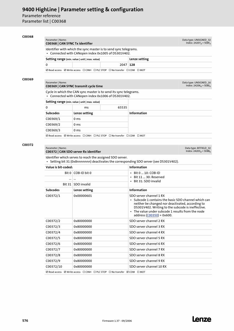
9400 HighLine | Parameter setting & configurationParameter referenceParameter list | C00368
576 Firmware 1.37 - 09/2006 L
C00368
C00369
C00372
Parameter | Name:
C00368 | CAN SYNC Tx identifierData type: UNSIGNED_32
Index: 24207d = 5E8Fh
Identifier with which the sync master is to send sync telegrams. • Connected with CANopen index 0x1005 of DS301V402.
Setting range (min. value | unit | max. value) Lenze setting
0 2047 128
Read access Write access CINH PLC STOP No transfer COM MOT
Parameter | Name:
C00369 | CAN SYNC transmit cycle timeData type: UNSIGNED_16
Index: 24206d = 5E8Eh
Cycle in which the CAN sync master is to send its sync telegrams. • Connected with CANopen index 0x1006 of DS301V402.
Setting range (min. value | unit | max. value)
0 ms 65535
Subcodes Lenze setting Information
C00369/1 0 ms
C00369/2 0 ms
C00369/3 0 ms
Read access Write access CINH PLC STOP No transfer COM MOT
Parameter | Name:
C00372 | CAN SDO server Rx identifierData type: BITFIELD_32Index: 24203d = 5E8Bh
Identifier which serves to reach the assigned SDO server. • Setting bit 31 (0x8nnnnnnn) deactivates the corresponding SDO server (see DS301V402).
Value is bit-coded: Information
Bit 0 COB-ID bit 0 • Bit 0 ... 10: COB-ID • Bit 11 ... 30: Reserved • Bit 31: SDO invalid
... ...
Bit 31 SDO invalid
Subcodes Lenze setting Information
C00372/1 0x00000601 SDO server channel 1 RX • Subcode 1 contains the basic SDO channel which can
neither be changed nor deactivated, according to DS301V402. Writing to the subcode is ineffective.
• The value under subcode 1 results from the node address (C00350) + 0x600.
C00372/2 0x80000000 SDO server channel 2 RX
C00372/3 0x80000000 SDO server channel 3 RX
C00372/4 0x80000000 SDO server channel 4 RX
C00372/5 0x80000000 SDO server channel 5 RX
C00372/6 0x80000000 SDO server channel 6 RX
C00372/7 0x80000000 SDO server channel 7 RX
C00372/8 0x80000000 SDO server channel 8 RX
C00372/9 0x80000000 SDO server channel 9 RX
C00372/10 0x80000000 SDO server channel 10 RX
Read access Write access CINH PLC STOP No transfer COM MOT
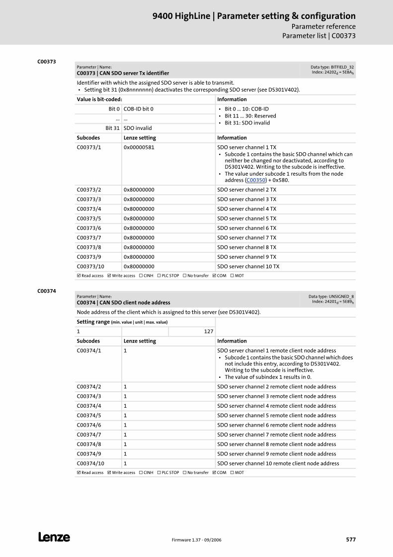
L Firmware 1.37 - 09/2006 577
9400 HighLine | Parameter setting & configurationParameter reference
Parameter list | C00373
C00373
C00374
Parameter | Name:
C00373 | CAN SDO server Tx identifierData type: BITFIELD_32Index: 24202d = 5E8Ah
Identifier with which the assigned SDO server is able to transmit. • Setting bit 31 (0x8nnnnnnn) deactivates the corresponding SDO server (see DS301V402).
Value is bit-coded: Information
Bit 0 COB-ID bit 0 • Bit 0 ... 10: COB-ID • Bit 11 ... 30: Reserved • Bit 31: SDO invalid
... ...
Bit 31 SDO invalid
Subcodes Lenze setting Information
C00373/1 0x00000581 SDO server channel 1 TX • Subcode 1 contains the basic SDO channel which can
neither be changed nor deactivated, according to DS301V402. Writing to the subcode is ineffective.
• The value under subcode 1 results from the node address (C00350) + 0x580.
C00373/2 0x80000000 SDO server channel 2 TX
C00373/3 0x80000000 SDO server channel 3 TX
C00373/4 0x80000000 SDO server channel 4 TX
C00373/5 0x80000000 SDO server channel 5 TX
C00373/6 0x80000000 SDO server channel 6 TX
C00373/7 0x80000000 SDO server channel 7 TX
C00373/8 0x80000000 SDO server channel 8 TX
C00373/9 0x80000000 SDO server channel 9 TX
C00373/10 0x80000000 SDO server channel 10 TX
Read access Write access CINH PLC STOP No transfer COM MOT
Parameter | Name:
C00374 | CAN SDO client node addressData type: UNSIGNED_8
Index: 24201d = 5E89h
Node address of the client which is assigned to this server (see DS301V402).
Setting range (min. value | unit | max. value)
1 127
Subcodes Lenze setting Information
C00374/1 1 SDO server channel 1 remote client node address • Subcode 1 contains the basic SDO channel which does
not include this entry, according to DS301V402. Writing to the subcode is ineffective.
• The value of subindex 1 results in 0.
C00374/2 1 SDO server channel 2 remote client node address
C00374/3 1 SDO server channel 3 remote client node address
C00374/4 1 SDO server channel 4 remote client node address
C00374/5 1 SDO server channel 5 remote client node address
C00374/6 1 SDO server channel 6 remote client node address
C00374/7 1 SDO server channel 7 remote client node address
C00374/8 1 SDO server channel 8 remote client node address
C00374/9 1 SDO server channel 9 remote client node address
C00374/10 1 SDO server channel 10 remote client node address
Read access Write access CINH PLC STOP No transfer COM MOT
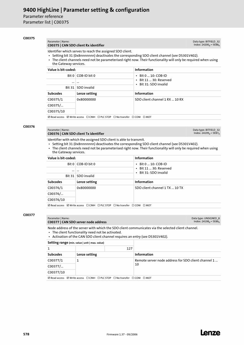
9400 HighLine | Parameter setting & configurationParameter referenceParameter list | C00375
578 Firmware 1.37 - 09/2006 L
C00375
C00376
C00377
Parameter | Name:
C00375 | CAN SDO client Rx identifierData type: BITFIELD_32Index: 24200d = 5E88h
Identifier which serves to reach the assigned SDO client. • Setting bit 31 (0x8nnnnnnn) deactivates the corresponding SDO client channel (see DS301V402). • The client channels need not be parameterised right now. Their functionality will only be required when using
the Gateway services.
Value is bit-coded: Information
Bit 0 COB-ID bit 0 • Bit 0 ... 10: COB-ID • Bit 11 ... 30: Reserved • Bit 31: SDO invalid
... ...
Bit 31 SDO invalid
Subcodes Lenze setting Information
C00375/1 0x80000000 SDO client channel 1 RX ... 10 RX
C00375/...
C00375/10
Read access Write access CINH PLC STOP No transfer COM MOT
Parameter | Name:
C00376 | CAN SDO client Tx identifierData type: BITFIELD_32Index: 24199d = 5E87h
Identifier with which the assigned SDO client is able to transmit. • Setting bit 31 (0x8nnnnnnn) deactivates the corresponding SDO client channel (see DS301V402). • The client channels need not be parameterised right now. Their functionality will only be required when using
the Gateway services.
Value is bit-coded: Information
Bit 0 COB-ID bit 0 • Bit 0 ... 10: COB-ID • Bit 11 ... 30: Reserved • Bit 31: SDO invalid
... ...
Bit 31 SDO invalid
Subcodes Lenze setting Information
C00376/1 0x80000000 SDO client channel 1 TX ... 10 TX
C00376/...
C00376/10
Read access Write access CINH PLC STOP No transfer COM MOT
Parameter | Name:
C00377 | CAN SDO server node addressData type: UNSIGNED_8
Index: 24198d = 5E86h
Node address of the server with which the SDO client communicates via the selected client channel. • The client functionality need not be activated. • Activation of the CAN SDO client channel requires an entry (see DS301V402).
Setting range (min. value | unit | max. value)
1 127
Subcodes Lenze setting Information
C00377/1 1 Remote server node address for SDO client channel 1 ... 10
C00377/...
C00377/10
Read access Write access CINH PLC STOP No transfer COM MOT
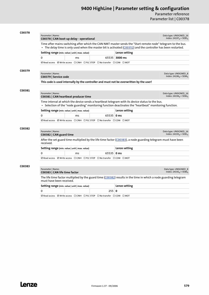
L Firmware 1.37 - 09/2006 579
9400 HighLine | Parameter setting & configurationParameter reference
Parameter list | C00378
C00378
C00379
C00381
C00382
C00383
Parameter | Name:
C00378 | CAN boot-up delay - operationalData type: UNSIGNED_16
Index: 24197d = 5E85h
Time after mains switching after which the CAN NMT master sends the "Start remote node" telegram to the bus. • The delay time is only used when the master bit is activated (C00352) and the controller has been restarted.
Setting range (min. value | unit | max. value) Lenze setting
0 ms 65535 3000 ms
Read access Write access CINH PLC STOP No transfer COM MOT
Parameter | Name:
C00379 | Service codeData type: UNSIGNED_8
Index: 24196d = 5E84h
This code is used internally by the controller and must not be overwritten by the user!
Parameter | Name:
C00381 | CAN heartbeat producer timeData type: UNSIGNED_16
Index: 24194d = 5E82h
Time interval at which the device sends a heartbeat telegram with its device status to the bus. • Selection of the "node guarding" monitoring function deactivates the "heartbeat" monitoring function.
Setting range (min. value | unit | max. value) Lenze setting
0 ms 65535 0 ms
Read access Write access CINH PLC STOP No transfer COM MOT
Parameter | Name:
C00382 | CAN guard timeData type: UNSIGNED_16
Index: 24193d = 5E81h
After the set guard time multiplied by the life time factor (C00383), a node guarding telegram must have been received.
Setting range (min. value | unit | max. value) Lenze setting
0 ms 65535 0 ms
Read access Write access CINH PLC STOP No transfer COM MOT
Parameter | Name:
C00383 | CAN life time factorData type: UNSIGNED_8
Index: 24192d = 5E80h
The life time factor multiplied by the guard time (C00382) results in the time in which a node guarding telegram must have been received.
Setting range (min. value | unit | max. value) Lenze setting
0 255 0
Read access Write access CINH PLC STOP No transfer COM MOT
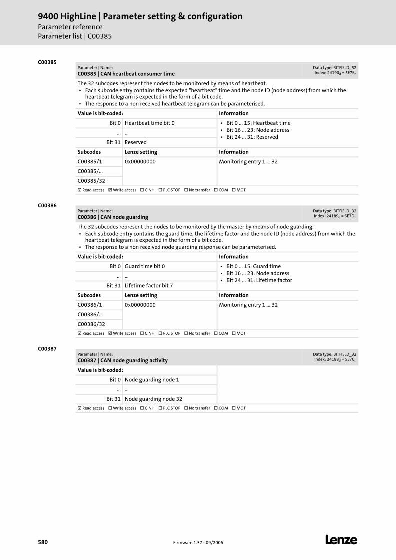
9400 HighLine | Parameter setting & configurationParameter referenceParameter list | C00385
580 Firmware 1.37 - 09/2006 L
C00385
C00386
C00387
Parameter | Name:
C00385 | CAN heartbeat consumer timeData type: BITFIELD_32Index: 24190d = 5E7Eh
The 32 subcodes represent the nodes to be monitored by means of heartbeat. • Each subcode entry contains the expected "heartbeat" time and the node ID (node address) from which the
heartbeat telegram is expected in the form of a bit code. • The response to a non received heartbeat telegram can be parameterised.
Value is bit-coded: Information
Bit 0 Heartbeat time bit 0 • Bit 0 ... 15: Heartbeat time • Bit 16 ... 23: Node address • Bit 24 ... 31: Reserved
... ...
Bit 31 Reserved
Subcodes Lenze setting Information
C00385/1 0x00000000 Monitoring entry 1 ... 32
C00385/...
C00385/32
Read access Write access CINH PLC STOP No transfer COM MOT
Parameter | Name:
C00386 | CAN node guardingData type: BITFIELD_32Index: 24189d = 5E7Dh
The 32 subcodes represent the nodes to be monitored by the master by means of node guarding. • Each subcode entry contains the guard time, the lifetime factor and the node ID (node address) from which the
heartbeat telegram is expected in the form of a bit code. • The response to a non received node guarding response can be parameterised.
Value is bit-coded: Information
Bit 0 Guard time bit 0 • Bit 0 ... 15: Guard time • Bit 16 ... 23: Node address • Bit 24 ... 31: Lifetime factor
... ...
Bit 31 Lifetime factor bit 7
Subcodes Lenze setting Information
C00386/1 0x00000000 Monitoring entry 1 ... 32
C00386/...
C00386/32
Read access Write access CINH PLC STOP No transfer COM MOT
Parameter | Name:
C00387 | CAN node guarding activityData type: BITFIELD_32Index: 24188d = 5E7Ch
Value is bit-coded:
Bit 0 Node guarding node 1
... ...
Bit 31 Node guarding node 32
Read access Write access CINH PLC STOP No transfer COM MOT
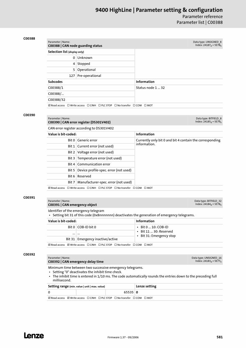
L Firmware 1.37 - 09/2006 581
9400 HighLine | Parameter setting & configurationParameter reference
Parameter list | C00388
C00388
C00390
C00391
C00392
Parameter | Name:
C00388 | CAN node guarding statusData type: UNSIGNED_8
Index: 24187d = 5E7Bh
Selection list (display only)
0 Unknown
4 Stopped
5 Operational
127 Pre-operational
Subcodes Information
C00388/1 Status node 1 ... 32
C00388/...
C00388/32
Read access Write access CINH PLC STOP No transfer COM MOT
Parameter | Name:
C00390 | CAN error register (DS301V402)Data type: BITFIELD_8Index: 24185d = 5E79h
CAN error register according to DS301V402
Value is bit-coded: Information
Bit 0 Generic error Currently only bit 0 and bit 4 contain the corresponding information.
Bit 1 Current error (not used)
Bit 2 Voltage error (not used)
Bit 3 Temperature error (not used)
Bit 4 Communication error
Bit 5 Device profile-spec. error (not used)
Bit 6 Reserved
Bit 7 Manufacturer-spec. error (not used)
Read access Write access CINH PLC STOP No transfer COM MOT
Parameter | Name:
C00391 | CAN emergency objectData type: BITFIELD_32Index: 24184d = 5E78h
Identifier of the emergency telegram • Setting bit 31 of this code (0x8nnnnnnn) deactivates the generation of emergency telegrams.
Value is bit-coded: Information
Bit 0 COB-ID bit 0 • Bit 0 ... 10: COB-ID • Bit 11 ... 30: Reserved • Bit 31: Emergency stop
... ...
Bit 31 Emergency inactive/active
Read access Write access CINH PLC STOP No transfer COM MOT
Parameter | Name:
C00392 | CAN emergency delay timeData type: UNSIGNED_16
Index: 24183d = 5E77h
Minimum time between two successive emergency telegrams. • Setting "0" deactivates the inhibit time check. • The inhibit time is entered in 1/10 ms. The code automatically rounds the entries down to the preceding full
millisecond.
Setting range (min. value | unit | max. value) Lenze setting
0 65535 0
Read access Write access CINH PLC STOP No transfer COM MOT
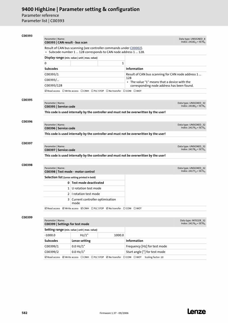
9400 HighLine | Parameter setting & configurationParameter referenceParameter list | C00393
582 Firmware 1.37 - 09/2006 L
C00393
C00395
C00396
C00397
C00398
C00399
Parameter | Name:
C00393 | CAN result - bus scanData type: UNSIGNED_8
Index: 24182d = 5E76h
Result of CAN bus scanning (see controller commands under C00002). • Subcode number 1 ... 128 corresponds to CAN node address 1 ... 128.
Display range (min. value | unit | max. value)
0 1
Subcodes Information
C00393/1 Result of CAN bus scanning for CAN node address 1 ... 128 • The value "1" means that a device with the
corresponding node address has been found.
C00393/...
C00393/128
Read access Write access CINH PLC STOP No transfer COM MOT
Parameter | Name:
C00395 | Service codeData type: UNSIGNED_32
Index: 24180d = 5E74h
This code is used internally by the controller and must not be overwritten by the user!
Parameter | Name:
C00396 | Service codeData type: UNSIGNED_32
Index: 24179d = 5E73h
This code is used internally by the controller and must not be overwritten by the user!
Parameter | Name:
C00397 | Service codeData type: UNSIGNED_32
Index: 24178d = 5E72h
This code is used internally by the controller and must not be overwritten by the user!
Parameter | Name:
C00398 | Test mode - motor controlData type: UNSIGNED_32
Index: 24177d = 5E71h
Selection list (Lenze setting printed in bold)
0 Test mode deactivated
1 U rotation test mode
2 I rotation test mode
3 Current controller optimisation mode
Read access Write access CINH PLC STOP No transfer COM MOT
Parameter | Name:
C00399 | Settings for test modeData type: INTEGER_32Index: 24176d = 5E70h
Setting range (min. value | unit | max. value)
-1000.0 Hz/1° 1000.0
Subcodes Lenze setting Information
C00399/1 0.0 Hz/1° Frequency [Hz] for test mode
C00399/2 0.0 Hz/1° Start angle [°] for test mode
Read access Write access CINH PLC STOP No transfer COM MOT Scaling factor: 10
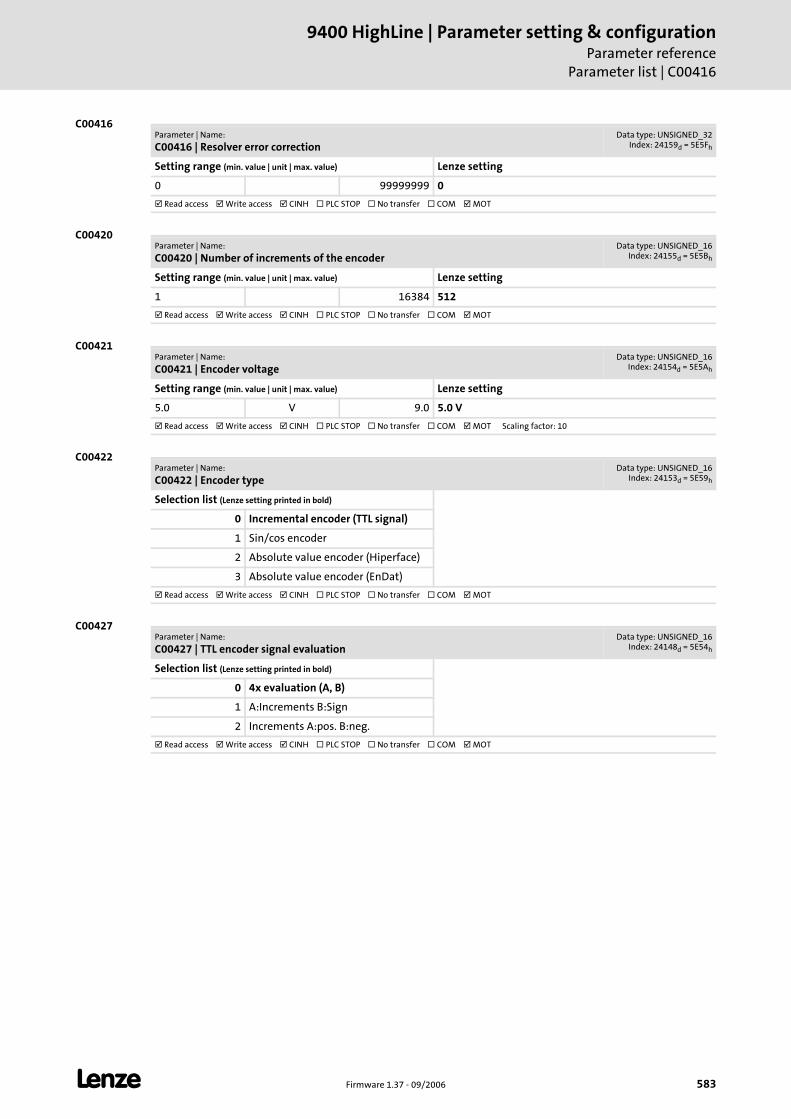
L Firmware 1.37 - 09/2006 583
9400 HighLine | Parameter setting & configurationParameter reference
Parameter list | C00416
C00416
C00420
C00421
C00422
C00427
Parameter | Name:
C00416 | Resolver error correctionData type: UNSIGNED_32
Index: 24159d = 5E5Fh
Setting range (min. value | unit | max. value) Lenze setting
0 99999999 0
Read access Write access CINH PLC STOP No transfer COM MOT
Parameter | Name:
C00420 | Number of increments of the encoderData type: UNSIGNED_16
Index: 24155d = 5E5Bh
Setting range (min. value | unit | max. value) Lenze setting
1 16384 512
Read access Write access CINH PLC STOP No transfer COM MOT
Parameter | Name:
C00421 | Encoder voltageData type: UNSIGNED_16
Index: 24154d = 5E5Ah
Setting range (min. value | unit | max. value) Lenze setting
5.0 V 9.0 5.0 V
Read access Write access CINH PLC STOP No transfer COM MOT Scaling factor: 10
Parameter | Name:
C00422 | Encoder typeData type: UNSIGNED_16
Index: 24153d = 5E59h
Selection list (Lenze setting printed in bold)
0 Incremental encoder (TTL signal)
1 Sin/cos encoder
2 Absolute value encoder (Hiperface)
3 Absolute value encoder (EnDat)
Read access Write access CINH PLC STOP No transfer COM MOT
Parameter | Name:
C00427 | TTL encoder signal evaluationData type: UNSIGNED_16
Index: 24148d = 5E54h
Selection list (Lenze setting printed in bold)
0 4x evaluation (A, B)
1 A:Increments B:Sign
2 Increments A:pos. B:neg.
Read access Write access CINH PLC STOP No transfer COM MOT
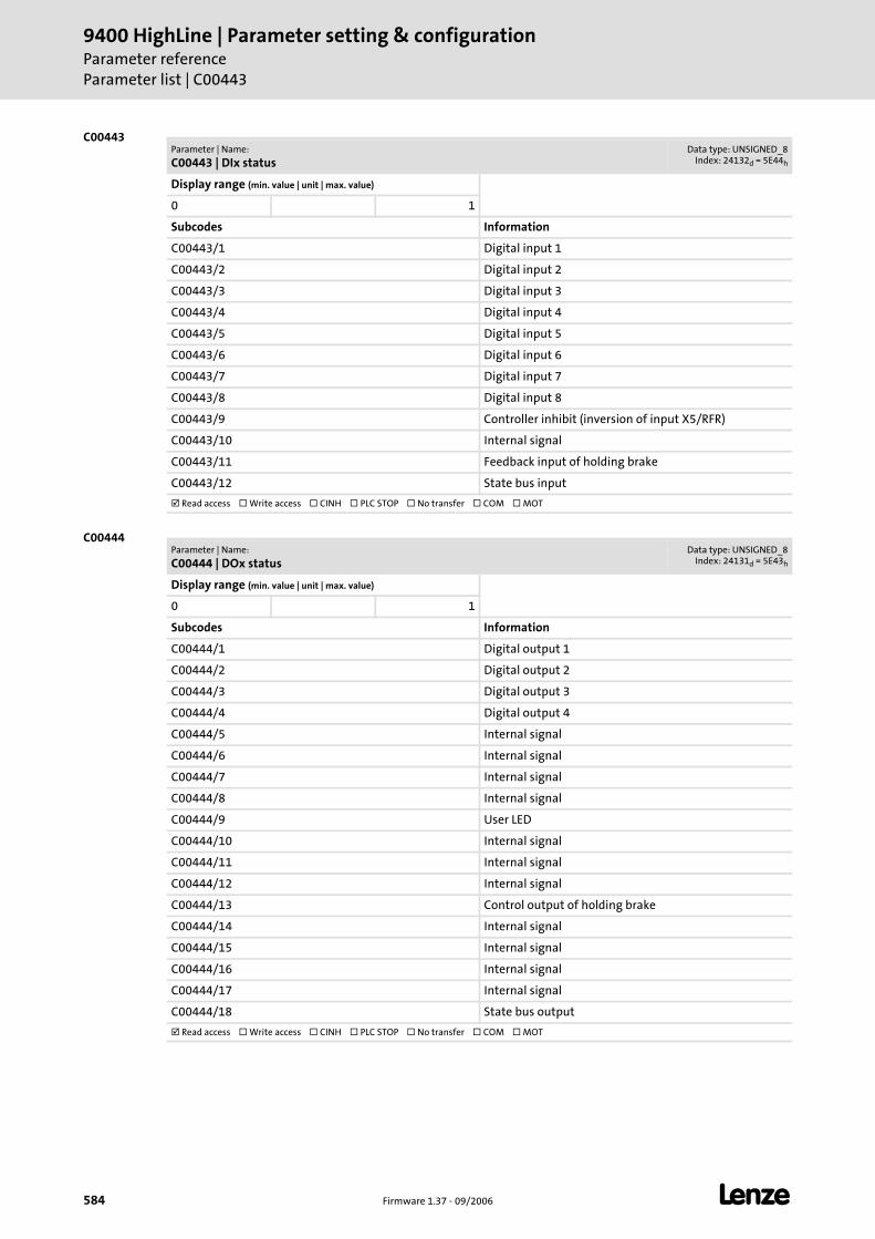
9400 HighLine | Parameter setting & configurationParameter referenceParameter list | C00443
584 Firmware 1.37 - 09/2006 L
C00443
C00444
Parameter | Name:
C00443 | DIx statusData type: UNSIGNED_8
Index: 24132d = 5E44h
Display range (min. value | unit | max. value)
0 1
Subcodes Information
C00443/1 Digital input 1
C00443/2 Digital input 2
C00443/3 Digital input 3
C00443/4 Digital input 4
C00443/5 Digital input 5
C00443/6 Digital input 6
C00443/7 Digital input 7
C00443/8 Digital input 8
C00443/9 Controller inhibit (inversion of input X5/RFR)
C00443/10 Internal signal
C00443/11 Feedback input of holding brake
C00443/12 State bus input
Read access Write access CINH PLC STOP No transfer COM MOT
Parameter | Name:
C00444 | DOx statusData type: UNSIGNED_8
Index: 24131d = 5E43h
Display range (min. value | unit | max. value)
0 1
Subcodes Information
C00444/1 Digital output 1
C00444/2 Digital output 2
C00444/3 Digital output 3
C00444/4 Digital output 4
C00444/5 Internal signal
C00444/6 Internal signal
C00444/7 Internal signal
C00444/8 Internal signal
C00444/9 User LED
C00444/10 Internal signal
C00444/11 Internal signal
C00444/12 Internal signal
C00444/13 Control output of holding brake
C00444/14 Internal signal
C00444/15 Internal signal
C00444/16 Internal signal
C00444/17 Internal signal
C00444/18 State bus output
Read access Write access CINH PLC STOP No transfer COM MOT
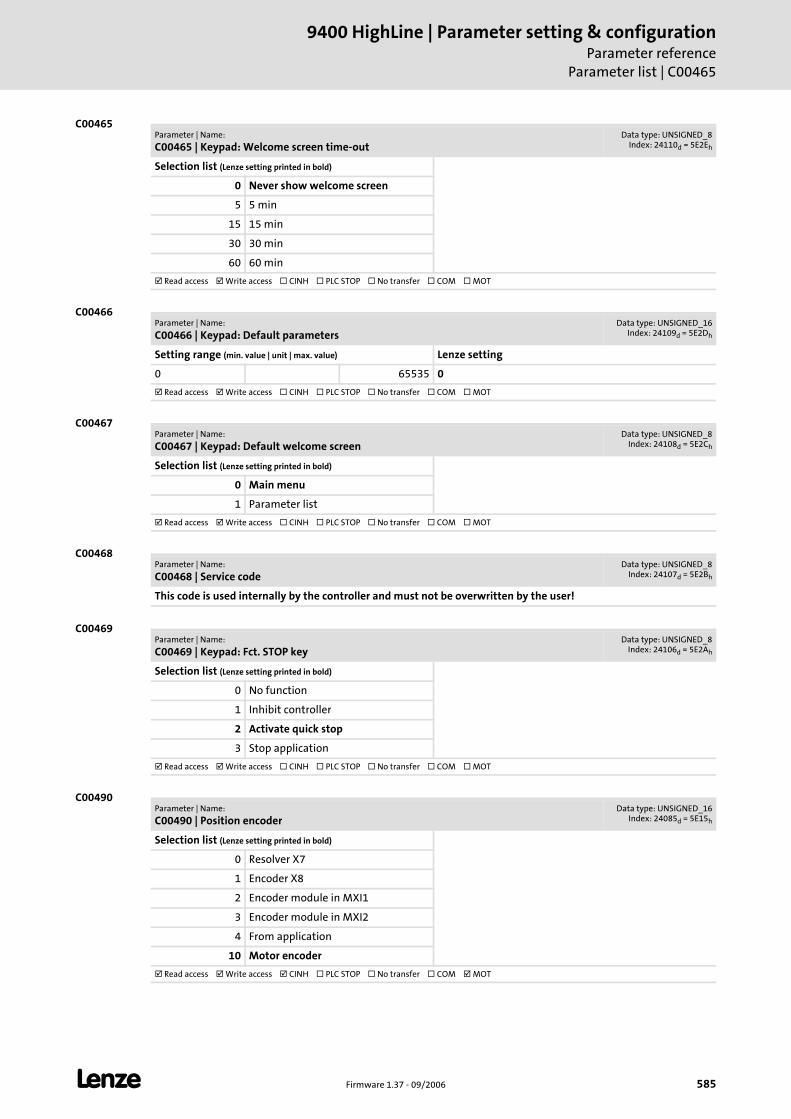
L Firmware 1.37 - 09/2006 585
9400 HighLine | Parameter setting & configurationParameter reference
Parameter list | C00465
C00465
C00466
C00467
C00468
C00469
C00490
Parameter | Name:
C00465 | Keypad: Welcome screen time-outData type: UNSIGNED_8
Index: 24110d = 5E2Eh
Selection list (Lenze setting printed in bold)
0 Never show welcome screen
5 5 min
15 15 min
30 30 min
60 60 min
Read access Write access CINH PLC STOP No transfer COM MOT
Parameter | Name:
C00466 | Keypad: Default parametersData type: UNSIGNED_16
Index: 24109d = 5E2Dh
Setting range (min. value | unit | max. value) Lenze setting
0 65535 0
Read access Write access CINH PLC STOP No transfer COM MOT
Parameter | Name:
C00467 | Keypad: Default welcome screenData type: UNSIGNED_8
Index: 24108d = 5E2Ch
Selection list (Lenze setting printed in bold)
0 Main menu
1 Parameter list
Read access Write access CINH PLC STOP No transfer COM MOT
Parameter | Name:
C00468 | Service codeData type: UNSIGNED_8
Index: 24107d = 5E2Bh
This code is used internally by the controller and must not be overwritten by the user!
Parameter | Name:
C00469 | Keypad: Fct. STOP keyData type: UNSIGNED_8
Index: 24106d = 5E2Ah
Selection list (Lenze setting printed in bold)
0 No function
1 Inhibit controller
2 Activate quick stop
3 Stop application
Read access Write access CINH PLC STOP No transfer COM MOT
Parameter | Name:
C00490 | Position encoderData type: UNSIGNED_16
Index: 24085d = 5E15h
Selection list (Lenze setting printed in bold)
0 Resolver X7
1 Encoder X8
2 Encoder module in MXI1
3 Encoder module in MXI2
4 From application
10 Motor encoder
Read access Write access CINH PLC STOP No transfer COM MOT
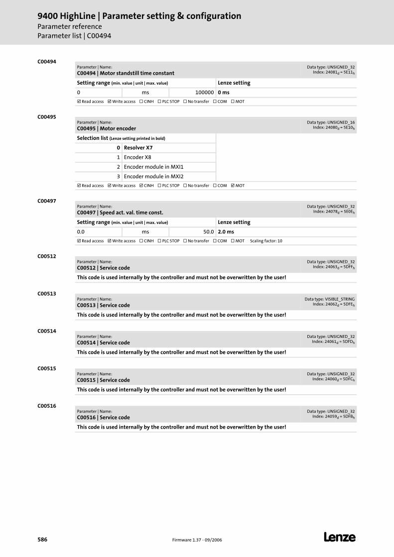
9400 HighLine | Parameter setting & configurationParameter referenceParameter list | C00494
586 Firmware 1.37 - 09/2006 L
C00494
C00495
C00497
C00512
C00513
C00514
C00515
C00516
Parameter | Name:
C00494 | Motor standstill time constantData type: UNSIGNED_32
Index: 24081d = 5E11h
Setting range (min. value | unit | max. value) Lenze setting
0 ms 100000 0 ms
Read access Write access CINH PLC STOP No transfer COM MOT
Parameter | Name:
C00495 | Motor encoderData type: UNSIGNED_16
Index: 24080d = 5E10h
Selection list (Lenze setting printed in bold)
0 Resolver X7
1 Encoder X8
2 Encoder module in MXI1
3 Encoder module in MXI2
Read access Write access CINH PLC STOP No transfer COM MOT
Parameter | Name:
C00497 | Speed act. val. time const.Data type: UNSIGNED_32
Index: 24078d = 5E0Eh
Setting range (min. value | unit | max. value) Lenze setting
0.0 ms 50.0 2.0 ms
Read access Write access CINH PLC STOP No transfer COM MOT Scaling factor: 10
Parameter | Name:
C00512 | Service codeData type: UNSIGNED_32
Index: 24063d = 5DFFh
This code is used internally by the controller and must not be overwritten by the user!
Parameter | Name:
C00513 | Service codeData type: VISIBLE_STRING
Index: 24062d = 5DFEh
This code is used internally by the controller and must not be overwritten by the user!
Parameter | Name:
C00514 | Service codeData type: UNSIGNED_32
Index: 24061d = 5DFDh
This code is used internally by the controller and must not be overwritten by the user!
Parameter | Name:
C00515 | Service codeData type: UNSIGNED_32
Index: 24060d = 5DFCh
This code is used internally by the controller and must not be overwritten by the user!
Parameter | Name:
C00516 | Service codeData type: UNSIGNED_32
Index: 24059d = 5DFBh
This code is used internally by the controller and must not be overwritten by the user!
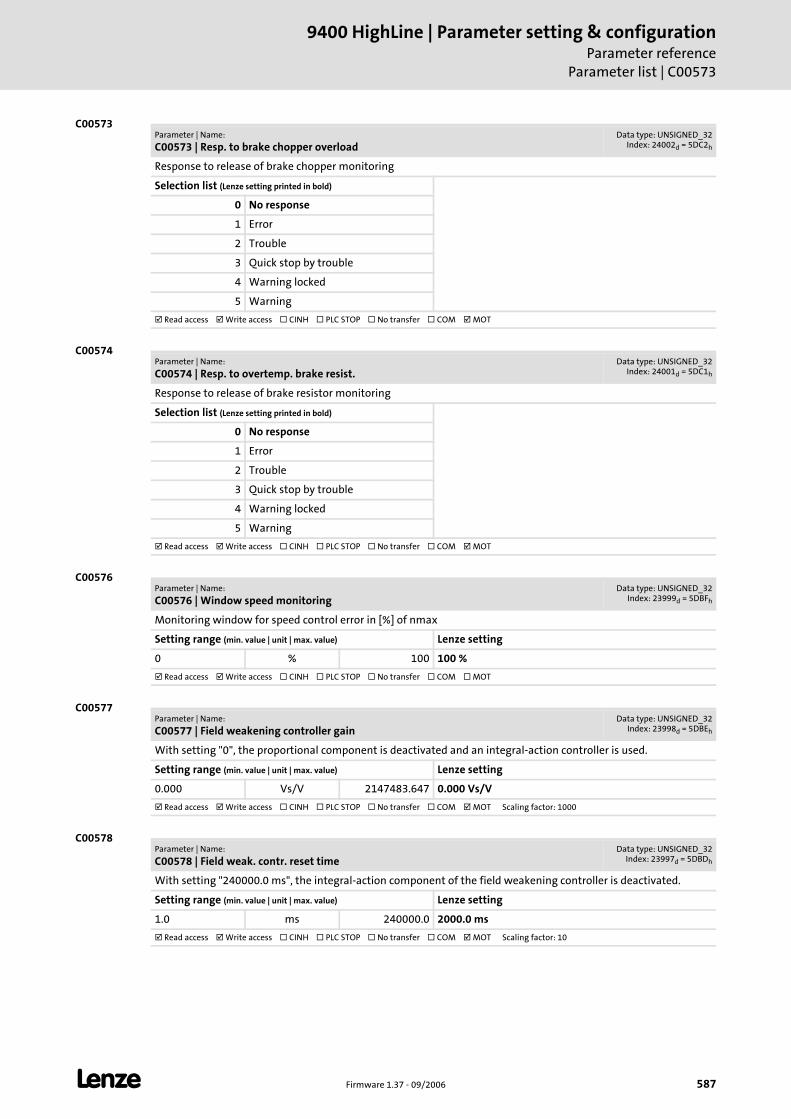
L Firmware 1.37 - 09/2006 587
9400 HighLine | Parameter setting & configurationParameter reference
Parameter list | C00573
C00573
C00574
C00576
C00577
C00578
Parameter | Name:
C00573 | Resp. to brake chopper overloadData type: UNSIGNED_32
Index: 24002d = 5DC2h
Response to release of brake chopper monitoring
Selection list (Lenze setting printed in bold)
0 No response
1 Error
2 Trouble
3 Quick stop by trouble
4 Warning locked
5 Warning
Read access Write access CINH PLC STOP No transfer COM MOT
Parameter | Name:
C00574 | Resp. to overtemp. brake resist.Data type: UNSIGNED_32
Index: 24001d = 5DC1h
Response to release of brake resistor monitoring
Selection list (Lenze setting printed in bold)
0 No response
1 Error
2 Trouble
3 Quick stop by trouble
4 Warning locked
5 Warning
Read access Write access CINH PLC STOP No transfer COM MOT
Parameter | Name:
C00576 | Window speed monitoringData type: UNSIGNED_32
Index: 23999d = 5DBFh
Monitoring window for speed control error in [%] of nmax
Setting range (min. value | unit | max. value) Lenze setting
0 % 100 100 %
Read access Write access CINH PLC STOP No transfer COM MOT
Parameter | Name:
C00577 | Field weakening controller gainData type: UNSIGNED_32
Index: 23998d = 5DBEh
With setting "0", the proportional component is deactivated and an integral-action controller is used.
Setting range (min. value | unit | max. value) Lenze setting
0.000 Vs/V 2147483.647 0.000 Vs/V
Read access Write access CINH PLC STOP No transfer COM MOT Scaling factor: 1000
Parameter | Name:
C00578 | Field weak. contr. reset timeData type: UNSIGNED_32
Index: 23997d = 5DBDh
With setting "240000.0 ms", the integral-action component of the field weakening controller is deactivated.
Setting range (min. value | unit | max. value) Lenze setting
1.0 ms 240000.0 2000.0 ms
Read access Write access CINH PLC STOP No transfer COM MOT Scaling factor: 10
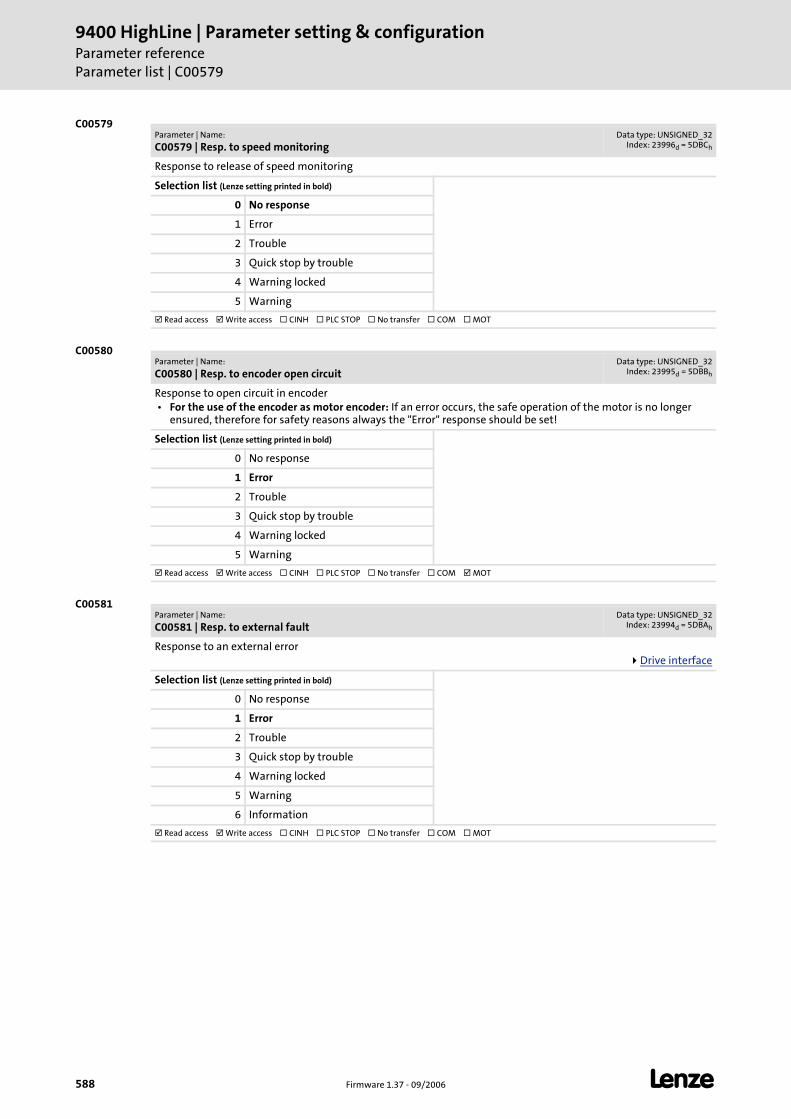
9400 HighLine | Parameter setting & configurationParameter referenceParameter list | C00579
588 Firmware 1.37 - 09/2006 L
C00579
C00580
C00581
Parameter | Name:
C00579 | Resp. to speed monitoringData type: UNSIGNED_32
Index: 23996d = 5DBCh
Response to release of speed monitoring
Selection list (Lenze setting printed in bold)
0 No response
1 Error
2 Trouble
3 Quick stop by trouble
4 Warning locked
5 Warning
Read access Write access CINH PLC STOP No transfer COM MOT
Parameter | Name:
C00580 | Resp. to encoder open circuitData type: UNSIGNED_32
Index: 23995d = 5DBBh
Response to open circuit in encoder • For the use of the encoder as motor encoder: If an error occurs, the safe operation of the motor is no longer
ensured, therefore for safety reasons always the "Error" response should be set!
Selection list (Lenze setting printed in bold)
0 No response
1 Error
2 Trouble
3 Quick stop by trouble
4 Warning locked
5 Warning
Read access Write access CINH PLC STOP No transfer COM MOT
Parameter | Name:
C00581 | Resp. to external faultData type: UNSIGNED_32
Index: 23994d = 5DBAh
Response to an external errorDrive interface
Selection list (Lenze setting printed in bold)
0 No response
1 Error
2 Trouble
3 Quick stop by trouble
4 Warning locked
5 Warning
6 Information
Read access Write access CINH PLC STOP No transfer COM MOT
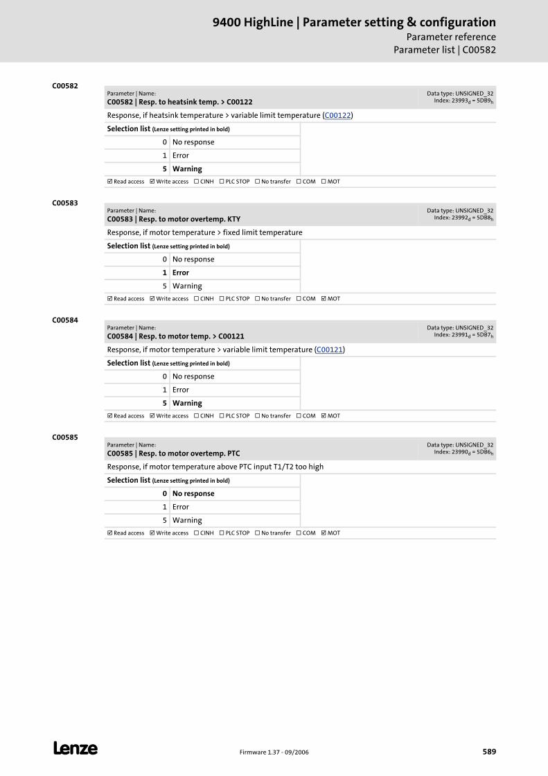
L Firmware 1.37 - 09/2006 589
9400 HighLine | Parameter setting & configurationParameter reference
Parameter list | C00582
C00582
C00583
C00584
C00585
Parameter | Name:
C00582 | Resp. to heatsink temp. > C00122Data type: UNSIGNED_32
Index: 23993d = 5DB9h
Response, if heatsink temperature > variable limit temperature (C00122)
Selection list (Lenze setting printed in bold)
0 No response
1 Error
5 Warning
Read access Write access CINH PLC STOP No transfer COM MOT
Parameter | Name:
C00583 | Resp. to motor overtemp. KTYData type: UNSIGNED_32
Index: 23992d = 5DB8h
Response, if motor temperature > fixed limit temperature
Selection list (Lenze setting printed in bold)
0 No response
1 Error
5 Warning
Read access Write access CINH PLC STOP No transfer COM MOT
Parameter | Name:
C00584 | Resp. to motor temp. > C00121Data type: UNSIGNED_32
Index: 23991d = 5DB7h
Response, if motor temperature > variable limit temperature (C00121)
Selection list (Lenze setting printed in bold)
0 No response
1 Error
5 Warning
Read access Write access CINH PLC STOP No transfer COM MOT
Parameter | Name:
C00585 | Resp. to motor overtemp. PTCData type: UNSIGNED_32
Index: 23990d = 5DB6h
Response, if motor temperature above PTC input T1/T2 too high
Selection list (Lenze setting printed in bold)
0 No response
1 Error
5 Warning
Read access Write access CINH PLC STOP No transfer COM MOT
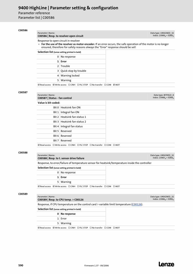
9400 HighLine | Parameter setting & configurationParameter referenceParameter list | C00586
590 Firmware 1.37 - 09/2006 L
C00586
C00587
C00588
C00589
Parameter | Name:
C00586 | Resp. to resolver open circuitData type: UNSIGNED_32
Index: 23989d = 5DB5h
Response to open circuit in resolver • For the use of the resolver as motor encoder: If an error occurs, the safe operation of the motor is no longer
ensured, therefore for safety reasons always the "Error" response should be set!
Selection list (Lenze setting printed in bold)
0 No response
1 Error
2 Trouble
3 Quick stop by trouble
4 Warning locked
5 Warning
Read access Write access CINH PLC STOP No transfer COM MOT
Parameter | Name:
C00587 | Status - fan controlData type: BITFIELD_8
Index: 23988d = 5DB4h
Value is bit-coded:
Bit 0 Heatsink fan ON
Bit 1 Integral fan ON
Bit 2 Heatsink fan status 1
Bit 3 Heatsink fan status 2
Bit 4 Integral fan status
Bit 5 Reserved
Bit 6 Reserved
Bit 7 Reserved
Read access Write access CINH PLC STOP No transfer COM MOT
Parameter | Name:
C00588 | Resp. to t. sensor drive failureData type: UNSIGNED_32
Index: 23987d = 5DB3h
Response, to error/failure of temperature sensor for heatsink/temperature inside the controller
Selection list (Lenze setting printed in bold)
0 No response
1 Error
5 Warning
Read access Write access CINH PLC STOP No transfer COM MOT
Parameter | Name:
C00589 | Resp. to CPU temp. > C00126Data type: UNSIGNED_32
Index: 23986d = 5DB2h
Response, if CPU temperature on the control card > variable limit temperature (C00126).
Selection list (Lenze setting printed in bold)
0 No response
1 Error
5 Warning
Read access Write access CINH PLC STOP No transfer COM MOT
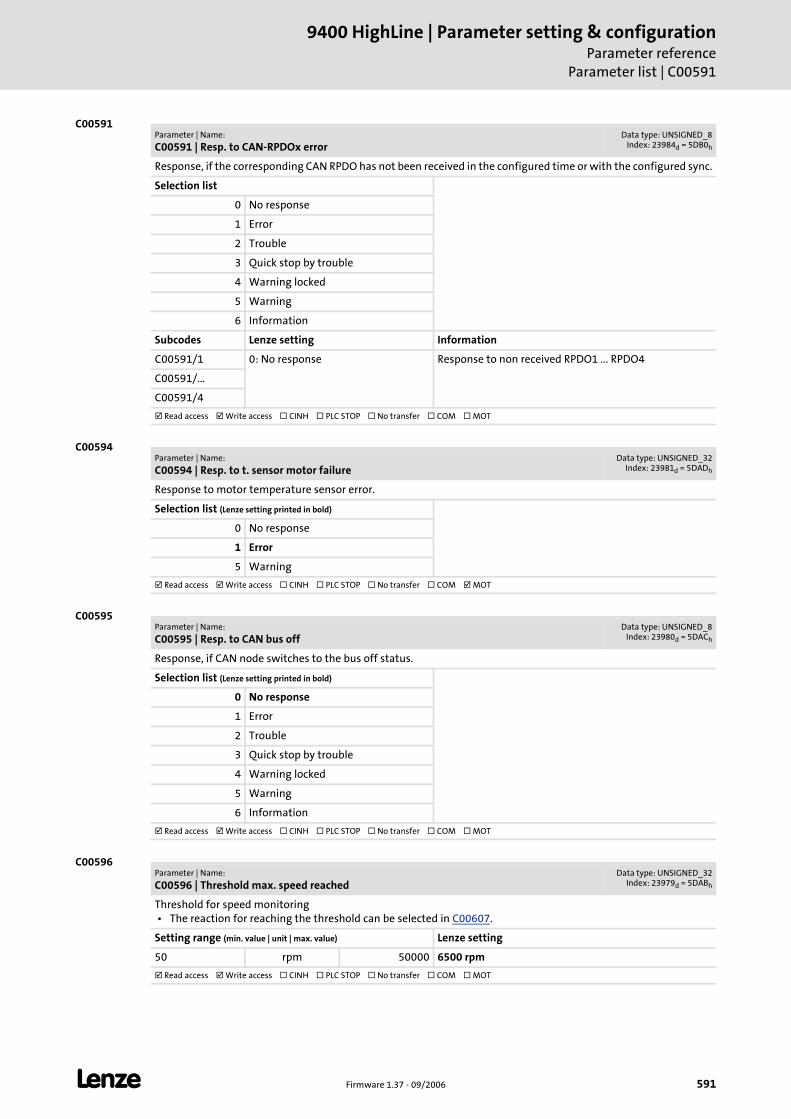
L Firmware 1.37 - 09/2006 591
9400 HighLine | Parameter setting & configurationParameter reference
Parameter list | C00591
C00591
C00594
C00595
C00596
Parameter | Name:
C00591 | Resp. to CAN-RPDOx errorData type: UNSIGNED_8
Index: 23984d = 5DB0h
Response, if the corresponding CAN RPDO has not been received in the configured time or with the configured sync.
Selection list
0 No response
1 Error
2 Trouble
3 Quick stop by trouble
4 Warning locked
5 Warning
6 Information
Subcodes Lenze setting Information
C00591/1 0: No response Response to non received RPDO1 ... RPDO4
C00591/...
C00591/4
Read access Write access CINH PLC STOP No transfer COM MOT
Parameter | Name:
C00594 | Resp. to t. sensor motor failureData type: UNSIGNED_32
Index: 23981d = 5DADh
Response to motor temperature sensor error.
Selection list (Lenze setting printed in bold)
0 No response
1 Error
5 Warning
Read access Write access CINH PLC STOP No transfer COM MOT
Parameter | Name:
C00595 | Resp. to CAN bus offData type: UNSIGNED_8
Index: 23980d = 5DACh
Response, if CAN node switches to the bus off status.
Selection list (Lenze setting printed in bold)
0 No response
1 Error
2 Trouble
3 Quick stop by trouble
4 Warning locked
5 Warning
6 Information
Read access Write access CINH PLC STOP No transfer COM MOT
Parameter | Name:
C00596 | Threshold max. speed reachedData type: UNSIGNED_32
Index: 23979d = 5DABh
Threshold for speed monitoring • The reaction for reaching the threshold can be selected in C00607.
Setting range (min. value | unit | max. value) Lenze setting
50 rpm 50000 6500 rpm
Read access Write access CINH PLC STOP No transfer COM MOT
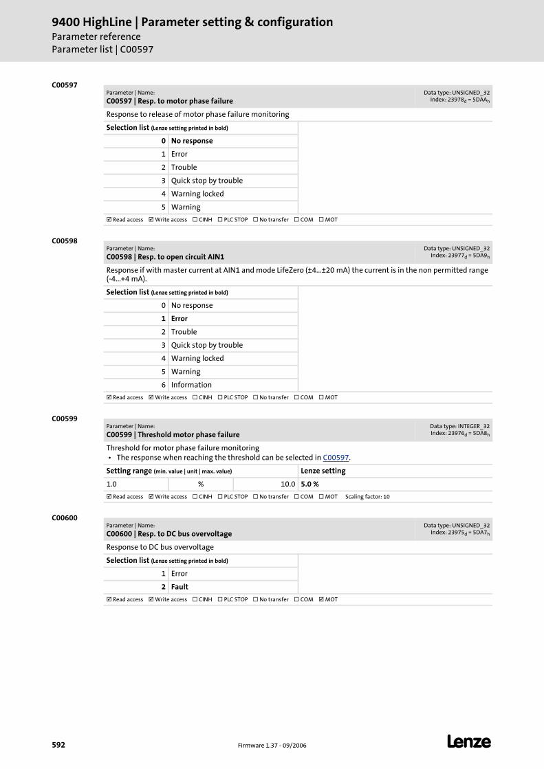
9400 HighLine | Parameter setting & configurationParameter referenceParameter list | C00597
592 Firmware 1.37 - 09/2006 L
C00597
C00598
C00599
C00600
Parameter | Name:
C00597 | Resp. to motor phase failureData type: UNSIGNED_32
Index: 23978d = 5DAAh
Response to release of motor phase failure monitoring
Selection list (Lenze setting printed in bold)
0 No response
1 Error
2 Trouble
3 Quick stop by trouble
4 Warning locked
5 Warning
Read access Write access CINH PLC STOP No transfer COM MOT
Parameter | Name:
C00598 | Resp. to open circuit AIN1Data type: UNSIGNED_32
Index: 23977d = 5DA9h
Response if with master current at AIN1 and mode LifeZero (±4...±20 mA) the current is in the non permitted range (-4...+4 mA).
Selection list (Lenze setting printed in bold)
0 No response
1 Error
2 Trouble
3 Quick stop by trouble
4 Warning locked
5 Warning
6 Information
Read access Write access CINH PLC STOP No transfer COM MOT
Parameter | Name:
C00599 | Threshold motor phase failureData type: INTEGER_32Index: 23976d = 5DA8h
Threshold for motor phase failure monitoring • The response when reaching the threshold can be selected in C00597.
Setting range (min. value | unit | max. value) Lenze setting
1.0 % 10.0 5.0 %
Read access Write access CINH PLC STOP No transfer COM MOT Scaling factor: 10
Parameter | Name:
C00600 | Resp. to DC bus overvoltageData type: UNSIGNED_32
Index: 23975d = 5DA7h
Response to DC bus overvoltage
Selection list (Lenze setting printed in bold)
1 Error
2 Fault
Read access Write access CINH PLC STOP No transfer COM MOT
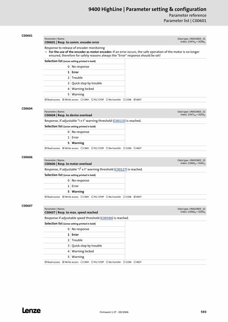
L Firmware 1.37 - 09/2006 593
9400 HighLine | Parameter setting & configurationParameter reference
Parameter list | C00601
C00601
C00604
C00606
C00607
Parameter | Name:
C00601 | Resp. to comm. encoder errorData type: UNSIGNED_32
Index: 23974d = 5DA6h
Response to release of encoder monitoring • For the use of the encoder as motor encoder: If an error occurs, the safe operation of the motor is no longer
ensured, therefore for safety reasons always the "Error" response should be set!
Selection list (Lenze setting printed in bold)
0 No response
1 Error
2 Trouble
3 Quick stop by trouble
4 Warning locked
5 Warning
Read access Write access CINH PLC STOP No transfer COM MOT
Parameter | Name:
C00604 | Resp. to device overloadData type: UNSIGNED_32
Index: 23971d = 5DA3h
Response, if adjustable "I x t" warning threshold (C00123) is reached.
Selection list (Lenze setting printed in bold)
0 No response
1 Error
5 Warning
Read access Write access CINH PLC STOP No transfer COM MOT
Parameter | Name:
C00606 | Resp. to motor overloadData type: UNSIGNED_32
Index: 23969d = 5DA1h
Response, if adjustable "I2 x t" warning threshold (C00127) is reached.
Selection list (Lenze setting printed in bold)
0 No response
1 Error
5 Warning
Read access Write access CINH PLC STOP No transfer COM MOT
Parameter | Name:
C00607 | Resp. to max. speed reachedData type: UNSIGNED_32
Index: 23968d = 5DA0h
Response if adjustable speed threshold (C00596) is reached.
Selection list (Lenze setting printed in bold)
0 No response
1 Error
2 Trouble
3 Quick stop by trouble
4 Warning locked
5 Warning
Read access Write access CINH PLC STOP No transfer COM MOT
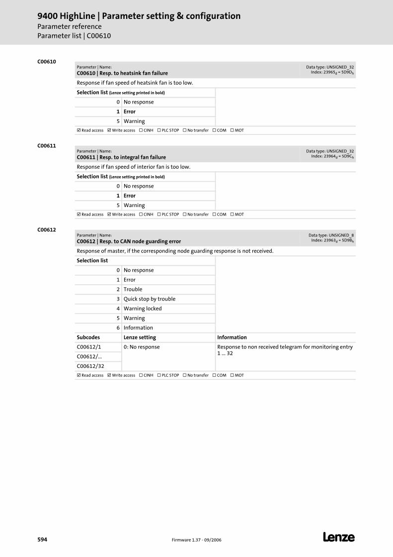
9400 HighLine | Parameter setting & configurationParameter referenceParameter list | C00610
594 Firmware 1.37 - 09/2006 L
C00610
C00611
C00612
Parameter | Name:
C00610 | Resp. to heatsink fan failureData type: UNSIGNED_32
Index: 23965d = 5D9Dh
Response if fan speed of heatsink fan is too low.
Selection list (Lenze setting printed in bold)
0 No response
1 Error
5 Warning
Read access Write access CINH PLC STOP No transfer COM MOT
Parameter | Name:
C00611 | Resp. to integral fan failureData type: UNSIGNED_32
Index: 23964d = 5D9Ch
Response if fan speed of interior fan is too low.
Selection list (Lenze setting printed in bold)
0 No response
1 Error
5 Warning
Read access Write access CINH PLC STOP No transfer COM MOT
Parameter | Name:
C00612 | Resp. to CAN node guarding errorData type: UNSIGNED_8
Index: 23963d = 5D9Bh
Response of master, if the corresponding node guarding response is not received.
Selection list
0 No response
1 Error
2 Trouble
3 Quick stop by trouble
4 Warning locked
5 Warning
6 Information
Subcodes Lenze setting Information
C00612/1 0: No response Response to non received telegram for monitoring entry 1 ... 32
C00612/...
C00612/32
Read access Write access CINH PLC STOP No transfer COM MOT
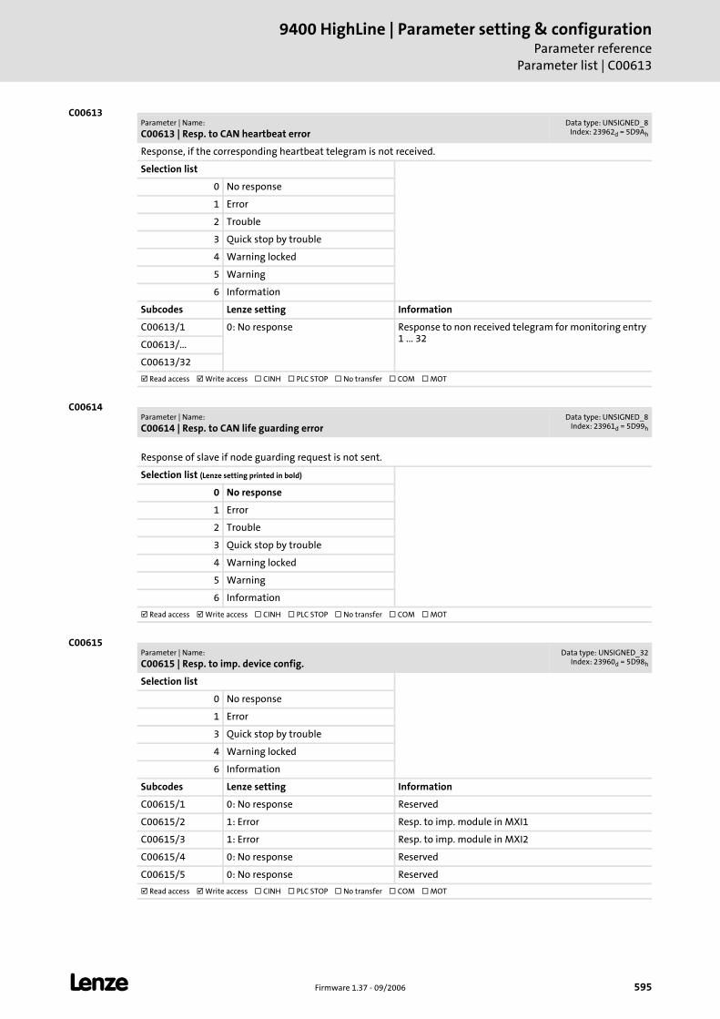
L Firmware 1.37 - 09/2006 595
9400 HighLine | Parameter setting & configurationParameter reference
Parameter list | C00613
C00613
C00614
C00615
Parameter | Name:
C00613 | Resp. to CAN heartbeat errorData type: UNSIGNED_8
Index: 23962d = 5D9Ah
Response, if the corresponding heartbeat telegram is not received.
Selection list
0 No response
1 Error
2 Trouble
3 Quick stop by trouble
4 Warning locked
5 Warning
6 Information
Subcodes Lenze setting Information
C00613/1 0: No response Response to non received telegram for monitoring entry 1 ... 32
C00613/...
C00613/32
Read access Write access CINH PLC STOP No transfer COM MOT
Parameter | Name:
C00614 | Resp. to CAN life guarding errorData type: UNSIGNED_8
Index: 23961d = 5D99h
Response of slave if node guarding request is not sent.
Selection list (Lenze setting printed in bold)
0 No response
1 Error
2 Trouble
3 Quick stop by trouble
4 Warning locked
5 Warning
6 Information
Read access Write access CINH PLC STOP No transfer COM MOT
Parameter | Name:
C00615 | Resp. to imp. device config.Data type: UNSIGNED_32
Index: 23960d = 5D98h
Selection list
0 No response
1 Error
3 Quick stop by trouble
4 Warning locked
6 Information
Subcodes Lenze setting Information
C00615/1 0: No response Reserved
C00615/2 1: Error Resp. to imp. module in MXI1
C00615/3 1: Error Resp. to imp. module in MXI2
C00615/4 0: No response Reserved
C00615/5 0: No response Reserved
Read access Write access CINH PLC STOP No transfer COM MOT
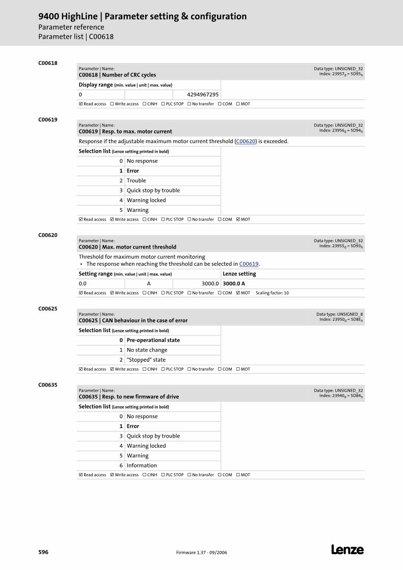
9400 HighLine | Parameter setting & configurationParameter referenceParameter list | C00618
596 Firmware 1.37 - 09/2006 L
C00618
C00619
C00620
C00625
C00635
Parameter | Name:
C00618 | Number of CRC cyclesData type: UNSIGNED_32
Index: 23957d = 5D95h
Display range (min. value | unit | max. value)
0 4294967295
Read access Write access CINH PLC STOP No transfer COM MOT
Parameter | Name:
C00619 | Resp. to max. motor currentData type: UNSIGNED_32
Index: 23956d = 5D94h
Response if the adjustable maximum motor current threshold (C00620) is exceeded.
Selection list (Lenze setting printed in bold)
0 No response
1 Error
2 Trouble
3 Quick stop by trouble
4 Warning locked
5 Warning
Read access Write access CINH PLC STOP No transfer COM MOT
Parameter | Name:
C00620 | Max. motor current thresholdData type: UNSIGNED_32
Index: 23955d = 5D93h
Threshold for maximum motor current monitoring • The response when reaching the threshold can be selected in C00619.
Setting range (min. value | unit | max. value) Lenze setting
0.0 A 3000.0 3000.0 A
Read access Write access CINH PLC STOP No transfer COM MOT Scaling factor: 10
Parameter | Name:
C00625 | CAN behaviour in the case of errorData type: UNSIGNED_8
Index: 23950d = 5D8Eh
Selection list (Lenze setting printed in bold)
0 Pre-operational state
1 No state change
2 "Stopped" state
Read access Write access CINH PLC STOP No transfer COM MOT
Parameter | Name:
C00635 | Resp. to new firmware of driveData type: UNSIGNED_32
Index: 23940d = 5D84h
Selection list (Lenze setting printed in bold)
0 No response
1 Error
3 Quick stop by trouble
4 Warning locked
5 Warning
6 Information
Read access Write access CINH PLC STOP No transfer COM MOT
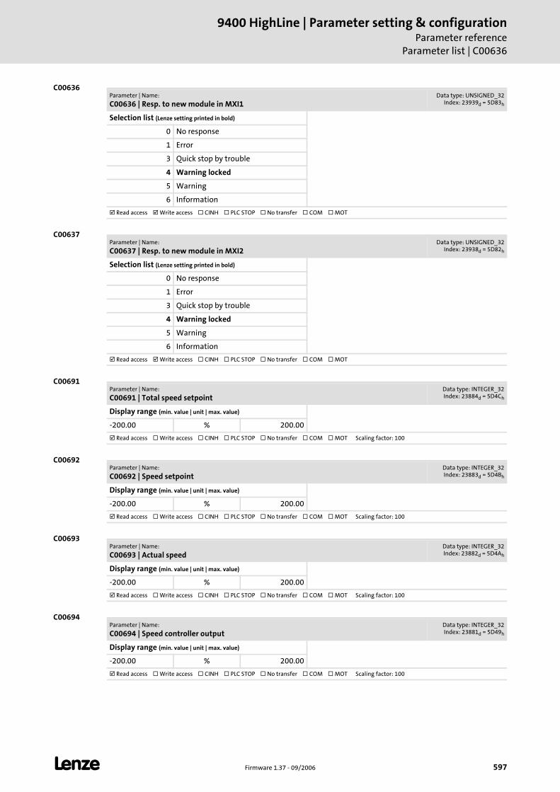
L Firmware 1.37 - 09/2006 597
9400 HighLine | Parameter setting & configurationParameter reference
Parameter list | C00636
C00636
C00637
C00691
C00692
C00693
C00694
Parameter | Name:
C00636 | Resp. to new module in MXI1Data type: UNSIGNED_32
Index: 23939d = 5D83h
Selection list (Lenze setting printed in bold)
0 No response
1 Error
3 Quick stop by trouble
4 Warning locked
5 Warning
6 Information
Read access Write access CINH PLC STOP No transfer COM MOT
Parameter | Name:
C00637 | Resp. to new module in MXI2Data type: UNSIGNED_32
Index: 23938d = 5D82h
Selection list (Lenze setting printed in bold)
0 No response
1 Error
3 Quick stop by trouble
4 Warning locked
5 Warning
6 Information
Read access Write access CINH PLC STOP No transfer COM MOT
Parameter | Name:
C00691 | Total speed setpointData type: INTEGER_32Index: 23884d = 5D4Ch
Display range (min. value | unit | max. value)
-200.00 % 200.00
Read access Write access CINH PLC STOP No transfer COM MOT Scaling factor: 100
Parameter | Name:
C00692 | Speed setpointData type: INTEGER_32Index: 23883d = 5D4Bh
Display range (min. value | unit | max. value)
-200.00 % 200.00
Read access Write access CINH PLC STOP No transfer COM MOT Scaling factor: 100
Parameter | Name:
C00693 | Actual speedData type: INTEGER_32Index: 23882d = 5D4Ah
Display range (min. value | unit | max. value)
-200.00 % 200.00
Read access Write access CINH PLC STOP No transfer COM MOT Scaling factor: 100
Parameter | Name:
C00694 | Speed controller outputData type: INTEGER_32Index: 23881d = 5D49h
Display range (min. value | unit | max. value)
-200.00 % 200.00
Read access Write access CINH PLC STOP No transfer COM MOT Scaling factor: 100
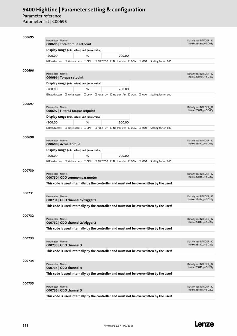
9400 HighLine | Parameter setting & configurationParameter referenceParameter list | C00695
598 Firmware 1.37 - 09/2006 L
C00695
C00696
C00697
C00698
C00730
C00731
C00732
C00733
C00734
C00735
Parameter | Name:
C00695 | Total torque setpointData type: INTEGER_32Index: 23880d = 5D48h
Display range (min. value | unit | max. value)
-200.00 % 200.00
Read access Write access CINH PLC STOP No transfer COM MOT Scaling factor: 100
Parameter | Name:
C00696 | Torque setpointData type: INTEGER_32Index: 23879d = 5D47h
Display range (min. value | unit | max. value)
-200.00 % 200.00
Read access Write access CINH PLC STOP No transfer COM MOT Scaling factor: 100
Parameter | Name:
C00697 | Filtered torque setpointData type: INTEGER_32Index: 23878d = 5D46h
Display range (min. value | unit | max. value)
-200.00 % 200.00
Read access Write access CINH PLC STOP No transfer COM MOT Scaling factor: 100
Parameter | Name:
C00698 | Actual torqueData type: INTEGER_32Index: 23877d = 5D45h
Display range (min. value | unit | max. value)
-200.00 % 200.00
Read access Write access CINH PLC STOP No transfer COM MOT Scaling factor: 100
Parameter | Name:
C00730 | GDO common parameterData type: INTEGER_32Index: 23845d = 5D25h
This code is used internally by the controller and must not be overwritten by the user!
Parameter | Name:
C00731 | GDO channel 1/trigger 1Data type: INTEGER_32Index: 23844d = 5D24h
This code is used internally by the controller and must not be overwritten by the user!
Parameter | Name:
C00732 | GDO channel 2/trigger 2Data type: INTEGER_32Index: 23843d = 5D23h
This code is used internally by the controller and must not be overwritten by the user!
Parameter | Name:
C00733 | GDO channel 3Data type: INTEGER_32Index: 23842d = 5D22h
This code is used internally by the controller and must not be overwritten by the user!
Parameter | Name:
C00734 | GDO channel 4Data type: INTEGER_32Index: 23841d = 5D21h
This code is used internally by the controller and must not be overwritten by the user!
Parameter | Name:
C00735 | GDO channel 5Data type: INTEGER_32Index: 23840d = 5D20h
This code is used internally by the controller and must not be overwritten by the user!
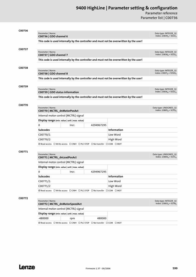
L Firmware 1.37 - 09/2006 599
9400 HighLine | Parameter setting & configurationParameter reference
Parameter list | C00736
C00736
C00737
C00738
C00739
C00770
C00771
C00772
Parameter | Name:
C00736 | GDO channel 6Data type: INTEGER_32Index: 23839d = 5D1Fh
This code is used internally by the controller and must not be overwritten by the user!
Parameter | Name:
C00737 | GDO channel 7Data type: INTEGER_32Index: 23838d = 5D1Eh
This code is used internally by the controller and must not be overwritten by the user!
Parameter | Name:
C00738 | GDO channel 8Data type: INTEGER_32Index: 23837d = 5D1Dh
This code is used internally by the controller and must not be overwritten by the user!
Parameter | Name:
C00739 | GDO status informationData type: INTEGER_32Index: 23836d = 5D1Ch
This code is used internally by the controller and must not be overwritten by the user!
Parameter | Name:
C00770 | MCTRL_dnMotorPosActData type: UNSIGNED_32
Index: 23805d = 5CFDh
Internal motor control (MCTRL) signal
Display range (min. value | unit | max. value)
0 Incr. 4294967295
Subcodes Information
C00770/1 Low Word
C00770/2 High Word
Read access Write access CINH PLC STOP No transfer COM MOT
Parameter | Name:
C00771 | MCTRL_dnLoadPosActData type: UNSIGNED_32
Index: 23804d = 5CFCh
Internal motor control (MCTRL) signal
Display range (min. value | unit | max. value)
0 Incr. 4294967295
Subcodes Information
C00771/1 Low Word
C00771/2 High Word
Read access Write access CINH PLC STOP No transfer COM MOT
Parameter | Name:
C00772 | MCTRL_dnMotorSpeedActData type: INTEGER_32Index: 23803d = 5CFBh
Internal motor control (MCTRL) signal
Display range (min. value | unit | max. value)
-480000 rpm 480000
Read access Write access CINH PLC STOP No transfer COM MOT

9400 HighLine | Parameter setting & configurationParameter referenceParameter list | C00773
600 Firmware 1.37 - 09/2006 L
C00773
C00774
C00775
C00776
C00777
C00778
Parameter | Name:
C00773 | MCTRL_dnLoadSpeedActData type: INTEGER_32Index: 23802d = 5CFAh
Internal motor control (MCTRL) signal
Display range (min. value | unit | max. value)
-480000 rpm 480000
Read access Write access CINH PLC STOP No transfer COM MOT
Parameter | Name:
C00774 | MCTRL_dnTorqueActData type: INTEGER_32Index: 23801d = 5CF9h
Internal motor control (MCTRL) signal
Display range (min. value | unit | max. value)
-21474836.47 Nm 21474836.47
Read access Write access CINH PLC STOP No transfer COM MOT Scaling factor: 100
Parameter | Name:
C00775 | MCTRL_dnOutputSpeedCtrlData type: INTEGER_32Index: 23800d = 5CF8h
Internal motor control (MCTRL) signal
Display range (min. value | unit | max. value)
-21474836.47 Nm 21474836.47
Read access Write access CINH PLC STOP No transfer COM MOT Scaling factor: 100
Parameter | Name:
C00776 | MCTRL_dnInputJerkCtrlData type: INTEGER_32Index: 23799d = 5CF7h
Internal motor control (MCTRL) signal
Display range (min. value | unit | max. value)
-21474836.47 Nm 21474836.47
Read access Write access CINH PLC STOP No transfer COM MOT Scaling factor: 100
Parameter | Name:
C00777 | MCTRL_dnInputTorqueCtrlData type: INTEGER_32Index: 23798d = 5CF6h
Internal motor control (MCTRL) signal
Display range (min. value | unit | max. value)
-21474836.47 Nm 21474836.47
Read access Write access CINH PLC STOP No transfer COM MOT Scaling factor: 100
Parameter | Name:
C00778 | MCTRL_dnFluxActData type: INTEGER_32Index: 23797d = 5CF5h
Internal motor control (MCTRL) signal
Display range (min. value | unit | max. value)
-200.00 % 200.00
Read access Write access CINH PLC STOP No transfer COM MOT Scaling factor: 100
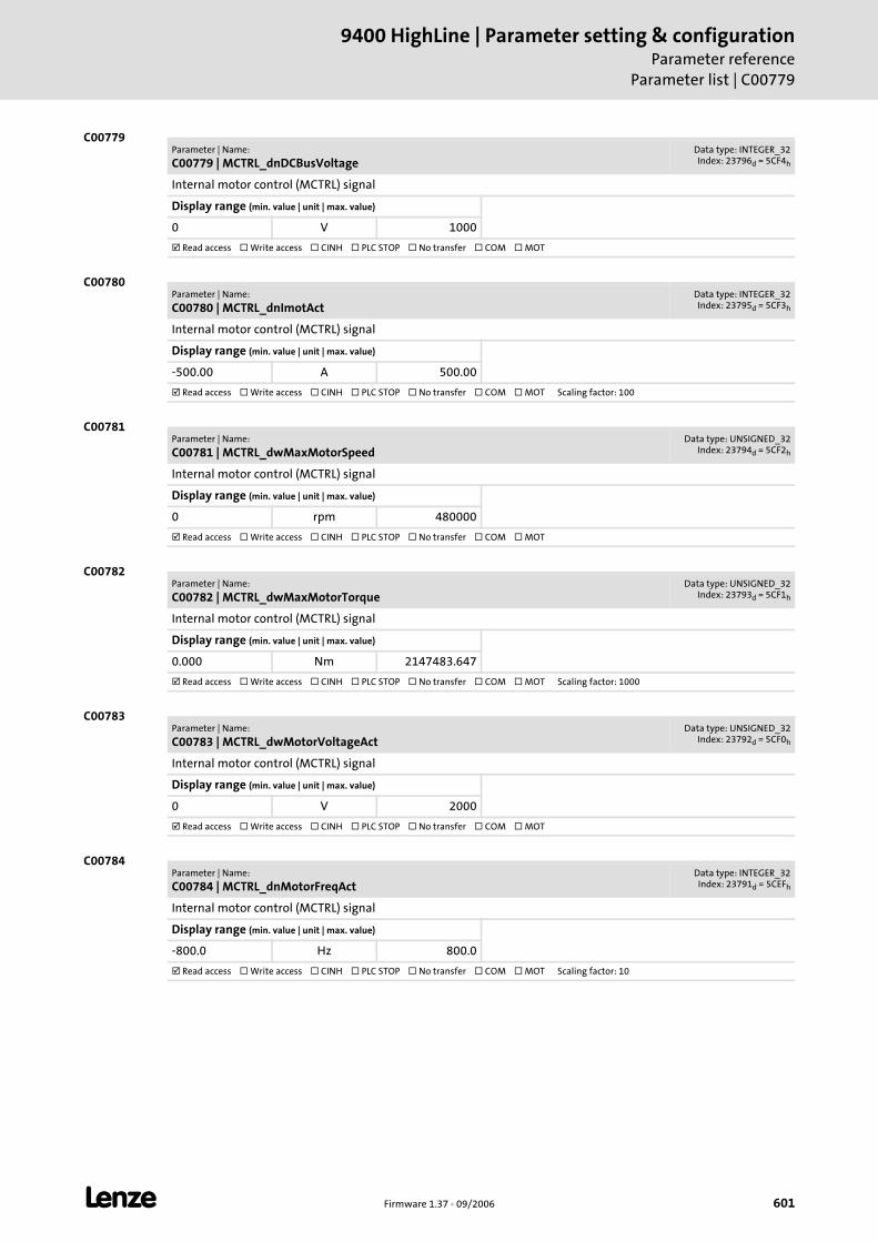
L Firmware 1.37 - 09/2006 601
9400 HighLine | Parameter setting & configurationParameter reference
Parameter list | C00779
C00779
C00780
C00781
C00782
C00783
C00784
Parameter | Name:
C00779 | MCTRL_dnDCBusVoltageData type: INTEGER_32Index: 23796d = 5CF4h
Internal motor control (MCTRL) signal
Display range (min. value | unit | max. value)
0 V 1000
Read access Write access CINH PLC STOP No transfer COM MOT
Parameter | Name:
C00780 | MCTRL_dnImotActData type: INTEGER_32Index: 23795d = 5CF3h
Internal motor control (MCTRL) signal
Display range (min. value | unit | max. value)
-500.00 A 500.00
Read access Write access CINH PLC STOP No transfer COM MOT Scaling factor: 100
Parameter | Name:
C00781 | MCTRL_dwMaxMotorSpeedData type: UNSIGNED_32
Index: 23794d = 5CF2h
Internal motor control (MCTRL) signal
Display range (min. value | unit | max. value)
0 rpm 480000
Read access Write access CINH PLC STOP No transfer COM MOT
Parameter | Name:
C00782 | MCTRL_dwMaxMotorTorqueData type: UNSIGNED_32
Index: 23793d = 5CF1h
Internal motor control (MCTRL) signal
Display range (min. value | unit | max. value)
0.000 Nm 2147483.647
Read access Write access CINH PLC STOP No transfer COM MOT Scaling factor: 1000
Parameter | Name:
C00783 | MCTRL_dwMotorVoltageActData type: UNSIGNED_32
Index: 23792d = 5CF0h
Internal motor control (MCTRL) signal
Display range (min. value | unit | max. value)
0 V 2000
Read access Write access CINH PLC STOP No transfer COM MOT
Parameter | Name:
C00784 | MCTRL_dnMotorFreqActData type: INTEGER_32Index: 23791d = 5CEFh
Internal motor control (MCTRL) signal
Display range (min. value | unit | max. value)
-800.0 Hz 800.0
Read access Write access CINH PLC STOP No transfer COM MOT Scaling factor: 10
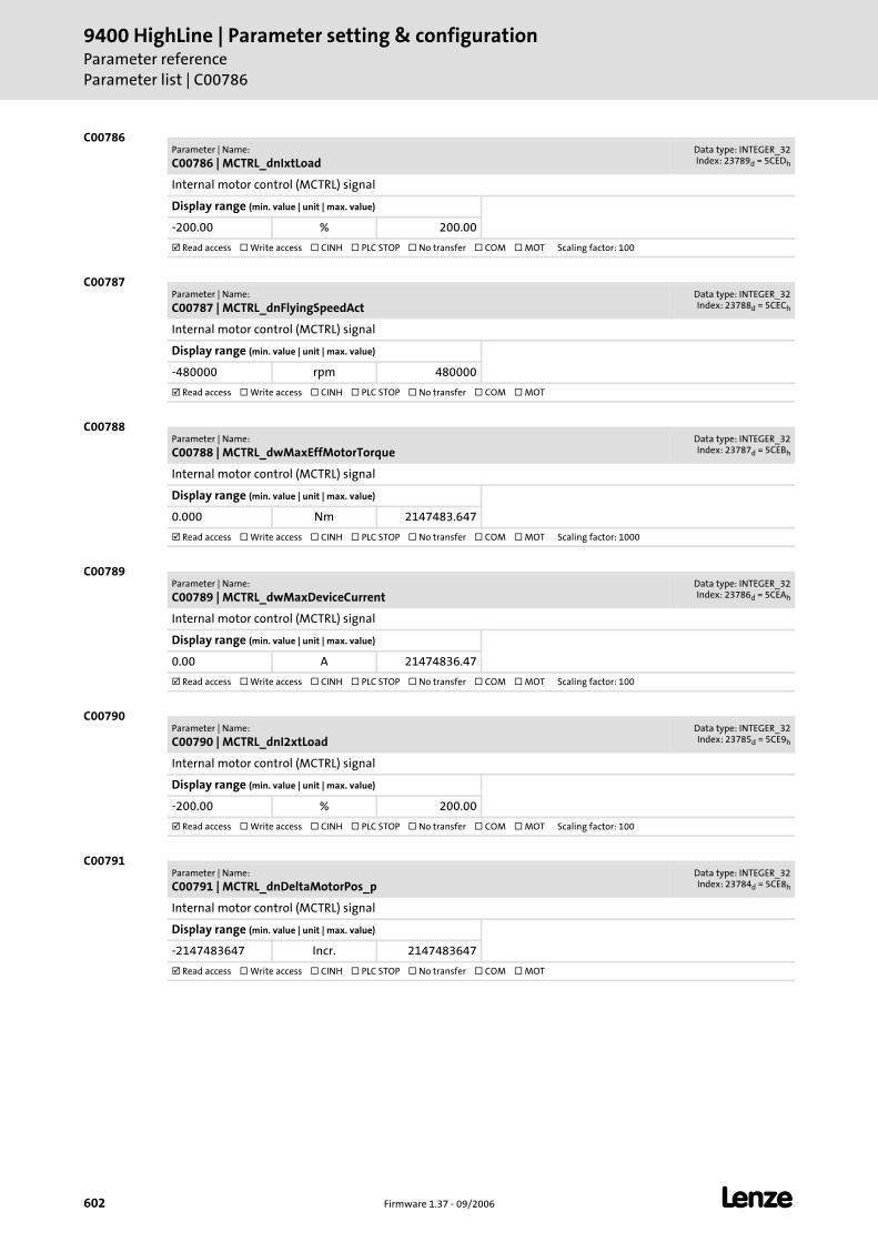
9400 HighLine | Parameter setting & configurationParameter referenceParameter list | C00786
602 Firmware 1.37 - 09/2006 L
C00786
C00787
C00788
C00789
C00790
C00791
Parameter | Name:
C00786 | MCTRL_dnIxtLoadData type: INTEGER_32Index: 23789d = 5CEDh
Internal motor control (MCTRL) signal
Display range (min. value | unit | max. value)
-200.00 % 200.00
Read access Write access CINH PLC STOP No transfer COM MOT Scaling factor: 100
Parameter | Name:
C00787 | MCTRL_dnFlyingSpeedActData type: INTEGER_32Index: 23788d = 5CECh
Internal motor control (MCTRL) signal
Display range (min. value | unit | max. value)
-480000 rpm 480000
Read access Write access CINH PLC STOP No transfer COM MOT
Parameter | Name:
C00788 | MCTRL_dwMaxEffMotorTorqueData type: INTEGER_32Index: 23787d = 5CEBh
Internal motor control (MCTRL) signal
Display range (min. value | unit | max. value)
0.000 Nm 2147483.647
Read access Write access CINH PLC STOP No transfer COM MOT Scaling factor: 1000
Parameter | Name:
C00789 | MCTRL_dwMaxDeviceCurrentData type: INTEGER_32Index: 23786d = 5CEAh
Internal motor control (MCTRL) signal
Display range (min. value | unit | max. value)
0.00 A 21474836.47
Read access Write access CINH PLC STOP No transfer COM MOT Scaling factor: 100
Parameter | Name:
C00790 | MCTRL_dnI2xtLoadData type: INTEGER_32Index: 23785d = 5CE9h
Internal motor control (MCTRL) signal
Display range (min. value | unit | max. value)
-200.00 % 200.00
Read access Write access CINH PLC STOP No transfer COM MOT Scaling factor: 100
Parameter | Name:
C00791 | MCTRL_dnDeltaMotorPos_pData type: INTEGER_32Index: 23784d = 5CE8h
Internal motor control (MCTRL) signal
Display range (min. value | unit | max. value)
-2147483647 Incr. 2147483647
Read access Write access CINH PLC STOP No transfer COM MOT
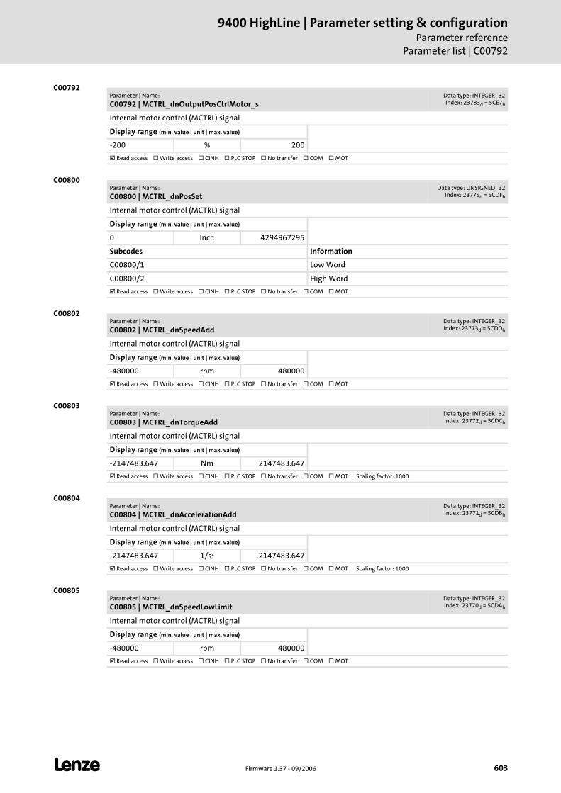
L Firmware 1.37 - 09/2006 603
9400 HighLine | Parameter setting & configurationParameter reference
Parameter list | C00792
C00792
C00800
C00802
C00803
C00804
C00805
Parameter | Name:
C00792 | MCTRL_dnOutputPosCtrlMotor_sData type: INTEGER_32Index: 23783d = 5CE7h
Internal motor control (MCTRL) signal
Display range (min. value | unit | max. value)
-200 % 200
Read access Write access CINH PLC STOP No transfer COM MOT
Parameter | Name:
C00800 | MCTRL_dnPosSetData type: UNSIGNED_32
Index: 23775d = 5CDFh
Internal motor control (MCTRL) signal
Display range (min. value | unit | max. value)
0 Incr. 4294967295
Subcodes Information
C00800/1 Low Word
C00800/2 High Word
Read access Write access CINH PLC STOP No transfer COM MOT
Parameter | Name:
C00802 | MCTRL_dnSpeedAddData type: INTEGER_32Index: 23773d = 5CDDh
Internal motor control (MCTRL) signal
Display range (min. value | unit | max. value)
-480000 rpm 480000
Read access Write access CINH PLC STOP No transfer COM MOT
Parameter | Name:
C00803 | MCTRL_dnTorqueAddData type: INTEGER_32Index: 23772d = 5CDCh
Internal motor control (MCTRL) signal
Display range (min. value | unit | max. value)
-2147483.647 Nm 2147483.647
Read access Write access CINH PLC STOP No transfer COM MOT Scaling factor: 1000
Parameter | Name:
C00804 | MCTRL_dnAccelerationAddData type: INTEGER_32Index: 23771d = 5CDBh
Internal motor control (MCTRL) signal
Display range (min. value | unit | max. value)
-2147483.647 1/s² 2147483.647
Read access Write access CINH PLC STOP No transfer COM MOT Scaling factor: 1000
Parameter | Name:
C00805 | MCTRL_dnSpeedLowLimitData type: INTEGER_32Index: 23770d = 5CDAh
Internal motor control (MCTRL) signal
Display range (min. value | unit | max. value)
-480000 rpm 480000
Read access Write access CINH PLC STOP No transfer COM MOT
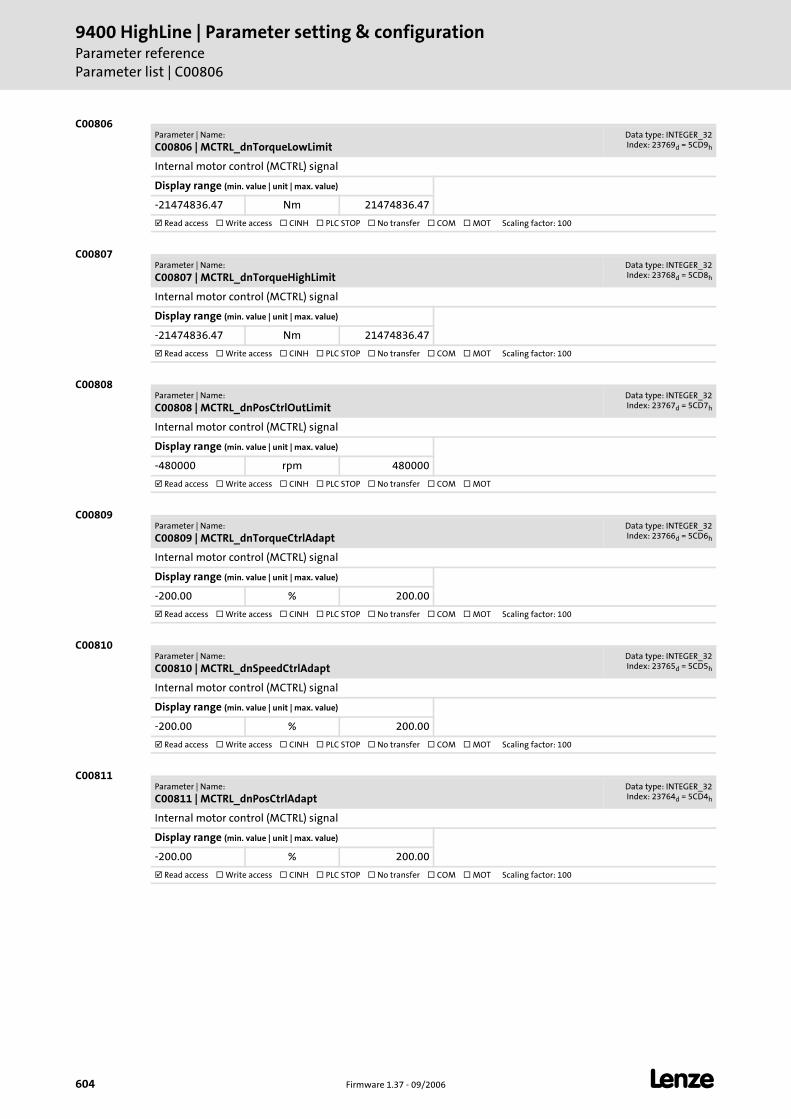
9400 HighLine | Parameter setting & configurationParameter referenceParameter list | C00806
604 Firmware 1.37 - 09/2006 L
C00806
C00807
C00808
C00809
C00810
C00811
Parameter | Name:
C00806 | MCTRL_dnTorqueLowLimitData type: INTEGER_32Index: 23769d = 5CD9h
Internal motor control (MCTRL) signal
Display range (min. value | unit | max. value)
-21474836.47 Nm 21474836.47
Read access Write access CINH PLC STOP No transfer COM MOT Scaling factor: 100
Parameter | Name:
C00807 | MCTRL_dnTorqueHighLimitData type: INTEGER_32Index: 23768d = 5CD8h
Internal motor control (MCTRL) signal
Display range (min. value | unit | max. value)
-21474836.47 Nm 21474836.47
Read access Write access CINH PLC STOP No transfer COM MOT Scaling factor: 100
Parameter | Name:
C00808 | MCTRL_dnPosCtrlOutLimitData type: INTEGER_32Index: 23767d = 5CD7h
Internal motor control (MCTRL) signal
Display range (min. value | unit | max. value)
-480000 rpm 480000
Read access Write access CINH PLC STOP No transfer COM MOT
Parameter | Name:
C00809 | MCTRL_dnTorqueCtrlAdaptData type: INTEGER_32Index: 23766d = 5CD6h
Internal motor control (MCTRL) signal
Display range (min. value | unit | max. value)
-200.00 % 200.00
Read access Write access CINH PLC STOP No transfer COM MOT Scaling factor: 100
Parameter | Name:
C00810 | MCTRL_dnSpeedCtrlAdaptData type: INTEGER_32Index: 23765d = 5CD5h
Internal motor control (MCTRL) signal
Display range (min. value | unit | max. value)
-200.00 % 200.00
Read access Write access CINH PLC STOP No transfer COM MOT Scaling factor: 100
Parameter | Name:
C00811 | MCTRL_dnPosCtrlAdaptData type: INTEGER_32Index: 23764d = 5CD4h
Internal motor control (MCTRL) signal
Display range (min. value | unit | max. value)
-200.00 % 200.00
Read access Write access CINH PLC STOP No transfer COM MOT Scaling factor: 100
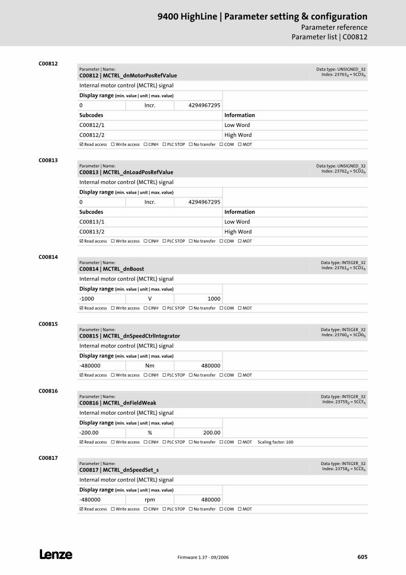
L Firmware 1.37 - 09/2006 605
9400 HighLine | Parameter setting & configurationParameter reference
Parameter list | C00812
C00812
C00813
C00814
C00815
C00816
C00817
Parameter | Name:
C00812 | MCTRL_dnMotorPosRefValueData type: UNSIGNED_32
Index: 23763d = 5CD3h
Internal motor control (MCTRL) signal
Display range (min. value | unit | max. value)
0 Incr. 4294967295
Subcodes Information
C00812/1 Low Word
C00812/2 High Word
Read access Write access CINH PLC STOP No transfer COM MOT
Parameter | Name:
C00813 | MCTRL_dnLoadPosRefValueData type: UNSIGNED_32
Index: 23762d = 5CD2h
Internal motor control (MCTRL) signal
Display range (min. value | unit | max. value)
0 Incr. 4294967295
Subcodes Information
C00813/1 Low Word
C00813/2 High Word
Read access Write access CINH PLC STOP No transfer COM MOT
Parameter | Name:
C00814 | MCTRL_dnBoostData type: INTEGER_32Index: 23761d = 5CD1h
Internal motor control (MCTRL) signal
Display range (min. value | unit | max. value)
-1000 V 1000
Read access Write access CINH PLC STOP No transfer COM MOT
Parameter | Name:
C00815 | MCTRL_dnSpeedCtrlIntegratorData type: INTEGER_32Index: 23760d = 5CD0h
Internal motor control (MCTRL) signal
Display range (min. value | unit | max. value)
-480000 Nm 480000
Read access Write access CINH PLC STOP No transfer COM MOT
Parameter | Name:
C00816 | MCTRL_dnFieldWeakData type: INTEGER_32Index: 23759d = 5CCFh
Internal motor control (MCTRL) signal
Display range (min. value | unit | max. value)
-200.00 % 200.00
Read access Write access CINH PLC STOP No transfer COM MOT Scaling factor: 100
Parameter | Name:
C00817 | MCTRL_dnSpeedSet_sData type: INTEGER_32Index: 23758d = 5CCEh
Internal motor control (MCTRL) signal
Display range (min. value | unit | max. value)
-480000 rpm 480000
Read access Write access CINH PLC STOP No transfer COM MOT
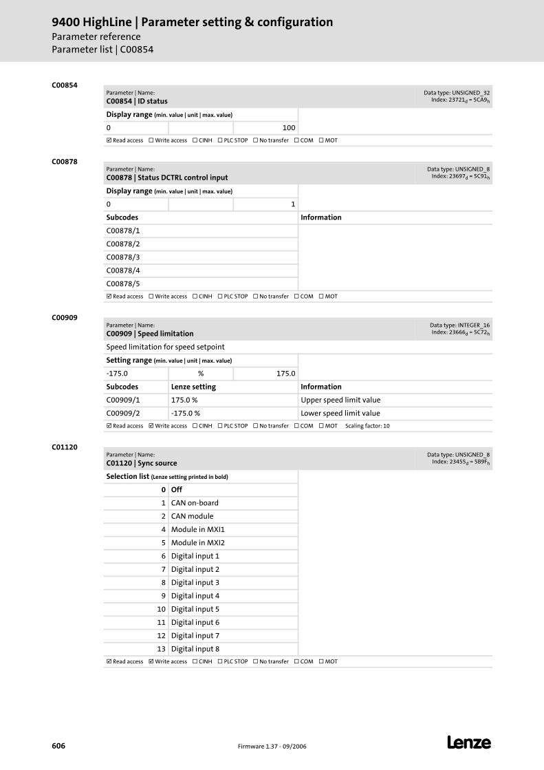
9400 HighLine | Parameter setting & configurationParameter referenceParameter list | C00854
606 Firmware 1.37 - 09/2006 L
C00854
C00878
C00909
C01120
Parameter | Name:
C00854 | ID statusData type: UNSIGNED_32
Index: 23721d = 5CA9h
Display range (min. value | unit | max. value)
0 100
Read access Write access CINH PLC STOP No transfer COM MOT
Parameter | Name:
C00878 | Status DCTRL control inputData type: UNSIGNED_8
Index: 23697d = 5C91h
Display range (min. value | unit | max. value)
0 1
Subcodes Information
C00878/1
C00878/2
C00878/3
C00878/4
C00878/5
Read access Write access CINH PLC STOP No transfer COM MOT
Parameter | Name:
C00909 | Speed limitationData type: INTEGER_16Index: 23666d = 5C72h
Speed limitation for speed setpoint
Setting range (min. value | unit | max. value)
-175.0 % 175.0
Subcodes Lenze setting Information
C00909/1 175.0 % Upper speed limit value
C00909/2 -175.0 % Lower speed limit value
Read access Write access CINH PLC STOP No transfer COM MOT Scaling factor: 10
Parameter | Name:
C01120 | Sync sourceData type: UNSIGNED_8
Index: 23455d = 5B9Fh
Selection list (Lenze setting printed in bold)
0 Off
1 CAN on-board
2 CAN module
4 Module in MXI1
5 Module in MXI2
6 Digital input 1
7 Digital input 2
8 Digital input 3
9 Digital input 4
10 Digital input 5
11 Digital input 6
12 Digital input 7
13 Digital input 8
Read access Write access CINH PLC STOP No transfer COM MOT
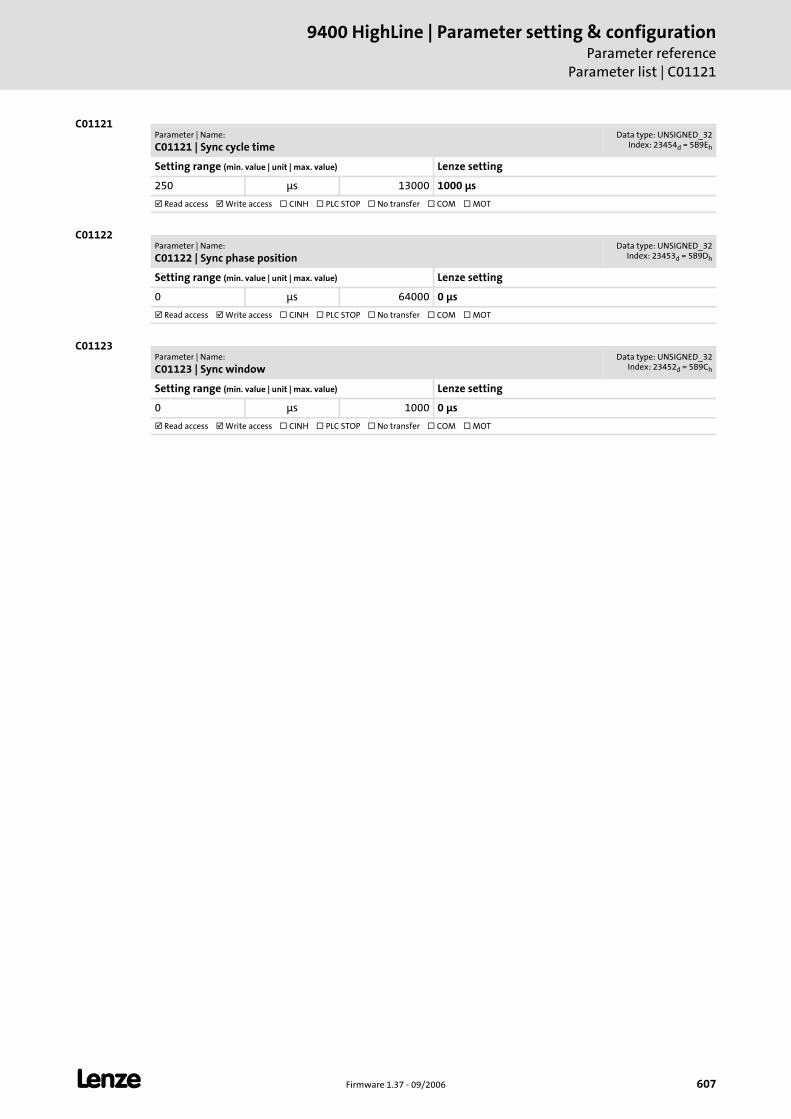
L Firmware 1.37 - 09/2006 607
9400 HighLine | Parameter setting & configurationParameter reference
Parameter list | C01121
C01121
C01122
C01123
Parameter | Name:
C01121 | Sync cycle timeData type: UNSIGNED_32
Index: 23454d = 5B9Eh
Setting range (min. value | unit | max. value) Lenze setting
250 μs 13000 1000 μs
Read access Write access CINH PLC STOP No transfer COM MOT
Parameter | Name:
C01122 | Sync phase positionData type: UNSIGNED_32
Index: 23453d = 5B9Dh
Setting range (min. value | unit | max. value) Lenze setting
0 μs 64000 0 μs
Read access Write access CINH PLC STOP No transfer COM MOT
Parameter | Name:
C01123 | Sync windowData type: UNSIGNED_32
Index: 23452d = 5B9Ch
Setting range (min. value | unit | max. value) Lenze setting
0 μs 1000 0 μs
Read access Write access CINH PLC STOP No transfer COM MOT
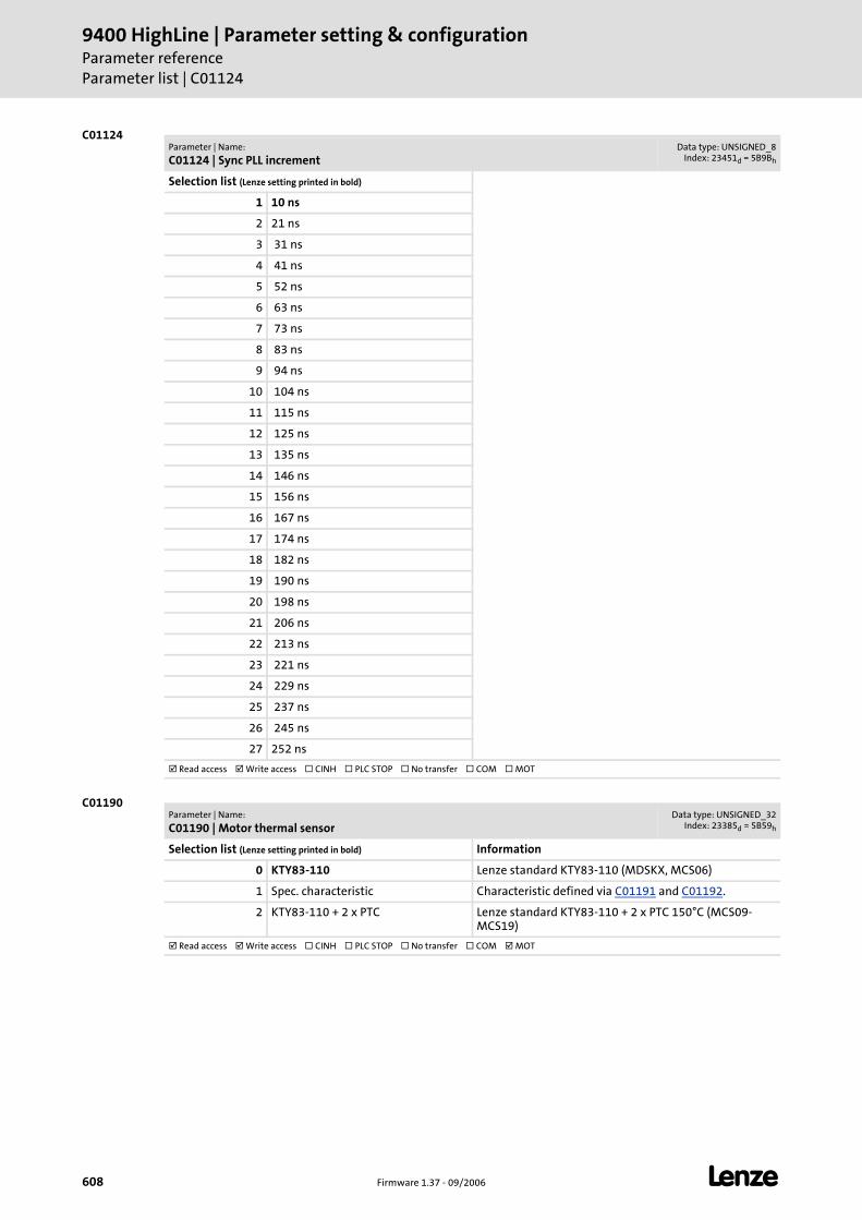
9400 HighLine | Parameter setting & configurationParameter referenceParameter list | C01124
608 Firmware 1.37 - 09/2006 L
C01124
C01190
Parameter | Name:
C01124 | Sync PLL incrementData type: UNSIGNED_8
Index: 23451d = 5B9Bh
Selection list (Lenze setting printed in bold)
1 10 ns
2 21 ns
3 31 ns
4 41 ns
5 52 ns
6 63 ns
7 73 ns
8 83 ns
9 94 ns
10 104 ns
11 115 ns
12 125 ns
13 135 ns
14 146 ns
15 156 ns
16 167 ns
17 174 ns
18 182 ns
19 190 ns
20 198 ns
21 206 ns
22 213 ns
23 221 ns
24 229 ns
25 237 ns
26 245 ns
27 252 ns
Read access Write access CINH PLC STOP No transfer COM MOT
Parameter | Name:
C01190 | Motor thermal sensorData type: UNSIGNED_32
Index: 23385d = 5B59h
Selection list (Lenze setting printed in bold) Information
0 KTY83-110 Lenze standard KTY83-110 (MDSKX, MCS06)
1 Spec. characteristic Characteristic defined via C01191 and C01192.
2 KTY83-110 + 2 x PTC Lenze standard KTY83-110 + 2 x PTC 150°C (MCS09-MCS19)
Read access Write access CINH PLC STOP No transfer COM MOT
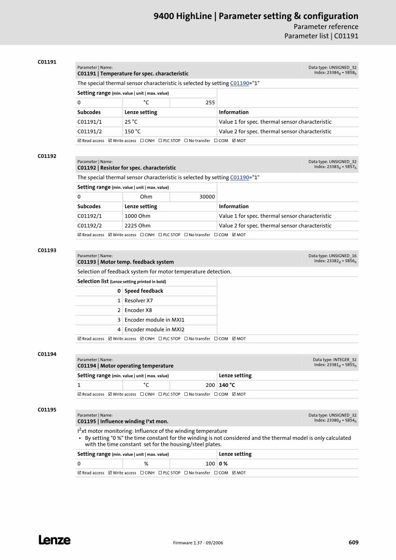
L Firmware 1.37 - 09/2006 609
9400 HighLine | Parameter setting & configurationParameter reference
Parameter list | C01191
C01191
C01192
C01193
C01194
C01195
Parameter | Name:
C01191 | Temperature for spec. characteristicData type: UNSIGNED_32
Index: 23384d = 5B58h
The special thermal sensor characteristic is selected by setting C01190="1"
Setting range (min. value | unit | max. value)
0 °C 255
Subcodes Lenze setting Information
C01191/1 25 °C Value 1 for spec. thermal sensor characteristic
C01191/2 150 °C Value 2 for spec. thermal sensor characteristic
Read access Write access CINH PLC STOP No transfer COM MOT
Parameter | Name:
C01192 | Resistor for spec. characteristicData type: UNSIGNED_32
Index: 23383d = 5B57h
The special thermal sensor characteristic is selected by setting C01190="1"
Setting range (min. value | unit | max. value)
0 Ohm 30000
Subcodes Lenze setting Information
C01192/1 1000 Ohm Value 1 for spec. thermal sensor characteristic
C01192/2 2225 Ohm Value 2 for spec. thermal sensor characteristic
Read access Write access CINH PLC STOP No transfer COM MOT
Parameter | Name:
C01193 | Motor temp. feedback systemData type: UNSIGNED_16
Index: 23382d = 5B56h
Selection of feedback system for motor temperature detection.
Selection list (Lenze setting printed in bold)
0 Speed feedback
1 Resolver X7
2 Encoder X8
3 Encoder module in MXI1
4 Encoder module in MXI2
Read access Write access CINH PLC STOP No transfer COM MOT
Parameter | Name:
C01194 | Motor operating temperatureData type: INTEGER_32Index: 23381d = 5B55h
Setting range (min. value | unit | max. value) Lenze setting
1 °C 200 140 °C
Read access Write access CINH PLC STOP No transfer COM MOT
Parameter | Name:
C01195 | Influence winding I²xt mon.Data type: UNSIGNED_32
Index: 23380d = 5B54h
I2xt motor monitoring: Influence of the winding temperature • By setting "0 %" the time constant for the winding is not considered and the thermal model is only calculated
with the time constant set for the housing/steel plates.
Setting range (min. value | unit | max. value) Lenze setting
0 % 100 0 %
Read access Write access CINH PLC STOP No transfer COM MOT
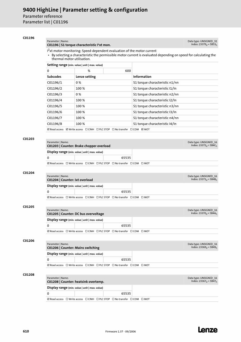
9400 HighLine | Parameter setting & configurationParameter referenceParameter list | C01196
610 Firmware 1.37 - 09/2006 L
C01196
C01203
C01204
C01205
C01206
C01208
Parameter | Name:
C01196 | S1 torque characteristic I²xt mon.Data type: UNSIGNED_32
Index: 23379d = 5B53h
I2xt motor monitoring: Speed-dependent evaluation of the motor current • By selecting a characteristic the permissible motor current is evaluated depending on speed for calculating the
thermal motor utilisation.
Setting range (min. value | unit | max. value)
0 % 600
Subcodes Lenze setting Information
C01196/1 0 % S1 torque characteristic n1/nn
C01196/2 100 % S1 torque characteristic I1/In
C01196/3 0 % S1 torque characteristic n2/nn
C01196/4 100 % S1 torque characteristic I2/In
C01196/5 100 % S1 torque characteristic n3/nn
C01196/6 100 % S1 torque characteristic I3/In
C01196/7 100 % S1 torque characteristic n4/nn
C01196/8 100 % S1 torque characteristic I4/In
Read access Write access CINH PLC STOP No transfer COM MOT
Parameter | Name:
C01203 | Counter: Brake chopper overloadData type: UNSIGNED_16
Index: 23372d = 5B4Ch
Display range (min. value | unit | max. value)
0 65535
Read access Write access CINH PLC STOP No transfer COM MOT
Parameter | Name:
C01204 | Counter: Ixt overloadData type: UNSIGNED_16
Index: 23371d = 5B4Bh
Display range (min. value | unit | max. value)
0 65535
Read access Write access CINH PLC STOP No transfer COM MOT
Parameter | Name:
C01205 | Counter: DC bus overvoltageData type: UNSIGNED_16
Index: 23370d = 5B4Ah
Display range (min. value | unit | max. value)
0 65535
Read access Write access CINH PLC STOP No transfer COM MOT
Parameter | Name:
C01206 | Counter: Mains switchingData type: UNSIGNED_16
Index: 23369d = 5B49h
Display range (min. value | unit | max. value)
0 65535
Read access Write access CINH PLC STOP No transfer COM MOT
Parameter | Name:
C01208 | Counter: heatsink overtemp.Data type: UNSIGNED_16
Index: 23367d = 5B47h
Display range (min. value | unit | max. value)
0 65535
Read access Write access CINH PLC STOP No transfer COM MOT
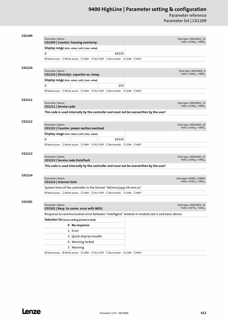
L Firmware 1.37 - 09/2006 611
9400 HighLine | Parameter setting & configurationParameter reference
Parameter list | C01209
C01209
C01210
C01211
C01212
C01213
C01214
C01501
Parameter | Name:
C01209 | Counter: housing overtemp.Data type: UNSIGNED_16
Index: 23366d = 5B46h
Display range (min. value | unit | max. value)
0 65535
Read access Write access CINH PLC STOP No transfer COM MOT
Parameter | Name:
C01210 | Electrolyt. capacitor av. temp.Data type: UNSIGNED_8
Index: 23365d = 5B45h
Display range (min. value | unit | max. value)
0 255
Read access Write access CINH PLC STOP No transfer COM MOT
Parameter | Name:
C01211 | Service codeData type: UNSIGNED_32
Index: 23364d = 5B44h
This code is used internally by the controller and must not be overwritten by the user!
Parameter | Name:
C01212 | Counter: power section overloadData type: UNSIGNED_16
Index: 23363d = 5B43h
Display range (min. value | unit | max. value)
0 65535
Read access Write access CINH PLC STOP No transfer COM MOT
Parameter | Name:
C01213 | Service code DataFlashData type: UNSIGNED_32
Index: 23362d = 5B42h
This code is used internally by the controller and must not be overwritten by the user!
Parameter | Name:
C01214 | Internal clockData type: VISIBLE_STRING
Index: 23361d = 5B41h
System time of the controller in the format "dd/mm/yyyy hh:mm:ss"
Read access Write access CINH PLC STOP No transfer COM MOT
Parameter | Name:
C01501 | Resp. to comm. error with MXI1Data type: UNSIGNED_32
Index: 23074d = 5A22h
Response to communication error between "intelligent" module in module slot 1 and basic device
Selection list (Lenze setting printed in bold)
0 No response
1 Error
3 Quick stop by trouble
4 Warning locked
5 Warning
Read access Write access CINH PLC STOP No transfer COM MOT
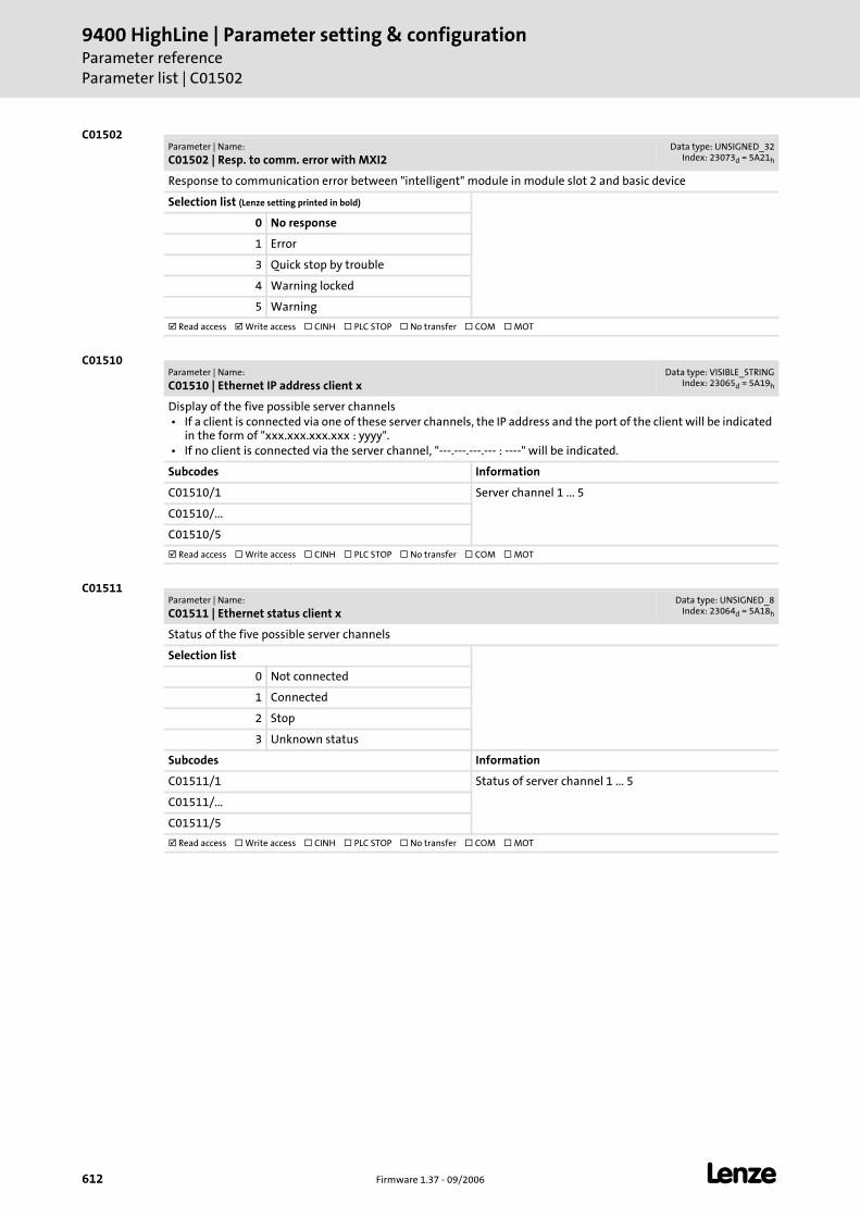
9400 HighLine | Parameter setting & configurationParameter referenceParameter list | C01502
612 Firmware 1.37 - 09/2006 L
C01502
C01510
C01511
Parameter | Name:
C01502 | Resp. to comm. error with MXI2Data type: UNSIGNED_32
Index: 23073d = 5A21h
Response to communication error between "intelligent" module in module slot 2 and basic device
Selection list (Lenze setting printed in bold)
0 No response
1 Error
3 Quick stop by trouble
4 Warning locked
5 Warning
Read access Write access CINH PLC STOP No transfer COM MOT
Parameter | Name:
C01510 | Ethernet IP address client xData type: VISIBLE_STRING
Index: 23065d = 5A19h
Display of the five possible server channels • If a client is connected via one of these server channels, the IP address and the port of the client will be indicated
in the form of "xxx.xxx.xxx.xxx : yyyy". • If no client is connected via the server channel, "---.---.---.--- : ----" will be indicated.
Subcodes Information
C01510/1 Server channel 1 ... 5
C01510/...
C01510/5
Read access Write access CINH PLC STOP No transfer COM MOT
Parameter | Name:
C01511 | Ethernet status client xData type: UNSIGNED_8
Index: 23064d = 5A18h
Status of the five possible server channels
Selection list
0 Not connected
1 Connected
2 Stop
3 Unknown status
Subcodes Information
C01511/1 Status of server channel 1 ... 5
C01511/...
C01511/5
Read access Write access CINH PLC STOP No transfer COM MOT
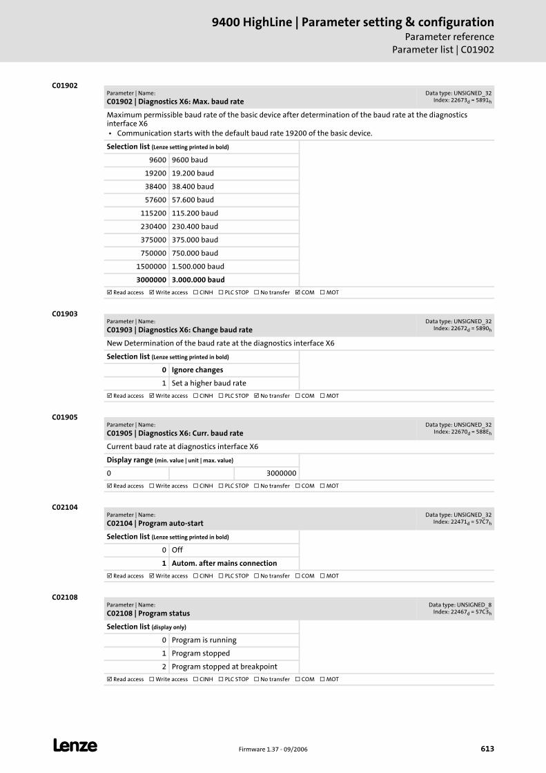
L Firmware 1.37 - 09/2006 613
9400 HighLine | Parameter setting & configurationParameter reference
Parameter list | C01902
C01902
C01903
C01905
C02104
C02108
Parameter | Name:
C01902 | Diagnostics X6: Max. baud rateData type: UNSIGNED_32
Index: 22673d = 5891h
Maximum permissible baud rate of the basic device after determination of the baud rate at the diagnostics interface X6 • Communication starts with the default baud rate 19200 of the basic device.
Selection list (Lenze setting printed in bold)
9600 9600 baud
19200 19.200 baud
38400 38.400 baud
57600 57.600 baud
115200 115.200 baud
230400 230.400 baud
375000 375.000 baud
750000 750.000 baud
1500000 1.500.000 baud
3000000 3.000.000 baud
Read access Write access CINH PLC STOP No transfer COM MOT
Parameter | Name:
C01903 | Diagnostics X6: Change baud rateData type: UNSIGNED_32
Index: 22672d = 5890h
New Determination of the baud rate at the diagnostics interface X6
Selection list (Lenze setting printed in bold)
0 Ignore changes
1 Set a higher baud rate
Read access Write access CINH PLC STOP No transfer COM MOT
Parameter | Name:
C01905 | Diagnostics X6: Curr. baud rateData type: UNSIGNED_32
Index: 22670d = 588Eh
Current baud rate at diagnostics interface X6
Display range (min. value | unit | max. value)
0 3000000
Read access Write access CINH PLC STOP No transfer COM MOT
Parameter | Name:
C02104 | Program auto-startData type: UNSIGNED_32
Index: 22471d = 57C7h
Selection list (Lenze setting printed in bold)
0 Off
1 Autom. after mains connection
Read access Write access CINH PLC STOP No transfer COM MOT
Parameter | Name:
C02108 | Program statusData type: UNSIGNED_8
Index: 22467d = 57C3h
Selection list (display only)
0 Program is running
1 Program stopped
2 Program stopped at breakpoint
Read access Write access CINH PLC STOP No transfer COM MOT

9400 HighLine | Parameter setting & configurationParameter referenceParameter list | C02109
614 Firmware 1.37 - 09/2006 L
C02109
C02113
C02121
C02122
C02123
C02520
Parameter | Name:
C02109 | Program runtimeData type: UNSIGNED_16
Index: 22466d = 57C2h
Display range (min. value | unit | max. value)
0 μs 65535
Read access Write access CINH PLC STOP No transfer COM MOT
Parameter | Name:
C02113 | Program nameData type: VISIBLE_STRING
Index: 22462d = 57BEh
Read access Write access CINH PLC STOP No transfer COM MOT
Parameter | Name:
C02121 | Runtime task 1Data type: UNSIGNED_32
Index: 22454d = 57B6h
Display range (min. value | unit | max. value)
0 μs 3600000000
Subcodes Information
C02121/1 Curr. runtime task 1
C02121/2 max. runtime task 1
Read access Write access CINH PLC STOP No transfer COM MOT
Parameter | Name:
C02122 | Runtime task 2Data type: UNSIGNED_32
Index: 22453d = 57B5h
Display range (min. value | unit | max. value)
0 μs 3600000000
Subcodes Information
C02122/1 Curr. runtime task 2
C02122/2 max. runtime task 2
Read access Write access CINH PLC STOP No transfer COM MOT
Parameter | Name:
C02123 | Runtime task 3Data type: UNSIGNED_32
Index: 22452d = 57B4h
Display range (min. value | unit | max. value)
0 μs 3600000000
Subcodes Information
C02123/1 Curr. runtime task 3
C02123/2 max. runtime task 3
Read access Write access CINH PLC STOP No transfer COM MOT
Parameter | Name:
C02520 | Gearbox fact. numer. motorData type: INTEGER_32Index: 22055d = 5627h
Drive interface
Setting range (min. value | unit | max. value) Lenze setting
1 2147483647 1
Read access Write access CINH PLC STOP No transfer COM MOT
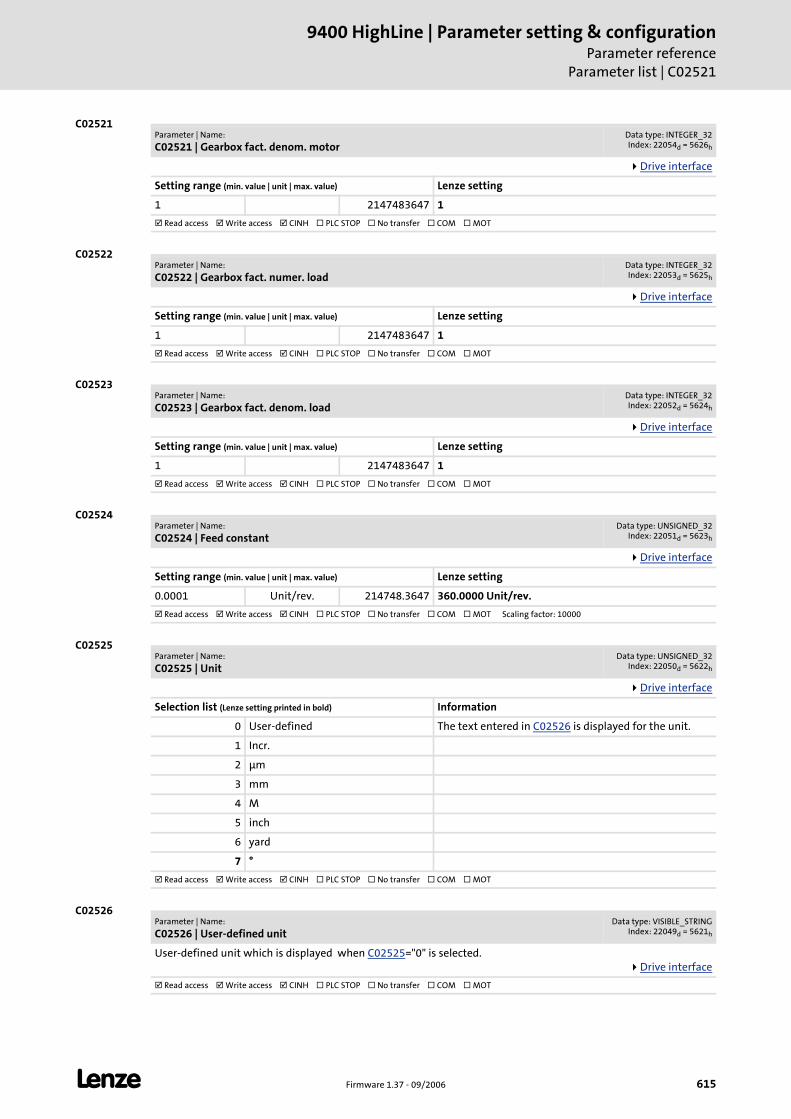
L Firmware 1.37 - 09/2006 615
9400 HighLine | Parameter setting & configurationParameter reference
Parameter list | C02521
C02521
C02522
C02523
C02524
C02525
C02526
Parameter | Name:
C02521 | Gearbox fact. denom. motorData type: INTEGER_32Index: 22054d = 5626h
Drive interface
Setting range (min. value | unit | max. value) Lenze setting
1 2147483647 1
Read access Write access CINH PLC STOP No transfer COM MOT
Parameter | Name:
C02522 | Gearbox fact. numer. loadData type: INTEGER_32Index: 22053d = 5625h
Drive interface
Setting range (min. value | unit | max. value) Lenze setting
1 2147483647 1
Read access Write access CINH PLC STOP No transfer COM MOT
Parameter | Name:
C02523 | Gearbox fact. denom. loadData type: INTEGER_32Index: 22052d = 5624h
Drive interface
Setting range (min. value | unit | max. value) Lenze setting
1 2147483647 1
Read access Write access CINH PLC STOP No transfer COM MOT
Parameter | Name:
C02524 | Feed constantData type: UNSIGNED_32
Index: 22051d = 5623h
Drive interface
Setting range (min. value | unit | max. value) Lenze setting
0.0001 Unit/rev. 214748.3647 360.0000 Unit/rev.
Read access Write access CINH PLC STOP No transfer COM MOT Scaling factor: 10000
Parameter | Name:
C02525 | UnitData type: UNSIGNED_32
Index: 22050d = 5622h
Drive interface
Selection list (Lenze setting printed in bold) Information
0 User-defined The text entered in C02526 is displayed for the unit.
1 Incr.
2 μm
3 mm
4 M
5 inch
6 yard
7 °
Read access Write access CINH PLC STOP No transfer COM MOT
Parameter | Name:
C02526 | User-defined unitData type: VISIBLE_STRING
Index: 22049d = 5621h
User-defined unit which is displayed when C02525="0" is selected.Drive interface
Read access Write access CINH PLC STOP No transfer COM MOT
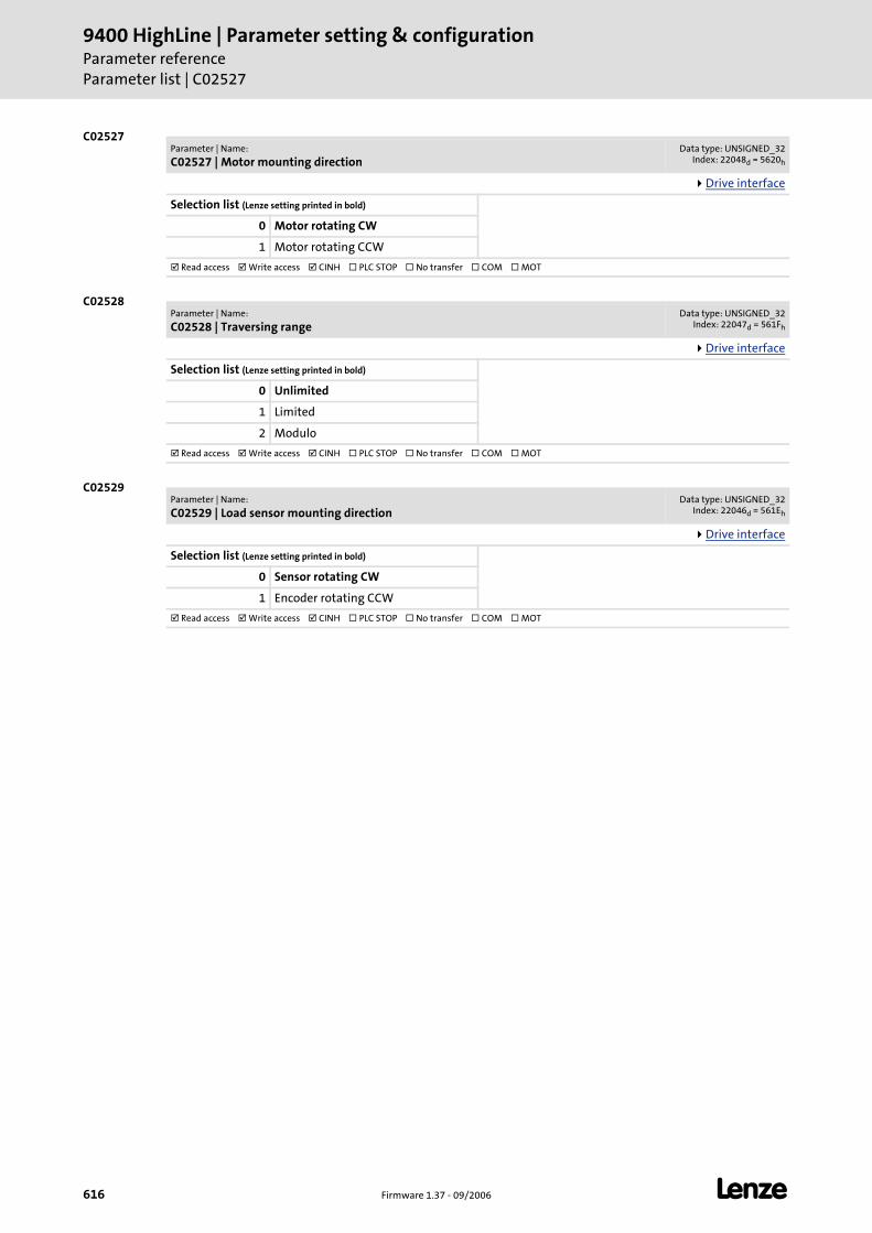
9400 HighLine | Parameter setting & configurationParameter referenceParameter list | C02527
616 Firmware 1.37 - 09/2006 L
C02527
C02528
C02529
Parameter | Name:
C02527 | Motor mounting directionData type: UNSIGNED_32
Index: 22048d = 5620h
Drive interface
Selection list (Lenze setting printed in bold)
0 Motor rotating CW
1 Motor rotating CCW
Read access Write access CINH PLC STOP No transfer COM MOT
Parameter | Name:
C02528 | Traversing rangeData type: UNSIGNED_32
Index: 22047d = 561Fh
Drive interface
Selection list (Lenze setting printed in bold)
0 Unlimited
1 Limited
2 Modulo
Read access Write access CINH PLC STOP No transfer COM MOT
Parameter | Name:
C02529 | Load sensor mounting directionData type: UNSIGNED_32
Index: 22046d = 561Eh
Drive interface
Selection list (Lenze setting printed in bold)
0 Sensor rotating CW
1 Encoder rotating CCW
Read access Write access CINH PLC STOP No transfer COM MOT
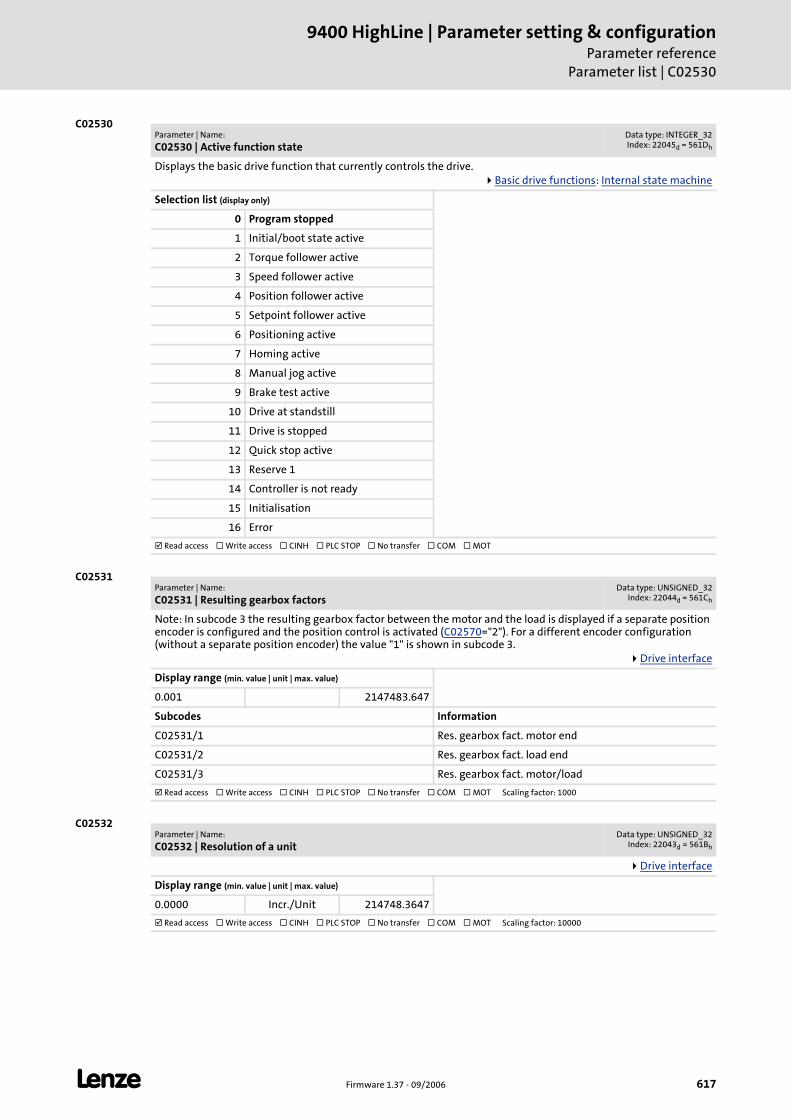
L Firmware 1.37 - 09/2006 617
9400 HighLine | Parameter setting & configurationParameter reference
Parameter list | C02530
C02530
C02531
C02532
Parameter | Name:
C02530 | Active function stateData type: INTEGER_32Index: 22045d = 561Dh
Displays the basic drive function that currently controls the drive.Basic drive functions: Internal state machine
Selection list (display only)
0 Program stopped
1 Initial/boot state active
2 Torque follower active
3 Speed follower active
4 Position follower active
5 Setpoint follower active
6 Positioning active
7 Homing active
8 Manual jog active
9 Brake test active
10 Drive at standstill
11 Drive is stopped
12 Quick stop active
13 Reserve 1
14 Controller is not ready
15 Initialisation
16 Error
Read access Write access CINH PLC STOP No transfer COM MOT
Parameter | Name:
C02531 | Resulting gearbox factorsData type: UNSIGNED_32
Index: 22044d = 561Ch
Note: In subcode 3 the resulting gearbox factor between the motor and the load is displayed if a separate position encoder is configured and the position control is activated (C02570="2"). For a different encoder configuration (without a separate position encoder) the value "1" is shown in subcode 3.
Drive interface
Display range (min. value | unit | max. value)
0.001 2147483.647
Subcodes Information
C02531/1 Res. gearbox fact. motor end
C02531/2 Res. gearbox fact. load end
C02531/3 Res. gearbox fact. motor/load
Read access Write access CINH PLC STOP No transfer COM MOT Scaling factor: 1000
Parameter | Name:
C02532 | Resolution of a unitData type: UNSIGNED_32
Index: 22043d = 561Bh
Drive interface
Display range (min. value | unit | max. value)
0.0000 Incr./Unit 214748.3647
Read access Write access CINH PLC STOP No transfer COM MOT Scaling factor: 10000
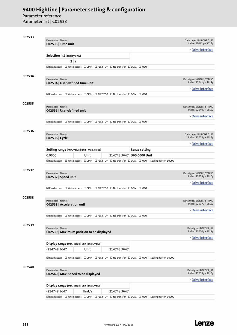
9400 HighLine | Parameter setting & configurationParameter referenceParameter list | C02533
618 Firmware 1.37 - 09/2006 L
C02533
C02534
C02535
C02536
C02537
C02538
C02539
C02540
Parameter | Name:
C02533 | Time unitData type: UNSIGNED_32
Index: 22042d = 561Ah
Drive interface
Selection list (display only)
2 s
Read access Write access CINH PLC STOP No transfer COM MOT
Parameter | Name:
C02534 | User-defined time unitData type: VISIBLE_STRING
Index: 22041d = 5619h
Drive interface
Read access Write access CINH PLC STOP No transfer COM MOT
Parameter | Name:
C02535 | User-defined unitData type: VISIBLE_STRING
Index: 22040d = 5618h
Drive interface
Read access Write access CINH PLC STOP No transfer COM MOT
Parameter | Name:
C02536 | CycleData type: UNSIGNED_32
Index: 22039d = 5617h
Drive interface
Setting range (min. value | unit | max. value) Lenze setting
0.0000 Unit 214748.3647 360.0000 Unit
Read access Write access CINH PLC STOP No transfer COM MOT Scaling factor: 10000
Parameter | Name:
C02537 | Speed unitData type: VISIBLE_STRING
Index: 22038d = 5616h
Drive interface
Read access Write access CINH PLC STOP No transfer COM MOT
Parameter | Name:
C02538 | Acceleration unitData type: VISIBLE_STRING
Index: 22037d = 5615h
Drive interface
Read access Write access CINH PLC STOP No transfer COM MOT
Parameter | Name:
C02539 | Maximum position to be displayedData type: INTEGER_32Index: 22036d = 5614h
Drive interface
Display range (min. value | unit | max. value)
-214748.3647 Unit 214748.3647
Read access Write access CINH PLC STOP No transfer COM MOT Scaling factor: 10000
Parameter | Name:
C02540 | Max. speed to be displayedData type: INTEGER_32Index: 22035d = 5613h
Drive interface
Display range (min. value | unit | max. value)
-214748.3647 Unit/s 214748.3647
Read access Write access CINH PLC STOP No transfer COM MOT Scaling factor: 10000
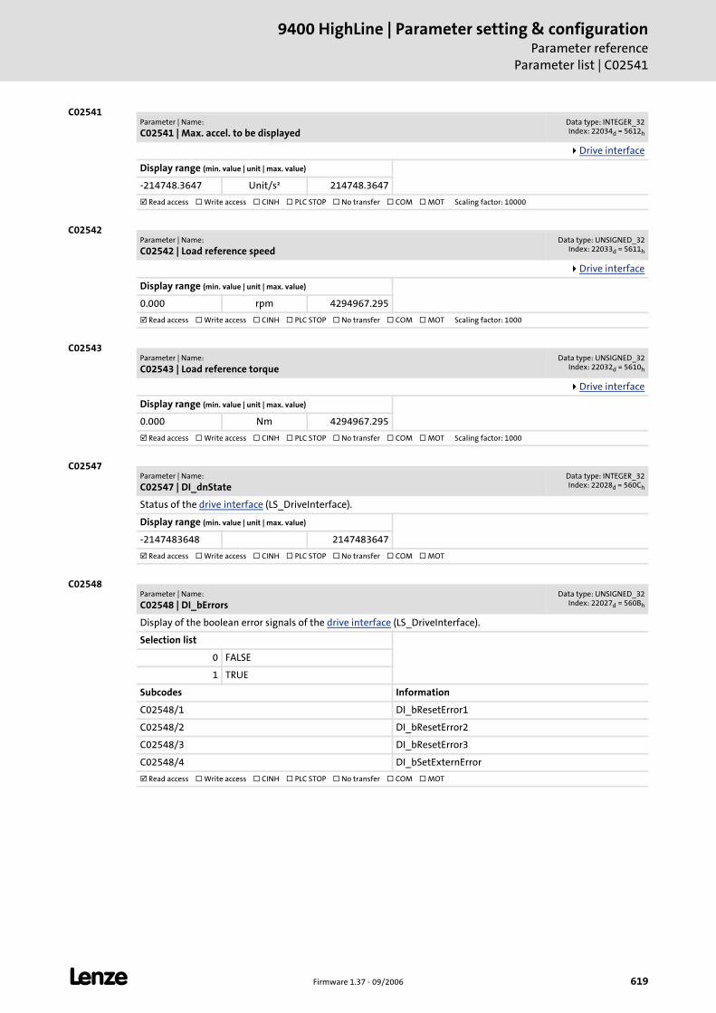
L Firmware 1.37 - 09/2006 619
9400 HighLine | Parameter setting & configurationParameter reference
Parameter list | C02541
C02541
C02542
C02543
C02547
C02548
Parameter | Name:
C02541 | Max. accel. to be displayedData type: INTEGER_32Index: 22034d = 5612h
Drive interface
Display range (min. value | unit | max. value)
-214748.3647 Unit/s² 214748.3647
Read access Write access CINH PLC STOP No transfer COM MOT Scaling factor: 10000
Parameter | Name:
C02542 | Load reference speedData type: UNSIGNED_32
Index: 22033d = 5611h
Drive interface
Display range (min. value | unit | max. value)
0.000 rpm 4294967.295
Read access Write access CINH PLC STOP No transfer COM MOT Scaling factor: 1000
Parameter | Name:
C02543 | Load reference torqueData type: UNSIGNED_32
Index: 22032d = 5610h
Drive interface
Display range (min. value | unit | max. value)
0.000 Nm 4294967.295
Read access Write access CINH PLC STOP No transfer COM MOT Scaling factor: 1000
Parameter | Name:
C02547 | DI_dnStateData type: INTEGER_32Index: 22028d = 560Ch
Status of the drive interface (LS_DriveInterface).
Display range (min. value | unit | max. value)
-2147483648 2147483647
Read access Write access CINH PLC STOP No transfer COM MOT
Parameter | Name:
C02548 | DI_bErrorsData type: UNSIGNED_32
Index: 22027d = 560Bh
Display of the boolean error signals of the drive interface (LS_DriveInterface).
Selection list
0 FALSE
1 TRUE
Subcodes Information
C02548/1 DI_bResetError1
C02548/2 DI_bResetError2
C02548/3 DI_bResetError3
C02548/4 DI_bSetExternError
Read access Write access CINH PLC STOP No transfer COM MOT
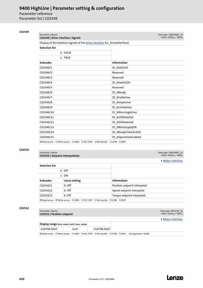
9400 HighLine | Parameter setting & configurationParameter referenceParameter list | C02549
620 Firmware 1.37 - 09/2006 L
C02549
C02550
C02552
Parameter | Name:
C02549 | Drive interface: SignalsData type: UNSIGNED_32
Index: 22026d = 560Ah
Display of the boolean signals of the drive interface (LS_DriveInterface).
Selection list
0 FALSE
1 TRUE
Subcodes Information
C02549/1 DI_bSetCInh
C02549/2 Reserved
C02549/3 Reserved
C02549/4 DI_bSwitchOn
C02549/5 Reserved
C02549/6 DI_bReady
C02549/7 DI_bFailActive
C02549/8 DI_bImpActive
C02549/9 DI_bCInhActive
C02549/10 DI_bWarningActive
C02549/11 DI_bUVDetected
C02549/12 DI_bOVDetected
C02549/13 DI_bMainSupplyOk
C02549/14 DI_bReadyToSwitchOn
C02549/15 DI_bOperationEnabled
Read access Write access CINH PLC STOP No transfer COM MOT
Parameter | Name:
C02550 | Setpoint interpolationData type: UNSIGNED_32
Index: 22025d = 5609h
Motor interface
Selection list
0 Off
1 ON
Subcodes Lenze setting Information
C02550/1 0: Off Position setpoint interpolat.
C02550/2 0: Off Speed setpoint interpolat.
C02550/3 0: Off Torque setpoint interpolat.
Read access Write access CINH PLC STOP No transfer COM MOT
Parameter | Name:
C02552 | Position setpointData type: INTEGER_32Index: 22023d = 5607h
Motor interface
Display range (min. value | unit | max. value)
-214748.3647 Unit 214748.3647
Read access Write access CINH PLC STOP No transfer COM MOT Scaling factor: 10000
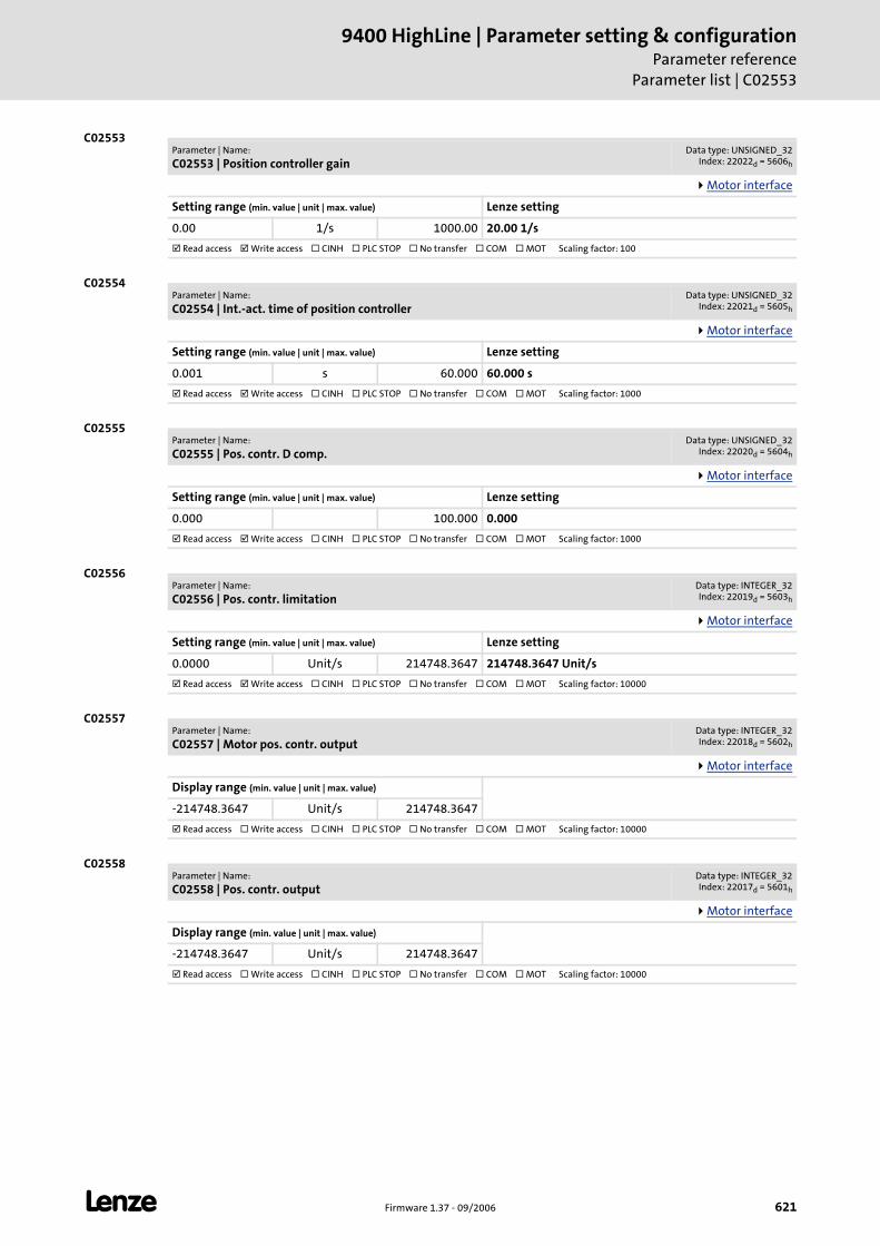
L Firmware 1.37 - 09/2006 621
9400 HighLine | Parameter setting & configurationParameter reference
Parameter list | C02553
C02553
C02554
C02555
C02556
C02557
C02558
Parameter | Name:
C02553 | Position controller gainData type: UNSIGNED_32
Index: 22022d = 5606h
Motor interface
Setting range (min. value | unit | max. value) Lenze setting
0.00 1/s 1000.00 20.00 1/s
Read access Write access CINH PLC STOP No transfer COM MOT Scaling factor: 100
Parameter | Name:
C02554 | Int.-act. time of position controllerData type: UNSIGNED_32
Index: 22021d = 5605h
Motor interface
Setting range (min. value | unit | max. value) Lenze setting
0.001 s 60.000 60.000 s
Read access Write access CINH PLC STOP No transfer COM MOT Scaling factor: 1000
Parameter | Name:
C02555 | Pos. contr. D comp.Data type: UNSIGNED_32
Index: 22020d = 5604h
Motor interface
Setting range (min. value | unit | max. value) Lenze setting
0.000 100.000 0.000
Read access Write access CINH PLC STOP No transfer COM MOT Scaling factor: 1000
Parameter | Name:
C02556 | Pos. contr. limitationData type: INTEGER_32Index: 22019d = 5603h
Motor interface
Setting range (min. value | unit | max. value) Lenze setting
0.0000 Unit/s 214748.3647 214748.3647 Unit/s
Read access Write access CINH PLC STOP No transfer COM MOT Scaling factor: 10000
Parameter | Name:
C02557 | Motor pos. contr. outputData type: INTEGER_32Index: 22018d = 5602h
Motor interface
Display range (min. value | unit | max. value)
-214748.3647 Unit/s 214748.3647
Read access Write access CINH PLC STOP No transfer COM MOT Scaling factor: 10000
Parameter | Name:
C02558 | Pos. contr. outputData type: INTEGER_32Index: 22017d = 5601h
Motor interface
Display range (min. value | unit | max. value)
-214748.3647 Unit/s 214748.3647
Read access Write access CINH PLC STOP No transfer COM MOT Scaling factor: 10000
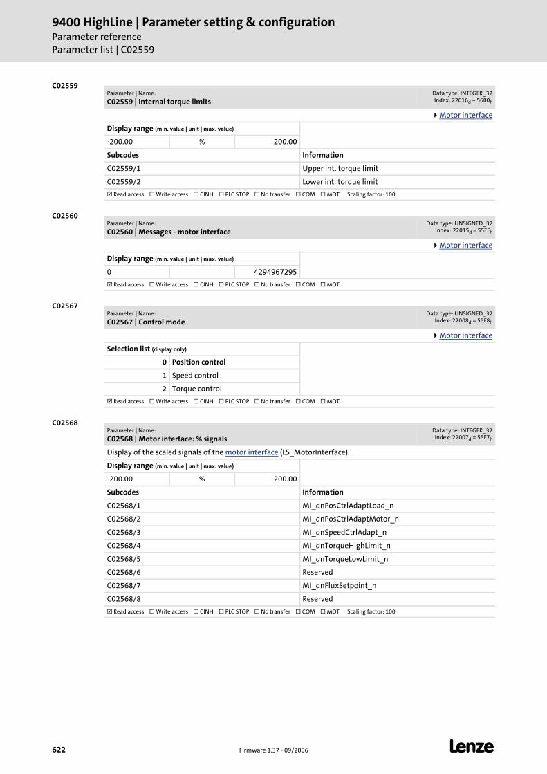
9400 HighLine | Parameter setting & configurationParameter referenceParameter list | C02559
622 Firmware 1.37 - 09/2006 L
C02559
C02560
C02567
C02568
Parameter | Name:
C02559 | Internal torque limitsData type: INTEGER_32Index: 22016d = 5600h
Motor interface
Display range (min. value | unit | max. value)
-200.00 % 200.00
Subcodes Information
C02559/1 Upper int. torque limit
C02559/2 Lower int. torque limit
Read access Write access CINH PLC STOP No transfer COM MOT Scaling factor: 100
Parameter | Name:
C02560 | Messages - motor interfaceData type: UNSIGNED_32
Index: 22015d = 55FFh
Motor interface
Display range (min. value | unit | max. value)
0 4294967295
Read access Write access CINH PLC STOP No transfer COM MOT
Parameter | Name:
C02567 | Control modeData type: UNSIGNED_32
Index: 22008d = 55F8h
Motor interface
Selection list (display only)
0 Position control
1 Speed control
2 Torque control
Read access Write access CINH PLC STOP No transfer COM MOT
Parameter | Name:
C02568 | Motor interface: % signalsData type: INTEGER_32Index: 22007d = 55F7h
Display of the scaled signals of the motor interface (LS_MotorInterface).
Display range (min. value | unit | max. value)
-200.00 % 200.00
Subcodes Information
C02568/1 MI_dnPosCtrlAdaptLoad_n
C02568/2 MI_dnPosCtrlAdaptMotor_n
C02568/3 MI_dnSpeedCtrlAdapt_n
C02568/4 MI_dnTorqueHighLimit_n
C02568/5 MI_dnTorqueLowLimit_n
C02568/6 Reserved
C02568/7 MI_dnFluxSetpoint_n
C02568/8 Reserved
Read access Write access CINH PLC STOP No transfer COM MOT Scaling factor: 100

L Firmware 1.37 - 09/2006 623
9400 HighLine | Parameter setting & configurationParameter reference
Parameter list | C02569
C02569
C02570
C02572
C02573
Parameter | Name:
C02569 | Motor interface: Dig. signalsData type: UNSIGNED_32
Index: 22006d = 55F6h
Display of the boolean signals of the motor interface (LS_MotorInterface).
Selection list
0 FALSE
1 TRUE
Subcodes Information
C02569/1 Reserved
C02569/2 MI_bResetSpeedCtrlIntegrator
C02569/3 MI_bLimitationActive
C02569/4 MI_bPosCtrlLimited
C02569/5 MI_bSpeedSetPointLimited
C02569/6 MI_bSpeedCtrlLimited
C02569/7 MI_bTorqueSetpointLimited
C02569/8 MI_bCurrentSetpointLimited
C02569/9 MI_bSpeedBelowC19
C02569/10 MI_bSpeedFollowingError
C02569/11 MI_bMotorOverloadWarning
Read access Write access CINH PLC STOP No transfer COM MOT
Parameter | Name:
C02570 | Controller configurationData type: UNSIGNED_32
Index: 22005d = 55F5h
Encoder evaluation
Selection list (Lenze setting printed in bold) Information
1 Phase control Motor encoder selection is effected in C00495.
2 Position control Position controller selection is effected in C00490.
Read access Write access CINH PLC STOP No transfer COM MOT
Parameter | Name:
C02572 | Speed setpointData type: INTEGER_32Index: 22003d = 55F3h
Encoder evaluation
Display range (min. value | unit | max. value)
-214748.3647 Unit/s 214748.3647
Read access Write access CINH PLC STOP No transfer COM MOT Scaling factor: 10000
Parameter | Name:
C02573 | Position setpointData type: INTEGER_32Index: 22002d = 55F2h
Encoder evaluation
Display range (min. value | unit | max. value)
-214748.3647 Unit 214748.3647
Read access Write access CINH PLC STOP No transfer COM MOT Scaling factor: 10000
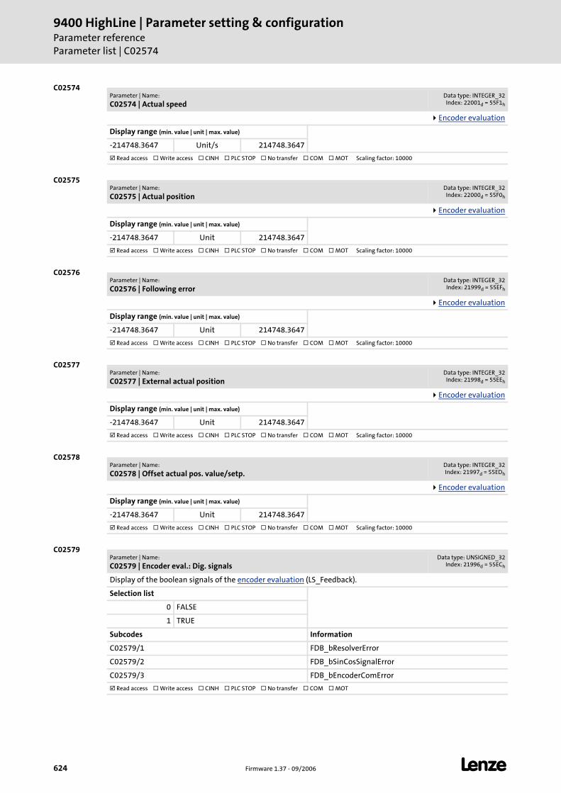
9400 HighLine | Parameter setting & configurationParameter referenceParameter list | C02574
624 Firmware 1.37 - 09/2006 L
C02574
C02575
C02576
C02577
C02578
C02579
Parameter | Name:
C02574 | Actual speedData type: INTEGER_32Index: 22001d = 55F1h
Encoder evaluation
Display range (min. value | unit | max. value)
-214748.3647 Unit/s 214748.3647
Read access Write access CINH PLC STOP No transfer COM MOT Scaling factor: 10000
Parameter | Name:
C02575 | Actual positionData type: INTEGER_32Index: 22000d = 55F0h
Encoder evaluation
Display range (min. value | unit | max. value)
-214748.3647 Unit 214748.3647
Read access Write access CINH PLC STOP No transfer COM MOT Scaling factor: 10000
Parameter | Name:
C02576 | Following errorData type: INTEGER_32
Index: 21999d = 55EFh
Encoder evaluation
Display range (min. value | unit | max. value)
-214748.3647 Unit 214748.3647
Read access Write access CINH PLC STOP No transfer COM MOT Scaling factor: 10000
Parameter | Name:
C02577 | External actual positionData type: INTEGER_32Index: 21998d = 55EEh
Encoder evaluation
Display range (min. value | unit | max. value)
-214748.3647 Unit 214748.3647
Read access Write access CINH PLC STOP No transfer COM MOT Scaling factor: 10000
Parameter | Name:
C02578 | Offset actual pos. value/setp.Data type: INTEGER_32Index: 21997d = 55EDh
Encoder evaluation
Display range (min. value | unit | max. value)
-214748.3647 Unit 214748.3647
Read access Write access CINH PLC STOP No transfer COM MOT Scaling factor: 10000
Parameter | Name:
C02579 | Encoder eval.: Dig. signalsData type: UNSIGNED_32
Index: 21996d = 55ECh
Display of the boolean signals of the encoder evaluation (LS_Feedback).
Selection list
0 FALSE
1 TRUE
Subcodes Information
C02579/1 FDB_bResolverError
C02579/2 FDB_bSinCosSignalError
C02579/3 FDB_bEncoderComError
Read access Write access CINH PLC STOP No transfer COM MOT
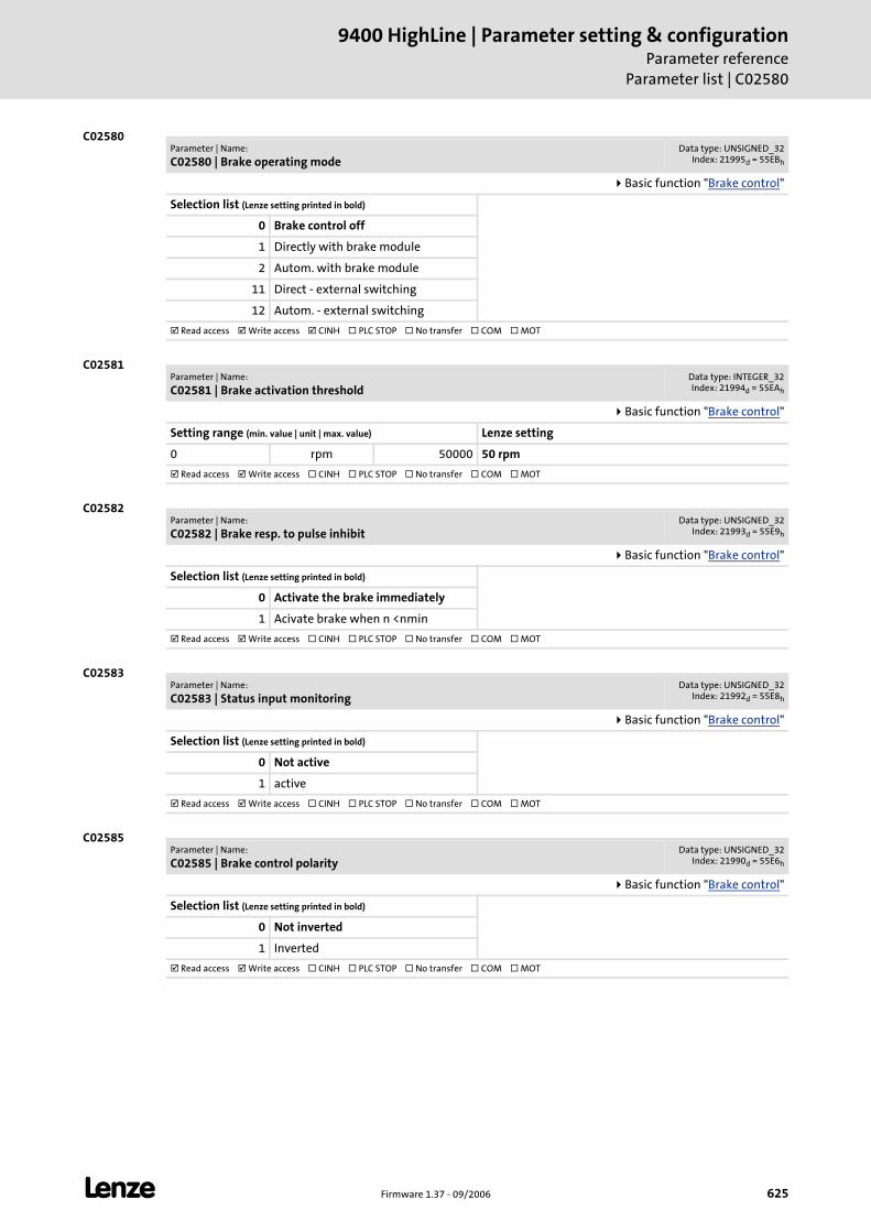
L Firmware 1.37 - 09/2006 625
9400 HighLine | Parameter setting & configurationParameter reference
Parameter list | C02580
C02580
C02581
C02582
C02583
C02585
Parameter | Name:
C02580 | Brake operating modeData type: UNSIGNED_32
Index: 21995d = 55EBh
Basic function "Brake control"
Selection list (Lenze setting printed in bold)
0 Brake control off
1 Directly with brake module
2 Autom. with brake module
11 Direct - external switching
12 Autom. - external switching
Read access Write access CINH PLC STOP No transfer COM MOT
Parameter | Name:
C02581 | Brake activation thresholdData type: INTEGER_32Index: 21994d = 55EAh
Basic function "Brake control"
Setting range (min. value | unit | max. value) Lenze setting
0 rpm 50000 50 rpm
Read access Write access CINH PLC STOP No transfer COM MOT
Parameter | Name:
C02582 | Brake resp. to pulse inhibitData type: UNSIGNED_32
Index: 21993d = 55E9h
Basic function "Brake control"
Selection list (Lenze setting printed in bold)
0 Activate the brake immediately
1 Acivate brake when n <nmin
Read access Write access CINH PLC STOP No transfer COM MOT
Parameter | Name:
C02583 | Status input monitoringData type: UNSIGNED_32
Index: 21992d = 55E8h
Basic function "Brake control"
Selection list (Lenze setting printed in bold)
0 Not active
1 active
Read access Write access CINH PLC STOP No transfer COM MOT
Parameter | Name:
C02585 | Brake control polarityData type: UNSIGNED_32
Index: 21990d = 55E6h
Basic function "Brake control"
Selection list (Lenze setting printed in bold)
0 Not inverted
1 Inverted
Read access Write access CINH PLC STOP No transfer COM MOT
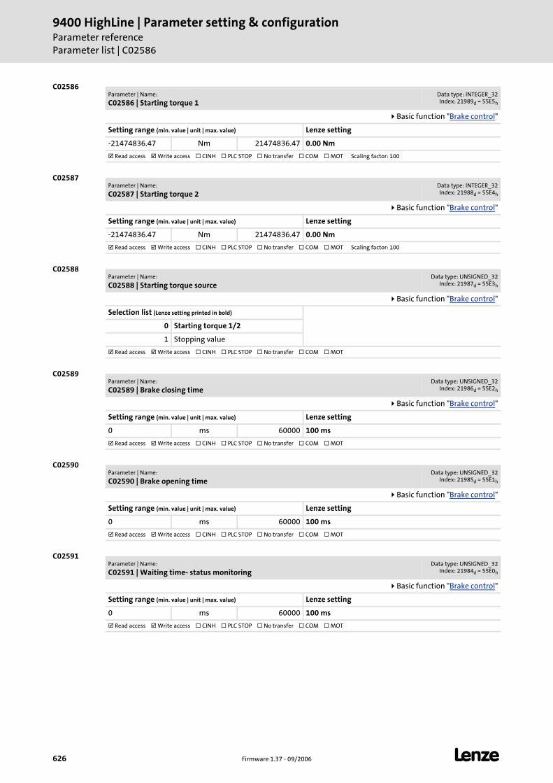
9400 HighLine | Parameter setting & configurationParameter referenceParameter list | C02586
626 Firmware 1.37 - 09/2006 L
C02586
C02587
C02588
C02589
C02590
C02591
Parameter | Name:
C02586 | Starting torque 1Data type: INTEGER_32Index: 21989d = 55E5h
Basic function "Brake control"
Setting range (min. value | unit | max. value) Lenze setting
-21474836.47 Nm 21474836.47 0.00 Nm
Read access Write access CINH PLC STOP No transfer COM MOT Scaling factor: 100
Parameter | Name:
C02587 | Starting torque 2Data type: INTEGER_32Index: 21988d = 55E4h
Basic function "Brake control"
Setting range (min. value | unit | max. value) Lenze setting
-21474836.47 Nm 21474836.47 0.00 Nm
Read access Write access CINH PLC STOP No transfer COM MOT Scaling factor: 100
Parameter | Name:
C02588 | Starting torque sourceData type: UNSIGNED_32
Index: 21987d = 55E3h
Basic function "Brake control"
Selection list (Lenze setting printed in bold)
0 Starting torque 1/2
1 Stopping value
Read access Write access CINH PLC STOP No transfer COM MOT
Parameter | Name:
C02589 | Brake closing timeData type: UNSIGNED_32
Index: 21986d = 55E2h
Basic function "Brake control"
Setting range (min. value | unit | max. value) Lenze setting
0 ms 60000 100 ms
Read access Write access CINH PLC STOP No transfer COM MOT
Parameter | Name:
C02590 | Brake opening timeData type: UNSIGNED_32
Index: 21985d = 55E1h
Basic function "Brake control"
Setting range (min. value | unit | max. value) Lenze setting
0 ms 60000 100 ms
Read access Write access CINH PLC STOP No transfer COM MOT
Parameter | Name:
C02591 | Waiting time- status monitoringData type: UNSIGNED_32
Index: 21984d = 55E0h
Basic function "Brake control"
Setting range (min. value | unit | max. value) Lenze setting
0 ms 60000 100 ms
Read access Write access CINH PLC STOP No transfer COM MOT
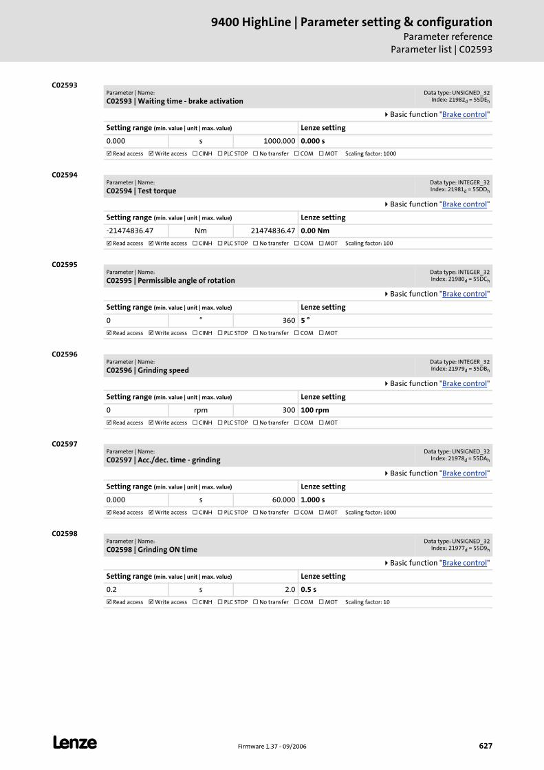
L Firmware 1.37 - 09/2006 627
9400 HighLine | Parameter setting & configurationParameter reference
Parameter list | C02593
C02593
C02594
C02595
C02596
C02597
C02598
Parameter | Name:
C02593 | Waiting time - brake activationData type: UNSIGNED_32
Index: 21982d = 55DEh
Basic function "Brake control"
Setting range (min. value | unit | max. value) Lenze setting
0.000 s 1000.000 0.000 s
Read access Write access CINH PLC STOP No transfer COM MOT Scaling factor: 1000
Parameter | Name:
C02594 | Test torqueData type: INTEGER_32Index: 21981d = 55DDh
Basic function "Brake control"
Setting range (min. value | unit | max. value) Lenze setting
-21474836.47 Nm 21474836.47 0.00 Nm
Read access Write access CINH PLC STOP No transfer COM MOT Scaling factor: 100
Parameter | Name:
C02595 | Permissible angle of rotationData type: INTEGER_32Index: 21980d = 55DCh
Basic function "Brake control"
Setting range (min. value | unit | max. value) Lenze setting
0 ° 360 5 °
Read access Write access CINH PLC STOP No transfer COM MOT
Parameter | Name:
C02596 | Grinding speedData type: INTEGER_32Index: 21979d = 55DBh
Basic function "Brake control"
Setting range (min. value | unit | max. value) Lenze setting
0 rpm 300 100 rpm
Read access Write access CINH PLC STOP No transfer COM MOT
Parameter | Name:
C02597 | Acc./dec. time - grindingData type: UNSIGNED_32
Index: 21978d = 55DAh
Basic function "Brake control"
Setting range (min. value | unit | max. value) Lenze setting
0.000 s 60.000 1.000 s
Read access Write access CINH PLC STOP No transfer COM MOT Scaling factor: 1000
Parameter | Name:
C02598 | Grinding ON timeData type: UNSIGNED_32
Index: 21977d = 55D9h
Basic function "Brake control"
Setting range (min. value | unit | max. value) Lenze setting
0.2 s 2.0 0.5 s
Read access Write access CINH PLC STOP No transfer COM MOT Scaling factor: 10
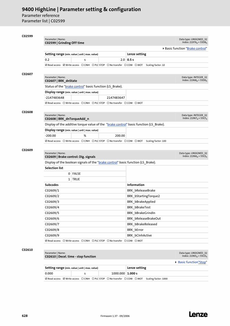
9400 HighLine | Parameter setting & configurationParameter referenceParameter list | C02599
628 Firmware 1.37 - 09/2006 L
C02599
C02607
C02608
C02609
C02610
Parameter | Name:
C02599 | Grinding OFF timeData type: UNSIGNED_32
Index: 21976d = 55D8h
Basic function "Brake control"
Setting range (min. value | unit | max. value) Lenze setting
0.2 s 2.0 0.5 s
Read access Write access CINH PLC STOP No transfer COM MOT Scaling factor: 10
Parameter | Name:
C02607 | BRK_dnStateData type: INTEGER_32Index: 21968d = 55D0h
Status of the "brake control" basic function (LS_Brake).
Display range (min. value | unit | max. value)
-2147483648 2147483647
Read access Write access CINH PLC STOP No transfer COM MOT
Parameter | Name:
C02608 | BRK_dnTorqueAdd_nData type: INTEGER_32Index: 21967d = 55CFh
Display of the additive torque value of the "brake control" basic function (LS_Brake).
Display range (min. value | unit | max. value)
-200.00 % 200.00
Read access Write access CINH PLC STOP No transfer COM MOT Scaling factor: 100
Parameter | Name:
C02609 | Brake control: Dig. signalsData type: UNSIGNED_32
Index: 21966d = 55CEh
Display of the boolean signals of the "brake control" basic function (LS_Brake).
Selection list
0 FALSE
1 TRUE
Subcodes Information
C02609/1 BRK_bReleaseBrake
C02609/2 BRK_bStartingTorque2
C02609/3 BRK_bBrakeApplied
C02609/4 BRK_bBrakeTest
C02609/5 BRK_bBrakeGrindIn
C02609/6 BRK_bReleaseBrakeOut
C02609/7 BRK_bBrakeReleased
C02609/8 BRK_bError
C02609/9 BRK_bCInhActive
Read access Write access CINH PLC STOP No transfer COM MOT
Parameter | Name:
C02610 | Decel. time - stop functionData type: UNSIGNED_32
Index: 21965d = 55CDh
Basic function"Stop"
Setting range (min. value | unit | max. value) Lenze setting
0.000 s 1000.000 1.000 s
Read access Write access CINH PLC STOP No transfer COM MOT Scaling factor: 1000
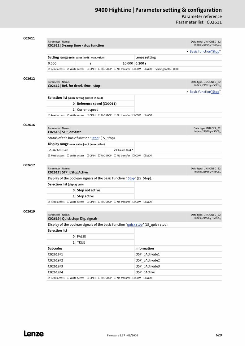
L Firmware 1.37 - 09/2006 629
9400 HighLine | Parameter setting & configurationParameter reference
Parameter list | C02611
C02611
C02612
C02616
C02617
C02619
Parameter | Name:
C02611 | S-ramp time - stop functionData type: UNSIGNED_32
Index: 21964d = 55CCh
Basic function"Stop"
Setting range (min. value | unit | max. value) Lenze setting
0.000 s 10.000 0.100 s
Read access Write access CINH PLC STOP No transfer COM MOT Scaling factor: 1000
Parameter | Name:
C02612 | Ref. for decel. time - stopData type: UNSIGNED_32
Index: 21963d = 55CBh
Basic function"Stop"
Selection list (Lenze setting printed in bold)
0 Reference speed (C00011)
1 Current speed
Read access Write access CINH PLC STOP No transfer COM MOT
Parameter | Name:
C02616 | STP_dnStateData type: INTEGER_32Index: 21959d = 55C7h
Status of the basic function "Stop" (LS_Stop).
Display range (min. value | unit | max. value)
-2147483648 2147483647
Read access Write access CINH PLC STOP No transfer COM MOT
Parameter | Name:
C02617 | STP_bStopActiveData type: UNSIGNED_32
Index: 21958d = 55C6h
Display of the boolean signals of the basic function " Stop" (LS_Stop).
Selection list (display only)
0 Stop not active
1 Stop active
Read access Write access CINH PLC STOP No transfer COM MOT
Parameter | Name:
C02619 | Quick stop: Dig. signalsData type: UNSIGNED_32
Index: 21956d = 55C4h
Display of the boolean signals of the basic function "quick stop" (LS_quick stop).
Selection list
0 FALSE
1 TRUE
Subcodes Information
C02619/1 QSP_bActivate1
C02619/2 QSP_bActivate2
C02619/3 QSP_bActivate3
C02619/4 QSP_bActive
Read access Write access CINH PLC STOP No transfer COM MOT
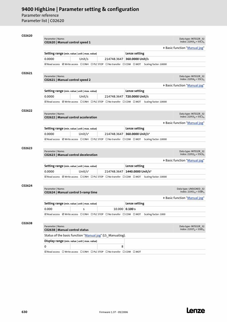
9400 HighLine | Parameter setting & configurationParameter referenceParameter list | C02620
630 Firmware 1.37 - 09/2006 L
C02620
C02621
C02622
C02623
C02624
C02638
Parameter | Name:
C02620 | Manual control speed 1Data type: INTEGER_32Index: 21955d = 55C3h
Basic function "Manual jog"
Setting range (min. value | unit | max. value) Lenze setting
0.0000 Unit/s 214748.3647 360.0000 Unit/s
Read access Write access CINH PLC STOP No transfer COM MOT Scaling factor: 10000
Parameter | Name:
C02621 | Manual control speed 2Data type: INTEGER_32Index: 21954d = 55C2h
Basic function "Manual jog"
Setting range (min. value | unit | max. value) Lenze setting
0.0000 Unit/s 214748.3647 720.0000 Unit/s
Read access Write access CINH PLC STOP No transfer COM MOT Scaling factor: 10000
Parameter | Name:
C02622 | Manual control accelerationData type: INTEGER_32Index: 21953d = 55C1h
Basic function "Manual jog"
Setting range (min. value | unit | max. value) Lenze setting
0.0000 Unit/s² 214748.3647 360.0000 Unit/s²
Read access Write access CINH PLC STOP No transfer COM MOT Scaling factor: 10000
Parameter | Name:
C02623 | Manual control decelerationData type: INTEGER_32Index: 21952d = 55C0h
Basic function "Manual jog"
Setting range (min. value | unit | max. value) Lenze setting
0.0000 Unit/s² 214748.3647 1440.0000 Unit/s²
Read access Write access CINH PLC STOP No transfer COM MOT Scaling factor: 10000
Parameter | Name:
C02624 | Manual control S-ramp timeData type: UNSIGNED_32
Index: 21951d = 55BFh
Basic function "Manual jog"
Setting range (min. value | unit | max. value) Lenze setting
0.000 s 10.000 0.100 s
Read access Write access CINH PLC STOP No transfer COM MOT Scaling factor: 1000
Parameter | Name:
C02638 | Manual control statusData type: INTEGER_32Index: 21937d = 55B1h
Status of the basic function "Manual jog" (LS_ManualJog).
Display range (min. value | unit | max. value)
0 8
Read access Write access CINH PLC STOP No transfer COM MOT
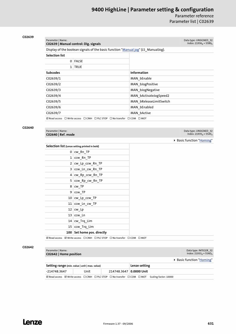
L Firmware 1.37 - 09/2006 631
9400 HighLine | Parameter setting & configurationParameter reference
Parameter list | C02639
C02639
C02640
C02642
Parameter | Name:
C02639 | Manual control: Dig. signalsData type: UNSIGNED_32
Index: 21936d = 55B0h
Display of the boolean signals of the basic function "Manual jog" (LS_ManualJog).
Selection list
0 FALSE
1 TRUE
Subcodes Information
C02639/1 MAN_bEnable
C02639/2 MAN_bJogPositive
C02639/3 MAN_bJogNegative
C02639/4 MAN_bActivateJogSpeed2
C02639/5 MAN_bReleaseLimitSwitch
C02639/6 MAN_bEnabled
C02639/7 MAN_bActive
Read access Write access CINH PLC STOP No transfer COM MOT
Parameter | Name:
C02640 | Ref. modeData type: UNSIGNED_32
Index: 21935d = 55AFh
Basic function "Homing"
Selection list (Lenze setting printed in bold)
0 cw_Rn_TP
1 ccw_Rn_TP
2 cw_Lp_ccw_Rn_TP
3 ccw_Ln_cw_Rn_TP
4 cw_Rp_ccw_Rn_TP
5 ccw_Rp_cw_Rn_TP
8 cw_TP
9 ccw_TP
10 cw_Lp_ccw_TP
11 ccw_Ln_cw_TP
12 cw_Lp
13 ccw_Ln
14 cw_Trq_Lim
15 ccw_Trq_Lim
100 Set home pos. directly
Read access Write access CINH PLC STOP No transfer COM MOT
Parameter | Name:
C02642 | Home positionData type: INTEGER_32Index: 21933d = 55ADh
Basic function "Homing"
Setting range (min. value | unit | max. value) Lenze setting
-214748.3647 Unit 214748.3647 0.0000 Unit
Read access Write access CINH PLC STOP No transfer COM MOT Scaling factor: 10000
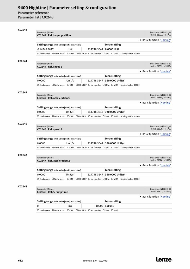
9400 HighLine | Parameter setting & configurationParameter referenceParameter list | C02643
632 Firmware 1.37 - 09/2006 L
C02643
C02644
C02645
C02646
C02647
C02648
Parameter | Name:
C02643 | Ref. target positionData type: INTEGER_32Index: 21932d = 55ACh
Basic function "Homing"
Setting range (min. value | unit | max. value) Lenze setting
-214748.3647 Unit 214748.3647 0.0000 Unit
Read access Write access CINH PLC STOP No transfer COM MOT Scaling factor: 10000
Parameter | Name:
C02644 | Ref. speed 1Data type: INTEGER_32Index: 21931d = 55ABh
Basic function "Homing"
Setting range (min. value | unit | max. value) Lenze setting
0.0000 Unit/s 214748.3647 360.0000 Unit/s
Read access Write access CINH PLC STOP No transfer COM MOT Scaling factor: 10000
Parameter | Name:
C02645 | Ref. acceleration 1Data type: INTEGER_32Index: 21930d = 55AAh
Basic function "Homing"
Setting range (min. value | unit | max. value) Lenze setting
0.0000 Unit/s² 214748.3647 720.0000 Unit/s²
Read access Write access CINH PLC STOP No transfer COM MOT Scaling factor: 10000
Parameter | Name:
C02646 | Ref. speed 2Data type: INTEGER_32Index: 21929d = 55A9h
Basic function "Homing"
Setting range (min. value | unit | max. value) Lenze setting
0.0000 Unit/s 214748.3647 180.0000 Unit/s
Read access Write access CINH PLC STOP No transfer COM MOT Scaling factor: 10000
Parameter | Name:
C02647 | Ref. acceleration 2Data type: INTEGER_32Index: 21928d = 55A8h
Basic function "Homing"
Setting range (min. value | unit | max. value) Lenze setting
0.0000 Unit/s² 214748.3647 360.0000 Unit/s²
Read access Write access CINH PLC STOP No transfer COM MOT Scaling factor: 10000
Parameter | Name:
C02648 | Ref. S-ramp timeData type: INTEGER_32Index: 21927d = 55A7h
Basic function "Homing"
Setting range (min. value | unit | max. value) Lenze setting
0 ms 10000 100 ms
Read access Write access CINH PLC STOP No transfer COM MOT
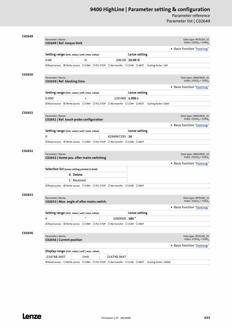
L Firmware 1.37 - 09/2006 633
9400 HighLine | Parameter setting & configurationParameter reference
Parameter list | C02649
C02649
C02650
C02651
C02652
C02653
C02656
Parameter | Name:
C02649 | Ref. torque limitData type: INTEGER_32Index: 21926d = 55A6h
Basic function "Homing"
Setting range (min. value | unit | max. value) Lenze setting
0.00 % 200.00 10.00 %
Read access Write access CINH PLC STOP No transfer COM MOT Scaling factor: 100
Parameter | Name:
C02650 | Ref. blocking timeData type: UNSIGNED_32
Index: 21925d = 55A5h
Basic function "Homing"
Setting range (min. value | unit | max. value) Lenze setting
0.000 s 120.000 1.000 s
Read access Write access CINH PLC STOP No transfer COM MOT Scaling factor: 1000
Parameter | Name:
C02651 | Ref. touch probe configurationData type: UNSIGNED_32
Index: 21924d = 55A4h
Basic function "Homing"
Setting range (min. value | unit | max. value) Lenze setting
0 4294967295 16
Read access Write access CINH PLC STOP No transfer COM MOT
Parameter | Name:
C02652 | Home pos. after mains switchingData type: UNSIGNED_32
Index: 21923d = 55A3h
Basic function "Homing"
Selection list (Lenze setting printed in bold)
0 Delete
1 Received
Read access Write access CINH PLC STOP No transfer COM MOT
Parameter | Name:
C02653 | Max. angle of after mains switch.Data type: INTEGER_32Index: 21922d = 55A2h
Basic function "Homing"
Setting range (min. value | unit | max. value) Lenze setting
0 ° 1000000 180 °
Read access Write access CINH PLC STOP No transfer COM MOT
Parameter | Name:
C02656 | Current positionData type: INTEGER_32Index: 21919d = 559Fh
Basic function "Homing"
Display range (min. value | unit | max. value)
-214748.3647 Unit 214748.3647
Read access Write access CINH PLC STOP No transfer COM MOT Scaling factor: 10000
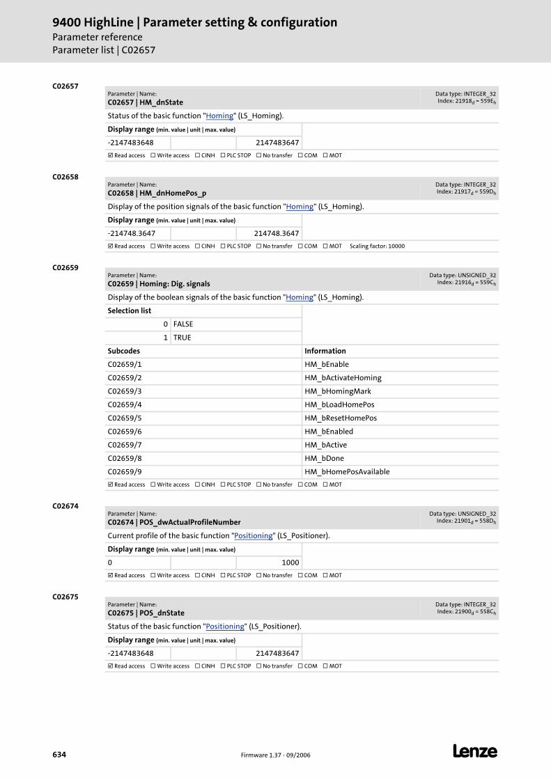
9400 HighLine | Parameter setting & configurationParameter referenceParameter list | C02657
634 Firmware 1.37 - 09/2006 L
C02657
C02658
C02659
C02674
C02675
Parameter | Name:
C02657 | HM_dnStateData type: INTEGER_32Index: 21918d = 559Eh
Status of the basic function "Homing" (LS_Homing).
Display range (min. value | unit | max. value)
-2147483648 2147483647
Read access Write access CINH PLC STOP No transfer COM MOT
Parameter | Name:
C02658 | HM_dnHomePos_pData type: INTEGER_32Index: 21917d = 559Dh
Display of the position signals of the basic function "Homing" (LS_Homing).
Display range (min. value | unit | max. value)
-214748.3647 214748.3647
Read access Write access CINH PLC STOP No transfer COM MOT Scaling factor: 10000
Parameter | Name:
C02659 | Homing: Dig. signalsData type: UNSIGNED_32
Index: 21916d = 559Ch
Display of the boolean signals of the basic function "Homing" (LS_Homing).
Selection list
0 FALSE
1 TRUE
Subcodes Information
C02659/1 HM_bEnable
C02659/2 HM_bActivateHoming
C02659/3 HM_bHomingMark
C02659/4 HM_bLoadHomePos
C02659/5 HM_bResetHomePos
C02659/6 HM_bEnabled
C02659/7 HM_bActive
C02659/8 HM_bDone
C02659/9 HM_bHomePosAvailable
Read access Write access CINH PLC STOP No transfer COM MOT
Parameter | Name:
C02674 | POS_dwActualProfileNumberData type: UNSIGNED_32
Index: 21901d = 558Dh
Current profile of the basic function "Positioning" (LS_Positioner).
Display range (min. value | unit | max. value)
0 1000
Read access Write access CINH PLC STOP No transfer COM MOT
Parameter | Name:
C02675 | POS_dnStateData type: INTEGER_32Index: 21900d = 558Ch
Status of the basic function "Positioning" (LS_Positioner).
Display range (min. value | unit | max. value)
-2147483648 2147483647
Read access Write access CINH PLC STOP No transfer COM MOT
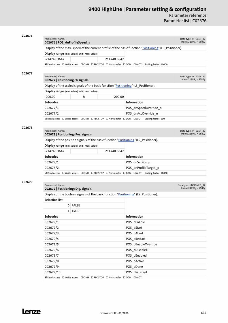
L Firmware 1.37 - 09/2006 635
9400 HighLine | Parameter setting & configurationParameter reference
Parameter list | C02676
C02676
C02677
C02678
C02679
Parameter | Name:
C02676 | POS_dnProfileSpeed_sData type: INTEGER_32Index: 21899d = 558Bh
Display of the max. speed of the current profile of the basic function "Positioning" (LS_Positioner).
Display range (min. value | unit | max. value)
-214748.3647 214748.3647
Read access Write access CINH PLC STOP No transfer COM MOT Scaling factor: 10000
Parameter | Name:
C02677 | Positioning: % signalsData type: INTEGER_32Index: 21898d = 558Ah
Display of the scaled signals of the basic function "Positioning" (LS_Positioner).
Display range (min. value | unit | max. value)
-200.00 % 200.00
Subcodes Information
C02677/1 POS_dnSpeedOverride_n
C02677/2 POS_dnAccOverride_n
Read access Write access CINH PLC STOP No transfer COM MOT Scaling factor: 100
Parameter | Name:
C02678 | Positioning: Pos. signalsData type: INTEGER_32Index: 21897d = 5589h
Display of the position signals of the basic function "Positioning "(LS_Positioner).
Display range (min. value | unit | max. value)
-214748.3647 214748.3647
Subcodes Information
C02678/1 POS_dnSetPos_p
C02678/2 POS_dnProfileTarget_p
Read access Write access CINH PLC STOP No transfer COM MOT Scaling factor: 10000
Parameter | Name:
C02679 | Positioning: Dig. signalsData type: UNSIGNED_32
Index: 21896d = 5588h
Display of the boolean signals of the basic function "Positioning" (LS_Positioner).
Selection list
0 FALSE
1 TRUE
Subcodes Information
C02679/1 POS_bEnable
C02679/2 POS_bStart
C02679/3 POS_bAbort
C02679/4 POS_bRestart
C02679/5 POS_bEnableOverride
C02679/6 POS_bDisableTP
C02679/7 POS_bEnabled
C02679/8 POS_bActive
C02679/9 POS_bDone
C02679/10 POS_bInTarget
Read access Write access CINH PLC STOP No transfer COM MOT
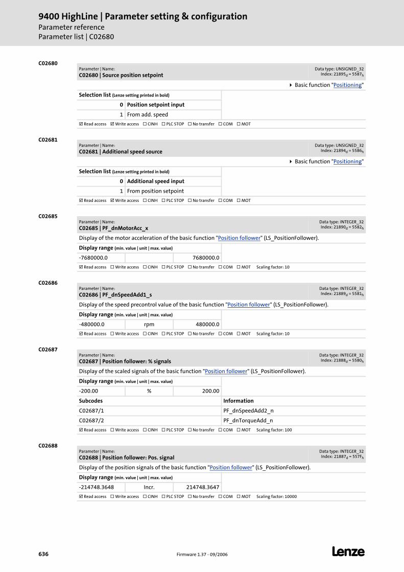
9400 HighLine | Parameter setting & configurationParameter referenceParameter list | C02680
636 Firmware 1.37 - 09/2006 L
C02680
C02681
C02685
C02686
C02687
C02688
Parameter | Name:
C02680 | Source position setpointData type: UNSIGNED_32
Index: 21895d = 5587h
Basic function "Positioning"
Selection list (Lenze setting printed in bold)
0 Position setpoint input
1 From add. speed
Read access Write access CINH PLC STOP No transfer COM MOT
Parameter | Name:
C02681 | Additional speed sourceData type: UNSIGNED_32
Index: 21894d = 5586h
Basic function "Positioning"
Selection list (Lenze setting printed in bold)
0 Additional speed input
1 From position setpoint
Read access Write access CINH PLC STOP No transfer COM MOT
Parameter | Name:
C02685 | PF_dnMotorAcc_xData type: INTEGER_32Index: 21890d = 5582h
Display of the motor acceleration of the basic function "Position follower" (LS_PositionFollower).
Display range (min. value | unit | max. value)
-7680000.0 7680000.0
Read access Write access CINH PLC STOP No transfer COM MOT Scaling factor: 10
Parameter | Name:
C02686 | PF_dnSpeedAdd1_sData type: INTEGER_32Index: 21889d = 5581h
Display of the speed precontrol value of the basic function "Position follower" (LS_PositionFollower).
Display range (min. value | unit | max. value)
-480000.0 rpm 480000.0
Read access Write access CINH PLC STOP No transfer COM MOT Scaling factor: 10
Parameter | Name:
C02687 | Position follower: % signalsData type: INTEGER_32Index: 21888d = 5580h
Display of the scaled signals of the basic function "Position follower" (LS_PositionFollower).
Display range (min. value | unit | max. value)
-200.00 % 200.00
Subcodes Information
C02687/1 PF_dnSpeedAdd2_n
C02687/2 PF_dnTorqueAdd_n
Read access Write access CINH PLC STOP No transfer COM MOT Scaling factor: 100
Parameter | Name:
C02688 | Position follower: Pos. signalData type: INTEGER_32Index: 21887d = 557Fh
Display of the position signals of the basic function "Position follower" (LS_PositionFollower).
Display range (min. value | unit | max. value)
-214748.3648 Incr. 214748.3647
Read access Write access CINH PLC STOP No transfer COM MOT Scaling factor: 10000
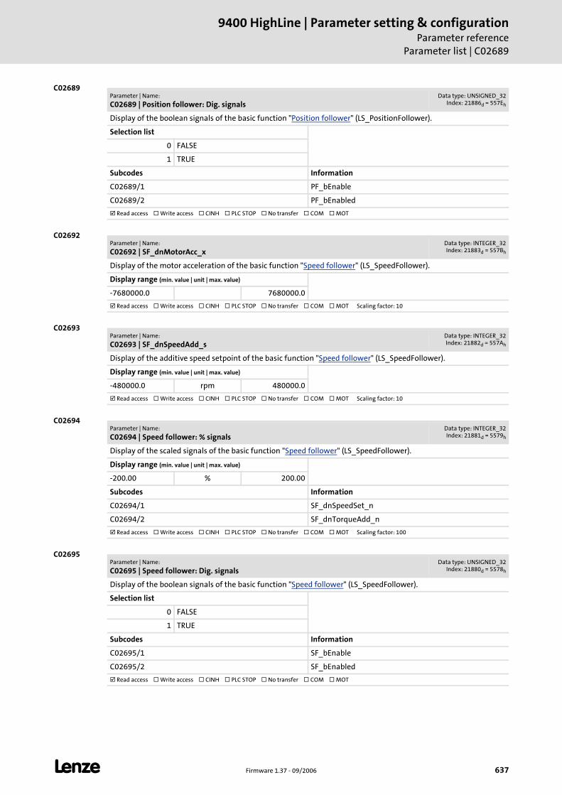
L Firmware 1.37 - 09/2006 637
9400 HighLine | Parameter setting & configurationParameter reference
Parameter list | C02689
C02689
C02692
C02693
C02694
C02695
Parameter | Name:
C02689 | Position follower: Dig. signalsData type: UNSIGNED_32
Index: 21886d = 557Eh
Display of the boolean signals of the basic function "Position follower" (LS_PositionFollower).
Selection list
0 FALSE
1 TRUE
Subcodes Information
C02689/1 PF_bEnable
C02689/2 PF_bEnabled
Read access Write access CINH PLC STOP No transfer COM MOT
Parameter | Name:
C02692 | SF_dnMotorAcc_xData type: INTEGER_32Index: 21883d = 557Bh
Display of the motor acceleration of the basic function "Speed follower" (LS_SpeedFollower).
Display range (min. value | unit | max. value)
-7680000.0 7680000.0
Read access Write access CINH PLC STOP No transfer COM MOT Scaling factor: 10
Parameter | Name:
C02693 | SF_dnSpeedAdd_sData type: INTEGER_32Index: 21882d = 557Ah
Display of the additive speed setpoint of the basic function "Speed follower" (LS_SpeedFollower).
Display range (min. value | unit | max. value)
-480000.0 rpm 480000.0
Read access Write access CINH PLC STOP No transfer COM MOT Scaling factor: 10
Parameter | Name:
C02694 | Speed follower: % signalsData type: INTEGER_32Index: 21881d = 5579h
Display of the scaled signals of the basic function "Speed follower" (LS_SpeedFollower).
Display range (min. value | unit | max. value)
-200.00 % 200.00
Subcodes Information
C02694/1 SF_dnSpeedSet_n
C02694/2 SF_dnTorqueAdd_n
Read access Write access CINH PLC STOP No transfer COM MOT Scaling factor: 100
Parameter | Name:
C02695 | Speed follower: Dig. signalsData type: UNSIGNED_32
Index: 21880d = 5578h
Display of the boolean signals of the basic function "Speed follower" (LS_SpeedFollower).
Selection list
0 FALSE
1 TRUE
Subcodes Information
C02695/1 SF_bEnable
C02695/2 SF_bEnabled
Read access Write access CINH PLC STOP No transfer COM MOT
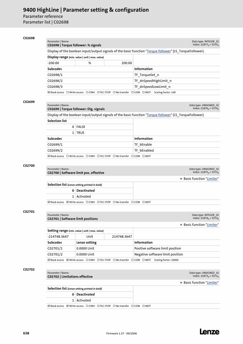
9400 HighLine | Parameter setting & configurationParameter referenceParameter list | C02698
638 Firmware 1.37 - 09/2006 L
C02698
C02699
C02700
C02701
C02702
Parameter | Name:
C02698 | Torque follower: % signalsData type: INTEGER_32Index: 21877d = 5575h
Display of the boolean input/output signals of the basic function "Torque follower" (LS_TorqueFollower).
Display range (min. value | unit | max. value)
-200.00 % 200.00
Subcodes Information
C02698/1 TF_TorqueSet_n
C02698/2 TF_dnSpeedHighLimit_n
C02698/3 TF_dnSpeedLowLimit_n
Read access Write access CINH PLC STOP No transfer COM MOT Scaling factor: 100
Parameter | Name:
C02699 | Torque follower: Dig. signalsData type: UNSIGNED_32
Index: 21876d = 5574h
Display of the boolean input/output signals of the basic function "Torque follower" (LS_TorqueFollower).
Selection list
0 FALSE
1 TRUE
Subcodes Information
C02699/1 TF_bEnable
C02699/2 TF_bEnabled
Read access Write access CINH PLC STOP No transfer COM MOT
Parameter | Name:
C02700 | Software limit pos. effectiveData type: UNSIGNED_32
Index: 21875d = 5573h
Basic function "Limiter"
Selection list (Lenze setting printed in bold)
0 Deactivated
1 Activated
Read access Write access CINH PLC STOP No transfer COM MOT
Parameter | Name:
C02701 | Software limit positionsData type: INTEGER_32Index: 21874d = 5572h
Basic function "Limiter"
Setting range (min. value | unit | max. value)
-214748.3647 Unit 214748.3647
Subcodes Lenze setting Information
C02701/1 0.0000 Unit Positive software limit position
C02701/2 0.0000 Unit Negative software limit position
Read access Write access CINH PLC STOP No transfer COM MOT Scaling factor: 10000
Parameter | Name:
C02702 | Limitations effectiveData type: UNSIGNED_32
Index: 21873d = 5571h
Basic function "Limiter"
Selection list (Lenze setting printed in bold)
0 Deactivated
1 Activated
Read access Write access CINH PLC STOP No transfer COM MOT
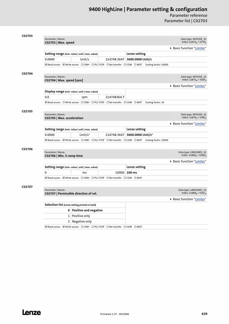
L Firmware 1.37 - 09/2006 639
9400 HighLine | Parameter setting & configurationParameter reference
Parameter list | C02703
C02703
C02704
C02705
C02706
C02707
Parameter | Name:
C02703 | Max. speedData type: INTEGER_32Index: 21872d = 5570h
Basic function "Limiter"
Setting range (min. value | unit | max. value) Lenze setting
0.0000 Unit/s 214748.3647 3600.0000 Unit/s
Read access Write access CINH PLC STOP No transfer COM MOT Scaling factor: 10000
Parameter | Name:
C02704 | Max. speed [rpm]Data type: INTEGER_32Index: 21871d = 556Fh
Basic function "Limiter"
Display range (min. value | unit | max. value)
0.0 rpm 214748364.7
Read access Write access CINH PLC STOP No transfer COM MOT Scaling factor: 10
Parameter | Name:
C02705 | Max. accelerationData type: INTEGER_32Index: 21870d = 556Eh
Basic function "Limiter"
Setting range (min. value | unit | max. value) Lenze setting
0.0000 Unit/s² 214748.3647 3600.0000 Unit/s²
Read access Write access CINH PLC STOP No transfer COM MOT Scaling factor: 10000
Parameter | Name:
C02706 | Min. S-ramp timeData type: UNSIGNED_32
Index: 21869d = 556Dh
Basic function "Limiter"
Setting range (min. value | unit | max. value) Lenze setting
0 ms 10000 100 ms
Read access Write access CINH PLC STOP No transfer COM MOT
Parameter | Name:
C02707 | Permissible direction of rot.Data type: UNSIGNED_32
Index: 21868d = 556Ch
Basic function "Limiter"
Selection list (Lenze setting printed in bold)
0 Positive and negative
1 Positive only
2 Negative only
Read access Write access CINH PLC STOP No transfer COM MOT
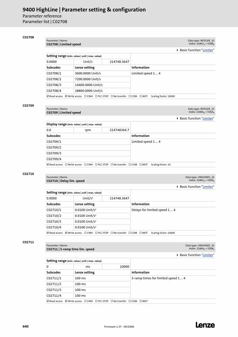
9400 HighLine | Parameter setting & configurationParameter referenceParameter list | C02708
640 Firmware 1.37 - 09/2006 L
C02708
C02709
C02710
C02711
Parameter | Name:
C02708 | Limited speedData type: INTEGER_32Index: 21867d = 556Bh
Basic function "Limiter"
Setting range (min. value | unit | max. value)
0.0000 Unit/s 214748.3647
Subcodes Lenze setting Information
C02708/1 3600.0000 Unit/s Limited speed 1 ... 4
C02708/2 7200.0000 Unit/s
C02708/3 14400.0000 Unit/s
C02708/4 28800.0000 Unit/s
Read access Write access CINH PLC STOP No transfer COM MOT Scaling factor: 10000
Parameter | Name:
C02709 | Limited speedData type: INTEGER_32Index: 21866d = 556Ah
Basic function "Limiter"
Display range (min. value | unit | max. value)
0.0 rpm 214748364.7
Subcodes Information
C02709/1 Limited speed 1 ... 4
C02709/2
C02709/3
C02709/4
Read access Write access CINH PLC STOP No transfer COM MOT Scaling factor: 10
Parameter | Name:
C02710 | Delay lim. speedData type: UNSIGNED_32
Index: 21865d = 5569h
Basic function "Limiter"
Setting range (min. value | unit | max. value)
0.0000 Unit/s² 214748.3647
Subcodes Lenze setting Information
C02710/1 0.0100 Unit/s² Delays for limited speed 1 ... 4
C02710/2 0.0100 Unit/s²
C02710/3 0.0100 Unit/s²
C02710/4 0.0100 Unit/s²
Read access Write access CINH PLC STOP No transfer COM MOT Scaling factor: 10000
Parameter | Name:
C02711 | S-ramp time lim. speedData type: UNSIGNED_32
Index: 21864d = 5568h
Basic function "Limiter"
Setting range (min. value | unit | max. value)
0 ms 10000
Subcodes Lenze setting Information
C02711/1 100 ms S-ramp times for limited speed 1 ... 4
C02711/2 100 ms
C02711/3 100 ms
C02711/4 100 ms
Read access Write access CINH PLC STOP No transfer COM MOT
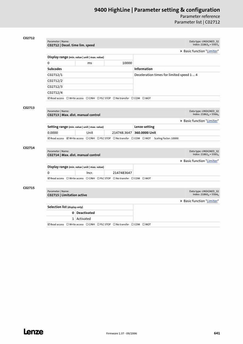
L Firmware 1.37 - 09/2006 641
9400 HighLine | Parameter setting & configurationParameter reference
Parameter list | C02712
C02712
C02713
C02714
C02715
Parameter | Name:
C02712 | Decel. time lim. speedData type: UNSIGNED_32
Index: 21863d = 5567h
Basic function "Limiter"
Display range (min. value | unit | max. value)
0 ms 10000
Subcodes Information
C02712/1 Deceleration times for limited speed 1 ... 4
C02712/2
C02712/3
C02712/4
Read access Write access CINH PLC STOP No transfer COM MOT
Parameter | Name:
C02713 | Max. dist. manual controlData type: UNSIGNED_32
Index: 21862d = 5566h
Basic function "Limiter"
Setting range (min. value | unit | max. value) Lenze setting
0.0000 Unit 214748.3647 360.0000 Unit
Read access Write access CINH PLC STOP No transfer COM MOT Scaling factor: 10000
Parameter | Name:
C02714 | Max. dist. manual controlData type: UNSIGNED_32
Index: 21861d = 5565h
Basic function "Limiter"
Display range (min. value | unit | max. value)
0 Incr. 2147483647
Read access Write access CINH PLC STOP No transfer COM MOT
Parameter | Name:
C02715 | Limitation activeData type: UNSIGNED_32
Index: 21860d = 5564h
Basic function "Limiter"
Selection list (display only)
0 Deactivated
1 Activated
Read access Write access CINH PLC STOP No transfer COM MOT
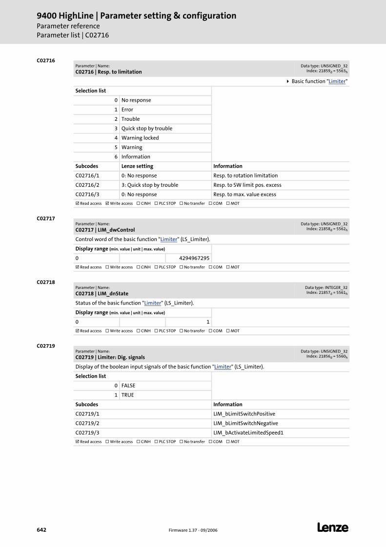
9400 HighLine | Parameter setting & configurationParameter referenceParameter list | C02716
642 Firmware 1.37 - 09/2006 L
C02716
C02717
C02718
C02719
Parameter | Name:
C02716 | Resp. to limitationData type: UNSIGNED_32
Index: 21859d = 5563h
Basic function "Limiter"
Selection list
0 No response
1 Error
2 Trouble
3 Quick stop by trouble
4 Warning locked
5 Warning
6 Information
Subcodes Lenze setting Information
C02716/1 0: No response Resp. to rotation limitation
C02716/2 3: Quick stop by trouble Resp. to SW limit pos. excess
C02716/3 0: No response Resp. to max. value excess
Read access Write access CINH PLC STOP No transfer COM MOT
Parameter | Name:
C02717 | LIM_dwControlData type: UNSIGNED_32
Index: 21858d = 5562h
Control word of the basic function "Limiter" (LS_Limiter).
Display range (min. value | unit | max. value)
0 4294967295
Read access Write access CINH PLC STOP No transfer COM MOT
Parameter | Name:
C02718 | LIM_dnStateData type: INTEGER_32Index: 21857d = 5561h
Status of the basic function "Limiter" (LS_Limiter).
Display range (min. value | unit | max. value)
0 1
Read access Write access CINH PLC STOP No transfer COM MOT
Parameter | Name:
C02719 | Limiter: Dig. signalsData type: UNSIGNED_32
Index: 21856d = 5560h
Display of the boolean input signals of the basic function "Limiter" (LS_Limiter).
Selection list
0 FALSE
1 TRUE
Subcodes Information
C02719/1 LIM_bLimitSwitchPositive
C02719/2 LIM_bLimitSwitchNegative
C02719/3 LIM_bActivateLimitedSpeed1
Read access Write access CINH PLC STOP No transfer COM MOT

L Firmware 1.37 - 09/2006 643
9400 HighLine | Parameter setting & configurationParameter reference
Parameter list | C02730
C02730
C02731
C02732
C02733
C02734
Parameter | Name:
C02730 | AINx: GainData type: INTEGER_32Index: 21845d = 5555h
Setting range (min. value | unit | max. value)
-200.00 % 200.00
Subcodes Lenze setting Information
C02730/1 100.00 % Gain of analog input 1
C02730/2 100.00 % Gain of analog input 2
Read access Write access CINH PLC STOP No transfer COM MOT Scaling factor: 100
Parameter | Name:
C02731 | AINx: OffsetData type: INTEGER_32Index: 21844d = 5554h
Setting range (min. value | unit | max. value)
-200.00 % 200.00
Subcodes Lenze setting Information
C02731/1 0.00 % Offset of analog input 1
C02731/2 0.00 % Offset of analog input 2
Read access Write access CINH PLC STOP No transfer COM MOT Scaling factor: 100
Parameter | Name:
C02732 | AINx: Dead bandData type: INTEGER_32Index: 21843d = 5553h
Setting range (min. value | unit | max. value)
0.00 % 100.00
Subcodes Lenze setting Information
C02732/1 0.00 % Dead band of analog input 1
C02732/2 0.00 % Dead band of analog input 2
Read access Write access CINH PLC STOP No transfer COM MOT Scaling factor: 100
Parameter | Name:
C02733 | AOUTx: GainData type: INTEGER_32Index: 21842d = 5552h
Setting range (min. value | unit | max. value)
-200.00 % 200.00
Subcodes Lenze setting Information
C02733/1 100.00 % Gain of analog output 1
C02733/2 100.00 % Gain of analog output 2
Read access Write access CINH PLC STOP No transfer COM MOT Scaling factor: 100
Parameter | Name:
C02734 | AOUTx: OffsetData type: INTEGER_32Index: 21841d = 5551h
Setting range (min. value | unit | max. value)
-200.00 % 200.00
Subcodes Lenze setting Information
C02734/1 0.00 % Offset of analog output 1
C02734/2 0.00 % Offset of analog output 2
Read access Write access CINH PLC STOP No transfer COM MOT Scaling factor: 100
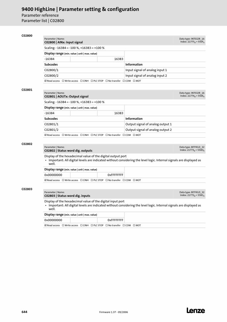
9400 HighLine | Parameter setting & configurationParameter referenceParameter list | C02800
644 Firmware 1.37 - 09/2006 L
C02800
C02801
C02802
C02803
Parameter | Name:
C02800 | AINx: Input signalData type: INTEGER_16Index: 21775d = 550Fh
Scaling: -16384 ≡ -100 %, +16383 ≡ +100 %
Display range (min. value | unit | max. value)
-16384 16383
Subcodes Information
C02800/1 Input signal of analog input 1
C02800/2 Input signal of analog input 2
Read access Write access CINH PLC STOP No transfer COM MOT
Parameter | Name:
C02801 | AOUTx: Output signalData type: INTEGER_16Index: 21774d = 550Eh
Scaling: -16384 ≡ -100 %, +16383 ≡ +100 %
Display range (min. value | unit | max. value)
-16384 16383
Subcodes Information
C02801/1 Output signal of analog output 1
C02801/2 Output signal of analog output 2
Read access Write access CINH PLC STOP No transfer COM MOT
Parameter | Name:
C02802 | Status word dig. outputsData type: BITFIELD_32Index: 21773d = 550Dh
Display of the hexadecimal value of the digital output port • Important: All digital levels are indicated without considering the level logic. Internal signals are displayed as
well.
Display range (min. value | unit | max. value)
0x00000000 0xFFFFFFFF
Read access Write access CINH PLC STOP No transfer COM MOT
Parameter | Name:
C02803 | Status word dig. inputsData type: BITFIELD_32Index: 21772d = 550Ch
Display of the hexadecimal value of the digital input port • Important: All digital levels are indicated without considering the level logic. Internal signals are displayed as
well.
Display range (min. value | unit | max. value)
0x00000000 0xFFFFFFFF
Read access Write access CINH PLC STOP No transfer COM MOT
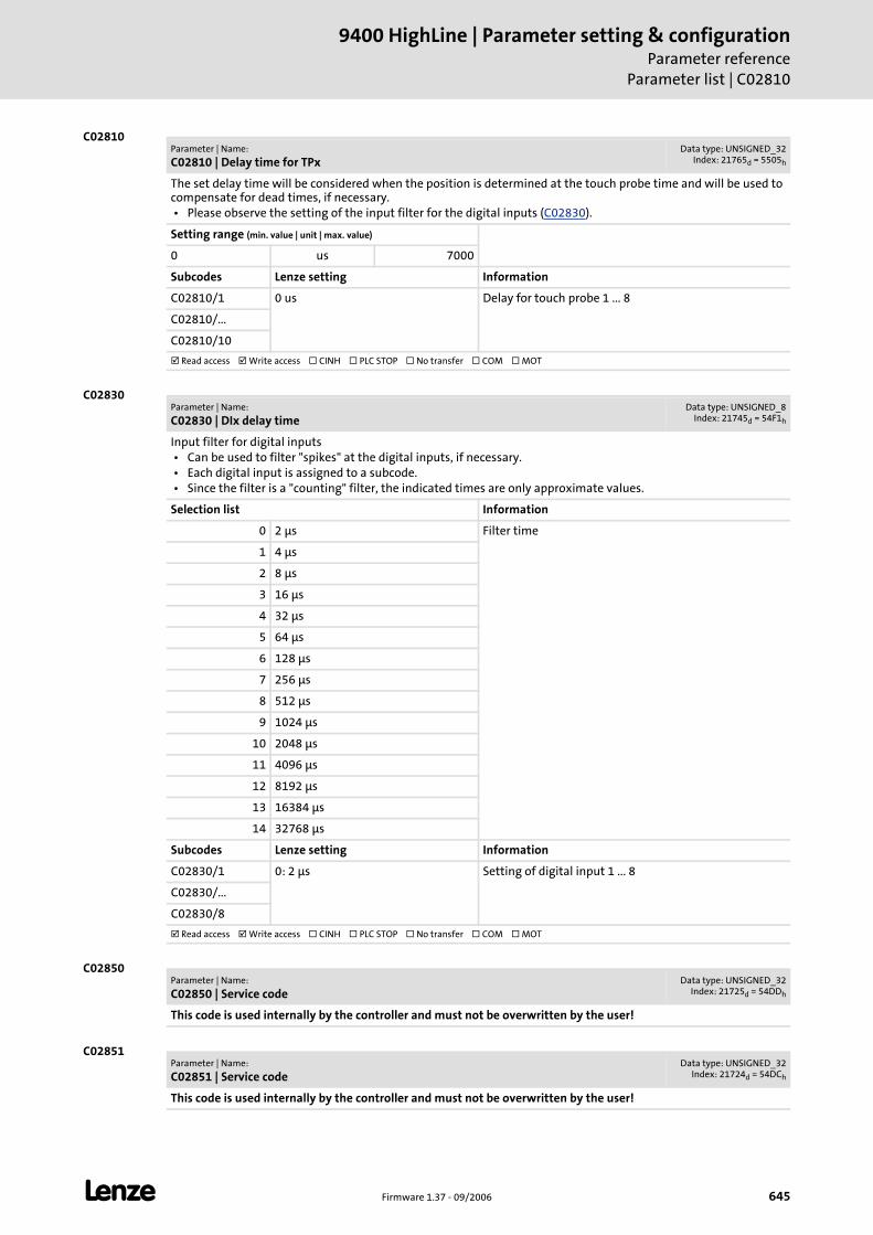
L Firmware 1.37 - 09/2006 645
9400 HighLine | Parameter setting & configurationParameter reference
Parameter list | C02810
C02810
C02830
C02850
C02851
Parameter | Name:
C02810 | Delay time for TPxData type: UNSIGNED_32
Index: 21765d = 5505h
The set delay time will be considered when the position is determined at the touch probe time and will be used to compensate for dead times, if necessary. • Please observe the setting of the input filter for the digital inputs (C02830).
Setting range (min. value | unit | max. value)
0 us 7000
Subcodes Lenze setting Information
C02810/1 0 us Delay for touch probe 1 ... 8
C02810/...
C02810/10
Read access Write access CINH PLC STOP No transfer COM MOT
Parameter | Name:
C02830 | DIx delay timeData type: UNSIGNED_8
Index: 21745d = 54F1h
Input filter for digital inputs • Can be used to filter "spikes" at the digital inputs, if necessary. • Each digital input is assigned to a subcode. • Since the filter is a "counting" filter, the indicated times are only approximate values.
Selection list Information
0 2 μs Filter time
1 4 μs
2 8 μs
3 16 μs
4 32 μs
5 64 μs
6 128 μs
7 256 μs
8 512 μs
9 1024 μs
10 2048 μs
11 4096 μs
12 8192 μs
13 16384 μs
14 32768 μs
Subcodes Lenze setting Information
C02830/1 0: 2 μs Setting of digital input 1 ... 8
C02830/...
C02830/8
Read access Write access CINH PLC STOP No transfer COM MOT
Parameter | Name:
C02850 | Service codeData type: UNSIGNED_32
Index: 21725d = 54DDh
This code is used internally by the controller and must not be overwritten by the user!
Parameter | Name:
C02851 | Service codeData type: UNSIGNED_32
Index: 21724d = 54DCh
This code is used internally by the controller and must not be overwritten by the user!
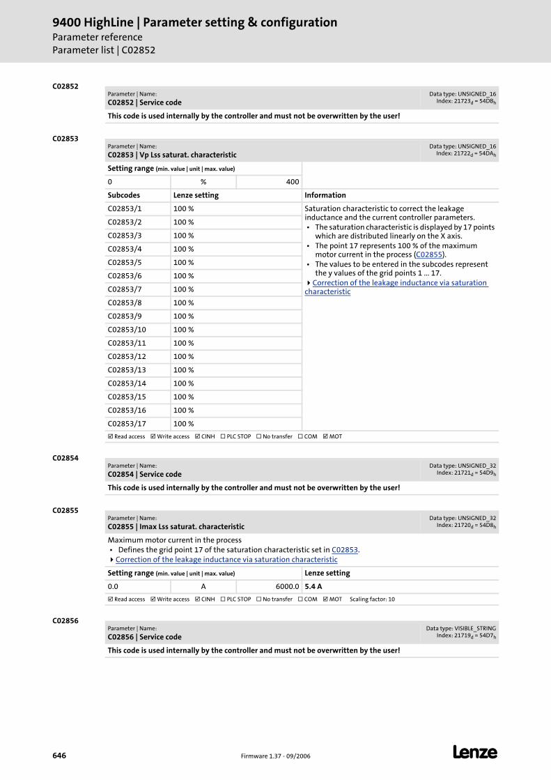
9400 HighLine | Parameter setting & configurationParameter referenceParameter list | C02852
646 Firmware 1.37 - 09/2006 L
C02852
C02853
C02854
C02855
C02856
Parameter | Name:
C02852 | Service codeData type: UNSIGNED_16
Index: 21723d = 54DBh
This code is used internally by the controller and must not be overwritten by the user!
Parameter | Name:
C02853 | Vp Lss saturat. characteristicData type: UNSIGNED_16
Index: 21722d = 54DAh
Setting range (min. value | unit | max. value)
0 % 400
Subcodes Lenze setting Information
C02853/1 100 % Saturation characteristic to correct the leakage inductance and the current controller parameters. • The saturation characteristic is displayed by 17 points
which are distributed linearly on the X axis. • The point 17 represents 100 % of the maximum
motor current in the process (C02855). • The values to be entered in the subcodes represent
the y values of the grid points 1 ... 17.Correction of the leakage inductance via saturation
characteristic
C02853/2 100 %
C02853/3 100 %
C02853/4 100 %
C02853/5 100 %
C02853/6 100 %
C02853/7 100 %
C02853/8 100 %
C02853/9 100 %
C02853/10 100 %
C02853/11 100 %
C02853/12 100 %
C02853/13 100 %
C02853/14 100 %
C02853/15 100 %
C02853/16 100 %
C02853/17 100 %
Read access Write access CINH PLC STOP No transfer COM MOT
Parameter | Name:
C02854 | Service codeData type: UNSIGNED_32
Index: 21721d = 54D9h
This code is used internally by the controller and must not be overwritten by the user!
Parameter | Name:
C02855 | Imax Lss saturat. characteristicData type: UNSIGNED_32
Index: 21720d = 54D8h
Maximum motor current in the process • Defines the grid point 17 of the saturation characteristic set in C02853.
Correction of the leakage inductance via saturation characteristic
Setting range (min. value | unit | max. value) Lenze setting
0.0 A 6000.0 5.4 A
Read access Write access CINH PLC STOP No transfer COM MOT Scaling factor: 10
Parameter | Name:
C02856 | Service codeData type: VISIBLE_STRING
Index: 21719d = 54D7h
This code is used internally by the controller and must not be overwritten by the user!
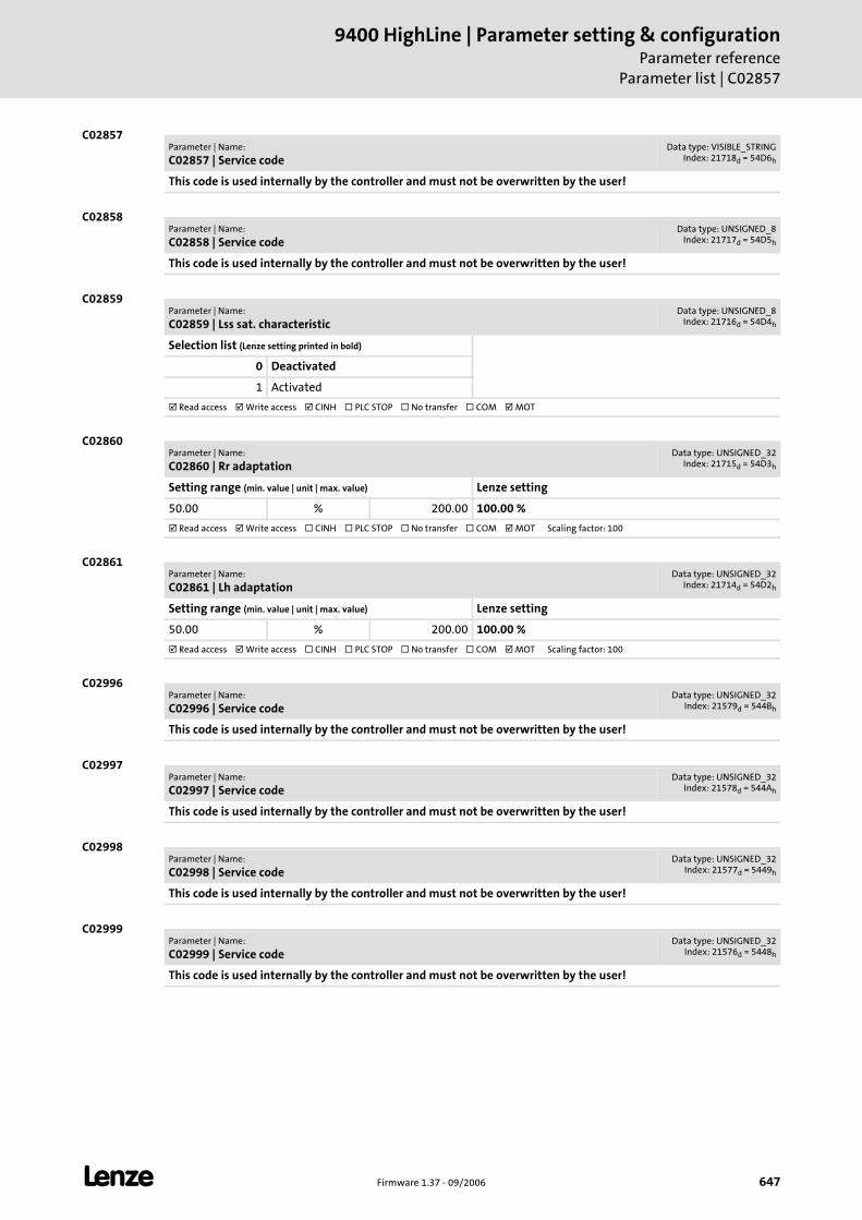
L Firmware 1.37 - 09/2006 647
9400 HighLine | Parameter setting & configurationParameter reference
Parameter list | C02857
C02857
C02858
C02859
C02860
C02861
C02996
C02997
C02998
C02999
Parameter | Name:
C02857 | Service codeData type: VISIBLE_STRING
Index: 21718d = 54D6h
This code is used internally by the controller and must not be overwritten by the user!
Parameter | Name:
C02858 | Service codeData type: UNSIGNED_8
Index: 21717d = 54D5h
This code is used internally by the controller and must not be overwritten by the user!
Parameter | Name:
C02859 | Lss sat. characteristicData type: UNSIGNED_8
Index: 21716d = 54D4h
Selection list (Lenze setting printed in bold)
0 Deactivated
1 Activated
Read access Write access CINH PLC STOP No transfer COM MOT
Parameter | Name:
C02860 | Rr adaptationData type: UNSIGNED_32
Index: 21715d = 54D3h
Setting range (min. value | unit | max. value) Lenze setting
50.00 % 200.00 100.00 %
Read access Write access CINH PLC STOP No transfer COM MOT Scaling factor: 100
Parameter | Name:
C02861 | Lh adaptationData type: UNSIGNED_32
Index: 21714d = 54D2h
Setting range (min. value | unit | max. value) Lenze setting
50.00 % 200.00 100.00 %
Read access Write access CINH PLC STOP No transfer COM MOT Scaling factor: 100
Parameter | Name:
C02996 | Service codeData type: UNSIGNED_32
Index: 21579d = 544Bh
This code is used internally by the controller and must not be overwritten by the user!
Parameter | Name:
C02997 | Service codeData type: UNSIGNED_32
Index: 21578d = 544Ah
This code is used internally by the controller and must not be overwritten by the user!
Parameter | Name:
C02998 | Service codeData type: UNSIGNED_32
Index: 21577d = 5449h
This code is used internally by the controller and must not be overwritten by the user!
Parameter | Name:
C02999 | Service codeData type: UNSIGNED_32
Index: 21576d = 5448h
This code is used internally by the controller and must not be overwritten by the user!
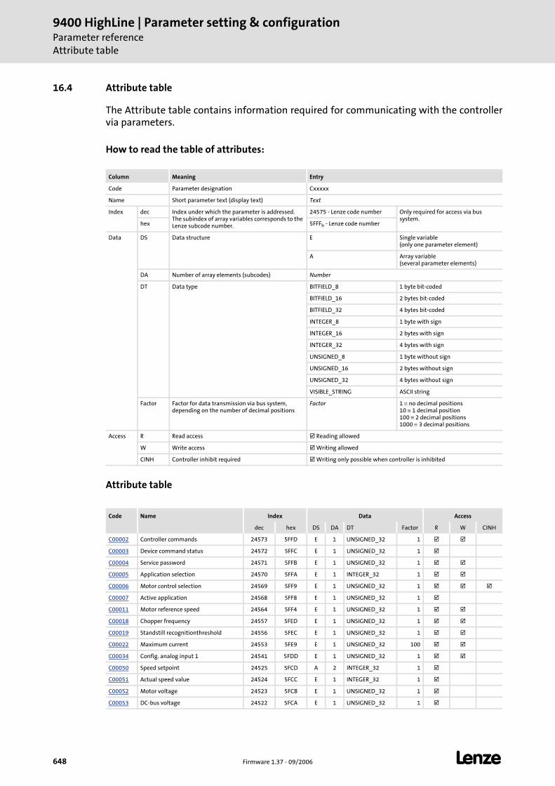
9400 HighLine | Parameter setting & configurationParameter referenceAttribute table
648 Firmware 1.37 - 09/2006 L
16.4 Attribute table
The Attribute table contains information required for communicating with the controller via parameters.
How to read the table of attributes:
Attribute table
Column Meaning Entry
Code Parameter designation Cxxxxx
Name Short parameter text (display text) Text
Index dec Index under which the parameter is addressed.The subindex of array variables corresponds to the Lenze subcode number.
24575 - Lenze code number Only required for access via bus system.
hex 5FFFh - Lenze code number
Data DS Data structure E Single variable (only one parameter element)
A Array variable (several parameter elements)
DA Number of array elements (subcodes) Number
DT Data type BITFIELD_8 1 byte bit-coded
BITFIELD_16 2 bytes bit-coded
BITFIELD_32 4 bytes bit-coded
INTEGER_8 1 byte with sign
INTEGER_16 2 bytes with sign
INTEGER_32 4 bytes with sign
UNSIGNED_8 1 byte without sign
UNSIGNED_16 2 bytes without sign
UNSIGNED_32 4 bytes without sign
VISIBLE_STRING ASCII string
Factor Factor for data transmission via bus system, depending on the number of decimal positions
Factor 1 ≡ no decimal positions10 ≡ 1 decimal position100 ≡ 2 decimal positions1000 ≡ 3 decimal positions
Access R Read access Reading allowed
W Write access Writing allowed
CINH Controller inhibit required Writing only possible when controller is inhibited
Code Name Index Data Access
dec hex DS DA DT Factor R W CINH
C00002 Controller commands 24573 5FFD E 1 UNSIGNED_32 1
C00003 Device command status 24572 5FFC E 1 UNSIGNED_32 1
C00004 Service password 24571 5FFB E 1 UNSIGNED_32 1
C00005 Application selection 24570 5FFA E 1 INTEGER_32 1
C00006 Motor control selection 24569 5FF9 E 1 UNSIGNED_32 1
C00007 Active application 24568 5FF8 E 1 UNSIGNED_32 1
C00011 Motor reference speed 24564 5FF4 E 1 UNSIGNED_32 1
C00018 Chopper frequency 24557 5FED E 1 UNSIGNED_32 1
C00019 Standstill recognitionthreshold 24556 5FEC E 1 UNSIGNED_32 1
C00022 Maximum current 24553 5FE9 E 1 UNSIGNED_32 100
C00034 Config. analog input 1 24541 5FDD E 1 UNSIGNED_32 1
C00050 Speed setpoint 24525 5FCD A 2 INTEGER_32 1
C00051 Actual speed value 24524 5FCC E 1 INTEGER_32 1
C00052 Motor voltage 24523 5FCB E 1 UNSIGNED_32 1
C00053 DC-bus voltage 24522 5FCA E 1 UNSIGNED_32 1
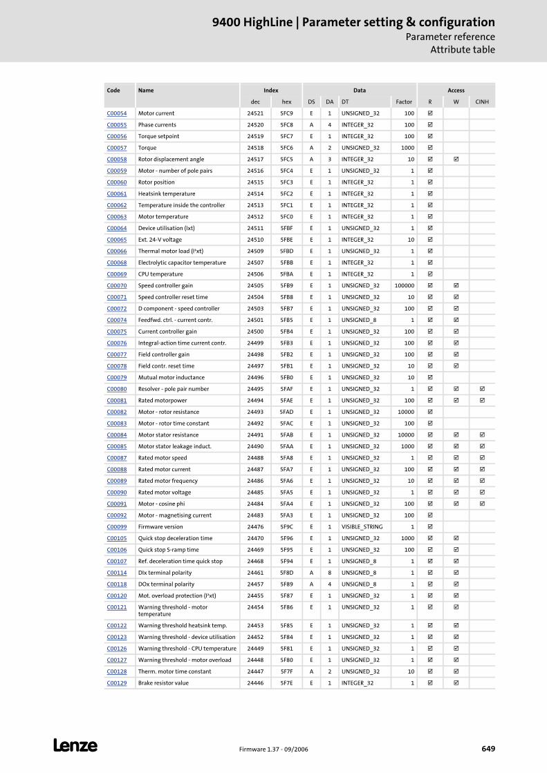
L Firmware 1.37 - 09/2006 649
9400 HighLine | Parameter setting & configurationParameter reference
Attribute table
C00054 Motor current 24521 5FC9 E 1 UNSIGNED_32 100
C00055 Phase currents 24520 5FC8 A 4 INTEGER_32 100
C00056 Torque setpoint 24519 5FC7 E 1 INTEGER_32 100
C00057 Torque 24518 5FC6 A 2 UNSIGNED_32 1000
C00058 Rotor displacement angle 24517 5FC5 A 3 INTEGER_32 10
C00059 Motor - number of pole pairs 24516 5FC4 E 1 UNSIGNED_32 1
C00060 Rotor position 24515 5FC3 E 1 INTEGER_32 1
C00061 Heatsink temperature 24514 5FC2 E 1 INTEGER_32 1
C00062 Temperature inside the controller 24513 5FC1 E 1 INTEGER_32 1
C00063 Motor temperature 24512 5FC0 E 1 INTEGER_32 1
C00064 Device utilisation (Ixt) 24511 5FBF E 1 UNSIGNED_32 1
C00065 Ext. 24-V voltage 24510 5FBE E 1 INTEGER_32 10
C00066 Thermal motor load (I²xt) 24509 5FBD E 1 UNSIGNED_32 1
C00068 Electrolytic capacitor temperature 24507 5FBB E 1 INTEGER_32 1
C00069 CPU temperature 24506 5FBA E 1 INTEGER_32 1
C00070 Speed controller gain 24505 5FB9 E 1 UNSIGNED_32 100000
C00071 Speed controller reset time 24504 5FB8 E 1 UNSIGNED_32 10
C00072 D component - speed controller 24503 5FB7 E 1 UNSIGNED_32 100
C00074 Feedfwd. ctrl. - current contr. 24501 5FB5 E 1 UNSIGNED_8 1
C00075 Current controller gain 24500 5FB4 E 1 UNSIGNED_32 100
C00076 Integral-action time current contr. 24499 5FB3 E 1 UNSIGNED_32 100
C00077 Field controller gain 24498 5FB2 E 1 UNSIGNED_32 100
C00078 Field contr. reset time 24497 5FB1 E 1 UNSIGNED_32 10
C00079 Mutual motor inductance 24496 5FB0 E 1 UNSIGNED_32 10
C00080 Resolver - pole pair number 24495 5FAF E 1 UNSIGNED_32 1
C00081 Rated motorpower 24494 5FAE E 1 UNSIGNED_32 100
C00082 Motor - rotor resistance 24493 5FAD E 1 UNSIGNED_32 10000
C00083 Motor - rotor time constant 24492 5FAC E 1 UNSIGNED_32 100
C00084 Motor stator resistance 24491 5FAB E 1 UNSIGNED_32 10000
C00085 Motor stator leakage induct. 24490 5FAA E 1 UNSIGNED_32 1000
C00087 Rated motor speed 24488 5FA8 E 1 UNSIGNED_32 1
C00088 Rated motor current 24487 5FA7 E 1 UNSIGNED_32 100
C00089 Rated motor frequency 24486 5FA6 E 1 UNSIGNED_32 10
C00090 Rated motor voltage 24485 5FA5 E 1 UNSIGNED_32 1
C00091 Motor - cosine phi 24484 5FA4 E 1 UNSIGNED_32 100
C00092 Motor - magnetising current 24483 5FA3 E 1 UNSIGNED_32 100
C00099 Firmware version 24476 5F9C E 1 VISIBLE_STRING 1
C00105 Quick stop deceleration time 24470 5F96 E 1 UNSIGNED_32 1000
C00106 Quick stop S-ramp time 24469 5F95 E 1 UNSIGNED_32 100
C00107 Ref. deceleration time quick stop 24468 5F94 E 1 UNSIGNED_8 1
C00114 DIx terminal polarity 24461 5F8D A 8 UNSIGNED_8 1
C00118 DOx terminal polarity 24457 5F89 A 4 UNSIGNED_8 1
C00120 Mot. overload protection (I²xt) 24455 5F87 E 1 UNSIGNED_32 1
C00121 Warning threshold - motor temperature
24454 5F86 E 1 UNSIGNED_32 1
C00122 Warning threshold heatsink temp. 24453 5F85 E 1 UNSIGNED_32 1
C00123 Warning threshold - device utilisation 24452 5F84 E 1 UNSIGNED_32 1
C00126 Warning threshold - CPU temperature 24449 5F81 E 1 UNSIGNED_32 1
C00127 Warning threshold - motor overload 24448 5F80 E 1 UNSIGNED_32 1
C00128 Therm. motor time constant 24447 5F7F A 2 UNSIGNED_32 10
C00129 Brake resistor value 24446 5F7E E 1 INTEGER_32 1
Code Name Index Data Access
dec hex DS DA DT Factor R W CINH
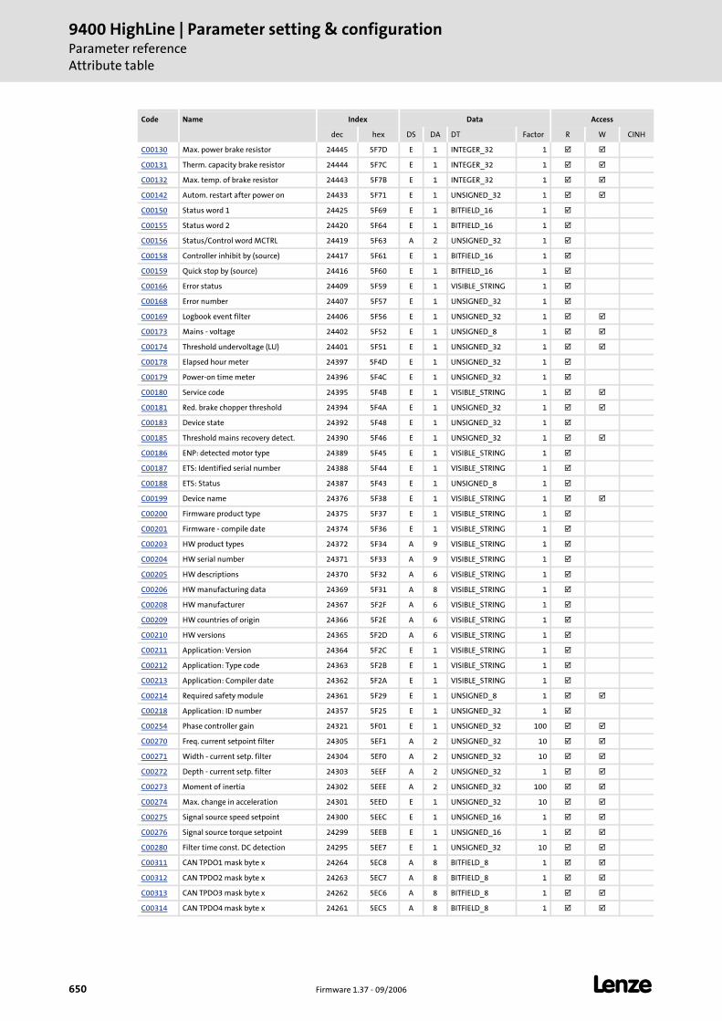
9400 HighLine | Parameter setting & configurationParameter referenceAttribute table
650 Firmware 1.37 - 09/2006 L
C00130 Max. power brake resistor 24445 5F7D E 1 INTEGER_32 1
C00131 Therm. capacity brake resistor 24444 5F7C E 1 INTEGER_32 1
C00132 Max. temp. of brake resistor 24443 5F7B E 1 INTEGER_32 1
C00142 Autom. restart after power on 24433 5F71 E 1 UNSIGNED_32 1
C00150 Status word 1 24425 5F69 E 1 BITFIELD_16 1
C00155 Status word 2 24420 5F64 E 1 BITFIELD_16 1
C00156 Status/Control word MCTRL 24419 5F63 A 2 UNSIGNED_32 1
C00158 Controller inhibit by (source) 24417 5F61 E 1 BITFIELD_16 1
C00159 Quick stop by (source) 24416 5F60 E 1 BITFIELD_16 1
C00166 Error status 24409 5F59 E 1 VISIBLE_STRING 1
C00168 Error number 24407 5F57 E 1 UNSIGNED_32 1
C00169 Logbook event filter 24406 5F56 E 1 UNSIGNED_32 1
C00173 Mains - voltage 24402 5F52 E 1 UNSIGNED_8 1
C00174 Threshold undervoltage (LU) 24401 5F51 E 1 UNSIGNED_32 1
C00178 Elapsed hour meter 24397 5F4D E 1 UNSIGNED_32 1
C00179 Power-on time meter 24396 5F4C E 1 UNSIGNED_32 1
C00180 Service code 24395 5F4B E 1 VISIBLE_STRING 1
C00181 Red. brake chopper threshold 24394 5F4A E 1 UNSIGNED_32 1
C00183 Device state 24392 5F48 E 1 UNSIGNED_32 1
C00185 Threshold mains recovery detect. 24390 5F46 E 1 UNSIGNED_32 1
C00186 ENP: detected motor type 24389 5F45 E 1 VISIBLE_STRING 1
C00187 ETS: Identified serial number 24388 5F44 E 1 VISIBLE_STRING 1
C00188 ETS: Status 24387 5F43 E 1 UNSIGNED_8 1
C00199 Device name 24376 5F38 E 1 VISIBLE_STRING 1
C00200 Firmware product type 24375 5F37 E 1 VISIBLE_STRING 1
C00201 Firmware - compile date 24374 5F36 E 1 VISIBLE_STRING 1
C00203 HW product types 24372 5F34 A 9 VISIBLE_STRING 1
C00204 HW serial number 24371 5F33 A 9 VISIBLE_STRING 1
C00205 HW descriptions 24370 5F32 A 6 VISIBLE_STRING 1
C00206 HW manufacturing data 24369 5F31 A 8 VISIBLE_STRING 1
C00208 HW manufacturer 24367 5F2F A 6 VISIBLE_STRING 1
C00209 HW countries of origin 24366 5F2E A 6 VISIBLE_STRING 1
C00210 HW versions 24365 5F2D A 6 VISIBLE_STRING 1
C00211 Application: Version 24364 5F2C E 1 VISIBLE_STRING 1
C00212 Application: Type code 24363 5F2B E 1 VISIBLE_STRING 1
C00213 Application: Compiler date 24362 5F2A E 1 VISIBLE_STRING 1
C00214 Required safety module 24361 5F29 E 1 UNSIGNED_8 1
C00218 Application: ID number 24357 5F25 E 1 UNSIGNED_32 1
C00254 Phase controller gain 24321 5F01 E 1 UNSIGNED_32 100
C00270 Freq. current setpoint filter 24305 5EF1 A 2 UNSIGNED_32 10
C00271 Width - current setp. filter 24304 5EF0 A 2 UNSIGNED_32 10
C00272 Depth - current setp. filter 24303 5EEF A 2 UNSIGNED_32 1
C00273 Moment of inertia 24302 5EEE A 2 UNSIGNED_32 100
C00274 Max. change in acceleration 24301 5EED E 1 UNSIGNED_32 10
C00275 Signal source speed setpoint 24300 5EEC E 1 UNSIGNED_16 1
C00276 Signal source torque setpoint 24299 5EEB E 1 UNSIGNED_16 1
C00280 Filter time const. DC detection 24295 5EE7 E 1 UNSIGNED_32 10
C00311 CAN TPDO1 mask byte x 24264 5EC8 A 8 BITFIELD_8 1
C00312 CAN TPDO2 mask byte x 24263 5EC7 A 8 BITFIELD_8 1
C00313 CAN TPDO3 mask byte x 24262 5EC6 A 8 BITFIELD_8 1
C00314 CAN TPDO4 mask byte x 24261 5EC5 A 8 BITFIELD_8 1
Code Name Index Data Access
dec hex DS DA DT Factor R W CINH
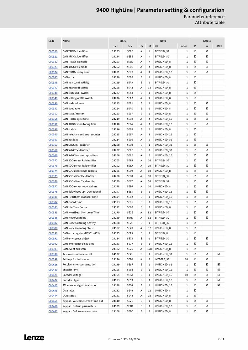
L Firmware 1.37 - 09/2006 651
9400 HighLine | Parameter setting & configurationParameter reference
Attribute table
C00320 CAN TPDOx identifier 24255 5EBF A 4 BITFIELD_32 1
C00321 CAN RPDOx identifier 24254 5EBE A 4 BITFIELD_32 1
C00322 CAN TPDOx Tx mode 24253 5EBD A 4 UNSIGNED_8 1
C00323 CAN RPDOx Rx mode 24252 5EBC A 4 UNSIGNED_8 1
C00324 CAN TPDOx delay time 24251 5EBB A 4 UNSIGNED_16 1
C00345 CAN error 24230 5EA6 E 1 UNSIGNED_8 1
C00346 CAN heartbeat activity 24229 5EA5 E 1 BITFIELD_32 1
C00347 CAN heartbeat status 24228 5EA4 A 32 UNSIGNED_8 1
C00348 CAN status DIP switch 24227 5EA3 E 1 UNSIGNED_8 1
C00349 CAN setting of DIP switch 24226 5EA2 A 2 UNSIGNED_8 1
C00350 CAN node address 24225 5EA1 E 1 UNSIGNED_8 1
C00351 CAN baud rate 24224 5EA0 E 1 UNSIGNED_8 1
C00352 CAN slave/master 24223 5E9F E 1 UNSIGNED_8 1
C00356 CAN TPDOx cycle time 24219 5E9B A 4 UNSIGNED_16 1
C00357 CAN RPDOx monitoring time 24218 5E9A A 4 UNSIGNED_16 1
C00359 CAN status 24216 5E98 E 1 UNSIGNED_8 1
C00360 CAN telegram and error counter 24215 5E97 A 8 UNSIGNED_16 1
C00361 CAN bus load 24214 5E96 A 6 UNSIGNED_32 1
C00367 CAN SYNC Rx identifier 24208 5E90 E 1 UNSIGNED_32 1
C00368 CAN SYNC Tx identifier 24207 5E8F E 1 UNSIGNED_32 1
C00369 CAN SYNC transmit cycle time 24206 5E8E A 3 UNSIGNED_16 1
C00372 CAN SDO server Rx identifier 24203 5E8B A 10 BITFIELD_32 1
C00373 CAN SDO server Tx identifier 24202 5E8A A 10 BITFIELD_32 1
C00374 CAN SDO client node address 24201 5E89 A 10 UNSIGNED_8 1
C00375 CAN SDO client Rx identifier 24200 5E88 A 10 BITFIELD_32 1
C00376 CAN SDO client Tx identifier 24199 5E87 A 10 BITFIELD_32 1
C00377 CAN SDO server node address 24198 5E86 A 10 UNSIGNED_8 1
C00378 CAN delay boot-up - Operational 24197 5E85 E 1 UNSIGNED_16 1
C00381 CAN Heartbeat Producer Time 24194 5E82 E 1 UNSIGNED_16 1
C00382 CAN Guard Time 24193 5E81 E 1 UNSIGNED_16 1
C00383 CAN Life Time Factor 24192 5E80 E 1 UNSIGNED_8 1
C00385 CAN Heartbeat Consumer Time 24190 5E7E A 32 BITFIELD_32 1
C00386 CAN Node Guarding 24189 5E7D A 32 BITFIELD_32 1
C00387 CAN Node Guarding Activity 24188 5E7C E 1 BITFIELD_32 1
C00388 CAN Node Guarding Status 24187 5E7B A 32 UNSIGNED_8 1
C00390 CAN error register (DS301V402) 24185 5E79 E 1 BITFIELD_8 1
C00391 CAN emergency object 24184 5E78 E 1 BITFIELD_32 1
C00392 CAN emergency delay time 24183 5E77 E 1 UNSIGNED_16 1
C00393 CAN event bus scan 24182 5E76 A 128 UNSIGNED_8 1
C00398 Test mode motor control 24177 5E71 E 1 UNSIGNED_32 1
C00399 Settings for test mode 24176 5E70 A 2 INTEGER_32 10
C00416 Resolver error compensation 24159 5E5F E 1 UNSIGNED_32 1
C00420 Encoder - PPR 24155 5E5B E 1 UNSIGNED_16 1
C00421 Encoder voltage 24154 5E5A E 1 UNSIGNED_16 10
C00422 Encoder - type 24153 5E59 E 1 UNSIGNED_16 1
C00427 TTL encoder signal evaluation 24148 5E54 E 1 UNSIGNED_16 1
C00443 DIx status 24132 5E44 A 12 UNSIGNED_8 1
C00444 DOx status 24131 5E43 A 18 UNSIGNED_8 1
C00465 Keypad: Welcome screen time-out 24110 5E2E E 1 UNSIGNED_8 1
C00466 Keypad: Default parameters 24109 5E2D E 1 UNSIGNED_16 1
C00467 Keypad: Def. welcome screen 24108 5E2C E 1 UNSIGNED_8 1
Code Name Index Data Access
dec hex DS DA DT Factor R W CINH
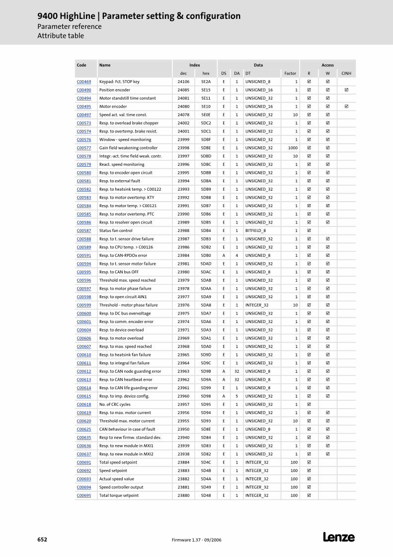
9400 HighLine | Parameter setting & configurationParameter referenceAttribute table
652 Firmware 1.37 - 09/2006 L
C00469 Keypad: Fct. STOP key 24106 5E2A E 1 UNSIGNED_8 1
C00490 Position encoder 24085 5E15 E 1 UNSIGNED_16 1
C00494 Motor standstill time constant 24081 5E11 E 1 UNSIGNED_32 1
C00495 Motor encoder 24080 5E10 E 1 UNSIGNED_16 1
C00497 Speed act. val. time const. 24078 5E0E E 1 UNSIGNED_32 10
C00573 Resp. to overload brake chopper 24002 5DC2 E 1 UNSIGNED_32 1
C00574 Resp. to overtemp. brake resist. 24001 5DC1 E 1 UNSIGNED_32 1
C00576 Window - speed monitoring 23999 5DBF E 1 UNSIGNED_32 1
C00577 Gain field weakening controller 23998 5DBE E 1 UNSIGNED_32 1000
C00578 Integr.-act. time field weak. contr. 23997 5DBD E 1 UNSIGNED_32 10
C00579 React. speed monitoring 23996 5DBC E 1 UNSIGNED_32 1
C00580 Resp. to encoder open circuit 23995 5DBB E 1 UNSIGNED_32 1
C00581 Resp. to external fault 23994 5DBA E 1 UNSIGNED_32 1
C00582 Resp. to heatsink temp. > C00122 23993 5DB9 E 1 UNSIGNED_32 1
C00583 Resp. to motor overtemp. KTY 23992 5DB8 E 1 UNSIGNED_32 1
C00584 Resp. to motor temp. > C00121 23991 5DB7 E 1 UNSIGNED_32 1
C00585 Resp. to motor overtemp. PTC 23990 5DB6 E 1 UNSIGNED_32 1
C00586 Resp. to resolver open circuit 23989 5DB5 E 1 UNSIGNED_32 1
C00587 Status fan control 23988 5DB4 E 1 BITFIELD_8 1
C00588 Resp. to t. sensor drive failure 23987 5DB3 E 1 UNSIGNED_32 1
C00589 Resp. to CPU temp. > C00126 23986 5DB2 E 1 UNSIGNED_32 1
C00591 Resp. to CAN-RPDOx error 23984 5DB0 A 4 UNSIGNED_8 1
C00594 Resp. to t. sensor motor failure 23981 5DAD E 1 UNSIGNED_32 1
C00595 Resp. to CAN bus OFF 23980 5DAC E 1 UNSIGNED_8 1
C00596 Threshold max. speed reached 23979 5DAB E 1 UNSIGNED_32 1
C00597 Resp. to motor phase failure 23978 5DAA E 1 UNSIGNED_32 1
C00598 Resp. to open circuit AIN1 23977 5DA9 E 1 UNSIGNED_32 1
C00599 Threshold - motor phase failure 23976 5DA8 E 1 INTEGER_32 10
C00600 Resp. to DC bus overvoltage 23975 5DA7 E 1 UNSIGNED_32 1
C00601 Resp. to comm. encoder error 23974 5DA6 E 1 UNSIGNED_32 1
C00604 Resp. to device overload 23971 5DA3 E 1 UNSIGNED_32 1
C00606 Resp. to motor overload 23969 5DA1 E 1 UNSIGNED_32 1
C00607 Resp. to max. speed reached 23968 5DA0 E 1 UNSIGNED_32 1
C00610 Resp. to heatsink fan failure 23965 5D9D E 1 UNSIGNED_32 1
C00611 Resp. to integral fan failure 23964 5D9C E 1 UNSIGNED_32 1
C00612 Resp. to CAN node guarding error 23963 5D9B A 32 UNSIGNED_8 1
C00613 Resp. to CAN heartbeat error 23962 5D9A A 32 UNSIGNED_8 1
C00614 Resp. to CAN life guarding error 23961 5D99 E 1 UNSIGNED_8 1
C00615 Resp. to imp. device config. 23960 5D98 A 5 UNSIGNED_32 1
C00618 No. of CRC cycles 23957 5D95 E 1 UNSIGNED_32 1
C00619 Resp. to max. motor current 23956 5D94 E 1 UNSIGNED_32 1
C00620 Threshold max. motor current 23955 5D93 E 1 UNSIGNED_32 10
C00625 CAN behaviour in case of fault 23950 5D8E E 1 UNSIGNED_8 1
C00635 Resp to new firmw. standard dev. 23940 5D84 E 1 UNSIGNED_32 1
C00636 Resp. to new module in MXI1 23939 5D83 E 1 UNSIGNED_32 1
C00637 Resp. to new module in MXI2 23938 5D82 E 1 UNSIGNED_32 1
C00691 Total speed setpoint 23884 5D4C E 1 INTEGER_32 100
C00692 Speed setpoint 23883 5D4B E 1 INTEGER_32 100
C00693 Actual speed value 23882 5D4A E 1 INTEGER_32 100
C00694 Speed controller output 23881 5D49 E 1 INTEGER_32 100
C00695 Total torque setpoint 23880 5D48 E 1 INTEGER_32 100
Code Name Index Data Access
dec hex DS DA DT Factor R W CINH
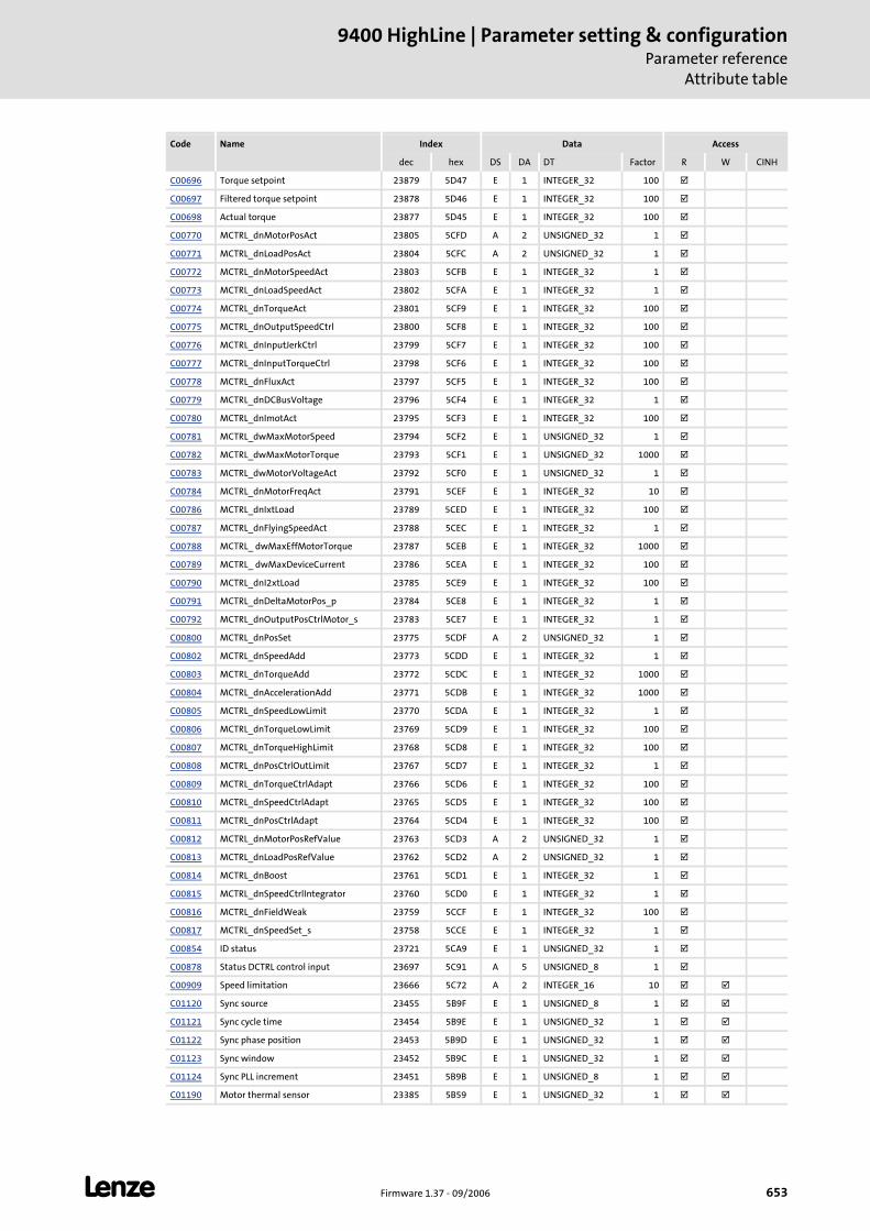
L Firmware 1.37 - 09/2006 653
9400 HighLine | Parameter setting & configurationParameter reference
Attribute table
C00696 Torque setpoint 23879 5D47 E 1 INTEGER_32 100
C00697 Filtered torque setpoint 23878 5D46 E 1 INTEGER_32 100
C00698 Actual torque 23877 5D45 E 1 INTEGER_32 100
C00770 MCTRL_dnMotorPosAct 23805 5CFD A 2 UNSIGNED_32 1
C00771 MCTRL_dnLoadPosAct 23804 5CFC A 2 UNSIGNED_32 1
C00772 MCTRL_dnMotorSpeedAct 23803 5CFB E 1 INTEGER_32 1
C00773 MCTRL_dnLoadSpeedAct 23802 5CFA E 1 INTEGER_32 1
C00774 MCTRL_dnTorqueAct 23801 5CF9 E 1 INTEGER_32 100
C00775 MCTRL_dnOutputSpeedCtrl 23800 5CF8 E 1 INTEGER_32 100
C00776 MCTRL_dnInputJerkCtrl 23799 5CF7 E 1 INTEGER_32 100
C00777 MCTRL_dnInputTorqueCtrl 23798 5CF6 E 1 INTEGER_32 100
C00778 MCTRL_dnFluxAct 23797 5CF5 E 1 INTEGER_32 100
C00779 MCTRL_dnDCBusVoltage 23796 5CF4 E 1 INTEGER_32 1
C00780 MCTRL_dnImotAct 23795 5CF3 E 1 INTEGER_32 100
C00781 MCTRL_dwMaxMotorSpeed 23794 5CF2 E 1 UNSIGNED_32 1
C00782 MCTRL_dwMaxMotorTorque 23793 5CF1 E 1 UNSIGNED_32 1000
C00783 MCTRL_dwMotorVoltageAct 23792 5CF0 E 1 UNSIGNED_32 1
C00784 MCTRL_dnMotorFreqAct 23791 5CEF E 1 INTEGER_32 10
C00786 MCTRL_dnIxtLoad 23789 5CED E 1 INTEGER_32 100
C00787 MCTRL_dnFlyingSpeedAct 23788 5CEC E 1 INTEGER_32 1
C00788 MCTRL_ dwMaxEffMotorTorque 23787 5CEB E 1 INTEGER_32 1000
C00789 MCTRL_ dwMaxDeviceCurrent 23786 5CEA E 1 INTEGER_32 100
C00790 MCTRL_dnI2xtLoad 23785 5CE9 E 1 INTEGER_32 100
C00791 MCTRL_dnDeltaMotorPos_p 23784 5CE8 E 1 INTEGER_32 1
C00792 MCTRL_dnOutputPosCtrlMotor_s 23783 5CE7 E 1 INTEGER_32 1
C00800 MCTRL_dnPosSet 23775 5CDF A 2 UNSIGNED_32 1
C00802 MCTRL_dnSpeedAdd 23773 5CDD E 1 INTEGER_32 1
C00803 MCTRL_dnTorqueAdd 23772 5CDC E 1 INTEGER_32 1000
C00804 MCTRL_dnAccelerationAdd 23771 5CDB E 1 INTEGER_32 1000
C00805 MCTRL_dnSpeedLowLimit 23770 5CDA E 1 INTEGER_32 1
C00806 MCTRL_dnTorqueLowLimit 23769 5CD9 E 1 INTEGER_32 100
C00807 MCTRL_dnTorqueHighLimit 23768 5CD8 E 1 INTEGER_32 100
C00808 MCTRL_dnPosCtrlOutLimit 23767 5CD7 E 1 INTEGER_32 1
C00809 MCTRL_dnTorqueCtrlAdapt 23766 5CD6 E 1 INTEGER_32 100
C00810 MCTRL_dnSpeedCtrlAdapt 23765 5CD5 E 1 INTEGER_32 100
C00811 MCTRL_dnPosCtrlAdapt 23764 5CD4 E 1 INTEGER_32 100
C00812 MCTRL_dnMotorPosRefValue 23763 5CD3 A 2 UNSIGNED_32 1
C00813 MCTRL_dnLoadPosRefValue 23762 5CD2 A 2 UNSIGNED_32 1
C00814 MCTRL_dnBoost 23761 5CD1 E 1 INTEGER_32 1
C00815 MCTRL_dnSpeedCtrlIntegrator 23760 5CD0 E 1 INTEGER_32 1
C00816 MCTRL_dnFieldWeak 23759 5CCF E 1 INTEGER_32 100
C00817 MCTRL_dnSpeedSet_s 23758 5CCE E 1 INTEGER_32 1
C00854 ID status 23721 5CA9 E 1 UNSIGNED_32 1
C00878 Status DCTRL control input 23697 5C91 A 5 UNSIGNED_8 1
C00909 Speed limitation 23666 5C72 A 2 INTEGER_16 10
C01120 Sync source 23455 5B9F E 1 UNSIGNED_8 1
C01121 Sync cycle time 23454 5B9E E 1 UNSIGNED_32 1
C01122 Sync phase position 23453 5B9D E 1 UNSIGNED_32 1
C01123 Sync window 23452 5B9C E 1 UNSIGNED_32 1
C01124 Sync PLL increment 23451 5B9B E 1 UNSIGNED_8 1
C01190 Motor thermal sensor 23385 5B59 E 1 UNSIGNED_32 1
Code Name Index Data Access
dec hex DS DA DT Factor R W CINH
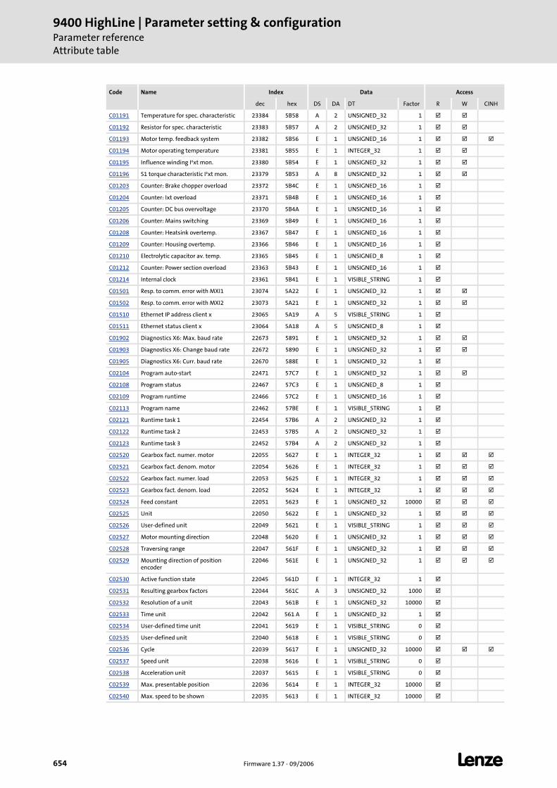
9400 HighLine | Parameter setting & configurationParameter referenceAttribute table
654 Firmware 1.37 - 09/2006 L
C01191 Temperature for spec. characteristic 23384 5B58 A 2 UNSIGNED_32 1
C01192 Resistor for spec. characteristic 23383 5B57 A 2 UNSIGNED_32 1
C01193 Motor temp. feedback system 23382 5B56 E 1 UNSIGNED_16 1
C01194 Motor operating temperature 23381 5B55 E 1 INTEGER_32 1
C01195 Influence winding I²xt mon. 23380 5B54 E 1 UNSIGNED_32 1
C01196 S1 torque characteristic I²xt mon. 23379 5B53 A 8 UNSIGNED_32 1
C01203 Counter: Brake chopper overload 23372 5B4C E 1 UNSIGNED_16 1
C01204 Counter: Ixt overload 23371 5B4B E 1 UNSIGNED_16 1
C01205 Counter: DC bus overvoltage 23370 5B4A E 1 UNSIGNED_16 1
C01206 Counter: Mains switching 23369 5B49 E 1 UNSIGNED_16 1
C01208 Counter: Heatsink overtemp. 23367 5B47 E 1 UNSIGNED_16 1
C01209 Counter: Housing overtemp. 23366 5B46 E 1 UNSIGNED_16 1
C01210 Electrolytic capacitor av. temp. 23365 5B45 E 1 UNSIGNED_8 1
C01212 Counter: Power section overload 23363 5B43 E 1 UNSIGNED_16 1
C01214 Internal clock 23361 5B41 E 1 VISIBLE_STRING 1
C01501 Resp. to comm. error with MXI1 23074 5A22 E 1 UNSIGNED_32 1
C01502 Resp. to comm. error with MXI2 23073 5A21 E 1 UNSIGNED_32 1
C01510 Ethernet IP address client x 23065 5A19 A 5 VISIBLE_STRING 1
C01511 Ethernet status client x 23064 5A18 A 5 UNSIGNED_8 1
C01902 Diagnostics X6: Max. baud rate 22673 5891 E 1 UNSIGNED_32 1
C01903 Diagnostics X6: Change baud rate 22672 5890 E 1 UNSIGNED_32 1
C01905 Diagnostics X6: Curr. baud rate 22670 588E E 1 UNSIGNED_32 1
C02104 Program auto-start 22471 57C7 E 1 UNSIGNED_32 1
C02108 Program status 22467 57C3 E 1 UNSIGNED_8 1
C02109 Program runtime 22466 57C2 E 1 UNSIGNED_16 1
C02113 Program name 22462 57BE E 1 VISIBLE_STRING 1
C02121 Runtime task 1 22454 57B6 A 2 UNSIGNED_32 1
C02122 Runtime task 2 22453 57B5 A 2 UNSIGNED_32 1
C02123 Runtime task 3 22452 57B4 A 2 UNSIGNED_32 1
C02520 Gearbox fact. numer. motor 22055 5627 E 1 INTEGER_32 1
C02521 Gearbox fact. denom. motor 22054 5626 E 1 INTEGER_32 1
C02522 Gearbox fact. numer. load 22053 5625 E 1 INTEGER_32 1
C02523 Gearbox fact. denom. load 22052 5624 E 1 INTEGER_32 1
C02524 Feed constant 22051 5623 E 1 UNSIGNED_32 10000
C02525 Unit 22050 5622 E 1 UNSIGNED_32 1
C02526 User-defined unit 22049 5621 E 1 VISIBLE_STRING 1
C02527 Motor mounting direction 22048 5620 E 1 UNSIGNED_32 1
C02528 Traversing range 22047 561F E 1 UNSIGNED_32 1
C02529 Mounting direction of position encoder
22046 561E E 1 UNSIGNED_32 1
C02530 Active function state 22045 561D E 1 INTEGER_32 1
C02531 Resulting gearbox factors 22044 561C A 3 UNSIGNED_32 1000
C02532 Resolution of a unit 22043 561B E 1 UNSIGNED_32 10000
C02533 Time unit 22042 561 A E 1 UNSIGNED_32 1
C02534 User-defined time unit 22041 5619 E 1 VISIBLE_STRING 0
C02535 User-defined unit 22040 5618 E 1 VISIBLE_STRING 0
C02536 Cycle 22039 5617 E 1 UNSIGNED_32 10000
C02537 Speed unit 22038 5616 E 1 VISIBLE_STRING 0
C02538 Acceleration unit 22037 5615 E 1 VISIBLE_STRING 0
C02539 Max. presentable position 22036 5614 E 1 INTEGER_32 10000
C02540 Max. speed to be shown 22035 5613 E 1 INTEGER_32 10000
Code Name Index Data Access
dec hex DS DA DT Factor R W CINH
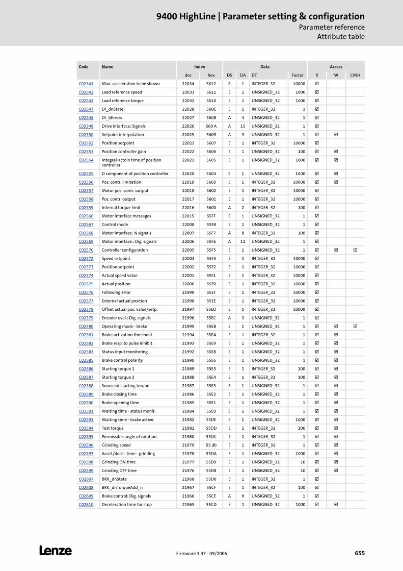
L Firmware 1.37 - 09/2006 655
9400 HighLine | Parameter setting & configurationParameter reference
Attribute table
C02541 Max. acceleration to be shown 22034 5612 E 1 INTEGER_32 10000
C02542 Load reference speed 22033 5611 E 1 UNSIGNED_32 1000
C02543 Load reference torque 22032 5610 E 1 UNSIGNED_32 1000
C02547 DI_dnState 22028 560C E 1 INTEGER_32 1
C02548 DI_bErrors 22027 560B A 4 UNSIGNED_32 1
C02549 Drive interface: Signals 22026 560 A A 15 UNSIGNED_32 1
C02550 Setpoint interpolation 22025 5609 A 3 UNSIGNED_32 1
C02552 Position setpoint 22023 5607 E 1 INTEGER_32 10000
C02553 Position controller gain 22022 5606 E 1 UNSIGNED_32 100
C02554 Integral-actoin time of position controller
22021 5605 E 1 UNSIGNED_32 1000
C02555 D component of position controller 22020 5604 E 1 UNSIGNED_32 1000
C02556 Pos. contr. limitation 22019 5603 E 1 INTEGER_32 10000
C02557 Motor pos. contr. output 22018 5602 E 1 INTEGER_32 10000
C02558 Pos. contr. output 22017 5601 E 1 INTEGER_32 10000
C02559 Internal torque limit 22016 5600 A 2 INTEGER_32 100
C02560 Motor interface messages 22015 55FF E 1 UNSIGNED_32 1
C02567 Control mode 22008 55F8 E 1 UNSIGNED_32 1
C02568 Motor interface: % signals 22007 55F7 A 8 INTEGER_32 100
C02569 Motor interface.: Dig. signals 22006 55F6 A 11 UNSIGNED_32 1
C02570 Controller configuration 22005 55F5 E 1 UNSIGNED_32 1
C02572 Speed setpoint 22003 55F3 E 1 INTEGER_32 10000
C02573 Position setpoint 22002 55F2 E 1 INTEGER_32 10000
C02574 Actual speed value 22001 55F1 E 1 INTEGER_32 10000
C02575 Actual position 22000 55F0 E 1 INTEGER_32 10000
C02576 Following error 21999 55EF E 1 INTEGER_32 10000
C02577 External actual position 21998 55EE E 1 INTEGER_32 10000
C02578 Offset actual pos. value/setp. 21997 55ED E 1 INTEGER_32 10000
C02579 Encoder eval.: Dig. signals 21996 55EC A 3 UNSIGNED_32 1
C02580 Operating mode - brake 21995 55EB E 1 UNSIGNED_32 1
C02581 Brake activation threshold 21994 55EA E 1 INTEGER_32 1
C02582 Brake resp. to pulse inhibit 21993 55E9 E 1 UNSIGNED_32 1
C02583 Status input monitoring 21992 55E8 E 1 UNSIGNED_32 1
C02585 Brake control polarity 21990 55E6 E 1 UNSIGNED_32 1
C02586 Starting torque 1 21989 55E5 E 1 INTEGER_32 100
C02587 Starting torque 2 21988 55E4 E 1 INTEGER_32 100
C02588 Source of starting torque 21987 55E3 E 1 UNSIGNED_32 1
C02589 Brake closing time 21986 55E2 E 1 UNSIGNED_32 1
C02590 Brake opening time 21985 55E1 E 1 UNSIGNED_32 1
C02591 Waiting time - status monit. 21984 55E0 E 1 UNSIGNED_32 1
C02593 Waiting time - brake active. 21982 55DE E 1 UNSIGNED_32 1000
C02594 Test torque 21981 55DD E 1 INTEGER_32 100
C02595 Permissible angle of rotation 21980 55DC E 1 INTEGER_32 1
C02596 Grinding speed 21979 55 db E 1 INTEGER_32 1
C02597 Accel./decel. time - grinding 21978 55DA E 1 UNSIGNED_32 1000
C02598 Grinding ON time 21977 55D9 E 1 UNSIGNED_32 10
C02599 Grinding OFF time 21976 55D8 E 1 UNSIGNED_32 10
C02607 BRK_dnState 21968 55D0 E 1 INTEGER_32 1
C02608 BRK_dnTorqueAdd_n 21967 55CF E 1 INTEGER_32 100
C02609 Brake control: Dig. signals 21966 55CE A 9 UNSIGNED_32 1
C02610 Deceleration time for stop 21965 55CD E 1 UNSIGNED_32 1000
Code Name Index Data Access
dec hex DS DA DT Factor R W CINH
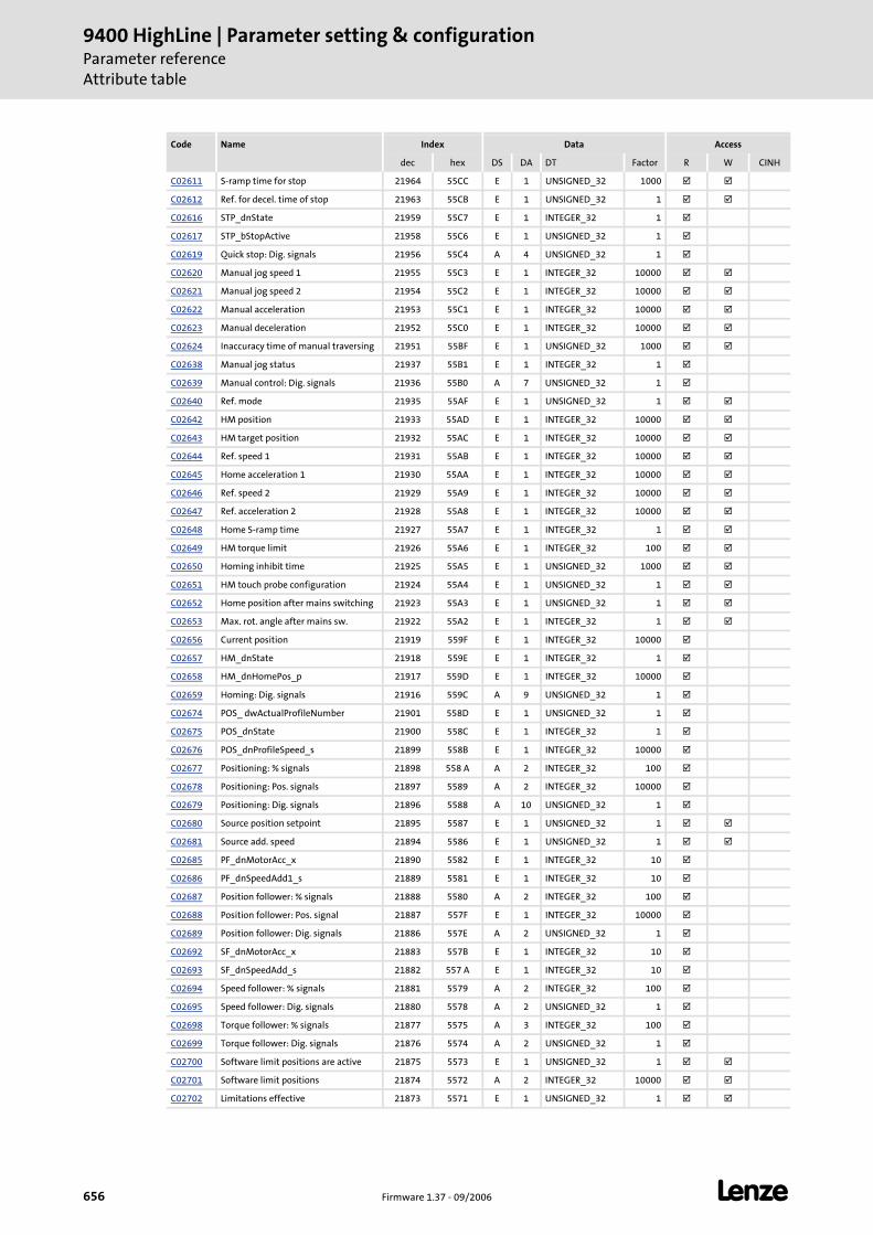
9400 HighLine | Parameter setting & configurationParameter referenceAttribute table
656 Firmware 1.37 - 09/2006 L
C02611 S-ramp time for stop 21964 55CC E 1 UNSIGNED_32 1000
C02612 Ref. for decel. time of stop 21963 55CB E 1 UNSIGNED_32 1
C02616 STP_dnState 21959 55C7 E 1 INTEGER_32 1
C02617 STP_bStopActive 21958 55C6 E 1 UNSIGNED_32 1
C02619 Quick stop: Dig. signals 21956 55C4 A 4 UNSIGNED_32 1
C02620 Manual jog speed 1 21955 55C3 E 1 INTEGER_32 10000
C02621 Manual jog speed 2 21954 55C2 E 1 INTEGER_32 10000
C02622 Manual acceleration 21953 55C1 E 1 INTEGER_32 10000
C02623 Manual deceleration 21952 55C0 E 1 INTEGER_32 10000
C02624 Inaccuracy time of manual traversing 21951 55BF E 1 UNSIGNED_32 1000
C02638 Manual jog status 21937 55B1 E 1 INTEGER_32 1
C02639 Manual control: Dig. signals 21936 55B0 A 7 UNSIGNED_32 1
C02640 Ref. mode 21935 55AF E 1 UNSIGNED_32 1
C02642 HM position 21933 55AD E 1 INTEGER_32 10000
C02643 HM target position 21932 55AC E 1 INTEGER_32 10000
C02644 Ref. speed 1 21931 55AB E 1 INTEGER_32 10000
C02645 Home acceleration 1 21930 55AA E 1 INTEGER_32 10000
C02646 Ref. speed 2 21929 55A9 E 1 INTEGER_32 10000
C02647 Ref. acceleration 2 21928 55A8 E 1 INTEGER_32 10000
C02648 Home S-ramp time 21927 55A7 E 1 INTEGER_32 1
C02649 HM torque limit 21926 55A6 E 1 INTEGER_32 100
C02650 Homing inhibit time 21925 55A5 E 1 UNSIGNED_32 1000
C02651 HM touch probe configuration 21924 55A4 E 1 UNSIGNED_32 1
C02652 Home position after mains switching 21923 55A3 E 1 UNSIGNED_32 1
C02653 Max. rot. angle after mains sw. 21922 55A2 E 1 INTEGER_32 1
C02656 Current position 21919 559F E 1 INTEGER_32 10000
C02657 HM_dnState 21918 559E E 1 INTEGER_32 1
C02658 HM_dnHomePos_p 21917 559D E 1 INTEGER_32 10000
C02659 Homing: Dig. signals 21916 559C A 9 UNSIGNED_32 1
C02674 POS_ dwActualProfileNumber 21901 558D E 1 UNSIGNED_32 1
C02675 POS_dnState 21900 558C E 1 INTEGER_32 1
C02676 POS_dnProfileSpeed_s 21899 558B E 1 INTEGER_32 10000
C02677 Positioning: % signals 21898 558 A A 2 INTEGER_32 100
C02678 Positioning: Pos. signals 21897 5589 A 2 INTEGER_32 10000
C02679 Positioning: Dig. signals 21896 5588 A 10 UNSIGNED_32 1
C02680 Source position setpoint 21895 5587 E 1 UNSIGNED_32 1
C02681 Source add. speed 21894 5586 E 1 UNSIGNED_32 1
C02685 PF_dnMotorAcc_x 21890 5582 E 1 INTEGER_32 10
C02686 PF_dnSpeedAdd1_s 21889 5581 E 1 INTEGER_32 10
C02687 Position follower: % signals 21888 5580 A 2 INTEGER_32 100
C02688 Position follower: Pos. signal 21887 557F E 1 INTEGER_32 10000
C02689 Position follower: Dig. signals 21886 557E A 2 UNSIGNED_32 1
C02692 SF_dnMotorAcc_x 21883 557B E 1 INTEGER_32 10
C02693 SF_dnSpeedAdd_s 21882 557 A E 1 INTEGER_32 10
C02694 Speed follower: % signals 21881 5579 A 2 INTEGER_32 100
C02695 Speed follower: Dig. signals 21880 5578 A 2 UNSIGNED_32 1
C02698 Torque follower: % signals 21877 5575 A 3 INTEGER_32 100
C02699 Torque follower: Dig. signals 21876 5574 A 2 UNSIGNED_32 1
C02700 Software limit positions are active 21875 5573 E 1 UNSIGNED_32 1
C02701 Software limit positions 21874 5572 A 2 INTEGER_32 10000
C02702 Limitations effective 21873 5571 E 1 UNSIGNED_32 1
Code Name Index Data Access
dec hex DS DA DT Factor R W CINH
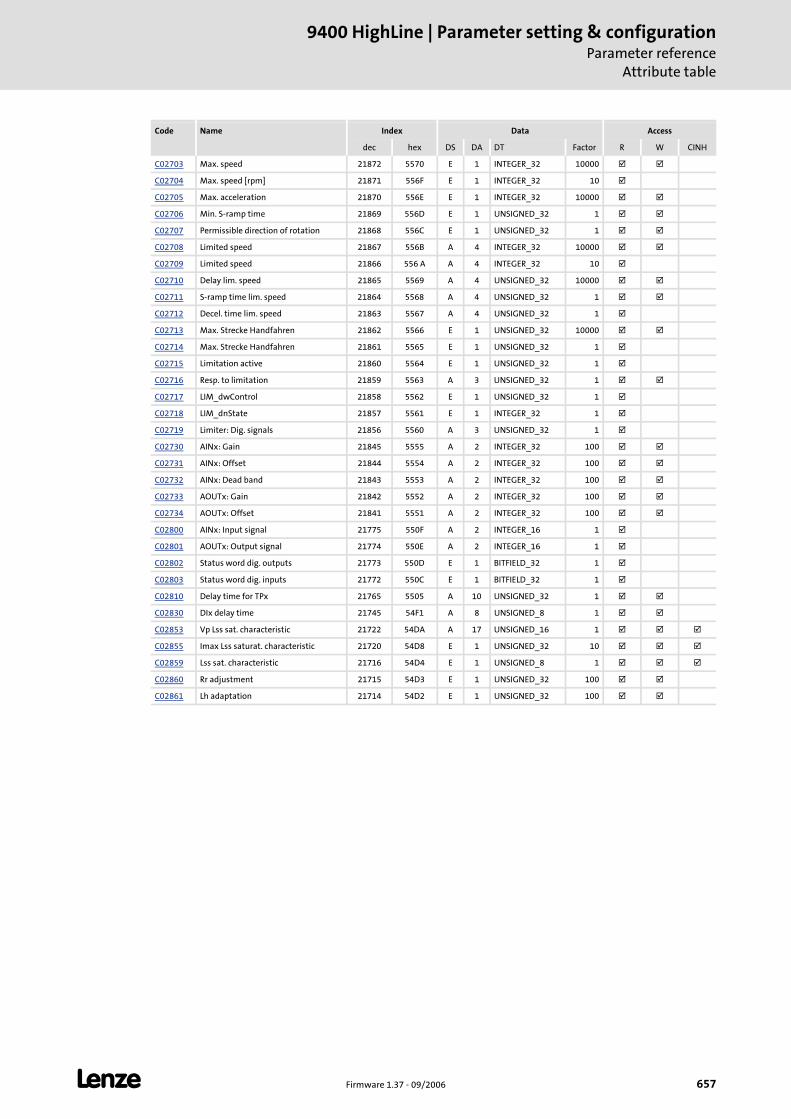
L Firmware 1.37 - 09/2006 657
9400 HighLine | Parameter setting & configurationParameter reference
Attribute table
C02703 Max. speed 21872 5570 E 1 INTEGER_32 10000
C02704 Max. speed [rpm] 21871 556F E 1 INTEGER_32 10
C02705 Max. acceleration 21870 556E E 1 INTEGER_32 10000
C02706 Min. S-ramp time 21869 556D E 1 UNSIGNED_32 1
C02707 Permissible direction of rotation 21868 556C E 1 UNSIGNED_32 1
C02708 Limited speed 21867 556B A 4 INTEGER_32 10000
C02709 Limited speed 21866 556 A A 4 INTEGER_32 10
C02710 Delay lim. speed 21865 5569 A 4 UNSIGNED_32 10000
C02711 S-ramp time lim. speed 21864 5568 A 4 UNSIGNED_32 1
C02712 Decel. time lim. speed 21863 5567 A 4 UNSIGNED_32 1
C02713 Max. Strecke Handfahren 21862 5566 E 1 UNSIGNED_32 10000
C02714 Max. Strecke Handfahren 21861 5565 E 1 UNSIGNED_32 1
C02715 Limitation active 21860 5564 E 1 UNSIGNED_32 1
C02716 Resp. to limitation 21859 5563 A 3 UNSIGNED_32 1
C02717 LIM_dwControl 21858 5562 E 1 UNSIGNED_32 1
C02718 LIM_dnState 21857 5561 E 1 INTEGER_32 1
C02719 Limiter: Dig. signals 21856 5560 A 3 UNSIGNED_32 1
C02730 AINx: Gain 21845 5555 A 2 INTEGER_32 100
C02731 AINx: Offset 21844 5554 A 2 INTEGER_32 100
C02732 AINx: Dead band 21843 5553 A 2 INTEGER_32 100
C02733 AOUTx: Gain 21842 5552 A 2 INTEGER_32 100
C02734 AOUTx: Offset 21841 5551 A 2 INTEGER_32 100
C02800 AINx: Input signal 21775 550F A 2 INTEGER_16 1
C02801 AOUTx: Output signal 21774 550E A 2 INTEGER_16 1
C02802 Status word dig. outputs 21773 550D E 1 BITFIELD_32 1
C02803 Status word dig. inputs 21772 550C E 1 BITFIELD_32 1
C02810 Delay time for TPx 21765 5505 A 10 UNSIGNED_32 1
C02830 DIx delay time 21745 54F1 A 8 UNSIGNED_8 1
C02853 Vp Lss sat. characteristic 21722 54DA A 17 UNSIGNED_16 1
C02855 Imax Lss saturat. characteristic 21720 54D8 E 1 UNSIGNED_32 10
C02859 Lss sat. characteristic 21716 54D4 E 1 UNSIGNED_8 1
C02860 Rr adjustment 21715 54D3 E 1 UNSIGNED_32 100
C02861 Lh adaptation 21714 54D2 E 1 UNSIGNED_32 100
Code Name Index Data Access
dec hex DS DA DT Factor R W CINH
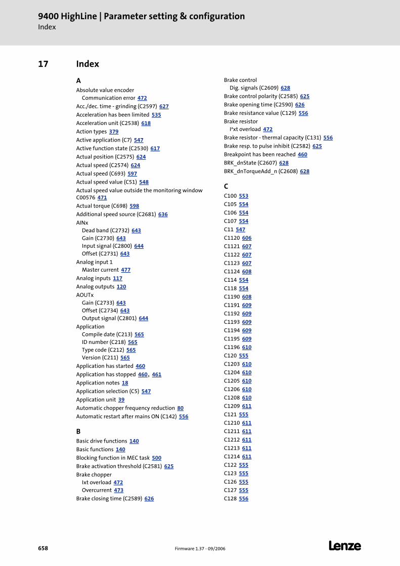
9400 HighLine | Parameter setting & configurationIndex
658 Firmware 1.37 - 09/2006 L
17 Index
AAbsolute value encoder
Communication error 472
Acc./dec. time - grinding (C2597) 627
Acceleration has been limited 535
Acceleration unit (C2538) 618
Action types 379
Active application (C7) 547
Active function state (C2530) 617
Actual position (C2575) 624
Actual speed (C2574) 624
Actual speed (C693) 597
Actual speed value (C51) 548
Actual speed value outside the monitoring window C00576 471
Actual torque (C698) 598
Additional speed source (C2681) 636
AINxDead band (C2732) 643Gain (C2730) 643Input signal (C2800) 644Offset (C2731) 643
Analog input 1Master current 477
Analog inputs 117
Analog outputs 120
AOUTxGain (C2733) 643Offset (C2734) 643Output signal (C2801) 644
ApplicationCompile date (C213) 565ID number (C218) 565Type code (C212) 565Version (C211) 565
Application has started 460
Application has stopped 460, 461
Application notes 18
Application selection (C5) 547
Application unit 39
Automatic chopper frequency reduction 80
Automatic restart after mains ON (C142) 556
BBasic drive functions 140
Basic functions 140
Blocking function in MEC task 500
Brake activation threshold (C2581) 625
Brake chopperIxt overload 472Overcurrent 473
Brake closing time (C2589) 626
Brake controlDig. signals (C2609) 628
Brake control polarity (C2585) 625
Brake opening time (C2590) 626
Brake resistance value (C129) 556
Brake resistorI²xt overload 472
Brake resistor - thermal capacity (C131) 556
Brake resp. to pulse inhibit (C2582) 625
Breakpoint has been reached 460
BRK_dnState (C2607) 628
BRK_dnTorqueAdd_n (C2608) 628
CC100 553
C105 554
C106 554
C107 554
C11 547
C1120 606
C1121 607
C1122 607
C1123 607
C1124 608
C114 554
C118 554
C1190 608
C1191 609
C1192 609
C1193 609
C1194 609
C1195 609
C1196 610
C120 555
C1203 610
C1204 610
C1205 610
C1206 610
C1208 610
C1209 611
C121 555
C1210 611
C1211 611
C1212 611
C1213 611
C1214 611
C122 555
C123 555
C126 555
C127 555
C128 556
L Firmware 1.37 - 09/2006 659
9400 HighLine | Parameter setting & configurationIndex
C129 556
C130 556
C131 556
C132 556
C142 556
C150 557
C1501 611
C1502 612
C1510 612
C1511 612
C155 557
C156 558
C158 558
C159 559
C166 559
C167 559
C168 559
C169 559
C171 559
C173 560
C174 560
C175 560
C176 560
C177 561
C178 561
C179 561
C18 547
C180 561
C181 561
C183 561
C185 562
C186 562
C187 562
C188 562
C19 547
C1902 613
C1903 613
C1905 613
C199 562
C2 544
C200 562
C201 562
C203 563
C204 563
C205 563
C206 564
C208 564
C209 564
C210 564
C2104 613
C2108 613
C2109 614
C211 565
C2113 614
C212 565
C2121 614
C2122 614
C2123 614
C213 565
C214 565
C217 565
C218 565
C22 548
C225 565
C2520 614
C2521 615
C2522 615
C2523 615
C2524 615
C2525 615
C2526 615
C2527 616
C2528 616
C2529 616
C2530 617
C2531 617
C2532 617
C2533 618
C2534 618
C2535 618
C2536 618
C2537 618
C2538 618
C2539 618
C254 565
C2540 618
C2541 619
C2542 619
C2543 619
C2547 619
C2548 619
C2549 620
C2550 620
C2552 620
C2553 621
C2554 621
C2555 621
C2556 621
C2557 621
C2558 621
C2559 622
C2560 622
C2567 622
C2568 622
C2569 623
C2570 623
9400 HighLine | Parameter setting & configurationIndex
660 Firmware 1.37 - 09/2006 L
C2572 623
C2573 623
C2574 624
C2575 624
C2576 624
C2577 624
C2578 624
C2579 624
C2580 625
C2581 625
C2582 625
C2583 625
C2585 625
C2586 626
C2587 626
C2588 626
C2589 626
C2590 626
C2591 626
C2593 627
C2594 627
C2595 627
C2596 627
C2597 627
C2598 627
C2599 628
C2607 628
C2608 628
C2609 628
C2610 628
C2611 629
C2612 629
C2616 629
C2617 629
C2619 629
C2620 630
C2621 630
C2622 630
C2623 630
C2624 630
C2638 630
C2639 631
C2640 631
C2642 631
C2643 632
C2644 632
C2645 632
C2646 632
C2647 632
C2648 632
C2649 633
C2650 633
C2651 633
C2652 633
C2653 633
C2656 633
C2657 634
C2658 634
C2659 634
C2674 634
C2675 634
C2676 635
C2677 635
C2678 635
C2679 635
C2680 636
C2681 636
C2685 636
C2686 636
C2687 636
C2688 636
C2689 637
C2692 637
C2693 637
C2694 637
C2695 637
C2698 638
C2699 638
C270 566
C2700 638
C2701 638
C2702 638
C2703 639
C2704 639
C2705 639
C2706 639
C2707 639
C2708 640
C2709 640
C271 566
C2710 640
C2711 640
C2712 641
C2713 641
C2714 641
C2715 641
C2716 642
C2717 642
C2718 642
C2719 642
C272 566
C273 566
C2730 643
C2731 643
C2732 643
C2733 643
L Firmware 1.37 - 09/2006 661
9400 HighLine | Parameter setting & configurationIndex
C2734 643
C274 566
C275 567
C276 567
C280 567
C2800 644
C2801 644
C2802 644
C2803 644
C2810 645
C2830 645
C2850 645
C2851 645
C2852 646
C2853 646
C2854 646
C2855 646
C2856 646
C2857 647
C2858 647
C2859 647
C2860 647
C2861 647
C2996 647
C2997 647
C2998 647
C2999 647
C3 546
C308 567
C309 567
C310 567
C311 567
C312 568
C313 568
C314 568
C320 569
C321 569
C322 570
C323 570
C324 570
C325 570
C326 570
C327 571
C328 571
C329 571
C330 571
C335 571
C336 571
C337 571
C338 571
C34 548
C345 571
C346 572
C347 572
C348 572
C349 572
C350 573
C351 573
C352 573
C356 574
C357 574
C359 574
C360 575
C361 575
C367 575
C368 576
C369 576
C372 576
C373 577
C374 577
C375 578
C376 578
C377 578
C378 579
C379 579
C381 579
C382 579
C383 579
C385 580
C386 580
C387 580
C388 581
C390 581
C391 581
C392 581
C393 582
C395 582
C396 582
C397 582
C398 582
C399 582
C4 546
C416 583
C420 583
C421 583
C422 583
C427 583
C443 584
C444 584
C465 585
C466 585
C467 585
C468 585
C469 585
C490 585
C494 586
9400 HighLine | Parameter setting & configurationIndex
662 Firmware 1.37 - 09/2006 L
C495 586
C497 586
C5 547
C50 548
C51 548
C512 586
C513 586
C514 586
C515 586
C516 586
C52 548
C53 548
C54 548
C55 549
C56 549
C57 549
C573 587
C574 587
C576 587
C577 587
C578 587
C579 588
C58 549
C580 588
C581 588
C582 589
C583 589
C584 589
C585 589
C586 590
C587 590
C588 590
C589 590
C59 549
C591 591
C594 591
C595 591
C596 591
C597 592
C598 592
C599 592
C6 547
C60 549
C600 592
C601 593
C604 593
C606 593
C607 593
C61 550
C610 594
C611 594
C612 594
C613 595
C614 595
C615 595
C618 596
C619 596
C62 550
C620 596
C625 596
C63 550
C635 596
C636 597
C637 597
C64 550
C65 550
C66 550
C68 550
C69 551
C691 597
C692 597
C693 597
C694 597
C695 598
C696 598
C697 598
C698 598
C7 547
C70 551
C71 551
C72 551
C730 598
C731 598
C732 598
C733 598
C734 598
C735 598
C736 599
C737 599
C738 599
C739 599
C74 551
C75 551
C76 551
C77 551
C770 599
C771 599
C772 599
C773 600
C774 600
C775 600
C776 600
C777 600
C778 600
C779 601
C78 552
L Firmware 1.37 - 09/2006 663
9400 HighLine | Parameter setting & configurationIndex
C780 601
C781 601
C782 601
C783 601
C784 601
C786 602
C787 602
C788 602
C789 602
C79 552
C790 602
C791 602
C792 603
C80 552
C800 603
C802 603
C803 603
C804 603
C805 603
C806 604
C807 604
C808 604
C809 604
C81 552
C810 604
C811 604
C812 605
C813 605
C814 605
C815 605
C816 605
C817 605
C82 552
C83 552
C84 552
C85 552
C854 606
C87 553
C878 606
C88 553
C89 553
C90 553
C909 606
C91 553
C92 553
C99 553
CAN - DIP switch setting (C349) 572
CAN baud rate (C351) 573
CAN behaviour in the case of fault (C625) 596
CAN bus load (C361) 575
CAN delay boot-up - operational (C378) 579
CAN emergency delay time (C392) 581
CAN emergency object (C391) 581
CAN error (C345) 571
CAN error register (DS301V402) (C390) 581
CAN guard time (C382) 579
CAN Heartbeat activity (C346) 572
CAN heartbeat consumer time (C385) 580
CAN heartbeat producer time (C381) 579
CAN Heartbeat status (C347) 572
CAN life time factor (C383) 579
CAN module (MXI1)Bus off 501Faulty emergency configuration 508Faulty NMT master configuration 514Faulty NMT slave configuration 508Heartbeat error index 1 502Heartbeat error index 10 504Heartbeat error index 11 504Heartbeat error index 12 504Heartbeat error index 13 504Heartbeat error index 14 504Heartbeat error index 15 504Heartbeat error index 16 505Heartbeat error index 17 505Heartbeat error index 18 505Heartbeat error index 19 505Heartbeat error index 2 502Heartbeat error index 20 505Heartbeat error index 21 505Heartbeat error index 22 506Heartbeat error index 23 506Heartbeat error index 24 506Heartbeat error index 25 506Heartbeat error index 26 506Heartbeat error index 27 506Heartbeat error index 28 507Heartbeat error index 29 507Heartbeat error index 3 502Heartbeat error index 30 507Heartbeat error index 31 507Heartbeat error index 32 507Heartbeat error index 4 503Heartbeat error index 5 503Heartbeat error index 6 503Heartbeat error index 7 503Heartbeat error index 8 503Heartbeat error index 9 503Invalid basic configuration 502Invalid node address 0 502Life guarding error 507Node guarding error 1 508Node guarding error 10 510Node guarding error 11 510Node guarding error 12 510Node guarding error 13 510Node guarding error 14 510Node guarding error 15 511Node guarding error 16 511Node guarding error 17 511
9400 HighLine | Parameter setting & configurationIndex
664 Firmware 1.37 - 09/2006 L
Node guarding error 18 511Node guarding error 19 511Node guarding error 2 508Node guarding error 20 511Node guarding error 21 512Node guarding error 22 512Node guarding error 23 512Node guarding error 24 512Node guarding error 25 512Node guarding error 26 512Node guarding error 27 513Node guarding error 28 513Node guarding error 29 513Node guarding error 3 509Node guarding error 30 513Node guarding error 31 513Node guarding error 32 513Node guarding error 4 509Node guarding error 5 509Node guarding error 6 509Node guarding error 7 509Node guarding error 8 509Node guarding error 9 510
CAN module (MXI1) PDO managerFaulty configuration 516
CAN module (MXI1) RPDO1Telegram not received or faulty 514
CAN module (MXI1) RPDO2Telegram not received or faulty 514
CAN module (MXI1) RPDO3Telegram not received or faulty 514
CAN module (MXI1) RPDO4Telegram not received or faulty 515
CAN module (MXI1) RPDO5Telegram not received or faulty 515
CAN module (MXI1) RPDO6Telegram not received or faulty 515
CAN module (MXI1) RPDO7Telegram not received or faulty 515
CAN module (MXI1) RPDO8Telegram not received or faulty 515
CAN module (MXI1) SDO clientFaulty configuration 516
CAN module (MXI1) SDO serverFaulty configuration 516
CAN module (MXI2)Bus off 517Faulty emergency configuration 524Faulty NMT master configuration 530Faulty NMT slave configuration 524Heartbeat error index 1 518Heartbeat error index 10 520Heartbeat error index 11 520Heartbeat error index 12 520Heartbeat error index 13 520Heartbeat error index 14 520Heartbeat error index 15 520
Heartbeat error index 16 521Heartbeat error index 17 521Heartbeat error index 18 521Heartbeat error index 19 521Heartbeat error index 2 518Heartbeat error index 20 521Heartbeat error index 21 521Heartbeat error index 22 522Heartbeat error index 23 522Heartbeat error index 24 522Heartbeat error index 25 522Heartbeat error index 26 522Heartbeat error index 27 522Heartbeat error index 28 523Heartbeat error index 29 523Heartbeat error index 3 518Heartbeat error index 30 523Heartbeat error index 31 523Heartbeat error index 32 523Heartbeat error index 4 519Heartbeat error index 5 519Heartbeat error index 6 519Heartbeat error index 7 519Heartbeat error index 8 519Heartbeat error index 9 519Invalid basic configuration 518Invalid node address 0 518Life guarding error 523Node guarding error 1 524Node guarding error 10 526Node guarding error 11 526Node guarding error 12 526Node guarding error 13 526Node guarding error 14 526Node guarding error 15 527Node guarding error 16 527Node guarding error 17 527Node guarding error 18 527Node guarding error 19 527Node guarding error 2 524Node guarding error 20 527Node guarding error 21 528Node guarding error 22 528Node guarding error 23 528Node guarding error 24 528Node guarding error 25 528Node guarding error 26 528Node guarding error 27 529Node guarding error 28 529Node guarding error 29 529Node guarding error 3 525Node guarding error 30 529Node guarding error 31 529Node guarding error 32 529Node guarding error 4 525Node guarding error 5 525Node guarding error 6 525Node guarding error 7 525
L Firmware 1.37 - 09/2006 665
9400 HighLine | Parameter setting & configurationIndex
Node guarding error 8 525Node guarding error 9 526
CAN module (MXI2) PDO managerFaulty configuration 532
CAN module (MXI2) RPDO1Telegram not received or faulty 530
CAN module (MXI2) RPDO2Telegram not received or faulty 530
CAN module (MXI2) RPDO3Telegram not received or faulty 530
CAN module (MXI2) RPDO4Telegram not received or faulty 531
CAN module (MXI2) RPDO5Telegram not received or faulty 531
CAN module (MXI2) RPDO6Telegram not received or faulty 531
CAN module (MXI2) RPDO7Telegram not received or faulty 531
CAN module (MXI2) RPDO8Telegram not received or faulty 531
CAN module (MXI2) SDO clientFaulty configuration 532
CAN module (MXI2) SDO serverFaulty configuration 532
CAN node address (C350) 573
CAN node guarding (C386) 580
CAN node guarding activity (C387) 580
CAN node guarding status (C388) 581
CAN on boardBus off 477Faulty emergency configuration 484Faulty NMT master configuration 489Faulty NMT slave configuration 484Heartbeat error index 1 478Heartbeat error index 10 480Heartbeat error index 11 480Heartbeat error index 12 480Heartbeat error index 13 480Heartbeat error index 14 480Heartbeat error index 15 480Heartbeat error index 16 481Heartbeat error index 17 481Heartbeat error index 18 481Heartbeat error index 19 481Heartbeat error index 2 478Heartbeat error index 20 481Heartbeat error index 21 481Heartbeat error index 22 482Heartbeat error index 23 482Heartbeat error index 24 482Heartbeat error index 25 482Heartbeat error index 26 482Heartbeat error index 27 482Heartbeat error index 28 483Heartbeat error index 29 483Heartbeat error index 3 478Heartbeat error index 30 483
Heartbeat error index 31 483Heartbeat error index 32 483Heartbeat error index 4 479Heartbeat error index 5 479Heartbeat error index 6 479Heartbeat error index 7 479Heartbeat error index 8 479Heartbeat error index 9 479Invalid basic configuration 478Invalid node address 0 478Life guarding error 483Node guarding error 1 484Node guarding error 10 486Node guarding error 11 486Node guarding error 12 486Node guarding error 13 486Node guarding error 14 486Node guarding error 15 486Node guarding error 16 487Node guarding error 17 487Node guarding error 18 487Node guarding error 19 487Node guarding error 2 484Node guarding error 20 487Node guarding error 21 487Node guarding error 22 488Node guarding error 23 488Node guarding error 24 488Node guarding error 25 488Node guarding error 26 488Node guarding error 27 488Node guarding error 28 489Node guarding error 29 489Node guarding error 3 484Node guarding error 30 489Node guarding error 31 489Node guarding error 32 489Node guarding error 4 485Node guarding error 5 485Node guarding error 6 485Node guarding error 7 485Node guarding error 8 485Node guarding error 9 485
CAN on board PDO managerFaulty configuration 490
CAN on board RPDO1Telegram not received or faulty 490
CAN on board RPDO2Telegram not received or faulty 490
CAN on board RPDO3Telegram not received or faulty 490
CAN on board RPDO4Telegram not received or faulty 490
CAN on board SDO clientFaulty configuration 491
CAN on board SDO serverFaulty configuration 491
9400 HighLine | Parameter setting & configurationIndex
666 Firmware 1.37 - 09/2006 L
CAN on-board 134
CAN result - bus scan (C393) 582
CAN RPDOx identifier (C321) 569
CAN RPDOx monitoring time (C357) 574
CAN RPDOx Rx mode (C323) 570
CAN SDO client node address (C374) 577
CAN SDO client Rx identifier (C375) 578
CAN SDO client Tx identifier (C376) 578
CAN SDO server node address (C377) 578
CAN SDO server Rx identifier (C372) 576
CAN SDO server Tx identifier (C373) 577
CAN slave/master (C352) 573
CAN status (C359) 574
CAN status DIP switch (C348) 572
CAN sync transmission cycle time (C369) 576
CAN sync-Rx identifier (C367) 575
CAN sync-Tx identifier (C368) 576
CAN telegram and error counter (C360) 575
CAN TPDO1 mask byte x (C311) 567
CAN TPDO2 mask byte x (C312) 568
CAN TPDO3 mask byte x (C313) 568
CAN TPDO4 mask byte x (C314) 568
CAN TPDOx cycle time (C356) 574
CAN TPDOx delay time (C324) 570
CAN TPDOx identifier (C320) 569
CAN TPDOx Tx mode (C322) 570
Capacitor temperature (C68) 550
Check configuration (C225) 565
Code number has been assigned twice 497
Combination Memory module/device not possible 455
Combination MXI1/MXI2 not possible 454
Combination of module in MXI1/device not possible 455
Combination of module in MXI2/device not possible 455
Communication error between device and device module 477
Communication taskStandstill > 3 s 499
Config. analog input 1 (C34) 548
Connection table in use 495
Control cardSupply voltage (24 V DC) too low 461
Control card is defective 449, 451
Control card is defective (UB18 neg.) 468
Control card is defective (UB24) 467
Control card is defective (UB8) 467
Control card is defective (VCC15 neg.) 467
Control card is defective (VCC15) 467
Control card is defective (VCC5) 468
Control card is not compatible 452
Control mode (C2567) 622
ControllerPulse inhibit is active 462
Controller command status (C3) 546
Controller commands (C2) 544
Controller configuration (C2570) 623
Controller in STO state 462
Controller inhibit by (source) (C158) 558
Controller initialised 462
Controller is enabled 462
Controller load (Ixt) (C64) 550
Conventions used 16
Copyright 2
Copyright information 2
Correction of the leakage inductance 82
CounterBrake chopper overload (C1203) 610DC bus overvoltage (C1205) 610Heatsink overtemp. (C1208) 610Housing overtemp. (C1209) 611Ixt overload (C1204) 610Mains switching (C1206) 610Power section overload (C1212) 611
CPUOvertemperature 465Temperature > C00126 464Temperature sensor defective 466
CPU temperature (C69) 551
Current controller feedforward control (C74) 551
Current controller gain (C75) 551
Current controller reset time (C76) 551
Current position (C2656) 633
Cycle (C2536) 618
Cyclic taskStandstill > 60 s 499
DData type 537
DC bus overvoltage 470
DC bus undervoltage 470
DC bus voltage (C53) 548
DC-bus capacitorOvertemperature 464Temperature > CXXXXX 464Temperature sensor defective 465
Decel. time - stop function (C2610) 628
Decel. time lim. speed (C2712) 641
Deceleration has been limited 535
Delay lim. speed (C2710) 640
Delay time for TPx (C2810) 645
Depth - current setpoint filter (C272) 566
Device name (C199) 562
Device state (C183) 561
Device util. warning threshold (C123) 555
Device utilisation Ixt > 100 % 466
Device utilisation Ixt > C00123 466
DeviceCFG.dat file is faulty 491
DeviceCFG.dat file is invalid 492
DeviceCFG.dat file is missing 492
DFIN (MXI1)
L Firmware 1.37 - 09/2006 667
9400 HighLine | Parameter setting & configurationIndex
A-/A track error 500B-/B track error 500Enable/lamp control signal error 501Supply cannot be corrected anymore 501Z-/Z track error 501
DFIN (MXI2)A-/A track error 516B-/B track error 516Enable/lamp control signal error 517Supply cannot be corrected anymore 517Z-/Z track error 517
DFOUT (MXI1)Maximum frequency reached 501
DFOUT (MXI2)Maximum frequency reached 517
DI_bErrors (C2548) 619
DI_dnState (C2547) 619
Diagnostics X6Change baud rate (C1903) 613curr. baud rate (C1905) 613max. baud rate (C1902) 613
Digital inputs 123
Digital outputs 125
Division by zero 460
DIx delay time (C2830) 645
DIx status (C443) 584
DIx terminal polarity (C114) 554
DOx status (C444) 584
DOx terminal polarity (C118) 554
Drive interface 34Signals (C2549) 620
DRIVE-ERROR LED 34
DRIVE-READY LED 34
EEarth fault detected 471
Elapsed-time meter (C178) 561
Electrolytic capacitor av. temp. (C1210) 611
Electronic nameplateChecksum error 454Communication error 454Data incompatible 468Data loaded 475Data out of parameter limits 476Not found 475Unknown encoder protocol 475Unknown encoder signal 476
E-mail to Lenze 679
EncoderOpen circuit 472
Encoder - PPR (C420) 583
Encoder - type (C422) 583
Encoder - voltage (C421) 583
Encoder evaluation 108Dig. signals (C2579) 624
EnDat encoderFlat battery 474Lamp error 474Overcurrent 474Overvoltage 474Position error 474Signal error 474Undervoltage 474
ENPdetected motor type (C186) 562detected serial number (C187) 562Status (C188) 562
Error during initialisation 500
Error during the update of inputs and outputs 458
Error messages 443
Error number 4430x00650000 4490x00650001 4490x00650002 4490x00650003 4490x00680000 4490x00680001 4490x00680002 4500x00680003 4500x00680004 4500x00680005 4500x00680006 4500x00680007 4510x00680008 4510x00680009 4510x0068000a 4510x0068000b 4510x0068000c 4510x0068000d 4520x0068000e 4520x0068000f 4520x00680010 4520x00680011 4520x00680012 4520x00680013 4530x00680014 4530x00680015 4530x00680016 4530x00680017 4530x00680018 4530x00680019 4540x0068001a 4540x0068001b 4540x0068001c 4540x0068001d 4540x0068001e 4540x0068001f 4550x00680020 4550x00680021 4550x00690000 4550x00690001 4550x00690002 455
9400 HighLine | Parameter setting & configurationIndex
668 Firmware 1.37 - 09/2006 L
0x00690003 4560x00690004 4560x00690005 4560x00690006 4560x00690007 4560x00690008 4560x00690009 4570x0069000a 4570x0069000b 4570x0069000c 4570x0069000d 4570x006a0000 4570x006a0001 4580x006a0002 4580x006a0003 4580x006a0004 4580x006a0005 4580x006a0006 4580x006a0007 4590x006a0008 4590x006a0009 4590x006a000a 4590x006a000b 4590x006a000c 4590x006a000d 4590x006a000e 4600x006a000f 4600x006a0010 4600x006a0011 4600x006a0012 4600x006a0013 4600x006a0014 4610x006a0015 4610x006a0016 4610x006f0000 4610x00720000 4620x00750000 4620x00750001 4620x00750002 4620x00750003 4620x00750005 4620x00750006 4630x00770000 4630x00770001 4630x00770002 4630x00770003 4630x00770004 4640x00770005 4640x00770006 4640x00770007 4640x00770008 4640x00770009 4650x0077000a 4650x0077000b 4650x0077000c 4650x0077000d 4650x0077000e 4660x0077000f 466
0x00770010 4660x00770011 4660x00780000 4660x00780001 4660x00780002 4670x00780003 4670x00780004 4670x00780005 4670x00780006 4670x00780007 4670x00780008 4680x00780009 4680x0078000a 4680x00790000 4680x00790001 4680x00790002 4680x007b0001 4680x007b0002 4690x007b0003 4690x007b0004 4690x007b0006 4690x007b0007 4690x007b0009 4690x007b000a 4690x007b000b 4700x007b000c 4700x007b000d 4700x007b000e 4700x007b000f 4700x007b0010 4700x007b0011 4710x007b0012 4710x007b0013 4710x007b0014 4710x007b0017 4710x007b0018 4710x007b0019 4720x007b001a 4720x007b001b 4720x007b001c 4720x007b001d 4720x007b001e 4720x007b001f 4730x007b0020 4730x007b0021 4730x007b0023 4730x007b0024 4730x007b0025 4730x007b0026 4740x007b0027 4740x007b0028 4740x007b0029 4740x007b002a 4740x007b002b 4740x007b002c 4740x007b002d 4750x007b002e 4750x007b002f 475
L Firmware 1.37 - 09/2006 669
9400 HighLine | Parameter setting & configurationIndex
0x007b0030 4750x007b0031 4750x007b0032 4750x007b0033 4760x007b0034 4760x007b0036 4760x007b0037 4760x007b0038 4760x007b0039 4760x007c0000 4770x007c0001 4770x007d0000 4770x007d0001 4770x007f0002 4770x00830000 4770x00830001 4780x00830002 4780x00840000 4780x00840001 4780x00840002 4780x00840003 4790x00840004 4790x00840005 4790x00840006 4790x00840007 4790x00840008 4790x00840009 4800x0084000a 4800x0084000b 4800x0084000c 4800x0084000d 4800x0084000e 4800x0084000f 4810x00840010 4810x00840011 4810x00840012 4810x00840013 4810x00840014 4810x00840015 4820x00840016 4820x00840017 4820x00840018 4820x00840019 4820x0084001a 4820x0084001b 4830x0084001c 4830x0084001d 4830x0084001e 4830x0084001f 4830x00840020 4830x00840021 4840x00850000 4840x00860000 4840x00860001 4840x00860002 4840x00860003 4850x00860004 4850x00860005 485
0x00860006 4850x00860007 4850x00860008 4850x00860009 4860x0086000a 4860x0086000b 4860x0086000c 4860x0086000d 4860x0086000e 4860x0086000f 4870x00860010 4870x00860011 4870x00860012 4870x00860013 4870x00860014 4870x00860015 4880x00860016 4880x00860017 4880x00860018 4880x00860019 4880x0086001a 4880x0086001b 4890x0086001c 4890x0086001d 4890x0086001e 4890x0086001f 4890x00860020 4890x00870000 4900x00870001 4900x00870002 4900x00870003 4900x00870008 4900x00880000 4910x00890000 4910x008c0000 4910x008c0001 4910x008c0002 4910x008c0003 4910x008c0004 4920x008c0005 4920x008c0006 4920x008c0007 4920x008c0008 4920x008c0009 4920x008c000a 4930x008c000b 4930x008c000d 4930x008c000e 4930x008c000f 4930x008c0010 4930x008c0011 4940x008c0012 4940x008c0013 4940x008c0014 4940x008c0015 4940x008c0016 4940x008c0017 4950x008c0018 495
9400 HighLine | Parameter setting & configurationIndex
670 Firmware 1.37 - 09/2006 L
0x008c001a 4950x008c001d 4950x00900000 4950x00900001 4950x00900002 4960x00900003 4960x00900004 4960x00900005 4960x00900006 4960x00900007 4960x00900008 4970x00900009 4970x0090000a 4970x0090000b 4970x00910000 4970x00910001 4970x00910002 4980x00910003 4980x00910004 4980x00910005 4980x00910006 4980x00910008 4980x00910009 4980x0091000a 4990x0091000b 4990x0091000c 4990x0091000d 4990x0091000e 4990x0091000f 4990x00910010 5000x00910011 5000x00910012 5000x00920000 5000x00990000 5000x00990001 5000x00990002 5010x00990003 5010x00990004 5010x00990005 5010x009d0000 5010x009d0001 5020x009d0002 5020x009e0000 5020x009e0001 5020x009e0002 5020x009e0003 5030x009e0004 5030x009e0005 5030x009e0006 5030x009e0007 5030x009e0008 5030x009e0009 5040x009e000a 5040x009e000b 5040x009e000c 5040x009e000d 5040x009e000e 5040x009e000f 505
0x009e0010 5050x009e0011 5050x009e0012 5050x009e0013 5050x009e0014 5050x009e0015 5060x009e0016 5060x009e0017 5060x009e0018 5060x009e0019 5060x009e001a 5060x009e001b 5070x009e001c 5070x009e001d 5070x009e001e 5070x009e001f 5070x009e0020 5070x009e0021 5080x009f0000 5080x00a00000 5080x00a00001 5080x00a00002 5090x00a00003 5090x00a00004 5090x00a00005 5090x00a00006 5090x00a00007 5090x00a00008 5100x00a00009 5100x00a0000a 5100x00a0000b 5100x00a0000c 5100x00a0000d 5100x00a0000e 5110x00a0000f 5110x00a00010 5110x00a00011 5110x00a00012 5110x00a00013 5110x00a00014 5120x00a00015 5120x00a00016 5120x00a00017 5120x00a00018 5120x00a00019 5120x00a0001a 5130x00a0001b 5130x00a0001c 5130x00a0001d 5130x00a0001e 5130x00a0001f 5130x00a00020 5140x00a10000 5140x00a10001 5140x00a10002 5140x00a10003 5150x00a10004 5150x00a10005 515
L Firmware 1.37 - 09/2006 671
9400 HighLine | Parameter setting & configurationIndex
0x00a10006 5150x00a10007 5150x00a10008 5160x00a20000 5160x00a30000 5160x00aa0000 5160x00aa0001 5160x00aa0002 5170x00aa0003 5170x00aa0004 5170x00aa0005 5170x00ac0000 5170x00ac0001 5180x00ac0002 5180x00ad0000 5180x00ad0001 5180x00ad0002 5180x00ad0003 5190x00ad0004 5190x00ad0005 5190x00ad0006 5190x00ad0007 5190x00ad0008 5190x00ad0009 5200x00ad000a 5200x00ad000b 5200x00ad000c 5200x00ad000d 5200x00ad000e 5200x00ad000f 5210x00ad0010 5210x00ad0011 5210x00ad0012 5210x00ad0013 5210x00ad0014 5210x00ad0015 5220x00ad0016 5220x00ad0017 5220x00ad0018 5220x00ad0019 5220x00ad001a 5220x00ad001b 5230x00ad001c 5230x00ad001d 5230x00ad001e 5230x00ad001f 5230x00ad0020 5230x00ad0021 5240x00ae0000 5240x00af0000 5240x00af0001 5240x00af0002 5250x00af0003 5250x00af0004 5250x00af0005 5250x00af0006 5250x00af0007 5250x00af0008 526
0x00af0009 5260x00af000a 5260x00af000b 5260x00af000c 5260x00af000d 5260x00af000e 5270x00af000f 5270x00af0010 5270x00af0011 5270x00af0012 5270x00af0013 5270x00af0014 5280x00af0015 5280x00af0016 5280x00af0017 5280x00af0018 5280x00af0019 5280x00af001a 5290x00af001b 5290x00af001c 5290x00af001d 5290x00af001e 5290x00af001f 5290x00af0020 5300x00b00000 5300x00b00001 5300x00b00002 5300x00b00003 5310x00b00004 5310x00b00005 5310x00b00006 5310x00b00007 5310x00b00008 5320x00b10000 5320x00b20000 5320x00b80000 5320x00b80001 5320x00b80002 5330x00b80003 5330x00b80004 5330x00b80005 5330x00b80007 5340x00b80008 5340x00b80009 5340x00b8000a 5340x00b8000b 5340x00b8000c 5350x00b8000d 5350x00b8000e 5350x00b8000f 5350x00b80010 5360x00b80011 536
Error number (C168) 559
Error status (C166) 559
Ethernet IP address client x (C1510) 612
Ethernet status client x (C1511) 612
Ext. 24-V voltage (C65) 550
9400 HighLine | Parameter setting & configurationIndex
672 Firmware 1.37 - 09/2006 L
External actual position (C2577) 624
External error 462
FFailure of motor phase U 475
Failure of motor phase V 475
Failure of motor phase W 475
Faulty application parameter 460
Faulty device command transmission 468
Faulty program download 458
Feed constant (C2524) 615
Feedback 38
Feedback system motor temperature (C1193) 609
Feedback to Lenze 679
Feedforward control of torque 93
Field controller gain (C77) 551
Field controller reset time (C78) 552
Field weak. contr. reset time (C578) 587
Field weakening controller gain (C577) 587
Filter time const. DC detection (C280) 567
Filtered torque setpoint (C697) 598
Firmware - compile date (C201) 562
Firmware - version (C99) 553
Firmware has been changed 454
Firmware is not compatible 454
Firmware product type (C200) 562
Following error (C2576) 624
Frequency - current setpoint filter (C270) 566
GGDO channel 1/trigger 1 (C731) 598
GDO channel 2/trigger 2 (C732) 598
GDO channel 3 (C733) 598
GDO channel 4 (C734) 598
GDO channel 5 (C735) 598
GDO channel 6 (C736) 599
GDO channel 7 (C737) 599
GDO channel 8 (C738) 599
GDO common parameter (C730) 598
GDO status information (C739) 599
Gearbox fact. denom. load (C2523) 615
Gearbox fact. denom. motor (C2521) 615
Gearbox fact. numer. load (C2522) 615
Gearbox fact. numer. motor (C2520) 614
General error in the application 457
Grinding OFF time (C2599) 628
Grinding ON time (C2598) 627
Grinding speed (C2596) 627
HHeartbeat not periodic 498
HeatsinkFan is defective 466Overtemperature 463
Temperature > C00122 463Temperature sensor defective 465
Heatsink temp. warn. threshold (C122) 555
Heatsink temperature (C61) 550
HM_dnHomePos_p (C2658) 634
HM_dnState (C2657) 634
Home pos. after mains switching (C2652) 633
Home position (C2642) 631
Home target position (C2643) 632
HomingDig. signals (C2659) 634
HW countries of origin (C209) 564
HW descriptions (C205) 563
HW manufacturer (C208) 564
HW manufacturing data (C206) 564
HW product types (C203) 563
HW serial numbers (C204) 563
HW versions (C210) 564
IIdentification status (C854) 606
Imax Lss saturat. characteristic (C2855) 646
Imprint 2
Incorrect memory module 452
Influence winding I²xt mon. (C1195) 609
Inside the deviceFan is defective 466Overtemperature 464Temperature > CXXXXX 464Temperature sensor defective 465
Integal-action time of position controller (C2554) 621
Internal clock (C1214) 611
Internal communication error (DMA) 476
Internal communication error (host MCTRL) 471
Internal communication error (MCTRL host) 476
Internal errorsee C00180 498
Internal error (CRC application) 495
Internal error (CRC code RAM) 455
Internal error (event mechanism) 457
Internal error (faulty binary semaphores) 457
Internal error (file system) 457
Internal error (LDS instance data) 455
Internal error (LDS tasks) 456
Internal error (memory area - logbook) 455
Internal error (message memory) 456
Internal error (message queue) 456
Internal error (name data base) 456
Internal error (semaphores) 457
Internal error (storage blocks) 456
Internal error (task queue) 456
Internal torque limits (C2559) 622
Invalid PLC configuration 463, 476, 477, 532
L Firmware 1.37 - 09/2006 673
9400 HighLine | Parameter setting & configurationIndex
JJerk has been limited 535
KKeypad
Default parameter (C466) 585Default welcome screen (C467) 585Fct. STOP key (C469) 585Welcome screen time-out (C465) 585
Keypad LCD display 434
LLayout of the safety information 18
LCD display (keypad) 434
LED status displays 34
Lenze setting loaded 495
Lh adaptation (C2861) 647
Liability 2
LIM_dnState (C2718) 642
LIM_dwControl (C2717) 642
Limitation active (C2715) 641
Limitations effective (C2702) 638
Limited speed (C2708) 640
Limited speed (C2709) 640
LimiterDig. signals (C2719) 642
Load reference speed (C2542) 619
Load reference torque (C2543) 619
Loading of Lenze setting failed 496
Log file - event filter (C169) 559
LOGFILEOverflow 449Reset (read error) 449Reset (version error) 449
LS_AnalogInput 119
LS_AnalogOutput 122
LS_Brake 231
LS_DigitalInput 124
LS_DigitalOutput 126
LS_DriveInterface 60
LS_Feedback 115
LS_Homing 174
LS_Limiter 209
LS_ManualJog 162
LS_MotorInterface 104
LS_Positioner 180
LS_PositionFollower 189
LS_quick stop 155
LS_SafetyModule 139
LS_SpeedFollower 195
LS_Stop 151
LS_TorqueFollower 199
LS_TouchProbe1 132
LS_TouchProbe2 132
LS_TouchProbe3 132
LS_TouchProbe4 132
LS_TouchProbe5 132
LS_TouchProbe6 132
LS_TouchProbe7 132
LS_TouchProbe8 132
LS_TouchProbeLoad 133
LS_TouchProbeMotor 133
Lss sat. characteristic (C2859) 647
MMachine parameters 35
Mains - voltage (C173) 560
Mains voltage switched off 497
Mains voltage switched on 497
Manual acceleration (C2622) 630
Manual deceleration (C2623) 630
Manual jogDig. signals (C2639) 631
Manual jog to software limit position 160
Manual speed 1 (C2620) 630
Manual speed 2 (C2621) 630
Manual S-ramp time (C2624) 630
Max. accel. to be displayed (C2541) 619
Max. acceleration (C2705) 639
Max. acceleration change (C274) 566
Max. angle of rotation after mains switching (C2653) 633
Max. dist. manual jog (C2713) 641
Max. dist. manual jog (C2714) 641
Max. power of brake resistor (C130) 556
Max. speed (C2703) 639
Max. speed [rpm] (C2704) 639
Max. speed to be displayed (C2540) 618
Max. temperature of brake resistor (C132) 556
Maximum acceleration exceeded 536
Maximum current (C22) 548
Maximum position to be displayed (C2539) 618
Maximum speed exceeded 536
MCTRL_dnAccelerationAdd (C804) 603
MCTRL_dnBoost (C814) 605
MCTRL_dnDCBusVoltage (C779) 601
MCTRL_dnDeltaMotorPos_p (C791) 602
MCTRL_dnFieldWeak (C816) 605
MCTRL_dnFluxAct (C778) 600
MCTRL_dnFlyingSpeedAct (C787) 602
MCTRL_dnI2xtLoad (C790) 602
MCTRL_dnImotAct (C780) 601
MCTRL_dnInputJerkCtrl (C776) 600
MCTRL_dnInputTorqueCtrl (C777) 600
MCTRL_dnIxtLoad (C786) 602
MCTRL_dnLoadPosAct (C771) 599
MCTRL_dnLoadPosRefValue (C813) 605
MCTRL_dnLoadSpeedAct (C773) 600
9400 HighLine | Parameter setting & configurationIndex
674 Firmware 1.37 - 09/2006 L
MCTRL_dnMotorFreqAct (C784) 601
MCTRL_dnMotorPosAct (C770) 599
MCTRL_dnMotorPosRefValue (C812) 605
MCTRL_dnMotorSpeedAct (C772) 599
MCTRL_dnOutputPosCtrlMotor_s (C792) 603
MCTRL_dnOutputSpeedCtrl (C775) 600
MCTRL_dnPosCtrlAdapt (C811) 604
MCTRL_dnPosCtrlOutLimit (C808) 604
MCTRL_dnPosSet (C800) 603
MCTRL_dnSpeedAdd (C802) 603
MCTRL_dnSpeedCtrlAdapt (C810) 604
MCTRL_dnSpeedCtrlIntegrator (C815) 605
MCTRL_dnSpeedLowLimit (C805) 603
MCTRL_dnSpeedSet_s (C817) 605
MCTRL_dnTorqueAct (C774) 600
MCTRL_dnTorqueAdd (C803) 603
MCTRL_dnTorqueCtrlAdapt (C809) 604
MCTRL_dnTorqueHighLimit (C807) 604
MCTRL_dnTorqueLowLimit (C806) 604
MCTRL_dwMaxDeviceCurrent (C789) 602
MCTRL_dwMaxEffMotorTorque (C788) 602
MCTRL_dwMaxMotorSpeed (C781) 601
MCTRL_dwMaxMotorTorque (C782) 601
MCTRL_dwMotorVoltageAct (C783) 601
Memory moduleFile system has been formatted 477File system has been restored 477File system is faulty 454
Memory module has been changed 453
Memory module has been removed 450
Memory module is defective or missing 450, 451
Memory module is missing 449
Messages motor interface (C2560) 622
Min. S-ramp time (C2706) 639
Modulation modes 80
Moment of inertia (C273) 566
Monitoring 439
MotorActual current value > C00620 472Actual speed value > C00596 473Calculated electromotive force factor unrealistic 470Calculated flux factor unrealistic 470Calculated leakage inductance unrealistic 472Calculated motor impedance unrealistic 468Calculated mutual inductance unrealistic 469Calculated rotor resistance unrealistic 469Calculated rotor time constant unrealistic 470Device current is too low for rated magnetisation 469Overtemperature 463Phase resistance is too high 469PTC has triggered 466Rated current 469Temperature > C00121 463Temperature sensor defective 465
Motor - cosine phi (C91) 553
Motor - magnetising current (C92) 553
Motor - mutual inductance (C79) 552
Motor - pole pair number (C59) 549
Motor - rated current (C88) 553
Motor - rated frequency (C89) 553
Motor - rated speed (C87) 553
Motor - rated voltage (C90) 553
Motor - rotor resistance (C82) 552
Motor - rotor time constant (C83) 552
Motor brakeAngular drift with closed brake is too large 533Automatically activated when the waiting time has elapsed 533Status monitoring error 533
Motor controlTask overflow 471
Motor control selection (C6) 547
Motor current (C54) 548
Motor data are inconsistent 469, 471
Motor encoder 112Module selected under C00495 not available 473
Motor encoder (C495) 586
Motor interface 64% signals (C2568) 622Dig. signals (C2569) 623
Motor load I²xt > C00120 467
Motor load I²xt > C00127 467
Motor mounting direction (C2527) 616
Motor operating temperature (C1194) 609
Motor overload protection (I²xt) (C120) 555
Motor parameter identification cancelled 476
Motor pos. contr. output (C2557) 621
Motor reference speed (C11) 547
Motor standstill time constant (C494) 586
Motor stator leakage inductance (C85) 552
Motor stator resistance (C84) 552
Motor temp. warning threshold (C121) 555
Motor temperatureModule selected under C01193 not available 473
Motor temperature (C63) 550
Motor thermal sensor (C1190) 608
Motor voltage (C52) 548
MXI1CAN module is missing or incompatible 495Digital frequency module is missing or incompatible 494Ethernet module is missing or incompatible 494ICM module missing or incompatible 494Module changed during operation 450Module has been changed 453Module is defective or missing 451Module is missing or incompatible 493PROFIBUS module is missing or incompatible 493Wrong module 452
MXI2
L Firmware 1.37 - 09/2006 675
9400 HighLine | Parameter setting & configurationIndex
CAN module is missing or incompatible 495Digital frequency module is missing or incompatible 494Ethernet module is missing or incompatible 494ICM module missing or incompatible 494Module changed during operation 450Module has been changed 453Module is defective or missing 451Module is missing or incompatible 493PROFIBUS module is missing or incompatible 493Wrong module 452
NNegative direction of rotation limited 534
Negative limit switch has triggered 533
Negative software limit switch overtravelled 534
New applications loaded 458
No heartbeat signal detected 498
No parameters for module in MXI1 497
No parameters for module in MXI2 497
Number of CRC cycles (C618) 596
OOffset actual pos. value/setp. (C2578) 624
Operating mode brake (C2580) 625
Optimise response to setpoint changes 93
Overchange 392
Overcurrent detected 470
PParameter error information (C217) 565
Parameter setVariant conflict 497Version conflict 496
Parameter set faulty 495
Parameter set loaded 496
Parameter set restored 496
Parameter set saved 496
PDO mapping (MXI1)Faulty configuration 461
PDO mapping (MXI2)Faulty configuration 461
Permissible angle of rotation (C2595) 627
Permissible direction of rot. (C2707) 639
PF_dnMotorAcc_x (C2685) 636
PF_dnSpeedAdd1_s (C2686) 636
Phase controller gain (C254) 565
Phase currents (C55) 549
Pointer access in impermissible memory area 460
Pos. contr D comp.(C2555) 621
Pos. contr. limitation (C2556) 621
Pos. contr. output (C2558) 621
POS_dnProfileSpeed_s (C2676) 635
POS_dnState (C2675) 634
POS_dwActualProfileNumber (C2674) 634
Position controller gain (C2553) 621
Position encoder 113Module selected under C00490 not available 473
Position encoder (C490) 585
Position encoder mounting direction (C2529) 616
Position follower% signals (C2687) 636Dig. signals (C2689) 637Pos. signal (C2688) 636
Position setpoint (C2552) 620
Position setpoint (C2573) 623
Position target outside the software limit positions 535
Position value faulty 500
Positioning% signals (C2677) 635Dig. signals (C2679) 635Pos. signals (C2678) 635
Positioning modes 395
Positive direction of rotation limited 534
Positive limit switch has triggered 532
Positive software limit switch overtravelled 534
Power section is defective 449, 451
Power section is not compatible 452
Power stage has been changed 453
Power-on time meter (C179) 561
Profile chaining with velocity changeover (overchange) 392
Program auto-start (C2104) 613
Program name (C2113) 614
Program runtime (C2109) 614
Program status (C2108) 613
Project not available 493
Project not loaded 492
ProjectList.dat file is faulty 491
ProjectList.dat file is invalid 492
ProjectList.dat file is missing 492
ProjectSelection.dat file is faulty 491
ProjectSelection.dat file is invalid 492
ProjectSelection.dat file is missing 491
QQuick stop
Dig. signals (C2619) 629
Quick stop by (source) (C159) 559
Quick stop deceleration time (C105) 554
Quick stop S-ramp time (C106) 554
RRated motor power (C81) 552
Read error - service register 462
Red. brake chopper threshold (C181) 561
Ref. acceleration 1 (C2645) 632
Ref. acceleration 2 (C2647) 632
Ref. blocking time (C2650) 633
9400 HighLine | Parameter setting & configurationIndex
676 Firmware 1.37 - 09/2006 L
Ref. deceleration time quick stop (C107) 554
Ref. for dec. time of stop (C2612) 629
Ref. mode (C2640) 631
Ref. speed 1 (C2644) 632
Ref. speed 2 (C2646) 632
Ref. S-ramp time (C2648) 632
Ref. torque limit (C2649) 633
Ref. touch probe configuration (C2651) 633
Reference search 165
Reference setting 165
Required license missing 493
Required safety module (C214) 565
Reset of error message 44, 447
Resistor for spec. characteristic (C1192) 609
Resolution of a unit (C2532) 617
ResolverCalculated acceleration unrealistic 473Open circuit 471
Resolver - pole pair number (C80) 552
Resolver error correction (C416) 583
Resp. CAN life guarding error (C614) 595
Resp. DC bus overvoltage (C600) 592
Resp. to CAN bus off (C595) 591
Resp. to CAN heartbeat error (C613) 595
Resp. to CAN node guarding error (C612) 594
Resp. to CAN-RPDOx error (C591) 591
Resp. to comm. encoder error (C601) 593
Resp. to comm. error with MXI1 (C1501) 611
Resp. to comm. error with MXI2 (C1502) 612
Resp. to CPU temp. > C00126 (C589) 590
Resp. to device overload (C604) 593
Resp. to encoder open circuit (C580) 588
Resp. to external fault (C581) 588
Resp. to failure t. sensor motor (C594) 591
Resp. to heatsink fan failure (C610) 594
Resp. to heatsink temp. > C00122 (C582) 589
Resp. to imp. device config. (C615) 595
Resp. to integral fan failure (C611) 594
Resp. to limitation (C2716) 642
Resp. to max. motor current (C619) 596
Resp. to max. speed reached (C607) 593
Resp. to motor overload (C606) 593
Resp. to motor overtemp. KTY (C583) 589
Resp. to motor overtemp. PTC (C585) 589
Resp. to motor phase failure (C597) 592
Resp. to motor temp. > C00121 (C584) 589
Resp. to new firmware of drive (C635) 596
Resp. to new module in MXI1 (C636) 597
Resp. to new module in MXI2 (C637) 597
Resp. to open circuit AIN1 (C598) 592
Resp. to overload brake chopper (C573) 587
Resp. to resolver open circuit (C586) 590
Resp. to speed monitoring (C579) 588
Resp. to t. sensor drive failure (C588) 590
Resp.to overtemp. brake resist. (C574) 587
Resulting gearbox factors (C2531) 617
Rotor angle (C58) 549
Rotor position (C60) 549
Rr adaptation (C2860) 647
Run-time error 459
Runtime task 1 (C2121) 614
Runtime task 2 (C2122) 614
Runtime task 3 (C2123) 614
SS1 torque characteristic I²xt mon. (C1196) 610
Safety engineering 135
Safety instructions 18
Safety module 135Incompatible to setting under C00214 500
Safety module has been changed 453
Safety module has been removed 451
Safety module is defective or missing 450, 452
Saturation characteristic 82
Saving of parameters failed 496
Service code (C100) 553
Service code (C1211) 611
Service code (C167) 559
Service code (C171) 559
Service code (C175) 560
Service code (C176) 560
Service code (C177) 561
Service code (C180) 561
Service code (C2850) 645
Service code (C2851) 645
Service code (C2852) 646
Service code (C2854) 646
Service code (C2856) 646
Service code (C2857) 647
Service code (C2858) 647
Service code (C2996) 647
Service code (C2997) 647
Service code (C2998) 647
Service code (C2999) 647
Service code (C308) 567
Service code (C309) 567
Service code (C310) 567
Service code (C325) 570
Service code (C326) 570
Service code (C327) 571
Service code (C328) 571
Service code (C329) 571
Service code (C330) 571
Service code (C335) 571
Service code (C336) 571
Service code (C337) 571
L Firmware 1.37 - 09/2006 677
9400 HighLine | Parameter setting & configurationIndex
Service code (C338) 571
Service code (C379) 579
Service code (C395) 582
Service code (C396) 582
Service code (C397) 582
Service code (C468) 585
Service code (C512) 586
Service code (C513) 586
Service code (C514) 586
Service code (C515) 586
Service code (C516) 586
Service code DataFlash (C1213) 611
Service password (C4) 546
Setpoint interpolation (C2550) 620
Setting for test mode (C399) 582
Setting the error response 439
SF_dnMotorAcc_x (C2692) 637
SF_dnSpeedAdd_s (C2693) 637
Signal source - speed setpoint (C275) 567
Signal source - torque setpoint (C276) 567
Software limit pos. effective (C2700) 638
Software limit positions (C2701) 638
Source position setpoint (C2680) 636
Speed act. val. time const. (C497) 586
Speed controller D component (C72) 551
Speed controller gain (C70) 551
Speed controller output (C694) 597
Speed controller reset time (C71) 551
Speed follower% signals (C2694) 637Dig. signals (C2695) 637
Speed has been limited 534
Speed limitation (C909) 606
Speed setpoint (C2572) 623
Speed setpoint (C50) 548
Speed setpoint (C692) 597
Speed unit (C2537) 618
S-ramp time - stop function (C2611) 629
S-ramp time lim. speed (C2711) 640
Starting torque 1 (C2586) 626
Starting torque 2 (C2587) 626
Starting torque source (C2588) 626
State bus 127
Status - fan control (C587) 590
Status DCTRL control input (C878) 606
Status displays 34
Status input monitoring (C2583) 625
Status manual jog (C2638) 630
Status word 1 (C150) 557
Status word 2 (C155) 557
Status word dig. inputs (C2803) 644
Status word dig.outputs (C2802) 644
Status/control word MCTRL (C156) 558
STP_bStopActive (C2617) 629
STP_dnState (C2616) 629
Structure of safety instructions 18
Switching frequency (C18) 547
Switching frequency reduction 79
Sync- cycle time (C1121) 607
Sync phase position (C1122) 607
Sync source (C1120) 606
Sync window (C1123) 607
Sync-PLL increment (C1124) 608
System bus 134
System error messages 443
System taskTask overflow 499
System task 1Task overflow 499
System task 2Task overflow 499
System task 3Task overflow 499
TTechnology applications 233, 241, 287, 367
Temperature for spec. characteristic (C1191) 609
Temperature inside the controller (C62) 550
Test mode - motor control (C398) 582
Test torque (C2594) 627
Therm. motor time constant (C128) 556
Thermal motor load (I²xt) (C66) 550
Threshold - mains recov. detect. (C185) 562
Threshold - undervoltage (LU) (C174) 560
Threshold for max. motor current (C620) 596
Threshold max. speed reached (C596) 591
Threshold motor phase failure (C599) 592
Time error - controller interface 468
Time unit (C2533) 618
Torque (C57) 549
Torque feedforward control 93
Torque follower% signals (C2698) 638Dig. signals (C2699) 638
Torque setpoint (C56) 549
Torque setpoint (C696) 598
Total speed setpoint (C691) 597
Total torque setpoint (C695) 598
Touch probe detection 129
Traversing range (C2528) 616
TTL encoder signal evaluation (C427) 583
UUnit 39
Unit (C2525) 615
User task 1Overflow 458
9400 HighLine | Parameter setting & configurationIndex
678 Firmware 1.37 - 09/2006 L
User task 2Overflow 458
User task 3Overflow 458
User task 4Overflow 459
User task 5Overflow 459
User task 6Overflow 459
User task 7Overflow 459
User task 8Overflow 459
User task 9Overflow 459
User-defined time unit (C2534) 618
User-defined unit (C2526) 615
User-defined unit (C2535) 618
VViolation of the time dial 468
Vp Lss saturat. characteristic (C2853) 646
WWaiting time - brake activation (C2593) 627
Waiting time - status monitoring (C2591) 626
Warning threshold - CPU temperature (C126) 555
Warning threshold - motor overload (C127) 555
Width - current setpoint filter (C271) 566
Window speed monitoring (C576) 587
Wrong safety module 453
ZZero speed detection threshold (C19) 547
L 679
Your opinion is important to us
These Instructions were created to the best of our knowledge and belief to give you the best possible support for handling our product.
If you have suggestions for improvement, please e-mail us to:
Thank you for your support.
Your Lenze documentation team