
HOSS Horizontal Pumps LLC. Providing Solutions Through Innovative Technology.
Upload
hoangquynhCategory
view
216download
0
02/24/14 PN 96577 v.3.0
Banks Big Hoss®
Bundles1999-2003 Ford Power Stroke 7.3L Turbo-Diesel F250/F350 Trucks
T H I S M A N U A L I S F O R U S E W I T H B U N D L E S 4 7 5 8 2 - 4 7 5 8 8
Owne
r’sM
anua
l…
with
inst
alla
tion
inst
ruct
ions
Gale Banks Engineering 546 Duggan Avenue • Azusa, CA 91702 (626) 969-9600 • Fax (626) 334-1743
Product Information & Sales: (800) 438-7693Customer Support: (888) 839-5600 Installation Support: (888) 839-2700
bankspower.com
©2014 Gale Banks Engineering
General Installation PracticesDear Customer,
If you have any questions
concerning the installation
of your Banks Big Hoss
Bundle, please call our
Technical Service Hotline at
(888) 839-2700 between 7:00
am and 4:00 pm (PT). If you
have any questions relating
to shipping or billing, please
contact our Customer
Service Department at
(888) 839-5600.
Thank you.
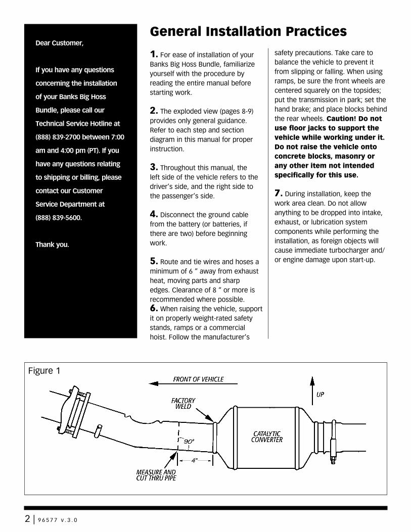
Figure 1
1. For ease of installation of your Banks Big Hoss Bundle, familiarize yourself with the procedure by reading the entire manual before starting work.
2. The exploded view (pages 8-9) provides only general guidance. Refer to each step and section diagram in this manual for proper instruction.
3. Throughout this manual, the left side of the vehicle refers to the driver’s side, and the right side to the passenger’s side.
4. Disconnect the ground cable from the battery (or batteries, if there are two) before beginning work.
5. Route and tie wires and hoses a minimum of 6 “ away from exhaust heat, moving parts and sharp edges. Clearance of 8 “ or more is recommended where possible.6. When raising the vehicle, support it on properly weight-rated safety stands, ramps or a commercial hoist. Follow the manufacturer’s
safety precautions. Take care to balance the vehicle to prevent it from slipping or falling. When using ramps, be sure the front wheels are centered squarely on the topsides; put the transmission in park; set the hand brake; and place blocks behind the rear wheels. Caution! Do not use floor jacks to support the vehicle while working under it. Do not raise the vehicle onto concrete blocks, masonry or any other item not intended specifically for this use.
7. During installation, keep the work area clean. Do not allow anything to be dropped into intake, exhaust, or lubrication system components while performing the installation, as foreign objects will cause immediate turbocharger and/or engine damage upon start-up.
2 | 9 6 5 7 7 v . 3 . 0
1. Replace the factory air filter element with the Banks Ram-Air™ filter.
2. Raise the vehicle on a hoist or safety stands to provide access to the exhaust system. Loosen the clamp at the front of the muffler and pry the muffler and tailpipe hanger pins from the rubber hangers (spray lubricant will ease hanger removal). Remove the muffler and tailpipe from the vehicle. Cutting the tailpipe may ease the process of removal.
3. If your vehicle is equipped with a catalytic converter, mark a point 4” from the forward edge of the weld at the inlet of the catalytic converter on the downward facing side of the pipe (see Figure 1).
4. Remove the remaining portion of the exhaust system from the vehicle. Retain the T.O.P V-band clamp for re-use (on Bundles 47582-47587, use supplied V-band clamp). The converter must be reinstalled in the vehicle. Remove the intermediate pipe from the outlet end of the converter. At the mark previously made, cut through the converter pipe square with the remaining face of the pipe as shown in Figure 1.
WARNING: At the outlet of each exhaust manifold, locate the short section of tubing that feeds exhaust up to the turbocharger. Check these tubes to ensure that they are not loose, as we have found several new vehicles with exhaust leaks in this area. Correct this condition now or soon after installation of the Monster exhaust components to eliminate dangerous exhaust leaks and poor turbocharger performance.
IMPORTANT: The catalytic converter should be inspected. Diesel catalysts may become plugged with soot and can cause a restriction to exhaust flow, impeding performance. Shine a powerful flashlight into the inlet end of the converter. Observe the light through the other end of the converter. The full circle of the flashlight should be visible without any blockage in the gridwork of the catalyst. If excessive soot is observed, the catalyst may need to be cleaned. TAKE PRECAUTIONS to avoid blowing soot toward the work area or where it could be inhaled. ALWAYS use breathing protection. Also inspect the catalyst for damage (i.e. chips, bent corners, etc.) to the gridwork. If your catalytic converter is damaged, it may be covered under your vehicle’s emissions warranty.
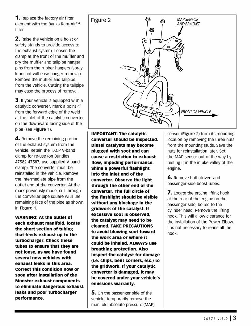
5. On the passenger side of the vehicle, temporarily remove the manifold absolute pressure (MAP)
sensor (Figure 2) from its mounting location by removing the three nuts from the mounting studs. Save the nuts for reinstallation later. Set the MAP sensor out of the way by resting it in the intake valley of the engine.
6. Remove both driver- and passenger-side boost tubes.
7. Locate the engine lifting hook at the rear of the engine on the passenger side, bolted to the cylinder head. Remove the lifting hook. This will allow clearance for the installation of the Power Elbow. It is not necessary to re-install the hook.
Figure 2
9 6 5 7 7 v . 3 . 0 | 3
Turbocharger Removal 8. Remove the decorative plastic cover directly over the engine.
9. Loosen the clamp holding the air intake hose at the turbocharger compressor inlet. Pull the hose free of the turbo compressor. Disconnect the boost line attached to the nipple on the wastegate actuator. Disconnect wiring and plastic tubing attached to components on the turbo compressor discharge plenum casting.
10. Loosen the four clamps on the hoses connecting the compressor discharge plenum casting to the intake manifolds. Loosen the clamp attaching the plenum to the turbocharger compressor outlet and the intercooler duct. Remove the compressor discharge plenum from the engine. Cover the two intake-manifold hose nipples with clean rags to prevent foreign objects from entering the engine.
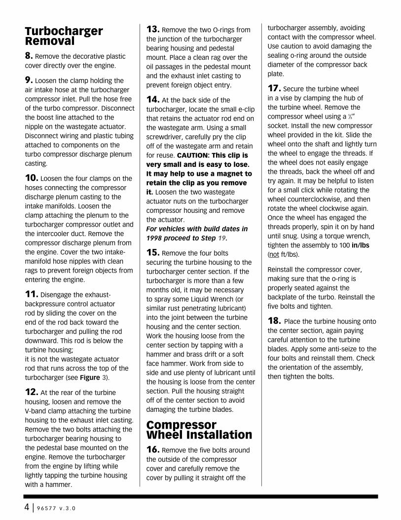
11. Disengage the exhaust-backpressure control actuator rod by sliding the cover on the end of the rod back toward the turbocharger and pulling the rod downward. This rod is below the turbine housing; it is not the wastegate actuator rod that runs across the top of the turbocharger (see Figure 3).
12. At the rear of the turbine housing, loosen and remove the V-band clamp attaching the turbine housing to the exhaust inlet casting. Remove the two bolts attaching the turbocharger bearing housing to the pedestal base mounted on the engine. Remove the turbocharger from the engine by lifting while lightly tapping the turbine housing with a hammer.
13. Remove the two O-rings from the junction of the turbocharger bearing housing and pedestal mount. Place a clean rag over the oil passages in the pedestal mount and the exhaust inlet casting to prevent foreign object entry.
14. At the back side of the turbocharger, locate the small e-clip that retains the actuator rod end on the wastegate arm. Using a small screwdriver, carefully pry the clip off of the wastegate arm and retain for reuse. CAUTION: This clip is very small and is easy to lose. It may help to use a magnet to retain the clip as you remove it. Loosen the two wastegate actuator nuts on the turbocharger compressor housing and remove the actuator.For vehicles with build dates in 1998 proceed to Step 19.
15. Remove the four bolts securing the turbine housing to the turbocharger center section. If the turbocharger is more than a few months old, it may be necessary to spray some Liquid Wrench (or similar rust penetrating lubricant) into the joint between the turbine housing and the center section. Work the housing loose from the center section by tapping with a hammer and brass drift or a soft face hammer. Work from side to side and use plenty of lubricant until the housing is loose from the center section. Pull the housing straight off of the center section to avoid damaging the turbine blades.
Compressor Wheel Installation16. Remove the five bolts around the outside of the compressor cover and carefully remove the cover by pulling it straight off the
turbocharger assembly, avoiding contact with the compressor wheel. Use caution to avoid damaging the sealing o-ring around the outside diameter of the compressor back plate.
17. Secure the turbine wheel in a vise by clamping the hub of the turbine wheel. Remove the compressor wheel using a 5⁄8” socket. Install the new compressor wheel provided in the kit. Slide the wheel onto the shaft and lightly turn the wheel to engage the threads. If the wheel does not easily engage the threads, back the wheel off and try again. It may be helpful to listen for a small click while rotating the wheel counterclockwise, and then rotate the wheel clockwise again. Once the wheel has engaged the threads properly, spin it on by hand until snug. Using a torque wrench, tighten the assembly to 100 in/lbs (not ft/lbs).
Reinstall the compressor cover, making sure that the o-ring is properly seated against the backplate of the turbo. Reinstall the five bolts and tighten.
18. Place the turbine housing onto the center section, again paying careful attention to the turbine blades. Apply some anti-seize to the four bolts and reinstall them. Check the orientation of the assembly, then tighten the bolts.
4 | 9 6 5 7 7 v . 3 . 0
19. Install the Banks Big Head™ actuator onto the turbocharger. Tighten the lock nuts on the mounting studs and adjust the rod end until the hole aligns with the wastegate arm pin. Turn the rod end link clockwise an additional four full turns, such that it will add preload to the wastegate. Apply a regulated supply of air pressure to the nipple on the actuator until the rod extends enough to slip over the wastegate arm pin. Install the e-clip onto the wastegate arm pin to retain the actuator rod. Tighten the jam nut down on the end link.
20. Remove the exhaust backpressure control valve assembly from the factory turbine housing by removing the seven (12-point, 8mm head) bolts. Retain these bolts for reuse.
21. Install the Banks Power Elbow casting onto the outlet of
the turbocharger using the original bolts. Use the supplied anti-seize compound on the bolts and tighten them evenly. The torque specification for these bolts is 62 in-lb (not ft-lb).
22. Reinstall the turbocharger onto the pedestal assembly on the engine. Make sure the sealing area on the pedestal assembly and the bottom of the turbocharger are clean, and the new O-rings provided are in place, then bolt the turbocharger to the pedestal. Reinstall the V-band clamp attaching the turbine housing to the exhaust inlet casting.
IMPORTANT: Check the condition of the V-band clamp as over-tightening can cause the clamp to spread, allowing the T-bolt to become loose. Replace the clamp if the clamp is damaged or will not tighten.
Note: It may be necessary to re-locate the transmission dipstick tube to allow clearance for the V-band clamp at outlet of Power Elbow. The tube can be re-located with a prybar or similar tool. There should be 3⁄4”-1” clearance between the tube and the Power Elbow casting.
23. On 19991⁄2 and later vehicles, install support bracket between Power Elbow casting and passenger-side cylinder head using supplied 3⁄8-16 x 3⁄4” bolt, M10 x 1.5 x 20mm long bolt. See Figure 4. The M10x1.5x20mm bolt is used on the cylinder-head side of the bracket.
Figure 3
9 6 5 7 7 v . 3 . 0 | 5
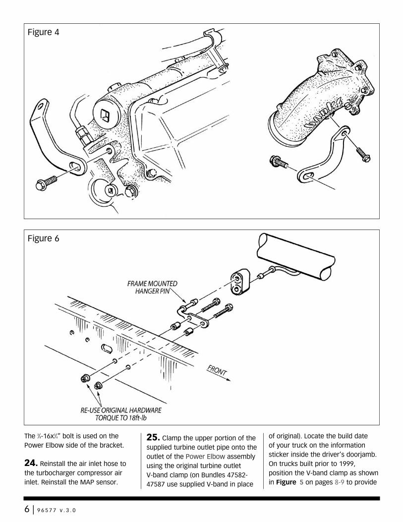
The 3⁄8-16x3⁄4” bolt is used on the Power Elbow side of the bracket. 24. Reinstall the air inlet hose to the turbocharger compressor air inlet. Reinstall the MAP sensor.
25. Clamp the upper portion of the supplied turbine outlet pipe onto the outlet of the Power Elbow assembly using the original turbine outlet V-band clamp (on Bundles 47582-47587 use supplied V-band in place
of original). Locate the build date of your truck on the information sticker inside the driver’s doorjamb. On trucks built prior to 1999, position the V-band clamp as shown in Figure 5 on pages 8-9 to provide
Figure 4
Figure 6
6 | 9 6 5 7 7 v . 3 . 0
room for tightening. On trucks built in 1999 or later, position this clamp as needed.
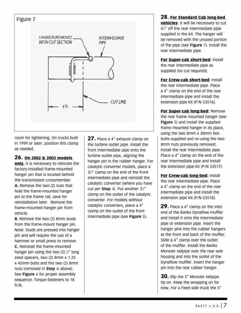
26. On 2002 & 2003 models only, it is necessary to relocate the factory-installed frame-mounted hanger pin that is located behind the transmission crossmember.A. Remove the two (2) nuts that hold the frame-mounted hanger pin to the frame rail, save for reinstallation later. Remove the frame-mounted hanger pin from vehicle.B. Remove the two (2) 8mm studs from the frame-mount hanger pin. Note: Studs are pressed into hanger pin and will require the use of a hammer or small press to remove. C. Reinstall the frame-mounted hanger pin using the two (2) 5⁄8” long steel spacers, two (2) 8mm x 1.25 x 45mm bolts and the two (2) 8mm nuts (removed in Step A above). See Figure 6 for proper assembly sequence. Torque fasteners to 18 ft-lb.
27. Place a 4” exhaust clamp on the turbine outlet pipe. Install the front intermediate pipe onto the turbine outlet pipe, aligning the hanger pin in the rubber hanger. For catalytic converter models, place a 31⁄2” clamp on the end of the front intermediate pipe and reinstall the catalytic converter (where you have cut per Step 4). Put another 31⁄2” clamp on the outlet of the catalytic converter. For models without catalytic converters, place a 4” clamp on the outlet of the front intermediate pipe (see Figure 5).
28. For Standard Cab long-bed vehicles: It will be necessary to cut 43⁄4” off the rear intermediate pipe supplied in the kit. The hanger will be removed with the unused portion of the pipe (see Figure 7). Install the rear intermediate pipe.
For Super-cab short-bed: Install the rear intermediate pipe as supplied (no cut required).
For Crew-cab short-bed: Install the rear intermediate pipe. Place a 4” clamp on the end of the rear intermediate pipe and install the extension pipe kit (P/N 53516).
For Super-cab long-bed: Remove the rear frame mounted hanger (see Figure 5) and install the supplied frame mounted hanger in its place, using the two 8mm x 30mm hex bolts supplied and re-using the two 8mm nuts previously removed. Install the rear intermediate pipe. Place a 4” clamp on the end of the rear intermediate pipe and install the extension pipe kit (P/N 53517).
For Crew-cab long-bed: Install the rear intermediate pipe. Place a 4” clamp on the end of the rear intermediate pipe and install the extension pipe kit (P/N 53518).
29. Place a 4” clamp on the inlet end of the Banks Dynaflow muffler and install it onto the intermediate pipe or extension pipe. Insert the hanger pins into the rubber hangers at the front and back of the muffler. Slide a 4” clamp over the outlet of the muffler. Install the Banks Monster tailpipe over the rear axle housing and into the outlet of the Dynaflow muffler. Insert the hanger pin into the rear rubber hanger.
30. Slip the 5” Monster tailpipe tip on. Keep the wrapping on for now. For a Fleet-side truck the 5”
Figure 7
9 6 5 7 7 v . 3 . 0 | 7
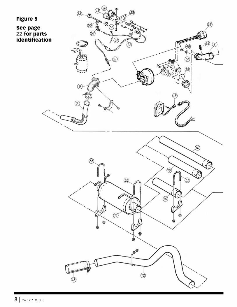
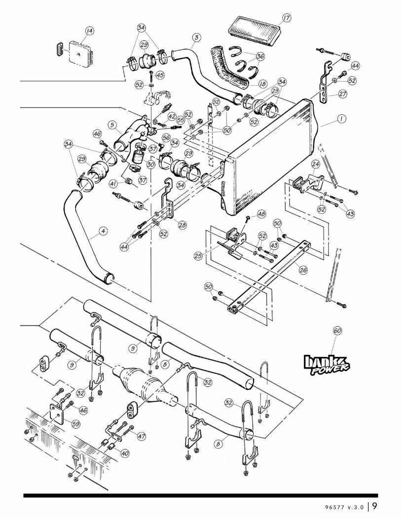
Figure 5
See page 22 for parts identification
8 | 9 6 5 7 7 v . 3 . 0
9 6 5 7 7 v . 3 . 0 | 9
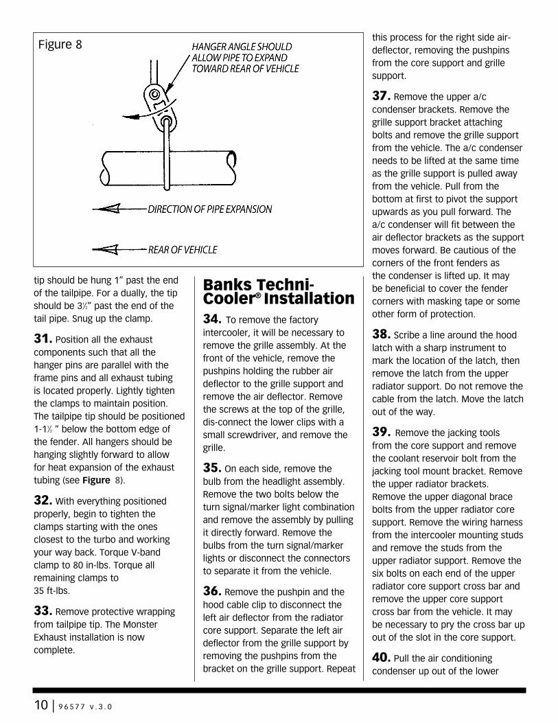
tip should be hung 1” past the end of the tailpipe. For a dually, the tip should be 31⁄2” past the end of the tail pipe. Snug up the clamp.
31. Position all the exhaust components such that all the hanger pins are parallel with the frame pins and all exhaust tubing is located properly. Lightly tighten the clamps to maintain position. The tailpipe tip should be positioned 1-11⁄2 “ below the bottom edge of the fender. All hangers should be hanging slightly forward to allow for heat expansion of the exhaust tubing (see Figure 8).
32. With everything positioned properly, begin to tighten the clamps starting with the ones closest to the turbo and working your way back. Torque V-band clamp to 80 in-lbs. Torque all remaining clamps to 35 ft-lbs.
33. Remove protective wrapping from tailpipe tip. The Monster Exhaust installation is now complete.
Banks Techni-Cooler® Installation34. To remove the factory intercooler, it will be necessary to remove the grille assembly. At the front of the vehicle, remove the pushpins holding the rubber air deflector to the grille support and remove the air deflector. Remove the screws at the top of the grille, dis-connect the lower clips with a small screwdriver, and remove the grille.
35. On each side, remove the bulb from the headlight assembly. Remove the two bolts below the turn signal/marker light combination and remove the assembly by pulling it directly forward. Remove the bulbs from the turn signal/marker lights or disconnect the connectors to separate it from the vehicle.
36. Remove the pushpin and the hood cable clip to disconnect the left air deflector from the radiator core support. Separate the left air deflector from the grille support by removing the pushpins from the bracket on the grille support. Repeat
this process for the right side air-deflector, removing the pushpins from the core support and grille support.
37. Remove the upper a/c condenser brackets. Remove the grille support bracket attaching bolts and remove the grille support from the vehicle. The a/c condenser needs to be lifted at the same time as the grille support is pulled away from the vehicle. Pull from the bottom at first to pivot the support upwards as you pull forward. The a/c condenser will fit between the air deflector brackets as the support moves forward. Be cautious of the corners of the front fenders as the condenser is lifted up. It may be beneficial to cover the fender corners with masking tape or some other form of protection.
38. Scribe a line around the hood latch with a sharp instrument to mark the location of the latch, then remove the latch from the upper radiator support. Do not remove the cable from the latch. Move the latch out of the way.
39. Remove the jacking tools from the core support and remove the coolant reservoir bolt from the jacking tool mount bracket. Remove the upper radiator brackets. Remove the upper diagonal brace bolts from the upper radiator core support. Remove the wiring harness from the intercooler mounting studs and remove the studs from the upper radiator support. Remove the six bolts on each end of the upper radiator core support cross bar and remove the upper core support cross bar from the vehicle. It may be necessary to pry the cross bar up out of the slot in the core support.
40. Pull the air conditioning condenser up out of the lower
Figure 8
10 | 9 6 5 7 7 v . 3 . 0
brackets and swing it up over the engine and out of the way. Be careful of the tubes that carry pressurized refrigerant. Do not bend the tubes as they are aluminum, and can be easily damaged. Using a bungee cord or similar equipment, temporarily suspend the condenser from the hood of the vehicle, out of the way.
41. Remove the bolt attaching the power steering cooler to the diagonal brace. Remove the diagonal braces from the lower radiator core support. Tilt the intercooler forward and remove it up and out of the vehicle.
NOTE: Later models do not have diagonal braces, unbolt power-steering cooler from brackets as required.
42. Using the four 1⁄4”-28 x 2” bolts, washers and nylock nuts, loosely bolt the new lower intercooler mounting brackets to the lower mounting crossbar. Position this mounting assembly into the vehicle as shown in Figure 5. Using the lower diagonal brace mounting holes as locations, position the crossbar assembly level in the vehicle and temporarily bolt the brackets to the core support using the lower diagonal brace bolts. Using the brackets as a template, mark the four holes necessary to complete the attaching of the lower mounting brackets, and drill four 1⁄8” holes in those positions. Attach the lower mounting brackets to these holes in the core support with the four #10 sheet metal screws provided. Now remove the two factory diagonal brace bolts.
NOTE: On later model vehicles without diagonal braces and associated bolt holes, slide the lower intercooler mounting
crossbar, with brackets loosely attached, up the sides of the core support opening until the brackets come against the bottom edges for the “ears” that overlap the inside edge of the core support opening. If the lower intercooler mounting brackets cannot be slid out far enough on the crossbar to contact the sides of the core support opening at this elevation, slide each bracket outward on the crossbar as far as it will go, then tighten the 1⁄4” thru-bolts, set the crossbar assembly in the core support opening, and level it to the vehicle.
With the crossbar assembly positioned in the core support opening as indicated, scribe the core support through the four holes on the inside edges of the brackets, being certain that the front flanges of the brackets (with the single unused bolt hole) are against the face of the core support. Drill four 1⁄8” holes at the scribed locations, then attach the brackets to the core support with four #10 sheet metal screws provided.
43. Remove the rubber air deflector strips from the ends of the factory intercooler by snipping the plastic ties that run through the intercooler fins. Attach the deflectors to the inboard side of the 3-hole tabs on the Banks intercooler by installing one 1⁄4-28 x 1” hex bolt, washer, and nylock nut assembly through the bottom hole on the lower tab on each end of the intercooler and the existing bottom hole on each deflector strip. The remaining three holes on the deflector strips will not line up with the holes in the intercooler. Drill or punch a new set of holes in the deflector strips to line up with the upper holes in the lower tabs on the intercooler, then install a 1⁄4-28 x
1” hex bolt, washer, and nylock nut assembly in each of these locations. (See Figure 5) Drill or punch a third set of holes through each deflector strip to line up with the middle hole in the upper tabs on the intercooler.
44. Loosely bolt the upper brackets to the Banks Techni-Cooler as shown in Figure 5 using four 1⁄4-28 x 1” hex bolts, 1⁄4 washers and nylock nuts through the outboard holes in the two upper tabs on the intercooler.
45. Trim the rubber air deflector to clear the upper bracket attaching nuts so the deflector will sit flat against the tab on the intercooler. Attach the deflectors to the intercooler at the middle hole in each upper tab using another pair of 1⁄4”-28 bolt assemblies. Do not tighten these bolts yet.
46. On the passenger side of the engine compartment, locate the air conditioning filter/dryer assembly. It will be necessary to modify the clamping bracket to allow clearance for the new tube assembly. Remove the upper filter dryer bracket by unbolting in three places. Using a hacksaw or other cutting tool cut the forward half of the clamp off in front of the elevated tab across from the opening of the clamp. Next cut the remaining tab off of the open side of the clamp. Reinstall the bracket using a #56 hose clamp provided to secure the filter/dryer unit to the bracket.
47. Slide three #52 hose clamps over the left boost tube. These will be used later to secure the heatshield in place. Set both boost tubes into place in the vehicle. Place two of the 3” silicone hump hoses onto the intercooler inlet and outlet, and fasten with the T-bolt clamps provided. Position two
9 6 5 7 7 v . 3 . 0 | 11
more clamps on the open ends of the silicone hoses, and place the intercooler into the vehicle slipping the boost tubes into the hoses on the intercooler and the intercooler into the rubber saddles on the lower mounting brackets. Do not tighten these clamps yet.
48. Place the air conditioning condenser back into its original position. Reinstall upper crossbar into truck, using the original bolts. Reinstall the diagonal braces to the radiator support and reattach the power steering cooler to the right side diagonal. Note: Rotate the upper power-steering fluid tube in the clip to allow the hose portion to clear the bottom of the right lower intercooler bracket.
49. Remove the factory rubber isolators from the factory intercooler and install them into the upper brackets of the Banks intercooler. Install the original studs through the isolators into the upper crossbar and tighten them. Tighten the upper mounting-bracket bolts on the intercooler. For late 19991⁄2–2002 models proceed to Step 55.
50. Remove the sensors from the factory compressor discharge plenum casting and install them into the Banks TwinRam intake assembly.Early 19991⁄2 models: Remove the heating element from the factory compressor discharge plenum casting and install it in the Banks TwinRam intake assembly.
51. Slide the two 2” silicone hoses up the legs of the TwinRam. Slip two #36 hose clamps over each hose and install the TwinRam to the engine, sliding the hoses down the legs and onto the intake stubs, making sure that the hoses are positioned equally between the
TwinRam legs and the manifold stubs. Tighten the clamps. Attach the bracket to the rocker cover using the 8mm x 30mm metric bolts and spacers provided.
52. Attach the wastegate control solenoid to the tab on the TwinRam with the supplied 1⁄4-20 x 11⁄14” hex bolt and washer. Reconnect the wiring harnesses to the sensors.
53. Attach the right side boost tube to the TwinRam using a 3” silicone hump hose, and two T-bolt clamps.
54. Place the new O-ring into the recess in the compressor housing and attach the compressor discharge elbow to the compressor housing with the new V-band clamp provided. A small amount of bearing grease may be used to hold the O-ring in position while installing the elbow. Bolt the compressor discharge elbow to the TwinRam through the tab provided for this purpose using the 5⁄16” bolt, washers, and nylock nut provided. Install a 1⁄8” NPT x 1⁄8” compression fitting (supplied in the boost gauge kit) in the bung on the compressor discharge elbow. Sparingly apply pipe sealant tape or paste on the male pipe threads, and tighten the hex on the fitting body (NOT the compression nut). Proceed to Step 56.
55. Late 19991⁄2–2002 models: Place the O-ring into the recess in the turbo compressor outlet and reinstall the factory compressor discharge plenum casting on the turbocharger. A small amount of bearing grease may be used to hold the O-ring in position while installing the casting. Slide the hump hoses on the boost tubes onto the compressor plenum discharge casting. Reconnect any wiring or
sensor tubes to components on the compressor discharge casting. Reconnect boost line to wastegate actuator.
56. While engine is running, check for oil leaks around the base of the turbocharger center section or the pedestal mount. Repair any leaks before continuing. NOTE: The most likely cause of an oil leak in this installation is a pinched O-ring at the base of the turbocharger.
57. Make sure that the boost tubes clear all moving parts, and that the hoses do not chafe on any sharp edges. Tighten all of the boost tube clamps.
58. Reposition the left and right air deflectors back into their original positions, and use the pushpins to attach them to the radiator support. Reattach the wiring harness removed from the intercooler mounting studs. Reinstall the original radiator mount brackets onto the radiator upper support. Tighten the bolts. Reattach the radiator overflow tank to the upper radiator bracket. Reinstall the jacking tools to the core support. Reinstall the grille support to the vehicle using the original hardware. Reinstall the air conditioning condenser upper brackets. Reattach the right and left air deflectors to the grille support with the original hardware. Reinstall the hood latch in its original position.
59. Reinstall the light bulbs into the turn signal/marker light combinations, and reinstall the combinations into the vehicle. Press them firmly, straight back into the attaching clips and bolt them into place. Reinstall the headlight bulbs into the headlight assemblies. Be careful not to touch the headlight bulbs themselves with your fingers,
12 | 9 6 5 7 7 v . 3 . 0
as oil from your skin can cause damage to the bulbs. If necessary, clean the bulbs thoroughly with rubbing alcohol before reinstalling them.
60. Turn on the headlights and turn signals briefly to check for proper operation.
61. Reattach the upper radiator air deflector to the grille support and upper radiator support with the plastic pushpins previously removed. Reinstall the grille by pushing it into the lower clips. Reinstall the original screws.
62. Recheck all clamps to ensure that they are tight before driving the vehicle.
DynaFact®
Instrumentation Installation 63. If gauges are being installed into an existing gauge panel, this step may be skipped. If gauges and a gauge panel or console are being installed, choose a location where the driver can easily view the gauges. This will typically be to the right of the accelerator pedal, under the lower edge of the dash panel. Mount the gauge panel with the machine screws, washers, and nuts provided.
64. Install the DynaFact pyrometer probe (supplied in the pyrometer kit) in the 1⁄4” NPT bung located in the Power Elbow. Use anti-seize compound on the threads. Connect the pyrometer 4-pin gauge harness to the sensor with the supplied screws. The wires are different lengths and color to prevent cross connecting. Make sure that the screws are tight. Slip the heat shrink tubing provided over the wire ends.
65. Supply moderate heat to
the heat shrink tubing to seal the connections. A heat-gun or lighter works well.
66. When passing through the firewall either make a hole in a factory grommet or drill a hole and use a new grommet. If a hole needs to be drilled, drill a 5⁄16” hole and deburr it on both sides, so that the wiring or tubing does not get cut as it passes through the hole. For added protection, wrap the wiring with several layers of electrical tape in the area where it passes through the hole. When drilling, check the backside to make sure that there are no components blocking the backside of the hole that would be damaged by drilling.
67. Route the pyrometer 4-pin gauge harness up and across the top of the firewall then down and through the hole in the firewall. Inside the vehicle, route the wire to the gauge location. If routing the pyrometer 4-pin gauge harness under the carpet, avoid placing it where the driver’s feet will rest on the wire. Tie the wire to existing wire looms and hoses with the cable ties provided.
68. Position the gauge through the console or gauge panel. Slip the plastic U-clamp, provided with the pyrometer, over the studs on the rear of the gauge and tighten the nuts, provided.
69. Pull any excess wire through the firewall, coil it and secure it up under the dash, out of the way. Do not shorten the lead-wire. The pyrometer is calibrated to work with the predetermined length provided.
70. Locate the rubber hose connecting the intake manifold on the passenger side to the pressure sensor mounted on the firewall.
Cut through this hose at a point 3” below the sensor. Install the 1⁄8” hose by 1⁄8” NPT tee fitting and the spring band clamps, provided, between the cut ends of the hose as shown in Figure 5.
71. Install one 1⁄8” NPT female by 1⁄8” compression 90° fitting onto the threaded end of the tee. Sparingly apply pipe sealant tape or paste on the male pipe threads, and adjust the 90° fitting to point back toward the firewall, as shown in Figure 9. Do not allow any sealant to cover the small hole in the fitting. Do not over-tighten the plastic fitting.
72. Install one end of the 1⁄8” diameter plastic tube provided into the compression fitting on the plastic tee or the fitting on the compressor discharge elbow and tighten the nut. Be sure the plastic tube cannot be pulled out of the ferrule, but do not over-tighten the nut.
73. Route the free end of the tube up and along the top of the firewall toward the brake master cylinder assembly. Use caution to avoid kinks in the line. Tie the tube to existing wires and hoses with the cable ties provided. Follow the routing of the pyrometer lead-wire through the firewall.
74. Route the plastic tube to the gauge panel and cut the tube to the proper length. Install the gauge through the panel or console using the U-clamp and two hex nuts provided with the gauge.
75. Install the 90° elbow fitting onto the connection at the back of the gauge. Use Teflon thread sealer on the male threads of the gauge nipple. Do not allow any sealant to cover the pin-sized hole in the end of the gauge nipple.
9 6 5 7 7 v . 3 . 0 | 13
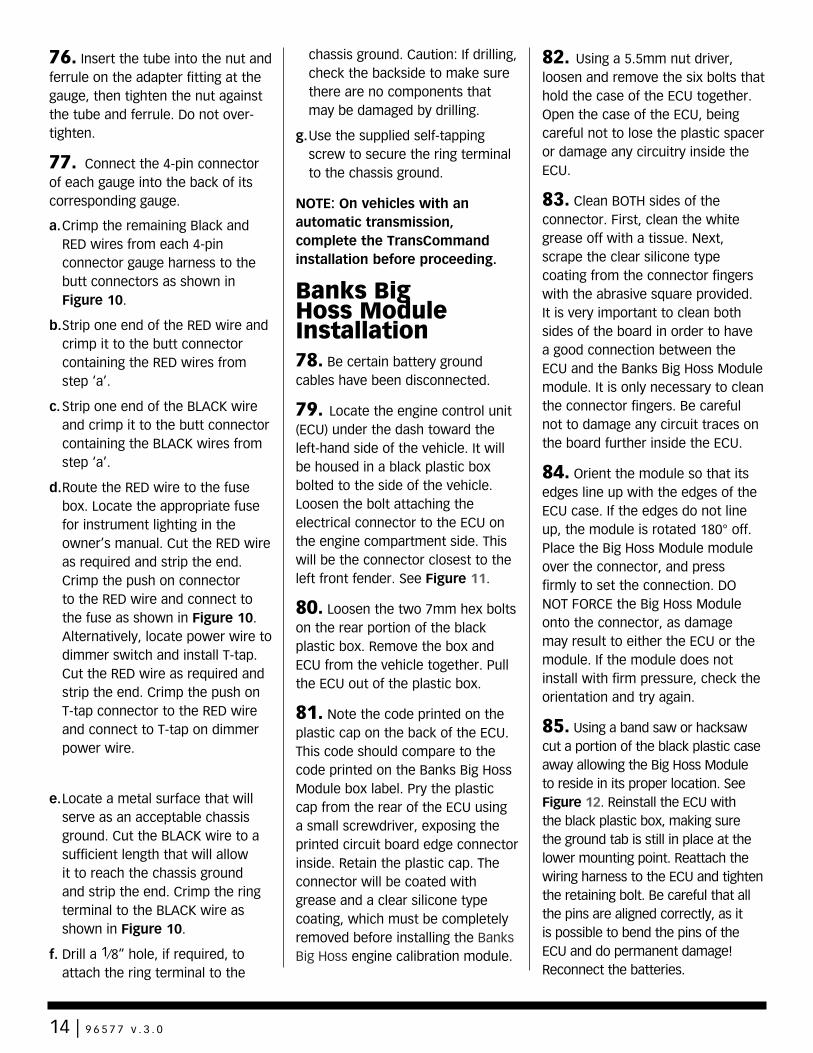
76. Insert the tube into the nut and ferrule on the adapter fitting at the gauge, then tighten the nut against the tube and ferrule. Do not over-tighten.
77. Connect the 4-pin connector of each gauge into the back of its corresponding gauge.
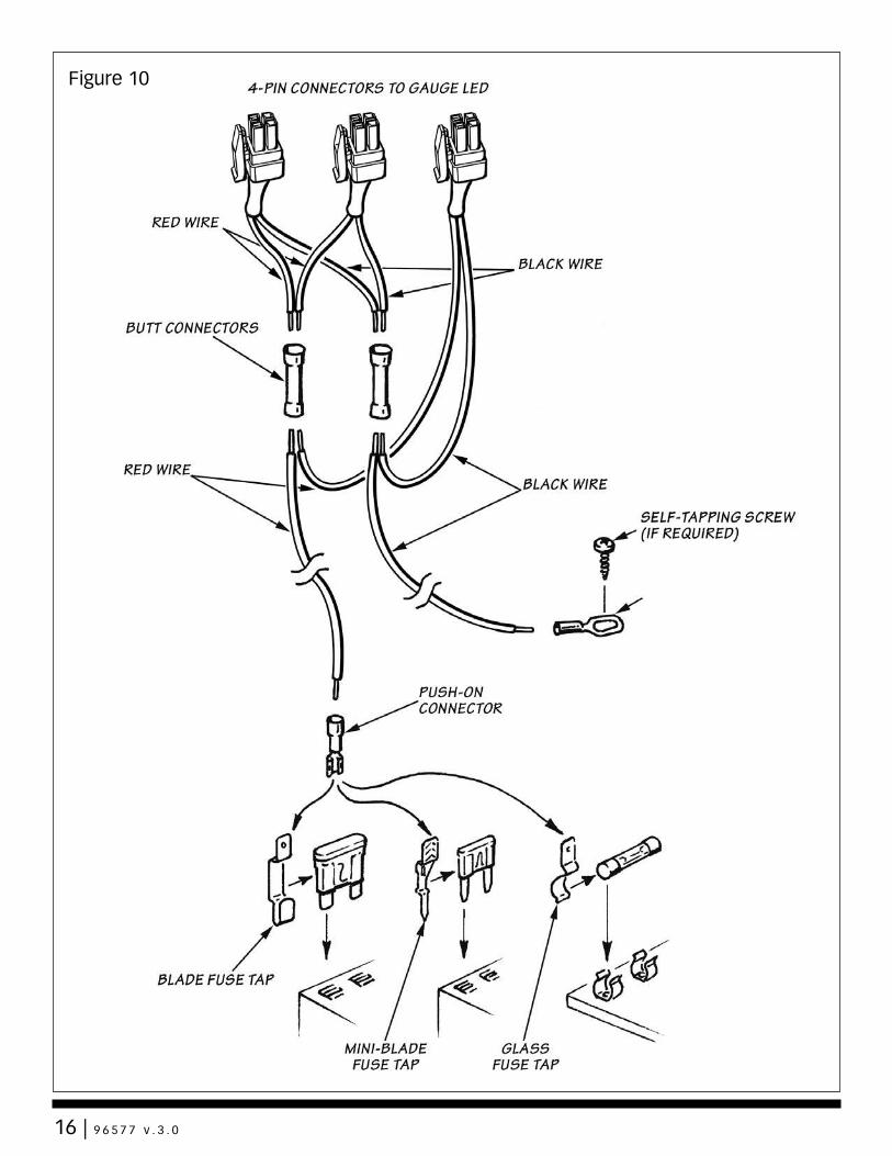
a. Crimp the remaining Black and RED wires from each 4-pin connector gauge harness to the butt connectors as shown in Figure 10.
b. Strip one end of the RED wire and crimp it to the butt connector containing the RED wires from step ‘a’.
c. Strip one end of the BLACK wire and crimp it to the butt connector containing the BLACK wires from step ‘a’.
d. Route the RED wire to the fuse box. Locate the appropriate fuse for instrument lighting in the owner’s manual. Cut the RED wire as required and strip the end. Crimp the push on connector to the RED wire and connect to the fuse as shown in Figure 10. Alternatively, locate power wire to dimmer switch and install T-tap. Cut the RED wire as required and strip the end. Crimp the push on T-tap connector to the RED wire and connect to T-tap on dimmer power wire.
e. Locate a metal surface that will serve as an acceptable chassis ground. Cut the BLACK wire to a sufficient length that will allow it to reach the chassis ground and strip the end. Crimp the ring terminal to the BLACK wire as shown in Figure 10.
f. Drill a 1⁄8” hole, if required, to attach the ring terminal to the
chassis ground. Caution: If drilling, check the backside to make sure there are no components that may be damaged by drilling.
g. Use the supplied self-tapping screw to secure the ring terminal to the chassis ground.
NOTE: On vehicles with an automatic transmission, complete the TransCommand installation before proceeding.
Banks Big Hoss Module Installation78. Be certain battery ground cables have been disconnected.
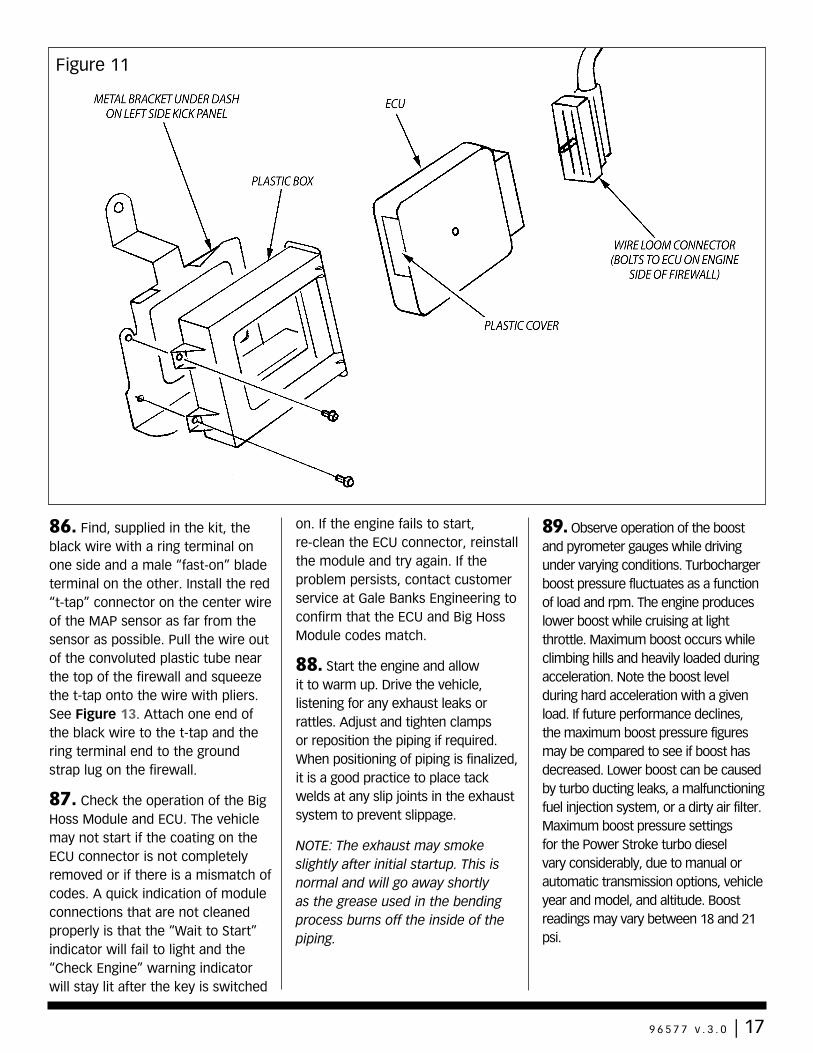
79. Locate the engine control unit (ECU) under the dash toward the left-hand side of the vehicle. It will be housed in a black plastic box bolted to the side of the vehicle. Loosen the bolt attaching the electrical connector to the ECU on the engine compartment side. This will be the connector closest to the left front fender. See Figure 11.
80. Loosen the two 7mm hex bolts on the rear portion of the black plastic box. Remove the box and ECU from the vehicle together. Pull the ECU out of the plastic box.
81. Note the code printed on the plastic cap on the back of the ECU. This code should compare to the code printed on the Banks Big Hoss Module box label. Pry the plastic cap from the rear of the ECU using a small screwdriver, exposing the printed circuit board edge connector inside. Retain the plastic cap. The connector will be coated with grease and a clear silicone type coating, which must be completely removed before installing the Banks Big Hoss engine calibration module.
82. Using a 5.5mm nut driver, loosen and remove the six bolts that hold the case of the ECU together. Open the case of the ECU, being careful not to lose the plastic spacer or damage any circuitry inside the ECU.
83. Clean BOTH sides of the connector. First, clean the white grease off with a tissue. Next, scrape the clear silicone type coating from the connector fingers with the abrasive square provided. It is very important to clean both sides of the board in order to have a good connection between the ECU and the Banks Big Hoss Module module. It is only necessary to clean the connector fingers. Be careful not to damage any circuit traces on the board further inside the ECU.
84. Orient the module so that its edges line up with the edges of the ECU case. If the edges do not line up, the module is rotated 180° off. Place the Big Hoss Module module over the connector, and press firmly to set the connection. DO NOT FORCE the Big Hoss Module onto the connector, as damage may result to either the ECU or the module. If the module does not install with firm pressure, check the orientation and try again.
85. Using a band saw or hacksaw cut a portion of the black plastic case away allowing the Big Hoss Module to reside in its proper location. See Figure 12. Reinstall the ECU with the black plastic box, making sure the ground tab is still in place at the lower mounting point. Reattach the wiring harness to the ECU and tighten the retaining bolt. Be careful that all the pins are aligned correctly, as it is possible to bend the pins of the ECU and do permanent damage! Reconnect the batteries.
14 | 9 6 5 7 7 v . 3 . 0
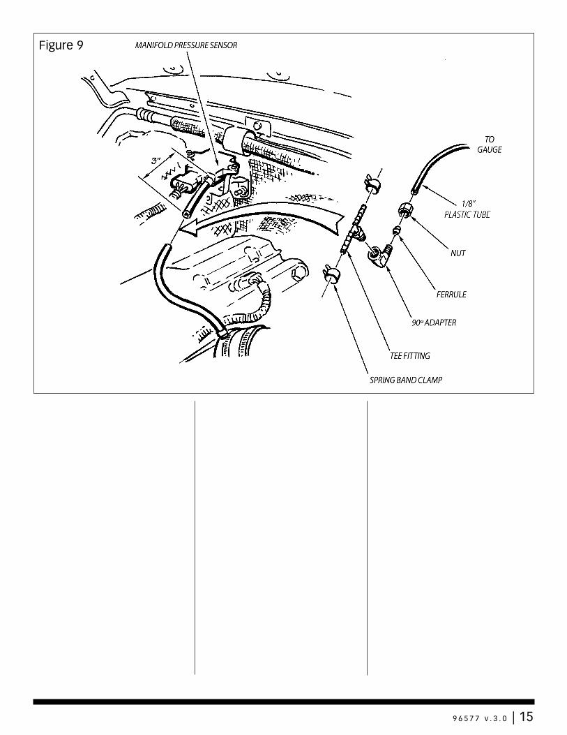
Figure 9
9 6 5 7 7 v . 3 . 0 | 15
16 | 9 6 5 7 7 v . 3 . 0
Figure 10
16 | 9 6 5 7 7 v . 2 . 0
Figure 10
86. Find, supplied in the kit, the black wire with a ring terminal on one side and a male “fast-on” blade terminal on the other. Install the red “t-tap” connector on the center wire of the MAP sensor as far from the sensor as possible. Pull the wire out of the convoluted plastic tube near the top of the firewall and squeeze the t-tap onto the wire with pliers. See Figure 13. Attach one end of the black wire to the t-tap and the ring terminal end to the ground strap lug on the firewall.
87. Check the operation of the Big Hoss Module and ECU. The vehicle may not start if the coating on the ECU connector is not completely removed or if there is a mismatch of codes. A quick indication of module connections that are not cleaned properly is that the “Wait to Start” indicator will fail to light and the “Check Engine” warning indicator will stay lit after the key is switched
on. If the engine fails to start, re-clean the ECU connector, reinstall the module and try again. If the problem persists, contact customer service at Gale Banks Engineering to confirm that the ECU and Big Hoss Module codes match.
88. Start the engine and allow it to warm up. Drive the vehicle, listening for any exhaust leaks or rattles. Adjust and tighten clamps or reposition the piping if required. When positioning of piping is finalized, it is a good practice to place tack welds at any slip joints in the exhaust system to prevent slippage.
NOTE: The exhaust may smoke slightly after initial startup. This is normal and will go away shortly as the grease used in the bending process burns off the inside of the piping.
89. Observe operation of the boost and pyrometer gauges while driving under varying conditions. Turbocharger boost pressure fluctuates as a function of load and rpm. The engine produces lower boost while cruising at light throttle. Maximum boost occurs while climbing hills and heavily loaded during acceleration. Note the boost level during hard acceleration with a given load. If future performance declines, the maximum boost pressure figures may be compared to see if boost has decreased. Lower boost can be caused by turbo ducting leaks, a malfunctioning fuel injection system, or a dirty air filter. Maximum boost pressure settings for the Power Stroke turbo diesel vary considerably, due to manual or automatic transmission options, vehicle year and model, and altitude. Boost readings may vary between 18 and 21 psi.
Figure 11
9 6 5 7 7 v . 3 . 0 | 17
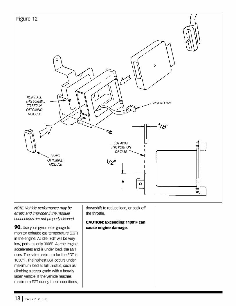
NOTE: Vehicle performance may be erratic and improper if the module connections are not properly cleaned.
90. Use your pyrometer gauge to monitor exhaust gas temperature (EGT) in the engine. At idle, EGT will be very low, perhaps only 300°F. As the engine accelerates and is under load, the EGT rises. The safe maximum for the EGT is 1050°F. The highest EGT occurs under maximum load at full throttle, such as climbing a steep grade with a heavily laden vehicle. If the vehicle reaches maximum EGT during these conditions,
downshift to reduce load, or back off the throttle.
CAUTION: Exceeding 1100°F can cause engine damage.
Figure 12
18 | 9 6 5 7 7 v . 3 . 0
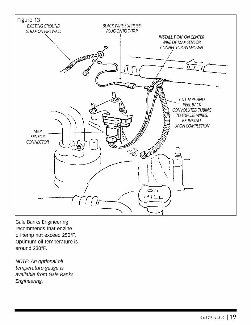
Gale Banks Engineering recommends that engine oil temp not exceed 250°F. Optimum oil temperature is around 230°F.
NOTE: An optional oil temperature gauge is available from Gale Banks Engineering.
Figure 13
9 6 5 7 7 v . 3 . 0 | 19
Service Tips1. If the need should arise for you to have your vehicle serviced, the Banks Big Hoss Module should be removed from the engine control unit (ECU). It is common for the service provider to connect a computer diagnostic link to the vehicle regardless of the type of service being performed. When the Big Hoss Module is installed, the computer will return a code that indicates a memory fault with the vehicle ECU. The suggested repair for a fault of this type is replacement of the ECU.
2. The operation of the Big Hoss Module is such that the computer is directed to reference certain information in the Big Hoss Module rather than the ECU. Therefore, the memory fault that occurs is not an ECU failure, but rather the presence of an electronic device that the diagnostic computer cannot identify.
3. To avoid confusion about whether or not an ECU is properly functioning, simply remove the Big Hoss Module from the ECU before
having the vehicle serviced, and reinsert the plastic cap in the ECU access port. The Big Hoss Module can be easily accessed from inside the truck, and it is unnecessary to remove the computer from the vehicle. The Big Hoss Module may be reinstalled after the service is complete.
4. It is also not uncommon for a service provider to update the program in the vehicle ECU. If this occurs, it is possible that the programming in the Big Hoss Module will no longer match the ECU program. If you experience any difficulty with the operation of the Banks Big Hoss Module after service, check with the service provider to determine if an update was performed. Then contact customer service at Gale Banks Engineering for an updated Big Hoss Module, if necessary.
5. Your system includes two (2) Banks Power logos that have been designed to compliment the Ford badging on your truck. We have provided measurements, which will allow you to place these logos in a
position that gives a clean factory look. See Figure 14.
20 | 9 6 5 7 7 v . 3 . 0
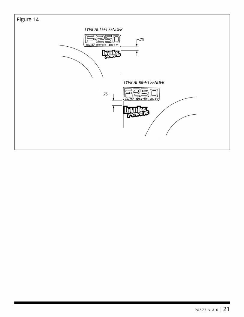
Figure 14
9 6 5 7 7 v . 3 . 0 | 21
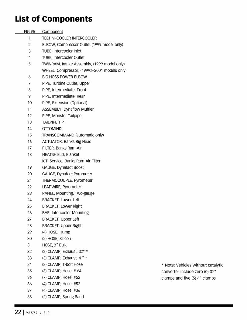
FIG #5 Component
1 TECHNI-COOLER INTERCOOLER
2 ELBOW, Compressor Outlet (1999 model only)
3 TUBE, Intercooler Inlet
4 TUBE, Intercooler Outlet
5 TWINRAM, Intake Assembly, (1999 model only)
WHEEL, Compressor, (19991⁄2–2001 models only)
6 BIG HOSS POWER ELBOW
7 PIPE, Turbine Outlet, Upper
8 PIPE, Intermediate, Front
9 PIPE, Intermediate, Rear
10 PIPE, Extension (Optional)
11 ASSEMBLY, Dynaflow Muffler
12 PIPE, Monster Tailpipe
13 TAILPIPE TIP
14 OTTOMIND
15 TRANSCOMMAND (automatic only)
16 ACTUATOR, Banks Big Head
17 FILTER, Banks Ram-Air
18 HEATSHIELD, Blanket
KIT, Service, Banks Ram-Air Filter
19 GAUGE, Dynafact Boost
20 GAUGE, Dynafact Pyrometer
21 THERMOCOUPLE, Pyrometer
22 LEADWIRE, Pyrometer
23 PANEL, Mounting, Two-gauge
24 BRACKET, Lower Left
25 BRACKET, Lower Right
26 BAR, Intercooler Mounting
27 BRACKET, Upper Left
28 BRACKET, Upper Right
29 (4) HOSE, Hump
30 (2) HOSE, Silicon
31 HOSE, 1⁄8” Bulk
32 (2) CLAMP, Exhaust, 31⁄2” *
33 (3) CLAMP, Exhaust, 4 “ *
34 (8) CLAMP, T-bolt Hose
35 (3) CLAMP, Hose, # 64
36 (7) CLAMP, Hose, #52
36 (4) CLAMP, Hose, #52
37 (4) CLAMP, Hose, #36
38 (2) CLAMP, Spring Band
List of Components
* Note: Vehicles without catalytic
converter include zero (0) 31⁄2”
clamps and five (5) 4” clamps
22 | 9 6 5 7 7 v . 3 . 0
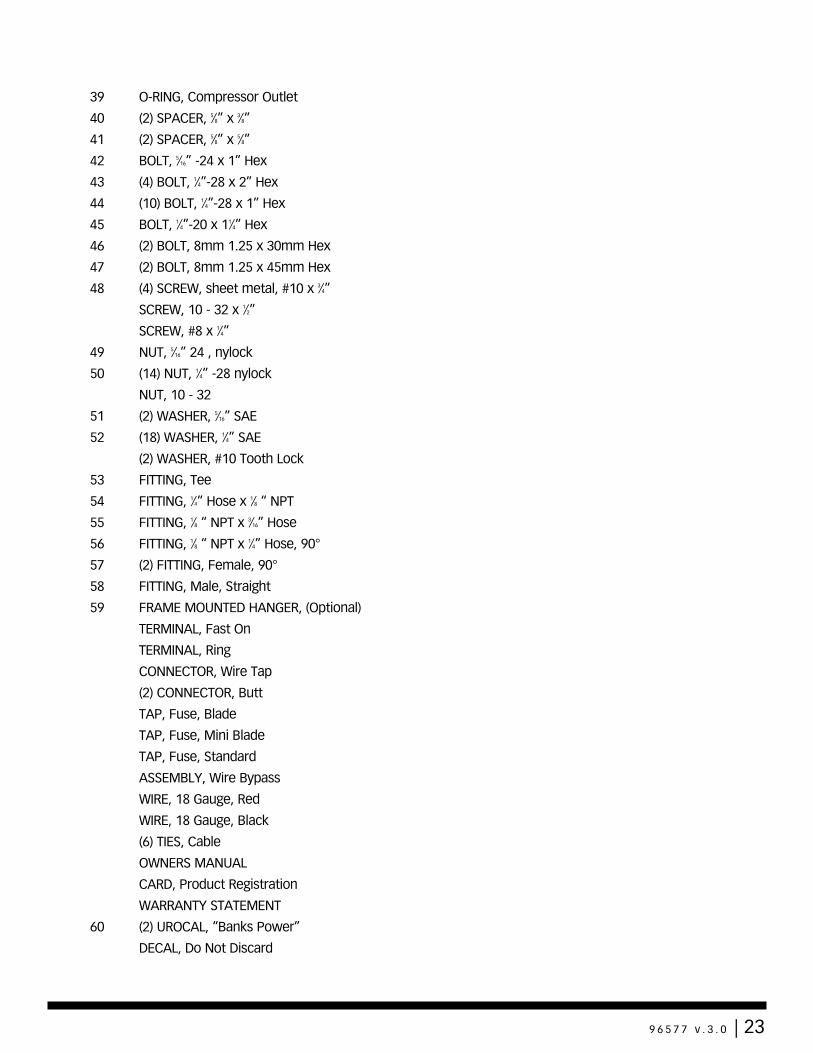
39 O-RING, Compressor Outlet
40 (2) SPACER, 5⁄8” x 3⁄8”
41 (2) SPACER, 5⁄8” x 5⁄8”
42 BOLT, 5⁄16” -24 x 1” Hex
43 (4) BOLT, 1⁄4”-28 x 2” Hex
44 (10) BOLT, 1⁄4”-28 x 1” Hex
45 BOLT, 1⁄4”-20 x 11⁄4” Hex
46 (2) BOLT, 8mm 1.25 x 30mm Hex
47 (2) BOLT, 8mm 1.25 x 45mm Hex
48 (4) SCREW, sheet metal, #10 x 3⁄4”
SCREW, 10 - 32 x 1⁄2”
SCREW, #8 x 1⁄4”
49 NUT, 5⁄16” 24 , nylock
50 (14) NUT, 1⁄4” -28 nylock
NUT, 10 - 32
51 (2) WASHER, 5⁄16” SAE
52 (18) WASHER, 1⁄4” SAE
(2) WASHER, #10 Tooth Lock
53 FITTING, Tee
54 FITTING, 1⁄4” Hose x 1⁄8 “ NPT
55 FITTING, 1⁄8 “ NPT x 3⁄16” Hose
56 FITTING, 1⁄8 “ NPT x 1⁄4” Hose, 90°
57 (2) FITTING, Female, 90°
58 FITTING, Male, Straight
59 FRAME MOUNTED HANGER, (Optional)
TERMINAL, Fast On
TERMINAL, Ring
CONNECTOR, Wire Tap
(2) CONNECTOR, Butt
TAP, Fuse, Blade
TAP, Fuse, Mini Blade
TAP, Fuse, Standard
ASSEMBLY, Wire Bypass
WIRE, 18 Gauge, Red
WIRE, 18 Gauge, Black
(6) TIES, Cable
OWNERS MANUAL
CARD, Product Registration
WARRANTY STATEMENT
60 (2) UROCAL, “Banks Power”
DECAL, Do Not Discard
9 6 5 7 7 v . 3 . 0 | 23

Gale Banks Engineering 546 Duggan Avenue • Azusa, CA 91702 (626) 969-9600 • Fax (626) 334-1743
Product Information & Sales: (800) 438-7693Customer Support: (888) 839-5600 Installation Support: (888) 839-2700
bankspower.com