Generic Adaptation Languages Explicit Intelligence in Adaptive Hypermedia

1
15-446 Distributed Systems
Spring 2009
L-24 Adaptive Applications

2
State of the Art – Manual Adaptation
Objective: automating adaptation
?
California New York

3
Motivation
Large-scale distributed services and applications Napster, Gnutella, End System Multicast, etc
Large number of configuration choicesK participants O(K2) e2e paths to consider
Stanford MIT
CMUBerkeley
CMU
MIT
Stanford
Berkeley
Stanford MIT
CMUBerkeley
CMU
MIT
Stanford
Berkeley
Stanford MIT
CMUBerkeley
CMU
MIT
Stanford
Berkeley

4
Why is Automated Adaptation Hard?
Must infer Internet performance Scalability Accuracy Tradeoff with timeliness
Support for a variety of applications Different performance metrics API requirements
Layered implementations hide information

5
Tools to Automate Adaptation
Tools to facilitate the creation of adaptive networked applications
Adapting on longer time scale (minutes) Deciding what actions to perform Deciding where to perform actions Need to predict performance
Adapting on short time scale (round-trip time) Deciding how to perform action Need to determine correct rate of transmission

6
Adaptation on Different Time Scales
?
California New York
Long Time Scale
Short Time Scale
Content Negotiation
Server Selection
Adaptive Media

7
Motivation
Source: planet-lab.org
What’s the closest server to a client in Brazil ?
Geographical distances-------------------------------server1 -> 4500 milesserver2 -> 6000 miles……
Client
Server

8
Motivation
Difficulties: Geographical distances ≠ network distances
Routing policies/Connectivity GPS not available
Client needs ‘N’ distances to select the closest server

9
Motivation
Source: planet-lab.org
Network Latency (tim
e)
Network Latency-------------------------------server1 -> 120 msserver2 -> 130 ms……

10
Motivation
Network latency = network distance E.g. ping measurements
Still have the issue of ‘N’ distances… Need ‘N’ measurements (high overhead) Update list of network distances How do we solve this problem ?

11
Outline
Active Measurements
Passive Observation
Network Coordinates

12
Network Distance
Round-trip propagation and transmission delayReflects Internet topology and routingA good first order performance optimization
metric Helps achieve low communication delay A reasonable indicator of TCP throughput
Can weed out most bad choicesBut the O(N2) network distances are also hard
to determine efficiently in Internet-scale systems

13
Active Measurements
Network distance can be measured with ping-pong messages
But active measurement does not scale

14
Scaling Alternatives

15
State of the Art: IDMaps [Francis et al ‘99]
A network distance prediction service
Tracer
Tracer
Tracer
HOPS Server
A
B
50ms
A/B

16
Assumptions
Probe nodes approximate direct path May require large number Careful placement may help
Requires that distance between end-points is approximated by sum Triangle inequality must hold (i.e., (a,c) > (a,b) + (b,c)

17
Triangle Inequality in the Internet

18
A More Detailed Internet Map
How do we … build a structured atlas of the Internet? predict routing between arbitrary end-hosts? measure properties of links in the core? measure links at the edge?

19
Build a Structural Atlas of the Internet
Use PlanetLab + public traceroute servers Over 700 geographically distributed vantage points
Build an atlas of Internet routes Perform traceroutes to a random sample of BGP
prefixes Cluster interfaces into PoPs Repeat daily from vantage points

20
Model for Path Prediction
SD
V2 (Rio)
V1 (Seattle)
(Portland)(Paris)
V3 (Chicago)
I Identify candidate paths by intersecting observed
routes
Choose candidate path that models Internet
routing
Actual path unknown
V4 (Atlanta)
I2

21
Example of Path Prediction
Actual path: RTT 298ms Predicted path: RTT 310ms

22
Predicting Path Properties
To estimate end-to-end path properties between arbitrary S and D Use measured atlas to predict route Combine properties of
Links in the core along predicted route Access links at either end
Latency Sum of link latencies
Loss-rate Product of link loss-rates
Bandwidth Minimum of link bandwidths

23
Outline
Active Measurements
Passive Observation
Network Coordinates

24
SPAND Design Choices
Measurements are shared Hosts share performance information by placing
it in a per-domain repositoryMeasurements are passive
Application-to-application traffic is used to measure network performance
Measurements are application-specific When possible, measure application response
time, not bandwidth, latency, hop count, etc.

25
SPAND Architecture
Data
Perf. Reports
Perf Query/Response
Client
Packet Capture
Host
Client
PerformanceServer
Internet

26
SPAND Assumptions
Geographic Stability: Performance observed by nearby clients is similar works within a domain
Amount of Sharing: Multiple clients within domain access same destinations within reasonable time period strong locality exists
Temporal Stability: Recent measurements are indicative of future performance true for 10’s of minutes

27
Prediction Accuracy
Packet capture trace of IBM Watson trafficCompare predictions to actual throughputs
Cu
mu
lati
ve P
rob
ab
ility
Ratio of Predicted to Actual Throughput
0
0.2
0.4
0.6
0.8
1
1/64 1/4 1 4 16 641/16

28
Outline
Active Measurements
Passive Observation
Network Coordinates
29
First Key Insight
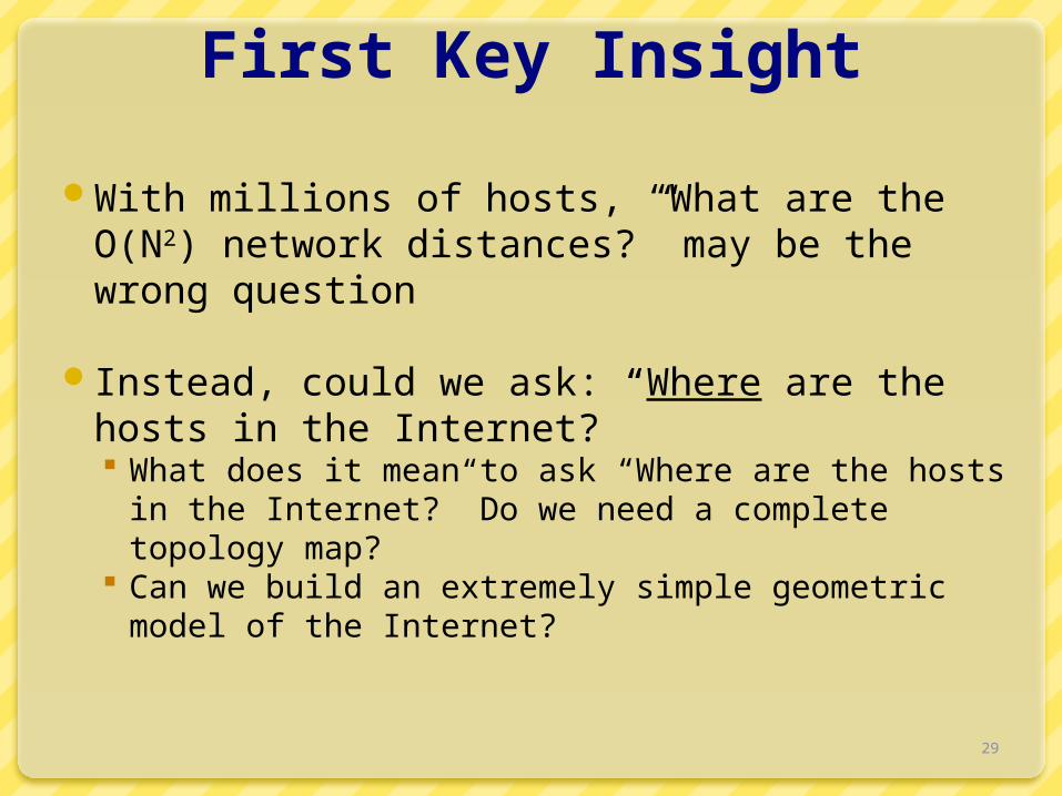
With millions of hosts, “What are the O(N2) network distances?” may be the wrong question
Instead, could we ask: “Where are the hosts in the Internet?” What does it mean to ask “Where are the hosts in the
Internet?” Do we need a complete topology map? Can we build an extremely simple geometric model of
the Internet?

30
New Fundamental Concept:“Internet Position”
Using GNP, every host can have an “Internet position” O(N) positions, as opposed to O(N2) distances
Accurate network distance estimates can be rapidly computed from “Internet positions”
“Internet position” is a localproperty that can bedetermined before applications need it
Can be an interface for independent systems to interact
y(x2,y2,z2)
x
z
(x1,y1,z1)
(x3,y3,z3)(x4,y4,z4)

31
Vision: Internet Positioning Service
Enable every host to independently determine its Internet position
Internet position should be as fundamental as IP address “Where” as well as “Who”
126.93.2.34
65.4.3.87
12.5.222.1
33.99.31.1
123.4.22.54
128.2.254.36
(2,0)(6,0)
(1,3)
(2,4)
(5,4)(7,3)

32
Global Network Positioning (GNP) Coordinates
Model the Internet as a geometric space (e.g. 3-D Euclidean)
Characterize the position of any end host with geometric coordinates
Use geometric distances to predict network distances
y(x2,y2,z2)
x
z
(x1,y1,z1)
(x3,y3,z3)(x4,y4,z4)

33
Landmark Operations (Basic Design)
Measure inter-Landmark distances Use minimum of several round-trip time (RTT) samples
Compute coordinates by minimizing the discrepancy between measured distances and geometric distances Cast as a generic multi-dimensional minimization problem, solved
by a central node
y
xInternet
(x2,y2)
(x1,y1)
(x3,y3)
L1
L2
L3
L1
L2
L3

34
Ordinary Host Operations (Basic Design)
Each host measures its distances to all the Landmarks Compute coordinates by minimizing the discrepancy
between measured distances and geometric distances Cast as a generic multi-dimensional minimization problem, solved
by each host
x
Internet
(x4,y4)
L1
L2
L3
y (x2,y2)
(x1,y1)
(x3,y3)
L2
L1
L3

35
Overall Accuracy
0.1 0.28

36
Why the Difference?
IDMaps overpredicts
IDMapsGNP (1-dimensional model)

37
Alternate Motivation
Select nodes based on a set of system properties
Real-world problems Locate closest game server Distribute web-crawling to nearby hosts Perform efficient application level multicast Satisfy a Service Level Agreement Provide inter-node latency bounds for clusters

38
Underlying Abstract Problems
I. Finding closest node to targetII. Finding the closest node to the center of a
set of targetsIII. Finding a node that is <ri ms from target ti
for all targets

39
Meridian Approach
Solve node selection directly without computing coordinates Combine query routing with active measurements
3 Design Goals Accurate: Find satisfying nodes with high probability General: Users can express their network location
requirements Scalable: O(log N) state per node
Design Tradeoffs Active measurements incur higher query latencies Overhead more dependent on query load

40
Multi-resolution Rings
Organize peers into small fixed number of concentric rings
Radii of rings grow outwards exponentiallyLogarithmic number of peers per ringRetains a sufficient number of pointers to
remote regions

41
Multi-resolution Ring structure
For the ith ring:Inner Radius ri = si-1
Outer Radius Ri = si
is a constants is multiplicative increase
factorr0 = 0, R0 = Each node keeps track of finite
rings
42
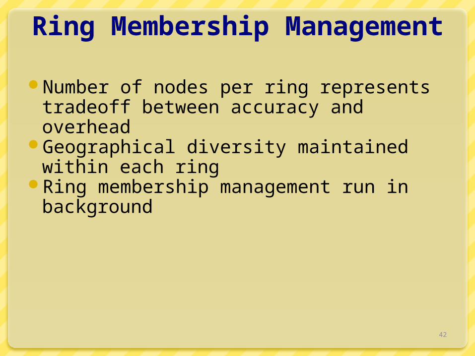
Ring Membership Management
Number of nodes per ring represents tradeoff between accuracy and overhead
Geographical diversity maintained within each ring
Ring membership management run in background

43
Gossip Based Node Discovery
Aimed to assist each node to maintain a few pointers to a diverse set of nodes
Protocol1. Each node A randomly picks a node B from each of its
rings and sends a gossip packet to B containing a randomly chosen node from each of its rings
2. On receiving the packet, node B determines through direct probes its latency to A and to each of the nodes contained in the gossip packet from A
3. After sending a gossip packet to a node in each of its rings, node A waits until the start of its next gossip period and then begins again from step 1

44
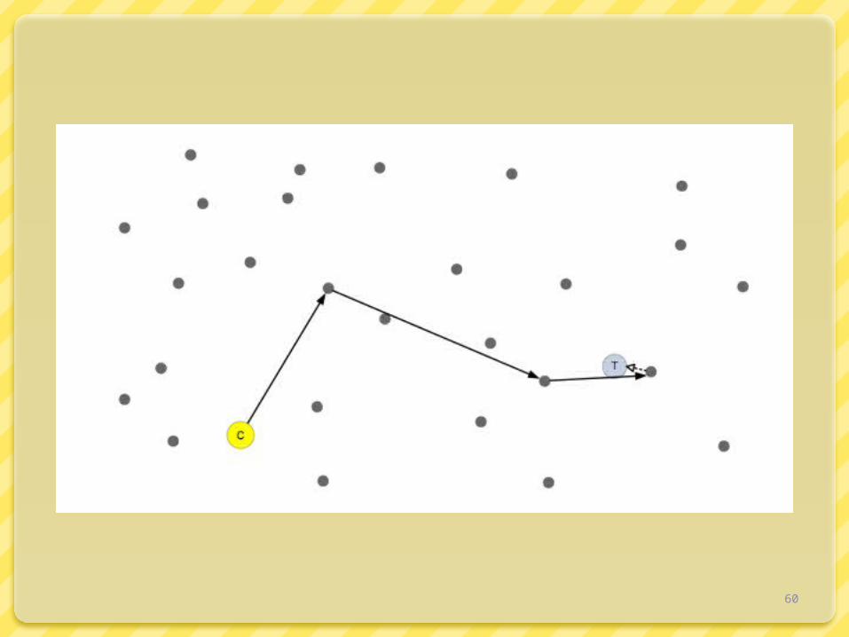
Closest Node Discovery
Client sends closest node discovery request for target T to Meridian node A
Node A determines latency to T, say dNode A probes its ring members within
distance (1-β).d to (1+β).d, where β is the acceptance threshold between 0 and 1
The request is then forwarded to closest node discovered that is closer than β times the distance d to T
Process continues until no node that is β times closer can be found

45

46

47

48

49

50

51

52

53

54

55

56

57

58

59
60

61

62

63

64
Revisit: Why is Automated Adaptation Hard?
Must infer Internet performance Scalability Accuracy Tradeoff with timeliness
Support for a variety of applications Different performance metrics API requirements
Layered implementations hide information