KYT 2018: Bentoniteinvestigations -...
67
07 April 2017 Wojciech T. So łowski KYT 2018: Bentonite investigations
Transcript of KYT 2018: Bentoniteinvestigations -...

07 April 2017
WojciechT. Sołowski
KYT 2018: Bentonite investigations

2
Bentonite!


THEBES goals
Experimental research
Data for modelling
Creation & validation of
numerical models
Implementation into numerical software
Case studies
feedback loop feedback loop
Soft clay barriers:thermo – hydro – mechanical – chemical
coupling

5
Outline
I. Introduction & overview II. Research at Aalto

6
Bentonite
Highly compactedbricks, made of dry bentonite, used to construct a barrier preventing possible contamination
during construction
during dismantling
© Villar, 2016

7
Bentonite
during construction
during dismantling
Dry compacted bentonite bricks swell if wetted, hopefully leading to a self-healing and impermeable barrier
© Villar, 2016

8
Bentonite - microstructure
Bentonite behaviour is complex and to predict it reliably we need to understand the physical processes which leads to the observable macroscopic behaviour
© Villar, 2016

9
Bentonite behaviour is complex and to predict it reliably we need to understand the physical processes which leads to the observable macroscopic behaviour
© Villar, 2016© Lloret et al. 2003
Bentonite - microstructure

10
Bentonite - microstructure Forces acting in bentonite:
Macroscale: forces from mechanical loading
Meso: capillary forces due to water menisci between aggregates
Micro: Forces within laminae of clay minerals (mainly montmorillonite) – inter-particle distance exceeds ~30-40 Å van der Waals attraction & electric repulsion on atomic levelinter-particle distance below ~10-20 Å –electric repulsion on atomic level
© Santamarina, 2001
11
Bentonite swellling
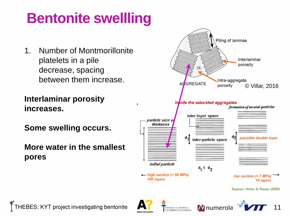
1. Number of Montmorillonite platelets in a pile decrease, spacing between them increase.
Interlaminar porosity increases.
Some swelling occurs.
More water in the smallest pores
© Villar, 2016

12
Bentonite - microstructure

13
Bentonite swelling
2. Size of the aggregates changes. They become also more easy to break. Double porosity structure slowly disappears
Interlaminar porosity still increases.
More some swelling occurs.
© Delage et al. 2006

14
Bentonite swelling: montmorillonite water absorption
3. Amount of water between layers of montmorillonite changes
Additionally, the swelling is affected by the mesoscale – size of the aggregates changes and capillary forces make a difference
© Delage, 2015© Sayiouri et al. 2000

15
Bentonite swelling
4. Swelling pressure is affected by the mechanical, thermal, conditions, as well as availability of water and water composition (e.g. salinity).
Similarly, the number of layers / volume change is different for different mechanical conditions: complex thermo-hydro-mechanical-chemical coupling
© Delage, 2015

16
Water transportDue to complex microstructure, water transport is complex, mixture of transport via vapour and liquid.
Also highly temperature dependent
Necessary to predict swelling, as swelling depends on amount of water available.
© Delage, 2015
Prediction in time is crucial, as material is affected by stress history
17
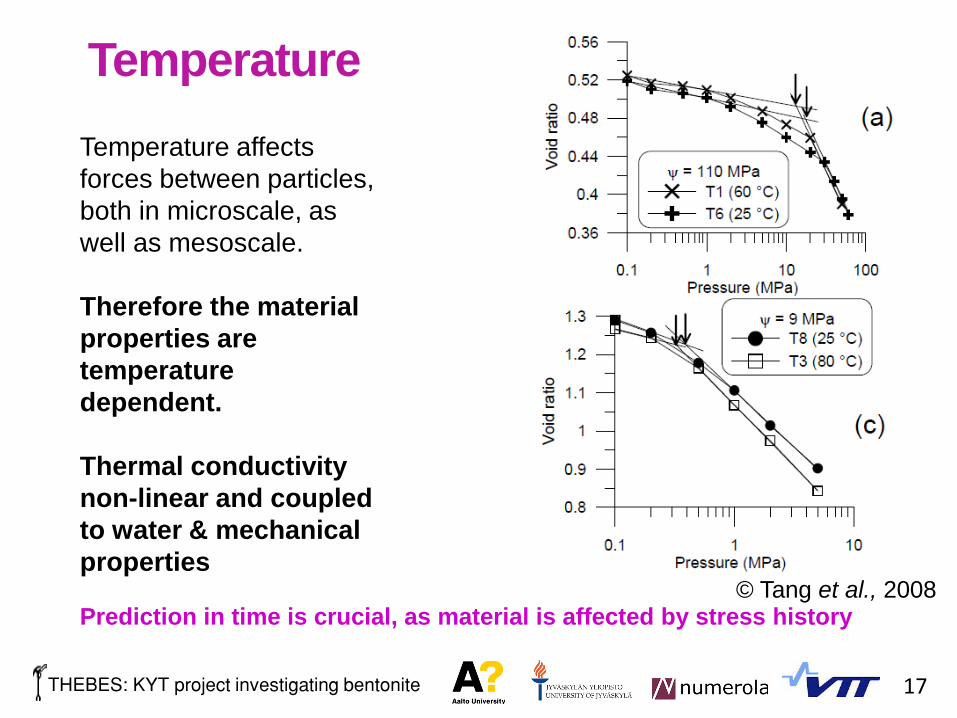
TemperatureTemperature affects forces between particles, both in microscale, as well as mesoscale.
Therefore the material properties are temperature dependent.
Thermal conductivity non-linear and coupled to water & mechanical properties
© Tang et al., 2008Prediction in time is crucial, as material is affected by stress history

18
Water salinity affects the hydraulic behaviour of bentonite, as well asmechanical properties. It also affects the swelling of bentonite aggregatesand generally lowers the swelling pressure.
Salinity effects
© Manca et al., 2016

19
Water in liquid phase transport salt, but water vapour not!In non-isothermal condition creation of high saline zones (zonereached wetted by liquid water which evaporates) likely. Effects onmaterial being investigated.
Salinity effects
© Manca et al., 2016

20
Outline
I. Introduction & overviewII. Research at Aalto
I. THMC modelling of bentonite / swelling clays

21
Thermo-hydro-mechanical FE framework
mechanical: amended BBM, models by della Vecchia et al. (2013, 2014, 2015), new models which take into account micro and macro structure of bentonite are in development
hydraulic: number of models for water retention, Philip & De Vries model for vapourtransport, extended Darcy law for liquid water transport, Henry’s law for solubility of water, phase changes and heat effects are taken into account
thermal: heat flux in solid, water and gas phases, full energy balance / coupling
Taking into account well established laws of physics and thermodynamics
Some experiments on water retention behaviour of MX80 bentonite and its microstructure in saline solutions leading to inclusion of those into modelling (chemical coupling)

22
Thermo-hydro-mechanical FE framework

23
Thermo-hydro-mechanical FE framework
Barcelona Basic Model (Alonso et al. 1990)

24
Thermo-hydro-mechanical FE framework
mechanical: BBM (Alonso et al. 1990)
parameterκ
(-)
𝜿𝜿𝒔𝒔(-)
𝒌𝒌
(-)
𝑮𝑮
(MPa)
𝜷𝜷
(MPa-1)
𝒓𝒓
(-)
𝝀𝝀(𝟎𝟎)
(-)
𝒑𝒑𝒄𝒄
(kPa)
𝑴𝑴
(-)
𝑵𝑵(𝟎𝟎)
(-)
𝒑𝒑𝟎𝟎∗
(kPa)
value 0.02 0.117 0.08 10.1 0.05 0.20 0.5 41 0.5 6.36 variable
accuracy +0.005-0.01
+0.10
-0.01
+0.0
-0.05±0.5 +0.5
-0.02
+0.2
-0.0
+0.0
-0.2±30 +0.1
-0.05±0.5 −
Porté, Abed & Sołowski (in preparation)
parameters established based on:- Tang et al. (2008), PhD Thesis, Ecole des Ponts- Villar (2005), Ciemat technical report, CIEMAT/DIAE/54540/5/04- Seiphoori (2014), PhD thesis, Ecole Polytechnique Federale de Lausanne- Dueck and Nilsson (2010), SKB Technical report, TR-10-32- Dueck et al. (2010), SKB Technical report, TR-10-55

25
Thermo-hydro-mechanical FE framework
mechanical: amended BBM – enhanced for temperature effects
Abed & Sołowski (2017)
Salinity effects on mechanical behaviour: in progress
𝑝𝑝𝑜𝑜𝑜𝑜∗ = 𝑝𝑝𝑜𝑜∗ + 2 𝛼𝛼1Δ𝑇𝑇 + 𝛼𝛼3Δ𝑇𝑇 Δ𝑇𝑇 , Gens (1995)
𝑝𝑝𝑜𝑜𝑜𝑜∗ = 𝑝𝑝𝑜𝑜∗ 1 − 𝛾𝛾𝑜𝑜 log𝑇𝑇 − 𝑇𝑇𝑟𝑟𝑟𝑟𝑟𝑟𝑇𝑇𝑜𝑜 − 𝑇𝑇𝑟𝑟𝑟𝑟𝑟𝑟
or
Laloui & Cekerevac (2003)
𝜀𝜀𝑟𝑟𝑜𝑜 =𝛼𝛼𝑜𝑜 + 𝛼𝛼2 𝑇𝑇 − 𝑇𝑇𝑜𝑜 ��𝑇
3𝜅𝜅 = 𝜅𝜅𝑜𝑜 1 + 𝛼𝛼𝜅𝜅𝑠𝑠
Changes in elasticity:

26
Thermo-hydro-mechanical FE framework
hydraulic: number of models for water retention, Philip & De Vries model for vapour transport, extended Darcy law for liquid water transport, Henry’s law for solubility of air, phase changes and heat effects are taken into account. Also gas flow.
𝒒𝒒𝑙𝑙 = −𝐾𝐾𝑙𝑙 𝛻𝛻ℎ𝑤𝑤 + 1 Liquid phase
𝒒𝒒𝑔𝑔 = −𝐾𝐾𝑔𝑔 𝛻𝛻ℎ𝑔𝑔 +𝜌𝜌𝑔𝑔
𝜌𝜌𝑤𝑤𝑙𝑙gas phase
Advective liquid and gas flow (transport due to head difference):
𝐾𝐾𝑙𝑙 = 𝐾𝐾𝑠𝑠𝑠𝑠𝑠𝑠𝑙𝑙𝑆𝑆𝑙𝑙 − 𝑆𝑆𝑟𝑟𝑟𝑟𝑠𝑠𝑙𝑙
𝑆𝑆𝑠𝑠𝑠𝑠𝑠𝑠𝑙𝑙 − 𝑆𝑆𝑟𝑟𝑟𝑟𝑠𝑠𝑙𝑙
3
𝐾𝐾𝑠𝑠𝑠𝑠𝑠𝑠𝑙𝑙 =𝑔𝑔𝜌𝜌𝑤𝑤𝑙𝑙 𝑘𝑘𝑠𝑠𝑠𝑠𝑠𝑠𝑙𝑙
𝜇𝜇𝑙𝑙
𝑘𝑘𝑠𝑠𝑠𝑠𝑠𝑠𝑙𝑙 = 𝑘𝑘𝑟𝑟𝑟𝑟𝑟𝑟𝑙𝑙 𝑛𝑛3
1 − 𝑛𝑛 21 − 𝑛𝑛𝑟𝑟𝑟𝑟𝑟𝑟
2
𝑛𝑛𝑟𝑟𝑟𝑟𝑟𝑟3 𝜇𝜇𝑙𝑙 = 243.18 × 10⁻⁷ 10247.8𝑜𝑜−140
Abed & Sołowski (2017)

27
Thermo-hydro-mechanical FE framework
hydraulic: number of models for water retention, Philip & De Vries model for vapour transport, extended Darcy law for liquid water transport, Henry’s law for solubility of air, phase changes and heat effects are taken into account. Also gas flow.
gas phase𝒒𝒒𝑔𝑔 = −𝐾𝐾𝑔𝑔 𝛻𝛻ℎ𝑔𝑔 +𝜌𝜌𝑔𝑔
𝜌𝜌𝑤𝑤𝑙𝑙
Advective liquid and gas flow:
𝐾𝐾𝑔𝑔 = 𝐾𝐾𝑑𝑑𝑟𝑟𝑑𝑑𝑔𝑔 𝑆𝑆𝑔𝑔 − 𝑆𝑆𝑟𝑟𝑟𝑟𝑠𝑠
𝑔𝑔
𝑆𝑆𝑑𝑑𝑟𝑟𝑑𝑑𝑔𝑔 − 𝑆𝑆𝑟𝑟𝑟𝑟𝑠𝑠
𝑔𝑔
3
𝐾𝐾𝑑𝑑𝑟𝑟𝑑𝑑𝑔𝑔 =
𝑔𝑔𝜌𝜌𝑤𝑤𝑙𝑙 𝑘𝑘𝑑𝑑𝑟𝑟𝑑𝑑𝑔𝑔
𝜇𝜇𝑔𝑔𝜇𝜇𝑔𝑔 = 1.48 × 10⁻⁶
𝑇𝑇
1 + 119𝑇𝑇
Abed & Sołowski (2017)
28
Thermo-hydro-mechanical FE framework
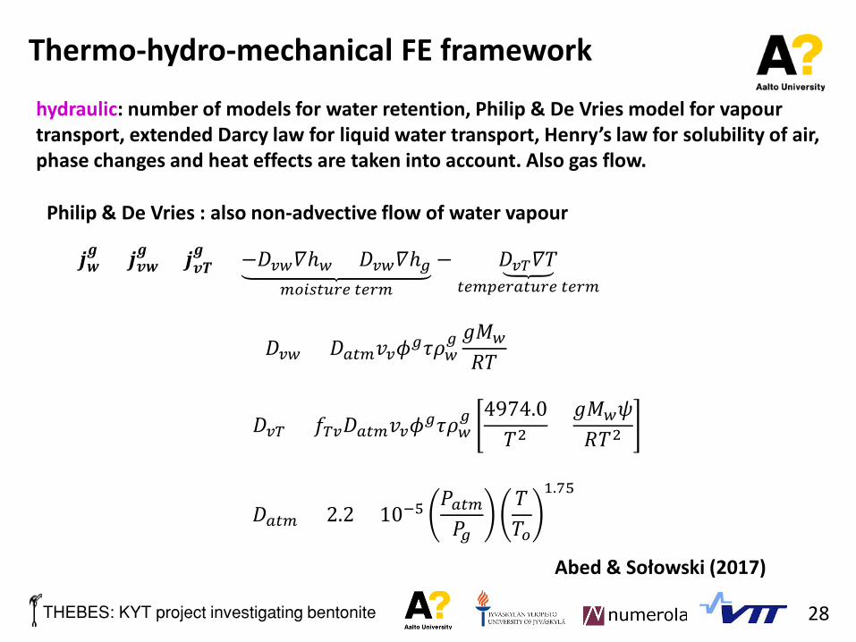
hydraulic: number of models for water retention, Philip & De Vries model for vapour transport, extended Darcy law for liquid water transport, Henry’s law for solubility of air, phase changes and heat effects are taken into account. Also gas flow.
Philip & De Vries : also non-advective flow of water vapour
𝒋𝒋𝒘𝒘𝒈𝒈 = 𝒋𝒋𝒗𝒗𝒘𝒘
𝒈𝒈 + 𝒋𝒋𝒗𝒗𝒗𝒗𝒈𝒈 = −𝐷𝐷𝑣𝑣𝑤𝑤𝛻𝛻ℎ𝑤𝑤 + 𝐷𝐷𝑣𝑣𝑤𝑤𝛻𝛻ℎ𝑔𝑔
𝑚𝑚𝑜𝑜𝑚𝑚𝑠𝑠𝑠𝑠𝑚𝑚𝑟𝑟𝑟𝑟 𝑠𝑠𝑟𝑟𝑟𝑟𝑚𝑚
− 𝐷𝐷𝑣𝑣𝑜𝑜𝛻𝛻𝑇𝑇𝑠𝑠𝑟𝑟𝑚𝑚𝑡𝑡𝑟𝑟𝑟𝑟𝑠𝑠𝑠𝑠𝑚𝑚𝑟𝑟𝑟𝑟 𝑠𝑠𝑟𝑟𝑟𝑟𝑚𝑚
𝐷𝐷𝑣𝑣𝑤𝑤 = 𝐷𝐷𝑠𝑠𝑠𝑠𝑚𝑚𝑣𝑣𝑣𝑣𝜙𝜙𝑔𝑔𝜏𝜏𝜌𝜌𝑤𝑤𝑔𝑔 𝑔𝑔𝑀𝑀𝑤𝑤𝑅𝑅𝑇𝑇
𝐷𝐷𝑣𝑣𝑜𝑜 = 𝑓𝑓𝑜𝑜𝑣𝑣𝐷𝐷𝑠𝑠𝑠𝑠𝑚𝑚𝑣𝑣𝑣𝑣𝜙𝜙𝑔𝑔𝜏𝜏𝜌𝜌𝑤𝑤𝑔𝑔 4974.0
𝑇𝑇2 +𝑔𝑔𝑀𝑀𝑤𝑤𝜓𝜓𝑅𝑅𝑇𝑇2
𝐷𝐷𝑠𝑠𝑠𝑠𝑚𝑚 = 2.2 × 10⁻⁵𝑃𝑃𝑠𝑠𝑠𝑠𝑚𝑚𝑃𝑃𝑔𝑔
𝑇𝑇𝑇𝑇𝑜𝑜
1.75
Abed & Sołowski (2017)

29
Thermo-hydro-mechanical FE framework
hydraulic: number of models for water retention, Philip & De Vries model for vapour transport, extended Darcy law for liquid water transport, Henry’s law for solubility of air, phase changes and heat effects are taken into account. Also gas flow.
Henry’s law
𝐻𝐻 =𝜌𝜌𝑤𝑤𝑙𝑙
𝐻𝐻𝑐𝑐𝑅𝑅𝑇𝑇𝑀𝑀𝑤𝑤
𝜕𝜕𝐻𝐻𝜕𝜕𝑡𝑡
= 𝑔𝑔𝜌𝜌𝑤𝑤𝑙𝑙 𝛽𝛽𝑤𝑤𝑡𝑡𝐻𝐻𝜕𝜕ℎ𝑤𝑤𝜕𝜕𝑡𝑡
+1𝑇𝑇− 𝛽𝛽𝑤𝑤𝑜𝑜 𝐻𝐻
𝜕𝜕𝑇𝑇𝜕𝜕𝑡𝑡
Coupling:Formulation include mass balance for the phases and changes in density due to all the factors. Coupling due to saline concentration is being developed.
Abed & Sołowski (2017)

30
Thermo-hydro-mechanical FE framework
coupling: mass balance of solid, liquid and dry air
solid:
𝜕𝜕𝑛𝑛𝜕𝜕𝑡𝑡 = 1 − 𝑛𝑛
𝜕𝜕𝜀𝜀𝑣𝑣𝜕𝜕𝑡𝑡 + 𝛽𝛽𝑠𝑠𝑡𝑡
𝜕𝜕𝑝𝑝𝜕𝜕𝑡𝑡 − 𝛽𝛽𝑠𝑠𝑜𝑜
𝜕𝜕𝑇𝑇𝜕𝜕𝑡𝑡
𝜕𝜕 𝜙𝜙𝑠𝑠𝜌𝜌𝑠𝑠
𝜕𝜕𝑡𝑡+ 𝛻𝛻 � 𝜙𝜙𝑠𝑠𝜌𝜌𝑠𝑠𝒗𝒗𝑠𝑠 = 0,
𝜌𝜌𝑠𝑠 = 𝜌𝜌𝑠𝑠𝑜𝑜𝑒𝑒𝛽𝛽𝑠𝑠𝑠𝑠 𝑡𝑡−𝑡𝑡𝑟𝑟𝑟𝑟𝑟𝑟𝑜𝑜 −𝛽𝛽𝑠𝑠𝑠𝑠 𝑜𝑜−𝑜𝑜𝑜𝑜 ,
𝜕𝜕𝜌𝜌𝑠𝑠
𝜕𝜕𝑡𝑡 =𝜕𝜕𝜌𝜌𝑠𝑠
𝜕𝜕𝑝𝑝𝜕𝜕𝑝𝑝𝜕𝜕𝑡𝑡 +
𝜕𝜕𝜌𝜌𝑠𝑠
𝜕𝜕𝑇𝑇𝜕𝜕𝑇𝑇𝜕𝜕𝑡𝑡 = 𝛽𝛽𝑠𝑠𝑡𝑡𝜌𝜌𝑠𝑠
𝜕𝜕𝑝𝑝𝜕𝜕𝑡𝑡 − 𝛽𝛽𝑠𝑠𝑜𝑜𝜌𝜌𝑠𝑠
𝜕𝜕𝑇𝑇𝜕𝜕𝑡𝑡
Abed & Sołowski (2017)

31
Thermo-hydro-mechanical FE framework
coupling: mass balance of solid, liquid and dry air
�𝑛𝑛 𝜌𝜌𝑤𝑤𝑙𝑙 − 𝜌𝜌𝑤𝑤𝑔𝑔 𝜕𝜕𝑆𝑆𝑙𝑙
𝜕𝜕𝑇𝑇 − 1 − 𝑛𝑛 𝑆𝑆𝑙𝑙𝜌𝜌𝑤𝑤𝑙𝑙 + 𝑆𝑆𝑔𝑔𝜌𝜌𝑤𝑤𝑔𝑔 𝛽𝛽𝑠𝑠𝑜𝑜 − 𝑛𝑛𝑆𝑆𝑙𝑙𝛽𝛽𝑤𝑤𝑜𝑜𝜌𝜌𝑤𝑤𝑙𝑙
water:𝜕𝜕 𝜙𝜙𝑙𝑙𝜌𝜌𝑙𝑙𝜔𝜔𝑤𝑤𝑙𝑙
𝜕𝜕𝑡𝑡+ 𝛻𝛻 � 𝜙𝜙𝑙𝑙𝜌𝜌𝑙𝑙𝜔𝜔𝑤𝑤𝑙𝑙 𝒗𝒗𝑙𝑙 + 𝛻𝛻 � 𝒋𝒋𝑤𝑤𝑙𝑙
𝑤𝑤𝑠𝑠𝑠𝑠𝑟𝑟𝑟𝑟 𝑚𝑚𝑖𝑖 𝑙𝑙𝑚𝑚𝑙𝑙𝑚𝑚𝑚𝑚𝑑𝑑 𝑡𝑡𝑝𝑠𝑠𝑠𝑠𝑟𝑟
+𝜕𝜕 𝜙𝜙𝑔𝑔𝜌𝜌𝑔𝑔𝜔𝜔𝑤𝑤
𝑔𝑔
𝜕𝜕𝑡𝑡+ 𝛻𝛻 � 𝜙𝜙𝑔𝑔𝜌𝜌𝑔𝑔𝜔𝜔𝑤𝑤
𝑔𝑔𝒗𝒗𝑔𝑔 + 𝛻𝛻 � 𝒋𝒋𝑤𝑤𝑔𝑔
𝑤𝑤𝑠𝑠𝑠𝑠𝑟𝑟𝑟𝑟 𝑚𝑚𝑖𝑖 𝑔𝑔𝑠𝑠𝑠𝑠 𝑡𝑡𝑝𝑠𝑠𝑠𝑠𝑟𝑟
+ ⏟0𝑤𝑤𝑠𝑠𝑠𝑠𝑟𝑟𝑟𝑟 𝑚𝑚𝑖𝑖 𝑠𝑠𝑜𝑜𝑙𝑙𝑚𝑚𝑑𝑑 𝑡𝑡𝑝𝑠𝑠𝑠𝑠𝑟𝑟
= 0
Abed & Sołowski (2017)

32
Thermo-hydro-mechanical FE framework
coupling: mass balance of solid, liquid and dry air
dry air:
𝜕𝜕 𝜙𝜙𝑙𝑙𝜌𝜌𝑙𝑙𝜔𝜔𝑠𝑠𝑙𝑙
𝜕𝜕𝑡𝑡+ 𝛻𝛻 � 𝜙𝜙𝑙𝑙𝜌𝜌𝑙𝑙𝜔𝜔𝑠𝑠𝑙𝑙 𝒗𝒗𝑙𝑙 + 𝛻𝛻 � 𝒋𝒋𝑠𝑠𝑙𝑙
𝑑𝑑𝑚𝑚𝑠𝑠𝑠𝑠𝑜𝑜𝑙𝑙𝑣𝑣𝑟𝑟𝑑𝑑 𝑑𝑑𝑟𝑟𝑑𝑑 𝑠𝑠𝑚𝑚𝑟𝑟 𝑚𝑚𝑖𝑖 𝑙𝑙𝑚𝑚𝑙𝑙𝑚𝑚𝑚𝑚𝑑𝑑 𝑡𝑡𝑝𝑠𝑠𝑠𝑠𝑟𝑟
+𝜕𝜕 𝜙𝜙𝑔𝑔𝜌𝜌𝑔𝑔𝜔𝜔𝑠𝑠
𝑔𝑔
𝜕𝜕𝑡𝑡+ 𝛻𝛻 � 𝜙𝜙𝑔𝑔𝜌𝜌𝑔𝑔𝜔𝜔𝑠𝑠
𝑔𝑔𝒗𝒗𝑔𝑔 + 𝛻𝛻 � 𝒋𝒋𝑠𝑠𝑔𝑔
𝑑𝑑𝑟𝑟𝑑𝑑 𝑠𝑠𝑚𝑚𝑟𝑟 𝑚𝑚𝑖𝑖 𝑠𝑠𝑜𝑜𝑚𝑚𝑙𝑙 𝑣𝑣𝑜𝑜𝑚𝑚𝑑𝑑𝑠𝑠+ ⏟0
𝑑𝑑𝑟𝑟𝑑𝑑 𝑠𝑠𝑚𝑚𝑟𝑟 𝑚𝑚𝑖𝑖 𝑠𝑠𝑜𝑜𝑙𝑙𝑚𝑚𝑑𝑑 𝑡𝑡𝑝𝑠𝑠𝑠𝑠𝑟𝑟= 0
�𝑛𝑛𝜌𝜌𝑠𝑠 𝐻𝐻 − 1𝜕𝜕𝑆𝑆𝑙𝑙
𝜕𝜕𝑇𝑇 + 𝑛𝑛𝜌𝜌𝑠𝑠𝑆𝑆𝑙𝑙𝜕𝜕𝐻𝐻𝜕𝜕𝑇𝑇 − 1 − 𝑛𝑛 𝜌𝜌𝑠𝑠 𝑆𝑆𝑔𝑔 + 𝐻𝐻𝑆𝑆𝑙𝑙 𝛽𝛽𝑠𝑠𝑜𝑜
Abed & Sołowski (2017)

33
Thermo-hydro-mechanical FE framework
Thermal:
Φ𝑝 = 𝜙𝜙𝑚𝑚𝜌𝜌𝑚𝑚𝜔𝜔𝑘𝑘𝑚𝑚 𝐸𝐸𝑜𝑜𝑘𝑘𝑚𝑚heat capacity:
𝐸𝐸𝑜𝑜𝑘𝑘𝑚𝑚 = 𝑐𝑐𝑘𝑘𝑚𝑚 𝑇𝑇𝑘𝑘𝑚𝑚 − 𝑇𝑇𝑘𝑘𝑜𝑜𝑚𝑚
Φ𝑝 = 1 − 𝑛𝑛 𝜌𝜌𝑠𝑠𝑐𝑐𝑠𝑠 + 𝑛𝑛 𝐻𝐻𝑆𝑆𝑙𝑙 + 𝑆𝑆𝑔𝑔 𝜌𝜌𝑠𝑠𝑐𝑐𝑠𝑠 + 𝑛𝑛𝑆𝑆𝑙𝑙𝜌𝜌𝑤𝑤𝑙𝑙 𝑐𝑐𝑤𝑤𝑙𝑙 + 𝑛𝑛𝑆𝑆𝑔𝑔𝜌𝜌𝑤𝑤𝑔𝑔𝑐𝑐𝑤𝑤
𝑔𝑔 𝑇𝑇 − 𝑇𝑇𝑜𝑜
heat flux:𝒒𝒒𝑝 = �𝒒𝒒𝑜𝑜
𝑐𝑐𝑜𝑜𝑖𝑖𝑑𝑑𝑚𝑚𝑐𝑐𝑠𝑠𝑚𝑚𝑜𝑜𝑖𝑖+ 𝜌𝜌𝑚𝑚 𝜔𝜔𝑘𝑘𝑚𝑚 𝐸𝐸𝑜𝑜𝑘𝑘𝑚𝑚 𝒒𝒒𝑚𝑚
𝑐𝑐𝑜𝑜𝑖𝑖𝑣𝑣𝑟𝑟𝑐𝑐𝑠𝑠𝑚𝑚𝑜𝑜𝑖𝑖 𝑏𝑏𝑑𝑑 𝑙𝑙𝑚𝑚𝑙𝑙𝑚𝑚𝑚𝑚𝑑𝑑 𝑡𝑡𝑝𝑠𝑠𝑠𝑠𝑟𝑟
+ 𝐸𝐸𝑜𝑜𝑘𝑘𝑚𝑚 𝒋𝒋𝑤𝑤𝑚𝑚𝑐𝑐𝑜𝑜𝑖𝑖𝑣𝑣𝑟𝑟𝑐𝑐𝑠𝑠𝑚𝑚𝑜𝑜𝑖𝑖 𝑏𝑏𝑑𝑑 𝑔𝑔𝑠𝑠𝑠𝑠 𝑡𝑡𝑝𝑠𝑠𝑠𝑠𝑟𝑟
𝒒𝒒𝑝 = −λ𝑜𝑜𝛻𝛻𝑇𝑇 + 𝜌𝜌𝑠𝑠𝑐𝑐𝑠𝑠 + 𝜌𝜌𝑤𝑤𝑔𝑔𝑐𝑐𝑤𝑤
𝑔𝑔 𝒒𝒒𝒈𝒈 + 𝜌𝜌𝑤𝑤𝑙𝑙 𝑐𝑐𝑤𝑤𝑙𝑙 + 𝜌𝜌𝑠𝑠𝑐𝑐𝑠𝑠𝐻𝐻 𝒒𝒒𝒍𝒍 𝑇𝑇 − 𝑇𝑇𝑜𝑜 + 𝑐𝑐𝑤𝑤𝑔𝑔 − 𝑐𝑐𝑠𝑠 𝒋𝒋𝑤𝑤
𝑔𝑔 𝑇𝑇 − 𝑇𝑇𝑜𝑜
Abed & Sołowski (2017)

34
Thermo-hydro-mechanical FE framework
Energy balance: very complex
𝛻𝛻 � 𝒒𝒒𝒉𝒉= −λ𝑜𝑜𝛻𝛻 � 𝛻𝛻𝑇𝑇 + 𝜌𝜌𝑠𝑠𝑐𝑐𝑠𝑠 + 𝜌𝜌𝑤𝑤
𝑔𝑔𝑐𝑐𝑤𝑤𝑔𝑔 𝑇𝑇 − 𝑇𝑇𝑜𝑜 𝛻𝛻 � 𝒒𝒒𝑔𝑔 + 𝜌𝜌𝑠𝑠𝑐𝑐𝑠𝑠 + 𝜌𝜌𝑤𝑤
𝑔𝑔𝑐𝑐𝑤𝑤𝑔𝑔 𝒒𝒒𝒈𝒈 � 𝛻𝛻𝑇𝑇
+ 𝜌𝜌𝑤𝑤𝑙𝑙 𝑐𝑐𝑤𝑤𝑙𝑙 + 𝜌𝜌𝑠𝑠𝑐𝑐𝑠𝑠𝐻𝐻 𝑇𝑇 − 𝑇𝑇𝑜𝑜 𝛻𝛻 � 𝒒𝒒𝑙𝑙 + 𝜌𝜌𝑤𝑤𝑙𝑙 𝑐𝑐𝑤𝑤𝑙𝑙 + 𝜌𝜌𝑠𝑠𝑐𝑐𝑠𝑠𝐻𝐻 𝒒𝒒𝑙𝑙 + 𝑐𝑐𝑤𝑤𝑔𝑔 − 𝑐𝑐𝑠𝑠 𝒋𝒋𝑤𝑤
𝑔𝑔 � 𝛻𝛻𝑇𝑇+ 𝑐𝑐𝑤𝑤
𝑔𝑔 − 𝑐𝑐𝑠𝑠 𝑇𝑇 − 𝑇𝑇𝑜𝑜 𝛻𝛻 � 𝒋𝒋𝑤𝑤𝑔𝑔
𝐴𝐴 = −𝜌𝜌𝑠𝑠𝑐𝑐𝑠𝑠 + 𝐻𝐻𝑆𝑆𝑙𝑙𝜌𝜌𝑠𝑠𝑐𝑐𝑠𝑠 + 𝑆𝑆𝑔𝑔𝜌𝜌𝑠𝑠𝑐𝑐𝑠𝑠 + 𝑆𝑆𝑙𝑙𝜌𝜌𝑤𝑤𝑙𝑙 𝑐𝑐𝑤𝑤𝑙𝑙 + 𝑆𝑆𝑔𝑔𝜌𝜌𝑤𝑤𝑔𝑔𝑐𝑐𝑤𝑤
𝑔𝑔 𝑇𝑇 − 𝑇𝑇𝑜𝑜
𝐵𝐵 = 1 − 𝑛𝑛 𝜌𝜌𝑠𝑠𝑐𝑐𝑠𝑠 𝑇𝑇 − 𝑇𝑇𝑜𝑜
𝐶𝐶 = 𝐻𝐻𝜌𝜌𝑠𝑠𝑐𝑐𝑠𝑠 − 𝜌𝜌𝑠𝑠𝑐𝑐𝑠𝑠 + 𝜌𝜌𝑤𝑤𝑙𝑙 𝑐𝑐𝑤𝑤𝑙𝑙 − 𝜌𝜌𝑤𝑤𝑔𝑔𝑐𝑐𝑤𝑤
𝑔𝑔 𝑇𝑇 − 𝑇𝑇𝑜𝑜
𝐷𝐷 = 𝑛𝑛 𝐻𝐻𝑆𝑆𝑙𝑙𝜌𝜌𝑠𝑠𝑐𝑐𝑠𝑠 + 𝑆𝑆𝑔𝑔𝜌𝜌𝑠𝑠𝑐𝑐𝑠𝑠 + 𝑆𝑆𝑙𝑙𝜌𝜌𝑤𝑤𝑙𝑙 𝑐𝑐𝑤𝑤𝑙𝑙 + 𝑆𝑆𝑔𝑔𝜌𝜌𝑤𝑤𝑔𝑔𝑐𝑐𝑤𝑤
𝑔𝑔 + 1 − 𝑛𝑛 𝜌𝜌𝑠𝑠𝑐𝑐𝑠𝑠Abed & Sołowski (2017)

35
Thermo-hydro-mechanical FE simulations
0,60
0,65
0,70
0,75
0,80
0,85
0,90
0,95
1,00
1,05
0 100 200 300 400 500 600 700
void
ratio
e[-]
isotropic net stress p [kPa]
Alonso et al. (1990)Current BBM implementation in Numerrin
Abed et al. (2016)

36
Thermo-hydro-mechanical FE simulations
0
50
100
150
200
250
300
350
0,00 0,05 0,10 0,15 0,20 0,25 0,30
devi
ator
ic st
ress
q[k
Pa]
shear strain εq [-]
Alonso et al. (1990)
Current BBM implementation in Numerrin
Abed et al. (2016)

37
Thermo-hydro-mechanical FE simulations
Abed & Sołowski (2017)

38
Replication of data from Jyväskylä University
Abed et al. (2016)

39
Thermo-hydro-mechanical FE simulations
Abed & Sołowski, (2017)
Infiltration test, Villar (2005)

40
Thermo-hydro-mechanical FE simulations
Abed & Sołowski, (2017)
Infiltration test, Villar (2005)

41
Thermo-hydro-mechanical FE simulations
No perfect match between codes due to different water vapour transport models
isothermal infiltration
Abed & Sołowski, (2017)

42
Thermo-hydro-mechanical FE simulations
non-isothermal infiltration
Abed & Sołowski, (2017)

43
Thermo-hydro-mechanical FE simulations
non-isothermal infiltrationthe effect of swelling on the water hydraulic conductivity
Abed & Sołowski, (2017)

44
FE simulations: CIEMAT Mock-Up testExample: Simulation of CIEMAT Mock-Up test for 2500 days (Martin et al. 2006)The hydro-thermal coupling is based on the theory proposed by Philip & De Vries (1957).
Abed & Sołowski (2017)

45
FE simulations: CIEMAT Mock-Up testExample: Simulation of CIEMAT Mock-Up test for 2500 days (Martin et al. 2006)The hydro-thermal coupling is based on the theory proposed by Philip & De Vries (1957).
Abed & Sołowski (2017)

46
FE simulations: CIEMAT Mock-Up testExample: Simulation of CIEMAT Mock-Up test for 2500 days (Martin et al. 2006)The hydro-thermal coupling is based on the theory proposed by Philip & De Vries (1957).
Abed & Sołowski (2017)

47
Calculated relative humidity versus measurements
FE simulations: CIEMAT Mock-Up test
20
30
40
50
60
70
80
90
100
0 500 1000 1500 2000 2500
Rel
ativ
e hu
mid
ity [%
]
Time [days]
RH1 (0.22,1.0)RH2 (0.37, 1.0)RH3 (0.55,1.0)RH4 (0.7, 1.0)Aalto Code
Abed & Sołowski (2017)

48
Calculated temperature versus measurements
FE simulations: CIEMAT Mock-Up test
0
10
20
30
40
50
60
70
80
90
100
0 500 1000 1500 2000 2500
Tem
pera
ture
[Co ]
Time [days]
T (0.77, 1.185) T (0.58, 1.185)T (0.39, 1.185) T (0.22, 1.185)Aalto Code
Abed & Sołowski (2017)

49
Calculated swelling pressure versus measurements
FE simulations: CIEMAT Mock-Up test
0
1000
2000
3000
4000
5000
6000
7000
8000
9000
10000
0 500 1000 1500 2000 2500
Rad
ial s
tres
s [kP
a]
Time [days]
Radial stress (0.667, 1.0)
Aalto Code
Abed & Sołowski (2017)

50
FE simulations: CIEMAT Mock-Up test
0
200
400
600
800
1000
1200
0 500 1000 1500 2000 2500
wat
er m
ass [
kg]
Time [days]
Water intake measurements
Aalto Code
Abed & Sołowski (2017)
Calculated water intake versus measurements

51
FE simulations: CIEMAT Mock-Up testAalto Code prediction after a duration of 2500 days of the test
Temperature Degree of saturation Porosity

52
References:1- Martin, P. L., Barcala, J. M., & Huertas, F. (2006). Large-scale and long-term coupled thermo-hydro-mechanic experiments with bentonite: the FEBEX mock-up test. Journal of Iberian geology, 32(2), 259-282.
2- Philip, J. R. and D. De Vries.1957. Moisture movement in porous material under temperature gradients. Transactions of the American Geophysical Union, 38 (2): 222-232.
3- Abed, A. A., Sołowski, W. T. (2017). A study on how to couple thermo-hydro-mechanical behaviourof unsaturated soils: Physical equations, numerical implementation and examples. Computers and Geotechnics 92, 132-155
4- Abed, A. A., Sołowski, W. T. (2017).Validation of a Fully Coupled THM Finite Element Code: Simulation of CIEMAT Mock-Up Test. Submitted to 15th IACMAG, 15th International Conference of the International Association for Computer Methods and Advances in Geomechanics (15th IACMAG) on October 19-23, 2017 in Wuhan, China.

53
Outline
I. Introduction & overview (15 min)II. Research at Aalto
I. THMC modelling of bentonite / swelling claysII. Investigation of effects of salinity on bentonite

54
Water retention behaviour of MX-80 bentonite
Aim: find out what is the influence of salinity on water retention behaviour of MX-80 bentonite
Lahtinen et al. 2016

55
Water retention behaviour of MX-80 bentoniteAim: find out what is the influence of salinity on water retention behaviour of MX-80 bentonite
Yang & Sołowski (in preparation)

56
Water retention behaviour of MX-80 bentonite
Aim: find out what is the influence of salinity on water retention behaviour of MX-80 bentonite
Yang & Sołowski (in preparation)
0
10
20
30
40
50
60
70
80
90
100
0 20 40 60 80 100 120 140 160 180
satu
ratio
n %
total suction MPa
0M-FP-total suction
1M-FP-total suction
2M-FP-total suction
5M-FP-total suction
0M-WP4C-total suction
1M-WP4C-total suction
2M-WP4C-total suction
5M-WP4C-total suction

57
Water retention behaviour of MX-80 bentonite
Aim: find out what is the influence of salinity on water retention behaviour of MX-80 bentonite
Yang & Sołowski (in preparation)

58
Water retention behaviour of MX-80 bentoniteAim: find out what is the influence of salinity on water retention behaviour of MX-80 bentonite
Yang & Sołowski (in preparation)1,50
1,55
1,60
1,65
0 10 20 30 40 50 60 70 80 90 100
dry
dens
ity
saturation
0M-wp4c new
1M -wp4c-new
2M-new
5m-new
0
10
20
30
40
50
60
70
80
90
100
0 20 40 60 80 100 120 140 160 180sa
tura
tion
%total suction MPa
0M-FP-total suction
1M-FP-total suction
2M-FP-total suction
5M-FP-total suction
0M-WP4C-total suction
1M-WP4C-total suction
2M-WP4C-total suction
5M-WP4C-total suction
1,50
1,52
1,54
1,56
1,58
1,60
1,62
1,64
1,66
1,68
0,0 0,2 0,4 0,6 0,8 1,0
dry
dens
ity, g
/cm
3
degree of saturation
0M-FPM 1M-FPM 2M-FPM5M-FPM 0M-WP4C 1M-WP4C2M-WP4C 5M-WP4C

59
Water retention behaviour of MX-80 bentonite
Microstructure characterization (note: issues in the test – higher pressureneeded! – work in progress)
Yang & Sołowski (in preparation)

60
Water retention behaviour of MX-80 bentoniteMicrostructure based model: Dieudonné et al. (2013)
PSD model after fitting on Boom clays experimental data (Dieudonné et al., 2013)
Porté, Abed & Sołowski (in preparation)

61
Water retention behaviour of MX-80 bentoniteMicrostrucure based model: Dieudonné et al. (2013)
Porté, Abed & Sołowski (in preparation)
Pore size distribution curve of Mx-80 bentonite (after Seiphoori et al, 2014)

62
Water retention behaviour of MX-80 bentoniteMicrostrucure based model: Dieudonné et al. (2013)
PSD test and calibrated model for Mx-80 bentonite which has a degree of saturation of 0.62.
Porté, Abed & Sołowski (in preparation)

63
Water retention behaviour of MX-80 bentoniteMicrostrucure based model: Dieudonné et al. (2013)
Porté, Abed & Sołowski (in preparation)
Calibrated water retention curve of Mx-80 compared with the tests used for the calibration process.

64
Water retention behaviour of MX-80 bentoniteMicrostrucure based model: Dieudonné et al. (2013)
Porté, Abed & Sołowski (in preparation)
Calibrated water retention curve of Mx-80 compared with the test made by the Aalto University with the WP4C instrument (after Yang and Sołowski, in preparation)

65
Water retention behaviour of MX-80 bentonite
• Dieudonné et al. 2013 is now available in the FE code now, so calculations will follow
• Constitutive models which incorporate micro- and macrostructure are being implemented (or are available already) in the FE code
• Salinity effects are being implemented
• Better microstructural investigations of salinity effects are thought of

Thank you !!!
Presentation will be uploaded and available athttp://solowski.info and THEBES website

67
THEBESTHMC Behaviour of the Swelling Clay Barriers
Questions?