Replacement Fan Clutch Repair Kits for KYSOR K26RA, K30RA ...
1
Kysor-Style Fan ClutchInstallation and Repair Kit Instructions
Klondike is a Horton, Inc. brand.
36
22815-B-0304
Horton, Inc.2565 Walnut StreetRoseville, MN 55113, USAPhone: (651) 361-6400Toll-free: (800) 621-1320Fax: (651) 361-6801Web site: www.hortonww.come-mail: [email protected]

2
Table of Contents
Introduction and Safety Precautions 3
Pre-Installation 4
Fan Clutch Installation 6
Liner Kit Installation (Front Air or Rear Air) 9
Rear-Air Seal Kit Installation 11
Rear-Air Major Kit Installation 15
Front-Air Seal Kit Installation 23
Front-Air Major Kit Installation 26
Hub Bearing Kit Installation 34
35
10. On Rear-Air Units: Lubricate new shaft O-ring withgrease* and reinstall clutch to hub using new couplerfrom kit.
*NOTEUse a high temperature rated wheel bearing grease,
preferably a synthetic. DO NOT USE CHASSISGREASE AND DO NOT USE GREASES THAT YOU
ARE NOT SURE OF.
3
Introduction
Horton uses the following special notices to give warning ofpossible safety related problems which could cause seriousinjury and provide information to help prevent damage toequipment.
Danger is used to indicate the presence of a hazardwhich will cause severe personal injury, death, or
substantial property damage if the warning isignored.
Warning is used to indicate the presence of a hazardwhich can cause severe personal injury, death, or
substantial property damage if the warning isignored.
Caution is used to indicate the presence of a hazardwhich will or can cause minor personal injury or
property damage if the warning is ignored.
NOTENote is used to notify people of installation,
operation, or maintenance information which isimportant but not hazard related.
34
KLONDIKE Kysor-Style Fan Clutch:Hub Bearing Kit Instructions
Tools Required
Foot pound or Newton Meter torque wrench3/8” drive flex head ratchet3/8” drive 5/16” hex bit socket1 5/8” socketLoctite 271
NOTEProtect the radiator from possible damage from the fan
during fan removal and fan and clutch installation.
1. Remove clutch from hub. On Rear-Air Units: Removeand discard rear shaft O-ring and replace it with newone from kit.
2. Remove hub from engine.3. Remove nut and washer from front of hub.4. Remove pulley from hub shaft.5. Remove bearing(s) and retaining ring(s) from pulley
and discard.6. Install new bearing(s) and retaining ring(s).7. Press pulley back onto hub and reinstall washer.8. Apply Loctite 271 to nut and torque to 170 ft.-lbs.9. Reinstall hub to engine.
4
Pre-InstallationYou must follow your company safety practices, whichshould adhere to or be better than Federal or Stateapproved shop safety practices and procedures. Be sureyou have all the required parts and have read andunderstand all the procedures and instructions beforebeginning work on the unit.
Torque SpecificationsClutch to Hub 45 ft.-lbs. (61.0 Newton Meters)Fan to Clutch 26 ft.-lbs. (35.3 Newton Meters)Cylinder Nut 84 in.-lbs. (9.5 Newton Meters)Retaining Plate Screws 30 in.-lbs. (3.4 Newton Meters)
Optional ToolsIn addition to the required tools listed in the kitinstructions, the following tools will be helpful inexpediting the repair of your fan drive:
• Foot pound or Newton Meter torque wrench• Hydraulic or hand-operated press• Scotchbrite® pad• Brake Cleaner• Fan clutch support tool and
compressor
33
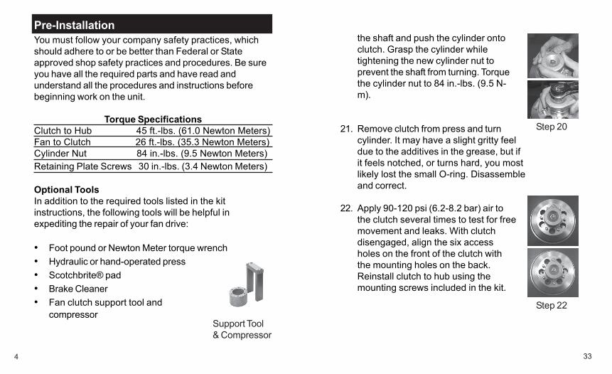
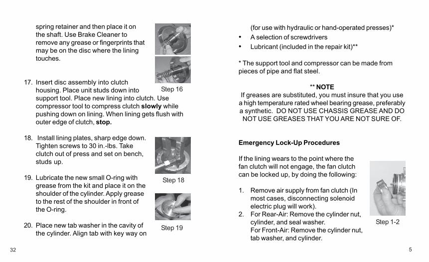
the shaft and push the cylinder ontoclutch. Grasp the cylinder whiletightening the new cylinder nut toprevent the shaft from turning. Torquethe cylinder nut to 84 in.-lbs. (9.5 N-m).
21. Remove clutch from press and turncylinder. It may have a slight gritty feeldue to the additives in the grease, but ifit feels notched, or turns hard, you mostlikely lost the small O-ring. Disassembleand correct.
22. Apply 90-120 psi (6.2-8.2 bar) air tothe clutch several times to test for freemovement and leaks. With clutchdisengaged, align the six accessholes on the front of the clutch withthe mounting holes on the back.Reinstall clutch to hub using themounting screws included in the kit.
Support Tool& Compressor
Step 20
Step 22
5
(for use with hydraulic or hand-operated presses)*• A selection of screwdrivers• Lubricant (included in the repair kit)**
* The support tool and compressor can be made frompieces of pipe and flat steel.
** NOTEIf greases are substituted, you must insure that you use
a high temperature rated wheel bearing grease, preferablya synthetic. DO NOT USE CHASSIS GREASE AND DONOT USE GREASES THAT YOU ARE NOT SURE OF.
Emergency Lock-Up Procedures
If the lining wears to the point where thefan clutch will not engage, the fan clutchcan be locked up, by doing the following:
1. Remove air supply from fan clutch (Inmost cases, disconnecting solenoidelectric plug will work).
2. For Rear-Air: Remove the cylinder nut,cylinder, and seal washer.For Front-Air: Remove the cylinder nut,tab washer, and cylinder.
32
spring retainer and then place it onthe shaft. Use Brake Cleaner toremove any grease or fingerprints thatmay be on the disc where the liningtouches.
17. Insert disc assembly into clutchhousing. Place unit studs down intosupport tool. Place new lining into clutch. Usecompressor tool to compress clutch slowly whilepushing down on lining. When lining gets flush withouter edge of clutch, stop.
18. Install lining plates, sharp edge down.Tighten screws to 30 in.-lbs. Takeclutch out of press and set on bench,studs up.
19. Lubricate the new small O-ring withgrease from the kit and place it on theshoulder of the cylinder. Apply greaseto the rest of the shoulder in front ofthe O-ring.
20. Place new tab washer in the cavity ofthe cylinder. Align tab with key way on
Step 1-2
Step 16
Step 18
Step 19
6
For some situations it will be necessary to tilt the radia-tor away from the engine in order to gain enough roomto remove and repair the fan clutch. A few applicationsrequire removing the entire fan drive assembly. Werecommend whenever possible to remove only theclutch, doing so will save substantial time and work.
NOTEProtect the radiator from possible damage from the fan
during fan removal and fan and clutch installation.
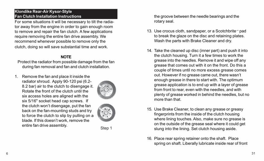
1. Remove the fan and place it inside theradiator shroud. Apply 90-120 psi (6.2-8.2 bar) air to the clutch to disengage it.Rotate the front of the clutch until thesix access holes are aligned with thesix 5/16" socket head cap screws. Ifthe clutch won’t disengage, put the fanback on the fan-mounting studs and tryto force the clutch to slip by pulling on ablade. If this doesn’t work, remove theentire fan drive assembly.
Klondike Rear-Air Kysor-StyleFan Clutch Installation Instructions
Step 1
31
the groove between the needle bearings and therotary seal.
13. Use crocus cloth, sandpaper, or a Scotchbrite→ padto break the glaze on the disc and retaining plates.Wash the parts with Brake Cleaner and dry.
14. Take the cleaned up disc (inner part) and push it intothe clutch housing. Turn it a few times to work thegrease into the needles. Remove it and wipe off anygrease that comes out with it on the front. Do this acouple of times until no more excess grease comesout. However if no grease came out, there wasn’tenough grease in there to start with. The optimumgrease application is to end up with a layer of greasefrom front to rear, even with the needles, and withplenty of grease worked in behind the needles, but nomore than that.
15. Use Brake Cleaner, to clean any grease or greasyfingerprints from the inside of the clutch housingwhere lining touches. Also, make sure no grease ison the outside of the grease seal where it could getslung into the lining. Set clutch housing aside.
16. Place rear spring retainer onto the shaft. Placespring on shaft. Liberally lubricate inside rear of front
7
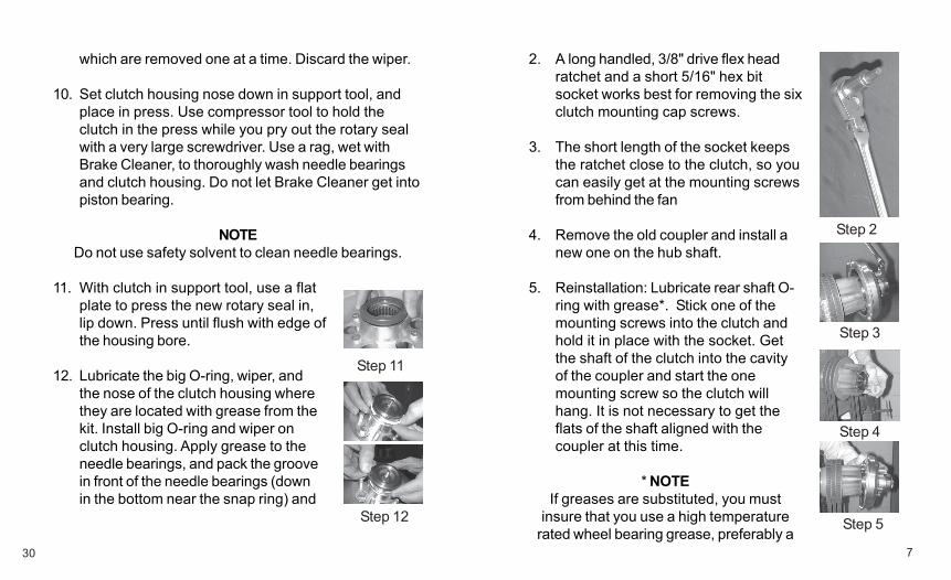
2. A long handled, 3/8" drive flex headratchet and a short 5/16" hex bitsocket works best for removing the sixclutch mounting cap screws.
3. The short length of the socket keepsthe ratchet close to the clutch, so youcan easily get at the mounting screwsfrom behind the fan
4. Remove the old coupler and install anew one on the hub shaft.
5. Reinstallation: Lubricate rear shaft O-ring with grease*. Stick one of themounting screws into the clutch andhold it in place with the socket. Getthe shaft of the clutch into the cavityof the coupler and start the onemounting screw so the clutch willhang. It is not necessary to get theflats of the shaft aligned with thecoupler at this time.
* NOTEIf greases are substituted, you must
insure that you use a high temperaturerated wheel bearing grease, preferably a
30
which are removed one at a time. Discard the wiper.
10. Set clutch housing nose down in support tool, andplace in press. Use compressor tool to hold theclutch in the press while you pry out the rotary sealwith a very large screwdriver. Use a rag, wet withBrake Cleaner, to thoroughly wash needle bearingsand clutch housing. Do not let Brake Cleaner get intopiston bearing.
NOTEDo not use safety solvent to clean needle bearings.
11. With clutch in support tool, use a flatplate to press the new rotary seal in,lip down. Press until flush with edge ofthe housing bore.
12. Lubricate the big O-ring, wiper, andthe nose of the clutch housing wherethey are located with grease from thekit. Install big O-ring and wiper onclutch housing. Apply grease to theneedle bearings, and pack the groovein front of the needle bearings (downin the bottom near the snap ring) and
Step 2
Step 3
Step 4
Step 5
Step 11
Step 12
8
Grab the front of the clutch and push ittowards the hub. Now, slowly turn thecylinder until the flats of the shaft alignwith the coupler. The clutch should nowpop into place on the hub. Install theother mounting screws and torque allsix to 45 ft.-lbs. (61 N-m).
6.
Step 6
synthetic. DO NOT USE CHASSISGREASE AND DO NOT USE GREASES
THAT YOU ARE NOT SURE OF.
29
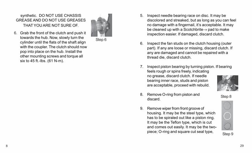
5. Inspect needle bearing race on disc. It may bediscolored and streaked, but as long as you can feelno damage with a fingernail, it’s acceptable. It maybe cleaned up with a Scotchbrite→ pad to makeinspection easier. If damaged, discard clutch.
6. Inspect the fan studs on the clutch housing (outerpart). If any are loose or missing, discard clutch. Ifany are damaged and cannot be repaired with athread die, discard clutch.
7. Inspect piston bearing by turning piston. If bearingfeels rough or spins freely, indicatingno grease, discard clutch. If needlebearing inner race, studs and pistonare acceptable, proceed with rebuild.
8. Remove O-ring from piston anddiscard.
9. Remove wiper from front groove ofhousing. It may be the steel type, whichhas to be spiraled out like a piston ring.It may be the Teflon type, which is cutand comes out easily. It may be the two-piece; O-ring and square cut seal type,
Step 8
Step 9
9
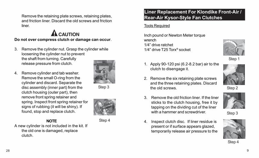
Liner Replacement For Klondike Front-Air /Rear-Air Kysor-Style Fan ClutchesTools Required
Inch pound or Newton Meter torquewrench1/4” drive ratchet1/4” drive T25 Torx® socket
1. Apply 90-120 psi (6.2-8.2 bar) air to theclutch to disengage it.
2. Remove the six retaining plate screwsand the three retaining plates. Discardthe old screws.
3. Remove the old friction liner. If the linersticks to the clutch housing, free it bytapping on the dividing cut of the linerwith a hammer and screwdriver.
4. Inspect clutch disc. If liner residue ispresent or if surface appears glazed,temporarily release air pressure to the
28
Remove the retaining plate screws, retaining plates,and friction liner. Discard the old screws and frictionliner.
Do not over compress clutch or damage can occur.
3. Remove the cylinder nut. Grasp the cylinder whileloosening the cylinder nut to preventthe shaft from turning. Carefullyrelease pressure from clutch.
4. Remove cylinder and tab washer.Remove the small O-ring from thecylinder and discard. Separate thedisc assembly (inner part) from theclutch housing (outer part), thenremove front spring retainer andspring. Inspect front spring retainer forsigns of rubbing (it will be shiny). Iffound, stop and replace clutch.
NOTEA new cylinder is not included in the kit. If
the old one is damaged, replaceclutch.
Step 1
Step 2
Step 3
Step 4
Step 3
Step 4

10
clutch to get a little more access tothe clutch disc, and use crocus cloth,sandpaper, or a Scotchbrite® pad tobreak the glaze.
5. Reapply air pressure to the clutch, andinstall the new liner as shown.
6. Reinstall the retaining plates with thescrews supplied in the kit and torquethem to 30 in.-lbs. (3.4 N-m).
27
Tools Required
Inch pound or Newton Meter torque wrench3/8” drive flex head ratchet3/8” drive 5/16” hex bit socket3/8” drive 1/2” socket1/4” drive ratchet1/4” drive T25 Torx® socket
NOTEProtect the radiator from possible damage from the fan
during fan removal and fan and clutch installation.
1. Disconnect air line from front of fan clutch. Removethe fan and place it inside the radiatorshroud. Apply 90-120 psi (6.2-8.2 bar)air to the clutch to disengage it.Rotate the front of the clutch until thesix access holes are aligned with thesix 5/16” socket head cap screws andremove them with the flex headratchet and 5/16” hex bit socket.
2. Using either a hydraulic press or two4” long bolts with washers and wingnuts, compress clutch slightly.
Step 5
Step 6
Step 1
11
Klondike Rear-Air Kysor-Style Fan Clutch:Seal Kit InstructionsTools Required
Inch pound or Newton Meter torque wrench3/8" drive flex head ratchet3/8" drive 5/16" hex bit socket3/8" drive 1/2” socket5/8" open-end wrench
NOTEProtect the radiator from possible damage
from the fan during fan removal and fanand clutch installation.
1. Remove the fan and place it inside theradiator shroud. Apply 90-120 psi (6.2-8.2 bar) air to the clutch to disengageit. Rotate the front of the clutch untilthe six access holes are aligned withthe six 5/16" socket head cap screwsand remove them with the flex headratchet and 5/16" hex bit socket.
2. Using either a hydraulic press or two4” long bolts with washers and wingnuts, compress clutch slightly.
26
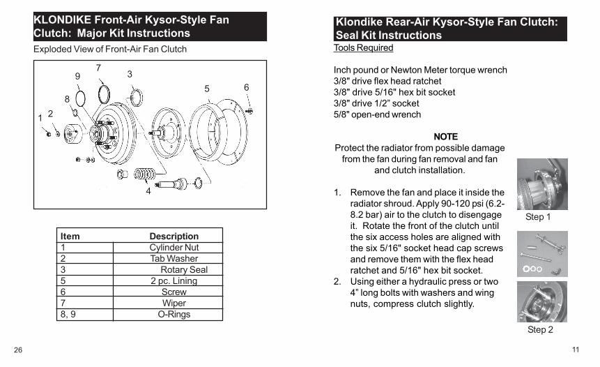
Item Description1 Cylinder Nut2 Tab Washer3 Rotary Seal5 2 pc. Lining6 Screw7 Wiper8, 9 O-Rings
1 2
3
4
5 6
7
8
9
KLONDIKE Front-Air Kysor-Style FanClutch: Major Kit InstructionsExploded View of Front-Air Fan Clutch
Step 1
Step 2
12
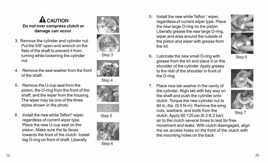
Do not over compress clutch ordamage can occur.
3. Remove the cylinder and cylinder nut.Put the 5/8" open-end wrench on theflats of the shaft to prevent it fromturning while loosening the cylindernut.
4. Remove the seal washer from the frontof the shaft.
5. Remove the U-cup seal from thepiston, the O-ring from the front of theshaft, and the wiper from the housing.The wiper may be one of the threestyles shown in the photo.
6. Install the new white Teflon® wiper,regardless of current wiper type.Place the new U-cup seal on thepiston. Make sure the lip facestowards the front of the clutch. Installbig O-ring on front of shaft. Liberally
25
5. Install the new white Teflon→ wiper,regardless of current wiper type. Placethe new large O-ring on the piston.Liberally grease the new large O-ring,wiper and area around the outside ofthe piston and wiper with grease fromthe kit.
6. Lubricate the new small O-ring withgrease from the kit and place it on theshoulder of the cylinder. Apply greaseto the rest of the shoulder in front ofthe O-ring.
7. Place new tab washer in the cavity ofthe cylinder. Align tab with key way onthe shaft and push the cylinder ontoclutch. Torque the new cylinder nut to84 in.-lbs. (9.5 N-m). Remove the wingnuts, washers, and bolts from theclutch. Apply 90-120 psi (6.2-8.2 bar)air to the clutch several times to test for freemovement and leaks. With clutch disengaged, alignthe six access holes on the front of the clutch withthe mounting holes on the back.
Step 6
Step 4
Step 3
Step 5
Step 6
Step 7

13
grease the U-cup seal, O-ring, andwiper with the grease from the kit.
7. Lubricate the new seal washer withgrease from the kit and place it on theshaft.
8. Align tab on cylinder with key way onthe shaft and push the cylinder ontoclutch. Place a 5/8” wrench on theflats of the shaft to prevent thecylinder from turning while tighteningthe new cylinder nut. Torque thecylinder nut to 84 in-lbs. (9.5 N-m).
9. Remove the wing nuts, washers, andbolts from the clutch. Apply 90-120psi (6.2-8.2 bar) air to the clutchseveral times to test for freemovement and leaks. With clutchdisengaged, align the six accessholes on the front of the clutch withthe mounting holes on the back.
24
2. Using either a hydraulic press or two4” long bolts with washers and wingnuts, compress clutch slightly.
Do not over compress clutch ordamage can occur.
3. Remove the cylinder nut, tab washerand cylinder. Grasp the cylinder whileloosening the cylinder nut to preventthe shaft from turning. Remove thesmall O-ring from the cylinder anddiscard.
NOTEA new cylinder is not included in the kit. If
the old one is damaged, replaceclutch.
4. Remove the large O-ring from thepiston and the wiper from thehousing. The wiper may be one of thethree styles shown in the photo.
Step 7
Step 8
Step 9
Step 3
Step 4
Step 5

14
10. Remove old O-ring from rear of shaft and replace itwith new one from kit. Lubricate O-ring with greasefrom the kit and reinstall clutch to hub using newcoupler.
23
KLONDIKE Front-Air Kysor-Style Fan Clutch:Seal Kit Instructions
Tools Required
Inch pound or Newton Meter torque wrench3/8” drive flex head ratchet3/8” drive 5/16” hex bit socket3/8” drive 1/2” socket
NOTEProtect the radiator from possible damage
from the fan during fan removal and fanand clutch installation.
1. Disconnect air line from front of fanclutch. Remove the fan and place itinside the radiator shroud. Apply 90-120 psi (6.2-8.2 bar) air to the clutchto disengage it. Rotate the front ofthe clutch until the six access holesare aligned with the six 5/16” sockethead cap screws and remove themwith the flex head ratchet and 5/16”hex bit socket.
Step 1
Step 2
15
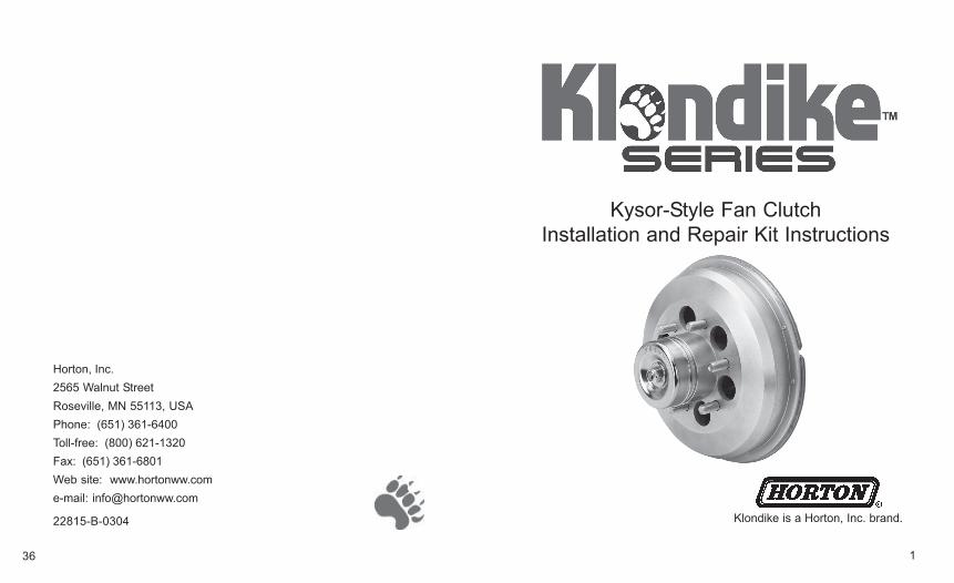
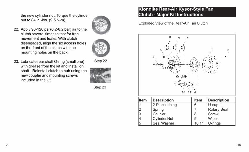
Klondike Rear-Air Kysor-Style FanClutch - Major Kit Instructions
1
2
3
4
5
6 7
8
9
10 11
Item Description Item Description1 2-Piece Lining 6 U-cup2 Spring 7 Rotary Seal3 Coupler 8 Screw4 Cylinder Nut 9 Wiper5 Seal Washer 10,11 O-rings
Exploded View of the Rear-Air Fan Clutch
1
22
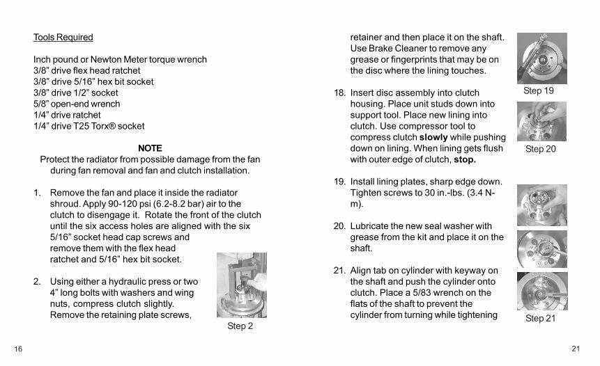
the new cylinder nut. Torque the cylindernut to 84 in.-lbs. (9.5 N-m).
22. Apply 90-120 psi (6.2-8.2 bar) air to theclutch several times to test for freemovement and leaks. With clutchdisengaged, align the six access holeson the front of the clutch with themounting holes on the back.
23. Lubricate rear shaft O-ring (small one)with grease from the kit and install onshaft. Reinstall clutch to hub using thenew coupler and mounting screwsincluded in the kit.
Step 22
Step 23
16
Tools Required
Inch pound or Newton Meter torque wrench3/8” drive flex head ratchet3/8” drive 5/16” hex bit socket3/8” drive 1/2” socket5/8” open-end wrench1/4” drive ratchet1/4” drive T25 Torx® socket
NOTEProtect the radiator from possible damage from the fan
during fan removal and fan and clutch installation.
1. Remove the fan and place it inside the radiatorshroud. Apply 90-120 psi (6.2-8.2 bar) air to theclutch to disengage it. Rotate the front of the clutchuntil the six access holes are aligned with the six5/16” socket head cap screws andremove them with the flex headratchet and 5/16” hex bit socket.
2. Using either a hydraulic press or two4” long bolts with washers and wingnuts, compress clutch slightly.Remove the retaining plate screws,
21
retainer and then place it on the shaft.Use Brake Cleaner to remove anygrease or fingerprints that may be onthe disc where the lining touches.
18. Insert disc assembly into clutchhousing. Place unit studs down intosupport tool. Place new lining intoclutch. Use compressor tool tocompress clutch slowly while pushingdown on lining. When lining gets flushwith outer edge of clutch, stop.
19. Install lining plates, sharp edge down.Tighten screws to 30 in.-lbs. (3.4 N-m).
20. Lubricate the new seal washer withgrease from the kit and place it on theshaft.
21. Align tab on cylinder with keyway onthe shaft and push the cylinder ontoclutch. Place a 5/83 wrench on theflats of the shaft to prevent thecylinder from turning while tightening
Step 2
Step 19
Step 20
Step 21
17
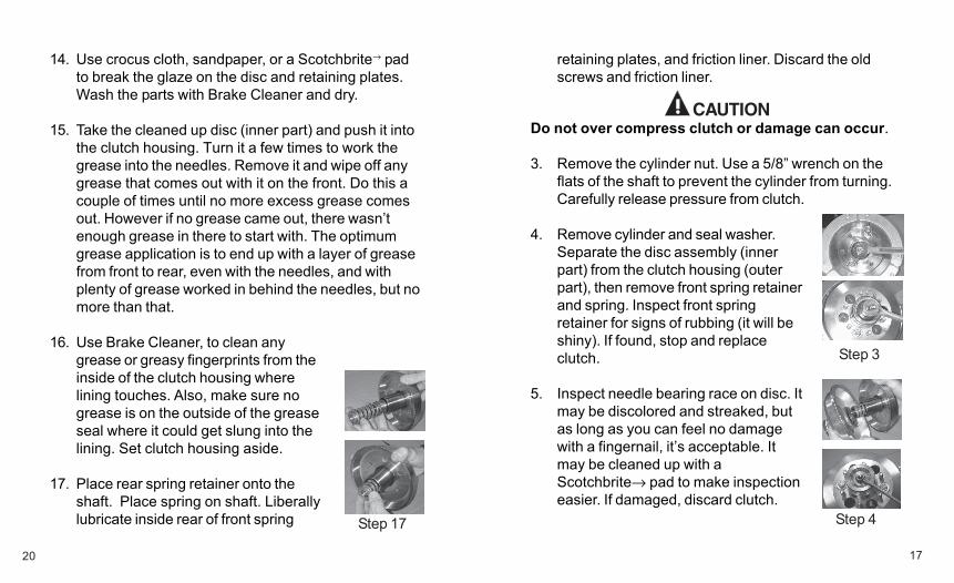
retaining plates, and friction liner. Discard the oldscrews and friction liner.
Do not over compress clutch or damage can occur.
3. Remove the cylinder nut. Use a 5/8” wrench on theflats of the shaft to prevent the cylinder from turning.Carefully release pressure from clutch.
4. Remove cylinder and seal washer.Separate the disc assembly (innerpart) from the clutch housing (outerpart), then remove front spring retainerand spring. Inspect front springretainer for signs of rubbing (it will beshiny). If found, stop and replaceclutch.
5. Inspect needle bearing race on disc. Itmay be discolored and streaked, butas long as you can feel no damagewith a fingernail, it’s acceptable. Itmay be cleaned up with aScotchbrite→ pad to make inspectioneasier. If damaged, discard clutch.
20
14. Use crocus cloth, sandpaper, or a Scotchbrite→ padto break the glaze on the disc and retaining plates.Wash the parts with Brake Cleaner and dry.
15. Take the cleaned up disc (inner part) and push it intothe clutch housing. Turn it a few times to work thegrease into the needles. Remove it and wipe off anygrease that comes out with it on the front. Do this acouple of times until no more excess grease comesout. However if no grease came out, there wasn’tenough grease in there to start with. The optimumgrease application is to end up with a layer of greasefrom front to rear, even with the needles, and withplenty of grease worked in behind the needles, but nomore than that.
16. Use Brake Cleaner, to clean anygrease or greasy fingerprints from theinside of the clutch housing wherelining touches. Also, make sure nogrease is on the outside of the greaseseal where it could get slung into thelining. Set clutch housing aside.
17. Place rear spring retainer onto theshaft. Place spring on shaft. Liberallylubricate inside rear of front spring
Step 3
Step 4Step 17
18
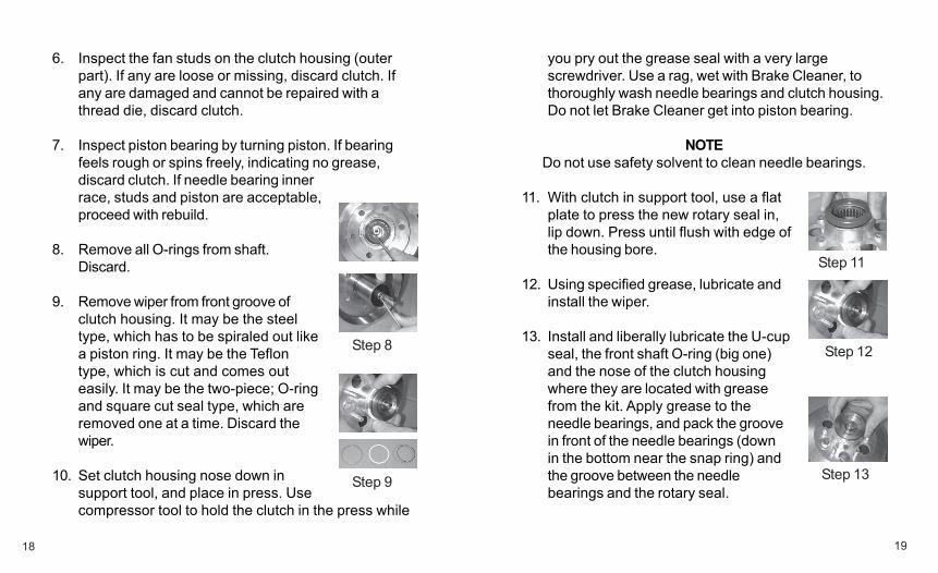
6. Inspect the fan studs on the clutch housing (outerpart). If any are loose or missing, discard clutch. Ifany are damaged and cannot be repaired with athread die, discard clutch.
7. Inspect piston bearing by turning piston. If bearingfeels rough or spins freely, indicating no grease,discard clutch. If needle bearing innerrace, studs and piston are acceptable,proceed with rebuild.
8. Remove all O-rings from shaft.Discard.
9. Remove wiper from front groove ofclutch housing. It may be the steeltype, which has to be spiraled out likea piston ring. It may be the Teflontype, which is cut and comes outeasily. It may be the two-piece; O-ringand square cut seal type, which areremoved one at a time. Discard thewiper.
10. Set clutch housing nose down insupport tool, and place in press. Usecompressor tool to hold the clutch in the press while
19
you pry out the grease seal with a very largescrewdriver. Use a rag, wet with Brake Cleaner, tothoroughly wash needle bearings and clutch housing.Do not let Brake Cleaner get into piston bearing.
NOTEDo not use safety solvent to clean needle bearings.
11. With clutch in support tool, use a flatplate to press the new rotary seal in,lip down. Press until flush with edge ofthe housing bore.
12. Using specified grease, lubricate andinstall the wiper.
13. Install and liberally lubricate the U-cupseal, the front shaft O-ring (big one)and the nose of the clutch housingwhere they are located with greasefrom the kit. Apply grease to theneedle bearings, and pack the groovein front of the needle bearings (downin the bottom near the snap ring) andthe groove between the needlebearings and the rotary seal.
Step 8
Step 9
Step 11
Step 12
Step 13