Kyocera Fax System S Service Manual
84
SERVICE MANUAL Published in July 2010 5JPSM062 Rev. 2 FAX System(S)
description
Kyocera Fax System S Service Manual
Transcript of Kyocera Fax System S Service Manual

F
AX System(S)SERVICEMANUAL
Published in July 20105JPSM062
Rev. 2

RISK OF EXPLOSION IUSED BATTERIES ACC
It may be illegal to disposolid waste officials for d
IL Y A UN RISQUE D’ETYPE INCORRECT. METIONS DONNEES.
Il peut être illégal de jetetionnaires municipaux dau rebut appropriée.
CAUTION
F BATTERY IS REPLACED BY AN INCORRECT TYPE. DISPOSE OF ORDING TO THE INSTRUCTIONS.
se of this battery into the municipal waste stream. Check with your local etails in your area for proper disposal.
ATTENTION
XPLOSION SI LA BATTERIE EST REMPLACEE PAR UN MODELE DE TTRE AU REBUT LES BATTERIES UTILISEES SELON LES INSTRUC-
r les batteries dans des eaux d’égout municipales. Vérifiez avec les fonc-e votre région pour les détails concernant des déchets solides et une mise

Revision history
Revision D
1 Novemb
2 July 2
ate Replaced pages Remarks
er 26, 2009 CONTENTS, 1-1-1, 1-1-4 to 1-1-6, 1-2-2 to 1-2-6, 1-3-1, 1-3-2, 1-3-4 to 1-3-7, 1-3-9, 1-3-26, 1-3-30, 1-3-31, 1-5-1, 1-5-2, 1-6-1, 2-1-1, 2-3-1 to 2-3-4
-
0, 2010 1-3-3 -

This page is intentionally left blank.

Safety precautions
This booklet provides safety warnings and precautions for our service personnel to ensure the safety of their customers, their machines as well as themselves during maintenance activities. Service personnel are advised to read this booklet carefully to familiarize themselves with the warnings and precautions described here before engaging in maintenance activities.

Safety warnings and precautions
Various symbols are used to protect our service personnel and customers from physical danger and to prevent damage to their property. These symbols are described below:
DANGER: High risk of serious bodily injury or death may result from insufficient attention to or incorrect
compliance with warning messages using this symbol.
WARNING: Serious bodily injury or death may result from insufficient attention to or incorrect compliance
with warning messages using this symbol.
CAUTION: Bodily injury or damage to property may result from insufficient attention to or incorrect com-
pliance with warning messages using this symbol.
Symbols
The triangle ( ) symbol indicates a warning including danger and caution. The specific point of attention is
shown inside the symbol.
General warning. Warning of risk of electric shock.
Warning of high temperature.
indicates a prohibited action. The specific prohibition is shown inside the symbol.
General prohibited action. Disassembly prohibited.
indicates that action is required. The specific action required is shown inside the symbol.
General action required. Remove the power plug from the wall outlet.
Always ground the copier.

1. Installation Precautions
WARNING
• Do not use a power supply with a voltage other than that specified. Avoid multiple connections to one outlet: they may cause fire or electric shock. When using an extension cable, always check that it is adequate for the rated current. .....................................................................................................
• Connect the ground wire to a suitable grounding point. Not grounding the copier may cause fire or electric shock. Connecting the earth wire to an object not approved for the purpose may cause explosion or electric shock. Never connect the ground cable to any of the following: gas pipes, light-ning rods, ground cables for telephone lines and water pipes or faucets not approved by the proper authorities. ..........................................................................................................................................
CAUTION:
• Do not place the copier on an infirm or angled surface: the copier may tip over, causing injury. .........
• Do not install the copier in a humid or dusty place. This may cause fire or electric shock. .................
• Do not install the copier near a radiator, heater, other heat source or near flammable material. This may cause fire. ...................................................................................................................................
• Allow sufficient space around the copier to allow the ventilation grills to keep the machine as cool as possible. Insufficient ventilation may cause heat buildup and poor copying performance. ............
• Always handle the machine by the correct locations when moving it. .................................................
• Always use anti-toppling and locking devices on copiers so equipped. Failure to do this may cause the copier to move unexpectedly or topple, leading to injury. ..............................................................
• Avoid inhaling toner or developer excessively. Protect the eyes. If toner or developer is accidentally ingested, drink a lot of water to dilute it in the stomach and obtain medical attention immediately. If it gets into the eyes, rinse immediately with copious amounts of water and obtain medical atten-tion. .....................................................................................................................................................
• Advice customers that they must always follow the safety warnings and precautions in the copier’s instruction handbook. .........................................................................................................................

2. Precautions for M
WARNING
• Always remove the powe
• Always follow the procedbrochures. .....................
• Under no circumstancesand protective circuits. ..
• Always use parts having
• Always use the thermostwhen replacing them. Usdent. ..............................
• When the service manuapart, always use the corr
• Always check that the co
• Check that the power cais dirty, clean it to remov
• Never attempt to disassedamage eyesight. .........
• Handle the charger sectishock if handled imprope
CAUTION
• Wear safe clothing. If wesecured so they will not
• Use utmost caution whe
• Handle the fixing section
• Check that the fixing uniabnormally high tempera
aintenance
r plug from the wall outlet before starting machine disassembly. ................
ures for maintenance described in the service manual and other related .....................................................................................................................
attempt to bypass or disable safety features including safety mechanisms ......................................................................................................................
the correct specifications. ............................................................................
at or thermal fuse specified in the service manual or other related brochure ing a piece of wire, for example, could lead to fire or other serious acci-.....................................................................................................................
l or other serious brochure specifies a distance or gap for installation of a ect scale and measure carefully. ..................................................................
pier is correctly connected to an outlet with a ground connection. ...............
ble covering is free of damage. Check that the power plug is dust-free. If it e the risk of fire or electric shock. .................................................................
mble the optical unit in machines using lasers. Leaking laser light may ......................................................................................................................
ons with care. They are charged to high potentials and may cause electric rly. ...............................................................................................................
aring loose clothing or accessories such as ties, make sure they are safely be caught in rotating sections. ......................................................................
n working on a powered machine. Keep away from chains and belts. ..........
with care to avoid burns as it can be extremely hot. ..................................
t thermistor, heat and press rollers are clean. Dirt on them can cause tures. ...........................................................................................................

• Do not remove the ozone filter, if any, from the copier except for routine replacement. ......................
• Do not pull on the AC power cord or connector wires on high-voltage components when removing them; always hold the plug itself. ........................................................................................................
• Do not route the power cable where it may be stood on or trapped. If necessary, protect it with a cable cover or other appropriate item. ................................................................................................
• Treat the ends of the wire carefully when installing a new charger wire to avoid electric leaks. ..........
• Remove toner completely from electronic components. .....................................................................
• Run wire harnesses carefully so that wires will not be trapped or damaged. ......................................
• After maintenance, always check that all the parts, screws, connectors and wires that were removed, have been refitted correctly. Special attention should be paid to any forgotten connector, trapped wire and missing screws. .......................................................................................................
• Check that all the caution labels that should be present on the machine according to the instruction handbook are clean and not peeling. Replace with new ones if necessary. .......................................
• Handle greases and solvents with care by following the instructions below: ......................................· Use only a small amount of solvent at a time, being careful not to spill. Wipe spills off completely.· Ventilate the room well while using grease or solvents.· Allow applied solvents to evaporate completely before refitting the covers or turning the power switch on.· Always wash hands afterwards.
• Never dispose of toner or toner bottles in fire. Toner may cause sparks when exposed directly to fire in a furnace, etc. ...........................................................................................................................
• Should smoke be seen coming from the copier, remove the power plug from the wall outlet immedi-ately. ...................................................................................................................................................
3. Miscellaneous
WARNING
• Never attempt to heat the drum or expose it to any organic solvents such as alcohol, other than the specified refiner; it may generate toxic gas. ........................................................................................

This page is intentionally left blank.

5JP-1
CONTENTS
1-1 Specifications1-1-1 Specifications..........................................................................................................................................1-1-11-1-2 Parts names............................................................................................................................................1-1-4
(1) Main body..........................................................................................................................................1-1-4(2) Document processor (option) ............................................................................................................1-1-5(3) Operation panel.................................................................................................................................1-1-6
1-2 Installation1-2-1 Installation environment ..........................................................................................................................1-2-11-2-2 Unpacking ...............................................................................................................................................1-2-21-2-3 Installing the memory DIMM (fullcolor machine).....................................................................................1-2-41-2-4 Installing the memory DIMM (monochrome machine (42/52 ppm))........................................................1-2-51-2-5 Installing the memory DIMM (monochrome machine (30 ppm)).............................................................1-2-6
1-3 Maintenance Mode1-3-1 Maintenance mode .................................................................................................................................1-3-1
(1) Executing a maintenance item ..........................................................................................................1-3-1(2) Maintenance mode item list...............................................................................................................1-3-3(3) Contents of maintenance mode items...............................................................................................1-3-5
1-3-2 User management ................................................................................................................................1-3-34(1) Using the user management mode .................................................................................................1-3-34
1-4 Error Codes1-4-1 Error codes .............................................................................................................................................1-4-1
(1) Error code..........................................................................................................................................1-4-1(2) Table of general classification ...........................................................................................................1-4-2
(2-1) U004XX error code table: Interrupted phase B .........................................................................1-4-3 (2-2) U006XX error code table: Problems with the unit .....................................................................1-4-4 (2-3) U008XX error code table: Page transmission error...................................................................1-4-4 (2-4) U009XX error code table: Page reception error ........................................................................1-4-4 (2-5) U010XX error code table: G3 transmission...............................................................................1-4-5 (2-6) U011XX error code table: G3 reception ....................................................................................1-4-6 (2-7) U017XX error code table: V.34 transmission ............................................................................1-4-7 (2-8) U018XX error code table: V.34 reception..................................................................................1-4-7 (2-9) U044XX error code table: Encrypted transmission ...................................................................1-4-7
1-5 Troubleshooting1-5-1 Self-diagnosis .........................................................................................................................................1-5-1
(1) Self-diagnostic function .....................................................................................................................1-5-1(2) Self diagnostic codes ........................................................................................................................1-5-1
1-6 Requirements on PWB Replacement1-6-1 Upgrading the firmware on the fax control PWB.....................................................................................1-6-1
2-1 Electrical Parts Layout2-1-1 Electrical parts layout..............................................................................................................................2-1-1
2-2 Operation of the PWBs2-2-1 Fax control PWB.....................................................................................................................................2-2-1
2-3 AppendixesWiring diagram (fullcolor machine (25/25, 30/30, 40/40, 50/40 ppm)) ....................................................2-3-1Wiring diagram (fullcolor machine (55/50 ppm)) .....................................................................................2-3-2Wiring diagram (monochrome machine (42/52 ppm)) ............................................................................2-3-3Wiring diagram (monochrome machine (30 ppm)) .................................................................................2-3-4

5JP
This page is intentionally left blank.

5JP-1
1-1 Specifications
1-1-1 SpecificationsType ........................................................... Optional FAX kitCompatibility .............................................. G3Communication Line .................................. Subscriber telephone lineTransmission Time..................................... 3 seconds or less (33600 bps, JBIG, ITU-T A4-R #1 chart)Transmission Speed .................................. 33600/31200/28800/26400/24000/21600/19200/16800/14400/12000/9600/
7200/4800/2400 bpsCoding Scheme ......................................... JBIG/MMR/MR/MHError Correction ......................................... ECMOriginal Size .............................................. Max. width: 11"/297 mm, Max. length: 63"/1,600 mmAutomatic Document Feed ........................ Max. 100 sheets (with optional DP)Scanner Resolution ................................... Horizontal x Vertical
200 x 100 dpi Normal (8 dot/mm x 3.85 line/mm)200 x 200 dpi Fine (8 dot/mm x 7.7 line/mm)200 x 400 dpi Super Fine (8 dot/mm x 15.4 line/mm)400 x 400 dpi Ultra Fine (16 dot/mm x 15.4 line/mm)600 x 600 dpi
Printing Resolution..................................... 600 x 600 dpiGradations ................................................. 256 shades (Error diffusion)One-Touch Key .......................................... 1000 keysMulti-Station Transmission......................... Max. 500 destinationsSubstitute Memory Reception.................... 700 sheets or more (when using ITU-T A4 #1)Image Memory Capacity ............................ Standard memory DIMM (machine): 16MB (for memory forwarding and mem-
ory reception of incoming faxed originals)Report Output ............................................ Sent result report, FAX RX result report, Activity report, Status pageOption ........................................................ Dual FAX, expanded memory and internet FAX kitFunctions ................................................... See P.1-1-2 and P.1-1-3.
NOTE: These specifications are subject to change without notice.
1-1-1

5JP
Reception functions Manual receptionAutomatic receptionFax/telephone auto selectionTAD receptionD.R.D. reception*1
Remote switching
Transmission functions Program dialChain dialRedial (manual/automatic)
Communication functions Direct transmissionMemory transmissionBulk fax output
Additional communication func-tions
Broadcast transmission (up to 500 numbers)Polling communicationEncrypted communicationPassword check communicationMemory forwardingStandby transmissionDelayed transmissionInterrupt sendECMSub address transmissionSub address confidential deliverySub address bulletin board communication
Supplementary communication functions
Manual sendAddress bookCanceling communicationLine monitorTransmission destination displayTone transmissionMemory back-upPrinting out from FAX box (subaddress-based confidential reception)Communication result displayBatch transmissionTTI transmissionBulletin board communication functionRotation transmissionDuplex transmission*2
Initial communication speed settingLine type settingZooming communicationTransmission port restriction*3
Mixed sized originalsOriginal orientation (Border erase book)
Supplementary reception func-tions
Memory reception2 in 1 receptionAuto reduce receptionRotation receptionDuplex receptionRecording paper media type settingReception date and time recordingReceive-only port*3
Reduced size receptionCommunication restriction (up to 50)Document box
1-1-2

5JP
*1: For 120 V specifications only.*2: Available only when optional document processor of the machine is installed.*3: When optional dual FAX is installed.*4: When optional internet Fax kit is installed.
Reports Send result reportReceipt result reportActivity reportStatus pageFax box list
Network FAX Addition of a cover pagei-FAX (internet faxing) transmissionE-mail reporting of the transmission resultTerminal serviceFile name
Others Cancelling and sending delayed transmissions (queued)Remote diagnosisSmoothing receptionFax priority printoutCommon address for the machine and FAXInternet faxing*4
1-1-3

5JP-1
1-1-2 Parts names
(1) Main body
Figure 1-1-1
Note that you cannot automatically receive FAX when turning the main power switch off.To turn the power off, press the Power key on the operation panel.
B1
A2
DP
B1
A2
DP
OPT2
OPT1
1Monochrome
machine(42/52 ppm)
Monochrome machine(30 ppm)
Fullcolor machine
2
3
3
2
2
3
1
1
4
6
5
4
6
5
1. Operation panel2. Main power switch3. MP tray4. Line connection connector (port 1)5. Line connection connector (port 2)6. TEL connection connector (port 1)
1-1-4

5JP-1
(2) Document processor (option)
Figure 1-1-2
2
4 41
3 3
1
2
6 6
5 5
Fullcolor machineMonochrome machine (42/52 ppm)
Monochrome machine (30 ppm)
1. Original placement indicator2. DP top cover3. Original width guides4. Original tray5. Original eject table6. Opening handle
1-1-5

5JP-1
(3) Operation panel
Figure 1-1-3
1
13 14 15 16 17 18 19 20 21 22 23 24 25
2 3 4 5 6 7 8 9 10 11 12
1 2 4 5 6 7 8 9 10 11 12
13
14
15 1817 233 16 2419 20 21 22 25
Fullcolor machineMonochrome machine (42/52 ppm)
Monochrome machine (30 ppm)
1. System menu key/indicator2. Counter key/indicator3. Help key/indicator4. Print indicator5. Send indicator6. Receive indicator7. Memory indicator8. Attention indicator9. Interrupt key/indicator10. Logout key/indicator11. Power key/indicator12. Main power indicator13. Status/Job cancel key/indicator
14. Program key/indicator15. Document box key/indicator16. Accessibility key/indicator17. Send/FAX key/indicator18. Copy key/indicator19. Numeric keys20. Clear key21. Quick No. search key22. Enter key23. Start key/indicator24. Stop key25. Reset key
1-1-6

5JP
1-2 Installation
1-2-1 Installation environmentInstallation location (Be based on the machine establishment place.)Avoid direct sunlight or bright lighting. Ensure that the photoconductor will not be exposed to direct sunlight or other strong light when removing paper jams.Avoid locations subject to high temperature and high humidity or low temperature and low humidity; an abrupt change in the environmental temperature; and cool or hot, direct air.Avoid places subject to dust and vibrations.Choose a surface capable of supporting the weight of the machine.Place the machine on a level surface (maximum allowance inclination: 1°).Avoid air-borne substances that may adversely affect the machine or degrade the photoconductor, such as mercury, acidic of alkaline vapors, inorganic gasses, NOx, SOx gases and chlorine-based organic solvents.Select a well-ventilated location.
1-2-1

5JP-1
1-2-2 Unpacking
Figure 1-2-1 Unpacking
Caution: See the Installation Guide for installation.
8
6
7
5
4
1
3
2
15
9
1213
14
11
10
1. Fax assembly2. Plastic bag3. Memory DIMM4. Plastic bag5. Air-padded bag6. Modular cord*1
7. Plastic bag8. Outer case9. CD-ROM
10. Installation guide11. Terminal seal12. Alphabet label13. FAX operation section label14. Approval label*2
15. Plastic bag
*1: 120 V and Australian models only.*2: Australian/New Zealand models only.
1-2-2

5JP-1
Initialization procedure after installing the facsimile system1. Insert the machine power plug to the wall outlet and turn the main power switch on.2. Enter 10871087 using the numeric keys. The machine enters maintenance mode.3. Only when the optional dual FAX is installed:
When both the FAX system and the dual FAX are installed: Run maintenance mode U698 using the cursor up or down key, or numeric keys, press [PORT SELECT], select [ALL] and press the start key.If the FAX system is already in use and the dual FAX is additionally installed: Run maintenance mode U698, press [PORT SELECT], select [P2] and press the start key.
4. Run maintenance item U600 using the cursor up/down keys or numeric keys.5. Press [Execute] and then press the start key.6. Select [Country Code] and enter a destination code using the numeric keys (refer to the destination code list).
Enter a destination code with three digits.
7. Select [OEM Code], enter the OEM code (000) and then press the start key.
8. After initialization, the entered destination, OEM codes and ROM version are dis-played. A ROM version displays three kinds, application, boot, and IPL.When the optional dual FAX is installed and U698 set to [ALL], the ROM version for port 1 is primarily displayed.
Figure 1-2-2
9. After completing the installation, run the communications test to confirm that the fax system is operative.
Code Destination Code Destination Code Destination
000 Japan 156 Singapore 253 Sweden
009 Australia 159 South Africa France
038 China 169 Thailand Austria
080 Hong Kong 181 U.S.A. Switzerland
084 Indonesia 242 South America Belgium
088 Israel 243 Saudi Arabia Denmark
097 Korea 253 CTR21 (European nations) Finland
108 Malaysia Italy Portugal
126 New Zealand Germany Ireland
136 Peru Spain Norway
137 Philippines U.K. 254 Taiwan
152 Middle East Netherlands
MAINTENANCE MODE MAINTENANCE MODE ACTIVE. U600 Initialize: All Data
Country Code XXX
OEM Code YYY
MAINTENANCE MODE MAINTENANCE MODE ACTIVE. U600 Initialize: All Data
Country Code XXX
OEM Code YYY
APL ****************
BOOT ****************
IPL ****************
1-2-3

5JP-1
1-2-3 Installing the memory DIMM (fullcolor machine)Press the Power key on the operation panel to off. Make sure that the Power indicator and the Memory indicator are offbefore turning off the main power switch.Press the power key on the operation panel to off. Make sure that the power indicator and the memory indicator are off before turning off the main power switch. And then unplug the power cable from the wall outlet.
Procedure1. Remove the rear upper filter cover.2. Remove nine screws and remove the rear
upper cover.
Figure 1-2-33. Install the memory DIMM into the memory slot.
25/25, 30/30, 40/40, 50/40 ppm: middle level (FLS)55/50 ppm: lower level (FLS)Install it with the IC side facing down.Insert it in the direction of the arrow until it clicks.
4. Refit the rear upper cover and the rear upper filter cover.
Figure 1-2-4
Screw
Screw
Screw
Screw
Screw
Screw
Screw
Screw
Rear upper cover
Rear upper filter cover
25/25, 30/30,
40/40, 50/40 ppm
55/50 ppm
Memory DIMM
Memory slot
(FLS)
Memory slot
(FLS)
Memory DIMM
Memory slot
(FLS)
Memory slot
(FLS)
1-2-4

5JP-1
1-2-4 Installing the memory DIMM (monochrome machine (42/52 ppm))Press the Power key on the operation panel to off. Make sure that the Power indicator and the Memory indicator are offbefore turning off the main power switch.Press the power key on the operation panel to off. Make sure that the power indicator and the memory indicator are off before turning off the main power switch. And then unplug the power cable from the wall outlet.
Procedure1. Remove the screw and remove the main
PWB lid.
Figure 1-2-5
2. Install the memory DIMM into the memory slot at the lower level (FLS). Install it with the IC side facing down.Insert it in the direction of the arrow until it clicks.
3. Refit the main PWB lid.
Figure 1-2-6
Screw
Main PWB lid
Memory slot
(FLS)Memory DIMM
1-2-5

5JP-1
1-2-5 Installing the memory DIMM (monochrome machine (30 ppm))Press the Power key on the operation panel to off. Make sure that the Power indicator and the Memory indicator are offbefore turning off the main power switch.Press the power key on the operation panel to off. Make sure that the power indicator and the memory indicator are off before turning off the main power switch. And then unplug the power cable from the wall outlet.
Procedure1. Remove two screws and remove the cover.
Figure 1-2-7
2. Install the memory DIMM into the memory slot at the lower level (FLS). Install it with the IC side facing down.Insert it in the direction of the arrow until it clicks.
3. Refit the cover.
Figure 1-2-8
Screw
Cover
Screw
Memory slot
(FLS)Memory DIMM
1-2-6

5JP-1
1-3 Maintenance Mode
1-3-1 Maintenance modeThe machine is equipped with a maintenance function which can be used to maintain and service the machine.
(1) Executing a maintenance item
Fullcolor machine/Monochrome machine (42/52 ppm)
Enter 10871087 using
the numeric keys.
Enter 001 using the cursor
up/down keys or numeric keys
and press the start key.
Enter the maintenance item
number using the cursor up/down keys
or numeric keys.
The selected maintenance item is run.
Press the stop key.
Press the start key.
Start
End
Maintenance mode is entered.
The maintenance item is
selected.
Maintenance mode is exited.
Repeat the same
maintenance item?
Run another maintenance
item?
No
No
Yes
Yes
1-3-1

5JP-1
Monochrome machine (30 ppm)
Enter “10871087” using
the numeric keys.
Enter “001” using the cursor
up/down keys or numeric keys
and press the start key.
Enter the maintenance item
number using the cursor up/down keys
or numeric keys.
The selected maintenance item is run.
Press the stop key.
Press the start key.
Start
End
Maintenance mode is entered.
The maintenance item is
selected.
Maintenance mode is exited.
Repeat the same
maintenance item?
Run another maintenance
item?
No
No
Yes
Yes
Press the status/Job cancel key.
1-3-2

5JP
(2) Maintenance mode item list
Section ItemNo. Content of maintenance item Initial setting*
Other U000 Outputting an own-status report -
U019 Displaying the ROM version -
Fax U600 Initializing all data -
U601 Initializing permanent data -
U603 Setting user data 1 DTMF*1
U604 Setting user data 2 2 (120 V)*1
1 (220-240 V)*1
U605 Clearing data -
U610 Setting system 1Setting the number of lines to be ignored when receiving a fax at 100% magnificationSetting the number of lines to be ignored when receiving a fax in the auto reduction modeSetting the number of lines to be ignored when receiving a fax (A4R/LetterR) in the auto reduction mode
3
0
0
U611 Setting system 2Setting the number of adjustment lines for automatic reductionSetting the number of adjustment lines for automatic reduction when A4 paper is setSetting the number of adjustment lines for automatic reduction when letter size paper is set
722
26
U612 Setting system 3Selecting if auto reduction in the auxiliary direction is to be per-formedSetting the automatic printing of the protocol list
ON
OFF
U615 Setting the system 6 -
U620 Setting the remote switching mode ONE*1
U625 Setting the transmission system 1Setting the auto redialing interval
Setting the number of times of auto redialing
3 (120 V)*1
2 (220-240 V)*1
2 (120 V)*1
3 (220-240 V)*1
U630 Setting communication control 1Setting the communication starting speedSetting the reception speedSetting the waiting period to prevent echo problems at the senderSetting the waiting period to prevent echo problems at the receiver
14400bps/V17*1
14400bps*1
300*1
75*1
U631 Setting communication control 2Setting ECM transmissionSetting ECM receptionSetting the frequency of the CED signal
ON*1
ON*1
2100*1
U632 Setting communication control 3Setting the DIS signal to 4 bytesSetting the CNG detection times in the fax/telephone auto select mode
OFF*1
2TIME*1
*: Factory initial setting, *2: The item initialized for executing U600
1-3-3

5JP-1
Fax U633 Setting communication control 4Enabling/disabling V.34 communicationSetting the V.34 symbol speed (3429 Hz)Setting the number of times of DIS signal receptionSetting the reference for RTN signal output
ON*1
ON*1
ONCE*1
15%*1
U634 Setting communication control 5 0*1
U640 Setting communication time 1One-shot detection time for remote switchingContinuous detection time for remote switching
7*1
80*1
U641 Setting communication time 2Setting the T0 time-out timeSetting the T1 time-out timeSetting the T2 time-out timeSetting the Ta time-out timeSetting the Tb1 time-out timeSetting the Tb2 time-out timeSetting the Tc time-out timeSetting the Td time-out time
56*1
36*1
69*1
30*1
20*1
80*1
60*1
9 (120 V)*1
6 (220-240 V)*1
U650 Setting modem 1Setting the G3 transmission cable equalizerSetting the G3 reception cable equalizerSetting the modem detection level
0dB*1
0dB*1
43dBm*1
U651 Setting modem 2Modem output level
DTMF output level (main value)
DTMF output level (level difference)
-9 (120 V)*1
-10 (220-240 V)*1
-5 (120 V)*1
-10.5 (220-240 V)*1
2 (120 V)*1
2.5 (220-240 V)*1
U660 Setting the NCUSetting the connection to PBX/PSTNSetting PSTN dial tone detectionSetting busy tone detectionSetting for a PBXSetting the loop current detection before dialing
PSTN*1
ON*1
ON*1
LOOP*1
ON*1
U670 Outputting lists -
U671 Clearing the FAX backup report data -
U695 FAX function customizeFax batch transmission ON/OFFChange of print size priority at the time of small size receptionSettings for zooming on the sent image attached to the send result report
ONOFFOFF
U698 Setting the port addressed in maintenance mode ALL
U699 Setting the software switches -
Section ItemNo. Content of maintenance item Initial setting*
*: Factory initial setting, *2: The item initialized for executing U600
1-3-4

5JP-1
(3) Contents of maintenance mode items
Maintenanceitem No. Description
U000 Outputting an own-status reportDescriptionOutputs the service status page.Printing a service status page is disabled either when a job is remaining in the buffer or when [Pause All Print Jobs] is pressed to halt printing.PurposePrints a status page for service purpose. The status page includes various printing settings and service cumu-latives.Method
1. Press the start key.2. Select [SERVICE STATUS] and press the start key.
The interrupt print mode is entered and a list is output.
Service status page (fullcolor machine)
Firmware version 2KY_2000.000.000
Memory statusTotal Size
Controller Information
2009.10.23
23/10/2009 08:40
[XXXXXXXX]
[XXXXXXXXXXXXXXXX]
[XXXXXXXX] [XXXXXXXX]
1.0 GB
TimeLocal Time Zone
Date and Time
Time Server
+01:00 Tokio
17/06/2009 08:40
10.183.53.13
Installed OptionsDocument Processor
Paper feeder
Finisher
Mail Box
Job Sparator
Installed
Cassette
3000-Finisher
Not Installed
Installed
FAX Information Slot1/Slot2Rings (Normal)
Rings (FAX/TEL)
Rings (TAD)
Option DIMM Size
3
3
3
16 MB
Digital Dot Coverage Average(%)
Total
K: 1.10
C: 2.20
M: 3.30
Y: 4.40
Copy
K: 1.10
C: 2.20
M: 3.30
Y: 4.40
Printer
K: 1.10
C: 2.20
M: 3.30
Y: 4.40
FAX
K: 1.10
Period
Last Page K/C/M/Y
/ Usage Page(A4/Letter Conversion)
/ 1111111.11
/ 2222222.22
/ 3333333.33
/ 4444444.44
/ 1111111.11
/ 2222222.22
/ 3333333.33
/ 4444444.44
/ 1111111.11
/ 2222222.22
/ 3333333.33
/ 4444444.44
/ 1111111.11
(03/11/2008 - 27/10/2008 08:40)
1.11/2.22/3.33/4.44
FRPO StatusDefault Pattern Switch
Default Font Number
.
.
.
.
.
.
.
.
.
.
.
.
.
.
.
.
.
.
.
.
.
.
.
.
.
.
.
.
.
.
.
e-MPS error control
B8
C5*10000+C2*100+C3
Y6
0
00000
0
Service Status PageMFP
1
1-3-5

5JP-1
U000(cont.)
Service status page (monochrome machine)
Completion Press the stop key. The screen for selecting a maintenance item No. is displayed.
Maintenanceitem No. Description
Firmware version 2KS_2000.000.000
Memory statusTotal Size
Controller Information
2009.06.17
17/06/2009 08:40
[XXXXXXXX]
[XXXXXXXXXXXXXXXX]
[XXXXXXXX] [XXXXXXXX]
1.0 GB
TimeLocal Time Zone
Date and Time
Time Server
+01:00 Tokio
17/06/2009 08:40
10.183.53.13
Installed OptionsDocument Processor
Paper feeder
Finisher
Mail Box
Job Sparator
Installed
Cassette
3000-Finisher
Not Installed
Installed
FAX Information Slot1/Slot2Rings (Normal)
Rings (FAX/TEL)
Rings (TAD)
Option DIMM Size
3
3
3
16 MB
Digital Dot Coverage Average(%)
Total
K: 1.10
Copy
K: 1.10
Printer
K: 1.10
FAX
K: 1.10
Period
Last Page (%)
/ Usage Page(A4/Letter Conversion)
/ 1111111.11
/ 1111111.11
/ 1111111.11
/ 1111111.11
(03/11/2009 - 27/10/2009 08:40)
1.00
FRPO StatusDefault Pattern Switch
Default Font Number
e-MPS error control
B8
C5*10000+C2*100+C3
Y6
0
00000
0
Service Status PageMFP
1
1-3-6

5JP-1
U019 Displaying the ROM versionDescriptionDisplays the part number of the ROM fitted to each PWB.PurposeTo check the part number or to decide, if the newest version of ROM is installed.Method
1. Press the start key. The ROM version are displayed.2. Change the screen using the cursor up/down keys.
Completion Press the stop key. The screen for selecting a maintenance item No. is displayed.
Maintenanceitem No. Description
Display Description
MAIN Main ROM
MMI Operation ROM
ENGINE Engine ROM
ENGINE BOOT Engine booting
ENGINE POWER Engine power (only for monochrome machine (30 ppm))
SCANNER Scanner ROM
BROWSER Browser ROM
OPTION LANGUAGE Optional language ROM
DICTIONARY -
DBA Database connection
Solution Framework FrameworkCOLOR TABLE1 Color table1 (only for fullcolor machine)
COLOR TABLE2 Color table2 (only for fullcolor machine)
MOTOR CPU Motor CPU (only for fullcolor machine)
MOTOR CPU BOOT Motor CPU booting (only for fullcolor machine)
H VLT CPU High voltage CPU (only for fullcolor machine)
H VLT CPU BOOT High voltage CPU booting (only for fullcolor machine)
SLEEP CPU Sleep CPU (only for fullcolor machine)
SLEEP CPU BOOT Sleep CPU booting (only for fullcolor machine)
DP Optional DP ROM
500x2PF Optional paper feeder ROM
3000PF Optional 3000-sheet paper feeder ROM
1000DF Optional document finisher ROM
3000DF MAIN Optional 3000-sheet document finisher main ROM
3000DF MIDDLE Optional 3000-sheet document finisher Inner tray ROM
MAIL BOX Optional mailbox ROM
BOOKLET Optional center-folding unit ROM
INNER DF Optional built-in finisher ROM (only for monochrome machine)
FAX BOOT1 Fax control PWB booting (port 1)
FAX APL1 Fax control PWB APL (port 1)
FAX IPL1 Fax control PWB IPL (port 1)
FAX BOOT2 Fax control PWB booting (port 2: optional dual FAX)
FAX APL2 Fax control PWB APL (port 2: optional dual FAX)
FAX IPL2 Fax control PWB IPL (port 2: optional dual FAX)
1-3-7

5JP
U600 Initializing all dataDescriptionInitializes software switches and all data in the backup data on the fax control PWB, according to the destina-tion and OEM.Executes the check of the file system, when abnormality of the file system is detected, initializes the file sys-tem, communication past record and register setting contents.PurposeTo initialize the fax control PWB.
RemarksWhen the optional dual FAX is installed, the fax control PWB that is set as a target port by U698 is initialized.U698 is set to [ALL]: Both the fax control PWB and the optional dual FAXU698 is set to [P1]: Fax control PWBU698 is set to [P2]: Optional dual FAX
Method1. Press the start key.2. Press [Execute]. The screen for entering the destination code and OEM code is displayed.
The port that is addressed by U698 is displayed when the optional dual FAX is installed.3. Select [Country Code] and enter a destination code using the numeric keys (refer to the destination
code list on page 1-3-9 for the destination code).4. Press the start key.
There is no operation necessary on this screen.The destination code and the OEM code are displayed with the values currently set.An asterisk (*) is displayed if U698 is set to [ALL] and settings for ports 1 and 2 are not identical.In this case, initialization is not possible.
5. Press the start key. Data initialization starts. To cancel data initialization, press the stop key.6. After data initialization, the entered destination, OEM codes and ROM version are displayed. A ROM
version displays three kinds, application, boot, and IPL.When U698 is set to [ALL], the ROM version for port 1 is primarily displayed.
Maintenanceitem No. Description
MAINTENANCE MODE MAINTENANCE MODE ACTIVE. U600 Initialize: All Data
Country Code XXX
OEM Code YYY
MAINTENANCE MODE MAINTENANCE MODE ACTIVE. U600 Initialize: All Data
Country Code XXX
OEM Code YYY
APL ****************
BOOT ****************
IPL ****************
1-3-8

5JP-1
U600(cont.)
Destination code list
Maintenanceitem No. Description
Code Destination Code Destination Code Destination
000 Japan 156 Singapore 253 Sweden
009 Australia 159 South Africa France
038 China 169 Thailand Austria
080 Hong Kong 181 U.S.A. Switzerland
084 Indonesia 242 South America Belgium
088 Israel 243 Saudi Arabia Denmark
097 Korea 253 CTR21 (European nations) Finland
108 Malaysia Italy Portugal
126 New Zealand Germany Ireland
136 Peru Spain Norway
137 Philippines U.K. 254 Taiwan
152 Middle East Netherlands
1-3-9

5JP
U601 Initializing permanent dataDescriptionInitializes software switches on the fax control PWB according to the destination and OEM.PurposeTo initialize the fax control PWB without changing user registration data.
Method1. Press the start key.2. Press [Execute]. The screen for entering the destination code and OEM code is displayed.
The port that is addressed by U698 is displayed when the optional dual FAX is installed.3. Select [Country Code] and enter a destination code using the numeric keys (refer to the destination
code list on page 1-3-9 for the destination code).4. Press the start key.
There is no operation necessary on this screen.The destination code and the OEM code are displayed with the values currently set.An asterisk (*) is displayed if U698 is set to [ALL] and settings for ports 1 and 2 are not identical.In this case, initialization is not possible.
5. Press the start key. Data initialization starts. To cancel data initialization, press the back key.6. After data initialization, the entered destination, OEM codes and ROM version are displayed. A ROM
version displays three kinds, application, boot, and IPL.When U698 is set to [ALL], the ROM version for port 1 is primarily displayed.
Maintenanceitem No. Description
MAINTENANCE MODE MAINTENANCE MODE ACTIVE. U601 Initialize: Keep Data
Country Code XXX
OEM Code YYY
MAINTENANCE MODE MAINTENANCE MODE ACTIVE. U601 Initialize: Keep Data
Country Code XXX
OEM Code YYY
APL ****************
BOOT ****************
IPL ****************
1-3-10

5JP
U603 Setting user data 1DescriptionMakes user settings to enable the use of the machine as a fax.PurposeTo be run after installation of the facsimile kit if necessary.
Method1. Press the start key. The port that is addressed by U698 is displayed when the optional dual FAX is
installed.2. Press [LINE TYPE]. The current setting is displayed in reverse.
If the optional dual FAX has been installed and if U698 is set to [ALL] and settings for ports 1 and 2 are not identical, the display is not highlighted.
3. Select the setting.
Initial setting: DTMF4. Press the start key. The value is set.
CompletionPress the stop key. The screen for selecting a maintenance item No. is displayed.
U604 Setting user data 2DescriptionMakes user settings to enable the use of the machine as a fax.PurposeUse this if the user wishes to adjust the number of rings that occur before the unit switches into fax receiving mode when fax/telephone auto-select is enabled.
Method1. Press the start key. The current setting is displayed.2. Press [RINGS(F/T)].3. Change the setting using the +/- or numeric keys.
If you set this to 0, the unit will start fax reception without any ringing.4. Press the start key. The value is set.
CompletionPress the stop key. The screen for selecting a maintenance item No. is displayed.
U605 Clearing dataDescriptionInitializes data related to the fax transmission such as transmission history.PurposeTo clear the transmission history.
Method1. Press the start key. The port that is addressed by U698 is displayed when the optional dual FAX is
installed.2. Press [CLEAR COM.REC.].3. Press the start key. Initialization processing starts. When processing is finished, the screen for selecting
a maintenance item No. is displayed.
Maintenanceitem No. Description
Display Description
DTMF DTMF
10PPS 10 PPS
20PPS 20 PPS
Description Setting range Initial settingNumber of fax/telephone rings 0 to 15 2 (120 V)/1 (220-240 V)
1-3-11

5JP
U610 Setting system 1DescriptionMakes settings for fax reception regarding the sizes of the fax paper and received images and automatic print-ing of the protocol list.
Start1. Press the start key. The current setting is displayed in each item.2. Select the item to be set.
Setting the number of lines to be ignored when receiving a fax at 100% magnificationSets the maximum number of lines to be ignored if the received data volume exceeds the recording capacity when recording the data at 100% magnification. If the number of excess lines is below the setting, those lines are ignored. If over the setting, they are recorded on the next page.
1. Change the setting using the +/- or numeric keys.
Increase the setting if a blank second page is output, and decrease it if the received image does not include the entire transmitted data.
2. Press the start key. The value is set.
Setting the number of lines to be ignored when receiving a fax in the auto reduction modeSets the maximum number of lines to be ignored if the received data volume exceeds the recording capacity when the data is recorded in the auto reduction mode. If the number of excess lines is below the setting, those lines are ignored. If over the setting, the entire data on a page is further reduced so that it can be recorded on the same page.
1. Change the setting using the +/- or numeric keys.
Increase the setting if a page received in the reduction mode is over-reduced and too much trailing edge margin is left. Decrease it if the received image does not include all transmitted data.
2. Press the start key. The value is set.
Setting the number of lines to be ignored when receiving a fax (A4R/LetterR) in the auto reduction modeSets the maximum number of lines to be ignored if the received data volume exceeds the recording capacity when the data is recorded in the auto reduction mode onto A4R or LetterR paper under the conditions below.If the number of excess lines is below the setting, those lines are ignored. If over the setting, the entire data on a page is further reduced so that it can be recorded on the same page.With A4R present and folio absent in the cassetteWith letterR paper present and legal paper absent in the cassette
Maintenanceitem No. Description
Display Description
CUT LINE (100%) Sets the number of lines to be ignored when receiving a fax at 100% magnification.
CUT LINE (AUTO) Sets the number of lines to be ignored when receiving a fax in the auto reduction mode.
CUT LINE (A4) Sets the number of lines to be ignored when receiving a fax (A4R/Let-terR) in the auto reduction mode.
Description Setting range Initial setting Change in valueper step
Number of lines to be ignoredwhen receiving at 100%
0 to 22 3 16 lines
Description Setting range Initial setting Change in valueper step
Number of lines to be ignoredwhen receiving in the auto reduction mode
0 to 22 0 16 lines
1-3-12
5JP
U610(cont.)
1. Change the setting using the +/- or numeric keys.
Increase the setting if a page received in the reduction mode is over-reduced and too much trailing edge margin is left. Decrease it if the received image does not include all transmitted data.
2. Press the start key. The value is set.
CompletionPress the stop key. The screen for selecting a maintenance item No. is displayed.
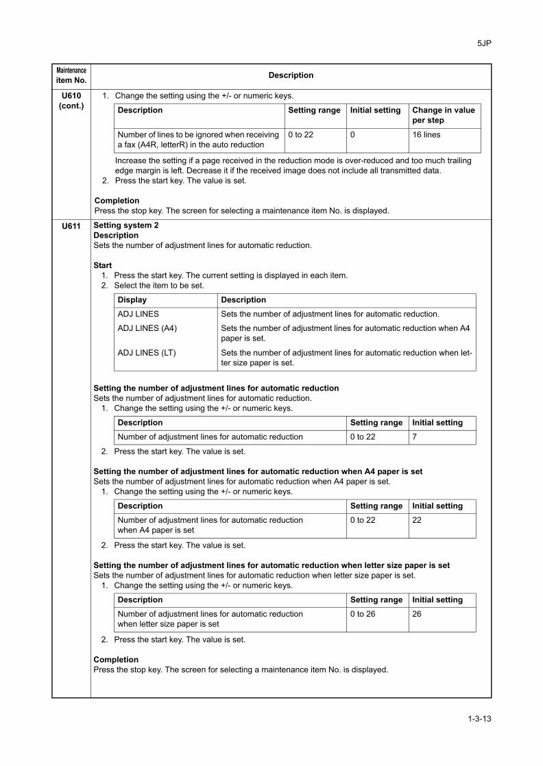
U611 Setting system 2DescriptionSets the number of adjustment lines for automatic reduction.
Start1. Press the start key. The current setting is displayed in each item.2. Select the item to be set.
Setting the number of adjustment lines for automatic reductionSets the number of adjustment lines for automatic reduction.
1. Change the setting using the +/- or numeric keys.
2. Press the start key. The value is set.
Setting the number of adjustment lines for automatic reduction when A4 paper is setSets the number of adjustment lines for automatic reduction when A4 paper is set.
1. Change the setting using the +/- or numeric keys.
2. Press the start key. The value is set.
Setting the number of adjustment lines for automatic reduction when letter size paper is setSets the number of adjustment lines for automatic reduction when letter size paper is set.
1. Change the setting using the +/- or numeric keys.
2. Press the start key. The value is set.
CompletionPress the stop key. The screen for selecting a maintenance item No. is displayed.
Maintenanceitem No. Description
Description Setting range Initial setting Change in valueper step
Number of lines to be ignored when receiving a fax (A4R, letterR) in the auto reduction
0 to 22 0 16 lines
Display Description
ADJ LINES Sets the number of adjustment lines for automatic reduction.
ADJ LINES (A4) Sets the number of adjustment lines for automatic reduction when A4 paper is set.
ADJ LINES (LT) Sets the number of adjustment lines for automatic reduction when let-ter size paper is set.
Description Setting range Initial setting
Number of adjustment lines for automatic reduction 0 to 22 7
Description Setting range Initial setting
Number of adjustment lines for automatic reductionwhen A4 paper is set
0 to 22 22
Description Setting range Initial setting
Number of adjustment lines for automatic reductionwhen letter size paper is set
0 to 26 26
1-3-13

5JP
U612 Setting system 3DescriptionMakes settings for fax transmission regarding operation and automatic printing of the protocol list.
Start1. Press the start key.2. Select the item to be set. The screen for the selected item appears.
The screen changes to the submenu for making settings.The current settings are highlighted.
Selecting if auto reduction in the auxiliary direction is to be performedSets whether to receive a long document by automatically reducing it in the auxiliary direction or at 100% magnification.
1. Select the setting.
Initial setting: ON2. Press the start key. The setting is set.
Setting the automatic printing of the protocol listSets if the protocol list is automatically printed out.
1. Select the setting.
Initial setting: OFF2. Press the start key. The setting is set.
CompletionPress the stop key. The screen for selecting a maintenance item No. is displayed.
Maintenanceitem No. Description
Display Description
AUTO REDUCTION Selects if auto reduction in the auxiliary direction is to be performed.
PROTOCOL LIST Sets the automatic printing of the protocol list.
Display Description
ON Auto reduction is performed if the received document is longer than the fax paper.
OFF Auto reduction is not performed.
Display Description
OFF The protocol list is not printed out automatically.
ERROR The protocol list is automatically printed out after communication only if a communication error occurs.
ON The protocol list is automatically printed out after communication.
1-3-14

5JP
U615 Setting the system 6DescriptionMakes settings for fax reception regarding the sizes of the fax paper and received images.PurposeTo set the maximum recording width and processing method when 11" width fax paper is loaded on an inch specification machine.
Method1. Press the start key. The current setting is displayed in reverse.2. Press [RX WIDTH FOR 11"].3. Select the setting.
4. Press the start key. The setting is set.
CompletionPress the stop key. The screen for selecting a maintenance item No. is displayed.
U620 Setting the remote switching modeDescriptionSets the signal detection method for remote switching. Be sure to change the setting according to the type of telephone connected to the machine.
Method1. Press the start key.
The port that is addressed by U698 is displayed when the optional dual FAX is installed.2. Press [REMOTE MODE].
The current setting is displayed in reverse.If the optional dual FAX has been installed and if U698 is set to [ALL] and settings for ports 1 and 2 are not identical, the display is not highlighted.
3. Select the setting.
Initial setting: ONE4. Press the start key. The setting is set.
CompletionPress the stop key. The screen for selecting a maintenance item No. is displayed.
Maintenanceitem No. Description
Display Description
LEDGER Communicates to the destination unit 11" width as A3 width and records at 100% magnifications.
B4 Communicates to the destination unit 11" width as B4 width.
Display Description
ONE One-shot detection
CONT Continuous detection
1-3-15

5JP
U625 Setting the transmission system 1DescriptionMakes settings for the auto redialing interval and the number of times of auto redialing.PurposeChange the setting to prevent the following problems: fax transmission is not possible due to too short redial interval, or fax transmission takes too much time to complete due to too long redial interval.
Start1. Press the start key.
The current setting is displayed in each item at port 1.2. Select the item to be set.
Setting the auto redialing interval1. Change the setting using the +/- keys.
The settings for both ports 1 and 2 are modified when the optional dual FAX is installed.
2. Press the start key. The value is set.
Setting the number of times of auto redialing1. Change the setting using the +/- or numeric keys.
The settings for both ports 1 and 2 are modified when the optional dual FAX is installed.
When set to 0, no redialing is performed.2. Press the start key. The value is set.
CompletionPress the stop key. The screen for selecting a maintenance item No. is displayed.
U630 Setting communication control 1DescriptionMakes settings for fax transmission regarding the communication.
Start1. Press the start key.3. Select the item to be set.
The screen changes to the submenu for making settings.The port that is addressed by U698 is displayed when the optional dual FAX is installed.The current settings are highlighted. If the optional dual FAX has been installed and if U698 is set to [ALL] and settings for ports 1 and 2 are not identical, the display is not highlighted.
Maintenanceitem No. Description
Display Description
INTERVAL Setting the auto redialing interval
TIMES Setting the number of times of auto redialing
Description Setting range Initial settingRedialing interval 1 to 9 (min.) 3 (120 V)/2 (220-240 V)
Description Setting range Initial setting
Number of redialing 0 to 15 2 (120 V)/3 (220-240 V)
Display Description
TX SPEED Sets the communication starting speed.
RX SPEED Sets the reception speed.
TX ECHO Sets the waiting period to prevent echo problems at the sender.
RX ECHO Sets the waiting period to prevent echo problems at the receiver.
1-3-16

5JP
U630(cont.)
Setting the communication starting speedSets the initial communication speed when starting transmission. When the destination unit has V.34 capabil-ity, V.34 is selected for transmission, regardless of this setting.
1. Select the setting.
Initial setting: 14400bps/V172. Press the start key. The setting is set.
Setting the reception speedSets the reception speed that the sender is informed of using the DIS or NSF signal. When the destination unit has V.34 capability, V.34 is selected, regardless of the setting.
1. Select the setting.
Initial setting: 14400bps2. Press the start key. The setting is set.
Setting the waiting period to prevent echo problems at the senderSets the period before a DCS signal is sent after a DIS signal is received. Used when problems occur due to echoes at the sender.
1. Select the setting.
Initial setting: 3002. Press the start key. The setting is set.
Setting the waiting period to prevent echo problems at the receiverSets the period before an NSF, CSI or DIS signal is sent after a CED signal is received. Used when problems occur due to echoes at the receiver.
1. Select the setting.
Initial setting: 752. Press the start key. The setting is set.
CompletionPress the stop key. The screen for selecting a maintenance item No. is displayed.
Maintenanceitem No. Description
Display Description
14400bps/V17 V.17, 14400 bps
9600bps/V29 V.17, 9600 bps
4800bps/V27ter V.27ter, 4800 bps
2400bps/V27ter V.27ter, 2400 bps
Display Description
14400bps V.17, V.33, V.29, V.27ter
9600bps V.29, V.27ter
4800bps V.27ter
2400bps V.27ter (fallback only)
Display Description
500 Sends a DCS 500 ms after receiving a DIS.
300 Sends a DCS 300 ms after receiving a DIS.
Display Description
500 Sends an NSF, CSI or DIS 500 ms after receiving a CED.
75 Sends an NSF, CSI or DIS 75 ms after receiving a CED.
1-3-17

5JP
U631 Setting communication control 2DescriptionMakes settings regarding fax transmission.
Start1. Press the start key.2. Select the item to be set. The screen for the selected item appears.
The screen changes to the submenu for making settings.The port that is addressed by U698 is displayed when the optional dual FAX is installed.The current settings are highlighted. If the optional dual FAX has been installed and if U698 is set to [ALL] and settings for ports 1 and 2 are not identical, the display is not highlighted.
Setting ECM transmissionTo be set to OFF when reduction of transmission costs is of higher priority than image quality.This should not be set to OFF when connecting to the IP (Internet Protocol) telephone line.
1. Select the setting.
Initial setting: ON2. Press the start key. The setting is set.
Setting ECM receptionTo be set to OFF when reduction of transmission costs is of higher priority than image quality.This should not be set to OFF when connecting to the IP (Internet Protocol) telephone line.
1. Select the setting.
Initial setting: ON2. Press the start key. The setting is set.
Setting the frequency of the CED signalSets the frequency of the CED signal. Used as one of the measures to improve transmission performance for international communications.
1. Select the setting.
Initial setting: 21002. Press the start key. The setting is set.
CompletionPress the stop key. The screen for selecting a maintenance item No. is displayed.
Maintenanceitem No. Description
Display Description
ECM TX Sets ECM transmission.
ECM RX Sets ECM reception.
CED FREQ. Sets the frequency of the CED signal.
Display Description
ON ECM transmission is enabled.
OFF ECM transmission is disabled.
Display Description
ON ECM reception is enabled.
OFF ECM reception is disabled.
Display Description
2100 2100 Hz
1100 1100 Hz
1-3-18

5JP
U632 Setting communication control 3DescriptionMakes settings for fax transmission regarding the communication.
Start1. Press the start key.2. Select the item to be set.
The screen changes to the submenu for making settings.The port that is addressed by U698 is displayed when the optional dual FAX is installed.The current settings are highlighted. If the optional dual FAX has been installed and if U698 is set to [ALL] and settings for ports 1 and 2 are not identical, the display is not highlighted.
Setting the DIS signal to 4 bytesSets if bit 33 and later bits of the DIS/DTC signal are sent.
1. Select the setting.
Initial setting: OFF2. Press the start key. The setting is set.
Setting the CNG detection times in the fax/telephone auto select modeSets the CNG detection times in the fax/telephone auto select mode.
1. Select the setting.
Initial setting: 2TIMES2. Press the start key. The setting is set.
CompletionPress the stop key. The screen for selecting a maintenance item No. is displayed.
Maintenanceitem No. Description
Display Description
DIS 4BYTE Sets the DIS signal to 4 bytes.
NUM. OF CNG (F/T) Sets the CNG detection times in the fax/telephone auto select mode.
Display Description
ON Bit 33 and later bits of the DIS/DTC signal are not sent.
OFF Bit 33 and later bits of the DIS/DTC signal are sent.
Display Description1TIME Detects CNG once.
2TIMES Detects CNG twice.
1-3-19

5JP
U633 Setting communication control 4DescriptionMakes settings for fax transmission regarding the communication.PurposeTo reduce transmission errors when a low quality line is used.
Start1. Press the start key.2. Select the item to be set.
The screen changes to the submenu for making settings.The port that is addressed by U698 is displayed when the optional dual FAX is installed.The current settings are highlighted. If the optional dual FAX has been installed and if U698 is set to [ALL] and settings for ports 1 and 2 are not identical, the display is not highlighted.
Enabling/disabling V.34 communicationSets whether V.34 communication is enabled/disabled for transmission and reception.
1. Select the setting.
Initial setting: ON2. Press the start key. The setting is set.
Setting the V.34 symbol speed (3429 Hz)Sets if the V.34 symbol speed 3429 Hz is used.
1. Select the setting.
Initial setting: ON2. Press the start key. The setting is set.
Setting the number of times of DIS signal receptionSets the number of times to receive the DIS signal to once or twice. Used as one of the correction measures for transmission errors and other problems.
1. Select the setting.
Initial setting: ONCE2. Press the start key. The setting is set.
Maintenanceitem No. Description
Display Description
V.34 Enables or disables V.34 communication.
V.34-3429Hz Sets the V.34 symbol speed (3429 Hz).
DIS 2RES Sets the number of times of DIS signal reception.
RTN CHECK Sets the reference for RTN signal output.
Display Description
ON V.34 communication is enabled for both transmission and reception.
TX V.34 communication is enabled for transmission only.
RX V.34 communication is enabled for reception only.
OFF V.34 communication is disabled for both transmission and reception.
Display Description
ON V.34 symbol speed 3429 Hz is used.
OFF V.34 symbol speed 3429 Hz is not used.
Display DescriptionONCE Responds to the first signal.
TWICE Responds to the second signal.
1-3-20

5JP
U633(cont.)
Setting the reference for RTN signal outputSets the error line rate as the reference for RTN signal output. If transmission errors occur frequently due to the quality of the line, they can be reduced by lowering this setting.
1. Select the setting.
Initial setting: 15%2. Press the start key. The setting is set.
CompletionPress the stop key. The screen for selecting a maintenance item No. is displayed.
U634 Setting communication control 5DescriptionSets the maximum number of error bytes judged acceptable when receiving a TCF signal. Used as a measure to ease transmission conditions if transmission errors occur.
Method1. Press the start key.
The port that is addressed by U698 is displayed when the optional dual FAX is installed.The current setting is displayed.An asterisk (*) is displayed if U698 is set to [ALL] and settings for ports 1 and 2 are not identical.In this case, the value cannot be changed.
2. Press [TCF CHECK].3. Change the setting using the +/- or numeric keys.
4. Press the start key. The value is set.
CompletionPress the stop key. The screen for selecting a maintenance item No. is displayed.
Maintenanceitem No. Description
Display Description
5% Error line rate of 5%
10% Error line rate of 10%
15% Error line rate of 15%
20% Error line rate of 20%
Description Setting range Initial setting
Number of allowed error bytes when detecting TCF 0 to 255 0
1-3-21

5JP
U640 Setting communication time 1DescriptionSets the detection time when one-shot detection is selected for remote switching. (This setting item will be dis-played, but the setting made is ineffective.)Sets the detection time when continuous detection is selected for remote switching. (This setting item will be displayed, but the setting made is ineffective.)Method
1. Press the start key.The port that is addressed by U698 is displayed when the optional dual FAX is installed.The current setting is displayed in each item.An asterisk (*) is displayed if U698 is set to [ALL] and settings for ports 1 and 2 are not identical.In this case, the value cannot be changed.
2. Select the item to be set.
3. Change the setting using the +/- or numeric keys.4. Press the start key. The value is set.
CompletionPress the stop key. The screen for selecting a maintenance item No. is displayed.
Maintenanceitem No. Description
Display Description Settingrange
Initialsetting
TIME (ONE) Sets the one-shot detection time for remote switching.
0 to 255 7
TIME (CONT) Sets the continuous detection time for remote switching.
0 to 255 80
1-3-22

5JP
U641 Setting communication time 2DescriptionSets the time-out time for fax transmission.PurposeTo improve transmission performance for international communications mainly.
Start1. Press the start key.
The port that is addressed by U698 is displayed when the optional dual FAX is installed.The current setting is displayed in each item.An asterisk (*) is displayed if U698 is set to [ALL] and settings for ports 1 and 2 are not identical.In this case, the value cannot be changed.
2. Select the item to be set.The screen for the selected item appears.
Setting the T0 time-out timeSets the time before detecting a CED or DIS signal after a dialing signal is sent.Depending on the quality of the exchange, or when the auto select function is selected at the destination unit, a line can be disconnected. Change the setting to prevent this problem.
1. Change the setting using the +/- keys.
2. Press the start key. The value is set.
Setting the T1 time-out timeSets the time before receiving the correct signal after call reception. No change is necessary for this mainte-nance item.
1. Change the setting using the +/- keys.
2. Press the start key. The value is set.
Maintenanceitem No. Description
Display Description
T0 TIME OUT Sets the T0 time-out time.
T1 TIME OUT Sets the T1 time-out time.
T2 TIME OUT Sets the T2 time-out time.
Ta TIME OUT Sets the Ta time-out time.
Tb1 TIME OUT Sets the Tb1 time-out time.
Tb2 TIME OUT Sets the Tb2 time-out time.
Tc TIME OUT Sets the Tc time-out time.
Td TIME OUT Sets the Td time-out time.
Description Setting range Initial setting
T0 time-out time 30 to 90 s 56
Description Setting range Initial setting
T1 time-out time 30 to 90 s 36
1-3-23

5JP
U641(cont.)
Setting the T2 time-out timeThe T2 time-out time decides the following.From CFR signal output to image data receptionFrom image data reception to the next signal receptionIn ECM, from RNR signal detection to the next signal reception
1. Change the setting using the +/- keys.
2. Press the start key. The value is set.
Setting the Ta time-out timeIn the fax/telephone auto select mode, sets the time to continue ringing an operator through the connected telephone after receiving a call as a fax machine (see figure 1-3-1). A fax signal is received within the Ta set time, or the fax mode is selected automatically when the time elapses. In fax/telephone auto select mode, change the setting when fax reception is unsuccessful or a telephone fails to receive a call.
1. Change the setting using the +/- keys.
2. Press the start key. The value is set.
Figure 1-3-1 Ta/Tb1/Tb2 time-out time
Setting the Tb1 time-out timeIn the fax/telephone auto select mode, sets the time to start sending the ring back tone after receiving a call as a fax machine (see figure 1-3-1). In fax/telephone auto select mode, change the setting when fax reception is unsuccessful or a telephone fails to receive a call.
1. Change the setting using the +/- keys.
2. Press the start key. The value is set.
Setting the Tb2 time-out timeIn the fax/telephone auto select mode, sets the time to start ringing an operator through the connected tele-phone after receiving a call as a fax machine (see figure 1-3-1). In the fax/telephone auto select mode, change the setting when fax reception is unsuccessful or a telephone fails to receive a call.
1. Change the setting using the +/- keys.
2. Press the start key. The value is set.
Maintenanceitem No. Description
Description Setting range Initial setting Change in value per step
T2 time-out time 1 to 255 69 100 ms
Description Setting range Initial setting
Ta time-out time 1 to 255 30
Ta
Tb2
Tb1Rin
g d
ete
ctio
n
Lin
e c
on
ne
ctio
n
as a
fa
x m
ach
ine
Rin
gs
Rin
g b
ack t
on
e s
en
d s
tart
Sta
rt o
f fa
x r
ece
ptio
n
Description Setting range Initial setting Change in value per step
Tb1 time-out time 1 to 255 20 100 ms
Description Setting range Initial setting Change in value per step
Tb2 time-out time 1 to 255 80 100 ms
1-3-24
5JP
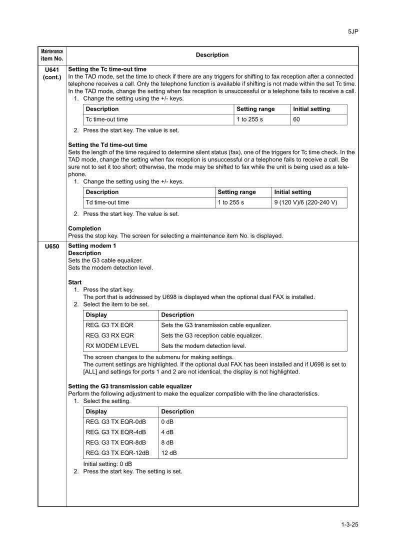
U641(cont.)
Setting the Tc time-out timeIn the TAD mode, set the time to check if there are any triggers for shifting to fax reception after a connected telephone receives a call. Only the telephone function is available if shifting is not made within the set Tc time.In the TAD mode, change the setting when fax reception is unsuccessful or a telephone fails to receive a call.
1. Change the setting using the +/- keys.
2. Press the start key. The value is set.
Setting the Td time-out timeSets the length of the time required to determine silent status (fax), one of the triggers for Tc time check. In the TAD mode, change the setting when fax reception is unsuccessful or a telephone fails to receive a call. Be sure not to set it too short; otherwise, the mode may be shifted to fax while the unit is being used as a tele-phone.
1. Change the setting using the +/- keys.
2. Press the start key. The value is set.
CompletionPress the stop key. The screen for selecting a maintenance item No. is displayed.
U650 Setting modem 1DescriptionSets the G3 cable equalizer.Sets the modem detection level.
Start1. Press the start key.
The port that is addressed by U698 is displayed when the optional dual FAX is installed.2. Select the item to be set.
The screen changes to the submenu for making settings.The current settings are highlighted. If the optional dual FAX has been installed and if U698 is set to [ALL] and settings for ports 1 and 2 are not identical, the display is not highlighted.
Setting the G3 transmission cable equalizerPerform the following adjustment to make the equalizer compatible with the line characteristics.
1. Select the setting.
Initial setting: 0 dB2. Press the start key. The setting is set.
Maintenanceitem No. Description
Description Setting range Initial setting
Tc time-out time 1 to 255 s 60
Description Setting range Initial setting
Td time-out time 1 to 255 s 9 (120 V)/6 (220-240 V)
Display DescriptionREG. G3 TX EQR Sets the G3 transmission cable equalizer.
REG. G3 RX EQR Sets the G3 reception cable equalizer.
RX MODEM LEVEL Sets the modem detection level.
Display DescriptionREG. G3 TX EQR-0dB 0 dB
REG. G3 TX EQR-4dB 4 dB
REG. G3 TX EQR-8dB 8 dB
REG. G3 TX EQR-12dB 12 dB
1-3-25

5JP-1
U650(cont.)
Setting the G3 reception cable equalizerPerform the following adjustment to make the equalizer compatible with the line characteristics.
1. Select the setting.
Initial setting: 0 dBPress the start key. The setting is set.
Setting the modem detection levelTo improve the transmission performance when a low quality line is used.
1. Select the setting.
Initial setting: 43 dBm2. Press the start key. The setting is set.
CompletionPress the stop key. The screen for selecting a maintenance item No. is displayed.
U651 Setting modem 2DescriptionSets the modem output level.Sets the DTMF output level of a push-button dial telephone.PurposeUsed if problems occur when sending a signal with a push-button dial telephone.
Start1. Press the start key.
The port that is addressed by U698 is displayed when the optional dual FAX is installed.The current setting is displayed in each item.An asterisk (*) is displayed if U698 is set to [ALL] and settings for ports 1 and 2 are not identical.In this case, the value cannot be changed.
2. Select the item to be set.
3. Change the setting using the +/- or numeric keys.4. Press the start key. The setting is set.
CompletionPress the stop key. The screen for selecting a maintenance item No. is displayed.
Maintenanceitem No. Description
Display Description
REG. G3 RX EQR-0dB 0 dB
REG. G3 RX EQR-4dB 4 dB
REG. G3 RX EQR-8dB 8 dB
REG. G3 RX EQR-12dB 12 dB
Display Description
RX MODEM LEVEL-33dBm -33 dBm
RX MODEM LEVEL-38dBm -38 dBm
RX MODEM LEVEL-43dBm -43 dBm
RX MODEM LEVEL-48dBm -48 dBm
Display Description Settingrange
Initialsetting
SGL LVL MODEM Modem output level -15 to 0 -9 (120 V)-10 (220-240 V)
DTMF LEV(CENT) DTMF output level (main value) -15.0 to 0.0 -5 (120 V)-10.5 (220-240 V)
DTMF LEV(DIFF) DTMF output level (level difference) 0 to 5.5 2 (120 V)2.5 (220-240 V)
1-3-26

5JP
U660 Setting the NCUDescriptionMakes setting regarding the network control unit (NCU).PurposeTo be set when installing the facsimile kit.
Start1. Press the start key.
The port that is addressed by U698 is displayed when the optional dual FAX is installed.2. Select the item to be set.
The screen changes to the submenu for making settings.The current settings are highlighted. If the optional dual FAX has been installed and if U698 is set to [ALL] and settings for ports 1 and 2 are not identical, the display is not highlighted.
Setting the connection to PBX/PSTNSelects if a fax is to be connected to either a PBX or public switched telephone network.
1. Select the setting.
Initial setting: PSTN2. Press the start key. The setting is set.
Setting PSTN dial tone detectionSelects if the dial tone is detected to check the telephone is off the hook when a fax is connected to a public switched telephone network.
1. Select the setting.
Initial setting: ON2. Press the start key. The setting is set.
Setting busy tone detectionWhen a fax signal is sent, sets whether the line is disconnected immediately after a busy tone is detected, or the busy tone is not detected and the line remains connected until T0 time-out time.Fax transmission may fail due to incorrect busy tone detection. When set to 2, this problem may be prevented.However, the line is not disconnected within the T0 time-out time even if the destination line is busy.
1. Select the setting.
Initial setting: ON2. Press the start key. The setting is set.
Maintenanceitem No. Description
Display Description
EXCHANGE Sets the connection to PBX/PSTN.
DIAL TONE Sets PSTN dial tone detection.
BUSY TONE Sets busy tone detection.
PBX SETTING Setting for a PBX.
DC LOOP Sets the loop current detection before dialing.
Display Description
PSTN Connected to the public switched telephone network.
PBX Connected to a PBX.
Display Description
ON Detects the dial tone.
OFF Does not detect the dial tone.
Display DescriptionON Detects busy tone.
OFF Does not detect busy tone.
1-3-27

5JP
U660(cont.)
Setting for a PBXSelects the mode to connect an outside call when connected to a PBX.According to the type of the PBX connected, select the mode to connect an outside call.
1. Select the setting.
Initial setting: LOOP2. Press the start key. The setting is set.
Setting the loop current detection before dialingSets if the loop current detection is performed before dialing.
1. Select the setting.
Initial setting: ON2. Press the start key. The setting is set.
CompletionPress the stop key. The screen for selecting a maintenance item No. is displayed.
Maintenanceitem No. Description
Display Description
FLASH Flashing mode
LOOP Code number mode
Display Description
ON Performs loop current detection before dialing.
OFF Does not perform loop current detection before dialing.
1-3-28

5JP
U670 Outputting listsDescriptionOutputs a list of data regarding fax transmissions.Printing a list is disabled either when a job is remaining in the buffer or when [Pause All Print Jobs] is pressed to halt printing.PurposeTo check conditions of use, settings and transmission procedures of the fax.
Method1. Press the start key.
The port that is addressed by U698 is displayed when the optional dual FAX is installed.2. Select the item to be output.3. Press the start key. The selected list is output.
When [ERROR LIST] is selected and the dual FAX is not installed, regardless of the port being dis-played, a Port 1 error list is delivered; while if the dual FAX is installed, an error list containing errors at both Port 1 and 2 is delivered.When [BACKUP REPORT] is selected, regardless of the port being displayed, the historical record of all fax and Internet-fax job as well as the reserved fax job information are delivered to a log.
CompletionPress the stop key. The screen for selecting a maintenance item No. is displayed.
Maintenanceitem No. Description
Display Description
SETTING LIST Outputs a list of software switches, self telephone number, confiden-tial boxes, ROM versions and other information.
ACTION LIST Outputs a list of error history, transmission line details and other infor-mation.
SELF ST REPORT Outputs a list of settings in maintenance mode (own-status report) regarding fax transmission only.
PROTOCOL LIST Outputs a list of transmission procedures.
ERROR LIST Outputs a list of error.
BACKUP REPORT Outputs the historical record of the fax and internet-fax job informa-tion as well as the reserved fax jobs stored in the standard memory DIMM on the machine.
ADDRESS BOOK(No.) Outputs the address book in the order of registration ID.
ADDRESS BOOK(Name) Outputs the address book in the order of registration name.
ONE-TOUCH LIST Outputs a one-touch list.
GROUP LIST Outputs a group list.
1-3-29

5JP-1
U671 Clearing the FAX backup report dataDescriptionClears the historical record of the fax and Internet-fax job as well as the reserved fax job information which are backed up in the FAX control PWB. Also, initializes the memory DIMM.PurposeFor prevention of backup data leakage.
Method1. Press the start key.2. Select the item.
3. Press the start key. The backed up data is cleared.4. Turn the main power switch off and on when selecting [RECOVERY FAX DIMM] or [FAX DIMM CLEAR].
CompletionPress the stop key. The screen for selecting a maintenance item No. is displayed.
U695 FAX function customizeDescriptionSets fax batch transmission ON/OFF.Changes the print size priority at the time of small size reception.Sets zooming on the sent image attached to the send result report.PurposeTo be executed as required.
Setting1. Select the setting.
Setting: [FAX BULK TX]1. Select ON or OFF.
Initial setting: ON2. Press the start key. The setting is set.
Setting: [A5 PRINT PRIORITY CHG]1. Select ON or OFF.
Initial setting: OFF2. Press the start key. The setting is set.
Maintenanceitem No. Description
Display Description
RESERVATION CLEAR Clears communication reservation information on the FAX control PWB.
RECOVERY FAX DIMM Enables DIMM that was used in another machine.
FAX DIMM CLEAR All the data of DIMM is cleared.
Display Description
FAX BULK TX Fax batch transmission ON/OFF
A5 PRINT PRIORITY CHG Change of print size priority at the time of small size reception
REPORT IMAGE FITTING Settings for zooming on the sent image attached to the send result report.
Display Description
ON Fax batch transmission is enabled.
OFF Fax batch transmission is disabled.
Display DescriptionON At the time of A5 size reception: A5→B5→A4→B4→A3OFF At the time of A5 size reception: A5→A4→B5→A3→B4
1-3-30

5JP-1
U695(cont.)
Setting: [REPORT IMAGE FITTING]1. Select ON or OFF.
Initial setting: OFF2. Press the start key. The setting is set.
CompletionPress the stop key. The screen for selecting a maintenance item No. is displayed.
U698 Setting the port addressed in maintenance modeDescriptionConfigures the port that is addressed in maintenance mode.PurposeTo configure the port that is addressed in maintenance mode when the optional dual FAX is installed.It is not required to assign the same settings to both ports. It should be used to assign different settings to each port.
RemarksThis maintenance item is shown only when the optional dual FAX has been installed.
Setting1. Press the start key.2. Press [PORT SELECT]. The current setting is displayed in reverse.3. Select the item to be set.
Initial setting: ALL4. Press the start key. The setting is set.
CompletionPress the stop key. The screen for selecting a maintenance item No. is displayed.
SupplementThe setting must be made after re-entering maintenance mode because it will be cleared when maintenance mode is canceled and power is switched off.
Maintenanceitem No. Description
Display Description
ON Provides overview for the sent image attached to the send result report, after down-zooming.
OFF Does not zoom the sent image attached to the send result report.
Display Description
ALL All ports
PORT 1 Port 1 (Fax control PWB)
PORT 2 Port 2 (Optional dual FAX)
1-3-31

5JP
U699 Setting the software switchesDescriptionSets the software switches on the fax control PWB individually.PurposeTo change the setting when a problem such as split output of received originals occurs. Since the communication performance is largely affected, normally this setting need not be changed.Method
1. Press the start key.The port that is addressed by U698 is displayed when the optional dual FAX is installed.
2. Press [SW No.].The current setting is displayed.An asterisk (*) is displayed if U698 is set to [ALL] and settings for ports 1 and 2 are not identical.
3. Enter the desired software switch number (3 digits) using the numeric keys and press the enter key.4. Use numeric keys 7 to 0 to switch each bit between 0 and 1.5. Press the start key to set the value.
CompletionPress the stop key. The screen for selecting a maintenance item No. is displayed.
List of Software Switches of Which the Setting Can Be Changed
<Communication control procedure>
Maintenanceitem No. Description
No. Bit Item
36 7654 Coding format in transmission
3210 Coding format in reception
37 5 33600 bps/V34
4 31200 bps/V34
3 28800 bps/V34
2 26400 bps/V34
1 24000 bps/V34
0 21600 bps/V34
38 7 19200 bps/V34
6 16800 bps/V34
5 14400 bps/V34
4 12000 bps/V34
3 9600 bps/V34
2 7200 bps/V34
1 4800 bps/V34
0 2400 bps/V34
41 3 FSK detection in V.8
42 4 4800 bps when low-speed setting is active
2 FIF length in transmission of more than 4 times of DIS/DTC signal
1-3-32

U699(cont.)
List of Software
<Communication
<Modem setting>
<NCU setting>
<Calling time set
Maintenanceitem No.
No.
53 765
54 765
55 765
60 765
63 765
64
66 765
68 765
No.
89
No.
121
122
125 765
126
No.
133 765
134 765
141 765
142 765
143 765
144 765
145 765
147 765
148 765
149 765
151 765
5JP-2
Switches of Which the Setting Can Be Changed
time setting>
ting>
Description
Bit Item
43210 T3 timeout setting
43210 T4 timeout setting (automatic equipment)
43210 T5 timeout setting
43210 Time before transmission of CNG (1100 Hz) signal
43210 T0 timeout setting (manual equipment)
7 Phase C timeout in ECM reception
43210 Timeout 1 in countermeasures against echo
43210 Timeout for FSK detection start in V.8
Bit Item
76543 RX gain adjust
Bit Item
7654 Dial tone/busy tone detection pattern
7654 Busy tone detection pattern
1 Busy tone detection in automatic FAX/TEL switching
43210 Access code registration for connection to PSTN
7654 FAX/TEL automatic switching ringback tone ON/OFF cycle
Bit Item
43210 DTMF signal transmission time
43210 DTMF signal pause time
43210 Ringer detection cycle (minimum)
43210 Ringer detection cycle (maximum)
43210 Ringer ON time detection
43210 Ringer OFF time detection
1-3-33
43210 Ringer OFF non-detection time
43210 Dial tone detection time (continuous tone)
43210 Allowable dial tone interruption time
43210 Time for transmitting selection signal after closing the DC circuit
43210 Ringer frequency detection invalid time

5JP
1-3-2 User management
(1) Using the user management mode
Rings1. Press the System Menu key.2. Press [FAX], [Next] of Reception and then press
[Next] of FAX. Press [Change] for the reception mode to be changed.
3. Press [+]/[-] or the numeric keys to enter the num-ber.
4. Press [OK].
Volume Adjustment1. Press the System Menu key.2. Press [Common Settings], [Next] of Sound and
then [Change] of FAX Speaker Volume or FAX Monitor Volume.
3. Select any of [1] (Minimum), [2] (Medium), [3] (Max-imum) or [0] (Mute).
4. Press [OK].
Retry Times1. Press the System Menu key.2. Press [FAX], [Next] of Transmission, [Next] of FAX
and then [Change] of Retry Times.3. Press [+]/[-] or the numeric keys to enter the num-
ber.4. Press [OK].
Receiving Mode1. Press the System Menu key.2. Press [FAX], [Next] of Reception, [Next] of FAX and
then [Change] of RX Setting.3. Select the reception mode to be changed. When
[Auto (DRD)] is selected, choose the pattern of ringing.
4. Press [OK].
Reception Date/Time1. Press the System Menu key.2. Press [FAX], [Next] of Reception, [Next] of Basic
and then [Change] of Reception Date/Time.3. Press [On].4. Press [OK].
Media Type for Print Output1. Press the System Menu key.2. Press [FAX], [Next] of Reception, [Next] of Basic
and then [Change] of Media Type.3. Select the desired paper type. If no specific paper
type is selected, press [All Media Types].4. Press [OK].
Setting the cassette for the print output of received faxes
1. Press the System Menu key.2. Press [Common Settings], [Next] of Original/Paper
Settings, [Next] of Cassette Setting.3. Cassette Setting, select one of [Cassette 1] to
[Cassette 4] and press [Next]. Then press Paper Size [Change].
4. For automatic detection of the paper size, press [Auto] and select [Metric] or [Inch] as the unit.To select the paper size, press [Standard Sizes 1] or [Standard Sizes 2] and select the paper size.
5. Press [OK]. The previous screen reappears.6. Press [Change] of Media Type and select the
media type. Then press [OK]. The previous screen reappears.
7. To exit from this setup, press [Close] several times until the System Menu default screen is displayed.
8. Next, set the fax reception settings. For the setting procedure, refer to Media Type for Print Output. Select the same media type that was selected in step 6.
MP Tray Paper Output1. Press the System Menu key.2. Press [FAX], [Next] of Reception, [Next] of Basic
and then [Change] of Multi Purpose Tray.3. Select either [Off] (not to use) or [On] (to use).4. Press [OK].
Registering Permit FAX No.1. Press the System Menu key.2. Press [FAX], [Next] of TX/RX Restriction and then
[Register/Edit] of Permit No. List.3. Press [Add].4. Use the numeric keys to enter Permit FAX No. Up
to 20 digits can be entered.5. Press [OK].6. When registering other Permit FAX numbers,
repeat steps 3 to 5.7. Press [Close].
Changing and Deleting Permit FAX No.1. Press the System Menu key.2. Press [FAX], [Next] of TX/RX Restriction and then
[Register/Edit] of Permit No. List.3. Select the Permit FAX No. to be changed or
deleted.To change Permit FAX No., go to step 4, and to delete Permit FAX No., go to step 7.
4. Press [Detail].
In addition to a maintenance function for service, the machine is equipped with a management function which can be op-erated by users. In this user management mode, settings such as default settings can be changed.
1-3-34

5JP
5. Use the numeric keys to reenter Permit FAX No. Up to 20 digits can be entered.
6. Press [OK]. When the change confirmation screen appears, press [Yes]. Go to step 8.
7. Press [Delete]. When the deletion confirmation screen appears, press [Yes].
8. To change or delete other Permit FAX numbers, repeat steps 3 to 7.
9. Press [Close].
Registering Reject FAX No.1. Press the System Menu key.2. Press [FAX], [Next] of TX/RX Restriction and then
[Register/Edit] of Reject No. List.3. Press [Add].4. Use the numeric keys to enter Reject FAX No. Up
to 20 digits can be entered.5. Press [OK].6. To register other Reject FAX numbers, repeat steps
3 to 5.7. Press [Close].
Changing and Deleting Reject FAX No.1. Press the System Menu key.2. Press [FAX], [Next] of TX/RX Restriction and then
[Register/Edit] of Reject No. List.3. Select the Reject FAX No. to be changed or
deleted.To change Reject FAX No., go to step 4, and to delete Reject FAX No., go to step 7.
4. Press [Detail].5. Use the numeric keys to reenter Reject FAX No. Up
to 20 digits can be entered.6. Press [OK]. When the change confirmation screen
appears, press [Yes]. Go to step 8.7. Press [Delete]. When the deletion confirmation
screen appears, press [Yes].8. To change and delete other Reject FAX numbers,
repeat steps 3 to 7.9. Press [Close].
Registering Permit ID No.1. Press the System Menu key.2. Press [FAX], [Next] of TX/RX Restriction and then
[Register/Edit] of Permit ID List.3. Press [Add].4. Use [+]/[-] or the numeric keys to enter Permit ID
No. (0000 to 9999)5. Press [OK].6. To register other Permit ID numbers, repeat steps 3
to 5.7. Press [Close].
Changing and Deleting Permit ID No.1. Press the System Menu key.2. Press [FAX], [Next] of TX/RX Restriction and then
[Register/Edit] of Permit ID List.3. Select the Permit ID No. to be changed or deleted.
To change Permit ID No., go to step 4, and to delete Permit ID No., go to step 7.
4. Press [Detail].5. Use [+]/[-] or the numeric keys to reenter Permit ID
No. (0000 to 9999)6. Press [OK]. When the change confirmation screen
appears, press [Yes]. Go to step 8.7. Press [Delete]. When the deletion confirmation
screen appears, press [Yes].8. To change and delete other Permit ID numbers,
repeat step 3 to 7.9. Press [Close].
Setting Send Restriction1. Press the System Menu key.2. Press [FAX], [Next] of TX/RX Restriction, and then
[Change] of TX Restriction.3. To not use the sending restriction, press [Off]. To
restrict the other parties to which you send originals only to the ones registered in Permit FAX No. and Permit ID No. as well as the ones registered in the Address Book, press [Permit List + Address Book].
4. Press [OK].
Setting Reception Restriction1. Press the System Menu key.2. Press [FAX], [Next] of TX/RX Restriction, and then
[Change] of RX Restriction.3. To not use the reception restriction, press [Off]. To
restrict the other parties from which you receive originals only to the ones registered in Permit FAX No. and Permit ID No. as well as the ones regis-tered in the Address Book, press [Permit List + Address Book]. To block incoming faxes from send-ers registered in Reject FAX No., press [Reject List].
4. Press [OK].
Unknown Number Reception1. Press the System Menu key.2. Press [FAX], [Next] of TX/RX Restriction, and then
[Change] of Unknown Number Reception.3. To receive faxes from the unknown number, press
[Permit]. To reject faxes from the unknown number, press [Reject].
4. Press [OK].
1-3-35

5JP
Registering an Encryption Key1. Press the System Menu key.2. Press [FAX], [Next] of TX/RX Common and then
[Register/Edit] of Encrypt. Key Registration.3. Select the unregistered encryption key and press
[Register/Edit].4. Press [Encryption Key].5. Use the numbers (0 to 9) and the alphabet (A to F)
on the touch panel to enter the encryption key (16 digits) and press [OK].
6. Press [OK]. To register other encryption keys, repeat steps 3 to 6.
Changing and Deleting Registration Contents of Encryption Key
1. Press the System Menu key.2. Press [FAX], [Next] of TX/RX Common and then
[Register/Edit] of Encrypt. Key Registration.3. Select the encryption key to be changed or deleted.
To change the registration contents, go to step 4, and to delete the registration contents, go to step 8.
4. Press [Register/Edit].5. Press [Encryption Key].6. Press [Backspace] to delete the encryption key last
entered. Use the numbers (0 to 9) and the alphabet (A to F) on the touch panel, enter the encryption key (16 digits), and press [OK].
7. Press [OK]. When the change confirmation screen appears, press [Yes]. Go to step 9.
8. Press [Delete]. When the deletion confirmation screen appears, press [Yes].
9. To change or delete other encryption keys, follow steps 3 to 8.
Operation at the Receiving System1. Press the System Menu key.2. Press [FAX], [Next] of Reception and [Change] of
Encrypted Reception.3. Press [On], select the encryption key number and
press [OK].4. The sending system conducts encrypted transmis-
sion. When encryption communication is conducted normally, the machine decrypts the encrypted origi-nals received and prints the originals.
Reduced Reception1. Press the System Menu key.2. Press [FAX], [Next] of Reception, [Next] of Basic,
and [Change] of Reduced RX Size.3. Select [Off] or [On].4. Press [OK].
Duplex Print Output1. Press the System Menu key.2. Press [FAX], [Next] of Reception, [Next] of Basic
and then [Change] of Duplex Printing.3. Select either [Off] or [On].4. Press [OK].
2 in 1 Reception1. Press the System Menu key.2. Press [FAX], [Next] of Reception, [Next] of Basic
and then [Change] of 2 in 1 Printing.3. Select either [Off] or [On].4. Press [OK].
Remote Diagnostics1. Press the System Menu key.2. Press [FAX], [Next] of TX/RX Common and then
[Change] of FAX Remote Diagnostics.3. Select either [Off] or [On].
If you selected [On], press [+] or [-] or use the numeric keys to enter the Predetermined ID.
4. Press [OK].
Prohibiting FAX Printing at Specified Times (Unus-able Time)
1. Press the System Menu key.2. Press cursor down key, [Date/Timer], cursor down
key and then [Change] of Unusable Time.3. Press [On] and use [+] or [-] to enter the start time
and end time.4. Press [OK].
Send Result Reports1. Press the System Menu key.2. Press [Report], and [Next] of Result Report Setting.
Then press [Next], [FAX], and [Change] of Send Result Report.
3. Press [Off] (not to print), [On] (to print), or [Error Only].If you selected [On] or [Error], you should then indi-cate whether the transmitted image is to be attached by selecting [Off] (do not print transmitted image) or [On] (print transmitted image].
4. Press [OK].
FAX RX Result Reports1. Press the System Menu key.2. Press [Report], and [Next] of Result Report Setting.
Then press [Change] of FAX RX Result Report.3. Press [Off] (not to print), [On] (to print), or [Error
and Forward Only].4. Press [OK].
Automatic Printout1. Press the System Menu key.2. Press [Report], and [Next] of Admin Report Set-
tings. Then press [Change] of Outgoing FAX Report or Incoming FAX Report.
3. Press [Off] (not to print) or [On] (to print).4. Press [OK].
1-3-36

5JP
Status Page1. Press the System Menu key.2. Press [Report], and [Next] of Report Print. Then
press [Print] of Status Page.3. When the printing confirmation screen appears,
press [Yes]. A status page is printed.
Reporting FAX Receipt Result by E-mail1. Press the System Menu key.2. Press [Report], and [Next] of Result Report Setting.
Then press [Change] of RX Result Report Type.3. To select destination from the address book, press
[E-mail Address Book] and then [Address Book].Specify the destination of E-mail, and press [OK].To enter an e-mail address directly, press [E-mail Address Entry] and then [E-mail Address].Enter the desired e-mail address, and press [OK]. Up to 128 characters can be entered.
4. Press [OK].
1-3-37

5JP
This page is intentionally left blank.
1-3-38

5JP
1-4 Error Codes
1-4-1 Error codes
(1) Error code
Error codes are listed on the communication reports, activity report, etc. The codes consist of an error code indication U followed by a 5-digit number. (Error codes for V34 communication errors start with an E indication, followed by five digits.)The upper three of the five digits indicate general classification of the error and its cause, while the lower two indicate the detailed classification. Items for which detailed classification is not necessary have 00 as the last two digits.
Error code
U X X X X X
Detailed classification of error code
General classification of error code
Error code indication
1-4-1

5JP
(2) Table of general classification
Error code Description
U00000 No response or busy after the set number of redials.
U00100 Transmission was interrupted by a press of the stop/clear key.
U00200 Reception was interrupted by a press of the stop/clear key.
U00300 Recording paper on the destination unit has run out during transmission.
U004XX A connection was made but interrupted during handshake with the receiver unit (refer to page 1-4-3 U004XX error code table).
U006XX Communication was interrupted because of a machine problem (refer to page 1-4-4 U006XX error code table).
U00700 Communication was interrupted because of a problem in the destination unit.
U008XX A page transmission error occurred in G3 mode (refer to page 1-4-4 U008XX error code table).
U009XX A page reception error occurred in G3 mode (refer to page 1-4-4 U009XX error code table).
U010XX Transmission in G3 mode was interrupted by a signal error (refer to page 1-4-5 U010XX error code table).
U011XX Reception in G3 mode was interrupted by a signal error (refer to page 1-4-6 U011XX error code table).
U01400 An invalid one-touch key was specified during communication.
U01500 A communication error occurred when calling in V.8 mode.
U01600 A communication error occurred when called in V.8 mode.
U017XX A communication error occurred before starting T.30 protocol during transmission in V.34 mode (refer to page 1-4-7 U017XX error code table).
U018XX A communication error occurred before starting T.30 protocol during reception in V.34 mode (refer to page 1-4-7 U018XX error code table).
U03000 No document was present in the destination unit when polling reception started.
U03200 In interoffice subaddress-based bulletin board reception, data was not stored in the box specified by the destination unit.
U03300 In polling reception from a unit of our make, operation was interrupted due to a mismatch in permit ID or telephone number. Or, in interoffice subaddress-based bulletin board reception, operation was interrupted due to a mismatch in permit ID or telephone number.
U03400 Polling reception was interrupted because of a mismatch in individual numbers (destination unit is either of our make or by another manufacturer).
U03500 In interoffice subaddress-based bulletin board reception, the specified Subaddress confidential box number was not registered in the destination unit.
U03600 An interoffice subaddress-based bulletin board reception was interrupted because of a mismatch in the specified subaddress confidential box number.
U03700 Interoffice subaddress-based bulletin board reception failed because the destination unit had no subaddress-based bulletin board transmission capability, or data was not stored in any subaddress confidential box in the destination unit.
U04000 In interoffice subaddress-based transmission mode, the specified subaddress box number was not registered in the destination unit.
U04100 Subaddress-based transmission failed because the destination unit had no subaddress-based reception capability.
U04200 In encrypted transmission, the specified encryption box was not registered in the destination unit.
U04300 Encrypted transmission failed because the destination unit had no encrypted communication capa-bility.
1-4-2

5JP
(2-1) U004XX error code table: Interrupted phase B
U044XX Communication was interrupted because of an encryption key error during encrypted transmission (refer to page 1-4-7 U044XX error code table).
U04500 Encrypted reception was interrupted because of a mismatch in encryption keys.
U05100 Password check transmission or restricted transmission was interrupted because the permit ID’s did not agree with.
U05200 Password check reception or restricted reception was interrupted because the permit ID’s did not match, the rejected FAX number’s did match, or the destination receiver did not return its phone number.
U05300 The password check reception or the restricted reception was interrupted because the permitted numbers did not match, the rejected numbers did match, or the machine in question did not acknowledge its phone number.
U14000 Memory overflowed during confidential reception. Or, in subaddress-based confidential reception, memory overflowed.
U14100 In interoffice subaddress-based transmission, memory overflowed in the destination unit.
U19000 Memory overflowed during memory reception.
U19100 Memory overflowed in the destination unit during transmission.
U19300 Transmission failed because an error occurred during JBIG encoding.
Error code Description
U00430 Polling request was received but interrupted because of a mismatch in permit number. Or, subad-dress-based bulletin board transmission request was received but interrupted because of a mis-match in permit ID in the transmitting unit.
U00431 An subaddress-based bulletin board transmission was interrupted because the specified subad-dress confidential box was not registered.
U00432 An subaddress-based bulletin board transmission was interrupted because of a mismatch in Sub-address confidential box numbers.
U00433 Subaddress-based bulletin board transmission request was received but data was not present in the subaddress confidential box.
U00440 Subaddress-based confidential reception was interrupted because the specified subaddress box was not registered.
U00450 The destination transmitter disconnected because the permit ID’s did not agree with while the des-tination transmitter is in password-check transmission or restricted transmission.
U00460 Encrypted reception was interrupted because the specified encryption box number was not regis-tered.
U00462 Encrypted reception was interrupted because the encryption key for the specified encryption box was not registered.
Error code Description
1-4-3

5JP
(2-2) U006XX error code table: Problems with the unit
(2-3) U008XX error code table: Page transmission error
(2-4) U009XX error code table: Page reception error
Error code Description
U00601 Document jam or the document length exceeds the maximum.
U00613 Image writing section problem
U00656 Data was not transmitted to a modem error.
U00690 System error.
Error code Description
U00800 A page transmission error occurred because of reception of a RTN or PIN signal.
U00811 A page transmission error reoccurred after retry of transmission in the ECM mode.
Error code Description
U00900 An RTN or PIN signal was transmitted because of a page reception error.
U00910 A page reception error remained after retry of transmission in the ECM mode.
1-4-4

5JP
(2-5) U010XX error code table: G3 transmission
Error code Description
U01000 An FTT signal was received for a set number of times after TCF signal transmission at 2400 bps. Or, an RTN signal was received in response to a Q signal (excluding EOP) after transmission at 2400 bps.
U01001 Function of the unit differs from that indicated by a DIS signal.
U01016 An MCF signal was received but no DIS signal was received after transmission of an EOM signal, and T1 timeout was detected.
U01019 No relevant signal was received after transmission of a CNC signal, and the preset number of command retransfers was exceeded (between units of our make).
U01020 No relevant signal was received after transmission of a CTC signal, and the preset number of com-mand retransfers was exceeded (ECM).
U01021 No relevant signal was received after transmission of an EOR.Q signal, and the preset number of command retransfers was exceeded (ECM).
U01022 No relevant signal was received after transmission of an RR signal, and the preset number of com-mand retransfers was exceeded (ECM).
U01028 T5 time-out was detected during ECM transmission (ECM).
U01052 A DCN signal was received after transmission of an RR signal (ECM).
U01080 A PIP signal was received after transmission of a PPS.NULL signal.
U01092 During transmission in V.34 mode, communication was interrupted because of an impossible com-bination of the symbol speed and communication speed.
U01093 A DCN or other inappropriate signal was received during phase B of transmission.
U01094 The preset number of command retransfers for DCS/NSS signals was exceeded during phase B of transmission.
U01095 No relevant signal was received after transmission of a PPS (Q) signal during phase D of transmis-sion, and the preset number of command transfers was exceeded.
U01096 A DCN signal or invalid command was received during phase D of transmission.
U01097 The preset number of command retransfers was exceeded after transmission of an RR signal or no response.
1-4-5

5JP
(2-6) U011XX error code table: G3 reception
Error code Description
U01100 Function of the unit differs from that indicated by a DCS signal.
U01101 Function of the unit (excl. communication mode select) differs from that indicated by an NSS sig-nal.
U01102 A DTC (NSC) signal was received when no transmission data was in the unit.
U01110 No response after transmission of a DIS signal.
U01111 No response after transmission of a DTC (NSC) signal.
U01113 No response after transmission of an FTT signal.
U01125 No response after transmission of a CNS signal (between units of our make).
U01129 No response after transmission of an SPA signal (short protocol).
U01141 A DCN signal was received after transmission of a DTC signal.
U01143 A DCN signal was received after transmission of an FTT signal.
U01155 A DCN signal was received after transmission of an SPA signal (short protocol).
U01160 During message reception, transmission time exceeded the maximum transmission time per line.
U01162 Reception was aborted due to a modem malfunction during message reception.
U01191 Communication was interrupted because an error occurred during an image data reception sequence in the V.34 mode.
U01193 There was no response, or a DCN signal or invalid command was received, during phase C/D of reception.
U01194 A DCN signal was received during phase B of reception.
U01195 No message was received during phase C of reception.
U01196 Error line control was exceeded and a decoding error occurred for the message being received.
1-4-6

5JP
(2-7) U017XX error code table: V.34 transmission
U01700: A communication error that occurs at the transmitting unit in the period after transmission of INFO0 before enter-ing phase 3 (primary channel equivalent device training). For example, INFO0/A/Abar (B/Bbar, for polling trans-mission)/INFOh was not detected.
U01720: A communication error that occurs at the transmitting unit in the period after initiating the control channel before entering the T.30 process. For example, PPh/ALT/MPh/E was not detected.
U01721: In the absence of a common communication speed between units (including when an impossible combination of communication speed and symbol speed occurs) after MPh exchange; 1) a DCN signal was received from the destination unit, and the line was cut; or 2) a DIS (NSF, CSI) signal was received from the destination unit and, in response to the signal, the unit transmitted a DCN signal, and the line was cut.
(2-8) U018XX error code table: V.34 reception
U01800: A communication error that occurs at the receiver unit in the period after transmission of INFO0 before entering phase 3 (primary channel equivalent device training). For example, INFO0/B/Bbar (A/Abar, for polling reception)/probing tone was not detected.
U01810: A communication error that occurs at the receiver unit in phase 3 (primary channel equivalent device training).For example, S/Sbar/PP/TRN was not detected.
U01820: A communication error that occurs at the receiver unit in the period after initiating the control channel before entering the T.30 process. For example, PPh/ALT/MPh/E was not detected.
U01821: In the absence of a common communication speed between units (including when an impossible combination of communication speed and symbol speed occurs) after MPh exchange, a DCN signal was transmitted to the des-tination unit and the line was cut.
(2-9) U044XX error code table: Encrypted transmission
Error code Description
U01700 A communication error occurred in phase 2 (line probing).
U01720 A communication error occurred in phase 4 (modem parameter exchange).
U01721 Operation was interrupted due to the absence of a common communication speed between units.
Error code Description
U01800 A communication error occurred in phase 2 (line probing).
U01810 A communication error occurred in phase 3 (primary channel equivalent device training).
U01820 A communication error occurred in phase 4 (modem parameter exchange).
U01821 Operation was interrupted due to the absence of a common communication speed between units.
Error code Description
U04400 Encrypted transmission was interrupted because encryption keys did not agree.
1-4-7

5JP
This page is intentionally left blank.
1-4-8
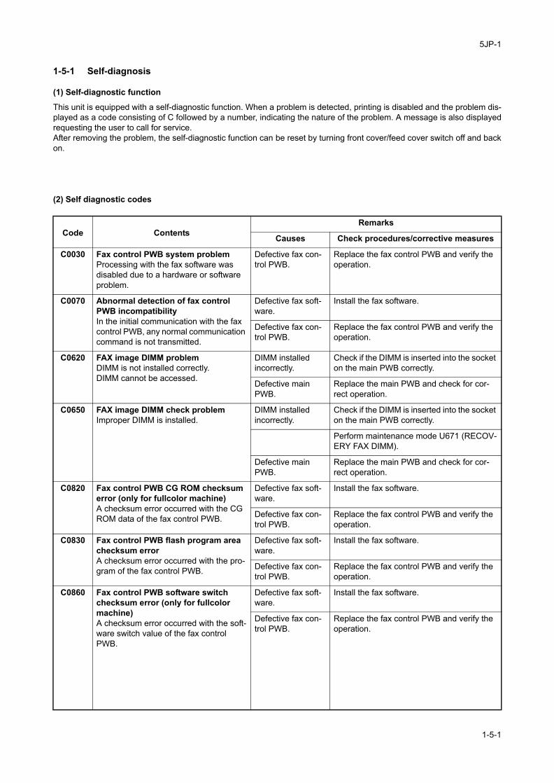
5JP-1
1-5 Troubleshooting
1-5-1 Self-diagnosis
(1) Self-diagnostic function
This unit is equipped with a self-diagnostic function. When a problem is detected, printing is disabled and the problem dis-played as a code consisting of C followed by a number, indicating the nature of the problem. A message is also displayedrequesting the user to call for service.After removing the problem, the self-diagnostic function can be reset by turning front cover/feed cover switch off and backon.
(2) Self diagnostic codes
Code ContentsRemarks
Causes Check procedures/corrective measures
C0030 Fax control PWB system problemProcessing with the fax software was disabled due to a hardware or software problem.
Defective fax con-trol PWB.
Replace the fax control PWB and verify the operation.
C0070 Abnormal detection of fax control PWB incompatibilityIn the initial communication with the fax control PWB, any normal communication command is not transmitted.
Defective fax soft-ware.
Install the fax software.
Defective fax con-trol PWB.
Replace the fax control PWB and verify the operation.
C0620 FAX image DIMM problemDIMM is not installed correctly.DIMM cannot be accessed.
DIMM installed incorrectly.
Check if the DIMM is inserted into the socket on the main PWB correctly.
Defective main PWB.
Replace the main PWB and check for cor-rect operation.
C0650 FAX image DIMM check problemImproper DIMM is installed.
DIMM installed incorrectly.
Check if the DIMM is inserted into the socket on the main PWB correctly.
Perform maintenance mode U671 (RECOV-ERY FAX DIMM).
Defective main PWB.
Replace the main PWB and check for cor-rect operation.
C0820 Fax control PWB CG ROM checksum error (only for fullcolor machine)A checksum error occurred with the CG ROM data of the fax control PWB.
Defective fax soft-ware.
Install the fax software.
Defective fax con-trol PWB.
Replace the fax control PWB and verify the operation.
C0830 Fax control PWB flash program area checksum errorA checksum error occurred with the pro-gram of the fax control PWB.
Defective fax soft-ware.
Install the fax software.
Defective fax con-trol PWB.
Replace the fax control PWB and verify the operation.
C0860 Fax control PWB software switch checksum error (only for fullcolor machine)A checksum error occurred with the soft-ware switch value of the fax control PWB.
Defective fax soft-ware.
Install the fax software.
Defective fax con-trol PWB.
Replace the fax control PWB and verify the operation.
1-5-1

5JP-1
C0870 Fax control PWB to main PWB high capacity data transfer problemHigh-capacity data transfer between the fax control PWB and the scanner MIP PWB was not normally performed even if the data transfer was retried 10 times.
Poor contact in the connector termi-nals.
Check the connection of connector on the interface PWB and the connector on the fax control PWB, and the continuity across the connector terminals. Repair or replace if necessary.
Defective PWB. Replace the fax control PWB or main PWB and check for correct operation.
C0880 Program archive problem (only for fullcolor machine)When power is turned on, the com-pressed program in the Flash ROM on the fax control PWB was not success-fully decompressed.
Defective fax soft-ware.
Install the fax software.
Defective fax con-trol PWB.
Replace the fax control PWB and verify the operation.
C0890 Fax control PWB CG FONT archive problem (only for fullcolor machine)When power is turned on, the com-pressed CG font in the Flash ROM on the fax control PWB was not success-fully decompressed.
Defective fax soft-ware.
Install the fax software.
Defective fax con-trol PWB.
Replace the fax control PWB and verify the operation.
C0920 Fax file system errorThe backup data is not retained for file system abnormality of flash memory of the fax control PWB.
Defective fax con-trol PWB.
Replace the fax control PWB and verify the operation.
F090 Fax control PWB communication error
Defective main PWB.
Replace the main PWB and check for cor-rect operation.
Code ContentsRemarks
Causes Check procedures/corrective measures
1-5-2

5JP-1
1-6 Requirements on PWB Replacement
1-6-1 Upgrading the firmware on the fax control PWBFollow the procedure below to upgrade the firmware.
Procedure1. Perform maintenance item U000 (mainte-
nance report output) and check U019 ROM version.
2. Press the power key on the operation panel to off. Make sure that the power indicator and the memory indicator are off before turning off the main power switch. And then unplug the power cable from the wall outlet.
3. Insert USB memory in a notch hole of the machine.
4. Insert the power plug and turn the main power switch on. Upgrading firmware starts.Caution:Never turn the main power switch off during upgrading.
Figure 1-6-15. [100% Completed] is displayed on the touch
panel when upgrading is complete.6. Turn the main power switch off and unplug
the power cable from the wall outlet.7. Remove USB memory from the machine.8. Insert the power plug and turn the main
power switch on.9. Perform maintenance item U000 (mainte-
nance report output) and check that U019 ROM version has been upgraded.
USB memory
1-6-1

5JP
This page is intentionally left blank.
1-6-2

5JP-1
2-1 Electrical Parts Layout
2-1-1 Electrical parts layout
Figure 2-1-1
1. Fax control PWB (FCPWB).......................... Modulates, demodulates, compresses, decompresses and smoothes out image data, and converts resolution of image data.
2. Dual FAX (option)......................................... Expands telephone lines.3. Memory DIMM ............................................. Stores the internet FAX reception data, FAX box data and job accounting
data for backup.
2
Monochrome machine (42/52 ppm) Monochrome machine (30 ppm)
Fullcolor machine
1
3
2
1
3
2
1
3
2-1-1

5JP
This page is intentionally left blank.
2-1-2

5JP
2-2 Operation of the PWBs
2-2-1 Fax control PWB
Figure 2-2-1 Fax control PWB silk-screen diagram
Connector Pin No. Signal I/O Voltage Description
YC1 A1 NC - - Not used
Connected to the machine main PWB (via inter-face PWB)
A2 NC - - Not used
A3 AUDIO O 3.3 V DC Speaker control signal
A4 +3.3 V I 3.3 V DC 3.3 V DC supply
A5 GND - - Ground
A6 A13 I 0/3.3 V DC (pulse) Address bus signal A13
A7 A11 I 0/3.3 V DC (pulse) Address bus signal A11
A8 A9 I 0/3.3 V DC (pulse) Address bus signal A9
A9 GND - - Ground
A10 A6 I 0/3.3 V DC (pulse) Address bus signal A6
A11 A4 I 0/3.3 V DC (pulse) Address bus signal A4
A12 A2 I 0/3.3 V DC (pulse) Address bus signal A2
A13 GND - - Ground
A14 OP2IF I 3.3 V/0 DC Option interface select signal
A15 OP2IR O 3.3 V/0 DC Interrupt signal
A16 RDY I 0/3.3 V DC Ready signal
A17 GND - - Ground
A18 IOR I 3.3 V/0 DC I/O reading signal
A19 RESET I 3.3 V/0 DC Reset signal
A20 D15 I/O 0/3.3 V DC (pulse) Data bus signal D15
YC1
YC3
2-2-1

5JP
YC1 A21 GND - - Ground
Connected to the machine main PWB (via inter-face PWB)
A22 D12 I/O 0/3.3 V DC (pulse) Data bus signal D12
A23 D10 I/O 0/3.3 V DC (pulse) Data bus signal D10
A24 D8 I/O 0/3.3 V DC (pulse) Data bus signal D8
A25 GND - - Ground
A26 D5 I/O 0/3.3 V DC (pulse) Data bus signal D5
A27 D3 I/O 0/3.3 V DC (pulse) Data bus signal D3
A28 D1 I/O 0/3.3 V DC (pulse) Data bus signal D1
A29 GND - - Ground
A30 NC - - Not used
B1 NC - - Not used
B2 TXDREQ O 0/3.3 V DC DMA transmission request signal
B3 +3.3V I 3.3 V DC 3.3 V DC supply
B4 A15 I 0/3.3 V DC (pulse) Address bus signal A15
B5 A14 I 0/3.3 V DC (pulse) Address bus signal A14
B6 A12 I 0/3.3 V DC (pulse) Address bus signal A12
B7 A10 I 0/3.3 V DC (pulse) Address bus signal A10
B8 A8 I 0/3.3 V DC (pulse) Address bus signal A8
B9 A7 I 0/3.3 V DC (pulse) Address bus signal A7
B10 A5 I 0/3.3 V DC (pulse) Address bus signal A5
B11 A3 I 0/3.3 V DC (pulse) Address bus signal A3
B12 A1 I 0/3.3 V DC (pulse) Address bus signal A1
B13 +3.3V I 3.3 V DC 3.3 V DC supply
B14 OP2ACKn O 3.3 V/0 V DC Data response signal
B15 +5V I 5 V DC 5 V DC supply
B16 RXDREQ O 0/3.3 V DC DMA reception request signal
B17 RXDMACK I 3.3 V/0 V DC DMA reception response signal
B18 IOW I 3.3 V/0 V DC I/O writing signal
B19 TXDMACK I 3.3 V/0 V DC DMA transmission response signal
B20 D14 I/O 0/3.3 V DC (pulse) Data bus signal D14
B21 D13 I/O 0/3.3 V DC (pulse) Data bus signal D13
B22 D11 I/O 0/3.3 V DC (pulse) Data bus signal D11
B23 D9 I/O 0/3.3 V DC (pulse) Data bus signal D9
B24 D7 I/O 0/3.3 V DC (pulse) Data bus signal D7
B25 D6 I/O 0/3.3 V DC (pulse) Data bus signal D6
B26 D4 I/O 0/3.3 V DC (pulse) Data bus signal D4
B27 D2 I/O 0/3.3 V DC (pulse) Data bus signal D2
B28 D0 I/O 0/3.3 V DC (pulse) Data bus signal D0
B29 NC - - Not used
B30 NC - - Not used
Connector Pin No. Signal I/O Voltage Description
2-2-2

5JP-1
2-3-1
01
T0T1R0R10101
NCNC
AUDIO+3.3VGNDA13A11A9
GNDA6A4A2
GNDOP"IFOP2IRRDYGNDIOR
RESETD15GNDD12D10D8
GNDD5D3D1
GNDNC
NCTXDREQ
+3.3VA15A14A12A10A8A7A5A3A1
+3.3VOP2ACK
+5VRXDREQ
RXDMACKIOW
TXDMACKD14D13D11 D9D7D6D4D2D0NCNC
NCNC
AUDIO+3.3VGNDA13A11A9
GNDA6A4A2
GNDOP"IFOP2IRRDYGNDIOR
RESETD15GNDD12D10D8
GNDD5D3D1
GNDNC
NCTXDREQ
+3.3VA15A14A12A10A8A7A5A3A1
+3.3VOP2ACK
+5VRXDREQ
RXDMACKIOW
TXDMACKD14D13D11 D9D7D6D4D2D0NCNC
A1A2A3A4A5A6A7A8A9
A10A11A12A13A14A15A16A17A18A19A20A21A22A23A24A25A26A27A28A29A30
B1B2B3B4B5B6B7B8B9
B10B11B12B13B14B15B16B17B18B19B20B21B22B23B24B25B26B27B28B29B30
A1A2A3A4A5A6A7A8A9
A10A11A12A13A14A15A16A17A18A19A20A21A22A23A24A25A26A27A28A29A30
B1B2B3B4B5B6B7B8B9
B10B11B12B13B14B15B16B17B18B19B20B21B22B23B24B25B26B27B28B29B30
NCNC
AUDIO+3.3VGNDA13A11A9
GNDA6A4A2
GNDOP"IFOP2IRRDYGNDIOR
RESETD15GNDD12D10D8
GNDD5D3D1
GNDNC
NCTXDREQ
+3.3VA15A14A12A10A8A7A5A3A1
+3.3VOP2ACK
+5VRXDREQ
RXDMACKIOW
TXDMACKD14D13D11 D9D7D6D4D2D0NCNC
NCNC
AUDIO+3.3VGNDA13A11A9
GNDA6A4A2
GNDOP"IFOP2IRRDYGNDIOR
RESETD15GNDD12D10D8
GNDD5D3D1
GNDNC
NCTXDREQ
+3.3VA15A14A12A10A8A7A5A3A1
+3.3VOP2ACK
+5VRXDREQ
RXDMACKIOW
TXDMACKD14D13D11 D9D7D6D4D2D0NCNC
A1A2A3A4A5A6A7A8A9
A10A11A12A13A14A15A16A17A18A19A20A21A22A23A24A25A26A27A28A29A30
B1B2B3B4B5B6B7B8B9
B10B11B12B13B14B15B16B17B18B19B20B21B22B23B24B25B26B27B28B29B30
A1A2A3A4A5A6A7A8A9
A10A11A12A13A14A15A16A17A18A19A20A21A22A23A24A25A26A27A28A29A30
B1B2B3B4B5B6B7B8B9
B10B11B12B13B14B15B16B17B18B19B20B21B22B23B24B25B26B27B28B29B30
0101
01
N0N1N0N101
0
1
2
YC3 YC4
IFPWB
FCPWB FCPWB
2-3 Appendixes
Wiring diagram (fullcolor machine (25/25, 30/30, 40/40, 50/40 ppm))
SGNDSGND
B5(MSB)B4B3
SGNDB2B1
B0(LSB)SGND
G5(MSB)G4G3
SGNDG2G1
G0(LSB)SGND
R5(MSB)R4R3
SGNDR2R1
R0(LSB)SGND
DESGNDL_RU_D
SGNDDCLK
NCSGND+5V+5V+5V+5V
SGNDSGND
SGNDSGND
B5B4B3
SGNDB2B1B0
SGNDG5G4G3
SGNDG2G1G0
SGNDR5R4R3
SGNDR2R1R0
SGNDDE
SGNDL_RU_D
SGNDDCLK
NCSGND+5V+5V+5V+5V
SGNDSGND
12345678910111213141516171819202122232425262728293031323334353637383940
123456789
10111213141516171819202122232425262728293031323334353637383940
123456789
10111213141516171819202122232425262728293031323334353637383940
123456789
10111213141516171819202122232425262728293031323334353637383940
KEY0KEY1KEY2KEY3KEY4
SCAN0SCAN1SCAN2SCAN3SCAN6LED0LED1
PH KEYSUPND POWER
GND
KEYSENSE0KEYSENSE1KEYSENSE2KEYSENSE3KEYSENSE4
SCAN0SCAN1SCAN2SCAN3SCAN6LED0LED1
PH KEY+5V MSWON
SGND
123456789101112131415
123456789
101112131415
151413121110987654321
151413121110987654321
+12V+5V+5VGNDGNDGND
123456
654321
SCAN5LED5LED6
S_LED1GND
12345
12345
SCAN4SCAN5LED5LED6LED7
S_LED0S_LED1
GND
12345678
12345678
VBUSDNDPID
GNDLockPin(1)LockPin(2)LockPin(3)
12345
12345
LP-1LP-2LP-3
SUPND POWERGND
PH KEYGND
AUDIOSUPND_ENTER
+24V_DOWNSW_FOOTNHOLDPANEL
PANEL_RESETS_LED1S_LED0
PANEL_STATUS
12345678910111213
12345678910111213
GND+12V
LCDBKLTADJUST
GND
PGND+12V
BK ONADJUSTSGND
12345
12345
+12V1+5V3+5V3GNDGNDGND
123456
123456
12345
12345
HV
12
12
HOTCOLD
12
12
SCAN6KEY5KEY6KEY7
SCAN0SCAN1SCAN2SCAN3LED2LED3LED4GND
NCNCNC
SCANSKEYSENSE5KEYSENSE6KEYSENSE7
SCAN0SCAN1SCAN2SCAN3LED2LED3LED4SGND
123456789101112
123456789
101112
SCAN4SCAN5LED5LED6LED7LED0LED1SGND
87654321
87654321
SCAN5LED5LED6
S LED1SGND
54321
54321
SUPND POWERSGND
PH KEYSGNDAUDIO
SUPND ENTER+24V DOWNSW FOOTNHLD PANEL
PANEL RESETS LED1S LED0FPSTAT
13121110987654321
13121110987654321
VBUSDATA-DATA+
NCGND
LockPin(1)LockPin(2)LockPin(3)
12345
LP-1LP-2LP-3
12345
VBUSDATA-DATA+
NCGND
LockPin1LockPin2LockPin3
12345
LP1LP2LP3
12345
TOP Y+LEFT X+BOT Y-
RIGHT X-
1234
1234
VO2VO1
12
12
FAN_REMOTE5V2
21
151413121110987654321
151413121110987654321
TOPLEFT
BOTTOMRIGHT
1234
VBUSDATA-DATA+
NCGND
123
4
+-
654321
123456
654321
123456
A1 A2 A3A4A5
A6A7A8A9B1B2B3B4 B5B6 B7B8B9
A9 A8 A7A6A5
A4A3A2A1B9B8B7B6B5B4 B3B2B1
GNDAUDIO
SEL AUDIOSEL AUDIO
_REGA8
A15A7
A14A6
A13A5
A12A4A11A3
A10A2A9A1
GNDGNDD8D0D9D1
D10D2D11D3
GNDGNDD12D4
D13D5
D14D6
D15D7
GNDGND
KUIODREQKUIODREQKUIODREQKUIODREQKUIOIORNKUIOIORNKUIOIOWNKUIOIOWN
GNDAUDIO
SEL AUDIO0SEL AUDIO1
_REGA8
A15A7
A14A6
A13A5
A12A4A11A3
A10A2A9A1
GNDGNDD8D0D9D1
D10D2D11D3
GNDGNDD12D4
D13D5
D14D6
D15D7
GNDGND
KUIODREQT0KUIODREQT1KUIODREQR0KUIODREQR1KUIOIORN0KUIOIORN1KUIOIOWN0KUIOIOWN1
123456789
1011121314151617181920212223242526272829303132333435363738394041424344454647484950
123456789
1011121314151617181920212223242526272829303132333435363738394041424344454647484950
123456789
1011121314151617181920212223242526272829303132333435363738394041424344454647484950
123456789
1011121314151617181920212223242526272829303132333435363738394041424344454647484950
KUIOCSNKUIOCSN
KUIOACKNKUIOACKNKUIOIRN0KUIOIRN1KUIORDYKUIORDY
GNDGND
KUIODACKRKUIODACKRKUIODACKTKUIODACKT
KUIORSTNKUIORSTN
GNDGND
3.3V_COMCFOEN0
EXTBOENCFWEN0EXTBDIRCFRST0
CF0CSN0CFWAITNCF0CSN1
CF0CDETGND
CF0CDET
KUIOCSN0KUIOCSN1
KUIOACKN0KUIOACKN1KUIOIRN0KUIOIRN1KUIORDY0KUIORDY1
GNDGND
KUIODACKRN0KUIODACKRN1KUIODACKTN0KUIODACKTN1
KUIORSTN0KUIORSTN1
GNDGND
SLEEPCFOEN0
EXTBOENCFWEN0EXTBDIRCFRST0
CF0CSN0CFWAITN0CF0CSN1
CF0CDET1GND
CF0CDET2
123456789
101112131415161718192021222324252627282930
123456789
101112131415161718192021222324252627282930
123456789
101112131415161718192021222324252627282930
123456789
101112131415161718192021222324252627282930
5VGND
5VGND
12
12
12
12
Connecto
r hold
er
Rela
y c
onnecto
r
Connecto
r hold
er
Relayconnector
Relayconnector
YC2CN1
CN2
YC7YC1
YC15
YC10
YC9
YC3
YC4
YC6
YC9
YC8
YC1
YC1
YC12
YC17
YC21
YC1
YC11
YC5
YC1
YC1YC8
YC2YC9
YC6YC25
LIN
PW
BL
CD
OP
WB
-R
OPWB-M
PSPWB
OPWB-U
OPWB-F
MPWB
Operation unit
OP
WB
-L
USB
Touch panel
Speaker

5JP-1
2-3-2
O0O1
T0T1R0R1
N0N1N0N1
NCNC
AUDIO+3.3VGNDA13A11A9
GNDA6A4A2
GNDOP"IFOP2IRRDYGNDIOR
RESETD15GNDD12D10D8
GNDD5D3D1
GNDNC
NCTXDREQ
+3.3VA15A14A12A10A8A7A5A3A1
+3.3VOP2ACK
+5VRXDREQ
RXDMACKIOW
TXDMACKD14D13D11 D9D7D6D4D2D0NCNC
NCNC
AUDIO+3.3VGNDA13A11A9
GNDA6A4A2
GNDOP"IFOP2IRRDYGNDIOR
RESETD15GNDD12D10D8
GNDD5D3D1
GNDNC
NCTXDREQ
+3.3VA15A14A12A10A8A7A5A3A1
+3.3VOP2ACK
+5VRXDREQ
RXDMACKIOW
TXDMACKD14D13D11 D9D7D6D4D2D0NCNC
A1A2A3A4A5A6A7A8A9
A10A11A12A13A14A15A16A17A18A19A20A21A22A23A24A25A26A27A28A29A30
B1B2B3B4B5B6B7B8B9
B10B11B12B13B14B15B16B17B18B19B20B21B22B23B24B25B26B27B28B29B30
A1A2A3A4A5A6A7A8A9
A10A11A12A13A14A15A16A17A18A19A20A21A22A23A24A25A26A27A28A29A30
B1B2B3B4B5B6B7B8B9
B10B11B12B13B14B15B16B17B18B19B20B21B22B23B24B25B26B27B28B29B30
NCNC
AUDIO+3.3VGNDA13A11A9
GNDA6A4A2
GNDOP"IFOP2IRRDYGNDIOR
RESETD15GNDD12D10D8
GNDD5D3D1
GNDNC
NCTXDREQ
+3.3VA15A14A12A10A8A7A5A3A1
+3.3VOP2ACK
+5VRXDREQ
RXDMACKIOW
TXDMACKD14D13D11 D9D7D6D4D2D0NCNC
NCNC
AUDIO+3.3VGNDA13A11A9
GNDA6A4A2
GNDOP"IFOP2IRRDYGNDIOR
RESETD15GNDD12D10D8
GNDD5D3D1
GNDNC
NCTXDREQ
+3.3VA15A14A12A10A8A7A5A3A1
+3.3VOP2ACK
+5VRXDREQ
RXDMACKIOW
TXDMACKD14D13D11 D9D7D6D4D2D0NCNC
A1A2A3A4A5A6A7A8A9
A10A11A12A13A14A15A16A17A18A19A20A21A22A23A24A25A26A27A28A29A30
B1B2B3B4B5B6B7B8B9
B10B11B12B13B14B15B16B17B18B19B20B21B22B23B24B25B26B27B28B29B30
A1A2A3A4A5A6A7A8A9
A10A11A12A13A14A15A16A17A18A19A20A21A22A23A24A25A26A27A28A29A30
B1B2B3B4B5B6B7B8B9
B10B11B12B13B14B15B16B17B18B19B20B21B22B23B24B25B26B27B28B29B30
01
N0N10101
RN0RN1TN0TN1N0N1
M0N0R
0011
2
YC3 YC4
IFPWB
FCPWB FCPWB
Wiring diagram (fullcolor machine (55/50 ppm))
KEY0KEY1KEY2KEY3KEY4
SCAN0SCAN1SCAN2SCAN3SCAN6LED0LED1
PH KEYSUPND POWER
GND
KEYSENSE0KEYSENSE1KEYSENSE2KEYSENSE3KEYSENSE4
SCAN0SCAN1SCAN2SCAN3SCAN6LED0LED1
PH KEY+5V MSWON
SGND
123456789101112131415
123456789
101112131415
151413121110987654321
151413121110987654321
+12V+5V+5VGNDGNDGND
123456
654321
SCAN5LED5LED6
S_LED1GND
12345
12345
SCAN4SCAN5LED5LED6LED7
S_LED0S_LED1
GND
12345678
12345678
VBUSDNDPID
GNDLockPin(1)LockPin(2)LockPin(3)
12345
12345
LP-1LP-2LP-3
SUPND POWERGND
PH KEYGND
AUDIOSUPND_ENTER
+24V_DOWNSW_FOOTNHOLDPANEL
PANEL_RESETS_LED1S_LED0
PANEL_STATUS
12345678910111213
12345678910111213
+12V1+5V3+5V3GNDGNDGND
123456
123456
SCAN6KEY5KEY6KEY7
SCAN0SCAN1SCAN2SCAN3LED2LED3LED4GND
NCNCNC
SCAN6KEYSENSE5KEYSENSE6KEYSENSE7
SCAN0SCAN1SCAN2SCAN3LED2LED3LED4SGND
123456789101112
123456789
101112
SCAN4SCAN5LED5LED6LED7LED0LED1SGND
87654321
87654321
SCAN5LED5LED6
S LED1SGND
54321
54321
SUPND POWERSGND
PH KEYSGNDAUDIO
SUPND ENTER+24V DOWNSW FOOTNHLD PANEL
PANEL RESETS LED1S LED0FPSTAT
13121110987654321
13121110987654321
VBUSDATA-DATA+
NCGND
LockPin(1)LockPin(2)LockPin(3)
12345
LP-1LP-2LP-3
12345
VBUSDATA-DATA+
NCGND
LockPin1LockPin2LockPin3
12345
LP1LP2LP3
12345
TOP Y+LEFT X+BOT Y-
RIGHT X-
1234
1234
VO2VO1
12
12
FAN_REMOTE5V2
21
151413121110987654321
151413121110987654321
TOPLEFT
BOTTOMRIGHT
1234
VBUSDATA-DATA+
NCGND
123
4
+-
Relayconnector
654321
123456
Relayconnector
654321
123456
A1 A2 A3A4A5
A6A7A8A9B1B2B3B4 B5B6 B7B8B9
A9 A8 A7A6A5
A4A3A2A1B9B8B7B6B5B4 B3B2B1
Connecto
r hold
er
Rela
y c
onnecto
r
Connecto
r hold
er
SGNDSGND
CKSGNDSGND
SCR0(LSB)
R1R2
SGNDR3R4
R5(MSB)SGND
G0(LSB)G1G2
SGNDG3G4
G5(MSB)SGND
B0(LSB)B1B2
SGNDB3 B4
B5(MSB)SGND
H_SYNCSGND
V_SYNCSGNDENBCM3.3V3.3V3.3V3.3V
SGNDSGND
CKSGNDSGND
SCR0(LSB)
R1R2
SGNDR3R4
R5(MSB)SGND
G0(LSB)G1G2
SGNDG3G4
G5(MSB)SGND
B0(LSB)B1B2
SGNDB3 B4
B5(MSB)SGND
H_SYNCSGND
V_SYNCSGNDENBCM3.3V3.3V3.3V3.3V
12345678910111213141516171819202122232425262728293031323334353637383940
123456789
10111213141516171819202122232425262728293031323334353637383940
40393837363534333231302928272625242322212019181716151413121110987654321
40393837363534333231302928272625242322212019181716151413121110987654321
VPP_LEDNC
LED_RETURNNC
VPP_LEDNC
LED_RETURNNC
1234
1234
1234
1234
GNDAUDIO
SEL AUDISEL AUDI
_REGA8
A15A7
A14A6
A13A5
A12A4A11A3
A10A2A9A1
GNDGNDD8D0D9D1
D10D2D11D3
GNDGNDD12D4
D13D5
D14D6
D15D7
GNDGND
KUIODREQKUIODREQKUIODREQKUIODREQKUIOIORKUIOIORKUIOIOWKUIOIOW
GNDAUDIO
SEL AUDIO0SEL AUDIO1
_REGA8
A15A7
A14A6
A13A5
A12A4A11A3
A10A2A9A1
GNDGNDD8D0D9D1
D10D2D11D3
GNDGNDD12D4
D13D5
D14D6
D15D7
GNDGND
KUIODREQT0KUIODREQT1KUIODREQR0KUIODREQR1KUIOIORN0KUIOIORN1KUIOIOWN0KUIOIOWN1
123456789
1011121314151617181920212223242526272829303132333435363738394041424344454647484950
123456789
1011121314151617181920212223242526272829303132333435363738394041424344454647484950
123456789
1011121314151617181920212223242526272829303132333435363738394041424344454647484950
123456789
1011121314151617181920212223242526272829303132333435363738394041424344454647484950
KUIOCSNKUIOCSN
KUIOACKKUIOACKKUIOIRNKUIOIRNKUIORDYKUIORDY
GNDGND
KUIODACKKUIODACKKUIODACKKUIODACK
KUIORSTKUIORST
GNDGND
3.3V_COCFOEN
EXTBOECFWENEXTBDICFRST0
CF0CSNCFWAITNCF0CSN
CF0CDETGND
CF0CDET
KUIOCSN0KUIOCSN1
KUIOACKN0KUIOACKN1KUIOIRN0KUIOIRN1KUIORDY0KUIORDY1
GNDGND
KUIODACKRN0KUIODACKRN1KUIODACKTN0KUIODACKTN1
KUIORSTN0KUIORSTN1
GNDGND
SLEEPCFOEN0
EXTBOENCFWEN0EXTBDIRCFRST0
CF0CSN0CFWAITN0CF0CSN1
CF0CDET1GND
CF0CDET2
123456789
101112131415161718192021222324252627282930
123456789
101112131415161718192021222324252627282930
123456789
101112131415161718192021222324252627282930
123456789
101112131415161718192021222324252627282930
5VGND
5VGND
12
12
12
12
YC7YC1
YC15
YC10
YC9
YC3
YC4
YC9
YC8
YC1
YC1
YC12
YC17
YC21
YC1
YC11
YC5
YC1
YC2CN1
CN2 YC16
YC1YC8
YC2YC9
YC6YC25
OP
WB
-R
OPWB-M
PSPWB
OPWB-U
OPWB-F
MPWB
Operation unit
OP
WB
-L
Touch panel
USB
Speaker
LC
D

5JP-1
2-3-3
A7
GND
5VGND
GND NC A1 A1 NC NC A1 A1 NCUDIO NC A2 A2 NC NC A2 A2 NC AUDIO0 AUDIO A3 A3 AUDIO AUDIO A3 A3 AUDIO AUDIO1 +3.3V A4 A4 +3.3V +3.3V A4 A4 +3.3V_REG GND A5 A5 GND GND A5 A5 GND
A13 A6 A6 A13 A13 A6 A6 A13A15 A11 A7 A7 A11 A11 A7 A7 A11
A9 A8 A8 A9 A9 A8 A8 A9A14 GND A9 A9 GND GND A9 A9 GNDA6 A6 A10 A10 A6 A6 A10 A10 A6
A13 A4 A11 A11 A4 A4 A11 A11 A4A5 A2 A12 A12 A2 A2 A12 A12 A2
A12 GND A13 A13 GND GND A13 A13 GNDA4 OP2IF A14 A14 OP2IF OP2IF A14 A14 OP2IF
A11 OP2IR A15 A15 OP2IR OP2IR A15 A15 OP2IRA3 RDY A16 A16 RDY RDY A16 A16 RDY
A10 GND A17 A17 GND GND A17 A17 GNDA2 IOR A18 A18 IOR IOR A18 A18 IORA9 RESET A19 A19 RESET RESET A19 A19 RESETA1 D15 A20 A20 D15 D15 A20 A20 D15
GND GND A21 A21 GND GND A21 A21 GNDGND D12 A22 A22 D12 D12 A22 A22 D12D8 D10 A23 A23 D10 D10 A23 A23 D10D0 D8 A24 A24 D8 D8 A24 A24 D8D9 GND A25 A25 GND GND A25 A25 GNDD1 D5 A26 A26 D5 D5 A26 A26 D5D10 D3 A27 A27 D3 D3 A27 A27 D3D2 D1 A28 A28 D1 D1 A28 A28 D1D11 GND A29 A29 GND GND A29 A29 GNDD3 NC A30 A30 NC NC A30 A30 NC
GNDGND NC B1 B1 NC NC B1 B1 NCD12 TXDREQ B2 B2 TXDREQ TXDREQ B2 B2 TXDREQD4 +3.3V B3 B3 +3.3V +3.3V B3 B3 +3.3VD13 A15 B4 B4 A15 A15 B4 B4 A15D5 A14 B5 B5 A14 A14 B5 B5 A14D14 A12 B6 B6 A12 A12 B6 B6 A12D6 A10 B7 B7 A10 A10 B7 B7 A10D15 A8 B8 B8 A8 A8 B8 B8 A8D7 A7 B9 B9 A7 A7 B9 B9 A7
GND A5 B10 B10 A5 A5 B10 B10 A5GND A3 B11 B11 A3 A3 B11 B11 A3DREQT0 A1 B12 B12 A1 A1 B12 B12 A1DREQT1 +3.3V B13 B13 +3.3V +3.3V B13 B13 +3.3VDREQR0 OP2ACK B14 B14 OP2ACK OP2ACK B14 B14 OP2ACKDREQR1 +5V B15
IOIORN0 RXDREQ B16 B16 RXDREQB15 +5VB15 +5V +5V B15
RXDREQ B16 B16 RXDREQIOIORN1 B17 RXDMACKRXDMACK B17 RXDMACK B17 B17 RXDMACKIOIOWN0 IOW B18 B18 IOW IOW B18 B18 IOWIOIOWN1 TXDMACK B19 B19 TXDMACK TXDMACK B19 B19 TXDMACK
D14 B20 B20 D14 D14 B20 B20 D14D13 B21 B21 D13 D13 B21 B21 D13D11 B22 B22 D11 D11 B22 B22 D11
IOCSN0 D9 B23 B23 D9 D9 B23 B23 D9IOCSN1 D7 B24 B24 D7 D7 B24 B24 D7
IOACKN0 D6 B25 B25 D6 D6 B25 B25 D6IOACKN1 D4 B26 B26 D4 D4 B26 B26 D4
IOIRN0 D2 B27 B27 D2 D2 B27 B27 D2IOIRN1 D0 B28 B28 D0 D0 B28 B28 D0IORDY0 NC B29 B29 NC NC B29
NC B30B29 NCB30 NCB30 NCIORDY1 NC B30
DACKRN1
GNDDACKRN0
DACKTN0
IORSTN1
DACKTN1IORSTN0
GND
FOEN0
GND3V_CON
TBOEN
FRST0
FWEN0XTBDIR
F0CSN0
0CDET1
WAITN0F0CSN1
GND0CDET2
A8
YC1 YC3 YC4
YC2
YC6
IFPWB
FCPWBFCPWB
Wiring diagram (monochrome machine (42/52 ppm))
1234
-
SCAN4 1
6
4LED5 3
SCAN5 2
2 SGNDSGND 39 39 2SGND 40 40 1 1 SGND
B5 38 38 3 3 B6(MSB)B4 37 37 4 4 B5B3 36 36 5
18 SGND
5 B4
NC
14
2
17 G0(LSB)
SGND
16 G1
10 SGNDGND11
SGND 35 35 65
6 SGND 1B2 34 34 7 7 B2 +5V
1
B1 33 33 8 8 B1B0 32 32 9 9 B0(LSB)
+5V 4
GND 2GND 3
5
3
SGND 31 31 104
G5 30 30 11 G5(MSB) 6G4 29 29 12 12 G4
6
34
2
S_LED1 7S_LED0
5
7
LED6
13 G3G3 28 28 13SGND 27 27 14
G2 26 26 15 15 G2G1 25 25 16G0 24 24 17
SGND 23 23 18R5 22 22 19 19 R5(MSB)R4 21 21 20 R4
21 R3SCAN4122 SGND
20 20 2120
SGND 19 19 22R3
R2 18 18 23 23 R2R1 17 17 24 24 R1R0 16 16 25 25 R0(LSB)
GND45
LED7
S_LED13
GND 8
527 DE28 SGND
3LED62LED51SCAN5
26 SGND
4
829 L_R30 U_D31
1
5
2
12
SGND 15DE 14 14 27
15 26
SGND 13 13 28L R 12 12 29U D 11 11 30
SGNDSGND 10 10 3132 DCLKDCLK 933 NCNC 834 SGNDSGND 7
+5V 636 +5V35 +5V
+5V 537 +5V
+5V 3+5V 4
40 SGND39 SGND38 +5V
SGND 2SGND 1
HOT 1 1COLD 2 2
1
PGND 1
21
2
VBUSDN
43
4IDDP 3
1 GND
1
1 KEY02 KEY1
5
9
LockPin(1)5
1
2 +12V3 LCDBKLT
GND
3+12V 2
SGND 5 GND4 ADJUST
BK ONADJUST
SUPND_POWER
4GND 45AUDIO
3GND
PH_KEY 3
4
KEYSENSE1 14 14 2KEYSENSE0
6
KEYSENSE2 13 13 3 3 KEY2
SUPND_ENTR 6
15
7
KEYSENSE3 12 12 4 4 KEY3
+24V_DOWN 7
15
8
KEYSENSE4 11 11 5 5 KEY4
SW_FOOTN 8
1
9
SCAN0 6 6 SCAN0
HLDPANEL 910
SCAN1 7 SCAN1
PANEL_RESET 10
SCAN3
S_LED0
SCAN2SCAN3
11
8 SCAN2
S_LED1 11
1312 12
11 LED0LED1
SCAN6 10 SCAN6LED0
PH KEY 13 PH_KEY12 LED1
14 SUPND_POWER+5V MSWON15 GNDSGND
NC 15
NC 13 13
15NC 14 14
11SCAN6 12 12
2 KEY5KEYSENSE6 10 10 3 KEY6KEYSENSE5 11
KEYSENSE7SCAN0 5 SCAN0
6 SCAN1SCAN1SCAN2SCAN3LED2
8 SCAN39 LED2
10 LED3LED3LED4
TOP
11SGND
BOTTOMLEFT
VO2
BOT Y-
TOP Y+LEFT X+
2 FAN_REMOTE1 5V2
RIGHT
2 2 VO1
RIGHT X-
+
LockPin(3)
LED4
7 SCAN2
4 KEY7 VBUS2DATA -
LP-3
12
3DATA +
4
1+12V 6
LockPin(2)LockPin(3)
LP-1LP-2LP-3
PANEL_STATUS 13
5
2
1 SCAN6
12 GND
2
4
12
6 GND
4
5
3
8
LED7
SCAN5
7
LockPin1LockPin2LockPin3
GNDLP1LP2LP3
12345
B3 B7B8
B1 B9
5
2
A8A9
B3B4
A5 A5
45
NCGND
+5V32
+5V
1 +12VD
32
6
A9
1
4
5
4
7
A8A7A6
B2
B5
A4
A2A1
B7
B5B4 B6
B9 B1B8 B2
B6
A6A3 A7
A1A2A3A4
3
VBUSDATA-DATA+
DATA -
2
VBUS
4
8
3
65
5
2
43
87
910
1211
13
7
3
1
1
4
6
3
21 SGND
5
1
23
1
NCDATA +
4
3
SGND
LED6
SCAN5LED5
S LED1
HLD PANEL
SGND
8
S LED0
SUPND ENTR+24V DOWN7SW FOOTN6
5
9
PH KEYSGND10
11
4 PANEL RESET
1
3 S LED1
GND54 GND
LED12LED0
765 LED6
LED5
13 SUPND POWER
AUDIO
FPSTAT
LP-2 LockPin(2)LP-1 LockPin(1)
5 GND
323334
3635
37
403938
98765
34
21
1098765
34
21
1098765
34
21
98765
34
21
98765
34
21
23
56
89
1011
7
4
1
12
1
32
54
1
32
54
HV
12
1234
1234
1
5
32
6
4
1
5
32
6
4
6
2
45
1
3
6
2
45
1
3
234
1
1 1
9
78
1110
1312
1415
21 1
2
5
1 1
9
12
GND 2 25V 1
212
GND 1 1AUDIO 2 2 A
SEL AUDIO0 3 3 SELSEL AUDIO1 4 4 SEL
_REG 5 5A8 6A15 7 7A7 8
A14 9 9A6 10 10 10 10
A13 11 11 11 11A5 12 12 12 12
A12 13 13 13 13A4 14 14 14 14A11 15 15 15 15A3 16 16 16 16
A10 17 17 17 17A2 18 18 18 18A9 19 19 19 19A1 20 20 20 20
GND 21 21 21 21GND 22 22 22 22D8 23 23 23 23D0 24 24 24 24D9 25 25 25 25D1 26 26 26 26
D10 27 27 27 27D2 28 28 28 28D11 29 29 29 29D3 30 30 30 30
GND 31 31 31 31GND 32 32 32 32D12 33 33 33 33D4 34 34 34 34
D13 35 35 35 35D5 36 36 36 36D14 37 37 37 37D6 38 38 38 38
D15 39 39 39 39D7 40 40 40 40
GND 41 41 41 41GND 42 42 42 42
KUIODREQT0 43 43 43 43 KUIOKUIODREQT1 44 44 44 44 KUIOKUIODREQR0 45 45 45 45 KUIOKUIODREQR1 46 46 46 46 KUIO
47 KUKUIOIORN0 47 47 47KUIOIORN1 48 48 48 48 KUKUIOIOWN0 49 49 49 49 KUKUIOIOWN1 50 50 50 50 KU
KUIOCSN0 1 1 KUKUIOCSN1 2 2 KU
KUIOACKN0 3 3 KUKUIOACKN1 4 4 KU
KUIOIRN0 5 5 KUKUIOIRN1 6 6 KUKUIORDY0 7 7 KUKUIORDY1 8
GND 98 KU
GND 10 10 10
KUIOKUIODACKRN0 11 11 11
1011 KUIO
13 KUIOKUIODACKRN1 12KUIODACKTN0 13 13 13
12 12
KUIODACKTN1 14 14 14
16 KUKUIORSTN0 15 15 15
14 KUIO15 KU
17KUIORSTN1 16
GND 17 17 1716 16
GND 18 18 18
20 CSLEEP 19 19 19
1819 3.
21 EXCFOEN0 20
EXTBOEN 21 21 2120 20
CFWEN0 22 22 22
24 CEXTBDIR 23 23 23
22 C23 E
25 CCFRST0 24
CF0CSN0 25 25 2524 24
CFWAITN0 26 26 26
28 CFCF0CSN1 27 27 27
26 CF27 C
29CF0CDET1 28
GND 29 29 2928 28
30 CFCF0CDET2 30 30 30
9
12345678
9
12345678
123456789
123456789
6
8
YC1
YC11
YC5
YC8
YC1
YC3
YC1
YC6
YC4
YC7
CN2
YC10
CN1 YC2
YC9
YC15
YC1
YC9
YC12
YC1
YC21
YC17
YC8
YC9
YC25
Touchpanel
Speaker
OP
WB
-LO
PW
B-R
OPWB-M
LIN
PW
B
LC
D
MPWB
Co
nn
ecto
r h
old
er
Re
lay c
on
ne
cto
r
Relay
connector
OPWB-U
OPWB-F
PSPWB
USB
Co
nn
ecto
r h
old
er
Relay
connector

5JP-1
2-3-4
5VGND
GND A1 A1 NCNC
AUDIO
+3.3V
NC NC A1 A1 NCAUDIO NC A2 A2 NC A2 A2 NC
SEL AUDIO0 AUDIO A3 A3 AUDIO A3 A3 AUDIOSEL AUDIO1 +3.3V A4 A4 +3.3V A4 A4 +3.3V
_REG GND A5 A5 GND GND A5 A5 GNDA13 A6 A6 A13 A13 A6 A6 A13
A15 A11 A7 A7 A11 A11 A7 A7 A11A9 A8 A8 A9 A9 A8 A8 A9
A14 GND A9 A9 GND GND A9 A9 GNDA6
A7
A8
A6 A10 A10 A6 A6 A10 A10 A6A13 A4 A11 A11 A4 A4 A11 A11 A4A5 A2 A12 A12 A2 A2 A12 A12 A2A12 GND A13 A13 GND GND A13 A13 GNDA4 OP2IF A14 A14 OP2IF OP2IF A14 A14 OP2IFA11 OP2IR A15 A15 OP2IR OP2IR A15 A15 OP2IRA3 RDY A16 A16 RDY RDY A16 A16 RDYA10 GND A17 A17 GND GND A17 A17 GNDA2 IOR A18 A18 IOR IOR A18 A18 IORA9 RESET A19 A19 RESET RESET A19 A19 RESETA1 D15 A20 A20 D15 D15 A20 A20 D15
GND GND A21 A21 GND GND A21 A21 GNDGND D12 A22 A22 D12 D12 A22 A22 D12D8 D10 A23 A23 D10 D10 A23 A23 D10D0 D8 A24 A24 D8 D8 A24 A24 D8D9 GND A25 A25 GND GND A25 A25 GNDD1 D5 A26 A26 D5 D5 A26 A26 D5D10 D3 A27 A27 D3 D3 A27 A27 D3D2 D1 A28 A28 D1 D1 A28 A28 D1D11 GND A29 A29 GND GND A29 A29 GNDD3 NC A30 A30 NC NC A30 A30 NC
GNDGND NC B1 B1 NC NC B1 B1 NCD12 TXDREQ B2 B2 TXDREQ TXDREQ B2 B2 TXDREQD4 +3.3V B3 B3 +3.3V +3.3V B3 B3 +3.3VD13 A15 B4 B4 A15 A15 B4 B4 A15D5 A14 B5 B5 A14 A14 B5 B5 A14D14 A12 B6 B6 A12 A12 B6 B6 A12D6 A10 B7 B7 A10 A10 B7 B7 A10D15 A8 B8 B8 A8 A8 B8 B8 A8D7 A7 B9 B9 A7 A7 B9 B9 A7
GND A5 B10 B10 A5 A5 B10 B10 A5
GND A3 B11 B11 A3 A3 B11 B11 A3KUIODREQT0 A1 B12 B12 A1 A1 B12 B12 A1KUIODREQT1 +3.3V B13 B13 +3.3V +3.3V B13 B13 +3.3VKUIODREQR0 OP2ACK B14 B14 OP2ACK OP2ACK B14 B14 OP2ACKKUIODREQR1 +5V B15KUIOIORN0 RXDREQ B16 B16 RXDREQ
B15 +5VB15 +5V +5V B15RXDREQ B16 B16 RXDREQ
KUIOIORN1 B17 RXDMACKRXDMACK B17 RXDMACK B17 B17 RXDMACKKUIOIOWN0 IOW B18 B18 IOW IOW B18 B18 IOWKUIOIOWN1 TXDMACK B19 B19 TXDMACK TXDMACK B19 B19 TXDMACK
D14 B20 B20 D14 D14 B20 B20 D14D13 B21 B21 D13 D13 B21 B21 D13D11 B22 B22 D11 D11 B22 B22 D11
KUIOCSN0 D9 B23 B23 D9 D9 B23 B23 D9KUIOCSN1 D7 B24 B24 D7 D7 B24 B24 D7
KUIOACKN0 D6 B25 B25 D6 D6 B25 B25 D6KUIOACKN1 D4 B26 B26 D4 D4 B26 B26 D4KUIOIRN0 D2 B27 B27 D2 D2 B27 B27 D2KUIOIRN1 D0 B28 B28 D0 D0 B28 B28 D0KUIORDY0 NC B29 B29 NC NC B29
NC B30B29 NCB30 NC
GNDB30 NCKUIORDY1 NC B30
KUIODACKRN1
GND
KUIODACKRN0
KUIODACKTN0
KUIORSTN1
KUIODACKTN1KUIORSTN0
GND
CFOEN0
GND3.3V_CON
EXTBOEN
CFRST0
CFWEN0
EXTBDIR
CF0CSN0
CF0CDET1
CFWAITN0CF0CSN1
GNDCF0CDET2
YC6
YC1 YC3 YC4
YC2
FCPWBFCPWB
IFPWB
Wiring diagram (monochrome machine (30 ppm))
5
1234
5
1234
12
2
3
1
25
2728
26
3334
SGNDSGND 2SGND 1 SGND
B5 3 B6(MSB)B4 4 4
5B5
B3 5 B4
SCAN4 1
14 SGND
16 G117 G0(LSB)18
5432
SGND 65
6789
SGND 6B2 7 B2 +5V
+5V 4
GND 2GND 3
1
B1 8 B1B0 9
21
3456789
21
3456789 B0(LSB)
SGND 10 10 10 10 SGNDG5 11 11 11 11 G5(MSB) GNDG4 12 12 12 12 G4
SCAN5 2
6 6
34
21
6
LED6 4LED5 3
5
GND 8
5
S_LED1 7S_LED0
7
13 G3G3 13 13 13
SGND 14 14 14G2 15 15 15 15 G2G1 16 16 16G0 17 17 17
SGND 18 18 18 SGNDR5 19 19 19 19 R5(MSB)
R4R4 20 20 20R3 21 21 21 21 R3
20
SCAN5
SGND 22 22 22 22 SGNDR2 23 23 23 23 R2R1 24 24 24 24 R1R0 25 25 25 R0(LSB)
GND
45
LED7DE
SGND
SGND
DCLKNC
S_LED1LED6
2LED51
4
829 L_R
30 U_D31
1
SGND
32
5
23 3
12
SGND 26DE 27 27 27
26 26
SGND 28 28 28L R 29 29 29U D 30 30 30
SGND 31 31 31
DCLK 32 32 32NC 33 33 33
SGNDSGND 34 34 34+5V 35 35 35
36 +5V35 +5V
+5V 36 36 3637 +5V
+5V 38+5V 37 37 37
38 38
40 SGND39 SGND
38 +5VSGND 39 39 39SGND 40 40 40
HOT 1 1COLD 2 2
PGND 1 GND
1
21
2HV
12
VBUSDN
43
4IDDP 3
8 SCAN2
S_LED1 1112
KEY02 KEY1
9
4
PH_KEY 3
1
SCAN3
1
5
1
+12VLCDBKLT
GND
4GND5
3+12V 2
BK ON
5AUDIO
ADJUST SUPND_POWERADJUST2
4GND5
1
32
4
5
1
32
4
5
1
32
4
5 GND 2SGND
KEYSENSE1 14 14 2KEYSENSE0
6
KEYSENSE2 13 13 3 3 KEY2
SUPND_ENTR 6
15
7
KEYSENSE3 12 12 4 4 KEY3
+24V_DOWN 7
158
KEYSENSE4 11 11 5 5 KEY4
SW_FOOTN 89
SCAN0 10 10 6 6 SCAN0
HLDPANEL 9
S_LED0
10
SCAN1 7 SCAN1
PANEL_RESET 10
SCAN2SCAN3
11 LED0LED1
SCAN6 10 SCAN6LED0
PH KEY 13 PH_KEY12 LED1
14 SUPND_POWER+5V MSWONGNDSGND
NC 15 15NC 14 14
SCAN6 12 12NC 13 13
KEYSENSE5 11 11KEYSENSE6 10 10
2 KEY53 KEY6
SCAN1 7
KEYSENSE7 98SCAN0
SCAN2 6
543
SCAN3
LED3 10LED2
4
2
LED4 21
7
98
6
5432
1
7
98
6
5432
1
7
98
6
5432
1
TOP
SGND
1
2
LED411
LED2LED3
7
1 TOP Y+
VO2 A5 1A6
LEFT X+
11
SCAN2
1
1 1
2
3
2
33 2
BOT Y-RIGHT X-4
2 FAN_REMOTE1 5V2
3DATA +
VBUS2DATA -
LP-3 LockPin(3)LockPin(2)LockPin(3)
LP-1
2VO1
11
1312
1
5432
6
1+12VSL 654
23
1
6
LockPin(1)
1
4 KEY75 SCAN06 SCAN1
15
89
7
1110
1312
1415
1 SCAN6
8 SCAN39
6 GND
4
12
23
1011
7
456
1
89
12 GND
LP-2LP-3
PANEL_STATUS 13
5
4
12
5
3
SGND
LED6S LED1
2
3
8
LED7
SCAN58
3
LockPin1LockPin2LockPin3
GNDLP1LP2LP3
445
B3 B8B9
B1 B10
5
2
3
12
B6B7
34
A5
45
IDGND
A10B1
+5V32
+5V
1 +12VSL
45
1
A10
1
4
5
3
A6
A9A8A7
B4
A3
A3A4
B6
B9B8
A4
123
VBUSDATA-DATA+
DATA -
2
VBUS
6
65
5
2
43
3
+-
2
87
910
1211
13
7
1
1
6
1 SGND
4
12
5
34
54
1
32
12
SCAN5LED5
HLD PANEL
SGNDPH KEYSGND10
11
98 SUPND ENTR
5
+24V DOWN7SW FOOTN
4 PANEL RESETn
1
3
S LED0S LED1
GND54 GND
2LED0
765 LED6
LED5
SCAN4
LED1
LP-2 LockPin(2)LP-1 LockPin(1)
5 GND
3
1
IDDATA +
4
2
13 SUPND POWER
AUDIO
FPSTAT
2
A1A2
RIGHT
A7
A8A2 A9
B2
A1
B5
LEFTBOTTOM
B10
B7 B4B5
B2B3
Relayconnector
Relayconnector
37
12
12
GND 1 1AUDIO 2 2
SEL AUDIO0 3 3SEL AUDIO1 4 4
_REG 5 56A8 6
A15 7 78A7 8
A14 9
123456789
123456789 9
A6 10 10 10 10A13 11 11 11 11A5 12 12 12 12A12 13 13 13 13A4 14 14 14 14A11 15 15 15 15A3 16 16 16 16A10 17 17 17 17A2 18 18 18 18A9 19 19 19 19A1 20 20 20 20
GND 21 21 21 21GND 22 22 22 22D8 23 23 23 23D0 24 24 24 24D9 25 25 25 25D1 26 26 26 26D10 27 27 27 27D2 28 28 28 28D11 29 29 29 29D3 30 30 30 30
GND 31 31 31 31GND 32 32 32 32D12 33 33 33 33D4 34 34 34 34D13 35 35 35 35D5 36 36 36 36D14 37 37 37D6 38 38 38 38D15 39 39 39 39D7 40 40 40 40
GND 41 41 41 41
GND 42 42 42 42KUIODREQT0 43 43 43 43KUIODREQT1 44 44 44 44KUIODREQR0 45 45 45 45KUIODREQR1 46 46 46 46
47KUIOIORN0 47 47 47KUIOIORN1 48 48 48 48KUIOIOWN0 49 49 49 49KUIOIOWN1 50 50 50 50
KUIOCSN0 1 1KUIOCSN1 2 2
KUIOACKN0 3 3KUIOACKN1 4 4KUIOIRN0 5 5KUIOIRN1 6 6KUIORDY0 7 7KUIORDY1 8
GND 9
123456789
123456789 9
8
GND 10 10 10
12KUIODACKRN0 11 11 11
10
11
13KUIODACKRN1 12KUIODACKTN0 13 13 13
12 12
KUIODACKTN1 14 14 14
16KUIORSTN0 15 15 15
1415
17KUIORSTN1 16
GND 17 17 1716 16
GND 18 18 18
20SLEEP 19 19 19
1819
21CFOEN0 20
EXTBOEN 21 21 2120 20
CFWEN0 22 22 22
24EXTBDIR 23 23 23
22
23
25CFRST0 24
CF0CSN0 25 25 2524 24
CFWAITN0 26 26 26
28CF0CSN1 27 27 27
2627
29CF0CDET1 28
GND 29 29 2928 28
30CF0CDET2 30 30 30
GND 2 2+5V 1 1
CN2
CN1 YC2
YC9
YC10
YC6
YC4
YC1 YC7
YC1
YC11
YC3
YC5
YC15
YC1
YC8
YC1
YC29
YC12
YC1
YC21
YC17
YC8
YC9
YC25
LC
DP
WB
OFM
Touch panel
OPWB-M
OPWB-F
OPWB-U
MPWB
USB host
OP
WB
-LO
PW
B-R
LIN
PW
B
Co
nn
ecto
r h
old
er
Co
nn
ecto
r h
old
er
Re
lay c
on
ne
cto
r
Speaker