KVF - Cutter Networks · sell any product that supports substantially similar functionality as the...
42
KVF.8 Installation and Operation Manual 8-Channel Analog Voice Compression Module KILOMUX-2100 MODULE Order from: Cutter Networks Ph:727-398-5252/Fax:727-397-9610 www.bestdatasource.com
Transcript of KVF - Cutter Networks · sell any product that supports substantially similar functionality as the...

KVF.8
Installation and Operation Manual
8-Channel Analog Voice Compression Module
KILOMUX-2100 MODULE
Order from: Cutter Networks Ph:727-398-5252/Fax:727-397-9610 www.bestdatasource.com

Order from: Cutter Networks Ph:727-398-5252/Fax:727-397-9610 www.bestdatasource.com

KVF.8 8-Channel Analog Voice Compression Module
Installation and Operation Manual
Notice This manual contains information that is proprietary to RAD Data Communications Ltd. ("RAD"). No part of this publication may be reproduced in any form whatsoever without prior written approval by RAD Data Communications.
Right, title and interest, all information, copyrights, patents, know-how, trade secrets and other intellectual property or other proprietary rights relating to this manual and to the KVF.8 and any software components contained therein are proprietary products of RAD protected under international copyright law and shall be and remain solely with RAD.
KVF.8 is a registered trademark of RAD. No right, license, or interest to such trademark is granted hereunder, and you agree that no such right, license, or interest shall be asserted by you with respect to such trademark.
You shall not copy, reverse compile or reverse assemble all or any portion of the Manual or the KVF.8. You are prohibited from, and shall not, directly or indirectly, develop, market, distribute, license, or sell any product that supports substantially similar functionality as the KVF.8, based on or derived in any way from the KVF.8. Your undertaking in this paragraph shall survive the termination of this Agreement.
This Agreement is effective upon your opening of the KVF.8 package and shall continue until terminated. RAD may terminate this Agreement upon the breach by you of any term hereof. Upon such termination by RAD, you agree to return to RAD the KVF.8 and all copies and portions thereof.
For further information contact RAD at the address below or contact your local distributor.
International Headquarters RAD Data Communications Ltd. 24 Raoul Wallenberg St. Tel Aviv 69719 Israel Tel: 972-3-6458181 Fax: 972-3-6498250 E-mail: [email protected]
U.S. Headquarters RAD Data Communications Inc. 900 Corporate Drive Mahwah, NJ 07430 USA Tel: (201) 529-1100, Toll free: 1-800-444-7234 Fax: (201) 529-5777 E-mail: [email protected]
© 1988-2002 RAD Data Communications Ltd. Publication No. 420-248-12/02
Order from: Cutter Networks Ph:727-398-5252/Fax:727-397-9610 www.bestdatasource.com

Order from: Cutter Networks Ph:727-398-5252/Fax:727-397-9610 www.bestdatasource.com
KVF.8 Installation and Operation i
Contents
Chapter 1. Introduction 1.1 OVERVIEW......................................................................................................................1-1
Versions...................................................................................................................1-2 System Compatibility Considerations........................................................................1-2 Applications.............................................................................................................1-3 Features...................................................................................................................1-6 Test and Diagnostic Capabilities ...............................................................................1-7
1.2 PHYSICAL DESCRIPTION ....................................................................................................1-7 Connectors ..............................................................................................................1-7
1.3 FUNCTIONAL DESCRIPTION ...............................................................................................1-8 Signal Processing Capabilities ...................................................................................1-8 Management ...........................................................................................................1-9 Configuration Parameters.........................................................................................1-9
1.4 TECHNICAL SPECIFICATIONS ............................................................................................1-10
Chapter 2. Module Installation and Operation 2.1 INSTALLATION .................................................................................................................2-1
Chapter 3. Configuring with an ASCII Terminal 3.1 INITIAL SETUP..................................................................................................................3-1
Connecting to the Terminal......................................................................................3-2 3.2 CONFIGURATION.............................................................................................................3-2
Chapter 4. Tests & Diagnostics 4.1 DIAGNOSTIC TESTS ..........................................................................................................4-1
Local Loopback .......................................................................................................4-2 Remote Loopback....................................................................................................4-2 Tone Injection Test ..................................................................................................4-3
4.2 ALARM MESSAGES............................................................................................................4-5
Appendix A. Interface Specifications A.1 KVF.8/E&M ................................................................................................................... A-1 A.2 KVF.8/FXS, AND KVF.8/FXO CONNECTORS....................................................................... A-3 A.3 DC PWR-IN CONNECTOR (FOR KVF.8/FXS AND KVF.8/E&M) ............................................ A-3 A.4 DOWNLOAD CONNECTOR ................................................................................................ A-4
Appendix B. Software Download B.1 INSTALLATION PROCEDURE ...............................................................................................B-1
Warm Installation ....................................................................................................B-1 File Transfer via Kilomux Common Logic..................................................................B-3 Cold Installation.......................................................................................................B-3
Order from: Cutter Networks Ph:727-398-5252/Fax:727-397-9610 www.bestdatasource.com
Table of Contents
ii KVF.8 Installation and Operation
List of Figures 1-1. Typical KVF.8/E&M Application................................................................................. 1-3 1-2. Typical Application for KVF.8/FXO, KVF.8/FXS Modules ............................................ 1-4 1-3. Typical Tandem Application for the KVF.8 Modules .................................................. 1-5 1-4. KVF.8 Working Opposite KVF.6 ................................................................................ 1-6 2-1. Rear Panels of Different Versions of KVF.8................................................................. 2-1 3-1. Rear panel of the KCL.2 module (three versions) ........................................................ 3-1 4-1. Local Channel Loop, Signal Path................................................................................ 4-2 4-2. KVF.8 Module, Remote Channel Loop Signal Path .................................................... 4-3 4-3. Test Tone Injection Path............................................................................................ 4-4
List of Tables 1-1. KVF.8 Module Versions ............................................................................................. 1-2 1-2. Supported Fax Rates.................................................................................................. 1-8 1-3. Power Consumption................................................................................................ 1-12 2-1. KVF.8/E&M Module Rear Panel Components ............................................................ 2-2 2-2. KVF.8/FXO Module Rear Panel Components ............................................................. 2-2 2-3. KVF.8/FXS Module Rear Panel Components .............................................................. 2-2 3-1. Channel Configuration Parameters ............................................................................ 3-3 4-1. Diagnostic Commands............................................................................................... 4-1 4-2. KVF.8 Alarm Messages............................................................................................... 4-5 A-1. SCSI Connector Wiring for KVF.8 Family Modules.....................................................A-1 A-2. DB-25Connector Wiring for KVF.8 Family Modules ..................................................A-3 A-3. DC PWR-IN Connector Wiring...................................................................................A-3 A-4. Download Connector Pinout......................................................................................A-4
Order from: Cutter Networks Ph:727-398-5252/Fax:727-397-9610 www.bestdatasource.com
Overview 1-1
Chapter 1 Introduction This chapter provides general information about the various KVF.8 modules. This chapter discusses:
• Overview – the versions, applications, features, and diagnostic capabilities of the various KVF.8 modules
• Physical Description – the jumpers and connectors of the different KVF.8 versions
• Functional Description – the signal processing capabilities, management, and configuration parameters of KVF.8
• Technical Specifications – provides the technical information for KVF.8 versions in table form.
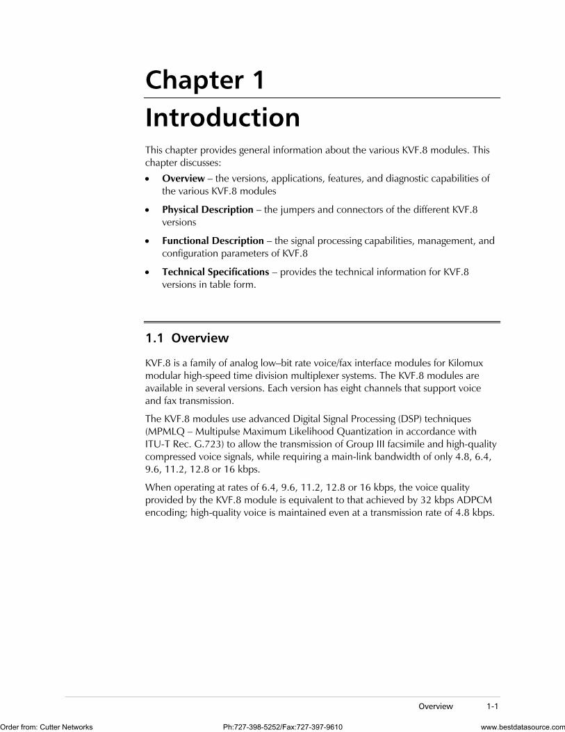
1.1 Overview
KVF.8 is a family of analog low–bit rate voice/fax interface modules for Kilomux modular high-speed time division multiplexer systems. The KVF.8 modules are available in several versions. Each version has eight channels that support voice and fax transmission.
The KVF.8 modules use advanced Digital Signal Processing (DSP) techniques (MPMLQ – Multipulse Maximum Likelihood Quantization in accordance with ITU-T Rec. G.723) to allow the transmission of Group III facsimile and high-quality compressed voice signals, while requiring a main-link bandwidth of only 4.8, 6.4, 9.6, 11.2, 12.8 or 16 kbps.
When operating at rates of 6.4, 9.6, 11.2, 12.8 or 16 kbps, the voice quality provided by the KVF.8 module is equivalent to that achieved by 32 kbps ADPCM encoding; high-quality voice is maintained even at a transmission rate of 4.8 kbps.
Order from: Cutter Networks Ph:727-398-5252/Fax:727-397-9610 www.bestdatasource.com
Chapter 1 Introduction KVF.8 Installation and Operation Manual
1-2 Overview
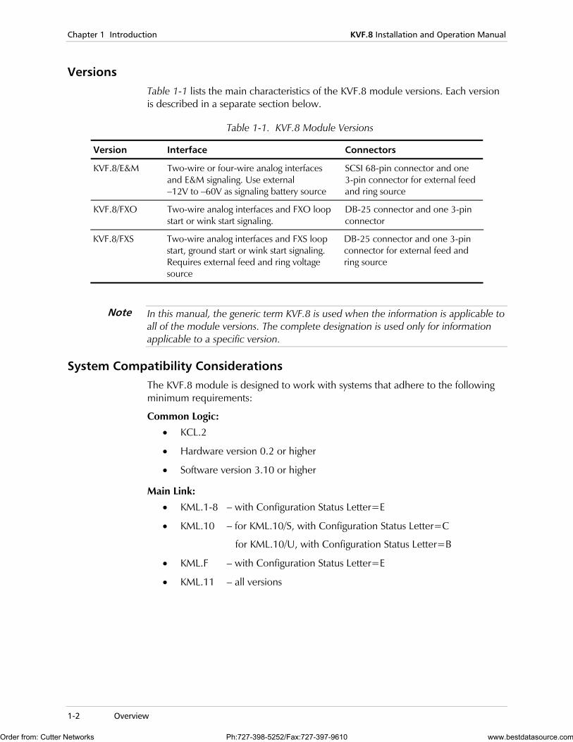
Versions Table 1-1 lists the main characteristics of the KVF.8 module versions. Each version is described in a separate section below.
Table 1-1. KVF.8 Module Versions
Version Interface Connectors
KVF.8/E&M Two-wire or four-wire analog interfaces and E&M signaling. Use external –12V to –60V as signaling battery source
SCSI 68-pin connector and one 3-pin connector for external feed and ring source
KVF.8/FXO Two-wire analog interfaces and FXO loop start or wink start signaling.
DB-25 connector and one 3-pin connector
KVF.8/FXS Two-wire analog interfaces and FXS loop start, ground start or wink start signaling. Requires external feed and ring voltage source
DB-25 connector and one 3-pin connector for external feed and ring source
In this manual, the generic term KVF.8 is used when the information is applicable to all of the module versions. The complete designation is used only for information applicable to a specific version.
System Compatibility Considerations The KVF.8 module is designed to work with systems that adhere to the following minimum requirements:
Common Logic:
• KCL.2
• Hardware version 0.2 or higher
• Software version 3.10 or higher
Main Link:
• KML.1-8 – with Configuration Status Letter=E
• KML.10 – for KML.10/S, with Configuration Status Letter=C
for KML.10/U, with Configuration Status Letter=B
• KML.F – with Configuration Status Letter=E
• KML.11 – all versions
Note
Order from: Cutter Networks Ph:727-398-5252/Fax:727-397-9610 www.bestdatasource.com
KVF.8 Installation and Operation Manual Chapter 1 Introduction
Overview 1-3
Applications This section describes typical KVF.8 applications.
KVF.8/E&M Application
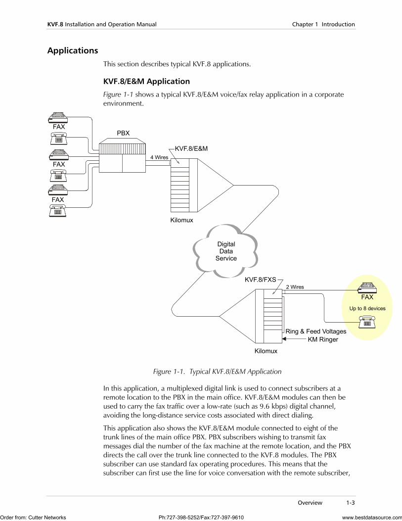
Figure 1-1 shows a typical KVF.8/E&M voice/fax relay application in a corporate environment.
FAXPBX
Kilomux
Kilomux
DigitalData
Service
KVF.8/E&M
KVF.8/FXS
FAX
FAX
FAX
KM RingerRing & Feed Voltages
4 Wires
Up to 8 devices
2 Wires
Figure 1-1. Typical KVF.8/E&M Application
In this application, a multiplexed digital link is used to connect subscribers at a remote location to the PBX in the main office. KVF.8/E&M modules can then be used to carry the fax traffic over a low-rate (such as 9.6 kbps) digital channel, avoiding the long-distance service costs associated with direct dialing.
This application also shows the KVF.8/E&M module connected to eight of the trunk lines of the main office PBX. PBX subscribers wishing to transmit fax messages dial the number of the fax machine at the remote location, and the PBX directs the call over the trunk line connected to the KVF.8 modules. The PBX subscriber can use standard fax operating procedures. This means that the subscriber can first use the line for voice conversation with the remote subscriber,
Order from: Cutter Networks Ph:727-398-5252/Fax:727-397-9610 www.bestdatasource.com
Chapter 1 Introduction KVF.8 Installation and Operation Manual
1-4 Overview
and then can start sending the fax message. The KVF.8/E&M is initially in the voice mode, and switches automatically to the fax mode when the fax transmission starts.
KVF.8/FXO, KVF.8/FXS Application
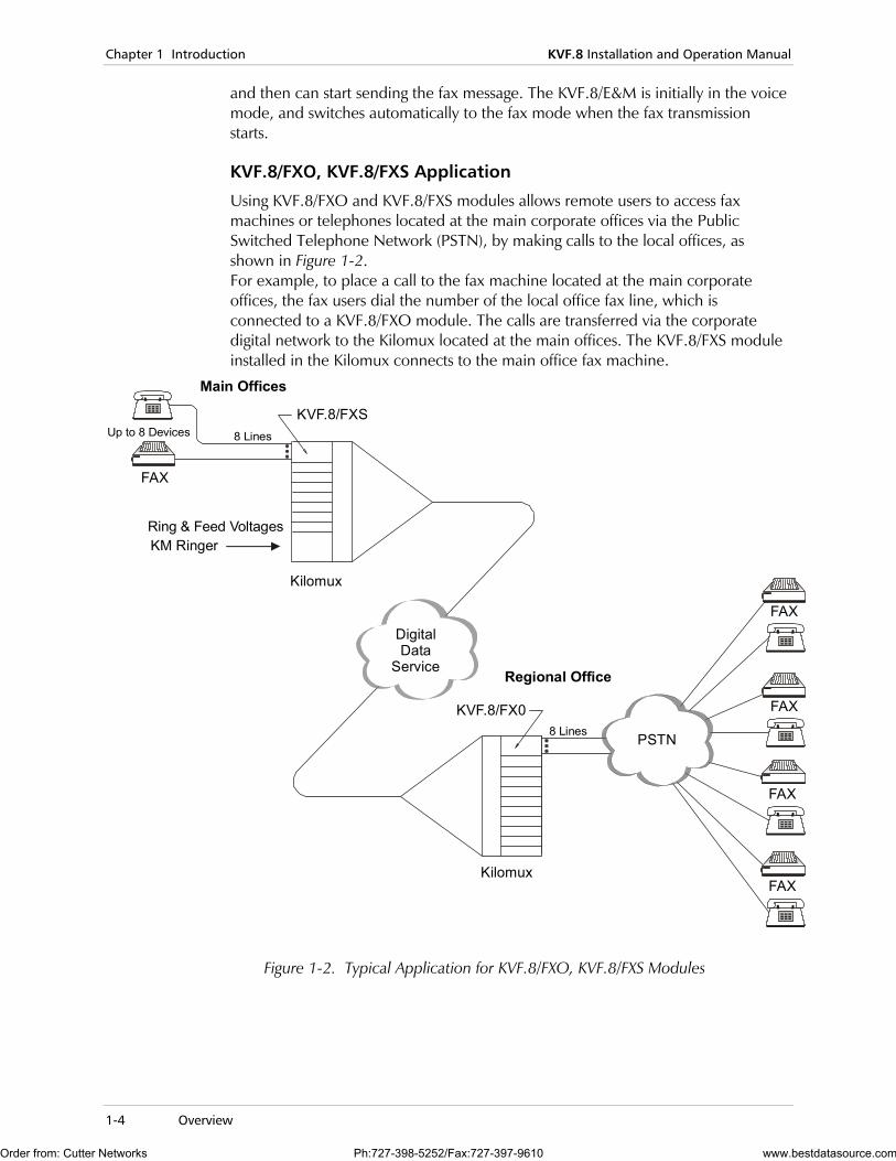
Using KVF.8/FXO and KVF.8/FXS modules allows remote users to access fax machines or telephones located at the main corporate offices via the Public Switched Telephone Network (PSTN), by making calls to the local offices, as shown in Figure 1-2. For example, to place a call to the fax machine located at the main corporate offices, the fax users dial the number of the local office fax line, which is connected to a KVF.8/FXO module. The calls are transferred via the corporate digital network to the Kilomux located at the main offices. The KVF.8/FXS module installed in the Kilomux connects to the main office fax machine.
Kilomux
Kilomux
Main Offices
Regional Office
PSTN
KVF.8/FXS
DigitalData
Service
KVF.8/FX0
FAX
FAX
FAX
8 LinesUp to 8 Devices
8 Lines
FAX
FAX
KM RingerRing & Feed Voltages
Figure 1-2. Typical Application for KVF.8/FXO, KVF.8/FXS Modules
Order from: Cutter Networks Ph:727-398-5252/Fax:727-397-9610 www.bestdatasource.com
KVF.8 Installation and Operation Manual Chapter 1 Introduction
Overview 1-5
Tandem KVF.8 Applications
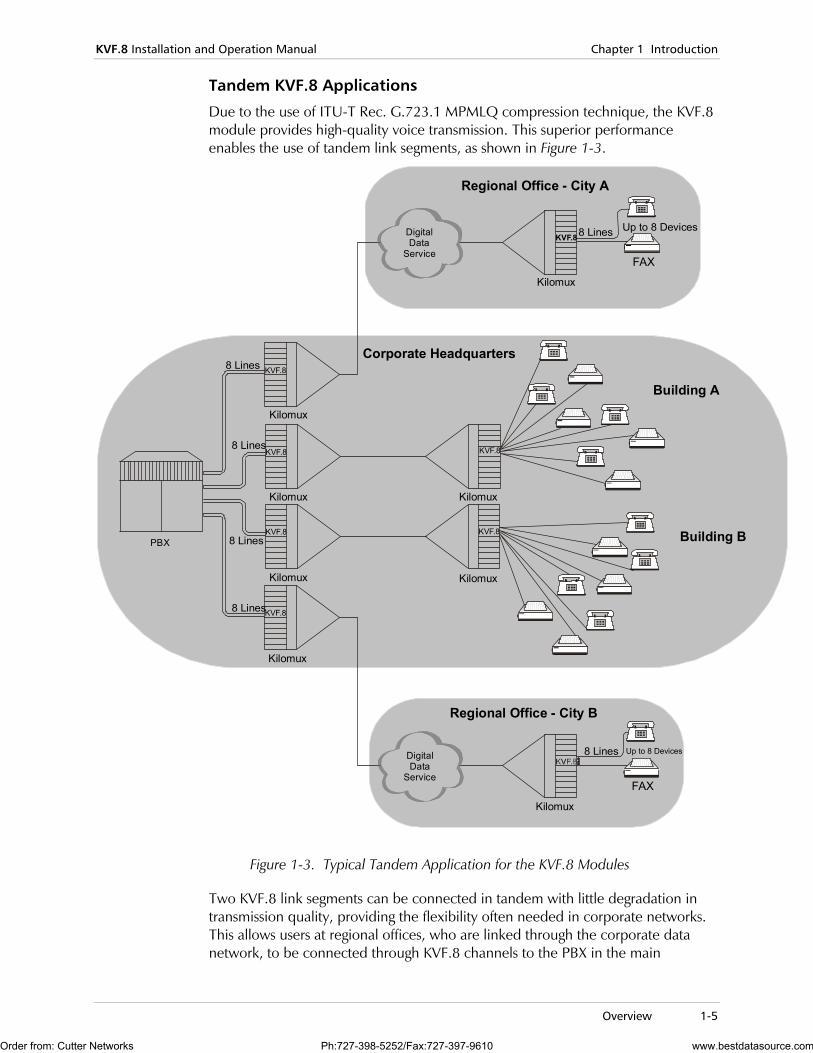
Due to the use of ITU-T Rec. G.723.1 MPMLQ compression technique, the KVF.8 module provides high-quality voice transmission. This superior performance enables the use of tandem link segments, as shown in Figure 1-3.
Kilomux
Kilomux
Kilomux
Kilomux
Kilomux
Kilomux
Kilomux
Kilomux
Regional Office - City A
Regional Office - City B
Corporate Headquarters
KVF.8
KVF.8KVF.8
KVF.8
KVF.8
KVF.8
KVF.8PBX
FAX
FAX
DigitalData
Service
DigitalData
Service
8 Lines
8 Lines
8 Lines
8 Lines
8 Lines
8 Lines
Up to 8 Devices
Up to 8 Devices
Building A
Building B
Figure 1-3. Typical Tandem Application for the KVF.8 Modules
Two KVF.8 link segments can be connected in tandem with little degradation in transmission quality, providing the flexibility often needed in corporate networks. This allows users at regional offices, who are linked through the corporate data network, to be connected through KVF.8 channels to the PBX in the main
Order from: Cutter Networks Ph:727-398-5252/Fax:727-397-9610 www.bestdatasource.com
Chapter 1 Introduction KVF.8 Installation and Operation Manual
1-6 Overview
corporate offices, without making any special arrangements to ensure that such links are not incidentally connected in tandem.
When using tandem segments, it is necessary to consider the end-to-end processing delay introduced by each pair of KVF.8 modules, which is less than 100 msec. This delay is inherent to the MPMLQ compression algorithm.
The end-to-end delay must be considered when using tandem connections over satellite hops. In cases where the end-to-end delay may build up to values that exceed the time-out intervals used during call set up by fax equipment (approximately 700 msec), it is not recommended to have more than one satellite hop.
KVF.8/KVF.6 Application
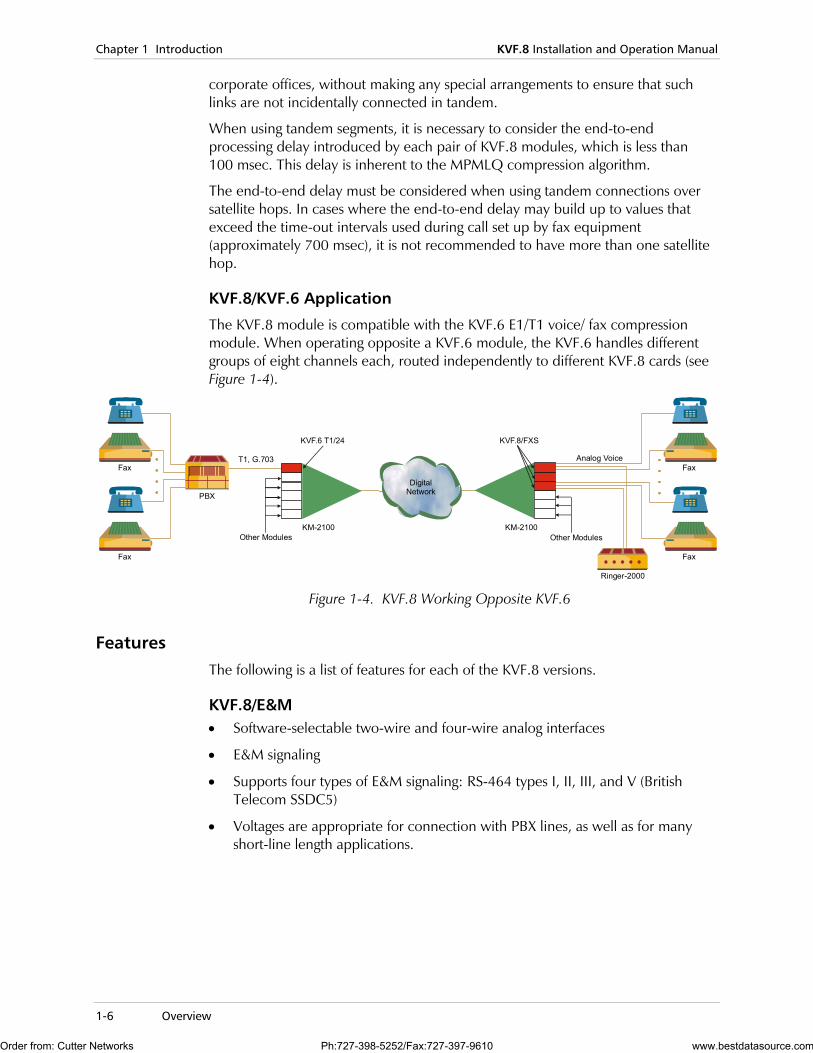
The KVF.8 module is compatible with the KVF.6 E1/T1 voice/ fax compression module. When operating opposite a KVF.6 module, the KVF.6 handles different groups of eight channels each, routed independently to different KVF.8 cards (see Figure 1-4).
KM-2100
KVF.6 T1/24
Fax
Fax
PBX
Other Modules
DigitalNetwork
KM-2100
Fax
Fax
Ringer-2000
Other Modules
Analog VoiceT1, G.703
KVF.8/FXS
Figure 1-4. KVF.8 Working Opposite KVF.6
Features The following is a list of features for each of the KVF.8 versions.
KVF.8/E&M • Software-selectable two-wire and four-wire analog interfaces
• E&M signaling
• Supports four types of E&M signaling: RS-464 types I, II, III, and V (British Telecom SSDC5)
• Voltages are appropriate for connection with PBX lines, as well as for many short-line length applications.
Order from: Cutter Networks Ph:727-398-5252/Fax:727-397-9610 www.bestdatasource.com
KVF.8 Installation and Operation Manual Chapter 1 Introduction
Physical Description 1-7
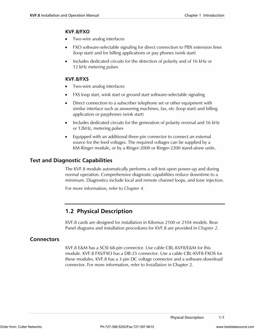
KVF.8/FXO • Two-wire analog interfaces
• FXO software-selectable signaling for direct connection to PBX extension lines (loop start) and for billing applications or pay phones (wink start)
• Includes dedicated circuits for the detection of polarity and of 16 kHz or 12 kHz metering pulses
KVF.8/FXS • Two-wire analog interfaces
• FXS loop start, wink start or ground start software-selectable signaling
• Direct connection to a subscriber telephone set or other equipment with similar interface such as answering machines, fax, etc (loop start) and billing application or payphones (wink start)
• Includes dedicated circuits for the generation of polarity reversal and 16 kHz or 12kHz, metering pulses
• Equipped with an additional three-pin connector to connect an external source for the feed voltages. The required voltages can be supplied by a KM-Ringer module, or by a Ringer-2000 or Ringer-2200 stand-alone units.
Test and Diagnostic Capabilities The KVF.8 module automatically performs a self-test upon power-up and during normal operation. Comprehensive diagnostic capabilities reduce downtime to a minimum. Diagnostics include local and remote channel loops, and tone injection.
For more information, refer to Chapter 4.
1.2 Physical Description
KVF.8 cards are designed for installation in Kilomux 2100 or 2104 models. Rear Panel diagrams and installation procedures for KVF.8 are provided in Chapter 2.
Connectors KVF.8 E&M has a SCSI 68-pin connector. Use cable CBL-KVF8/E&M for this module. KVF.8 FXS/FXO has a DB-25 connector. Use a cable CBL-KVF8-FXOS for these modules. KVF.8 has a 3-pin DC voltage connector and a software-download connector. For more information, refer to Installation in Chapter 2.
Order from: Cutter Networks Ph:727-398-5252/Fax:727-397-9610 www.bestdatasource.com
Chapter 1 Introduction KVF.8 Installation and Operation Manual
1-8 Functional Description
1.3 Functional Description
Signal Processing Capabilities Each channel of the KVF.8 module can operate in two modes, voice and fax: Voice mode: in this mode, the KVF.8 channel enables the transmission of a high-quality compressed voice channel, including the associated call set-up signaling information, either DTMF or pulse dialing, over the main link. Voice is digitized at the selected main link rate, i.e., 4.8, 6.4, 9.6, 12.8 or 16 kbps. Due to the use of the MPMLQ speech compression technique, the end-to-end voice performance is equivalent to the performance of 32 kbps ADPCM, as measured using the Mean Opinion Score (MOS). This holds true for all available rates, except for 4.8 kbps.
The end-to-end processing delay introduced by the KVF.8 module is less than 100 msec. To improve the perceived link quality, the KVF.8 module includes an adaptive echo canceler that handles near-end reflections (echo tail delay of less than 15 milliseconds), such as reflections being caused by a nearby hybrid used for 2W/4W conversion. The echo canceler convergence time exceeds ITU-T Rec. G.165 requirements. If the link is a pure 4W link with no hybrid along the path between the two subscribers, the user can turn off the adaptive echo canceler.
To maintain voice quality on bad communication links, when operating at rates of 9.6, 12.8 and 16 kbps, the KVF.8 module uses Hamming Forward Error Correction (FEC) coding to protect the critical information bits in the compressed voice data stream. The FEC code can maintain voice quality for main link error rates down to 1x10⁻³.
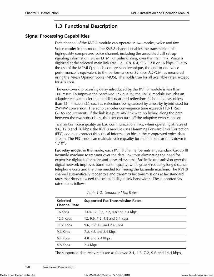
Fax relay mode: in this mode, each KVF.8 channel permits any standard Group III facsimile machine to transmit over the data link, thus eliminating the need for expensive digital fax or store-and-forward systems. Facsimile transmission over the digital network improves transmission quality, while greatly reducing long distance telephone costs and the time needed for freeing the facsimile machine. The KVF.8 channel automatically recognizes and transmits fax transmissions at fax standard rates that do not exceed the selected digital link bandwidth. The supported fax rates are as follows:
Table 1-2. Supported Fax Rates
Selected Channel Rate
Supported Fax Transmission Rates
16 Kbps 14.4, 12, 9.6, 7.2, 4.8 and 2.4 Kbps
12.8 Kbps 12, 9.6, 7.2, 4.8 and 2.4 Kbps
11.2 Kbps 9.6, 7.2, 4.8 and 2.4 Kbps
9.6 Kbps 7.2, 4.8 and 2.4 Kbps
6.4 Kbps 4.8 and 2.4 Kbps
4.8 Kbps 2.4 Kbps
The supported data relay rates are as follows: 2.4, 4.8, 7.2, 9.6 and 14.4 kbps.
Order from: Cutter Networks Ph:727-398-5252/Fax:727-397-9610 www.bestdatasource.com
KVF.8 Installation and Operation Manual Chapter 1 Introduction
Functional Description 1-9
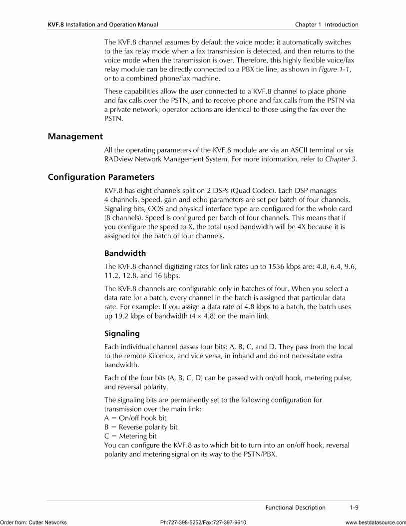
The KVF.8 channel assumes by default the voice mode; it automatically switches to the fax relay mode when a fax transmission is detected, and then returns to the voice mode when the transmission is over. Therefore, this highly flexible voice/fax relay module can be directly connected to a PBX tie line, as shown in Figure 1-1, or to a combined phone/fax machine.
These capabilities allow the user connected to a KVF.8 channel to place phone and fax calls over the PSTN, and to receive phone and fax calls from the PSTN via a private network; operator actions are identical to those using the fax over the PSTN.
Management All the operating parameters of the KVF.8 module are via an ASCII terminal or via RADview Network Management System. For more information, refer to Chapter 3.
Configuration Parameters KVF.8 has eight channels split on 2 DSPs (Quad Codec). Each DSP manages 4 channels. Speed, gain and echo parameters are set per batch of four channels. Signaling bits, OOS and physical interface type are configured for the whole card (8 channels). Speed is configured per batch of four channels. This means that if you configure the speed to X, the total used bandwidth will be 4X because it is assigned for the batch of four channels.
Bandwidth
The KVF.8 channel digitizing rates for link rates up to 1536 kbps are: 4.8, 6.4, 9.6, 11.2, 12.8, and 16 kbps.
The KVF.8 channels are configurable only in batches of four. When you select a data rate for a batch, every channel in the batch is assigned that particular data rate. For example: If you assign a data rate of 4.8 kbps to a batch, the batch uses up 19.2 kbps of bandwidth (4 × 4.8) on the main link.
Signaling
Each individual channel passes four bits: A, B, C, and D. They pass from the local to the remote Kilomux, and vice versa, in inband and do not necessitate extra bandwidth.
Each of the four bits (A, B, C, D) can be passed with on/off hook, metering pulse, and reversal polarity.
The signaling bits are permanently set to the following configuration for transmission over the main link: A = On/off hook bit B = Reverse polarity bit C = Metering bit You can configure the KVF.8 as to which bit to turn into an on/off hook, reversal polarity and metering signal on its way to the PSTN/PBX.
Order from: Cutter Networks Ph:727-398-5252/Fax:727-397-9610 www.bestdatasource.com
Chapter 1 Introduction KVF.8 Installation and Operation Manual
1-10 Technical Specifications
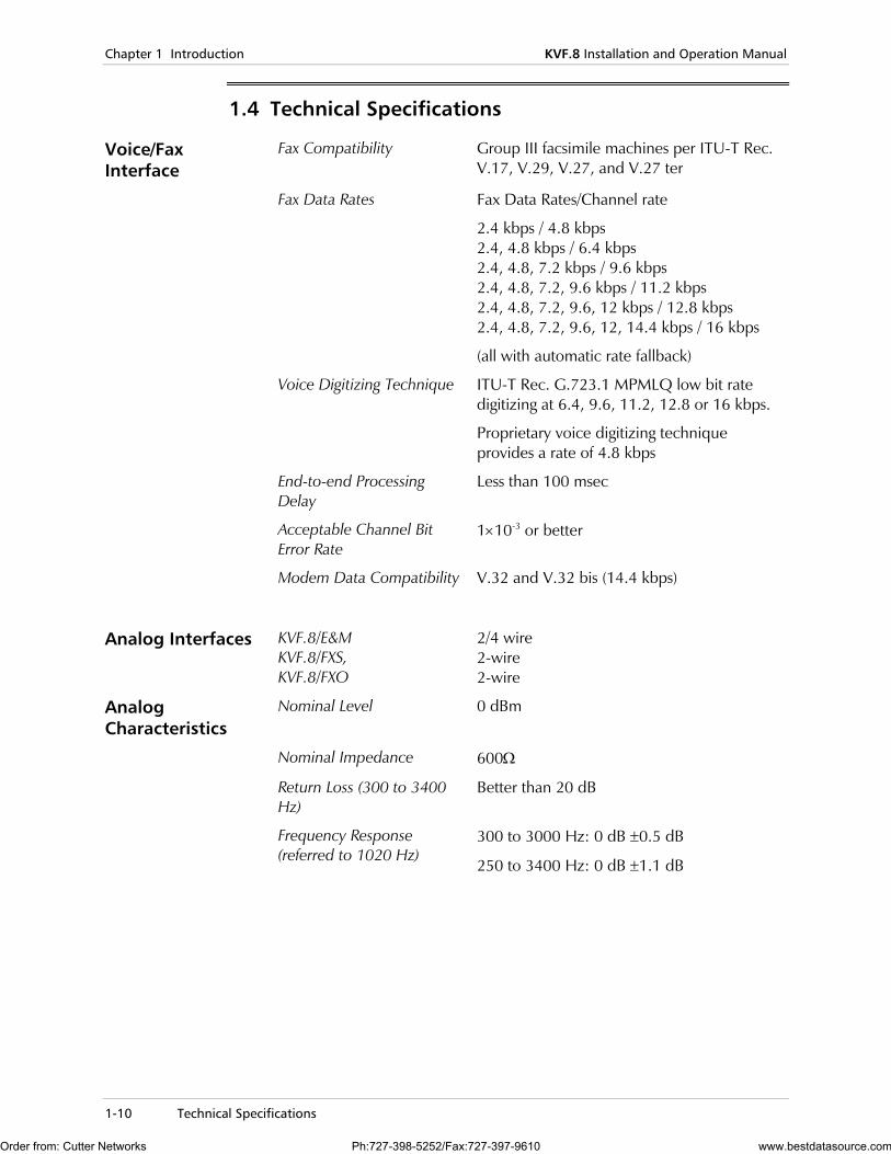
1.4 Technical Specifications
Voice/Fax Interface
Fax Compatibility Group III facsimile machines per ITU-T Rec. V.17, V.29, V.27, and V.27 ter
Fax Data Rates
Fax Data Rates/Channel rate
2.4 kbps / 4.8 kbps 2.4, 4.8 kbps / 6.4 kbps 2.4, 4.8, 7.2 kbps / 9.6 kbps 2.4, 4.8, 7.2, 9.6 kbps / 11.2 kbps 2.4, 4.8, 7.2, 9.6, 12 kbps / 12.8 kbps 2.4, 4.8, 7.2, 9.6, 12, 14.4 kbps / 16 kbps
(all with automatic rate fallback)
Voice Digitizing Technique ITU-T Rec. G.723.1 MPMLQ low bit rate digitizing at 6.4, 9.6, 11.2, 12.8 or 16 kbps.
Proprietary voice digitizing technique provides a rate of 4.8 kbps
End-to-end Processing Delay
Less than 100 msec
Acceptable Channel Bit Error Rate
1×10⁻³ or better
Modem Data Compatibility V.32 and V.32 bis (14.4 kbps)
Analog Interfaces KVF.8/E&M KVF.8/FXS, KVF.8/FXO
2/4 wire 2-wire 2-wire
Analog Characteristics
Nominal Level 0 dBm
Nominal Impedance 600Ω
Return Loss (300 to 3400 Hz)
Better than 20 dB
Frequency Response (referred to 1020 Hz)
300 to 3000 Hz: 0 dB ±0.5 dB
250 to 3400 Hz: 0 dB ±1.1 dB
Order from: Cutter Networks Ph:727-398-5252/Fax:727-397-9610 www.bestdatasource.com
KVF.8 Installation and Operation Manual Chapter 1 Introduction
Technical Specifications 1-11
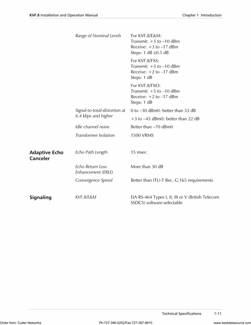
Range of Nominal Levels For KVF.8/E&M: Transmit: +5 to –10 dBm Receive: +3 to –17 dBm Steps: 1 dB ±0.5 dB
For KVF.8/FXS: Transmit: +5 to –10 dBm Receive: +2 to –17 dBm Steps: 1 dB
For KVF.8/FXO: Transmit: +5 to –10 dBm Receive: +2 to –17 dBm Steps: 1 dB
Signal-to-total-distortion at 6.4 kbps and higher
0 to −30 dBm0: better than 33 dB
+3 to −45 dBm0: better than 22 dB
Idle channel noise Better than –70 dBm0
Transformer Isolation 1500 VRMS
Adaptive Echo Canceler
Echo Path Length 15 msec
Echo Return Loss Enhancement (ERLE)
More than 30 dB
Convergence Speed Better than ITU-T Rec. G.165 requirements
Signaling KVF.8/E&M EIA RS-464 Types I, II, III or V (British Telecom SSDC5) software-selectable
Order from: Cutter Networks Ph:727-398-5252/Fax:727-397-9610 www.bestdatasource.com
Chapter 1 Introduction KVF.8 Installation and Operation Manual
1-12 Technical Specifications
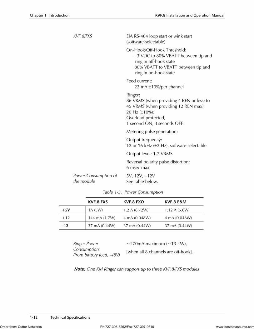
KVF.8/FXS EIA RS-464 loop start or wink start (software-selectable)
On-Hook/Off-Hook Threshold: −3 VDC to 80% VBATT between tip and ring in off-hook state 80% VBATT to VBATT between tip and ring in on-hook state
Feed current: 22 mA ±10%/per channel
Ringer: 86 VRMS (when providing 4 REN or less) to 45 VRMS (when providing 12 REN max), 20 Hz (±10%); Overload protected, 1 second ON, 3 seconds OFF
Metering pulse generation:
Output frequency: 12 or 16 kHz (±2 Hz), software-selectable
Output level: 1.7 VRMS
Reversal polarity pulse distortion: 6 msec max
Power Consumption of the module
5V, 12V, −12V See table below.
Table 1-3. Power Consumption
KVF.8 FXS KVF.8 FXO KVF.8 E&M
+5V 1A (5W) 1.2 A (6.72W) 1.12 A (5.6W)
+12 144 mA (1.7W) 4 mA (0.048W) 4 mA (0.048W)
–12 37 mA (0.44W) 37 mA (0.44W) 37 mA (0.44W)
Ringer Power Consumption (from battery feed, -48V)
~270mA maximum (~13.4W),
[when all 8 channels are off-hook].
Note: One KM Ringer can support up to three KVF.8/FXS modules
Order from: Cutter Networks Ph:727-398-5252/Fax:727-397-9610 www.bestdatasource.com
KVF.8 Installation and Operation Manual Chapter 1 Introduction
Technical Specifications 1-13
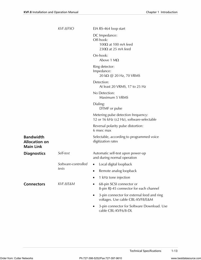
KVF.8/FXO EIA RS-464 loop start
DC Impedance: Off-hook: 100Ω at 100 mA feed 230Ω at 25 mA feed
On-hook: Above 1 MΩ
Ring detector: Impedance: 20 kΩ @ 20 Hz, 70 VRMS
Detection: At least 20 VRMS, 17 to 25 Hz
No Detection: Maximum 5 VRMS
Dialing: DTMF or pulse
Metering pulse detection frequency: 12 or 16 kHz (±2 Hz), software-selectable
Reversal polarity pulse distortion: 6 msec max
Bandwidth Allocation on Main Link
Selectable, according to programmed voice digitization rates
Diagnostics Self-test Automatic self-test upon power-up and during normal operation
Software-controlled tests
• Local digital loopback
• Remote analog loopback
• 1 kHz tone injection
Connectors KVF.8/E&M • 68-pin SCSI connector or 8-pin RJ-45 connector for each channel
• 3-pin connector for external feed and ring voltages. Use cable CBL-KVF8/E&M
• 3-pin connector for Software Download. Use cable CBL-KVF6/8-DL
Order from: Cutter Networks Ph:727-398-5252/Fax:727-397-9610 www.bestdatasource.com
Chapter 1 Introduction KVF.8 Installation and Operation Manual
1-14 Technical Specifications
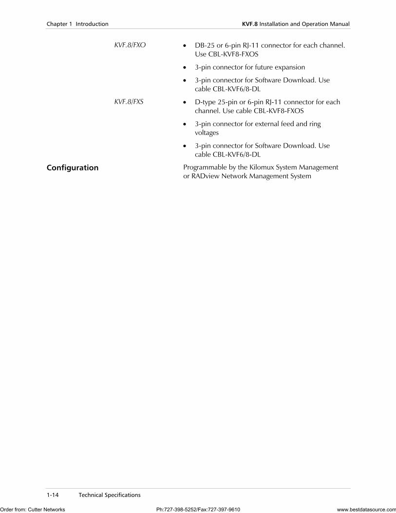
KVF.8/FXO • DB-25 or 6-pin RJ-11 connector for each channel. Use CBL-KVF8-FXOS
• 3-pin connector for future expansion
• 3-pin connector for Software Download. Use cable CBL-KVF6/8-DL
KVF.8/FXS • D-type 25-pin or 6-pin RJ-11 connector for each channel. Use cable CBL-KVF8-FXOS
• 3-pin connector for external feed and ring voltages
• 3-pin connector for Software Download. Use cable CBL-KVF6/8-DL
Configuration Programmable by the Kilomux System Management or RADview Network Management System
Order from: Cutter Networks Ph:727-398-5252/Fax:727-397-9610 www.bestdatasource.com
Installation 2-1
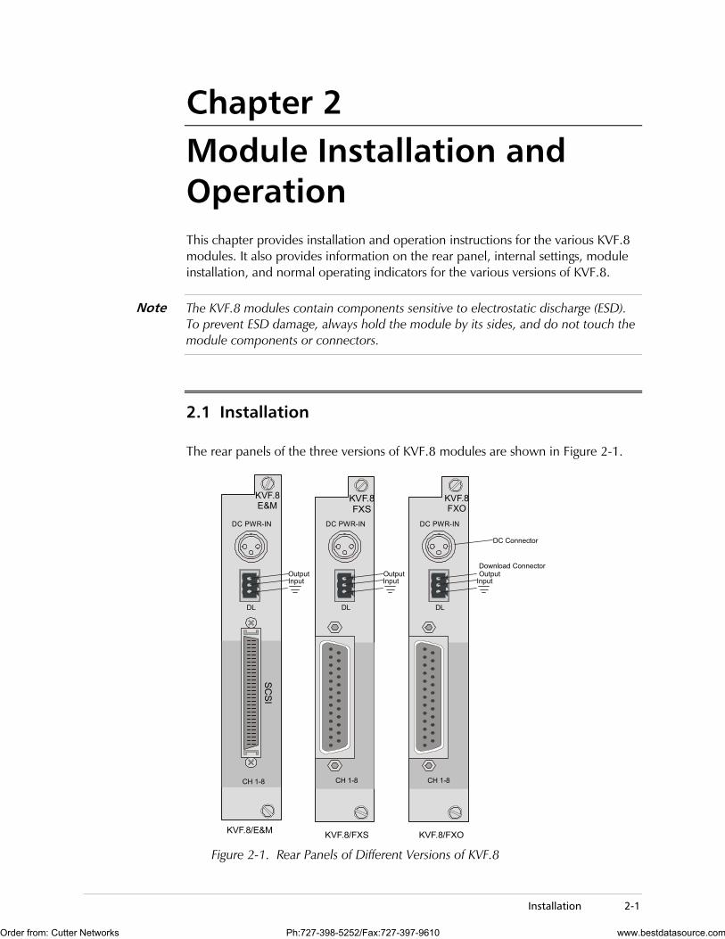
Chapter 2 Module Installation and Operation This chapter provides installation and operation instructions for the various KVF.8 modules. It also provides information on the rear panel, internal settings, module installation, and normal operating indicators for the various versions of KVF.8.
The KVF.8 modules contain components sensitive to electrostatic discharge (ESD). To prevent ESD damage, always hold the module by its sides, and do not touch the module components or connectors.
2.1 Installation
The rear panels of the three versions of KVF.8 modules are shown in Figure 2-1.
KVF.8/E&M KVF.8/FXO
SCSI
DC PWR-IN
KVF.8E&M
KVF.8FXO
KVF.8FXS
DC PWR-IN
KVF.8/FXS
CH 1-8 CH 1-8CH 1-8
DL DL
DC PWR-IN
DL
Input
Download ConnectorOutput
InputOutput
InputOutput
DC Connector
Figure 2-1. Rear Panels of Different Versions of KVF.8
Note
Order from: Cutter Networks Ph:727-398-5252/Fax:727-397-9610 www.bestdatasource.com
Chapter 2 Module Installation and Operation KVF.8 Installation and Operation Manual
2-2 Installation
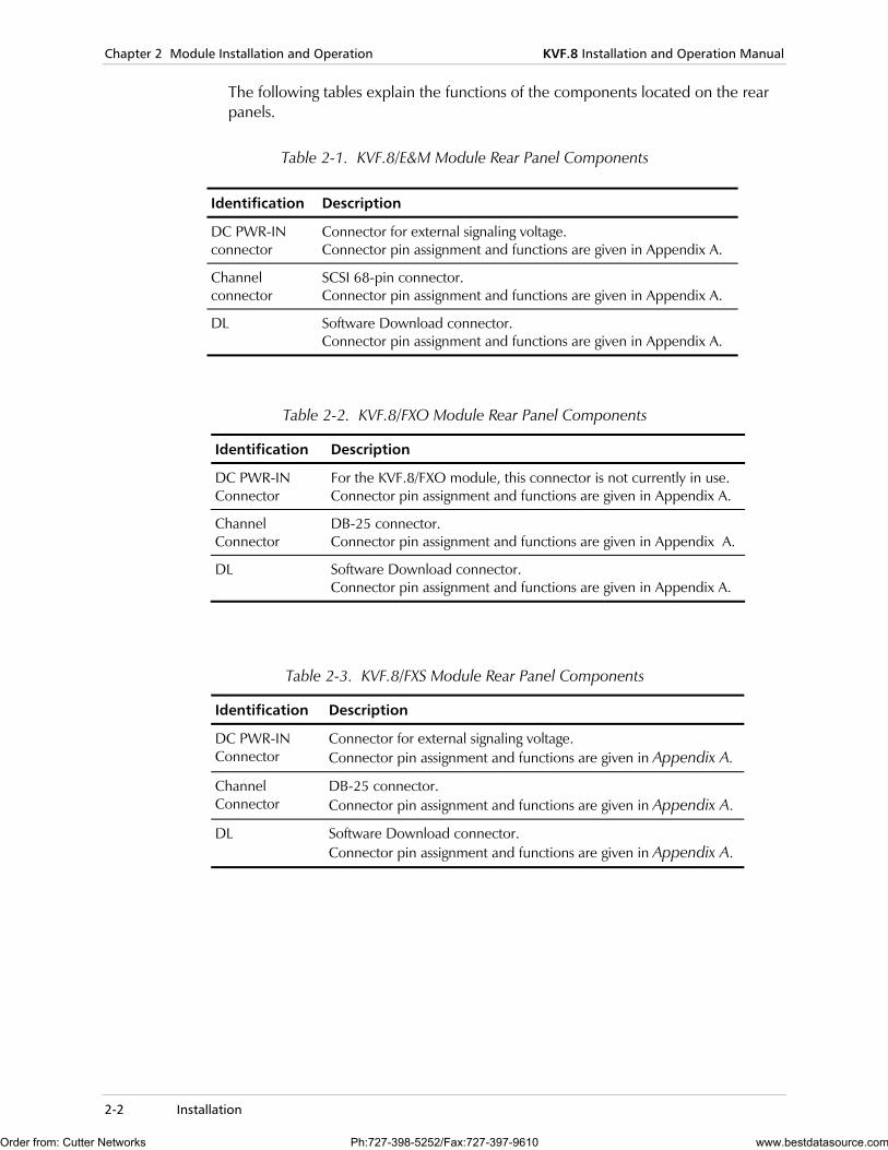
The following tables explain the functions of the components located on the rear panels.
Table 2-1. KVF.8/E&M Module Rear Panel Components
Table 2-2. KVF.8/FXO Module Rear Panel Components
Identification Description
DC PWR-IN Connector
For the KVF.8/FXO module, this connector is not currently in use. Connector pin assignment and functions are given in Appendix A.
Channel Connector
DB-25 connector. Connector pin assignment and functions are given in Appendix A.
DL Software Download connector. Connector pin assignment and functions are given in Appendix A.
Table 2-3. KVF.8/FXS Module Rear Panel Components
Identification Description
DC PWR-IN Connector
Connector for external signaling voltage. Connector pin assignment and functions are given in Appendix A.
Channel Connector
DB-25 connector. Connector pin assignment and functions are given in Appendix A.
DL Software Download connector. Connector pin assignment and functions are given in Appendix A.
Identification Description
DC PWR-IN connector
Connector for external signaling voltage. Connector pin assignment and functions are given in Appendix A.
Channel connector
SCSI 68-pin connector. Connector pin assignment and functions are given in Appendix A.
DL Software Download connector. Connector pin assignment and functions are given in Appendix A.
Order from: Cutter Networks Ph:727-398-5252/Fax:727-397-9610 www.bestdatasource.com
Initial Setup 3-1
Chapter 3 Configuring with an ASCII Terminal This chapter provides specific instructions for the configuration of the KVF.8 module using a supervision terminal. This chapter discusses:
• Initial Setup – this section provides the procedure for connecting to an ASCII terminal
• Configuration – this section provides the configuration instructions for KVF.8.
The KVF.8 cannot be configured from the Kilomux front panel controls
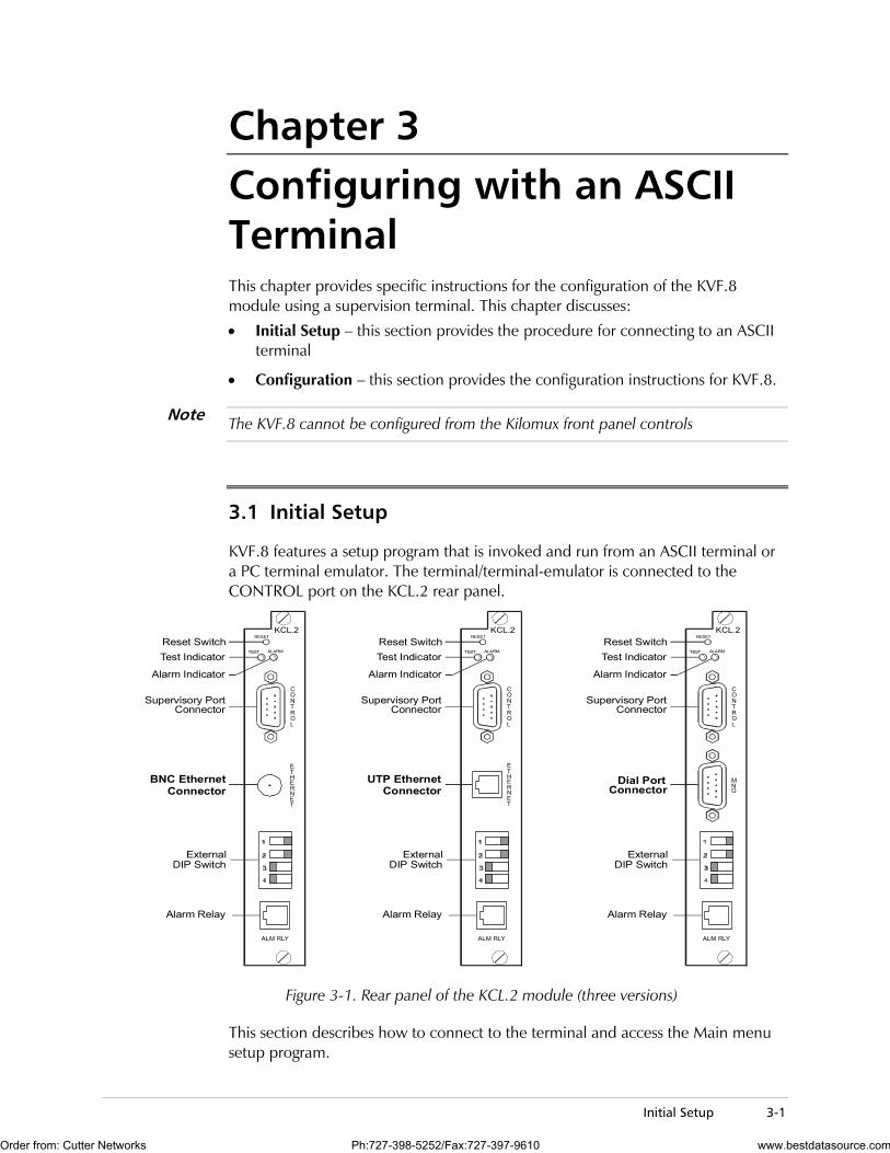
3.1 Initial Setup
KVF.8 features a setup program that is invoked and run from an ASCII terminal or a PC terminal emulator. The terminal/terminal-emulator is connected to the CONTROL port on the KCL.2 rear panel.
KCL.2RESET
ALARM
NGM
CONTROL
TEST
Reset SwitchTest Indicator
Alarm Indicator
Supervisory PortConnector
Dial PortConnector
ExternalDIP Switch
Alarm Relay
ALM RLY
KCL.2RESET
ALARM
ETHERNET
ETHERNET
CONTROL
TEST
Reset SwitchTest Indicator
Alarm Indicator
Supervisory PortConnector
ExternalDIP Switch
Alarm Relay
ALM RLY
KCL.2RESET
ALARM
CONTROL
TEST
Reset SwitchTest Indicator
Alarm Indicator
Supervisory PortConnector
UTP Ethernet Connector
BNC Ethernet Connector
ExternalDIP Switch
Alarm Relay
ALM RLY
Figure 3-1. Rear panel of the KCL.2 module (three versions)
This section describes how to connect to the terminal and access the Main menu setup program.
Note
Order from: Cutter Networks Ph:727-398-5252/Fax:727-397-9610 www.bestdatasource.com
Chapter 3 Configuring with an ASCII Terminal KVF.8 Installation and Operation Manual
3-2 Configuration
Connecting to the Terminal
To connect the terminal:
1. Connect a control cable between the KCL CONTROL port and the connector on the terminal; or between the KCL CONTROL port and the PC communication port (refer the Kilomux system manual for instructions and diagrams).
2. Set the terminal to work at any Baud rate from 9.6 kbps, No Parity, 8 Data Bits. The Baud rate is self-adaptable.
3.2 Configuration
The following instructions assume you are familiar with the operation and capabilities of the supervision terminal. For Kilomux operating instructions, refer to the Kilomux Operating manual.
The configuration functions applicable to the KVF.8 module are listed below:
• Inclusion of a KVF.8 module not yet installed in the Kilomux database. This allows the pre-programming of the module parameters, so when the module is installed in the enclosure, it will immediately start operating in the desired mode. This function is performed by means of the DEF SYS command.
• Selection of the main link to be used by the module, and when applicable, module priority. This function is performed using the DEF CON command. This command is available only on the Kilomux-2100, provided it is operated in the dual-link, priority bumping or switched-backup mode (but not in the single link or redundancy modes).
• Programming of the module channel parameters, using the DEF CH command.
To include the KVF.8 module in the database, use the DEF_SYS and DEF_CON commands. Refer to the Kilomux System Installation and Operation Manual.
Channel Configuration
The 8 channels of KVF.8 are divided into two batches: Channel 1 = channels 1-4; Channel 2 = channels 5-8. The channels are configurable per batch only.
To start the configuration of a specific channel of a KVF.8 module:
1. Type DEF CH i:j and press ENTER.
Where ”i" is the number of the module slot (1 through 12 for the Kilomux-2100, or 1 through 4 for the Kilomux-2104), and “j” is the desired module channel (batch number 1 or batch number 2). The supervision terminal displays the channel configuration data form.
2. Use the space bar to bring the cursor to the beginning of the first field to be changed.
3. Press F or B to scroll among the available selections.
Order from: Cutter Networks Ph:727-398-5252/Fax:727-397-9610 www.bestdatasource.com
KVF.8 Installation and Operation Manual Chapter 3 Configuring with an ASCII Terminal
Configuration 3-3
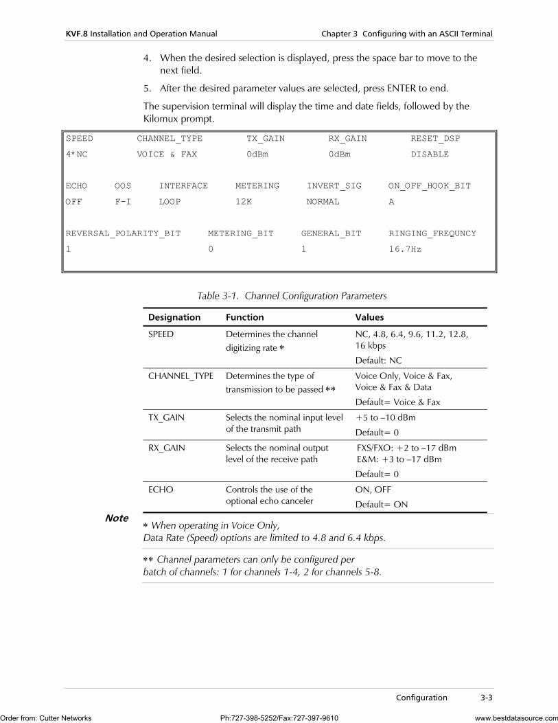
4. When the desired selection is displayed, press the space bar to move to the next field.
5. After the desired parameter values are selected, press ENTER to end.
The supervision terminal will display the time and date fields, followed by the Kilomux prompt.
SPEED CHANNEL_TYPE TX_GAIN RX_GAIN RESET_DSP
4*NC VOICE & FAX 0dBm 0dBm DISABLE
ECHO OOS INTERFACE METERING INVERT_SIG ON_OFF_HOOK_BIT
OFF F-I LOOP 12K NORMAL A
REVERSAL_POLARITY_BIT METERING_BIT GENERAL_BIT RINGING_FREQUNCY
1 0 1 16.7Hz
Table 3-1. Channel Configuration Parameters
Designation Function Values
SPEED Determines the channel digitizing rate ∗
NC, 4.8, 6.4, 9.6, 11.2, 12.8, 16 kbps
Default: NC
CHANNEL_TYPE Determines the type of transmission to be passed ∗∗
Voice Only, Voice & Fax, Voice & Fax & Data
Default= Voice & Fax
TX_GAIN Selects the nominal input level of the transmit path
+5 to –10 dBm
Default= 0
RX_GAIN Selects the nominal output level of the receive path
FXS/FXO: +2 to –17 dBm E&M: +3 to –17 dBm
Default= 0
ECHO Controls the use of the optional echo canceler
ON, OFF
Default= ON
∗ When operating in Voice Only, Data Rate (Speed) options are limited to 4.8 and 6.4 kbps.
∗∗ Channel parameters can only be configured per batch of channels: 1 for channels 1-4, 2 for channels 5-8.
Note
Order from: Cutter Networks Ph:727-398-5252/Fax:727-397-9610 www.bestdatasource.com
Chapter 3 Configuring with an ASCII Terminal KVF.8 Installation and Operation Manual
3-4 Configuration
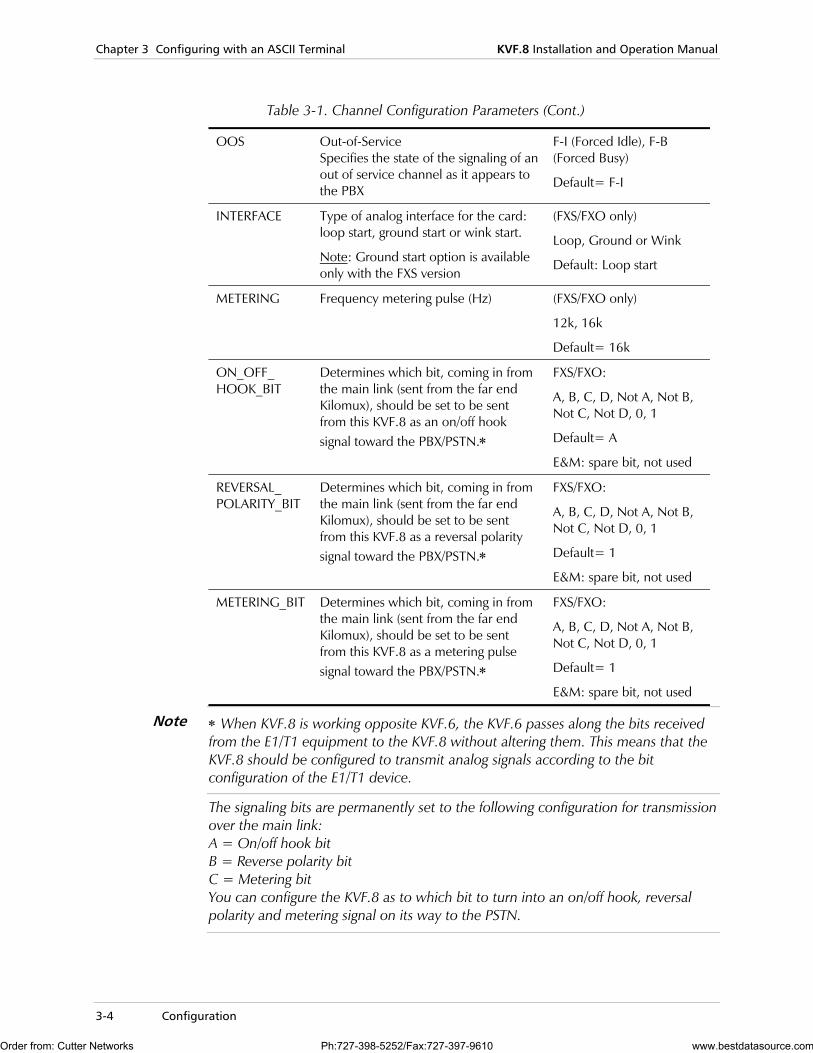
Table 3-1. Channel Configuration Parameters (Cont.)
OOS Out-of-Service Specifies the state of the signaling of an out of service channel as it appears to the PBX
F-I (Forced Idle), F-B (Forced Busy)
Default= F-I
INTERFACE Type of analog interface for the card: loop start, ground start or wink start.
Note: Ground start option is available only with the FXS version
(FXS/FXO only)
Loop, Ground or Wink
Default: Loop start
METERING Frequency metering pulse (Hz) (FXS/FXO only)
12k, 16k
Default= 16k
ON_OFF_ HOOK_BIT
Determines which bit, coming in from the main link (sent from the far end Kilomux), should be set to be sent from this KVF.8 as an on/off hook signal toward the PBX/PSTN.∗
FXS/FXO:
A, B, C, D, Not A, Not B, Not C, Not D, 0, 1
Default= A
E&M: spare bit, not used
REVERSAL_ POLARITY_BIT
Determines which bit, coming in from the main link (sent from the far end Kilomux), should be set to be sent from this KVF.8 as a reversal polarity signal toward the PBX/PSTN.∗
FXS/FXO:
A, B, C, D, Not A, Not B, Not C, Not D, 0, 1
Default= 1
E&M: spare bit, not used
METERING_BIT Determines which bit, coming in from the main link (sent from the far end Kilomux), should be set to be sent from this KVF.8 as a metering pulse signal toward the PBX/PSTN.∗
FXS/FXO:
A, B, C, D, Not A, Not B, Not C, Not D, 0, 1
Default= 1
E&M: spare bit, not used
∗ When KVF.8 is working opposite KVF.6, the KVF.6 passes along the bits received from the E1/T1 equipment to the KVF.8 without altering them. This means that the KVF.8 should be configured to transmit analog signals according to the bit configuration of the E1/T1 device.
The signaling bits are permanently set to the following configuration for transmission over the main link: A = On/off hook bit B = Reverse polarity bit C = Metering bit You can configure the KVF.8 as to which bit to turn into an on/off hook, reversal polarity and metering signal on its way to the PSTN.
Note
Order from: Cutter Networks Ph:727-398-5252/Fax:727-397-9610 www.bestdatasource.com
KVF.8 Installation and Operation Manual Chapter 3 Configuring with an ASCII Terminal
Configuration 3-5
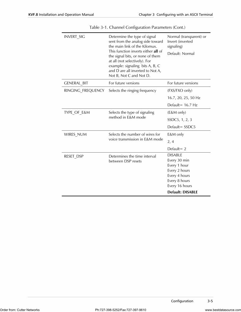
Table 3-1. Channel Configuration Parameters (Cont.)
INVERT_SIG Determine the type of signal sent from the analog side toward the main link of the Kilomux. This function inverts either all of the signal bits, or none of them at all (not selectively). For example: signaling bits A, B, C and D are all inverted to Not A, Not B, Not C and Not D.
Normal (transparent) or Invert (inverted signaling)
Default: Normal
GENERAL_BIT For future versions For future versions
RINGING_FREQUENCY Selects the ringing frequency (FXS/FXO only)
16.7, 20, 25, 50 Hz
Default= 16.7 Hz
TYPE_OF_E&M Selects the type of signaling method in E&M mode
(E&M only)
SSDC5, 1, 2, 3
Default= SSDC5
WIRES_NUM Selects the number of wires for voice transmission in E&M mode
E&M only
2, 4
Default= 2
RESET_DSP Determines the time interval between DSP resets
DISABLE Every 30 min Every 1 hour Every 2 hours Every 4 hours Every 8 hours Every 16 hours
Default: DISABLE
Order from: Cutter Networks Ph:727-398-5252/Fax:727-397-9610 www.bestdatasource.com
Chapter 3 Configuring with an ASCII Terminal KVF.8 Installation and Operation Manual
3-6 Configuration
Order from: Cutter Networks Ph:727-398-5252/Fax:727-397-9610 www.bestdatasource.com
Diagnostic Tests 4-1
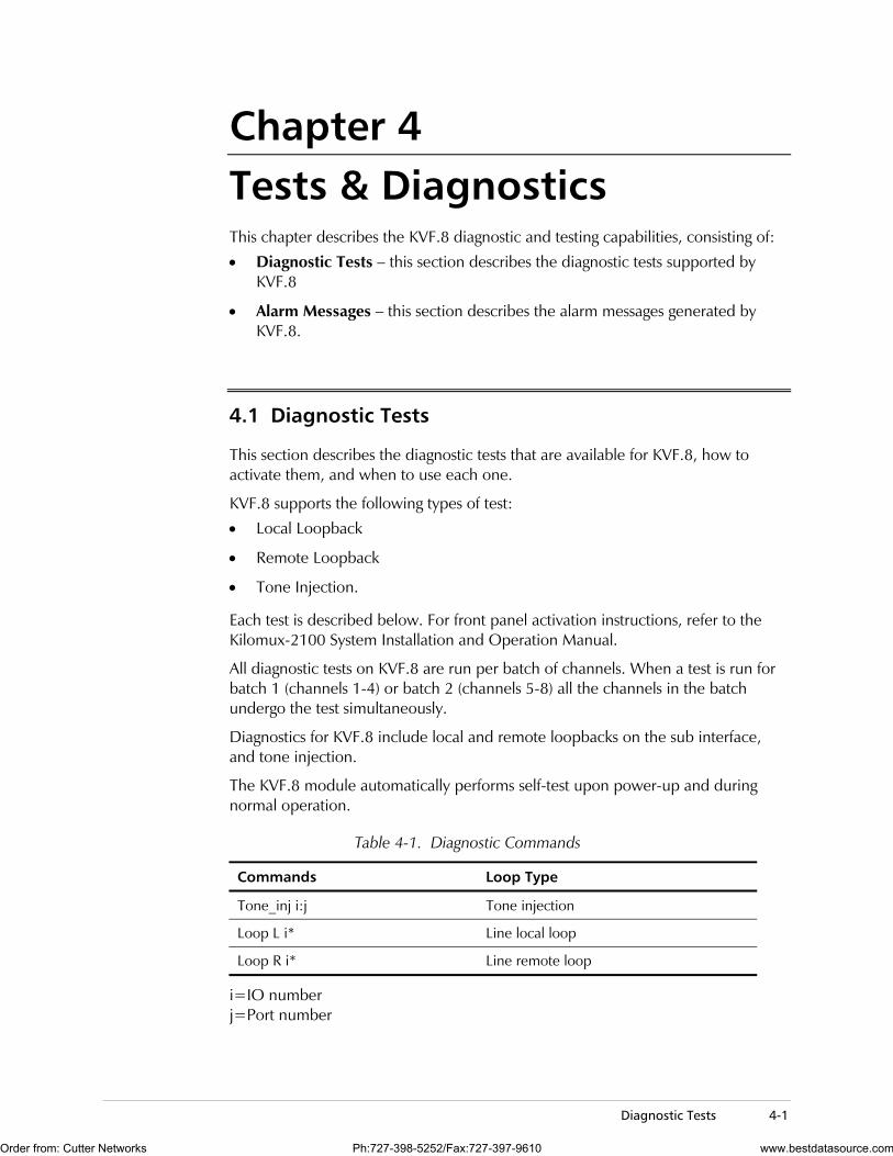
Chapter 4 Tests & Diagnostics This chapter describes the KVF.8 diagnostic and testing capabilities, consisting of:
• Diagnostic Tests – this section describes the diagnostic tests supported by KVF.8
• Alarm Messages – this section describes the alarm messages generated by KVF.8.
4.1 Diagnostic Tests
This section describes the diagnostic tests that are available for KVF.8, how to activate them, and when to use each one.
KVF.8 supports the following types of test:
• Local Loopback
• Remote Loopback
• Tone Injection.
Each test is described below. For front panel activation instructions, refer to the Kilomux-2100 System Installation and Operation Manual.
All diagnostic tests on KVF.8 are run per batch of channels. When a test is run for batch 1 (channels 1-4) or batch 2 (channels 5-8) all the channels in the batch undergo the test simultaneously.
Diagnostics for KVF.8 include local and remote loopbacks on the sub interface, and tone injection.
The KVF.8 module automatically performs self-test upon power-up and during normal operation.
Table 4-1. Diagnostic Commands
Commands Loop Type
Tone_inj i:j Tone injection
Loop L i* Line local loop
Loop R i* Line remote loop
i=IO number j=Port number
Order from: Cutter Networks Ph:727-398-5252/Fax:727-397-9610 www.bestdatasource.com
Chapter 4 Tests & Diagnostics KVF.8 Installation and Operation Manual
4-2 Diagnostic Tests
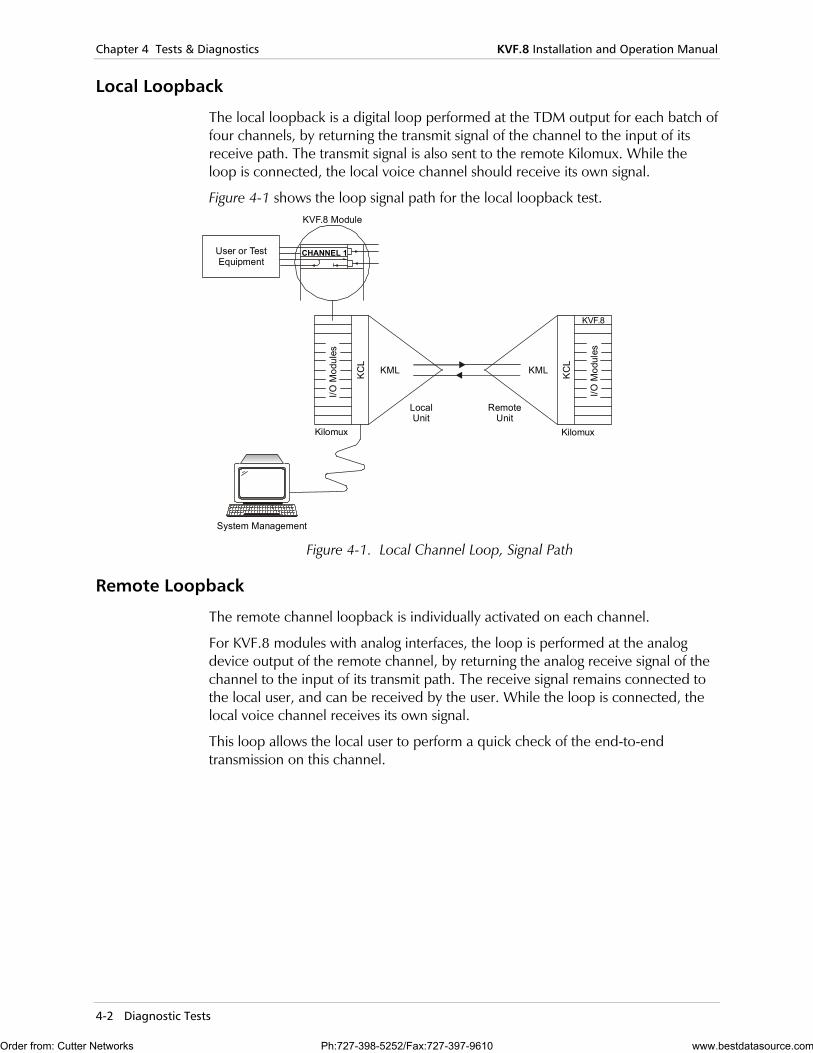
Local Loopback
The local loopback is a digital loop performed at the TDM output for each batch of four channels, by returning the transmit signal of the channel to the input of its receive path. The transmit signal is also sent to the remote Kilomux. While the loop is connected, the local voice channel should receive its own signal.
Figure 4-1 shows the loop signal path for the local loopback test.
System Management
User or TestEquipment
KVF.8 Module
KML
LocalUnit
RemoteUnit
KML
KVF.8I/O
Mod
ules
I/O M
odul
es
KCL
KCL
Kilomux Kilomux
CHANNEL 1
Figure 4-1. Local Channel Loop, Signal Path
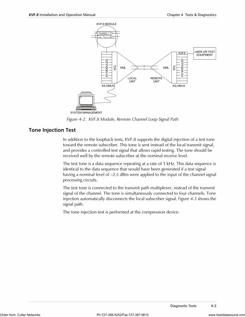
Remote Loopback
The remote channel loopback is individually activated on each channel.
For KVF.8 modules with analog interfaces, the loop is performed at the analog device output of the remote channel, by returning the analog receive signal of the channel to the input of its transmit path. The receive signal remains connected to the local user, and can be received by the user. While the loop is connected, the local voice channel receives its own signal.
This loop allows the local user to perform a quick check of the end-to-end transmission on this channel.
Order from: Cutter Networks Ph:727-398-5252/Fax:727-397-9610 www.bestdatasource.com
KVF.8 Installation and Operation Manual Chapter 4 Tests & Diagnostics
Diagnostic Tests 4-3
SYSTEM MANAGEMENT
USER OR TESTEQUIPMENT
KVF.8 MODULE
KML
LOCALUNIT
REMOTEUNIT
KML
KVF.8
I/O M
OD
ULE
S
I/O M
OD
ULE
S
KCL
KCL
CHANNEL 1
KILOMUX KILOMUX
Figure 4-2. KVF.8 Module, Remote Channel Loop Signal Path
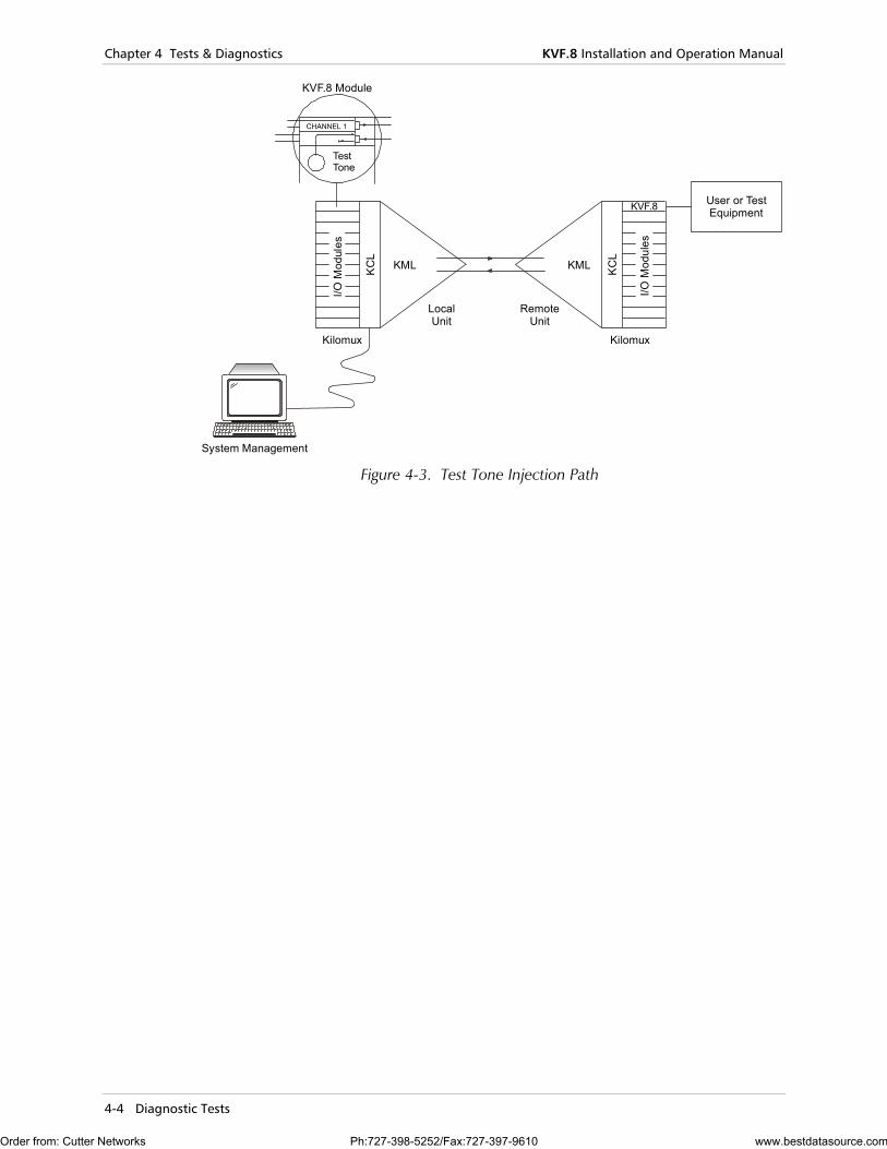
Tone Injection Test
In addition to the loopback tests, KVF.8 supports the digital injection of a test tone toward the remote subscriber. This tone is sent instead of the local transmit signal, and provides a controlled test signal that allows rapid testing. The tone should be received well by the remote subscriber at the nominal receive level.
The test tone is a data sequence repeating at a rate of 1 kHz. This data sequence is identical to the data sequence that would have been generated if a test signal having a nominal level of –2.5 dBm were applied to the input of the channel signal processing circuits.
The test tone is connected to the transmit path multiplexer, instead of the transmit signal of the channel. The tone is simultaneously connected to four channels. Tone injection automatically disconnects the local subscriber signal. Figure 4-3 shows the signal path.
The tone injection test is performed at the compression device.
Order from: Cutter Networks Ph:727-398-5252/Fax:727-397-9610 www.bestdatasource.com
Chapter 4 Tests & Diagnostics KVF.8 Installation and Operation Manual
4-4 Diagnostic Tests
System Management
User or TestEquipment
KVF.8 Module
KML
LocalUnit
Kilomux Kilomux
RemoteUnit
KML
KVF.8
I/O M
odul
es
I/O M
odul
es
KC
L
KC
L
CHANNEL 1
TestTone
Figure 4-3. Test Tone Injection Path
Order from: Cutter Networks Ph:727-398-5252/Fax:727-397-9610 www.bestdatasource.com
KVF.8 Installation and Operation Manual Chapter 4 Tests & Diagnostics
Alarm Messages 4-5
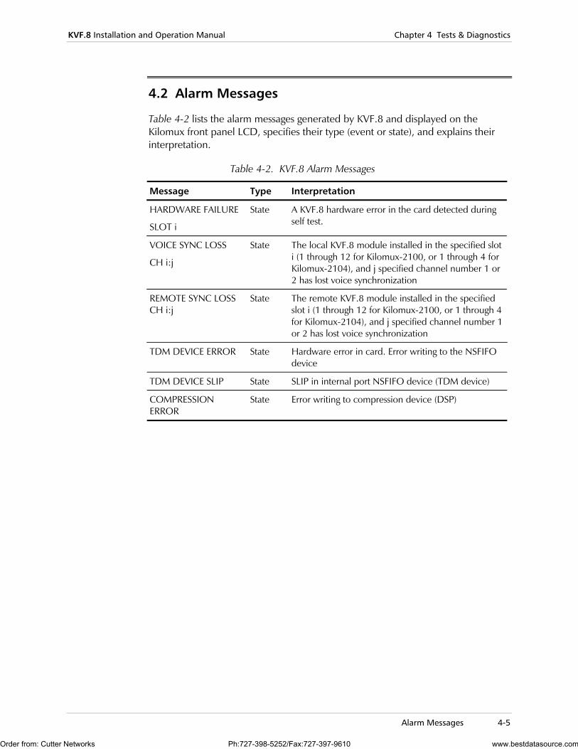
4.2 Alarm Messages
Table 4-2 lists the alarm messages generated by KVF.8 and displayed on the Kilomux front panel LCD, specifies their type (event or state), and explains their interpretation.
Table 4-2. KVF.8 Alarm Messages
Message Type Interpretation
HARDWARE FAILURE
SLOT i
State A KVF.8 hardware error in the card detected during self test.
VOICE SYNC LOSS
CH i:j
State The local KVF.8 module installed in the specified slot i (1 through 12 for Kilomux-2100, or 1 through 4 for Kilomux-2104), and j specified channel number 1 or 2 has lost voice synchronization
REMOTE SYNC LOSS CH i:j
State The remote KVF.8 module installed in the specified slot i (1 through 12 for Kilomux-2100, or 1 through 4 for Kilomux-2104), and j specified channel number 1 or 2 has lost voice synchronization
TDM DEVICE ERROR State Hardware error in card. Error writing to the NSFIFO device
TDM DEVICE SLIP State SLIP in internal port NSFIFO device (TDM device)
COMPRESSION ERROR
State Error writing to compression device (DSP)
Order from: Cutter Networks Ph:727-398-5252/Fax:727-397-9610 www.bestdatasource.com

Chapter 4 Tests & Diagnostics KVF.8 Installation and Operation Manual
4-6 Alarm Messages
Order from: Cutter Networks Ph:727-398-5252/Fax:727-397-9610 www.bestdatasource.com
KVF.8/E&M A-1
Appendix A Interface Specifications
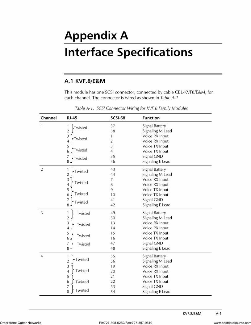
A.1 KVF.8/E&M
This module has one SCSI connector, connected by cable CBL-KVF8/E&M, for each channel. The connector is wired as shown in Table A-1.
Table A-1. SCSI Connector Wiring for KVF.8 Family Modules
Channel RJ-45 SCSI-68 Function
1 1 2 3 4 5 6 7 8
37 38 1 2 3 4 35 36
Signal Battery Signaling M Lead Voice RX Input Voice RX Input Voice TX Input Voice TX Input Signal GND Signaling E Lead
2 1 2 3 4 5 6 7 8
43 44 7 8 9 10 41 42
Signal Battery Signaling M Lead Voice RX Input Voice RX Input Voice TX Input Voice TX Input Signal GND Signaling E Lead
3 1 2 3 4 5 6 7 8
49 50 13 14 15 16 47 48
Signal Battery Signaling M Lead Voice RX Input Voice RX Input Voice TX Input Voice TX Input Signal GND Signaling E Lead
4 1 2 3 4 5 6 7 8
55 56 19 20 21 22 53 54
Signal Battery Signaling M Lead Voice RX Input Voice RX Input Voice TX Input Voice TX Input Signal GND Signaling E Lead
Twisted
Twisted
Twisted
Twisted
Twisted
Twisted
Twisted
Twisted
Twisted
Twisted
Twisted
Twisted
Twisted
Twisted
Twisted
Twisted
Order from: Cutter Networks Ph:727-398-5252/Fax:727-397-9610 www.bestdatasource.com
Appendix A Interface Specifications KVF.8 Installation and Operation Manual
A-2 KVF.8/E&M
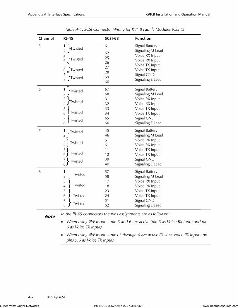
Table A-1. SCSI Connector Wiring for KVF.8 Family Modules (Cont.)
Channel RJ-45 SCSI-68 Function
5 1 2 3 4 5 6 7 8
61
62 25 26 27 28 59 60
Signal Battery Signaling M Lead Voice RX Input Voice RX Input Voice TX Input Voice TX Input Signal GND Signaling E Lead
6 1 2 3 4 5 6 7 8
67 68 31 32 33 34 65 66
Signal Battery Signaling M Lead Voice RX Input Voice RX Input Voice TX Input Voice TX Input Signal GND Signaling E Lead
7 1 2 3 4 5 6 7 8
45 46 5 6 11 12 39 40
Signal Battery Signaling M Lead Voice RX Input Voice RX Input Voice TX Input Voice TX Input Signal GND Signaling E Lead
8 1 2 3 4 5 6 7 8
57 58 17 18 23 24 51 52
Signal Battery Signaling M Lead Voice RX Input Voice RX Input Voice TX Input Voice TX Input Signal GND Signaling E Lead
In the RJ-45 connectors the pins assignments are as followed:
• When using 2W mode – pin 3 and 6 are active (pin 3 as Voice RX Input and pin 6 as Voice TX Input)
• When using 4W mode – pins 3 through 6 are active (3, 4 as Voice RX Input and pins 5,6 as Voice TX Input)
Twisted
Twisted
Twisted
Twisted
Twisted
Twisted
Twisted
Twisted
Twisted
Twisted
Twisted
Twisted
Twisted
Twisted
Twisted
Twisted
Note
Order from: Cutter Networks Ph:727-398-5252/Fax:727-397-9610 www.bestdatasource.com
KVF.8 Installation and Operation Manual Appendix A Interface Specifications
DC PWR-IN Connector (For KVF.8/FXS and KVF.8/E&M) A-3
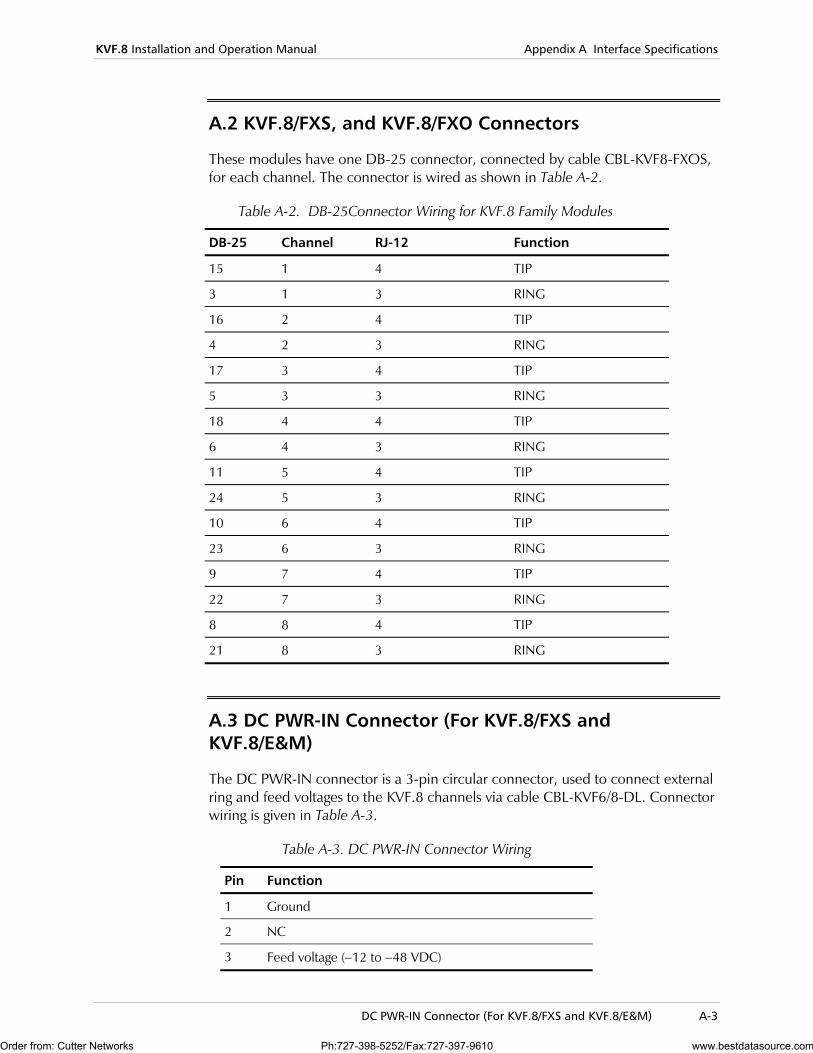
A.2 KVF.8/FXS, and KVF.8/FXO Connectors
These modules have one DB-25 connector, connected by cable CBL-KVF8-FXOS, for each channel. The connector is wired as shown in Table A-2.
Table A-2. DB-25Connector Wiring for KVF.8 Family Modules
DB-25 Channel RJ-12 Function
15 1 4 TIP
3 1 3 RING
16 2 4 TIP
4 2 3 RING
17 3 4 TIP
5 3 3 RING
18 4 4 TIP
6 4 3 RING
11 5 4 TIP
24 5 3 RING
10 6 4 TIP
23 6 3 RING
9 7 4 TIP
22 7 3 RING
8 8 4 TIP
21 8 3 RING
A.3 DC PWR-IN Connector (For KVF.8/FXS and KVF.8/E&M)
The DC PWR-IN connector is a 3-pin circular connector, used to connect external ring and feed voltages to the KVF.8 channels via cable CBL-KVF6/8-DL. Connector wiring is given in Table A-3.
Table A-3. DC PWR-IN Connector Wiring
Pin Function
1 Ground
2 NC
3 Feed voltage (−12 to −48 VDC)
Order from: Cutter Networks Ph:727-398-5252/Fax:727-397-9610 www.bestdatasource.com
Appendix A Interface Specifications KVF.8 Installation and Operation Manual
A-4 Download Connector
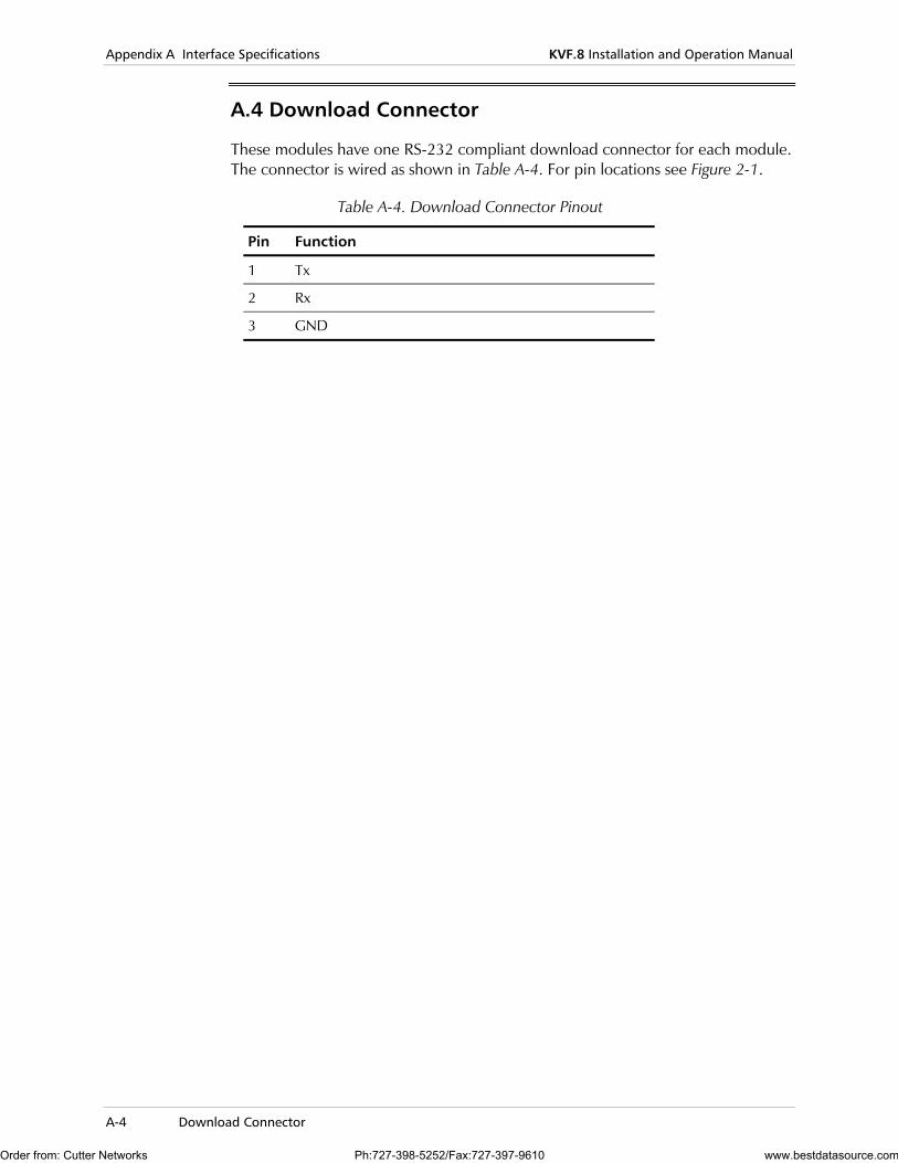
A.4 Download Connector
These modules have one RS-232 compliant download connector for each module. The connector is wired as shown in Table A-4. For pin locations see Figure 2-1.
Table A-4. Download Connector Pinout
Pin Function
1 Tx
2 Rx
3 GND
Order from: Cutter Networks Ph:727-398-5252/Fax:727-397-9610 www.bestdatasource.com

Installation Procedure B-1
Appendix B Software Download This appendix presents the procedure for installing new software upgrade releases in the KVF.8 module. The KVF.8 module stores the software in FLASH memory. The software is stored in compressed format, and is decompressed and loaded into the module RAM upon power up. Since the FLASH memory is not used to run the software, new software can be loaded using any PC, which is directly connected to the download port of the KVF.8 module or through the Kilomux Common Logic (KCL.2). This operation can be done in any one of three ways:
1. Off line- In this case, the KVF.8 module cannot carry traffic while software is downloading. This procedure can be used to upgrade the module software version as well as to install software in a new/repaired KVF.8 module. This installation method is called COLD software installation. For this installation, the program DL.exe is required.
2. Online – This procedure can be used to upgrade the KVF.8 software while the module is operating; it is called WARM software installation. For software version 0.8 (or higher), the software upgrade will be downloaded using the Xmodem option in HyperTerminal. If the software version is lower than 0.8, the program DL_IO.exe is required.
3. File transfer via the Kilomux Common Logic – This procedure can be used to upgrade the KVF.8 software via the Kilomux Common Logic (KCL.2). This procedure is possible only if the hardware version is 0.3 (or higher), the software version is 0.8 (or higher) and the Kilomux Common Logic is KCL.2.
B.1 Installation Procedure
Software releases include the compressed software file KVF8.arj.
Warm Installation
Warm Installation for SW version Lower then version 0.8
While the Kilomux-2100 system is running and the KVF.8 module is installed in the system:
1. Copy the distribution file KVF8.arj and DL_IO.exe to the root directory of your PC.
2. Using the supervision port in the KCL.2 card, type the command ‘LOAD IO j’ (where j is the IO slot number in which the KVF.8 module is installed).
Order from: Cutter Networks Ph:727-398-5252/Fax:727-397-9610 www.bestdatasource.com

Appendix B Software Download KVF.8 Installation and Operation Manual
B-2 Installation Procedure
3. Wait 20 seconds while the flash memory is erased and prepares to download the new software.
4. Connect the serial port of your PC to the download port (DL) in the KVF.8 module using the download cable.
5. Run the DL_IO.exe program. After the program starts, select option 2, and configure the PC for downloading as follows: Select option 1, and then select the PC serial port, com1 or com2,
connected to the KVF.8 module.
Press ESC.
Select option 2 and type kvf8.arj as the file name.
Press ESC.
6. Begin transmitting the file by selecting option 1 from the main menu. The software file is transmitted to the KVF.8 module. You can monitor the progress of file transmission on the PC as the software is sent: The ALM indicator in the KVF.8 blinks and the LOC LED lights, as long as data transfer proceeds normally.
7. Wait until the transfer process has been successfully completed.
8. Select option 3 to exit the DL_IO.exe program.
Warm Installation for SW version 0.8 and Up
While the Kilomux-2100 system is running and the KVF.8 module is installed in the system:
1. Copy the distribution file KVF8.arj and DL_IO.exe to the root directory of your PC.
2. Using the supervision port in the KCL.2 card, type the command ‘LOAD IO j’ (where j is the IO slot number in which the KVF.8 module is installed).
3. Wait 20 seconds while the flash memory is erased and prepares to download the new software.
4. Connect the serial port of your PC to the download port (DL) in the KVF.8 module using the download cable.
5. Open HyperTerminal and configure it to operate at a rate of 57600 bps.
6. Transfer the file using the Xmodem protocol by selecting the Send File option as the transfer method in HyperTerminal.
7. Begin transmitting the file by selecting option 1 from the main menu. The software file is transmitted to the KVF.8 module. You can monitor the progress of file transmission on the PC as the software is sent: The ALM indicator in the KVF.8 blinks and the LOC LED lights, as long as data transfer proceeds normally.
8. Wait until the transfer process has been successfully completed.
9. Select option 3 to exit the DL_IO.exe program.
Order from: Cutter Networks Ph:727-398-5252/Fax:727-397-9610 www.bestdatasource.com
KVF.8 Installation and Operation Manual Appendix B Software Download
Installation Procedure B-3
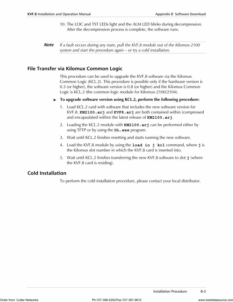
10. The LOC and TST LEDs light and the ALM LED blinks during decompression. After the decompression process is complete, the software runs.
If a fault occurs during any state, pull the KVF.8 module out of the Kilomux-2100 system and start the procedure again – or try a cold installation.
File Transfer via Kilomux Common Logic This procedure can be used to upgrade the KVF.8 software via the Kilomux Common Logic (KCL.2). This procedure is possible only if the hardware version is 0.3 (or higher), the software version is 0.8 (or higher) and the Kilomux Common Logic is KCL.2 (the common logic module for Kilomux-2100/2104).
To upgrade software version using KCL.2, perform the following procedure:
1. Load KCL.2 card with software that includes the new software version for KVF.8. KM2100.arj and KVF8.arj are both contained within (compressed and encapsulated within) the latest release of KM2100.arj.
2. Loading the KCL.2 module with KM2100.arj can be performed either by using TFTP or by using the DL.exe program.
3. Wait until KCL.2 finishes resetting and starts running the new software.
4. Load the KVF.8 module by using the load io j kcl command, where j is the Kilomux slot number in which the KVF.8 card is inserted into.
5. Wait until KCL.2 finishes transferring the new KVF.8 software to slot j (where the KVF.8 card is residing).
Cold Installation To perform the cold installation procedure, please contact your local distributor.
Note
Order from: Cutter Networks Ph:727-398-5252/Fax:727-397-9610 www.bestdatasource.com

Appendix B Software Download KVF.8 Installation and Operation Manual
B-4 Installation Procedure
Order from: Cutter Networks Ph:727-398-5252/Fax:727-397-9610 www.bestdatasource.com