KunKle safety and relief products Technical RefeRence · 3 KunKle safety and relief products...
32
KUNKLE SAFETY AND RELIEF PRODUCTS TECHNICAL REFERENCE Emerson.com/FinalControl © 2017 Emerson. All Rights Reserved. VCTDS-00398-EN 17/07 Technical reference for safety and relief products
Transcript of KunKle safety and relief products Technical RefeRence · 3 KunKle safety and relief products...
KunKle safety and relief productsTechnical RefeRence
emerson.com/FinalControl © 2017 emerson. all rights reserved. VCTDS-00398-en 17/07
technical reference for safety and relief products

2
KunKle safety and relief products
ConTenTS
definitions and commonly used terms ........................................................................................ 3asMe codes.................................................................................................................................... 4asMe code requirements ............................................................................................................. 5
General safety and relief valve informationGeneral safety and relief valve information ................................................................................. 6safety and relief valve pointers ..................................................................................................... 7safety and relief valve principles of operation ............................................................................. 8-9ordering information ..................................................................................................................... 9
SelectionValve selection ............................................................................................................................... 10Valve selection guide ..................................................................................................................... 11-13
SizingValve sizing overview and coefficient method .............................................................................. 14sizing formulas .............................................................................................................................. 15sizing coefficient method .............................................................................................................. 16sizing table a .................................................................................................................................. 17sizing table B ................................................................................................................................. 18-19sizing tables c and d ..................................................................................................................... 20physical properties ........................................................................................................................ 21-25conversion factors ......................................................................................................................... 26-27
Installation and maintenanceinstallation ...................................................................................................................................... 28-31Maintenance ................................................................................................................................... 32

3
KunKle safety and relief products
DeFInITIonS anD Commonly uSeD TermS
a.S.m.e.american society of Mechanical engineers.a.P.I.american petroleum institutePrVrelief valve, safety valve, safety relief valve.Back pressurethe pressure that exists at the outlet of a pressure relief device as a result of the pressure in the discharge system. it is the sum of the superimposed and built-up back pressures.Built-up back pressurethe increase in pressure in the dischargeheader that develops as a result of flow afterthe pressure relief device opens.Blowdownthe difference in pressure between the opening pressure and reclose pressure. May be expressed in percent of set pressure or 'psig'.Body/nozzle/seatthe stationary seating surface, the inlet.Capthe pressure screw cover and/or lever housing. May be screwed, bolted, packed, or plain lever.Chatterabnormal, rapid reciprocating movement of the disc on the seat of a pressure relief valve.Coefficient of dischargethe ratio of the measured relieving capacity to the theoretical relieving capacity.Discthe moveable seating surface.Gaga device attached to a safety or safety relief valve that prevents it from opening at the set pressure.Guidethat portion of the valve used to guide the disc.liftthe distance between the seat and disc seating surfaces when the valve is in the full open position.maWPMaximum allowable working pressure. this data is found on the pressure vessel nameplate and is the maximum pressure at which the lowest set safety valve must be set (stamped).n.B.national Board of Boiler and pressure Vessel inspectors.operating pressurethe gauge pressure at which a pressure vessel is maintained in normal operation. the operating pressure should not be in excess of 90 percent of the prV set pressure.accumulationthe permitted increase in pressure developed after the valve has opened. usually expressed in percentage, maximum allowable accumulations are established by applicable codes for operating and fire contingencies.
Pre-open/warnan audible or visual discharge at a pressure slightly lower than the set pressure. Warns the operator that the valve is about to operate.Pressure relief devicea device actuated by inlet static pressure and designed to open during an emergency or abnormal condition to prevent a rise of internal fluid pressure in excess of a specified value. the device may also be designed to prevent excessive internal vacuum. the device may be a pressure relief valve, a non-reclosing pressure relief device, or a vacuum relief valve.psiapounds per square inch absolute or absolute pressure. absolute pressure is equal to gauge pressure plus atmospheric pressure (14.7 psi [1.01 barg] at sea level).psigpounds per square inch gauge or gauge pressure. differential pressure across the valve, equal to absolute pressure inside the pressure vessel minus atmospheric pressure (14.7 psi [1.01 barg] at sea level).relief valvea spring-loaded pressure relief valve actuated by the static pressure upstream of the valve. the valve opens normally in proportion to the pressure increase over the opening pressure. a relief valve is used primarily with incompressible fluids (liquids).Safety relief valvea spring-loaded pressure relief valve that may be used as either a safety or relief valve depending on the application.Safety valvea spring-loaded pressure relief valve actuated by the static pressure upstream of the valve and characterized by rapid opening or pop action. a safety valve is normally used with compressible fluids.Set pressurethe gauge pressure at which a safety valve visibly and audibly opens or at which a relief valve discharges a 1" long unbroken stream of liquid.Spindle/stemthe rod connecting to the disc.Stamped capacitythe rated relieving capacity that appears on the device nameplate. the stamped capacity is based on the set pressure or burst pressure plus the allowable overpressure for compressible fluids and the differential pressure for incompressible fluids.Superimposed back pressurethe static pressure that exists at the outlet of a pressure relief device at the time the device is required to operate. it is the result of pressure in the discharge system coming from other sources and may be constant or variable.
Warn ring or regulator ringthe control ring which surrounds the seat, used to control preopen and blowdown.yoke/bonnetthe portion of a safety/relief valve that surrounds the spring; the spring housing.
4
KunKle safety and relief products
aSme CoDeS
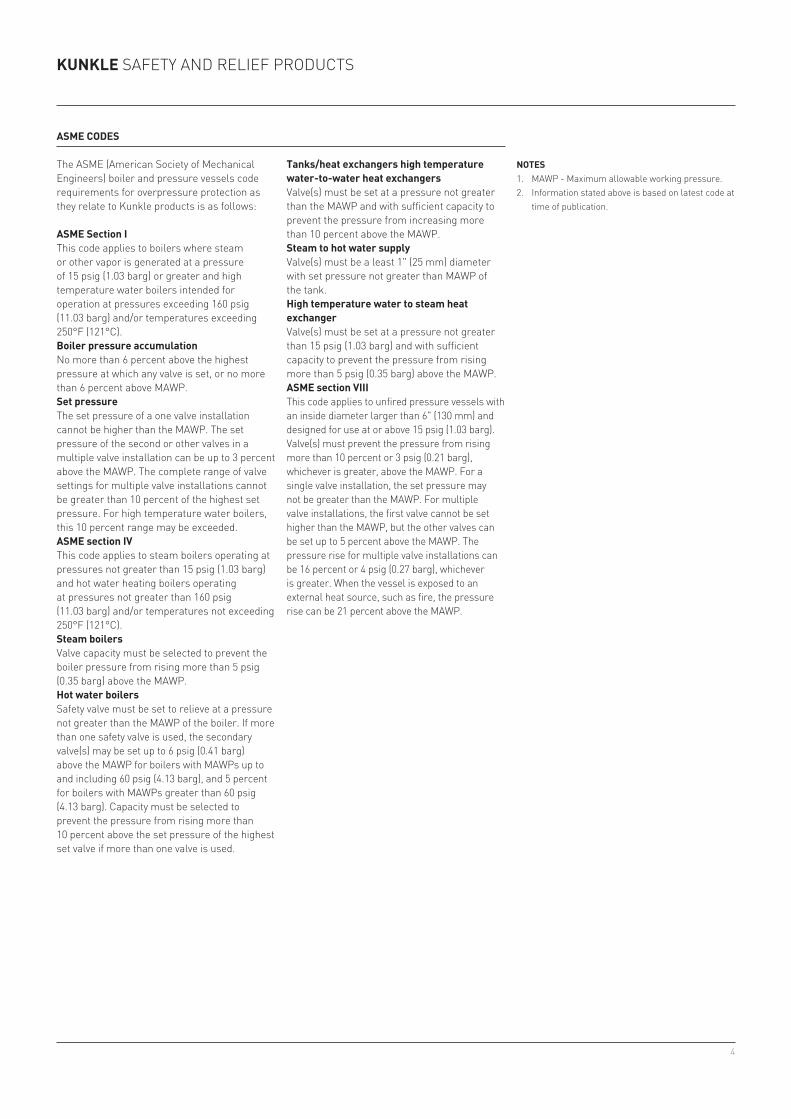
the asMe (american society of Mechanical engineers) boiler and pressure vessels code requirements for overpressure protection as they relate to Kunkle products is as follows:
aSme Section Ithis code applies to boilers where steam or other vapor is generated at a pressure of 15 psig (1.03 barg) or greater and high temperature water boilers intended for operation at pressures exceeding 160 psig (11.03 barg) and/or temperatures exceeding 250°f (121°c).Boiler pressure accumulationno more than 6 percent above the highest pressure at which any valve is set, or no more than 6 percent above MaWp.Set pressurethe set pressure of a one valve installation cannot be higher than the MaWp. the set pressure of the second or other valves in a multiple valve installation can be up to 3 percent above the MaWp. the complete range of valve settings for multiple valve installations cannot be greater than 10 percent of the highest set pressure. for high temperature water boilers, this 10 percent range may be exceeded.aSme section IVthis code applies to steam boilers operating at pressures not greater than 15 psig (1.03 barg) and hot water heating boilers operating at pressures not greater than 160 psig (11.03 barg) and/or temperatures not exceeding 250°f (121°c).Steam boilersValve capacity must be selected to prevent the boiler pressure from rising more than 5 psig (0.35 barg) above the MaWp.Hot water boilerssafety valve must be set to relieve at a pressure not greater than the MaWp of the boiler. if more than one safety valve is used, the secondary valve(s) may be set up to 6 psig (0.41 barg) above the MaWp for boilers with MaWps up to and including 60 psig (4.13 barg), and 5 percent for boilers with MaWps greater than 60 psig (4.13 barg). capacity must be selected to prevent the pressure from rising more than 10 percent above the set pressure of the highest set valve if more than one valve is used.
noTeS1. MaWp - Maximum allowable working pressure.2. information stated above is based on latest code at
time of publication.
Tanks/heat exchangers high temperature water-to-water heat exchangersValve(s) must be set at a pressure not greater than the MaWp and with sufficient capacity to prevent the pressure from increasing more than 10 percent above the MaWp.Steam to hot water supplyValve(s) must be a least 1" (25 mm) diameter with set pressure not greater than MaWp of the tank.High temperature water to steam heat exchangerValve(s) must be set at a pressure not greater than 15 psig (1.03 barg) and with sufficient capacity to prevent the pressure from rising more than 5 psig (0.35 barg) above the MaWp.aSme section VIIIthis code applies to unfired pressure vessels with an inside diameter larger than 6" (130 mm) and designed for use at or above 15 psig (1.03 barg). Valve(s) must prevent the pressure from rising more than 10 percent or 3 psig (0.21 barg), whichever is greater, above the MaWp. for a single valve installation, the set pressure may not be greater than the MaWp. for multiple valve installations, the first valve cannot be set higher than the MaWp, but the other valves can be set up to 5 percent above the MaWp. the pressure rise for multiple valve installations can be 16 percent or 4 psig (0.27 barg), whichever is greater. When the vessel is exposed to an external heat source, such as fire, the pressure rise can be 21 percent above the MaWp.
5
KunKle safety and relief products
aSme CoDeS - requIremenTS
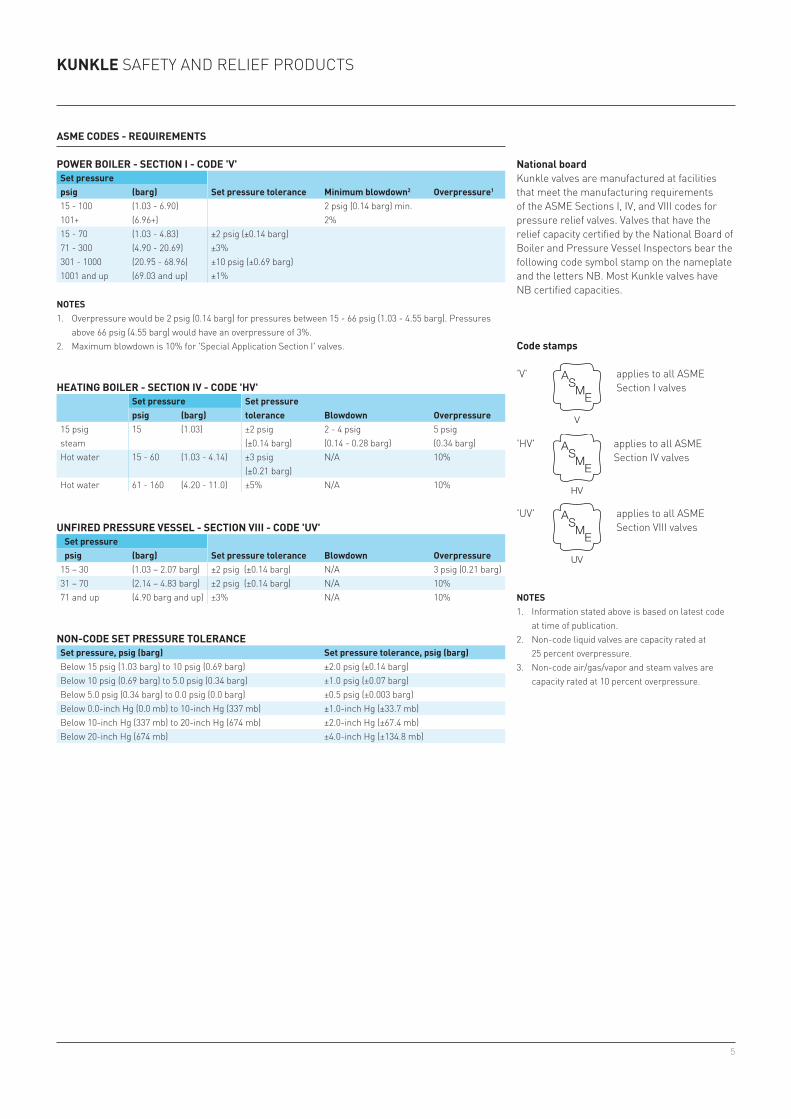
non-CoDe SeT PreSSure ToleranCeSet pressure, psig (barg) Set pressure tolerance, psig (barg)Below 15 psig (1.03 barg) to 10 psig (0.69 barg) ±2.0 psig (±0.14 barg)Below 10 psig (0.69 barg) to 5.0 psig (0.34 barg) ±1.0 psig (±0.07 barg)Below 5.0 psig (0.34 barg) to 0.0 psig (0.0 barg) ±0.5 psig (±0.003 barg)Below 0.0-inch Hg (0.0 mb) to 10-inch Hg (337 mb) ±1.0-inch Hg (±33.7 mb)Below 10-inch Hg (337 mb) to 20-inch Hg (674 mb) ±2.0-inch Hg (±67.4 mb)Below 20-inch Hg (674 mb) ±4.0-inch Hg (±134.8 mb)
Code stamps
'V' applies to all asMe section i valves
'HV' applies to all asMe section iV valves
'uV' applies to all asMe section Viii valves
ASME
V
ASME
HV
ASME
UV
noTeS1. overpressure would be 2 psig (0.14 barg) for pressures between 15 - 66 psig (1.03 - 4.55 barg). pressures
above 66 psig (4.55 barg) would have an overpressure of 3%.2. Maximum blowdown is 10% for 'special application section i' valves.
PoWer BoIler - SeCTIon I - CoDe 'V'Set pressure
Set pressure tolerance minimum blowdown2 overpressure1psig (barg)15 - 100 (1.03 - 6.90) 2 psig (0.14 barg) min.101+ (6.96+) 2% 15 - 70 (1.03 - 4.83) ±2 psig (±0.14 barg)71 - 300 (4.90 - 20.69) ±3%301 - 1000 (20.95 - 68.96) ±10 psig (±0.69 barg)1001 and up (69.03 and up) ±1%
HeaTInG BoIler - SeCTIon IV - CoDe 'HV'Set pressure Set pressure
tolerance Blowdown overpressurepsig (barg)15 psigsteam
15 (1.03) ±2 psig(±0.14 barg)
2 - 4 psig(0.14 - 0.28 barg)
5 psig(0.34 barg)
Hot water 15 - 60 (1.03 - 4.14) ±3 psig(±0.21 barg)
n/a 10%
Hot water 61 - 160 (4.20 - 11.0) ±5% n/a 10%
unFIreD PreSSure VeSSel - SeCTIon VIII - CoDe 'uV' Set pressure
Set pressure tolerance Blowdown overpressure psig (barg)15 – 30 (1.03 – 2.07 barg) ±2 psig (±0.14 barg) n/a 3 psig (0.21 barg)31 – 70 (2.14 – 4.83 barg) ±2 psig (±0.14 barg) n/a 10%71 and up (4.90 barg and up) ±3% n/a 10% noTeS
1. information stated above is based on latest code at time of publication.
2. non-code liquid valves are capacity rated at 25 percent overpressure.
3. non-code air/gas/vapor and steam valves are capacity rated at 10 percent overpressure.
national boardKunkle valves are manufactured at facilities that meet the manufacturing requirements of the asMe sections i, iV, and Viii codes for pressure relief valves. Valves that have the relief capacity certified by the national Board of Boiler and pressure Vessel inspectors bear the following code symbol stamp on the nameplate and the letters nB. Most Kunkle valves have nB certified capacities.
6
KunKle safety and relief products
General SaFeTy anD relIeF ValVe InFormaTIon
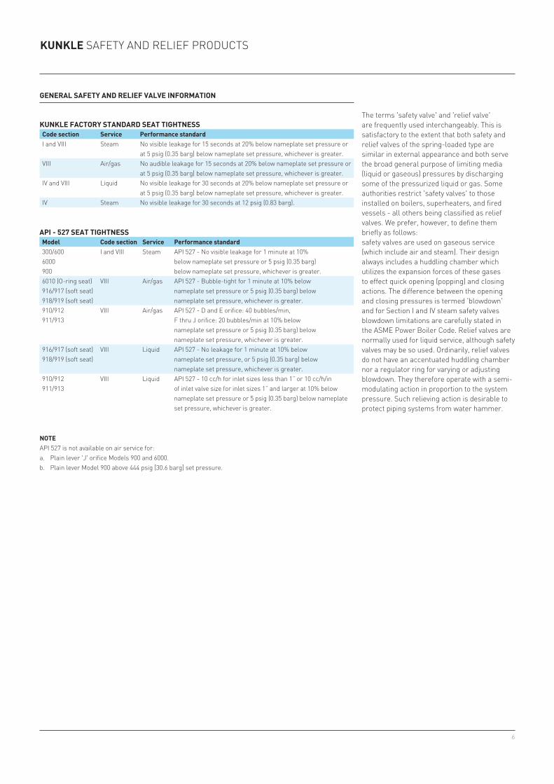
KunKle FaCTory STanDarD SeaT TIGHTneSSCode section Service Performance standardi and Viii steam no visible leakage for 15 seconds at 20% below nameplate set pressure or
at 5 psig (0.35 barg) below nameplate set pressure, whichever is greater.Viii air/gas no audible leakage for 15 seconds at 20% below nameplate set pressure or
at 5 psig (0.35 barg) below nameplate set pressure, whichever is greater.iV and Viii liquid no visible leakage for 30 seconds at 20% below nameplate set pressure or
at 5 psig (0.35 barg) below nameplate set pressure, whichever is greater.iV steam no visible leakage for 30 seconds at 12 psig (0.83 barg).
the terms 'safety valve' and 'relief valve' are frequently used interchangeably. this is satisfactory to the extent that both safety and relief valves of the spring-loaded type are similar in external appearance and both serve the broad general purpose of limiting media (liquid or gaseous) pressures by discharging some of the pressurized liquid or gas. some authorities restrict 'safety valves' to those installed on boilers, superheaters, and fired ves sels - all others being classified as relief valves. We prefer, how ever, to define them briefly as follows:safety valves are used on gaseous service (which include air and steam). their design always includes a huddling chamber which utilizes the expansion forces of these gases to effect quick opening (popping) and closing actions. the difference between the open ing and closing pressures is termed 'blowdown' and for section i and iV steam safety valves blowdown limitations are carefully stated in the asMe power Boiler code. relief valves are normally used for liquid service, although safety valves may be so used. ordi narily, relief valves do not have an accentuated huddling chamber nor a regulator ring for varying or adjusting blowdown. they therefore operate with a semi-modulating action in proportion to the system pressure. such relieving action is desirable to protect piping systems from water hammer.
noTeapi 527 is not available on air service for:a. plain lever 'J' orifice Models 900 and 6000.b. plain lever Model 900 above 444 psig [30.6 barg] set pressure.
aPI - 527 SeaT TIGHTneSSmodel Code section Service Performance standard300/6006000900
i and Viii steam api 527 - no visible leakage for 1 minute at 10%below nameplate set pressure or 5 psig (0.35 barg)below nameplate set pressure, whichever is greater.
6010 (o-ring seat)916/917 (soft seat)918/919 (soft seat)
Viii air/gas api 527 - Bubble-tight for 1 minute at 10% belownameplate set pressure or 5 psig (0.35 barg) belownameplate set pressure, whichever is greater.
910/912911/913
Viii air/gas api 527 - d and e orifice: 40 bubbles/min,f thru J orifice: 20 bubbles/min at 10% belownameplate set pressure or 5 psig (0.35 barg) belownameplate set pressure, whichever is greater.
916/917 (soft seat)918/919 (soft seat)
Viii liquid api 527 - no leakage for 1 minute at 10% belownameplate set pressure, or 5 psig (0.35 barg) belownameplate set pressure, whichever is greater.
910/912911/913
Viii liquid api 527 - 10 cc/h for inlet sizes less than 1” or 10 cc/h/in of inlet valve size for inlet sizes 1” and larger at 10% below nameplate set pressure or 5 psig (0.35 barg) below nameplate set pressure, whichever is greater.
7
KunKle safety and relief products
SaFeTy anD relIeF ValVe PoInTerS
1. asMe codes require that steam and air safety valves have test levers, although levers may be omitted on valves used in hazardous or toxic gas service.
2. steam safety valves may be used for air service but not vice versa. liquid valves should be used on liquid only.
3. safety/relief valves should be installed vertically with the drain holes open or piped to a convenient location.
4. the inlet to and outlet from a safety/relief valve must be at least as large as the valve connections.
5. every safety/relief valve is individually tested and set by Kunkle.6. in the event you have safety/relief valve problems, first check the accuracy and cleanliness
of pressure gauges and then refer to 'recommended installation' for help in determining the cause of your problem. feel free to consult your sales representative.
7. When ordering, we need to know size, type of connections, model number, pressure setting, required relieving capacity, and service media, or advise your complete requirements so that we can make a selection for you.
8. following are procedures on the operation and testing of safety/ relief valves: a. avoid excessive operation of the safety/relief valve as even one opening can provide a
means for leakage. safety/relief valves should be operated only often enough to assure that they are in good working order.
B. test the valve by raising the operating pressure to the set pressure of the safety/relief valve, allowing it to open and reset as it would in normal service.
c. do not hand operate the valve with less than 75 percent of the stamped set pressure exerted on the underside of the disc. When hand operating, be sure to hold the valve in an open position long enough to purge accumulated foreign material from the seat area and then allow the valve to snap shut.
8
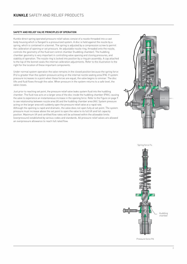
Spring Force Fs
HuddlingChamber
Pressure Force PA
KunKle safety and relief products
SaFeTy anD relIeF ValVe PrInCIPleS oF oPeraTIon
Kunkle direct spring operated pressure relief valves consist of a nozzle threaded into a cast body housing which is flanged to a pressurized system. a disc is held against the nozzle by a spring, which is contained in a bonnet. the spring is adjusted by a compression screw to permit the calibration of opening or set pressure. an adjustable nozzle ring, threaded onto the nozzle, controls the geometry of the fluid exit control chamber (huddling chamber). the huddling chamber geometry is very important in controlling valve opening and closing pressures, and stability of operation. the nozzle ring is locked into position by a ring pin assembly. a cap attached to the top of the bonnet seals the internal calibration adjustments. refer to the illustration to the right for the location of these important components.
under normal system operation the valve remains in the closed position because the spring force (fs) is greater than the system pressure acting on the internal nozzle seating area (pa). if system pressure increases to a point when these forces are equal, the valve begins to simmer. the disc lifts and fluid flows through the valve. When pressure in the system returns to a safe level, the valve closes.
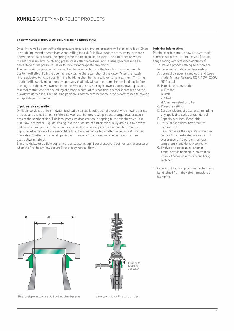
Just prior to reaching set point, the pressure relief valve leaks system fluid into the huddling chamber. the fluid now acts on a larger area of the disc inside the huddling chamber (pah), causing the valve to experience an instantaneous increase in the opening force. refer to the figure on page 9 to see relationship between nozzle area (a) and the huddling chamber area (ah). system pressure acting on the larger area will suddenly open the pressure relief valve at a rapid rate.although the opening is rapid and dramatic, the valve does not open fully at set point. the system pressure must increase above the set point to open the valve to its full lift and full capacity position. Maximum lift and certified flow rates will be achieved within the allowable limits (overpressure) established by various codes and standards. all pressure relief valves are allowed an overpressure allowance to reach full rated flow.
spring force fs
Huddling chamber
pressure force pa
9
Relationship of Nozzle Area to Huddling Chamber Area
Ah
A
Fluid ExitsHuddlingChamber
Valve Opens, Force PAh Acting on Disc
KunKle safety and relief products
SaFeTy anD relIeF ValVe PrInCIPleS oF oPeraTIon
once the valve has controlled the pressure excursion, system pressure will start to reduce. since the huddling chamber area is now controlling the exit fluid flow, system pressure must reduce below the set point before the spring force is able to close the valve. the difference between the set pressure and the closing pressure is called blowdown, and is usually expressed as a percentage of set pressure. refer to code for appropriate blowdown.the nozzle ring adjustment changes the shape and volume of the huddling chamber, and its position will affect both the opening and closing characteristics of the valve. When the nozzle ring is adjusted to its top position, the huddling chamber is restricted to its maximum. this ring position will usually make the valve pop very distinctly with a minimum simmer (leakage before opening), but the blowdown will increase. When the nozzle ring is lowered to its lowest position, minimal restriction to the huddling chamber occurs. at this position, simmer increases and the blowdown decreases. the final ring position is somewhere between these two extremes to provide acceptable performance.
liquid service operationon liquid service, a different dynamic situation exists. liquids do not expand when flowing across orifices, and a small amount of fluid flow across the nozzle will produce a large local pressure drop at the nozzle orifice. this local pressure drop causes the spring to reclose the valve if the fluid flow is minimal. liquids leaking into the huddling chamber can quickly drain out by gravity and prevent fluid pressure from building up on the secondary area of the huddling chamber. liquid relief valves are thus susceptible to a phenomenon called chatter, especially at low fluid flow rates. chatter is the rapid opening and closing of the pressure relief valve and is often destructive in nature.since no visible or audible pop is heard at set point, liquid set pressure is defined as the pressure when the first heavy flow occurs (first steady vertical flow).
ordering Informationpurchase orders must show the size, model number, set pressure, and service (include flange rating with size when applicable).1. to make a proper catalog selection, the
following informa tion will be needed: a. connection sizes (in and out), and types
(male, female, flanged; 125#, 150#, 250#, 300#, etc.)
B. Material of construction a. Bronze b. iron c. steel d. stainless steel or other
c. pressure setting d. service (steam, air, gas, etc., including
any appli cable codes or standards) e. capacity required, if available f. unusual conditions (temperature,
location, etc.) Be sure to use the capacity correction
factors for superheated steam, liquid overpressure (10 percent), air-gas temperature and density correction.
G. if valve is to be 'equal to' another brand, provide nameplate information or specification data from brand being re placed.
2. ordering data for replacement valves may be obtained from the valve nameplate or stamping.
relationship of nozzle area to huddling chamber area
fluid exits huddling chamber
Valve opens, force pah acting on disc
10
KunKle safety and relief products
ValVe SeleCTIon
the most critical consideration when selecting a pressure relief valve is that the valve will be capable of passing the maximum expected flow capacity. to properly select a relief valve the user must first determine the following:1. the set pressure at which the valve is to
operate. this pressure is based on the pressure limits of the system and the applicable codes. the set pressure of the primary pressure relief valve must not exceed the maximum allowable pressure of the system, but should be at least 10 percent above the maximum operating pressure.
2. the physical properties of the fluid media to be relieved. capacity values are given in the Kunkle catalogs based on air, saturated steam, and water. Kunkle valves will relieve many other fluids, but information such as molecular weight, specific gravity, viscosity, ratio of specific heats, compressibility factor, and process temperature may be necessary to insure accurate valve selection.
3. the required relieving capacity. the asMe Boiler and pressure Vessel code, american petroleum institute recommended practices, and other applicable standards have many rules for obtaining the required relieving capacity and should be referenced when making this determination. the user must consider all sources of pressure generation in the system that will be protected by the pressure relief valve. examples of pressure generation sources are pumps, heat input that may cause the system fluid to boil or expand, etc. the pressure relief valve(s) selected must exceed the worst case source of flow generation to prevent the system pressure from exceeding acceptable limits.
once the previous information has been collected, the pressure relief valve may be sized by using the capacity charts (included in each model’s catalog sheet) or by performing sizing calculations (see Valve sizing, pages 14-25). the user will also want to consider other important factors such as:
• connection size and type. this information is given in the Valve selection guide and in each of the Model catalog sheets. please note that the inlet to and outlet from a pressure relief valve must be at least as large as the valve connections to prevent valve malfunction.
• pipe size. connection pipe sizes should not be determined by equipment connections, but rather by the relieving capacity of the prV.
• applicable code compliance. the asMe code summary section gives important information about pressure relief valves from the code. pressure relief valve users are strongly encouraged to reference the full version of the code for important rules that may not be included in this manual.
• Maximum allowable seat leakage. the General safety and relief valve information (page 6) section of this manual shows the leakage acceptance criteria applied to each Kunkle valve. pressure relief valve users should keep in mind that if 'zero leakage' is a requirement, a soft seated valve must be selected.
• environmental conditions. environmental conditions play a significant role in how pressure relief valves operate. extremely high ambient temperatures may affect the set pressure of the valve, extremely low temperatures combined with moisture can cause valves to 'freeze up' and prevent proper operation, and vibration may severely shorten the service life of the valve. the Valve selection guide (pages 11-13) in this manual has general information on the pressure and temperature limits for each valve series. for specific model limitations refer to the individual model catalog. for vibration service, please contact your local Kunkle representative for assistance.
• Valve options. each Kunkle model is offered with useful options such as pressure tight caps, lift lever options, or vibration dampening preparation. When selecting valve options, keep in mind that there are code requirements that may dictate what options may be used. for instance the asMe code dictates that all air, steam and hot water (140°f+ [60°c+]) pressure relief valves must be equipped with a lift lever. refer to the individual model catalogs for listings of available options.
• installation space. the individual model catalogs show envelope dimensions for each configuration and size.
for assistance on valve sizing and selection, please contact your local sales representative.

11
KunKle safety and relief products
STeam (aSme Section I - power boilers)
model(s)material connections Inlet size range min/max1 press. min/max temp.
Body Trim nPT FlGD in (mm) psig (barg) °F (°C)300, 600 cs ss X 1¼ - 6” (31.75 - 152.4) 15/1000 (1.0/69) -20/800 (-29/427)920, 921, 927 (special use - 10% blowdown)
cs ss X o ½ - 2” (12.7 - 50.8) 15/1400 (1.0/96.5) -20/800 (-29/427)
6010, 6021, 6121, 61826186, 6221, 6283
Bronze Brass X ½ - 2½” (12.7 - 63.5) 3/250 (0.69/17.2) -60/406 (-51/208)
6030, 6130, 6230 Bronze ss X ½ - 2½” (12.7 - 63.5) 3/300 (0.69/20.7) -60/425 (-51/219)6252 iron ss X X 1½ - 6” (38.1 - 152.4) 10/250 (0.69/17.2) -20/406 (-29/208)
noTeS1. set pressures less than 15 psig [1.0 barg] are non-code only.2. see also asMe section Viii steam valves for non-code steam applications.
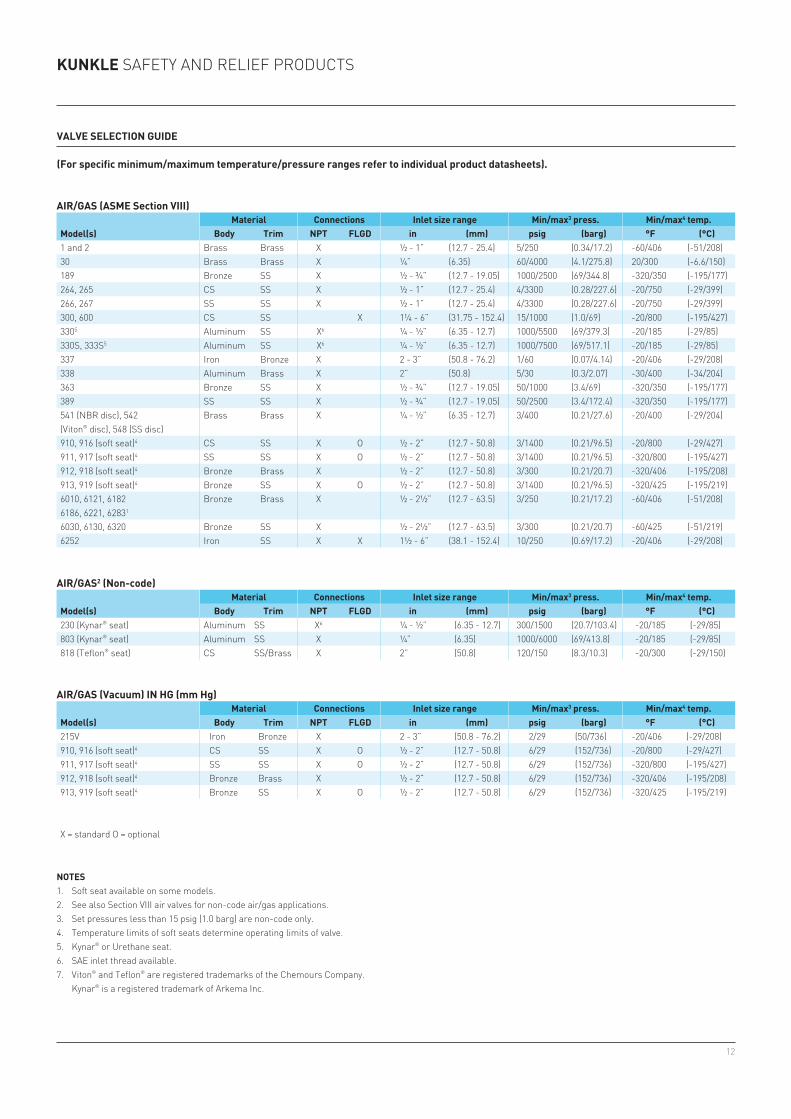
ValVe SeleCTIon GuIDe
(For specific minimum/maximum temperature/pressure ranges refer to individual product datasheets).
STeam (non-code)2
model(s)material connections Inlet size range min/max1 press. min/max temp.
Body Trim nPT FlGD in (mm) psig (barg) °F (°C)40r, 40rl ss ss X ½ - ¾” [12.7 - 19.05] 1/400 [0.07/27.6] -60/850 [-51/454]
X = standard o = optional
STeam (aSme Section IV - low pressure steam heating boilers)
model(s)material connections Inlet size range min/max1 press. min/max temp.
Body Trim nPT FlGD in (mm) psig (barg) °F (°C)930 iron Bronze X 2 - 3” (50.8 - 76.2) 15 only (1.0) 250 only (122)6933, 6934 Bronze Brass X ½ - 2” (12.7 - 50.8) 15 only (1.0) 250 only (122)6935 Bronze ss X ½ - 2” (12.7 - 50.8) 15 only (1.0) 250 only (122)6254 iron ss X X 1½ - 6” (38.1 - 152.4) 15 only (1.0) 250 only (122)
STeam (aSme Section VIII - unfired steam equipment)
model(s)material connections Inlet size range min/max1 press. min/max temp.
Body Trim nPT FlGD in (mm) psig (barg) °F (°C)1 and 2 Bronze Brass X ½ - 1” (12.7 - 25.4) 5/250 (0.34/17.2) -60/406 (-51/208)264, 265 cs ss X ½ - 1” (12.7 - 25.4) 4/3300 (0.28/227.6) -20/750 (-29/399)266, 267 ss ss X ½ - 1” (12.7 - 25.4) 4/3300 (0.28/227.6) -20/750 (-29/399)300, 600 cs ss X 1¼ - 6” (31.75 - 152.4) 15/1000 (1.0/69) -20/750 (-29/399)910 cs ss X o ½ - 2” (12.7 - 50.8) 3/1400 (0.21/96.5) -20/800 (-29/427)911 ss ss X o ½ - 2” (12.7 - 50.8) 3/1400 (0.21/96.5) -320/800 (-195/427)912 Bronze Brass X ½ - 2” (12.7 - 50.8) 3/250 (0.21/17.2) -320/406 (-195/208)913 Bronze ss X o ½ - 2” (12.7 - 50.8) 3/300 (0.21/20.7) -320/425 (-195/219)6010, 6021, 6121, 6182,6186, 6221, 6283
Bronze Brass X ½ - 2½” (12.7 - 63.5) 3/250 (0.21/17.2) -60/406 (-51/208)
6030, 6130, 6230 Bronze ss X ½ - 2½” (12.7 - 63.5) 3/300 (0.21/20.7) -60/425 (-51/219)6252 iron ss X X 1½ - 6” (38.1 - 152.4) 10/250 (0.69/17.2) -20/406 (-29/208)
12
KunKle safety and relief products
ValVe SeleCTIon GuIDe
(For specific minimum/maximum temperature/pressure ranges refer to individual product datasheets).
noTeS1. soft seat available on some models.2. see also section Viii air valves for non-code air/gas applications.3. set pressures less than 15 psig (1.0 barg) are non-code only.4. temperature limits of soft seats determine operating limits of valve.5. Kynar® or urethane seat.6. sae inlet thread available.7. V iton® and t eflon® are registered trademarks of the chemours company. Kynar® is a registered trademark of arkema inc.
aIr/GaS (Vacuum) In HG (mm Hg)
model(s)material Connections Inlet size range min/max3 press. min/max4 temp.
Body Trim nPT FlGD in (mm) psig (barg) °F (°C)215V iron Bronze X 2 - 3” (50.8 - 76.2) 2/29 (50/736) -20/406 (-29/208)910, 916 (soft seat)4 cs ss X o ½ - 2” (12.7 - 50.8) 6/29 (152/736) -20/800 (-29/427)911, 917 (soft seat)4 ss ss X o ½ - 2” (12.7 - 50.8) 6/29 (152/736) -320/800 (-195/427)912, 918 (soft seat)4 Bronze Brass X ½ - 2” (12.7 - 50.8) 6/29 (152/736) -320/406 (-195/208)913, 919 (soft seat)4 Bronze ss X o ½ - 2” (12.7 - 50.8) 6/29 (152/736) -320/425 (-195/219)
X = standard o = optional
aIr/GaS2 (non-code)
model(s)material Connections Inlet size range min/max3 press. min/max4 temp.
Body Trim nPT FlGD in (mm) psig (barg) °F (°C)230 (Kynar® seat) aluminum ss X6 ¼ - ½” (6.35 - 12.7) 300/1500 (20.7/103.4) -20/185 (-29/85)803 (Kynar® seat) aluminum ss X ¼” (6.35) 1000/6000 (69/413.8) -20/185 (-29/85)818 (t eflon® seat) cs ss/Brass X 2” (50.8) 120/150 (8.3/10.3) -20/300 (-29/150)
aIr/GaS (aSme Section VIII)
model(s)material Connections Inlet size range min/max3 press. min/max4 temp.
Body Trim nPT FlGD in (mm) psig (barg) °F (°C)1 and 2 Brass Brass X ½ - 1” (12.7 - 25.4) 5/250 (0.34/17.2) -60/406 (-51/208)30 Brass Brass X ¼” (6.35) 60/4000 (4.1/275.8) 20/300 (-6.6/150)189 Bronze ss X ½ - ¾” (12.7 - 19.05) 1000/2500 (69/344.8) -320/350 (-195/177)264, 265 cs ss X ½ - 1” (12.7 - 25.4) 4/3300 (0.28/227.6) -20/750 (-29/399)266, 267 ss ss X ½ - 1” (12.7 - 25.4) 4/3300 (0.28/227.6) -20/750 (-29/399)300, 600 cs ss X 1¼ - 6” (31.75 - 152.4) 15/1000 (1.0/69) -20/800 (-195/427)3305 aluminum ss X6 ¼ - ½” (6.35 - 12.7) 1000/5500 (69/379.3) -20/185 (-29/85)330s, 333s5 aluminum ss X6 ¼ - ½” (6.35 - 12.7) 1000/7500 (69/517.1) -20/185 (-29/85)337 iron Bronze X 2 - 3” (50.8 - 76.2) 1/60 (0.07/4.14) -20/406 (-29/208)338 aluminum Brass X 2” (50.8) 5/30 (0.3/2.07) -30/400 (-34/204)363 Bronze ss X ½ - ¾” (12.7 - 19.05) 50/1000 (3.4/69) -320/350 (-195/177)389 ss ss X ½ - ¾” (12.7 - 19.05) 50/2500 (3.4/172.4) -320/350 (-195/177)541 (nBr disc), 542 (V iton® disc), 548 (ss disc)
Brass Brass X ¼ - ½” (6.35 - 12.7) 3/400 (0.21/27.6) -20/400 (-29/204)
910, 916 (soft seat)4 cs ss X o ½ - 2” (12.7 - 50.8) 3/1400 (0.21/96.5) -20/800 (-29/427)911, 917 (soft seat)4 ss ss X o ½ - 2” (12.7 - 50.8) 3/1400 (0.21/96.5) -320/800 (-195/427)912, 918 (soft seat)4 Bronze Brass X ½ - 2” (12.7 - 50.8) 3/300 (0.21/20.7) -320/406 (-195/208)913, 919 (soft seat)4 Bronze ss X o ½ - 2” (12.7 - 50.8) 3/1400 (0.21/96.5) -320/425 (-195/219)6010, 6121, 61826186, 6221, 62831
Bronze Brass X ½ - 2½” (12.7 - 63.5) 3/250 (0.21/17.2) -60/406 (-51/208)
6030, 6130, 6320 Bronze ss X ½ - 2½” (12.7 - 63.5) 3/300 (0.21/20.7) -60/425 (-51/219)6252 iron ss X X 1½ - 6” (38.1 - 152.4) 10/250 (0.69/17.2) -20/406 (-29/208)

13
ValVe SeleCTIon GuIDe
(For specific minimum/maximum temperature/pressure ranges refer to individual product datasheets).
oTHer - DrIP Pan elBoW
model(s)material Connections Inlet size range min/max1 press. min/max2 temp.
Body Trim nPT FlGD in (mm) psig (barg) °F (°C)299 iron n/a X X 2 - 8” (50.80 - 203.2) n/a n/a -20/406 (-29/208)
X = standard o = optional
noTeS1. set pressures below 15 psig [1.0 barg] are non-code only.2. temperature limits of soft seats determine operating limits of valve.3. fM approved only.
KunKle safety and relief products
lIquID (aSme Section VIII)
model(s)material Connections Inlet size range min/max1 press. min/max2 temp.
Body Trim nPT FlGD in (mm) psig (barg) °F (°C)910, 916 (soft seat)2 cs ss X o ½ - 2” (12.7 - 50.8) 3/1400 (0.21/96.5) -20/800 (-29/427)911, 917 (soft seat)2 ss ss X o ½ - 2” (12.7 - 50.8) 3/1400 (0.21/96.5) -320/800 (-195/427)912, 918 (soft seat)2 Bronze Brass X ½ - 2” (12.7 - 50.8) 3/300 (0.21/20.7) -320/406 (-195/208)913, 919 (soft seat)2 Bronze ss X o ½ - 2” (12.7 - 50.8) 3/1400 (0.21/96.5) -320/425 (-195/219)
lIquID (non-code)
model(s)material Connections Inlet size range min/max1 press. min/max2 temp.
Body Trim nPT FlGD in (mm) psig (barg) °F (°C)19, 20 Bronze Bronze X o ½ - 3” (12.7 - 76.2) 1/300 (0.07/20.7) -60/406 (-51/208)19M, 20M Bronze ss X o 2½ - 3” (63.5 - 76.2) 1/500 (0.07/34.5) -60/406 (-51/208)71s iron ss X ½ - 2” (12.7 - 50.8) 1/250 (0.07/17.2) -20/406 (-29/208)171, 171p cs ss X ½ - 2” (12.7 - 50.8) 1/400 (0.07/27.6) -20/550 (-29/288)171s ss ss X ½ - 2” (12.7 - 50.8) 1/400 (0.07/27.6) -20/550 (-29/288)91 iron Bronze X X 1½ - 6” (38.1 - 152.4) 5/400 (0.34/27.6) -20/406 (-29/208)218,228 iron Bronze X X 3, 4, and 6” (76.2 - 152.4) 60/200 (4.1/13.8) -20/406 (-29/208)140 ss ss X ⅜ - ½ “ (9.5 - 12.7) 10/300 (0.69/20.7) -60/406 (-51/208)264, 265 cs ss X ½ - 1” (12.7 - 25.4) 4/3300 (0.28/227.6) -20/750 (-29/399)266, 267 ss ss X ½ - 1” (12.7 - 25.4) 4/3300 (0.28/227.6) -20/750 (-29/399)910, 916 (soft seat)2 cs ss X o ½ - 2” (12.7 - 50.8) 3/1400 (0.21/96.5) -20/800 (-29/427)911, 917 (soft seat)2 ss ss X o ½ - 2” (12.7 - 50.8) 3/1400 (0.21/96.5) -320/800 (-195/427)912, 918 (soft seat)2 Bronze Brass X ½ - 2” (12.7 - 50.8) 3/300 (0.21/20.7) -320/406 (-195/208)913, 919 (soft seat)2 Bronze ss X o ½ - 2” (12.7 - 50.8) 3/1400 (0.21/96.5) -320/425 (-195/219)
lIquID - unDerWrITerS laBoraTorIeS (ul) For oIl SerVICeS
model(s)material Connections Inlet size range min/max1 press. min/max2 temp.
Body Trim nPT FlGD in (mm) psig (barg) °F (°C)200a Bronze Brass X ¾ - 1½” (19.05 - 38.1) 1/200 (0.07/13.8) -60/406 (-51/208)200H Bronze ss X o ¾ - 2” (19.05 - 50.8) 1/200 (0.07/13.8) -60/406 (-51/208)
lIquID - unDerWrITerS laBoraTorIeS (ul) anD FaCTory muTual reSearCH (Fm) For FIre PumP WaTer relIeF
model(s)material Connections Inlet size range min/max1 press. min/max2 temp.
Body Trim nPT FlGD in (mm) psig (barg) °F (°C)218, 228 iron Bronze X X 3, 4 and 6” (76.2 - 152.4) 60/200 (4.1/13.8) -20/406 (-29/208)918 (soft seat)2,3 Bronze Brass X ¾ - 1” (19.05 - 25.4) 60/250 (4.1/17.2) -20/406 (-29/208)
lIquID (aSme Section IV - hot water boilers)
model(s)material Connections Inlet size range min/max1 press. min/max2 temp.
Body Trim nPT FlGD in (mm) psig (barg) °F (°C)537 (soft seat) iron/bronze Brass X ¾ - 2” (19.05 - 50.8) 15/160 (1.0/11) -20/250 (-29/121)
14
KunKle safety and relief products
ValVe SIzInG
after the required relieving capacity has been determined, the pressure relief valve may be sized by using the capacity charts that are included in each model’s catalog sheet. the capacities given in those charts may be adjusted for special conditions such as fluid density and temperature by using the correction factors given in tables B through d (pages 18-20). Valves may also be sized by performing sizing calculations per the formulas (pages 15 and 16) in this section.
Most Kunkle valves may be sized by using the 'coefficient method' (listed below). these valves typically are high lift valves where the nozzle bore is the flow controlling orifice. this calculation method involves selecting the valve model and corresponding flow coefficient and orifice area from table a (page 17) and then using the capacity formula (pages 15 and 16) for the service in which the valve will function.
Kunkle Models 30, 541, 542, and 548 use the 'slope method' for sizing calculations. these valves are typically low lift valves, where the annular orifice between the disc and the nozzle seat is the flow controlling orifice. these models are characterized by having a linear increase in capacity with respect to inlet pressure. the 'slope' defines this direct relationship of inlet pressure to capacity. consult your sales representative for sizing assistance.
Kunkle Models 1, 2, 19, 20, 200, 71s, 171, 171s, 91, 218, 228, and 140 use the 'Ka method' for sizing calculations. this method is similar to the slope method, in that it is used for low lift valves and is empirically derived. the major difference is that the relationship between inlet pressure and capacity is not linear. these valves are characterized by having low lift that varies with inlet pressure, which makes the flow controlling orifice area indeterminate. consult your sales representative for sizing assistance.
IV-a Coefficient methodfollow these steps for calculating what orifice size is necessary to flow the required capacity:1. select the Model family that you are interested in from the Valve selection guide (pages 10-13).2. from table a (page 17), record the flow coefficient (Kd) corresponding to the service in which
the valve will operate.3. select the proper formula(s) for the service in which the valve will operate. calculate the
minimum required orifice area.4. select the orifice/size designation from table a (page 17) that has a flow area closest to, but not
less than the minimum required orifice area calculated in step 3.
15
KunKle safety and relief productsValVe Sizing
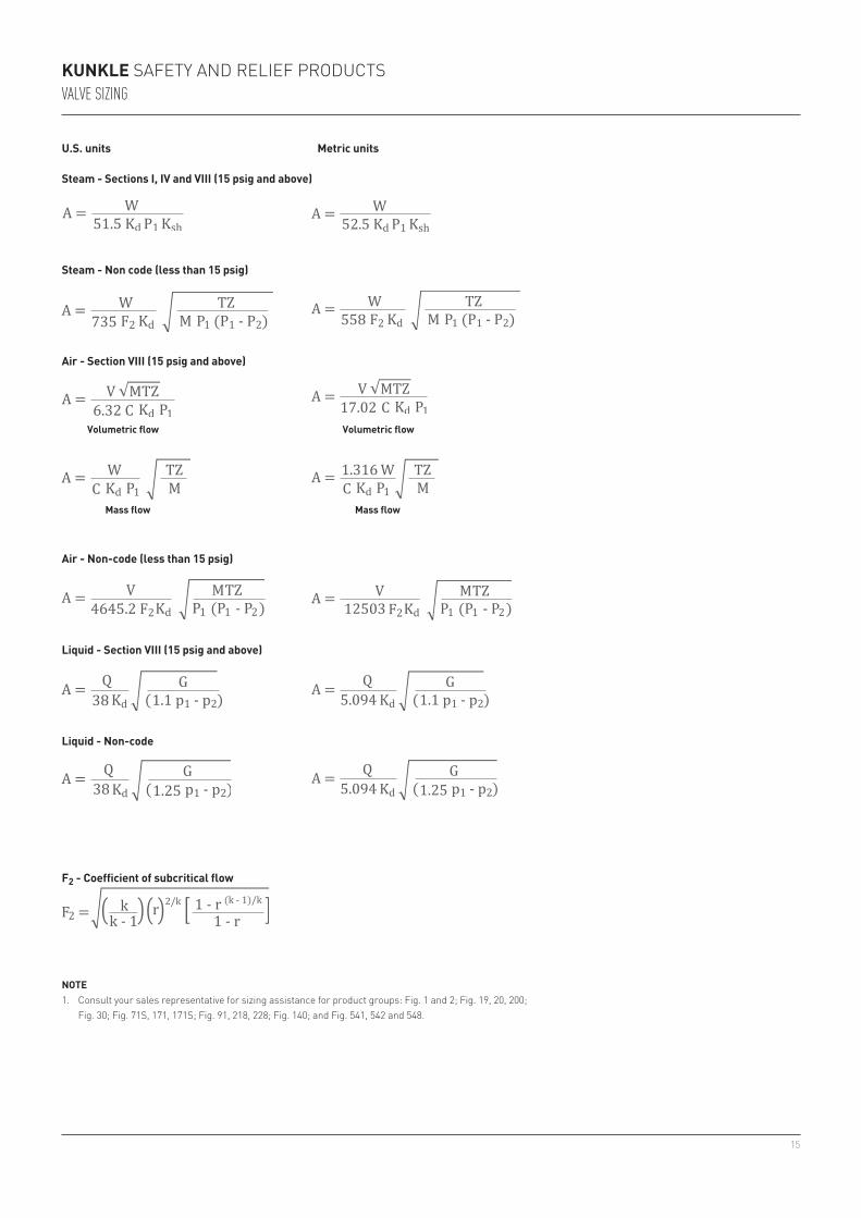
u.S. units metric units
F2 - Coefficient of subcritical flow
noTe1. consult your sales representative for sizing assistance for product groups: fig. 1 and 2; fig. 19, 20, 200;
fig. 30; fig. 71s, 171, 171s; fig. 91, 218, 228; fig. 140; and fig. 541, 542 and 548.
Volumetric flow Volumetric flow
mass flow mass flow
Steam - Sections I, IV and VIII (15 psig and above)
Steam - non code (less than 15 psig)
air - Section VIII (15 psig and above)
air - non-code (less than 15 psig)
liquid - Section VIII (15 psig and above)
liquid - non-code
16
KunKle safety and relief productsValVe Sizing
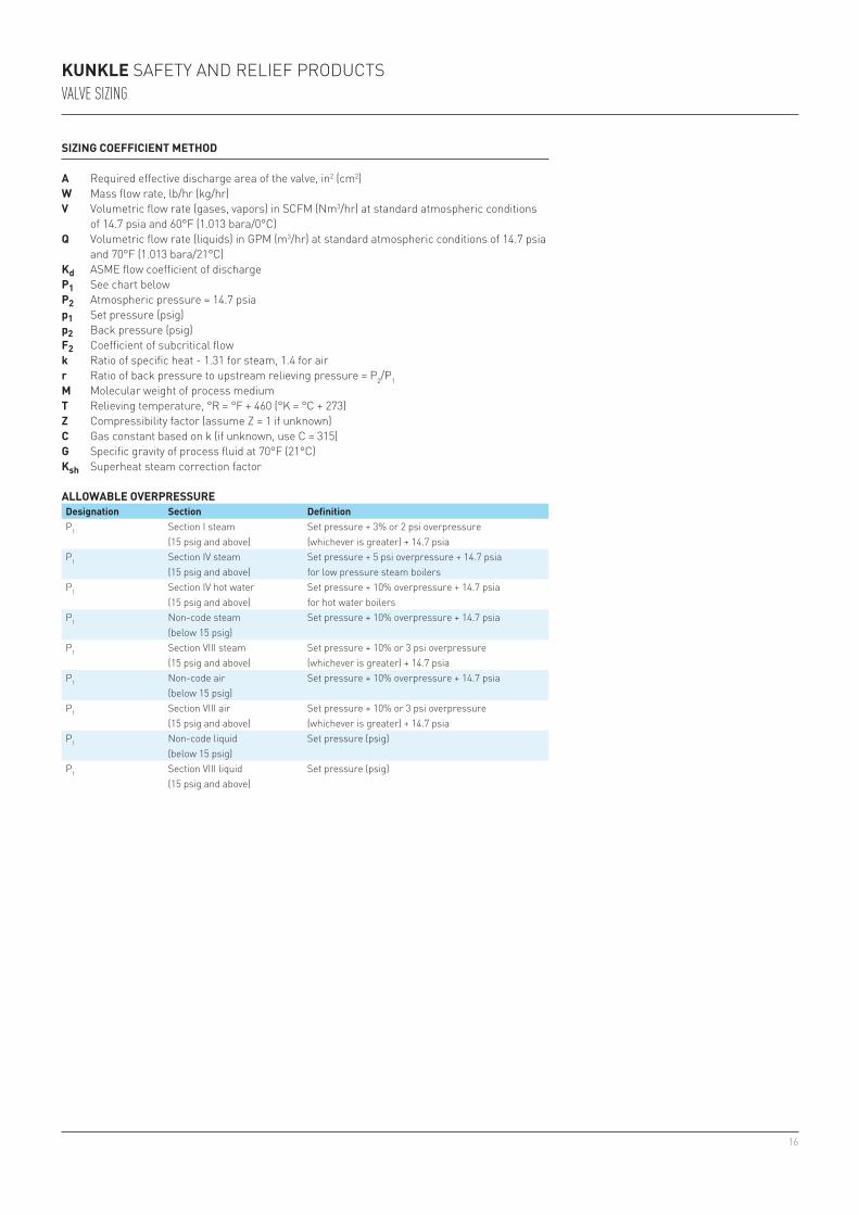
SIzInG CoeFFICIenT meTHoD
a required effective discharge area of the valve, in2 (cm2)W Mass flow rate, lb/hr (kg/hr)V Volumetric flow rate (gases, vapors) in scfM (nm3/hr) at standard atmospheric conditions
of 14.7 psia and 60°f (1.013 bara/0°c)q Volumetric flow rate (liquids) in GpM (m3/hr) at standard atmospheric conditions of 14.7 psia
and 70°f (1.013 bara/21°c)Kd asMe flow coefficient of dischargeP1 see chart belowP2 atmospheric pressure = 14.7 psiap1 set pressure (psig)p2 Back pressure (psig)F2 coefficient of subcritical flowk ratio of specific heat - 1.31 for steam, 1.4 for airr ratio of back pressure to upstream relieving pressure = p2/p1m Molecular weight of process mediumT relieving temperature, °r = °f + 460 (°K = °c + 273)z compressibility factor (assume Z = 1 if unknown)C Gas constant based on k (if unknown, use c = 315)G specific gravity of process fluid at 70°f (21°c)Ksh superheat steam correction factor
alloWaBle oVerPreSSureDesignation Section Definitionp1 section i steam
(15 psig and above)set pressure + 3% or 2 psi overpressure (whichever is greater) + 14.7 psia
p1 section iV steam(15 psig and above)
set pressure + 5 psi overpressure + 14.7 psia for low pressure steam boilers
p1 section iV hot water(15 psig and above)
set pressure + 10% overpressure + 14.7 psia for hot water boilers
p1 non-code steam(below 15 psig)
set pressure + 10% overpressure + 14.7 psia
p1 section Viii steam(15 psig and above)
set pressure + 10% or 3 psi overpressure (whichever is greater) + 14.7 psia
p1 non-code air(below 15 psig)
set pressure + 10% overpressure + 14.7 psia
p1 section Viii air(15 psig and above)
set pressure + 10% or 3 psi overpressure (whichever is greater) + 14.7 psia
p1 non-code liquid(below 15 psig)
set pressure (psig)
p1 section Viii liquid(15 psig and above)
set pressure (psig)
17
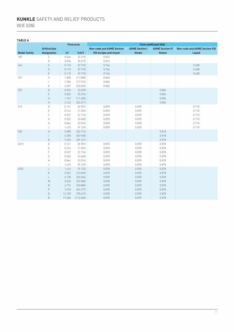
189 c 0.034 (0.219) 0.874d 0.034 (0.219) 0.874
264 c 0.110 (0.710) 0.766 0.408d 0.110 (0.710) 0.766 0.408e 0.110 (0.710) 0.766 0.408
337 H 1.838 (11.858) 0.860J 2.786 (17.974) 0.860K 4.037 (26.045) 0.860
537 d 0.533 (3.439) 0.806e 0.833 (5.374) 0.806G 1.767 (11.400) 0.806H 3.142 (20.271) 0.806
910 d 0.121 (0.781) 0.878 0.878 0.710e 0.216 (1.394) 0.878 0.878 0.710f 0.337 (2.174) 0.878 0.878 0.710G 0.553 (3.568) 0.878 0.878 0.710H 0.864 (5.574) 0.878 0.878 0.710J 1.415 (9.129) 0.878 0.878 0.710
930 H 5.080 (32.774) 0.818J 6.350 (40.968) 0.818K 7.620 (49.161) 0.818
6010 d 0.121 (0.781) 0.878 0.878 0.878e 0.216 (1.394) 0.878 0.878 0.878f 0.337 (2.174) 0.878 0.878 0.878G 0.553 (3.568) 0.878 0.878 0.878H 0.864 (5.574) 0.878 0.878 0.878J 1.415 (9.129) 0.878 0.878 0.878
6252 J 1.414 (9.123) 0.878 0.878 0.878K 2.022 (13.045) 0.878 0.878 0.878l 3.138 (20.245) 0.878 0.878 0.878M 3.960 (25.548) 0.878 0.878 0.878n 4.774 (30.800) 0.878 0.878 0.878p 7.018 (45.277) 0.878 0.878 0.878Q 12.155 (78.419) 0.878 0.878 0.878r 17.600 (113.548) 0.878 0.878 0.878
KunKle safety and relief productsValVe Sizing
TaBle a
model familyorifice/size designation
Flow area Flow coefficient (Kd)
in2 (cm2)non-code and aSme Section
VIII air/gas and steamaSme Section I
SteamaSme Section IV
Steamnon-code and aSme Section VIII
liquid

18
15 (1.03) 250 (121) 1.00 1.00 1.00 .99 .99 .98 .98 .97 .96 .95 .94 .93 .92 .91 .9020 (1.38) 259 (126) 1.00 1.00 1.00 .99 .99 .98 .98 .97 .96 .95 .94 .93 .92 .91 .9040 (2.76) 287 (142) 1.00 1.00 1.00 .99 .99 .98 .97 .96 .95 .94 .93 .92 .91 .9060 (4.14) 308 (153) 1.00 1.00 .99 .99 .98 .97 .96 .95 .94 .93 .92 .91 .9080 (5.52) 324 (162) 1.00 1.00 .99 .99 .98 .97 .96 .94 .93 .92 .91 .90100 (6.90) 338 (170) 1.00 1.00 .99 .98 .97 .96 .95 .94 .93 .92 .91120 (8.27) 350 (177) 1.00 1.00 .99 .98 .97 .96 .95 .94 .93 .92 .91140 (9.65) 361 (183) 1.00 1.00 .99 .98 .96 .95 .94 .93 .92 .91160 (11.0) 371 (188) 1.00 1.00 .99 .98 .97 .95 .94 .93 .92 .91180 (12.4) 380 (193) 1.00 .99 .98 .97 .96 .95 .93 .92 .91200 (13.8) 388 (198) 1.00 .99 .99 .97 .96 .95 .93 .92 .91220 (15.2) 395 (202) 1.00 1.00 .9 .98 .96 .95 .94 .93 .92240 (16.6) 403 (206) 1.00 .99 .98 .97 .95 .94 .93 .92260 (17.9) 409 (210) 1.00 .99 .98 .97 .96 .94 .93 .92280 (19.3) 416 (213) 1.00 1.00 .98 .97 .96 .95 .93 .92300 (20.7) 422 (217) 1.00 .99 .98 .96 .95 .93 .92350 (24.1) 436 (225) 1.00 1.00 .99 .96 .96 .94 .93400 (27.6) 448 (231) 1.00 .99 .96 .96 .95 .93450 (31.0) 460 (238) 1.00 .96 .96 .96 .94500 (34.5) 470 (243) 1.00 .96 .96 .96 .94550 (37.9) 480 (249) .97 .97 .97 .95600 (41.4) 489 (254) .97 .97 .97 .97650 (44.8) 497 (258) 1.00 .99 .97700 (48.3) 506 (263) 1.00 .99 .97750 (51.7) 513 (267) 1.00 1.00 .98800 (55.2) 520 (271) 1.00 .99850 (58.6) 527 (275) 1.00 .99900 (62.1) 533 (278) 1.00 1.00950 (65.5) 540 (282) 1.001000 (69.0) 546 (286) 1.001050 (72.4) 552 (289) 1.001100 (75.9) 558 (292)1150 (79.3) 563 (295)1200 (82.7) 569 (298)
KunKle safety and relief productsValVe Sizing
TaBle B - Steam super heat correction factor, Ksh
Set pressure Saturated steam temp. Total steam temperature °F (°C)
280 300 320 340 360 380 400 420 440 460 480 500 520 540 560psig (barg) °F (°C) (138) (149) (160) (171) (182) (193) (205) (216) (227) (238) (249) (260) (271) (282) (293)
noTerevised capacity for 'super heat steam': multiply capacity of valve x factor noted above.
19
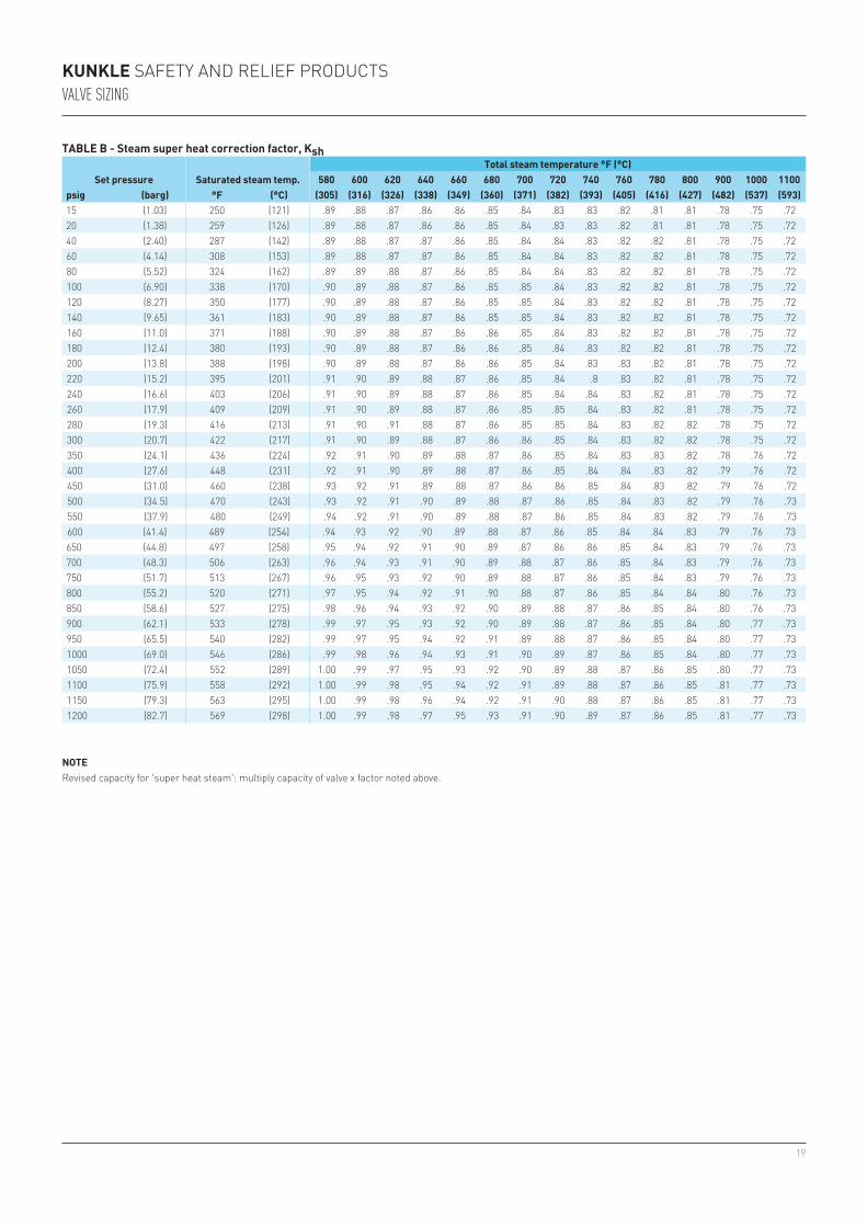
15 (1.03) 250 (121) .89 .88 .87 .86 .86 .85 .84 .83 .83 .82 .81 .81 .78 .75 .7220 (1.38) 259 (126) .89 .88 .87 .86 .86 .85 .84 .83 .83 .82 .81 .81 .78 .75 .7240 (2.40) 287 (142) .89 .88 .87 .87 .86 .85 .84 .84 .83 .82 .82 .81 .78 .75 .7260 (4.14) 308 (153) .89 .88 .87 .87 .86 .85 .84 .84 .83 .82 .82 .81 .78 .75 .7280 (5.52) 324 (162) .89 .89 .88 .87 .86 .85 .84 .84 .83 .82 .82 .81 .78 .75 .72100 (6.90) 338 (170) .90 .89 .88 .87 .86 .85 .85 .84 .83 .82 .82 .81 .78 .75 .72120 (8.27) 350 (177) .90 .89 .88 .87 .86 .85 .85 .84 .83 .82 .82 .81 .78 .75 .72140 (9.65) 361 (183) .90 .89 .88 .87 .86 .85 .85 .84 .83 .82 .82 .81 .78 .75 .72160 (11.0) 371 (188) .90 .89 .88 .87 .86 .86 .85 .84 .83 .82 .82 .81 .78 .75 .72180 (12.4) 380 (193) .90 .89 .88 .87 .86 .86 .85 .84 .83 .82 .82 .81 .78 .75 .72200 (13.8) 388 (198) .90 .89 .88 .87 .86 .86 .85 .84 .83 .83 .82 .81 .78 .75 .72220 (15.2) 395 (201) .91 .90 .89 .88 .87 .86 .85 .84 .8 .83 .82 .81 .78 .75 .72240 (16.6) 403 (206) .91 .90 .89 .88 .87 .86 .85 .84 .84 .83 .82 .81 .78 .75 .72260 (17.9) 409 (209) .91 .90 .89 .88 .87 .86 .85 .85 .84 .83 .82 .81 .78 .75 .72280 (19.3) 416 (213) .91 .90 .91 .88 .87 .86 .85 .85 .84 .83 .82 .82 .78 .75 .72300 (20.7) 422 (217) .91 .90 .89 .88 .87 .86 .86 .85 .84 .83 .82 .82 .78 .75 .72350 (24.1) 436 (224) .92 .91 .90 .89 .88 .87 .86 .85 .84 .83 .83 .82 .78 .76 .72400 (27.6) 448 (231) .92 .91 .90 .89 .88 .87 .86 .85 .84 .84 .83 .82 .79 .76 .72450 (31.0) 460 (238) .93 .92 .91 .89 .88 .87 .86 .86 .85 .84 .83 .82 .79 .76 .72500 (34.5) 470 (243) .93 .92 .91 .90 .89 .88 .87 .86 .85 .84 .83 .82 .79 .76 .73550 (37.9) 480 (249) .94 .92 .91 .90 .89 .88 .87 .86 .85 .84 .83 .82 .79 .76 .73600 (41.4) 489 (254) .94 .93 .92 .90 .89 .88 .87 .86 .85 .84 .84 .83 .79 .76 .73650 (44.8) 497 (258) .95 .94 .92 .91 .90 .89 .87 .86 .86 .85 .84 .83 .79 .76 .73700 (48.3) 506 (263) .96 .94 .93 .91 .90 .89 .88 .87 .86 .85 .84 .83 .79 .76 .73750 (51.7) 513 (267) .96 .95 .93 .92 .90 .89 .88 .87 .86 .85 .84 .83 .79 .76 .73800 (55.2) 520 (271) .97 .95 .94 .92 .91 .90 .88 .87 .86 .85 .84 .84 .80 .76 .73850 (58.6) 527 (275) .98 .96 .94 .93 .92 .90 .89 .88 .87 .86 .85 .84 .80 .76 .73900 (62.1) 533 (278) .99 .97 .95 .93 .92 .90 .89 .88 .87 .86 .85 .84 .80 .77 .73950 (65.5) 540 (282) .99 .97 .95 .94 .92 .91 .89 .88 .87 .86 .85 .84 .80 .77 .731000 (69.0) 546 (286) .99 .98 .96 .94 .93 .91 .90 .89 .87 .86 .85 .84 .80 .77 .731050 (72.4) 552 (289) 1.00 .99 .97 .95 .93 .92 .90 .89 .88 .87 .86 .85 .80 .77 .731100 (75.9) 558 (292) 1.00 .99 .98 .95 .94 .92 .91 .89 .88 .87 .86 .85 .81 .77 .731150 (79.3) 563 (295) 1.00 .99 .98 .96 .94 .92 .91 .90 .88 .87 .86 .85 .81 .77 .731200 (82.7) 569 (298) 1.00 .99 .98 .97 .95 .93 .91 .90 .89 .87 .86 .85 .81 .77 .73
KunKle safety and relief productsValVe Sizing
TaBle B - Steam super heat correction factor, Ksh
Set pressure Saturated steam temp.Total steam temperature °F (°C)
580 600 620 640 660 680 700 720 740 760 780 800 900 1000 1100psig (barg) °F (°C) (305) (316) (326) (338) (349) (360) (371) (382) (393) (405) (416) (427) (482) (537) (593)
noTerevised capacity for 'super heat steam': multiply capacity of valve x factor noted above.
20
0 1.062 90 0.972 260 0.849 440 0.76010 1.051 100 0.964 280 0.838 460 0.75220 1.041 120 0.947 300 0.828 480 0.74430 1.030 140 0.931 320 0.817 500 0.73740 1.020 160 0.916 340 0.806 550 0.71850 1.009 180 0.902 360 0.796 600 0.70160 1.000 200 0.888 380 0.787 650 0.68570 0.991 220 0.874 400 0.778 700 0.66980 0.981 240 0.862 420 0.769 750 0.656
0.07 3.770 0.60 1.290 1.05 0.975 1.70 0.7680.08 3.530 0.65 1.240 1.10 0.955 1.80 0.7450.09 3.333 0.70 1.195 1.15 0.933 1.90 0.7250.10 3.160 0.75 1.155 1.20 0.913 2.00 0.7070.20 2.240 0.80 1.117 1.25 0.895 2.50 0.6330.30 1.825 0.85 1.085 1.30 0.877 3.00 0.5770.40 1.580 0.90 1.055 1.40 0.845 3.50 0.5350.50 1.414 0.95 1.025 1.50 0.817 4.00 0.5000.55 1.350 1.00 1.000 1.60 0.791 4.50 0.471
KunKle safety and relief productsValVe Sizing
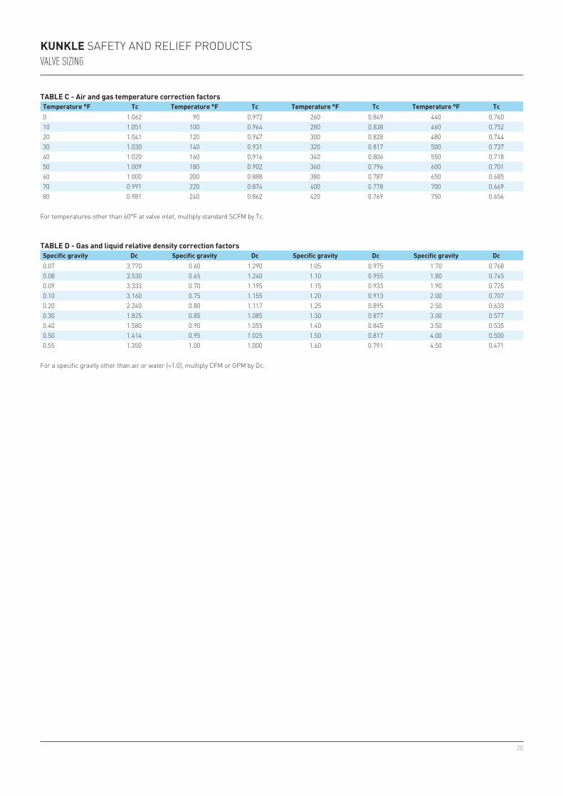
TaBle C - air and gas temperature correction factorsTemperature °F Tc Temperature °F Tc Temperature °F Tc Temperature °F Tc
TaBle D - Gas and liquid relative density correction factorsSpecific gravity Dc Specific gravity Dc Specific gravity Dc Specific gravity Dc
for temperatures other than 60°f at valve inlet, multiply standard scfM by tc.
for a specific gravity other than air or water (=1.0), multiply cfM or GpM by dc.
21
KunKle safety and relief productsValVe Sizing
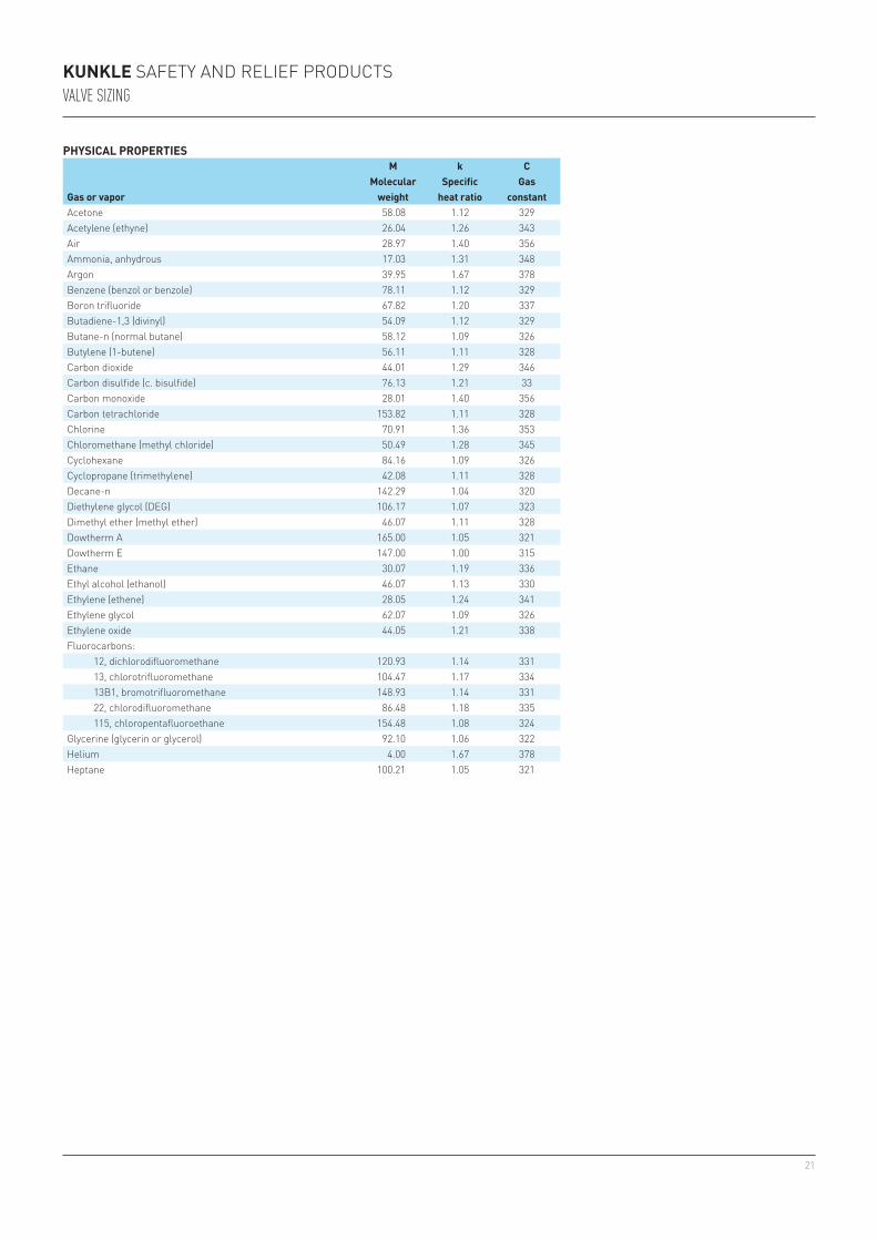
PHySICal ProPerTIeS
Gas or vapor
mmolecular
weight
kSpecific
heat ratio
CGas
constantacetone 58.08 1.12 329acetylene (ethyne) 26.04 1.26 343air 28.97 1.40 356ammonia, anhydrous 17.03 1.31 348argon 39.95 1.67 378Benzene (benzol or benzole) 78.11 1.12 329Boron trifluoride 67.82 1.20 337Butadiene-1,3 (divinyl) 54.09 1.12 329Butane-n (normal butane) 58.12 1.09 326Butylene (1-butene) 56.11 1.11 328carbon dioxide 44.01 1.29 346carbon disulfide (c. bisulfide) 76.13 1.21 33carbon monoxide 28.01 1.40 356carbon tetrachloride 153.82 1.11 328chlorine 70.91 1.36 353chloromethane (methyl chloride) 50.49 1.28 345cyclohexane 84.16 1.09 326cyclopropane (trimethylene) 42.08 1.11 328decane-n 142.29 1.04 320diethylene glycol (deG) 106.17 1.07 323dimethyl ether (methyl ether) 46.07 1.11 328dowtherm a 165.00 1.05 321dowtherm e 147.00 1.00 315ethane 30.07 1.19 336ethyl alcohol (ethanol) 46.07 1.13 330ethylene (ethene) 28.05 1.24 341ethylene glycol 62.07 1.09 326ethylene oxide 44.05 1.21 338fluorocarbons: 12, dichlorodifluoromethane 120.93 1.14 331 13, chlorotrifluoromethane 104.47 1.17 334 13B1, bromotrifluoromethane 148.93 1.14 331 22, chlorodifluoromethane 86.48 1.18 335 115, chloropentafluoroethane 154.48 1.08 324Glycerine (glycerin or glycerol) 92.10 1.06 322Helium 4.00 1.67 378Heptane 100.21 1.05 321

22
KunKle safety and relief productsValVe Sizing
PHySICal ProPerTIeS
Gas or vapor
mmolecular
weight
kSpecific heat
ratio
CGas
constantHexane 86.18 1.06 322Hydrogen 2.02 1.41 357Hydrogen chloride, anhydrous 36.46 1.41 357Hydrogen sulfide 34.08 1.32 349isobutane (2-methylpropane) 58.12 1.10 327isoprene (2-methyl-1, 3 butadiene) 68.12 1.09 326isopropyl alcohol (isopropanol) 60.10 1.09 326Krypton 83.80 1.71 380Methane 16.04 1.31 348Methyl alcohol (methanol) 32.04 1.20 337Methylamines, anhydrousMonomethylamine (methylamine) 31.06 1.02 317dimethylamine 45.08 1.15 332trimethylamine 59.11 1.18 335Methyl mercapton (methanethiol) 48.11 1.20 337naphthalene (napthaline) 128.17 1.07 323natural gas (specific gravity = 0.60) 17.40 1.27 344neon 20.18 1.64 375nitrogen 28.01 1.40 356nitrous oxide 44.01 1.30 347octane 114.23 1.05 321oxygen 32.00 1.40 356pentane 72.15 1.07 323propadiene (allene) 40.07 1.69 379propane 44.10 1.13 330propylene (propene) 42.08 1.15 332propylene oxide 58.08 1.13 330styrene 104.15 1.07 323sulfur dioxide 64.06 1.28 345sulfur hexafluoride 146.05 1.09 326steam 18.02 1.31 348toluene (toluol or methylbenzene) 92.14 1.09 326triethylene glycol (teG) 150.18 1.04 320Vinyl chloride monomer (VcM) 62.50 1.19 336Xenon 131.30 1.65 376Xylene (p-xylene) 106.17 1.07 323

23
KunKle safety and relief productsValVe Sizing
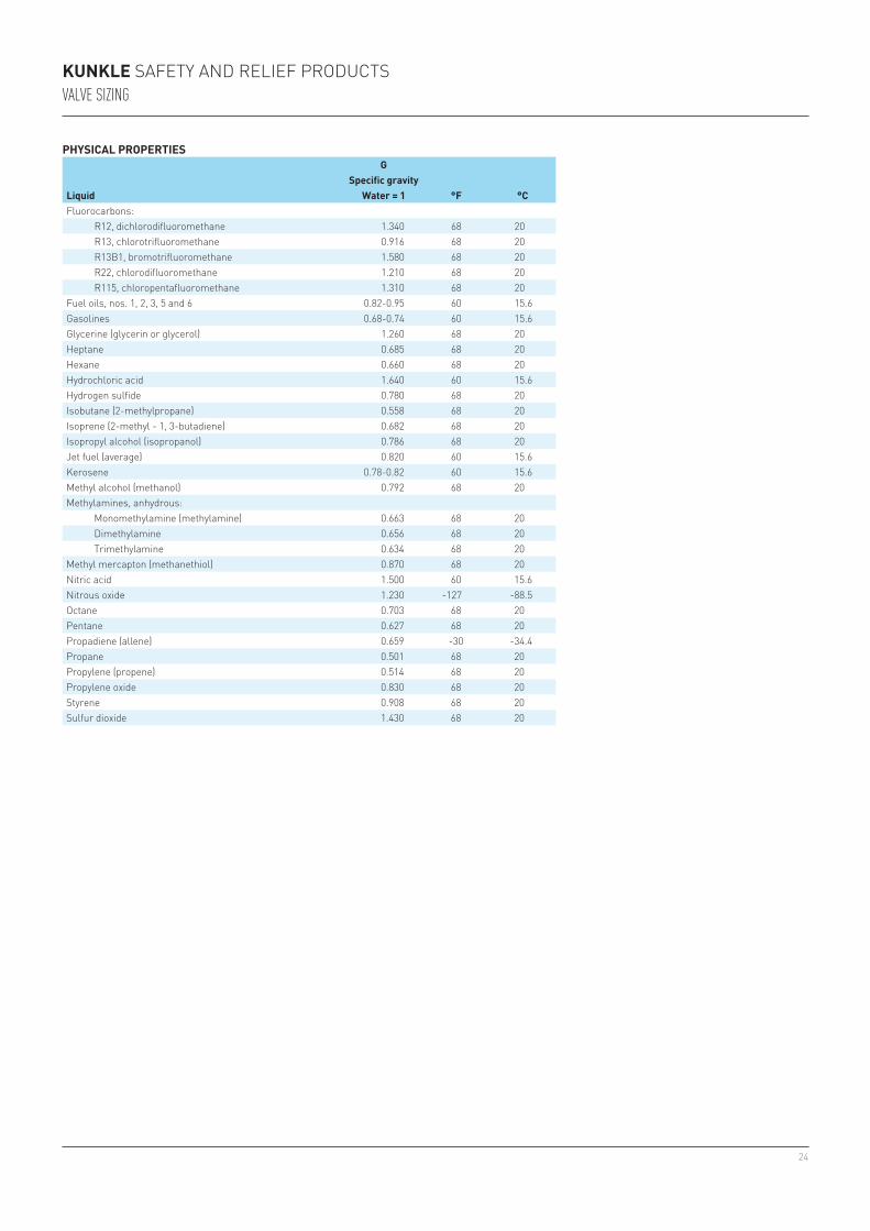
PHySICal ProPerTIeS
liquid
GSpecific gravity
Water = 1 °F °Cacetaldehyde 0.779 68 20acetic acid 1.051 68 20acetone 0.792 68 20ammonia, anhydrous 0.666 68 20automotive crankcase and gear oils:sae-5W through sae 150 0.88-0.94 60 15.6Beer 1.010 60 15.6Benzene (benzol) 0.880 68 20Boron trifluoride 1.570 -148 -100Butadiene - 1, 3 0.622 68 20Butane-n (normal butane) 0.579 68 20Butylene (1-butene) 0.600 68 20carbon dioxide 1.030 -4 -20carbon disulfide (c. bisulfide) 1.270 68 20carbon tetrachloride 1.600 68 20chlorine 1.420 68 20chloromethane (methyl chloride) 0.921 68 20crude oils: 32.6 deg api 0.862 60 15.6 35.6 deg api 0.847 60 15.6 40 deg api 0.825 60 15.6 48 deg api 0.790 60 15.6cyclohexane 0.780 68 20cyclopropane (trimethylene) 0.621 68 20decane-n 0.731 68 20diesel fuel oils 0.82-0.95 60 15.6diethylene glycol (deG) 1.120 68 20dimethyl ether (methyl ether) 0.663 68 20dowtherm a 0.998 68 20dowtherm e 1.087 68 20ethane 0.336 68 20ethyl alcohol (ethanol) 0.790 68 20ethylene (ethene) 0.569 -155 -104ethylene glycol 1.115 68 20ethylene oxide 0.901 68 20
24
KunKle safety and relief productsValVe Sizing
PHySICal ProPerTIeS
liquid
GSpecific gravity
Water = 1 °F °Cfluorocarbons: r12, dichlorodifluoromethane 1.340 68 20 r13, chlorotrifluoromethane 0.916 68 20 r13B1, bromotrifluoromethane 1.580 68 20 r22, chlorodifluoromethane 1.210 68 20 r115, chloropentafluoromethane 1.310 68 20fuel oils, nos. 1, 2, 3, 5 and 6 0.82-0.95 60 15.6Gasolines 0.68-0.74 60 15.6Glycerine (glycerin or glycerol) 1.260 68 20Heptane 0.685 68 20Hexane 0.660 68 20Hydrochloric acid 1.640 60 15.6Hydrogen sulfide 0.780 68 20isobutane (2-methylpropane) 0.558 68 20isoprene (2-methyl - 1, 3-butadiene) 0.682 68 20isopropyl alcohol (isopropanol) 0.786 68 20Jet fuel (average) 0.820 60 15.6Kerosene 0.78-0.82 60 15.6Methyl alcohol (methanol) 0.792 68 20Methylamines, anhydrous: Monomethylamine (methylamine) 0.663 68 20 dimethylamine 0.656 68 20 trimethylamine 0.634 68 20Methyl mercapton (methanethiol) 0.870 68 20nitric acid 1.500 60 15.6nitrous oxide 1.230 -127 -88.5octane 0.703 68 20pentane 0.627 68 20propadiene (allene) 0.659 -30 -34.4propane 0.501 68 20propylene (propene) 0.514 68 20propylene oxide 0.830 68 20styrene 0.908 68 20sulfur dioxide 1.430 68 20
25
1.0
0.9
0.8
0.7
0.6
0.5
0.4
0.3
10 20 40 60 100 200 400 1,000 2,000 10,000 20,000 100,000
R = Reynolds Number
Kv
= V
isco
sity
Co
rrec
tio
n F
acto
rKunKle safety and relief productsValVe Sizing
PHySICal ProPerTIeS
liquid
GSpecific gravity
Water = 1 °F °Csulfur hexafluoride 1.37 68 20sulfuric acid: 95-100% 1.839 68 20 60% 1.50 68 20 20% 1.14 68 20toluene (toluol or methylbenzene) 0.868 68 20triethylene glycol (teG) 1.126 68 20Vinyl chloride monomer (VcM) 0.985 -4 -20Water, fresh 1.00 68 20Water, sea 1.03 68 20Xylene (p-xylene) 0.862 68 20
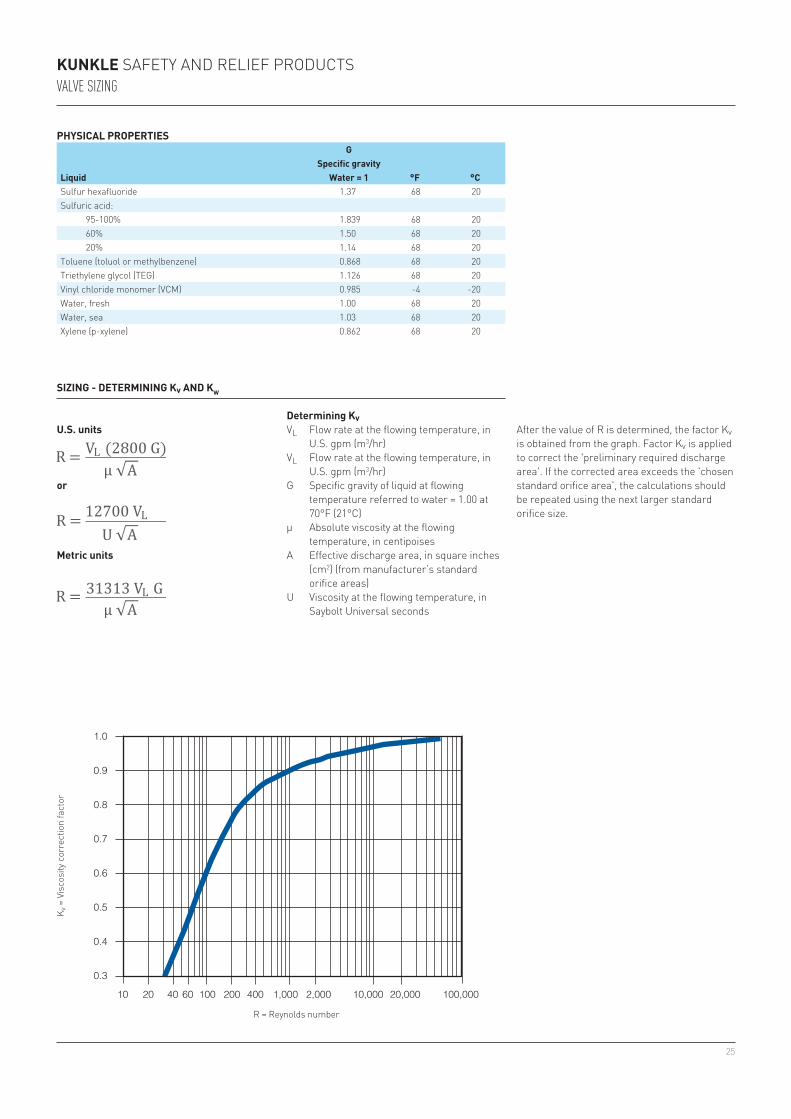
SIzInG - DeTermInInG Kv anD KW
Determining KvVl flow rate at the flowing temperature, in
u.s. gpm (m3/hr)Vl flow rate at the flowing temperature, in
u.s. gpm (m3/hr)G specific gravity of liquid at flowing
temperature referred to water = 1.00 at 70°f (21°c)
µ absolute viscosity at the flowing temperature, in centipoises
a effective discharge area, in square inches (cm2) (from manufacturer’s standard orifice areas)
u Viscosity at the flowing temperature, in saybolt universal seconds
u.S. units
or
metric units
K v =
Vis
cosi
ty c
orre
ctio
n fa
ctor
r = reynolds number
after the value of r is determined, the factor Kv is obtained from the graph. factor Kv is applied to correct the 'preliminary required discharge area'. if the corrected area exceeds the 'chosen standard orifice area', the calculations should be repeated using the next larger standard orifice size.
26
KunKle safety and relief productsconVeRSion facToRS
aBSoluTe VISCoSITy
Given
To find desired value, multiply “Given” value by factor below
poise Centipoisegm
cm-seclb
ft-secpoise - 100 1 0.0672centipoise 0.01 - 0.01 0.000672gmcm-sec
1.00 100 - 0.0672
lbft-sec
14.88 1488 14.88 -
noTeS1. Kinematic viscosity x specific gravity =
absolute viscosity.2. centistokes x specific gravity = centipoise.3. saybolt second universal (ssu) x 0.216 x specific
gravity = centipoise.
noTe1. G = specific gravity of liquid at its relieving
temperature compared to that of water at 68°f (20°c), where Gwater = 1.00.
lIquID FloW ConVerSIonS
GivenTo find desired value, multiply “Given” value by factor below
l/hr gpm - uS gpm - Imp barrels/day m3/hrl/hr(litres/hour)
- 0.00440 0.003666 0.1510 0.0010
gpm(us gallons per minute)
227.1 - 0.8327 34.29 0.2271
gpm(imperial gallons per minute)
272.8 1.201 - 41.18 0.2728
barrels/day(petroleum - 42 us gallons)
6.624 0.02917 0.02429 - 0.006624
m3/hr(cubic meters per hour)
1000 4.403 3.666 151.0 -
m3/s(cubic meters per second)
3.6 x 10⁶ 0.02917 0.02429 - 0.006624
kg/hr(kilograms per hour)
1G
1227.1G
1272.8G
0.151G
11000G
lb/hr(pounds per hour)
12.205G
1500.8G
1601.5G
114.61G
12205G
KInemaTIC VISCoSITy
Given
To find desired value, multiply “Given” value by factor below
stoke Centistokecm2
secft2
secstoke - 100 1 0.001076centistoke 0.01 - 0.01 1.076 x 10⁻⁵cm2
sec1 100 - 0.001076
ft2
sec929.00 92900 929.00 -
27
KunKle safety and relief productsconVeRSion facToRS
PreSSure ConVerSIon
GivenTo find desired value, multiply “Given” value by factor belowkPa psig kg/cm2 barg
kpa (kilopascal) - 0.1450 0.0102 0.0100psig (pounds/in2)3 6.895 - 0.0703 0.06895kg/cm2(1)(kilograms/cm2) 98.07 14.22 - 0.9807barg 100.00 14.50 1.020 -
noTeS1. also expressed as kp/cm2 and kgf/cm2.2. normal temperature and pressure (ntp)
conditions are, at sea level, equal to 1.013 bara or 1.033 kg/cm2 (kilograms force per square centimeter absolute) at a base temperature of 32°f (0°c). this differs slightly from Metric standard conditions (Msc), which uses 1.013 bara 60°f (15°c) for the base temperature.
3. inch-pound standard conditions are, at sea level, equal to 14.7 psia (pounds force per square inch absolute), rounded up from 14.696 psia, and at a base temperature of 60°f (16°c).
GaS FloW ConVerSIonS
GivenTo find desired value, multiply “Given” value by factor below
scfm scfh lb/hr (kg/hr) (nm3/hr) (nm3/min)scfm2 - 60 M
6.32M
13.931.608 0.0268
scfh2 0.01677 - M379.2
M836.1
0.0268 0.000447
lb/hr3 or#/hr3
6.32M
379.2M
- 0.4536 10.17M
0.1695M
kg/hr4 13.93M
836.1M
2.205 - 22.40M
0.3733M
nm3/hr5 0.6216 37.30 M10.17
M22.40
- 0.01667
nm3/min5 37.30 2238 5.901 M 2.676 M 60 -
noTeS1. M = molecular weight of vapor or gas.2. Volumetric flow (per time unit of hour or minute as
shown) in standard cubic feet per minute at 14.7 psia (1.013 bara), 60°f (16°c).
3. Weight flow in pounds per hour.4. Weight flow in kilograms per hour.5. Volumetric flow (per time unit of hour or minute as
shown) at 1.013 bara 32°f (0°c). this represents the commercial standard, known as the normal temperature and pressure (ntp).
conversions from one volumetric flow rate to another or to weight flow (and vice versa) may only be done when the volumetric flow is expressed in the standard conditions shown above. if flows are expressed at temperature or pressure bases that differ from those listed above, they must first be converted to the standard base.
if flow is expressed in actual volume, such as cfm (cubic feet per minute) or acfm (actual cfm) as is often done for compressors, where the flow is described as
Inch-Pound units
Where:p = gauge pressure of gas or vapor in psigt = temperature of gas or vapor in °f
displacement or swept volume, the flow may be converted to scfm as follows (or from flow expressed in m3/hr to nm3/hr).
metric units
Where:p = gauge pressure of gas or vapor in bargt = temperature of gas or vapor in °c
TemPeraTure ConVerSIonDegrees Celsius (°C) Degrees Fahrenheit (°F)c + 273.15 = K (Kelvin) f + 459.67 = r (rankine)(c x 1.8) + 32 = f (fahrenheit) (f - 32) x 0.556 = c (celsius)
area ConVerSIon
GivenTo find desired value, multiply “Given” value by factor below
in2 ft2 mm2 cm2
in2 - 0.006944 645.16 6.4516cm2 0.155 1.076 x 10⁻³ 100 -ft2 144.000 - 92900 929.00mm2 0.00155 1.076 x 10⁻⁵ - 0.01
28
KunKle safety and relief products
InSTallaTIon
1. Before installing a new safety/relief valve, we recommend that a pipe tap be used to assure clean-cut and uniform threads in the vessel opening and to allow for normal hand engagement followed by a half to one turn by wrench.
2. install the valve in a vertical position so that discharge piping and code required drains can be properly piped to prevent build-up of back pressure and accumulation of foreign material around the valve seat area.
3. avoid over-tightening as this can distort safety/relief valve seats. one need only remember that as the vessel and valve are heated, the expansion involved will grasp the valve more firmly.
4. When installing flange connected valves, use new gaskets and draw the mounting bolts down evenly.
5. do not use the valve outlet or cap as a lever for installation. use only flat jawed wrenches on the flats provided.
6. avoid excessive 'popping' of the safety/relief valve as even one opening can provide a means for leakage. safety/relief valves should be operated only often enough to assure that they are in good working order.
7. avoid wire, cable, or chain pulls for attachment to levers that do not allow a vertical pull. the weight of these devices should not be directed to the safety/relief valve.
8. avoid having the operating pressure too near the safety/relief valve set pressure. a very minimum differential of 5 psig or 10 percent (whichever is greater) is recommended. an even greater differen tial is desirable, when possible, to assure better seat tightness and valve longevity. safety/relief valves in high-temperature hot water and organic fluid service are more susceptible to damage and leakage than safety valves for steam. it is recommended that the maximum allowable working pressure of the boiler and the safety/relief valve setting be selected substantially higher than the op erating pressure. a differential of 30-40 percent is recommended.
9. avoid discharge piping where its weight is carried by the safety/relief valve. even though supported separately, changes in temp erature alone can cause piping strain. We recommend that drip pan elbows or flexible connections be used wherever possible (see type a, B, c installation, page 29).
10. apply a moderate amount of pipe compound to male threads only, leaving the first thread clean. compound applied to female threads or used to excess can find its way into the valve, causing leakage.
29
KunKle safety and relief productsinSTallaTion
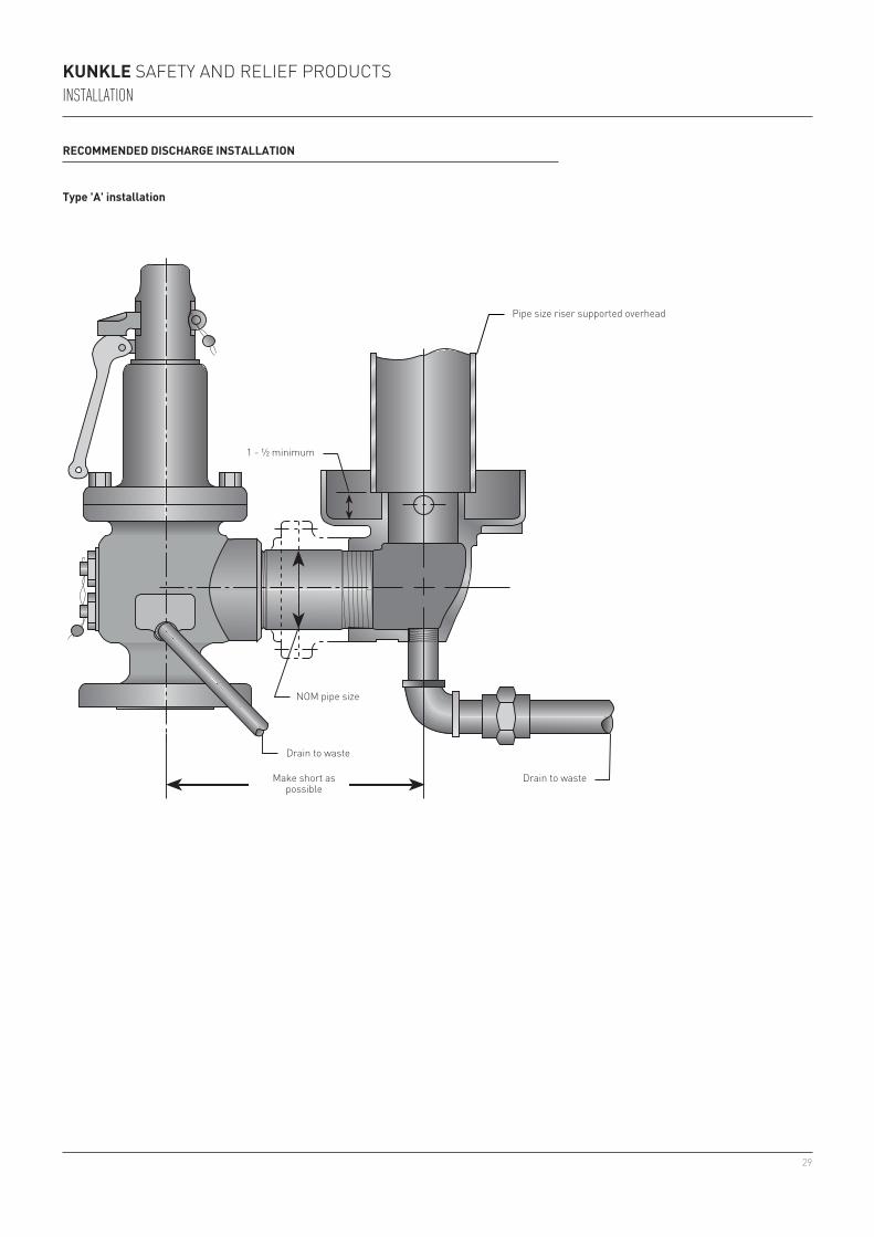
reCommenDeD DISCHarGe InSTallaTIon
Type 'a' installation
pipe size riser supported overhead
drain to waste
noM pipe size
drain to waste
Make short as possible
1 - ½ minimum

30
KunKle safety and relief productsinSTallaTion
reCommenDeD DISCHarGe InSTallaTIon
Type 'B' installation
pipe nipple
Hose
Bushing one size larger than outlet
clamps
pipe to discharge
12" min.
31
KunKle safety and relief productsinSTallaTion
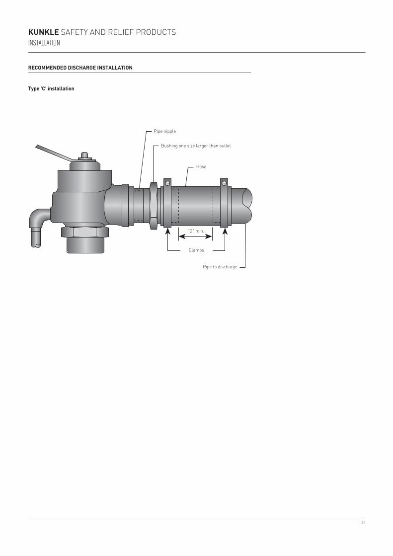
reCommenDeD DISCHarGe InSTallaTIon
Type 'C' installation
pipe nipple
Bushing one size larger than outlet
Hose
12" min.
clamps
pipe to discharge
32
KunKle safety and relief products
maInTenanCe
1. develop a regular program of visual inspection, looking for clogged drains and discharge pipe, dirt build-up in and around the valve seat and broken or missing parts.
2. test the valve every two to six months (depending on valves’ age and condition) preferably by raising the system pressure to the valves set pressure or operating the hand lever (see #3 in operation).
3. do not paint, oil, or otherwise cover any interior or working parts of any safety valve. they do not require any lubrication or protective coating to work properly.
When safety/relief valves require repair, service adjustments, or set pressure changes, work shall be accomplished by the manufacturer, or holders of 'V', 'uV', and/or 'Vr' stamps.