
KUHNKE Instruction Manual - banulscys.com Instruction Manual AirBox – ... This instruction manual...
70
KUHNKE Instruction Manual AirBox – Pneumatic module for AS-Interface E 705 GB 18.05.2006 / 107.071
Transcript of KUHNKE Instruction Manual - banulscys.com Instruction Manual AirBox – ... This instruction manual...

KUHNKE Instruction Manual AirBox – Pneumatic module for AS-Interface
E 705 GB 18.05.2006 / 107.071

This instruction manual is primarily intended for use by design, project and development engineers. It does not contain any availability information. Data is only given to describe the product and must not be regarded as guaranteed properties in the legal sense. Any claims for damages - on whatever legal grounds - are excluded except for instances of deliberate intent or gross negligence on our part. We reserve the rights for errors, omissions and modifications. Reproduction even of extracts only with the editor's express and written prior consent.
AirBox
E 705 GB 3
Table of Contents 1 Introduction......................................................................................................................................................6
1.1 AS-Interface in automation ..................................................................................................................6 1.1.1 Cost-effectiveness, ease of assembly and maintenance...................................................................6 1.1.2 The AS-Interface on the periphery of networks .................................................................................6 1.1.3 Levels of Automation..........................................................................................................................7
1.2 Experienced Box Crew ........................................................................................................................7 1.2.1 AS-i Fieldbus instead of hard-wiring ..................................................................................................7 1.2.2 Plug & Play.........................................................................................................................................7 1.2.3 Diagnostics.........................................................................................................................................8 1.2.4 Increase in productivity ......................................................................................................................8 1.2.5 ATEX ..................................................................................................................................................8
2 Reliability, Safety .............................................................................................................................................9 2.1 Intended Use........................................................................................................................................9 2.2 Target Group........................................................................................................................................9 2.3 Reliability..............................................................................................................................................9 2.4 Symbols ...............................................................................................................................................9
2.4.1 Danger................................................................................................................................................9 2.4.2 Attention ...........................................................................................................................................10 2.4.3 Note..................................................................................................................................................10 2.4.4 Under Construction ..........................................................................................................................10 2.4.5 Instruction.........................................................................................................................................10
2.5 Safety .................................................................................................................................................10 2.5.1 Project Planning and Installation......................................................................................................11 2.5.2 Maintenance and Servicing..............................................................................................................11
2.6 Electromagnetic Compatibility............................................................................................................12 2.6.1 Definition ..........................................................................................................................................12 2.6.2 Interference Emission ......................................................................................................................12 2.6.3 General Notes on Installation...........................................................................................................12 2.6.4 Electrical Interference Safeguard.....................................................................................................12 2.6.5 Cable Routing and Wiring ................................................................................................................13 2.6.6 Location of Installation .....................................................................................................................13 2.6.7 Particular Sources of Interference....................................................................................................13
3 Pneumatic Basics ..........................................................................................................................................14 3.1 Symbols .............................................................................................................................................14 3.2 Type of Valve .....................................................................................................................................14
3.2.1 Pneumatic Pilot Controlled Valves ...................................................................................................14 3.2.2 Poppet valve or slide damper?.........................................................................................................14
3.3 Pneumatic Use...................................................................................................................................14 3.3.1 Single-acting actuators.....................................................................................................................14 3.3.2 3/2-way valve with single-acting cylinders .......................................................................................14 3.3.3 Double-acting actuators ...................................................................................................................14 3.3.4 4/2-way valve with double-acting cylinder........................................................................................14
3.4 Flows / tube length.............................................................................................................................14 4 How to make proper use of compressed air..................................................................................................14
4.1 Accessories........................................................................................................................................14 4.1.1 Cylinders ..........................................................................................................................................14 4.1.2 Valves...............................................................................................................................................14 4.1.3 AirBox...............................................................................................................................................14
4.2 Purity of compressed air ....................................................................................................................14

AS-Interface
4 E 705 GB
4.2.1 Compressed air purity specification .................................................................................................14 4.2.2 General information..........................................................................................................................14 4.2.3 Humidity content and pressure dew point........................................................................................14 4.2.4 Admissible lubricants .......................................................................................................................14 4.2.5 Further information...........................................................................................................................14
5 AS-Interface Basics .......................................................................................................................................14 5.1 Piercing technology............................................................................................................................14 5.2 Network topology ...............................................................................................................................14 5.3 Checklist for beginners and experienced users.................................................................................14 5.4 Mounting Hints ...................................................................................................................................14
5.4.1 General Assembly tricks ..................................................................................................................14 5.4.2 Ten valuable mounting hints ............................................................................................................14
6 KUHNKE Products ........................................................................................................................................14 6.1 AirBox 1/32.........................................................................................................................................14
6.1.1 Overview AirBox 1............................................................................................................................14 6.1.2 Overview Airbox 32 ..........................................................................................................................14 6.1.3 Application........................................................................................................................................14 6.1.4 Installation / Wiring...........................................................................................................................14 6.1.5 Putting into Service ..........................................................................................................................14 6.1.6 Logical Assignment AirBox 1 ...........................................................................................................14 6.1.7 Logical Assignment AirBox 32 .........................................................................................................14 6.1.8 Notes ................................................................................................................................................14 6.1.9 Dimensions.......................................................................................................................................14 6.1.10 Technical Data (as per AS-I specification).....................................................................................14
6.2 Overview AirBox K .............................................................................................................................14 6.2.1 Application........................................................................................................................................14 6.2.2 Installation / Wiring...........................................................................................................................14 6.2.3 Connector.........................................................................................................................................14 6.2.4 Putting into Service ..........................................................................................................................14 6.2.5 Logical assignments (PLC output bit to function of the pneumatic module) ...................................14 6.2.6 Status LEDs and their operating states ...........................................................................................14 6.2.7 Notes ................................................................................................................................................14 6.2.8 Functional Principle (with double acting cylinders) ..........................................................................14 6.2.9 Dimensions.......................................................................................................................................14 6.2.10 Technical Data (as per AS-I specification).....................................................................................14
6.3 Other AS-I slave modules ..................................................................................................................14 6.3.1 Concept ............................................................................................................................................14 6.3.2 Active and Passive Modules ............................................................................................................14
6.4 Coupling module for AirBox 1/32 .......................................................................................................14 6.4.1 Application range..............................................................................................................................14 6.4.2 Assembly instructions ......................................................................................................................14 6.4.3 Installation ........................................................................................................................................14
7 Pneumatic characteristics..............................................................................................................................14 7.1 AirBox 1/32.........................................................................................................................................14
7.1.1 Equivalent diagram ..........................................................................................................................14 7.1.2 What happens in case of compressed air failure? ...........................................................................14
7.2 AirBox K .............................................................................................................................................14 7.2.1 Equivalent diagram ..........................................................................................................................14 7.2.2 What happens in case of compressed air failure .............................................................................14
7.3 AirBox Valve functionality ..................................................................................................................14

AirBox
E 705 GB 5
7.3.1 3/2-way valves (nc) ..........................................................................................................................14 7.3.2 3/2-way valve (no)............................................................................................................................14 7.3.3 4/2-way valve ...................................................................................................................................14 7.3.4 5/2-way valve ...................................................................................................................................14 7.3.5 5/3-way valve, starting position ventilates........................................................................................14 7.3.6 5/3-way valve, starting position blocked ..........................................................................................14 7.3.7 5/3-way valve, starting position pressurises ....................................................................................14
8 Electrical characteristics ................................................................................................................................14 8.1 Symbol description.............................................................................................................................14 8.2 AirBox 1..............................................................................................................................................14
8.2.1 With single-acting cylinder ...............................................................................................................14 8.3 AirBox 32............................................................................................................................................14
8.3.1 With single-acting cylinder ...............................................................................................................14 8.3.2 With double-acting cylinder ..............................................................................................................14 8.3.3 Operating without auxiliary 24V supply............................................................................................14
8.4 AirBox K, monostable ........................................................................................................................14 8.4.1 Behaviour in case of AS-I voltage failure .........................................................................................14 8.4.2 Behaviour in case of failure in the 24V supply .................................................................................14 8.4.3 Behaviour in case of failure in the 24 V suppy.................................................................................14
8.5 AirBox K, electrically bistable.............................................................................................................14 8.5.1 Behaviour in case of AS-i voltage failure .........................................................................................14 8.5.2 Behaviour in case of failure in the 24V supply .................................................................................14 8.5.3 Behaviour in case of failure in the 24V supply .................................................................................14
9 Special information for ATEX AirBox.............................................................................................................14 9.1 Remarks for safe use in hazardous areas .........................................................................................14
9.1.1 Function and features ......................................................................................................................14 9.1.2 Installation /Setup.............................................................................................................................14 9.1.3 Installation remarks/Mounting ..........................................................................................................14 9.1.4 Special conditions for safe operation ...............................................................................................14 9.1.5 Maintenance /Repair ........................................................................................................................14
10 Appendix......................................................................................................................................................14 10.1 Order Specifications .......................................................................................................................14
10.1.1 Order Data AirBox 1.......................................................................................................................14 10.1.2 Order Data AirBox 32.....................................................................................................................14 10.1.3 Order Data AirBox K ......................................................................................................................14
10.2 FAQs ..............................................................................................................................................14 10.3 References .....................................................................................................................................14 10.4 Index...............................................................................................................................................14 10.5 Sales & Service ..............................................................................................................................14
10.5.1 Main Factory in Malente.................................................................................................................14

AS-Interface
6 E 705 GB
1 Introduction
1.1 AS-Interface in automation Industry has placed many demands on modern automation systems, requiring also that the necessary functions be offered at a good price/performance ratio. The AS-Interface system meets this requirement not only through its modular expandability. The objective in its creation was not a universal field bus for all areas of automation, but rather an economically reasonable system for the lower field level. The AS-Interface was developed in order to network binary sensors and actuators to the higher control level. Important development objectives included simple and cost-effective assembly with low wiring costs.
1.1.1 Cost-effectiveness, ease of assembly and maintenance The interface is an enduring part of the modern industrial landscape. Many sensors and actuators can be networked through the 2-wire cable, which also supplies the power. By eliminating the cable trees of traditional cabling and replacing them with the yellow AS-Interface cable, significant cost reductions through simple wiring without a lot of training are the result. Thanks to its simple, defined electromechanical interface the AS-Interface can be installed without the need for any special expertise. The "Snap and Go" cable penetration system has proven itself. The freely selectable network topology and ease of configuration make installation that much easier. Ease of assembly requiring little prior knowledge reduces downtime when faults occur. The fault susceptibility of other systems often results in assembly delays, so the AS-Interface was consciously designed to reduce error sources. The special profile of the AS-Interface cable prevents reversal of the poles when connecting devices, and is just one example of the measures taken to reduce error frequency. Installation, a large cost factor, is drastically reduced by using the system. The low installation costs show the AS-Interface to be a technically and economically realistic solution to the normal fieldbus.
1.1.2 The AS-Interface on the periphery of networks The AS-Interface, which is more an intelligent form of cabling than a true fieldbus, neither can nor intends to replace complex networks. But on the lower level of industrial communication, the Sensor/Actuator Level, the system stands out with its simple and cost-effective solutions. Modern studies even verify the economical advantage to integrating the AS-Interface with switches and buttons on control panels. The low added cost of the AS-Interface Slave Chip are made up for by the reduced wiring expense. For quite some time already there have been gateways, links or other bus couplers for all the usual fieldbus systems (e.g. CAN, DeviceNet, Ethernet, Interbus, Profibus and others). The high capability for integrating into other networks makes the modular construction of automation networks just that much easier. Cost-effective, rugged AS-Interface components are especially suited for use in harsh industrial environments.
AirBox
E 705 GB 7
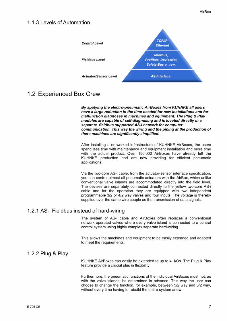
1.1.3 Levels of Automation
1.2 Experienced Box Crew By applying the electro-pneumatic AirBoxes from KUHNKE all users have a large reduction in the time needed for new installations and for malfunction diagnoses in machines and equipment. The Plug & Play modules are capable of self-diagnosing and is located directly in a separate fieldbus supported AS-I network for computer communication. This way the wiring and the piping at the production of there machines are significantly simplified. After installing a networked infrastructure of KUHNKE AirBoxes, the users spend less time with maintenance and equipment installation and more time with the actual product. Over 150.000 AirBoxes have already left the KUHNKE production and are now providing for efficient pneumatic applications. Via the two-core AS-i cable, from the actuator-sensor interface specification, you can control almost all pneumatic actuators with the AirBox, which unlike conventional valve islands are accommodated directly into the field level. The devises are separately connected directly to the yellow two-core AS-i cable and for the operation they are equipped with two independent programmable 3/2 or 4/2 way valves and four inputs. The voltage is thereby supplied over the same wire couple as the transmission of data signals.
1.2.1 AS-i Fieldbus instead of hard-wiring The system of AS-i cable and AirBoxes often replaces a conventional network operated valves where every valve island is connected to a central control system using highly complex separate hard-wiring. This allows the machines and equipment to be easily extended and adapted to meet the requirements.
1.2.2 Plug & Play KUHNKE AirBoxes can easily be extended to up to 4 I/Os. The Plug & Play feature provide a crucial plus in flexibility. Furthermore, the pneumatic functions of the individual AirBoxes must not, as with the valve islands, be determined in advance. This way the user can choose to change the function, for example, between 5/2 way and 3/2 way, without every time having to rebuild the entire system anew.

AS-Interface
8 E 705 GB
1.2.3 Diagnostics In case of failure or malfunction of any AS-i network components, an indicator light, for example, can accurately pinpoint the source of the malfunction. Since the AirBoxes are connected directly to the fieldbus cable, you can use this diagnostics in a way that the decentralised valve islands cannot provide. The AirBoxes directly connected to the AS-i cable conduct a self diagnostics. With the new AirBox system, the fault clearance normally lasts between 15 and 20 minutes. Previously, six hours was not uncommon. This flexibility is very important to the modern user: “The AirBox with AS-i takes the modular approach in an ideal way, since all the I/Os are easily attached and then reattached elsewhere according to the requirements – a flexibility we frequently need. The result is that today we need just about a month for the entire set-up and start-up of a new segment. Compared to the hard-wired valve island this means time savings of 60%. There is always something to change here and something to add there. The AirBox apply such changes with no restrictions whatsoever."
1.2.4 Increase in productivity “As a result we work today with the largest possible efficiency; but we could never provide our customers with such short handling time. The AirBox has more then fulfilled our expectations on the productivity. If it works, the set-up time is reduced to less than half and thanks to the quick diagnosis of the AirBox the downtime is also considerably shortened, the day now easily has a lot more time for production.”
1.2.5 ATEX The field of dust explosion control gets more and more important to many businesses. Gripping, holding, transporting, filling – and also in dust explosion hazardous areas – the KUHNKE AirBox 32 and AirBox K are now also available with an ATEX-licence for zone 22.
AirBox
E 705 GB 9
2 Reliability, Safety
2.1 Intended Use KUHNKE products are designed as resources for use in industrial environments. All other applications need to be discussed with the factory first. The manufacturer shall neither be liable for any other than the intended use of our products nor for any ensuing damages. The risk shall be borne by the operator alone. The use as intended includes that you read and apply all information and instructions contained in this manual.
2.2 Target Group This instruction manual contains all information necessary for the use of the described product (control device, control terminal, software, etc.) according to instructions. It is written for design, project planning, servicing and commissioning experts. For proper understanding and error-free application of technical descriptions, instructions for use and particularly of notes of danger and warning, extensive knowledge of automation technology is compulsory.
2.3 Reliability Reliability of KUHNKE products is brought to the highest possible standards by extensive and cost-effective means in their design and manufacture. These include: • selecting high-quality components, • quality agreements with our suppliers, • actions to avoid static charges when handling MOS circuits, • worst case planning and design of all circuits, • visual inspections at various stages of fabrication, • computer-aided tests of all assemblies and their interaction in the circuit, • statistical assessment of the quality of fabrication and of all returned
goods for the immediate taking of appropriate corrective actions.
2.4 Symbols Despite the measures described in chapter 2.3 the occurrence of faults or errors in electronic control units - even if most highly improbable - must be taken into consideration. Please pay particular attention to the additional notices which we have marked by symbols throughout this instruction manual. While some of these notices make you aware of possible dangers, others are intended as a means of orientation. They are described further down below in descending order of importance.
2.4.1 Danger
This symbol warns you of dangers which may cause death or grievous bodily harm if operators fail to implement the precautions described.

AS-Interface
10 E 705 GB
2.4.2 Attention
This symbol draws your attention to information you must take a look at to avoid malfunctions, possible material damage or dangerous states.
2.4.3 Note
This symbol draws your attention to additional information concerning the use of the described product. This may include cross references to information found elsewhere (e.g. in other manuals).
2.4.4 Under Construction
This symbol tells you that the function described was not or not fully available at the time this document went to press.
2.4.5 Instruction
Wherever you see these symbols in the left margin, you will find a list of steps instructing you to take the appropriate computer or hardware actions. They are intended as a means of orientation wherever working steps and background information alternate (e.g. in tutorials).
2.5 Safety Our products normally become part of larger systems or installations. The information below is intended to help you integrate the product into its environment without dangers to humans or material/equipment.
To achieve a high degree of conceptual safety in planning and installing an electronic controller, it is essential to exactly follow the instructions given in the manual because wrong handling could lead to rendering measures against dangers ineffective or to creating additional dangers.
AirBox
E 705 GB 11
2.5.1 Project Planning and Installation • 24 VDC power supply: generate as electrically safely separated low
voltage. Suitable devices are, for example, split transformers constructed in compliance with European Standard EN 60742 (corresponds to VDE 0551).
• In case of power breakdowns or power fades: the program structure is to ensure that a defined state at restart excludes all dangerous states.
• Emergency switch-off installations must comply with EN 60204/IEC 204 (VDE 0113). They must be effective at any time.
• Safety and precautions regulations for qualified applications have to be complied with.
• Please pay particular attention to the notices of warning which, at relevant places, will make you aware of possible sources of dangerous mistakes or faults.
• Relevant standards and VDE regulations are to be complied with in every case.
• Install control elements such that unintended operation is excluded. • Lay control cables such that interference (inductive or capacitive) is
excluded if this interference could influence controller operation or its functionality.
2.5.2 Maintenance and Servicing • Precautions regulation VBG 4.0 must be observed when measuring or
checking a controller in a power-up condition. This applies to section 8 (Admissible deviations when working on parts) in particular.
• Repairs must be carried out by specially trained KUHNKE staff only (usually in the main factory in Malente). Warranty expires in every other case.
• Spare parts: • Only use parts approved of by KUHNKE. Only genuine KUHNKE
modules must be used in modular controllers. • Modular systems: always plug or unplug modules in a power-down state.
You might otherwise damage the modules or (possibly not immediately recognisably!) inhibit their functionality.
• Always dispose of any batteries and accumulators as hazardous waste.
AS-Interface
12 E 705 GB
2.6 Electromagnetic Compatibility
2.6.1 Definition Electromagnetic compatibility is the ability of a device to function satisfactorily in its electromagnetic environment without itself causing any electromagnetic interference that would be intolerable to other devices in this environment. Of all known phenomena of electromagnetic noise, only a certain range occurs at the location of a given device. These kinds of noise are specified in the applicable product standards. The design and immunity to interference of programmable logic controllers are internationally governed by standard IEC 61131-2 which, in Europe, has been the basis for European Standard EN 61131-2.
Refer to IEC 61131-4, User's Guideline, for general installation instructions to be complied with to ensure that hardware interface factors and the ensuing noise voltages are limited to tolerable levels.
2.6.2 Interference Emission Interfering emission of electromagnetic fields, HF compliant to EN 55011, limiting value class B.
If the controller is designed for use in residential areas, high-frequency emissions must comply with limiting value class B as described in EN 55011. Fitting the controller into earthed metal cabinets and in-stalling filters in the supply lines may produce a shielding compliant to the above standard.
2.6.3 General Notes on Installation As component parts of machines, facilities and systems, electronic control systems must comply with valid rules and regulations, depending on their field of application. General requirements concerning the electrical equipment of machines and aiming at the safety of these machines are contained in Part 1 of European Standard EN 60204 (corresponds to VDE 0113).
For safe installation of our control system please observe the information contained in the next chapters (� 2.6.4 ff).
2.6.4 Electrical Interference Safeguard Connect the control system to the protective earth conductor to eliminate electromagnetic interference. Practice best cable routing.
AirBox
E 705 GB 13
2.6.5 Cable Routing and Wiring Keep power circuits separate from control circuits: • DC voltages 60 V ... 400 V • AC voltages 25 V ... 400 V Joint laying of control circuits is allowed for: • shielded data signals • shielded analogue signals • unshielded digital I/O lines • unshielded DC voltages < 60 V • unshielded AC voltages < 25 V
2.6.6 Location of Installation Ensure that temperatures, contaminations, impact, vibration or electromagnetic interference are no impediment to the installation.
2.6.6.1 Temperature Consider heat sources such as general heating of rooms, sunlight, heat accumulation in assembly rooms or control cabinets.
2.6.6.2 Contamination Use suitable casings to avoid possible negative influences due to humidity, corrosive gas, liquid or conducting dust.
2.6.6.3 Impact and Vibration Consider possible influences caused by motors, compressors, transfer lines, presses, ramming machines and vehicles.
2.6.6.4 Electromagnetic Interference Consider electromagnetic interference from various local sources: motors, switching devices, switching thyristors, radio-controlled devices, welding equipment, arcing, switched-mode power supplies, converters / inverters.
2.6.7 Particular Sources of Interference
2.6.7.1 Inductive Actuators Switching off inductances (such as from relays, contactors, solenoids or switching magnets) produces surge voltages. It is mandatory to throttle these noise voltages to an admissible dimension. Throttling elements could be diodes, Z diodes, varistors or RC elements. To find the best adapted elements, we recommend that you contact the manufacturer or supplier of the corresponding actuators for the relevant information.

AS-Interface
14 E 705 GB
3 Pneumatic Basics
3.1 Symbols 4/2-way valve
2 Operating positions
Off- position
On- position
4 controlled connections
= Line + Flow course
= Stop

AirBox
E 705 GB 15
4 2
3 13 (R)1 (P)
4(A)2 (B)
Operating line : 2, 4, (A, B) Compressed air connection : 1,(P) Exhaust : 3, (R)
Via button
Manual override
Electrical operation
Pneumatic pilot valve
Electromagnet
Mechanic operation via spring
Reset with spring: - for short response time
Electrical operation
Pneumatic pilot valve
Electromagnet
AS-Interface
16 E 705 GB
3.2 Type of Valve There are: • directly actuated valves (exclusive solenoid systems with larger
dimensions by using large spools are necessary) • pilot controlled valves (in AS-i pneumatic module)
pilot controlled valves
= Pilot control solenoid system (3/2-way valve with small nominal size)
+ Pneumatically operated main valve
3.2.1 Pneumatic Pilot Controlled Valves
Operating method: • The control piston is pressurised with pilot air • The valve tappet rod is reversed against the spring force • The valve is energised through the continual pressurisation of the control
piston.
• After the exhaust of the control line, the valve tappet rods are reset to their start position by a built-in spring.
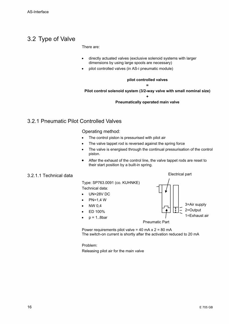
3.2.1.1 Technical data Type: SP763.0091 (co. KUHNKE) Technical data: • UN=28V DC • PN=1,4 W • NW 0,4 • ED 100% • p = 1..8bar
Power requirements pilot valve = 40 mA x 2 = 80 mA The switch-on current is shortly after the activation reduced to 20 mA Problem: Releasing pilot air for the main valve
Pneumatic Part
3=Air supply 2=Output 1=Exhaust air
Electrical part
AirBox
E 705 GB 17
P
3.2.1.2 Mode of Operation Activation of the valve through electro-pneumatic control Pilot valve with lower capacity (1,4W) • The position of the pilot elements is changed via a
magnetic field • Medium air can penetrate the valve and build up pressure • Higher pressure can in the same way cause a delay in
the pilot element • The switching operation of the valve is triggered
3.2.2 Poppet valve or slide damper? • Poppet valve (AS-i pneumatic module Airbox ) e.g. The „air"-duct is
closed using a disc • very short response time • full valve cross section even with small valve tappets strokes • insensitive to dirt • very good sealing • few wearing parts
• Slide damper (valve cluster) The control element is a control piston Because of the geometric form of the slide, a packing is very difficult • expensive fittings necessary • shorter lifespan than for example a poppet valve
3.3 Pneumatic Use
3.3.1 Single-acting actuators
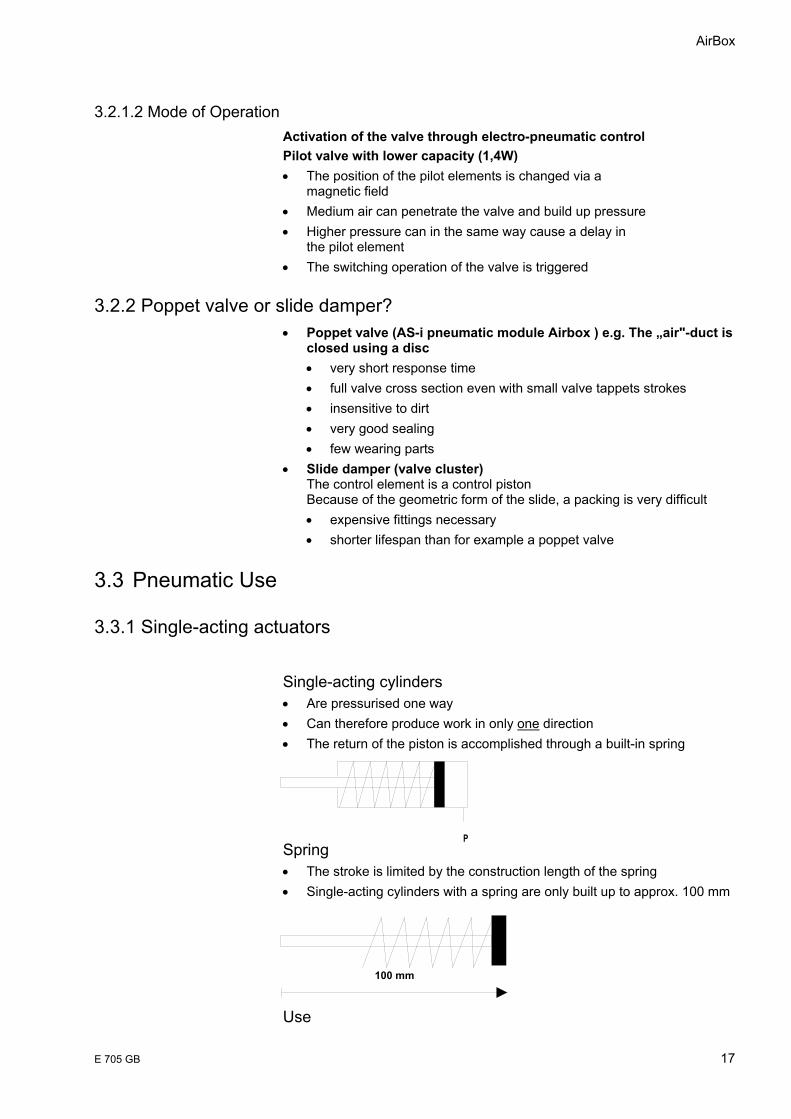
Single-acting cylinders • Are pressurised one way • Can therefore produce work in only one direction • The return of the piston is accomplished through a built-in spring
Spring • The stroke is limited by the construction length of the spring • Single-acting cylinders with a spring are only built up to approx. 100 mm
Use
100 mm
AS-Interface
18 E 705 GB
• Tension, ejection, force fitting of parts • Lifting, feeding and so on
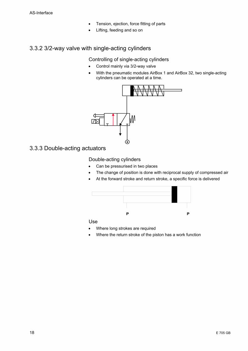
3.3.2 3/2-way valve with single-acting cylinders
Controlling of single-acting cylinders • Control mainly via 3/2-way valve • With the pneumatic modules AirBox 1 and AirBox 32, two single-acting
cylinders can be operated at a time.
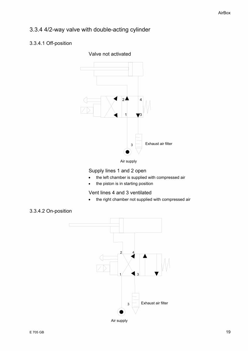
3.3.3 Double-acting actuators
Double-acting cylinders • Can be pressurised in two places • The change of position is done with reciprocal supply of compressed air • At the forward stroke and return stroke, a specific force is delivered
Use • Where long strokes are required • Where the return stroke of the piston has a work function
PP
AirBox
E 705 GB 19
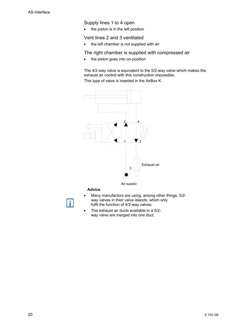
3.3.4 4/2-way valve with double-acting cylinder
3.3.4.1 Off-position
Valve not activated
Supply lines 1 and 2 open • the left chamber is supplied with compressed air • the piston is in starting position
Vent lines 4 and 3 ventilated • the right chamber not supplied with compressed air
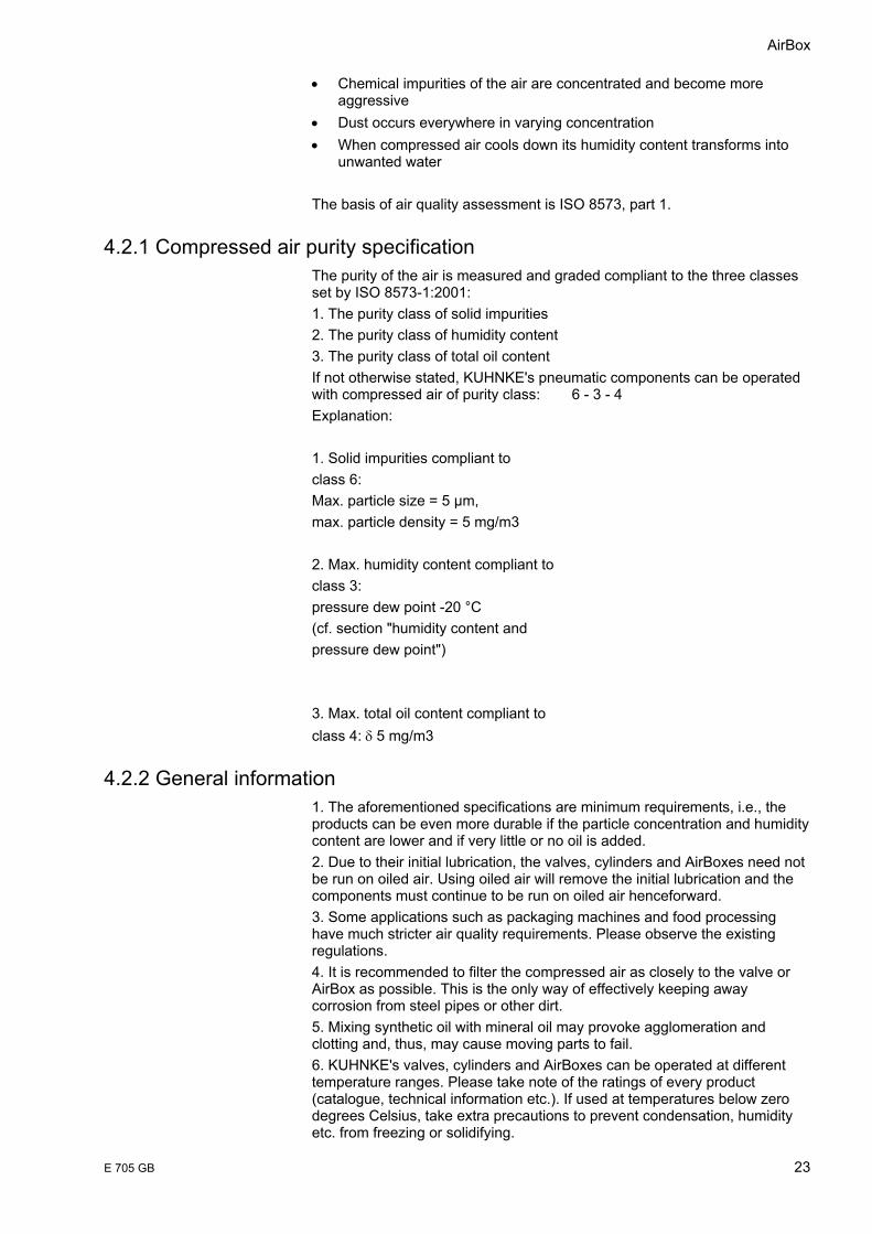
3.3.4.2 On-position
3
1 3
42
Exhaust air filter
Air supply
3
1 3
42
Exhaust air filter
Air supply
AS-Interface
20 E 705 GB
Supply lines 1 to 4 open • the piston is in the left position
Vent lines 2 and 3 ventilated • the left chamber is not supplied with air
The right chamber is supplied with compressed air • the piston goes into on-position The 4/2-way valve is equivalent to the 5/2-way valve which makes the exhaust air control with this construction impossible. This type of valve is inserted in the AirBox K Advice • Many manufactors are using, among other things, 5/2-
way valves in their valve islands, which only fulfil the function of 4/2-way valves.
• The exhaust air ducts available in a 5/2- way valve are merged into one duct.
3
1 3
42
Exhaust air
Air supply

AirBox
E 705 GB 21
3.4 Flows / tube length
Flow rates depending on tube length
0,0
100,0
200,0
300,0
400,0
500,0
600,0
700,0
800,0
900,0
0 2 4 6 8 10 12
Tube length [m]
Nl /
min
4*14*0,656*18*110*1

AS-Interface
22 E 705 GB
4 How to make proper use of compressed air KUHNKE's pneumatic components are designed for operation with compressed air. The person creating the pneumatic system (circuit diagram) or its specifications is also responsible for ensuring the compatibility or suitability of the pneumatic components selected. Detailed analyses and/or tests are a mandatory requirement for deciding whether or not pneumatic products supplied by KUHNKE are suitable for a particular application. Compressed air can be dangerous if an operator does not exactly know how to handle it. Operation and servicing of pneumatically operated machines and systems is therefore strictly limited to trained persons observing all applicable safety regulations. To ensure proper operation of our components, please take heed of the information contained herein.
4.1 Accessories We recommend the use of our fittings and accessories because they are perfectly adapted to our products. To avoid problems, care should be taken to only use clean accessory and other pneumatic elements.
4.1.1 Cylinders To maintain a long and untroubled service life of the cylinders, try to avoid shearing forces on the piston rod and to install external stroke arresters whenever possible. Only use accessories and mounting material originally manufactured by KUHNKE.
4.1.2 Valves Depending on type, our sliding valves are mounted either using a central mounting device or screws. If screwing down the valves, ensure that the valves are flat down on the mounting surface. Always look at the port labelling of valve symbols and connectors.
4.1.3 AirBox The seat valves of the AirBoxes are of a very rugged design. They are pneumatically pilot-controlled valves made for pressures between 3 and 8 bar (including peak pressures). Install technically accepted means to avoid peak pressures going beyond the admissible operating pressure. Likewise, the minimum rated pressure must be maintained. The latter specifically applies to restarting the system or following an emergency stop. To also control the pneumatically pilot-controlled AirBox at lower pressures (e.g. soft start) or at vacuum pressure, supply separate control air.
4.2 Purity of compressed air However, a long life and safe operation not only depend on the pressure but also on the purity of the compressed air. Certain requirements should be met to ensure a long service life. The compressed air should always be of perfect quality and free from chemical impurities and microbiological organisms. Its very nature does not grant these properties, though. On the contrary:
AirBox
E 705 GB 23
• Chemical impurities of the air are concentrated and become more aggressive
• Dust occurs everywhere in varying concentration • When compressed air cools down its humidity content transforms into
unwanted water The basis of air quality assessment is ISO 8573, part 1.
4.2.1 Compressed air purity specification The purity of the air is measured and graded compliant to the three classes set by ISO 8573-1:2001: 1. The purity class of solid impurities 2. The purity class of humidity content 3. The purity class of total oil content If not otherwise stated, KUHNKE's pneumatic components can be operated with compressed air of purity class: 6 - 3 - 4 Explanation: 1. Solid impurities compliant to class 6: Max. particle size = 5 µm, max. particle density = 5 mg/m3 2. Max. humidity content compliant to class 3: pressure dew point -20 °C (cf. section "humidity content and pressure dew point") 3. Max. total oil content compliant to class 4: δ 5 mg/m3
4.2.2 General information 1. The aforementioned specifications are minimum requirements, i.e., the products can be even more durable if the particle concentration and humidity content are lower and if very little or no oil is added. 2. Due to their initial lubrication, the valves, cylinders and AirBoxes need not be run on oiled air. Using oiled air will remove the initial lubrication and the components must continue to be run on oiled air henceforward. 3. Some applications such as packaging machines and food processing have much stricter air quality requirements. Please observe the existing regulations. 4. It is recommended to filter the compressed air as closely to the valve or AirBox as possible. This is the only way of effectively keeping away corrosion from steel pipes or other dirt. 5. Mixing synthetic oil with mineral oil may provoke agglomeration and clotting and, thus, may cause moving parts to fail. 6. KUHNKE's valves, cylinders and AirBoxes can be operated at different temperature ranges. Please take note of the ratings of every product (catalogue, technical information etc.). If used at temperatures below zero degrees Celsius, take extra precautions to prevent condensation, humidity etc. from freezing or solidifying.
AS-Interface
24 E 705 GB
4.2.3 Humidity content and pressure dew point Ambient air contains water vapour. The ability of air to carry water solely depends on the temperature. The ratio of the quantity of water actually carried and the maximum quantity that could be carried at a given temperature is referred to as relative humidity. A relative humidity of 100% means that, at a given temperature and pressure, the air can absorb no more water. It is saturated. Warm air can absorb more water than cold air. Cooling down saturated air leads to a condensation of fog. The temperature at which water vapour starts condensating is called dew point. Condensation also occurs if saturated air is compressed without changing the temperature. Thus, increasing the air pressure from 1 bar to 2 bar turns 50% relative humidity air into 100% relative humidity air. Further compressing this air leads to condensation. However, compressing the air also heats it up, which means that it can hold all of the water. As the air leaves the compressor and enters the pneumatic tubing, it starts to cool down. When it reaches the dew point the water vapour condensates and will cause damage to the system unless it is removed. To supply dry air to the system, the pressure dew point should be set to at least 10 °C below the lowest ambient temperature of the air pipe. Drying the air to an even lower dew point will only cause more costs. Always keep in mind that there is a large difference between the atmospheric dew point and the pressure dew point. For example, an atmospheric dew point of -15 °C corresponds to a pressure dew point of 10 °C at 5.5 bar. Always dry the air down to the pressure dew point. At an ambient temperature of 21 °C, a pressure dew point of 10 °C should be enough to avoid further condensation.
4.2.4 Admissible lubricants Oil used to lubricate the compressed air must comply with class 1 (no additives) of ISO VG10. The oil used must not corrode the materials it contacts. If in doubt, please contact the manufacturer.
4.2.5 Further information Further information and safety instructions can be found in our pneumatics catalogue.

AirBox
E 705 GB 25
5 AS-Interface Basics
5.1 Piercing technology The simple connection technique of the AS-Interface system is ensured by the defined, electromechanical interface with piercing technology.
• mechanically coded flat cable
• two wires for data and power • insulation piercing connectors
• simple and safe • protection class up to IP67, even after disconnecting
• directly connected slaves • sensors, actuators • valve terminals • electrical modules etc.
5.2 Network topology
The protocol of the AS-Interface system ensures a simple extendibility. The AS-Interface network can be configured like any conventional electrical installation. Every AS-Interface Slave is freely addressable and can get connected to the bus cable in any arbitrary place. This makes a modular construction possible, and due to the robust operating principle, there are no limits to the structure and any network topology can be used: e.g. bus, star, or tree topologies.
AS-Interface
26 E 705 GB
5.3 Checklist for beginners and experienced users
How many inputs and outputs are required? The number of inputs and outputs tells you how many AS-Interface networks you need.
How much power do the I/Os require? The total power requirement of the respective modules determines which AS-Interface power supply unit you need. As it is not possible to connect power supply units in parallel, a power supply unit sized to the requirement must be used.
Are special cables required? Any combination of profiled and round cables is possible. External conditions determine whether rubber, TPE or PUR cables should be used. Repeaters or extenders have to be used for cable lengths exceeding 100 m.
Have the addresses been correctly assigned? A plan should definitely be drawn up making it clear which addresses have been assigned to which slaves. Double addressing will not be identified as an error by the master!
Which modules belong to which addresses? The modules, or rather, the slaves which are addressed, should be carefully labelled.
When are the modules mounted? Only when points 4 and 5 have been dealt with. Cables can be routed in any way.
How is it all configured? The configuration is simply read in by entering the AS Interface profile for each slave in the master. This usually happens automatically, but can be done manually in the controller software.
Are the slaves detected? First you must check whether the master has recognised all its slaves. Only then can you switch to protected operation and switch the controller to RUN.
How is testing done? Input/output tests are performed by the familiar PLC method, i.e. the sensors are activated locally and then checked in the PLC.
How do you get it up and running? You can either create your own controller software in the usual way, or use existing software. In the latter case, you might have to adapt the symbolic assignment of addresses.
AirBox
E 705 GB 27
5.4 Mounting Hints
5.4.1 General Assembly tricks
• Place power supply next to slaves with high power consumption • Twist the single cores to a two core cable • Do not install AS-Interface together with power line in the same multi
core cable • Keep maximum distance between AS-Interface cable and power
cable (min 15 cm). • Keep strictly maximum distance to noise sources, for instance to
frequency converters • Keep maximum distance between the PLC and power devices • Do not overload the AS-Interface cable. A slave needs minimum
26.5 V
5.4.2 Ten valuable mounting hints
Tip 1 - Power supply unit On no account must AS Interface be earthed or grounded! Never use a normal power supply unit, only AS Interface power supply units (PELV) with integrated data de- coupling and connect ground (GND) with system ground.
Tip 2 - Network extension Without repeaters or extenders the AS Interface cable must be no longer than 100 m, including all feeders to the assembly terminals! If you want to expand the network, please note the following: Expansion with extenders: • The maximum cable length between the extender and the master must
not exceed 100 m • Do not connect any slaves or AS Interface network power supply unit
between the master and the extender • Never confuse the + and - lines Expansion with repeaters: • Up to two repeaters can be connected in series. This increases the
cable length to maximum 300 m (i. e. 3 segments with maximum 100 m). • An AS Interface power supply unit must be connected at every repeater. • Under normal conditions, an extender must not be connected beyond a
repeater.
Tip 3 - Slaves Each slave address is to be used only one. Only use addresses 1 to 31 or 1A to 31B in A/ B technology (Specification 2.1). Please note: modules containing the chip SAP 4.0 can be re- addressed up to 15 times, thereafter they will retain the last address.
Tip 4 - Additional auxiliary power The following applies if slaves are to be supplied with additional auxiliary power:

AS-Interface
28 E 705 GB
• at 24 V DC, a PELV power supply unit should be used and, if possible, the black profiled auxiliary power cable.
• at 230 V AC, if possible, the red profiled auxiliary power cable should be used.
Tip 5 - Routing of the cable When laying the AS Interface cables, please note the following: • Always use the yellow profiled AS Interface cable where possible, brown
for + and blue for -. • Even though communication along the AS Interface cable offers a high
degree of EMC immunity, it should still be routed away from power cables, even in the control cabinet!
• Every AS Interface line requires its own cable. AS Interface cables must not be laid together with others in a bus cable.
• If individual cores are used (e. g. in the control cabinet), always lay parallel core pairs. In standard stranded wires, lay individual cores together or twist them.
Tip 6 - Ensuring EMC immunity Connect all inductance, e. g. contactor and relay coils, valves, brakes, with suppresser diodes, variators or RC elements. If frequency inverters are used, always use network filters, output filters and shielded motor cables.
Tip 7 - Sensor and actuator power Sensors and actuators must be supplied directly from the associated input or output of the slave. The cables should be kept as short as possible and away from energy cables, i. e. the slave modules should be as close as possible to the sensors and actuators.
Tip 8 - Installing frequency converters • Always follow the assembly guidelines in the operating instructions. • Connect the cable shield, e. g. between filter and frequency converter
and between the frequency converter and the motor, directly at both ends with a sufficient cross section (at least 4 mm²).
Tip 9 - Expanding system 2.1 Operating A/ B- Slaves and “new” analogue slaves is only possible with a master according to specification 2.1.
Tip 10 - Status/Diagnosis For quick error location, the status and diagnosis bits should be evaluated in the PLC.
AirBox
E 705 GB 29
6 KUHNKE Products
6.1 AirBox 1/32
Further information and technical data for AirBox 1, 32 and K can be found in the instruction manual E705GB or on the Internet: www.kuhnke.com
6.1.1 Overview AirBox 1
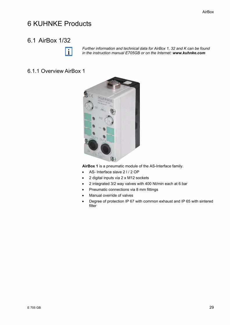
AirBox 1 is a pneumatic module of the AS-Interface family. • AS- Interface slave 2 I / 2 OP • 2 digital inputs via 2 x M12 sockets • 2 integrated 3/2 way valves with 400 NI/min each at 6 bar • Pneumatic connections via 8 mm fittings • Manual override of valves • Degree of protection IP 67 with common exhaust and IP 65 with sintered
filter
AS-Interface
30 E 705 GB
6.1.2 Overview Airbox 32
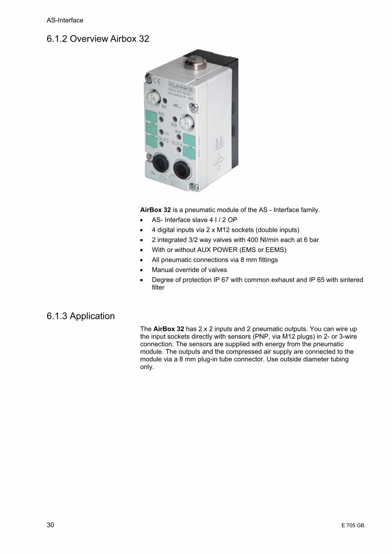
AirBox 32 is a pneumatic module of the AS - Interface family. • AS- Interface slave 4 I / 2 OP • 4 digital inputs via 2 x M12 sockets (double inputs) • 2 integrated 3/2 way valves with 400 Nl/min each at 6 bar • With or without AUX POWER (EMS or EEMS) • All pneumatic connections via 8 mm fittings • Manual override of valves • Degree of protection IP 67 with common exhaust and IP 65 with sintered
filter
6.1.3 Application The AirBox 32 has 2 x 2 inputs and 2 pneumatic outputs. You can wire up the input sockets directly with sensors (PNP, via M12 plugs) in 2- or 3-wire connection. The sensors are supplied with energy from the pneumatic module. The outputs and the compressed air supply are connected to the module via a 8 mm plug-in tube connector. Use outside diameter tubing only.
AirBox
E 705 GB 31
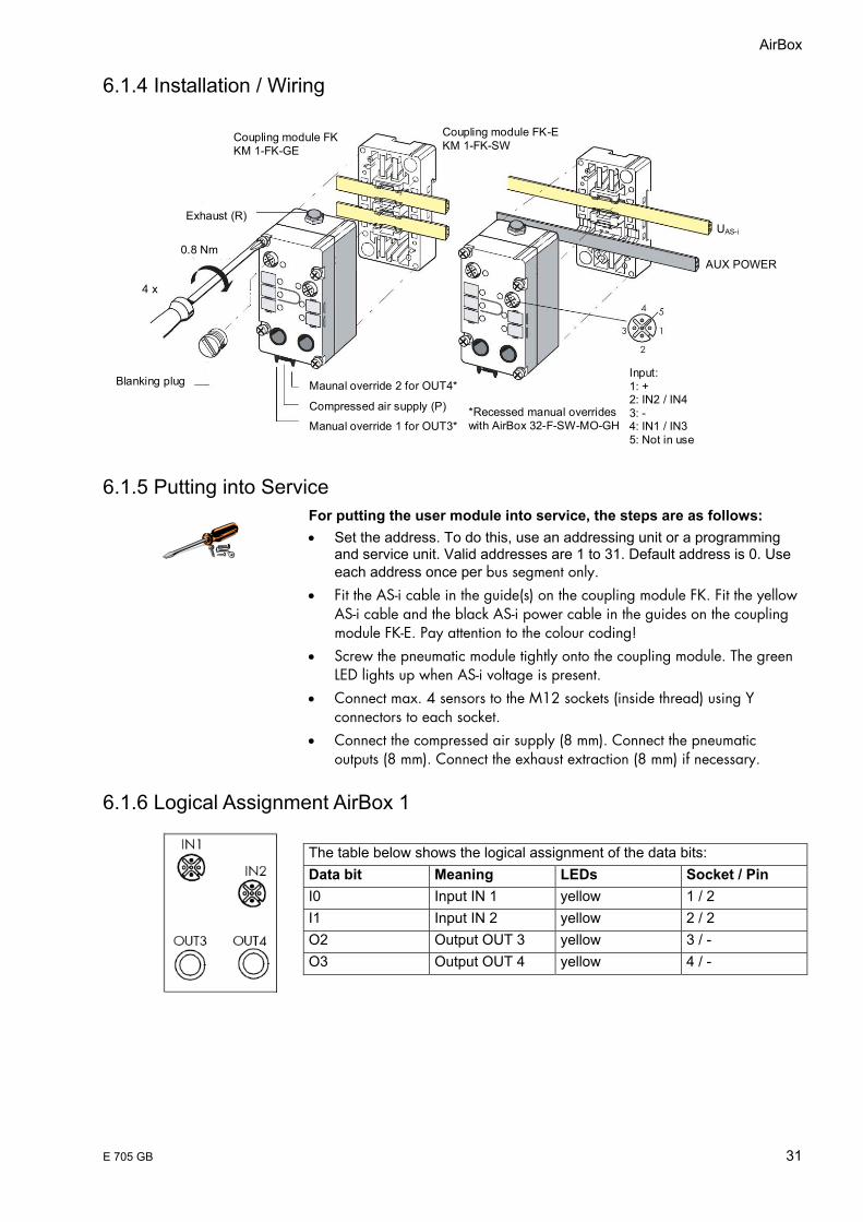
6.1.4 Installation / Wiring
Maunal override 2 for OUT4*
Compressed air supply (P)
Manual override 1 for OUT3**Recessed manual overrides with AirBox 32-F-SW-MO-GH
Input: 1: + 2: IN2 / IN4 3: - 4: IN1 / IN3 5: Not in use
Coupling module FK KM 1-FK-GE
Exhaust (R)
0.8 Nm
4 x
Coupling module FK-E KM 1-FK-SW
UAS-i
AUX POWER
Blanking plug
6.1.5 Putting into Service For putting the user module into service, the steps are as follows: • Set the address. To do this, use an addressing unit or a programming
and service unit. Valid addresses are 1 to 31. Default address is 0. Use each address once per bus segment only.
• Fit the AS-i cable in the guide(s) on the coupling module FK. Fit the yellow AS-i cable and the black AS-i power cable in the guides on the coupling module FK-E. Pay attention to the colour coding!
• Screw the pneumatic module tightly onto the coupling module. The green LED lights up when AS-i voltage is present.
• Connect max. 4 sensors to the M12 sockets (inside thread) using Y connectors to each socket.
• Connect the compressed air supply (8 mm). Connect the pneumatic outputs (8 mm). Connect the exhaust extraction (8 mm) if necessary.
6.1.6 Logical Assignment AirBox 1 The table below shows the logical assignment of the data bits: Data bit Meaning LEDs Socket / Pin I0 Input IN 1 yellow 1 / 2 I1 Input IN 2 yellow 2 / 2 O2 Output OUT 3 yellow 3 / - O3 Output OUT 4 yellow 4 / -
AS-Interface
32 E 705 GB
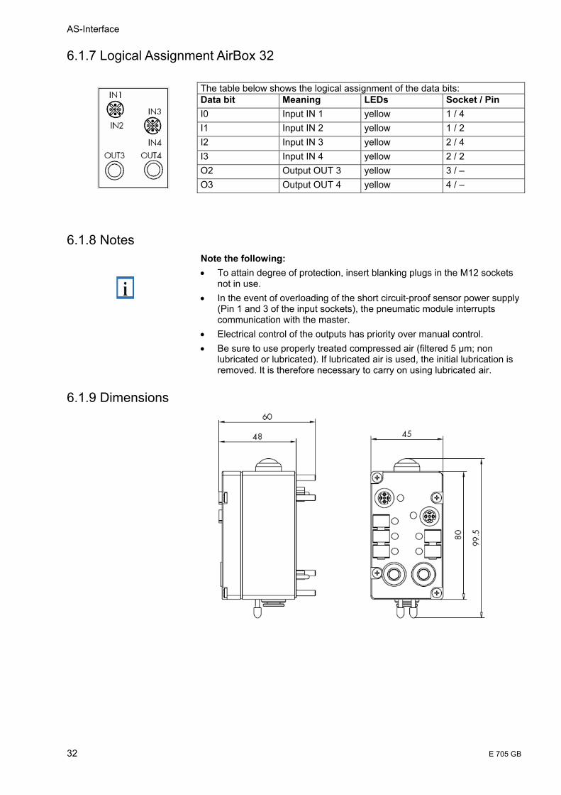
6.1.7 Logical Assignment AirBox 32
6.1.8 Notes Note the following: • To attain degree of protection, insert blanking plugs in the M12 sockets
not in use. • In the event of overloading of the short circuit-proof sensor power supply
(Pin 1 and 3 of the input sockets), the pneumatic module interrupts communication with the master.
• Electrical control of the outputs has priority over manual control. • Be sure to use properly treated compressed air (filtered 5 µm; non
lubricated or lubricated). If lubricated air is used, the initial lubrication is removed. It is therefore necessary to carry on using lubricated air.
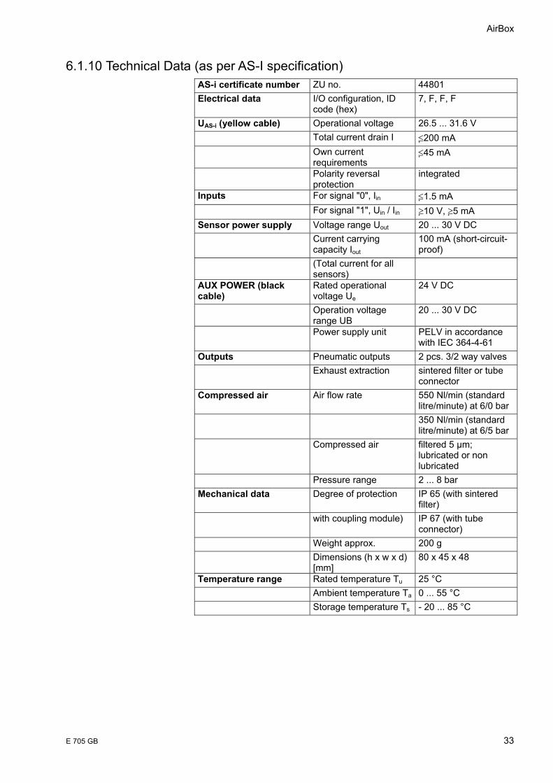
6.1.9 Dimensions
The table below shows the logical assignment of the data bits: Data bit Meaning LEDs Socket / Pin I0 Input IN 1 yellow 1 / 4 I1 Input IN 2 yellow 1 / 2 I2 Input IN 3 yellow 2 / 4 I3 Input IN 4 yellow 2 / 2 O2 Output OUT 3 yellow 3 / – O3 Output OUT 4 yellow 4 / –
AirBox
E 705 GB 33
6.1.10 Technical Data (as per AS-I specification) AS-i certificate number ZU no. 44801 Electrical data I/O configuration, ID
code (hex) 7, F, F, F
UAS-i (yellow cable) Operational voltage 26.5 ... 31.6 V Total current drain I ≤200 mA Own current
requirements ≤45 mA
Polarity reversal protection
integrated
Inputs For signal "0", Iin ≤1.5 mA For signal "1", Uin / Iin ≥10 V, ≥ 5 mA Sensor power supply Voltage range Uout 20 ... 30 V DC Current carrying
capacity Iout 100 mA (short-circuit-proof)
(Total current for all sensors)
AUX POWER (black cable)
Rated operational voltage Ue
24 V DC
Operation voltage range UB
20 ... 30 V DC
Power supply unit PELV in accordance with IEC 364-4-61
Outputs Pneumatic outputs 2 pcs. 3/2 way valves Exhaust extraction sintered filter or tube
connector Compressed air Air flow rate 550 Nl/min (standard
litre/minute) at 6/0 bar 350 Nl/min (standard
litre/minute) at 6/5 bar Compressed air filtered 5 µm;
lubricated or non lubricated
Pressure range 2 ... 8 bar Mechanical data Degree of protection IP 65 (with sintered
filter) with coupling module) IP 67 (with tube
connector) Weight approx. 200 g Dimensions (h x w x d)
[mm] 80 x 45 x 48
Temperature range Rated temperature Tu 25 °C Ambient temperature Ta 0 ... 55 °C Storage temperature Ts - 20 ... 85 °C
AS-Interface
34 E 705 GB
6.2 Overview AirBox K
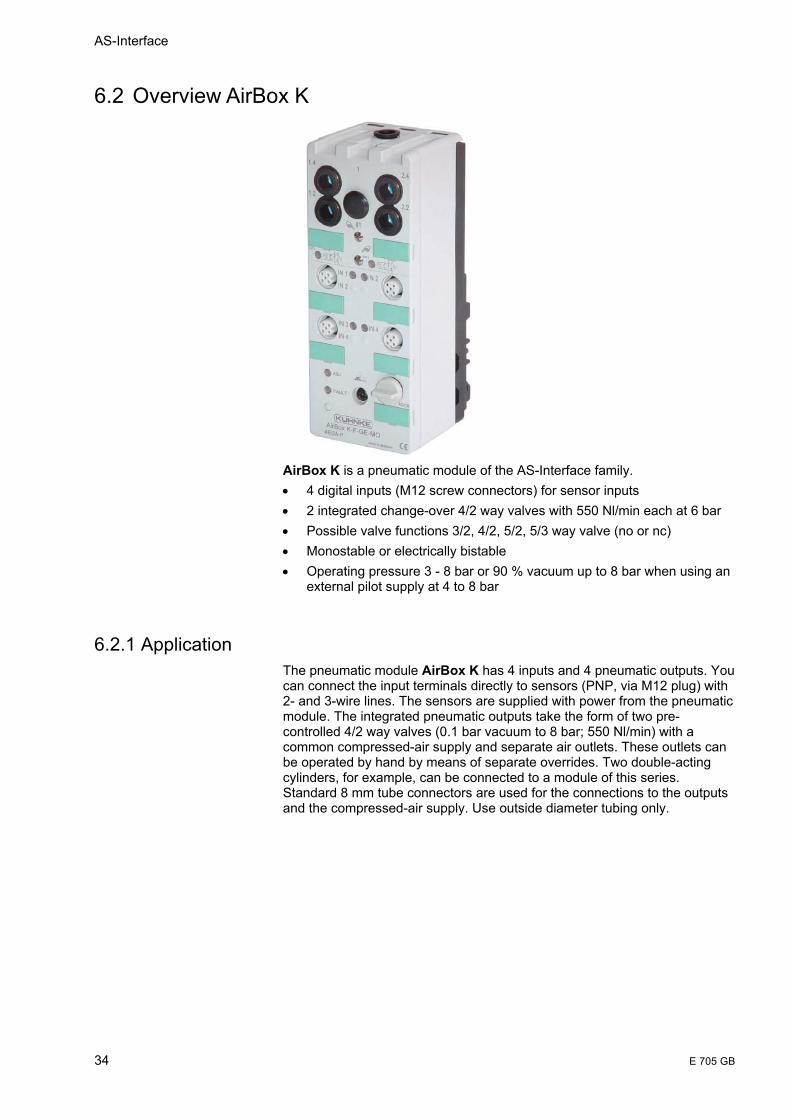
AirBox K is a pneumatic module of the AS-Interface family. • 4 digital inputs (M12 screw connectors) for sensor inputs • 2 integrated change-over 4/2 way valves with 550 Nl/min each at 6 bar • Possible valve functions 3/2, 4/2, 5/2, 5/3 way valve (no or nc) • Monostable or electrically bistable • Operating pressure 3 - 8 bar or 90 % vacuum up to 8 bar when using an
external pilot supply at 4 to 8 bar
6.2.1 Application The pneumatic module AirBox K has 4 inputs and 4 pneumatic outputs. You can connect the input terminals directly to sensors (PNP, via M12 plug) with 2- and 3-wire lines. The sensors are supplied with power from the pneumatic module. The integrated pneumatic outputs take the form of two pre-controlled 4/2 way valves (0.1 bar vacuum to 8 bar; 550 Nl/min) with a common compressed-air supply and separate air outlets. These outlets can be operated by hand by means of separate overrides. Two double-acting cylinders, for example, can be connected to a module of this series. Standard 8 mm tube connectors are used for the connections to the outputs and the compressed-air supply. Use outside diameter tubing only.
AirBox
E 705 GB 35
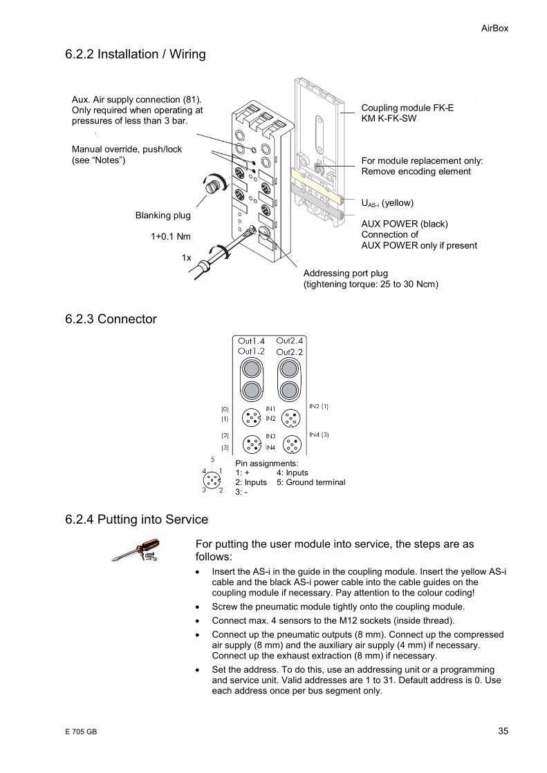
6.2.2 Installation / Wiring
Coupling module FK-EKM K-FK-SW For module replacement only: Remove encoding element UAS-i (yellow) AUX POWER (black) Connection of AUX POWER only if present
Addressing port plug (tightening torque: 25 to 30 Ncm)
Aux. Air supply connection (81). Only required when operating at pressures of less than 3 bar.
Manual override, push/lock (see “Notes”)
Blanking plug
1+0.1 Nm
1x
6.2.3 Connector
Pin assignments: 1: + 4: Inputs 2: Inputs 5: Ground terminal 3: -
6.2.4 Putting into Service
For putting the user module into service, the steps are as follows: • Insert the AS-i in the guide in the coupling module. Insert the yellow AS-i
cable and the black AS-i power cable into the cable guides on the coupling module if necessary. Pay attention to the colour coding!
• Screw the pneumatic module tightly onto the coupling module. • Connect max. 4 sensors to the M12 sockets (inside thread). • Connect up the pneumatic outputs (8 mm). Connect up the compressed
air supply (8 mm) and the auxiliary air supply (4 mm) if necessary. Connect up the exhaust extraction (8 mm) if necessary.
• Set the address. To do this, use an addressing unit or a programming and service unit. Valid addresses are 1 to 31. Default address is 0. Use each address once per bus segment only.
AS-Interface
36 E 705 GB
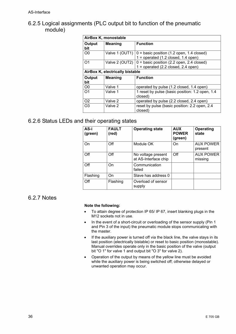
6.2.5 Logical assignments (PLC output bit to function of the pneumatic module)
AirBox K, monostable Output bit
Meaning Function
O0
Valve 1 (OUT1) 0 = basic position (1.2 open, 1.4 closed) 1 = operated (1.2 closed, 1.4 open)
O1 Valve 2 (OUT2) 0 = basic position (2.2 open, 2.4 closed) 1 = operated (2.2 closed, 2.4 open)
AirBox K, electrically bistable Output bit
Meaning Function
O0 Valve 1 operated by pulse (1.2 closed, 1.4 open) O1 Valve 1 1 reset by pulse (basic position: 1.2 open, 1.4
closed) O2 Valve 2 operated by pulse (2.2 closed, 2.4 open) O3 Valve 2 reset by pulse (basic position: 2.2 open, 2.4
closed)
6.2.6 Status LEDs and their operating states AS-i (green)
FAULT (red)
Operating state AUX POWER (green)
Operating state
On
Off Module OK On AUX POWER present
Off
Off No voltage present at AS-Interface chip
Off AUX POWER missing
Off
On Communication failed
Flashing On Slave has address 0 Off
Flashing Overload of sensor supply
6.2.7 Notes Note the following: • To attain degree of protection IP 65/ IP 67, insert blanking plugs in the
M12 sockets not in use. • In the event of a short-circuit or overloading of the sensor supply (Pin 1
and Pin 3 of the input) the pneumatic module stops communicating with the master.
• If the auxiliary power is turned off via the black line, the valve stays in its last position (electrically bistable) or reset to basic position (monostable). Manual overrides operate only in the basic position of the valve (output bit "O 1" for valve 1 and output bit "O 3" for valve 2).
• Operation of the output by means of the yellow line must be avoided while the auxiliary power is being switched off; otherwise delayed or unwanted operation may occur.

AirBox
E 705 GB 37
6.2.8 Functional Principle (with double acting cylinders)
Monostable
Outputs not operated Outputs operated
Electrically Bistable
Outputs not operated Outputs operated
6.2.9 Dimensions

AS-Interface
38 E 705 GB
6.2.10 Technical Data (as per AS-I specification) AS-i certificate number
ZU no. 44901
Electrical data I/O code / ID code (hex) 7 / F / F / F UAS-i (yellow cable) Operational voltage 26.5 ... 31.6 V Total current input I ≤270 mA Own current requirements ≤45 mA Polarity reversal protection integrated Inputs For signal "0", Iin ≤1.5 mA For signal "1", Uin / Iin ≥10 V / ≥ 6 mA Sensor power supply
Voltage range Uout 20 ... 30 V DC
Current carrying capacity Iout 100 mA (short-circuit-proof)
(with AUX POWER) Iout 200 mA (short-circuit-proof)
AUX POWER (black cable)
Rated operational voltage Ue 24 V DC
Operation voltage range UB 20 ... 30 V DC Current strength Ipulse, Ihold 115 mA, 40 mA Polarity reversal protection yes Power supply unit PELV in accordance
with IEC 364 -4-61 Outputs Pneumatic outputs 2 pcs. pre-contr.- 4/2
way valves Max. operating frequency 5 Hz, max. 60
operations per minute permissible
Compressed air Air flow rate at 6/0 bar 700 Nl/min (standard litre/minute)
Air flow rate at 6/5 bar 500 Nl/min (standard litre/minute)
Compressed air filtered 5 µm; lubricated or non lubricated
Pressure range 3 to 8 bar (90 % vacuum to 8 bar, at control air > 4 bar)
Auxiliary air supply Pressure > 3 bar Connection by plug-in tube
connector 4 mm Mechanical data Degree of protection IP 65 (with sintered
filter) (with coupling module) IP 67 (with tube
connector) Weight approx. 400 g Dimensions (h x w x d) [mm] 152 x 60 x 45 Temperature range Rated temperature Tu 25 °C Ambient temperature Ta
0 ... 55 °C
Storage temperature Ts -5 ... 70 °C
Note: Connection to port 81 automatically engages auxiliary air supply (active by push)
AirBox
E 705 GB 39
6.3 Other AS-I slave modules
6.3.1 Concept Within the AS-i system, the AS-i modules can be compared with input and output modules. Along with the actuators and sensors they make up the AS-i slaves and connect the slaves to the AS-i master. The actuators/sensors are connected via M12 connectors. The pin out corresponds to DIN IEC 947 5-2. The modules with dimensions of approximately 45 x 45 x 80 mm are used locally on the machine itself. They are connected via the AS-i cable and have protection degree IP67.
6.3.2 Active and Passive Modules The following modules must be distinguished: • The active AS-i module with integrated AS-i chip: Using the active
module, conventional sensors and actuators can be connected. Every normal actuator or sensor can therefore be networked via AS-i.
• The passive AS-i module: The passive module does not contain its own electronics and allows the connection of AS-I sensors and actuators with integrated AS-i chips.
In matching the concept of the standard AS-i master and the extended AS-I master, either AS-i chips with standard functions or with extended functions are used. The modules are designed so that a uniform electromechanical interface to the AS-i cable can be created. This is achieved with the uniform lower section of the module, which is therefore also known as a coupling module. Specially constructed upper module sections, also known as application modules are also available. The variations in the module components range from the simple cover for branching the AS-i cable to application modules with integrated AS-I chips for connecting up to four conventional sensors or actuators.
AS-Interface
40 E 705 GB
6.4 Coupling module for AirBox 1/32
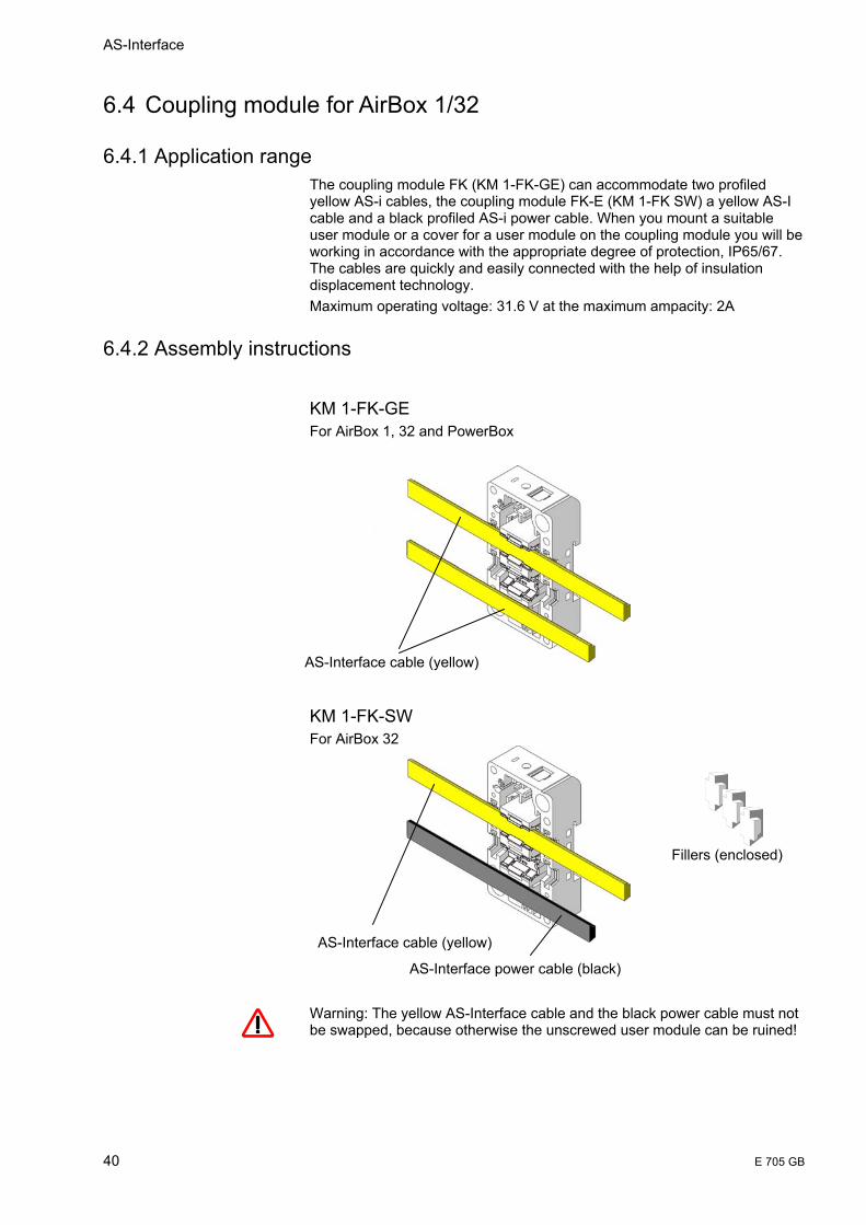
6.4.1 Application range The coupling module FK (KM 1-FK-GE) can accommodate two profiled yellow AS-i cables, the coupling module FK-E (KM 1-FK SW) a yellow AS-I cable and a black profiled AS-i power cable. When you mount a suitable user module or a cover for a user module on the coupling module you will be working in accordance with the appropriate degree of protection, IP65/67. The cables are quickly and easily connected with the help of insulation displacement technology. Maximum operating voltage: 31.6 V at the maximum ampacity: 2A
6.4.2 Assembly instructions
KM 1-FK-GE For AirBox 1, 32 and PowerBox
KM 1-FK-SW For AirBox 32 Warning: The yellow AS-Interface cable and the black power cable must not be swapped, because otherwise the unscrewed user module can be ruined!
AS-Interface cable (yellow)
AS-Interface cable (yellow)
AS-Interface power cable (black)
Fillers (enclosed)
AirBox
E 705 GB 41
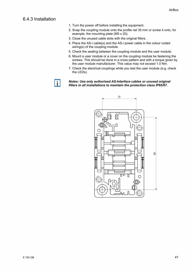
6.4.3 Installation 1. Turn the power off before installing the equipment. 2. Snap the coupling module onto the profile rail 35 mm or screw it onto, for example, the mounting plate (M5 x 20). 3. Close the unused cable slots with the original fillers. 4. Place the AS-i cable(s) and the AS-i power cable in the colour coded wiring(s) of the coupling module. 5. Check the sealing between the coupling module and the user module. 6. Mount a user module or a cover on the coupling module be fastening the screws. This should be done in a cross pattern and with a torque given by the user module manufacturer. This value may not exceed 1.0 Nm. 7. Check the electrical couplings while you test the user module (e.g. check the LEDs).
Notes: Use only authorised AS-Interface cables or unused original fillers in all installations to maintain the protection class IP65/67.
AS-Interface
42 E 705 GB
7 Pneumatic characteristics
7.1 AirBox 1/32
7.1.1 Equivalent diagram
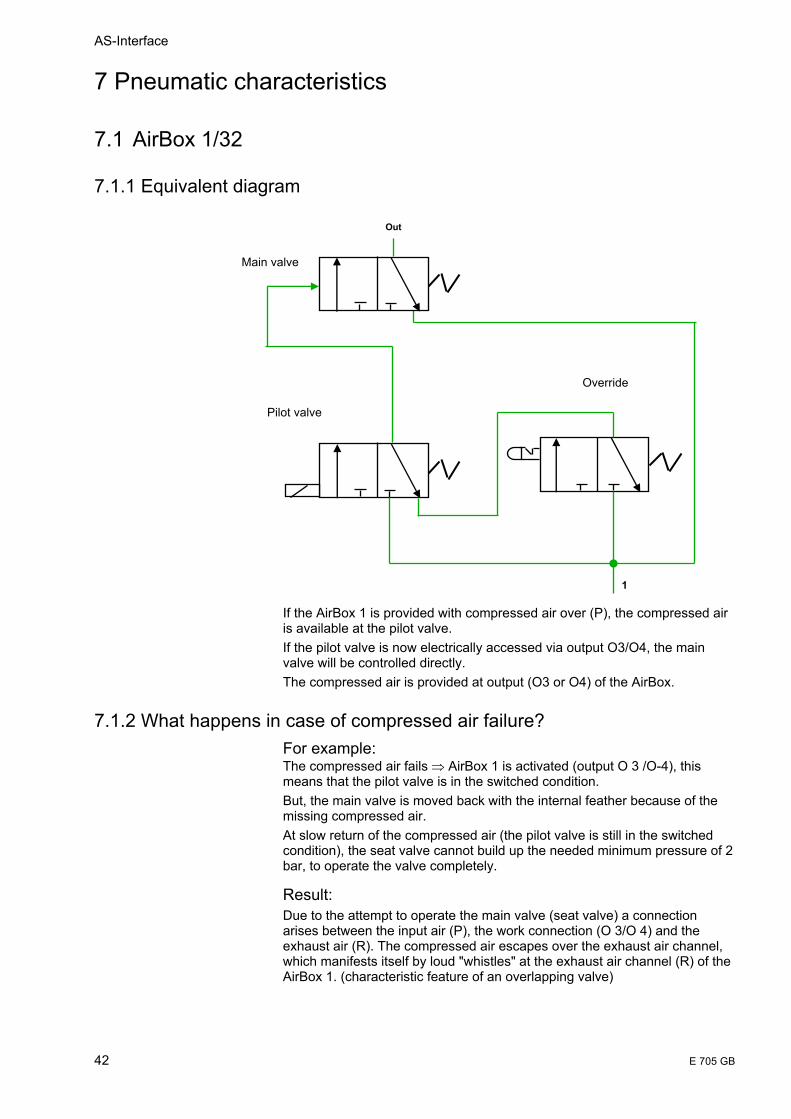
If the AirBox 1 is provided with compressed air over (P), the compressed air is available at the pilot valve. If the pilot valve is now electrically accessed via output O3/O4, the main valve will be controlled directly. The compressed air is provided at output (O3 or O4) of the AirBox.
7.1.2 What happens in case of compressed air failure? For example: The compressed air fails ⇒ AirBox 1 is activated (output O 3 /O-4), this means that the pilot valve is in the switched condition. But, the main valve is moved back with the internal feather because of the missing compressed air. At slow return of the compressed air (the pilot valve is still in the switched condition), the seat valve cannot build up the needed minimum pressure of 2 bar, to operate the valve completely.
Result: Due to the attempt to operate the main valve (seat valve) a connection arises between the input air (P), the work connection (O 3/O 4) and the exhaust air (R). The compressed air escapes over the exhaust air channel, which manifests itself by loud "whistles" at the exhaust air channel (R) of the AirBox 1. (characteristic feature of an overlapping valve)
1
Main valve
Pilot valve
Override
Out

AirBox
E 705 GB 43
7.2 AirBox K
7.2.1 Equivalent diagram
• The auxiliary air connection is mechanically locked when no tube is attached.
• Only the input air is released to the pilot valve. • If the AirBox K is provided with compressed air over (P), the compressed
air is available at output (2). • If the pilot valve is operated electrically over output O3, the main valve is
activated pneumatically by means of a control piston ⇒ Compressed air is available at output(4) of the AirBox.
7.2.2 What happens in case of compressed air failure
Example: The compressed air fails ⇒ AirBox K is activated (output O-3 /O-4), this means that the pilot valve is in the switched condition. But, the main valve is moved back with the internal feather because of the missing compressed air. At slow return of the compressed air (the pilot valve is still in the switched condition), the control piston of the main valve cannot build up the needed minimum pressure of 2 bar, to operate the valve completely.
Result: Due to the attempt of the control piston to operate the main valve, a connection arises between the input air (P), the work connection (A) and the exhaust air (R).By the attempt of the control piston to press the main valve a connection arises between the input air (P), the work connection (A) and the waste air (R). The compressed air escapes over the exhaust air channel, which manifests itself by loud "whistles" at the exhaust air channel (R) of the AirBox 1. (characteristic feature of an overlapping valve)
1[P] 81[X]
Main valve
Pilot valve
Aux. air connection (Active by push)
Override
.2.4
AS-Interface
44 E 705 GB
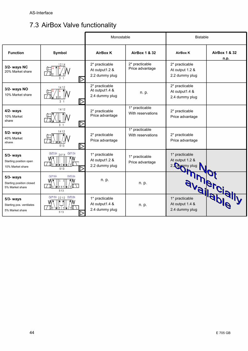
7.3 AirBox Valve functionality
Function Symbol
3/2- ways NC 20% Market share
3/2- ways NO 10% Market share
4/2- ways 10% Market share
5/2- ways 40% Market share
5/3- ways Starting position open
10% Market share
Monostable Bistable
AirBox K AirBox K AirBox 1 & 32 AirBox 1 & 32 n.p.
2* practicable Price advantage
n. p.
n. p.
n. p.
1* practicable Price advantage
1* practicable With reservations
1* practicable With reservations
1* practicable At output 1.4 & 2.4 dummy plug
1* practicable At output 1.2 & 2.2 dummy plug
2* practicable At output 1.2 & 2.2 dummy plug
2* practicable Price advantage
2* practicable Price advantage
2* practicable At output1.4 & 2.4 dummy plug
n. p.
1* practicable At output1.4 & 2.4 dummy plug
1* practicable At output1.2 & 2.2 dummy plug
2* practicable At output1.2 & 2.2 dummy plug
2* practicable Price advantage
2* practicable Price advantage
2* practicable At output1.4 & 2.4 dummy plug
5/3- ways Starting position closed 5% Market share
5/3- ways Starting pos. ventilates
5% Market share

AirBox
E 705 GB 45
7.3.1 3/2-way valves (nc)
7.3.1.1 Function
Functions of the 3/2-way valve NC (normal closed)
• On-position • The output 1.2 is connected to the air supply in the on-position • The cylinder is ventilated • Output 1.4 is closed with a dummy plug
• Off-position • Output 1.2 is connected to the exhaust air in the off-position • Output 1.4 is closed with a dummy plug
Notes: • this function is twice practicable with the compact pneumatic module
AirBox K • 3/2-ways (n.c.) is equivalent to the functions of the pneumatic modules
AirBox1 and AirBox 32
7.3.1.2 Tubing

AS-Interface
46 E 705 GB
7.3.2 3/2-way valve (no)
7.3.2.1 Function
Functions of the 3/2-way valve NO (normal open)
• On-position
• Output 1.4 is connected to the exhaust air in the on-position • The cylinder is ventilated • Output 1.2 is closed with a dummy plug
• Off-position • Output 1.4 is connected to the air supply in the off-position • The cylinder is ventilated (normal open) • Output 1.2 is closed with a dummy plug
Notes: • this function is twice practicable with the compact pneumatic module
AirBox K • 3/2-ways(n.o.) is not practicable with the pneumatic modules AirBox 1
and 32
7.3.2.2 Tubing

AirBox
E 705 GB 47
7.3.3 4/2-way valve
7.3.3.1 Function
Functions of the 4/2-way valve (inside)
• There are 2 x 4/2-way valves integrated in the compact pneumatic
module AirBox K
Notes: • this function is twice practicable with the compact pneumatic module
AirBox K
7.3.3.2 Tubing
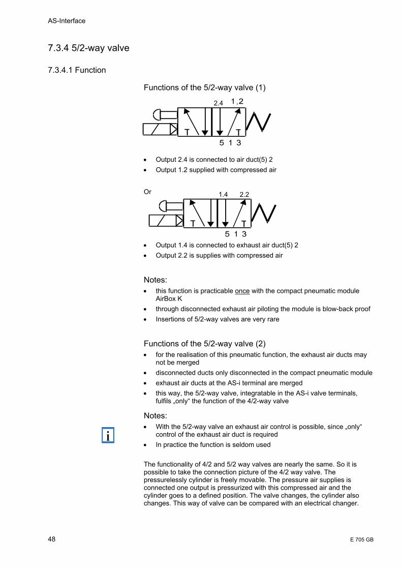
AS-Interface
48 E 705 GB
7.3.4 5/2-way valve
7.3.4.1 Function
Functions of the 5/2-way valve (1)
• Output 2.4 is connected to air duct(5) 2 • Output 1.2 supplied with compressed air
Or
• Output 1.4 is connected to exhaust air duct(5) 2 • Output 2.2 is supplies with compressed air
Notes: • this function is practicable once with the compact pneumatic module
AirBox K • through disconnected exhaust air piloting the module is blow-back proof • Insertions of 5/2-way valves are very rare
Functions of the 5/2-way valve (2) • for the realisation of this pneumatic function, the exhaust air ducts may
not be merged • disconnected ducts only disconnected in the compact pneumatic module • exhaust air ducts at the AS-i terminal are merged • this way, the 5/2-way valve, integratable in the AS-i valve terminals,
fulfils „only“ the function of the 4/2-way valve
Notes: • With the 5/2-way valve an exhaust air control is possible, since „only“
control of the exhaust air duct is required • In practice the function is seldom used The functionality of 4/2 and 5/2 way valves are nearly the same. So it is possible to take the connection picture of the 4/2 way valve. The pressurelessly cylinder is freely movable. The pressure air supplies is connected one output is pressurized with this compressed air and the cylinder goes to a defined position. The valve changes, the cylinder also changes. This way of valve can be compared with an electrical changer.
2.4
1.4 2.2
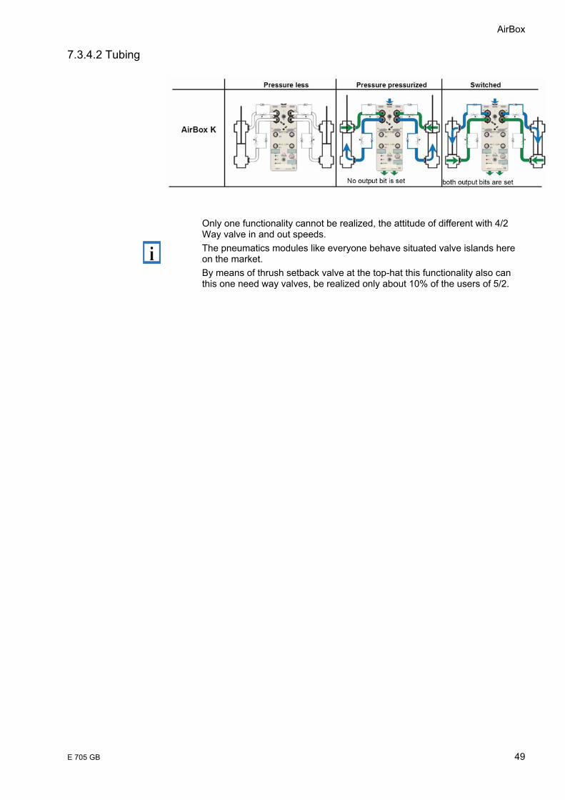
AirBox
E 705 GB 49
7.3.4.2 Tubing
Only one functionality cannot be realized, the attitude of different with 4/2 Way valve in and out speeds. The pneumatics modules like everyone behave situated valve islands here on the market. By means of thrush setback valve at the top-hat this functionality also can this one need way valves, be realized only about 10% of the users of 5/2.
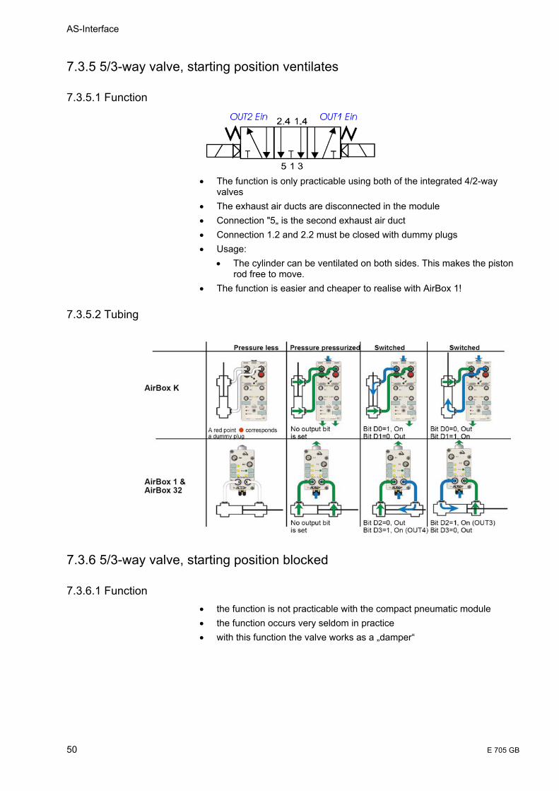
AS-Interface
50 E 705 GB
7.3.5 5/3-way valve, starting position ventilates
7.3.5.1 Function
• The function is only practicable using both of the integrated 4/2-way
valves • The exhaust air ducts are disconnected in the module • Connection "5„ is the second exhaust air duct • Connection 1.2 and 2.2 must be closed with dummy plugs • Usage:
• The cylinder can be ventilated on both sides. This makes the piston rod free to move.
• The function is easier and cheaper to realise with AirBox 1!
7.3.5.2 Tubing
7.3.6 5/3-way valve, starting position blocked
7.3.6.1 Function • the function is not practicable with the compact pneumatic module • the function occurs very seldom in practice • with this function the valve works as a „damper“

AirBox
E 705 GB 51
7.3.7 5/3-way valve, starting position pressurises
7.3.7.1 Function • The function is only practicable using both of the integrated 4/2-way
valves • The exhaust air ducts are disconnected in the Module • Connection "5„ is the second exhaust air duct • Connection 1.4 and 2.4 must be closed with dummy plugs • Usage:
• The cylinder can be supplied with compressed air on both sides. The function is not practicable with AirBox 1, since „normal open“ valves are required
7.3.7.2 Tubing

AS-Interface
52 E 705 GB
8 Electrical characteristics
8.1 Symbol description The working line for AirBox K (1.4), accessed via digital outputs O-3 and the working line for AirBox K (1.2), accessed via digital outputs O-4 are connected to other connectors on the cylinder.
The working line for AirBox 32 (O-3) is connected to a single-acting cylinder or the working line for the AirBox 32 is connected to another single-acting cylinder. The working lines for AirBox 32 (O-3/O-4) are connected to a double-acting cylinder.
4 [O-3] 4 [O-3]
O-3
O-3 O-4
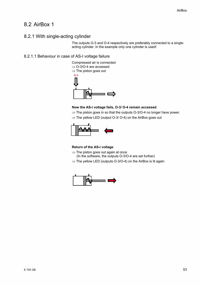
AirBox
E 705 GB 53
8.2 AirBox 1
8.2.1 With single-acting cylinder The outputs O-3 and O-4 respectively are preferably connected to a single-acting cylinder. In the example only one cylinder is used!
8.2.1.1 Behaviour in case of AS-I voltage failure Compressed air is connected ⇒ O-3/O-4 are accessed ⇒ The piston goes out
Now the AS-i voltage fails, O-3/ O-4 remain accessed ⇒ The piston goes in so that the outputs O-3/O-4 no longer have power. ⇒ The yellow LED (output O-3/ O-4) on the AirBox goes out Return of the AS-i voltage ⇒ The piston goes out again at once (In the software, the outputs O-3/O-4 are set further) ⇒ The yellow LED (outputs O-3/O-4) on the AirBox is lit again
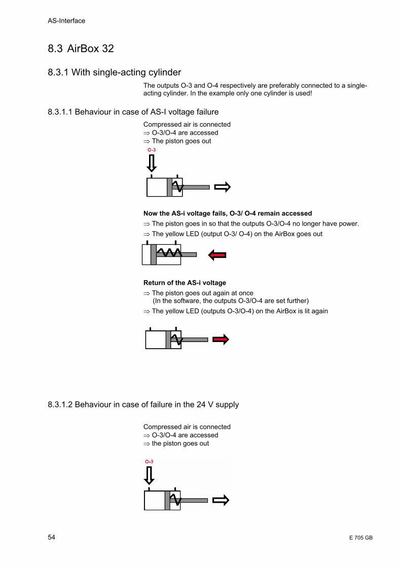
AS-Interface
54 E 705 GB
8.3 AirBox 32
8.3.1 With single-acting cylinder The outputs O-3 and O-4 respectively are preferably connected to a single-acting cylinder. In the example only one cylinder is used!
8.3.1.1 Behaviour in case of AS-I voltage failure Compressed air is connected ⇒ O-3/O-4 are accessed ⇒ The piston goes out
Now the AS-i voltage fails, O-3/ O-4 remain accessed ⇒ The piston goes in so that the outputs O-3/O-4 no longer have power. ⇒ The yellow LED (output O-3/ O-4) on the AirBox goes out Return of the AS-i voltage ⇒ The piston goes out again at once (In the software, the outputs O-3/O-4 are set further) ⇒ The yellow LED (outputs O-3/O-4) on the AirBox is lit again
8.3.1.2 Behaviour in case of failure in the 24 V supply Compressed air is connected ⇒ O-3/O-4 are accessed ⇒ the piston goes out

AirBox
E 705 GB 55
Now the 24V supply fails, e.g. emergency stop, O-3/O-4 remain accessed ⇒ The piston goes in, so that the outputs O-3/O-4 no longer have power ⇒ The yellow LED (output O-3/O-4) on the AirBox goes out
Return of the 24V supply ⇒ The piston remains in the in-state ⇒ The yellow LED (output O-3/ O-4) on the AirBox is lit again, But the valve is not connected.
The outputs O-3/O-4 must be reset in the software!
8.3.2 With double-acting cylinder The outputs O-3 and O-4 respectively of the AirBox 32 are connected to a double-acting cylinder!
8.3.2.1 Behaviour in case of AS-I voltage failure Compressed air is connected ⇒ O-3 is accessed ⇒ The piston goes out
Now the AS-i voltage fails, O-3 remains accessed ⇒ The piston remains in the out position, but it is movable, that is with corresponding counteracting force the piston goes in. ⇒ The yellow LED (output O-3) on the AirBox goes out Return of the AS-i voltage ⇒ The piston goes out again at once (In the software, the output O-3 is set further) ⇒ The yellow LED (output O-3) on the AirBox is lit again
Counteracting force
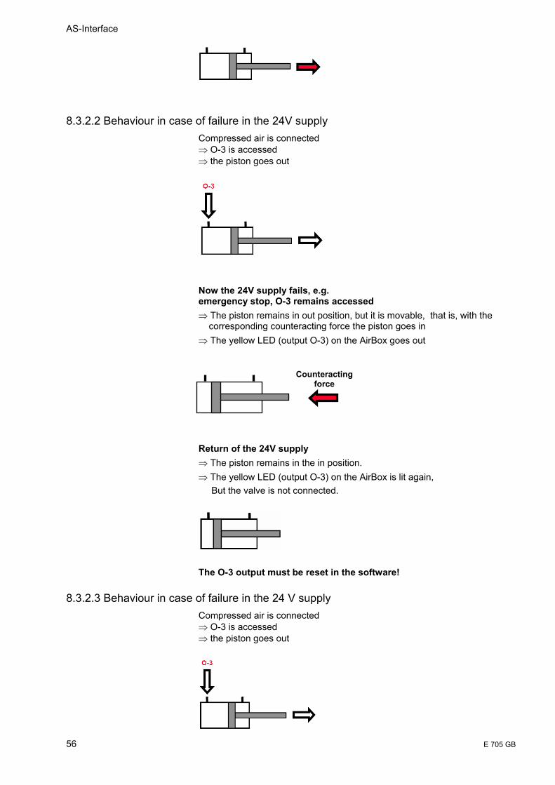
AS-Interface
56 E 705 GB
8.3.2.2 Behaviour in case of failure in the 24V supply Compressed air is connected ⇒ O-3 is accessed ⇒ the piston goes out
Now the 24V supply fails, e.g. emergency stop, O-3 remains accessed ⇒ The piston remains in out position, but it is movable, that is, with the corresponding counteracting force the piston goes in ⇒ The yellow LED (output O-3) on the AirBox goes out Return of the 24V supply ⇒ The piston remains in the in position. ⇒ The yellow LED (output O-3) on the AirBox is lit again, But the valve is not connected.
The O-3 output must be reset in the software!
8.3.2.3 Behaviour in case of failure in the 24 V supply Compressed air is connected ⇒ O-3 is accessed ⇒ the piston goes out
Counteracting force

AirBox
E 705 GB 57
Now the 24V supply fails, e.g. emergency stop, and is subsequently rerouted to O-4 ⇒ The piston remains in the out position, but it is movable, that is, with the corresponding counteracting force the piston goes in ⇒ The yellow LED (output O-3) on the AirBox goes out
Return of the 24V supply ⇒ The piston remains in the in position ⇒ The yellow LED (output O-4) on the AirBox is lit But the valve is not connected.
The output O-4 must be reset in the software again!
8.3.3 Operating without auxiliary 24V supply
Background: When (electrically) activating, the outputs will momentarily generate an increased current for piloting the valve, then the current will be adjusted to the holding current. This „activating boost“ is absent when only the extern voltage is switched off, so that at the restart, only the holding current is available. This still is not enough to activate the valve after an emergency stop.
Solution: In case of an emergency stop the outputs of the AirBox 32 must be reset in the SPS. That is also the customary procedure in case of an emergency stop!
Counteracting force
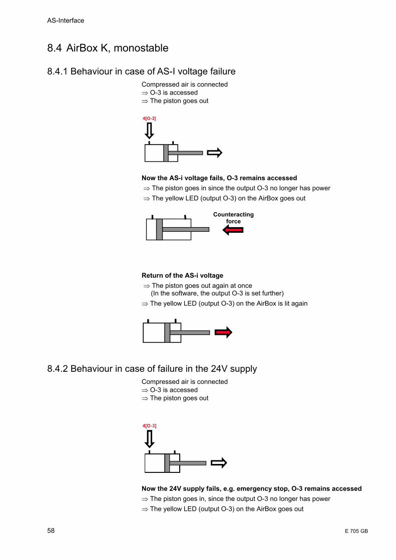
AS-Interface
58 E 705 GB
8.4 AirBox K, monostable
8.4.1 Behaviour in case of AS-I voltage failure Compressed air is connected ⇒ O-3 is accessed ⇒ The piston goes out
Now the AS-i voltage fails, O-3 remains accessed ⇒ The piston goes in since the output O-3 no longer has power ⇒ The yellow LED (output O-3) on the AirBox goes out
Return of the AS-i voltage ⇒ The piston goes out again at once (In the software, the output O-3 is set further) ⇒ The yellow LED (output O-3) on the AirBox is lit again
8.4.2 Behaviour in case of failure in the 24V supply Compressed air is connected ⇒ O-3 is accessed ⇒ The piston goes out
Now the 24V supply fails, e.g. emergency stop, O-3 remains accessed ⇒ The piston goes in, since the output O-3 no longer has power ⇒ The yellow LED (output O-3) on the AirBox goes out
Counteractingforce
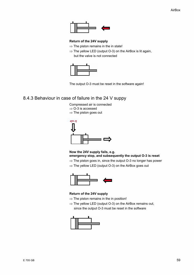
AirBox
E 705 GB 59
Return of the 24V supply ⇒ The piston remains in the in state! ⇒ The yellow LED (output O-3) on the AirBox is lit again, but the valve is not connected
The output O-3 must be reset in the software again!
8.4.3 Behaviour in case of failure in the 24 V suppy Compressed air is connected ⇒ O-3 is accessed ⇒ The piston goes out
Now the 24V supply fails, e.g. emergency stop, and subsequently the output O-3 is reset ⇒ The piston goes in, since the output O-3 no longer has power ⇒ The yellow LED (output O-3) on the AirBox goes out
Return of the 24V supply ⇒ The piston remains in the in position! ⇒ The yellow LED (output O-3) on the AirBox remains out, since the output O-3 must be reset in the software
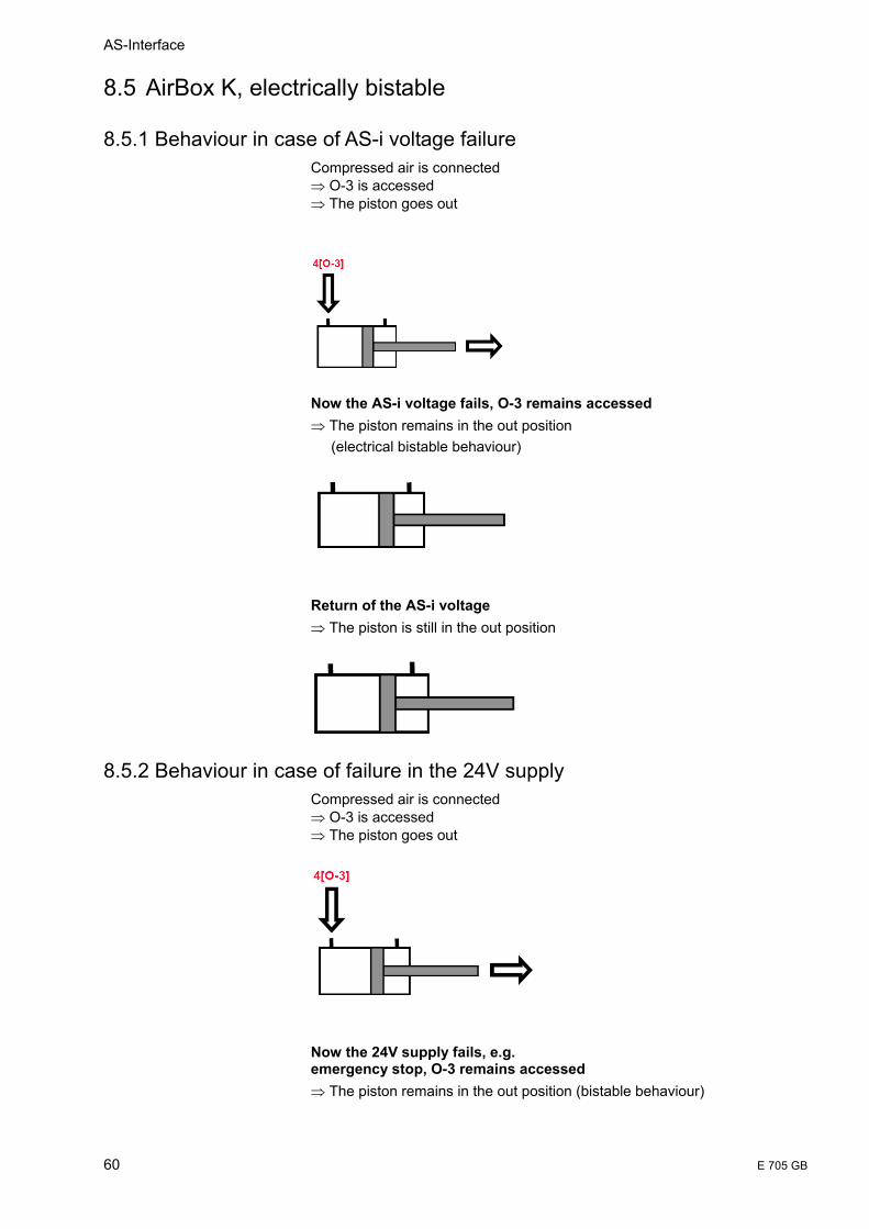
AS-Interface
60 E 705 GB
8.5 AirBox K, electrically bistable
8.5.1 Behaviour in case of AS-i voltage failure Compressed air is connected ⇒ O-3 is accessed ⇒ The piston goes out
Now the AS-i voltage fails, O-3 remains accessed ⇒ The piston remains in the out position (electrical bistable behaviour)
Return of the AS-i voltage ⇒ The piston is still in the out position
8.5.2 Behaviour in case of failure in the 24V supply Compressed air is connected ⇒ O-3 is accessed ⇒ The piston goes out
Now the 24V supply fails, e.g. emergency stop, O-3 remains accessed ⇒ The piston remains in the out position (bistable behaviour)

AirBox
E 705 GB 61
Return of the 24V supply ⇒ The piston remains in the out position!
8.5.3 Behaviour in case of failure in the 24V supply Compressed air is connected ⇒ O-3 is accessed ⇒ The piston goes in
Now the 24V supply fails, e.g. emergency stop, and is subsequently rerouted to O-4 ⇒ The piston remains in the out position (bistable behaviour)
Return of the 24V supply ⇒ The piston goes back in at once since the O-4 was set in the software during the emergency stop phase!

AS-Interface
62 E 705 GB
9 Special information for ATEX AirBox 1. According to the EU directive 94/9/EC (ATEX) the original operating
instructions and a translation of these operating instructions into the language or languages of the EU user country must be supplied when a unit or protective system is put into operation within the member countries of the European Union (EU).
2. If no operating instructions in the language of the EU user country have been included in this delivery, they can be requested on the indicated homepage via the internet, at the indicated address(es) by e-mail, fax, phone or post.
3. Only qualified personnel is allowed to put the product. Furthermore, we expressly point out that any liability resulting from putting the unit into operation without the corresponding operating instructions in the language of the EU user country is excluded.
9.1 Remarks for safe use in hazardous areas
9.1.1 Function and features II 3D Use in hazardous areas according to classification (group II, category 3, apparatus for dust atmosphere) The following standards have been applied: EN50281-1-1:1998, EN50014:1997, EN 50295:1999 Marking II 3D T 65°C IP65 X
9.1.2 Installation /Setup The units should only be mounted, connected and put into service by qualified staff. The qualified staff must have knowledge of protection classes, regulations and provisions for apparatus in hazardous areas. Check whether the classification (see "Marking" above and marking on the unit) is suitable for the application. Permissible operating temperature of the application (referred to the maximum power which can be supplied): 0 ... +40°C
9.1.3 Installation remarks/Mounting • Adhere to the respective national regulations and provisions. • Before mounting ensure that the installation is disconnected from power. • Fasten the FC lower part (KM 1-FK-GE/KM K-FK-GE) on a 35mm rail or
on a mounting device. Mount the module on the wired FC lower part. The FC lower part must not be operated without an ATEX approved upper part.
• To maintain the specified protection class, the 4 screws of the upper part must be tightened evenly crosswise with 0.8Nm. When mounting the module ensure that the seal is carefully inserted.
• During installation and laying the bending radii of the cables and a suitable strain relief must be such that neither the cable entries nor the seals are subjected to mechanical stress.
AirBox
E 705 GB 63
9.1.4 Special conditions for safe operation • Avoid electrostatic charging from plastic units and cables. • Do not mount the module in the dust flow. • Avoid dust deposits on the module. • Avoid electrostatic charging, only clean the unit with a damp cloth. In
principle, rubbing with nonconductive materials must be avoided. • Avoid direct radiation with high UV components (sunlight), mount the
unit at a protected place. • The unit is rated for a low impact energy (mechanical damage) (0.5
joules). The module housing and the cables must be effectively protected against mechanical stress and damage by means of appropriate measures.
• Insert the blanking seals in the FC lower part if the module is located at the end of the cable line. The end of the flat cable must be located inside the module.
• Cover any unused sockets with protective caps , tightening torque 0.8Nm.
• Do not separate the module upper part from the FC lower part while live. • Do not disconnect the M12 connections while live. • Use M12 connectors with hexagon nuts, tightening torque 0.8Nm. • Check the tightening torque of the screws two weeks after mounting and
retighten them, if necessary. • Protective caps, housing upper / lower part and M12 nuts may only be
opened or closed in a sufficiently clean environment. • Using an FC lower part with addressing socket is not permitted. • For use in hazardous areas according to the indication compliance with
the protection rating is essential. Therefore appropriate care must be taken when mounting the housing and the seals, see installation instructions / mounting.
9.1.5 Maintenance /Repair The unit must not be modified nor can it be repaired. In case of a fault please contact the manufacturer.
3RX9400–0AA00
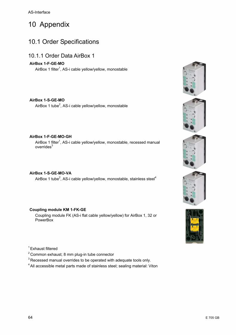
AS-Interface
64 E 705 GB
10 Appendix
10.1 Order Specifications
10.1.1 Order Data AirBox 1 AirBox 1-F-GE-MO
AirBox 1 filter1, AS-i cable yellow/yellow, monostable
AirBox 1-S-GE-MO
AirBox 1 tube2, AS-i cable yellow/yellow, monostable
AirBox 1-F-GE-MO-GH
AirBox 1 filter1, AS-i cable yellow/yellow, monostable, recessed manual overrides3
AirBox 1-S-GE-MO-VA
AirBox 1 tube2, AS-i cable yellow/yellow, monostable, stainless steel4
Coupling module KM 1-FK-GE
Coupling module FK (AS-i flat cable yellow/yellow) for AirBox 1, 32 or PowerBox
1 Exhaust filtered
2 Common exhaust; 8 mm plug-in tube connector 3 Recessed manual overrides to be operated with adequate tools only. 4
All accessible metal parts made of stainless steel; sealing material: Viton
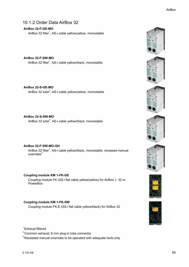
AirBox
E 705 GB 65
10.1.2 Order Data AirBox 32 AirBox 32-F-GE-MO
AirBox 32 filter1, AS-i cable yellow/yellow, monostable
AirBox 32-F-SW-MO
AirBox 32 filter1, AS-i cable yellow/black, monostable
AirBox 32-S-GE-MO
AirBox 32 tube2, AS-i cable yellow/yellow, monostable
AirBox 32-S-SW-MO
AirBox 32 tube2, AS-i cable yellow/black, monostable
AirBox 32-F-SW-MO-GH
AirBox 32 filter1, AS-i cable yellow/black, monostable, recessed manual overrides3
Coupling module KM 1-FK-GE
Coupling module FK (AS-i flat cable yellow/yellow) for AirBox 1, 32 or PowerBox
Coupling module KM 1-FK-SW
Coupling module FK-E (AS-i flat cable yellow/black) for AirBox 32
1
Exhaust filtered 2 Common exhaust; 8 mm plug-in tube connector 3 Recessed manual overrides to be operated with adequate tools only

AS-Interface
66 E 705 GB
10.1.3 Order Data AirBox K AirBox K-F-GE-MO
AirBox K filter1, AS-i cable yellow/yellow, monostable
AirBox K-F-SW-MO
AirBox K filter1, AS-i cable yellow/black, monostable
AirBox K-S-GE-MO
AirBox K tube2, AS-i cable yellow/yellow, monostable
AirBox K-S-SW-MO
AirBox K tube2, AS-i cable yellow/black, monostable
AirBox K-F-GE-BI
AirBox K filter1, AS-i cable yellow/yellow, electrically bistable
AirBox K-F-SW-BI
AirBox K filter1, AS-i cable yellow/black, electrically bistable
AirBox K-S-GE-BI
AirBox K tube2, AS-i cable yellow/yellow, electrically bistable

AirBox
E 705 GB 67
AirBox K-S-SW-BI AirBox K tube2, AS-i cable yellow/black, electrically bistable
KM K-FK-SW
Coupling module FK-E for AirBox K; surface mounting
KM K-HS
Rail adapter for coupling module KM K-FK-SW
1 Exhaust filtered 2 Common exhaust; 8 mm plug-in tube connector
AS-Interface
68 E 705 GB
10.2 FAQs
10.3 References AS-Interface Das Aktuator-Sensor-Interface für die Automation Werner Kriesel, O.W. Madelung, Carl Hanser Verlag München Wien 1994 AS-Interface Complete Specification can be ordered from the AS-i Association e.V. Address: AS-International Association e.V. Geschäftsführung: Dr. Otto W. Madelung Auf den Broich 4A D – 51519 Odenthal Germany Tel.: +49 – 2174 – 40756 Fax.: +49 – 2174 – 41571 (The AS-i technology is promoted by the AS-Interface Association e. V.) Internet address of the AS-International Association e.V.: http://www.as-interface.com PROFIBUS standard EN 50170 AS-Interface The Automation Solution Published by: AS-International Association, Rolf Becker (CEO) Authors: Rolf Becker, Dr. Bernhard Müller, Dr. Andreas Schiff, Tilman Schinke, Heinz Walker
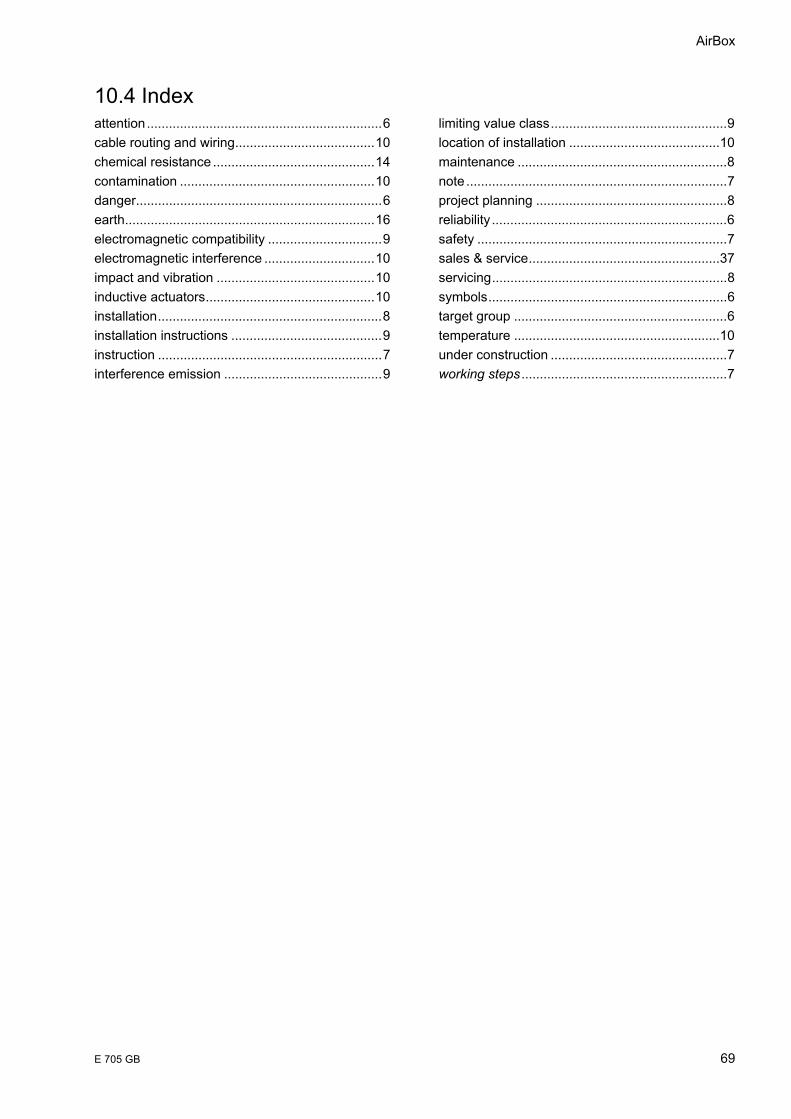
AirBox
E 705 GB 69
10.4 Index attention................................................................6 cable routing and wiring......................................10 chemical resistance ............................................14 contamination .....................................................10 danger...................................................................6 earth....................................................................16 electromagnetic compatibility ...............................9 electromagnetic interference ..............................10 impact and vibration ...........................................10 inductive actuators..............................................10 installation.............................................................8 installation instructions .........................................9 instruction .............................................................7 interference emission ...........................................9
limiting value class................................................9 location of installation .........................................10 maintenance .........................................................8 note .......................................................................7 project planning ....................................................8 reliability ................................................................6 safety ....................................................................7 sales & service....................................................37 servicing................................................................8 symbols.................................................................6 target group ..........................................................6 temperature ........................................................10 under construction ................................................7 working steps ........................................................7

AS-Interface
70 E 705 GB
10.5 Sales & Service Please visit us on the Internet to find a comprehensive overview of our sales and service network including all the relevant addresses.
www.kuhnke.com
10.5.1 Main Factory in Malente Kuhnke GmbH Lütjenburger Str. 101 D-23714 Malente Phone +49-45 23-4 02-0 Fax +49-45 23-40 22 47 Email [email protected] Internet www.kuhnke.de