Kubota 1505 Workshop Manual
124
05-E2B SERIES, 05-E2BG SERIES WORKSHOP MANUAL DIESEL ENGINE KiSC issued 06, 2011 A
-
Upload
solserengsa -
Category
Documents
-
view
301 -
download
22
description
Manual de servicio motor kubota
Transcript of Kubota 1505 Workshop Manual
05-E2B SERIES,05-E2BG SERIES
WORKSHOP MANUALDIESEL ENGINE
KiSC issued 06, 2011 A
TO THE READER
This Workshop Manual has been prepared to provide servicing personnel withinformation on the mechanism, service and maintenance of 05-E2B and 05-E2BGseries. It is divided into three parts, “General”, “Mechanism” and “Servicing”.
GeneralInformation on the engine identification, the general precautions, maintenance check
list, check and maintenance and special tools are described.
MechanismInformation on the construction and function are included. This part should be
understood before proceeding with troubleshooting, disassembling and servicing.Refer to Diesel Engine Mechanism Workshop Manual (Code No. 9Y021-01870) for
the one which has not been described to this workshop manual.
ServicingInformation on the troubleshooting, servicing specification lists, tightening torque,
checking and adjusting, disassembling and assembling, and servicing which coverprocedures, precautions, factory specifications and allowable limits.
All information illustrations and specifications contained in this manual are based onthe latest product information available at the time of publication.
The right is reserved to make changes in all information at any time without notice.Do to covering many models of this manual, information or picture being used have
not been specified as one model.
August 2005© KUBOTA Corporation 2005
KiSC issued 06, 2011 A
1
05-E2B, 05-E2BG, WSM SAFETY INSTRUCTIONS
SAFETY INSTRUCTIONS
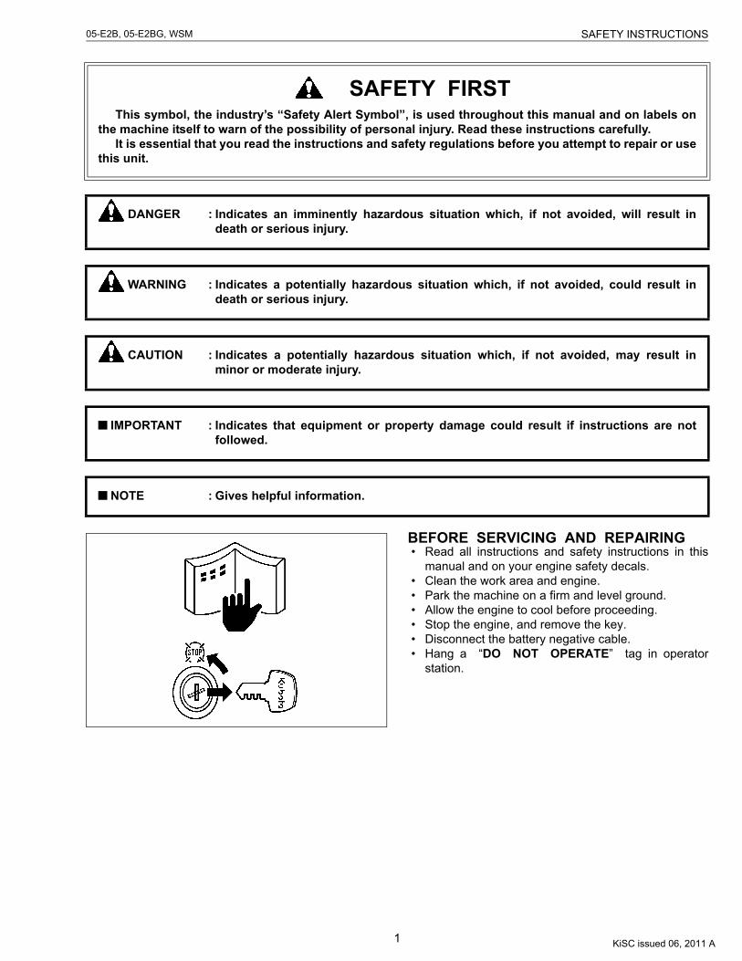
BEFORE SERVICING AND REPAIRING• Read all instructions and safety instructions in this
manual and on your engine safety decals.• Clean the work area and engine.• Park the machine on a firm and level ground.• Allow the engine to cool before proceeding.• Stop the engine, and remove the key.• Disconnect the battery negative cable.• Hang a “DO NOT OPERATE” tag in operator
station.
SAFETY FIRSTThis symbol, the industry’s “Safety Alert Symbol”, is used throughout this manual and on labels on
the machine itself to warn of the possibility of personal injury. Read these instructions carefully.It is essential that you read the instructions and safety regulations before you attempt to repair or use
this unit.
DANGER : Indicates an imminently hazardous situation which, if not avoided, will result indeath or serious injury.
WARNING : Indicates a potentially hazardous situation which, if not avoided, could result indeath or serious injury.
CAUTION : Indicates a potentially hazardous situation which, if not avoided, may result inminor or moderate injury.
IMPORTANT : Indicates that equipment or property damage could result if instructions are notfollowed.
NOTE : Gives helpful information.
KiSC issued 06, 2011 A
2
05-E2B, 05-E2BG, WSM SAFETY INSTRUCTIONS
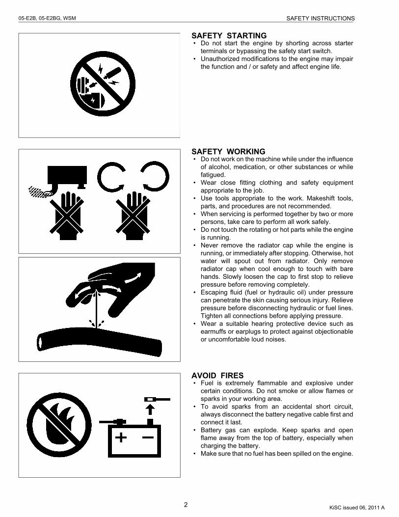
SAFETY STARTING• Do not start the engine by shorting across starter
terminals or bypassing the safety start switch.• Unauthorized modifications to the engine may impair
the function and / or safety and affect engine life.
SAFETY WORKING• Do not work on the machine while under the influence
of alcohol, medication, or other substances or whilefatigued.
• Wear close fitting clothing and safety equipmentappropriate to the job.
• Use tools appropriate to the work. Makeshift tools,parts, and procedures are not recommended.
• When servicing is performed together by two or morepersons, take care to perform all work safely.
• Do not touch the rotating or hot parts while the engineis running.
• Never remove the radiator cap while the engine isrunning, or immediately after stopping. Otherwise, hotwater will spout out from radiator. Only removeradiator cap when cool enough to touch with barehands. Slowly loosen the cap to first stop to relievepressure before removing completely.
• Escaping fluid (fuel or hydraulic oil) under pressurecan penetrate the skin causing serious injury. Relievepressure before disconnecting hydraulic or fuel lines.Tighten all connections before applying pressure.
• Wear a suitable hearing protective device such asearmuffs or earplugs to protect against objectionableor uncomfortable loud noises.
AVOID FIRES• Fuel is extremely flammable and explosive under
certain conditions. Do not smoke or allow flames orsparks in your working area.
• To avoid sparks from an accidental short circuit,always disconnect the battery negative cable first andconnect it last.
• Battery gas can explode. Keep sparks and openflame away from the top of battery, especially whencharging the battery.
• Make sure that no fuel has been spilled on the engine.
KiSC issued 06, 2011 A
3
05-E2B, 05-E2BG, WSM SAFETY INSTRUCTIONS
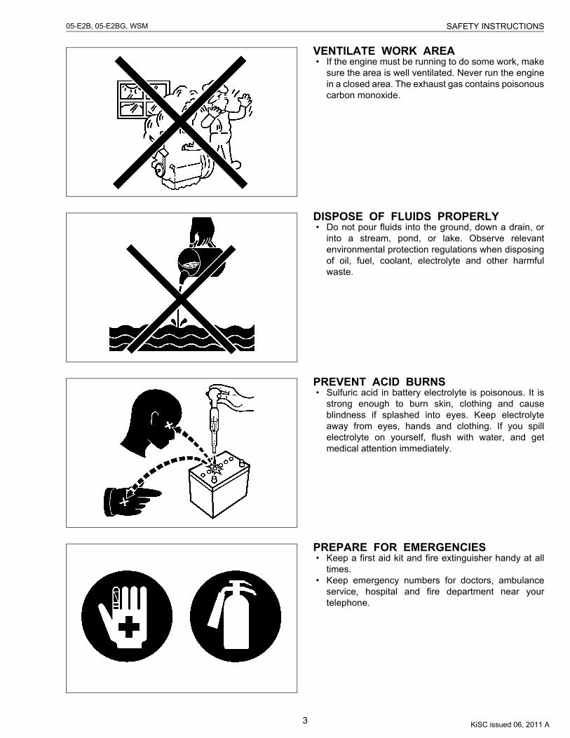
VENTILATE WORK AREA• If the engine must be running to do some work, make
sure the area is well ventilated. Never run the enginein a closed area. The exhaust gas contains poisonouscarbon monoxide.
DISPOSE OF FLUIDS PROPERLY• Do not pour fluids into the ground, down a drain, or
into a stream, pond, or lake. Observe relevantenvironmental protection regulations when disposingof oil, fuel, coolant, electrolyte and other harmfulwaste.
PREVENT ACID BURNS• Sulfuric acid in battery electrolyte is poisonous. It is
strong enough to burn skin, clothing and causeblindness if splashed into eyes. Keep electrolyteaway from eyes, hands and clothing. If you spillelectrolyte on yourself, flush with water, and getmedical attention immediately.
PREPARE FOR EMERGENCIES• Keep a first aid kit and fire extinguisher handy at all
times.• Keep emergency numbers for doctors, ambulance
service, hospital and fire department near yourtelephone.
KiSC issued 06, 2011 A
4
05-E2B, 05-E2BG, WSM SPECIFICATIONS
SPECIFICATIONS
* The specification described above is of the standard engine of each model.* Conversion Formula : HP = 0.746 kW, PS = 0.7355 kW
W10275180
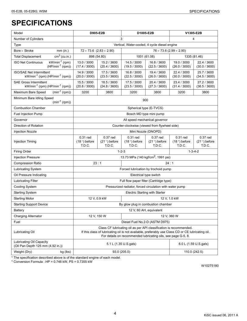
Model D905-E2B D1005-E2B V1305-E2B
Number of Cylinders 3 4
Type Vertical, Water-cooled, 4 cycle diesel engine
Bore × Stroke mm (in.) 72 × 73.6 (2.83 × 2.90) 76 × 73.6 (2.99 × 2.90)
Total Displacement cm3 (cu.in.) 898 (54.80) 1001 (61.08) 1335 (81.46)
ISO Net Continuous kW/min-1 (rpm) (HP/min-1 (rpm))
13.0 / 3000(17.4 / 3000)
15.2 / 3600(20.4 / 3600)
14.5 / 3000(19.5 / 3000)
16.8 / 3600(22.5 / 3600)
19.0 / 3000(26.0 / 3000)
22.4 / 3600(30.0 / 3600)
ISO/SAE Net Intermittent kW/min-1 (rpm) (HP/min-1 (rpm))
14.9 / 3000(20.0 / 3000)
17.5 / 3600(23.5 / 3600)
16.8 / 3000(22.5 / 3000)
19.4 / 3600(26.0 / 3600)
22.4 / 3000(30.0 / 3000)
25.7 / 3600(34.5 / 3600)
SAE Gross Intermittent kW/min-1 (rpm) (HP/min-1 (rpm))
15.5 / 3000(20.8 / 3000)
18.5 / 3600(24.8 / 3600)
17.5 / 3000(23.5 / 3000)
20.4 / 3600(27.3 / 3600)
23.4 / 3000(31.4 / 3000)
27.2 / 3600(36.5 / 3600)
Maximum Bare Speed (min-1 (rpm)) 3200 3800 3200 3800 3200 3800
Minimum Bare Idling Speed (min-1 (rpm)) 900
Combustion Chamber Spherical type (E-TVCS)
Fuel Injection Pump Bosch MD type mini pump
Governor All speed mechanical governor
Direction of Rotation Counter-clockwise (viewed from flywheel side)
Injection Nozzle Mini Nozzle (DNOPD)
Injection Timing0.31 rad
(18 °) before T.D.C.
0.37 rad(21 °) before
T.D.C.
0.31 rad(18 °) before
T.D.C.
0.37 rad(21 °) before
T.D.C.
0.31 rad(18 °) before
T.D.C.
0.37 rad(21 °) before
T.D.C.
Firing Order 1-2-3 1-3-4-2
Injection Pressure 13.73 MPa (140 kgf/cm2, 1991 psi)
Compression Ratio 23 : 1 24 : 1
Lubricating System Forced lubrication by trochoid pump
Oil Pressure Indicating Electrical type switch
Lubricating Filter Full flow paper filter (Cartridge type)
Cooling System Pressurized radiator, forced circulation with water pump
Starting System Electric Starting with Starter
Starting Motor 12 V, 0.9 kW 12 V, 1.0 kW
Starting Support Device By glow plug in combustion chamber
Battery 12 V, 60 AH, equivalent
Charging Alternator 12 V, 150 W 12 V, 360 W
Fuel Diesel Fuel No.2-D (ASTM D975)
Lubricating OilClass CF lubricating oil as per API classification is recommended.
If this class of lubricating oil is not available, preferably use Class CD or CE lubricating oil.For details on recommended lubricating oils, see page G-5, 8.
Lubricating Oil Capacity(Oil Pan Depth 125 mm (4.92 in.)) 5.1 L (1.35 U.S.gals) 6.0 L (1.59 U.S.gals)
Weight (Dry) kg (lbs) 93.0 (205.0) 110.0 (242.5)
KiSC issued 06, 2011 A
5
05-E2B, 05-E2BG, WSM SPECIFICATIONS
* The specification described above is of the standard engine of each model.* Conversion Formula : HP = 0.746 kW, PS = 0.7355 kW
W10316890
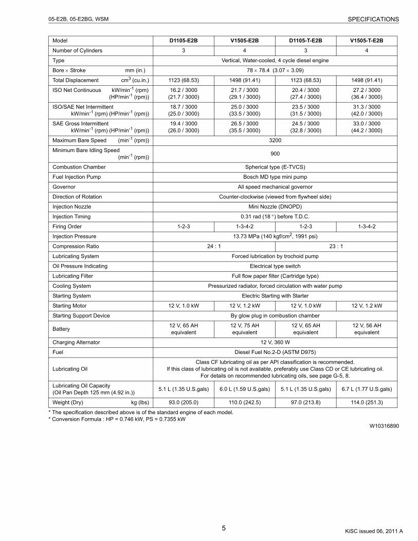
Model D1105-E2B V1505-E2B D1105-T-E2B V1505-T-E2B
Number of Cylinders 3 4 3 4
Type Vertical, Water-cooled, 4 cycle diesel engine
Bore × Stroke mm (in.) 78 × 78.4 (3.07 × 3.09)
Total Displacement cm3 (cu.in.) 1123 (68.53) 1498 (91.41) 1123 (68.53) 1498 (91.41)
ISO Net Continuous kW/min-1 (rpm) (HP/min-1 (rpm))
16.2 / 3000(21.7 / 3000)
21.7 / 3000(29.1 / 3000)
20.4 / 3000(27.4 / 3000)
27.2 / 3000(36.4 / 3000)
ISO/SAE Net Intermittent kW/min-1 (rpm) (HP/min-1 (rpm))
18.7 / 3000(25.0 / 3000)
25.0 / 3000(33.5 / 3000)
23.5 / 3000(31.5 / 3000)
31.3 / 3000(42.0 / 3000)
SAE Gross Intermittent kW/min-1 (rpm) (HP/min-1 (rpm))
19.4 / 3000(26.0 / 3000)
26.5 / 3000(35.5 / 3000)
24.5 / 3000(32.8 / 3000)
33.0 / 3000(44.2 / 3000)
Maximum Bare Speed (min-1 (rpm)) 3200
Minimum Bare Idling Speed (min-1 (rpm)) 900
Combustion Chamber Spherical type (E-TVCS)
Fuel Injection Pump Bosch MD type mini pump
Governor All speed mechanical governor
Direction of Rotation Counter-clockwise (viewed from flywheel side)
Injection Nozzle Mini Nozzle (DNOPD)
Injection Timing 0.31 rad (18 °) before T.D.C.
Firing Order 1-2-3 1-3-4-2 1-2-3 1-3-4-2
Injection Pressure 13.73 MPa (140 kgf/cm2, 1991 psi)
Compression Ratio 24 : 1 23 : 1
Lubricating System Forced lubrication by trochoid pump
Oil Pressure Indicating Electrical type switch
Lubricating Filter Full flow paper filter (Cartridge type)
Cooling System Pressurized radiator, forced circulation with water pump
Starting System Electric Starting with Starter
Starting Motor 12 V, 1.0 kW 12 V, 1.2 kW 12 V, 1.0 kW 12 V, 1.2 kW
Starting Support Device By glow plug in combustion chamber
Battery 12 V, 65 AH equivalent
12 V, 75 AH equivalent
12 V, 65 AH equivalent
12 V, 56 AH equivalent
Charging Alternator 12 V, 360 W
Fuel Diesel Fuel No.2-D (ASTM D975)
Lubricating OilClass CF lubricating oil as per API classification is recommended.
If this class of lubricating oil is not available, preferably use Class CD or CE lubricating oil.For details on recommended lubricating oils, see page G-5, 8.
Lubricating Oil Capacity(Oil Pan Depth 125 mm (4.92 in.)) 5.1 L (1.35 U.S.gals) 6.0 L (1.59 U.S.gals) 5.1 L (1.35 U.S.gals) 6.7 L (1.77 U.S.gals)
Weight (Dry) kg (lbs) 93.0 (205.0) 110.0 (242.5) 97.0 (213.8) 114.0 (251.3)
KiSC issued 06, 2011 A
6
05-E2B, 05-E2BG, WSM SPECIFICATIONS
* The specification described above is of the standard engine of each model.* Conversion Formula : HP = 0.746 kW, PS = 0.7355 kW
W10336300
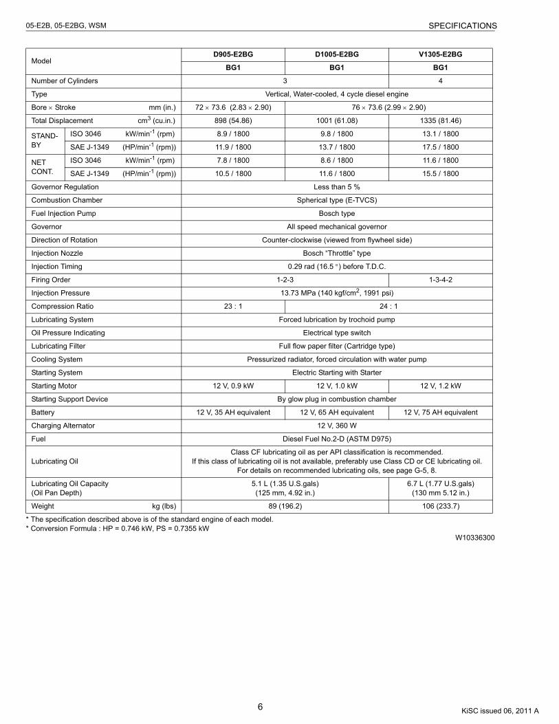
ModelD905-E2BG D1005-E2BG V1305-E2BG
BG1 BG1 BG1
Number of Cylinders 3 4
Type Vertical, Water-cooled, 4 cycle diesel engine
Bore × Stroke mm (in.) 72 × 73.6 (2.83 × 2.90) 76 × 73.6 (2.99 × 2.90)
Total Displacement cm3 (cu.in.) 898 (54.86) 1001 (61.08) 1335 (81.46)
STAND-BY
ISO 3046 kW/min-1 (rpm) 8.9 / 1800 9.8 / 1800 13.1 / 1800
SAE J-1349 (HP/min-1 (rpm)) 11.9 / 1800 13.7 / 1800 17.5 / 1800
NET CONT.
ISO 3046 kW/min-1 (rpm) 7.8 / 1800 8.6 / 1800 11.6 / 1800
SAE J-1349 (HP/min-1 (rpm)) 10.5 / 1800 11.6 / 1800 15.5 / 1800
Governor Regulation Less than 5 %
Combustion Chamber Spherical type (E-TVCS)
Fuel Injection Pump Bosch type
Governor All speed mechanical governor
Direction of Rotation Counter-clockwise (viewed from flywheel side)
Injection Nozzle Bosch “Throttle” type
Injection Timing 0.29 rad (16.5 °) before T.D.C.
Firing Order 1-2-3 1-3-4-2
Injection Pressure 13.73 MPa (140 kgf/cm2, 1991 psi)
Compression Ratio 23 : 1 24 : 1
Lubricating System Forced lubrication by trochoid pump
Oil Pressure Indicating Electrical type switch
Lubricating Filter Full flow paper filter (Cartridge type)
Cooling System Pressurized radiator, forced circulation with water pump
Starting System Electric Starting with Starter
Starting Motor 12 V, 0.9 kW 12 V, 1.0 kW 12 V, 1.2 kW
Starting Support Device By glow plug in combustion chamber
Battery 12 V, 35 AH equivalent 12 V, 65 AH equivalent 12 V, 75 AH equivalent
Charging Alternator 12 V, 360 W
Fuel Diesel Fuel No.2-D (ASTM D975)
Lubricating OilClass CF lubricating oil as per API classification is recommended.
If this class of lubricating oil is not available, preferably use Class CD or CE lubricating oil.For details on recommended lubricating oils, see page G-5, 8.
Lubricating Oil Capacity(Oil Pan Depth)
5.1 L (1.35 U.S.gals)(125 mm, 4.92 in.)
6.7 L (1.77 U.S.gals)(130 mm 5.12 in.)
Weight kg (lbs) 89 (196.2) 106 (233.7)
KiSC issued 06, 2011 A
7
05-E2B, 05-E2BG, WSM SPECIFICATIONS
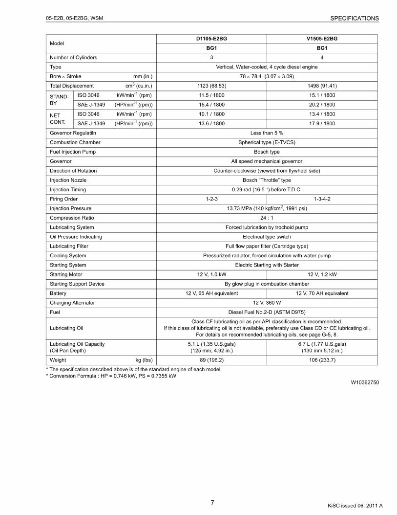
* The specification described above is of the standard engine of each model.* Conversion Formula : HP = 0.746 kW, PS = 0.7355 kW
W10362750
ModelD1105-E2BG V1505-E2BG
BG1 BG1
Number of Cylinders 3 4
Type Vertical, Water-cooled, 4 cycle diesel engine
Bore × Stroke mm (in.) 78 × 78.4 (3.07 × 3.09)
Total Displacement cm3 (cu.in.) 1123 (68.53) 1498 (91.41)
STAND-BY
ISO 3046 kW/min-1 (rpm) 11.5 / 1800 15.1 / 1800
SAE J-1349 (HP/min-1 (rpm)) 15.4 / 1800 20.2 / 1800
NET CONT.
ISO 3046 kW/min-1 (rpm) 10.1 / 1800 13.4 / 1800
SAE J-1349 (HP/min-1 (rpm)) 13.6 / 1800 17.9 / 1800
Governor Regulatiln Less than 5 %
Combustion Chamber Spherical type (E-TVCS)
Fuel Injection Pump Bosch type
Governor All speed mechanical governor
Direction of Rotation Counter-clockwise (viewed from flywheel side)
Injection Nozzle Bosch “Throttle” type
Injection Timing 0.29 rad (16.5 °) before T.D.C.
Firing Order 1-2-3 1-3-4-2
Injection Pressure 13.73 MPa (140 kgf/cm2, 1991 psi)
Compression Ratio 24 : 1
Lubricating System Forced lubrication by trochoid pump
Oil Pressure Indicating Electrical type switch
Lubricating Filter Full flow paper filter (Cartridge type)
Cooling System Pressurized radiator, forced circulation with water pump
Starting System Electric Starting with Starter
Starting Motor 12 V, 1.0 kW 12 V, 1.2 kW
Starting Support Device By glow plug in combustion chamber
Battery 12 V, 65 AH equivalent 12 V, 70 AH equivalent
Charging Alternator 12 V, 360 W
Fuel Diesel Fuel No.2-D (ASTM D975)
Lubricating OilClass CF lubricating oil as per API classification is recommended.
If this class of lubricating oil is not available, preferably use Class CD or CE lubricating oil.For details on recommended lubricating oils, see page G-5, 8.
Lubricating Oil Capacity(Oil Pan Depth)
5.1 L (1.35 U.S.gals)(125 mm, 4.92 in.)
6.7 L (1.77 U.S.gals)(130 mm 5.12 in.)
Weight kg (lbs) 89 (196.2) 106 (233.7)
KiSC issued 06, 2011 A
8
05-E2B, 05-E2BG, WSM PERFORMANCE CURVES
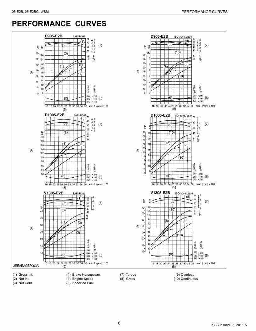
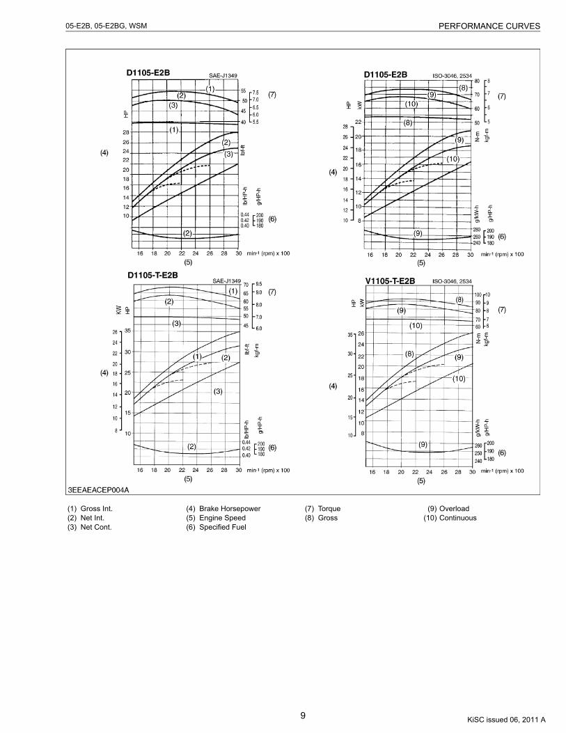
PERFORMANCE CURVES
(1) Gross Int.(2) Net Int.(3) Net Cont.
(4) Brake Horsepower(5) Engine Speed(6) Specified Fuel
(7) Torque(8) Gross
(9) Overload(10) Continuous
KiSC issued 06, 2011 A
9
05-E2B, 05-E2BG, WSM PERFORMANCE CURVES
(1) Gross Int.(2) Net Int.(3) Net Cont.
(4) Brake Horsepower(5) Engine Speed(6) Specified Fuel
(7) Torque(8) Gross
(9) Overload(10) Continuous
KiSC issued 06, 2011 A

10
05-E2B, 05-E2BG, WSM PERFORMANCE CURVES
(1) Gross Int.(2) Net Int.(3) Net Cont.
(4) Brake Horsepower(5) Engine Speed(6) Specified Fuel
(7) Torque(8) Gross
(9) Overload(10) Continuous
KiSC issued 06, 2011 A
11
05-E2B, 05-E2BG, WSM DIMENSIONS
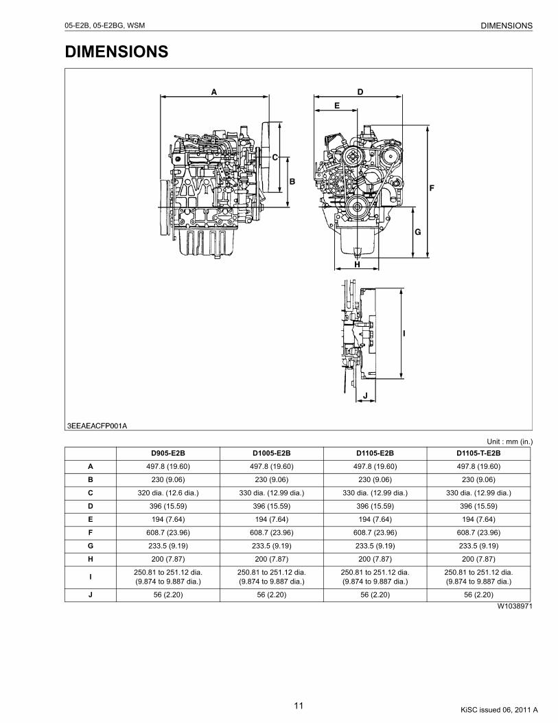
DIMENSIONS
Unit : mm (in.)
W1038971
D905-E2B D1005-E2B D1105-E2B D1105-T-E2B
A 497.8 (19.60) 497.8 (19.60) 497.8 (19.60) 497.8 (19.60)
B 230 (9.06) 230 (9.06) 230 (9.06) 230 (9.06)
C 320 dia. (12.6 dia.) 330 dia. (12.99 dia.) 330 dia. (12.99 dia.) 330 dia. (12.99 dia.)
D 396 (15.59) 396 (15.59) 396 (15.59) 396 (15.59)
E 194 (7.64) 194 (7.64) 194 (7.64) 194 (7.64)
F 608.7 (23.96) 608.7 (23.96) 608.7 (23.96) 608.7 (23.96)
G 233.5 (9.19) 233.5 (9.19) 233.5 (9.19) 233.5 (9.19)
H 200 (7.87) 200 (7.87) 200 (7.87) 200 (7.87)
I 250.81 to 251.12 dia.(9.874 to 9.887 dia.)
250.81 to 251.12 dia.(9.874 to 9.887 dia.)
250.81 to 251.12 dia.(9.874 to 9.887 dia.)
250.81 to 251.12 dia.(9.874 to 9.887 dia.)
J 56 (2.20) 56 (2.20) 56 (2.20) 56 (2.20)
KiSC issued 06, 2011 A
12
05-E2B, 05-E2BG, WSM DIMENSIONS
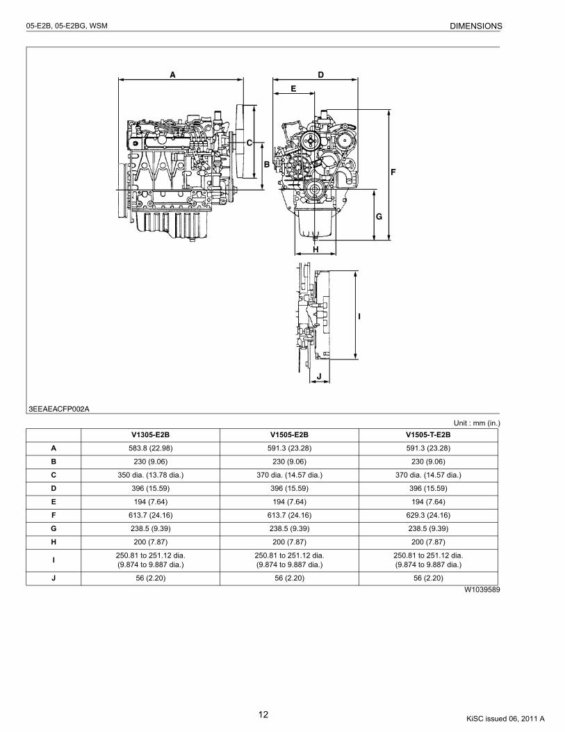
Unit : mm (in.)
W1039589
V1305-E2B V1505-E2B V1505-T-E2B
A 583.8 (22.98) 591.3 (23.28) 591.3 (23.28)
B 230 (9.06) 230 (9.06) 230 (9.06)
C 350 dia. (13.78 dia.) 370 dia. (14.57 dia.) 370 dia. (14.57 dia.)
D 396 (15.59) 396 (15.59) 396 (15.59)
E 194 (7.64) 194 (7.64) 194 (7.64)
F 613.7 (24.16) 613.7 (24.16) 629.3 (24.16)
G 238.5 (9.39) 238.5 (9.39) 238.5 (9.39)
H 200 (7.87) 200 (7.87) 200 (7.87)
I 250.81 to 251.12 dia.(9.874 to 9.887 dia.)
250.81 to 251.12 dia.(9.874 to 9.887 dia.)
250.81 to 251.12 dia.(9.874 to 9.887 dia.)
J 56 (2.20) 56 (2.20) 56 (2.20)
KiSC issued 06, 2011 A
13
05-E2B, 05-E2BG, WSM DIMENSIONS
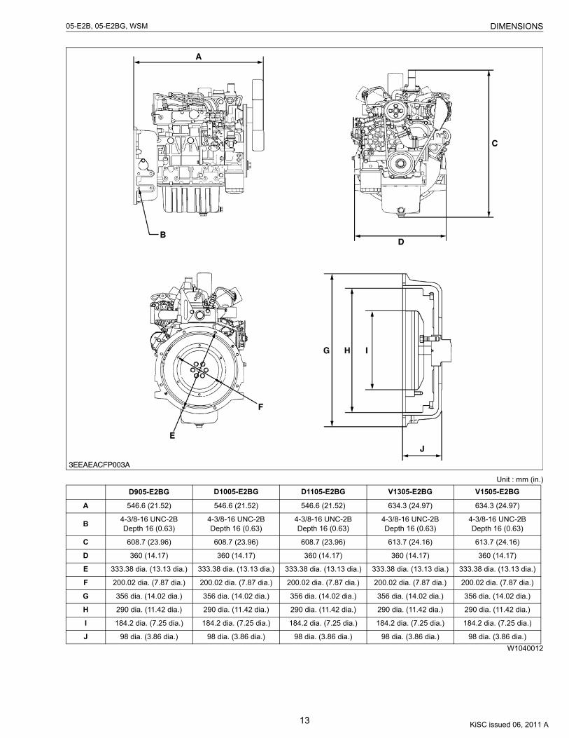
Unit : mm (in.)
W1040012
D905-E2BG D1005-E2BG D1105-E2BG V1305-E2BG V1505-E2BG
A 546.6 (21.52) 546.6 (21.52) 546.6 (21.52) 634.3 (24.97) 634.3 (24.97)
B 4-3/8-16 UNC-2BDepth 16 (0.63)
4-3/8-16 UNC-2BDepth 16 (0.63)
4-3/8-16 UNC-2BDepth 16 (0.63)
4-3/8-16 UNC-2BDepth 16 (0.63)
4-3/8-16 UNC-2BDepth 16 (0.63)
C 608.7 (23.96) 608.7 (23.96) 608.7 (23.96) 613.7 (24.16) 613.7 (24.16)
D 360 (14.17) 360 (14.17) 360 (14.17) 360 (14.17) 360 (14.17)
E 333.38 dia. (13.13 dia.) 333.38 dia. (13.13 dia.) 333.38 dia. (13.13 dia.) 333.38 dia. (13.13 dia.) 333.38 dia. (13.13 dia.)
F 200.02 dia. (7.87 dia.) 200.02 dia. (7.87 dia.) 200.02 dia. (7.87 dia.) 200.02 dia. (7.87 dia.) 200.02 dia. (7.87 dia.)
G 356 dia. (14.02 dia.) 356 dia. (14.02 dia.) 356 dia. (14.02 dia.) 356 dia. (14.02 dia.) 356 dia. (14.02 dia.)
H 290 dia. (11.42 dia.) 290 dia. (11.42 dia.) 290 dia. (11.42 dia.) 290 dia. (11.42 dia.) 290 dia. (11.42 dia.)
I 184.2 dia. (7.25 dia.) 184.2 dia. (7.25 dia.) 184.2 dia. (7.25 dia.) 184.2 dia. (7.25 dia.) 184.2 dia. (7.25 dia.)
J 98 dia. (3.86 dia.) 98 dia. (3.86 dia.) 98 dia. (3.86 dia.) 98 dia. (3.86 dia.) 98 dia. (3.86 dia.)
KiSC issued 06, 2011 A
CONTENTS
GENERAL
1. ENGINE IDENTIFICATION............................................................................. G-1[1] MODEL NAME AND ENGINE SERIAL NUMBER ................................ G-1[2] E2B ENGINE............................................................................................. G-2[3] CYLINDER NUMBER ............................................................................... G-2
2. GENERAL PRECAUTIONS ............................................................................ G-33. MAINTENANCE CHECK LIST....................................................................... G-44. CHECK AND MAINTENANCE....................................................................... G-6
[1] DAILY CHECK POINTS........................................................................... G-6[2] CHECK POINTS OF INITIAL 50 HOURS ............................................. G-8[3] CHECK POINTS OF EVERY 50 HOURS ........................................... G-10[4] CHECK POINTS OF EVERY 100 HOURS......................................... G-11[5] CHECK POINTS OF EVERY 200 HOURS......................................... G-13[6] CHECK POINTS OF EVERY 400 HOURS......................................... G-14[7] CHECK POINTS OF EVERY 500 HOURS......................................... G-15[8] CHECK POINTS OF EVERY 1 OR 2 MONTHS ............................... G-17[9] CHECK POINTS OF EVERY YEAR .................................................... G-18[10]CHECK POINTS OF EVERY 800 HOURS......................................... G-19[11]CHECK POINTS OF EVERY 1500 HOURS....................................... G-20[12]CHECK POINTS OF EVERY 3000 HOURS....................................... G-21[13]CHECK POINTS OF EVERY 2 YEARS.............................................. G-24
5. SPECIAL TOOLS.......................................................................................... G-28
KiSC issued 06, 2011 A
G-1
05-E2B, 05-E2BG, WSM G GENERAL
1. ENGINE IDENTIFICATION[1] MODEL NAME AND ENGINE SERIAL NUMBER
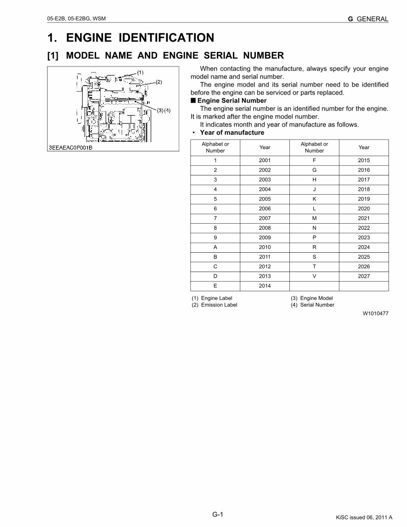
When contacting the manufacture, always specify your enginemodel name and serial number.
The engine model and its serial number need to be identifiedbefore the engine can be serviced or parts replaced.
Engine Serial NumberThe engine serial number is an identified number for the engine.
It is marked after the engine model number.It indicates month and year of manufacture as follows.
• Year of manufacture
W1010477
Alphabet or Number Year Alphabet or
Number Year
1 2001 F 2015
2 2002 G 2016
3 2003 H 2017
4 2004 J 2018
5 2005 K 2019
6 2006 L 2020
7 2007 M 2021
8 2008 N 2022
9 2009 P 2023
A 2010 R 2024
B 2011 S 2025
C 2012 T 2026
D 2013 V 2027
E 2014
(1) Engine Label(2) Emission Label
(3) Engine Model(4) Serial Number
KiSC issued 06, 2011 A
G-2
05-E2B, 05-E2BG, WSM G GENERAL
• Month of manufacture
e.g. D1105-4A0001“4” indicates 2004 and “A” indicates January.
So, 4A indicates that the engine was manufactured in January,2004.
W1011076
[2] E2B ENGINE[ex. Model Name D1105-E2B]The emission controls that have been put into effect in various countries to prevent air pollution will be stepped up.
The time to enforce the regulations differs depending on the engine output classifications.Kubota has been supplying the diesel engines conforming to the emission regulations in respective countries.
Exhaust emissions regulations shift to the second stage. Kubota executed the improvement of the engine accordingto this regulation.
In order to discriminate the engines conforming to Tier 1 / Phase 1 requirements and those conforming to Tier 2 /Phase 2 requirements, we have adopted E2B as a new model name for the engines conforming Tier 2 / Phase 2regulations.
In the after-sale services for 05-E2B and 05-E2BG series engines, only use the dedicated parts for E2B modelsand carry out the maintenance services accordingly.
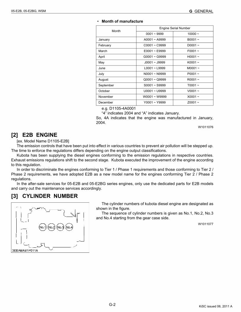
[3] CYLINDER NUMBERThe cylinder numbers of kubota diesel engine are designated as
shown in the figure.The sequence of cylinder numbers is given as No.1, No.2, No.3
and No.4 starting from the gear case side.W1011077
MonthEngine Serial Number
0001 ~ 9999 10000 ~
January A0001 ~ A9999 B0001 ~
February C0001 ~ C9999 D0001 ~
March E0001 ~ E9999 F0001 ~
April G0001 ~ G9999 H0001 ~
May J0001 ~ J9999 K0001 ~
June L0001 ~ L9999 M0001 ~
July N0001 ~ N9999 P0001 ~
August Q0001 ~ Q9999 R0001 ~
September S0001 ~ S9999 T0001 ~
October U0001 ~ U9999 V0001 ~
November W0001 ~ W9999 X0001 ~
December Y0001 ~ Y9999 Z0001 ~
KiSC issued 06, 2011 A
G-3
05-E2B, 05-E2BG, WSM G GENERAL
2. GENERAL PRECAUTIONS• During disassembly, carefully arrange removed parts in a clean
area to prevent confusion later. Screws, bolts and nuts should bereplaced in their original position to prevent reassembly errors.
• When special tools are required, use KUBOTA genuine specialtools. Special tools which are not frequently used should bemade according to the drawings provided.
• Before disassembling or servicing live wires, make sure toalways disconnect the grounding cable from the battery first.
• Remove oil and dirt from parts before measuring.• Use only KUBOTA genuine parts for parts replacement to
maintain engine performance and to ensure safety.• Gaskets and O-rings must be replaced during reassembly.
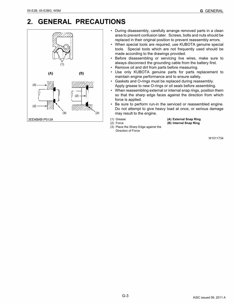
Apply grease to new O-rings or oil seals before assembling.• When reassembling external or internal snap rings, position them
so that the sharp edge faces against the direction from whichforce is applied.
• Be sure to perform run-in the serviced or reassembled engine.Do not attempt to give heavy load at once, or serious damagemay result to the engine.
W1011734
(1) Grease(2) Force(3) Place the Sharp Edge against the
Direction of Force
(A) External Snap Ring(B) Internal Snap Ring
KiSC issued 06, 2011 A
G-4
05-E2B, 05-E2BG, WSM G GENERAL
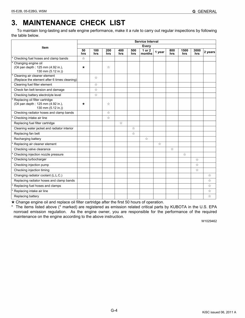
3. MAINTENANCE CHECK LISTTo maintain long-lasting and safe engine performance, make it a rule to carry out regular inspections by following
the table below.
Change engine oil and replace oil filter cartridge after the first 50 hours of operation.* The items listed above (* marked) are registered as emission related critical parts by KUBOTA in the U.S. EPA
nonroad emission regulation. As the engine owner, you are responsible for the performance of the requiredmaintenance on the engine according to the above instruction.
W1029462
Item
Service Interval Every
50hrs
100hrs
200hrs
400hrs
500hrs
1 or 2 months 1 year 800
hrs1500hrs
3000hrs 2 years
* Checking fuel hoses and clamp bands* Changing engine oil
(Oil pan depth : 125 mm (4.92 in.), 130 mm (5.12 in.))* Cleaning air cleaner element
(Replace the element after 6 times cleaning)Cleaning fuel filter elementCheck fan belt tension and damageChecking battery electrolyte level
* Replacing oil filter cartridge(Oil pan depth : 125 mm (4.92 in.),
130 mm (5.12 in.))Checking radiator hoses and clamp bands
* Checking intake air lineReplacing fuel filter cartridgeCleaning water jacket and radiator interiorReplacing fan beltRecharging battery
* Replacing air cleaner elementChecking valve clearance
* Checking injection nozzle pressure* Checking turbocharger
Checking injection pumpChecking injection timingChanging radiator coolant (L.L.C.)Replacing radiator hoses and clamp bands
* Replacing fuel hoses and clamps* Replacing intake air line
Replacing battery
KiSC issued 06, 2011 A
G-5
05-E2B, 05-E2BG, WSM G GENERAL
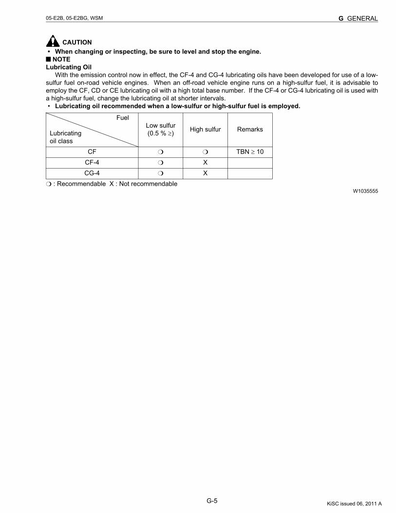
CAUTION• When changing or inspecting, be sure to level and stop the engine. NOTE
Lubricating OilWith the emission control now in effect, the CF-4 and CG-4 lubricating oils have been developed for use of a low-
sulfur fuel on-road vehicle engines. When an off-road vehicle engine runs on a high-sulfur fuel, it is advisable toemploy the CF, CD or CE lubricating oil with a high total base number. If the CF-4 or CG-4 lubricating oil is used witha high-sulfur fuel, change the lubricating oil at shorter intervals.• Lubricating oil recommended when a low-sulfur or high-sulfur fuel is employed.
: Recommendable X : Not recommendableW1035555
Fuel
Lubricatingoil class
Low sulfur(0.5 % ≥) High sulfur Remarks
CF TBN ≥ 10CF-4 XCG-4 X
KiSC issued 06, 2011 A
G-6
05-E2B, 05-E2BG, WSM G GENERAL
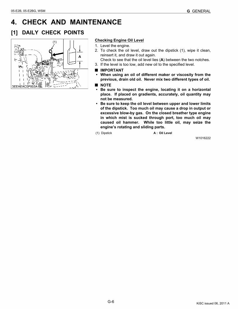
4. CHECK AND MAINTENANCE[1] DAILY CHECK POINTS
Checking Engine Oil Level1. Level the engine.2. To check the oil level, draw out the dipstick (1), wipe it clean,
reinsert it, and draw it out again.Check to see that the oil level lies (A) between the two notches.
3. If the level is too low, add new oil to the specified level.IMPORTANT
• When using an oil of different maker or viscosity from theprevious, drain old oil. Never mix two different types of oil.NOTE
• Be sure to inspect the engine, locating it on a horizontalplace. If placed on gradients, accurately, oil quantity maynot be measured.
• Be sure to keep the oil level between upper and lower limitsof the dipstick. Too much oil may cause a drop in output orexcessive blow-by gas. On the closed breather type enginein which mist is sucked through port, too much oil maycaused oil hammer. While too little oil, may seize theengine’s rotating and sliding parts.
W1016222(1) Dipstick A : Oil Level
KiSC issued 06, 2011 A
G-7
05-E2B, 05-E2BG, WSM G GENERAL
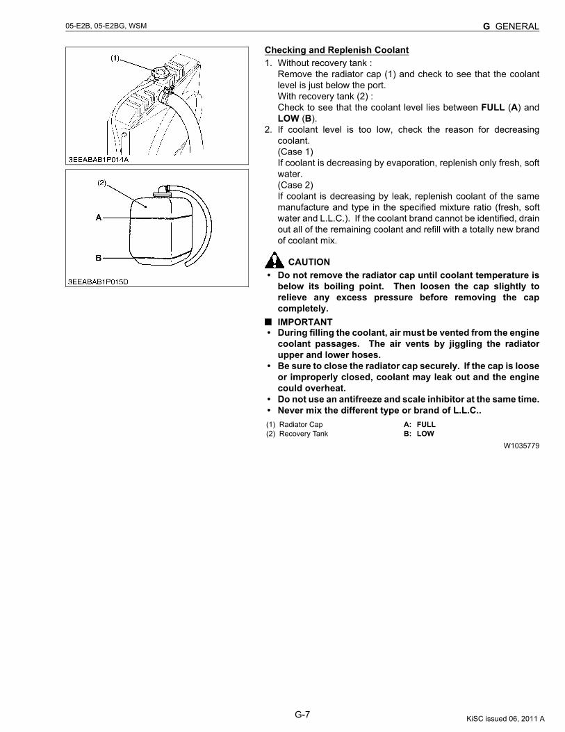
Checking and Replenish Coolant1. Without recovery tank :
Remove the radiator cap (1) and check to see that the coolantlevel is just below the port.With recovery tank (2) :Check to see that the coolant level lies between FULL (A) andLOW (B).
2. If coolant level is too low, check the reason for decreasingcoolant.(Case 1)If coolant is decreasing by evaporation, replenish only fresh, softwater.(Case 2)If coolant is decreasing by leak, replenish coolant of the samemanufacture and type in the specified mixture ratio (fresh, softwater and L.L.C.). If the coolant brand cannot be identified, drainout all of the remaining coolant and refill with a totally new brandof coolant mix.
CAUTION• Do not remove the radiator cap until coolant temperature is
below its boiling point. Then loosen the cap slightly torelieve any excess pressure before removing the capcompletely.IMPORTANT
• During filling the coolant, air must be vented from the enginecoolant passages. The air vents by jiggling the radiatorupper and lower hoses.
• Be sure to close the radiator cap securely. If the cap is looseor improperly closed, coolant may leak out and the enginecould overheat.
• Do not use an antifreeze and scale inhibitor at the same time.• Never mix the different type or brand of L.L.C..
W1035779
(1) Radiator Cap(2) Recovery Tank
A: FULLB: LOW
KiSC issued 06, 2011 A
G-8
05-E2B, 05-E2BG, WSM G GENERAL
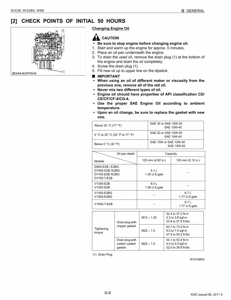
[2] CHECK POINTS OF INITIAL 50 HOURSChanging Engine Oil
CAUTION• Be sure to stop engine before changing engine oil.
1. Start and warm up the engine for approx. 5 minutes.2. Place an oil pan underneath the engine.3. To drain the used oil, remove the drain plug (1) at the bottom of
the engine and drain the oil completely.4. Screw the drain plug (1).5. Fill new oil up to upper line on the dipstick.
IMPORTANT• When using an oil of different maker or viscosity from the
previous one, remove all of the old oil.• Never mix two different types of oil.• Engine oil should have properties of API classification CD/
CE/CF/CF-4/CG-4.• Use the proper SAE Engine Oil according to ambient
temperature.• Upon an oil change, be sure to replace the gasket with new
one.
W1016604
Above 25 °C (77 °F) SAE 30 or SAE 10W-30 SAE 10W-40
0 °C to 25 °C (32 °F to 77 °F) SAE 20 or SAE 10W-30 SAE 10W-40
Below 0 °C (32 °F) SAE 10W or SAE 10W-30 SAE 10W-40
Oil pan depth
Models
Capacity
125 mm (4.92 in.) 130 mm (5.12 in.)
D905-E2B / E2BGD1005-E2B /E2BGD1105-E2B /E2BGD1105-T-E2B
5.1 L1.35 U.S.gals –
V1305-E2BV1505-E2B
6.0 L1.59 U.S.gals –
V1305-E2BGV1505-E2BG – 6.7 L
1.77 U.S.gals
V1505-T-E2B – 6.7 L1.77 U.S.gals
Tightening torque
Drain plug with copper gasket
M12 × 1.2532.4 to 37.3 N·m3.3 to 3.8 kgf·m23.9 to 27.5 ft-lbs
M22 × 1.563.7 to 73.5 N·m6.5 to 7.5 kgf·m47.0 to 54.2 ft-lbs
Drain plug with rubber coated gasket
M22 × 1.544.1 to 53.9 N·m4.5 to 5.5 kgf·m32.5 to 39.8 ft-lbs
(1) Drain Plug
KiSC issued 06, 2011 A
G-9
05-E2B, 05-E2BG, WSM G GENERAL
Replacing Oil Filter Cartridge
CAUTION• Be sure to stop the engine before changing filter cartridge.
1. Remove the oil filter cartridge with the filter wrench.2. Apply a slight coat of oil onto the new cartridge gasket.3. To install the new cartridge, screw it in by hand. Over tightening
may cause deformation of rubber gasket.4. After the new cartridge has been replaced, the engine oil
normally decrease a little. Thus see that the engine oil does notleak through the seal and be sure to read the oil level on thedipstick. Then, replenish the engine oil up to the specified level.IMPORTANT
• To prevent serious damage to the engine, replacementelement must be highly efficient. Use only a KUBOTAgenuine filter or its equivalent.
W1017137
KiSC issued 06, 2011 A
G-10
05-E2B, 05-E2BG, WSM G GENERAL
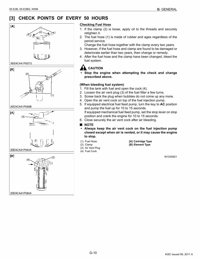
[3] CHECK POINTS OF EVERY 50 HOURSChecking Fuel Hose1. If the clamp (2) is loose, apply oil to the threads and securely
retighten it.2. The fuel hose (1) is made of rubber and ages regardless of the
period service.Change the fuel hose together with the clamp every two years.
3. However, if the fuel hose and clamp are found to be damaged ordeteriorate earlier than two years, then change or remedy.
4. After the fuel hose and the clamp have been changed, bleed thefuel system.
CAUTION• Stop the engine when attempting the check and change
prescribed above.
(When bleeding fuel system)1. Fill the tank with fuel and open the cock (4).2. Loosen the air vent plug (3) of the fuel filter a few turns.3. Screw back the plug when bubbles do not come up any more.4. Open the air vent cock on top of the fuel injection pump.5. If equipped electrical fuel feed pump, turn the key to AC position
and pump the fuel up for 10 to 15 seconds.If equipped mechanical fuel feed pump, set the stop lever on stopposition and crank the engine for 10 to 15 seconds.
6. Close securely the air vent cock after air bleeding.NOTE
• Always keep the air vent cock on the fuel injection pumpclosed except when air is vented, or it may cause the engineto stop.
W1035921
(1) Fuel Hose(2) Clamp(3) Air Vent Plug(4) Fuel Cock
[A] Cartridge Type[B] Element Type
KiSC issued 06, 2011 A
G-11
05-E2B, 05-E2BG, WSM G GENERAL
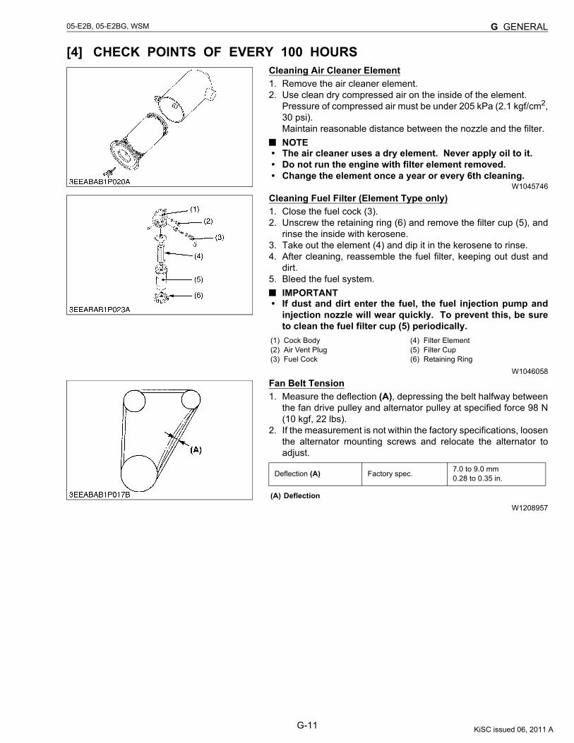
[4] CHECK POINTS OF EVERY 100 HOURSCleaning Air Cleaner Element1. Remove the air cleaner element.2. Use clean dry compressed air on the inside of the element.
Pressure of compressed air must be under 205 kPa (2.1 kgf/cm2,30 psi).Maintain reasonable distance between the nozzle and the filter.NOTE
• The air cleaner uses a dry element. Never apply oil to it.• Do not run the engine with filter element removed.• Change the element once a year or every 6th cleaning.
W1045746
Cleaning Fuel Filter (Element Type only)1. Close the fuel cock (3).2. Unscrew the retaining ring (6) and remove the filter cup (5), and
rinse the inside with kerosene.3. Take out the element (4) and dip it in the kerosene to rinse.4. After cleaning, reassemble the fuel filter, keeping out dust and
dirt.5. Bleed the fuel system.
IMPORTANT• If dust and dirt enter the fuel, the fuel injection pump and
injection nozzle will wear quickly. To prevent this, be sureto clean the fuel filter cup (5) periodically.
W1046058
Fan Belt Tension1. Measure the deflection (A), depressing the belt halfway between
the fan drive pulley and alternator pulley at specified force 98 N(10 kgf, 22 lbs).
2. If the measurement is not within the factory specifications, loosenthe alternator mounting screws and relocate the alternator toadjust.
W1208957
(1) Cock Body(2) Air Vent Plug(3) Fuel Cock
(4) Filter Element(5) Filter Cup(6) Retaining Ring
Deflection (A) Factory spec. 7.0 to 9.0 mm0.28 to 0.35 in.
(A) Deflection
KiSC issued 06, 2011 A

G-12
05-E2B, 05-E2BG, WSM G GENERAL
Fan Belt Damage and Wear1. Check the fan belt for damage.2. If the fan belt is damaged, replace it.3. Check if the fan belt is worn and sunk in the pulley groove.4. If the fan belt is nearly worn out and deeply sunk in the pulley
groove, replace it.
W1209480
Checking Battery Electrolyte Level1. Check the battery electrolyte level.2. If the level is below than lower level line (2), and the distilled water
to pour level of each cell.
W1047154
(A) Good (B) Bad
(1) Upper Level Line (2) Lower Level Line
KiSC issued 06, 2011 A
G-13
05-E2B, 05-E2BG, WSM G GENERAL
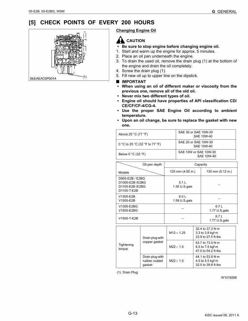
[5] CHECK POINTS OF EVERY 200 HOURSChanging Engine Oil
CAUTION• Be sure to stop engine before changing engine oil.
1. Start and warm up the engine for approx. 5 minutes.2. Place an oil pan underneath the engine.3. To drain the used oil, remove the drain plug (1) at the bottom of
the engine and drain the oil completely.4. Screw the drain plug (1).5. Fill new oil up to upper line on the dipstick.
IMPORTANT• When using an oil of different maker or viscosity from the
previous one, remove all of the old oil.• Never mix two different types of oil.• Engine oil should have properties of API classification CD/
CE/CF/CF-4/CG-4.• Use the proper SAE Engine Oil according to ambient
temperature.• Upon an oil change, be sure to replace the gasket with new
one.
W1018298
Above 25 °C (77 °F) SAE 30 or SAE 10W-30 SAE 10W-40
0 °C to 25 °C (32 °F to 77 °F) SAE 20 or SAE 10W-30 SAE 10W-40
Below 0 °C (32 °F) SAE 10W or SAE 10W-30 SAE 10W-40
Oil pan depth
Models
Capacity
125 mm (4.92 in.) 130 mm (5.12 in.)
D905-E2B / E2BGD1005-E2B /E2BGD1105-E2B /E2BGD1105-T-E2B
5.1 L1.35 U.S.gals –
V1305-E2BV1505-E2B
6.0 L1.59 U.S.gals –
V1305-E2BGV1505-E2BG – 6.7 L
1.77 U.S.gals
V1505-T-E2B – 6.7 L1.77 U.S.gals
Tightening torque
Drain plug with copper gasket
M12 × 1.2532.4 to 37.3 N·m3.3 to 3.8 kgf·m23.9 to 27.5 ft-lbs
M22 × 1.563.7 to 73.5 N·m6.5 to 7.5 kgf·m47.0 to 54.2 ft-lbs
Drain plug with rubber coated gasket
M22 × 1.544.1 to 53.9 N·m4.5 to 5.5 kgf·m32.5 to 39.8 ft-lbs
(1) Drain Plug
KiSC issued 06, 2011 A
G-14
05-E2B, 05-E2BG, WSM G GENERAL
Replacing Oil Filter Cartridge
CAUTION• Be sure to stop the engine before changing filter cartridge.
1. Remove the oil filter cartridge with the filter wrench.2. Apply a slight coat of oil onto the new cartridge gasket.3. To install the new cartridge, screw it in by hand. Over tightening
may cause deformation of rubber gasket.4. After the new cartridge has been replaced, the engine oil
normally decrease a little. Thus see that the engine oil does notleak through the seal and be sure to read the oil level on thedipstick. Then, replenish the engine oil up to the specified level.IMPORTANT
• To prevent serious damage to the engine, replacementelement must be highly efficient. Use only a KUBOTAgenuine filter or its equivalent.
W1018617
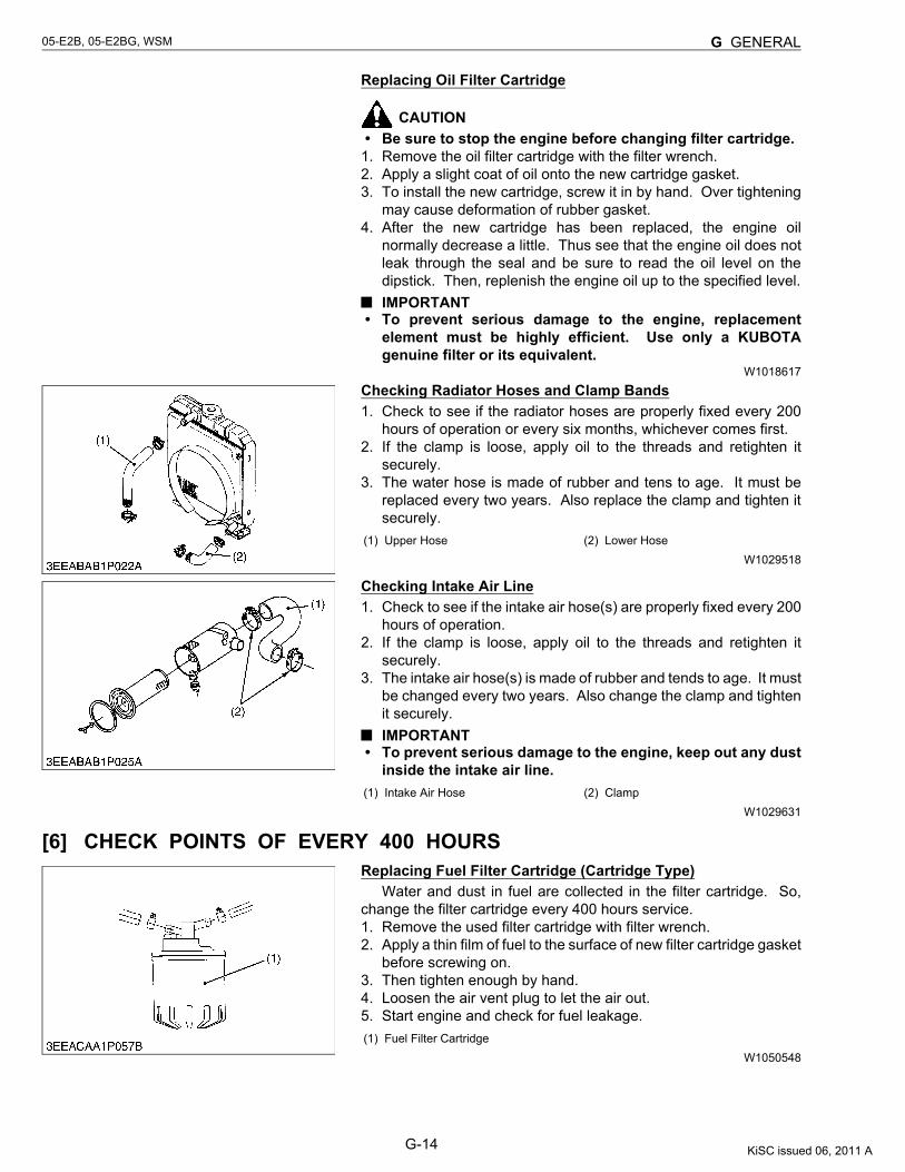
Checking Radiator Hoses and Clamp Bands1. Check to see if the radiator hoses are properly fixed every 200
hours of operation or every six months, whichever comes first.2. If the clamp is loose, apply oil to the threads and retighten it
securely.3. The water hose is made of rubber and tens to age. It must be
replaced every two years. Also replace the clamp and tighten itsecurely.
W1029518
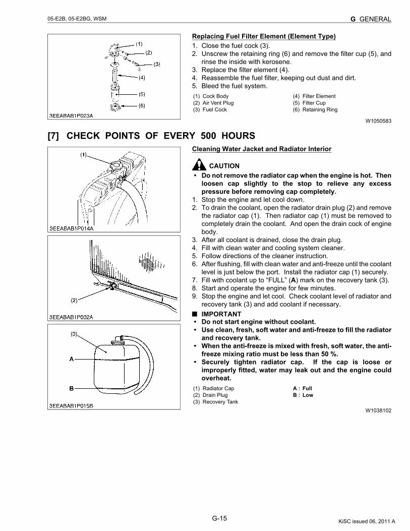
Checking Intake Air Line1. Check to see if the intake air hose(s) are properly fixed every 200
hours of operation.2. If the clamp is loose, apply oil to the threads and retighten it
securely.3. The intake air hose(s) is made of rubber and tends to age. It must
be changed every two years. Also change the clamp and tightenit securely.IMPORTANT
• To prevent serious damage to the engine, keep out any dustinside the intake air line.
W1029631
[6] CHECK POINTS OF EVERY 400 HOURSReplacing Fuel Filter Cartridge (Cartridge Type)
Water and dust in fuel are collected in the filter cartridge. So,change the filter cartridge every 400 hours service. 1. Remove the used filter cartridge with filter wrench.2. Apply a thin film of fuel to the surface of new filter cartridge gasket
before screwing on.3. Then tighten enough by hand.4. Loosen the air vent plug to let the air out.5. Start engine and check for fuel leakage.
W1050548
(1) Upper Hose (2) Lower Hose
(1) Intake Air Hose (2) Clamp
(1) Fuel Filter Cartridge
KiSC issued 06, 2011 A
G-15
05-E2B, 05-E2BG, WSM G GENERAL
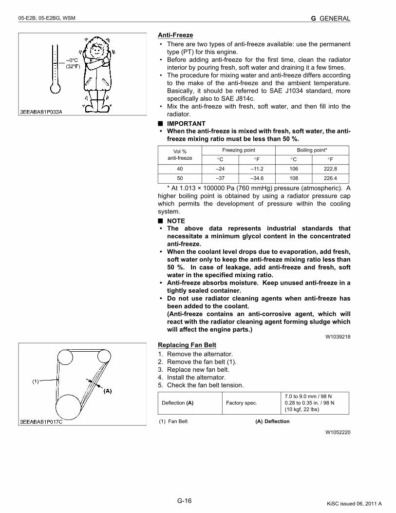
Replacing Fuel Filter Element (Element Type)1. Close the fuel cock (3).2. Unscrew the retaining ring (6) and remove the filter cup (5), and
rinse the inside with kerosene.3. Replace the filter element (4).4. Reassemble the fuel filter, keeping out dust and dirt.5. Bleed the fuel system.
W1050583
[7] CHECK POINTS OF EVERY 500 HOURSCleaning Water Jacket and Radiator Interior
CAUTION• Do not remove the radiator cap when the engine is hot. Then
loosen cap slightly to the stop to relieve any excesspressure before removing cap completely.
1. Stop the engine and let cool down.2. To drain the coolant, open the radiator drain plug (2) and remove
the radiator cap (1). Then radiator cap (1) must be removed tocompletely drain the coolant. And open the drain cock of enginebody.
3. After all coolant is drained, close the drain plug.4. Fill with clean water and cooling system cleaner.5. Follow directions of the cleaner instruction.6. After flushing, fill with clean water and anti-freeze until the coolant
level is just below the port. Install the radiator cap (1) securely.7. Fill with coolant up to “FULL” (A) mark on the recovery tank (3).8. Start and operate the engine for few minutes.9. Stop the engine and let cool. Check coolant level of radiator and
recovery tank (3) and add coolant if necessary.IMPORTANT
• Do not start engine without coolant.• Use clean, fresh, soft water and anti-freeze to fill the radiator
and recovery tank.• When the anti-freeze is mixed with fresh, soft water, the anti-
freeze mixing ratio must be less than 50 %.• Securely tighten radiator cap. If the cap is loose or
improperly fitted, water may leak out and the engine couldoverheat.
W1038102
(1) Cock Body(2) Air Vent Plug(3) Fuel Cock
(4) Filter Element(5) Filter Cup(6) Retaining Ring
(1) Radiator Cap(2) Drain Plug(3) Recovery Tank
A : FullB : Low
KiSC issued 06, 2011 A
G-16
05-E2B, 05-E2BG, WSM G GENERAL
Anti-Freeze• There are two types of anti-freeze available: use the permanent
type (PT) for this engine.• Before adding anti-freeze for the first time, clean the radiator
interior by pouring fresh, soft water and draining it a few times.• The procedure for mixing water and anti-freeze differs according
to the make of the anti-freeze and the ambient temperature.Basically, it should be referred to SAE J1034 standard, morespecifically also to SAE J814c.
• Mix the anti-freeze with fresh, soft water, and then fill into theradiator.IMPORTANT
• When the anti-freeze is mixed with fresh, soft water, the anti-freeze mixing ratio must be less than 50 %.
* At 1.013 × 100000 Pa (760 mmHg) pressure (atmospheric). Ahigher boiling point is obtained by using a radiator pressure capwhich permits the development of pressure within the coolingsystem.
NOTE• The above data represents industrial standards that
necessitate a minimum glycol content in the concentratedanti-freeze.
• When the coolant level drops due to evaporation, add fresh,soft water only to keep the anti-freeze mixing ratio less than50 %. In case of leakage, add anti-freeze and fresh, softwater in the specified mixing ratio.
• Anti-freeze absorbs moisture. Keep unused anti-freeze in atightly sealed container.
• Do not use radiator cleaning agents when anti-freeze hasbeen added to the coolant.(Anti-freeze contains an anti-corrosive agent, which willreact with the radiator cleaning agent forming sludge whichwill affect the engine parts.)
W1039218
Replacing Fan Belt1. Remove the alternator.2. Remove the fan belt (1).3. Replace new fan belt.4. Install the alternator.5. Check the fan belt tension.
W1052220
Vol %anti-freeze
Freezing point Boiling point*
°C °F °C °F
40 –24 –11.2 106 222.8
50 –37 –34.6 108 226.4
Deflection (A) Factory spec.7.0 to 9.0 mm / 98 N0.28 to 0.35 in. / 98 N(10 kgf, 22 lbs)
(1) Fan Belt (A) Deflection
KiSC issued 06, 2011 A
G-17
05-E2B, 05-E2BG, WSM G GENERAL
[8] CHECK POINTS OF EVERY 1 OR 2 MONTHSRecharging
CAUTION• When the battery is being activated, hydrogen and oxygen
gases in the battery are extremely explosive. Keep opensparks and flames away from the battery at all times,especially when charging the battery.
• When charging battery, remove battery vent plugs.• When disconnecting the cable from the battery, start with
the negative terminal first. When connecting the cable to thebattery, start with the positive terminal first.
• Never check battery charge by placing a metal object acrossthe posts.Use a voltmeter or hydrometer.
1) Slow Charging1. Add distilled water if the electrolyte level is low. When charging,
the amount of electrolyte should be slightly lower than thespecified level to prevent overflow.
2. Connect the battery to the charging unit, following themanufacture’s instructions.
3. As the electrolyte generates gas while charging, remove all portcaps.
4. The electrolyte temperature must not exceed 40 °C (104 °F)during charging.If it exceed 40 °C (104 °F), decrease the charging amperage orstop charging for a while.
5. When charging several batteries in series, charg at the rate of thesmallest battery in the line.
2) Quick Charging1. Determine the proper charging current and charging time with the
tester attached to the quick charger.2. Determine the proper charging current as 1/1 of the battery
capacity. If the battery capacity exceeds 50 Ah, consider 50 A asthe maximum.
Precaution for Operating a Quick Charger• Operate with a quick charger differs according to the type.
Consult the instruction manual and use accordingly.W1052658
KiSC issued 06, 2011 A
G-18
05-E2B, 05-E2BG, WSM G GENERAL
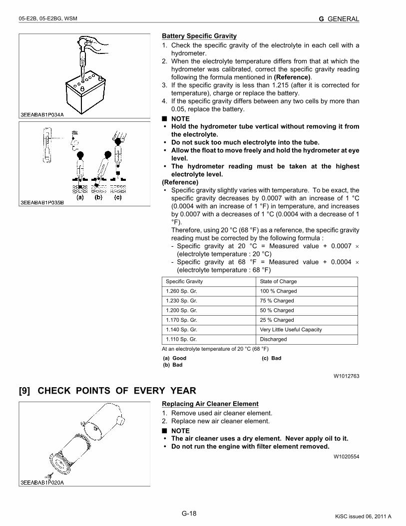
Battery Specific Gravity1. Check the specific gravity of the electrolyte in each cell with a
hydrometer.2. When the electrolyte temperature differs from that at which the
hydrometer was calibrated, correct the specific gravity readingfollowing the formula mentioned in (Reference).
3. If the specific gravity is less than 1.215 (after it is corrected fortemperature), charge or replace the battery.
4. If the specific gravity differs between any two cells by more than0.05, replace the battery.NOTE
• Hold the hydrometer tube vertical without removing it fromthe electrolyte.
• Do not suck too much electrolyte into the tube.• Allow the float to move freely and hold the hydrometer at eye
level.• The hydrometer reading must be taken at the highest
electrolyte level.(Reference)• Specific gravity slightly varies with temperature. To be exact, the
specific gravity decreases by 0.0007 with an increase of 1 °C(0.0004 with an increase of 1 °F) in temperature, and increasesby 0.0007 with a decreases of 1 °C (0.0004 with a decrease of 1°F).Therefore, using 20 °C (68 °F) as a reference, the specific gravityreading must be corrected by the following formula :- Specific gravity at 20 °C = Measured value + 0.0007 ×
(electrolyte temperature : 20 °C)- Specific gravity at 68 °F = Measured value + 0.0004 ×
(electrolyte temperature : 68 °F)
At an electrolyte temperature of 20 °C (68 °F)
W1012763
[9] CHECK POINTS OF EVERY YEARReplacing Air Cleaner Element1. Remove used air cleaner element.2. Replace new air cleaner element.
NOTE• The air cleaner uses a dry element. Never apply oil to it.• Do not run the engine with filter element removed.
W1020554
Specific Gravity State of Charge
1.260 Sp. Gr. 100 % Charged
1.230 Sp. Gr. 75 % Charged
1.200 Sp. Gr. 50 % Charged
1.170 Sp. Gr. 25 % Charged
1.140 Sp. Gr. Very Little Useful Capacity
1.110 Sp. Gr. Discharged
(a) Good(b) Bad
(c) Bad
KiSC issued 06, 2011 A
G-19
05-E2B, 05-E2BG, WSM G GENERAL
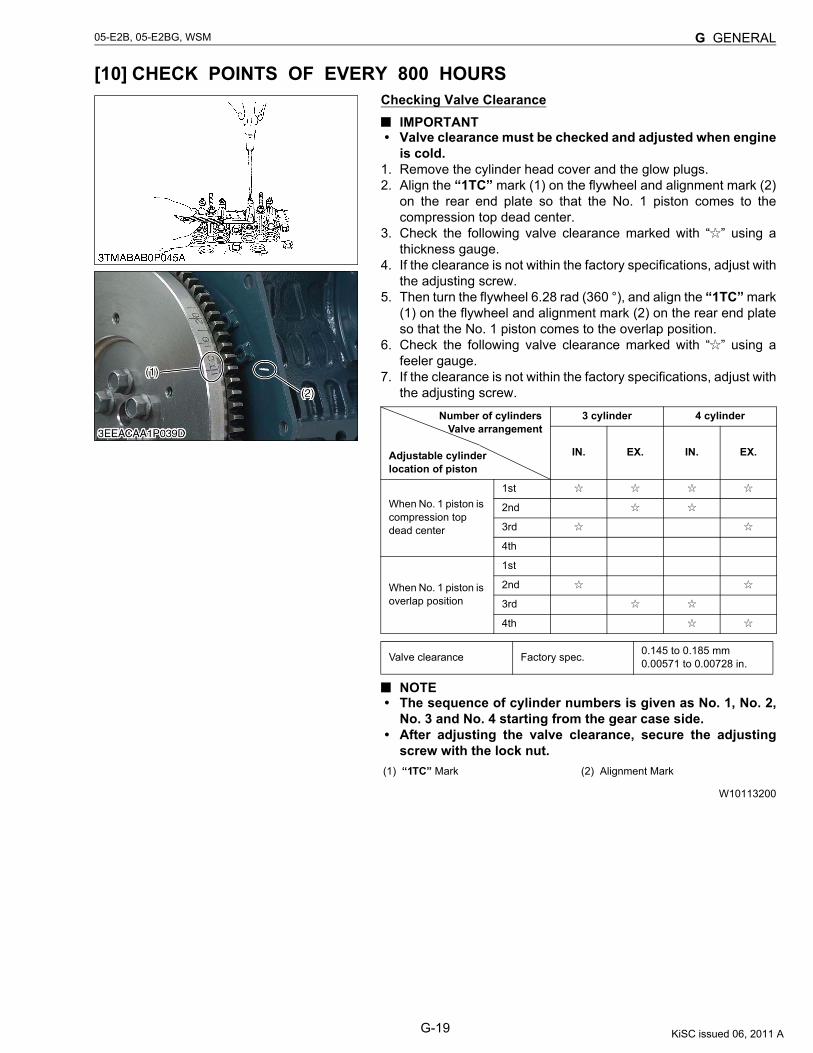
[10] CHECK POINTS OF EVERY 800 HOURSChecking Valve Clearance
IMPORTANT• Valve clearance must be checked and adjusted when engine
is cold.1. Remove the cylinder head cover and the glow plugs.2. Align the “1TC” mark (1) on the flywheel and alignment mark (2)
on the rear end plate so that the No. 1 piston comes to thecompression top dead center.
3. Check the following valve clearance marked with “ ” using athickness gauge.
4. If the clearance is not within the factory specifications, adjust withthe adjusting screw.
5. Then turn the flywheel 6.28 rad (360 °), and align the “1TC” mark(1) on the flywheel and alignment mark (2) on the rear end plateso that the No. 1 piston comes to the overlap position.
6. Check the following valve clearance marked with “ ” using afeeler gauge.
7. If the clearance is not within the factory specifications, adjust withthe adjusting screw.
NOTE• The sequence of cylinder numbers is given as No. 1, No. 2,
No. 3 and No. 4 starting from the gear case side.• After adjusting the valve clearance, secure the adjusting
screw with the lock nut.
W10113200
Number of cylinders Valve arrangement
Adjustable cylinderlocation of piston
3 cylinder 4 cylinder
IN. EX. IN. EX.
When No. 1 piston is compression top dead center
1st
2nd
3rd
4th
When No. 1 piston is overlap position
1st
2nd
3rd
4th
Valve clearance Factory spec. 0.145 to 0.185 mm0.00571 to 0.00728 in.
(1) “1TC” Mark (2) Alignment Mark
KiSC issued 06, 2011 A
G-20
05-E2B, 05-E2BG, WSM G GENERAL
[11] CHECK POINTS OF EVERY 1500 HOURS
CAUTION• Check the injection pressure and condition after confirming that there is nobody standing in the direction
the fume goes.If the fume from the nozzle directly contacts the human body, cells may be destroyed and blood poisoningmay be caused.
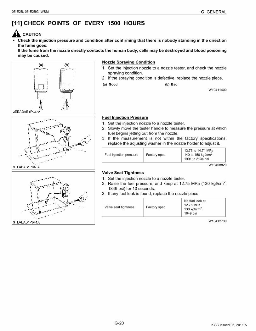
Nozzle Spraying Condition1. Set the injection nozzle to a nozzle tester, and check the nozzle
spraying condition.2. If the spraying condition is defective, replace the nozzle piece.
W10411400
Fuel Injection Pressure1. Set the injection nozzle to a nozzle tester.2. Slowly move the tester handle to measure the pressure at which
fuel begins jetting out from the nozzle.3. If the measurement is not within the factory specifications,
replace the adjusting washer in the nozzle holder to adjust it.
W10408820
Valve Seat Tightness1. Set the injection nozzle to a nozzle tester.2. Raise the fuel pressure, and keep at 12.75 MPa (130 kgf/cm2,
1849 psi) for 10 seconds.3. If any fuel leak is found, replace the nozzle piece.
W10412730
(a) Good (b) Bad
Fuel injection pressure Factory spec.13.73 to 14.71 MPa140 to 150 kgf/cm2
1991 to 2134 psi
Valve seat tightness Factory spec.
No fuel leak at12.75 MPa130 kgf/cm2
1849 psi
KiSC issued 06, 2011 A
G-21
05-E2B, 05-E2BG, WSM G GENERAL
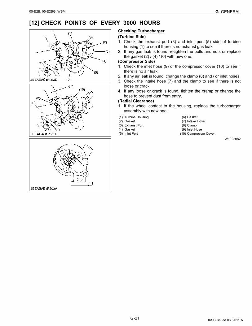
[12] CHECK POINTS OF EVERY 3000 HOURSChecking Turbocharger(Turbine Side)1. Check the exhaust port (3) and inlet port (5) side of turbine
housing (1) to see if there is no exhaust gas leak.2. If any gas leak is found, retighten the bolts and nuts or replace
the gasket (2) / (4) / (6) with new one.(Compressor Side)1. Check the inlet hose (9) of the compressor cover (10) to see if
there is no air leak.2. If any air leak is found, change the clamp (8) and / or inlet hoses.3. Check the intake hose (7) and the clamp to see if there is not
loose or crack.4. If any loose or crack is found, tighten the cramp or change the
hose to prevent dust from entry.(Radial Clearance)1. If the wheel contact to the housing, replace the turbocharger
assembly with new one.
W1022082
(1) Turbine Housing(2) Gasket(3) Exhaust Port(4) Gasket(5) Inlet Port
(6) Gasket(7) Intake Hose
(8) Clamp(9) Inlet Hose
(10) Compressor Cover
KiSC issued 06, 2011 A
G-22
05-E2B, 05-E2BG, WSM G GENERAL
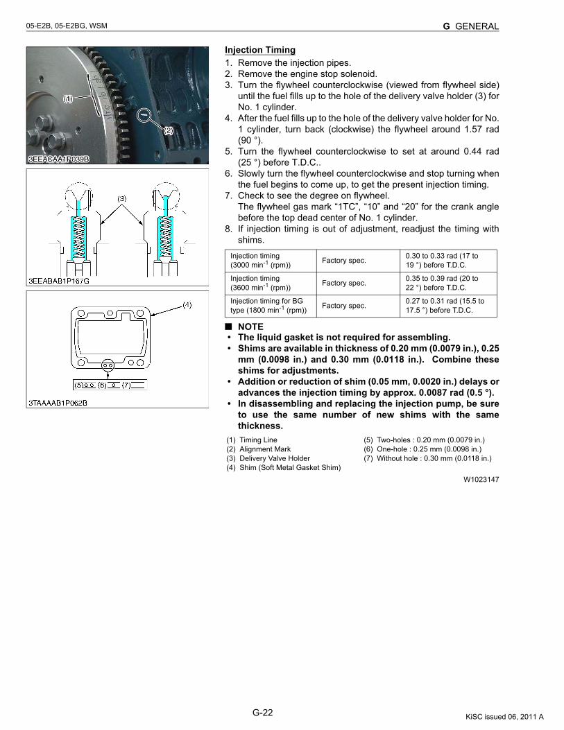
Injection Timing1. Remove the injection pipes.2. Remove the engine stop solenoid.3. Turn the flywheel counterclockwise (viewed from flywheel side)
until the fuel fills up to the hole of the delivery valve holder (3) forNo. 1 cylinder.
4. After the fuel fills up to the hole of the delivery valve holder for No.1 cylinder, turn back (clockwise) the flywheel around 1.57 rad(90 °).
5. Turn the flywheel counterclockwise to set at around 0.44 rad(25 °) before T.D.C..
6. Slowly turn the flywheel counterclockwise and stop turning whenthe fuel begins to come up, to get the present injection timing.
7. Check to see the degree on flywheel.The flywheel gas mark “1TC”, “10” and “20” for the crank anglebefore the top dead center of No. 1 cylinder.
8. If injection timing is out of adjustment, readjust the timing withshims.
NOTE• The liquid gasket is not required for assembling.• Shims are available in thickness of 0.20 mm (0.0079 in.), 0.25
mm (0.0098 in.) and 0.30 mm (0.0118 in.). Combine theseshims for adjustments.
• Addition or reduction of shim (0.05 mm, 0.0020 in.) delays oradvances the injection timing by approx. 0.0087 rad (0.5 °).
• In disassembling and replacing the injection pump, be sureto use the same number of new shims with the samethickness.
W1023147
Injection timing(3000 min-1 (rpm)) Factory spec. 0.30 to 0.33 rad (17 to
19 °) before T.D.C.
Injection timing(3600 min-1 (rpm)) Factory spec. 0.35 to 0.39 rad (20 to
22 °) before T.D.C.
Injection timing for BG type (1800 min-1 (rpm)) Factory spec. 0.27 to 0.31 rad (15.5 to
17.5 °) before T.D.C.
(1) Timing Line(2) Alignment Mark(3) Delivery Valve Holder(4) Shim (Soft Metal Gasket Shim)
(5) Two-holes : 0.20 mm (0.0079 in.)(6) One-hole : 0.25 mm (0.0098 in.)(7) Without hole : 0.30 mm (0.0118 in.)
KiSC issued 06, 2011 A
G-23
05-E2B, 05-E2BG, WSM G GENERAL
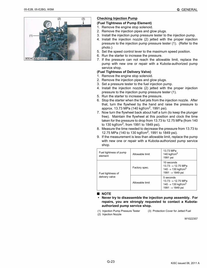
Checking Injection Pump(Fuel Tightness of Pump Element)1. Remove the engine stop solenoid.2. Remove the injection pipes and glow plugs.3. Install the injection pump pressure tester to the injection pump.4. Install the injection nozzle (2) jetted with the proper injection
pressure to the injection pump pressure tester (1). (Refer to thephoto.)
5. Set the speed control lever to the maximum speed position.6. Run the starter to increase the pressure.7. If the pressure can not reach the allowable limit, replace the
pump with new one or repair with a Kubota-authorized pumpservice shop.
(Fuel Tightness of Delivery Valve)1. Remove the engine stop solenoid.2. Remove the injection pipes and glow plugs.3. Set a pressure tester to the fuel injection pump.4. Install the injection nozzle (2) jetted with the proper injection
pressure to the injection pump pressure tester (1).5. Run the starter to increase the pressure.6. Stop the starter when the fuel jets from the injection nozzle. After
that, turn the flywheel by the hand and raise the pressure toapprox. 13.73 MPa (140 kgf/cm2, 1991 psi).
7. Now turn the flywheel back about half a turn (to keep the plungerfree). Maintain the flywheel at this position and clock the timetaken for the pressure to drop from 13.73 to 12.75 MPa (from 140to 130 kgf/cm2, from 1991 to 1849 psi).
8. Measure the time needed to decrease the pressure from 13.73 to12.75 MPa (140 to 130 kgf/cm2, 1991 to 1849 psi).
9. If the measurement is less than allowable limit, replace the pumpwith new one or repair with a Kubota-authorized pump serviceshop.
NOTE• Never try to disassemble the injection pump assembly. For
repairs, you are strongly requested to contact a Kubota-authorized pump service shop.
W1022357
Fuel tightness of pump element Allowable limit
13.73 MPa140 kgf/cm2
1991 psi
Fuel tightness of delivery valve
Factory spec.
10 seconds13.73 → 12.75 MPa140 → 130 kgf/cm2
1991 → 1849 psi
Allowable limit
5 seconds13.73 → 12.75 MPa140 → 130 kgf/cm2
1991 → 1849 psi
(1) Injection Pump Pressure Tester(2) Injection Nozzle
(3) Protection Cover for Jetted Fuel
KiSC issued 06, 2011 A
G-24
05-E2B, 05-E2BG, WSM G GENERAL
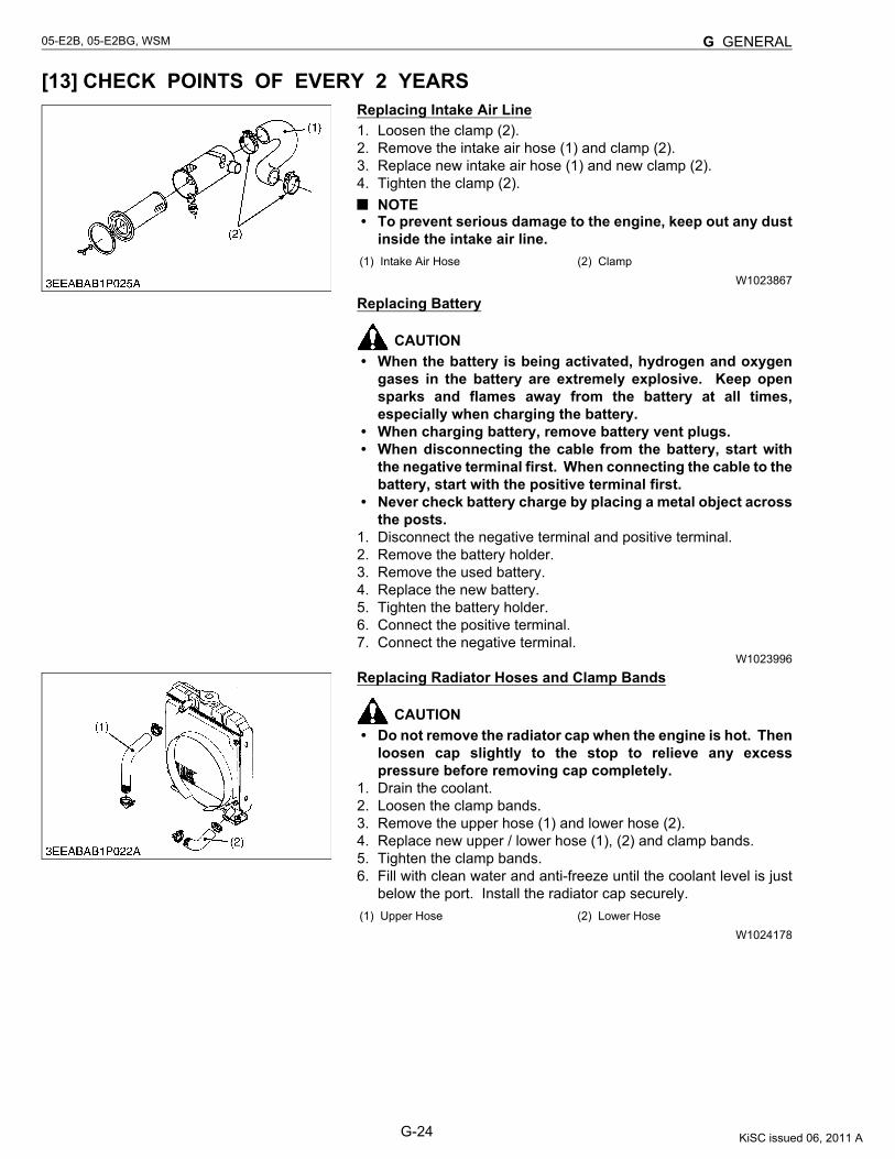
[13] CHECK POINTS OF EVERY 2 YEARSReplacing Intake Air Line1. Loosen the clamp (2).2. Remove the intake air hose (1) and clamp (2).3. Replace new intake air hose (1) and new clamp (2).4. Tighten the clamp (2).
NOTE• To prevent serious damage to the engine, keep out any dust
inside the intake air line.
W1023867
Replacing Battery
CAUTION• When the battery is being activated, hydrogen and oxygen
gases in the battery are extremely explosive. Keep opensparks and flames away from the battery at all times,especially when charging the battery.
• When charging battery, remove battery vent plugs.• When disconnecting the cable from the battery, start with
the negative terminal first. When connecting the cable to thebattery, start with the positive terminal first.
• Never check battery charge by placing a metal object acrossthe posts.
1. Disconnect the negative terminal and positive terminal.2. Remove the battery holder.3. Remove the used battery.4. Replace the new battery.5. Tighten the battery holder.6. Connect the positive terminal.7. Connect the negative terminal.
W1023996
Replacing Radiator Hoses and Clamp Bands
CAUTION• Do not remove the radiator cap when the engine is hot. Then
loosen cap slightly to the stop to relieve any excesspressure before removing cap completely.
1. Drain the coolant.2. Loosen the clamp bands.3. Remove the upper hose (1) and lower hose (2).4. Replace new upper / lower hose (1), (2) and clamp bands.5. Tighten the clamp bands.6. Fill with clean water and anti-freeze until the coolant level is just
below the port. Install the radiator cap securely.
W1024178
(1) Intake Air Hose (2) Clamp
(1) Upper Hose (2) Lower Hose
KiSC issued 06, 2011 A
G-25
05-E2B, 05-E2BG, WSM G GENERAL
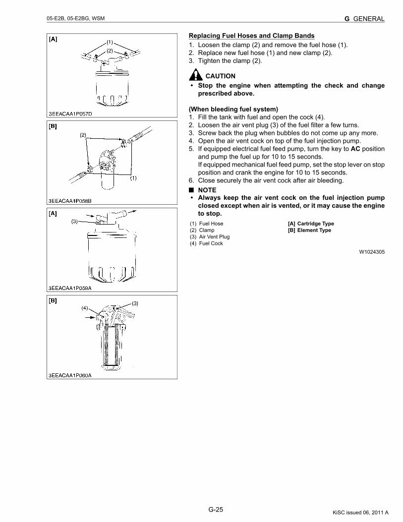
Replacing Fuel Hoses and Clamp Bands1. Loosen the clamp (2) and remove the fuel hose (1).2. Replace new fuel hose (1) and new clamp (2).3. Tighten the clamp (2).
CAUTION• Stop the engine when attempting the check and change
prescribed above.
(When bleeding fuel system)1. Fill the tank with fuel and open the cock (4).2. Loosen the air vent plug (3) of the fuel filter a few turns.3. Screw back the plug when bubbles do not come up any more.4. Open the air vent cock on top of the fuel injection pump.5. If equipped electrical fuel feed pump, turn the key to AC position
and pump the fuel up for 10 to 15 seconds.If equipped mechanical fuel feed pump, set the stop lever on stopposition and crank the engine for 10 to 15 seconds.
6. Close securely the air vent cock after air bleeding.NOTE
• Always keep the air vent cock on the fuel injection pumpclosed except when air is vented, or it may cause the engineto stop.
W1024305
(1) Fuel Hose(2) Clamp(3) Air Vent Plug(4) Fuel Cock
[A] Cartridge Type[B] Element Type
KiSC issued 06, 2011 A
G-26
05-E2B, 05-E2BG, WSM G GENERAL
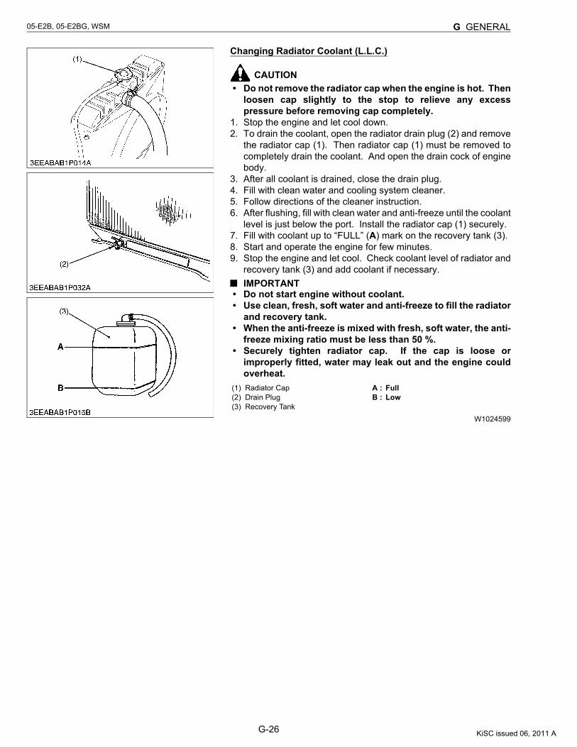
Changing Radiator Coolant (L.L.C.)
CAUTION• Do not remove the radiator cap when the engine is hot. Then
loosen cap slightly to the stop to relieve any excesspressure before removing cap completely.
1. Stop the engine and let cool down.2. To drain the coolant, open the radiator drain plug (2) and remove
the radiator cap (1). Then radiator cap (1) must be removed tocompletely drain the coolant. And open the drain cock of enginebody.
3. After all coolant is drained, close the drain plug.4. Fill with clean water and cooling system cleaner.5. Follow directions of the cleaner instruction.6. After flushing, fill with clean water and anti-freeze until the coolant
level is just below the port. Install the radiator cap (1) securely.7. Fill with coolant up to “FULL” (A) mark on the recovery tank (3).8. Start and operate the engine for few minutes.9. Stop the engine and let cool. Check coolant level of radiator and
recovery tank (3) and add coolant if necessary.IMPORTANT
• Do not start engine without coolant.• Use clean, fresh, soft water and anti-freeze to fill the radiator
and recovery tank.• When the anti-freeze is mixed with fresh, soft water, the anti-
freeze mixing ratio must be less than 50 %.• Securely tighten radiator cap. If the cap is loose or
improperly fitted, water may leak out and the engine couldoverheat.
W1024599
(1) Radiator Cap(2) Drain Plug(3) Recovery Tank
A : FullB : Low
KiSC issued 06, 2011 A
G-27
05-E2B, 05-E2BG, WSM G GENERAL
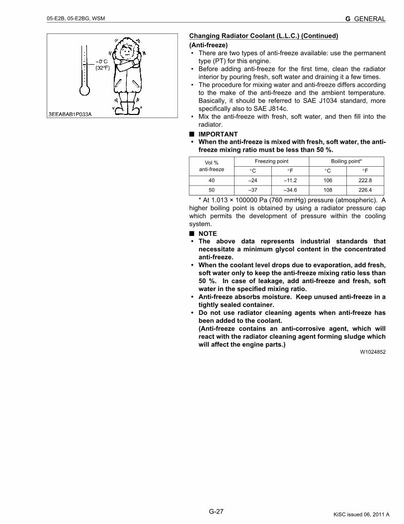
Changing Radiator Coolant (L.L.C.) (Continued)(Anti-freeze)• There are two types of anti-freeze available: use the permanent
type (PT) for this engine.• Before adding anti-freeze for the first time, clean the radiator
interior by pouring fresh, soft water and draining it a few times.• The procedure for mixing water and anti-freeze differs according
to the make of the anti-freeze and the ambient temperature.Basically, it should be referred to SAE J1034 standard, morespecifically also to SAE J814c.
• Mix the anti-freeze with fresh, soft water, and then fill into theradiator.IMPORTANT
• When the anti-freeze is mixed with fresh, soft water, the anti-freeze mixing ratio must be less than 50 %.
* At 1.013 × 100000 Pa (760 mmHg) pressure (atmospheric). Ahigher boiling point is obtained by using a radiator pressure capwhich permits the development of pressure within the coolingsystem.
NOTE• The above data represents industrial standards that
necessitate a minimum glycol content in the concentratedanti-freeze.
• When the coolant level drops due to evaporation, add fresh,soft water only to keep the anti-freeze mixing ratio less than50 %. In case of leakage, add anti-freeze and fresh, softwater in the specified mixing ratio.
• Anti-freeze absorbs moisture. Keep unused anti-freeze in atightly sealed container.
• Do not use radiator cleaning agents when anti-freeze hasbeen added to the coolant.(Anti-freeze contains an anti-corrosive agent, which willreact with the radiator cleaning agent forming sludge whichwill affect the engine parts.)
W1024852
Vol %anti-freeze
Freezing point Boiling point*
°C °F °C °F
40 –24 –11.2 106 222.8
50 –37 –34.6 108 226.4
KiSC issued 06, 2011 A
G-28
05-E2B, 05-E2BG, WSM G GENERAL
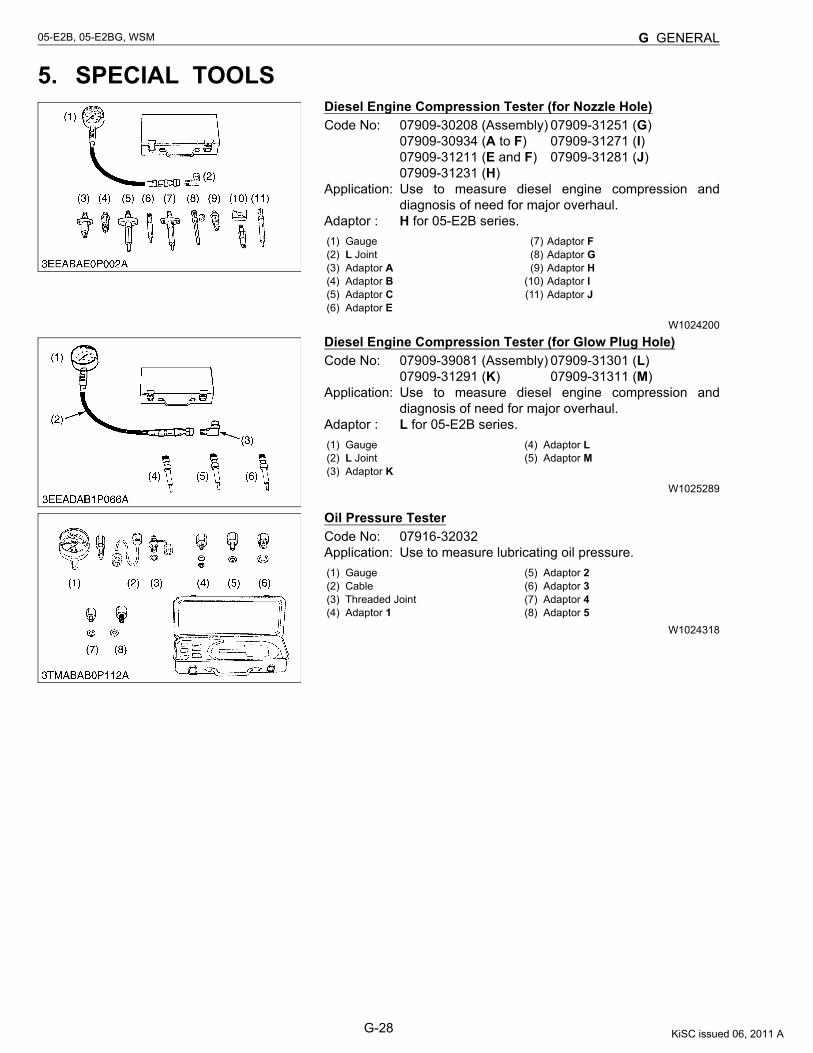
5. SPECIAL TOOLSDiesel Engine Compression Tester (for Nozzle Hole)Code No: 07909-30208 (Assembly) 07909-31251 (G)
07909-30934 (A to F) 07909-31271 (I)07909-31211 (E and F) 07909-31281 (J)07909-31231 (H)
Application: Use to measure diesel engine compression anddiagnosis of need for major overhaul.
Adaptor : H for 05-E2B series.
W1024200
Diesel Engine Compression Tester (for Glow Plug Hole)Code No: 07909-39081 (Assembly) 07909-31301 (L)
07909-31291 (K) 07909-31311 (M)Application: Use to measure diesel engine compression and
diagnosis of need for major overhaul.Adaptor : L for 05-E2B series.
W1025289
Oil Pressure TesterCode No: 07916-32032Application: Use to measure lubricating oil pressure.
W1024318
(1) Gauge(2) L Joint(3) Adaptor A(4) Adaptor B(5) Adaptor C(6) Adaptor E
(7) Adaptor F(8) Adaptor G(9) Adaptor H
(10) Adaptor I(11) Adaptor J
(1) Gauge(2) L Joint(3) Adaptor K
(4) Adaptor L(5) Adaptor M
(1) Gauge(2) Cable(3) Threaded Joint(4) Adaptor 1
(5) Adaptor 2(6) Adaptor 3(7) Adaptor 4(8) Adaptor 5
KiSC issued 06, 2011 A
G-29
05-E2B, 05-E2BG, WSM G GENERAL
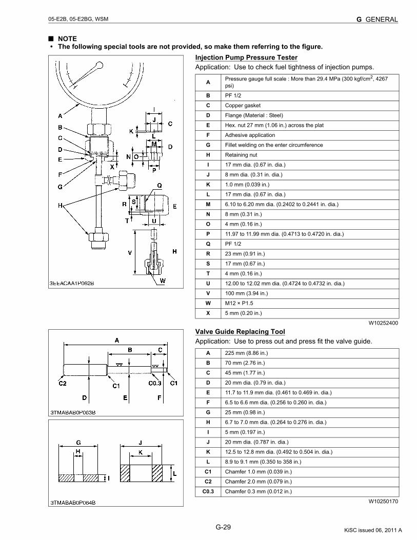
NOTE• The following special tools are not provided, so make them referring to the figure.
Injection Pump Pressure TesterApplication: Use to check fuel tightness of injection pumps.
W10252400
Valve Guide Replacing ToolApplication: Use to press out and press fit the valve guide.
W10250170
A Pressure gauge full scale : More than 29.4 MPa (300 kgf/cm2, 4267 psi)
B PF 1/2
C Copper gasket
D Flange (Material : Steel)
E Hex. nut 27 mm (1.06 in.) across the plat
F Adhesive application
G Fillet welding on the enter circumference
H Retaining nut
I 17 mm dia. (0.67 in. dia.)
J 8 mm dia. (0.31 in. dia.)
K 1.0 mm (0.039 in.)
L 17 mm dia. (0.67 in. dia.)
M 6.10 to 6.20 mm dia. (0.2402 to 0.2441 in. dia.)
N 8 mm (0.31 in.)
O 4 mm (0.16 in.)
P 11.97 to 11.99 mm dia. (0.4713 to 0.4720 in. dia.)
Q PF 1/2
R 23 mm (0.91 in.)
S 17 mm (0.67 in.)
T 4 mm (0.16 in.)
U 12.00 to 12.02 mm dia. (0.4724 to 0.4732 in. dia.)
V 100 mm (3.94 in.)
W M12 × P1.5
X 5 mm (0.20 in.)
A 225 mm (8.86 in.)
B 70 mm (2.76 in.)
C 45 mm (1.77 in.)
D 20 mm dia. (0.79 in. dia.)
E 11.7 to 11.9 mm dia. (0.461 to 0.469 in. dia.)
F 6.5 to 6.6 mm dia. (0.256 to 0.260 in. dia.)
G 25 mm (0.98 in.)
H 6.7 to 7.0 mm dia. (0.264 to 0.276 in. dia.)
I 5 mm (0.197 in.)
J 20 mm dia. (0.787 in. dia.)
K 12.5 to 12.8 mm dia. (0.492 to 0.504 in. dia.)
L 8.9 to 9.1 mm (0.350 to 358 in.)
C1 Chamfer 1.0 mm (0.039 in.)
C2 Chamfer 2.0 mm (0.079 in.)
C0.3 Chamfer 0.3 mm (0.012 in.)
KiSC issued 06, 2011 A
G-30
05-E2B, 05-E2BG, WSM G GENERAL
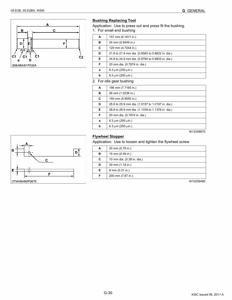
Bushing Replacing ToolApplication: Use to press out and press fit the bushing.1. For small end bushing
2. For idle gear bushing
W12358870
Flywheel StopperApplication: Use to loosen and tighten the flywheel screw.
W10259480
A 157 mm (6.1811 in.)
B 24 mm (0.9449 in.)
C 120 mm (4.7244 in.)
D 21.8 to 21.9 mm dia. (0.8583 to 0.8622 in. dia.)
E 24.8 to 24.9 mm dia. (0.9764 to 0.9803 in. dia.)
F 20 mm dia. (0.7874 in. dia.)
a 6.3 μm (250 μin.)
b 6.3 μm (250 μin.)
A 196 mm (7.7165 in.)
B 26 mm (1.0236 in.)
C 150 mm (5.9055 in.)
D 25.8 to 25.9 mm dia. (1.0157 to 1.0197 in. dia.)
E 28.8 to 28.9 mm dia. (1.1339 to 1.1378 in. dia.)
F 20 mm dia. (0.7874 in. dia.)
a 6.3 μm (250 μin.)
b 6.3 μm (250 μin.)
A 20 mm (0.79 in.)
B 15 mm (0.59 in.)
C 10 mm dia. (0.39 in. dia.)
D 30 mm (1.18 in.)
E 8 mm (0.31 in.)
F 200 mm (7.87 in.)
KiSC issued 06, 2011 A
G-31
05-E2B, 05-E2BG, WSM G GENERAL
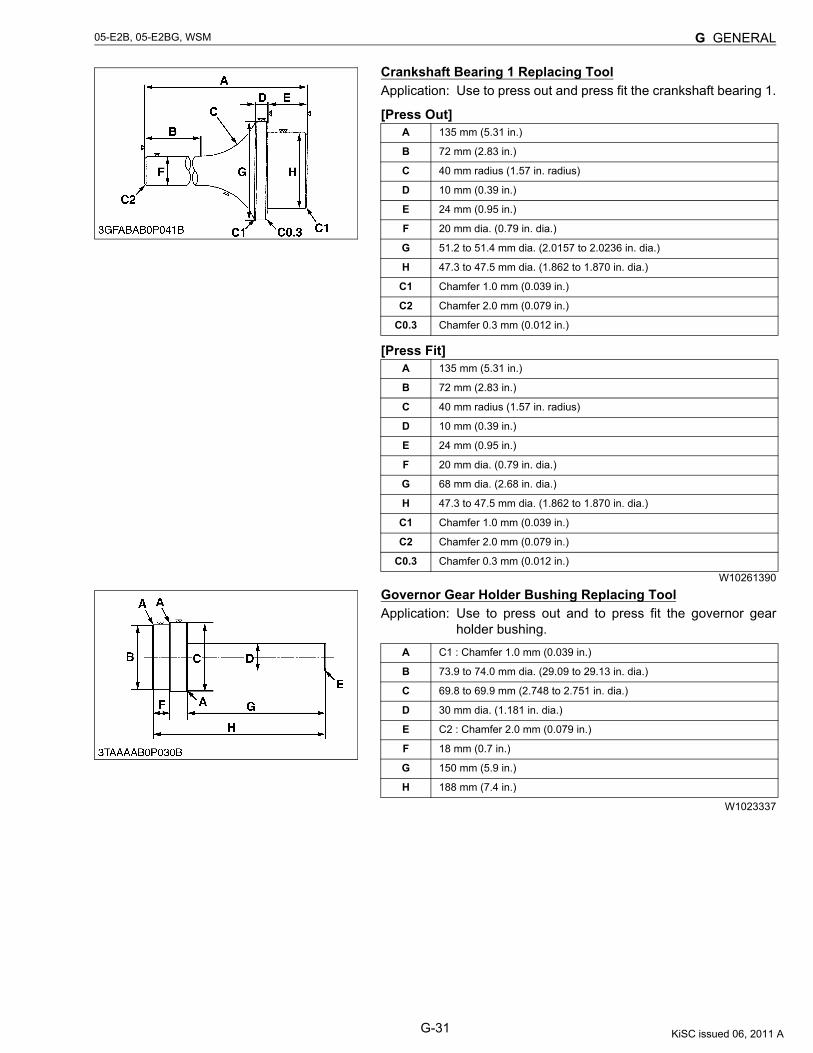
Crankshaft Bearing 1 Replacing ToolApplication: Use to press out and press fit the crankshaft bearing 1.
[Press Out]
[Press Fit]
W10261390
Governor Gear Holder Bushing Replacing ToolApplication: Use to press out and to press fit the governor gear
holder bushing.
W1023337
A 135 mm (5.31 in.)
B 72 mm (2.83 in.)
C 40 mm radius (1.57 in. radius)
D 10 mm (0.39 in.)
E 24 mm (0.95 in.)
F 20 mm dia. (0.79 in. dia.)
G 51.2 to 51.4 mm dia. (2.0157 to 2.0236 in. dia.)
H 47.3 to 47.5 mm dia. (1.862 to 1.870 in. dia.)
C1 Chamfer 1.0 mm (0.039 in.)
C2 Chamfer 2.0 mm (0.079 in.)
C0.3 Chamfer 0.3 mm (0.012 in.)
A 135 mm (5.31 in.)
B 72 mm (2.83 in.)
C 40 mm radius (1.57 in. radius)
D 10 mm (0.39 in.)
E 24 mm (0.95 in.)
F 20 mm dia. (0.79 in. dia.)
G 68 mm dia. (2.68 in. dia.)
H 47.3 to 47.5 mm dia. (1.862 to 1.870 in. dia.)
C1 Chamfer 1.0 mm (0.039 in.)
C2 Chamfer 2.0 mm (0.079 in.)
C0.3 Chamfer 0.3 mm (0.012 in.)
A C1 : Chamfer 1.0 mm (0.039 in.)
B 73.9 to 74.0 mm dia. (29.09 to 29.13 in. dia.)
C 69.8 to 69.9 mm (2.748 to 2.751 in. dia.)
D 30 mm dia. (1.181 in. dia.)
E C2 : Chamfer 2.0 mm (0.079 in.)
F 18 mm (0.7 in.)
G 150 mm (5.9 in.)
H 188 mm (7.4 in.)
KiSC issued 06, 2011 A
G-32
05-E2B, 05-E2BG, WSM G GENERAL
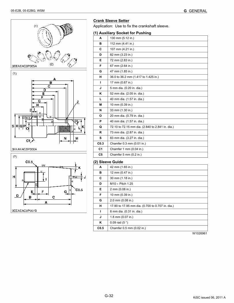
Crank Sleeve SetterApplication: Use to fix the crankshaft sleeve.
(1) Auxiliary Socket for Pushing
(2) Sleeve Guide
W1026961
A 130 mm (5.12 in.)
B 112 mm (4.41 in.)
C 107 mm (4.21 in.)
D 82 mm (3.23 in.)
E 72 mm (2.83 in.)
F 67 mm (2.64 in.)
G 47 mm (1.85 in.)
H 36.0 to 36.2 mm (1.417 to 1.425 in.)
I 17 mm (0.67 in.)
J 5 mm dia. (0.20 in. dia.)
K 52 mm dia. (2.05 in. dia.)
L 40 mm dia. (1.57 in. dia.)
M 10 mm (0.39 in.)
N 33 mm (1.30 in.)
O 20 mm dia. (0.79 in. dia.)
P 40 mm dia. (1.57 in. dia.)
Q 72.10 to 72.15 mm dia. (2.840 to 2.841 in. dia.)
R 73 mm dia. (2.87 in. dia.)
S 83 mm dia. (3.27 in. dia.)
C0.3 Chamfer 0.3 mm (0.01 in.)
C1 Chamfer 1 mm (0.04 in.)
C5 Chamfer 5 mm (0.2 in.)
A 42 mm (1.65 in.)
B 12 mm (0.47 in.)
C 30 mm (1.18 in.)
D M10 × Pitch 1.25
E 2 mm (0.08 in.)
F 10 mm (0.39 in.)
G 2.0 mm (0.08 in.)
H 17.90 to 17.95 mm dia. (0.700 to 0.707 in. dia.)
I 8 mm dia. (0.31 in. dia.)
J 1.8 mm (0.07 in.)
K 0.09 rad (5 °)
C0.5 Chamfer 0.5 mm (0.02 in.)
KiSC issued 06, 2011 A
CONTENTS
MECHANISM
1. ENGINE BODY ............................................................................................... M-1[1] CLOSED BREATHER (NATURAL ASPIRATION TYPE ONLY)........... M-1[2] GOVERNOR .............................................................................................. M-2[3] BOOST COMPENSATOR ........................................................................ M-4
KiSC issued 06, 2011 A
M-1
05-E2B, 05-E2BG, WSM DIESEL ENGINE
1. ENGINE BODY[1] CLOSED BREATHER (NATURAL ASPIRATION TYPE ONLY)
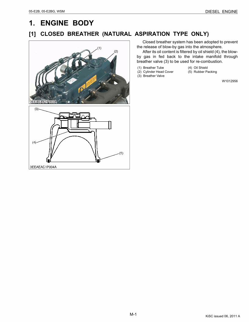
Closed breather system has been adopted to preventthe release of blow-by gas into the atmosphere.
After its oil content is filtered by oil shield (4), the blow-by gas in fed back to the intake manifold throughbreather valve (3) to be used for re-combustion.
W1012956
(1) Breather Tube(2) Cylinder Head Cover(3) Breather Valve
(4) Oil Shield(5) Rubber Packing
KiSC issued 06, 2011 A
M-2
05-E2B, 05-E2BG, WSM DIESEL ENGINE
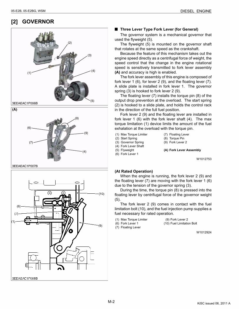
[2] GOVERNORThree Lever Type Fork Lever (for General)The governor system is a mechanical governor that
used the flyweight (5).The flyweight (5) is mounted on the governor shaft
that rotates at the same speed as the crankshaft.Because the feature of this mechanism takes out the
engine speed directly as a centrifugal force of weight, thespeed control that the change in the engine rotationalspeed is sensitively transmitted to fork lever assembly(A) and accuracy is high is enabled.
The fork lever assembly of this engine is composed offork lever 1 (6), for lever 2 (9), and the floating lever (7).A slide plate is installed in fork lever 1. The governorspring (3) is hooked to fork lever 2 (9).
The floating lever (7) installs the torque pin (8) of theoutput drop prevention at the overload. The start spring(2) is hooked to a slide plate, and holds the control rackin the direction of the full fuel position.
Fork lever 2 (9) and the floating lever are installed infork lever 1 (6) with the fork lever shaft (4). The maxtorque limitation (1) device limits the amount of the fuelexhalation at the overload with the torque pin.
W1012753
(At Rated Operation)When the engine is running, the fork lever 2 (9) and
the floating lever (7) are moving with the fork lever 1 (6)due to the tension of the governor spring (3).
During the time, the torque pin (8) is pressed into thefloating lever by centrifugal force of the governor weight(5).
The fork lever 2 (9) comes in contact with the fuellimitation bolt (10), and the fuel injection pump supplies afuel necessary for rated operation.
W1012924
(1) Max Torque Limiter(2) Start Spring(3) Governor Spring(4) Fork Lever Shaft(5) Flyweight(6) Fork Lever 1
(7) Floating Lever(8) Torque Pin(9) Fork Lever 2
(A) Fork Lever Assembly
(1) Max Torque Limiter(6) Fork Lever 1(7) Floating Lever
(9) Fork Lever 2(10) Fuel Limitation Bolt
KiSC issued 06, 2011 A
M-3
05-E2B, 05-E2BG, WSM DIESEL ENGINE
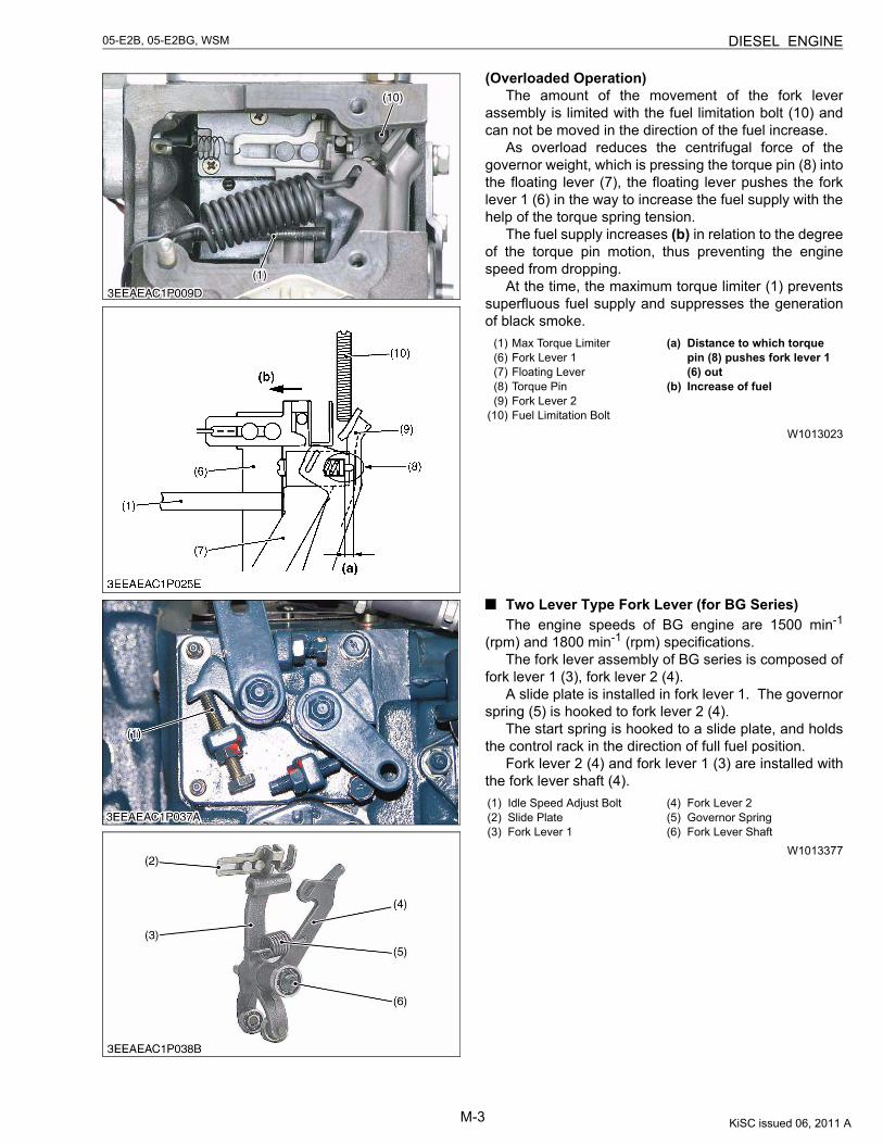
(Overloaded Operation)The amount of the movement of the fork lever
assembly is limited with the fuel limitation bolt (10) andcan not be moved in the direction of the fuel increase.
As overload reduces the centrifugal force of thegovernor weight, which is pressing the torque pin (8) intothe floating lever (7), the floating lever pushes the forklever 1 (6) in the way to increase the fuel supply with thehelp of the torque spring tension.
The fuel supply increases (b) in relation to the degreeof the torque pin motion, thus preventing the enginespeed from dropping.
At the time, the maximum torque limiter (1) preventssuperfluous fuel supply and suppresses the generationof black smoke.
W1013023
Two Lever Type Fork Lever (for BG Series)The engine speeds of BG engine are 1500 min-1
(rpm) and 1800 min-1 (rpm) specifications.The fork lever assembly of BG series is composed of
fork lever 1 (3), fork lever 2 (4).A slide plate is installed in fork lever 1. The governor
spring (5) is hooked to fork lever 2 (4).The start spring is hooked to a slide plate, and holds
the control rack in the direction of full fuel position.Fork lever 2 (4) and fork lever 1 (3) are installed with
the fork lever shaft (4).
W1013377
(1) Max Torque Limiter(6) Fork Lever 1(7) Floating Lever(8) Torque Pin(9) Fork Lever 2
(10) Fuel Limitation Bolt
(a) Distance to which torque pin (8) pushes fork lever 1 (6) out
(b) Increase of fuel
(1) Idle Speed Adjust Bolt(2) Slide Plate(3) Fork Lever 1
(4) Fork Lever 2(5) Governor Spring(6) Fork Lever Shaft
KiSC issued 06, 2011 A
M-4
05-E2B, 05-E2BG, WSM DIESEL ENGINE
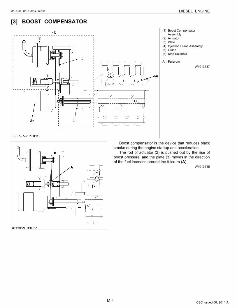
[3] BOOST COMPENSATOR
W1013537
Boost compensator is the device that reduces blacksmoke during the engine startup and acceleration.
The rod of actuator (2) is pushed out by the rise ofboost pressure, and the plate (3) moves in the directionof the fuel increase around the fulcrum (A).
W1013615
(1) Boost Compensator Assembly
(2) Actuator(3) Plate(4) Injection Pump Assembly(5) Guide(6) Stop Solenoid
A : Fulcrum
KiSC issued 06, 2011 A
CONTENTS
SERVICING
1. TROUBLESHOOTING ......................................................................................S-12. SERVICING SPECIFICATIONS ......................................................................S-53. TIGHTENING TORQUES ..............................................................................S-13
[1] TIGHTENING TORQUES FOR GENERAL USE SCREWS, BOLTSAND NUTS...............................................................................................S-13
[2] TIGHTENING TORQUES FOR SPECIAL USE SCREWS, BOLTSAND NUTS...............................................................................................S-14
4. CHECKING, DISASSEMBLING AND SERVICING......................................S-15[1] CHECKING AND ADJUSTING ...............................................................S-15
(1) Engine Body........................................................................................S-15(2) Lubricating System .............................................................................S-17(3) Cooling System...................................................................................S-17(4) Fuel System ........................................................................................S-19(5) Electrical System ................................................................................S-22(6) Turbocharger ......................................................................................S-26
[2] DISASSEMBLING AND ASSEMBLING..................................................S-27(1) Draining Oil and Coolant.....................................................................S-27(2) External Components .........................................................................S-27(3) Cylinder Head and Valve ....................................................................S-28(4) Gear Case and Timing Gears .............................................................S-32(5) Piston and Connecting Rod ................................................................S-37(6) Flywheel and Crankshaft ....................................................................S-40(7) Starter .................................................................................................S-42(8) Alternator ............................................................................................S-44
[3] SERVICING ..............................................................................................S-45(1) Cylinder Head and Valves ..................................................................S-45(2) Timing Gears, Camshaft and Governor Gear .....................................S-51(3) Piston and Connecting Rod ................................................................S-54(4) Crankshaft...........................................................................................S-58(5) Cylinder...............................................................................................S-63(6) Oil Pump .............................................................................................S-64(7) Starter .................................................................................................S-65(8) Alternator ............................................................................................S-68
KiSC issued 06, 2011 A

S-1
05-E2B, 05-E2BG, WSM DIESEL ENGINE
1. TROUBLESHOOTING
W1014322
Symptom Probable Cause Solution Reference Page
Engine Does Not Start
No fuel Replenish fuel G-10Air in the fuel system Vent air G-10Water in the fuel system Change fuel and
repair or replace fuel system
–
Fuel pipe clogged Clean or replace G-10Fuel filter clogged Replace G-14, 15Excessively high viscosity of fuel or engine oil at low temperature
Use specified fuel or engine oil
4, G-8
Fuel with low cetane number Use specified fuel –Fuel leak due to loose injection pipe retaining nut Tighten retaining nut –Incorrect injection timing Adjust S-19Fuel camshaft worn Replace S-36Injection nozzle clogged Clean or replace S-21, 22Injection pump malfunctioning Repair or replace S-20, 35Seizure of crankshaft, camshaft, piston, cylinder or bearing
Repair or replace S-58 to 64S-36 to 39
Compression leak from cylinder Replace head gasket, tighten cylinder head screw, glow plug and nozzle holder
S-29, 30, 31
Improper valve timing Correct or replace timing gear
S-36
Piston ring and cylinder worn Replace S-37, 38, 39
Excessive valve clearance Adjust S-16Stop solenoid malfunctioning Replace S-34
Starter Does Not Run Battery discharged Charge –Starter malfunctioning Repair or replace S-27, 65,
66, 67Key switch malfunctioning Replace –Wiring disconnected Connect –
KiSC issued 06, 2011 A
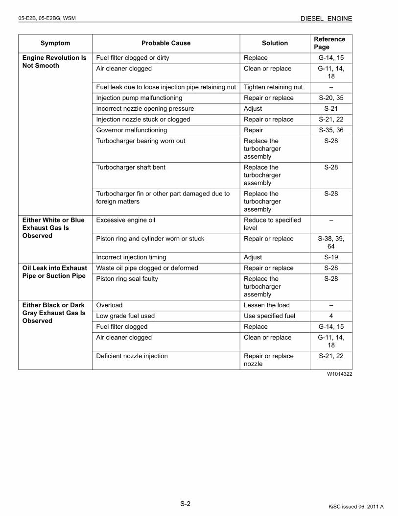
S-2
05-E2B, 05-E2BG, WSM DIESEL ENGINE
W1014322
Symptom Probable Cause Solution Reference Page
Engine Revolution Is Not Smooth
Fuel filter clogged or dirty Replace G-14, 15Air cleaner clogged Clean or replace G-11, 14,
18Fuel leak due to loose injection pipe retaining nut Tighten retaining nut –Injection pump malfunctioning Repair or replace S-20, 35Incorrect nozzle opening pressure Adjust S-21Injection nozzle stuck or clogged Repair or replace S-21, 22Governor malfunctioning Repair S-35, 36Turbocharger bearing worn out Replace the
turbocharger assembly
S-28
Turbocharger shaft bent Replace the turbocharger assembly
S-28
Turbocharger fin or other part damaged due to foreign matters
Replace the turbocharger assembly
S-28
Either White or Blue Exhaust Gas Is Observed
Excessive engine oil Reduce to specified level
–
Piston ring and cylinder worn or stuck Repair or replace S-38, 39, 64
Incorrect injection timing Adjust S-19Oil Leak into Exhaust Pipe or Suction Pipe
Waste oil pipe clogged or deformed Repair or replace S-28Piston ring seal faulty Replace the
turbocharger assembly
S-28
Either Black or Dark Gray Exhaust Gas Is Observed
Overload Lessen the load –Low grade fuel used Use specified fuel 4Fuel filter clogged Replace G-14, 15Air cleaner clogged Clean or replace G-11, 14,
18Deficient nozzle injection Repair or replace
nozzleS-21, 22
KiSC issued 06, 2011 A
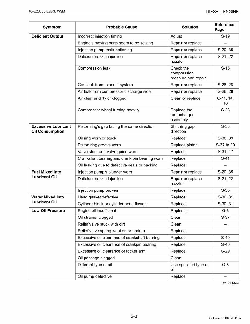
S-3
05-E2B, 05-E2BG, WSM DIESEL ENGINE
W1014322
Symptom Probable Cause Solution Reference Page
Deficient Output Incorrect injection timing Adjust S-19Engine’s moving parts seem to be seizing Repair or replace –Injection pump malfunctioning Repair or replace S-20, 35Deficient nozzle injection Repair or replace
nozzleS-21, 22
Compression leak Check the compression pressure and repair
S-15
Gas leak from exhaust system Repair or replace S-26, 28Air leak from compressor discharge side Repair or replace S-26, 28Air cleaner dirty or clogged Clean or replace G-11, 14,
18Compressor wheel turning heavily Replace the
turbocharger assembly
S-28
Excessive Lubricant Oil Consumption
Piston ring’s gap facing the same direction Shift ring gap direction
S-38
Oil ring worn or stuck Replace S-38, 39Piston ring groove worn Replace piston S-37 to 39Valve stem and valve guide worn Replace S-31, 47Crankshaft bearing and crank pin bearing worn Replace S-41Oil leaking due to defective seals or packing Replace –
Fuel Mixed into Lubricant Oil
Injection pump’s plunger worn Repair or replace S-20, 35Deficient nozzle injection Repair or replace
nozzleS-21, 22
Injection pump broken Replace S-35Water Mixed into Lubricant Oil
Head gasket defective Replace S-30, 31Cylinder block or cylinder head flawed Replace S-30, 31
Low Oil Pressure Engine oil insufficient Replenish G-8Oil strainer clogged Clean S-37Relief valve stuck with dirt Clean –Relief valve spring weaken or broken Replace –Excessive oil clearance of crankshaft bearing Replace S-40Excessive oil clearance of crankpin bearing Replace S-40Excessive oil clearance of rocker arm Replace S-29Oil passage clogged Clean –Different type of oil Use specified type of
oilG-8
Oil pump defective Replace –
KiSC issued 06, 2011 A
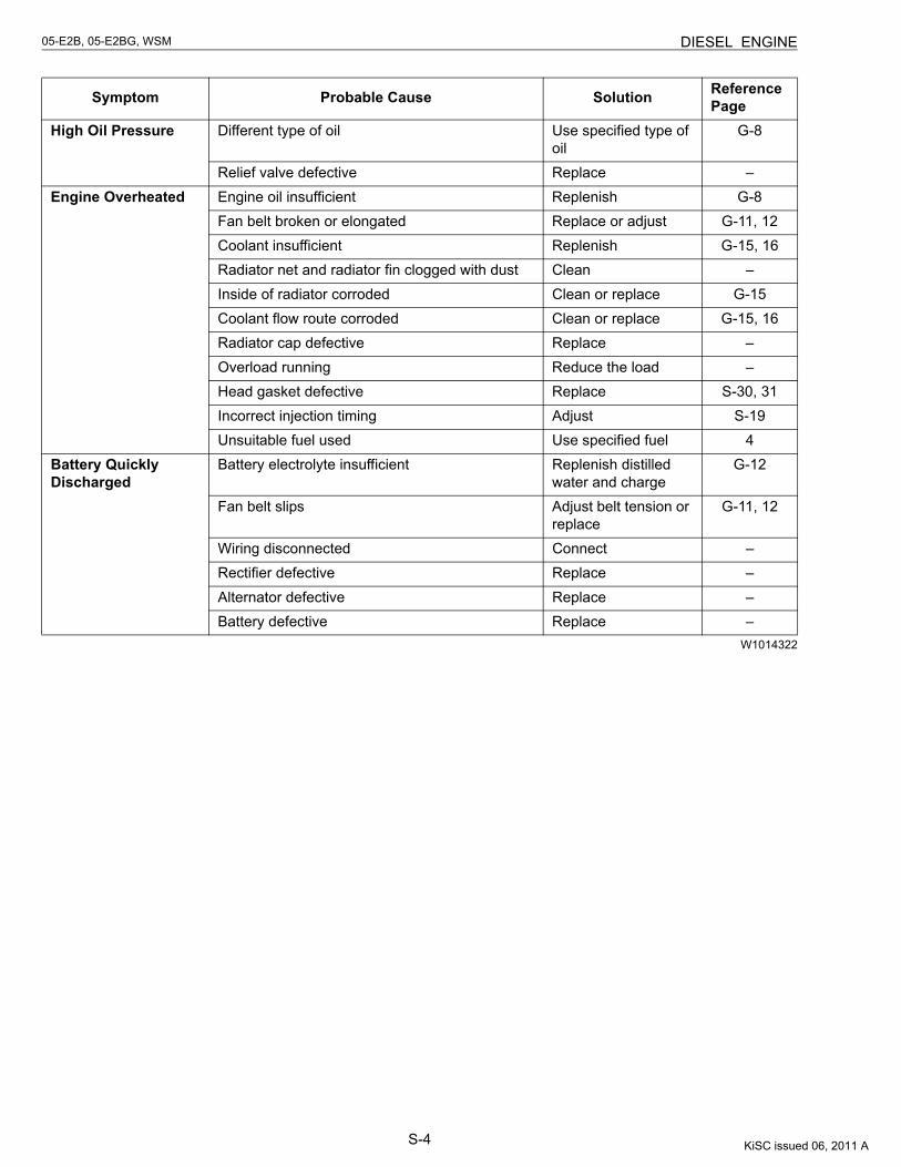
S-4
05-E2B, 05-E2BG, WSM DIESEL ENGINE
W1014322
Symptom Probable Cause Solution Reference Page
High Oil Pressure Different type of oil Use specified type of oil
G-8
Relief valve defective Replace –Engine Overheated Engine oil insufficient Replenish G-8
Fan belt broken or elongated Replace or adjust G-11, 12Coolant insufficient Replenish G-15, 16Radiator net and radiator fin clogged with dust Clean –Inside of radiator corroded Clean or replace G-15Coolant flow route corroded Clean or replace G-15, 16Radiator cap defective Replace –Overload running Reduce the load –Head gasket defective Replace S-30, 31Incorrect injection timing Adjust S-19Unsuitable fuel used Use specified fuel 4
Battery Quickly Discharged
Battery electrolyte insufficient Replenish distilled water and charge
G-12
Fan belt slips Adjust belt tension or replace
G-11, 12
Wiring disconnected Connect –Rectifier defective Replace –Alternator defective Replace –Battery defective Replace –
KiSC issued 06, 2011 A
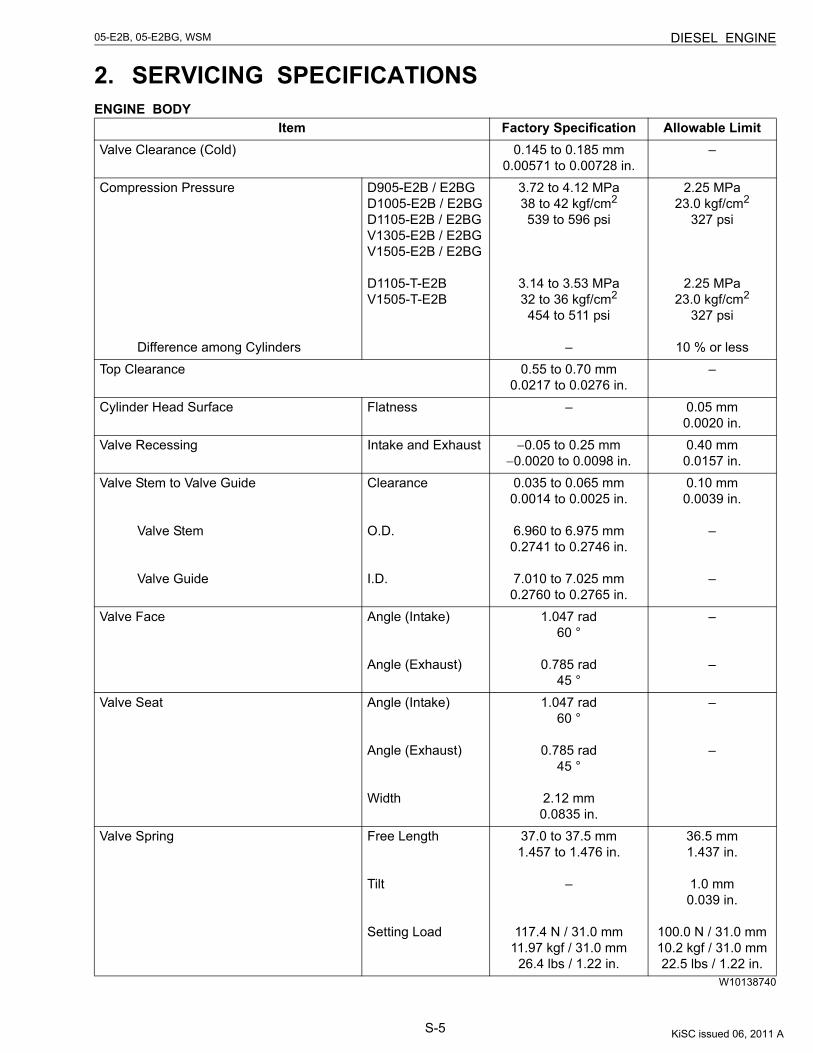
S-5
05-E2B, 05-E2BG, WSM DIESEL ENGINE
2. SERVICING SPECIFICATIONSENGINE BODY
W10138740
Item Factory Specification Allowable LimitValve Clearance (Cold) 0.145 to 0.185 mm
0.00571 to 0.00728 in.–
Compression Pressure
Difference among Cylinders
D905-E2B / E2BGD1005-E2B / E2BGD1105-E2B / E2BGV1305-E2B / E2BGV1505-E2B / E2BG
D1105-T-E2BV1505-T-E2B
3.72 to 4.12 MPa38 to 42 kgf/cm2
539 to 596 psi
3.14 to 3.53 MPa32 to 36 kgf/cm2
454 to 511 psi
–
2.25 MPa23.0 kgf/cm2
327 psi
2.25 MPa23.0 kgf/cm2
327 psi
10 % or lessTop Clearance 0.55 to 0.70 mm
0.0217 to 0.0276 in.–
Cylinder Head Surface Flatness – 0.05 mm0.0020 in.
Valve Recessing Intake and Exhaust −0.05 to 0.25 mm−0.0020 to 0.0098 in.
0.40 mm0.0157 in.
Valve Stem to Valve Guide
Valve Stem
Valve Guide
Clearance
O.D.
I.D.
0.035 to 0.065 mm0.0014 to 0.0025 in.
6.960 to 6.975 mm0.2741 to 0.2746 in.
7.010 to 7.025 mm0.2760 to 0.2765 in.
0.10 mm0.0039 in.
–
–
Valve Face Angle (Intake)
Angle (Exhaust)
1.047 rad60 °
0.785 rad45 °
–
–
Valve Seat Angle (Intake)
Angle (Exhaust)
Width
1.047 rad60 °
0.785 rad45 °
2.12 mm0.0835 in.
–
–
Valve Spring Free Length
Tilt
Setting Load
37.0 to 37.5 mm1.457 to 1.476 in.
–
117.4 N / 31.0 mm11.97 kgf / 31.0 mm
26.4 lbs / 1.22 in.
36.5 mm1.437 in.
1.0 mm0.039 in.
100.0 N / 31.0 mm10.2 kgf / 31.0 mm22.5 lbs / 1.22 in.
KiSC issued 06, 2011 A
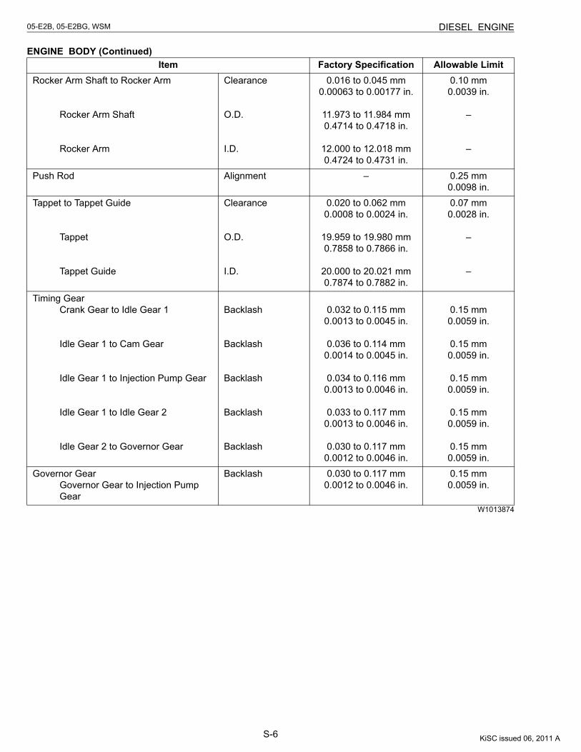
S-6
05-E2B, 05-E2BG, WSM DIESEL ENGINE
ENGINE BODY (Continued)
W1013874
Item Factory Specification Allowable LimitRocker Arm Shaft to Rocker Arm
Rocker Arm Shaft
Rocker Arm
Clearance
O.D.
I.D.
0.016 to 0.045 mm0.00063 to 0.00177 in.
11.973 to 11.984 mm0.4714 to 0.4718 in.
12.000 to 12.018 mm0.4724 to 0.4731 in.
0.10 mm0.0039 in.
–
–
Push Rod Alignment – 0.25 mm0.0098 in.
Tappet to Tappet Guide
Tappet
Tappet Guide
Clearance
O.D.
I.D.
0.020 to 0.062 mm0.0008 to 0.0024 in.
19.959 to 19.980 mm0.7858 to 0.7866 in.
20.000 to 20.021 mm0.7874 to 0.7882 in.
0.07 mm0.0028 in.
–
–
Timing GearCrank Gear to Idle Gear 1
Idle Gear 1 to Cam Gear
Idle Gear 1 to Injection Pump Gear
Idle Gear 1 to Idle Gear 2
Idle Gear 2 to Governor Gear
Backlash
Backlash
Backlash
Backlash
Backlash
0.032 to 0.115 mm0.0013 to 0.0045 in.
0.036 to 0.114 mm0.0014 to 0.0045 in.
0.034 to 0.116 mm0.0013 to 0.0046 in.
0.033 to 0.117 mm0.0013 to 0.0046 in.
0.030 to 0.117 mm0.0012 to 0.0046 in.
0.15 mm0.0059 in.
0.15 mm0.0059 in.
0.15 mm0.0059 in.
0.15 mm0.0059 in.
0.15 mm0.0059 in.
Governor GearGovernor Gear to Injection PumpGear
Backlash 0.030 to 0.117 mm0.0012 to 0.0046 in.
0.15 mm0.0059 in.
KiSC issued 06, 2011 A
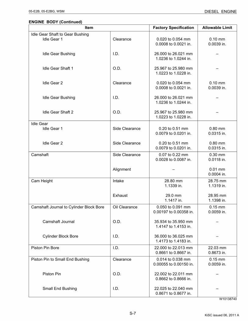
S-7
05-E2B, 05-E2BG, WSM DIESEL ENGINE
ENGINE BODY (Continued)
W10138740
Item Factory Specification Allowable LimitIdle Gear Shaft to Gear Bushing
Idle Gear 1
Idle Gear Bushing
Idle Gear Shaft 1
Idle Gear 2
Idle Gear Bushing
Idle Gear Shaft 2
Clearance
I.D.
O.D.
Clearance
I.D.
O.D.
0.020 to 0.054 mm0.0008 to 0.0021 in.
26.000 to 26.021 mm1.0236 to 1.0244 in.
25.967 to 25.980 mm1.0223 to 1.0228 in.
0.020 to 0.054 mm0.0008 to 0.0021 in.
26.000 to 26.021 mm1.0236 to 1.0244 in.
25.967 to 25.980 mm1.0223 to 1.0228 in.
0.10 mm0.0039 in.
–
–
0.10 mm0.0039 in.
–
–
Idle GearIdle Gear 1
Idle Gear 2
Side Clearance
Side Clearance
0.20 to 0.51 mm0.0079 to 0.0201 in.
0.20 to 0.51 mm0.0079 to 0.0201 in.
0.80 mm0.0315 in.
0.80 mm0.0315 in.
Camshaft Side Clearance
Alignment
0.07 to 0.22 mm0.0028 to 0.0087 in.
–
0.30 mm0.0118 in.
0.01 mm0.0004 in.
Cam Height Intake
Exhaust
28.80 mm1.1339 in.
29.0 mm1.1417 in.
28.75 mm1.1319 in.
28.95 mm1.1398 in.
Camshaft Journal to Cylinder Block Bore
Camshaft Journal
Cylinder Block Bore
Oil Clearance
O.D.
I.D.
0.050 to 0.091 mm0.00197 to 0.00358 in.
35.934 to 35.950 mm1.4147 to 1.4153 in.
36.000 to 36.025 mm1.4173 to 1.4183 in.
0.15 mm0.0059 in.
–
–
Piston Pin Bore I.D. 22.000 to 22.013 mm0.8661 to 0.8667 in.
22.03 mm0.8673 in.
Piston Pin to Small End Bushing
Piston Pin
Small End Bushing
Clearance
O.D.
I.D.
0.014 to 0.038 mm0.00055 to 0.00150 in.
22.002 to 22.011 mm0.8662 to 0.8666 in.
22.025 to 22.040 mm0.8671 to 0.8677 in.
0.15 mm0.0059 in.
–
–
KiSC issued 06, 2011 A
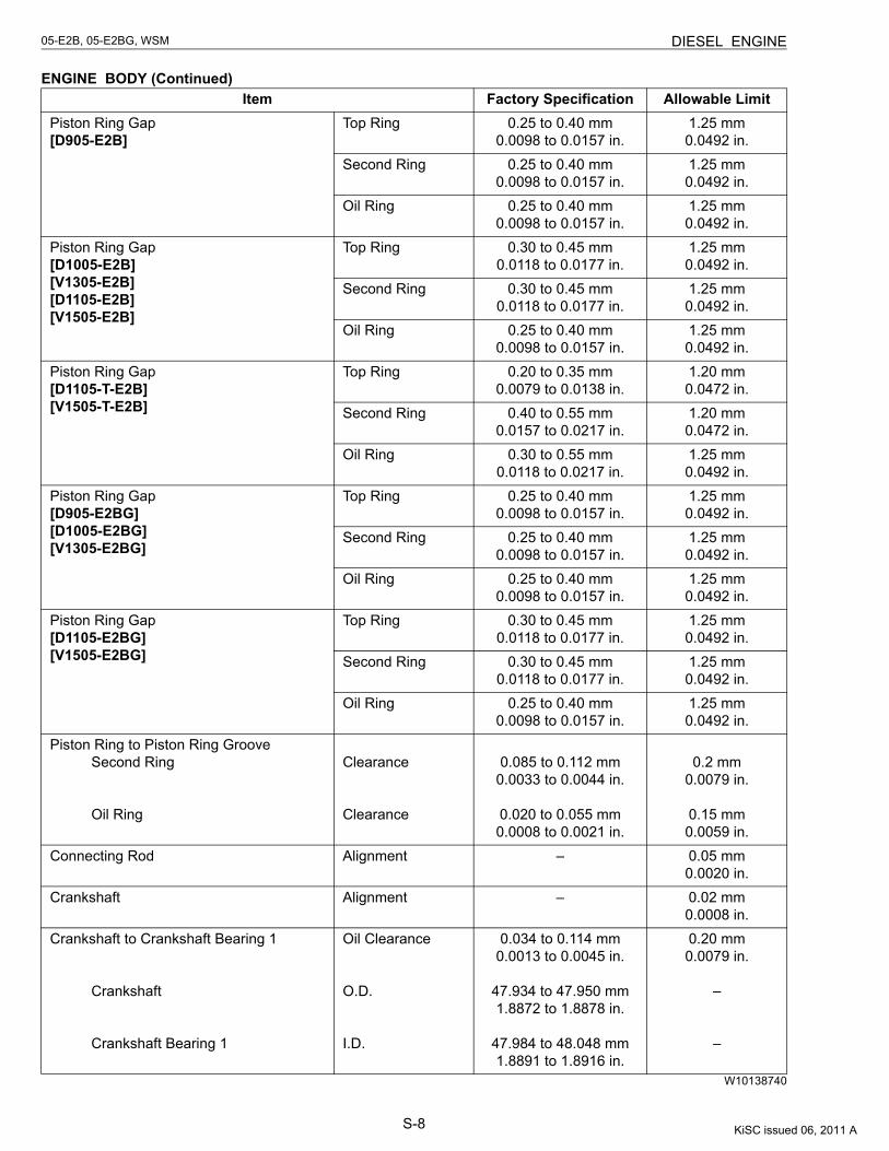
S-8
05-E2B, 05-E2BG, WSM DIESEL ENGINE
ENGINE BODY (Continued)
W10138740
Item Factory Specification Allowable LimitPiston Ring Gap[D905-E2B]
Top Ring 0.25 to 0.40 mm0.0098 to 0.0157 in.
1.25 mm0.0492 in.
Second Ring 0.25 to 0.40 mm0.0098 to 0.0157 in.
1.25 mm0.0492 in.
Oil Ring 0.25 to 0.40 mm0.0098 to 0.0157 in.
1.25 mm0.0492 in.
Piston Ring Gap[D1005-E2B][V1305-E2B][D1105-E2B][V1505-E2B]
Top Ring 0.30 to 0.45 mm0.0118 to 0.0177 in.
1.25 mm0.0492 in.
Second Ring 0.30 to 0.45 mm0.0118 to 0.0177 in.
1.25 mm0.0492 in.
Oil Ring 0.25 to 0.40 mm0.0098 to 0.0157 in.
1.25 mm0.0492 in.
Piston Ring Gap[D1105-T-E2B][V1505-T-E2B]
Top Ring 0.20 to 0.35 mm0.0079 to 0.0138 in.
1.20 mm0.0472 in.
Second Ring 0.40 to 0.55 mm0.0157 to 0.0217 in.
1.20 mm0.0472 in.
Oil Ring 0.30 to 0.55 mm0.0118 to 0.0217 in.
1.25 mm0.0492 in.
Piston Ring Gap[D905-E2BG][D1005-E2BG][V1305-E2BG]
Top Ring 0.25 to 0.40 mm0.0098 to 0.0157 in.
1.25 mm0.0492 in.
Second Ring 0.25 to 0.40 mm0.0098 to 0.0157 in.
1.25 mm0.0492 in.
Oil Ring 0.25 to 0.40 mm0.0098 to 0.0157 in.
1.25 mm0.0492 in.
Piston Ring Gap[D1105-E2BG][V1505-E2BG]
Top Ring 0.30 to 0.45 mm0.0118 to 0.0177 in.
1.25 mm0.0492 in.
Second Ring 0.30 to 0.45 mm0.0118 to 0.0177 in.
1.25 mm0.0492 in.
Oil Ring 0.25 to 0.40 mm0.0098 to 0.0157 in.
1.25 mm0.0492 in.
Piston Ring to Piston Ring GrooveSecond Ring
Oil Ring
Clearance
Clearance
0.085 to 0.112 mm0.0033 to 0.0044 in.
0.020 to 0.055 mm0.0008 to 0.0021 in.
0.2 mm0.0079 in.
0.15 mm0.0059 in.
Connecting Rod Alignment – 0.05 mm0.0020 in.
Crankshaft Alignment – 0.02 mm0.0008 in.
Crankshaft to Crankshaft Bearing 1
Crankshaft
Crankshaft Bearing 1
Oil Clearance
O.D.
I.D.
0.034 to 0.114 mm0.0013 to 0.0045 in.
47.934 to 47.950 mm1.8872 to 1.8878 in.
47.984 to 48.048 mm1.8891 to 1.8916 in.
0.20 mm0.0079 in.
–
–
KiSC issued 06, 2011 A
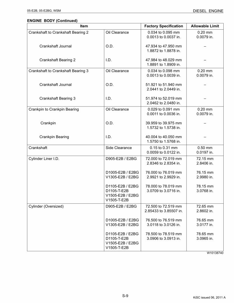
S-9
05-E2B, 05-E2BG, WSM DIESEL ENGINE
ENGINE BODY (Continued)
W10138740
Item Factory Specification Allowable LimitCrankshaft to Crankshaft Bearing 2
Crankshaft Journal
Crankshaft Bearing 2
Oil Clearance
O.D.
I.D.
0.034 to 0.095 mm0.0013 to 0.0037 in.
47.934 to 47.950 mm1.8872 to 1.8878 in.
47.984 to 48.029 mm1.8891 to 1.8909 in.
0.20 mm0.0079 in.
–
–
Crankshaft to Crankshaft Bearing 3
Crankshaft Journal
Crankshaft Bearing 3
Oil Clearance
O.D.
I.D.
0.034 to 0.098 mm0.0013 to 0.0039 in.
51.921 to 51.940 mm2.0441 to 2.0449 in.
51.974 to 52.019 mm2.0462 to 2.0480 in.
0.20 mm0.0079 in.
–
–
Crankpin to Crankpin Bearing
Crankpin
Crankpin Bearing
Oil Clearance
O.D.
I.D.
0.029 to 0.091 mm0.0011 to 0.0036 in.
39.959 to 39.975 mm1.5732 to 1.5738 in.
40.004 to 40.050 mm1.5750 to 1.5768 in.
0.20 mm0.0079 in.
–
–
Crankshaft Side Clearance 0.15 to 0.31 mm0.0059 to 0.0122 in.
0.50 mm0.0197 in.
Cylinder Liner I.D. D905-E2B / E2BG
D1005-E2B / E2BGV1305-E2B / E2BG
D1105-E2B / E2BGD1105-T-E2BV1505-E2B / E2BGV1505-T-E2B
72.000 to 72.019 mm2.8346 to 2.8354 in.
76.000 to 76.019 mm2.9921 to 2.9929 in.
78.000 to 78.019 mm3.0709 to 3.0716 in.
72.15 mm2.8406 in.
76.15 mm2.9980 in.
78.15 mm3.0768 in.
Cylinder (Oversized) D905-E2B / E2BG
D1005-E2B / E2BGV1305-E2B / E2BG
D1105-E2B / E2BGD1105-T-E2BV1505-E2B / E2BGV1505-T-E2B
72.500 to 72.519 mm2.85433 to 3.85507 in.
76.500 to 76.519 mm3.0118 to 3.0126 in.
78.500 to 78.519 mm3.0906 to 3.0913 in.
72.65 mm2.8602 in.
76.65 mm3.0177 in.
78.65 mm3.0965 in.
KiSC issued 06, 2011 A
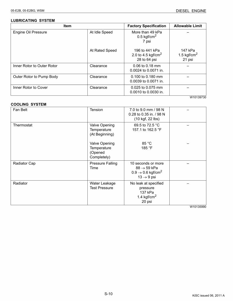
S-10
05-E2B, 05-E2BG, WSM DIESEL ENGINE
LUBRICATING SYSTEM
W10139730
COOLING SYSTEM
W10135990
Item Factory Specification Allowable LimitEngine Oil Pressure At Idle Speed
At Rated Speed
More than 49 kPa0.5 kgf/cm2
7 psi
196 to 441 kPa2.0 to 4.5 kgf/cm2
28 to 64 psi
–
147 kPa1.5 kgf/cm2
21 psiInner Rotor to Outer Rotor Clearance 0.06 to 0.18 mm
0.0024 to 0.0071 in.–
Outer Rotor to Pump Body Clearance 0.100 to 0.180 mm0.0039 to 0.0071 in.
–
Inner Rotor to Cover Clearance 0.025 to 0.075 mm0.0010 to 0.0030 in.
–
Fan Belt Tension 7.0 to 9.0 mm / 98 N0.28 to 0.35 in. / 98 N
(10 kgf, 22 lbs)
–
Thermostat Valve Opening Temperature(At Beginning)
Valve Opening Temperature(Opened Completely)
69.5 to 72.5 °C157.1 to 162.5 °F
85 °C185 °F
–
–
Radiator Cap Pressure Falling Time
10 seconds or more 88 → 59 kPa
0.9 → 0.6 kgf/cm2
13 → 9 psi
–
Radiator Water Leakage Test Pressure
No leak at specified pressure137 kPa
1.4 kgf/cm2
20 psi
–
KiSC issued 06, 2011 A
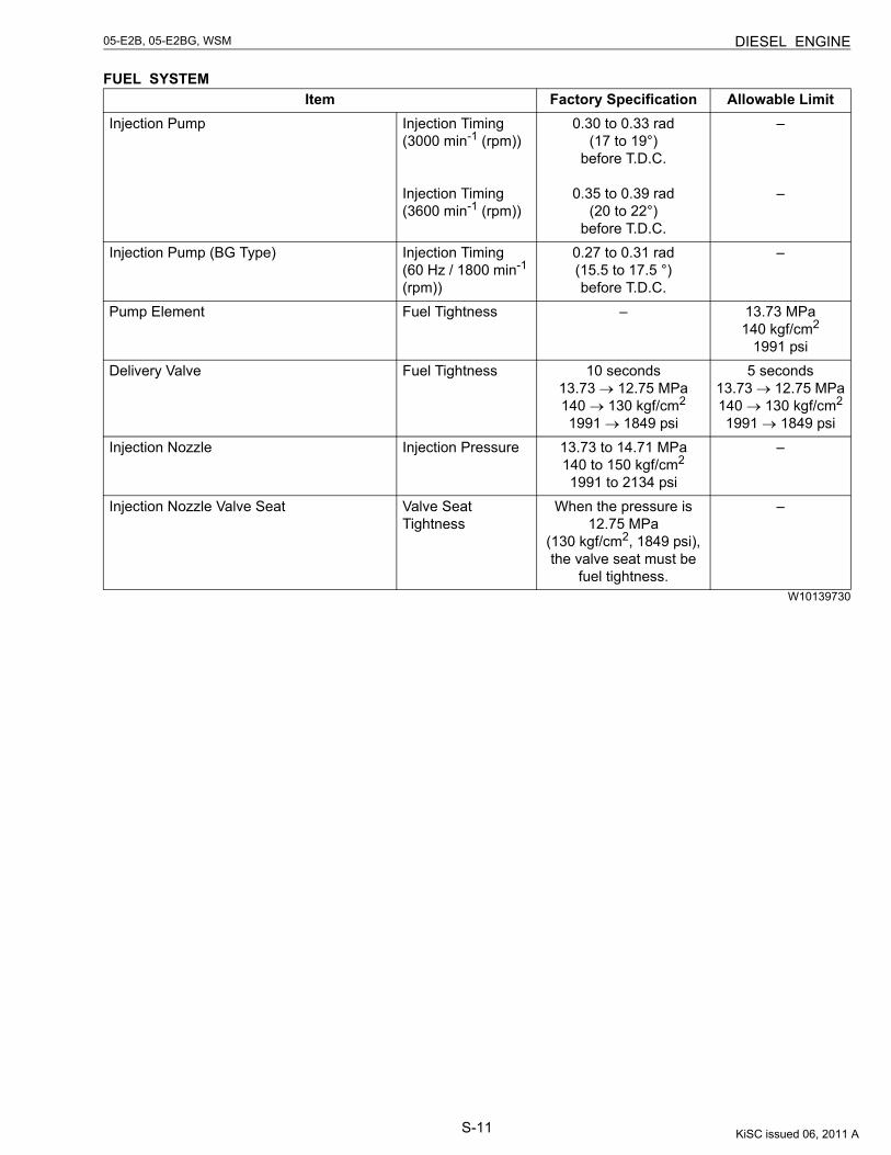
S-11
05-E2B, 05-E2BG, WSM DIESEL ENGINE
FUEL SYSTEM
W10139730
Item Factory Specification Allowable LimitInjection Pump Injection Timing
(3000 min-1 (rpm))
Injection Timing(3600 min-1 (rpm))
0.30 to 0.33 rad(17 to 19°)
before T.D.C.
0.35 to 0.39 rad(20 to 22°)
before T.D.C.
–
–
Injection Pump (BG Type) Injection Timing(60 Hz / 1800 min-1 (rpm))
0.27 to 0.31 rad(15.5 to 17.5 °)before T.D.C.
–
Pump Element Fuel Tightness – 13.73 MPa140 kgf/cm2
1991 psiDelivery Valve Fuel Tightness 10 seconds
13.73 → 12.75 MPa140 → 130 kgf/cm2
1991 → 1849 psi
5 seconds13.73 → 12.75 MPa140 → 130 kgf/cm2
1991 → 1849 psiInjection Nozzle Injection Pressure 13.73 to 14.71 MPa
140 to 150 kgf/cm2
1991 to 2134 psi
–
Injection Nozzle Valve Seat Valve Seat Tightness
When the pressure is 12.75 MPa
(130 kgf/cm2, 1849 psi), the valve seat must be
fuel tightness.
–
KiSC issued 06, 2011 A
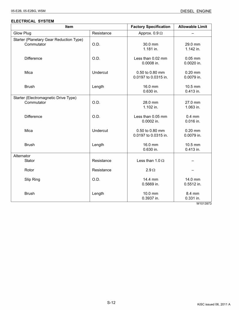
S-12
05-E2B, 05-E2BG, WSM DIESEL ENGINE
ELECTRICAL SYSTEM
W1013973
Item Factory Specification Allowable LimitGlow Plug Resistance Approx. 0.9 Ω –Starter (Planetary Gear Reduction Type)
Commutator
Difference
Mica
Brush
O.D.
O.D.
Undercut
Length
30.0 mm1.181 in.
Less than 0.02 mm0.0008 in.
0.50 to 0.80 mm0.0197 to 0.0315 in.
16.0 mm0.630 in.
29.0 mm1.142 in.
0.05 mm0.0020 in.
0.20 mm0.0079 in.
10.5 mm0.413 in.
Starter (Electromagnetic Drive Type)Commutator
Difference
Mica
Brush
O.D.
O.D.
Undercut
Length
28.0 mm1.102 in.
Less than 0.05 mm0.0002 in.
0.50 to 0.80 mm0.0197 to 0.0315 in.
16.0 mm0.630 in.
27.0 mm1.063 in.
0.4 mm0.016 in.
0.20 mm0.0079 in.
10.5 mm0.413 in.
AlternatorStator
Rotor
Slip Ring
Brush
Resistance
Resistance
O.D.
Length
Less than 1.0 Ω
2.9 Ω
14.4 mm0.5669 in.
10.0 mm0.3937 in.
–
–
14.0 mm0.5512 in.
8.4 mm0.331 in.
KiSC issued 06, 2011 A
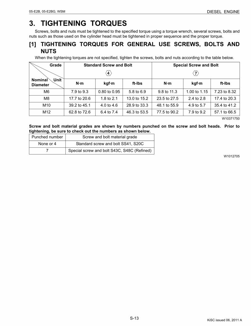
S-13
05-E2B, 05-E2BG, WSM DIESEL ENGINE
3. TIGHTENING TORQUESScrews, bolts and nuts must be tightened to the specified torque using a torque wrench, several screws, bolts and
nuts such as those used on the cylinder head must be tightened in proper sequence and the proper torque.
[1] TIGHTENING TORQUES FOR GENERAL USE SCREWS, BOLTS ANDNUTS
When the tightening torques are not specified, tighten the screws, bolts and nuts according to the table below.
W10371750
Screw and bolt material grades are shown by numbers punched on the screw and bolt heads. Prior totightening, be sure to check out the numbers as shown below.
W1012705
Grade
Nominal UnitDiameter
Standard Screw and Bolt
Special Screw and Bolt
N·m kgf·m ft-lbs N·m kgf·m ft-lbs
M6 7.9 to 9.3 0.80 to 0.95 5.8 to 6.9 9.8 to 11.3 1.00 to 1.15 7.23 to 8.32M8 17.7 to 20.6 1.8 to 2.1 13.0 to 15.2 23.5 to 27.5 2.4 to 2.8 17.4 to 20.3M10 39.2 to 45.1 4.0 to 4.6 28.9 to 33.3 48.1 to 55.9 4.9 to 5.7 35.4 to 41.2M12 62.8 to 72.6 6.4 to 7.4 46.3 to 53.5 77.5 to 90.2 7.9 to 9.2 57.1 to 66.5
Punched number Screw and bolt material gradeNone or 4 Standard screw and bolt SS41, S20C
7 Special screw and bolt S43C, S48C (Refined)
KiSC issued 06, 2011 A
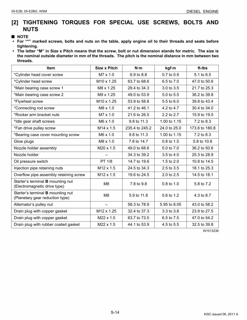
S-14
05-E2B, 05-E2BG, WSM DIESEL ENGINE
[2] TIGHTENING TORQUES FOR SPECIAL USE SCREWS, BOLTS ANDNUTS
NOTE• For “*” marked screws, bolts and nuts on the table, apply engine oil to their threads and seats before
tightening.• The letter “M” in Size x Pitch means that the screw, bolt or nut dimension stands for metric. The size is
the nominal outside diameter in mm of the threads. The pitch is the nominal distance in mm between twothreads.
W1013236
Item Size x Pitch N·m kgf·m ft-lbs*Cylinder head cover screw M7 x 1.0 6.9 to 8.8 0.7 to 0.9 5.1 to 6.5*Cylinder head screw M10 x 1.25 63.7 to 68.6 6.5 to 7.0 47.0 to 50.6*Main bearing case screw 1 M8 x 1.25 29.4 to 34.3 3.0 to 3.5 21.7 to 25.3*Main bearing case screw 2 M9 x 1.25 49.0 to 53.9 5.0 to 5.5 36.2 to 39.8*Flywheel screw M10 x 1.25 53.9 to 58.8 5.5 to 6.0 39.8 to 43.4*Connecting rod screw M8 x 1.0 41.2 to 46.1 4.2 to 4.7 30.4 to 34.0*Rocker arm bracket nuts M7 x 1.0 21.6 to 26.5 2.2 to 2.7 15.9 to 19.5*Idle gear shaft screws M6 x 1.0 9.8 to 11.3 1.00 to 1.15 7.2 to 8.3*Fan drive pulley screw M14 x 1.5 235.4 to 245.2 24.0 to 25.0 173.6 to 180.8*Bearing case cover mounting screw M6 x 1.0 9.8 to 11.3 1.00 to 1.15 7.2 to 8.3Glow plugs M8 x 1.0 7.8 to 14.7 0.8 to 1.5 5.8 to 10.8Nozzle holder assembly M20 x 1.5 49.0 to 68.6 5.0 to 7.0 36.2 to 50.6Nozzle holder – 34.3 to 39.2 3.5 to 4.0 25.3 to 28.9Oil pressure switch PT 1/8 14.7 to 19.6 1.5 to 2.0 10.8 to 14.5Injection pipe retaining nuts M12 x 1.5 24.5 to 34.3 2.5 to 3.5 18.1 to 25.3Overflow pipe assembly retaining screw M12 x 1.5 19.6 to 24.5 2.0 to 2.5 14.5 to 18.1Starter’s terminal B mounting nut(Electromagnetic drive type) M8 7.8 to 9.8 0.8 to 1.0 5.8 to 7.2
Starter’s terminal B mounting nut(Planetary gear reduction type) M8 5.9 to 11.8 0.6 to 1.2 4.3 to 8.7
Alternator’s pulley nut – 58.3 to 78.9 5.95 to 8.05 43.0 to 58.2Drain plug with copper gasket M12 x 1.25 32.4 to 37.3 3.3 to 3.8 23.9 to 27.5Drain plug with copper gasket M22 x 1.5 63.7 to 73.5 6.5 to 7.5 47.0 to 54.2Drain plug with rubber coated gasket M22 x 1.5 44.1 to 53.9 4.5 to 5.5 32.5 to 39.8
KiSC issued 06, 2011 A
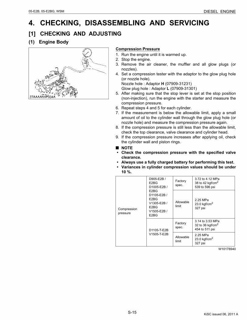
S-15
05-E2B, 05-E2BG, WSM DIESEL ENGINE
4. CHECKING, DISASSEMBLING AND SERVICING[1] CHECKING AND ADJUSTING(1) Engine Body
Compression Pressure1. Run the engine until it is warmed up.2. Stop the engine.3. Remove the air cleaner, the muffler and all glow plugs (or
nozzles).4. Set a compression tester with the adaptor to the glow plug hole
(or nozzle hole).Nozzle hole : Adaptor H (07909-31231)Glow plug hole : Adaptor L (07909-31301)
5. After making sure that the stop lever is set at the stop position(non-injection), run the engine with the starter and measure thecompression pressure.
6. Repeat steps 4 and 5 for each cylinder.7. If the measurement is below the allowable limit, apply a small
amount of oil to the cylinder wall through the glow plug hole (ornozzle hole) and measure the compression pressure again.
8. If the compression pressure is still less than the allowable limit,check the top clearance, valve clearance and cylinder head.
9. If the compression pressure increases after applying oil, checkthe cylinder wall and piston rings.NOTE
• Check the compression pressure with the specified valveclearance.
• Always use a fully charged battery for performing this test.• Variances in cylinder compression values should be under
10 %.
W10178940
Compression pressure
D905-E2B / E2BGD1005-E2B / E2BGD1105-E2B / E2BGV1305-E2B / E2BGV1505-E2B / E2BG
Factory spec.
3.72 to 4.12 MPa38 to 42 kgf/cm2
539 to 596 psi
Allowable limit
2.25 MPa23.0 kgf/cm2
327 psi
D1105-T-E2BV1505-T-E2B
Factory spec.
3.14 to 3.53 MPa32 to 36 kgf/cm2
454 to 511 psi
Allowable limit
2.25 MPa23.0 kgf/cm2
327 psi
KiSC issued 06, 2011 A
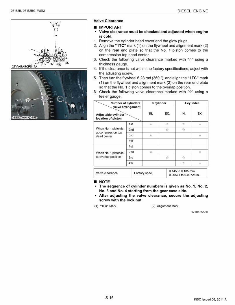
S-16
05-E2B, 05-E2BG, WSM DIESEL ENGINE
Valve ClearanceIMPORTANT
• Valve clearance must be checked and adjusted when engineis cold.
1. Remove the cylinder head cover and the glow plugs.2. Align the “1TC” mark (1) on the flywheel and alignment mark (2)
on the rear end plate so that the No. 1 piston comes to thecompression top dead center.
3. Check the following valve clearance marked with “ ” using athickness gauge.
4. If the clearance is not within the factory specifications, adjust withthe adjusting screw.
5. Then turn the flywheel 6.28 rad (360 °), and align the “1TC” mark(1) on the flywheel and alignment mark (2) on the rear end plateso that the No. 1 piston comes to the overlap position.
6. Check the following valve clearance marked with “ “ using afeeler gauge.
NOTE• The sequence of cylinder numbers is given as No. 1, No. 2,
No. 3 and No. 4 starting from the gear case side.• After adjusting the valve clearance, secure the adjusting
screw with the lock nut.
W10155550
Number of cylinders Valve arrangement
Adjustable cylinderlocation of piston
3 cylinder 4 cylinder
IN. EX. IN. EX.
When No. 1 piston is at compression top dead center
1st
2nd
3rd
4th
When No. 1 piston is at overlap position
1st
2nd
3rd
4th
Valve clearance Factory spec. 0.145 to 0.185 mm0.00571 to 0.00728 in.
(1) “1TC” Mark (2) Alignment Mark
KiSC issued 06, 2011 A
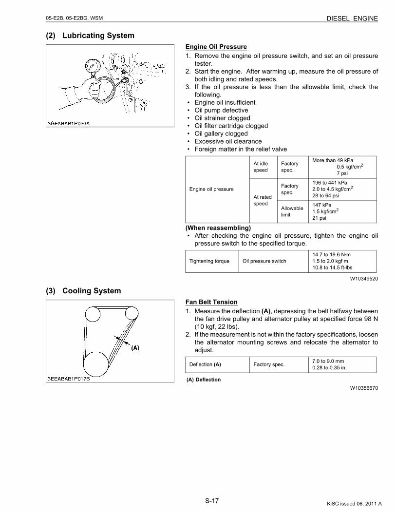
S-17
05-E2B, 05-E2BG, WSM DIESEL ENGINE
(2) Lubricating SystemEngine Oil Pressure1. Remove the engine oil pressure switch, and set an oil pressure
tester.2. Start the engine. After warming up, measure the oil pressure of
both idling and rated speeds.3. If the oil pressure is less than the allowable limit, check the
following.• Engine oil insufficient• Oil pump defective• Oil strainer clogged• Oil filter cartridge clogged• Oil gallery clogged• Excessive oil clearance• Foreign matter in the relief valve
(When reassembling)• After checking the engine oil pressure, tighten the engine oil
pressure switch to the specified torque.
W10349520
(3) Cooling SystemFan Belt Tension1. Measure the deflection (A), depressing the belt halfway between
the fan drive pulley and alternator pulley at specified force 98 N(10 kgf, 22 lbs).
2. If the measurement is not within the factory specifications, loosenthe alternator mounting screws and relocate the alternator toadjust.
W10356670
Engine oil pressure
At idle speed
Factory spec.
More than 49 kPa 0.5 kgf/cm2
7 psi
At rated speed
Factory spec.
196 to 441 kPa2.0 to 4.5 kgf/cm2
28 to 64 psi
Allowable limit
147 kPa1.5 kgf/cm2
21 psi
Tightening torque Oil pressure switch14.7 to 19.6 N·m1.5 to 2.0 kgf·m10.8 to 14.5 ft-lbs
Deflection (A) Factory spec. 7.0 to 9.0 mm0.28 to 0.35 in.
(A) Deflection
KiSC issued 06, 2011 A
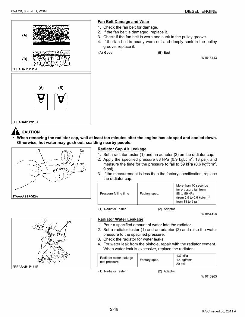
S-18
05-E2B, 05-E2BG, WSM DIESEL ENGINE
Fan Belt Damage and Wear1. Check the fan belt for damage.2. If the fan belt is damaged, replace it.3. Check if the fan belt is worn and sunk in the pulley groove.4. If the fan belt is nearly worn out and deeply sunk in the pulley
groove, replace it.
W1016443
CAUTION• When removing the radiator cap, wait at least ten minutes after the engine has stopped and cooled down.
Otherwise, hot water may gush out, scalding nearby people.Radiator Cap Air Leakage1. Set a radiator tester (1) and an adaptor (2) on the radiator cap.2. Apply the specified pressure 88 kPa (0.9 kgf/cm2, 13 psi), and
measure the time for the pressure to fall to 59 kPa (0.6 kgf/cm2,9 psi).
3. If the measurement is less than the factory specification, replacethe radiator cap.
W1054156
Radiator Water Leakage1. Pour a specified amount of water into the radiator.2. Set a radiator tester (1) and an adaptor (2) and raise the water
pressure to the specified pressure.3. Check the radiator for water leaks.4. For water leak from the pinhole, repair with the radiator cement.
When water leak is excessive, replace the radiator.
W1016903
(A) Good (B) Bad
Pressure falling time Factory spec.
More than 10 secondsfor pressure fall from88 to 59 kPa(from 0.9 to 0.6 kgf/cm2,from 13 to 9 psi)
(1) Radiator Tester (2) Adaptor
Radiator water leakage test pressure Factory spec.
137 kPa1.4 kgf/cm2
20 psi
(1) Radiator Tester (2) Adaptor
KiSC issued 06, 2011 A
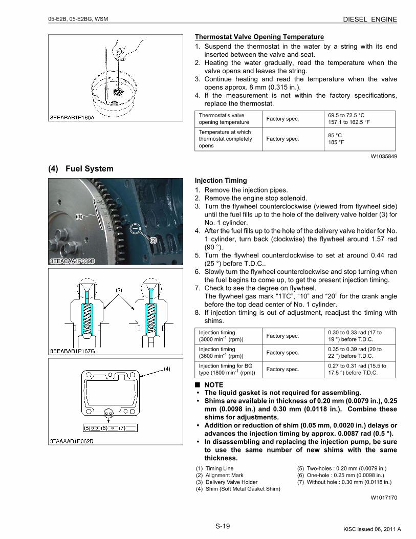
S-19
05-E2B, 05-E2BG, WSM DIESEL ENGINE
Thermostat Valve Opening Temperature1. Suspend the thermostat in the water by a string with its end
inserted between the valve and seat.2. Heating the water gradually, read the temperature when the
valve opens and leaves the string.3. Continue heating and read the temperature when the valve
opens approx. 8 mm (0.315 in.).4. If the measurement is not within the factory specifications,
replace the thermostat.
W1035849
(4) Fuel SystemInjection Timing1. Remove the injection pipes.2. Remove the engine stop solenoid.3. Turn the flywheel counterclockwise (viewed from flywheel side)
until the fuel fills up to the hole of the delivery valve holder (3) forNo. 1 cylinder.
4. After the fuel fills up to the hole of the delivery valve holder for No.1 cylinder, turn back (clockwise) the flywheel around 1.57 rad(90 °).
5. Turn the flywheel counterclockwise to set at around 0.44 rad(25 °) before T.D.C..
6. Slowly turn the flywheel counterclockwise and stop turning whenthe fuel begins to come up, to get the present injection timing.
7. Check to see the degree on flywheel.The flywheel gas mark “1TC”, “10” and “20” for the crank anglebefore the top dead center of No. 1 cylinder.
8. If injection timing is out of adjustment, readjust the timing withshims.
NOTE• The liquid gasket is not required for assembling.• Shims are available in thickness of 0.20 mm (0.0079 in.), 0.25
mm (0.0098 in.) and 0.30 mm (0.0118 in.). Combine theseshims for adjustments.
• Addition or reduction of shim (0.05 mm, 0.0020 in.) delays oradvances the injection timing by approx. 0.0087 rad (0.5 °).
• In disassembling and replacing the injection pump, be sureto use the same number of new shims with the samethickness.
W1017170
Thermostat’s valve opening temperature Factory spec. 69.5 to 72.5 °C
157.1 to 162.5 °F
Temperature at which thermostat completely opens
Factory spec. 85 °C185 °F
Injection timing(3000 min-1 (rpm)) Factory spec. 0.30 to 0.33 rad (17 to
19 °) before T.D.C.
Injection timing(3600 min-1 (rpm)) Factory spec. 0.35 to 0.39 rad (20 to
22 °) before T.D.C.
Injection timing for BG type (1800 min-1 (rpm)) Factory spec. 0.27 to 0.31 rad (15.5 to
17.5 °) before T.D.C.
(1) Timing Line(2) Alignment Mark(3) Delivery Valve Holder(4) Shim (Soft Metal Gasket Shim)
(5) Two-holes : 0.20 mm (0.0079 in.)(6) One-hole : 0.25 mm (0.0098 in.)(7) Without hole : 0.30 mm (0.0118 in.)
KiSC issued 06, 2011 A
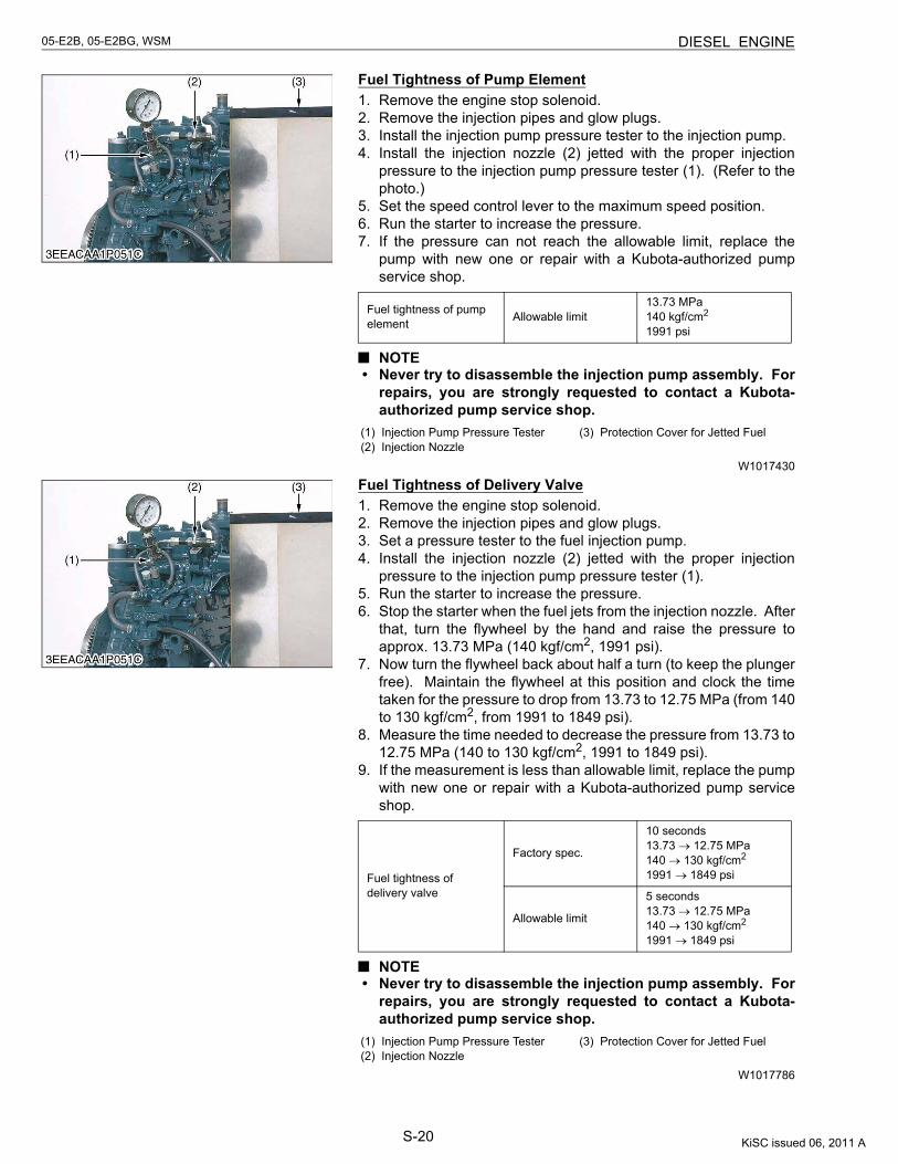
S-20
05-E2B, 05-E2BG, WSM DIESEL ENGINE
Fuel Tightness of Pump Element1. Remove the engine stop solenoid.2. Remove the injection pipes and glow plugs.3. Install the injection pump pressure tester to the injection pump.4. Install the injection nozzle (2) jetted with the proper injection
pressure to the injection pump pressure tester (1). (Refer to thephoto.)
5. Set the speed control lever to the maximum speed position.6. Run the starter to increase the pressure.7. If the pressure can not reach the allowable limit, replace the
pump with new one or repair with a Kubota-authorized pumpservice shop.
NOTE• Never try to disassemble the injection pump assembly. For
repairs, you are strongly requested to contact a Kubota-authorized pump service shop.
W1017430
Fuel Tightness of Delivery Valve1. Remove the engine stop solenoid.2. Remove the injection pipes and glow plugs.3. Set a pressure tester to the fuel injection pump.4. Install the injection nozzle (2) jetted with the proper injection
pressure to the injection pump pressure tester (1).5. Run the starter to increase the pressure.6. Stop the starter when the fuel jets from the injection nozzle. After
that, turn the flywheel by the hand and raise the pressure toapprox. 13.73 MPa (140 kgf/cm2, 1991 psi).
7. Now turn the flywheel back about half a turn (to keep the plungerfree). Maintain the flywheel at this position and clock the timetaken for the pressure to drop from 13.73 to 12.75 MPa (from 140to 130 kgf/cm2, from 1991 to 1849 psi).
8. Measure the time needed to decrease the pressure from 13.73 to12.75 MPa (140 to 130 kgf/cm2, 1991 to 1849 psi).
9. If the measurement is less than allowable limit, replace the pumpwith new one or repair with a Kubota-authorized pump serviceshop.
NOTE• Never try to disassemble the injection pump assembly. For
repairs, you are strongly requested to contact a Kubota-authorized pump service shop.
W1017786
Fuel tightness of pump element Allowable limit
13.73 MPa140 kgf/cm2
1991 psi
(1) Injection Pump Pressure Tester(2) Injection Nozzle
(3) Protection Cover for Jetted Fuel
Fuel tightness of delivery valve
Factory spec.
10 seconds13.73 → 12.75 MPa140 → 130 kgf/cm2
1991 → 1849 psi
Allowable limit
5 seconds13.73 → 12.75 MPa140 → 130 kgf/cm2
1991 → 1849 psi
(1) Injection Pump Pressure Tester(2) Injection Nozzle
(3) Protection Cover for Jetted Fuel
KiSC issued 06, 2011 A
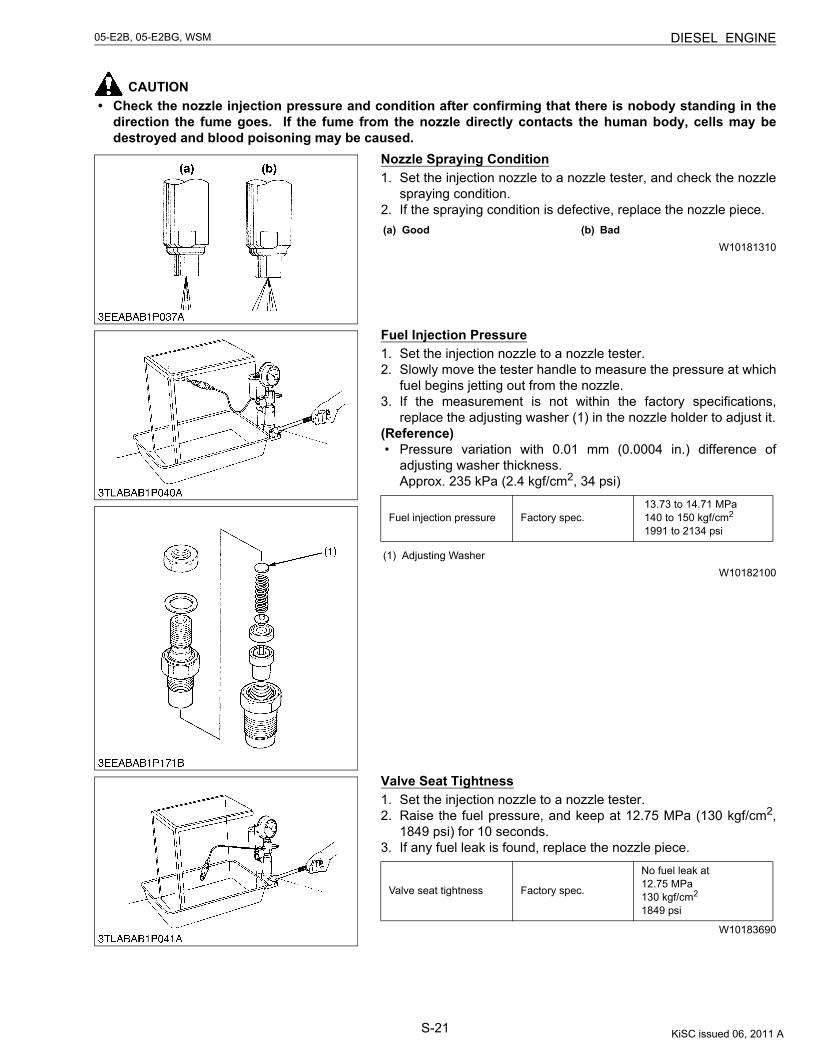
S-21
05-E2B, 05-E2BG, WSM DIESEL ENGINE
CAUTION• Check the nozzle injection pressure and condition after confirming that there is nobody standing in the
direction the fume goes. If the fume from the nozzle directly contacts the human body, cells may bedestroyed and blood poisoning may be caused.
Nozzle Spraying Condition1. Set the injection nozzle to a nozzle tester, and check the nozzle
spraying condition.2. If the spraying condition is defective, replace the nozzle piece.
W10181310
Fuel Injection Pressure1. Set the injection nozzle to a nozzle tester.2. Slowly move the tester handle to measure the pressure at which
fuel begins jetting out from the nozzle.3. If the measurement is not within the factory specifications,
replace the adjusting washer (1) in the nozzle holder to adjust it.(Reference)• Pressure variation with 0.01 mm (0.0004 in.) difference of
adjusting washer thickness.Approx. 235 kPa (2.4 kgf/cm2, 34 psi)
W10182100
Valve Seat Tightness1. Set the injection nozzle to a nozzle tester.2. Raise the fuel pressure, and keep at 12.75 MPa (130 kgf/cm2,
1849 psi) for 10 seconds.3. If any fuel leak is found, replace the nozzle piece.
W10183690
(a) Good (b) Bad
Fuel injection pressure Factory spec. 13.73 to 14.71 MPa 140 to 150 kgf/cm2
1991 to 2134 psi
(1) Adjusting Washer
Valve seat tightness Factory spec.
No fuel leak at12.75 MPa130 kgf/cm2
1849 psi
KiSC issued 06, 2011 A
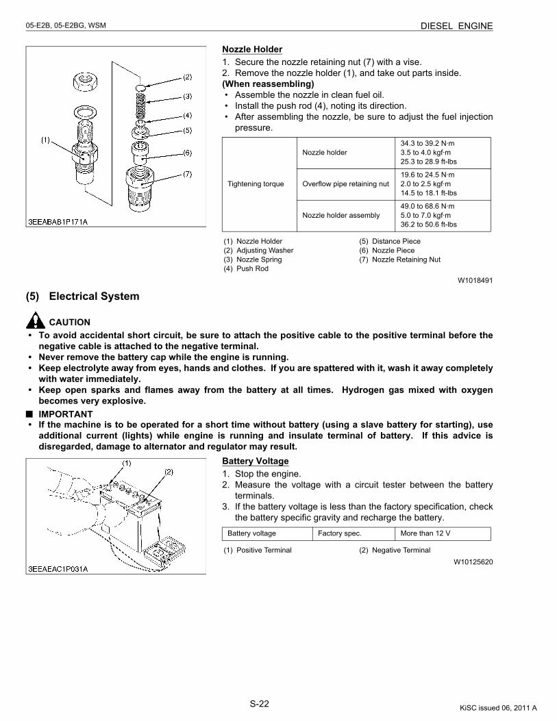
S-22
05-E2B, 05-E2BG, WSM DIESEL ENGINE
Nozzle Holder1. Secure the nozzle retaining nut (7) with a vise.2. Remove the nozzle holder (1), and take out parts inside.(When reassembling)• Assemble the nozzle in clean fuel oil.• Install the push rod (4), noting its direction.• After assembling the nozzle, be sure to adjust the fuel injection
pressure.
W1018491
(5) Electrical System
CAUTION• To avoid accidental short circuit, be sure to attach the positive cable to the positive terminal before the
negative cable is attached to the negative terminal.• Never remove the battery cap while the engine is running.• Keep electrolyte away from eyes, hands and clothes. If you are spattered with it, wash it away completely
with water immediately.• Keep open sparks and flames away from the battery at all times. Hydrogen gas mixed with oxygen
becomes very explosive.IMPORTANT
• If the machine is to be operated for a short time without battery (using a slave battery for starting), useadditional current (lights) while engine is running and insulate terminal of battery. If this advice isdisregarded, damage to alternator and regulator may result.
Battery Voltage1. Stop the engine.2. Measure the voltage with a circuit tester between the battery
terminals.3. If the battery voltage is less than the factory specification, check
the battery specific gravity and recharge the battery.
W10125620
Tightening torque
Nozzle holder34.3 to 39.2 N·m3.5 to 4.0 kgf·m25.3 to 28.9 ft-lbs
Overflow pipe retaining nut19.6 to 24.5 N·m2.0 to 2.5 kgf·m14.5 to 18.1 ft-lbs
Nozzle holder assembly49.0 to 68.6 N·m5.0 to 7.0 kgf·m36.2 to 50.6 ft-lbs
(1) Nozzle Holder(2) Adjusting Washer(3) Nozzle Spring(4) Push Rod
(5) Distance Piece(6) Nozzle Piece(7) Nozzle Retaining Nut
Battery voltage Factory spec. More than 12 V
(1) Positive Terminal (2) Negative Terminal
KiSC issued 06, 2011 A

S-23
05-E2B, 05-E2BG, WSM DIESEL ENGINE
Battery Specific Gravity1. Check the specific gravity of the electrolyte in each cell with a
hydrometer.2. When the electrolyte temperature differs from that at which the
hydrometer was calibrated, correct the specific gravity readingfollowing the formula mentioned in (Reference).
3. If the specific gravity is less than 1.215 (after it is corrected fortemperature), charge or replace the battery.
4. If the specific gravity differs between any two cells by more than0.05, replace the battery.NOTE
• Hold the hydrometer tube vertical without removing it fromthe electrolyte.
• Do not suck too much electrolyte into the tube.• Allow the float to move freely and hold the hydrometer at eye
level.• The hydrometer reading must be taken at the highest
electrolyte level.(Reference)• Specific gravity slightly varies with temperature. To be exact, the
specific gravity decreases by 0.0007 with an increase of 1 °C(0.0004 with an increase of 1 °F) in temperature, and increasesby 0.0007 with a decreases of 1 °C (0.0004 with a decrease of 1°F).Therefore, using 20 °C (68 °F) as a reference, the specific gravityreading must be corrected by the following formula :- Specific gravity at 20 °C = Measured value + 0.0007 ×
(electrolyte temperature : 20 °C)- Specific gravity at 68 °F = Measured value + 0.0004 ×
(electrolyte temperature : 68 °F)
At an electrolyte temperature of 20 °C (68 °F)
W1019017
Specific Gravity State of Charge
1.260 Sp. Gr. 100 % Charged
1.230 Sp. Gr. 75 % Charged
1.200 Sp. Gr. 50 % Charged
1.170 Sp. Gr. 25 % Charged
1.140 Sp. Gr. Very Little Useful Capacity
1.110 Sp. Gr. Discharged
(a) Good(b) Bad
(c) Bad
KiSC issued 06, 2011 A
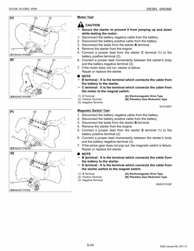
S-24
05-E2B, 05-E2BG, WSM DIESEL ENGINE
Motor Test
CAUTION• Secure the starter to prevent it from jumping up and down
while testing the motor.1. Disconnect the battery negative cable from the battery.2. Disconnect the battery positive cable from the battery.3. Disconnect the leads from the starter B terminal.4. Remove the starter from the engine.5. Connect a jumper lead from the starter C terminal (1) to the
battery positive terminal (2).6. Connect a jumper lead momentarily between the starter’s body
and the battery negative terminal (3).7. If the motor does not run, starter is failure.
Repair or replace the starter.NOTE
• B terminal : It is the terminal which connects the cable fromthe battery to the starter.
• C terminal : It is the terminal which connects the cable fromthe motor to the magnet switch.
W1019297
Magnetic Switch Test1. Disconnect the battery negative cable from the battery.2. Disconnect the battery positive cable from the battery.3. Disconnect the leads from the starter B terminal.4. Remove the starter from the engine.5. Connect a jumper lead from the starter S terminal (1) to the
battery positive terminal (2).6. Connect a jumper lead momentarily between the starter’s body
and the battery negative terminal (3).7. If the pinion gear does not pop out, the magnetic switch is failure.
Repair or replace the starter.NOTE
• B terminal : It is the terminal which connects the cable fromthe battery to the starter.
• S terminal : It is the terminal which connects the cable fromthe starter switch to the magnet switch.
0000010743E
(1) C Terminal(2) Positive Terminal(3) Negative Terminal
[A] Electromagnetic Drive Type[B] Planetary Gear Reduction Type
(1) S Terminal(2) Positive Terminal(3) Negative Terminal
[A] Electromagnetic Drive Type[B] Planetary Gear Reduction Type
KiSC issued 06, 2011 A
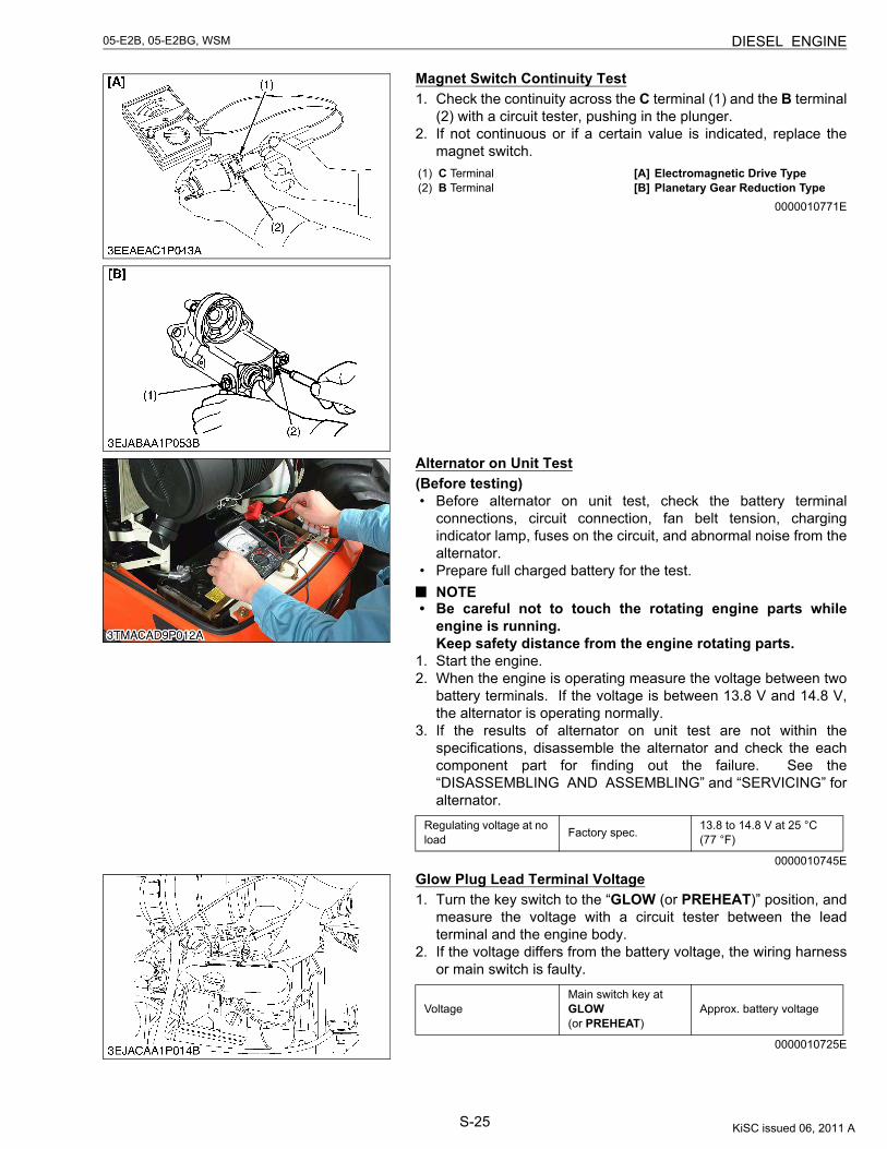
S-25
05-E2B, 05-E2BG, WSM DIESEL ENGINE
Magnet Switch Continuity Test1. Check the continuity across the C terminal (1) and the B terminal
(2) with a circuit tester, pushing in the plunger.2. If not continuous or if a certain value is indicated, replace the
magnet switch.
0000010771E
Alternator on Unit Test(Before testing)• Before alternator on unit test, check the battery terminal
connections, circuit connection, fan belt tension, chargingindicator lamp, fuses on the circuit, and abnormal noise from thealternator.
• Prepare full charged battery for the test.NOTE
• Be careful not to touch the rotating engine parts whileengine is running.Keep safety distance from the engine rotating parts.
1. Start the engine.2. When the engine is operating measure the voltage between two
battery terminals. If the voltage is between 13.8 V and 14.8 V,the alternator is operating normally.
3. If the results of alternator on unit test are not within thespecifications, disassemble the alternator and check the eachcomponent part for finding out the failure. See the“DISASSEMBLING AND ASSEMBLING” and “SERVICING” foralternator.
0000010745E
Glow Plug Lead Terminal Voltage1. Turn the key switch to the “GLOW (or PREHEAT)” position, and
measure the voltage with a circuit tester between the leadterminal and the engine body.
2. If the voltage differs from the battery voltage, the wiring harnessor main switch is faulty.
0000010725E
(1) C Terminal(2) B Terminal
[A] Electromagnetic Drive Type[B] Planetary Gear Reduction Type
Regulating voltage at no load Factory spec. 13.8 to 14.8 V at 25 °C
(77 °F)
VoltageMain switch key at GLOW (or PREHEAT)
Approx. battery voltage
KiSC issued 06, 2011 A
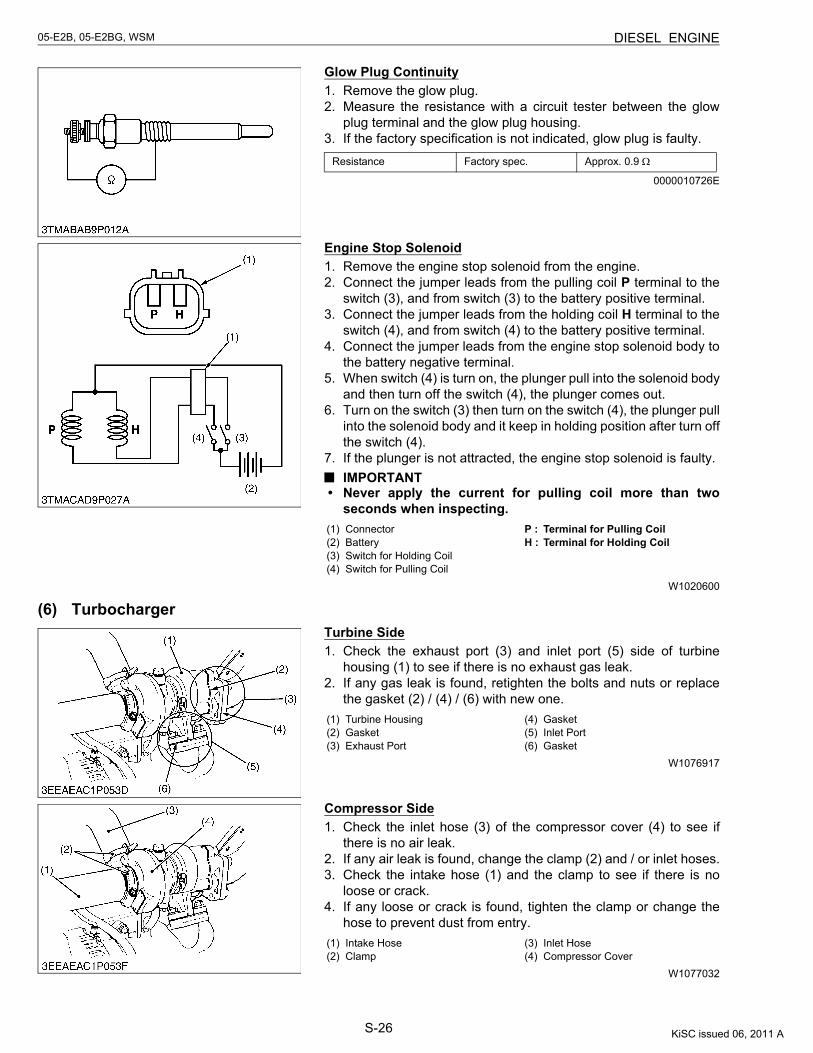
S-26
05-E2B, 05-E2BG, WSM DIESEL ENGINE
Glow Plug Continuity1. Remove the glow plug.2. Measure the resistance with a circuit tester between the glow
plug terminal and the glow plug housing.3. If the factory specification is not indicated, glow plug is faulty.
0000010726E
Engine Stop Solenoid1. Remove the engine stop solenoid from the engine.2. Connect the jumper leads from the pulling coil P terminal to the
switch (3), and from switch (3) to the battery positive terminal.3. Connect the jumper leads from the holding coil H terminal to the
switch (4), and from switch (4) to the battery positive terminal.4. Connect the jumper leads from the engine stop solenoid body to
the battery negative terminal.5. When switch (4) is turn on, the plunger pull into the solenoid body
and then turn off the switch (4), the plunger comes out.6. Turn on the switch (3) then turn on the switch (4), the plunger pull
into the solenoid body and it keep in holding position after turn offthe switch (4).
7. If the plunger is not attracted, the engine stop solenoid is faulty.IMPORTANT
• Never apply the current for pulling coil more than twoseconds when inspecting.
W1020600
(6) TurbochargerTurbine Side1. Check the exhaust port (3) and inlet port (5) side of turbine
housing (1) to see if there is no exhaust gas leak.2. If any gas leak is found, retighten the bolts and nuts or replace
the gasket (2) / (4) / (6) with new one.
W1076917
Compressor Side1. Check the inlet hose (3) of the compressor cover (4) to see if
there is no air leak.2. If any air leak is found, change the clamp (2) and / or inlet hoses.3. Check the intake hose (1) and the clamp to see if there is no
loose or crack.4. If any loose or crack is found, tighten the clamp or change the
hose to prevent dust from entry.
W1077032
Resistance Factory spec. Approx. 0.9 Ω
(1) Connector(2) Battery(3) Switch for Holding Coil(4) Switch for Pulling Coil
P : Terminal for Pulling CoilH : Terminal for Holding Coil
(1) Turbine Housing(2) Gasket(3) Exhaust Port
(4) Gasket(5) Inlet Port(6) Gasket
(1) Intake Hose(2) Clamp
(3) Inlet Hose(4) Compressor Cover
KiSC issued 06, 2011 A
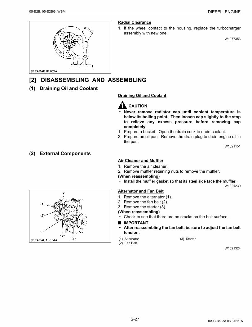
S-27
05-E2B, 05-E2BG, WSM DIESEL ENGINE
Radial Clearance1. If the wheel contact to the housing, replace the turbocharger
assembly with new one.W1077353
[2] DISASSEMBLING AND ASSEMBLING(1) Draining Oil and Coolant
Draining Oil and Coolant
CAUTION• Never remove radiator cap until coolant temperature is
below its boiling point. Then loosen cap slightly to the stopto relieve any excess pressure before removing capcompletely.
1. Prepare a bucket. Open the drain cock to drain coolant.2. Prepare an oil pan. Remove the drain plug to drain engine oil in
the pan.W1021151
(2) External ComponentsAir Cleaner and Muffler1. Remove the air cleaner.2. Remove muffler retaining nuts to remove the muffler.(When reassembling)• Install the muffler gasket so that its steel side face the muffler.
W1021239
Alternator and Fan Belt1. Remove the alternator (1).2. Remove the fan belt (2).3. Remove the starter (3).(When reassembling)• Check to see that there are no cracks on the belt surface.
IMPORTANT• After reassembling the fan belt, be sure to adjust the fan belt
tension.
W1021324
(1) Alternator(2) Fan Belt
(3) Starter
KiSC issued 06, 2011 A
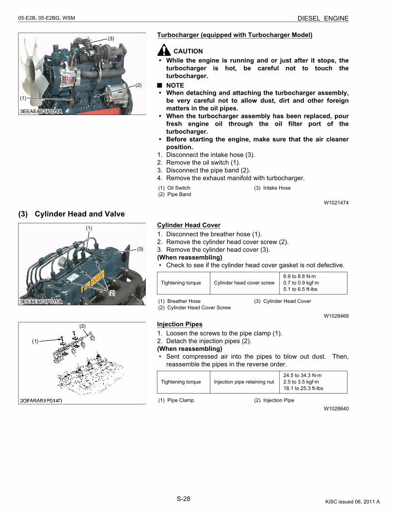
S-28
05-E2B, 05-E2BG, WSM DIESEL ENGINE
Turbocharger (equipped with Turbocharger Model)
CAUTION• While the engine is running and or just after it stops, the
turbocharger is hot, be careful not to touch theturbocharger.NOTE
• When detaching and attaching the turbocharger assembly,be very careful not to allow dust, dirt and other foreignmatters in the oil pipes.
• When the turbocharger assembly has been replaced, pourfresh engine oil through the oil filter port of theturbocharger.
• Before starting the engine, make sure that the air cleanerposition.
1. Disconnect the intake hose (3).2. Remove the oil switch (1).3. Disconnect the pipe band (2).4. Remove the exhaust manifold with turbocharger.
W1021474
(3) Cylinder Head and ValveCylinder Head Cover1. Disconnect the breather hose (1).2. Remove the cylinder head cover screw (2).3. Remove the cylinder head cover (3).(When reassembling)• Check to see if the cylinder head cover gasket is not defective.
W1028468
Injection Pipes1. Loosen the screws to the pipe clamp (1).2. Detach the injection pipes (2).(When reassembling)• Sent compressed air into the pipes to blow out dust. Then,
reassemble the pipes in the reverse order.
W1028640
(1) Oil Switch(2) Pipe Band
(3) Intake Hose
Tightening torque Cylinder head cover screw6.9 to 8.8 N·m0.7 to 0.9 kgf·m5.1 to 6.5 ft-lbs
(1) Breather Hose(2) Cylinder Head Cover Screw
(3) Cylinder Head Cover
Tightening torque Injection pipe retaining nut24.5 to 34.3 N·m2.5 to 3.5 kgf·m18.1 to 25.3 ft-lbs
(1) Pipe Clamp (2) Injection Pipe
KiSC issued 06, 2011 A
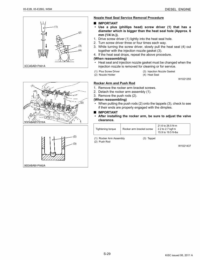
S-29
05-E2B, 05-E2BG, WSM DIESEL ENGINE
Nozzle Heat Seal Service Removal ProcedureIMPORTANT
• Use a plus (phillips head) screw driver (1) that has adiameter which is bigger than the heat seal hole (Approx. 6mm (1/4 in.)).
1. Drive screw driver (1) lightly into the heat seal hole.2. Turn screw driver three or four times each way.3. While turning the screw driver, slowly pull the heat seal (4) out
together with the injection nozzle gasket (3).4. If the heat seal drops, repeat the above procedure.(When reassembling)• Heat seal and injection nozzle gasket must be changed when the
injection nozzle is removed for cleaning or for service.
W1021255
Rocker Arm and Push Rod1. Remove the rocker arm bracket screws.2. Detach the rocker arm assembly (1).3. Remove the push rods (2).(When reassembling)• When putting the push rods (2) onto the tappets (3), check to see
if their ends are properly engaged with the dimples.IMPORTANT
• After installing the rocker arm, be sure to adjust the valveclearance.
W1021437
(1) Plus Screw Driver(2) Nozzle Holder
(3) Injection Nozzle Gasket(4) Heat Seal
Tightening torque Rocker arm bracket screw21.6 to 26.5 N·m2.2 to 2.7 kgf·m15.9 to 19.5 ft-lbs
(1) Rocker Arm Assembly(2) Push Rod
(3) Tappet
KiSC issued 06, 2011 A
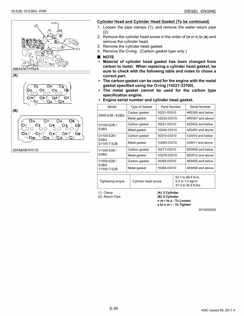
S-30
05-E2B, 05-E2BG, WSM DIESEL ENGINE
Cylinder Head and Cylinder Head Gasket (To be continued)1. Loosen the pipe clamps (1), and remove the water return pipe
(2).2. Remove the cylinder head screw in the order of (n or r) to (a) and
remove the cylinder head.3. Remove the cylinder head gasket.4. Remove the O-ring. (Carbon gasket type only.)
NOTE• Material of cylinder head gasket has been changed from
carbon to metal. When replacing a cylinder head gasket, besure to check with the following table and notes to chose acorrect part.
• The carbon gasket can be used for the engine with the metalgasket specified using the O-ring (15221-33700).
• The metal gasket cannot be used for the carbon typespecification engine.
• Engine serial number and cylinder head gasket.
W10205250
Model Type of Gasket Parts Number Serial Number
D905-E2B / E2BGCarbon gasket 16221-03310 4R0300 and below
Metal gasket 1G032-03310 4R0301 and above
D1005-E2B / E2BG
Carbon gasket 16231-03310 4Z0452 and below
Metal gasket 1G040-03310 4Z0453 and above
D1105-E2B / E2BGD1105-T-E2B
Carbon gasket 1E010-03310 4J0010 and below
Metal gasket 1G063-03310 4J0011 and above
V1305-E2B / E2BG
Carbon gasket 16271-03310 5E0009 and below
Metal gasket 1G078-03310 5E0010 and above
V1505-E2B / E2BGV1505-T-E2B
Carbon gasket 16292-03310 4E9455 and below
Metal gasket 16394-03310 4E9456 and above
Tightening torque Cylinder head screw63.7 to 68.6 N·m6.5 to 7.0 kgf·m47.0 to 50.6 ft-lbs
(1) Clamp(2) Return Pipe
(A) 3 Cylinder(B) 4 Cylindern or r to a : To Loosena to n or r : To Tighten
KiSC issued 06, 2011 A
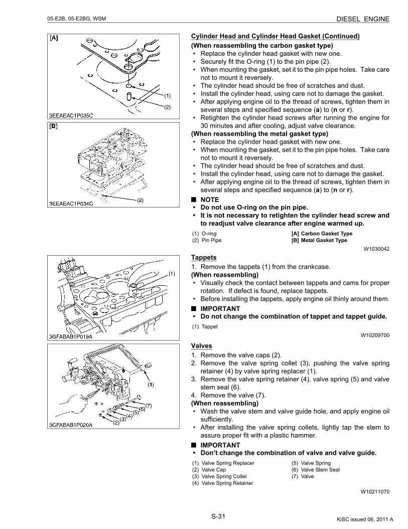
S-31
05-E2B, 05-E2BG, WSM DIESEL ENGINE
Cylinder Head and Cylinder Head Gasket (Continued)(When reassembling the carbon gasket type)• Replace the cylinder head gasket with new one.• Securely fit the O-ring (1) to the pin pipe (2).• When mounting the gasket, set it to the pin pipe holes. Take care
not to mount it reversely.• The cylinder head should be free of scratches and dust.• Install the cylinder head, using care not to damage the gasket.• After applying engine oil to the thread of screws, tighten them in
several steps and specified sequence (a) to (n or r).• Retighten the cylinder head screws after running the engine for
30 minutes and after cooling, adjust valve clearance.(When reassembling the metal gasket type)• Replace the cylinder head gasket with new one.• When mounting the gasket, set it to the pin pipe holes. Take care
not to mount it reversely.• The cylinder head should be free of scratches and dust.• Install the cylinder head, using care not to damage the gasket.• After applying engine oil to the thread of screws, tighten them in
several steps and specified sequence (a) to (n or r).NOTE
• Do not use O-ring on the pin pipe.• It is not necessary to retighten the cylinder head screw and
to readjust valve clearance after engine warmed up.
W1030042
Tappets1. Remove the tappets (1) from the crankcase.(When reassembling)• Visually check the contact between tappets and cams for proper
rotation. If defect is found, replace tappets.• Before installing the tappets, apply engine oil thinly around them.
IMPORTANT• Do not change the combination of tappet and tappet guide.
W10209700
Valves1. Remove the valve caps (2).2. Remove the valve spring collet (3), pushing the valve spring
retainer (4) by valve spring replacer (1).3. Remove the valve spring retainer (4), valve spring (5) and valve
stem seal (6).4. Remove the valve (7).(When reassembling)• Wash the valve stem and valve guide hole, and apply engine oil
sufficiently.• After installing the valve spring collets, lightly tap the stem to
assure proper fit with a plastic hammer.IMPORTANT
• Don’t change the combination of valve and valve guide.
W10211070
(1) O-ring(2) Pin Pipe
[A] Carbon Gasket Type[B] Metal Gasket Type
(1) Tappet
(1) Valve Spring Replacer(2) Valve Cap(3) Valve Spring Collet(4) Valve Spring Retainer
(5) Valve Spring(6) Valve Stem Seal(7) Valve
KiSC issued 06, 2011 A
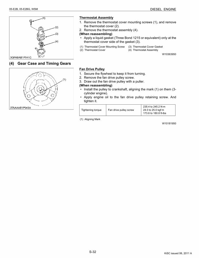
S-32
05-E2B, 05-E2BG, WSM DIESEL ENGINE
Thermostat Assembly1. Remove the thermostat cover mounting screws (1), and remove
the thermostat cover (2).2. Remove the thermostat assembly (4).(When reassembling)• Apply a liquid gasket (Three Bond 1215 or equivalent) only at the
thermostat cover side of the gasket (3).
W10363950
(4) Gear Case and Timing GearsFan Drive Pulley1. Secure the flywheel to keep it from turning.2. Remove the fan drive pulley screw.3. Draw out the fan drive pulley with a puller.(When reassembling)• Install the pulley to crankshaft, aligning the mark (1) on them (3-
cylinder engine).• Apply engine oil to the fan drive pulley retaining screw. And
tighten it.
W10181950
(1) Thermostat Cover Mounting Screw(2) Thermostat Cover
(3) Thermostat Cover Gasket(4) Thermostat Assembly
Tightening torque Fan drive pulley screw235.4 to 245.2 N·m24.0 to 25.0 kgf·m173.6 to 180.8 ft-lbs
(1) Aligning Mark
KiSC issued 06, 2011 A
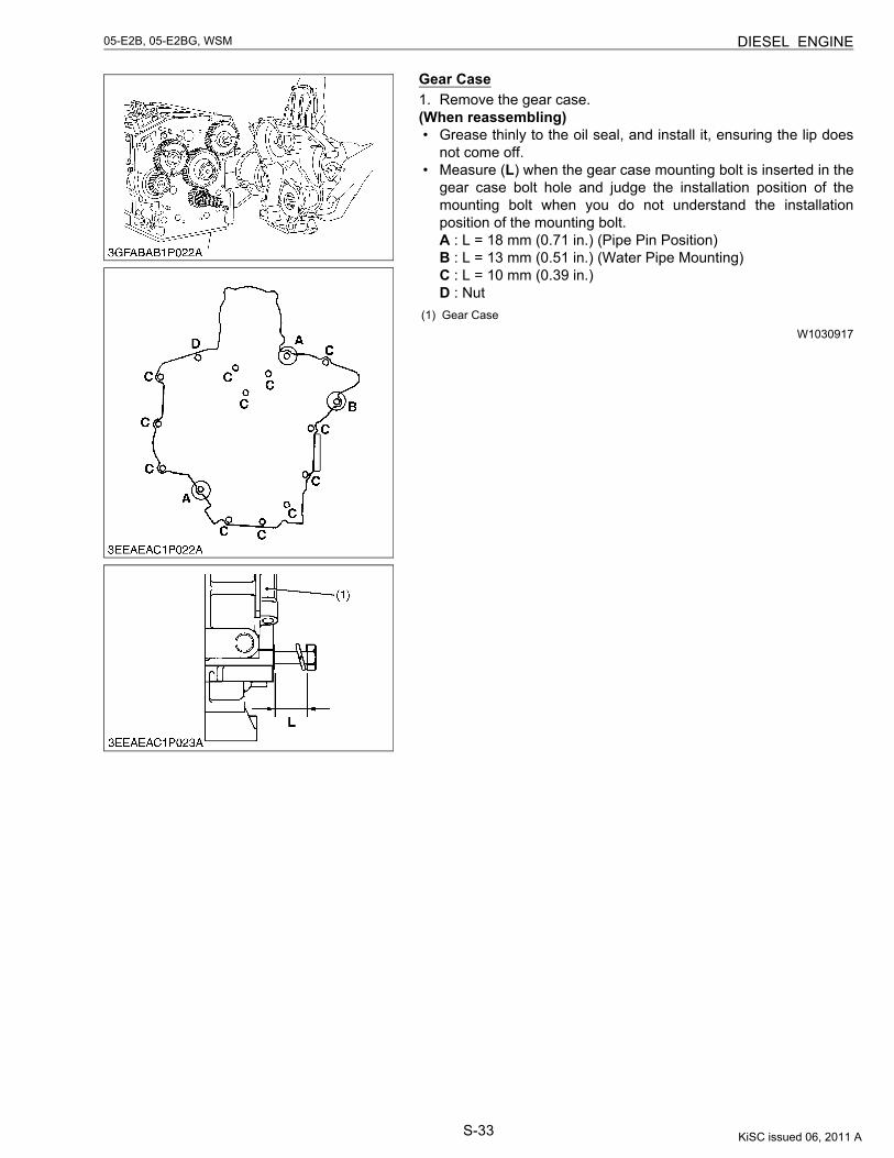
S-33
05-E2B, 05-E2BG, WSM DIESEL ENGINE
Gear Case1. Remove the gear case.(When reassembling)• Grease thinly to the oil seal, and install it, ensuring the lip does
not come off.• Measure (L) when the gear case mounting bolt is inserted in the
gear case bolt hole and judge the installation position of themounting bolt when you do not understand the installationposition of the mounting bolt.A : L = 18 mm (0.71 in.) (Pipe Pin Position)B : L = 13 mm (0.51 in.) (Water Pipe Mounting)C : L = 10 mm (0.39 in.)D : Nut
W1030917(1) Gear Case
KiSC issued 06, 2011 A
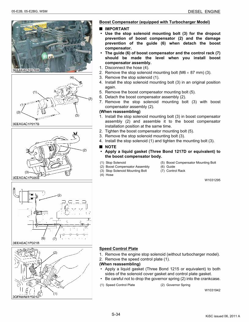
S-34
05-E2B, 05-E2BG, WSM DIESEL ENGINE
Boost Compensator (equipped with Turbocharger Model)IMPORTANT
• Use the stop solenoid mounting bolt (3) for the dropoutprevention of boost compensator (2) and the damageprevention of the guide (6) when detach the boostcompensator.
• The guide (6) of boost compensator and the control rack (7)should be made the level when you install boostcompensator assembly.
1. Disconnect the hose (4).2. Remove the stop solenoid mounting bolt (M6 × 87 mm) (3).3. Remove the stop solenoid (1).4. Install the stop solenoid mounting bolt (3) in an original position
again.5. Remove the boost compensator mounting bolt (5).6. Detach the boost compensator assembly (2).7. Remove the stop solenoid mounting bolt (3) with boost
compensator assembly (2).(When reassembling)1. Install the stop solenoid mounting bolt (3) in boost compensator
assembly (2) and assemble it to the boost compensatorinstallation position at the same time.
2. Tighten the boost compensator mounting bolt (5).3. Remove the stop solenoid mounting bolt (3).4. Install the stop solenoid (1) and tighten the mounting bolt (3).
NOTE• Apply a liquid gasket (Three Bond 1217D or equivalent) to
the boost compensator body.
W1031295
Speed Control Plate1. Remove the engine stop solenoid (without turbocharger model).2. Remove the speed control plate (1).(When reassembling)• Apply a liquid gasket (Three Bond 1215 or equivalent) to both
sides of the solenoid cover gasket and control plate gasket.• Be careful not to drop the governor spring (2) into the crankcase.
W1031942
(1) Stop Solenoid(2) Boost Compensator Assembly(3) Stop Solenoid Mounting Bolt(4) Hose
(5) Boost Compensator Mounting Bolt(6) Guide(7) Control Rack
(1) Speed Control Plate (2) Governor Spring
KiSC issued 06, 2011 A
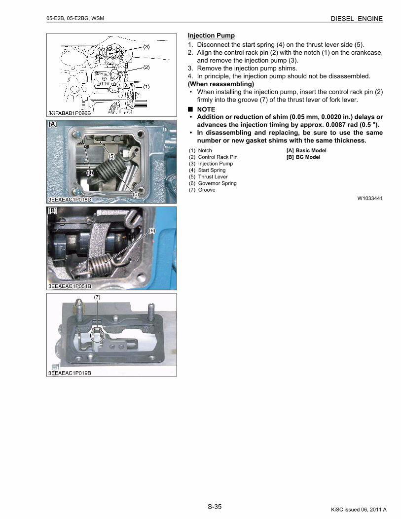
S-35
05-E2B, 05-E2BG, WSM DIESEL ENGINE
Injection Pump1. Disconnect the start spring (4) on the thrust lever side (5).2. Align the control rack pin (2) with the notch (1) on the crankcase,
and remove the injection pump (3).3. Remove the injection pump shims.4. In principle, the injection pump should not be disassembled.(When reassembling)• When installing the injection pump, insert the control rack pin (2)
firmly into the groove (7) of the thrust lever of fork lever.NOTE
• Addition or reduction of shim (0.05 mm, 0.0020 in.) delays oradvances the injection timing by approx. 0.0087 rad (0.5 °).
• In disassembling and replacing, be sure to use the samenumber or new gasket shims with the same thickness.
W1033441
(1) Notch(2) Control Rack Pin(3) Injection Pump(4) Start Spring(5) Thrust Lever(6) Governor Spring(7) Groove
[A] Basic Model[B] BG Model
KiSC issued 06, 2011 A
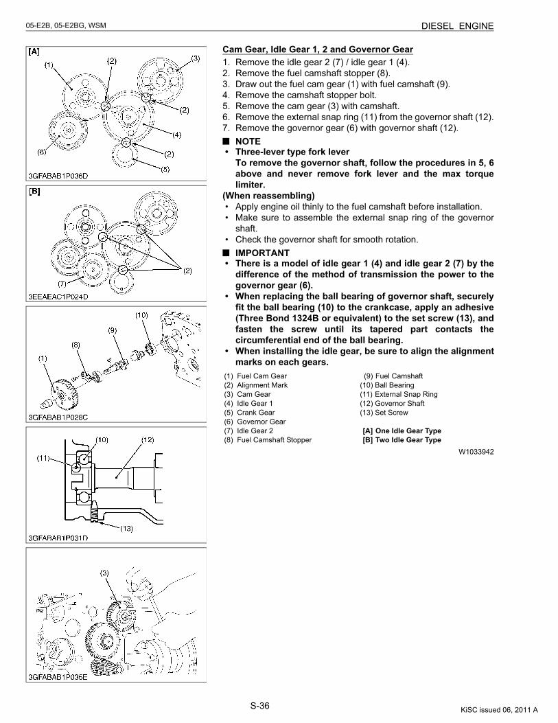
S-36
05-E2B, 05-E2BG, WSM DIESEL ENGINE
Cam Gear, Idle Gear 1, 2 and Governor Gear1. Remove the idle gear 2 (7) / idle gear 1 (4).2. Remove the fuel camshaft stopper (8).3. Draw out the fuel cam gear (1) with fuel camshaft (9).4. Remove the camshaft stopper bolt.5. Remove the cam gear (3) with camshaft.6. Remove the external snap ring (11) from the governor shaft (12).7. Remove the governor gear (6) with governor shaft (12).
NOTE• Three-lever type fork lever
To remove the governor shaft, follow the procedures in 5, 6above and never remove fork lever and the max torquelimiter.
(When reassembling)• Apply engine oil thinly to the fuel camshaft before installation.• Make sure to assemble the external snap ring of the governor
shaft.• Check the governor shaft for smooth rotation.
IMPORTANT• There is a model of idle gear 1 (4) and idle gear 2 (7) by the
difference of the method of transmission the power to thegovernor gear (6).
• When replacing the ball bearing of governor shaft, securelyfit the ball bearing (10) to the crankcase, apply an adhesive(Three Bond 1324B or equivalent) to the set screw (13), andfasten the screw until its tapered part contacts thecircumferential end of the ball bearing.
• When installing the idle gear, be sure to align the alignmentmarks on each gears.
W1033942
(1) Fuel Cam Gear(2) Alignment Mark(3) Cam Gear(4) Idle Gear 1(5) Crank Gear(6) Governor Gear(7) Idle Gear 2(8) Fuel Camshaft Stopper
(9) Fuel Camshaft(10) Ball Bearing(11) External Snap Ring(12) Governor Shaft(13) Set Screw
[A] One Idle Gear Type[B] Two Idle Gear Type
KiSC issued 06, 2011 A
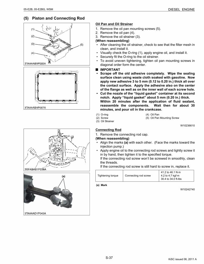
S-37
05-E2B, 05-E2BG, WSM DIESEL ENGINE
(5) Piston and Connecting RodOil Pan and Oil Strainer1. Remove the oil pan mounting screws (5).2. Remove the oil pan (4).3. Remove the oil strainer (3).(When reassembling)• After cleaning the oil strainer, check to see that the filter mesh in
clean, and install it.• Visually check the O-ring (1), apply engine oil, and install it.• Securely fit the O-ring to the oil strainer.• To avoid uneven tightening, tighten oil pan mounting screws in
diagonal order form the center.IMPORTANT
• Scrape off the old adhesive completely. Wipe the sealingsurface clean using waste cloth soaked with gasoline. Nowapply new adhesive 3 to 5 mm (0.12 to 0.20 in.) thick all overthe contact surface. Apply the adhesive also on the centerof the flange as well as on the inner wall of each screw hole.
• Cut the nozzle of the “liquid gasket” container at its secondnotch. Apply “liquid gasket” about 5 mm (0.20 in.) thick.Within 20 minutes after the application of fluid sealant,reassemble the components. Wait then for about 30minutes, and pour oil in the crankcase.
W10236610
Connecting Rod1. Remove the connecting rod cap.(When reassembling)• Align the marks (a) with each other. (Face the marks toward the
injection pump.)• Apply engine oil to the connecting rod screws and lightly screw it
in by hand, then tighten it to the specified torque.If the connecting rod screw won’t be screwed in smoothly, cleanthe threads.If the connecting rod screw is still hard to screw in, replace it.
W10242740
(1) O-ring(2) Screw(3) Oil Strainer
(4) Oil Pan(5) Oil Pan Mounting Screw
Tightening torque Connecting rod screw41.2 to 46.1 N·m4.2 to 4.7 kgf·m30.4 to 34.0 ft-lbs
(a) Mark
KiSC issued 06, 2011 A
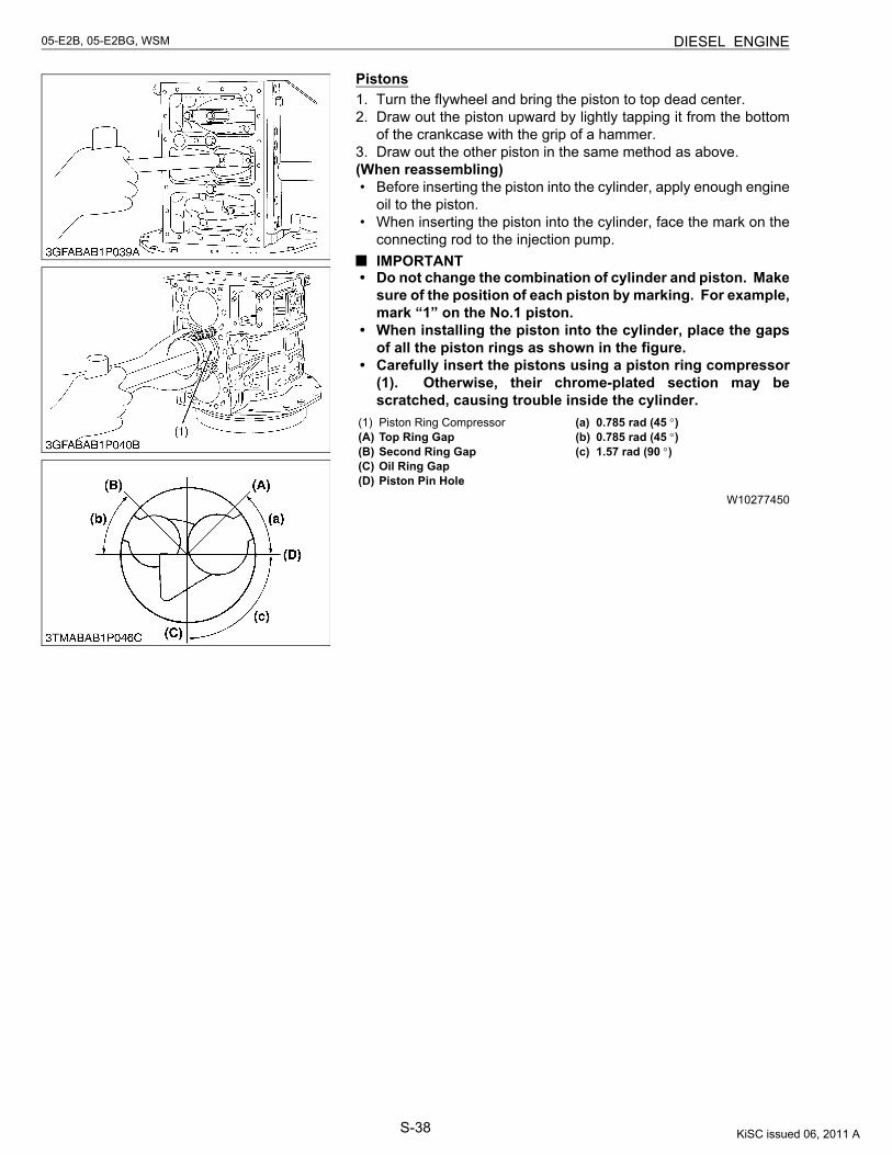
S-38
05-E2B, 05-E2BG, WSM DIESEL ENGINE
Pistons1. Turn the flywheel and bring the piston to top dead center.2. Draw out the piston upward by lightly tapping it from the bottom
of the crankcase with the grip of a hammer.3. Draw out the other piston in the same method as above.(When reassembling)• Before inserting the piston into the cylinder, apply enough engine
oil to the piston.• When inserting the piston into the cylinder, face the mark on the
connecting rod to the injection pump.IMPORTANT
• Do not change the combination of cylinder and piston. Makesure of the position of each piston by marking. For example,mark “1” on the No.1 piston.
• When installing the piston into the cylinder, place the gapsof all the piston rings as shown in the figure.
• Carefully insert the pistons using a piston ring compressor(1). Otherwise, their chrome-plated section may bescratched, causing trouble inside the cylinder.
W10277450
(1) Piston Ring Compressor(A) Top Ring Gap(B) Second Ring Gap(C) Oil Ring Gap(D) Piston Pin Hole
(a) 0.785 rad (45 °)(b) 0.785 rad (45 °)(c) 1.57 rad (90 °)
KiSC issued 06, 2011 A
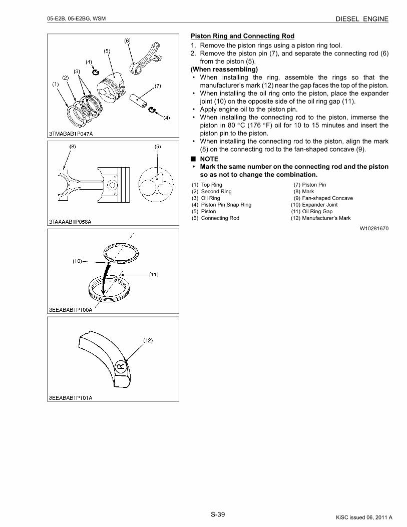
S-39
05-E2B, 05-E2BG, WSM DIESEL ENGINE
Piston Ring and Connecting Rod1. Remove the piston rings using a piston ring tool.2. Remove the piston pin (7), and separate the connecting rod (6)
from the piston (5).(When reassembling)• When installing the ring, assemble the rings so that the
manufacturer’s mark (12) near the gap faces the top of the piston.• When installing the oil ring onto the piston, place the expander
joint (10) on the opposite side of the oil ring gap (11).• Apply engine oil to the piston pin.• When installing the connecting rod to the piston, immerse the
piston in 80 °C (176 °F) oil for 10 to 15 minutes and insert thepiston pin to the piston.
• When installing the connecting rod to the piston, align the mark(8) on the connecting rod to the fan-shaped concave (9).NOTE
• Mark the same number on the connecting rod and the pistonso as not to change the combination.
W10281670
(1) Top Ring(2) Second Ring(3) Oil Ring(4) Piston Pin Snap Ring(5) Piston(6) Connecting Rod
(7) Piston Pin(8) Mark(9) Fan-shaped Concave
(10) Expander Joint(11) Oil Ring Gap(12) Manufacturer’s Mark
KiSC issued 06, 2011 A
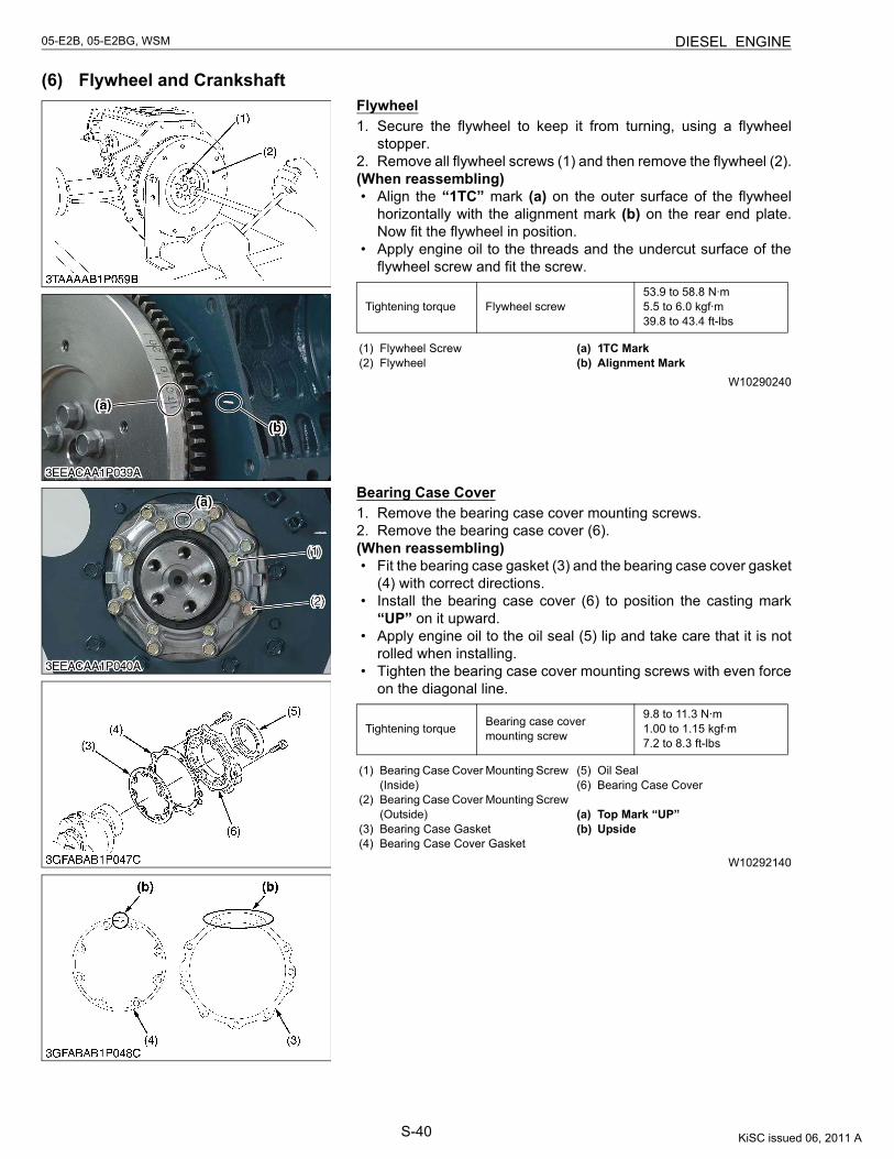
S-40
05-E2B, 05-E2BG, WSM DIESEL ENGINE
(6) Flywheel and CrankshaftFlywheel1. Secure the flywheel to keep it from turning, using a flywheel
stopper.2. Remove all flywheel screws (1) and then remove the flywheel (2).(When reassembling)• Align the “1TC” mark (a) on the outer surface of the flywheel
horizontally with the alignment mark (b) on the rear end plate.Now fit the flywheel in position.
• Apply engine oil to the threads and the undercut surface of theflywheel screw and fit the screw.
W10290240
Bearing Case Cover1. Remove the bearing case cover mounting screws.2. Remove the bearing case cover (6).(When reassembling)• Fit the bearing case gasket (3) and the bearing case cover gasket
(4) with correct directions.• Install the bearing case cover (6) to position the casting mark
“UP” on it upward.• Apply engine oil to the oil seal (5) lip and take care that it is not
rolled when installing.• Tighten the bearing case cover mounting screws with even force
on the diagonal line.
W10292140
Tightening torque Flywheel screw53.9 to 58.8 N·m5.5 to 6.0 kgf·m39.8 to 43.4 ft-lbs
(1) Flywheel Screw(2) Flywheel
(a) 1TC Mark(b) Alignment Mark
Tightening torque Bearing case cover mounting screw
9.8 to 11.3 N·m1.00 to 1.15 kgf·m7.2 to 8.3 ft-lbs
(1) Bearing Case Cover Mounting Screw (Inside)
(2) Bearing Case Cover Mounting Screw (Outside)
(3) Bearing Case Gasket(4) Bearing Case Cover Gasket
(5) Oil Seal(6) Bearing Case Cover
(a) Top Mark “UP”(b) Upside
KiSC issued 06, 2011 A
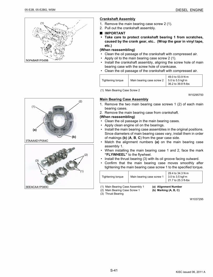
S-41
05-E2B, 05-E2BG, WSM DIESEL ENGINE
Crankshaft Assembly1. Remove the main bearing case screw 2 (1).2. Pull out the crankshaft assembly.
IMPORTANT• Take care to protect crankshaft bearing 1 from scratches,
caused by the crank gear, etc.. (Wrap the gear in vinyl tape,etc.)
(When reassembling)• Clean the oil passage of the crankshaft with compressed air.• Apply oil to the main bearing case screw 2 (1).• Install the crankshaft assembly, aligning the screw hole of main
bearing case with the screw hole of crankcase.• Clean the oil passage of the crankshaft with compressed air.
W10295750
Main Bearing Case Assembly1. Remove the two main bearing case screws 1 (2) of each main
bearing cases.2. Remove the main bearing case from crankshaft.(When reassembling)• Clean the oil passage in the main bearing cases.• Apply clean engine oil on the bearings.• Install the main bearing case assemblies in the original positions.
Since diameters of main bearing cases vary, install them in orderof makings (b) (A, B, C) from the gear case side.
• Match the alignment numbers (a) on the main bearing caseassembly 1.
• When installing the main bearing case 1 and 2, face the mark“FLYWHEEL” to the flywheel.
• Install the thrust bearing (3) with its oil groove facing outward.• Confirm that the main bearing case moves smoothly after
tightening the main bearing case screw 1 to the specified torque.
W1037295
Tightening torque Main bearing case screw 249.0 to 53.9 N·m5.0 to 5.5 kgf·m36.2 to 39.8 ft-lbs
(1) Main Bearing Case Screw 2
Tightening torque Main bearing case screw 129.4 to 34.3 N·m3.0 to 3.5 kgf·m21.7 to 25.3 ft-lbs
(1) Main Bearing Case Assembly 1 (2) Main Bearing Case Screw 1(3) Thrust Bearing
(a) Alignment Number(b) Marking (A, B, C)
KiSC issued 06, 2011 A
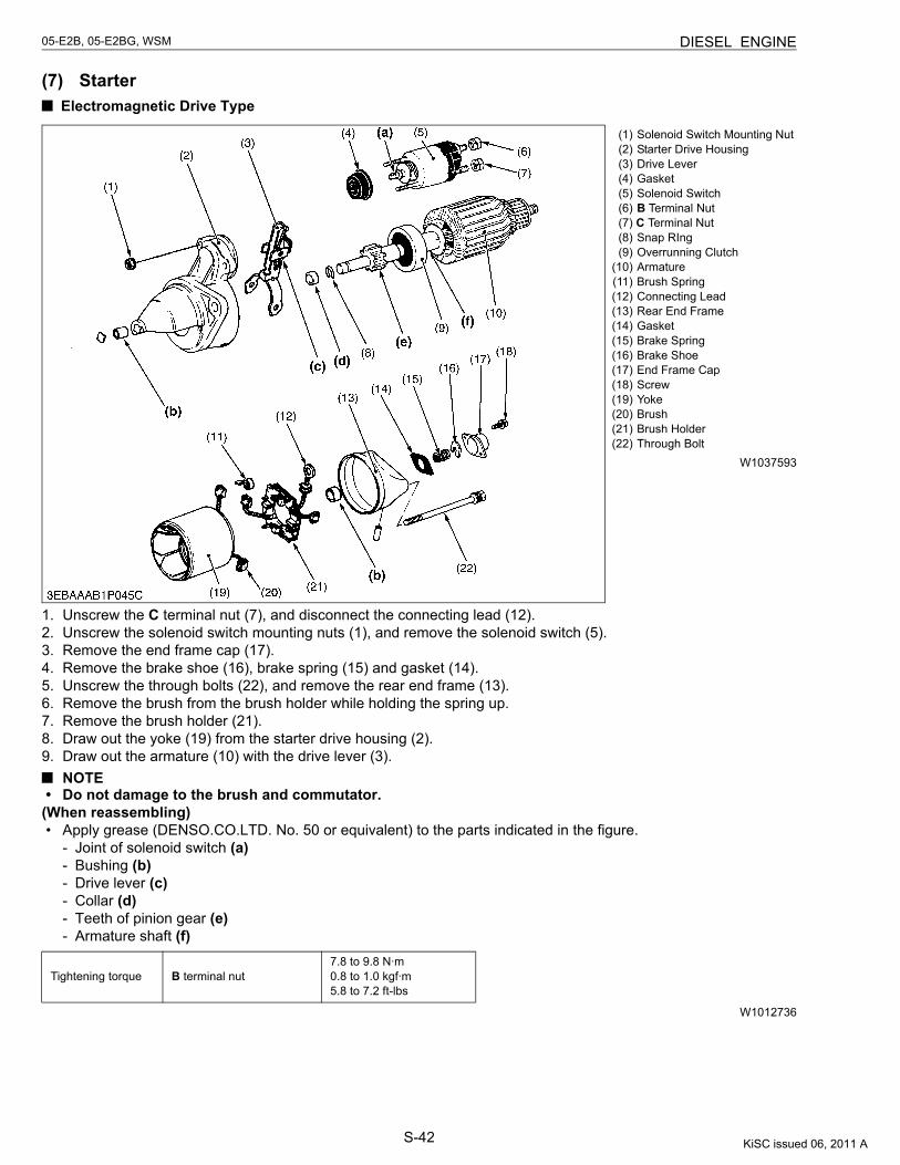
S-42
05-E2B, 05-E2BG, WSM DIESEL ENGINE
(7) Starter Electromagnetic Drive Type
W1037593
1. Unscrew the C terminal nut (7), and disconnect the connecting lead (12).2. Unscrew the solenoid switch mounting nuts (1), and remove the solenoid switch (5).3. Remove the end frame cap (17).4. Remove the brake shoe (16), brake spring (15) and gasket (14).5. Unscrew the through bolts (22), and remove the rear end frame (13).6. Remove the brush from the brush holder while holding the spring up.7. Remove the brush holder (21).8. Draw out the yoke (19) from the starter drive housing (2).9. Draw out the armature (10) with the drive lever (3).
NOTE• Do not damage to the brush and commutator.
(When reassembling)• Apply grease (DENSO.CO.LTD. No. 50 or equivalent) to the parts indicated in the figure.
- Joint of solenoid switch (a)- Bushing (b)- Drive lever (c)- Collar (d)- Teeth of pinion gear (e)- Armature shaft (f)
W1012736
(1) Solenoid Switch Mounting Nut(2) Starter Drive Housing(3) Drive Lever(4) Gasket(5) Solenoid Switch(6) B Terminal Nut
(7) C Terminal Nut(8) Snap RIng(9) Overrunning Clutch
(10) Armature(11) Brush Spring(12) Connecting Lead(13) Rear End Frame(14) Gasket(15) Brake Spring(16) Brake Shoe(17) End Frame Cap(18) Screw(19) Yoke(20) Brush(21) Brush Holder(22) Through Bolt
Tightening torque B terminal nut7.8 to 9.8 N·m0.8 to 1.0 kgf·m5.8 to 7.2 ft-lbs
KiSC issued 06, 2011 A
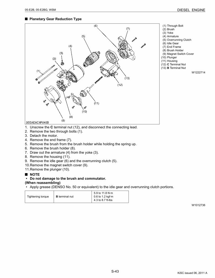
S-43
05-E2B, 05-E2BG, WSM DIESEL ENGINE
Planetary Gear Reduction Type
W1222714
1. Unscrew the C terminal nut (12), and disconnect the connecting lead.2. Remove the two through bolts (1).3. Detach the motor.4. Remove the end frame (7).5. Remove the brush from the brush holder while holding the spring up.6. Remove the brush holder (8).7. Draw out the armature (4) from the yoke (3).8. Remove the housing (11).9. Remove the idle gear (6) and the overrunning clutch (5).10.Remove the magnet switch cover (9).11.Remove the plunger (10).
NOTE• Do not damage to the brush and commutator.
(When reassembling)• Apply grease (DENSO No. 50 or equivalent) to the idle gear and overrunning clutch portions.
W1012736
(1) Through Bolt(2) Brush(3) Yoke(4) Armature(5) Overrunning Clutch(6) Idle Gear(7) End Frame(8) Brush Holder(9) Magnet Switch Cover
(10) Plunger(11) Housing(12) C Terminal Nut(13) B Terminal Nut
Tightening torque B terminal nut5.9 to 11.8 N·m0.6 to 1.2 kgf·m4.3 to 8.7 ft-lbs
KiSC issued 06, 2011 A
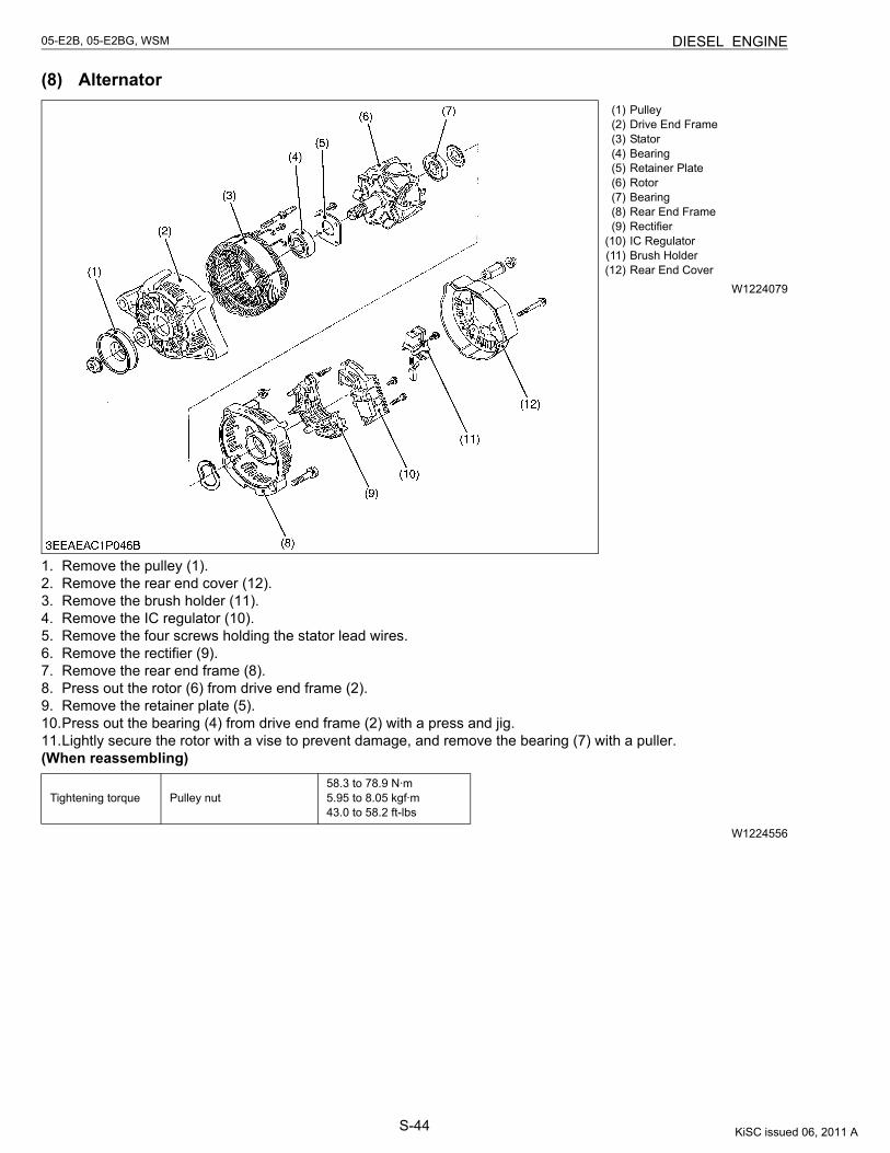
S-44
05-E2B, 05-E2BG, WSM DIESEL ENGINE
(8) Alternator
W1224079
1. Remove the pulley (1).2. Remove the rear end cover (12).3. Remove the brush holder (11).4. Remove the IC regulator (10).5. Remove the four screws holding the stator lead wires.6. Remove the rectifier (9).7. Remove the rear end frame (8).8. Press out the rotor (6) from drive end frame (2).9. Remove the retainer plate (5).10.Press out the bearing (4) from drive end frame (2) with a press and jig.11.Lightly secure the rotor with a vise to prevent damage, and remove the bearing (7) with a puller.(When reassembling)
W1224556
(1) Pulley(2) Drive End Frame(3) Stator(4) Bearing(5) Retainer Plate(6) Rotor(7) Bearing(8) Rear End Frame(9) Rectifier
(10) IC Regulator(11) Brush Holder(12) Rear End Cover
Tightening torque Pulley nut58.3 to 78.9 N·m5.95 to 8.05 kgf·m43.0 to 58.2 ft-lbs
KiSC issued 06, 2011 A
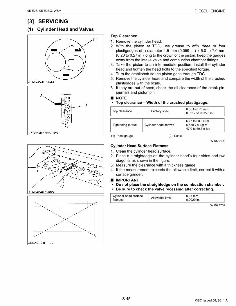
S-45
05-E2B, 05-E2BG, WSM DIESEL ENGINE
[3] SERVICING(1) Cylinder Head and Valves
Top Clearance1. Remove the cylinder head.2. With the piston at TDC, use grease to affix three or four
plastigauges of a diameter 1.5 mm (0.059 in.) x 5.0 to 7.0 mm(0.20 to 0.27 in.) long to the crown of the piston; keep the gaugesaway from the intake valve and combustion chamber fittings.
3. Take the piston to an intermediate position, install the cylinderhead and tighten the head bolts to the specified torque.
4. Turn the crankshaft so the piston goes through TDC.5. Remove the cylinder head and compare the width of the crushed
plastigages with the scale.6. If they are out of spec, check the oil clearance of the crank pin,
journals and piston pin.NOTE
• Top clearance = Width of the crushed plastigauge.
W1020190
Cylinder Head Surface Flatness1. Clean the cylinder head surface.2. Place a straightedge on the cylinder head’s four sides and two
diagonal as shown in the figure.3. Measure the clearance with a thickness gauge.4. If the measurement exceeds the allowable limit, correct it with a
surface grinder.IMPORTANT
• Do not place the straightedge on the combustion chamber.• Be sure to check the valve recessing after correcting.
W1027737
Top clearance Factory spec. 0.55 to 0.70 mm0.0217 to 0.0276 in.
Tightening torque Cylinder head screws63.7 to 68.6 N·m6.5 to 7.0 kgf·m47.0 to 50.6 ft-lbs
(1) Plastigauge (2) Scale
Cylinder head surface flatness Allowable limit 0.05 mm
0.0020 in.
KiSC issued 06, 2011 A
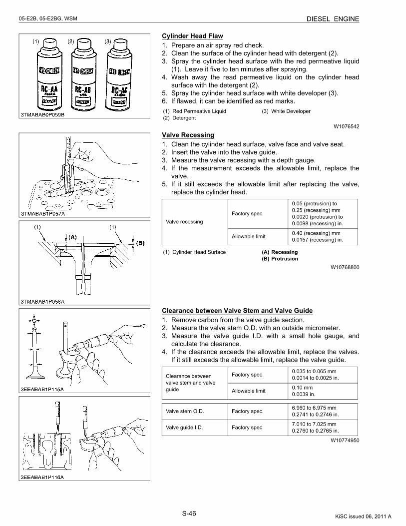
S-46
05-E2B, 05-E2BG, WSM DIESEL ENGINE
Cylinder Head Flaw1. Prepare an air spray red check.2. Clean the surface of the cylinder head with detergent (2).3. Spray the cylinder head surface with the red permeative liquid
(1). Leave it five to ten minutes after spraying.4. Wash away the read permeative liquid on the cylinder head
surface with the detergent (2).5. Spray the cylinder head surface with white developer (3).6. If flawed, it can be identified as red marks.
W1076542
Valve Recessing1. Clean the cylinder head surface, valve face and valve seat.2. Insert the valve into the valve guide.3. Measure the valve recessing with a depth gauge.4. If the measurement exceeds the allowable limit, replace the
valve.5. If it still exceeds the allowable limit after replacing the valve,
replace the cylinder head.
W10768800
Clearance between Valve Stem and Valve Guide1. Remove carbon from the valve guide section.2. Measure the valve stem O.D. with an outside micrometer.3. Measure the valve guide I.D. with a small hole gauge, and
calculate the clearance.4. If the clearance exceeds the allowable limit, replace the valves.
If it still exceeds the allowable limit, replace the valve guide.
W10774950
(1) Red Permeative Liquid(2) Detergent
(3) White Developer
Valve recessingFactory spec.
0.05 (protrusion) to 0.25 (recessing) mm0.0020 (protrusion) to 0.0098 (recessing) in.
Allowable limit 0.40 (recessing) mm0.0157 (recessing) in.
(1) Cylinder Head Surface (A) Recessing(B) Protrusion
Clearance between valve stem and valve guide
Factory spec. 0.035 to 0.065 mm0.0014 to 0.0025 in.
Allowable limit 0.10 mm0.0039 in.
Valve stem O.D. Factory spec. 6.960 to 6.975 mm0.2741 to 0.2746 in.
Valve guide I.D. Factory spec. 7.010 to 7.025 mm0.2760 to 0.2765 in.
KiSC issued 06, 2011 A
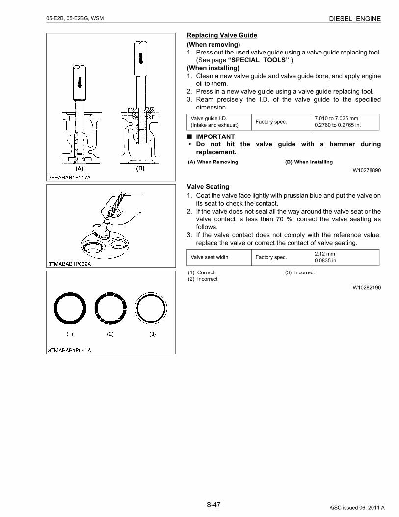
S-47
05-E2B, 05-E2BG, WSM DIESEL ENGINE
Replacing Valve Guide(When removing)1. Press out the used valve guide using a valve guide replacing tool.
(See page “SPECIAL TOOLS”.)(When installing)1. Clean a new valve guide and valve guide bore, and apply engine
oil to them.2. Press in a new valve guide using a valve guide replacing tool.3. Ream precisely the I.D. of the valve guide to the specified
dimension.
IMPORTANT• Do not hit the valve guide with a hammer during
replacement.
W10278890
Valve Seating1. Coat the valve face lightly with prussian blue and put the valve on
its seat to check the contact.2. If the valve does not seat all the way around the valve seat or the
valve contact is less than 70 %, correct the valve seating asfollows.
3. If the valve contact does not comply with the reference value,replace the valve or correct the contact of valve seating.
W10282190
Valve guide I.D.(Intake and exhaust) Factory spec. 7.010 to 7.025 mm
0.2760 to 0.2765 in.
(A) When Removing (B) When Installing
Valve seat width Factory spec. 2.12 mm0.0835 in.
(1) Correct(2) Incorrect
(3) Incorrect
KiSC issued 06, 2011 A
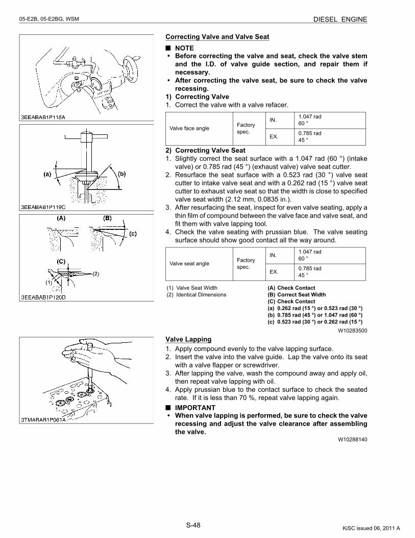
S-48
05-E2B, 05-E2BG, WSM DIESEL ENGINE
Correcting Valve and Valve SeatNOTE
• Before correcting the valve and seat, check the valve stemand the I.D. of valve guide section, and repair them ifnecessary.
• After correcting the valve seat, be sure to check the valverecessing.
1) Correcting Valve1. Correct the valve with a valve refacer.
2) Correcting Valve Seat1. Slightly correct the seat surface with a 1.047 rad (60 °) (intake
valve) or 0.785 rad (45 °) (exhaust valve) valve seat cutter.2. Resurface the seat surface with a 0.523 rad (30 °) valve seat
cutter to intake valve seat and with a 0.262 rad (15 °) valve seatcutter to exhaust valve seat so that the width is close to specifiedvalve seat width (2.12 mm, 0.0835 in.).
3. After resurfacing the seat, inspect for even valve seating, apply athin film of compound between the valve face and valve seat, andfit them with valve lapping tool.
4. Check the valve seating with prussian blue. The valve seatingsurface should show good contact all the way around.
W10283500
Valve Lapping1. Apply compound evenly to the valve lapping surface.2. Insert the valve into the valve guide. Lap the valve onto its seat
with a valve flapper or screwdriver.3. After lapping the valve, wash the compound away and apply oil,
then repeat valve lapping with oil.4. Apply prussian blue to the contact surface to check the seated
rate. If it is less than 70 %, repeat valve lapping again.IMPORTANT
• When valve lapping is performed, be sure to check the valverecessing and adjust the valve clearance after assemblingthe valve.
W10288140
Valve face angle Factory spec.
IN. 1.047 rad60 °
EX. 0.785 rad45 °
Valve seat angle Factory spec.
IN. 1.047 rad60 °
EX. 0.785 rad45 °
(1) Valve Seat Width(2) Identical Dimensions
(A) Check Contact(B) Correct Seat Width(C) Check Contact(a) 0.262 rad (15 °) or 0.523 rad (30 °)(b) 0.785 rad (45 °) or 1.047 rad (60 °)(c) 0.523 rad (30 °) or 0.262 rad (15 °)
KiSC issued 06, 2011 A
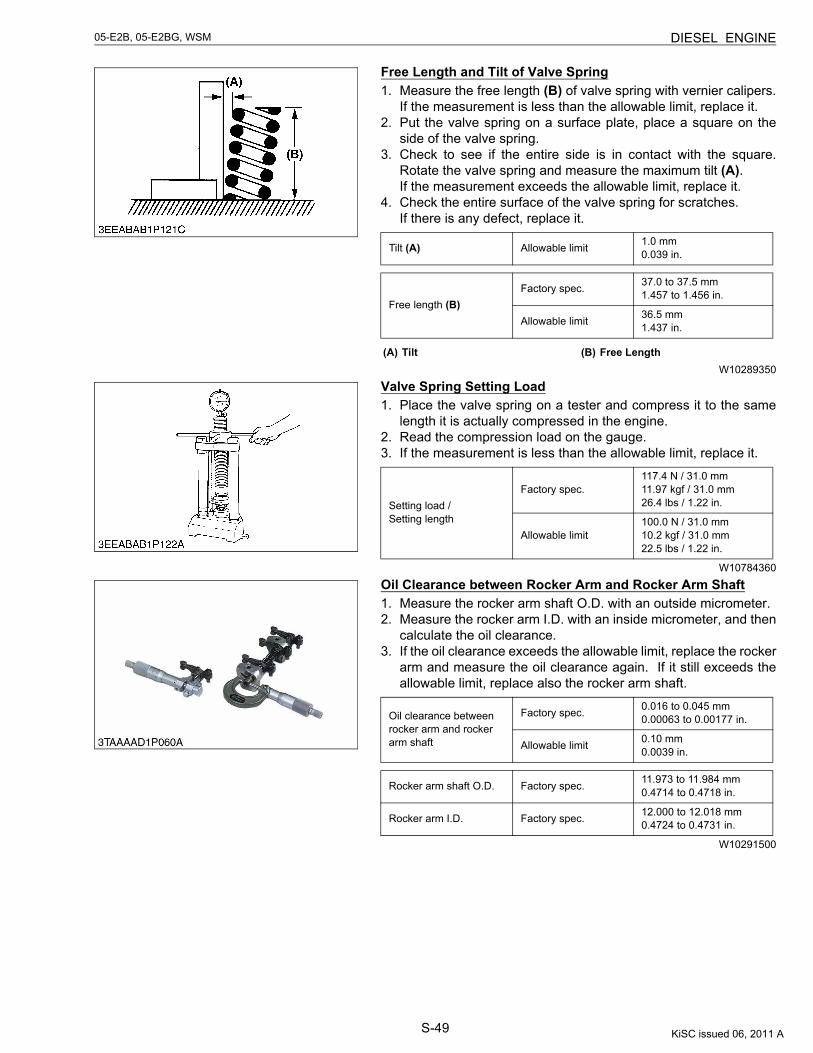
S-49
05-E2B, 05-E2BG, WSM DIESEL ENGINE
Free Length and Tilt of Valve Spring1. Measure the free length (B) of valve spring with vernier calipers.
If the measurement is less than the allowable limit, replace it.2. Put the valve spring on a surface plate, place a square on the
side of the valve spring.3. Check to see if the entire side is in contact with the square.
Rotate the valve spring and measure the maximum tilt (A).If the measurement exceeds the allowable limit, replace it.
4. Check the entire surface of the valve spring for scratches.If there is any defect, replace it.
W10289350
Valve Spring Setting Load1. Place the valve spring on a tester and compress it to the same
length it is actually compressed in the engine.2. Read the compression load on the gauge.3. If the measurement is less than the allowable limit, replace it.
W10784360
Oil Clearance between Rocker Arm and Rocker Arm Shaft1. Measure the rocker arm shaft O.D. with an outside micrometer.2. Measure the rocker arm I.D. with an inside micrometer, and then
calculate the oil clearance.3. If the oil clearance exceeds the allowable limit, replace the rocker
arm and measure the oil clearance again. If it still exceeds theallowable limit, replace also the rocker arm shaft.
W10291500
Tilt (A) Allowable limit 1.0 mm0.039 in.
Free length (B)Factory spec. 37.0 to 37.5 mm
1.457 to 1.456 in.
Allowable limit 36.5 mm1.437 in.
(A) Tilt (B) Free Length
Setting load / Setting length
Factory spec.117.4 N / 31.0 mm11.97 kgf / 31.0 mm26.4 lbs / 1.22 in.
Allowable limit100.0 N / 31.0 mm10.2 kgf / 31.0 mm22.5 lbs / 1.22 in.
Oil clearance between rocker arm and rocker arm shaft
Factory spec. 0.016 to 0.045 mm0.00063 to 0.00177 in.
Allowable limit 0.10 mm0.0039 in.
Rocker arm shaft O.D. Factory spec. 11.973 to 11.984 mm0.4714 to 0.4718 in.
Rocker arm I.D. Factory spec. 12.000 to 12.018 mm0.4724 to 0.4731 in.
KiSC issued 06, 2011 A
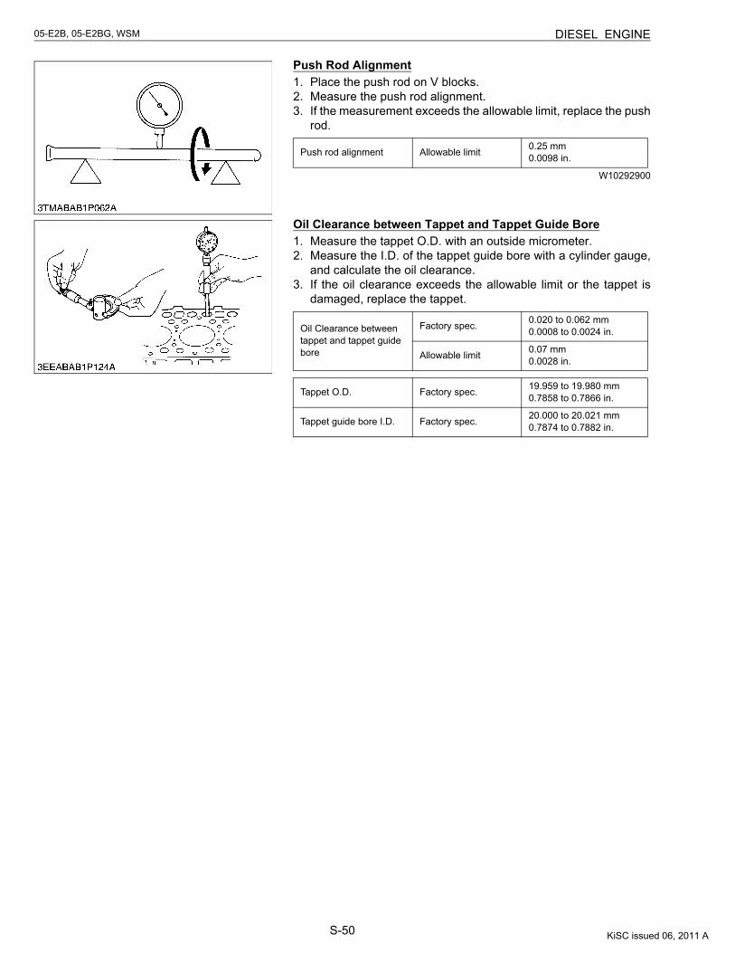
S-50
05-E2B, 05-E2BG, WSM DIESEL ENGINE
Push Rod Alignment1. Place the push rod on V blocks.2. Measure the push rod alignment.3. If the measurement exceeds the allowable limit, replace the push
rod.
W10292900
Oil Clearance between Tappet and Tappet Guide Bore1. Measure the tappet O.D. with an outside micrometer.2. Measure the I.D. of the tappet guide bore with a cylinder gauge,
and calculate the oil clearance.3. If the oil clearance exceeds the allowable limit or the tappet is
damaged, replace the tappet.
Push rod alignment Allowable limit 0.25 mm0.0098 in.
Oil Clearance between tappet and tappet guide bore
Factory spec. 0.020 to 0.062 mm0.0008 to 0.0024 in.
Allowable limit 0.07 mm0.0028 in.
Tappet O.D. Factory spec. 19.959 to 19.980 mm0.7858 to 0.7866 in.
Tappet guide bore I.D. Factory spec. 20.000 to 20.021 mm0.7874 to 0.7882 in.
KiSC issued 06, 2011 A
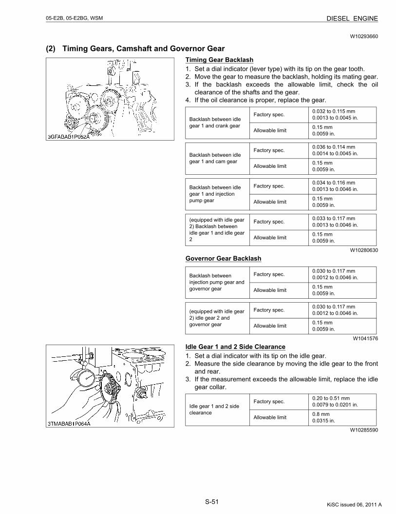
S-51
05-E2B, 05-E2BG, WSM DIESEL ENGINE
W10293660
(2) Timing Gears, Camshaft and Governor GearTiming Gear Backlash1. Set a dial indicator (lever type) with its tip on the gear tooth.2. Move the gear to measure the backlash, holding its mating gear.3. If the backlash exceeds the allowable limit, check the oil
clearance of the shafts and the gear.4. If the oil clearance is proper, replace the gear.
W10280630
Governor Gear Backlash
W1041576
Idle Gear 1 and 2 Side Clearance1. Set a dial indicator with its tip on the idle gear.2. Measure the side clearance by moving the idle gear to the front
and rear.3. If the measurement exceeds the allowable limit, replace the idle
gear collar.
W10285590
Backlash between idle gear 1 and crank gear
Factory spec. 0.032 to 0.115 mm0.0013 to 0.0045 in.
Allowable limit 0.15 mm0.0059 in.
Backlash between idle gear 1 and cam gear
Factory spec. 0.036 to 0.114 mm0.0014 to 0.0045 in.
Allowable limit 0.15 mm0.0059 in.
Backlash between idle gear 1 and injection pump gear
Factory spec. 0.034 to 0.116 mm0.0013 to 0.0046 in.
Allowable limit 0.15 mm0.0059 in.
(equipped with idle gear 2) Backlash between idle gear 1 and idle gear 2
Factory spec. 0.033 to 0.117 mm0.0013 to 0.0046 in.
Allowable limit 0.15 mm0.0059 in.
Backlash between injection pump gear and governor gear
Factory spec. 0.030 to 0.117 mm0.0012 to 0.0046 in.
Allowable limit 0.15 mm0.0059 in.
(equipped with idle gear 2) idle gear 2 and governor gear
Factory spec. 0.030 to 0.117 mm0.0012 to 0.0046 in.
Allowable limit 0.15 mm0.0059 in.
Idle gear 1 and 2 side clearance
Factory spec. 0.20 to 0.51 mm0.0079 to 0.0201 in.
Allowable limit 0.8 mm0.0315 in.
KiSC issued 06, 2011 A
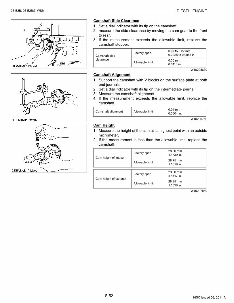
S-52
05-E2B, 05-E2BG, WSM DIESEL ENGINE
Camshaft Side Clearance1. Set a dial indicator with its tip on the camshaft.2. measure the side clearance by moving the cam gear to the front
to rear.3. If the measurement exceeds the allowable limit, replace the
camshaft stopper.
W10295630
Camshaft Alignment1. Support the camshaft with V blocks on the surface plate at both
end journals.2. Set a dial indicator with its tip on the intermediate journal.3. Measure the camshaft alignment.4. If the measurement exceeds the allowable limit, replace the
camshaft.
W10296710
Cam Height1. Measure the height of the cam at its highest point with an outside
micrometer.2. If the measurement is less than the allowable limit, replace the
camshaft.
W10297880
Camshaft side clearance
Factory spec. 0.07 to 0.22 mm0.0028 to 0.0087 in.
Allowable limit 0.30 mm0.0118 in.
Camshaft alignment Allowable limit 0.01 mm0.0004 in.
Cam height of intakeFactory spec. 28.80 mm
1.1339 in.
Allowable limit 28.75 mm1.1319 in.
Cam height of exhaustFactory spec. 29.00 mm
1.1417 in.
Allowable limit 28.95 mm1.1398 in.
KiSC issued 06, 2011 A
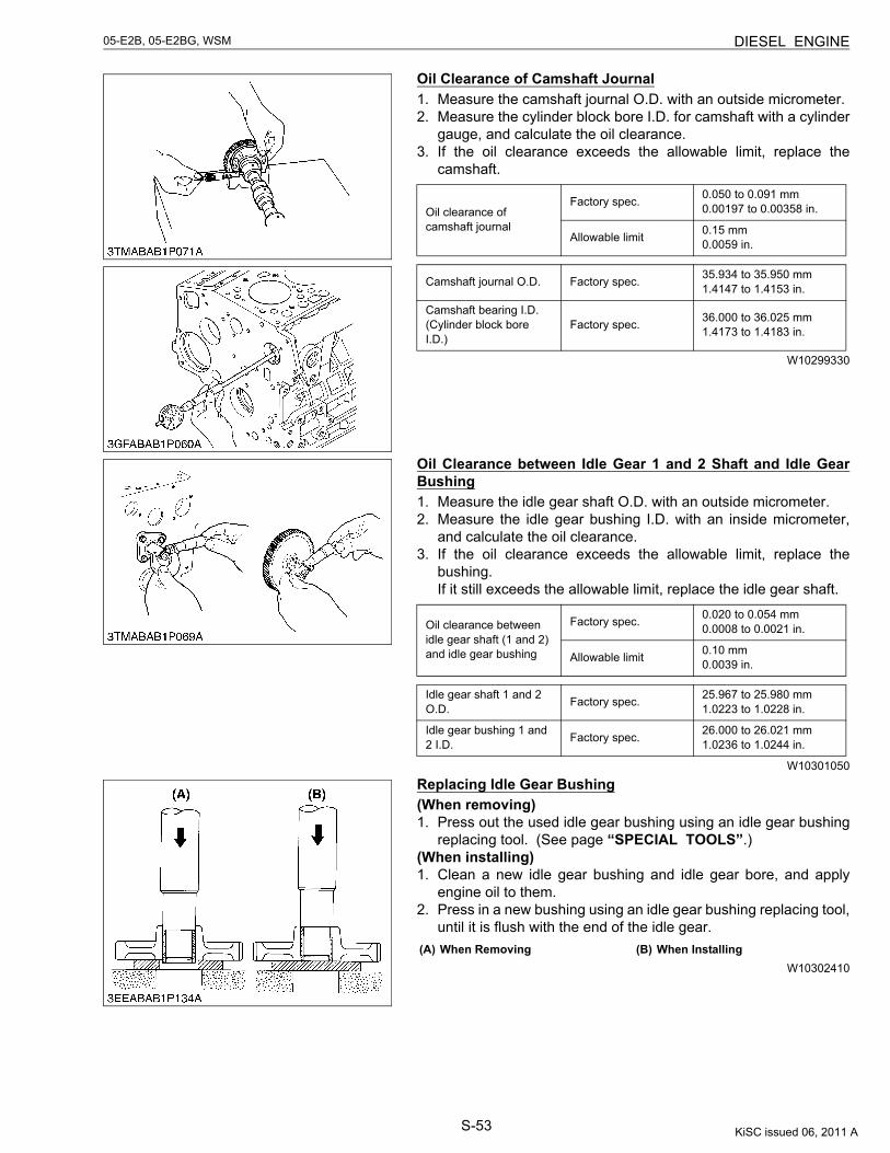
S-53
05-E2B, 05-E2BG, WSM DIESEL ENGINE
Oil Clearance of Camshaft Journal1. Measure the camshaft journal O.D. with an outside micrometer.2. Measure the cylinder block bore I.D. for camshaft with a cylinder
gauge, and calculate the oil clearance.3. If the oil clearance exceeds the allowable limit, replace the
camshaft.
W10299330
Oil Clearance between Idle Gear 1 and 2 Shaft and Idle GearBushing1. Measure the idle gear shaft O.D. with an outside micrometer.2. Measure the idle gear bushing I.D. with an inside micrometer,
and calculate the oil clearance.3. If the oil clearance exceeds the allowable limit, replace the
bushing.If it still exceeds the allowable limit, replace the idle gear shaft.
W10301050
Replacing Idle Gear Bushing(When removing)1. Press out the used idle gear bushing using an idle gear bushing
replacing tool. (See page “SPECIAL TOOLS”.)(When installing)1. Clean a new idle gear bushing and idle gear bore, and apply
engine oil to them.2. Press in a new bushing using an idle gear bushing replacing tool,
until it is flush with the end of the idle gear.
W10302410
Oil clearance of camshaft journal
Factory spec. 0.050 to 0.091 mm0.00197 to 0.00358 in.
Allowable limit 0.15 mm0.0059 in.
Camshaft journal O.D. Factory spec. 35.934 to 35.950 mm1.4147 to 1.4153 in.
Camshaft bearing I.D. (Cylinder block bore I.D.)
Factory spec. 36.000 to 36.025 mm1.4173 to 1.4183 in.
Oil clearance between idle gear shaft (1 and 2) and idle gear bushing
Factory spec. 0.020 to 0.054 mm0.0008 to 0.0021 in.
Allowable limit 0.10 mm0.0039 in.
Idle gear shaft 1 and 2 O.D. Factory spec. 25.967 to 25.980 mm
1.0223 to 1.0228 in.
Idle gear bushing 1 and 2 I.D. Factory spec. 26.000 to 26.021 mm
1.0236 to 1.0244 in.
(A) When Removing (B) When Installing
KiSC issued 06, 2011 A
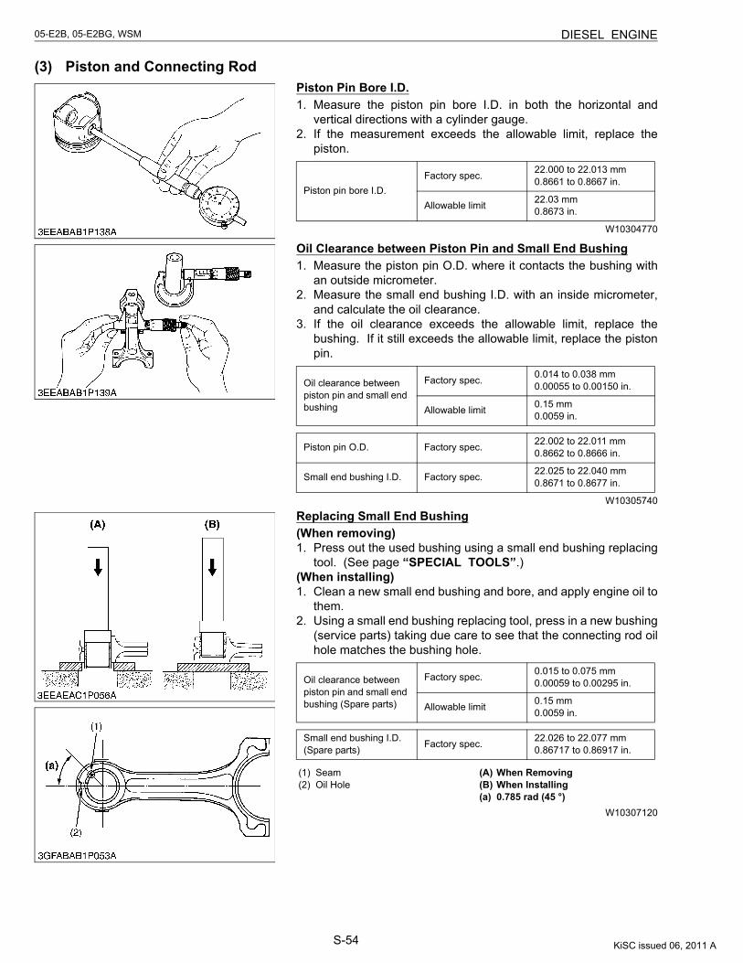
S-54
05-E2B, 05-E2BG, WSM DIESEL ENGINE
(3) Piston and Connecting RodPiston Pin Bore I.D.1. Measure the piston pin bore I.D. in both the horizontal and
vertical directions with a cylinder gauge.2. If the measurement exceeds the allowable limit, replace the
piston.
W10304770
Oil Clearance between Piston Pin and Small End Bushing1. Measure the piston pin O.D. where it contacts the bushing with
an outside micrometer.2. Measure the small end bushing I.D. with an inside micrometer,
and calculate the oil clearance.3. If the oil clearance exceeds the allowable limit, replace the
bushing. If it still exceeds the allowable limit, replace the pistonpin.
W10305740
Replacing Small End Bushing(When removing)1. Press out the used bushing using a small end bushing replacing
tool. (See page “SPECIAL TOOLS”.)(When installing)1. Clean a new small end bushing and bore, and apply engine oil to
them.2. Using a small end bushing replacing tool, press in a new bushing
(service parts) taking due care to see that the connecting rod oilhole matches the bushing hole.
W10307120
Piston pin bore I.D.Factory spec. 22.000 to 22.013 mm
0.8661 to 0.8667 in.
Allowable limit 22.03 mm0.8673 in.
Oil clearance between piston pin and small end bushing
Factory spec. 0.014 to 0.038 mm0.00055 to 0.00150 in.
Allowable limit 0.15 mm0.0059 in.
Piston pin O.D. Factory spec. 22.002 to 22.011 mm0.8662 to 0.8666 in.
Small end bushing I.D. Factory spec. 22.025 to 22.040 mm0.8671 to 0.8677 in.
Oil clearance between piston pin and small end bushing (Spare parts)
Factory spec. 0.015 to 0.075 mm0.00059 to 0.00295 in.
Allowable limit 0.15 mm0.0059 in.
Small end bushing I.D. (Spare parts) Factory spec. 22.026 to 22.077 mm
0.86717 to 0.86917 in.
(1) Seam(2) Oil Hole
(A) When Removing(B) When Installing(a) 0.785 rad (45 °)
KiSC issued 06, 2011 A
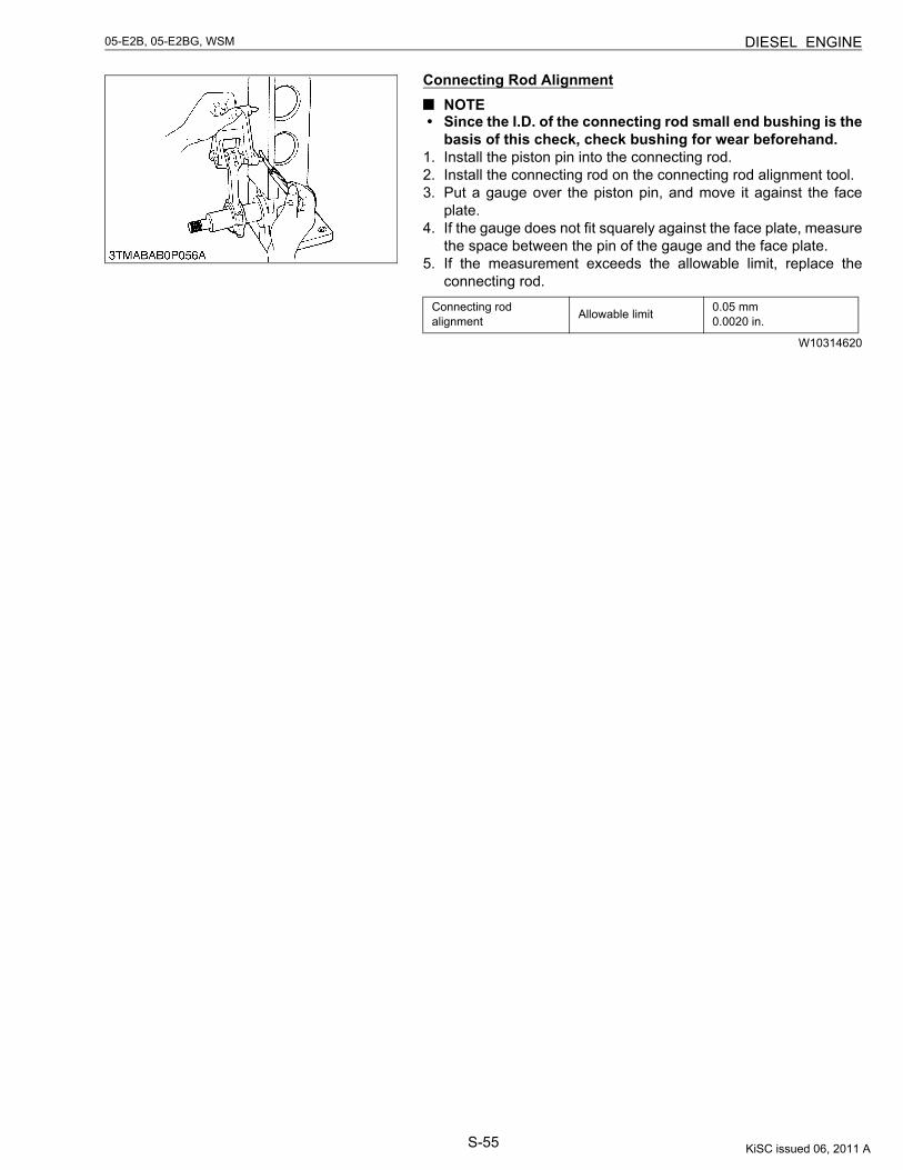
S-55
05-E2B, 05-E2BG, WSM DIESEL ENGINE
Connecting Rod AlignmentNOTE
• Since the I.D. of the connecting rod small end bushing is thebasis of this check, check bushing for wear beforehand.
1. Install the piston pin into the connecting rod.2. Install the connecting rod on the connecting rod alignment tool.3. Put a gauge over the piston pin, and move it against the face
plate.4. If the gauge does not fit squarely against the face plate, measure
the space between the pin of the gauge and the face plate.5. If the measurement exceeds the allowable limit, replace the
connecting rod.
W10314620
Connecting rod alignment Allowable limit 0.05 mm
0.0020 in.
KiSC issued 06, 2011 A
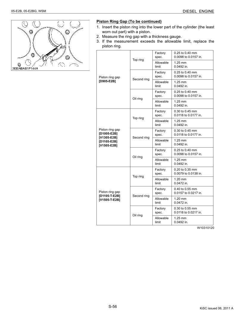
S-56
05-E2B, 05-E2BG, WSM DIESEL ENGINE
Piston Ring Gap (To be continued)1. Insert the piston ring into the lower part of the cylinder (the least
worn out part) with a piston.2. Measure the ring gap with a thickness gauge.3. If the measurement exceeds the allowable limit, replace the
piston ring.
W10310120
Piston ring gap[D905-E2B]
Top ring
Factory spec.
0.25 to 0.40 mm0.0098 to 0.0157 in.
Allowable limit
1.25 mm0.0492 in.
Second ring
Factory spec.
0.25 to 0.40 mm0.0098 to 0.0157 in.
Allowable limit
1.25 mm0.0492 in.
Oil ring
Factory spec.
0.25 to 0.40 mm0.0098 to 0.0157 in.
Allowable limit
1.25 mm0.0492 in.
Piston ring gap[D1005-E2B][V1305-E2B][D1105-E2B][V1505-E2B]
Top ring
Factory spec.
0.30 to 0.45 mm0.0118 to 0.0177 in.
Allowable limit
1.25 mm0.0492 in.
Second ring
Factory spec.
0.30 to 0.45 mm0.0118 to 0.0177 in.
Allowable limit
1.25 mm0.0492 in.
Oil ring
Factory spec.
0.25 to 0.40 mm0.0098 to 0.0157 in.
Allowable limit
1.25 mm0.0492 in.
Piston ring gap[D1105-T-E2B][V1505-T-E2B]
Top ring
Factory spec.
0.20 to 0.35 mm0.0079 to 0.0138 in.
Allowable limit
1.20 mm0.0472 in.
Second ring
Factory spec.
0.40 to 0.55 mm0.0157 to 0.0217 in.
Allowable limit
1.20 mm0.0472 in.
Oil ring
Factory spec.
0.30 to 0.55 mm0.0118 to 0.0217 in.
Allowable limit
1.25 mm0.0492 in.
KiSC issued 06, 2011 A
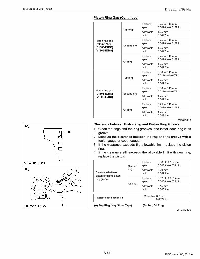
S-57
05-E2B, 05-E2BG, WSM DIESEL ENGINE
Piston Ring Gap (Continued)
W1043413
Clearance between Piston ring and Piston Ring Groove1. Clean the rings and the ring grooves, and install each ring in its
groove.2. Measure the clearance between the ring and the groove with a
feeler gauge or depth gauge.3. If the clearance exceeds the allowable limit, replace the piston
ring.4. If the clearance still exceeds the allowable limit with new ring,
replace the piston.
W10312390
Piston ring gap[D905-E2BG][D1005-E2BG][V1305-E2BG]
Top ring
Factory spec.
0.25 to 0.40 mm0.0098 to 0.0157 in.
Allowable limit
1.25 mm0.0492 in.
Second ring
Factory spec.
0.25 to 0.40 mm0.0098 to 0.0157 in.
Allowable limit
1.25 mm0.0492 in.
Oil ring
Factory spec.
0.25 to 0.40 mm0.0098 to 0.0157 in.
Allowable limit
1.25 mm0.0492 in.
Piston ring gap[D1105-E2BG][V1505-E2BG]
Top ring
Factory spec.
0.30 to 0.45 mm0.0118 to 0.0177 in.
Allowable limit
1.25 mm0.0492 in.
Second ring
Factory spec.
0.30 to 0.45 mm0.0118 to 0.0177 in.
Allowable limit
1.25 mm0.0492 in.
Oil ring
Factory spec.
0.25 to 0.40 mm0.0098 to 0.0157 in.
Allowable limit
1.25 mm0.0492 in.
Clearance between piston ring and piston ring groove
Second ring
Factory spec.
0.085 to 0.112 mm0.0033 to 0.0044 in.
Allowable limit
0.20 mm0.0079 in.
Oil ring
Factory spec.
0.020 to 0.055 mm0.0008 to 0.0021 in.
Allowable limit
0.15 mm0.0059 in.
Factory specification : a More than 0.2 mm 0.0079 in.
(A) Top Ring (Key Stone Type) (B) 2nd, Oil Ring
KiSC issued 06, 2011 A
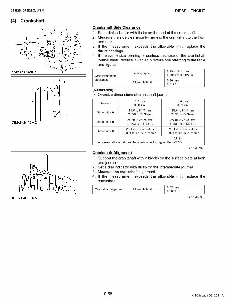
S-58
05-E2B, 05-E2BG, WSM DIESEL ENGINE
(4) CrankshaftCrankshaft Side Clearance1. Set a dial indicator with its tip on the end of the crankshaft.2. Measure the side clearance by moving the crankshaft to the front
and rear.3. If the measurement exceeds the allowable limit, replace the
thrust bearings.4. If the same size bearing is useless because of the crankshaft
journal wear, replace it with an oversize one referring to the tableand figure.
(Reference)• Oversize dimensions of crankshaft journal
W10317070
Crankshaft Alignment1. Support the crankshaft with V blocks on the surface plate at both
end journals.2. Set a dial indicator with its tip on the intermediate journal.3. Measure the crankshaft alignment.4. If the measurement exceeds the allowable limit, replace the
crankshaft.
W10330010
Crankshaft side clearance
Factory spec. 0.15 to 0.31 mm0.0059 to 0.0122 in.
Allowable limit 0.50 mm0.0197 in.
Oversize 0.2 mm0.008 in.
0.4 mm0.016 in.
Dimension A 51.5 to 51.7 mm2.028 to 2.035 in.
51.6 to 51.8 mm2.031 to 2.039 in.
Dimension B 28.20 to 28.25 mm1.1102 to 1.1122 in.
28.40 to 28.45 mm1.1181 to 1.1201 in.
Dimension C 2.3 to 2.7 mm radius0.091 to 0.106 in. radius
2.3 to 3.7 mm radius0.091 to 0.106 in. radius
(0.8-S)The crankshaft journal must be fine-finished to higher than ∇∇∇∇
Crankshaft alignment Allowable limit 0.02 mm0.0008 in.
KiSC issued 06, 2011 A
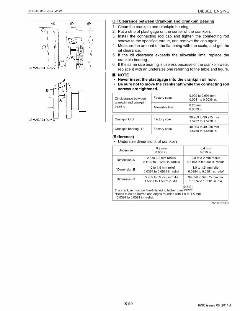
S-59
05-E2B, 05-E2BG, WSM DIESEL ENGINE
Oil Clearance between Crankpin and Crankpin Bearing1. Clean the crankpin and crankpin bearing.2. Put a strip of plastigage on the center of the crankpin.3. Install the connecting rod cap and tighten the connecting rod
screws to the specified torque, and remove the cap again.4. Measure the amount of the flattening with the scale, and get the
oil clearance.5. If the oil clearance exceeds the allowable limit, replace the
crankpin bearing.6. If the same size bearing is useless because of the crankpin wear,
replace it with an undersize one referring to the table and figure.NOTE
• Never insert the plastigage into the crankpin oil hole.• Be sure not to move the crankshaft while the connecting rod
screws are tightened.
(Reference)• Undersize dimensions of crankpin
W10331060
Oil clearance between crankpin and crankpin bearing
Factory spec. 0.029 to 0.091 mm0.0011 to 0.0036 in.
Allowable limit 0.20 mm0.0079 in.
Crankpin O.D. Factory spec. 39.959 to 39.975 mm1.5732 to 1.5738 in.
Crankpin bearing I.D. Factory spec. 40.004 to 40.050 mm1.5750 to 1.5768 in.
Undersize 0.2 mm0.008 in.
0.4 mm0.016 in.
Dimension A 2.8 to 3.2 mm radius0.1102 to 0.1260 in. radius
2.8 to 3.2 mm radius0.1102 to 0.1260 in. radius
*Dimension B 1.0 to 1.5 mm relief0.0394 to 0.0591 in. relief
1.0 to 1.5 mm relief0.0394 to 0.0591 in. relief
Dimension C 39.759 to 39.775 mm dia.1.5653 to 1.5659 in. dia.
39.559 to 39.575 mm dia.1.5574 to 1.5581 in. dia.
(0.8-S)The crankpin must be fine-finished to higher than ∇∇∇∇*Holes to be de-burred and edges rounded with 1.0 to 1.5 mm (0.0394 to 0.0591 in.) relief.
KiSC issued 06, 2011 A
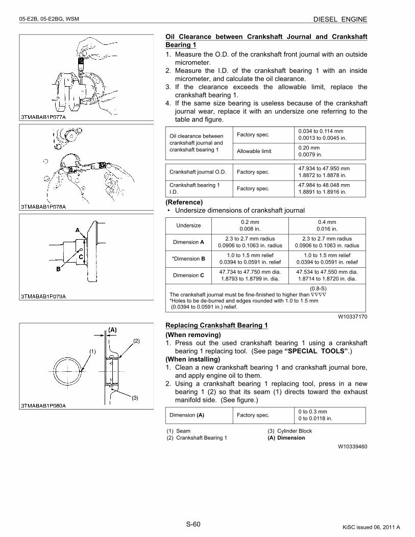
S-60
05-E2B, 05-E2BG, WSM DIESEL ENGINE
Oil Clearance between Crankshaft Journal and CrankshaftBearing 11. Measure the O.D. of the crankshaft front journal with an outside
micrometer.2. Measure the I.D. of the crankshaft bearing 1 with an inside
micrometer, and calculate the oil clearance.3. If the clearance exceeds the allowable limit, replace the
crankshaft bearing 1.4. If the same size bearing is useless because of the crankshaft
journal wear, replace it with an undersize one referring to thetable and figure.
(Reference)• Undersize dimensions of crankshaft journal
W10337170
Replacing Crankshaft Bearing 1(When removing)1. Press out the used crankshaft bearing 1 using a crankshaft
bearing 1 replacing tool. (See page “SPECIAL TOOLS”.)(When installing)1. Clean a new crankshaft bearing 1 and crankshaft journal bore,
and apply engine oil to them.2. Using a crankshaft bearing 1 replacing tool, press in a new
bearing 1 (2) so that its seam (1) directs toward the exhaustmanifold side. (See figure.)
W10339460
Oil clearance between crankshaft journal and crankshaft bearing 1
Factory spec. 0.034 to 0.114 mm0.0013 to 0.0045 in.
Allowable limit 0.20 mm0.0079 in.
Crankshaft journal O.D. Factory spec. 47.934 to 47.950 mm1.8872 to 1.8878 in.
Crankshaft bearing 1 I.D. Factory spec. 47.984 to 48.048 mm
1.8891 to 1.8916 in.
Undersize 0.2 mm0.008 in.
0.4 mm0.016 in.
Dimension A 2.3 to 2.7 mm radius0.0906 to 0.1063 in. radius
2.3 to 2.7 mm radius0.0906 to 0.1063 in. radius
*Dimension B 1.0 to 1.5 mm relief0.0394 to 0.0591 in. relief
1.0 to 1.5 mm relief0.0394 to 0.0591 in. relief
Dimension C 47.734 to 47.750 mm dia.1.8793 to 1.8799 in. dia.
47.534 to 47.550 mm dia.1.8714 to 1.8720 in. dia.
(0.8-S)The crankshaft journal must be fine-finished to higher than ∇∇∇∇*Holes to be de-burred and edges rounded with 1.0 to 1.5 mm (0.0394 to 0.0591 in.) relief.
Dimension (A) Factory spec. 0 to 0.3 mm0 to 0.0118 in.
(1) Seam(2) Crankshaft Bearing 1
(3) Cylinder Block(A) Dimension
KiSC issued 06, 2011 A
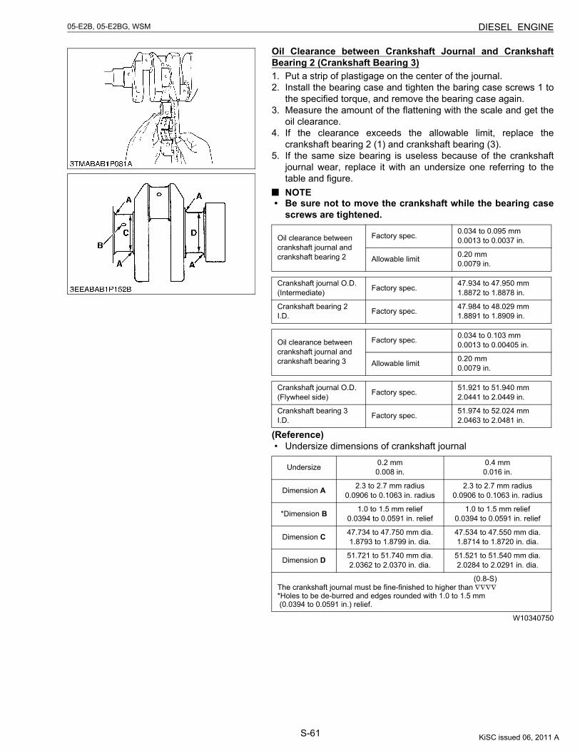
S-61
05-E2B, 05-E2BG, WSM DIESEL ENGINE
Oil Clearance between Crankshaft Journal and CrankshaftBearing 2 (Crankshaft Bearing 3)1. Put a strip of plastigage on the center of the journal.2. Install the bearing case and tighten the baring case screws 1 to
the specified torque, and remove the bearing case again.3. Measure the amount of the flattening with the scale and get the
oil clearance.4. If the clearance exceeds the allowable limit, replace the
crankshaft bearing 2 (1) and crankshaft bearing (3).5. If the same size bearing is useless because of the crankshaft
journal wear, replace it with an undersize one referring to thetable and figure.NOTE
• Be sure not to move the crankshaft while the bearing casescrews are tightened.
(Reference)• Undersize dimensions of crankshaft journal
W10340750
Oil clearance between crankshaft journal and crankshaft bearing 2
Factory spec. 0.034 to 0.095 mm0.0013 to 0.0037 in.
Allowable limit 0.20 mm0.0079 in.
Crankshaft journal O.D.(Intermediate) Factory spec. 47.934 to 47.950 mm
1.8872 to 1.8878 in.
Crankshaft bearing 2 I.D. Factory spec. 47.984 to 48.029 mm
1.8891 to 1.8909 in.
Oil clearance between crankshaft journal and crankshaft bearing 3
Factory spec. 0.034 to 0.103 mm0.0013 to 0.00405 in.
Allowable limit 0.20 mm0.0079 in.
Crankshaft journal O.D.(Flywheel side) Factory spec. 51.921 to 51.940 mm
2.0441 to 2.0449 in.
Crankshaft bearing 3 I.D. Factory spec. 51.974 to 52.024 mm
2.0463 to 2.0481 in.
Undersize 0.2 mm0.008 in.
0.4 mm0.016 in.
Dimension A 2.3 to 2.7 mm radius0.0906 to 0.1063 in. radius
2.3 to 2.7 mm radius0.0906 to 0.1063 in. radius
*Dimension B 1.0 to 1.5 mm relief0.0394 to 0.0591 in. relief
1.0 to 1.5 mm relief0.0394 to 0.0591 in. relief
Dimension C 47.734 to 47.750 mm dia.1.8793 to 1.8799 in. dia.
47.534 to 47.550 mm dia.1.8714 to 1.8720 in. dia.
Dimension D 51.721 to 51.740 mm dia.2.0362 to 2.0370 in. dia.
51.521 to 51.540 mm dia.2.0284 to 2.0291 in. dia.
(0.8-S)The crankshaft journal must be fine-finished to higher than ∇∇∇∇*Holes to be de-burred and edges rounded with 1.0 to 1.5 mm (0.0394 to 0.0591 in.) relief.
KiSC issued 06, 2011 A
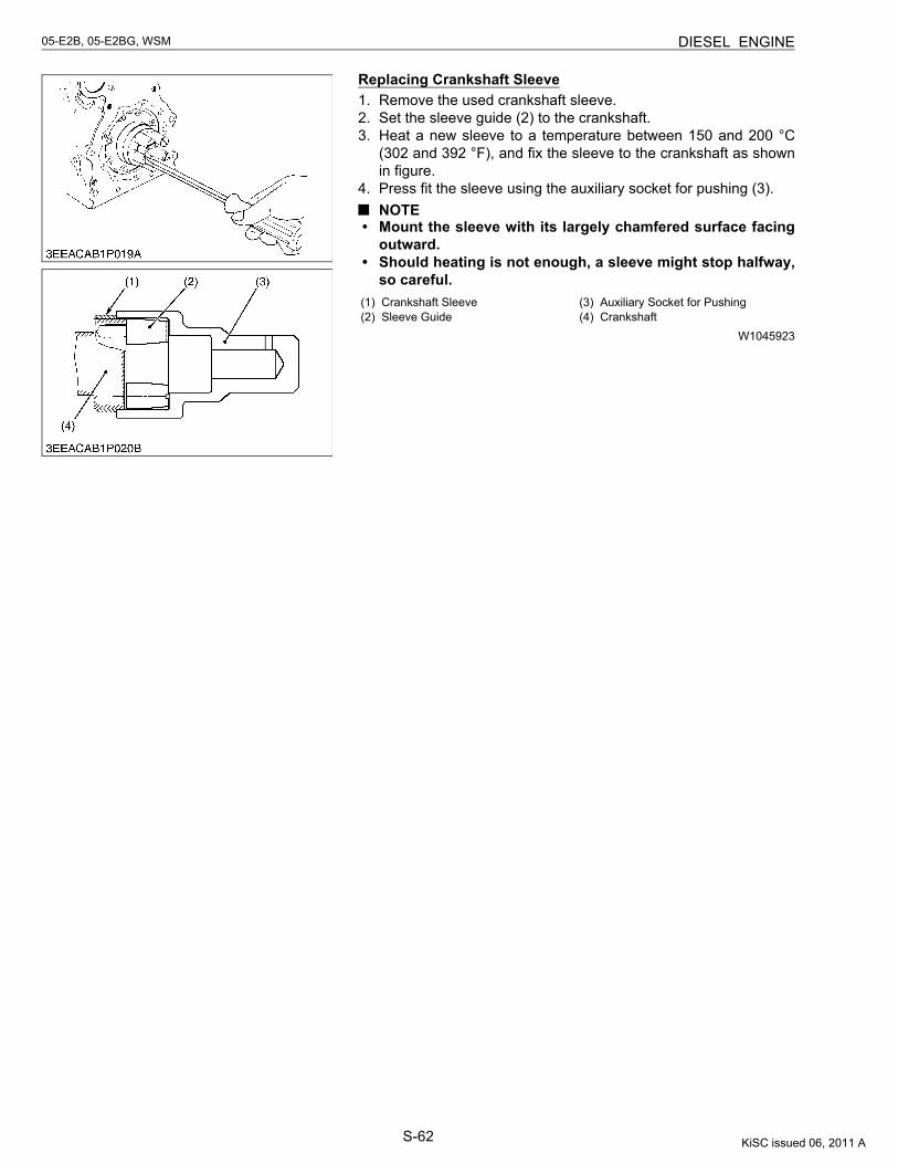
S-62
05-E2B, 05-E2BG, WSM DIESEL ENGINE
Replacing Crankshaft Sleeve1. Remove the used crankshaft sleeve.2. Set the sleeve guide (2) to the crankshaft.3. Heat a new sleeve to a temperature between 150 and 200 °C
(302 and 392 °F), and fix the sleeve to the crankshaft as shownin figure.
4. Press fit the sleeve using the auxiliary socket for pushing (3).NOTE
• Mount the sleeve with its largely chamfered surface facingoutward.
• Should heating is not enough, a sleeve might stop halfway,so careful.
W1045923
(1) Crankshaft Sleeve(2) Sleeve Guide
(3) Auxiliary Socket for Pushing(4) Crankshaft
KiSC issued 06, 2011 A
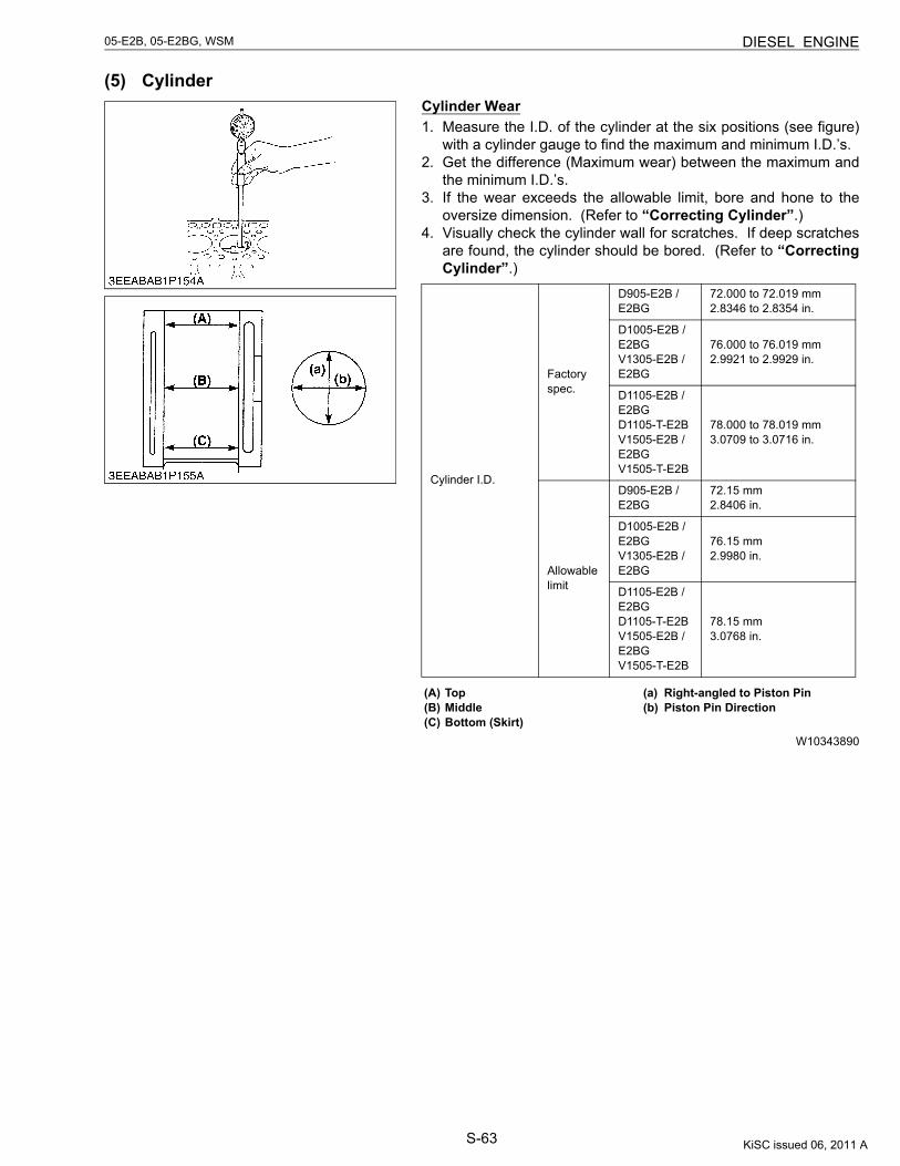
S-63
05-E2B, 05-E2BG, WSM DIESEL ENGINE
(5) CylinderCylinder Wear1. Measure the I.D. of the cylinder at the six positions (see figure)
with a cylinder gauge to find the maximum and minimum I.D.’s.2. Get the difference (Maximum wear) between the maximum and
the minimum I.D.’s.3. If the wear exceeds the allowable limit, bore and hone to the
oversize dimension. (Refer to “Correcting Cylinder”.)4. Visually check the cylinder wall for scratches. If deep scratches
are found, the cylinder should be bored. (Refer to “CorrectingCylinder”.)
W10343890
Cylinder I.D.
Factory spec.
D905-E2B / E2BG
72.000 to 72.019 mm2.8346 to 2.8354 in.
D1005-E2B / E2BGV1305-E2B / E2BG
76.000 to 76.019 mm2.9921 to 2.9929 in.
D1105-E2B / E2BGD1105-T-E2BV1505-E2B / E2BGV1505-T-E2B
78.000 to 78.019 mm3.0709 to 3.0716 in.
Allowable limit
D905-E2B / E2BG
72.15 mm2.8406 in.
D1005-E2B / E2BGV1305-E2B / E2BG
76.15 mm2.9980 in.
D1105-E2B / E2BGD1105-T-E2BV1505-E2B / E2BGV1505-T-E2B
78.15 mm3.0768 in.
(A) Top(B) Middle(C) Bottom (Skirt)
(a) Right-angled to Piston Pin(b) Piston Pin Direction
KiSC issued 06, 2011 A
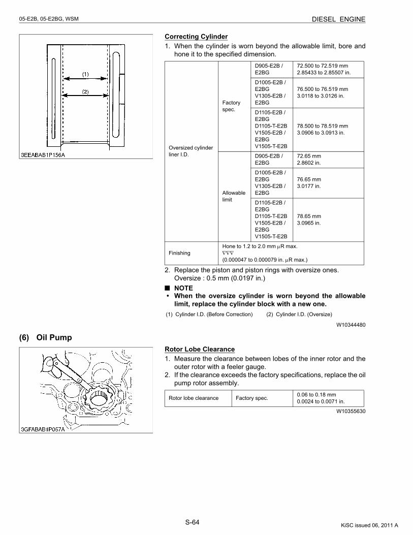
S-64
05-E2B, 05-E2BG, WSM DIESEL ENGINE
Correcting Cylinder1. When the cylinder is worn beyond the allowable limit, bore and
hone it to the specified dimension.
2. Replace the piston and piston rings with oversize ones.Oversize : 0.5 mm (0.0197 in.)NOTE
• When the oversize cylinder is worn beyond the allowablelimit, replace the cylinder block with a new one.
W10344480
(6) Oil PumpRotor Lobe Clearance1. Measure the clearance between lobes of the inner rotor and the
outer rotor with a feeler gauge.2. If the clearance exceeds the factory specifications, replace the oil
pump rotor assembly.
W10355630
Oversized cylinder liner I.D.
Factory spec.
D905-E2B / E2BG
72.500 to 72.519 mm2.85433 to 2.85507 in.
D1005-E2B / E2BGV1305-E2B / E2BG
76.500 to 76.519 mm3.0118 to 3.0126 in.
D1105-E2B / E2BGD1105-T-E2BV1505-E2B / E2BGV1505-T-E2B
78.500 to 78.519 mm3.0906 to 3.0913 in.
Allowable limit
D905-E2B / E2BG
72.65 mm2.8602 in.
D1005-E2B / E2BGV1305-E2B / E2BG
76.65 mm3.0177 in.
D1105-E2B / E2BGD1105-T-E2BV1505-E2B / E2BGV1505-T-E2B
78.65 mm3.0965 in.
FinishingHone to 1.2 to 2.0 mm μR max.∇∇∇(0.000047 to 0.000079 in. μR max.)
(1) Cylinder I.D. (Before Correction) (2) Cylinder I.D. (Oversize)
Rotor lobe clearance Factory spec. 0.06 to 0.18 mm0.0024 to 0.0071 in.
KiSC issued 06, 2011 A
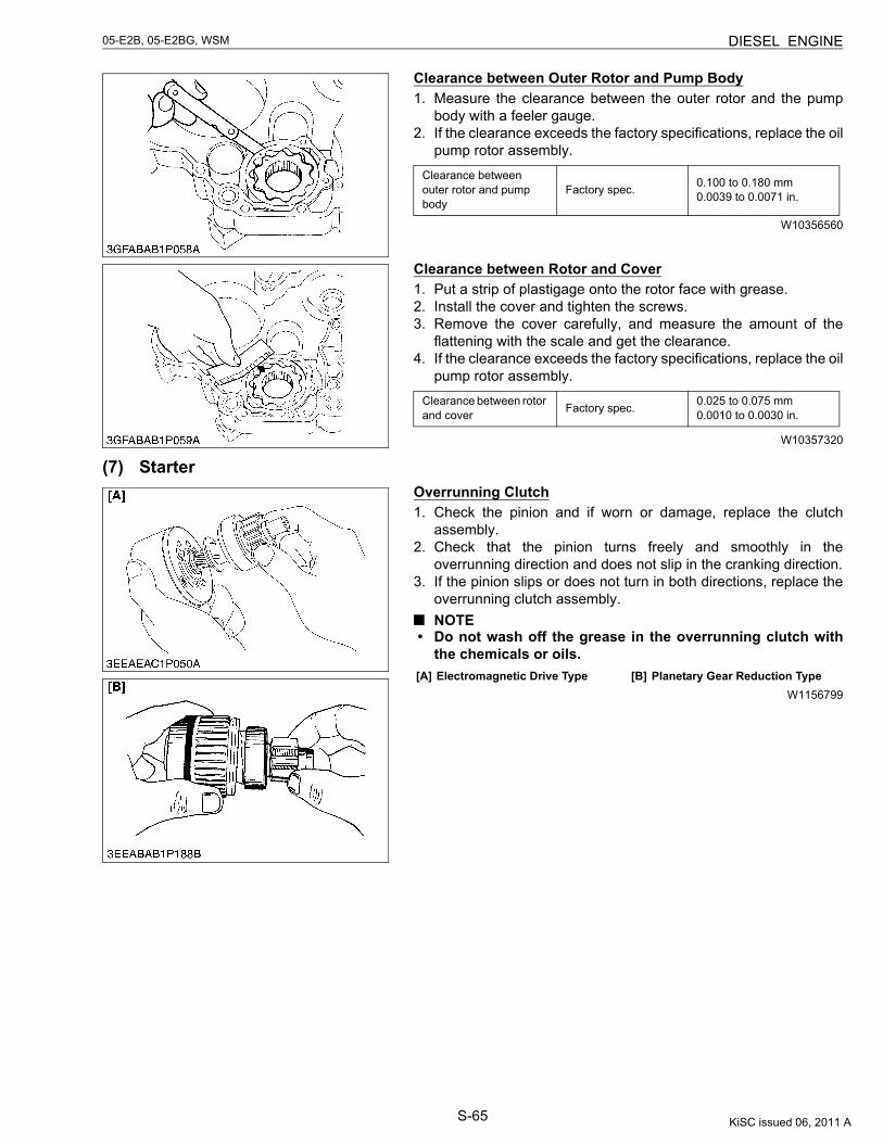
S-65
05-E2B, 05-E2BG, WSM DIESEL ENGINE
Clearance between Outer Rotor and Pump Body1. Measure the clearance between the outer rotor and the pump
body with a feeler gauge.2. If the clearance exceeds the factory specifications, replace the oil
pump rotor assembly.
W10356560
Clearance between Rotor and Cover1. Put a strip of plastigage onto the rotor face with grease.2. Install the cover and tighten the screws.3. Remove the cover carefully, and measure the amount of the
flattening with the scale and get the clearance.4. If the clearance exceeds the factory specifications, replace the oil
pump rotor assembly.
W10357320
(7) StarterOverrunning Clutch1. Check the pinion and if worn or damage, replace the clutch
assembly.2. Check that the pinion turns freely and smoothly in the
overrunning direction and does not slip in the cranking direction.3. If the pinion slips or does not turn in both directions, replace the
overrunning clutch assembly.NOTE
• Do not wash off the grease in the overrunning clutch withthe chemicals or oils.
W1156799
Clearance between outer rotor and pump body
Factory spec. 0.100 to 0.180 mm0.0039 to 0.0071 in.
Clearance between rotor and cover Factory spec. 0.025 to 0.075 mm
0.0010 to 0.0030 in.
[A] Electromagnetic Drive Type [B] Planetary Gear Reduction Type
KiSC issued 06, 2011 A
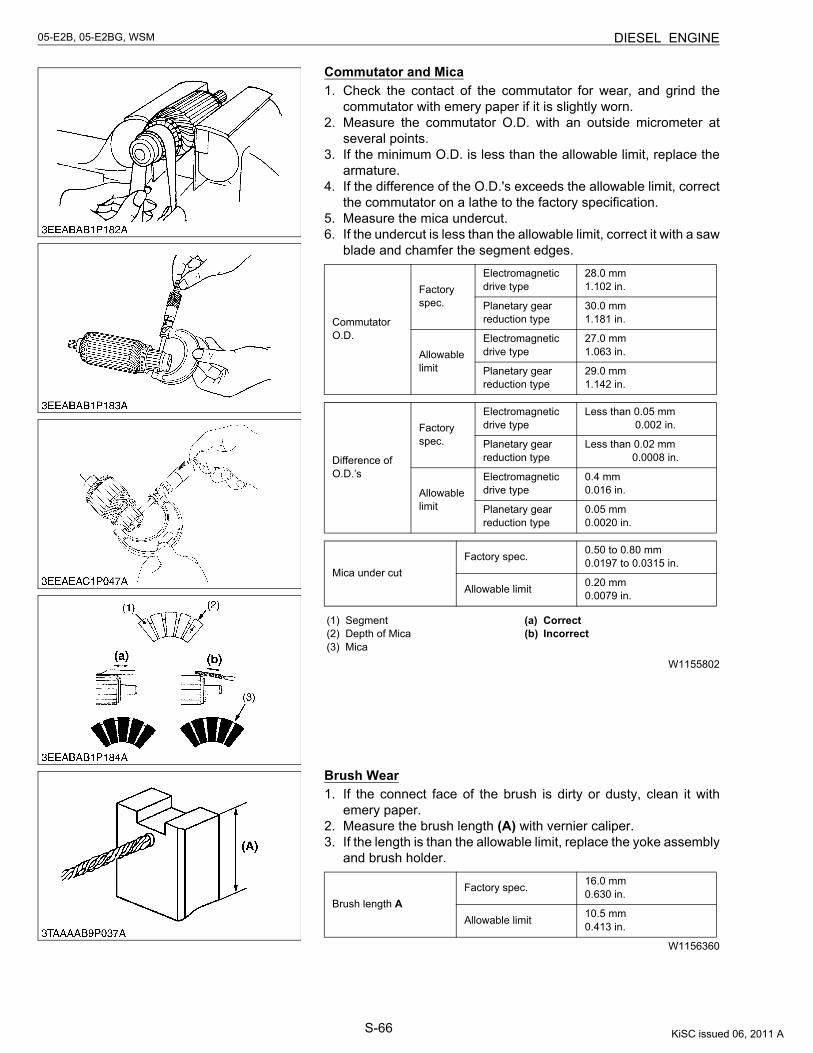
S-66
05-E2B, 05-E2BG, WSM DIESEL ENGINE
Commutator and Mica1. Check the contact of the commutator for wear, and grind the
commutator with emery paper if it is slightly worn.2. Measure the commutator O.D. with an outside micrometer at
several points.3. If the minimum O.D. is less than the allowable limit, replace the
armature.4. If the difference of the O.D.'s exceeds the allowable limit, correct
the commutator on a lathe to the factory specification.5. Measure the mica undercut.6. If the undercut is less than the allowable limit, correct it with a saw
blade and chamfer the segment edges.
W1155802
Brush Wear1. If the connect face of the brush is dirty or dusty, clean it with
emery paper.2. Measure the brush length (A) with vernier caliper.3. If the length is than the allowable limit, replace the yoke assembly
and brush holder.
W1156360
Commutator O.D.
Factory spec.
Electromagnetic drive type
28.0 mm1.102 in.
Planetary gear reduction type
30.0 mm1.181 in.
Allowable limit
Electromagnetic drive type
27.0 mm1.063 in.
Planetary gear reduction type
29.0 mm1.142 in.
Difference of O.D.’s
Factory spec.
Electromagnetic drive type
Less than 0.05 mm 0.002 in.
Planetary gear reduction type
Less than 0.02 mm 0.0008 in.
Allowable limit
Electromagnetic drive type
0.4 mm0.016 in.
Planetary gear reduction type
0.05 mm0.0020 in.
Mica under cutFactory spec. 0.50 to 0.80 mm
0.0197 to 0.0315 in.
Allowable limit 0.20 mm0.0079 in.
(1) Segment(2) Depth of Mica(3) Mica
(a) Correct(b) Incorrect
Brush length AFactory spec. 16.0 mm
0.630 in.
Allowable limit 10.5 mm0.413 in.
KiSC issued 06, 2011 A
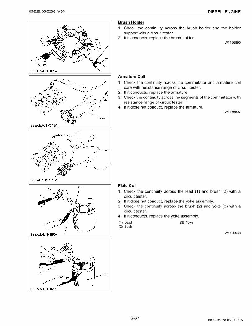
S-67
05-E2B, 05-E2BG, WSM DIESEL ENGINE
Brush Holder1. Check the continuity across the brush holder and the holder
support with a circuit tester.2. If it conducts, replace the brush holder.
W1156895
Armature Coil1. Check the continuity across the commutator and armature coil
core with resistance range of circuit tester.2. If it conducts, replace the armature.3. Check the continuity across the segments of the commutator with
resistance range of circuit tester.4. If it dose not conduct, replace the armature.
W1156507
Field Coil1. Check the continuity across the lead (1) and brush (2) with a
circuit tester.2. If it dose not conduct, replace the yoke assembly.3. Check the continuity across the brush (2) and yoke (3) with a
circuit tester.4. If it conducts, replace the yoke assembly.
W1156968
(1) Lead(2) Bush
(3) Yoke
KiSC issued 06, 2011 A
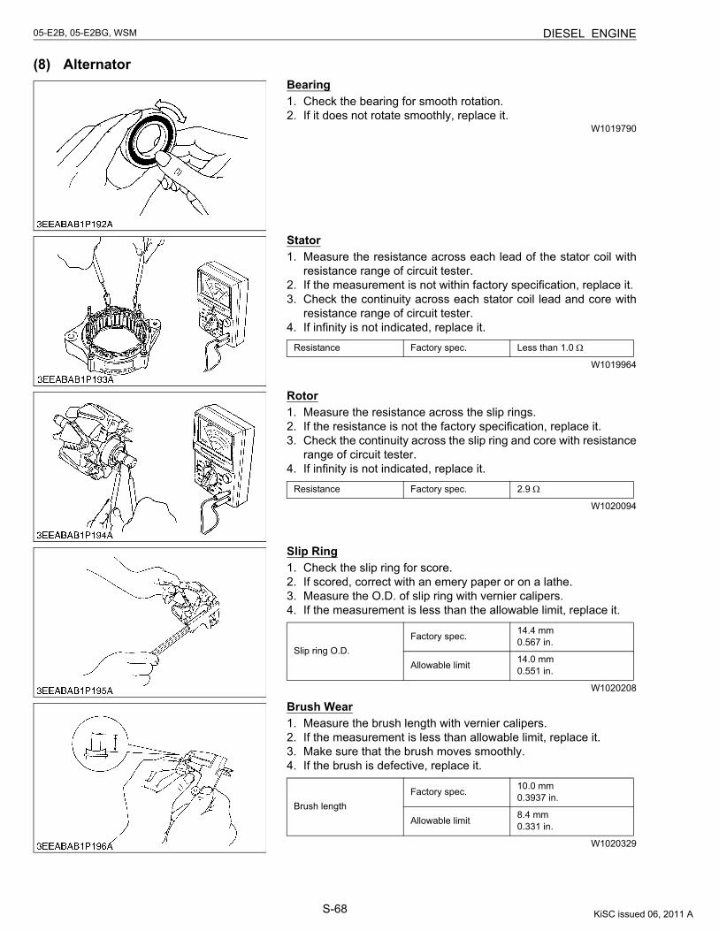
S-68
05-E2B, 05-E2BG, WSM DIESEL ENGINE
(8) AlternatorBearing1. Check the bearing for smooth rotation.2. If it does not rotate smoothly, replace it.
W1019790
Stator1. Measure the resistance across each lead of the stator coil with
resistance range of circuit tester.2. If the measurement is not within factory specification, replace it.3. Check the continuity across each stator coil lead and core with
resistance range of circuit tester.4. If infinity is not indicated, replace it.
W1019964
Rotor1. Measure the resistance across the slip rings.2. If the resistance is not the factory specification, replace it.3. Check the continuity across the slip ring and core with resistance
range of circuit tester.4. If infinity is not indicated, replace it.
W1020094
Slip Ring1. Check the slip ring for score.2. If scored, correct with an emery paper or on a lathe.3. Measure the O.D. of slip ring with vernier calipers.4. If the measurement is less than the allowable limit, replace it.
W1020208
Brush Wear1. Measure the brush length with vernier calipers.2. If the measurement is less than allowable limit, replace it.3. Make sure that the brush moves smoothly.4. If the brush is defective, replace it.
W1020329
Resistance Factory spec. Less than 1.0 Ω
Resistance Factory spec. 2.9 Ω
Slip ring O.D.Factory spec. 14.4 mm
0.567 in.
Allowable limit 14.0 mm0.551 in.
Brush lengthFactory spec. 10.0 mm
0.3937 in.
Allowable limit 8.4 mm0.331 in.
KiSC issued 06, 2011 A
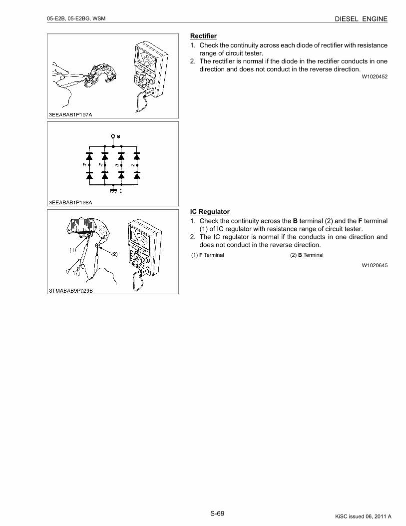
S-69
05-E2B, 05-E2BG, WSM DIESEL ENGINE
Rectifier1. Check the continuity across each diode of rectifier with resistance
range of circuit tester.2. The rectifier is normal if the diode in the rectifier conducts in one
direction and does not conduct in the reverse direction.W1020452
IC Regulator1. Check the continuity across the B terminal (2) and the F terminal
(1) of IC regulator with resistance range of circuit tester.2. The IC regulator is normal if the conducts in one direction and
does not conduct in the reverse direction.
W1020645
(1) F Terminal (2) B Terminal
KiSC issued 06, 2011 A
EDITOR:KUBOTA FARM & INDUSTRIAL MACHINERY SERVICE, LTD.64, ISHIZU-KITAMACHI, SAKAI-KU, SAKAI-CITY, OSAKA, 590-0823, JAPANPHONE : (81)72-241-1129FAX : (81)72-245-2484E-mail : [email protected]
KUBOTA CorporationPrinted in Japan 2011. 06, S, EI, EI, e Code No.9Y011-02754 2004. 02, S, EI, EI, e