kt.com.trkt.com.tr/Bilgi bank data/abb_dcs550_EN_kullanim_kilavuzu.pdfkt.com.tr
310
ABB DCS550 Manual DCS550 Drives (20 A to 1000 A)
Transcript of kt.com.trkt.com.tr/Bilgi bank data/abb_dcs550_EN_kullanim_kilavuzu.pdfkt.com.tr

ABB
DCS550
Manual DCS550 Drives (20 A to 1000 A)
DCS550 Manuals Language
Public. number E D I ES F CN RU Quick Guide 3ADW000395 x x x x x DCS550 Tools & Documentation CD 3ADW000377 x DCS550 Modules
DCS550 Flyer 3ADW000374 x x DCS550 Technical Catalogue 3ADW000378 p DCS550 Manual 3ADW000379 x DCS550 Service Manual 3ADW000399 p Installation according to EMC 3ADW000032 x Technical Guide 3ADW000163 x
Extension Modules
RAIO-01 Analogue IO Extension 3AFE64484567 x RDIO-01 Digital IO Extension 3AFE64485733 x
Serial Communication
RPBA-01 PROFIBUS 3AFE64504215 x RCAN-01 CANopen 3AFE64504231 x RCNA-01 ControlNet 3AFE64506005 x RDNA-01 DeviceNet 3AFE64504223 x RMBA-01 MODBUS 3AFE64498851 x RETA-01 Ethernet 3AFE64539736 x
x -> existing p -> planned Status 05.2011
DCS550 Drive Manuals-List_d.doc
3
Safety instructions
3ADW000379R0301 DCS550 Manual e c
Safety instructions Chapter overview This chapter contains the safety instructions you must follow when installing, operating and servicing the drive. If ignored, physical injury or death may follow, or damage may occur to the drive, the motor or driven equipment. Read the safety instructions before you work on the unit.
To which products this chapter applies The information is valid for the whole range of the product DCS550.
Usage of warnings and notes There are two types of safety instructions throughout this manual: warnings and notes. Warnings caution you about conditions, which can result in serious injury or death and/or damage to the equipment, and advice on how to avoid the danger. Notes draw attention to a particular condition or fact, or give information on a subject. The warning symbols are used as follows:
Dangerous voltage warning warns of high voltage, which can cause physical injury or death and/or damage to the equipment.
General danger warning warns about conditions, other than those caused by electricity, which can result in physical injury or death and/or damage to the equipment.
Electrostatic sensitive devices warning warn of electrostatic discharge, which can damage the equipment.
Installation and maintenance work These warnings are intended for all who work on the drive, motor cable or motor. Ignoring the instructions can cause physical injury or death and/or damage to the equipment.
WARNING! 1. Only qualified electricians are allowed to install and maintain the drive! Never work on the drive, motor cable or motor when main power is applied. Always ensure
by measuring with a multimeter (impedance at least 1 Mohm) that: 1. Voltage between drive input phases U1, V1 and W1 and the frame is close to 0 V. 2. Voltage between terminals C+ and D- and the frame is close to 0 V.
Do not work on the control cables when power is applied to the drive or to the external control circuits. Externally supplied control circuits may cause dangerous voltages inside the drive even when the main power on the drive is switched off.
Do not make any insulation resistance or voltage withstand tests on the drive or drive modules.
Isolate the motor cables from the drive when testing the insulation resistance or voltage withstand of the cables or the motor.
When reconnecting the motor cable, always check that the C+ and D- cables are connected with the proper terminal.
Note: The motor cable terminals on the drive are at a dangerously high voltage when the main
power is on, regardless of whether the motor is running or not. Depending on the external wiring, dangerous voltages (115 V, 220 V or 230 V) may be
present on the relay outputs of the drive system (e.g. RDIO). DCS550 with enclosure extension: Before working on the drive, isolate the whole drive
system from the supply.
4
Safety instructions
3ADW000379R0301 DCS550 Manual e c
Grounding These instructions are intended for all who are responsible for the grounding of the drive. Incorrect grounding can cause physical injury, death and/or equipment malfunction and increase electromagnetic interference.
WARNING! Ground the drive, motor and adjoining equipment to ensure personnel safety in all
circumstances, and to reduce electromagnetic emission and pick-up. Make sure that grounding conductors are adequately sized and marked as required by safety
regulations. In a multiple-drive installation, connect each drive separately to protective earth (PE ). Minimize EMC emission and make a 360° high frequency grounding (e.g. conductive
sleeves) of screened cable entries at the cabinet lead-through plate. Note: Power cable shields are suitable as equipment grounding conductors only when adequately
sized to meet safety regulations. As the normal leakage current of the drive is higher than 3.5 mAAC or 10 mADC (stated by EN
50178, 5.2.11.1), a fixed protective earth connection is required.
Printed circuit boards and fiber optic cables These instructions are intended for all who handle the circuit boards and fiber optic cables. Ignoring the following instructions can cause damage to the equipment.
WARNING! The printed circuit boards contain components sensitive to electrostatic discharge. Wear a grounding wristband when handling the boards. Do not touch the boards unnecessarily. Use grounding strip:
ABB order no.: 3ADV050035P0001
WARNING! Handle the fiber optic cables with care. When unplugging optic cables, always grab the connector, not the cable itself. Do not touch the ends of the fibers with bare hands, as the fiber is extremely sensitive to dirt. The minimum allowed bend radius is 35 mm (1.38 in.).
5
Safety instructions
3ADW000379R0301 DCS550 Manual e c
Mechanical installation These notes are intended for all who install the drive. Handle the unit carefully to avoid damage and injury.
WARNING! DCS550 size F4: The drive is heavy. Do not lift it alone. Do not lift the unit by the front cover.
Place it only on its back. Make sure that dust from drilling does not enter the drive when installing. Electrically
conductive dust inside the unit may cause damage or lead to malfunction. Ensure sufficient cooling. Do not fasten the drive by riveting or welding.
Operation These warnings are intended for all who plan the operation of the drive or operate the drive. Ignoring the instructions can cause physical injury or death and/or damage to the equipment.
WARNING! Before adjusting the drive and putting it into service, make sure that the motor and all driven
equipment are suitable for operation throughout the speed range provided by the drive. The drive can be adjusted to operate the motor at speeds above and below the base speed.
Do not control the motor with the disconnecting device (disconnecting mains); instead, use
the control panel keys and , or commands via the I/O board of the drive. Mains connection
You can use a disconnect switch (with fuses) to disconnect the electrical components of the drive from the mains for installation and maintenance work. The type of disconnect switch used must be as per EN 60947-3, Class B, so as to comply with EU regulations, or a circuit-breaker type which switches off the load circuit by means of an auxiliary contact causing the breaker's main contacts to open. The mains disconnect must be locked in its "OPEN" position during any installation and maintenance work.
EMERGENCY STOP buttons must be installed at each control desk and at all other control panels requiring an emergency stop function. Pressing the STOP button on the control panel of the drive will neither cause an emergency stop of the motor, nor will the drive be disconnected from any dangerous potential. To avoid unintentional operating states, or to shut the unit down in case of any imminent danger according to the standards in the safety instructions it is not sufficient to merely shut down the drive via signals "RUN", "drive OFF" or "Emergency Stop" respectively "control panel" or "PC tool".
Intended use The operating instructions cannot take into consideration every possible case of configuration, operation or maintenance. Thus, they mainly give such advice only, which is required by qualified personnel for normal operation of the machines and devices in industrial installations. If in special cases the electrical machines and devices are intended for use in non-industrial installations - which may require stricter safety regulations (e.g. protection against contact by children or similar) - these additional safety measures for the installation must be provided by the customer during assembly.
Note: When the control location is not set to Local (L not shown in the status row of the display),
the stop key on the control panel will not stop the drive. To stop the drive using the control
panel, press the LOC/REM key and then the stop key .
6
Table of contents
3ADW000379R0301 DCS550 Manual e c
Table of contents DCS550 Manuals................................................................................................................................................. 2
Safety instructions................................................................................................................................................ 3
Table of contents ................................................................................................................................................. 6
Introduction .......................................................................................................................................................... 8
The DCS550 ........................................................................................................................................................ 9
General ...................................................................................................................................................... 9 Overview Main circuit and control............................................................................................................ 11 Environmental Conditions........................................................................................................................ 12 Type code................................................................................................................................................ 13 Voltage ratings......................................................................................................................................... 13 Current ratings......................................................................................................................................... 14 Dimensions and weights.......................................................................................................................... 16
Mechanical installation....................................................................................................................................... 19
Cabinet installation .................................................................................................................................. 20
Planning the electrical installation...................................................................................................................... 21
Drive connection and wiring example...................................................................................................... 22 Installation components........................................................................................................................... 24 Cabling..................................................................................................................................................... 29 ⑥ Cooling fans ........................................................................................................................................ 32
Electrical installation .......................................................................................................................................... 33
Power connections .................................................................................................................................. 34 Drive interfaces........................................................................................................................................ 36 Installation checklist................................................................................................................................. 38
Electronic board details...................................................................................................................................... 39
Terminal locations ................................................................................................................................... 39 Table of used boards............................................................................................................................... 40 Control board SDCS-CON-F ................................................................................................................... 41 Power Interface board SDCS-PIN-F........................................................................................................ 44 OnBoard field exciters SDCS-BAB-F01 and SDCS-BAB-F02 ................................................................ 46
Accessories........................................................................................................................................................ 49
① Line reactors (L1)................................................................................................................................ 49 ② Semiconductor fuses (F1)................................................................................................................... 55 ③ EMC filters (E1)................................................................................................................................... 57 ④ Auxiliary transformer (T2) for converter electronics and fan............................................................... 57
Start-up .............................................................................................................................................................. 58
Commissioning ........................................................................................................................................ 58 Macros ..................................................................................................................................................... 62
Firmware description.......................................................................................................................................... 73
Start / stop sequences............................................................................................................................. 73 Excitation ................................................................................................................................................. 74
7
Table of contents
3ADW000379R0301 DCS550 Manual e c
DC-breaker...............................................................................................................................................76 Dynamic braking.......................................................................................................................................77 Digital I/O configuration............................................................................................................................79 Analog I/O configuration...........................................................................................................................83
Serial field bus communication...........................................................................................................................87
CANopen communication with fieldbus adapter RCAN-01......................................................................87 ControlNet communication with fieldbus adapter RCNA-01 ....................................................................91 DeviceNet communication with fieldbus adapter RDNA-01.....................................................................94 Ethernet/IP communication with fieldbus adapter RETA-01....................................................................97 Modbus (RTU) communication with fieldbus adapter RMBA-01 ...........................................................100 Modbus/TCP communication with fieldbus adapter RETA-01...............................................................102 Profibus communication with fieldbus adapter RPBA-01.......................................................................103 ProfiNet communication with fieldbus adapter RETA-02.......................................................................107 Switch on sequence ...............................................................................................................................108 Data set table .........................................................................................................................................108
AP (Adaptive Program).....................................................................................................................................109
What is AP?............................................................................................................................................109 DWL AP..................................................................................................................................................113 Function blocks ......................................................................................................................................118
Winder ..............................................................................................................................................................130
Winder blocks.........................................................................................................................................130 Winder macros .......................................................................................................................................136 Winder commissioning ...........................................................................................................................145
Signal and parameter list..................................................................................................................................148
Parameter group list ...............................................................................................................................149 Signals....................................................................................................................................................151 Parameters.............................................................................................................................................176
DCS Control Panel ...........................................................................................................................................264
Fault tracing......................................................................................................................................................270
Converter protection...............................................................................................................................270 Motor protection .....................................................................................................................................273 Display of status, fault messages and error codes ................................................................................279 Fault signals (F)......................................................................................................................................280 Alarm signals (A) ....................................................................................................................................288 Notices ...................................................................................................................................................295
Appendix A: Quick start-up diagrams...............................................................................................................296
Drive configuration with reduced components .......................................................................................296 I/O connections ......................................................................................................................................298
Appendix B: Firmware structure diagrams .......................................................................................................299
Appendix C: Index of signals and parameters..................................................................................................303
8
Introduction
3ADW000379R0301 DCS550 Manual e c
Introduction Chapter overview This chapter describes the purpose, contents and the intended use of this manual.
Before You Start The purpose of this manual is to provide you with the information necessary to control and program the drive. Study carefully the Safety instructions at the beginning of this manual before attempting any work on or with the drive. Read this manual before starting-up the drive. Note: This manual describes the standard DCS550 firmware.
What this manual contains The Safety instructions are at the beginning of this manual. Introduction, the chapter you are currently reading, introduces you to this manual. The DCS550, this chapter describes the basic properties of the DCS550. Mechanical installation, this chapter describes the mechanical installation of the DCS550. Planning the electrical installation, this chapter describes how to plan the electrical installation of the DCS550. Electrical installation, this chapter describes the electrical installation of the DCS550. Electronic board details, this chapter describes the electronics of the DCS550. Accessories, this chapter describes the accessories for the DCS550. Start-up, this chapter describes the basic start-up procedure of the DCS550. Firmware description, this chapter describes how to control the DCS550 with standard firmware. Serial field bus communication, this chapter describes the communication capabilities of the DCS550. AP (Adaptive Program), this chapter describes the basics of AP and instructs how to build an application. Winder, this chapter describes the winder and instructs how to use the winder blocks of the DCS550. Signal and parameter list, this chapter contains all signals and parameters. DCS Control Panel, this chapter describes the handling of the DCS Control Panel. Fault tracing, this chapter describes the protections and fault tracing of the drive. Appendix A: Quick start-up diagrams Appendix B: Firmware structure diagrams Appendix C: Index of signal and parameters
9
The DCS550
3ADW000379R0301 DCS550 Manual e c
The DCS550 Chapter overview This chapter describes the basic properties of the DCS550.
General
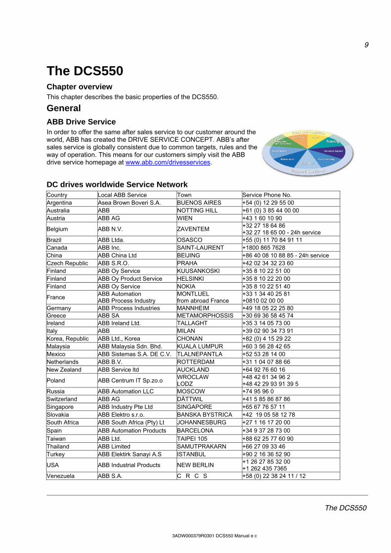
ABB Drive Service In order to offer the same after sales service to our customer around the world, ABB has created the DRIVE SERVICE CONCEPT. ABB’s after sales service is globally consistent due to common targets, rules and the way of operation. This means for our customers simply visit the ABB drive service homepage at www.abb.com/drivesservices.
DC drives worldwide Service Network Country Local ABB Service Town Service Phone No. Argentina Asea Brown Boveri S.A. BUENOS AIRES +54 (0) 12 29 55 00 Australia ABB NOTTING HILL +61 (0) 3 85 44 00 00 Austria ABB AG WIEN +43 1 60 10 90
Belgium ABB N.V. ZAVENTEM +32 27 18 64 86 +32 27 18 65 00 - 24h service
Brazil ABB Ltda. OSASCO +55 (0) 11 70 84 91 11 Canada ABB Inc. SAINT-LAURENT +1800 865 7628 China ABB China Ltd BEIJING +86 40 08 10 88 85 - 24h service Czech Republic ABB S.R.O. PRAHA +42 02 34 32 23 60 Finland ABB Oy Service KUUSANKOSKI +35 8 10 22 51 00 Finland ABB Oy Product Service HELSINKI +35 8 10 22 20 00 Finland ABB Oy Service NOKIA +35 8 10 22 51 40
France ABB Automation ABB Process Industry
MONTLUEL from abroad France
+33 1 34 40 25 81 +0810 02 00 00
Germany ABB Process Industries MANNHEIM +49 18 05 22 25 80 Greece ABB SA METAMORPHOSSIS +30 69 36 58 45 74 Ireland ABB Ireland Ltd. TALLAGHT +35 3 14 05 73 00 Italy ABB MILAN +39 02 90 34 73 91 Korea, Republic ABB Ltd., Korea CHONAN +82 (0) 4 15 29 22 Malaysia ABB Malaysia Sdn. Bhd. KUALA LUMPUR +60 3 56 28 42 65 Mexico ABB Sistemas S.A. DE C.V. TLALNEPANTLA +52 53 28 14 00 Netherlands ABB B.V. ROTTERDAM +31 1 04 07 88 66 New Zealand ABB Service ltd AUCKLAND +64 92 76 60 16
Poland ABB Centrum IT Sp.zo.o WROCLAW LODZ
+48 42 61 34 96 2 +48 42 29 93 91 39 5
Russia ABB Automation LLC MOSCOW +74 95 96 0 Switzerland ABB AG DÄTTWIL +41 5 85 86 87 86 Singapore ABB Industry Pte Ltd SINGAPORE +65 67 76 57 11 Slovakia ABB Elektro s.r.o. BANSKA BYSTRICA +42 19 05 58 12 78 South Africa ABB South Africa (Pty) Lt JOHANNESBURG +27 1 16 17 20 00 Spain ABB Automation Products BARCELONA +34 9 37 28 73 00 Taiwan ABB Ltd. TAIPEI 105 +88 62 25 77 60 90 Thailand ABB Limited SAMUTPRAKARN +66 27 09 33 46 Turkey ABB Elektirk Sanayi A.S ISTANBUL +90 2 16 36 52 90
USA ABB Industrial Products NEW BERLIN +1 26 27 85 32 00 +1 262 435 7365
Venezuela ABB S.A. CRCS +58 (0) 22 38 24 11 / 12
10
The DCS550
3ADW000379R0301 DCS550 Manual e c
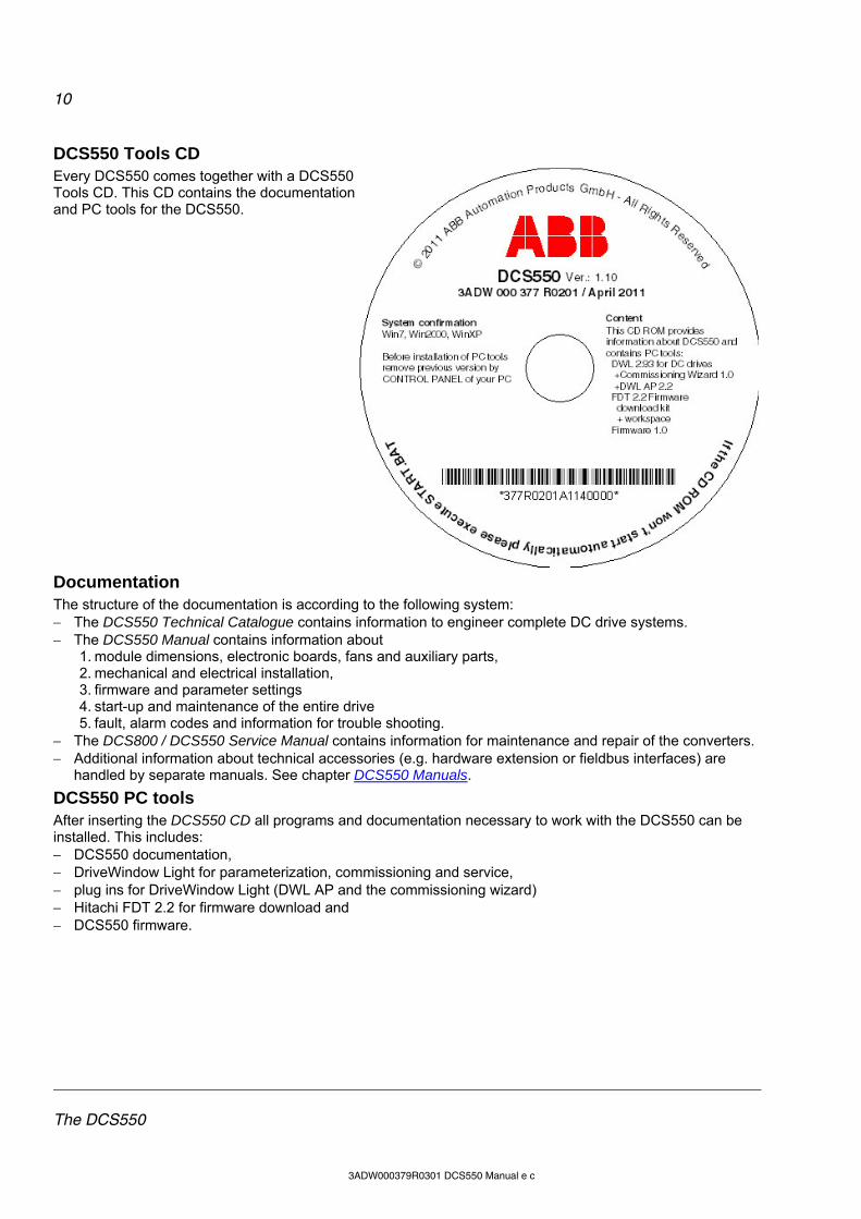
DCS550 Tools CD Every DCS550 comes together with a DCS550 Tools CD. This CD contains the documentation and PC tools for the DCS550.
Documentation The structure of the documentation is according to the following system: The DCS550 Technical Catalogue contains information to engineer complete DC drive systems. The DCS550 Manual contains information about
1. module dimensions, electronic boards, fans and auxiliary parts, 2. mechanical and electrical installation, 3. firmware and parameter settings 4. start-up and maintenance of the entire drive 5. fault, alarm codes and information for trouble shooting.
The DCS800 / DCS550 Service Manual contains information for maintenance and repair of the converters. Additional information about technical accessories (e.g. hardware extension or fieldbus interfaces) are
handled by separate manuals. See chapter DCS550 Manuals.
DCS550 PC tools After inserting the DCS550 CD all programs and documentation necessary to work with the DCS550 can be installed. This includes: DCS550 documentation, DriveWindow Light for parameterization, commissioning and service, plug ins for DriveWindow Light (DWL AP and the commissioning wizard) Hitachi FDT 2.2 for firmware download and DCS550 firmware.
11
The DCS550
3ADW000379R0301 DCS550 Manual e c
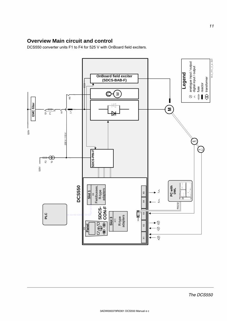
Overview Main circuit and control DCS550 converter units F1 to F4 for 525 V with OnBoard field exciters.
K1
T2
Q1
F2
M
F1
525
V
52
5V
B12_001_0_a.dsf
EM
C f
ilte
r
L1
K5
OnBoard field exciter(SDCS-BAB-F)
M
DC
S5
50
SD
CS
-PIN
-F
anal
ogue
inp
ut /
out
put
digi
tal i
nput
/ o
utp
ut
Leg
end
fuse
reac
tor
tran
sfor
mer
230
V /
115
V
18
47
3
E
T
SD
CS
-C
ON
-F
X1
X2
X3
X4
X5
X9
Pan
elX
33
X34
PC
wit
hD
WL
RS
232F
ield
buss
es,
R-t
ype
adap
ters
Slo
t 1
X11
R-t
ype
adap
ters
Slo
t 3PL
C
12
The DCS550
3ADW000379R0301 DCS550 Manual e c
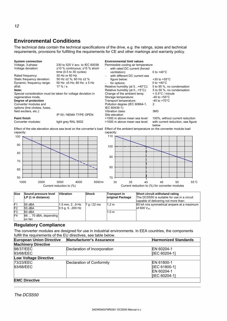
Environmental Conditions The technical data contain the technical specifications of the drive, e.g. the ratings, sizes and technical requirements, provisions for fulfilling the requirements for CE and other markings and warranty policy.
System connection Environmental limit values Voltage, 3-phase: 230 to 525 V acc. to IEC 60038 Permissible cooling air temperature Voltage deviation: ±10 % continuous; ±15 % short-
time (0.5 to 30 cycles) with rated DC current (forced
ventilation): 0 to +40°C Rated frequency: 50 Hz or 60 Hz Static frequency deviation: 50 Hz ±2 %; 60 Hz ±2 %
with different DC current see figure below: +30 to +55°C
Dynamic: frequency range: 50 Hz: ±5 Hz; 60 Hz: ± 5 Hz for options: 0 to +40°C df/dt: 17 % / s Relative humidity (at 5...+40°C): 5 to 95 %, no condensation
Relative humidity (at 0...+5°C): 5 to 50 %, no condensation Change of the ambient temp. < 0.5°C / minute
Note: Special consideration must be taken for voltage deviation in regenerative mode. Storage temperature: -40 to +55°C Degree of protection Transport temperature: -40 to +70°C
Pollution degree (IEC 60664-1, IEC 60439-1):
2
Vibration class: 3M3
Converter modules and options (line chokes, fuses, field exciters, etc.):
IP 00 / NEMA TYPE OPEN Site elevation Paint finish <1000 m above mean sea level: 100%, without current reduction Converter modules: light grey RAL 9002 >1000 m above mean sea level: with current reduction, see figure
below Effect of the site elevation above sea level on the converter’s load capacity:
Effect of the ambient temperature on the converter module load capacity:
Current reduction to (%)
Current reduction to (%) for converter modules
Size Sound pressure level
LP (1 m distance) Vibration Shock Transport in
original Package Short circuit withstand rating The DCS550 is suitable for use in a circuit capable of delivering not more than:
F1 55 dBA F2 55 dBA
1.2 m
F3 60 dBA F4 66 ... 70 dBA, depending
on fan
1.5 mm, 2...9 Hz 0.5 g, 9...200 Hz
7 g / 22 ms
1.0 m
65 kA rms symmetrical ampere at a maximum of 600 VAC
Regulatory Compliance The converter modules are designed for use in industrial environments. In EEA countries, the components fulfill the requirements of the EU directives, see table below. European Union Directive Manufacturer's Assurance Harmonized Standards Machinery Directive 98/37/EEC 93/68/EEC
Declaration of Incorporation EN 60204-1 [IEC 60204-1]
Low Voltage Directive 73/23/EEC 93/68/EEC
Declaration of Conformity EN 61800-1 [IEC 61800-1] EN 60204-1 [IEC 60204-1]
EMC Directive
13
The DCS550
3ADW000379R0301 DCS550 Manual e c
EN 61800-3 [IEC 61800-3]
89/336/EEC 93/68/EEC
Declaration of Conformity (If all installation instructions concerning cable selection, cabling and EMC filters or dedicated transformer are followed.)
in accordance with 3ADW000032
North American Standards In North America, the system components fulfill the requirements of the table below. Rated supply voltage Standards up to 525 VAC See UL Listing www. ul.com / certificate no. E196914
Approval: cULus The spacings in the modules were evaluated to table 36.1 of UL 508 C. Spacings also comply with table 6 and table 40 of C22.2 No. 14-05.
or on request
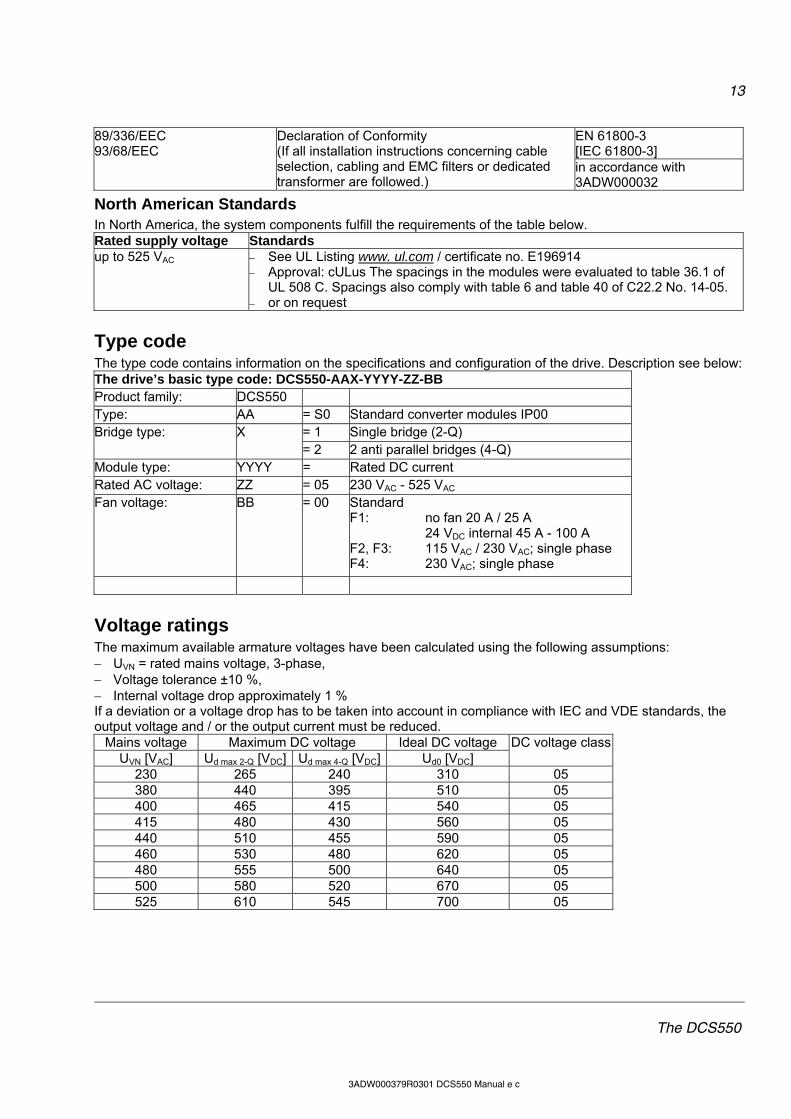
Type code The type code contains information on the specifications and configuration of the drive. Description see below: The drive’s basic type code: DCS550-AAX-YYYY-ZZ-BB Product family: DCS550 Type: AA = S0 Standard converter modules IP00
= 1 Single bridge (2-Q) Bridge type: X = 2 2 anti parallel bridges (4-Q)
Module type: YYYY = Rated DC current Rated AC voltage: ZZ = 05 230 VAC - 525 VAC Fan voltage: BB = 00 Standard
F1: no fan 20 A / 25 A 24 VDC internal 45 A - 100 A F2, F3: 115 VAC / 230 VAC; single phase F4: 230 VAC; single phase
Voltage ratings The maximum available armature voltages have been calculated using the following assumptions: UVN = rated mains voltage, 3-phase, Voltage tolerance ±10 %, Internal voltage drop approximately 1 % If a deviation or a voltage drop has to be taken into account in compliance with IEC and VDE standards, the output voltage and / or the output current must be reduced.
Mains voltage Maximum DC voltage Ideal DC voltage UVN [VAC] Ud max 2-Q [VDC] Ud max 4-Q [VDC] Ud0 [VDC]
DC voltage class
230 265 240 310 05 380 440 395 510 05 400 465 415 540 05 415 480 430 560 05 440 510 455 590 05 460 530 480 620 05 480 555 500 640 05 500 580 520 670 05 525 610 545 700 05
14
The DCS550
3ADW000379R0301 DCS550 Manual e c
The maximum available field voltage can be calculated using following formula:
%100
%10035.1
TOLUU VNF
, with:
UF = field voltage, UVN = mains voltage and TOL = tolerance of the mains voltage in %.
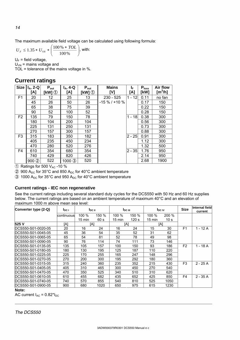
Current ratings Size IA, 2-Q
[A] Pout
[kW] ① IA, 4-Q
[A] Pout
[kW] ① Mains
[V] IF
[A] Ploss [kW]
Air flow [m3/h]
20 12 25 13 0.11 no fan 45 26 50 26 0.17 150 65 38 75 39 0.22 150
F1
90 52 100 52
1 - 12
0.28 150 135 79 150 78 0.38 300 180 104 200 104 0.56 300 225 131 250 131 0.73 300
F2
270 157 300 157
1 - 18
0.88 300 315 183 350 182 0.91 300 405 235 450 234 1.12 300
F3
470 280 520 276
2 - 25
1.32 500 610 354 680 354 1.76 950 740 429 820 426 2.14 950
F4
900 ② 522 1000 ③ 520
230 - 525 -15 % / +10 %
2 - 35
2.68 1900
① Ratings for 500 VAC -10 % ② 900 ADC for 35°C and 850 ADC for 40°C ambient temperature ③ 1000 ADC for 35°C and 950 ADC for 40°C ambient temperature
Current ratings - IEC non regenerative See the current ratings including several standard duty cycles for the DCS550 with 50 Hz and 60 Hz supplies below. The current ratings are based on an ambient temperature of maximum 40°C and an elevation of maximum 1000 m above mean sea level:
Converter type (2-Q) IDC I IDC II IDC III IDC IV Size Internal field current
continuous 100 % 15 min
150 % 60 s
100 % 15 min
150 % 120 s
100 % 15 min
200 % 10 s
525 V [A] [A] [A] [A]
DCS550-S01-0020-05 20 16 24 16 24 15 30 DCS550-S01-0045-05 45 36 54 35 52 31 62 DCS550-S01-0065-05 65 54 81 52 78 49 98 DCS550-S01-0090-05 90 76 114 74 111 73 146
F1 1 - 12 A
DCS550-S01-0135-05 135 105 157 100 150 93 186 DCS550-S01-0180-05 180 130 195 125 187 110 220 DCS550-S01-0225-05 225 170 255 165 247 148 296 DCS550-S01-0270-05 270 200 300 195 292 180 360
F2 1 - 18 A
DCS550-S01-0315-05 315 240 360 235 352 215 430 DCS550-S01-0405-05 405 310 465 300 450 270 540 DCS550-S01-0470-05 470 350 525 340 510 310 620
F3 2 - 25 A
DCS550-S01-0610-05 610 455 682 435 652 425 850 DCS550-S01-0740-05 740 570 855 540 810 525 1050 DCS550-S01-0900-05 900 680 1020 650 975 615 1230
F4 2 - 35 A
Note: AC current IAC = 0.82*IDC
15
The DCS550
3ADW000379R0301 DCS550 Manual e c
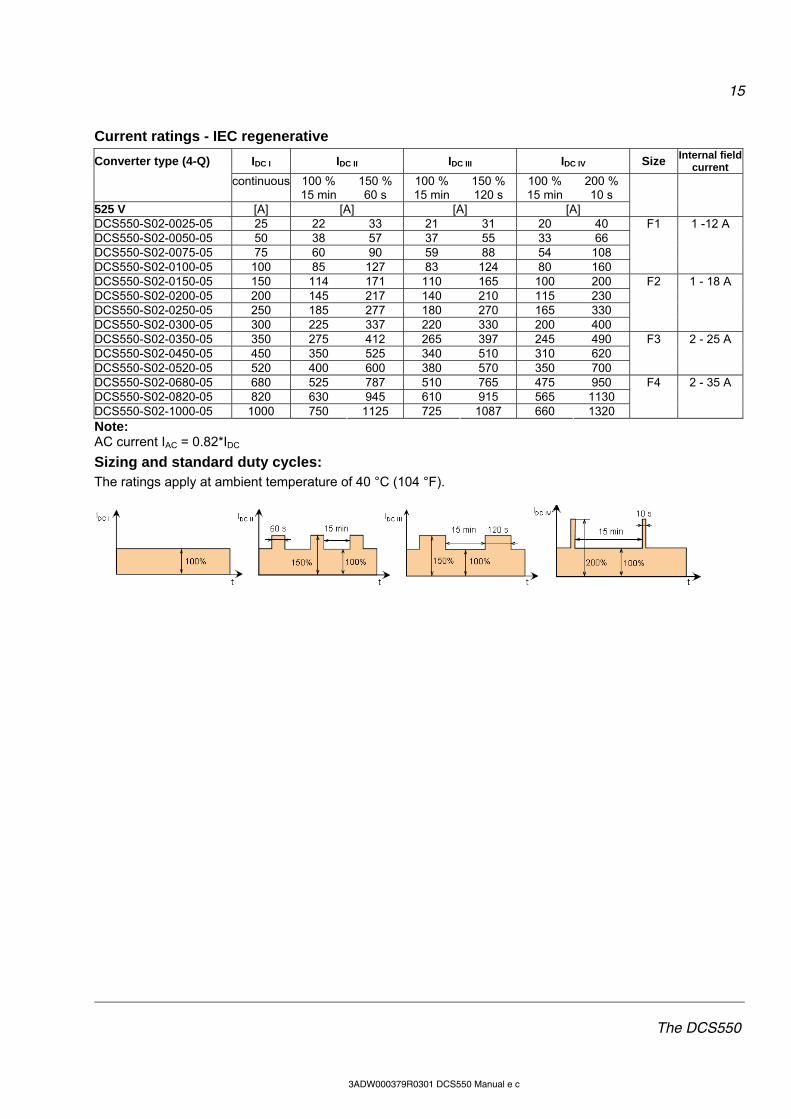
Current ratings - IEC regenerative
Converter type (4-Q) IDC I IDC II IDC III IDC IV Size Internal field current
continuous 100 % 15 min
150 % 60 s
100 % 15 min
150 % 120 s
100 % 15 min
200 % 10 s
525 V [A] [A] [A] [A]
DCS550-S02-0025-05 25 22 33 21 31 20 40 DCS550-S02-0050-05 50 38 57 37 55 33 66 DCS550-S02-0075-05 75 60 90 59 88 54 108 DCS550-S02-0100-05 100 85 127 83 124 80 160
F1 1 -12 A
DCS550-S02-0150-05 150 114 171 110 165 100 200 DCS550-S02-0200-05 200 145 217 140 210 115 230 DCS550-S02-0250-05 250 185 277 180 270 165 330 DCS550-S02-0300-05 300 225 337 220 330 200 400
F2 1 - 18 A
DCS550-S02-0350-05 350 275 412 265 397 245 490 DCS550-S02-0450-05 450 350 525 340 510 310 620 DCS550-S02-0520-05 520 400 600 380 570 350 700
F3 2 - 25 A
DCS550-S02-0680-05 680 525 787 510 765 475 950 DCS550-S02-0820-05 820 630 945 610 915 565 1130 DCS550-S02-1000-05 1000 750 1125 725 1087 660 1320
F4 2 - 35 A
Note: AC current IAC = 0.82*IDC
Sizing and standard duty cycles: The ratings apply at ambient temperature of 40 °C (104 °F).
16
The DCS550
3ADW000379R0301 DCS550 Manual e c
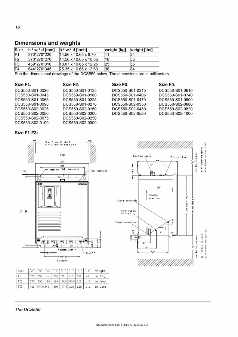
Dimensions and weights Size h * w * d [mm] h * w * d [inch] weight [kg] weight [lbs] F1 370*270*220 14.56 x 10.65 x 8.70 11 24 F2 370*270*270 14.56 x 10.65 x 10.65 16 35 F3 459*270*310 18.07 x 10.65 x 12.25 25 55 F4 644*270*345 25.35 x 10.65 x 13.60 38 84 See the dimensional drawings of the DCS550 below. The dimensions are in millimeters.
Size F1: Size F2: Size F3: Size F4: DCS550-S01-0020 DCS550-S01-0045 DCS550-S01-0065 DCS550-S01-0090 DCS550-S02-0025 DCS550-S02-0050 DCS550-S02-0075 DCS550-S02-0100
DCS550-S01-0135 DCS550-S01-0180 DCS550-S01-0225 DCS550-S01-0270 DCS550-S02-0150 DCS550-S02-0200 DCS550-S02-0250 DCS550-S02-0300
DCS550-S01-0315 DCS550-S01-0405 DCS550-S01-0470 DCS550-S02-0350 DCS550-S02-0450 DCS550-S02-0520
DCS550-S01-0610 DCS550-S01-0740 DCS550-S01-0900 DCS550-S02-0680 DCS550-S02-0820 DCS550-S02-1000
Size F1-F3:
17
The DCS550
3ADW000379R0301 DCS550 Manual e c
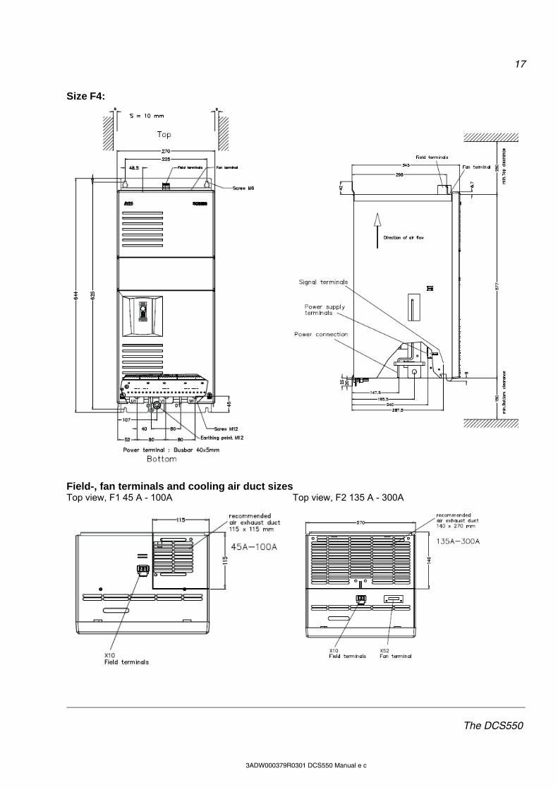
Size F4:
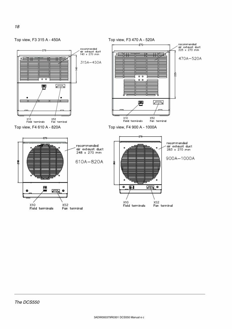
Field-, fan terminals and cooling air duct sizes Top view, F1 45 A - 100A Top view, F2 135 A - 300A
18
The DCS550
3ADW000379R0301 DCS550 Manual e c
Top view, F3 315 A - 450A Top view, F3 470 A - 520A
Top view, F4 610 A - 820A Top view, F4 900 A - 1000A

19
Mechanical installation
3ADW000379R0301 DCS550 Manual e c
Mechanical installation Chapter overview This chapter describes the mechanical installation of the DCS550.
Unpacking the unit Open the box, take out shock dampers, separate manual and
accessories. Attention: Do not lift the drive by the cover!
Delivery check Check that there are no signs of damage. Before attempting installation and operation, check the information on the nameplate of the converter module to verify that the unit is of the correct type. The label includes an IEC rating, cULus and CE markings, a type code and a serial number, which allow individual identification of each unit. The remaining digits complete the serial number so that there are no two units with the same serial number. See an example nameplate below.
ABB Automation Products GmbH U1 3 525 V U2 610 V Made in Germany
Type: DCS550-S02-0075-05-00-00 I1 62 A I2 75 A
f1 50/60 Hz If 18 A
Ser No: 0025421A10524264
SCCR 65 kA Fan ----
Production year 2010 and week 52
Before installation Install the drive in an upright position with the cooling section facing a wall. Check the installation site according to the requirements below. Refer to chapter Dimensions for frame details.
Requirements for the installation site See chapter Technical data for the allowed operation conditions of the drive. Wall The wall should be as close to vertical as possible, of non-flammable material and strong enough to carry the weight of the unit. Check that there is nothing on the wall to inhibit the installation. Floor The floor or material below the installation must be non-flammable. Free space around the unit Around the unit free space is required to enable cooling airflow, service and maintenance see chapter Dimensions.
Rated input voltage Rated input current
Rated output current Rated internal field exciter current Rated fan voltage
20
Mechanical installation
3ADW000379R0301 DCS550 Manual e c
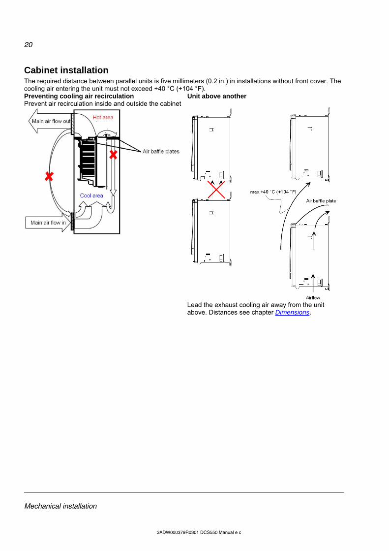
Cabinet installation The required distance between parallel units is five millimeters (0.2 in.) in installations without front cover. The cooling air entering the unit must not exceed +40 °C (+104 °F). Preventing cooling air recirculation Unit above another Prevent air recirculation inside and outside the cabinet
Lead the exhaust cooling air away from the unit
above. Distances see chapter Dimensions.

21
Planning the electrical installation
3ADW000379R0301 DCS550 Manual e c
Planning the electrical installation Chapter overview This chapter contains the instructions that must be followed when selecting the motor, cables, protections, cable routing and way of operation for the drive system. Always follow local regulations. This chapter applies to all DCS550 converter modules. Attention: If the recommendations given by ABB are not followed, the drive may experience problems that the warranty does not cover. See also Technical Guide.

22
Planning the electrical installation
3ADW000379R0301 DCS550 Manual e c
Drive connection and wiring example The drive configuration with a reduced set of components gives the same control performance, but a lower degree of monitoring functions.
X96
:
DO
8
12
X52
:1
23
U1
W1
V1PE
K1
K20
K21
K20
K1X
96:1
X96
:2
L1L2
L3
525V
, 50
/60H
z
F1
M 1~
K21
C 1
D 1
AIT
AC
AI1
AI2
AI3
AI4
+10
V-1
0VA
O1
AO
2I A
CT
DI1
DI2
DI3
DI4
DI5
DI6
DI7
DI8
+24
VD
O1
DO
2D
O3
DO
4_
__
__
++
++
+E
ncod
er
T
EM
GN
DG
ND
GN
DG
ND
GN
DN
CN
CN
C
X1:
12
34
56
78
910
X2:
12
34
56
78
910
X4:
12
34
56
78
910
X5:
12
34
56
78
1...1
0X
3:
+_
+ _
K1
K20
K21
F5
1 2F
81 2
F7
1 2
K1
13
5
24
6
L1
F+
F-
X10:
L1N
21
43
65F
6
I >I >
I >
13 14
UV
W
M 3~
DCS550_ans_2_c.dsf
*
see
6.03
bit 7
2
1
6
5
X99
:1
2
Con
trol
boa
rd (
SD
CS
-CO
N-F
)
Pow
er s
uppl
y(S
DC
S-P
IN-F
)
DC
S55
0C
onve
rter
mod
ule
ON
OF
FS
TO
P
ST
AR
T
OnB
oard
fie
ld e
xcite
r(S
DC
S-B
AB
-F)
dep
endi
ng
on t
he u
nit
type
ano
the
r co
nfig
ura
tion
is p
oss
ible
the
po
larit
ies
are
sho
wn
for
mot
or o
pera
tion
if th
ere
are
inte
rmed
iate
te
rmin
als
Aux
. su
pply
* se
t by
[5
0.12
], [
50.
13]
Le
ge
nd
fuse
reac
tor
23
Planning the electrical installation
3ADW000379R0301 DCS550 Manual e c
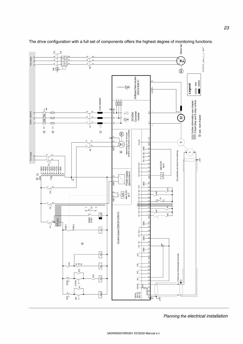
The drive configuration with a full set of components offers the highest degree of monitoring functions.
X96
:
DO
8
12
X52
:12
3U
1W
1V1
PE
K1
F6
K20
K21
K20
K1X
96:1
X96
:2
L1L2
L3
F1
M 1~
F2
3 4
1 2
T2
690
V66
0V60
0V57
5V52
5V50
0V45
0V41
5V40
0V38
0V
115V
230V
K15
K15
S11 2
K6
K8
K10
K21
C 1
D 1
AIT
AC
AI1
AI2
AI3
AI4
+10
V-1
0VA
O1
AO
2I A
CT
DI1
DI2
DI3
DI4
DI5
DI6
DI7
DI8
+24
VD
O1
DO
2D
O3
DO
4_
__
__
++
++
+E
ncod
er
T
EM
GN
DG
ND
GN
DG
ND
GN
DN
CN
CN
C
X1:
12
34
56
78
910
X2:
12
34
56
78
910
X4:
12
34
56
78
910
X5:
12
34
56
78
1...1
0X
3:
+_
+ _
K1
K20
K21
K6
K8
1 2S1
K10
24
6
13
5K
6
F5
1 2F
81 2
F7
1 2
21
43
65F
6
I >I >
I >
13 14
UV
W
M 3~
K1
13
5
24
6
L1
1 2
3 4K
8
13 14
X10
: F+
F-
L1L2
L1L2
L3
DCS550_ans_1_c.dsf
DC
S55
0
*
(SD
CS
-PIN
-F)
Aux
sup
ply
Aux
sup
ply
5525
V, 5
0/6
0Hz
EM
C F
ilter
E1
see
6.0
3b
it 7
(SD
CS
-BA
B-F
)
see
6.0
3b
it 0
furt
her
info
rmat
ion
se
e ch
apt
er
5 S
tart
,Sto
p an
d E
-sto
p c
ont
rol
3 2 1
4
5
6
6se
e n
ext
ch
apt
er
X99
:1
2
Con
tro
l bo
ard
(SD
CS
-CO
N-F
)
Po
we
r su
pp
ly
Co
nve
rter
mo
dul
e
ON
OF
FS
TO
P
ST
AR
T
EM
ER
.S
TO
P
On
Boa
rd fi
eld
exc
iter
dep
endi
ng
on t
he u
nit
type
ano
the
r co
nfig
ura
tion
is p
oss
ible
the
po
larit
ies
are
sho
wn
for
mot
orin
gif
the
re a
re in
term
edia
te t
erm
inal
s
* se
t by
[5
0.12
], [
50.
13]
Le
ge
nd fuse
reac
tor
Lin
e re
act
or
Mot
or f
an
24
Planning the electrical installation
3ADW000379R0301 DCS550 Manual e c
Installation components
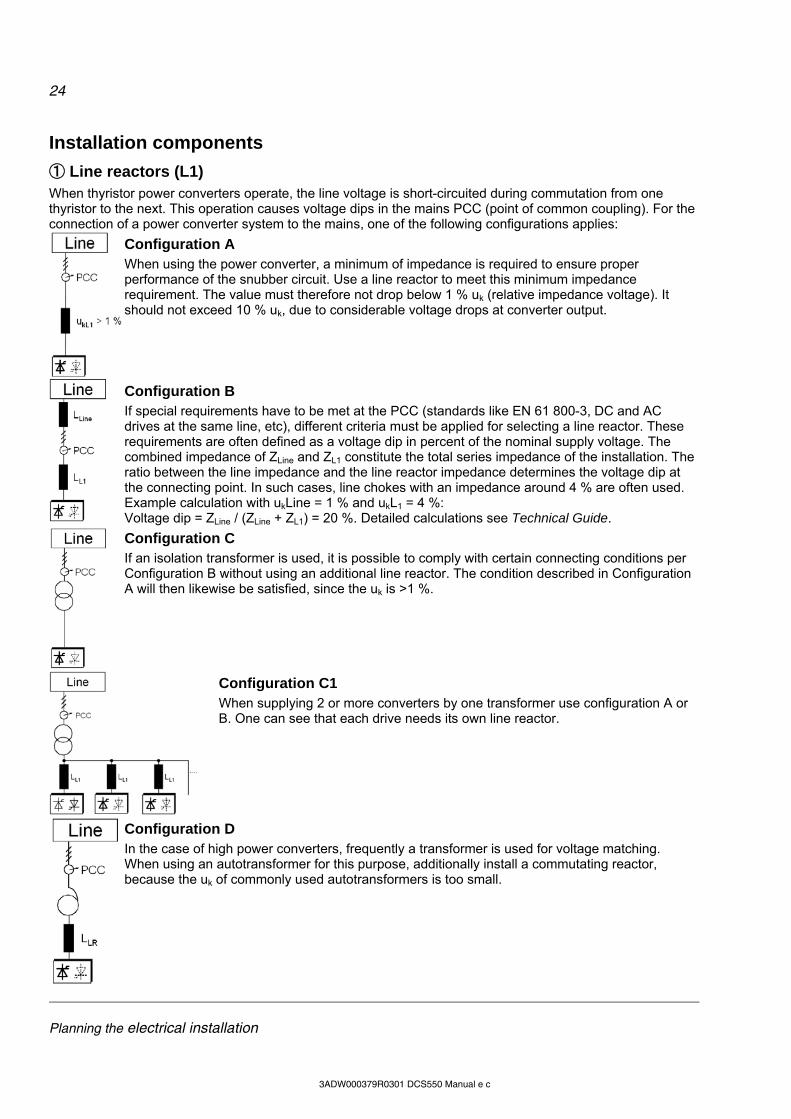
① Line reactors (L1) When thyristor power converters operate, the line voltage is short-circuited during commutation from one thyristor to the next. This operation causes voltage dips in the mains PCC (point of common coupling). For the connection of a power converter system to the mains, one of the following configurations applies:
Configuration A When using the power converter, a minimum of impedance is required to ensure proper performance of the snubber circuit. Use a line reactor to meet this minimum impedance requirement. The value must therefore not drop below 1 % uk (relative impedance voltage). It should not exceed 10 % uk, due to considerable voltage drops at converter output.
Configuration B If special requirements have to be met at the PCC (standards like EN 61 800-3, DC and AC drives at the same line, etc), different criteria must be applied for selecting a line reactor. These requirements are often defined as a voltage dip in percent of the nominal supply voltage. The combined impedance of ZLine and ZL1 constitute the total series impedance of the installation. The ratio between the line impedance and the line reactor impedance determines the voltage dip at the connecting point. In such cases, line chokes with an impedance around 4 % are often used. Example calculation with ukLine = 1 % and ukL1 = 4 %: Voltage dip = ZLine / (ZLine + ZL1) = 20 %. Detailed calculations see Technical Guide.
Configuration C If an isolation transformer is used, it is possible to comply with certain connecting conditions per Configuration B without using an additional line reactor. The condition described in Configuration A will then likewise be satisfied, since the uk is >1 %.
Configuration C1 When supplying 2 or more converters by one transformer use configuration A or B. One can see that each drive needs its own line reactor.
Configuration D In the case of high power converters, frequently a transformer is used for voltage matching. When using an autotransformer for this purpose, additionally install a commutating reactor, because the uk of commonly used autotransformers is too small.

25
Planning the electrical installation
3ADW000379R0301 DCS550 Manual e c
② Semiconductor fuses (F1) Aspects of fusing for the armature circuit of DC drives
Unit configuration Protection elements such as fuses or overcurrent trip circuits are required in all cases to protect against further damage. In some configurations, this will entail the following questions: 1. Where to place which protective element? 2. In the event of what faults will the element in question provide protection against damage?
The figure shows the arrangement of the switch-off elements in the armature circuit. Further information is available in the Technical Guide.
Conclusion Never use standard fusing instead of semi-conductor fusing in order to save money on the installation. In the event of a fault condition, the small amount of money saved can cause the semiconductors or other devices to explode and cause fires. Adequate protection against short circuit and earth fault, as depicted in the EN50178 standard, is possible only with appropriate semiconductor fuses. Use DC fuses (2 of them) for all regenerative drives to protect the motor in case of a fault during regeneration. DC fuses must be rated for the same current and voltage as AC fuses, thus follows DC fuses = AC fuses.
③ EMC filters (E1)
Filter in a grounded line (earthed TN or TT network) The filters are suitable for grounded lines only, for example in public European 400 V lines. According to EN 61800-3 filters are not needed in insulated industrial networks with own supply transformers. Furthermore, they could cause safety risks in such floating lines (IT networks). According to EN 61800-3 filters are not needed in industrial zone (Second Environment) for DCS550 drives above 100 ADC rated current. For rated currents below 100 ADC, the filter requirement is identical to Light Industry (First Environment).
Three-phase filters EMC filters are necessary to fulfill the standard for emitted interference if a converter shall be run at a public low voltage line, in Europe for example with 400 V. Such lines have a grounded neutral conductor. ABB offers suitable three-phase filters for 400 VAC. For 440 VAC public low voltage lines outside Europe 500 VAC filters are available. Optimize the filters for the real motor currents: iFilter = 0.8 * iMot max; the factor 0.8 respects the current ripple. Lines with 500 VAC and higher are not public. They are local networks inside factories, and they do not supply sensitive electronics. Therefore, converters do not need EMC filters if they shall run with 500 VAC and more.
26
Planning the electrical installation
3ADW000379R0301 DCS550 Manual e c
EMC filters Further information is available in the Technical Guide.
The paragraphs below describe selection of the electrical components in conformity with the EMC Guideline. The aim of the EMC Guideline is, as the name implies, to achieve electromagnetic compatibility with other products and systems. The guideline ensures that the emissions from the product concerned are so low that they do not impair another product's interference immunity. In the context of the EMC Guideline, two aspects must be borne in mind: the product's interference immunity and
the product's actual emissions. The EMC Guideline expects EMC to be taken into account when developing a product; however, EMC cannot be designed in, it can only be quantitatively measured. Notes on EMC conformity: The conformity procedure is the responsibility of both the power converter's supplier and the manufacturer of the machine or system concerned, in proportion to their share in expanding the electrical equipment involved.
First environment (residential area with light industry) with PDS category C2 Not applied, since category C1 (general distribution sales channel) excluded
Not applicable satisfied satisfied

27
Planning the electrical installation
3ADW000379R0301 DCS550 Manual e c
For compliance with the protection objectives of the German EMC Act (EMVG) in systems and machines, the following EMC standards must be satisfied: Product Standard EN 61800-3 EMC standard for drive systems (PowerDriveSystem), interference immunity and emissions in residential areas, enterprise zones with light industry and in industrial facilities. This standard must be complied with in the EU for satisfying the EMC requirements for systems and machines!
For emitted interference, the following apply: EN 61000-6-3 Specialized basic standard for emissions in light industry
can be satisfied with special features (mains filters, screened power cables) in the lower rating range *(EN 50081-1).
EN 61000-6-4 Specialized basic standard for emissions in industry *(EN 50081-2)
For interference immunity, the following apply: EN 61000-6-1 Specialized basic standard for interference immunity in
residential areas *(EN 50082-1) EN 61000-6-2 Specialized basic standard for interference immunity in
industry. If this standard is satisfied, then the EN 61000-6-1 standard is automatically satisfied as well *(EN 50082-2).
* The old generic standards are given in brackets
Standards Second environment (industry) with PDS categories C3, C4 EN 61800-3
Not applicable EN 61000-6-3 satisfied on customer's
request satisfied EN 61000-6-4
satisfied EN 61000-6-2 EN 61000-6-1
Classification The following overview utilizes the terminology and indicates the action required in accordance with Product Standard EN 61800-3 For the DCS550 series, the limit values for emitted interference are complied with, provided the measure indicated is carried out. PDS of category C2 (formerly restricted distribution in first environment) is intended to be installed and commissioned only by a professional (person or organization with necessary skills in installing and/or commissioning PDS including their EMC aspects). For power converters without additional components, the following warning applies: This is a product of category C2 under IEC 61800-3:2004. In a domestic/residential environment, this product may cause radio interference in which case supplementary mitigation measures may be required. The field supply is not depicted in this overview diagram. For the field current cables, the same rules apply as for the armature-circuit cables.

28
Planning the electrical installation
3ADW000379R0301 DCS550 Manual e c
④ Auxiliary transformer (T2) for converter electronics and fan The converter module requires various auxiliary voltages, e.g. the module’s electronics and cooling fans requires either a single-phase supply of 115 VAC or 230 VAC. The auxiliary transformer (T2) is designed to supply the module’s electronics and cooling fans.
⑤ Start, Stop and E-stop control The relay logic is splitted into three parts:
1. Generation of On / Off and Start / Stop commands: The commands represented by K20 and K21 (latching interface relay) can also be generated by a PLC and transferred to the terminals of the converter either by relays, using galvanic isolation or directly via 24 V signals. There is no need to use hardwired signals. Transfer these commands via serial communication. Even a mixed solution can be realized by selecting different possibilities for the one or the other signal (see parameter group 11).
2. Generation of control and monitoring signals: Control the main contactor K1 for the armature circuit by the dry contact of DO8 located on the SDCS-PIN-F. The status of motor (K6) and converter (K8) fans can be monitored by means of MotFanAck (10.06).
3. Off2 (Coast Stop) and Off3 (E-stop): Beside On / Off and Start / Stop the drive is equipped with two additional stop functions Off2 (Coast Stop) and Off3 (E-stop) according to Profibus standard. Off3 (E-stop) is scalable via E StopMode (21.04) to perform stop category 1. Connect this function to the E-stop push button without any time delay. In case of E StopMode (21.04) = RampStop the K15 timer relay must be set longer than E StopRamp (22.04). For E StopMode (21.04) = Coast the drive opens the main contactor immediately. Off2 (Coast Stop) switches the DC current off as fast as possible and prepares the drive to open the main contactor or drop the mains supply. For a normal DC motor load the time to force the DC current to zero is below 20 ms. This function should be connected to all signals and safety functions opening the main contactor. This function is important for 4-Q drives. Do not open main contactor during regenerative current. The correct sequence is:
1. switch off regenerative current, 2. then open the main contactor.
In case the E-stop push button is hit, the information is transferred to the converter via DI5. In case E StopMode (21.04) = RampStop or TorqueLimit the converter will decelerate the motor and then open the main contactor. If the drive has not finished the function within the K15 timer setting, the drive must get the command to switch off the current via K16. After the K16 timer has elapsed, the main contactor is opened immediately, independent of the drive’s status.
K16
K15 K16
K15
DI4
K15
X4:4
SDCS-CON-F
S1
1
2
E-STOP
electricaldisconnect
(coast)
Blockcurrentcommand
E-STOP
speed
Block current control
K1 main contactor
E-Stop ramp Coast
Timer K15
Timer K16
29
Planning the electrical installation
3ADW000379R0301 DCS550 Manual e c
Cabling
Thermal overload and short-circuit protection The drive protects itself and the input and motor cables against thermal overload when the cables are dimensioned according to the nominal current of the drive.
Power cables Dimension the mains and motor cables according to local regulations. The cables must: 1. be able to carry the DCS550 load current, 2. be rated for at least 60°C (140°F), 3. fulfill short-circuit protection, 4. be rated according permissible touch voltage appearing under fault conditions (so that the fault point
voltage will not rise too high when an earth fault occurs) and 5. be screened according to safety regulations.
Mains cable (AC line cable) short-circuit protection Always protect the input cable with fuses. Size the fuses according to local safety regulations, appropriate input voltage and the rated current of the drive, see chapter Technical Data. High-speed semiconductor fuses provide short-circuit protection, but do not provide thermal overload protection.
Control / signal cables Used screened cables for digital signals, which are longer than 3 m and all cables for analogue signals. Connect each screen at both ends by metal clamps or comparable means directly on clean metal surfaces, if both earthing points belong to the same earth line. Otherwise, connect a capacitor to earth on one end. In the converter cabinet this kind of connection must be made directly on the sheet metal close to the terminals and if the cable comes from outside also on the PE bar. At the other end of the cable, connect the screen well with the housing of the signal emitter or receiver.
Connection of cable screens with metal clamps to the metal surface of the electronic tray.
A double shielded twisted pair cable, e.g. JAMAK by NK Cables, Finland), must be used for analogue signals and the pulse encoder signals. Employ one individually shielded pair for each signal. Do not use common return for different analogue signals. A double shielded cable is the best alternative for low voltage digital signals but single shielded twisted multi pair cable is also usable.

30
Planning the electrical installation
3ADW000379R0301 DCS550 Manual e c
Double shielded twisted pair cable Single shielded twisted multi pair cable
Pairs should be twisted as close to terminals as possible. Run analogue and digital signals in separate, screened cables. Relay-controlled signals, providing their voltage does not exceed 48 V, can be run in the same cables as
digital input signals. It is recommended that the relay-controlled signals be run as twisted pairs too. Attention: Never run 24 VDC and 115 / 230 VAC signals in the same cable!
Co-axial cables Recommendations for use with DCS550: 75 Ω type, RG59 cable with diameter 7 mm or RG11 cable 11 mm and a maximum cable length of 300 m.
Relay cables Cable types with braided metallic screens (e.g. ÖLFLEX, LAPPKABEL, Germany) has been tested and approved by ABB.
DCS Control Panel cable The cable connecting the DCS Control Panel to the DCS550 converter module must not exceed 3 meters (10 ft.). The cable type tested and approved by ABB is included in the DCS Control Panel option kits.
Fieldbus cables Fieldbus cables can be quite different, depending on the fieldbus type. Please refer to control / signal cables and co-axial cables.
Connection example in accordance with EMC The example shows the principle structure of a DC drive and its connections. It is not a binding recommendation, and it cannot respect all conditions of a plant. Therefore, consider each drive separately and with respect to the special application. Additionally take the general installation and safety rules into account:

31
Planning the electrical installation
3ADW000379R0301 DCS550 Manual e c
A F
C1 / D1 F+ / F-
M
A1 A2
F1
F2
A1 A2
F1
F2
L1
L2
L3
U1
V1
W1C1
D1
F-F+
PE
PE
PE
A
F
A F
T
AF
AF
C1 / D1 F+ / F-
PE
PE
I/O
Mounting plate
DC motor
Tac
ho
ScreensContact to the motorhousing at the whole
screen perimeter
Filter
Mounting plate with PE busbar and terminals
DC motor
Tac
ho
Scr
een
OnBoardfield
Armature and field cables with screens for
"first environment"
Armature and field cables without
screens suitable for "second
environment"
Hint: The armature current cable must contain a third wire for a PE connection if the copper cross section of the screen cannot fulfil the PE safety demands.
terminals on SDCS-CON-F
Mounting plate with PE busbar and terminals
terminals on SDCS-CON-F
inte
rmed
iate
term
inal
s
pre
fere
d s
olu
tion
PE bar
to filter, choke...
directly to
lower edgeof the PCB
carrier
TachoEncoder, analogue I/O,and digital I/O (>3 m)
TachoEncoder, analogue I/O,and digital I/O (>3 m)
directly to
lower edgeof the PCB
carrier
to filter, choke...
inte
rmed
iate
term
inal
s
pref
ered
so
lutio
n
PE bar

32
Planning the electrical installation
3ADW000379R0301 DCS550 Manual e c
⑥ Cooling fans
Fan assignment for DCS550: Converter type Size Configuration Fan type DCS550-S01-0020, …, DCS550-S02-0025
- No fan, convection cooled
DCS550-S01-0045, …, DCS550-S02-0100
F1
1 1 x 3110 KL-05W (internal 24 VDC)
DCS550-S01-0135, …, DCS550-S02-0300
F2
DCS550-S01-0315, …, DCS550-S02-0450
2 2 x 4715 MS-12T (115 VAC / 230 VAC)
DCS550-S01-0470, …, DCS550-S02-0520
F3
3 2 x 4715 MS-12T (115 VAC / 230 VAC) 2 x 3115 FS-12T (115 VAC / 230 VAC)
DCS550-S01-0610, …, DCS550-S02-0820
1 x W2E200 (230 VAC)
DCS550-S01-0900, …, DCS550-S02-1000
F4 4
1 x W2E250 (230 VAC)
Fan data for DCS550: Fan 3110 KL-05W 4715 MS-12T 3115 FS-12T W2E200 W2E250 Rated voltage [VAC] 24 VDC ① 115; 1~ 115; 1~ 230; 1~ 230; 1~
Tolerance [%] +15 / -50 ± 10 ± 10 +6 / -10 +6 / -10 Frequency [Hz] - 50 60 50 60 50 60 50 60 Power consumption [W] 2.88 16 13 9.5 8.0 64 80 135 185 Current consumption [A] 0.12 0.2 0.17 0.075 0.060 0.29 0.35 0.59 0.82 Blocking current [A] - < 0.3 < 0.26 < 0.085 < 0.075 < 0.7 < 0.8 < 0.9 < 0.9 Air flow [m3/h] freely blowing 66 156 180 47.5 55 925 1030 1860 1975 Max. ambient temp. [°C] < 70 < 60 < 70 < 70 < 60 Useful lifetime of grease approximately
70,000 h / 25° approximately 40,000 h / 60°
approximately 50,000 h / 20°
approximately 40,000 h / 60°
Protection DC Impedance ② Impedance Internal temperature detector
① Internally connected ② Increased losses due to increased current with a blocked rotor will not result in a winding temperature, higher than permissible for the insulation class being involved.
Fan connection for DCS550:
1 2 3X52: 4 5
L N230 VAC
1 2 3X52: 4 5
L N115 VAC
M~
1 2 3X52:
M~
4 5
M55 M56
M~
1 2 3X52:
M~
4 5
M55 M56
M~
M~
M57 M58
M55M~
1 2 3 4 5X52:
L N
L N
1 2 3X52: 4 5
L N230 VAC
1 2 3X52: 4 5
L N115 VAC
only 230 VAC
M55
M~
X19:
SDCS-PIN-F
Configuration 4
F4
Configuration 3
F3
Configuration 2
F2, F3
Configuration 1
F1
Terminals are located on top ofthe converter housing
fan_con_e.dsf
33
Electrical installation
3ADW000379R0301 DCS550 Manual e c
Electrical installation Chapter overview This chapter describes the electrical installation procedure of the DCS550.
WARNING! A qualified electrician may only carry out the work described in this chapter. Follow the Safety instructions on the first pages of this manual. Ignoring the safety instructions can cause injury or death. Make sure that the drive is disconnected from the mains (input power) during installation. If the drive was already connected to the mains, wait for 5 min. after disconnecting mains power. Further information is available in the Technical Guide.
Checking the insulation of the assembly Every drive has been tested for insulation between the main circuit and the chassis (2500 V rms 50 Hz for 1 second) at the factory. Therefore, do not make any voltage tolerance or insulation resistance tests (e.g. hi-pot or megger) on any part of the drive. Check the insulation of the assembly as follows.
WARNING! Check the insulation before connecting the drive to the mains. Make sure that the drive is disconnected from the mains (input power).
1. Check that the motor cable is disconnected from the drive output terminals
C1, D1, F+ and F-. 2. Measure the insulation resistances of the motor cable and the motor
between each circuit (C1, D1) / (F+, F-) and Protective Earth (PE) by using a measuring voltage of 1 kV DC. The insulation resistance must be higher than 1 MΩ.
Connection of a motor temperature sensor to the drive I/O
WARNING! IEC 60664 requires double or reinforced insulation between live parts and the surface of accessible parts of electrical equipment that are either nonconductive or conductive but not connected to the protective earth. To fulfill this requirement, the connection of a thermistor (or other similar components) to the inputs of the drive can be implemented by 3 alternate ways: 1. there is double or reinforced insulation between the thermistor and live parts of the motor, 2. circuits connected to all digital and analogue inputs of the drive are protected against contact
and insulated with basic insulation (the same voltage level as the drive main circuit) from other low voltage circuits or
3. an external thermistor relay is used. Rate the insulation of the relay for the same voltage level as the main circuit of the drive.
34
Electrical installation
3ADW000379R0301 DCS550 Manual e c
Power connections
IT (ungrounded) systems Don’t use EMC filters in IT systems:
The screen winding of an existing dedicated transformers must be grounded:
For installations without low voltage switch (e.g. contactor, air-circuit-breaker) use an overvoltage protection on the secondary side of the mains transformer.
The voltage shift of the isolated supply must not be larger than the voltage shift in case on an earth fault:
Supply voltage Check voltage levels of: auxiliary voltage (X99 on SDCS-PIN-F), cooling fan terminals and mains voltage connected to U1, V1, W1.
Connecting the power cables Check: Grounding and screening of power cables see chapter Cabling. Cross sectional areas and tightening torques of power cable, see chapter Cross-sectional areas -
Tightening torques.
Cross-sectional areas - Tightening torques Recommended cross-sectional area according to DINVDE 0276-1000 and DINVDE 0100-540 (PE) trefoil arrangement, up to 50°C ambient temperature. The necessary wire torque at 60°C wire temperature is the same as recommended in the following tables.
Excitation: Size F1 F2 F3 F4 DC output current 12 A 18 A 25 A 35 A max. cross sectional area 6 mm²/ AWG 10 6 mm²/ AWG 10 6 mm²/ AWG 10 6 mm²/ AWG 10 min. cross sectional area 2.5 mm²/ AWG 16 4 mm²/ AWG 13 6 mm²/ AWG 11 6 mm²/ AWG 10 Tightening torque 1.5, ..., 1.7 Nm
35
Electrical installation
3ADW000379R0301 DCS550 Manual e c
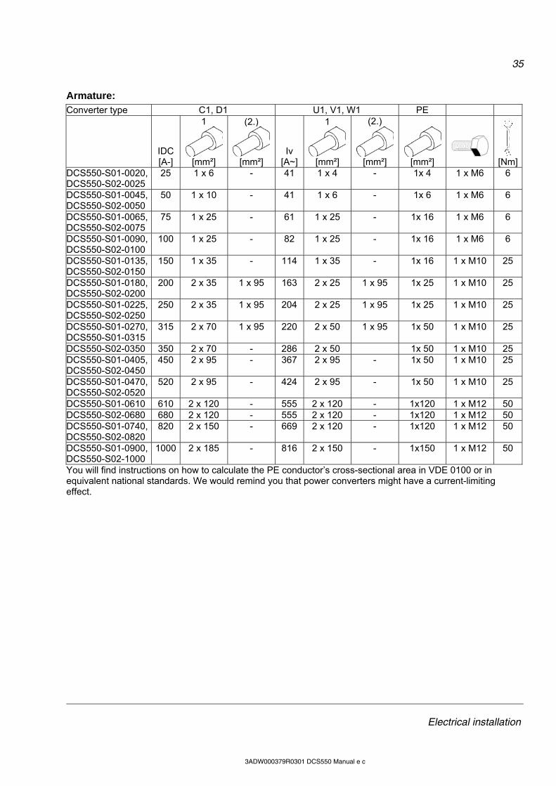
Armature: Converter type C1, D1 U1, V1, W1 PE
IDC [A-]
1
[mm²]
(2.)
[mm²]
Iv
[A~]
1
[mm²]
(2.)
[mm²]
[mm²]
[Nm]DCS550-S01-0020, DCS550-S02-0025
25 1 x 6 - 41 1 x 4 - 1x 4 1 x M6 6
DCS550-S01-0045, DCS550-S02-0050
50 1 x 10 - 41 1 x 6 - 1x 6 1 x M6 6
DCS550-S01-0065, DCS550-S02-0075
75 1 x 25 - 61 1 x 25 - 1x 16 1 x M6 6
DCS550-S01-0090, DCS550-S02-0100
100 1 x 25 - 82 1 x 25 - 1x 16 1 x M6 6
DCS550-S01-0135, DCS550-S02-0150
150 1 x 35 - 114 1 x 35 - 1x 16 1 x M10 25
DCS550-S01-0180, DCS550-S02-0200
200 2 x 35 1 x 95 163 2 x 25 1 x 95 1x 25 1 x M10 25
DCS550-S01-0225, DCS550-S02-0250
250 2 x 35 1 x 95 204 2 x 25 1 x 95 1x 25 1 x M10 25
DCS550-S01-0270, DCS550-S01-0315
315 2 x 70 1 x 95 220 2 x 50 1 x 95 1x 50 1 x M10 25
DCS550-S02-0350 350 2 x 70 - 286 2 x 50 1x 50 1 x M10 25 DCS550-S01-0405, DCS550-S02-0450
450 2 x 95 - 367 2 x 95 - 1x 50 1 x M10 25
DCS550-S01-0470, DCS550-S02-0520
520 2 x 95 - 424 2 x 95 - 1x 50 1 x M10 25
DCS550-S01-0610 610 2 x 120 - 555 2 x 120 - 1x120 1 x M12 50 DCS550-S02-0680 680 2 x 120 - 555 2 x 120 - 1x120 1 x M12 50 DCS550-S01-0740, DCS550-S02-0820
820 2 x 150 - 669 2 x 120 - 1x120 1 x M12 50
DCS550-S01-0900, DCS550-S02-1000
1000 2 x 185 - 816 2 x 150 - 1x150 1 x M12 50
You will find instructions on how to calculate the PE conductor’s cross-sectional area in VDE 0100 or in equivalent national standards. We would remind you that power converters might have a current-limiting effect.

36
Electrical installation
3ADW000379R0301 DCS550 Manual e c
Drive interfaces
Location R-type options and interfaces Tighten the screws to secure the extension modules.
X33:DCS Control Panel
X9: slot1 for fieldbusses or I/O extension X11: slot3 for I/O extension X34: DriveWindow Light
Pulse encoder connection
Power supply for pulse encoders The SDCS-CON-F uses jumper S4 to select either the 5 V or 24 V supply voltage.
Encoder supply Jumper S4 setting Hardware configuration 5 V 10 - 11 sense controlled 24 V 11 - 12 no sense
Use the sense feedback when the power supply level of a differential pulse encoder only is 5 V. Commissioning hint: If the drive’s measured direction of rotation is wrong or does not correspond to the measured EMF speed, F522 SpeedFb may appear during start-up. If necessary correct it by exchanging the field connections F1 and F2 or exchange tracks A+ & A-.
A+
A-
B+
B-
Z+
Z-
+U
0V
X3:2
X3:1
X3:4
X3:3
X3:6
X3:5
X3:7
X3:10
X3:8
X3:9
SDCS-CON-F
GND
ChA+
ChA-
ChB+
ChB-
ChZ+
ChZ-
DIFFERENTIAL
+5 V or +24 V
Sense +5 V
Sense GND
= twisted pair
37
Electrical installation
3ADW000379R0301 DCS550 Manual e c
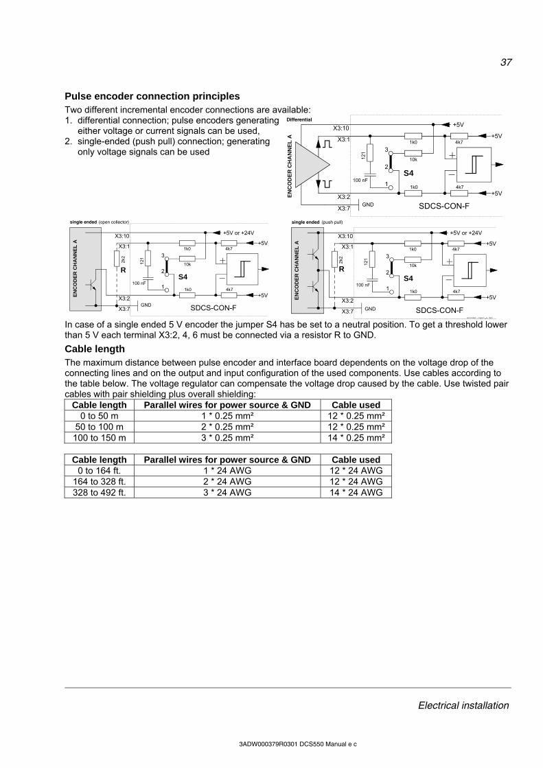
Pulse encoder connection principles Two different incremental encoder connections are available: 1. differential connection; pulse encoders generating
either voltage or current signals can be used, 2. single-ended (push pull) connection; generating
only voltage signals can be used 1k0 4k7
1k0 4k7
+5V
121
100 nF
10k
+5V
GND
+5V
X3:1
X3:2
X3:7
X3:10
3
2
1
S4
EN
CO
DE
R C
HA
NN
EL
A
SDCS-CON-F
Differential
1k0 4k7
1k0 4k7
+5V
121
100 nF
10k
+5V
+5V or +24V
X3:1
X3:2
X3:7
X3:10
3
2
1
S4R
2k2
EN
CO
DE
R C
HA
NN
EL
A
SDCS-CON-F
single ended (open collector)
GND
2k2
1k0 4k7
1k0 4k7
+5V
121
100 nF
10k
+5V
+5V or +24V
X3:1
X3:2
X3:7
X3:10
3
2
1
S4R
encoder input_a.dsf
EN
CO
DE
R C
HA
NN
EL
A
SDCS-CON-F
single ended (push pull)
GND
In case of a single ended 5 V encoder the jumper S4 has be set to a neutral position. To get a threshold lower than 5 V each terminal X3:2, 4, 6 must be connected via a resistor R to GND.
Cable length The maximum distance between pulse encoder and interface board dependents on the voltage drop of the connecting lines and on the output and input configuration of the used components. Use cables according to the table below. The voltage regulator can compensate the voltage drop caused by the cable. Use twisted pair cables with pair shielding plus overall shielding:
Cable length Parallel wires for power source & GND Cable used 0 to 50 m 1 * 0.25 mm² 12 * 0.25 mm²
50 to 100 m 2 * 0.25 mm² 12 * 0.25 mm² 100 to 150 m 3 * 0.25 mm² 14 * 0.25 mm²
Cable length Parallel wires for power source & GND Cable used
0 to 164 ft. 1 * 24 AWG 12 * 24 AWG 164 to 328 ft. 2 * 24 AWG 12 * 24 AWG 328 to 492 ft. 3 * 24 AWG 14 * 24 AWG

38
Electrical installation
3ADW000379R0301 DCS550 Manual e c
Installation checklist Check the mechanical and electrical installation of the drive before start-up. Go through the checklist below together with another person. Read the Safety instructions on the first pages of this manual before you work on the unit.
MECHANICAL INSTALLATION The ambient operating conditions are allowed (see Environmental conditions, Current ratings) The unit is mounted properly on a vertical non-flammable wall (see Mechanical installation) Cooling air will flow freely (see Mechanical installation) The motor and the driven equipment is ready for start All screen terminals are checked for tightness (see Cabling) All cable connections are seated properly (see Cabling)
ELECTRICAL INSTALLATION (see Planning the electrical installation, Electrical installation) The converter modules are grounded properly The mains voltage matches the converter module’s nominal input voltage The mains (input power) connections at U1, V1 and W1 (L1, L2 and L3) are OK The appropriate mains fuses and disconnector are installed The motor connections at C1, D1 and F+, F- and their tightening torques are OK Motor cable routing (armature and excitation) is OK Check that the screens are properly installed at the motor and in the drive cabinet The connections L+, L-, F+ and F- at motor and drive are OK The control connections are OK If pulse encoder is used, check the encoder cables and correct direction of rotation PTC, Klixon cables: Check that the connections are appropriate for the type of sensor used in the motor Check the prevention of unexpected start-up (on inhibit, coast stop) circuit for proper function Proper function of E-stop circuit and relay Cooling fan power wiring connected The external control connections inside the drive are OK There are no tools, foreign objects or dust from drilling inside the drive Drive, motor connection box and other covers are in place
39
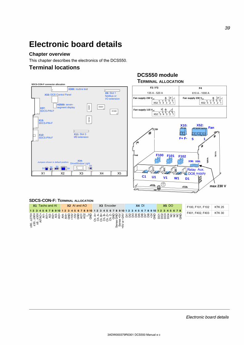
Electronic board details
3ADW000379R0301 DCS550 Manual e c
Electronic board details Chapter overview This chapter describes the electronics of the DCS550.
Terminal locations
X2X1 X3 X4 X51 1 1 1 1
S515
6 9
S3S2 S4
1212
12
12
D21
001
D20
01 D2001
D1000
1 30
1
2
1
2
S1 1 342
123
101112
1 782
1 342
123
789
X12: SDCS-PIN-F
X13: SDCS-PIN-F
X34:DriveWindow Light
X37: SDCS-PIN-F
X9: Slot 1fieldbus orI/O extension
X11: Slot 3I/O extension
X33: DCS Control Panel
X300: routine test
H2500: seven-segment display
Jumpers shown in default position
SDCS-CON-F connector allocation
4 3X52: 2 1
LN
5 4 3X52: 2 1
5
Fan supply 230 VAC
LNFan supply 115 VAC
F4F2 / F3
135 A - 520 A 610 A - 1000 A
4 3X52: 2 1
LN
5
Fan supply 230 VAC
DCS550 moduleTERMINAL ALLOCATION
F100 F101 F102
C1 U1 V1 W1 D1
F+ F-
X10:
max 230 V
X96: X99:
RelayDO8
Aux.supply
X52:
5 1
Fan
1 2 3 4 5 6 7 8 9 10 1 2 3 4 5 6 7 8 9 10 1 2 3 4 5 6 7 8 9 10 1 2 3 4 5 6 7 8 9 10 1 2 3 4 5 6 7 8
±9
0...±
270
V±
30.
..±90
V±
8...
±3
0VA
ITA
C+
AI1
-A
I1+
AI2
-A
I2+
AI3
-A
I3+
SDCS-CON-F: TERMINAL ALLOCATION
AI4
-A
I4+
GN
D+
10V
-10V
GN
DA
O1
AO
2 I act
GN
D
Ch.
A+
Ch.
A-
Ch.
B+
Ch.
B-
Ch.
Z+
Ch.
Z-
GN
DS
ens
e G
ND
Se
nse
+5
V+
5V
or
+24
V
DI1
DI2
DI3
DI4
DI5
DI6
DI7
DI8
+2
4G
ND
DO
1D
O2
DO
3D
O4
NC
NC
NC
GN
D
X1 Tacho and AI X2 AI and AO X3 Encoder X4 DI X5 DO
F100, F101, F102
F401, F402, F403
KTK 25
KTK 30
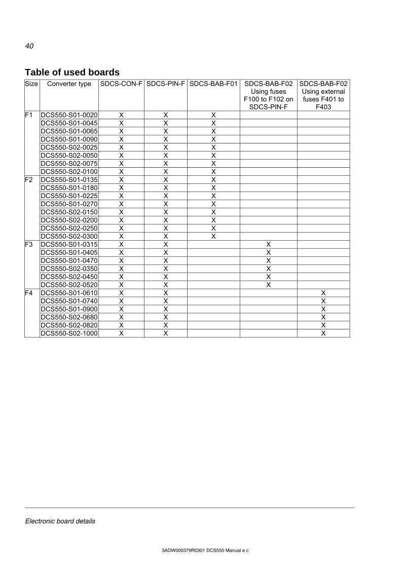
40
Electronic board details
3ADW000379R0301 DCS550 Manual e c
Table of used boards Size Converter type SDCS-CON-F SDCS-PIN-F SDCS-BAB-F01 SDCS-BAB-F02
Using fuses F100 to F102 on
SDCS-PIN-F
SDCS-BAB-F02Using external fuses F401 to
F403 DCS550-S01-0020 X X X DCS550-S01-0045 X X X DCS550-S01-0065 X X X DCS550-S01-0090 X X X DCS550-S02-0025 X X X DCS550-S02-0050 X X X DCS550-S02-0075 X X X
F1
DCS550-S02-0100 X X X DCS550-S01-0135 X X X DCS550-S01-0180 X X X DCS550-S01-0225 X X X DCS550-S01-0270 X X X DCS550-S02-0150 X X X DCS550-S02-0200 X X X DCS550-S02-0250 X X X
F2
DCS550-S02-0300 X X X DCS550-S01-0315 X X X DCS550-S01-0405 X X X DCS550-S01-0470 X X X DCS550-S02-0350 X X X DCS550-S02-0450 X X X
F3
DCS550-S02-0520 X X X DCS550-S01-0610 X X X DCS550-S01-0740 X X X DCS550-S01-0900 X X X DCS550-S02-0680 X X X DCS550-S02-0820 X X X
F4
DCS550-S02-1000 X X X

41
Electronic board details
3ADW000379R0301 DCS550 Manual e c
Control board SDCS-CON-F
Layout 247
230
X2X1 X3 X4 X51 1 1 1 1
S515
6 9
S3S2 S4
1212
12
12
D21
001
D20
01 D2001
D1000
1 30
1
2
1
2
S1 1 342
123
101112
1 782
1 342
123
789
X12: SDCS-PIN-F
X13: SDCS-PIN-F
X34:DriveWindow Light
X37: SDCS-PIN-F
X9: Slot 1fieldbus orI/O extension
X11: Slot 3I/O extension
X33: DCS Control Panel
X300: routine test
H2500: seven-segment display
Jumpers shown in default position
S1123
S2 1 342
123
789
789
1 342
S3
78
S4123
789
123
101112
101112
S51 3
42
1 342
456
456
Jumper parking position;do not change
Reserved, do not use
1 342
1 342
AI2 (X1:7-8): Rin = 200 k range ±10 V
AI2 (X1:7-8): Rin = 250 range ±20 mA
65
78
65
789
Jumper coding
default value250 x 20 mA = 5 V = 100%
AI1 (X1:5-6): Rin = 200 k range ±10 V
AI1 (X1:5-6): Rin = 250 range ±20 mA
Jumper parking position,normal DC tacho
Reserved, do not use
AITAC+ (X1:4) connected to GND
Jumper parking position; AITAC+ (X1:4) not grounded
Jumper parking position;no PTC connected
PTC connected at X1:7-8, 4.75 k pull-up resistor activated
Encoder mode: differential; RC loadsactivated with R = 121 and C = 100 nF
Encoder mode: single ended, 10 k pull-uip resistor activated
Encoder supply +5 V, sense at X3:8-9 is active
Encoder supply +24 V,no sense available
Firmware download
Normal program executionor text download
Location The SDCS-CON-F is mounted on an electronic tray. The electronic tray is put in the housing by means of four hinges and the SDCS-CON-F is connected with the SDCS-PIN-F through three flat cables.
Memory circuit The SDCS-CON-F is equipped with a flash PROM that contains the firmware and the stored parameters. It is possible to handle the parameters by DCS Control Panel, DWL or overriding control. Changed parameters are stored immediately in the flash with the exception of parameters for cyclic communication via the dataset table in groups 90 to 92 and pointers in group 51. In addition, the fault logger entries are stored in the flash during de-energizing the auxiliary power.
Watchdog function The SDCS-CON-F has an internal watchdog. The watchdog controls the proper function of the SDCS-CON-F and the firmware. If the watchdog trips, it has the following effects: the thyristor firing control is reset and disabled, all DI’s are forced low (zero) and all programmable AO’s are reset to zero (0 V).
10 11 12
S4
SDCS-CON-F
+24 V
X3:10
SDCS-PIN-F
+5 V
encoder supply
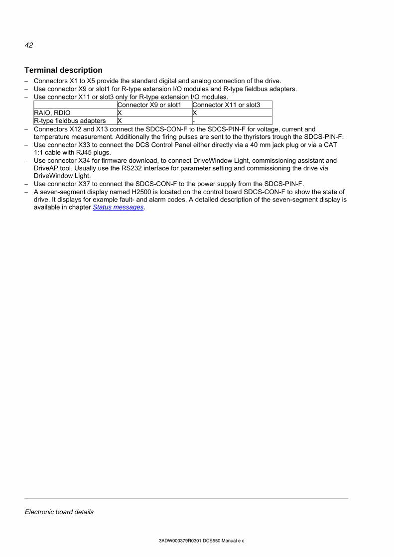
42
Electronic board details
3ADW000379R0301 DCS550 Manual e c
Terminal description Connectors X1 to X5 provide the standard digital and analog connection of the drive. Use connector X9 or slot1 for R-type extension I/O modules and R-type fieldbus adapters. Use connector X11 or slot3 only for R-type extension I/O modules.
Connector X9 or slot1 Connector X11 or slot3 RAIO, RDIO X X R-type fieldbus adapters X -
Connectors X12 and X13 connect the SDCS-CON-F to the SDCS-PIN-F for voltage, current and temperature measurement. Additionally the firing pulses are sent to the thyristors trough the SDCS-PIN-F.
Use connector X33 to connect the DCS Control Panel either directly via a 40 mm jack plug or via a CAT 1:1 cable with RJ45 plugs.
Use connector X34 for firmware download, to connect DriveWindow Light, commissioning assistant and DriveAP tool. Usually use the RS232 interface for parameter setting and commissioning the drive via DriveWindow Light.
Use connector X37 to connect the SDCS-CON-F to the power supply from the SDCS-PIN-F. A seven-segment display named H2500 is located on the control board SDCS-CON-F to show the state of
drive. It displays for example fault- and alarm codes. A detailed description of the seven-segment display is available in chapter Status messages.
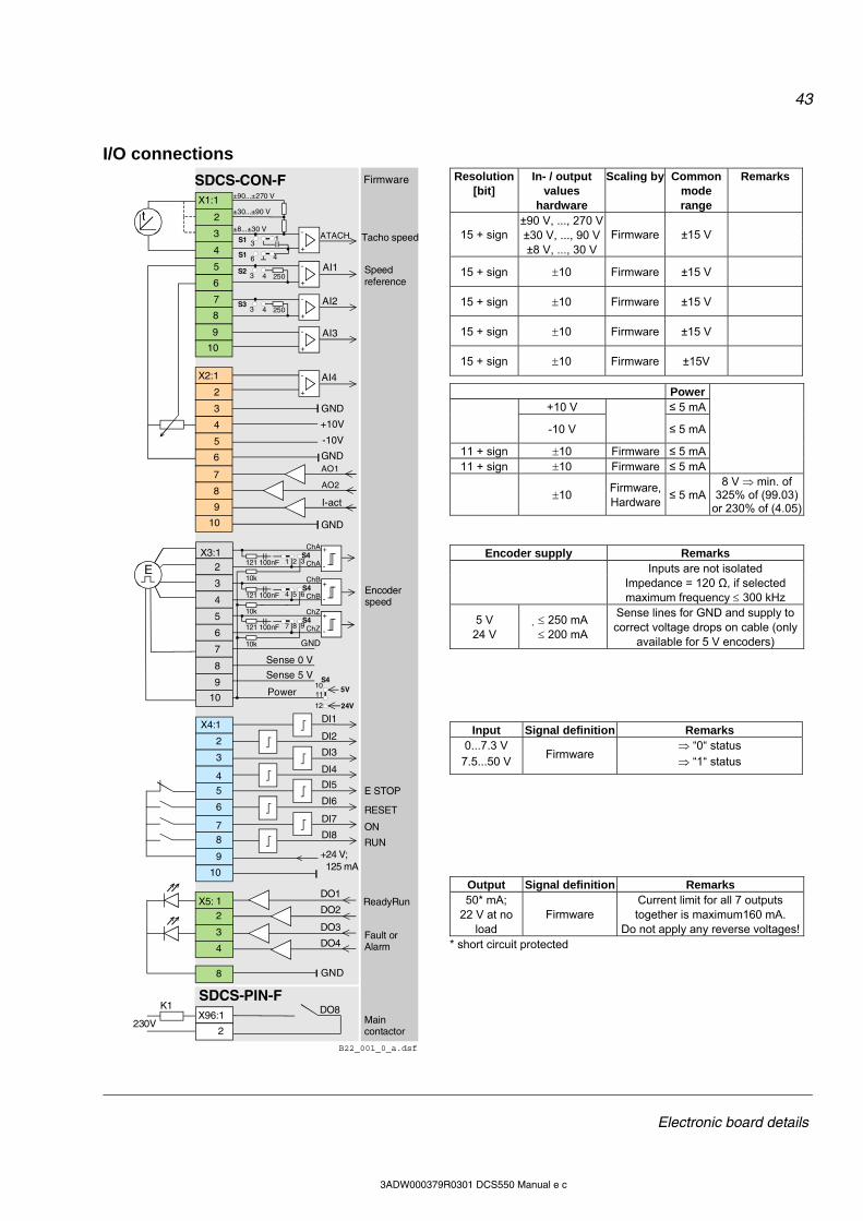
43
Electronic board details
3ADW000379R0301 DCS550 Manual e c
I/O connections
±90...±270 V
±30...±90 V
±8...±30 V
AI4
GND
GND
+24 V; 125 mA
Power
Sense 0 V
Sense 5 V
AI2
AI3
AI1
AO1
I-act
GND
+10V
GND
-10V
DI1
DI2
DI3
DI4
DI5
DI6
DI7
DI8
DO4
DO1
DO2
DO3
3
4
5
8
7
6
7
9
X4:1
2
3
4
5
6
7 8
10
4
1
2
3
4
2
3
6
5
9
10
8
9
10
2
4
5
7
2
3
6
8
9
10
8
X1:1
X2:1
X3:1
X5:
SDCS-CON-F
B22_001_0_a.dsf
+
-
S23 4 250
S33 4 250
ATACH
+
-
+
-
+
-
+
-
GND
10
+
-
+
-
+
-
5VS4
11
12
AO2
24V
K1X96:1
t
DO8230V
E
2
SDCS-PIN-F
13
46S1
S1
1 3S4
2121 100nF
4 6S4
5121 100nF
7S4
8121 100nF
10k
10k
10k
9
ChA
ChB
ChZ
ChA
ChB
ChZ
Firmware
ReadyRun
RUN
ON
RESET
E STOP
Main contactor
Fault orAlarm
Encoder speed
Speed reference
Tacho speed
Resolution [bit]
In- / output values
hardware
Scaling by Common mode range
Remarks
±90 V, ..., 270 V±30 V, ..., 90 V15 + sign ±8 V, ..., 30 V
Firmware ±15 V
15 + sign 10 Firmware ±15 V
15 + sign 10 Firmware ±15 V
15 + sign 10 Firmware ±15 V
15 + sign 10 Firmware ±15V
Power +10 V ≤ 5 mA
-10 V
≤ 5 mA
11 + sign 10 Firmware ≤ 5 mA 11 + sign 10 Firmware ≤ 5 mA
10 Firmware, Hardware
≤ 5 mA 8 V min. of
325% of (99.03) or 230% of (4.05)
Encoder supply Remarks
Inputs are not isolated
Impedance = 120 Ω, if selected maximum frequency 300 kHz
5 V 24 V
250 mA 200 mA
Sense lines for GND and supply to correct voltage drops on cable (only
available for 5 V encoders)
Input Signal definition Remarks 0...7.3 V 7.5...50 V
Firmware “0“ status “1“ status
Output Signal definition Remarks 50* mA;
22 V at no load
Firmware Current limit for all 7 outputs together is maximum160 mA.
Do not apply any reverse voltages!* short circuit protected

44
Electronic board details
3ADW000379R0301 DCS550 Manual e c
Power Interface board SDCS-PIN-F
Layout
V1 W1 D1C1 U1X24 X21 X23 X20
SDCS-PIN-F
conducting point
Hig
h vo
ltage
T100
X96 X99
K400
F1
02
F1
01
F1
00
R300R400
X1
1X
12
X1
3
L400
X9
5X9
X1X2 X7
X31
X22X5
X4
X3
X19
X3
7
X1
5
X1
7
X30
X1
8
X1
6
T300
PinF_layout_b.dsf
RelayoutputDO 8
InputAux.supply
24V
To protect X96 and X99 from being swapped both plugs are coded:

45
Electronic board details
3ADW000379R0301 DCS550 Manual e c
Location The SDCS-PIN-F is located between the power part and the control board SDCS-CON-F.
Functions The DCS550 provides an automatic adjustment for current and voltage measurement, burden resistor settings and 2-Q or 4-Q operation by means of setting parameters in the firmware. The SDCS-PIN-F provides: the power supply for all the auxiliary voltages of the whole drive and the connected options, control of armature bridge including high ohmic measurement of DC- and AC voltage and an interface for
the current transformer measuring the armature current, control of the OnBoard field exciter and field current measurement, an interface for the heatsink temperature measurement with a PTC resistor, a snubber circuit for thyristor protection together with the snubber resistor mounted on the heatsink.
Terminal description The OnBoard field exciter with firing pulse transformers and field current measurement via transformer
T100 is located on the SDCS-PIN-F. The power part is a three phase half-controlled bridge supplied from the mains U1, V1, W1 via fuses F100, F101, F102 and is located on the heat sink. The measurement of the field current is automatically scaled and selected by the firmware. De-select a not needed OnBoard field exciter by means of the firmware.
Connector X96 controls the main circuit breaker. To save an additional relay in the cabinet the DCS550 provides a normally open relay contact integrated on the SDCS-PIN-F. Digital output 8 controls the relay output at connector X96. The function or signal definition of digital output 8 is done in the firmware by means of parameters.
Isolated relay with a normally open contact Contact ratings: 230 V~ / <3 A~ 24 V- / <3 A- or 115 / 230 V- / <0.3 A-
Use connector X99 to connect the auxiliary input voltages of 230 VAC, 115 VAC or 230 VDC.
X99:
PIN-F_in-output_circuit.dsf
3.15 AT
R30
0
NTC
U
R310
F302
X99 features a hardware filter and a voltage limitation.
Auxiliary voltages 115 VAC 230 VAC 230 VDC Tolerance -15 % / +10 % -15 % / +10 % -15 % / +10 % Frequency 45 Hz to 65 Hz 45 Hz to 65 Hz Power consumption 120 VA 120 VA Power loss ≤ 60 W ≤ 60 W ≤ 60 W Inrush current *20 A / 20 ms 10 A / 20 ms 10 A / 20 ms recommended fusing 6 AT 6 AT 6 AT Mains buffering min 30 ms min 300 ms 150 ms Power fail < 95 VAC < 95 VAC < 140 VDC
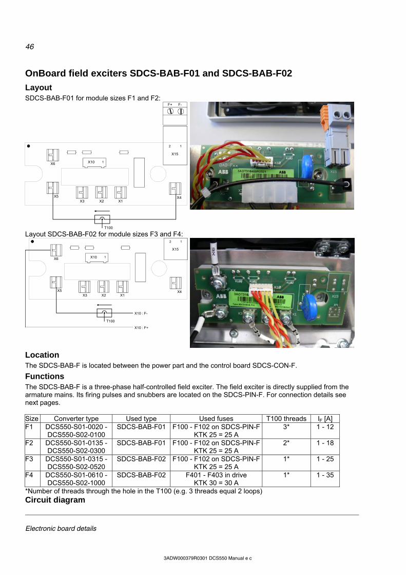
46
Electronic board details
3ADW000379R0301 DCS550 Manual e c
OnBoard field exciters SDCS-BAB-F01 and SDCS-BAB-F02
Layout SDCS-BAB-F01 for module sizes F1 and F2:
X6 X10
X15
X5X3 X2 X1
X4
2 1
1
F+ F-
T100
Layout SDCS-BAB-F02 for module sizes F3 and F4:
X6 X10
X15
X5X3 X2 X1
X4
2 1
1
T100
X10 : F-
X10 : F+
Location The SDCS-BAB-F is located between the power part and the control board SDCS-CON-F.
Functions The SDCS-BAB-F is a three-phase half-controlled field exciter. The field exciter is directly supplied from the armature mains. Its firing pulses and snubbers are located on the SDCS-PIN-F. For connection details see next pages. Size Converter type Used type Used fuses T100 threads IF [A] F1 DCS550-S01-0020 -
DCS550-S02-0100 SDCS-BAB-F01 F100 - F102 on SDCS-PIN-F
KTK 25 = 25 A 3* 1 - 12
F2 DCS550-S01-0135 - DCS550-S02-0300
SDCS-BAB-F01 F100 - F102 on SDCS-PIN-FKTK 25 = 25 A
2* 1 - 18
F3 DCS550-S01-0315 - DCS550-S02-0520
SDCS-BAB-F02 F100 - F102 on SDCS-PIN-FKTK 25 = 25 A
1* 1 - 25
F4 DCS550-S01-0610 - DCS550-S02-1000
SDCS-BAB-F02 F401 - F403 in drive KTK 30 = 30 A
1* 1 - 35
*Number of threads through the hole in the T100 (e.g. 3 threads equal 2 loops) Circuit diagram
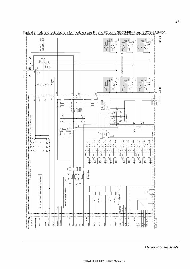
47
Electronic board details
3ADW000379R0301 DCS550 Manual e c
Typical armature circuit diagram for module sizes F1 and F2 using SDCS-PIN-F and SDCS-BAB-F01:
V11
V24
V21
V14
1.4
2.1
2.4
1.1
2.6
V26
V13
1.3
2.3
1.6
V23
V16
2.2
V22
V15
1.5
2.5
1.2
V25 V12
KG KGG KG K
G KG KG K KG
KGG K
KGG K
X12
:U
1V
1W
1
C1
(+)
D1
(-)
3S
TW
A
VW
16
UV
UU
144
0V
5M
GN
DI
IDC
8,13
9,10
IDC
M11
,12
1X
4:
3
X3:
31
N/1
P1
T51
P2
25A
...27
5A
1500
:127
6A...
680A
30
00:1
681A
...12
00A
45
00:1
P1
T53
N/1
AN
TC
2
1X
22:
3R
57
7B
ZP
4
+48
V1
SR
1
GN
DI
SR
2
BZ
P5
BZ
P6
8,61011
144,29
BZ
P2
BZ
P3
BZ
P1
X13
: 3 51
+ 4
8 V
1
UA
+6
UA
-15
S1
S2
S1
S2
PE
1 2 3 4 5 6
T10
0
K G
1.4
2.4
2.2
2.6
2.1
2.5
2.3
1.2
1.6
1.1
1.5
HW
CD
D5
7
HW
CO
D3
5N
C
NC
1.3
F10
0
F10
1
F10
2
16A
C1W
1
V1
U1D1
12781314123456
1 3
P2
P1
T52
N/1
S1
S2
X5:
X21
:
X23
:
X20
:
X24
:
X30
:
X31
:
R1
X1: X
2: X7:
X13
:
F-
F+
SD
CS
-BA
B-F
X5
1615
1312
X99
:1
2X
96:
12
+24
V
X37
:
+48
V
+24
V+
15 V
-15
VG
ND
2 4 6 8 1224
, 22,
20, 1
8, 1
0
X10
:PinF_a.dsf
X18
:
X15
:
K G K G K G K G K G
V13
V15
V11
V16
V12
V14
K G K G K G K G K G K G
14 138 72 16 54 32 1
X16
:
X17
:
V23
V25
V21
V26
V22
V24
X4
X15
:12
Con
trol
boa
rd
Arm
atur
e c
urre
nt m
easu
ring
res
ista
nce
s
AC
/DC
vol
tage
mea
surin
g ci
rcui
ts
Firi
ng p
ulse
cha
nnel
son
ly in
cas
e of
4-Q
co
nver
ters
PO
WE
R IN
TE
RF
AC
E B
OA
RD
SD
CS
-PIN
-F
RE
VE
RS
E
FO
RW
AR
D
Fie
ld c
ircui
t in
terf
ace
Arm
atur
e c
ircui
t int
erf
ace
Dis
trib
utio
n
X10
:1
23
4
13
2
X3:
X2:
X1:
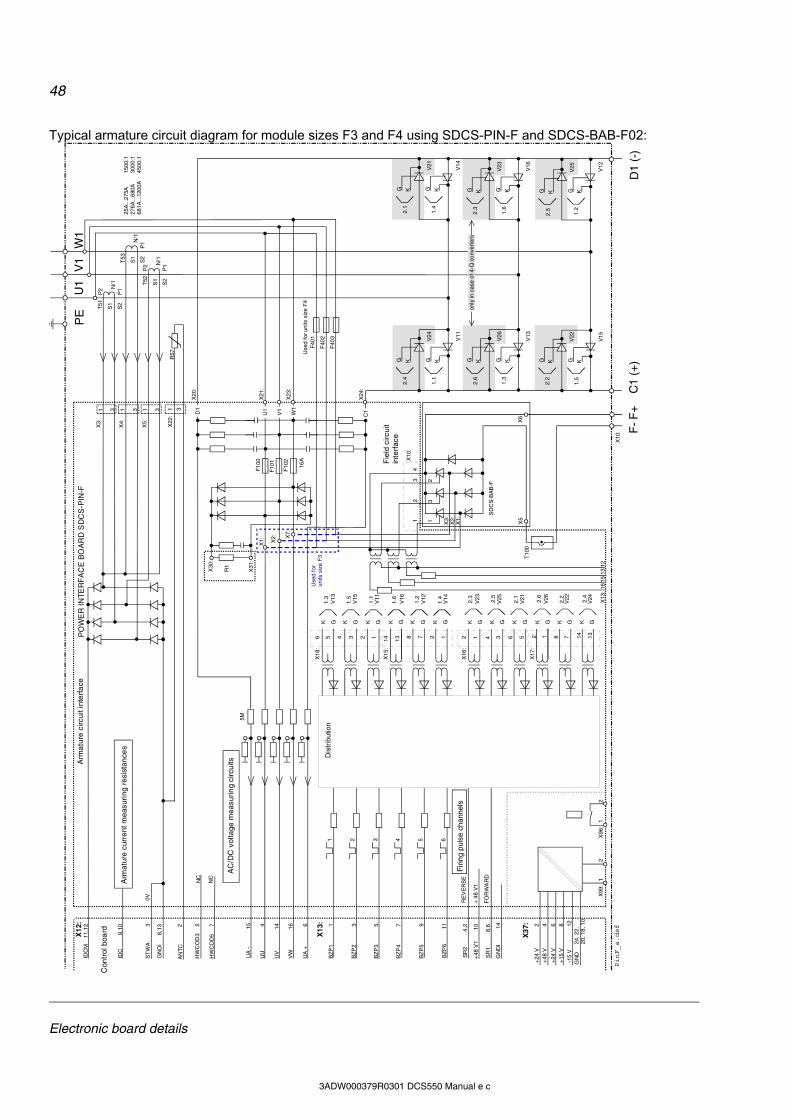
48
Electronic board details
3ADW000379R0301 DCS550 Manual e c
Typical armature circuit diagram for module sizes F3 and F4 using SDCS-PIN-F and SDCS-BAB-F02:
V11
V24
V21
V14
1.4
2.1
2.4
1.1
2.6
V26
V13
1.3
2.3
1.6
V23
V16
2.2
V22
V15
1.5
2.5
1.2
V25 V12
KG KGG KG K
G KG KG K KG
KGG K
KGG K
X12
:U
1V
1W
1
C1
(+)
D1
(-)
3S
TW
A
VW
16
UV
UU
144
0V
5M
GN
DI
IDC
8,13
9,10
IDC
M11
,12
1X
4:
3
X3:
31
N/1
P1
T51
P2
25A
...27
5A
1500
:127
6A...
680A
30
00:1
681A
...12
00A
45
00:1
P1
T53
N/1
AN
TC
2
1X
22:
3R
57
7B
ZP
4
+48
V1
SR
1
GN
DI
SR
2
BZ
P5
BZ
P6
8,61011
144,29
BZ
P2
BZ
P3
BZ
P1
X13
: 3 51
+ 4
8 V
1
UA
+6
UA
-15
S1
S2
S1
S2
PE
1 2 3 4 5 6
T10
0
K G
1.4
2.4
2.2
2.6
2.1
2.5
2.3
1.2
1.6
1.1
1.5
HW
CD
D5
7
HW
CO
D3
5N
C
NC
1.3
F10
0
F10
1
F10
2
16A
C1W1
V1
U1D1
12781314123456
1 3
P2
P1
T52
N/1
S1
S2
X5:
X21
:
X23
:
X20
:
X24
:
X30
:
X31
:
R1
X1: X2: X
7:
X13
:
F-
F+
SD
CS
-BA
B-F
X5
1615
1312
X99
:1
2X
96:
12
+24
V
X37
:
+48
V
+24
V+
15 V
-15
VG
ND
2 4 6 8 1224
, 22,
20, 1
8, 1
0
X10
:PinF_a.dsf
X18
:
X15
:
K G K G K G K G K G
V13
V15
V11
V16
V12
V14
K G K G K G K G K G K G
14 138 72 16 54 32 1
X16
:
X17
:
V23
V25
V21
V26
V22
V24
F40
1
F40
2
F40
3
X6
Use
d fo
r un
its s
ize
F3
Use
d fo
r uni
ts s
ize
F4
Con
trol
boa
rd
Arm
atur
e c
urre
nt m
easu
ring
res
ista
nce
s
AC
/DC
vol
tage
mea
surin
g ci
rcui
ts
Firi
ng p
ulse
cha
nnel
son
ly in
cas
e of
4-Q
co
nver
ters
RE
VE
RS
E
FO
RW
AR
D
Fie
ld c
ircui
t in
terf
ace
Arm
atur
e c
ircui
t int
erf
ace
Dis
trib
utio
n
X10
:1
23
4
13
2
X3:
X2:
X1:
PO
WE
R IN
TE
RF
AC
E B
OA
RD
SD
CS
-PIN
-F
49
Accessories
3ADW000379R0301 DCS550 Manual e c
Accessories Chapter overview This chapter describes the accessories for the DCS550.
① Line reactors (L1)
Line reactor types ND01 to ND13 (uk = 1 %) Line reactors of types ND01 to ND13 are sized to the unit’s nominal current and frequency (50 / 60 Hz). These line reactors with a uk of 1 are designed for use in industrial environment (minimum requirements). They have low inductive voltage drop, but deep commutation notches. Line reactors ND01 to ND06 are equipped with cables. The larger ones ND07 to ND13 are equipped with busbars. When connecting them to other components, please consider relevant standards in case the busbar materials are different. Attention: Do not use the line reactor terminals as cable or busbar support! Size Converter type (2-Q) Converter type (4-Q) Line reactor (uk = 1 %) Design figure
DCS550-S01-0020 DCS550-S02-0025 ND01 DCS550-S01-0045 DCS550-S02-0050 ND02 DCS550-S01-0065 DCS550-S02-0075 ND04
F1
DCS550-S01-0090 DCS550-S02-0100 DCS550-S01-0135 DCS550-S02-0150
ND06
1
DCS550-S01-0180 DCS550-S02-0200 DCS550-S01-0225 DCS550-S02-0250
ND07 F2
DCS550-S01-0270 DCS550-S02-0300 DCS550-S01-0315 DCS550-S02-0350
ND09
DCS550-S01-0405 DCS550-S02-0450 F3
DCS550-S01-0470 DCS550-S02-0520 ND10
DCS550-S01-0610 DCS550-S02-0680 ND12
2
DCS550-S01-0740 DCS550-S02-0820 F4
DCS550-S01-0900 DCS550-S02-1000 ND13 3
Fig. 1 Fig. 2 Fig. 3
50
Accessories
3ADW000379R0301 DCS550 Manual e c
Power lossesLine reactor (uk = 1 %)
L [H] IRMS [A] ipeak [A] Rated voltage [UN]
Weight [kg] Fe [W] Cu [W]
ND01 512 18 27 2.0 5 16 ND02 250 37 68 3.0 7 22 ND04 168 55 82 5.8 10 33 ND06 90 102 153 7.6 7 41 ND07 50 184 275 12.6 45 90 ND09 37.5 245 367 16.0 50 140 ND10 25.0 367 551 22.2 80 185 ND12 18.8 490 734
500
36.0 95 290 ND13 18.2 698 1047 690 46.8 170 160
Line reactor types ND01 to ND06 Line reactor (uk = 1 %)
a1 [mm]
a [mm]
b [mm]
c [mm]
d [mm]
e [mm]
f [mm]
g [mm]
[mm²] ND01 120 100 130 48 65 116 4 8 6 ND02 120 100 130 58 65 116 4 8 10 ND04 148 125 157 78 80 143 5 10 16 ND06 178 150 180 72 90 170 5 10 35
Line reactor types ND07 to ND12
Line reactor (uk = 1 %)
A [mm]
B [mm]
C [mm]
C1 [mm]
E [mm]
F [mm]
G [mm]
H [mm]
I [mm]
K [mm]
L [mm]
Busbar
ND07 285 230 86 100 250 176 65 80 9x18 385 232 20 * 4 ND09 327 250 99 100 292 224 63 100 9x18 423 280 30 * 5 ND10 408 250 99 100 374 224 63 100 11x18 504 280 60 * 6 ND12 458 250 112 113 424 224 63 100 13x18 554 280 40 * 6

51
Accessories
3ADW000379R0301 DCS550 Manual e c
Line reactor type ND13 all busbars are 40 * 10 Dimensions in [mm]:
52
Accessories
3ADW000379R0301 DCS550 Manual e c
Line reactor types ND401 to ND413 (uk = 4 %) Line reactors of types ND401 to ND413 are sized to the unit’s nominal current and frequency (50 / 60 Hz). These line reactors with a uk of 4 are designed for use in light industrial / residential environment. They have high inductive voltage drop, but reduced commutation notches. These reactors are designed for drives, which usually operate in speed control in 400 or 500 VAC networks. The percentage taken into account for that duty cycle is different: for Usupply = 400 VAC follows IDC1 = 90 % of nominal current, for Usupply = 500 VAC follows IDC2 = 72 % of nominal current. Line reactors ND401 to ND402 are equipped with terminals. The larger ones ND403 to ND413 are equipped with busbars. When connecting them to other components, please consider relevant standards in case the busbar materials are different. Attention: Do not use the line reactor terminals as cable or busbar support! Size Converter type (2-Q) Converter type (4-Q) Line reactor (uk = 4 %) Design figure
DCS550-S01-0020 DCS550-S02-0025 ND401 DCS550-S01-0045 DCS550-S02-0050 ND402
4
DCS550-S01-0065 DCS550-S02-0075 ND403
F1
DCS550-S01-0090 DCS550-S02-0100 ND404 DCS550-S01-0135 DCS550-S02-0150 ND405 DCS550-S01-0180 DCS550-S02-0200 ND406 DCS550-S01-0225 DCS550-S02-0250 ND407
F2
DCS550-S01-0270 DCS550-S02-0300 DCS550-S01-0315 DCS550-S02-0350
ND408
DCS550-S01-0405 DCS550-S02-0450 ND409 F3
DCS550-S01-0470 DCS550-S02-0520 ND410 DCS550-S01-0610 DCS550-S02-0680 ND411 DCS550-S01-0740 DCS550-S02-0820 ND412
F4
DCS550-S01-0900 DCS550-S02-1000 ND413
5
Power losses Line reactor
(uk = 4 %) L [H] IRMS [A] ipeak [A] Rated voltage
[UN] Weight
[kg] Fe [W] Cu [W]DC current for Umains
= 400 VAC DC current for Umains
= 500 VAC
ND401 1000 18.5 27 3.5 13 35 22.6 18 ND402 600 37 68 7.5 13 50 45 36 ND403 450 55 82 11 42 90 67 54 ND404 350 74 111 13 78 105 90 72 ND405 250 104 156 19 91 105 127 101 ND406 160 148 220 22 104 130 179 143 ND407 120 192 288 23 117 130 234 187 ND408 90 252 387 29 137 160 315 252 ND409 70 332 498 33 170 215 405 324 ND410 60 406 609 51 260 225 495 396 ND411 50 502 753 56 260 300 612 490 ND412 40 605 805 62 280 335 738 590 ND413 35 740 1105
400
75 312 410 900 720
Fig. 5 Fig. 4
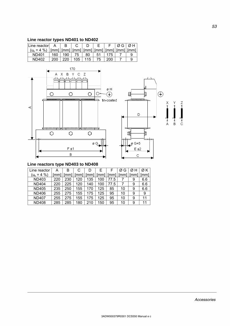
53
Accessories
3ADW000379R0301 DCS550 Manual e c
Line reactor types ND401 to ND402 Line reactor (uk = 4 %)
A [mm]
B [mm]
C [mm]
D [mm]
E [mm]
F [mm]
Ø G [mm]
Ø H [mm]
ND401 160 190 75 80 51 175 7 9 ND402 200 220 105 115 75 200 7 9
Line reactors type ND403 to ND408 Line reactor (uk = 4 %)
A [mm]
B [mm]
C [mm]
D [mm]
E [mm]
F [mm]
Ø G [mm]
Ø H [mm]
Ø K [mm]
ND403 220 230 120 135 100 77.5 7 9 6.6 ND404 220 225 120 140 100 77.5 7 9 6.6 ND405 235 250 155 170 125 85 10 9 6.6 ND406 255 275 155 175 125 95 10 9 9 ND407 255 275 155 175 125 95 10 9 11 ND408 285 285 180 210 150 95 10 9 11
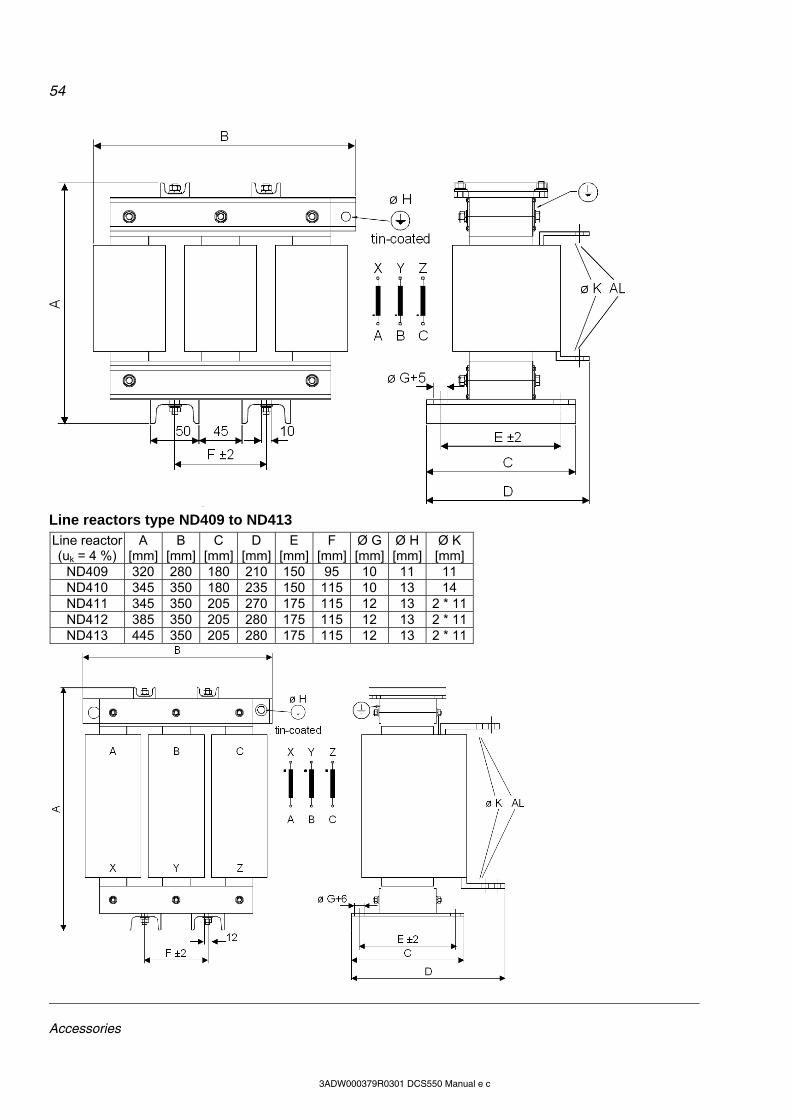
54
Accessories
3ADW000379R0301 DCS550 Manual e c
Line reactors type ND409 to ND413 Line reactor (uk = 4 %)
A [mm]
B [mm]
C [mm]
D [mm]
E [mm]
F [mm]
Ø G [mm]
Ø H [mm]
Ø K [mm]
ND409 320 280 180 210 150 95 10 11 11 ND410 345 350 180 235 150 115 10 13 14 ND411 345 350 205 270 175 115 12 13 2 * 11ND412 385 350 205 280 175 115 12 13 2 * 11ND413 445 350 205 280 175 115 12 13 2 * 11
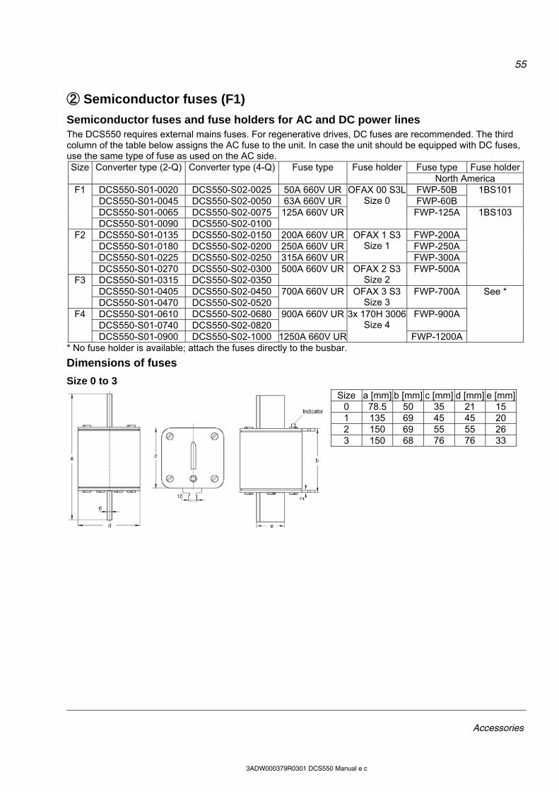
55
Accessories
3ADW000379R0301 DCS550 Manual e c
② Semiconductor fuses (F1)
Semiconductor fuses and fuse holders for AC and DC power lines The DCS550 requires external mains fuses. For regenerative drives, DC fuses are recommended. The third column of the table below assigns the AC fuse to the unit. In case the unit should be equipped with DC fuses, use the same type of fuse as used on the AC side.
Fuse type Fuse holderSize Converter type (2-Q) Converter type (4-Q) Fuse type Fuse holder North America
DCS550-S01-0020 DCS550-S02-0025 50A 660V UR FWP-50B DCS550-S01-0045 DCS550-S02-0050 63A 660V UR FWP-60B
1BS101
DCS550-S01-0065 DCS550-S02-0075
F1
DCS550-S01-0090 DCS550-S02-0100 125A 660V UR
OFAX 00 S3L Size 0
FWP-125A
DCS550-S01-0135 DCS550-S02-0150 200A 660V UR FWP-200A DCS550-S01-0180 DCS550-S02-0200 250A 660V UR FWP-250A DCS550-S01-0225 DCS550-S02-0250 315A 660V UR
OFAX 1 S3 Size 1
FWP-300A
F2
DCS550-S01-0270 DCS550-S02-0300 DCS550-S01-0315 DCS550-S02-0350
500A 660V UR OFAX 2 S3 Size 2
FWP-500A
1BS103
DCS550-S01-0405 DCS550-S02-0450 F3
DCS550-S01-0470 DCS550-S02-0520 700A 660V UR OFAX 3 S3
Size 3 FWP-700A
DCS550-S01-0610 DCS550-S02-0680 DCS550-S01-0740 DCS550-S02-0820
900A 660V UR FWP-900A F4
DCS550-S01-0900 DCS550-S02-1000 1250A 660V UR
3x 170H 3006 Size 4
FWP-1200A
See *
* No fuse holder is available; attach the fuses directly to the busbar.
Dimensions of fuses
Size 0 to 3
Size a [mm] b [mm] c [mm] d [mm] e [mm]0 78.5 50 35 21 15 1 135 69 45 45 20 2 150 69 55 55 26 3 150 68 76 76 33
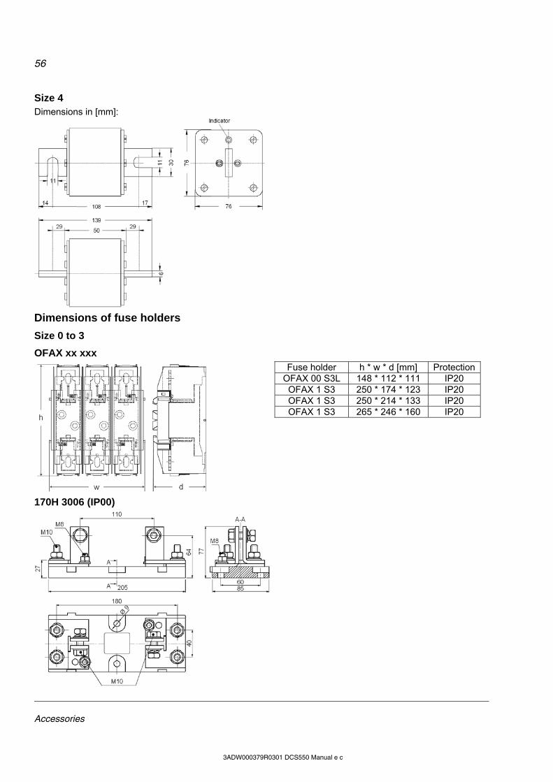
56
Accessories
3ADW000379R0301 DCS550 Manual e c
Size 4 Dimensions in [mm]:
Dimensions of fuse holders
Size 0 to 3
OFAX xx xxx
Fuse holder h * w * d [mm] ProtectionOFAX 00 S3L 148 * 112 * 111 IP20
OFAX 1 S3 250 * 174 * 123 IP20 OFAX 1 S3 250 * 214 * 133 IP20 OFAX 1 S3 265 * 246 * 160 IP20
170H 3006 (IP00)
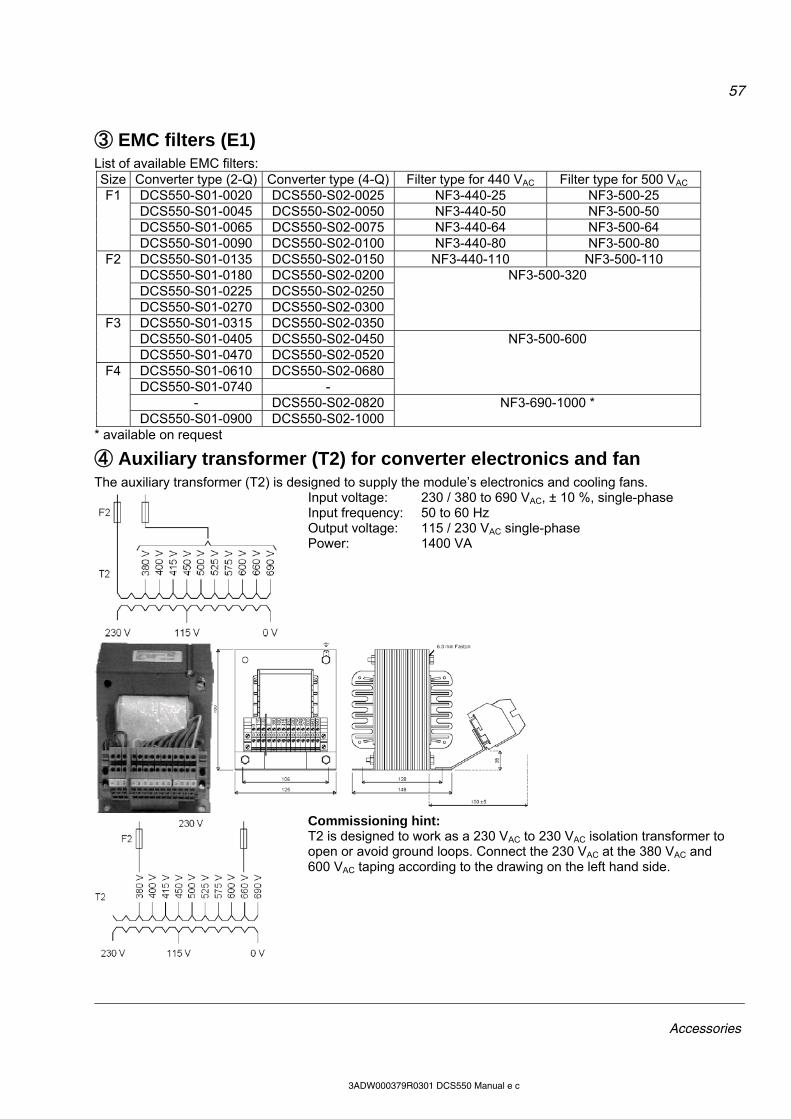
57
Accessories
3ADW000379R0301 DCS550 Manual e c
③ EMC filters (E1) List of available EMC filters: Size Converter type (2-Q) Converter type (4-Q) Filter type for 440 VAC Filter type for 500 VAC
DCS550-S01-0020 DCS550-S02-0025 NF3-440-25 NF3-500-25 DCS550-S01-0045 DCS550-S02-0050 NF3-440-50 NF3-500-50 DCS550-S01-0065 DCS550-S02-0075 NF3-440-64 NF3-500-64
F1
DCS550-S01-0090 DCS550-S02-0100 NF3-440-80 NF3-500-80 DCS550-S01-0135 DCS550-S02-0150 NF3-440-110 NF3-500-110 DCS550-S01-0180 DCS550-S02-0200 DCS550-S01-0225 DCS550-S02-0250
F2
DCS550-S01-0270 DCS550-S02-0300 DCS550-S01-0315 DCS550-S02-0350
NF3-500-320
DCS550-S01-0405 DCS550-S02-0450 F3
DCS550-S01-0470 DCS550-S02-0520 DCS550-S01-0610 DCS550-S02-0680 DCS550-S01-0740 -
NF3-500-600
- DCS550-S02-0820
F4
DCS550-S01-0900 DCS550-S02-1000 NF3-690-1000 *
* available on request
④ Auxiliary transformer (T2) for converter electronics and fan The auxiliary transformer (T2) is designed to supply the module’s electronics and cooling fans.
Input voltage: 230 / 380 to 690 VAC, ± 10 %, single-phase Input frequency: 50 to 60 Hz Output voltage: 115 / 230 VAC single-phase Power: 1400 VA
Commissioning hint: T2 is designed to work as a 230 VAC to 230 VAC isolation transformer to open or avoid ground loops. Connect the 230 VAC at the 380 VAC and 600 VAC taping according to the drawing on the left hand side.
58
Start-up
3ADW000379R0301 DCS550 Manual e c
Start-up Chapter overview This chapter describes the basic start-up procedure of the drive. A more detailed description of the signals and parameters involved in the procedure is available in section Signal and parameter list.
General Operate the drive: local, with DWL or DCS Control Panel remote, with local I/O or overriding control. The following start-up procedure uses DWL (for further information about DWL, consult its online help). However, it is possible to change parameters with the DCS Control Panel. The start-up procedure includes actions that need only be taken when powering up the drive for the first time in a new installation (e.g. entering the motor data). After the start-up, the drive can be powered up without using these start-up functions again. Repeat the start-up procedure, if the start-up data need to be changed. Refer to section Fault tracing in case problems should arise. In case of a major problem, disconnect mains and wait for 5 minutes before attempting any work on the drive, the motor, or the motor cables.
Commissioning
Start-up procedure
Observe the Safety Instructions at the beginning of this manual with extreme care during the start-up procedure! Only a qualified electrician should carry out the start-up procedure.
Tools For drive commissioning following tools are mandatory: standard tools, an oscilloscope including memory function with either galvanically isolating transformer or isolating
amplifier for safe measurements, a clamp on current probe (in case the scaling of the DC load current needs to be checked it must be a DC
clamp on current probe), a voltmeter and DriveWindow Light including commissioning wizard and DWL AP. Make sure that all equipment in use is suitable for the voltage level applied to the power part!
Checking with the power switched off Check the settings of: the main breaker (e.g. overcurrent = 1.6 * In, short circuit current = 10 * In, time for thermal tripping = 10 s), time, overcurrent, thermal and voltage relays, the earth fault protection (e.g. Bender relay) Check the insulation of the mains voltage cables between the secondary side of the supply transformer and the drive: disconnect the supply transformer from its incoming voltage, check that all circuits between the mains and the drive (e.g. control / auxiliary voltage) are disconnected, measure the insulation resistance between L1 - L2, L1 - L3, L2 - L3, L1 -PE, L2 - PE, L3 - PE, the result should be Ms Check the installation: crosscheck the wiring with the drawings, check the mechanical mounting of the motor and pulse encoder or analog tacho, make sure that the motor is connected in a correct way (armature, field, serial windings, cable shields), check the connections of the motor fan if existing, make sure that the converter fan is connected correctly,
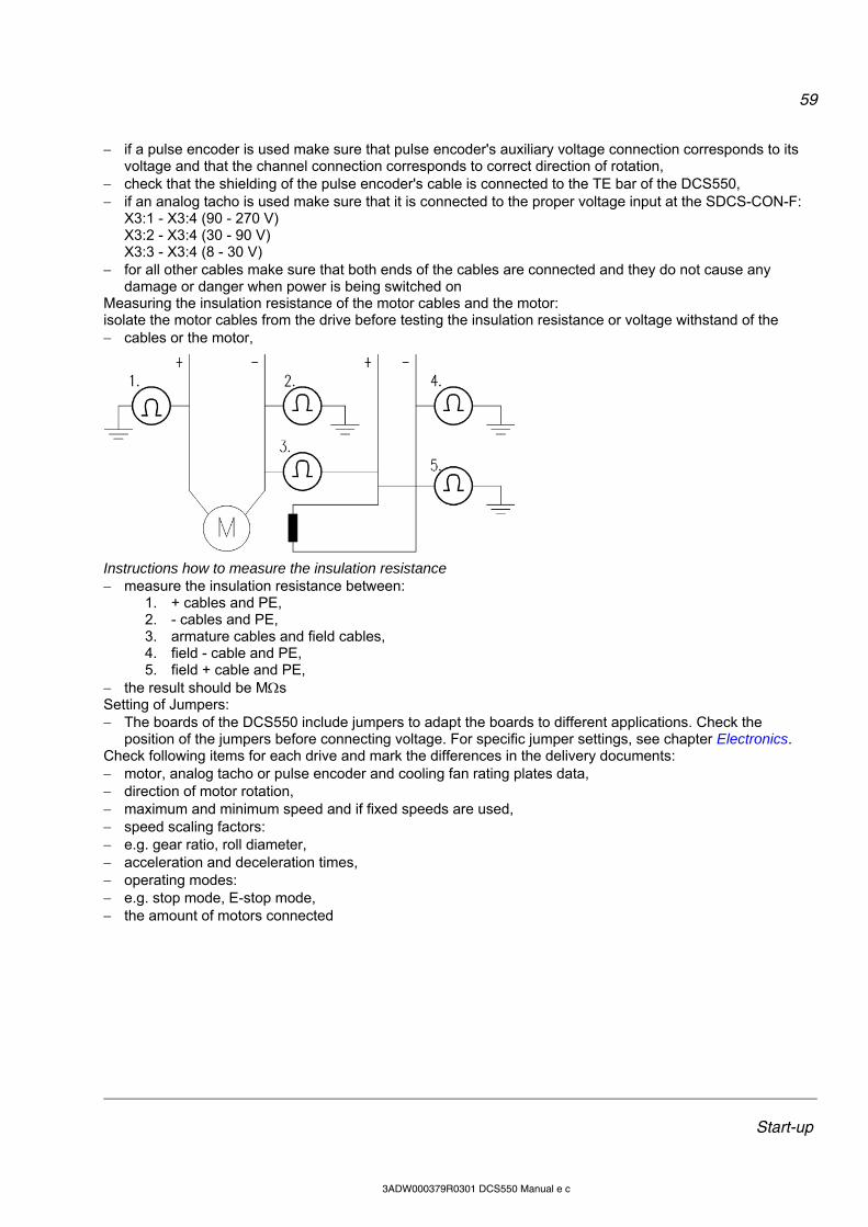
59
Start-up
3ADW000379R0301 DCS550 Manual e c
if a pulse encoder is used make sure that pulse encoder's auxiliary voltage connection corresponds to its voltage and that the channel connection corresponds to correct direction of rotation,
check that the shielding of the pulse encoder's cable is connected to the TE bar of the DCS550, if an analog tacho is used make sure that it is connected to the proper voltage input at the SDCS-CON-F:
X3:1 - X3:4 (90 - 270 V) X3:2 - X3:4 (30 - 90 V) X3:3 - X3:4 (8 - 30 V)
for all other cables make sure that both ends of the cables are connected and they do not cause any damage or danger when power is being switched on
Measuring the insulation resistance of the motor cables and the motor: isolate the motor cables from the drive before testing the insulation resistance or voltage withstand of the cables or the motor,
Instructions how to measure the insulation resistance measure the insulation resistance between:
1. + cables and PE, 2. - cables and PE, 3. armature cables and field cables, 4. field - cable and PE, 5. field + cable and PE,
the result should be Ms Setting of Jumpers: The boards of the DCS550 include jumpers to adapt the boards to different applications. Check the
position of the jumpers before connecting voltage. For specific jumper settings, see chapter Electronics. Check following items for each drive and mark the differences in the delivery documents: motor, analog tacho or pulse encoder and cooling fan rating plates data, direction of motor rotation, maximum and minimum speed and if fixed speeds are used, speed scaling factors: e.g. gear ratio, roll diameter, acceleration and deceleration times, operating modes: e.g. stop mode, E-stop mode, the amount of motors connected

60
Start-up
3ADW000379R0301 DCS550 Manual e c
Checking with the power switched on
There is dangerous voltage inside the cabinet!
Switching the power on: prior to connecting the voltage proceed as follows:
1. ensure that all the cable connections are checked and that the connections can’t cause any danger, 2. close all doors of enclosed converter before switching power on, 3. be ready to trip the supply transformer if anything abnormal occurs, 4. switch the power on
Measurements made with power on: check the operation of the auxiliary equipment,
1. check the circuits for external interfaces on site: 2. E-stop circuit, 3. remote control of the main breaker, 4. signals connected to the control system, 5. other signals which remain to be checked
Connecting voltage to the drive: check from the delivery diagrams the type of boards and converters which are used in the system, check all time relay and breaker settings, close the supply disconnecting device (check the connection from the delivery diagrams), close all protection switches one at a time and measure for proper voltage
Checking the DCS550 firmware Nominal values of the converter are available in group 4, check following signals: ConvNomVolt (4.04), nominal AC converter voltage in V read from TypeCode (97.01), ConvNomCur (4.05), nominal converter DC current in A read from TypeCode (97.01), ConvType (4.14), recognized converter type read from TypeCode (97.01), QuadrantType (4.15), recognized converter quadrant type read from TypeCode (97.01) or S BlockBrdg2
(97.07), MaxBridgeTemp (4.17), maximum bridge temperature in degree centigrade read from TypeCode (97.01) or
S MaxBrdgTemp (97.04) If signals are not correct adapt them, see group 97 in this manual.
Connect DCS550 to PC with DWL Connect a normal serial cable from the PC COM port to X34 on the drive:
Remove the DCS Control Panel, if present. Depress the locks to remove the cover
Connect the DCS550 via X34 to the PC COM port
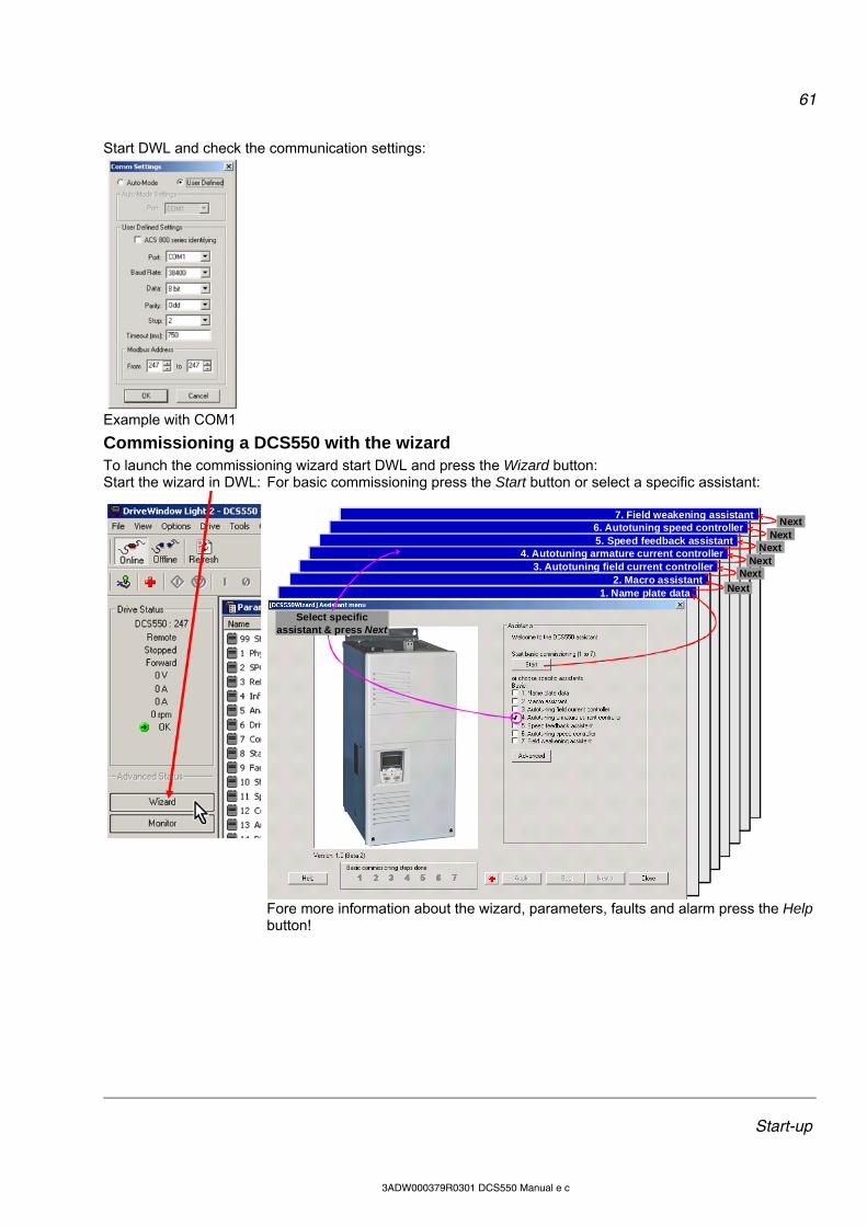
61
Start-up
3ADW000379R0301 DCS550 Manual e c
Start DWL and check the communication settings:
Example with COM1
Commissioning a DCS550 with the wizard To launch the commissioning wizard start DWL and press the Wizard button: Start the wizard in DWL: For basic commissioning press the Start button or select a specific assistant:
7. Field weakening assistant
6. Autotuning speed controller5. Speed feedback assistant
4. Autotuning armature current controller3. Autotuning field current controller
2. Macro assistant1. Name plate data Next
Next Next
Next Next
Next
Select specific assistant & press Next
Fore more information about the wizard, parameters, faults and alarm press the Help
button!
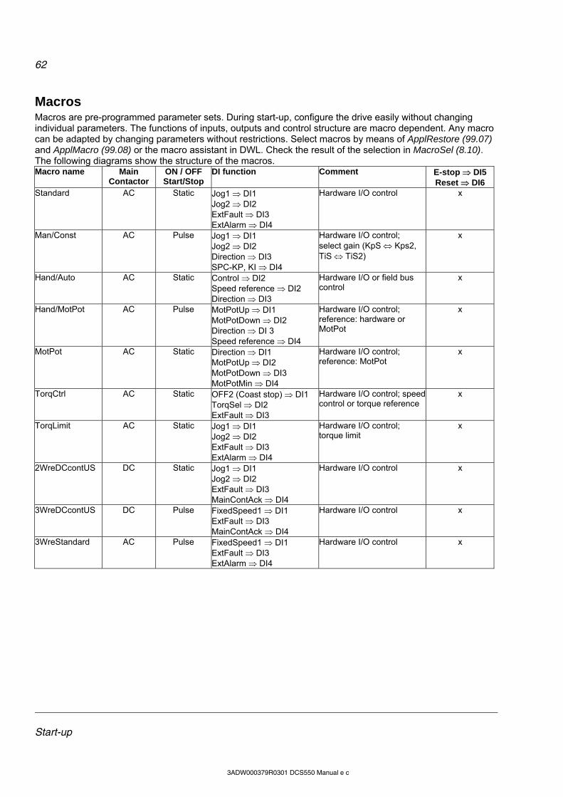
62
Start-up
3ADW000379R0301 DCS550 Manual e c
Macros Macros are pre-programmed parameter sets. During start-up, configure the drive easily without changing individual parameters. The functions of inputs, outputs and control structure are macro dependent. Any macro can be adapted by changing parameters without restrictions. Select macros by means of ApplRestore (99.07) and ApplMacro (99.08) or the macro assistant in DWL. Check the result of the selection in MacroSel (8.10). The following diagrams show the structure of the macros. Macro name Main
Contactor ON / OFF Start/Stop
DI function Comment E-stop DI5 Reset DI6
Standard AC Static Jog1 DI1 Jog2 DI2 ExtFault DI3 ExtAlarm DI4
Hardware I/O control x
Man/Const AC Pulse Jog1 DI1 Jog2 DI2 Direction DI3 SPC-KP, KI DI4
Hardware I/O control; select gain (KpS Kps2, TiS TiS2)
x
Hand/Auto AC Static Control DI2 Speed reference DI2 Direction DI3
Hardware I/O or field bus control
x
Hand/MotPot AC Pulse MotPotUp DI1 MotPotDown DI2 Direction DI 3 Speed reference DI4
Hardware I/O control; reference: hardware or MotPot
x
MotPot AC Static Direction DI1 MotPotUp DI2 MotPotDown DI3 MotPotMin DI4
Hardware I/O control; reference: MotPot
x
TorqCtrl AC Static OFF2 (Coast stop) DI1 TorqSel DI2 ExtFault DI3
Hardware I/O control; speed control or torque reference
x
TorqLimit AC Static Jog1 DI1 Jog2 DI2 ExtFault DI3 ExtAlarm DI4
Hardware I/O control; torque limit
x
2WreDCcontUS DC Static Jog1 DI1 Jog2 DI2 ExtFault DI3 MainContAck DI4
Hardware I/O control x
3WreDCcontUS DC Pulse FixedSpeed1 DI1 ExtFault DI3 MainContAck DI4
Hardware I/O control x
3WreStandard AC Pulse FixedSpeed1 DI1 ExtFault DI3 ExtAlarm DI4
Hardware I/O control x

63
Start-up
3ADW000379R0301 DCS550 Manual e c
ONOFFStatStopFault
Ext Fault30.31
Ext Alarm30.32
X96:
DO8
1 2 X99:1 2 X52: 1 2 3 U1 W1V1 PE
X96:1
X96:2
L1 L2 L3
F1
M~
F51
2
K15
K15
C 1 D 1
AITAC AI1
AI2
AI3
AI4
+10V-10V A
O1
AO
2
IAC
T
_ _ _ _ _+ + + + +
T
E
0V0V0V0V0V
X1: 1 2 3 4 5 6 7 8 9 10 X2: 1 2 3 4 5 6 7 8 9 10 1...10X3:
+
_
F41
2
F71
2
1 3 5
2 4 6
L1
X10:F+ F-2 1
L1 N
DCS550_macros_c.dsf
DCS550
*
(SDCS-PIN-F)
M
+ _
DI1
DI2
DI3
DI4
DI5
DI6
DI7
DI8
+24V DO
1
DO
2
DO
3
DO
4
NC
NC
NC
X4:1 2 3 4 5 6 7 8 9 10 X5:1 2 3 4 5 6 7 8
current controller
20.1820.19
limiter
secondSPC 24.29
speedcontroller
-
EMF
Tacho
Encoderramplimit
secondramp
11.06
+
+
10
.02
Up
11.
13
Do
wn
11.
14
Min
11
.15
Motor pot
RPBARCANRCNARDNARMBA
Word1
Word2
Word3
Jog2 10.18Jog1 10.17
HW Start 10.16 1
7.01
HW On 10.15 HW ctrl
10.0110.07
ESTOP
Fixspeed223.03
Fixspeed123.02
11.03
11.02
11.12
+
26.0126.04
-
+
8.01
6.03
8.02
Enc
od
er
90
...2
70
V
30
...9
0V
DO8
14.1514.16MCW
K1
Control board (SDCS-CON-F)
Power supply
Convertermodule
'on board' field exciter
see section fan connection
the polarities are shown for motoringif there are intermediate terminals
Aux.supply 525V 50/60 Hz
Legend
fuse
reactor
Line reactor
push button
switch NO NC
K1
K1
Jog
1
Jog
2
Ext
ern
al fa
ult
Ext
ern
al a
larm
ES
TO
P 1
0.0
9
Re
set 1
0.0
3
Sta
rtS
top
On
Off1
Re
ad
yRu
n
Re
ad
y R
ef
Fa
ult
or A
larm
Ze
ro s
pe
ed
K15
Sp
eed
ref.
Mo
tor s
pe
ed
act
. Arm
. vo
lt.
act
. cu
rre
nt
Standard
close
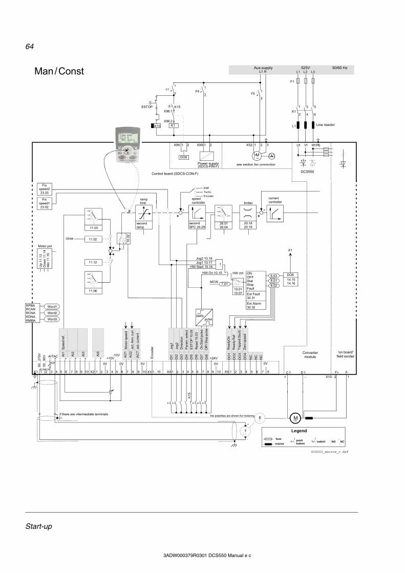
64
Start-up
3ADW000379R0301 DCS550 Manual e c
ONOFFStatStopFault
Ext Fault30.31
Ext Alarm30.32
X96:
DO8
1 2 X99:1 2 X52: 1 2 3 U1 W1V1 PE
X96:1
X96:2
L1 L2 L3
F1
M~
F51
2
K15
K15
C 1 D 1
AITAC AI1
AI2
AI3
AI4
+10V-10V A
O1
AO
2
IAC
T
_ _ _ _ _+ + + + +
T
E
0V0V0V0V0V
X1: 1 2 3 4 5 6 7 8 9 10 X2: 1 2 3 4 5 6 7 8 9 10 1...10X3:
+
_
F41
2
F71
2
1 3 5
2 4 6
L1
X10:F+ F-2 1
L1 N
DCS550_macros_c.dsf
DCS550
*
(SDCS-PIN-F)
M
+ _
DI1
DI2
DI3
DI4
DI5
DI6
DI7
DI8
+24V DO
1
DO
2
DO
3
DO
4
NC
NC
NC
X4:1 2 3 4 5 6 7 8 9 10 X5:1 2 3 4 5 6 7 8
current controller
20.1820.19
limiter
secondSPC 24.29
speedcontroller
-
EMF
Tacho
Encoderramplimit
secondramp
11.06
+
+
10
.02
Up
11.
13
Do
wn
11.
14
Min
11
.15
Motor pot
RPBARCANRCNARDNARMBA
Word1
Word2
Word3
Jog2 10.18Jog1 10.17
HW Start 10.16 1
7.01
HW On 10.15 HW ctrl
10.0110.07
ESTOP
Fixspeed223.03
Fixspeed123.02
11.03
11.02
11.12
+
26.0126.04
-
+
8.01
6.03
8.02
Enc
od
er
90
...2
70V
30
...9
0V
DO8
14.1514.16MCW
K1
Control board (SDCS-CON-F)
Power supply
Convertermodule
'on board' field exciter
see section fan connection
the polarities are shown for motoringif there are intermediate terminals
Aux.supply 525V 50/60 Hz
Legend
fuse
reactor
Line reactor
push button
switch NO NC
K1
K1
Jog
1
Jog
2
Dir
ect
ion
Pa
ram
. se
lect
ES
TO
P 1
0.0
9
Re
set 1
0.0
3
Off1
Sto
p pu
lse
On
Sta
rt p
uls
e
Re
ady
On
Re
ady
Ref
Tri
pp
ed
(fa
ult)
Ze
ro s
pe
ed
K15
Sp
eed
ref.
Mo
tor s
pe
ed
act
. Arm
. cu
rr.
act
. cu
rren
t
Man / Const
static pulse
close
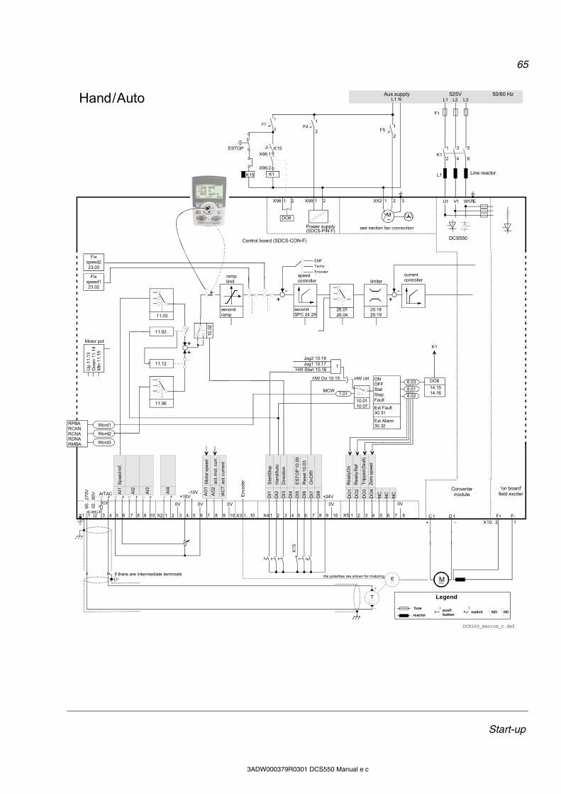
65
Start-up
3ADW000379R0301 DCS550 Manual e c
ONOFFStatStopFault
Ext Fault30.31
Ext Alarm30.32
X96:
DO8
1 2 X99:1 2 X52: 1 2 3 U1 W1V1 PE
X96:1
X96:2
L1 L2 L3
F1
M~
F51
2
K15
K15
C 1 D 1
AITAC AI1
AI2
AI3
AI4
+10V-10V A
O1
AO
2
IAC
T
_ _ _ _ _+ + + + +
T
E
0V0V0V0V0V
X1: 1 2 3 4 5 6 7 8 9 10 X2: 1 2 3 4 5 6 7 8 9 10 1...10X3:
+
_
F41
2
F71
2
1 3 5
2 4 6
L1
X10:F+ F-2 1
L1 N
DCS550_macros_c.dsf
DCS550
*
(SDCS-PIN-F)
M
+ _
DI1
DI2
DI3
DI4
DI5
DI6
DI7
DI8
+24V DO
1
DO
2
DO
3
DO
4
NC
NC
NC
X4:1 2 3 4 5 6 7 8 9 10 X5:1 2 3 4 5 6 7 8
current controller
20.1820.19
limiter
secondSPC 24.29
speedcontroller
-
EMF
Tacho
Encoderramplimit
secondramp
11.06
+
+
10
.02
Up
11.
13
Do
wn
11
.14
Min
11
.15
Motor pot
RPBARCANRCNARDNARMBA
Word1
Word2
Word3
Jog2 10.18Jog1 10.17
HW Start 10.16 1
7.01
HW On 10.15 HW ctrl
10.0110.07
ESTOP
Fixspeed223.03
Fixspeed123.02
11.03
11.02
11.12
+
26.0126.04
-
+
8.01
6.03
8.02
Enc
od
er
90
...2
70V
30
...9
0V
DO8
14.1514.16MCW
K1
Control board (SDCS-CON-F)
Power supply
Convertermodule
'on board' field exciter
see section fan connection
the polarities are shown for motoringif there are intermediate terminals
Aux.supply 525V 50/60 Hz
Legend
fuse
reactor
Line reactor
push button
switch NO NC
K1
K1
Sta
rtS
top
Ha
nd
Au
to
Dir
ect
ion
ES
TO
P 1
0.0
9
Re
set 1
0.0
3
On
Off1
Rea
dyO
n
Rea
dy
Re
f
Tri
pp
ed
(fa
ult)
Ze
ro s
pe
ed
K1
5
Spe
ed
ref.
Mo
tor s
pe
ed
act
. mot
. cu
rr.
act
. cu
rre
nt
Hand / Auto

66
Start-up
3ADW000379R0301 DCS550 Manual e c
ONOFFStatStopFault
Ext Fault30.31
Ext Alarm30.32
X96:
DO8
1 2 X99:1 2 X52: 1 2 3 U1 W1V1 PE
X96:1
X96:2
L1 L2 L3
F1
M~
F51
2
K15
K15
C 1 D 1
AITAC AI1
AI2
AI3
AI4
+10V-10V A
O1
AO
2
IAC
T
_ _ _ _ _+ + + + +
T
E
0V0V0V0V0V
X1: 1 2 3 4 5 6 7 8 9 10 X2: 1 2 3 4 5 6 7 8 9 10 1...10X3:
+
_
F41
2
F71
2
1 3 5
2 4 6
L1
X10:F+ F-2 1
L1 N
DCS550_macros_c.dsf
DCS550
*
(SDCS-PIN-F)
M
+ _
DI1
DI2
DI3
DI4
DI5
DI6
DI7
DI8
+24V DO
1
DO
2
DO
3
DO
4
NC
NC
NC
X4:1 2 3 4 5 6 7 8 9 10 X5:1 2 3 4 5 6 7 8
current controller
20.1820.19
limiter
secondSPC 24.29
speedcontroller
-
EMF
Tacho
Encoderramplimit
secondramp
11.06
+
+
10
.02
Up
11.
13
Do
wn
11
.14
Min
11
.15
Motor pot
RPBARCANRCNARDNARMBA
Word1
Word2
Word3
Jog2 10.18Jog1 10.17
HW Start 10.16 1
7.01
HW On 10.15 HW ctrl
10.0110.07
ESTOP
Fixspeed223.03
Fixspeed123.02
11.03
11.02
11.12
+
26.0126.04
-
+
8.01
6.03
8.02
Enc
od
er
90
...2
70V
30
...9
0V
DO8
14.1514.16MCW
K1
Control board (SDCS-CON-F)
Power supply
Convertermodule
'on board' field exciter
see section fan connection
the polarities are shown for motoringif there are intermediate terminals
Aux.supply 525V 50/60 Hz
Legend
fuse
reactor
Line reactor
push button
switch NO NC
K1
K1
Mo
tor p
ot u
p
Mo
tor
pot d
own
Dir
ect
ion
Sp
eed
ref.
se
l.
ES
TO
P 1
0.0
9
Re
set 1
0.0
3
Off
1 S
top
puls
e
On
Sta
rt p
uls
e
Rea
dyO
n
Rea
dy
Re
f
Tri
pp
ed
(fa
ult)
Ze
ro s
pe
ed
K15
Sp
eed
ref.
Mo
tor s
pe
ed
act
. mo
t. v
olt.
act
. cu
rre
nt
Hand / Mot Pot
static pulse
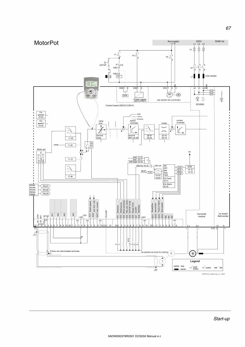
67
Start-up
3ADW000379R0301 DCS550 Manual e c
ONOFFStatStopFault
Ext Fault30.31
Ext Alarm30.32
X96:
DO8
1 2 X99:1 2 X52: 1 2 3 U1 W1V1 PE
X96:1
X96:2
L1 L2 L3
F1
M~
F51
2
K15
K15
C 1 D 1
AITAC AI1
AI2
AI3
AI4
+10V-10V A
O1
AO
2
IAC
T
_ _ _ _ _+ + + + +
T
E
0V0V0V0V0V
X1: 1 2 3 4 5 6 7 8 9 10 X2: 1 2 3 4 5 6 7 8 9 10 1...10X3:
+
_
F41
2
F71
2
1 3 5
2 4 6
L1
X10:F+ F-2 1
L1 N
DCS550_macros_c.dsf
DCS550
*
(SDCS-PIN-F)
M
+ _
DI1
DI2
DI3
DI4
DI5
DI6
DI7
DI8
+24V DO
1
DO
2
DO
3
DO
4
NC
NC
NC
X4:1 2 3 4 5 6 7 8 9 10 X5:1 2 3 4 5 6 7 8
current controller
20.1820.19
limiter
secondSPC 24.29
speedcontroller
-
EMF
Tacho
Encoderramplimit
secondramp
11.06
+
+
10.0
2
Up
11.
13
Do
wn
11
.14
Min
11
.15
Motor pot
RPBARCANRCNARDNARMBA
Word1
Word2
Word3
Jog2 10.18Jog1 10.17
HW Start 10.16 1
7.01
HW On 10.15 HW ctrl
10.0110.07
ESTOP
Fixspeed223.03
Fixspeed123.02
11.03
11.02
11.12
+
26.0126.04
-
+
8.01
6.03
8.02
Enc
od
er
90
...2
70
V
30
...9
0V
DO8
14.1514.16MCW
K1
Control board (SDCS-CON-F)
Power supply
Convertermodule
'on board' field exciter
see section fan connection
the polarities are shown for motoringif there are intermediate terminals
Aux.supply 525V 50/60 Hz
Legend
fuse
reactor
Line reactor
push button
switch NO NC
K1
K1
Dir
ect
ion
Mot
ot p
ot u
p
Mo
tor p
ot d
ow
n
Mot
. po
t. m
inim
.
ES
TO
P 1
0.0
9
Re
set 1
0.0
3
Sta
rtS
top
On
Off1
Re
adyR
un
ab
ove
lim
it
Fa
ult
or A
larm
Ze
ro s
pe
ed
K1
5
Mo
tor s
pe
ed
act
. Arm
. vo
lt.
act
. cu
rre
nt
Motor Pot
close

68
Start-up
3ADW000379R0301 DCS550 Manual e c
ONOFFStatStopFault
Ext Fault30.31
Ext Alarm30.32
X96:
DO8
1 2 X99:1 2 X52: 1 2 3 U1 W1V1 PE
X96:1
X96:2
L1 L2 L3
F1
M~
F51
2
K15
K15
C 1 D 1
AITAC AI1
AI2
AI3
AI4
+10V-10V A
O1
AO
2
IAC
T
_ _ _ _ _+ + + + +
T
E
0V0V0V0V0V
X1: 1 2 3 4 5 6 7 8 9 10 X2: 1 2 3 4 5 6 7 8 9 10 1...10X3:
+
_
F41
2
F71
2
1 3 5
2 4 6
L1
X10:F+ F-2 1
L1 N
DCS550_macros_c.dsf
DCS550
*
(SDCS-PIN-F)
M
+ _
DI1
DI2
DI3
DI4
DI5
DI6
DI7
DI8
+24V DO
1
DO
2
DO
3
DO
4
NC
NC
NC
X4:1 2 3 4 5 6 7 8 9 10 X5:1 2 3 4 5 6 7 8
current controller
20.1820.19
limiter
secondSPC 24.29
speedcontroller
-
EMF
Tacho
Encoderramplimit
secondramp
11.06
+
+
10
.02
Up
11.
13
Do
wn
11
.14
Min
11
.15
Motor pot
RPBARCANRCNARDNARMBA
Word1
Word2
Word3
Jog2 10.18Jog1 10.17
HW Start 10.16 1
7.01
HW On 10.15 HW ctrl
10.0110.07
ESTOP
Fixspeed223.03
Fixspeed123.02
11.03
11.02
11.12
+
26.0126.04
-
+
8.01
6.03
8.02
Enc
od
er
90
...2
70V
30
...9
0V
DO8
14.1514.16MCW
K1
Control board (SDCS-CON-F)
Power supply
Convertermodule
'on board' field exciter
see section fan connection
the polarities are shown for motoringif there are intermediate terminals
Aux.supply 525V 50/60 Hz
Legend
fuse
reactor
Line reactor
push button
switch NO NC
K1
K1
Off
2 (c
oa
st s
top
)
To
rqu
e s
ele
ct
Ext
ern
al f
ault
ES
TO
P 1
0.0
9
Re
set 1
0.0
3
Sta
rtS
top
On
Off1
= c
urr
ent o
ff
Re
ady
Ru
n
Re
ady
Re
f
Fa
ult
or A
larm
Ze
ro s
pe
ed
K15
Mo
tor s
pe
ed
Mo
tor T
orq
ue
act
. cu
rre
nt
Mo
tor s
pe
ed
Fixref1
23.01
close
Torque Ctrl

69
Start-up
3ADW000379R0301 DCS550 Manual e c
ONOFFStatStopFault
Ext Fault30.31
Ext Alarm30.32
X96:
DO8
1 2 X99:1 2 X52: 1 2 3 U1 W1V1 PE
X96:1
X96:2
L1 L2 L3
F1
M~
F51
2
K15
K15
C 1 D 1
AITAC AI1
AI2
AI3
AI4
+10V-10V A
O1
AO
2
IAC
T
_ _ _ _ _+ + + + +
T
E
0V0V0V0V0V
X1: 1 2 3 4 5 6 7 8 9 10 X2: 1 2 3 4 5 6 7 8 9 10 1...10X3:
+
_
F41
2
F71
2
1 3 5
2 4 6
L1
X10:F+ F-2 1
L1 N
DCS550_macros_c.dsf
DCS550
*
(SDCS-PIN-F)
M
+ _
DI1
DI2
DI3
DI4
DI5
DI6
DI7
DI8
+24V DO
1
DO
2
DO
3
DO
4
NC
NC
NC
X4:1 2 3 4 5 6 7 8 9 10 X5:1 2 3 4 5 6 7 8
current controller
20.1820.19
limiter
secondSPC 24.29
speedcontroller
-
EMF
Tacho
Encoderramplimit
secondramp
11.06
+
+
10
.02
Up
11.
13
Do
wn
11
.14
Min
11
.15
Motor pot
RPBARCANRCNARDNARMBA
Word1
Word2
Word3
Jog2 10.18Jog1 10.17
HW Start 10.16 1
7.01
HW On 10.15 HW ctrl
10.0110.07
ESTOP
Fixspeed223.03
Fixspeed123.02
11.03
11.02
11.12
+
26.0126.04
-
+
8.01
6.03
8.02
Enc
od
er
90
...2
70V
30
...9
0V
DO8
14.1514.16MCW
K1
Control board (SDCS-CON-F)
Power supply
Convertermodule
'on board' field exciter
see section fan connection
the polarities are shown for motoringif there are intermediate terminals
Aux.supply 525V 50/60 Hz
Legend
fuse
reactor
Line reactor
push button
switch NO NC
K1
K1
Jog
1
Jog
2
Ext
ern
al f
au
lt
Ext
ern
al a
larm
ES
TO
P 1
0.0
9
Re
set 1
0.0
3
Sta
rtS
top
On
Off1
Rea
dyR
un
Rea
dy
Re
f
Fa
ult
or A
larm
Ze
ro s
pe
ed
K1
5
Sp
eed
ref.
To
rqu
e li
mit
Mo
tor s
pe
ed
act
. Arm
. vo
lt.
act
. cu
rre
nt
Torque limit
AI2
> 0
close
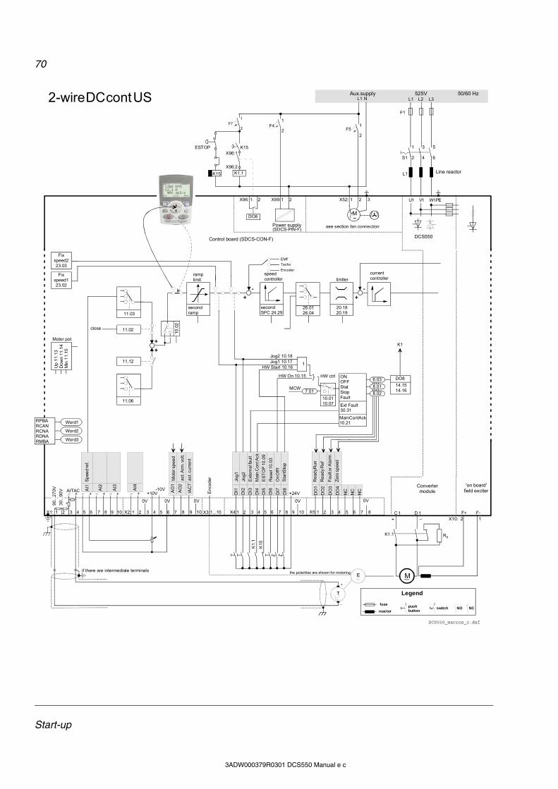
70
Start-up
3ADW000379R0301 DCS550 Manual e c
ONOFFStatStopFault
Ext Fault30.31
Ext Alarm30.32
X96:
DO8
1 2 X99:1 2 X52: 1 2 3 U1 W1V1 PE
X96:1
X96:2
L1 L2 L3
F1
M~
F51
2
K15
K15
C 1 D 1
AITAC AI1
AI2
AI3
AI4
+10V-10V A
O1
AO
2
IAC
T
_ _ _ _ _+ + + + +
T
E
0V0V0V0V0V
X1: 1 2 3 4 5 6 7 8 9 10 X2: 1 2 3 4 5 6 7 8 9 10 1...10X3:
+
_
F41
2
F71
2
1 3 5
2 4 6
L1
X10:F+ F-2 1
L1 N
DCS550_macros_c.dsf
DCS550
*
(SDCS-PIN-F)
M
+ _
DI1
DI2
DI3
DI4
DI5
DI6
DI7
DI8
+24V DO
1
DO
2
DO
3
DO
4
NC
NC
NC
X4:1 2 3 4 5 6 7 8 9 10 X5:1 2 3 4 5 6 7 8
current controller
20.1820.19
limiter
secondSPC 24.29
speedcontroller
-
EMF
Tacho
Encoderramplimit
secondramp
11.06
+
+
10
.02
Up
11.
13
Do
wn
11
.14
Min
11
.15
Motor pot
RPBARCANRCNARDNARMBA
Word1
Word2
Word3
Jog2 10.18Jog1 10.17
HW Start 10.16 1
7.01
HW On 10.15 HW ctrl
10.0110.07
ESTOP
Fixspeed223.03
Fixspeed123.02
11.03
11.02
11.12
+
26.0126.04
-
+
8.01
6.03
8.02
Enc
od
er
90
...2
70V
30
...9
0V
DO8
14.1514.16MCW
K1
Control board (SDCS-CON-F)
Power supply
Convertermodule
'on board' field exciter
see section fan connection
the polarities are shown for motoringif there are intermediate terminals
Aux.supply 525V 50/60 Hz
Legend
fuse
reactor
Line reactor
push button
switch NO NC
K1.1 RB
S1
K1.1
Jog
1
Jog
2
Ext
ern
al f
au
lt
Ma
in C
on
t Ack
ES
TO
P 1
0.0
9
Re
set 1
0.0
3
Sta
rtS
top
On
Off1
Rea
dyR
un
Rea
dy
Re
f
Fa
ult
or A
larm
Ze
ro s
pe
ed
K15
Spe
ed
ref.
Mo
tor s
pe
ed
act
. Arm
. vo
lt.
act
. cu
rre
nt
2-wire DC cont US
K1.
1
MainContAck10.21
close
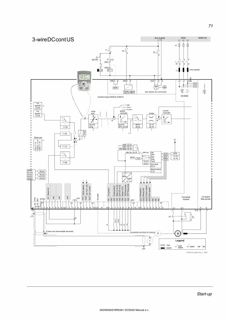
71
Start-up
3ADW000379R0301 DCS550 Manual e c
ONOFFStatStopFault
Ext Fault30.31
Ext Alarm30.32
X96:
DO8
1 2 X99:1 2 X52: 1 2 3 U1 W1V1 PE
X96:1
X96:2
L1 L2 L3
F1
M~
F51
2
K15
K15
C 1 D 1
AITAC AI1
AI2
AI3
AI4
+10V-10V A
O1
AO
2
IAC
T
_ _ _ _ _+ + + + +
T
E
0V0V0V0V0V
X1: 1 2 3 4 5 6 7 8 9 10 X2: 1 2 3 4 5 6 7 8 9 10 1...10X3:
+
_
F41
2
F71
2
1 3 5
2 4 6
L1
X10:F+ F-2 1
L1 N
DCS550_macros_c.dsf
DCS550
*
(SDCS-PIN-F)
M
+ _
DI1
DI2
DI3
DI4
DI5
DI6
DI7
DI8
+24V DO
1
DO
2
DO
3
DO
4
NC
NC
NC
X4:1 2 3 4 5 6 7 8 9 10 X5:1 2 3 4 5 6 7 8
current controller
20.1820.19
limiter
secondSPC 24.29
speedcontroller
-
EMF
Tacho
Encoderramplimit
secondramp
11.06
+
+
10
.02
Up
11.
13
Do
wn
11
.14
Min
11
.15
Motor pot
RPBARCANRCNARDNARMBA
Word1
Word2
Word3
Jog2 10.18Jog1 10.17
HW Start 10.16 1
7.01
HW On 10.15 HW ctrl
10.0110.07
ESTOP
Fixspeed223.03
Fixspeed123.02
11.03
11.02
11.12
+
26.0126.04
-
+
8.01
6.03
8.02
Enc
od
er
90
...2
70V
30
...9
0V
DO8
14.1514.16MCW
K1
Control board (SDCS-CON-F)
Power supply
Convertermodule
'on board' field exciter
see section fan connection
the polarities are shown for motoringif there are intermediate terminals
Aux.supply 525V 50/60 Hz
Legend
fuse
reactor
Line reactor
push button
switch NO NC
K1.1 RB
S1
K1.1
Fix
sp
eed
1
Ext
ern
al f
au
lt
Ma
in C
on
t Ack
ES
TO
P 1
0.0
9
Re
set 1
0.0
3
OF
F S
top
pu
lse
ON
Sta
rt p
uls
e
Re
ad
yRu
n
Re
ad
y R
ef
Fa
ult
or A
larm
Ze
ro s
pe
ed
K15
static pulse
Spe
ed
ref.
Mo
tor s
pe
ed
act
. Arm
. vo
lt.
act
. cu
rre
nt
3-wire DC cont US
K1.
1
MainContAck10.21
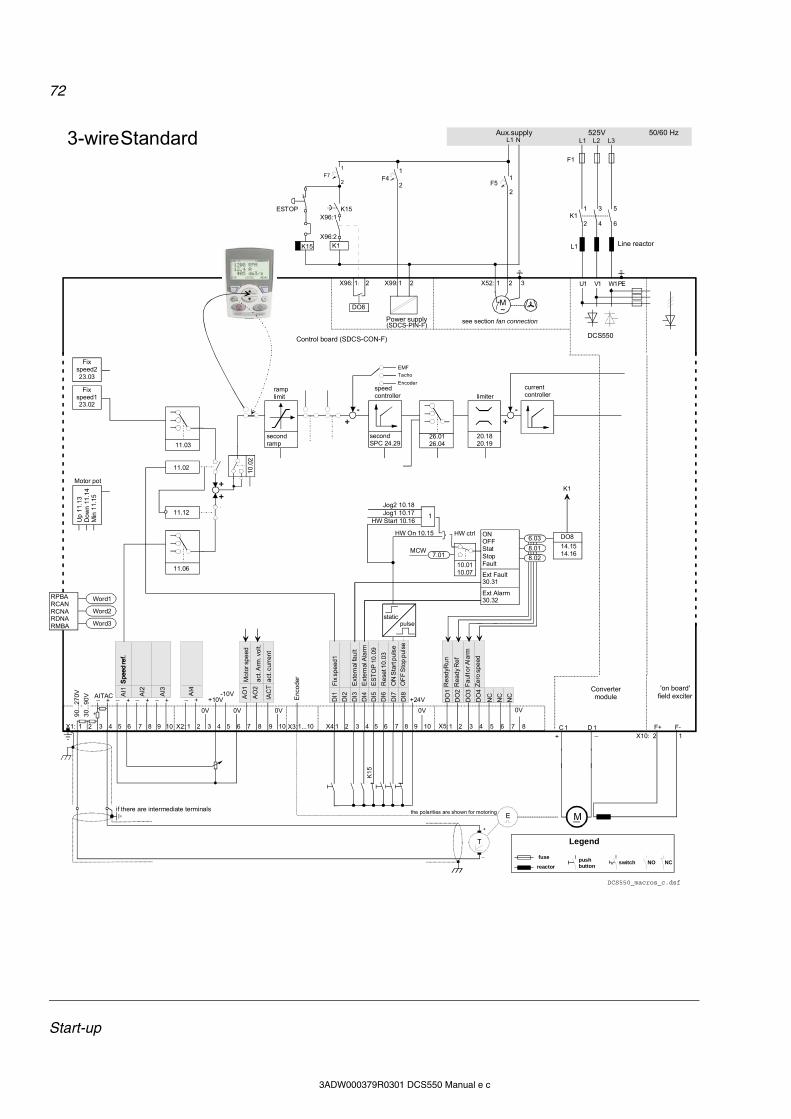
72
Start-up
3ADW000379R0301 DCS550 Manual e c
ONOFFStatStopFault
Ext Fault30.31
Ext Alarm30.32
X96:
DO8
1 2 X99:1 2 X52: 1 2 3 U1 W1V1 PE
X96:1
X96:2
L1 L2 L3
F1
M~
F51
2
K15
K15
C 1 D 1
AITAC AI1
AI2
AI3
AI4
+10V-10V A
O1
AO
2
IAC
T
_ _ _ _ _+ + + + +
T
E
0V0V0V0V0V
X1: 1 2 3 4 5 6 7 8 9 10 X2: 1 2 3 4 5 6 7 8 9 10 1...10X3:
+
_
F41
2
F71
2
1 3 5
2 4 6
L1
X10:F+ F-2 1
L1 N
DCS550_macros_c.dsf
DCS550
*
(SDCS-PIN-F)
M
+ _
DI1
DI2
DI3
DI4
DI5
DI6
DI7
DI8
+24V DO
1
DO
2
DO
3
DO
4
NC
NC
NC
X4:1 2 3 4 5 6 7 8 9 10 X5:1 2 3 4 5 6 7 8
current controller
20.1820.19
limiter
secondSPC 24.29
speedcontroller
-
EMF
Tacho
Encoderramplimit
secondramp
11.06
+
+
10
.02
Up
11.
13
Do
wn
11
.14
Min
11
.15
Motor pot
RPBARCANRCNARDNARMBA
Word1
Word2
Word3
Jog2 10.18Jog1 10.17
HW Start 10.16 1
7.01
HW On 10.15 HW ctrl
10.0110.07
ESTOP
Fixspeed223.03
Fixspeed123.02
11.03
11.02
11.12
+
26.0126.04
-
+
8.01
6.03
8.02
Enc
od
er
90
...2
70V
30
...9
0V
DO8
14.1514.16MCW
K1
Control board (SDCS-CON-F)
Power supply
Convertermodule
'on board' field exciter
see section fan connection
the polarities are shown for motoringif there are intermediate terminals
Aux.supply 525V 50/60 Hz
Legend
fuse
reactor
Line reactor
push button
switch NO NC
Fix
sp
eed
1
Ext
ern
al f
au
lt
Ext
ern
al A
larm
ES
TO
P 1
0.0
9
Re
set 1
0.0
3
OF
F S
top
pul
se
ON
Sta
rt p
uls
e
Re
ad
yRu
n
Re
ad
y R
ef
Fa
ult
or A
larm
Ze
ro s
pe
ed
static pulse
Sp
eed
ref.
Mo
tor s
pe
ed
act
. Arm
. vol
t.
act
. cu
rre
nt
K1
K1
K1
5
Sp
eed
ref.
3-wire Standard
static pulse
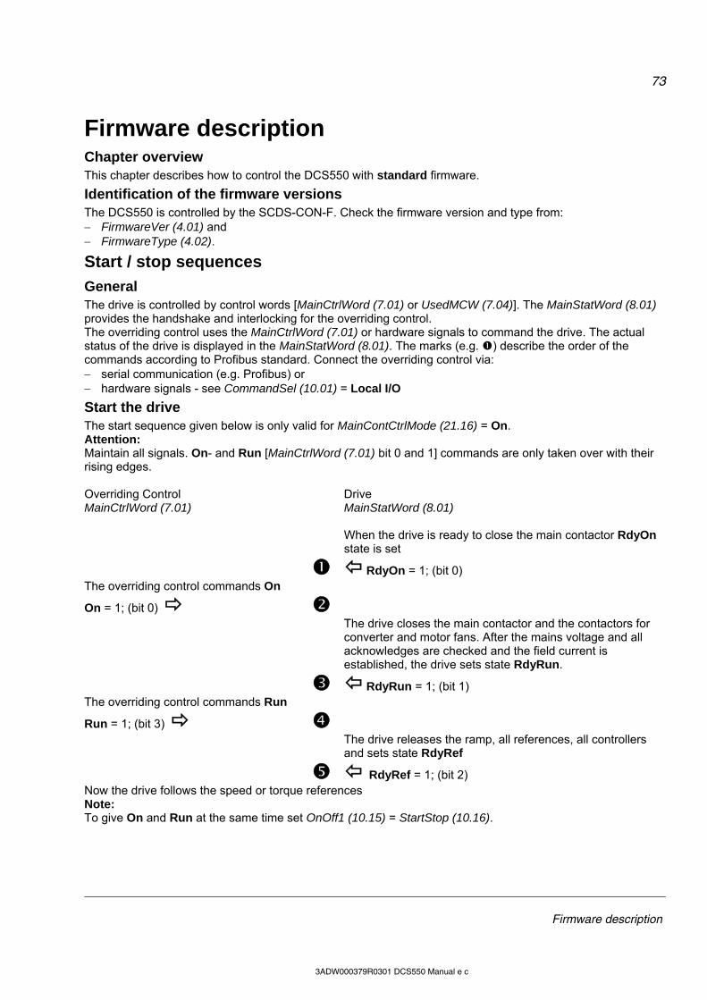
73
Firmware description
3ADW000379R0301 DCS550 Manual e c
Firmware description Chapter overview This chapter describes how to control the DCS550 with standard firmware.
Identification of the firmware versions The DCS550 is controlled by the SCDS-CON-F. Check the firmware version and type from: FirmwareVer (4.01) and FirmwareType (4.02).
Start / stop sequences
General The drive is controlled by control words [MainCtrlWord (7.01) or UsedMCW (7.04)]. The MainStatWord (8.01) provides the handshake and interlocking for the overriding control. The overriding control uses the MainCtrlWord (7.01) or hardware signals to command the drive. The actual status of the drive is displayed in the MainStatWord (8.01). The marks (e.g. ) describe the order of the commands according to Profibus standard. Connect the overriding control via: serial communication (e.g. Profibus) or hardware signals - see CommandSel (10.01) = Local I/O
Start the drive The start sequence given below is only valid for MainContCtrlMode (21.16) = On. Attention: Maintain all signals. On- and Run [MainCtrlWord (7.01) bit 0 and 1] commands are only taken over with their rising edges. Overriding Control MainCtrlWord (7.01)
Drive MainStatWord (8.01)
When the drive is ready to close the main contactor RdyOn
state is set RdyOn = 1; (bit 0) The overriding control commands On
On = 1; (bit 0)
The drive closes the main contactor and the contactors for converter and motor fans. After the mains voltage and all acknowledges are checked and the field current is established, the drive sets state RdyRun.
RdyRun = 1; (bit 1) The overriding control commands Run
Run = 1; (bit 3)
The drive releases the ramp, all references, all controllers and sets state RdyRef
RdyRef = 1; (bit 2) Now the drive follows the speed or torque references Note: To give On and Run at the same time set OnOff1 (10.15) = StartStop (10.16).
74
Firmware description
3ADW000379R0301 DCS550 Manual e c
Stop the drive The drive can be stopped in two ways, either by taking away the On command directly which opens all contactors as fast as possible after stopping the drive according to Off1Mode (21.02) or by means of the following sequence: Overriding Control MainCtrlWord (7.01)
Drive MainStatWord (8.01)
The overriding control removes Run
Run = 0; (bit 3)
In speed control mode, the drive stops according to StopMode (21.03). In torque control mode, the torque reference is reduced to zero. When zero speed or zero torque is reached the state RdyRef is removed.
RdyRef = 0; (bit 2) The overriding control can keep the On command if the drive has to be started up again
The overriding control removes On
On = 0; (bit 0)
All contactors are opened - the fan contactors stay in according to FanDly (21.14) - and the state RdyRun is removed
RdyRun = 0; (bit 1) Besides, in MainStatWord (8.01), the drive’s state is shown in DriveStat (8.08). Off2 (Coast Stop) and Off3 (E-stop) see chapter Start, Stop and E-stop control.
Excitation
General The DCS550 is equipped with an OnBoard field exciter its function is explained here.
Field control The OnBoard field exciter is controlled by means of FldCtrlMode (44.01): Mode Functionality Armature converter Fix constant field (no field weakening), EMF controller blocked, default 2-Q or 4-Q EMF field weakening active, EMF controller released 2-Q or 4-Q
Field current monitoring
Field minimum trip During normal operation, the field current is compared with M1FldMinTrip (30.12). The drive trips with F541 M1FexLowCur [FaultWord3 (9.03) bit 8] if the field current drops below this limit and is still undershot when FldMinTripDly (45.18) is elapsed. Note: M1FldMinTrip (30.12) is not valid during field heating. In this case, the trip level is automatically set to 50 % of M1FldHeatRef (44.04). The drive trips with F541 M1FexLowCur [FaultWord3 (9.03) bit 8] if 50 % of M1FldHeatRef (44.04) is still undershot when FldMinTripDly (45.18) is elapsed.
75
Firmware description
3ADW000379R0301 DCS550 Manual e c
Field Heating
Overview Field heating (also referred to as “field warming and field economy”) is used for a couple of reasons. Previous generations of DC-drives used voltage-controlled field supplies, meaning that the only thing the field supply could directly control was the field voltage. For DC-motors to maintain optimal torque, it is important to maintain the field current. Ohm’s law (U = R*I) tells us that voltage equals resistance multiplied by current. So as long as resistance remains constant, current is proportional to voltage. However, field resistance increases with temperature. Therefore, a cold motor would have a higher field current than a warm motor, even though voltage remained unchanged. To keep the resistance and thus the current constant, the field was left on to keep it warm. Then the voltage-controlled field supply works just fine. The new generation of drives, including the OnBoard field exciter used with the DCS550, is current controlled. Thus, the field supply directly controls field current. This means that field heating may no longer be necessary when the DCS550 is employed. Another reason field heating is used is to keep moisture out of the motor. Use following parameters to turn on and control field heating: FldHeatSel (21.18), M1FldHeatRef (44.04)
Modes of operation There is one mode of operation in which the field current will be at a reduced level, determined by M1FldHeatRef (44.04). With FldHeatSel (21.18) = OnRun the field heating is on as long as On = 1, Run = 0 [UsedMCW (7.04) bit 3], Off2N = 1 and Off3N = 1. In general, field heating will be on as long as the OnOff input is set, the Start/Stop input is not set and no Coast Stop or E-stop is pending. On [UsedMCW (7.04) bit 0]
Run [UsedMCW (7.04) bit 3]
Off2N [UsedMCW (7.04) bit 1]*
Result
0 x x field is turned off 1 0 1 reduced field current** 1 1 1 normal field current 1 1 0 1 normal field current, then reduced** after stop 1 x 1 0 field is turned off as motor coasts to stop and
cannot turned back on again as long as Coast Stop is pending
*see Off2 (10.08) **the field current will be at the level set by means of M1FldHeatRef (44.04) while motor is stopped
E-stop A pending E-stop - see E Stop (10.09) - switches the field off. It cannot be turned back on again as long as the E-stop is pending. If the E-stop is cleared while in motion, the motor stops according to E StopMode (21.04) and then field and drive will be turned off.
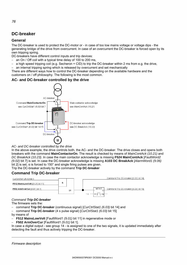
76
Firmware description
3ADW000379R0301 DCS550 Manual e c
DC-breaker
General The DC-breaker is used to protect the DC-motor or - in case of too low mains voltage or voltage dips - the generating bridge of the drive from overcurrent. In case of an overcurrent the DC-breaker is forced open by its own tripping spring. DC-breakers have different control inputs and trip devices: an On / Off coil with a typical time delay of 100 to 200 ms, a high speed tripping coil (e.g. Secheron = CID) to trip the DC-breaker within 2 ms from e.g. the drive, an internal tripping spring which is released by overcurrent and set mechanically There are different ways how to control the DC-breaker depending on the available hardware and the customers on / off philosophy. The following is the most common.
AC- and DC-breaker controlled by the drive
AC- and DC-breaker controlled by the drive In the above example, the drive controls both, the AC- and the DC-breaker. The drive closes and opens both breakers with the command MainContactorOn. The result is checked by means of MainContAck (10.21) and DC BreakAck (10.23). In case the main contactor acknowledge is missing F524 MainContAck [FaultWord2 (9.02) bit 7] is set. In case the DC-breaker acknowledge is missing A103 DC BreakAck [AlarmWord1 (9.06) bit 2] is set, α is forced to 150° and single firing pulses are given. Trip the DC-breaker actively by the command Trip DC-breaker
Command Trip DC-breaker
Command Trip DC-breaker The firmware sets the: command Trip DC-breaker (continuous signal) [CurCtrlStat1 (6.03) bit 14] and command Trip DC-breaker (4 s pulse signal) [CurCtrlStat1 (6.03) bit 15] by means of F512 MainsLowVolt [FaultWord1 (9.01) bit 11] in regenerative mode or F502 ArmOverCur [FaultWord1 (9.01) bit 1]. In case a digital output - see group 14 - is assigned to one of the two signals, it is updated immediately after detecting the fault and thus actively tripping the DC-breaker.

77
Firmware description
3ADW000379R0301 DCS550 Manual e c
Dynamic braking
General Dynamic braking can stop the drive. The principle is to transfer the power of the machine inertia into a braking resistor. Therefore, the armature circuit has to be switched over from the drive to a braking resistor. Additionally flux and field current have to be maintained.
Operation
Activation Dynamic breaking can be activated by all stop modes, in cases of a fault or due to communication breaks: Off1Mode (21.02) when UsedMCW (7.04) bit 0 On is set to low, StopMode (21.03) when UsedMCW (7.04) bit 3 Run is set to low, E StopMode (21.04) when UsedMCW (7.04) bit 2 Off3N is set to low, FaultStopMode (30.30) in case of a trip level 4 fault, SpeedFbFltMode (30.36) in case of a trip level 3 fault, LocalLossCtrl (30.27) when local control is lost, ComLossCtrl (30.28) when communication is lost, In addition dynamic braking can be forced by setting AuxCtrlWord (7.02) bit 5 to high. At the same time, UsedMCW (7.04) bit 3 Run must be set to low.
Application example of dynamic breaking
Function During dynamic braking the field current is maintained by keeping the field exciter activated. The OnBoard field exciter will be supplied via the main contactor, thus CurCtrlStat1 (6.03) bit 7 stays high (MainContactorOn) until zero speed is reached. ① The activation of dynamic braking immediately sets CurCtrlStat1 (6.03) bit 6 to high (dynamic braking
active). ② Dynamic braking forces the armature current to zero and opens the DC-breaker by setting CurCtrlStat1
(6.03) bit 14 to high (Trip DC-breaker). ③ After the armature current is zero and the DC-breaker acknowledge is gone CurCtrlStat1 (6.03) bit 8 is set
to high (DynamicBrakingOn). Connect this signal to a digital output (see group 14) and used it to close the brake contactor. As soon as the brake contactor is closed, dynamic braking starts and decreases the speed.
④ With DynBrakeAck (10.22) it is possible to select a digital input for the brake resistor acknowledge. This input sets A105 DynBrakeAck [AlarmWord1 (9.06) bit 4] as long as the acknowledge is present. Thus the drive cannot be started or re-started while dynamic braking is active, except FlyStart (21.10) = FlyStartDyn.

78
Firmware description
3ADW000379R0301 DCS550 Manual e c
Deactivation ⑤ Dynamic braking is deactivated as soon as zero speed is reached and AuxStatWord (8.02) bit 11
ZeroSpeed is set to high. In case of dynamic braking with EMF feedback [M1SpeedFbSel (50.03) = EMF] there is no valid information about the motor speed and thus no zero speed information. To prevent an interlocking of the drive after dynamic braking the speed is assumed zero after DynBrakeDly (50.11) is elapsed:
Dynamic braking sequence For usage of US style DC-breakers see MainContCtrlMode (21.16).
79
Firmware description
3ADW000379R0301 DCS550 Manual e c
Digital I/O configuration
Chapter overview This chapter describes the I/O configuration of digital and analog inputs and outputs with different hardware possibilities.
Digital inputs (DI’s) The basic I/O board is the SDCS-CON-F with 8 standard DI’s. Extend them by means of one or two RDIO-01 digital I/O extension modules. Thus, the maximum number of DI’s is 14. Select the hardware source by: 1. DIO ExtModule1 (98.03) for DI9 to DI11 and 2. DIO ExtModule2 (98.04) for DI12 to DI14
SDCS-CON-F On the SDCS-CON-F, the standard DI's are filtered and not isolated. Maximum input voltage is 48 VDC Scan time for DI1 to DI6 is 5 ms Scan time for DI7 and DI8 is 3.3 ms / 2.77 ms (synchronized with mains frequency)
1st and 2nd RDIO-01 All extension DI’s are isolated and filtered. Selectable hardware filtering time is 2 ms or 5 ms to 10 ms. Input voltages 24 VDC to 250 VDC, 110 VAC to 230 VAC for more details see RDIO-01 User’s Manual Scan time for DI9 to DI14 is 5 ms
Configuration All DI’s can be read from DI StatWord (8.05): bit DI configurable default setting 0 1 yes - 1 2 yes MotFanAck (10.06) 2 3 yes MainContAck (10.21) 3 4 yes Off2 (10.08) 4 5 yes E Stop (10.09) 5 6 yes Reset (10.03) 6 7 yes OnOff1 (10.15) 7 8 yes StartStop (10.16) 8 9 yes - 9 10 yes - 10 11 yes - 11 12 no not selectable 12 13 no not selectable 13 14 no not selectable
Configurable = yes: The DI’s can be connected to several converter functions and it is possible to invert the DI’s - DI1Invert
(10.25) to DI11Invert (10.35). In addition the DI’s can be used by AP or overriding control. Configurable = no: The DI’s can only be used by AP or overriding control. Configurable DI’s are defined by means of following parameters: Direction (10.02) Reset (10.03) MotFanAck (10.06) HandAuto (10.07) Off2 (10.08) E Stop (10.09) ParChange (10.10) OnOff1 (10.15)
DynBrakeAck (10.22) DC BreakAck (10.23) Ref1Mux (11.02) Ref2Mux (11.12) MotPotUp (11.13) MotPotDown (11.14) MotPotMin (11.15) Par2Select (24.29)
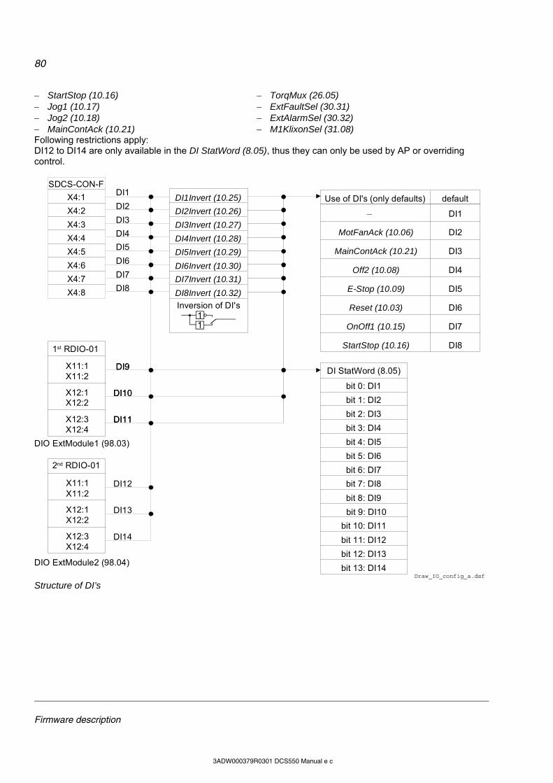
80
Firmware description
3ADW000379R0301 DCS550 Manual e c
StartStop (10.16) Jog1 (10.17) Jog2 (10.18) MainContAck (10.21)
TorqMux (26.05) ExtFaultSel (30.31) ExtAlarmSel (30.32) M1KlixonSel (31.08)
Following restrictions apply: DI12 to DI14 are only available in the DI StatWord (8.05), thus they can only be used by AP or overriding control.
bit 3: DI4
bit 7: DI8
bit 6: DI7
bit 5: DI6
bit 4: DI5
DI StatWord (8.05)
bit 0: DI1
bit 1: DI2
bit 2: DI3
bit 11: DI12
bit 13: DI14
bit 12: DI13
bit 8: DI9
bit 9: DI10
bit 10: DI11
X11:1X11:2
X12:1X12:2
X12:3X12:4
DI9
DI10
DI11
SDCS-CON-F
X4:1
X4:2
X4:3
X4:4
X4:5
X4:6
X4:7
X4:8
DI4
DI3
DI2
DI1
DI8
DI7
DI6
DI5
X11:1X11:2
X12:1X12:2
X12:3X12:4
DI12
DI13
DI14
11
DI1Invert (10.25)
DI2Invert (10.26)
DI4Invert (10.28)
DI5Invert (10.29)
DI6Invert (10.30)
DI7Invert (10.31)
DI8Invert (10.32)
DI3Invert (10.27)
E-Stop (10.09)
StartStop (10.16)
Reset (10.03)
_
MotFanAck (10.06)
MainContAck (10.21)
Off2 (10.08)
DI8
DI1
DI2
DI3
DI4
DI5
DI6
DI7OnOff1 (10.15)
DI9
DI10
DI11
Draw_IO_config_a.dsf
1st RDIO-01
DIO ExtModule1 (98.03)
DIO ExtModule2 (98.04)
2nd RDIO-01
Inversion of DI's
Use of DI's (only defaults) default
Structure of DI’s
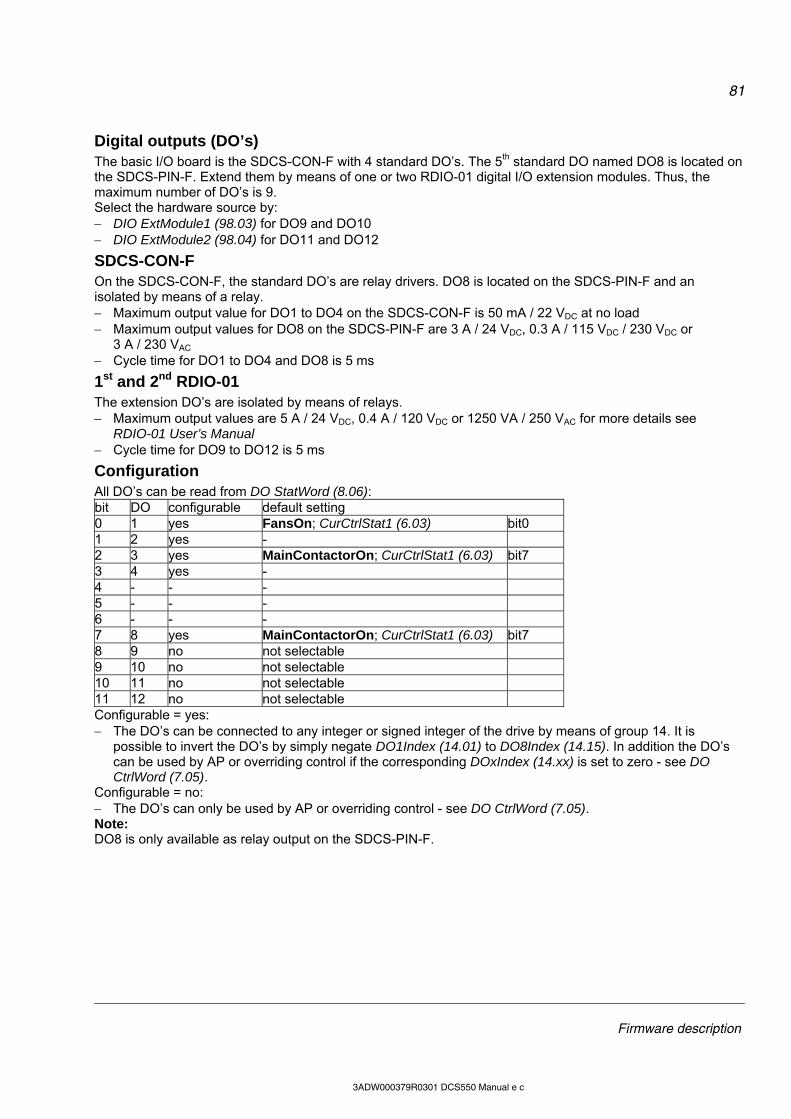
81
Firmware description
3ADW000379R0301 DCS550 Manual e c
Digital outputs (DO’s) The basic I/O board is the SDCS-CON-F with 4 standard DO’s. The 5th standard DO named DO8 is located on the SDCS-PIN-F. Extend them by means of one or two RDIO-01 digital I/O extension modules. Thus, the maximum number of DO’s is 9. Select the hardware source by: DIO ExtModule1 (98.03) for DO9 and DO10 DIO ExtModule2 (98.04) for DO11 and DO12
SDCS-CON-F On the SDCS-CON-F, the standard DO’s are relay drivers. DO8 is located on the SDCS-PIN-F and an isolated by means of a relay. Maximum output value for DO1 to DO4 on the SDCS-CON-F is 50 mA / 22 VDC at no load Maximum output values for DO8 on the SDCS-PIN-F are 3 A / 24 VDC, 0.3 A / 115 VDC / 230 VDC or
3 A / 230 VAC Cycle time for DO1 to DO4 and DO8 is 5 ms
1st and 2nd RDIO-01 The extension DO’s are isolated by means of relays. Maximum output values are 5 A / 24 VDC, 0.4 A / 120 VDC or 1250 VA / 250 VAC for more details see
RDIO-01 User’s Manual Cycle time for DO9 to DO12 is 5 ms
Configuration All DO’s can be read from DO StatWord (8.06): bit DO configurable default setting 0 1 yes FansOn; CurCtrlStat1 (6.03) bit0 1 2 yes - 2 3 yes MainContactorOn; CurCtrlStat1 (6.03) bit7 3 4 yes - 4 - - - 5 - - - 6 - - - 7 8 yes MainContactorOn; CurCtrlStat1 (6.03) bit7 8 9 no not selectable 9 10 no not selectable 10 11 no not selectable 11 12 no not selectable Configurable = yes: The DO’s can be connected to any integer or signed integer of the drive by means of group 14. It is
possible to invert the DO’s by simply negate DO1Index (14.01) to DO8Index (14.15). In addition the DO’s can be used by AP or overriding control if the corresponding DOxIndex (14.xx) is set to zero - see DO CtrlWord (7.05).
Configurable = no: The DO’s can only be used by AP or overriding control - see DO CtrlWord (7.05). Note: DO8 is only available as relay output on the SDCS-PIN-F.
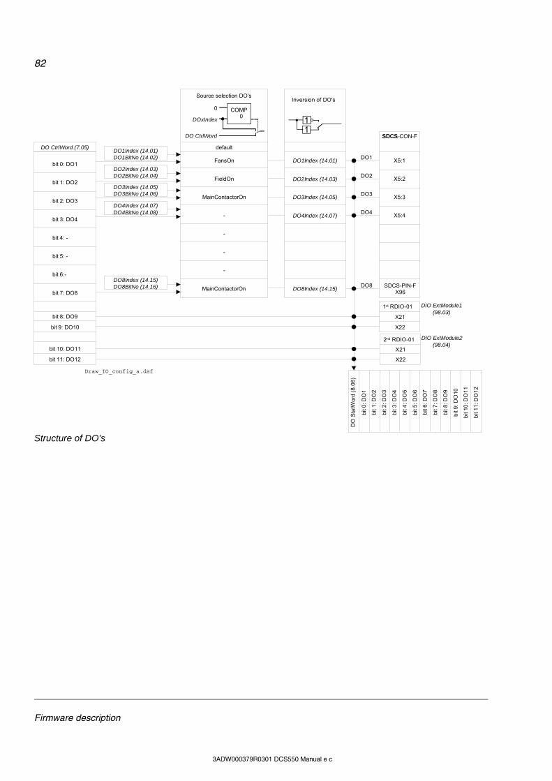
82
Firmware description
3ADW000379R0301 DCS550 Manual e c
SDCS
X5:1
X5:2
X5:3
X5:4DO4
DO3
DO2
DO8
bit
3:
DO
4
bit
7:
DO
8
bit
6:
DO
7
bit
5:
DO
6
bit
4:
DO
5
DO
Sta
tWo
rd (
8.0
6)
bit
0:
DO
1
bit
1:
DO
2
bit
2:
DO
3
bit
11
: D
O1
2
bit
8:
DO
9
bit
9:
DO
10
bit
10
: D
O1
1
DO1DO1Index (14.01)DO1BitNo (14.02)
DO2Index (14.03)DO2BitNo (14.04)
DO3Index (14.05)DO3BitNo (14.06)
DO4Index (14.07)DO4BitNo (14.08)
DO8Index (14.15)DO8BitNo (14.16)
bit 3: DO4
bit 7: DO8
bit 6:-
bit 5: -
bit 4: -
DO CtrlWord (7.05)
bit 0: DO1
bit 1: DO2
bit 2: DO3
bit 11: DO12
bit 8: DO9
bit 9: DO10
bit 10: DO11
-
MainContactorOn
-
-
-
FansOn
FieldOn
MainContactorOn
0 COMP 0
DOxIndex
DO CtrlWord
DO4Index (14.07)
DO8Index (14.15)
DO1Index (14.01)
DO2Index (14.03)
DO3Index (14.05)
DIO ExtModule1 (98.03)
DIO ExtModule2 (98.04)
X21
X22
X21
X22
SDCS-CON-F
Draw_IO_config_a.dsf
SDCS-PIN-FX96
2nd RDIO-01
1st RDIO-01
11
Inversion of DO's
default
Source selection DO's
Structure of DO’s
83
Firmware description
3ADW000379R0301 DCS550 Manual e c
Analog I/O configuration
Analog inputs (AI’s) The basic I/O board is the SDCS-CON-F with 4 standard AI’s. Extend them by means of one RAIO-01 analog I/O extension module. Thus, the maximum number of AI’s is 6. Select the hardware source by: AIO ExtModule (98.06) for AI5 and AI6
SDCS-CON-F Hardware setting: switching from voltage input to current input by means of jumper S2 and S3 Input range AI1 and AI2 set by parameter: 10 V, 0 V to 10 V, 2 V to 10 V, 5 V offset, 6 V offset 20 mA, 0 mA to 20 mA, 4 mA to 20 mA, 10 mA offset, 12 mA offset Input range AI3 and AI4 set by parameter: 10 V, 0 V to 10 V, 2 V to 10 V, 5 V offset, 6 V offset Resolution: 15 bits + sign Scan time for AI1 and AI2: 3.3 ms / 2.77 ms (synchronized with mains frequency) Scan time for AI3 and AI4: 5 ms
RAIO-01 Hardware setting: input range and switching from voltage to current by means of a DIP switch, for more details see RAIO-01
User’s Manual Input range AI5 and AI6 set by parameter: 10 V, 0 V to 10 V, 2 V to 10 V, 5 V offset, 6 V offset 20 mA, 0 mA to 20 mA, 4 mA to 20 mA, 10 mA offset, 12 mA offset Resolution: 11 bits + sign Scan time for AI5 and AI6: 10 ms Additional functions: all AI’s are galvanically isolated
Configuration The value of AI1 to AI6 and AITacho can be read from group 5. AI configurable default setting 1 yes - 2 yes - 3 yes - 4 yes - 5 yes - 6 yes -
Configurable = yes: The AI’s can be connected to several converter functions and it is possible to scale them by means of
group 13. In addition the AI’s can be read by AP or overriding control.
84
Firmware description
3ADW000379R0301 DCS550 Manual e c
Configurable AI’s are defined by means of following parameters: Ref1Sel (11.03) Ref2Sel (11.06) TorqUsedMaxSel (20.18) TorqUsedMinSel (20.19) TorqRefA Sel (25.10) M1TempSel (31.05) CurSel (43.02) Following restrictions apply: the motor temperature measurement via PTC is fixed assigned to AI2, if activated via M1TempSel (31.05)
Scaling
It is possible to scale AI1 to AI6 and AITacho with 3 parameters each: the range of each AI is set by means of a jumper - distinguishing between current and voltage - and
ConvModeAI1 (13.03) to ConvModeAI6 (13.27) +100 % of the input signal connected to an AI is scaled by means of AI1HighVal (13.01) to AI6HighVal
(13.25) -100 % of the input signal connected to an AI is scaled by means of AI1LowVal (13.02) to AI6LowVal
(13.26) Example: In case the min. / max. voltage (10 V) of AI1 should equal 250 % of TorqRefExt (2.24), set:
1. TorqRefA Sel (25.10) = AI1 2. ConvModeAI1 (13.03) = 10V Bi 3. AI1HighVal (13.01) = 4000 mV 4. AI1LowVal (13.02) = -4000 mV
AIO ExtModule (98.06)
SDCS-CON-F
X3:1 toX3:4
X3:5X3:6
X3:7X3:8
X3:9X3:10
X4:1X4:2
AI3
AI2
AI1
AITacho
AI4
RAIO-01
X1:1X1:2
X1:3X1:4
AI5
AI6
AI4 Val (5.06)
AI1 Val (5.03)
AI2 Val (5.04)
AI3 Val (5.05)
AI6 Val (5.08)
AI5 Val (5.07)
ConvModeAI4 (13.15)
ConvModeAI1 (13.03)
ConvModeAI2 (13.07)
ConvModeAI3 (13.11)
ConvModeAI6 (13.27)
ConvModeAI5 (13.23)
AI4HighVal (13.13)AI4LowVal (13.14)
AI1HighVal (13.01)AI1LowVal (13.02)
AI2HighVal (13.05)AI2LowVal (13.06)
AI3HighVal (13.09)AI3LowVal (13.10)
AI6HighVal (13.25)AI6LowVal (13.26)
AI5HighVal (13.21)AI5LowVal (13.22)
Ref1Sel (11.03)
Ref2Sel (11.06)
TorqUsedMaxSel (20.18)
TorqUsedMinSel (20.19) TorqRefA Sel (25.10)
CurSel (43.02)
M1TempSel (31.05)
SpeedActTach (1.05)
AITachoVal (5.01)
Draw_IO_config_a.dsf
Fixed assigned AI's:The motor temperaturemeasurement via PTC is fixed assigned to AI2.
Input valueScaling Scaling
Use of AI's
Structure of AI’s
85
Firmware description
3ADW000379R0301 DCS550 Manual e c
Analog outputs (AO’s) The basic I/O board is the SDCS-CON-F with 3 standard AO’s. Two AO’s are programmable, the third one is fixed and used to display the actual armature current taken directly from the burden resistors. They can be extended by means of one RAIO-01 analog I/O extension module. Thus, the maximum number of AO’s is 5. The hardware source is selected by: AIO ExtModule (98.06) for AO3 and AO4
SDCS-CON-F Output range AO1 and AO2 set by parameter: 10 V, 0 V to 10 V, 2 V to 10 V, 5 V offset, 6 V offset Output range fixed AO I-act: 8 V equals the minimum of 325 % M1NomCur (99.03) or 230 % ConvNomCur (4.05) see also IactScaling
(4.26) Resolution: 11 bits + sign Cycle time for AO1 and AO2: 5 ms Cycle time fixed AO I-act: directly taken from hardware
RAIO-01 Output range AO3 and AO4 set by parameter: 0 mA to 20 mA, 4 mA to 20 mA, 10 mA offset, 12 mA offset Resolution: 12 bits Cycle time for AO3 and AO4: 5 ms Additional functions: all AO’s are galvanically isolated
Configuration The value of AO1 and AO2 can be read from group 5. AO configurable default setting 1 yes - 2 yes - 3 yes - 4 yes - Curr fixed not selectable
Configurable = yes: The AO’s can be connected to any integer or signed integer of the drive by means of group 15. It is
possible to invert the AO’s by simply negate IndexAO1 (15.01) to IndexAO4 (15.16).
Scaling
It is possible to scale AO1 to AO4 with 2 parameters each: the range of each AO is set by means of ConvModeAO1 (15.03) to ConvModeAO4 (15.18)
86
Firmware description
3ADW000379R0301 DCS550 Manual e c
if the range is set to bipolar or unipolar signals with offset, 100 % of the input signal connected to an AO is scaled by means of ScaleAO1 (15.06) to ScaleAO4 (15.20)
If the range is set to unipolar signals without offset, only +100 % of the input signal connected to an AO is scaled by means of ScaleAO1 (15.06) to ScaleAO4 (15.20). The smallest value is always zero.
It is possible to invert the AO’s by simply negate IndexAO1 (15.01) to IndexAO4 (15.16) Example: In case the min. / max. voltage (10 V) of AO1 should equal 250 % of TorqRefUsed (2.13), set:
1. IndexAO1 (15.01) = 213 2. ConvModeAO1 (15.03) = 10V Bi 3. ScaleAO1 (15.05) = 4000 mV
IndexAO1 (15.01)CtrlWordAO1 (15.02)
IndexAO2 (15.06)CtrlWordAO2 (15.07)
IndexAO3 (15.11)CtrlWordAO3 (15.12)
IndexAO4 (15.15)CtrlWordAO4 (15.16)
Hardware
0
IndexAOx
CtrlWordAOx
-
-
-
-
AO1 Val (5.11)
AO2 Val (5.12)
fixed AO
AO2
AO1
AO3
AO4
IndexAO1 (15.01)
IndexAO2 (15.06)
IndexAO4 (15.15)
IndexAO3 (15.11)
SDCS-CON-F
X2:7X2:10
X2:8X2:10
X2:9X2:10
AIO ExtModule (98.06)
X2:1X2:2
X2:3X2:4
ConvModeAO3 (15.13)ScaleAO3 (15.15)
ConvModeAO1 (15.03)ScaleAO1 (15.05)
ConvModeAO2 (15.08)ScaleAO2 (15.10)
ConvModeAO4 (15.18)ScaleAO4 (15.20)
RAIO-01
Draw_IO_config_a.dsf
11
Inversion of AO's
COMP 0
Source
Source selection AO's
Default Output valueScaling
Structure of AO’s
87
Communication
3ADW000379R0301 DCS550 Manual e c
Serial field bus communication Chapter overview This chapter describes the serial communication of the DCS550.
CANopen communication with fieldbus adapter RCAN-01
General This chapter gives additional information using the CANopen adapter RCAN-01 together with the DCS550.
RCAN-01 - DCS550 The CANopen communication with the drive requires the option RCAN-01.
Related documentation User’s Manual CANopen Adapter Module RCAN-01. The quoted page numbers correspond to the User’s Manual.
Overriding control configuration Supported operation mode is PDO21 (see page 43 and 44).
EDS file The EDS file for RCAN-01 and DCS550 is available. Please ask Your local ABB agent for the newest one concerning the current DCS550 firmware.
Mechanical and electrical installation If not already done so insert the RCAN-01 into slot 1 of the drive.
Drive configuration Activate the CANopen adapter by means of CommModule (98.02). Please note that the DCS550 works with the operation mode PDO21 (see page 43 and 44).
Parameter setting example 1 using group 51 Communication via group 51 is using 4 data words in each direction. The following table shows the parameter setting using group 51: Drive parameters Settings Comments CommandSel (10.01) MainCtrlWord Ref1Sel (11.03) SpeedRef2301 CommModule (98.02) Fieldbus ModuleType (51.01) CANopen* Node ID (51.02) 1** set node address as required Baudrate (51.03) 8** 8 = 1 Mbits/s PDO21 Cfg (51.04) 1 0 = Configuration via CANopen objects
1 = Configuration via RCAN-01 adapter parameters RX-PDO21-Enable (51.05) 769 This value has to be calculated
with 300 Hex = 768 + Node ID (51.02). Here 768 + 1 = 769
RX-PDO21-TxType (51.06) 255 255 = Asynchronous (see page 83) RX-PDO21-1stObj (51.07) 8197 2005 Hex = 8197 = Transparent Control Word (see
page 62) RX-PDO21-1stSubj (51.08) 0 RX-PDO21-2ndObj (51.09) 8198 2006 Hex = 8198 = Transparent Reference Speed (see
page 62) RX-PDO21-2ndSubj (51.10) 0 RX-PDO21-3rdObj (51.11) 16409 This value has to be calculated
with 4000 Hex = 16384 + parameter group number.
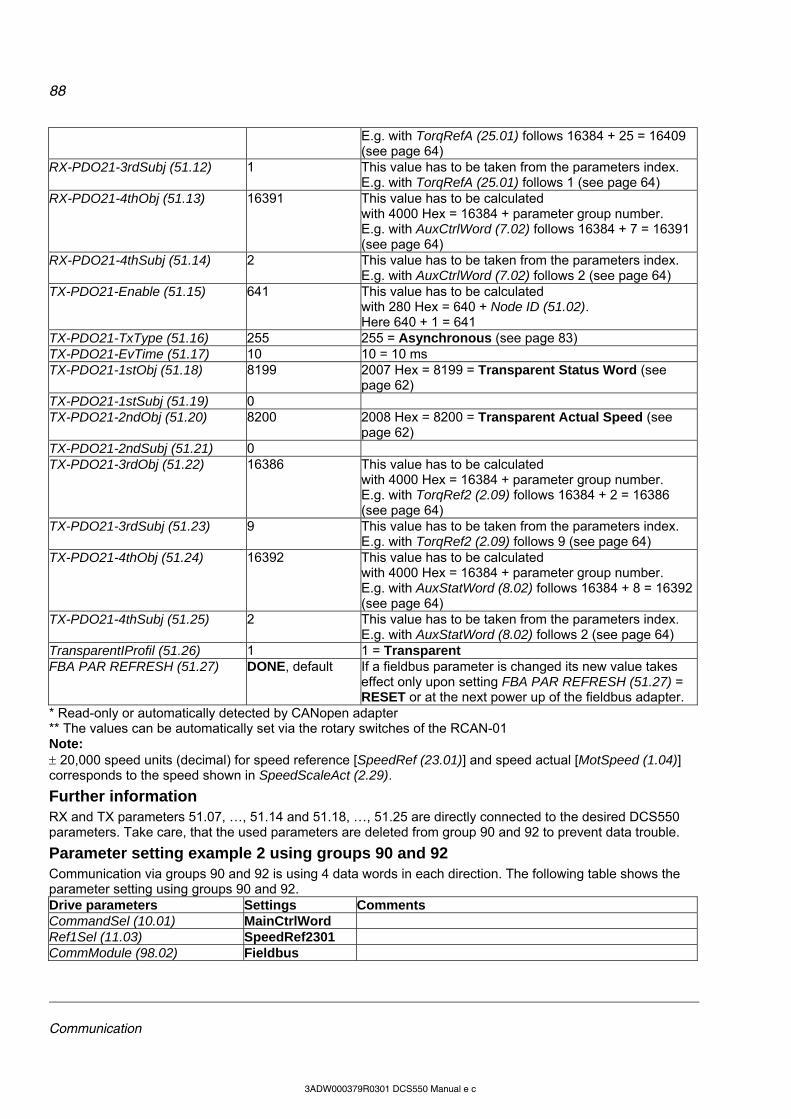
88
Communication
3ADW000379R0301 DCS550 Manual e c
E.g. with TorqRefA (25.01) follows 16384 + 25 = 16409 (see page 64)
RX-PDO21-3rdSubj (51.12) 1 This value has to be taken from the parameters index. E.g. with TorqRefA (25.01) follows 1 (see page 64)
RX-PDO21-4thObj (51.13) 16391 This value has to be calculated with 4000 Hex = 16384 + parameter group number. E.g. with AuxCtrlWord (7.02) follows 16384 + 7 = 16391 (see page 64)
RX-PDO21-4thSubj (51.14) 2 This value has to be taken from the parameters index. E.g. with AuxCtrlWord (7.02) follows 2 (see page 64)
TX-PDO21-Enable (51.15) 641 This value has to be calculated with 280 Hex = 640 + Node ID (51.02). Here 640 + 1 = 641
TX-PDO21-TxType (51.16) 255 255 = Asynchronous (see page 83) TX-PDO21-EvTime (51.17) 10 10 = 10 ms TX-PDO21-1stObj (51.18) 8199 2007 Hex = 8199 = Transparent Status Word (see
page 62) TX-PDO21-1stSubj (51.19) 0 TX-PDO21-2ndObj (51.20) 8200 2008 Hex = 8200 = Transparent Actual Speed (see
page 62) TX-PDO21-2ndSubj (51.21) 0 TX-PDO21-3rdObj (51.22) 16386 This value has to be calculated
with 4000 Hex = 16384 + parameter group number. E.g. with TorqRef2 (2.09) follows 16384 + 2 = 16386 (see page 64)
TX-PDO21-3rdSubj (51.23) 9 This value has to be taken from the parameters index. E.g. with TorqRef2 (2.09) follows 9 (see page 64)
TX-PDO21-4thObj (51.24) 16392 This value has to be calculated with 4000 Hex = 16384 + parameter group number. E.g. with AuxStatWord (8.02) follows 16384 + 8 = 16392 (see page 64)
TX-PDO21-4thSubj (51.25) 2 This value has to be taken from the parameters index. E.g. with AuxStatWord (8.02) follows 2 (see page 64)
TransparentIProfil (51.26) 1 1 = Transparent FBA PAR REFRESH (51.27) DONE, default If a fieldbus parameter is changed its new value takes
effect only upon setting FBA PAR REFRESH (51.27) = RESET or at the next power up of the fieldbus adapter.
* Read-only or automatically detected by CANopen adapter ** The values can be automatically set via the rotary switches of the RCAN-01 Note: 20,000 speed units (decimal) for speed reference [SpeedRef (23.01)] and speed actual [MotSpeed (1.04)] corresponds to the speed shown in SpeedScaleAct (2.29).
Further information RX and TX parameters 51.07, …, 51.14 and 51.18, …, 51.25 are directly connected to the desired DCS550 parameters. Take care, that the used parameters are deleted from group 90 and 92 to prevent data trouble.
Parameter setting example 2 using groups 90 and 92 Communication via groups 90 and 92 is using 4 data words in each direction. The following table shows the parameter setting using groups 90 and 92. Drive parameters Settings Comments CommandSel (10.01) MainCtrlWord Ref1Sel (11.03) SpeedRef2301 CommModule (98.02) Fieldbus
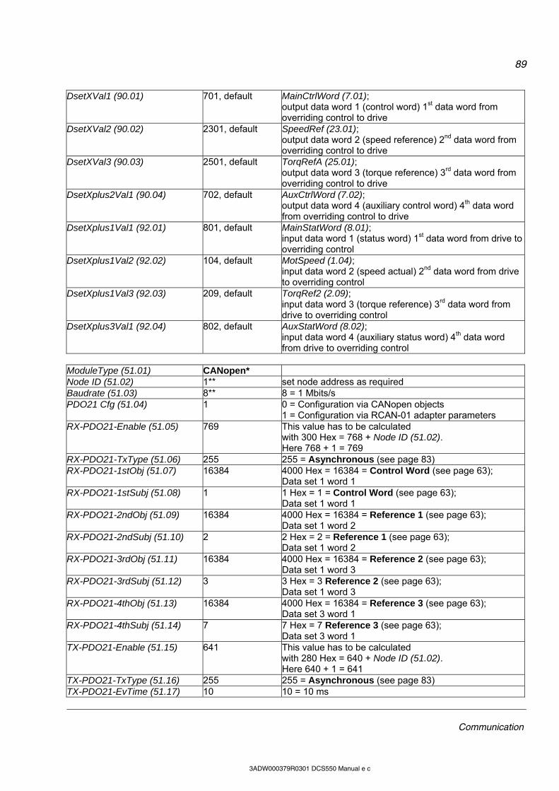
89
Communication
3ADW000379R0301 DCS550 Manual e c
DsetXVal1 (90.01) 701, default MainCtrlWord (7.01); output data word 1 (control word) 1st data word from overriding control to drive
DsetXVal2 (90.02) 2301, default SpeedRef (23.01); output data word 2 (speed reference) 2nd data word from overriding control to drive
DsetXVal3 (90.03) 2501, default TorqRefA (25.01); output data word 3 (torque reference) 3rd data word from overriding control to drive
DsetXplus2Val1 (90.04) 702, default AuxCtrlWord (7.02); output data word 4 (auxiliary control word) 4th data word from overriding control to drive
DsetXplus1Val1 (92.01) 801, default MainStatWord (8.01); input data word 1 (status word) 1st data word from drive to overriding control
DsetXplus1Val2 (92.02) 104, default MotSpeed (1.04); input data word 2 (speed actual) 2nd data word from drive to overriding control
DsetXplus1Val3 (92.03) 209, default TorqRef2 (2.09); input data word 3 (torque reference) 3rd data word from drive to overriding control
DsetXplus3Val1 (92.04) 802, default AuxStatWord (8.02); input data word 4 (auxiliary status word) 4th data word from drive to overriding control
ModuleType (51.01) CANopen* Node ID (51.02) 1** set node address as required Baudrate (51.03) 8** 8 = 1 Mbits/s PDO21 Cfg (51.04) 1 0 = Configuration via CANopen objects
1 = Configuration via RCAN-01 adapter parameters RX-PDO21-Enable (51.05) 769 This value has to be calculated
with 300 Hex = 768 + Node ID (51.02). Here 768 + 1 = 769
RX-PDO21-TxType (51.06) 255 255 = Asynchronous (see page 83) RX-PDO21-1stObj (51.07) 16384 4000 Hex = 16384 = Control Word (see page 63);
Data set 1 word 1 RX-PDO21-1stSubj (51.08) 1 1 Hex = 1 = Control Word (see page 63);
Data set 1 word 1 RX-PDO21-2ndObj (51.09) 16384 4000 Hex = 16384 = Reference 1 (see page 63);
Data set 1 word 2 RX-PDO21-2ndSubj (51.10) 2 2 Hex = 2 = Reference 1 (see page 63);
Data set 1 word 2 RX-PDO21-3rdObj (51.11) 16384 4000 Hex = 16384 = Reference 2 (see page 63);
Data set 1 word 3 RX-PDO21-3rdSubj (51.12) 3 3 Hex = 3 Reference 2 (see page 63);
Data set 1 word 3 RX-PDO21-4thObj (51.13) 16384 4000 Hex = 16384 = Reference 3 (see page 63);
Data set 3 word 1 RX-PDO21-4thSubj (51.14) 7 7 Hex = 7 Reference 3 (see page 63);
Data set 3 word 1 TX-PDO21-Enable (51.15) 641 This value has to be calculated
with 280 Hex = 640 + Node ID (51.02). Here 640 + 1 = 641
TX-PDO21-TxType (51.16) 255 255 = Asynchronous (see page 83) TX-PDO21-EvTime (51.17) 10 10 = 10 ms

90
Communication
3ADW000379R0301 DCS550 Manual e c
TX-PDO21-1stObj (51.18) 16384 4000 Hex = 16384 = Status Word (see page 63); Data set 2 word 1
TX-PDO21-1stSubj (51.19) 4 4 Hex = 4 = Status Word (see page 63); Data set 2 word 1
TX-PDO21-2ndObj (51.20) 16384 4000 Hex = 16384 = Actual Value 1 (see page 63); Data set 2 word 2
TX-PDO21-2ndSubj (51.21) 5 5 Hex = 5 = Actual Value 1 (see page 63); Data set 2 word 2
TX-PDO21-3rdObj (51.22) 16384 4000 Hex = 16384 = Actual Value 2 (see page 63); Data set 2 word 3
TX-PDO21-3rdSubj (51.23) 6 6 Hex = 6 = Actual Value 2 (see page 63); Data set 2 word 3
TX-PDO21-4thObj (51.24) 16384 4000 Hex = 16384 = Actual Value 3 (see page 63); Data set 4 word 1
TX-PDO21-4thSubj (51.25) 10 A Hex = 10 = Actual Value 3 (see page 63); Data set 4 word 1
TransparentIProfil (51.26) 1 1 = Transparent FBA PAR REFRESH (51.27) DONE, default If a fieldbus parameter is changed its new value takes
effect only upon setting FBA PAR REFRESH (51.27) = RESET or at the next power up of the fieldbus adapter.
* Read-only or automatically detected by CANopen adapter ** The values can be automatically set via the rotary switches of the RCAN-01 Note: 20,000 speed units (decimal) for speed reference [SpeedRef (23.01)] and speed actual [MotSpeed (1.04)] corresponds to the speed shown in SpeedScaleAct (2.29).
Switch on sequence Please see the example at the end of this chapter.
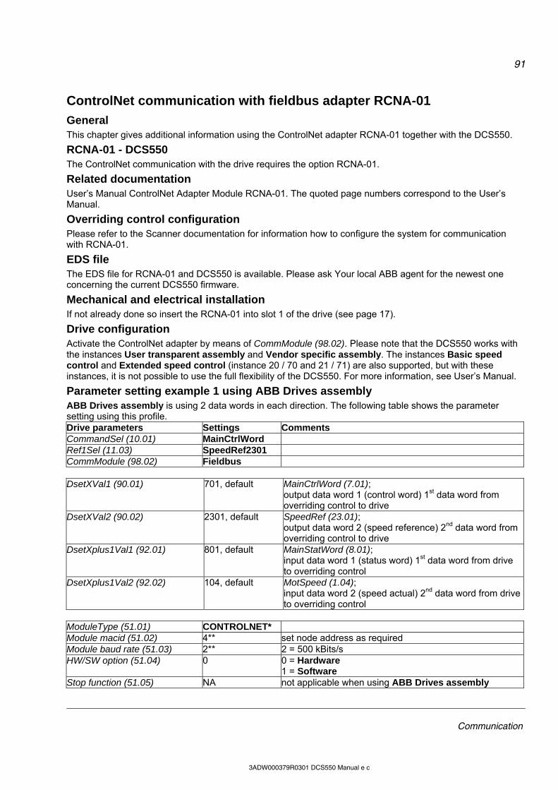
91
Communication
3ADW000379R0301 DCS550 Manual e c
ControlNet communication with fieldbus adapter RCNA-01
General This chapter gives additional information using the ControlNet adapter RCNA-01 together with the DCS550.
RCNA-01 - DCS550 The ControlNet communication with the drive requires the option RCNA-01.
Related documentation User’s Manual ControlNet Adapter Module RCNA-01. The quoted page numbers correspond to the User’s Manual.
Overriding control configuration Please refer to the Scanner documentation for information how to configure the system for communication with RCNA-01.
EDS file The EDS file for RCNA-01 and DCS550 is available. Please ask Your local ABB agent for the newest one concerning the current DCS550 firmware.
Mechanical and electrical installation If not already done so insert the RCNA-01 into slot 1 of the drive (see page 17).
Drive configuration Activate the ControlNet adapter by means of CommModule (98.02). Please note that the DCS550 works with the instances User transparent assembly and Vendor specific assembly. The instances Basic speed control and Extended speed control (instance 20 / 70 and 21 / 71) are also supported, but with these instances, it is not possible to use the full flexibility of the DCS550. For more information, see User’s Manual.
Parameter setting example 1 using ABB Drives assembly ABB Drives assembly is using 2 data words in each direction. The following table shows the parameter setting using this profile. Drive parameters Settings Comments CommandSel (10.01) MainCtrlWord Ref1Sel (11.03) SpeedRef2301 CommModule (98.02) Fieldbus DsetXVal1 (90.01) 701, default MainCtrlWord (7.01);
output data word 1 (control word) 1st data word from overriding control to drive
DsetXVal2 (90.02) 2301, default SpeedRef (23.01); output data word 2 (speed reference) 2nd data word from overriding control to drive
DsetXplus1Val1 (92.01) 801, default MainStatWord (8.01); input data word 1 (status word) 1st data word from drive to overriding control
DsetXplus1Val2 (92.02) 104, default MotSpeed (1.04); input data word 2 (speed actual) 2nd data word from drive to overriding control
ModuleType (51.01) CONTROLNET* Module macid (51.02) 4** set node address as required Module baud rate (51.03) 2** 2 = 500 kBits/s HW/SW option (51.04) 0 0 = Hardware
1 = Software Stop function (51.05) NA not applicable when using ABB Drives assembly

92
Communication
3ADW000379R0301 DCS550 Manual e c
Output instance (51.06) 100 100 = ABB Drives assembly Input instance (51.07) 101 101 = ABB Drives assembly Output I/O par 1 (51.08) to Input I/O par 9 (51.25)
NA not applicable when using ABB Drives assembly
VSA I/O size (51.26) NA not applicable when using ABB Drives assembly FBA PAR REFRESH (51.27) DONE, default If a fieldbus parameter is changed its new value takes
effect only upon setting FBA PAR REFRESH (51.27) = RESET or at the next power up of the fieldbus adapter.
* Read-only or automatically detected by ControlNet adapter. ** If HW/SW option (51.04) = 0 (Hardware), the values are automatically set via the rotary switches of the RCNA-01. Note: 20,000 speed units (decimal) for speed reference [SpeedRef (23.01)] and speed actual [MotSpeed (1.04)] corresponds to the speed shown in SpeedScaleAct (2.29).
Parameter setting example 2 using Vendor specific assembly Vendor specific assembly can run with up to 9 data words in each direction. The following table shows the parameter setting using this profile. Drive parameters Settings Comments CommandSel (10.01) MainCtrlWord Ref1Sel (11.03) SpeedRef2301 CommModule (98.02) Fieldbus ModuleType (51.01) CONTROLNET* Module macid (51.02) 4** set node address as required Module baud rate (51.03) 5 5 = 5 Mbits/s HW/SW option (51.04) 0 0 = Hardware
1 = Software Stop function (51.05) NA not applicable when using Vendor specific assembly Output instance (51.06) 102 102 = Vendor specific assembly Input instance (51.07) 103 103 = Vendor specific assembly Output I/O par 1 (51.08) to Input I/O par 9 (51.25)
1 - 18 Set these values according table: Setting of parameter groups 51, 90 and 92 depending on desired data words and according to the desired numbers of data words
VSA I/O size (51.26) 1 - 9 Defines the length of the Vendor specific assembly in pairs of data words. E.g. a parameter value of 4 means 4 word as output and 4 words as input.
FBA PAR REFRESH (51.27) DONE, default If a fieldbus parameter is changed its new value takes effect only upon setting FBA PAR REFRESH (51.27) = RESET or at the next power up of the fieldbus adapter.
* Read-only or automatically detected by ControlNet adapter ** If HW/SW option (51.04) = 0 (Hardware), the values are automatically set via the rotary switches of the RCNA-01 Note: 20,000 speed units (decimal) for speed reference [SpeedRef (23.01)] and speed actual [MotSpeed (1.04)] corresponds to the speed shown in SpeedScaleAct (2.29).
Setting of parameter groups 51, 90 and 92

93
Communication
3ADW000379R0301 DCS550 Manual e c
*For proper communication shown values have to be used
Further information Output and input parameters 51.08, …, 51.25 can also be connected directly to the desired DCS550 parameters. In this case please take care that the RCNA-01 adapter gets the changed values and also take care, that the used parameters are deleted from group 90 to prevent data trouble.
Switch on sequence Please see the example at the end of this chapter.
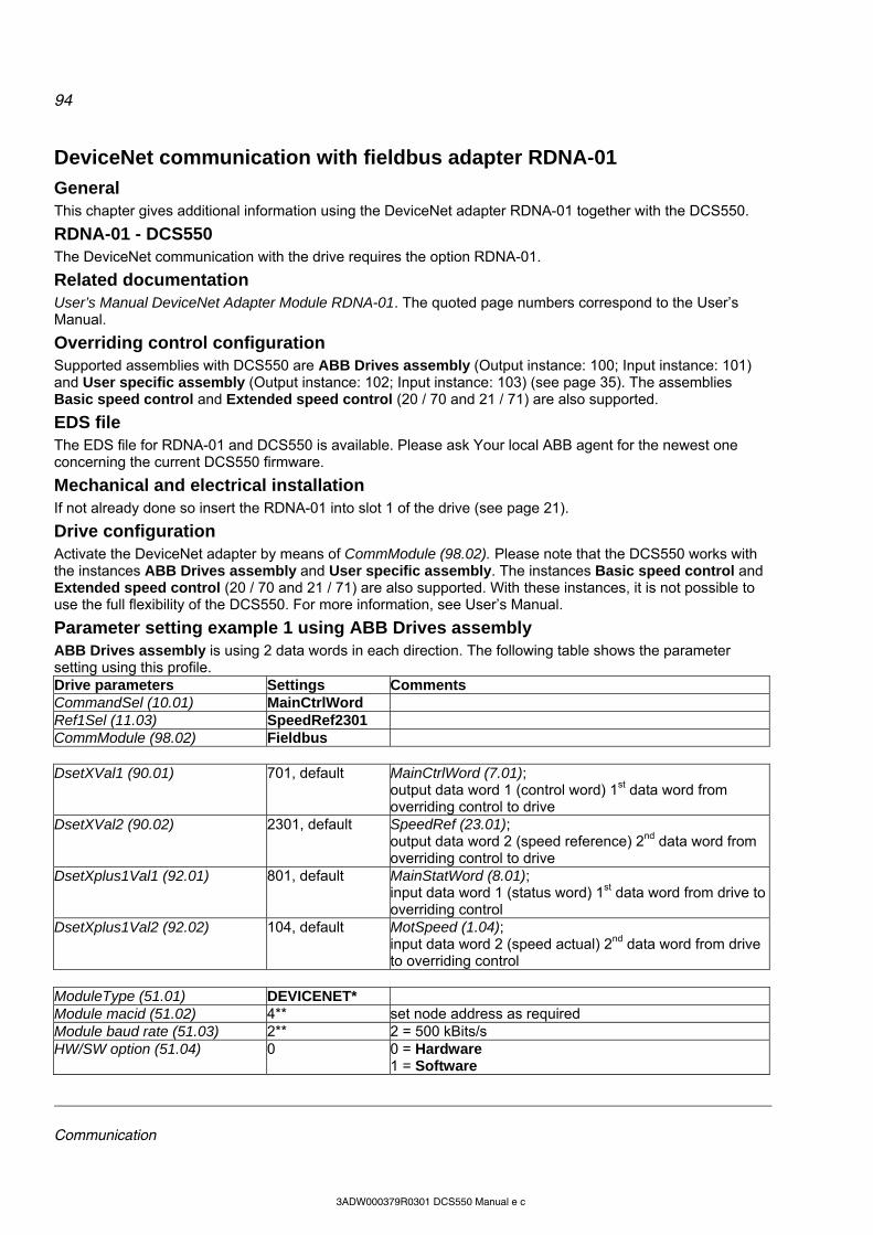
94
Communication
3ADW000379R0301 DCS550 Manual e c
DeviceNet communication with fieldbus adapter RDNA-01
General This chapter gives additional information using the DeviceNet adapter RDNA-01 together with the DCS550.
RDNA-01 - DCS550 The DeviceNet communication with the drive requires the option RDNA-01.
Related documentation User’s Manual DeviceNet Adapter Module RDNA-01. The quoted page numbers correspond to the User’s Manual.
Overriding control configuration Supported assemblies with DCS550 are ABB Drives assembly (Output instance: 100; Input instance: 101) and User specific assembly (Output instance: 102; Input instance: 103) (see page 35). The assemblies Basic speed control and Extended speed control (20 / 70 and 21 / 71) are also supported.
EDS file The EDS file for RDNA-01 and DCS550 is available. Please ask Your local ABB agent for the newest one concerning the current DCS550 firmware.
Mechanical and electrical installation If not already done so insert the RDNA-01 into slot 1 of the drive (see page 21).
Drive configuration Activate the DeviceNet adapter by means of CommModule (98.02). Please note that the DCS550 works with the instances ABB Drives assembly and User specific assembly. The instances Basic speed control and Extended speed control (20 / 70 and 21 / 71) are also supported. With these instances, it is not possible to use the full flexibility of the DCS550. For more information, see User’s Manual.
Parameter setting example 1 using ABB Drives assembly ABB Drives assembly is using 2 data words in each direction. The following table shows the parameter setting using this profile. Drive parameters Settings Comments CommandSel (10.01) MainCtrlWord Ref1Sel (11.03) SpeedRef2301 CommModule (98.02) Fieldbus DsetXVal1 (90.01) 701, default MainCtrlWord (7.01);
output data word 1 (control word) 1st data word from overriding control to drive
DsetXVal2 (90.02) 2301, default SpeedRef (23.01); output data word 2 (speed reference) 2nd data word from overriding control to drive
DsetXplus1Val1 (92.01) 801, default MainStatWord (8.01); input data word 1 (status word) 1st data word from drive to overriding control
DsetXplus1Val2 (92.02) 104, default MotSpeed (1.04); input data word 2 (speed actual) 2nd data word from drive to overriding control
ModuleType (51.01) DEVICENET* Module macid (51.02) 4** set node address as required Module baud rate (51.03) 2** 2 = 500 kBits/s HW/SW option (51.04) 0 0 = Hardware
1 = Software

95
Communication
3ADW000379R0301 DCS550 Manual e c
Stop function (51.05) NA not applicable when using ABB Drives assembly Output instance (51.06) 100 100 = ABB Drives assembly Input instance (51.07) 101 101 = ABB Drives assembly Output I/O par 1 (51.08) to Input I/O par 9 (51.25)
NA not applicable when using ABB Drives assembly
VSA I/O size (51.26) NA not applicable when using ABB Drives assembly FBA PAR REFRESH (51.27) DONE, default If a fieldbus parameter is changed its new value takes
effect only upon setting FBA PAR REFRESH (51.27) = RESET or at the next power up of the fieldbus adapter.
* Read-only or automatically detected by DeviceNet adapter ** If HW/SW option (51.04) = 0 (Hardware), the values are automatically set via DIP switches of the RDNA-01 Note: 20,000 speed units (decimal) for speed reference [SpeedRef (23.01)] and speed actual [MotSpeed (1.04)] corresponds to the speed shown in SpeedScaleAct (2.29).
Parameter setting example 2 using User specific assembly User specific assembly can run with up to 9 data words in each direction. The following table shows the parameter setting using this profile. Drive parameters Settings Comments CommandSel (10.01) MainCtrlWord Ref1Sel (11.03) SpeedRef2301 CommModule (98.02) Fieldbus ModuleType (51.01) DEVICENET* Module macid (51.02) 4** set node address as required Module baud rate (51.03) 2** 2 = 500 kBits/s HW/SW option (51.04) 0 0 = Hardware
1 = Software Stop function (51.05) NA not applicable when using User specific assembly Output instance (51.06) 102 102 = User specific assembly Input instance (51.07) 103 103 = User specific assembly Output I/O par 1 (51.08) to Input I/O par 9 (51.25)
1 - 18 Set these values according table: Setting of parameter groups 51, 90 and 92 depending on desired data words and according to the desired numbers of data words
VSA I/O size (51.26) 1 - 9 Defines the length of the User specific assembly in pairs of data words. E.g. a parameter value of 4 means 4 word as output and 4 words as input.
FBA PAR REFRESH (51.27) DONE, default If a fieldbus parameter is changed its new value takes effect only upon setting FBA PAR REFRESH (51.27) = RESET or at the next power up of the fieldbus adapter.
* Read-only or automatically detected by DeviceNet adapter ** If HW/SW option (51.04) = 0 (Hardware), the values are automatically set via DIP switches of the RDNA-01 Note: 20,000 speed units (decimal) for speed reference [SpeedRef (23.01)] and speed actual [MotSpeed (1.04)] corresponds to the speed shown in SpeedScaleAct (2.29).

96
Communication
3ADW000379R0301 DCS550 Manual e c
Setting of parameter groups 51, 90 and 92
*For proper communication shown values have to be used
Further information Output and input parameters 51.08, …, 51.25 can also be connected directly to the desired DCS550 parameters. In this case, please take care that the RDNA-01 adapter gets the changed values and take care, that the used parameters are deleted from group 90 to prevent data trouble.
Switch on sequence Please see the example at the end of this chapter.
97
Communication
3ADW000379R0301 DCS550 Manual e c
Ethernet/IP communication with fieldbus adapter RETA-01
General This chapter gives additional information using the Ethernet adapter RETA-01 together with the DCS550.
RETA-01 - DCS550 The Ethernet/IP communication with the drive requires the option RETA-01.
Related documentation User’s Manual Ethernet Adapter Module RETA-01. The quoted page numbers correspond to the User’s Manual.
EDS file The EDS file for RETA-01 and DCS550 is available. Please ask Your local ABB agent for the newest one concerning the current DCS550 firmware.
Mechanical and electrical installation If not already done so insert RETA-01 into slot 1 of the drive.
Drive configuration Activate the Ethernet adapter by means of CommModule (98.02). Please note that the DCS550 works with the instances 102 / 103, if Protocol (51.16) is set to 2 (Ethernet/IP ABB Drives communication profile). The instances 100 / 101, 20 / 70 and 21 / 71 are also supported, if Protocol (51.16) is set to 1 (Ethernet/IP AC/DC communication profile). With these instances, it is not possible to use the full flexibility of the DCS550. For more information, see User’s Manual.
Parameter setting example using Ethernet/IP ABB Drives communication profile Ethernet/IP ABB Drives communication profile uses up to 4 data words in each direction by default. The internal connection from and to the DCS550 has to be done by means of parameter group 51. Ethernet/IP ABB Drives communication profile uses up to 12 data words in each direction. The configuration has to be done via fieldbus link configuration using Vendor Specific Drive I/O Object (Class 91h). Drive parameters Settings Comments CommandSel (10.01) MainCtrlWord Ref1Sel (11.03) SpeedRef2301 CommModule (98.02) Fieldbus DsetXVal1 (90.01) 701, default MainCtrlWord (7.01);
output data word 1 (control word) 1st data word from overriding control to drive
DsetXVal2 (90.02) 2301, default SpeedRef (23.01); output data word 2 (speed reference) 2nd data word from overriding control to drive
DsetXplus1Val1 (92.01) 801, default MainStatWord (8.01); input data word 1 (status word) 1st data word from drive to overriding control
DsetXplus1Val2 (92.02) 104, default MotSpeed (1.04); input data word 2 (speed actual) 2nd data word from drive to overriding control
ModuleType (51.01) ETHERNET TCP* Comm rate (51.02) 0 Auto-negotiate;
automatic, set baud rate as required DHCP (51.03) 0 DHCP disabled;
IP address setting from following parameters
98
Communication
3ADW000379R0301 DCS550 Manual e c
IP address 1 (51.04) 192** e.g. IP address: 192.168.0.1
IP address 2 (51.05) 168** IP address 3 (51.06) 0** IP address 4 (51.07) 1** Subnet mask 1 (51.08) 255 e.g. subnet mask:
255.255.255.0 Subnet mask 2 (51.09) 255 Subnet mask 3 (51.10) 255 Subnet mask 4 (51.11) 0 GW address 1 (51.12) 0 e.g. gateway address:
0.0.0.0 GW address 2 (51.13) 0 GW address 3 (51.14) 0 GW address 4 (51.15) 0 Protocol (51.16) 2 1 = Ethernet/IP AC/DC communication profile
2 = Ethernet/IP ABB Drives communication profile Modbus timeout (51.17) 22 0 = no monitoring
1 = 100 ms 22 = 2200 ms
Stop function (51.18) 0 0 = Ramp stop Output 1 (51.19) 1 data word 1; setting via parameter 90.01 Output 2 (51.20) 2 data word 2; setting via parameter 90.02 Output 3 (51.21) 3 data word 3; setting via parameter 90.03 Output 4 (51.22) 7 data word 4; setting via parameter 90.04 Input 1 (51.23) 4 data word 1; setting via parameter 92.01 Input 2 (51.24) 5 data word 2; setting via parameter 92.02 Input 3 (51.25) 6 data word 3; setting via parameter 92.03 Input 4 (51.26) 10 data word 4; setting via parameter 92.04 FBA PAR REFRESH (51.27) DONE, default If a fieldbus parameter is changed its new value takes
effect only upon setting FBA PAR REFRESH (51.27) = RESET or at the next power up of the fieldbus adapter.
* Read-only or automatically detected by Ethernet adapter ** If all DIP switches (S1) are OFF; the IP address is set according to parameters 51.04, …, 51.07. In case at least one DIP switch is on, the last byte of the IP address [IP address 4 (51.07)] is set according to the DIP switches (see page 42). Note: 20,000 speed units (decimal) for speed reference [SpeedRef (23.01)] and speed actual [MotSpeed (1.04)] corresponds to the speed shown in SpeedScaleAct (2.29).
Up to 4 data words The content of Input/Output 1 to 4 can be configured with the RETA-01 configuration parameters. Please see table RETA-01 Ethernet/IP configuration parameters, which contains all the necessary basic settings.
Up to 10 data words The DCS550 supports up to 10 data words in each direction. The first configuration of the RETA-01 adapter has to be done according to the table RETA-01 Ethernet/IP configuration parameters, which contains all the necessary basic settings. The additional desired data words have to be configured via the fieldbus network using Vendor Specific Drive I/O Object (Class 91h). The adapter will automatically save the configuration. The table RETA-01 Ethernet/IP configuration parameters shows the index configuration numbers and the corresponding data words (via data sets). Please note: The grayed index is also addressed via group 51, please set the outputs and inputs to the same configuration numbers as shown in the table RETA-01 Ethernet/IP configuration parameters. Example:
99
Communication
3ADW000379R0301 DCS550 Manual e c
Task: The 5th data word of the telegram (index05) should be connected to AuxCtrlWord (7.03). To do: AuxCtrlWord (7.03) is the default content of DsetXplus2Val2 (90.05). The corresponding index configuration number of DsetXplus2Val2 (90.05) is 8. Therefore, the configuration has to be done using the following values in the IP address (all values are in hex):
service 0x10 (write single) class 0x91 (drive IO map function) instance 0x01 (output) attribute 5 (index05) data 08 00 (2 char hex value)
RETA-01 Ethernet/IP configuration parameters After configuration, the packed telegram is defined:
Switch on sequence Please see the example at the end of this chapter.
100
Communication
3ADW000379R0301 DCS550 Manual e c
Modbus (RTU) communication with fieldbus adapter RMBA-01
General This chapter gives additional information using the Modbus adapter RMBA-01 together with the DCS550.
RMBA-01 - DCS550 The Modbus communication with the drive requires the option RMBA-01. The protocol Modbus RTU (Remote Terminal Unit using serial communication) is supported.
Related documentation User’s Manual Modbus Adapter Module RMBA-01. The quoted page numbers correspond to the User’s Manual.
Mechanical and electrical installation If not already done so insert RMBA-01 into a slot of the drive. Slot 1 has to be used, if the Modbus should control the drive.
Drive configuration The Modbus adapter is activated by means of CommModule (98.02) and ModBusModule2 (98.08). The serial communication parameters of the RMBA-01 adapter have to be set by means of group 52. Up to 10 data words in each direction are possible.
Parameter setting example controlling a drive In data set mode (cyclic communication), the drive will be controlled from the overriding control using the Modbus. Up to 10 data words in each direction are possible. The following table shows the parameter settings. Drive parameters Settings Comments CommandSel (10.01) MainCtrlWord Ref1Sel (11.03) SpeedRef2301 CommModule (98.02) Modbus ModBusModule2 (98.08) Slot1
StationNumber (52.01) 1, …, 247 desired station number BaudRate (52.02) 5 5 = 9600 Baud Parity (52.03) 4 4 = Even
DsetXVal1 (90.01) 701, default MainCtrlWord (7.01); output data word 1 (control word) 1st data word from overriding control to drive (40001 => data word 1.1)
DsetXVal2 (90.02) 2301, default SpeedRef (23.01); output data word 2 (speed reference) 2nd data word from overriding control to drive (40002 => data word 1.2)
DsetXVal3 (90.03) 2501, default TorqRefA (25.01); output data word 3 (torque reference) 3rd data word from overriding control to drive (40003 => data word 1.3)
up to, …, DsetXplus6Val1 (90.10) 0, default not connected;
output data word 10 (not connected) 10th data word from overriding control to drive (40019 <= data word 7.1)
DsetXplus1Val1 (92.01) 801, default MainStatWord (8.01); input data word 1 (status word) 1st data word from drive to overriding control (40004 <= data word 2.1)

101
Communication
3ADW000379R0301 DCS550 Manual e c
DsetXplus1Val2 (92.02) 104, default MotSpeed (1.04); input data word 2 (speed actual) 2nd data word from drive to overriding control (40005 <= data word 2.2)
DsetXplus1Val3 (92.03) 209, default TorqRef2 (2.09); input data word 3 (torque reference) 3rd data word from drive to overriding control (40006 <= data word 2.3)
up to, …, DsetXplus7Val1 (92.10) 904, default Faultword4 (9.04);
input data word 10 (fault word 4) 10th data word from drive to overriding control (40022 <= data word 8.1)
Notes: New settings of group 52 take effect only after the next power up of the adapter. 20,000 speed units (decimal) for speed reference [SpeedRef (23.01)] and speed actual [MotSpeed
(1.04)] corresponds to the speed shown in SpeedScaleAct (2.29).
Setting of PLC, parameter groups 90 and 92
Setting of PLC, parameter groups 90 and 92 depending on desired data words
Switch on sequence Please see the example at the end of this chapter.

102
Communication
3ADW000379R0301 DCS550 Manual e c
Modbus/TCP communication with fieldbus adapter RETA-01
General This chapter gives additional information using the Ethernet adapter RETA-01 together with the DCS550.
RETA-01 - DCS550 The Modbus/TCP communication with the drive requires the option RETA-01. The protocol Modbus TCP (Ethernet) is supported.
Related documentation User’s Manual Ethernet Adapter Module RETA-01. The quoted page numbers correspond to the User’s Manual.
Mechanical and electrical installation If not already done so insert RETA-01 into slot 1 of the drive.
Drive configuration Activate the Ethernet adapter by means of CommModule (98.02). Please note that the DCS550 works with Modbus/TCP, if Protocol (51.16) is set to 0 (Modbus/TCP).
Parameter setting example using Modbus/TCP Modbus/TCP is using 4 data words in each direction. The following table shows the parameter setting using this protocol. Drive parameters Settings Comments CommandSel (10.01) MainCtrlWord Ref1Sel (11.03) SpeedRef2301 CommModule (98.02) Fieldbus
DsetXVal1 (90.01) 701, default MainCtrlWord (7.01); output data word 1 (control word) 1st data word from overriding control to drive
DsetXVal2 (90.02) 2301, default SpeedRef (23.01); output data word 2 (speed reference) 2nd data word from overriding control to drive
DsetXplus1Val1 (92.01) 801, default MainStatWord (8.01); input data word 1 (status word) 1st data word from drive to overriding control
DsetXplus1Val2 (92.02) 104, default MotSpeed (1.04); input data word 2 (speed actual) 2nd data word from drive to overriding control
ModuleType (51.01) ETHERNET TCP* Comm rate (51.02) 0 Auto-negotiate;
automatic, set baud rate as required DHCP (51.03) 0 DHCP disabled;
IP address setting from following parameters IP address 1 (51.04) 192** e.g. IP address:
192.168.0.1 IP address 2 (51.05) 168** IP address 3 (51.06) 0** IP address 4 (51.07) 1** Subnet mask 1 (51.08) 255 e.g. subnet mask:
255.255.255.0 Subnet mask 2 (51.09) 255 Subnet mask 3 (51.10) 255 Subnet mask 4 (51.11) 0

103
Communication
3ADW000379R0301 DCS550 Manual e c
GW address 1 (51.12) 0 e.g. gateway address: 0.0.0.0
GW address 2 (51.13) 0 GW address 3 (51.14) 0 GW address 4 (51.15) 0 Protocol (51.16) 0 0 = Modbus/TCP Modbus timeout (51.17) 22 0 = no monitoring
1 = 100 ms 22 = 2200 ms
Stop function (51.18) NA not applicable when using Modbus/TCP Output 1 (51.19) 1 data word 1; setting via parameter 90.01 Output 2 (51.20) 2 data word 2; setting via parameter 90.02 Output 3 (51.21) 3 data word 3; setting via parameter 90.03 Output 4 (51.22) 7 data word 4; setting via parameter 90.04 Input 1 (51.23) 4 data word 1; setting via parameter 92.01 Input 2 (51.24) 5 data word 2; setting via parameter 92.02 Input 3 (51.25) 6 data word 3; setting via parameter 92.03 Input 4 (51.26) 10 data word 4; setting via parameter 92.04 FBA PAR REFRESH (51.27) DONE, default If a fieldbus parameter is changed its new value takes
effect only upon setting FBA PAR REFRESH (51.27) = RESET or at the next power up of the fieldbus adapter.
* Read-only or automatically detected by Ethernet adapter ** If all DIP switches (S1) are OFF; the IP address is set according to parameters 51.04, …, 51.07. In case at least one DIP switch is on, the last byte of the IP address [IP address 4 (51.07)] is set according to the DIP switches (see page 42). Note: 20,000 speed units (decimal) for speed reference [SpeedRef (23.01)] and speed actual [MotSpeed (1.04)] corresponds to the speed shown in SpeedScaleAct (2.29).
Switch on sequence Please see the example at the end of this chapter.
Profibus communication with fieldbus adapter RPBA-01
General This chapter gives additional information using the Profibus adapter RPBA-01 together with the DCS550.
RPBA-01 - DCS550 The Profibus communication with the drive requires the option RPBA-01.
Related documentation User’s Manual PROFIBUS DP Adapter Module RPBA-01. The quoted page numbers correspond to the User’s Manual.
Overriding control configuration Supported operation mode is VENDOR SPECIFIC for ABB Drives (see page 19 and 20). The RPBA-01 uses data consistent communication, meaning that the whole data frame is transmitted during a single program cycle. Some overriding controls handle this internally, but others must be programmed to transmit data consistent telegrams.
Mechanical and electrical installation If not already done so insert RPBA-01 into slot 1 of the drive (see page 21).
Drive configuration Activate the Profibus adapter by means of CommModule (98.02) (see page 22). Please note that the DCS550 works only with the ABB Drives profile.
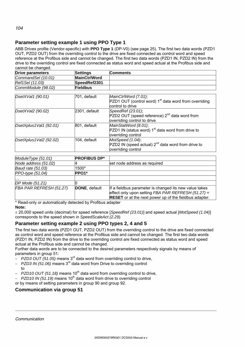
104
Communication
3ADW000379R0301 DCS550 Manual e c
Parameter setting example 1 using PPO Type 1 ABB Drives profile (Vendor-specific) with PPO Type 1 (DP-V0) (see page 25). The first two data words (PZD1 OUT, PZD2 OUT) from the overriding control to the drive are fixed connected as control word and speed reference at the Profibus side and cannot be changed. The first two data words (PZD1 IN, PZD2 IN) from the drive to the overriding control are fixed connected as status word and speed actual at the Profibus side and cannot be changed. Drive parameters Settings Comments CommandSel (10.01) MainCtrlWord Ref1Sel (11.03) SpeedRef2301 CommModule (98.02) Fieldbus
DsetXVal1 (90.01) 701, default MainCtrlWord (7.01); PZD1 OUT (control word) 1st data word from overriding control to drive
DsetXVal2 (90.02) 2301, default SpeedRef (23.01); PZD2 OUT (speed reference) 2nd data word from overriding control to drive
DsetXplus1Val1 (92.01) 801, default MainStatWord (8.01); PZD1 IN (status word) 1st data word from drive to overriding control
DsetXplus1Val2 (92.02) 104, default MotSpeed (1.04); PZD2 IN (speed actual) 2nd data word from drive to overriding control
ModuleType (51.01) PROFIBUS DP* Node address (51.02) 4 set node address as required Baud rate (51.03) 1500* PPO-type (51.04) PPO1* … DP Mode (51.21) 0 FBA PAR REFRESH (51.27) DONE, default If a fieldbus parameter is changed its new value takes
effect only upon setting FBA PAR REFRESH (51.27) = RESET or at the next power up of the fieldbus adapter.
* Read-only or automatically detected by Profibus adapter Note: 20,000 speed units (decimal) for speed reference [SpeedRef (23.01)] and speed actual [MotSpeed (1.04)] corresponds to the speed shown in SpeedScaleAct (2.29).
Parameter setting example 2 using PPO types 2, 4 and 5 The first two data words (PZD1 OUT, PZD2 OUT) from the overriding control to the drive are fixed connected as control word and speed reference at the Profibus side and cannot be changed. The first two data words (PZD1 IN, PZD2 IN) from the drive to the overriding control are fixed connected as status word and speed actual at the Profibus side and cannot be changed. Further data words are to be connected to the desired parameters respectively signals by means of parameters in group 51: PZD3 OUT (51.05) means 3rd data word from overriding control to drive, PZD3 IN (51.06) means 3rd data word from Drive to overriding control
to PZD10 OUT (51.18) means 10th data word from overriding control to drive, PZD10 IN (51.19) means 10th data word from drive to overriding control or by means of setting parameters in group 90 and group 92.
Communication via group 51
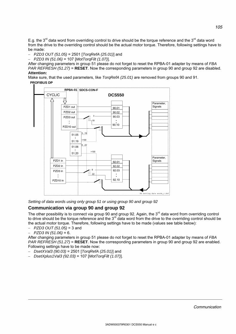
105
Communication
3ADW000379R0301 DCS550 Manual e c
E.g. the 3rd data word from overriding control to drive should be the torque reference and the 3rd data word from the drive to the overriding control should be the actual motor torque. Therefore, following settings have to be made: PZD3 OUT (51.05) = 2501 [TorqRefA (25.01)] and PZD3 IN (51.06) = 107 [MotTorqFilt (1.07)]. After changing parameters in group 51 please do not forget to reset the RPBA-01 adapter by means of FBA PAR REFRESH (51.27) = RESET. Now the corresponding parameters in group 90 and group 92 are disabled. Attention: Make sure, that the used parameters, like TorqRefA (25.01) are removed from groups 90 and 91.
PZD1 out
PZD2 out
PZD3 out
: PZD10 out
3
19
90.01
90.02
90.03
: 90.10
Parameter,Signals
51.05 : 51.19
51.06 : 51.20
PZD1 in
PZD2 in
PZD3 in
:PZD10 in
6
92.01
92.02
92.03
: 92.10
SDCS-CON-F CYCLIC
PROFIBUS DP
3...19
>100
22
6...22
>100
Parameter,Signals
RPBA-01
DCS550
PB setting data words_c.dsf
Setting of data words using only group 51 or using group 90 and group 92
Communication via group 90 and group 92 The other possibility is to connect via group 90 and group 92. Again, the 3rd data word from overriding control to drive should be the torque reference and the 3rd data word from the drive to the overriding control should be the actual motor torque. Therefore, following settings have to be made (values see table below): PZD3 OUT (51.05) = 3 and PZD3 IN (51.06) = 6. After changing parameters in group 51 please do not forget to reset the RPBA-01 adapter by means of FBA PAR REFRESH (51.27) = RESET. Now the corresponding parameters in group 90 and group 92 are enabled. Following settings have to be made now: DsetXVal3 (90.03) = 2501 [TorqRefA (25.01)] and DsetXplus1Val3 (92.03) = 107 [MotTorqFilt (1.07)].
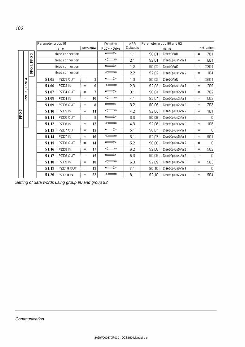
106
Communication
3ADW000379R0301 DCS550 Manual e c
Setting of data words using group 90 and group 92

107
Communication
3ADW000379R0301 DCS550 Manual e c
ProfiNet communication with fieldbus adapter RETA-02

108
Communication
3ADW000379R0301 DCS550 Manual e c
Switch on sequence
Examples for the MainCtrlWord (7.01)
Data set table Many fieldbus communications use the data set table to transmit data words. The next table shows the configuration number of each data word and the corresponding pointer:
Configuration numbers of each data word and its corresponding pointer

109
AP
3ADW000379R0301 DCS550 Manual e c
AP (Adaptive Program) Chapter overview This chapter describes the basics of AP and instructs how to build an application. All needed parameters can be found in the groups 83 to 86.
What is AP? Conventionally, the user can control the operation of the drive by parameters. Each parameter has a fixed set of choices or a setting range. The parameters make adapting of the drive easy, but the choices are limited. It is not possible to customize the drive any further. AP makes customizing possible without the need of a special programming tool or language: AP is using function blocks, DWL AP is the programming and documentation tool. The maximum size of AP is 16 function blocks. The program may consist of several separate functions.
Features AP of DCS550 provides the following features: 16 function blocks, more than 20 block types, password protection, 4 different cycle times selectable, shift functions for function blocks, debug functions,
o output forcing, o breakpoint, o single step, o single cycle,
additional output write pointer parameter for each block (group 86) and 10 additional user constants (group 85) used as data container
How to build the program The programmer connects a function block to other blocks through a Block Parameter Set. The sets are also used for reading values from the firmware and transferring data to the firmware. Each Block Parameter Set consists of six parameters in group 84 and a write pointer in group 86. The figure below shows the use of Block Parameter Set 1 in the firmware (parameters 84.04 to 84.09 and 86.01): Block1Type (84.04) selects the function block type. Block1In1 (84.05) selects the source of IN1. A negative value means that the source will be inverted. Block1In2 (84.06) selects the source of IN2. A negative value means that the source will be inverted. Block1In3 (84.07) selects the source of IN3. A negative value means that the source will be inverted. Block1Attrib (84.08) defines the attributes of the inputs. Block1Output (84.09) provides the value of the function block output, which can be used further for other
input selections. The user cannot edit this parameter value. The output value is also available in write pointer Block1Out (86.01). Block1Out (86.01) contains the
destination parameter, into which the value is written.
How to connect AP with the firmware The outputs of AP need to be connected to the firmware. For that purpose, there are two possibilities: The outputs, e.g. Block1Output (84.09), can be selected for further functions. The output values are available in the write pointers, e.g. Block1Out (86.01). These parameters contain the
destination parameters, into which the values are written.
Block Parameter Set of block 1
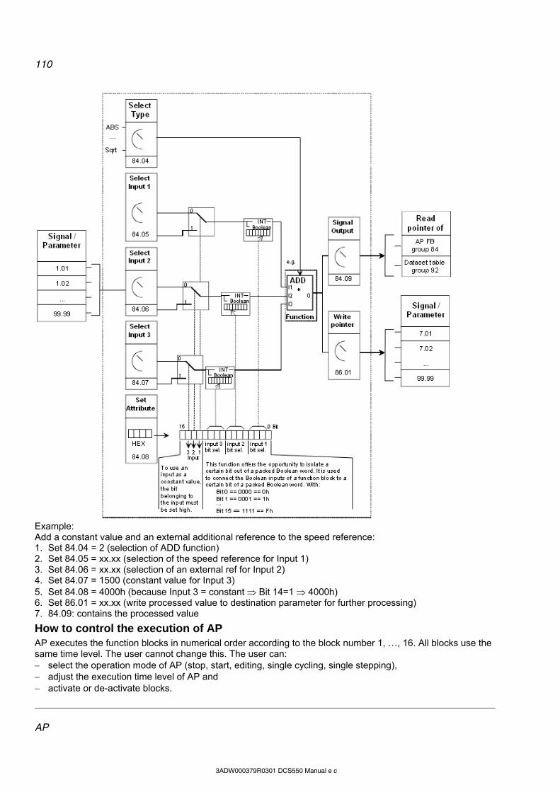
110
AP
3ADW000379R0301 DCS550 Manual e c
Example: Add a constant value and an external additional reference to the speed reference: 1. Set 84.04 = 2 (selection of ADD function) 2. Set 84.05 = xx.xx (selection of the speed reference for Input 1) 3. Set 84.06 = xx.xx (selection of an external ref for Input 2) 4. Set 84.07 = 1500 (constant value for Input 3) 5. Set 84.08 = 4000h (because Input 3 = constant Bit 14=1 4000h) 6. Set 86.01 = xx.xx (write processed value to destination parameter for further processing) 7. 84.09: contains the processed value
How to control the execution of AP AP executes the function blocks in numerical order according to the block number 1, …, 16. All blocks use the same time level. The user cannot change this. The user can: select the operation mode of AP (stop, start, editing, single cycling, single stepping), adjust the execution time level of AP and activate or de-activate blocks.

111
AP
3ADW000379R0301 DCS550 Manual e c
Function blocks, general rules The use of block input 1 (BlockxIn1) is compulsory (it must be connected). Use of input 2 (BlockxIn2) and input 3 (BlockxIn3) is voluntary for the most blocks. As a rule of thumb, an unconnected input does not affect the output of the block. The Attribute Input (BlockxAttrib) is to set with the attributes, like declaration of constant and bits, of all three inputs. DWL AP does this automatically. The constant attribute defines a block constant, which can only be changed or modified in EDIT mode.
Block inputs The blocks use two input formats: integer or boolean The used format depends on the function block type. For example, the ADD block uses integer inputs and the OR block boolean inputs. Note: The inputs of the block are read when the execution of the block starts, not simultaneously for all blocks!
Block input attributes Connect block inputs to the parameter of the signal source or a user constant, e.g. Constant1 (85.01). Depending on the used block type and the desired function, the attributes of all three inputs are to be set as integer, constant or as selection of a bit of a 16-bit word source. Therefore, it is used a 16-bit word, which is defined as following:
* this type of constant defines a Block Constant. Modification is only possible in EDIT mode. Example:
112
AP
3ADW000379R0301 DCS550 Manual e c
Parameter value as an integer input
How the block handles the input The block reads the selected value in as an integer. Note: The parameter selected as an input should be an integer value. The internal scaling for each parameter is available in chapter Parameters.
How to select the input Scroll to the input selection parameter of the block and switch to edit mode (Enter). Set the address, from which the input value is to be read, with group * 100 + index, e.g. AccTime1 (22.01)
== 2201. A negative address (e.g. -2201) will act an inversion of the connected value. The figure below shows the DCS Control Panel display when Block1In1 (84.05) is in edit mode:
Example: AI1 is supplied with a voltage source of 5.8 V. Connect AI1 to the block as follows: Scroll to Block1In1 (84.05) and shift to edit mode (Enter). Set to 503, because the value of AI1 is shown in
group 5 with index 3 - AI1 Val (05.03) == 05 * 100 + 3 = 503. The value at the input of the block is 5800, since the integer scaling of AI1 Val (05.03) is 1000 == 1 V see
chapter Parameters.
Constant as an integer input
How to set and connect the input Option 1: Scroll to the input selection parameter of the block and switch to edit mode (Enter). Give the constant value to this input parameter (arrow keys). Accept with Enter. Scroll to attribute parameter, e.g. Block1Attrib (4.08). Set the bit for constant attribute of this input in Block1Attrib (4.08). Accept by Enter. The constant may have a value from -32768 to 32767. It is not possible to change the constant while AP is running. The figures below shows the DCS Control Panel display when Block1In2 (84.06) is in edit mode and the constant field is visible:

113
AP
3ADW000379R0301 DCS550 Manual e c
Option 2: User constants 85.01 to 85.10 are reserved for AP. Use them for custom setting. Use parameters 19.01 to
19.12 in the same way, but they are not stored in the flash. Connect the user constant to a block as usual by the input selection parameter. It is possible to change user constants while AP is running. They may have values from -32767 to 32767.
Parameter value as a boolean input
How the block handles the input The block: reads the selected value as an integer, uses the bit defined by the bit field as the boolean input and interprets bit value 1 as true and 0 as false. Example: The figure below shows the value of Block1In3 (84.07) when the input is connected to DI2. All digital inputs are available in DI StatWord (8.05). Bit 0 corresponds to DI1 and bit 1 to DI2.
Note: The parameter selected as an input should have a packed boolean value (binary data word).
Constant as a boolean input
How to set and connect the input Scroll to the input selection parameter of the block and switch to edit mode (Enter). If boolean value true is needed, set the constant to 1. If boolean value false is needed, set to 0. Accept by Enter. Scroll to attribute parameter (BlockxAttrib). Set the bit for constant attribute of this input in BlockxAttrib parameter. Accept by Enter.
DWL AP
General Another way to create applications is with DWL AP. It is a program plugged into DWL and can be opened with Tools and DriveAP for DCS550:
114
AP
3ADW000379R0301 DCS550 Manual e c
Important keys and buttons Control DWL AP by means of following keys and buttons: Keys and buttons Function Ctrl + left mouse button on a box or function block
Change / insert function blocks, connect in- and outputs in Edit mode
Shift + left mouse button on the red cross View actual values in Start mode Cancel Abort the action Help Open the online help
Program modes There are 5 modes, see AdapProgCmd (83.01): Stop: AP is not running and cannot be edited, Start: AP is running and cannot be edited, Edit: AP is not running and can be edited, Use SingleCycle and SingleStep for testing.
Change to Edit mode Use Ctrl + left mouse button on 83.01 Adaptive Program Control and set to Edit:
Insert function blocks Use Ctrl + left mouse button on one of the yellow boxes. This opens the pop-up window Insert / Change / Remove Block:

115
AP
3ADW000379R0301 DCS550 Manual e c
In this manner, it is possible to insert up to 16 function blocks from the list to the desktop. The button Change Block xx changes the selected block. The button Insert Before Block xx inserts the new block before the selected block. Button Insert After Block xx inserts the new block after the selected block:
Connect function blocks It is possible to connect function blocks to other blocks or to firmware parameters. To connect use Ctrl + left mouse button on the red cross at the input. This opens the pop-up window Set Pointer Parameter. This window provides several connection possibilities: Connect a Parameter from the list and set the bit in case of connecting a packed boolean value:
Connect a Constant value to the input:
116
AP
3ADW000379R0301 DCS550 Manual e c
In Advanced mode choose the parameter with group * 100 + index, e.g. MainCtrlWord (7.01) == 701:
Select Undefined if no connection is required:
Connections of outputs to firmware parameters can be done by means of the output pointers on the right side of the desktop:
To connect an output of a function block with an input of a function block, simply select the output’s parameter at the input.
117
AP
3ADW000379R0301 DCS550 Manual e c
Set the Time level
Saving AP applications It is possible to save AP applications as *.ap files:

118
AP
3ADW000379R0301 DCS550 Manual e c
Function blocks
General Each of the 16 function blocks has three input parameters IN1 to IN3. It is possible to connect them to the firmware, outputs of other function blocks or constants. Boolean values are interpreted like this: 1 as true and 0 as false. A 4th parameter is used for the attributes of the inputs. Manually set this attribute, if the functions blocks are edited with the DCS Control Panel or DWL. The attribute is set automatically when DWL AP is used. The output OUT can connected with the inputs of function blocks. To write output values into firmware parameters connect the necessary output pointer (group 86) to the desired parameter.
Function block
-
Illustration
ABS Arithmetical function
Illustration
Operation OUT is the absolute value of IN1 multiplied by IN2 and divided by IN3.
OUT = |IN1| * IN2 / IN3
Connections IN1, IN2 and IN3: 16 bit integer (15 bit + sign)
OUT: 16 bit integer (15 bit + sign)
ADD Arithmetical function
Illustration
Operation OUT is the sum of the inputs.
OUT = IN1 + IN2 + IN3 Connections IN1, IN2 and IN3: 16 bit integer (15 bit + sign)
OUT: 16 bit integer (15 bit + sign)
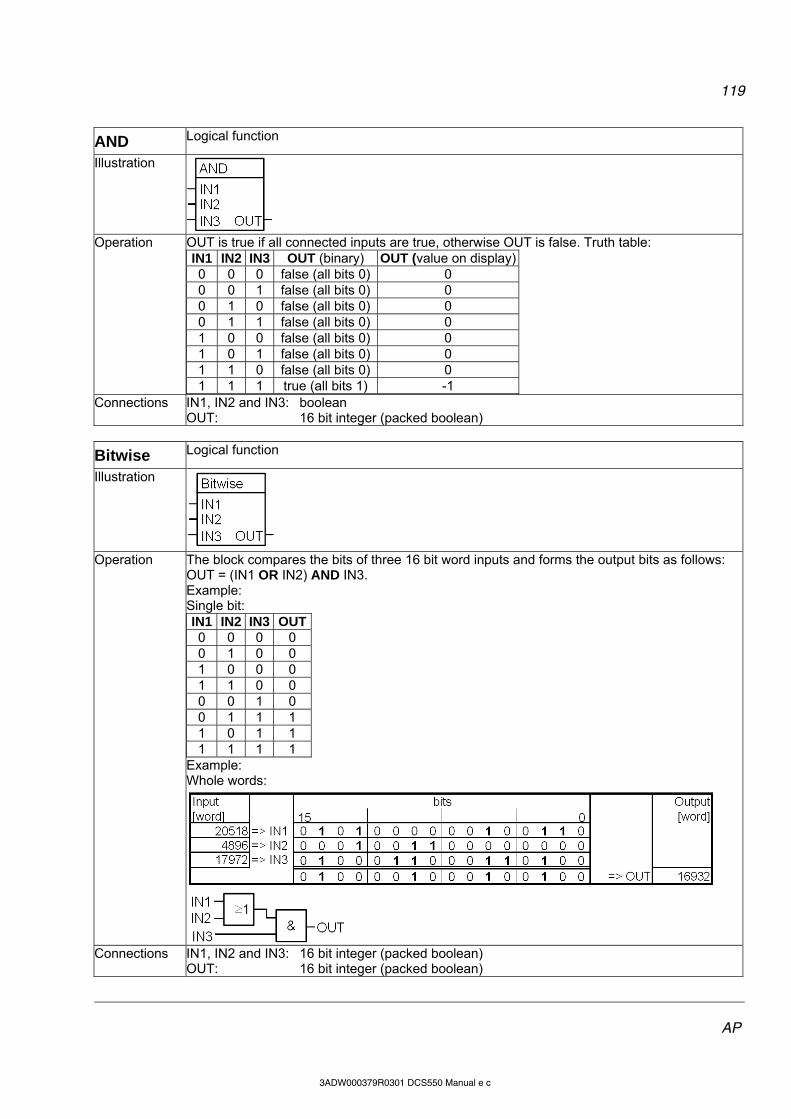
119
AP
3ADW000379R0301 DCS550 Manual e c
AND Logical function
Illustration
Operation OUT is true if all connected inputs are true, otherwise OUT is false. Truth table:
IN1 IN2 IN3 OUT (binary) OUT (value on display)0 0 0 false (all bits 0) 0 0 0 1 false (all bits 0) 0 0 1 0 false (all bits 0) 0 0 1 1 false (all bits 0) 0 1 0 0 false (all bits 0) 0 1 0 1 false (all bits 0) 0 1 1 0 false (all bits 0) 0 1 1 1 true (all bits 1) -1
Connections IN1, IN2 and IN3: boolean OUT: 16 bit integer (packed boolean)
Bitwise Logical function
Illustration
Operation The block compares the bits of three 16 bit word inputs and forms the output bits as follows:
OUT = (IN1 OR IN2) AND IN3. Example: Single bit: IN1 IN2 IN3 OUT 0 0 0 0 0 1 0 0 1 0 0 0 1 1 0 0 0 0 1 0 0 1 1 1 1 0 1 1 1 1 1 1
Example: Whole words:
Connections IN1, IN2 and IN3: 16 bit integer (packed boolean)
OUT: 16 bit integer (packed boolean)
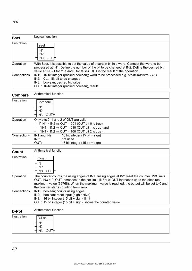
120
AP
3ADW000379R0301 DCS550 Manual e c
Bset Logical function
Illustration
Operation With Bset, it is possible to set the value of a certain bit in a word. Connect the word to be
processed at IN1. Define the number of the bit to be changed at IN2. Define the desired bit value at IN3 (1 for true and 0 for false). OUT is the result of the operation.
Connections IN1: 16-bit integer (packed boolean); word to be processed e.g. MainCtrlWord (7.01) IN2: 0 … 15; bit to be changed IN3: boolean; desired bit value OUT: 16-bit integer (packed boolean), result
Compare Arithmetical function
Illustration
Operation Only bits 0, 1 and 2 of OUT are valid:
If IN1 > IN2 OUT = 001 (OUT bit 0 is true), if IN1 = IN2 OUT = 010 (OUT bit 1 is true) and if IN1 < IN2 OUT = 100 (OUT bit 2 is true).
Connections IN1 and IN2: 16 bit integer (15 bit + sign) IN3: not used OUT: 16 bit integer (15 bit + sign)
Count Arithmetical function
Illustration
Operation The counter counts the rising edges of IN1. Rising edges at IN2 reset the counter. IN3 limits
OUT. IN3 > 0: OUT increases to the set limit. IN3 < 0: OUT increases up to the absolute maximum value (32768). When the maximum value is reached, the output will be set to 0 and the counter starts counting from zero.
Connections IN1: boolean; counts rising edges IN2: boolean; reset input (high active) IN3: 16 bit integer (15 bit + sign); limit OUT: 15 bit integer (15 bit + sign); shows the counted value
D-Pot Arithmetical function
Illustration

121
AP
3ADW000379R0301 DCS550 Manual e c
Operation IN1 increases OUT. IN2 decreases OUT. The absolute value of IN3 is the ramp time in ms, which is needed to increase OUT from 0 to 32767. With positive IN3, the output range is limited from 0 to 32767. With negative IN3, the output range is between -32767 and +32767. If both IN1 and IN2 are true, IN2 overwrites IN1.
Connections IN1: boolean; ramp up IN2: boolean; ramp down IN3: 16 bit integer (15 bit + sign); ramp time scale OUT: 16 bit integer (15 bit + sign); ramp value
Event Display function
Illustration
Operation IN1 triggers the event. IN2 selects the fault, alarm or notice. IN3 is the event delay in ms.
Activation input (boolean) 0 -> 1 trigger event
IN1
0 block deactivated Selection of the message to be displayed. 15 different messages exist. Select them by using numbers. The default message is shown in the brackets. Change it by means of string parameters. Alarms Faults Notices String parameters 301 (APAlarm1) 601 (APFault1) 801 (…) String1 (85.11) 302 (APAlarm2) 602 (APFault2) 802 (…) String2 (85.12) 303 (APAlarm3) 603 (APFault3) 803 (…) String3 (85.13) 304 (APAlarm4) 604 (APFault4) 804 (…) String4 (85.14)
IN2
305 (APAlarm5) 605 (APFault5) 805 (…) String5 (85.15) IN3 delay in ms
Connections IN1: boolean IN2: Text of alarm, fault or notice. Must be defined via String1 (85.11) to String5 (85.15) and
connected to IN2 IN3: 16 bit integer OUT: not used
Filter Arithmetical function
Illustration
Operation OUT is the filtered value of IN1. IN2 is the filter time in ms.
OUT = IN1 (1 - e-t/IN2) Note: The internal calculation uses 32 bits accuracy to avoid offset errors.
Connections IN1: 16 bit integer (15 bits + sign); value to be filtered IN2: 16 bit integer (15 bits + sign); filter time in ms IN3: not used OUT: 16 bit integer (15 bits + sign); filtered value
Limit Logical function
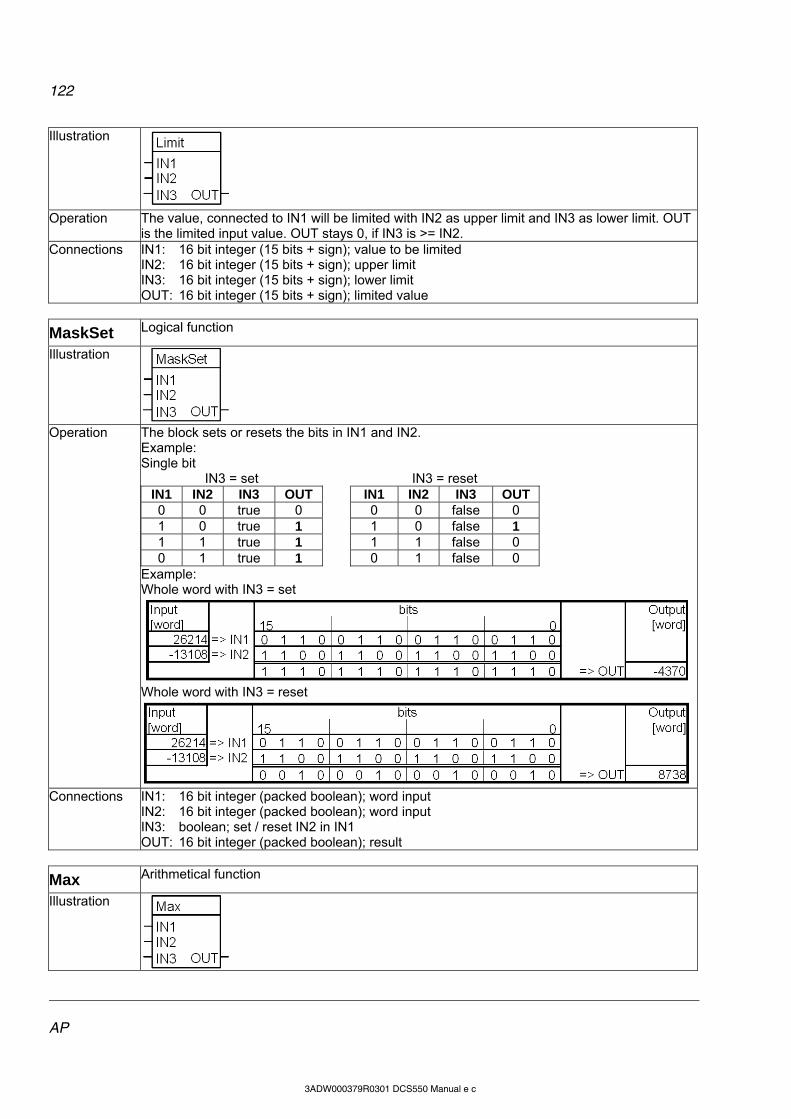
122
AP
3ADW000379R0301 DCS550 Manual e c
Illustration
Operation The value, connected to IN1 will be limited with IN2 as upper limit and IN3 as lower limit. OUT
is the limited input value. OUT stays 0, if IN3 is >= IN2. Connections IN1: 16 bit integer (15 bits + sign); value to be limited
IN2: 16 bit integer (15 bits + sign); upper limit IN3: 16 bit integer (15 bits + sign); lower limit OUT: 16 bit integer (15 bits + sign); limited value
MaskSet Logical function
Illustration
Operation The block sets or resets the bits in IN1 and IN2.
Example: Single bit
IN3 = set IN3 = reset IN1 IN2 IN3 OUT IN1 IN2 IN3 OUT 0 0 true 0 0 0 false 0 1 0 true 1 1 0 false 1 1 1 true 1 1 1 false 0 0 1 true 1
0 1 false 0 Example: Whole word with IN3 = set
Whole word with IN3 = reset
Connections IN1: 16 bit integer (packed boolean); word input IN2: 16 bit integer (packed boolean); word input IN3: boolean; set / reset IN2 in IN1 OUT: 16 bit integer (packed boolean); result
Max Arithmetical function
Illustration

123
AP
3ADW000379R0301 DCS550 Manual e c
Operation OUT is the highest input value. OUT = MAX (IN1, IN2, IN3) Note: An open input is ignored.
Connections IN1, IN2 and IN3: 16 bit integer (15 bits + sign) OUT: 16 bit integer (15 bits + sign)
Min Arithmetical function
Illustration
Operation OUT is the lowest input value.
OUT = MIN (IN1, IN2, IN3) Note: An open input is ignored.
Connections IN1, IN2 and IN3: 16 bit integer (15 bits + sign) OUT: 16 bit integer (15 bits + sign)
MulDiv Arithmetical function
Illustration
Operation OUT is the IN1 multiplied with IN2 and divided by IN3.
OUT = (IN1 * IN2) / IN3 Connections IN1, IN2 and IN3: 16 bit integer (15 bits + sign)
OUT: 16 bit integer (15 bits + sign)
NotUsed -
Illustration
Operation Block is not enabled and not working, default Connections -
OR Logical function
Illustration
Operation OUT is true if any of the connected inputs is true, otherwise OUT is false. Truth table:
IN1 IN2 IN3 OUT (binary) OUT (value on display) 0 0 0 false (all bits 0) 0 0 0 1 true (all bits 1) -1 0 1 0 true (all bits 1) -1
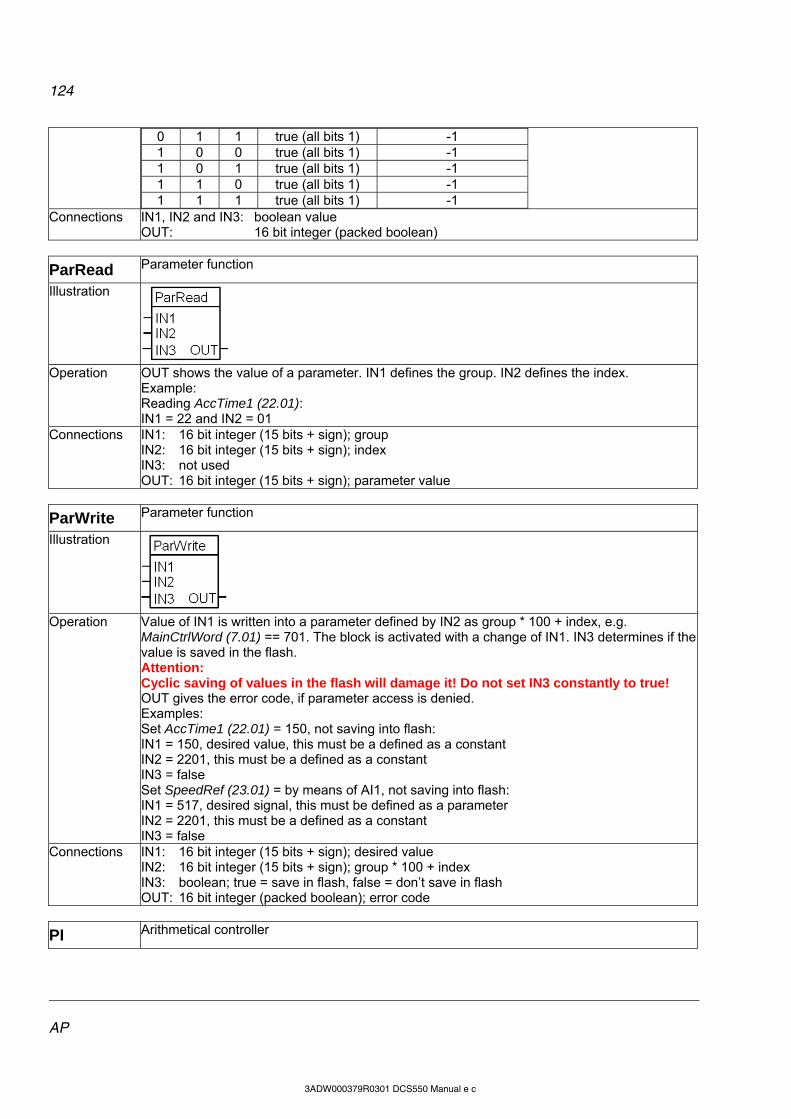
124
AP
3ADW000379R0301 DCS550 Manual e c
0 1 1 true (all bits 1) -1 1 0 0 true (all bits 1) -1 1 0 1 true (all bits 1) -1 1 1 0 true (all bits 1) -1 1 1 1 true (all bits 1) -1
Connections IN1, IN2 and IN3: boolean value OUT: 16 bit integer (packed boolean)
ParRead Parameter function
Illustration
Operation OUT shows the value of a parameter. IN1 defines the group. IN2 defines the index.
Example: Reading AccTime1 (22.01): IN1 = 22 and IN2 = 01
Connections IN1: 16 bit integer (15 bits + sign); group IN2: 16 bit integer (15 bits + sign); index IN3: not used OUT: 16 bit integer (15 bits + sign); parameter value
ParWrite Parameter function
Illustration
Operation Value of IN1 is written into a parameter defined by IN2 as group * 100 + index, e.g.
MainCtrlWord (7.01) == 701. The block is activated with a change of IN1. IN3 determines if the value is saved in the flash. Attention: Cyclic saving of values in the flash will damage it! Do not set IN3 constantly to true! OUT gives the error code, if parameter access is denied. Examples: Set AccTime1 (22.01) = 150, not saving into flash: IN1 = 150, desired value, this must be a defined as a constant IN2 = 2201, this must be a defined as a constant IN3 = false Set SpeedRef (23.01) = by means of AI1, not saving into flash: IN1 = 517, desired signal, this must be defined as a parameter IN2 = 2201, this must be a defined as a constant IN3 = false
Connections IN1: 16 bit integer (15 bits + sign); desired value IN2: 16 bit integer (15 bits + sign); group * 100 + index IN3: boolean; true = save in flash, false = don’t save in flash OUT: 16 bit integer (packed boolean); error code
PI Arithmetical controller
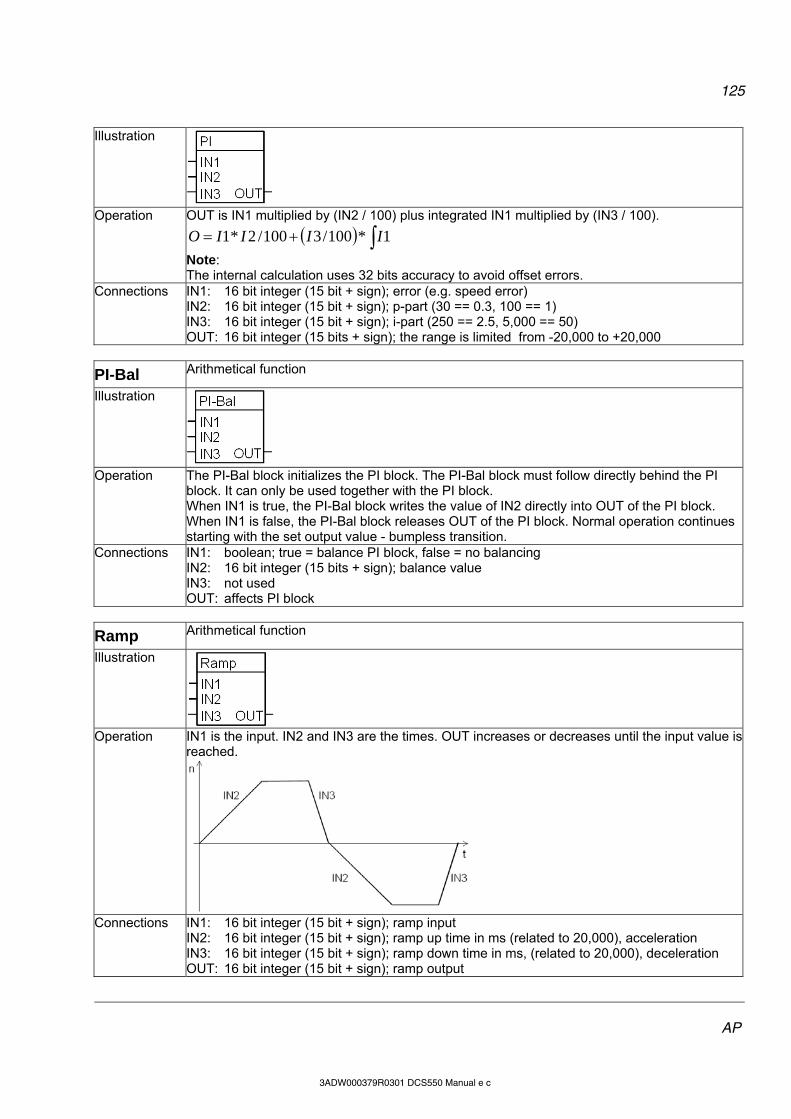
125
AP
3ADW000379R0301 DCS550 Manual e c
Illustration
Operation OUT is IN1 multiplied by (IN2 / 100) plus integrated IN1 multiplied by (IN3 / 100).
1*100/3100/2*1 IIIIO
Note: The internal calculation uses 32 bits accuracy to avoid offset errors.
Connections IN1: 16 bit integer (15 bit + sign); error (e.g. speed error) IN2: 16 bit integer (15 bit + sign); p-part (30 == 0.3, 100 == 1) IN3: 16 bit integer (15 bit + sign); i-part (250 == 2.5, 5,000 == 50) OUT: 16 bit integer (15 bits + sign); the range is limited from -20,000 to +20,000
PI-Bal Arithmetical function
Illustration
Operation The PI-Bal block initializes the PI block. The PI-Bal block must follow directly behind the PI
block. It can only be used together with the PI block. When IN1 is true, the PI-Bal block writes the value of IN2 directly into OUT of the PI block. When IN1 is false, the PI-Bal block releases OUT of the PI block. Normal operation continues starting with the set output value - bumpless transition.
Connections IN1: boolean; true = balance PI block, false = no balancing IN2: 16 bit integer (15 bits + sign); balance value IN3: not used OUT: affects PI block
Ramp Arithmetical function
Illustration
Operation IN1 is the input. IN2 and IN3 are the times. OUT increases or decreases until the input value is
reached.
Connections IN1: 16 bit integer (15 bit + sign); ramp input
IN2: 16 bit integer (15 bit + sign); ramp up time in ms (related to 20,000), acceleration IN3: 16 bit integer (15 bit + sign); ramp down time in ms, (related to 20,000), deceleration OUT: 16 bit integer (15 bit + sign); ramp output
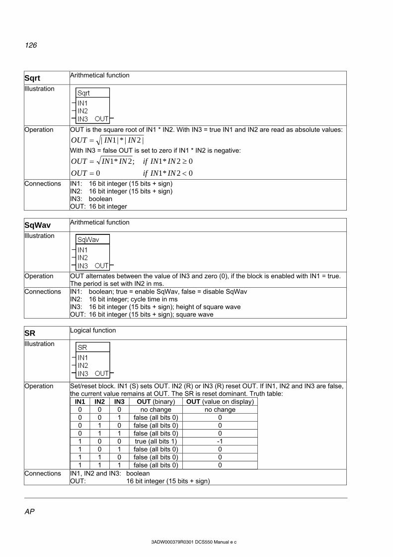
126
AP
3ADW000379R0301 DCS550 Manual e c
Sqrt Arithmetical function
Illustration
Operation OUT is the square root of IN1 * IN2. With IN3 = true IN1 and IN2 are read as absolute values:
|2|*|1| ININOUT
With IN3 = false OUT is set to zero if IN1 * IN2 is negative:
02*10
02*1;2*1
ININifOUT
ININifININOUT
Connections IN1: 16 bit integer (15 bits + sign) IN2: 16 bit integer (15 bits + sign) IN3: boolean OUT: 16 bit integer
SqWav Arithmetical function
Illustration
Operation OUT alternates between the value of IN3 and zero (0), if the block is enabled with IN1 = true.
The period is set with IN2 in ms. Connections IN1: boolean; true = enable SqWav, false = disable SqWav
IN2: 16 bit integer; cycle time in ms IN3: 16 bit integer (15 bits + sign); height of square wave OUT: 16 bit integer (15 bits + sign); square wave
SR Logical function
Illustration
Operation Set/reset block. IN1 (S) sets OUT. IN2 (R) or IN3 (R) reset OUT. If IN1, IN2 and IN3 are false,
the current value remains at OUT. The SR is reset dominant. Truth table: IN1 IN2 IN3 OUT (binary) OUT (value on display)0 0 0 no change no change 0 0 1 false (all bits 0) 0 0 1 0 false (all bits 0) 0 0 1 1 false (all bits 0) 0 1 0 0 true (all bits 1) -1 1 0 1 false (all bits 0) 0 1 1 0 false (all bits 0) 0 1 1 1 false (all bits 0) 0
Connections IN1, IN2 and IN3: boolean OUT: 16 bit integer (15 bits + sign)
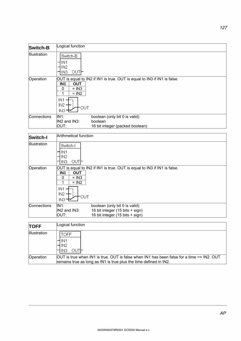
127
AP
3ADW000379R0301 DCS550 Manual e c
Switch-B Logical function
Illustration
Operation OUT is equal to IN2 if IN1 is true. OUT is equal to IN3 if IN1 is false.
IN1 OUT 0 = IN3 1 = IN2
Connections IN1: boolean (only bit 0 is valid)
IN2 and IN3: boolean OUT: 16 bit integer (packed boolean)
Switch-I Arithmetical function
Illustration
Operation OUT is equal to IN2 if IN1 is true. OUT is equal to IN3 if IN1 is false.
IN1 OUT 0 = IN3 1 = IN2
Connections IN1: boolean (only bit 0 is valid)
IN2 and IN3: 16 bit integer (15 bits + sign) OUT: 16 bit integer (15 bits + sign)
TOFF Logical function
Illustration
Operation OUT is true when IN1 is true. OUT is false when IN1 has been false for a time >= IN2. OUT
remains true as long as IN1 is true plus the time defined in IN2.
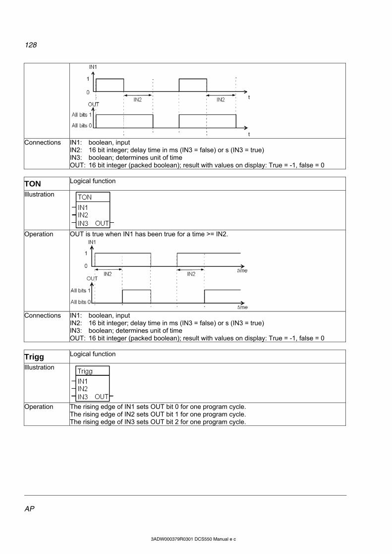
128
AP
3ADW000379R0301 DCS550 Manual e c
Connections IN1: boolean, input
IN2: 16 bit integer; delay time in ms (IN3 = false) or s (IN3 = true) IN3: boolean; determines unit of time OUT: 16 bit integer (packed boolean); result with values on display: True = -1, false = 0
TON Logical function
Illustration
Operation OUT is true when IN1 has been true for a time >= IN2.
Connections IN1: boolean, input
IN2: 16 bit integer; delay time in ms (IN3 = false) or s (IN3 = true) IN3: boolean; determines unit of time OUT: 16 bit integer (packed boolean); result with values on display: True = -1, false = 0
Trigg Logical function
Illustration
Operation The rising edge of IN1 sets OUT bit 0 for one program cycle.
The rising edge of IN2 sets OUT bit 1 for one program cycle. The rising edge of IN3 sets OUT bit 2 for one program cycle.
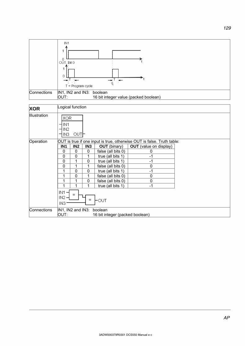
129
AP
3ADW000379R0301 DCS550 Manual e c
Connections IN1, IN2 and IN3: boolean
OUT: 16 bit integer value (packed boolean)
XOR Logical function
Illustration
Operation OUT is true if one input is true, otherwise OUT is false. Truth table:
IN1 IN2 IN3 OUT (binary) OUT (value on display)0 0 0 false (all bits 0) 0 0 0 1 true (all bits 1) -1 0 1 0 true (all bits 1) -1 0 1 1 false (all bits 0) 0 1 0 0 true (all bits 1) -1 1 0 1 false (all bits 0) 0 1 1 0 false (all bits 0) 0 1 1 1 true (all bits 1) -1
Connections IN1, IN2 and IN3: boolean
OUT: 16 bit integer (packed boolean)
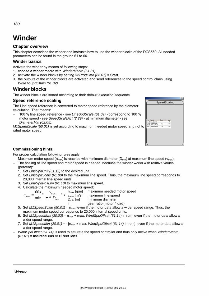
130
Winder
3ADW000379R0301 DCS550 Manual e c
Winder Chapter overview This chapter describes the winder and instructs how to use the winder blocks of the DCS550. All needed parameters can be found in the groups 61 to 66.
Winder basics Activate the winder by means of following steps: 1. choose a winder macro with WinderMacro (61.01), 2. activate the winder blocks by setting WiProgCmd (66.01) = Start, 3. the outputs of the winder blocks are activated and send references to the speed control chain using
WriteToSpdChain (61.02)
Winder blocks The winder blocks are sorted according to their default execution sequence.
Speed reference scaling The Line speed reference is converted to motor speed reference by the diameter calculation. That means: 100 % line speed reference - see LineSpdScale (61.09) - correspond to 100 %
motor speed - see SpeedScaleAct (2.29) - at minimum diameter - see DiameterMin (62.05).
M1SpeedScale (50.01) is set according to maximum needed motor speed and not to rated motor speed.
Commissioning hints: For proper calculation following rules apply: Maximum motor speed (nmax) is reached with minimum diameter (Dmin) at maximum line speed (vmax). The scaling of line speed and motor speed is needed, because the winder works with relative values
(percent): 1. Set LineSpdUnit (61.12) to the desired unit. 2. Set LineSpdScale (61.09) to the maximum line speed. Thus, the maximum line speed corresponds to
20,000 internal line speed units. 3. Set LineSpdPosLim (61.10) to maximum line speed. 4. Calculate the maximum needed motor speed:
iD
vsn *
**
min
60
min
maxmax
nmax [rpm] maximum needed motor speed vmax [m/s] maximum line speed Dmin [m] minimum diameter i gear ratio (motor / load)
5. Set M1SpeedScale (50.01) = nmax, even if the motor data allow a wider speed range. Thus, the maximum motor speed corresponds to 20,000 internal speed units.
6. Set M1SpeedMax (20.02) = nmax + max. WindSpdOffset (61.14) in rpm, even if the motor data allow a wider speed range.
7. Set M1SpeedMin (20.01) = - [nmax + max. WindSpdOffset (61.14) in rpm], even if the motor data allow a wider speed range.
WindSpdOffset (61.14) is used to saturate the speed controller and thus only active when WinderMacro (61.01) = IndirectTens or DirectTens.
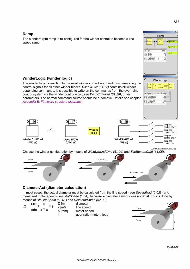
131
Winder
3ADW000379R0301 DCS550 Manual e c
Ramp The standard rpm ramp is re-configured for the winder control to become a line speed ramp.
WinderLogic (winder logic) The winder logic is reacting to the used winder control word and thus generating the control signals for all other winder blocks. UsedWCW (61.17) contains all winder depending commands. It is possible to write on the commands from the overriding control system via the winder control word, see WindCtrlWord (61.16), or via parameters. The normal command source should be automatic. Details see chapter Appendix B: Firmware structure diagrams.
WinderCtrlWord(WCW)
61.16
Used WCW (UWCW)
WindStatWord (WSW)
to speedcontrol chainto speedcontrol chain
61.17 61.19
Winder logic
to speedcontrol chainto speedcontrol chain
DCS550_Fw_blocksch_rev_a.dsf
Choose the winder configuration by means of WindUnwindCmd (61.04) and TopBottomCmd (61.05):
DiameterAct (diameter calculation) In most cases, the actual diameter must be calculated from the line speed - see SpeedRef3 (2.02) - and measured motor speed - see MotSpeed (1.04), because a diameter sensor does not exist. This is done by means of DiaLineSpdIn (62.01) and DiaMotorSpdIn (62.02):
in
vsD *
**
min
60
D [m] diameter v [m/s] line speed n [rpm] motor speed i gear ratio (motor / load)
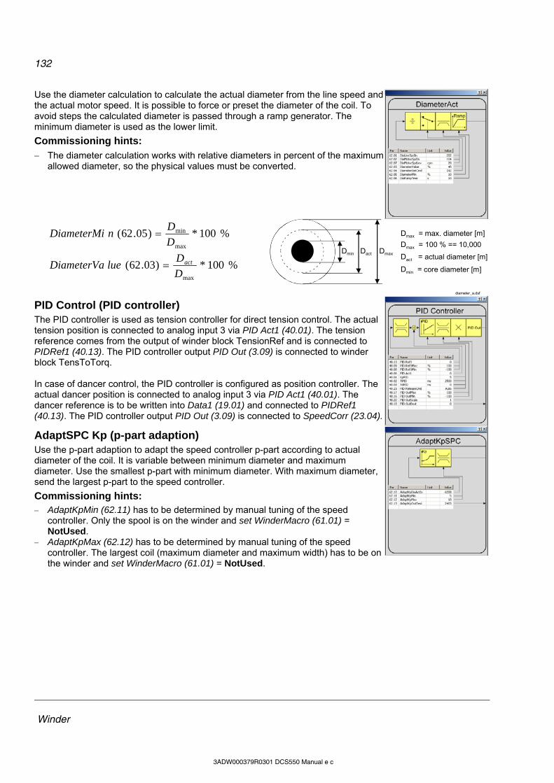
132
Winder
3ADW000379R0301 DCS550 Manual e c
Use the diameter calculation to calculate the actual diameter from the line speed and the actual motor speed. It is possible to force or preset the diameter of the coil. To avoid steps the calculated diameter is passed through a ramp generator. The minimum diameter is used as the lower limit.
Commissioning hints: The diameter calculation works with relative diameters in percent of the maximum
allowed diameter, so the physical values must be converted.
%100*)05.62(max
min
D
DnDiameterMi
%100*)03.62(maxD
DlueDiameterVa act
Dmax = max. diameter [m]
Dmax = 100 % == 10,000
Dact = actual diameter [m]
Dmin = core diameter [m]
DmaxDactDmin
diameter_a.dsf
PID Control (PID controller) The PID controller is used as tension controller for direct tension control. The actual tension position is connected to analog input 3 via PID Act1 (40.01). The tension reference comes from the output of winder block TensionRef and is connected to PIDRef1 (40.13). The PID controller output PID Out (3.09) is connected to winder block TensToTorq. In case of dancer control, the PID controller is configured as position controller. The actual dancer position is connected to analog input 3 via PID Act1 (40.01). The dancer reference is to be written into Data1 (19.01) and connected to PIDRef1 (40.13). The PID controller output PID Out (3.09) is connected to SpeedCorr (23.04).
AdaptSPC Kp (p-part adaption) Use the p-part adaption to adapt the speed controller p-part according to actual diameter of the coil. It is variable between minimum diameter and maximum diameter. Use the smallest p-part with minimum diameter. With maximum diameter, send the largest p-part to the speed controller.
Commissioning hints: AdaptKpMin (62.11) has to be determined by manual tuning of the speed
controller. Only the spool is on the winder and set WinderMacro (61.01) = NotUsed.
AdaptKpMax (62.12) has to be determined by manual tuning of the speed controller. The largest coil (maximum diameter and maximum width) has to be on the winder and set WinderMacro (61.01) = NotUsed.
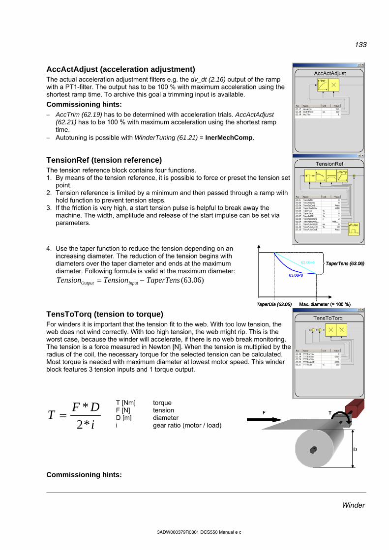
133
Winder
3ADW000379R0301 DCS550 Manual e c
AccActAdjust (acceleration adjustment) The actual acceleration adjustment filters e.g. the dv_dt (2.16) output of the ramp with a PT1-filter. The output has to be 100 % with maximum acceleration using the shortest ramp time. To archive this goal a trimming input is available.
Commissioning hints: AccTrim (62.19) has to be determined with acceleration trials. AccActAdjust
(62.21) has to be 100 % with maximum acceleration using the shortest ramp time.
Autotuning is possible with WinderTuning (61.21) = InerMechComp.
TensionRef (tension reference) The tension reference block contains four functions. 1. By means of the tension reference, it is possible to force or preset the tension set
point. 2. Tension reference is limited by a minimum and then passed through a ramp with
hold function to prevent tension steps. 3. If the friction is very high, a start tension pulse is helpful to break away the
machine. The width, amplitude and release of the start impulse can be set via parameters.
4. Use the taper function to reduce the tension depending on an increasing diameter. The reduction of the tension begins with diameters over the taper diameter and ends at the maximum diameter. Following formula is valid at the maximum diameter:
)06.63(TaperTensTensionTension InputOutput
TaperDia (63.05) Max. diameter (= 100 %)
TaperTens (63.06)63.06>0
63.06<0
TaperDia (63.05) Max. diameter (= 100 %)
TaperTens (63.06)
TaperDia (63.05) Max. diameter (= 100 %)
TaperTens (63.06)63.06>0
63.06<0
TensToTorq (tension to torque) For winders it is important that the tension fit to the web. With too low tension, the web does not wind correctly. With too high tension, the web might rip. This is the worst case, because the winder will accelerate, if there is no web break monitoring. The tension is a force measured in Newton [N]. When the tension is multiplied by the radius of the coil, the necessary torque for the selected tension can be calculated. Most torque is needed with maximum diameter at lowest motor speed. This winder block features 3 tension inputs and 1 torque output.
i
DFT
*2
*
T [Nm] torque F [N] tension D [m] diameter i gear ratio (motor / load)
F T
D
F T
D
Commissioning hints:
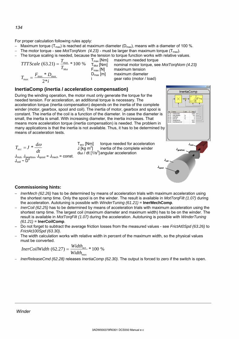
134
Winder
3ADW000379R0301 DCS550 Manual e c
For proper calculation following rules apply: Maximum torque (Tmax) is reached at maximum diameter (Dmax), means with a diameter of 100 %. The motor torque - see MotTorqNom (4.23) - must be larger than maximum torque (Tmax). The torque scaling is needed, because the tension to torque function works with relative values.
%100*)21.63( max
MotT
TScaleTTT
i
DFT
*2
* maxmaxmax
Tmax [Nm] maximum needed torque TMot [Nm] nominal motor torque, see MotTorqNom (4.23) Fmax [N] maximum tension Dmax [m] maximum diameter i gear ratio (motor / load)
InertiaComp (inertia / acceleration compensation) During the winding operation, the motor must only generate the torque for the needed tension. For acceleration, an additional torque is necessary. The acceleration torque (inertia compensation) depends on the inertia of the complete winder (motor, gearbox, spool and coil). The inertia of motor, gearbox and spool is constant. The inertia of the coil is a function of the diameter. In case the diameter is small, the inertia is small. With increasing diameter, the inertia increases. That means more acceleration torque (inertia compensation) is needed. The problem in many applications is that the inertia is not available. Thus, it has to be determined by means of acceleration tests.
dt
dJTacc
*
Jmot, Jgearbox, Jspool = Jmech = const. Jcoil ~ D4
Tacc [Nm] torque needed for acceleration J [kg m2] inertia of the complete winder dω / dt [1/s2] angular acceleration
Jmot
Jgearbox
Jcoil
Jspool
Jmot
Jgearbox
Jcoil
Jspool
Commissioning hints: InerMech (62.26) has to be determined by means of acceleration trials with maximum acceleration using
the shortest ramp time. Only the spool is on the winder. The result is available in MotTorqFilt (1.07) during the acceleration. Autotuning is possible with WinderTuning (61.21) = InerMechComp.
InerCoil (62.25) has to be determined by means of acceleration trials with maximum acceleration using the shortest ramp time. The largest coil (maximum diameter and maximum width) has to be on the winder. The result is available in MotTorqFilt (1.07) during the acceleration. Autotuning is possible with WinderTuning (61.21) = InerCoilComp.
Do not forget to subtract the average friction losses from the measured values - see FrictAt0Spd (63.26) to FrictAt100Spd (63.30).
The width calculation works with relative width in percent of the maximum width, so the physical values must be converted.
%100*)27.62(maxWidth
WidthdthInerCoilWi act
InerReleaseCmd (62.28) releases InertiaComp (62.30). The output is forced to zero if the switch is open.
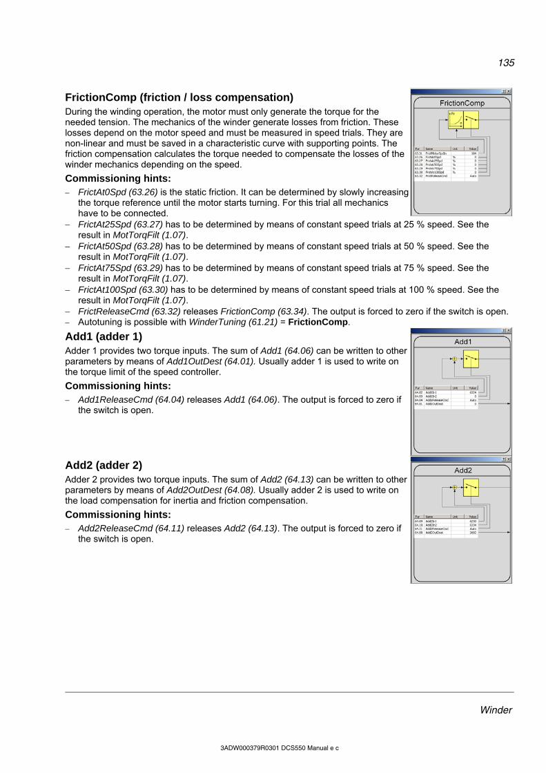
135
Winder
3ADW000379R0301 DCS550 Manual e c
FrictionComp (friction / loss compensation) During the winding operation, the motor must only generate the torque for the needed tension. The mechanics of the winder generate losses from friction. These losses depend on the motor speed and must be measured in speed trials. They are non-linear and must be saved in a characteristic curve with supporting points. The friction compensation calculates the torque needed to compensate the losses of the winder mechanics depending on the speed.
Commissioning hints: FrictAt0Spd (63.26) is the static friction. It can be determined by slowly increasing
the torque reference until the motor starts turning. For this trial all mechanics have to be connected.
FrictAt25Spd (63.27) has to be determined by means of constant speed trials at 25 % speed. See the result in MotTorqFilt (1.07).
FrictAt50Spd (63.28) has to be determined by means of constant speed trials at 50 % speed. See the result in MotTorqFilt (1.07).
FrictAt75Spd (63.29) has to be determined by means of constant speed trials at 75 % speed. See the result in MotTorqFilt (1.07).
FrictAt100Spd (63.30) has to be determined by means of constant speed trials at 100 % speed. See the result in MotTorqFilt (1.07).
FrictReleaseCmd (63.32) releases FrictionComp (63.34). The output is forced to zero if the switch is open. Autotuning is possible with WinderTuning (61.21) = FrictionComp.
Add1 (adder 1) Adder 1 provides two torque inputs. The sum of Add1 (64.06) can be written to other parameters by means of Add1OutDest (64.01). Usually adder 1 is used to write on the torque limit of the speed controller.
Commissioning hints: Add1ReleaseCmd (64.04) releases Add1 (64.06). The output is forced to zero if
the switch is open.
Add2 (adder 2) Adder 2 provides two torque inputs. The sum of Add2 (64.13) can be written to other parameters by means of Add2OutDest (64.08). Usually adder 2 is used to write on the load compensation for inertia and friction compensation.
Commissioning hints: Add2ReleaseCmd (64.11) releases Add2 (64.13). The output is forced to zero if
the switch is open.

136
Winder
3ADW000379R0301 DCS550 Manual e c
Winder macros Winder macros are pre-programmed parameter sets. During start-up, configure the winder easily without changing individual parameters. The functions of inputs, outputs and control structure are macro dependent. Any winder macro can be adapted by changing individual parameters without restrictions. Select a winder macro by means of WinderMacro (61.01). The following tables and diagrams show the structure of the macros.
NotUsed Winder is blocked, default setting. Following parameters are set when using WinderMacro (61.01) = NotUsed:
Parameter name NotUsed Factory (default) TorqMaxSPC (20.07) 325 % 325 % TorqMinSPC (20.08) -325 % -325 %
IndepTorqMaxSPC (20.24) 325 % 325 % IndepTorqMinSPC (20.25) -325 % -325 %
SpeedCorr (23.04) 0 rpm 0 rpm SpeedRefScale (23.16) 1 1
TorqSel (26.01) Speed Speed LoadComp (26.02) 0 % 0 % PID Act1 (40.06) 0 0 PID Ref1 (40.13) 0 0
PID OutMin (40.16) -100 % -100 % PID OutMax (40.17) 100 % 100 % PID OutDest (40.18) 0 0
PID ReleaseCmd (40.23) NotUsed Auto AdaptKpOutDest (62.13) 0 0
Add1OutDest (64.01) 0 0 Add2OutDest (64.08) 0 0
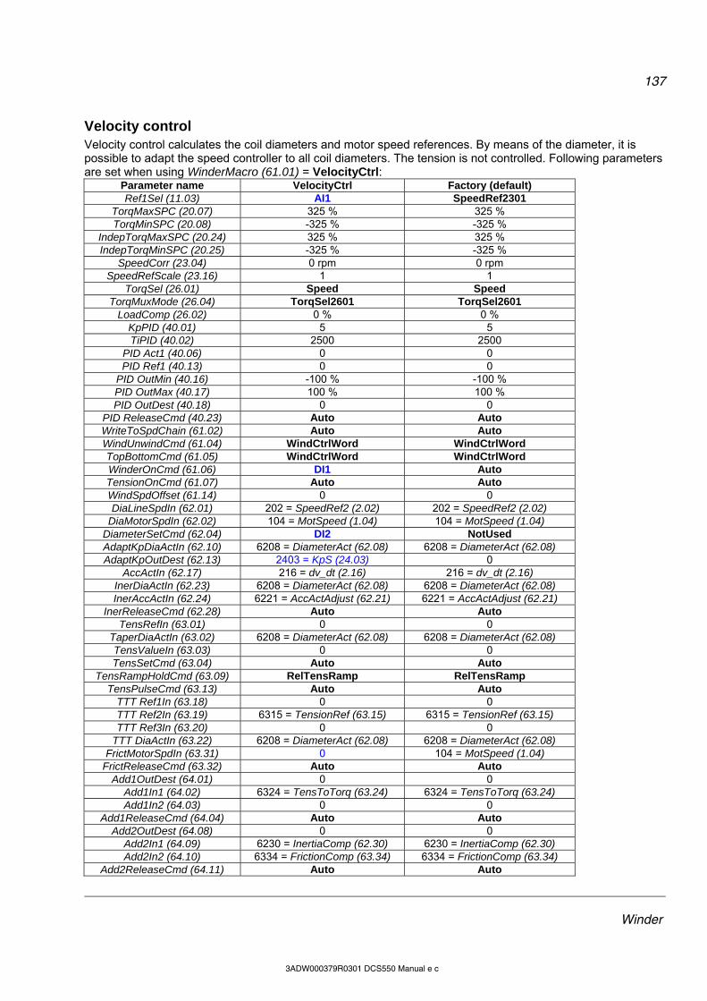
137
Winder
3ADW000379R0301 DCS550 Manual e c
Velocity control Velocity control calculates the coil diameters and motor speed references. By means of the diameter, it is possible to adapt the speed controller to all coil diameters. The tension is not controlled. Following parameters are set when using WinderMacro (61.01) = VelocityCtrl:
Parameter name VelocityCtrl Factory (default) Ref1Sel (11.03) AI1 SpeedRef2301
TorqMaxSPC (20.07) 325 % 325 % TorqMinSPC (20.08) -325 % -325 %
IndepTorqMaxSPC (20.24) 325 % 325 % IndepTorqMinSPC (20.25) -325 % -325 %
SpeedCorr (23.04) 0 rpm 0 rpm SpeedRefScale (23.16) 1 1
TorqSel (26.01) Speed Speed TorqMuxMode (26.04) TorqSel2601 TorqSel2601
LoadComp (26.02) 0 % 0 % KpPID (40.01) 5 5 TiPID (40.02) 2500 2500
PID Act1 (40.06) 0 0 PID Ref1 (40.13) 0 0
PID OutMin (40.16) -100 % -100 % PID OutMax (40.17) 100 % 100 % PID OutDest (40.18) 0 0
PID ReleaseCmd (40.23) Auto Auto WriteToSpdChain (61.02) Auto Auto WindUnwindCmd (61.04) WindCtrlWord WindCtrlWord TopBottomCmd (61.05) WindCtrlWord WindCtrlWord WinderOnCmd (61.06) DI1 Auto TensionOnCmd (61.07) Auto Auto WindSpdOffset (61.14) 0 0 DiaLineSpdIn (62.01) 202 = SpeedRef2 (2.02) 202 = SpeedRef2 (2.02)
DiaMotorSpdIn (62.02) 104 = MotSpeed (1.04) 104 = MotSpeed (1.04) DiameterSetCmd (62.04) DI2 NotUsed AdaptKpDiaActIn (62.10) 6208 = DiameterAct (62.08) 6208 = DiameterAct (62.08) AdaptKpOutDest (62.13) 2403 = KpS (24.03) 0
AccActIn (62.17) 216 = dv_dt (2.16) 216 = dv_dt (2.16) InerDiaActIn (62.23) 6208 = DiameterAct (62.08) 6208 = DiameterAct (62.08) InerAccActIn (62.24) 6221 = AccActAdjust (62.21) 6221 = AccActAdjust (62.21)
InerReleaseCmd (62.28) Auto Auto TensRefIn (63.01) 0 0
TaperDiaActIn (63.02) 6208 = DiameterAct (62.08) 6208 = DiameterAct (62.08) TensValueIn (63.03) 0 0 TensSetCmd (63.04) Auto Auto
TensRampHoldCmd (63.09) RelTensRamp RelTensRamp TensPulseCmd (63.13) Auto Auto
TTT Ref1In (63.18) 0 0 TTT Ref2In (63.19) 6315 = TensionRef (63.15) 6315 = TensionRef (63.15) TTT Ref3In (63.20) 0 0
TTT DiaActIn (63.22) 6208 = DiameterAct (62.08) 6208 = DiameterAct (62.08) FrictMotorSpdIn (63.31) 0 104 = MotSpeed (1.04)
FrictReleaseCmd (63.32) Auto Auto Add1OutDest (64.01) 0 0
Add1In1 (64.02) 6324 = TensToTorq (63.24) 6324 = TensToTorq (63.24) Add1In2 (64.03) 0 0
Add1ReleaseCmd (64.04) Auto Auto Add2OutDest (64.08) 0 0
Add2In1 (64.09) 6230 = InertiaComp (62.30) 6230 = InertiaComp (62.30) Add2In2 (64.10) 6334 = FrictionComp (63.34) 6334 = FrictionComp (63.34)
Add2ReleaseCmd (64.11) Auto Auto
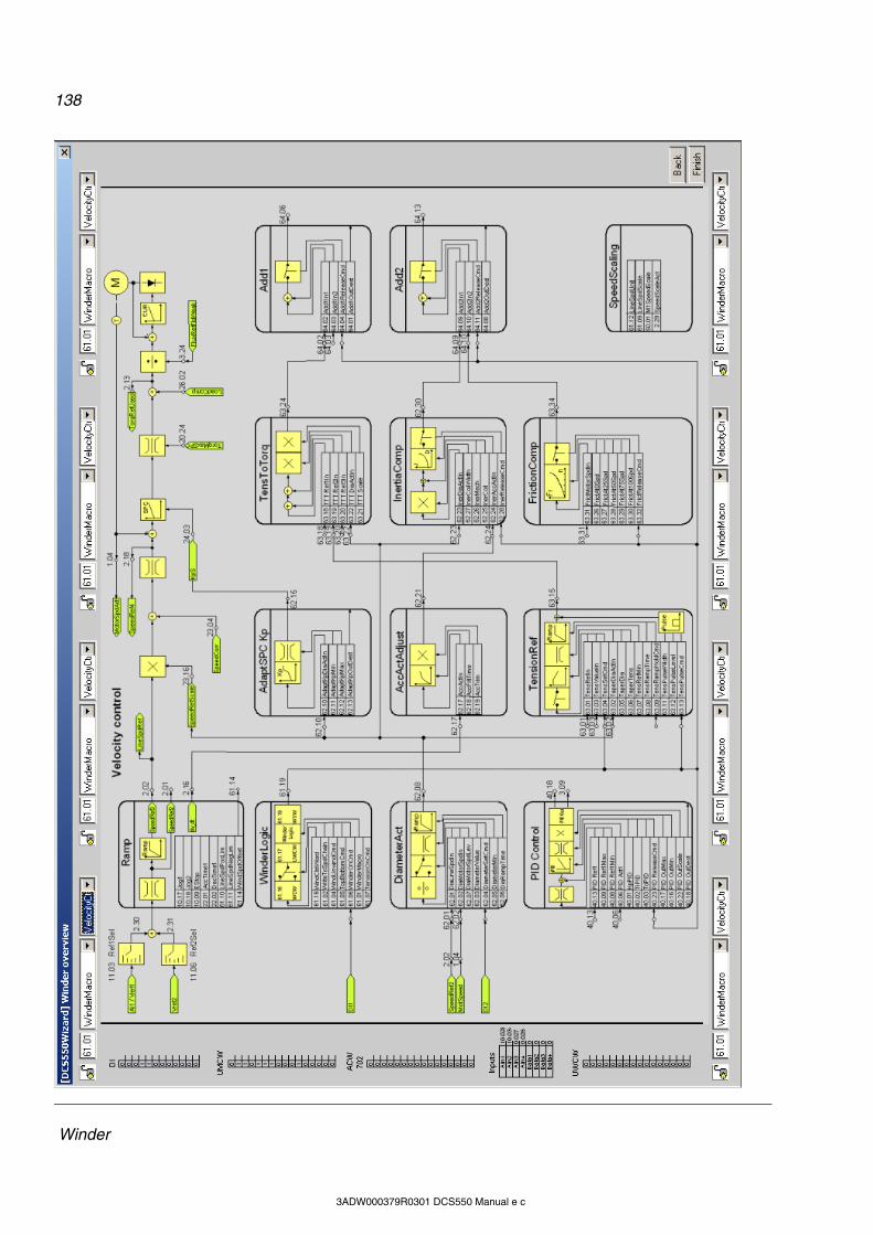
138
Winder
3ADW000379R0301 DCS550 Manual e c
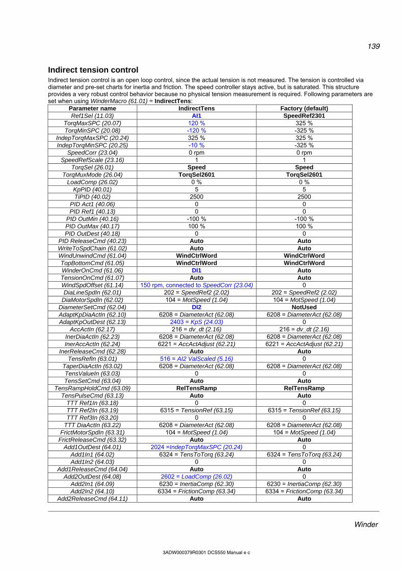
139
Winder
3ADW000379R0301 DCS550 Manual e c
Indirect tension control Indirect tension control is an open loop control, since the actual tension is not measured. The tension is controlled via diameter and pre-set charts for inertia and friction. The speed controller stays active, but is saturated. This structure provides a very robust control behavior because no physical tension measurement is required. Following parameters are set when using WinderMacro (61.01) = IndirectTens:
Parameter name IndirectTens Factory (default) Ref1Sel (11.03) AI1 SpeedRef2301
TorqMaxSPC (20.07) 120 % 325 % TorqMinSPC (20.08) -120 % -325 %
IndepTorqMaxSPC (20.24) 325 % 325 % IndepTorqMinSPC (20.25) -10 % -325 %
SpeedCorr (23.04) 0 rpm 0 rpm SpeedRefScale (23.16) 1 1
TorqSel (26.01) Speed Speed TorqMuxMode (26.04) TorqSel2601 TorqSel2601
LoadComp (26.02) 0 % 0 % KpPID (40.01) 5 5 TiPID (40.02) 2500 2500
PID Act1 (40.06) 0 0 PID Ref1 (40.13) 0 0
PID OutMin (40.16) -100 % -100 % PID OutMax (40.17) 100 % 100 % PID OutDest (40.18) 0 0
PID ReleaseCmd (40.23) Auto Auto WriteToSpdChain (61.02) Auto Auto WindUnwindCmd (61.04) WindCtrlWord WindCtrlWord TopBottomCmd (61.05) WindCtrlWord WindCtrlWord WinderOnCmd (61.06) DI1 Auto TensionOnCmd (61.07) Auto Auto WindSpdOffset (61.14) 150 rpm, connected to SpeedCorr (23.04) 0 DiaLineSpdIn (62.01) 202 = SpeedRef2 (2.02) 202 = SpeedRef2 (2.02)
DiaMotorSpdIn (62.02) 104 = MotSpeed (1.04) 104 = MotSpeed (1.04) DiameterSetCmd (62.04) DI2 NotUsed AdaptKpDiaActIn (62.10) 6208 = DiameterAct (62.08) 6208 = DiameterAct (62.08) AdaptKpOutDest (62.13) 2403 = KpS (24.03) 0
AccActIn (62.17) 216 = dv_dt (2.16) 216 = dv_dt (2.16) InerDiaActIn (62.23) 6208 = DiameterAct (62.08) 6208 = DiameterAct (62.08) InerAccActIn (62.24) 6221 = AccActAdjust (62.21) 6221 = AccActAdjust (62.21)
InerReleaseCmd (62.28) Auto Auto TensRefIn (63.01) 516 = AI2 ValScaled (5.16) 0
TaperDiaActIn (63.02) 6208 = DiameterAct (62.08) 6208 = DiameterAct (62.08) TensValueIn (63.03) 0 0 TensSetCmd (63.04) Auto Auto
TensRampHoldCmd (63.09) RelTensRamp RelTensRamp TensPulseCmd (63.13) Auto Auto
TTT Ref1In (63.18) 0 0 TTT Ref2In (63.19) 6315 = TensionRef (63.15) 6315 = TensionRef (63.15) TTT Ref3In (63.20) 0 0
TTT DiaActIn (63.22) 6208 = DiameterAct (62.08) 6208 = DiameterAct (62.08) FrictMotorSpdIn (63.31) 104 = MotSpeed (1.04) 104 = MotSpeed (1.04)
FrictReleaseCmd (63.32) Auto Auto Add1OutDest (64.01) 2024 =IndepTorqMaxSPC (20.24) 0
Add1In1 (64.02) 6324 = TensToTorq (63.24) 6324 = TensToTorq (63.24) Add1In2 (64.03) 0 0
Add1ReleaseCmd (64.04) Auto Auto Add2OutDest (64.08) 2602 = LoadComp (26.02) 0
Add2In1 (64.09) 6230 = InertiaComp (62.30) 6230 = InertiaComp (62.30) Add2In2 (64.10) 6334 = FrictionComp (63.34) 6334 = FrictionComp (63.34)
Add2ReleaseCmd (64.11) Auto Auto
140
Winder
3ADW000379R0301 DCS550 Manual e c

141
Winder
3ADW000379R0301 DCS550 Manual e c
Direct tension control Direct tension control (load cell control) is a closed loop control for the tension. The actual tension is measured by means of a load cell and fed into the drive via analog input (AI3) and PID controller in group 40. The speed controller stays active, but is saturated. Following parameters are set when using WinderMacro (61.01) = DirectTens:
Parameter name DirectTens Factory (default) Ref1Sel (11.03) AI1 SpeedRef2301
TorqMaxSPC (20.07) 120 % 325 % TorqMinSPC (20.08) -120 % -325 %
IndepTorqMaxSPC (20.24) 325 % 325 % IndepTorqMinSPC (20.25) -10 % -325 %
SpeedCorr (23.04) 0 rpm 0 rpm SpeedRefScale (23.16) 1 1
TorqSel (26.01) Speed Speed TorqMuxMode (26.04) TorqSel2601 TorqSel2601
LoadComp (26.02) 0 % 0 % KpPID (40.01) 1 5 TiPID (40.02) 1000 2500
PID Act1 (40.06) 517 = AI3 ValScaled (5.17) 0 PID Ref1 (40.13) 6315 = TensionRef (63.15) 0
PID OutMin (40.16) -10 % -100 % PID OutMax (40.17) 10 % 100 % PID OutDest (40.18) 0 0
PID ReleaseCmd (40.23) Auto Auto WriteToSpdChain (61.02) Auto Auto WindUnwindCmd (61.04) WindCtrlWord WindCtrlWord TopBottomCmd (61.05) WindCtrlWord WindCtrlWord WinderOnCmd (61.06) DI1 Auto TensionOnCmd (61.07) Auto Auto WindSpdOffset (61.14) 150 rpm, connected to SpeedCorr (23.04) 0 DiaLineSpdIn (62.01) 202 = SpeedRef2 (2.02) 202 = SpeedRef2 (2.02)
DiaMotorSpdIn (62.02) 104 = MotSpeed (1.04) 104 = MotSpeed (1.04) DiameterSetCmd (62.04) DI2 NotUsed AdaptKpDiaActIn (62.10) 6208 = DiameterAct (62.08) 6208 = DiameterAct (62.08) AdaptKpOutDest (62.13) 2403 = KpS (24.03) 0
AccActIn (62.17) 216 = dv_dt (2.16) 216 = dv_dt (2.16) InerDiaActIn (62.23) 6208 = DiameterAct (62.08) 6208 = DiameterAct (62.08) InerAccActIn (62.24) 6221 = AccActAdjust (62.21) 6221 = AccActAdjust (62.21)
InerReleaseCmd (62.28) Auto Auto TensRefIn (63.01) 516 = AI2 ValScaled (5.16) 0
TaperDiaActIn (63.02) 6208 = DiameterAct (62.08) 6208 = DiameterAct (62.08) TensValueIn (63.03) 0 0 TensSetCmd (63.04) Auto Auto
TensRampHoldCmd (63.09) RelTensRamp RelTensRamp TensPulseCmd (63.13) Auto Auto
TTT Ref1In (63.18) 309 = PID Out (3.09) 0 TTT Ref2In (63.19) 6315 = TensionRef (63.15) 6315 = TensionRef (63.15) TTT Ref3In (63.20) 0 0
TTT DiaActIn (63.22) 6208 = DiameterAct (62.08) 6208 = DiameterAct (62.08) FrictMotorSpdIn (63.31) 104 = MotSpeed (1.04) 104 = MotSpeed (1.04)
FrictReleaseCmd (63.32) Auto Auto Add1OutDest (64.01) 2024 =IndepTorqMaxSPC (20.24) 0
Add1In1 (64.02) 6324 = TensToTorq (63.24) 6324 = TensToTorq (63.24) Add1In2 (64.03) 0 0
Add1ReleaseCmd (64.04) Auto Auto Add2OutDest (64.08) 2602 = LoadComp (26.02) 0
Add2In1 (64.09) 6230 = InertiaComp (62.30) 6230 = InertiaComp (62.30) Add2In2 (64.10) 6334 = FrictionComp (63.34) 6334 = FrictionComp (63.34)
Add2ReleaseCmd (64.11) Auto Auto
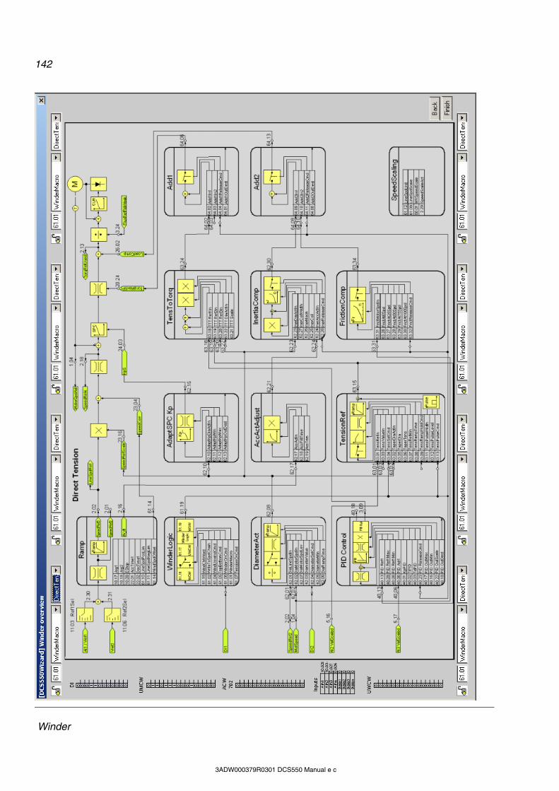
142
Winder
3ADW000379R0301 DCS550 Manual e c

143
Winder
3ADW000379R0301 DCS550 Manual e c
Dancer control In dancer control the tension is established through the dancer’s weight. The position of the dancer is read by means of an analog input (AI3). Its position is controlled by an additional speed reference coming from the PID controller in group 40. Following parameters are set when using WinderMacro (61.01) = DancerCtrl:
Parameter name DancerCtrl Factory (default) Ref1Sel (11.03) AI1 SpeedRef2301
TorqMaxSPC (20.07) 325 % 325 % TorqMinSPC (20.08) -325 % -325 %
IndepTorqMaxSPC (20.24) 325 % 325 % IndepTorqMinSPC (20.25) -325 % -325 %
SpeedCorr (23.04) 0 rpm 0 rpm SpeedRefScale (23.16) 1 1
TorqSel (26.01) Speed Speed TorqMuxMode (26.04) TorqSel2601 TorqSel2601
LoadComp (26.02) 0 % 0 % KpPID (40.01) 1 5 TiPID (40.02) 1000 2500
PID Act1 (40.06) 517 = AI3 ValScaled (5.17) 0 PID Ref1 (40.13) 1901 = Data1 (19.01) 0
PID OutMin (40.16) -10 % -100 % PID OutMax (40.17) 10 % 100 % PID OutDest (40.18) 2304 = SpeedCorr (23.04) 0
PID ReleaseCmd (40.23) Auto Auto WriteToSpdChain (61.02) Auto Auto WindUnwindCmd (61.04) WindCtrlWord WindCtrlWord TopBottomCmd (61.05) WindCtrlWord WindCtrlWord WinderOnCmd (61.06) DI1 Auto TensionOnCmd (61.07) Auto Auto WindSpdOffset (61.14) 0 0 DiaLineSpdIn (62.01) 202 = SpeedRef2 (2.02) 202 = SpeedRef2 (2.02)
DiaMotorSpdIn (62.02) 104 = MotSpeed (1.04) 104 = MotSpeed (1.04) DiameterSetCmd (62.04) DI2 NotUsed AdaptKpDiaActIn (62.10) 6208 = DiameterAct (62.08) 6208 = DiameterAct (62.08) AdaptKpOutDest (62.13) 2403 = KpS (24.03) 0
AccActIn (62.17) 216 = dv_dt (2.16) 216 = dv_dt (2.16) InerDiaActIn (62.23) 6208 = DiameterAct (62.08) 6208 = DiameterAct (62.08) InerAccActIn (62.24) 6221 = AccActAdjust (62.21) 6221 = AccActAdjust (62.21)
InerReleaseCmd (62.28) Auto Auto TensRefIn (63.01) 0 0
TaperDiaActIn (63.02) 6208 = DiameterAct (62.08) 6208 = DiameterAct (62.08) TensValueIn (63.03) 0 0 TensSetCmd (63.04) Auto Auto
TensRampHoldCmd (63.09) RelTensRamp RelTensRamp TensPulseCmd (63.13) Auto Auto
TTT Ref1In (63.18) 0 0 TTT Ref2In (63.19) 6315 = TensionRef (63.15) 6315 = TensionRef (63.15) TTT Ref3In (63.20) 0 0
TTT DiaActIn (63.22) 6208 = DiameterAct (62.08) 6208 = DiameterAct (62.08) FrictMotorSpdIn (63.31) 104 = MotSpeed (1.04) 104 = MotSpeed (1.04)
FrictReleaseCmd (63.32) Auto Auto Add1OutDest (64.01) 0 0
Add1In1 (64.02) 6324 = TensToTorq (63.24) 6324 = TensToTorq (63.24) Add1In2 (64.03) 0 0
Add1ReleaseCmd (64.04) Auto Auto Add2OutDest (64.08) 2602 = LoadComp (26.02) 0
Add2In1 (64.09) 6230 = InertiaComp (62.30) 6230 = InertiaComp (62.30) Add2In2 (64.10) 6334 = FrictionComp (63.34) 6334 = FrictionComp (63.34)
Add2ReleaseCmd (64.11) Auto Auto

144
Winder
3ADW000379R0301 DCS550 Manual e c
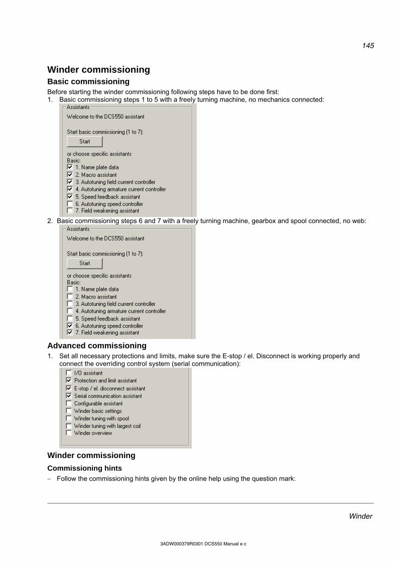
145
Winder
3ADW000379R0301 DCS550 Manual e c
Winder commissioning
Basic commissioning Before starting the winder commissioning following steps have to be done first: 1. Basic commissioning steps 1 to 5 with a freely turning machine, no mechanics connected:
2. Basic commissioning steps 6 and 7 with a freely turning machine, gearbox and spool connected, no web:
Advanced commissioning 1. Set all necessary protections and limits, make sure the E-stop / el. Disconnect is working properly and
connect the overriding control system (serial communication):
Winder commissioning
Commissioning hints Follow the commissioning hints given by the online help using the question mark:

146
Winder
3ADW000379R0301 DCS550 Manual e c
Following default settings should be kept: WriteToSpdChain (61.02) = Auto TensionOnCmd (61.07) = Auto LineSpdNegLim (61.11) = Zero LineSpdUnit (61.12) = % AccFiltTime (62.18) = 100 ms InerReleaseCmd (62.28) = Auto TensSetCmd (63.04) = Auto TensRampHoldCmd (63.09) = RelTensRamp TensPulseCmd (63.13) = Auto TTT Ref2In (63.19) = 6315 (tension reference) FrictReleaseCmd (63.32) = Auto
To go back to normal speed control set WiProgCmd (66.01) = Stop, but keep the winder macro selected - see WinderMacro (61.01) - this will keep the parameter settings.
Commissioning 1. Print out the winder overview diagram according to the chosen winder macro. 2. Specify the needed in- and outputs for the winder.
Example using serial communication: Set CommandSel (10.01) = MainCtrlWord. For additional winder commands use the auxiliary control bits of the MainCtrlWord (7.01), e.g.: Rewind / Unwind command via bit 11, set WindUnwindCmd (61.04) = MCW B11. Top / Bottom Command via bit 12, set TopBottomCmd (61.05) = MCW B12. Winder on command via bit 13, set WinderOnCmd (61.06) = MCW B13. Diameter set command via bit 14, set DiameterSetCmd (62.04) = MCW B14. Write the line speed reference on SpeedRef (23.01) and set Ref1Sel (11.03) = SpeedRef2301. Write the initial diameter on DiameterValue (62.03). Write the tension reference e.g. on Data1 (19.01) and set TensRefIn (63.01) = 1901. Example using serial local I/O: Set CommandSel (10.01) = Local I/O. For additional winder commands use digital inputs, e.g.: DI1 for winder on command, set WinderOnCmd (61.06) = DI1. DI2 for diameter set command, set DiameterSetCmd (62.04) = DI2. DI3 for rewind / unwind command, set WindUnwindCmd (61.04) = DI3. DI4 for Coast Stop, set Off2 (10.08) = DI4. DI5 for E-stop, set E Stop (10.09) = DI5. DI6 for reset, set Reset (10.03) = DI6 DI7 for On, set OnOff1 (10.15) = DI7. DI8 for Run, set StartStop (10.16) = DI8. AI1 for line speed reference, set Ref1Sel (11.03) = AI1. AI2 for tension reference, set TensRefIn (63.01) = 516. see AI2 ValScaled (5.16). AI3 for initial diameter use - see AI3 ValScaled (5.17) and DiameterValue (62.03) - AP block ParWrite:
3. Set the winder basics:
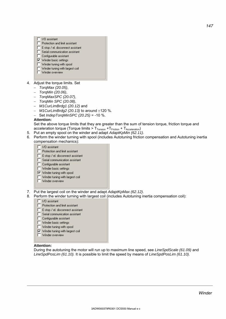
147
Winder
3ADW000379R0301 DCS550 Manual e c
4. Adjust the torque limits. Set
TorqMax (20.05), TorqMin (20.06), TorqMaxSPC (20.07), TorqMin SPC (20.08), M1CurLimBrdg1 (20.12) and M1CurLimBrdg2 (20.13) to around 120 %. Set IndepTorqMinSPC (20.25) = -10 %. Attention: Set the above torque limits that they are greater than the sum of tension torque, friction torque and acceleration torque (Torque limits > TTension +TFriction + TAcceleration)
5. Put an empty spool on the winder and adapt AdaptKpMin (62.11). 6. Perform the winder turning with spool (includes Autotuning friction compensation and Autotuning inertia
compensation mechanics):
7. Put the largest coil on the winder and adapt AdaptKpMax (62.12). 8. Perform the winder turning with largest coil (includes Autotuning inertia compensation coil):
Attention: During the autotuning the motor will run up to maximum line speed, see LineSpdScale (61.09) and LineSpdPosLim (61.10). It is possible to limit the speed by means of LineSpdPosLim (61.10).
148
Signal and parameter list
3ADW000379R0301 DCS550 Manual e c
Signal and parameter list Chapter overview This chapter describes all signals and parameters of the DCS550.
Signals Signals are measured and calculated actual values of the drive. This includes the control-, status-, limit-, fault- and alarm words. The drive’s signals are available in groups 1 to 9. None of the values inside these groups is stored in the flash and thus volatile. Note: Signals in group 7 can be written to by means of DWL, DCS Control Panel, AP or overriding control. The following table gives an overview of all signal groups: Group Description 1 Physical actual values 2 Speed controller signals 3 Reference actual values 4 Information 5 Analog I/O 6 Drive logic signals 7 Control words 8 Status / limit words 9 Fault / alarm words
Signal / Parameter name
min
.
max
.
def.
unit
1.08 MotTorq (motor torque) Motor torque in percent of MotNomTorque (4.23): Filtered by means of a 6th order FIR filter (sliding average filter), filter time is 1 mains voltage period. Int. Scaling: 100 == 1 % Type: SI Volatile: Y
- - - %
2.17 SpeedRefUsed (used speed reference) Used speed reference selected with: Ref1Mux (11.02) and Ref1Sel (11.03) or Ref2Mux (11.12) and Ref2Sel (11.06) Int. Scaling: (2.29) Type: SI Volatile: Y
- - -
rpm
Sample of signals All signals are read-only. However, the overriding control can write to the control words, but it only affects the RAM. Min., max., def.: Minimum, maximum and default values are not valid for groups 1 to 9. Unit: Shows the physical unit of a signal, if applicable. The unit is displayed in the DCS Control Panel and DWL. Group.Index: Signal and parameter numbers consists of group number and its index. Integer Scaling: Communication between the drive and the overriding control uses 16-bit integer values. The overriding control has to use the information given in integer scaling to read the value of the signal properly. Example1: If the overriding control reads MotTorq (1.08) 100 corresponds to 1 % torque. Example2: If the overriding control reads SpeedRefUsed (2.17) 20,000 equals the speed (in rpm) shown in SpeedScaleAct (2.29). Type: A short code shows the data type: I = 16-bit integer value (0, …, 65536)
149
Signal and parameter list
3ADW000379R0301 DCS550 Manual e c
SI = 16-bit signed integer value (-32768, …, 32767) C = text string (ENUM) Volatile: Y = values are NOT stored in the flash, they will be lost when the drive is de-energized N = values are stored in the flash, they will remain when the drive is de-energized
Parameter group list This chapter explains the function and valid values or selections for all parameters. They are arranged in groups by their function. The following table gives an overview of all parameter groups: Group Description 10 Start / stop select 11 Speed reference inputs 12 Constant speeds 13 Analog inputs 14 Digital outputs 15 Analog outputs 16 System control inputs 19 Data storage 20 Limits 21 Start / stop 22 Speed ramp 23 Speed reference 24 Speed control 25 Torque reference 26 Torque reference handling 30 Fault functions 31 Motor temperature 34 DCS Control Panel display 40 PID controller 43 Current control 44 Field excitation 45 Field converter settings 50 Speed measurement 51 Fieldbus 52 Modbus 61 Winder control 62 Diameter adaption 63 Tension torque 64 Write selection 66 Winder program control 83 AP control 84 AP 85 User constants 86 AP outputs 88 Internal 90 Receiving data sets addresses 92 Transmit data sets addresses 97 Measurement 98 Option modules 99 Start-up data
150
Signal and parameter list
3ADW000379R0301 DCS550 Manual e c
Signal / Parameter name
min
.
max
.
def.
unit
20.07 TorqMaxSPC (maximum torque speed controller) Maximum torque limit - in percent of MotNomTorque (4.23) - at the output of the speed controller: TorqRef2 (2.09) Note: The used torque limit depends also on the converter's actual limitation situation (e.g. other torque limits, current limits, field weakening). The limit with the smallest value is valid. Int. Scaling: 100 == 1 % Type: SI Volatile: N
0
325
325 %
23.01 SpeedRef (speed reference) Main speed reference input for the speed control of the drive. Can be connected to SpeedRefUsed (2.17) via: Ref1Mux (11.02) and Ref1Sel (11.03) or Ref2Mux (11.12) and Ref2Sel (11.06)
Internally limited from: rpmtorpm20000
32767*)29.2(
20000
32767*)29.2(
Int. Scaling: (2.29) Type: SI Volatile: Y
-100
00
100
00 0
rpm
Sample of parameters Parameter changes by DCS Control Panel or DWL are stored in the flash. Changes made by the overriding control are only stored in the RAM. Min., max., def.: Minimum and maximum value or selection of parameter. Default value or default selection of parameter. Unit: Shows the physical unit of a parameter, if applicable. The unit is displayed in the DCS Control Panel and DWL. Group.Index: Signal and parameter numbers consists of group number and its index. Integer Scaling: Communication between the drive and the overriding control uses 16-bit integer values. The overriding control has to use the information given in integer scaling to change the value of the parameter properly. Example1: If the overriding control writes on TorqMaxSPC (20.07) 100 corresponds to 1 %. Example2: If the overriding control writes on SpeedRef (23.01) 20,000 equals the speed (in rpm) shown in SpeedScaleAct (2.29). Type: A short code shows the data type: I = 16-bit integer value (0, …, 65536) SI = 16-bit signed integer value (-32768, …, 32767) C = text string (ENUM) Volatile: Y = values are NOT stored in the flash, they will be lost when the drive is de-energized N = values are stored in the flash, they will remain when the drive is de-energized
151
Signal and parameter list
3ADW000379R0301 DCS550 Manual e c
Signals
Signal / Parameter name
min
. m
ax.
def.
unit
Group 1: Physical actual values
1.01 MotSpeedFilt (filtered motor speed) Filtered actual speed feedback: Choose motor speed feedback with M1SpeedFbSel (50.03) Filtered with 1 s and SpeedFiltTime (50.06) Int. Scaling: (2.29) Type: SI Volatile: Y - - - rp
m
1.02 SpeedActEMF (speed actual EMF) Actual speed calculated from EMF. Int. Scaling: (2.29) Type: SI Volatile: Y - - - rp
m
1.03 SpeedActEnc (speed actual encoder) Actual speed measured with pulse encoder. Int. Scaling: (2.29) Type: SI Volatile: Y - - - rp
m
1.04 MotSpeed (motor speed) Actual motor speed: Choose motor speed feedback with M1SpeedFbSel (50.03). SpeedFiltTime (50.06) Int. Scaling: (2.29) Type: SI Volatile: Y - - - rp
m
SDCS-CON-F
X1:1
1
1
1
Analog tacho inputs
X1:2X1:3
X1:4
AITAC
90V to 270V -90V to 270V -
30V to 90V -8V to 30V -
+
SDCS-CON-F
X1:1
1
1
1
SDCS-CON-F
X1:1
1
1
1
Analog tacho inputs
X1:2X1:3
X1:4
AITAC
90V to 270V -90V to 270V -
30V to 90V -8V to 30V -
+ SpeedActTach
5.01 1.05
speed_act_tach_a.dsf
Analog tacho scalingM1SpeedScale (50.01)M1TachoAdjust (50.12)
M1TachoVolt1000 (50.13)AITachoVal
1.05 SpeedActTach (speed actual tacho) Actual speed measured with analog tacho. Note: This value is only valid, if an analog tacho is connected! Int. Scaling: (2.29) Type: SI Volatile: Y - - - rp
m
1.06 MotCur (motor current) Relative actual motor current in percent of M1NomCur (99.03). Int. Scaling: 100 == 1 % Type: SI Volatile: Y - - - %
1.07 MotTorqFilt (filtered motor torque) Relative filtered motor torque in percent of MotNomTorque (4.23): Filtered by means of a 6th order FIR filter (sliding average filter), filter time is 1 mains voltage period plus TorqActFiltTime (97.20) Notes: The cycle time is 20 ms The value is calculated the following way:
NotUsedeUsedFexTypMorBaseSpeedMnforFluxMaxfFldWeakFlux
or
BaseSpeedMnforMotSpeed
BaseSpeedMFluxMaxfFldWeakFlux
with
MotCurfFldWeakFluxtMotTorqFil
)12.99(1)04.99(1%;100)24.3(Re
)04.99(1;)04.1(
)04.99(1*)24.3(Re
100
)06.1(*)24.3(Re)07.1(
Int. Scaling: 100 == 1 % Type: SI Volatile: Y - - - %
152
Signal and parameter list
3ADW000379R0301 DCS550 Manual e c
Signal / Parameter name
min
. m
ax.
def.
unit
1.08 MotTorq (motor torque) Motor torque in percent of MotNomTorque (4.23): Filtered by means of a 6th order FIR filter (sliding average filter), filter time is 1 mains voltage period. Notes: The cycle time is 20 ms The value is calculated the following way:
NotUsedeUsedFexTypMorBaseSpeedMnforFluxMaxfFldWeakFlux
or
BaseSpeedMnforMotSpeed
BaseSpeedMFluxMaxfFldWeakFlux
with
MotCurfFldWeakFluxMotTorq
)12.99(1)04.99(1%;100)24.3(Re
)04.99(1;)04.1(
)04.99(1*)24.3(Re
100
)06.1(*)24.3(Re)08.1(
Int. Scaling: 100 == 1 % Type: SI Volatile: Y - - - %
1.09 Unused
1.10 CurRippleFilt (filtered current ripple) Relative filtered current ripple monitor output in percent of M1NomCur (99.03) filtered with 200 ms. Int. Scaling: 100 == 1 % Type: SI Volatile: Y - - - %
1.11 MainsVoltActRel (relative actual mains voltage) Relative actual mains voltage in percent of NomMainsVolt (99.10). Int. Scaling: 100 == 1 % Type: I Volatile: Y - - - %
1.12 MainsVoltAct (actual mains voltage) Actual mains voltage filtered with 10 ms. Int. Scaling: 1 == 1 V Type: I Volatile: Y - - - V
1.13 ArmVoltActRel (relative actual armature voltage) Relative actual armature voltage in percent of M1NomVolt (99.02). Int. Scaling: 100 == 1 % Type: SI Volatile: Y - - - %
1.14 ArmVoltAct (actual armature voltage) Actual armature voltage filtered with 10 ms. Int. Scaling: 1 == 1 V Type: SI Volatile: Y - - - V
1.15 ConvCurActRel (relative actual converter current [DC]) Relative actual converter current in percent of ConvNomCur (4.05). Int. Scaling: 100 == 1 % Type: SI Volatile: Y - - - %
1.16 ConvCurAct (actual converter current [DC]) Actual converter current filtered with 10 ms. Int. Scaling: 1 == 1 A Type: SI Volatile: Y - - - A
1.17 EMF VoltActRel (relative actual EMF) Relative actual EMF in percent of M1NomVolt (99.02): EMF VoltActRel (1.17). Int. Scaling: 100 == 1 % Type: SI Volatile: Y - - - %
1.18 - 1.19 Unused
1.20 Mot1TempCalc (calculated temperature) Calculated temperature from motor thermal model in percent - see M1AlarmLimLoad (31.03) and M1FaultLimLoad (31.04). Used for motor overload protection. M1AlarmLimLoad (31.03) M1FaultLimLoad (31.04) Int. Scaling: 100 == 1 % Type: I Volatile: Y - - - %
1.21 Unused
153
Signal and parameter list
3ADW000379R0301 DCS550 Manual e c
Signal / Parameter name
min
. m
ax.
def.
unit
1.22 Mot1TempMeas (motor measured temperature) Motor measured temperature. Used for motor overtemperature protection: Unit depends on setting of M1TempSel (31.05): 0 = NotUsed 1 = reserved 2 = PTC Int. Scaling: 1 == 1 / 1 Type: I Volatile: Y - - - °
/ -
1.23 Unused
1.24 BridgeTemp (actual bridge temperature) Actual bridge temperature in degree centigrade. Int. Scaling: 1 == 1 °C Type: I Volatile: Y - - - °C
1.25 CtrlMode (control mode) Used control mode: see TorqSel (26.01) 0 = NotUsed 1 = SpeedCtrl speed control 2 = TorqCtrl torque control 3 = CurCtrl current control Int. Scaling: 1 == 1 Type: C Volatile: Y - - - -
1.26 - 1.28 Unused
1.29 Mot1FldCurRel (relative actual field current) Relative field current in percent of M1NomFldCur (99.11). Int. Scaling: 100 == 1 % Type: SI Volatile: Y - - - %
1.30 Mot1FldCur (actual field current) Field current filtered with 500 ms. Int. Scaling: 10 == 1 A Type: SI Volatile: Y - - - A
1.31 - 1.37 Unused
1.38 MainsFreqAct (internal mains frequency) Calculated and internally controlled mains frequency. Output of PLL controller. See also: DevLimPLL (97.13) KpPLL (97.14) Int. Scaling: 100 == 1 Hz Type: I Volatile: Y - - - H
z
Group 2: Speed controller signals
2.01 SpeedRef2 (speed reference 2) Speed reference after limiter: M1SpeedMin (20.01) M1SpeedMax (20.02) Int. Scaling: (2.29) Type: SI Volatile: Y - - - rp
m
2.02 SpeedRef3 (speed reference 3) Speed reference after speed ramp and jog input. Int. Scaling: (2.29) Type: SI Volatile: Y - - - rp
m
2.03 SpeedErrNeg (n) n = speed actual - speed reference. Int. Scaling: (2.29) Type: SI Volatile: Y - - - rp
m
2.04 TorqPropRef (proportional part of torque reference) P-part of the speed controllers output in percent of MotNomTorque (4.23). Int. Scaling: 100 == 1 % Type: SI Volatile: Y - - - %
2.05 TorqIntegRef (integral part of torque reference) I-part of the speed controllers output in percent of MotNomTorque (4.23). Int. Scaling: 100 == 1 % Type: SI Volatile: Y - - - %
2.06 TorqDerRef (derivation part of torque reference) D-part of the speed controllers output in percent of MotNomTorque (4.23). Int. Scaling: 100 == 1 % Type: SI Volatile: Y - - - %
154
Signal and parameter list
3ADW000379R0301 DCS550 Manual e c
Signal / Parameter name
min
. m
ax.
def.
unit
2.07 Unused
2.08 TorqRef1 (torque reference 1) Relative torque reference value in percent of MotNomTorque (4.23) after limiter for the external torque reference: TorqMaxTref (20.09) TorqMinTref (20.10) Int. Scaling: 100 == 1 % Type: SI Volatile: Y - - - %
2.09 TorqRef2 (torque reference 2) Output value of the speed controller in percent of MotNomTorque (4.23) after limiter: TorqMaxSPC (20.07) TorqMinSPC (20.08) Int. Scaling: 100 == 1 % Type: SI Volatile: Y - - - %
2.10 TorqRef3 (torque reference 3) Relative torque reference value in percent of MotNomTorque (4.23) after torque selector: TorqSel (26.01) Int. Scaling: 100 == 1 % Type: SI Volatile: Y - - - %
2.11 TorqRef4 (torque reference 4) = TorqRef3 (2.10) + LoadComp (26.02) in percent of MotNomTorque (4.23). Int. Scaling: 100 == 1 % Type: SI Volatile: Y - - - %
2.12 Unused
2.13 TorqRefUsed (used torque reference) Relative final torque reference value in percent of MotNomTorque (4.23) after torque limiter: TorqMax (20.05) TorqMin (20.06) Int. Scaling: 100 == 1 % Type: SI Volatile: Y - - - %
2.14 - 2.15 Unused
2.16 dv_dt (dv/dt) Acceleration/deceleration (speed reference change) at the output of the speed reference ramp. Int. Scaling: (2.29)/s Type: SI Volatile: Y - - - rp
m/s
2.17 SpeedRefUsed (used speed reference) Used speed reference selected with: Ref1Mux (11.02) and Ref1Sel (11.03) or Ref2Mux (11.12) and Ref2Sel (11.06) Int. Scaling: (2.29) Type: SI Volatile: Y - - - rp
m
2.18 SpeedRef4 (speed reference 4) = SpeedRef3 (2.02) + SpeedCorr (23.04). Int. Scaling: (2.29) Type: SI Volatile: Y - - - rp
m
2.19 TorqMaxAll (torque maximum all) Relative calculated positive torque limit in percent of MotNomTorque (4.23). Calculated from the smallest maximum torque limit, field weakening and armature current limits: TorqUsedMax (2.22) FluxRefFldWeak (3.24) and M1CurLimBrdg1 (20.12) Int. Scaling: 100 == 1 % Type: SI Volatile: Y - - - %
2.20 TorqMinAll (torque minimum all) Relative calculated negative torque limit in percent of MotNomTorque (4.23). Calculated from the largest minimum torque limit, field weakening and armature current limits: TorqUsedMax (2.22) FluxRefFldWeak (3.24) and M1CurLimBrdg2 (20.13) Int. Scaling: 100 == 1 % Type: SI Volatile: Y - - - %
2.21 Unused
155
Signal and parameter list
3ADW000379R0301 DCS550 Manual e c
Signal / Parameter name
min
. m
ax.
def.
unit
2.22 TorqUsedMax (used torque maximum) Relative positive torque limit in percent of MotNomTorque (4.23). Selected with: TorqUsedMaxSel (20.18) Connected to torque limiter after TorqRef4 (2.11). Int. Scaling: 100 == 1 % Type: SI Volatile: Y - - - %
2.23 TorqUsedMin (used torque minimum) Relative negative torque limit in percent of MotNomTorque (4.23). Selected with: TorqUsedMinSel (20.19) Connected to torque limiter after TorqRef4 (2.11). Int. Scaling: 100 == 1 % Type: SI Volatile: Y - - - %
2.24 TorqRefExt (external torque reference) Relative external torque reference value in percent of MotNomTorque (4.23) after torque reference A selector: TorqRefA (25.01) and TorqRefA Sel (25.10) Int. Scaling: 100 == 1 % Type: SI Volatile: Y - - - %
2.25 Unused
2.26 TorqLimAct (actual used torque limit) Shows parameter number of the actual active torque limit: 0 = 0 no limitation active 1 = 2.19 TorqMaxAll (2.19) is active, includes current limits and field weakening 2 = 2.20 TorqMinAll (2.20) is active, includes current limits and field weakening 3 = 2.22 TorqUsedMax (2.22) selected torque limit is active 4 = 2.23 TorqUsedMin (2.23) selected torque limit is active 5 = 20.07 TorqMaxSPC (20.07) speed controller limit is active 6 = 20.08 TorqMinSPC (20.08) speed controller limit is active 7 = 20.09 TorqMaxTref (20.09) external reference limit is active 8 = 20.10 TorqMinTref (20.10) external reference limit is active 9 = 20.22 TorqGenMax (20.22) regenerating limit is active 10 = 20.24 IndepTorqMaxSPC (20.24) independent speed controller limit is active 11 = 20.25 IndepTorqMinSPC (20.25) independent speed controller limit is active 12 = 2.08 TorqRef1 (2.08) limits TorqRef2 (2.09), see also TorqSel (26.01) Int. Scaling: 1 == 1 Type: C Volatile: Y - - - -
2.27 - 2.28 Unused
2.29 SpeedScaleAct (actual used speed scaling) The value of SpeedScaleAct (2.29) equals 20,000 internal speed units. Thus follows 20,000 speed units == M1SpeedScale (50.01), in case M1SpeedScale (50.01) 10 or 20,000 speed units == maximum absolute value of M1SpeedMin (20.01) and M1SpeedMax (20.02), in case M1SpeedScale (50.01) < 10. Mathematically speaking: If (50.01) 10 then 20,000 == (50.01) in rpm If (50.01) < 10 then 20,000 == Max [|(20.01)|, |(20.02)|] in rpm
Int. Scaling: 1 == 1 rpm Type: SI Volatile: Y - - - rp
m
2.30 SpeedRefExt1 (external speed reference 1) External speed reference 1 after reference 1 multiplexer: Ref1Mux (11.02) Int. Scaling: (2.29) Type: SI Volatile: Y - - - rp
m
156
Signal and parameter list
3ADW000379R0301 DCS550 Manual e c
Signal / Parameter name
min
. m
ax.
def.
unit
2.31 SpeedRefExt2 (external speed reference 2) External speed reference 2 after reference 2 multiplexer: Ref2Mux (11.12) Int. Scaling: (2.29) Type: SI Volatile: Y - - - rp
m
2.32 SpeedRampOut (speed ramp output) Speed reference after ramp Int. Scaling: (2.29) Type: SI Volatile: Y rp
m
Group 3: Reference actual values
3.01 - 3.02 Unused
3.03 SquareWave (square wave) Output signal of the square wave generator, see: Pot1 (99.15), Pot2 (99.16), SqrWavePeriod (99.17), SqrWaveIndex (99.18) and TestSignal (99.19) Int. Scaling: 1==1 Type: SI Volatile: Y - - - -
3.04 - 3.08 Unused
3.09 PID Out (output PID controller) PID controller output value in percent of the used PID controller input (see group 40). Int. Scaling: 100 == 1 % Type: SI Volatile: Y - - - -
3.10 Unused
3.11 CurRef (current reference) Relative current reference in percent of M1NomCur (99.03) after adaption to field weakening. Int. Scaling: 100 == 1 % Type: SI Volatile: Y - - - %
3.12 CurRefUsed (used current reference) Relative current reference in percent of M1NomCur (99.03) after current limitation: M1CurLimBrdg1 (20.12) M1CurLimBrdg2 (20.13) Int. Scaling: 100 == 1 % Type: SI Volatile: Y - - - %
3.13 ArmAlpha (armature , firing angle) Firing angle (). Int. Scaling: 1 == 1 ° Type: I Volatile: Y - - - ° 3.14 - 3.19 Unused
3.20 PLL In (phase locked loop input) Actual measured mains voltage cycle (period) time. Is used as input of the PLL controller. The value should be: 1/50 Hz = 20 ms = 20,000 or 1/60 Hz = 16.7 ms = 16,667 See also DevLimPLL (97.13), KpPLL (97.14) and TfPLL (97.15). Int. Scaling: 1 == 1 Type: I Volatile: Y - - - -
3.21 Unused
3.22 CurCtrlIntegOut (integral part of current controller output) I-part of the current controllers output in percent of M1NomCur (99.03). Int. Scaling: 100 == 1 % Type: SI Volatile: Y - - - %
3.23 Unused
3.24 FluxRefFldWeak (flux reference for field weakening) Relative flux reference for speeds above the field weakening point (base speed) in percent of nominal flux. Int. Scaling: 100 == 1 % Type: SI Volatile: Y - - - %
3.25 VoltRef1 (EMF voltage reference 1) Relative EMF voltage reference in percent of M1NomVolt (99.02). Int. Scaling: 100 == 1 % Type: SI Volatile: Y - - - %
3.26 Unused

157
Signal and parameter list
3ADW000379R0301 DCS550 Manual e c
Signal / Parameter name
min
. m
ax.
def.
unit
3.27 FluxRefEMF (flux reference after EMF controller) Relative EMF flux reference in percent of nominal flux after EMF controller. Int. Scaling: 100 == 1 % Type: SI Volatile: Y - - - %
3.28 FluxRefSum (sum of flux reference) FluxRefSum (3.28) = FluxRefEMF (3.27) + FluxRefFldWeak (3.24) in percent of nominal flux. Int. Scaling: 100 == 1 % Type: SI Volatile: Y - - - %
3.29 Unused
3.30 FldCurRefM1 (field current reference) Relative field current reference in percent of M1NomFldCur (99.11). Int. Scaling: 100 == 1 % Type: SI Volatile: Y - - - %
Group 4: Information
4.01 FirmwareVer (firmware version) Name of the loaded firmware version. The format is: yyy or -yyy with: yyy = consecutively numbered version and -yyy = single-phase firmware for demo units. Int. Scaling: - Type: C Volatile: Y - - - -
4.02 FirmwareType (firmware type) Type of the loaded firmware version. The format is: 55 = Standard firmware Int. Scaling: - Type: C Volatile: Y - - - -
4.03 Unused
4.04 ConvNomVolt (converter nominal AC voltage measurement circuit) Adjustment of AC voltage measuring channels (SDCS-PIN-F). Read from TypeCode (97.01). Int. Scaling: 1 == 1 V Type: I Volatile: Y - - - V
4.05 ConvNomCur (converter nominal DC current measurement circuit) Adjustment of DC current measuring channels (SDCS-PIN-F). Read from TypeCode (97.01). Int. Scaling: 1 == 1 A Type: I Volatile: Y - - - A
4.06 Mot1FexType (type of field exciter) Field exciter type. Read from M1UsedFexType (99.12): 0 = NotUsed no or third party field exciter connected 1 = OnBoard integrated 1-Q field exciter (for sizes D1 - D4 only), default Int. Scaling: 1 == 1 Type: C Volatile: Y - - - -
4.07 - 4.13 Unused
4.14 ConvType (converter type) Recognized converter type. Read from TypeCode (97.01): 0 = reserved 1 = F1 F1 converter 2 = F2 F2 converter 3 = F3 F3 converter 4 = F4 F4 converter Int. Scaling: 1 == 1 Type: C Volatile: Y - - - -
4.15 QuadrantType (quadrant type of converter; 1 or 2 bridges) Recognized converter quadrant type. Read from TypeCode (97.01) or set with S BlockBrdg2 (97.07): Read from TypeCode (97.01) if S BlockBrdg2 (97.07) = 0 Read from S BlockBrdg2 (97.07) if S BlockBrdg2 (97.07) 0 0 = BlockBridge2 bridge 2 blocked (== 2-Q operation) 1 = RelBridge2 bridge 2 released (== 4-Q operation), default Int. Scaling: 1 == 1 Type: C Volatile: Y - - - -
4.16 ConvOvrCur (converter overcurrent [DC] level) Converter current tripping level. This signal is set during initialization of the drive, new values are shown after the next power-up. Int. Scaling: 1 == 1 A Type: I Volatile: Y - - - A
158
Signal and parameter list
3ADW000379R0301 DCS550 Manual e c
Signal / Parameter name
min
. m
ax.
def.
unit
4.17 MaxBridgeTemp (maximum bridge temperature) Maximum bridge temperature in degree centigrade. Read from TypeCode (97.01) or set with S MaxBrdgTemp (97.04): Read from TypeCode (97.01) if S MaxBrdgTemp (97.04) = 0 Read from S MaxBrdgTemp (97.04) if S MaxBrdgTemp (97.04) 0 The drive trips with F504 ConvOverTemp [FaultWord1 (9.01) bit 3], when MaxBridgeTemp (4.17) is reached. A104 ConvOverTemp [AlarmWord1 (9.06) bit 3] is set, when the actual converter temperature is approximately 5°C below MaxBridgeTemp (4.17). Int. Scaling: 1 == 1 °C Type: I Volatile: Y - - - °C
4.18 - 4.19 Unused
4.20 Ext IO Stat (external IO status) Status of external I/O: Bit Value Comment B0 1 RAIO-xx detected, see AIO ExtModule (98.06) 0 RAIO-xx not existing or faulty B1-B3 reserved ------------------------------------------------------------------------------------------------------------------------------------------------------------------B4 1 first RDIO-xx detected, see DIO ExtModule1 (98.03) 0 first RDIO-xx not existing or faulty B5 1 second RDIO-xx detected, see DIO ExtModule2 (98.04) 0 second RDIO-xx not existing or faulty B6-B7 reserved ------------------------------------------------------------------------------------------------------------------------------------------------------------------B8-B11 reserved ------------------------------------------------------------------------------------------------------------------------------------------------------------------B12 reserved B13 1 SDCS-COM-8 detected 0 SDCS-COM-8 faulty B14 - B15 reserved Int. Scaling: 1 == 1 Type: C Volatile: Y
4.21 CPU Load (load of processor) The calculating power of the processor is divided into two parts: CPU Load (4.21) shows the load of the firmware and ApplLoad (4.22) shows the load of AP and the winder macro. Neither should reach 100%. Int. Scaling: 10 == 1 % Type: I Volatile: Y - - - %
4.22 ApplLoad (load of application) The calculating power of the processor is divided into two parts: CPU Load (4.21) shows the load of the firmware and ApplLoad (4.22) shows the load of AP and the winder macro. Neither should reach 100%. Int. Scaling: 10 == 1 % Type: I Volatile: Y - - - %
4.23 MotTorqNom (motor nominal torque) Calculated nominal motor torque:
)04.99(1
)03.99(1*)10.43(1*)03.99(1)02.99(1*
*2
60)23.4(
BaseSpeedM
NomCurMArmRMMotCurMNomVoltMMotTorqNom
Int. Scaling: 1 == 1 Nm Type: I Volatile: Y - - - Nm
4.24 ProgressSignal (progress signal for auto tunings) Progress signal for auto tunings used for Startup Assistants. Int. Scaling: 1 == 1 % Type: I Volatile: Y - - - %
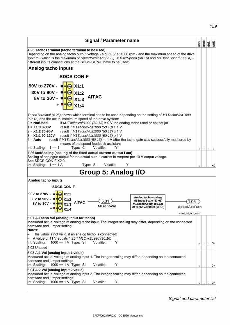
159
Signal and parameter list
3ADW000379R0301 DCS550 Manual e c
Signal / Parameter name
min
. m
ax.
def.
unit
4.25 TachoTerminal (tacho terminal to be used) Depending on the analog tacho output voltage - e.g. 60 V at 1000 rpm - and the maximum speed of the drive system - which is the maximum of SpeedScaleAct (2.29), M1OvrSpeed (30.16) and M1BaseSpeed (99.04) - different inputs connections at the SDCS-CON-F have to be used:
SDCS-CON-F
X1:1
1
1
1
Analog tacho inputs
X1:2X1:3
X1:4
AITAC
90V to 270V -90V to 270V -
30V to 90V -8V to 30V -
+
SDCS-CON-F
X1:1
1
1
1
SDCS-CON-F
X1:1
1
1
1
Analog tacho inputs
X1:2X1:3
X1:4
AITAC
90V to 270V -90V to 270V -
30V to 90V -8V to 30V -
+
TachoTerminal (4.25) shows which terminal has to be used depending on the setting of M1TachoVolt1000 (50.13) and the actual maximum speed of the drive system: 0 = NotUsed if M1TachoVolt1000 (50.13) = 0 V, no analog tacho used or not set jet 1 = X1:3 8-30V result if M1TachoVolt1000 (50.13) 1 V 2 = X1:2 30-90V result if M1TachoVolt1000 (50.13) 1 V 3 = X1:1 90-120V result if M1TachoVolt1000 (50.13) 1 V 4 = Auto result if M1TachoVolt1000 (50.13) = -1 V after the tacho gain was successfully measured by
means of the speed feedback assistant Int. Scaling: 1 == 1 Type: C Volatile: Y - - - -
4.26 IactScaling (scaling of the fixed actual current output I-act) Scaling of analogue output for the actual output current in Ampere per 10 V output voltage. See SDCS-CON-F X2:9. Int. Scaling: 1 == 1 A Type: SI Volatile: Y - - - A
Group 5: Analog I/O
SDCS-CON-F
X1:1
1
1
1
Analog tacho inputs
X1:2X1:3
X1:4
AITAC
90V to 270V -90V to 270V -
30V to 90V -8V to 30V -
+
SDCS-CON-F
X1:1
1
1
1
SDCS-CON-F
X1:1
1
1
1
Analog tacho inputs
X1:2X1:3
X1:4
AITAC
90V to 270V -90V to 270V -
30V to 90V -8V to 30V -
+ SpeedActTach
5.01 1.05
speed_act_tach_a.dsf
Analog tacho scalingM1SpeedScale (50.01)M1TachoAdjust (50.12)
M1TachoVolt1000 (50.13)AITachoVal
5.01 AITacho Val (analog input for tacho) Measured actual voltage at analog tacho input. The integer scaling may differ, depending on the connected hardware and jumper setting. Notes: This value is not valid, if an analog tacho is connected! A value of 11 V equals 1.25 * M1OvrSpeed (30.16) Int. Scaling: 1000 == 1 V Type: SI Volatile: Y - - - V
5.02 Unused
5.03 AI1 Val (analog input 1 value) Measured actual voltage at analog input 1. The integer scaling may differ, depending on the connected hardware and jumper settings. Int. Scaling: 1000 == 1 V Type: SI Volatile: Y - - - V
5.04 AI2 Val (analog input 2 value) Measured actual voltage at analog input 2. The integer scaling may differ, depending on the connected hardware and jumper settings. Int. Scaling: 1000 == 1 V Type: SI Volatile: Y - - - V
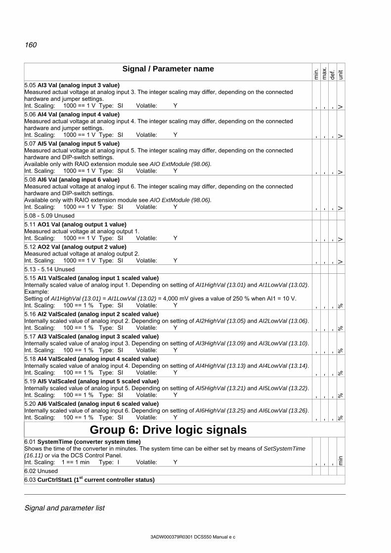
160
Signal and parameter list
3ADW000379R0301 DCS550 Manual e c
Signal / Parameter name
min
. m
ax.
def.
unit
5.05 AI3 Val (analog input 3 value) Measured actual voltage at analog input 3. The integer scaling may differ, depending on the connected hardware and jumper settings. Int. Scaling: 1000 == 1 V Type: SI Volatile: Y - - - V
5.06 AI4 Val (analog input 4 value) Measured actual voltage at analog input 4. The integer scaling may differ, depending on the connected hardware and jumper settings. Int. Scaling: 1000 == 1 V Type: SI Volatile: Y - - - V
5.07 AI5 Val (analog input 5 value) Measured actual voltage at analog input 5. The integer scaling may differ, depending on the connected hardware and DIP-switch settings. Available only with RAIO extension module see AIO ExtModule (98.06). Int. Scaling: 1000 == 1 V Type: SI Volatile: Y - - - V
5.08 AI6 Val (analog input 6 value) Measured actual voltage at analog input 6. The integer scaling may differ, depending on the connected hardware and DIP-switch settings. Available only with RAIO extension module see AIO ExtModule (98.06). Int. Scaling: 1000 == 1 V Type: SI Volatile: Y - - - V
5.08 - 5.09 Unused
5.11 AO1 Val (analog output 1 value) Measured actual voltage at analog output 1. Int. Scaling: 1000 == 1 V Type: SI Volatile: Y - - - V
5.12 AO2 Val (analog output 2 value) Measured actual voltage at analog output 2. Int. Scaling: 1000 == 1 V Type: SI Volatile: Y - - - V
5.13 - 5.14 Unused
5.15 AI1 ValScaled (analog input 1 scaled value) Internally scaled value of analog input 1. Depending on setting of AI1HighVal (13.01) and AI1LowVal (13.02). Example: Setting of AI1HighVal (13.01) = AI1LowVal (13.02) = 4,000 mV gives a value of 250 % when AI1 = 10 V. Int. Scaling: 100 == 1 % Type: SI Volatile: Y - - - %
5.16 AI2 ValScaled (analog input 2 scaled value) Internally scaled value of analog input 2. Depending on setting of AI2HighVal (13.05) and AI2LowVal (13.06). Int. Scaling: 100 == 1 % Type: SI Volatile: Y - - - %
5.17 AI3 ValScaled (analog input 3 scaled value) Internally scaled value of analog input 3. Depending on setting of AI3HighVal (13.09) and AI3LowVal (13.10). Int. Scaling: 100 == 1 % Type: SI Volatile: Y - - - %
5.18 AI4 ValScaled (analog input 4 scaled value) Internally scaled value of analog input 4. Depending on setting of AI4HighVal (13.13) and AI4LowVal (13.14). Int. Scaling: 100 == 1 % Type: SI Volatile: Y - - - %
5.19 AI5 ValScaled (analog input 5 scaled value) Internally scaled value of analog input 5. Depending on setting of AI5HighVal (13.21) and AI5LowVal (13.22). Int. Scaling: 100 == 1 % Type: SI Volatile: Y - - - %
5.20 AI6 ValScaled (analog input 6 scaled value) Internally scaled value of analog input 6. Depending on setting of AI6HighVal (13.25) and AI6LowVal (13.26). Int. Scaling: 100 == 1 % Type: SI Volatile: Y - - - %
Group 6: Drive logic signals
6.01 SystemTime (converter system time) Shows the time of the converter in minutes. The system time can be either set by means of SetSystemTime (16.11) or via the DCS Control Panel. Int. Scaling: 1 == 1 min Type: I Volatile: Y - - - m
in
6.02 Unused
6.03 CurCtrlStat1 (1st current controller status)
161
Signal and parameter list
3ADW000379R0301 DCS550 Manual e c
Signal / Parameter name
min
. m
ax.
def.
unit
1st current controller status word: Bit Value Comment B0 1 command FansOn 0 command FansOff; See also trip levels in paragraph Fault signals of this manual B1 1 one mains phase missing 0 no action B2 reserved B3 1 motor heating function active 0 motor heating function not active ------------------------------------------------------------------------------------------------------------------------------------------------------------------B4-5 reserved B6 1 dynamic braking active / started 0 dynamic braking not active B7 1 command to close main contactor: MainContactorOn 0 command to open main contactor: MainContactorOff ------------------------------------------------------------------------------------------------------------------------------------------------------------------B8 1 command to close contactor for dynamic braking resistor (armature current is zero): DynamicBrakingOn 0 command to open contactor for dynamic braking resistor: DynamicBrakingOff B9 1 drive is generating 0 drive is motoring B10 1 command to close the US style changeover DC-contactor (close the DC-contact, open the resistor contact):
US DCContactorOn 0 command to open the US style changeover DC-contactor (open the DC-contact, close the resistor contact):
US DCContactorOff
B11 1 firing pulses active (on) 0 firing pulses blocked ------------------------------------------------------------------------------------------------------------------------------------------------------------------B12 1 continuous current 0 discontinuous current B13 1 zero current detected 0 current not zero B14 1 command Trip DC-breaker (continuous signal) 0 no action B15 1 command Trip DC-breaker (1 s pulse) 0 no action Int. Scaling: 1 == 1 Type: I Volatile: Y
6.04 CurCtrlStat2 (2nd current controller status) 2nd current controller status word. The current controller will be blocked, CurRefUsed (3.12) is forced to zero and ArmAlpha (3.13) is forced to the value of ArmAlphaMax (20.14) if any of the bits is set (0 == OK): Bit Value Meaning B0 1 overcurrent, F502 ArmOverCur [FaultWord1 (9.01) bit 1] 0 no action B1 1 mains overvoltage (AC), F513 MainsOvrVolt [FaultWord1 (9.01) bit 12] 0 no action B2 1 mains undervoltage (AC), F512 MainsLowVolt [FaultWord1 (9.01) bit 11] 0 no action B3 1 waiting for reduction of EMF to match the mains voltage [see RevVoltMargin (44.21)] 0 no action ------------------------------------------------------------------------------------------------------------------------------------------------------------------B4-7 reserved ------------------------------------------------------------------------------------------------------------------------------------------------------------------B8-9 reserved B10 1 waiting for zero current 0 no action B11 reserved ------------------------------------------------------------------------------------------------------------------------------------------------------------------
162
Signal and parameter list
3ADW000379R0301 DCS550 Manual e c
Signal / Parameter name
min
. m
ax.
def.
unit
B12 reserved B13 1 current controller not released, because DevLimPLL (97.13) is reached 0 no action B14 1 mains not in synchronism (AC), F514 MainsNotSync [FaultWord1 (9.01) bit 13] 0 no action B15 1 Current controller not released. This bit is set in case of a relevant fault (Fxxx) or an alarm (Axxx) of alarm
level 3. 0 no action Note: A set bit does not necessarily lead to a fault message it depends also on the status of the drive. Int. Scaling: 1 == 1 Type: I Volatile: Y
6.05 SelBridge (selected bridge) Selected (current-conducting) bridge: 0 = NoBridge no bridge selected 1 = Bridge1 bridge 1 selected (motoring bridge) 2 = Bridge2 bridge 2 selected (generating bridge) Int. Scaling: 1 == 1 Type: C Volatile: Y - - - -
Group 7: Control words
It is possible to write on all signals in this group - except UsedMCW (7.04) - my means of DWL, DCS Control Panel, AP or overriding control. 7.01 MainCtrlWord (main control word, MCW) The main control word contains all drive depending commands and can be written to by AP or overriding control: Bit Name Value Comment B0 On (Off1N) 1 Command to RdyRun state.
With MainContCtrlMode (21.16) = On: Closes contactors, starts field exciter and fans. With MainContCtrlMode (21.16) = On&Run: RdyRun flag in MainStatWord (8.01) is forced to 1
0 Command to Off state. Stopping via Off1Mode (21.02). B1 Off2N 1 No Off2 (Emergency Off / Coast Stop)
0 Command to OnInhibit state. Stop by coasting. The firing pulses are immediately set to 150 degrees to decrease the armature current. When the armature current is zero the firing pulses are blocked, the contactors are opened, field exciter and fans are stopped. Off2N has priority over OffN3 and On.
B2 Off3N 1 No Off3 (E-stop) 0 Command to OnInhibit state. Stopping via E StopMode (21.04).
Off3N has priority over On. B3 Run 1 Command to RdyRef state. The firing pulses are released and the drive is running with the
selected speed reference. 0 Command to RdyRun state. Stop via StopMode (21.03).
------------------------------------------------------------------------------------------------------------------------------------------------------------------B4 RampOutZero 1 no action
0 speed ramp output is forced to zero B5 RampHold 1 no action
0 freeze (hold) speed ramp B6 RampInZero 1 no action
0 speed ramp input is forced to zero B7 Reset 1 acknowledge fault indications with the positive edge
0 no action ------------------------------------------------------------------------------------------------------------------------------------------------------------------B8 Inching1 1 constant speed defined by FixedSpeed1 (23.02), active only with CommandSel (10.01) =
MainCtrlWord and RampOutZero = RampHold = RampInZero = 0; Inching2 overrides Inching1 alternatively Jog1 (10.17) can be used
0 no action B9 Inching2 1 constant speed defined by FixedSpeed2 (23.03), active only with CommandSel (10.01) =
MainCtrlWord and RampOutZero = RampHold = RampInZero = 0; Inching2 overrides Inching1 alternatively Jog2 (10.18) can be used
0 no action
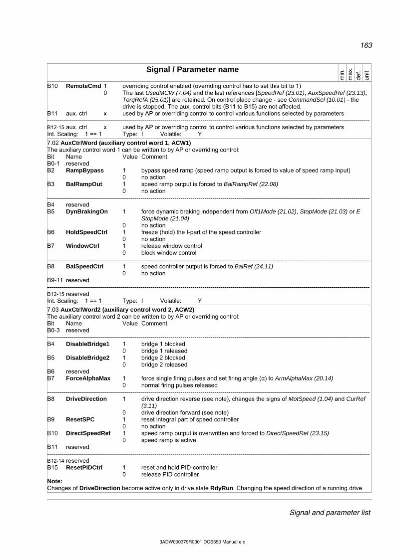
163
Signal and parameter list
3ADW000379R0301 DCS550 Manual e c
Signal / Parameter name
min
. m
ax.
def.
unit
B10 RemoteCmd 1 overriding control enabled (overriding control has to set this bit to 1) 0 The last UsedMCW (7.04) and the last references [SpeedRef (23.01), AuxSpeedRef (23.13),
TorqRefA (25.01)] are retained. On control place change - see CommandSel (10.01) - the drive is stopped. The aux. control bits (B11 to B15) are not affected.
B11 aux. ctrl x used by AP or overriding control to control various functions selected by parameters ------------------------------------------------------------------------------------------------------------------------------------------------------------------B12-15 aux. ctrl x used by AP or overriding control to control various functions selected by parameters Int. Scaling: 1 == 1 Type: I Volatile: Y
7.02 AuxCtrlWord (auxiliary control word 1, ACW1) The auxiliary control word 1 can be written to by AP or overriding control: Bit Name Value Comment B0-1 reserved B2 RampBypass 1 bypass speed ramp (speed ramp output is forced to value of speed ramp input)
0 no action B3 BalRampOut 1 speed ramp output is forced to BalRampRef (22.08)
0 no action ------------------------------------------------------------------------------------------------------------------------------------------------------------------B4 reserved B5 DynBrakingOn 1 force dynamic braking independent from Off1Mode (21.02), StopMode (21.03) or E
StopMode (21.04) 0 no action
B6 HoldSpeedCtrl 1 freeze (hold) the I-part of the speed controller 0 no action
B7 WindowCtrl 1 release window control 0 block window control
------------------------------------------------------------------------------------------------------------------------------------------------------------------B8 BalSpeedCtrl 1 speed controller output is forced to BalRef (24.11)
0 no action B9-11 reserved ------------------------------------------------------------------------------------------------------------------------------------------------------------------B12-15 reserved Int. Scaling: 1 == 1 Type: I Volatile: Y
7.03 AuxCtrlWord2 (auxiliary control word 2, ACW2) The auxiliary control word 2 can be written to by AP or overriding control: Bit Name Value Comment B0-3 reserved ------------------------------------------------------------------------------------------------------------------------------------------------------------------B4 DisableBridge1 1 bridge 1 blocked
0 bridge 1 released B5 DisableBridge2 1 bridge 2 blocked
0 bridge 2 released B6 reserved B7 ForceAlphaMax 1 force single firing pulses and set firing angle (α) to ArmAlphaMax (20.14)
0 normal firing pulses released ------------------------------------------------------------------------------------------------------------------------------------------------------------------B8 DriveDirection 1 drive direction reverse (see note), changes the signs of MotSpeed (1.04) and CurRef
(3.11) 0 drive direction forward (see note)
B9 ResetSPC 1 reset integral part of speed controller 0 no action B10 DirectSpeedRef 1 speed ramp output is overwritten and forced to DirectSpeedRef (23.15)
0 speed ramp is active B11 reserved ------------------------------------------------------------------------------------------------------------------------------------------------------------------B12-14 reserved B15 ResetPIDCtrl 1 reset and hold PID-controller
0 release PID controller Note: Changes of DriveDirection become active only in drive state RdyRun. Changing the speed direction of a running drive

164
Signal and parameter list
3ADW000379R0301 DCS550 Manual e c
Signal / Parameter name
min
. m
ax.
def.
unit
(RdyRef state) by means of DriveDirection is not possible. Int. Scaling: 1 == 1 Type: I Volatile: Y
7.04 UsedMCW (used main control word, UMCW) Internal used (selected) main control word is read only and contains all drive depending commands. The selection is depending on the drives local/remote control setting, CommandSel (10.01) and HandAuto (10.07). The bit functionality of bit 0 to bit 10 is the same as the in the MainCtrlWord (7.01). Not all functions are controllable from local control or local I/O mode. B0-10 see MainCtrlWord (7.01) B11-15 reserved
Attention: The UsedMCW (7.04) is write protected, thus it is not possible to write on the used main control word by means of Master-follower, AP or overriding control. Int. Scaling: 1 == 1 Type: I Volatile: Y
7.05 DO CtrlWord (digital output control word, DOCW) The DO control word 1 can be written to by AP or overriding control. To connect bits of the DO CtrlWord (7.05) with DO1 to DO8 use the parameters in group 14 (Digital outputs). DO9 to DO12 are directly sent to the extension I/O. Thus, they are only available for AP or overriding control. Bit Name Comment B0 DO1 this bit has to be send to the digital output via the parameters of group 14 (Digital outputs) B1 DO2 this bit has to be send to the digital output via the parameters of group 14 (Digital outputs) B2 DO3 this bit has to be send to the digital output via the parameters of group 14 (Digital outputs) B3 DO4 this bit has to be send to the digital output via the parameters of group 14 (Digital outputs) ------------------------------------------------------------------------------------------------------------------------------------------------------------------B4-B6 reserved B7 DO8 this bit has to be send to the digital output via the parameters of group 14 (Digital outputs) ------------------------------------------------------------------------------------------------------------------------------------------------------------------B8 DO9 this bit is written directly to DO1 of the extension IO defined by DIO ExtModule1 (98.03) B9 DO10 this bit is written directly to DO2 of the extension IO defined by DIO ExtModule1 (98.03) B10 DO11 this bit is written directly to DO1 of the extension IO defined by DIO ExtModule2 (98.04) B11 DO12 this bit is written directly to DO2 of the extension IO defined by DIO ExtModule2 (98.04) ------------------------------------------------------------------------------------------------------------------------------------------------------------------B12-15 reserved Int. Scaling: 1 == 1 Type: I Volatile: Y
Group 8: Status / limit words
8.01 MainStatWord (main status word, MSW)
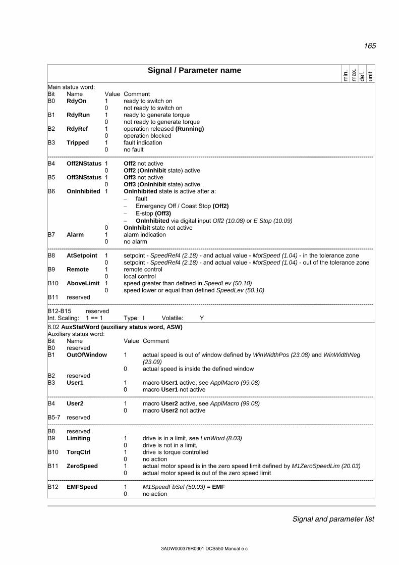
165
Signal and parameter list
3ADW000379R0301 DCS550 Manual e c
Signal / Parameter name
min
. m
ax.
def.
unit
Main status word: Bit Name Value Comment B0 RdyOn 1 ready to switch on
0 not ready to switch on B1 RdyRun 1 ready to generate torque
0 not ready to generate torque B2 RdyRef 1 operation released (Running)
0 operation blocked B3 Tripped 1 fault indication
0 no fault ------------------------------------------------------------------------------------------------------------------------------------------------------------------B4 Off2NStatus 1 Off2 not active
0 Off2 (OnInhibit state) active B5 Off3NStatus 1 Off3 not active
0 Off3 (OnInhibit state) active B6 OnInhibited 1 OnInhibited state is active after a:
fault Emergency Off / Coast Stop (Off2) E-stop (Off3) OnInhibited via digital input Off2 (10.08) or E Stop (10.09)
0 OnInhibit state not active B7 Alarm 1 alarm indication
0 no alarm ------------------------------------------------------------------------------------------------------------------------------------------------------------------B8 AtSetpoint 1 setpoint - SpeedRef4 (2.18) - and actual value - MotSpeed (1.04) - in the tolerance zone
0 setpoint - SpeedRef4 (2.18) - and actual value - MotSpeed (1.04) - out of the tolerance zone B9 Remote 1 remote control
0 local control B10 AboveLimit 1 speed greater than defined in SpeedLev (50.10)
0 speed lower or equal than defined SpeedLev (50.10) B11 reserved ------------------------------------------------------------------------------------------------------------------------------------------------------------------B12-B15 reserved Int. Scaling: 1 == 1 Type: I Volatile: Y
8.02 AuxStatWord (auxiliary status word, ASW) Auxiliary status word: Bit Name Value Comment B0 reserved B1 OutOfWindow 1 actual speed is out of window defined by WinWidthPos (23.08) and WinWidthNeg
(23.09) 0 actual speed is inside the defined window
B2 reserved B3 User1 1 macro User1 active, see ApplMacro (99.08)
0 macro User1 not active ------------------------------------------------------------------------------------------------------------------------------------------------------------------B4 User2 1 macro User2 active, see ApplMacro (99.08)
0 macro User2 not active B5-7 reserved ------------------------------------------------------------------------------------------------------------------------------------------------------------------B8 reserved B9 Limiting 1 drive is in a limit, see LimWord (8.03)
0 drive is not in a limit, B10 TorqCtrl 1 drive is torque controlled
0 no action B11 ZeroSpeed 1 actual motor speed is in the zero speed limit defined by M1ZeroSpeedLim (20.03)
0 actual motor speed is out of the zero speed limit ------------------------------------------------------------------------------------------------------------------------------------------------------------------B12 EMFSpeed 1 M1SpeedFbSel (50.03) = EMF
0 no action
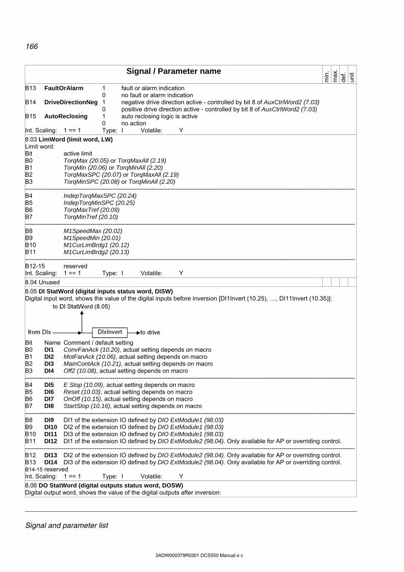
166
Signal and parameter list
3ADW000379R0301 DCS550 Manual e c
Signal / Parameter name
min
. m
ax.
def.
unit
B13 FaultOrAlarm 1 fault or alarm indication 0 no fault or alarm indication
B14 DriveDirectionNeg 1 negative drive direction active - controlled by bit 8 of AuxCtrlWord2 (7.03) 0 positive drive direction active - controlled by bit 8 of AuxCtrlWord2 (7.03)
B15 AutoReclosing 1 auto reclosing logic is active 0 no action
Int. Scaling: 1 == 1 Type: I Volatile: Y
8.03 LimWord (limit word, LW) Limit word: Bit active limit B0 TorqMax (20.05) or TorqMaxAll (2.19) B1 TorqMin (20.06) or TorqMinAll (2.20) B2 TorqMaxSPC (20.07) or TorqMaxAll (2.19) B3 TorqMinSPC (20.08) or TorqMinAll (2.20) ------------------------------------------------------------------------------------------------------------------------------------------------------------------B4 IndepTorqMaxSPC (20.24) B5 IndepTorqMinSPC (20.25) B6 TorqMaxTref (20.09) B7 TorqMinTref (20.10) ------------------------------------------------------------------------------------------------------------------------------------------------------------------B8 M1SpeedMax (20.02) B9 M1SpeedMin (20.01) B10 M1CurLimBrdg1 (20.12) B11 M1CurLimBrdg2 (20.13) ------------------------------------------------------------------------------------------------------------------------------------------------------------------B12-15 reserved Int. Scaling: 1 == 1 Type: I Volatile: Y
8.04 Unused
8.05 DI StatWord (digital inputs status word, DISW) Digital input word, shows the value of the digital inputs before inversion [DI1Invert (10.25), …, DI11Invert (10.35)]:
Bit Name Comment / default setting B0 DI1 ConvFanAck (10.20), actual setting depends on macro B1 DI2 MotFanAck (10.06), actual setting depends on macro B2 DI3 MainContAck (10.21), actual setting depends on macro B3 DI4 Off2 (10.08), actual setting depends on macro ------------------------------------------------------------------------------------------------------------------------------------------------------------------B4 DI5 E Stop (10.09), actual setting depends on macro B5 DI6 Reset (10.03), actual setting depends on macro B6 DI7 OnOff (10.15), actual setting depends on macro B7 DI8 StartStop (10.16), actual setting depends on macro ------------------------------------------------------------------------------------------------------------------------------------------------------------------B8 DI9 DI1 of the extension IO defined by DIO ExtModule1 (98.03) B9 DI10 DI2 of the extension IO defined by DIO ExtModule1 (98.03) B10 DI11 DI3 of the extension IO defined by DIO ExtModule1 (98.03) B11 DI12 DI1 of the extension IO defined by DIO ExtModule2 (98.04). Only available for AP or overriding control. ------------------------------------------------------------------------------------------------------------------------------------------------------------------B12 DI13 DI2 of the extension IO defined by DIO ExtModule2 (98.04). Only available for AP or overriding control. B13 DI14 DI3 of the extension IO defined by DIO ExtModule2 (98.04). Only available for AP or overriding control. B14-15 reserved Int. Scaling: 1 == 1 Type: I Volatile: Y
8.06 DO StatWord (digital outputs status word, DOSW) Digital output word, shows the value of the digital outputs after inversion:
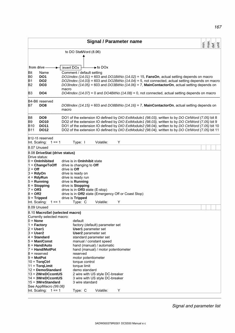
167
Signal and parameter list
3ADW000379R0301 DCS550 Manual e c
Signal / Parameter name
min
. m
ax.
def.
unit
Bit Name Comment / default setting B0 DO1 DO1Index (14.01) = 603 and DO1BitNo (14.02) = 15, FansOn, actual setting depends on macro B1 DO2 DO2Index (14.03) = 603 and DO2BitNo (14.04) = 5, not connected, actual setting depends on macroB2 DO3 DO3Index (14.05) = 603 and DO3BitNo (14.06) = 7, MainContactorOn, actual setting depends on
macro B3 DO4 DO4Index (14.07) = 0 and DO4BitNo (14.08) = 0, not connected, actual setting depends on macro ------------------------------------------------------------------------------------------------------------------------------------------------------------------B4-B6 reserved B7 DO8 DO8Index (14.15) = 603 and DO8BitNo (14.16) = 7, MainContactorOn, actual setting depends on
macro ------------------------------------------------------------------------------------------------------------------------------------------------------------------B8 DO9 DO1 of the extension IO defined by DIO ExtModule1 (98.03), written to by DO CtrlWord (7.05) bit 8 B9 DO10 DO2 of the extension IO defined by DIO ExtModule1 (98.03), written to by DO CtrlWord (7.05) bit 9 B10 DO11 DO1 of the extension IO defined by DIO ExtModule2 (98.04), written to by DO CtrlWord (7.05) bit 10B11 DO12 DO2 of the extension IO defined by DIO ExtModule2 (98.04), written to by DO CtrlWord (7.05) bit 11------------------------------------------------------------------------------------------------------------------------------------------------------------------B12-15 reserved Int. Scaling: 1 == 1 Type: I Volatile: Y
8.07 Unused
8.08 DriveStat (drive status) Drive status: 0 = OnInhibited drive is in OnInhibit state 1 = ChangeToOff drive is changing to Off 2 = Off drive is Off 3 = RdyOn drive is ready on 4 = RdyRun drive is ready run 5 = Running drive is Running 6 = Stopping drive is Stopping 7 = Off3 drive is in Off3 state (E-stop) 8 = Off2 drive is in Off2 state (Emergency Off or Coast Stop) 9 = Tripped drive is Tripped Int. Scaling: 1 == 1 Type: C Volatile: Y
8.09 Unused
8.10 MacroSel (selected macro) Currently selected macro: 0 = None default 1 = Factory factory (default) parameter set 2 = User1 User1 parameter set 3 = User2 User2 parameter set 4 = Standard standard parameter set 5 = Man/Const manual / constant speed 6 = Hand/Auto hand (manual) / automatic 7 = Hand/MotPot hand (manual) / motor potentiometer 8 = reserved reserved 9 = MotPot motor potentiometer 10 = TorqCtrl torque control 11 = TorqLimit torque limit 12 = DemoStandard demo standard 13 = 2WreDCcontUS 2 wire with US style DC-breaker 14 = 3WreDCcontUS 3 wire with US style DC-breaker 15 = 3WreStandard 3 wire standard See ApplMacro (99.08) Int. Scaling: 1 == 1 Type: C Volatile: Y
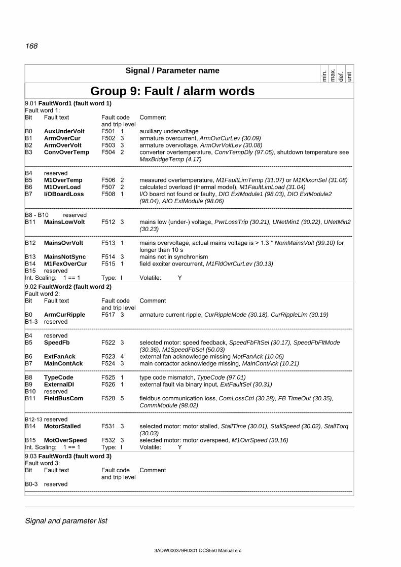
168
Signal and parameter list
3ADW000379R0301 DCS550 Manual e c
Signal / Parameter name
min
. m
ax.
def.
unit
Group 9: Fault / alarm words
9.01 FaultWord1 (fault word 1) Fault word 1: Bit Fault text Fault code Comment and trip level B0 AuxUnderVolt F501 1 auxiliary undervoltage B1 ArmOverCur F502 3 armature overcurrent, ArmOvrCurLev (30.09) B2 ArmOverVolt F503 3 armature overvoltage, ArmOvrVoltLev (30.08) B3 ConvOverTemp F504 2 converter overtemperature, ConvTempDly (97.05), shutdown temperature see
MaxBridgeTemp (4.17) ------------------------------------------------------------------------------------------------------------------------------------------------------------------B4 reserved B5 M1OverTemp F506 2 measured overtemperature, M1FaultLimTemp (31.07) or M1KlixonSel (31.08) B6 M1OverLoad F507 2 calculated overload (thermal model), M1FaultLimLoad (31.04) B7 I/OBoardLoss F508 1 I/O board not found or faulty, DIO ExtModule1 (98.03), DIO ExtModule2
(98.04), AIO ExtModule (98.06) ------------------------------------------------------------------------------------------------------------------------------------------------------------------B8 - B10 reserved B11 MainsLowVolt F512 3 mains low (under-) voltage, PwrLossTrip (30.21), UNetMin1 (30.22), UNetMin2
(30.23) ------------------------------------------------------------------------------------------------------------------------------------------------------------------B12 MainsOvrVolt F513 1 mains overvoltage, actual mains voltage is > 1.3 * NomMainsVolt (99.10) for
longer than 10 s B13 MainsNotSync F514 3 mains not in synchronism B14 M1FexOverCur F515 1 field exciter overcurrent, M1FldOvrCurLev (30.13) B15 reserved Int. Scaling: 1 == 1 Type: I Volatile: Y
9.02 FaultWord2 (fault word 2) Fault word 2: Bit Fault text Fault code Comment and trip level B0 ArmCurRipple F517 3 armature current ripple, CurRippleMode (30.18), CurRippleLim (30.19) B1-3 reserved ------------------------------------------------------------------------------------------------------------------------------------------------------------------B4 reserved B5 SpeedFb F522 3 selected motor: speed feedback, SpeedFbFltSel (30.17), SpeedFbFltMode
(30.36), M1SpeedFbSel (50.03) B6 ExtFanAck F523 4 external fan acknowledge missing MotFanAck (10.06) B7 MainContAck F524 3 main contactor acknowledge missing, MainContAck (10.21) ------------------------------------------------------------------------------------------------------------------------------------------------------------------B8 TypeCode F525 1 type code mismatch, TypeCode (97.01) B9 ExternalDI F526 1 external fault via binary input, ExtFaultSel (30.31) B10 reserved B11 FieldBusCom F528 5 fieldbus communication loss, ComLossCtrl (30.28), FB TimeOut (30.35),
CommModule (98.02) ------------------------------------------------------------------------------------------------------------------------------------------------------------------B12-13 reserved B14 MotorStalled F531 3 selected motor: motor stalled, StallTime (30.01), StallSpeed (30.02), StallTorq
(30.03) B15 MotOverSpeed F532 3 selected motor: motor overspeed, M1OvrSpeed (30.16) Int. Scaling: 1 == 1 Type: I Volatile: Y
9.03 FaultWord3 (fault word 3) Fault word 3: Bit Fault text Fault code Comment and trip level B0-3 reserved ------------------------------------------------------------------------------------------------------------------------------------------------------------------
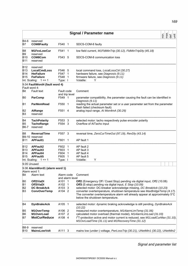
169
Signal and parameter list
3ADW000379R0301 DCS550 Manual e c
Signal / Parameter name
min
. m
ax.
def.
unit
B4-6 reserved B7 COM8Faulty F540 1 SDCS-COM-8 faulty ------------------------------------------------------------------------------------------------------------------------------------------------------------------B8 M1FexLowCur F541 1 low field current, M1FldMinTrip (30.12), FldMinTripDly (45.18) B9 reserved B10 COM8Com F543 5 SDCS-COM-8 communication loss B11 reserved ------------------------------------------------------------------------------------------------------------------------------------------------------------------B12 reserved B13 LocalCmdLoss F546 5 local command loss, LocalLossCtrl (30.27) B14 HwFailure F547 1 hardware failure, see Diagnosis (9.11) B15 FwFailure F548 1 firmware failure, see Diagnosis (9.11) Int. Scaling: 1 == 1 Type: I Volatile: Y
9.04 FaultWord4 (fault word 4) Fault word 4: Bit Fault text Fault code Comment and trip level B0 ParComp F549 1 parameter compatibility, the parameter causing the fault can be identified in
Diagnosis (9.11) B1 ParMemRead F550 1 reading the actual parameter set or a user parameter set from the parameter
flash failed (checksum fault) B2 AIRange F551 4 analog input range, AI Mon4mA (30.29) B3 reserved ------------------------------------------------------------------------------------------------------------------------------------------------------------------B4 TachPolarity F553 3 selected motor: tacho respectively pulse encoder polarity B5 TachoRange F554 3 Overflow of AITacho input B6-7 reserved ------------------------------------------------------------------------------------------------------------------------------------------------------------------B8 ReversalTime F557 3 reversal time, ZeroCurTimeOut (97.19), RevDly (43.14) B9-10 reserved B11 APFault1 F601 1 AP fault 1 ------------------------------------------------------------------------------------------------------------------------------------------------------------------B12 APFault2 F602 1 AP fault 2 B13 APFault3 F603 1 AP fault 3 B14 APFault4 F604 1 AP fault 4 B15 APFault5 F605 1 AP fault 5 Int. Scaling: 1 == 1 Type: I Volatile: Y
9.05 Unused
9.06 AlarmWord1 (alarm word 1) Alarm word 1: Bit Alarm text Alarm code Comment and alarm level B0 Off2ViaDI A101 1 Off2 (Emergency Off / Coast Stop) pending via digital input, Off2 (10.08) B1 Off3ViaDI A102 1 Off3 (E-stop) pending via digital input, E Stop (10.09) B2 DC BreakAck A103 3 selected motor: DC-breaker acknowledge missing, DC BreakAck (10.23) B3 ConvOverTemp A104 2 converter overtemperature, shutdown temperature see MaxBridgeTemp (4.17).
The converter overtemperature alarm will already appear at approximately 5°C below the shutdown temperature.
------------------------------------------------------------------------------------------------------------------------------------------------------------------B4 DynBrakeAck A105 1 selected motor: dynamic braking acknowledge is still pending, DynBrakeAck
(10.22) B5 M1OverTemp A106 2 measured motor overtemperature, M1AlarmLimTemp (31.06) B6 M1OverLoad A107 2 calculated motor overload (thermal model), M1AlarmLimLoad (31.03) B7 MotCurReduce A108 4 I2T-protection active and motor current is reduced, see M1LoadCurMax (31.10),
M1OvrLoadTime (31.11) and M1RecoveryTime (31.12) ------------------------------------------------------------------------------------------------------------------------------------------------------------------B8-9 reserved B10 MainsLowVolt A111 3 mains low (under-) voltage, PwrLossTrip (30.21), UNetMin1 (30.22), UNetMin2
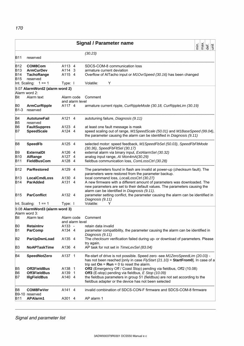
170
Signal and parameter list
3ADW000379R0301 DCS550 Manual e c
Signal / Parameter name
min
. m
ax.
def.
unit
(30.23) B11 reserved ------------------------------------------------------------------------------------------------------------------------------------------------------------------B12 COM8Com A113 4 SDCS-COM-8 communication loss B13 ArmCurDev A114 3 armature current deviation B14 TachoRange A115 4 Overflow of AITacho input or M1OvrSpeed (30.16) has been changed B15 reserved Int. Scaling: 1 == 1 Type: I Volatile: Y
9.07 AlarmWord2 (alarm word 2) Alarm word 2: Bit Alarm text Alarm code Comment and alarm level B0 ArmCurRipple A117 4 armature current ripple, CurRippleMode (30.18, CurRippleLim (30.19) B1-3 reserved ------------------------------------------------------------------------------------------------------------------------------------------------------------------B4 AutotuneFail A121 4 autotuning failure, Diagnosis (9.11) B5 reserved B6 FaultSuppres A123 4 at least one fault message is mask B7 SpeedScale A124 4 speed scaling out of range, M1SpeedScale (50.01) and M1BaseSpeed (99.04),
the parameter causing the alarm can be identified in Diagnosis (9.11) ------------------------------------------------------------------------------------------------------------------------------------------------------------------B8 SpeedFb A125 4 selected motor: speed feedback, M1SpeedFbSel (50.03), SpeedFbFltMode
(30.36), SpeedFbFltSel (30.17) B9 ExternalDI A126 4 external alarm via binary input, ExtAlarmSel (30.32) B10 AIRange A127 4 analog input range, AI Mon4mA(30.29) B11 FieldBusCom A128 4 fieldbus communication loss, ComLossCtrl (30.28) ------------------------------------------------------------------------------------------------------------------------------------------------------------------B12 ParRestored A129 4 The parameters found in flash are invalid at power-up (checksum fault). The
parameters were restored from the parameter backup. B13 LocalCmdLoss A130 4 local command loss, LocalLossCtrl (30.27) B14 ParAdded A131 4 A new firmware with a different amount of parameters was downloaded. The
new parameters are set to their default values. The parameters causing the alarm can be identified in Diagnosis (9.11).
B15 ParConflict A132 4 parameter setting conflict, the parameter causing the alarm can be identified in Diagnosis (9.11)
Int. Scaling: 1 == 1 Type: I Volatile: Y
9.08 AlarmWord3 (alarm word 3) Alarm word 3: Bit Alarm text Alarm code Comment and alarm level B0 RetainInv A133 - retain data invalid B1 ParComp A134 4 parameter compatibility, the parameter causing the alarm can be identified in
Diagnosis (9.11) B2 ParUpDwnLoad A135 4 The checksum verification failed during up- or download of parameters. Please
try again. B3 NoAPTaskTime A136 4 AP task for not set in TimeLevSel (83.04) ------------------------------------------------------------------------------------------------------------------------------------------------------------------B4 SpeedNotZero A137 1 Re-start of drive is not possible. Speed zero -see M1ZeroSpeedLim (20.03) -
has not been reached [only in case FlyStart (21.10) = StartFrom0]. In case of a trip set On = Run = 0 to reset the alarm.
B5 Off2FieldBus A138 1 Off2 (Emergency Off / Coast Stop) pending via fieldbus, Off2 (10.08) B6 Off3FieldBus A139 1 Off3 (E-stop) pending via fieldbus, E Stop (10.09) B7 IllgFieldBus A140 4 the fieldbus parameters in group 51 (fieldbus) are not set according to the
fieldbus adapter or the device has not been selected ------------------------------------------------------------------------------------------------------------------------------------------------------------------B8 COM8FwVer A141 4 invalid combination of SDCS-CON-F firmware and SDCS-COM-8 firmware B9-10 reserved B11 APAlarm1 A301 4 AP alarm 1

171
Signal and parameter list
3ADW000379R0301 DCS550 Manual e c
Signal / Parameter name
min
. m
ax.
def.
unit
------------------------------------------------------------------------------------------------------------------------------------------------------------------B12 APAlarm2 A302 4 AP alarm 2 B13 APAlarm3 A303 4 AP alarm 3 B14 APAlarm4 A304 4 AP alarm 4 B15 APAlarm5 A305 4 AP alarm 5 Int. Scaling: 1 == 1 Type: I Volatile: Y
9.09 Unused
9.10 SysFaultWord (system fault word) Operating system faults from SDCS-COM-8 board: Bit Fault text Fault code F B0 Factory macro parameter file error default parameters are invalid B1 User macro parameter file error one of the User macros is invalid B2 Non volatile operating system error AMCOS fault, please contact Your local ABB agent B3 File error in flash problems when writing to the flash memory, please try again ------------------------------------------------------------------------------------------------------------------------------------------------------------------B4 Internal time level T2 overflow (100 s) timeout of task T2, if happens frequently please contact Your
local ABB agent B5 Internal time level T3 overflow (1 ms) timeout of task T3, if happens frequently please contact Your
local ABB agent B6 Internal time level T4 overflow (50 ms) timeout of task T4, if happens frequently please contact Your
local ABB agent B7 Internal time level T5 overflow (1 s) timeout of task T5, if happens frequently please contact Your
local ABB agent ------------------------------------------------------------------------------------------------------------------------------------------------------------------B8 State overflow timeout of task State, if happens frequently please contact Your
local ABB agent B9 Application window ending overflow application on SDCS-COM-8 faulty B10 Application program overflow application on SDCS-COM-8 faulty B11 Illegal instruction crash of CPU due to EMC or hardware problems ------------------------------------------------------------------------------------------------------------------------------------------------------------------B12 Register stack overflow overflow due to EMC or firmware bug B13 System stack overflow overflow due to EMC or firmware bug B14 System stack underflow underflow due to crash of CPU or firmware bug B15 reserved Int. Scaling: 1 == 1 Type: I Volatile: Y
9.11 Diagnosis (diagnosis) Attention: Diagnosis (9.11) is set to zero by means of Reset. Displays diagnostics messages: 0 = no message Firmware: 1 = default setting of parameters wrong 2 = parameter flash image too small for all parameters 3 = reserved 4 = illegal write attempt on a signal or write-protected parameter, e.g. writing on UsedMCW (7.04) 5 = reserved 6 = wrong type code 7 = an un-initialized interrupted has occurred 8, 9 = reserved 10 = wrong parameter value Autotuning: 11 = autotuning aborted by fault or removing the Run command [UsedMCW (7.04) bit 3] 12 = autotuning timeout, Run command [UsedMCW (7.04) bit 3] is not set in time 13 = motor is still turning, no speed zero indication 14 = field current not zero 15 = armature current not zero

172
Signal and parameter list
3ADW000379R0301 DCS550 Manual e c
Signal / Parameter name
min
. m
ax.
def.
unit
16 = armature voltage measurement circuit open (e.g. not connected) or interrupted, check also current and torque limits
17 = armature circuit and/or armature voltage measurement circuit wrongly connected 18 = no load connected to armature circuit 19 = invalid nominal armature current setting;
armature current M1MotNomCur (99.03) is set to zero 20 = field current does not decrease when the excitation is switched off 21 = field current actual doesn't reach field current reference;
no detection of field resistance; field circuit open (e.g. not connected) respectively interrupted
22 = no writing of control parameters of speed controller 23 = tacho adjustment faulty or not OK or the tacho voltage is too high during autotuning 24 = tuning of speed controller, speed feedback assistant or tacho fine tuning not possible due to speed limitation - see
e.g. M1SpeedMin (20.01) and M1SpeedMax (20.02) 25 = Tuning of speed controller, speed feedback assistant or tacho fine tuning not possible due to voltage limitation.
During the tuning of the speed controller, the speed feedback assistant or the tacho fine-tuning base speed [M1BaseSpeed (99.04)] might be reached. Thus full armature voltage [M1NomVolt (99.02)] is necessary. In case the mains voltage is too low to provide for the needed armature voltage the autotuning procedure is canceled. Check and adapt if needed: Mains voltage M1NomVolt (99.02) M1BaseSpeed (99.04)
26 = field weakening not allowed, see M1SpeedFbSel (50.03) and FldCtrlMode (44.01) 27 = discontinuous current limit could not be determined due to low current limitation in M1CurLimBrdg1 (20.12) or
M1CurLimBrdg2 (20.13) 28 = reserved 29 = no field exciter selected, see M1UsedFexType (99.12) 30 = reserved 30 = DCS Control Panel up- or download not started 32 = DCS Control Panel data not up- or downloaded in time 33 = reserved 34 = DCS Control Panel up -or download checksum faulty 35 = DCS Control Panel up- or download software faulty 36 = DCS Control Panel up- or download verification failed 37-40 reserved 41 = The flash is written to cyclic by AP (e.g. block ParWrite). Cyclic saving of values in the flash will damage it! Do not
write cyclic on the flash! 42-49 reserved Hardware: 50 = parameter flash faulty (erase) 51 = parameter flash faulty (program) 52 = check connector X12 on SDCS-CON-F and connector X12 and X22 on SDCS-PIN-F 53-69 reserved A132 ParConflict (alarm parameter setting conflict): 70 = reserved 71 = flux linearization parameters not consistent 72 = wrong firing angle limitation ( Max and Min value 20.14 and 20.15) 73 = armature data not consistent.
Check if: M1NomCur (99.03) is set to zero, M1NomVolt (99.02) and M1NomCur (99.03) are fitting with the drive. In case they are much smaller than the
drive the internal calculation of M1ArmL (43.09) and M1ArmR (43.10) can cause an internal overflow. Set M1ArmL (43.09) and M1ArmR (43.10) to zero. For M1ArmL (43.09) following limitation is valid:
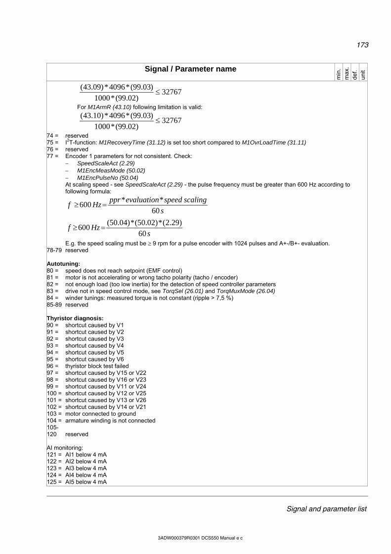
173
Signal and parameter list
3ADW000379R0301 DCS550 Manual e c
Signal / Parameter name
min
. m
ax.
def.
unit
32767)02.99(*1000
)03.99(*4096*)09.43(
For M1ArmR (43.10) following limitation is valid:
32767)02.99(*1000
)03.99(*4096*)10.43(
74 = reserved 75 = I2T-function: M1RecoveryTime (31.12) is set too short compared to M1OvrLoadTime (31.11) 76 = reserved 77 = Encoder 1 parameters for not consistent. Check:
SpeedScaleAct (2.29) M1EncMeasMode (50.02) M1EncPulseNo (50.04) At scaling speed - see SpeedScaleAct (2.29) - the pulse frequency must be greater than 600 Hz according to following formula:
sHzf
s
scalingspeedevaluationpprHzf
60
)29.2(*)02.50(*)04.50(600
60
**600
E.g. the speed scaling must be 9 rpm for a pulse encoder with 1024 pulses and A+-/B+- evaluation. 78-79 reserved Autotuning: 80 = speed does not reach setpoint (EMF control) 81 = motor is not accelerating or wrong tacho polarity (tacho / encoder) 82 = not enough load (too low inertia) for the detection of speed controller parameters 83 = drive not in speed control mode, see TorqSel (26.01) and TorqMuxMode (26.04) 84 = winder tunings: measured torque is not constant (ripple > 7,5 %) 85-89 reserved Thyristor diagnosis: 90 = shortcut caused by V1 91 = shortcut caused by V2 92 = shortcut caused by V3 93 = shortcut caused by V4 94 = shortcut caused by V5 95 = shortcut caused by V6 96 = thyristor block test failed 97 = shortcut caused by V15 or V22 98 = shortcut caused by V16 or V23 99 = shortcut caused by V11 or V24 100 = shortcut caused by V12 or V25 101 = shortcut caused by V13 or V26 102 = shortcut caused by V14 or V21 103 = motor connected to ground 104 = armature winding is not connected 105- 120 reserved AI monitoring: 121 = AI1 below 4 mA 122 = AI2 below 4 mA 123 = AI3 below 4 mA 124 = AI4 below 4 mA 125 = AI5 below 4 mA
174
Signal and parameter list
3ADW000379R0301 DCS550 Manual e c
Signal / Parameter name
min
. m
ax.
def.
unit
126 = AI6 below 4 mA 127 = AITAC below 4 mA 128- 149 reserved Option modules: 150 = fieldbus module missing see CommModule (98.02) 151- 154 reserved 155 = RAIO-xx in option slot on SDCS-CON-F missing see group 98 156 reserved 157 = RDIO-xx in option slot on SDCS-CON-F missing see group 98 158- 164 reserved A134 ParComp (alarm parameter compatibility conflict): 10000 … 19999 = the parameter with the compatibility conflict can be identified by means of the last 4 digits ParNoCyc (notice parameter not cyclic): 20000 … 29999 = the not cyclic parameter which is being written to by means of a pointer parameter [e.g. DsetXVal1
(90.01)] can be identified by means of the last 4 digits F548 FwFailure (fault firmware failure): 20000 … 29999 = the read only parameter which is being written to by means of a pointer parameter [e.g. DsetXVal1
(90.01) ] or AP can be identified by means of the last 4 digits Thyristor diagnosis: 30000 = possibly trigger pulse channels are mixed up 31xdd = V1 or V11 not conducting 32xdd = V2 or V12 not conducting 33xdd = V3 or V13 not conducting 34xdd = V4 or V14 not conducting 35xdd = V5 or V15 not conducting 36xdd = V6 or V16 not conducting x = 0: only a single thyristor in bridge 1 is not conducting (e.g. 320dd means V2 respectively V12 is not conducting) x = 1 … 6: additionally a second thyristor in bridge 1 is no conducting (e.g. 325dd means V2 and V5 respectively V12 and V15 are not conducting) dd = don’t care, the numbers of this digits do not carry any information about the thyristors of the first bridge. Example: 36030: means V16 in bridge 1 and V23 in bridge 2 are not conducting 3dd1y = V21 not conducting 3dd2y = V22 not conducting 3dd3y = V23 not conducting 3dd4y = V24 not conducting 3dd5y = V25 not conducting 3dd6y = V26 not conducting y = 0: only a single thyristor in bridge 2 is not conducting (e.g. 3dd20 means V22 is not conducting) y = 1 … 6: additionally a second thyristor in bridge 2 is no conducting (e.g. 3dd25 means V22 and V25 are not conducting)dd = don’t care, the numbers of this digits do not carry any information about the thyristors of the second bridge. Example: 36030: means V16 in bridge 1 and V23 in bridge 2 are not conducting A124 SpeedScale (alarm speed scaling): 40000 … 49999 = the parameter with the speed scaling conflict can be identified by means of the last 4 digits F549 ParComp (fault parameter compatibility conflict): 50000 … 59999= the parameter with the compatibility conflict can be identified by means of the last 4 digits Int. Scaling: 1 == 1 Type: I Volatile: Y
175
Signal and parameter list
3ADW000379R0301 DCS550 Manual e c
Signal / Parameter name
min
. m
ax.
def.
unit
9.12 LastFault (last fault) Displays the last fault: F<Fault code> <FaultName> (e.g. F2 ArmOverCur) Int. Scaling: 1 == 1 Type: C Volatile: Y - - - -
9.13 2ndLastFault (2nd last fault) Displays the 2nd last fault: F<Fault code> <FaultName> (e.g. F2 ArmOverCur) Int. Scaling: 1 == 1 Type: C Volatile: Y - - - -
9.14 3rdLastFault (3rdlast fault) Displays the 3rd last fault: F<Fault code> <FaultName> (e.g. F2 ArmOverCur) Int. Scaling: 1 == 1 Type: C Volatile: Y - - - -
176
Signal and parameter list
3ADW000379R0301 DCS550 Manual e c
Parameters Signal / Parameter name
min
. m
ax.
def.
unit
Group 10: Start / stop select
10.01 CommandSel (command selector) UsedMCW (7.04) selector: 0 = Local I/O Drive is controlled via local I/O.
Reset (10.03) = DI6; UsedMCW (7.04) bit 7, default OnOff1 (10.15) = DI7; UsedMCW (7.04) bit 0, default and StartStop (10.16) = DI8; UsedMCW (7.04) bit 3, default
1 = MainCtrlWord drive is controlled via MainCtrlWord (7.01) 2 = Key Automatic switchover from MainCtrlWord to Local I/O in case of F528 FieldBusCom
[FaultWord2 (9.02) bit 11]. It is still possible to control the drive via local I/O. OnOff1 (10.15) = DI7; UsedMCW (7.04) bit 0, default and StartStop (10.16) = DI8; UsedMCW (7.04) bit 3, default. The used speed reference is set by means of FixedSpeed1 (23.02).
Notes: Local control mode has higher priority than the selection made with CommandSel (10.01). The commands Off2 (10.08), E Stop (10.09) and Reset (10.03) are always active (in case they are
assigned) regardless of CommandSel (10.01) setting. Int. Scaling: 1 == 1 Type: C Volatile: N Lo
cal I
/O
Key
Lo
cal I
/O
-
10.02 Direction (direction of rotation) Binary signal for Direction. Direction (10.02) allows to change the direction of rotation by negating the speed reference in remote operation: 0 = NotUsed default 1 = DI1 1 = Reverse, 0 = Forward 2 = DI2 1 = Reverse, 0 = Forward 3 = DI3 1 = Reverse, 0 = Forward 4 = DI4 1 = Reverse, 0 = Forward 5 = DI5 1 = Reverse, 0 = Forward 6 = DI6 1 = Reverse, 0 = Forward 7 = DI7 1 = Reverse, 0 = Forward 8 = DI8 1 = Reverse, 0 = Forward 9 = DI9 1 = Reverse, 0 = Forward, only available with digital extension board 10 = DI10 1 = Reverse, 0 = Forward, only available with digital extension board 11 = DI11 1 = Reverse, 0 = Forward, only available with digital extension board 12 = MCW Bit11 1 = Reverse, 0 = Forward, MainCtrlWord (7.01) bit 11 13 = MCW Bit12 1 = Reverse, 0 = Forward, MainCtrlWord (7.01) bit 12 14 = MCW Bit13 1 = Reverse, 0 = Forward, MainCtrlWord (7.01) bit 13 15 = MCW Bit14 1 = Reverse, 0 = Forward, MainCtrlWord (7.01) bit 14 16 = MCW Bit15 1 = Reverse, 0 = Forward, MainCtrlWord (7.01) bit 15 Int. Scaling: 1 == 1 Type: C Volatile: N N
otU
sed
MC
W B
it15
Not
Use
d -

177
Signal and parameter list
3ADW000379R0301 DCS550 Manual e c
Signal / Parameter name
min
. m
ax.
def.
unit
10.03 Reset (Reset command) Binary signal for Reset, UsedMCW (7.04) bit 7: 0 = NotUsed 1 = DI1 Reset by rising edge (0 1) 2 = DI2 Reset by rising edge (0 1) 3 = DI3 Reset by rising edge (0 1) 4 = DI4 Reset by rising edge (0 1) 5 = DI5 Reset by rising edge (0 1) 6 = DI6 Reset by rising edge (0 1), default 7 = DI7 Reset by rising edge (0 1) 8 = DI8 Reset by rising edge (0 1) 9 = DI9 Reset by rising edge (0 1), only available with digital extension board 10 = DI10 Reset by rising edge (0 1), only available with digital extension board 11 = DI11 Reset by rising edge (0 1), only available with digital extension board 12 = MCW Bit11 Reset by rising edge (0 1), MainCtrlWord (7.01) bit 11 13 = MCW Bit12 Reset by rising edge (0 1), MainCtrlWord (7.01) bit 12 14 = MCW Bit13 Reset by rising edge (0 1), MainCtrlWord (7.01) bit 13 15 = MCW Bit14 Reset by rising edge (0 1), MainCtrlWord (7.01) bit 14 16 = MCW Bit15 Reset by rising edge (0 1), MainCtrlWord (7.01) bit 15 Int. Scaling: 1 == 1 Type: C Volatile: N N
otU
sed
MC
W B
it15
DI6
-
10.04 - 10.05 Unused
10.06 MotFanAck (motor fan acknowledge) The drive trips with F523 ExtFanAck [FaultWord2 (9.02) bit 6] if a digital input for an external fan is selected and the acknowledge is missing for 10 seconds: 0 = NotUsed 1 = DI1 1= acknowledge OK, 0 = no acknowledge 2 = DI2 1= acknowledge OK, 0 = no acknowledge, default 3 = DI3 1= acknowledge OK, 0 = no acknowledge 4 = DI4 1= acknowledge OK, 0 = no acknowledge 5 = DI5 1= acknowledge OK, 0 = no acknowledge 6 = DI6 1= acknowledge OK, 0 = no acknowledge 7 = DI7 1= acknowledge OK, 0 = no acknowledge 8 = DI8 1= acknowledge OK, 0 = no acknowledge 9 = DI9 1= acknowledge OK, 0 = no acknowledge, only available with digital extension board 10 = DI10 1= acknowledge OK, 0 = no acknowledge, only available with digital extension board 11 = DI11 1= acknowledge OK, 0 = no acknowledge, only available with digital extension board Int. Scaling: 1 == 1 Type: C Volatile: N N
otU
sed
DI1
1 D
I2
-
178
Signal and parameter list
3ADW000379R0301 DCS550 Manual e c
Signal / Parameter name
min
. m
ax.
def.
unit
10.07 HandAuto (Hand/Auto command) Binary signal to switch between Hand (Local I/O) and Auto (MainCtrlWord) control. Thus the selection made by CommandSel (10.01) is overwritten: 0 = NotUsed 1 = DI1 1 = Auto, 0 = Hand 2 = DI2 1 = Auto, 0 = Hand 3 = DI3 1 = Auto, 0 = Hand 4 = DI4 1 = Auto, 0 = Hand 5 = DI5 1 = Auto, 0 = Hand 6 = DI6 1 = Auto, 0 = Hand 7 = DI7 1 = Auto, 0 = Hand 8 = DI8 1 = Auto, 0 = Hand 9 = DI9 1 = Auto, 0 = Hand, only available with digital extension board 10 = DI10 1 = Auto, 0 = Hand, only available with digital extension board 11 = DI11 1 = Auto, 0 = Hand, only available with digital extension board 12 = MCW Bit11 1 = Auto, 0 = Hand, MainCtrlWord (7.01) bit 11 13 = MCW Bit12 1 = Auto, 0 = Hand, MainCtrlWord (7.01) bit 12 14 = MCW Bit13 1 = Auto, 0 = Hand, MainCtrlWord (7.01) bit 13 15 = MCW Bit14 1 = Auto, 0 = Hand, MainCtrlWord (7.01) bit 14 16 = MCW Bit15 1 = Auto, 0 = Hand, MainCtrlWord (7.01) bit 15 Int. Scaling: 1 == 1 Type: C Volatile: N N
otU
sed
MC
W B
it15
Not
Use
d -
10.08 Off2 (Off2 command, electrical disconnect) Binary signal for Off2 (Emergency Off / Coast Stop), UsedMCW (7.04) bit 1. For fastest reaction use fast digital inputs DI7 or DI8: 0 = NotUsed 1 = DI1 1= no Off2, 0 = Off2 active 2 = DI2 1= no Off2, 0 = Off2 active 3 = DI3 1= no Off2, 0 = Off2 active 4 = DI4 1= no Off2, 0 = Off2 active, default 5 = DI5 1= no Off2, 0 = Off2 active 6 = DI6 1= no Off2, 0 = Off2 active 7 = DI7 1= no Off2, 0 = Off2 active 8 = DI8 1= no Off2, 0 = Off2 active 9 = DI9 1= no Off2, 0 = Off2 active, only available with digital extension board 10 = DI10 1= no Off2, 0 = Off2 active, only available with digital extension board 11 = DI11 1= no Off2, 0 = Off2 active, only available with digital extension board 12 = MCW Bit11 1= no Off2, 0 = Off2 active, MainCtrlWord (7.01) bit 11 13 = MCW Bit12 1= no Off2, 0 = Off2 active, MainCtrlWord (7.01) bit 12 14 = MCW Bit13 1= no Off2, 0 = Off2 active, MainCtrlWord (7.01) bit 13 15 = MCW Bit14 1= no Off2, 0 = Off2 active, MainCtrlWord (7.01) bit 14 16 = MCW Bit15 1= no Off2, 0 = Off2 active, MainCtrlWord (7.01) bit 15 Int. Scaling: 1 == 1 Type: C Volatile: N N
otU
sed
MC
W B
it15
DI4
-

179
Signal and parameter list
3ADW000379R0301 DCS550 Manual e c
Signal / Parameter name
min
. m
ax.
def.
unit
10.09 E Stop (emergency stop command) Binary signal for Off3 (E-Stop), UsedMCW (7.04) bit 2. For fastest reaction use fast digital inputs DI7 or DI8: 0 = NotUsed 1 = DI1 1= no E Stop, 0 = E Stop active 2 = DI2 1= no E Stop, 0 = E Stop active 3 = DI3 1= no E Stop, 0 = E Stop active 4 = DI4 1= no E Stop, 0 = E Stop active 5 = DI5 1= no E Stop, 0 = E Stop active, default 6 = DI6 1= no E Stop, 0 = E Stop active 7 = DI7 1= no E Stop, 0 = E Stop active 8 = DI8 1= no E Stop, 0 = E Stop active 9 = DI9 1= no E Stop, 0 = E Stop active, only available with digital extension board 10 = DI10 1= no E Stop, 0 = E Stop active, only available with digital extension board 11 = DI11 1= no E Stop, 0 = E Stop active, only available with digital extension board 12 = MCW Bit11 1= no E Stop, 0 = E Stop active, MainCtrlWord (7.01) bit 11 13 = MCW Bit12 1= no E Stop, 0 = E Stop active, MainCtrlWord (7.01) bit 12 14 = MCW Bit13 1= no E Stop, 0 = E Stop active, MainCtrlWord (7.01) bit 13 15 = MCW Bit14 1= no E Stop, 0 = E Stop active, MainCtrlWord (7.01) bit 14 16 = MCW Bit15 1= no E Stop, 0 = E Stop active, MainCtrlWord (7.01) bit 15 Int. Scaling: 1 == 1 Type: C Volatile: N N
otU
sed
MC
W B
it15
DI5
-
10.10 ParChange (parameter change) Binary signal to release User1 or User2. 0 = NotUsed default 1 = DI1 switch to User2 by rising edge (0 1), switch to User1 by falling edge (1 0) 2 = DI2 switch to User2 by rising edge (0 1), switch to User1 by falling edge (1 0) 3 = DI3 switch to User2 by rising edge (0 1), switch to User1 by falling edge (1 0) 4 = DI4 switch to User2 by rising edge (0 1), switch to User1 by falling edge (1 0) 5 = DI5 switch to User2 by rising edge (0 1), switch to User1 by falling edge (1 0) 6 = DI6 switch to User2 by rising edge (0 1), switch to User1 by falling edge (1 0) 7 = DI7 switch to User2 by rising edge (0 1), switch to User1 by falling edge (1 0) 8 = DI8 switch to User2 by rising edge (0 1), switch to User1 by falling edge (1 0) 9 = DI9 switch to User2 by rising edge (0 1), switch to User1 by falling edge (1 0) only
available with digital extension board 10 = DI10 switch to User2 by rising edge (0 1), switch to User1 by falling edge (1 0) only
available with digital extension board 11 = DI11 switch to User2 by rising edge (0 1), switch to User1 by falling edge (1 0) only
available with digital extension board 12 = MCW Bit11 switch to User2 by rising edge (0 1), switch to User1 by falling edge (1 0),
MainCtrlWord (7.01) bit 11 13 = MCW Bit12 switch to User2 by rising edge (0 1), switch to User1 by falling edge (1 0),
MainCtrlWord (7.01) bit 12 14 = MCW Bit13 switch to User2 by rising edge (0 1), switch to User1 by falling edge (1 0),
MainCtrlWord (7.01) bit 13 15 = MCW Bit14 switch to User2 by rising edge (0 1), switch to User1 by falling edge (1 0),
MainCtrlWord (7.01) bit 14 16 = MCW Bit15 switch to User2 by rising edge (0 1), switch to User1 by falling edge (1 0),
MainCtrlWord (7.01) bit 15 Notes: The macro selection made by ParChange (10.10) overrides the selection made with ApplMacro (99.08). It
takes about 2 s, until the new parameter values are active. If User1 is active, AuxStatWord (8.02) bit 3 is set. If User2 is active, AuxStatWord (8.02) bit 4 is set. In case macros User1 or User2 are loaded by means of ParChange (10.10), they are not saved into the
flash and thus not valid after the next power on. When changing parameters in a user macro first call the macro with ApplMacro (99.08), then
change the parameters and save them with ApplMacro (99.08). ParChange (10.10) itself is not overwritten. Int. Scaling: 1 == 1 Type: C Volatile: N N
otU
sed
MC
W B
it15
Not
Use
d -
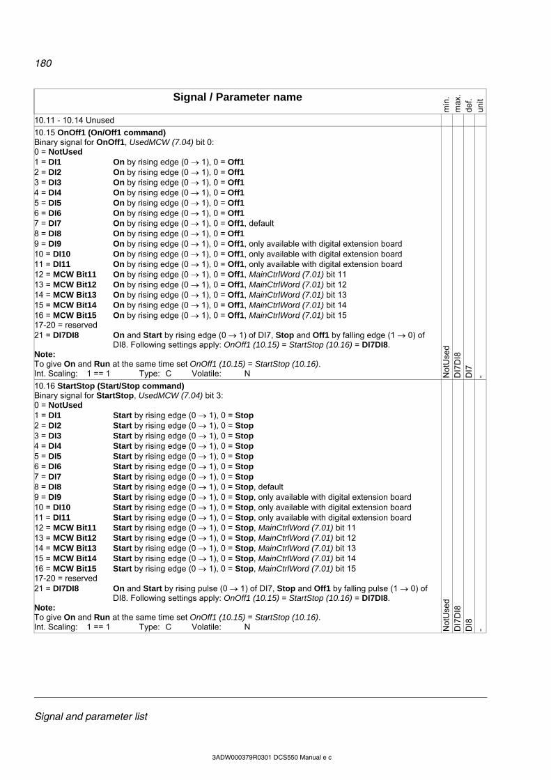
180
Signal and parameter list
3ADW000379R0301 DCS550 Manual e c
Signal / Parameter name
min
. m
ax.
def.
unit
10.11 - 10.14 Unused
10.15 OnOff1 (On/Off1 command) Binary signal for OnOff1, UsedMCW (7.04) bit 0: 0 = NotUsed 1 = DI1 On by rising edge (0 1), 0 = Off1 2 = DI2 On by rising edge (0 1), 0 = Off1 3 = DI3 On by rising edge (0 1), 0 = Off1 4 = DI4 On by rising edge (0 1), 0 = Off1 5 = DI5 On by rising edge (0 1), 0 = Off1 6 = DI6 On by rising edge (0 1), 0 = Off1 7 = DI7 On by rising edge (0 1), 0 = Off1, default 8 = DI8 On by rising edge (0 1), 0 = Off1 9 = DI9 On by rising edge (0 1), 0 = Off1, only available with digital extension board 10 = DI10 On by rising edge (0 1), 0 = Off1, only available with digital extension board 11 = DI11 On by rising edge (0 1), 0 = Off1, only available with digital extension board 12 = MCW Bit11 On by rising edge (0 1), 0 = Off1, MainCtrlWord (7.01) bit 11 13 = MCW Bit12 On by rising edge (0 1), 0 = Off1, MainCtrlWord (7.01) bit 12 14 = MCW Bit13 On by rising edge (0 1), 0 = Off1, MainCtrlWord (7.01) bit 13 15 = MCW Bit14 On by rising edge (0 1), 0 = Off1, MainCtrlWord (7.01) bit 14 16 = MCW Bit15 On by rising edge (0 1), 0 = Off1, MainCtrlWord (7.01) bit 15 17-20 = reserved 21 = DI7DI8 On and Start by rising edge (0 1) of DI7, Stop and Off1 by falling edge (1 0) of
DI8. Following settings apply: OnOff1 (10.15) = StartStop (10.16) = DI7DI8. Note: To give On and Run at the same time set OnOff1 (10.15) = StartStop (10.16). Int. Scaling: 1 == 1 Type: C Volatile: N N
otU
sed
DI7
DI8
D
I7
-
10.16 StartStop (Start/Stop command) Binary signal for StartStop, UsedMCW (7.04) bit 3: 0 = NotUsed 1 = DI1 Start by rising edge (0 1), 0 = Stop 2 = DI2 Start by rising edge (0 1), 0 = Stop 3 = DI3 Start by rising edge (0 1), 0 = Stop 4 = DI4 Start by rising edge (0 1), 0 = Stop 5 = DI5 Start by rising edge (0 1), 0 = Stop 6 = DI6 Start by rising edge (0 1), 0 = Stop 7 = DI7 Start by rising edge (0 1), 0 = Stop 8 = DI8 Start by rising edge (0 1), 0 = Stop, default 9 = DI9 Start by rising edge (0 1), 0 = Stop, only available with digital extension board 10 = DI10 Start by rising edge (0 1), 0 = Stop, only available with digital extension board 11 = DI11 Start by rising edge (0 1), 0 = Stop, only available with digital extension board 12 = MCW Bit11 Start by rising edge (0 1), 0 = Stop, MainCtrlWord (7.01) bit 11 13 = MCW Bit12 Start by rising edge (0 1), 0 = Stop, MainCtrlWord (7.01) bit 12 14 = MCW Bit13 Start by rising edge (0 1), 0 = Stop, MainCtrlWord (7.01) bit 13 15 = MCW Bit14 Start by rising edge (0 1), 0 = Stop, MainCtrlWord (7.01) bit 14 16 = MCW Bit15 Start by rising edge (0 1), 0 = Stop, MainCtrlWord (7.01) bit 15 17-20 = reserved 21 = DI7DI8 On and Start by rising pulse (0 1) of DI7, Stop and Off1 by falling pulse (1 0) of
DI8. Following settings apply: OnOff1 (10.15) = StartStop (10.16) = DI7DI8. Note: To give On and Run at the same time set OnOff1 (10.15) = StartStop (10.16). Int. Scaling: 1 == 1 Type: C Volatile: N N
otU
sed
DI7
DI8
D
I8
-
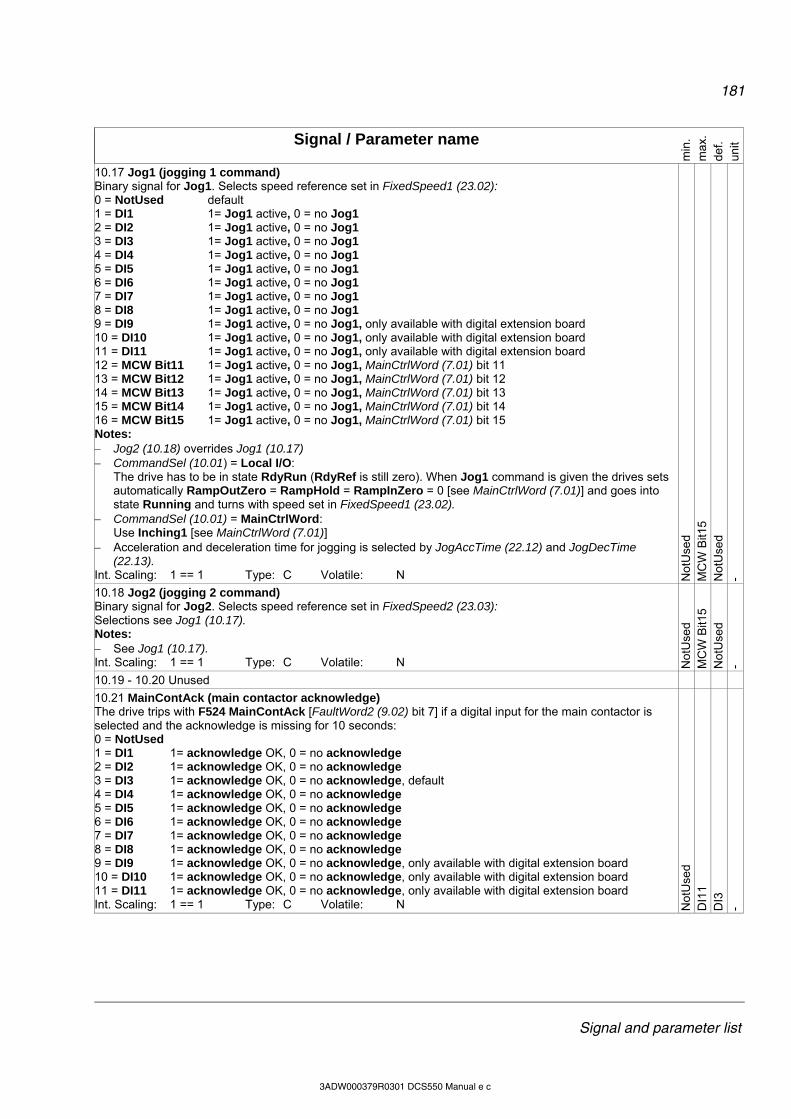
181
Signal and parameter list
3ADW000379R0301 DCS550 Manual e c
Signal / Parameter name
min
. m
ax.
def.
unit
10.17 Jog1 (jogging 1 command) Binary signal for Jog1. Selects speed reference set in FixedSpeed1 (23.02): 0 = NotUsed default 1 = DI1 1= Jog1 active, 0 = no Jog1 2 = DI2 1= Jog1 active, 0 = no Jog1 3 = DI3 1= Jog1 active, 0 = no Jog1 4 = DI4 1= Jog1 active, 0 = no Jog1 5 = DI5 1= Jog1 active, 0 = no Jog1 6 = DI6 1= Jog1 active, 0 = no Jog1 7 = DI7 1= Jog1 active, 0 = no Jog1 8 = DI8 1= Jog1 active, 0 = no Jog1 9 = DI9 1= Jog1 active, 0 = no Jog1, only available with digital extension board 10 = DI10 1= Jog1 active, 0 = no Jog1, only available with digital extension board 11 = DI11 1= Jog1 active, 0 = no Jog1, only available with digital extension board 12 = MCW Bit11 1= Jog1 active, 0 = no Jog1, MainCtrlWord (7.01) bit 11 13 = MCW Bit12 1= Jog1 active, 0 = no Jog1, MainCtrlWord (7.01) bit 12 14 = MCW Bit13 1= Jog1 active, 0 = no Jog1, MainCtrlWord (7.01) bit 13 15 = MCW Bit14 1= Jog1 active, 0 = no Jog1, MainCtrlWord (7.01) bit 14 16 = MCW Bit15 1= Jog1 active, 0 = no Jog1, MainCtrlWord (7.01) bit 15 Notes: Jog2 (10.18) overrides Jog1 (10.17) CommandSel (10.01) = Local I/O:
The drive has to be in state RdyRun (RdyRef is still zero). When Jog1 command is given the drives sets automatically RampOutZero = RampHold = RampInZero = 0 [see MainCtrlWord (7.01)] and goes into state Running and turns with speed set in FixedSpeed1 (23.02).
CommandSel (10.01) = MainCtrlWord: Use Inching1 [see MainCtrlWord (7.01)]
Acceleration and deceleration time for jogging is selected by JogAccTime (22.12) and JogDecTime (22.13).
Int. Scaling: 1 == 1 Type: C Volatile: N Not
Use
d M
CW
Bit1
5 N
otU
sed
-
10.18 Jog2 (jogging 2 command) Binary signal for Jog2. Selects speed reference set in FixedSpeed2 (23.03): Selections see Jog1 (10.17). Notes: See Jog1 (10.17). Int. Scaling: 1 == 1 Type: C Volatile: N N
otU
sed
MC
W B
it15
Not
Use
d -
10.19 - 10.20 Unused
10.21 MainContAck (main contactor acknowledge) The drive trips with F524 MainContAck [FaultWord2 (9.02) bit 7] if a digital input for the main contactor is selected and the acknowledge is missing for 10 seconds: 0 = NotUsed 1 = DI1 1= acknowledge OK, 0 = no acknowledge 2 = DI2 1= acknowledge OK, 0 = no acknowledge 3 = DI3 1= acknowledge OK, 0 = no acknowledge, default 4 = DI4 1= acknowledge OK, 0 = no acknowledge 5 = DI5 1= acknowledge OK, 0 = no acknowledge 6 = DI6 1= acknowledge OK, 0 = no acknowledge 7 = DI7 1= acknowledge OK, 0 = no acknowledge 8 = DI8 1= acknowledge OK, 0 = no acknowledge 9 = DI9 1= acknowledge OK, 0 = no acknowledge, only available with digital extension board 10 = DI10 1= acknowledge OK, 0 = no acknowledge, only available with digital extension board 11 = DI11 1= acknowledge OK, 0 = no acknowledge, only available with digital extension board Int. Scaling: 1 == 1 Type: C Volatile: N N
otU
sed
DI1
1 D
I3
-

182
Signal and parameter list
3ADW000379R0301 DCS550 Manual e c
Signal / Parameter name
min
. m
ax.
def.
unit
10.22 DynBrakeAck (dynamic braking acknowledge) The drive sets A105 DynBrakeAck [AlarmWord1 (9.06) bit 4] if a digital input for dynamic braking is selected and the acknowledge (dynamic braking active) is still present when On [UsedMCW (7.04) bit 3] is set. Selections see MainContAck (10.21). A105 DynBrakeAck [AlarmWord1 (9.06) bit 4] should prevent the drive to be started while dynamic braking is active. Int. Scaling: 1 == 1 Type: C Volatile: N N
otU
sed
DI1
1 N
otU
sed
-
10.23 DC BreakAck (DC breaker acknowledge) The drive sets A103 DC BreakAck [AlarmWord1 (9.06) bit 2] if a digital input for the DC-breaker is selected and the acknowledge is missing. Selections see MainContAck (10.21). The motor will coast if A103 DC BreakAck [AlarmWord1 (9.06) bit 2] is set. Int. Scaling: 1 == 1 Type: C Volatile: N N
otU
sed
DI1
1 N
otU
sed
-
10.24 Unused
10.25 DI1Invert (invert digital input 1) Inversion selection for digital input 1: 0 = Direct 1 = Inverted Int. Scaling: 1 == 1 Type: C Volatile: N D
irect
In
vert
ed
Dire
ct
-
10.26 DI2Invert (invert digital input 2) Inversion selection for digital input 2: 0 = Direct 1 = Inverted Int. Scaling: 1 == 1 Type: C Volatile: N D
irect
In
vert
ed
Dire
ct
-
10.27 DI3Invert (invert digital input 3) Inversion selection for digital input 3: 0 = Direct 1 = Inverted Int. Scaling: 1 == 1 Type: C Volatile: N D
irect
In
vert
ed
Dire
ct
-
10.28 DI4Invert (invert digital input 4) Inversion selection for digital input 4: 0 = Direct 1 = Inverted Int. Scaling: 1 == 1 Type: C Volatile: N D
irect
In
vert
ed
Dire
ct
-
10.29 DI5Invert (invert digital input 5) Inversion selection for digital input 5: 0 = Direct 1 = Inverted Int. Scaling: 1 == 1 Type: C Volatile: N D
irect
In
vert
ed
Dire
ct
-
10.30 DI6Invert (invert digital input 6) Inversion selection for digital input 6: 0 = Direct 1 = Inverted Int. Scaling: 1 == 1 Type: C Volatile: N D
irect
In
vert
ed
Dire
ct
-
10.31 DI7Invert (invert digital input 7) Inversion selection for digital input 7: 0 = Direct 1 = Inverted Int. Scaling: 1 == 1 Type: C Volatile: N D
irect
In
vert
ed
Dire
ct
-
10.32 DI8Invert (invert digital input 8) Inversion selection for digital input 8: 0 = Direct 1 = Inverted Int. Scaling: 1 == 1 Type: C Volatile: N D
irect
In
vert
ed
Dire
ct
-
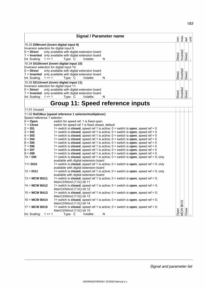
183
Signal and parameter list
3ADW000379R0301 DCS550 Manual e c
Signal / Parameter name
min
. m
ax.
def.
unit
10.33 DI9Invert (invert digital input 9) Inversion selection for digital input 9: 0 = Direct only available with digital extension board 1 = Inverted only available with digital extension board Int. Scaling: 1 == 1 Type: C Volatile: N D
irect
In
vert
ed
Dire
ct
-
10.34 DI10Invert (invert digital input 10) Inversion selection for digital input 10: 0 = Direct only available with digital extension board 1 = Inverted only available with digital extension board Int. Scaling: 1 == 1 Type: C Volatile: N D
irect
In
vert
ed
Dire
ct
-
10.35 DI11Invert (invert digital input 11) Inversion selection for digital input 11: 0 = Direct only available with digital extension board 1 = Inverted only available with digital extension board Int. Scaling: 1 == 1 Type: C Volatile: N D
irect
In
vert
ed
Dire
ct
-
Group 11: Speed reference inputs
11.01 Unused
11.02 Ref1Mux (speed reference 1 selector/multiplexer) Speed reference 1 selector: 0 = Open switch for speed ref. 1 is fixed open 1 = Close switch for speed ref 1 is fixed closed, default 2 = DI1 1= switch is closed, speed ref 1 is active; 0 = switch is open, speed ref = 0 3 = DI2 1= switch is closed, speed ref 1 is active; 0 = switch is open, speed ref = 0 4 = DI3 1= switch is closed, speed ref 1 is active; 0 = switch is open, speed ref = 0 5 = DI4 1= switch is closed, speed ref 1 is active; 0 = switch is open, speed ref = 0 6 = DI5 1= switch is closed, speed ref 1 is active; 0 = switch is open, speed ref = 0 7 = DI6 1= switch is closed, speed ref 1 is active; 0 = switch is open, speed ref = 0 8 = DI7 1= switch is closed, speed ref 1 is active; 0 = switch is open, speed ref = 0 9 = DI8 1= switch is closed, speed ref 1 is active; 0 = switch is open, speed ref = 0 10 = DI9 1= switch is closed, speed ref 1 is active; 0 = switch is open, speed ref = 0; only
available with digital extension board 11= DI10 1= switch is closed, speed ref 1 is active; 0 = switch is open, speed ref = 0; only
available with digital extension board 12 = DI11 1= switch is closed, speed ref 1 is active; 0 = switch is open, speed ref = 0; only
available with digital extension board 13 = MCW Bit11 1= switch is closed, speed ref 1 is active; 0 = switch is open, speed ref = 0;
MainCtrlWord (7.01) bit 11 14 = MCW Bit12 1= switch is closed, speed ref 1 is active; 0 = switch is open, speed ref = 0;
MainCtrlWord (7.01) bit 12 15 = MCW Bit13 1= switch is closed, speed ref 1 is active; 0 = switch is open, speed ref = 0;
MainCtrlWord (7.01) bit 13 16 = MCW Bit14 1= switch is closed, speed ref 1 is active; 0 = switch is open, speed ref = 0;
MainCtrlWord (7.01) bit 14 17 = MCW Bit15 1= switch is closed, speed ref 1 is active; 0 = switch is open, speed ref = 0;
MainCtrlWord (7.01) bit 15 Int. Scaling: 1 == 1 Type: C Volatile: N O
pen
MC
W B
it15
Clo
se
-
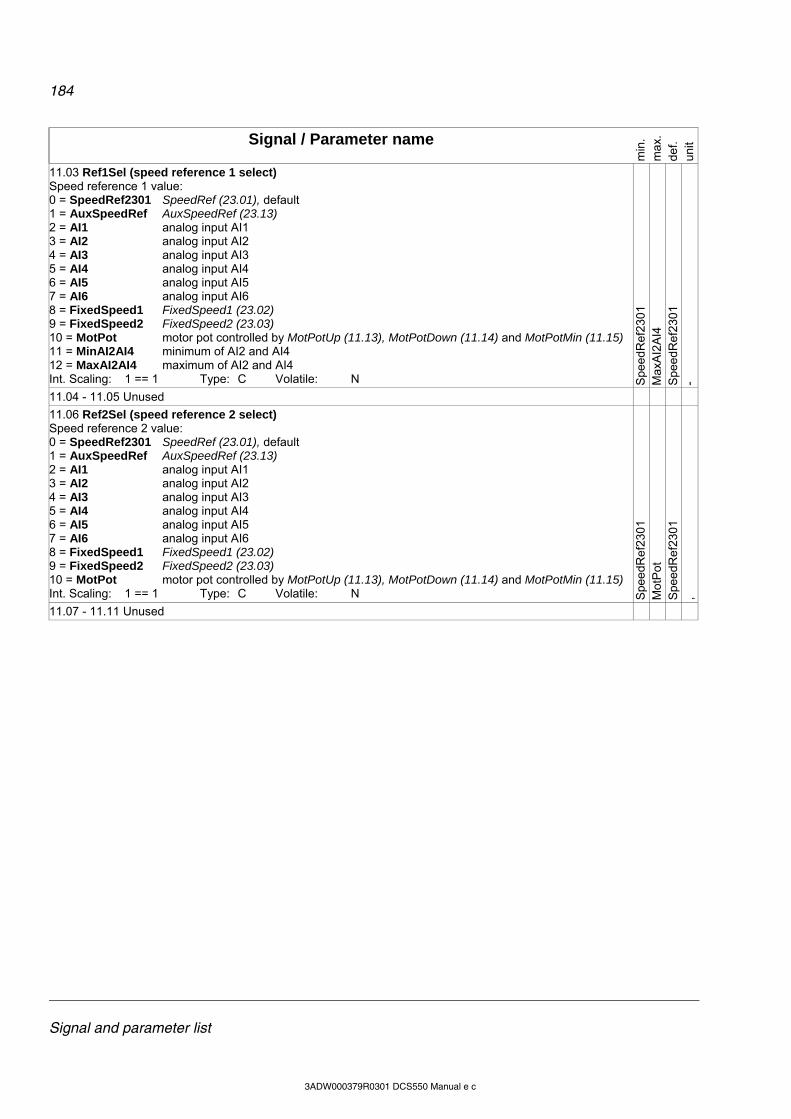
184
Signal and parameter list
3ADW000379R0301 DCS550 Manual e c
Signal / Parameter name
min
. m
ax.
def.
unit
11.03 Ref1Sel (speed reference 1 select) Speed reference 1 value: 0 = SpeedRef2301 SpeedRef (23.01), default 1 = AuxSpeedRef AuxSpeedRef (23.13) 2 = AI1 analog input AI1 3 = AI2 analog input AI2 4 = AI3 analog input AI3 5 = AI4 analog input AI4 6 = AI5 analog input AI5 7 = AI6 analog input AI6 8 = FixedSpeed1 FixedSpeed1 (23.02) 9 = FixedSpeed2 FixedSpeed2 (23.03) 10 = MotPot motor pot controlled by MotPotUp (11.13), MotPotDown (11.14) and MotPotMin (11.15) 11 = MinAI2AI4 minimum of AI2 and AI4 12 = MaxAI2AI4 maximum of AI2 and AI4 Int. Scaling: 1 == 1 Type: C Volatile: N S
pee
dRef
230
1
Max
AI2
AI4
S
pee
dRef
230
1
-
11.04 - 11.05 Unused
11.06 Ref2Sel (speed reference 2 select) Speed reference 2 value: 0 = SpeedRef2301 SpeedRef (23.01), default 1 = AuxSpeedRef AuxSpeedRef (23.13) 2 = AI1 analog input AI1 3 = AI2 analog input AI2 4 = AI3 analog input AI3 5 = AI4 analog input AI4 6 = AI5 analog input AI5 7 = AI6 analog input AI6 8 = FixedSpeed1 FixedSpeed1 (23.02) 9 = FixedSpeed2 FixedSpeed2 (23.03) 10 = MotPot motor pot controlled by MotPotUp (11.13), MotPotDown (11.14) and MotPotMin (11.15) Int. Scaling: 1 == 1 Type: C Volatile: N S
pee
dRef
230
1
Mot
Pot
S
pee
dRef
230
1
,
11.07 - 11.11 Unused
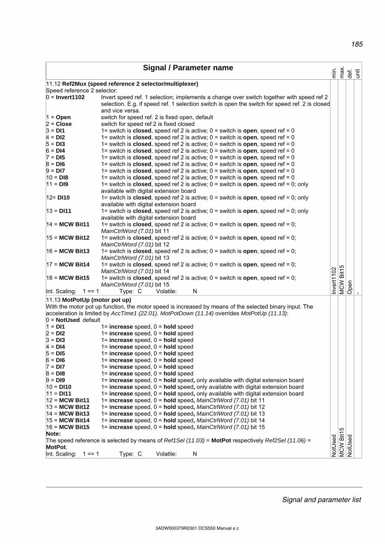
185
Signal and parameter list
3ADW000379R0301 DCS550 Manual e c
Signal / Parameter name
min
. m
ax.
def.
unit
11.12 Ref2Mux (speed reference 2 selector/multiplexer) Speed reference 2 selector: 0 = Invert1102 Invert speed ref. 1 selection; implements a change over switch together with speed ref 2
selection. E.g. if speed ref. 1 selection switch is open the switch for speed ref. 2 is closed and vice versa.
1 = Open switch for speed ref. 2 is fixed open, default 2 = Close switch for speed ref 2 is fixed closed 3 = DI1 1= switch is closed, speed ref 2 is active; 0 = switch is open, speed ref = 0 4 = DI2 1= switch is closed, speed ref 2 is active; 0 = switch is open, speed ref = 0 5 = DI3 1= switch is closed, speed ref 2 is active; 0 = switch is open, speed ref = 0 6 = DI4 1= switch is closed, speed ref 2 is active; 0 = switch is open, speed ref = 0 7 = DI5 1= switch is closed, speed ref 2 is active; 0 = switch is open, speed ref = 0 8 = DI6 1= switch is closed, speed ref 2 is active; 0 = switch is open, speed ref = 0 9 = DI7 1= switch is closed, speed ref 2 is active; 0 = switch is open, speed ref = 0 10 = DI8 1= switch is closed, speed ref 2 is active; 0 = switch is open, speed ref = 0 11 = DI9 1= switch is closed, speed ref 2 is active; 0 = switch is open, speed ref = 0; only
available with digital extension board 12= DI10 1= switch is closed, speed ref 2 is active; 0 = switch is open, speed ref = 0; only
available with digital extension board 13 = DI11 1= switch is closed, speed ref 2 is active; 0 = switch is open, speed ref = 0; only
available with digital extension board 14 = MCW Bit11 1= switch is closed, speed ref 2 is active; 0 = switch is open, speed ref = 0;
MainCtrlWord (7.01) bit 11 15 = MCW Bit12 1= switch is closed, speed ref 2 is active; 0 = switch is open, speed ref = 0;
MainCtrlWord (7.01) bit 12 16 = MCW Bit13 1= switch is closed, speed ref 2 is active; 0 = switch is open, speed ref = 0;
MainCtrlWord (7.01) bit 13 17 = MCW Bit14 1= switch is closed, speed ref 2 is active; 0 = switch is open, speed ref = 0;
MainCtrlWord (7.01) bit 14 18 = MCW Bit15 1= switch is closed, speed ref 2 is active; 0 = switch is open, speed ref = 0;
MainCtrlWord (7.01) bit 15 Int. Scaling: 1 == 1 Type: C Volatile: N In
vert
110
2 M
CW
Bit1
5 O
pen
-
11.13 MotPotUp (motor pot up) With the motor pot up function, the motor speed is increased by means of the selected binary input. The acceleration is limited by AccTime1 (22.01). MotPotDown (11.14) overrides MotPotUp (11.13): 0 = NotUsed default 1 = DI1 1= increase speed, 0 = hold speed 2 = DI2 1= increase speed, 0 = hold speed 3 = DI3 1= increase speed, 0 = hold speed 4 = DI4 1= increase speed, 0 = hold speed 5 = DI5 1= increase speed, 0 = hold speed 6 = DI6 1= increase speed, 0 = hold speed 7 = DI7 1= increase speed, 0 = hold speed 8 = DI8 1= increase speed, 0 = hold speed 9 = DI9 1= increase speed, 0 = hold speed, only available with digital extension board 10 = DI10 1= increase speed, 0 = hold speed, only available with digital extension board 11 = DI11 1= increase speed, 0 = hold speed, only available with digital extension board 12 = MCW Bit11 1= increase speed, 0 = hold speed, MainCtrlWord (7.01) bit 11 13 = MCW Bit12 1= increase speed, 0 = hold speed, MainCtrlWord (7.01) bit 12 14 = MCW Bit13 1= increase speed, 0 = hold speed, MainCtrlWord (7.01) bit 13 15 = MCW Bit14 1= increase speed, 0 = hold speed, MainCtrlWord (7.01) bit 14 16 = MCW Bit15 1= increase speed, 0 = hold speed, MainCtrlWord (7.01) bit 15 Note: The speed reference is selected by means of Ref1Sel (11.03) = MotPot respectively Ref2Sel (11.06) = MotPot. Int. Scaling: 1 == 1 Type: C Volatile: N N
otU
sed
MC
W B
it15
Not
Use
d
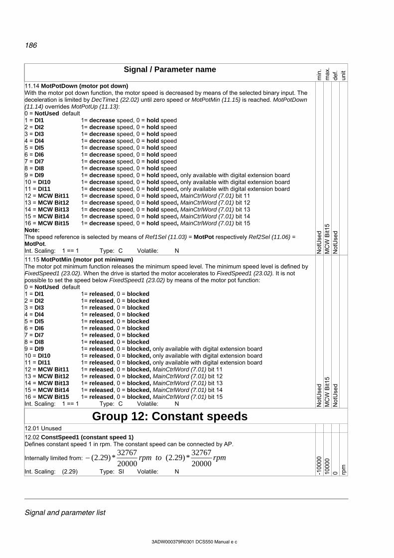
186
Signal and parameter list
3ADW000379R0301 DCS550 Manual e c
Signal / Parameter name
min
. m
ax.
def.
unit
11.14 MotPotDown (motor pot down) With the motor pot down function, the motor speed is decreased by means of the selected binary input. The deceleration is limited by DecTime1 (22.02) until zero speed or MotPotMin (11.15) is reached. MotPotDown (11.14) overrides MotPotUp (11.13): 0 = NotUsed default 1 = DI1 1= decrease speed, 0 = hold speed 2 = DI2 1= decrease speed, 0 = hold speed 3 = DI3 1= decrease speed, 0 = hold speed 4 = DI4 1= decrease speed, 0 = hold speed 5 = DI5 1= decrease speed, 0 = hold speed 6 = DI6 1= decrease speed, 0 = hold speed 7 = DI7 1= decrease speed, 0 = hold speed 8 = DI8 1= decrease speed, 0 = hold speed 9 = DI9 1= decrease speed, 0 = hold speed, only available with digital extension board 10 = DI10 1= decrease speed, 0 = hold speed, only available with digital extension board 11 = DI11 1= decrease speed, 0 = hold speed, only available with digital extension board 12 = MCW Bit11 1= decrease speed, 0 = hold speed, MainCtrlWord (7.01) bit 11 13 = MCW Bit12 1= decrease speed, 0 = hold speed, MainCtrlWord (7.01) bit 12 14 = MCW Bit13 1= decrease speed, 0 = hold speed, MainCtrlWord (7.01) bit 13 15 = MCW Bit14 1= decrease speed, 0 = hold speed, MainCtrlWord (7.01) bit 14 16 = MCW Bit15 1= decrease speed, 0 = hold speed, MainCtrlWord (7.01) bit 15 Note: The speed reference is selected by means of Ref1Sel (11.03) = MotPot respectively Ref2Sel (11.06) = MotPot. Int. Scaling: 1 == 1 Type: C Volatile: N N
otU
sed
MC
W B
it15
Not
Use
d
11.15 MotPotMin (motor pot minimum) The motor pot minimum function releases the minimum speed level. The minimum speed level is defined by FixedSpeed1 (23.02). When the drive is started the motor accelerates to FixedSpeed1 (23.02). It is not possible to set the speed below FixedSpeed1 (23.02) by means of the motor pot function: 0 = NotUsed default 1 = DI1 1= released, 0 = blocked 2 = DI2 1= released, 0 = blocked 3 = DI3 1= released, 0 = blocked 4 = DI4 1= released, 0 = blocked 5 = DI5 1= released, 0 = blocked 6 = DI6 1= released, 0 = blocked 7 = DI7 1= released, 0 = blocked 8 = DI8 1= released, 0 = blocked 9 = DI9 1= released, 0 = blocked, only available with digital extension board 10 = DI10 1= released, 0 = blocked, only available with digital extension board 11 = DI11 1= released, 0 = blocked, only available with digital extension board 12 = MCW Bit11 1= released, 0 = blocked, MainCtrlWord (7.01) bit 11 13 = MCW Bit12 1= released, 0 = blocked, MainCtrlWord (7.01) bit 12 14 = MCW Bit13 1= released, 0 = blocked, MainCtrlWord (7.01) bit 13 15 = MCW Bit14 1= released, 0 = blocked, MainCtrlWord (7.01) bit 14 16 = MCW Bit15 1= released, 0 = blocked, MainCtrlWord (7.01) bit 15 Int. Scaling: 1 == 1 Type: C Volatile: N N
otU
sed
MC
W B
it15
Not
Use
d
Group 12: Constant speeds
12.01 Unused
12.02 ConstSpeed1 (constant speed 1) Defines constant speed 1 in rpm. The constant speed can be connected by AP.
Internally limited from: rpmtorpm20000
32767*)29.2(
20000
32767*)29.2(
Int. Scaling: (2.29) Type: SI Volatile: N -100
00
100
00
0 rpm
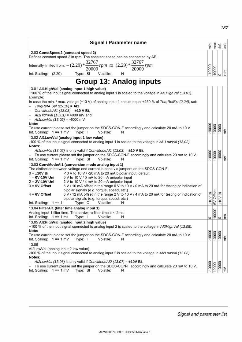
187
Signal and parameter list
3ADW000379R0301 DCS550 Manual e c
Signal / Parameter name
min
. m
ax.
def.
unit
12.03 ConstSpeed2 (constant speed 2) Defines constant speed 2 in rpm. The constant speed can be connected by AP.
Internally limited from: rpmtorpm20000
32767*)29.2(
20000
32767*)29.2(
Int. Scaling: (2.29) Type: SI Volatile: N -100
00
100
00
0 rpm
Group 13: Analog inputs
13.01 AI1HighVal (analog input 1 high value) +100 % of the input signal connected to analog input 1 is scaled to the voltage in AI1HighVal (13.01). Example: In case the min. / max. voltage (10 V) of analog input 1 should equal 250 % of TorqRefExt (2.24), set: TorqRefA Sel (25.10) = AI1 ConvModeAI1 (13.03) = 10 V Bi, AI1HighVal (13.01) = 4000 mV and AI1LowVal (13.02) = -4000 mV Note: To use current please set the jumper on the SDCS-CON-F accordingly and calculate 20 mA to 10 V. Int. Scaling: 1 == 1 mV Type: I Volatile: N -1
0000
10
000
10
000
m
V
13.02 AI1LowVal (analog input 1 low value) -100 % of the input signal connected to analog input 1 is scaled to the voltage in AI1LowVal (13.02). Notes: AI1LowVal (13.02) is only valid if ConvModeAI1 (13.03) = 10 V Bi. To use current please set the jumper on the SDCS-CON-F accordingly and calculate 20 mA to 10 V. Int. Scaling: 1 == 1 mV Type: SI Volatile: N -1
0000
10
000
-1
0000
m
V
13.03 ConvModeAI1 (conversion mode analog input 1) The distinction between voltage and current is done via jumpers on the SDCS-CON-F: 0 = 10V Bi -10 V to 10 V / -20 mA to 20 mA bipolar input, default 1 = 0V-10V Uni 0 V to 10 V / 0 mA to 20 mA unipolar input 2 = 2V-10V Uni 2 V to 10 V / 4 mA to 20 mA unipolar input 3 = 5V Offset 5 V / 10 mA offset in the range 0 V to 10 V / 0 mA to 20 mA for testing or indication of
bipolar signals (e.g. torque, speed, etc.) 4 = 6V Offset 6 V / 12 mA offset in the range 2 V to 10 V / 4 mA to 20 mA for testing or indication of
bipolar signals (e.g. torque, speed, etc.) Int. Scaling: 1 == 1 Type: C Volatile: N 1
0V B
i 6V
Offs
et
10V
Bi
-
13.04 FilterAI1 (filter time analog input 1) Analog input 1 filter time. The hardware filter time is 2ms. Int. Scaling: 1 == 1 ms Type: I Volatile: N 0 10
000
0 m
s 13.05 AI2HighVal (analog input 2 high value) +100 % of the input signal connected to analog input 2 is scaled to the voltage in AI2HighVal (13.05). Note: To use current please set the jumper on the SDCS-CON-F accordingly and calculate 20 mA to 10 V. Int. Scaling: 1 == 1 mV Type: I Volatile: N -1
0000
10
000
10
000
m
V
13.06 AI2LowVal (analog input 2 low value) -100 % of the input signal connected to analog input 2 is scaled to the voltage in AI2LowVal (13.06). Notes: AI2LowVal (13.06) is only valid if ConvModeAI2 (13.07) = 10V Bi. To use current please set the jumper on the SDCS-CON-F accordingly and calculate 20 mA to 10 V. Int. Scaling: 1 == 1 mV Type: SI Volatile: N -1
0000
10
000
-1
0000
m
V
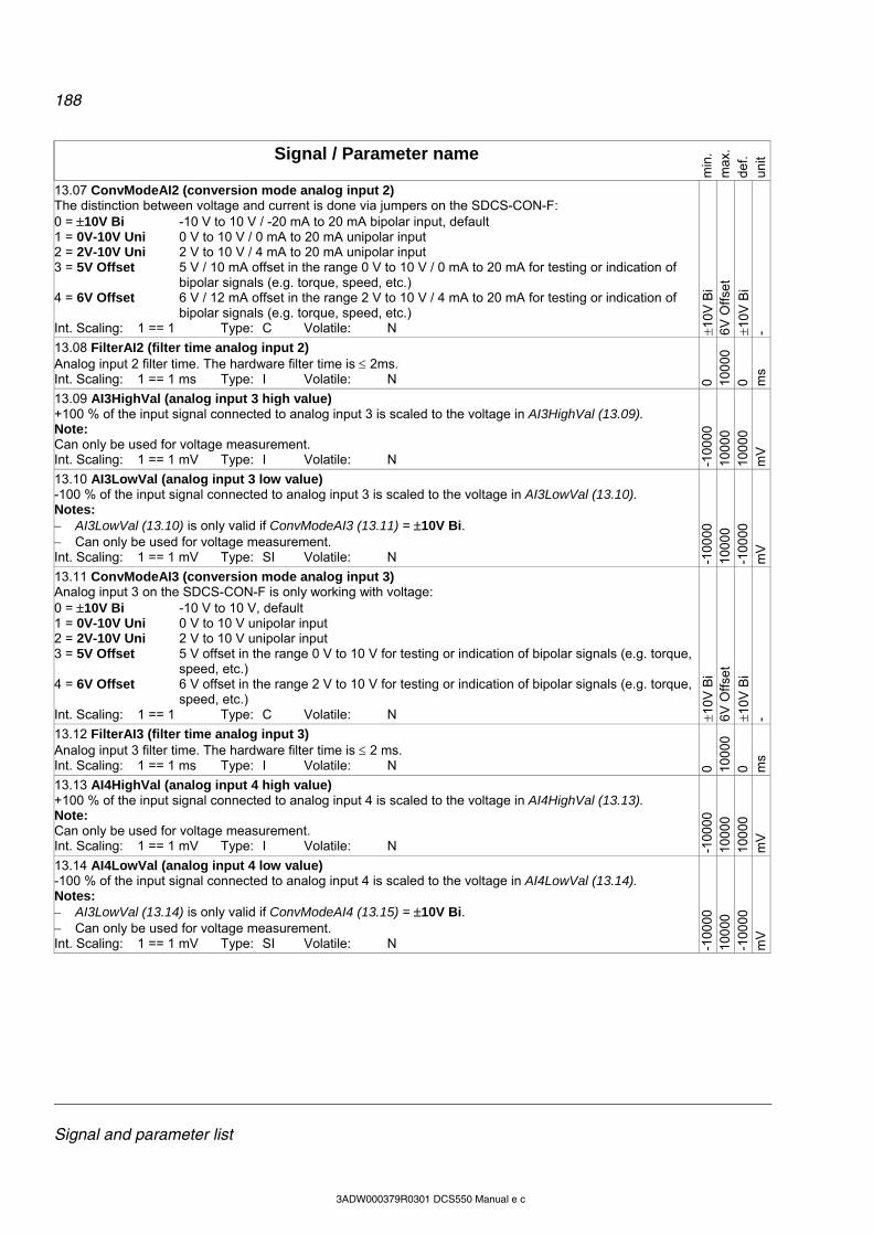
188
Signal and parameter list
3ADW000379R0301 DCS550 Manual e c
Signal / Parameter name
min
. m
ax.
def.
unit
13.07 ConvModeAI2 (conversion mode analog input 2) The distinction between voltage and current is done via jumpers on the SDCS-CON-F: 0 = 10V Bi -10 V to 10 V / -20 mA to 20 mA bipolar input, default 1 = 0V-10V Uni 0 V to 10 V / 0 mA to 20 mA unipolar input 2 = 2V-10V Uni 2 V to 10 V / 4 mA to 20 mA unipolar input 3 = 5V Offset 5 V / 10 mA offset in the range 0 V to 10 V / 0 mA to 20 mA for testing or indication of
bipolar signals (e.g. torque, speed, etc.) 4 = 6V Offset 6 V / 12 mA offset in the range 2 V to 10 V / 4 mA to 20 mA for testing or indication of
bipolar signals (e.g. torque, speed, etc.) Int. Scaling: 1 == 1 Type: C Volatile: N 1
0V B
i 6V
Offs
et
10V
Bi
-
13.08 FilterAI2 (filter time analog input 2) Analog input 2 filter time. The hardware filter time is 2ms. Int. Scaling: 1 == 1 ms Type: I Volatile: N 0 10
000
0 m
s
13.09 AI3HighVal (analog input 3 high value) +100 % of the input signal connected to analog input 3 is scaled to the voltage in AI3HighVal (13.09). Note: Can only be used for voltage measurement. Int. Scaling: 1 == 1 mV Type: I Volatile: N -1
0000
10
000
10
000
m
V
13.10 AI3LowVal (analog input 3 low value) -100 % of the input signal connected to analog input 3 is scaled to the voltage in AI3LowVal (13.10). Notes: AI3LowVal (13.10) is only valid if ConvModeAI3 (13.11) = 10V Bi. Can only be used for voltage measurement. Int. Scaling: 1 == 1 mV Type: SI Volatile: N -1
0000
10
000
-1
0000
m
V
13.11 ConvModeAI3 (conversion mode analog input 3) Analog input 3 on the SDCS-CON-F is only working with voltage: 0 = 10V Bi -10 V to 10 V, default 1 = 0V-10V Uni 0 V to 10 V unipolar input 2 = 2V-10V Uni 2 V to 10 V unipolar input 3 = 5V Offset 5 V offset in the range 0 V to 10 V for testing or indication of bipolar signals (e.g. torque,
speed, etc.) 4 = 6V Offset 6 V offset in the range 2 V to 10 V for testing or indication of bipolar signals (e.g. torque,
speed, etc.) Int. Scaling: 1 == 1 Type: C Volatile: N 1
0V B
i 6V
Offs
et
10V
Bi
-
13.12 FilterAI3 (filter time analog input 3) Analog input 3 filter time. The hardware filter time is 2 ms. Int. Scaling: 1 == 1 ms Type: I Volatile: N 0 10
000
0 m
s
13.13 AI4HighVal (analog input 4 high value) +100 % of the input signal connected to analog input 4 is scaled to the voltage in AI4HighVal (13.13). Note: Can only be used for voltage measurement. Int. Scaling: 1 == 1 mV Type: I Volatile: N -1
0000
10
000
10
000
m
V
13.14 AI4LowVal (analog input 4 low value) -100 % of the input signal connected to analog input 4 is scaled to the voltage in AI4LowVal (13.14). Notes: AI3LowVal (13.14) is only valid if ConvModeAI4 (13.15) = 10V Bi. Can only be used for voltage measurement. Int. Scaling: 1 == 1 mV Type: SI Volatile: N -1
0000
10
000
-1
0000
m
V
189
Signal and parameter list
3ADW000379R0301 DCS550 Manual e c
Signal / Parameter name
min
. m
ax.
def.
unit
13.15 ConvModeAI4 (conversion mode analog input 4) Analog input 4 on the SDCS-CON-F is only working with voltage: 0 = 10V Bi -10 V to 10 V bipolar input, default 1 = 0V-10V Uni 0 V to 10 V unipolar input 2 = 2V-10V Uni 2 V to 10 V unipolar input 3 = 5V Offset 5 V offset in the range 0 V to 10 V for testing or indication of bipolar signals (e.g. torque,
speed, etc.) 4 = 6V Offset 6 V offset in the range 2 V to 10 V for testing or indication of bipolar signals (e.g. torque,
speed, etc.) Int. Scaling: 1 == 1 Type: C Volatile: N 1
0V B
i 6V
Offs
et
10V
Bi
-
13.16 FilterAI4 (filter time analog input 4) Analog input 4 filter time. The hardware filter time is 2 ms. Int. Scaling: 1 == 1 ms Type: I Volatile: N 0 10
000
0 m
s
13.17 – 13.20 Unused
13.21 AI5HighVal (analog input 5 high value) +100 % of the input signal connected to analog input 5 is scaled to the voltage in AI5HighVal (13.21). Note: To use current please set the DIP-switches (RAIO-01) accordingly and calculate 20 mA to 10 V. Int. Scaling: 1 == 1 mV Type: I Volatile: N -1
0000
10
000
10
000
m
V
13.22 AI5LowVal (analog input 5 low value) -100 % of the input signal connected to analog input 5 is scaled to the voltage in AIO5LowVal (13.22). Notes: AI5LowVal (13.22) is only valid if ConvModeAI5 (13.23) = 10V Bi. To use current please set the DIP-switches (RAIO-01) accordingly and calculate 20 mA to 10 V. Int. Scaling: 1 == 1 mV Type: SI Volatile: N -1
0000
10
000
-1
0000
m
V
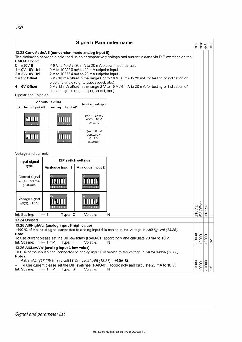
190
Signal and parameter list
3ADW000379R0301 DCS550 Manual e c
Signal / Parameter name
min
. m
ax.
def.
unit
13.23 ConvModeAI5 (conversion mode analog input 5) The distinction between bipolar and unipolar respectively voltage and current is done via DIP-switches on the RAIO-01 board: 0 = 10V Bi -10 V to 10 V / -20 mA to 20 mA bipolar input, default 1 = 0V-10V Uni 0 V to 10 V / 0 mA to 20 mA unipolar input 2 = 2V-10V Uni 2 V to 10 V / 4 mA to 20 mA unipolar input 3 = 5V Offset 5 V / 10 mA offset in the range 0 V to 10 V / 0 mA to 20 mA for testing or indication of
bipolar signals (e.g. torque, speed, etc.) 4 = 6V Offset 6 V / 12 mA offset in the range 2 V to 10 V / 4 mA to 20 mA for testing or indication of
bipolar signals (e.g. torque, speed, etc.) Bipolar and unipolar:
Voltage and current:
Int. Scaling: 1 == 1 Type: C Volatile: N 1
0V B
i 6V
Offs
et
10V
Bi
-
13.24 Unused
13.25 AI6HighVal (analog input 6 high value) +100 % of the input signal connected to analog input 6 is scaled to the voltage in AI6HighVal (13.25). Note: To use current please set the DIP-switches (RAIO-01) accordingly and calculate 20 mA to 10 V. Int. Scaling: 1 == 1 mV Type: I Volatile: N -1
0000
10
000
10
000
m
V
13.26 AI6LowVal (analog input 6 low value) -100 % of the input signal connected to analog input 6 is scaled to the voltage in AIO6LowVal (13.26). Notes: AI6LowVal (13.26) is only valid if ConvModeAI6 (13.27) = 10V Bi. To use current please set the DIP-switches (RAIO-01) accordingly and calculate 20 mA to 10 V. Int. Scaling: 1 == 1 mV Type: SI Volatile: N -1
0000
10
000
-1
0000
m
V

191
Signal and parameter list
3ADW000379R0301 DCS550 Manual e c
Signal / Parameter name
min
. m
ax.
def.
unit
13.27 ConvModeAI6 (conversion mode analog input 6) The distinction between bipolar and unipolar respectively voltage and current is done via DIP-switches on the RAIO-01 board: 0 = 10V Bi -10 V to 10 V / -20 mA to 20 mA bipolar input, default 1 = 0V-10V Uni 0 V to 10 V / 0 mA to 20 mA unipolar input 2 = 2V-10V Uni 2 V to 10 V / 4 mA to 20 mA unipolar input 3 = 5V Offset 5 V / 10 mA offset in the range 0 V to 10 V / 0 mA to 20 mA for testing or indication of
bipolar signals (e.g. torque, speed, etc.) 4 = 6V Offset 6 V / 12 mA offset in the range 2 V to 10 V / 4 mA to 20 mA for testing or indication of
bipolar signals (e.g. torque, speed, etc.) Int. Scaling: 1 == 1 Type: C Volatile: N 1
0V B
i 6V
Offs
et
10V
Bi
-
Group 14: Digital outputs
14.01 DO1Index (digital output 1 index) Digital output 1 is controlled by a selectable bit - see DO1BitNo (14.02) - of the source (signal/parameter) selected with this parameter. The format is -xxyy, with: - = invert digital output, xx = group and yy = index. Examples: If DO1Index (14.01) = 801 (main status word) and DO1BitNo (14.02) = 1 (RdyRun) digital output 1 is high
when the drive is RdyRun. If DO1Index (14.01) = -801 (main status word) and DO1BitNo (14.02) = 3 (Tripped) digital output 1 is high
when the drive is not faulty. Digital output 1 default setting is: command FansOn CurCtrlStat1 (6.03) bit 0. Int. Scaling: 1 == 1 Type: SI Volatile: N -9
999
999
9 60
3 -
14.02 DO1BitNo (digital output 1 bit number) Bit number of the signal/parameter selected with DO1Index (14.02). Int. Scaling: 1 == 1 Type: I Volatile: N 0 15
0 -
14.03 DO2Index (digital output 2 index) Digital output 2 is controlled by a selectable bit - see DO2BitNo (14.04) - of the source (signal/parameter) selected with this parameter. The format is -xxyy, with: - = invert digital output, xx = group and yy = index. Int. Scaling: 1 == 1 Type: SI Volatile: N -9
999
999
9 0 -
14.04 DO2BitNo (digital output 2 bit number) Bit number of the signal/parameter selected with DO2Index (14.03). Int. Scaling: 1 == 1 Type: I Volatile: N 0 15
0 -
14.05 DO3Index (digital output 3 index) Digital output 3 is controlled by a selectable bit - see DO3BitNo (14.06) - of the source (signal/parameter) selected with this parameter. The format is -xxyy, with: - = invert digital output, xx = group and yy = index. Digital output 3 default setting is: command MainContactorOn CurCtrlStat1 (6.03) bit 7. Int. Scaling: 1 == 1 Type: SI Volatile: N -9
999
999
9 60
3 -
14.06 DO3BitNo (digital output 3 bit number) Bit number of the signal/parameter selected with DO3Index (14.05). Int. Scaling: 1 == 1 Type: I Volatile: N 0 15
7 -
14.07 DO4Index (digital output 4 index) Digital output 4 is controlled by a selectable bit - see DO4BitNo (14.08) - of the source (signal/parameter) selected with this parameter. The format is -xxyy, with: - = invert digital output, xx = group and yy = index. Int. Scaling: 1 == 1 Type: SI Volatile: N -9
999
999
9 0 -
14.08 DO4BitNo (digital output 4 bit number) Bit number of the signal/parameter selected with DO4Index (14.07). Int. Scaling: 1 == 1 Type: I Volatile: N 0 15
0 -
14.09 - 14.14 Unused
14.15 DO8Index (digital output 8 index) Digital output 8 is controlled by a selectable bit - see DO8BitNo (14.16) - of the source (signal/parameter) selected with this parameter. The format is -xxyy, with: - = invert digital output, xx = group and yy = index. Digital output 8 default setting is: command MainContactorOn CurCtrlStat1 (6.03) bit 7 Int. Scaling: 1 == 1 Type: SI Volatile: N -9
999
999
9 60
3 -
192
Signal and parameter list
3ADW000379R0301 DCS550 Manual e c
Signal / Parameter name
min
. m
ax.
def.
unit
14.16 DO8BitNo (digital output 8 bit number) Bit number of the signal/parameter selected with DO8Index (14.15). Int. Scaling: 1 == 1 Type: I Volatile: N 0 15
7 -
Group 15: Analog outputs
15.01 IndexAO1 (analog output 1 index) Analog output 1 is controlled by a source (signal/parameter) selected with IndexAO1 (15.01). The format is -xxyy, with: - = negate analog output, xx = group and yy = index. Int. Scaling: 1 == 1 Type: SI Volatile: N -9
999
999
9 0 -
15.02 CtrlWordAO1 (control word analog output 1) Analog output 1 can be written to via CtrlWordAO1 (15.02) using AP or overriding control if IndexAO1 (15.01) is set to zero. Further description see group 19 Data Storage. Int. Scaling: 1 == 1 Type: SI Volatile: Y -3
276
8 32
767
0 -
15.03 ConvModeAO1 (convert mode analog output 1) Analog output 1 signal offset: 0 = 10V Bi -10 V to 10 V bipolar output, default 1 = 0V-10V Uni 0 V to 10 V unipolar output 2 = 2V-10V Uni 2 V to 10 V unipolar output 3 = 5V Offset 5 V offset in the range 0 V to 10 V for testing or indication of bipolar signals (e.g. torque,
speed, etc.) 4 = 6V Offset 6 V offset in the range 2 V to 10 V for testing or indication of bipolar signals (e.g. torque,
speed, etc.) 5 = 0V-10V Abs absolute 0 V to 10 V unipolar output (negative values are shown positive) Int. Scaling: 1 == 1 Type: C Volatile: N 1
0V B
i 0V
-10V
Abs
10V
Bi
-
15.04 FilterAO1 (filter analog output 1) Analog output 1 filter time. Int. Scaling: 1 == 1 ms Type: I Volatile: N 0 10
000
0 m
s
15.05 ScaleAO1 (scaling analog output 1) 100 % of the signal/parameter selected with IndexAO1 (15.01) is scaled to the voltage in ScaleAO1 (15.05). Example: In case the min. / max. voltage (10 V) of analog output 1 should equal 250 % of TorqRefUsed (2.13), set: IndexAO1 (15.01) = 213, ConvModeAO1 (15.03) = 10V Bi and ScaleAO1 (15.05) = 4000 mV Int. Scaling: 1 == 1 mV Type: I Volatile: N 0 10
000
10
000
m
V
15.06 IndexAO2 (analog output 2 index) Analog output 2 is controlled by a source (signal/parameter) selected with IndexAO2 (15.06). The format is -xxyy, with: - = negate analog output, xx = group and yy = index. Int. Scaling: 1 == 1 Type: SI Volatile: N -9
999
999
9 0 -
15.07 CtrlWordAO2 (control word analog output 2) Analog output 2 can be written to via CtrlWordAO2 (15.07) using AP or overriding control if IndexAO2 (15.06) is set to zero. Further description see group 19 Data Storage. Int. Scaling: 1 == 1 Type: SI Volatile: Y -3
276
8 32
767
0 -
15.08 ConvModeAO2 (convert mode analog output 2) Analog output 2 signal offset: 0 = 10V Bi -10 V to 10 V bipolar output, default 1 = 0V-10V Uni 0 V to 10 V unipolar output 2 = 2V-10V Uni 2 V to 10 V unipolar output 3 = 5V Offset 5 V offset in the range 0 V to 10 V for testing or indication of bipolar signals (e.g. torque,
speed, etc.) 4 = 6V Offset 6 V offset in the range 2 V to 10 V for testing or indication of bipolar signals (e.g. torque,
speed, etc.) 5 = 0V-10V Abs absolute 0 V to 10 V unipolar output (negative values are shown positive) Int. Scaling: 1 == 1 Type: C Volatile: N 1
0V B
i 0V
-10V
Abs
10V
Bi
-
193
Signal and parameter list
3ADW000379R0301 DCS550 Manual e c
Signal / Parameter name
min
. m
ax.
def.
unit
15.09 FilterAO2 (filter analog output 2) Analog output 2 filter time. Int. Scaling: 1 == 1 ms Type: I Volatile: N 0 10
000
0 m
s
15.10 ScaleAO2 (scaling analog output 2) 100 % of the signal/parameter selected with IndexAO2 (15.06) is scaled to the voltage in ScaleAO2 (15.10). Int. Scaling: 1 == 1 mV Type: I Volatile: N 0 10
000
10
000
m
V
15.11 IndexAO3 (analog output 3 index) Analog output 3 is controlled by a source (signal/parameter) selected with IndexAO3 (15.11). The format is -xxyy, with: - = negate analog output, xx = group and yy = index. Int. Scaling: 1 == 1 Type: SI Volatile: N -9
999
999
9 - -
15.12 CtrlWordAO3 (control word analog output 3 Analog output 3 can be written to via CtrlWordAO3 (15.12) using AP or overriding control if IndexAO3 (15.11) is set to zero. Further description see group 19 Data Storage. Int. Scaling: 1 == 1 Type: SI Volatile: Y -3
2768
32
767
0 -
15.13 ConvModeAO3 (convert mode analog output 3) Analog output 3 signal offset: 0 = 0mA-20mA Uni 0 mA to 20 mA unipolar output 1 = 4mA-20mA Uni 4 mA to 20 mA unipolar output, default 2 = 10mA Offset 10 mA offset in the range 0 mA to 20 mA for testing or indication of bipolar signals (e.g.
torque, speed, etc.) 3 = 12mA Offset 12 mA offset in the range 4 mA to 20 mA for testing or indication of bipolar signals (e.g.
torque, speed, etc.) 4 = 0mA-20mA Abs absolute 0 mA to 20 mA unipolar output (negative values are shown positive) Int. Scaling: 1 == 1 Type: C Volatile: N 4m
A-2
0mA
Uni
0m
A-2
0mA
Abs
4m
A-2
0mA
Uni
-
15.14 FilterAO3 (filter analog output 3) Analog output 3 filter time. Int. Scaling: 1 == 1 ms Type: I Volatile: N 0 10
000
0 m
s
15.15 ScaleAO3 (scaling analog output 3) 100 % of the signal/parameter selected with IndexAO3 (15.11) is scaled to the current in ScaleAO3 (15.15). Int. Scaling: 1 == 1 Type: I Volatile: N 0 20
20
m
A
15.16 IndexAO4 (analog output 4 index) Analog output 4 is controlled by a source (signal/parameter) selected with IndexAO4 (15.16). The format is -xxyy, with: - = negate analog output, xx = group and yy = index. Int. Scaling: 1 == 1 Type: SI Volatile: N -9
999
999
9
15.17 CtrlWordAO4 (control word analog output 4) Analog output 4 can be written to via CtrlWordAO4 (15.17) using AP or overriding control if IndexAO4 (15.17) is set to zero. Further description see group 19 Data Storage. Int. Scaling: 1 == 1 Type: SI Volatile: Y -3
2768
32
767
0 -
15.18 ConvModeAO4 (convert mode analog output 4) Analog output 4 signal offset: 0 = 0mA-20mA Uni 0 mA to 20 mA unipolar output 1 = 4mA-20mA Uni 4 mA to 20 mA unipolar output, default 2 = 10mA Offset 10 mA offset in the range 0 mA to 20 mA for testing or indication of bipolar signals (e.g.
torque, speed, etc.) 3 = 12mA Offset 12 mA offset in the range 4 mA to 20 mA for testing or indication of bipolar signals (e.g.
torque, speed, etc.) 4 = 0mA-20mA Abs absolute 0 mA to 20 mA unipolar output (negative values are shown positive) Int. Scaling: 1 == 1 Type: C Volatile: N 4m
A-2
0mA
Uni
0m
A-2
0mA
Abs
4m
A-2
0mA
Uni
-
15.19 FilterAO4 (filter analog output 4) Analog output 4 filter time. Int. Scaling: 1 == 1 ms Type: I Volatile: N 0 10
000
0 m
s
15.20 ScaleAO4 (scaling analog output 4) 100 % of the signal/parameter selected with IndexAO4 (15.16) is scaled to the current in ScaleAO4 (15.20). Int. Scaling: 1 == 1 Type: I Volatile: N 0 20
20
m
A

194
Signal and parameter list
3ADW000379R0301 DCS550 Manual e c
Signal / Parameter name
min
. m
ax.
def.
unit
Group 16: System control inputs
16.01 Unused
16.02 ParLock (parameter lock) The user can lock all parameters by means of ParLock (16.02) and SysPassCode (16.03). To lock parameters set SysPassCode (16.03) to the desired value and change ParLock (16.02) from Open to Locked. Unlocking of parameters is only possible if the proper pass code (the value that was present during locking) is used. To open parameters set SysPassCode (16.03) to the proper value and change ParLock (16.02) from Locked to Open. After the parameters are locked or opened the value in SysPassCode (16.03) is automatically changed to 0: 0 = Open parameter change possible, default 1 = Locked parameter change not possible Int. Scaling: 1 == 1 Type: C Volatile: N O
pen
Lock
ed
Ope
n -
16.03 SysPassCode (system pass code) The SysPassCode (16.03) is a number between 1 and 30,000 to lock all parameters by means of ParLock (16.02). After using Open or Locked SysPassCode (16.03) is automatically set back to zero. Attention: Do not forget the pass code! Int. Scaling: 1 == 1 Type: I Volatile: Y 0 30
000
0 -
16.04 LocLock (local lock) Local control can be disabled by setting LocLock (16.04) to True. If LocLock (16.04) is released in local control, it becomes valid after the next changeover to remote control. No pass code is required to change LocLock (16.04): 0 = False local control released, default 1 = True local control blocked Int. Scaling: 1 == 1 Type: C Volatile: N F
alse
T
rue
Fal
se
-
16.05 Unused
16.06 ParApplSave (save parameters) If parameters are written to cyclic, e.g. from an overriding control, they are only stored in the RAM and not in the flash. By means of ParApplSave (16.06), all parameter values are saved from the RAM into the flash: 0 = Done parameters are saved, default 1 = Save saves the actual used parameters into the flash After the action is finished ParApplSave (16.06) is changed back to Done. This will take max. 1 second. Note: Do not use the parameter save function unnecessarily Note: Parameters changed by DCS Control Panel or commissioning tools are immediately saved into the flash. Int. Scaling: 1 == 1 Type: C Volatile: Y D
one
Sav
e D
one
-
16.07 - 16.10 Unused
16.11 SetSystemTime (set the drive’s system time) Sets the time of the converter in minutes. The system time can be either set by means of SetSystemTime (16.11) or via the DCS Control Panel. Int. Scaling: 1 == 1 min Type: I Volatile: Y 0 64
000
0 m
in
16.12 - 16.13 Unused
16.14 ToolLinkConfig (tool link configuration) The communication speed of the serial communication for the commissioning tool and the application program tool can be selected with ToolLinkConfig (16.14): 0 = 9600 9600 Baud 1 = 19200 19200 Baud 2 = 38400 38400 Baud, default 3 = 57600 57600 Baud 4 = 115200 115200 Baud If ToolLinkConfig (16.14) is changed its new value is taken over after the next power up. Int. Scaling: 1 == 1 Type: C Volatile: N 96
00
115
200
384
00
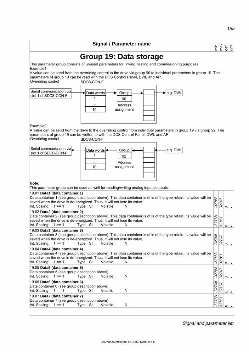
195
Signal and parameter list
3ADW000379R0301 DCS550 Manual e c
Signal / Parameter name
min
. m
ax.
def.
unit
Group 19: Data storage
This parameter group consists of unused parameters for linking, testing and commissioning purposes. Example1: A value can be send from the overriding control to the drive via group 90 to individual parameters in group 19. The parameters of group 19 can be read with the DCS Control Panel, DWL and AP.
e.g. DWLGroupData words
Overriding control
90
Address assignment
SDCS-CON-F
Serial communication viaslot 1 of SDCS-CON-F
1
...
10
Example2: A value can be send from the drive to the overriding control from individual parameters in group 19 via group 92. The parameters of group 19 can be written to with the DCS Control Panel, DWL and AP.
e.g. DWLGroupData words
Overriding control
92
Address assignment
SDCS-CON-F
Serial communication viaslot 1 of SDCS-CON-F
1
...
10
Note: This parameter group can be used as well for reading/writing analog inputs/outputs.
19.01 Data1 (data container 1) Data container 1 (see group description above). This data container is of is of the type retain. Its value will be saved when the drive is de-energized. Thus, it will not lose its value. Int. Scaling: 1 == 1 Type: SI Volatile: N -3
2768
32
767
0 -
19.02 Data2 (data container 2) Data container 2 (see group description above). This data container is of is of the type retain. Its value will be saved when the drive is de-energized. Thus, it will not lose its value. Int. Scaling: 1 == 1 Type: SI Volatile: N -3
2768
32
767
0 -
19.03 Data3 (data container 3) Data container 3 (see group description above). This data container is of is of the type retain. Its value will be saved when the drive is de-energized. Thus, it will not lose its value. Int. Scaling: 1 == 1 Type: SI Volatile: N -3
2768
32
767
0 -
19.04 Data4 (data container 4) Data container 4 (see group description above). This data container is of is of the type retain. Its value will be saved when the drive is de-energized. Thus, it will not lose its value. Int. Scaling: 1 == 1 Type: SI Volatile: N -3
2768
32
767
0 -
19.05 Data5 (data container 5) Data container 5 (see group description above) Int. Scaling: 1 == 1 Type: SI Volatile: N -3
2768
32
767
0 -
19.06 Data6 (data container 6) Data container 6 (see group description above) Int. Scaling: 1 == 1 Type: SI Volatile: N -3
2768
32
767
0 -
19.07 Data7 (data container 7) Data container 7 (see group description above) Int. Scaling: 1 == 1 Type: SI Volatile: N -3
2768
32
767
0 -

196
Signal and parameter list
3ADW000379R0301 DCS550 Manual e c
Signal / Parameter name
min
. m
ax.
def.
unit
19.08 Data8 (data container 8) Data container 8 (see group description above) Int. Scaling: 1 == 1 Type: SI Volatile: N -3
2768
32
767
0 -
19.09 Data9 (data container 9) Data container 9 (see group description above) Int. Scaling: 1 == 1 Type: SI Volatile: N -3
2768
32
767
0 -
19.10 Data10 (data container 10) Data container 10 (see group description above) Int. Scaling: 1 == 1 Type: SI Volatile: N -3
2768
32
767
0 -
19.11 Data11 (data container 11) Data container 11 (see group description above) Int. Scaling: 1 == 1 Type: SI Volatile: N -3
2768
32
767
0 -
19.12 Data12 (data container 12) Data container 12 (see group description above) Int. Scaling: 1 == 1 Type: SI Volatile: N -3
2768
32
767
0 -
Group 20: Limits
20.01 M1SpeedMin (minimum speed) Negative speed reference limit in rpm for: SpeedRef2 (2.01) SpeedRefUsed (2.17)
Internally limited from: rpmtorpm20000
32767*)29.2(
20000
32767*)29.2(
Notes: M1SpeedMin (20.01) is must be set in the range of 0.625 to 5 times of M1BaseSpeed (99.04). If the
scaling is out of range A124 SpeedScale [AlarmWord2 (9.07) bit 7] is generated. M1SpeedMin (20.01) is also applied to SpeedRef4 (2.18) to avoid exceeding the speed limits by means of
SpeedCorr (23.04). Int. Scaling: (2.29) Type: SI Volatile: N -1
0000
10
000
-1
500
rpm
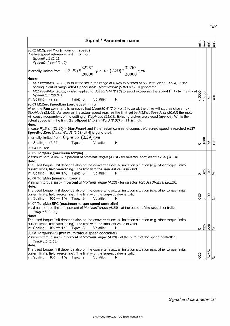
197
Signal and parameter list
3ADW000379R0301 DCS550 Manual e c
Signal / Parameter name
min
. m
ax.
def.
unit
20.02 M1SpeedMax (maximum speed) Positive speed reference limit in rpm for: SpeedRef2 (2.01) SpeedRefUsed (2.17)
Internally limited from: rpmtorpm20000
32767*)29.2(
20000
32767*)29.2(
Notes: M1SpeedMax (20.02) is must be set in the range of 0.625 to 5 times of M1BaseSpeed (99.04). If the
scaling is out of range A124 SpeedScale [AlarmWord2 (9.07) bit 7] is generated. M1SpeedMax (20.02) is also applied to SpeedRef4 (2.18) to avoid exceeding the speed limits by means of
SpeedCorr (23.04). Int. Scaling: (2.29) Type: SI Volatile: N -1
0000
10
000
15
00
rpm
20.03 M1ZeroSpeedLim (zero speed limit) When the Run command is removed [set UsedMCW (7.04) bit 3 to zero], the drive will stop as chosen by StopMode (21.03). As soon as the actual speed reaches the limit set by M1ZeroSpeedLim (20.03) the motor will coast independent of the setting of StopMode (21.03). Existing brakes are closed (applied). While the actual speed is in the limit, ZeroSpeed [AuxStatWord (8.02) bit 11] is high. Note: In case FlyStart (21.10) = StartFrom0 and if the restart command comes before zero speed is reached A137 SpeedNotZero [AlarmWord3 (9.08) bit 4] is generated.
Internally limited from: rpmtorpm )29.2(0
Int. Scaling: (2.29) Type: I Volatile: N 0 100
0 75
rp
m
20.04 Unused
20.05 TorqMax (maximum torque) Maximum torque limit - in percent of MotNomTorque (4.23) - for selector TorqUsedMaxSel (20.18). Note: The used torque limit depends also on the converter's actual limitation situation (e.g. other torque limits, current limits, field weakening). The limit with the smallest value is valid. Int. Scaling: 100 == 1 % Type: SI Volatile: N 0 32
5 10
0 %
20.06 TorqMin (minimum torque) Minimum torque limit - in percent of MotNomTorque (4.23) - for selector TorqUsedMinSel (20.19). Note: The used torque limit depends also on the converter's actual limitation situation (e.g. other torque limits, current limits, field weakening). The limit with the largest value is valid. Int. Scaling: 100 == 1 % Type: SI Volatile: N -3
25
0 -100
%
20.07 TorqMaxSPC (maximum torque speed controller) Maximum torque limit - in percent of MotNomTorque (4.23) - at the output of the speed controller: TorqRef2 (2.09) Note: The used torque limit depends also on the converter's actual limitation situation (e.g. other torque limits, current limits, field weakening). The limit with the smallest value is valid. Int. Scaling: 100 == 1 % Type: SI Volatile: N 0 32
5 32
5 %
20.08 TorqMinSPC (minimum torque speed controller) Minimum torque limit - in percent of MotNomTorque (4.23) - at the output of the speed controller. TorqRef2 (2.09) Note: The used torque limit depends also on the converter's actual limitation situation (e.g. other torque limits, current limits, field weakening). The limit with the largest value is valid. Int. Scaling: 100 == 1 % Type: SI Volatile: N -3
25
0 -325
%
%

198
Signal and parameter list
3ADW000379R0301 DCS550 Manual e c
Signal / Parameter name
min
. m
ax.
def.
unit
20.09 TorqMaxTref (maximum torque of torque reference A/B) Maximum torque limit - in percent of MotNomTorque (4.23) - for external references: TorqRefA (25.01) TorqRefB (25.04) Note: The used torque limit depends also on the converter's actual limitation situation (e.g. other torque limits, current limits, field weakening). The limit with the smallest value is valid. Int. Scaling: 100 == 1 % Type: SI Volatile: N 0.
32
5 32
5 %
20.10 TorqMinTref (minimum torque of torque reference A/B) Minimum torque limit - in percent of MotNomTorque (4.23) - for external references: TorqRefA (25.01) TorqRefB (25.04) Note: The used torque limit depends also on the converter's actual limitation situation (e.g. other torque limits, current limits, field weakening). The limit with the largest value is valid. Int. Scaling: 100 == 1 % Type: SI Volatile: N -3
25
0 -325
%
20.11 Unused
20.12 M1CurLimBrdg1 (current limit of bridge 1) Current limit bridge 1 in percent of M1NomCur (99.03). Notes: Setting M1CurLimBrdg1 (20.12) to 0 % disables bridge 1. The used current limit depends also on the converter's actual limitation situation (e.g. torque limits, other
current limits, field weakening). The limit with the smallest value is valid. Int. Scaling: 100 == 1 % Type: SI Volatile: N 0 32
5 10
0 %
20.13 M1CurLimBrdg2 (current limit of bridge 2) Current limit bridge 2 in percent of M1NomCur (99.03). Notes: Setting M1CurLimBrdg2 (20.13) to 0 % disables bridge 2. The used current limit depends also on the converter's actual limitation situation (e.g. torque limits, other
current limits, field weakening). The limit with the largest value is valid. M1CurLimBrdg2 (20.13) is internally set to 0 % if QuadrantType (4.15) = 2-Q (2-Q drive). Thus, do not
change the default setting for 2-Q drives. Int. Scaling: 100 == 1 % Type: SI Volatile: N -3
25
0 -100
%
20.14 ArmAlphaMax (maximum firing angle) Maximum firing angle () in degrees. The maximum firing angel can be forced using AuxCtrlWord2 (7.03) bit 7. Int. Scaling: 1 == 1 deg Type: SI Volatile: N 0 16
5 15
0 de
g
20.15 ArmAlphaMin (minimum firing angle) Minimum firing angle () in degrees. Int. Scaling: 1 == 1 deg Type: SI Volatile: N 0 16
5 15
de
g
20.16 - 20.17 Unused
20.18 TorqUsedMaxSel (maximum used torque selector) TorqUsedMax (2.22) selector: 0 = TorqMax2005 TorqMax (20.05), default 1 = AI1 analog input 1 2 = AI2 analog input 2 3 = AI3 analog input 3 4 = AI4 analog input 4 5 = AI5 analog input 5 6 = AI6 analog input 6 Int. Scaling: 1 == 1 Type: C Volatile: N T
orqM
ax2
005
AI6
T
orqM
ax2
005
-
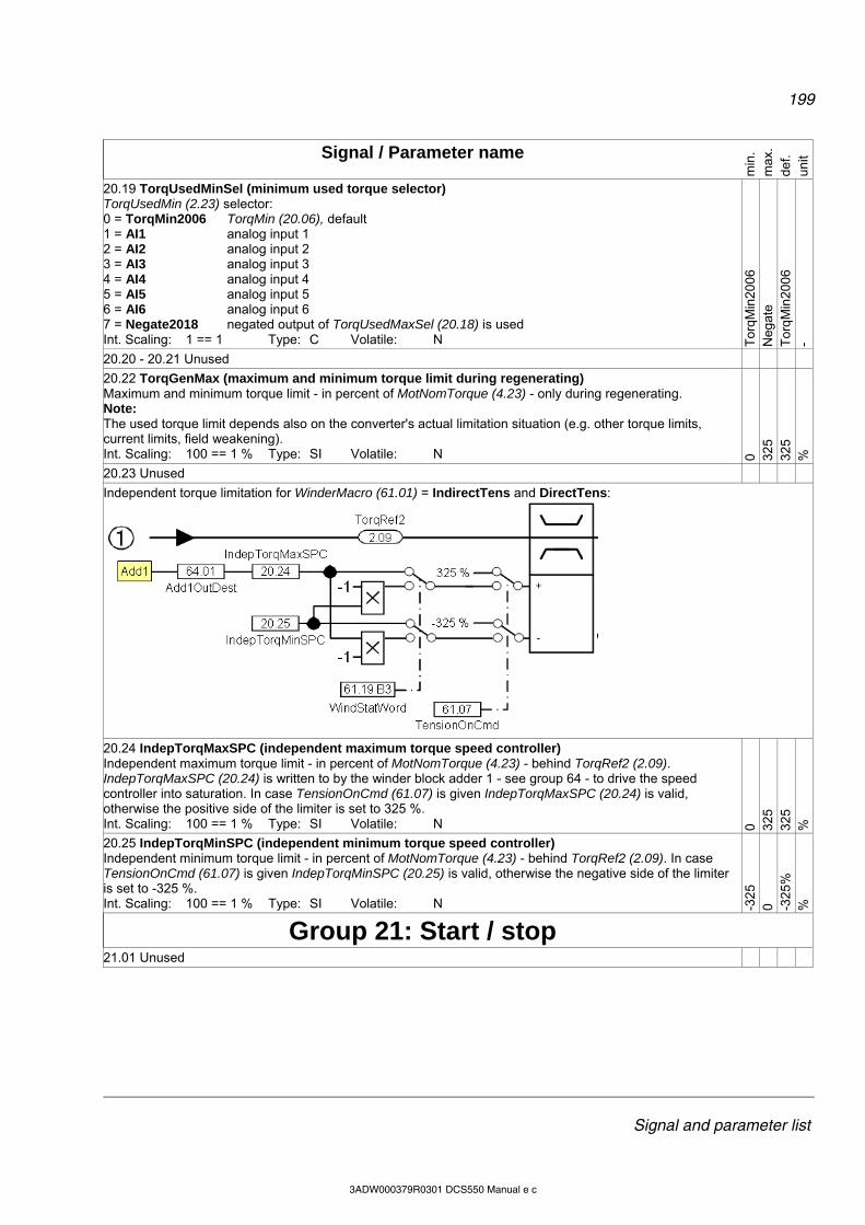
199
Signal and parameter list
3ADW000379R0301 DCS550 Manual e c
Signal / Parameter name
min
. m
ax.
def.
unit
20.19 TorqUsedMinSel (minimum used torque selector) TorqUsedMin (2.23) selector: 0 = TorqMin2006 TorqMin (20.06), default 1 = AI1 analog input 1 2 = AI2 analog input 2 3 = AI3 analog input 3 4 = AI4 analog input 4 5 = AI5 analog input 5 6 = AI6 analog input 6 7 = Negate2018 negated output of TorqUsedMaxSel (20.18) is used Int. Scaling: 1 == 1 Type: C Volatile: N T
orqM
in20
06
Neg
ate
Tor
qMin
200
6 -
20.20 - 20.21 Unused
20.22 TorqGenMax (maximum and minimum torque limit during regenerating) Maximum and minimum torque limit - in percent of MotNomTorque (4.23) - only during regenerating. Note: The used torque limit depends also on the converter's actual limitation situation (e.g. other torque limits, current limits, field weakening). Int. Scaling: 100 == 1 % Type: SI Volatile: N 0 32
5 32
5 %
20.23 Unused
Independent torque limitation for WinderMacro (61.01) = IndirectTens and DirectTens:
20.24 IndepTorqMaxSPC (independent maximum torque speed controller) Independent maximum torque limit - in percent of MotNomTorque (4.23) - behind TorqRef2 (2.09). IndepTorqMaxSPC (20.24) is written to by the winder block adder 1 - see group 64 - to drive the speed controller into saturation. In case TensionOnCmd (61.07) is given IndepTorqMaxSPC (20.24) is valid, otherwise the positive side of the limiter is set to 325 %. Int. Scaling: 100 == 1 % Type: SI Volatile: N 0 32
5 32
5 %
20.25 IndepTorqMinSPC (independent minimum torque speed controller) Independent minimum torque limit - in percent of MotNomTorque (4.23) - behind TorqRef2 (2.09). In case TensionOnCmd (61.07) is given IndepTorqMinSPC (20.25) is valid, otherwise the negative side of the limiter is set to -325 %. Int. Scaling: 100 == 1 % Type: SI Volatile: N -3
25
0 -325
%
%
Group 21: Start / stop
21.01 Unused
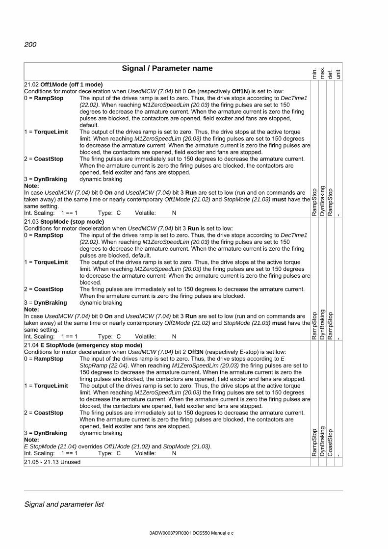
200
Signal and parameter list
3ADW000379R0301 DCS550 Manual e c
Signal / Parameter name
min
. m
ax.
def.
unit
21.02 Off1Mode (off 1 mode) Conditions for motor deceleration when UsedMCW (7.04) bit 0 On (respectively Off1N) is set to low: 0 = RampStop The input of the drives ramp is set to zero. Thus, the drive stops according to DecTime1
(22.02). When reaching M1ZeroSpeedLim (20.03) the firing pulses are set to 150 degrees to decrease the armature current. When the armature current is zero the firing pulses are blocked, the contactors are opened, field exciter and fans are stopped, default.
1 = TorqueLimit The output of the drives ramp is set to zero. Thus, the drive stops at the active torque limit. When reaching M1ZeroSpeedLim (20.03) the firing pulses are set to 150 degrees to decrease the armature current. When the armature current is zero the firing pulses are blocked, the contactors are opened, field exciter and fans are stopped.
2 = CoastStop The firing pulses are immediately set to 150 degrees to decrease the armature current. When the armature current is zero the firing pulses are blocked, the contactors are opened, field exciter and fans are stopped.
3 = DynBraking dynamic braking Note: In case UsedMCW (7.04) bit 0 On and UsedMCW (7.04) bit 3 Run are set to low (run and on commands are taken away) at the same time or nearly contemporary Off1Mode (21.02) and StopMode (21.03) must have the same setting. Int. Scaling: 1 == 1 Type: C Volatile: N R
ampS
top
Dyn
Bra
king
R
ampS
top
-
21.03 StopMode (stop mode) Conditions for motor deceleration when UsedMCW (7.04) bit 3 Run is set to low: 0 = RampStop The input of the drives ramp is set to zero. Thus, the drive stops according to DecTime1
(22.02). When reaching M1ZeroSpeedLim (20.03) the firing pulses are set to 150 degrees to decrease the armature current. When the armature current is zero the firing pulses are blocked, default.
1 = TorqueLimit The output of the drives ramp is set to zero. Thus, the drive stops at the active torque limit. When reaching M1ZeroSpeedLim (20.03) the firing pulses are set to 150 degrees to decrease the armature current. When the armature current is zero the firing pulses are blocked.
2 = CoastStop The firing pulses are immediately set to 150 degrees to decrease the armature current. When the armature current is zero the firing pulses are blocked.
3 = DynBraking dynamic braking Note: In case UsedMCW (7.04) bit 0 On and UsedMCW (7.04) bit 3 Run are set to low (run and on commands are taken away) at the same time or nearly contemporary Off1Mode (21.02) and StopMode (21.03) must have the same setting. Int. Scaling: 1 == 1 Type: C Volatile: N R
ampS
top
Dyn
Bra
king
R
ampS
top
- 21.04 E StopMode (emergency stop mode) Conditions for motor deceleration when UsedMCW (7.04) bit 2 Off3N (respectively E-stop) is set low: 0 = RampStop The input of the drives ramp is set to zero. Thus, the drive stops according to E
StopRamp (22.04). When reaching M1ZeroSpeedLim (20.03) the firing pulses are set to 150 degrees to decrease the armature current. When the armature current is zero the firing pulses are blocked, the contactors are opened, field exciter and fans are stopped.
1 = TorqueLimit The output of the drives ramp is set to zero. Thus, the drive stops at the active torque limit. When reaching M1ZeroSpeedLim (20.03) the firing pulses are set to 150 degrees to decrease the armature current. When the armature current is zero the firing pulses are blocked, the contactors are opened, field exciter and fans are stopped.
2 = CoastStop The firing pulses are immediately set to 150 degrees to decrease the armature current. When the armature current is zero the firing pulses are blocked, the contactors are opened, field exciter and fans are stopped.
3 = DynBraking dynamic braking Note: E StopMode (21.04) overrides Off1Mode (21.02) and StopMode (21.03). Int. Scaling: 1 == 1 Type: C Volatile: N R
ampS
top
Dyn
Bra
king
C
oast
Sto
p -
21.05 - 21.13 Unused
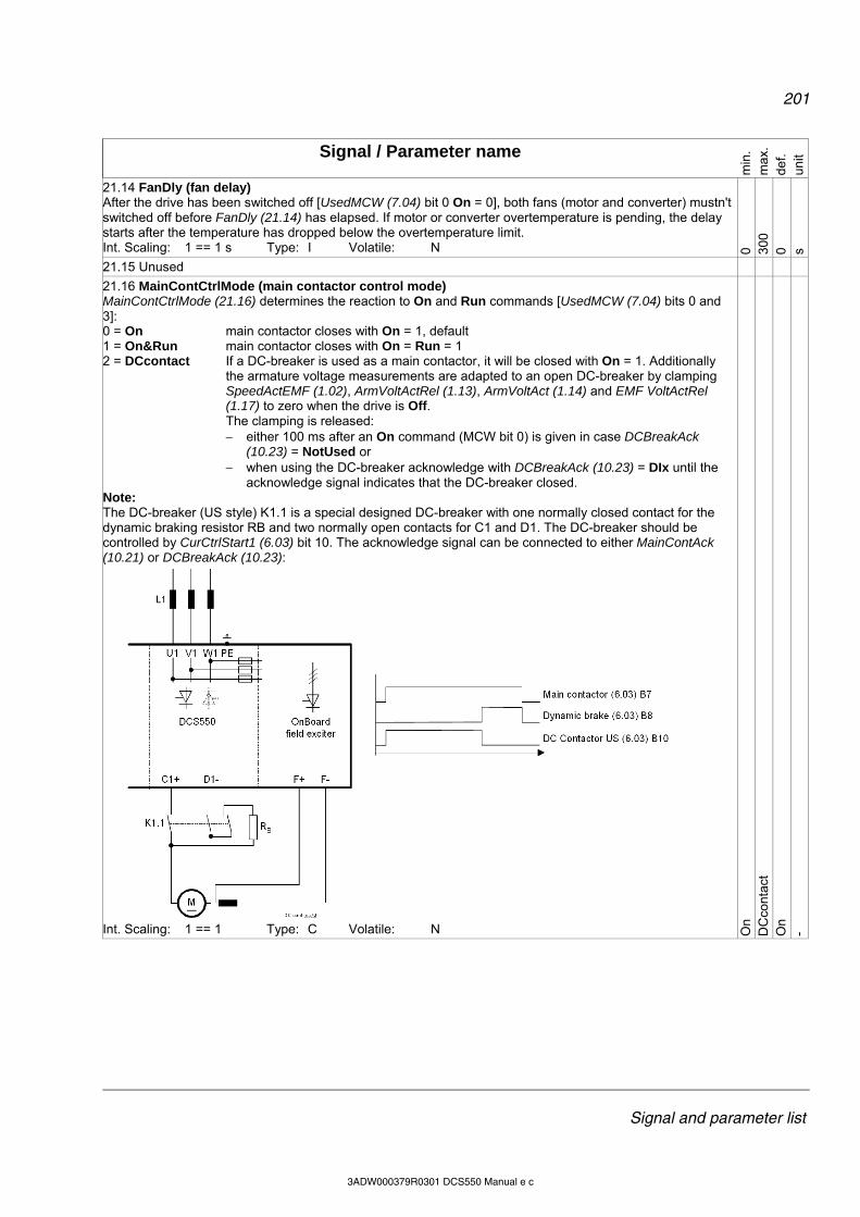
201
Signal and parameter list
3ADW000379R0301 DCS550 Manual e c
Signal / Parameter name
min
. m
ax.
def.
unit
21.14 FanDly (fan delay) After the drive has been switched off [UsedMCW (7.04) bit 0 On = 0], both fans (motor and converter) mustn't switched off before FanDly (21.14) has elapsed. If motor or converter overtemperature is pending, the delay starts after the temperature has dropped below the overtemperature limit. Int. Scaling: 1 == 1 s Type: I Volatile: N 0 30
0 0 s
21.15 Unused
21.16 MainContCtrlMode (main contactor control mode) MainContCtrlMode (21.16) determines the reaction to On and Run commands [UsedMCW (7.04) bits 0 and 3]: 0 = On main contactor closes with On = 1, default 1 = On&Run main contactor closes with On = Run = 1 2 = DCcontact If a DC-breaker is used as a main contactor, it will be closed with On = 1. Additionally
the armature voltage measurements are adapted to an open DC-breaker by clamping SpeedActEMF (1.02), ArmVoltActRel (1.13), ArmVoltAct (1.14) and EMF VoltActRel (1.17) to zero when the drive is Off. The clamping is released: either 100 ms after an On command (MCW bit 0) is given in case DCBreakAck
(10.23) = NotUsed or when using the DC-breaker acknowledge with DCBreakAck (10.23) = DIx until the
acknowledge signal indicates that the DC-breaker closed. Note: The DC-breaker (US style) K1.1 is a special designed DC-breaker with one normally closed contact for the dynamic braking resistor RB and two normally open contacts for C1 and D1. The DC-breaker should be controlled by CurCtrlStart1 (6.03) bit 10. The acknowledge signal can be connected to either MainContAck (10.21) or DCBreakAck (10.23):
Int. Scaling: 1 == 1 Type: C Volatile: N O
n D
Cco
ntac
t O
n -
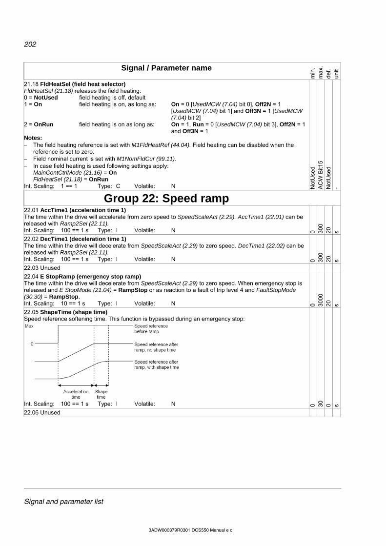
202
Signal and parameter list
3ADW000379R0301 DCS550 Manual e c
Signal / Parameter name
min
. m
ax.
def.
unit
21.18 FldHeatSel (field heat selector) FldHeatSel (21.18) releases the field heating: 0 = NotUsed field heating is off, default 1 = On field heating is on, as long as: On = 0 [UsedMCW (7.04) bit 0], Off2N = 1
[UsedMCW (7.04) bit 1] and Off3N = 1 [UsedMCW (7.04) bit 2]
2 = OnRun field heating is on as long as: On = 1, Run = 0 [UsedMCW (7.04) bit 3], Off2N = 1 and Off3N = 1
Notes: The field heating reference is set with M1FldHeatRef (44.04). Field heating can be disabled when the
reference is set to zero. Field nominal current is set with M1NomFldCur (99.11). In case field heating is used following settings apply:
MainContCtrlMode (21.16) = On FldHeatSel (21.18) = OnRun
Int. Scaling: 1 == 1 Type: C Volatile: N Not
Use
d A
CW
Bit1
5 N
otU
sed
-
Group 22: Speed ramp
22.01 AccTime1 (acceleration time 1) The time within the drive will accelerate from zero speed to SpeedScaleAct (2.29). AccTime1 (22.01) can be released with Ramp2Sel (22.11). Int. Scaling: 100 == 1 s Type: I Volatile: N 0 30
0 20
s
22.02 DecTime1 (deceleration time 1) The time within the drive will decelerate from SpeedScaleAct (2.29) to zero speed. DecTime1 (22.02) can be released with Ramp2Sel (22.11). Int. Scaling: 100 == 1 s Type: I Volatile: N 0 30
0 20
s
22.03 Unused
22.04 E StopRamp (emergency stop ramp) The time within the drive will decelerate from SpeedScaleAct (2.29) to zero speed. When emergency stop is released and E StopMode (21.04) = RampStop or as reaction to a fault of trip level 4 and FaultStopMode (30.30) = RampStop. Int. Scaling: 10 == 1 s Type: I Volatile: N 0 30
00
20
s
22.05 ShapeTime (shape time) Speed reference softening time. This function is bypassed during an emergency stop:
Int. Scaling: 100 == 1 s Type: I Volatile: N 0 30
0 s
22.06 Unused
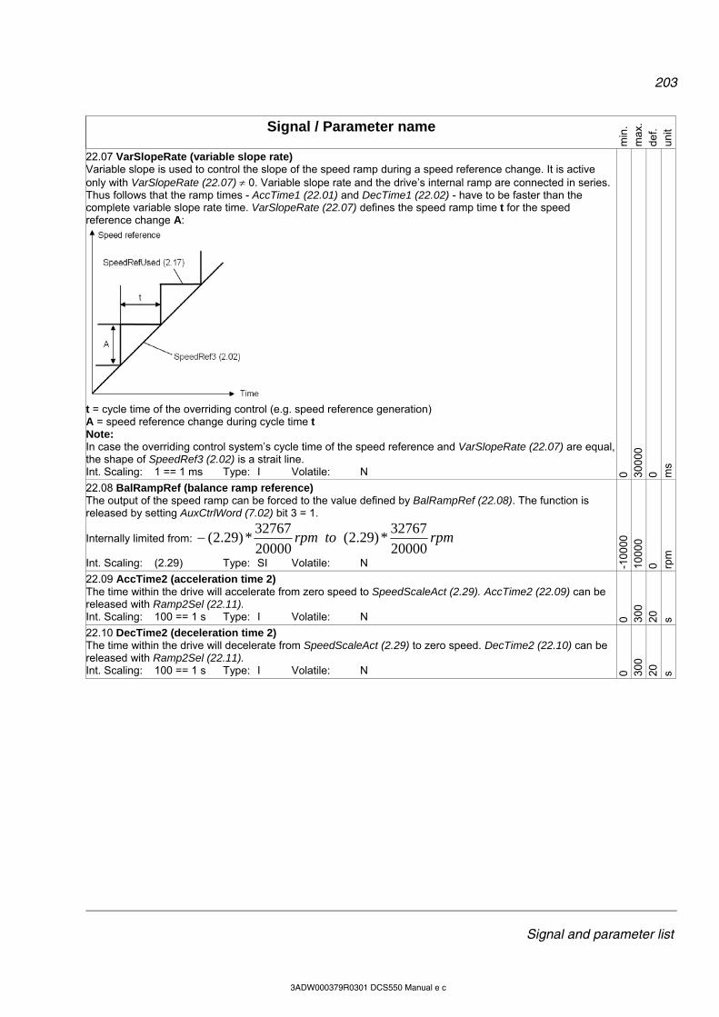
203
Signal and parameter list
3ADW000379R0301 DCS550 Manual e c
Signal / Parameter name
min
. m
ax.
def.
unit
22.07 VarSlopeRate (variable slope rate) Variable slope is used to control the slope of the speed ramp during a speed reference change. It is active only with VarSlopeRate (22.07) 0. Variable slope rate and the drive’s internal ramp are connected in series. Thus follows that the ramp times - AccTime1 (22.01) and DecTime1 (22.02) - have to be faster than the complete variable slope rate time. VarSlopeRate (22.07) defines the speed ramp time t for the speed reference change A:
t = cycle time of the overriding control (e.g. speed reference generation) A = speed reference change during cycle time t Note: In case the overriding control system’s cycle time of the speed reference and VarSlopeRate (22.07) are equal, the shape of SpeedRef3 (2.02) is a strait line. Int. Scaling: 1 == 1 ms Type: I Volatile: N 0 30
000
0 m
s
22.08 BalRampRef (balance ramp reference) The output of the speed ramp can be forced to the value defined by BalRampRef (22.08). The function is released by setting AuxCtrlWord (7.02) bit 3 = 1.
Internally limited from: rpmtorpm20000
32767*)29.2(
20000
32767*)29.2(
Int. Scaling: (2.29) Type: SI Volatile: N -100
00
100
00
0 rpm
22.09 AccTime2 (acceleration time 2) The time within the drive will accelerate from zero speed to SpeedScaleAct (2.29). AccTime2 (22.09) can be released with Ramp2Sel (22.11). Int. Scaling: 100 == 1 s Type: I Volatile: N 0 30
0 20
s
22.10 DecTime2 (deceleration time 2) The time within the drive will decelerate from SpeedScaleAct (2.29) to zero speed. DecTime2 (22.10) can be released with Ramp2Sel (22.11). Int. Scaling: 100 == 1 s Type: I Volatile: N 0 30
0 20
s

204
Signal and parameter list
3ADW000379R0301 DCS550 Manual e c
Signal / Parameter name
min
. m
ax.
def.
unit
22.11 Ramp2Select (ramp 2 selector) Select active ramp parameters: 0 = Acc/Dec1 parameter set 1 [AccTime1 (22.01) and DecTime1 (22.02)] is active, default 1 = Acc/Dec2 parameter set 2 [AccTime2 (22.09) and DecTime2 (22.10)] is active 2 = SpeedLevel If |SpeedRef3 (2.02)| |SpeedLev (50.10)|, then parameter set1 is active. If |SpeedRef3 (2.02)| > |SpeedLev (50.10)|, then parameter set 2 is active. 3 = DI1 0 = parameter set 1 is active, 1 = parameter set 2 is active 4 = DI2 0 = parameter set 1 is active, 1 = parameter set 2 is active 5 = DI3 0 = parameter set 1 is active, 1 = parameter set 2 is active 6 = DI4 0 = parameter set 1 is active, 1 = parameter set 2 is active 7 = DI5 0 = parameter set 1 is active, 1 = parameter set 2 is active 8 = DI6 0 = parameter set 1 is active, 1 = parameter set 2 is active 9 = DI7 0 = parameter set 1 is active, 1 = parameter set 2 is active 10 = DI8 0 = parameter set 1 is active, 1 = parameter set 2 is active 11 = DI9 0 = parameter set 1 is active, 1 = parameter set 2 is active, only available with digital
extension board 12 = DI10 0 = parameter set 1 is active, 1 = parameter set 2 is active, only available with digital
extension board 13 = DI11 0 = parameter set 1 is active, 1 = parameter set 2 is active, only available with digital
extension board 14 = MCW Bit11 0 = parameter set 1 is active, 1 = parameter set 2 is active, MainCtrlWord (7.01) bit 11 15 = MCW Bit12 0 = parameter set 1 is active, 1 = parameter set 2 is active, MainCtrlWord (7.01) bit 12 16 = MCW Bit13 0 = parameter set 1 is active, 1 = parameter set 2 is active, MainCtrlWord (7.01) bit 13 17 = MCW Bit14 0 = parameter set 1 is active, 1 = parameter set 2 is active, MainCtrlWord (7.01) bit 14 18 = MCW Bit15 0 = parameter set 1 is active, 1 = parameter set 2 is active, MainCtrlWord (7.01) bit 15 Int. Scaling: 1 == 1 Type: C Volatile: N A
cc/D
cc1
MC
W B
it15
Acc
/Dcc
1 -
22.12 JogAccTime (acceleration time jogging) The time within the drive will accelerate from zero speed to SpeedScaleAct (2.29) in case of jogging: When using jog command Jog1 (10.17) or MainCtrlWord (7.01) bit 8 speed is set by FixedSpeed1 (23.02) When using jog command Jog2 (10.18) ) or MainCtrlWord (7.01) bit 9 speed is set by FixedSpeed2
(23.03) Int. Scaling: 100 == 1 s Type: I Volatile: N 0 30
0 20
s
22.13 JogDecTime (deceleration time jogging) The time within the drive will decelerate from SpeedScaleAct (2.29) to zero speed in case of jogging: When using jog command Jog1 (10.17) or MainCtrlWord (7.01) bit 8 speed is set by FixedSpeed1 (23.02) When using jog command Jog2 (10.18) ) or MainCtrlWord (7.01) bit 9 speed is set by FixedSpeed2
(23.03) Int. Scaling: 100 == 1 s Type: I Volatile: N 0 30
0 20
s
Group 23: Speed reference
23.01 SpeedRef (speed reference) Main speed reference input for the speed control of the drive. Can be connected to SpeedRefUsed (2.17) via: Ref1Mux (11.02) and Ref1Sel (11.03) or Ref2Mux (11.12) and Ref2Sel (11.06)
Internally limited from: rpmtorpm20000
32767*)29.2(
20000
32767*)29.2(
Int. Scaling: (2.29) Type: SI Volatile: Y -100
00
100
00
0 rpm
23.02 FixedSpeed1 (fixed speed 1) FixedSpeed1 (23.02) is specifying a constant speed reference and overrides SpeedRef2 (2.01) at the speed ramps input. It can be released by Jog1 (10.17) or MainCtrlWord (7.01) bit 8. The ramp times are set with JogAccTime (22.12) and JogDecTime (22.13).
Internally limited from: rpmtorpm20000
32767*)29.2(
20000
32767*)29.2(
Int. Scaling: (2.29) Type: SI Volatile: N -100
00
100
00
0 rpm
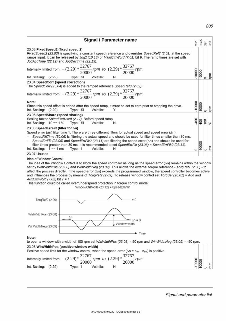
205
Signal and parameter list
3ADW000379R0301 DCS550 Manual e c
Signal / Parameter name
min
. m
ax.
def.
unit
23.03 FixedSpeed2 (fixed speed 2) FixedSpeed2 (23.03) is specifying a constant speed reference and overrides SpeedRef2 (2.01) at the speed ramps input. It can be released by Jog2 (10.18) or MainCtrlWord (7.01) bit 9. The ramp times are set with JogAccTime (22.12) and JogDecTime (22.13).
Internally limited from: rpmtorpm20000
32767*)29.2(
20000
32767*)29.2(
Int. Scaling: (2.29) Type: SI Volatile: N -100
00
100
00
0 rpm
23.04 SpeedCorr (speed correction) The SpeedCorr (23.04) is added to the ramped reference SpeedRef3 (2.02).
Internally limited from: rpmtorpm20000
32767*)29.2(
20000
32767*)29.2(
Note: Since this speed offset is added after the speed ramp, it must be set to zero prior to stopping the drive. Int. Scaling: (2.29) Type: SI Volatile: Y -1
0000
10
000
0 rp
m
23.05 SpeedShare (speed sharing) Scaling factor SpeedRefUsed (2.17). Before speed ramp. Int. Scaling: 10 == 1 % Type: SI Volatile: N -4
00
400
100
%
23.06 SpeedErrFilt (filter for n) Speed error (n) filter time 1. There are three different filters for actual speed and speed error (n): SpeedFiltTime (50.06) is filtering the actual speed and should be used for filter times smaller than 30 ms. SpeedErrFilt (23.06) and SpeedErrFilt2 (23.11) are filtering the speed error (n) and should be used for
filter times greater than 30 ms. It is recommended to set SpeedErrFilt (23.06) = SpeedErrFilt2 (23.11). Int. Scaling: 1 == 1 ms Type: I Volatile: N 0 10
000
0 m
s
23.07 Unused
Idea of Window Control: The idea of the Window Control is to block the speed controller as long as the speed error (n) remains within the window set by WinWidthPos (23.08) and WinWidthNeg (23.09). This allows the external torque reference - TorqRef1 (2.08) - to affect the process directly. If the speed error (n) exceeds the programmed window, the speed controller becomes active and influences the process by means of TorqRef2 (2.09). To release window control set TorqSel (26.01) = Add and AuxCtrlWord (7.02) bit 7 = 1. This function could be called over/underspeed protection in torque control mode:
Note: to open a window with a width of 100 rpm set WinWidthPos (23.08) = 50 rpm and WinWidthNeg (23.09) = -50 rpm.
23.08 WinWidthPos (positive window width) Positive speed limit for the window control, when the speed error (n = nref - nact) is positive.
Internally limited from: rpmtorpm20000
32767*)29.2(
20000
32767*)29.2(
Int. Scaling: (2.29) Type: I Volatile: N -100
00
100
00
0 rpm
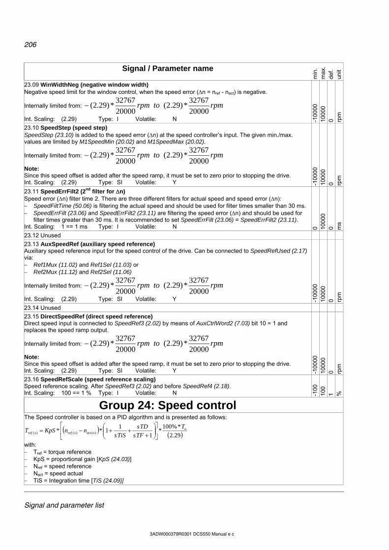
206
Signal and parameter list
3ADW000379R0301 DCS550 Manual e c
Signal / Parameter name
min
. m
ax.
def.
unit
23.09 WinWidthNeg (negative window width) Negative speed limit for the window control, when the speed error (n = nref - nact) is negative.
Internally limited from: rpmtorpm20000
32767*)29.2(
20000
32767*)29.2(
Int. Scaling: (2.29) Type: I Volatile: N -100
00
100
00
0 rpm
23.10 SpeedStep (speed step) SpeedStep (23.10) is added to the speed error (n) at the speed controller’s input. The given min./max. values are limited by M1SpeedMin (20.02) and M1SpeedMax (20.02).
Internally limited from: rpmtorpm20000
32767*)29.2(
20000
32767*)29.2(
Note: Since this speed offset is added after the speed ramp, it must be set to zero prior to stopping the drive. Int. Scaling: (2.29) Type: SI Volatile: Y -1
0000
10
000
0 rp
m
23.11 SpeedErrFilt2 (2nd filter for n) Speed error (n) filter time 2. There are three different filters for actual speed and speed error (n): SpeedFiltTime (50.06) is filtering the actual speed and should be used for filter times smaller than 30 ms. SpeedErrFilt (23.06) and SpeedErrFilt2 (23.11) are filtering the speed error (n) and should be used for
filter times greater than 30 ms. It is recommended to set SpeedErrFilt (23.06) = SpeedErrFilt2 (23.11). Int. Scaling: 1 == 1 ms Type: I Volatile: N 0 10
000
0 m
s
23.12 Unused
23.13 AuxSpeedRef (auxiliary speed reference) Auxiliary speed reference input for the speed control of the drive. Can be connected to SpeedRefUsed (2.17) via: Ref1Mux (11.02) and Ref1Sel (11.03) or Ref2Mux (11.12) and Ref2Sel (11.06)
Internally limited from: rpmtorpm20000
32767*)29.2(
20000
32767*)29.2(
Int. Scaling: (2.29) Type: SI Volatile: Y -100
00
100
00
0 rpm
23.14 Unused
23.15 DirectSpeedRef (direct speed reference) Direct speed input is connected to SpeedRef3 (2.02) by means of AuxCtrlWord2 (7.03) bit 10 = 1 and replaces the speed ramp output.
Internally limited from: rpmtorpm20000
32767*)29.2(
20000
32767*)29.2(
Note: Since this speed offset is added after the speed ramp, it must be set to zero prior to stopping the drive. Int. Scaling: (2.29) Type: SI Volatile: Y -1
0000
10
000
0 rp
m
23.16 SpeedRefScale (speed reference scaling) Speed reference scaling. After SpeedRef3 (2.02) and before SpeedRef4 (2.18). Int. Scaling: 100 == 1 % Type: I Volatile: N -1
00
100
1 %
Group 24: Speed control
The Speed controller is based on a PID algorithm and is presented as follows:
29.2
*%100*
1
11** )()()(
nsactsrefsref
T
TFs
TDs
TiSsnnKpST
with: Tref = torque reference KpS = proportional gain [KpS (24.03)] Nref = speed reference Nact = speed actual TiS = Integration time [TiS (24.09)]

207
Signal and parameter list
3ADW000379R0301 DCS550 Manual e c
Signal / Parameter name
min
. m
ax.
def.
unit
TD = Derivation time [DerivTime (24.12)] TF = Derivation filter time [DerivFiltTime (24.13)] Tn = nominal motor torque (2.29) = actual used speed scaling [SpeedScaleAct (2.29)]
24.01 - 24.02 Unused
24.03 KpS (p-part speed controller) Proportional gain of the speed controller can be released by means of Par2Select (24.29). Example: The controller generates 15 % of motor nominal torque with KpS (24.03) = 3, if the speed error (n) is 5 % of SpeedScaleAct (2.29). Int. Scaling: 100 == 1 Type: I Volatile: N 0 32
5 5 -
24.04 - 24.08 Unused
24.09 TiS (i-part speed controller) Integral time of the speed controller can be released by means of Par2Select (24.29). TiS (24.09) defines the time within the integral part of the controller achieves the same value as the proportional part. Example: The controller generates 15 % of motor nominal torque with KpS (24.03) = 3, if the speed error (n) is 5 % of SpeedScaleAct (2.29). On that condition and with TiS (24.09) = 300 ms follows: the controller generates 30 % of motor nominal torque, if the speed error (n) is constant, after 300 ms are
elapsed (15 % from proportional part and 15 % from integral part). Setting TIS (24.09) to 0 ms disables the integral part of the speed controller and resets its integrator. Int. Scaling: 1 == 1 ms Type: I Volatile: N 0 64
000
25
00
ms
24.10 TiSInitValue (initial value for i-part speed controller) Initial value of the speed controller integrator, in percent of MotNomTorque (4.23). The integrator is set as soon as RdyRef [MainStatWord (8.01)] becomes valid. Int. Scaling: 100 == 1 % Type: SI Volatile: N -3
25
325
0 %
24.11 BalRef (balance speed reference) External value in percent of MotNomTorque (4.23). Both, i-part and output of the speed controller are forced to BalRef (24.11) when AuxCtrlWord (7.02) bit 8 = 1. Int. Scaling: 100 == 1 % Type: SI Volatile: N -3
25
325
0 %
24.12 DerivTime (d-part speed controller) Speed controller derivation time. DerivTime (24.12) defines the time within the speed controller derives the error value. The speed controller works as PI controller, if DerivTime (24.12) is set to zero. Int. Scaling: 1 == 1 ms Type: I Volatile: N 0 10
000
0 m
s
24.13 DerivFiltTime (filter time for d-part speed controller) Derivation filter time. Int. Scaling: 1 == 1 ms Type: I Volatile: N 0 10
000
8 m
s
24.14 - 24.26 Unused
24.27 KpS2 (2nd p-part speed controller) 2nd proportional gain of the speed controller can be released by means of Par2Select (24.29). Int. Scaling: 100 == 1 Type: I Volatile: N 0 32
5 5 -

208
Signal and parameter list
3ADW000379R0301 DCS550 Manual e c
Signal / Parameter name
min
. m
ax.
def.
unit
24.28 TiS2 (2nd i-part speed controller) 2nd integral time of the speed controller can be released by means of Par2Select (24.29). Int. Scaling: 1 == 1 ms Type: I Volatile: N 0 64
000
25
00
ms
24.29 Par2Select (selector for 2nd set of speed controller parameters) Select active speed controller parameters: 0 = ParSet1 parameter set 1 [KpS (24.03) and TiS (24.09)] is active, default 1 = ParSet2 parameter set 2 [KpS2 (24.27) and TiS2 (24.28)] is active 2 = SpeedLevel If |MotSpeed (1.04)| |SpeedLev (50.10)|, then parameter set1 is active.
If |MotSpeed (1.04)| > |SpeedLev (50.10)|, then parameter set 2 is active. 3 = SpeedError If |SpeedErrNeg (2.03)| |SpeedLev (50.10)|, then parameter set1 is active.
If | SpeedErrNeg (2.03)| > |SpeedLev (50.10)|, then parameter set 2 is active. 4 = DI1 0 = parameter set 1 is active, 1 = parameter set 2 is active 5 = DI2 0 = parameter set 1 is active, 1 = parameter set 2 is active 6 = DI3 0 = parameter set 1 is active, 1 = parameter set 2 is active 7 = DI4 0 = parameter set 1 is active, 1 = parameter set 2 is active 8 = DI5 0 = parameter set 1 is active, 1 = parameter set 2 is active 9 = DI6 0 = parameter set 1 is active, 1 = parameter set 2 is active 10 = DI7 0 = parameter set 1 is active, 1 = parameter set 2 is active 11 = DI8 0 = parameter set 1 is active, 1 = parameter set 2 is active 12 = DI9 0 = parameter set 1 is active, 1 = parameter set 2 is active, only available with digital
extension board 13 = DI10 0 = parameter set 1 is active, 1 = parameter set 2 is active, only available with digital
extension board 14 = DI11 0 = parameter set 1 is active, 1 = parameter set 2 is active, only available with digital
extension board 15 = MCW Bit11 0 = parameter set 1 is active, 1 = parameter set 2 is active, MainCtrlWord (7.01) bit 11 16 = MCW Bit12 0 = parameter set 1 is active, 1 = parameter set 2 is active, MainCtrlWord (7.01) bit 12 17 = MCW Bit13 0 = parameter set 1 is active, 1 = parameter set 2 is active, MainCtrlWord (7.01) bit 13 18 = MCW Bit14 0 = parameter set 1 is active, 1 = parameter set 2 is active, MainCtrlWord (7.01) bit 14 19 = MCW Bit15 0 = parameter set 1 is active, 1 = parameter set 2 is active, MainCtrlWord (7.01) bit 15 Note: Load and speed dependent adaptation parameters are valid regardless of the selected parameter set. Int. Scaling: 1 == 1 Type: C Volatile: N P
arS
et1
MC
W B
it15
Par
Set
1
Group 25: Torque reference 25.01 TorqRefA (torque reference A) External torque reference in percent of MotNomTorque (4.23). TorqRefA (25.01) can be scaled by LoadShare (25.03). Note: TorqRefA (25.01) is only valid, if TorqRefA Sel (25.10) = TorqRefA2501. Int. Scaling: 100 == 1 % Type: SI Volatile: Y -3
25
325
0 %
25.02 Unused
25.03 LoadShare (load share) Scaling factor TorqRefA (25.01). Int. Scaling: 10 == 1 % Type: SI Volatile: N -4
00
400
100
%
25.04 - 24.09 Unused
25.10 TorqRefA Sel (torque reference A selector) Selector for TorqRefExt (2.24): 0 = TorqRefA2501 TorqRefA (25.01), default 1 = AI1 analog input AI1 2 = AI2 analog input AI2 3 = AI3 analog input AI3 4 = AI4 analog input AI4 5 = AI5 analog input AI5 6 = AI6 analog input AI6 Int. Scaling: 1 == 1 Type: C Volatile: N T
orqR
efA
250
1
AI6
T
orqR
efA
250
1
-
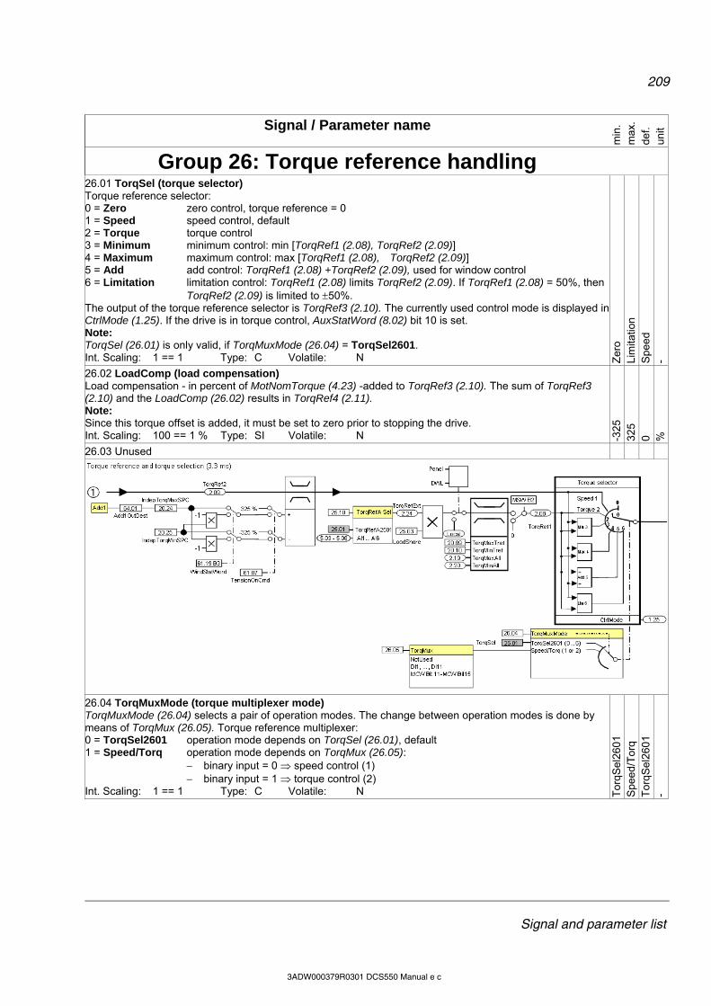
209
Signal and parameter list
3ADW000379R0301 DCS550 Manual e c
Signal / Parameter name
min
. m
ax.
def.
unit
Group 26: Torque reference handling
26.01 TorqSel (torque selector) Torque reference selector: 0 = Zero zero control, torque reference = 0 1 = Speed speed control, default 2 = Torque torque control 3 = Minimum minimum control: min [TorqRef1 (2.08), TorqRef2 (2.09)] 4 = Maximum maximum control: max [TorqRef1 (2.08), TorqRef2 (2.09)] 5 = Add add control: TorqRef1 (2.08) +TorqRef2 (2.09), used for window control 6 = Limitation limitation control: TorqRef1 (2.08) limits TorqRef2 (2.09). If TorqRef1 (2.08) = 50%, then
TorqRef2 (2.09) is limited to 50%. The output of the torque reference selector is TorqRef3 (2.10). The currently used control mode is displayed in CtrlMode (1.25). If the drive is in torque control, AuxStatWord (8.02) bit 10 is set. Note: TorqSel (26.01) is only valid, if TorqMuxMode (26.04) = TorqSel2601. Int. Scaling: 1 == 1 Type: C Volatile: N Z
ero
Lim
itatio
n S
pee
d -
26.02 LoadComp (load compensation) Load compensation - in percent of MotNomTorque (4.23) -added to TorqRef3 (2.10). The sum of TorqRef3 (2.10) and the LoadComp (26.02) results in TorqRef4 (2.11). Note: Since this torque offset is added, it must be set to zero prior to stopping the drive. Int. Scaling: 100 == 1 % Type: SI Volatile: N -3
25
325
0 %
26.03 Unused
26.04 TorqMuxMode (torque multiplexer mode) TorqMuxMode (26.04) selects a pair of operation modes. The change between operation modes is done by means of TorqMux (26.05). Torque reference multiplexer: 0 = TorqSel2601 operation mode depends on TorqSel (26.01), default 1 = Speed/Torq operation mode depends on TorqMux (26.05):
binary input = 0 speed control (1) binary input = 1 torque control (2)
Int. Scaling: 1 == 1 Type: C Volatile: N Tor
qSel
260
1 S
pee
d/T
orq
Tor
qSel
260
1 -
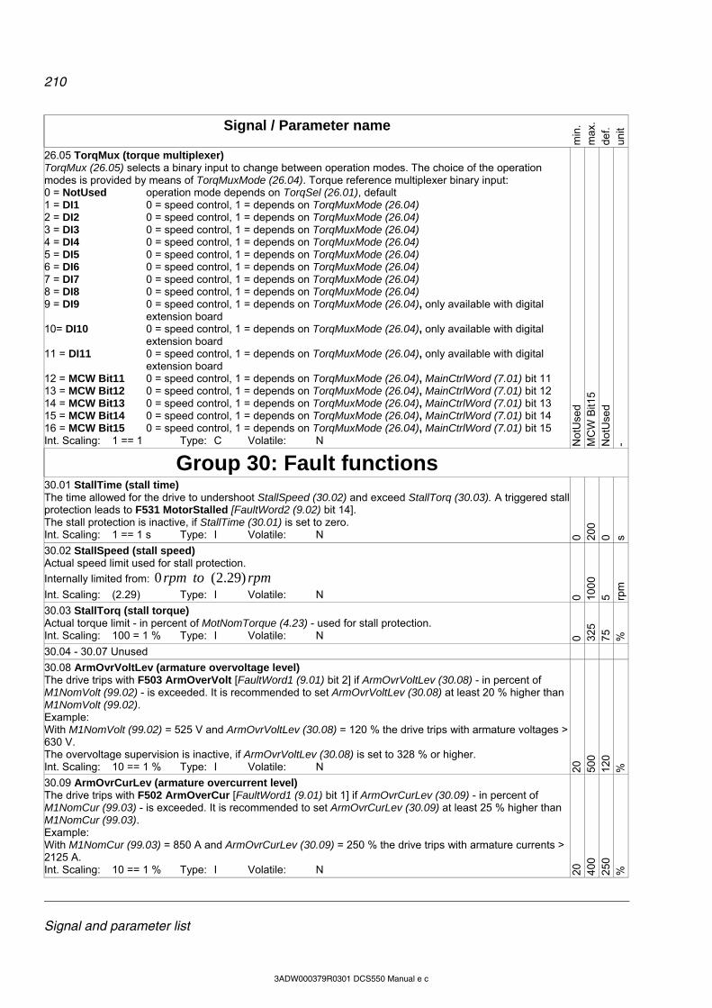
210
Signal and parameter list
3ADW000379R0301 DCS550 Manual e c
Signal / Parameter name
min
. m
ax.
def.
unit
26.05 TorqMux (torque multiplexer) TorqMux (26.05) selects a binary input to change between operation modes. The choice of the operation modes is provided by means of TorqMuxMode (26.04). Torque reference multiplexer binary input: 0 = NotUsed operation mode depends on TorqSel (26.01), default 1 = DI1 0 = speed control, 1 = depends on TorqMuxMode (26.04) 2 = DI2 0 = speed control, 1 = depends on TorqMuxMode (26.04) 3 = DI3 0 = speed control, 1 = depends on TorqMuxMode (26.04) 4 = DI4 0 = speed control, 1 = depends on TorqMuxMode (26.04) 5 = DI5 0 = speed control, 1 = depends on TorqMuxMode (26.04) 6 = DI6 0 = speed control, 1 = depends on TorqMuxMode (26.04) 7 = DI7 0 = speed control, 1 = depends on TorqMuxMode (26.04) 8 = DI8 0 = speed control, 1 = depends on TorqMuxMode (26.04) 9 = DI9 0 = speed control, 1 = depends on TorqMuxMode (26.04), only available with digital
extension board 10= DI10 0 = speed control, 1 = depends on TorqMuxMode (26.04), only available with digital
extension board 11 = DI11 0 = speed control, 1 = depends on TorqMuxMode (26.04), only available with digital
extension board 12 = MCW Bit11 0 = speed control, 1 = depends on TorqMuxMode (26.04), MainCtrlWord (7.01) bit 11 13 = MCW Bit12 0 = speed control, 1 = depends on TorqMuxMode (26.04), MainCtrlWord (7.01) bit 12 14 = MCW Bit13 0 = speed control, 1 = depends on TorqMuxMode (26.04), MainCtrlWord (7.01) bit 13 15 = MCW Bit14 0 = speed control, 1 = depends on TorqMuxMode (26.04), MainCtrlWord (7.01) bit 14 16 = MCW Bit15 0 = speed control, 1 = depends on TorqMuxMode (26.04), MainCtrlWord (7.01) bit 15 Int. Scaling: 1 == 1 Type: C Volatile: N N
otU
sed
MC
W B
it15
Not
Use
d -
Group 30: Fault functions
30.01 StallTime (stall time) The time allowed for the drive to undershoot StallSpeed (30.02) and exceed StallTorq (30.03). A triggered stall protection leads to F531 MotorStalled [FaultWord2 (9.02) bit 14]. The stall protection is inactive, if StallTime (30.01) is set to zero. Int. Scaling: 1 == 1 s Type: I Volatile: N 0 20
0 0 s
30.02 StallSpeed (stall speed) Actual speed limit used for stall protection.
Internally limited from: rpmtorpm )29.2(0
Int. Scaling: (2.29) Type: I Volatile: N 0 100
0 5 rp
m
30.03 StallTorq (stall torque) Actual torque limit - in percent of MotNomTorque (4.23) - used for stall protection. Int. Scaling: 100 = 1 % Type: I Volatile: N 0 32
5 75
%
30.04 - 30.07 Unused
30.08 ArmOvrVoltLev (armature overvoltage level) The drive trips with F503 ArmOverVolt [FaultWord1 (9.01) bit 2] if ArmOvrVoltLev (30.08) - in percent of M1NomVolt (99.02) - is exceeded. It is recommended to set ArmOvrVoltLev (30.08) at least 20 % higher than M1NomVolt (99.02). Example: With M1NomVolt (99.02) = 525 V and ArmOvrVoltLev (30.08) = 120 % the drive trips with armature voltages > 630 V. The overvoltage supervision is inactive, if ArmOvrVoltLev (30.08) is set to 328 % or higher. Int. Scaling: 10 == 1 % Type: I Volatile: N 20
50
0 12
0 %
30.09 ArmOvrCurLev (armature overcurrent level) The drive trips with F502 ArmOverCur [FaultWord1 (9.01) bit 1] if ArmOvrCurLev (30.09) - in percent of M1NomCur (99.03) - is exceeded. It is recommended to set ArmOvrCurLev (30.09) at least 25 % higher than M1NomCur (99.03). Example: With M1NomCur (99.03) = 850 A and ArmOvrCurLev (30.09) = 250 % the drive trips with armature currents > 2125 A. Int. Scaling: 10 == 1 % Type: I Volatile: N 20
40
0 25
0 %

211
Signal and parameter list
3ADW000379R0301 DCS550 Manual e c
Signal / Parameter name
min
. m
ax.
def.
unit
30.10 - 30.11 Unused
30.12 M1FldMinTrip (minimum field trip) The drive trips with F541 M1FexLowCur [FaultWord3 (9.03) bit 8] if M1FldMinTrip (30.12) - in percent of M1NomFldCur (99.11) - is still undershot when FldMinTripDly (45.18) is elapsed. Note: M1FldMinTrip (30.12) is not valid during field heating. In this case, the trip level is automatically set to 50 % of M1FldHeatRef (44.04). The drive trips with F541 M1FexLowCur [FaultWord3 (9.03) bit 8] if 50 % of M1FldHeatRef (44.04) is still undershot when FldMinTripDly (45.18) is elapsed. Int. Scaling: 100 == 1 % Type: I Volatile: N 0 10
0 50
%
30.13 M1FldOvrCurLev (field overcurrent level) The drive trips with F515 M1FexOverCur [FaultWord1 (9.01) bit 14] if M1FldOvrCurLev (30.13) - in percent of M1NomFldCur (99.11) - is exceeded. It is recommended to set M1FldOvrCurtLev (30.13) at least 25 % higher than M1NomFldCur (99.11). The field overcurrent fault is inactive, if M1FldOvrCurLev (30.13) is set to 135 %. Int. Scaling: 100 == 1 % Type: I Volatile: N 0 13
5 12
5 %
30.14 SpeedFbMonLev (speed feedback monitor level) The drive reacts according to SpeedFbFltSel (30.17) or trips with F553 TachPolarity [FaultWord4 (9.04) bit 4]if the measured speed feedback [SpeedActEnc (1.03) or SpeedActTach (1.05)] does not exceed SpeedFbMonLev (30.14) while the measured EMF exceeds EMF FbMonLev (30.15).
Internally limited from: rpmtorpm20000
32767*)29.2(0
Example: With SpeedFbMonLev (30.14) = 15 rpm and EMF FbMonLev (30.15) = 50 V the drive trips when the EMF is > 50 V while the speed feedback is 15 rpm. Int. Scaling: (2.29) Type: I Volatile: N 0 10
000
15
rp
m
30.15 EMF FbMonLev (EMF feedback monitor level) The speed measurement monitoring function is activated, when the measured EMF exceeds EMF FbMonLev (30.15). See also SpeedFbMonLev (30.14). Int. Scaling: 1 == 1 V Type: I Volatile: N 0 20
00
50
V
30.16 M1OvrSpeed (overspeed) The drive trips with F532 MotOverSpeed [FaultWord2 (9.02) bit 15] if M1OvrSpeed (30.16) is exceeded. It is recommended to set M1OvrSpeed (30.16) at least 20 % higher than the maximum motor speed.
Internally limited from: rpmtorpm20000
32767*)29.2(0
The overspeed fault is inactive, if M1OvrSpeed (30.16) is set to zero. Int. Scaling: (2.29) Type: I Volatile: N 0 10
000
18
00
rpm
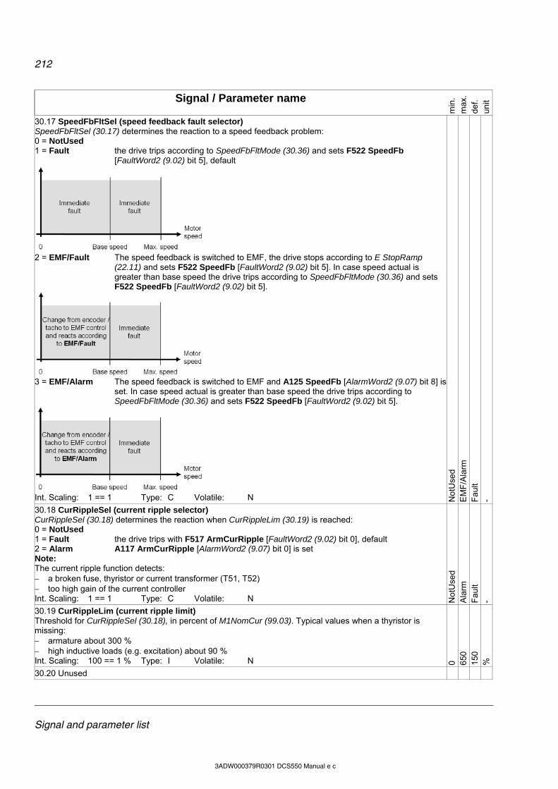
212
Signal and parameter list
3ADW000379R0301 DCS550 Manual e c
Signal / Parameter name
min
. m
ax.
def.
unit
30.17 SpeedFbFltSel (speed feedback fault selector) SpeedFbFltSel (30.17) determines the reaction to a speed feedback problem: 0 = NotUsed 1 = Fault the drive trips according to SpeedFbFltMode (30.36) and sets F522 SpeedFb
[FaultWord2 (9.02) bit 5], default
2 = EMF/Fault The speed feedback is switched to EMF, the drive stops according to E StopRamp
(22.11) and sets F522 SpeedFb [FaultWord2 (9.02) bit 5]. In case speed actual is greater than base speed the drive trips according to SpeedFbFltMode (30.36) and sets F522 SpeedFb [FaultWord2 (9.02) bit 5].
3 = EMF/Alarm The speed feedback is switched to EMF and A125 SpeedFb [AlarmWord2 (9.07) bit 8] is
set. In case speed actual is greater than base speed the drive trips according to SpeedFbFltMode (30.36) and sets F522 SpeedFb [FaultWord2 (9.02) bit 5].
Int. Scaling: 1 == 1 Type: C Volatile: N N
otU
sed
EM
F/A
larm
F
ault
-
30.18 CurRippleSel (current ripple selector) CurRippleSel (30.18) determines the reaction when CurRippleLim (30.19) is reached: 0 = NotUsed 1 = Fault the drive trips with F517 ArmCurRipple [FaultWord2 (9.02) bit 0], default 2 = Alarm A117 ArmCurRipple [AlarmWord2 (9.07) bit 0] is set Note: The current ripple function detects: a broken fuse, thyristor or current transformer (T51, T52) too high gain of the current controller Int. Scaling: 1 == 1 Type: C Volatile: N N
otU
sed
Ala
rm
Fau
lt -
30.19 CurRippleLim (current ripple limit) Threshold for CurRippleSel (30.18), in percent of M1NomCur (99.03). Typical values when a thyristor is missing: armature about 300 % high inductive loads (e.g. excitation) about 90 % Int. Scaling: 100 == 1 % Type: I Volatile: N 0 65
0 15
0 %
30.20 Unused

213
Signal and parameter list
3ADW000379R0301 DCS550 Manual e c
Signal / Parameter name
min
. m
ax.
def.
unit
30.21 PwrLossTrip (power loss trip) The action taken, when the mains voltage undershoots UNetMin2 (30.23): 0 = Immediately the drive trips immediately with F512 MainsLowVolt [FaultWord1 (9.01) bit 11], default 1 = Delayed A111 MainsLowVolt [AlarmWord1 (9.06) bit 10] is set as long as the mains voltage
recovers before PowrDownTime (30.24) is elapsed, otherwise F512 MainsLowVolt [FaultWord1 (9.01) bit 11] is generated
Int. Scaling: 1 == 1 Type: C Volatile: N Imm
edia
tely
D
elay
ed
Imm
edia
tely
-
30.22 UNetMin1 (mains voltage minimum 1) First (upper) limit for mains undervoltage monitoring in percent of NomMainsVolt (99.10). If the mains voltage undershoots UNetMin1 (30.22) following actions take place: the firing angle is set to ArmAlphaMax (20.14), single firing pulses are applied in order to extinguish the current as fast as possible, the controllers are frozen, the speed ramp output is updated from the measured speed and A111 MainsLowVolt [AlarmWord1 (9.06) bit 10] is set as long as the mains voltage recovers before
PowrDownTime (30.24) is elapsed, otherwise F512 MainsLowVolt [FaultWord1 (9.01) bit 11] is generated.
Note: UNetMin2 (30.23) is not monitored, unless the mains voltage drops below UNetMin1 (30.22) first. Thus for a proper function of the mains undervoltage monitoring UNetMin1 (30.22) has to be larger than UNetMin2 (30.23). Int. Scaling: 100 == 1 % Type: I Volatile: N 0 15
0 80
%
30.23 UNetMin2 (mains voltage minimum 2) Second (lower) limit for mains undervoltage monitoring in percent of NomMainsVolt (99.10). If the mains voltage undershoots UnetMin2 (30.23) following actions take place: if PwrLossTrip (30.21) = Immediately: the drive trips immediately with F512 MainsLowVolt [FaultWord1 (9.01) bit 11] if PwrLossTrip (30.21) = Delayed: field acknowledge signals are ignored, the firing angle is set to ArmAlphaMax (20.14), single firing pulses are applied in order to extinguish the current as fast as possible, the controllers are frozen the speed ramp output is updated from the measured speed and A111 MainsLowVolt [AlarmWord1 (9.06) bit 10] is set as long as the mains voltage recovers before
PowrDownTime (30.24) is elapsed, otherwise F512 MainsLowVolt [FaultWord1 (9.01) bit 11] is generated.
Note: UNetMin2 (30.23) is not monitored, unless the mains voltage drops below UNetMin1 (30.22) first. Thus for a proper function of the mains undervoltage monitoring UNetMin1 (30.22) has to be larger than UNetMin2 (30.23). Int. Scaling: 100 == 1 % Type: I Volatile: N 0 15
0 60
%
30.24 PowrDownTime (power down time) The mains voltage must recover (over both limits) within PowrDownTime (30.24). Otherwise F512 MainsLowVolt [FaultWord1 (9.01) bit 11] will be generated. Int. Scaling: 1 == 1 ms Type: I Volatile: N 0 64
000
50
0 m
s
30.25 - 30.26 Unused
Overview local and communication loss: Device Loss control Time out Related fault Related alarm DCS Control Panel
DWL
LocalLossCtrl (30.27) fixed to 5 s F546 LocalCmdLoss A130 LocalCmdLoss
R-type fieldbus ComLossCtrl (30.28) FB TimeOut (30.35) F528 FieldBusCom A128 FieldBusCom
SDCS-COM-8 F543 COM8Com A113 COM8Com

214
Signal and parameter list
3ADW000379R0301 DCS550 Manual e c
Signal / Parameter name
min
. m
ax.
def.
unit
30.27 LocalLossCtrl (local loss control) LocalLossCtrl (30.27) determines the reaction to a local loss (DCS Control Panel, DWL). F546 LocalCmdLoss [FaultWord3 (9.03) bit 13] is set with: 0 = RampStop The input of the drives ramp is set to zero. Thus, the drive stops according to E
StopRamp (22.04). When reaching M1ZeroSpeedLim (20.03) the firing pulses are set to 150 degrees to decrease the armature current. When the armature current is zero the firing pulses are blocked, the contactors are opened, field exciter and fans are stopped.
1 = TorqueLimit The output of the drives ramp is set to zero. Thus, the drive stops at the active torque limit. When reaching M1ZeroSpeedLim (20.03) the firing pulses are set to 150 degrees to decrease the armature current. When the armature current is zero the firing pulses are blocked, the contactors are opened, field exciter and fans are stopped.
2 = CoastStop The firing pulses are immediately set to 150 degrees to decrease the armature current. When the armature current is zero the firing pulses are blocked, the contactors are opened, field exciter and fans are stopped.
3 = DynBraking dynamic braking A130 LocalCmdLoss [AlarmWord2 (9.07) bit 13] is set with: 4 = LastSpeed the drive continues to run at the last speed before the warning 5 = FixedSpeed1 the drive continuous to run with FixedSpeed1 (23.02) Note: The time out for LocalLossCtrl (30.27) is fixed to 10 s. Int. Scaling: 1 == 1 Type: C Volatile: N R
ampS
top
Fix
edS
pee
d1
Ram
pSto
p -
30.28 ComLossCtrl (communication loss control) ComLossCtrl (30.28) determines the reaction to a communication control loss (R-type fieldbusses) see also CommandSel (10.01). F528 FieldBusCom [FaultWord2 (9.02) bit 11] is set with: 0 = RampStop The input of the drives ramp is set to zero. Thus, the drive stops according to E
StopRamp (22.04). When reaching M1ZeroSpeedLim (20.03) the firing pulses are set to 150 degrees to decrease the armature current. When the armature current is zero the firing pulses are blocked, the contactors are opened, field exciter and fans are stopped.
1 = TorqueLimit The output of the drives ramp is set to zero. Thus, the drive stops at the active torque limit. When reaching M1ZeroSpeedLim (20.03) the firing pulses are set to 150 degrees to decrease the armature current. When the armature current is zero the firing pulses are blocked, the contactors are opened, field exciter and fans are stopped.
2 = CoastStop The firing pulses are immediately set to 150 degrees to decrease the armature current. When the armature current is zero the firing pulses are blocked, the contactors are opened, field exciter and fans are stopped.
3 = DynBraking dynamic braking A128 FieldBusCom [AlarmWord2 (9.02) bit 11] is set with: 4 = LastSpeed the drive continues to run at the last speed before the warning 5 = FixedSpeed1 the drive continuous to run with FixedSpeed1 (23.02) Note: The time out for ComLossCtrl (30.28) is set by FB TimeOut (30.35) for all R-type fieldbusses. Int. Scaling: 1 == 1 Type: C Volatile: N R
ampS
top
Fix
edS
pee
d1
Ram
pSto
p -
30.29 AI Mon4mA (analog input 4 mA fault selector) AI Mon4mA (30.29) determines the reaction to an undershoot of one of the analog inputs under 4 mA / 2 V - if it is configured to this mode: 0 = NotUsed 1 = Fault the drive stops according to FaultStopMode (30.30) and trips with F551 AIRange
[FaultWord4 (9.04) bit 2], default 2 = LastSpeed the drive continues to run at the last speed and sets A127 AIRange [AlarmWord2 (9.07)
bit 10] 3 = FixedSpeed1 the drive continues to run with FixedSpeed1 (23.02) and sets A127 AIRange
[AlarmWord2 (9.07) bit 10] Int. Scaling: 1 == 1 Type: C Volatile: N N
otU
sed
Fix
edS
pee
d1
Fau
lt -

215
Signal and parameter list
3ADW000379R0301 DCS550 Manual e c
Signal / Parameter name
min
. m
ax.
def.
unit
30.30 FaultStopMode (fault stop mode) FaultStopMode (30.30) determines the reaction to a fault of trip level 4: 0 = RampStop The input of the drives ramp is set to zero. Thus, the drive stops according to E
StopRamp (22.04). When reaching M1ZeroSpeedLim (20.03) the firing pulses are set to 150 degrees to decrease the armature current. When the armature current is zero the firing pulses are blocked, the contactors are opened, field exciter and fans are stopped.
1 = TorqueLimit The output of the drives ramp is set to zero. Thus, the drive stops at the active torque limit. When reaching M1ZeroSpeedLim (20.03) the firing pulses are set to 150 degrees to decrease the armature current. When the armature current is zero the firing pulses are blocked, the contactors are opened, field exciter and fans are stopped.
2 = CoastStop The firing pulses are immediately set to 150 degrees to decrease the armature current. When the armature current is zero the firing pulses are blocked, the contactors are opened, field exciter and fans are stopped.
3 = DynBraking dynamic braking Note: FaultStopMode (30.30) does not apply to communication faults. Int. Scaling: 1 == 1 Type: C Volatile: N R
ampS
top
Dyn
Bra
king
R
ampS
top
-
30.31 ExtFaultSel (external fault selector) The drive trips with F526 ExternalDI [FaultWord2 (9.02) bit 9] if a binary input for an external fault is selected and 1: 0 = NotUsed default 1 = DI1 1 = fault, 0 = no fault 2 = DI2 1 = fault, 0 = no fault 3 = DI3 1 = fault, 0 = no fault 4 = DI4 1 = fault, 0 = no fault 5 = DI5 1 = fault, 0 = no fault 6 = DI6 1 = fault, 0 = no fault 7 = DI7 1 = fault, 0 = no fault 8 = DI8 1 = fault, 0 = no fault 9 = DI9 1 = fault, 0 = no fault, Only available with digital extension board 10 = DI10 1 = fault, 0 = no fault, Only available with digital extension board 11 = DI11 1 = fault, 0 = no fault, Only available with digital extension board 12 = MCW Bit11 1 = fault, 0 = no fault, MainCtrlWord (7.01) bit 11 13 = MCW Bit12 1 = fault, 0 = no fault, MainCtrlWord (7.01) bit 12 14 = MCW Bit13 1 = fault, 0 = no fault, MainCtrlWord (7.01) bit 13 15 = MCW Bit14 1 = fault, 0 = no fault, MainCtrlWord (7.01) bit 14 16 = MCW Bit15 1 = fault, 0 = no fault, MainCtrlWord (7.01) bit 15 Int. Scaling: 1 == 1 Type: C Volatile: N N
otU
sed
MC
W B
it15
Not
Use
d -
30.32 ExtAlarmSel (external alarm selector) The drive sets A126 ExternalDI [AlarmWord2 (9.07) bit 9] if a binary input for an external alarm is selected and 1: 0 = NotUsed default 1 = DI1 1 = fault, 0 = no fault 2 = DI2 1 = fault, 0 = no fault 3 = DI3 1 = fault, 0 = no fault 4 = DI4 1 = fault, 0 = no fault 5 = DI5 1 = fault, 0 = no fault 6 = DI6 1 = fault, 0 = no fault 7 = DI7 1 = fault, 0 = no fault 8 = DI8 1 = fault, 0 = no fault 9 = DI9 1 = fault, 0 = no fault. Only available with digital extension board 10 = DI10 1 = fault, 0 = no fault. Only available with digital extension board 11 = DI11 1 = fault, 0 = no fault. Only available with digital extension board 12 = MCW Bit11 1 = fault, 0 = no fault, MainCtrlWord (7.01) bit 11 13 = MCW Bit12 1 = fault, 0 = no fault, MainCtrlWord (7.01) bit 12 14 = MCW Bit13 1 = fault, 0 = no fault, MainCtrlWord (7.01) bit 13 15 = MCW Bit14 1 = fault, 0 = no fault, MainCtrlWord (7.01) bit 14 16 = MCW Bit15 1 = fault, 0 = no fault, MainCtrlWord (7.01) bit 15 Int. Scaling: 1 == 1 Type: C Volatile: N N
otU
sed
MC
W B
it15
Not
Use
d -
216
Signal and parameter list
3ADW000379R0301 DCS550 Manual e c
Signal / Parameter name
min
. m
ax.
def.
unit
30.33 - 30.34 Unused
30.35 FB TimeOut (fieldbus time out) Time delay before a communication break with a fieldbus is declared. Depending on the setting of ComLossCtrl (30.28) either F528 FieldBusCom [FaultWord2 (9.02) bit 11] or A128 FieldBusCom [AlarmWord2 (9.07) bit 11] is set. The communication fault and alarm are inactive, if FB TimeOut (30.35) is set to 0 ms. Int. Scaling: 1 == 1 ms Type: I Volatile: N 0 64
000
10
0 m
s
30.36 SpeedFbFltMode (speed feedback fault mode) SpeedFbFltMode (30.36) determines the reaction to a fault of trip level 3: 0 = CoastStop The firing pulses are immediately set to 150 degrees to decrease the armature current.
When the armature current is zero the firing pulses are blocked, the contactors are opened, field exciter and fans are stopped.
1 = DynBraking dynamic braking Note: SpeedFbFltMode (30.36) does not apply to communication faults. Int. Scaling: 1 == 1 Type: C Volatile: N C
oast
Sto
p D
ynB
raki
ng
Coa
stS
top
-
Group 31: Motor temperature
31.01 M1ModelTime (model time constant) Thermal time constant for motors with fan/forced cooling. The time within the temperature rises to 63% of its nominal value. The motor thermal model is blocked, if M1ModelTime (31.01) is set to zero. The value of Mot1TempCalc (1.20) is saved at power down of the drives electronics. Energizing the drives electronics the very first time the motor's ambient temperature is set to 30°C.
WARNING! The model does not protect the motor if it is not properly cooled e.g. due to dust and dirt. Int. Scaling: 10 == 1 s Type: I Volatile: N 0 64
00
240
s
31.02 M1ModelTime2 (model time 2 constant) Thermal time constant for motors with fan/forced cooling if motor fan is switched off.
Attention: For motors without fan set M1ModelTime (31.01) = M1ModelTime2 (31.02). Int. Scaling: 10 == 1 % Type: I Volatile: N 0 64
00
240
0 s
31.03 M1AlarmLimLoad (alarm limit load) The drive sets A107 M1OverLoad [AlarmWord1 (9.06) bit 6] if M1AlarmLimLoad (31.03) - in percent of M1NomCur (99.03) - is exceeded. Output value is Mot1TempCalc (1.20). Int. Scaling: 10 == 1 % Type: I Volatile: N 10
32
5 10
2 %
31.04 M1FaultLimLoad (fault limit load) The drive trips with F507 M1OverLoad [FaultWord1 (9.01) bit 6] if M1FaultLimLoad (31.04) - in percent of M1NomCur (99.03) - is exceeded. Output value is Mot1TempCalc (1.20). Int. Scaling: 10 == 1 % Type: I Volatile: N 10
32
5 10
6 %
217
Signal and parameter list
3ADW000379R0301 DCS550 Manual e c
Signal / Parameter name
min
. m
ax.
def.
unit
31.05 M1TempSel (temperature selector) M1TempSel (31.05) selects the measured temperature input for the connected motor. The result is displayed in Mot1TemopMeas (1.22). Only one single PTC can be connected. 0 = NotUsed motor temperature measurement is blocked, default 1 = 1PTC AI2/Con one PTC connected to AI2 on SDCS-CON-F For more information, see section Motor protection. Int. Scaling: 1 == 1 Type: C Volatile: N N
otU
sed
1PT
C A
I2/C
on
Not
Use
d -
31.06 M1AlarmLimTemp (alarm limit temperature) The drive sets A106 M1OverTemp [AlarmWord1 (9.06) bit 5] if M1AlarmLimTemp (31.06) is exceeded. Output value is Mot1TempMeas (1.22). Note: The unit depends on M1TempSel (31.05). Int. Scaling: 1 == 1 / 1 Type: SI Volatile: N -1
0 40
00
0 °C /
/
-
31.07 M1FaultLimTemp (fault limit temperature) The drive trips with F506 M1OverTemp [FaultWord1 (9.01) bit 5] if M1FaultLimTemp (31.07) is exceeded. Output value is Mot1TempMeas (1.22). Note: The unit depends on M1TempSel (31.05). Int. Scaling: 1 == 1 / 1 Type: SI Volatile: N -1
0 40
00
0 °C /
/
-
31.08 M1KlixonSel (klixon selector) The drive trips with F506 M1OverTemp [FaultWord1 (9.01) bit 5] if a digital input selected and the klixon is open: 0 = NotUsed default 1 = DI1 0 = fault, 1 = no fault 2 = DI2 0 = fault, 1 = no fault 3 = DI3 0 = fault, 1 = no fault 4 = DI4 0 = fault, 1 = no fault 5 = DI5 0 = fault, 1 = no fault 6 = DI6 0 = fault, 1 = no fault 7 = DI7 0 = fault, 1 = no fault 8 = DI8 0 = fault, 1 = no fault 9 = DI9 0 = fault, 1 = no fault. Only available with digital extension board 10 = DI10 0 = fault, 1 = no fault. Only available with digital extension board 11 = DI11 0 = fault, 1 = no fault. Only available with digital extension board Note: It is possible to connect several klixons in series. Int. Scaling: 1 == 1 Type: C Volatile: N N
otU
sed
DI1
1 N
otU
sed
-
31.10 M1LoadCurMax (maximum overload current I2T-function) Maximum overload current of the connected motor in % of M1NomCur (99.03). The overload current is independent of its sign and applies to both current directions. Thus an activated I2T-function limits M1CurLimBrdg1 (20.12) and M1CurLimBrdg2 (20.13). The I2T-function is inactive, if M1LoadCurMax (31.10) is set to values 100 %. In case the I2T-function is reducing the armature current A108 MotCurReduce [AlarmWord1 (9.06) bit 7] is set. Notes: The used current limit depends also on the converter's actual limitation situation (e.g. torque limits, other
current limits, field weakening). Int. Scaling: 100 == 1 % Type: I Volatile: N 0 32
5 10
0 %
31.11 M1OvrLoadTime (overload time I2T-function) Longest permissible time for the maximum overload current defined in M1LoadCurMax (31.10). The I2T-protection is inactive, if M1OvrLoadTime (31.11) is set to zero. In case the I2T-protection is reducing the armature current A108 MotCurReduce [AlarmWord1 (9.06) bit 7] is set. Int. Scaling: 1 == 1 s Type: I Volatile: N 0 18
0 0 s
31.12 M1RecoveryTime (recovery time I2T-function) Recovery time during which a reduced current must flow. The I2T-protection is inactive, if M1RecoveryTime (31.12) is set to zero. In case the I2T-protection is reducing the armature current A108 MotCurReduce [AlarmWord1 (9.06) bit 7] is set. Int. Scaling: 1 == 1 s Type: I Volatile: N 0 36
00
0 s
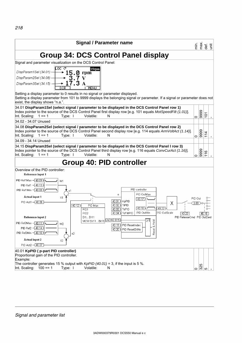
218
Signal and parameter list
3ADW000379R0301 DCS550 Manual e c
Signal / Parameter name
min
. m
ax.
def.
unit
Group 34: DCS Control Panel display
Signal and parameter visualization on the DCS Control Panel:
Setting a display parameter to 0 results in no signal or parameter displayed. Setting a display parameter from 101 to 9999 displays the belonging signal or parameter. If a signal or parameter does not exist, the display shows “n.a.”.
34.01 DispParam1Sel (select signal / parameter to be displayed in the DCS Control Panel row 1) Index pointer to the source of the DCS Control Panel first display row [e.g. 101 equals MotSpeedFilt (1.01)]. Int. Scaling: 1 == 1 Type: I Volatile: N 0 99
99
101
-
34.02 - 34.07 Unused
34.08 DispParam2Sel (select signal / parameter to be displayed in the DCS Control Panel row 2) Index pointer to the source of the DCS Control Panel second display row [e.g. 114 equals ArmVoltAct (1.14)]. Int. Scaling: 1 == 1 Type: I Volatile: N 0 99
99
114
-
34.09 - 34.14 Unused
34.15 DispParam3Sel (select signal / parameter to be displayed in the DCS Control Panel l row 3) Index pointer to the source of the DCS Control Panel third display row [e.g. 116 equals ConvCurAct (1.16)]. Int. Scaling: 1 == 1 Type: I Volatile: N 0 99
99
116
-
Group 40: PID controller
Overview of the PID controller:
40.01 KpPID ( p-part PID controller) Proportional gain of the PID controller. Example: The controller generates 15 % output with KpPID (40.01) = 3, if the input is 5 %. Int. Scaling: 100 == 1 Type: I Volatile: N 0 32
5 5 -
219
Signal and parameter list
3ADW000379R0301 DCS550 Manual e c
Signal / Parameter name
min
. m
ax.
def.
unit
40.02 TiPID (i-part PID controller) Integral time of the PID controller. TiPID (40.02) defines the time within the integral part of the controller achieves the same value as the proportional part. Example: The controller generates 15 % output with KpPID (40.01) = 3, if the input is 5 %. On that condition and with TiPID (40.02) = 300 ms follows: the controller generates 30 % output, if the input is constant, after 300 ms are elapsed (15 % from
proportional part and 15 % from integral part). Int. Scaling: 1 == 1 ms Type: I Volatile: N 0 64
000
25
00
ms
40.03 TdPID (d-part PID controller) PID controller derivation time. TdPID (40.03) defines the time within the PID controller derives the error value. The PID controller works as PI controller, if TdPID (40.03) is set to zero. Int. Scaling: 1 == 1 ms Type: I Volatile: N 0 10
000
0 m
s
40.04 TdFiltPID (filter time for d-part PID controller) Derivation filter time. Int. Scaling: 1 == 1 ms Type: I Volatile: N 0 10
000
10
m
s
40.05 Unused
40.06 PID Act1 (PID controller actual input value 1 index) Index pointer to the source of the PID controller actual input value 1. The format is -xxyy, with: - = negate actual input value 1, xx = group and yy = index [e.g. 101 equals MotSpeedFilt (1.01)]. Int. Scaling: 1 == 1 Type: SI Volatile: N -9
999
999
9 0 -
40.07 PID Act2 (PID controller actual input value 2 index) Index pointer to the source of the PID controller actual input value 2. The format is -xxyy, with: - = negate actual input value 2, xx = group and yy = index [e.g. 101 equals MotSpeedFilt (1.01)]. Int. Scaling: 1 == 1 Type: SI Volatile: N -9
999
999
9 0 -
40.08 PID Ref1Min (PID controller minimum limit reference input value 1) Minimum limit of the PID controller reference input value 1 in percent of the source of PID Ref1 (40.13). Int. Scaling: 100 == 1 % Type: SI Volatile: N -3
25
0 -100
%
40.09 PID Ref1Max (PID controller maximum limit reference input value 1) Maximum limit of the PID controller reference input value 1 in percent of the source of PID Ref1 (40.13). Int. Scaling: 100 == 1 % Type: SI Volatile: N 0 32
5 10
0 %
40.10 PID Ref2Min (PID controller minimum limit reference input value 2) Minimum limit of the PID controller reference input value 2 in percent of the source of PID Ref2 (40.14). Int. Scaling: 100 == 1 % Type: SI Volatile: N -3
25
0 -100
%
40.11 PID Ref2Max (PID controller maximum limit reference input value 2) Maximum limit of the PID controller reference input value 2 in percent of the source of PID Ref2 (40.14). Int. Scaling: 100 == 1 % Type: SI Volatile: N 0 32
5 10
0 %
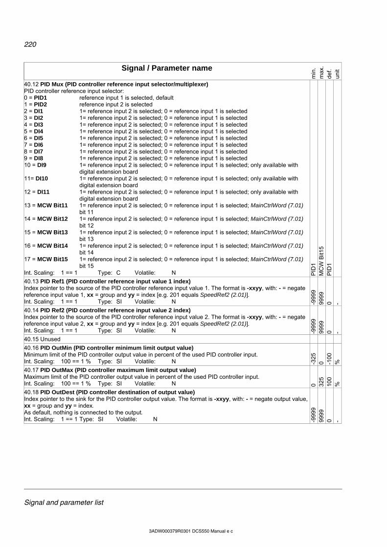
220
Signal and parameter list
3ADW000379R0301 DCS550 Manual e c
Signal / Parameter name
min
. m
ax.
def.
unit
40.12 PID Mux (PID controller reference input selector/multiplexer) PID controller reference input selector: 0 = PID1 reference input 1 is selected, default 1 = PID2 reference input 2 is selected 2 = DI1 1= reference input 2 is selected; 0 = reference input 1 is selected 3 = DI2 1= reference input 2 is selected; 0 = reference input 1 is selected 4 = DI3 1= reference input 2 is selected; 0 = reference input 1 is selected 5 = DI4 1= reference input 2 is selected; 0 = reference input 1 is selected 6 = DI5 1= reference input 2 is selected; 0 = reference input 1 is selected 7 = DI6 1= reference input 2 is selected; 0 = reference input 1 is selected 8 = DI7 1= reference input 2 is selected; 0 = reference input 1 is selected 9 = DI8 1= reference input 2 is selected; 0 = reference input 1 is selected 10 = DI9 1= reference input 2 is selected; 0 = reference input 1 is selected; only available with
digital extension board 11= DI10 1= reference input 2 is selected; 0 = reference input 1 is selected; only available with
digital extension board 12 = DI11 1= reference input 2 is selected; 0 = reference input 1 is selected; only available with
digital extension board 13 = MCW Bit11 1= reference input 2 is selected; 0 = reference input 1 is selected; MainCtrlWord (7.01)
bit 11 14 = MCW Bit12 1= reference input 2 is selected; 0 = reference input 1 is selected; MainCtrlWord (7.01)
bit 12 15 = MCW Bit13 1= reference input 2 is selected; 0 = reference input 1 is selected; MainCtrlWord (7.01)
bit 13 16 = MCW Bit14 1= reference input 2 is selected; 0 = reference input 1 is selected; MainCtrlWord (7.01)
bit 14 17 = MCW Bit15 1= reference input 2 is selected; 0 = reference input 1 is selected; MainCtrlWord (7.01)
bit 15 Int. Scaling: 1 == 1 Type: C Volatile: N P
ID1
MC
W B
it15
PID
1
40.13 PID Ref1 (PID controller reference input value 1 index) Index pointer to the source of the PID controller reference input value 1. The format is -xxyy, with: - = negate reference input value 1, xx = group and yy = index [e.g. 201 equals SpeedRef2 (2.01)]. Int. Scaling: 1 == 1 Type: SI Volatile: N -9
999
999
9 0 -
40.14 PID Ref2 (PID controller reference input value 2 index) Index pointer to the source of the PID controller reference input value 2. The format is -xxyy, with: - = negate reference input value 2, xx = group and yy = index [e.g. 201 equals SpeedRef2 (2.01)]. Int. Scaling: 1 == 1 Type: SI Volatile: N -9
999
999
9 0 -
40.15 Unused
40.16 PID OutMin (PID controller minimum limit output value) Minimum limit of the PID controller output value in percent of the used PID controller input. Int. Scaling: 100 == 1 % Type: SI Volatile: N -3
25
0 -100
%
40.17 PID OutMax (PID controller maximum limit output value) Maximum limit of the PID controller output value in percent of the used PID controller input. Int. Scaling: 100 == 1 % Type: SI Volatile: N 0 32
5 10
0 %
40.18 PID OutDest (PID controller destination of output value) Index pointer to the sink for the PID controller output value. The format is -xxyy, with: - = negate output value, xx = group and yy = index. As default, nothing is connected to the output. Int. Scaling: 1 == 1 Type: SI Volatile: N -9
999
999
9 0 -
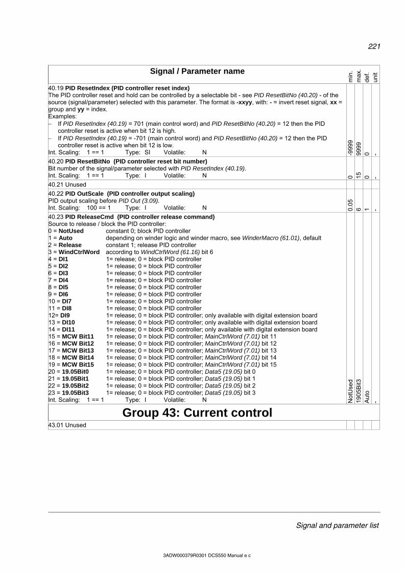
221
Signal and parameter list
3ADW000379R0301 DCS550 Manual e c
Signal / Parameter name
min
. m
ax.
def.
unit
40.19 PID ResetIndex (PID controller reset index) The PID controller reset and hold can be controlled by a selectable bit - see PID ResetBitNo (40.20) - of the source (signal/parameter) selected with this parameter. The format is -xxyy, with: - = invert reset signal, xx = group and yy = index. Examples: If PID ResetIndex (40.19) = 701 (main control word) and PID ResetBitNo (40.20) = 12 then the PID
controller reset is active when bit 12 is high. If PID ResetIndex (40.19) = -701 (main control word) and PID ResetBitNo (40.20) = 12 then the PID
controller reset is active when bit 12 is low. Int. Scaling: 1 == 1 Type: SI Volatile: N -9
999
999
9 0 -
40.20 PID ResetBitNo (PID controller reset bit number) Bit number of the signal/parameter selected with PID ResetIndex (40.19). Int. Scaling: 1 == 1 Type: I Volatile: N 0 15
0 -
40.21 Unused
40.22 PID OutScale (PID controller output scaling) PID output scaling before PID Out (3.09). Int. Scaling: 100 == 1 Type: I Volatile: N 0.
05
6 1 -
40.23 PID ReleaseCmd (PID controller release command) Source to release / block the PID controller: 0 = NotUsed constant 0; block PID controller 1 = Auto depending on winder logic and winder macro, see WinderMacro (61.01), default 2 = Release constant 1; release PID controller 3 = WindCtrlWord according to WindCtrlWord (61.16) bit 6 4 = DI1 1= release; 0 = block PID controller 5 = DI2 1= release; 0 = block PID controller 6 = DI3 1= release; 0 = block PID controller 7 = DI4 1= release; 0 = block PID controller 8 = DI5 1= release; 0 = block PID controller 9 = DI6 1= release; 0 = block PID controller 10 = DI7 1= release; 0 = block PID controller 11 = DI8 1= release; 0 = block PID controller 12= DI9 1= release; 0 = block PID controller; only available with digital extension board 13 = DI10 1= release; 0 = block PID controller; only available with digital extension board 14 = DI11 1= release; 0 = block PID controller; only available with digital extension board 15 = MCW Bit11 1= release; 0 = block PID controller; MainCtrlWord (7.01) bit 11 16 = MCW Bit12 1= release; 0 = block PID controller; MainCtrlWord (7.01) bit 12 17 = MCW Bit13 1= release; 0 = block PID controller; MainCtrlWord (7.01) bit 13 18 = MCW Bit14 1= release; 0 = block PID controller; MainCtrlWord (7.01) bit 14 19 = MCW Bit15 1= release; 0 = block PID controller; MainCtrlWord (7.01) bit 15 20 = 19.05Bit0 1= release; 0 = block PID controller; Data5 (19.05) bit 0 21 = 19.05Bit1 1= release; 0 = block PID controller; Data5 (19.05) bit 1 22 = 19.05Bit2 1= release; 0 = block PID controller; Data5 (19.05) bit 2 23 = 19.05Bit3 1= release; 0 = block PID controller; Data5 (19.05) bit 3 Int. Scaling: 1 == 1 Type: I Volatile: N N
otU
sed
190
5Bit3
A
uto
-
Group 43: Current control
43.01 Unused
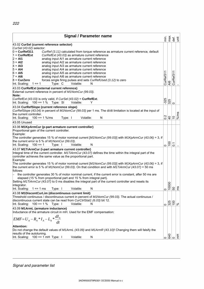
222
Signal and parameter list
3ADW000379R0301 DCS550 Manual e c
Signal / Parameter name
min
. m
ax.
def.
unit
43.02 CurSel (current reference selector) CurSel (43.02) selector: 0 = CurRef311 CurRef (3.11) calculated from torque reference as armature current reference, default 1 = CurRefExt CurRefExt (43.03) as armature current reference 2 = AI1 analog input AI1 as armature current reference 3 = AI2 analog input AI2 as armature current reference 4 = AI3 analog input AI3 as armature current reference 5 = AI4 analog input AI4 as armature current reference 6 = AI5 analog input AI5 as armature current reference 7 = AI6 analog input AI6 as armature current reference 8 = CurZero forces single firing pulses and sets CurRefUsed (3.12) to zero Int. Scaling: 1 == 1 Type: C Volatile: N C
urR
ef31
1 A
I6
Cur
Ref
311
-
43.03 CurRefExt (external current reference) External current reference in percent of M1NomCur (99.03). Note: CurRefExt (43.03) is only valid, if CurSel (43.02) = CurRefExt. Int. Scaling: 100 == 1 % Type: SI Volatile: Y -3
25
325
0
43.04 CurRefSlope (current reference slope) CurRefSlope (43.04) in percent of M1NomCur (99.03) per 1 ms. The di/dt limitation is located at the input of the current controller. Int. Scaling: 100 == 1 %/ms Type: I Volatile: N 0.
2 40
10
%
/ms
43.05 Unused
43.06 M1KpArmCur (p-part armature current controller) Proportional gain of the current controller. Example: The controller generates 15 % of motor nominal current [M1NomCur (99.03)] with M1KpArmCur (43.06) = 3, if the current error is 5 % of M1NomCur (99.03). Int. Scaling: 100 == 1 Type: I Volatile: N 0 10
0 0.
1 -
43.07 M1TiArmCur (i-part armature current controller) Integral time of the current controller. M1TiArmCur (43.07) defines the time within the integral part of the controller achieves the same value as the proportional part. Example: The controller generates 15 % of motor nominal current [M1NomCur (99.03)] with M1KpArmCur (43.06) = 3, if the current error is 5 % of M1NomCur (99.03). On that condition and with M1TiArmCur (43.07) = 50 ms follows: the controller generates 30 % of motor nominal current, if the current error is constant, after 50 ms are
elapsed (15 % from proportional part and 15 % from integral part). Setting M1TiArmCur (43.07) to 0 ms disables the integral part of the current controller and resets its integrator. Int. Scaling: 1 == 1 ms Type: I Volatile: N 0 10
000
50
m
s
43.08 M1DiscontCurLim (discontinuous current limit) Threshold continuous / discontinuous current in percent of M1NomCur (99.03). The actual continuous / discontinuous current state can be read from CurCtrlStat1 (6.03) bit 12. Int. Scaling: 100 == 1 % Type: I Volatile: N 0 32
5 10
0 %
43.09 M1ArmL (armature inductance) Inductance of the armature circuit in mH. Used for the EMF compensation:
dt
dILIRUEMF A
AAAA **
Attention: Do not change the default values of M1ArmL (43.09) and M1ArmR (43.10)! Changing them will falsify the results of the autotuning. Int. Scaling: 100 == 1 mH Type: I Volatile: N 0 64
0 0 m
H
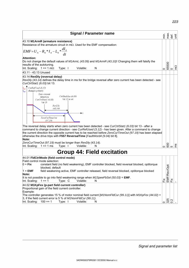
223
Signal and parameter list
3ADW000379R0301 DCS550 Manual e c
Signal / Parameter name
min
. m
ax.
def.
unit
43.10 M1ArmR (armature resistance) Resistance of the armature circuit in m. Used for the EMF compensation:
dt
dILIRUEMF A
AAAA **
Attention: Do not change the default values of M1ArmL (43.09) and M1ArmR (43.10)! Changing them will falsify the results of the autotuning. Int. Scaling: 1 == 1 m Type: I Volatile: N 0 65
500
0 m
43.11 - 43.13 Unused
43.14 RevDly (reversal delay) RevDly (43.14) defines the delay time in ms for the bridge reversal after zero current has been detected - see CurCtrlStat1 (6.03) bit 13.
The reversal delay starts when zero current has been detected - see CurCtrlStat1 (6.03) bit 13 - after a command to change current direction - see CurRefUsed (3.12) - has been given. After a command to change the current direction the opposite current has to be reached before ZeroCurTimeOut (97.19) has been elapsed otherwise the drive trips with F557 ReversalTime [FaultWord4 (9.04) bit 8]. Note: ZeroCurTimeOut (97.19) must be longer than RevDly (43.14). Int. Scaling: 1 == 1 ms Type: I Volatile: N 0 60
0 5 m
s
Group 44: Field excitation
44.01 FldCtrlMode (field control mode) Field control mode selection: 0 = Fix constant field (no field weakening), EMF controller blocked, field reversal blocked, optitorque
blocked, default 1 = EMF field weakening active, EMF controller released, field reversal blocked, optitorque blocked Note: It is not possible to go into field weakening range when M1SpeeFbSel (50.03) = EMF. Int. Scaling: 1 == 1 Type: C Volatile: N F
ix
EM
F/R
ev/O
pti
Fix
-
44.02 M1KpFex (p-part field current controller) Proportional gain of the field current controller. Example: The controller generates 15 % of motor nominal field current [M1NomFldCur (99.11)] with M1KpFex (44.02) = 3, if the field current error is 5 % of M1NomFldCur (99.11). Int. Scaling: 100 == 1 Type: I Volatile: N 0 32
5 0.
2 -
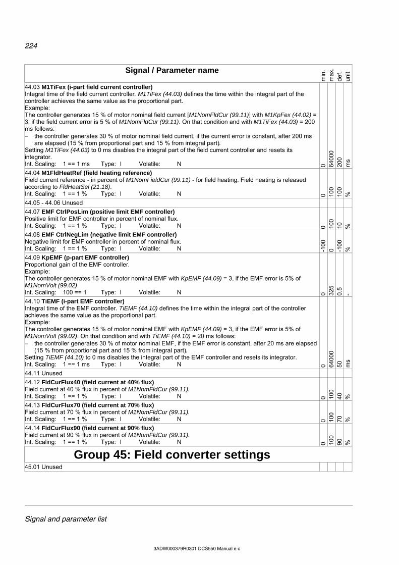
224
Signal and parameter list
3ADW000379R0301 DCS550 Manual e c
Signal / Parameter name
min
. m
ax.
def.
unit
44.03 M1TiFex (i-part field current controller) Integral time of the field current controller. M1TiFex (44.03) defines the time within the integral part of the controller achieves the same value as the proportional part. Example: The controller generates 15 % of motor nominal field current [M1NomFldCur (99.11)] with M1KpFex (44.02) = 3, if the field current error is 5 % of M1NomFldCur (99.11). On that condition and with M1TiFex (44.03) = 200 ms follows: the controller generates 30 % of motor nominal field current, if the current error is constant, after 200 ms
are elapsed (15 % from proportional part and 15 % from integral part). Setting M1TiFex (44.03) to 0 ms disables the integral part of the field current controller and resets its integrator. Int. Scaling: 1 == 1 ms Type: I Volatile: N 0 64
000
20
0 m
s
44.04 M1FldHeatRef (field heating reference) Field current reference - in percent of M1NomFieldCur (99.11) - for field heating. Field heating is released according to FldHeatSel (21.18). Int. Scaling: 1 == 1 % Type: I Volatile: N 0 10
0 10
0 %
44.05 - 44.06 Unused
44.07 EMF CtrlPosLim (positive limit EMF controller) Positive limit for EMF controller in percent of nominal flux. Int. Scaling: 1 == 1 % Type: I Volatile: N 0 10
0 10
%
44.08 EMF CtrlNegLim (negative limit EMF controller) Negative limit for EMF controller in percent of nominal flux. Int. Scaling: 1 == 1 % Type: I Volatile: N -1
00
0 -100
%
44.09 KpEMF (p-part EMF controller) Proportional gain of the EMF controller. Example: The controller generates 15 % of motor nominal EMF with KpEMF (44.09) = 3, if the EMF error is 5% of M1NomVolt (99.02). Int. Scaling: 100 == 1 Type: I Volatile: N 0 32
5 0.
5 -
44.10 TiEMF (i-part EMF controller) Integral time of the EMF controller. TiEMF (44.10) defines the time within the integral part of the controller achieves the same value as the proportional part. Example: The controller generates 15 % of motor nominal EMF with KpEMF (44.09) = 3, if the EMF error is 5% of M1NomVolt (99.02). On that condition and with TiEMF (44.10) = 20 ms follows: the controller generates 30 % of motor nominal EMF, if the EMF error is constant, after 20 ms are elapsed
(15 % from proportional part and 15 % from integral part). Setting TiEMF (44.10) to 0 ms disables the integral part of the EMF controller and resets its integrator. Int. Scaling: 1 == 1 ms Type: I Volatile: N 0 64
000
50
m
s
44.11 Unused
44.12 FldCurFlux40 (field current at 40% flux) Field current at 40 % flux in percent of M1NomFldCur (99.11). Int. Scaling: 1 == 1 % Type: I Volatile: N 0 10
0 40
%
44.13 FldCurFlux70 (field current at 70% flux) Field current at 70 % flux in percent of M1NomFldCur (99.11). Int. Scaling: 1 == 1 % Type: I Volatile: N 0 10
0 70
%
44.14 FldCurFlux90 (field current at 90% flux) Field current at 90 % flux in percent of M1NomFldCur (99.11). Int. Scaling: 1 == 1 % Type: I Volatile: N 0 10
0 90
%
Group 45: Field converter settings
45.01 Unused
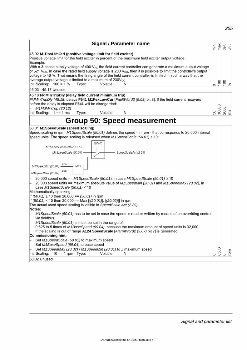
225
Signal and parameter list
3ADW000379R0301 DCS550 Manual e c
Signal / Parameter name
min
. m
ax.
def.
unit
45.02 M1PosLimCtrl (positive voltage limit for field exciter) Positive voltage limit for the field exciter in percent of the maximum field exciter output voltage. Example: With a 3-phase supply voltage of 400 VAC the field current controller can generate a maximum output voltage of 521 VDC. In case the rated field supply voltage is 200 VDC, then it is possible to limit the controller’s output voltage to 46 %. That means the firing angle of the field current controller is limited in such a way that the average output voltage is limited to a maximum of 230VDC. Int. Scaling: 100 = 1 % Type: I Volatile: N 0 10
0 10
0 %
45.03 - 45.17 Unused
45.18 FldMinTripDly (delay field current minimum trip) FldMinTripDly (45.18) delays F541 M1FexLowCur [FaultWord3 (9.03) bit 8]. If the field current recovers before the delay is elapsed F541 will be disregarded: M1FldMinTrip (30.12) Int. Scaling: 1 == 1 ms Type: I Volatile: N 50
10
000
20
00
ms
Group 50: Speed measurement
50.01 M1SpeedScale (speed scaling) Speed scaling in rpm. M1SpeedScale (50.01) defines the speed - in rpm - that corresponds to 20,000 internal speed units. The speed scaling is released when M1SpeedScale (50.01) 10:
20,000 speed units == M1SpeedScale (50.01), in case M1SpeedScale (50.01) 10 20,000 speed units == maximum absolute value of M1SpeedMin (20.01) and M1SpeedMax (20.02), in
case M1SpeedScale (50.01) < 10 Mathematically speaking: If (50.01) 10 then 20,000 == (50.01) in rpm If (50.01) < 10 then 20,000 == Max [|(20.01)|, |(20.02)|] in rpm The actual used speed scaling is visible in SpeedScale Act (2.29). Notes: M1SpeedScale (50.01) has to be set in case the speed is read or written by means of an overriding control
via fieldbus. M1SpeedScale (50.01) is must be set in the range of:
0.625 to 5 times of M1BaseSpeed (99.04), because the maximum amount of speed units is 32,000. If the scaling is out of range A124 SpeedScale [AlarmWord2 (9.07) bit 7] is generated.
Commissioning hint: Set M1SpeedScale (50.01) to maximum speed Set M1BaseSpeed (99.04) to base speed Set M1SpeedMax (20.02) / M1SpeedMin (20.01) to maximum speed Int. Scaling: 10 == 1 rpm Type: I Volatile: N 0 65
00
0 rpm
50.02 Unused

226
Signal and parameter list
3ADW000379R0301 DCS550 Manual e c
Signal / Parameter name
min
. m
ax.
def.
unit
50.03 M1SpeedFbSel (speed feedback selector) Speed feedback selection: 0 = EMF speed is calculated by means of the EMF feedback with flux compensation, default 1 = Encoder speed is measured by means of a pulse encoder 2 = Tacho speed is measured by means of an analog tacho 3 = External MotSpeed (1.04) is updated by Adaptive Program or overriding control Notes: It is not possible to go into field weakening range when M1SpeeFbSel (50.03) = EMF. When using EMF speed feedback together with a DC-breaker wrong voltage measurements can lead to
F532 MotOverSpeed [FaultWord2 (9.02) bit 15]. In case of an open DC-breaker the voltage measurement might show high values caused by leakage currents through the snubber circuits of the thyristors, because there is no load on the DC side. To prevent these trips set MainContAck (10.21) = DCcontact.
Int. Scaling: 1 == 1 Type: C Volatile: N EM
F
Enc
oder
2 E
MF
-
50.04 M1EncPulseNo (encoder 1 pulse number) Amount of pulses per revolution (ppr) for the pulse encoder. Int. Scaling: 1 == 1 ppr Type: I Volatile: N 20
10
000
10
24
ppr
50.05 MaxEncoderTime (maximum encoder time) When an encoder is used as speed feedback device the actual speed is measured by counting the amount of pulses per cycle time. The cycle time for the measurement is synchronized with the mains (every 3.3 ms or 2.77 ms). In case very small speeds have to be measured - that means there is less than one pulse per cycle time - it is possible to increase the measuring time by means of MaxEncoderTime (50.05). The speed is set to zero after MaxEncoderTime (50.05) is elapsed without a measured pulse.
Notes: Formula to calculate the maximum speed using an encoder:
ppr
skHzrpmn
60*300max
with: ppr = pulses per revolution - see M1EncPulseNo (50.04) Formula to calculate the minimum speed resolution using an encoder:
cycletpprk
srpmn
**
60min
with: k = 4 (speed evaluation factor) ppr = pulses per revolution - see M1EncPulseNo (50.04) tcycle = cycle time of the speed controller, either 3.3 ms or 2.77 ms
Int. Scaling: 1 == 1 ms Type: I Volatile: N 3 200
3 ms
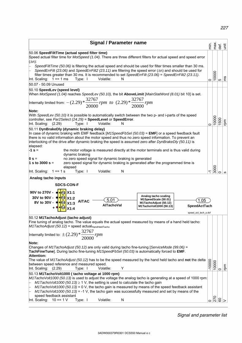
227
Signal and parameter list
3ADW000379R0301 DCS550 Manual e c
Signal / Parameter name
min
. m
ax.
def.
unit
50.06 SpeedFiltTime (actual speed filter time) Speed actual filter time for MotSpeed (1.04). There are three different filters for actual speed and speed error (n): SpeedFiltTime (50.06) is filtering the actual speed and should be used for filter times smaller than 30 ms. SpeedErrFilt (23.06) and SpeedErrFilt2 (23.11) are filtering the speed error (n) and should be used for
filter times greater than 30 ms. It is recommended to set SpeedErrFilt (23.06) = SpeedErrFilt2 (23.11). Int. Scaling: 1 == 1 ms Type: I Volatile: N 0 10
000
5 m
s
50.07 - 50.09 Unused
50.10 SpeedLev (speed level) When MotSpeed (1.04) reaches SpeedLev (50.10), the bit AboveLimit [MainStatWord (8.01) bit 10] is set.
Internally limited from: rpmtorpm20000
32767*)29.2(
20000
32767*)29.2(
Note: With SpeedLev (50.10) it is possible to automatically switch between the two p- and i-parts of the speed controller, see Par2Select (24.29) = SpeedLevel or SpeedError. Int. Scaling: (2.29) Type: I Volatile: N 0 10
000
15
00
rpm
50.11 DynBrakeDly (dynamic braking delay) In case of dynamic braking with EMF feedback [M1SpeedFbSel (50.03) = EMF] or a speed feedback fault there is no valid information about the motor speed and thus no zero speed information. To prevent an interlocking of the drive after dynamic braking the speed is assumed zero after DynBrakeDly (50.11) is elapsed: -1 s = the motor voltage is measured directly at the motor terminals and is thus valid during
dynamic braking 0 s = no zero speed signal for dynamic braking is generated 1 s to 3000 s = zero speed signal for dynamic braking is generated after the programmed time is
elapsed Int. Scaling: 1 == 1 s Type: I Volatile: N -1
30
00
0 s
SDCS-CON-F
X1:1
1
1
1
Analog tacho inputs
X1:2X1:3
X1:4
AITAC
90V to 270V -90V to 270V -
30V to 90V -8V to 30V -
+
SDCS-CON-F
X1:1
1
1
1
SDCS-CON-F
X1:1
1
1
1
Analog tacho inputs
X1:2X1:3
X1:4
AITAC
90V to 270V -90V to 270V -
30V to 90V -8V to 30V -
+ SpeedActTach
5.01 1.05
speed_act_tach_a.dsf
Analog tacho scalingM1SpeedScale (50.01)M1TachoAdjust (50.12)
M1TachoVolt1000 (50.13)AITachoVal
50.12 M1TachoAdjust (tacho adjust) Fine tuning of analog tacho. The value equals the actual speed measured by means of a hand held tacho: M1TachoAdjust (50.12) = speed actualHandHeldTacho
Internally limited to: rpm20000
32767*)29.2(
Note: Changes of M1TachoAdjust (50.12) are only valid during tacho fine-tuning [ServiceMode (99.06) = TachFineTune]. During tacho fine-tuning M1SpeedFbSel (50.03) is automatically forced to EMF. Attention: The value of M1TachoAdjust (50.12) has to be the speed measured by the hand held tacho and not the delta between speed reference and measured speed. Int. Scaling: (2.29) Type: I Volatile: Y -1
0000
10
000
0 rp
m
50.13 M1TachoVolt1000 ( tacho voltage at 1000 rpm) M1TachoVolt1000 (50.13) is used to adjust the voltage the analog tacho is generating at a speed of 1000 rpm: M1TachoVolt1000 (50.13) 1 V, the setting is used to calculate the tacho gain M1TachoVolt1000 (50.13) = 0 V, the tacho gain is measured by means of the speed feedback assistant M1TachoVolt1000 (50.13) = -1 V, the tacho gain was successfully measured and set by means of the
speed feedback assistant Int. Scaling: 10 == 1 V Type: I Volatile: N 0 27
0 60
V
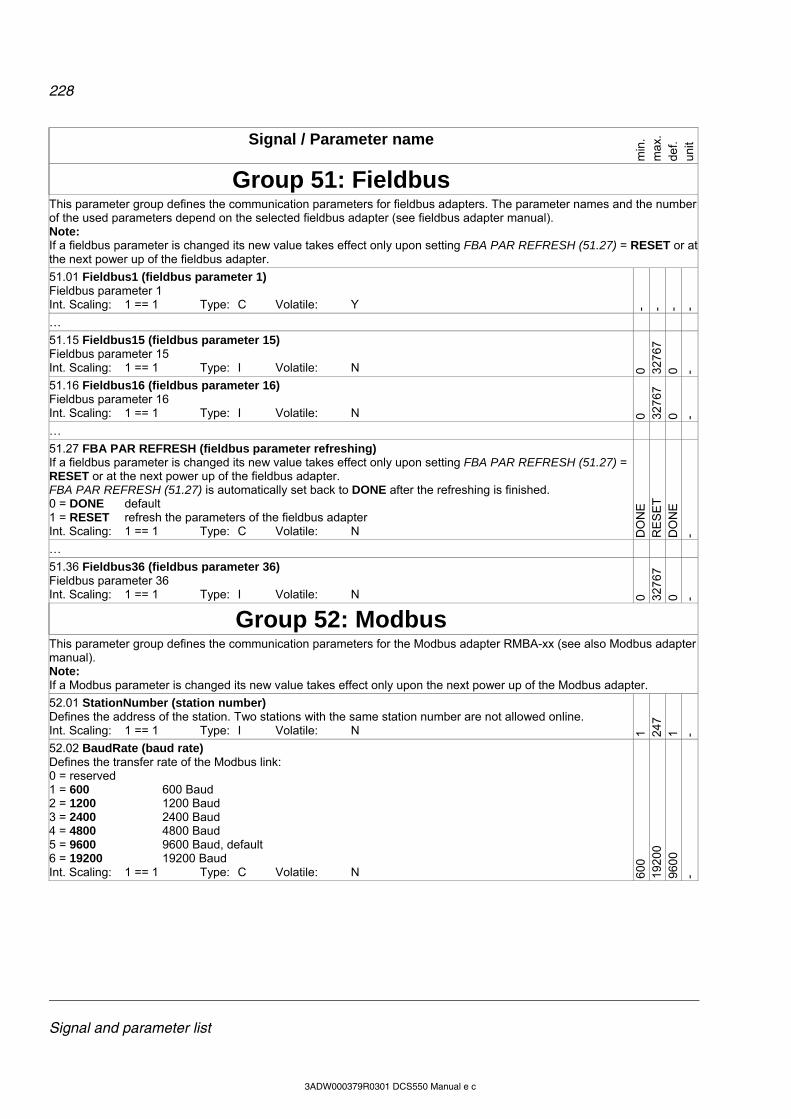
228
Signal and parameter list
3ADW000379R0301 DCS550 Manual e c
Signal / Parameter name
min
. m
ax.
def.
unit
Group 51: Fieldbus
This parameter group defines the communication parameters for fieldbus adapters. The parameter names and the number of the used parameters depend on the selected fieldbus adapter (see fieldbus adapter manual). Note: If a fieldbus parameter is changed its new value takes effect only upon setting FBA PAR REFRESH (51.27) = RESET or at the next power up of the fieldbus adapter.
51.01 Fieldbus1 (fieldbus parameter 1) Fieldbus parameter 1 Int. Scaling: 1 == 1 Type: C Volatile: Y - - - -
…
51.15 Fieldbus15 (fieldbus parameter 15) Fieldbus parameter 15 Int. Scaling: 1 == 1 Type: I Volatile: N 0 32
767
0 -
51.16 Fieldbus16 (fieldbus parameter 16) Fieldbus parameter 16 Int. Scaling: 1 == 1 Type: I Volatile: N 0 32
767
0 -
…
51.27 FBA PAR REFRESH (fieldbus parameter refreshing) If a fieldbus parameter is changed its new value takes effect only upon setting FBA PAR REFRESH (51.27) = RESET or at the next power up of the fieldbus adapter. FBA PAR REFRESH (51.27) is automatically set back to DONE after the refreshing is finished. 0 = DONE default 1 = RESET refresh the parameters of the fieldbus adapter Int. Scaling: 1 == 1 Type: C Volatile: N D
ON
E
RE
SE
T
DO
NE
-
…
51.36 Fieldbus36 (fieldbus parameter 36) Fieldbus parameter 36 Int. Scaling: 1 == 1 Type: I Volatile: N 0 32
767
0 -
Group 52: Modbus
This parameter group defines the communication parameters for the Modbus adapter RMBA-xx (see also Modbus adapter manual). Note: If a Modbus parameter is changed its new value takes effect only upon the next power up of the Modbus adapter.
52.01 StationNumber (station number) Defines the address of the station. Two stations with the same station number are not allowed online. Int. Scaling: 1 == 1 Type: I Volatile: N 1 24
7 1 -
52.02 BaudRate (baud rate) Defines the transfer rate of the Modbus link: 0 = reserved 1 = 600 600 Baud 2 = 1200 1200 Baud 3 = 2400 2400 Baud 4 = 4800 4800 Baud 5 = 9600 9600 Baud, default 6 = 19200 19200 Baud Int. Scaling: 1 == 1 Type: C Volatile: N 60
0 19
200
96
00
-
229
Signal and parameter list
3ADW000379R0301 DCS550 Manual e c
Signal / Parameter name
min
. m
ax.
def.
unit
52.03 Parity (parity) Defines the use of parity and stop bit(s). The same setting must be used in all online stations: 0 = reserved 1 = None1Stopbit no parity bit, one stop bit 2 = None2Stopbit no parity bit, two stop bits 3 = Odd odd parity indication bit, one stop bit 4 = Even even parity indication bit, one stop bit, default Int. Scaling: 1 == 1 Type: C Volatile: N re
serv
ed
Eve
n E
ven
-
Group 61: Winder control
61.01 WinderMacro (winder control, winder macro) WinderMacro (61.01) selects and activates a winder macro: 0 = NotUsed winder macro is blocked, default 1 = VelocityCtrl Velocity control calculates the coil diameters and motor speed references. By means of
the diameter, it is possible to adapt the speed controller to all coil diameters. The tension is not controlled.
2 = IndirectTens Indirect tension control is an open loop control, since the actual tension is not measured. The tension is controlled via diameter and pre-set charts for inertia and friction. The speed controller stays active, but is saturated. This structure provides a very robust control behavior because no physical tension measurement is required.
3 = DirectTens Direct tension control (load cell control) is a closed loop control for the tension. The actual tension is measured by means of a load cell and fed into the drive via analog input (AI3) and PID controller in group 40. The speed controller stays active, but is saturated.
4 = DancerCtrl In dancer control the tension is established through the dancer’s weight. The position of the dancer is read by means of an analog input (AI3). Its position is controlled by an additional speed reference coming from the PID controller in group 40.
Note: The winder program is only running when WiProgCmd (66.01) = Start Int. Scaling: 1 == 1 Type: C Volatile: N N
otU
sed
Dan
cerC
trl
Not
Use
d -

230
Signal and parameter list
3ADW000379R0301 DCS550 Manual e c
Signal / Parameter name
min
. m
ax.
def.
unit
61.02 WriteToSpdChain (winder control, write to speed chain) WriteToSpdChain (61.02) controls the outputs of the winder blocks: 0 = NotUsed constant 0; values of connected block outputs are not written to the speed control chain 1 = Auto values of connected block outputs are written to the speed control chain, depending on
winder logic and winder macro, see WinderMacro (61.01), default 2 = Release constant 1; values of connected block outputs are written to the speed control chain 3 = WindCtrlWord according to WindCtrlWord (61.16) bit 2 4 = DI1 1= written; 0 = not written 5 = DI2 1= written; 0 = not written 6 = DI3 1= written; 0 = not written 7 = DI4 1= written; 0 = not written 8 = DI5 1= written; 0 = not written 9 = DI6 1= written; 0 = not written 10 = DI7 1= written; 0 = not written 11 = DI8 1= written; 0 = not written 12 = DI9 1= written; 0 = not written; only available with digital extension board 13 = DI10 1= written; 0 = not written; only available with digital extension board 14 = DI11 1= written; 0 = not written; only available with digital extension board 15 = MCW Bit11 1= written; 0 = not written; MainCtrlWord (7.01) bit 11 16 = MCW Bit12 1= written; 0 = not written; MainCtrlWord (7.01) bit 12 17 = MCW Bit13 1= written; 0 = not written; MainCtrlWord (7.01) bit 13 18 = MCW Bit14 1= written; 0 = not written; MainCtrlWord (7.01) bit 14 19 = MCW Bit15 1= written; 0 = not written; MainCtrlWord (7.01) bit 15 20 = 19.05Bit0 1= written; 0 = not written; Data5 (19.05) bit 0 21 = 19.05Bit1 1= written; 0 = not written; Data5 (19.05) bit 1 22 = 19.05Bit2 1= written; 0 = not written; Data5 (19.05) bit 2 23 = 19.05Bit3 1= written; 0 = not written; Data5 (19.05) bit 3 Note: The connections itself are set by the selected winder macro and by the user. Int. Scaling: 1 == 1 Type: C Volatile: N N
otU
sed
190
5Bit3
A
uto
-
61.03 Unused
61.04 WindUnwindCmd (winder control, rewind / unwind command) Source for the rewind / unwind command: 0 = NotUsed no action 1 = Winder constant 1; rewinder, default 2 = Unwinder constant 0; unwinder 3 = WindCtrlWord according to WindCtrlWord (61.16) bit 3 4 = DI1 1= rewinder; 0 = unwinder 5 - 23 see WriteToSpdChain (61.02)
rewind
unwind
rewind
unwind
Int. Scaling: 1 == 1 Type: C Volatile: N N
otU
sed
190
5Bit3
W
inde
r -

231
Signal and parameter list
3ADW000379R0301 DCS550 Manual e c
Signal / Parameter name
min
. m
ax.
def.
unit
61.05 TopBottomCmd (winder control, top / bottom command) Source for the top (overwind) / bottom (underwind) command: 0 = NotUsed no action 1 = Top constant 1; top (overwind) , default 2 = Bottom constant 0; bottom (underwind) 3 = WindCtrlWord according to WindCtrlWord (61.16) bit 4 4 = DI1 1= Top (overwind); 0 = bottom (underwind) 5 - 23 see WriteToSpdChain (61.02)
top / overwind
bottom / underwind
top / overwind
bottom / underwind
Int. Scaling: 1 == 1 Type: C Volatile: N N
otU
sed
190
5Bit3
T
op
-
61.06 WinderOnCmd (winder control, winder on command) Source to release / block winder functions: 0 = NotUsed constant 0; block winder functions 1 = Auto depending on winder logic and winder macro, see WinderMacro (61.01), default 2 = Release constant 1; release winder functions 3 = WindCtrlWord according to WindCtrlWord (61.16) bit 5 4 = DI1 1= release winder functions; 0 = block winder functions 5 - 23 see WriteToSpdChain (61.02) Int. Scaling: 1 == 1 Type: C Volatile: N N
otU
sed
190
5Bit3
A
uto
-
61.07 TensionOnCmd (winder control, tension on command) Source to release / block the independent speed controller torque limits - IndepTorqMaxSPC (20.24) and - IndepTorqMinSPC (20.25) - for tension control: 0 = NotUsed constant 0; no tension control 1 = Auto depending on winder logic and winder macro, see WinderMacro (61.01), default 2 = Release constant 1; release tension control 3 = WindCtrlWord according to WindCtrlWord (61.16) bit 8 4 = DI1 1= release tension control; 0 = no tension control 5 - 23 see WriteToSpdChain (61.02) Int. Scaling: 1 == 1 Type: C Volatile: N N
otU
sed
190
5Bit3
A
uto
- 61.08 Unused

232
Signal and parameter list
3ADW000379R0301 DCS550 Manual e c
Signal / Parameter name
min
. m
ax.
def.
unit
The standard ramp will be re-configured for the winder control. Commissioning hints: For proper calculation following rules apply: Maximum motor speed (nmax) is reached with minimum diameter (Dmin) at maximum line speed (vmax). The scaling of line speed and motor speed is needed, because the winder works with relative values (percent).
1. Set LineSpdUnit (61.12) to the desired unit. 2. Set LineSpdScale (61.09) to the maximum line speed. Thus, the maximum line speed corresponds to 20,000
internal line speed units. 3. Set LineSpdPosLim (61.10) to maximum line speed. 4. Calculate the maximum needed motor speed:
iD
vsn *
**
min
60
min
maxmax
nmax [rpm] maximum needed motor speed vmax [m/s] maximum line speed Dmin [m] minimum diameter i gear ratio (motor / load)
5. Set M1SpeedScale (50.01) = nmax even if the motor data allow a wider speed range. Thus, the maximum motor speed corresponds to 20,000 internal speed units.
6. Set M1SpeedMax (20.02) = nmax + max WindSpdOffset (61.14) in rpm, even if the motor data allow a wider speed range.
7. Set M1SpeedMin (20.01) = - [nmax + max. WindSpdOffset (61.14) in rpm], even if the motor data allow a wider speed range.
WindSpdOffset (61.14) is only active when WinderMacro (61.01) = IndirectTens or DirectTens.
61.09 LineSpdScale (winder set, line speed scaling) Line speed scaling. LineSpdScale (61.09) defines the line speed that corresponds to 20,000 internal speed units. The line speed scaling should be set in a way, that 20,000 internal speed units equal 100 % line speed. The line speed unit is defined in LineSpdUnit(61.12): LineSpdScale (61.09) == 20,000 speed units == 100 % Int. Scaling: 10 == 1 (61.12) Type: I Volatile: N 0 65
00
100
(61.
12)
61.10 LineSpdPosLim (ramp, maximum line speed limit) Maximum line speed reference limit at the ramp. Int. Scaling: 1 == 1 (61.12) Type: SI Volatile: N 0 10
000
10
0 (6
1.12
)
61.11 LineSpdNegLim (ramp, minimum line speed limit) Minimum line speed reference limit at the ramp. Int. Scaling: 1 == 1 (61.12) Type: SI Volatile: N -1
0000
0 0 (6
1.12
)
61.12 LineSpdUnit (winder set, line speed unit) The line speed unit: 0 = % percent, default 1 = m/s meters per second 2 = m/min meters per minute 3 = ft/s feet per second 3 = ft/min feet per minute 4 = rpm rpm Int. Scaling: 1 == 1 Type: C Volatile: N %
rp
m
%
-
61.13 Unused
61.14 WindSpdOffset (winder control, winder speed offset) Winder speed offset connected to SpeedCorr (23.04) is used to saturate the speed controller. Active only when WinderMacro (61.01) = IndirectTens or DirectTens. Should be 10 % of SpeedScaleAct (2.29). Int. Scaling: 1 == 1 rpm Type: SI Volatile: N -1
0000
10
000
0 rp
m
61.15 Unused
Link between WindCtrlWord (61.16), UsedWCW (61.17) and WindStatWord (61.19): (details see appendix)
233
Signal and parameter list
3ADW000379R0301 DCS550 Manual e c
Signal / Parameter name
min
. m
ax.
def.
unit
WinderCtrlWord(WCW)
61.16
Used WCW (UWCW)
WindStatWord (WSW)
to speedcontrol chainto speedcontrol chain
61.17 61.19
Winder logic
to speedcontrol chain
to speedcontrol chain
DCS550_Fw_blocksch_rev_a.dsf 61.16 WindCtrlWord (winder control, winder control word, WCW) The winder control word contains all winder depending commands and can be written to by AP or overriding control: Bit Name Value Comment B0 - 1 reserved B2 WriteToSpd 1 signals connected to the speed control chain are released
0 signals connected to the speed control chain are blocked B3 WindUnwind 1 rewinder
0 unwinder ------------------------------------------------------------------------------------------------------------------------------------------------------------------B4 TopBottom 1 top (overwind)
0 bottom (underwind) B5 WinderOn 1 release winder
0 block winder B6 StartPID 1 release PID controller in group 40
0 block PID controller in group 40 B7 SetDiameter 1 read DiameterValue (62.03) and connect it to DiameterAct (62.08)
0 calculate diameter and connect it to DiameterAct (62.08) ------------------------------------------------------------------------------------------------------------------------------------------------------------------B8 TensionOn 1 release tension
0 block tension B9 InerRelease 1 release inertia compensation
0 block inertia compensation B10 SetTension 1 release standstill tension reference
0 release tension reference B11 HoldTensRamp 1 hold tension ramp
0 release tension ramp ------------------------------------------------------------------------------------------------------------------------------------------------------------------B12 TensionPulse 1 release tension pulse
0 no action B13 FrictRelease 1 release friction compensation
0 block friction compensation B14 Add1Release 1 release adder 1
0 block adder 1 B15 Add2Release 1 release adder 2
0 block adder 2 Int. Scaling: 1 == 1 Type: I Volatile: Y
61.17 UsedWCW (winder control, used winder control word output, UWCW) The used winder control word is read only and contains all winder depending commands. The sources are selectable depending on the parameter setting. The bit functionality is the same as the in the WinderCtrlWord (61.16). Attention: The UsedWCW (61.17) is write protected, thus it is not possible to write on the used winder control word by AP or overriding control. Int. Scaling: 1 == 1 Type: I Volatile: Y
61.18 Unused
61.19 WindStatWord (winder control, winder status word, WSW) The winder status word is read only and contains the winder status bits. Bit Name Value Comment B0 - 1 reserved B2 WrittenToSpd 1 all winder block outputs are released and values of the connected ones are written to
the speed control chain

234
Signal and parameter list
3ADW000379R0301 DCS550 Manual e c
Signal / Parameter name
min
. m
ax.
def.
unit
0 all winder block outputs are blocked and forced to zero B3 SpeedRefSign 1 forward
0 reverse ------------------------------------------------------------------------------------------------------------------------------------------------------------------B4 DiaCalc 1 diameter calculation is released 0 diameter calculator is blocked B5 WinderIsOn 1 winder functions released
0 winder functions blocked B6 PID Started 1 PID controller in group 40 released
0 PID controller in group 40 blocked B7 DiaIsSet 1 initial diameter of the coil was set
0 no action ------------------------------------------------------------------------------------------------------------------------------------------------------------------B8 TensionIsOn 1 tension released
0 tension blocked B9 InerReleased 1 inertia compensation released
0 inertia compensation blocked B10 TensionIsSet 1 standstill tension reference released
0 tension reference released B11 TensRampHeld 1 tension ramp held
0 tension ramp released ------------------------------------------------------------------------------------------------------------------------------------------------------------------B12 TensPulseRel 1 tension pulse released
0 no action B13 FricReleased 1 friction compensation released
0 friction compensation blocked B14 Add1Released 1 adder 1 released
0 adder 1 blocked B15 Add2Released 1 adder 2 released
0 adder 2 blocked Int. Scaling: 1 == 1 Type: I Volatile: Y
61.20 Unused
61.21 WinderTuning (winder autotuning) WinderTuning (61.21) contains all winder autotuning procedures. The drive mode is automatically set to NotUsed after an autotuning procedure is finished or failed. In case errors occur during the selected procedure A121 AutotuneFail [AlarmWord2 (9.07) bit 4] is generated. The reason of the error can be seen in Diagnosis (9.11). 0 = NotUsed no winder autotuning active, default 1 = FrictionComp Autotuning friction compensation, sets FrictAt0Spd (63.26) to FrictAt100Spd
(63.26). Only a spool is on the winder. 2 = InerMechComp Autotuning actual acceleration adjustment and inertia compensation of the
connected mechanics, sets AccTrim (62.19) and InerMech (62.26). Only a spool is on the winder.
3 = InerCoilComp Autotuning inertia compensation of the coil, sets InerCoil (62.25). The largest coil has to be on the winder (maximum coil diameter and maximum coil width).
Int. Scaling: 1 == 1 Type: C Volatile: Y Not
Use
d In
erC
oilC
omp
Not
Use
d -
Group 62: Diameter adaption
Diameter: In most cases, the actual diameter must be calculated from the measured line speed and measured motor speed, because a diameter sensor does not exist:
235
Signal and parameter list
3ADW000379R0301 DCS550 Manual e c
Signal / Parameter name
min
. m
ax.
def.
unit
in
vsD *
**
min
60
D [m] diameter v [m/s] line speed n [rpm] motor speed i gear ratio (motor / load)
vrewind
vunwind
n
D
vrewind
vunwind
n
D
The diameter calculation is used to calculate the actual diameter from the actual line speed and the actual motor speed. It is possible to force or preset the diameter of the coil. To avoid steps the calculated diameter is passed through a ramp generator. The minimum diameter is used as the lower limit.
Commissioning hint: The diameter calculation works with relative diameters in percent of the maximum allowed diameter, so the physical
values must be converted.
%100*)05.62(max
min
D
DnDiameterMi
%100*)03.62(maxD
DlueDiameterVa act
Dmax = max. diameter [m]
Dmax = 100 % == 10,000
Dact = actual diameter [m]
Dmin = core diameter [m]
DmaxDactDmin
diameter_a.dsf DiaRampTime (62.06) is calculated the following way.
**2
*)06.62(
2max
v
DeDiaRampTim
Dmax [m] maximum diameter v [m/s] line speed δ [m] web thickness
62.01 DiaLineSpdIn (diameter calculation, line speed input) Source (signal/parameter) for the line speed input of the diameter calculation. The format is -xxyy, with: - = negate input, xx = group and yy = index. Default setting of 202 equals SpeedRef3 (2.02). Int. Scaling: 1 == 1 Type: SI Volatile: N -9
999
999
9 20
2 -
62.02 DiaMotorSpdIn (diameter calculation, motor speed input) Source (signal/parameter) for the motor speed input of the diameter calculation. The format is -xxyy, with: - = negate input, xx = group and yy = index. Default setting of 104 equals MotSpeed (1.04). Int. Scaling: 1 == 1 Type: SI Volatile: N -9
999
999
9 10
4 -
62.03 DiameterValue (diameter calculation, initial diameter value) Initial diameter of the coil in percent of the maximum diameter. To be set by means of DiameterSetCmd (62.04). Int. Scaling: 100 == 1 % Type: I Volatile: N 1 10
0 45
%
236
Signal and parameter list
3ADW000379R0301 DCS550 Manual e c
Signal / Parameter name
min
. m
ax.
def.
unit
62.04 DiameterSetCmd (diameter calculation, set initial diameter value command) Source for command to set the initial diameter of the coil: 0 = NotUsed constant 0; no action, default 1 = reserved 2 = Set constant 1; read DiameterValue (62.03) and connect it to DiameterAct (62.08) 3 = WindCtrlWord according to WindCtrlWord (61.16) bit 7 4 = DI1 1= read DiameterValue (62.03) and connect it to DiameterAct (62.08); 0 = calculate
diameter and connect it to DiameterAct (62.08) 5 - 23 see WriteToSpdChain (61.02) Int. Scaling: 1 == 1 Type: C Volatile: N N
otU
sed
190
5Bit3
N
otU
sed
-
62.05 DiameterMin (diameter calculation, minimum diameter) Minimum diameter of the coil in percent of the maximum diameter. Int. Scaling: 100 == 1 % Type: I Volatile: N 1 10
0 10
%
62.06 DiaRampTime (diameter calculation, ramp time) Filter time for the diameter calculation to adapt the initial diameter to the actual diameter. The slope is dependent on a PT1-filter using positive times. The slope of the ramp is diameter dependent using negative ramp times. Int. Scaling: 100 == 1 s Type: I Volatile: N -3
00
300
10
s
62.07 DiaMotorSpdLev (diameter calculation, motor speed level) As soon as the motor speed reaches the level set by DiaMotorSpdLev (62.073) the diameter calculation is released.
Internally limited from: rpmtorpm )29.2(0
Int. Scaling: (2.29) Type: I Volatile: N 0 100
0 20
rp
m
62.08 DiameterAct (diameter calculation, actual diameter output) Output of the diameter calculation. Calculated actual diameter in percent of the maximum diameter. This value is automatically written to SpeedRefScale (23.16) in case WinderMacro (61.01) = VelocityCtrl, IndirectTens, DirectTens or DancerCtrl and WriteToSpdChain (61.02) is high. Int. Scaling: 100 == 1 % Type: I Volatile: Y - - - %
62.09 Unused
Use the p-part adaption to adapt the speed controller p-part according to actual diameter of the coil. It is variable between minimum diameter and maximum diameter. Use the smallest p-part with minimum diameter. With maximum diameter, send the largest p-part to the speed controller.
Commissioning hint: AdaptKpMin (62.11) has to be determined by manual tuning of the speed controller. Only the spool is on the winder
and set WinderMacro (61.01) = NotUsed. AdaptKpMax (62.12) has to be determined by manual tuning of the speed controller. The largest coil (maximum
diameter and maximum width) has to be on the winder and set WinderMacro (61.01) = NotUsed.
62.10 AdaptKpDiaActIn (speed controller p-part adaption, actual diameter input) Source (signal/parameter) for the actual diameter input of the speed controller adaption. The format is xxyy, with: xx = group and yy = index. Default setting of 6208 equals DiameterAct (62.08). Int. Scaling: 1 == 1 Type: I Volatile: N 0 99
99
620
8 -
62.11 AdaptKpMin (speed controller p-part adaption, minimum p-part) Proportional gain of the speed controller with minimum diameter (spool). Int. Scaling: 100 == 1 Type: I Volatile: N 0 32
5 5 -
237
Signal and parameter list
3ADW000379R0301 DCS550 Manual e c
Signal / Parameter name
min
. m
ax.
def.
unit
62.12 AdaptKpMax (speed controller p-part adaption, maximum p-part) Proportional gain of the speed controller with maximum diameter (larges coil). Int. Scaling: 100 == 1 Type: I Volatile: N 0 32
5 10
-
62.13 AdaptKpOutDest (speed controller p-part adaption, destination of output value) Index pointer to the sink for speed controller p-part adaption output value. The format is xxyy, with: xx = group and yy = index. As default, nothing is connected to the output. Int. Scaling: 1 == 1 Type: SI Volatile: N 0 99
99
0 -
62.14 Unused
62.15 AdaptKpSPC (speed controller p-part adaption, adapted p-part output) Output of the speed controller p-part adaption. Calculated actual p-part of the speed controller depending on the coil diameter. The adapted p-part is automatically written onto KpS (24.03) when the speed controller p-part adaption is released, see SPC ReleaseCmd (62.13). Int. Scaling: 100 == 1 Type: I Volatile: Y - - - -
62.16 Unused
The actual acceleration adjust filters e.g. the dv_dt (2.16) output of the ramp with a PT1-filter. The output has to be 100 % with maximum acceleration using the shortest ramp time. To archive this goal a trimming input is available.
Commissioning hint: AccTrim (62.19) has to be determined with acceleration trials. AccActAdjust (62.21) has to be 100 % with maximum
acceleration using the shortest ramp time. Autotuning is possible with WinderTuning (61.21) = InerMechComp.
62.17 AccActIn (actual acceleration adjustment, actual acceleration input) Source (signal/parameter) for the actual acceleration input of the actual acceleration adjustment. The format is -xxyy, with: - = negate input, xx = group and yy = index. Default setting of 216 equals dv_dt (2.16). Int. Scaling: 1 == 1 Type: SI Volatile: N -9
999
999
9 21
6 -
62.18 AccFiltTime (actual acceleration adjustment, filter time) Actual acceleration filter time. Can usually be left on default. Int. Scaling: 1 == 1 ms Type: I Volatile: N 0 30
000
10
0 m
s
62.19 AccTrim (actual acceleration adjustment, trimming) Trimming / scaling of the actual acceleration. Int. Scaling: 100 == 1 Type: SI Volatile: N -3
25
325
1 -
62.20 Unused
62.21 AccActAdjust (actual acceleration adjustment, output) Output of the actual acceleration adjustment. Adjusted actual acceleration in percent of maximum acceleration. Int. Scaling: 100 == 1 % Type: SI Volatile: Y - - - %
62.22 Unused
Inertia compensation (acceleration compensation): During the winding operation, the motor must only generate the torque for the needed tension. For acceleration, an additional torque is necessary. The acceleration torque (inertia compensation) depends on the inertia of the complete winder (motor, gearbox, spool and coil). The inertia of motor, gearbox and spool is constant. The inertia of the coil is a function of the diameter. In case the diameter is small, the inertia is small. With increasing diameter, the inertia increases. That means more acceleration torque (inertia compensation) is needed. The problem in many applications is that the inertia is not available. Thus, it has to be determined by means of acceleration tests.

238
Signal and parameter list
3ADW000379R0301 DCS550 Manual e c
Signal / Parameter name
min
. m
ax.
def.
unit
dt
dJTacc
*
Jmot, Jgearbox, Jspool = Jmech = const. Jcoil ~ D4
Tacc [Nm] torque needed for acceleration J [kg m2] inertia of the complete winder dω / dt [1/s2] angular acceleration
Jmot
Jgearbox
Jcoil
Jspool
Jmot
Jgearbox
Jcoil
Jspool
The inertia compensation calculates the acceleration torque needed to compensate the inertia of the winder mechanics plus the inertia of the coil. To adapt the inertia of the coil its diameter and width is needed.
Commissioning hint: InerMech (62.26) has to be determined by means of acceleration trials with maximum acceleration using the shortest
ramp time. Only the spool is on the winder. The result is available in MotTorqFilt (1.07) during the acceleration. Autotuning is possible with WinderTuning (61.21) = InerMechComp.
InerCoil (62.25) has to be determined by means of acceleration trials with maximum acceleration using the shortest ramp time. The largest coil (maximum diameter and maximum width) has to be on the winder. The result is available in MotTorqFilt (1.07) during the acceleration. Autotuning is possible with WinderTuning (61.21) = InerCoilComp.
Do not forget to subtract the average friction losses from the measured values - see FrictAt0Spd (63.26) to FrictAt100Spd (63.30).
The width calculation works with relative width’ in percent of the maximum width, so the physical values must be converted.
%100*)27.62(maxWidth
WidthdthInerCoilWi act
InerReleaseCmd (62.28) releases InertiaComp (62.30). The output is forced to zero if the switch is open.
62.23 InerDiaActIn (inertia compensation, actual diameter input) Source (signal/parameter) for the actual diameter input of the inertia compensation. The format is xxyy, with: xx = group and yy = index. Default setting of 6208 equals DiameterAct (62.08). Int. Scaling: 1 == 1 Type: I Volatile: N 0 99
99
620
8 -
62.24 InerAccActIn (inertia compensation, actual acceleration input) Source (signal/parameter) for the actual acceleration input of the inertia compensation. The format is -xxyy, with: - = negate input, xx = group and yy = index. Default setting of 6221 equals AccActAdjust (62.21). Int. Scaling: 1 == 1 Type: SI Volatile: N -9
999
999
9 62
21
-
62.25 InerCoil (inertia compensation, coil inertia) Acceleration torque for the inertia of the coil in percent of MotNomTorque (4.23). Acceleration trials have to be done with the largest (maximum diameter and maximum width) coil available. Int. Scaling: 100 == 1 % Type: I Volatile: N 0 10
0 0 %
62.26 InerMech (inertia compensation, mechanics inertia) Acceleration torque for the inertia of the winder mechanics in percent of MotNomTorque (4.23). Acceleration trials have to be done with an empty spindle or empty spool. Int. Scaling: 100 == 1 % Type: I Volatile: N 0 10
0 0 %

239
Signal and parameter list
3ADW000379R0301 DCS550 Manual e c
Signal / Parameter name
min
. m
ax.
def.
unit
62.27 InerCoilWidth (inertia compensation, coil width) Width of the coil in percent of the maximum allowed coil width. Is used to adapt the coil inertia. Int. Scaling: 100 == 1 % Type: I Volatile: N 0 10
0 10
0 %
62.28 InerReleaseCmd (inertia compensation, release command) Source to release / block the inertia compensation: 0 = NotUsed constant 0; block inertia compensation 1 = Auto depending on winder logic and winder macro, see WinderMacro (61.01), default 2 = Release constant 1; release inertia compensation 3 = WindCtrlWord according to WindCtrlWord (61.16) bit 9 4 = DI1 1= release inertia compensation; 0 = block inertia compensation 5 - 23 see WriteToSpdChain (61.02) Int. Scaling: 1 == 1 Type: C Volatile: N N
otU
sed
190
5Bit3
A
uto
-
62.29 Unused
62.30 InertiaComp (inertia compensation, output) Output of the inertia compensation. Calculated inertia compensation torque in percent of MotNomTorque (4.23). Int. Scaling: 100 == 1 % Type: I Volatile: Y - - - %
Group 63: Tension torque
The tension reference block contains four functions: 1. By means of the tension reference, it is possible to force or preset the tension set point. 2. Use the taper function to reduce the tension depending on an increasing diameter. The reduction of the tension begins
with diameters over the taper diameter and ends at the maximum diameter. Following formula is valid at the maximum diameter:
)06.63(TaperTensTensionTension InputOutput
3. Tension reference is limited by a minimum and then passed through a ramp with hold function to prevent tension steps.
4. If the friction is very high, a start tension pulse is helpful to break away the machine. The width, amplitude and release of the start impulse can be set via parameters.
TensionRef (63.15)
Ramp
Pulse
TensRefIn (63.01)
TensValueIn (63.03)TensSetCmd (63.04)
TaperDiaActIn (63.02)TaperDia (63.05)
TaperTens (63.06)
(63.05) Dmax
(63.06)
TensRefMin (63.07)
TensRampTime (63.08)TensRampHoldCmd (63.09)
TensPulseWidth (63.11)TensPulseLevel (63.12)TensPulseCmd (63.13)
+
TensionRef (63.15)
Ramp
Pulse
TensRefIn (63.01)
TensValueIn (63.03)TensSetCmd (63.04)
TaperDiaActIn (63.02)TaperDia (63.05)
TaperTens (63.06)
(63.05) Dmax
(63.06)
TensRefMin (63.07)
TensRampTime (63.08)TensRampHoldCmd (63.09)
TensPulseWidth (63.11)TensPulseLevel (63.12)TensPulseCmd (63.13)
+
TensionRef (63.15)
Ramp
Pulse
TensRefIn (63.01)
TensValueIn (63.03)TensSetCmd (63.04)
TaperDiaActIn (63.02)TaperDia (63.05)
TaperTens (63.06)
(63.05) Dmax
(63.06)
TensRefMin (63.07)
TensRampTime (63.08)TensRampHoldCmd (63.09)
TensPulseWidth (63.11)TensPulseLevel (63.12)TensPulseCmd (63.13)
+
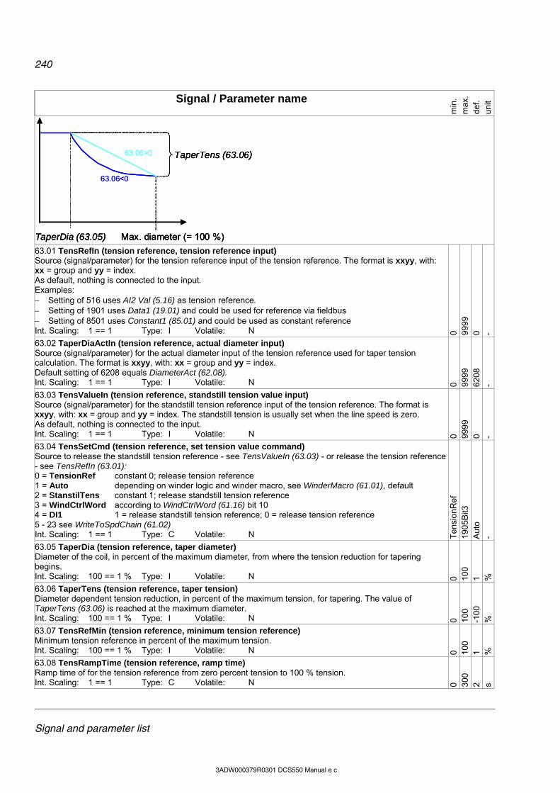
240
Signal and parameter list
3ADW000379R0301 DCS550 Manual e c
Signal / Parameter name
min
. m
ax.
def.
unit
TaperDia (63.05) Max. diameter (= 100 %)
TaperTens (63.06)63.06>0
63.06<0
TaperDia (63.05) Max. diameter (= 100 %)
TaperTens (63.06)
TaperDia (63.05) Max. diameter (= 100 %)
TaperTens (63.06)63.06>0
63.06<0
63.01 TensRefIn (tension reference, tension reference input) Source (signal/parameter) for the tension reference input of the tension reference. The format is xxyy, with: xx = group and yy = index. As default, nothing is connected to the input. Examples: Setting of 516 uses AI2 Val (5.16) as tension reference. Setting of 1901 uses Data1 (19.01) and could be used for reference via fieldbus Setting of 8501 uses Constant1 (85.01) and could be used as constant reference Int. Scaling: 1 == 1 Type: I Volatile: N 0 99
99
0 -
63.02 TaperDiaActIn (tension reference, actual diameter input) Source (signal/parameter) for the actual diameter input of the tension reference used for taper tension calculation. The format is xxyy, with: xx = group and yy = index. Default setting of 6208 equals DiameterAct (62.08). Int. Scaling: 1 == 1 Type: I Volatile: N 0 99
99
620
8 -
63.03 TensValueIn (tension reference, standstill tension value input) Source (signal/parameter) for the standstill tension reference input of the tension reference. The format is xxyy, with: xx = group and yy = index. The standstill tension is usually set when the line speed is zero. As default, nothing is connected to the input. Int. Scaling: 1 == 1 Type: I Volatile: N 0 99
99
0 -
63.04 TensSetCmd (tension reference, set tension value command) Source to release the standstill tension reference - see TensValueIn (63.03) - or release the tension reference - see TensRefIn (63.01): 0 = TensionRef constant 0; release tension reference 1 = Auto depending on winder logic and winder macro, see WinderMacro (61.01), default 2 = StanstilTens constant 1; release standstill tension reference 3 = WindCtrlWord according to WindCtrlWord (61.16) bit 10 4 = DI1 1 = release standstill tension reference; 0 = release tension reference 5 - 23 see WriteToSpdChain (61.02) Int. Scaling: 1 == 1 Type: C Volatile: N T
ensi
onR
ef
190
5Bit3
A
uto
-
63.05 TaperDia (tension reference, taper diameter) Diameter of the coil, in percent of the maximum diameter, from where the tension reduction for tapering begins. Int. Scaling: 100 == 1 % Type: I Volatile: N 0 10
0 1 %
63.06 TaperTens (tension reference, taper tension) Diameter dependent tension reduction, in percent of the maximum tension, for tapering. The value of TaperTens (63.06) is reached at the maximum diameter. Int. Scaling: 100 == 1 % Type: I Volatile: N 0 10
0 -1
00
%
63.07 TensRefMin (tension reference, minimum tension reference) Minimum tension reference in percent of the maximum tension. Int. Scaling: 100 == 1 % Type: I Volatile: N 0 10
0 1 %
63.08 TensRampTime (tension reference, ramp time) Ramp time of for the tension reference from zero percent tension to 100 % tension. Int. Scaling: 1 == 1 Type: C Volatile: N 0 30
0 2 s

241
Signal and parameter list
3ADW000379R0301 DCS550 Manual e c
Signal / Parameter name
min
. m
ax.
def.
unit
63.09 TensRampHoldCmd (tension reference, tension ramp hold command) Source to hold / release the tension ramp: 0 = RelTensRamp constant 0; release tension ramp, default 1 = reserved 2 = HoldTensRamp constant 1; hold tension ramp 3 = WindCtrlWord according to WindCtrlWord (61.16) bit 11 4 = DI1 1= hold tension ramp; 0 = release tension ramp 5 - 23 see WriteToSpdChain (61.02) Int. Scaling: 1 == 1 Type: C Volatile: N R
elT
ens
Ram
p
190
5Bit3
R
elT
ens
Ram
p
-
63.10 Unused
63.11 TensPulseWidth (tension reference, tension pulse width) Width of the tension pulse used to overcome the friction of the winder mechanics. Int. Scaling: 1 == 1 ms Type: I Volatile: N 0 30
000
0 m
s
63.12 TensPulseLevel (tension reference, tension pulse level) Level of the tension pulse used to overcome the friction of the winder mechanics in percent of maximum tension. Int. Scaling: 100 == 1 % Type: I Volatile: N 0 10
0 10
%
63.13 TensPulseCmd (tension reference, tension pulse command) Source for command to release the tension pulse to overcome the friction of the winder mechanics: 0 = NotUsed constant 0; no action 1 = Auto depending on winder logic and winder macro, see WinderMacro (61.01), default 2 = Release constant 1; release tension pulse once 3 = WindCtrlWord according to WindCtrlWord (61.16) bit 12 4 = DI1 1= release tension pulse; 0 = no action 5 - 23 see WriteToSpdChain (61.02) Int. Scaling: 1 == 1 Type: C Volatile: N N
otU
sed
190
5Bit3
A
uto
-
63.14 Unused
63.15 TensionRef (tension reference, output) Output of the tension reference. Tension reference in percent of the maximum tension. Int. Scaling: 100 == 1 % Type: I Volatile: Y - - - %
63.16 - 63.17 Unused
Tension to torque: For winders it is important that the tension fit to the web. With too low tension, the web does not wind correctly. With too high tension, the web might rip. This is the worst case, because the winder will accelerate, if there is no web break monitoring. The tension is a force measured in Newton [N]. When the tension is multiplied by the radius of the coil, the necessary torque for the selected tension can be calculated. Most torque is needed with maximum diameter at lowest motor speed.
i
DFT
*2
*
T [Nm] torque F [N] tension D [m] diameter i gear ratio (motor / load)
F T
D
F T
D
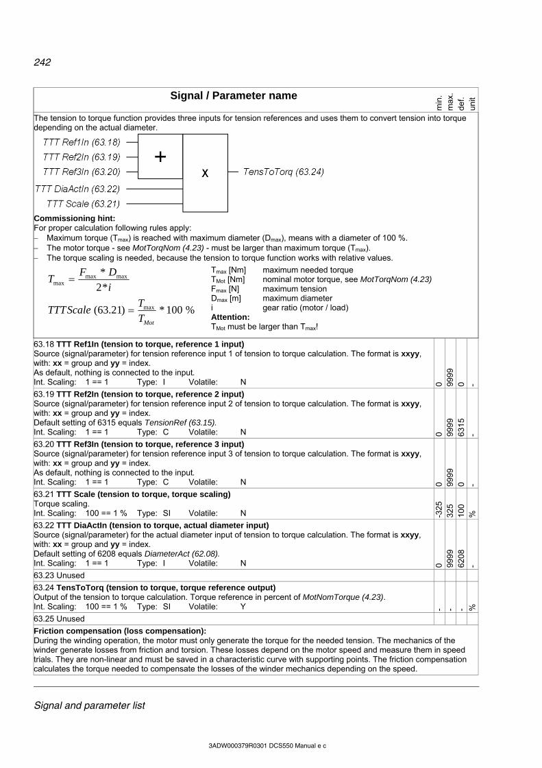
242
Signal and parameter list
3ADW000379R0301 DCS550 Manual e c
Signal / Parameter name
min
. m
ax.
def.
unit
The tension to torque function provides three inputs for tension references and uses them to convert tension into torque depending on the actual diameter.
Commissioning hint: For proper calculation following rules apply: Maximum torque (Tmax) is reached with maximum diameter (Dmax), means with a diameter of 100 %. The motor torque - see MotTorqNom (4.23) - must be larger than maximum torque (Tmax). The torque scaling is needed, because the tension to torque function works with relative values.
i
DFT
*2
* maxmaxmax
%100*)21.63( max
MotT
TScaleTTT
Tmax [Nm] maximum needed torque TMot [Nm] nominal motor torque, see MotTorqNom (4.23) Fmax [N] maximum tension Dmax [m] maximum diameter i gear ratio (motor / load) Attention: TMot must be larger than Tmax!
63.18 TTT Ref1In (tension to torque, reference 1 input) Source (signal/parameter) for tension reference input 1 of tension to torque calculation. The format is xxyy, with: xx = group and yy = index. As default, nothing is connected to the input. Int. Scaling: 1 == 1 Type: I Volatile: N 0 99
99
0 -
63.19 TTT Ref2In (tension to torque, reference 2 input) Source (signal/parameter) for tension reference input 2 of tension to torque calculation. The format is xxyy, with: xx = group and yy = index. Default setting of 6315 equals TensionRef (63.15). Int. Scaling: 1 == 1 Type: C Volatile: N 0 99
99
631
5 -
63.20 TTT Ref3In (tension to torque, reference 3 input) Source (signal/parameter) for tension reference input 3 of tension to torque calculation. The format is xxyy, with: xx = group and yy = index. As default, nothing is connected to the input. Int. Scaling: 1 == 1 Type: C Volatile: N 0 99
99
0 -
63.21 TTT Scale (tension to torque, torque scaling) Torque scaling. Int. Scaling: 100 == 1 % Type: SI Volatile: N -3
25
325
100
%
63.22 TTT DiaActIn (tension to torque, actual diameter input) Source (signal/parameter) for the actual diameter input of tension to torque calculation. The format is xxyy, with: xx = group and yy = index. Default setting of 6208 equals DiameterAct (62.08). Int. Scaling: 1 == 1 Type: I Volatile: N 0 99
99
620
8 -
63.23 Unused
63.24 TensToTorq (tension to torque, torque reference output) Output of the tension to torque calculation. Torque reference in percent of MotNomTorque (4.23). Int. Scaling: 100 == 1 % Type: SI Volatile: Y - - - %
63.25 Unused
Friction compensation (loss compensation): During the winding operation, the motor must only generate the torque for the needed tension. The mechanics of the winder generate losses from friction and torsion. These losses depend on the motor speed and measure them in speed trials. They are non-linear and must be saved in a characteristic curve with supporting points. The friction compensation calculates the torque needed to compensate the losses of the winder mechanics depending on the speed.
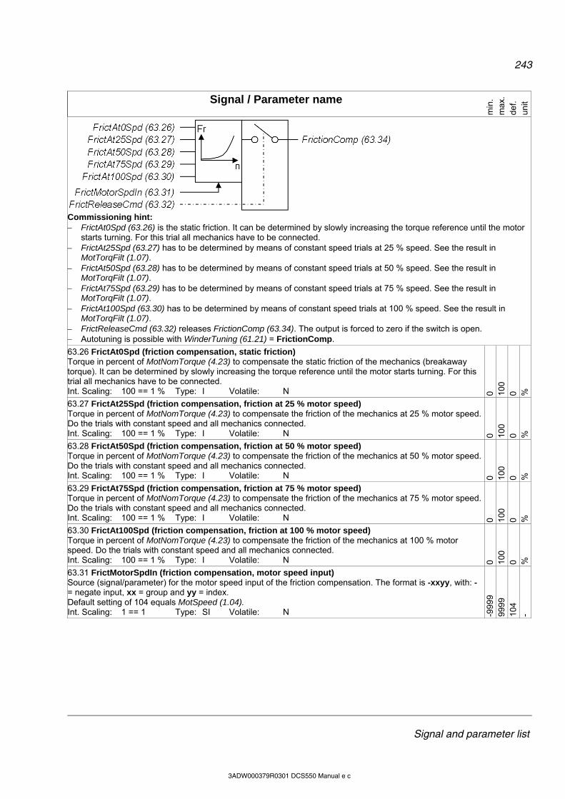
243
Signal and parameter list
3ADW000379R0301 DCS550 Manual e c
Signal / Parameter name
min
. m
ax.
def.
unit
Commissioning hint: FrictAt0Spd (63.26) is the static friction. It can be determined by slowly increasing the torque reference until the motor
starts turning. For this trial all mechanics have to be connected. FrictAt25Spd (63.27) has to be determined by means of constant speed trials at 25 % speed. See the result in
MotTorqFilt (1.07). FrictAt50Spd (63.28) has to be determined by means of constant speed trials at 50 % speed. See the result in
MotTorqFilt (1.07). FrictAt75Spd (63.29) has to be determined by means of constant speed trials at 75 % speed. See the result in
MotTorqFilt (1.07). FrictAt100Spd (63.30) has to be determined by means of constant speed trials at 100 % speed. See the result in
MotTorqFilt (1.07). FrictReleaseCmd (63.32) releases FrictionComp (63.34). The output is forced to zero if the switch is open. Autotuning is possible with WinderTuning (61.21) = FrictionComp.
63.26 FrictAt0Spd (friction compensation, static friction) Torque in percent of MotNomTorque (4.23) to compensate the static friction of the mechanics (breakaway torque). It can be determined by slowly increasing the torque reference until the motor starts turning. For this trial all mechanics have to be connected. Int. Scaling: 100 == 1 % Type: I Volatile: N 0 10
0 0 %
63.27 FrictAt25Spd (friction compensation, friction at 25 % motor speed) Torque in percent of MotNomTorque (4.23) to compensate the friction of the mechanics at 25 % motor speed. Do the trials with constant speed and all mechanics connected. Int. Scaling: 100 == 1 % Type: I Volatile: N 0 10
0 0 %
63.28 FrictAt50Spd (friction compensation, friction at 50 % motor speed) Torque in percent of MotNomTorque (4.23) to compensate the friction of the mechanics at 50 % motor speed. Do the trials with constant speed and all mechanics connected. Int. Scaling: 100 == 1 % Type: I Volatile: N 0 10
0 0 %
63.29 FrictAt75Spd (friction compensation, friction at 75 % motor speed) Torque in percent of MotNomTorque (4.23) to compensate the friction of the mechanics at 75 % motor speed. Do the trials with constant speed and all mechanics connected. Int. Scaling: 100 == 1 % Type: I Volatile: N 0 10
0 0 %
63.30 FrictAt100Spd (friction compensation, friction at 100 % motor speed) Torque in percent of MotNomTorque (4.23) to compensate the friction of the mechanics at 100 % motor speed. Do the trials with constant speed and all mechanics connected. Int. Scaling: 100 == 1 % Type: I Volatile: N 0 10
0 0 %
63.31 FrictMotorSpdIn (friction compensation, motor speed input) Source (signal/parameter) for the motor speed input of the friction compensation. The format is -xxyy, with: - = negate input, xx = group and yy = index. Default setting of 104 equals MotSpeed (1.04). Int. Scaling: 1 == 1 Type: SI Volatile: N -9
999
999
9 10
4 -
244
Signal and parameter list
3ADW000379R0301 DCS550 Manual e c
Signal / Parameter name
min
. m
ax.
def.
unit
63.32 FrictReleaseCmd (friction compensation, release command) Source to release / block the friction compensation: 0 = NotUsed constant 0; block friction compensation 1 = Auto depending on winder logic and winder macro, see WinderMacro (61.01), default 2 = Release constant 1; release friction compensation 3 = WindCtrlWord according to WindCtrlWord (61.16) bit 13 4 = DI1 1= release friction compensation; 0 = block friction compensation 5 - 23 see WriteToSpdChain (61.02) Int. Scaling: 1 == 1 Type: C Volatile: N N
otU
sed
190
5Bit3
A
uto
-
63.33 Unused
63.34 FrictionComp (friction compensation, output) Output of the friction compensation. Calculated friction compensation torque in percent of MotNomTorque (4.23). Int. Scaling: 100 == 1 % Type: I Volatile: Y - - - %
Group 64: Write selection
Adder 1 provides two torque inputs. The sum of Add1 (64.06) can be written to other parameters by means of Add1OutDest (64.01). Usually adder 1 is used to write on the torque limit of the speed controller.
Commissioning hint: Add1Cmd (64.04) releases Add1 (64.06). The output is forced to zero if the switch is open.
64.01 Add1OutDest (adder 1, destination of output value) Index pointer to the sink for adder 1 output value. The format is -xxyy, with: - = negate output value, xx = group and yy = index. As default, nothing is connected to the output. Int. Scaling: 1 == 1 Type: SI Volatile: N -9
999
999
9 0 -
64.02 Add1In1 (adder 1, input 1) Source (signal/parameter) for adder 1 input 1. The format is -xxyy, with: - = negate output value, xx = group and yy = index. Default setting of 6324 equals TensToTorq (63.24). Int. Scaling: 1 == 1 Type: SI Volatile: N -9
999
999
9 63
24
-
64.03 Add1In2 (adder 1, input 2) Source (signal/parameter) for adder 1 input 2. The format is -xxyy, with: - = negate output value, xx = group and yy = index. As default, nothing is connected to the input. Int. Scaling: 1 == 1 Type: SI Volatile: N -9
999
999
9 0 -
64.04 Add1ReleaseCmd (adder 1, release command) Source to release / block adder 1: 0 = NotUsed constant 0; block adder 1 1 = Auto depending on winder logic and winder macro, see WinderMacro (61.01), default 2 = Release constant 1; release adder 1 3 = WindCtrlWord according to WindCtrlWord (61.16) bit 14 4 = DI1 1= release adder 1; 0 = block adder 1 5 - 23 see WriteToSpdChain (61.02) Note: Blocking adder 1 forces its output to zero - Add1 (64.06) = 0. Int. Scaling: 1 == 1 Type: C Volatile: N N
otU
sed
190
5Bit3
A
uto
-
64.05 Unused

245
Signal and parameter list
3ADW000379R0301 DCS550 Manual e c
Signal / Parameter name
min
. m
ax.
def.
unit
64.06 Add1 (adder 1, output) Output of adder 1 in percent of MotNomTorque (4.23). Int. Scaling: 100 == 1 % Type: I Volatile: Y - - - %
64.07 Unused
Adder 2 provides two torque inputs. The sum of Add2 (64.13) can be written to other parameters by means of Add2OutDest (64.08). Usually adder 2 is used to write on the load compensation for inertia and friction compensation.
Commissioning hint: Add2Cmd (64.11) releases Add2 (64.13). The output is forced to zero if the switch is open.
64.08 Add2OutDest (adder 2, destination of output value) Index pointer to the sink for adder 2 output value. The format is -xxyy, with: - = negate output value, xx = group and yy = index. As default, nothing is connected to the output. Int. Scaling: 1 == 1 Type: SI Volatile: N -9
999
999
9 0 -
64.09 Add2In1 (adder 2, input 1) Source (signal/parameter) for adder 2 input 1. The format is -xxyy, with: - = negate output value, xx = group and yy = index. Default setting of 6230 equals InertiaComp (62.30). Int. Scaling: 1 == 1 Type: SI Volatile: N -9
999
999
9 62
30
-
64.10 Add2In2 (adder 2, input 2) Source (signal/parameter) for adder 2 input 2. The format is -xxyy, with: - = negate output value, xx = group and yy = index. Default setting of 6334 equals FrictionComp (63.34). Int. Scaling: 1 == 1 Type: SI Volatile: N -9
999
999
9 63
34
-
64.11 Add2ReleaseCmd (adder 2, release command) Source to release / block adder 1: 0 = NotUsed constant 0; block adder 2 1 = Auto depending on winder logic and winder macro, see WinderMacro (61.01), default 2 = Release constant 1; release adder 2 3 = WindCtrlWord according to WindCtrlWord (61.16) bit 15 4 = DI1 1= release adder 2; 0 = block adder 2 5 - 23 see WriteToSpdChain (61.02) Note: Blocking adder 2 forces its output to zero - Add2 (64.11) = 0. Int. Scaling: 1 == 1 Type: C Volatile: N N
otU
sed
190
5Bit3
A
uto
-
64.12 Unused
64.13 Add2 (adder 2, output) Output of adder 2 in percent of MotNomTorque (4.23). Int. Scaling: 100 == 1 % Type: I Volatile: Y - - - %

246
Signal and parameter list
3ADW000379R0301 DCS550 Manual e c
Signal / Parameter name
min
. m
ax.
def.
unit
Group 66: Winder program control
66.01 WiProgCmd (winder program, command) Selects the operation mode for the winder program: 0 = Stop Execution of winder blocks stopped. Speed control chain parameters are set back to
default parameter values, e.g. SpeedCorr (23.04), SpeedRefScale (23.16), LoadComp (26.02).
1 = Start Enable execution of winder blocks if a winder macro is selected. 2 = Edit reserved 3 = EditExecTab reserved 4 = SingleCycle reserved 5 = SingleStep reserved Int. Scaling: 1 == 1 Type: C Volatile: N S
top
Sin
gleS
tep
Sto
p -
66.02 - 66. 03 Unused
66.04 WiUserMode (winder program, user mode) 0 = Standard reserved 1 = Expert reserved Int. Scaling: 1 == 1 Type: C Volatile: N S
tand
ard
Exp
ert
Sta
ndar
d
66.05 WiPassCode reserved Int. Scaling: 1 == 1 Type: C Volatile: N 0 30
000
0 -
247
Signal and parameter list
3ADW000379R0301 DCS550 Manual e c
Signal / Parameter name
min
. m
ax.
def.
unit
Group 83: AP control
83.01 AdapProgCmd (AP command) Selects the operation mode for AP: 0 = Stop stop, AP is not running and cannot be edited, default 1 = Start running, AP is running and cannot be edited 2 = Edit edit, AP is not running and can be edited 3 = SingleCycle AP runs only once. If a breakpoint is set with BreakPoint (83.06), AP will stop before the
breakpoint. After the SingleCycle AdapProgCmd (83.01) is automatically set back to Stop.
4 = SingleStep Runs only one function block. LocationCounter (84.03) shows the function block number, which will be executed during the next SingleStep. After a SingleStep AdapProgCmd (83.01) is automatically set back to Stop. LocationCounter (84.03) shows the next function block to be executed. To reset LocationCounter (84.03) to the first function block set AdapProgCmd (83.01) to Stop again (even if it is already set to Stop).
A136 NoAPTaskTime [AlarmWord3 (9.08) bit 3] is set when TimeLevSel (83.04) is not set to 5 ms, 20 ms, 100 ms or 500 ms but AdapProgCmd (83.01) is set to Start, SingleCycle or SingleStep Note: AdapProgCmd (83.01) = Start, SingleCycle or SingleStep is only valid, if AdapPrgStat (84.01) Running. Int. Scaling: 1 == 1 Type: C Volatile: N S
top
Sin
gleS
tep
Sto
p -
83.02 EditCmd (edit command) Edit AP. EditCmd (83.02) is automatically set back to Done after the chosen action is finished: 0 = Done no action or edit of AP completed, default 1 = Push Shifts the function block in the spot defined by EditBlock (83.03) and all subsequent
function blocks one spot forward. A new function block can be placed in the now empty spot by programming its parameter set as usual. Example: A new function block needs to be placed in between the function block number four (84.22) to (84.27) and five (84.28) to (84.33). In order to do this: 1. set AdapProgCmd (83.01) = Edit 2. set EditBlock (83.03) = 5 (selects function block 5 as the desired spot for the new
function block) 3. set EditCmd (83.02) = Push (shifts function block 5 and all subsequent function
blocks one spot forward) 4. program empty spot 5 by means of (84.28) to (84.33)
2 = Delete Deletes the function block in the spot defined by EditBlock (83.03) and shifts all subsequent function blocks one spot backward. To delete all function blocks set EditBlock (83.03) = 17.
3 = Protect Turns all parameters of AP into protected mode (parameters cannot be read or written to). Before using the Protect command set the pass code by means of PassCode (83.05). Attention: Do not forget the pass code!
4 = Unprotect Reset of protected mode. Before the Unprotect command can be used, PassCode (83.05) has to be set. Attention: Use the proper pass code!
Int. Scaling: 1 == 1 Type: C Volatile: Y Don
e U
npro
tect
D
one
-
83.03 EditBlock (edit block) Defines the function block which is selected by EditCmd (83.02) = Push or Delete. After a Push or Delete EditBlock (83.03) is automatically set back to 1. Note: To delete all function blocks set EditBlock (83.03) = 17. Int. Scaling: 1 == 1 Type: I Volatile: Y 0 17
0 -
248
Signal and parameter list
3ADW000379R0301 DCS550 Manual e c
Signal / Parameter name
min
. m
ax.
def.
unit
83.04 TimeLevSel (time level select) Selects the cycle time for AP. This setting is valid for all function blocks. 0 = Off no task selected 1 = 5ms AP runs with 5 ms 2 = 20ms AP runs with 20 ms 3 = 100ms AP runs with 100 ms 4 = 500ms AP runs with 500 ms A136 NoAPTaskTime [AlarmWord3 (9.08) bit 3] is set when TimeLevSel (83.04) is not set to 5 ms, 20 ms, 100 ms or 500 ms but AdapProgCmd (83.01) is set to Start, SingleCycle or SingleStep. Int. Scaling: 1 == 1 Type: C Volatile: N O
ff
500m
s O
ff
-
83.05 PassCode (pass code) The pass code is a number between 1 and 65535 to write protect AP by means of EditCmd (83.02). After using Protect or Unprotect PassCode (83.05) is automatically set back to zero. Attention: Do not forget the pass code! Int. Scaling: 1 == 1 Type: I Volatile: Y 0 65
535
0 -
83.06 BreakPoint (break point) Breakpoint for AdapProgCmd (83.01) = SingleCycle. The break point is not used, if BreakPoint (83.06) is set to zero. Int. Scaling: 1 == 1 Type: I Volatile: Y 0 16
0 -
Group 84: AP
84.01 AdapPrgStat (AP status word) AP status word: Bit Name Value Comment B0 Bit 0 1 AP is running
0 AP is stopped B1 Bit 1 1 AP can be edited
0 AP cannot be edited B2 Bit 2 1 AP is being checked
0 no action B3 Bit 3 1 AP is faulty
0 AP is OK B4 Bit 4 1 AP is protected
0 AP is unprotected Faults in AP can be: used function block with not at least input 1 connection used pointer is not valid invalid bit number for function block Bset location of function block PI-Bal after PI function block Int. Scaling: 1 == 1 Type: I Volatile: Y - - - -
84.02 FaultedPar (faulted parameters) AP will be checked before running. If there is a fault, AdapPrgStat (84.01) is set to “faulty” and FaultedPar (84.02) shows the faulty input. Note: In case of a problem, check the value and the attribute of the faulty input. Int. Scaling: 1 == 1 Type: I Volatile: Y - - - -
84.03 LocationCounter (location counter) Location counter for AdapProgCmd (83.01) = SingleStep shows the function block number, which will be executed next. Int. Scaling: 1 == 1 Type: I Volatile: Y - - - -

249
Signal and parameter list
3ADW000379R0301 DCS550 Manual e c
Signal / Parameter name
min
. m
ax.
def.
unit
84.04 Block1Type (function block 1 type) Selects the type for function block 1 [Block Parameter Set 1 (BPS1)]. Detailed description of the type can be found in chapter ‘Function blocks’: 0 = NotUsed function block is not used 1 = ABS absolute value 2 = ADD sum 3 = AND AND 4 = Bitwise bit compare 5 = Bset bit set 6 = Compare compare 7 = Count counter 8 = D-Pot ramp 9 = Event event 10 = Filter filter 11 = Limit limit 12 = MaskSet mask set 13 = Max maximum 14 = Min minimum 15 = MulDiv multiplication and division 16 = OR OR 17 = ParRead parameter read 18 = ParWrite parameter write 19 = PI PI-controller 20 = PI-Bal initialization for PI-controller 21 = Ramp ramp 22 = SqWav square wave 23 = SR SR flip-flop 24 = Switch-B switch Boolean 25 = Switch-I switch integer 26 = TOFF timer off 27 = TON timer on 28 = Trigg trigger 29 = XOR exclusive OR 30 = Sqrt square root Int. Scaling: 1 == 1 Type: C Volatile: N N
otU
sed
Sqr
t N
otU
sed
-
84.05 Block1In1 (function block 1 input 1) Selects the source for input 1 of function block 1 (BPS1). There are 2 types of inputs, signals/parameters and constants: Signals/parameters are all signals and parameters available in the drive. The format is -xxyy, with: - =
negate signal/parameter, xx = group and yy = index. Example: To connect negated SpeedRef (23.01) set Block1In1 (84.05) = -2301 and Block1Attrib (84.08) = 0h. To get only a certain bit e.g. RdyRef bit 3 of MainStatWord (8.01) set Block1In1 (84.05) = 801 and Block1Attrib (84.08) = 3h.
Constants are feed directly into the function block input. Declare them by means of Block1Attrib (84.08). Example: To connect the constant value of 12345 set Block1In1 (84.05) = 12345 and Block1Attrib (84.08) = 1000h.
Int. Scaling: 1 == 1 Type: SI Volatile: N -327
68
327
67
0 -
84.06 Block1In2 (function block 1 input 2) Selects the source for input 2 of function block 1 (BPS1). Description see Block1In1 (84.05), except: To get only a certain bit e.g. RdyRef bit 3 of MainStatWord (8.01) set Block1In2 (84.06) = 801 and Block1Attrib (84.08) = 30h. Int. Scaling: 1 == 1 Type: SI Volatile: N -3
2768
32
767
0 -
84.07 Block1In3 (function block 1 input 3) Selects the source for input 3 of function block 1 (BPS1). Description see Block1In1 (84.05), except: To get only a certain bit e.g. RdyRef bit 3 of MainStatWord (8.01) set Block1In3 (84.07) = 801 and Block1Attrib (84.08) = 300h. Int. Scaling: 1 == 1 Type: SI Volatile: N -3
2768
32
767
0 -

250
Signal and parameter list
3ADW000379R0301 DCS550 Manual e c
Signal / Parameter name
min
. m
ax.
def.
unit
84.08 Block1Attrib (function block 1 attribute) Defines the attributes of function block 1 for all three inputs [Block1In1 (84.05), Block1In2 (84.06) and Block1In3 (84.07)] (BPS1). Block1Attrib (84.08) is divided into 4 parts: Bit number 0 - 3 for input 1 to get a certain bit out of a packed Boolean word. Bit number 4 - 7 for input 2 to get a certain bit out of a packed Boolean word. Bit number 8 - 11 for input 3 to get a certain bit out of a packed Boolean word. Bit number 12 - 14 for input 1 - 3 to feed a constant directly into the input
Int. Scaling: 1 == 1 Type: h Volatile: N 0h
F
FF
Fh
0h
-
84.09 Block1Output (function block 1 output) Function block 1 output, can be used as an input for further function blocks. Int. Scaling: 1 == 1 Type: SI Volatile: Y - - - -
84.10 to 84.99 The description of the parameters for function blocks 2 to 16 is the same as for function block 1. For Your convenience the following table shows the parameter numbers of all function blocks1:
Function block
BlockxType BlockxIn1 input 1
BlockxIn2 input 2
BlockxIn3 input 1
BlockxAttrib BlockxOutput signal
BlockxOut pointer
1 84.04 84.05 84.06 84.07 84.08 84.09 86.01 2 84.10 84.11 84.12 84.13 84.14 84.15 86.02 3 84.16 84.17 84.18 84.19 84.20 84.21 86.03 4 84.22 84.23 84.24 84.25 84.26 84.27 86.04 5 84.28 84.29 84.30 84.31 84.32 84.33 86.05 6 84.34 84.35 84.36 84.37 84.38 84.39 86.06 7 84.40 84.41 84.42 84.43 84.44 84.45 86.07 8 84.46 84.47 84.48 84.49 84.50 84.51 86.08 9 84.52 84.53 84.54 84.55 84.56 84.57 86.09 10 84.58 84.59 84.60 84.61 84.62 84.63 86.10 11 84.64 84.65 84.66 84.67 84.68 84.69 86.11 12 84.70 84.71 84.72 84.73 84.74 84.75 86.12 13 84.76 84.77 84.78 84.79 84.80 84.81 86.13 14 84.82 84.83 84.84 84.85 84.86 84.87 86.14 15 84.88 84.89 84.90 84.91 84.92 84.93 86.15 16 84.94 84.95 84.96 84.97 84.98 84.99 86.16
Group 85: User constants
85.01 Constant1 (constant 1) Sets an integer constant for AP. Int. Scaling: 1 == 1 Type: SI Volatile: N -3
2768
32
767
0 -
251
Signal and parameter list
3ADW000379R0301 DCS550 Manual e c
Signal / Parameter name
min
. m
ax.
def.
unit
85.02 Constant2 (constant 2) Sets an integer constant for AP. Int. Scaling: 1 == 1 Type: SI Volatile: N -3
2768
32
767
0 -
85.03 Constant3 (constant 3) Sets an integer constant for AP. Int. Scaling: 1 == 1 Type: SI Volatile: N -3
2768
32
767
0 -
85.04 Constant4 (constant 4) Sets an integer constant for AP. Int. Scaling: 1 == 1 Type: SI Volatile: N -3
2768
32
767
0 -
85.05 Constant5 (constant 5) Sets an integer constant for AP. Int. Scaling: 1 == 1 Type: SI Volatile: N -3
2768
32
767
0 -
85.06 Constant6 (constant 6) Sets an integer constant for AP. Int. Scaling: 1 == 1 Type: SI Volatile: N -3
2768
32
767
0 -
85.07 Constant7 (constant 7) Sets an integer constant for AP. Int. Scaling: 1 == 1 Type: SI Volatile: N -3
2768
32
767
0 -
85.08 Constant8 (constant 8) Sets an integer constant for AP. Int. Scaling: 1 == 1 Type: SI Volatile: N -3
2768
32
767
0 -
85.09 Constant9 (constant 9) Sets an integer constant for AP. Int. Scaling: 1 == 1 Type: SI Volatile: N -3
2768
32
767
0 -
85.10 Constant10 (constant 10) Sets an integer constant for AP. Int. Scaling: 1 == 1 Type: SI Volatile: N -3
2768
32
767
0 -
85.11 String1 (string 1) Sets a string for AP (only possible with DriveWindow).This string is shown in the DCS Control Panel. Int. Scaling: 1 == 1 Type: SI/C Volatile: N ‘s
trin
g’
‘str
ing’
‘ ’
-
85.12 String2 (string 2) Sets a string for AP (only possible with DriveWindow).This string is shown in the DCS Control Panel. Int. Scaling: 1 == 1 Type: SI/C Volatile: N ‘s
trin
g’
‘str
ing’
‘ ’
-
85.13 String3 (string 3) Sets a string for AP (only possible with DriveWindow).This string is shown in the DCS Control Panel. Int. Scaling: 1 == 1 Type: SI/C Volatile: N ‘s
trin
g’
‘str
ing’
‘ ’
-
85.14 String4 (string 4) Sets a string for AP (only possible with DriveWindow).This string is shown in the DCS Control Panel. Int. Scaling: 1 == 1 Type: SI/C Volatile: N ‘s
trin
g’
‘str
ing’
‘ ’
-
85.15 String5 (string 5) Sets a string for AP (only possible with DriveWindow).This string is shown in the DCS Control Panel. Int. Scaling: 1 == 1 Type: SI/C Volatile: N ‘s
trin
g’
‘str
ing’
‘ ’
-
Group 86: AP outputs
86.01 Block1Out (block 1 output) The value of function block 1 output [Block1Output (84.09)] is written to a sink (signal/parameter) by means of this index pointer [e.g. 2301 equals SpeedRef (23.01)]. The format is -xxyy, with: - = negate signal/parameter, xx = group and yy = index. Int. Scaling: 1 == 1 Type: I Volatile: N -9
999
999
9 0 -
86.02 Block2Out (block 2 output) The value of function block 2 output [Block2Output (84.15)] is written to a sink (signal/parameter) by means of this index pointer [e.g. 2301 equals SpeedRef (23.01)]. The format is -xxyy, with: - = negate signal/parameter, xx = group and yy = index. Int. Scaling: 1 == 1 Type: I Volatile: N -9
999
999
9 0 -

252
Signal and parameter list
3ADW000379R0301 DCS550 Manual e c
Signal / Parameter name
min
. m
ax.
def.
unit
86.03 Block3Out (block 3 output) The value of function block 3 output [Block3Output (84.21)] is written to a sink (signal/parameter) by means of this index pointer [e.g. 2301 equals SpeedRef (23.01)]. The format is -xxyy, with: - = negate signal/parameter, xx = group and yy = index. Int. Scaling: 1 == 1 Type: I Volatile: N -9
999
999
9 0 -
86.04 Block4Out (block 4 output) The value of function block 4 output [Block1Output (84.27)] is written to a sink (signal/parameter) by means of this index pointer [e.g. 2301 equals SpeedRef (23.01)]. The format is -xxyy, with: - = negate signal/parameter, xx = group and yy = index. Int. Scaling: 1 == 1 Type: I Volatile: N -9
999
999
9 0 -
86.05 Block5Out (block 5 output) The value of function block 5 output [Block1Output (84.33)] is written to a sink (signal/parameter) by means of this index pointer [e.g. 2301 equals SpeedRef (23.01)]. The format is -xxyy, with: - = negate signal/parameter, xx = group and yy = index. Int. Scaling: 1 == 1 Type: I Volatile: N -9
999
999
9 0 -
86.06 Block6Out (block 6 output) The value of function block 6 output [Block1Output (84.39)] is written to a sink (signal/parameter) by means of this index pointer [e.g. 2301 equals SpeedRef (23.01)]. The format is -xxyy, with: - = negate signal/parameter, xx = group and yy = index. Int. Scaling: 1 == 1 Type: I Volatile: N -9
999
999
9 0 -
86.07 Block7Out (block 7 output) The value of function block 7 output [Block1Output (84.45)] is written to a sink (signal/parameter) by means of this index pointer [e.g. 2301 equals SpeedRef (23.01)]. The format is -xxyy, with: - = negate signal/parameter, xx = group and yy = index. Int. Scaling: 1 == 1 Type: I Volatile: N -9
999
999
9 0 -
86.08 Block8Out (block 8 output) The value of function block 8 output [Block1Output (84.51)] is written to a sink (signal/parameter) by means of this index pointer [e.g. 2301 equals SpeedRef (23.01)]. The format is -xxyy, with: - = negate signal/parameter, xx = group and yy = index. Int. Scaling: 1 == 1 Type: I Volatile: N -9
999
999
9 0 -
86.09 Block9Out (block 9 output) The value of function block 9 output [Block1Output (84.57)] is written to a sink (signal/parameter) by means of this index pointer [e.g. 2301 equals SpeedRef (23.01)]. The format is -xxyy, with: - = negate signal/parameter, xx = group and yy = index. Int. Scaling: 1 == 1 Type: I Volatile: N -9
999
999
9 0 -
86.10 Block10Out (block 10 output) The value of function block 10 output [Block1Output (84.63)] is written to a sink (signal/parameter) by means of this index pointer [e.g. 2301 equals SpeedRef (23.01)]. The format is -xxyy, with: - = negate signal/parameter, xx = group and yy = index. Int. Scaling: 1 == 1 Type: I Volatile: N -9
999
999
9 0 -
86.11 Block11Out (block 11 output) The value of function block 11 output [Block1Output (84.69)] is written to a sink (signal/parameter) by means of this index pointer [e.g. 2301 equals SpeedRef (23.01)]. The format is -xxyy, with: - = negate signal/parameter, xx = group and yy = index. Int. Scaling: 1 == 1 Type: I Volatile: N -9
999
999
9 0 -
86.12 Block12Out (block 12 output) The value of function block 12 output [Block1Output (84.75)] is written to a sink (signal/parameter) by means of this index pointer [e.g. 2301 equals SpeedRef (23.01)]. The format is -xxyy, with: - = negate signal/parameter, xx = group and yy = index. Int. Scaling: 1 == 1 Type: I Volatile: N -9
999
999
9 0 -
86.13 Block13Out (block 13 output) The value of function block 13 output [Block1Output (84.81)] is written to a sink (signal/parameter) by means of this index pointer [e.g. 2301 equals SpeedRef (23.01)]. The format is -xxyy, with: - = negate signal/parameter, xx = group and yy = index. Int. Scaling: 1 == 1 Type: I Volatile: N -9
999
999
9 0 -

253
Signal and parameter list
3ADW000379R0301 DCS550 Manual e c
Signal / Parameter name
min
. m
ax.
def.
unit
86.14 Block14Out (block 14 output) The value of function block 14 output [Block1Output (84.87)] is written to a sink (signal/parameter) by means of this index pointer [e.g. 2301 equals SpeedRef (23.01)]. The format is -xxyy, with: - = negate signal/parameter, xx = group and yy = index. Int. Scaling: 1 == 1 Type: I Volatile: N -9
999
999
9 0 -
86.15 Block15Out (block 15 output) The value of function block 15 output [Block1Output (84.93)] is written to a sink (signal/parameter) by means of this index pointer [e.g. 2301 equals SpeedRef (23.01)]. The format is -xxyy, with: - = negate signal/parameter, xx = group and yy = index. Int. Scaling: 1 == 1 Type: I Volatile: N -9
999
999
9 0 -
86.16 Block16Out (block 16 output) The value of function block 16 output [Block16Output (84.99)] is written to a sink (signal/parameter) by means of this index pointer [e.g. 2301 equals SpeedRef (23.01)]. The format is -xxyy, with: - = negate signal/parameter, xx = group and yy = index. Int. Scaling: 1 == 1 Type: I Volatile: N -9
999
999
9 0 -
Group 88: Internal
This parameter group contains internal variables and should not be changed by the user
88.01 - 88.24 Reserved
88.25 M1TachMaxSpeed (maximum tacho speed) Internally used maximum tacho speed. This value is depending on the analog tacho output voltage - e.g. 60 V at 1000 rpm - and the maximum speed of the drive system - which is the maximum of SpeedScaleAct (2.29), M1OvrSpeed (30.16) and M1BaseSpeed (99.04). This value should only be written to by: tacho fine tuning via ServiceMode (99.06) = TachFineTune, via M1TachVolt1000 (50.13), TachoAdjust block in AP and parameter download
Internally limited from: rpmtorpm20000
32767*)29.2(
20000
32767*)29.2(
Int. Scaling: (2.29) Type: SI Volatile: N 0 100
00
0 rpm
88.26 Reserved
88.27 M1TachoTune (tacho tuning factor) Internally used tacho fine tuning factor. This value should only be written to by: tacho fine tuning via ServiceMode (99.06) = TachFineTune, TachoAdjust block in AP and parameter download Int. Scaling: 1000 == 1 Type: I Volatile: N 0.
3 3 1 -
88.28 Reserved
88.29 M1TachoGain (tacho tuning gain) Internally used tacho gain tuning. This value should only be written to by: tacho gain tuning via ServiceMode (99.06) = SpdFbAssist, M1TachoVolt1000 (50.13) and parameter download Int. Scaling: 1 == 1 Type: I Volatile: N 0 15
15
-
88.30 Reserved
88.31 AnybusModType (last connected serial communication module) Internally used memory for the last attached serial communication module. This value should only be written to by: the DCS550 firmware and parameter download Int. Scaling: 1 == 1 Type: I Volatile: N 0 65
535
0 -
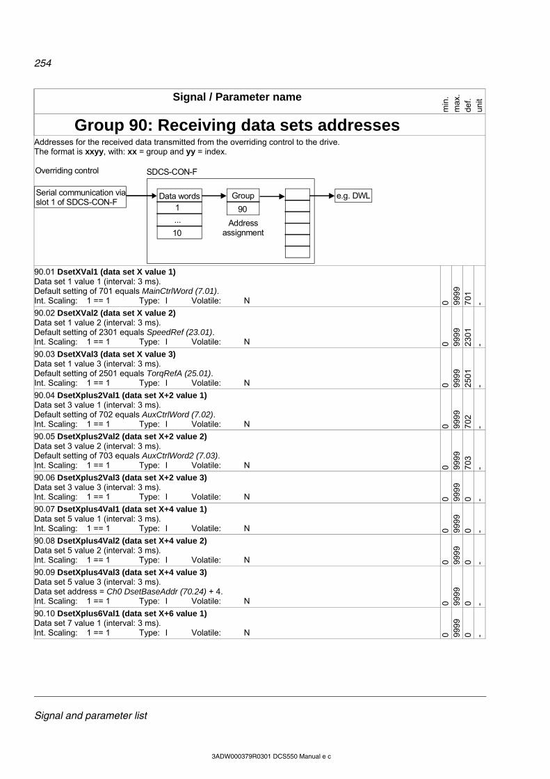
254
Signal and parameter list
3ADW000379R0301 DCS550 Manual e c
Signal / Parameter name
min
. m
ax.
def.
unit
Group 90: Receiving data sets addresses
Addresses for the received data transmitted from the overriding control to the drive. The format is xxyy, with: xx = group and yy = index.
e.g. DWLGroupData words
Overriding control
90
Address assignment
SDCS-CON-F
Serial communication viaslot 1 of SDCS-CON-F
1
...
10
90.01 DsetXVal1 (data set X value 1) Data set 1 value 1 (interval: 3 ms). Default setting of 701 equals MainCtrlWord (7.01). Int. Scaling: 1 == 1 Type: I Volatile: N 0 99
99
701
-
90.02 DsetXVal2 (data set X value 2) Data set 1 value 2 (interval: 3 ms). Default setting of 2301 equals SpeedRef (23.01). Int. Scaling: 1 == 1 Type: I Volatile: N 0 99
99
230
1 -
90.03 DsetXVal3 (data set X value 3) Data set 1 value 3 (interval: 3 ms). Default setting of 2501 equals TorqRefA (25.01). Int. Scaling: 1 == 1 Type: I Volatile: N 0 99
99
250
1 -
90.04 DsetXplus2Val1 (data set X+2 value 1) Data set 3 value 1 (interval: 3 ms). Default setting of 702 equals AuxCtrlWord (7.02). Int. Scaling: 1 == 1 Type: I Volatile: N 0 99
99
702
-
90.05 DsetXplus2Val2 (data set X+2 value 2) Data set 3 value 2 (interval: 3 ms). Default setting of 703 equals AuxCtrlWord2 (7.03). Int. Scaling: 1 == 1 Type: I Volatile: N 0 99
99
703
- 90.06 DsetXplus2Val3 (data set X+2 value 3) Data set 3 value 3 (interval: 3 ms). Int. Scaling: 1 == 1 Type: I Volatile: N 0 99
99
0 -
90.07 DsetXplus4Val1 (data set X+4 value 1) Data set 5 value 1 (interval: 3 ms). Int. Scaling: 1 == 1 Type: I Volatile: N 0 99
99
0 -
90.08 DsetXplus4Val2 (data set X+4 value 2) Data set 5 value 2 (interval: 3 ms). Int. Scaling: 1 == 1 Type: I Volatile: N 0 99
99
0 -
90.09 DsetXplus4Val3 (data set X+4 value 3) Data set 5 value 3 (interval: 3 ms). Data set address = Ch0 DsetBaseAddr (70.24) + 4. Int. Scaling: 1 == 1 Type: I Volatile: N 0 99
99
0 -
90.10 DsetXplus6Val1 (data set X+6 value 1) Data set 7 value 1 (interval: 3 ms). Int. Scaling: 1 == 1 Type: I Volatile: N 0 99
99
0 -
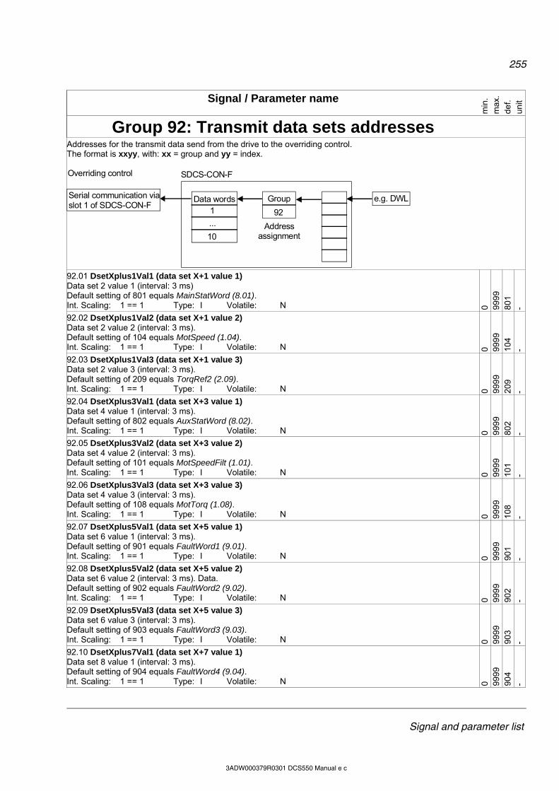
255
Signal and parameter list
3ADW000379R0301 DCS550 Manual e c
Signal / Parameter name
min
. m
ax.
def.
unit
Group 92: Transmit data sets addresses
Addresses for the transmit data send from the drive to the overriding control. The format is xxyy, with: xx = group and yy = index.
e.g. DWLGroupData words
Overriding control
92
Address assignment
SDCS-CON-F
Serial communication viaslot 1 of SDCS-CON-F
1
...
10
92.01 DsetXplus1Val1 (data set X+1 value 1) Data set 2 value 1 (interval: 3 ms) Default setting of 801 equals MainStatWord (8.01). Int. Scaling: 1 == 1 Type: I Volatile: N 0 99
99
801
-
92.02 DsetXplus1Val2 (data set X+1 value 2) Data set 2 value 2 (interval: 3 ms). Default setting of 104 equals MotSpeed (1.04). Int. Scaling: 1 == 1 Type: I Volatile: N 0 99
99
104
-
92.03 DsetXplus1Val3 (data set X+1 value 3) Data set 2 value 3 (interval: 3 ms). Default setting of 209 equals TorqRef2 (2.09). Int. Scaling: 1 == 1 Type: I Volatile: N 0 99
99
209
-
92.04 DsetXplus3Val1 (data set X+3 value 1) Data set 4 value 1 (interval: 3 ms). Default setting of 802 equals AuxStatWord (8.02). Int. Scaling: 1 == 1 Type: I Volatile: N 0 99
99
802
-
92.05 DsetXplus3Val2 (data set X+3 value 2) Data set 4 value 2 (interval: 3 ms). Default setting of 101 equals MotSpeedFilt (1.01). Int. Scaling: 1 == 1 Type: I Volatile: N 0 99
99
101
-
92.06 DsetXplus3Val3 (data set X+3 value 3) Data set 4 value 3 (interval: 3 ms). Default setting of 108 equals MotTorq (1.08). Int. Scaling: 1 == 1 Type: I Volatile: N 0 99
99
108
- 92.07 DsetXplus5Val1 (data set X+5 value 1) Data set 6 value 1 (interval: 3 ms). Default setting of 901 equals FaultWord1 (9.01). Int. Scaling: 1 == 1 Type: I Volatile: N 0 99
99
901
-
92.08 DsetXplus5Val2 (data set X+5 value 2) Data set 6 value 2 (interval: 3 ms). Data. Default setting of 902 equals FaultWord2 (9.02). Int. Scaling: 1 == 1 Type: I Volatile: N 0 99
99
902
-
92.09 DsetXplus5Val3 (data set X+5 value 3) Data set 6 value 3 (interval: 3 ms). Default setting of 903 equals FaultWord3 (9.03). Int. Scaling: 1 == 1 Type: I Volatile: N 0 99
99
903
-
92.10 DsetXplus7Val1 (data set X+7 value 1) Data set 8 value 1 (interval: 3 ms). Default setting of 904 equals FaultWord4 (9.04). Int. Scaling: 1 == 1 Type: I Volatile: N 0 99
99
904
-
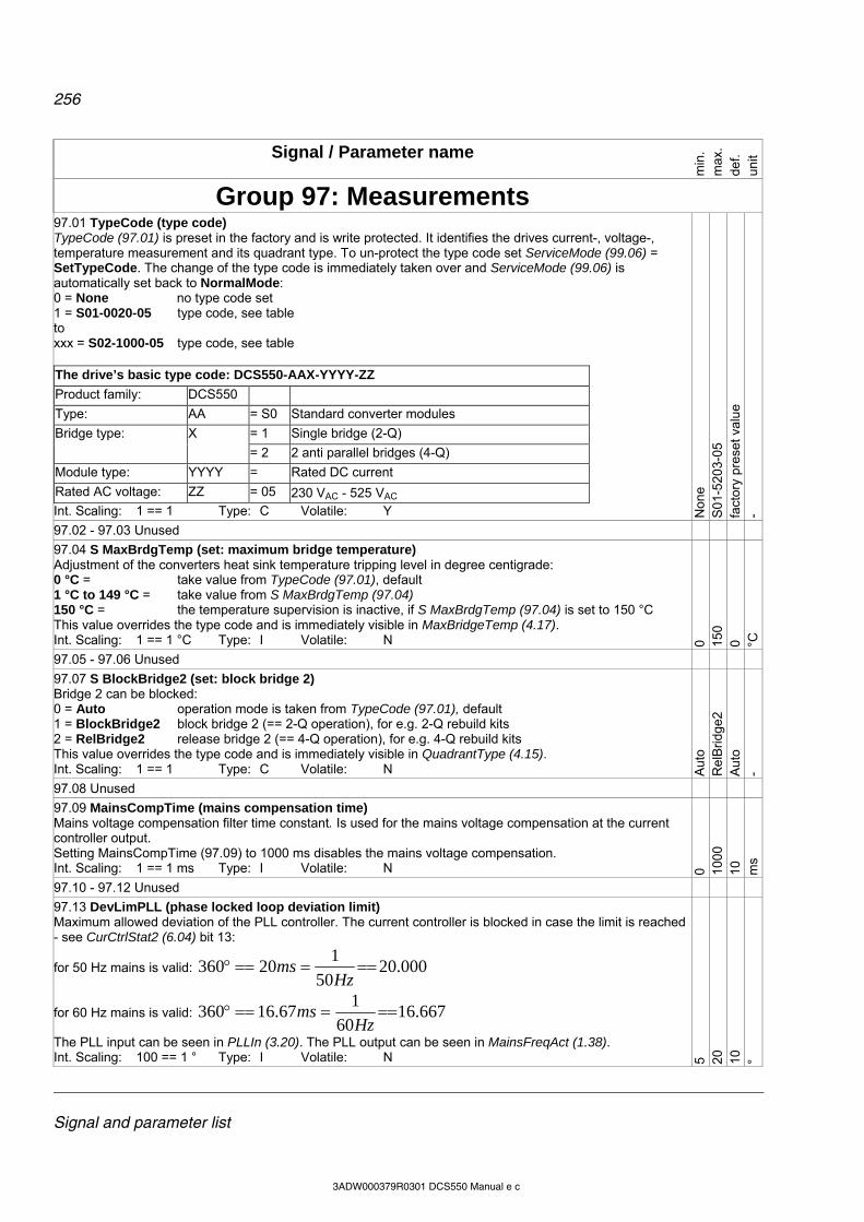
256
Signal and parameter list
3ADW000379R0301 DCS550 Manual e c
Signal / Parameter name
min
. m
ax.
def.
unit
Group 97: Measurements
97.01 TypeCode (type code) TypeCode (97.01) is preset in the factory and is write protected. It identifies the drives current-, voltage-, temperature measurement and its quadrant type. To un-protect the type code set ServiceMode (99.06) = SetTypeCode. The change of the type code is immediately taken over and ServiceMode (99.06) is automatically set back to NormalMode: 0 = None no type code set 1 = S01-0020-05 type code, see table to xxx = S02-1000-05 type code, see table The drive’s basic type code: DCS550-AAX-YYYY-ZZ
Product family: DCS550
Type: AA = S0 Standard converter modules
= 1 Single bridge (2-Q) Bridge type: X
= 2 2 anti parallel bridges (4-Q)
Module type: YYYY = Rated DC current
Rated AC voltage: ZZ = 05 230 VAC - 525 VAC Int. Scaling: 1 == 1 Type: C Volatile: Y N
one
S01
-520
3-05
fa
ctor
y pr
eset
val
ue
-
97.02 - 97.03 Unused
97.04 S MaxBrdgTemp (set: maximum bridge temperature) Adjustment of the converters heat sink temperature tripping level in degree centigrade: 0 °C = take value from TypeCode (97.01), default 1 °C to 149 °C = take value from S MaxBrdgTemp (97.04) 150 °C = the temperature supervision is inactive, if S MaxBrdgTemp (97.04) is set to 150 °C This value overrides the type code and is immediately visible in MaxBridgeTemp (4.17). Int. Scaling: 1 == 1 °C Type: I Volatile: N 0 15
0 0 °C
97.05 - 97.06 Unused
97.07 S BlockBridge2 (set: block bridge 2) Bridge 2 can be blocked: 0 = Auto operation mode is taken from TypeCode (97.01), default 1 = BlockBridge2 block bridge 2 (== 2-Q operation), for e.g. 2-Q rebuild kits 2 = RelBridge2 release bridge 2 (== 4-Q operation), for e.g. 4-Q rebuild kits This value overrides the type code and is immediately visible in QuadrantType (4.15). Int. Scaling: 1 == 1 Type: C Volatile: N A
uto
Rel
Brid
ge2
A
uto
-
97.08 Unused
97.09 MainsCompTime (mains compensation time) Mains voltage compensation filter time constant. Is used for the mains voltage compensation at the current controller output. Setting MainsCompTime (97.09) to 1000 ms disables the mains voltage compensation. Int. Scaling: 1 == 1 ms Type: I Volatile: N 0 10
00
10
ms
97.10 - 97.12 Unused
97.13 DevLimPLL (phase locked loop deviation limit) Maximum allowed deviation of the PLL controller. The current controller is blocked in case the limit is reached - see CurCtrlStat2 (6.04) bit 13:
for 50 Hz mains is valid: 000.2050
120360
Hzms
for 60 Hz mains is valid: 667.1660
167.16360
Hzms
The PLL input can be seen in PLLIn (3.20). The PLL output can be seen in MainsFreqAct (1.38). Int. Scaling: 100 == 1 ° Type: I Volatile: N 5 20
10
°
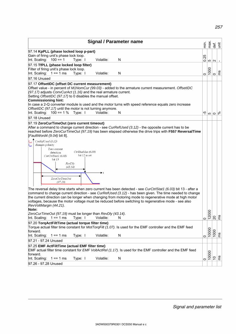
257
Signal and parameter list
3ADW000379R0301 DCS550 Manual e c
Signal / Parameter name
min
. m
ax.
def.
unit
97.14 KpPLL (phase locked loop p-part) Gain of firing unit’s phase lock loop. Int. Scaling: 100 == 1 Type: I Volatile: N 0.
25
5 2 -
97.15 TfPLL (phase locked loop filter) Filter of firing unit’s phase lock loop. Int. Scaling: 1 == 1 ms Type: I Volatile: N 0 10
00
0 ms
97.16 Unused
97.17 OffsetIDC (offset DC current measurement) Offset value - in percent of M1NomCur (99.03) - added to the armature current measurement. OffsetIDC (97.17) adjusts ConvCurAct (1.16) and the real armature current. Setting OffsetIDC (97.17) to 0 disables the manual offset. Commissioning hint: In case a 2-Q converter module is used and the motor turns with speed reference equals zero increase OffsetIDC (97.17) until the motor is not turning anymore. Int. Scaling: 100 == 1 % Type: I Volatile: N -5
5 0 %
97.18 Unused
97.19 ZeroCurTimeOut (zero current timeout) After a command to change current direction - see CurRefUsed (3.12) - the opposite current has to be reached before ZeroCurTimeOut (97.19) has been elapsed otherwise the drive trips with F557 ReversalTime [FaultWord4 (9.04) bit 8].
The reversal delay time starts when zero current has been detected - see CurCtrlStat1 (6.03) bit 13 - after a command to change current direction - see CurRefUsed (3.12) - has been given. The time needed to change the current direction can be longer when changing from motoring mode to regenerative mode at high motor voltages, because the motor voltage must be reduced before switching to regenerative mode - see also RevVoltMargin (44.21). Note: ZeroCurTimeOut (97.19) must be longer than RevDly (43.14). Int. Scaling: 1 == 1 ms Type: I Volatile: N 0 12
000
20
m
s 97.20 TorqActFiltTime (actual torque filter time) Torque actual filter time constant for MotTorqFilt (1.07). Is used for the EMF controller and the EMF feed forward. Int. Scaling: 1 == 1 ms Type: I Volatile: N 0 10
000
10
00
ms
97.21 - 97.24 Unused
97.25 EMF ActFiltTime (actual EMF filter time) EMF actual filter time constant for EMF VoltActRel (1.17). Is used for the EMF controller and the EMF feed forward. Int. Scaling: 1 == 1 ms Type: I Volatile: N 0 10
000
10
m
s
97.26 - 97.28 Unused
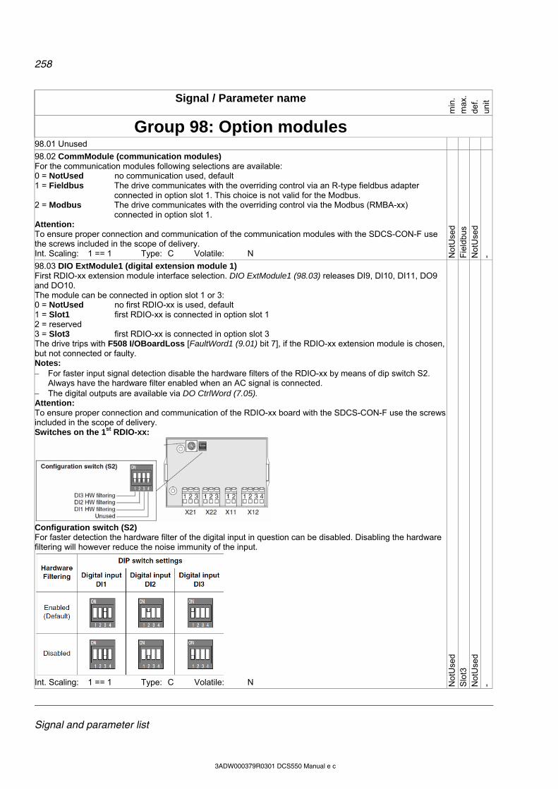
258
Signal and parameter list
3ADW000379R0301 DCS550 Manual e c
Signal / Parameter name
min
. m
ax.
def.
unit
Group 98: Option modules
98.01 Unused
98.02 CommModule (communication modules) For the communication modules following selections are available: 0 = NotUsed no communication used, default 1 = Fieldbus The drive communicates with the overriding control via an R-type fieldbus adapter
connected in option slot 1. This choice is not valid for the Modbus. 2 = Modbus The drive communicates with the overriding control via the Modbus (RMBA-xx)
connected in option slot 1. Attention: To ensure proper connection and communication of the communication modules with the SDCS-CON-F use the screws included in the scope of delivery. Int. Scaling: 1 == 1 Type: C Volatile: N N
otU
sed
Fie
ldbu
s N
otU
sed
-
98.03 DIO ExtModule1 (digital extension module 1) First RDIO-xx extension module interface selection. DIO ExtModule1 (98.03) releases DI9, DI10, DI11, DO9 and DO10. The module can be connected in option slot 1 or 3: 0 = NotUsed no first RDIO-xx is used, default 1 = Slot1 first RDIO-xx is connected in option slot 1 2 = reserved 3 = Slot3 first RDIO-xx is connected in option slot 3 The drive trips with F508 I/OBoardLoss [FaultWord1 (9.01) bit 7], if the RDIO-xx extension module is chosen, but not connected or faulty. Notes: For faster input signal detection disable the hardware filters of the RDIO-xx by means of dip switch S2.
Always have the hardware filter enabled when an AC signal is connected. The digital outputs are available via DO CtrlWord (7.05). Attention: To ensure proper connection and communication of the RDIO-xx board with the SDCS-CON-F use the screws included in the scope of delivery. Switches on the 1st RDIO-xx:
Configuration switch (S2) For faster detection the hardware filter of the digital input in question can be disabled. Disabling the hardware filtering will however reduce the noise immunity of the input.
Int. Scaling: 1 == 1 Type: C Volatile: N N
otU
sed
Slo
t3
Not
Use
d -

259
Signal and parameter list
3ADW000379R0301 DCS550 Manual e c
Signal / Parameter name
min
. m
ax.
def.
unit
98.04 DIO ExtModule2 (digital extension module 2) Second RDIO-xx extension module interface selection. DIO ExtModule2 (98.04) releases DI12, DI13, DI14, DO11 and DO12. The module can be connected in option slot 1 or 3: 0 = NotUsed no second RDIO-xx is used, default 1 = Slot1 second RDIO-xx is connected in option slot 1 2 = reserved 3 = Slot3 second RDIO-xx is connected in option slot 3 The drive trips with F508 I/OBoardLoss [FaultWord1 (9.01) bit 7], if the RDIO-xx extension module is chosen, but not connected or faulty. Notes: For faster input signal detection disable the hardware filters of the RDIO-xx by means of dip switch S2.
Always have the hardware filter enabled when an AC signal is connected. The digital inputs are available via DI StatWord (8.05) The digital outputs are available via DO CtrlWord (7.05). Attention: To ensure proper connection and communication of the RDIO-xx board with the SDCS-CON-F use the screws included in the scope of delivery. Switches on the 2nd RDIO-xx:
Configuration switch (S2) For faster detection the hardware filter of the digital input in question can be disabled. Disabling the hardware filtering will however reduce the noise immunity of the input.
Int. Scaling: 1 == 1 Type: C Volatile: N N
otU
sed
Slo
t3
Not
Use
d -
98.05 Unused
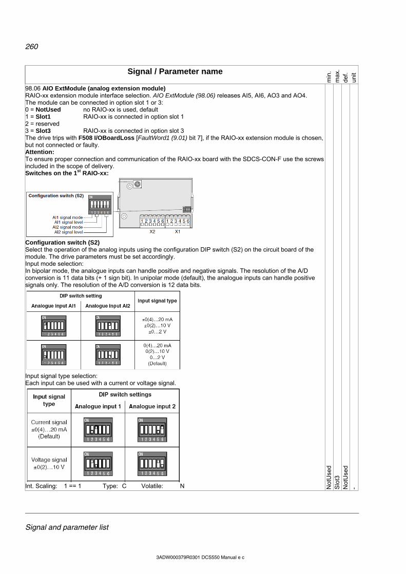
260
Signal and parameter list
3ADW000379R0301 DCS550 Manual e c
Signal / Parameter name
min
. m
ax.
def.
unit
98.06 AIO ExtModule (analog extension module) RAIO-xx extension module interface selection. AIO ExtModule (98.06) releases AI5, AI6, AO3 and AO4. The module can be connected in option slot 1 or 3: 0 = NotUsed no RAIO-xx is used, default 1 = Slot1 RAIO-xx is connected in option slot 1 2 = reserved 3 = Slot3 RAIO-xx is connected in option slot 3 The drive trips with F508 I/OBoardLoss [FaultWord1 (9.01) bit 7], if the RAIO-xx extension module is chosen, but not connected or faulty. Attention: To ensure proper connection and communication of the RAIO-xx board with the SDCS-CON-F use the screws included in the scope of delivery. Switches on the 1st RAIO-xx:
Configuration switch (S2) Select the operation of the analog inputs using the configuration DIP switch (S2) on the circuit board of the module. The drive parameters must be set accordingly. Input mode selection: In bipolar mode, the analogue inputs can handle positive and negative signals. The resolution of the A/D conversion is 11 data bits (+ 1 sign bit). In unipolar mode (default), the analogue inputs can handle positive signals only. The resolution of the A/D conversion is 12 data bits.
Input signal type selection: Each input can be used with a current or voltage signal.
Int. Scaling: 1 == 1 Type: C Volatile: N N
otU
sed
Slo
t3
Not
Use
d -

261
Signal and parameter list
3ADW000379R0301 DCS550 Manual e c
Signal / Parameter name
min
. m
ax.
def.
unit
Group 99: Start-up data
99.01 Language (language) Select language: 0 = English default 1 = reserved 2 = Deutsch 3 = Italiano 4 = Español 5 = reserved 6 = reserved 7 = Français Int. Scaling: 1 == 1 Type: C Volatile: N E
nglis
h E
nglis
h E
nglis
h -
99.02 M1NomVolt (nominal DC voltage) Nominal armature voltage (DC) from the motor rating plate. Int. Scaling: 1 == 1 V Type: I Volatile: N 5 70
0 35
0 V
99.03 M1NomCur (nominal DC current) Nominal armature current (DC) from the motor rating plate. Int. Scaling: 1 == 1 A Type: I Volatile: N 0 10
00
0 A
99.04 M1BaseSpeed (base speed) Base speed from the rating plate, usually the field weak point. M1BaseSpeed (99.04) is must be set in the range of: 0.2 to 1.6 times of SpeedScaleAct (2.29). If the scaling is out of range A124 SpeedScale [AlarmWord2 (9.07) bit 7] is generated. Int. Scaling: 10 == 1 rpm Type: I Volatile: N 10
65
00
150
0 rp
m
99.05 Unused
99.06 ServiceMode (service mode) ServiceMode (99.06) contains several test- and auto tuning procedures. The drive mode is automatically set to NormalMode after an autotuning procedure or after the thyristor diagnosis is finished or failed. In case errors occur during the selected procedure A121 AutotuneFail [AlarmWord2 (9.07) bit 4] is generated. The reason of the error can be seen in Diagnosis (9.11). SetTypeCode is automatically set to NormalMode after the next power up. 0 = NormalMode normal operating mode depending on OperModeSel (43.01), default 1 = ArmCurAuto autotuning armature current controller 2 = FieldCurAuto autotuning field current controller 3 = EMF FluxAuto autotuning EMF controller and flux linearization 4 = SpdCtrlAuto autotuning speed controller 5 = SpdFbAssist test speed feedback, see M1SpeedFbSel (50.03), M1EncPulseNo (50.04) and
M1TachoVolt1000 (50.13) 6 = TachFineTune tacho fine tuning, see M1TachoAdjust (50.12) 7 = ThyDiagnosis the thyristor diagnosis mode is set with TestFire (97.28), the result is shown in
Diagnosis (9.11) 8 = FindDiscCur find discontinuous current limit 9 = SetTypeCode set type code, releases following parameters:
TypeCode (97.01) 10 = LD FB Config reserved for future use (load fieldbus configuration file) Note: The reference chain is blocked while ServiceMode (99.06) NormalMode. Int. Scaling: 1 == 1 Type: C Volatile: Y N
orm
alM
ode
Fin
dDis
cCur
N
orm
alM
ode
-
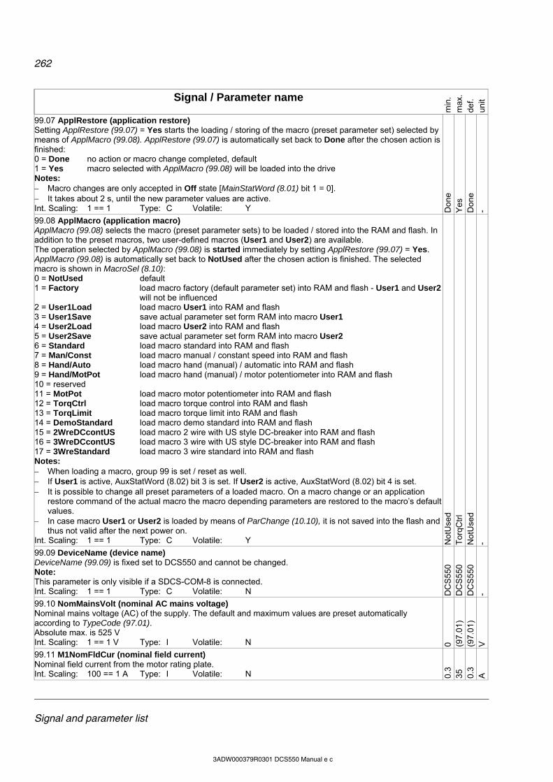
262
Signal and parameter list
3ADW000379R0301 DCS550 Manual e c
Signal / Parameter name
min
. m
ax.
def.
unit
99.07 ApplRestore (application restore) Setting ApplRestore (99.07) = Yes starts the loading / storing of the macro (preset parameter set) selected by means of ApplMacro (99.08). ApplRestore (99.07) is automatically set back to Done after the chosen action is finished: 0 = Done no action or macro change completed, default 1 = Yes macro selected with ApplMacro (99.08) will be loaded into the drive Notes: Macro changes are only accepted in Off state [MainStatWord (8.01) bit 1 = 0]. It takes about 2 s, until the new parameter values are active. Int. Scaling: 1 == 1 Type: C Volatile: Y D
one
Yes
D
one
-
99.08 ApplMacro (application macro) ApplMacro (99.08) selects the macro (preset parameter sets) to be loaded / stored into the RAM and flash. In addition to the preset macros, two user-defined macros (User1 and User2) are available. The operation selected by ApplMacro (99.08) is started immediately by setting ApplRestore (99.07) = Yes. ApplMacro (99.08) is automatically set back to NotUsed after the chosen action is finished. The selected macro is shown in MacroSel (8.10): 0 = NotUsed default 1 = Factory load macro factory (default parameter set) into RAM and flash - User1 and User2
will not be influenced 2 = User1Load load macro User1 into RAM and flash 3 = User1Save save actual parameter set form RAM into macro User1 4 = User2Load load macro User2 into RAM and flash 5 = User2Save save actual parameter set form RAM into macro User2 6 = Standard load macro standard into RAM and flash 7 = Man/Const load macro manual / constant speed into RAM and flash 8 = Hand/Auto load macro hand (manual) / automatic into RAM and flash 9 = Hand/MotPot load macro hand (manual) / motor potentiometer into RAM and flash 10 = reserved 11 = MotPot load macro motor potentiometer into RAM and flash 12 = TorqCtrl load macro torque control into RAM and flash 13 = TorqLimit load macro torque limit into RAM and flash 14 = DemoStandard load macro demo standard into RAM and flash 15 = 2WreDCcontUS load macro 2 wire with US style DC-breaker into RAM and flash 16 = 3WreDCcontUS load macro 3 wire with US style DC-breaker into RAM and flash 17 = 3WreStandard load macro 3 wire standard into RAM and flash Notes: When loading a macro, group 99 is set / reset as well. If User1 is active, AuxStatWord (8.02) bit 3 is set. If User2 is active, AuxStatWord (8.02) bit 4 is set. It is possible to change all preset parameters of a loaded macro. On a macro change or an application
restore command of the actual macro the macro depending parameters are restored to the macro’s default values.
In case macro User1 or User2 is loaded by means of ParChange (10.10), it is not saved into the flash and thus not valid after the next power on.
Int. Scaling: 1 == 1 Type: C Volatile: Y Not
Use
d T
orqC
trl
Not
Use
d -
99.09 DeviceName (device name) DeviceName (99.09) is fixed set to DCS550 and cannot be changed. Note: This parameter is only visible if a SDCS-COM-8 is connected. Int. Scaling: 1 == 1 Type: C Volatile: N D
CS
550
D
CS
550
D
CS
550
-
99.10 NomMainsVolt (nominal AC mains voltage) Nominal mains voltage (AC) of the supply. The default and maximum values are preset automatically according to TypeCode (97.01). Absolute max. is 525 V Int. Scaling: 1 == 1 V Type: I Volatile: N 0 (9
7.01
) (9
7.01
) V
99.11 M1NomFldCur (nominal field current) Nominal field current from the motor rating plate. Int. Scaling: 100 == 1 A Type: I Volatile: N 0.
3 35
0.
3 A
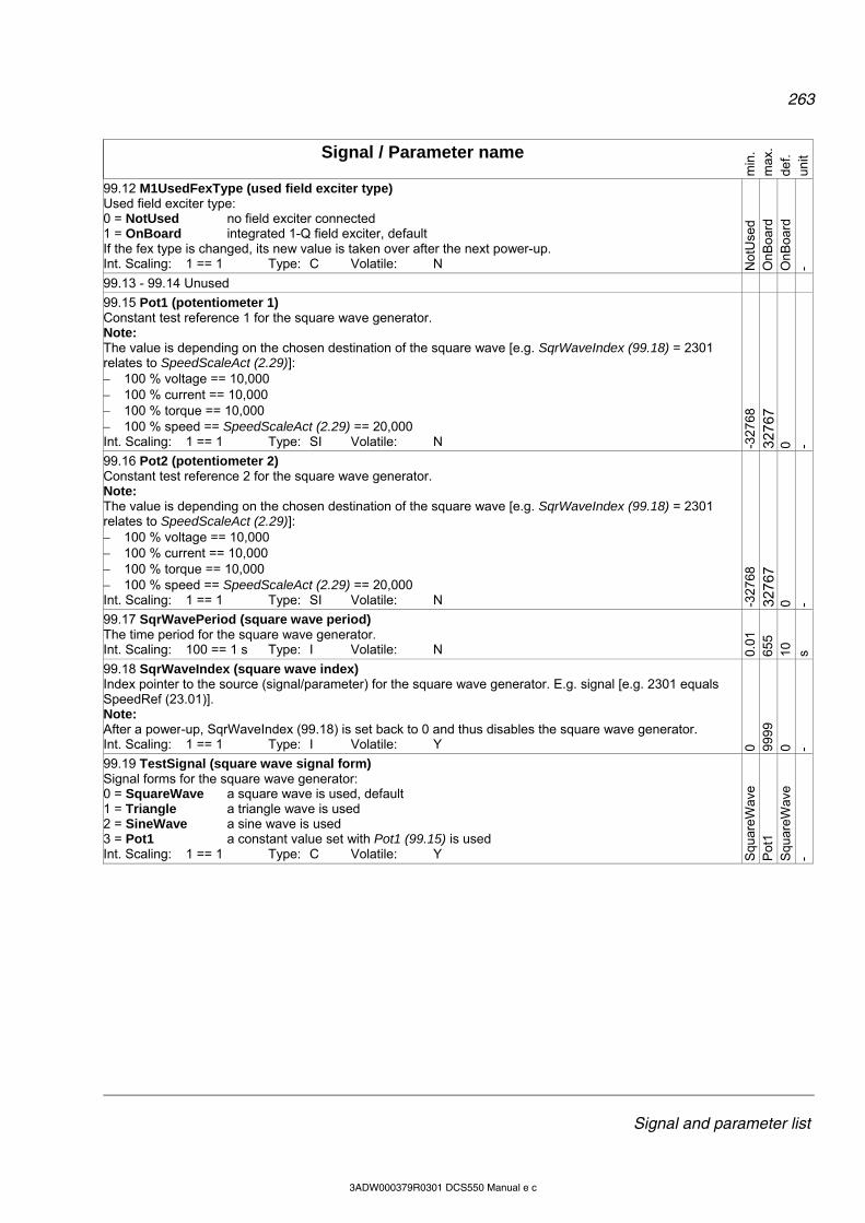
263
Signal and parameter list
3ADW000379R0301 DCS550 Manual e c
Signal / Parameter name
min
. m
ax.
def.
unit
99.12 M1UsedFexType (used field exciter type) Used field exciter type: 0 = NotUsed no field exciter connected 1 = OnBoard integrated 1-Q field exciter, default If the fex type is changed, its new value is taken over after the next power-up. Int. Scaling: 1 == 1 Type: C Volatile: N N
otU
sed
OnB
oard
O
nBoa
rd
-
99.13 - 99.14 Unused
99.15 Pot1 (potentiometer 1) Constant test reference 1 for the square wave generator. Note: The value is depending on the chosen destination of the square wave [e.g. SqrWaveIndex (99.18) = 2301 relates to SpeedScaleAct (2.29)]: 100 % voltage == 10,000 100 % current == 10,000 100 % torque == 10,000 100 % speed == SpeedScaleAct (2.29) == 20,000 Int. Scaling: 1 == 1 Type: SI Volatile: N -3
2768
3276
7 0 -
99.16 Pot2 (potentiometer 2) Constant test reference 2 for the square wave generator. Note: The value is depending on the chosen destination of the square wave [e.g. SqrWaveIndex (99.18) = 2301 relates to SpeedScaleAct (2.29)]: 100 % voltage == 10,000 100 % current == 10,000 100 % torque == 10,000 100 % speed == SpeedScaleAct (2.29) == 20,000 Int. Scaling: 1 == 1 Type: SI Volatile: N -3
2768
3276
7 0 -
99.17 SqrWavePeriod (square wave period) The time period for the square wave generator. Int. Scaling: 100 == 1 s Type: I Volatile: N 0.
01
655
10
s
99.18 SqrWaveIndex (square wave index) Index pointer to the source (signal/parameter) for the square wave generator. E.g. signal [e.g. 2301 equals SpeedRef (23.01)]. Note: After a power-up, SqrWaveIndex (99.18) is set back to 0 and thus disables the square wave generator. Int. Scaling: 1 == 1 Type: I Volatile: Y 0 99
99
0 -
99.19 TestSignal (square wave signal form) Signal forms for the square wave generator: 0 = SquareWave a square wave is used, default 1 = Triangle a triangle wave is used 2 = SineWave a sine wave is used 3 = Pot1 a constant value set with Pot1 (99.15) is used Int. Scaling: 1 == 1 Type: C Volatile: Y S
quar
eWav
e P
ot1
Squ
areW
ave
-

264
DCS550 panel operation
3ADW000379R0301 DCS550 Manual e c
DCS Control Panel Chapter overview This chapter describes the handling of the DCS Control Panel.
Start-up The commissioning configures the drive and sets parameters that define how the drive operates and communicates. Depending on the control and communication requirements, the commissioning requires any or all of the following: The Start-up Assistant (via DCS Control Panel or DWL) steps you through the default configuration. The
DCS Control Panel Start-up Assistant runs automatically at the first power up, or can be accessed at any time using the main menu.
Select application macros to define common, system configurations. Additional adjustments can be made using the DCS Control Panel to manually select and set individual
parameters. See chapter Signal and parameter list.
DCS Control Panel Use the DCS Control Panel to control the drive, to read status data, to adjust parameters and to use the pre-programmed assistants. Features: The DCS Control Panel features: Alphanumeric LCD display Language selection for the display by means of Language (99.01) Panel can be connected or detached at any time Start-up Assistant for ease drive commissioning Copy function, parameters can be copied into the DCS Control Panel memory to be downloaded to other
drives or as backup Context sensitive help Fault- and alarm messages including fault history
Display overview The following table summarizes the button functions and displays of the DCS Control Panel.
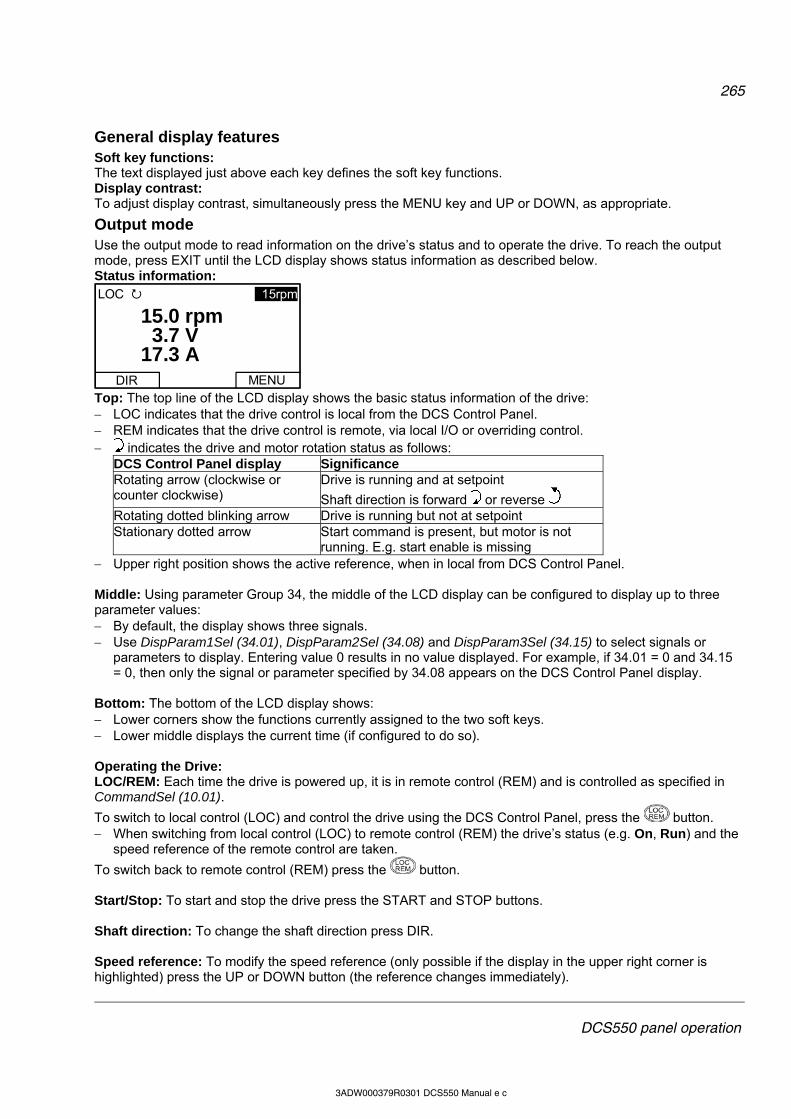
265
DCS550 panel operation
3ADW000379R0301 DCS550 Manual e c
General display features Soft key functions: The text displayed just above each key defines the soft key functions. Display contrast: To adjust display contrast, simultaneously press the MENU key and UP or DOWN, as appropriate.
Output mode Use the output mode to read information on the drive’s status and to operate the drive. To reach the output mode, press EXIT until the LCD display shows status information as described below. Status information:
DIR
LOC 15rpm
MENU
3.715.0
17.3Vrpm
A
Top: The top line of the LCD display shows the basic status information of the drive: LOC indicates that the drive control is local from the DCS Control Panel. REM indicates that the drive control is remote, via local I/O or overriding control. indicates the drive and motor rotation status as follows:
DCS Control Panel display Significance Rotating arrow (clockwise or counter clockwise)
Drive is running and at setpoint
Shaft direction is forward or reverse Rotating dotted blinking arrow Drive is running but not at setpoint Stationary dotted arrow Start command is present, but motor is not
running. E.g. start enable is missing Upper right position shows the active reference, when in local from DCS Control Panel. Middle: Using parameter Group 34, the middle of the LCD display can be configured to display up to three parameter values: By default, the display shows three signals. Use DispParam1Sel (34.01), DispParam2Sel (34.08) and DispParam3Sel (34.15) to select signals or
parameters to display. Entering value 0 results in no value displayed. For example, if 34.01 = 0 and 34.15 = 0, then only the signal or parameter specified by 34.08 appears on the DCS Control Panel display.
Bottom: The bottom of the LCD display shows: Lower corners show the functions currently assigned to the two soft keys. Lower middle displays the current time (if configured to do so). Operating the Drive: LOC/REM: Each time the drive is powered up, it is in remote control (REM) and is controlled as specified in CommandSel (10.01).
To switch to local control (LOC) and control the drive using the DCS Control Panel, press the button. When switching from local control (LOC) to remote control (REM) the drive’s status (e.g. On, Run) and the
speed reference of the remote control are taken.
To switch back to remote control (REM) press the button. Start/Stop: To start and stop the drive press the START and STOP buttons. Shaft direction: To change the shaft direction press DIR. Speed reference: To modify the speed reference (only possible if the display in the upper right corner is highlighted) press the UP or DOWN button (the reference changes immediately).
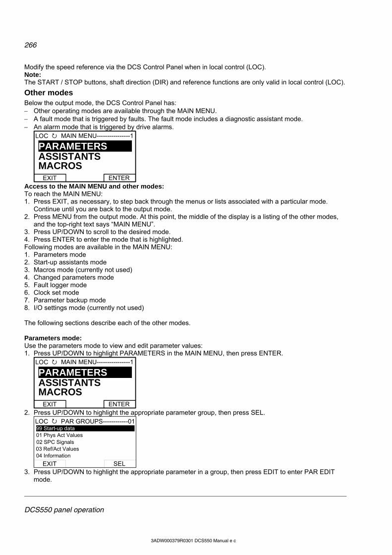
266
DCS550 panel operation
3ADW000379R0301 DCS550 Manual e c
Modify the speed reference via the DCS Control Panel when in local control (LOC). Note: The START / STOP buttons, shaft direction (DIR) and reference functions are only valid in local control (LOC).
Other modes Below the output mode, the DCS Control Panel has: Other operating modes are available through the MAIN MENU. A fault mode that is triggered by faults. The fault mode includes a diagnostic assistant mode. An alarm mode that is triggered by drive alarms.
EXIT
LOC MAIN MENU----------------1
ENTER
ASSISTANTSPARAMETERS
MACROS
Access to the MAIN MENU and other modes: To reach the MAIN MENU: 1. Press EXIT, as necessary, to step back through the menus or lists associated with a particular mode.
Continue until you are back to the output mode. 2. Press MENU from the output mode. At this point, the middle of the display is a listing of the other modes,
and the top-right text says “MAIN MENU”. 3. Press UP/DOWN to scroll to the desired mode. 4. Press ENTER to enter the mode that is highlighted. Following modes are available in the MAIN MENU: 1. Parameters mode 2. Start-up assistants mode 3. Macros mode (currently not used) 4. Changed parameters mode 5. Fault logger mode 6. Clock set mode 7. Parameter backup mode 8. I/O settings mode (currently not used) The following sections describe each of the other modes. Parameters mode: Use the parameters mode to view and edit parameter values: 1. Press UP/DOWN to highlight PARAMETERS in the MAIN MENU, then press ENTER.
EXIT
LOC MAIN MENU----------------1
ENTER
ASSISTANTSPARAMETERS
MACROS
2. Press UP/DOWN to highlight the appropriate parameter group, then press SEL.
EXIT
LOC PAR GROUPS------------01
SEL
99 Start-up data 01 Phys Act Values
03 Ref/Act Values02 SPC Signals
04 Information
3. Press UP/DOWN to highlight the appropriate parameter in a group, then press EDIT to enter PAR EDIT
mode.

267
DCS550 panel operation
3ADW000379R0301 DCS550 Manual e c
EXIT
LOC PARAMETERS--------------
EDIT
9901 Language9902 M1NomVolt 350 V 9903 M1NomCur9904 M1BaseSpeed
Note: The current parameter value appears below the highlighted parameter. 4. Press UP/DOWN to step to the desired parameter value.
CANCEL
LOC PAR EDIT---------------------
SAVE
9902 M1NomVolt
60 V
Note: To get the parameter default value press UP/DOWN simultaneously. 5. Press SAVE to store the modified value and leave the PAR EDIT mode or press CANCEL to leave the
PAR EDIT mode without modifications. 6. Press EXIT to return to the listing of parameter groups, and again to step back to the MAIN MENU. Start-up assistants mode: Use the start-up assistants mode for basic commissioning of the drive. When the drive is powered up the first time, the start-up assistants guide you through the setup of the basic parameters. There are seven start-up assistants available. They can be activated one after the other, as the ASSISTANTS menu suggests, or independently. The use of the assistants is not required. It is also possible to use the parameter mode instead. The assistant list in the following table is typical: Name plate data Enter the motor data, the mains (supply) data, the most important protections and follow the
instructions of the assistant. After filling out the parameters of this assistant it is - in most cases - possible to turn the motor for the first time.
Macro assistant Selects an application macro. Autotuning field current controller
Enter the field circuit data and follow the instructions of the assistant. During the autotuning the main respectively field contactor will be closed, the field circuit is measured by means of increasing the field current to nominal field current and the field current control parameters are set. The armature current is not released while the autotuning is active and thus the motor should not turn. When the autotuning is finished successfully, the parameters changed by the assistant are shown for confirmation. If the assistant fails, it is possible to enter the fault mode for more help.
Autotuning armature current controller
Enter the motor nominal current, the basic current limitations and follow the instructions of the assistant. During the autotuning the main contactor will be closed, the armature circuit is measured by means of armature current bursts and the armature current control parameters are set. The field current is not released while the autotuning is active and thus the motor should not turn, but due to remanence in the field circuit about 40% of all motors will turn (create torque). Lock these motors. When the autotuning is finished successfully, the parameters changed by the assistant are shown for confirmation. If the assistant fails, it is possible to enter the fault mode for more help.
Speed feedback assistant Enter the EMF speed feedback parameters, - if applicable - the parameters for the pulse encoder respectively the analog tacho and follow the instructions of the assistant. The speed feedback assistant detects the kind of speed feedback the drive is using and provides help to set up pulse encoders or analog tachometers. During the autotuning the main contactor and the field contactor - if existing - will be closed and the motor will run up to base speed [M1BaseSpeed (99.04)]. During the whole procedure, the drive will be in EMF speed control despite the setting of M1SpeedFbSel (50.03). When the assistant is finished successfully, the speed feedback is set. If the assistant fails, it is possible to enter the fault mode for more help.
Autotuning speed controller Enter the motor base speed, the basic speed limitations, the speed filter time and follow the instructions of the assistant.
268
DCS550 panel operation
3ADW000379R0301 DCS550 Manual e c
During the autotuning the main contactor and the field contactor - if existing - will be closed, the ramp is bypassed and torque respectively current limits are valid. The speed controller is tuned by means of speed bursts up to base speed [M1BaseSpeed (99.04)] and the speed controller parameters are set. Attention: During the autotuning the torque limits will be reached. When the autotuning is finished successfully, the parameters changed by the assistant are shown for confirmation. If the assistant fails, it is possible to enter the fault mode for more help. Attention: This assistant is using the setting of M1SpeedFbSel (50.03). If using setting Encoder or Tacho make sure, the speed feedback is working properly!
Field weakening assistant (only used when maximum speed is higher than base speed)
Enter the motor data, the field circuit data and follow the instructions of the assistant. During the autotuning the main contactor and the field contactor - if existing - will be closed and the motor will run up to base speed [M1BaseSpeed (99.04)]. The EMF controller data are calculated, the flux linearization is tuned by means of a constant speed while decreasing the field current and the EMF controller respectively flux linearization parameters are set. When the autotuning is finished successfully, the parameters changed by the assistant are shown for confirmation. If the assistant fails, it is possible to enter the fault mode for more help.
1. Press UP/DOWN to highlight ASSISTANTS in the MAIN MENU, then press ENTER. 2. Press UP/DOWN to highlight the appropriate start-up assistant, then press SEL to enter PAR EDIT mode. 3. Make entries or selections as appropriate. 4. Press SAVE to save settings. Each individual parameter setting is valid immediately after pressing SAVE. Press EXIT to step back to the MAIN MENU. Macros mode: Currently not used! Changed parameters mode: Use the changed parameters mode to view and edit a listing of all parameter that have been changed from their default values: 1. Press UP/DOWN to highlight CHANGED PAR in the MAIN MENU, then press ENTER. 2. Press UP/DOWN to highlight a changed parameter, then press EDIT to enter PAR EDIT mode. Note: The current parameter value appears below the highlighted parameter. 3. Press UP/DOWN to step to the desired parameter value. Note: To get the parameter default value press UP/DOWN simultaneously. 4. Press SAVE to store the modified value and leave the PAR EDIT mode or press CANCEL to leave the
PAR EDIT mode without modifications. Note: If the new value is the default value, the parameter will no longer appear in the changed parameter list. 5. Press EXIT to step back to the MAIN MENU. Fault logger mode: Use the fault logger mode to see the drives fault, alarm and event history, the fault state details and help for the faults: 1. Press UP/DOWN to highlight FAULT LOGGER in the MAIN MENU, then press ENTER to see the latest
faults (up to 20 faults, alarms and events are logged). 2. Press DETAIL to see details for the selected fault. Details are available for the three latest faults,
independent of the location in the fault logger. 3. Press DIAG to get additional help (only for faults). 4. Press EXIT to step back to the MAIN MENU. Clock set mode: Use the Clock set mode to: Enable or disable the clock function. Select the display format. Set date and time. 1. Press UP/DOWN to highlight CLOCK SET in the MAIN MENU, then press ENTER. 2. Press UP/DOWN to highlight the desired option, then press SEL.
269
DCS550 panel operation
3ADW000379R0301 DCS550 Manual e c
3. Choose the desired setting, and then press SEL or OK to store the setting or press CANCEL to leave without modifications.
4. Press EXIT to step back to the MAIN MENU. Note: To get the clock visible on the LCD display at least one change has to be done in the clock set mode and the DCS Control Panel has to be de-energized and energized again. Parameter backup mode: The DCS Control Panel can store a full set of drive parameters. AP will be uploaded and downloaded. The type code of the drive is write protected and has to be set manually by means of ServiceMode (99.06)
= SetTypeCode and TypeCode (97.01). The parameter backup mode has following functions: UPLOAD TO PANEL: Copies all parameters from the drive into the DCS Control Panel. This includes both
user sets (User1 and User2) - if defined - and internal parameters such as those created by tacho fine tuning. The DCS Control Panel memory is non-volatile and does not depend on its battery. Can only be done in drive state Off and local from DCS Control Panel.
DOWNLOAD FULL SET: Restores the full parameter set from the DCS Control Panel into the drive. Use this option to restore a drive, or to configure identical drives. Can only be done in drive state Off and local from DCS Control Panel.
Note: This download does not include the user sets. DOWNLOAD APPLICATION: Currently not used! The general procedure for parameter backup operations is: 1. Press UP/DOWN to highlight PAR BACKUP in the MAIN MENU, then press ENTER. 2. Press UP/DOWN to highlight the desired option, then press SEL. 3. Wait until the service is finished, then press OK. 4. Press EXIT to step back to the MAIN MENU. I/O settings mode: Currently not used!
Maintenance Cleaning: Use a soft damp cloth to clean the DCS Control Panel. Avoid harsh cleaners, which could scratch the display window. Battery: A battery is used in the DCS Control Panel to keep the clock function available and enabled. The battery keeps the clock operating during power interruptions. The expected life for the battery is greater than ten years. To remove the battery, use a coin to rotate the battery holder on the back of the control panel. The type of the battery is CR2032. Note: The battery is not required for any DCS Control Panel or drive functions, except for the clock.

270
Fault tracing
3ADW000379R0301 DCS550 Manual e c
Fault tracing Chapter overview This chapter describes the protections and fault tracing of the drive.
Fault modes Depending on the trip level of the fault, the drive reacts differently. The drive’s reaction to a fault with trip level 1 and 2 is fixed. See also paragraph Fault signals of this manual. The reaction to a fault of level 3 and 4 can be chosen by means of SpeedFbFltMode (30.36) respectively FaultStopMode (30.30).
Converter protection
Auxiliary undervoltage If the auxiliary supply voltage fails while the drive is in RdyRun state (MSW bit 1), fault F501 AuxUnderVolt is generated. Auxiliary supply voltage Trip level 230 VAC < 95 VAC 115 VAC < 95 VAC 230 VDC < 140 VDC
Armature overcurrent The nominal value of the armature current is set with M1NomCur (99.02). The overcurrent level is set by means of ArmOvrCurLev (30.09). Additionally the actual current is monitored against the overcurrent level of the converter module. The converter’s actual overcurrent level can be read from ConvOvrCur (4.16). Exceeding one of the two levels causes F502 ArmOverCur.
Converter overtemperature The maximum temperature of the bridge can be read from MaxBridgeTemp (4.17) and is automatically set by TypeCode (97.01) or manually set by S MaxBrdgTemp (97.04). Exceeding this level causes F504 ConvOverTemp. The threshold for A104 ConvOverTemp is 5 C below the tripping level. The measured temperature can be read from BridgeTemp (1.24). If the measured temperature drops below minus 10 C, F504 ConvOverTemp is generated.
Auto-reclosing (mains undervoltage) Auto-reclosing allows continuing drive operation immediately after a short mains undervoltage without any additional functions in the overriding control system. In order to keep the overriding control system and the drive control electronics running through short mains undervoltage, an UPS is needed for the 115/230 VAC auxiliary voltages. Without the UPS all DI like e.g. E-stop, start inhibition, acknowledge signals etc. would have false states and trip the drive although the system itself could stay alive. In addition, the control circuits of the main contactor must be supplied during the mains undervoltage. Auto-reclosing defines whether the drive trips immediately with F512 MainsLowVolt or if the drive will continue running after the mains voltage returns. To activate the auto-reclosing set PwrLossTrip (30.21) = Delayed. Short mains undervoltage The supervision of mains undervoltage has two levels: 1. UNetMin1 (30.22) alarm, protection and trip level 2. UNetMin2 (30.23) trip level If the mains voltage falls below UNetMin1 (30.22) but stays above UNetMin2 (30.23), the following actions take place: 1. the firing angle is set to ArmAlphaMax (20.14), 2. single firing pulses are applied in order to extinguish the current as fast as possible, 3. the controllers are frozen, 4. the speed ramp output is updated from the measured speed and
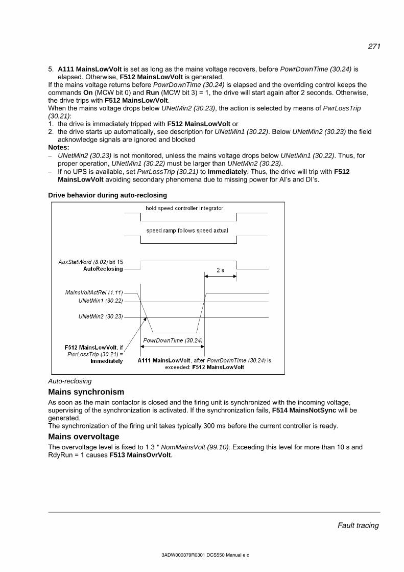
271
Fault tracing
3ADW000379R0301 DCS550 Manual e c
5. A111 MainsLowVolt is set as long as the mains voltage recovers, before PowrDownTime (30.24) is elapsed. Otherwise, F512 MainsLowVolt is generated.
If the mains voltage returns before PowrDownTime (30.24) is elapsed and the overriding control keeps the commands On (MCW bit 0) and Run (MCW bit 3) = 1, the drive will start again after 2 seconds. Otherwise, the drive trips with F512 MainsLowVolt. When the mains voltage drops below UNetMin2 (30.23), the action is selected by means of PwrLossTrip (30.21): 1. the drive is immediately tripped with F512 MainsLowVolt or 2. the drive starts up automatically, see description for UNetMin1 (30.22). Below UNetMin2 (30.23) the field
acknowledge signals are ignored and blocked Notes: UNetMin2 (30.23) is not monitored, unless the mains voltage drops below UNetMin1 (30.22). Thus, for
proper operation, UNetMin1 (30.22) must be larger than UNetMin2 (30.23). If no UPS is available, set PwrLossTrip (30.21) to Immediately. Thus, the drive will trip with F512
MainsLowVolt avoiding secondary phenomena due to missing power for AI’s and DI’s. Drive behavior during auto-reclosing
Auto-reclosing
Mains synchronism As soon as the main contactor is closed and the firing unit is synchronized with the incoming voltage, supervising of the synchronization is activated. If the synchronization fails, F514 MainsNotSync will be generated. The synchronization of the firing unit takes typically 300 ms before the current controller is ready.
Mains overvoltage The overvoltage level is fixed to 1.3 * NomMainsVolt (99.10). Exceeding this level for more than 10 s and RdyRun = 1 causes F513 MainsOvrVolt.
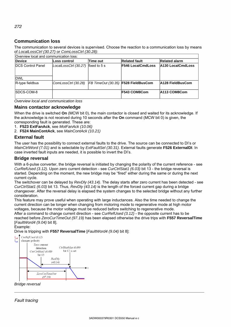
272
Fault tracing
3ADW000379R0301 DCS550 Manual e c
Communication loss The communication to several devices is supervised. Choose the reaction to a communication loss by means of LocalLossCtrl (30.27) or ComLossCtrl (30.28): Overview local and communication loss: Device Loss control Time out Related fault Related alarm DCS Control Panel
DWL
LocalLossCtrl (30.27) fixed to 5 s F546 LocalCmdLoss A130 LocalCmdLoss
R-type fieldbus ComLossCtrl (30.28) FB TimeOut (30.35) F528 FieldBusCom A128 FieldBusCom
SDCS-COM-8 F543 COM8Com A113 COM8Com
Overview local and communication loss
Mains contactor acknowledge When the drive is switched On (MCW bit 0), the main contactor is closed and waited for its acknowledge. If the acknowledge is not received during 10 seconds after the On command (MCW bit 0) is given, the corresponding fault is generated. These are: 1. F523 ExtFanAck, see MotFanAck (10.06) 2. F524 MainContAck, see MainContAck (10.21)
External fault The user has the possibility to connect external faults to the drive. The source can be connected to DI’s or MainCtrlWord (7.01) and is selectable by ExtFaultSel (30.31). External faults generate F526 ExternalDI. In case inverted fault inputs are needed, it is possible to invert the DI’s.
Bridge reversal With a 6-pulse converter, the bridge reversal is initiated by changing the polarity of the current reference - see CurRefUsed (3.12). Upon zero current detection - see CurCtrlStat1 (6.03) bit 13 - the bridge reversal is started. Depending on the moment, the new bridge may be “fired” either during the same or during the next current cycle. The switchover can be delayed by RevDly (43.14). The delay starts after zero current has been detected - see CurCtrlStat1 (6.03) bit 13. Thus, RevDly (43.14) is the length of the forced current gap during a bridge changeover. After the reversal delay is elapsed the system changes to the selected bridge without any further consideration. This feature may prove useful when operating with large inductances. Also the time needed to change the current direction can be longer when changing from motoring mode to regenerative mode at high motor voltages, because the motor voltage must be reduced before switching to regenerative mode. After a command to change current direction - see CurRefUsed (3.12) - the opposite current has to be reached before ZeroCurTimeOut (97.19) has been elapsed otherwise the drive trips with F557 ReversalTime [FaultWord4 (9.04) bit 8]. Example: Drive is tripping with F557 ReversalTime [FaultWord4 (9.04) bit 8]:
Bridge reversal
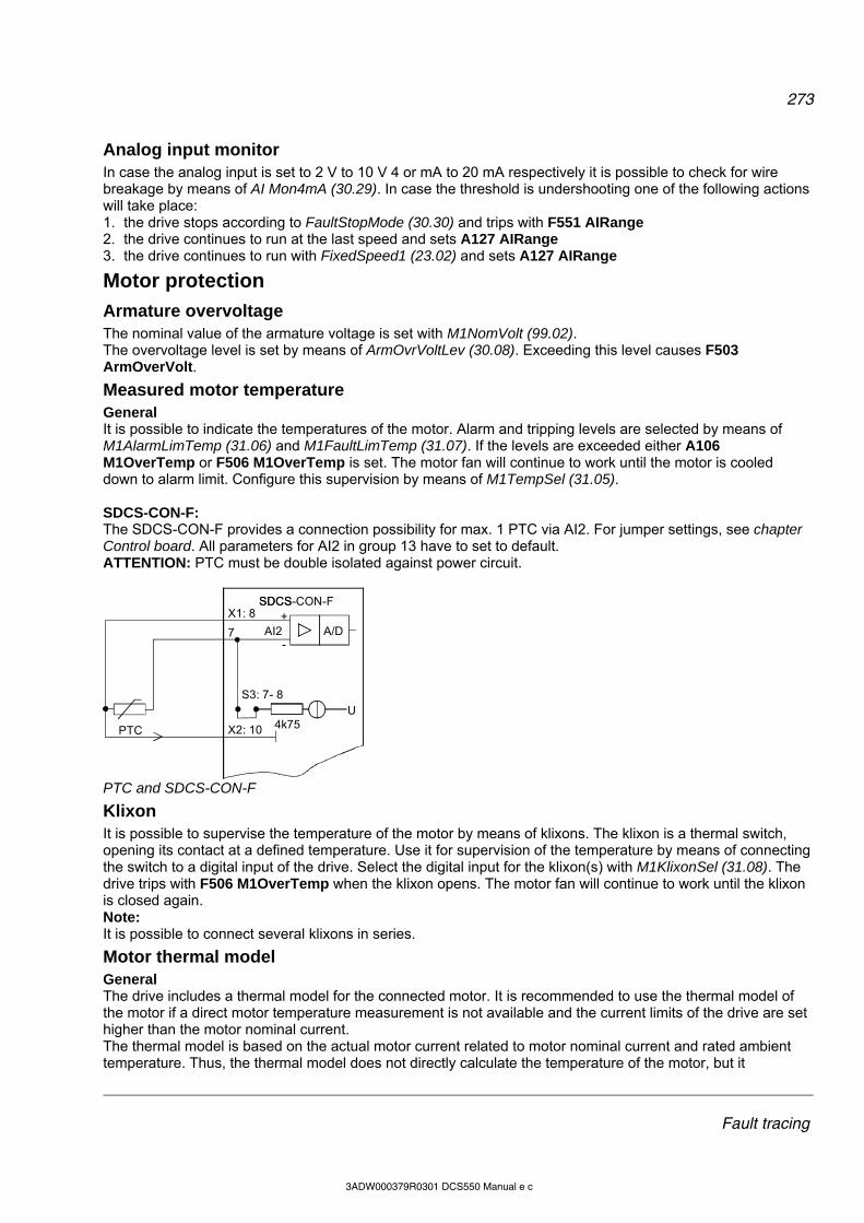
273
Fault tracing
3ADW000379R0301 DCS550 Manual e c
Analog input monitor In case the analog input is set to 2 V to 10 V 4 or mA to 20 mA respectively it is possible to check for wire breakage by means of AI Mon4mA (30.29). In case the threshold is undershooting one of the following actions will take place: 1. the drive stops according to FaultStopMode (30.30) and trips with F551 AIRange 2. the drive continues to run at the last speed and sets A127 AIRange 3. the drive continues to run with FixedSpeed1 (23.02) and sets A127 AIRange
Motor protection
Armature overvoltage The nominal value of the armature voltage is set with M1NomVolt (99.02). The overvoltage level is set by means of ArmOvrVoltLev (30.08). Exceeding this level causes F503 ArmOverVolt.
Measured motor temperature General It is possible to indicate the temperatures of the motor. Alarm and tripping levels are selected by means of M1AlarmLimTemp (31.06) and M1FaultLimTemp (31.07). If the levels are exceeded either A106 M1OverTemp or F506 M1OverTemp is set. The motor fan will continue to work until the motor is cooled down to alarm limit. Configure this supervision by means of M1TempSel (31.05). SDCS-CON-F: The SDCS-CON-F provides a connection possibility for max. 1 PTC via AI2. For jumper settings, see chapter Control board. All parameters for AI2 in group 13 have to set to default. ATTENTION: PTC must be double isolated against power circuit.
X1: 8
U
7 AI2
S3: 7- 8
X2: 10
A/D
PTC
SDCS+
-
4k75
SDCS-CON-F
PTC and SDCS-CON-F
Klixon It is possible to supervise the temperature of the motor by means of klixons. The klixon is a thermal switch, opening its contact at a defined temperature. Use it for supervision of the temperature by means of connecting the switch to a digital input of the drive. Select the digital input for the klixon(s) with M1KlixonSel (31.08). The drive trips with F506 M1OverTemp when the klixon opens. The motor fan will continue to work until the klixon is closed again. Note: It is possible to connect several klixons in series.
Motor thermal model General The drive includes a thermal model for the connected motor. It is recommended to use the thermal model of the motor if a direct motor temperature measurement is not available and the current limits of the drive are set higher than the motor nominal current. The thermal model is based on the actual motor current related to motor nominal current and rated ambient temperature. Thus, the thermal model does not directly calculate the temperature of the motor, but it
274
Fault tracing
3ADW000379R0301 DCS550 Manual e c
calculates the temperature rise of the motor. This is because the motor will reach its end temperature after the specified time when starting to run the cold motor (40°C) with nominal current. This time is about four times the motor thermal time constant. The temperature rise of the motor behaves like the time constant which is proportional with the motor current to the power of two:
)1(1*2
2
t
Motn
act eI
I
When the motor is cooling down, following temperature model is valid:
)2(*2
2t
Motn
act eI
I
with: alarm = temperature rise == [M1AlarmLimLoad (31.03)]2 trip = temperature rise == [M1FaultLimLoad (31.04)]2 = temperature rise == Mot1TempCalc (1.20) iact = actual motor current (overload e.g. 170%) iMotN = nominal motor current (100%) t = length of overload (e.g. 60 s) = temperature time constant (in seconds) == M1ModelTime (31.01)
As from the formulas (1) and (2) can be seen, the temperature model uses the same time constant when the motor is heating or cooling down. Alarm and tripping levels Alarm and tripping levels are selected by means of M1AlarmLimLoad (31.03) and M1FaultLimLoad (31.04). If the levels are exceeded either A107 M1OverLoad or F507 M1OverLoad is set. The motor fan will continue to work until the motor is cooled down under the alarm limit. The default values are selected in order to achieve quite high overload ability. Recommended value for alarming is 102 % and for tripping 106 % of nominal motor current. Thus the temperature rise is: alarm == [M1AlarmLimLoad (31.03)]2 = (102%)2 = 1.022 = 1.04 and trip == [M1FaultLimLoad (31.04)]2= (106%)2 = 1.062 = 1.12. The temperature rise output of the model is shown in Mot1TempCalc (1.20). Thermal model selection The thermal models is activated by setting M1ModelTime (31.01) greater than zero. Thermal time constant Set the time constant for the thermal model by means of M1ModelTime (31.01). If the thermal time constant of a motor is given by the manufacturer just write it into M1ModelTime (31.01). In many cases, the motor manufacturer provides a curve that defines how long the motor can be overloaded by a certain overload factor. In this case, calculate the proper thermal time constant. Example: The drive is designed to trip if the motor current exceeds 170 % of motor nominal current for more than 60 seconds. Selected tripping base level is 106 % of nominal motor current, thus M1FaultLimLoad (31.04) = 106 %.
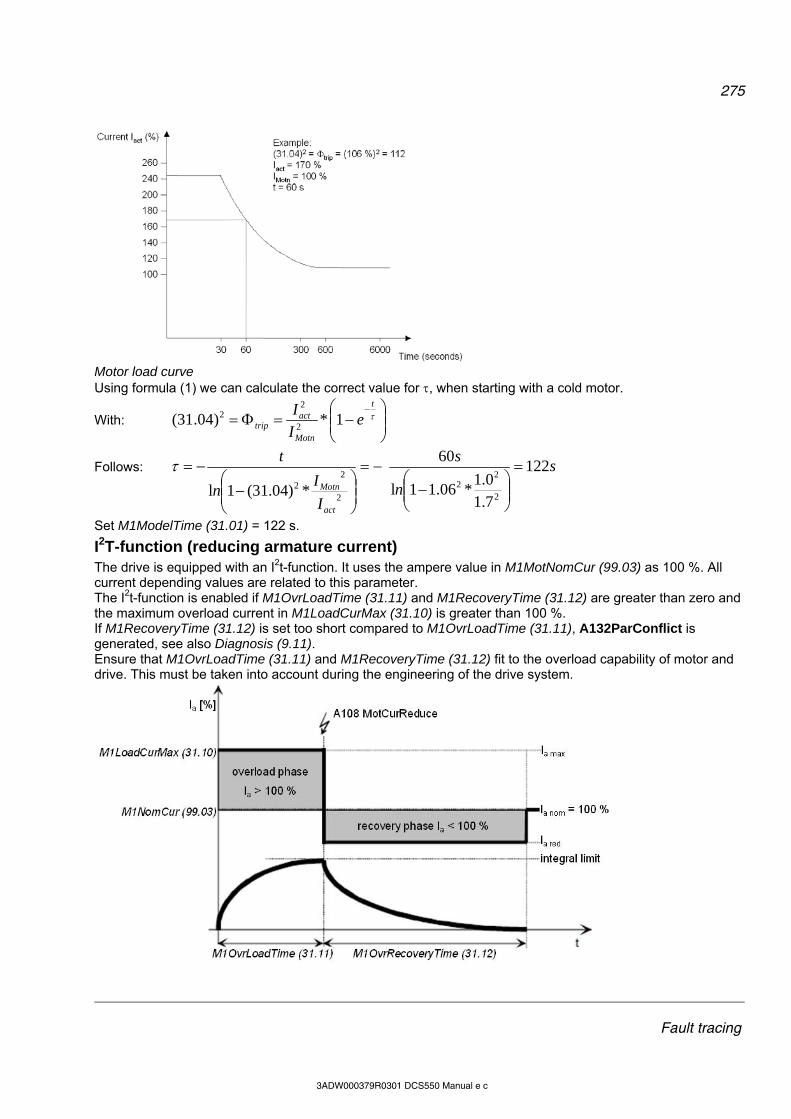
275
Fault tracing
3ADW000379R0301 DCS550 Manual e c
Motor load curve Using formula (1) we can calculate the correct value for , when starting with a cold motor.
With:
t
Motn
acttrip e
I
I1*)04.31(
2
22
Follows: s
n
s
I
In
t
act
Motn
122
7.1
0.1*06.11l
60
*)04.31(1l 2
22
2
22
Set M1ModelTime (31.01) = 122 s.
I2T-function (reducing armature current) The drive is equipped with an I2t-function. It uses the ampere value in M1MotNomCur (99.03) as 100 %. All current depending values are related to this parameter. The I2t-function is enabled if M1OvrLoadTime (31.11) and M1RecoveryTime (31.12) are greater than zero and the maximum overload current in M1LoadCurMax (31.10) is greater than 100 %. If M1RecoveryTime (31.12) is set too short compared to M1OvrLoadTime (31.11), A132ParConflict is generated, see also Diagnosis (9.11). Ensure that M1OvrLoadTime (31.11) and M1RecoveryTime (31.12) fit to the overload capability of motor and drive. This must be taken into account during the engineering of the drive system.
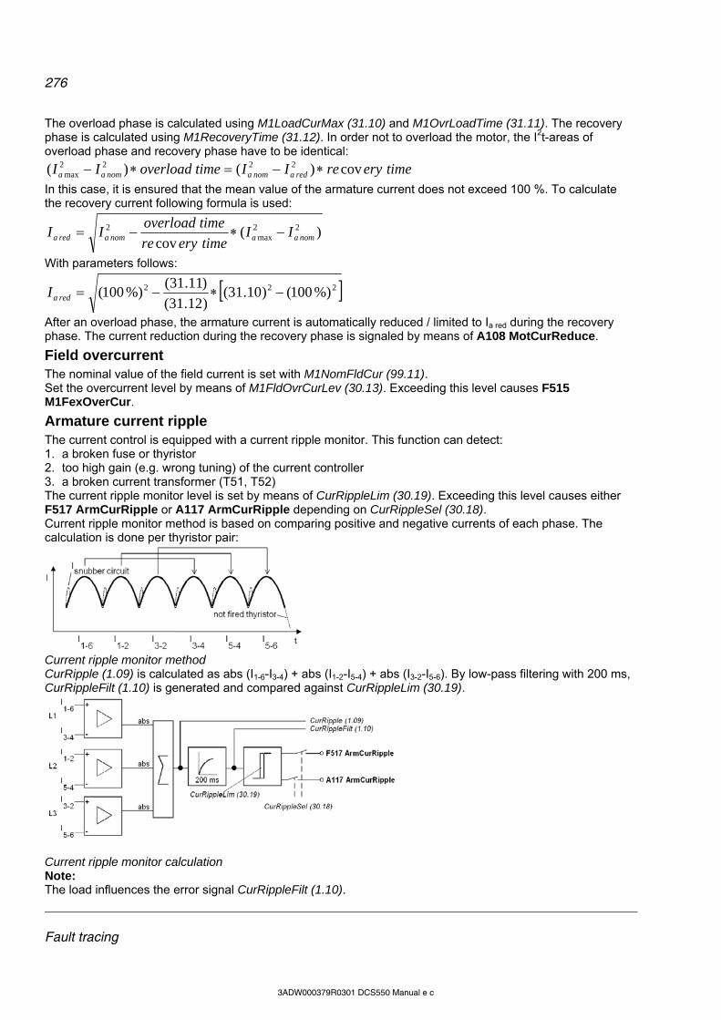
276
Fault tracing
3ADW000379R0301 DCS550 Manual e c
The overload phase is calculated using M1LoadCurMax (31.10) and M1OvrLoadTime (31.11). The recovery phase is calculated using M1RecoveryTime (31.12). In order not to overload the motor, the I2t-areas of overload phase and recovery phase have to be identical:
timeeryreIItimeoverloadII redanomanomaa cov)()( 2222max
In this case, it is ensured that the mean value of the armature current does not exceed 100 %. To calculate the recovery current following formula is used:
)(cov
22max
2nomaanomareda II
timeeryre
timeoverloadII
With parameters follows:
222 %)100()10.31()12.31(
)11.31(%)100( redaI
After an overload phase, the armature current is automatically reduced / limited to Ia red during the recovery phase. The current reduction during the recovery phase is signaled by means of A108 MotCurReduce.
Field overcurrent The nominal value of the field current is set with M1NomFldCur (99.11). Set the overcurrent level by means of M1FldOvrCurLev (30.13). Exceeding this level causes F515 M1FexOverCur.
Armature current ripple The current control is equipped with a current ripple monitor. This function can detect: 1. a broken fuse or thyristor 2. too high gain (e.g. wrong tuning) of the current controller 3. a broken current transformer (T51, T52) The current ripple monitor level is set by means of CurRippleLim (30.19). Exceeding this level causes either F517 ArmCurRipple or A117 ArmCurRipple depending on CurRippleSel (30.18). Current ripple monitor method is based on comparing positive and negative currents of each phase. The calculation is done per thyristor pair:
Current ripple monitor method CurRipple (1.09) is calculated as abs (I1-6-I3-4) + abs (I1-2-I5-4) + abs (I3-2-I5-6). By low-pass filtering with 200 ms, CurRippleFilt (1.10) is generated and compared against CurRippleLim (30.19).
Current ripple monitor calculation Note: The load influences the error signal CurRippleFilt (1.10).

277
Fault tracing
3ADW000379R0301 DCS550 Manual e c
Current near discontinuous level will create values of about 300 % * ConvCurActRel (1.15) if a thyristor is not fired.
High inductive loads will create values of about 90% * ConvCurActRel (1.15) if a thyristor is not fired. Commissioning hint: It is not possible to pre-calculate clear levels. The current control reacts to unstable current feedback. The load is continuously driving the current if a thyristor is not fired.
Speed feedback monitor The speed feedback monitor supervises an attached analog tacho or encoder for proper function by means of measured speed and measured EMF. Above a certain EMF, the measured speed feedback must be above a certain threshold. The sign of the speed measurement must be correct as well:
Speed measurement supervision The drive reacts according to SpeedFbFltSel (30.17) when: 1. the measured EMF is greater than EMF FbMonLev (30.15) and 2. the measured speed feedback SpeedActEnc (1.03), SpeedActTach (1.05) or SpeedActEnc2 (1.42) is lower
than SpeedFbMonLev (30.14). Example: SpeedFbMonLev (30.14) = 15 rpm EMF FbMonLev (30.15) = 50 V The drive trips when the EMF is greater than 50 V while the speed feedback is 15 rpm.
speed feedbackmonitoring (F522) enabled
tacho polaritymonitoring (F553) enabled
Motorspeed
Motorvoltage
Motor speed_volt_a.dsf
EMF FbMonLev (30.15)
Speed FbMonLev (30.14)
speed feedbackmonitoring (F522) enabled
tacho polaritymonitoring (F553) enabled
Speed feedback monitor SpeedFbFltSel (30.17) selects the reaction to a speed feedback problem:
278
Fault tracing
3ADW000379R0301 DCS550 Manual e c
1. the drive is immediately tripped with F522 SpeedFb 2. the speed feedback is switched to EMF and the drive is stopped according to E StopRamp (22.11), then
F522 SpeedFb is set 3. the speed feedback is switched to EMF and A125 SpeedFb is set In case of field weakening, the drive is immediately tripped with F522 SpeedFb.
Stall protection The stall protection trips the converter with F531 MotorStalled when the motor is in apparent danger of overheating. The rotor is either mechanically stalled or the load is continuously too high. It is possible to adjust the supervision (time, speed and torque). The stall protection trips the drive if: 1. the actual speed is below StallSpeed (30.02) and 2. the actual torque - in percent of MotNomTorque (4.23) - exceeds StallTorq (30.03) 3. for a time longer than programmed in StallTime (30.01).
Overspeed protection The motor is protected against overspeed e.g. in a case when the drive is in torque control mode and the load drops unexpected. Set the overspeed level by means of M1OvrSpeed (30.16). Exceeding this level causes F532 MotOverSpeed.
Field undercurrent The nominal value of the field current is set with M1NomFldCur (99.11). Set the minimum field current level by means of M1FldMinTrip (30.12). Undershooting this level causes F541 M1FexLowCur. FldMinTripDly (45.18) delays F541 M1FexLowCur.
Tacho / pulse encoder polarity The polarity of the analog tacho or pulse encoder [depending on M1SpeedFbSell (50.03)] is checked against the EMF. A wrong polarity generates F553 TachPolarity.
Tacho range An imminent overflow of the AITacho input generates F554 TachoRange. Check for the right connections (X1:1 to X1:4) on the SDCS-CON-F.
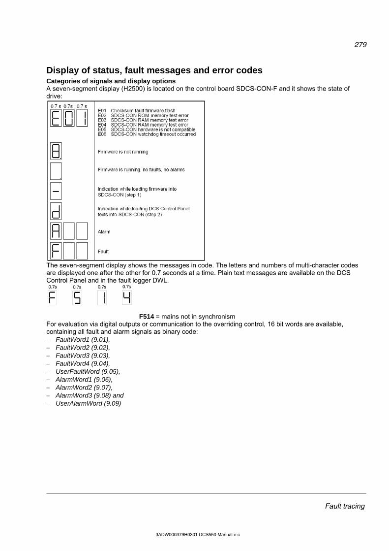
279
Fault tracing
3ADW000379R0301 DCS550 Manual e c
Display of status, fault messages and error codes Categories of signals and display options A seven-segment display (H2500) is located on the control board SDCS-CON-F and it shows the state of drive:
The seven-segment display shows the messages in code. The letters and numbers of multi-character codes are displayed one after the other for 0.7 seconds at a time. Plain text messages are available on the DCS Control Panel and in the fault logger DWL. 0.7s 0.7s0.7s
0.7s
F514 = mains not in synchronism For evaluation via digital outputs or communication to the overriding control, 16 bit words are available, containing all fault and alarm signals as binary code: FaultWord1 (9.01), FaultWord2 (9.02), FaultWord3 (9.03), FaultWord4 (9.04), UserFaultWord (9.05), AlarmWord1 (9.06), AlarmWord2 (9.07), AlarmWord3 (9.08) and UserAlarmWord (9.09)

280
Fault tracing
3ADW000379R0301 DCS550 Manual e c
General messages General messages will only be indicated on the seven-segment display of the SDCS-CON-F. 7-segment
display Text on DCS Control
Panel and DWL Definition Remark
8 not available firmware is not running 1 . not available firmware is running, no faults, no alarms - - not available indication while loading firmware into SDCS-CON-F - d not available indication while loading DCS Control Panel texts into SDCS-
CON-F -
u not available DCS Control Panel text now formatting in the flash - don't switch off
-
Power-up errors (E) Power-up errors will only be indicated on the seven-segment display of the SDCS-CON-F. With a power-up error active, it is not possible to start the drive. 7-segment
display Text on DCS Control
Panel and DWL Definition Remark
E01 not available Checksum fault firmware flash 1,2 E02 not available SDCS-CON-F ROM memory test error 1,2 E03 not available SDCS-CON-F RAM memory test error (even addresses) 1,2 E04 not available SDCS-CON-F RAM memory test error (odd addresses) 1,2 E05 not available SDCS-CON-F hardware is not compatible, unknown board 1,2 E06 not available SDCS-CON-F watchdog timeout occurred 1,2
1. Units should be de- and re-energized. If the fault occurs again, check the SDCS-CON-F and SDCS-PIN-F
boards and change them if necessary. 2. Power-up errors are only enabled immediately after power on. If a power-up error is indicated during
normal operation, the reason is usually caused by EMC. In this case, please check for proper grounding of cables, converter and cabinet.
Fault signals (F) To avoid dangerous situations, damage of the motor, the drive or any other material some physical values must not exceed certain limits. Therefore, limit values can be specified for these values by parameter setting which cause an alarm or a fault when the value exceeds the limits (e.g. max. armature voltage, max. converter temperature). Faults can also be caused by situations, which inhibit the drive from normal operation (e.g. blown fuse). A fault is a condition, which requires an immediate stop of the drive in order to avoid danger or damage. The drive is stopped automatically and cannot be restarted before removing its cause. All fault signals, with the exception of: F501 AuxUnderVolt, F525 TypeCode, F547 HwFailure and F548 FwFailure are resetable in case the fault is eliminated. To reset a fault following steps are required: remove the Run and On commands [UsedMCW (7.04) bit 3 and 0] eliminate the faults acknowledge the fault with Reset [UsedMCW (7.04) bit 7] via digital input, overriding control system or in
Local mode with DCS Control Panel or DWL depending on the systems condition, generate Run and On commands [UsedMCW (7.04) bit 3 and 0]
again The fault signals will switch the drive off completely or partly depending on its trip level.

281
Fault tracing
3ADW000379R0301 DCS550 Manual e c
Trip level 1: main contactor is switched off immediately fan contactor is switched off immediately
Trip level 2: main contactor is switched off immediately fan contactor stays on as long as the fault is pending or as long as FanDly (21.14) is running
Trip level 3: main contactor is switched off immediately fan contactor stays on as long as FanDly (21.14) is running At standstill the main contactor cannot be switched on again
Trip level 4: As long as the drive is stopping via FaultStopMode (30.30), the main contactor is switched off immediately in case of FaultStopMode (30.30) = CoastStop or DynBraking,
but it stays on in case of FaultStopMode (30.30) = RampStop or TorqueLimit fan contactor is switched off immediately in case of FaultStopMode (30.30) = CoastStop, but stays on in
case of FaultStopMode (30.30) = RampStop, TorqueLimit or DynBraking At standstill the main contactor is switched off immediately fan contactor stays on as long as FanDly (21.14) is running
Trip level 5 As long as the drive is stopping via any com. loss control [LocalLossCtrl (30.27) or ComLossCtrl (30.28)], the main contactor is switched off immediately or stays on depending on the selected com. loss control fan contactor is switched off immediately or stays on depending on the selected com. loss control At standstill main contactor is switched off immediately fan contactor stays on as long as FanDly (21.14) is running In case a fault occurs, it stays active until the cause is eliminated and a Reset [UsedMCW (7.04) bit 7] is given.
Fault name Fault number Fault name Fault number AIRange F551 M1FexLowCur F541 ArmCurRipple F517 M1FexOverCur F515 ArmOverCur F502 M1OverLoad F507 ArmOverVolt F503 M1OverTemp F506 AuxUnderVolt F501 MainContAck F524 MainsLowVolt F512 COM8Com F543 MainsNotSync F514 COM8Faulty F540 MainsOvrVolt F513 MotorStalled F531 ConvOverTemp F504 MotOverSpeed F532 ExternalDI F526 ParComp F549 ExtFanAck F523 ParMemRead F550 FieldBusCom F528 ReversalTime F557 FwFailure F548 SpeedFb F522 HwFailure F547 TachPolarity F553 I/OBoardLoss F508 TachoRange F554 TypeCode F525 LocalCmdLoss F546
For additional fault messages, see SysFaultWord (9.10).
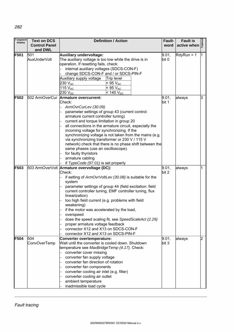
282
Fault tracing
3ADW000379R0301 DCS550 Manual e c
7-segment display Text on DCS
Control Panel and DWL
Definition / Action Fault-word
Fault is active when
Tri
ple
vel
F501 501 AuxUnderVolt
Auxiliary undervoltage: The auxiliary voltage is too low while the drive is in operation. If resetting fails, check: internal auxiliary voltages (SDCS-CON-F) change SDCS-CON-F and / or SDCS-PIN-F Auxiliary supply voltage Trip level 230 VAC < 95 VAC 115 VAC < 95 VAC 230 VDC < 140 VDC
9.01, bit 0
RdyRun = 1 1
F502 502 ArmOverCur Armature overcurrent: Check: ArmOvrCurLev (30.09) parameter settings of group 43 (current control:
armature current controller tuning) current and torque limitation in group 20 all connections in the armature circuit, especially the
incoming voltage for synchronizing. If the synchronizing voltage is not taken from the mains (e.g. via synchronizing transformer or 230 V / 115 V network) check that there is no phase shift between the same phases (use an oscilloscope).
for faulty thyristors armature cabling if TypeCode (97.01) is set properly
9.01, bit 1
always 3
F503 503 ArmOverVolt Armature overvoltage (DC): Check: if setting of ArmOvrVoltLev (30.08) is suitable for the
system parameter settings of group 44 (field excitation: field
current controller tuning, EMF controller tuning, flux linearization)
too high field current (e.g. problems with field weakening)
if the motor was accelerated by the load, overspeed does the speed scaling fit, see SpeedScaleAct (2.29) proper armature voltage feedback connector X12 and X13 on SDCS-CON-F connector X12 and X13 on SDCS-PIN-F
9.01, bit 2
always 1
F504 504 ConvOverTemp
Converter overtemperature: Wait until the converter is cooled down. Shutdown temperature see MaxBridgeTemp (4.17). Check: converter cover missing converter fan supply voltage converter fan direction of rotation converter fan components converter cooling air inlet (e.g. filter) converter cooling air outlet ambient temperature inadmissible load cycle
9.01, bit 3
always 2
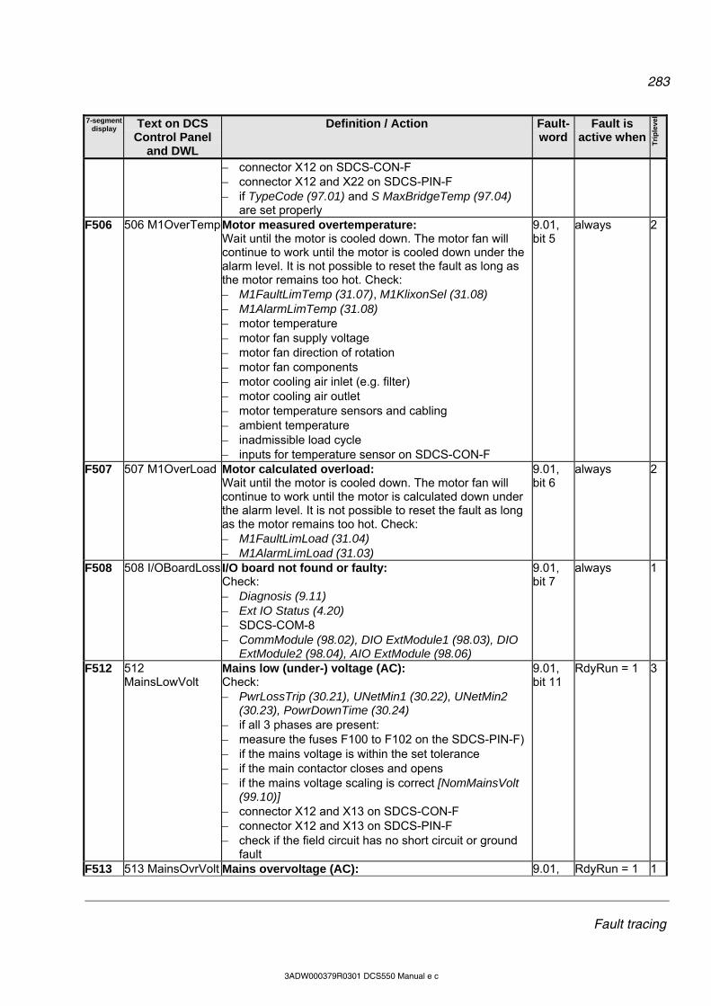
283
Fault tracing
3ADW000379R0301 DCS550 Manual e c
7-segment display Text on DCS
Control Panel and DWL
Definition / Action Fault-word
Fault is active when
Tri
ple
vel
connector X12 on SDCS-CON-F connector X12 and X22 on SDCS-PIN-F if TypeCode (97.01) and S MaxBridgeTemp (97.04)
are set properly F506 506 M1OverTemp Motor measured overtemperature:
Wait until the motor is cooled down. The motor fan will continue to work until the motor is cooled down under the alarm level. It is not possible to reset the fault as long as the motor remains too hot. Check: M1FaultLimTemp (31.07), M1KlixonSel (31.08) M1AlarmLimTemp (31.08) motor temperature motor fan supply voltage motor fan direction of rotation motor fan components motor cooling air inlet (e.g. filter) motor cooling air outlet motor temperature sensors and cabling ambient temperature inadmissible load cycle inputs for temperature sensor on SDCS-CON-F
9.01, bit 5
always 2
F507 507 M1OverLoad Motor calculated overload: Wait until the motor is cooled down. The motor fan will continue to work until the motor is calculated down under the alarm level. It is not possible to reset the fault as long as the motor remains too hot. Check: M1FaultLimLoad (31.04) M1AlarmLimLoad (31.03)
9.01, bit 6
always 2
F508 508 I/OBoardLoss I/O board not found or faulty: Check: Diagnosis (9.11) Ext IO Status (4.20) SDCS-COM-8 CommModule (98.02), DIO ExtModule1 (98.03), DIO
ExtModule2 (98.04), AIO ExtModule (98.06)
9.01, bit 7
always 1
F512 512 MainsLowVolt
Mains low (under-) voltage (AC): Check: PwrLossTrip (30.21), UNetMin1 (30.22), UNetMin2
(30.23), PowrDownTime (30.24) if all 3 phases are present: measure the fuses F100 to F102 on the SDCS-PIN-F) if the mains voltage is within the set tolerance if the main contactor closes and opens if the mains voltage scaling is correct [NomMainsVolt
(99.10)] connector X12 and X13 on SDCS-CON-F connector X12 and X13 on SDCS-PIN-F check if the field circuit has no short circuit or ground
fault
9.01, bit 11
RdyRun = 1 3
F513 513 MainsOvrVolt Mains overvoltage (AC): 9.01, RdyRun = 1 1
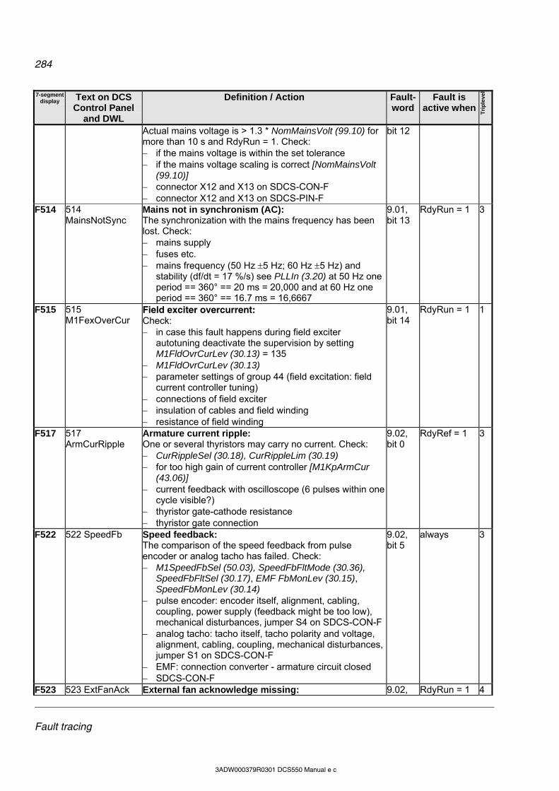
284
Fault tracing
3ADW000379R0301 DCS550 Manual e c
7-segment display Text on DCS
Control Panel and DWL
Definition / Action Fault-word
Fault is active when
Tri
ple
vel
Actual mains voltage is > 1.3 * NomMainsVolt (99.10) for more than 10 s and RdyRun = 1. Check: if the mains voltage is within the set tolerance if the mains voltage scaling is correct [NomMainsVolt
(99.10)] connector X12 and X13 on SDCS-CON-F connector X12 and X13 on SDCS-PIN-F
bit 12
F514 514 MainsNotSync
Mains not in synchronism (AC): The synchronization with the mains frequency has been lost. Check: mains supply fuses etc. mains frequency (50 Hz 5 Hz; 60 Hz 5 Hz) and
stability (df/dt = 17 %/s) see PLLIn (3.20) at 50 Hz one period == 360° == 20 ms = 20,000 and at 60 Hz one period == 360° == 16.7 ms = 16,6667
9.01, bit 13
RdyRun = 1 3
F515 515 M1FexOverCur
Field exciter overcurrent: Check: in case this fault happens during field exciter
autotuning deactivate the supervision by setting M1FldOvrCurLev (30.13) = 135
M1FldOvrCurLev (30.13) parameter settings of group 44 (field excitation: field
current controller tuning) connections of field exciter insulation of cables and field winding resistance of field winding
9.01, bit 14
RdyRun = 1 1
F517 517 ArmCurRipple
Armature current ripple: One or several thyristors may carry no current. Check: CurRippleSel (30.18), CurRippleLim (30.19) for too high gain of current controller [M1KpArmCur
(43.06)] current feedback with oscilloscope (6 pulses within one
cycle visible?) thyristor gate-cathode resistance thyristor gate connection
9.02, bit 0
RdyRef = 1 3
F522 522 SpeedFb Speed feedback: The comparison of the speed feedback from pulse encoder or analog tacho has failed. Check: M1SpeedFbSel (50.03), SpeedFbFltMode (30.36),
SpeedFbFltSel (30.17), EMF FbMonLev (30.15), SpeedFbMonLev (30.14)
pulse encoder: encoder itself, alignment, cabling, coupling, power supply (feedback might be too low), mechanical disturbances, jumper S4 on SDCS-CON-F
analog tacho: tacho itself, tacho polarity and voltage, alignment, cabling, coupling, mechanical disturbances, jumper S1 on SDCS-CON-F
EMF: connection converter - armature circuit closed SDCS-CON-F
9.02, bit 5
always 3
F523 523 ExtFanAck External fan acknowledge missing: 9.02, RdyRun = 1 4
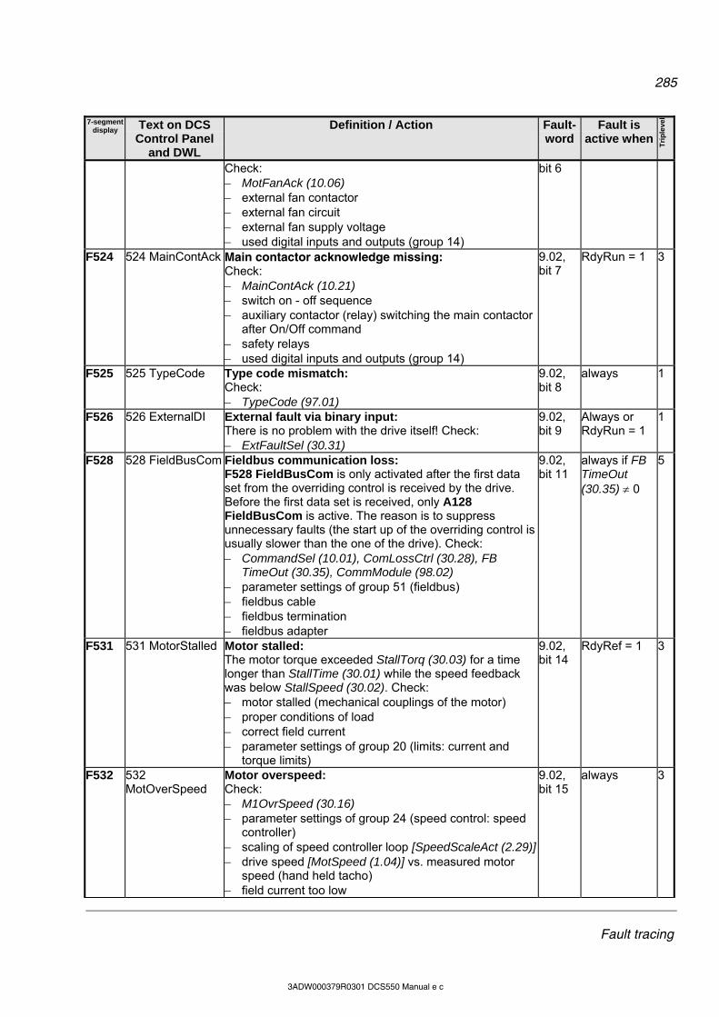
285
Fault tracing
3ADW000379R0301 DCS550 Manual e c
7-segment display Text on DCS
Control Panel and DWL
Definition / Action Fault-word
Fault is active when
Tri
ple
vel
Check: MotFanAck (10.06) external fan contactor external fan circuit external fan supply voltage used digital inputs and outputs (group 14)
bit 6
F524 524 MainContAck Main contactor acknowledge missing: Check: MainContAck (10.21) switch on - off sequence auxiliary contactor (relay) switching the main contactor
after On/Off command safety relays used digital inputs and outputs (group 14)
9.02, bit 7
RdyRun = 1 3
F525 525 TypeCode Type code mismatch: Check: TypeCode (97.01)
9.02, bit 8
always 1
F526 526 ExternalDI External fault via binary input: There is no problem with the drive itself! Check: ExtFaultSel (30.31)
9.02, bit 9
Always or RdyRun = 1
1
F528 528 FieldBusCom Fieldbus communication loss: F528 FieldBusCom is only activated after the first data set from the overriding control is received by the drive. Before the first data set is received, only A128 FieldBusCom is active. The reason is to suppress unnecessary faults (the start up of the overriding control is usually slower than the one of the drive). Check: CommandSel (10.01), ComLossCtrl (30.28), FB
TimeOut (30.35), CommModule (98.02) parameter settings of group 51 (fieldbus) fieldbus cable fieldbus termination fieldbus adapter
9.02, bit 11
always if FB TimeOut (30.35) 0
5
F531 531 MotorStalled Motor stalled: The motor torque exceeded StallTorq (30.03) for a time longer than StallTime (30.01) while the speed feedback was below StallSpeed (30.02). Check: motor stalled (mechanical couplings of the motor) proper conditions of load correct field current parameter settings of group 20 (limits: current and
torque limits)
9.02, bit 14
RdyRef = 1 3
F532 532 MotOverSpeed
Motor overspeed: Check: M1OvrSpeed (30.16) parameter settings of group 24 (speed control: speed
controller) scaling of speed controller loop [SpeedScaleAct (2.29)] drive speed [MotSpeed (1.04)] vs. measured motor
speed (hand held tacho) field current too low
9.02, bit 15
always 3
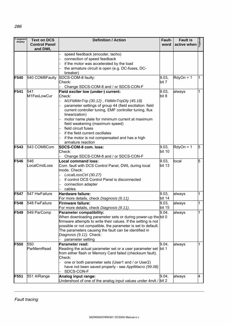
286
Fault tracing
3ADW000379R0301 DCS550 Manual e c
7-segment display Text on DCS
Control Panel and DWL
Definition / Action Fault-word
Fault is active when
Tri
ple
vel
speed feedback (encoder, tacho) connection of speed feedback if the motor was accelerated by the load the armature circuit is open (e.g. DC-fuses, DC-
breaker) F540 540 COM8Faulty SDCS-COM-8 faulty:
Check: Change SDCS-COM-8 and / or SDCS-CON-F
9.03, bit 7
RdyOn = 1 1
F541 541 M1FexLowCur
Field exciter low (under-) current: Check: M1FldMinTrip (30.12) , FldMinTripDly (45.18) parameter settings of group 44 (field excitation: field
current controller tuning, EMF controller tuning, flux linearization)
motor name plate for minimum current at maximum field weakening (maximum speed)
field circuit fuses if the field current oscillates if the motor is not compensated and has a high
armature reaction
9.03, bit 8
always 1
F543 543 COM8Com SDCS-COM-8 com. loss: Check: Change SDCS-COM-8 and / or SDCS-CON-F
9.03, bit 10
RdyOn = 1 5
F546 546 LocalCmdLoss
Local command loss: Com. fault with DCS Control Panel, DWL during local mode. Check: LocalLossCtrl (30.27) if control DCS Control Panel is disconnected connection adapter cables
9.03, bit 13
local 5
F547 547 HwFailure Hardware failure: For more details, check Diagnosis (9.11).
9.03, bit 14
always 1
F548 548 FwFailure Firmware failure: For more details, check Diagnosis (9.11).
9.03, bit 15
always 1
F549 549 ParComp Parameter compatibility: When downloading parameter sets or during power-up the firmware attempts to write their values. If the setting is not possible or not compatible, the parameter is set to default. The parameters causing the fault can be identified in Diagnosis (9.11). Check: parameter setting
9.04, bit 0
always 1
F550 550 ParMemRead
Parameter read: Reading the actual parameter set or a user parameter set from either flash or Memory Card failed (checksum fault). Check: one or both parameter sets (User1 and / or User2)
have not been saved properly - see ApplMacro (99.08) SDCS-CON-F
9.04, bit 1
always 1
F551 551 AIRange Analog input range:Undershoot of one of the analog input values under 4mA /
9.04, bit 2
always 4

287
Fault tracing
3ADW000379R0301 DCS550 Manual e c
7-segment display Text on DCS
Control Panel and DWL
Definition / Action Fault-word
Fault is active when
Tri
ple
vel
2V. Check: AI Mon4mA (30.29) used analog inputs connections and cables polarity of connection
F553 553 TachPolarity Tacho polarity: The polarity of the analog tacho respectively pulse encoder [depending on M1SpeedFbSell (50.03)] is checked against the EMF. Check: EMF FbMonLev (30.15), SpeedFbMonLev (30.14) polarity of tacho cable polarity of pulse encoder cable (e.g. swap channels A
and A not) polarity of armature and field cables direction of motor rotation
9.04, bit 4
always 3
F554 554 TachoRange Tacho range: Overflow of AITacho input. Check: for the right connections (X1:1 to X1:4) on the SDCS-
CON-F
9.04, bit 5
always 3
F557 557 ReversalTime Reversal time: Current direction not changed before ZeroCurTimeOut (97.19) is elapsed. Check: for high inductive motor too high motor voltage compared to mains voltage lower RevDly (43.14) if possible and increase ZeroCurTimeOut (97.19)
9.04, bit 8
RdyRef = 1 3
F601 601 APFault1 User defined fault by AP 9.04, bit 11
always 1
F602 602 APFault2 User defined fault by AP 9.04, bit 12
always 1
F603 603 APFault3 User defined fault by AP 9.04, bit 13
always 1
F604 604 APFault4 User defined fault by AP 9.04, bit 14
always 1
F605 605 APFault5 User defined fault by AP 9.04, bit 15
always 1

288
Fault tracing
3ADW000379R0301 DCS550 Manual e c
Alarm signals (A) An alarm is a message, that a condition occurred, which may lead to a dangerous situation. It is displayed and written into the fault logger. However, the cause for the alarm can inhibit the drive from continuing with normal operation. If the cause of the alarm disappears, the alarm will be automatically reset. The fault logger shows the appearing alarm (A1xx) with a plus sign and the disappearing alarm (A2xx) with a minus sign. An appearing user defined alarm is indicated as A3xx. A disappearing user defined alarm is indicated as A4xx. The alarm handling must provides 4 alarm levels. Alarm level 1: the drive keeps on running and the alarm is indicated after the drive is stopped, the main contactor cannot be switched on again (no re-start possible) Alarm level 2: the drive keeps on running and the alarm is indicated fan contactor stays on as long as the alarm is pending if the alarm disappears FanDly (21.14) will start Alarm level 3: AutoReclosing (auto re-start) is [AuxStatWord (8.02) bit 15] active RdyRun [MainStatWord (8.01) bit 1] is disabled, but the drive is automatically restarted when the alarm
condition vanishes α is set to 150° single firing pulses Alarm level 4: the drive keeps on running and the alarm is indicated In case an alarm occurs, it stays active until the cause is eliminated. Then the alarm will automatically disappear, thus a Reset [UsedMCW (7.04) bit 7] is not needed and will have no effect.
Alarm number Alarm number Alarm name appearing disappearing
Alarm name appearing disappearing
AIRange A127 A227 MainsLowVolt A111 A211 ArmCurDev A114 A214 MotCurReduce A108 A208 ArmCurRipple A117 A217 AutotuneFail A121 A221 NoAPTaskTime A136 A236 COM8Com A113 A213 Off2FieldBus A138 A238 COM8FwVer A141 A241 Off2ViaDI A101 A201 ConvOverTemp A104 A204 Off3FieldBus A139 A239 Off3ViaDI A102 A202 DC BreakAck A103 A203 DynBrakeAck A105 A205 ParAdded A131 A231 ParComp A134 A234 ExternalDI A126 A226 ParConflict A132 A232 ParRestored A129 A229 FaultSuppres A123 A223 ParUpDwnLoad A135 A235 FieldBusCom A128 A228 RetainInv A133 A233 IllgFieldBus A140 A240 SpeedFb A125 A225 LocalCmdLoss A130 A230 SpeedNotZero A137 A237 SpeedScale A124 A224 M1OverLoad A107 A207 M1OverTemp A106 A206 TachoRange A115 A215
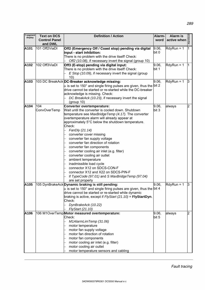
289
Fault tracing
3ADW000379R0301 DCS550 Manual e c
7-segment display Text on DCS
Control Panel and DWL
Definition / Action Alarm-word
Alarm is active when
Ala
rmle
ve
l
A101 101 Off2ViaDI Off2 (Emergency Off / Coast stop) pending via digital input - start inhibition: There is no problem with the drive itself! Check: Off2 (10.08), if necessary invert the signal (group 10)
9.06, bit 0
RdyRun = 1 1
A102 102 Off3ViaDI Off3 (E-stop) pending via digital input: There is no problem with the drive itself! Check: E Stop (10.09), if necessary invert the signal (group
10)
9.06, bit 1
RdyRun = 1 1
A103 103 DC BreakAck DC-Breaker acknowledge missing: is set to 150° and single firing pulses are given, thus the drive cannot be started or re-started while the DC-breaker acknowledge is missing. Check: DC BreakAck (10.23), if necessary invert the signal
(group 10)
9.06, bit 2
RdyRun = 1 3
A104 104 ConvOverTemp
Converter overtemperature: Wait until the converter is cooled down. Shutdown temperature see MaxBridgeTemp (4.17). The converter overtemperature alarm will already appear at approximately 5°C below the shutdown temperature. Check: FanDly (21.14) converter cover missing converter fan supply voltage converter fan direction of rotation converter fan components converter cooling air inlet (e.g. filter) converter cooling air outlet ambient temperature inadmissible load cycle connector X12 on SDCS-CON-F connector X12 and X22 on SDCS-PIN-F if TypeCode (97.01) and S MaxBridgeTemp (97.04)
are set properly
9.06, bit 3
always 2
A105 105 DynBrakeAck Dynamic braking is still pending: is set to 150° and single firing pulses are given, thus the drive cannot be started or re-started while dynamic braking is active, except if FlyStart (21.10) = FlyStartDyn. Check: DynBrakeAck (10.22) FlyStart (21.10)
9.06, bit 4
RdyRun = 1 3
A106 106 M1OverTemp Motor measured overtemperature: Check: M1AlarmLimTemp (31.06) motor temperature motor fan supply voltage motor fan direction of rotation motor fan components motor cooling air inlet (e.g. filter) motor cooling air outlet motor temperature sensors and cabling
9.06, bit 5
always 2
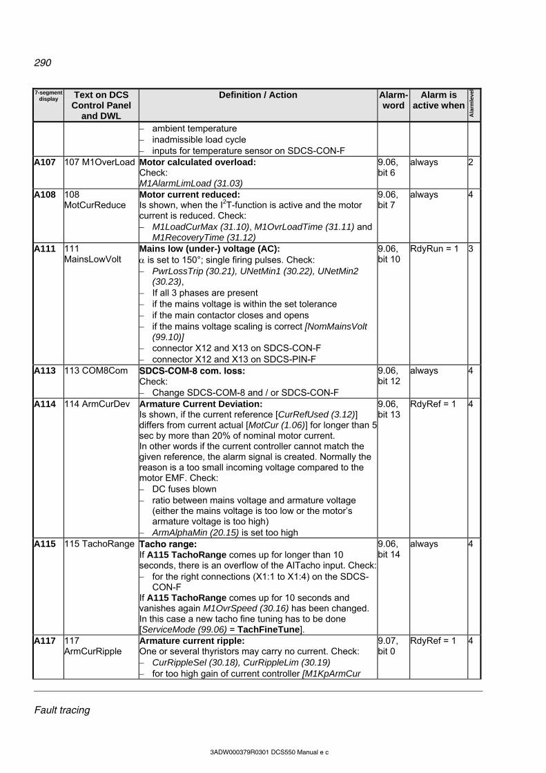
290
Fault tracing
3ADW000379R0301 DCS550 Manual e c
7-segment display Text on DCS
Control Panel and DWL
Definition / Action Alarm-word
Alarm is active when
Ala
rmle
vel
ambient temperature inadmissible load cycle inputs for temperature sensor on SDCS-CON-F
A107 107 M1OverLoad Motor calculated overload: Check: M1AlarmLimLoad (31.03)
9.06, bit 6
always 2
A108 108 MotCurReduce
Motor current reduced: Is shown, when the I2T-function is active and the motor current is reduced. Check: M1LoadCurMax (31.10), M1OvrLoadTime (31.11) and
M1RecoveryTime (31.12)
9.06, bit 7
always 4
A111 111 MainsLowVolt
Mains low (under-) voltage (AC): is set to 150°; single firing pulses. Check: PwrLossTrip (30.21), UNetMin1 (30.22), UNetMin2
(30.23), If all 3 phases are present if the mains voltage is within the set tolerance if the main contactor closes and opens if the mains voltage scaling is correct [NomMainsVolt
(99.10)] connector X12 and X13 on SDCS-CON-F connector X12 and X13 on SDCS-PIN-F
9.06, bit 10
RdyRun = 1 3
A113 113 COM8Com SDCS-COM-8 com. loss: Check: Change SDCS-COM-8 and / or SDCS-CON-F
9.06, bit 12
always 4
A114 114 ArmCurDev Armature Current Deviation: Is shown, if the current reference [CurRefUsed (3.12)] differs from current actual [MotCur (1.06)] for longer than 5 sec by more than 20% of nominal motor current. In other words if the current controller cannot match the given reference, the alarm signal is created. Normally the reason is a too small incoming voltage compared to the motor EMF. Check: DC fuses blown ratio between mains voltage and armature voltage
(either the mains voltage is too low or the motor’s armature voltage is too high)
ArmAlphaMin (20.15) is set too high
9.06, bit 13
RdyRef = 1 4
A115 115 TachoRange Tacho range: If A115 TachoRange comes up for longer than 10 seconds, there is an overflow of the AITacho input. Check: for the right connections (X1:1 to X1:4) on the SDCS-
CON-F If A115 TachoRange comes up for 10 seconds and vanishes again M1OvrSpeed (30.16) has been changed. In this case a new tacho fine tuning has to be done [ServiceMode (99.06) = TachFineTune].
9.06, bit 14
always 4
A117 117 ArmCurRipple
Armature current ripple: One or several thyristors may carry no current. Check: CurRippleSel (30.18), CurRippleLim (30.19) for too high gain of current controller [M1KpArmCur
9.07, bit 0
RdyRef = 1 4
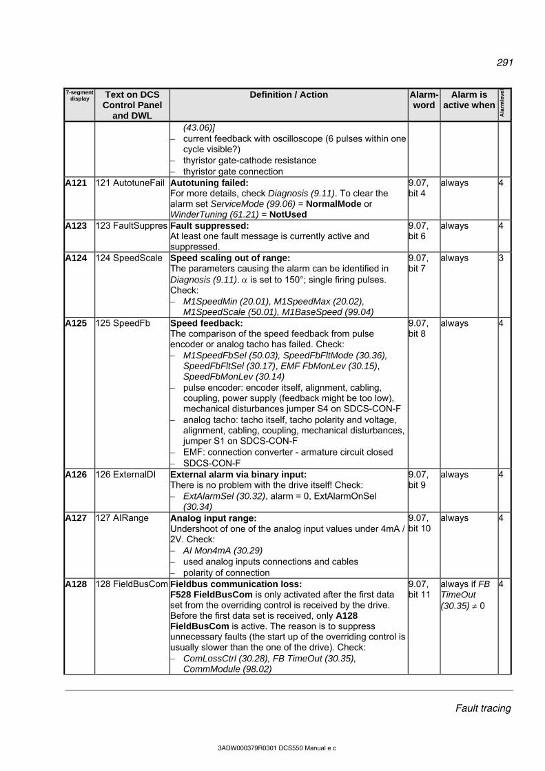
291
Fault tracing
3ADW000379R0301 DCS550 Manual e c
7-segment display Text on DCS
Control Panel and DWL
Definition / Action Alarm-word
Alarm is active when
Ala
rmle
vel
(43.06)] current feedback with oscilloscope (6 pulses within one
cycle visible?) thyristor gate-cathode resistance thyristor gate connection
A121 121 AutotuneFail Autotuning failed: For more details, check Diagnosis (9.11). To clear the alarm set ServiceMode (99.06) = NormalMode or WinderTuning (61.21) = NotUsed
9.07, bit 4
always 4
A123 123 FaultSuppres Fault suppressed: At least one fault message is currently active and suppressed.
9.07, bit 6
always 4
A124 124 SpeedScale Speed scaling out of range: The parameters causing the alarm can be identified in Diagnosis (9.11). is set to 150°; single firing pulses. Check: M1SpeedMin (20.01), M1SpeedMax (20.02),
M1SpeedScale (50.01), M1BaseSpeed (99.04)
9.07, bit 7
always 3
A125 125 SpeedFb Speed feedback: The comparison of the speed feedback from pulse encoder or analog tacho has failed. Check: M1SpeedFbSel (50.03), SpeedFbFltMode (30.36),
SpeedFbFltSel (30.17), EMF FbMonLev (30.15), SpeedFbMonLev (30.14)
pulse encoder: encoder itself, alignment, cabling, coupling, power supply (feedback might be too low), mechanical disturbances jumper S4 on SDCS-CON-F
analog tacho: tacho itself, tacho polarity and voltage, alignment, cabling, coupling, mechanical disturbances, jumper S1 on SDCS-CON-F
EMF: connection converter - armature circuit closed SDCS-CON-F
9.07, bit 8
always 4
A126 126 ExternalDI External alarm via binary input: There is no problem with the drive itself! Check: ExtAlarmSel (30.32), alarm = 0, ExtAlarmOnSel
(30.34)
9.07, bit 9
always 4
A127 127 AIRange Analog input range: Undershoot of one of the analog input values under 4mA / 2V. Check: AI Mon4mA (30.29) used analog inputs connections and cables polarity of connection
9.07, bit 10
always 4
A128 128 FieldBusCom Fieldbus communication loss: F528 FieldBusCom is only activated after the first data set from the overriding control is received by the drive. Before the first data set is received, only A128 FieldBusCom is active. The reason is to suppress unnecessary faults (the start up of the overriding control is usually slower than the one of the drive). Check: ComLossCtrl (30.28), FB TimeOut (30.35),
CommModule (98.02)
9.07, bit 11
always if FB TimeOut (30.35) 0
4
292
Fault tracing
3ADW000379R0301 DCS550 Manual e c
7-segment display Text on DCS
Control Panel and DWL
Definition / Action Alarm-word
Alarm is active when
Ala
rmle
vel
parameter settings of group 51 (fieldbus) fieldbus cable fieldbus termination fieldbus adapter
A129 129 ParRestored Parameter restored: The parameters found in the flash were invalid at power-up (checksum fault). All parameters were restored from the parameter backup.
9.07, bit 12
always 4
A130 130 LocalCmdLoss
Local command loss: Connection fault with DCS Control Panel or DWL. Check: LocalLossCtrl (30.27) if control DCS Control Panel is disconnected connection adapter cables
9.07, bit 13
local 4
A131 131 ParAdded Parameter added: A new firmware with a different amount of parameters was downloaded. The new parameters are set to their default values. The parameters causing the alarm can be identified in Diagnosis (9.11). Check: new parameters and set them to the desired values
9.07, bit 14
after download of firmware for max. 10 s
4
A132 132 ParConflict Parameter setting conflict: Is triggered by parameter settings conflicting with other parameters. The parameters causing the alarm can be identified in Diagnosis (9.11).
9.07, bit 15
always 4
A133 133 RetainInv Retain data invalid: Set when the retain data in the flash are invalid during power-up. In this case, the backup data are used. Note: The backup of the lost retain data reflects the status at the previous power-up. Examples for retain data are: fault logger data, Data1 (19.01) to Data4 (19.04) and I/O options (see group 98) The situation of invalid retain data occurs, if the auxiliary voltage of the DCS550 is switched off about 2 seconds after power-up (while the retain data sector is being rearranged). Check: if the flash of the SDCS-CON-F is defective and if the auxiliary power supply has a problem
9.08, bit 0
directly after energizing of electronics for max. 10 s
4
A134 134 ParComp Parameter compatibility: When downloading parameter sets or during power-up the firmware attempts to write the parameters. If the setting is not possible or not compatible, the parameter is set to default. The parameters causing the alarm can be identified in Diagnosis (9.11). Check: parameter setting
9.08, bit 1
after download of a parameter set for max. 10 s
4
A135 135 ParUpDwnLoad
Parameter up- or download failed: The checksum verification failed during up- or download of parameters. Please try again. Two or more parameter set actions were requested at the same time. Please try
9.08, bit 2
after up- or download of parameters for max. 10 s
4
293
Fault tracing
3ADW000379R0301 DCS550 Manual e c
7-segment display Text on DCS
Control Panel and DWL
Definition / Action Alarm-word
Alarm is active when
Ala
rmle
vel
again. A136 136
NoAPTaskTime AP task time not set: AP task time is not set, while AP is started. Check: that TimeLevSel (83.04) is set to 5 ms, 20 ms, 100 ms
or 500 ms when AdapProgCmd (83.01) is set to Start, SingleCycle or SingleStep
9.08, bit 3
always 4
A137 137 SpeedNotZero
Speed not zero: Re-start of drive is not possible. Speed zero [see M1ZeroSpeedLim (20.03)] has not been reached. In case of an alarm set On = Run = 0 and check if the actual speed is within the zero speed limit. This alarm is valid for: normal stop, Off1N [UsedMCW (7.04) bit 0] in case
FlyStart (21.10) = StartFrom0, Coast Stop, Off2N [UsedMCW (7.04) bit 1], E-stop, Off3N [UsedMCW (7.04) bit 2] and if the drive is de-energized and then re-energized. Check: M1ZeroSpeedLim (20.03) FlyStart (21.10) M1SpeedFbSel (50.03) for proper function of the used speed feedback devices
(analog tacho / encoder)
9.08, bit 4
Not active if RdyRef = 1
1
A138 138 Off2FieldBus Off2 (Emergency Off / Coast Stop) pending via MainCtrlWord (7.01) / fieldbus - start inhibition: There is no problem with the drive itself! Check: MainCtrlWord (7.01) bit1 Off2N
9.08, bit 5
RdyRun = 1 1
A139 139 Off3FieldBus Off3 (E-stop) pending via MainCtrlWord (7.01) / fieldbus: There is no problem with the drive itself! Check: MainCtrlWord (7.01) bit2 Off3N
9.08, bit 6
RdyRun = 1 1
A140 140 IllgFieldBus Illegal fieldbus settings: The fieldbus parameters in group 51 (fieldbus) are not set according to the fieldbus adapter or the device has not been selected. Check: group 51 (fieldbus) configuration of fieldbus adapter
9.08, bit 7
always 4
A141 141 COM8FwVer SDCS-COM-8 firmware version conflict: Invalid combination of SDCS-CON-F firmware and SDCS-COM-8 firmware. Check: for valid combination of SDCS-CON-F [FirmwareVer
(4.01)] and SDCS-COM-8 [Com8SwVersion (4.11)] firmware version according to the release notes
9.08, bit 8
always 4
A2xx 2xx <alarm name>
Disappearing system alarm - -
A301 301 APAlarm1 User defined alarm by AP 9.08, bit 11
always 4
A302 302 APAlarm2 User defined alarm by AP 9.08, bit 12
always 4
A303 303 APAlarm3 User defined alarm by AP 9.08, bit 13
always 4

294
Fault tracing
3ADW000379R0301 DCS550 Manual e c
7-segment display Text on DCS
Control Panel and DWL
Definition / Action Alarm-word
Alarm is active when
Ala
rmle
vel
A304 304 APAlarm4 User defined alarm by AP 9.08, bit 14
always 4
A305 305 APAlarm5 User defined alarm by AP 9.08, bit 15
always 4
A4xx 4xx UserAlarmxx Disappearing user alarm - -
295
Fault tracing
3ADW000379R0301 DCS550 Manual e c
Notices A notice is a message to inform the user about a specific occurrence which happened to the drive.
Text on DCS Control Panel
Definition / Action
718 PowerUp Energize electronics: The auxiliary voltage for the drives electronics is switched on
719 FaultReset Reset: Reset of all faults which can be acknowledged
801 APNotice1 User defined notice by AP 802 APNotice2 User defined notice by AP 803 APNotice3 User defined notice by AP 804 APNotice4 User defined notice by AP 805 APNotice5 User defined notice by AP ParNoCyc Cyclic parameters:
A non-cyclical parameter is written to (e.g. the overriding control writes cyclical on a non-cyclical parameter). The parameters causing the notice can be identified in Diagnosis (9.11).
PrgInvMode AP not in Edit mode: Push or Delete action while AP is not in Edit mode. Check: EditCmd (83.02) AdapProgCmd (83.01)
PrgFault AP faulty: AP faulty. Check: FaultedPar (84.02)
PrgProtected AP protected: AP is protected by password and cannot be edited. Check: PassCode (83.05)
PrgPassword AP wrong password: Wrong password is used to unlock AP, Check: PassCode (83.05)
FB found R-type fieldbus adapter found: R-type fieldbus adapter found
Modbus found R-type Modbus adapter found: R-type Modbus adapter found
COM8 found SDCS-COM-8 found: Communication board SDCS-COM-8 found
AIO found Analog extension module found: Analog extension module found
DIO found Digital extension module found: Digital extension module found
Drive not responding Drive not responding: The communication between drive and DCS Control Panel was not established or was interrupted. Check:
Change the DCS Control Panel Change the cable / connector which is used to connect the DCS Control Panel
to the SDCS-CON-F Change the SDCS-CON-F Change the SDCS-PIN-F
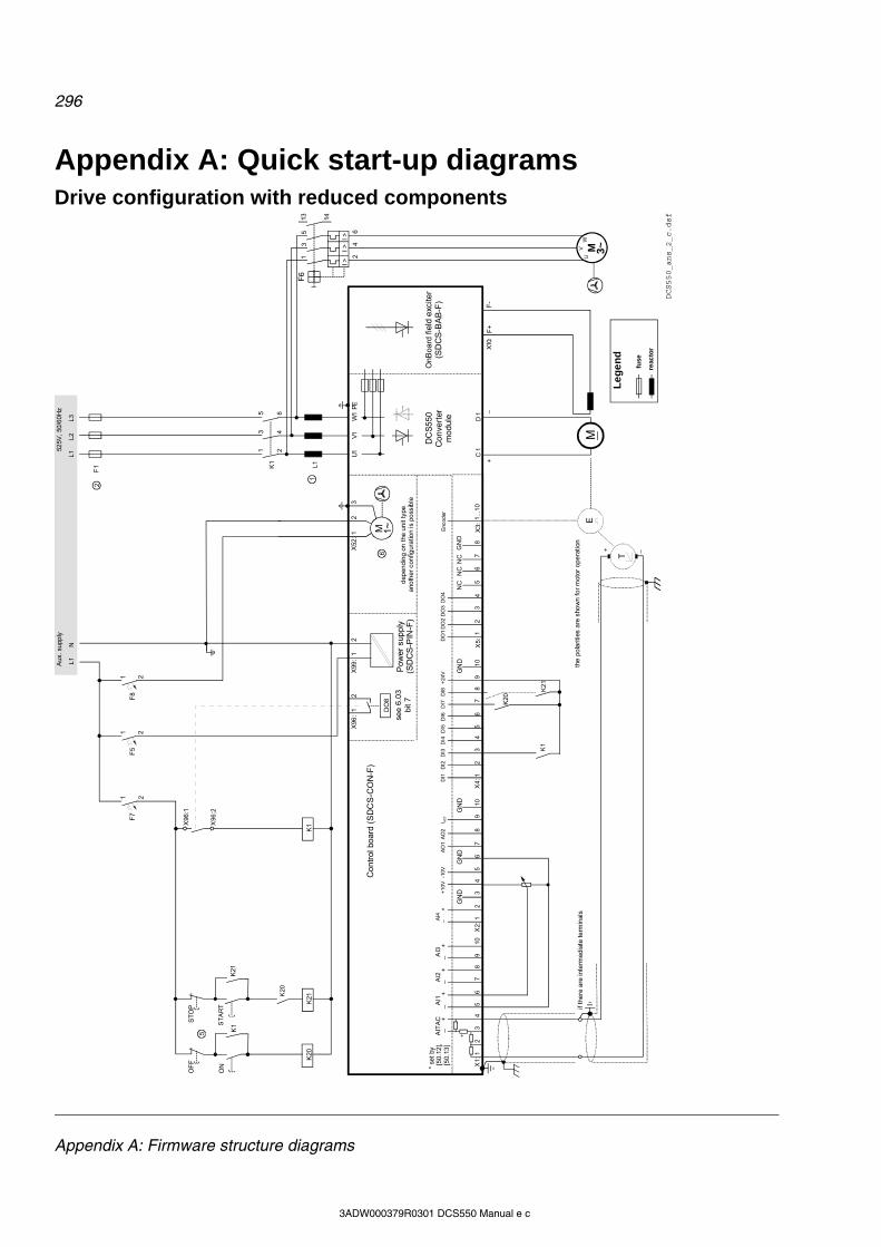
296
Appendix A: Firmware structure diagrams
3ADW000379R0301 DCS550 Manual e c
Appendix A: Quick start-up diagrams Drive configuration with reduced components
X96
:
DO
8
12
X52
:1
23
U1
W1
V1PE
K1
K20
K21
K20
K1X
96:1
X96
:2
L1L2
L3
525V
, 50
/60H
z
F1
M 1~
K21
C 1
D 1
AIT
AC
AI1
AI2
AI3
AI4
+10
V-1
0VA
O1
AO
2I A
CT
DI1
DI2
DI3
DI4
DI5
DI6
DI7
DI8
+24
VD
O1
DO
2D
O3
DO
4_
__
__
++
++
+E
ncod
er
T
EM
GN
DG
ND
GN
DG
ND
GN
DN
CN
CN
C
X1:
12
34
56
78
910
X2:
12
34
56
78
910
X4
:12
34
56
78
910
X5:
12
34
56
78
1...1
0X
3:
+_
+ _
K1
K20
K21
F5
1 2F
8
1 2F
7
1 2
K1
13
5
24
6
L1
F+
F-
X10:
L1N
21
43
65F
6
I >I >
I >
13 14
UV
W
M 3~
DCS550_ans_2_c.dsf
*
see
6.0
3bi
t 7
2
1
6
5
X99
:1
2
Con
trol
boa
rd (
SD
CS
-CO
N-F
)
Pow
er s
upp
ly(S
DC
S-P
IN-F
)
DC
S55
0C
onve
rter
mo
dul
e
ON
OF
FS
TO
P
ST
AR
T
OnB
oard
fie
ld e
xcite
r(S
DC
S-B
AB
-F)
dep
endi
ng
on t
he u
nit
type
ano
the
r co
nfig
ura
tion
is p
oss
ible
the
po
larit
ies
are
sho
wn
for
mot
or o
pera
tion
if th
ere
are
inte
rmed
iate
te
rmin
als
Aux
. su
pply
* se
t by
[5
0.12
], [
50.
13]
Le
ge
nd
fuse
reac
tor

297
Appendix A: Firmware structure diagrams
3ADW000379R0301 DCS550 Manual e c
Terminal locations
X2X1 X3 X4 X51 1 1 1 1
S515
6 9
S3S2 S4
1212
12
12
D21
001
D20
01 D2001
D1000
1 30
1
2
1
2
S1 1 342
123
101112
1 782
1 342
123
789
X12: SDCS-PIN-F
X13: SDCS-PIN-F
X34:DriveWindow Light
X37: SDCS-PIN-F
X9: Slot 1fieldbus orI/O extension
X11: Slot 3I/O extension
X33: DCS Control Panel
X300: routine test
H2500: seven-segment display
Jumpers shown in default position
SDCS-CON-F connector allocation
4 3X52: 2 1
LN
5 4 3X52: 2 1
5
Fan supply 230 VAC
LNFan supply 115 VAC
F4F2 / F3
135 A - 520 A 610 A - 1000 A
4 3X52: 2 1
LN
5
Fan supply 230 VAC
DCS550 moduleTERMINAL ALLOCATION
F100 F101 F102
C1 U1 V1 W1 D1
F+ F-
X10:
max 230 V
X96: X99:
RelayDO8
Aux.supply
X52:
5 1
Fan
1 2 3 4 5 6 7 8 9 10 1 2 3 4 5 6 7 8 9 10 1 2 3 4 5 6 7 8 9 10 1 2 3 4 5 6 7 8 9 10 1 2 3 4 5 6 7 8
±9
0...±
270
V±
30.
..±90
V±
8...
±3
0VA
ITA
C+
AI1
-A
I1+
AI2
-A
I2+
AI3
-A
I3+
SDCS-CON-F: TERMINAL ALLOCATION
AI4
-A
I4+
GN
D+
10V
-10V
GN
DA
O1
AO
2 I act
GN
D
Ch.
A+
Ch.
A-
Ch.
B+
Ch.
B-
Ch.
Z+
Ch.
Z-
GN
DS
ens
e G
ND
Se
nse
+5
V+
5V
or
+24
V
DI1
DI2
DI3
DI4
DI5
DI6
DI7
DI8
+2
4G
ND
DO
1D
O2
DO
3D
O4
NC
NC
NC
GN
DX1 Tacho and AI X2 AI and AO X3 Encoder X4 DI X5 DO
F100, F101, F102
F401, F402, F403
KTK 25
KTK 30
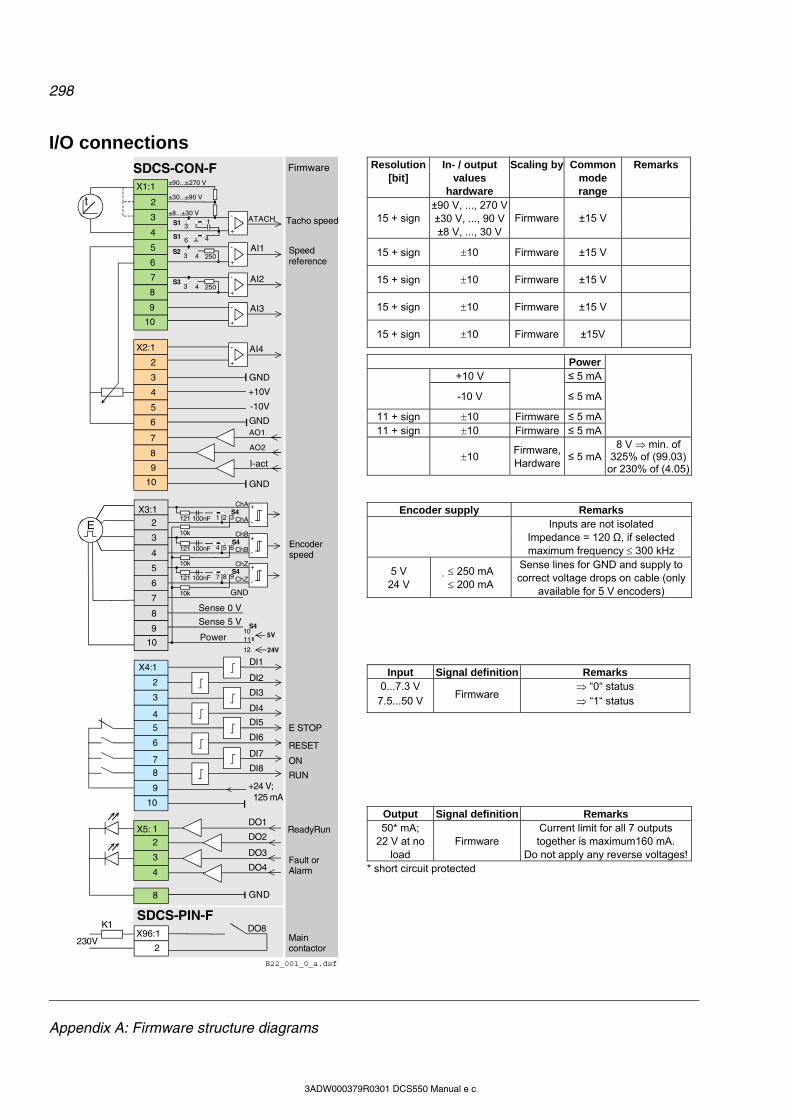
298
Appendix A: Firmware structure diagrams
3ADW000379R0301 DCS550 Manual e c
I/O connections
±90...±270 V
±30...±90 V
±8...±30 V
AI4
GND
GND
+24 V; 125 mA
Power
Sense 0 V
Sense 5 V
AI2
AI3
AI1
AO1
I-act
GND
+10V
GND
-10V
DI1
DI2
DI3
DI4
DI5
DI6
DI7
DI8
DO4
DO1
DO2
DO3
3
4
5
8
7
6
7
9
X4:1
2
3
4
5
6
7 8
10
4
1
2
3
4
2
3
6
5
9
10
8
9
10
2
4
5
7
2
3
6
8
9
10
8
X1:1
X2:1
X3:1
X5:
SDCS-CON-F
B22_001_0_a.dsf
+
-
S23 4 250
S33 4 250
ATACH
+
-
+
-
+
-
+
-
GND
10
+
-
+
-
+
-
5VS4
11
12
AO2
24V
K1X96:1
t
DO8230V
E
2
SDCS-PIN-F
13
46S1
S1
1 3S4
2121 100nF
4 6S4
5121 100nF
7S4
8121 100nF
10k
10k
10k
9
ChA
ChB
ChZ
ChA
ChB
ChZ
Firmware
ReadyRun
RUN
ON
RESET
E STOP
Main contactor
Fault orAlarm
Encoder speed
Speed reference
Tacho speed
Resolution [bit]
In- / output values
hardware
Scaling by Common mode range
Remarks
±90 V, ..., 270 V±30 V, ..., 90 V15 + sign ±8 V, ..., 30 V
Firmware ±15 V
15 + sign 10 Firmware ±15 V
15 + sign 10 Firmware ±15 V
15 + sign 10 Firmware ±15 V
15 + sign 10 Firmware ±15V
Power +10 V ≤ 5 mA
-10 V
≤ 5 mA
11 + sign 10 Firmware ≤ 5 mA 11 + sign 10 Firmware ≤ 5 mA
10 Firmware, Hardware
≤ 5 mA 8 V min. of
325% of (99.03) or 230% of (4.05)
Encoder supply Remarks
Inputs are not isolated
Impedance = 120 Ω, if selected maximum frequency 300 kHz
5 V 24 V
250 mA 200 mA
Sense lines for GND and supply to correct voltage drops on cable (only
available for 5 V encoders)
Input Signal definition Remarks 0...7.3 V 7.5...50 V
Firmware “0“ status “1“ status
Output Signal definition Remarks 50* mA;
22 V at no load
Firmware Current limit for all 7 outputs together is maximum160 mA.
Do not apply any reverse voltages!* short circuit protected
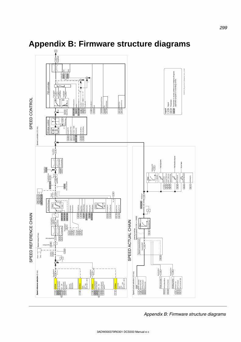
299
Appendix B: Firmware structure diagrams
3ADW000379R0301 DCS550 Manual e c
Appendix B: Firmware structure diagrams
11.
12
11.
06
AC
W1
B6
Ana
log
tach
o
Re
f1S
elS
peed
Ref
Ext
1
2.1
7SpeedRefUsed
2.1
8
23.1
5
M1T
achA
dju
st
M1T
acho
Vol
t100
0
Spe
edR
ef3
Spe
edR
ef4
2.0
2
To
rqR
ef1
To
rqM
inA
ll
Hol
dS
peed
Ctr
l
Spe
edS
tep
AC
W1
B8
D2
3.10
Tor
qRef
2
Bal
Spe
edC
trl
Bal
Ref
PI
24
.11
PID
-con
trol
ler
To
rqD
erR
ef
To
rqP
ropR
efT
orq
Max
SP
C
To
rqM
inS
PC
To
rqIn
teg
Re
f
2.08
2.2
0
Der
ivT
ime
Der
ivF
iltT
ime
24
.10
24
.09
24
.06
24
.03
KpS
KpS
We
akpF
iltT
ime
TiS
InitV
alue
24
.13
24
.12
TiS
+2
0.02
20.0
1
Spe
edR
ef23
01A
uxS
pee
dRef
AI1
…A
I6F
ixed
Spe
ed1
Fix
edS
peed
2M
otP
ot
rese
rve
dM
inA
I2A
I4M
axA
I2A
I4
Re
f1M
ux
Ope
nC
lose
DI1
…D
I8M
CW
Bit1
1…B
it15
2.3
0
Ref
2Se
l
Spe
edR
ef23
01A
uxS
pee
dRef
AI1
…A
I6
Fix
edS
peed
1F
ixed
Spe
ed2
Mot
Po
t
Ref
2Mu
x
Inve
rt11
02O
pen
Clo
seD
I1, …
, DI8
MC
W B
it11…
Bit1
5
2.1
6
0000
2.0
1
Hol
d
Ram
p
Jog
Ram
p
Jog
De
cTim
e
Jog
Acc
Tim
e2
2.12
22.
13
23.
02
23.
03
2.3
2
Fix
edS
peed
1
Fix
edS
peed
2
Spe
edR
ef2
E S
topR
am
p
Sha
peT
ime
Var
Slo
peR
ate
Bal
Ram
pOut
Ram
pByp
ass
Bal
Ram
pRef
dv_
dt
Acc
/Dec
/Sha
pe
Spe
edR
ampO
ut
Spe
edA
ctT
ach
inte
rnal
sca
ling:
Spe
edS
cale
Act
(2.
29)
== 2
000
0
Mot
Sp
eed
1 se
cond
Filt
er
Mot
Sp
eedF
ilt
Spe
edE
rrF
ilt
Win
Wid
thP
os
Win
Wid
thN
eg
Win
dow
con
trol 2.0
3
Spe
edE
rrN
eg
23.
06
-1
-
23.0
8
23.0
9
Spe
ed m
eas
urem
ent
+
20.
012
0.02
50.0
6
Filt
er
Spe
edF
iltT
ime
Acc
eler
atio
n
Dec
eler
atio
n
To
rqM
axA
ll2.
19
-
To
rqS
el =
Ad
d-
Spe
ed r
efe
renc
e se
lect
ion
Spe
ed r
efe
renc
e se
lect
ion
(5 m
s)S
peed
ra
mp
(5 m
s)
Spe
ed a
ctua
l sel
ectio
n (3
.3 m
s)
Spe
ed
cont
rolle
r (3
.3 m
s)
SP
EE
D R
EF
ER
EN
CE
CH
AIN
SP
EE
D C
ON
TR
OL
Loc
al
AC
W1B
2
UM
CW
B5
22.0
4
22
.05
22.0
7
22.0
8
AC
W1B
3
23.
0123
.13
23.
022
3.03
23.0
123
.13
23.0
223
.03
+
2.0
5
2.0
4
2.0
62
0.0
7
20.0
8
2.0
9
50.
12
50.
13
1.0
5
50.
03
1.0
4
1.0
1
Filt
er1
11.0
3
11.0
2
10
.02
Dire
ctio
n
-1
AC
W2
B1
0
24.
13
2.1
9
24.
13
Sig
nal
Par
ame
ter
Par
ame
ter
is u
sua
lly w
ritte
n to
by
Ad
aptiv
e P
rog
ram
,ap
plic
atio
n p
rog
ram
or
ove
rrid
ing
cont
rol
Leg
en
d
Spe
edR
efE
xt2
2.3
1
Pan
el
DW
L
23.
05SpeedShare
UM
CW
B6
UM
CW
B4
22.
01
Ram
p2S
elec
t
22.
09
22.
11A
ccT
ime1
Acc
Tim
e2
22.
02
22.
10
Dec
Tim
e1
Dec
Tim
e2
Jog
2 (1
0.1
8)Jo
g1
(10.
17)
UM
CW
B8,
B9
23.1
6S
peed
Ref
Sca
le
Spe
edE
rrF
ilt2
23.
11
Max
Min
1.1
4
30.
14
Arm
Vol
tAct
Spe
edF
bMon
Lev
30.
15E
MF
FbM
onL
ev
30.
17S
peed
FbF
iltS
el
M1O
vrS
pee
d3
0.16
M1Z
eroS
peed
Lim
50.
11D
ynB
rake
Dly
20.
03
F5
22 S
pee
dF
b
F5
32 M
otO
ver
Sp
eed
Dri
ve lo
gic
Dire
ctS
pee
dRef
5.0
3-5.
08
0 0
5.03
-5.0
8
Filt
er2
26
.01
Win
dow
Ctr
l
To
rqS
el =
Ad
d
AC
W1
B7
26.
01
SP
EE
D A
CT
UA
L C
HA
IN
Pul
se e
nco
der
1
M1E
ncM
easM
ode
M1E
ncP
ulse
No
Spe
edA
ctE
nc
50.
04
50.0
2
1.0
3
5.0
1A
lTa
cho
Va
l
Spe
edA
ctE
MF
1.0
2
AC
W2
B8
-1
M1S
peed
Min
M1S
peed
Max
22.0
7
M1S
peed
Min
M1S
peed
Max
99.
02
1.1
7
99.
04
1.2
9
EM
FE
MF
Vol
tAct
Rel
M1N
omV
olt
M1B
aseS
pee
d
Mot
1Fld
Cur
Re
l
Var
Slo
peR
ate
DCS550_Fw_struct_diagram_rev_a.dsf
Spe
edC
orr
23
.04
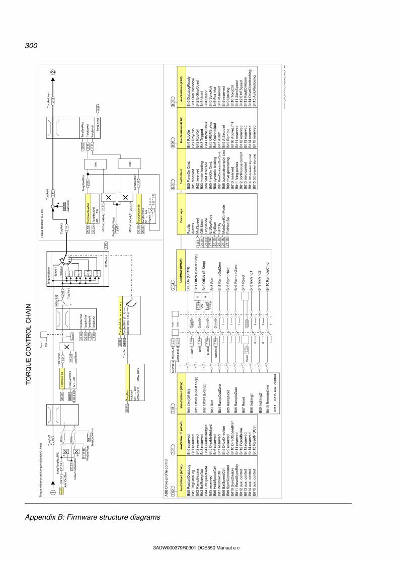
300
Appendix B: Firmware structure diagrams
3ADW000379R0301 DCS550 Manual e c
0 0 11 1 1
1 1 1 0 0
7.04
20.1
9
20.1
3M
1Cu
rLim
Brd
g2
Min
To
rqU
sedM
axS
el
To
rqM
ax2
005
AI1
, …, A
I6
To
rqU
sed
Max
To
rqU
sedM
in
Lim
6
6
Tor
qLim
Act
Tor
qRef
A25
01
AI1
…A
I6
Tor
qR
efA
Sel
+ +
01 2 34
5
To
rque
sel
ecto
r
Min
3
Ma
x 4
To
rqR
efE
xt
2.24
To
rqG
enM
ax
Load
Com
p
Tor
qMa
xAll
To
rqM
inA
ll
To
rqM
axT
ref
To
rqM
inT
ref
To
rqM
axA
ll
To
rqM
inA
ll
26.0
1T
orq
Sel
25.0
1
Tor
qRef
4
25.0
3
Loa
dSha
re
Add
5
Sp
eed
1
Tor
que
2T
orqR
ef3
To
rqU
sedM
inS
el
To
rqM
in20
06
AI1
, …
, AI6
Neg
ate
2.2
3 =
2.2
2 *
(-1)
M1C
urLi
mB
rdg
1
Flu
xRef
Fld
Wea
k
Max
Tor
qR
ef1
No
tUse
dD
I1,
…,
DI1
1M
CW
Bit
11,
…,
MC
W B
it15
Tor
qMu
xT
orq
Sel
260
1 (0
…6
)S
peed
/To
rq (
1 o
r 2)
To
rqM
uxM
ode
+
Tor
qR
efU
sed
Tor
que
refe
renc
e an
d to
rque
se
lect
ion
(3.
3 m
s)T
orq
ue li
mita
tion
(3.
3 m
s)
TO
RQ
UE
CO
NT
RO
L C
HA
IN
20.0
9
20.1
0
2.19
2.20
2.0
8
2.10
26.0
2
20.0
5
20.1
2
3.24
2.11
2.22
20.2
2
2.19
2.20
2.2
6
2.13
20.
06
2.23
On
Off
1
Off
2
E S
top
Sta
rtS
top
&
Re
set
Use
dM
CW
(U
MC
W)
Bit0
On
(Off1
N)
Bit1
Off2
N (
Coa
st S
top)
Bit2
Off3
N (
E-S
top)
Bit3
Run
Bit4
Ram
pOut
Ze
ro
Bit5
Ram
pHol
d
Bit6
Ram
pInZ
ero
Bit7
Res
et
Bit8
Inch
ing1
Bit9
Inch
ing2
Bit1
0 R
emot
eC
md
Mai
nC
trlW
ord
(M
CW
)
Bit0
On
(Off1
N)
Bit1
Off2
N (
Coa
st S
top)
Bit2
Off3
N (
E-S
top)
Bit3
Run
Bit4
Ram
pOut
Ze
ro
Bit5
Ram
pHol
d
Bit6
Ram
pInZ
ero
Bit7
Res
et
Bit8
Inch
ing1
Bit9
Inch
ing2
Bit1
0 R
emot
eC
md
Bit1
1…B
it15
aux
. co
ntro
l
AB
B D
rive
pro
file
cont
rol
10.
15
10.
08
10.
09
10.
16
10.0
3
Loca
l
10.
08O
ff2
E-S
top
Au
xCtr
lWo
rd2
(A
CW
2)
Au
xCtr
lWo
rd (
AC
W1)
Bit0
Res
tart
Dat
aLo
gB
it1 T
rigD
ataL
og
Bit2
Ram
pByp
ass
Bit3
Ba
lRam
pOut
Bit4
Lim
Spe
edR
ef4
Bit5
re
serv
edB
it6 H
oldS
pee
dC
trl
Bit7
Win
dow
Ctr
lB
it8 B
alS
peed
Ctr
lB
it9 S
yncC
omm
and
Bit1
0 S
yncD
isab
leB
it11
Re
setS
yncR
dy
Bit1
2 au
x. c
ontr
olB
it13
aux.
con
trol
Bit1
4 au
x. c
ontr
olB
it15
aux.
con
trol
Bit0
re
serv
edB
it1 r
ese
rved
Bit2
re
serv
edB
it3 r
ese
rved
Bit4
Dis
able
Brid
ge1
Bit5
Dis
able
Brid
ge2
Bit6
re
serv
edB
it7 r
ese
rved
Bit8
Driv
eDir
ectio
nB
it9 r
ese
rved
Bit1
0 D
irec
tSpe
edR
ef
Bit1
1 re
serv
ed
Bit1
2 F
orce
Bra
keB
it13
rese
rve
dB
it14
rese
rve
dB
it15
Re
setP
IDC
trl
Dri
ve
Lo
gic
Fa
ults
Ala
rms
Mot
Sp
eed
Off1
Mod
eS
topM
ode
E S
topM
ode
Fly
Sta
rtF
anD
lyM
ain
Con
tCtr
lMod
eF
ldH
eatS
el
Cu
rCtr
lSta
t1
Bit0
Fa
nsO
n C
md
.B
it1 r
ese
rved
Bit2
re
serv
edB
it3 m
oto
r he
atin
gB
it4 fi
eld
dir
ectio
nB
it5 F
ield
On
Cm
d.B
it6 d
ynam
ic b
raki
ng
Bit7
Ma
inC
onta
cto
rOn
Cm
d
Bit8
Dyn
amic
Bra
king
On
Cm
d
Bit9
driv
e g
ene
ratin
gB
it10
rese
rved
Bit1
1 fir
ing
pul
ses
Bit1
2 co
ntin
uous
cu
rren
tB
it13
zero
cur
ren
tB
it14
DC
-bre
ake
r tr
ip c
md
Bit1
5 D
C-b
rea
ker
trip
cm
d
Ma
inS
tatW
ord
(M
SW
)
Bit0
Rdy
On
Bit1
Rdy
Run
Bit2
Rdy
Ref
Bit3
Tri
pped
Bit4
Off2
NS
tatu
sB
it5 O
ff3N
Sta
tus
Bit6
OnI
nhi
bite
dB
it7 A
larm
Bit8
AtS
etpo
int
Bit9
Rem
ote
Bit1
0 A
bove
Lim
itB
it11
rese
rve
dB
it12
rese
rve
dB
it13
rese
rve
dB
it14
rese
rve
dB
it15
rese
rve
d
Au
xS
tatW
ord
(A
SW
)
Bit0
Dat
aLo
gRe
ady
Bit1
Out
OfW
ind
owB
it2 E
-Sto
pCo
ast
Bit3
Use
r1B
it4 U
ser2
Bit5
Syn
cRdy
Bit6
Fe
x1A
ctB
it7 r
ese
rved
Bit8
re
serv
edB
it9 L
imiti
ng
Bit1
0 T
orq
Ctr
lB
it11
Zer
oS
pee
dB
it12
EM
FS
pee
dB
it13
Fau
ltOrA
larm
Bit1
4 D
rive
Dire
ctio
nNe
gB
it15
Aut
oR
eclo
sing
1.04
21.0
121
.03
21.0
421
.10
21.1
421
.16
21.1
8
25.1
0
26.0
5
26.
04
Tor
qRef
22
.09
20.1
8
-1
7.02
7.03
7.01
&
6.03
8.01
8.02
Loca
l
Pan
el
DW
L
Loca
l
Loca
l
Loca
l
10.
09
Pan
el
DW
L
1
Han
d/A
uto
10.
07
Com
man
dSe
l10.
01
MC
W B
10
Loca
l
5.03
-5.0
80MS
W B
2
Ctr
lMo
de1
.25
DCS550_Fw_struct_diagram_rev_a.dsf
+ -
325%
-325
%
20.2
4
20.2
5
-1 -1
Inde
pT
orqM
axS
PC
Inde
pTo
rqM
inS
PC
64.
01
Ad
d1O
utD
est
Ad
d1
61.1
9 B
3
61.0
7W
inS
tatW
ord T
ensi
onO
nC
md
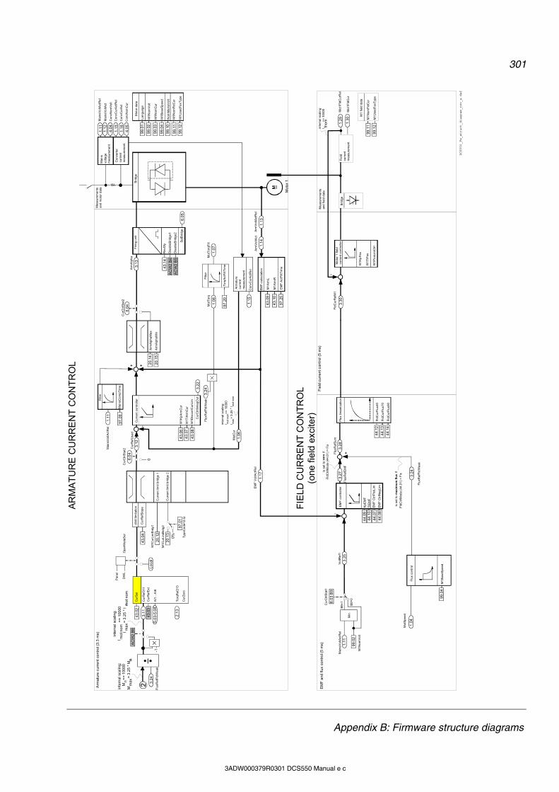
301
Appendix B: Firmware structure diagrams
3ADW000379R0301 DCS550 Manual e c
Fie
ldcu
rren
tm
easu
rem
ent
Mot
1Fld
Cu
rRel
Mot
1Fld
Cu
r
1.2
9
1.3
0
Mot
or 1
fie
ld
curr
ent c
ont
rolle
r
M1K
pF
ex
M1T
iFex
Fld
Cur
Ref
M1
inte
rna
l sca
ling
:I fn
om=
= 1
000
0
M1P
osL
imC
trl
Fie
ld c
urr
ent
con
trol
(5
ms)
Mea
sure
men
tsan
d fie
ld d
ata
3.3
0
M1N
omF
ldC
ur
M1
field
da
ta
99
.12
99
.11
M1U
sedF
exT
ype
Bri
dge
44
.09
44
.10
44
.07
44
.08
is s
et to
max
imu
m f
lux
if
Fld
Ctr
lMod
e (4
4.0
1)
= F
ix
M1A
rmL
M1A
rmR
Se
lBrid
ge6
.05
M1N
omF
ldC
ur
M1U
sedF
exT
ype
M1B
ase
Sp
eed
Cur
Ref
Slo
pe
di/d
t lim
itatio
n
20
.12
Cur
ren
t lim
it b
ridge
1
20
.13
Cur
Ref
Use
d
Cur
ren
t con
trol
ler
M1K
pA
rmC
ur
M1T
iArm
Cu
r
M1D
isco
ntC
urLi
m
Mot
Cur
1.1
5
EM
F-c
alcu
latio
n Arm
Alp
haF
irin
g un
it
43
.14
Rev
Dly
M1N
omV
olt
M1N
omC
ur
Mai
nsvo
ltage
mea
sure
me
nt
Con
vert
ercu
rren
tm
easu
rem
ent
.
Nom
Ma
insV
olt
Mai
nsV
oltA
ctR
el
Mai
nsV
oltA
ct
Con
vCur
Act
Re
l
Con
vCur
Act
1.1
11
.12
1.1
5
1.1
6
M
Mo
tor
1
Fld
Cur
Flu
x40
Fld
Cur
Flu
x70
Fld
Cur
Flu
x90
Flu
x lin
eari
zatio
n
EM
F V
oltA
ctR
el
1.1
7
EM
F c
ont
rolle
r
Kp
EM
F
TiE
MF
Flu
x co
ntro
l
M1B
ase
Sp
eed
Mot
Spe
ed
inte
rna
l sca
ling
:M
n=
= 1
00
00M
ma
x=
3.2
5 *
Mn
Flu
xRef
Fld
Wea
k
3.2
4
Flu
xRef
Sum
Cur
Ctr
lSta
t1
Flu
xRef
EM
F
is s
et to
zer
oif
Fld
Ctr
lMod
e (4
4.0
1)
= F
ix
EM
F C
trlP
osL
im
EM
F C
trlN
egLi
m
97
.09
Filt
erFilt
er
Mai
nsC
ompT
ime
Mai
nsV
oltA
ctR
el
Lan
guag
e
Mot
or d
ata
EM
F A
ctF
iltT
ime
Arm
atur
ecu
rren
tm
easu
rem
ent
Con
vCur
Act
Re
l
-++
+
Arm
Vo
ltAct
A
rmV
oltA
ctR
el
Bri
dge
inte
rna
l sca
ling
:I m
ot n
om
==
10
000
I max
= 3
.25
* I
mot
no
m
FIE
LD C
UR
RE
NT
CO
NT
RO
L(o
ne fi
eld
exci
ter)
Mai
nsV
oltA
ctR
el
Min
M1N
omV
olt
B9=
1
B9=
0
Vo
ltRe
f1
Arm
atu
re c
urr
en
t co
ntr
ol (
3.3
ms)
EM
F a
nd
flu
x co
ntr
ol (
5 m
s)
AR
MA
TU
RE
CU
RR
EN
T C
ON
TR
OL
Mea
sure
me
nts
and
mot
or d
ata
Con
vNom
Vol
t4
.04
Con
vNom
Cu
r4
.05
3.1
2
1.0
6
43
.06
43
.07
43
.08
1.1
1
20
.15
20
.14
3.1
3
99
.02
99
.03
99
.11
99
.12
99
.04
99
.10
99
.01
1.1
41
.13
43
.09
43
.10
97
.25
1.1
1
99
.02
3.2
5
1.0
4
99
.04
3.2
73
.28
44
.12
44
.13
44
.14
43
.04
6.0
3 B
9
Cur
Ref
311
Cur
Ref
Ext
AI1
…A
I6
Cur
Sel
Flu
xRef
Fld
Wea
k
n
3.2
44
3.0
33
.11
43
.02
Loc
al
Pan
el
DW
L
0%
97
.01
Typ
eCo
de=
2-Q
0
Cur
Ctr
lSta
t2
6.0
4O
perM
odeS
elC
urC
trlS
tat2
6.0
4A
CW
2 B
8
-1
inte
rna
l sca
ling
:I m
ot n
om
==
10
000
Im
ax
= 3
.25
* I
n mo
t no
m
5.0
3-5
.08
Cur
Zer
o
3.2
2
97
.20
Filt
er
To
rqA
ctF
iltT
ime
1.0
8
Mot
Tor
q
1.0
7
Mot
Tor
qFilt
3.2
4
AC
W2
B4
AC
W2
B5
Dis
able
Brid
ge1
Dis
able
Brid
ge2
Cur
Ctr
tlint
egO
ut
M1C
urLi
mB
rdg
1
M1C
urLi
mB
rdg
2
Cur
ren
t lim
it b
ridge
2
--
Flu
xRef
Fld
Wea
k
Arm
Alp
haM
in
Arm
Alp
haM
ax
DCS550_Fw_struct_diagram_rev_a.dsf
To
rqR
ef21
32
.13
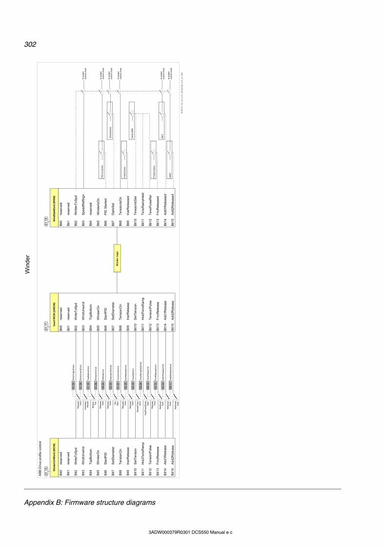
302
Appendix B: Firmware structure diagrams
3ADW000379R0301 DCS550 Manual e c
AB
B D
rive
pro
file
cont
rol
Win
der
Ctr
lWo
rd (
WC
W)
Bit0
re
serv
ed
Bit1
re
serv
ed
Bit2
W
rite
ToS
pd
Bit3
W
ind
Un
win
d
Bit4
T
opB
otto
m
Bit5
W
ind
erO
n
Bit6
S
tart
PID
Bit7
S
etD
iam
eter
Bit8
T
ens
ion
On
Bit9
In
erR
elea
se
Bit1
0 S
etT
ensi
on
Bit1
1 H
old
Te
nsR
amp
Bit1
2 T
ens
ion
Pul
se
Bit1
3 F
rict
Re
leas
e
Bit1
4 A
dd1
Re
leas
e
Bit1
5 A
dd2
Re
leas
e
61.1
6
Use
d W
CW
(U
WC
W)
61.1
7
Win
de
r lo
gic
DCS550_Fw_struct_diagram_rev_b.dsf
Win
der
Bit0
re
serv
ed
Bit1
re
serv
ed
Bit2
W
rite
ToS
pd
Bit3
W
ind
Un
win
d
Bit4
T
opB
otto
m
Bit5
W
ind
erO
n
Bit6
S
tart
PID
Bit7
S
etD
iam
eter
Bit8
T
ens
ion
On
Bit9
In
erR
elea
se
Bit1
0 S
etT
ensi
on
Bit1
1 H
old
Te
nsR
amp
Bit1
2 T
ens
ion
Pul
se
Bit1
3 F
rict
Re
leas
e
Bit1
4 A
dd1
Re
leas
e
Bit1
5 A
dd2
Re
leas
e
Rel
eas
e
A
uto
61
.02
Writ
eTo
Sp
dCh
ain
Unw
inde
r
Win
der
61
.04
Win
dUn
win
dCm
d
Bot
tom
To
p
61
.05
Top
Bot
tom
Cm
d
Rel
eas
e
A
uto
61
.06
Win
derO
nCm
d
Rel
eas
e
A
uto
40
.22
PID
Ctr
lCm
d
Se
tA
uto
62
.04
Dia
me
terS
etC
md
Rel
eas
e
A
uto
61
.07
Ten
sion
OnC
md
Rel
eas
e
A
uto
62
.28
Ine
rRel
ease
Cm
d
Sta
nst
ilTen
s
A
uto
63
.04
Ten
sSel
Cm
d
Hol
dT
ens
Ram
p
A
uto
63
.09
Ten
sRa
mpH
old
Cm
d
Rel
eas
e
A
uto
63
.13
Ten
sPul
seC
md
Not
Use
d
A
uto
63
.32
Fric
tRe
leas
eCm
d
64
.04
Add
1Re
lea
seC
md
64
.11
Add
2Re
lea
seC
md
Win
dS
tatW
ord
(W
SW
)
61.1
9
Bit0
re
serv
ed
Bit1
re
serv
ed
Bit2
W
ritte
nTo
Spd
Bit3
S
pee
dR
efS
ign
Bit4
re
serv
ed
Bit5
W
ind
erIs
On
Bit6
P
ID S
tart
ed
Bit7
D
iaIs
Set
Bit8
T
ens
ion
IsO
n
Bit9
In
erR
elea
sed
Bit1
0 T
ens
ion
IsS
et
Bit1
1 T
ens
Ram
pHel
d
Bit1
2 T
ens
Pul
seR
el
Bit1
3 F
ricR
ele
ase
d
Bit1
4 A
dd1
Re
leas
ed
Bit1
5 A
dd2
Re
leas
ed
PID
Co
ntro
ller
Not
Use
d
A
uto
Not
Use
d
A
uto
Dia
me
terA
ct
Ine
rtia
Com
p
Ten
sion
Ref
Fric
tion
Com
p
Add
1
Add
2
to s
pee
dco
ntro
l ch
ain
to s
pee
dco
ntro
l ch
ain
to s
pee
dco
ntro
l ch
ain
to s
pee
dco
ntro
l ch
ain
to s
pee
dco
ntro
l ch
ain
to s
pee
dco
ntro
l ch
ain
303
Appendix C: Index of signals and parameters
3ADW000379R0301 DCS550 Manual e c
Appendix C: Index of signals and parameters Index of signals and parameters (alphabetic order) 2ndLastFault 175 3rdLastFault 175 AccActAdjust 133, 237 AccActIn 237 AccFiltTime 237 AccTime1 202 AccTime2 203 AccTrim 133, 237 AdapPrgStat 248 AdapProgCmd 114, 247, 293, 295 AdaptKpDiaActIn 236 AdaptKpMax 132, 147, 237 AdaptKpMin 132, 147, 236 AdaptKpOutDest 237 AdaptKpSPC 237 Add1 135, 245 Add1Cmd 135 Add1In1 244 Add1In2 244 Add1OutDest 135, 244 Add1ReleaseCmd 244 Add2 135, 245 Add2Cmd 135 Add2In1 245 Add2In2 245 Add2OutDest 135, 245 Add2ReleaseCmd 245 AI Mon4mA 214, 273, 286, 291 AI1 Val 159 AI1 ValScaled 160 AI1HighVal 84, 187 AI1LowVal 84, 187 AI2 Val 159 AI2 ValScaled 160 AI2HighVal 187 AI2LowVal 187 AI3 Val 160 AI3 ValScaled 160 AI3HighVal 188 AI3LowVal 188 AI4 Val 160 AI4 ValScaled 160 AI4HighVal 188 AI4LowVal 188 AI5 Val 160 AI5 ValScaled 160 AI5HighVal 189 AI5LowVal 189 AI6 Val 160 AI6 ValScaled 160 AI6HighVal 84, 190 AI6LowVal 84, 190
AIO ExtModule 83, 85, 260, 283 AITacho Val 159 AlarmWord1 169, 279 AlarmWord2 170, 279 AlarmWord3 170, 279 AnybusModType 253 AO1 Val 160 AO2 Val 160 ApplLoad 158 ApplMacro 62, 262, 269 ApplRestore 62, 262 ArmAlpha 156 ArmAlphaMax 198 ArmAlphaMin 198, 290 ArmOvrCurLev 210, 270, 282 ArmOvrVoltLev 210, 273, 282 ArmVoltAct 152 ArmVoltActRel 152 AuxCtrlWord 77, 88, 89, 163 AuxCtrlWord2 163 AuxSpeedRef 206 AuxStatWord 78, 88, 89, 165 BalRampRef 203 BalRef 207 Baud rate 104 Baudrate 87, 89 BaudRate 100, 228 Block10Out 252 Block11Out 252 Block12Out 252 Block13Out 252 Block14Out 253 Block15Out 253 Block16Out 253 Block1Attrib 250 Block1In1 249 Block1In2 249 Block1In3 249 Block1Out 251 Block1Output 250 Block1Type 249 Block2Out 251 Block3Out 252 Block4Out 252 Block5Out 252 Block6Out 252 Block7Out 252 Block8Out 252 Block9Out 252 BreakPoint 248 BridgeTemp 153, 270 Com8SwVersion 293
304
Appendix C: Index of signals and parameters
3ADW000379R0301 DCS550 Manual e c
ComLossCtrl 77, 214, 272, 285, 291 Comm rate 97, 102 CommandSel 73, 87, 88, 91, 92, 94, 95, 97, 100, 102, 104, 146, 176, 265, 285 CommModule 87, 91, 94, 97, 100, 102, 103, 258, 283, 285, 291 Constant1 250 Constant10 251 Constant2 251 Constant3 251 Constant4 251 Constant5 251 Constant6 251 Constant7 251 Constant8 251 Constant9 251 ConstSpeed1 186 ConstSpeed2 187 ConvCurAct 152 ConvCurActRel 152, 277 ConvModeAI1 84, 187 ConvModeAI2 188 ConvModeAI3 188 ConvModeAI4 189 ConvModeAI5 190 ConvModeAI6 84, 191 ConvModeAO1 85, 86, 192 ConvModeAO2 192 ConvModeAO3 193 ConvModeAO4 85, 193 ConvNomCur 60, 85, 157 ConvNomVolt 60, 157 ConvOvrCur 157, 270 ConvType 60, 157 CPU Load 158 CtrlMode 153 CtrlWordAO1 192 CtrlWordAO2 192 CtrlWordAO3 193 CtrlWordAO4 193 CurCtrlIntegOut 156 CurCtrlStat1 76, 77, 160, 272 CurCtrlStat2 161 CurRef 156 CurRefExt 222 CurRefSlope 222 CurRefUsed 156, 272, 290 CurRipple 276 CurRippleFilt 152, 276 CurRippleLim 212, 276, 284, 290 CurRippleSel 212, 276, 284, 290 CurSel 84, 222 Data1 132, 146, 195, 292 Data10 196 Data11 196 Data12 196
Data2 195 Data3 195 Data4 195, 292 Data5 195 Data6 195 Data7 195 Data8 196 Data9 196 DC BreakAck 79, 182, 289 DecTime1 202 DecTime2 203 DerivFiltTime 207 DerivTime 207 DeviceName 262 DevLimPLL 256 DHCP 97, 102 DI StatWord 79, 80, 166 DI10Invert 183 DI11Invert 79, 183 DI1Invert 79, 182 DI2Invert 182 DI3Invert 182 DI4Invert 182 DI5Invert 182 DI6Invert 182 DI7Invert 182 DI8Invert 182 DI9Invert 183 Diagnosis 171, 283, 292 DiaLineSpdIn 131, 235 DiameterAct 236 DiameterMin 236 DiameterMin 130 DiameterSetCmd 146, 236 DiameterValue 146, 235 DiaMotorSpdIn 131, 235 DiaMotorSpdLev 236 DiaRampTime 236 DIO ExtModule1 79, 81, 258, 283 DIO ExtModule2 79, 81, 259, 283 Direction 79, 176 DirectSpeedRef 206 DispParam1Sel 218, 265 DispParam2Sel 218, 265 DispParam3Sel 218, 265 DO CtrlWord 81, 164 DO StatWord 81, 166 DO1BitNo 191 DO1Index 81, 191 DO2BitNo 191 DO2Index 191 DO3BitNo 191 DO3Index 191 DO4BitNo 191 DO4Index 191 DO8BitNo 192
305
Appendix C: Index of signals and parameters
3ADW000379R0301 DCS550 Manual e c
DO8Index 81, 191 DP Mode 104 DriveStat 74, 167 DsetXplus1Val1 89, 91, 94, 97, 100, 102, 104, 255 DsetXplus1Val2 89, 91, 94, 97, 101, 102, 104, 255 DsetXplus1Val3 89, 101, 105, 255 DsetXplus2Val1 89, 254 DsetXplus2Val2 254 DsetXplus2Val3 254 DsetXplus3Val1 89, 255 DsetXplus3Val2 255 DsetXplus3Val3 255 DsetXplus4Val1 254 DsetXplus4Val2 254 DsetXplus4Val3 254 DsetXplus5Val1 255 DsetXplus5Val2 255 DsetXplus5Val3 255 DsetXplus6Val1 100, 254 DsetXplus7Val1 101, 255 DsetXVal1 89, 91, 94, 97, 100, 102, 104, 254 DsetXVal2 89, 91, 94, 97, 100, 102, 104, 254 DsetXVal3 89, 100, 105, 254 dv_dt 154 DynBrakeAck 77, 79, 182, 289 DynBrakeDly 78, 227 E Stop 79, 179, 289 E StopMode 28, 77, 200 E StopRamp 28, 202 EditBlock 247 EditCmd 247, 295 EMF ActFiltTime 257 EMF CtrlNegLim 224 EMF CtrlPosLim 224 EMF FbMonLev 211, 277, 284, 287, 291 Ext IO Stat 158 Ext IO Status 283 ExtAlarmOnSel 291 ExtAlarmSel 79, 215, 291 ExtFaultSel 79, 215, 272, 285 FanDly 74, 201, 281, 289 FaultedPar 248, 295 FaultStopMode 77, 215, 270, 281 FaultWord1 168, 279 FaultWord2 168, 279 FaultWord3 168, 279 Faultword4 101 FaultWord4 169, 279 FB TimeOut 216, 285, 291 FBA PAR REFRESH 88, 90, 95, 98, 103, 104, 228 FbMonLev 284, 287, 291 Fieldbus1 228 Fieldbus15 228 Fieldbus16 228 Fieldbus36 228 FilterAI1 187
FilterAI2 188 FilterAI3 188 FilterAI4 189 FilterAO1 192 FilterAO2 193 FilterAO3 193 FilterAO4 193 FirmwareType 73, 157 FirmwareVer 73, 157, 293 FixedSpeed1 204 FixedSpeed2 205 FldCtrlMode 74, 223 FldCurFlux40 224 FldCurFlux70 224 FldCurFlux90 224 FldCurRefM1 157 FldHeatSel 75, 202 FldMinTripDly 225, 278, 286 FluxRefEMF 157 FluxRefFldWeak 156 FluxRefSum 157 FlyStart 77, 289, 293 FrictAt0Spd 134, 243 FrictAt100Spd 134, 243 FrictAt20Spd 243 FrictAt25Spd 135 FrictAt40Spd 243 FrictAt50Spd 135 FrictAt60Spd 243 FrictAt75Spd 135 FrictionComp 135, 244 FrictMotorSpdIn 243 FrictReleaseCmd 135, 244 GW address 1 98, 103 GW address 2 98, 103 GW address 3 98, 103 GW address 4 98, 103 HandAuto 79, 178 HW/SW option 91, 92, 94, 95 I IP address 4 98, 102 IactScaling 85, 159 IndepTorqMaxSPC 199 IndepTorqMinSPC 199 IndexAO1 85, 86, 192 IndexAO2 192 IndexAO3 193 IndexAO4 85, 86, 193 InerAccActIn 238 InerCoil 134, 238 InerCoilWidth 239 InerDiaActIn 238 InerMech 134, 238 InerReleaseCmd 134, 239 InertiaComp 134, 239 Input 1 98, 103 Input 2 98, 103
306
Appendix C: Index of signals and parameters
3ADW000379R0301 DCS550 Manual e c
Input 3 98, 103 Input 4 98, 103 Input I/O par 9 92, 95 Input instance 92, 95 IP address 1 98, 102 IP address 2 98, 102 IP address 3 98, 102 Jog1 79, 181 Jog2 79, 181 JogAccTime 204 JogDecTime 204 KpEMF 224 KpPID 218 KpPLL 257 KpS 207 KpS2 207 Language 261, 264 LastFault 175 LimWord 166 LineSpdNegLim 232 LineSpdPosLim 130, 147, 232 LineSpdScale 130, 147, 232 LineSpdUnit 130, 232 LoadComp 209 LoadShare 208 LocalLossCtrl 77, 214, 272, 286, 292 LocationCounter 248 LocLock 194 M1AlarmLimLoad 216, 274, 283, 290 M1AlarmLimTemp 217, 273, 283, 289 M1ArmL 222 M1ArmR 223 M1BaseSpeed 261, 267, 291 M1CurLimBrdg1 198 M1CurLimBrdg2 198 M1DiscontCurLim 222 M1EncPulseNo 226 M1FaultLimLoad 216, 274, 283 M1FaultLimTemp 217, 273, 283 M1FldHeatRef 75, 224 M1FldMinTrip 74, 211, 278, 286 M1FldOvrCurLev 211, 276, 284 M1KlixonSel 79, 217, 273, 283 M1KpArmCur 222, 284, 290 M1KpFex 223 M1LoadCurMax 217, 275, 290 M1ModelTime 216, 274 M1MotNomCur 275 M1NomCur 85, 261, 270 M1NomFldCur 262, 276, 278 M1NomVolt 261, 273 M1OvrLoadTime 217 M1OvrLoadTime 275 M1OvrLoadTime 290 M1OvrSpeed 211, 278, 285, 290 M1PosLimCtrl 225
M1RecoveryTime 217 M1RecoveryTime 275 M1RecoveryTime 290 M1SpeedFbSel 78, 226, 267, 278, 284, 291, 293 M1SpeedMax 130, 197, 291 M1SpeedMin 130, 196, 291 M1SpeedScale 130, 225, 291 M1TachMaxSpeed 253 M1TachoAdjust 227 M1TachoGain 253 M1TachoTune 253 M1TachoVolt1000 227 M1TempSel 84, 217, 273 M1TiArmCur 222 M1TiFex 224 M1UsedFexType 263 M1ZeroSpeedLim 197, 293 MacroSel 62, 167 MainContAck 79, 181, 272, 285 MainContCtrlMode 73, 78, 201 MainCtrlWord 73, 89, 91, 94, 97, 100, 102, 104, 146, 162 MainsCompTime 256 MainsFreqAct 153 MainStatWord 73, 89, 94, 97, 100, 102, 104, 164 MainsVoltAct 152 MainsVoltActRel 152 MaxBridgeTemp 60, 158, 270, 282, 289 MaxEncoderTime 226 Modbus timeout 98, 103 ModBusModule2 100 Module baud rate 91, 92, 94, 95 Module macid 91, 92, 94, 95 ModuleType 87, 89, 91, 92, 94, 95, 97, 102, 104 Mot1FexType 157 Mot1FldCur 153 Mot1FldCurRel 153 Mot1TempCalc 152, 274 Mot1TempMeas 153 MotCur 151, 290 MotFanAck 28, 79, 177, 272, 284 MotNomTorque 278 MotPotDown 79, 186 MotPotMin 79, 186 MotPotUp 79, 185 MotSpeed89, 94, 97, 101, 102, 104, 131, 151, 285 MotSpeedFilt 151 MotTorq 148, 152 MotTorqFilt 105, 134, 151 MotTorqNom 133, 158 Node address 104 Node ID 87, 89 NomMainsVolt 262, 271, 283, 290 Off1Mode 74, 77, 200 Off2 79, 178, 289 OffsetIDC 257
307
Appendix C: Index of signals and parameters
3ADW000379R0301 DCS550 Manual e c
OnOff1 73, 79, 180 Output 1 98, 103 Output 2 98, 103 Output 3 98, 103 Output 4 98, 103 Output I/O par 1 92, 95 Output instance 92, 95 Par2Select 79, 208 ParApplSave 194 ParChange 79, 179 Parity 100, 229 ParLock 194 PassCode 248, 295 PDO21 Cfg 87, 89 PID Act1 132, 219 PID Act2 219 PID Mux 220 PID Out 132, 156 PID OutDest 220 PID OutMax 220 PID OutMin 220 PID OutScale 221 PID Ref1 220 PID Ref1Max 219 PID Ref1Min 219 PID Ref2 220 PID Ref2Max 219 PID Ref2Min 219 PID ReleaseCmd 221 PID ResetBitNo 221 PID ResetIndex 221 PIDRef1 132 PLL In 156 PLLIn 284 Pot1 263 Pot2 263 PowrDownTime 213, 271, 283 PPO-type 104 ProgressSignal 158 Protocol 97, 98, 102, 103 PwrLossTrip 213, 270, 271, 283, 290 PZD10 IN 104 PZD10 OUT 104 PZD3 IN 104 PZD3 OUT 104 QuadrantType 60, 157 Ramp2Select 204 Ref1Mux 79, 183 Ref1Sel 84, 87, 88, 91, 92, 94, 95, 97, 100, 102, 104, 146, 184 Ref2Mux 79, 185 Ref2Sel 84, 184 Reset 79, 177 RevDly 223, 272, 287 RX-PDO21-1stObj 87, 89 RX-PDO21-1stSubj 87, 89
RX-PDO21-2ndSubj 87, 89 RX-PDO21-2ndtObj 87, 89 RX-PDO21-3rdObj 87, 89 RX-PDO21-3rdSubj 88, 89 RX-PDO21-4thObj 88, 89 RX-PDO21-4thSubj 88, 89 RX-PDO21-Enable 87, 89 RX-PDO21-TxType 87, 89 S BlockBrdg2 60 S BlockBridge2 256 S MaxBrdgTemp 256, 270 S MaxBrdgTemp 60 S MaxBridgeTemp 282, 289 ScaleAO1 86, 192 ScaleAO2 193 ScaleAO3 193 ScaleAO4 86, 193 SelBridge 162 ServiceMode 261, 269, 290, 291 SetSystemTime 194 ShapeTime 202 SpeedActEMF 151 SpeedActEnc 151, 277 SpeedActEnc2 277 SpeedActTach 151, 277 SpeedCorr 132, 205 SpeedErrFilt 205 SpeedErrFilt2 206 SpeedErrNeg 153 SpeedFbFltMode 77, 216, 270, 284, 291 SpeedFbFltSel 212, 277, 284, 291 SpeedFbMonLev 211, 277 SpeedFiltTime 227 SpeedLev 227 SpeedRampOut 156 SpeedRef 89, 91, 94, 97, 100, 102, 104, 150, 204 SpeedRef2 153 SpeedRef3 131, 153 SpeedRef4 154 SpeedRefExt1 155 SpeedRefExt2 156 SpeedRefScale 206 SpeedRefUsed 148, 154 SpeedScaleAct 88, 90, 92, 95, 98, 101, 103, 104, 130, 148, 150, 155, 282, 285 SpeedShare 205 SpeedStep 206 SqrWaveIndex 263 SqrWavePeriod 263 SquareWave 156 StallSpeed 210, 278, 285 StallTime 210, 278, 285 StallTorq 210, 278, 285 StartStop 73, 79, 180 StationNumber 100, 228 Stop function 91, 92, 95, 98, 103

308
Appendix C: Index of signals and parameters
3ADW000379R0301 DCS550 Manual e c
StopMode 74, 77, 200 String1 121, 251 String2 121, 251 String3 121, 251 String4 121, 251 String5 121, 251 Subnet mask 1 98, 102 Subnet mask 2 98, 102 Subnet mask 3 98, 102 Subnet mask 4 98, 102 SysFaultWord 171 SysPassCode 194 SystemTime 160 TachoTerminal 159 TaperDia 240 TaperDiaActIn 240 TaperTens 240 TdFiltPID 219 TdPID 219 TensionOnCmd 231 TensionRef 241 TensPulseCmd 241 TensPulseLevel 241 TensPulseWidth 241 TensRampHoldCmd 241 TensRampTime 240 TensRefIn 146, 240 TensRefMin 240 TensSetCmd 240 TensToTorq 242 TensValueIn 240 TestSignal 263 TfPLL 257 TiEMF 224 TimeLevSel 248, 293 TiPID 219 TiS 207 TiS2 208 TiSInitValue 207 ToolLinkConfig 194 TopBottomCmd 131, 146, 231 TorqActFiltTime 257 TorqDerRef 153 TorqGenMax 199 TorqIntegRef 153 TorqLimAct 155 TorqMax 197 TorqMaxAll 154 TorqMaxSPC 150, 197 TorqMaxTref 198 TorqMin 197 TorqMinAll 154 TorqMinSPC 197 TorqMinTref 198 TorqMux 79, 210 TorqMuxMode 209
TorqPropRef 153 TorqRef1 154 TorqRef2 88, 89, 101, 154 TorqRef3 154 TorqRef4 154 TorqRefA 87, 89, 100, 105, 208 TorqRefA Sel 84 TorqRefExt 84, 155 TorqRefUsed 86, 154 TorqSel 209 TorqUsedMax 155 TorqUsedMaxSel 84, 198 TorqUsedMin 155 TorqUsedMinSel 84, 199 TransparentIProfil 88, 90 TTT DiaActIn 242 TTT Ref1In 242 TTT Ref2In 242 TTT Ref3In 242 TTT Scale 242 TX-PDO21-1stObj 88, 90 TX-PDO21-1stSubj 88, 90 TX-PDO21-2ndSubj 88, 90 TX-PDO21-2ndtObj 88, 90 TX-PDO21-3rdObj 88, 90 TX-PDO21-3rdSubj 88, 90 TX-PDO21-4thObj 88, 90 TX-PDO21-4thSubj 88, 90 TX-PDO21-Enable 88, 89 TX-PDO21-EvTime 88, 89 TX-PDO21-TxType 88, 89 TypeCode 60, 256, 269, 270, 282, 285, 289 UNetMin1 213, 270, 283, 290 UNetMin2 213, 270, 283, 290 UsedMCW 73, 77, 164 UsedWCW 131, 233 UserAlarmWord 279 UserFaultWord 279 VarSlopeRate 203 VoltActRel 152 VoltRef1 156 VSA I/O size 92, 95 WindCtrlWord 131, 233 WinderMacro 130, 136, 137, 146, 229 WinderOnCmd 146, 231 WinderTuning 133, 234, 291 WindSpdOffset 130, 232 WindStatWord 233 WindUnwindCmd 131, 146, 230 WinWidthNeg 206 WinWidthPos 205 WiPassCode 246 WiProgCmd 130, 146, 246 WiUserMode 246 WriteToSpdChain 130, 230 ZeroCurTimeOut 257, 272, 287

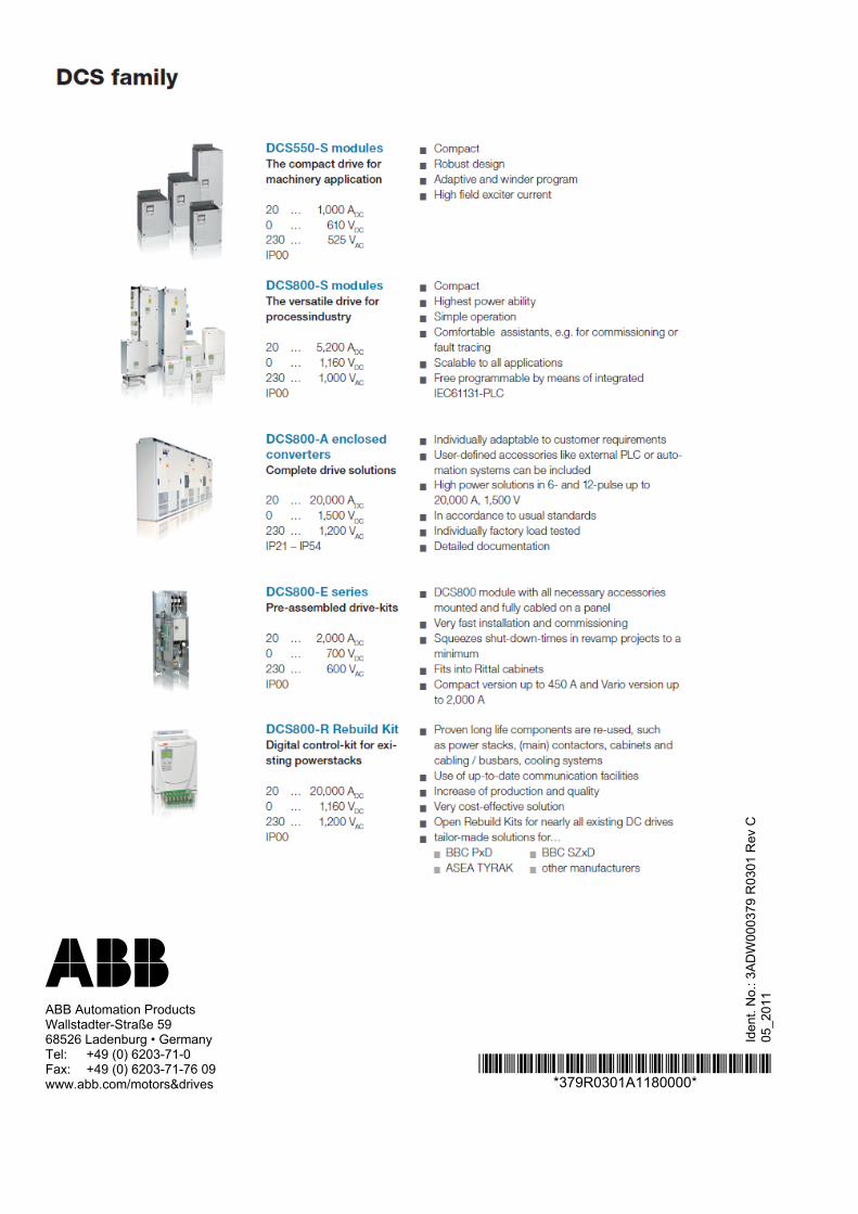
*379R0301A1180000**379R0301A1180000*
Iden
t. N
o.: 3
AD
W00
037
9 R
030
1 R
ev C
05
_20
11 ABB
ABB Automation Products Wallstadter-Straße 59 68526 Ladenburg • Germany Tel: +49 (0) 6203-71-0 Fax: +49 (0) 6203-71-76 09 www.abb.com/motors&drives