KSC RELIABILITY & MAINTAINABILITY PROCEDURAL REQUIREMENTS · Kennedy NASA Procedural Requirements...
95
KNPR 8720.2 Rev. Basic-2 Page 1 of 95 Kennedy NASA Procedural Requirements Effective Date: November 28, 2007 Expiration Date: February 28, 2013 (EXTENDED UNTIL MARCH 31, 2014) Responsible Office: Safety and Mission Assurance KSC RELIABILITY & MAINTAINABILITY PROCEDURAL REQUIREMENTS National Aeronautics and Space Administration John F. Kennedy Space Center KDP-KSC-F-2120 Rev. B RELEASED - Printed documents may be obsolete; validate prior to use.
Transcript of KSC RELIABILITY & MAINTAINABILITY PROCEDURAL REQUIREMENTS · Kennedy NASA Procedural Requirements...

KNPR 8720.2 Rev. Basic-2
Page 1 of 95
Kennedy NASA Procedural Requirements Effective Date: November 28, 2007 Expiration Date: February 28, 2013 (EXTENDED UNTIL MARCH 31, 2014) Responsible Office: Safety and Mission Assurance
KSC RELIABILITY & MAINTAINABILITY PROCEDURAL REQUIREMENTS
National Aeronautics and Space Administration John F. Kennedy Space Center
KDP-KSC-F-2120 Rev. B
RELEASED - Printed documents may be obsolete; validate prior to use.
KNPR 8720.2 Rev. Basic-2
Page 2 of 95
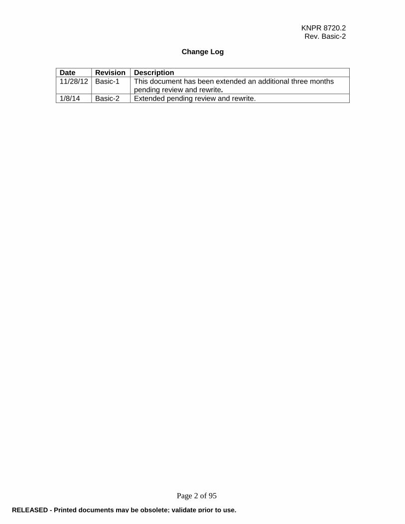
Change Log
Date Revision Description
11/28/12 Basic-1 This document has been extended an additional three months pending review and rewrite.
1/8/14 Basic-2 Extended pending review and rewrite.
RELEASED - Printed documents may be obsolete; validate prior to use.

KNPR 8720.2 Rev. Basic-2
Page 3 of 95
TABLE OF CONTENTS Preface P.1 Purpose P.2 Applicability and Scope P.3 Authority P.4 Applicable Documents P.5 Deviations and Waivers P.6 Cancellation/Supersession Chapter 1. General Reliability and Maintainability (R&M) Requirements 1.1 Management 1.2 R&M Plans 1.3 R&M Contract Review 1.4 R&M Contractor Surveillance 1.5 R&M Technical/Milestone Reviews and Certifications 1.6 Government-Industry Data Exchange Program (GIDEP) 1.7 Problem/Failure Reporting and Corrective Action System Chapter 2. Reliability Program Requirements 2.0 General 2.1 Task 101 Reliability Program Plan 2.2 Task 102 Develop Reliability Requirements 2.3 Task 103 Develop the Reliability Model 2.4 Task 104 Allocation of Reliability Requirements 2.5 Task 105 Develop Reliability Design Criteria 2.6 Task 106 Electrical/Thermal Stress/Derating Analysis 2.7 Task 107 Reliability Prediction 2.8 Task 108 Electrical Tolerance Analysis 2.9 Task 109 Mechanical Tolerance Analysis 2.10 Task 110 Failure Modes and Effects Analysis 2.11 Task 111 Critical Items List 2.12 Task 112 Fault Tree Analysis 2.13 Task 113 Event Tree Analysis 2.14 Task 114 Sneak Circuit Analysis 2.15 Task 115 Connector-Pin/Signal Analysis 2.16 Task 116 Test Effectiveness/Testability Analysis 2.17 Task 117 Probabilistic Risk Assessment Plan 2.18 Task 118 Probabilistic Risk Assessment 2.19 Task 119 Human Error Risk Assessment 2.20 Task 120 Reliability Status Reporting Chapter3. Electrical, Electronic, and Electromechanical (EEE) & Mechanical Parts, Materials, and Processes Requirements 3.0 NASA Standard Parts Program 3.1 Task 201 Parts, Materials, and Processes Control Plan 3.2 Task 202 Parts, Materials, and Processes Control Board 3.3 Task 203 Part Application and Derating Requirements 3.4 Task 204 Parts, Materials, and Processes Selection List 3.5 Task 205 As-Designed Parts and Materials List
RELEASED - Printed documents may be obsolete; validate prior to use.

KNPR 8720.2 Rev. Basic-2
Page 4 of 95
3.6 Task 206 As-Built Parts and Materials List 3.7 Task 207 Limited-Life Items List 3.8 Task 208 GIDEP Participation Chapter 4. Software Reliability Program Requirements 4.0 General 4.1 Task 301 Software Reliability Plan 4.2 Task 302 Software Test Program 4.3 Task 303 Software Reliability Assessment Chapter 5. Maintainability Program Requirements 5.0 General 5.1 Task 401 Maintainability Program Plan 5.2 Task 402 Establish Maintainability Program Requirements and Maintenance Concept 5.3 Task 403 Maintainability Modeling 5.4 Task 404 Maintainability Allocation 5.5 Task 405 Maintainability Design Criteria 5.6 Task 406 Maintainability Prediction 5.7 Task 407 Human Factors Analysis 5.8 Task 408 Reliability Centered Maintenance Chapter 6. Reliability/Maintainability Test Program Requirements 6.0 General 6.1 Task 501 Equipment Development Testing 6.2 Task 502 Equipment Preconditioning and Screening Tests 6.3 Task 503 Reliability/Maintainability Growth Test 6.4 Task 504 Reliability/Maintainability Qualification/ Demonstration Test 6.5 Task 505 Environmental Qualification/Acceptance Testing 6.6 Task 506 Trend Analysis Chapter 7. Logistics Support Analysis 7.0 General 7.1 Task 601 Logistics Support Analysis Appendices A. Definitions B. Acronyms & Abbreviations C. Reference Document D. R&M Plan Template E. R&M Design Review Checklist F. R&M Life Cycle Activities G. A Sample of Statement of Work Requirements for a Major Element or Mission Support Contract H. Sample of Reliability and Maintainability Requirements Applied to a Contract I. Guideline for the Selection and Utilization of COTS Systems J. Availability
RELEASED - Printed documents may be obsolete; validate prior to use.

KNPR 8720.2 Rev. Basic-2
Page 5 of 95
PREFACE P.1 PURPOSE This KNPR contains Reliability and Maintainability (R&M) requirements to be implemented at the John F. Kennedy Space Center (KSC). These requirements are consistent with NASA R&M policies, procedures, and standards and are intended to assist KSC in meeting institutional and programmatic R&M goals in a timely and cost-effective manner. Strong emphasis is placed on satisfactory accomplishment of all functions having a significant bearing on R&M, beginning with the earliest phases of program formulation and continuing through the decommissioning phase of program implementation. R&M plans shall be used to define performance requirements and management relationships within the R&M organizations. P.2 APPLICABILITY AND SCOPE This KNPR applies to all KSC organizations/contractors performing operations at KSC or KSC facilities, involved in the procurement, operation, maintenance, or servicing of flight system, subsystems, or components, and in the acquisition, design, fabrication, or servicing of related ground support equipment (GSE) and facilities systems. a. The provisions of this KNPR shall be included in KSC contracts where deemed necessary by the contracting or source selecting officials. b. The appropriate R&M requirements, tailored to the specific project, shall be selected and incorporated in the contracts in the Required Documents List (RDL), the technical sections in the Statement of Work (SOW), the Contract Data Requirements List (CDRL) and Data Requirements Descriptions (DRD). These tailored plans must be properly documented, and have documented approval from the appropriate SMA Directorate authority. c. Consideration shall be given to the factors of criticality, complexity, state-of-the-art, and types of services or products requested, when selecting the specific R&M requirements. d. In the event of a conflict between the R&M requirements set forth in this document and other KSC requirements documents, directives, or other sub-tier procedural documents, the requirements defined in this document shall take precedence. In case of conflict between this document and Agency or program documents, the Agency or program documents shall apply. P.3 AUTHORITY a. NPD 8700.1, NASA Policy for Safety and Mission Success b. NPD 7120.4, Program/Project Management c. NPD 8720.1, NASA Reliability and Maintainability (R&M) Program Policy
RELEASED - Printed documents may be obsolete; validate prior to use.

KNPR 8720.2 Rev. Basic-2
Page 6 of 95
P.4 APPLICABLE DOCUMENTS The following list provides requirements for KSC organizations to develop and implement an effective R&M program. The documents are mandatory for KSC implementation but should not be incorporated directly on NASA contracts. Specific requirements should be selected from these documents and appropriately incorporated into the contracts to support the KSC implementation of the R&M program. a. NPD 8610.7, Launch Services Risk Mitigation Policy for NASA-Owned and/or NASA-Sponsored Payloads/Missions b. NPR 7150.2, NASA Software Engineering Requirements c. NPR 8705.5, Probabilistic Risk Assessment (PRA) Procedures for NASA Programs and Projects d. NASA-STD 8729.1, Planning, Developing and Managing an Effective Reliability and Maintainability (R&M) Program e. NASA-STD-8739.8, Software Assurance Standard AIAA-R-100, Recommended Practice for Parts Management f. NPD 8730.2, NASA Parts Policy KSC shall employ the latest revisions of these documents, unless other revisions are contractually specified. Further, the aforementioned documents shall be applicable on KSC contracts when appropriately incorporated in contract language. P.5 DEVIATIONS AND WAIVERS a. Careful consideration of R&M requirements should preclude waivers and deviations. However, when waivers or deviations from this KNPR are required, they shall be identified and recorded in the appropriate R&M plans and procedures. b. Deviations and waivers from R&M requirements shall be approved by the Project Control Board or its equivalent board. P.6 CANCELLATION/SUPERSESSION This KNPR supersedes the R&M portions of the previously cancelled KNPR 8720.1, KSC Reliability, Maintainability, and Quality Assurance Procedural Requirements, dated November 16, 2004. (KNPR 8730.2 Rev. Basic, Dated October 30, 2006, supersedes the Quality Assurance portion of KNPR 8720.1.) Original signed by: Shannon D. Bartell Director, Safety and Mission Assurance
RELEASED - Printed documents may be obsolete; validate prior to use.

KNPR 8720.2 Rev. Basic-2
Page 7 of 95
CHAPTER 1. GENERAL RELIABILITY AND MAINTAINABILITY (R&M) REQUIREMENTS 1.1 MANAGEMENT 1.1.1 GENERAL The R&M programs are an integral part of KSC operations and, as such, are planned and developed in conjunction with Center activities to attain the following goals: a. Integrate R&M practices into all aspects of KSC programs and provide an organized approach to achieve them. b. Ensure R&M requirements are implemented and completed throughout all program phases including, but not limited to design, development, processing, assembly, test and checkout, pre-launch, launch, and post-launch activities. c. Provide for the detection, documentation, analysis, and correction of actual and potential discrepancies, system(s) incompatibility; marginal reliability, maintainability, or availability; and trends that may result in unsatisfactory conditions. 1.1.2 DEVELOPMENT a. The KSC Safety and Mission Assurance Office develops R&M requirements to be implemented by KSC Programs/Projects and contractors. (1) Contractors shall implement specified R&M requirements in accordance with their contracts. (2) Implementing details shall be provided in KSC and contractor R&M organization plans and internal procedures. b. The KSC Director of Safety and Mission Assurance shall assure that the necessary reliability analyses, trend analyses, and other analytical services such as hazard and failure analyses, etc., are coordinated to assure that the R&M program attains desired goals. R&M survey and audit activities measure program effectiveness, and periodic status reports prepared by the Safety and Mission Assurance Directorate and contractor organizations provide a measure of program achievements. 1.2 R&M PLANS 1.2.1 PURPOSE The purpose of these procedural requirements is to establish basic requirements for the development, content, review, approval, and implementation of R&M requirements. 1.2.2 APPLICABILITY These procedural requirements apply to all KSC organizations and to contractors as specified in their contracts. KSC procurements shall include provisions for R&M
RELEASED - Printed documents may be obsolete; validate prior to use.

KNPR 8720.2 Rev. Basic-2
Page 8 of 95
requirements based on the criticality, complexity, and low life cycle cost of systems/services being procured. 1.2.3 GENERAL PROVISIONS a. R&M Plans shall describe, in detail, implementation of the following requirements: (l) KSC Policies and Procedural Requirements. (2) Delegated R&M functions (applicable requirements), contained in letters of delegation in NPR 8735.2. (3) R&M organizational functional statements. b. R&M Plans shall address each of the applicable requirements contained in paragraph 1.2.3a and their place as an integral part of the overall directorate’s function. c. R&M Plans Specific requirements shall be addressed from the viewpoint of how they will be implemented, when and by whom, and controls provided to ensure their accomplishment. d. Plans shall contain a reference to all implementing procedures, either in the appropriate paragraphs of the Plans, or as a separate addendum to the Plans. (1) Each requirement cited in the Plans shall reference implementing procedures, unless appropriate sections of the Plans are sufficiently detailed to allow adequate implementation of requirements without procedures. (2) The implementing procedures and references to them shall be sufficiently detailed to provide traceability of the Plan's requirements back to document(s) contained in paragraph 1.2.3a. e. R&M Plans shall provide sufficient detail to permit evaluation of the adequacy of coverage and performance, and degree of control being exercised over the R&M programs. f. R&M Plans, and subsequent revisions shall be coordinated with the KSC Safety and Mission Assurance organization for review prior to operating-directorate approval. g. Copies of all procedures initiated to implement R&M Plans shall be provided to the KSC Safety and Mission Assurance organization for review prior to issuance. h. Provisions for fulfilling all requirements of this issuance shall be included in the R&M Plans or in procedures referenced in the R&M Plans. i. R&M Plans shall provide for maintaining objective evidence of the performance of R&M activities. j. Government R&M organizations shall maintain appropriate records.
RELEASED - Printed documents may be obsolete; validate prior to use.

KNPR 8720.2 Rev. Basic-2
Page 9 of 95
k. Organizational plans will be prepared in accordance with the template in Appendix D. Where a section of template does not apply to an organization, "No Applicable Functions," will be entered under that paragraph number and title. 1.2.4 R&M PLAN REVIEW a. Organizational elements responsible for review and approval of contractor plans shall use the foregoing criteria as a basis for determining acceptability of R&M Plans submitted by contractors. b. Revisions to Plans shall be processed in the same manner as original submissions. 1.3 R&M CONTRACT REVIEW 1.3.1 GENERAL a. The R&M Program shall assure the adequacy of R&M requirements in all purchased articles, materials, and services. b. Procurement R&M review activities shall be planned, implemented, and maintained to provide timely integration with other Center activities. c. The KSC Safety and Mission Assurance Directorate shall participate in proposal or bid evaluation through the Source Evaluation Board (SEB). d. Turn-in and disposal processes shall be implemented for excess Government Property. e. Program functional responsibilities shall include the following: (1) Making recommendations to the contracting officer pertaining to the adequacy of R&M provisions that will be considered in selections of procurement sources. (2) Developing R&M requirements for procurements. (3) Participating in pre-award and post-award surveys of potential suppliers. (4) Providing technical assistance and training to contractors, when necessary, to achieve desired R&M levels. (5) Recommending approval/disapproval of R&M provisions to the contracting officer. Recommending changes needed to make procurement documents with R&M requirements acceptable. (6) Providing source inspection, when necessary, based upon criticality, complexity, and low life cycle cost of the particular procurement. (7) Turning-in, excessing, and disposing of Government Property in accordance with KNPR 4000.1, Part 8, Section 5, “Turn-in of Material and Equipment.”
RELEASED - Printed documents may be obsolete; validate prior to use.
KNPR 8720.2 Rev. Basic-2
Page 10 of 95
1.3.2 PROCUREMENT CYCLE PARTICIPATION R&M personnel shall participate in the procurement cycle from definition of requirements through procurement operations and final disposition of the product(s) received in response to the purchase order or specification. 1.3.3 DOCUMENTATION Procurement documents shall be reviewed to assure inclusion of R&M requirements based upon criticality, complexity, and the cost of the hardware/materials involved. 1.3.4 PROCUREMENT SOURCES a. R&M personnel shall support the contracting officer in the selection of procurement sources and assure that each procurement source has a history and current capability of supplying reliable and maintainable products. b. Where this cannot be determined by review of R&M records, pre-award surveys shall be conducted after formal request by the contracting officer, to determine potential capability of source to meet NASA/KSC requirements. 1.3.5 PURPOSE These procedural requirements define responsibilities and provide definitions, general provisions, and criteria for ensuring that appropriate R&M requirements are developed and incorporated in KSC procurement requests, SOWs for KSC contracts, subcontracts/ purchase orders let by on-site and certain off-site contractors, and all other procurement documents. 1.3.6 APPLICABILITY These procedural requirements apply to all KSC R&M activities, and to NASA activities operating at KSC that participate in developing R&M provisions for procurement documents, including SOW provisions. This procedure also applies to on-site and certain off-site contractors to the extent provided for in their respective contracts. a. The R&M requirements shall be appropriately tailored to the procurement. b. Consideration shall be given to the factors of criticality, complexity, state-of-the-art, types of services, and schedules associated with the procurement. 1.3.7 GENERAL PROVISIONS a. Requirements for KSC contractors to incorporate (flow-down) R&M provisions in procurements shall be included in KSC contracts. b. The originating organization and the KSC Director of Safety and Mission Assurance shall assure the implementation of this requirement by monitoring the preparation of contractor procurement documents and contractor controls over subcontractors and suppliers, through audits, surveillance, or by other means of evaluation.
RELEASED - Printed documents may be obsolete; validate prior to use.

KNPR 8720.2 Rev. Basic-2
Page 11 of 95
c. R&M organizations and personnel assigned R&M functions are responsible for preparing and/or reviewing R&M provisions in the SOWs of proposed procurement actions. The intent of the Federal Acquisition Regulations (FAR) shall be implemented by tailoring proposed contract requirements to specific procurements based on operational requirements, criticality and complexity of work, and cost effectiveness. d. Each paragraph in the applicable program requirement documents shall be evaluated to determine applicability to KSC operations and the particular procurement. e. Where necessary, paragraphs shall be modified or eliminated to tailor a SOW to specific KSC needs. The goal of this tailoring effort should be the development of cost-effective, yet adequate KSC R&M programs. R&M program effectiveness should not be sacrificed for cost savings; the goal should be a reasonable balance between R&M requirements and costs. f. R&M organizations shall maintain records, as applicable, which provide rationale for the selection, modification, and deletion of requirements. g. To provide traceability to higher-level NASA R&M requirements and R&M provisions, SOWs shall be tailored in the format shown in Appendix E of this document, which is a sample of requirements for a major element or mission support contract. h. The responsible R&M organization should use good judgment and the guidelines in the FAR when considering a particular specification to be tailored. Rationale shall be documented and maintained in the organization's official record files. i. In competitive procurements, detailed plans shall be required within a time period mutually agreed to by the government and the contractor after award of the contract. j. R&M requirements for new equipment or major modifications to existing equipment shall be included in the design requirements package by the responsible design and SMA organizations. k. Procurement documents for design, engineering, or technical services at KSC and other NASA-KSC responsible facilities, including criteria or specification documents transmitted to DOD agencies for contract administration, and for the acquisition of supplies and property as defined in the FAR, shall contain appropriate and adequate SRM&QA requirements in accordance with this document, KPD 8710.1, KNPR 8715.3, and the FAR. l. R&M requirements included in procurement requests, SOWs, and other contractual documents shall not be changed or modified without the signed concurrence of all R&M activities that originated and concurred in the original requirements. All organizations (originators and R&M) have a responsibility to coordinate all procurement document requirement changes with the affected organization(s). m. For NASA procurements, three copies of the contract or purchase order should be submitted to the procurement quality assurance organization. n. The responsible R&M organization shall assure applicable acceptance data package requirements are invoked in procurements.
RELEASED - Printed documents may be obsolete; validate prior to use.

KNPR 8720.2 Rev. Basic-2
Page 12 of 95
1.4 R&M CONTRACTOR SURVEILLANCE 1.4.1 PURPOSE These procedural requirements establish basic guidelines for conducting R&M quality assurance surveys and audits. 1.4.2 APPLICABILITY These procedural requirements cover all R&M activities under the cognizance of KSC and apply to all KSC organizational elements and contractors as specified in their contracts. 1.4.3 GENERAL PROVISIONS The Safety and Mission Assurance Directorate may perform formal R&M quality assurance surveys, compliance audits, and process audits on complete programs, segments, or any phase or activity concerning R&M. Surveys or audits may include any of the product or service requirements that affect the R&M Program. a. When KSC has delegated R&M oversight functions to another Government agency or support service contractor, surveys or audits of the reviewed contractor's activities shall be conducted through or by the agency or support service contractor. b. When an R&M survey/audit is to be performed by a Government agency for KSC, the agency's survey/audit procedures shall be submitted to the KSC Director of Safety and Mission Assurance (SMA) through the contracting officer for approval by SMA prior to implementation of the survey/audit. c. Normally, R&M surveys or audits shall be scheduled, and organizations scheduled to be reviewed shall be officially notified at least one month in advance by an SMA Survey or Audit Notice Letter; however, unscheduled surveys or audits may be performed at any time. Surveys or audits are usually conducted on a noninterference basis. (1) The KSC SMA organization shall prepare, approximately one month before the end of each calendar quarter, a schedule of surveys or audits planned for the next two successive quarters. (2) Contractors and Government agencies shall be notified, through the contract management channels of the cognizant primary organization, prior to the conduct of surveys or audits. d. Surveillance of off-site KSC hardware contractors and Government agencies delegated KSC R&M tasks shall be performed by KSC. e. Heads of primary organizations who have contractors within their purview performing R&M functions shall request specific or special surveys or audits of their respective contractors.
RELEASED - Printed documents may be obsolete; validate prior to use.

KNPR 8720.2 Rev. Basic-2
Page 13 of 95
f. R&M personnel performing unscheduled audits shall comply with all security and safety regulations that apply to the subject and area of the audit. Audits should not be conducted in a manner, which could interfere with a scheduled test or with individuals supporting or conducting the test. g. Laboratories engaged in research and development work are excluded from R&M random audits. However, if the laboratories are used to process (fabricate, clean, calibrate, adjust, etc.) equipment that is to become part of an operational system, then in-process procedures shall be required and shall be subject to audits. h. SMA shall conduct random audits of work procedures and periodically performs Safety, R&M, QA, and special audits to assess and evaluate the performance of Government and contractor personnel in meeting safety or operational requirements. i. SMA random audits of work procedures shall address the following: (1) Existence of a work authorization. (2) Existence and use of a work procedure at the site where work is being performed. (3) Approval signatures and dates. (4) Inclusion of adequate details and information for performing the work. (5) Accomplishment of the work in accordance with the work procedure and acceptable work practices.
NOTE: Safety and Mission Assurance random audits do not relieve managers and supervisors, at all organizational levels, of their responsibilities for ensuring that adequate operating procedures are prepared, available, and followed during work operations.
j. Findings considered significant by personnel conducting surveys or audits, shall be identified immediately to the appropriate Government and contractor personnel if prompt corrective action is required. k. Heads of primary organizations shall be responsible for ensuring that: (1) All levels of management under their jurisdiction are notified of the provisions of this procedure. (2) Assistance is provided to the KSC Director of Safety and Mission Assurance (SMA) in surveying or auditing Government organizations, contractors, and Government agencies under their jurisdiction. (3) A formal debriefing is requested (as required) following SMA survey/audits. (4) Prompt and effective corrective action is taken on deficiencies noted in SMA survey/audit reports. Immediate action will be taken on findings that may result in loss of life, personnel injury, loss of mission, or damage to equipment. Generally, survey/audit closure of nonconformances and observations is achieved after receipt of an acceptable
RELEASED - Printed documents may be obsolete; validate prior to use.
KNPR 8720.2 Rev. Basic-2
Page 14 of 95
Corrective Action Plan within a period of time agreed to by the SMA and the surveyed/audited organizations. Once SMA approves the Corrective Action Plan, any findings not completed will be subject to further review and appropriate action. (5) Contractors under their jurisdiction shall: (a) Audit performance of in-house R&M activities as required by the contract and approved in R&M Plans. (b) Audit performance of subcontractors and suppliers as required by the contract and approved in R&M Plans. (c) Deliver audit schedules and reports as requested. (6) Government agencies (including NASA resident personnel) survey and audit R&M activities performed by the contractor or supplier as directed by the KSC letter of delegation. l. The chief of the audit organization shall be responsible for ensuring that: (1) KSC organizations, on-site Government agencies, and on-site contractors having SRM&QA functions are periodically surveyed or audited. (2) A six-month schedule of planned surveys and audits is provided to the cognizant program management personnel approximately one month prior to the beginning of each quarter. (3) Special activity areas that are included in surveys/audits are identified. (4) Approximately one month in advance of the planned survey or audit, an approved letter of notification is distributed to the organization to be reviewed. (5) Scheduled surveys and audits consist of an Entrance Briefing, an Informal Debriefing, and a Formal Debriefing (if requested). The KSC Director of Safety and Mission Assurance will be briefed on request by the survey/audit team during the report approval process. (6) Random audits of procedures and R&M requirements are performed in accordance with this procedure. (7) Individuals are designated to perform random audits. (8) The designated random auditors are provided with identification signed by the KSC Director of Safety and Mission Assurance. (9) Survey and audit findings are reported as Nonconformances, Observations, Verifications, and Commendations as described in paragraph 1.4.5. m. The chief of the procurement quality assurance organization shall be responsible for ensuring that:
RELEASED - Printed documents may be obsolete; validate prior to use.
KNPR 8720.2 Rev. Basic-2
Page 15 of 95
(1) Off-site hardware contractors and associated Government agencies (including NASA resident R&M personnel) under KSC cognizance are surveyed/audited in accordance with these procedures. Contractors and Government agencies having cognizance over contractors having contracts lasting one year or more shall be surveyed/audited at least once each year. (2) Special activity areas identified by NASA management are included in surveys/audits of off-site contractors and Government agencies. (3) A six-month schedule of planned surveys/audits is provided to the Chief, and appropriate cognizant program management personnel approximately one month prior to the beginning of each quarter. (4) This procedure is incorporated into all stage, element, and support services and appropriate construction contracts extending for periods of one or more years. 1.4.4 SURVEY AND AUDIT REPORT FORMAT AND FOLLOWUP ACTIONS a. R&M survey and audit reports shall generally contain the following information in the format described below: (1) A transmittal letter signed by the KSC Director of Safety and Mission Assurance shall transmit the survey or audit report to the organization(s) reviewed. (2) Cover or Title Page includes organization surveyed or audited, contract number and survey or audit dates. (3) Approval Signature Page (4) Executive Summary (Section 1.0): Provides a brief overview of the entire survey or audit. Summarizes the findings of the entire report, highlighting the major findings that require management attention and their support to facilitate corrective action. (5) Description and Organization of Survey or Audit (Section 2.0) Includes purpose of the survey and audit, scope, names of survey and audit team members, and the survey and audit schedule. (6) Survey or Audit Results and Recommendations (Section 3.0) Survey or audit results are documented on KSC Form 2-96, Survey Record Sheet. A separate heading for each major activity area covered by the survey and audit shall be used. A narrative discussion of the pertinent facts examined or revealed, citation of requirements, descriptions of findings, when appropriate, and a recommendation of corrective action for each nonconformance shall be included. Observations shall include the rationale for the condition associated and the recommendation for improvement. Verifications and Commendations are also documented on KSC Form 2-96. (7) Appendix: Include supplementary data, such as charts, graphs, and hardware description, when pertinent.
RELEASED - Printed documents may be obsolete; validate prior to use.

KNPR 8720.2 Rev. Basic-2
Page 16 of 95
b. Random Audit Reports: Results of random audits performed by the SMA organization shall be reported on KSC Form 2-97 (Work Procedures) or 2-97A (Special Audits), as appropriate. The reports that contain nonconformances are normally distributed within 10 workdays after performance of the audit. The audited organization is requested to report within 30 days what action is being taken to correct the recorded audited nonconformance. The audit report is closed when the audited organization reports that corrective action has been taken. c. Survey and audit reports shall be controlled and distributed as follows: (1) Survey or audit reports of organizations and contractors shall not be distributed or forwarded outside KSC until the initial corrective action has been approved, except as specifically required to fulfill the intent of paragraph 1.4.4.c.(2)(c) or paragraphs 1.4.4.c.(3)(b) and (c). (2) When on-site surveys or audits are performed: (a) The report shall usually be distributed at KSC within 15 working days after the Informal Debriefing, and not more than 30 working days after completion of the Informal or Formal Debriefing. (b) The survey or audit report shall be forwarded to the head of the cognizant KSC primary organization, with an information copy to the cognizant Program and Project Directors and Managers. (c) The heads of the primary organizations receiving the survey or audit report shall: (i) Reply by letter to the KSC Director of Safety and Mission Assurance if the survey or audit covers a KSC organization. Attach the reply letter to a copy of the report. (ii) Obtain the reply through appropriate contract management channels if the survey or audit report covers an agency or contractor. Attach the reply to a copy of the report and forward to the KSC Director of Safety and Mission Assurance. (iii) Retain and distribute copies of the survey or audit report as indicated in the letter of transmittal from the KSC Director of Safety and Mission Assurance. (3) When off-site surveys are performed: (a) The survey/audit report of an agency shall be directed to the agency, with copies to the designated contracting officer. (b) The survey/audit report of a contractor (when there is no agency) shall be directed to the designated contracting officer. (c) Request for corrective action shall be directed to the designated contracting officer. (d) Information copies of all reports shall be forwarded to the KSC Director of Safety and Mission Assurance and the designated program and project director and manager, with distribution to other organizations as applicable.
RELEASED - Printed documents may be obsolete; validate prior to use.

KNPR 8720.2 Rev. Basic-2
Page 17 of 95
d. The following actions shall be taken after surveys and audits have been performed: (1) Surveyed or audited organizations shall be required to: (a) Reply to the report as directed by the Letter(s) of Transmittal from the Safety and Mission Assurance Directorate. Fully explain any proposed noncompliance with the report’s recommendations and provide rationale for alternative solutions. Provide a Corrective Action Plan within the time period agreed to by SMA, stating the actions to be taken and their scheduled completion dates. (b) Take prompt action to effectively close out all nonconformances and observations in accordance with the schedule in the approved Corrective Action Plan. (c) Submit any proposed change(s) to the approved Corrective Action Plan, with rationale for the change(s). (2) Surveying or auditing organizations shall: (a) Approve or disapprove the Corrective Action Plan, in writing, to replying organization; normally, within 30 working days after receipt. (b) Sample scheduled closeout actions. (c) Approve or disapprove requested modifications to the original Corrective Action Plan. (d) Maintain official files of survey and audit reports, Corrective Action Plans, and sampling results of closeout actions. (3) Copies of all replies and approval or disapproval correspondence shall be distributed in same manner as the related report. (4) Follow-up investigations shall be reported and processed in the same manner as the original survey or audit. 1.4.5 REPORTING TO CENTER UPPER MANAGEMENT The KSC Director of Safety and Mission Assurance will, when deemed appropriate: a. Forward survey or audit reports containing significant discrepancies, with all replies and approvals or disapprovals, to the Center Director for review. b. Forward reports of random audits containing significant nonconformances to the head of the appropriate primary organization and, when considered necessary, to the Center Director for review. 1.5 R&M TECHNICAL/MILESTONE REVIEWS AND CERTIFICATIONS 1.5.1 GENERAL
RELEASED - Printed documents may be obsolete; validate prior to use.

KNPR 8720.2 Rev. Basic-2
Page 18 of 95
The R&M program provides for participation, by R&M personnel, in all phases of the design and development process, including contractor activities having an impact on design or operations. This effort may include reviews and assessments of all R&M-related documents. 1.5.2 APPLICABILITY These procedural requirements are applicable to R&M personnel participating in technical/milestone reviews and certification such as Conceptual Review, PDR, CDR, SARR, LRR, FRR, GSE Certification, and Certification of Flight Readiness, etc. 1.5.3 GENERAL PROVISIONS R&M personnel assigned to participate in technical reviews and certifications shall be responsible for reviewing all technical data to assure, as a minimum, include the following: a. Identification and data retrieval requirements. b. Identification of critical hardware characteristics necessary for procurement and fabrication. c. Inspection and test criteria. d. Performance and/or tolerance limits. e. Contamination control requirements and specifications. f. Process control requirements, specifications, standards, and procedures. g. Limited life items. h. Acceptance/rejection criteria. i. All documentation required at specified design review milestones. j. Qualification test. k. Mandatory inspections. l. Human factors assessments, which demonstrate that design development, hazardous/critical operations, procedures, and equipment have been evaluated to ensure effective integration of the human element. m. In addition, R&M personnel or other personnel when assigned these functions shall perform, review, and evaluate failure mode and effect analyses, critical items lists, and other analyses, as appropriate, to assure R&M requirements are being considered in the designs. Particular attention shall be given to:
RELEASED - Printed documents may be obsolete; validate prior to use.

KNPR 8720.2 Rev. Basic-2
Page 19 of 95
(1) Ground Support Equipment (GSE) end item function and use shall include an evaluation of the equipment's use in turnaround flow activities and probable result of equipment failure on the turnaround process. (2) Failure Modes and Effects Analyses (FMEA) shall be evaluated to assure Single Failure Points (SFP) have been properly identified, and listed on the Critical Items List (CIL) with the correct criticality category code. (3) Documented rationale for decisions to accept SFP's shall also be evaluated for impact on R&M aspects of end use and function of equipment. These requirements are not only applicable to flight hardware but to GSE having a direct interface with flight hardware and station sets where hazardous flammability problems could result in vehicle damage. 1.5.4 TECHNICAL REVIEW CHECKLIST A checklist to be used as a guide by personnel performing design reviews is provided in Appendix E. This checklist is not all-inclusive. Common sense and good judgment will be required for all designs, especially those of an unusual nature. 1.6 GOVERNMENT-INDUSTRY DATA EXCHANGE PROGRAM (GIDEP) 1.6.1 PURPOSE It is imperative that NASA activities be cognizant of part and material problems, and unsafe conditions that might adversely affect NASA missions. The purpose of GIDEP is to exchange technical information and information regarding unsafe conditions between government agencies and contractors. The technical material includes failure data on components and materials, including manufacturer data such as supplier corrective action implementations. GIDEP data have been found to be very useful for prevention of inappropriate use of components or the use of defective components that could cause mission failures. Participation in GIDEP ensures that information concerning significant problems involving parts, materials and safety is exchanged both internal and external to NASA, and provides a mechanism to assure that appropriate parts are used in the fabrication of NASA hardware. 1.6.2 APPLICABILITY All NASA Centers are required to participate in GIDEP in accordance with NPR 8735.1A, Procedures for Exchanging Parts, Materials, and Safety Problem Data Utilizing the Government-Industry Data Exchange Program and NASA Advisories w/Change 1. Participation in GIDEP shall apply to all organizational elements at KSC and their associated contractors to the extent specified in their respective contracts. 1.6.3 GENERAL INFORMATION AND REQUIREMENTS a. The KSC GIDEP Alert and NASA Advisory Coordinator is the KSC representative to GIDEP. The Alert Coordinator role includes reviewing the GIDEP database for Alert applicability to KSC, distributing Alerts for impact evaluation, and investigating failures for the purpose of determining if an Alert or Advisory is warranted. The KSC GIDEP files
RELEASED - Printed documents may be obsolete; validate prior to use.
KNPR 8720.2 Rev. Basic-2
Page 20 of 95
and retrieval system are located within the KSC Safety and Mission Assurance Directorate. b. KSC contracts are formulated to incorporate GIDEP participation in accordance with NPR 8735.1. Guidance for contractual implementation is included in Appendix 2 to NPR 8735.1. c. In addition to failure experience and safety data addressed in NPR 8735.1, KSC supports and uses GIDEP in the acquisition, dissemination, storage, and retrieval of R&M and qualification information and calibration procedures. d. The KSC representative to GIDEP will submit problem information and test reports to GIDEP for both in-house activities and for KSC contractors who are not members of GIDEP (see KSC-UG-2808, KSC SMA DRD User Guide, DI-P-008). e. GIDEP does not cover the exchange of classified information, government specifications, or contractor(s) proprietary information. f. Definitions and procedures related to participation/ implementation of GIDEP are detailed in NPR 8735.1. 1.7 PROBLEM/FAILURE REPORTING AND CORRECTIVE ACTION SYSTEM (P/FRACAS) 1.7.1 GENERAL This section provides requirements for implementing a P/FRACAS to record the occurrence of problems, failures, nonconformances, and other anomalies in hardware and software systems; to trace the problem from discovery through analysis to close-out; to develop and implement corrective actions to eliminate or mitigate the problem; and to implement preventive action to preclude recurrence of the problem in future systems. For contracts use KSC-UG-2808, KSC SMA DRD User Guide, DI-G-001. 1.7.2 RECORDING PROBLEMS/FAILURES a. All problems, failures, nonconformances, and anomalies in hardware and software systems shall be recorded in the appropriate KSC program or contractor data system. b. The problem shall be fully described, including but not limited to symptoms and effects, operating conditions (including environmental conditions), operating time on equipment at time of problem, date/time of problem, and results of the investigation to determine root cause. Sufficient detail is necessary for future data and trend analysis and R&M predictions. 1.7.3 ANALYZING PROBLEMS a. All problems shall be fully analyzed by means of test, circuit analysis, destructive analysis, teardown analysis, or other suitable means to determine the actual root cause of the problem.
RELEASED - Printed documents may be obsolete; validate prior to use.

KNPR 8720.2 Rev. Basic-2
Page 21 of 95
b. The cause of the problem shall be sufficiently documented to support the development and implementation of corrective action and to support future analysis and R&M predictions. 1.7.4 CORRECTIVE ACTIONS a. Corrective actions developed from the root cause analysis shall be implemented to eliminate the problem. b. The effectiveness of corrective actions shall be verified by repeating the test or operation in which the problem originally occurred. c. Corrective actions shall be documented in sufficient detail to support future analysis and R&M predictions. 1.7.5 PREVENTIVE ACTION a. Preventive actions shall be implemented to eliminate potential problems detected through trend analysis, marginal test results, and marginal or unsatisfactory reliability or maintainability analysis results, either on the current hardware or software system or in future systems. b. Preventive actions shall be documented in sufficient detail to support future analysis and R&M predictions. 1.7.6 PROBLEM CLOSURE Once all of the appropriate analysis and corrective and preventive actions have been taken and verified effective, the problem shall be closed out and the close-out reflected in applicable mission risk assessments. 1.7.7 CAN NOT DUPLICATE (CND) OR ONE-TIME OCCURRENCES a. Problems encountered that cannot be duplicated shall be fully documented, investigated, and tracked, with appropriate risk assessments prepared to track the problem throughout the mission. b. CND problems shall be carried as residual risk items and documentation is required to support management assessments of these problems at mission reviews and to make final judgments on acceptability to launch.
RELEASED - Printed documents may be obsolete; validate prior to use.

KNPR 8720.2 Rev. Basic-2
Page 22 of 95
CHAPTER 2. RELIABILITY PROGRAM REQUIREMENTS 2.0 GENERAL. This chapter sets forth KSC responsibilities and requirements for complying with the NASA reliability requirements of NPD 8720.1, NASA R&M Program Policy. For application to projects, appropriate requirements shall be selected and tailored based on the risk (to both safety and mission success), complexity, criticality, and value of the project. Typical reliability tasks are listed in Table 2-1. For use on contracts, corresponding Data Requirements Descriptions can be found in KSC-UG-2808, KSC SMA Data Requirements Descriptions (DRD) User Guide. Guidance for planning, conducting, and administering a reliability program can be found in NASA-STD-8729.1. This Reliability chapter provides methods and techniques to:
a. Model systems in order to predict their reliability and to allocate system reliability goals to the subsystem and component level for reliability design implementation.
b. Develop reliability design criteria to guide the design group in meeting the reliability requirements for the equipment.
c. Perform systematic analyses of the local and system effects of specific component failure modes and evaluate the mission criticality of each failure mode.
d. Systematically identify all possible causes leading to system, subsystem, or component failures or undesirable events or end-states.
e. Demonstrate design margins in electronic and electrical circuits and electromechanical and mechanical items.
f. Identify and assess the risk of low-probability, high-consequence events that might compromise safety or mission success in complex technological systems for which limited statistical data exist.
g. Monitor over time or cycles, the change in the reliability of a system resulting from the identification and correction of failure modes.
h. Analyze test data for systems, subsystems, and components to determine, verify, or demonstrate their reliability characteristics.
i. Analyze over time or cycles, the occurrence of events affecting system reliability in order to detect the presence of adverse trends so that corrective action can be taken. Because of the interdependence between Reliability, the Parts Program, Testing, Maintainability, and Logistics, Table 2.1 lists all tasks applicable to Chapters 2 through 7 herein. The tasks defined in this document are intended to be selectively tailored for each project. The tasks have been selected based on current industry findings and recommendations and on demonstrated effectiveness on both NASA and commercial programs.
RELEASED - Printed documents may be obsolete; validate prior to use.

KNPR 8720.2 Rev. Basic-2
Page 23 of 95
Table 2-1. R&M Tasks
TASK TITLE APPLICA-BLE
TO GROUN
D SUPPORT AND CONTR
OL HARDW
ARE
APPLICA-BLE
TO REUSA
BLE FLIGHT HARDW
ARE
APPLICA-BLE
TO ONE- SHOT
FLIGHT HARDW
ARE
APPLICA-BLE DATA ITEM
DESCRIP-TION (DID)
(KSC SMA DRD User
Guide)
101 Reliability Program Plan x x x DI-R-001
102 Develop Reliability Requirements x x x DI-R-002
103 Develop the Reliability Model x x x DI-R-003
104 Allocation of Reliability Requirements x x x DI-R-004
105 Develop Reliability Design Criteria x x x DI-R-005
106 Electrical/Thermal Stress/Derating Analysis
x x x DI-R-006
107 Reliability Prediction x x x DI-R-007
108 Electrical Tolerance Analysis x x x DI-R-008
109 Mechanical Tolerance Analysis x x x DI-R-009
110 Failure Modes and Effects Analysis x x x DI-R-010
111 Criticality Analysis x x x DI-R-011
112 Fault Tree Analysis x x x DI-R-012
113 Event Tree Analysis x x x DI-R-013
114 Sneak Circuit Analysis x x x DI-R--14
115 Connector Pin/Signal Analysis x x x DI-R-015
116 Test Effectiveness/ Testability Analysis x x x DI-R-016
117 Probabilistic Risk Assessment Plan x x x DI-R-017
118 Probabilistic Risk Assessment X X x DI-R-
RELEASED - Printed documents may be obsolete; validate prior to use.

KNPR 8720.2 Rev. Basic-2
Page 24 of 95
TASK TITLE APPLICA-BLE
TO GROUN
D SUPPORT AND CONTR
OL HARDW
ARE
APPLICA-BLE
TO REUSA
BLE FLIGHT HARDW
ARE
APPLICA-BLE
TO ONE- SHOT
FLIGHT HARDW
ARE
APPLICA-BLE DATA ITEM
DESCRIP-TION (DID)
(KSC SMA DRD User
Guide)
018
119 Human Error Risk Assessment x x x DI-R-019
120 Reliability Status Reporting x x x DI-R-020
201 Parts, Materials, and Processes (PMP) Control Plan
x x x DI-P-001
202 PMP Control Board x x x DI-P-002
203 Part Application and Derating Requirements
x x x DI-P-003
204 Parts, Materials, and Processes Selection List
x x x DI-P-004
205 As-Designed Parts and Materials List x x x DI-P-005
206 As-Built Parts and Materials List x x x DI-P-006
207 Limited-Life Item List x x x DI-P-007
208 GIDEP Participation x x x DI-P-008
301 Software Reliability Plan x x x DI-S-001
302 Software Test Program x x x DI-S-002
303 Software Reliability Assessment x x x DI-S-003
401 Maintainability Plan x x x DI-M-001
402 Establish Maintainability Requirements and Maintenance Concept
x x x DI-M-002
403 Maintainability Modeling x x DI-M-003
404 Maintainability Allocation x x DI-M-
RELEASED - Printed documents may be obsolete; validate prior to use.

KNPR 8720.2 Rev. Basic-2
Page 25 of 95
TASK TITLE APPLICA-BLE
TO GROUN
D SUPPORT AND CONTR
OL HARDW
ARE
APPLICA-BLE
TO REUSA
BLE FLIGHT HARDW
ARE
APPLICA-BLE
TO ONE- SHOT
FLIGHT HARDW
ARE
APPLICA-BLE DATA ITEM
DESCRIP-TION (DID)
(KSC SMA DRD User
Guide)
004
405 Maintainability Design Criteria x x x DI-M-005
406 Maintainability Prediction x x DI-M-006
407 Human Factors Analysis x x DI-M-007
408 Reliability Centered Maintenance x x DI-M-008
501 Equipment Development Testing x x x DI-T-001
502 Equipment Preconditioning and Screening Tests
x x x DI-T-002
503 Reliability/Maintainability Growth Test x x DI-T-003
504 Reliability/Maintainability Qualification/Demonstration Test
x x DI-T-004
505 Environmental Qualification Test x x x DI-T-005
506 Trend Analysis x x DI-T-006
601 Logistics Support Analysis x x DI-L-001
2.1 TASK 101. RELIABILITY PROGRAM PLAN. a. KSC RELIABILITY PROGRAM PLANS. KSC and Project Reliability Program Plans shall be in accordance with Chapter 1 herein. b. CONTRACTOR RELIABILITY PROGRAM PLAN.
RELEASED - Printed documents may be obsolete; validate prior to use.

KNPR 8720.2 Rev. Basic-2
Page 26 of 95
Note: Contractor Reliability Program Plans should conform with and be submitted in accordance with KSC-UG-2808, KSC SMA DRD User Guide, DI-R-001.
The plans shall: (1) Identify each task in accordance with the contract Statement of Work (SOW). (2) Identify the functional elements responsible for accomplishing each task. (3) Provide a time-phased schedule for accomplishing each task. (4) Define the criteria for acceptability of each task. (5) Describe the monitoring and control of subcontractors, and (6) Provide for reporting the reliability status of the equipment as part of each periodic management report. 2.2 TASK 102. DEVELOP RELIABILITY REQUIREMENTS. a. The reliability requirements for the system and all subsystems shall be established as early as practicable.
Note: If the Inherent Availability requirement is established, it is calculated as the mean time between failure (MTBF) divided by the MTBF plus the mean time to repair (MTTR)
b. The requirements shall be based on an analysis of the program objectives such as mission criticality, availability, logistics and maintenance concept, maintainability, safety, and life cycle costs, and shall consider feasibility of attainment, based on the available technology.
Note: The reliability requirements should be documented in accordance with KSC-UG-2808, KSC SMA DRD User Guide, DI-R-002.
(1) Statement of Reliability Requirements
(a) Reliability requirements shall be stated in explicit terms. (b) Reliability requirements shall include, to the extent practicable, a quantitative requirement (Probability of Success, Mean Time Between Failures, Mean Time To Failure, or similar quantitative measure), the conditions to which the quantitative requirement applies, alternative operating modes (if applicable), individual requirements for each element of the system, a description of the hardware elements to which the requirements apply, and conditions under which the requirements are to be demonstrated. (2) Supporting Analyses
RELEASED - Printed documents may be obsolete; validate prior to use.

KNPR 8720.2 Rev. Basic-2
Page 27 of 95
The establishment of reliability requirements depends on the results of a number of supporting studies, including Systems Concept Definition, Life Cycle Profile Development, and a determination of the Environmental Requirements. The System Concept will define the need for the system, the major characteristics such as performance, availability, dependability, and any human-rating or similar characteristics. (a) The Life Cycle Profile Development will examine all significant events that are anticipated throughout the life cycle of the system. The life cycle profile shall depict, for each event, the duration, operating mode, environmental conditions (including temperature extremes, shock, vibration, humidity, corrosive atmospheres, radiation, etc.), test or checkout frequency, and any other conditions that might have an impact on the availability of the system. Alternative sequences shall be shown where applicable. (b) The Environmental Requirements which is based on the Life Cycle Profile shall define the environmental conditions to be encountered during the life of the system, including manufacture, transportation, storage, and operational sequences. (c) The Environmental Requirements shall then be reduced to a group of test conditions that encompass all of the extremes for each type of exposure as a baseline for the system specification and the environmental qualification program. 2.3 TASK 103. DEVELOP THE RELIABILITY MODEL. a. The system concept shall be translated into a reliability block diagram and a reliability mathematical model of the system, which shows the functional interrelationship of each of the system elements and the mathematical expression that will be used to support the allocation and prediction tasks. Guidance for preparing reliability models, excluding repair considerations, can be found in MIL-STD-756. Guidance for preparing reliability models for repairable or reconfigurable systems can be found in IEC 61165. b. Reliability Modeling (see KSC-UG-2808, KSC SMA DRD User Guide, DI-R-003) provides a mathematical and often graphic representation of a complex system, its components, interconnections, and dependencies. Quantification of the reliability model with component reliability data enables Reliability Prediction or the prediction of system-level reliability. Reliability Modeling for the purposes of Reliability Prediction or Allocation shall be performed to: (1) Evaluate alternative design concepts, redundancy, and part selections.
(2) Identify design elements that impact system reliability.
(3) Identify potential mission limiting elements and components that will require special attention in part selection, testing, environmental isolation, or special operations.
(4) Evaluate designs in terms of mission success requirements.
(5) Evaluate reliability impacts of proposed engineering changes or waivers.
2.4 TASK 104. ALLOCATION OF RELIABILITY REQUIREMENTS.
RELEASED - Printed documents may be obsolete; validate prior to use.

KNPR 8720.2 Rev. Basic-2
Page 28 of 95
a. When the system reliability requirements have been established, the requirements shall be allocated to the appropriate subsystems and/or assembly levels as defined in the Reliability Model (see KSC-UG-2808, KSC SMA DRD User Guide, DI-R-004) Reliability allocation is somewhat the opposite of prediction in that it starts with a system-level reliability goal, along with the reliability model, and determines the necessary component reliability that will allow the system goal to be met.
Note: If the Inherent Availability requirement is established, it is calculated as the mean time between failure (MTBF) divided by the MTBF plus the mean time to repair (MTTR)
b. Reliability Program Plans shall define the methods, techniques, and rationale used in performing the reliability allocation, and shall be subject to the concurrence of the contracting activity. 2.5 TASK 105. DEVELOP RELIABILITY DESIGN CRITERIA. a. Reliability Design Criteria shall be developed to support and guide the design activities (see KSC-UG-2808, KSC SMA DRD User Guide, DI-R-005). b. The Design Criteria shall consider trade-offs between performance, availability, reliability, maintainability, safety, human factors, logistics, producibility, cost, standardization, engineering realism, and other factors pertinent to the system under development. c. The resulting criteria, when established, shall be formally documented and directed for compliance to all organizational entities participating in the development effort. d. The design criteria shall include thermal design criteria based on the mission environmental profiles and self heating, mechanical design criteria based on the expected service life of the equipment and the anticipated environmental stresses, structural design criteria based on the anticipated static and dynamic loads, electrical and electronic design criteria based on standard practices such as MIL-HDBK-454, and environmental design criteria in terms of environmental stresses, durations, and safety margins. e. The criteria shall be subject to approval by the contracting activity. 2.6 TASK 106. ELECTRICAL/THREMAL STRESS/DERATING ANALYSIS a. The electrical and thermal stress applied to each electrical, electronic, and electromechanical (EEE) component shall be calculated and compared to the derating criteria defined in Task 203. b. Separate calculations shall be required for each operating mode, if applicable.
Note: Calculations should be documented in accordance with KSC-UG-2808, KSC SMA DRD User Guide, DI-R-006.
c. Where appropriate, calculations shall be supplemented with other techniques such as electrical measurements or thermo graphic analyses.
RELEASED - Printed documents may be obsolete; validate prior to use.
KNPR 8720.2 Rev. Basic-2
Page 29 of 95
d. Unless otherwise specified, all EEE component applications shall be in accordance with NASA TP-2003-212242 (EEE-INST-002). 2.7 TASK 107. RELIABILITY PREDICTION a. A reliability prediction of the system shall be performed in general conformance with MIL-STD-756 and MIL-HDBK-217. b. The initial prediction shall be a parts-count prediction, based on conceptual designs. c. The prediction shall be updated as the design progresses, and converted to a stress-analysis type prediction. d. The prediction shall utilize the reliability model of Task 103, the stress data from Task 106. e. The prediction shall compare the predicted reliability of each subsystem or assembly with the allocated requirements determined in Task 104. f. Operating and dormant part failure rate data and any environmental adjustment factors shall be derived from MIL-HDBK-217 to the greatest extent possible. g. Failure rate data for parts not covered in MIL-HDBK-217 shall be selected from alternate sources subject to the approval of the contracting activity. h. Failure rates based on test data shall be demonstrated at the lower 60 percent confidence level as a minimum.
Note: The Reliability Prediction Report should be in accordance with KSC-UG-2808, KSC SMA DRD User Guide, DI-R-007.
2.8 TASK 108. ELECTRICAL TOLERANCE ANALYSIS Tolerance analyses shall be prepared for each electrical circuit and shall be maintained current as design and part changes occur (see KSC-UG-2808, KSC SMA DRD User Guide, DI-R-008) a. Establish circuit performance criteria. (1) Circuit performance criteria shall be established at the functional block level as identified in the reliability model. (2) Nominal performance requirements and maximum limits shall be defined. (3) Nominal requirements shall describe all conditions that each circuit must meet, such as output voltages and tolerances, waveforms, gains, frequency response, etc. (4) Nominal requirements shall be utilized as the standard against which predicted circuit performance is evaluated.
RELEASED - Printed documents may be obsolete; validate prior to use.

KNPR 8720.2 Rev. Basic-2
Page 30 of 95
b. Detailed electrical performance analysis (1) A detailed analysis of each circuit shall be performed. (2) Each circuit shall be simulated mathematically to predict circuit performance and performance variations as a result of voltage, signal, and part parameter variations resulting from environmental stresses, part aging, and initial tolerances. (3) As a minimum, the electrical tolerance analysis shall consist of a Worst Case Analysis, and may also include a sensitivity analysis and statistical tolerance analysis. Worst Case Analyses (WCA) should be performed on electronic circuits where the manufacturing tolerances of individual components might combine in such a way as to result in an out-of-specification output. WCA is appropriate where failures would result in an FMEA severity category of 2 or higher. The most sensitive design parameters should be analyzed; especially those that are subject to variations that could degrade performance. Design margins in electronic circuits and electromechanical and mechanical items should be demonstrated by analyses, test, or both to ensure they meet design requirements. WCA should consider all parameters set at worst case limits and worst case environmental stresses for the parameter and operation being evaluated in the analyses. Part parameter values for the analyses typically include: (a) Manufacturing variability.
(b) Variability due to temperature and applied voltage.
(c) Environmental aging effects (including radiation effects, if applicable).
(d) Electrostatic or electromagnetic effects
(4) The analyses shall be revised with relevant design changes.
(5) Results of the analyses shall be presented at all design reviews starting with the PDR.
(6) Presentations shall include design trade study results and WCA results impacting design or risk decisions. c. Correlation with part specifications Part parameters used in the electrical tolerance analysis, and any special part tolerance requirements, shall be compared to the part specification to assure that all part parameters critical to circuit operation are properly controlled and defined in the part specification. 2.9 TASK 109. MECHANICAL TOLERANCE ANALYSIS a. The design shall be subjected to analysis of mechanical tolerances to assure optimum producibility and probability of adequate functioning of all parts in a production environment. b. As a minimum, all interface dimensions for field replaceable parts, subassemblies, and assemblies shall be analyzed to assure interchangeability.
RELEASED - Printed documents may be obsolete; validate prior to use.

KNPR 8720.2 Rev. Basic-2
Page 31 of 95
Note: The analysis results should be documented in accordance with KSC-UG-2808, KSC SMA DRD User Guide, DI-R-009.
c. The methodology and extent of the analysis shall be included in the Reliability Program Plan and shall be subject to procuring activity approval. 2.10 TASK 110. FAILURE MODES AND EFFECTS ANALYSIS a. Failure Modes and Effects Analysis (FMEA) (see KSC-UG-2808, KSC SMA DRD User Guide, DI-R-010). shall be performed early in the design to identify potential failure modes and the effects of those failures on related systems or the intended purpose of the project. b. The FMEA shall be revised as needed to reflect current configuration. c. Failure modes shall be assessed at the component interface level. d. Each failure mode shall be assessed for the effect at that level of analysis, the next higher level, and upward. e. Failure modes shall be assigned a severity category based on the most severe effect caused by a failure. f. The FMEA shall address applicable phases (e.g., construction/fabrication, test, operation, maintenance, and disposal) in the analysis. g. The results of the FMEA shall be used to evaluate the design against requirements. h. Management and design groups shall evaluate identified discrepancies to determine the need for corrective action. i. The FMEA shall be used to ensure that redundant paths are isolated or protected so that any single failure causing loss of a functional path will not affect other functional paths, or the capability to switch to a redundant path. j. The FMEA shall be performed under documented procedures. k. Failure modes resulting in severity categories 1, 1R, 1S or 2 shall be analyzed down to the level necessary to determine the root failure cause. Severity Categories are defined as follows: Category 1: Single Failure point that could result in loss of vehicle or loss of flight or ground personnel. Category 1R: Redundant items, which if all failed, could result in loss of the vehicle or loss of flight or ground personnel. Category 1S: A single failure point of the system component designed to provide safety or protection capability against a potentially hazardous condition or event, or a single failure point in a hazard or safety monitoring system that causes the
RELEASED - Printed documents may be obsolete; validate prior to use.

KNPR 8720.2 Rev. Basic-2
Page 32 of 95
system to fail to detect, or operate when needed during the existence of a hazardous condition that could lead to a loss of flight or ground personnel or vehicle. Category 2: A single failure point that could result in loss of a critical mission support capability. Category 3: All others.
Note: Some programs/projects may define severity categories differently. l. When specified (see Task 111), parts exhibiting failure modes in Severity Categories 1, 1R, 1S, and 2 shall be itemized on a Critical Items List (CIL); the CIL shall be maintained with the FMEA. m. FMEA results shall be presented at all design reviews, beginning with PDR. n. Presentations shall include design trade-study results and FMEA results impacting design or risk decisions. o. When specified, the FMEA technique shall be applied to processes. (1) Each step in the process shall be identified and analyzed for potential errors, either as a result of human error or incomplete, inaccurate, or erroneous instructions, procedures, or criteria. (2) As with the hardware FMEA, corrective action shall be taken to eliminate or minimize the occurrence or effects of each error or ambiguity. 2.11 TASK 111. CRITICAL ITEMS LIST a. All parts exhibiting failure modes in Severity Categories 1, 1R, 1S, and 2 shall be itemized on a Critical Items List (CIL). b. The CIL shall be maintained current.
Note: CIL should be submitted in accordance with KSC-UG-2808, KSC SMA DRD User Guide, DI-R-011.
c. Rationale shall be included for retaining the items on the CIL. d. Rationale shall include mitigation procedures to minimize the potential effects of critical item failure. e. All items on the CIL shall be subjected to periodic review to attempt to eliminate them from the CIL. f. The rationale for retention of a Critical Item shall be reviewed, and the system documentation reviewed to assure that the mitigating procedures are actually implemented in the system or manufacturing documentation.
RELEASED - Printed documents may be obsolete; validate prior to use.

KNPR 8720.2 Rev. Basic-2
Page 33 of 95
2.12 TASK 112. FAULT TREE ANALYSIS. a. Fault Tree Analyses (see KSC-UG-2808, KSC SMA DRD User Guide, DI-R-012) addressing potential mishaps, system failures, and degraded modes of operation shall be performed in accordance with the “NASA Fault Tree Handbook with Aerospace Applications.” The goal is to determine potential causes of mishaps, failures, or operational degradation, so that corrective action can be taken early in the system design process. b. Beginning with each undesired event or state (mishap, system failure, or degraded operation), the developer shall expand the fault tree to include all credible combinations of events, faults, failures, and environments that could lead to the undesired state. Component hardware and software faults and failures, external hardware and software faults and failures, and human factors (capabilities and errors) shall be considered in the analysis. c. Common cause failures (single failures which can affect multiple components or subsystems) shall be identified for special treatment because such failures can often disable both primary and redundant functions. A sample Common Cause Failure Analysis process is included in Appendix D to NSTS 22254. d. FTA results shall be presented at all design reviews, beginning with PDR. Presentations shall include design trade-study results and FTA results impacting design or risk decisions. 2.13 TASK 113. EVENT TREE ANALYSIS The Event Tree Analysis is usually conducted in coordination with the Fault Tree Analysis of Task 112. The Event Tree is most useful when it is necessary to consider multiple failures. Event Trees shall be performed to: a. Identify the initiating challenge to the system being examined. b. Determine the paths (alternate logic sequences) by answering the question, “What happens when the system is challenged by the initiation event?” By convention, trace successful paths upward and failure paths downward. (1) For the general event tree, trace all plausible system operating permutations to a success or failure termination. (2) For the Bernoulli model event tree, use binary branching to show the system pathways. Simplify the tree by pruning unnecessary alternate branches of no recoverable failures or undefeatable successes. c. Determine the probability of the initiating event by applying a fault tree or other analysis. For a decision tree, assume the probability of the initiating event is one. d. Determine the probability of each potential path by multiplying the individual probabilities of events making up the path.
RELEASED - Printed documents may be obsolete; validate prior to use.

KNPR 8720.2 Rev. Basic-2
Page 34 of 95
e. Determine the probability of system success by adding the probabilities for all paths terminating in success. f. Determine the probability of system failure by adding the probabilities for all paths terminating in failure.
Note: Event Tree Analyses should be documented in accordance with KSC-UG-2808, KSC SMA DRD User Guide, DI-R-013.
2.14 TASK 114. SNEAK CIRCUIT ANALYSIS A Sneak Circuit is an unexpected path or logic flow within a system that, under certain conditions, can initiate an undesired function or inhibit a desired function (NAVSO P-3634). a. Sneak Circuit Analysis shall be prepared by analyzing and simplifying the system schematics and preparing “network trees.” The trees shall then be analyzed, manually, graphically, or with automated programs, to identify the sneak “clues” which are indicative of the undesired circuitry. Typical clues can be found in NAVSO P-3634, NSTS 22254, and similar publications. b. Software shall be analyzed by applying the same techniques to the software flow diagrams.
Note: Sneak Circuit Analysis results should be documented in accordance with KSC-UG-2808, KSC SMA DRD User Guide, DI-R-014.
2.15 TASK 115. CONNECTOR-PIN/SIGNAL ANALYSIS a. A connector-pin/signal assignment analysis shall be performed to provide optimum pin assignments for all critical signals in system connectors. b. Bent pins, signal cross-talk, adjacency requirements, and corona shall be considered in the analysis. c. The task shall identify those signals critical to reliability and system performance and provide pin assignments to minimize the effects of connector shorts. d. The analysis shall include the following elements as a minimum: (1) Matrices shall be prepared to identify possible pin-to-pin and pin-to-shell shorts, and to identify those short circuit conditions which are critical to reliability or safety. (2) Field data shall be reviewed to identify pin locations least susceptible to bent pin damage. Consideration shall be given to the assignment of critical circuits to those pins least susceptible to damage. (3) Susceptibility to cross-talk shall be evaluated and a determination made as to the optimum separation of circuits that would be susceptible to coupling effects. Return signal paths shall be evaluated to determine if they are optimally located with respect to the primary signal path of each circuit.
RELEASED - Printed documents may be obsolete; validate prior to use.

KNPR 8720.2 Rev. Basic-2
Page 35 of 95
(4) Other pin assignments, such as power, very noisy signals, and circuits subject to corona shall be considered on an individual basis. e. The reliability organizational element shall define a set of detailed criteria to be used for making pin assignments, provide an objective method of examining each connector pin assignment, and provide a method to re-examine connector pin assignments as a result of engineering changes. f. The criteria and procedures shall be included in the Reliability Program Plan (Task 101).
Note: The analysis results should be documented in accordance with KSC-UG-2808, KSC SMA DRD User Guide, DI-R-015.
2.16 TASK 116. TEST EFFECTIVENESS/TESTABILITY ANALYSIS a. A Test Effectiveness/Testability Analysis of the system, the system test features, telemetry, and, where provided, the associated test equipment shall be performed to assure that the system design will support effective servicing, maintainability, or fault management, as appropriate to the system. Factors to be evaluated include the probability of detecting a fault, erroneous declaration that a fault exists, failure to detect a fault, and test coverage (the percentage of the system, in terms of failure rate, that is managed by the testability features). Guidance for conducting Test Effectiveness/Testability Analyses can be found in MIL-HDBK-2165.
Note: The analysis should be reported in accordance with KSC-UG-2808, KSC SMA DRD User Guide, DI-R-016.
2.17 TASK 117. PROBABILISTIC RISK ASSESSMENT PLAN The first step in performing a Probabilistic Risk Assessment (PRA) shall be to develop a PRA Plan (see KSC-UG-2808, KSC SMA DRD User Guide, DI-R-017) that demonstrates the necessary understanding of the PRA process and the expected results. a. The plan shall describe the scenarios that warrant the use of PRA. b. The plan shall identify the types of analyses to be performed for each scenario, and the modeling tools and techniques to be used (e.g., Master Logic Diagrams (MLD), Fault Tree Analyses (FTA), Event Tree Analyses (ETA), Event Sequence Diagrams, etc.). c. The plan shall identify the expected end results and how they will be used to improve the design of the system or reduce the severity or probability of serious mishaps or mission failures. d. The KSC Director of Safety and Mission Assurance shall approve the plan before the commencement of work on the PRA.
RELEASED - Printed documents may be obsolete; validate prior to use.

KNPR 8720.2 Rev. Basic-2
Page 36 of 95
2.18 TASK 118. PROBABILISTIC RISK ASSESSMENT (PRA) a. Following approval of the PRA Plan by the KSC Director of Safety and Mission Assurance, the PRA (see KSC-UG-2808, KSC SMA DRD User Guide, DI-R-018) shall be developed in accordance with the Plan. b. The PRA shall include a comprehensive, systematic, and integrated approach to identifying undesired events, the scenarios and event sequences leading to those events beginning with the initiating event or events, the frequency or likelihood and uncertainty of those events and the event consequences. c. Event sequences shall include pivotal events that may protect against, aggravate, or mitigate the resulting consequences. d. The PRA shall provide a comprehensive and balanced model that considers all relevant critical factors, including safety of the public, astronauts and pilots, NASA workforce, high value equipment and property, adverse impacts on the environment, national interests, security, etc. e. The PRA shall reflect and incorporate the results of project risk analysis, including the identification of hazards, risks, and recommended controls to manage risk. 2.19 TASK 119. HUMAN ERROR RISK ASSESSMENT a. The system concept and design shall be analyzed to identify opportunities for human-induced errors or malfunctions. b. Opportunities shall include all human-system interactions, including mission planning, mission operations, and equipment maintenance. Human errors generally encompass two basic types of errors: those caused by human characteristics unrelated to work, and those related to the design of the work situation. More than 80 percent of errors result from the design of the work situation, which can be controlled. Many errors can be prevented by ensuring that clear, accurate procedures and job aids are available and used by all workers. Training ensures that workers possess the basic skills necessary to effectively perform their functions. c. The Human Error Risk Assessment shall identify those functions that can be affected by human error.
Note: Functional failure effects in Severity Categories 1, 1R, 1S, or 2 (see 2.10) should be documented in accordance with KSC-UG-2808, KSC SMA DRD User Guide, DI-R-019.
2.20 TASK 120. RELIABILITY STATUS REPORTING a. Reliability status (see KSC-UG-2808, KSC SMA DRD User Guide, DI-R-019) shall be reported on the same frequency as program management reports. b. The reliability status reports shall include a summary of accomplishments during the reporting period, a comparison of actual vs. planned expenditures, completed vs. scheduled activities.
RELEASED - Printed documents may be obsolete; validate prior to use.

KNPR 8720.2 Rev. Basic-2
Page 37 of 95
c. All reporting periods after PDR, shall include the reliability block diagram, the reliability allocation for each block, the current predicted or assessed reliability for each block and the system, and the program status.
RELEASED - Printed documents may be obsolete; validate prior to use.

KNPR 8720.2 Rev. Basic-2
Page 38 of 95
CHAPTER 3. ELECTRICAL, ELECTRONIC, AND ELECTROMECHANICAL (EEE) & MECHANICAL PARTS, MATERIALS, AND PROCESSES REQUIREMENTS 3.0 NASA STANDARD PARTS PROGRAM 3.0.1 PURPOSE This chapter sets forth guidelines and assigns responsibilities for complying with the NASA Standard Parts Program as defined in NPD 8730.2. KSC policy is to use Electrical, Electronic, and Electromechanical (EEE) parts whose quality is commensurate with the criticality of the application and the life cycle cost. 3.0.2 APPLICABILITY These procedural requirements apply to all KSC organizations involved in parts selection, procurement, application, and testing. It covers flight systems, subsystems, components, GSE, and facilities systems for new programs and projects under the cognizance of KSC, and outlines how KSC will accomplish the established tasks. 3.0.3 GENERAL PROCEDURES The following defines the procedures for parts selection in KSC designs: a. The design organization shall recommend the appropriate grade and application of EEE parts to be used in the design or major modification of flight systems, subsystems, components, GSE and facility equipment, based on the approved system criticality and the following criteria: (1) Ground Support Equipment (GSE) shall be designed in accordance with NASA-STD-(I)-5005, NASA Standard for the Design and Fabrication of Ground Support Equipment. (2) Flight systems, subsystems, components, or ground systems that interface with flight hardware and could cause a catastrophic condition (Criticality 1; refer to Paragraph 2.10 herein) shall be candidates for application of Grade 1 EEE parts. (a) Selection of Grade 1 EEE parts shall be based on the specific circuit function and its associated criticality. (b) Specific applications shall be determined by the designer, coordinated with the KSC SMA organization, and approved by the responsible NASA KSC design agency prior to implementation. (c) When a Grade 1 part cannot be procured for a special application, the design organization shall initiate and process the EEE part deviation per Task 202 herein. (3) Flight systems, subsystems, components, or ground systems that interface with flight hardware and could cause loss of mission, but not loss of vehicle or loss of life (Criticality 2; refer to paragraph 2.10), shall be candidates for Grade 2 EEE parts
RELEASED - Printed documents may be obsolete; validate prior to use.

KNPR 8720.2 Rev. Basic-2
Page 39 of 95
(a) Grade 2 includes screened and burned-in, high grade, Military Standard parts. (b) Where Grade 2 parts are not available, the design organization shall: designate a higher-grade part or initiate an appropriate test and screening program. (c) A higher grade of part can be recommended in accordance with paragraph (b) above, where it can be shown to be cost effective from a life cycle costing standpoint, or where there is no lower grade part that can be shown to be a satisfactory candidate for the application. (d) New technology and commercial off-the-shelf (COTS) parts identified for critical applications shall require review and approval of the cognizant program organization. (e) Burn-in accomplished at the board or assembly level does not eliminate the requirement for derating, screening, and burn-in of original and replacement parts. (4) Part selection for systems that do not interface with flight hardware, and would not result in a catastrophic condition, or cause vehicle or payload damage (Criticality 3; refer to paragraph 2.10), shall be based on part availability and life cycle costs. b. The design organization shall specify the appropriate grade of parts on the hardware and system documentation, based on the guidance and definitions provided above. Part procurements shall be in accordance with this system documentation. c. Parts selection in KSC design shall be taken from an established approved parts list where possible and this approved parts list shall be maintained throughout the program/project.
Note: The NASA EEE Parts Information Network (NEPIN) database may be utilized to establish PMP list, store up-to-date information on procurement status, manufacturer, lot date code, etc.
3.1 TASK 201. PARTS, MATERIALS, AND PROCESSES CONTROL PLAN a. A formal program shall be established for the control of the reliability of all parts, materials, and processes proposed for use in the system or equipment. b. The program shall be documented in a Parts, Materials, and Processes Control Plan (PMPCP) (see KSC-UG-2808, KSC SMA DRD User Guide, DI-P-001). c. The Plan shall address each of the elements of this section and shall clearly delineate the areas of responsibility of the reliability organization, as well as the interrelated functions to be performed by other organizational elements such as design, quality assurance, integrated logistics support, safety, etc. d. The Plan shall include controls for the prevention of counterfeit parts, and for preventing the use of obsolete parts or parts with diminishing sources.
Note: Use the authorized vendor sources to prevent counterfeit parts
RELEASED - Printed documents may be obsolete; validate prior to use.

KNPR 8720.2 Rev. Basic-2
Page 40 of 95
e. The Mechanical Parts Control section of the PMPCP shall specifically address certification of structural strength and protection against counterfeit parts. f. The Plan shall identify the methods to be established to assure effective and timely communications between the organizational elements. g. The PMPCP shall address inspection of parts prior to assembly. Mechanical parts that provide rotational, transitional, or other movements shall be tested for full range of motion prior to assembly into systems or equipment. h. The plan shall address the process for performing destructive physical analysis (DPA), X-Ray, and particle impact noise detection (PIND) testing on EEE parts used in flight hardware and critical GSE. 3.2 TASK 202. PARTS, MATERIALS, AND PROCESSES CONTROL BOARD a. A Parts, Materials, and Processes Control Board (PMPCB) shall be established to administer the Parts, Materials, and Processes program, resolve conflicts, and assure conformance with the contract and the requirements of this section. b. The contractor shall appoint a chairperson responsible for the planning and execution of all PMPCB actions and responsibilities. The PMPCB shall include a government representative who retains the right of review and disapproval of all PMPCB decisions. c. All program contractors and subcontractors shall support the PMPCB by performing or implementing the decisions, findings, and action items of the PMPCB. d. The contractor shall document and implement procedures and processes that define the PMPCB functions, roles, responsibilities, membership, and interaction with other program functions (see KSC-UG-2808, KSC SMA DRD User Guide, DI-P-002). e. The PMPCB shall meet regularly, with meetings scheduled as determined necessary to satisfy program requirements. f. PMPCB procedures shall encompass at least the following: (1) Establish and maintain all Parts, Materials, and Processes (PMP) Lists for the system. (2) Review and approve new parts, materials and processes for addition to the approved PMP List. (3) Define and implement procedures for the qualification, screening, documenting, and approval of nonstandard parts for use in the affected hardware. (4) Review all proposed COTS hardware for acceptability, and define any additional screening, qualification, inspections, or modifications required before approval for use on the program. (5) Interface with the design activity to ensure the design selection and use of PMP that meets the technical program requirements.
RELEASED - Printed documents may be obsolete; validate prior to use.

KNPR 8720.2 Rev. Basic-2
Page 41 of 95
(6) Ensure derating of all EEE parts, and adequate design margins for mechanical parts used in deliverable end items. (7) Ensure the screening of EEE parts as required by the PMP List, and the resolution of any problems identified by the screening. (8) Ensure the review of Destructive Physical Analysis (DPA) Reports, Material Review Board actions, Failure Analysis reports, Failure Review Board actions, and other matters pertaining to PMP. (9) Ensure the timely identification of long-lead items and problem procurements. (10) Establish and maintain a prohibited-PMP list. (11) Review all GIDEP, NASA, and contractor Alerts, advisories, and reports for relevance to items used in the program or system, and ensure that appropriate action is taken. 3.3 TASK 203. PART APPLICATION AND DERATING REQUIREMENTS a. EEE Parts shall be applied, derated, qualified, and screened in accordance with TP-2003-212242 (EEE-INST-002).
Note: The contractor should document the application and derating criteria to be used in accordance with KSC-UG-2808, KSC SMA DRD User Guide, DI-P-003.
b. Planned departures from the requirements of TP-2003-212242 (EEE-INST-002) shall be documented for review and direction by the PMPCB. Analyses to verify the proper derating are performed under Task 106. 3.4 TASK 204. PARTS, MATERIALS, and PROCESSES SELECTION LIST a. The PMPCB shall develop a Program Parts, Materials, and Processes Selection List that identifies all PMP approved for use on the program.
Note: The NASA EEE Parts Information Network (NEPIN) database may be utilized to establish PMP list, store up-to-date information on procurement status, manufacturer, lot date code, etc.
b. The list shall be maintained current as new items are added through the approval processes defined herein.
Note: The list should be submitted in accordance with KSC-UG-2808, KSC SMA DRD User Guide, DI-P-004.
c. The PMP Selection List shall be developed and comply with the following: (1) PMP Selection Precedence
RELEASED - Printed documents may be obsolete; validate prior to use.

KNPR 8720.2 Rev. Basic-2
Page 42 of 95
(a) Parts, materials, and processes shall be selected in the following order: (i) Standard PMP: Standard parts shall be selected for the program. Higher Grades of parts are also considered Standard. (ii) Nonstandard PMP: Military standard PMP, Military/NASA specification controlled PMP, and Commercial PMP (any part not identified as "Standard"). Standard EEE parts are approved for use on the project as is, subject to the additional screening defined in NASA TP-2003-212242 (EEE-INST-002). (b) Nonstandard PMP shall be submitted to the PMPCB for approval before use. (c) Nonstandard parts and materials shall be documented on Specification Control Drawings, which shall define the performance, qualification, acceptance, screening, and marking requirements for each part or material. (d) Nonstandard processes shall be documented, and shall define the performance, personnel training and certification requirements, and acceptance requirements for the process. (2) EEE Part Qualification and Screening EEE part qualification and screening shall be in accordance with NASA TP-2003-212242 (EEE-INST-002). (3) Part and Materials Traceablilty When specified (see 3.6), part and material traceability shall be maintained from the as-built parts list back to the manufacturer's lot identification and/or date code and to the screening results (such as the DPA Report and the Particle Impact Noise Detection (PIND) Test Report).
Note: The NEPIN electronic format may be used to record and retrieve part data and information relating to specific tests performed, test result, part number, lot date code, serial number, etc.
(4) Parts Storage and Age Control (a) Parts intended for deliverable hardware shall be stored under controlled conditions to preclude damage, loss, or degradation during storage. Controlled conditions include electrostatic discharge (ESD) controls for ESD-susceptible material, controlled atmospheres for corrosion susceptible hardware and parts, and controlled access to preclude loss of parts or traceability information. (b) Parts drawn from controlled storage after 5 years from the date of the last full screen shall be subjected to a full rescreen and sample DPA. Reduced testing such as PVT or sampled screen may be performed instead, with KSC or PMPCB approval, if it is deemed adequate for a particular part type.
RELEASED - Printed documents may be obsolete; validate prior to use.

KNPR 8720.2 Rev. Basic-2
Page 43 of 95
(c) Parts stored in other than controlled conditions, where they are exposed to the elements or sources of contamination, shall not be used. (5) Electric Motors All electric motors chosen for space flight use shall be noncontacting devices. (6) Whisker Growth (a) No pure tin, or >97% tin by weight, zinc, cadmium, or other metals that are subject to the growth of metal whiskers, shall be used internally or externally, as an under-plating or final finish in the design and manufacture of the hardware, including, but not limited to, EEE parts and their packages/terminals/leads, mounting hardware, solder lugs, electromagnetic interference (EMI) shields, and structures. Tin shall be alloyed with a minimum of 3 percent lead (Pb) by weight. (b) Lead-free tin alloy coatings or solders have not been approved for use on NASA hardware. The contractor shall demonstrate that any lead-free tin alloy soldering process used to manufacture the equipment meets the program’s requirements for reliability, mission life, parts compatibility, rework and thermal, vibration, and shock environments. (i) The information provided shall include data from design of experiments, life test results, whiskering and/or tin pest susceptibility evaluation results, statistical process control monitor data, temperature/materials compatibility analyses, and mechanical test results. (ii) KSC program management shall review and approve these data. Note that Sn96/Ag4 and Sn95/Sb5 are standard solder-attach materials used in high temperature soldering applications and are acceptable for those applications only. Tin plated wire may be used provided that for each lot of wire, all the tin has been converted to copper-tin intermetallic as demonstrated by chemical analysis. (7) Radiation Requirements (a) The radiation environment shall be as defined under Task 102. (i) Standard and nonstandard parts shall be selected to meet their mission application in the predicted radiation environment. The radiation environment consists of two separate effects, those of total ionizing dose and single-event effects (SEE). (ii) For Grades 1, 2, and 3 parts used in space flight applications, the effects of the projected ionizing radiation on each part shall be determined by analysis and/or test. (iii) Failure mitigation or a design margin shall be established by the project to assure acceptable performance in the projected radiation environment. (b) Parameter degradation limits shall be developed from the available test data for use in the Worst Case Analysis (Task 108), and for use in determining acceptance requirements after radiation testing.
RELEASED - Printed documents may be obsolete; validate prior to use.

KNPR 8720.2 Rev. Basic-2
Page 44 of 95
(i) Allowable SEE rates shall be defined and used for reference in evaluating designs for suitability. (ii) Parts shall be selected so that equipment meets specified performance requirements when exposed to the SEE radiation environment. SEE include single event upsets, transients, latch-ups, burnouts, gate ruptures, and snapbacks. (iii) Safety critical circuits shall be designed so that they will not fail because of SEE. The likelihood of a SEE occurring is a function of the sensitivity of the device in question and of the natural space environment that will be encountered. Unlike total dose, SEE is not a cumulative effect; it does not depend on the length of time on orbit. (c) The contractor shall demonstrate through testing or analysis whether the selected parts can withstand SEE. Proper part selection, as well as appropriate circuit design and parts de-rating, can help to mitigate the impact of SEE. (8) Mechanical Parts Selection (a) Mechanical parts shall be selected in order to meet project reliability and availability requirements over mission life. (b) To the greatest extent possible, selection of mechanical parts (fasteners, bearings, studs, pins, shims, valves, springs, slides, pulleys, brackets, clamps, spacers, etc.) shall be made from previously qualified parts that meet performance, environmental, criticality, and life cycle requirements. (c) In selecting mechanical parts, the material compositions must be addressed and shall be addressed for life cycle use. Specific attention should be given to any lubricants, sealants, coatings, and other materials and processes that are utilized by the vendors, and their acceptability for the planned environment and life cycle use. Many commercial lubricants are unacceptable for space flight applications due to off-gassing, out-gassing, or their physical behavior in microgravity. 3.5 TASK 205. AS-DESIGNED PARTS AND MATERIALS LIST a. An As-Designed Parts and Materials List for EEE and mechanical parts (see KSC-UG-2808, KSC SMA DRD User Guide, DI-P-005) shall be prepared, maintained, and updated by the contractor in accordance with the contractor's configuration control system. b. The As-Designed Parts and Materials List shall be reviewed against GIDEP Failure Experience Data and NASA Parts Advisories. c. The List shall include as a minimum the following information: part number, part name or description, manufacturer name or Commercial and Governmental Entity (CAGE) number, quantity, schematic reference numbers, screening information, and drawing number and name of the next higher assembly where part is located.
Note: The NEPIN electronic format may be used to record and retrieve part data and information.
RELEASED - Printed documents may be obsolete; validate prior to use.
KNPR 8720.2 Rev. Basic-2
Page 45 of 95
d. The part number shall be the military specification part number if it is a standard part or the procurement document number if it is a nonstandard part, and shall include the manufacturer's part number for all nonstandard parts. 3.6 TASK 206. AS-BUILT PARTS AND MATERIALS LIST a. An As-Built Parts and Materials List for EEE and mechanical parts shall be prepared and submitted.
Note: The list should be submitted in accordance with KSC-UG-2808, KSC SMA DRD User Guide, DI-P-006.
b. The As-Built Parts and Materials List shall be reviewed against GIDEP Failure Experience Data and NASA Parts Advisories. c. The List shall include as a minimum the following information: part number, part name or description, manufacturer name or CAGE number, quantity, schematic reference numbers, screening information, lot date code, and drawing number and name of the next higher assembly where part is located.
Note: The NEPIN electronic format may be used to record and retrieve part data and information.
d. The part number shall be the military specification part number if it is a standard part or the procurement document number if it is a nonstandard part, and shall include the manufacturer's part number and the Nonstandard Part Approval number for all nonstandard parts. e. When specified, the contractor shall also include traceability by part number, manufacturer, screening serial number, Screening Report number, and lot date code for all parts assembled into deliverable hardware. 3.7 TASK 207. LIMITED-LIFE ITEMS LIST a. Limited-Life items shall be identified and managed by means of a Limited-Life Items List.
Note: The list should be submitted for approval in accordance with KSC-UG-2808, KSC SMA DRD User Guide, DI-P-007.
b. The list shall present data elements as follows: expected life, required life, duty cycle, and rationale for selection. The useful life period starts with fabrication and ends with the completion of the defined mission. The list of limited-life items should include selected structures, thermal control surfaces, solar arrays, and electromechanical mechanisms. Atomic oxygen, solar radiation, shelf-life, extreme temperatures, thermal cycling, wear, and fatigue should be used to identify limited-life thermal control surfaces and structure items. Mechanisms such as batteries, compressors, seals, bearings, valves, tape recorders, momentum wheels, gyros,
RELEASED - Printed documents may be obsolete; validate prior to use.

KNPR 8720.2 Rev. Basic-2
Page 46 of 95
actuators, and scan devices should be included when aging, wear, fatigue, and lubricant degradation limit their lives. c. Records shall be maintained that allow evaluation of the cumulative stress (time and/or cycles) for limited-life items, starting when useful life is initiated and indicating the program activity that stressed the items. Refurbishment schedules and procedures shall be included. d. The use of an item whose expected life is less than its mission design life shall be approved by KSC. e. Provisions shall be made to periodically inspect limited life items on the shelf in storage to verify condition and continued usability. 3.8 TASK 208. GIDEP PARTICIPATION a. The contractor shall review incoming NASA Advisories and GIDEP Alerts, Safe-Alerts, Problem Advisories, and Agency Action Notices to avoid the problematic condition or to determine if there is any impact to the hardware. b. As generic non-conformances or problems are identified, a NASA Advisory or GIDEP Alert, Safe-Alert, or Problem Advisory (as appropriate for the situation) shall be generated and distributed accordingly. c. Contractors who are members of GIDEP shall submit such data in accordance with GIDEP procedures. d. Contractors who are not members of GIDEP shall summit the Alerts or Advisories to KSC (see 1.6.3.d herein). NASA Advisories were formerly known as NASA ALERTs (Acute Launch Emergency Restraint Tips).
Note: The contractor should report the results of the evaluation of GIDEP and NASA problem data in accordance with KSC-UG-2808, KSC SMA DRD User Guide, DI-P-008.
RELEASED - Printed documents may be obsolete; validate prior to use.

KNPR 8720.2 Rev. Basic-2
Page 47 of 95
CHAPTER 4. SOFTWARE RELIABILITY PROGRAM REQUIREMENTS
4.0 GENERAL Software is an integral part of all programs managed and implemented at KSC. It plays a vital role in checkout and launch operations as well as in the institutional infrastructure and business systems. The software reliability program is intended to attain the following goals: a. Ensure software R&M requirements are implemented and completed throughout all program phases including, but not limited to design, development, processing, assembly, test and checkout, pre-launch, launch, and post-launch activities, as well as in institutional infrastructure programs and business systems. b. Provide for the detection, documentation, and analysis of actual and potential software anomalies, system(s) incompatibility; marginal reliability, maintainability, or availability; and trends that may result in unsatisfactory conditions in software systems.
Note: When commercial-off-the-shelf (COTS) software is considered for use in critical systems, insight into vendor reliability methodologies should be obtained. These methodologies shall be deemed equivalent to those described in this section, or appropriate deviations and waivers shall be written, and appropriate risk assessment and mitigation actions shall be accomplished.
4.1 TASK 301. SOFTWARE RELIABILITY PLAN a. NASA and contractor personnel at KSC shall abide by applicable agency and program Software Reliability Plan requirements including NASA-STD-8739.8, Software Assurance Standard. b. All Checkout, Launch, and Control Systems, and Complex Control Systems at KSC shall have a corresponding Software Reliability Plan in effect during the life of the system. The Software Reliability Plan (see KSC-UG-2808, KSC SMA DRD User Guide, DI-SW-001) shall address the following: (1) Reliability analysis and predictions (2) Failure modes, effects, and criticality analysis (3) Failure reporting and corrective action (4) Monitoring/control of contractors and subcontractors (5) Reliability development, testing, and qualification (6) Ensuring reliability performance levels are maintained (7) Reliability provisions for redundancy
RELEASED - Printed documents may be obsolete; validate prior to use.

KNPR 8720.2 Rev. Basic-2
Page 48 of 95
4.2 TASK 302. SOFTWARE TEST PROGRAM a. NASA and contractor personnel at KSC shall abide by applicable agency and program Software Test Program requirements including NPR 7150.2, NASA Software Engineering Requirements. b. All Checkout, Launch, and Control Systems; Complex Control Systems, and Business Systems at KSC shall have a corresponding Software Test Program in effect during the life of the system. c. The Software Test Program (see KSC-UG-2808, KSC SMA DRD User Guide, DI-SW-002) shall address the following: (1) Unit testing (2) Integration testing (3) Simulation testing (4) Software verification (5) Validation (6) Desktop review/code inspection (7) Requirements mapping (8) Test procedure development (9) Software waivers and deviations 4.3 TASK 303. SOFTWARE RELIABILITY ASSESSMENT a. NASA and contractor personnel at KSC shall abide by applicable agency and program Software Reliability Assessment requirements including NASA-STD-8729.1, Planning, Developing, and Managing an Effective Reliability and Maintainability (R&M) Program. b. All Checkout, Launch, and Control Systems and Complex Control Systems at KSC shall have a corresponding Software Reliability Assessment Plan in effect during the life of the system. c. Software Reliability Assessment (see KSC-UG-2808, KSC SMA DRD User Guide, DI-SW-003) shall address the following: (1) Specification, implementation, and verification of fault tolerance and redundancy (2) Evaluation of software reliability analyses and measurements, including metrics and trends
RELEASED - Printed documents may be obsolete; validate prior to use.

KNPR 8720.2 Rev. Basic-2
Page 49 of 95
(3) Collection and classification of software defects (4) Fault counts by severity level and time between discovery and removal of fault (5) Root cause analysis, trend analysis, and collection and documentation of lessons learned
RELEASED - Printed documents may be obsolete; validate prior to use.

KNPR 8720.2 Rev. Basic-2
Page 50 of 95
CHAPTER 5. MAINTAINABILITY PROGRAM REQUIREMENTS 5.0 GENERAL This section sets forth KSC responsibilities and requirements for complying with the NASA maintainability requirements of NPD 8720.1, NASA R&M Program. 5.0.1 APPLICABILITY This section applies to all organizational elements at KSC involved with the design, development, and sustaining engineering of KSC systems and equipment. 5.0.2 GENERAL PROVISIONS a. It is KSC policy to ensure KSC flight, GSE, and facility systems incorporate design features, which facilitate ease of maintenance and repair. Specific maintainability design criteria shall be selected based upon mission needs and life cycle cost considerations. b. Project managers for newly developed or procured KSC systems and equipment are responsible for identifying project maintainability design requirements and ensuring their accomplishment. c. Sustaining engineering organizations are responsible for ensuring modifications to systems and equipment do not adversely impact maintainability design features and that system maintainability issues are identified for correction during modification projects. d. KSC SMA is responsible for establishing policies and preferred methodologies and standards for the application of maintainability and providing consultation and insight to assure maintainability processes are incorporated effectively in KSC projects, including integration with Human Factors, Life Cycle Cost, Testability/Test Effectiveness, Safety, and Reliability activities. 5.1 TASK 401. MAINTAINABILITY PROGRAM PLAN a. Maintainability Program Plans shall conform with and be submitted.
Note: The plans should be submitted in accordance with KSC-UG-2808, KSC SMA DRD User Guide, DI-M-001.
b. The plans shall: identify each task in accordance with the contract SOW, identify the functional elements responsible for accomplishing each task, provide a time-phased schedule for accomplishing each task, define the criteria for acceptability of each task, describe the monitoring and control of subcontractors, and provide for reporting the maintainability status of the equipment as part of each periodic management report. 5.2 TASK 402. ESTABLISH MAINTAINABILITY PROGRAM REQUIREMENTS AND MAINTENANCE CONCEPT a. Maintainability requirements for the system and all subsystems shall be established as early as practicable.
RELEASED - Printed documents may be obsolete; validate prior to use.

KNPR 8720.2 Rev. Basic-2
Page 51 of 95
b. The requirements shall be based on an analysis of the program objectives such as mission criticality, availability, logistics and maintenance concept, safety, and life cycle costs, and shall consider feasibility of attainment, based on the available technology.
Note: The Maintainability requirements and the Maintenance Concept should be documented in accordance with KSC-UG-2808, KSC SMA DRD User Guide, DI-M-002.
5.2.1 STATEMENT OF MAINTAINABILITY REQUIREMENTS a. Maintainability requirements shall include both qualitative requirements (ease of servicing, accessibility, etc.) and quantitative requirements (Mean Time to Repair (MTTR), Maximum Corrective Maintenance Time (MmaxCT), etc.), the conditions to which the quantitative requirements apply, applicable alternative operating modes, individual requirements for each element of the system, and conditions under which the requirements are to be demonstrated. b. Maintainability requirements shall address both corrective and preventive maintenance requirements. 5.2.2 SUPPORTING ANALYSES The establishment of maintainability requirements depends on the performance of a number of supporting studies, including Systems Concept Definition, Life Cycle Profile Development, Life Cycle Cost considerations, and a determination of the Environmental Requirements. The System Concept will define the need for the system, the major characteristics such as performance, availability, dependability, and any human-rating or similar characteristics. a. The Life Cycle Profile Development will examine all significant events that are anticipated throughout the life cycle of the system. The life cycle profile shall depict for each event, the duration, operating mode, environmental conditions (including temperature extremes, shock, vibration, humidity, corrosive atmospheres, radiation, etc.), test or checkout frequency, and any other conditions that might have an impact on the availability of the system. Alternative sequences shall be shown where applicable. b. The Environmental Requirements shall be based on the Life Cycle Profile, and shall define the environmental conditions to be encountered during the life of the system, including manufacture, transportation, storage, and operational sequences. c. The Environmental Requirements shall identify the environmental conditions under which maintenance activities will be conducted, and must be reflected in the Maintainability Demonstration Test Plan (see 6.4 herein). Life Cycle Cost trade-offs will examine alternative maintenance concepts (on-board repair or reconfiguration, depot repair, vendor repair, throw-away, etc.).
RELEASED - Printed documents may be obsolete; validate prior to use.
KNPR 8720.2 Rev. Basic-2
Page 52 of 95
5.3 TASK 403. MAINTAINABILITY MODELING a. The system and maintenance concept shall be translated into a maintainability block diagram and a maintainability mathematical model of the system, which shows the functional interrelationship of each of the system elements and the mathematical expression that will be used to support the allocation and prediction tasks. b. The Maintainability Model (see KSC-UG-2808, KSC SMA DRD User Guide, DI-M-003) provides a mathematical and often graphic representation of a complex system, its components, interconnections, and dependencies. Quantification of the maintainability model with component maintainability data enables maintainability prediction or the prediction of system-level maintainability. Maintainability modeling for the purposes of maintainability prediction or allocation shall be performed to: (1) Evaluate alternative design concepts, redundancy, and part selections. (2) Identify design elements that impact system maintainability. (3) Identify potential mission limiting elements and components that will require special attention in part selection, testing, environmental isolation, or special operations. (4) Evaluate designs in terms of mission success requirements. (5) Evaluate maintainability impacts of proposed engineering changes or waivers. Guidance for developing maintainability models is contained in MIL-HDBK-470. 5.4 TASK 404. MAINTAINABILITY ALLOCATION a. When the system maintainability requirements have been established, the requirements shall be allocated to the appropriate subsystems and/or assembly levels as defined in the Maintainability Model. Maintainability allocation is somewhat the opposite of prediction in that it starts with a system-level maintainability goal, along with the Maintainability Model, and determines the necessary component maintainability that will allow the system goal to be met.
Note: The Maintainability Allocation should be submitted in accordance with KSC-UG-2808, KSC SMA DRD User Guide, DI-M-004.
b. The Maintainability Program Plan shall define the methods, techniques, and rationale to be used in performing the maintainability allocation, and shall be subject to the concurrence of the contracting activity. 5.5 TASK 405. MAINTAINABILITY DESIGN CRITERIA a. Maintainability Design Criteria shall be developed to support and guide the design activities.
Note: The Maintainability Design Criteria should be submitted in accordance with KSC-UG-2808, KSC SMA DRD User Guide, DI-M-005.
RELEASED - Printed documents may be obsolete; validate prior to use.
KNPR 8720.2 Rev. Basic-2
Page 53 of 95
b. The Design Criteria shall consider trade-offs between performance, reliability, maintainability, safety, human factors, logistics, producibility, cost, standardization, engineering realism, and other factors pertinent to the system under development. c. The resulting criteria, when established, shall be formally documented and directed for compliance to all organizational entities participating in the development effort. d. The design criteria shall include qualitative design criteria in terms of accessibility, test provisions and test equipment interfaces, fault isolation considerations, and human factors and error-proofing considerations, as well as quantitative requirements derived from the Maintainability Allocation task. 5.6 TASK 406. MAINTAINABILITY PREDICTION a. A maintainability prediction of the system shall be performed in general conformance with MIL-HDBK-472. The initial prediction shall be based on conceptual designs. b. The prediction shall be updated as the design progresses. c. The prediction shall utilize the Maintainability Model of Task 403, and shall compare the predicted maintainability of each subsystem or assembly with the allocated requirements determined in Task 404. d. Elemental task-time data and any environmental adjustment factors shall be derived from MIL-HDBK-472 to the greatest extent possible. e. Task-time data for activities not covered in MIL-HDBK-472 shall be selected from alternate sources subject to the approval of the contracting activity.
Note: The Maintainability Prediction Report should be in accordance with KSC-UG-2808, KSC SMA DRD User Guide, DI-M-006.
5.7 TASK 407. HUMAN FACTORS ANALYSIS a. An analysis of the human factors aspects of the Maintenance Concept and planned maintenance procedures shall be conducted to evaluate the visual and physical accessibility provisions, skill level requirements, interpretation of fault indications, handling provisions, safety concerns (weight, touch temperatures, sharp edges/corners, labeling, strength requirements), communication requirements, and environmental impacts (noise, lighting, special clothing, etc.). b. The Human Factors Analysis Report shall be used to guide design activities to improve the maintainability characteristics of the design. Therefore, the report shall be prepared during the design concept phase of the program, and shall be maintained current with the design. c. The final report (see KSC-UG-2808, KSC SMA DRD User Guide, DI-M-007) shall be submitted in support of the Critical Design Review.
RELEASED - Printed documents may be obsolete; validate prior to use.

KNPR 8720.2 Rev. Basic-2
Page 54 of 95
5.8 TASK 408. RELIABILITY CENTERED MAINTENANCE a. Using the results of the FMEA and the reliability prediction tasks, a Preventive Maintenance schedule shall be developed, based on probability of failure rather than an arbitrary time schedule, to provide optimum resource allocation for equipment maintenance. Functions that do not impact safety can be inspected or maintained when detectable conditions exist (known as "On-Condition" Maintenance).
b. Functions that are safety-critical and whose failures are not detectable shall be maintained on a scheduled basis. c. The objective of this task shall be in two-fold: (1) Identify those functions that can be maintained only when detectable conditions occur ("On-Condition" Maintenance). Assure that the design features will permit monitoring or an observation of incipient failure to support this effort. (2) Identify the critical functions whose failures are not detectable and which must be maintained on a scheduled basis. Design efforts should be directed at developing incipient failure indicators, which would then permit the function to be subjected to preventive maintenance as needed by the part condition rather than a fixed schedule. Using these data, develop a preventive maintenance schedule that minimizes the maintenance workload while maintaining an acceptable level of reliability. d. The Reliability Centered Maintenance Analysis Report (see KSC-UG-2808, KSC SMA DRD User Guide, DI-M-008) shall document the preventive maintenance schedules and maintenance indications. e. The Report shall also indicate where additional monitoring could be incorporated to minimize the preventive maintenance tasks.
RELEASED - Printed documents may be obsolete; validate prior to use.

KNPR 8720.2 Rev. Basic-2
Page 55 of 95
CHAPTER 6. RELIABILITY/MAINTAINABILITY TEST PROGRAM REQUIREMENTS 6.0 GENERAL The Reliability/Maintainability Test Program is intended to ensure that the end item hardware will meet the program requirements in a cost effective manner. Identification and removal of design inadequacies during hardware development will minimize supportability costs and enhance reliability, maintainability, and system effectiveness. a. The Test Program Plan shall be documented in a section of the Reliability Program Plan (see KSC-UG-2808, KSC SMA DRD User Guide, DI-R-001) and maintained current as the program evolves. b. The test program shall ensure the maximum integration and correlation of all testing, and shall ensure optimum utilization of data resulting from all tests. c. Standardized Test Reports (see KSC-UG-2808, KSC SMA DRD User Guide, DI-T-001) shall be submitted at the conclusion of each identified test, and shall be summarized for presentation at periodic design reviews. 6.1 TASK 501. EQUIPMENT DEVELOPMENT TESTING a. Development testing shall be conducted on all hardware during the design and development phases of a program to assure that the resulting design will survive the intended environment with a suitable safety margin. In general, development testing encompasses applying stresses to the development hardware, monitoring for failures and departures from specification requirements, performing root-cause analysis and incorporating corrective action to eliminate the cause of the failure, and retesting. This process is repeated with increasing stress severity until non-representative failure modes are encountered. Typical techniques employed during development testing include Test, Analyze, and Fix (TAAF) testing and Highly Accelerated Life Testing (HALT). When maintainability requirements have been specified, development testing will include hardware simulation to evaluate accessibility characteristics and task-time validation. b. A summary of the Reliability and Maintainability Development Testing and the current results shall be included in each periodic management report. 6.2 TASK 502. EQUIPMENT PRECONDITIONING AND SCREENING TESTS a. During development, preconditioning and screening tests shall be developed to stabilize the equipment, to identify latent defects, and to identify workmanship flaws. The objective is to determine test levels, environmental conditions, and test durations that will stress the hardware and expose latent defects (infant mortality) yet not damage defect-free hardware. b. Test sequences shall be developed and evaluated using development hardware and proved for effectiveness prior to subjecting end-item hardware to testing.
RELEASED - Printed documents may be obsolete; validate prior to use.

KNPR 8720.2 Rev. Basic-2
Page 56 of 95
c. Typical preconditioning and screening tests include burn-in, Highly Accelerated Stress Test (HAST), thermal cycling, random vibration, and failure-free operation. The proposed Equipment Preconditioning and Screening tests shall be documented and shall be available to support the Critical Design Review.
Note: The proposed Equipment Preconditioning and Screening tests should be documented in accordance with KSC-UG-2808, KSC SMA DRD
User Guide, DI-T-002. d. The techniques to be employed on end-item hardware shall be approved by NASA prior to the start of acceptance testing. 6.3 TASK 503. RELIABILITY/MAINTAINABILITY GROWTH TEST If system failure modes are corrected during the design process as soon as they are found through analysis or testing, then system reliability will improve or grow. The earlier those problems are found and the more effectively they are fixed, the faster reliability will grow, with attendant cost and schedule savings. Reliability Growth analysis (see KSC-UG-2808, KSC SMA DRD User Guide, DI-T-003) monitors over time or cycles, the change in the failure rate or mean time between failures (MTBF) of a system resulting from the identification and correction of failure modes. It is a useful tool during system development to help assure that the development process remains on track for meeting system reliability goals. Reliability Growth depends on the effective use of the Problem/Failure Reporting & Corrective Action System (P/FRACAS) described in section 1.7 herein. a. Reliability Growth analysis shall be maintained during the design process to reflect the latest failure modes that have been identified and corrected. b. Results of Reliability Growth analysis shall be presented at all design reviews starting with the PDR. 6.4 TASK 504. RELIABILITY/MAINTAINABILITY QUALIFICATION/ DEMONSTRATION TEST a. R&M Qualification/Demonstration testing is conducted to determine that the specified reliability and maintainability requirements have been achieved. Test hardware shall be representative of the approved production configuration. R&M qualification or demonstration testing may be integrated with other system qualification testing when practical and cost-effective. b. The Test Plan (see KSC-UG-2808, KSC SMA DRD User Guide, DI-R-001) shall address the following: (1) Test objectives, including numerical requirements and confidence levels (2) Test hardware, including any computer programs (3) Test environment, test duration, and data analysis procedures and techniques (4) Procedures in the event of hardware failures and anomalies
RELEASED - Printed documents may be obsolete; validate prior to use.

KNPR 8720.2 Rev. Basic-2
Page 57 of 95
(5) Test schedules, test locations, and similar pertinent information. Guidance for planning and conducting Reliability Qualification or Demonstration Tests can be found in MIL-HDBK-781. Guidance for conducting Maintainability Qualification or Demonstration Tests can be found in MIL-HDBK-470. c. The Standardized Test Report (see KSC-UG-2808, KSC SMA DRD User Guide, DI-T-001) shall summarize the testing and the data analyses, provide or reference the raw data, and provide a recommendation regarding the acceptability of the hardware. d. The Reliability/Maintainability Qualification/Demonstration Test Report (see KSC-UG-2808, KSC SMA DRD User Guide, DI-T-004) shall reference the Standardized Test Report, and provide any additional details or explanations necessary to support the findings and qualification/demonstration recommendations. 6.5 TASK 505. ENVIRONMENTAL QUALIFICATION/ACCEPTANCE TESTING a. Environmental Qualification/Acceptance Testing shall be in accordance with the equipment specification. b. The environmental test sequence shall be based on the Life Cycle Profile developed under Task 102. The combined operational and environmental sequences should duplicate, to the greatest extent possible, the operational usage conditions. 6.5.1 TEST REQUIREMENTS a. The equipment specification shall define the qualification and acceptance test requirements (environments, levels, and durations).
b. Qualification testing is usually accomplished at levels above the anticipated operational profile that include a safety margin, and is performed on engineering or special qualification units that are fully representative of flight hardware. c. Proto-flight testing is usually conducted on flight hardware, at levels and test durations between qualification and acceptance tests. d. Acceptance testing is conducted at levels and durations predicted to duplicate the operational and environmental levels to be encountered in service. 6.5.2 TASK ACTIVITIES a. Task 505 shall consist of monitoring the qualification and acceptance testing.
Note: Summarizing the testing should be in accordance with KSC-UG-2808, KSC SMA DRD User Guide, DI-T-005.
b. Task 505 shall assure that the testing shall be documented.
Note: The document should be documented in accordance with KSC-UG-2808, KSC SMA DRD User Guide, DI-T-001.
RELEASED - Printed documents may be obsolete; validate prior to use.

KNPR 8720.2 Rev. Basic-2
Page 58 of 95
c. Assuring that all failures and anomalies are documented, analyzed, and corrective action incorporated in accordance with the P/FRACAS system of Section 1.7 herein. d. Assuring that the test data are subjected to reliability growth analysis in accordance with Task 503 and trend analysis in accordance with paragraph 6.6 herein. 6.6 TASK 506. TREND ANALYSIS The occurrence of events affecting system reliability shall be analyzed over time or cycles, in order to detect the presence of adverse trends so that corrective action can be taken. Trend Analysis (TA) (see KSC-UG-2808, KSC SMA DRD User Guide, DI-T-006) in NASA nominally includes the following five varieties: a. Programmatic Trend Analysis. Monitors programmatic posture and provides visibility to determine current/projected health of the human support element.
b. Problem Trend Analysis. Examines the frequency of problem occurrence, monitors the progress of problem resolution, uncovers recurring problems and assesses the effectiveness of recurrence control. c. Performance Trend Analysis. Detects a degrading parameter prior to a potential failure. Predicts future parameter values or estimates the long-term range of values of influential variables. The service life of systems or system elements can be predicted. d. Reliability Trend Analysis. Measures reliability degradation or improvement and enables the prediction of failures so action can be taken to avert failure. e. Supportability Trend Analysis. Monitors the current health of support systems and forecasts support problems to enable resolution with minimum adverse effect. All of the above forms of trend analysis can be useful to the R&M program. Programmatic Trend Analysis could be used to gauge the health of an R&M program. Problem, Performance, and Reliability Trend Analysis can all identify trends that could adversely affect reliability. Supportability Trend Analysis can be useful to the Maintainability and Availability efforts. Appropriate forms of trend analysis should be employed when adverse trends could lead to serious mishaps, mission failures, or significant unavailability of critical resources.
RELEASED - Printed documents may be obsolete; validate prior to use.

KNPR 8720.2 Rev. Basic-2
Page 59 of 95
CHAPTER 7. LOGISTICS SUPPORT ANALYSIS 7.0 GENERAL Supportability is the degree to which system design characteristics and planned logistics resources meet system requirements. Supportability is the capability of a total system design to support operations and readiness needs throughout the system’s service life at an affordable cost. It provides a means of assessing the suitability of a total system design for a set of operational needs within the intended operations and support environment (including cost constraints). Supportability characteristics include many performance measures of the individual elements of a total system. For example: Repair Cycle Time is a support system performance characteristic independent of the hardware system. Mean Time Between Failures and Mean Time to Repair are reliability and maintainability characteristics, respectively, of the system hardware, but their ability to impact operational support of the total system makes them also supportability characteristics. Supportability analyses shall be conducted as an integral part of the systems engineering process beginning at program initiation and continuing throughout program development. Supportability analyses form the basis for related design requirements included in the system specification and for subsequent decisions concerning how to most cost-effectively support the system over its entire life-cycle. 7.1 TASK 601. LOGISTICS SUPPORT PLAN a. The contractor shall conduct the supportability analyses required by Appendix A of MIL-PRF-49506 as a precursor to the preparation of the Logistics Support Plan. (see KSC-UG-2808, KSC SMA DRD User Guide, DI-L-001). b. The Logistics Support Plan shall summarize the studies, trade-offs, and decisions leading to the reliability, maintainability, availability, maintenance concept, and logistics support requirements. c. Based on these logistics support requirements, the Logistics Support Plan shall define the organization, the responsibilities, the schedules, and the milestones for the Logistics Support activities. d. The plan shall identify the spares requirements, the support equipment requirements, personnel and training requirements, and facilities requirements to implement the defined maintenance concept.
RELEASED - Printed documents may be obsolete; validate prior to use.

KNPR 8720.2 Rev. Basic-2
Page 60 of 95
APPENDIX A: DEFINITIONS a. Audit: A systematic, independent, official, examination and verification of: records and other objective evidence of work performed; the process; or the process requirements to determine compliance to requirements; and to assess the effectiveness of implementation and identify potential improvements. b. Category 1: Single Failure point that could result in loss of vehicle or loss of flight or ground personnel.
c. Category 1R: Redundant items, which if all failed, could result in loss of the vehicle or loss of flight or ground personnel.
d. Category 1S: A single failure point of the system component designed to provide safety or protection capability against a potentially hazardous condition or event, or a single failure point in a hazard or safety monitoring system that causes the system to fail to detect, or operate when needed during the existence of a hazardous condition that could lead to a loss of flight or ground personnel or vehicle.
e. Category 2: A single failure point that could result in loss of a critical mission support capability.
f. Category 3: All others.
Note: Some programs/projects may define severity categories differently.
g. Entrance Briefing: The first interview, usually held the first day of the survey/audit, attended by survey/audit team members and by management members of the organization to be reviewed to discuss the objectives and conduct of the survey/audit, brief team members, introduce personnel, and resolve any questions. h. Finding: Documented results of investigations and evaluations, which are based on substantiating evidence. A Finding may be: * A "Nonconformance" identifying a deviation from requirements. * An "Observation" identifying a condition or practice that should be corrected to improve a process. * A "Verification" indicating compliance to a requirement. * A "Commendation" recognizing outstanding performance. i. Formal Debriefing: A critique conducted by the survey/audit team members to the surveyed organization's top management personnel and to the KSC Director of Safety and Mission Assurance. The debriefing is a survey option and is conducted only when requested by the reviewed organization as a result of controversial or significant Findings and Observations that could not be agreed on in the informal debriefing.
RELEASED - Printed documents may be obsolete; validate prior to use.

KNPR 8720.2 Rev. Basic-2
Page 61 of 95
j. Government Agency: A contract administration office, such as, Air Force, Navy, or Defense Contract Management Command, or another NASA Center, that has been delegated authority by KSC, or any element of KSC, to perform contract administrative service functions. k. Grade 1: The classification used for higher quality standard parts intended for applications where either: * Part performance is critical to safety. * Part performance is critical to mission success. * Maintenance or replacement is extremely difficult or impossible, and failure would cause major mission degradation. Grade 1 parts are Level 1 parts contained in the NASA Parts Selection List (NPSL), Class S/Class V microcircuits, Class K hybrids, JANS semiconductor devices, and established reliability passive parts with failure rate levels S and R.
l. Grade 2: The classification used for standard parts which meet minimum criteria for inclusion in the NPSL, and are intended for applications not requiring Grade 1 parts.
Grade 2 parts are Level 2 parts contained in the NPSL, Class B/Class Q microcircuits, Class H hybrids, JANTXV and JANJ semiconductor devices, and established reliability passive parts with failure rate level P.
m. Grade 3: Grade 3 parts are Level 3 parts contained in the NPSL; Class M/Class N/Class T microcircuits; Class D/Class E hybrids; MIL-STD-883 compliant microcircuits; JANTX and JAN semiconductor devices; and established reliability passive parts with failure rate levels M and L. n. Informal Debriefing: A meeting at the end of the survey/audit between the survey/audit team and the appropriate personnel of the reviewed organization to discuss the survey/audit results. o. Mission-Essential Ground Support Equipment: Ground Support Equipment (GSE) whose operation is essential to successful mission performance; or whose problems can create a safety hazard adversely affecting mission performance, or cause flight hardware malfunction or damage, or inability to detect a flight hardware or software problem. p. Nonstandard Part: An electronic part that is not approved for listing in NASA TP-2003-212242 (EEE-INST-002) or other applicable NASA-approved parts lists; e.g., NPSL, and which fits into one of the applicable Federal Stock Classes (i.e., 5905, 5910, 5915, 5920, 5935, 5950, 5961, 5962, or 6145). Grade 2 parts used in Grade 1 applications are nonstandard. q. Primary Organizations: All organizations reporting to the Center Director.
RELEASED - Printed documents may be obsolete; validate prior to use.
KNPR 8720.2 Rev. Basic-2
Page 62 of 95
r. Random Audit of Work Procedures: An unscheduled examination and review to determine the availability, use, and adequacy of work procedures used during operational tasks performed at or for KSC. s. R&M Random or Special Audit: A documented scheduled or unscheduled examination and review conducted of personnel, procedures, or operations that implement reliability or maintainability requirements. Random audits may involve KSC work procedures. t. Scheduled Surveys and Audits: Surveys or audits performed on a predetermined basis. u. Standard Part: An electronic part approved for listing in NASA TP-2003-212242 (EEE-INST-002) or other applicable NASA-approved parts lists. v. Survey: An independent, official, comprehensive evaluation and assessment of capabilities to ensure programmatic systems are adequately documented, effectively implemented, and suitable for achieving requirements and desired SMA objectives. w. Survey Audit Notice: A formal letter notifying the organization to be reviewed of the survey/audit dates, activities, or subjects upon which emphasis will be placed, the name of the survey/audit chairperson and any special requirements or requests, such as, work area documentation representation, and presentation. x. Unscheduled Surveys and Audits: Surveys or audits performed on a random basis or as a result of an identified problem area or valid request. y. Work Procedures: Approved written instructions for performing assigned tasks, for example, assembly, test, test preparation, checkout, operation, and maintenance.
RELEASED - Printed documents may be obsolete; validate prior to use.

KNPR 8720.2 Rev. Basic-2
Page 63 of 95
APPENDIX B: ACRONYMS & ABBREVIATIONS Acronym/ Meaning Abbreviation a. Ai Inherent Availability b. Ao Operational Availability c. Ag chemical symbol for the element Silver d. AIAA American Institute of Aeronautics and Astronautics e. ALERT Acute Launch Emergency Restraint Tip f. CAGE Commercial and Governmental Entity g. CDR Critical Design Review h. CIL Critical Items List i. CMR Contract Management Representative j. CND Can Not Duplicate k. COTS Commercial Off-the-Shelf l. DOD Department of Defense m. DPA Destructive Physical Analysis n. DRD Data Requirements Document o. EEE Electrical, Electronic, and Electromechanical p. EMI Electromagnetic Interference q. ESD Electrostatic Discharge r. ESS Environmental Stress Screening s. ETA Event tree Analysis t. FAR Federal Acquisition Regulations u. FMEA Failure Modes and Effects Analysis v. FRACAS Failure Reporting and Corrective Action System w. FTA Fault Tree Analysis x. GIDEP Government-Industry Data Exchange Program y. GFE Government-Furnished Equipment z. GSE Ground Support Equipment aa. HALT Highly Accelerated Life Test bb. HAST Highly Accelerated Stress Test cc. IEC International Electrotechnical Commission dd. JAN Joint Army-Navy; also, a designation for a qualified
military-specification EEE part ee. JANS EEE military-specification part qualified to quality level "S"
(space grade). ff. JANTX EEE military specification part qualified to quality level "TX"
(extra testing). gg. JANTXV EEE military specification part qualified to quality level
“TXV” (extra testing plus pre-cap visual inspection) hh. KNPR Kennedy NASA Procedural Requirements ii. KSC John F. Kennedy Space Center jj. KSC-DE KSC Design Engineering kk. LLIS Lessons Learned Information System ll. LOC Loss of crew mm. MDT Mean Downtime nn. MIL-HDBK Military Handbook oo. MIL-STD Military Standard pp. MIP Mandatory Inspection Point
RELEASED - Printed documents may be obsolete; validate prior to use.

KNPR 8720.2 Rev. Basic-2
Page 64 of 95
qq. MLD Master Logic Diagram rr. MmaxCT Maximum Corrective Maintenance Time ss. MTBF Mean Time Between Failures tt. MTTR Mean Time to Repair uu. NASA National Aeronautics and Space Administration vv. NASA-STD NASA Standard ww. NASA RP NASA Reference Publication xx. NASA TP NASA Technical Publication yy. NAVSO Publication of the Department of the Navy. Available from
Naval Publications and Forms Center. zz. NEPIN NASA EEE Parts Information Network aaa. NPD NASA Policy Directive bbb. NPR NASA Procedural Requirements ccc. NPSL NASA Parts Selection List ddd. NSTS National Space Transportation System eee. Pb chemical symbol for the element Lead fff. PDR Preliminary Design Review ggg. P/FRACAS Problem/Failure Reporting and Corrective Action System hhh. PIND Particle Impact Noise Detection iii. PMP Parts, Materials, and Processes jjj. PMPCB Parts, Materials, and Processes Control Board kkk. PMPCP Parts, Materials, and Processes Control Plan lll. PRA Probabilistic Risk Assessment mmm. PRACA Problem Reporting and Corrective Action System nnn. PVT Product Verification Test ooo. QA Quality Assurance ppp. R&M Reliability and Maintainability qqq. RCM Reliability Centered Maintenance rrr. RM&QA Reliability, Maintainability, and Quality Assurance sss. Sb chemical symbol for the element Antimony ttt. SCA Sneak Circuit Analysis uuu. SEB Source Evaluation Board vvv. SEE Single-Event Effects www. SFP Single Failure Point xxx. SMA Safety and Mission Assurance yyy. Sn chemical symbol for the element Tin zzz. SOW Statement of Work aaaa. SRM&QA Safety, Reliability, Maintainability, and Quality Assurance bbbb. TA Trend Analysis cccc. TAAF Test, Analyze, and Fix dddd. WCA Worst Case Analysis
RELEASED - Printed documents may be obsolete; validate prior to use.

KNPR 8720.2 Rev. Basic-2
Page 65 of 95
APPENDIX C. REFERENCE DOCUMENT a. NPR 8621.1, NASA Procedural Requirements for Mishap and Close Call Reporting, Investigating, and Recordkeeping b. NPR 8715.3, NASA General Safety Program Requirements c. NPR 8735.1, Procedures For Exchanging Parts, Materials, and Safety Problem Data Utilizing the Government-Industry Data Exchange Program and NASA Advisories d. NPR 8735.2, Management of Government Quality Assurance Functions for NASA Contracts e. KPD-KSC-P-1473, KSC mishap Reporting and Investigation f. KDP-KSC-P-2111, Reporting Close Calls g. KNPR 8730.2 Quality Assurance Procedural Requirements h. KNPR 4000.1, Supply and Equipment System Manual i. KNPR 8715.3, KSC Safety Practices Procedural Requirements j. NASA-STD-8739 series of Process Standards k. NASA-STD-(I)-505 Standard for the Design and Fabrication of Ground Support Equipment. l. NASA Fault Tree Handbook with Aerospace Applications (http://www.hq.nasa.gov/office/codeq/doctree/fthb.pdf) m. NASA Preferred Reliability and Maintainability Practices, http://www.hq.nasa.gov/office/codeq/rm/prefprac.htm n. NASA RP-1358, System Engineering "Toolbox" for Design-Oriented Engineers
o. NASA Parts Selection List (NPSL) p. NASA TP-2003-212242, EEE-INST-002: Instructions for EEE Parts Selection, Screening, Qualification, and Derating q. NSTS 22254, Methodology for Conduct of Space Shuttle Program Hazard Analyses r. KSC-DE-512SM, Guide for Design Engineering of Ground Support Equipment and Facilities for use at Kennedy Space Center s. GIDEP S0300-BU-GYD-010, Government-Industry Data Exchange Program (GIDEP) Requirements Guide t. GIDEP S0300-BT-PRO-010, GIDEP Operations Manual u. MIL-HDBK-217, Reliability Prediction of Electronic Equipment, U.S. Department of Defense v. MIL-HDBK-251, Reliability Design/Thermal Applications, U.S. Department of Defense w. MIL-HDBK-338, Electronic Reliability Design Handbook, U.S. Department of Defense x. MIL-HDBK-454, General Guidelines for Electronic Equipment, U.S. Department of Defense y. MIL-HDBK-470A, Designing and Developing Maintainable Products and Systems, U.S. Department of Defense z. MIL-HDBK-472, Maintainability Prediction, U.S. Department of Defense aa. MIL-HDBK-781, Handbook for Reliability Test Methods, Plans, and Environments for Engineering, Development, Qualification, and Production, U.S. Department of Defense bb. MIL-HDBK-2155, Failure Reporting, Analysis and Corrective Action System (FRACAS), U.S. Department of Defense cc. MIL-HDBK-2164, Environmental Stress Screening Process for Electronic Equipment, U.S. Department of Defense dd. MIL-HDBK-2165, Testability Handbook for Systems and Equipment, U.S. Department of Defense ee. MIL-STD-454, General Guidelines for Electronic Equipment, US Department of Defense
RELEASED - Printed documents may be obsolete; validate prior to use.

KNPR 8720.2 Rev. Basic-2
Page 66 of 95
ff. MIL-STD-756, Reliability Modeling and Prediction¸ August 31, 1982, U.S. Department of Defense (Canceled May 4,1998, but the techniques therein are still valid and may be used on KSC projects) gg. MIL-STD-785, Reliability Modeling and Prediction, August 5, 1988, U.S. Department of Defense (Canceled, but the techniques therein are still valid and may be used on KSC projects) hh. MIL-STD-883, Test Method Standard, Microcircuits, U.S. Department of Defense ii. MIL-STD-1472, Human Engineering, U.S. Department of Defense jj. MIL-STD-1540, Product Verification Requirements for Launch, Upper Stage, and Space vehicles, U.S. Department of Defense kk. MIL-STD-1629, Procedure for Performing a Failure Mode, Effects, and Criticality Analysis, U.S. Department of Defense ll. MIL-STD-2173, Reliability Centered Maintenance Requirements for Naval Aircraft, Weapons Systems, and Support Equipment, U.S. Department of Defense mm. MIL-PRF-49506, Logistics Management Information, U.S. Department of Defense nn. TOR-2006 (8583)-5235, Parts, Materials, and Processes Control Program for Space and Launch Vehicles oo. IEC 61165, Application of Markov techniques, International Electrotechnical Commission pp. NAVSO P-3634, Sneak Circuit Analysis, a Means of Verifying Design Integrity, Department of the Navy qq. SAE ARP5580, Recommended Failure Modes and Effects Analysis (FMEA) Practices for Non-Automotive Applications rr. The Reliability Analysis Center Maintainability Toolkit ss. KSC-UG-2808, KSC Safety and Mission Assurance Data Requirement Description User Guide.
RELEASED - Printed documents may be obsolete; validate prior to use.
KNPR 8720.2 Rev. Basic-2
Page 67 of 95
APPENDIX D: RELIABILITY & MAINTAINABILITY PLAN TEMPLATE 1. APPROVAL PAGE a. Date of Document b. Prepared By: Name and Organization of Preparer c. Approval: Signature of the applicable KSC Safety and Mission Assurance office for KSC R&M plans, signature of the KSC Contracting Officer for Contractor R&M Plans, and signature of project manager. 2. LIST OF EFFECTIVE PAGES This page shall provide a record of changes made to the plan and will include change number, date of change, and parts of plan changed. 3. TABLE OF CONTENTS 4. REFERENCES All documents citing requirements to be fulfilled by the plan shall be listed, including NASA, KSC management, and Contractor issuances, program/project directives, and letters of delegation from other Centers. 5. INTRODUCTION This section will contain an introduction to the plan, including purpose, scope and applicability, and special notations pertaining to additions, deletions, or changes in provisions cited in referenced documents. 6. ORGANIZATION This section will identify organizational structure, assigned functions, and will include chart(s) of R&M organization(s) showing relationship of organization(s) with respect to management. Details of this chart, or a separate chart, if desired, should show specific segments of R&M organizations, functions and responsibilities, and indicate participation in other functions; for example, engineering, procurement, and/or testing. 7. RELIABILILTY AND MAINTAINABILITY FUNCTIONS This section shall contain a description of all R&M functions for which the organization is responsible and shall be in narrative form with numbered paragraphs. (Paragraph 1.2.3 of this document shall be followed in defining tasks, referencing requirements documents, and referencing organizational implementing procedures.)
RELEASED - Printed documents may be obsolete; validate prior to use.

KNPR 8720.2 Rev. Basic-2
Page 68 of 95
APPENDIX E: RELIABILITY & MAINTAINABILITY DESIGN REVIEW CHECKLIST 1. Has criticality of equipment/system been established? 2. Have FMEAs or Fault Trees been performed? 3. Are FMEAs and Fault Trees adequate? 4. Has a Critical Item List (CIL) been prepared? 5. Are critical items properly coded on the CIL? 6. Are specific reliability design criteria specified? 7. Have MTBF, Availability, or MTTR been established? 8. Has an adequate testing/certification/verification program been established? 9. Have ALERT/GIDEP data been used for guidance in selection of parts/materials? 10. Has approved parts list been developed to provide complete traceability to the exact location of any part used in the system? 11. Have parts of unknown reliability been identified? (Note that the latest versions of MIL-HDBK-217 and DoD Reliability Analysis Center documents may provide reliability estimates.) 12. Have state-of-the-art parts or problems been identified? 13. Has the shelf life of selected parts been determined? 14. Have limited life parts been identified and inspection and replacement requirements specified? 15. Has the need for selection of parts (matching) been eliminated? 16. Has redundancy been provided where needed to meet safety, availability and reliability goals? 17. Has fail-safe design philosophy been used? 18. Is protection against secondary failures (resulting from primary failures) incorporated where possible? 19. Have provisions been made for reliability documentation of all vendor-supplied components? 20. Has design been coordinated with the using organization for function and simplicity? 21. Has standard parts usage been maximized, thereby reducing needs for qualification tests and nonstandard part procedures?
RELEASED - Printed documents may be obsolete; validate prior to use.
KNPR 8720.2 Rev. Basic-2
Page 69 of 95
22. Have time/cycle requirements been identified? 23. Is reliability demonstration testing and/or qualification and acceptance testing of components and parts required? 24. Has the NASA Lessons Learned Information System (LLIS) been checked for applicable lessons? 25. Have all required studies and reports been completed, checked for accuracy and completeness, and all noted problems resolved?
RELEASED - Printed documents may be obsolete; validate prior to use.
KNPR 8720.2 Rev. Basic-2
Page 70 of 95
APPENDIX F. RELIABILITY & MAINTAINABILITY LIFE CYCLE ACTIVITIES The following tables provide brief descriptions of R&M-related analyses and activities that have proven effective on past programs. Each activity is accompanied by its task number in this document; a brief synopsis of what the activity does, why it is used, when it is called for, and when during a program/project it is performed. Note that the activities are sorted in alphabetical order and not in the chronological order of their application or occurrence. This appendix is provided for information only and should not be construed as a requirement or considered as an all-encompassing list.
RELEASED - Printed documents may be obsolete; validate prior to use.

KNPR 8720.2 Rev. Basic-2
Page 71 of 95
ACTIVITY
KNPR 8720.1 TASK No.
WHAT IS DONE WHY IT IS DONE WHEN IT IS CALLED FOR
WHEN IT IS PERFORMED
Alert Reporting 208 Document significant problem and nonconforming item data for exchange among NASA Centers and GIDEP.
Identifies potential problems.
Used throughout a program/project (extends beyond just R&M)
As close to problem identification as possible
Approved Parts List
204 Identify parts to be approved for use on a given program/project.
Restricts use of parts to those meeting requirements.
Commonly used on spaceflight programs/projects
Early in system design
Connector Pin/Signal Analysis
115 Analyze connectors for potential pin-pin shorts and signal problems.
Minimizes connector wire placements as a source of failures.
Appropriate for all hardware programs
Early in system design
Develop Reliability Design Criteria
105 Identify features that enhance reliability.
Improves the probability that the design will meet the reliability requirements.
Whenever reliability requirements are designated in the design specification
As early in system design as possible
Failure Modes and Effects (& Criticality) Analysis (FMEA/FMECA)
110, 111
Perform a systematic analysis of the local and system effects of specific component failure modes. Under FMECA, also evaluate the mission criticality of each failure mode.
Identifies potential single failure points requiring corrective action; identifies critical items and assesses system redundancy.
Should be considered even under a low cost mission regime
When a system block diagram is available; update throughout system design
Fault Tree Analysis (FTA)
112 Systematically identify all possible causes leading to component failure or an undesirable event or state.
Permits systematic, top-down, penetration to significant failure mechanisms.
Apply to critical (especially safety-critical) mechanical & electromechanical hardware
During system design
Ground Handling Analysis
102 Characterize the effects on equipment of ground
Identifies potential problems related to
Where functional design of
Early in design
RELEASED - Printed documents may be obsolete; validate prior to use.

KNPR 8720.2 Rev. Basic-2
Page 72 of 95
ACTIVITY
KNPR 8720.1 TASK No.
WHAT IS DONE WHY IT IS DONE WHEN IT IS CALLED FOR
WHEN IT IS PERFORMED
handling and transportation.
handling effects, including temperature and humidity.
spacecraft structures must consider handling effects
Human Error Risk Assessment
119 Identify risks to designs, equipment, procedures, and tasks as a result of human error.
Identifies candidate designs to support both risk and maintainability goals.
For both ground and manned spaceflight programs/projects
Initially early in design and iteratively as the design matures
Human Factors Task Analysis
407 Analyze and list all the things people will do in a system, procedure, or operation with details on: (a) information requirements; (b) evaluations and decisions that must be made; (c) task times; (d) operator actions; and (c) environmental conditions.
Identifies influence factors that drive design for maintainability.
For both ground and human spaceflight programs/projects
Initially early in design and iteratively as the design matures
Limited Life Item List
207 Identify all parts and materials with an anticipated life less than the mission duration.
Provides management visibility of the need to control use of hardware and plan for periodic maintenance or refurbishment.
Appropriate for all hardware programs
During system design and fabrication
Link Analysis 405, 407
Arrange the physical layout of instrument panels, control panels, workstations, or work areas to meet specific objectives; e.g., increased accessibility.
Provides an assessment of the connection between (a) a person and a machine or part of a machine, (b) two persons, or (c) two parts of a machine.
During design for maintainability
During Formulation and early Implementation
RELEASED - Printed documents may be obsolete; validate prior to use.

KNPR 8720.2 Rev. Basic-2
Page 73 of 95
ACTIVITY
KNPR 8720.1 TASK No.
WHAT IS DONE WHY IT IS DONE WHEN IT IS CALLED FOR
WHEN IT IS PERFORMED
Logistics Support Analysis/Plan
601 Examine the resource elements of a proposed system to determine the required logistics support and to influence system design.
Provides an integrated and coordinated approach to meeting support requirements and attaining a maintainable design.
Where supportability and readiness are major concerns
Early in concept development and design
Maintainability Modeling (Prediction/ Allocation)
403, 404, 406
Perform prediction, allocation, and modeling tasks to estimate the system mean-time-to-repair requirements.
Determines the potential of a given design for meeting system maintainability performance requirements.
Whenever maintainability requirements are designated in the design specification
Early in design
Maintenance Concept
402 Describe what, how, and where preventive and corrective maintenance is to be performed.
Establishes the overall approach to maintenance for meeting the operational requirements and the logistics and maintenance objectives.
Performed for ground and flight based systems where maintenance is a consideration
During Formulation and revise throughout the life cycle
Maintenance Engineering Analysis
402, 405
Describe the planned general scheme for maintenance and support of an item in the operational environment.
Provides the basis for design, layout, and packaging of the system and its test equipment and establishes the scope of maintenance resources required to maintain the system.
A Maintenance Plan may be substituted on smaller programs/projects where maintainability prediction and analysis is not a requirement
Prepare during concept development and update throughout the life of the program/project
Maintenance Plan
401, 402, 405
Describe in detail how the support program will be conducted to accomplish the program/project goals.
Identifies the desired long-term maintenance characteristics of the system, and the steps for attaining them.
Performed for ground and flight based systems where maintenance is a consideration
Prepare during concept development and update throughout the
RELEASED - Printed documents may be obsolete; validate prior to use.

KNPR 8720.2 Rev. Basic-2
Page 74 of 95
ACTIVITY
KNPR 8720.1 TASK No.
WHAT IS DONE WHY IT IS DONE WHEN IT IS CALLED FOR
WHEN IT IS PERFORMED
life of the program/project
Mechanical Tolerance Analysis
109 Analyze interface dimensions between replaceable subassemblies.
Assures that subassemblies can be interchanged during maintenance.
Appropriate for all hardware programs
Prior to drawing release
Parts Control Plan
201, 202
Describes the process used to control the pedigree of component parts of a program/ project.
Provides a consistent means of identifying and controlling part lots, standardizing part selection, and controlling parts characteristics requirements.
Appropriate for all hardware programs
Developed prior to parts selection and purchase
As-designed and As-built Parts Lists
205, 206
List all parts and materials incorporated in the design and actually incorporated in the as-built hardware.
Provides government visibility of the parts incorporated in the design, and permit GIDEP analysis of the parts lists.
Appropriate for all hardware programs
During system design and fabrication
Parts Traceability
206 Trace parts pedigree from manufacturer to user.
In the event of failure, provides a means to identify the source and production lot as well as to maintain consistency in parts control.
Appropriate for all hardware programs
Early in design
Parts Electrical Stress Analysis (PSA)
106 Subject each part to a worst-case part stress analysis at the anticipated part temperature experienced during the assembly qualification test.
Finds electrical and electromechanical piece parts that are electrically stressed beyond the limits imposed by the part derating criteria.
Nearly all spaceflight subsystems because PSA is cheap and eliminates potential single failure point
During system design
RELEASED - Printed documents may be obsolete; validate prior to use.

KNPR 8720.2 Rev. Basic-2
Page 75 of 95
ACTIVITY
KNPR 8720.1 TASK No.
WHAT IS DONE WHY IT IS DONE WHEN IT IS CALLED FOR
WHEN IT IS PERFORMED
parts
Physics of Failure Analysis
107, 110
Identify and understand the physical processes and mechanisms which cause failure.
Minimizes the risk of failures by understanding the relationship between failure and driving parameters (environmental, manufacturing process, material defects, etc.).
For new product technology (e.g., electronic packaging, devices) or new usage of existing technology
Throughout new technology development, and throughout the design and build processes
Probabilistic Risk Analysis
117, 118
Provide a numerical assessment of various risks to the program.
Apprises management of the risks associated with various designs and concepts.
Appropriate for all critical hardware programs
During system design
Problem/Failure Reporting & Corrective Action System (P/FRACAS)
Para. 2.7
Provide a closed-loop system for documenting hardware and software anomalies, analyzing their impact on R&M, and tracking them to their resolution (Root Cause Analysis).
Ensures that problems are systematically evaluated, reported, and corrected.
All programs/projects will benefit from some type of formal, closed-loop system
Throughout product acquisition and operations
Problem/Failure Reporting Plan
Para. 2.7
Document the process for closed-loop problem/failure identification, reporting, and resolution notification.
Shows that if problems exist within the program/project, action will be taken to correct them and to verify the effectiveness of the remedial action.
At the outset of a program/project
During program/project planning; updated as needed throughout product acquisition and operation
Problem Avoidance
Para 2.7
Review past problems (e.g., power-on reset,
Reveals patterns of anomalous responses
As indicated by the failure history of
Throughout product
RELEASED - Printed documents may be obsolete; validate prior to use.
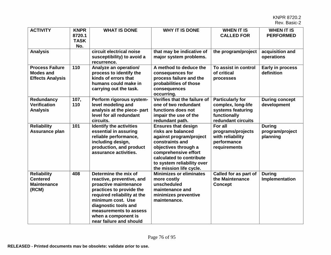
KNPR 8720.2 Rev. Basic-2
Page 76 of 95
ACTIVITY
KNPR 8720.1 TASK No.
WHAT IS DONE WHY IT IS DONE WHEN IT IS CALLED FOR
WHEN IT IS PERFORMED
Analysis circuit electrical noise susceptibility) to avoid a recurrence.
that may be indicative of major system problems.
the program/project acquisition and operations
Process Failure Modes and Effects Analysis
110 Analyze an operation/ process to identify the kinds of errors that humans could make in carrying out the task.
A method to deduce the consequences for process failure and the probabilities of those consequences occurring.
To assist in control of critical processes
Early in process definition
Redundancy Verification Analysis
107, 110
Perform rigorous system-level modeling and analysis at the piece- part level for all redundant circuits.
Verifies that the failure of one of two redundant functions does not impair the use of the redundant path.
Particularly for complex, long-life systems featuring functionally redundant circuits
During concept development
Reliability Assurance plan
101 Identify the activities essential in assuring reliable performance, including design, production, and product assurance activities.
Ensures that design risks are balanced against program/project constraints and objectives through a comprehensive effort calculated to contribute to system reliability over the mission life cycle.
For all programs/projects with reliability performance requirements
During program/project planning
Reliability Centered Maintenance (RCM)
408 Determine the mix of reactive, preventive, and proactive maintenance practices to provide the required reliability at the minimum cost. Use diagnostic tools and measurements to assess when a component is near failure and should
Minimizes or eliminates more costly unscheduled maintenance and minimizes preventive maintenance.
Called for as part of the Maintenance Concept
During Implementation
RELEASED - Printed documents may be obsolete; validate prior to use.

KNPR 8720.2 Rev. Basic-2
Page 77 of 95
ACTIVITY
KNPR 8720.1 TASK No.
WHAT IS DONE WHY IT IS DONE WHEN IT IS CALLED FOR
WHEN IT IS PERFORMED
be replaced.
Reliability Modeling (Prediction/ Allocation)
103, 104, 107
Perform prediction, allocation, and modeling tasks to identify inherent reliability characteristics.
Aids in evaluating the reliability of competing designs.
Mainly for reusable or crewed systems, or where failure rates are needed for tradeoff studies, sparing analysis, etc.
Early in design
Reliability Tradeoff Studies
102 Compare all realistic alternative reliability design approaches against cost, schedule, risk, and performance impacts.
Aids in deriving the optimal set of reliability performance requirements, architectures, baselines, or designs.
Conducted at some level on all systems; predictive techniques may be used
Formulation and Implementation
Reliability and Maintainability Qualification status
501, 502, 503, 504, 505, 506
Summarize and document all testing.
Demonstrates compliance with R&M quantitative requirements.
Appropriate for all hardware programs
During system design and fabrication
Reliability and Maintainability Status Reporting
120, 401
Report the status of the R&M program and development efforts.
Apprises management of the status of the R&M program.
Appropriate for all hardware programs
Prepare during concept development and update throughout the life of the program/project
Sneak Circuit Analysis
114 Methodically identify sneak conditions (unexpected paths or logic flows) in circuits.
Identifies design weaknesses which could inhibit desired functions or initiate undesired functions.
Generally used only on the most safety- or mission-critical equipment
Early in design
Structural Stress 203 Analyze the dynamic Identifies spacecraft When critical During
RELEASED - Printed documents may be obsolete; validate prior to use.
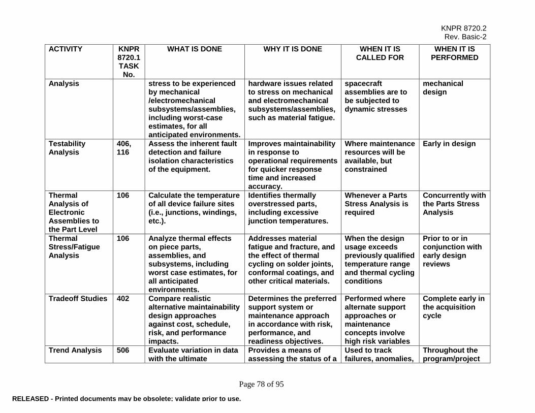
KNPR 8720.2 Rev. Basic-2
Page 78 of 95
ACTIVITY
KNPR 8720.1 TASK No.
WHAT IS DONE WHY IT IS DONE WHEN IT IS CALLED FOR
WHEN IT IS PERFORMED
Analysis stress to be experienced by mechanical /electromechanical subsystems/assemblies, including worst-case estimates, for all anticipated environments.
hardware issues related to stress on mechanical and electromechanical subsystems/assemblies, such as material fatigue.
spacecraft assemblies are to be subjected to dynamic stresses
mechanical design
Testability Analysis
406, 116
Assess the inherent fault detection and failure isolation characteristics of the equipment.
Improves maintainability in response to operational requirements for quicker response time and increased accuracy.
Where maintenance resources will be available, but constrained
Early in design
Thermal Analysis of Electronic Assemblies to the Part Level
106 Calculate the temperature of all device failure sites (i.e., junctions, windings, etc.).
Identifies thermally overstressed parts, including excessive junction temperatures.
Whenever a Parts Stress Analysis is required
Concurrently with the Parts Stress Analysis
Thermal Stress/Fatigue Analysis
106 Analyze thermal effects on piece parts, assemblies, and subsystems, including worst case estimates, for all anticipated environments.
Addresses material fatigue and fracture, and the effect of thermal cycling on solder joints, conformal coatings, and other critical materials.
When the design usage exceeds previously qualified temperature range and thermal cycling conditions
Prior to or in conjunction with early design reviews
Tradeoff Studies 402 Compare realistic alternative maintainability design approaches against cost, schedule, risk, and performance impacts.
Determines the preferred support system or maintenance approach in accordance with risk, performance, and readiness objectives.
Performed where alternate support approaches or maintenance concepts involve high risk variables
Complete early in the acquisition cycle
Trend Analysis 506 Evaluate variation in data with the ultimate
Provides a means of assessing the status of a
Used to track failures, anomalies,
Throughout the program/project
RELEASED - Printed documents may be obsolete; validate prior to use.

KNPR 8720.2 Rev. Basic-2
Page 79 of 95
ACTIVITY
KNPR 8720.1 TASK No.
WHAT IS DONE WHY IT IS DONE WHEN IT IS CALLED FOR
WHEN IT IS PERFORMED
objective of forecasting future events based on examination of past results.
program/project or the maturity of a system or equipment and to predict future performance.
quality processes, delivery dates, etc.
Worst Case Analysis (WCA)
108 Evaluate circuit performance assuming part parameter variations associated with extreme conditions; e.g., long life, temperature, radiation, shock, etc.
Ensures that all circuits will perform within specifications over a given lifetime while experiencing the worst possible variations of electrical piece parts and environments.
Critical flight equipment
During system design
RELEASED - Printed documents may be obsolete; validate prior to use.

KNPR 8720.2 Rev. Basic-2
Page 80 of 95
APPENDIX G. A SAMPLE OF STATEMENT OF WORK REQUIREMENTS FOR A MAJOR ELEMENT OR MISSION SUPPORT CONTRACT (see paragraph 1.3.7 for applicability) 1. GENERAL REQUIREMENTS The contractor may develop, implement, and maintain an effective Reliability, Maintainability, and Quality Assurance (RM&QA) program to satisfy, as a minimum, the requirements of NSTS 5300.4(1D-2), Chapters 1, 3, and 5 and amendments as described below. If a paragraph of NSTS 5300.4(1D-2) is not deleted, modified, or supplemented in the following document, it is applicable to the contract as written. 2. RM&QA PLANS Paragraphs 1D300.2 and 1D500.3 are deleted in their entirety, and the following is substituted: Reliability, Maintainability, and Quality Assurance Program Plan The offeror(s) selected for award of the contract shall submit a detailed RM&QA program plan, which shall be subject to evaluation and approval before incorporation into the contract. This detailed plan shall: a. Have a format so each portion of the plan can be readily identified with each cited RM&QA requirement. b. Serve as master planning and control document for the contractor's RM&QA Program(s). c. Include charts and narrative statements describing each element of contractor's organization (e.g., procurement, engineering, reliability, fabrication, test, safety, and quality assurance) that implements the RM&QA program and detailed statements of duties, functions, and responsibilities relating to each RM&QA program task. The plan shall show the relationship of individuals managing RM&QA functions with each element performing tasks, including authority to control and monitor the cited tasks. d. Include narrative descriptions of the contractor's execution and management of each task. These shall be detailed in terms of when, how and by whom each task will be accomplished. Applicable contractor policies and procedures shall be stated in the plan, either within task paragraphs of the plan or as an appendix or separate section of the plan with cross references to tasks cited. All RM&QA procedures shall be submitted as specified in Data Requirements Document/Data Requirements List (DRD/DRL). e. Include charts indicating the flow of fabrication and assembly operations and related inspection and test points. 3. INTRODUCTION Delete last sentence of 1D102, and all of 1D102.1 through 1D102.6. 4. RELIABILITY a. Paragraph lD300, between 2nd and 3rd sentences, and the following:
RELEASED - Printed documents may be obsolete; validate prior to use.

KNPR 8720.2 Rev. Basic-2
Page 81 of 95
These reviews and analyses may include: (1) System design reviews. (2) Workarounds and alternate modes of operations. (3) Analyses of failed components. (4) Analyses of design changes/modifications accomplished at KSC. b. Paragraph 1D300.3, delete entirely. c. Paragraphs lD300.5a and b are considered applicable at KSC when local purchasing is required as a result of engineering changes and modifications. Procedures for implementing these requirements shall be compatible with those used under development contracts. d. Paragraph 1D301, delete the lead paragraph and substitute the following: The contractor shall accomplish the following reliability engineering tasks: e. Paragraph 1D301.1, add the following: This effort shall be limited to design and specification changes originating at KSC. Reliability analyses shall be in accordance with KSC GP-1040, Design Reliability Analysis Instruction. f. Paragraph 1D301.2, delete entirely. g. Paragraph 1D301.3, change the lead sentence to read as follows: The contractor shall establish a system for the updating and maintenance of development center-supplied Failure Modes and Effects Analysis (FMEAs) and Critical Items Lists (CILs) that may changed as a result of design changes and modifications made at KSC. The system shall be in consonance with development center FMEA/CIL system. h. Paragraph 1D301.3a, delete entirely, and add the following: The contractor may prepare design FMEAs at the lowest level of system definition required to support potential uses (e.g., testing failure reporting, and corrective action, and selection of mandatory inspection points). FMEAs will be prepared to lowest level necessary to pursue all critical functions. Failure modes will be identified to piece part level when they are Criticality 1 or 2. The FMEA shall include an integration of all flight hardware, Government Furnished Equipment (GFE), and critical Ground Support Equipment (GSE). CILs shall be updated according to results of FMEAs. i. Paragraph 1D301.3b, delete entirely. j. Paragraph 1D301.3c, add the following: The contractor shall provide documented evidence that critical items on CILs prepared under development Center contract and updated as required in item h are adequately tested and/or inspected during manufacturing and testing operations.
RELEASED - Printed documents may be obsolete; validate prior to use.
KNPR 8720.2 Rev. Basic-2
Page 82 of 95
k. Paragraph 1D301.4, delete entirely. l. Paragraph 1D301.5, delete entirely and replace with the following: The contractor(s) reliability activities shall support all milestone reviews at KSC. m. Paragraph 1D301.6, delete last sentence from lead-in paragraph and add: The contractor(s) system shall conform to the requirements of the KSC PRACA System. n. Paragraphs 1D301.6a, b, and c delete entirely. o. Paragraph 1D301.7, delete the 3rd and 4th sentences. p. Paragraph 1D301.8 and 1D301.9, delete entirely and add the following: The contractor shall continue an Electronic, Electrical, Electromechanical (EEE) and mechanical parts control program and conduct materials specifications and application reviews; comply with development center contract requirements. q. Paragraph 1D302, delete entirely and substitute the following: The contractor shall participate in KSC verification testing activities as required by the Launch and Landing Verification Test Plan and other associated documents. 5. QUALITY ASSURANCE a. Paragraph 1D500.3, delete and replace as noted in paragraph 2. b. Paragraph lD500.8c, add the following: Summaries of audits, including remedial and preventive action taken, and results of reviews of deficient areas shall be furnished to the cognizant NASA/KSC contractor management and quality organization every six months. c. Paragraph 1D501.1a, add subparagraphs as follows: (1) Technical Procedures Review: Contractors shall review technical operating procedures, as applicable, for the following criteria: (a) Verification of calibration status and personnel certification. (b) Clarity to minimize the possibility of human error. (c) To eliminate characteristics that could compromise quality assurance and reliability functions. (d) For inspection verification of critical actions, steps, or sequences, with system single failure point considerations as applicable. (e) Inclusion of general reliability and/or quality provisions.
RELEASED - Printed documents may be obsolete; validate prior to use.

KNPR 8720.2 Rev. Basic-2
Page 83 of 95
(f) All NASA requirements, such as man-loading system limits, acceptance criteria, special tools, and verification/certification points are identified. A list of contractor acceptance points shall be submitted to NASA/KSC. A list of NASA Mandatory Inspection Points (MIPs) and other requirements will be supplied to the contractor by NASA and revised on a periodic basis to add or delete items as required. (2) Work Authorizing Document Review: As required by GOP 5-1, the contractor shall review task orders, work orders, support requests, or any document that requires the expenditure of labor/materials/ services, and shall record on each document the level of quality inspection required to satisfy contract requirements (i.e., in process and/or end item inspection). The review effort includes incoming as well as outgoing requests. d. Paragraph lD501.1b, add the following: When contractor under authorizing documentation performs work, quality assurance shall verify compliance to this requirement and shall perform those inspections required by the documentation. e. Paragraph 1D503.1, add the following between the first and second sentences: The contractor shall issue purchase orders for flight hardware, critical GSE and spares at KSC. In cases where articles must be locally procured, the contractor shall utilize the KSC qualified vendor and parts list in making selections. The same receiving inspection criteria developed at the contractor's home plant will be used for locally procured hardware. f. Paragraph lD503.4b, add the following: Contractor procurements requiring contractor source inspection may be approved by the cognizant KSC quality organization. g. Paragraph lD503.4c, delete entirely. h. Paragraph 1D503.6; add subparagraph "m" as follows: Articles purchased by the design agency's contractor that have receiving inspection performed at contractor's facility and shipped to KSC will require identification and damage inspection at KSC. i. Paragraph lD503.9b, add the following: Contractor procurement surveys may have prior approval of the cognizant KSC quality organization. j. Paragraph lD503.9c, delete. k. Paragraph lD505.5a, add the following: The contractor's procedures shall define the inspector's authority and method to be used to stop work and/or test due to personnel hazards or possible damage to flight hardware or GSE. l. Paragraph 1D505.6a, add the following:
RELEASED - Printed documents may be obsolete; validate prior to use.

KNPR 8720.2 Rev. Basic-2
Page 84 of 95
All Acceptance Data Packages and other equipment records shall be maintained current and updated continuously. m. Paragraph 1D505.9, add the following: Training and certification requirements for quality assurance designees, implementing procedures, and designated personnel shall be approved by the cognizant KSC quality organization prior to implementation. n. Paragraph 1D505.10, add the following: These controls shall preclude the entrance of unauthorized materials, tools, and personnel into specified test and checkout areas. o. Paragraph 1D505-12, change to read as follows: Integrity Control. Transportation services as outlined in KHB 6000.1 shall be used by the contractor to ensure that the hardware is not jeopardized through such operations as unpacking, receiving, inspection, storage, testing, installation, shipping, scheduled and unscheduled maintenance, operations, modifications and repairs. Positive controls shall be established, documented, and maintained by the contractor to ensure serviceability seals and tags will be used to indicate the condition of equipment not installed in a system or subsystem, to seal segments of installed systems from which portions have been removed, to indicate status of the remaining installed equipment, and to seal controls, covers, doors, etc., of equipment to provide an indication of the entry into or possible alteration of equipment. p. Paragraph 1D506.1, add the following: The Withhold Tag shall be used in identifying serious defects or unsafe conditions requiring immediate corrective action. The Withholding Tag is red in color and alerts personnel working on equipment of the existence of a serious problem. The contractor shall maintain a system to identify conditions such as: (1) Equipment overdue for calibration. (2) Unauthorized breaks of integrity. (3) Safety hazards. (4) Unauthorized work (additions/removals) that has changed the basic configuration. q. Paragraph lD507.6a, delete and substitute the following: The contractor shall use the services of the KSC Calibration and Standards Laboratory for the calibration of portable equipment and standards. r. Paragraph ID509.6, add the following: The contractor shall furnish packing and packaging instructions to NASA/KSC support contractors when requested.
RELEASED - Printed documents may be obsolete; validate prior to use.

KNPR 8720.2 Rev. Basic-2
Page 85 of 95
s. Paragraph 1D510.1, delete the second and third sentences and substitute the following: Sampling inspection plans and/or procedures shall not be employed by the contractor to determine quality conformance of articles and/or services furnished under contract without prior approval of the cognizant KSC NASA quality organization. t. Paragraph 1D512, delete entirely. u. Add new paragraph, lD513r Government-Industry Data Exchange Program (GIDEP), as follows: The contractor shall develop and implement a GIDEP system that conforms to the requirements of KNPD 5310.1. v. Add new paragraph ID514, as follows: 1D514. Parts and Materials Control 1. The contractor shall assure that a physical separation of parts and materials is maintained to provide, as a minimum, separation of: a. Parts and materials awaiting inspection or acceptance test results. b. Parts and materials acceptable for stock. c. Rejected items being held pending disposition. d. Bulk hardware common to flight hardware and GSE, which is controlled by the assignment of lot numbers. 2. The contractor shall establish and maintain a system for the identification and control of non-flight hardware in accordance with NASA/KSC requirements and JSCM 8080, STD. 99B. Shuttle flight critical hardware and Shuttle Safety Critical GSE shall be controlled in accordance with JSCM 8080, STD. 86.
RELEASED - Printed documents may be obsolete; validate prior to use.

KNPR 8720.2 Rev. Basic-2
Page 86 of 95
APPENDIX H. SAMPLE OF RELIABILITY AND MAINTAINABILITY REQUIREMENTS APPLIED TO A CONTRACT This appendix provides sample contract sections showing how the portions of the contract flow to establish technical requirements, specify appropriate tasks, request deliverable documents, and to specify the content and schedule for the deliverable products. This information is provided solely as an example for SMA personnel in order to ensure that a consistent approach is applied throughout the SMA portion of the contract Statement of Work. 1.0 Guideline Documents The current revisions of the following documents are to be used as guidelines to the extent specified in this SOW: Document No. - Revision - Document Title - Date NPR 7150.2, NASA Software Engineering Requirements NPD 7500.1, Program and Projects Logistics Policy NPD 8700.1, NASA Policy for Safety and Mission Success NPD 8700.3, Safety and Mission Assurance (SMA) Policy for NASA Spacecraft, Instruments, and Launch Services NPR 8705.2, Human-Rating Requirements for Space Systems NPR 8705.4, Risk Classification for NASA Payloads NPR 8705.5, Probabilistic Risk Assessment (PRA) Procedures for NASA Programs and Projects NPR 8705.6, Safety and Mission Assurance Audits, Reviews, and Assessments NPR 8715.3, NASA General Safety program Requirements NPD 8720.1, NASA Reliability and Maintainability (R&M) Program Policy KNPR 8720.1 KSC Reliability and Maintainability Procedural Requirements NPD 8730.1, Metrology and Calibration NPD 8730.2, NASA Parts Policy NPR 8735.1, Procedures for Exchanging Parts, Materials, and Safety Problem Data Utilizing the Government-Industry Data Exchange Program and NASA Advisories NPR 8735.2, Management of Government Quality Assurance Functions for NASA Contracts (Un-numbered) Probabilistic Risk Assessment Procedures Guide for NASA Managers and Practitioners, August 2002
RELEASED - Printed documents may be obsolete; validate prior to use.

KNPR 8720.2 Rev. Basic-2
Page 87 of 95
NASA-STD-8729.1, Planning, Developing, and Managing an Effective Reliability and Maintainability (R&M) Program NASA-STD-8739.8, Software Assurance Standard NASA-STD-7001, Payload Vibroacoustic test Criteria NASA-STD-7002, Payload Test Requirements NASA-STD-7003, Pyroshock Test Criteria Statement of Work 2.0 Reliability and Maintainability Program Plans 2.1 The contractor shall develop a Reliability Plan which ensures that the contractors Reliability program covers the following elements:
a. Model systems in order to predict their reliability and to allocate system reliability goals to the subsystem and component level for reliability design implementation.
b. Develop reliability design criteria to guide the design group in meeting the reliability requirements for the equipment.
c. Perform systematic analyses of the local and system effects of specific component failure modes and evaluate the mission criticality of each failure mode.
d. Systematically identify all possible causes leading to system, subsystem, or component failures or undesirable events or end-states.
e. Demonstrate design margins in electronic and electrical circuits and electromechanical and mechanical items.
f. Identify and assess the risk of low-probability, high-consequence events that might compromise safety or mission success in complex technological systems for which limited statistical data exist.
g. Monitor over time or cycles, the change in the reliability of a system resulting from the identification and correction of failure modes.
h. Analyze test data for systems, subsystems, and components to determine, verify, or demonstrate their reliability characteristics.
i. Analyze over time or cycles, the occurrence of events affecting system reliability in order to detect the presence of adverse trends so that corrective action can be taken.
2.2 The contractor shall develop a Maintainability Plan which ensures that the contractor’s program covers the following elements: Establishing Maintainability Program Requirements and Maintenance Concept; Maintainability Modeling; Maintainability Allocation; Maintainability Design Criteria; Maintainability Predictions; and Human Factors Analysis.
RELEASED - Printed documents may be obsolete; validate prior to use.

KNPR 8720.2 Rev. Basic-2
Page 88 of 95
Attachment D 2 Contract Data Requirements List CDRL The Contract Data Requirements List (CDRL) identifies critical elements of the contracted effort where NASA requires aspects of mission integration insight and approval. The following CDRL defines the scope of documentation required; however, NASA will utilize the Contractor’s existing documentation to the extent practicable.
Item Document Approval/ Review
Initial Submittal Date
Subsequent Submittal date
No. of Copies
DI-X-00X Documentation Requirements
DI-R-001
Reliability Plan Approval Preliminary Design Review
Critical Design Review/as changed
5
DI-M-001
Maintainability Plan Approval Preliminary Design Review
Critical Design Review/as changed
5
The following Data Requirements Documents are guidelines for requesting data specified in the CDRL. The use of this format is not mandatory but provides a consistent approach for specifying structure, content, and schedule for the applicable data to be delivered in support of the requirements stated in the contract SOW. 1. DRD/DID NO.: DI-R-001 2. TITLE: Reliability Program Plan 3. OPR: Safety and Mission Assurance 4. SUBMISSION FREQUENCY: As updated 5. INITIAL SUBMISSION: Preliminary Design Review 6. DISTRIBUTION: Contracts Library, 1 Copy; Safety and Mission Assurance, 3 copies; Project library, 1copy. 7. DESCRIPTION/USE/PURPOSE: This will serve as the master planning and control document for the contractor's reliability program. Contractor progress will be assessed against the schedules and milestones defined in the plan. 8. REFERENCES: a. NPD 8720.1, NASA Reliability and Maintainability (R&M) Program Policy. b. NASA-STD-8729.1, Planning, Developing and Managing an Effective Reliability and Maintainability (R&M) Program. c. MIL-STD-785, Reliability Modeling and Prediction
RELEASED - Printed documents may be obsolete; validate prior to use.

KNPR 8720.2 Rev. Basic-2
Page 89 of 95
9. INTERRELATIONSHIP/RELATED DOCUMENTS: This document may be combined with the Parts, Materials, and Processes Program Plan (Task 201), the Software Program Plan (Task 301), and the Maintainability Program Plan (Task 401) at the contractor's discretion to provide an integrated Product Assurance Program Plan. 10. PREPARATION INFORMATION: a. SCOPE: The plan shall cover the hardware, software, and any services specified in the Statement of Work (SOW). b. FORMAT: Contractor's format is acceptable, provided that the document permits correlation between the SOW requirements and the Plan response c. CONTENTS: The plan shall provide: (1) A discussion of how the contractor intends to implement and comply with Reliability program requirements. (2) Include charts and narrative descriptions of each element of the contractor’s organization (e.g., procurement, engineering, fabrication, test, Reliability and Maintainability) and detailed statements of duties, responsibilities, and functions relating to each reliability program task. The plan shall show the relationship between these organizational elements and individuals responsible for managing reliability program tasks and having authority to monitor and control cited tasks. (3) A summary (matrix or other brief form), which indicates for each requirement, the organization responsible for implementing the task, the resources allocated, and the responsibility for generating the necessary documents. Identify in the summary the approval, oversight, or review authority (see below), as appropriate, for each task. (4) Describe the contractor's approach to performance and management of each task. These shall be described in terms of when (start-stop dates or milestones), by which organizations, by which methods each task will be accomplished, and the criteria for task acceptability. (5) Existing and required new contractor policies, directives, methods, and procedures specific to each task in the plan shall be referenced in the plan, either within the text or as an appendix showing cross-references to tasks. (6) The plan shall define the reliability support to scheduled reviews and audits. For each scheduled review, the plan shall define the reports to be submitted and any necessary corrective action procedures. (7) The plan shall define the reliability participation in the integrated test program, and describe the testing to be accomplished and the data analysis techniques to be employed in accordance with the SOW requirements. (8) The Plan shall describe any known reliability problems to be solved and provide an assessment of the impact of such problems on the reliability program, and the proposed solutions to these problems.
RELEASED - Printed documents may be obsolete; validate prior to use.
KNPR 8720.2 Rev. Basic-2
Page 90 of 95
(9) The plan shall describe the interdisciplinary coordination between the various contractor elements, and an effective communication and coordination process. (10) The plan shall address reliability training and indoctrination to assure that program personnel responsible for system hardware are aware of the reliability requirements, and are indoctrinated in the methods and tasks required to achieve these objectives. The plan shall also address training for any tasks that are unique to this development effort. (11) The plan shall delineate those supplies and services to be provided by subcontractors and suppliers, and the extent of the reliability program requirements deemed to be applicable. The contractor shall require management and control of subcontractor and supplier reliability activities, (12) The Plan shall provide for periodic reporting of the Reliability Program progress, including activities scheduled and status of accomplishment, and a listing of subsystem reliability allocations and current predicted values. d. MAINTENANCE: 1. DRD/DID NO.: DI-M-001 2. TITLE: Maintainability Program Plan 3. OPR: Safety and Mission Assurance 4. SUBMISSION FREQUENCY: As updated 5. INITIAL SUBMISSION: Preliminary Design Review 6. DISTRIBUTION: KSC Contracts Library, 1 Copy; Safety and Mission Assurance, 3 copies; Project library, 1copy. 7. DESCRIPTION/USE/PURPOSE: This will serve as the master planning and control document for the contractor's maintainability program. Contractor progress will be assessed against the schedules and milestones defined in the plan. The Maintainability Program Plan may be a standalone plan, may be combined with the program/project Reliability Plan, or may be included as part of the program/project Safety and Mission Assurance Plan. 8. REFERENCES: a. NPD 8720.1, NASA Reliability and Maintainability (R&M) Program Policy. b. NASA-STD-8729.1, Planning, Developing and Managing an Effective Reliability and Maintainability (R&M) Program. 9. INTERRELATIONSHIP/RELATED DOCUMENTS: MIL-HDBK-470, Designing and Developing Maintainable Products and Systems 10. PREPARATION INFORMATION:
RELEASED - Printed documents may be obsolete; validate prior to use.

KNPR 8720.2 Rev. Basic-2
Page 91 of 95
a. SCOPE: The Maintainability Program Plan shall address the hardware, software, and any services specified in the Statement of Work (SOW). b. FORMAT: Contractor's format is acceptable. c. CONTENTS: The Maintainability Plan shall provide: (1) A discussion of how the contractor intends to implement and comply with Maintainability program requirements. (2) Include charts and narrative descriptions of each element of the contractor’s organization (e.g., procurement, engineering, fabrication, test, Reliability and Maintainability) and detailed statements of duties, responsibilities, and functions relating to each maintainability program task. The plan shall show the relationship between these organizational elements and individuals responsible for managing maintainability program tasks and having authority to monitor and control cited tasks. (3) A summary (matrix or other brief form), which indicates for each requirement, the organization responsible for implementing the task, the resources allocated, and the responsibility for generating the necessary documents. Identify in the summary the approval, oversight, or review authority, as appropriate, for each task. (4) Describe the contractor's approach to performance and management of each task. These shall be described in terms of when (start-stop dates or milestones), by which organizations, by which methods each task will be accomplished, and the criteria for task acceptability. (5) Existing and required new contractor policies, directives, methods, and procedures specific to each task in the plan shall be referenced in the plan, either within the text or as an appendix showing cross-references to tasks. (6) The plan shall define the maintainability support to scheduled reviews and audits. For each scheduled review, the plan shall define the reports to be submitted and any necessary corrective action procedures. (7) The plan shall define the maintainability participation in the integrated test program, and describe the testing to be accomplished and the data analysis techniques to be employed in accordance with the SOW requirements. (8) The Plan shall describe any known maintainability problems to be solved and provide an assessment of the impact of such problems on the maintainability program, and the proposed solutions to these problems. (9) The plan shall describe the interdisciplinary coordination between the various contractor elements, and an effective communication and coordination process. (10) The plan shall address maintainability training and indoctrination to assure that program personnel responsible for system hardware are aware of the maintainability requirements, and are indoctrinated in the methods and tasks required to achieve these objectives. The plan shall also address training for any tasks that are unique to this development effort. (11) The plan shall delineate those supplies and services to be provided by subcontractors and suppliers, and the extent of the maintainability program requirements deemed to be applicable.
RELEASED - Printed documents may be obsolete; validate prior to use.
KNPR 8720.2 Rev. Basic-2
Page 92 of 95
The contractor shall require management and control of subcontractor and supplier maintainability activities, (12) The Plan shall provide for periodic reporting of the Maintainability Program progress, including activities scheduled and status of accomplishment, and a listing of subsystem Maintainability allocations and current predicted values. d. MAINTENANCE:
RELEASED - Printed documents may be obsolete; validate prior to use.
KNPR 8720.2 Rev. Basic-2
Page 93 of 95
APPENDIX I. GUIDELINES FOR THE SELECTION, APPLICATION, AND TESTING OF COMMERCIAL OFF-THE SHELF (COTS) This appendix provides guidelines for the selection, application, and testing of COTS. Guidelines for the Selection, Application, and Testing of Commercial Off-the-Shelf (COTS) The nature of “off-the-shelf’ hardware (parts/assemblies) is that most quality assurance provisions are pre-established and are not responsive to requirements. Additionally, an item designed for one environment may not be suitable for another. This risk must be addressed in selecting COTS. Therefore, selection and procurement of COTS hardware (component, circuit board, subsystem, etc.) must be evaluated against the specific application to insure that the COTS hardware quality and reliability level is commensurate with the mission environment and requirements. When there is a need for the procurement of COTS hardware, the following steps should be followed: 1. Application: a. Evaluate system to determine critical or non-critical applications. b. Evaluate system concept (performance, availability, etc), life cycle/mission profile (transportation and storage, operation mode and sequences, duration, etc), and environmental conditions (temperature extremes, humidity, shock, vibration, radiation). c. For critical applications: (1) Perform reliability analysis. (2) Consider redundant architecture. 2. Testing/Qualification: a. Base on the environmental and mission profile requirements, develop an appropriate test & qualification program (testing/qualification for components/black boxes and FMEAs for subsystems). b. COTS shall also be tested in accordance to its operational/mission profile environment. Tests such as acoustic, vibration, shock, pressure, thermal, and accelerated life shall be performed when applicable.
3. Vendor Selection: a. Determine authorized vendor sources b. Review approved supplier quality listings to determine existing acceptability of any potential vendor. c. Investigate vendors’ quality practice (Audits), test data, failure data, etc. d. Are good design, workmanship, quality control practices in place?
RELEASED - Printed documents may be obsolete; validate prior to use.
KNPR 8720.2 Rev. Basic-2
Page 94 of 95
e. Work with vendors to modify/upgrade parts with higher reliability parts, if necessary. f. Evaluate COTS for lifecycle obsolescence and required logistic spares for the project life cycle. 4. Additional NASA information: NASA Electronic Parts and Packaging Program (NEPP) generates technical knowledge and recommendations about electrical, electronic, electromechanical (EEE) and photonic part performance, application, failure modes, test methods, reliability and supply chain quality within the context of NASA space flight missions and hardware. This information is made available to the NASA and high-reliability aerospace community through publications, web pages and links published on this website. NEPP is sponsored by the Office of Safety and Mission Assurance and is executed by the NASA Goddard Space Flight Center. (Website: http://nepp.nasa.gov)
RELEASED - Printed documents may be obsolete; validate prior to use.

KNPR 8720.2 Rev. Basic-2
Page 95 of 95
APPENDIX J. AVAILABILITY This appendix describes the relationship between Availability, Reliability, Maintainability, and Logistic Support. Availability - The probability that an item will be in an operable and committable state at the start of a mission when the mission is called for at a random time. Availability is generally defined as uptime divided by downtime; the specific definitions are provided below and illustrated in the following Table: Availability, Inherent (Ai) - The probability that an item will operate satisfactorily at a given point in time when used under stated conditions in an ideal support environment. It excludes logistics time, waiting or administrative downtime, and preventive maintenance downtime. It includes corrective maintenance downtime. Inherent availability is generally derived from analysis of an engineering design and is calculated as the mean time between failures (MTBF) divided by the mean time between failures plus the mean time to repair (MTTR). It is based on quantities under the control of the designer.
Availability, Achieved - The probability that an item will operate satisfactorily at a given point in time when used under stated conditions in an ideal support environment (i.e., that personnel, tools, spares, etc. are instantaneously available). It excludes logistics time and waiting or administrative downtime. It includes active preventive and corrective maintenance downtime.
Availability, Operational (Ao) - The probability that an item will operate satisfactorily at a given point in time when used in an actual or realistic operating and support environment. It includes logistics time, ready time, and waiting or administrative downtime, and both preventive and corrective maintenance downtime. This value is equal to the mean time between failures (MTBF) divided by the mean time between failures plus the mean downtime (MDT). This measure extends the definition of availability to elements controlled by the logisticians and mission planners such as quantity and proximity of spares to the hardware item. Table Q-1. Availability Definitions and Factors
AVAILABILITY TYPE
MTBF ACTIVE CORRECTIVE
MAINTENANCE
PREVENTIVE MAINTENANCE
LOGISTICS DOWNTIME
ADMINISTRATIVE DOWNTIME
Inherent x x
Achieved x x x
Operational x x x x x
Thus, when establishing the R&M requirements for maintainable systems, availability can be optimized by the proper trade-offs between Reliability, Maintainability, and the Logistics Program. Availability is a consideration, even for non-maintainable systems, since failures during launch preparations and launch-pad failures can result in expensive launch delays. Ease of maintenance can minimize such launch-delay costs.
RELEASED - Printed documents may be obsolete; validate prior to use.