Krohne Waterflux 3000 Brochure - Incledon Watermeters/5 Krohne Waterflux... · WATERFLUX 3000...
24
WATERFLUX 3000 WATERFLUX 3000 WATERFLUX 3000 WATERFLUX 3000 Technical Datasheet Technical Datasheet Technical Datasheet Technical Datasheet Electromagnetic flow / water meter • Engineered and manufactured for the water and wastewater industry • All relevant approvals for potable water • Long time reliability and durability © KROHNE 04/2009 - 4000572001 - TD WATERFLUX 3000 R01 en
Transcript of Krohne Waterflux 3000 Brochure - Incledon Watermeters/5 Krohne Waterflux... · WATERFLUX 3000...
WATERFLUX 3000WATERFLUX 3000WATERFLUX 3000WATERFLUX 3000 Technical DatasheetTechnical DatasheetTechnical DatasheetTechnical Datasheet
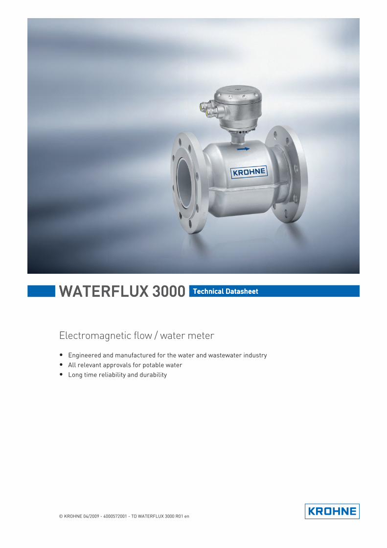
Electromagnetic flow / water meter
• Engineered and manufactured for the water and wastewater industry• All relevant approvals for potable water• Long time reliability and durability
© KROHNE 04/2009 - 4000572001 - TD WATERFLUX 3000 R01 en

CONTENTS
2 www.krohne.com 04/2009 - 4000572001 - TD WATERFLUX 3000 R01 en
WATERFLUX 3000
1 Product features 3
1.1 The battery powered water meter ................................................................................... 31.2 Options.............................................................................................................................. 51.3 Measuring principle.......................................................................................................... 7
2 Technical data 8
2.1 Technnical data ................................................................................................................ 82.2 Dimensions and weights ................................................................................................ 122.3 Measuring accuracy ....................................................................................................... 142.4 Vacuum load ................................................................................................................... 15
3 Installation 16
3.1 Notes on installation ...................................................................................................... 163.2 Inlet and outlet ............................................................................................................... 163.3 Mounting position ........................................................................................................... 163.4 Flange deviation ............................................................................................................. 173.5 T-section......................................................................................................................... 173.6 Vibration.......................................................................................................................... 173.7 Magnetic field ................................................................................................................. 183.8 Bends .............................................................................................................................. 183.9 Open discharge............................................................................................................... 193.10 Control valve................................................................................................................. 193.11 Air venting..................................................................................................................... 193.12 Pump............................................................................................................................. 20
4 Electrical connections 21
4.1 Safety instructions.......................................................................................................... 214.2 Grounding ....................................................................................................................... 214.3 Connection of signal cable ............................................................................................. 22
5 Notes 23
PRODUCT FEATURES 1
3
WATERFLUX 3000
www.krohne.com04/2009 - 4000572001 - TD WATERFLUX 3000 R01 en
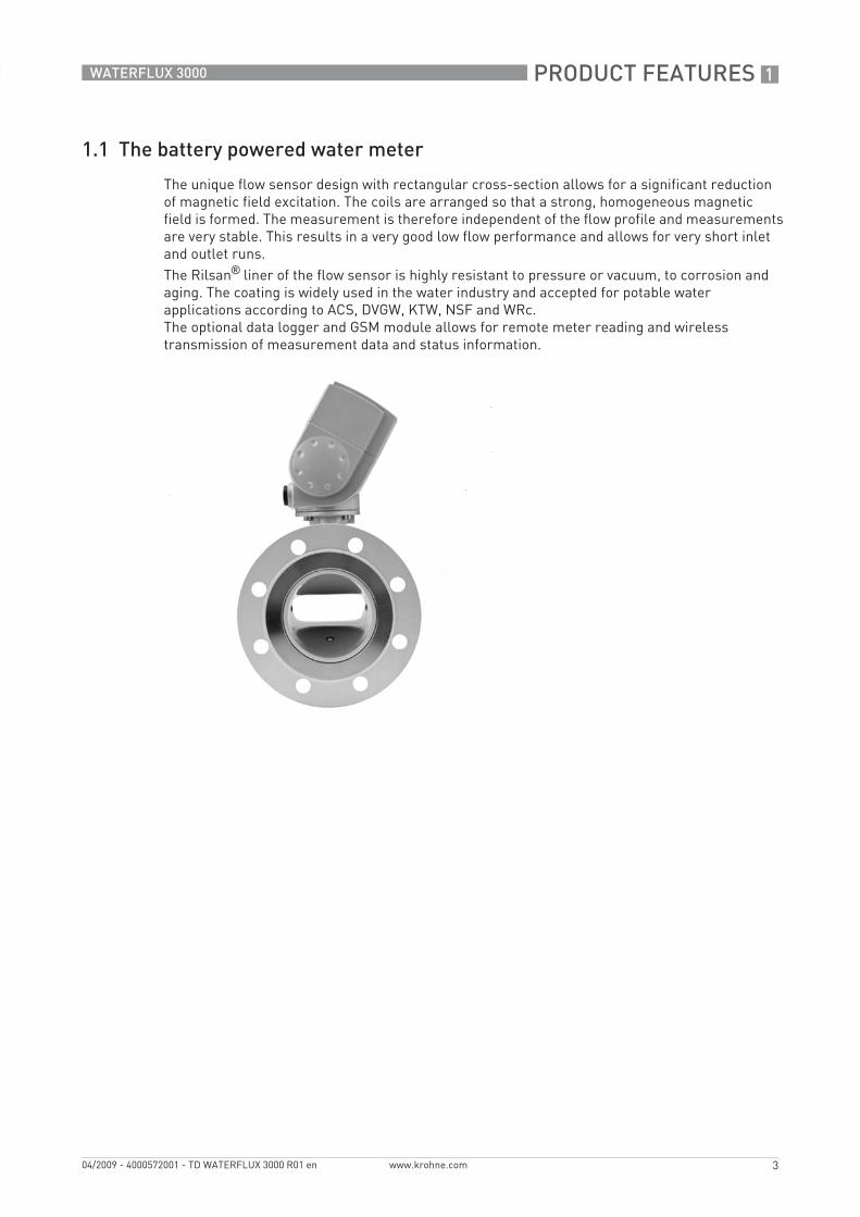
1.1 The battery powered water meter
The unique flow sensor design with rectangular cross-section allows for a significant reduction of magnetic field excitation. The coils are arranged so that a strong, homogeneous magnetic field is formed. The measurement is therefore independent of the flow profile and measurements are very stable. This results in a very good low flow performance and allows for very short inlet and outlet runs.The Rilsan® liner of the flow sensor is highly resistant to pressure or vacuum, to corrosion and aging. The coating is widely used in the water industry and accepted for potable water applications according to ACS, DVGW, KTW, NSF and WRc.The optional data logger and GSM module allows for remote meter reading and wireless transmission of measurement data and status information.

1 PRODUCT FEATURES
4
WATERFLUX 3000
www.krohne.com 04/2009 - 4000572001 - TD WATERFLUX 3000 R01 en
Highlights• Battery operated, stand alone water meter; battery life up to 15 years• Excellent performance in low flow conditions and over wide flow range• Easy installation, short inlet and outlet runs, no filters and bi-directional flow• Buriable (IP68), installation in chambers is not required• Maintenance free operation, no moving parts, no wear and obstruction free• Optional battery powered data logger / GSM module for remote data transfer
Industries• Water abstraction• Distribution of potable water• Irrigation
Applications• Raw water, potable water, irrigation water• Well chambers• Water revenue metering for accurate billing• Monitoring of distribution networks• Pipeline leak detection• Measuring water consumption

PRODUCT FEATURES 1
5
WATERFLUX 3000
www.krohne.com04/2009 - 4000572001 - TD WATERFLUX 3000 R01 en
1.2 Options
ConstructionConstructionConstructionConstructionThe measuring tube of the sensor has a specific shape, transient from round to rectangular and back to round. This design, consisting of an obstruction less cross section (no internal or moving parts) and a homogeneous magnetic field, provides reliable measurements that are largely independent of the flow profile. This design allows the sensor to measure the flow bidirectional. As an additional benefit, it optimizes the precision of the measurement results, thanks to high sampling rates. The power consumption is minimal; an indispensable advantage, for example during night time operation. In addition, the required straight inlet and outlet runs are minimum. The liner of the measuring tube is made of Rilsan® or hard rubber and is resistant to corrosion, aging and abrasion. As a result, this meter is a water meter in accordance with all common drinking water approvals. The surface and shape of the measuring tube also minimize mineral deposits, resulting in exemplary measurement quality - even over the long term.
Design and performanceDesign and performanceDesign and performanceDesign and performanceElectromagnetic water meters have many important advantages over their mechanical counterparts: outstanding long-term stability, maximum process reliability, no maintenance - to name just a few. As a result, these meters can deliver precise and reliable measurements for many years. The water meter has extensive factory-set diagnostic functions that provide continuous self diagnosis in accordance with the applicable standards such as OIML R-49, EN 14154, ISO 4064 and MI-001. Converter operation is also monitored continuously, as are the sensor electrodes and electronic functions. Malfunctions and irregularities are detected and immediately displayed on the high contrast, high-resolution display.
1 PRODUCT FEATURES
6
WATERFLUX 3000
www.krohne.com 04/2009 - 4000572001 - TD WATERFLUX 3000 R01 en
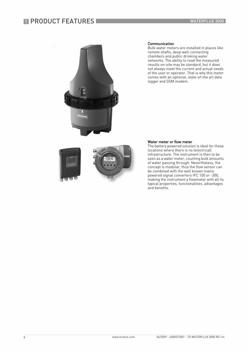
CommunicationCommunicationCommunicationCommunicationBulk water meters are installed in places like remote shafts, deep well-connecting chambers and public drinking water networks. The ability to read the measured results on-site may be standard, but it does not always meet the current and actual needs of the user or operator. That is why this meter comes with an optional, state-of-the art data logger and GSM modem.
Water meter or flow meterWater meter or flow meterWater meter or flow meterWater meter or flow meterThe battery powered solution is ideal for those locations where there is no (electrical) infrastructure. The instrument is then to be seen as a water meter, counting bulk amounts of water passing through. Nevertheless, the concept is modular, thus the flow sensor can be combined with the well known mains powered signal converters IFC 100 or -300, making the instrument a flowmeter with all its typical properties, functionalities, advantages and benefits.

PRODUCT FEATURES 1
7
WATERFLUX 3000
www.krohne.com04/2009 - 4000572001 - TD WATERFLUX 3000 R01 en
1.3 Measuring principle
An electrically conductive fluid flows inside an electrically insulating pipe through a magnetic field. This magnetic field is generated by a current, flowing through a pair of field coils. Inside of the fluid, a voltage U is generated:U = v * k * B * DU = v * k * B * DU = v * k * B * DU = v * k * B * D
in which:v = mean flow velocityk = factor correcting for geometryB = magnetic field strengthD = inner diameter of flow meter
The signal voltage U is picked off by electrodes and is proportional to the mean flow velocity v and thus the flow rate q. The signal voltage is quite small (typically 1 mV at v = 3 m/s / 10 ft/s and field coil power of 1 W). Finally, a signal converter is used to amplify the signal voltage, filter it (separate from noise) and convert it into signals for totalising, recording and output processing.
1 Voltage (induced voltage proportional to flow velocity)2 Electrodes3 Magnetic field4 Field coils
2 TECHNICAL DATA
8
WATERFLUX 3000
www.krohne.com 04/2009 - 4000572001 - TD WATERFLUX 3000 R01 en
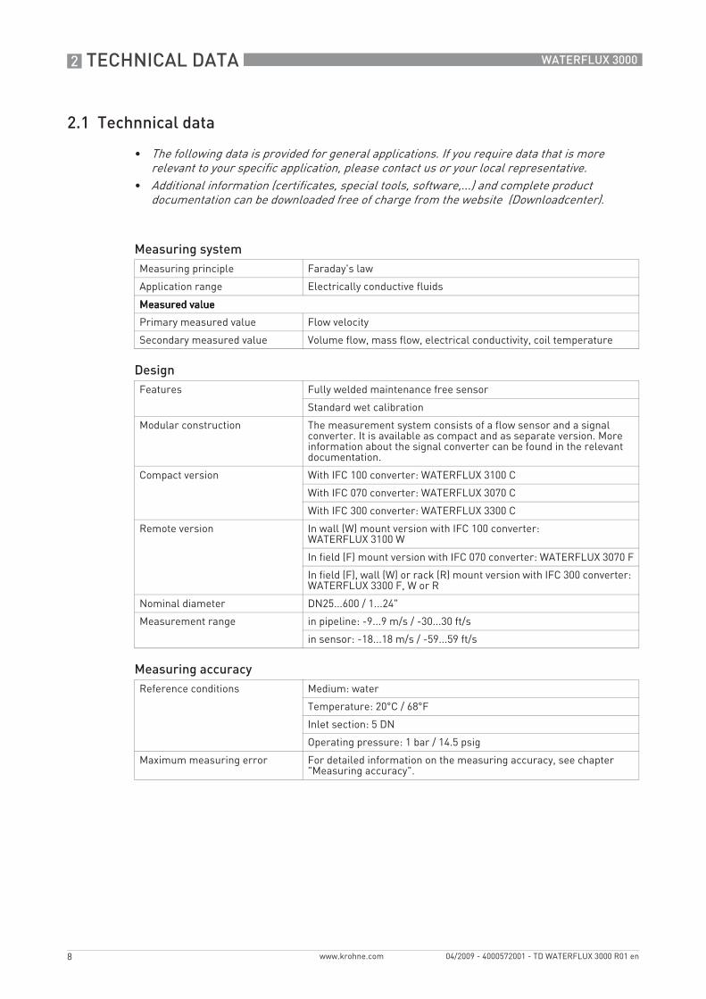
2.1 Technnical data
• The following data is provided for general applications. If you require data that is more relevant to your specific application, please contact us or your local representative.
• Additional information (certificates, special tools, software,...) and complete product documentation can be downloaded free of charge from the website (Downloadcenter).
Measuring systemMeasuring principle Faraday's law
Application range Electrically conductive fluids
Measured valueMeasured valueMeasured valueMeasured value
Primary measured value Flow velocity
Secondary measured value Volume flow, mass flow, electrical conductivity, coil temperature
DesignFeatures Fully welded maintenance free sensor
Standard wet calibration
Modular construction The measurement system consists of a flow sensor and a signal converter. It is available as compact and as separate version. More information about the signal converter can be found in the relevant documentation.
Compact version With IFC 100 converter: WATERFLUX 3100 C
With IFC 070 converter: WATERFLUX 3070 C
With IFC 300 converter: WATERFLUX 3300 C
Remote version In wall (W) mount version with IFC 100 converter: WATERFLUX 3100 W
In field (F) mount version with IFC 070 converter: WATERFLUX 3070 F
In field (F), wall (W) or rack (R) mount version with IFC 300 converter: WATERFLUX 3300 F, W or R
Nominal diameter DN25...600 / 1...24"
Measurement range in pipeline: -9...9 m/s / -30...30 ft/s
in sensor: -18...18 m/s / -59...59 ft/s
Measuring accuracyReference conditions Medium: water
Temperature: 20°C / 68°F
Inlet section: 5 DN
Operating pressure: 1 bar / 14.5 psig
Maximum measuring error For detailed information on the measuring accuracy, see chapter "Measuring accuracy".

TECHNICAL DATA 2
9
WATERFLUX 3000
www.krohne.com04/2009 - 4000572001 - TD WATERFLUX 3000 R01 en
Operating conditionsTemperatureTemperatureTemperatureTemperature
Process temperature Rilsan liner: -5...+70°C / +23...+158°F
Hard rubber liner: -5...+80°C / +23...+176°F
Ambient temperature -40…+65°C / -40…+149°F
Storage temperature -50…+70°C / -58…+158°F
PressurePressurePressurePressure
Ambient Atmospheric
Nominal flange pressure up to PN16
DIN (EN 1092-1) PN10 for DN200...600
PN16 for DN25...150
ISO insertion length StandardStandardStandardStandard
DN25...200 / ASME 1...8"
DN300 / ASME 12"
DN400...600 / ASME 16...24"
OptionOptionOptionOption
DN250 / ASME 10"
DN350 / ASME 14"
ASME B16.5 150 lbs RF for ASME1...24"
Vacuum load For information on pressure limits depending on liner material see chapter "Vacuum load".
Chemical propertiesChemical propertiesChemical propertiesChemical properties
Physical condition Liquids
Electrical conductivity ≥ 20 μS/cm
Recommended flow velocity in pipeline: -9...9 m/s / -30...30 ft/s
in sensor: -18...18 m/s / -59...59 ft/s
Other conditionsOther conditionsOther conditionsOther conditions
Protection category acc. to IEC 529 / EN 60529
StandardStandardStandardStandard
IP 66/67 (NEMA 4/4X/6)
OptionalOptionalOptionalOptional
IP 68 field (NEMA 6P)
IP 68 factory (NEMA 6P)
IP68 is only available with a stainless steel connection box.
Vibration resistance IEC 68-2-3

2 TECHNICAL DATA
10
WATERFLUX 3000
www.krohne.com 04/2009 - 4000572001 - TD WATERFLUX 3000 R01 en
Installation conditionsInstallation For detailed information see chapter "Installation"
Inlet run ≥ 3DN
Outlet run ≥ 1DN
Dimensions and weights For detailed information see chapter "Dimensions and weights".
MaterialsSensor housing Sheet steel, polyurethane coated
Measuring tube Non-magnetic alloy
Flanges Standard: steel 1.0460 / 1.0038 (RSt37-2)
Liner DN50...300: Rilsan
DN350...600: Hard rubber
Connection box (remote versions only)
Standard: Die-cast aluminium, polyurethane coated
Option: stainless steel
Measuring electrodes Stainless steel 1.4301 / AISI 304
Other materials on request
Grounding electrode Stainless steel 1.4301 / AISI 304
Other materials on request
Process connectionsDIN DN25...600 in PN 10...16
ASME 1...24" in 150 lbs
JIS DN25...600 in JIS 10 K
For information on available combinations of nominal flange pressure and nominal diameter see chapter "Dimensions and weights".
Electrical connectionsElectrical connections For full details, including: power supply, power consumption etc., see
technical data for the relevant converter.
I/O For full details of I/O options, including data streams and protocols, see technical data for the relevant converter.
TECHNICAL DATA 2
11
WATERFLUX 3000
www.krohne.com04/2009 - 4000572001 - TD WATERFLUX 3000 R01 en
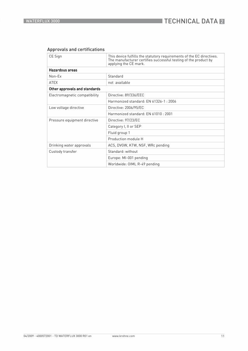
Approvals and certificationsCE Sign This device fulfills the statutory requirements of the EC directives.
The manufacturer certifies successful testing of the product by applying the CE mark.
Hazardous areasHazardous areasHazardous areasHazardous areas
Non-Ex Standard
ATEX not available
Other approvals and standardsOther approvals and standardsOther approvals and standardsOther approvals and standards
Electromagnetic compatibility Directive: 89/336/EEC
Harmonized standard: EN 61326-1 : 2006
Low voltage directive Directive: 2006/95/EC
Harmonized standard: EN 61010 : 2001
Pressure equipment directive Directive: 97/23/EC
Category I, II or SEP
Fluid group 1
Production module H
Drinking water approvals ACS, DVGW, KTW, NSF, WRc pending
Custody transfer Standard: without
Europe: MI-001 pending
Worldwide: OIML R-49 pending
2 TECHNICAL DATA
12
WATERFLUX 3000
www.krohne.com 04/2009 - 4000572001 - TD WATERFLUX 3000 R01 en
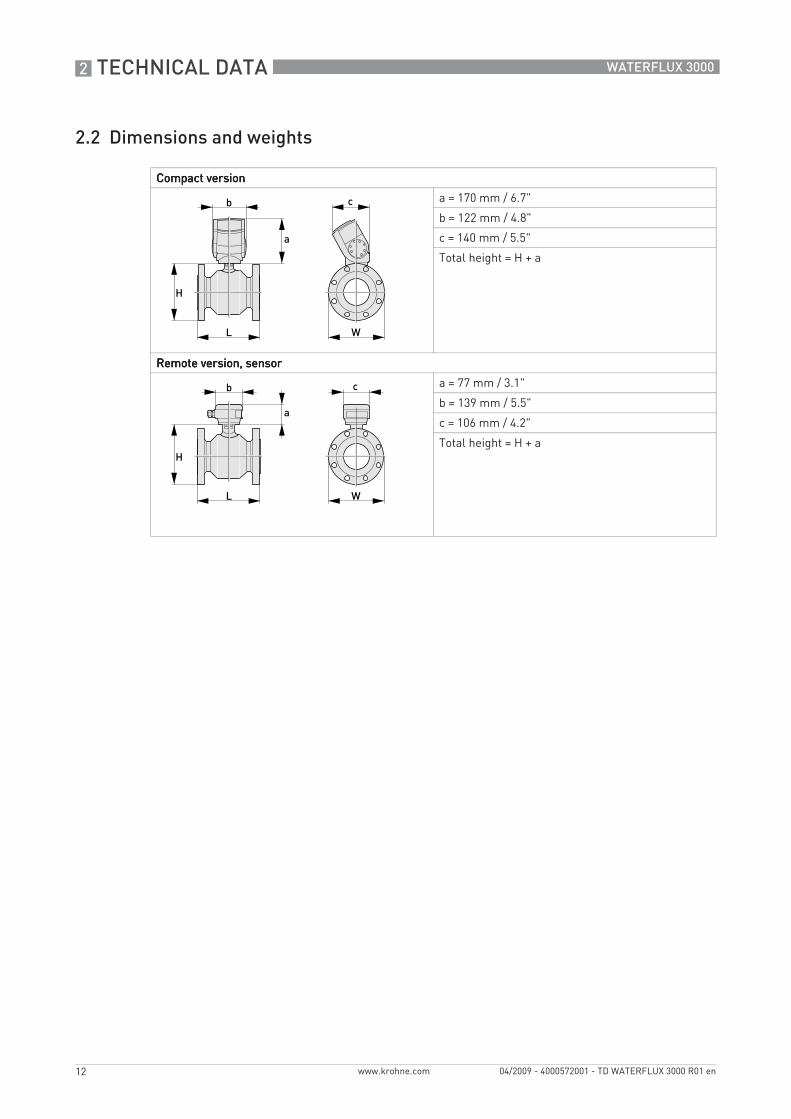
2.2 Dimensions and weights
Compact versionCompact versionCompact versionCompact version
a = 170 mm / 6.7"
b = 122 mm / 4.8"
c = 140 mm / 5.5"
Total height = H + a
Remote version, sensorRemote version, sensorRemote version, sensorRemote version, sensor
a = 77 mm / 3.1"
b = 139 mm / 5.5"
c = 106 mm / 4.2"
Total height = H + a
TECHNICAL DATA 2
13
WATERFLUX 3000
www.krohne.com04/2009 - 4000572001 - TD WATERFLUX 3000 R01 en
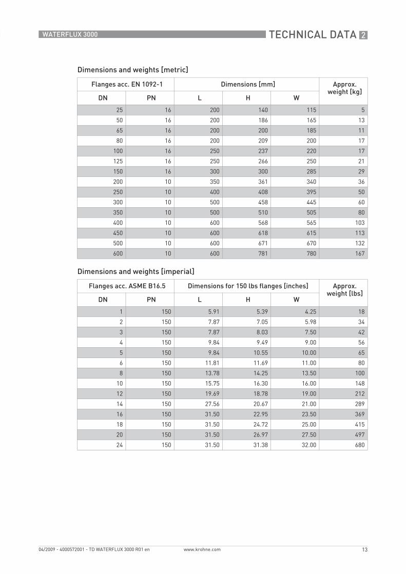
Dimensions and weights [metric]
Dimensions and weights [imperial]
Flanges acc. EN 1092-1 Dimensions [mm] Approx. weight [kg]
DN PN L H W
25 16 200 140 115 5
50 16 200 186 165 13
65 16 200 200 185 11
80 16 200 209 200 17
100 16 250 237 220 17
125 16 250 266 250 21
150 16 300 300 285 29
200 10 350 361 340 36
250 10 400 408 395 50
300 10 500 458 445 60
350 10 500 510 505 80
400 10 600 568 565 103
450 10 600 618 615 113
500 10 600 671 670 132
600 10 600 781 780 167
Flanges acc. ASME B16.5 Dimensions for 150 lbs flanges [inches] Approx. weight [lbs]
DN PN L H W
1 150 5.91 5.39 4.25 18
2 150 7.87 7.05 5.98 34
3 150 7.87 8.03 7.50 42
4 150 9.84 9.49 9.00 56
5 150 9.84 10.55 10.00 65
6 150 11.81 11.69 11.00 80
8 150 13.78 14.25 13.50 100
10 150 15.75 16.30 16.00 148
12 150 19.69 18.78 19.00 212
14 150 27.56 20.67 21.00 289
16 150 31.50 22.95 23.50 369
18 150 31.50 24.72 25.00 415
20 150 31.50 26.97 27.50 497
24 150 31.50 31.38 32.00 680
2 TECHNICAL DATA
14
WATERFLUX 3000
www.krohne.com 04/2009 - 4000572001 - TD WATERFLUX 3000 R01 en
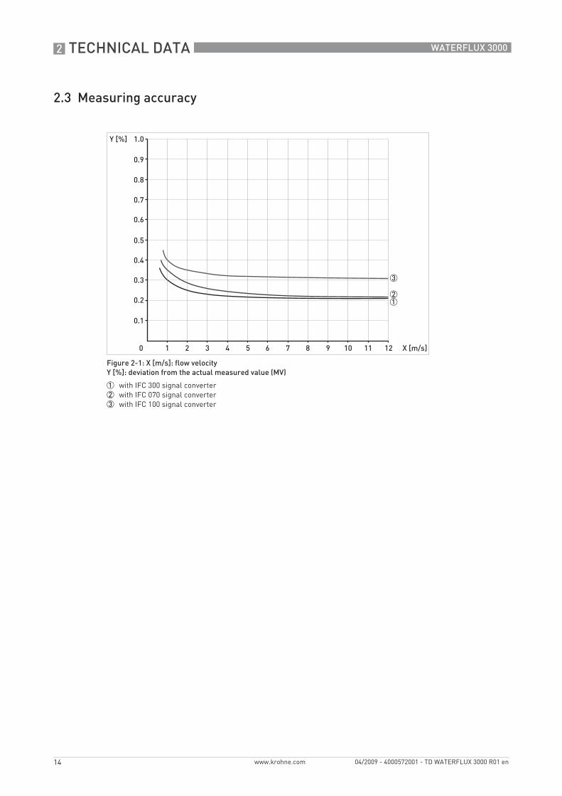
2.3 Measuring accuracy
Figure 2-1: X [m/s]: flow velocityY [%]: deviation from the actual measured value (MV)
1 with IFC 300 signal converter2 with IFC 070 signal converter3 with IFC 100 signal converter
TECHNICAL DATA 2
15
WATERFLUX 3000
www.krohne.com04/2009 - 4000572001 - TD WATERFLUX 3000 R01 en
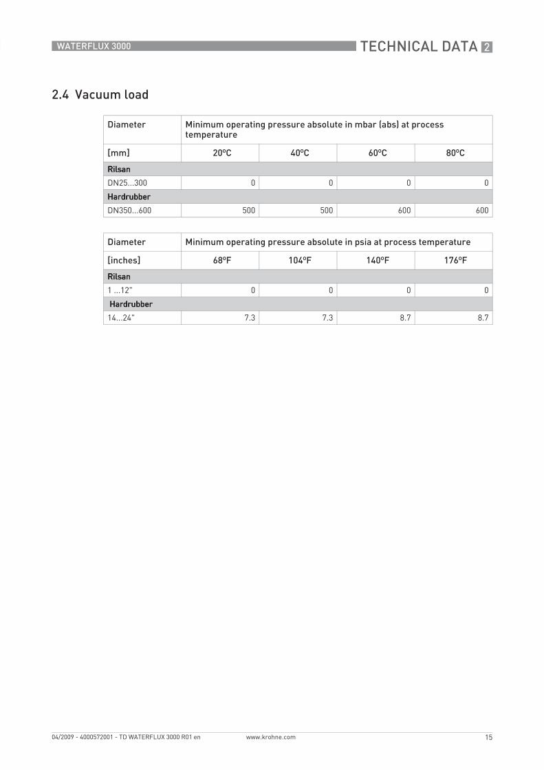
2.4 Vacuum load
Diameter Minimum operating pressure absolute in mbar (abs) at process temperature
[mm] 20ºC 40ºC 60ºC 80ºC
RilsanRilsanRilsanRilsan
DN25...300 0 0 0 0
HardrubberHardrubberHardrubberHardrubber
DN350...600 500 500 600 600
Diameter Minimum operating pressure absolute in psia at process temperature
[inches] 68ºF 104ºF 140ºF 176ºF
RilsanRilsanRilsanRilsan
1 ...12" 0 0 0 0
Hardrubber Hardrubber Hardrubber Hardrubber
14...24" 7.3 7.3 8.7 8.7

3 INSTALLATION
16
WATERFLUX 3000
www.krohne.com 04/2009 - 4000572001 - TD WATERFLUX 3000 R01 en
3.1 Notes on installation
3.2 Inlet and outlet
3.3 Mounting position
Inspect the cartons carefully for damage or signs of rough handling. Report damage to the carrier and to the local office of the manufacturer.
Check the packing list to check if you received completely all that you ordered.
Look at the device nameplate to ensure that the device is delivered according to your order. Check for the correct supply voltage printed on the nameplate.
Figure 3-1: Recommended inlet and outlet
1 ≥ 3DN2 ≥ 1DN
Figure 3-2: Mounting position

INSTALLATION 3
17
WATERFLUX 3000
www.krohne.com04/2009 - 4000572001 - TD WATERFLUX 3000 R01 en
3.4 Flange deviation
3.5 T-section
3.6 Vibration
Max. permissible deviation of pipe flange faces: Lmax - Lmin ≤ 0.5 mm / 0.02"
Figure 3-3: Flange deviation
1 Lmax2 Lmin
Figure 3-4: Distance after T-sections
1 ≥ 10DN
Figure 3-5: Avoid vibrations

3 INSTALLATION
18
WATERFLUX 3000
www.krohne.com 04/2009 - 4000572001 - TD WATERFLUX 3000 R01 en
3.7 Magnetic field
3.8 Bends
Figure 3-6: Avoid magnetic fields
Figure 3-7: Installation in bending pipes
Figure 3-8: Installation in bending pipes
INSTALLATION 3
19
WATERFLUX 3000
www.krohne.com04/2009 - 4000572001 - TD WATERFLUX 3000 R01 en
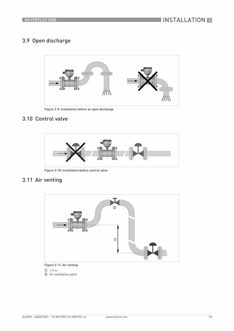
3.9 Open discharge
3.10 Control valve
3.11 Air venting
Figure 3-9: Installation before an open discharge
Figure 3-10: Installation before control valve
Figure 3-11: Air venting
1 ≥ 5 m2 Air ventilation point

3 INSTALLATION
20
WATERFLUX 3000
www.krohne.com 04/2009 - 4000572001 - TD WATERFLUX 3000 R01 en
3.12 Pump
Figure 3-12: Installation after pump
ELECTRICAL CONNECTIONS 4
21
WATERFLUX 3000
www.krohne.com04/2009 - 4000572001 - TD WATERFLUX 3000 R01 en
4.1 Safety instructions
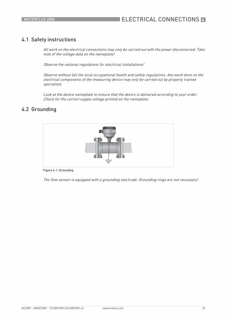
4.2 Grounding
All work on the electrical connections may only be carried out with the power disconnected. Take note of the voltage data on the nameplate!
Observe the national regulations for electrical installations!
Observe without fail the local occupational health and safety regulations. Any work done on the electrical components of the measuring device may only be carried out by properly trained specialists.
Look at the device nameplate to ensure that the device is delivered according to your order. Check for the correct supply voltage printed on the nameplate.
Figure 4-1: Grounding
The flow sensor is equipped with a grounding electrode. Grounding rings are not necessary!

4 ELECTRICAL CONNECTIONS
22
WATERFLUX 3000
www.krohne.com 04/2009 - 4000572001 - TD WATERFLUX 3000 R01 en
4.3 Connection of signal cable
• Prepare appropiate cable lengths (1...3)• Connect the shield to the U-clamp, the brown cable to terminal 7 and the white to terminal 8.• Connect the shield to terminal 1, the purple cable (red in case of type A or B cable) to terminal
2 and the blue (white in case of type A or B cable) to terminal 3.
The signal cable is only used with remote versions. The standard cable includes both electrode and field current leads, the optional type A / B cable is only used for the electrodes. In that case, the field current cable is no part of the supply.
Figure 4-2: Cable connection at sensor side, standard cable
1 cable length: 13 cm / 5"2 cable length: 5 cm / 2"3 brown + white cable, used for field current4 purple and blue cable, used for electrode signals5 cable length: 8 cm / 3"6 Shield (terminal 1 of connector X2 + U-clamp

NOTES 5
23
WATERFLUX 3000
www.krohne.com04/2009 - 4000572001 - TD WATERFLUX 3000 R01 en
KROHNE product overview
• Electromagnetic flowmeters
• Variable area flowmeters
• Ultrasonic flowmeters
• Mass flowmeters
• Vortex flowmeters
• Flow controllers
• Level meters
• Temperature meters
• Pressure meters
• Analysis products
• Measuring systems for the oil and gas industry
• Measuring systems for sea-going tankers
Head Office KROHNE Messtechnik GmbH & Co. KG Ludwig-Krohne-Str. 5D-47058 DuisburgTel.:+49 (0)203 301 0Fax:+49 (0)203 301 10389 [email protected]
© K
RO
HN
E 04
/200
9 -
4000
5720
01 -
TD
WA
TER
FLU
X 30
00 R
01 e
n -
Subj
ect t
o ch
ange
with
out n
otic
e.
The current list of all KROHNE contacts and addresses can be found at:www.krohne.com
KK
K