KRAMER Catalog C-806C - Genemco Catalog C-806C FEB 1997 Supercedes C-806B THERMOBANK Model CTT Hot...
15
KRAMER Catalog C-806C FEB 1997 Supercedes C-806B THERMOBANK Model CTT Hot Gas Defrost Refrigeration System KRAMER 14230 Lochridge Boulevard / Covington, GA / 30014 Phone: 770-788-5800 Fax: 770-788-5820 www.kramerusa.net
Transcript of KRAMER Catalog C-806C - Genemco Catalog C-806C FEB 1997 Supercedes C-806B THERMOBANK Model CTT Hot...
KRAMER CatalogC-806CFEB 1997SupercedesC-806B
THERMOBANK
Model CTTHot Gas Defrost
Refrigeration System
KRAMER 14230 Lochridge Boulevard / Covington, GA / 30014Phone: 770-788-5800 Fax: 770-788-5820
www.kramerusa.net

STANDARD FEATURES INCLUDE • Semi-hermetic Copeland Compressor • Copper tube, aluminum fin air cooled condenser • Receiver with service valves and fusible plug • Discharge and suction line vibration eliminators • High-Low pressure control • Crankcase heater • Weathertight control cabinet • Rugged galvanized steel construction • Permanent liquid line filter-drier (loose) • Permanent suction line filter (loose) • Minimum Charge Monitor • Insulated Thermolator (loose)
OPTIONAL COMPONENTS • Non-fused disconnect (loose) • Pressure relief valve • Suction accumulator • Oil separator
CTT THERMOBANK NOMENCLATURE
CTT 1 0200 L 44 X
Special Refrigerant 22=R-22 44=R-404A, R-507
Temperature L=Low, M=Medium
Nominal Compressor HP 0075= 3/4HP, 0300=3HP
Compressor Code 1=Copeland Semi-Hermetic Reed
Thermobank Condensing Unit
CAPACITY - BTUH at 95°F AMBIENT
SATURATED SUCTION TEMPERATURE - °F MODEL NUMBER
HP
COMPRESSOR MODEL
+25 +20 +15 +10 +5
CTT10075M22 3/4 KAN-0075 6400 5660 4960 4320 3750 CTT10100M22 1 KAR-0100 9240 8260 7360 6530 5800
CTT10100M44 1 KAR-010E 8200 7600 6900 6300 5700
CTT10150M22 1 1/2 KAG-0150 11780 10500 9300 8400 7350
CTT10200M22 2 KAK-0200 15700 14070 12510 10990 9680 CTT10200M44 2 KAK-021E 14200 12900 11750 10700 9650
CTT10300M22 3 ERF-0310 24340 21830 19480 17490 15650
CTT10300M44 3 ERF-031E 25950 23650 21500 19370 17450
CAPACITY - BTUH at 95°F AMBIENT
SATURATED SUCTION TEMPERATURE - °F MODEL
NUMBER HP
COMPRESSOR
MODEL -10 -15 -20 -25 -30 CTT10075L44 CTT10100L44
3/4 1
KAM-007E KAJ-010E
4450 5850
3870 5150
3350 4500
2850 3900
2450 3350
CTT10150L44 CTT10200L44 CTT10300L44
1 1/2 2 3
KAL-015E EAV-020E LAH-031E
8800 11600 18300
7800 10100 15900
6850 8650
13700
6050 7550
11250
5100 6400 9650
KRAMER THERMOBANK IS A PATENTED SYSTEM
AMBIENT CORRECTION FACTORS
AMBIENT TEMPERATURE - °F
REFRIGERANT 80 85 90 95 100 105
R-22
R-404A or R-507
1.10
1.15
1.07
1.10
1.03
1.05
1.00
1.00
0,96
0.95
0.92
0.90
All CTT Models suitable for operation up to 110°F ambient

THE THERMOBANK SYSTEM
The THERMOBANK is a patented, factory packaged, air cooled, completely automatic refrigeration system with WARM GAS defrost. Less equipment is required with THERMOBANK because it does more refrigeration in 24 hours than other packaged systems. With a typical defrost time of 5 to 10 minutes, THERMOBANK is refrigerating while others are still defrosting. The "BANK" stores sufficient discharge heat to fully re-evaporate all the liquid resulting from the defrost of the evaporator. With the lowest possible floating head pressure, there is a marked increase in BTU per day. THERMOBANK has no head pressure controls, no reversing valves, and no hot gas line between the condensing unit and evaporator.
With THERMOBANKS fast defrost, room temperatures are very consistent and do not rise like they do with longer defrost times.
The THERMOBANK delivers more refrigeration with less energy consumption, less equipment, less installation and lower operating cost than any other refrigeration package now on the market or likely to be in the foreseeable future! The THERMOBANK Condensing Unit is delivered factory assembled and run tested complete with a matching THERMOBANK Evaporator and controls for easy and economical on site installation. THERMOBANK is available for all refrigerated room applications from -20°F to+35°F.

KRAMER MODEL CTT 3/4 THRU 3 HP THERMOBANK
PHYSICAL AND ELECTRICAL DATA
CONNECTIONS AMPS at 230 / 1 / 60 AMPS at 230 / 3 / 60
COMPRESSOR COMPRESSOR
CTT MODEL
NUMBER SUCT. ODS
LIQ. ODS
RCVR.
LBS.
90% RLA HP COND.
FLA
UNIT
AMPS
* MCA RLA HP
COND.
FLA
UNIT
AMPS
* MCA
APRX.
SHIP
LBS.
0075M22 5/8 3/8 6.0 6.1 3/4 2.9 10.0 15 3.5 3/4 2.9 7.4 15 380
0100M22 5/8 3/8 6.0 7.4 1 2.9 11.3 15 4.3 1 2.9 8.2 15 390
0100M44 5/8 3/8 5.1 7.4 1 2.9 11.3 15 4.3 1 2.9 8.2 15 390
0150M22 7/8 3/8 10.0 9.6 1 1/2 2.9 13.5 16 5.5 1 1/2 2.9 9.4 15 415
0200M22 7/8 3/8 10.0 10.6 2 2.9 14.5 18 6.8 2 2.9 10.7 15 490
0200M44 7/8 3/8 8.6 10.6 2 2.9 14.5 18 6.8 2 2.9 10.7 15 490
0300M22 1 1/8 1/2 19.6 17.0 3 2.9 20.9 26 12.4 3 2.9 16.3 20 550
0300M44 1 1/8 1/2 16.8 --- --- --- --- --- 12.4 3 2.9 16.3 20 550
0075L44 5/8 3/8 5.1 5.6 3/4 2.9 9.5 15 3.2 3/4 2.9 7.1 15 380
0100L44 5/8 3/8 5.1 6.9 1 2.9 10.8 15 4.6 1 2.9 8.5 15 390
0150L44 7/8 3/8 8.6 9.9 1 1/2 2.9 13.8 17 6.6 1 1/2 2.9 10.5 15 405 0200L44 7/8 3/8 8.6 14.7 2 2.9 18.6 23 7.4 2 2.9 11.3 15 490
0300L44 1 1/8 1/2 16.8 16.7 3 2.9 20.6 25 12.8 3 2.9 16.7 20 550
* MCA does not include evaporator load. Evaporator load may increase MCA requirements. UNIT AMPS includes 1.0 amp for control circuit. RLA = Rated Load Amps of compressor manufacturer. 460/3/60 units are available in most sizes - please contact the factory for availability.
KRAMER 14230 Lochridge Boulevard / Covington, GA / 30014Phone: 770-788-5800 Fax: 770-788-5820
www.kramerusa.net
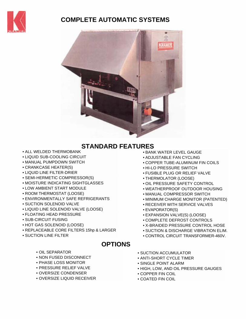
• ALL WELDED THERMOBANK • LIQUID SUB-COOLING CIRCUIT • MANUAL PUMPDOWN SWITCH • CRANKCASE HEATER(S) • LIQUID LINE FILTER-DRIER • SEMI-HERMETIC COMPRESSOR(S) • MOISTURE INDICATING SIGHTGLASSES • LOW AMBIENT START MODULE • ROOM THERMOSTAT (LOOSE) • ENVIRONMENTALLY SAFE REFRIGERANTS • SUCTION SOLENOID VALVE • LIQUID LINE SOLENOID VALVE (LOOSE) • FLOATING HEAD PRESSURE • SUB-CIRCUIT FUSING • HOT GAS SOLENOID (LOOSE) • REPLACEABLE CORE FILTERS 15hp & LARGER • SUCTION LINE FILTER
• BANK WATER LEVEL GAUGE • ADJUSTABLE FAN CYCLING • COPPER TUBE-ALUMINUM FIN COILS • HI-LO PRESSURE SWITCH • FUSIBLE PLUG OR RELIEF VALVE • THERMOLATOR (LOOSE) • OIL PRESSURE SAFETY CONTROL • WEATHERPROOF OUTDOOR HOUSING • MANUAL COMPRESSOR SWITCH • MINIMUM CHARGE MONITOR (PATENTED) • RECEIVER WITH SERVICE VALVES • EVAPORATOR(S) • EXPANSION VALVE(S) (LOOSE) • COMPLETE DEFROST CONTROLS • X-BRAIDED PRESSURE CONTROL HOSE • SUCTION & DISCHARGE VIBRATION ELIM. • CONTROL CIRCUIT TRANSFORMER-460V.
• OIL SEPARATOR • NON FUSED DISCONNECT • PHASE LOSS MONITOR • PRESSURE RELIEF VALVE • OVERSIZE CONDENSER • OVERSIZE LIQUID RECEIVER
• SUCTION ACCUMULATOR • ANTI-SHORT CYCLE TIMER • SINGLE POINT ALARM • HIGH, LOW, AND OIL PRESSURE GAUGES • COPPER FIN COIL • COATED FIN COIL
COMPLETE AUTOMATIC SYSTEMS
STANDARD FEATURES
OPTIONS


HOW THERMOBANK WORKS Every refrigeration system discharges the heat picked up from the evaporator and the compressor. This waste heat is normally rejected by the condenser. With Thermobank, the Compressor (C) discharge passes through a heating loop that is submerged in the water filled Bank (B), and then on through the Condenser (A). The bank stores sufficient heat to fully re-evaporate all the liquid resulting from the defrost of the Evaporator (E).
THE REFRIGERATION CYCLE The compressor discharge refrigerant, after heating the Bank water, flows to the air cooled Condenser and then to the Receiver (R). From the Receiver the liquid refrigerant flows through a sub-cooling circuit in the condenser and on to the Thermolator (T), the Expansion Valve (X), and the Evaporator (E). The refrigerant returns to the Compressor as in any standard system.
To prevent excessive superheating of the refrigerant vapor returning to the compressor and maintain the water temperature in the Bank, the refrigerant flow bypasses the Bank through the Suction Line Solenoid (4) during the refrigeration cycle. This Suction Line Solenoid is generously sized for minimum pressure drop and is of the normally closed type providing an extra margin of safety. On low temperature systems a spring loaded hold back Check Valve (7) is installed upstream of the Holdback Valve (H) to ensure no refrigerant flows through the Bank during the refrigeration cycle.
THE DEFROST CYCLE A time clock automatically puts the Thermobank system into a defrost cycle and initiates the following: Discharge Solenoid Valve (1) closes; the Evaporator (E) fans stop; Hot Gas Solenoid Valve (2) opens; Liquid Solenoid Valve (3) closes; Suction Solenoid Valve (4) closes.
The Compressor discharge gas goes directly into the liquid line because By-Pass Solenoid Valve (5) is open when Discharge Solenoid (1) is closed. All the warm liquid refrigerant in the liquid line flows into and through the Evaporator. This liquid refrigerant insures a rapid defrost and charges the defrost circuit. Additional hot gas condenses in the Evaporator providing an unusually rapid defrost at all ambient conditions.
During the defrost cycle the hot gas passes through the liquid side of the Thermolator (T) and the suction from the Evaporator goes through the inner core. The heat transfer in the Thermolator reduces the superheat of the hot gas and minimizes coil steaming and temperature rise in the refrigerated room.
With the Suction Solenoid (4) closed, the liquid refrigerant flows through the Holdback Valve (H) which controls the rate of refrigerant flow and the pressure in the Bank. The Bank becomes an evaporator and absorbs the stored heat. The Thermobank system utilizes a high pressure safety control which will function to momentarily open the Discharge Line Solenoid (1) if discharge pressures rise to a high level.
The defrost cycle is terminated by a pressure switch that senses Evaporator pressure and starts the post-defrost period. During post-defrost the Discharge Solenoid (1) is open; By-Pass Solenoid Valve (5) is closed and Hot Gas Solenoid (2) is closed. Suction Solenoid (4) and Liquid Solenoid (3) remain closed. At the end of the pressure terminated post-defrost period both Suction Solenoid (4) and Liquid Solenoid (3) open and the Evaporator fan motors start. During defrost the hot gas by-passes the receiver so after defrost the receiver contains ample liquid refrigerant to begin refrigerating immediately and prevent compressor short cycling. The system then returns to the normal refrigeration cycle.
NEW - IMPROVED HOT GAS DEFROST

EVAPORATOR DESIGN Evaporator designs were developed to fulfill the ruggedness and reliability requirements of the industrial and commercial refrigeration industry. Heavy gauge aluminum tube sheets virtually eliminate the potential for refrigerant leaks at the tube sheets caused by thermal expansion and contraction. Corrosion resistant construction will give maximum performance. All THERMOBANK evaporators feature mechanically expanded coils for positive fin-tube bond to insure maximum heat transfer. All coils are custom circuited for the exact requirements of each application thereby providing maximum efficiency and performance during both refrigeration and defrost mode.
Four fin per inch coils are used in low and medium temperature levels. Four fin per inch coils will allow the defrost water to clear the coil faster and allows more time between defrost. Four fin per inch coils should be used for the minimum number of defrost per day and the shortest defrost time. They should always be used if heavy frost loading is possible.
Six fin per inch coils are available and may provide optimum performance for a specific area. They are often used in confined spaces where other coils will not fit. They are sometimes used when light frost loads are expected.
THERMOLATOR The Thermolator is a unique Kramer engineering development and plays a significant part in the Kramer THERMOBANK System. It has no moving parts to wear out. It consists of a round vessel with convolute interior that will turbulate the refrigerant flow for maximum heat transfer. The suction stream from the evaporator moves through this convolute interior on the way to the compressor. Surrounding the outside of this convolute interior is the liquid on the way to the expansion valve. Should the suction stream contain any liquid mist it would be boiled off. The liquid is sub-cooled and feeds liquid to the expansion valve at a considerably lower temperature.
The Thermolator has a dual purpose and its function differs during the defrost cycle. During defrost the hot discharge gas passes through the liquid side of the Thermolator and the suction from the evaporator goes through the convolute core of the Thermolator. The heat transfer in the Thermolator reduces the superheat of the hot gas and minimizes coil steaming and temperature rise in the refrigerated room.
The Thermolator improves system efficiency, stabilizes the defrost, and provides additional insurance that only vapor is returned to the compressor. The complete Thermolator assembly is insulated to insure high efficiency heat transfer.
MINIMUM-CHARGE-MONITOR (Patented) Thermobank uses the unique Minimum-Charge-Monitor for charging simply, accurately and quickly. Incorporating the use of two sight glasses, one glass shows system undercharge while the other sight glass indicates system overcharge.
IMPROVED THERMOBANK SYSTEM

SMALLEST REFRIGERANT CHARGE Ton for ton, THERMOBANK'S refrigerant charge is much lower than any conventional equipment. This is made possible by applying a receiver in combination with the Minimum-Charge-Monitor and the elimina-tion of condenser liquid flooding for head pressure control. The same charge works for all seasons -summer or winter. The Minimum-Charge-Monitor allows the contractor to easily fine tune the refrigerant charge and prevents overcharging. With the Minimum-Charge-Monitor and floating head pressure combination a Thermobank system will only use about 70 to 80% of the refrigerant required by a conven-tional flooded condenser system. Saving 20 to 30% on refrigerant cost can amount to substantial $$ savings.
FASTEST DEFROST - ADEQUATE HEAT Thermobank has the fastest defrost, typically 5 to 10 minutes, of any outdoor packaged refrigeration system. In addition, the defrost is uniform throughout the coil, and minimizes the heat and vapor added to the room during defrost. The defrosting evaporator receives the full heat of rejection of the refrigerant. This is the sum of the compressor heat while operating at maximum suction pressure during the defrost cycle and the heat extracted from the BANK. There is always an adequate supply of refrigerant for defrosting.
EXTRA COMPRESSOR PROTECTION Many factors are incorporated in Thermobank to protect the compressor and insure long life. To prevent refrigerant migration to the compressor during the off-cycle, all units have a pumpdown cycle. During the defrost cycle the BANK is protection against floodback. The holdback valve protects against overloading the compressor motor by regulating the inlet pressure to the compressor. The reduced refrigerant charge is additional protection for the compressor.
NEW IMPROVED BANK DESIGN The BANK has a totally new welded hermetic design to insure a long, leak free life. The heavy gauge steel shell has a bulls-eye water level gauge. Checking the water level is quick and easy. The shell is insulated with closed cell foam to maintain proper water temperature at any ambient condition and provide optimum system performance. The internal heat transfer loops are die formed from extra heavy wall, seamless, copper tube. The BANK contains a thermostat controlled immersion heater for stabilizing water temperature and automatic freeze protection. The new heavy duty welded design makes the BANK durable, reliable, safe and service free.
EXTRA LARGE CONDENSERS Ratings for ambient temperatures to 105°F are given for all Thermobank systems. Many competitive systems are limited to 100°F ambient. Special systems are available for ambient design temperatures above 110°F. All condensers have a maximum fin spacing of 10 FPI to help prevent coil fouling and increase the time between coil cleanings. The generous coil surface keeps head pressures lower, saves energy, and extends the life of the equipment. An integral sub-cooling circuit is standard to prevent flash gas in liquid risers and increase system efficiency. Fan cycle controls allow some adjustability to the head pressure and will minimize fan motor energy consumption in low ambients. A pressure control on the header end fan assures sufficient head pressure is available for a good cold ambient re-start.
DEPENDABLE HOT GAS DEFROST


THERMOBANK
0°F TO -40°F SUCTION TEMPERATURE
PHYSICAL DATA - R-404A & R-507
MODEL COMPRESSOR COND FANS CONNECTIONS CHARGE LBS. APPROX. CTT QTY MODEL NO. QTY DIA HP SUC OD LIQ OD UNIT2 RECV1 NET LBS.
0400L44 1 2DF-030E 2 24 1/2 1 1/8 1/2 8 30 700 0500L44 1 2DA-060E 2 24 1/2 1 3/8 1/2 8 30 880 0600L44 1 3DA-060E 2 24 1/2 1 3/8 1/2 10 30 9500800L44 1 3DB-075E 2 24 1/2 1 5/8 5/8 10 30 1100 0900L44 1 3DF-090E 2 24 1/2 1 5/8 5/8 19 64 11201000L44 1 3DS-100E 2 24 1/2 1 5/8 5/8 19 64 1150 1200L44 1 4DA-101E 2 24 1/2 1 5/8 5/8 20 64 1230 1500L44 1 4DL-150E 3 24 1/2 1 5/8 7/8 21 71 1500 2200L44 1 4DT-220E 3 24 1/2 2 1/8 7/8 24 71 1870 2700L44 1 6DL-270E 3 24 3/4 2 1/8 7/8 27 71 2240 3100L44 1 6DT-300E 3 24 3/4 2 1/8 7/8 31 103 2890 4400L44 2a 4DT-220E 4 30 3/4 2 1/8 1 1/8 44 103 40305400L44 2a 6DL-270E 5 30 3/4 2 5/8 1 1/8 49 103 4580 6200L44 2a 6DT-300E 5 30 3/4 2 5/8 1 1/8 57 103 5930
a 2 Compressors piped in parallel. 1 Receiver at 90% full. 2 Estimated refrigerant charge is for a condensing unit only. It does not include evaporators, interconnecting piping or other accessories.
ELECTRICAL DATA - R-404A & R-507 230 - 3 - 60 460-3-60
|MODEL COMPRESSOR COND UNIT COMPRESSOR COND UNIT CTT RLA LRA FLA AMPS MCA3 RLA LRA FLA AMPS MCA3
0400L44 16.8 102 8.0 25.8 30 8.1 52 4.0 12.6 15 0500L44 28.8 161 8.0 37.8 45 10.2 60 4.0 14.7 18 0600L44 30.3 150 8.0 39.3 47 13.7 77 4.0 18.2 220800L44 31.5 161 8.0 40.5 49 16.1 83 4.0 20.6 25 0900L44 39.0 215 8.0 48.0 58 16.9 106 4.0 21.4 26 1000L44 42.0 215 8.0 51.0 62 18.6 106 4.0 23.1 28 1200L44 45.2 220 8.0 54.2 66 22.6 110 4.0 27.6 34 1500L44 52.6 278 5.4 59.0 73 26.3 139 2.7 29.5 37 2200L44 66.0 374 5.4 72.4 89 33.0 187 2.7 36.2 45 2700L44 80.8 450 10.2 92.0 113 40.4 225 5.1 46.0 57 3100L44 95.6 470 10.2 106.8 131 47.8 235 5.1 53.4 66 4400L44 (2) 66.0 (2) 374 13.6 146.6 164 (2) 33.0 (2) 187 6.8 73.3 83 5400L44 (2) 80.8 (2) 450 17.0 179.6 200 (2) 40.4 (2) 225 8.5 89.8 101 6200L44 (2) 95.6 (2) 470 17.0 209.2 234 (2) 47.8 (2) 235 8.5 104.6 118
3 MCA does not include evaporator motors.
CAPACITY- BTUH @ 95°F AMBIENT
SUCTION TEMPERATURE MODEL CTT 0°F -5°F -10°F -15°F -20°F -25°F -30°F -40°F
0400L44 32700 29100 25700 22600 19700 17100 14700 10400 0500L44 42800 38400 34300 30400 26900 23600 20500 14900 0600L44 52500 47100 42000 37200 32800 28700 24900 18500 0800L44 60800 54600 48800 43400 38400 33700 29400 21600 0900L44 78100 69900 62300 55300 48700 42600 37100 27400 1000L44 82900 74700 67000 59700 52800 46400 40400 29800 1200L44 96100 86000 76800 68400 60700 53400 46500 33200 1500L44 113700 102400 92200 82700 73900 65700 57800 42400 2200L44 132000 119800 109200 98100 87500 77300 67600 49100 2700L44 169800 153700 138100 123100 108700 95200 82600 60400 3100L44 187300 169600 153900 136300 121700 106400 92700 69350 4400L44 267000 242100 218600 196300 175100 154800 135300 98300 5400L44 340500 307900 279100 248500 219400 192000 166400 121700 6200L44 373300 338000 306700 271650 242600 212100 184750 138200
AMBIENT
CORR. FACTOR
AMB. 404A
80°F 1.15
85°F 1.10
90°F 1.05
95°F 1.00
100°F 0.95
105°F 0.90


THERMOBANK
+10°F TO+25°F SUCTION TEMPERATURE
PHYSICAL DATA - R-22, R-404A & R-507 CONNECTIONS CHARGE LBS. COMPRESSOR COND FANS
R-22 R-404A & R-507 R-22 R-404A & R-S07 MODEL
CTT
QTY MODEL NO. QTY DIA HP SUC OD LIQ OD SUC OD LIQ OD UNIT2 RECV1 UNIT2 RECV1
APPX NET LBS.
0500M** 1 2DD-050* 2 24 1/2 1 3/8 1/2 1 1/8 1/2 7 35 8 30 820 0700M** 1 2DA-075* 2 24 1/2 1 3/8 5/8 1 3/8 5/8 9 35 10 30 980 0800M** 1 3DA-075* 2 24 1/2 1 3/8 5/8 1 3/8 5/8 15 74 14 64 1030 1000M** 1 3DB-100* 2 24 1/2 1 3/8 5/8 1 3/8 5/8 19 74 17 64 1150 1200M** 1 3DF-120* 2 24 1/2 1 3/8 7/8 1 3/8 5/8 21 74 19 64 1225 1500M** 1 3DS-150* 3 24 1/2 1 5/8 7/8 1 3/8 5/8 25 103 23 88 1450 2000M** 1 4DA-200* 3 24 1/2 1 5/8 7/8 1 5/8 7/8 29 103 26 88 1850 2500M** 1 4DH-250* 3 24 3/4 2 1/8 7/8 2 1/8 7/8 32 103 29 88 2190 3000M** 1 4DJ-300* 3 30 3/4 2 1/8 7/8 2 1/8 7/8 46 120 33 103 3030 3500M** 1 6DH-350* 4 30 3/4 2 1/8 1 1/8 2 1/8 1 1/8 49 120 42 103 4130 4000M** 1 6DJ-400* 4 30 3/4 2 1/8 1 3/8 2 1/8 1 1/8 60 120 53 103 3630 5000M** 2a 4DH-250* 5 30 3/4 2 5/8 1 3/8 2 5/8 1 1/8 65 120 57 103 4130 6000M** 2a 4DJ-300* 5 30 3/4 2 5/8 1 5/8 2 5/8 1 1/8 74 120 65 103 4480 7000M** 2a 6DH-350* 5 30 3/4 2 5/8 1 5/8 2 5/8 1 1/8 89 182 78 157 6130
* 0=Mineral Oil, R-22. E=POE Synthetic Lubricant. **22 = R-22, 44 = R-404A or R-507. a 2 Compressors piped in parallel. 1 Receiver at 90% full. 2 Estimated refrigerant charge is for a condensing unit only. It does not include evaporators, interconnecting piping or other accessories.
ELECTRICAL DATA - R-22, R-404A & R-507 230 - 3 - 60 460 - 3 - 60
COMPRESSOR COND UNIT COMPRESSOR COND UNIT MODEL
CTT
RLA LRA FLA AMPS MCA3 RLA LRA FLA AMPS MCA3 0500M** 22.3 120 8.0 31.3 37 10.5 60 4.0 15.0 18 0700M** 32.0 169 8.0 41.0 49 14.1 85 4.0 18.7 23 0800M** 41.0 215 8.0 50.0 61 20.0 106 4.0 24.5 30 1000M** 43.6 215 8.0 52.6 64 20.0 106 4.0 24.5 30 1200M** 48.2 275 8.0 57.2 70 23.6 138 4.0 28.1 34 1500M** 59.6 275 5.4 66.0 81 29.0 138 2.7 32.2 40 2000M** 66.6 308 5.4 73.0 90 33.0 154 2.7 36.2 45 2500M** 82.2 428 10.2 93.4 114 41.1 214 5.1 46.7 57 3000M** 94.0 470 10.2 105.2 129 47.0 235 5.1 52.6 653500M** 107.0 565 13.6 121.6 149 53.5 283 6.8 60.8 75 4000M** 142.0 594 13.6 156.6 193 71.0 297 6.8 78.3 97 5000M** (2) 82.2 (2) 428 17.0 182.4 203 (2) 41.1 (2) 214 8.5 91.8 103 6000M** (2) 94.0 (2) 470 17.0 206.0 230 (2) 47.0 (2) 235 8.5 103.5 115 7000M** (2) 107.0 (2) 565 17.0 232.0 259 (2) 53.5 (2) 283 8.5 116.5 130
**22 = R-22, 44 = R-404A or R-507. 3 MCA does not include evaporator motors
CAPACITY- BTUH @ 95°F AMBIENT
R-22 R-404A & R-507 SUCTION TEMPERATURE SUCTION TEMPERATURE
MODEL CTT
+25°F +20°F +15°F +10°F +25°F +20°F +15°F +10°F 0500M** 0700M**
52100 72300
46600 65000
41300 57900
36500 51200
52800 74600
47700 67900
42900 61600
38400 55700
0800M** 1000M** 1200M**
89300 105200 116000
80500 95200 105200
72300 85900 95000
64600 77300 85500
91000 107800 125300
82800 98300 114700
75100 89300 104600
67700 80700 95000
1SOOM** 2000M** 2500M**
136600 152500 192100
123000 137600 172200
111300 125900 154900
100200 112500 128200
144300 157900 201000
130700 143500 183200
119100 132200 167700
108000 118900 151200
3000M** 3500M** 4000M**
216700 278800 319800
196200 252200 290800
177000 227700 263800
159200 205200 238900
228100 298900 339400
207700 272000 310000
188400 246700 282000
170100 222900 255400
5000M** 6000M** 7000M**
374100 433600 555000
338800 392600 502700
306100 353900 454400
275800 317200 410200
384800 455400 584100
350400 414900 533700
317300 376300 485700
285900 339800 440300
AMBIENT
CORR. FACTOR
AMB. 404A 22
80°F 1.15 1.10
85°F 1.10 1.07
90°F 1.05 1.03
95°F 1.00 1.00
100°F 0.95 0.96
105°F 0.90 0.92
"22 = R-22, 44 = R-404A or R-507

THERMOBANK SYSTEMS WITH 4 FPI EVAPORATORS
LOW TEMPERATURE THERMOBANK SYSTEMS WITH 4 FPI EVAPORATORS
MODEL MBH @ - EVAP FOR -10°F ROOM MBH @ EVAP FOR -20°F ROOM MBH @ FOR -30°F ROOM LPG-T MSG-T TV LPG-T MSG-T TV TV
0400L44 0500L44
19.7 26.9
182,214 214
175 230
14.7 20.5
182 214
175 175, 230
10.4
0600L44 0800L44
32.8 38.4
(2) 182 (2) 214
325 390 400
24.9 29.4
(2) 142 (2) 182
230 325
18.5
0900L44 1000L44 1200L44
48.7 52.8 60.7
510 510 (2) 325
550 550 550
37.1 40.4 46.5
(2) 214 390, (2) 175 390 510, (2) 230
400 400 550
27.4
29.
400 400 400
1500L44 2200L44
73.9 87.5
(2) 390 (2) 510
750 950, (2) 550
57.8 67.6
510, (2) 390 (2) 390
550 750, (2) 400
42.4
550 550
2700L44 3100L44
108.7 121.7
(2) 510 1100, (2) 550 1200,1400
82.6 92.7
(2) 510 (2) 510
950, (2) 550 1100, (2) 550
60.4
750, (2) 400 950, (2) 550
4400L44 5400L44 6200L44
175.1 219.4 242.6
1900, (2) 950 (2) 1100, (2) 1200 (2) 1400
135.3 166.4 184.8
1400, (2) 750 1900, (2) 950 (2) 1100, (2) 1200
98.3 121.7 138.2
1200 1400, (2) 750 1900, (2) 950
MEDIUM TEMPERATURE THERMOBANK SYSTEMS WITH 4 FPI EVAPORATORS
MODEL MBH @ +10° SST EVAP FOR +20°F ROOM MBH @ +20° SST EVAPORATOR FOR +30°F ROOM CTT M22 M44 LPG-T MSG-T TV M22 M44 LPG-T MSG-T TV
0500M 0700M
36.5 51.2
38.4 55.7
(2) 182, (2) 214 (2) 214
390 510
400 400, 550
46.6 65.0
47.7 67.9
(2) 214 390, 510 510, (2) 325
400 550
0800M 1000M 1200M
64.6 77.3 85.5
67.7 80.7 95.0
510, (2) 325 (2) 390 (2) 390
550 750, (2) 400 950, (2) 400
80.5 95.2 105.2
82.8 98.3 114.7
(2) 390 (2) 390 (2) 510
750, (2) 400 950, (2) 400 1100, (2) 550
1SOOM 2000M 2500M
100.2 112.5 128.2
108.0 118.9 151.2
(2) 510 (2) 510
1100, (2) 550 1100, (2) 550 1400, (2) 750
123.0 137.6 172.2
130.7 143.5 183.2
1200, (2) 550 1400, (2) 750 1600, (2) 750
3000M 3500M 4000M
159.2 205.2 238.9
170.1 222.9 255.4
1600, (2) 750 1900, (2) 950 (2) 1100
196.2 252.2 290.8
207.7 272.0 310.0
1900, (2) 950 (2) 1200 (2) 1400
5000M 6000M 7000M
275.8 317.2 410.2
285.9 339.8 440.3
(2) 1400 (2) 1600 (2) 1900
338.8 392.6 502.7
350.4 414.9 533.7
(2) 1600 (2) 1900 (2) 1900
MEDIUM TEMP THERMOBANK SYSTEMS
MODEL MBH @ +25°F SST EVAPORATOR FOR +35°F ROOM
CTT M22 M44 MSA (4 FPI) CM (4 FPI)
0500M 0700M
52.1 52.8 465, 585 585, (2) 340
450 620
0800M 1000M 1200M
77.3 85.5
80.7 95.0
(2) 465 (2) 585 (2) 585
850, (2) 450 1100, (2) 450 1250, (2) 620
1500M 2000M 2500M
100.2 112.5 128.2
108.0 118.9 151.2
1350, 1600, (2) 850 1600, (2) 850 1800, 2100, (2) 1100
3000M 3500M 4000M
159.2 205.2 238.9
170.1 222.9 255.4
21,00, (2) 1100 (2) 1600 (2) 1600
5000M 6000M 7000M
275.8 317.2 555.0
285.9 339.8 584.1
(2) 1800 (2) 2100 (3) 1800
System selections are based on 95°F ambient and approximately 9 to 11° TD. Other balanced systems are available and can be customized for your specific application.
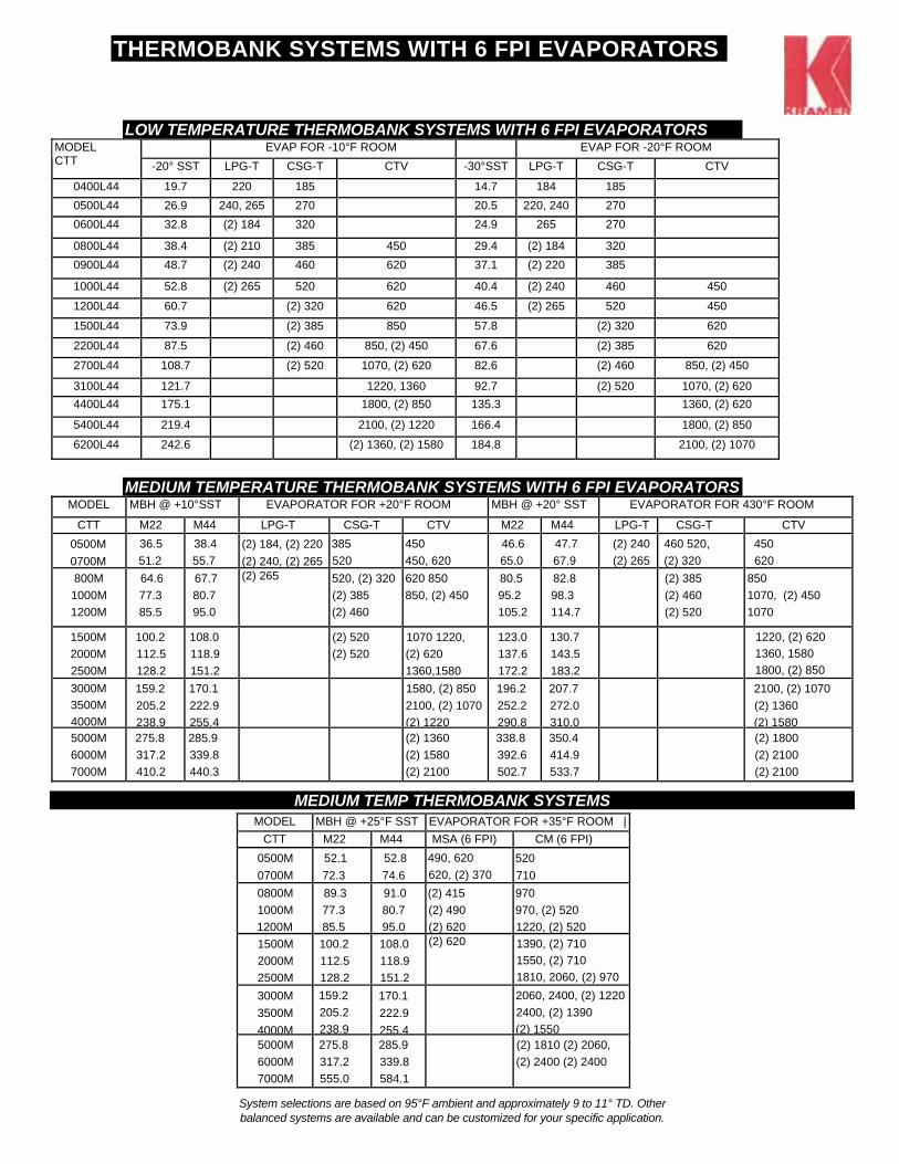
THERMOBANK SYSTEMS WITH 6 FPI EVAPORATORS
LOW TEMPERATURE THERMOBANK SYSTEMS WITH 6 FPI EVAPORATORS EVAP FOR -10°F ROOM EVAP FOR -20°F ROOM MODEL
CTT -20° SST LPG-T CSG-T CTV -30°SST LPG-T CSG-T CTV
0400L44 19.7 220 185 14.7 184 185 0500L44 26.9 240, 265 270 20.5 220, 240 270 0600L44 32.8 (2) 184 320 24.9 265 270
0800L44 38.4 (2) 210 385 450 29.4 (2) 184 320 0900L44 48.7 (2) 240 460 620 37.1 (2) 220 385
1000L44 52.8 (2) 265 520 620 40.4 (2) 240 460 450
1200L44 60.7 (2) 320 620 46.5 (2) 265 520 450
1500L44 73.9 (2) 385 850 57.8 (2) 320 620
2200L44 87.5 (2) 460 850, (2) 450 67.6 (2) 385 620
2700L44 108.7 (2) 520 1070, (2) 620 82.6 (2) 460 850, (2) 450
3100L44 121.7 1220, 1360 92.7 (2) 520 1070, (2) 620 4400L44 175.1 1800, (2) 850 135.3 1360, (2) 620
5400L44 219.4 2100, (2) 1220 166.4 1800, (2) 850
6200L44 242.6 (2) 1360, (2) 1580 184.8 2100, (2) 1070
MEDIUM TEMPERATURE THERMOBANK SYSTEMS WITH 6 FPI EVAPORATORS MODEL MBH @ +10°SST EVAPORATOR FOR +20°F ROOM MBH @ +20° SST EVAPORATOR FOR 430°F ROOM
CTT M22 M44 LPG-T CSG-T CTV M22 M44 LPG-T CSG-T CTV 0500M 0700M
36.5 51.2
38.4 55.7
(2) 184, (2) 220 (2) 240, (2) 265
385 520
450 450, 620
46.6 65.0
47.7 67.9
(2) 240 (2) 265
460 520, (2) 320
450 620
800M 1000M
1200M
64.6 77.3 85.5
67.7 80.7 95.0
(2) 265 520, (2) 320 (2) 385 (2) 460
620 850 850, (2) 450
80.5 95.2 105.2
82.8 98.3 114.7
(2) 385 (2) 460 (2) 520
850 1070, (2) 450 1070
1500M 2000M 2500M
100.2 112.5 128.2
108.0 118.9 151.2
(2) 520 (2) 520
1070 1220, (2) 620 1360,1580
123.0 137.6 172.2
130.7 143.5 183.2
1220, (2) 620 1360, 1580 1800, (2) 850
3000M 3500M 4000M
159.2 205.2 238.9
170.1 222.9 255.4
1580, (2) 850 2100, (2) 1070 (2) 1220
196.2 252.2 290.8
207.7 272.0 310.0
2100, (2) 1070 (2) 1360 (2) 1580
5000M 6000M 7000M
275.8 317.2 410.2
285.9 339.8 440.3
(2) 1360 (2) 1580 (2) 2100
338.8 392.6 502.7
350.4 414.9 533.7
(2) 1800 (2) 2100 (2) 2100
MEDIUM TEMP THERMOBANK SYSTEMS
MODEL MBH @ +25°F SST EVAPORATOR FOR +35°F ROOM |CTT M22 M44 MSA (6 FPI) CM (6 FPI)
0500M 0700M
52.1 72.3
52.8 74.6
490, 620 620, (2) 370
520 710
0800M 1000M 1200M
89.3 77.3 85.5
91.0 80.7 95.0
(2) 415 (2) 490 (2) 620
970 970, (2) 520 1220, (2) 520
1500M 2000M 2500M
100.2 112.5 128.2
108.0 118.9 151.2
(2) 620 1390, (2) 710 1550, (2) 710 1810, 2060, (2) 970
3000M 3500M 4000M
159.2 205.2 238.9
170.1 222.9 255.4
2060, 2400, (2) 1220 2400, (2) 1390 (2) 1550
5000M 6000M 7000M
275.8 317.2 555.0
285.9 339.8 584.1
(2) 1810 (2) 2060, (2) 2400 (2) 2400
System selections are based on 95°F ambient and approximately 9 to 11° TD. Other balanced systems are available and can be customized for your specific application.