KR9700137 KAERI/TR-865/97 Development Status and Research ...
102
Ill KR9700137 KAERI/TR-865/97 Development Status and Research Directions on the Structural Components of the Fuel Assembly 2 8 «« 2 2
Transcript of KR9700137 KAERI/TR-865/97 Development Status and Research ...

IllKR9700137
KAERI/TR-865/97
Development Status and Research Directions on the
Structural Components of the Fuel Assembly
2 8 «« 2 2

KAERI/TR-865/97
as
Development Status and Research Directions on the
Structural Components of the Fuel Assembly

KAERI/TR-865/97
1997

Vendorf-s]
ASME
- l -

SUMMARY
Survey on the structural components of the state-of-the art of the PWR fuel
assembly developed by various nuclear fuel vendors has been performed. As a
result, some developmental directions and mechanical/structural basic technology to
be established for these structural components have been drawn out.
The developmental directions are as follows: The top end piece shall be
designed in shape to reduce its height to accomodate the fuel rod growth for high
bumup and to have a function for easy reconstitution of the fuel assembly. The
bottom end piece shall be designed in shape to reduce its height to accomodate
the fuel rod growth for high burnup and to have a function of debris protection.
The spacer grid shall be designed in shape to have a function of enhancing the
thermal margin and maintaining the fuel rod integrity without fuel failure due to
fuel rod fretting and vibration.
The mechanical/structural basic technology which must be established is as
follows: The stress analysis results shall comply with the stress criteria specified
in the ASME code stress limits and the shape optimization technology shall be
developed for the top/bottom end pieces. For the spacer grid cell, the nonlinear
-analysis model of the fuel rod and the analysis model on the flow-induced fuel
rod vibration, and a study of the mechanism and a quantified model on the fuel
rod fretting wear shall be developed. In addition, numerical analysis model to
estimate the buckling strength of the spacer grid assembly shall be developed.
Besides above technology, technology related the verification test should be
developed.
- 11 -

I.
II. .8. ^
III. Abstract
IV. List of Figures
1. *1 £ 1
2. q$ TEt^gs) TU^S* 3
2.1 -#2^*11 3
2.1.1
2.1.2
2.1.3
2.1.4
2.2 «Va-Ji^^ 8
2.2.1
2.2.2
2.2.3
2.2.4 ^WTf l^Vadoi i c f l ^
2.3 *M3*l-*fl 15
2.3.i
2.3.2
2.3.3
3. «}^ ^ ^ - ^ - ^ 7im#f! 7la>7l^ 20
3.1 -SMr^jl^ *H * ^ 7lHV7l^ 20
3.1.1 # .*K!:J13*II ^i-M^liL^
3.1.2 ^.^^-jL^aisl T-SL^-S. ^ 7 1 - ^ ^
- iii -

3.1.3
3.1.4
3.2 *
32.1
32.2
32.3
3.2.4
7}
24
4.
4.1 tf
4.1.1
4.1.2
4.2 *l
4.2.1
4.2.2
4.2.3
4.2.4
47
47
48
-5. 57
- IV -

List of Figures
Figure 1. KOFA 17x17 Type Fuel Assembly
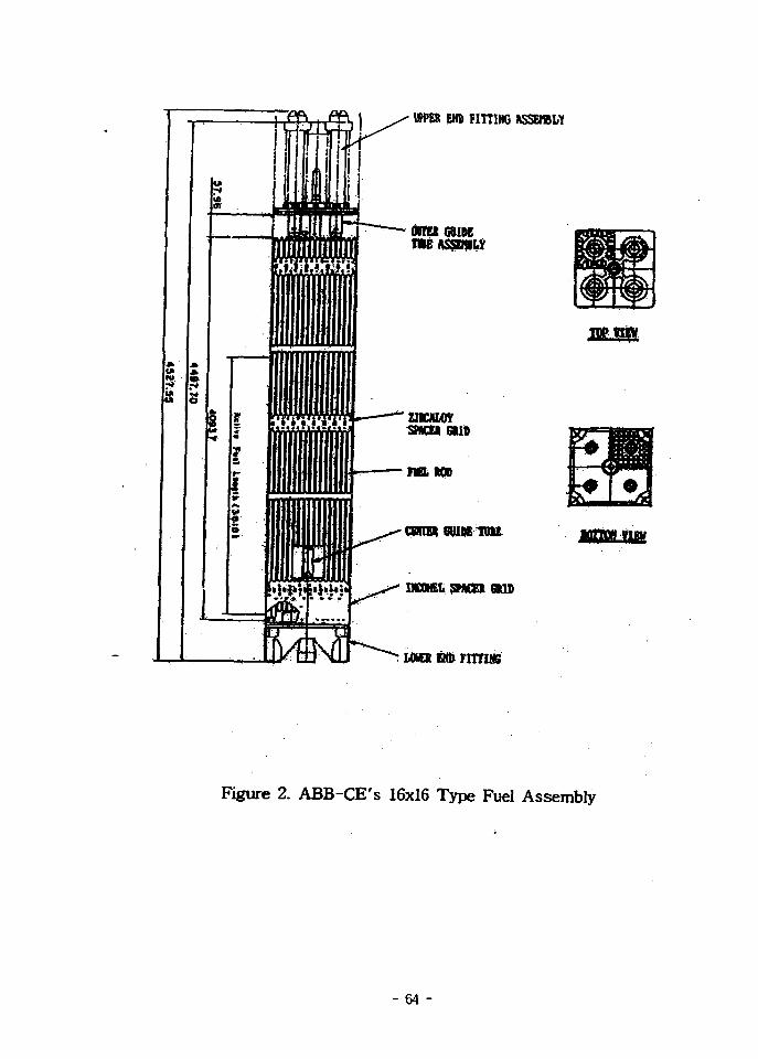
Figure 2. ABB-CE's 16x16 Type Fuel Assembly
Figure 3. Quick Release Top Nozzle (Westinghouse)
Figure 4. Upper Tie Plate (ABB-CE)
Figure 5. Upper Tie Plate Assembly (SPC)
Figure 6. Top End Piece (Siemens/KWU)
Figure 7. Fuel Failure Inspection Results (ABB-CE)
Figure 8. Axial Evaluation of Debris-Induced Fuel Rod Failure (ABB-CE)
Figure 9. Debris Filter Bottom Nozzle (Westinghouse)
Figure 10. Triple Protection Against Debris (Westinghouse)
Figure 11. Lower End Fitting (ABB-CE)
Figure 12. GUARDIAN™ Grid (ABB-CE)
Figure 13. FUELGUARD™ Lower Tie Plate (SPC)
Figure 14. Bottom End Piece with Debris Separation Sieve (Siemens/KWU)
Figure 15. Integrated Debris Filter(IDF)
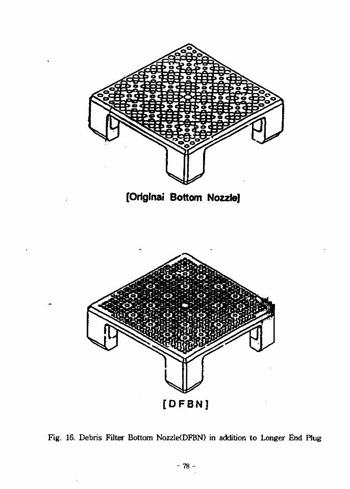
Figure 16. Debris Filter Bottom Nozzle(DFBN) in addition to Longer End Plug
Figure. 17 Debris Filter Grid in combination with Low Pressure-drop Bottom
Nozzle (Mitsubish)
Figure 18. Fine-Mesh Debris Filter Attached to New Type Bottom Nozzle
(Mitsubish)
Figure 19. Anti-Debris Drilled Hole Type Model (KAERI)
Figure 20. Anti-Debris Fin and Anti-Debris Double Fin Type Model (KAERI)
Figure 21. Westinghouse's Spacer Grid
Figure 22. Zircaloy Spacer Grid (ABB-CE)
Figure 23. Siemens/KWU's Spacer Grid
Figure 24. Vantage 5H Fuel Assembly Vibration Test Results
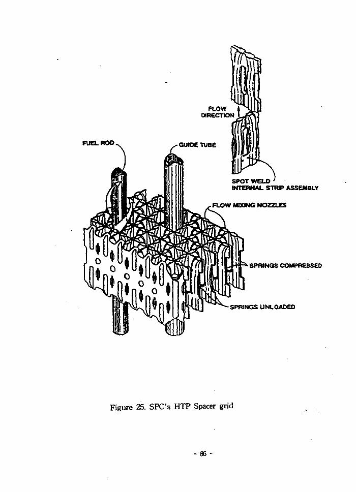
Figure 25. SPC's HTP Spacer Grid
- v -

Figure 26. SPC's IFM Grid
Figure 27. Configuration of I-type Grid and Spring
Figure 28. Finite Element Model of Fragema's Top End Piece
Figure 29. Finite Element Model of KOFA's Bottom End Piece
Figure 30. Finite Element Model of KOFA's Top End Piece
- vi -

1. *\ ۥ
TT Figure 1 3 Figure 2% £<>1 UO2
- 7 ] ^ 4 ^ s - g - A>O]OJI ^ S f ^ ^ « 1 - £ S - ^ f e 7 ) ^ n e l J L ^1^1, LOCA
Vendor
7fl
Hardware
KAERI7}- ^ - ^ ^ . S - i 3 1 $ Westinghouse ( W ) ^ ^ ^ S . ^ <a^-?] KOFA
(KOrean Fuel Assembly)7]- 1989\1 ^ 2 ^ 7 H ^-g-o .S . ^ - ^ ^ ©1 efl
- 1 -

#5.7} ABB/CE*}
^ - ^ S ) J L SIA^ 1997\! 5 ^ 3*1! WA> 1 VANTAGE
5H
ELTfl
Vendor*^ *M>°H
Vendorl-^ 7«^-§-^3)- z{- Vendor!-^
- 2 -

2.
2.1
2.1.1
3 0 4 ^ ^ . ^
Ovaloid 3 3 n^o] ^
1: ne]jl ^Hcf-c- ^^^(Holddown Spring)-^^.S. ^ 3 < H Si4
7) 7171-
2.1.2
2.1.2.1 Westinghouse (W)
Nozzle Insert) ifl-^ofl ^ ^ ^ ( L o c k Tube)
•a-(Release Top Nozzle ; RTN)t-
- 3 -
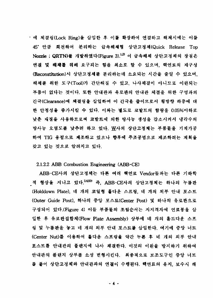
ofl « 3 (Lock Ring)-!-
45* # # 3 # * M £ 3 ^ ^*fl*l|<8 tf#:a3*fl (Quick Release Top
Nozzle ; QRTN)# 7fl£s)-^(Figure 3).u) °1
"32 gj *g*«# 3*1! -Q-^s)^ 3 # H i s tt
(Reconstitution)Al
TIG -8-3.2.
2.1.2.2 ABB Combustion Engineering (ABB-CE)
Vendort^
(Holddown Plate), Ml 7fls] 3 ^ ^ £ 4 £ ^ ^ ^ , M) 7)1^ fil-^ ojvfl
(Outer Guide Post), «1-M- f oj- 5^E.(Center Post)
Si4.(Figure 4) <>)* -¥-**5) £«^A)fe XJ
Plate Assembly) W * Ml
(Center Nut)* *>l-8-«H * 4 * ^^^J-i- ^ ^ ¥ * ^ Ml
lilt
- 4 -

oi
2.1.2.3 Siemens Power Corporation (SPC)
Siemens l
14X14 « |^S.s i ^ - ^ J L ^ ^ I ^ A B B - C E 4 ^ - ^ ^ ^ ^ ^ ^ | 7 | - cf^- Vendor
^-8-^:(Reaction Plate), Ml 7l)fil aV-g-^^ig (Reaction Spring), Ml 7flfil afl^
M^.(Locking Nuts), Ml 7flfi] -fi-*l#5l ^.(Retaining Sleeves), Ml 7fl^ ^ S ^
^(Spring Cups), «rM-5l ^<S-ulE.(Center Nut), Sj-M-s] -8-¥-Ji^^(Upper
Tie Plate)°.3. ^^s)<H alcf(Figure 5).
M M # 90°
90° ^ ^ A l ^ l ^ £.2:5.=?-*
- 5 -

JMi 90*
2.1.2.4 Siemens/KWU (KWU)
514.
Sli4.
Alofl tfJUHfr 7)7j|7V^«l-^ O ] * 3) Aj ^ ^
FOCUS ^S.ofl Al-g-^ai sa4(Figure 6).910)
_ul -g-^Sl ^V^^-i- ^ ^ A l ^ ^ 5^^ #*]-ul<a-8-^ (Electron Beam Welding
; EBW)-g-
2.1.2.5 Fragema
Fragema-M-fc KWUAV14
FragemaA>£
2.1.3ol2fl Siemens/KWU, ABB-CE
- 6 -

S14. 1995^°!] KAERISJ- S P O W # * * . £ 78*$ INGLES
KAERIS)- KNFCfe-
TIG
2.1.4
SPOM-
- 7 -

2.2
2.2.1
Plate) « £ .
^0] 304^ i iEf lufoiE^ iEflojefl^7j-^ A > ^ - ^ ^ 7l?l|7>* ^ ^ CF-8
0.03«<>l*|-S ^ ^ CF-3^- A>-g-«).7]£ «•) zfl*!
Plate)2j-
iLJl€ ABB-CES] xffiofl s}s)-£ ^ ^ f i . ^ ^ ^ ^ ^ ^o ]^ - o]
66%, ^Ml^^s)- ^S-S-?>fil Sefl^ofl s|^- ^ ^ o ] 7 %5
27%!- *M*|-jl ^ ^ ( F i g u r e 7).
8).
Sflfe o l * ^ 0 ! ^ ^ £ # # HJ-^«|-7| fl^<^ z Vendor** zj"7l ^^^ 0}
Solids
- 8 -

, oje|# t i | 3 3 ^ 3 . oi^-^ofl 3 $ 0 ^ 3 ^^ .o . 3 7 ) )
2.2.2
2.2.2.1 Westinghouse (W)
^^ol^^(Debris FUter Bottom Nozzle; DFBN)
-g- HE]JL o )#^ a j ^ f l ^ ^ ^ - ^ oii-^
(Protective Grid) ^ 3 ) 4 ^ ^ ££•§• H^«V^(ZrO2 coating) ^S.°fl cfl?»-
Si .(Figure 9 ^ 10 ^-2:) S $ a^-^s] ^ - ^ ^ - 0.05%
90%
DFBN°fl 3*11 ^ei^jL ojcfai iLjisl^4.14) 1993V!ofl S ^ ^ Jl
DFBN3 ^-S.^-^^ofl s t rap 3-£ strap
grid-to-rod fretting^-
- 9 -

^ 7j) 7fl (Triple
Protective Design Concepts ° 1 * 3 ^ 4 ^ 3 °1 37)|
ris Capture Capability)^ 3L-§-*M*l
2.2.2.1 ABB Combustion Engineering (ABB-CE)
Solid-^t- «|-ia-JL^*f|(Figure I D *
Solid «!••¥-
GUARDIAN™
TURBO™
12).
2.2.2.3 Siemens Power Corporation (SPC)
FUELGUARD™^:
Insertl- 7fl^-«l-5a4. FUELGUARD™
Blades)-!-
FUELGUARD™
- 10 -

. ^(Pressing).*
1*} ^ t f 1 ^ #^#-fr ^ ^ f 2 ^ Stf-fl* 4M*H FUELGUARD™
tful^^l- # ^ € 4 . oj5]3- FUELGUARD™^
\+^-(coolant turbulance)!- ^t3"*l ^ i ^ ^ ^
^l-ia-JMM ^-^^^r Sife grid-to-rod fretting^
2.2.2.4 Siemens/KWU (Siemens)
*\-%-1l5L $14(Figure 14)8A10)
F i n)
Siemens^ ^^rS-^lfe Figure 15^ ^°1
(Intergrated Debris Filter; IDF)* ^ ^ 4-8-«fal 5a -»4 2 £ ^ ^ 4 ^ 1 SPC
4€- Vendorl-si
2.2.2.5 Fragema
(Anti Debris Filter)* AFA-2G ^ MK-BW^iS«| ^-8-«r^4.1117) Fragema
^ 3mm ^ o ] ^
- 11 -

3 3! A3. Ji^^cf. o)^-^ o^j!}-^^^ t }^ . Vendorl-sl
AFA-3G* ^
(Laser Beam Welding; LBWH4 EBW^-S. ^ f l i^ ^ ^ J l ^ ^ ^ - s i -
Cribbed structure)^ tfl ?|f«>H pin^: 4-g-sH ^^-
o)^-^ «j-x] (advanced anti-debris plate)^-
debris°l| ^^V OJ.JE.O|| ^ ^ ^ o ^ s . 7]7(|aj 7j-£7f # ^ AISI 660
2.2.2.6 Mitsubishi^l-
a f ^ J i ^ ^ -fi-S.^sl ^ ^ - i - Figure 164 £
^^(Debris Filter Bottom Nozzle ; DFBN)4
^^(Debris-trapping Filter Grid)!-
Pressure Drop Bottom Nozzle; LPBN)» 4-8-«!-J1 Slfe^l (Figure
17 # a ) ©ll-^ ^ 4 ^ ^ r ^ A mL* ^ ^ H £A]e|
Debris Filter Grid^ strap
Debris Filter Grid^
meshl- * J I Xi^ filter*
3|(Figure 18
- 12 -

2.2.3
2.2.3.1
KAERI4 SPOl-fc- ABB-CE^
1995\!°fl
FUELGUARD™^
2.2.3.2
7H 7>^-^^ o^^ig^(Anti-debris
Drilled Hole; Figure 19)4
_^^(Anti-debris Fin)4 o ^ ^ ^ (Anti-debris Double Fin; Figure 20)J5.
? « € 4 . oil" ^
Siemens/KWU44
Vendorl-^
2.2.4 ^^/7fl^A>afloi| cfl^-
44
- 13 -

- 14 -

2.3 xl
2.3.1
#£71-
Zircaloy-45.
(ZIRLO
ABB-CEA>, Siemens/KWUAl-
4 * T= Si4(Figure 21, 22, 23).
Grid-to-rod fretting^^H tftQ
'window'l- Si°1|JL ^^-^-71131 ^o ] i - ^7}X)?]v) w e i d c u t o u t
- 15 -
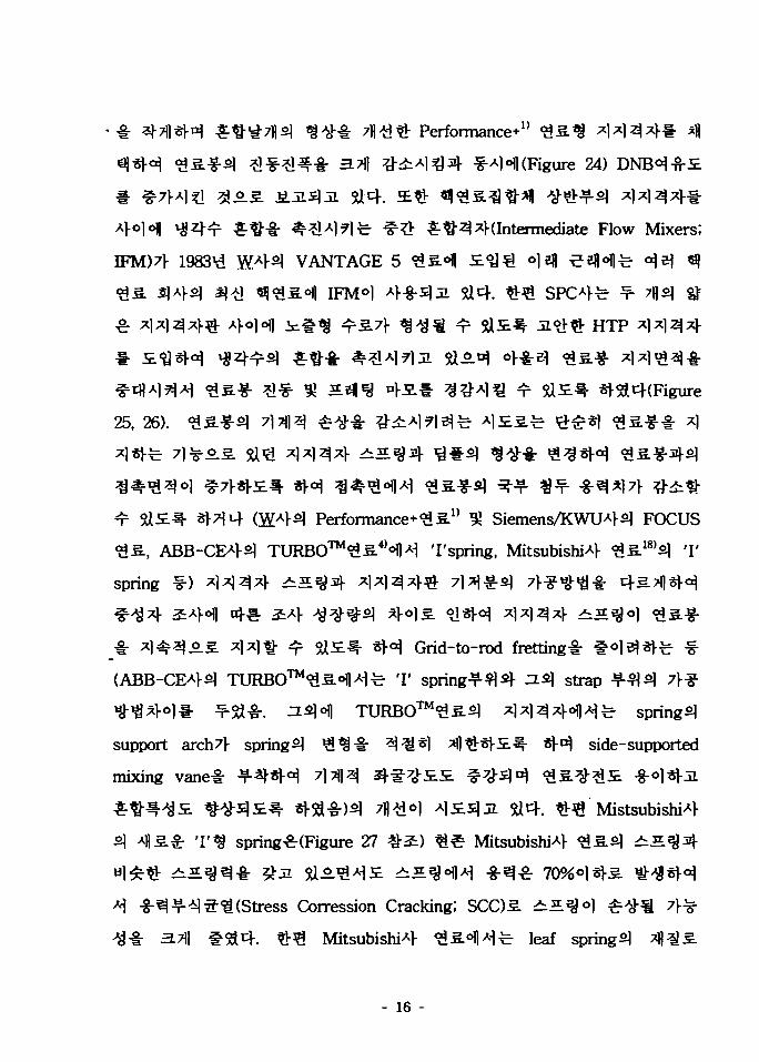
Performance*1'
-Ajofl (Figure 24)
£ # 3 ^(Intermediate Flow Mixers;
IFM)7l- 1983^ W 4 ^ VANTAGE 5
I F M 6 ]
HTP
25, 26).
(W421 Performance+^S" ^ Siemens/KWU4^ FOCUS
., ABB-CE42? TURBO™^^ 4 ^^ 'I'spring, Mitsubishi^} <9s.I8)2] 'I'
Spring ^ ) ^l
_ 4s 5 a ^ ^ * H Grid-to-rod fretting^- #
(ABB-CE4-2; TURBO™^^.^^^ T spring-?-^2} n<q strap
*1fl^-ol# ¥Sa-fr. ^ * W TURB0™££2] xlxl^^ollAi^ spring^
support arch7r spring^ ^ ^ - i - ^^) ^]^S}£.^- S)-^ side-supported
mixing vane^- -?-^-«r^ 7]A^ Q^^Z. ^7^^ £S .^? i£ . -g-ol*>j7
^ ^ i ^ ^ s ) £ ^ - «flt^-)5i 7fl^oi A ) £ S ) J I sacf. -53 Mistsubishi^l-
2] Afls. - T<g Spring^-(Figure 27 ^-S) ^ ^ Mitsubishi^}
Concession Cracking; SCO 3. i i 5 . ^ o l
Mitsubishi*} £S.°flA^ ieaf spring 2|
- 16 -

°fl Corelloy-n
SCC
TIG
beads]
EBW ^)-i-
W421 Performance*, ABB-CE^s) TURBO™ ^£(LBW
HTP ^fi(EBW V-8-) ^2] ^-a 7fl^ ^fiofl A)-g-^3i 5acj-.
Seismic
2.3.2
, Siemens/KWU^g
1987^
- 17 -

KOFA<8
2.3.3
HTP
swirling flow7V
#±*]9]7\ m ^ S * ^Ml ^ = 3SI
- 18 -

7j|^oJ|
- 19 -

3.
-8- U ^ 4 ^ S ] # 1 - f.0.3. ^ . e . ^ ^ 0 . ^ , o|fe ^ f io ] ^7fl/^|SAlaoV^ 7OV
7||«-fr ^ ^ ^ ^ 1 SUfe-H «I^£S) Hardware
i - f-^" 7|7fl/^3:^«y
- 20 -

3.1.1
ANS/ANS-51.1^25' 4 .1 .2^^^ core components.^
? £ # (core support structure)-!- ^ S r J L tt^
ASME code Section m NB-3000^
4»D . KOFA #3. f-)
ASME code Section m NB-3000°fl^
5000 /MABB-CE4
RESAR-3S
Condition I , Q
Condition IB, IV
Non-Operational(Shipping & Handling)
Note : PmP.Pb
s0sm
=0y
C u
ASME Sec.ffl
Level A, B
Level C, D
Stress Category
Pm
Pi
Pm + PiPm + Secondary
Pm
Pm + Pb
ConditionI . OS* * ^
Stress Limit
s m1.5 Sm
1.5 Sm
3.0 Sm
2.4 Sm or 1.07 Su
3.6 Sm or 1.05 S»
-
Primary Membrane Stress IntensityLocal Membrane Stress IntensityPrimary Bending Stress IntensityUltimate StrengthStress Intensitymin. of the {l/3<rymm, 2/3<rymm, 2/3<T«.T, 0S<>U.O2T)
0.2% offset yield stress,Ultimate Stress
- 21 -

3.1.2 #.
3.1.2.1
PlateH
RE. Peterson^]
3.1.2.2
ABB-CE4
# ^(Perforated
3.3.
3g7].
Siemens/KWU4
3.1.2.3
' 8 0 ^ ^ ^ Fragema4^10) 17x17^ W<8
(Adapter plate)4 ^f-^(Enclosure)-i-
(Figure 28) 1 cfl^^ i Adt(Beam element)!-
JE.«i
- 22 -
TIG
3.1.3
3.1.
cf.
ASME
ASME codes] 7
K O F A (KOrean Fuel Assembly)^
£°J ANSYS codes] 3*]-*)
^ ( F i g u r e 29 $ 30 #i)S}-:n. n
U FOCUS™^ DRBEPS]
cfl
3.1.4
3.1.4.1
-8-3.
- 23 -

Vendor** -8-
Inconel o]M- AISI
5a4.
3.1.4.2 ^ H 4 ^ - AB
Vendor**
3.2
3.2.1
LOCAM- ^1^1^4 ^ * ANS Condition m
- 24 -

3.2.2
3.2.2.1
<££.<*] 73
I«•
-o.
- 25 -

Neutron Fluence)
3,7] i »
^ S ^ £ f l , >i = ^ o)^f. gj o S-g- ^Tjoj ^^ofl
5A4.
« •
3.2.3 ^1
3.2.3.1 71) A
- 26 -

4.
FUELGUARD™
DFBN(Debris Filtering Bottom Nozzle) f-°l 514. ° H
GUARDIAN™
) 4.
^-S \J-#
- 27 -

7M-I-
5a<H
, Siemens/KWU4
71 #
- 28 -

3.2.3.2 S
Bending Vibration, Whirling Vibration, Tapping
Impacting^-S.
3.2.3.2.1
^1^^^> ^ S ^ ^ r «|^5L^^-^I - r ^ ^7lofl B14^ ^^$\ 10
3.2.3.2.2
^ ^ ^ - 0.090 ?]*1(2.286
0.045 $1*1(1.143 mm)7>
3.2.3.2.3 -fi- l
3.2.3.2.4
H ^ ^-T-oflS. 10 mils(0.254 m m ) t
- 29 -

3233 = «*«3 42-
3 .233.1 «B4
Vantage SH
# Performance*
3.2.3.3.2 ABB-CEA>
•Ml <S* 3,4 517) o | ^ 3 ^ s . < i ^x)-^ ^-^4ioJlAi A]-^-^«y « jo |a 16
X16 ^«flfe S .¥ 11 7fls) ^l^l^^^|7l-
6255. £)<H SlJL M-^^l 10
2
4 WH «j^5L?l Vantage 5H^ ^^Hl^i ^ ^ ^ ^ %$• Qo]
42-
- 30 -

3.2.3.3.3 SPC4
SPO1- «l 3 5 . 3 ^ 3 %^& ^ £)*)-&£l *]*|3*l-fe- Bi-metallic
# *JS&£.°|-4 *fl;go] ^xf^-ofl o i 3 ^ 7 1 8 ^ =
Bi-metallic
Siemens/KWU4
. ^ , Siemens/KWU^
FOCUS™
HTP (High
Thermal Performance) ^1^1^^°]4. HTP *
HTP
37fl^ IFM (Intermediate Flow Mixer)
?!4. IFM 1 ^1^^*11^ HTP
5a±IFM *W ^^1-
3.2.3.3.4 Siemens/KWUA>
2
- 31 -

3.2.3.4 SefltJ 45L
3.2.3.4.1
0)^.^0]
mode shape 1 3
WECAN 2 £ f o]-§-«)-^ ^i^S-g-sl S.E.*$$3\- *!f-^7l(frequency)
VIBAMP 2 £
OJO.DJ oj nfl«H) . -o. |ofl oj^- ^-^5L3f£ uLBJM. VIBAMP 3HS]
^J^o-S. WECAN 3.B.°\ ^z)- t ^ r ^ ^ ^ l ^ ^ l ^ ^ f e « |^S .^^-^ |
•°1°11 t -c- "^^-^-3L(axial flow distribution)^ ^#^-5.(cross flow
distribution)!-
sUding wear^ofl $*% ^>aL^-^r(wear coefficient)#
pulUng test)<Hl
ction coefficient)^
^ PAD 3 E S ° i | ^ - ,
Bettis
- 32 -

. o] 3.^ 7)
Archard £ . « ^S joa . 5U^^ o]fe cf^-s)
(local plastic deformation)«H1
Archard
1/ - SV ~ 4260//
t S = v\5L ^ &# &, .66 x 10"5)
H = •¥•
(kg/mm2), (^^i # £ 850°J)
F = ^ ^ ^ 2 1 ^ajej (lb)
L = -S-tfl*^- £<>1 (in)
V = or5L *f*\ (in3)
— r— I 4-Lc-D
l
- 33 -

D = *H<£3.& B 1 4 ^ 3 3 (in)
h = *}S. &°] ( in)
V = »}S. ** l (in3)
10
«»•§• ^ H
8171
1000 ^1?}S| m p-A^ A]^-a- f - s ) - ^ ^ ^ S I - J L $14
Tapping
- 34 -

10%
4.-o]
X14.
"I, 10 mUs (0.010 in.)s] »<>1
(Transient Condition)^
- WECAN
- IFM
- Zirconium Oxide
3.2.3.4.2
<$$.
5tU,
7l?}-oi
v\S.
(14X14, 15X15, 16
1000
3 mils(0.003 i t\
- 35 -

12
8iol ^°>Sl^- ^Efl (EOL £3)61711+, 1- 1)7)- ^Tfl (loose
cell 4
, EOL
3.2.3.4.3 SPCA>
€-^°1 ^ - ^ 4 ^ ^ ^ r »8fl«1-3. 5a4.
3? till
HTP * ] S
- 36 -

fl*H 7\% &£• LHGR(Linear Heat Generation Rate)
€• fluencel- #fe «| 3 S.#<>12.3. °1# ^
. LHGR(Linear Heat Generation Rate)*l q ^ S S - f r °l-g-*H
fluence
Bi-metalUc HTP « IFM 1000
bi-metallic * 1 *
"OH S]fe e^oflA^ nJ.JE.7V
HTP
HTPSf IFM
nj.JS.7l-
bi-metalUc
ojofl nl-sf bi-metallic
IFM
3.2.3.4.4 Siemens/KWlMl
Siemens/KWU^l-i S
n] 1000
Jg7l-SVal
FOCUS™
- 37 -

3.2.3.4
3.2.3.
£ ^ 3 . *J^3<y *^o]4. 3 ^ 4 3-g-
1000
Archard« r Si4
« •
5J
4-2-4
- 38 -

. o|n|
5a
*
^01 ^^oflujxii. 01-8-^4 -g- £ ^
eiS #-8-
5tl4.
- 39 -

3.2.4
3.2.4.1 7fl.a_
7l7)
flfccfl -fMI-ft-^-W- (Flow-Induced
Vibration; FIVH
5801*1)^-8:
Mechanism)!-
supported simple beamH4.
- 40 -

^(Single-phase flow)«|^l?> tf^olM^ ^l^-fi-W-(Two-phase flow)*]
^ 7|ol(force-excited)€
7\°$ ^-^(forcing function ^ random pressure
fluctuations)s)- -fr^|/^3:l- ^J:3)-8-(damping and couplingH
3.2.4.2
3.2.4.2.1
vane)!-
(1151,
*r?ll
^^-y-711 (mixing
Figure 31 r38' ^ ^ - ^ s ] ^ ^ u ] ^ 3 0 ] jif-o] ^ o | ^ 2 ^ (Re)7>
- 41 -

Ji Si4. Re < 402]
(downstream)°1M ^ £ $%-7
•fr^r°l * 7 r « H 40 < Re < 150 °
o.s ^^^v+71-fe- «^-(vortex shedding)<>l
-fr^-fr Strauhal number, SS. cf-g-4
S = fs D / U (1)
fs = vortex shedding frequency
D =
U =
Strauhal number^- - g ^ ^ A S . ^ # 4 . Figure 32 1- ^-ol Re <
Strauhal number^; #$7} 7)2\ &<m, Re > 100,00041^ *?-
strauhal number^ Re 2f ^^ISio] 0.18 - 0.22
LS^ ^-^l^- vortex shedding
vortex shedding ^7lfil 2afloflA
(fn)7l- o ] ^ vertex shedding^7]fif
Strauhal number (S)fe 0.3 < S < 0.7
vortex shedding0!!
Vortex shedding ^ 1 * $ H ^^-«}-^ -S?!cife 'turbulent buffeting %••&
turbulence-induced vibration'°fl S]«r^ ^*<>1 -n-^€ *r Si 4 . turbulent
- 42 -

buffeting^
(shapped band-pass filter)*] 3 *r-8-*M \*fi-
vertex shedding 4 turbulence buffeting^
. Pettigrewfif Gorman^-41'42' ©lfi ^I-^7)^-o
1 (excitation)^- random process^. 7>^«|-J1 buffeting
7>^-|- 2:Sj-^7l(harmonic)S. 7}-^«l-al vertex shedding -§-
^|oi«r5a4. Pettigrew, Gorman HE) 3! Blevins
^ ol*D*j!.Ei # ^ 1 - ^ 1 ^ - 7 l^o] fluidelastic instability
(self-excited vibration)^ ej-JL tbcf. °11-^1
Figure 332)- ^ 4 . Fluidelastic instability^- -
J . °1 ^^-^r 1961 d RoberH]
1970^°)] Connors^^ ^ ^ ^ ^ ^ c ] -g^o.S.-¥-El fluidelastic instability7}
2 ) 1 7 2Uc / fn D = 9.9 (m* / pD2)172 (2)
m = ^ ^ c ] ^ ^ (hydrodynamic mass
8 = logarithmic decrement
P =
Connors^
- 43 -

Blevinsofl damping
Connors^
^r 9.97)-
Uc / fn D = K (mS /
by Peake, K= 3.3 by Pettigrew
fluidelastic instabiUty
3.2.4.2.2
Figure 254 2 4 .
"^•§-A(pressure fluctuation W
turbulent buffeting^ -fr4«|-7fl
band-pass fil ter)^^ *J-8-*H
10"
tfl *f| s] £ 4.
(3)
(K=15.4 by Coit, K= 9.1
. °1# Figure 34°fl iL?]cf.
cfl ^ E ] (snapped
«1^I -(specific amplitude:
TMI-l, Angra,
Beaver VaUy #4.36)
fluidelastic instability^
- 44 -

Turbulent buffeting^}- G°] #*Ml*7]tt ^*£# -fr^ofH Re > 300,0(XW
A^-^cl-al Sj- -HI36' 3 « 3 $ ! 7}<&%^3.$) ±$£ 400,000 < Re <600,000^-
3. "B-BW &<>H °1 $*H t-°m4. *lf!
near-field' 2f far-field A i S . 7 ^ € 4 . near-field
shear
flowsHeJ-JL 471
Wambsganss^fl
Wambsganssfe43' power spectral density (psd)7]- -^HJ-^ ^o] x7V
^*1-534. «:« far-field
Turbulent buffeting^-
hydrodynamic coupUng-lr
turbulence buffeting^: tf#-{r^ ^-fs)- ^ ^ * 1 4 1 -
= Uo (1 + McosQtW £•& 3-f) d-Q^r?) f 7} 2fn / k (k = 1, 2, 3 H
'periodic wake shedding (- --cr parametric resonance)' o]2faL ti"4.
- 45 -

1200 rpm .2.3. 3 - f t 20 Hz, 1800 rpm^ r 3-ffe 30
cfl (0 ~ 50 Hz)7\
Hara f-«l|
u = (pA / El f1 UL
48°fl
7}
cflif u « 0.5 S
parametric resonance^ Paidoussis,
flutters)-
Eigenfrequencyfe Real(cyn)
0 and Im(£yn) <
0 °i n
Paidoussis°fl
«-« 97-100].
(4)
fluidelastic instability
433 *J-3
6.^f o ,
Imaginary(<yn)°1 5 1 ^ ^ ^ -^^r Re(<yn) =
flutter ?tft£: Re(wn) # 0 and Im(<un) <
- 46 -

4.
4.1
4.1.1
5U
. f e -g-^o)
^Ife
- 47 -

4.1.2 -&=4£ *s.
20,000MWD/MTU^
4.2 ^
4.2.1
7.}
- 48 -

7}-*! xl
5 a *
4.2.2 -fr l-8-*
instability)^- $*.2.si\
> *V^ ^ ^ « -fr# (u ^ 05)
- *11 Hl*M «« 37)
5a5ft4. ^ 3 4 -a* « l « a » *)«•
510.
- 49 -

71 £
37})
olH.7)
o. 3.7)7}
70 - l
7\JL
^ • ^ - i - &£\2) ^^ .S. e
fluidelastic instability, turbulence buffetting, n ^ J l vortex shedding f °| 2
- 50 -

fluidelastic instability
1) self-excited
2) forced vibration
3) parametric excitation
371-xlf1 2$*«3 forced vibration^
fl*H 7]-?l^-^ (forcing function)^
pressure fluctuationofl tfl^- p.s.d.
(power spectral density)* ^ ^ ^ ji-fi-a^s. -9-El ^^f 3 ^ * H
3L ^cf. tj-A] fHM -felS- p.s.d» ^ ^ 7 ] 41 « H prototyped
^«V^o> ^-cf^ 3jol4. ^ ^ -fr r ^ ^ 7l«o|A| 7|)^ o)
7\ &q slJi SI71 nij ofl 3 ^ 3 . ^ ^ . ^ 4 7 ] . ^ 6 . ^ ^ 3 1d)°fl tfl* ^^71- Si<Ho> fl ^}o.S- J i t l 4 . ^ ^ ^ l f e Conner, Paidoussis,
Chen, nelJL Wambsganss *«>1 A
- 51 -
(coupling)-i-
4.2.3
Si0.4 4.2.1 U 4.2.2ofl^^ <y^.^^:3 j .^ ^s_s_
J-5.S SBfl«!} nj.Jg.ofl
4-8-4
- 52 -

4.2.3.1 Sefl*e £>£s} jtal|^«J-^ SIM (Solid Mechanical Analysis)
•i-
(1)
(2)
SMr «H («|a^ HTP Grid
- 53 -

°l-g-*M -§-3 *l)^£ «• *r S i - ^ Fourier
Transform £^r -fr$.flL4i*l|4j ^Ij-I: <>l-g-SM°> $ 4 .
(3) 4 a ol^-i-fi] AJAJ£ $}# ^ ^ A]ofl #<go|
7}^(Criteria)*
5U
)(Mixing
- 54 -

4.2.3.2 -g^-fr •§•# - eflfJ £ # £«fi^ (Experimental Analysis &
Fretting Damage Modeling)
£.'8(Archard model)-!- S
7)^-8- ?J-ji Si^ *^r Si£.4 Steam Generator U-TubeS] ^
S°l ' S T 1 ^ ^ J8t^ NRCC (National Research Council Canada) a ^
AECL( Atomic Energy Canada Limited) £) CRNL(Chalk River Nuclear
4.2.4
- 55 -

full size *]£jicHr -f-ii 5x5
full size
- 56 -

5.
1)
2)
3)
- 57 -

REFERENCES
[I] Fuel presentation to KNFC, Westinghouse Presentation Material, 1996.
[2] S.L. Davidson, Reference Core Report VANTAGE 5 Fuel Assembly,
WCAP 10444-P-A, Westinghouse, 1985.
[3] C.L. Cling et al, "ABB Combustion Engineering Nuclear Fuel
Performance Target : Zero Defects, " Proceedings of the 10th KAIF/KNS
Annual Conference, 1995.
[4] TURBO and Korea, ABB-CE Presentation Material, 1996.
[5] R.B. Stout et al, "Presentation to KAERI on Siemens Fuel Group and
the HTP Fuel Design," 1995.
[6] Siemens Fuel Group and the HTP Fuel Design, SPC Presentation
Material, 1996.
[7] R.B. Stout et al, Presentation to KAERI on the HTP Fuel Design,
1994.
[8] FOCUS and HTP Fuel Assemblies for Pressurized Water Reactors,
- Siemens Brochure, 1990.
[9] Advanced Design Features for FOCUS Fuel Assembly, Siemens
Brochure, 1990.
[10] R. Holzer et al, "Fuel Design Advancements by Application of
Siemens FOCUS Technology," Proceedings of the 7th KAIF/KNS Annual
Conference, 1992.
[II] Fragema's Mechanical Design Report, 900 MWe STD Fuel Assembly,
ITB/84/4093, Rev.0, 1988.
[12] Fragema Upgrades the AFA, Fragema Brochure, 1990.
[13] £-§-S*1 13S!,"«I£3. -¥•§• 7)^7^: KAERI/RR-1026/90.
- 58 -

[14] H. W. Wilson et al., "Westinghouse Fuel Performance in Today's
Aggressive Plant Operating Environment," ibid, pp.23-30.
[15] Z. E. Karoutas et al., "ABB-CE's Advanced PWR Fuel Design," The
Fifth International Topical Meeting on Nuclear Thermal Hydraulics,
Operations and Safety(NUTHOS-5), Beijing, China, Apr. 14-18, 1997, pp.
U3-1-U3-8.
[16] K. N. Woods et al., "Siemens Fuel Performance Overview, "ibid, pp.
272-279.
[17] Gilles Ravier et al., "Framatone and FCF Recent Operating Experience
and Advanced Features to Increase Performance and Reliability," ibid, pp.
31-36.
[18] S. Abeta et al., "Design and Performance of Mitsubishi PWR Fuel for
Increased Reliability," Procedeeings of the 1997 International Topical
Meeting on LWR Fuel Performance, Portland,Oregon, Mar.2-6,1997,
pp.309-317.
[19] °}4%, ° ) # ^ ^ 4 SJ-^JI^^I 7fl£, KAERI/RR-1266/93, 1993.
[20] « a ^ ^ , °1*D3, s i -^a l^^ l -ffS.#£] ^ M %%#, KAERJ/TR-518/95,
1995.
[21] U34, £^a , 3^3. **<&s- *t#5L$n *s.#s\ ^n %*m, j . Of
the KNS, Vol. 27, No. 6, 1995.
[22] Advanced Light Water Reactor Utility Requirement Document, Rev. 5,
EPRI, 1992.
[23] *Hje $ 2U -frft-fi-i'S* «l-8-^ *]x}qx\ ^ 5 ^ ^ ^RJ*I)4H
^ ^ , KAERI/TR-523/95, 1995.
[24] £ 3 3 : , ^^fl 'SS.-g- ^1^1^-^^ ajl#,g- ^ ^ S-'fi 7m, KAERI >
-, 1995.
- 59 -

[25] ANSI/ANS-51.1-1983, American National Standard Nuclear Safety
Criteria for the Design of Stationary Pressurized Water Reactor Plants,
[26] W.D. Rabenstein, Mechanical Tests and Evaluation of the 17x17
Optimized Fuel Assembly and Components, WCAP-9363, 1979.
[27] K.N. Song, "Design of the Fuel Assembly Structure with Zircaloy
Spacer Grids," KWU Work Report, U6 312/87/e278, 1987.
[28] K.N. Song and D.S. Sohn, "A Study for the Improvement of Top End
Piece Structural Strength," J. of the Korean Nuclear Society, Vol. 21,
No. 3, 1989.
[29] M.D. Beaumont and J. Skaritka, Verification Testing and Analyses of
the 17X17 Optimized Fuel Assembly, WCAP-9401, 1979.
[30] L. Gesinski, Mechanical Test and Evaluation of the 17X17 Fuel
Assembly, WCAP-8286, 1974.
[31] F. Garzarolli et al, "9th International Symposium on Zirconium in the
Nuclear Industries," 1990.
[32] L.G. Stephens, Bi-metallic Spacer Friction Forces and High Thermal
Performance Friction Forces, Cell Sizes, and Doublet Stiffness Tests,
ANF-DTA-457, Rev. 2.
[33] K.N. Song and K.S. Seo, "A Characteristic Analysis on the Elastic
Stiffness of the Tapered-width Leaf Type Holddown Spring Assembly
Designed in KOFA's Design Space," J. of the Korean Nuclear Society,
Vol. 28, No. 6, 1996.
[34] K.A. Elliott, Results of the 1000 Hours Fretting Test for the ANF 17
X17 HTP Fuel Assembly, EMF-92-123(P), Rev.O.
[35] 3 3 ^ 3 , 3.<&±^ «I^^L 7J11M- Jfl# 7}#7]<g « ! T \ KEPRI94Z-J05,
!, 1995.
- 60 -

[36] M.W. Ken-ard et al, A Study cf Grid-to-Rod Fretting Wear in PWR
Fuel Assemblies, The S.M. Stoller Corporation, 1995.
[37] J.F. Archard, "Contact and Rubbing of Flat Surfaces," J. of Applied
Physics, Vol. 24, No. 8, 1953.
[38] Robert D. Blevins, Flow-Induced Vibration, Van Nostrand Reinhol&
1990
[39] M. J. Pettigrew, "Vibration analysis of heat exchanger and steam
generator designs," Nuclear Engineering and Design Vol. 48(1978) pp.
97-115
[40] R.M.C. So and Savkar, "Buffeting forces on rigid circular cylinders in
cross flows," Journal of Fluid Mechanics VoL 105 (1981) pp. 397-425
[41] M. J. Pettigrew and D. J. Gorman, Vibration of heat exchange
components in liquid and two-phase cross flow, paper 2.3 in Proceedings
BNES International conference, 1978
[42] M. J. Pettigrew and D. J. Gorman, "Vibration of heat exchanger tube
bundles in liquid and two-phase cross flow," PVP-Vol. 52(1981) pp.
89-110
[43] M. P. Paidoussis, "A review of flow-induced vibrations in reactor
components," Nuclear Engineering and Design, Vol. 74(1982) pp. 31-60
[44] H.J. Jr. Connors, "Fluidelastic vibration of tube arrays excited by
cross flow," ASME-Flow-induced vibration in heat exchangers, New
York (1970) pp. 42-56
[45] R.D. Blevins, "Fluidelastic whirling of tube rows and tube arrays,"
ASME-Joumal of Fluid Engineering VoL 99(1977) pp. 457-460
[46] R.D. Blevins, "Fluid damping and whirling instability of tube arrays,"
S.S Chen (eds) ASME-Fluid-Induced vibrations, (1979) pp. 35-39
- 61 -

[47] M.W. Wambsganss, T.M. Mulcahy, Flow-induced vibration of nuclear
reactor fuel'- Part I, Modeling,
[48] M.P. Paidoussis, "Fluidelastic vibration of cylinder arrays in axial and
cross flow, state of the art," Journal of Sound and Vibrations, Vol. 76
(1981) 326-360
[49] Shin, Y.W., Two-phase flow-induced vibrations of Rods in parallel
flow: A state of the art review, GEAT-24148/ANL-CL-78-18/C004175-4
(1978)
[50] L. V. Corsetti et al., Improved BWR and PWR Fuel Designs and
Operating Experience at ABB, pp. 280-286.
[51] Aisch and Schmucker, Minimum Necessary Spacer Springs Force,
KWU Work Report, B12/el67/79, 1979.
[52] R. E. Peterson, " Stress Concentration Factors," 1974, John Wiley &
Sons, New York.
[53] R. S. Miller et al., "Westinghouse Fuel Operating at High Burnup and
with Advanced Features," International Topical Meeting on LWR Fuel
Performance, 1994.
[54] & « 3 9^, " tf.*r# 5
-H," KAERI/TR-866/97, 1997.
- 62 -

BOTTOM I-MP PIE'CK
Figure 1. KOFA 17x17 Type FueJ Assembly
j ^ UPPER END FITTING ASSEMBLY
taasmSMCUGIID
OTTO 8QIK1UU
OCBKt 5MCEI GRID
LOHEK END FITtttB
Figure 2. ABB-CE's 16x16 Type Fuel Assembly
- 64 -

Top Plate L-ORTN L SupportEdge Joini(iG) insert
location (0)
InslrumenlTube Hole
^ n s * n Sleeve^ (Umgaan
GuW» Tlwntrie!
Figure 3. Quick Release Top Nozzle (Westinghouse)
- 65 -

FUEL ASSEMBLYSERIAL NUKBER
OUTER POST (4)
HOLOOOUN PLATE ( I )
HOLOOOVM SPRING (4)
CEHTER POST ( I )
FLOW PLATE ( I )
Figure 4. Upper Tie Plate (ABB-CE)
- 66 -
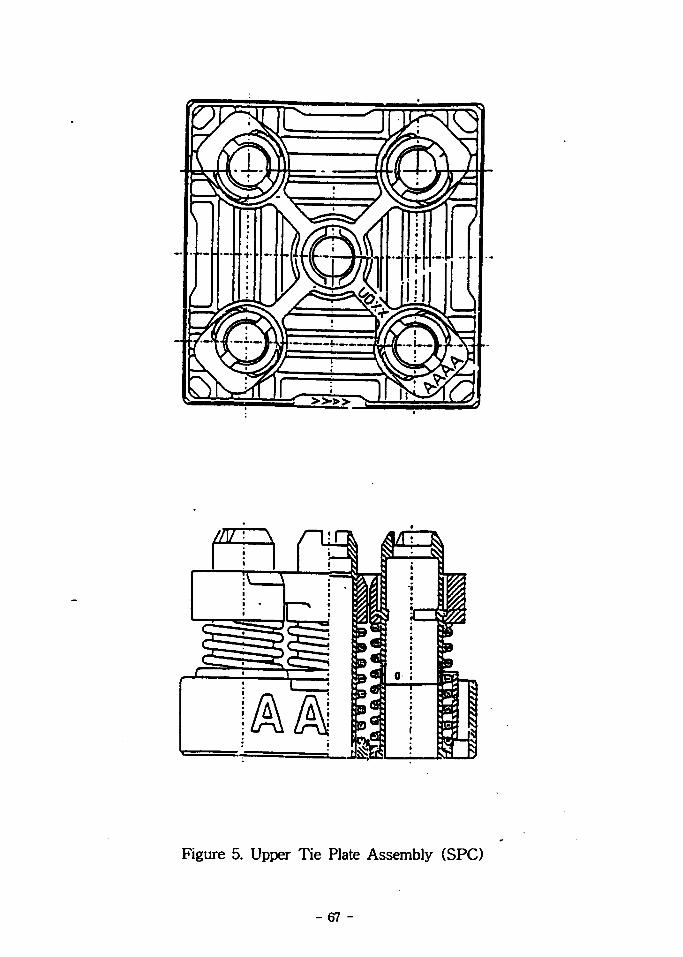
Figure 5. Upper Tie Plate Assembly (SPC)
- 67 -

Figure 6. Top End Piece (Siemens/KWU)
- 68 -

Debris Fret t ing66% Unknown Cause
27%
Grid- to-Rod Frett ing7%
Figure 7. Fuel Failure Inspection Results (ABB-CE)
- 69 -

ApproilmaieElevation olCenter a< LowarSupport A/th*( l . U Incnesl
IncfMS•ollom of
Elevation olLower Cage olflrw u X UG/td Ctae12-30 incites)
\
Solid Meiom ^\j O . .ol Fuel Hi-'End Cap(O.J« I
7 V V
Actual Cl««atian ol C M I M T II< Support Arcn^47 lnen«a. tmorior Suip. 2M IDCIMC. Cst««Mton Slnp
4.0
3.0
2.0
ia) 4 Fud
App<aatnui«Cloviriofl olCenter ol LowerSupport
\A 1
Lowar (oo* olK m if X K
Solid Moiohlol fuel Hod
(0.C3 Indies)
I
•noesFro*•oiiom olfuel Aod
1.0
1.0
0
Actual eievalion o< Cemer ol Support'Arcn2.00 Inches. MNenor Strip. 2.04 Incite*. Etttmion Strip
f\tm\ Hod erlorawon
fuel Hod w«ar
<h> Iri.xlrj
Figure 8. Axial Evaluation of Debris-Induced Fuel Rod Failure (ABB-CE)
- 70 -POORCMMUTYI
ORiam

Fuel Rod
flow Hole
Grid Dimple
Bollom View
Figure 9. Debris Filter Bottom Nozzle (Westinghouse)
- 71 -

Coated cladding
Protective grid,fonger-«nd *plugs
DFBN
Coated CladdingN. fifejR Bottom<Support Grid
InnerStrapHeight
ProtectiveGrid
Solid Bottom End P1u«
Figure 10. Triple Protection Against Debris (Westinghouse)
- 72 -

OOOQOOQQQOCDee
o -T--' ooeoooooo®ooooooooooooooooo 050 oooooo
OOOOOOOCbOOOOOOQ-OO ^ OOOOO .-;£N OOOOf£>4OOOOOf^OOO O f £ > O O O O O ^ O OOO ^ ' ' OOOOO ' OO000000000000000NOQQOQQQQOQQOQOQJ
• FLOW HOLE
U i LV^> I Kli :
CIRCUUR GROOVE FORRECEIVING THE CENTERGUIOE TUBE
LEAO-IN FOR THE IN-CORE INSTR,
Figure 11. Lower End Fitting ( A B B - C E )
- 73 -

BOTTOM NOZZLEFLOW HOLE
FUEL RODS
GUARDIAN STIUIM-VG FEATURES
Figure 12. GUARDIAN™ Grid (ABB-CE)
_ 74 _

Hods
QoltoittSpacer \ J • '
Luv/er I: mlCap
f.owcrtie IM.He
Cut veilni;«ics
OOllOliOIIUflollli
Figure 13. FUELGUARD™ Lower Tie Plate (SPC)
- 75 -

/ll II II II 1 (,
11 I I I I I I Jl I I 11-11 I I I I . I I S
V
/ | n i . . L L t in 1,1.. lt
\ \
•41II II
\
I I J l • I I I I - .11. I I . . I I . . I I V
Figure 14. Bottom End Piece with Debris Separation Sieve (Siemens/KWU)
- 76 -

Fig. 15. Integrated Debris Filter (IDF)
- 77 -
[Original Bottom Nozzle]
[OFBN]
Fig. 16. Debris Filter Bottom Nozzle(DFBN) in addition to Longer End Plug
- 78 -

] Grid a * Debris Filter
Grid
LP8N |
[zifcaloy Grfd FuaQ
Fig.17 Debris Filter Grid in combination withLow Pressure-drop Bottom Nozzle (mitsubishn)
Fig. 18 Fine-Mesh Debris Filter Attached to New
Type Bottom Nozzle (Mitsubishi)
- 79 -

I I
SECTIDN B - B
3 Type Hole
2 ) < ^ 4 = 1 0 . ,3 ) 0i=lO.5mr%
Figure 19. Anti-Debris Drilled Hole Type Model (KAERI)
- 80 -

Fig. 20. Anti-Debris Fin and Anti-Debris Double Fin Type Model (KAERI)
- 81 -

Guide Thirtle Sleeve Guide Vanes
Mixing Vanes
Guide Tabs
Grid Spring Support Qtapie
IdentificationHole
Figure 21. Westinghouse's Spacer grid
- 8 2 -

BACKUP ARCH
SPRING TAB
ARCH
INTERSECTIONWELO
GUIOE TUBELOCATIONS
ROD PITCH
SEAM WELD LEAD-IN TAB
Figure 22. Zircaloy Spacer Grid (ABB-CE)
- 83 -

Figure 23. Siemens/KWU's Spacer grid
- 84 -

Vibration Amplitude
LWithout Corrective Actions
With Rotated Gods —
r With Redesijped Grids
1200 1300 1400 1500 1600 1700
Flow Rdl# (Qpffl)
1800 1900 2000
Figure 24. VANTAGE 5H Fuel Assembly Vibration Test Results
- 85 -
FUEL ROD
FLOWDIRECTION
GUIDE TUBE
SPOT WELDINTERNAL. STRIP ASSEMBLY
FLOW MIXING NOZZLES
• SPRINGS COMPRESSED
SPRINGS UNLOADED
Figure 25. SPC's HTP Spacer grid
- 86 -

FLOWDIRECTION
GUIDE TUBE
RJELROO
FLOW MIXINGNOZZLES
Figure 26. SPC's IFM grid
- 87 -

Spring hi* 6t " I -
Figure 27. Configuration of I-Type Grid and Spring

Figure 28. Finite Element Model of Fragema's Top End Piece
- 89 -

!
I
k*GSC5 ( t lx*d ac):kaOSfS.i . c-15 . 5 . O-45-5 { 19 . 5/ -Otnra)
51]
H 1
Si
1i
1
Figure 29. Finite Element Model of KOFA's Bottom End Piece
- 90 -

Figure 30. Finite Element Model of KOFA's Top End Piece
- 91 -

^ *1 3 Ji <£ Q
*********
KAERI/TR-865/97
(TR.AR°] 3-f T*1*H
Hi ^ O t j ^-
92 pages
INIS
•^^T?" ^ -S-^ •§•'^•5., I8'3<l!?i ( ^ T S . ^ ^
£ S. 5fl*( v ), « » ( )
A £3 -7I] uL p] \
1£<8'd ! 1997.06
3 7l 19x26 Cm.
± ^(15-2O#M1^)
71 i
^ ^ Jl^^fi) ^4- ASME code*) •8-^/y7fl7l^«H| Jf^-^fe -tlsl^ •££
2] Hl-id^ ^l^lTl^- €-^7)^ , 'gB.^sl •fr D-ff-U' - sfl-^?!^, ^S.-8-fil
(lO'S'^ifls])

BIBLIOGRAPHIC INFORMATION SHEET
Performing Org.
Report No.
Sponsoring Org.
Report No.
Stamdard Report
No.INIS Subject Code
KAERI/TR-86B/W
Title/SubfitteDevelopment Status and Research Directions onthe Structural Components of the Fuel Assembly
Projectland Department
fSong. Kee Nam(LWR Fuel Development Team)
Researcher and
Department
Kim, Hyung Kyu; Kang, Heung Seok;
Yoon, Kyung Ho; Bang, Je Geon
(LWR Fuel Development Team)Publication
PlaceTaejon Publisher KAERI
Publication
Date1997. 06.
Page 92 p. 111. & Tab. Yes( V ), No ( ) Size 19x26 CmNote
ClassifiedOpen(V), Restricted(
Class DocumentReport Type Research Report
Sponsoring Org. Contract No.
Abstract
(15-20 Lines)
Survey on the structural components of the state-of-the art of the PWRfuel assembly developed by various nuclear fuel vendors has been performed.As a result, some developmental directions and mechanical/structural basictechnology to be established for these structural components have been drawnout The developmental directions are as follows-' The top end piece shall bedesigned in shape to reduce its height to accomodate the fuel rod growth forhigh burnup and to have a function for easy reconstitution of the fuel assembly.The bottom end piece shall be designed in shape to reduce its height toaccomodate the fuel rod growth for high bumup and to have a function ofdebris protection. The spacer grid shall be designed in shape to have a functionof enhancing the thermal margin and maintaining the fuel rod integrity withoutfuel failure due to fuel rod fretting and vibration. The mechanical/structuralbasic technology which must be established is as follows: The stress analysisresults shall comply with the stress criteria specified in the ASME code stresslimits and the shape optimization technology shall be developed for thetop/bottom end pieces. For the spacer grid cell, the nonlinear analysis model ofthe fuel rod and the analysis model on the flow-induced fuel rod vibration, anda study of the mechanism and a quantified model on the fuel rod fretting wearshall be developed. In addition, numerical analysis model to estimate thebuckling strength of the spacer grid assembly shall be developed. Besides abovetechnology, technology related the verification test should be developed.
Subject Keywords(About 10 words)
Top End Piece, Bottom End Piece, Spacer Grid, Fuel Rod FrettingWear, Flow Induced Vibration, Buckling Strength