
Kop-Flex - KD Disc Couplings Catalog
30
Industrial Products Couplings Catalog
Transcript of Kop-Flex - KD Disc Couplings Catalog

Industrial Products Couplings Catalog

7
Higher Torque Ratings, Similar toGear Couplings
Excellent BalanceCharacteristics
Index: PageTechnical Advantages ............................................. 8Selection Procedure ............................................... 9Disc Pack Descriptions ........................................... 9Service Factors ..................................................... 10Dynamic Balancing Guide .................................... 11Product Overview and Index.......................... 12 - 13KD Slide Disc Coupling Comments ............... 14 - 15KD1 Close Coupled ....................................... 16 - 17KD10 Close Coupled ..................................... 18 - 19KD11 Close Coupled ..................................... 20 - 21KD2® Spacer Coupling .................................. 22 - 23KD20 Spacer Coupling .................................. 24 - 25KD21 Spacer Coupling .................................. 26 - 27KD33 Cooling Tower Coupling .............................. 28 KD4 Single Flex .................................................... 29KD41 & KD41T Floating Shafts ..................... 30 - 31KD42 & KD42T Floating Shafts ..................... 32 - 33KD42S Slide Floating Shafts ......................... 34 - 35
KD®
Disc CouplingsSize 053 through 905
Non-Lubricated forSimplified Maintenance

8
KD® DISC CouplingsKD Series of flexible shaft couplings provides reliable transmission of mechanical power from driving to driven machine where a low-maintenance, non-lubricated coupling is required.
KD® Disc Couplings are specifically designed to accommodate general purpose drive system applications such as cen t r i f uga l pumps, compressors, generators, cooling towers, machine tools, printing and pulp and paper machines.
KD® Couplings transmit torque and provide for both angular and axial misalignment between shafts with a coupling comprised of shaft mounted hubs connected through flexible disc packs with spacer or sleeve assemblies.
All KD® Couplings use stainless steel discs as flexible members, providing high strength and good corrosion resistance. The streamline disk pack design results in the reaction load on equipment bearings being minimized. These disc pack couplings are inherently self-centering; additional provision for limited end float is not required.
Most disc packs are unitized and, along with self-locking nuts, they greatly reduce the number of loose parts, thus simplifying installation and replacement.
KD® Disc Couplings are now available in an expanded range of sizes and styles suitable for common installations. Or if you need something special, we can design a coupling to meet your specific requirements.
KD® Disc Couplings

9
MT disc pack [ Medium Torque ] unitized, 3 bolt disc with “prestretch”
bushings that get pressed into the flanges, uses standard fasteners.
KD1, 2
HT disc pack [ High Torque] unitized, 3, 4 or 5 bolt discs, thicker
for high torque, body fit bolts. KD11, 20, 21, 22, 4, 41, 42
HS disc pack [ High Torque - Semi-unitized ] same as HT but semi-unitized so that
the disc packs may be installed out between close-coupled hubs.
KD10
CT disc pack [ Cooling Tower ] unitized, 3 bolt disc for cooling
tower couplings, stainless steel components with body-fit bolts.
KD33
1. Coupling Style: Select the appropriate KD® coupling style for your application from the Product Overview & Index.
2. Coupling Size: Step 1: Determine the proper service factor from page 10
Step 2: Calculate the required HP/100 RPM, using the HP rating of the drive and the coupling speed (RPM) as shown below:
HP x SERVICE FACTOR x 100 = HP/100 RPM RPM
Step 3: Select the coupling size having a rating sufficient to handle the required HP/100 RPM at the appropriate service factor.
Step 4: Verify that the maximum bore of the coupling selected is equal to or larger than either of the equipment shafts.
Step 5: Check the overall dimensions to ensure the coupling will not interfere with the coupling guard, piping, or the equipment housings and that it will fit the required shaft separation.
3. Check Balance Requirements Consult the Dynamic Balancing Guide on page 11 to help determine if balancing is required. Verify that the maximum operating speed does not exceed the maximum speed rating of the coupling.
The maximum speed rating does not consider lateral critical speed considerations for floating shaft applications.
4. Specify Shaft Separation Specify the required shaft separation using standard length, if possible. Verify the actual shaft separation for a replacement application.
Note: Care must be exercised in proper selection of any shaft coupling. The Users must assure themselves that the design of the shaft to coupling hub connection is adequate for the duty intended.
KD® Disc Couplings
Disc Pack DataSelection Procedure
10
KD® Disc Couplings
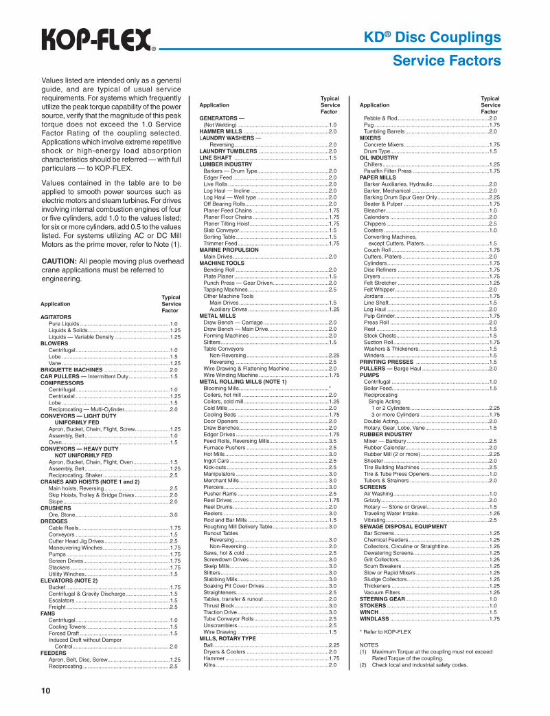
Service Factors
TypicalApplication Service FactorAGITATORS
Pure Liquids ...........................................................1.0Liquids & Solids ......................................................1.25Liquids — Variable Density ....................................1.25
BLOWERSCentrifugal ..............................................................1.0Lobe .......................................................................1.5Vane .......................................................................1.25
BRIQUETTE MACHINES ...........................................2.0 CAR PULLERS — Intermittent Duty ...........................1.5 COMPRESSORS
Centrifugal ..............................................................1.0Centriaxial ..............................................................1.25Lobe .......................................................................1.5Reciprocating — Multi-Cylinder ..............................2.0
CONVEYORS — LIGHT DUTY UNIFORMLY FEDApron, Bucket, Chain, Flight, Screw .......................1.25Assembly, Belt ........................................................1.0Oven .......................................................................1.5
CONVEYORS — HEAVY DUTY NOT UNIFORMLY FEDApron, Bucket, Chain, Flight, Oven ........................1.5Assembly, Belt ........................................................1.25Reciprocating, Shaker ............................................2.5
CRANES AND HOISTS (NOTE 1 and 2)Main hoists, Reversing ...........................................2.5Skip Hoists, Trolley & Bridge Drives .......................2.0Slope ......................................................................2.0
CRUSHERSOre, Stone ..............................................................3.0
DREDGESCable Reels ............................................................1.75Conveyors ..............................................................1.5Cutter Head Jig Drives ...........................................2.5Maneuvering Winches ............................................1.75Pumps ....................................................................1.75Screen Drives .........................................................1.75Stackers .................................................................1.75Utility Winches ........................................................1.5
ELEVATORS (NOTE 2)Bucket ....................................................................1.75Centrifugal & Gravity Discharge .............................1.5Escalators ..............................................................1.5Freight ....................................................................2.5
FANSCentrifugal ..............................................................1.0Cooling Towers .......................................................1.5Forced Draft ...........................................................1.5Induced Draft without Damper Control ................................................................2.0
FEEDERSApron, Belt, Disc, Screw.........................................1.25Reciprocating .........................................................2.5
TypicalApplication Service FactorGENERATORS —
(Not Welding) ............................................................1.0HAMMER MILLS ........................................................2.0LAUNDRY WASHERS —
Reversing ..............................................................2.0LAUNDRY TUMBLERS ..............................................2.0LINE SHAFT ..............................................................1.5LUMBER INDUSTRY
Barkers — Drum Type ...............................................2.0Edger Feed ...............................................................2.0Live Rolls ..................................................................2.0Log Haul — Incline ...................................................2.0Log Haul — Well type ...............................................2.0Off Bearing Rolls .......................................................2.0Planer Feed Chains ..................................................1.75Planer Floor Chains ..................................................1.75Planer Tilting Hoist ....................................................1.75Slab Conveyor ...........................................................1.5Sorting Table .............................................................1.5Trimmer Feed ............................................................1.75
MARINE PROPULSIONMain Drives ...............................................................2.0
MACHINE TOOLSBending Roll .............................................................2.0Plate Planer ..............................................................1.5Punch Press — Gear Driven.....................................2.0Tapping Machines .....................................................2.5Other Machine Tools Main Drives ...........................................................1.5 Auxiliary Drives .....................................................1.25
METAL MILLSDraw Bench — Carriage ...........................................2.0Draw Bench — Main Drive ........................................2.0Forming Machines ....................................................2.0Slitters .......................................................................1.5Table Conveyors Non-Reversing ......................................................2.25 Reversing .............................................................2.5Wire Drawing & Flattening Machine ..........................2.0Wire Winding Machine ..............................................1.75
METAL ROLLING MILLS (NOTE 1)Blooming Mills ...........................................................*Coilers, hot mill .........................................................2.0Coilers, cold mill ........................................................1.25Cold Mills ..................................................................2.0Cooling Beds ............................................................1.75Door Openers ...........................................................2.0Draw Benches ...........................................................2.0Edger Drives .............................................................1.75Feed Rolls, Reversing Mills .......................................3.5Furnace Pushers ......................................................2.5Hot Mills ....................................................................3.0Ingot Cars .................................................................2.5Kick-outs ...................................................................2.5Manipulators .............................................................3.0Merchant Mills ...........................................................3.0Piercers .....................................................................3.0Pusher Rams ............................................................2.5Reel Drives ...............................................................1.75Reel Drums ...............................................................2.0Reelers .....................................................................3.0Rod and Bar Mills .....................................................1.5Roughing Mill Delivery Table .....................................3.0Runout Tables Reversing ..............................................................3.0 Non-Reversing ......................................................2.0Saws, hot & cold .......................................................2.5Screwdown Drives ....................................................3.0Skelp Mills .................................................................3.0Slitters .......................................................................3.0Slabbing Mills ............................................................3.0Soaking Pit Cover Drives ..........................................3.0Straighteners.............................................................2.5Tables, transfer & runout ...........................................2.0Thrust Block ..............................................................3.0Traction Drive ............................................................3.0Tube Conveyor Rolls .................................................2.5Unscramblers ............................................................2.5Wire Drawing ............................................................1.5
MILLS, ROTARY TYPEBall ............................................................................2.25Dryers & Coolers ......................................................2.0Hammer ....................................................................1.75Kilns ..........................................................................2.0
TypicalApplication Service Factor
Pebble & Rod ............................................................2.0Pug ...........................................................................1.75Tumbling Barrels .......................................................2.0
MIXERSConcrete Mixers ........................................................1.75Drum Type .................................................................1.5
OIL INDUSTRYChillers ......................................................................1.25Paraffin Filter Press ..................................................1.75
PAPER MILLSBarker Auxiliaries, Hydraulic .....................................2.0Barker, Mechanical ...................................................2.0Barking Drum Spur Gear Only ..................................2.25Beater & Pulper ........................................................1.75Bleacher ....................................................................1.0Calenders .................................................................2.0Chippers ...................................................................2.5Coaters .....................................................................1.0Converting Machines, except Cutters, Platers ...........................................1.5Couch Roll ................................................................1.75Cutters, Platers .........................................................2.0Cylinders ...................................................................1.75Disc Refiners ............................................................1.75Dryers .......................................................................1.75Felt Stretcher ............................................................1.25Felt Whipper ..............................................................2.0Jordans .....................................................................1.75Line Shaft ..................................................................1.5Log Haul ...................................................................2.0Pulp Grinder ..............................................................1.75Press Roll .................................................................2.0Reel ..........................................................................1.5Stock Chests .............................................................1.5Suction Roll ...............................................................1.75Washers & Thickeners ..............................................1.5Winders .....................................................................1.5
PRINTING PRESSES ................................................1.5PULLERS — Barge Haul ............................................2.0PUMPS
Centrifugal ................................................................1.0Boiler Feed ................................................................1.5Reciprocating Single Acting 1 or 2 Cylinders ....................................................2.25 3 or more Cylinders .............................................1.75Double Acting............................................................2.0Rotary, Gear, Lobe, Vane ..........................................1.5
RUBBER INDUSTRYMixer — Banbury ......................................................2.5Rubber Calendar.......................................................2.0Rubber Mill (2 or more) .............................................2.25Sheeter .....................................................................2.0Tire Building Machines .............................................2.5Tire & Tube Press Openers .......................................1.0Tubers & Strainers ....................................................2.0
SCREENSAir Washing ...............................................................1.0Grizzly .......................................................................2.0Rotary — Stone or Gravel .........................................1.5Traveling Water Intake ...............................................1.25Vibrating ....................................................................2.5
SEWAGE DISPOSAL EQUIPMENTBar Screens ..............................................................1.25Chemical Feeders .....................................................1.25Collectors, Circuline or Straightline ...........................1.25Dewatering Screens..................................................1.25Grit Collectors ...........................................................1.25Scum Breakers .........................................................1.25Slow or Rapid Mixers ................................................1.25Sludge Collectors ......................................................1.25Thickeners ................................................................1.25Vacuum Filters ..........................................................1.25
STEERING GEAR .......................................................1.0STOKERS ...................................................................1.0WINCH ........................................................................1.5WINDLASS .................................................................1.75
* Refer to KOP-FLEX
NOTES(1) Maximum Torque at the coupling must not exceed Rated Torque of the coupling.(2) Check local and industrial safety codes.
Values listed are intended only as a general guide, and are typical of usual service requirements. For systems which frequently utilize the peak torque capability of the power source, verify that the magnitude of this peak torque does not exceed the 1.0 Service Factor Rating of the coupling selected. Applications which involve extreme repetitive shock or high-energy load absorption characteristics should be referred — with full particulars — to KOP-FLEX.
Values contained in the table are to be applied to smooth power sources such as electric motors and steam turbines. For drives involving internal combustion engines of four or five cylinders, add 1.0 to the values listed; for six or more cylinders, add 0.5 to the values listed. For systems utilizing AC or DC Mill Motors as the prime mover, refer to Note (1).
CAUTION: All people moving plus overhead crane applications must be referred to engineering.

11
KD® Disc Couplings
Dynamic Balancing GuideBalancing requirements for a coupling are dependent on factors determined by the characteristics of the connected equipment. For this reason, the Balancing Charts should be used as a GUIDE ONLY to assist in determining whether or not balancing is required.
The Balancing Charts shown are based on AGMA 9000-C90 suggested balance classes for systems with “Average” sensitivity to unbalance. For systems with higher sensitivity to unbalance, balancing of the coupling may be required at lower speeds. For systems which are less sensitive to unbalance, couplings may be able to operate at higher speeds than those shown at lower balance levels. Therefore, in the absence of either a thorough system analysis or past user experience with a similar installation, these charts should be used as a GUIDE ONLY.
KD® Couplings are available in several styles to meet the balance requirements of API 610 / ISO 13709, including the 8th Edition. Consult KOP-FLEX for details.
KD1 and KD10 couplings meet AGMA Class 8 balance levels as-manufactured (off-the-shelf) and may be component balanced to run at higher speeds. Refer to the ratings table for the maximum operating speeds for non-balanced and balanced couplings.
KD11 couplings are designed for higher speeds and meet AGMA Class 9 balance as-manufactured. KD11 couplings may be component balanced to meet Class 10 balance, and may be assembly balanced to Class 11.
KD2®, KD20, and KD21 couplings meet AGMA Class 9 balance levels as-manufactured and may be component balanced to meet Class 10 balance. KD2® and KD20 couplings may be assembly balanced to meet AGMA Class 11 balance. KD21 couplings are not assembly balanced. Refer to the charts on this page for balancing recommendations.
Balancing of sizes larger than 604 must be considered on a case-by-case basis. Consult KOP-FLEX for assistance.
For KD4, KD41 and KD42 couplings, balance considerations should be reviewed on a case-by-case basis. Consult Engineering for assistance.
12
KD® Disc Couplings
Product Overview & Index
Visit www.emerson-ept.com
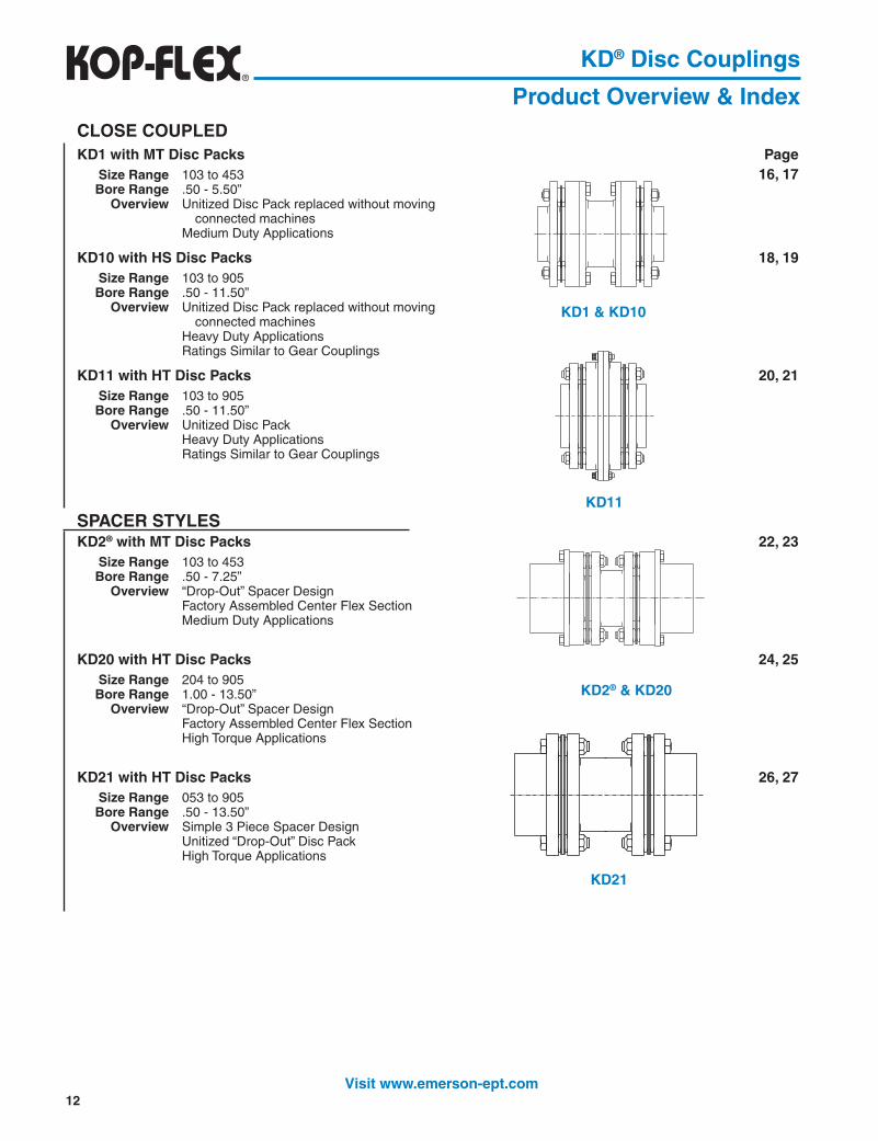
CLOSE COUPLEDKD1 with MT Disc Packs Page Size Range 103 to 453 16, 17 Bore Range .50 - 5.50” Overview Unitized Disc Pack replaced without moving connected machines Medium Duty Applications
KD10 with HS Disc Packs 18, 19 Size Range 103 to 905 Bore Range .50 - 11.50” Overview Unitized Disc Pack replaced without moving connected machines Heavy Duty Applications Ratings Similar to Gear Couplings
KD11 with HT Disc Packs 20, 21 Size Range 103 to 905 Bore Range .50 - 11.50” Overview Unitized Disc Pack Heavy Duty Applications Ratings Similar to Gear Couplings
SPACER STYLESKD2® with MT Disc Packs 22, 23 Size Range 103 to 453 Bore Range .50 - 7.25” Overview “Drop-Out” Spacer Design Factory Assembled Center Flex Section Medium Duty Applications
KD20 with HT Disc Packs 24, 25 Size Range 204 to 905 Bore Range 1.00 - 13.50” Overview “Drop-Out” Spacer Design Factory Assembled Center Flex Section High Torque Applications
KD21 with HT Disc Packs 26, 27 Size Range 053 to 905 Bore Range .50 - 13.50” Overview Simple 3 Piece Spacer Design Unitized “Drop-Out” Disc Pack High Torque Applications
KD1 & KD10
KD11
KD2® & KD20
KD21

13
Flexible Disc Couplings
Product Overview & IndexCOOLING TOWER PageKD33 with CT Disc Packs 28 Size Range 153 to 303 Bore Range .50 - 4.50” Overview Cooling Towers with Very Long Shaft Separation Stainless Steel/Composite Tubes Replaces most competitive Cooling Tower Couplings Non-lubricated
SINGLE FLEX & FLOATING SHAFTSKD4 with HT Disc Packs 29 Size Range 103 to 905 Bore Range .50 - 13.50” Overview Single Flex Unitized “Drop-Out” Disc Pack Heavy Duty Applications
KD41 with HT Disc Packs 30 - 31 Size Range 103 to 905 Bore Range .50 - 13.50” Overview Floating Shaft Design Unitized “Drop-Out” Disc Pack Heavy Duty Applications
KD42 with HT Disc Packs 32 - 35 Size Range 103 to 905 Bore Range .50 - 11.50” Flex Half Overview Floating Shaft Design Bolts Directly to Gear Coupling Rigids Unitized Disc Pack Heavy Duty Applications Ratings Similar to Gear Couplings
KD4
KD42
KD41

14
Our Slide Disc Couplings combine the best of two different worlds – themaintenance-free reliability of a disc coupling and the versatile slide feature of a
low-maintenance sliding spline.
For many years, people have been replacing their gear couplings with maintenance-free disc couplings in order to eliminate costly lubrication, maintenance and eventual replacement of their worn out gear couplings. But disc couplings have an inherent limitation that has kept them out of many applications where once only gear couplings would do the job – the disc packs themselves are not tolerant of significant axial movement. In these applications, the conventional thinking was that a slide gear coupling was the only solution.
We offer a solution that combines the best features of disc couplings and slide couplings:
KD® disc packs are supplied as unitized assemblies with stainless steel discs, which makes them easier to assemble and nearly maintenance-free. Disc packs available from stock, with the option of KOPLON coating for corrosive environments.
Standard spline sections are sealed and lubricated at the factory. The splines are provided with minimal backlash and coated with a special polymer for long life, minimal maintenance and low coefficient of friction (reduced sliding force).
Special slide sections can be supplied to accommodate special long slide applications.
Keep in mind that the advantages that KD® Slide Disc couplings offer over gear couplings:
Disc Couplings require no maintenance, and the spline sections are lubricated at the factory and do not need to be greased on a regular basis. Operating costs are greatly reduced compared to gear couplings!
Disc Couplings have near zero backlash and standard spline sections are coated for minimal backlash, while gear couplings rely on clearances in the gearing for misalignment, therefore coupling balance and smooth transmission of power is greatly improved over gear couplings. This is important where backlash and vibration can affect the quality of the product being produced.
KD® Slide Disc Couplings
Coupling Comments
Slide (Telescope)

15
Pulp Refiners – replaces slide gear couplings used to compensate for changing shaft separation as the refiner wears.
Polymer Pelletizer – the design shown replaced a slide gear coupling used to compensate for changing shaft separation as the pelletizer blades wear.
Fan Application (in tunnels) – shown here, a combination MAX-C® resilient coupling and KD® Disc Coupling with a spline section is used to compensate for changes in shaft separation due to thermal growth.
Test Stand Application – shown is a special KD® coupling designed for a high speed test stand to accommodate tests of different equipment, requiring different shaft separations.
This is merely a sampling of the different types of applications where disc couplings are being adapted to meet the slide requirements once thought to be addressed solely by gear couplings.
KD® Slide Disc Couplings
Coupling CommentsTypical Applications:
Paper Mill Roll Drives – the variable length feature compensates for different shaft separations. Typically, paper mills will have several couplings of the same size, but slightly different shaft separations. One KD® Slide coupling covers several different shaft separations – eliminating the need for multiple spares.

16
� All finish bores and keyways per AGMA/ANSI 9002 (Imperial) and AGMA/ANSI 9112 (Metric).
Component Parts
KD® Disc Couplings
KD1 Close CoupledThe KD1 coupling is designed for close coupled applications with minimal to short distance between shaft ends and light to medium loading. It can directly replace most REX* THOMAS* DBZ couplings and the unitized disc pack design makes the installation simpler and easier.
The KD1 is comprised of two hubs, two rings, two disc packs, and a piloted split spacer. The standard coupling hubs may be installed in any of three mounting positions for design and installation flexibility. The split spacer pilot gives the KD1 coupling improved dynamic balance characteristics and contains a design feature to hold the split spacer in place while the coupling is rotating.
KD1 disc packs are unitized to greatly reduce the number of loose parts. The split spacer simply drops away from the hubs for faster installation and replacement without moving connected machinery. The standard coupling balance meets AGMA Class 8 as manufactured, dynamic balance to AGMA Class 9 and conformance to API 610 / ISO 13709 are available options.
For higher power requirements, consider a KD10 disc coupling. For higher speeds, consider a KD11 disc coupling.
KD1 Couplings use MT Disc Packs.
Medium Duty Minimal to Short Shaft SeparationsSplit Spacer with Safety Pilot
Replacement for REX/THOMAS* DBZ Drop-Out, Unitized Disc Packs
* Center Assembly includes (2) disc packs, (2) disc pack fastener sets.** For Disc Packs and Fastener Sets, do not include “Series” number in the part number.
Complete Couplings
How to Order Components103 KD 1 SHUB
size
model
component
series
103 KD MTDP
size
component
model
How to Order Disc Packs and Fastener Sets
gnilpuoCeziS
gnilpuoCetelpmoCsbuH.dtS2htiw
gnilpuoCetelpmoCbuHgnoL1dnabuH.dtS1htiw
gnilpuoCetelpmoCsbuHgnoL2htiw
eroBhguoR eroBhsiniF eroBhguoR eroBhsiniF eroBhguoR eroBhsiniF
301 SS1DK301 BFSS1DK301 LS1DK301 BFLS1DK301 LL1DK301 BFLL1DK301
351 SS1DK351 BFSS1DK351 LS1DK351 BFLS1DK351 LL1DK351 BFLL1DK351
302 SS1DK302 BFSS1DK302 LS1DK302 BFLS1DK302 LL1DK302 BFLL1DK302
352 SS1DK352 BFSS1DK352 LS1DK352 BFLS1DK352 LL1DK352 BFLL1DK352
303 SS1DK303 BFSS1DK303 LS1DK303 BFLS1DK303 LL1DK303 BFLL1DK303
353 SS1DK353 BFSS1DK353 LS1DK353 BFLS1DK353 LL1DK353 BFLL1DK353
304 SS1DK304 BFSS1DK304 LS1DK304 BFLS1DK304 LL1DK304 BFLL1DK304
354 SS1DK354 BFSS1DK354 LS1DK354 BFLS1DK354 LL1DK354 BFLL1DK354
noitpircseD rebmuNtraP
buHdradnatS BUHS
buHgnoL BUHL
ylbmessAretneC* AC
ylbmessAkcaPcsiDTM** PDTM
teSrenetsaFkcaPcsiDTM** SFTM
teSrenetsaFegnalF** TMSFF
* Rex and Thomas are believed to be the trademarks and/or trade names of Rexnord Industries, LLC, and are not owned or controlled by Emerson Power Transmission.
� � �

17
Dimensional Data
KD® Disc Couplings
KD1 Close CoupledSelection Data
LONG HUBSSTANDARD HUBS
ONE HUB REVERSED TWO HUBS REVERSED
� Data based on maximum bores.
eziS.xaMeroB)ni(
gnitaRgnilpuoC)MPR001/PH(
gnitaReuqroT mumixaMdeepS
toNdecnalaB
)MPR(
mumixaMdeepS
decnalaB)MPR(
latoTthgieW
)sbl(
latoTRW 2
ni-bl( 2)
laixAyticapaC
)ni(suounitnoC)bl-ni(
kaeP)bl-ni(
301 26.1 3.4 0172 0245 0045 0079 1.8 6.81 060.±351 52.2 5.21 0887 06751 0054 0057 8.91 9.38 570.±302 57.2 9.22 00441 00882 0014 0076 9.13 481 090.±352 52.3 5.73 00632 00274 0063 0065 6.15 714 501.±303 88.3 0.06 00873 00657 0023 0015 3.77 658 521.±
353 83.4 001 00036 000621 0092 0044 921 0491 051.±304 00.5 551 00779 000591 0062 0004 981 0273 571.±354 05.5 502 000921 000852 0042 0083 322 0715 002.±
eziS hguoReroB
A)ni(
B1)ni(
B2)ni(
B3)ni(
C)ni(
C1)ni(
C2)ni(
C3)ni(
E)ni(
E1)ni(
O)ni(
301 05. 21.4 49.4 96.5 44.6 21. 49. 96.1 44.2 00.2 14.2 91.2351 05. 05.5 44.6 57.7 60.9 21. 91.1 05.2 18.3 26.2 61.3 00.3302 57. 05.6 13.7 18.8 13.01 91. 13.1 18.2 13.4 00.3 65.3 57.3352 00.1 57.7 83.8 60.01 57.11 91. 05.1 91.3 88.4 44.3 90.4 05.4303 00.1 00.9 88.9 49.11 00.41 52. 57.1 18.3 88.5 60.4 18.4 52.5
353 00.1 05.01 91.11 65.31 49.51 52. 49.1 13.4 96.6 26.4 74.5 00.6304 00.1 00.21 26.21 91.51 57.71 13. 21.2 96.4 52.7 52.5 61.6 57.6354 05.1 00.31 21.31 96.51 52.81 13. 21.2 96.4 52.7 05.5 14.6 05.7
� �

18
KD® Disc Couplings
KD10 Close CoupledThe KD10 coupling is designed to work in place of standard close coupled gear coupling applications with minimal distance between shaft ends. The power capacity of the KD10 coupling is the highest in the industry, allowing the easiest conversion from a lubricated coupling to a low maintenance disc coupling.
The KD10 is comprised of two hubs, two rings, two disc packs, and a piloted split spacer. The standard coupling hubs may be installed in two mounting positions for design and installation flexibility. The split spacer pilot gives the KD10 coupling improved dynamic balance characteristics and contains a design feature to hold the split spacer in place while the coupling is rotating.
KD10 disc packs are semi-unitized to greatly reduce the number of loose parts. The split spacer simply drops away from the hubs for faster installation and replacement of the disc packs without moving connected machinery. The standard coupling balance meets AGMA Class 8 as manufactured, dynamic balance to AGMA Class 9 and conformance to API 610 / ISO 13709 are available options.
For higher speed requirements, consider a KD11 disc coupling.
KD10 couplings use HS Semi-Unitized Disc Packs, for easy replacement without moving connected equipment.
Heavy Duty, Highest Power Capacity Minimal Shaft Separations Split Spacer with Safety Pilot Replacement for Standard Gear CouplingsDrop-Out, Semi-Unitized Disc Packs
Complete Couplings Component Parts
� All finish bores and keyways per AGMA/ANSI 9002 (Imperial) and AGMA/ANSI 9112 (Metric).
How to Order Components
* Center Assembly includes (2) disc packs, (2) disc pack fastener sets.** For Disc Packs and Fastener Sets, do not include “Series” number in the part number.
Note: Complete couplings are supplied with HT Disc Packs (HTDP) for ease of initial installation. HS Disc Packs (HSDP) should be used for replacement without moving connected equipment.
103 KD HSDP
size
component
model
How to Order Disc Packs & Fastener Sets
103 KD 10 SHUB
size
model
component
series
gnilpuoCeziS
gnilpuoCetelpmoCsbuH.dtS2htiw
eroBhguoR eroBhsiniF301 SS01DK301 BFSS01DK301351 SS01DK351 BFSS01DK351402 SS01DK402 BFSS01DK402452 SS01DK452 BFSS01DK452403 SS01DK403 BFSS01DK403
453 SS01DK453 BFSS01DK453404 SS01DK404 BFSS01DK404454 SS01DK454 BFSS01DK454405 SS01DK405 BFSS01DK405455 SS01DK455 BFSS01DK455
406 SS01DK406 BFSS01DK406507 SS01DK507 BFSS01DK507508 SS01DK508 BFSS01DK508509 SS01DK509 BFSS01DK509
noitpircseD rebmuNtraP
buHdradnatS BUHS
ylbmessAretneC* AC
ylbmessAkcaPcsiDSH** PDSH
teSrenetsaFkcaPcsiDSH** SFSH
teSrenetsaFegnalF** THSFF
�

19
Dimensional Data
� Data based on maximum bores.
KD® Disc Couplings
KD10 Close CoupledSelection Data
ONE HUB REVERSED
eziS.xaMeroB)ni(
gnilpuoCgnitaR
)MPR001/PH(
gnitaReuqroT deepS.xaMtoN
decnalaB)MPR(
mumixaMdeepS
decnalaB)MPR(
latoTthgieW
)sbl(
latoTRW 2
ni-bl( 2)
laixAyticapaC
)ni(suounitnoC
)bl-ni(kaeP)bl-ni(
301 05.1 3.6 0004 0008 0045 0079 9.6 61 080.±351 21.2 6.12 00631 00272 0054 0057 5.71 37 041.±402 26.2 1.75 00063 00027 0014 0076 2.72 841 011.±452 52.3 5.28 00025 000401 0063 0065 2.74 004 041.±403 57.3 141 00098 000871 0023 0015 0.87 619 071.±
453 52.4 832 000051 000003 0092 0044 431 0412 002.±404 57.4 043 000512 000034 0062 0004 391 0583 522.±454 05.5 504 000552 000015 0042 0083 922 0455 052.±405 57.5 075 000063 000027 0022 0053 613 0468 572.±455 52.6 008 000505 0000101 0091 0003 404 00131 003.±
406 57.6 0501 000066 0000231 0581 0092 955 00222 023.±507 05.8 0042 0000151 0000203 0081 0082 529 00465 072.±508 05.9 0763 0000132 0000264 0061 0052 0431 000201 013.±509 05.11 0314 0000062 0000025 0051 0032 0071 000361 004.±
� �
eziSA
)ni(1B)ni(
2B)ni(
1C)ni(
2C)ni(
D)ni(
E)ni(
O)ni(
301 49.3 05.3 49.4 521. 65.1 83. 96.1 01.2351 83.5 83.4 51.6 521. 09.1 25. 21.2 69.2402 83.6 26.5 09.7 521. 04.2 06. 57.2 46.3452 26.7 52.6 27.8 571. 66.2 06. 30.3 65.4403 00.9 83.7 03.01 571. 11.3 47. 95.3 52.5
453 05.01 00.9 75.21 052. 28.3 78. 83.4 19.5404 57.11 26.01 18.41 052. 44.4 00.1 91.5 57.6454 57.21 49.01 23.51 5213. 07.4 00.1 13.5 26.7405 88.31 83.21 53.71 5213. 82.5 41.1 30.6 91.8455 21.51 21.41 38.91 5213. 20.6 92.1 19.6 57.8
406 05.61 21.51 12.12 5213. 04.6 83.1 14.7 13.9507 05.02 57.71 78.42 573. 05.7 56.1 96.8 43.11508 00.32 00.02 00.82 573. 73.8 49.1 18.9 57.21509 05.52 52.22 42.13 005. 05.9 49.1 88.01 52.51

20
KD® Disc Couplings
KD11 Close CoupledThe KD11 coupling is designed to work in place of standard close coupled gear coupling applications with higher speed service. The power capacity of the KD11 coupling is the highest in the industry, allowing the easiest conversion from a lubricated coupling to a low maintenance disc coupling.
The KD11 is comprised of two hubs, two adapters, and two disc packs. The standard coupling hubs may be installed in any of three mounting positions for design and installation flexibility. The bolted adapters give the KD11 coupling the best dynamic balance characteristics and allow the connected equipment to be installed or removed while keeping each assembled half coupling undisturbed.
KD11 disc packs are unitized to greatly reduce the number of loose parts. The standard coupling balance meets AGMA Class 9 as manufactured, dynamic balance to AGMA Class 10 and 11, and conformance to API 610 / ISO 13709 are available options. The close tolerance bolts and safety overload washers help provide superior performance.
For lower speed requirements, consider a KD10 disc coupling. For medium-duty, consider a KD1 disc coupling.
KD11 couplings use HT Disc Packs.
Heavy Duty, Highest Power Capacity Minimal Shaft Separations Bolted Adapters for Higher Speeds Replacement for Standard Gear Couplings Unitized Disc Packs
Complete Couplings Component Parts
� All finish bores and keyways per AGMA/ANSI 9002 (Imperial) and AGMA/ANSI 9112 (Metric).
How to Order Components
* For Disc Packs and Fastener Sets, do not include “Series” number in the part number.
How to Order Disc Packs & Fastener Sets
103 KD 11 SHUB
size
model
component
series
103 KD HTDP
size
component
model
gnilpuoCeziS
gnilpuoCetelpmoCsbuH.dtS2htiw
eroBhguoR eroBhsiniF301 SS11DK301 BFSS11DK301351 SS11DK351 BFSS11DK351402 SS11DK402 BFSS11DK402452 SS11DK452 BFSS11DK452403 SS11DK403 BFSS11DK403
453 SS11DK453 BFSS11DK453404 SS11DK404 BFSS11DK404454 SS11DK454 BFSS11DK454405 SS11DK405 BFSS11DK405455 SS11DK455 BFSS11DK455
406 SS11DK406 BFSS11DK406507 SS11DK507 BFSS11DK507508 SS11DK508 BFSS11DK508509 SS11DK509 BFSS11DK509
�
noitpircseD rebmuNtraP
buHdradnatS BUHS
ylbmessAkcaPcsiDTH* PDTH
teSrenetsaFkcaPcsiDTH* SFTH
renetsaFegnalFretneC*teS SFFC

21
Dimensional Data
� Data based on maximum bores.��See Balance Specifications page 11. Consult engineering for applications where speed exceed 75% of max. speed rating.
KD® Disc Couplings
KD11 Close CoupledSelection Data
ONE HUB REVERSED
TWO HUBS REVERSED
eziS.xaMeroB)ni(
gnilpuoCgnitaR
)MPR001/PH(
gnitaReuqroT mumixaM �
deepS)MPR(
latoT �
thgieW)sbl(
latoT �
RW 2
ni-bl( 2)
laixAyticapaC
)ni(suounitnoC
)bl-ni(kaeP)bl-ni(
301 05.1 3.6 0004 0008 00241 0.9 72 080.±351 21.2 6.12 00631 00272 00521 6.81 09 041.±402 26.2 1.75 00063 00027 00111 2.92 981 011.±452 52.3 5.28 00025 000401 0099 8.34 004 041.±403 57.3 141 00098 000871 0078 6.96 938 071.±
453 52.4 832 000051 000003 0057 111 0971 002.±404 57.4 043 000512 000034 0066 861 0543 522.±454 05.5 504 000552 000015 0006 402 0225 052.±405 57.5 075 000063 000027 0065 272 0297 572.±455 52.6 008 000505 0000101 0084 463 00231 003.±
406 57.6 0501 000066 0000231 0064 854 00112 023.±507 05.8 0042 0000151 0000203 0683 428 00425 072.±508 05.9 0763 0000132 0000264 0543 0221 00089 013.±509 05.11 0314 0000062 0000025 0251 0251 000151 004.±
eziSA
)ni(1B)ni(
2B)ni(
3B)ni(
1C)ni(
2C)ni(
3C)ni(
E)ni(
O)ni(
301 44.5 83.3 65.4 57.5 21. 13.1 05.2 46.1 01.2351 18.6 21.4 85.5 30.7 21. 85.1 30.3 00.2 69.2402 18.7 00.5 05.6 00.8 21. 26.1 21.3 44.2 46.3452 13.9 91.6 22.7 52.8 91. 22.1 52.2 00.3 65.4403 26.01 91.7 14.8 26.9 91. 14.1 26.2 05.3 52.5
453 82.21 05.8 00.01 05.11 52. 57.1 52.3 21.4 19.5404 49.31 05.9 05.11 05.31 52. 52.2 52.4 26.4 57.6454 65.51 65.01 44.21 13.41 13. 91.2 60.4 21.5 26.7405 96.61 65.11 54.31 43.51 13. 02.2 90.4 26.5 91.8455 96.81 13.21 84.41 46.61 13. 84.2 46.4 00.6 57.8
406 00.02 13.31 07.51 90.81 13. 07.2 90.5 05.6 13.9507 00.42 83.61 00.91 26.12 83. 00.3 26.5 00.8 43.11508 88.62 83.81 35.12 86.42 83. 35.3 86.6 00.9 57.21509 00.03 05.02 95.32 86.62 05. 95.3 86.6 00.01 52.51

22
KD2® Rough Bore Part Numbers
��Note: For Finish Bore add FB to Part Number and specify bore. All finish bores and keyways per AGMA/ANSI 9002 (Imperial) and AGMA/ANSI 9112 (Metric) commercial standard tolerances.
Component Parts
The KD2® coupling is designed for medium duty applications requiring moderate shaft separations, and was specifically engineered to meet API 610 / ISO 13709 specifications for industrial pump couplings. Consisting of three main parts, two hubs and a factory assembled flexible center section which installs or drops out as one unit, the KD2 greatly simplifies installation or maintenance.
The flexible center section is piloted to help provide excellent dynamic balance. AGMA Class 9 is standard, as-manufactured. Dynamic balance to AGMA Class 10 or Class 11 are available options. An anti-flail safety feature is also included in the flexible center section assembly.
For higher power requirements, consider a KD20 disc coupling. For economy duty, consider a KD21 disc coupling.
KD2® couplings use MT Disc Packs.
Medium Duty Standard Shaft Separations for Industrial Pumps Factory Assembled Flexible Center Sections Designed Specifically for API 610 / ISO 13709 Highly Flexible, Unitized Disc Packs
How to Order Components
* Center Assembly includes (2) disc packs, (2) disc pack fastener sets.** For Disc Packs and Fastener Sets, do not include “Series” number in the part number.
How to Order Disc Packs and Fastener Sets103 KD MTDP
size
component
model
103 KD 2 SHUB
size
model
component
series
noitpircseD rebmuNtraPbuHdradnatS BUHS
buHgnoL BUHLbuHobmuJ BUHJ
rofylbmessAretneC*noitarapeStfahSxx.x XXXAC
kcaPcsiDTM** PDTMteSrenetsaFkcaPcsiDTM** SFTM
teSrenetsaFegnalF** TMSFF
teSrenetsaFbuHobmuJ** THSFJ
gnilpuoCeziS
neewteBtfahSsdnE
gnilpuoCetelpmoCsbuH.dtS2/w
eroBhguoR
gnilpuoCetelpmoCbuHgnoL1&.dtS1/w
eroBhguoR
gnilpuoCetelpmoCsbuHgnoL2/w
eroBhguoR
gnilpuoCetelpmoC&buHobmuJ1/w
buH.dtS1
gnilpuoCetelpmoCobmuJ2/w
sbuH
gnilpuoCetelpmoC&gnoL1/w
buHobmuJ1ylbmessAretneC
301 2/13 053SS2DK301 053SL2DK301 053LL2DK301 053SJ2DK301 053JJ2DK301 053LJ2DK301 053AC2DK3018/34 834SS2DK301 834SL2DK301 834LL2DK301 834SJ2DK301 834JJ2DK301 834LJ2DK301 834AC2DK301
5 005SS2DK301 005SL2DK301 005LL2DK301 005SJ2DK301 005JJ2DK301 005LJ2DK301 005AC2DK3017 007SS2DK301 007SL2DK301 007LL2DK301 007SJ2DK301 007JJ2DK301 007LJ2DK301 007AC2DK301
351 8/34 834SS2DK351 834SL2DK351 834LL2DK351 834SJ2DK351 834JJ2DK351 834LJ2DK351 834AC2DK3515 005SS2DK351 005SL2DK351 005LL2DK351 005SJ2DK351 005JJ2DK351 005LJ2DK351 005AC2DK3517 007SS2DK351 007SL2DK351 007LL2DK351 007SJ2DK351 007JJ2DK351 007LJ2DK351 007AC2DK351
302 5 005SS2DK302 005SL2DK302 005LL2DK302 005SJ2DK302 005JJ2DK302 005LJ2DK302 005AC2DK3027 007SS2DK302 007SL2DK302 007LL2DK302 007SJ2DK302 007JJ2DK302 007LJ2DK302 007AC2DK302
352 7 007SS2DK352 007SL2DK352 007LL2DK352 007SJ2DK352 007JJ2DK352 007LJ2DK352 007AC2DK3528 008SS2DK352 008SL2DK352 008LL2DK352 008SJ2DK352 008JJ2DK352 008LJ2DK352 008AC2DK352
303 7 007SS2DK303 007SL2DK303 007LL2DK303 007SJ2DK303 007JJ2DK303 007LJ2DK303 007AC2DK3038 008SS2DK303 008SL2DK303 008LL2DK303 008SJ2DK303 008JJ2DK303 008LJ2DK303 008AC2DK303
353 8 008SS2DK353 008SL2DK353 008LL2DK353 008SJ2DK353 008JJ2DK353 008LJ2DK353 008AC2DK3539 009SS2DK353 009SL2DK353 009LL2DK353 009SJ2DK353 009JJ2DK353 009LJ2DK353 009AC2DK353
304 9 009SS2DK304 009SL2DK304 009LL2DK304 009SJ2DK304 009JJ2DK304 009LJ2DK304 009AC2DK304
354 9 009SS2DK354 009SL2DK354 009LL2DK354 009SJ2DK354 009JJ2DK354 009LJ2DK354 009AC2DK354
KD® Disc Couplings
KD2® Spacer Coupling
�

23
Dimensional Data
KD® Disc Couplings
KD2® Spacer CouplingSelection Data
� Data based on Min. “C” dimensions, maximum bores and standard hubs.� See Balance Specifications page 11. Consult engineering for applications where speed exceed 75% of max. speed rating.
STANDARDHUB
FLEXIBLE CENTER
ASSEMBLY
LONG HUB
JUMBO HUB
eziS
seroBmumixaM)ni( gnilpuoC
gnitaR)MPR001/PH(
gnitaReuqroTmumixaM
deepS)MPR(
latoTthgieW
)sbl(
latoTRW 2
ni-bl( 2)
thgieWebuTrecapShcnirep
laixAyticapaC
)ni(&.dtSbuHgnoL
obmuJbuH
suounitnoC)bl-ni(
kaeP)bl-ni( thgieW
)sbl(RW 2
ni-bl( 2)
301 88.1 57.2 3.4 0172 0245 00071 9.9 0.22 44.0 54.0 060.±351 88.2 00.4 5.21 0887 06751 00241 2.32 1.39 45.0 60.1 570.±302 52.3 26.4 9.22 00441 00882 00821 5.53 502 65.0 76.1 090.±352 00.4 26.5 5.73 00632 00274 00511 8.85 574 37.0 95.3 501.±
303 57.4 05.6 0.06 00873 00657 00001 6.98 989 41.1 25.7 521.±353 05.5 26.7 001 00036 000621 0058 541 0612 75.1 07.21 051.±304 52.6 57.8 551 00779 000591 0057 022 0924 48.1 08.91 571.±354 52.7 83.9 502 000921 000852 0007 162 0816 10.2 00.72 002.±
� �
eziS hguoReroB
A)ni(
xaMeroB'C
)ni(
C.niM
)ni(
E)ni(
1E)ni(
G)ni(
)ni(noisnemiD'C"Standard
2/13 8/34 5 7 8 9
301 05.0 13.4 83.2 05.3 05.1 05.2 26.2 X X X X351 57.0 96.5 88.3 83.4 00.2 21.3 21.4 X X X302 00.1 57.6 05.4 18.4 52.2 26.3 57.4 X X352 00.1 00.8 05.5 57.5 88.2 52.4 57.5 X X
303 05.1 52.9 44.6 05.6 83.3 57.4 57.6 X X353 00.2 57.01 13.7 26.7 00.4 83.5 57.7 X X304 05.2 52.21 05.8 00.9 44.4 21.6 00.9 X354 00.3 52.31 26.9 00.9 18.4 57.6 21.01 X
Note: "C" dimension = center assembly length.
Note: Shaft separations longer than standard may be accommodated by using stock center assemblies and counterboring and overhanging long hubs to make up the difference. Shaft fit length should be equal to "E" or greater. Consult KOP-FLEX for more details.

24
KD® Disc Couplings
KD20 Spacer CouplingThe KD20 coupling is designed for heavy duty applications requiring moderate shaft separations, and was specifically engineered to meet API 610 / ISO 13709 specifications for industrial pump couplings. Consisting of three main parts, two hubs and a factory assembled flexible center section which installs or drops out as one unit, the KD20 greatly simplifies installation or maintenance.The larger size couplings available in the KD20 Series allow application to larger, high power machines. The flexible center section is piloted to provide excellent dynamic balance. AGMA Class 9 is standard, as manufactured. Dynamic balance to AGMA Class 10 or Class 11 are available options. The close tolerance bolts and safety overload washers help provide superior performance and trouble-free operation. An anti-flail safety feature is also included in the flexible center section assembly.For smaller sizes or lower power requirements, consider a KD2 disc coupling. For economy duty, consider a KD21 disc coupling.
KD20 Couplings use HT Disc Packs.
KD20 Rough Bore Part Numbers
��Note: For Finish Bore add FB to Part Number and specify bore.All finish bores and keyways per AGMA/ANSI 9002 (Imperial) and AGMA/ANSI 9112 (Metric)
gnilpuoCeziS
neewteBtfahSsdnE
gnilpuoCetelpmoCsbuH.dtS2/w
eroBhguoR
gnilpuoCetelpmoCbuHgnoL1&.dtS1/w
eroBhguoR
gnilpuoCetelpmoCsbuHgnoL2/w
eroBhguoR
gnilpuoCetelpmoC&buHobmuJ1/w
buH.dtS1
gnilpuoCetelpmoCobmuJ2/w
sbuH
gnilpuoCetelpmoC&gnoL1/w
buHobmuJ1ylbmessAretneC
402 7 007SS02DK402 007SL02DK402 007LL02DK402 007SJ02DK402 007JJ02DK402 007LJ02DK402 007AC02DK4028 008SS02DK402 008SL02DK402 008LL02DK402 008SJ02DK402 008JJ02DK402 008LJ02DK402 008AC02DK4029 009SS02DK402 009SL02DK402 009LL02DK402 009SJ02DK402 009JJ02DK402 009LJ02DK402 009AC02DK40201 0001SS02DK402 0001SL02DK402 0001LL02DK402 0001SJ02DK402 0001JJ02DK402 0001LJ02DK402 0001AC02DK40221 0021SS02DK402 0021SL02DK402 0021LL02DK402 0021SJ02DK402 0021JJ02DK402 0021LJ02DK402 0021AC02DK40241 0041SS02DK402 0041SL02DK402 0041LL02DK402 0041SJ02DK402 0041JJ02DK402 0041LJ02DK402 0041AC02DK402
452 7 007SS02DK452 007SL02DK452 007LL02DK452 007SJ02DK452 007JJ02DK452 007LJ02DK452 007AC02DK4528 008SS02DK452 008SL02DK452 008LL02DK452 008SJ02DK452 008JJ02DK452 008LJ02DK452 008AC02DK4529 009SS02DK452 009SL02DK452 009LL02DK452 009SJ02DK452 009JJ02DK452 009LJ02DK452 009AC02DK45201 0001SS02DK452 0001SL02DK452 0001LL02DK452 0001SJ02DK452 0001JJ02DK452 0001LJ02DK452 0001AC02DK45221 0021SS02DK452 0021SL02DK452 0021LL02DK452 0021SJ02DK452 0021JJ02DK452 0021LJ02DK452 0021AC02DK45241 0041SS02DK452 0041SL02DK452 0041LL02DK452 0041SJ02DK452 0041JJ02DK452 0041LJ02DK452 0041AC02DK452
403 7 007SS02DK403 007SL02DK403 007LL02DK403 007SJ02DK403 007JJ02DK403 007LJ02DK403 007AC02DK4038 008SS02DK403 008SL02DK403 008LL02DK403 008SJ02DK403 008JJ02DK403 008LJ02DK403 008AC02DK4039 009SS02DK403 009SL02DK403 009LL02DK403 009SJ02DK403 009JJ02DK403 009LJ02DK403 009AC02DK40301 0001SS02DK403 0001SL02DK403 0001LL02DK403 0001SJ02DK403 0001JJ02DK403 0001LJ02DK403 0001AC02DK40321 0021SS02DK403 0021SL02DK403 0021SL02DK403 0021SJ02DK403 0021JJ02DK403 0021LJ02DK403 0021AC02DK40341 0041SS02DK403 0041SL02DK403 0041LL02DK403 0041SJ02DK403 0041JJ02DK403 0041LJ02DK403 0041AC02DK403
453 9 009SS02DK453 009SL02DK453 009LL02DK453 009SJ02DK453 009JJ02DK453 009LJ02DK453 009AC02DK45301 0001SS02DK453 0001SL02DK453 0001LL02DK453 0001SJ02DK453 0001JJ02DK453 0001LJ02DK453 0001AC02DK45321 0021SS02DK453 0021SL02DK453 0021LL02DK453 0021SJ02DK453 0021JJ02DK453 0021JJ02DK453 0021AC02DK45341 0041SS02DK453 0041SL02DK453 0041LL02DK453 0041SJ02DK453 0041JJ02DK453 0041LJ02DK453 0041AC02DK453
404 01 0001SS02DK404 0001SL02DK404 0001LL02DK404 0001SJ02DK404 0001JJ02DK404 0001LJ02DK404 0001AC02DK40421 0021SS02DK404 0021SL02DK404 0021LL02DK404 0021SJ02DK404 0021JJ02DK404 0021LJ02DK404 0021AC02DK40441 0041SS02DK404 0041SL02DK404 0041LL02DK404 0041SJ02DK404 0041JJ02DK404 0041LJ02DK404 0041AC02DK404
454 01 0001SS02DK454 0001SL02DK454 0001LL02DK454 0001SJ02DK454 0001JJ02DK454 0001LJ02DK454 0001AC02DK45421 0021SS02DK454 0021SL02DK454 0021LL02DK454 0021SJ02DK454 0021JJ02DK454 0021LJ02DK454 0021AC02DK45441 0041SS02DK454 0041SL02DK454 0041LL02DK454 0041SJ02DK454 0041JJ02DK454 0041LJ02DK454 0041AC02DK454
�

25
KD® Disc Couplings
KD20 Spacer CouplingSelection Data
Dimensional Data
� Data based on Min. “C” dimensions, maximum bores and standard hubs.� See Balance Specifications page 11. Consult engineering for applications where speed exceed 75% of max. speed rating.
Long hubs are available for sizes 204 to 454 only.Component Parts How to Order Components
* Center Assembly includes (2) disc packs, (2) disc pack fastener sets.** For Disc Packs and Fastener Sets, do not include “Series” number in the part number.
103 KD 20 SHUB
size
model
component
series
How to Order Disc Packs and Fastener Sets103 KD HTDP
size
component
model
eziS
.xaMeroB)ni(
gnilpuoCgnitaR
)MPR001/PH(
gnitaReuqroT �
mumixaMdeepS)MPR(
latoT
thgieW
)sbl(
latoT �
RW 2
ni-bl( 2)
ebuTrecapShcnirep laixA
yticapaC)ni(&.dtS
buHgnoLobmuJ
buHsuounitnoC
)bl-ni(kaeP)bl-ni(
thgieW)sbl(
RW 2
ni-bl( 2)402 52.3 26.4 1.75 00063 00027 00031 2.93 032 18.0 76.2 011.±452 00.4 26.5 5.28 00025 000401 00211 2.16 015 97.0 63.4 041.±403 57.4 5.6 141 00098 000871 0099 401 0911 71.1 60.8 071.±453 05.5 26.7 832 000051 000003 0088 271 0362 69.1 0.71 002.±404 52.6 57.8 043 000512 000034 0087 152 0294 12.2 3.42 522.±
454 52.7 83.9 504 000552 000015 0027 203 0027 45.2 0.73 052.±405 05.7 - 075 000063 000027 0066 724 00611 76.3 6.26 572.±455 52.8 - 008 000505 0000101 0016 965 00281 98.3 7.47 003.±406 00.9 - 0501 000066 0000231 0065 777 00592 12.5 511 023.±507 88.01 - 0042 0000151 0000203 0054 0631 00577 04.9 303 072.±
508 52.21 - 0763 0000132 0000264 0004 0602 000051 6.21 705 013.±509 05.31 - 0314 0000062 0000025 0063 0942 000722 7.11 266 004.±
eziS A)ni(
.xaMeroB'C
)ni(C.niM
)ni(E
)ni(1E
)ni(G
)ni(oN)ni(
iN)ni(
"C").ni(noisnemiD
7 8 9 01 21 41402 26.6 44.4 00.6 52.2 26.3 57.4 88.3 83.3 X X X X X X452 88.7 44.5 00.6 88.2 52.4 57.5 88.4 05.4 X X X X X X403 52.9 83.6 00.7 83.3 57.4 57.6 05.5 00.5 X X X X X X453 57.01 13.7 05.8 00.4 83.5 57.7 52.6 05.5 X X X X404 00.21 05.8 00.01 44.4 21.6 00.9 00.7 52.6 X X X
454 00.31 26.9 00.01 18.4 57.6 21.01 00.8 91.7 X X X405 21.41 88.9 00.11 88.6 – 05.01 57.8 57.7455 83.51 57.01 05.21 05.7 – 05.11 52.9 52.8406 88.61 00.21 52.31 57.8 – 57.21 00.01 57.8507 88.02 05.41 00.61 57.9 – 52.51 52.21 83.01
508 83.32 83.61 00.91 57.01 – 52.71 57.31 05.11509 88.52 00.81 00.91 57.11 – 00.91 88.51 21.41
Standard�
noitpircseD rebmuNtraPbuHdradnatS BUHS
buHgnoL BUHLbuHobmuJ BUHJ
rofylbmessAretneC*noitarapeStfahSxx.x XXXAC
ylbmessAkcaPcsiDTH** PDTHteSrenetsaFkcaPcsiDTH** SFTH
teSrenetsaFegnalF** THSFF
teSrenetsaFbuHobmuJ** THSFJ
Note: "C" dimension = center assembly length.
Note: Shaft separations longer than standard may be accommodated by using stock center assemblies and counterboring and overhanging long hubs to make up the difference. Shaft fit length should be equal to "E" or greater. Consult KOP-FLEX for more details.
FLEXIBLECENTER
ASSEMBLY
STANDARDHUB
LONGHUB
E1E1
A
JUMBOHUB
C E
G
A
26
KD® Disc Couplings
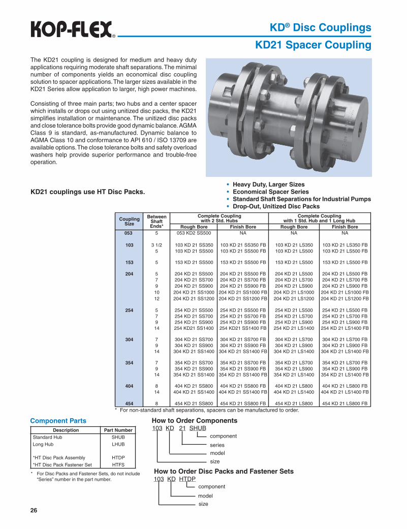
KD21 Spacer CouplingThe KD21 coupling is designed for medium and heavy duty applications requiring moderate shaft separations. The minimal number of components yields an economical disc coupling solution to spacer applications. The larger sizes available in the KD21 Series allow application to larger, high power machines.
Consisting of three main parts; two hubs and a center spacer which installs or drops out using unitized disc packs, the KD21 simplifies installation or maintenance. The unitized disc packs and close tolerance bolts provide good dynamic balance. AGMA Class 9 is standard, as-manufactured. Dynamic balance to AGMA Class 10 and conformance to API 610 / ISO 13709 are available options. The close tolerance bolts and safety overload washers help provide superior performance and trouble-free operation.
KD21 couplings use HT Disc Packs.
Component Parts
Heavy Duty, Larger Sizes Economical Spacer Series Standard Shaft Separations for Industrial Pumps Drop-Out, Unitized Disc Packs
How to Order Components
* For non-standard shaft separations, spacers can be manufactured to order.
* For Disc Packs and Fastener Sets, do not include “Series” number in the part number.
How to Order Disc Packs and Fastener Sets
103 KD 21 SHUB
model
series
component
size
103 KD HTDP
size
component
model
noitpircseD rebmuNtraP
buHdradnatS BUHS
buHgnoL BUHL
ylbmessAkcaPcsiDTH* PDTH
teSrenetsaFkcaPcsiDTH* SFTH
gnilpuoCeziS
neewteBtfahS*sdnE
gnilpuoCetelpmoCsbuH.dtS2htiw
gnilpuoCetelpmoCbuHgnoL1dnabuH.dtS1htiw
eroBhguoR eroBhsiniF eroBhguoR eroBhsiniF350 5 005SS2DK350 AN AN AN
301 2/13 053SS12DK301 BF053SS12DK301 053SL12DK301 BF053SL12DK3015 005SS12DK301 BF005SS12DK301 005SL12DK301 BF005SL12DK301
351 5 005SS12DK351 BF005SS12DK351 005SL12DK351 BF005SL12DK351
402 5 005SS12DK402 BF005SS12DK402 005SL12DK402 BF005SL12DK4027 007SS12DK402 BF007SS12DK402 007SL12DK402 BF007SL12DK4029 009SS12DK402 BF009SS12DK402 009SL12DK402 BF009SL12DK40201 0001SS12DK402 BF0001SS12DK402 0001SL12DK402 BF0001SL12DK40221 0021SS12DK402 BF0021SS12DK402 0021SL12DK402 BF0021SL12DK402
452 5 005SS12DK452 BF005SS12DK452 005SL12DK452 BF005SL12DK4527 007SS12DK452 BF007SS12DK452 007SL12DK452 BF007SL12DK4529 009SS12DK452 BF009SS12DK452 009SL12DK452 BF009SL12DK45241 0041SS12DK452 BF0041SS12DK452 0041SL12DK452 BF0041SL12DK452
403 7 007SS12DK403 BF007SS12DK403 007SL12DK403 BF007SL12DK4039 009SS12DK403 BF009SS12DK403 009SL12DK403 BF009SL12DK40341 0041SS12DK403 BF0041SS12DK403 0041SL12DK403 BF0041SL12DK403
453 7 007SS12DK453 BF007SS12DK453 007SL12DK453 BF007SL12DK4539 009SS12DK453 BF009SS12DK453 009SL12DK453 BF009SL12DK45341 0041SS12DK453 BF0041SS12DK453 0041SL12DK453 BF0041SL12DK453
404 8 008SS12DK404 BF008SS12DK404 008SL12DK404 BF008SL12DK40441 0041SS12DK404 BF0041SS12DK404 0041SL12DK404 BF0041SL12DK404
454 8 008SS12DK454 BF008SS12DK454 008SL12DK454 BF008SL12DK454

27
KD® Disc Couplings
KD21 Spacer CouplingSelection Data
Dimensional Data
� Data based on min. “C” dimensions and maximum bores.� See Balance Specifications page 11. Consult engineering for applications where speed exceed 75% of max. speed rating.
LONGHUB
STANDARDHUB
Long hubs are available for sizes 103 to 454 only.
eziS.xaMeroB)ni(
gnilpuoCgnitaR001/PH(
)MPR
gnitaReuqroTmumixaM
deepSMPR
latoTthgieW
)sbl(
latoTRW 2
ni-bl( 2)
hcnirepebuTrecapS laixAyticapaC
)ni(suounitnoC
)bl-ni(kaeP)bl-ni(
thgieW)sbl(
RW 2
ni-bl( 2)
350 57.1 2.3 0002 0004 0028 7.7 61 05.0 24.0 550.±301 57.1 3.6 0004 0008 00281 8.7 61 42.0 72.0 080.±351 05.2 6.12 00631 00272 00841 7.71 76 93.0 08.0 041.±402 00.3 1.75 00063 00027 00031 8.92 061 18.0 76.2 011.±452 57.3 5.28 00025 000401 00211 3.44 633 97.0 63.4 041.±
403 05.4 141 00098 000871 0099 4.07 547 71.1 60.8 071.±453 00.5 832 000051 000003 0088 711 0461 69.1 0.71 002.±404 05.5 043 000512 000034 0087 771 0513 12.2 3.42 522.±454 83.6 504 000552 000015 0027 502 0634 45.2 0.73 052.±405 00.7 075 000063 000027 0066 503 0647 76.3 6.26 572.±
455 57.7 008 000505 0000101 0016 204 00811 98.3 7.47 003.±406 05.8 0501 000066 0000231 0065 215 00871 12.5 511 023.±507 57.01 0042 0000151 0000203 0054 229 00005 04.9 303 072.±508 00.21 0763 0000132 0000264 0004 0531 00839 6.21 705 013.±509 05.31 0314 0000062 0000025 0063 0071 000641 8.11 576 004.±
� �
eziS A)ni(
C.niM)ni(
E)ni(
1E)ni(
G)ni(
oN)ni(
iN)ni(
"C"Standard).ni(noisnemiD
5.3 5 7 8 9 01 21 41350 49.3 00.3 26.1 - 65.2 21.2 05.1 - X - - - - - -301 49.3 57.2 66.1 49.1 75.2 52.2 00.2 X X - - - - - -351 83.5 83.3 49.1 44.2 45.3 00.3 96.2 - X - - - - - -402 83.6 88.3 83.2 30.3 23.4 88.3 83.3 - X X - X X X -452 26.7 88.3 00.3 95.3 43.5 88.4 05.4 - X X - X - - X
403 00.9 57.4 65.3 91.4 61.6 05.5 49.4 - - X - X - - X453 05.01 57.5 21.4 57.4 99.6 52.6 05.5 - - X - X - - X404 57.11 26.6 26.4 13.5 19.7 00.7 52.6 - - - X - - - X454 57.21 26.6 52.5 30.6 38.8 00.8 52.7 - - - X - - - -405 88.31 05.7 88.5 - 26.9 57.8 57.7 - - - - - - - -
455 21.51 26.8 61.7 - 84.01 52.9 52.8 - - - - - - - -406 05.61 21.9 66.7 - 33.11 00.01 57.8 - - - - - - - -507 05.02 88.01 00.9 - 70.41 52.21 00.01 - - - - - - - -508 00.32 00.31 21.01 - 37.51 57.31 05.11 - - - - - - - -509 05.52 00.31 18.11 - 88.71 88.51 21.41 - - - - - - - -
�
Note: "C" dimension = length of spacer plus (2) disc packs (including flat washers).
Note: Shaft separations longer than standard may be accommodated by using stock spacers and counterboring and overhanging long hubs to make up the differ-ence. Shaft fit length should be equal to "E" or greater. Consult KOP-FLEX for more details.

28
Selection and Dimensional Data
Part NumbersComplete KD33 Coupling, Class 1 (Stainless Steel & Composite Shaft)Shaft Separation Must Be Specified at Time of Order.
KD® Disc Couplings
KD33 Cooling TowerDesigned specifically for cooling tower drives and long span applications, the KD33 coupling is easy to handle, install and maintain. The drive shaft is a corrosion resistant lightweight composite tube of either special fiberglass or carbon graphite fibers engineered to provide the optimum combination of strength and bending stiffness required of cooling tower couplings.
The coupling hubs, adapters, disc packs and hardware are all stainless steel for high strength and corrosion resistance. The unitized disc packs are capable of up to 1/2° continuous misalignment, which provide trouble-free operation using close tolerance bolts and standard drive shaft dynamic balance.
The couplings shown below are stocked and available for quick supply. Two weeks standard delivery or 24 hour premium delivery is available.
For longer shaft spans or special designs, consult KOP-FLEX.
KD33 Couplings use CT Disc Packs.
Composite Tubes for Low Weight and Corrosion Resistance Stainless Steel Metal Components Quick Delivery High Flexible, Unitized Disc Packs
eziS tfahsevirD ESBDmumixaM gnilpuoCetelpmoC.oNtraP
kcaPcsiD.oNtraP
kcaPcsiDteSrenetsaF
.oNtraPMPR0081@ MPR0051@351 ssalG-E"4 69 501 GE33DK351 PDTCDK351 SFTCDK351351 nobraC"4 031 141 C33DK351
302 ssalG-E"6 811 821 GE33DK302 PDTCDK302 SFTCDK302302 nobraC"6 061 271 C33DK302
352 ssalG-E"6 611 821 GE33DK352 PDTCDK352 SFTCDK352352 nobraC"6 061 271 C33DK352
eziSeroBxaM)sehcni(
gnilpuoCgnitaR
MPR001/PH
gnitaReuqroT)bl-ni(
lanimoNebuT.aiD)ni(
etisopmoCebuT
lairetaM
mumixaM@ESBDMPR0081
)ni(
mumixaM@ESBDMPR0051
)ni(
snoisnemiD
suounitnoC kaeP A)ni(
E)ni(
O)ni(
D)ni(
351 83.2 5.21 0887 06751 4 SSALG-E 69 501 8.4 52.2 53.3 83.54 NOBRAC 031 141
302 00.3 9.22 00441 00882 6 SSALG-E 811 821 9.6 05.2 62.4 83.66 NOBRAC 061 271
352 57.3 5.73 00632 00274 6 SSALG-E 811 821 9.6 00.3 62.5 96.76 NOBRAC 061 271

29
KD® Disc Couplings
KD4 Single FlexThe KD4 coupling is designed for medium and heavy duty applications requiring only angular misalignment capacity as in three bearing installations or floating shaft arrangements.
The larger size couplings available in the KD4 Series allow application to larger, high power machines.
Consisting of three main parts, two hubs and a unitized disc pack which installs or drops out, the KD4 simplifies installation or maintenance. The close tolerance bolts and safety overload washers help provide superior performance and trouble free operation.
For complete floating shaft assemblies, consider a KD41 or KD42 disc coupling.
KD4 Couplings use HT Disc Packs.
Dimensional Data
Selection Data
� Data Based on Maximum Bores.��Axial Capacity for Single Flex Unit.
Angular Misalignment CapacityHeavy Duty, Small to Large Sizes
Drop-Out, Unitized Disc Packs
Note: KD4 couplings use standard KD21 hubs and disc pack components. See page 26 for part numbers.
eziSA
)ni(C
)ni(E
)ni(G
)ni(301 49.3 13. 66.1 75.2351 83.5 93. 49.1 45.3402 83.6 05. 83.2 23.4452 26.7 75. 00.3 43.5403 00.9 56. 65.3 61.6
453 05.01 18. 21.4 99.6404 57.11 88. 26.4 19.7454 57.21 49. 52.5 38.8405 88.31 90.1 88.5 26.9455 21.51 22.1 61.7 84.01
406 05.61 23.1 66.7 33.11507 05.02 65.1 00.9 70.41508 00.32 48.1 21.01 37.51509 05.52 67.1 18.11 88.71
SizeMax. Bore (in)
Coupling Rating
(HP/100 RPM)
Torque Rating Maximum Speed RPM
Total� Weight
(lbs)
Total� WR 2
(lb-in2)
Axial Capacity�
(in)Continuous
(in-lb)Peak (in-lb)
103153204254304
354404454504554
604705805905
1.752.503.003.754.50
5.005.506.387.007.75
8.5010.7512.0013.50
6.321.657.182.5141
238340405570800
1050240036704130
400013600360005200089000
150000215000255000360000505000
660000151000023100002600000
80002720072000
104000178000
3000004300005100007200001100000
1320000302000046200005200000
182001480013000112009900
88007800720066006100
5600450040003600
5.211.424.132.250.5
78.5118150197277
348625915
1250
9.538.5124212462
9801880278043807250
10900305005700095000
±.040±.070±.055±.070±.085
±.100±.113±.125±.138±.150
±.160±.135±.155±.200
30
Component Parts
KD® Disc Couplings
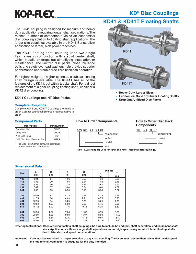
KD41 & KD41T Floating ShaftsThe KD41 coupling is designed for medium and heavy duty applications requiring longer shaft separations. The minimal number of components yields an economical disc coupling solution to floating shaft applications. The larger size couplings available in the KD41 Series allow application to larger, high power machines.
The KD41 floating shaft coupling uses two single flex halves in conjunction with a solid center shaft, which installs or drops out simplifying installation or maintenance. The unitized disc packs, close tolerance bolts and safety overload washers help provide superior performance and trouble-free zero backlash operation.
For lighter weight or higher stiffness, a tubular floating shaft design is available. The KD41T has all of the features of the KD41, but with a tubular shaft. For a direct replacement of a gear coupling floating shaft, consider a KD42 disc coupling.
KD41 Couplings use HT Disc Packs.
Dimensional Data
KD41
KD41T
Heavy Duty, Larger Sizes Economical Solid or Tubular Floating Shafts Drop-Out, Unitized Disc Packs
Complete CouplingsComplete KD41 and KD41T Couplings are made to order. Contact your local Emerson representative to order.
* For Disc Pack Components, do not include “Series” number in part number.
How to Order Components
Note: KD21 Hubs are used for KD41 and KD41T floating shaft couplings.
103 KD HTDP
size
component
model
Ordering Instructions: When ordering floating shaft couplings, be sure to include hp and rpm, shaft separation, and equipment shaft sizes. Applications with very large shaft separations and/or high speeds may require tubular floating shafts due to lateral critical speed considerations.
Important: Care must be exercised in proper selection of any shaft coupling. The Users must assure themselves that the design of the hub to shaft connection is adequate for the duty intended.
How to Order Disc Pack Components
103 KD 21 SHUB
model
series
component
size
noitpircseD rebmuNtraPbuHdradnatS BUHS
buHgnoL BUHL
kcaPcsiDTH* PDTH
teSrenetsaFkcaPcsiDTH* SFTH
eziSA
)ni(C
)ni(E
)ni(G
)ni(
lacipyTH
)ni(T
)ni(301 49.3 13. 66.1 75.2 05.1 63.2351 83.5 93. 49.1 45.3 88.1 51.3402 83.6 05. 83.2 23.4 26.2 26.3452 26.7 75. 00.3 43.5 00.3 93.4403 00.9 56. 65.3 61.6 05.3 76.5
453 05.01 18. 31.4 99.6 52.4 83.6404 57.11 88. 36.4 19.7 57.4 57.6454 57.21 49. 52.5 38.8 52.5 57.7405 88.31 90.1 88.5 26.9 57.5 00.8455 21.51 22.1 61.7 84.01 52.6 05.8
406 05.61 23.1 66.7 33.11 57.6 52.9507 05.02 65.1 00.9 70.41 05.8 05.11508 00.32 48.1 31.01 37.51 05.9 05.21509 05.52 67.1 18.11 88.71 00.11 05.51

31
KD® Disc Couplings
KD41 & KD41T Floating ShaftsSelection Data
� Data for two flex units with maximum bores. Weight and WR2 values do not include floating shaft or tube.
KD41
Ordering Instructions: When ordering floating shaft couplings, be sure to include hp and rpm, shaft separation, and equipment shaft sizes. Applications with very large shaft separations and/or high speeds may require tubular floating shafts due to lateral critical speed considerations.
Important: Care must be exercised in proper selection of any shaft coupling. The Users must assure themselves that the design of the hub to shaft connection is adequate for the duty intended.
eziS.xaMeroB)ni(
gnilpuoCgnitaR
)MPR001/PH(
gnitaReuqroT latoTthgieW
)sbl(
latoTRW 2
ni-bl( 2)
laixAyticapaC
)ni(suounitnoC
)bl-ni(kaeP)bl-ni(
301 57.1 3.6 0004 0008 4.01 91 080.±351 05.2 6.12 00631 00272 8.22 77 041.±402 00.3 1.75 00063 00027 2.84 742 011.±452 57.3 5.28 00025 000401 5.46 524 041.±403 05.4 141 00098 000871 101 529 071.±
453 00.5 832 000051 000003 751 0691 002.±404 05.5 043 000512 000034 732 0673 522.±454 83.6 504 000552 000015 992 0555 052.±405 00.7 075 000063 000027 593 0578 572.±455 57.7 008 000505 0000101 455 00541 003.±
406 05.8 0501 000066 0000231 796 00712 023.±507 57.01 0042 0000151 0000203 0521 00016 072.±508 00.21 0763 0000132 0000264 0381 000411 013.±509 05.31 0314 0000062 0000025 0152 000091 004.±
KD41T
� �

32
KD® Disc Couplings
KD42 & KD42T Floating ShaftsThe KD42 coupling is designed as a non-lubricated, drop-in replacement to gear coupling floating shafts. The standard bolt flanges of the KD42 allow the center gear coupling section to be dropped out, leaving rigid hubs in place on the equipment shafts to accept the low maintenance disc coupling shaft section.
The power capacity of the KD42 coupling is the highest in the industry, allowing the easiest conversion from a lubricated coupling to a low maintenance disc coupling. Existing solid shafts can be reused by simply machining the shaft ends to retrofit new disc couplings and dropping the new assembly in place on the rigid hubs.
The KD42 floating shaft coupling uses two flexible half couplings mounted on a solid center shaft, simplifying installation or maintenance. The unitized disc packs, close tolerance bolts and safety overload washers provide superior performance and trouble- free zero backlash operation.
For lighter weight or higher stiffness, a tubular floating shaft design is available. The KD42T has all of the features of the KD42, but with a tubular shaft. For a more economical floating shaft, consider a KD41 disc coupling.
KD42 Couplings use HT Disc Packs.
KD42
KD42T
Direct Gear Coupling Replacement Heavy Duty, Larger Sizes Solid or Tubular Floating Shafts Drop-Out Shaft Section
Component Parts
Gear Rigid Data
Complete CouplingsComplete KD42 and KD42T couplings are supplied without rigid hubs and rigid flange fastener sets. See Gear Rigid Data chart for rigid and fastener part numbers.
Complete KD42 and KD42T couplings are made to order. Contact your local Emerson representa-tive to order.
Interchange Chart - Gear to Disc Type Floating Shaft Coupling
* Flex Halves are designated by disc/gear size, and include (1) disc pack and (1) disc pack fastener set.** For Disc Packs Components, do not include “Series” number in the part number.
How to Order Hubs
How to Order Flex Halves
Note: KD10 Hubs are used for KD42 Floating Shaft Couplings.
103 KD 10 SHUB
model
series
component
size
Note: See Interchange Chart for standard and optional sizes.
How to Order Disc Pack Components103 KD HTDP
size
component
model
103/1.0 KD 42 FH
model
series
component
disc/gear size
� Denotes standard sizes. Shaded blocks are available options.
noitpircseD rebmuNtraPbuHdradnatS BUHS
flaHxelF* HFylbmessAkcaPcsiDTH** PDTH
teSrenetsaFkcaPcsiDSH** SFSH
EZISRAEG
EZISGNILPUOCCSID
301 351 402 452 403 453 404 454 405 455 406 507 508 509
12/11
22/12
32/13
42/14
52/15
678901
raeGdigiReziS
xaMeroB)ni(
AR )ni( BR )ni( ER )ni( )ni(CB eroB'CegnalF
CNU-stloB)ni(
raeGdigiR
egnalFrenetsaF
teS1 52.2 65.4 66.1 65.1 57.3 90. 4/1x6 BUHR1 SFBE1
2/11 96.2 00.6 49.1 48.1 18.4 90. 8/3x8 BUHR2/11 SFBE2/112 83.3 00.7 83.2 82.2 88.5 90. 2/1x6 BUHR2 SFBE2
2/12 00.4 83.8 00.3 19.2 21.7 90. 8/5x6 BUHR2/12 SFBE2/123 57.4 44.9 65.3 74.3 21.8 90. 8/5x8 BUHR3 SFBE3
2/13 05.5 00.11 21.4 30.4 05.9 90. 4/3x8 BUHR2/13 SFBE2/134 83.6 05.21 26.4 44.4 00.11 91. 4/3x8 BUHR4 SFBE4
2/14 52.7 26.31 52.5 60.5 00.21 91. 4/3x01 BUHR2/14 SFBE2/145 05.8 13.51 88.5 96.5 05.31 91. 8/7x8 BUHR5 SFBE5
2/15 00.8 57.61 61.7 79.6 05.41 91. 8/7x41 BUHR2/15 SFBE2/15
6 57.8 00.81 66.7 74.7 57.51 91. 8/7x41 BUHR6 SFBE67 00.01 57.02 00.9 57.8 52.81 52. 1x61 BUHR7 SFBE78 00.11 52.32 21.01 18.9 57.02 13. 8/11x61 BUHR8 SFBE89 57.21 00.62 91.11 88.01 52.32 13. 4/11x81 BUHR9 SFBE901 05.31 00.82 83.21 00.21 52.52 83. 8/31x81 BUHR01 SFBE01

33
KD® Disc Couplings
KD42 & KD42T Floating Shafts
KD 42
KD42T
Selection Data
Ordering Instructions: When ordering floating shaft couplings, be sure to include hp and rpm, shaft separation, and equipment shaft sizes. Applications with very large shaft separations and/or high speeds may require tubular floating shafts due to lateral critical speed considerations.
Important: Care must be exercised in proper selection of any shaft coupling. The Users must assure themselves that the design of the hub to shaft connection is adequate for the duty intended.
eziS
xelFxaMeroB)ni(
suounitnoCgnitaR
MPR001/PH
gnitaReuqroT laixAyticapaC
)ni(
AF)ni(
BF)ni(
EF)ni(
lacipyT
suounitnoC)bl-ni(
kaeP)bl-ni(
H )2(
)ni(T
)ni(301 05.1 3.6 0004 0008 080.± 49.3 53.2 96.1 05.1 63.2351 21.2 6.12 00631 00272 041.± 83.5 61.3 21.2 88.1 51.3
402 26.2 1.75 00063 00027 011.± 83.6 40.4 57.2 26.2 26.3452 52.3 5.28 00025 000401 041.± 26.7 44.4 30.3 00.3 93.4
403 57.3 141 00098 000871 071.± 00.9 00.5 95.3 05.3 76.5453 52.4 832 000051 000003 002.± 05.01 97.5 83.4 52.4 83.6
404 57.4 043 000512 000034 522.± 57.11 26.6 91.5 57.4 57.6454 05.5 504 000552 000015 052.± 57.21 47.6 13.5 52.5 57.7
405 57.5 075 000063 000027 572.± 88.31 64.7 30.6 57.5 00.8455 52.6 008 000505 0000101 003.± 21.51 74.8 19.6 52.6 05.8
406 57.6 029 000046 0000821 023.± 05.61 22.8 14.7 57.6 52.9507 05.8 0481 0000821 0000652 072.± 05.02 05.9 96.8 05.8 05.11
508 05.9 0322 0000871 0000653 013.± 00.32 00.11 18.9 05.9 05.21509 05.11 0314 0000062 0000025 004.± 05.52 28.11 88.01 00.11 05.51

34
KD® Disc Couplings
KD42S Slide Floating ShaftsThe power capacity of the KD42 coupling is the highest in the industry, allowing the easiest conversion from a lubricated coupling to a low maintenance disc coupling. Existing solid shafts can be reused by simply machining the shaft ends to retrofit new disc couplings and dropping the new assembly in place on the rigid hubs.
The KD42 floating shaft coupling uses two flexible half couplings mounted on a solid center shaft, simplifying installation or maintenance. The unitized disc packs, close tolerance bolts and safety overload washers help provide superior performance and trouble-free near zero backlash operation.
Direct Gear Coupling Replacement Heavy Duty, Larger Sizes Drop-Out Telescopic Shaft Section Stocked Standard Universal Joint
Slide (Telescopic) Assembly Splines Coated with Special Polymide
6 Coating for Reduced Maintenance
Gear Rigid Data
Complete Couplings
Complete KD42 and KD42S couplings are supplied without rigid hubs and rigid flange fastener sets. See Gear Rigid Data chart for rigid and fastener part numbers.
Complete KD42 and KD42S couplings are made to order. Contact your local Emerson representative to order.
How to Order Disc Pack Components103 KD HTDP
size
component
model
raeGdigiReziS
xaMeroB)ni(
AR )ni( BR )ni( ER )ni( )ni(CB eroB'CegnalF
CNU-stloB)ni(
raeGdigiR
egnalFrenetsaF
teS1 52.2 65.4 66.1 65.1 57.3 90. 4/1x6 BUHR1 SFBE1
2/11 96.2 00.6 49.1 48.1 18.4 90. 8/3x8 BUHR2/11 SFBE2/112 83.3 00.7 83.2 82.2 88.5 90. 2/1x6 BUHR2 SFBE2
2/12 00.4 83.8 00.3 19.2 21.7 90. 8/5x6 BUHR2/12 SFBE2/123 57.4 44.9 65.3 74.3 21.8 90. 8/5x8 BUHR3 SFBE3
2/13 05.5 00.11 21.4 30.4 05.9 90. 4/3x8 BUHR2/13 SFBE2/134 83.6 05.21 26.4 44.4 00.11 91. 4/3x8 BUHR4 SFBE4
2/14 52.7 26.31 52.5 60.5 00.21 91. 4/3x01 BUHR2/14 SFBE2/145 05.8 13.51 88.5 96.5 05.31 91. 8/7x8 BUHR5 SFBE5
2/15 00.8 57.61 61.7 79.6 05.41 91. 8/7x41 BUHR2/15 SFBE2/15
6 57.8 00.81 66.7 74.7 57.51 91. 8/7x41 BUHR6 SFBE67 00.01 57.02 00.9 57.8 52.81 52. 1x61 BUHR7 SFBE78 00.11 52.32 21.01 18.9 57.02 13. 8/11x61 BUHR8 SFBE89 57.21 00.62 91.11 88.01 52.32 13. 4/11x81 BUHR9 SFBE901 05.31 00.82 83.21 00.21 52.52 83. 8/31x81 BUHR01 SFBE01
For lighter weight or higher stiffness, a tubular floating shaft design is available. The KD42S has all of the features of the KD42, but with a tubular shaft.
KD42 Couplings use HT Disc Packs.

35
KD® Disc Couplings
KD42S Slide Floating Shafts
eziS
suounitnoCgnitaR
MPR001/PH
gnitaReuqroT AF)ni(
BF)ni(
T
)ni(
latoTedilS)ni(
laixAtnemtsujdA
)ni(suounitnoC)bl-ni(
kaeP)bl-ni(
402 1.75 00063 00027 83.6 40.4 26.3 33.4 05.1±452 5.28 00025 000401 26.7 44.4 90.4 33.4 ± 05.1
403 141 00098 000871 00.9 00.5 76.5 33.4 ± 05.1453 832 000051 000003 05.01 97.5 76.5 33.4 ± 05.1
404 043 000512 000034 57.11 26.6 05.6 33.4 ± 05.1454 504 000552 000015 57.21 47.6 05.6 33.4 ± 05.1
405 075 000063 000027 88.31 64.7 85.8 13.5 ± 00.2455 008 000505 0000101 21.51 74.8 85.8 13.5 ± 00.2
Refer to Page 34 for Flange Connection Data.
Selection Data
BR
BRBC
C’BORE
SHAFT SEPARATION
T
BF
AFAR
Interchange Chart - Gear to Disc Type Floating Shaft Coupling
� Denotes standard sizes. Shaded blocks are available options.
EZISRAEG
EZISGNILPUOCCSID
301 351 402 452 403 453 404 454 405 455 406 507 508 509
12/11
22/12
32/13
42/14
52/15
678901


![KD-A645 / KD-R640 / KD-R540 / KD-R440 - Car Audio ...santafeautosound.com/uploads/product-manuals/JVC KD-R540.pdfKD-A645 / KD-R640 / KD-R540 / KD-R440 GET0829-001A [J/JW] ENGLISH ESPAÑOL](https://static.fdocuments.in/doc/165x107/5aaf5da87f8b9a25088d67c4/kd-a645-kd-r640-kd-r540-kd-r440-car-audio-kd-r540pdfkd-a645-kd-r640.jpg)


![Kop-Flex KD Disc Couplings Metric - AHR International ball ... · 104 MT disc pack [ Medium Torque ] unitized, 3 bolt disc with “prestretch” bushings that get pressed into the](https://static.fdocuments.in/doc/165x107/5bd5a7d909d3f25d3e8c1d4d/kop-flex-kd-disc-couplings-metric-ahr-international-ball-104-mt-disc-pack.jpg)