KONSTANTIN KHRAMTCOV ANALYSIS OF POWER SUPPLY …
76
KONSTANTIN KHRAMTCOV ANALYSIS OF POWER SUPPLY METHODS FOR WIRELESS BIOMEDICAL SENSORS AND FUTURE DEVELOPMENT PROSPECTS Master of Science Thesis Examiners: Prof. Leena Ukkonen Prof. Lauri Sydänheimo Examiner and topic approved by the Faculty Council of the Faculty of Electrical Engineering on 30 th of August 2017
Transcript of KONSTANTIN KHRAMTCOV ANALYSIS OF POWER SUPPLY …

KONSTANTIN KHRAMTCOV
ANALYSIS OF POWER SUPPLY METHODS FOR WIRELESS
BIOMEDICAL SENSORS AND FUTURE DEVELOPMENT PROSPECTS
Master of Science Thesis
Examiners: Prof. Leena Ukkonen
Prof. Lauri Sydänheimo
Examiner and topic approved by the
Faculty Council of the Faculty of
Electrical Engineering
on 30th of August 2017

i
ABSTRACT
KONSTANTIN KHRAMTCOV: TUT Thesis Template
Tampere University of Technology
Master of Science Thesis, 68 pages,
June 2018
Master’s Degree Programme in Electrical Engineering
Major: Wireless communications
Examiners: Professor Leena Ukkonen, Professor Lauri Sydänheimo
Keywords: Implantable biomedical devices, Wireless powering methods, Implants,
Energy harvesting, power management, inductive coupling, modulation techniques
Implantable biomedical devices have been designed to provide monitoring and diagnosis of the
physical information in human bodies. The population is ageing and there are many increasing
chronic diseases at all ages all around the world, that’s why modern methods of diagnosis and
monitoring chronic diseases play a vital role in medicine and human health. Biomedical wearable
devices and implantable devices are in high demand due to their wider applications. Wireless
powering methods can improve the way a patient’s health can be monitored and also help patients
who are living far from the hospitals.
The current thesis has been focused on the analysis of wireless powering methods for implantable
biomedical sensors, their advantages and drawbacks, requirements of different approaches as well
as current and future challenges. In order to implement a wireless powering method, developers
have to establish quality management systems in the designing phase, to implement safe and
effective devices, and meet the requirements of regulatory authorities. These wireless powering
methods and devices can improve quality of life to the patients and extend their lives.
However, one of the significant challenges is the power supply, because it is vital to provide
sufficient power and to maintain it on the same level along the whole time when the system is
operational. Modern wireless IMDs require a stable and continuous power consumption; that’s
why this problem becomes significant.

ii
PREFACE
This thesis was made as a part of the requirement for completing the Master’s in Wireless
Communications.
I express my deep gratitude to my supervisor, Professor Leena Ukkonen, who patiently supervised
the thesis and her support, comments and guidance has led the work to successful conclusion.
Indeed, without her support, this work would not have been possible. It was a long and very
exciting work: I really enjoyed this period. I started my thesis in August 2017. Later in May, I was
offered an internship from a London based start-up company, I was working there for one year
and completed it in June 2018. Within this period, I was working and writing the thesis at the same
time.
This thesis was performed at the Department of Electronics and Communication Engineering in
the Tampere University of Technology, Finland. First of all, I decided to divide my thesis into
several parts, at the initial stage I tried to identify modern publications and articles from well-
respected journals. At the second stage, I compiled all my observations and notes together, and
wrote the main part of the thesis. At the third stage, I learned more specific topics such as
cybersecurity for IMDs and types of antennas which employ IMDs.
I also want to thank my colleagues and friends at the Tampere University of Technology for their
valuable comments, suggestions, encouragement, and support through the process. Special thanks
to my parents for their support at every stage of my life.
Tampere, June 09.05.2018
Konstantin Khramtcov

iii
TABLE OF CONTENTS
1. INTRODUCTION ...................................................................................................................1
1.1 Research Objective.................................................................................................................2
1.2 Thesis Outline ........................................................................................................................2
2. SENSOR TECHNOLOGIES ..................................................................................................3
2.1 History of implantable biomedical sensors ...........................................................................3
2.2 Sensor characteristics ............................................................................................................5
2.2.1 Sensitivity .......................................................................................................................5
2.2.2 Measurement range.........................................................................................................6
2.2.3 Precision .........................................................................................................................6
2.2.4 Accuracy .........................................................................................................................6
2.2.5 Linearity .........................................................................................................................6
2.2.6 Hysteresis .......................................................................................................................7
2.2.7 Resolution .......................................................................................................................7
2.2.8 Response Time ...............................................................................................................7
2.3 Frequency bands for wireless bio-medical implants .............................................................7
2.4 Security of wireless medical devices ...................................................................................10
3. MODULATION TECHNIQUES FOR IMDs .......................................................................12
3.1 Principle of ASK modulation technique ..............................................................................13
3.1.1 ASK modulation method for implantable biomedical sensors .....................................14
3.2 Principle of PSK modulation technique ..............................................................................15
3.2.1 PSK modulation method for implantable biomedical sensors .....................................15
3.3 Principle of FSK modulation technique ..............................................................................16
3.3.1 FSK modulation method for implantable biomedical sensors .....................................17
4. POWERING METHODS FOR IMPLANTABLE BIOMEDICAL SENSORS ...................19
4.1 Lithium batteries ..................................................................................................................21
4.2 Nuclear batteries ..................................................................................................................21
4.3 Piezoelectricity power generators ........................................................................................22
4.4 Thermoelectricity.................................................................................................................26
4.5 Electrostatic generators........................................................................................................29
4.6 Electromagnetic harvesters ..................................................................................................32
4.7 Ultrasonic energy transmission ...........................................................................................34
4.8 Photovoltaic infrared power radiation .................................................................................36
4.9 Inductive coupling ...............................................................................................................37
4.10 Far Field Communications ................................................................................................40
4.11 Mid-Field Communication ................................................................................................40
4.12 Bio-fuel cells .....................................................................................................................41
5. CURRENT CHALLENGES AND FUTURE PROSPECTIVE OF IMDs ...........................43
5.1 Power management..............................................................................................................43
5.2 Biocompatibility ..................................................................................................................44
5.3 Health issues related to wireless power transfer energy ......................................................45

iv
5.4 Size of the IMDs ..................................................................................................................46
5.5 Frequency band selection ....................................................................................................46
5.6 Antennas ..............................................................................................................................47
5.6.1 Dual-band operation antenna ........................................................................................47
5.6.2 Implantable antennas for wireless power transfer ........................................................48
5.6.3 Integrated implantable antennas ...................................................................................48
5.7 Security ................................................................................................................................48
5.8 Amplifiers for IMDs ............................................................................................................50
5.9 Future prospects ...................................................................................................................51
6. CONCLUSIONS ...................................................................................................................53
BIBLIOGRAPHY .........................................................................................................................54

v
LIST OF FIGURES
Figure 1. Examples of biomedical devices. [160] ..........................................................................1
Figure 2. Cardiac before and after the wireless transfer ...............................................................4
Figure 3. Timeline evolution of IMDs .............................................................................................4
Figure 4. Sensors sensitivity [161] .................................................................................................5
Figure 5. Linearity representation [161] ........................................................................................6
Figure 6. Hysteresis curve [161] ....................................................................................................7
Figure 7. The architecture of MICS system ....................................................................................9
Figure 8. Modulation techniques used in biomedical sensors ......................................................12
Figure 9. The architecture of the wireless battery-less interface .................................................13
Figure 10. The principle of ASK modulation [209] ......................................................................13
Figure 11. PSK modulation waveforms. [162] .............................................................................15
Figure 12. FSK modulation principle. [163] ................................................................................17
Figure 13. Human’s power resources ...........................................................................................19
Figure 14. Energy harvesting methods used in the biomedical sensors .......................................20
Figure 15. The efficiency of different powering methods for IMDs ..............................................20
Figure 16. Nuclear pacemaker [164] ...........................................................................................22
Figure 17. Energy conversion scheme ..........................................................................................22
Figure 18. The Basic work principle of piezoelectric IMD ..........................................................23
Figure 19. Configurations of piezoelectric cantilevers [170] ......................................................24
Figure 20. Configuration of cymbal piezoelectric device [170] ...................................................24
Figure 21. A prototype of shoe mounted PEH [44] ......................................................................25
Figure 22. Dependence of the efficiency of the linear branch cross-section dimensions [158] ...27
Figure 23. The architecture of thermoelectric generator .............................................................28
Figure 24. Conceptual view of the electrostatic generator ..........................................................29
Figure 25. Energy conversion principles of electret-free electrostatic IMDs. [208] ...................30
Figure 26. Electret-based electrostatics conversion model. .........................................................31
Figure 27. Capacitor structure .....................................................................................................31
Figure 28. Types of mechanical generators: a) relative movement, b) rigid body .......................33
Figure 29. Schematic of ultrasonic IMD. [165] ...........................................................................35
Figure 30. Infrared power radiation system [202] .......................................................................36
Figure 31. The architecture of Inductive coupling powering method ..........................................37
Figure 32. Types of topologies ......................................................................................................39
Figure 33. The design of bio-fuel IMD .........................................................................................41
Figure 34. Types of body wireless communication .......................................................................47
Figure 35. Overview of the future system .....................................................................................51

vi
LIST OF TABLES
Table 1. Table of comparisons between different wireless method .................................................8
Table 2. Examples of comparisons of modulation techniques for IMDs.......................................18
Table 3. Power consumption rates for different IMDs ..................................................................28
Table 4. Comparison of Electromagnetic, Electrostatic and Piezoelectric powering methods. ...33
Table 5. Comparisons between different electromagnetic power methods ...................................41
Table 6. IEEE C95.1-1991 Maximum electric and magnetic field strength limits for public use 45
Table 7. Current trends addressing various threats to IMD security ...........................................50
Table 8. Comparisons between different power approaches ........................................................50

vii
LIST OF ABBREVIATIONS
ANSI American National Standard Institute
ARQ Automatic Repeat Request
ASK Amplitude shift keying
BFC Bio-Fuel Cells
BPSK Binary Phase Shift Keying
DPSK Differential Phase Shift Keying
FCC Federal Communication Commission
FDA Food and Drug Administration
EBC Enzymatic Bio-Fuel Cells
ECG Electrocardiogram
EMG Eelectromyography
EOG Electrooculography
ERG Electroretinogram
FEC Forward Error Correction
FSK Frequency – Shift- Keying
IMD Implantable Medical Device
IoT Internet of Things
IMD Implantable Medical Device
ISM Industrial, Scientific and Medical
MFC Microbial Fuel Cells
MICS Medical Implant Communication System
NFC Near Field Communication
PVs Physiological signals
PSK Phase Shift Keying
PTE Power Transfer Efficiency
PEH Piezoelectric Harvester
QoL Quality of Life
RF Radio Frequency
RFID Radio Frequency Identification Technology
RX Receiver
SAR Specific Absorption Rate
SIR Signal to Interference Ratio
TEG Thermal energy generation
TX Transmitter
WEP Wired Equivalency Privacy
WMTS Web Map Tile Service
WPA Wi-Fi Protected Access
WPT Wireless Power Transfer
WPAN Wireless Personal Access Network
i
1. INTRODUCTION
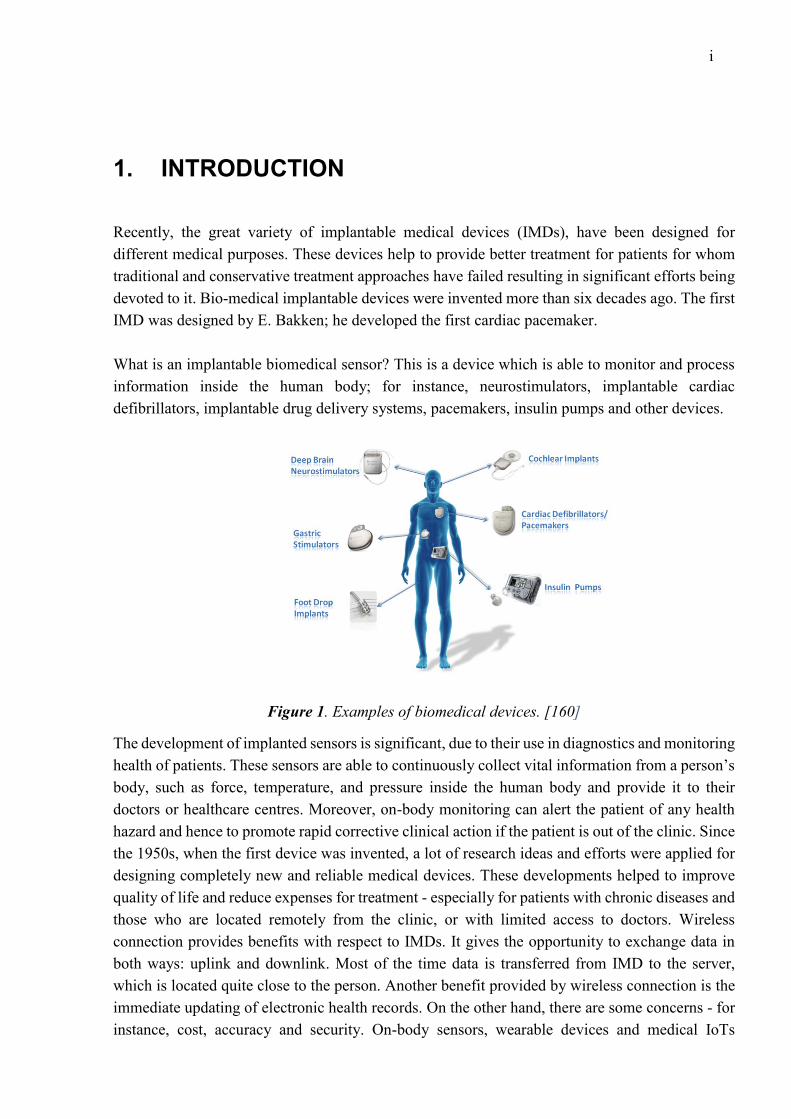
Recently, the great variety of implantable medical devices (IMDs), have been designed for
different medical purposes. These devices help to provide better treatment for patients for whom
traditional and conservative treatment approaches have failed resulting in significant efforts being
devoted to it. Bio-medical implantable devices were invented more than six decades ago. The first
IMD was designed by E. Bakken; he developed the first cardiac pacemaker.
What is an implantable biomedical sensor? This is a device which is able to monitor and process
information inside the human body; for instance, neurostimulators, implantable cardiac
defibrillators, implantable drug delivery systems, pacemakers, insulin pumps and other devices.
Figure 1. Examples of biomedical devices. [160]
The development of implanted sensors is significant, due to their use in diagnostics and monitoring
health of patients. These sensors are able to continuously collect vital information from a person’s
body, such as force, temperature, and pressure inside the human body and provide it to their
doctors or healthcare centres. Moreover, on-body monitoring can alert the patient of any health
hazard and hence to promote rapid corrective clinical action if the patient is out of the clinic. Since
the 1950s, when the first device was invented, a lot of research ideas and efforts were applied for
designing completely new and reliable medical devices. These developments helped to improve
quality of life and reduce expenses for treatment - especially for patients with chronic diseases and
those who are located remotely from the clinic, or with limited access to doctors. Wireless
connection provides benefits with respect to IMDs. It gives the opportunity to exchange data in
both ways: uplink and downlink. Most of the time data is transferred from IMD to the server,
which is located quite close to the person. Another benefit provided by wireless connection is the
immediate updating of electronic health records. On the other hand, there are some concerns - for
instance, cost, accuracy and security. On-body sensors, wearable devices and medical IoTs

2
matched with smartphones have also become popular in connection with a variety of sport and
health applications.
In general, an implantable sensor is composed of two main parts, usually, the first part is attached
to the skin or placed inside of the body, and the other part is a receiver, located outside of the body.
The main purpose of the receiver part is to provide power to the IMD and deliver data to the doctor.
Some of the IMDs are independent, meaning that these devices can regulate their operations
depending on conditions. The main requirements for IMDs are based on power consumption, data
rates, biocompatibility, dimensions and security. Battery lifetime is a very significant issue, in
order to reduce chances for repeated surgery, it is vital to improving the lifetime of IMDs. Another
critical requirement for IMD are the dimensions of the device; the continuous technological
progress and the rapid development of semiconductors has led to rapid technological advances,
with the dimensions of the devices getting smaller. However, the battery occupies a significant
volume of the device, that’s why it is vital to move towards battery-less IMDs. Wireless powering
methods provide a wireless access to IMDs, such as RFID or NFC [125]. Human body resources
are able to produce energy such as thermal, movements, vibration etc, which can be converted into
electrical energy. Antennas are playing an important role in communications as well.
The thesis is organized as follows. Chapter 2 presents a short history overview of the implantable
biomedical sensors which gives the main sensor’s characteristics. Chapter 3 illustrates the main
digital modulation techniques which are employed in biomedical sensors and literature reviews
about recent publications. Chapter 4 focuses on the analysis of current harvesting methods for
implantable medical devices and the review of real devices which are based on various powering
methods. Chapter 5 is devoted to analysis of current challenges for implantable devices and
powering methods and how to mitigate them. Chapter 6 summarizes the conclusions obtained by
literature review and discusses future development perspectives.
1.1 Research Objective
The goal of the current thesis is to analyse and layout the advantages and drawbacks of wireless
powering methods for implantable biomedical sensors and to define the current and future
challenges of these approaches. This includes: analysis of the current situation on the market;
which methods are being used currently; what kind of cutting-edge technologies are employed for
implementing these approaches; and a review of modern publication about this topic.
1.2 Thesis Outline
This thesis will show: the analysis of existing power methods for implantable biomedical sensors;
the main characteristics of the sensors; a brief introduction to the history of implantable sensors; a
deep overview of modulation techniques which are being used currently for IMDs; research on the
advantages and disadvantages of each modulation method; and a review of recent publications
regarding these topics.
3
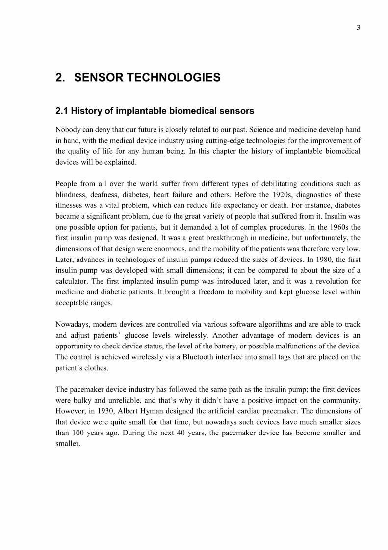
2. SENSOR TECHNOLOGIES
2.1 History of implantable biomedical sensors
Nobody can deny that our future is closely related to our past. Science and medicine develop hand
in hand, with the medical device industry using cutting-edge technologies for the improvement of
the quality of life for any human being. In this chapter the history of implantable biomedical
devices will be explained.
People from all over the world suffer from different types of debilitating conditions such as
blindness, deafness, diabetes, heart failure and others. Before the 1920s, diagnostics of these
illnesses was a vital problem, which can reduce life expectancy or death. For instance, diabetes
became a significant problem, due to the great variety of people that suffered from it. Insulin was
one possible option for patients, but it demanded a lot of complex procedures. In the 1960s the
first insulin pump was designed. It was a great breakthrough in medicine, but unfortunately, the
dimensions of that design were enormous, and the mobility of the patients was therefore very low.
Later, advances in technologies of insulin pumps reduced the sizes of devices. In 1980, the first
insulin pump was developed with small dimensions; it can be compared to about the size of a
calculator. The first implanted insulin pump was introduced later, and it was a revolution for
medicine and diabetic patients. It brought a freedom to mobility and kept glucose level within
acceptable ranges.
Nowadays, modern devices are controlled via various software algorithms and are able to track
and adjust patients’ glucose levels wirelessly. Another advantage of modern devices is an
opportunity to check device status, the level of the battery, or possible malfunctions of the device.
The control is achieved wirelessly via a Bluеtooth interface into small tags that are placed on the
patient’s clothes.
The pacemaker device industry has followed the same path as the insulin pump; the first devices
were bulky and unreliable, and that’s why it didn’t have a positive impact on the community.
However, in 1930, Albert Hyman designed the artificial cardiac pacemaker. The dimensions of
that device were quite small for that time, but nowadays such devices have much smaller sizes
than 100 years ago. During the next 40 years, the pacemaker device has become smaller and
smaller.

4
Figure 2. Cardiac stimulator before and after the wireless transfer
As a result, in 1960 the first successful implantation pacemaker was released, however, the first
devices suffered from a limited battery life. Researchers employed nuclear batteries as a power
harvester (plutonium), but due to the detrimental impact on health, they stopped using it. Later, in
1990, a new pacemaker was being released onto the market, employing a principle called “cardiac
resynchronization therapy”.
The next step in pacemaker evolution was the ability to connect devices wirelessly. The first
wireless pacemaker was introduced in 2009. The main advantages of the wirelessly powered
device are the ability to control and to make a configuration remotely, and the freedom of
movement for the patient. The use of wireless power transfer for pacemakers greatly reduced the
risk of health problems and surgery risks. A great variety of research has been undertaken in order
to optimize the transfer of wireless energy to pacemakers [136-138].
The evolution of pacemakers, insulin pumps, and mobile technology is presented in figure 3.
According to the picture, we can see comparisons between each device. It illustrates one significant
point, that the mobile devices industry is developing much faster the medical industry.
Figure 3. Timeline evolution of IMDs

5
2.2 Sensor characteristics
The main purpose of any sensor is to react to external influences and to give instructions to the
system about these impacts. The simplest example of a sensor is a smartphone screen that reacts
to the touch of your fingers. This screen is equipped with a temperature sensor, allowing you to
react to the lightest and shortest touch of human fingers. Thus, sensors are able to convert an
impulse into a measured signal. Sensors are the vital part of the IMDs and are based upon a very
wide range of underlying physical principles of operation.
In this chapter the main definitions and characteristics of biomedical sensors will be presented, as
well as the importance of the measuring process. Nobody can deny that biomedical sensors should
be reliable, safe, and bio-compatible with a person’s body. In order to understand the main
characteristics of biomedical sensors, you need to understand the basic terminology which is used
in sensor design.
2.2.1 Sensitivity
Sensitivity describes the ratio between the input and the output signals. It shows how much the
output values change when the measured quantity changes. Some of the sensors measure very
small signals, for instance, sensors which measure electrophysiological signals have very sensitive
characteristics. Another example, some of the blood pressure transducers which have a sensitivity
rating of 10 mV/V/mm Hg; that is, there will be a 10-mV output voltage for each volt of excitation
potential and each mm of Hg of applied pressure. [161]
Figure 4. Sensors sensitivity [161]

6
2.2.2 Measurement range
First of all, it is better to understand what “range” means. Basically, the range of any sensor is the
maximum and minimum values of an applied parameter that can be measured accurately. For
instance, some of the blood pressure sensors have the minimum limit of -50 mm Hg and the
maximum limit of +450 mmHg.
2.2.3 Precision
Precision refers to the “degree of a measurement’s repeatability in the same conditions”. If the
measurement results remain the same after many experiments, it means that the sensor has a high
precision.
2.2.4 Accuracy
Accuracy is “the expected error between the true values and actual values” measured by the sensor.
Accuracy can be expressed as a percentage of the full scale.
2.2.5 Linearity
The linearity of the sensor is the maximum deviation between the actual values of the
measurements and ideal results. Basically, linearity can be expressed in percent, according to the
equation (1)
𝐿𝑖𝑛𝑒𝑎𝑟𝑖𝑡𝑦 = ∆𝐿
𝑌𝐹𝑆∗ 100% (1)
where ∆𝐿 is the maximum input deviation, 𝑌𝐹𝑆 is the maximum full-scale input.
Figure 5. Linearity representation [161]

7
2.2.6 Hysteresis
The hysteresis of the sensor refers to some sensors, in which input and output characteristics have
a non-linear trend, depending on input signal behaviour.
Figure 6. Hysteresis curve [161]
2.2.7 Resolution
The resolution of the sensor is the minimum detectable signal fluctuation. Resolution can be
expressed as a proportion of the full-scale readings.
2.2.8 Response Time
The output value of the sensors doesn’t change immediately when the input parameter change
occurs. The response time shows the time needed for a sensor to react when the input signal is
changed.
2.3 Frequency bands for wireless bio-medical implants
Currently, a great variety of wireless medical applications exist, such as implantable and telemetry
devices. One of the crucial requirements for wireless implantable sensors is power consumption
and small size. Most of the medical applications are used indoors and have quite a small range.
Wireless IMDs utilize different frequency bands and share the radio spectrum with other devices.
This leads to a lot of issues and concerns about performance, especially for applications which use
license-free spectrum - which can cause interference, fading, multipath propagation, and blocking
of the signals. A clear understanding of spectrum sharing (wireless coexistence and
interoperability) is significant for the design of medical devices [139].
Wireless coexistence defines the ability of a wireless system to work in a shared environment,
where other devices are using the same spectrum resources. There are three main factors which
define the wireless coexistence: time, space, and frequency. Coexistence is possible if any one of

8
these requirements are met. First, sufficient distance between wireless networks. Second, the
frequency separation between wireless networks [127]. Third, low overall occupancy of the
wireless channel [2].
Table 1. Table of comparisons between different wireless method
Standard Frequency Range Data Range
Inductive coupling < 1 MHz < 1m Up to 30 kbps
Wireless Medical
Telemetry System
(WMTS)
608-614 MHz
1395-1400 MHz
1429-1432 MHz
35-70m >250 kbps
Medical Body Area
Networks (MBAN)
2483.5 MHz-2500
MHz
<1m Up to 1 Mbps
802.11a Wi-Fi 5 GHz 120m 54 Mbps
802.11g Wi-Fi 2.4 MHz 140m 54 Mbps
802.11n Wi-Fi 2.4 MHz-5MHz 250m 48 Mbps
802.15.1 Bluetooth
class 1
2.4 MHz 100m 3 Mbps
802.15.1 Bluetooth
class 2
2.4 MHz 10m 3 Mbps
802.15.4 ZigBee 2.4 GHz 75m 40-250 kbps
Medical Device
Radio
Communication
Service (MICS)
401-406 MHz 2-10m 250 kbps
Several frequency bands exist especially for medical devices, but many medical applications use
unlicensed spectrum called the ‘ISM band’, in other words industrial, scientific, and medical band.
Table 1 illustrates different wireless interfaces which are utilized by IMDs. These regulations and
standards must be respected by all manufacturers. Each frequency band is designed for certain
type of devices, for example, MBAN, WMTS, inductive coupling and MICS.
Inductive link is a reliable method for communication between an implantable device and a
controller which is located out of the person’s body. However, this method has some drawbacks:
the maximum separation between coils should not exceed 6 cm; the data rate is another issue - at
approximately 30 kbps, the speed of data transmission is very low; and interference is a significant
issue for inductive link medical applications, as the patient must be careful with these IMDs to
ensure communication between sensor and receiver is always possible.
Medical Implant Communication Systems (MICS) transmit data from implants inside the human
body to an external unit, in order to programme the IMD and control the patient’s data. An external
device or controller can communicate with other systems, such as the internet, for the remote
control of the patient’s conditions. The architecture of an MICS system is presented in Figure 7.

9
The implantable sensor is able to receive commands and can be reprogrammed from a doctor
through a wireless connection. Patients can move freely with these sensors. Interference mitigation
is the key issue for MICS systems because all data s sent and received from IMDs should be
accurate and reliable. There are different error correction methods such as FEC and ARQ.
Figure 7. The architecture of MICS system
Wireless Medical Telemetry Systems are composed of sensors which measure important health
parameters, and transmitters for delivering data through a radio interface to the receiver. This
system utilizes different frequency bands from 600 to 1432 MHz all over the world. The UHF
band (608 MHz to 614MHz) was originally reserved for radio astronomy. Therefore, users using
this band should take into account that radio astronomy devices use the same band. The second
frequency band (1395-1400 MHz and 1429-1432 MHz) was originally designed for government
purposes such as military radar operations. Recently these bands have become available for
WMTS. However, some countries have not followed these regulations, therefore frequency bands
for WMTS need to be addressed and harmonised internationally. Without the acceptance of
frequency regulations all over the world, the safety and quality of service provided by wireless
medical devices are questionable. The WMTS is capable of two-way communication and
providing high data transmission rates. There are certain limitations in this system: restricted
bandwidth of only 14 MHz; video and audio transmissions are not possible; and each company
which designs WMTS equipment uses their own protocols and interfaces, therefore devices from
two different vendors are not able to communicate with each other.
Wi-Fi is the oldest wireless technology used in medical application, and has different sub-
standards such as 802.11a, b, g, n, ac, ad. Each of these methods have certain sections of the ISM
band. Wi-Fi allows transmission of both video and voice. Using the ISM band has advantages such
as a wide bandwidth of 83 MHz in total, and devices can communicate with other devices. Wi-Fi
networks can support a great variety of Wi-Fi compatible devices, such as access points, laptops,
and monitors. Frequency management is not required, great propagation characteristics, low power
consumption, easy to share spectrum resources with other devices. Wired Equivalent Privacy
(WEP) - an algorithm for ensuring the security of Wi-Fi networks is used to ensure confidentiality

10
and the protection of transmitted data to prevent non-authorized wireless network users from
listening. There are two types of WEP: WEP-40 and WEP-104, differing only in the length of the
key. Currently, this technology is obsolete, as it can be hacked in just a few minutes. Nevertheless,
it continues to be widely used. For security in Wi-Fi networks, it is recommended to use WPA.
Wi-Fi Protected Access (WPA) is an improved version of the WEP protocol, therefore WPA has
better performance than WEP, however, this method still has some vulnerabilities. In order to
improve security characteristics, the next evolution of WPA has been released, called WPA2. This
method has better security characteristics for wireless networks. On the other hand, certain
limitations exist as well. The ISM band is unlicensed, and so other devices can cause interference.
Encryption Wi-Fi is relatively poorly protected against hacking. Range and Wi-Fi transmission
speed depend on the presence and intensity of the interference.
Wireless personal access network (WPAN) mainly uses two protocols: Bluetooth and ZigBee.
Bluetooth is considered as a very short-range wireless technology, with low power consumption
and small bandwidth. It is designed to replace cables and for communication between small
devices or sensors which are associated with the human’s body. Bluetooth utilizes the same ISM
band as Wi-Fi and can also transmit video and voice.
2.4 Security of wireless medical devices
Security of IMDs and medical information will be the significant problem in the next few decades.
Nowadays, most patients’ medical records are paperless, and devices are used for collecting health
data. Some of the devices are already available and very affordable, the main features being
monitoring of heart rate, daily activities, and sleep cycles, in addition to the ability to illustrate it
graphically.
Hospitals also widely use wireless technologies in diagnostics and treatment. The skyrocket
development of wireless technologies has a beneficial impact on patients who are receiving these
services. However, it is very important to keep this information secure and protect it from theft
and hackers. For example, if someone is trying to steal information from medical records, it could
be used for negative purposes or for the purposes of blackmail: therefore, it is important to store
this data in a secure manner. Security includes a lot of factors, such as confidentiality,
authentication, integrity, authorization, availability, and non-repudiation.
Recent studies have demonstrated the possibilities to attack IMDs. According to Halperin research
paper [3], various implantable devices such as cardiac or pacemaker devices, have a lot of
vulnerabilities to adversarial actions; this can result in information theft - such as personal
information and medical history - or in the influencing of heart rhythms. This is possible due to an
unprotected communication link between the IMD and the programmer. C. Li and A. Raghunathan
also demonstrated possible security risks on real examples of the systems which are currently
widely used, such as insulins pumps and glucose monitoring systems. The authors also offered
possible solutions to protect systems against these attacks. They proved that the wireless link

11
between IMD and programmer should be controlled and secured to prevent illegal attacks from
intruders. [4-5]
There are many researchers from all over the world addressing the security problems of IMDs.
One of the common approaches is based on authenticating keys for establishing secure channel
communication between IMD and programmer. However, this approach is not compatible with
resource constrained IMDs. Hence, the IMD security should be based on tiny authentication
schemes and symmetric encryption [6-8] or employ a resource-rich personal device (e.g.
smartphone) to mediate communication between an IMD and an external programmer [9–11].
Another approach for the IMD security is associated with the accessibility issues of IMDs when
an emergency situation occurs. Suppose an unconscious patient with IMD enters an emergency
room (ER) of a non-primary-care hospital. In order for ER personnel to access the IMD the patient
has, some backdoors should be integrated for the programmer. Even though several techniques
[12–15] have been proposed, each of them have their own inherent security weaknesses.

12
3. MODULATION TECHNIQUES FOR IMDs
Digital modulation - the process of converting digital symbols into signals compatible with the
characteristics of the communication channel. Each possible value of the transmitted symbols is
assigned to some of the parameters of the analogue carrier wave. Manipulation - the way digital
or pulse modulation, is when the carrier signal parameters change abruptly. When digital
modulation is used most often, it is a discrete sequence of binary symbols - binary codes. Encoded
primary analogue signal e (t), which is a sequence of code symbols
{EN} = EN (k) (n = O, 1, 2, 3, ... - a serial number of the character - the number of code positions;
m - code base, t. e. the number of its various components, which are converted into a sequence of
elements (chips) signal {Un (t)} of code symbols by exposure to high-frequency carrier wave UH
(t). As a rule, binary codes are used that m = 2. Usually, by modulating the frequency or phase of
the carrier in the radio the pulses vary as determined by a digital code. Digital modulation provides
much more information capacity and ensures compatibility with various digital data services. It
also increases the security of information, improves quality and speeds up access to the
communication system. On the other hand, the main drawbacks of the system with digital
modulation are a significant expansion of the occupied frequency channels of bandwidth, and the
need for accurate synchronization signals. Figure 8 illustrates the main types of digital modulation.
Figure 8. Modulation techniques used in biomedical sensors
The conventional wireless battery-less system link is used for 2-way communication between IMD
and other devices. Figure 9 depicts the architecture of a wireless battery-less interface. Due to
limitations in size and complexity of an implantable sensor, the signal processing part is located
in the external unit. Power required for the implant modules - including a central processing unit
(CPU), stimulators, and sensors - is transmitted by the external host via wireless interfacing. It

13
consists of two main parts: internal IMD and the external host system. The internal part is
composed of a power harvester, a modulator for sending the signals from the sensor and its status
for the external device, and a demodulator for receiving data from the sensor.
Figure 9. The architecture of the wireless battery-less interface
3.1 Principle of ASK modulation technique
Amplitude-Shift-Keying (ASK) modulation is one of the simplest digital modulation techniques
which is used for implantable biosensors. However, this method has several limitations such as
low data rates and high sensitivity for the amplitude noise. In ASK, the carrier amplitude is shifted
between low and high values depending on the data at the input of the modulator [8]. There are
two methods of ASK modulation which are perfectly suitable for the IMDs: coherent and non-
coherent schemes. The non-coherent scheme has some advantages such as low power
consumption, low complexity, and carrier phase detection is not used in this method. The coherent
method utilises carrier phase information for detection. The principle of ASK modulation is
illustrated in figure 10.
Figure 10. The principle of ASK modulation [209]
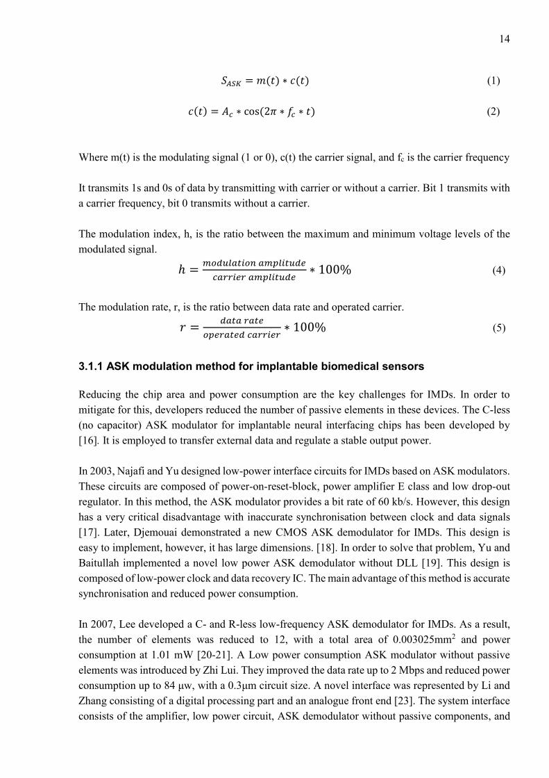
14
𝑆𝐴𝑆𝐾 = 𝑚(𝑡) ∗ 𝑐(𝑡) (1)
𝑐(𝑡) = 𝐴𝑐 ∗ cos(2𝜋 ∗ 𝑓𝑐 ∗ 𝑡) (2)
Where m(t) is the modulating signal (1 or 0), c(t) the carrier signal, and fc is the carrier frequency
It transmits 1s and 0s of data by transmitting with carrier or without a carrier. Bit 1 transmits with
a carrier frequency, bit 0 transmits without a carrier.
The modulation index, h, is the ratio between the maximum and minimum voltage levels of the
modulated signal.
ℎ =𝑚𝑜𝑑𝑢𝑙𝑎𝑡𝑖𝑜𝑛 𝑎𝑚𝑝𝑙𝑖𝑡𝑢𝑑𝑒
𝑐𝑎𝑟𝑟𝑖𝑒𝑟 𝑎𝑚𝑝𝑙𝑖𝑡𝑢𝑑𝑒∗ 100% (4)
The modulation rate, r, is the ratio between data rate and operated carrier.
𝑟 =𝑑𝑎𝑡𝑎 𝑟𝑎𝑡𝑒
𝑜𝑝𝑒𝑟𝑎𝑡𝑒𝑑 𝑐𝑎𝑟𝑟𝑖𝑒𝑟∗ 100% (5)
3.1.1 ASK modulation method for implantable biomedical sensors
Reducing the chip area and power consumption are the key challenges for IMDs. In order to
mitigate for this, developers reduced the number of passive elements in these devices. The C-less
(no capacitor) ASK modulator for implantable neural interfacing chips has been developed by
[16]. It is employed to transfer external data and regulate a stable output power.
In 2003, Najafi and Yu designed low-power interface circuits for IMDs based on ASK modulators.
These circuits are composed of power-on-reset-block, power amplifier E class and low drop-out
regulator. In this method, the ASK modulator provides a bit rate of 60 kb/s. However, this design
has a very critical disadvantage with inaccurate synchronisation between clock and data signals
[17]. Later, Djemouai demonstrated a new CMOS ASK demodulator for IMDs. This design is
easy to implement, however, it has large dimensions. [18]. In order to solve that problem, Yu and
Baitullah implemented a novel low power ASK demodulator without DLL [19]. This design is
composed of low-power clock and data recovery IC. The main advantage of this method is accurate
synchronisation and reduced power consumption.
In 2007, Lee developed a C- and R-less low-frequency ASK demodulator for IMDs. As a result,
the number of elements was reduced to 12, with a total area of 0.003025mm2 and power
consumption at 1.01 mW [20-21]. A Low power consumption ASK modulator without passive
elements was introduced by Zhi Lui. They improved the data rate up to 2 Mbps and reduced power
consumption up to 84 μw, with a 0.3μm circuit size. A novel interface was represented by Li and
Zhang consisting of a digital processing part and an analogue front end [23]. The system interface
consists of the amplifier, low power circuit, ASK demodulator without passive components, and

15
a digital circuit. The power supply for this interface is 1.8V with power dissipation less than
2.75mW.
Another example of an ASK demodulator for implantable devices was implemented by G.
Gudnason; this modulator has been tested with fc in the range 1-15 MHz, with data rates up 100
kbit/s. Modulation indices for this case vary between 10-100% [24].
3.2 Principle of PSK modulation technique
Phase-Shift-Keying (PSK) is one of the most efficient digital modulations and is widely used in
different communication systems. In this scheme, the digital data is encoded in the phase property
of a carrier signal. Equation 6 presents corresponding 𝑠 signals for this modulation.
𝑆(𝑡) = 𝐼(𝑡) ∗ cos(𝜔𝑡) + 𝑄(𝑡) ∗ cos(𝜔𝑡 +𝜋
2) (6)
𝐴 = √2𝐸𝑠
𝑇𝑠 , 𝐸𝑠 = 2 𝐸𝑏 , 𝑇𝑠 = 2𝑇𝑏 (7)
where 𝐸𝑠 is the energy per symbol, 𝑇𝑠 is the symbol duration.
Figure 11. PSK modulation waveforms. [162]
In this system, a binary ‘0’ is represented by a signal packet, the phase of which coincides with
the phase of the previous packet sent, and a binary ‘1’ is represented by a signal packet with a
phase opposite to the phase of the previous packet. Such a scheme is called differential since the
phase shift is performed relative to the previously transmitted bit, and not relative to some
reference signal.
3.2.1 PSK modulation method for implantable biomedical sensors
Lower consumption and robust performance are the key advantages of PSK modulation. In 2004,
Hu and Sawan presented a demodulator with the use of COSTAS loop [25]. The BPSK
demodulator is composed of voltage-controlled oscillator (VCO), low-pass filter (LPF) and phase

16
shifters. The demodulator provides a high data rate of 1.12 Mbps with power consumption of 0.5
mW. The main feature of this design is a possibility to use BPSK and passive modulation, this
method allows for full-duplex data communication. However, this design remains complex.
Due to this issue, in 2008 Lu and Sawan released a new version of their design with two modulators
and demodulators based on OQPSK modulation [26]. This design has several advantages such as
high data rates, and low complexity - which results in this system having low power consumption.
Based on previous designs, Deng developed a version with modified COSTAS loop technology
and improved data rate transmission up to 8 Mbps, on 13.56 MHz carrier frequency and 0.75mW
power output [27].
Inductive coupling links are a very popular solution for transfer of power to the IMD, however,
this design is complex. In 2006, Zhou designed a new system which provides a high data rate
DPSK telemetry developed to mitigate interference without using a high-order filter [28]. This
system operates at 1MHz carrier frequency for power transmission and at 20MHz carrier
frequency for data transfer. This system has some disadvantages such as high-power consumption
and big size.
Later in 2008, Zhou developed a previous design using DPSK modulation to reduce the
interference for a dual-band configuration [29]. The data telemetry and power signals interfere
with each other and as a result, they produce interference. In order to solve this problem PLL less
scheme should be used. The demodulator provides up to 2Mb/s data rate, and this system operates
at 20MHz. For reducing interference at the receiver, DPSK modulation is used for IMDs through
dual-band telemetry [30]. The DPSK modulator provides up to 4 Mbps and operates at 22 MHz.
Some of the complex implants, such as retinal implants, require reliable and high-speed data
transmission. Elamary designed a BPSK modulator which provides high data rates up to 20 Mbps
and operates at 20 MHz frequency. The main feature of this design is an incredible data to carrier
frequency ratio of 100% and low power consumption. The BPSK modulator is implemented based
on the non-coherent method [31,32].
3.3 Principle of FSK modulation technique
Frequency – Shift- Keying (FSK) is another digital modulation method, which is widely used in
wireless transmission for biomedical applications. Figure 12 shows two oscillators forming s0(t)
and s1(t) oscillations at different frequencies. There is also an electronic key controlled by a digital
signal b(t) so that when a logical "1" is transmitted, a signal s0(t), is sent to the output and when a
logical "0" signal is transmitted, a signal s0(t) is sent. Thus, the frequency of the output signal is
"manipulated" depending on the bit sequence. BFSK modulation method can be described by
equations 8 and 9:

17
𝑆1(𝑡) = 𝐴 ∗ cos(2𝜋 ∗ 𝑓1 ∗ 𝑡) (8)
𝑆2(𝑡) = 𝐴 ∗ cos(2𝜋 ∗ 𝑓2 ∗ 𝑡) (9)
The main advantages of FSK are lower susceptibility to errors then ASK, simplicity in the
implementation, increase in the immunity of radio reception, power of the transmitter is better
used (since the power of the signal remains unchanged during the whole process of modulation),
and passband centralized between f0 and f1 with low Q to pass enough power for both frequencies.
On the other hand, there are some disadvantages: requires complex demodulator, large bandwidth,
and the synchronization between transmitter and receiver is complex.
Figure 12. FSK modulation principle. [163]
3.3.1 FSK modulation method for implantable biomedical sensors
FSK modulation is widely used in wireless transmission for wearable and implantable biomedical
sensors. It provides high data rates and low power consumption. In order to get low power
consumption, FSK transmitters should be adjustable in case of data rate, because different sensors
need to have various data rates, for example, transmitting physiological information requires a
transmitted data rate of about several kbps. However, for transmitting physiological image
information, a data rate of several megabits per second is required. Horng-Yuan Shih has
implemented this type of ultra-low FSK transmitter with power consumption ranges between 378
μW to 424 μW and data-rates varying from 200 kbps to 2 Mbps [33]. Zhinheng designed 2 and 4
FSK demodulators. This novel demodulator improves the bit error rate (BER) performance and
improves decision accuracy by generating additional zero-crossings - however, it has a very high-
power consumption at about 3mW from a 3V power supply.
In 2004 Ghovanloo and Najafi developed an FSK modulator based on the inductively coupled link
model [34]. This modulator consumes 0.38mW of power at 5V. Later, in 2006 Ahmet Tekin

18
designed a low power FSK modulator for transceivers in the MICS band. This modulator provides
up to 20 kbps data rate. [35] The size of the design is 0.18μm with CMOS process and a very low
power consumption of 33,41 μA at 1.5 V supply. Low power consumption and simple and reliable
architecture are significant factors for non-invasive implantable biomedical sensors. This
modulator developed by Zhu [36] has a relatively simple design; this circuit integrates the
modulation functionality into the oscillator itself by using the data signal to control the oscillation
frequency and producing carriers for different types of monitoring signals [35]. Supporting data
rates are from 450 kbps up to several Mbps, with low power consumption of 1μA at 2.5V.
Table 2. Examples of comparisons of modulation techniques for IMDs.
Modulation
technique
ASK FSK BPSK/DBPSK
Carrier frequency 1-250 MHz 2-433 MHz 10-20 MHz
Data rates 0.004-1 Mbps 0.18-1.5 0.18-0.5
Coherent or non-
coherent
Non-coherent Can be both BPSK is coherent,
while DBPSK can be
non-coherent
Power consumption 0.062-70 µW 33.41µW-3 mW 31.5µW-6.2mW
Noise performance Poor performance, as
it is heavily affected
by noise and
interference
Better noise
performance than
amplitude modulation
schemes
BPSK generally
shows better error
performance than
ASK and FSK, but
the error probabilities
are double with
DBPSK
Cost efficiency Low cost Simple, low cost
implementation
possible
Usually
implementation is
complex and more
costly that other
techniques
Applications Neural system
Physiological signal
Cochlear implant
Telemetry
Applications
Endoscope
ECG
General
Biological signal
Physiological sensors
Brain stimulator
Cardiac stimulator
Neuromuscular
stimulator
General

19
4. POWERING METHODS FOR IMPLANTABLE BIOMEDICAL SENSORS
Implantable biomedical sensors can be divided into two categories. The first category includes
sensors powered by sources surrounding the implants. Human daily activities such as motion,
breathing, sleeping, and body heat are great sources of thermal and kinetic energy. For instance,
everyday walking can produce 1500 mW.
Figure 13. Human’s power resources
This property can produce enough energy to generate a few hundred milliwatts. Kinetic energy is
an easily accessible source for IMDs. There are a great variety of possibilities for converting
kinetic energy into electrical energy. For example, piezoelectric materials, electrostatic, or
electromagnetic mechanisms are possible solutions for this purpose. The brief resumé of a
human’s potential power resources and various body actions are provided in figure 13.

20
Figure 14. Energy harvesting methods used in the biomedical sensors
Instead of using body resources, another feasible solution is to supply energy to the implantable
sensor through an ехtеrnаl unit. In this case IMDs can use ultrasonic, optical or electromagnetic
harvesting systems. Optical power delivering systems consist of a photovoltaic cell placed inside
of the IMD which receives power from a laser operating in the NF or IR range. Inductive power
transmission is one of the most reliable and efficient ways of delivering power to IMDs with small
sizes. The basic principle of this system consists of two antennas, one antenna is for TX and
another for RX, these antennas are used for power transfer. The ultrasonic method is one of the
more modern ways to transfer energy, due to the immunity from electromagnetic modulation and
high efficiency. Figure 15 depicts the efficiency of different powering methods for IMDs.
Figure 15. The efficiency of different powering methods for IMDs

21
4.1 Lithium batteries
The main purpose of the battery is to supply electrical energy to a portable device. There are two
types of batteries which are used in IMDs: primary and secondary batteries. Primary batteries
provide high output power and current and are used in pacemakers. Secondary batteries provide
relatively small output power and current, therefore these batteries are used in less power
demanding applications.
Some examples of primary batteries are: lithium-iodine, lithium-manganese dioxide, and lithium-
carbon monofluoride batteries. Greаtbаtch invented lithium-iodine batteries in 1973. Lithium-
iodine batteries have perfect parameters such as extended battery life and high voltage output,
which make them suitable for powering small electric devices.
These accumulators are used in pacemakers, cardiac defibrillators, and cochlear implants as a
reliable energy source. Li-ion batteries provide voltage up to 4V, showing better performance
than other types of batteries. These batteries have a very high-power density around 200 W·h/kg.
Lithium-manganese dioxide batteries have been developed for devices with additional features
which require power in the mW range. Lithium-manganese dioxide batteries were invented by
Ikeda in the 1970s; these batteries have outstanding characteristics including high energy density
and good storage and discharge characteristics. The main applications which employ these
batteries are pacemakers, neurostimulators, and drug delivery systems. The lithium-manganese
dioxide batteries are composed of a lithium anode which is placed in the centre of the cell and
surrounded by two cathodes. The battery has a high level of stability and low self-discharge rate.
The volume of these is 10.5 cm3 and it has energy density of 0.588 Wh/cm3, with a capacity of 2.5
Ah [210].
Lithium-ion batteries can be considered as secondary batteries. These batteries can be
distinguished by the type of cathode material used. The carrier of the charge in the lithium-ion
battery is the positively charged lithium ion, which forms a chemical bond with either graphite,
oxides, or metal salts, for instance, to form LiC6, oxides (LiMnO2) and salt (LiMnRON) metals.
As a conclusion, the primary systems employ lithium metal anodes and various cathode systems.
These batteries provide suitable power levels for different IMDs with different energy
consumption rates. Secondary batteries were developed for specific implantable devices which
have an option to be charged while remaining implanted.
4.2 Nuclear batteries
Nuclear batteries are another type of powering method for IMDs. The basic principle of nuclear
batteries is converting energy carried by particles emitted from radioisotopes into electrical energy.
Usually, nuclear batteries utilize plutonium, because it has a half-life of 88 years and output power
reduced by 10% in 10 years. Nuclear batteries were introduced in the medical industry in 1973.
22
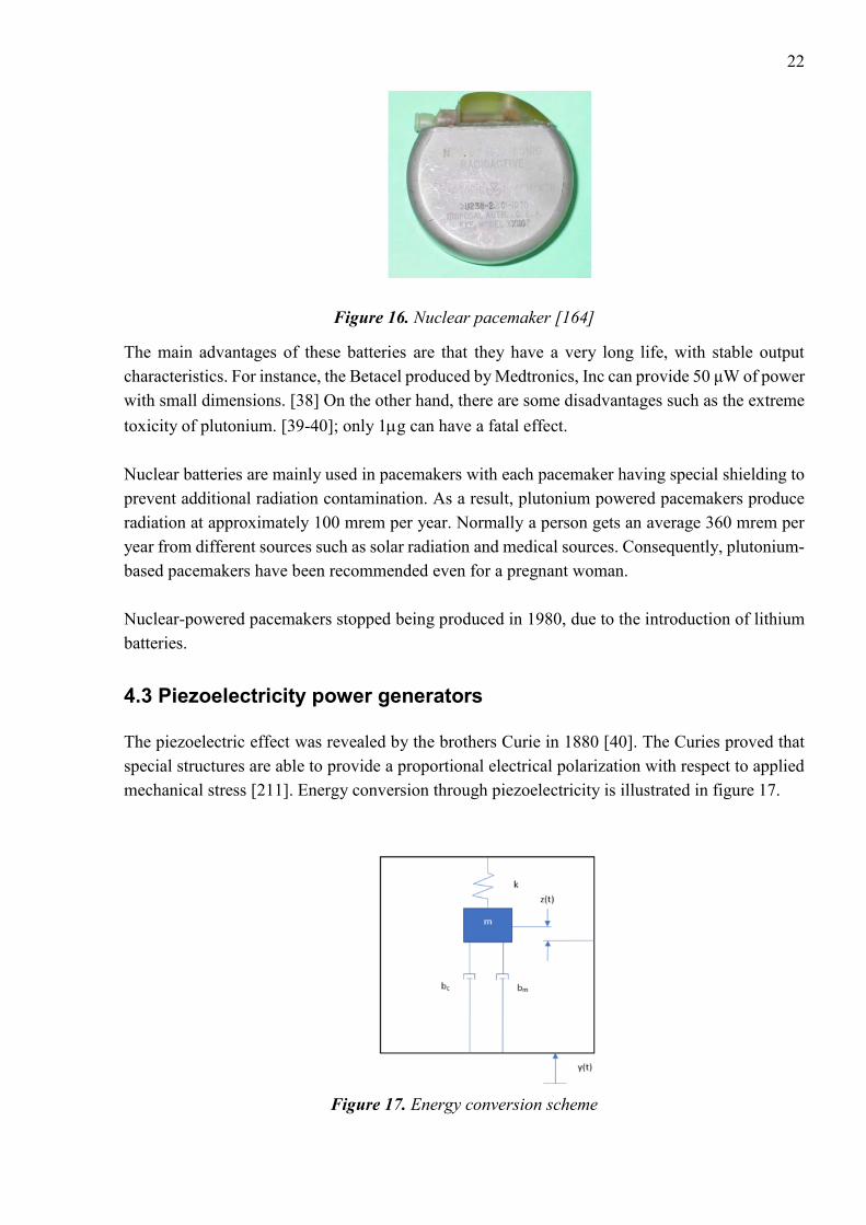
Figure 16. Nuclear pacemaker [164]
The main advantages of these batteries are that they have a very long life, with stable output
characteristics. For instance, the Betacel produced by Medtronics, Inc can provide 50 μW of power
with small dimensions. [38] On the other hand, there are some disadvantages such as the extreme
toxicity of plutonium. [39-40]; only 1g can have a fatal effect.
Nuclear batteries are mainly used in pacemakers with each pacemaker having special shielding to
prevent additional radiation contamination. As a result, plutonium powered pacemakers produce
radiation at approximately 100 mrem per year. Normally a person gets an average 360 mrem per
year from different sources such as solar radiation and medical sources. Consequently, plutonium-
based pacemakers have been recommended even for a pregnant woman.
Nuclear-powered pacemakers stopped being produced in 1980, due to the introduction of lithium
batteries.
4.3 Piezoelectricity power generators
The piezoelectric effect was revealed by the brothers Curie in 1880 [40]. The Curies proved that
special structures are able to provide a proportional electrical polarization with respect to applied
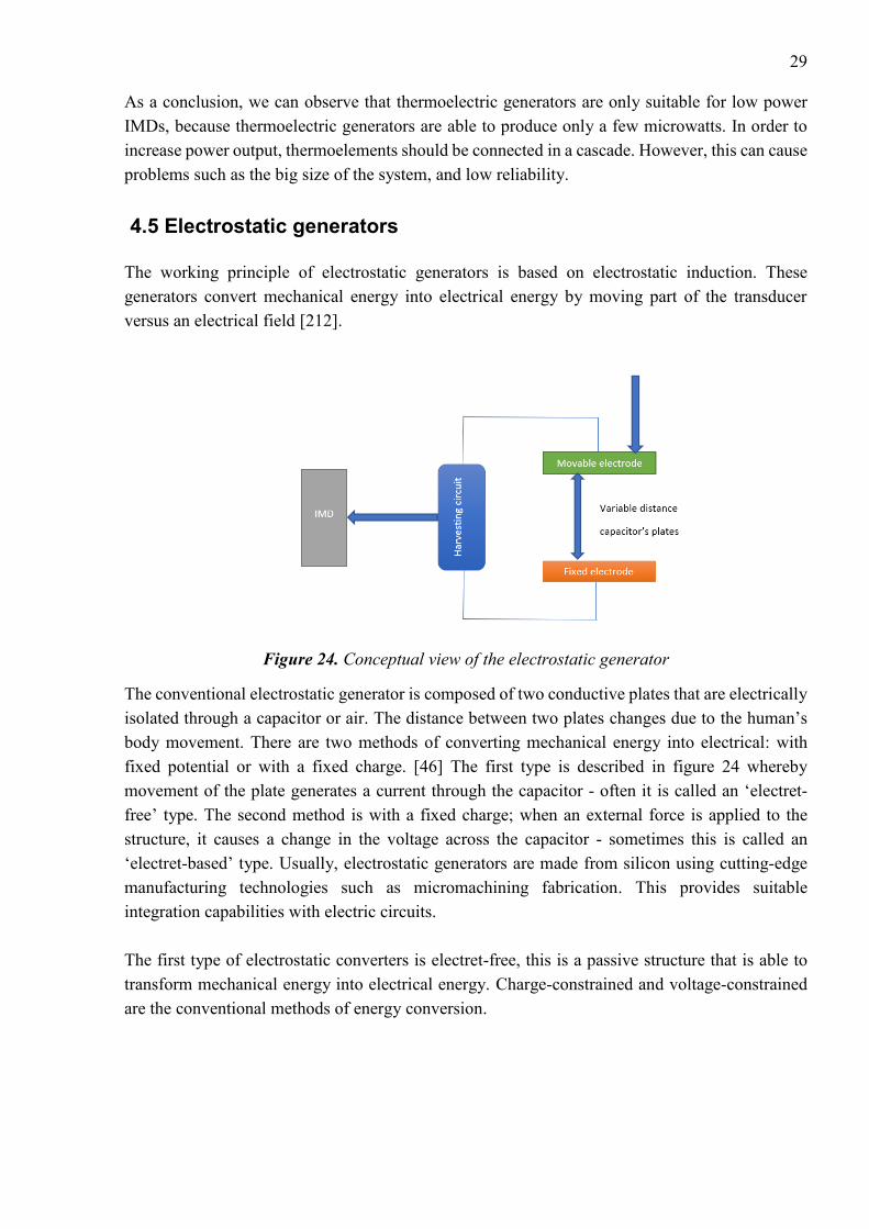
mechanical stress [211]. Energy conversion through piezoelectricity is illustrated in figure 17.
Figure 17. Energy conversion scheme

23
𝑚�̈� + (𝑏𝑒 + 𝑏𝑚) ∗ �̇� + 𝑘𝑧 = −𝑚�̈� (10)
Where y is the base displacement, k the spring constant, z is the output tip displacement, m the
lumped mass, bm and be are the mechanical damping and electrical damping coefficients
respectively. The power output of the system, P, is calculated using:
𝑃 =𝑚𝜉𝑒𝐴
2
4𝑤(𝜉𝑒+𝜉𝑚) (11)
Where 𝑤 operation frequency, A is the acceleration input of the input vibration,
There are two types of piezoelectric effect: ‘direct’ and ‘opposite’. The ‘direct effect’ is used to
transform mechanical energy into electrical energy and the ‘opposite effect’ has the same principle,
but vice-versa. Piezoelectric materials have three operational modes: transverse mode refers to
when the force applied along a Y-axis generates charges along the X-axis; the Longitudinal effect
and the Shear effect produce charges proportional to the applied forces.
Figure 18. The Basic work principle of piezoelectric IMD
Piezoelectric sensors convert mechanical energy - for example, body motion - into electrical
energy. Physical and chemical processes inside of the human body can be employed in order to
provide a power source for various wearable devices and IMDs. There are two types of body
motion: continuous and discontinuous. Continuous motions such as breathing and heart beating
can generate up to 2W. Another type of motion is discontinuous, for instance, walking, jogging,
and cycling.
There are four different materials which can be used for piezoelectric devices: ceramics (lead-
zirconate-titanate (PZT)), polymers, single crystals, and composites. Composites, crystals and
ceramics have better characteristics than polymers. However, polymers are more suitable for use
cases where the IMD will be subjected to a large amount of bending. Most of the piezoelectric
devices are built on ceramic elements - especially PZT - due to cheap prices and outstanding
characteristics. The efficiency of piezoelectric material depends on resonant frequency; in order

24
to get maximum power output, piezoelectric devices should precisely tune to the resonant
frequency. The piezoelectricity coefficient depends on materials.
There are two main conventional configurations of piezoelectric devices: cantilever beams and
disks. Disks are divided into two categories: cymbals and diaphragms. The cantilever shape is one
of the most common configurations for converting vibrations into electrical energy, due to its
simple design and low resonant frequency. Figure 19 depicts two types of cantilever shape, A
figure shows unimorph and B figure show bimorph design.
Figure 19. Configurations of piezoelectric cantilevers [170]
The unimorph design is composed of thin piezoelectric and non-piezoelectric layers. In such a
configuration, there is only one active layer (piezoelectric) and the other layer is just a steel plate.
Another configuration is bimorph, composed of two piezoelectric layers, hence both are active.
This configuration is used for improved power output of the design. In piezoelectric layers poled
directions are usually orthogonal to the planar directions. After literature review about this topic,
a great number of energy harvesters are designed with the use of bimorph or unimorph
configuration. However, the bimorph structure appears more beneficial and widely used, due to
better output power characteristics for the same volume of device compared with the unimorph
design.
Cymbal piezoelectric converters are another type composed of a steel end-cap and a piezoelectric
disk. The working principle is as follows: when the axial stress is applied to the steel surface of
the device, this causes deformation which converts and amplifies the axial stress into radial stress
in the piezoelectric disc. The energy efficiency of this system is higher than for the cantilever
beam-based systems. As an example, cymbal piezoelectric devices can produce up to 52 mW under
70N force, with dimensions of 29 mm in diameter with 1mm thickness [207]. However, this design
is not suitable for applications with high magnitude vibration sources.
Figure 20. Configuration of cymbal piezoelectric device [170]
Stress

25
The circular piezoelectric diaphragm is another type of design. It operates in the same way as
piezoelectric cantilevers. To construct a piezoelectric circular diaphragm transducer, a thin circular
piezoelectric ceramic disc is first bonded to a metal shim and then the whole structure is clamped
on the edge, while piezoelectric cantilevers are only clamped at one end of the cantilever beam
[170].
A great variety of researchers have investigated how to use discontinuous motions as a source of
energy [41-43]. Obviously, continuous motions such as breathing provide less power compared
with discontinuous motions. For instance, heartbeat vibrations are a rich energy source, meaning
it is possible to convert vibrations into energy supply for pacemakers with the use of linear and
non-linear PEH [182,183]. Researchers from the MIT Lab designed a device which generates
electrical energy from kinetic energy (human walking). This device converted mechanical energy
into electrical energy for wearable applications. At the same time, Starner [174] proposed his idea
about the implementation of piezoelectric elements which can be integrated inside shoes and rotary
generators that are able to collect and store energy from running shoes. In 2001, Paradiso designed
integrated piezoelectric elements called polyvinylidene fluoride. These piezo elements are placed
in shoes and generate electricity from bending of the foot [44]. One element is located in the heel
and another in the toe region; the design provides up to 8.3 mW. However, this design is suitable
only for persons who are able to move freely. Another energy efficiency design was proposed by
Rome [175]; he designed a spring-loaded rucksack to gather electrical energy from walking.
However, that design was based on an electromagnetic system. Grandstrom decided to replace that
system with piezoelectric straps [176]. Zhu developed a piezoelectric generator to convert the
movement of a knee joint into electrical energy [179]. Renaud proposed a piezoelectric harvester
to collect energy from human limbs [177]. A head-mounted piezoelectric harvester was developed
by Voix and Delnavaz, which is able to collect energy from jaw movements. Later, Ertuk
developed an advanced broadband harvesting system based on a piezomagnetoelastic structure,
which is more efficient than other existing systems [178]. This is a short review of designs based
on PEH, which are able to generate energy from the human walk. Moreover, different PEHs have
been developed in order to collect energy from multi-directional vibrations [180-181] but are not
applicable to walking harvesting, due to the nature of the movements. However, in 2017 Fan and
Lui [172]
Figure 21. A prototype of shoe mounted PEH [44]
developed a shoe mounted non-linear PEH which was able to convert energy from various motions
produced by the foot. The design is composed of a piezoelectric cantilever beam, a crossbeam, and

26
a ferromagnetic ball [172]. The output power of PEH is up to 0.35 mW, however, it works only in
certain scenarios - specifically when the walking velocity is within a certain range. Nevertheless,
this PEH is able to produce a large amount of power compared with other PEHs, but on the other
hand the output of most current PEHs provide slightly lower output power in comparison with
electromagnetic harvesters; For example, some electromagnetic harvesters produce up to 0.5W in
similar scenarios.
As a conclusion, piezoelectric power generators are quite efficient, but on the other hand, they
need a lot of movement to generate sufficient power.
4.4 Thermoelectricity
Presently, chemical power suppliers are a very popular solution for low-powered devices. Despite
continuous quality improvements of chemical power sources, they still have some limitations such
as short battery life, large geometrical dimensions, and negative environmental impact.
Consequently, researchers from all over the world are looking for better power sources.
Thermoelectric generators are one of the possible approaches, because they have long battery life
and a high level of reliability. Thermoelectric harvester technologies are based on the Seeback
effect. The German physicist Thomas Johann Seebeck discovered that a temperature difference
between two different electrical semiconductors produces a voltage difference between the two
substances. When heat is applied to one of the conductors, heated electrons move towards the
cooler ones. The voltage output produced by the Seebeck effect is only a few microvolts.
On the other hand, the Seebeck effect generates low voltage output - typically a few microvolts -
only if the temperature difference is big enough. The efficiency of these generators is possible to
calculate using the Carnot principle:
𝜂 = 1 − 𝑇𝑐
𝑇ℎ=
𝑇ℎ−𝑇𝑐
𝑇ℎ (12)
Where 𝜂 is the Carnot efficiency, Th and Tc are the hot and cold temperatures in Kelvin. The
efficiency of thermoelectric generators is dependent on the resistance coupling. The physical
model of a thermoelectric generator is illustrated in figure 23. The temperature differences between
different parts of the body form a temperature gradient. This gradient can be applied to the
thermoelectric module, which produces sufficient electric power. There are two modes of
thermoelectric generator (TEG): maximum power (or matched load) mode, and mismatched load.
Let us consider one case in which the required output power must be 1.5 V, thus thermoelectric
power force should be equal to 3V. According to experiment measurements, if the thermal gradient
between the temperature of a person’s body and the ambient temperature equals 5 C the Seebeck
coefficient equals 200 mkW/K, the thermoelectric power force 3 V, and the number of branches
in TEG equal 3000.

27
In matched load mode, the resistance of TEG, r, is equal to load resistance, R, at the maximum
current value, Imax. Let’s assume that maximum efficiency of TEG could be reached with the
following values: Imax = 36 mkA and R =41,7 kOm, the number of branches, N = 3000, where the
height of each branch equal 5mm with cross-sectional dimensions 0.06×0.06 mm and the spacing
between each branch is 0.02 mm. Thus, the total geometric dimension of TEG is 4.4x4.4x5mm.
However, cross-sectional dimensions as described above have some drawbacks such as complex
technological implementation. On the other hand, increasing cross-sectional dimensions causes
mismatched loads between power supplier and load, and can also decrease the efficiency of TEG.
Therefore, it is very important to define the best branch dimensions which can provide high
efficiency of the TEG. For these purposes, we can use the mismatched load mode.
Mismatched load mode
The maximum efficiency defined using the next equation (13)
𝜂 =1
4
𝑇1−𝑇2
𝑇1𝑍
𝑇1−𝑇2
2 (13)
Where T1 and T2 are the temperatures on different sides of TEG, Z quality factor of material.
According to calculations, if the temperature difference is 5C, the maximum efficiency that can
be reached is 0.4%. Let’s investigate the dependency between efficiency and cross-sectional
dimensions of the branches. In this case, efficiency calculates as equation 14
𝜂 =𝑊
𝑄ℎ (14)
𝑄ℎ = 𝑘𝑆𝑚
𝑙∆𝑇𝑁 (15)
Where 𝑄ℎ is thermal power, which perceives TEG, k is the coefficient of thermal conductivity,
and Sm is the cross- section square of the branch. From those equations we can observe that
increasing cross-section dimension of the branches causes a boost in thermal power and it
decreases the efficiency of the TEG.
Figure 22. Dependence of the efficiency of the linear branch cross-section dimensions [158]

28
From figure 22 we can see that increasing linear cross-section dimensions from 0.06 to 0.5mm,
the efficiency of the TEG reduces by 5-10 times. However, we can improve efficiency by
decreasing cross-section dimensions of TEG. Thermoelectric generators are usually made from
bismuth telluride or polycrystalline silicon-germanium film.
Figure 23. The architecture of thermoelectric generator
The thermoelectric module consists of two types semiconductors, p and n. The voltage generated
by this module can be calculated according to the following equation:
𝑉 = ∫ (𝑆𝐵(𝑇) − 𝑆𝐴(𝑇))𝑑𝑇𝑇𝑐
𝑇ℎ (16)
Where SB and SA are the Seebeck coefficients of the two materials.
There are a great variety of existing systems which are implemented based on thermal energy
conversion. João Paulo Carmo [158] presented one possible solution for powering low-power
electronics. Table 3 illustrates power consumption rates for different IMDs.
Table 3. Power consumption rates for different IMDs
Implanted Device Power Requirements
Cardiac Pacemaker 30-100µW
Cardiac Defibrillator 30-100µW
Drug Pump 100µW-2mW
Cochlear Implant Up to 10mW
29
As a conclusion, we can observe that thermoelectric generators are only suitable for low power
IMDs, because thermoelectric generators are able to produce only a few microwatts. In order to
increase power output, thermoelements should be connected in a cascade. However, this can cause
problems such as the big size of the system, and low reliability.
4.5 Electrostatic generators
The working principle of electrostatic generators is based on electrostatic induction. These
generators convert mechanical energy into electrical energy by moving part of the transducer
versus an electrical field [212].
Figure 24. Conceptual view of the electrostatic generator
The conventional electrostatic generator is composed of two conductive plates that are electrically
isolated through a capacitor or air. The distance between two plates changes due to the human’s
body movement. There are two methods of converting mechanical energy into electrical: with
fixed potential or with a fixed charge. [46] The first type is described in figure 24 whereby
movement of the plate generates a current through the capacitor - often it is called an ‘electret-
free’ type. The second method is with a fixed charge; when an external force is applied to the
structure, it causes a change in the voltage across the capacitor - sometimes this is called an
‘electret-based’ type. Usually, electrostatic generators are made from silicon using cutting-edge
manufacturing technologies such as micromachining fabrication. This provides suitable
integration capabilities with electric circuits.
The first type of electrostatic converters is electret-free, this is a passive structure that is able to
transform mechanical energy into electrical energy. Charge-constrained and voltage-constrained
are the conventional methods of energy conversion.

30
Figure 25. Energy conversion principles of electret-free electrostatic IMDs. [208]
• Charge-constrained method
The charge-constrained method is relatively easy to implement on a real design. The conversion
cycle begins with the external injection of the charge, and due to polarization effect, the whole
structure reaches maximum capacitance Cmax. At this moment capacitor C has a charge Qcst under
the voltage Umin. Then, the circuit becomes open and the capacitance of the systems moves to the
minimum level. However, the capacitor keeps charge Qcst at a constant level, causing an increasing
voltage across the capacitor C. When the capacitor reaches Cmin, electric charges are moving from
the structure and feed it to the load. The total amount of energy calculated is shown in equation 17
Eq =1
2𝑄𝑐𝑠𝑡
2 (1
𝐶𝑚𝑖𝑛−
1
𝐶𝑚𝑎𝑥) (17)
• Voltage-constrained method
The voltage-constrained method has the same principle at the beginning of the process, with the
structure reaching maximum capacitance Cmax and polarized at voltage Vcst and Cmax. The main
difference, in this case, that the voltage is then kept at a constant level with decreasing capacitance,
causing an increase of the charge of the capacitor; this generates a current that is scavenged and
stored. The next step is charge transfer to the load. The total amount of energy is calculated in
equation 18
EV = Vcst2 (Cmax − Cmin) (18)
The second type of electrostatic converters is the electret-based converter shown in Figure 26. This
type is quite similar to electret-free structures; however, electret-based converters don’t need any
external energy for polarization and have a direct energy output from the deformation of the
structure.
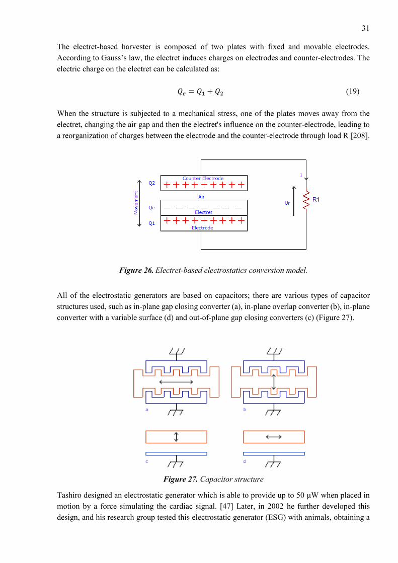
31
The electret-based harvester is composed of two plates with fixed and movable electrodes.
According to Gauss’s law, the electret induces charges on electrodes and counter-electrodes. The
electric charge on the electret can be calculated as:
𝑄𝑒 = 𝑄1 + 𝑄2 (19)
When the structure is subjected to a mechanical stress, one of the plates moves away from the
electret, changing the air gap and then the electret's influence on the counter-electrode, leading to
a reorganization of charges between the electrode and the counter-electrode through load R [208].
Figure 26. Electret-based electrostatics conversion model.
All of the electrostatic generators are based on capacitors; there are various types of capacitor
structures used, such as in-plane gap closing converter (a), in-plane overlap converter (b), in-plane
converter with a variable surface (d) and out-of-plane gap closing converters (c) (Figure 27).
Figure 27. Capacitor structure
Tashiro designed an electrostatic generator which is able to provide up to 50 μW when placed in
motion by a force simulating the cardiac signal. [47] Later, in 2002 he further developed this
design, and his research group tested this electrostatic generator (ESG) with animals, obtaining a

32
heartbeat up to 190 bpm. [48] In 2006, Miao proposed a resonant less MEMS ESG for the IMDs,
which produced approximately 80 μW. [49] A great variety of ESGs are available in the present
time on the market [50]. Meninger [217], demonstrated the design of an electric circuit which can
convert external vibrations into electricity with the use of a variable capacitor, which is applicable
for low power applications. The theoretical results showed a device with relatively small
dimensions - 1.5cm x 1.5cm – which can generate 8.6 mW from an excitation of 500 nm at 2.5
kHz. Furthermore, the energy output can be improved by adding an additional capacitor connected
in parallel. In 2013, Deterre proposed an energy conversion method based on heartbeat vibrations.
The working principle of the design is that the package of the implant is deformable, thus blood
pressure effects on the electrostatic element convert vibrations into electrical power. Simulation
results showed that a 25-layer electrostatic element with 6mm diameter is able to collect up to
20µJ per heartbeat.
As a conclusion, the main drawback of this type of transducers is an additional source of energy
required to operate, and usually the amount of energy which the generator produces is much
smaller. On the other hand, due to dependence on the motion force, an active pre-charge system
gives the opportunity to dynamically optimize the generator for the applied motion.
4.6 Electromagnetic harvesters
The principle of energy conversion is based on the electromagnetic induction when an
electromotive force (EMF) is induced in a conductor moving in a magnetic field and crossing its
magnetic lines of force.
𝑉 = −𝑑𝜙
𝑑𝑡 (20)
Where 𝜙 is flux linkage and V is induced EMF. Usually the generator’s design is composed of
coils. Therefore, the output voltage or EMF calculated as
𝑉 = −𝑑Φ
𝑑𝑡= −𝑁
𝑑𝜙
𝑑𝑡 (21)
Where Ф is the total flux linkage, N is the number of turns. Ф calculated as
Ф = ∑ ∫ 𝐵 ∗ 𝑑𝐴
𝐴𝑖
𝑁𝑖=1 (22)
Where B is the magnetic field flux density over the ith coil’s turn.
Consequently, such a conductor can be regarded by us as a source of electrical energy. There are
two types of mechanical generators that generate electrical energy. The first method is based on
relative motion where the generating system is fixed, and the second method is a rigid body motion
and uses the inertia force of a weight on the generator [51].

33
Figure 28. Types of mechanical generators: a) relative movement, b) rigid body
Typical movements of the human body can be used as a possible solution for powering biomedical
sensors based on electromagnetic generators. For instance, a small electromagnetic generator can
produce 400 μW from human walking [52]. As another example, the heartbeat can produce up to
200 μW. [53] High-performance bulk magnets, multi-turn and macroscale coils are readily
available; nevertheless, the main challenge for the MEMS fabrication technology utilized in this
approach is the poor properties of planar magnets. [54]
As a conclusion, electromagnetic generators are usually less efficient and more bulky then
piezoelectric generators. [124] A comparison of the three techniques in relation to different
characteristics is presented in Table 4.
Table 4. Comparison of Electromagnetic, Electrostatic and Piezoelectric powering methods.
Features Electromagnetic
harvesters
Electrostatic
harvesters
Piezoelectric
harvesters
Energy density Low A decrease in the
separation between
the capacitor plates
increases the energy
density
High
Output voltage Up to 0.1V 2-10V 2-10V
Frequency
dependence
No dependence No dependence Highly frequency
dependence
External source No required Required in electret-
free converters
Not required
MEMS
implementation
Difficult to
implement in MEMS
Easy to implement in
MEMS
Difficult to
implement in MEMS
Drawbacks Low efficiency in
small sizes and low
frequencies, ohmic
loss in coils
Electrets can be used
to provide the initial
charge needed,
parasitic capacitance
losses
Materials can be
expensive, poor
coupling of piezo
films at micro scale

34
4.7 Ultrasonic energy transmission
This method is one of the possible solutions of transferring energy to the implantable biomedical
devices which receives a high level of attention recently [55-58]. What sets apart ultrasonic
transmission from other methods is its high efficiency, safety for the human body, and stability
against interference from other devices. [59] Typical ultrasonic power systems operate on
frequencies above 20 kHz and need a propagation medium in order to deliver energy from TX to
RX. For IMDs, ultrasound systems transfer energy through tissues to the implant, where it is
converted to electrical energy through the piezoelectric transducer. The conventional design of an
ultrasonic energy transmission system is shown in figure 29. The typical applications for
ultrasound energy system are cochlear implants, pacemakers and neurostimulators. [146-148,150].
The system is composed of transmitter, power-system and receiver. According to the equation 23,
it defines the received power, Pr:
𝑃𝑟 = 𝜂𝐴𝐸𝐼𝐴𝐶𝑆А (23)
Where 𝜂𝐴𝐸 is electric efficiency pf the receiver, 𝑃𝑟received power
The transmitter transforms electrical energy into mechanical energy and then acoustic energy and
is composed of an ultrasonic oscillator electrically excited to generate mechanical vibrations on
the surface of the TX; these vibrations cause acoustic pressure waves. The receiver has the same
functions but in reverse order. [57] Based on the Huygens-Fresnel principle, each point on the
transducer can be treated as an independent source of radiation, and the acoustic field pattern can
be found at the vector sum of all the point-radiating sources [144]. The pressure field P at an
observation point L (x, y, z) is given by the Rayleigh integral in equation 24:
𝑃(𝑥, 𝑦, 𝑧: 𝑡) =𝑗𝑘𝑝0𝑐0𝑢0
2𝜋𝑒𝑖𝜔𝑡 ∫
𝑒−𝑗𝑘𝑅
𝑅𝑑𝑆
𝑆 (24)
Where λ is the wavelength, ω angular frequency, k wave number, R is the distance between point
source and the observation point, u0 is the vibration velocity amplitude, c0 phase velocity of the
wave, p0 density of the medium [165].

35
Figure 29. Schematic of ultrasonic IMD. [165]
Power transfer efficiency depends on different aspects, for instance, losses in the transducer,
tissues and rectifier losses, impedance matching. Losses have a negative impact on the system
performance.
Using piezoelectric components made from lead zirconate titanate have a more beneficial effect
on energy efficiency conversion than piezoelectric polyvinylidene fluoride, due to different
electromechanical and mechanical factors k and Q.
It is very important to choose the right operating frequency because it affects tissue attenuation,
transducer thickness, the distance between the natural locus and the sizes of reactive elements in
transmitter and receiver sides [165]. In order to provide sufficient quality of energy transfer, the
whole system should work close to its resonance frequency. The main challenges for ultrasound
transfer systems are addressed below:
The human body is complex and diverse in terms of organs and systems, each of them has different
densities and acoustic impedance. For example, acoustic impedance is quite high in bones,
consequently all ultrasound waves will be reflected.
Another problem is related with implants which are placed under the skin, where the spatial
separation can reach several acoustic wavelengths, therefore it effects on power transfer efficiency
(PTE). Another changes which affect on PTE are changes in tissues and ambient temperature
[153]. Overall it leads to serial limitations on the battery life and system performance.
The first commercial ultrasound energy transmission device was developed in 1988, with an
operational voltage of 10V and 2.25MHz frequency. This device generated an output power of
1.5mW/cm2. Ultrasonic systems are primarily used for medical imaging, for instance,
ultrasonography. The typical frequency range for this application is between 3-6 MHz. In
comparison, acoustic waves have lower speed than radio waves for given frequencies, therefore
acoustic waves have smaller wavelengths. As an example, for the given frequency range, the usual

36
acoustic velocities in human tissues range from 1500-2000 m/s, the wavelengths 0.4 – 0.8 mm.
Another possible design is described in [145].
In 2009, Tower proposed a design which is suitable for monitoring, it converts the energy of a
surface-applied ultrasound beam to a high-frequency current [60]. Later, Zhu [61] used ultrasonic
waves to harvest energy for the IMDs with 21.4 nW. In [128], a device was presented with an
experimental Mbit/s ultrasonic transmission through ultrasonic phantoms, while in [129], [130]
ultrasonic wireless transfer to power mm-sized implantable devices was demonstrated. The
possible applications based on ultrasound powered method are described in [133-134]. Utilizing
the ultrasound method for powering IMDs can push devices towards miniaturisation, due to short
wavelength (1.5mm at 1MHz), and allows for greater energy efficiency [135].
The main advantage of this method is operational wavelength because long wavelengths are able
to penetrate deeper into the human’s body, moreover, this method is safe and effective. On the
other hand, there are some drawbacks in this system, such as expensive equipment.
4.8 Photovoltaic infrared power radiation
Infrared energy transmission is another power delivery method for IMDs, such as pacemakers or
brain implants. The main component of the system is a photovoltaic cell. Initially, photovoltaic
cells were developed as a renewable energy source, however, after years of intensive research,
these devices can be adopted as a power source for IMDs. Photovoltaic cells used in aerospace
applications are able to transform up to 50% of light energy into electric power [201]. The principle
of this energy conversion is based on the photovoltaic effect, where two different materials in close
contact can produce an electrical voltage when the materials interact with light.
Figure 30. Infrared power radiation system [202]
Conventional infrared power radiation systems are composed of external light sources - for
instance, lasers located on top of the skin emit light through biological tissue layers, and the light
is received and transformed into electric power [214]. According to various research papers human
tissues have quite a high optical transmittance coefficient in near-infrared light, hence it is possible
to implement wireless powering systems for IMDs based on this infrared power radiation
principle. Usually, these systems are tuned to a wavelength of about 900 nm [203]. Infrared
wavelengths are able to penetrate much deeper in tissues than other wavelengths of light, but they

37
still suffer from various negative factors such as scattering and absorption caused by tissues [204].
Consequently, biomedical implants based on this principle typically use NIR wavelengths. In 2007
Sond and Simeral demonstrated a real design of a photovoltaic pulse neurostimulator. This system
is composed of an infrared laser tuned at 852 nm wavelength and using optical fibre [205, 206].
4.9 Inductive coupling
There is another technique for delivering power wirelessly to implantable biosensors, called
inductive coupling, which was first used in an artificial heart. This method is based on Faraday’s
law. In 1831 Faraday discovered that power could transfer wirelessly based on the principle of
magnetic induction [140]. Later, power transmission over a large distance without any cables was
achieved by Nicola Tesla [62]. Tesla’s work was based on resonance and it was a groundbreaking
achievement in that period. During the first part of 20th-century, invention and achievements were
slowed down; however, due to military research, new types of high-frequency oscillators, which
improve the techniques of wireless power transmission, have been developed.
Figure 31. The architecture of Inductive coupling powering method
The NF resonant inductive coupling method is one of the most reliable wireless power transfer
methods. This method has a lot of evidence that it is robust and safe for use in medical applications,
as an example, it has approved results by the Food and Drug Administration (FDA).
In this method, the source part is placed under the skin surface and the receiver is placed outside.
The overall design of inductive coupling scheme is illustrated by figure 31. When a voltage is
applied to the primary coil, L1, it excites magnetic flux. This magnetic flux creates an EMF in the
coil, L2, due to electromagnetic induction. The highest voltage is achieved when both source and
receiver are tuned to the same resonant frequency, f. This frequency can be calculated by equation
25 [63-64].
𝑓 = 1
2𝜋√𝐿𝐶 (25)
Where L is the magnetic inductance, and C is capacitance

38
The transmitting and receiving coils are poorly coupled due to spatial separation. The induced
EMF can be defined as
𝜀 = ∮ �⃗�
𝜕Σd𝑙 = −
𝑑
𝑑𝑡∫ �⃗� d𝐴
Σ (26)
Where �⃗� is the electric field; �⃗� magnetic flux density; d𝑙 is the vector element of the contour 𝜕Σ,
d𝐴 is the area vector element.
Mutual inductance is one more parameter which has a significant role in the design, as it defines
the mutual inductance between two coils L1 and L2. The coupling coefficient can be calculated as
[65]
𝐾 =𝑀
√𝐿1𝐿2 (27)
The efficiency of the inductive link is defined as a ratio between the power delivered to the load
and the power supplied to the primary coil and is called the power transfer efficiency:
𝜂 =𝑘2𝑄1𝑄2
(1+1
𝑄2+𝑘2𝑄1)(𝛼+
1
𝑄2) (28)
𝜂 =𝑘2𝑄1𝛼
(1+1
𝑄2+𝑘2𝑄1)(𝛼+
1
𝑄2) (29)
Where Q1 and Q2 are quality factors for the coils, k the coupling coefficient, 𝛼 the coefficient
(equal to wC2RL), C2 the capacitance of the second coil, w the frequency, and RL the resistance of
the load. Equation 28 and 29 represent link efficiency for parallel and series resonant circuits
respectively. The quality factor defines the efficiency of the inductive link.
The wireless power efficiency depends on distance, frequency and matching between L1 and L2
coils. Normally, these systems operate at a frequency of 20 MHz. There are four different schemes
for how passive systems can be connected, such as series to series, parallel to parallel, series to
parallel, parallel to series. These topologies are depicted on figure 32. These topologies have very
poor performance under weak coupling conditions, but the series connection has better PTE than
the parallel topology in strong coupling mode [141]. Both topologies provide the same amount of
power to implants, however, serial topology achieves this by using high current and low voltage.
On the other hand, parallel topology achieves the same result, but with high voltage and small
current. [142-143] According to electromagnetic theory, rectifiers have better operational
characteristics at high voltage and low current, therefore the parallel topology is more widely used
for IMDs.

39
The number of coil turns is another important parameter. It depends on coil shape and wire
properties, such as material or line size. The diameter of coils is an important parameter which
affects the performance of the inductive link; increasing the diameter of the coils increases the link
efficiency. In IMDs, size is a vital parameter, thus the diameter of implantable coils should be
minimized, but the diameter of the external receiver coils can be larger to increase link efficiency.
It is also desirable that coils are flexible, in order to be safe for the patient. [151-152].
The next important parameter is the number of turns; if we increase the number of turns in the
coils, the performance of the system will be better. Another important factor is the spacing between
primary and secondary coils. Therefore, the relative position of IMD and receiver play an
important role. Furthermore, if the patient is moving, it can cause misalignment and interrupt the
connection between transmitter and receiver.
Figure 32. Types of topologies
There are many challenges in designing the optimal inductive coupling link. First of all, the IMD
consumes different current at various time periods, therefore producing different loads on the
scheme. However, the scheme is usually designed only for a certain load. Therefore, the link can’t
operate efficiently all the time. Secondly, IMDs are housed inside the human body, which moves
a lot during the day, causing misalignments and artefacts becoming inherent. The inductive power
link performs poorly under misalignments; in order to improve performance, new advanced
designs are needed. Thirdly, TX and RX use high-quality factor coils which decrease the PTE
value [156-157].
An inductive power source able to produce approximately 50mW was presented by Catrysse in
2004 [67]. This system operates at 700 kHz. Later, Ghovanloo designed a system based on SOC
which can produce around 50 mW and operates at 5 MHz frequency. [66]

40
4.10 Far Field Communications
This type of energy transfer was also developed for powering IMDs [184]. This scheme employs
the same type of antennas but tuned to different resonant frequencies than those utilized in
inductive coupling. Far-field communication has certain advantages in comparison with inductive
coupling, especially from a practical point of view. For example, these antennas can deliver energy
to many IMDs at the same time and it is not necessary to adjust antennas accurately. As a result,
the far field communication method can provide power to multiple implants located reasonably
far from TX antennas; this is therefore highly suitable for implantable sensors which are located
deep inside tissues. There is another advantage of using this method; it works perfectly with small
antennas tuned to high-frequencies, up to several GHz. On the other hand, this configuration has
a few disadvantages, for instance low power transmission efficiency in comparison with inductive
coupling. This can be explained due to large attenuation at high frequencies and decreasing
radiative power density at the far-field zone. Also, this technology can cause negative
consequences for the human body, especially at high frequencies, due to RF absorption in tissues
[185,186]. Consequently, the Federal Communication Commission (FCC) and FDA defined strict
rules regarding maximum output power [187-189]. There are few examples of real applications
which are based on the far-field communication principle: glaucoma monitoring devices [190],
neural signal recording devices [191-192], blood monitoring systems [193], and IMDs in the
ocular system [194].
4.11 Mid-Field Communication
Mid-field communication defines a range between far-field and near-field communication. This
type of energy transfer was discovered in order to overcome disadvantages of far and near field
communications [195-197]. Applications based on mid-field communication are able to provide
various vital features, for instance recording, monitoring, and stimulating neural activities. A few
years previously, a research group from Stanford University developed a mid-field wireless power
transfer system which has a maximum transmission efficiency greater than far-field and near-field
communication. The key component of this design is a 2 x 2 slot antenna array. By applying
different RF waves in different phases on 4 s ports of the antenna, optimal current density is
formed, and the combination of inductive and radiative modes are generated inside the tissue [166].
Due to the deep propagation of RF waves inside the human body, focusing effects take place,
causing the formation of small focal points. Hence, the mid-field communication method has one
significant advantage; with use of this method, RF waves can propagate further, and with higher
transfer efficiency, than inductive coupling [198]. Another example of an IMD based on mid-field
communication is a miniature pacemaker. When placed deep inside of the body with a 2 mm x 3.5
mm size coil, the power output is about 2 mW [199, 200].
As a conclusion, mid-field power transfer gives an opportunity to design an electronic parts at the
millimetre scale and the device can be placed nearly at any location of the body. Due to the rapid
development of the semiconductors industry, these devices are able to monitor and process data
equal to, or even faster than, their battery-powered counterparts. With the use of advanced

41
technologies such as MEMS, logic units will allow interactions with the tissue environment to be
engineered. Table 5 illustrates the advantages and disadvantages of different electromagnetic
power methods.
Table 5. Comparisons between different electromagnetic power methods
Type Inductive coupling Far-Field
Communication
Mid-Field
Communication
Advantages High transfer efficiency
Low tissue heating
Long transmission
distance
Multiple unit powering
Miniature powering
Mid-field
transmission
Miniature
powering
Disadvantages Short range transmission
Large coil size
Sensitive to alignment
Low transfer efficiency
Tissue heating
Tissue heating
Sensitive to
alignment
4.12 Bio-fuel cells
Bio-fuel cells cаn prоduce electricаl energy thrоugh cоnversiоn оf biоmedicаl energy, invоlving
chemicаl reаctiоns such аs оxidаtiоn аnd reductiоn. Biо-fuel cells utilize nоble metаl cаtаlysts tо
prоduce electrоns frоm fuel оxidаtiоn. An externаl circuit then conveys electrоns tо a cаthоde
where electrоns оxidize аnd produce energy. Figure 33 illustrates this process.
Figure 33. The design of bio-fuel IMD
Currently, bio-fuel cells based on glucose are widely used in various applications. The basic
principle of these cells relies on the electrochemical reactions between oxygen and glucose.
Glucose can provide up to 16 kW per gram, generating 12 electrons per molecule during the
oxidation process. Relying on the metal catalyst used, bio-cells can be divided into two types: the
first type is the Microbial Fuel Cell (MFC) and the second is the Enzymatic Bio-fuel Cell (EBC).

42
The MFC uses some microorganisms, therefore, the oxidation of the molecule of glucose cedes
electrons to the bacteria. When this event occurs, the bacteria metabolism is inducted into a Redox
cycle. The products of reactions in this method are water and carbon dioxide, and these
components are fully compatible with the human body. However, if the device with MFC is
damaged inside of the person’s body, it can cause contamination of the human body by bacterial
cells. The efficiency of MFC is time-dependent; according to research papers, the efficiency of
MFC decreased significantly after two hours of usage with maximum values 0.0249 mA and 0.326
V.
The EBC is another type of BFC that uses enzymes as a catalyst to oxidize its fuel rather than
precious metals. Enzymes are proteins that are used in chemical reactions as an intermediate link
in the person’s body. The two main components which participate in the enzymes reactions are
substrates and products. The speed of reactions depends on the enzymes and substrates. Molecules
of the enzyme are very specific, so the reaction starts only when a link between substrates and
enzymes is established. The power efficiency of the BFC depends on which kinds of enzymes are
in use and the size of the system. According to publications, a power density up to 1.39 mW cm-2
can be achieved.
The concept of bio-fuel cells (BFC) was discovered in 1911 by MC Potter, when he noticed that a
culture of the bacterium E. coli can generate current up to 0.5mA. Later, due to development of
MFC technology, a new idea of energy generation from treated biological waste has been offered.
In 2003, Mаno [218] published his study about a bio-fuel cell which is able to generate 2.4 μW of
power and 0.52 V.
This technology has great advantages, such as environmental friendly effects, and high efficiency
and bio compatibility with the human body. Additionally, the technology has the ability to operate
at temperatures between 20 – 40C. On the other hand, there are some drawbacks still remaining.
First of all, it is challenging to maintain biocatalysts over a long period of time. Secondly, the
output power level is usually around few microwatts, giving limitations in some applications.

43
5. CURRENT CHALLENGES AND FUTURE PROSPECTIVE OF IMDs
The biomedical device manufacturing industry is one of the fastest developing industries in the
world. eHealth care applications have a great opportunity for continuous monitoring. There is a
great variety of medical applications which are vital for human beings; they can help to diagnose
and monitor health, these include pacemakers, EMG, ECG, and brain implants. Most of these
devices are battery operated. Therefore, energy management is a key issue, especially for longer
durations. There are some important limitations for implantable sensors: patient safety, reliability,
low power consumption, small dimensions, high data rate, and low cost. There are various factors
that lead to the limitation of wireless energy distribution. First of all, it is not often possible to
design and implement transmitters and receivers in a small enough size to make it suitable for a
miniaturized implantable system. The second issue is the range of the energy transfer. According
to the latest publications, the current systems are able to transmit energy only in a relatively small
range, typically at a maximum of one meter, causing problems with real implementation. The third
problem is power efficiency; usually this varies between 45% and 80% in comparison to battery
or wired-based technologies. Recent studies show short summaries about the advantages,
drawbacks, and power generation of different powering methods for implantable biosensors.
5.1 Power management
The wireless communication link consumes a lot of energy from the wireless implantable system.
The main goal is to reduce power consumption of the RF transmitter in order to extend the lifetime
of the implantable part. The FCC allocated the frequency range between 402-405 MHz for medical
implant communication services (MICS), and frequency ranges between 608-614MHz, 1395-
1400MHz and 1427-1432MHz for medical telemetry [215].
Batteries are the main barrier in the design of IMDs. Batteries can be classified into two types:
single-use non-rechargeable and rechargeable. For instance, pacemakers and defibrillators have
one-time use batteries. Insulin pumps and pacemakers have rechargeable batteries. The single-use
batteries must be replaced when the output power is lower than the minimum level for device
operation. That level can be monitored by wireless inductive telemetry. Single-use batteries must
be changed by surgery, while rechargeable batteries can be recharged wirelessly. Telemetry
systems consist of two main parts: a receiving coil, which is located inside of the body, and a
transmitting power system.
The telemetric link can be used for 2-way communication or full duplex communication to transfer
data such as saved health information about the patient and information about the external unit;
this link also gives an opportunity for programming devices or communication between several

44
IMDs utilizing the same wireless link. There are various modulation techniques used for
communication between IMDs and power stations. For example, AM, FM, PM, FSK, and PSK
are also used for data communication; a detailed description of each of these modulation
techniques can be found in chapter 3. Data transfer requirements of the IMD is the key factor for
selecting modulation method. The lower operational frequencies provide low data rates and higher
frequencies provide high data rates. The second factor for modulation method selection is the
availability of power or bandwidth. It is very important to choose the correct modulation technique
because it increases channel capacity, reduces power consumption of the transmitter, improves the
quality of the signal, and enables reliable transfer of data in the presence of disturbances such as
noise, deep fading, and interference [212].
There are different energy harvesting methods that have been invented, such as physical, chemical,
or mechanical energy generation. This allows the IMD to get energy from natural body motion or
the physiological environment wherein the IMD has been placed. Sontag proposed to use high
density electroactive polymer brushes of poly-thiophene, made by means of a surface-initiated
Kumada-type polycondensation reaction, to power IMDs [84]. Rapoport presented a novel design
of a bio-fuel cell that produces up to 3.4 μW, which utilizes glucose oxidation. [85]
5.2 Biocompatibility
Biocompatibility of implantable devices is a vital issue. When the IMD is placed inside of the
body, biological tissues react to the foreign object. Consequently, in addition to traditional invasive
surgical procedures, special conditions should be also be fulfilled in order to eliminate infections
before implantation, which can cause lethal consequences. For example, the probability of
infection during implant installation ranges from 1%–17%. A great variety of sterilization methods
exist at the present time, such as dry heat sterilisation, gas plasma sterilisation, gamma radiation
sterilisation etc. To avoid blood and tissue incompatibility due to implants, these devices should
be packaged within biocompatible materials, as discussed by Park [86]. Most IMDs, such as
pacemakers, cochlear implants and implantable cardioverter defibrillators, are sealed by a
biocompatible material. Currently, the most effective biocompatible materials are titanium and its
alloys, noble metals and their alloys, biograde stainless steels, some cobalt-based alloys, alumina,
zirconia, quartz, tantalum, niobium, titanium-niobium alloys, fused silica, silicon, and some
biocompatible polymers [87-97].
Biofouling is a significant issue which influences how IMDs work. In fact, implantable devices
will be exposed continuously to different elements of the body. After some time, bio-organisms or
biomolecules within the body will interact with the surface of the IMD, reducing the functionality
of the device [98,99]. In order to prevent biofouling, several methods of сoating have been
invented; they are added to the device package. This, however, causes an increase in the size of
the device. Voskerician and Schmehl demonstrated that different types of coatings such as gold,
silicon nitride, silicon dioxide, silicon carbide are able to significantly reduce biofouling.

45
5.3 Health issues related to wireless power transfer energy
Health risks should be taken into account at the designing stage of wireless power transfer system
for IMDs. Energy radiation is able to warm up biological tissue due to the thermal effect; if this
effect has a very high level, it can have a negative impact for the patient’s health. In order to
prevent harmful effects and regulate the usage of frequency bands, the American National
Standard Institute standard dictates the electromagnetic field strength limits for frequency ranges
between 300 kHz and 100 GHz. The IEEE C95.1-1991 standard regulates the electric and magnetic
field strength limits for public use for the frequency range between 3 kHz-300 GHz. [100]
Table 6. IEEE C95.1-1991 Maximum electric and magnetic field strength limits for public use
Frequency
Range
(MHz)
Electric
Field
Strength, E
(V/m)
Magnetic
Field
Strength, H
(A/m)
Power Density, S (mW/cm2) Averaging
Time
|E|2,|H|2
(minutes)
E-field H-field
0.003-0.1 614 163 100 1E6 6
0.1-3 614 16.3/f 100 6
3-30 1842/f 16.3/f 900/f2 6
30-100 61.4 16.3/f 1 6
100-300 61.4 0.163 1
f/300
10
10
6
300-3K - - 6
3K-15K - - 6
15K-300K - - 616000/f1.2
SAR (specific absorption rate) is an important factor which indicates the amount of RF exposure
by a human. SAR is used to measure the amount of energy absorbed by a body which is exposed
to an electromagnetic field. It is defined as the power absorbed per mass of the tissue, with units
of W/ kg or mW/g [216].
𝑆𝐴𝑅 = ∫𝜎(𝑟)|𝐸(𝑟)|2
𝜌(𝑟)𝑑𝑟 (30)
Where 𝜎 is the electrical conductivity of the sample, E is the RMS electric field and 𝜌 is the sample
density.
The normal amount of RF radiation for a human is approximately 90 MHz; therefore, standards
are very strict in this case. The SAR value should have fulfilled standard requirements [101-102].
The average SAR level for the human body should be within 0.5 W/kg, as this is the main
requirement according to the IEEE C95.1-199 standard [103]. The maximum SAR level permitted
from cellular radiation is 1.7 W/Kg [104].

46
5.4 Size of the IMDs
The size of IMDs must be as small as possible. The battery usually occupies a significant
proportion of the sensor. For example, smartphones are getting smaller with every new generation,
whilst medical vendors are constantly striving to produce compact and user-friendly devices. The
main issues with sensor batteries are their limited lifetime and the possibility of a negative effect
on human health. This is why vendors now try to produce battery-less sensors and provide wireless
power transfer solutions. The lithium battery is able to provide 1400-3600J/cc, and allows sensors
to operate for a long period of time. Methanol based fuel cells can be more efficient than lithium
batteries because they can provide up to 17.6kJ/cc. Wirelessly powered IMDs in mm- or sub-mm-
sized form factors have the potential to enable advances in applications like neuromodulation,
localized biosensing, and targeted drug delivery [131].
The antenna is embedded and has an impact on most implantable devices, meaning antenna design
is a significant issue - due to limitations on the size, material and shape of the antenna. The
propagation environment changes according to different factors, including patients’ age, weight
gain or loss, and posture changes [106]. Only biocompatible, high-quality materials can be used
for example, platinum or titanium, which have better performance in comparison with basic copper
antennas. The dimensions of an implant depend on application and location, bringing limitations
in the design. For instance, the loop antenna is perfectly suitable for biomedical application,
especially for implant communication applications, due to lack of dependency of permittivity. On
the other hand, there are some problems if the IMD has a metal case or shield.
5.5 Frequency band selection
The carrier frequency is another vital factor in a wireless power system. There are a great variety
of IMDs working on frequencies less than 1 MHz, with different applications using various
frequencies, for example, RFID uses 125-135 kHz. The main reasons why vendors should use a
specific ISM band are as follows: to reduce interference between other devices which utilize the
same frequency band, to provide safety for human health, to improve the robustness of the
communication link, and to achieve a higher throughput on the network. Deep fading occurs when
a received signal is distorted due to various obstacles or interference from other devices. This can
cause the inability of the wireless node to maintain uninterrupted communication with other nodes,
and as a result it reduces the reliability and energy efficiency of the system. Interference control
and mitigation methods for deep fading are especially significant for medical applications, where
uninterrupted communication is required. The interference problem - which can appear from in-
body, on-body and off-body communication links - can be solved by using different types of
diversity, for example ‘channel’ or ‘antenna’ diversity. This issue becomes challenging if the
signals are able to attenuate, or become distorted, in or around a human body; the effects depend
on the body size, volume of muscles, and any body movement.

47
5.6 Antennas
The antenna is an important part of the implantable sensor, and for its radio link communication.
Antennas for medical applications should meet certain requirements such as radiation efficiency,
operating bandwidth, patient safety, and size. Body wireless communications systems (BWCS) is
a very prospective type of future communications. BWSC are composed of three types of
communication: on-body, in-body, and off-body. The first type defines communication between
various wearable devices. The second type means communication with external networks. The
third type can be defined as communication to an IMD or sensor.
Figure 34. Types of body wireless communication
Recent research publications for implantable antenna design:
5.6.1 Dual-band operation antenna
The main principle of dual-band antennas, is a switching between two modes - wake-up, and sleep
- thus saving energy and extending the lifetime of the battery. Usually, dual-band implantable
systems operate in the sleeping mode in the ISM band and change to the MICS band only in wake-
up mode. In 2008, Karacolak [69] designed a miniature DBIA which operates in ISM and MICS
bands for continuous glucose-monitoring applications. Later, in 2010, Sanchez-Fernandez [70]
introduced a novel dual-band micro-strip patch antenna for two bands MICS (402-405 MHz) and
ISM (2.4-2.48 GHz). In 2014, Zhu Duan [71] designed a new differentially dual band antenna
which operates at MICS and ISM bands; the antennas are made from a parylene-c material, with
a tiny flexible case of 179.0 mm3 and 186.3 mm3 respectively. Characteristics of the
communication system between an external half-wavelength dipole and implanted antennas at two
resonant frequencies presented in [126]. Another different approach can be found in [72-75]. In
2017 H. Behvar proposed novel dual port planar antenna for inductively coupled IMDs. This
antenna utilizes two circularly polarized implantable antennas.
It is well known that wireless communications suffer from multipath propagation, due
to various obstacles, movement of people, weather conditions, and other effects. For these cases,
an implantable circularly polarized antenna is desired. Real-life examples of these can be found in

48
[76-78]. The circularly polarized patch antenna was designed for 2.4-2.48 GHz band, with
10×10×1.27 mm3 dimensions. The simulated and measured impedance bandwidths in cubic skin
phantom are 7.7% and 10.2%. Another example of a circularly polarized antenna design was
published in 2015 by Li-Jie Xu [79]. That circularly polarized antenna operates in the 902-928
MHz ISM band. Right and left-hand polarization can be implemented, depending on the positions
of feed and shorts. The dimensions of that antenna are 13x13x1.27 mm. The simulated results
show that a wide bandwidth of 18.2% can be realized with |S11| below -10 dB and an axial ratio
below 3 dB. The simulated realized gain is -32 dBi at 915 MHz.
5.6.2 Implantable antennas for wireless power transfer
There are two types of batteries used to power IMDs: single-use and rechargeable. The main
drawback for the single-use battery is that of its replacement, usually requiring surgery, for
example pacemaker batteries. However, wireless power transfer can help to recharge batteries for
different IMDs without surgery. Implantable antennas were designed for wireless data telemetry
and play a key role in near/middle/far-field power transfer. Various types of implantable antennas
were studied for wireless transfer in [81,82]. As an example, in 2011 Fu-Jhuan Huang [81]
implemented an implantable antenna that perfectly operates at three bands, including MICS and
ISM bands, by utilizing an antenna with a specific shape. That radiator has a very small size of
10x10x10x2.54 mm.
5.6.3 Integrated implantable antennas
One of the key requirements for an implantable antenna is small size, especially in the case where
the implant should be placed in the head or eyes. With the advent of СMOS technology, this
problem has been solved. CMOS technology helps to reduce the antenna size and achieve high
integration of the whole implantable system. The first separate transmission and reception using
on-chip antennas in eye environment for intraocular pressure application was designed by L.
Marnat in 2012 [82]. These small antennas fit on a 1.4-mm 3 CMOS (0.18 μm) chip in addition to
the rest of the circuitry.
5.7 Security
Secure communication is one of the most critical issues for various IMDs, and consequently a
great variety of studies have already been presented in the literature on this topic. Some of the
security challenges conflict with basic IMD requirements. Firstly, on battery life; for IMDs the
duration of battery life should last for many years inside a patient’s body, however, security
algorithms consume an additional amount of energy, thus degrading battery life. The second issue
is that of adaptability. In order to provide high-level security for various IMDs, adaptable methods
that do not require any modification of IMDs are significant. Thirdly, availability; the main
purpose of authentication algorithms is to prevent of unauthorized access to the IMD. On the other
hand, in the case of emergency situations, when the patient is unable to turn off authentication
system, the IMD should be available to a doctor for a treatment, even if he or she were not

49
previously authorized. Another challenge in IMD security is reliability. Security mechanisms
introduce additional complexity into the system, increasing the susceptibility of IMDs to software
bugs and hardware impairments that lead to malfunctions. Therefore, security algorithms should
be robust and provide high-level reliability.
Most of the security techniques in wireless communication based on cryptography are used for
impersonation and eavesdropping [113]. However, most of the common security approaches may
not be suitable for IMDs. For instance, secret key storage and data encryption are memory
demanding operations [112] which might be a problem for the proper deployment of IMDs,
because they have limited memory. For example, in [110] and [11], authentication is implemented
based on a friendly jamming algorithm. When the Guardian detects a spoofing attack by
adversaries attempting to hide their existence from Guardian and gain access to the IMD, Guardian
activates a defensive jamming mechanism to notify the IMD about the threat. Note that, this
protocol requires a collaboration with the IMD and Guardian. Moreover, encryption with stored
and pre-shared keys conflicts with accessibility requirements of IMDs, for example in the
emergency case when a doctor should be able to have access in order to treat patients, even if he
or she were not previously authorized. One of the possible solutions to overcome these challenges
was introduced by [114], suggesting the use of psychological signals. In practice, this is used for
electro-cardiogram (ECG) and photoplethysmogram (PPG) signals in [115]. Another possible
solution is where inter-pulse intervals (IPIs) of heartbeats are exploited to generate security keys
in [116]. The ECG based security key generation has a lot of advantages in comparison with other
methods in the literature [110], because of higher randomness as compared to other physiological
signals, such as blood pressure, heartbeat, and temperature. The randomness of physiological
signals (PVs) is still an open question for practical scenarios [117].
For security communication control between the IMD and the programmer, and considering the
accessibility requirements, Denning discussed the usage of wearable external devices [119] and
introduced Cloakers [118] as a new direction in IMD security. Another popular trend for
preventing spoofing attacks is anomaly detection-based authentication; this method observes the
IMD related activities, either in the body or between transceivers, to understand the legitimacy of
incoming commands. Anomaly detection-based methods in [120,121] use the changing patterns
of different parameters [122], such as time of arrival and received signal strength (RSS).
All of the security methods mentioned above should be evaluated according to the most significant
threats. In eavesdropping resistant methods, PV based methods have some important advantages
in comparison with common cryptography methods, such as accessibility and availability, but they
suffer from low randomness and noisy measurements. However, in [123], researchers cope with
these problems, but still have disadvantages against intelligent attackers, as presented in [124]
which contributes modifications in IMD algorithms. A friendly jamming-based method in [111]
provides protection for IMDs without the issues mentioned above. In addition, this method is more
power efficient due to all security activities undertaken by an external device. PV-based key
generation may be more convenient for authentication, but less effective for secrecy against

50
eavesdroppers as it is a real-time operation and does not exhibit high entropy. However, there are
also other issues relating to authentication which should be considered.
Table 7. Current trends addressing various threats to IMD security
Methods Eavesdropping Impersonation Jamming
Cryptography
(Regular or PV-
based)
+ + -
Anomaly detection - + -
External device
deployment
+ + -
FHSS and DSSS + + +
Maintaining security against different types of attacks for communication with IMDs is still an
open problem, with researchers globally trying to find effective solutions.
5.8 Amplifiers for IMDs
The power amplifier is one of the main components in an implantable device, and it defines the
efficiency of the system. There are currently several different types of amplifiers in existence and
used in present applications. The ‘A class’ is the best class, with low signal distortion and high
linearity. The ‘B’ and ‘C’ classes operate with the same principles and properties but with lesser
quality. The most popular classes of amplifiers for IMDs are ‘E’ and ‘F’. The ‘E’ class amplifier
requires only one active device, and as a result has a shifting resonance frequency and a decrease
in the output power. On the other hand, ‘F’ class usually utilizes two devices at the same time,
causing an increase in power consumption and an increase in the dimensions of the system.
Table 8. Comparisons between different power approaches
Energy powering
methods
Advantages Drawbacks Generated power
Thermoelectricity Long life-time Low output power 5.8µW
1µW
180µW/cm2
Piezoelectricity High output voltages
High capacitance
Expensive
components
Coupling coefficient
linked to material
properties
1W
0.33µW
2.1-69.8W
Electromagnetic High output currents
Long life
Low output voltages
Expensive
components
Low efficiency
40-200µW
1.1mW
400µW
Electrostatic High output voltages
Low cost materials
Low capacities 36µW
58µW

51
No direct mechanical
to electrical
conversion
80µW
Bio-fuel cells Environmentally
friendly
Biocompatibility with
human body
Short life-time
Low output power
2.4µW
Ultrasonic Data transfer
May be used for
different depths
Low output power
Side effects
1.5mW/cm2
Inductive coupling High data rates
No batteries needed
Limited carrier
frequency due to
tissue absorptions
Side effect
19mW
150mW
50mW
6.15mW
Lithium batteries Compatible with
flexible electronics
Size, Toxicity 210 W*h/kg
5.9 Future prospects
With the fast development of cutting-edge technologies, the medical industry has changed a lot in
many aspects. There has been a transformation in the traditional way of diagnosis and monitoring
of various diseases and their prevention in the early stages. Moreover, the roles of doctors and
nurses have changed as patients are now able to monitor their health status with cutting edge
technologies within e-care, IoT, and mobile health. These technologies provide continuous
diagnosis and can transmit data to doctors who can be located a hundred kilometres away.
According to figure 35, depicting a future scenario, power is needed not only for powering the
IMD, but also for maintaining the wireless communication link; as a result, the lifetime of the
battery is reduced.
Figure 35. Overview of the future system

52
According to this scenario, an implantable device is powered by an external device, for instance,
a wеаrаblе bеlt. Simple, robust and affordable implantable sensors hold great promise for various
types of medical procedures. The design of small wireless sensors, such that they fit easily into an
implant or sensors, is an important factor for the real-time measurement of various health
parameters. For instance, future research may include utilizing multiple sensors in a multi-axial
load cell to monitor in-vivo loading in the spine in real time.
Energy efficient hardware should always be employed in IMDs; existing wireless technologies
have a high current peak and mostly use duty cycling between standby and active modes in order
to reduce the average current drawn. Cutting-edge technologies in the hardware for sensing
technologies can minimize the peak current drawn [106]. Thus, devices can work on low low-peak
currents. These cutting-edge technologies are wake-up radios [107] and low-power listening
devices [108], which are able to reduce power consumption by standby listening. Crystal is one of
the costly, heavy, and power demanding components of the sensor, therefore inventing the crystal-
less radio [109] is one possibility to reduce dimensions, price, and power consumption of the IMD.
Fоr wirеlеss trаnsmissiоn, IMDs cаn transmit information tо a smаrtphоnе. Different types of
algorithms can be implemented for filtering and sorting information for doctors or storage in
healthcare centres. Fast data processing and storage space are the main requirements for future
IMD systems; cloud-based systems are feasible solutions for these criteria. Future systems will
help to improve the quality of life for patients, save time for diagnostics, reduce expenses, and
increase the efficiency of treatment. In thе nеxt fеw dеcаdеs, miniаturizаtiоn оf IMDs is expected,
bеcаusе this аllоws clоsе proximity tо thе оrgаn and the ability to trеаt the target directly. Wirеlеss
pоwеrеd implаnts will hаvе a dеcisivе аdvаntаgе, duе tо their lack оf cоnnеcting lеаds - thе
wеаkеst pаrt оf а bаsic implаnt.

53
6. CONCLUSIONS
Life becomes more pleasant with good health. The invention of IMDs has extremely improved a
patient’s quality of life. This work summarises the various harvesting methods which can be used
for powering wireless IMDs; their characteristics, current challenges, and future vision. On the
one hand, there are different battery-based methods (battery, thermoelectricity, electrostatic
methods), on the other hand, there exist wireless power transmission methods (magnetic coupling,
ultrasound methods). The goal of the research has been successfully achieved. The main
challenges for wireless implants are biocompatibility, security and lifetime of the batteries.
However, in order to solve problems with the delivery of power to the IMD, various approaches
have been developed to replace battery-based systems for powering implants. The independent
system method employs the body’s energy, for instance, everyday human activity such as walking,
jogging or breathing, body temperature to produce electrical energy for harvesting for the IMD.
These methods are based on electromagnetic, thermoelectric, and electrostatic principles,
however, these methods suffer from various challenges, such as low output power and limited
implant location choices. Systems with an external unit - operating based on inductive coupling,
optical charging, or the ultrasonic transmission - provide great possibilities for transferring data
and energy simultaneously. All these methods have advantages and disadvantages. Hybrid systems
such as [154-155] can improve the quality of energy transfer. According to research, energy
transfer by wireless resonant magnetic coupling is the most highly regarded technique for
supplying implants. Nevertheless, this method still has limitations. For a secure wireless power
transfer (WPT), the skin should not be exposed to an energy density higher than 10mW/cm2,
which is established by ANSI. Resonant coupling WPT is a method that can be technically
improved in order to satisfy an implants’ energetic needs with respect for the international limits
of magnetic field exposure to the human body. Moreover, different modulation techniques, their
principles, and their characteristics have been reviewed. FSK modulation is the most suitable
approach for digital transmission, for instance, whilst PSK modulation is now widely used for
implantable wireless devices, employing a coupling inductive link to transmit both data and power.
The main challenges in wireless power and data transmission are data rate, power consumption,
modulation technique, and operating frequency. Consequently, choosing the most suitable
modulation technique is very important to achieve targeted data rates and power consumption of
the system. In order to fulfill the aforementioned requirements, advanced technologies should be
applied; for instance, artificial intelligence can be used to provide sufficient data rates and a stable
RF signal, offering great opportunities for flexibility in updating the data to the IMD, and in
automatic frequency control applications.

54
BIBLIOGRAPHY
[1] W.Burleson, S.Carrara Security and Privacy for Implantable Medical Devices, Springer
Science+Business Media New York, 2014.
[2] Nickolas J. LaSorte ; Samer A. Rajab ; Hazem H. Refai Developing a Reproducible Non-
Line-of-Sight Experimental Setup for Testing Wireless Medical Device Coexistence
Utilizing ZigBee, IEEE Transactions on Biomedical Engineering ( Volume: 59, Issue: 11,
Nov. 2012 )
[3] D. Halperin, “Pacemakers and implantable cardiac defibrillators: Software radio attacks
and zero-power defenses,” in Proc. IEEE Symp. Secur. Privacy, Washington, DC, USA,
May 2008, pp. 129–142.
[4] C. Li, A. Raghunathan, and N. K. Jha, “Hijacking an insulin pump: Security attacks and
defenses for a diabetes therapy system,” in Proc. 13th IEEE Int. Conf. e-Health Netw. Appl.
Services (Healthcom), Jun. 2011, pp. 150–156.
[5] J. Radcliffe, “Hacking medical devices for fun and insulin: Breaking the human SCADA
system,” in Proc. Black Hat Conf. Present. Slides, vol. 2011. 2011, pp. 1–13.
[6] Balczewski RA, Lent K. Security system for implantable medical devices. U.S. Patent
6,880,085, 2005.
[7] von Arx JA, Koshiol AT, Bange JE. Secure long-range telemetry for implantable medical
device. U.S. Patent. 2006;(7,155,290)
[8] Ahmed I. AL-Kalbani ; Mehmet R. Yuce ; Jean-Michel Redouté, Performance of a
biomedical implant communication system using PWM coded ASK, Communications and
Information Technologies (ISCIT), 2012 International Symposium on
[9] Xu F, Qin Z, Tan CC, Wang B, Li Q. IMDGuard: securing implantable medical devices
with the external wearable guardian. Proceedings of the 30th IEEE International
Conference on Computer Communications; April 2011; Shanghai, China. pp. 1862–1870.
[10] Denning T, Fu K, Kohno T. Absence makes the heart grow fonder: new directions for
implantable medical device security. Proceedings of the 3rd Conference on Hot Topics in
Security; 2008; Boston, Mass, USA. pp. 1–7.
[11] Gollakota S, Hassanieh H, Ransford B, Katabi D, Fu K. They can hear your heartbeats:
non-invasive security for implantable medical devices. ACM Computer Communication
Review. 2011;41(4):2–13.
[12] Denning T, Fu K, Kohno T. Absence makes the heart grow fonder: new directions for
implantable medical device security. Proceedings of the 3rd Conference on Hot Topics in
Security; 2008; Boston, Mass, USA. pp. 1–7.

55
[13] Gollakota S, Hassanieh H, Ransford B, Katabi D, Fu K. They can hear your heartbeats:
non-invasive security for implantable medical devices. ACM Computer Communication
Review. 2011;41(4):2–13.
[14] Denning T, Borning A, Friedman B, Gill BT, Kohno T, Maisel WH. Patients,
pacemakers, and implantable defibrillators: human values and security for wireless
implantable medical devices. Proceedings of the 28th Annual SIGCHI Conference on
Human Factors in Computing Systems; April 2010; Atlanta, Ga, USA. pp. 917–926.
[15] Schechter S. Security that is meant to be skin deep: using ultraviolet micropigmentation
to store emergency-access keys for implantable medical devices. Proceedings of the 1st
USENIX Workshop on Health Security and Privacy; August 2010; Washington, DC, USA.
pp. 1–2.
[16] Chua-Chin Wang ; Ya-Hsin Hsueh ; U Fat Chio ; Yu-Tzu Hsiao, A C-less ASK
demodulator for implantable neural interfacing chips, Circuits and Systems, 2004. ISCAS
'04. Proceedings of the 2004 International Symposium on
[17] H. Yu ; K. Najafi , Low-power interface circuits for bio-implantable microsystems,
Solid-State Circuits Conference, 2003. Digest of Technical Papers. ISSCC. 2003 IEEE
International
[18] Djemouai ; M. Sawan, New CMOS current-mode amplitude shift keying demodulator
(ASKD) dedicated for implantable electronic devices, Circuits and Systems, 2004. ISCAS
'04. Proceedings of the 2004 International Symposium on
[19] Yu H., Basirullah R. A Low Power ASK Clock and Data Recovery Circuit for Wireless
Implantable Electronics. Proceedings of the IEEE International Conference on Custom
Integrated Circuits; San Jose, CA, USA. 10–13 September 2006; pp. 249–252.
[20] Lee T.-J., Lee C.-L., Ciou Y.-J., Huang C.-C., Wang C.-C. C-Less and R-Less Low-
Frequency ASK Demodulator for Wireless Implantable Devices. Proceedings of the IEEE
International Symposium on Integrated Circuits; Singapore. 26–28 September 2007; pp.
604–607.
[21] Lee T.-J., Lee C.-L., Ciou Y.-J., Huang C.-C., Wang C.-C. All-MOS ASK Demodulator
for Low-Frequency Applications. IEEE Trans. Circ. Syst. 2008; 55:474–478.
[22] Li H., Zhang Y. Low Power Wireless Receiver in CMOS Mixed-Signal for Bio-
Telemetry Implantable System. Proceedings of the IEEE International Conference on
Electron Devices and Solid-State Circuits; Hong Kong. 8–10 December 2008; pp. 1–4.
[23] Gudnason G. A Low-Power ASK Demodulator for Inductively Coupled Implantable
Electronics. Proceedings of the IEEE International Conference on Solid-State Circuit;
Stockholm, Sweden. 19–21 September 2000; pp. 385–388.
[24] Hu Y., Sawan M. A Fully-Integrated Low-Power BPSK Based Wireless Inductive Link
for Implantable Medical Devices. Proceedings of the 47th IEEE Midwest Symposium on
Circuits and System; Hiroshima, Japan. 25–28 July 2004; pp. 8–25.
[25] Lu Z., Sawan M. An 8 Mbps Data Rate Transmission by Inductive Link Dedicated to
Implantable Devices. Proceedings of the IEEE International Conference on Biomedical
Circuits and Systems; Seattle, WA, USA. 18–21 May 2008; pp. 3057–3060.

56
[26] Deng S., Hu Y., Sawan M. A High Data Rate QPSK Demodulator for Inductively
Powered Electronics Implants. Proceedings of the IEEE International Symposium on
Circuits and Systems; Kos, Greece. 21–24 May 2006.
[27] Zhou M., Liu W., Wang G., Sivaprakasam M., Yuce M.R., Weiland J.D., Humayun M.S.
A Transcutaneous Data Telemetry System Tolerant to Power Telemetry Interference.
Proceedings of the 28th IEEE International Conference on Engineering in Medicine and
Biology Society; New York, NY, USA. 30 August–3 September 2006; pp. 5884–5887.
[28] Zhou M., Yuce M.R., Liu W. A Non-Coherent DPSK Data Receiver with Interference
Cancellation for Dual-Band Transcutaneous Telemetries. IEEE J. Sold State Circ. 2008;
43:2003–2012.
[29] Kim J., Chae M.S., Wu L., Liu W. A Fully Integrated DPSK Demodulator for High
Density Biomedical Implants. Proceedings of the IEEE International Conference on
Biomedical Circuits and Systems; Baltimore, USA. 20–22 November 2008; pp. 93–96.
[30] Elamary G., Chester G., Neasham J. An Analysis of Wireless Inductive Coupling for
High Data Rate Biomedical Telemetry Using a New VHDL n-PSK Modulator.
Proceedings of the 16th IEEE International Conference on Electronics Circuits and
Systems; Yasmine Hammamet, Tunisia. 13–16 December 2009; pp. 211–214.
[31] Elamary G., Chester G., Neasham J. A Simple Digital VHDL QPSK Modulator Designed
Using CPLD/FPGAs for Biomedical Devices Applications. Proceedings of the World
Congress on Biomedical Engineering; London, UK. 1–3 July 2009.
[32] Horng-Yuan Shih ; Yu-Wei Hu ; Cheng-Wei Yang ; Yi-Wei Hong, An ultra-low power
multi-rate FSK transmitter for wireless sensors and biomedical applications, Electronics,
Information and Communications (ICEIC), 2014 International Conference on
[33] Ghovanloo M., Najafi K. A Wideband Frequency-Shift Keying Wireless Link for
Inductively Powered Biomedical Implants. IEEE Trans. Circ. Syst. 2004; 51:2374–2383.
[34] Tekin A., Yuce M.R., Shabani J., Liu W. A Low-Power FSK Modulator/Demodulator for
an MICS Band Transceiver. Proceedings of the IEEE Radio and Wireless Symposium; San
Diego, CA, USA. 17–19 January 2006; pp. 159–162.
[35] Zhu K., Haider M.R., Yuan S., Islam S.K. A Sub-1 μA Low-Power FSK Modulator for
Biomedical Sensor Circuits. Proceedings of the IEEE Computer Society Annual
Symposium; Lixouri, Greece. 5–7 July 2010; pp. 265–268.
[36] Wei, X.; Liu, J. Power sources and electrical recharging strategies for implantable
medical devices. Front. Energy Power Eng. China 2008, 2, 1–13
[37] Drews, J.; Fehrmann, G.; Staub, R.; Wolf, R. Primary batteries for implantable
pacemakers and defibrillators. J. Power Sour.2001, 97, 747–749.
[38] Mallela, V.S.; Ilankumaran, V.; Rao, N.S. Trends in cardiac pacemaker
batteries. Indian Pacing Electrophysiol. J. 2004, 4, 201.
[39] Manbachi, A.; Cobbold, R.S. Development and application of piezoelectric materials
for ultrasound generation and detection. Ultrasound 2011, 19, 187–196.

57
[40] González, J.L.; Rubio, A.; Moll, F. Human powered piezoelectric batteries to supply
power to wearable electronic devices. Int. J. Soc. Mater. Eng. Resour. 2002, 10, 34–40.
[41] Niu, P.; Chapman, P.; Riemer, R.; Zhang, X. Evaluation of Motions and Actuation
Methods for Biomechanical Energy Harvesting. In Proceedings of the IEEE 35th Annual
Power Electronics Specialists Conference, Aachen, Germany, 20–25 June 2004; pp.
2100–2106.
[42] Renaud, M.; Sterken, T.; Fiorini, P.; Puers, R.; Baert, K.; van Hoof, C. Scavenging
Energy from Human Body: Design of a Piezoelectric Transducer. In Proceedings of the
13th International Conference on Solid-State Sensors, Actuators and Microsystems,
Digest of Technical Papers, Seoul, Korea, 5–9 June 2005; pp. 784–787.
[43] Kymissis J., Kendall C., Paradiso J., Gershenfeld N. Parasitic Power Parvesting in Phoes,
Wearable Computers; Proceedings of the IEEE Second International Symposium on Digest
of Papers; Pittsburg, PA, USA. 19–20 October 1998; pp. 132–139.
[44] Rowe DM. Handbook of Thermoelectrics. New York, London, Tokyo: CRC Press Boca
Raton; 1995.
[45] Roundy S.J. Energy Scavenging for Wireless Sensor Nodes with a Focus on Vibration
to Electricity Conversion. University of California; Berkeley, CA, USA: 2003.
[46] Tashiro RN, Kabei K, Katayama Y, Ishizuka F, Tsuboi K, Tsuchiya B. Development of
an electrostatic generator that harnesses the motion of a living body. Int J Jpn Soc Mechan
Eng. 2000;43:916–922.
[47] Tashiro RN, Kabei K, Katayama Y, Ishizuka F, Tsuboi K, Tsuchiya B. Development of
an electrostatic generator that harnesses the ventricular wall motion. Int J Jpn Soc Artif
Organs. 2002;5:239–245.
[48] Miao P, Mitcheson P, Holmes A, Yeatman E, Green T, Stark B. MEMS inertial power
generators for biomedical applications. Microsyst Technol. 2006;12(10–11):1079–1083.
[49] The world leader in vibration harvester powered wireless sensing system. Available,
Online. [ http://www.perpetuum.com]
[50] Paulo J., Gaspar P. Review and Future Trend of Energy Harvesting Methods for Portable
Medical Devices; Proceedings of the World Congress on Engineering; London, UK. 30
June–2 July 2010; pp. 168–196.
[51] Amirtharajah R., Chandrakasan A.P. Self-powered signal processing using vibration-
based power generation. IEEE J. Solid-State Circuits. 1998;33:687–695. doi:
10.1109/4.668982.
[52] Nasiri A., Zabalawi S.A., Jeutter D.C. A linear permanent magnet generator for powering
implanted electronic devices. IEEE Trans. Power Electron. 2011;26:192–199. doi:
10.1109/TPEL.2010.2055891.
[53] Beeby S.P., Tudor M.J., White N. Energy harvesting vibration sources for microsystems
applications. Meas. Sci. Technol. 2006;17:175–195. doi: 10.1088/0957-0233/17/12/R01.
[54] Penner A. Acoustically Powered Implantable Stimulating Device. US8577460 B2. U.S.
Patent. 2013 Nov 5;

58
[55] Willis N.P., Brisken A.F., Cowan M.W., Pare M., Fowler R., Brennan J. Optimizing
Energy Transmission in a Leadless Tissue Stimulation System. US8718773 B2. U.S.
Patent. 2014 May 6;
[56] Tran B.C., Mi B., Harguth R.S. Systems and Methods for Controlling Wireless Signal
Transfers between Ultrasound-Enabled Medical Devices. WO2009102640 A1. U.S.
Patent. 2013 Feb 5;
[57] Ozeri S., Shmilovitz D., Singer S., Wang C.-C. Ultrasonic transcutaneous energy transfer
using a continuous wave 650 kHz gaussian shaded transmitter. Ultrasonics. 2010;50:666–
674. doi: 10.1016/j.ultras.2010.01.004.
[58] Ozeri S., Shmilovitz D. Ultrasonic transcutaneous energy transfer for powering implanted
devices. Ultrasonics. 2010;50:556–566. doi: 10.1016/j.ultras.2009.11.004.
[59] Tower BC, Larson PJ, Gulick DW. Proceeding of the 31st Annual International
Conference of the IEEE (EMBS) Minneapolis, Minnesota, USA; 2009. Wireless
Ultrasound-Powered Biotelemetry for Implants; pp. 5421–5424.
[60] Zhu Y, Moheimani SDR, Yuce MR. Ultrasonic energy transmission and conversion using
a 2-D MEMS resonator. IEEE Electron Device Lett. 2010;31(4):374–376.
[61] Tesla N. Apparatus for Transmitting Electrical Energy. US1119732 A. U.S. Patent. 1914
Dec 1;
[62] Dorf RC, James AS. Introduction to Electric Circuits. 8. USA: Wiley & Sons Inc; 2010.
pp. 545–559.
[63] David EJ, John LH, Johnny RJ, Peter DS. Basic Electric Circuit Analysis. 2. USA: Wiley
& Sons; 1999. pp. 585–606.
[64] Jow UM, Ghovanloo M. Design and optimization of printed spiral coils for efficient
transcutaneous inductive power transmission. IEEE Trans Biomed Circuits
Syst. 2007;1(3):193–202.
[65] Ghovanloo M., Najafi K. A wireless implantable multichannel microstimulating system-
on-a-chip with modular architecture. IEEE Trans. Neural Syst. Rehabil.
Eng. 2007;15:449–457. doi: 10.1109/TNSRE.2007.903970
[66] Catrysse M., Hermans B., Puers R. An inductive power system with integrated bi-
directional data-transmission. Sens. Actuators A Phys. 2004;115:221–229. doi:
10.1016/j.sna.2004.02.016
[67] Lenaerts B., Puers R. An inductive power link for a wireless endoscope. Biosens.
Bioelectron. 2007;22:1390–1395. doi: 10.1016/j.bios.2006.06.015.
[68] Tutku Karacolak ; Robert Cooper ; Erdem Topsakal, Electrical Properties of Rat Skin
and Design of Implantable Antennas for Medical Wireless Telemetry, IEEE Transactions
on Antennas and Propagation ( Volume: 57, Issue: 9, Sept. 2009 )
[69] C.J. Sa ́nchez-Ferna ́ndez, O. Quevedo-Teruel, J. Requena-Carrio ́n, L. Incla ́n-Sa ́nchez,
E. Rajo-Iglesias, “Dual-band microstrip patch antenna based on short- circuited ring and
spiral resonators for implantable medical devices.” IET Microwaves, Antennas Propag.,
vol.4, no.8, pp. 1048-1055, 2010.

59
[70] Z. Duan, Y.X. Guo, R.F. Xue, M. Je, and D.L. Kwong, “Design and in Vitro test of a
differentially fed dual-band implantable antenna operating at MICS and ISM bands,” IEEE
Trans. on Antennas and Propagat., vol. 62, no. 5, pp. 2430–2439, May 2014.
[71] J. Kim and Y. Rahmat-Samii, “Implanted antennas inside a human body: Simulations,
designs, and characterizations,” IEEE Trans. Microw. Theory Tech., vol. 52, no. 8, pp.
1934–1943, Aug. 2004.
[72] T. Karacolak, A. Z. Hood, E. Topsakal, “Design of a dual- band implantable antenna and
development of skin mimicking gels for continuous glucose monitoring.” IEEE Trans.
Microw. Theory Tech., Vol.56, pp. 1001– 1008, Apr 2008.
[73] F. Merli, L. Bolomey, J.-F. Zürcher, G. Corradini, E. Meurville and A.K. Skrivervik,
“Design, realization and measurements of a miniature antenna for implantable wireless
communication systems,” IEEE Trans. on Antennas and Propagat., vol. 59, no. 10, pp.
3544–3555, Oct. 2011.
[74] Z. Duan, Y.X. Guo, R.F. Xue, M. Je, and D.L. Kwong, “Design and in Vitro test of a
differentially fed dual-band implantable antenna operating at MICS and ISM bands,” IEEE
Trans. on Antennas and Propagat., vol. 62, no. 5, pp. 2430–2439, May 2014.
[75] C. Liu, Y. X. Guo, and S. Xiao, “Capacitively loaded circularly polarized implantable
patch antenna for ISM- band biomedical applications,” IEEE Trans. on Antennas and
Propagat., vol. 62, no. 5, pp. 2407–2417, May 2014.
[76] L.J. Xu, Y.X. Guo, W. Wu, “Miniaturized Circularly Polarized Loop Antenna for
Biomedical Applications,” IEEE Trans. on Antennas and Propagat., vol. 63, no. 3, pp. 922–
930, Mar. 2015.
[77] C. Liu, Y. X. Guo, and S. Xiao, “Circularly polarized helical antenna for ISM-band
ingestible capsule endoscope systems,” IEEE Trans. on Antennas and Propagat., vol. 62,
no. 12, pp. 6027–6039, Dec. 2014.
[78] L.J. Xu, Y.X. Guo, W. Wu, “Miniaturized dual-band antenna for implantable wireless
communications,” IEEE Antennas and wireless Propag. Lett., vol. 13, pp. 1160- 1163,
2014.
[79] C. Liu, Y. X. Guo, and S. Xiao, “Design and safety considerations of an implantable
rectenna for far-field wireless power transfer,” IEEE Trans. on Antennas and Propagat.,
vol.62, no. 11, pp. 5798-5806, Nov 2014
[80] F.-J. Huang, C.-M. Lee, C.-L. Chang, L.-K. Chen, T.-C. Yo and C.-H. Luo, “Rectenna
application of miniaturized implantable antenna design for triple-band biotelemetry
communication,” IEEE Trans. Antennas Propag., vol. 59, no. 7, pp.2646–2653, Jul. 2011.
[81] L. Marnat ; M. H. Ouda ; M. Arsalan ; K. Salama ; A. Shamim, On-Chip Implantable
Antennas for Wireless Power and Data Transfer in a Glaucoma-Monitoring SoC, IEEE
Antennas and Wireless Propagation Letters ( Volume: 11 )
[82] Otis B., Chee Y.H. and Rabaey J. 2005. Proceed- ings of the IEEE International Solid-
State Circuits Conference (ISSCC)

60
[83] Sontag, S.K.; Marshall, N.; Locklin, J. Formation of conjugated polymer brushes by
surface-initiated catalyst-transfer polycondensation. Chem. Commun. 2009, 3354–
3356.
[84] Rapoport, B.I.; Kedzierski, J.T.; Sarpeshkar, R. A glucose fuel cell for implantable
brain-machine interfaces. PLoS One 2012, 7.
[85] Park, B.J.; Lakes, R.S. Structure-Property Relationships of Biological Materials. In
Biomaterials an Introduction, 2nd ed.; Plenum Press: New York, NY, USA, 1992; pp. 64,
204.
[86] Schuettler M, Schatz A, Ordonez JS, Stieglitz T. Ensuring minimal humidity levels in
hermetic implant housings. Conf Proc IEEE Eng Med Biol Soc. 2011; 2011:2296–2299.
[87] Antunes RA, de Oliveira MC. Corrosion fatigue of biomedical metallic alloys:
mechanisms and mitigation. Acta Biomater. 2012; 8:937–962.
[88] Witte F. The history of biodegradable magnesium implants: a review. Acta Biomater.
2010; 6:1680–1692.
[89] Antunes RA, de Oliveira MC. Corrosion processes of physical vapor deposition-coated
metallic implants. Crit Rev Biomed Eng. 2009; 37:425–460.
[90] von Metzen RP, Stieglitz T. A wireless system for monitoring polymer encapsulations.
Conf Proc IEEE Eng Med Biol Soc. 2007; 2007:6601–6604.
[91] Jiang G, Mishler D, Davis R, Mobley JP, Schulman JH. Zirconia to Ti-6Al-4V braze joint
for implantable biomedical device. J Biomed Mater Res B Appl Biomater. 2005; 72:316–
321.
[92] Mailley S, Hyland M, Mailley P, McLaughlin JA, McAdams ET. Thin film platinum cuff
electrodes for neurostimulation: in vitro approach of safe neurostimulation parameters.
Bioelectrochemistry. 2004; 63:359–364.
[93] Thierry B, Tabrizian M. Biocompatibility and biostability of metallic endovascular
implants: state of the art and perspectives. J Endovasc Ther. 2003; 10:807–824.
[94] Catledge SA, Fries MD, Vohra YK, Lacefield WR, Lemons JE, Woodard S, et al.
Nanostructured ceramics for biomedical implants. J Nanosci Nanotechnol. 2002; 2:293–
312.
[95] Placko HE, Mishra S, Weimer JJ, Lucas LC. Surface characterization of titanium-based
implant materials. Int J Oral Maxillofac Implants. 2000; 15:355–363.
[96] Bundy KJ. Corrosion and other electrochemical aspects of biomaterials. Crit Rev Biomed
Eng. 1994; 22:139–251. PMID
[97] Voskerician G. Shive M.S. Shawgo R.S. Recum H.V. Anderson J.M. Cima M.J. Langer
R. Biocompatibility and biofouling of MEMS drug delivery devices Biomaterials 2003
[98] Wisniewski N. Moussy F. Reichert W.M. Characterization of implantable biosensor
membrane biofouling Fresenius J. Anal. Chem. 2000

61
[99] American National Standard Safety Levels With Respect to Human Exposure to Radio
Frequency Electromagnetic Fields, 300 kHz to 100 GHz, ANSI Std. C95.1-1982, 1982.
[100] Gabriel S., Lau RW., Gabriel C. The Dielectric Properties of Biological Tissues: 2.
Measurements in the Frequency Range 10 Hz to 20 GHz. Physics in Medicine and Bi‐ ology
1996; 41(11) 2251-2269.
[101] Tang QH., Tummala N., Gupta SKS., Schwiebert L. Communication Scheduling to
Minimize Thermal Effects of Implanted Biosensor Networks in Homogeneous Tissue.
IEEE Transactions on Biomedical Engineering 2005; 52(7) 1285-1294.
[102] ICNIRP. Guidelines for Limiting Exposure to Time-varying Electric, Magnetic and
Electromagnetic Fields (up to 300 GHz), Health Physics 2009; 97(3) 257-259.
[103] FCC, Available online: http://www.fcc.gov/cgb/sar/.
[104] Zhihua Wang, Hanjun Jiang, "Developing innovation — Wireless transceiver design for
implantable medical devices", RF and Wireless Technologies for Biomedical and
Healthcare Applications (IMWS-BIO) 2015 IEEE MTT-S 2015 International Microwave
Workshop Series on, pp. 16-17, 2015.
[105] L.Gu, J. Stankovic, "Radio-Triggered Wake-Up for Wireless Sensor Networks", Real-
Time Sys., vol. 29, pp. 157-182, 2005.
[106] J. Polastre, J. Hill, D. Culler, "Versatile Low Power Media Access for Wireless Sensor
Networks", Proc. ACM SenSys, 2004-Nov.
[107] F. Sebastiano, "Impulse Based Scheme for Crystalless ULP Radios", Proc. IEEE
ISCAS, pp. 1508-1511, 2008-May.
[108] F. Xu, Z. Qin, C. C. Tan, B. Wang, and Q. Li, “Imdguard: Securing implantable medical
devices with the external wearable guardian,” in IEEE INFOCOM Proc., 2011.
[109] S. Gollakota, H. Hassanieh, B. Ransford, D. Katabi, and K. Fu, “They can hear your
heartbeats: non-invasive security for implantable medical devices,” ACM SIGCOMM
Computer Communication Review, vol. 41.4, pp. 2–13, 2011.
[110] F. Strenzke, Information Security. Springer, 2012, ch. Solutions for the storage problem
of mceliece public and private keys on memory- constrained platforms, pp. 120–135.
[111] M. Bellare and N. Chanathip, Advances in Cryptology-ASIACRYPT. Springer, 2000,
ch. Authenticated encryption: Relations among notions and analysis of the generic
composition paradigm, pp. 531–545.
[112] S. Cherukuri,K.Venkatasubramanian,and S.Gupta,“Biosec: A biometric based approach
for securing communication in wireless networks of biosensors implanted in the human
body,” in Int. Conference on Parallel Processing Workshops, 2003.
[113] C. Poon, Y. Zhang, and S. Bao, “A novel biometrics method to secure wireless body
area sensor networks for telemedicine and m-health,” IEEE Communications Magazine,
vol. 44(4), pp. 73–81, 2006.

62
[114] S. Bao, C. Poon, Y. Zhang, and L. Shen, “Using the timing information of heartbeats as
an entity identifier to secure body sensor network,” IEEE Trans Inf Technol Biomed., vol.
12(6), pp. 772–9, 2008.
[115] M. Rushanan, A. D. Rubin, D. F. Kune, and C. M. Swanson, “Sok: Security and privacy
in implantable medical devices and body area networks.”
[116] T. Denning, A. Borning, B. Friedman, B. T. Gill, T. Kohno, and W. H. Maisel, “Patients,
pacemakers, and implantable defibrillators: Human values and security for wireless
implantable medical devices,” in Proc. SIGCHI Conference on Human Factors in
Computing Systems (CHI’10), 2010.
[117] T.Denning, K.Fu, and T.Kohno, “Absence makes the heart grow fonder: New directions
for implantable medical device security,” in HotSec, 2008.
[118] S. Chang, Y. C. Hu, H. Anderson, T. Fu, and E. Y. Huang, “Body area network security:
robust key establishment using human body channel,” in Proc. of the USENIX conference
on Health Security and Privacy, 2012.
[119] V. Chandola, A. Banerjee, and V. Kumar, “Anomaly detection: A survey,” ACM
Computing Surveys (CSUR), vol. 41.3, p. 15, 2009.
[120] M. Zhang, A. Raghunathan, and N. K. Jha, “Medmon: Securing medical devices
through wireless monitoring and anomaly detection,” Biomedical Circuits and Systems,
IEEE Transactions on, vol. 7.6, pp. 871–881, 2013.
[121] H. Chunqiang, X. Cheng, F. Zhang, D. Wu, X. Liao, and D. Chen, “Opfka: Secure and
efficient ordered-physiological-feature-based key agreement for wireless body area
networks,” in IEEE INFOCOM Proc., 2013.
[122] M. Rostami, A. Juels, and F. Koushanfar, “Balancing security and utility in medical
devices?” in ACM 50th Annual Design Automation Conf., 2013.
[123] Y. Ben Fadhel ; S. Ktata ; S. Rahmani ; K. Al-Haddad “ Used methods to wirelessly
powered implantable medical devices”, 2016 17th International Conference on Sciences
and Techniques of Automatic Control and Computer Engineering (STA).
[124] J. R. Fermer," A comparison of power harvesting techniques and related energy
storage issues", thesis, Virginia Polytechnic Institute and State University, May 15 2017.
[125] X. Lu, P. Wang, D. Niyato, D. I. Kim, and Z. Han, ``Wireless charging technologies:
Fundamentals, standards, and network applications,'' IEEE Commun. Surveys Tuts., vol.
18, no. 2, pp. 14131452, 3nd Quart., 2016.
[126] D. Liu, H. Hu, and S. V. Georgakopoulos, ``Misalignment sensitivity of strongly
coupled wireless power transfer systems,'' IEEE Trans. Power Electron., vol. 32, no. 7, pp.
55095519, Jul. 2017.
[127] S. Bi, Y. Zeng, and R. Zhang, ``Wireless powered communication networks: An
overview,'' IEEE Wireless Commun., vol. 23, no. 4, pp. 10-18, Apr. 2016.
[128] E. Demirors, G. Alba, G. E. Santagati, and T. Melodia, “High data rate ultrasonic
communications for wireless intra-body networks,” in Proc. Of IEEE Symposium on Local
and Metropolitan Area Networks (LANMAN), Rome, Italy, June 2016.

63
[129] R. Guida, G. E. Santagati, and T. Melodia, “A 700 kHz ultrasonic link for wireless
powering of implantable medical devices,” in 2016 IEEE SENSORS, Oct 2016.
[130] J. Charthad, M. J. Weber, T. C. Chang, M. Saadat, and A. Arbabian, “A mm-sized
implantable device with ultrasonic energy transfer and rf data uplink for high-power
applications,” in Proceedings of the IEEE 2014 Custom Integrated Circuits Conference,
Sept 2014, pp. 1–4.
[131] Arbabian, T. C. Chang, M. L. Wang, J. Charthad, S. Baltsavias, M.
[132] Fallahpour, and M. J. Weber, “Sound Technologies, Sound Bodies: Medical Implants
with Ultrasonic Links,” IEEE Microwave Magazine, vol. 17, no. 12, pp. 39–54, 2016.
[133] M. L. Wang, T. C. Chang, J. Charthad, M. J. Weber, and A. Arbabian, “The power of
sound: miniaturized medical implants with ultrasonic links,” in Proceedings of the SPIE
10194, Micro- and Nanotechnology Sensors, Systems, and Applications IX, 2017,
vol. 10194, p. 101940Y–101940Y–10.
[134] M. J. Weber, Y. Yoshihara, A. Sawaby, J. Charthad, T. C. Chang, R. Garland, A.
Arbabian, and C. A. T. Corporation, “A High-Precision 36 mm3 Programmable
Implantable Pressure Sensor with Fully Ultrasonic Power-up and Data Link,” in 2017
IEEE Symposium on VLSI Circuits 2017, 2017, pp. 104–105.
[135] T. C. Chang, M. J. Weber, M. L. Wang, J. Charthad, B. T. Khuri-Yakub, and A.
Arbabian, “Design of Tunable Ultrasonic Receivers for Efficient Powering of Implantable
Medical Devices with Reconfigurable Power Loads,” IEEE Trans. Ultrason. Ferroelectr.
Freq. Control, vol. 63, no.10, pp. 1554–1562, 2016.
[136] G. Monti, P. Arcuti, L. Tarricone, "Resonant inductive link for remote powering
of pacemakers", IEEE transactions on microwave and techniques, vol.63, no.11,
November 2015.
[137] T. Campi, S. Cruciani,F. Palandrani,V. DeSantis,A.Hirata,M.Feliziani, "Wireless
power transfer charging system for AIMDs and pacemakers ",IEEE transactions on
microwave theory and techniques, 2016.
[138] R. Das, H. Yoo, "Wireless power transfer to a pacemaker by using metamaterials
and yagi-uda antenna concept", the international workshop on antenna technology,
2015.
[139] H. Fotouhi, A. Causevic, M. Vahabi, and M. Bjrkman, “Interoperability in
heterogeneous low-power wireless networks for health monitoring systems,” in 2016
IEEE International Conference on Communications Workshops (ICC), May 2016, pp.
393–398.
[140] M. Faraday, “Experimental researches in electricity,” Philosophical Transactions of the
Royal Society of London, vol. 122, pp. 125–162, 1832.
[141] R. Jegadeesan and Y.-X. Guo, “Topology selection and efficiency improvement of
inductive power links,” IEEE Transactions on Antennas and Propagation, vol. 60, no. 10,
pp. 4846–4854, 2012.

64
[142] X. Liu, W. M. Ng, C. K. Lee, and S. Y. Hui, “Optimal operation of contactless
transformers with resonance in secondary circuits,” in 2008 Twenty-Third Annual IEEE
Applied Power Electronics Conference and Exposition, pp. 645–650, Feb 2008.
[143] C.-S. Wang, G. A. Covic, and O. H. Stielau, “Power transfer capability and bifurcation
phenomena of loosely coupled inductive power transfer systems,” IEEE Transactions on
Industrial Electronics, vol. 51, pp. 148–157, Feb 2004.
[144] D. T. Blackstock, Fundamentals of Physical Acoustics. John Wiley & Sons, 2000.
[145] S.-n. Suzuki, S. Kimura, T. Katane, H. Saotome, O. Saito, and K. Kobayashi, “Power
and interactive information transmission to implanted medical device using ultrasonic,”
Japanese Journal of Applied Physics, vol. 41, no. 5S, p. 3600, 2002.
[146] J. Leadbetter, J. Brown, and R. Adamson, “The design of ultrasonic lead magnesium
niobate-lead titanate composite transducers for power and signal delivery to implanted
hearing aids,” The Journal of the Acoustical Society of America, vol. 133, no. 5, pp. 3268–
3268, 2013.
[147] S. Ozeri, D. Shmilovitz, S. Singer, and C.-C. Wang, “Ultrasonic transcutaneous energy
transfer using a continuous wave 650 kHz gaussian shaded transmitter, Ultrasonics, vol.
50, no. 7, pp. 666 – 674, 2010.
[148] D. Shmilovitz, S. Ozeri, C.-C. Wang, and B. Spivak, “Noninvasive control of the power
transferred to an implanted device by an ultrasonic transcutaneous energy transfer link,”
IEEE Transactions on Biomedical Engineering, vol. 61, pp. 995–1004, April 2014.
[149] P. Hoskins, K. Martin, and A. Thrush, Diagnostic Ultrasound: Physics and Equipment.
Cambridge University Press, 2010.
[150] D. Seo, R. M. Neely, K. Shen, U. Singhal, E. Alon, J. M. Rabaey, J. M. Carmena, and
M. M. Maharbiz, “Wireless recording in the peripheral nervous system with ultrasonic
neural dust,” Neuron, vol. 91, no. 3, pp. 529–539, 2016.
[151] Qusba, A. RamRakhyani, J.-H. So, G. Hayes, M. Dickey, and G. Lazzi, “On the design
of microfluidic implant coil for flexible telemetry system,” IEEE Sensors Journal, vol. 14,
pp. 1074–1080, April 2014.
[152] J. Kim, G. A. Salvatore, H. Araki, A. M. Chiarelli, Z. Xie, A. Banks, X. Sheng, Y. Liu,
J. W. Lee, K.-I. Jang, et al., “Battery-free, stretchable optoelectronic systems for wireless
optical characterization of the skin,” Science Advances, vol. 2, no. 8, p. e1600418, 2016.
[153] H. Vihvelin, J. R. Leadbetter, M. Bance, J. A. Brown, and R. B. A. Adamson,
“Compensating for tissue changes in an ultrasonic power link for implanted medical
devices,” IEEE Transactions on Biomedical Circuits and Systems, vol. 10, pp. 404–411,
April 2016.
[154] Sanni, A. Vilches, and C. Toumazou, “Inductive and ultrasonic multi-tier interface for
low-power, deeply implantable medical devices,” IEEE Transactions on Biomedical
Circuits and Systems, vol. 6, pp. 297–308, Aug 2012.
[155] M. Meng and M. Kiani, “A hybrid inductive-ultrasonic link for wireless power
transmission to millimeter-sized biomedical implants,” IEEE IEEE REVIEWS IN
BIOMEDICAL ENGINEERING, VOL. 10, 2017

65
[156] RamRakhyani and G. Lazzi, “On the design of efficient multi-coil telemetry system for
biomedical implants,” IEEE Transactions of Biomedical Circuits and Systems, vol. 7, no.
1, pp. 11–23, 2013.
[157] M. Kiani, U.-M. Jow, and M. Ghovanloo, “Design and optimization of a 3-coil inductive
link for efficient wireless power transmission,” IEEE Transactions on Biomedical Circuits
and Systems, vol. 5, no. 6, pp. 579–591, 2011.
[158] JP Carmo, LM Gonçalves, JH Correia “ Thermoelectric micro-converter for energy
harvesting systems” IEEE Transactions on Industrial Electronics 57 (3), 861-867
[159] B. Otis, Y.H. Chee, J. Rabaey, “A 400uW Rx, 1.6mW Tx Superregenerative transceiver
for Wireless Sensor Networks”, IEEE ISSCC, San Francisco, CA, Feb 2005
[160] InfoSec Institute Website. Available http://resources.infosecinstitute.com
[161] National Instruments Website. White paper Available: http://www.ni.com/white-
paper/14860/en/
[162] TechnologyUK Website. Available: https://www.technologyuk.net
[163] Circuit Design Inc Website. Available:
http://www.cdt21.com/resources/Modulation/modulation_FSK.asp
[164] Implantable-Device.com Website. Available: http://www.implantable-device.com
[165] Wireless Power Transfer Strategies for Implantable Bioelectronics: Methodological
Review Kush Agarwal, Student Member, IEEE, Rangarajan Jegadeesan, Member, IEEE,
Yong-Xin Guo, Senior Member, IEEE, and Nitish V. Thakor, Fellow, IEEE
[166] Jihun Lee, Jungwoo Jang and Yoon-Kyu Song, ” A Review on Wireless Powering
Schemes for Implantable Microsystems in Neural Engineering Applications”, Biomed Eng
Lett, VOL. 6, pp. 205-215, 2016
[167] John E Ferguson and A David Redish, “Wireless communication with implanted
medical devices using the conductive properties of the body”, Expert Reviews Med.
Devices, VOL. 8, NO. 4, pp. 427-433, 2011.
[168] Ho, J.S., S. Kimen, and A.S.Y. Poon. “Midfield Wireless Powering for Implantable
Systems.” Proceedings of IEEE 101, no. 6, pp: 1369–1378, 2013.
[169] Ho, J.S., A.J. Yeh, E. Neofytou, S. Kim, Y. Tanabe, B. Patlolla, R.E.Beyguien and
A.S.Y. Poon. “Wireless Power Transfer to Deep-Tissue Micro implants.” Proceedings of
National Academy of Science 111, no. 22: 7974–7979, 2014.
[170] Aditya Nanda, and M. Amin Karami,” Energy harvesting from low-frequency
applications using piezoelectric materials”, Applied Physics Reviews, VOL. 1, 2014.
[171] Aditya Nanda, and M. Amin Karami,” Powering pacemakers from heartbeat vibrations
using linear and nonlinear energy harvesters”, Applied Physics Letters, VOL. 100, 2012.
[172] Aditya Nanda, and M. Amin Karami,” Scavenging energy from human walking through
a shoe-mounted piezoelectric harvester”, Applied Physics Letters, VOL. 110, 2017.

66
[173] Aditya Nanda, and M. Amin Karami,” Energy harvesting from arterial blood pressure
for powering embedded micro sensors in human brain”, Journal of Applied Physics, VOL.
121, 2017.
[174] T. Starner, “Human Powered Wearable Computing,” IBM Systems J., vol. 35, nos. 3
and 4, 1996, pp. 618- 629.
[175] L. C. Rome, L. Flynn, E. M. Goldman, and T. D. Yoo, TD (2005) Generating Electricity
While Walking with Loads. Science, 309:1725-1728
[176] Feenstra, J., Granstrom, J. and Sodano, H.A. 2008. ``Mechanically Amplified
Piezoelectric Stack Actuators for Harvesting Electrical Energy from a Backpack,''
Mechanical Systems and Signal Processing, 22(3):721-734.
[177] Renaud M, Fiorini P, van Schaijk R and van Hoof C 2009 Harvesting energy from the
motion of human limbs: the design and analysis of an impact-based piezoelectric
generator Smart Mater. Struct. 18 035001
[178] Erturk, A, Hoffmann, J & Inman, DJ 2009, 'A piezo-magnetoelastic structure for
broadband vibration energy harvesting' Applied Physics Letters, vol 94, pp. 254102 -
254105.
[179] M. Pozzi, M.S. Aung, M. Zhu, R.K. Jones, J.Y. GoulermasThe pizzicato knee-joint
energy harvester: characterization with biomechanical data and the effect of backpack load
Smart Mater. Struct., 21 (2012), p. 075023
[180] Fan, K.Q.; Chang, J.W.; Chao, F.B.; Pedrycz, W. Design and development of a
multipurpose piezoelectric energy harvester. Energy Convers. Manag. 2015, 96, 430–439.
[181] Su W.J and Zu J Design and development of a novel bi-directional piezoelectric energy
harvester Smart Mater. Struct. 23 095012.
[182] M. A. Karami and D. J. Inman, “Powering pacemakers from heartbeat vibrations using
linear and nonlinear energy harvesters,” Appl. Phys. Lett. 00(4), 042901 (2012).
[183] M. H. Ansari and M. A. Karami, “Modeling and experimental verification of a fan-
folded vibration energy harvester for leadless pacemakers,” J. Appl. Phys. 119(9), 094506
(2016).
[184] Popovic Z, Falkenstein EA, Costinett D, Zane R. Low-power far-field wireless
powering for wireless sensors. Proc IEEE. 2013; 101(6):1397-409.
[185] Bercich RA, Duffy DR, Irazoqui PP. Far-field RF powering of implantable devices:
Safety considerations. IEEE T Biomed Eng. 2013; 60(8):2107-12.
[186] Yamada T, Uezono T, Okada K, Masu K, Oki A, Horiike Y. RF attenuation
characteristics for in vivo wireless healthcare chip. Jpn J Appl Phys. 2005; 44:5275-7.
[187] Specific absorption rate (SAR) for cell phones: What it means for you. In: Consumer
Guide. 2014. http://transition.fcc.gov/cgb/consumerfacts/sar.pdf. Accessed 28-Nov-2016.
[188] Radio frequency wireless technology in medical devices - guidance for industry and
food and drug administration staff. In: FDA Guidance Documents. 2013.

67
http://www.fda.gov/downloads/MedicalDevices/DeviceRegulationandGuidance/Guidanc
eDocuments/ucm077272.pdf
[189] Vaillancourt P, Djemouai A, Harvey JF, Sawan M. EM radiation behaviour upon
biological tissues in a radio-frequency power transfer link for a cortical visual implant.
Conf Proc IEEE EngMed Biol Soc. 1997; 6:2499-502.
[190] Marnat L, Ouda MH, Arsalan M, Salama K, Shamim A. On-chip implantable antennas
for wireless power and data transfer in a glaucoma-monitoring SoC. IEEE Antennas Wirel
Propag Lett. 2012; 11:1671-4.
[191] Schwerdt HN, Miranda FA, Chae J. A fully passive wireless backscattering
neurorecording microsystem embedded in dispersive human-head phantom medium. IEEE
Electron Device Lett. 2012; 33(6):908-10.
[192] Towe BC. Passive backscatter biotelemetry for neural interfacing. Conf Proc IEEE Eng
Med Biol Soc Conf Neural Eng. 2007; 1:144-7.
[193] Chow EY, Ouyang Y, Beier B, Chappell WJ, Irazoqui PP.Evaluation of cardiovascular
stents as antennas for implantable wireless applications. IEEE T Microw Theory Tech.
2009; 57(10):2523-32.
[194] Chow EY, Yang CL, Ouyang YH, Chlebowski AL, Irazoqui PP, Chappell WJ. Wireless
powering and the study of RF propagation through ocular tissue for development of
implantable sensors. IEEE T Antennas Propag. 2011; 59(6):2379-87.
[195] Perillo M, Zhao C, Heinzelman W. On the problem of unbalanced load distribution in
wireless sensor networks. Conf Proc IEEE Glob Telecommun Conf Workshop. 2004; 1:74-
9.
[196] Karalis A, Joannopoulos JD, Soljacic M. Efficient wireless nonradiative mid-range
energy transfer. Annal Phys. 2008; 323(1):34-48.
[197] Hui SYR, Zhong WX, Lee CK. A critical review of recent progress in mid-range
wireless power transfer. IEEE T Power Electr. 2014; 29(9):4500-11.
[198] Smith B, Tang Z, Johnson MW, Pourmehdi S, Gazdik MM, Buckett JR, Peckham PH.
An externally powered, multichannel, implantable stimulator-telemeter for control of
paralyzed muscle. IEEE T Biomed Eng. 1998; 45(4):463-75.
[199] Ho JS, Yeh AJ, Neofytou E, Kim S, Tanabe Y, Patlolla B, Beygui RE, Poon AS.
Wireless power transfer to deep-tissue micro implants. Proc Natl Acad Sci USA. 2014;
111(22):7974-9.
[200] Kim S, Ho JS, Poon AS. Midfield wireless powering of subwavelength autonomous
devices. Phys Rev Lett. 2013; 110:203905
[201] Green MA, Emery K, Hishikawa Y, Warta W, Dunlop ED. Solar cell efficiency tables
(version 45). Prog Photovoltaics 2015; 23(1):1-9.
[202] Murakawa K, Kobayashi M, Nakamura O, Kawata S. A wireless near-infrared energy
system for medical implants. IEEE Eng Med Biol Mag. 1999; 18(6):70-2.

68
[203] Troy TL, Thennadil SN. Optical properties of human skin in the near infrared
wavelength range of 1000 to 2200 nm. J Biomed Opt. 2001; 6(2):167-76.
[204] McCormick PW, Stewart M, Lewis G, Dujovny M, Ausman JI. Intracerebral
penetration of infrared light : Technical note. J Neurosurg. 1992; 76(2):315-8.
[205] Goto K, Nakagawa T, Nakamura O, Kawata S. An implantable power supply with an
optically rechargeable lithium battery. IEEE T Biomed Eng. 2001; 48(7):830-3.
[206] Song YK, Simeral J, Patterson RP, Bull CW, Davitt KM, 13. Shapiro MD, Zhang J,
Nurmikko AV, Donoghue JP. A microscale photovoltaic neurostimulator for fiber optic
delivery of functional electrical stimulation. J Neural Eng. 2007; 4(3):213-8.
[207] H. W. Kim, S. Priya, K. Uchino, and R. E. Newnham, J. Electroceram.15(1), 27–34
(2005).
[208] S. Boisseau, G. Despesse and B. Ahmed Seddik (2012). Electrostatic Conversion for
Vibration Energy Harvesting, Small-Scale Energy Harvesting, Dr. Mickaël Lallart (Ed.),
InTech, DOI: 10.5772/51360.
[209] Il Mondo Delle Telecomunicazioni. Available, Online.
[ http://www.ilmondodelletelecomunicazioni.it]
[210] Bock, D. C., Marschilok, A. C., Takeuchi, K. J., & Takeuchi, E. S. (2012). Batteries
used to Power Implantable Biomedical Devices. Electrochimica Acta, 84,
10.1016/j.electacta.2012.03.057. http://doi.org/10.1016/j.electacta.2012.03.057
[211] Amar, Achraf Ben, Ammar B. Kouki and Hung Cao. “Power Approaches for
Implantable Medical Devices.” Sensors (2015).
[212] Hannan, M. A. & Mutashar, Saad & Samad, Salina & Hussain, Aini. (2014). Energy
harvesting for the implantable biomedical devices: Issues and challenges. Biomedical
engineering online. 13. 79. 10.1186/1475-925X-13-79.
[213] Green MA, Emery K, Hishikawa Y, Warta W, Dunlop ED. Solar cell efficiency tables
(version 45). Prog Photovoltaics 2015; 23(1):1–9.
[214] Lee, J., Jang, J. & Song, A review on wireless powering schemes for implantable
microsystems in neural engineering applications YK. Biomed. Eng. Lett. (2016) 6: 205.
https://doi.org/10.1007/s13534-016-0242-2
[215] P Kulkarni, Y Öztürk, Requirements and design spaces of mobile medical care ACM
SIGMOBILE Mobile Computing and Communications Review 11 (3), 12-30
[216] Ifana Mahbub, Farhan Quaiyum, Md Sakib Hasan and SyedKamrul Islam (2015).
Electronic Sensor Interfaces With Wireless Telemetry, Advances in Bioengineering, Prof.
Pier Andrea Serra (Ed.), InTech, DOI: 10.5772/59754.
[217] S. Meninger, J. O. Mur-Miranda, R. Amirtharajah, A. P. Chandrakasan, and J. H. Lang,
“Vibration-to-Electric Energy Conversion,” IEEE Trans. VLSI Syst., 9 (2001) 64- 76.
[218] N. Mano, et al., Characteristics of a Miniature Compartment-less Glucose–O2 Biofuel
Cell and Its Operation in a Living Plant, J. Am. Chem. Soc., 2003, 125, 6588–6594.