KOIKE ARONSON RANSOME - EH Popeehpope.com/media/Koike-Positioners.pdf · Koike Aronson Ransome...
40
The Most Complete Line in the Industry CUTTING, POSITIONING & WELDING EQUIPMENT KOIKE ARONSON RANSOME
Transcript of KOIKE ARONSON RANSOME - EH Popeehpope.com/media/Koike-Positioners.pdf · Koike Aronson Ransome...
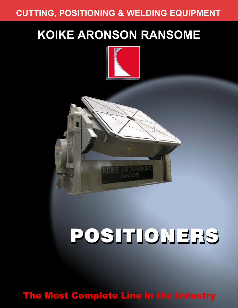
The Most Complete Line in the Industry
CUTTING, POSITIONING & WELDING EQUIPMENT
KOIKE ARONSON RANSOME

Table of Contents
Sizing a Positioner.............4Universal Balance Positioner.............8
Bench Positioners...........12
Gear Driven Positioners10P..........14
HD20 ..........16HD25 - 100 ..........18
HD160 - 700 ..........20G400 - 2200 45/90..........22
G3500 - 10,000 45/90..........24
Elevating PositionersGE 25-45..........26
GE60 - 250..........28GE500 - 3500..........30
P/E Elevating Models..........32
Floor Turntables..........34Options..........36
PAGE 3
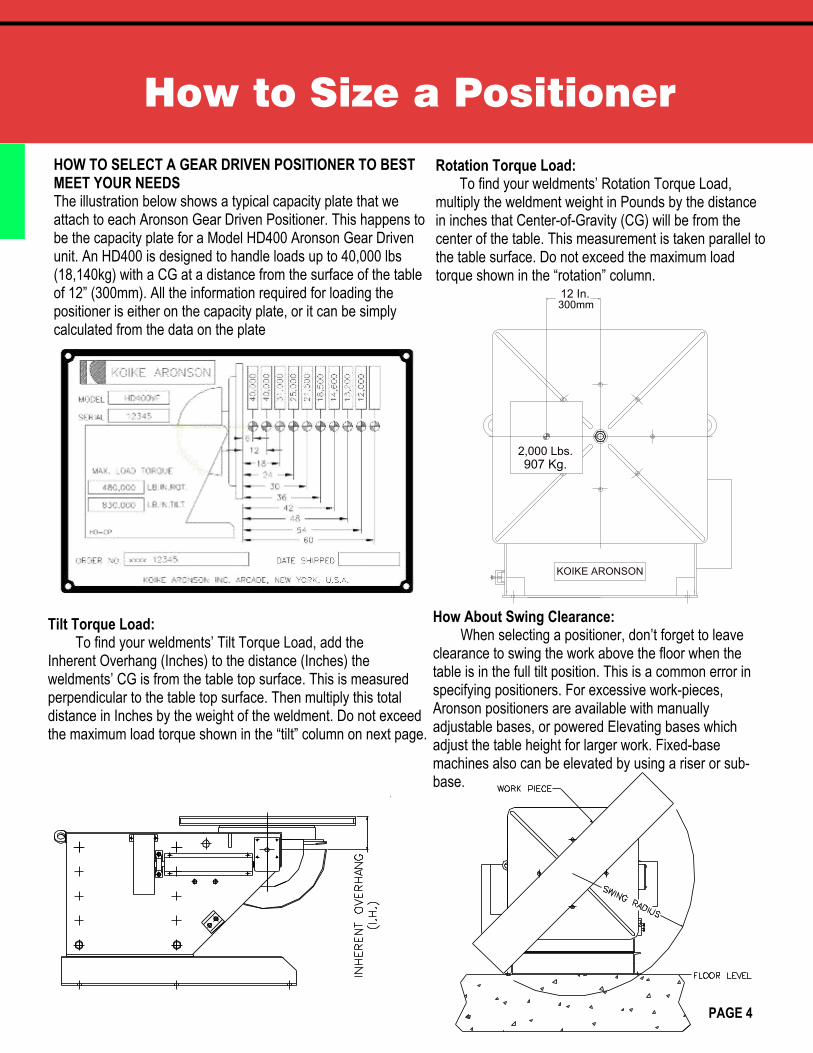
How to Size a Positioner
HOW TO SELECT A GEAR DRIVEN POSITIONER TO BESTMEET YOUR NEEDSThe illustration below shows a typical capacity plate that weattach to each Aronson Gear Driven Positioner. This happens tobe the capacity plate for a Model HD400 Aronson Gear Drivenunit. An HD400 is designed to handle loads up to 40,000 lbs(18,140kg) with a CG at a distance from the surface of the tableof 12” (300mm). All the information required for loading thepositioner is either on the capacity plate, or it can be simplycalculated from the data on the plate
Tilt Torque Load: To find your weldments’ Tilt Torque Load, add the
Inherent Overhang (Inches) to the distance (Inches) theweldments’ CG is from the table top surface. This is measuredperpendicular to the table top surface. Then multiply this totaldistance in Inches by the weight of the weldment. Do not exceedthe maximum load torque shown in the “tilt” column on next page.
Rotation Torque Load:To find your weldments’ Rotation Torque Load,
multiply the weldment weight in Pounds by the distancein inches that Center-of-Gravity (CG) will be from thecenter of the table. This measurement is taken parallel tothe table surface. Do not exceed the maximum loadtorque shown in the “rotation” column.
How About Swing Clearance: When selecting a positioner, don’t forget to leave
clearance to swing the work above the floor when thetable is in the full tilt position. This is a common error inspecifying positioners. For excessive work-pieces,Aronson positioners are available with manuallyadjustable bases, or powered Elevating bases whichadjust the table height for larger work. Fixed-basemachines also can be elevated by using a riser or sub-base.
PAGE 4
KOIKE ARONSON
12 In.300mm
2,000 Lbs.
907 Kg.
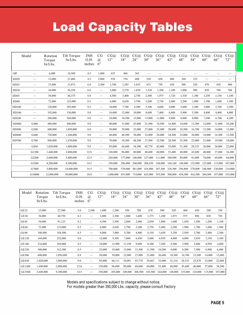
Load Capacity Tables
Tilt TorqueIn/Lbs.
INHO.H.
inches
CG@12”
CG@18”
CG@24”
CG@30”
CG@36”
CG@42”
CG@48”
CG@54”
CG@60”
CG@66”
CG@72”
10P — 6,000 10,500 4.5 635 466 365 — — — — — — — —
HD20 — 12,000 21,000 4.5 930 730 600 520 450 400 360 325 — — —
HD25 — 15,000 31,875 6.8 1,700 1,285 1,035 875 750 650 580 520 470 430 400
HD30 — 36,000 56,250 6.8 3,000 2,270 1,830 1,530 1,300 1,100 1,000 900 830 760 700
HD45 — 54,000 84,375 6.8 4,500 3,400 2,750 2,300 1,975 1,720 1,530 1,380 1,250 1,150 1,100
HD60 — 72,000 123,000 8.5 6,000 4,650 3,790 3,200 2,750 2,400 2,200 1,900 1,700 1,600 1,500
HD100 — 120,000 205,000 8.5 10,000 7,700 6,300 5,300 4,600 4,000 3,600 3,200 3,000 2,700 2,500
HD160 — 192,000 336,000 9.0 16,000 12,400 10,000 8,600 7,400 6,600 5,900 5,300 4,800 4,400 4,000
HD240 — 288,000 504,000 9.0 24,000 18,500 15,000 13,000 11,000 9,800 8,800 8,000 7,300 6,700 6,200
HD400 G400 480,000 840,000 9.0 40,000 31,000 25,000 21,500 18,500 16,400 14,600 13,200 12,000 11,000 10,200
HD500 G500 600,000 1,050,000 8.8 50,000 39,000 32,000 27,000 23,400 20,600 18,500 16,700 15,200 14,000 13,000
HD600 G600 720,000 1,260,000 9.0 60,000 46,500 38,000 32,000 28,000 24,500 22,000 20,000 18,000 16,500 15,500
HD700 G700 840,000 1,470,000 9.0 70,000 54,500 44,500 37,500 32,500 28,500 25,500 23,000 21,000 19,500 18,000
G850 1,020,000 1,800,000 9.0 85,000 66,600 54,500 45,770 42,000 35,000 31,300 28,333 26,000 24,000 22,000
G1200 1,440,000 2,880,000 12.0 120,000 96,000 80,000 68,600 60,000 53,400 48,000 43,600 40,000 37,000 34,200
G2200 2,640,000 5,400,000 12.5 220,000 177,000 148,000 127,000 111,000 100,000 89,000 81,000 74,000 69,000 64,000
G3500 4,200,000 9,300,000 14.5 350,000 286,000 240,000 208,430 184,000 164,160 148,400 135,000 125,000 115,000 107,000
G7000 5,000,000 18,600,000 14.5 700,000 570,000 481,000 416,800 367,300 328,300 296,800 270,000 248,900 230,000 214,000
G10000 12,000,000 30,000,000 18.0 1,000,000 833,000 714,000 625,000 555,500 500,000 454,500 416,500 384,500 357,000 333,000
CG@6”
1,000
2,000
2,500
—
—
—
—
—
—
—
—
—
—
—
—
—
—
—
—
GE25 15,000 27,500 5.0 2,500 1,600 1,200 950 780 670 580 520 460 420 380 350
GE30 36,000 60,750 8.2 — 3,000 2,300 1,880 1,600 1,375 1,200 1,075 975 890 820 750
GE45 54,000 91,125 8.2 — 4,500 3,500 2,800 2,400 2,050 1,800 1,600 1,450 1,300 1,200 1,100
GE60 72,000 123,000 8.5 — 6,000 4,650 3,790 3,200 2,750 2,400 2,200 1,900 1,700 1,600 1,500
GE90 108,000 184,500 8.5 — 9,000 7,000 5,700 4,800 4,150 3,650 3,250 2,950 2,700 2,480 2,300
GE120 144,000 252,000 9.0 — 12,000 9,300 7,600 6,450 5,600 4,950 4,400 4,000 3,650 3,350 3,100
GE180 216,000 369,000 8.5 — 18,000 13,900 11,350 9,600 8,300 7,300 6,500 5,900 5,400 4,950 4,600
GE250 300,000 512,500 8.5 — 25,000 19,400 15,800 13,300 11,500 10,200 9,000 8,200 7,500 6,900 6,400
GE500 600,000 1,050,000 8.8 — 50,000 39,000 32,000 27,000 23,400 20,600 18,500 16,700 15,200 14,000 13,000
GE850 1,020,000 1,800,000 9.0 — 85,000 66,111 54,091 45,770 39,667 35,000 31,316 28,333 25,870 23,800 22,000
GE1200 1,440,000 2,880,000 12.0 — 120,000 96,000 80,000 68,600 60,000 53,400 48,000 43,600 40,000 37,000 34,200
GE3500 2,640,000 9,300,000 14.5 — 350,000 285,000 240,000 208,500 183,500 164,000 148,000 135,000 124,000 115,000 107,000
Models and specifications subject to change without notice.For models greater than 350,000 Lbs. capacity, please consult Factory
Model RotationTorqueIn/Lbs.
Tilt TorqueIn/Lbs.
INHO.H.
inches
CG@6”
CG@12”
CG@18”
CG@24”
CG@30”
CG@36”
CG@42”
CG@48”
CG@54”
CG@60”
CG@66”
CG@72”
PAGE 5
Model Rotation Torque In/Lbs.
Other Factors to Consider
Practical Center of Gravity as it EffectsGear Driven Positioners
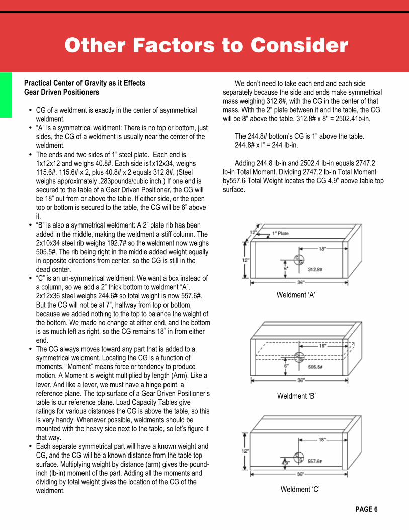
ü CG of a weldment is exactly in the center of asymmetricalweldment.
ü “A” is a symmetrical weldment: There is no top or bottom, justsides, the CG of a weldment is usually near the center of theweldment.
ü The ends and two sides of 1” steel plate. Each end is1x12x12 and weighs 40.8#. Each side is1x12x34, weighs115.6#. 115.6# x 2, plus 40.8# x 2 equals 312.8#. (Steelweighs approximately .283pounds/cubic inch.) If one end issecured to the table of a Gear Driven Positioner, the CG willbe 18” out from or above the table. If either side, or the opentop or bottom is secured to the table, the CG will be 6” aboveit.
ü “B” is also a symmetrical weldment: A 2” plate rib has beenadded in the middle, making the weldment a stiff column. The2x10x34 steel rib weighs 192.7# so the weldment now weighs505.5#. The rib being right in the middle added weight equallyin opposite directions from center, so the CG is still in thedead center.
ü “C” is an un-symmetrical weldment: We want a box instead ofa column, so we add a 2” thick bottom to weldment “A”.2x12x36 steel weighs 244.6# so total weight is now 557.6#.But the CG will not be at 7”, halfway from top or bottom,because we added nothing to the top to balance the weight ofthe bottom. We made no change at either end, and the bottomis as much left as right, so the CG remains 18” in from eitherend.
ü The CG always moves toward any part that is added to asymmetrical weldment. Locating the CG is a function ofmoments. “Moment” means force or tendency to producemotion. A Moment is weight multiplied by length (Arm). Like alever. And like a lever, we must have a hinge point, areference plane. The top surface of a Gear Driven Positioner’stable is our reference plane. Load Capacity Tables giveratings for various distances the CG is above the table, so thisis very handy. Whenever possible, weldments should bemounted with the heavy side next to the table, so let’s figure itthat way.
ü Each separate symmetrical part will have a known weight andCG, and the CG will be a known distance from the table topsurface. Multiplying weight by distance (arm) gives the pound-inch (lb-in) moment of the part. Adding all the moments anddividing by total weight gives the location of the CG of theweldment.
We don’t need to take each end and each sideseparately because the side and ends make symmetricalmass weighing 312.8#, with the CG in the center of thatmass. With the 2" plate between it and the table, the CGwill be 8" above the table. 312.8# x 8" = 2502.41b-in.
The 244.8# bottom’s CG is 1" above the table.244.8# x l" = 244 Ib-in.
Adding 244.8 Ib-in and 2502.4 Ib-in equals 2747.2lb-in Total Moment. Dividing 2747.2 lb-in Total Momentby557.6 Total Weight locates the CG 4.9” above table topsurface.
Weldment ‘A’
Weldment ‘B’
Weldment ‘C’
PAGE 6

Notes
PAGE 7
KOIKE ARONSON, INC. / RANSOME
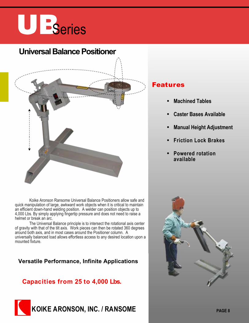
UBSeriesUniversal Balance Positioner
Features
Machined Tables
Caster Bases Available
Manual Height Adjustment
Friction Lock Brakes
Powered rotationavailable
Capacities from 25 to 4,000 Lbs.
Koike Aronson Ransome Universal Balance Positioners allow safe andquick manipulation of large, awkward work objects when it is critical to maintainan efficient down-hand welding position. A welder can position objects up to4,000 Lbs. By simply applying fingertip pressure and does not need to raise ahelmet or break an arc.
The Universal Balance principle is to intersect the rotational axis centerof gravity with that of the tilt axis. Work pieces can then be rotated 360 degreesaround both axis, and in most cases around the Positioner column. Auniversally balanced load allows effortless access to any desired location upon amounted fixture.
Versatile Performance, Infinite Applications
PAGE 8
Koike Aronson Inc.P.O. Box 307, Arcade, New York 14009
Phone (585) 492-2400 Fax (585) 457-3517
www.koike.com
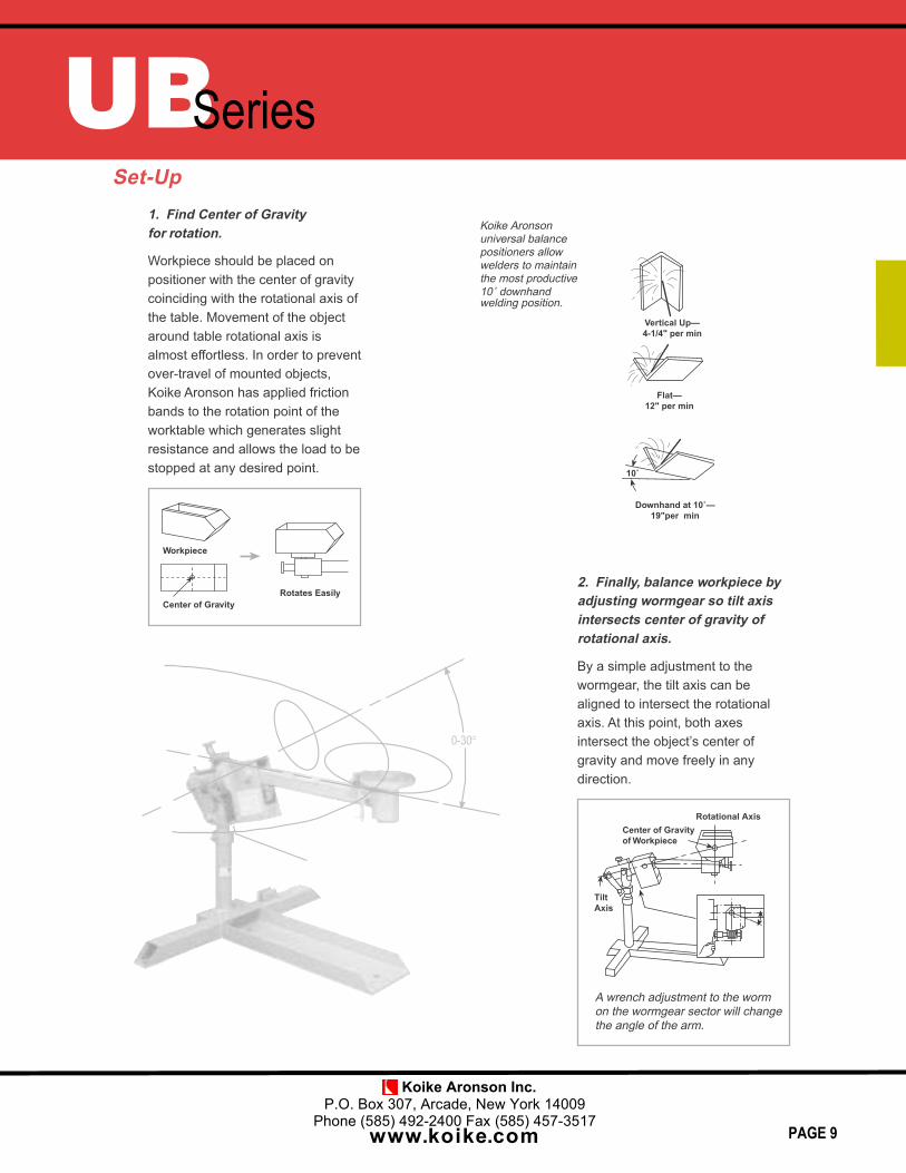
0-30
2. Finally, balance workpiece byadjusting wormgear so tilt axisintersects center of gravity ofrotational axis.
By a simple adjustment to the
wormgear, the tilt axis can be
aligned to intersect the rotational
axis. At this point, both axes
intersect the object’s center of
gravity and move freely in any
direction.
A wrench adjustment to the worm
on the wormgear sector will change
the angle of the arm.
Center of Gravityof Workpiece
Rotational Axis
TiltAxis
Set-Up1. Find Center of Gravityfor rotation.
Workpiece should be placed on
positioner with the center of gravity
coinciding with the rotational axis of
the table. Movement of the object
around table rotational axis is
almost effortless. In order to prevent
over-travel of mounted objects,
Koike Aronson has applied friction
bands to the rotation point of the
worktable which generates slight
resistance and allows the load to be
stopped at any desired point.
Workpiece
Center of GravityRotates Easily
��Û
Vertical Up—4-1/4" per min
'RZQKDQG�DW���۲19"per min
Flat—12" per min
Koike Aronson
universal balance
positioners allow
welders to maintain
the most productive
���GRZQKDQGwelding position.
UBSeries
PAGE 9

Koike Aronson Inc.P.O. Box 307, Arcade, New York 14009
Phone (585) 492-2400 Fax (585) 457-3517
www.koike.com
SpecificationsUniversal Balance Positioner
SPECIFICATIONS C25 C100 C1000 C2000 C4000
Maximum Load 25 Lbs. 100 Lbs. 1,000 Lbs. 2,000 Lbs. 4,000 Lbs.
DIM A, Overhang, 6-1/2” 11” 32” 35” 51-1/2”
DIM B, Max. CG Height 3” 4-3/4” 14-1/2” 16” 33-1/2”
DIM C, Max. Part Diameter 14” 20” 66” 75” 96”
DIM D, Max. Part Length 16” 24” 100” 100” 96”
DIM E, Table Diameter 1-1/2” 5” 8” 8” 12”
DIM F, Hole Size 10-32 1/4” Slots 17/32” 17/32” 1-1/32”
DIM G, Bolt Circle 1-1/4” 4 Slots 5” 5” 8”
DIM H, Table Thickness 1/4” 1/4” 15/16” 1” 1-1/2”
DIM I, Pilot Hole 10-32 1/4-20 1/2-13 3/4-10 1”-8 x 1.25
DIM J, Height Range 6-1/4” Fix 5” Fix 27”- 37” 30”- 36” 41-1/2” Fix
DIM K, Table to Tilt Axis 7/8” 2” 3-5/8” 3-1/8” 6”
DIM L, Rear Overhang 1-1/2” 2-1/8” 4-3/4” 8” 1”
DIM M, Base Overall Width 6” 4-1/2” 43” 43” 58”
DIM N, Base Overall Length. 9” 4-1/2” 37-3/4” 48” 78”
DIM O, Anchor Hole Size 9/32” (4) 13/32” (4) 9/16” (4) 9/16” (6) 13/16” (8)
DIM P, Anchor Hole Width Centers 5-1/4” 3-3/4” 40” 40” 55”
DIM Q, Anchor Hole Length Centers 8-1/4” 3-3/4” 29-3/4” 39” -
DIM R, Wrench Size 1/4” 1/2” 1” 1” 2-1/4”
Type of Base Plate Plate “T” “T” “T”
Tilt Axis Brake Yes No Yes Yes Yes
Tilt Axis Pinlock No No Yes Yes Yes
Rotation Axis Brake Yes No Yes Yes Yes
Rotation Axis Pinlock No Yes Yes Yes Yes
Bearing type Ball Tapered Tapered Tapered Tapered
Ground Current Conduction N/R 300 Amps 800 Amps 1200 Amps 2000 Amps
Power Axis Available No No Yes Yes Yes
Shipping Weight 15 Lbs. 30 Lbs. 340 Lbs. 500 Lbs. 1,300 Lbs.
PAGE 10
***All dimensions are for reference only and subject to change without notice.

Koike Aronson Inc.P.O. Box 307, Arcade, New York 14009
Phone (585) 492-2400 Fax (585) 457-3517
www.koike.com
C100
UBSeries
C4000
C2000
C2000 P30
Assembly positioners brake and hold workpieces in anyposition with the use of hydraulic disc brakes. Rotationand tilt are performed manually, off-balance loads can bequickly manipulated and locked in place to resist theforces of various production operations.
ASSEMBLY POSITIONER
C1000 Caster
PAGE 11
KOIKE ARONSON, INC. / RANSOME
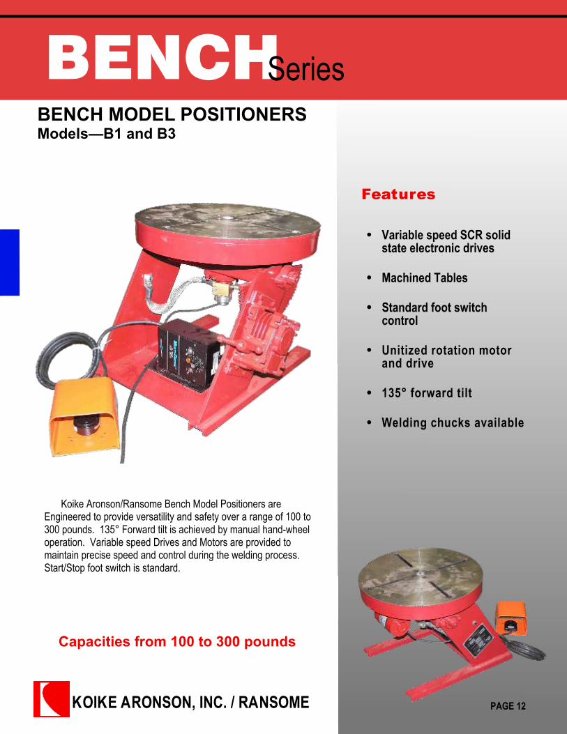
BENCHSeriesBENCH MODEL POSITIONERSModels—B1 and B3
Features
Capacities from 100 to 300 pounds
Koike Aronson/Ransome Bench Model Positioners areEngineered to provide versatility and safety over a range of 100 to300 pounds. 135° Forward tilt is achieved by manual hand-wheeloperation. Variable speed Drives and Motors are provided tomaintain precise speed and control during the welding process.Start/Stop foot switch is standard.
Variable speed SCR solidstate electronic drives
Machined Tables
Standard foot switchcontrol
Unitized rotation motorand drive
135° forward tilt
Welding chucks available
PAGE 12

Koike Aronson Inc.P.O. Box 307, Arcade, New York 14009
Phone (585) 492-2400 Fax (585) 457-3517
www.koike.com
SpecificationsBench Positioners
B1 Positioner
PAGE 13
B3 Positioner
SPECIFICATIONS B1 B3
MAXIMUM LOAD 100 Lbs. @ 1” Off Table & Concentric ontable
300 Lbs. @ 3” Off Table & 3” Eccentric
ROTATION 0.1 TO 4 RPM Variable Speed @ 100IN.LB. Torque
0.06 TO 2.5 RPM Variable Speed @ 900IN.LB. Torque
TILT 125° Forward Tilt-Powered by a Handwheel 125° Forward Tilt-Powered by a Handwheel
ELECTRICALS SCR DC Drive with Ready Light ToggleDisconnect Switch 1-Turn SpeedPententiometer CW-CCW Selector SwitchRemote ON/OFF Foot Switch, PrimaryCable and Plug
SCR DC Drive with Ready Light ToggleDisconnect Switch 1-Turn SpeedPententiometer CW-CCW Selector SwitchRemote ON/OFF Foot Switch, PrimaryCable and Plug
WELD GROUND CURRENT 190 Amps 500 Amps
VOLTAGE 115V/1PH/50-60HZ, Remote ON/OFF FootSwitch
115V/1PH/50-60HZ, Remote ON/OFF FootSwitch
SHIPPING WEIGHT 90 Lbs. 202 Lbs.
***All dimensions are for reference only and subject to change without notice.

KOIKE ARONSON, INC. / RANSOME
PSeries10P GEAR DRIVEN POSITIONER
Features
Manually Adjustable From 32-1/2” to 50-1/2”
The Koike Aronson/Ransome 10P Positioner is engineered toprovide versatility and safety. Variable speed drives and motors areprovided to maintain precise rotation speed and control during thewelding process. 135°Forward tilt is powered by a constant speedmotor. Hand pendant control includes Start/Stop/Forward/Reverse, 10turn speed potentiometer and Rapid Traverse. Adjustable baseprovides 5 separate height settings for various size work pieces. Tableslots are provided for easy fixturing and mounting of weldments. Tiltprotractor enables operator to repeat welding positions quickly andprecisely.
Variable speed SCR solidstate electronic drives
Machined table
Unitized tilt motor anddrive
135° forward tilt
Welding chucks available
PAGE 14

Koike Aronson Inc.P.O. Box 307, Arcade, New York 14009
Phone (585) 492-2400 Fax (585) 457-3517
www.koike.com
SPECIFICATIONS 10P
CAPACITY 1,000 LBS. Load Capacity, Center of Gravity 6" Overhang, 6" Off-center
ROTATION .04 - 2 RPM @ 6,000 Lb-In Torque, 1/2 HP AC Motor, Variable Frequency Drive
TILT 135° Forward Tilt, 10,500 Lb-In Torque, .4 RPM (90° in 38 Seconds) 1/2 HP Brake Motor; 4.5” Inherent Overhang
TABLE 30" Diameter Machined Table Top, with (4) Radial 'T' slots for 1/2" Diameter Bolts, 2.500 x ½” deep Pilot, 1-¾” Thru
FLAT TABLE HEIGHT Minimum 32-1/2" from Floor, Maximum 50-1/2", Manually Adjustable in 6" Increments
WELD GROUND CURRENT 1000 Amps
VOLTAGE 460/3/60
SHIPPING WEIGHT 1,180 Lbs.
Specifications10P GEAR DRIVEN POSTIONER
PAGE 15
***All dimensions are for reference only and subject to change without notice.
KOIKE ARONSON, INC. / RANSOME
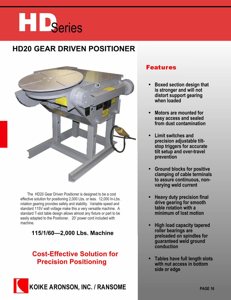
HDSeriesHD20 GEAR DRIVEN POSITIONER
Features
Cost-Effective Solution forPrecision Positioning
The HD20 Gear Driven Positioner is designed to be a costeffective solution for positioning 2,000 Lbs. or less. 12,000 In-Lbs.rotation gearing provides safety and stability. Variable speed andstandard 115V wall voltage make this a very versatile machine. Astandard T-slot table design allows almost any fixture or part to beeasily adapted to the Positioner. 20’ power cord included withmachine.
Boxed section design thatis stronger and will notdistort support gearingwhen loaded
Motors are mounted foreasy access and sealedfrom dust contamination
Limit switches andprecision adjustable tilt-stop triggers for accuratetilt setup and over-travelprevention
Ground blocks for positiveclamping of cable terminalsto assure continuous, non-varying weld current
Heavy duty precision finaldrive gearing for smoothtable rotation with aminimum of lost motion
High load capacity taperedroller bearings arepreloaded on spindles forguaranteed weld groundconduction
Tables have full length slotswith nut access in bottomside or edge
115/1/60—2,000 Lbs. Machine
PAGE 16
Koike Aronson Inc.P.O. Box 307, Arcade, New York 14009
Phone (585) 492-2400 Fax (585) 457-3517
www.koike.com
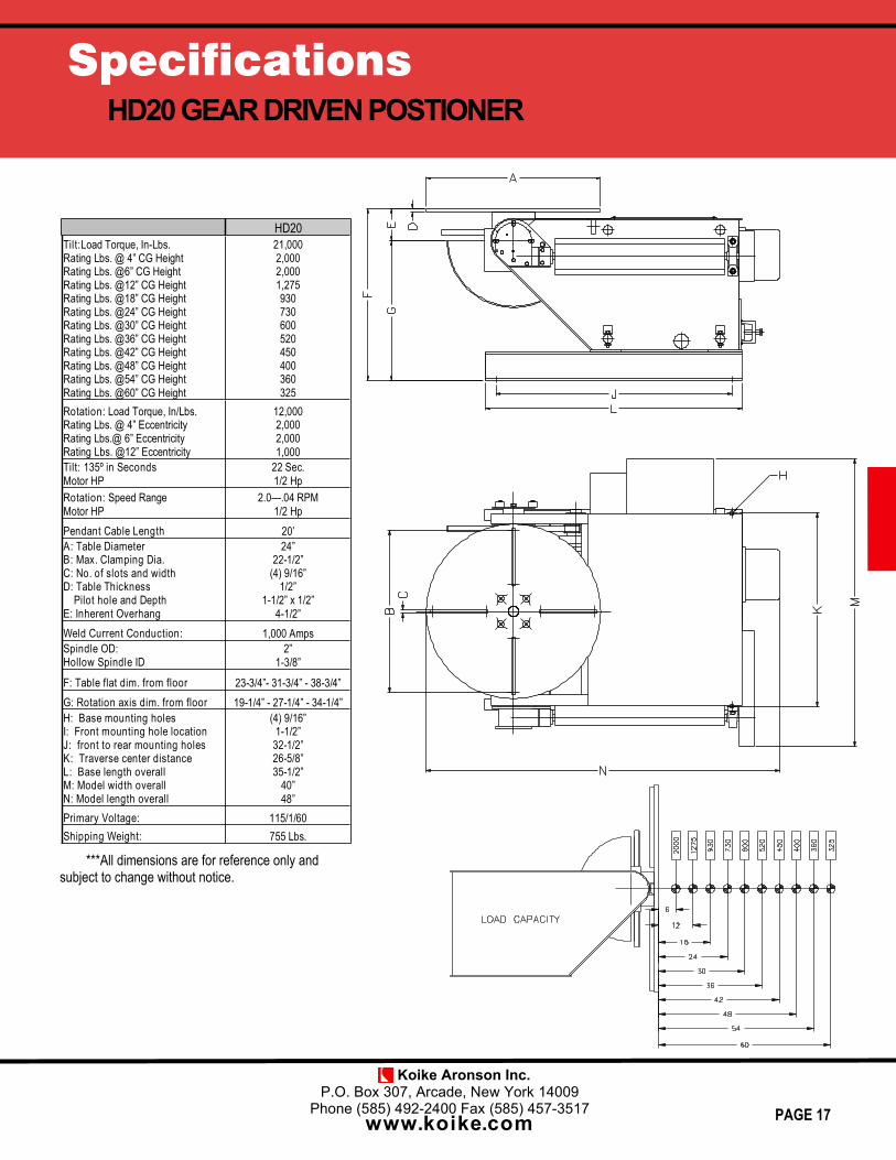
SpecificationsHD20 GEAR DRIVEN POSTIONER
HD20Tilt: Load Torque, In-Lbs.Rating Lbs. @ 4” CG HeightRating Lbs. @6” CG HeightRating Lbs. @12” CG HeightRating Lbs. @18” CG HeightRating Lbs. @24” CG HeightRating Lbs. @30” CG HeightRating Lbs. @36” CG HeightRating Lbs. @42” CG HeightRating Lbs. @48” CG HeightRating Lbs. @54” CG HeightRating Lbs. @60” CG Height
21,0002,0002,0001,275930730600520450400360325
Rotation: Load Torque, In/Lbs.Rating Lbs. @ 4” EccentricityRating Lbs.@ 6” EccentricityRating Lbs. @12” Eccentricity
12,0002,0002,0001,000
Tilt: 135º in SecondsMotor HP
22 Sec.1/2 Hp
Rotation: Speed RangeMotor HP
2.0—.04 RPM1/2 Hp
Pendant Cable Length 20’A: Table DiameterB: Max. Clamping Dia.C: No. of slots and widthD: Table Thickness
Pilot hole and DepthE: Inherent Overhang
24”22-1/2”
(4) 9/16”1/2”
1-1/2” x 1/2”4-1/2”
Weld Current Conduction: 1,000 AmpsSpindle OD:Hollow Spindle ID
2”1-3/8”
F: Table flat dim. from floor 23-3/4”- 31-3/4” - 38-3/4”G: Rotation axis dim. from floor 19-1/4” - 27-1/4” - 34-1/4”H: Base mounting holesI: Front mounting hole locationJ: front to rear mounting holesK: Traverse center distanceL: Base length overallM: Model width overallN: Model length overall
(4) 9/16”1-1/2”32-1/2”26-5/8”35-1/2”
40”48”
Primary Voltage: 115/1/60Shipping Weight: 755 Lbs.
PAGE 17
***All dimensions are for reference only andsubject to change without notice.
KOIKE ARONSON, INC. / RANSOME
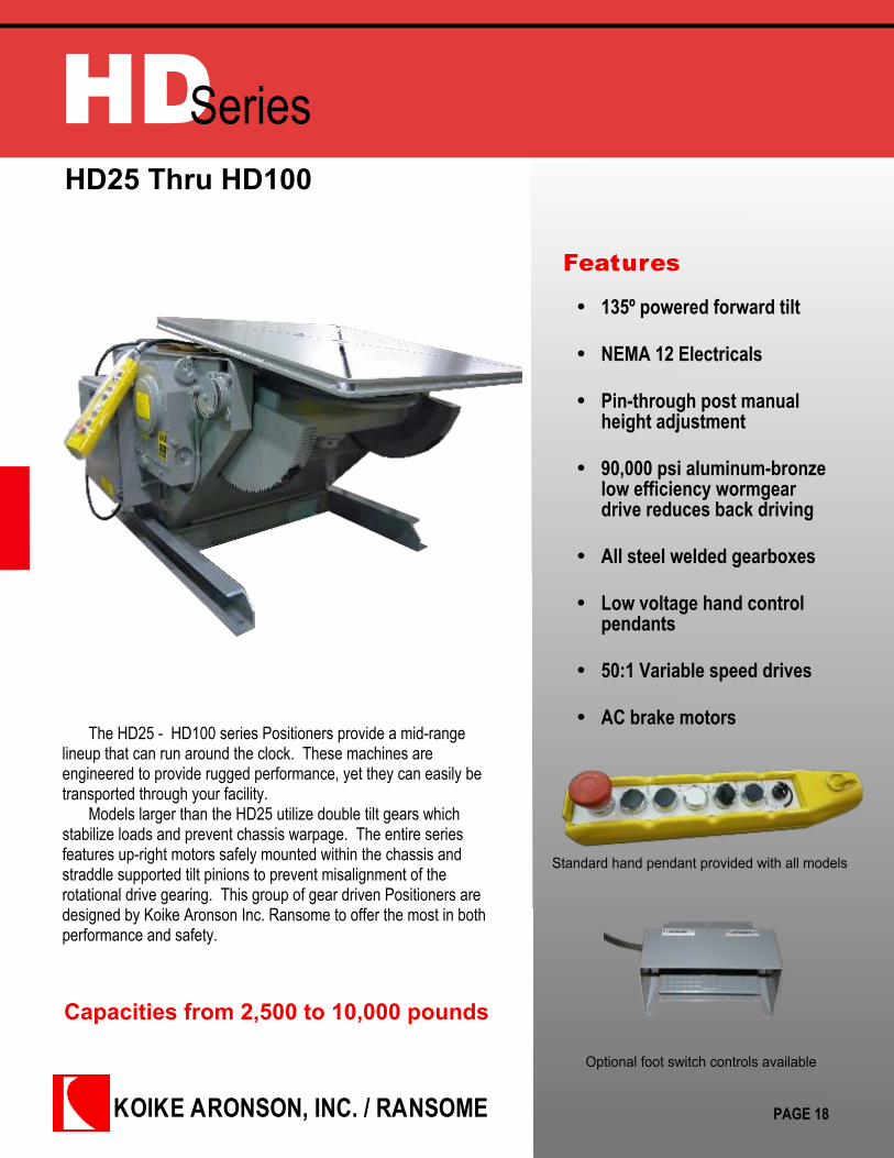
HDSeriesHD25 Thru HD100
Features
Capacities from 2,500 to 10,000 pounds
The HD25 - HD100 series Positioners provide a mid-rangelineup that can run around the clock. These machines areengineered to provide rugged performance, yet they can easily betransported through your facility.
Models larger than the HD25 utilize double tilt gears whichstabilize loads and prevent chassis warpage. The entire seriesfeatures up-right motors safely mounted within the chassis andstraddle supported tilt pinions to prevent misalignment of therotational drive gearing. This group of gear driven Positioners aredesigned by Koike Aronson Inc. Ransome to offer the most in bothperformance and safety.
135º powered forward tilt
NEMA 12 Electricals
Pin-through post manualheight adjustment
90,000 psi aluminum-bronzelow efficiency wormgeardrive reduces back driving
All steel welded gearboxes
Low voltage hand controlpendants
50:1 Variable speed drives
AC brake motors
PAGE 18
Standard hand pendant provided with all models
Optional foot switch controls available

Koike Aronson Inc.P.O. Box 307, Arcade, New York 14009
Phone (585) 492-2400 Fax (585) 457-3517
www.koike.com
SpecificationsHD25VF - HD100VF
PAGE 19
SPECIFICATIONS HD25VF HD30VF HD45VF HD60VF HD100VFTilt: Load Torque in-lb (N.m)Rating Lbs.(kg) @ 6” (152mm) CG HeightRating Lbs.(kg) @ 12” (305mm) CG HeightRating Lbs.(kg) @ 18” (457mm) CG HeightRating Lbs.(kg) @ 24” (609mm) CG HeightRating Lbs.(kg) @ 30” (762mm) CG HeightRating Lbs.(kg) @ 36” (914mm) CG HeightRating Lbs.(kg) @ 42” (1067mm) CG HeightRating Lbs.(kg) @ 48” (1219mm) CG HeightRating Lbs.(kg) @ 54” (1371mm) CG HeightRating Lbs.(kg) @ 60” (1524mm) CG HeightRating Lbs.(kg) @ 66” (1676mm) CG HeightRating Lbs.(kg) @ 72” (1829mm) CG Height
31,875 (3602)2,500 (1134)1,700 (771)1,285 (583)1,035 (469)875 (397)750 (340)650 (295)580 (263)520 (236)470 (213)430 (195)400 (181)
56,250 (6356)3,000 (1361)3,000 (1361)2,270 (1030)1,830 (830)1,530 (694)1,300 (590)1,100 (499)1,000 (453)900 (408)830 (376)760 (345)700 (317)
84,375 (9534)4,500 (2041)4,500 (2041)3,400 (1542)2,750 (1247)2,300 (1043)1,975 (896)1,720 (780)1,530 (694)1,380 (626)1,250 (567)1,150 (522)1,100 (499)
123,000 (13899)-
6,000 (2721)4,650 (2109)3,790 (1719)3,200 (1451)2,750 (1247)2,400 (1089)2,200 (998)1,900 (862)1,700 (771)1,600 (726)1,500 (680)
205,000 (23165)-
10,000 (4536)7,700 (3493)6,300 (2858)5,300 (2404)4,600 (2086)4,000 (1814)3,600 (1633)3,200 (1451)3,000 (1361)2,700 (1225)2,500 (1134)
Rotation: Load Torque in-lb (N.m)Rating Lbs.(kg) @ 6” (152mm) EccentricRating Lbs.(kg) @ 12” (305mm) Eccentric
15,000 (1695)2,500 (1134)1,250 (567)
36,000 (4068)3,000 (1361)3,000 (1350)
54,000 (6102)4,500 (2041)4,500 (2041)
72,000 (8136)-
6,000 (2721)
120,000 (13560)-
10,000 (4536)
Tilt: 135º in how many secondsTilt Motor Horse Power
23 Sec.1 HP
20 Sec.2 HP
20 Sec.3 HP
24 Sec.3 HP
49 Sec.3 HP
Rotation: Speed Range 50:1 AC DriveRotation Motor Horse Power
2.0 - .040 rpm¾ HP
1.2 - .024 rpm1 HP
1.2 - .024 rpm1-½ HP
1.5 - .030 rpm3 HP
1.0—.0205 HP
Pendant cable length: 20 ft. 20 ft. 20 ft. 20 ft. 20 ft.
A: Table SizeB: Maximum Clamping DiameterC: Number of slots and width
Number of Table nuts and ThreadD: Pilot hole and depthE: Table ThicknessF: Inherent Overhang
30” x 30” (762x762mm)38-½ ” (978mm)
(4) 13/16” (20.6mm)(4) ¾-10 ”
3.130”x½” (79.5 x13mm)1-¾ “ (44.4mm)6-¾ “ (171.4mm)
36” x 36” (914x914mm)47 ” (1194mm)
(4) 13/16” (20.6mm)(4) ¾-10 ”
3.130”x½” (79.5 x13mm)1-¾ “ (44.4mm)
6-¾ “ (171.4mm)
36” x 36” (914x914mm)47 ” (1194mm)
(4) 13/16” (20.6mm)(4) ¾-10 ”
3.130”x½” (79.5 x13mm)1-¾ “ (44.4mm)
6-¾ “ (171.4mm)
48” x 48” (1219 x 1219mm)65” (1651mm)
(4) 13/16” (20.6mm)(4) 3/4”-10
3.130” x ½” (79.5 x 12.7mm)2” (50.8mm)
8 1/2” (215.9mm)
48” x 48” (1219 x 1219mm)65” (1651mm)
4) 13/16” (20.6mm)(4) 3/4”-10
3.130” x ½” (79.5 x 12.7mm)2” (50.8mm)
8 1/2” (215.9mm)
Spindle OD Bearing BoreHollow Spindle Dia
2-1/2” (63.5mm)None
2-1/2” (63.5mm)None
3” (76.2mm)None
3” (76.2mm)None
4” (101.6mm)None
Weld Current Conduction 1,500 Amps 1,500 Amps 2,000 Amps 2,000 Amps 2,000 Amps
G: Table flat, Minimum HeightTable flat, Maximum HeightAdjustment Increments
34-½” (870mm)56-½” (1435mm)5-½” (139.7mm)
34-½” (870mm)54-½” (1384.3mm)
5” (127mm)
34-½” (870mm)54-½” (1384.3mm)
5” (127mm)
44-½” (1130.3mm)68-½” (1740mm)
6” (152.4mm)
44-½” (1130.3mm)74-½” (1892.3mm)
6” (152.4mm)
H: Rotation axis, Minimum HeightRotation axis, Maximum HeightMatching TS
27-¾” (704.8mm)49-¾” (1263.6mm)
TS2
27-¾” (704.8mm)47-¾” (1212.8mm)
TS2
27-¾” (704.8mm)47-¾” (1212.8mm)
TS4
36” (914.4mm)60” (1524mm)
TS6
36” (914.4mm)66” (1676mm)
TS10
I: Tie down hole sizeJ: Front Mounting hole locationK: Center mounting hole locationL: Rear mounting hole locationM: Bolt hole pattern pitchN: Overall base lengthO: Overall Machine widthP: Overall machine length
(6) 9/16” (14.3mm)1-½” (38.1mm)19” (482.6mm)19” (482.6mm)34” (863.6mm)
42-¼” (1073.1mm)47” (1194mm)
50-¾” (1289mm)
(6) 13/16” (20.6mm)1-½” (38.1mm)23” (584.2mm)20” (508mm)
35-¾” (908mm)48” (1219.2mm)48-¾” (1225mm)
60” (1524mm)
(6) 13/16” (20.6mm)1-½” (38.1mm)23” (584.2mm)20” (508mm)
35-¾” (908mm)48” (1219.2mm)
48-3/8” (1229mm)60” (1524mm)
(6) 13/16” (20.6mm)2” (50.8mm)30” (762mm)
24” (609.6mm)47-1/2” (1206.5mm)
60” (1524mm)63-3/8” (1610mm)76” (1930.4mm)
(6) 13/16” (20.6mm)2” (50.8mm)30” (762mm)
24” (609.6mm)47-5/8” (1209.7mm)
60” (1524mm)61-13/16” (1570mm)76” (1930.4mm)
Standard Primary Voltage 460/3/60 460/3/60 460/3/60 460/3/60 460/3/60
Shipping Weight 1500 lbs. (680kg) 1892 lbs. (858kg) 2080 lbs. (943kg) 3700 lbs. (1678kg) 4105 lbs. (1862kg)
***All dimensionsare for reference onlyand subject to changewithout notice.

KOIKE ARONSON, INC. / RANSOME
HDSeriesHD160 thru HD700
Features
Capacities from 16,000 to 70,000 pounds
The HD160 - HD700 series positioners are built to perform withlarger capacities with their strong boxed chassis and high precisiongearing.
Positioners larger than the HD240 are equipped with massive boxbeam trunnions, spur gear final drive for table rotation, and aluminum-bronze wormgear drive of the spur tilt pinions.
The only thing that contradicts the large capacity of this series istheir portability. They can be easily moved anywhere to tackle thelargest of jobs.
135º powered forward tilt
NEMA 12 Electricals
Pin-through post manualheight adjustment
90,000 psi aluminum-bronzelow efficiency wormgeardrive reduces back driving
All steel welded gearboxes
Low voltage hand controlpendants
50:1 Variable speed drives
AC brake motors
PAGE 20
Standard hand pendant provided with all models
Optional foot switch controls available
Koike Aronson Inc.P.O. Box 307, Arcade, New York 14009
Phone (585) 492-2400 Fax (585) 457-3517
www.koike.com
SpecificationsHD160VF - HD700VF
PAGE 21
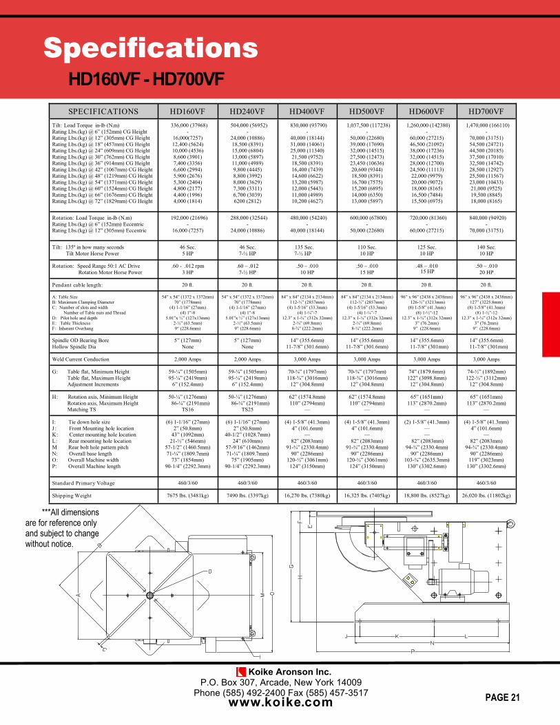
SPECIFICATIONS HD160VF HD240VF HD400VF HD500VF HD600VFTilt: Load Torque in-lb (N.m)Rating Lbs.(kg) @ 6” (152mm) CG HeightRating Lbs.(kg) @ 12” (305mm) CG HeightRating Lbs.(kg) @ 18” (457mm) CG HeightRating Lbs.(kg) @ 24” (609mm) CG HeightRating Lbs.(kg) @ 30” (762mm) CG HeightRating Lbs.(kg) @ 36” (914mm) CG HeightRating Lbs.(kg) @ 42” (1067mm) CG HeightRating Lbs.(kg) @ 48” (1219mm) CG HeightRating Lbs.(kg) @ 54” (1371mm) CG HeightRating Lbs.(kg) @ 60” (1524mm) CG HeightRating Lbs.(kg) @ 66” (1676mm) CG HeightRating Lbs.(kg) @ 72” (1829mm) CG Height
336,000 (37968)-
16,000(7257)12,400 (5624)10,000 (4536)8,600 (3901)7,400 (3356)6,600 (2994)5,900 (2676)5,300 (2404)4,800 (2177)4,400 (1996)4,000 (1814)
504,000 (56952)-
24,000 (10886)18,500 (8391)15,000 (6804)13,000 (5897)11,000 (4989)9,800 (4445)8,800 (3992)8,000 (3629)7,300 (3311)6,700 (3039)6200 (2812)
830,000 (93790)-
40,000 (18144)31,000 (14061)25,000 (11340)21,500 (9752)18,500 (8391)16,400 (7439)14,600 (6622)13,200 (5987)12,000 (5443)11,000 (4989)10,200 (4627)
1,037,500 (117238)-
50,000 (22680)39,000 (17690)32,000 (14515)27,500 (12473)23,450 (10636)20,600 (9344)18,500 (8391)16,700 (7575)15,200 (6895)14,000 (6350)13,000 (5897)
1,260,000 (142380)-
60,000 (27215)46,500 (21092)38,000 (17236)32,000 (14515)28,000 (12700)24,500 (11113)22,000 (9979)20,000 (9072)18,000 (8165)16,500 (7484)15,500 (6975)
Rotation: Load Torque in-lb (N.m)Rating Lbs.(kg) @ 6” (152mm) EccentricRating Lbs.(kg) @ 12” (305mm) Eccentric
192,000 (21696)-
16,000 (7257)
288,000 (32544)-
24,000 (10886)
480,000 (54240)-
40,000 (18144)
600,000 (67800)-
50,000 (22680)
720,000 (81360)-
60,000 (27215)
Tilt: 135º in how many secondsTilt Motor Horse Power
46 Sec.5 HP
46 Sec.7-½ HP
135 Sec.7-½ HP
110 Sec.10 HP
125 Sec.10 HP
Rotation: Speed Range 50:1 AC DriveRotation Motor Horse Power
.60 - .012 rpm3 HP
.60 – .0127-½ HP
.50 – .01010 HP
.50 – .01015 HP
.48 – .01015 HP
Pendant cable length: 20 ft. 20 ft. 20 ft. 20 ft. 20 ft.
A: Table SizeB: Maximum Clamping DiameterC: Number of slots and width
Number of Table nuts and ThreadD: Pilot hole and depthE: Table ThicknessF: Inherent Overhang
54” x 54” (1372 x 1372mm)70” (1778mm)
(4) 1-1/16” (27mm)(4) 1”-8
5.01”x ½” (127x13mm)2-½” (63.5mm)9“ (228.6mm)
54” x 54” (1372 x 1372mm)70” (1778mm)
(4) 1-1/16” (27mm)(4) 1”-8
5.01”x ½” (127x13mm)2-½” (63.5mm)9” (228.6mm)
84” x 84” (2134 x 2134mm)112-½” (2857mm)
(4) 1-5/16” (33.3mm)(4) 1-¼”-7
12.3” x 1-¼” (312x 32mm)2-¾” (69.8mm)8-¾” (222.2mm)
84” x 84” (2134 x 2134mm)112-½” (2857mm)
(4) 1-5/16” (33.3mm)(4) 1-¼”-7
12.3” x 1-¼” (312x 32mm)2-¾” (69.8mm)8-¾” (222.2mm)
96” x 96” (2438 x 2438mm)126-½” (3213mm)
(8) 1-5/8” (41.3mm)(8) 1-½”-12
12.3” x 1-¼” (312x 32mm)3” (76.2mm)
9” (228.6mm)
Spindle OD Bearing BoreHollow Spindle Dia
5” (127mm)None
5” (127mm)None
14” (355.6mm)11-7/8” (301.6mm)
14” (355.6mm)11-7/8” (301.6mm)
14” (355.6mm)11-7/8” (301mm)
Weld Current Conduction 2,000 Amps 2,000 Amps 3,000 Amps 3,000 Amps 3,000 Amps
G: Table flat, Minimum HeightTable flat, Maximum HeightAdjustment Increments
59-¼” (1505mm)95-¼” (2419mm)
6” (152.4mm)
59-¼” (1505mm)95-¼” (2419mm)
6” (152.4mm)
70-¾” (1797mm)118-¾” (3016mm)
12” (304.8mm)
70-¾” (1797mm)118-¾” (3016mm)
12” (304.8mm)
74” (1879.6mm)122” (3098.8mm)12” (304.8mm)
H: Rotation axis, Minimum HeightRotation axis, Maximum HeightMatching TS
50-¼” (1276mm)86-¼” (2191mm)
TS16
50-¼” (1276mm)86-¼” (2191mm)
TS25
62” (1574.8mm)110” (2794mm)
—
62” (1574.8mm)110” (2794mm)
—
65” (1651mm)113” (2870.2mm)
—
I: Tie down hole sizeJ : Front Mounting hole locationK: Center mounting hole locationL: Rear mounting hole locationM Rear bolt hole pattern pitchN: Overall base lengthO: Overall Machine widthP: Overall Machine length
(6) 1-1/16” (27mm)2” (50.8mm)
43” (1092mm)21-½” (546mm)
57-1/2” (1460.5mm)71-¼” (1809.7mm)
73” (1854mm)90-1/4” (2292.3mm)
(6) 1-1/16” (27mm)2” (50.8mm)
40-1/2” (1028.7mm)24” (610mm)
57-9/16” (1462mm)71-¼” (1809.7mm)
75” (1905mm)90-1/4” (2292.3mm)
(4) 1-5/8” (41.3mm)4” (101.6mm)
—82” (2083mm)
91-¾” (2330.4mm)90” (2286mm)
120-½” (3061mm)124” (3150mm)
(4) 1-5/8” (41.3mm)4” (101.6mm)
—82” (2083mm)
91-¾” (2330.4mm)90” (2286mm)
120-½” (3061mm)124” (3150mm)
(2) 1-5/8” (41.3mm)——
82” (2083mm)94-¾” (2330.4mm)
90” (2286mm)103-¾” (2635.3mm)
130” (3302.6mm)
Standard Primary Voltage 460/3/60 460/3/60 460/3/60 460/3/60 460/3/60
Shipping Weight 7675 lbs. (3481kg) 7490 lbs. (3397kg) 16,270 lbs. (7380kg) 16,325 lbs. (7405kg) 18,800 lbs. (8527kg)
HD700VF1,470,000 (166110)
-70,000 (31751)54,500 (24721)44,500 (20185)37,500 (17010)32,500 (14742)28,500 (12927)25,500 (11567)23,000 (10433)21,000 (9525)19,500 (8845)18,000 (8165)
840,000 (94920)-
70,000 (31751)
140 Sec.10 HP
.50 – .01020 HP
20 ft.
96” x 96” (2438 x 2438mm)127” (3225.8mm)
(8) 1-5/8” (41.3mm)(8) 1-½”-12
12.3” x 1-¼” (312x 32mm)3” (76.2mm)
9” (228.6mm)
14” (355.6mm)11-7/8” (301mm)
3,000 Amps
74-½” (1892mm)122-½” (3112mm)
12” (304.8mm)
65” (1651mm)113” (2870.2mm)
—
(4) 1-5/8” (41.3mm)4” (101.6mm)
—82” (2083mm)
94-¾” (2330.4mm)90” (2286mm)
119” (3023mm)130” (3302.6mm)
460/3/60
26,020 lbs. (11802kg)
***All dimensionsare for reference onlyand subject to changewithout notice.

KOIKE ARONSON, INC. / RANSOME
GSeriesG400 Thru G2200
Features
Capacities from 40,000 to 220,000 pounds
The G400-G2200 Positioners are a versatile series withcapacities ranging from 40,000 to 220,000 pounds. Designcharacteristics of these Positioners include powered tilt from 90ºforward to 45º backward, fixed height bases and hollow spindles.Larger models designed as “bolt together construction” reducingshipping costs and allowing for easier relocation of machine.
45/90 powered tilt
NEMA 12 Electricals
Fixed Bases
90,000 psi aluminum-bronzelow efficiency wormgeardrive reduces back driving
All steel welded gearboxes
Low voltage hand controlpendants
50:1 Variable speed drives
AC brake motors
PAGE 22
Standard hand pendant provided with all models
Optional foot switch controls available
Koike Aronson Inc.P.O. Box 307, Arcade, New York 14009
Phone (585) 492-2400 Fax (585) 457-3517
www.koike.com
SpecificationsG400 - G2200
PAGE 23
***All dimensions are forreference only and subject tochange without notice.
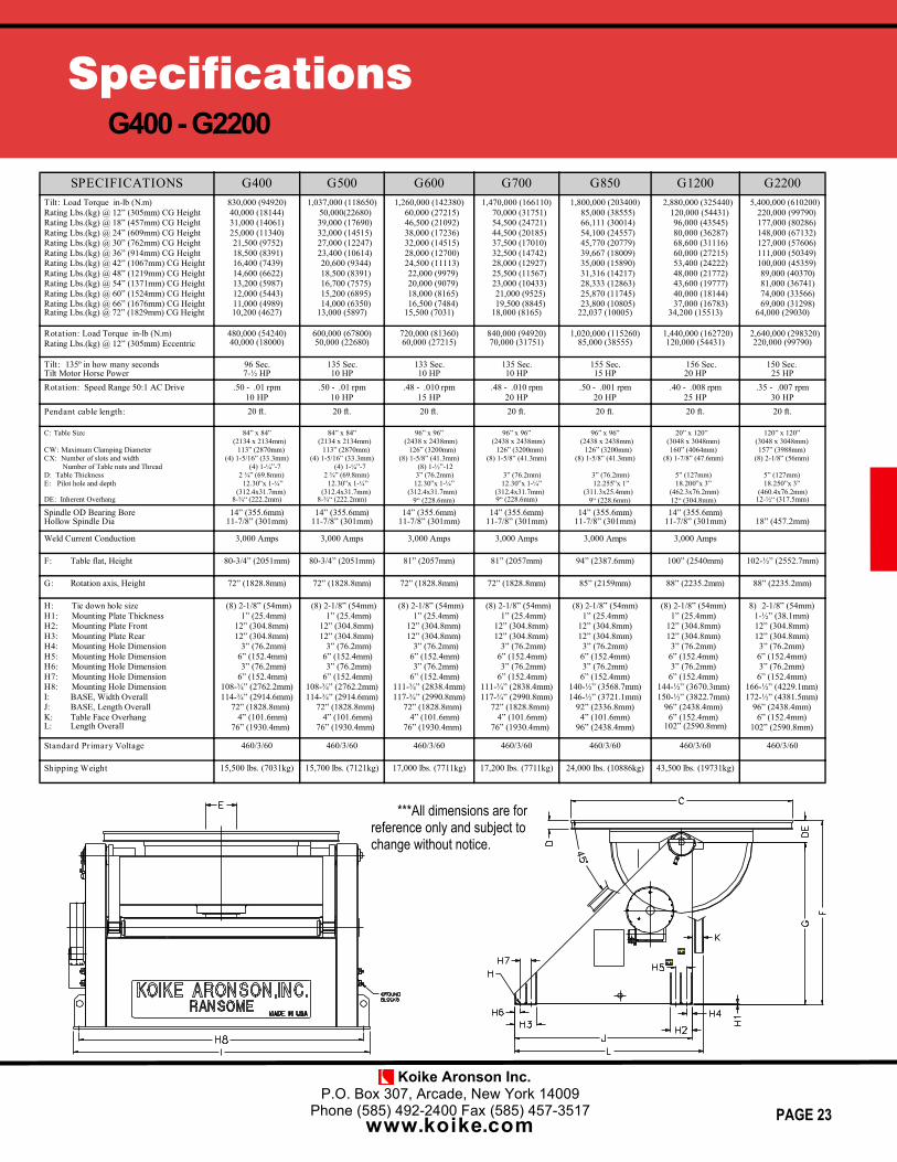
SPECIFICATIONS G400 G500 G600 G700 G850 G1200 G2200Tilt: Load Torque in-lb (N.m)Rating Lbs.(kg) @ 12” (305mm) CG HeightRating Lbs.(kg) @ 18” (457mm) CG HeightRating Lbs.(kg) @ 24” (609mm) CG HeightRating Lbs.(kg) @ 30” (762mm) CG HeightRating Lbs.(kg) @ 36” (914mm) CG HeightRating Lbs.(kg) @ 42” (1067mm) CG HeightRating Lbs.(kg) @ 48” (1219mm) CG HeightRating Lbs.(kg) @ 54” (1371mm) CG HeightRating Lbs.(kg) @ 60” (1524mm) CG HeightRating Lbs.(kg) @ 66” (1676mm) CG HeightRating Lbs.(kg) @ 72” (1829mm) CG Height
830,000 (94920)40,000 (18144)31,000 (14061)25,000 (11340)21,500 (9752)18,500 (8391)16,400 (7439)14,600 (6622)13,200 (5987)12,000 (5443)11,000 (4989)10,200 (4627)
1,037,000 (118650)50,000(22680)39,000 (17690)32,000 (14515)27,000 (12247)23,400 (10614)20,600 (9344)18,500 (8391)16,700 (7575)15,200 (6895)14,000 (6350)
13,000 (5897)
1,260,000 (142380)60,000 (27215)46,500 (21092)38,000 (17236)32,000 (14515)28,000 (12700)24,500 (11113)22,000 (9979)20,000 (9079)18,000 (8165)16,500 (7484)
15,500 (7031)
1,470,000 (166110)70,000 (31751)54,500 (24721)44,500 (20185)37,500 (17010)32,500 (14742)28,000 (12927)25,500 (11567)23,000 (10433)21,000 (9525)19,500 (8845)
18,000 (8165)
1,800,000 (203400)85,000 (38555)66,111 (30014)54,100 (24557)45,770 (20779)39,667 (18009)35,000 (15890)31,316 (14217)28,333 (12863)25,870 (11745)23,800 (10805)
22,037 (10005)
2,880,000 (325440)120,000 (54431)96,000 (43545)80,000 (36287)68,600 (31116)60,000 (27215)53,400 (24222)48,000 (21772)43,600 (19777)40,000 (18144)37,000 (16783)
34,200 (15513)
5,400,000 (610200)220,000 (99790)177,000 (80286)148,000 (67132)127,000 (57606)111,000 (50349)100,000 (45359)89,000 (40370)81,000 (36741)74,000 (33566)69,000 (31298)
64,000 (29030)
Rotation: Load Torque in-lb (N.m)Rating Lbs.(kg) @ 12” (305mm) Eccentric
480,000 (54240)40,000 (18000)
600,000 (67800)50,000 (22680)
720,000 (81360)60,000 (27215)
840,000 (94920)70,000 (31751)
1,020,000 (115260)85,000 (38555)
1,440,000 (162720)120,000 (54431)
2,640,000 (298320)220,000 (99790)
Tilt: 135º in how many secondsTilt Motor Horse Power
96 Sec.7-½ HP
135 Sec.10 HP
133 Sec.10 HP
135 Sec.10 HP
155 Sec.15 HP
156 Sec.20 HP
150 Sec.25 HP
Rotation: Speed Range 50:1 AC Drive .50 - .01 rpm10 HP
.50 - .01 rpm10 HP
.48 - .010 rpm15 HP
.48 - .010 rpm20 HP
.50 - .001 rpm20 HP
.40 - .008 rpm25 HP
.35 - .007 rpm30 HP
Pendant cable length: 20 ft. 20 ft. 20 ft. 20 ft. 20 ft. 20 ft. 20 ft.
C: Table Size
CW: Maximum Clamping DiameterCX: Number of slots and width
Number of Table nuts and ThreadD: Table ThicknessE: Pilot hole and depth
DE: Inherent Overhang
84” x 84”(2134 x 2134mm)
113” (2870mm)(4) 1-5/16” (33.3mm)
(4) 1-¼”-72 ¾” (69.8mm)
12.30”x 1-¼”(312.4x31.7mm)
8-¾“ (222.2mm)
84” x 84”(2134 x 2134mm)
113” (2870mm)(4) 1-5/16” (33.3mm)
(4) 1-¼”-72 ¾” (69.8mm)
12.30”x 1-¼”(312.4x31.7mm)
8-¾“ (222.2mm)
96” x 96”(2438 x 2438mm)
126” (3200mm)(8) 1-5/8” (41.3mm)
(8) 1-½”-123” (76.2mm)12.30”x 1-¼”
(312.4x31.7mm)9“ (228.6mm)
96” x 96”(2438 x 2438mm)
126” (3200mm)(8) 1-5/8” (41.3mm)
3” (76.2mm)12.30”x 1-¼”
(312.4x31.7mm)9“ (228.6mm)
96” x 96”(2438 x 2438mm)
126” (3200mm)(8) 1-5/8” (41.3mm)
3” (76.2mm)12.255”x 1”
(311.3x25.4mm)9“ (228.6mm)
20” x 120”(3048 x 3048mm)160” (4064mm)
(8) 1-7/8” (47.6mm)
5” (127mm)18.200”x 3”
(462.3x76.2mm)12“ (304.8mm)
120” x 120”(3048 x 3048mm)157” (3988mm)
(8) 2-1/8” (56mm)
5” (127mm)18.250”x 3”
(460.4x76.2mm)12-½“ (317.5mm)
Spindle OD Bearing BoreHollow Spindle Dia
14” (355.6mm)11-7/8” (301mm)
14” (355.6mm)11-7/8” (301mm)
14” (355.6mm)11-7/8” (301mm)
14” (355.6mm)11-7/8” (301mm)
14” (355.6mm)11-7/8” (301mm)
14” (355.6mm)11-7/8” (301mm) 18” (457.2mm)
Weld Current Conduction 3,000 Amps 3,000 Amps 3,000 Amps 3,000 Amps 3,000 Amps 3,000 Amps
F: Table flat, Height 80-3/4” (2051mm) 80-3/4” (2051mm) 81” (2057mm) 81” (2057mm) 94” (2387.6mm) 100” (2540mm) 102-½” (2552.7mm)
G: Rotation axis, Height 72” (1828.8mm) 72” (1828.8mm) 72” (1828.8mm) 72” (1828.8mm) 85” (2159mm) 88” (2235.2mm) 88” (2235.2mm)
H: Tie down hole sizeH1: Mounting Plate ThicknessH2: Mounting Plate FrontH3: Mounting Plate RearH4: Mounting Hole DimensionH5: Mounting Hole DimensionH6: Mounting Hole DimensionH7: Mounting Hole DimensionH8: Mounting Hole DimensionI: BASE, Width OverallJ: BASE, Length OverallK: Table Face OverhangL: Length Overall
(8) 2-1/8” (54mm)1” (25.4mm)
12” (304.8mm)12” (304.8mm)
3” (76.2mm)6” (152.4mm)3” (76.2mm)
6” (152.4mm)108-¾” (2762.2mm)114-¾” (2914.6mm)
72” (1828.8mm)4” (101.6mm)
76” (1930.4mm)
(8) 2-1/8” (54mm)1” (25.4mm)
12” (304.8mm)12” (304.8mm)
3” (76.2mm)6” (152.4mm)3” (76.2mm)
6” (152.4mm)108-¾” (2762.2mm)114-¾” (2914.6mm)
72” (1828.8mm)4” (101.6mm)
76” (1930.4mm)
(8) 2-1/8” (54mm)1” (25.4mm)
12” (304.8mm)12” (304.8mm)
3” (76.2mm)6” (152.4mm)3” (76.2mm)
6” (152.4mm)111-¾” (2838.4mm)117-¾” (2990.8mm)
72” (1828.8mm)4” (101.6mm)
76” (1930.4mm)
(8) 2-1/8” (54mm)1” (25.4mm)
12” (304.8mm)12” (304.8mm)
3” (76.2mm)6” (152.4mm)3” (76.2mm)
6” (152.4mm)111-¾” (2838.4mm)117-¾” (2990.8mm)
72” (1828.8mm)4” (101.6mm)
76” (1930.4mm)
(8) 2-1/8” (54mm)1” (25.4mm)
12” (304.8mm)12” (304.8mm)
3” (76.2mm)6” (152.4mm)3” (76.2mm)
6” (152.4mm)140-½” (3568.7mm)146-½” (3721.1mm)
92” (2336.8mm)4” (101.6mm)
96” (2438.4mm)
(8) 2-1/8” (54mm)1” (25.4mm)
12” (304.8mm)12” (304.8mm)3” (76.2mm)
6” (152.4mm)3” (76.2mm)
6” (152.4mm)144-½” (3670.3mm)150-½” (3822.7mm)
96” (2438.4mm)6” (152.4mm)
102” (2590.8mm)
8) 2-1/8” (54mm)1-½” (38.1mm)12” (304.8mm)12” (304.8mm)3” (76.2mm)6” (152.4mm)3” (76.2mm)6” (152.4mm)
166-½” (4229.1mm)172-½” (4381.5mm)
96” (2438.4mm)6” (152.4mm)
102” (2590.8mm)
Standard Primary Voltage 460/3/60 460/3/60 460/3/60 460/3/60 460/3/60 460/3/60 460/3/60
Shipping Weight 15,500 lbs. (7031kg) 15,700 lbs. (7121kg) 17,000 lbs. (7711kg) 17,200 lbs. (7711kg) 24,000 lbs. (10886kg) 43,500 lbs. (19731kg)
KOIKE ARONSON, INC. / RANSOME
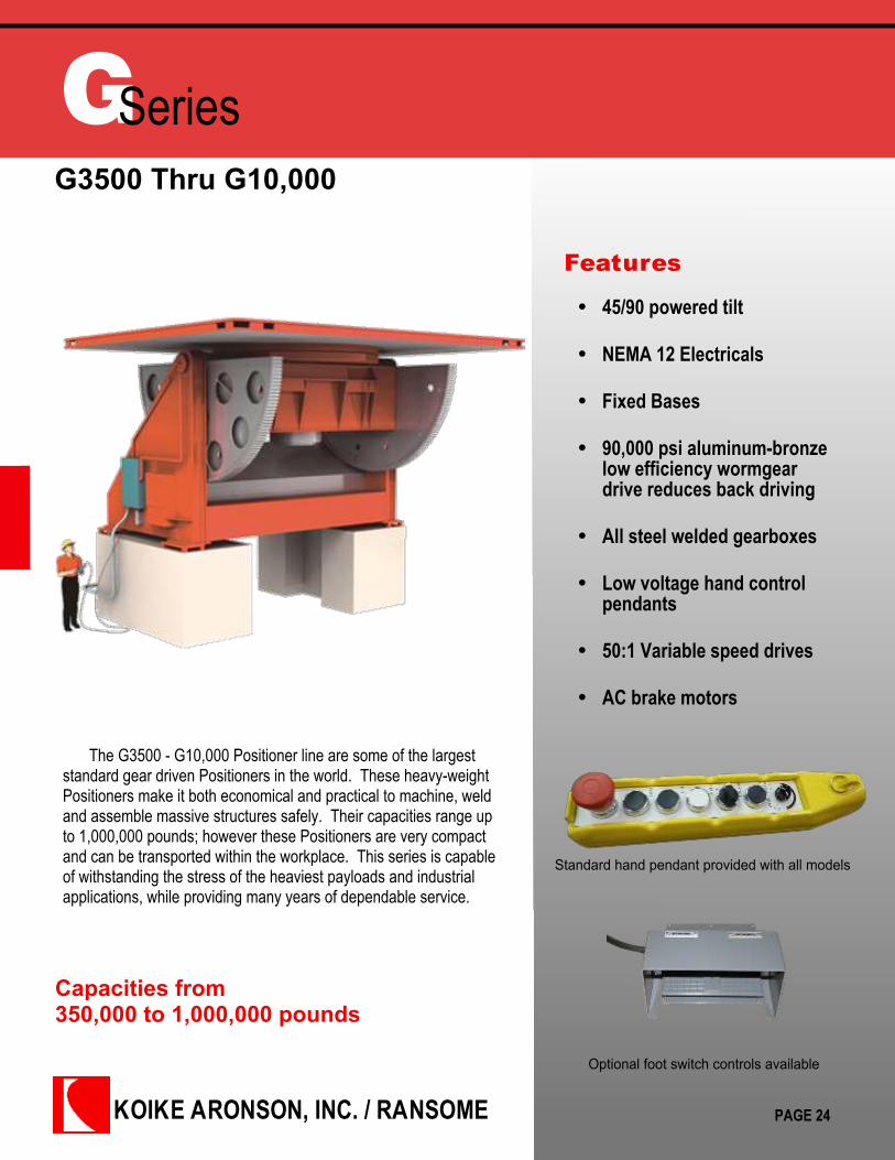
GSeriesG3500 Thru G10,000
Features
Capacities from350,000 to 1,000,000 pounds
The G3500 - G10,000 Positioner line are some of the largeststandard gear driven Positioners in the world. These heavy-weightPositioners make it both economical and practical to machine, weldand assemble massive structures safely. Their capacities range upto 1,000,000 pounds; however these Positioners are very compactand can be transported within the workplace. This series is capableof withstanding the stress of the heaviest payloads and industrialapplications, while providing many years of dependable service.
45/90 powered tilt
NEMA 12 Electricals
Fixed Bases
90,000 psi aluminum-bronzelow efficiency wormgeardrive reduces back driving
All steel welded gearboxes
Low voltage hand controlpendants
50:1 Variable speed drives
AC brake motors
PAGE 24
Standard hand pendant provided with all models
Optional foot switch controls available
Koike Aronson Inc.P.O. Box 307, Arcade, New York 14009
Phone (585) 492-2400 Fax (585) 457-3517
www.koike.com
SpecificationsG3500 - G10,000
PAGE 25
***All dimensions are for reference only and subject to change without notice.
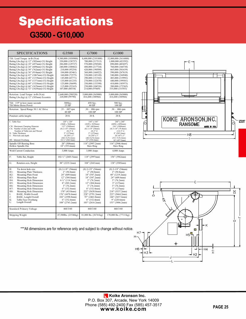
SPECIFICATIONS G3500 G7000 G1000Tilt: Load Torque in-lb (N.m)Rating Lbs.(kg) @ 12” (305mm) CG HeightRating Lbs.(kg) @ 18” (457mm) CG HeightRating Lbs.(kg) @ 24” (609mm) CG HeightRating Lbs.(kg) @ 30” (762mm) CG HeightRating Lbs.(kg) @ 36” (914mm) CG HeightRating Lbs.(kg) @ 42” (1067mm) CG HeightRating Lbs.(kg) @ 48” (1219mm) CG HeightRating Lbs.(kg) @ 54” (1371mm) CG HeightRating Lbs.(kg) @ 60” (1524mm) CG HeightRating Lbs.(kg) @ 66” (1676mm) CG HeightRating Lbs.(kg) @ 72” (1829mm) CG Height
9,300,000 (1050900)350,000 (158757)286,000 (129727)240,000 (108862)210,000 (95254)184,000 (83461)160,000 (72575)145,000 (65771)135,000 (61235)125,000 (56699)115,000 (52163)
107,000 (48534)
8,600,000 (2101800)700,000 (317515)570,000 (258548)480,000 (217724)420,000 (190509)368,000 (166922)320,000 (145149)290,000 (131542)270,000 (122470)250,000 (133398)230,000 (104326)214,000 (97069)
32,000,000 (3616000)1,000,000 (453592)
890,000 (403697)760,000 (344730)665,000 (301639)590,000 (267619)540,000 (244940)485,000 (219992)440,000 (199581)410,000 (185973)380,000 (172365)
335,000 (151953)
Rotation: Load Torque in-lb (N.m)Rating Lbs.(kg) @ 12” (305mm) Eccentric
2,640,000 (298320)220,000 (99790)
5,000,000 (565000)416,600 (188966)
5,000,000 (565000)416,600 (188966)
Tilt: 135º in how many secondsTilt Motor Horse Power
300Sec.25 HP
450 Sec.60 HP
500 Sec.100 HP
Rotation: Speed Range 50:1 AC Drive .35 - .007 rpm40 HP
.30 - .006 rpm100 HP
.30 - .006 rpm100 HP
Pendant cable length: 20 ft. 20 ft. 20 ft.
C: Table Size
CW: Maximum Clamping DiameterCX: Number of slots and width
Number of Table nuts and ThreadD: Table ThicknessE: Pilot hole and depth
DE: Inherent Overhang
120” x 120”(3048 x 3048mm)
157” (3988mm)(8) 2-1/8” (54mm)
(8) 2”-85” (127mm)18.250”x 3”
(463.5x76.2mm)14-½“ (368.3mm)
144” x 144”(3658 x 3658mm)
190” (4826mm)(8) 2-1/8” (54mm)
(8) 2”-85” (127mm)18.250”x 3”
(463.5x76.2mm)13“ (330.2mm)
240” x 240”(6096 x 6096mm)
336” (3988mm)(4) 3-1/8” (79.4mm)
(12) 3”-48” (203.2mm)
20.145”x 3”(511.7x76.2mm)18“ (457.2mm)
Spindle OD Bearing BoreHollow Spindle Dia
20” (508mm)18” (355.6mm)
118” (2997.2mm)Slew Ring
116” (2946.4mm)Slew Ring
Weld Current Conduction 3,000 Amps 3,000 Amps 4,000 Amps
F: Table flat, Height 102-½” (2603.5mm) 118” (2997mm) 156” (3962mm)
G: Rotation axis, Height 88” (2235.2mm) 104” (2641mm) 138” (3505mm)
H: Tie down hole sizeH1: Mounting Plate ThicknessH2: Mounting Plate FrontH3: Mounting Plate RearH4: Mounting Hole DimensionH5: Mounting Hole DimensionH6: Mounting Hole DimensionH7: Mounting Hole DimensionH8: Mounting Hole DimensionI: BASE, Width OverallJ: BASE, Length OverallK: Table Face OverhangL: Length Overall
(8) 2-1/8” (54mm)2” (50.8mm)
24” (609.6mm)12” (304.8mm)
4-½” (114.3mm)8” (203.2mm)3” (76.2mm)
6” (152.4mm)170” (4318mm)
176” (4470.4mm)102” (2590.8mm)
6” (152.4mm)108” (2743.2mm)
(8) 2-1/8” (54mm)2” (50.8mm)
18” (547.2mm)18” (547.2mm)
3” (76.2mm)12” (304.8mm)
3” (76.2mm)6” (152.4mm)
222” (5638.8mm)228” (5791.2mm)97” (2463.8mm)
6” (152.4mm)103” (2616.2mm)
(8) 2-1/8” (54mm)2” (50.8mm)
48” (1219.2mm)24” (609.6mm)
3” (76.2mm)5” (127mm)3” (76.2mm)5” (127mm)
218” (5537.2mm)223” (5664.2mm)144” (3657.6mm)
9” (228.6mm)153” (3886.2mm)
Standard Primary Voltage 460/3/60 460/3/60 460/3/60
Shipping Weight 47,500lbs. (21546kg) 81,000 lbs. (36741kg) 170,000 lbs. (77111kg)
KOIKE ARONSON, INC. / RANSOME
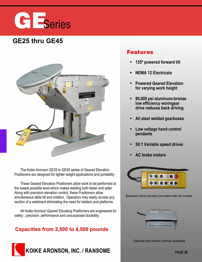
GESeriesGE25 thru GE45
Features
Capacities from 2,500 to 4,500 pounds
The Koike Aronson GE25 to GE45 series of Geared ElevationPositioners are designed for lighter weight applications and portability.
These Geared Elevation Positioners allow work to be performed atthe lowest possible level which makes welding both faster and safer.Along with precision elevation control, these Positioners allowsimultaneous table tilt and rotation. Operators may easily access anysection of a weldment eliminating the need for ladders and platforms.
All Koike Aronson Geared Elevating Positioners are engineered forsafety , precision, performance and unsurpassed durability.
135º powered forward tilt
NEMA 12 Electricals
Powered Geared Elevationfor varying work height
90,000 psi aluminum-bronzelow efficiency wormgeardrive reduces back driving
All steel welded gearboxes
Low voltage hand controlpendants
50:1 Variable speed drives
AC brake motors
PAGE 26
Standard hand pendant provided with all models
Optional foot switch controls available

Koike Aronson Inc.P.O. Box 307, Arcade, New York 14009
Phone (585) 492-2400 Fax (585) 457-3517
www.koike.com
SpecificationsGE25 - GE45
PAGE 27
SPECIFICATIONS GE25VF GE30VF GE45VFTilt: Load Torque in-lb (N.m)Rating Lbs.(kg) @ 6” (152mm) CG HeightRating Lbs.(kg) @ 12” (305mm) CG HeightRating Lbs.(kg) @ 18” (457mm) CG HeightRating Lbs.(kg) @ 24” (609mm) CG HeightRating Lbs.(kg) @ 30” (762mm) CG HeightRating Lbs.(kg) @ 36” (914mm) CG HeightRating Lbs.(kg) @ 42” (1067mm) CG HeightRating Lbs.(kg) @ 48” (1219mm) CG HeightRating Lbs.(kg) @ 54” (1371mm) CG HeightRating Lbs.(kg) @ 60” (1524mm) CG HeightRating Lbs.(kg) @ 66” (1676mm) CG HeightRating Lbs.(kg) @ 72” (1829mm) CG Height
27,500 (3108)2,500 (1134)1,600 (726)1,200 (544)950 (431)780 (354)670 (304)580 (263)520 (236)460 (209)420 (190)380 (172)350 (159)
60,750 (6864)-
3,000 (1361)2,500 (1043)1,880 (853)1,600 (726)1,375 (624)1,200 (544)1,075 (488)975 (442)890 (404)820 (372)750 (340)
91,125 (10297)-
4,500 (2041)3,500 (1587)2,800 (1270)2,400 (1089)2,050 (930)1,800 (816)1,600 (726)1,450 (658)1,300 (590)1,200 (544)1,100 (499)
Rotation: Load Torque in-lb (N.m)Rating Lbs.(kg) @ 6” (152mm) EccentricRating Lbs.(kg) @ 12” (305mm) Eccentric
15,000 (1695)2,500 (1134)1,250 (567)
36,000 (4068)-
3,000 (1361)
54,000 (6102)-
4,500 (2041)
Tilt: 135º in how many secondsTilt Motor Horse Power
19 Sec.1-½ HP
25 Sec.2 HP
25 Sec.3 HP
Rotation: Speed Range 50:1 AC DriveRotation Motor Horse Power
2.0 - .040 rpm1 HP
1.2 – .024 rpm1-½ HP
1.2 – .024 rpm2 HP
Pendant cable length: 20 ft. 20 ft. 20 ft.
C: Table SizeCW: Maximum Clamping DiameterCX: Number of slots and width
Number of Table nuts and ThreadD: Table ThicknessE: Pilot hole and depthDE: Inherent Overhang
36” Dia. (914mm)33-¾” (857)
(4) 25/32” (20mm)None1 (25)
1.500 x 1” (38.1 x 25mm)5 (127)
36”x 36” (914 x 914)47” (1194)
(4) 13/16” (21mm)(4) 3/4”-101–3/4(44)
9.126 x 1” (232 x 25)8-1/4 (209)
42”x 42” (1067 x 1067)55-½” (1410)
(4) 13/16” (21mm)(4) 3/4”-101–3/4(44)
9.126 x 1” (232 x 25)8-1/4 (209)
Spindle OD Bearing BoreHollow Spindle Dia
2-3/8 (60)1-1/2 (38)
10 (254)8-½” (216)
10 (254)8-½” (216)
Weld Current Conduction 1500 Amps 2000 Amps 2000 Amps
F: Table flat, Minimum HeightTable flat, Maximum HeightLift Stroke
35 (889)59 (1499)24” (610)
52-3/4 (1340)85-3/4 (2178)
33” (838)
52-3/4 (1340)85-3/4 (2178)
33” (838)
G: Rotation axis, Minimum HeightRotation axis, Maximum Height
30” (762)54” (1372)
44-½” (1130)77-½” (1968)
44-½” (1130)77-½” (1968)
I: Tie down hole sizeJ : Front Mounting hole locationK: Rear mounting hole locationL: Rear bolt hole pattern pitchM: Overall base lengthN: Overall Base widthO: Overall machine length
(4) 13/16” (20.6mm)1” (25)
53” (1346)41-1/2 (1054)
55 (1397)43 (1092)
68-1/2 (1740)
(4) 13/16” (20.6mm)3 (76)
73” (1854)46” (1168)79 (2007)50 (1270)
89-1/2 (2273)
(4) 13/16” (20.6mm)3 (76)
73” (1854)46” (1168)79 (2007)50 (1270)
92-1/2 (2349)
Standard Primary Voltage 460/3/60 460/3/60 460/3/60
Shipping Weight 2700 lbs. (1225 kg) 5400 lbs (2449 kg) 5622 lbs (2550)
Elevation: Constant Speed, IPM (mm/min)Elevation Motor Horse Power
34 (863)1-½ HP
30 (762)2 HP
30 (762)3 HP
***All dimensions are for reference only and subject to change without notice.
KOIKE ARONSON, INC. / RANSOME
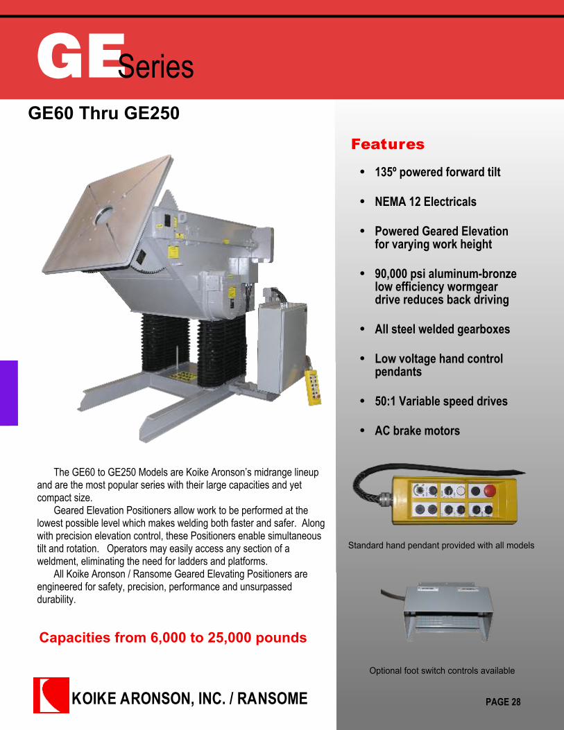
GESeriesGE60 Thru GE250
Features
Capacities from 6,000 to 25,000 pounds
The GE60 to GE250 Models are Koike Aronson’s midrange lineupand are the most popular series with their large capacities and yetcompact size.
Geared Elevation Positioners allow work to be performed at thelowest possible level which makes welding both faster and safer. Alongwith precision elevation control, these Positioners enable simultaneoustilt and rotation. Operators may easily access any section of aweldment, eliminating the need for ladders and platforms.
All Koike Aronson / Ransome Geared Elevating Positioners areengineered for safety, precision, performance and unsurpasseddurability.
135º powered forward tilt
NEMA 12 Electricals
Powered Geared Elevationfor varying work height
90,000 psi aluminum-bronzelow efficiency wormgeardrive reduces back driving
All steel welded gearboxes
Low voltage hand controlpendants
50:1 Variable speed drives
AC brake motors
PAGE 28
Standard hand pendant provided with all models
Optional foot switch controls available

Koike Aronson Inc.P.O. Box 307, Arcade, New York 14009
Phone (585) 492-2400 Fax (585) 457-3517
www.koike.com
SpecificationsGE60 - GE250
PAGE 29
SPECIFICATIONS GE60VF GE90VF GE120VF GE180VF GE250VFTilt: Load Torque in-lb (N.m)Rating Lbs.(kg) @ 6” (152mm) CG HeightRating Lbs.(kg) @ 12” (305mm) CG HeightRating Lbs.(kg) @ 18” (457mm) CG HeightRating Lbs.(kg) @ 24” (609mm) CG HeightRating Lbs.(kg) @ 30” (762mm) CG HeightRating Lbs.(kg) @ 36” (914mm) CG HeightRating Lbs.(kg) @ 42” (1067mm) CG HeightRating Lbs.(kg) @ 48” (1219mm) CG HeightRating Lbs.(kg) @ 54” (1371mm) CG HeightRating Lbs.(kg) @ 60” (1524mm) CG HeightRating Lbs.(kg) @ 66” (1676mm) CG HeightRating Lbs.(kg) @ 72” (1829mm) CG Height
123,000 (13899)-
6,000 (2721)4,650 (2109)3,790 (1719)3,200 (1451)2,750 (1247)2,400 (1089)2,200 (998)1,900 (862)1,700 (771)1,600 (726)1,500 (680)
184,500 (20848)-
9,000 (4082)7,000 (3175)5,700 (2585)4,800 (2177)4,150 (1882)3,650 (1656)3,250 (1474)2,950 (1338)2,700 (1225)2,480 (1125)2,300 (1043)
252,000 (28476)-
12,000 (5443)9,300 (4218)7,600 (3447)6,450 (2926)5,600 (2540)4,950 (2245)4,400 (1996)4,000 (1814)3,650 (1656)3,350 (1519)3,100 (1406)
369,500 (41753)-
18,000 (8165)13,900 (6304)11,350 (5148)9,600 (4354)8,300 (3765)7,300 (3311)6,500 (2948)5,900 (2676)5,400 (2449)4,950 (2245)4,600 (2086)
512,500 (57912)-
25,000 (11340)19,400 (8800)15,800 (7167)13,300 (6033)11,500 (5216)10,200 (4627)9,000 (4082)8,200 (3719)7,500 (3402)6,900 (3130)6,400 (2903)
Rotation: Load Torque in-lb (N.m)Rating Lbs.(kg) @ 6” (152mm) EccentricRating Lbs.(kg) @ 12” (305mm) Eccentric
72,000 (8136)-
6,000 (2721)
108,000 (12204)-
9,000 (4082)
144,000 (16272)-
12,000 (5443)
216,000 (24408)-
18,000 (8165)
300,000 (33900)-
25,000 (11340)
Tilt: 135º in how many secondsTilt Motor Horse Power
35 Sec.3 HP
47 Sec.3 HP
63 Sec.3 HP
47 Sec.7-½ HP
47 Sec.10 HP
Rotation: Speed Range 50:1 AC DriveRotation Motor Horse Power
1.5 - .030 rpm5 HP
1.0 - .020 rpm3 HP
0.8 - .016 rpm5 HP
0.6 - .012 rpm5 HP
0.6 - .012 rpm10 HP
Pendant cable length: 20 ft. 20 ft. 20 ft. 20 ft. 20 ft.
C: Table SizeCW: Maximum Clamping DiameterCX: Number of slots and width
Number of Table nuts and ThreadD: Table ThicknessE: Pilot hole and depthDE: Inherent Overhang
48” x 48” (1219 x 1219)64 (1626)
(4) 13/16” (21mm)(4) ¾-10
2 (51)9.126” x 1” (232 x 25)
8-½” (216)
48” x 48” (1219 x 1219)64 (1626)
(4) 13/16” (21mm)(4) ¾-10
2 (51)9.126” x 1 (232 x 25)
8-½” (216)
54” x 54” (1372 x 1372)70 (1778)
(4) 1-1/16” (27mm)(4) 1”-8
2-½” (63)9.127” x 1-½” (232 x 38)
8-½” (216)
54” x 54” (1372 x 1372)70 (1778)
(4) 1-1/16” (27mm)(4) 1”-8
2-½” (63)9.127” x 1-½” (232 x 38)
8-½” (216)
60” x 60” (1524 x 1524)79 (2007)
(4) 1-1/16” (27mm)(4) 1”-8
2-½” (63)8.625” x 1-½” (219 x 38)
8-1/2 (216)
Spindle OD Bearing BoreHollow Spindle Dia
10 (254)8-½” (216)
10 (254)9 (229)
10 (254)9 (229)
10 (254)9 (229)
10 (254)8-1/2 (216)
Weld Current Conduction 2,000 Amps 2,000 Amps 2,000 Amps 2,000 Amps 2,000 Amps
F: Table flat, Minimum HeightLift StrokeTable flat, Maximum Height
55” (1397mm)32-½” (826mm)
87-½” (2222mm)
54-¼” (1384mm)33” (838mm)
87-½” (2222mm)
55-½” (1410mm)32-½” (826mm)88” (2235mm)
55-½” (1410mm)32-½” (826mm)88” (2235mm)
57-½” (1460mm)33” (838mm)
90-½” (2299mm)
G: Rotation axis, Minimum HeightRotation axis, Maximum Height
46-½” (1181mm)79” (2007mm)
46” (1168mm)79” (2007mm)
47” (826mm)79-½” (2019mm)
47” (826mm)79-½” (2019mm)
49” (1245mm)82” (2083mm)
I: Tie down hole sizeJ: Front Mounting hole locationK: Rear mounting hole locationL: Rear bolt hole pattern pitchM: Overall base lengthN: Overall Base withO: Overall machine length
(4) 13/16” (21mm)3” (76mm)
74” (1880mm)41” (1041mm)80” (2032mm)44” (1118mm)
96-5/8” (2454mm)
(4) 13/16” (21mm)3” (76mm)
74” (1880mm)41” (1041mm)80” (2032mm)44” (1118mm)
96-5/8” (2454mm)
(4) 1–1/8” (28mm)3” (76mm)
74” (1880mm)47” (1194mm)80” (2032mm)54” (1372mm)
101-½” (2578mm)
(4) 1 1/8” (28mm)3” (76mm)
74” (1880mm)47” (1194mm)80” (2032mm)54” (1372mm)
100” (2540mm)
(4) 1 1/16” (27mm)3-3/8” (86mm)
89 ½” (2273mm)80” (2032mm)
94-½” (2400mm)88-½” (2248mm)133” (3378mm)
Standard Primary Voltage 460/3/60 460/3/60 460/3/60 460/3/60 460/3/60
Shipping Weight 7670 lbs. (3479kg) 7700 lbs. (3492kg) 9500 lbs. (4309kg) 9,960 lbs. (4518kg) 17,520 lbs. (7946kg)
Elevation: Constant Speed, IPM (mm/min)Elevation Motor Horse Power
24 (610)3 HP
21 (533)3 HP
18 (457)5 HP
24 (610)7-½ HP
20 (508)10 HP
***All dimensions are for reference only and subject to change without notice.

KOIKE ARONSON, INC. / RANSOME
GESeriesGE500 Thru GE3500
Features
Capacities from 50,000 to 350,000 pounds
The GE500 to GE3500 Models offer the largest capacities andrange of elevations in the line of Koike Aronson Positioners.
Geared Elevation Positioners allow work to be performed at thelowest possible level which makes welding both faster and safer.Along with precision elevation control, these Positioners enablesimultaneous tilt and rotation. Operators may easily access anysection of a weldment, eliminating the need for ladders andplatforms.
All Koike Aronson / Ransome Geared Elevating Positioners areengineered for safety, precision, performance and unsurpasseddurability.
135º powered forward tilt
NEMA 12 Electricals
Powered Geared Elevationfor varying work height
90,000 psi aluminum-bronzelow efficiency wormgeardrive reduces back driving
All steel welded gearboxes
Low voltage hand controlpendants
50:1 Variable speed drives
AC brake motors
PAGE 30
Standard hand pendant provided with all models
Optional foot switch controls available

Koike Aronson Inc.P.O. Box 307, Arcade, New York 14009
Phone (585) 492-2400 Fax (585) 457-3517
www.koike.com
SpecificationsGE500 - GE3500
PAGE 31
SPECIFICATIONS GE500VF GE850VF GE1200VF GE3500VFTilt: Load Torque in-lb (N.m)Rating Lbs.(kg) @ 12” (305mm) CG HeightRating Lbs.(kg) @ 18” (457mm) CG HeightRating Lbs.(kg) @ 24” (609mm) CG HeightRating Lbs.(kg) @ 30” (762mm) CG HeightRating Lbs.(kg) @ 36” (914mm) CG HeightRating Lbs.(kg) @ 42” (1067mm) CG HeightRating Lbs.(kg) @ 48” (1219mm) CG HeightRating Lbs.(kg) @ 54” (1371mm) CG HeightRating Lbs.(kg) @ 60” (1524mm) CG HeightRating Lbs.(kg) @ 66” (1676mm) CG HeightRating Lbs.(kg) @ 72” (1829mm) CG Height
1,050,000 (118650)50,000 (22680)39,000 (17690)32,000 (14515)27,000 (12247)23,400 (10614)20,600 (9344)18,500 (8391)16,700 (7575)15,200 (6895)14,000 (6350)13,000 (5896)
1,800,000 (203400)85,000 (38950)66,100 (30014)54,091 (24557)45,769 (20779)39,667 (18009)35,000 (15890)31,316 (14217)28,333 (12863)25,870 (11745)23,800 (10805)22,000 (9979)
2,880,000 (325440)120,000 (54431)96,000 (43545)80,000 (36287)68,600 (31116)60,000 (27215)53,400 (24222)48,000 (21772)43,600 (19777)40,000 (18144)37,000 (16783)34,200 (15513)
9,300,000 (1050900)350,000 (158757)286,000 (129727)240,000 (108862)210,000 (95254)184,000 (83461)160,000 (72575)145,000 (65771)135,000 (61235)125,000 (56699)115,000 (52163)107,000 (48534)
Rotation: Load Torque in-lb (N.m)Rating Lbs.(kg) @ 12” (305mm) Eccentric
600,000 (67800)50,000 (22680)
1,020,000 (115260)85,000 (38555)
1,440,000 (162780)120,000 (54431)
2,640,000 (298320)220,000 (99790)
Tilt: 135º in how many secondsTilt Motor Horse Power
67 Sec.15 HP
140 Sec.15 HP
156 Sec.25 HP
300 Sec.25 HP
Rotation: Speed Range 50:1 AC DriveRotation Motor Horse Power
0.50 - .010 rpm15 HP
0.40 - .008 rpm20 HP
0.40 - .008 rpm25 HP
0.35 - .007 rpm40 HP
Pendant cable length: 20 ft. 20 ft. 20 ft. 20 ft.
C: Table SizeCW: Maximum Clamping DiameterCX: Number of slots and width
Number of Table nuts and ThreadD: Table ThicknessE: Pilot hole and depthDE: Inherent Overhang
84” x 84” (2134x2134mm)112” (2845mm)
(4) 1 5/16” (33mm)(4) 1 ¼” -7
2-¾ “ (70mm)12.253”x1-¾” (311”x45mm)
8-¾ “ (222mm)
96” x 96” (3048x3048mm)128” (3251mm)
(8) 1 5/8” (41mm)(8) 1 ½” -123“ (76mm)
12.255”x1 3/8”9 “ (229mm)
120” x 120” (3048x3048mm)159” (4039mm)
(8) 1 7/8 ” (48mm)(8) 1 ¾” -125“ (127mm)
12.255”x1”12“ (305mm)
168” x 168” (4267x4267mm)224” (5690mm)
(8) 2 1/8” (54mm)(8) 2” -8
5-½“ (140mm)20.000”x3”
14-½“ (368mm)
Spindle OD Bearing BoreHollow Spindle Dia
14” (356mm)11-7/8” (301)
14” (356mm)11-7/8” (301)
14&20” (356 & 508mm)11/7/8” (301)
100” (2540mm) O.D.Slew Ring
Weld Current Conduction 3,000 Amps 3,000 Amps 3,000 Amps 3,000 Amps
F: Table flat, Minimum HeightLift StrokeTable flat, Maximum Height
58-½” (1486mm)33” (838mm)
94-½” (2400mm)
82” (2083mm)54” (1372mm)
136” (3454mm)
98” (2489mm)54” (1372mm)152” (3861mm)
144” (3658mm)92” (2337mm)
236” (5994mm)
G: Rotation axis, Minimum HeightRotation axis, Maximum Height
52-¾” (1340mm)85-¾” (2178mm)
73” (1854mm)127” (3226mm)
86” (2184mm)140” (3556mm)
129-½” (3289mm)221-½” (5626mm)
I: Tie down hole sizeJ: Front Mounting hole locationK: Rear mounting hole locationL: Rear bolt hole pattern pitchM: Overall base lengthN: Overall Machine widthO: Overall machine length
(2) 1-1/16” (27)None
96” (2438mm)98-½” (2501mm)98-¼” (2495mm)127-½” (3238mm)134-¾” (3423mm)
NoneNoneNoneNone
148 ¾” (3778mm)137 ½” (3492mm)196-¾” (4997mm)
NoneNoneNoneNone
148 ¾” (3778mm)141 ½” (3594mm)209” (5309mm)
NoneNoneNoneNone
297” (7544mm)184” (4674mm)363” (9220mm)
Standard Primary Voltage 460/3/60 460/3/60 460/3/60 460/3/60
Shipping Weight 30,819 lbs. (13979kg) 41,000 lbs. (18597kg) 53,000 lbs. (24040kg) 234,000 lbs. (106141kg)
Elevation: Constant Speed, IPM (mm/min)Elevation Motor Horse Power
20 (508)20 HP
17 (432)25 HP
15 (381)40 HP
10 (254)150 HP
***All dimensions are forreference only and subject tochange without notice.

KOIKE ARONSON, INC. / RANSOME
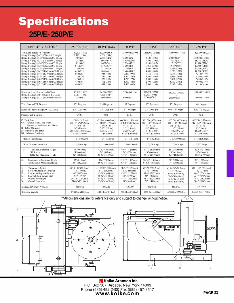
PESeries25P/E thru 250P/E
Features
Capacities from 2,500 to 25,000 pounds
The 25/PE - 250/PE series Positioners provide all of the samebenefits of the GE models but at a more affordable cost. The Powered Elevation design makes maximum use of provencommercially available components, both in the elevation and guidancesystems.
Elevation is made possible by means of commercial ball screwjacks for high duty cycle operation, driven by a worm/wormgeararrangement. Elevation uses two of these screw jacks for redundancy,coupled together and driven by a common motor. Belts, chains, andtransfer gears are no longer utilized in the design.
Guidance is by means of wide, large diameter cam followersbearing on flat guide-ways. Cam follower contact with the guide-waysis adjustable for wear. Guidance is provided in the front, back, and atthe sides of two columns that rigidly support the cantilevered load.
135º powered forward tilt
NEMA 12 Electricals
Powered Screw JackElevation
High capacity mechanicalgrounding shoes
Spur gear final drive on tiltand rotation axis
Low voltage hand controlpendants
50:1 Variable speed drives
AC brake motors
PAGE 32
Standard hand pendant provided with all models
Optional foot switch controls available
Koike Aronson Inc.P.O. Box 307, Arcade, New York 14009
Phone (585) 492-2400 Fax (585) 457-3517
www.koike.com
Specifications25P/E- 250P/E
PAGE 33
SPECIFICATIONS 25 P/E (6x6) 40 P/E (6x6) 60 P/E 100 P/E 200 P/ETilt: Load Torque in-lb (N.m)Rating Lbs.(kg) @ 6” (152mm) CG HeightRating Lbs.(kg) @ 12” (305mm) CG HeightRating Lbs.(kg) @ 18” (457mm) CG HeightRating Lbs.(kg) @ 24” (609mm) CG HeightRating Lbs.(kg) @ 30” (762mm) CG HeightRating Lbs.(kg) @ 36” (914mm) CG HeightRating Lbs.(kg) @ 42” (1067mm) CG HeightRating Lbs.(kg) @ 48” (1219mm) CG HeightRating Lbs.(kg) @ 54” (1371mm) CG HeightRating Lbs.(kg) @ 60” (1524mm) CG HeightRating Lbs.(kg) @ 66” (1676mm) CG HeightRating Lbs.(kg) @ 72” (1829mm) CG Height
30,000 (3390)2,500 (1134)1,700 (771)1,285 (583)1,035 (469)875 (397)750 (340)650 (295)580 (263)520 (236)470 (213)430 (195)400 (181)
52,000 (5876)4,000 (1814)2,737 (1242)2,080 (944)1,677 (761)1,405 (637)1,210 (549)1,061 (481)945 (428)852 (386)776 (352)712 (323)658 (298)
126,000 (13899)-
6,000 (2721)4,650 (2109)3,790 (1719)3,200 (1451)2,750 (1247)2,400 (1089)2,200 (998)1,900 (862)1,700 (771)1,600 (726)1,500 (680)
215,000 (23166)-
9,500 (4309)7,500 (3402)6,200 (2812)5,250 (2381)4,600 (2086)4,050 (1837)3,650 (1656)3,300 (1497)3,000 (1361)2,700 (1225)2,500 (1134)
420,000 (47460)-
20,000 (9071)15,555 (7055)12,727 (5772)10,769 (4884)9,333 (4233)8,235 (3735)7,368 (3342)6,666 (3023)6,087 (2761)5,600 (2450)5,185 (2351)
Rotation: Load Torque in-lb (N.m)Rating Lbs.(kg) @ 6” (152mm) EccentricRating Lbs.(kg) @ 12” (305mm) Eccentric
15,000 (1695)2,500 (1134)1,250 (567)
24,000 (2712)4,000 (1814)2,000 (907)
72,000 (8136)-
6,000 (2721)
240,000 (27120) -20,000 (9071)
Tilt: Forward Tilt Degrees 135 Degrees 135 Degrees 135 Degrees 135 Degrees 135 Degrees
Rotation: Speed Range 50:1 AC Drive 1.5 - .030 rpm 1.24 - .025 rpm 1.0 - .020 rpm 0.8—.016 rpm 0.49—.010 rpm
Pendant cable length: 20 ft. 20 ft. 20 ft. 20 ft. 20 ft.
C: Table SizeCX: Number of slots and width
Number of Table nuts and ThreadD: Table ThicknessE: Pilot hole and depthDE: Inherent Overhang
32” Dia. (812mm)(4) 11/16” (17.5mm)
(4) 5/8”-11¾”“ (19mm)
4.250”x ¼” (108”x6mm)6 “ (152.4mm)
42” Dia. (1067mm)(4) 11/16” (17.5mm)
(4) 5/8”-117/8”“ (22mm)
4.625”x 5/16”7” (178mm)
60” Dia. (1524mm)(4) 1-1/8” (28.5mm)
(4) 1”-12¾”“ (19mm)6.250”x 1/2”
10-¼” (260mm)
60” Dia. (1524mm)(4) 1-1/8” (28.5mm)
(4) 1”-12¾”“ (19mm)9.125”x 3/8”
10-5/8” (270mm)
60” Dia. (1524mm)(4) 1-1/8” (28.5mm)
(4) 1”-12 ¾”“ (19mm)
10.250”x 1/2”9” (228.6mm)
Hollow Spindle Dia 2” (50.8mm) 2” (50.8mm) 6” (152.4mm) 6” (152.4mm) 7-½” (190.5mm)
Weld Current Conduction 1,500 Amps 1,500 Amps 2,000 Amps 2,000 Amps 2,000 Amps
F: Table flat, Minimum HeightLift StrokeTable flat, Maximum Height
38” (965mm)24” (609mm)62” (1575mm)
42-½” (1080mm)24” (609mm)
66-½” (1689mm)
49-¾” (1263mm)24” (609mm)
73-¾” (1873mm)
69-¼” (1759mm)26” (660mm)
95-¼” (2419mm)
59” (1499mm)24” (610mm)
83” (2108mm)
G: Rotation axis, Minimum HeightRotation axis, Maximum Height
32” (813mm)56” (1422mm)
35-½” (902mm)59-½” (1511mm)
39-½” (1003mm)63-½” (1613mm)
58-5/8” (1489mm)84-5/8” (2150mm)
50” (1270mm)74” (1880mm)
I: Tie down hole sizeJ: Front Mounting hole locationK: Rear mounting hole locationL: Rear bolt hole pattern pitchM: Overall base lengthN: Overall Base with
(6) 1-1/8” (28.5mm)3-½” (89mm)44” (1117mm)9-¾” - 19-½”
50-7/8” (1292mm)51-¾” (1315mm)
(4) 13/16” (20.6mm)1-½” (38.1mm)
65-½” (1663mm)60-¼” (1530mm)68-½” (1740mm)63-¾” (1620mm)
(4) 7/8” (22.2mm)3-½” (89mm)
83-¾” (2127mm)55” (1397mm)
88-¼” (2242mm)59” (1499mm)
(4) 7/8” (22.2mm)3-½” (89mm)
83-¾” (2127mm)55” (1397mm)
88-¼” (2242mm)59” (1499mm)
(4) 1-1/8” (28.5mm)1-½” (38mm)
80-½” (2045mm)66-½” (1689mm)83-½” (2121mm)76-½” (1943mm)
Standard Primary Voltage 460/3/60 460/3/60 460/3/60 460/3/60 460/3/60
Shipping Weight 2700 lbs. (1225kg) 4000 lbs. (1814kg) 6500lbs. (2948kg) 10761 lbs. (4881kg) 16,700 lbs. (7575kg)
250 P/E525,000 (59325)
-25,000 (11340)19,445 (8820)15,910 (7216)13,460 (6105)11,600 (5261)10,300 (4672)9,210 (4177)8,300 (3764)7,600 (3447)7,000 (3175)3,110 (1410)
300,000 (33900)-
25,000 (11340)
135 Degrees
0.49—.010 rpm
20 ft.
60” Dia. (1524mm)(4) 1-1/8” (28.5mm)
(4) 1”-121“ (25mm)
10.250”x 1/8”9” (228.6mm)
7-½” (190.5mm)
2,000 Amps
62.5” (1588mm)24” (610mm)
86.5” (2197mm)
50” (1270mm)74” (1880mm)
(4) 1-1/8” (28.5mm)1-½” (38mm)
80-½” (2045mm)66-½” (1689mm)83-½” (2121mm)76-½” (1943mm)
460/3/60
17,000 lbs. (7711kg)
***All dimensions are for reference only and subject to change without notice.
120,000 (13560)10,000 (4535)9,500 (4309)
KOIKE ARONSON, INC. / RANSOME
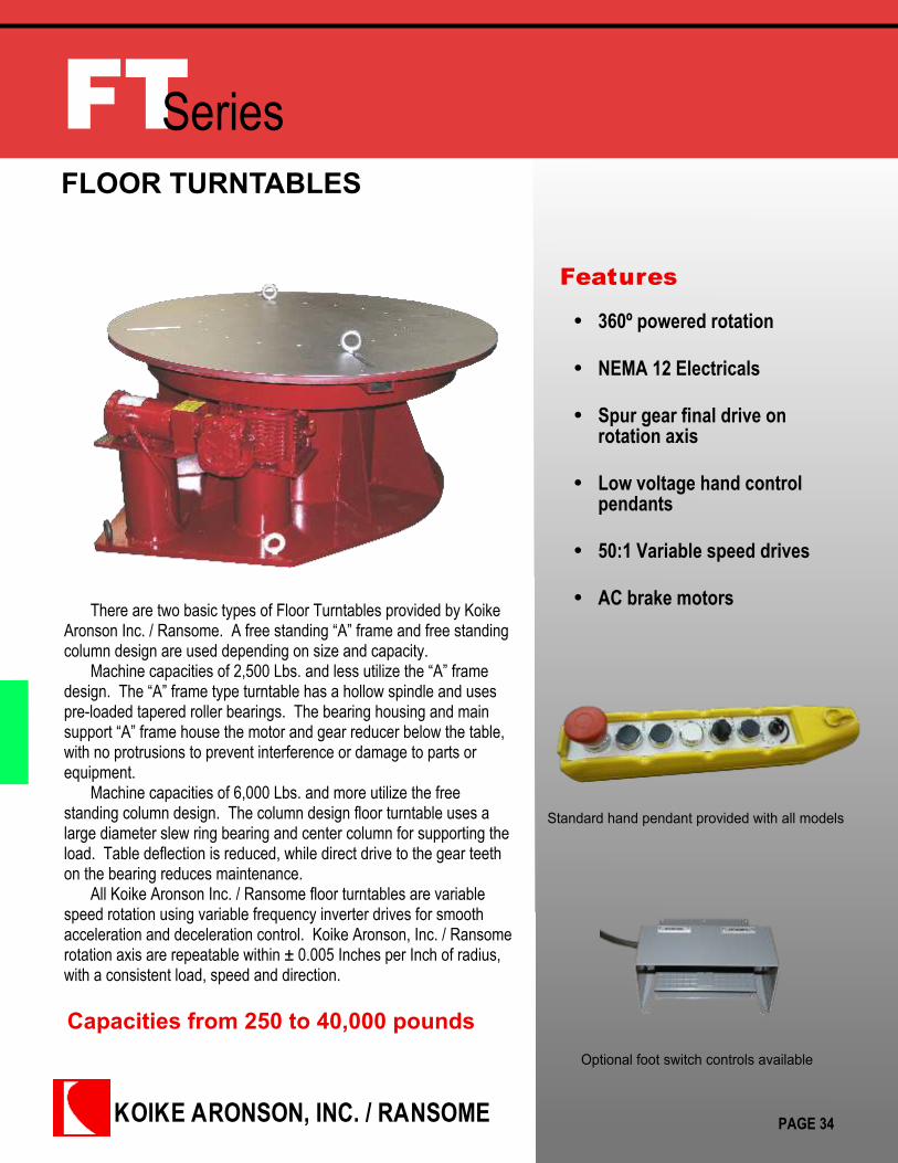
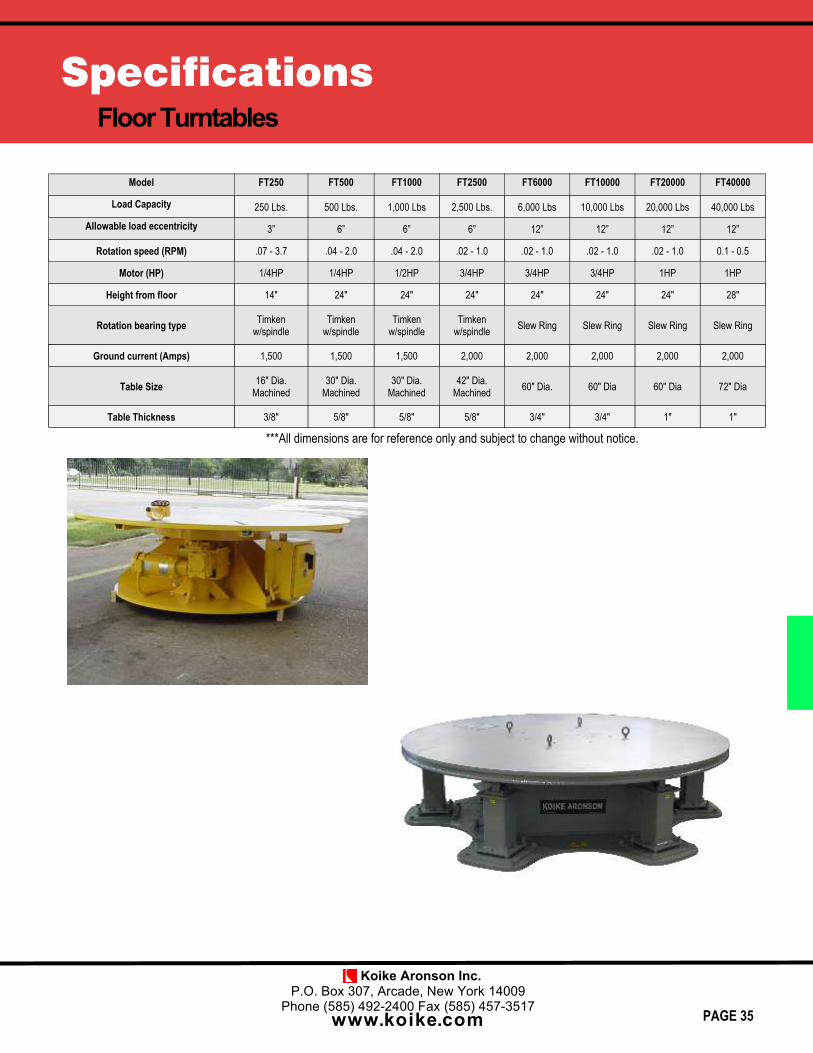
FTSeriesFLOOR TURNTABLES
Features
Capacities from 250 to 40,000 pounds
There are two basic types of Floor Turntables provided by KoikeAronson Inc. / Ransome. A free standing “A” frame and free standingcolumn design are used depending on size and capacity.
Machine capacities of 2,500 Lbs. and less utilize the “A” framedesign. The “A” frame type turntable has a hollow spindle and usespre-loaded tapered roller bearings. The bearing housing and mainsupport “A” frame house the motor and gear reducer below the table,with no protrusions to prevent interference or damage to parts orequipment.
Machine capacities of 6,000 Lbs. and more utilize the freestanding column design. The column design floor turntable uses alarge diameter slew ring bearing and center column for supporting theload. Table deflection is reduced, while direct drive to the gear teethon the bearing reduces maintenance.
All Koike Aronson Inc. / Ransome floor turntables are variablespeed rotation using variable frequency inverter drives for smoothacceleration and deceleration control. Koike Aronson, Inc. / Ransomerotation axis are repeatable within ± 0.005 Inches per Inch of radius,with a consistent load, speed and direction.
360º powered rotation
NEMA 12 Electricals
Spur gear final drive onrotation axis
Low voltage hand controlpendants
50:1 Variable speed drives
AC brake motors
PAGE 34
Standard hand pendant provided with all models
Optional foot switch controls available
Koike Aronson Inc.P.O. Box 307, Arcade, New York 14009
Phone (585) 492-2400 Fax (585) 457-3517
www.koike.com
Floor TurntablesSpecifications
PAGE 35
Model FT250 FT500 FT1000 FT2500 FT6000 FT10000 FT20000 FT40000
Load Capacity 250 Lbs. 500 Lbs. 1,000 Lbs 2,500 Lbs. 6,000 Lbs 10,000 Lbs 20,000 Lbs 40,000 Lbs
Allowable load eccentricity 3” 6” 6” 6” 12” 12” 12” 12”
Rotation speed (RPM) .07 - 3.7 .04 - 2.0 .04 - 2.0 .02 - 1.0 .02 - 1.0 .02 - 1.0 .02 - 1.0 0.1 - 0.5
Motor (HP) 1/4HP 1/4HP 1/2HP 3/4HP 3/4HP 3/4HP 1HP 1HP
Height from floor 14" 24" 24" 24" 24" 24" 24" 28"
Rotation bearing type Timkenw/spindle
Timkenw/spindle
Timkenw/spindle
Timkenw/spindle Slew Ring Slew Ring Slew Ring Slew Ring
Ground current (Amps) 1,500 1,500 1,500 2,000 2,000 2,000 2,000 2,000
Table Size 16" Dia.Machined
30" Dia.Machined
30" Dia.Machined
42" Dia.Machined 60" Dia. 60" Dia 60" Dia 72" Dia
Table Thickness 3/8" 5/8" 5/8" 5/8" 3/4" 3/4" 1" 1"
***All dimensions are for reference only and subject to change without notice.
KOIKE ARONSON, INC. / RANSOME
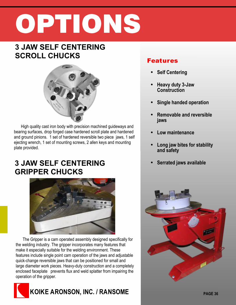
OPTIONS3 JAW SELF CENTERINGSCROLL CHUCKS
Features
High quality cast iron body with precision machined guideways andbearing surfaces, drop forged case hardened scroll plate and hardenedand ground pinions. 1 set of hardened reversible two piece jaws, 1 selfejecting wrench, 1 set of mounting screws, 2 allen keys and mountingplate provided.
Self Centering
Heavy duty 3-JawConstruction
Single handed operation
Removable and reversiblejaws
Low maintenance
Long jaw bites for stabilityand safety
Serrated jaws available
PAGE 36
3 JAW SELF CENTERINGGRIPPER CHUCKS
The Gripper is a cam operated assembly designed specifically forthe welding industry. The gripper incorporates many features thatmake it especially suitable for the welding environment. Thesefeatures include single point cam operation of the jaws and adjustablequick-change reversible jaws that can be positioned for small andlarge diameter work pieces. Heavy-duty construction and a completelyenclosed faceplate prevents flux and weld splatter from impairing theoperation of the gripper.

Koike Aronson Inc.P.O. Box 307, Arcade, New York 14009
Phone (585) 492-2400 Fax (585) 457-3517
www.koike.com
OPTIONS
PAGE 37
Size InsideClampRange
OutsideClamp Range
D F E d C H h ThreadM
WeightLbs.
MountPlate/Lbs
3JC6 1.65-5.75 .12-6.30 6-1/4” 5.511” 4.921” 1.653” .1575” 2.539” 1.693” M10 (3) 22 .75x8 Dia11 Lbs.
3JC12 2.56-10.43 .39-12.40 12-1/2” 11.26” 10.24” 4.055” .1969” 3.701” 2.244” M16 (6) 1211”X14.38Dia / 28
Lbs.
3JC25 5.51-23.23 1.18-24.80 25” 13.00” 16.03” 9.92” 1.18” 5.905” 3.42” ¾-10 (6) 6301”X28
Dia / 175Lbs.
SCROLL TYPE
GRIPPER TYPE
***All dimensions are for reference only and subject to change without notice.
Model ClampRangeinches
InsideClampRangeinches
OutsideClampRangeinches
LoadCapacity
Lbs.
WeightLbs.
Dimensions
A B C33 1.75” - 31.25” 5.25”- 31.25” 1.75” - 27.75” 3000 228 18” 7” 19-5/16”
44 1.75” - 44” 5.25” - 44” 1.75” - 40.5” 3000 305 23-1/2” 7” 19-5/16”63 3.5” - 62.5” 7” - 62.5” 3.5” - 59” 7500 722 34-13/16” 8-1/8” 26-3/4”
***All dimensions are for reference only and subject to change without notice.
KOIKE ARONSON, INC. / RANSOME
OPTIONS
Features
Self Centering
Heavy duty 3-JawConstruction
Quick lock handles
Low maintenance
Light weight for smallcapacity Positioners
PAGE 38
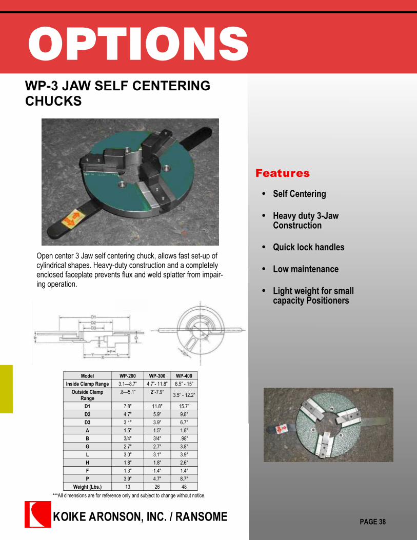
WP-3 JAW SELF CENTERINGCHUCKS
Open center 3 Jaw self centering chuck, allows fast set-up ofcylindrical shapes. Heavy-duty construction and a completelyenclosed faceplate prevents flux and weld splatter from impair-ing operation.
Model WP-200 WP-300 WP-400Inside Clamp Range 3.1—8.7” 4.7”- 11.8” 6.5” - 15”
Outside ClampRange
.8—5.1” 2”-7.9” 3.5” - 12.2”
D1 7.8" 11.8" 15.7"D2 4.7" 5.9" 9.8"D3 3.1" 3.9" 6.7"A 1.5" 1.5" 1.8"B 3/4" 3/4" .98"G 2.7" 2.7" 3.8"L 3.0" 3.1" 3.9"H 1.8" 1.8" 2.6"F 1.3" 1.4" 1.4"P 3.9" 4.7" 8.7"
Weight (Lbs.) 13 26 48***All dimensions are for reference only and subject to change without notice.
OPTIONSBy the nature of design and function, the majority of optional equipment for Koike Aronson / Ransome Positioners
should be installed at the time of manufacture. When ordering Positioners, it is therefore important to consider all optionalfeatures and equipment.
:
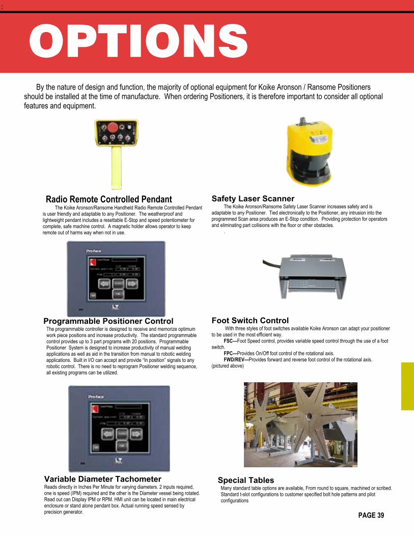
Radio Remote Controlled PendantThe Koike Aronson/Ransome Handheld Radio Remote Controlled Pendant
is user friendly and adaptable to any Positioner. The weatherproof andlightweight pendant includes a resettable E-Stop and speed potentiometer forcomplete, safe machine control. A magnetic holder allows operator to keepremote out of harms way when not in use.
Programmable Positioner ControlThe programmable controller is designed to receive and memorize optimumwork piece positions and increase productivity. The standard programmablecontrol provides up to 3 part programs with 20 positions. ProgrammablePositioner System is designed to increase productivity of manual weldingapplications as well as aid in the transition from manual to robotic weldingapplications. Built in I/O can accept and provide “In position” signals to anyrobotic control. There is no need to reprogram Positioner welding sequence,all existing programs can be utilized.
Variable Diameter TachometerReads directly in Inches Per Minute for varying diameters. 2 inputs required,one is speed (IPM) required and the other is the Diameter vessel being rotated.Read out can Display IPM or RPM. HMI unit can be located in main electricalenclosure or stand alone pendant box. Actual running speed sensed byprecision generator.
Safety Laser ScannerThe Koike Aronson/Ransome Safety Laser Scanner increases safety and is
adaptable to any Positioner. Tied electronically to the Positioner, any intrusion into theprogrammed Scan area produces an E-Stop condition. Providing protection for operatorsand eliminating part collisions with the floor or other obstacles.
.
Foot Switch Control With three styles of foot switches available Koike Aronson can adapt your positioner
to be used in the most efficient way.FSC—Foot Speed control, provides variable speed control through the use of a foot
switch.FPC—Provides On/Off foot control of the rotational axis.FWD/REV—Provides forward and reverse foot control of the rotational axis.
(pictured above)
Special TablesMany standard table options are available, From round to square, machined or scribed.Standard t-slot configurations to customer specified bolt hole patterns and pilotconfigurations
PAGE 39
KOIKE ARONSON, INC. / RANSOME635 West Main Street
P.O. Box 307,
Arcade, New York 14009
Phone (585) 492-2400
Fax (585) 457-3517
Toll Free: 800-252-5232
www.koike.com
Contact Koike Aronson’s World Wide Positioner Sales:
1-585-492-2400 x 480
CUTTING, POSITIONING & WELDING EQUIPMENT
CATALOG: POSITIONERS 08/13 REV 2
larrypope