Admission in Pediatrics India, South India, North India, West India, East India

GAIL (India) Limited (A Govt. of India Undertaking)
A Navratna Company NEW DELHI, INDIA
KOCHI-KOOTTANAD-BANGALORE-MANGALORE PIPELINE PROJECT
BID DOCUMENT
OF
UPS SYSTEM
OPEN DOMESTIC COMPETITIVE BIDDING
E-Tender no. 8000002191
Bid Document No.: 05/51/23M3(PH-1)/GAIL/071
VOLUME – II OF II
PREPARED AND ISSUED BY
MECON LIMITED (A Govt. of India Undertaking)
Delhi, India
GAIL (India) Ltd
KOCHI-KOTTANAD- BANGALORE –MANGALORE
GAS PIPELINE PROJECT- PHASE-I (FROM KOCHI TO ALWAYE) 30”/18” x44.0 KM (APPROX)
MECON LTD., DELHI
TABLE OF CONTENTS
Sl. No. DESCRIPTION
1. SCOPE OF WORK
2. SPECIFICATION OF UPS SYSTEM
2.1. STANDARD SPECIFICATION OF UPS
2.2. DATA SHEET
2.3 CHECKLIST
2.4. QAP
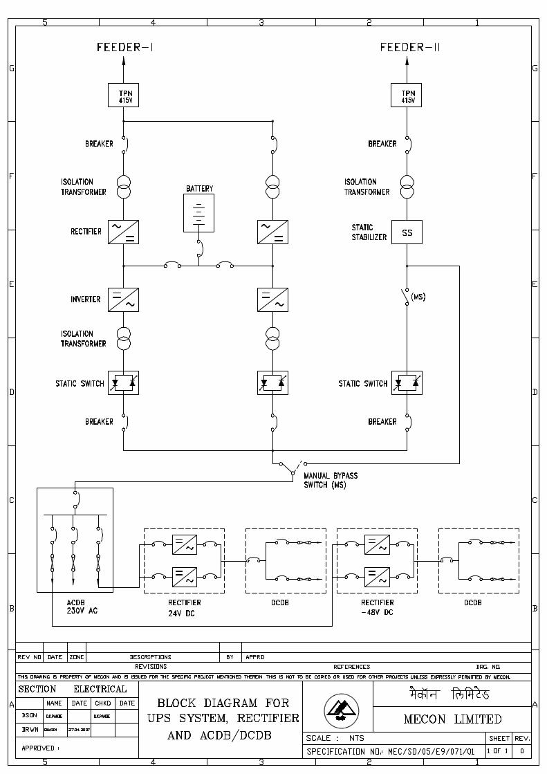
2.5. BLOCK DIAGRAM
3. SCHEDULE OF QUANTITY

SCOPE OF WORKS
FOR
UPS SYSTEM
KOCHI-KOTTANAD- BANGALORE –MANGALORE RLNG GAS PIPELINE PROJECT- PHASE-I
(FROM KOCHI TO ALWAYE) 30”/18” x44.0 KM (APPROX)
DOCUMENT NO. - MEC/23M3/05/E9/E/000/0002, R-0
(ELECTRICAL SECTION) MECON LIMITED DELHI 110 092
OIL & GAS SBU
KOCHI-KOTTANAD- BANGALORE –MANGALORE RLNG GAS PIPELINE PROJECT- PHASE-I
GAIL (India) Ltd MECON LTD, DELHI
DOCUMENT NO. Page 1 of 8 TITLE SCOPE OF WORK (ELECTRICAL)
MEC/23M3/05/E9/E/000/0002 REVISION 0
CONTENT
Sl. No. Description
1 GENERAL
2 SCOPE
3 OTHER MISCELLANEOUS WORK
4 AREA CLASSIFICATION
5 JOB SPECIFICATION
6 MAKES OF EQUIPMENTS AND MATERIALS
7 QUALITY ASSURANCE, INSPECTION AND TESTING
8 TESTING & COMMISSIONING
9 DRAWINGS, STANDARD SPECIFICATIONS AND INSTALLATION STANDARDS
10 LOCATION OF UPS SYSTEM
PREPARED BY:
(Aashish Moyal)
CHECKED BY:
(Saurabh Singh)
APPROVED BY:
(D.K. Pande)
ISSUE DATE :
June- 2010
OIL & GAS SBU
KOCHI-KOTTANAD- BANGALORE –MANGALORE RLNG GAS PIPELINE PROJECT- PHASE-I
GAIL (India) Ltd MECON LTD, DELHI
DOCUMENT NO. Page 2 of 8 TITLE SCOPE OF WORK (ELECTRICAL)
MEC/23M3/05/E9/E/000/0002 REVISION 0
1.0 GENERAL 1.1 Introduction
The intent of this specification is to define the requirements for the Design, manufacture, testing at works, supply, storage, Installation, earthing, commissioning and performance test at site of UPS (uninterruptible power supply) other equipments & materials (as required). The work shall be carried out in the best workmanship – like manner, in conformity with these specifications, approved drawings and the instructions of the Engineer-in-charge from time to time. The contract shall include clearing of temporary construction, waste materials and loose earth, which might get collected in and nearby the work site consequent of the execution of work under this contract.
1.2 Standards The work shall be performed in conformity with, standard specifications and installation standards enclosed and code of practices of the Bureau of India Standards. In case of any conflict, the stipulations under this specification shall govern. In addition, the work shall also conform to the requirements of the following: The Indian Electricity Act and the rules framed there under The fire Insurance Regulations The regulations lay down by the Chief Electrical Inspector of the state government / Central Electricity Authority (CEA). The regulations lay down by the Factory Inspector. The regulations lay down by the Chief Inspector of Explosives. Any other regulations lay down by the Central, State or Local Authorities from time to time during the pendency of this contract.
1.3 Guarantee
The contractor shall guarantee the installation against any defects of workmanship for a period of 12 months & 18 months for materials (supplied by the contractor) from the date of commissioning. Any damage or defects connected with the erection of materials, equipments or fittings supplied by the contractor that may be undiscovered at the time of issue of the completion certificate, or may arise or come to light thereafter, shall be rectified or replaced by the contractor at his own expense as deemed necessary and as per the instruction of the Engineer-in-charge within the time limit specified by the Engineer-in-charge. The above guarantee shall be applicable for the quality of work executed as well as for the equipment / cable / fittings/ Batteries other material/equipments supplied by the contractor.

OIL & GAS SBU
KOCHI-KOTTANAD- BANGALORE –MANGALORE RLNG GAS PIPELINE PROJECT- PHASE-I
GAIL (India) Ltd MECON LTD, DELHI
DOCUMENT NO. Page 3 of 8 TITLE SCOPE OF WORK (ELECTRICAL)
MEC/23M3/05/E9/E/000/0002 REVISION 0
1.4 Site Conditions
The equipment offered and the installation shall be suitable for continuous operation under the following site conditions. Max. / Min temperature : 48˚C/ 2˚C Max. Relative humidity : 90 % Altitude : 0.0 M Atmosphere : To withstand site conditions
(Humid & Heavy Rainfall during Monsoon) 1.5 Power Supply Parameters
i) For D/T, IP at FACT-I, SV, R/T at FACT-II & Various consumer Terminal.
NORMAL POWER 415V AC, 3 Phase & Neutral from existing consumer or KSEB
LIGHTING DISTRIBUTION (Normal) 230 V AC, Single Phase
230 V AC, Single Phase INSTRUMENTATION (UPS)
24 V DC
TELECOM SYSTEM (UPS) -48 V DC
SCADA (UPS) 24 V DC
CP SYSTEM (UPS) 230 V AC
FIRE DETECTION & ALARM SYSTEM (UPS)
230 V AC, Single Phase
GAS CHROMATOGRAPH 230 V AC, Single Phase
2.0 SCOPE 2.1 SCOPE OF DESIGN & ENGINEERING
2.1.1 Submission of electrical equipments (UPS, Charger, Battery & Rectifiers) selection criteria &
respective design calculations, inspection & test plan, installation & commissioning procedures, drawings for Review/Approval. Preparation of site engineering drawings and details for installation works wherever applicable or required by the Engineer-in-charge & final commissioning reports, submit to the Engineer-in-charge for Review/Approval.
2.1.2 Selection & design of all electrical equipment shall be as per relevant Indian & International
standards. 2.1.3 Correction, updating and submission of all Owner’s/Tender’s drawings for as-built status. 2.1.4 Obtaining clearance for energizing the complete electrical facilities covered under this tender
and approval of installation and drawings from the Chief Electrical Inspector of the State Government/Central Electricity Authority and other statutory authority as required. This includes

OIL & GAS SBU
KOCHI-KOTTANAD- BANGALORE –MANGALORE RLNG GAS PIPELINE PROJECT- PHASE-I
GAIL (India) Ltd MECON LTD, DELHI
DOCUMENT NO. Page 4 of 8 TITLE SCOPE OF WORK (ELECTRICAL)
MEC/23M3/05/E9/E/000/0002 REVISION 0
equipments installed or commissioned by others within the battery limit. This is for the purpose of obtaining a comprehensive approval from competent authority.
2.2 SCOPE OF SUPPLY
Following electrical equipment and material are in the contractor’s scope of supply in this tender.
2.2.1 5 KVA, 230 V Single Phase, 50HZ, dual redundant industrial type, UPS system suitable for
input Power supply voltage of 415 V, TPN, +/-10%, output 230 V +/-1%, AC with solid state voltage stabilizer for bypass supply, ACDB and 4 hrs battery back-up as per specification and data sheet. (Nickel Cadmium type battery, 1.2 V) and Battery capacity shall not be less than 32 KVAH (where KVAH = Battery Ahx1.2Vx No. of cells). Charger rating shall not be less than 15 KW.
2.2.2 Dual redundant Rectifier system and DCDB as per specification and following rating : (i) -48 V
DC(500 W) (ii) 24 V DC(2000 W). 2.2.3 All interconnecting cables among UPS, Rectifier, battery stand, ACDB/DCDB etc. 2.2.4 Fabrication and supply of MS frames, supports, canopies and brackets for miscellaneous
electrical equipments, including welding, supply of bolts, nuts etc for mounting and other necessary supplies, all inclusive of painting as specified.
2.3 SCOPE OF INSTALLATION, TESTING & COMMISSIONING 2.3.1 Installation, earthing, commissioning and performance test at site of 5 KVA, 230 V Single
Phase, 50HZ, dual redundant industrial type, UPS system as per specification, data sheet & block diagram.
2.3.2 Installation, earthing, commissioning and performance test at site of Dual redundant Rectifier
system and DCDB as per specification and following rating: (i) -48 V DC(500 W) (ii) 24 V DC(2000 W) as per specification, data sheet & block diagram.
2.3.3 Complete performance test at site of UPS system with battery bank, rectifier, DCDB & ACDB
etc. 2.3.4 Installation, laying, termination, testing & commissioning of all interconnecting Cables including
supply/making & installation of Cable tray/UG cable trenches, cable supports, double compression cable glands, cable marker, tags, lugs etc as required for cable laying.
2.3.5 All works relating to statutory approvals of the complete installation & commissioning, from
competent authority like CEA, DGMS, State electricity authority/Board etc shall be in the scope of contractor
3.0 OTHER MISCELLANEOUS WORKS
3.1 Preparation of buried cable trenches, including, back filling, compacting providing of brick
protection by second-class bricks, spreading of fine river sand, including all supplies as per drawing, specification & direction of Engineer In-charge.
OIL & GAS SBU
KOCHI-KOTTANAD- BANGALORE –MANGALORE RLNG GAS PIPELINE PROJECT- PHASE-I
GAIL (India) Ltd MECON LTD, DELHI
DOCUMENT NO. Page 5 of 8 TITLE SCOPE OF WORK (ELECTRICAL)
MEC/23M3/05/E9/E/000/0002 REVISION 0
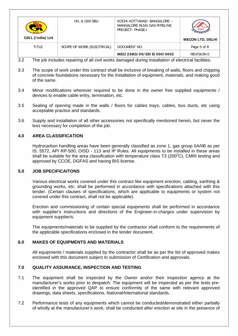
3.2 The job includes repairing of all civil works damaged during installation of electrical facilities. 3.3 The scope of work under this contract shall be inclusive of breaking of walls, floors and chipping
of concrete foundations necessary for the installation of equipment, materials, and making good of the same.
3.4 Minor modifications wherever required to be done in the owner free supplied equipments /
devices to enable cable entry, termination, etc. 3.5 Sealing of opening made in the walls / floors for cables trays, cables, bus ducts, etc using
acceptable practice and standards. 3.6 Supply and installation of all other accessories not specifically mentioned herein, but never the
less necessary for completion of the job. 4.0 AREA CLASSIFICATION
Hydrocarbon handling areas have been generally classified as zone 1, gas group IIA/IIB as per IS: 5572, API RP-500, OISD - 113 and IP Rules. All equipments to be installed in these areas shall be suitable for the area classification with temperature class T3 (2000C), CMRI testing and approved by CCOE, DGFAS and having BIS license.
5.0 JOB SPECIFICAITONS
Various electrical works covered under this contract like equipment erection, cabling, earthing & grounding works, etc. shall be performed in accordance with specifications attached with this tender. (Certain clauses of specifications, which are applicable to equipments or system not covered under this contract, shall not be applicable). Erection and commissioning of certain special equipments shall be performed in accordance with supplier’s instructions and directions of the Engineer-in-charges under supervision by equipment supplier/s. The equipments/materials to be supplied by the contractor shall conform to the requirements of the applicable specifications enclosed in the tender document.
6.0 MAKES OF EQUIPMENTS AND MATERIALS All equipments / materials supplied by the contractor shall be as per the list of approved makes enclosed with this document subject to submission of Certification and approvals.
7.0 QUALITY ASSURANCE, INSPECTION AND TESTING 7.1 The equipment shall be inspected by the Owner and/or their inspection agency at the
manufacturer’s works prior to despatch. The equipment will be inspected as per the tests pre-identified in the approved QAP to ensure conformity of the same with relevant approved drawings, data sheets, specifications, National/International standards.
7.2 Performance tests of any equipments which cannot be conducted/demonstrated either partially
of wholly at the manufacturer’s work, shall be conducted after erection at site in the presence of

OIL & GAS SBU
KOCHI-KOTTANAD- BANGALORE –MANGALORE RLNG GAS PIPELINE PROJECT- PHASE-I
GAIL (India) Ltd MECON LTD, DELHI
DOCUMENT NO. Page 6 of 8 TITLE SCOPE OF WORK (ELECTRICAL)
MEC/23M3/05/E9/E/000/0002 REVISION 0
Owner & their inspection agency. In all the cases, prior approval of the approval shall be obtained.
7.3 In case of waiver category of items, the same shall be pre identified. For such items, the
contractor shall furnish necessary certificates, test reports etc for Review/Approval to Owner/Inspection agency. The issue of Inspection Certificate/Waiver Certificate for any equipment or component there of does absolve the contractor from his contractual obligations towards subsequent satisfactory performance of the equipment at site. Should any equipment be found defective, In whole or part thereof after receipt at site or during erection/commissioning and testing shall be Rectified/Changed by contractor free of cost.
7.4 Contractor shall submit test plan for the equipments with four week advance notice. 8.0 TESTING & COMMISSIONING 8.1 The successful tenderer shall submit detailed site testing & commission procedure with time
schedules for Review/Approval to Owner/MECON. 8.2 The successful tenderer shall provide adequate supervisory/ skilled personnel and all tools and
tackles, testing equipment and instruments required for complete checking of installations and testing and commissioning of all equipment and accessories.
8.3 All the tests shall be conducted in the presence of Owner/ Engineer-in/charge or his authorized
representative unless he waives this requirement in writing. 8.4 The testing and commissioning of all equipment under the scope of the tenderer shall be carried
out in accordance with the latest edition of relevant Indian Standards, International Standard and IE Rules.
8.5 Test reports shall be submitted in required number of copies duly signed by the TENDERER to
MECON and OWNER. 8.6 All equipment after testing shall be energized only after certification by the qualified testing
engineer that the equipment is ready for energisation and with \ the concurrence of OWNER / MECON.
8.7 After the completion of all tests and rectification of all defects pointed out during final inspection,
plant start-up trials would be commenced. During the start-up trials contractor shall provide skilled / unskilled personnel and supervision round the clock at his cost. The number and category of workmen and duration up to which required, will be decided by the Engineer-in-charge. Any defects noticed during the start-up trial relating to the equipment supplied and work carried out by the Contractor, will be rectified by the contractor at his own cost.
8.8 On successful completion of erection of each item /equipment, a final inspection will be carried
out at site by Owner / MECON, for correctness and completeness of erection. 8.9 Any work not conforming to the execution drawings, specifications or codes shall be rejected
forthwith and the contractor shall carry out the rectification at his own cost.
OIL & GAS SBU
KOCHI-KOTTANAD- BANGALORE –MANGALORE RLNG GAS PIPELINE PROJECT- PHASE-I
GAIL (India) Ltd MECON LTD, DELHI
DOCUMENT NO. Page 7 of 8 TITLE SCOPE OF WORK (ELECTRICAL)
MEC/23M3/05/E9/E/000/0002 REVISION 0
8.10 After the operating conditions are fully achieved in the plant and the other requirements as stated in the General Conditions of Contract are fulfilled, the contractor would be eligible for applying for a completion certificate.
9.0 DRAWINGS, STANDARD SPECIFICATIONS AND INSTALLATION STANDARDS
9.1 The equipments / materials to be supplied by the contractor shall conform to the requirements of
the applicable specifications. Also the installation of various material / equipment shall conform to the installation standards /norms.
9.2 The drawings accompanying the tender documents when read with specification shall depict the
electrical system of the Terminal. These are indicative of the nature of work and issued for tendering purposes only. Purpose of these drawings is to enable the tendered to make an offer in line with the requirements of the Owner. Construction shall be as per drawings / specifications issued / approved by the Engineer-in-charge during the course of execution of work.
9.3 After the job completion, contractor shall prepare AS-BUILT drawings and documents, submit
catalogues/manuals (O&M) of major items like UPS, Rectifiers, Batteries, DCDB, ACDB etc. Final certified as built drawings, documents and manuals etc shall be submitted by the contractor to owner in bound volume with one set in soft copy (CD) plus five sets of prints.
Training
Contractor shall train the work force of Owner with his technical and supervisory personnel for safe, efficient operation and maintenance of the equipment and system installed by the contractor. The Number of personnel to be trained and the duration and structure of the training shall be mutually discussed and finalized.
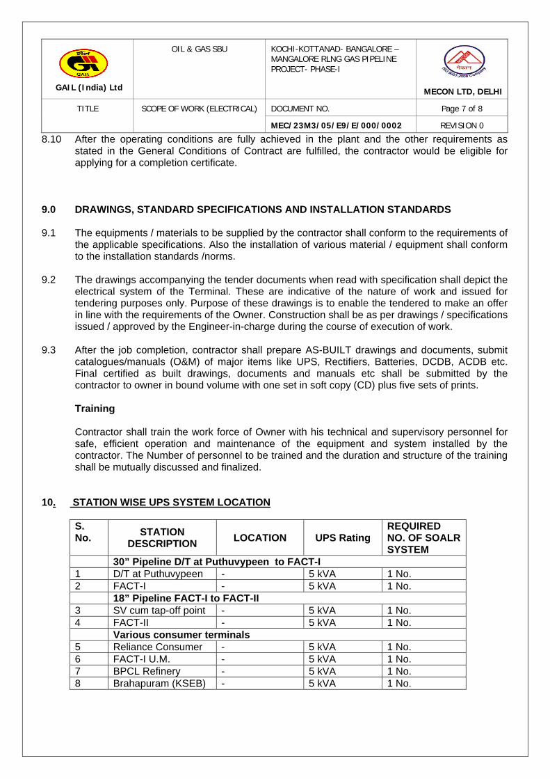
10. STATION WISE UPS SYSTEM LOCATION
S. No.
STATION DESCRIPTION
LOCATION UPS Rating REQUIRED NO. OF SOALR SYSTEM
30” Pipeline D/T at Puthuvypeen to FACT-I 1 D/T at Puthuvypeen - 5 kVA 1 No. 2 FACT-I - 5 kVA 1 No. 18” Pipeline FACT-I to FACT-II 3 SV cum tap-off point - 5 kVA 1 No. 4 FACT-II - 5 kVA 1 No. Various consumer terminals 5 Reliance Consumer - 5 kVA 1 No. 6 FACT-I U.M. - 5 kVA 1 No. 7 BPCL Refinery - 5 kVA 1 No. 8 Brahapuram (KSEB) - 5 kVA 1 No.

SPECIFICATION FOR
UN-INTERRUPTED POWER SUPPLY (UPS) SYSTEM
SPECIFICATION NO.- MEC/TS/05/E9/071
(ELECTRICAL SECTION)
MECON LIMITED DELHI 110 092
Rev: 01 Edition: 1

STANDARD TECHNICAL SPECIFICATION MECON LIMITED REGD. OFF: RANCHI 834002 OIL & GAS SBU, DELHI
DOCUMENT NO. Page 1 of 1
REVISION : 1 TITLE UNINTERRUPTED POWER SUPPLY
MEC/TS/05/E9/071
EDITION : 1
C O N T E N T S
SL. NO. DESCRIPTION 1.0 SCOPE 2.0 STANDARDS 3.0 GENERAL REQUIREMENTS 4.0 DRAWING AND DOCUMENTS 5.0 INSPECTION ANNEXURE -I PURCHASER'S DATA FOR UPS ANNEXURE -II TECHNICAL DATA FROM MANUFACTURER ANNEXURE -III PREFERRED MAKE
ANNEXURE -IV CHECK LIST
ANNEXURE -V QAP
ANNEXURE -V BLOCK DIAGRAM
PREPARED BY: CHECKED BY: APPROVED BY: Revision ISSUE DATE :
(Aashish Moyal) (Saurabh Singh) (D.K. Pande) 1 Feb. 2010
(Saurabh Singh) (Quasim Ahmad) (D.K. Pande) 0 Sept.2008
STANDARD TECHNICAL SPECIFICATION MECON LIMITED REGD. OFF: RANCHI 834002 OIL & GAS SBU, DELHI
DOCUMENT NO. Page 1 of 1
REVISION : 1 TITLE UNINTERRUPTED POWER SUPPLY
MEC/TS/05/E9/071
EDITION : 1
AMENDMENT STATUS
Sl. No.
Clause / Paragraph / Annexure / Exhibit / Drawing
Amended
Page No.
Revision Date By
(Name)
Verified
(Name)

STANDARD TECHNICAL SPECIFICATION MECON LIMITED REGD. OFF: RANCHI 834002 OIL & GAS SBU, DELHI
DOCUMENT NO. Page 1 of 7
REVISION : 1 TITLE UNINTERRUPTED POWER SUPPLY
MEC/TS/05/E9/071
EDITION : 1
1.0 SCOPE
The intent of this specification is to define the requirements of uninterrupted power supply system, Rectifiers, Inverter system and the associated battery sets. Tenderer's scope of work includes design, manufacture, testing, packing and delivery to site and testing & commissioning of the complete UPS system with static by-pass, solid state voltage stabilizer for by-pass supply, distribution boards and battery banks etc. as per this specification, data sheet.
2.0 STANDARDS 2.1 In general the equipment covered by this specification shall, unless otherwise specified, be in
line with the requirement of any of the latest applicable standards of a) Bureau of Indian Standards b) British Standard Institution c) American Standard Institution d) International Electro Technical Commission
2.2 Wherever the requirements in this specification are in conflict with any of the above Standards,
the requirements under this specification shall be binding. 2.2 In case of any contradiction between various referred standards/specification/data sheets and
statutory regulation etc. the following order of priority shall be govern- i) Schedule of rate ii) Data Sheet iii) Standard specification, Block diagram iv) Codes & standard
3.0 GENERAL REQUIREMENTS 3.1 ENVIRONMENTAL CONDITIONS
The uninterruptible power supplies shall be designed and constructed for continuous operation at full load under the climatic and environmental conditions as described in the “Design Basis / Purchaser Data”. The UPS shall be designed for non air-conditioned ambient.
3.2 COMPONENTS AND EQUIPMENT
a) The Contractor has to take care that all components and equipment are selected considering easy maintenance, simple and quick diagnosis and long maintenance intervals. All components and equipment shall be designed for continuous duty at rated load and under the given climatic conditions. Standard industrial high performance systems and components shall be used as far as possible. Components and equipment of same kind and type shall be selected for equivalent functions. The interchangeability must be guaranteed.
b) UPS shall be free from workmanship defects, sharp edges, nicks, scratches, burs etc. All
fasteners shall be fixed properly. The equipment shall be complete with all parts and all parts shall be functional.
STANDARD TECHNICAL SPECIFICATION MECON LIMITED REGD. OFF: RANCHI 834002 OIL & GAS SBU, DELHI
DOCUMENT NO. Page 2 of 7
REVISION : 1 TITLE UNINTERRUPTED POWER SUPPLY
MEC/TS/05/E9/071
EDITION : 1
3.3 TAGGING
All components, equipment and installations shall receive the respective tagging plates, labels, etc., which have to be of extremely durable material resistant against the environmental conditions. Tagging plates or labels on fronts of enclosures shall be fixed with screws. For further requirements, reference is made to specification. All wiring inside the UPS shall be neatly arranged & ferruled.
3.4 BASIC PARTICULARS FOR DESIGN - Suitable for industrial application. - Microprocessor based online UPS with static bypass.
- The rating of the system shall be as per Schedule of Rates at 0.8 pf lagging at ambient specified in design Basis/Data Sheet.
- 125% of the rated output for 10 minutes & 150% for 1 minute. - Automatic selection of available phase (out of three phases) in case of outage of power
supply of the phase in incoming feeding power supply to the UPS, if indicated in SOR/DATASHEET.
- Input supply to UPS (3-Phase or 1-Phase) shall be as per DATASHEET/SOR.
- Inverter switching device shall be IGBT based & Rectifier should be thyristor based.
- Single-phase voltage and frequency controlled output.
- Suitable protection shall be provided in the control circuit to guard against instability of phase controlled rectifier due to electrical oscillation, which may be present in input supply as caused by emergency DG set.
- Single/ Dual/ Parallel redundant system with automatic static bypass, Battery bank and solid-state voltage stabilizer as per data sheet, Schedule of rates and drawing.
- The load shall normally be fed from the inverter. - Battery shall be suitable to maintain the power supply in the event of mains failure or battery
charger failure for time period as indicated in Schedule of Rates. - Static by pass switch to connect the load to the mains supply through static voltage
stabilizer or hot standby UPS, as per the configuration, without interruption to the load in the event of inverter failure.
- AC Distribution board/ DC Distribution board as per data sheet. - Panel illumination to be provided. - Noise level at a distance of 1 m. from UPS panels shall not exceed 65 DB. - All wound elements shall be copper wound. - Total Harmonic Distortion (THD) at input shall not greater than 25%.
3.4.1 PERMISSIBLE VARIATIONS
1) Mains power supply system:- Voltage : +10% & -15% Frequency : ± 5%
2) Output of the uninterrupted power supply system while delivering a load of its rated
capacity:-

STANDARD TECHNICAL SPECIFICATION MECON LIMITED REGD. OFF: RANCHI 834002 OIL & GAS SBU, DELHI
DOCUMENT NO. Page 3 of 7
REVISION : 1 TITLE UNINTERRUPTED POWER SUPPLY
MEC/TS/05/E9/071
EDITION : 1
Voltage : ±1% Frequency : ±0.1%
3) Accuracy of static type voltage stabilizer for bypass supply shall be within ±2%.
3.4.2 PROTECTIVE FEATURES & INDICATIONS & ALARMS (i) PROTECTIVE FEATURES
a) Input- - Mains Over voltage, under voltage, phase failure
b) Inverter-
- Over voltage, short circuit, overload, over temperature c) Battery- - Under voltage at battery terminal, Battery over charge, Battery Over current d) Rectifier/ Battery charger-
- DC Earth Fault
(ii) INDICATIONS AND LCD DISPLAY
Following indication should be provided. Single line Power Flow Diagram (i) Single line Power Flow Diagram (Mimic diagram) with LED indications of UPS status (i.e.
Mains present, Battery charging & discharging, Low battery Voltage and unit on bypass). (ii) Digital panel Meter with LCD display shall be provided for monitoring viz.
a) Input AC Voltage, current, frequency b) Output AC Voltage, current, frequency. c) Battery current and voltage d) Total run time e) Mains ON/OFF, Mains Over/Under voltage, Phase fail f) Inverter ON/OFF, Inverter Over/Under voltage, inverter overload, over heat & load in % on
inverter. g) Battery voltage low, battery level in % & battery fault h) Battery Operation Boost Charge, Float Charge with of status - "in charge" or "discharge" i) Load on bypass or inverter. j) Detailed UPS Status with Operation/faults history
(iii) AUDIBLE ALARMS WITH LCD DISPLAY
a) Mains Failure b) Battery Low
STANDARD TECHNICAL SPECIFICATION MECON LIMITED REGD. OFF: RANCHI 834002 OIL & GAS SBU, DELHI
DOCUMENT NO. Page 4 of 7
REVISION : 1 TITLE UNINTERRUPTED POWER SUPPLY
MEC/TS/05/E9/071
EDITION : 1
c) UPS fault (Continuous) d) Inverter Under-voltage e) Over Temperature (Continuous) f) Inverter Overload (Continuous)
3.4.3 ISOLATION TRANSFORMER:
1. Rating suitable for the application & as per IEC726/IS-11171 2. Dry type, with class 'F' insulation 3. Isolation transformer for input & output-Required (As per block diagram).
3.4.4 RECTIFIER/ BATTERY CHARGER 1. Switched ON through a MCCB. 2. Charger size shall be based on the maximum inverter input load current and recharging
current (in maximum time of 10 hours after complete discharge).
The rating of rectifier / charger shall be not less than the value calculated as follows:
For Ni-Cd batteries = Inverter input current + 0.2 Ah (5 hr. rating of battery) For SMF LA/VRLA batteries= Inverter input current+ 0.2 Ah (10 hr. rating of battery) Where Rated kVA capacity of UPS X load p.f. Inverter input current = --------------------------------------------------------- Inverter eff. x (No. of cells x End Cell voltage)
3. Transient and surge protection circuit in input circuit to protect UPS from surges and voltage Spikes.
4. Necessary smoothing reactor and filters. 5. Automatic boost and float charging control 6. Protective features: - Maximum current limiting - Over temp. Trip
- Boost charging and float charging current limiting with back up protection against over charging.
7. Charger shall simultaneously supply entire power necessary for inverter (load) and to keep
the battery of required capacity in fully charged condition. Provision for automatic charging in both float and boost shall be made.
3.4.4.1 Rectifier for other critical load 24V DC & (-) 48V DC shall be SOR/datasheet.
STANDARD TECHNICAL SPECIFICATION MECON LIMITED REGD. OFF: RANCHI 834002 OIL & GAS SBU, DELHI
DOCUMENT NO. Page 5 of 7
REVISION : 1 TITLE UNINTERRUPTED POWER SUPPLY
MEC/TS/05/E9/071
EDITION : 1
The rating of these rectifiers shall be as per SOR. 3.4.5 INVERTER (IGBT Technology Based)
1. Input circuit consisting of battery MCCB, battery filter and smoothing reactor. 2. DC/DC converter for voltage control, if required. 3. The circuit should be IGBT based fully microprocessor controlled with PWM Technology 4. Control electronics 5. Series reactor and parallel filter 6. Output transformer 7. Protection against the following:
- Abnormal output voltage - Abnormal link voltage - Over load trip - Low battery voltage - High transformer temperature - Auxiliary supply failure 8. Static by-pass switch - Static switch automatically switches the load to the reserve power supply or the
mains whenever there is failure in inverter supply to the load. - Automatic Bypass-Static Bypass to provide uninterrupted transfer of load in case of
any system component or malfunctioning and shall return the load automatically to the UPS when malfunctioning & overload is cleared.
- The switching time from inverter to bypass & vice versa shall be no break type. - Automatic bypass shall be able to activate manually by a switch/push button to test
bypass operation. - Manual bypass shall be provided & shall be operated manually by a switch which
allows the electrical isolation of UPS from load for the purpose of maintenance of UPS.
- Retransfer of load from stabilized bypass supply to the inverter in auto as well as in manual mode.
- High-speed fuses shall be provided for protecting the thyristor’s against accidental overload.
- Inverter should be phase locked to the stabilized by pass supply as long as by pass supply remains within ±6% of nominal frequency.
The frequency should be site adjustable in steps of ±1%. 3.4.6 Constructional Features
1. Unitized construction and shall be manufactured as per IEC:62040, IEC60950 2. Free standing, floor mounted, indoor type and complete with all interconnection. 3. Dust and vermin proof 4. Sheet steel clad
- Minimum 2 mm thick for load bearing members & 1.6 mm thick for non-load bearing
members.

STANDARD TECHNICAL SPECIFICATION MECON LIMITED REGD. OFF: RANCHI 834002 OIL & GAS SBU, DELHI
DOCUMENT NO. Page 6 of 7
REVISION : 1 TITLE UNINTERRUPTED POWER SUPPLY
MEC/TS/05/E9/071
EDITION : 1
5. Units shall be self contained and serviceable 6. The arrangement and layout shall facilitate easy and convenient supervision of the unit while
running as well as quick detection of disturbances and troubleshooting. 7. Copper earth bus bar shall run through out the length of Panels. All doors & non-current
carrying metallic parts shall be suitably earthed. 8. Dimensions of panels shall be such that it can be accommodated in existing room if
indicated in MR/ SOR. 9. The maximum and minimum operating height of the switches shall be 1800mm and 300mm
respectively. 3.4.7 Enclosure and Ventilation - Enclosure conforming to minimum IP-31 class. - Units shall be provided with cooling fans and louvers. 3.5 Battery unit 3.5.1 Ampere-hour capacity of the battery shall be selected on the following basis:
a) Load power factor of 0.8 b) Aging factor of 0.8 c) Battery state of charge factor of 0.88 d) Temperature correction factor shall be taken as specified in data sheet e) Backup time as specified in SOR / data sheet f) Minimum end cell voltage shall be 1.1V per cell for Ni-Cd battery & 1.85 V per cell for SMF
LA/VRLA battery.
Inverter rated KVA X Rated load p.f Battery Current = ---------------------------------------------------------------------
Inverter Efficiency X End cell voltage X No of cells
Load break switch fuse unit/MCCB in sheet steel enclosure shall be provided near the battery bank for isolation.
3.5.2 The type of battery (Ni-Cd/SMF LA/VRLA) shall be as per Material Requisition/ SOR. 3.5.3 Sets of Indoor Stationary batteries of type as per enclosed data sheet complete with all required
accessories as applicable including but not limited to the following shall be supplied with each battery set;
a) Battery stands in two rows/ two tier formation. Stand Material shall be as per battery
manufacturer’s standard. b) Cell testing voltmeter complete with leads- (1 no. Per set). c) Spanner - (1 no. Per set).
3.5.4 Overall dimensions of complete battery set shall be such that it can be accommodated in existing
room if indicated in data sheet. 4.0 DRAWINGS AND DOCUMENTS

STANDARD TECHNICAL SPECIFICATION MECON LIMITED REGD. OFF: RANCHI 834002 OIL & GAS SBU, DELHI
DOCUMENT NO. Page 7 of 7
REVISION : 1 TITLE UNINTERRUPTED POWER SUPPLY
MEC/TS/05/E9/071
EDITION : 1
4.1 The following documents shall be submitted along with the offer:
a) List of two years operation and maintenance spare. b) Technical data sheet (Annex-II) and check list duly filled.
4.2 The following calculations/ dimensions shall be submitted along-with offer:
a) Charger sizing calculation. b) Battery sizing calculation. c) Battery bank/stand size. d) UPS panel size including solid-state stabilizer panel.
4.3 The following drawings shall be submitted for approval within 3 weeks of award of contract.
a) G.A. of panel, battery stand, ACDB and DCDB b) Bill of Material c) Schematic & Wiring diagram for reference d) Charger sizing calculation e) Battery sizing calculation f) Battery bank/stand size g) UPS panel size including solid-state stabilizer panel h) UPS Control & Protection philosophy i) List of LCD indication & audio alarms
4.4 Final drawings, operation & maintenance manual and erection Instructions shall be submitted along
with despatch of equipments in four sets in hard copy & two sets in soft copy (CD). 5.0 INSPECTION
Inspection and testing of equipment shall be carried out by the owner/ consultant at the works of the contractor on final product to ensure conformity of the same with the acceptable criteria of technical specification, approved drawings and national/ international standards.
5.1 The contractor shall submit Quality Assurance Plan (QAP) for respective equipments within 3 weeks
of award of contract. 5.2 QAP shall be prepared and furnished by the contractor in MECON Form No. 11.20(4.4) F-10 along
with their internal in process quality checks. 5.3 ‘Type test' including heat run test shall be conducted on one UPS System of each rating and
‘Routine test’ on the remaining. 5.4 Batteries shall be tested for type and `Acceptance Test’/ Routine Test at battery manufacturer’s
works and test reports shall be submitted for review and approval. 5.5 Final acceptance testing along with the batteries shall be done at site. Site acceptance test
procedure shall be submitted by the Contractor along with QAP.
-x-x-x-
Rev. :1
Edition : 1
DATA SHEET
FOR UN-INTERRUPTED POWER SUPPLY (UPS)
SYSTEM
SPECIFICATION NO.- MEC/DS/05/E9/071
(ELECTRICAL SECTION)
MECON LIMITED DELHI 110 092
STANDARD DATA SHEET MECON LIMITED REGD. OFF: RANCHI 834002 ELECTRICAL SECTION, DELHI
DOCUMENT NO. Page 1 of 12
REVISION : 1 TITLE UNINTERRUPTED POWER SUPPLY (UPS) MEC/DS/05/E9/071
EDITION : 1
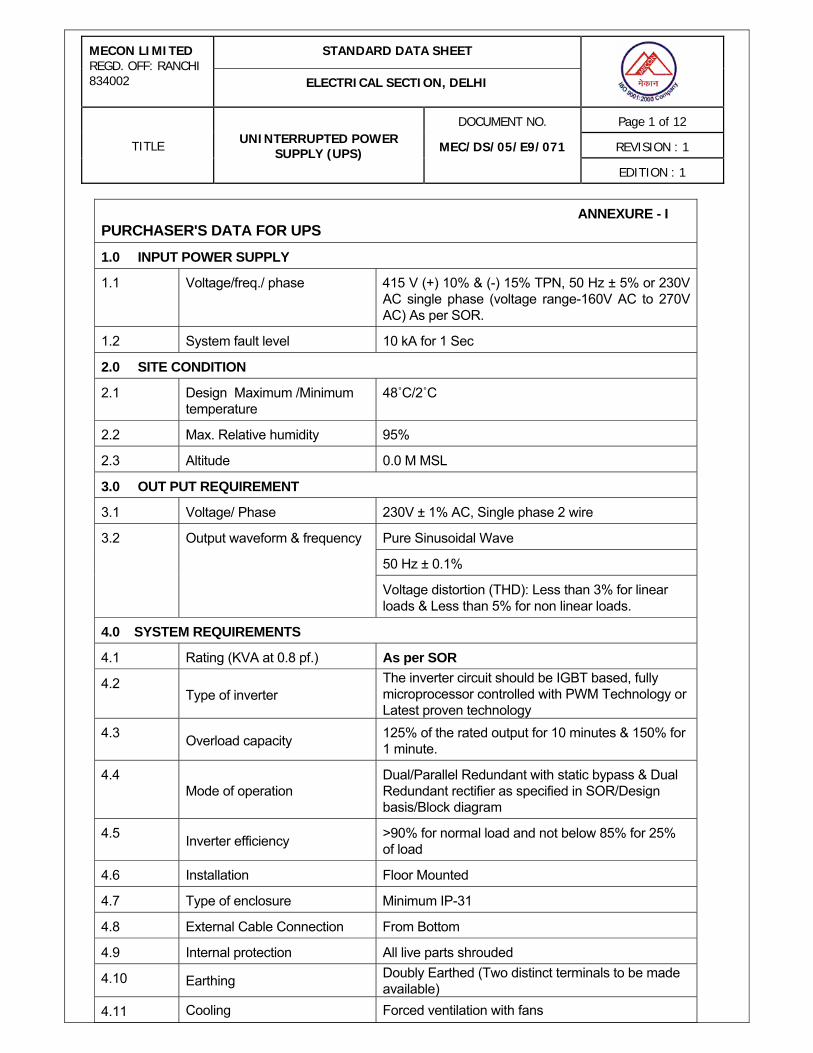
ANNEXURE - I PURCHASER'S DATA FOR UPS
1.0 INPUT POWER SUPPLY
1.1 Voltage/freq./ phase 415 V (+) 10% & (-) 15% TPN, 50 Hz ± 5% or 230V AC single phase (voltage range-160V AC to 270V AC) As per SOR.
1.2 System fault level 10 kA for 1 Sec
2.0 SITE CONDITION
2.1 Design Maximum /Minimum temperature
48˚C/2˚C
2.2 Max. Relative humidity 95%
2.3 Altitude 0.0 M MSL
3.0 OUT PUT REQUIREMENT
3.1 Voltage/ Phase 230V ± 1% AC, Single phase 2 wire
Pure Sinusoidal Wave
50 Hz ± 0.1%
3.2 Output waveform & frequency
Voltage distortion (THD): Less than 3% for linear loads & Less than 5% for non linear loads.
4.0 SYSTEM REQUIREMENTS
4.1 Rating (KVA at 0.8 pf.) As per SOR
4.2 Type of inverter
The inverter circuit should be IGBT based, fully microprocessor controlled with PWM Technology or Latest proven technology
4.3 Overload capacity 125% of the rated output for 10 minutes & 150% for 1 minute.
4.4 Mode of operation
Dual/Parallel Redundant with static bypass & Dual Redundant rectifier as specified in SOR/Design basis/Block diagram
4.5 Inverter efficiency >90% for normal load and not below 85% for 25% of load
4.6 Installation Floor Mounted
4.7 Type of enclosure Minimum IP-31
4.8 External Cable Connection From Bottom
4.9 Internal protection All live parts shrouded
4.10 Earthing Doubly Earthed (Two distinct terminals to be made available)
4.11 Cooling Forced ventilation with fans
STANDARD DATA SHEET MECON LIMITED REGD. OFF: RANCHI 834002 ELECTRICAL SECTION, DELHI
DOCUMENT NO. Page 2 of 12
REVISION : 1 TITLE UNINTERRUPTED POWER SUPPLY (UPS) MEC/DS/05/E9/071
EDITION : 1
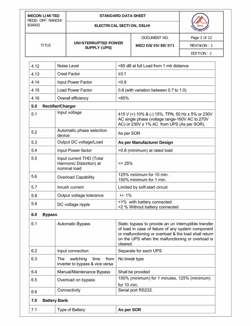
4.12 Noise Level <65 dB at full Load from 1 mtr distance
4.13 Crest Factor ≥3:1
4.14 Input Power Factor >0.9
4.15 Load Power Factor 0.8 (with variation between 0.7 to 1.0)
4.16 Overall efficiency >85%
5.0 Rectifier/Charger
5.1 Input voltage 415 V (+) 10% & (-) 15%, TPN, 50 Hz ± 5% or 230V AC single phase (voltage range-160V AC to 270V AC) or 230V ± 1% AC from UPS (As per SOR).
5.2 Automatic phase selection device As per SOR
5.3 Output DC voltage/Load As per Manufacturer Design
5.4 Input Power factor >0.8 (minimum) at rated load
5.5 Input current THD (Total Harmonic Distortion) at nominal load
<= 25%
5.6 Overload Capability 125% minimum for 10 min. 150% minimum for 1 min.
5.7 Inrush current Limited by soft-start circuit
5.8 Output voltage tolerance +/- 1%
5.9 DC voltage ripple <1% with battery connected <2 % Without battery connected
6.0 Bypass
6.1 Automatic Bypass Static bypass to provide an un interruptible transfer of load in case of failure of any system component or malfunctioning or overload & the load shall return on the UPS when the malfunctioning or overload is cleared.
6.2 Input connection Separate for each UPS
6.3 The switching time from inverter to bypass & vice versa
No break type
6.4 Manual/Maintenance Bypass Shall be provided
6.5 Overload on bypass 150% (minimum) for 1 minutes, 125% (minimum) for 10 min.
6.6 Connectivity Serial port RS232.
7.0 Battery Bank
7.1 Type of Battery As per SOR
STANDARD DATA SHEET MECON LIMITED REGD. OFF: RANCHI 834002 ELECTRICAL SECTION, DELHI
DOCUMENT NO. Page 3 of 12
REVISION : 1 TITLE UNINTERRUPTED POWER SUPPLY (UPS) MEC/DS/05/E9/071
EDITION : 1
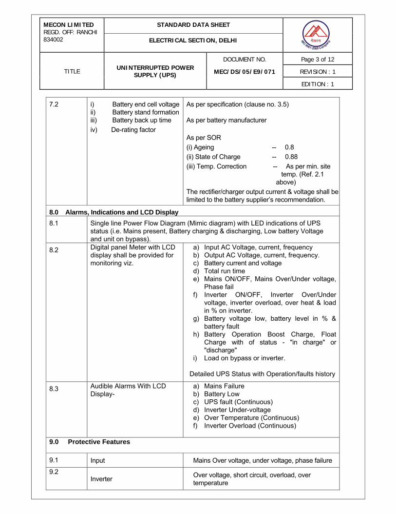
7.2 i) Battery end cell voltage ii) Battery stand formation iii) Battery back up time iv) De-rating factor
As per specification (clause no. 3.5) As per battery manufacturer As per SOR (i) Ageing -- 0.8 (ii) State of Charge -- 0.88 (iii) Temp. Correction -- As per min. site temp. (Ref. 2.1 above) The rectifier/charger output current & voltage shall be limited to the battery supplier’s recommendation.
8.0 Alarms, Indications and LCD Display
8.1 Single line Power Flow Diagram (Mimic diagram) with LED indications of UPS status (i.e. Mains present, Battery charging & discharging, Low battery Voltage and unit on bypass).
8.2
Digital panel Meter with LCD display shall be provided for monitoring viz.
a) Input AC Voltage, current, frequency b) Output AC Voltage, current, frequency. c) Battery current and voltage d) Total run time e) Mains ON/OFF, Mains Over/Under voltage,
Phase fail f) Inverter ON/OFF, Inverter Over/Under
voltage, inverter overload, over heat & load in % on inverter.
g) Battery voltage low, battery level in % & battery fault
h) Battery Operation Boost Charge, Float Charge with of status - "in charge" or "discharge"
i) Load on bypass or inverter.
Detailed UPS Status with Operation/faults history
8.3 Audible Alarms With LCD Display-
a) Mains Failure b) Battery Low c) UPS fault (Continuous) d) Inverter Under-voltage e) Over Temperature (Continuous) f) Inverter Overload (Continuous)
9.0 Protective Features
9.1 Input Mains Over voltage, under voltage, phase failure
9.2 Inverter Over voltage, short circuit, overload, over
temperature

STANDARD DATA SHEET MECON LIMITED REGD. OFF: RANCHI 834002 ELECTRICAL SECTION, DELHI
DOCUMENT NO. Page 4 of 12
REVISION : 1 TITLE UNINTERRUPTED POWER SUPPLY (UPS) MEC/DS/05/E9/071
EDITION : 1
9.3 Battery
Under voltage at battery terminal, Battery over charge, Battery Over current
9.4 Rectifier & Battery charger Maximum current limiting Over temp. Trip Boost charging and float charging current limiting with back up protection against over charging.
10.0 Distribution boxes
10.1 Distribution Board Details (As per tender drawings/SOR)
(1) ACDB 230 V, Single Phase (1 No.) :
Incomer : DP MCB
Outgoing : 8 Nos, 6A/10A (Combination) DP MCB’s
(2) DCDB : 24 V DC (1 No.)
Incomer : DP MCB
Outgoing : 6 Nos, 10A/16A DP MCB
(3) DCDB – 48 V DC (1 No.)
Incomer : DP MCB,
Outgoing ; 6 Nos, 10A/16ADP MCB

STANDARD DATA SHEET MECON LIMITED REGD. OFF: RANCHI 834002 ELECTRICAL SECTION, DELHI
DOCUMENT NO. Page 5 of 12
REVISION : 1 TITLE UNINTERRUPTED POWER SUPPLY (UPS) MEC/DS/05/E9/071
EDITION : 1
ANNEXURE-II (A) TECHNICAL DATA FROM MANUFACTURER (To be filled up by the Tendered)
1.0 INVERTER
1.1 Manufacturer’s Model No. (Enclose catalogue)
1.2 Rating (at specified ambient) / no. of phases
1.3 Applicable codes/standards
1.4 Steady state output volt/freq (230 V + 1%)
(50 Hz + 0.1%)
1.5 Input voltage - DC
1.6 Synchronization (inv. phase locked with main) in percentage
1.7 Synchronization manually adjustable in steps of
1.8 Allowable unbalance between phases (for 3 Phases only)
1.9 Harmonics distortion for linear & non-linear loads
1.10 Mode of operation Dual/Parallel Redundant with static bypass as specified in SOR/Design basis/Block diagram
1.11 Dynamic Responses at following conditions a) ± 50% step load (for parallel redundant
UPS) b) ± 100% step load (for hot standby and
single UPS system). c) Power supply interruption and restoration. d) Load Transferred to bypass line e) When one inv. gets faulty and load
transferred to healthy inv. (for parallel redundant UPS)
1.12 Recovery time to reach steady state after above disturbance (not more than 100m Sec)
1.13 Overload capacity (125% minimum for 10 min. 150% minimum for 1 min.)
1.14 Short circuit capacity and duration (in % and m sec.)
1.15
Noise Level (dB at 1 m)
(Not more than 65 dB)
STANDARD DATA SHEET MECON LIMITED REGD. OFF: RANCHI 834002 ELECTRICAL SECTION, DELHI
DOCUMENT NO. Page 6 of 12
REVISION : 1 TITLE UNINTERRUPTED POWER SUPPLY (UPS) MEC/DS/05/E9/071
EDITION : 1
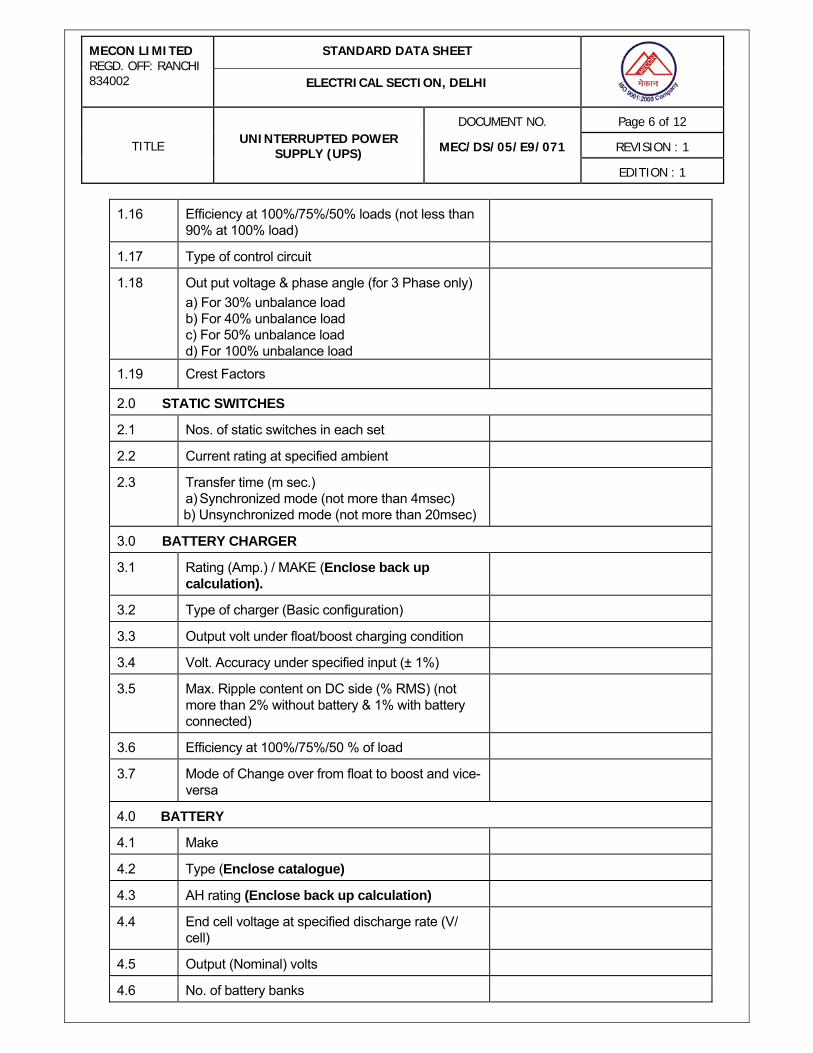
1.16 Efficiency at 100%/75%/50% loads (not less than 90% at 100% load)
1.17 Type of control circuit
1.18 Out put voltage & phase angle (for 3 Phase only) a) For 30% unbalance load b) For 40% unbalance load c) For 50% unbalance load d) For 100% unbalance load
1.19 Crest Factors
2.0 STATIC SWITCHES
2.1 Nos. of static switches in each set
2.2 Current rating at specified ambient
2.3 Transfer time (m sec.) a) Synchronized mode (not more than 4msec)
b) Unsynchronized mode (not more than 20msec)
3.0 BATTERY CHARGER
3.1 Rating (Amp.) / MAKE (Enclose back up calculation).
3.2 Type of charger (Basic configuration)
3.3 Output volt under float/boost charging condition
3.4 Volt. Accuracy under specified input (± 1%)
3.5 Max. Ripple content on DC side (% RMS) (not more than 2% without battery & 1% with battery connected)
3.6 Efficiency at 100%/75%/50 % of load
3.7 Mode of Change over from float to boost and vice-versa
4.0 BATTERY
4.1 Make
4.2 Type (Enclose catalogue)
4.3 AH rating (Enclose back up calculation)
4.4 End cell voltage at specified discharge rate (V/ cell)
4.5 Output (Nominal) volts
4.6 No. of battery banks
STANDARD DATA SHEET MECON LIMITED REGD. OFF: RANCHI 834002 ELECTRICAL SECTION, DELHI
DOCUMENT NO. Page 7 of 12
REVISION : 1 TITLE UNINTERRUPTED POWER SUPPLY (UPS) MEC/DS/05/E9/071
EDITION : 1
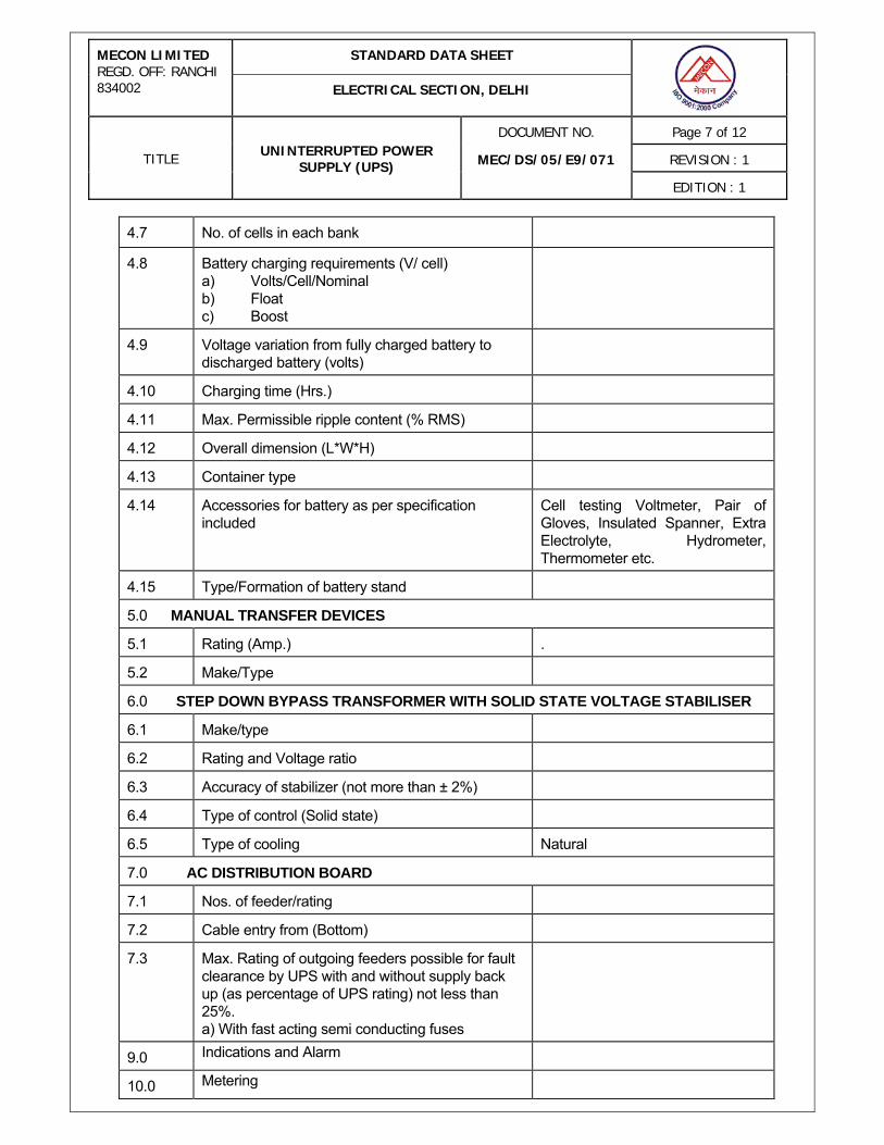
4.7 No. of cells in each bank
4.8 Battery charging requirements (V/ cell) a) Volts/Cell/Nominal b) Float c) Boost
4.9 Voltage variation from fully charged battery to discharged battery (volts)
4.10 Charging time (Hrs.)
4.11 Max. Permissible ripple content (% RMS)
4.12 Overall dimension (L*W*H)
4.13 Container type
4.14 Accessories for battery as per specification included
Cell testing Voltmeter, Pair of Gloves, Insulated Spanner, Extra Electrolyte, Hydrometer, Thermometer etc.
4.15 Type/Formation of battery stand
5.0 MANUAL TRANSFER DEVICES
5.1 Rating (Amp.) .
5.2 Make/Type
6.0 STEP DOWN BYPASS TRANSFORMER WITH SOLID STATE VOLTAGE STABILISER
6.1 Make/type
6.2 Rating and Voltage ratio
6.3 Accuracy of stabilizer (not more than ± 2%)
6.4 Type of control (Solid state)
6.5 Type of cooling Natural
7.0 AC DISTRIBUTION BOARD
7.1 Nos. of feeder/rating
7.2 Cable entry from (Bottom)
7.3 Max. Rating of outgoing feeders possible for fault clearance by UPS with and without supply back up (as percentage of UPS rating) not less than 25%. a) With fast acting semi conducting fuses
9.0 Indications and Alarm
10.0 Metering
STANDARD DATA SHEET MECON LIMITED REGD. OFF: RANCHI 834002 ELECTRICAL SECTION, DELHI
DOCUMENT NO. Page 8 of 12
REVISION : 1 TITLE UNINTERRUPTED POWER SUPPLY (UPS) MEC/DS/05/E9/071
EDITION : 1
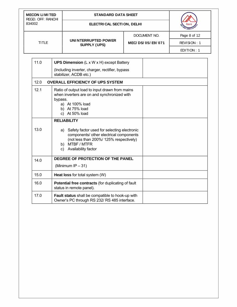
11.0 UPS Dimension (L x W x H) except Battery
(Including inverter, charger, rectifier, bypass stabilizer, ACDB etc.)
12.0 OVERALL EFFICIENCY OF UPS SYSTEM
12.1
Ratio of output load to input drawn from mains when inverters are on and synchronized with bypass.
a) At 100% load b) At 75% load c) At 50% load
13.0
RELIABILITY
a) Safety factor used for selecting electronic components/ other electrical components (not less than 200%/ 125% respectively)
b) MTBF / MTFR c) Availability factor
14.0 DEGREE OF PROTECTION OF THE PANEL
(Minimum IP – 31)
15.0 Heat loss for total system (W)
16.0 Potential free contracts (for duplicating of fault status in remote panel).
17.0 Fault status shall be compatible to hook-up with Owner’s PC through RS 232/ RS 485 interface.
STANDARD DATA SHEET MECON LIMITED REGD. OFF: RANCHI 834002 ELECTRICAL SECTION, DELHI
DOCUMENT NO. Page 9 of 12
REVISION : 1 TITLE UNINTERRUPTED POWER SUPPLY (UPS) MEC/DS/05/E9/071
EDITION : 1
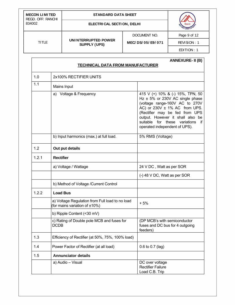
ANNEXURE- II (B)TECHNICAL DATA FROM MANUFACTURER
1.0 2x100% RECTIFIER UNITS
1.1 Mains Input
a) Voltage & Frequency
415 V (+) 10% & (-) 15%, TPN, 50 Hz ± 5% or 230V AC single phase (voltage range-160V AC to 270V AC) or 230V ± 1% AC from UPS. (Rectifier may be fed from UPS output. However it shall also be suitable for these variations if operated independent of UPS).
b) Input harmonics (max.) at full load.
5% RMS (Voltage)
1.2 Out put details
1.2.1 Rectifier
a) Voltage / Wattage 24 V DC , Watt as per SOR
(-) 48 V DC, Watt as per SOR
b) Method of Voltage /Current Control
1.2.2 Load Bus
a) Voltage Regulation from Full load to no load (for mains variation of ±10%) + 5%
b) Ripple Content (<30 mV)
c) Rating of Double pole MCB and fuses for DCDB
(DP MCB’s with semiconductor fuses and DC bus for 4 outgoing feeders)
1.3 Efficiency of Rectifier (at 50%, 75%, 100% load)
1.4 Power Factor of Rectifier (at all load) 0.6 to 0.7 (lag)
1.5 Annunciator details
a) Audio – Visual DC over voltage
Rectifier Failure Load C.B. Trip

STANDARD DATA SHEET MECON LIMITED REGD. OFF: RANCHI 834002 ELECTRICAL SECTION, DELHI
DOCUMENT NO. Page 10 of 12
REVISION : 1 TITLE UNINTERRUPTED POWER SUPPLY (UPS) MEC/DS/05/E9/071
EDITION : 1
b) Push buttons Acknowledge, reset
c) Remote One no. potential free common alarm annunciation contact.
1.6 Indication Lamps
AC Power ON, Rectifier ON
1.7 Meters A.C. input ammeter and voltmeter. Output ammeter and voltmeter.
1.8 MTBF (Hrs.) 60,000 Hrs.
1.9 MTTR (Hrs.) 4 Hrs. (Approx.)
1.10 PTRV (Peak Transient reverse voltage)
600 V on AC side 200 V on DC side
1.11 Construction Details
a) Type of Cooling Natural
b) Cable entry Same as UPS Panel
c) Access Same as UPS Panel
d) Painting Same as UPS Panel
e) Degree of Protection Same as UPS Panel
1.12 Safety Factor 2
STANDARD DATA SHEET MECON LIMITED REGD. OFF: RANCHI 834002 ELECTRICAL SECTION, DELHI
DOCUMENT NO. Page 11 of 12
REVISION : 1 TITLE UNINTERRUPTED POWER SUPPLY (UPS) MEC/DS/05/E9/071
EDITION : 1
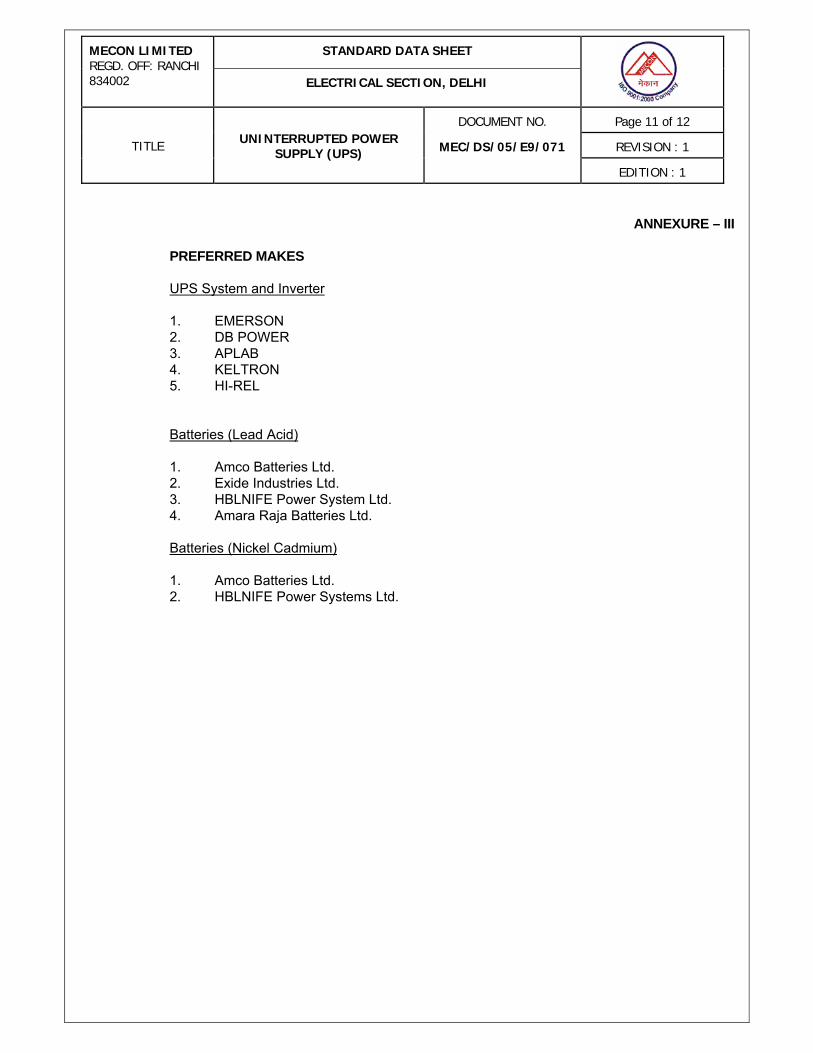
ANNEXURE – III PREFERRED MAKES
UPS System and Inverter 1. EMERSON 2. DB POWER 3. APLAB 4. KELTRON 5. HI-REL
Batteries (Lead Acid) 1. Amco Batteries Ltd. 2. Exide Industries Ltd. 3. HBLNIFE Power System Ltd. 4. Amara Raja Batteries Ltd.
Batteries (Nickel Cadmium) 1. Amco Batteries Ltd. 2. HBLNIFE Power Systems Ltd.
STANDARD DATA SHEET MECON LIMITED REGD. OFF: RANCHI 834002 ELECTRICAL SECTION, DELHI
DOCUMENT NO. Page 12 of 12
REVISION : 1 TITLE UNINTERRUPTED POWER SUPPLY (UPS) MEC/DS/05/E9/071
EDITION : 1
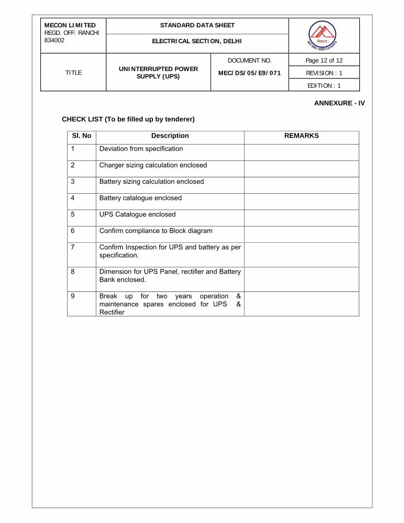
ANNEXURE - IV CHECK LIST (To be filled up by tenderer)
Sl. No Description REMARKS
1 Deviation from specification
2 Charger sizing calculation enclosed
3 Battery sizing calculation enclosed
4 Battery catalogue enclosed
5 UPS Catalogue enclosed
6 Confirm compliance to Block diagram
7 Confirm Inspection for UPS and battery as per specification.
8 Dimension for UPS Panel, rectifier and Battery Bank enclosed.
9 Break up for two years operation & maintenance spares enclosed for UPS & Rectifier