KOC P 017 - Colour Coding - 1997E
16
DOC.NO.KOC-P-017 11 Page 1 of 16 I REV. 1 I KUWAIT OIL COMPANY (K.S.C.) KOC STANDARD FOR COLOUR CODING OF PIPEWORK FOR IDENTIFICATION OF FLUIDS & SERVICES DOC. NO. KOC-P-017 ISSUING AUTHORITY: STANDARDS DIVISION
-
Upload
anonymous-2d4zzkr -
Category
Documents
-
view
777 -
download
68
description
KUWAIT OIL COMPANY - KOC COLOUR CODING SPECIFICATION
Transcript of KOC P 017 - Colour Coding - 1997E
DOC.NO.KOC-P-017 11 Page 1 of 16 I REV. 1 I
KUWAIT OIL COMPANY (K.S.C.)
KOC STANDARD FOR
COLOUR CODING OF PIPEWORK FOR IDENTIFICATION
OF FLUIDS & SERVICES DOC. NO. KOC-P-017
ISSUING AUTHORITY:
STANDARDS DIVISION

KOC STANDARD FOR
COLOUR CODING OF PIPEWORK FOR IDENTIFICATION OF
FLUIDS & SERVICES
DOC. NO. KOC-P-017

TABLE OF CONTENTS
SCOPE
GENERAL1 APPLICATION
TERMINOLOGY
REFERENCE CODES AND ST ANDARDS
ENVIRONMENTAL CONDITIONS
HEALTH, SAFETY AND ENVIRONMENT
COLOUR IDENTIFICATION MATERIALS
COLOUR CODING APPLICATION
INSPECTION & TESTING
QUALITY ASSURANCE
DOCUMENTATION
APPENDICES
Appendix 1 Examples of Base Colour ldentification and Additional lnformation on the Pipe Contents /Service.
Appendix 2 Examples of Base Colour ldentification and lndication Colour Band(s) Giving lnformation on the Pipe ContentslService.
Appendix 3 Examples of Base Cdour ldentification Bands and Indication Colour Band(s) Giving lnformation on the Pipe ContentslService.
PAGE NO.
4
4
4
4
5
5
5
6
12
12
12
13
14
16
DOC. NO. KOC- P- 01 7
SCOPE
This Standard describes the requirements for colour coding of metallic pipework for identification of fluids and services in above ground installation at new and existing KOC facilities. It also includes the requirements for colour coding when insulated or non-metallic pipes are used.
GENERAL / APPLICATION
Colour coding materials, application method and inspection & testing shall conform to the requirements of this Standard and the reference Standards 1 Codes.
Any exception or deviations from this Standard, along with their merits and justification, shall be brought to the attention of KOC's Controlling Department, for their review, consideration and amendment by Standards Division ( if required ).
TERMINOLOGY
KOC Kuwait Oil Company (K.S.C)
HSE Health, Safety and Environment
DFT Dry Film Thickness
FRP Fiberglass Reinforced Plastic
REFERENCE CODES AND STANDARDS
In the event of conflict between this Standard and the Standards1 codes referenced herein, the most stringent requirement shall apply, unless otherwise specified. KOC reserves the right to identify the applicable requirement(s) in such cases.
List of Standards and Codes
The latest edition of the following standards and codes shall apply:
BS 1710 Identification of Pipelines and Services.
BS 4800 Paint Colours for Building Purposes.
KOC- G- 007 KOC standard for Basic Design Data.
KOC - P- 001 Painting & Coating of Metal Surfaces - New Construction
ENVIRONMENTAL CONDITIONS
The environment of Kuwait is severe on all equipment and structures and must be considered carefully before the selection of colour coding material. It must be assumed that, unless otherwise specified, colour finish coat may be subjected to sand and fine particle dust storms, salt laden winds, chemical contaminants and extreme temperatures.
KOC Standard for Basic Design Data, KOC-G-007, provides the detailed design information regarding the environmental, site and utility supply conditions prevailing throughout the KOC facilities/ works which shall be compiled.
HEALTH, SAFETY AND ENVIRONMENT
All necessary health and safety procedures to protect personnel and surrounding environment shall be followed during on-site surface cleaning and application of identification colours.
All relevant safety requirements of the KOC Fire & Safety Regulations and the KOC's HSE policy shall be strictly adhered to for all works performed within KOC operation areas.
COLOUR IDENTIFICATION MATERIALS
Quality of Materials
All paint materials used for colour identification shall be chemically pure, uniform in composition and free from foreign contaminants.
Colour identification paidt materials shall not contain any toxic or hazardous constituents (e.g., Asbestos, Red Lead, Lead Chromate) .
Paint materials used for colour identification shall be specially made for colour coding purposes.
All paint materials shall be oikhemical resistant, abrasion resistant and capable of withstanding an application temperature as per the site conditions

of KOC facilities mentioned in KOC-G-007, and a service temperature as per the pipe design requirement.
Approval
The supplier's submittal for colour identification materials shall include details of manufacturer, generalized composition, technical specification, physical properties and laboratory testing certificates for the materials t o be used.
The colour identification paint material shall be compatible w i th the pipework protective coating.
The identification colours t o be used shall be in accordance wi th BS 4800 , Paint Colours for Building Purposes, and as specified in this Standard.
COLOUR CODING APPLICATION
General Requirements
Colour coding paint shall be applied on dry and clean pipe surfaces. Foreign materials like deposits, oil, grease, dustlsand and any other foreign material shall be removed by a suitable and approved method.
Colour coding paint shall be spray applied t o the specified area(s). Hand or roller application can be used for areas which can not be properly sprayed. The application shall be in accordance wi th the paint manufacturer's recommendations.
The minimum DFT of colour coding coat for new construction pipework shall be as specified for the finish coat in the painting schedules of KOC-P-001. For insulated, non metallic and existing metallic pipework, the DFT of colour coding coat shall not be less than 40 micron.
METHODS OF APPLICATION
Two methods of colour identification of pipe contents and services are adopted in this Standard. These are mainly based on the principles and guidelines of BS 17 10. The following clauses explain these methods.
Base Colours Only
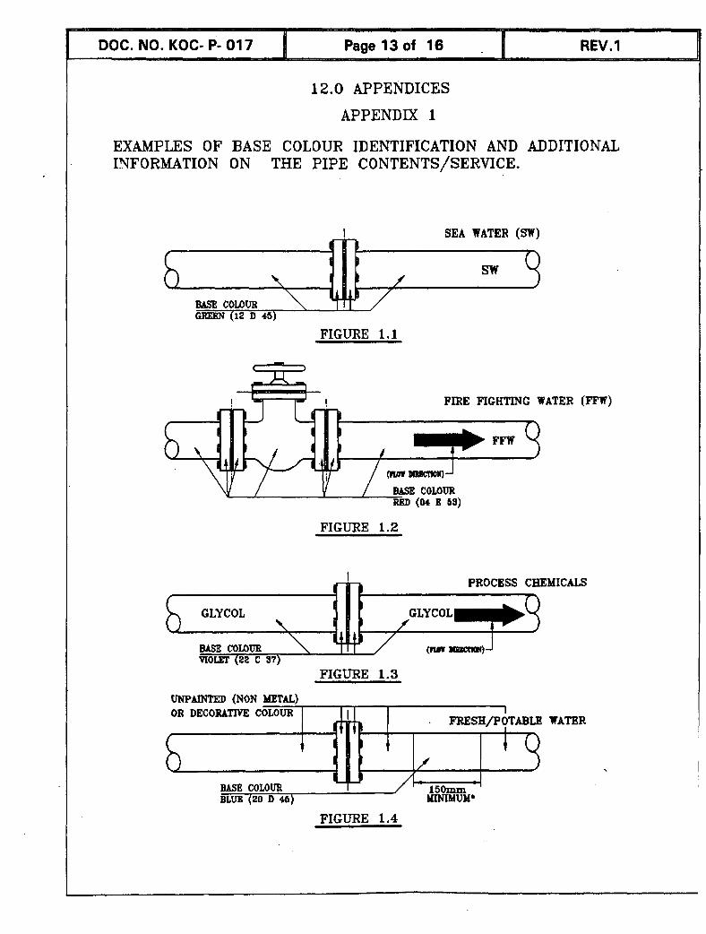
a) Where only identification of the basic nature of the fluid is required, the base colour shown in Table 1 shall be applied by painting it over the whole length of the pipework including valves, flanges, etc. For

example, if the pipework content has been coded for fire fighting, the whole pipe length and all valves and flanges shall be painted red. Appendix 1, Figures 1.1 t o 1.3 explain this method of colour identification.
For pipework were protective coating is not required e.g., FRP pipes, stainless Steel pipes, insulated pipes, ... etc, and for cases where painting the base colour over the whole existing painted pipe is not required for operational or economical reasons, the base colour can be painted on the pipe as a band over a length of about 150 m m for up t o 6 inches (1 50 mm) pipe; for pipe diameters greater than 6 inches, the length of the band shall be approximately pipe diameter.
The colour band shall be applied at intervals of 5 meters along the pipe and at junctions, both sides of every valve, inlet and outlet of every piece of equipment or vessel, wall penetration and any other place where identification is necessary.
Table 1. Base Colours.
P i ~ e Fluids/ Services 1 Colour f BS 4800 Code No. 1 Sea Water I Green 112D45 I
Oil/ Hvdrocarbon Liauids
FreshIPotable Fire extinguishing fluids Steam
Gases in either gaseous or liquefied condition Process Chemicals ( e.g., corrosion inhibitor, biocide, oxygen scavenger, glycol, chlorine, coagulant, ... etc.) acids and alkalis Air
Drainane
Blue Red Silver-nrev
Refrigeration
20 D 45 04 E 53 10 A 03
Brown Yellow
Violet
Linht blue Black Grev
8.2.2 Base Colours and Indication (Band) Colours
a) The base colours only designate broad groups of fluids. It may be necessary t o break these groups down further depending upon fluid type /function, e.g. the base colour for identification of all oils1 hydrocarbon fluids is brown, but it may be necessary t o differentiate between we t crude, dry crude, condensate oil, etc. In such cases the base colour shall identify the prime nature of the pipe contents with an indication colour(s) painted as a band t o identify more precisely the fluid. Table 2 explains
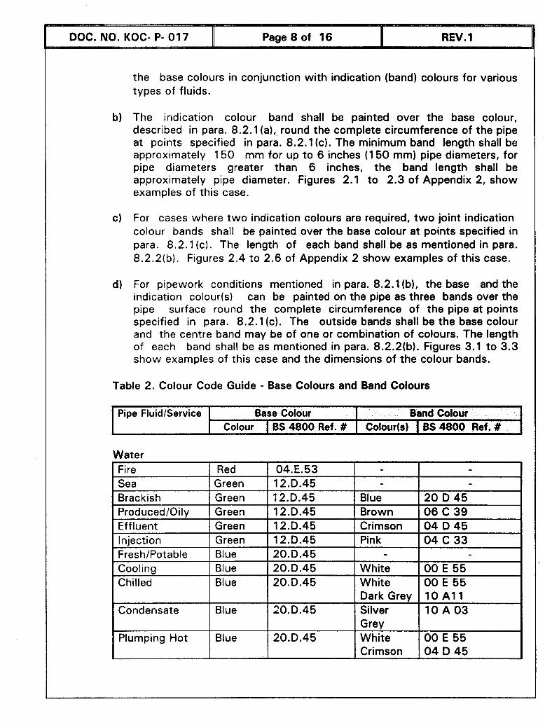
the base colours in conjunction with indication (band) colours for various types of fluids.
The indication colour band shall be painted over the base colour, described in para. 8.2.1 (a),, round the complete circumference of the pipe at points specified in para. 8.2.1 (c). The minimum band length shall be approximately 150 mm for up to 6 inches (1 5 0 mm) pipe diameters, for pipe diameters greater than 6 inches, the band length shall be approximately pipe diameter. Figures 2.1 to 2.3 of Appendix 2, show examples of this case.
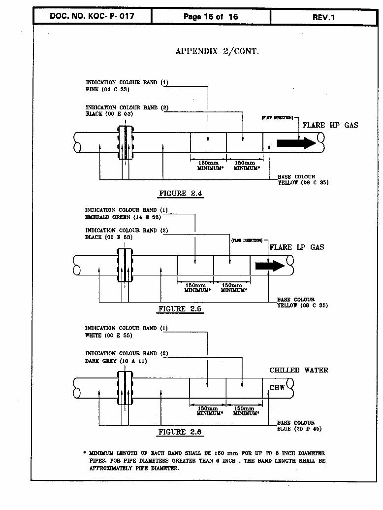
For cases where t w o indication colours are required, t w o joint indication colour bands shall be painted over the base colour at points specified in para. 8.2.1 (c). The length of each band shall be as mentioned in para. 8.2.2(b). Figures 2.4 to 2.6 of Appendix 2 show examples of this case.
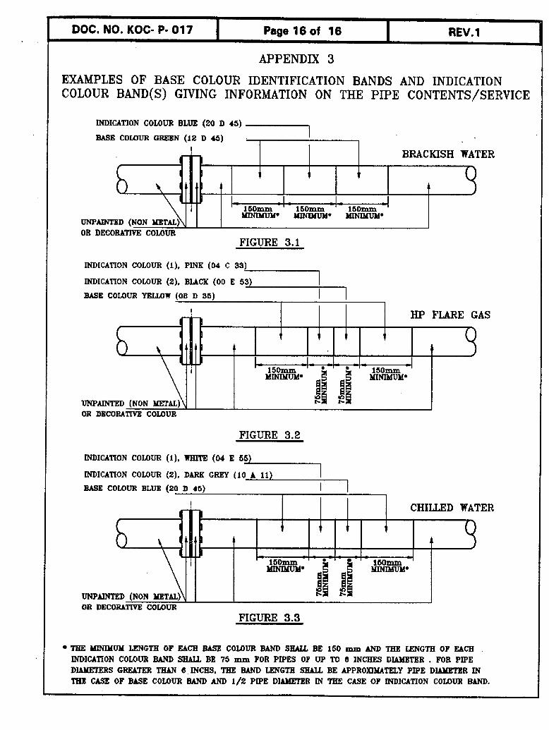
For pipework conditions mentioned in para. 8.2.1 (b), the base and the indication colour(s) can be painted on the pipe as three bands over the pipe surface round the complete circumference of the pipe at points specified in para. 8.2.1 (c). The outside bands shall be the base colour and the centre band may be of one or combination of colours. The length of each band shall be as mentioned in para. 8.2.2(b). Figures 3.1 to 3.3 show examples of this case and the dimensions of the colour bands.
Table 2. Colour Code Guide - Base Colours and Band Colours
Pipe FluidIService Base Colour Band Colour Colour 1 13s 4800 Ref. # Colout(s) 1 BS 4800 Ref. # I
Water t
Fire Red 04.E.53 - - Sea Green 12.D.45 - - Brackish Green 12.D.45 Blue 2 0 D 45 ProducedIOily Green 12.D.45 Brown 0 6 C 3 9 Effluent Green 12.D.45 Crimson 0 4 D 45 Injection Green 12.D.45 Pink 04 C 3 3 FreshIPotable Blue 20.D.45 - - Cooling Blue 20.D.45 White 00 ~ 5 5 Chilled Blue 20.D.45 White 00 E 55
Dark Grey 1 0 A1 1 Condensate Blue 20.D.45 Silver 1 0 A 0 3
Grey Plumping Hot Blue 20.D.45 White 00 E 55
Crimson 04 D 4 5

I Pipe FluidlService 1 Base Colour Band Colour 1 I I Colour I BS 4800 Ref. # I Colour(s) I BS 4800 Ref. # I
WaterlCont. Plumping Cold Blue 20.D.45 Whi te 00 E 55
Emerald - 14 E 53 - Green
Sterilized Blue 20.0.45 Orange 06 E 5 1 -
Hydrocarbon Liquid Crude Oil Dry Brown 0 6 C 39 Black 00 E 53 Crude Oil Wet Brown 0 6 C 39 Blue 2 0 D 45 Crude Oil Hot Brown 0 6 C 39 Red 0 4 E 53 Condensate Oil Brown 0 6 C 39 Yellow 0 8 C 35 Diesel Fuel Brown 0 6 C 39 White 00 E 55 Hydraulic Oil Brown 0 6 C 39 Pink 04 C 33 Seal Oil Brown 0 6 C 39 Silver Grey 1 0 A 0 3 Lubrication Oil Brown 0 6 C 39 Emerald - 14 E 53
Green Transformer Oil Brown 0 6 C 39 Crimson 0 4 D 45
Hydrocarbon Gas LP Gas Yellow 08 C 35 Emerald- 14 E 53
Green HP Gas Yellow 08 C 35 Pink 04 C 33 Hot Gas Yellow 0 8 C 35 Red 04 E 53 Fuel (LeanIRich) Yellow 08 C 35 Light Blue 20 E 51 lniection Yellow 08 C 35 Crimson 04 D 45 Acid gas Yellow 0 8 C 35 Violet 22 C 37 Tank Vapor Yellow 08 C 35 Brown 0 6 C 39 Flare LP Yellow 08 C 35 Emerald- 1 4 E 53
Green Black 00 E 53
Flare HP Yellow 0 8 C 35 Pink 04 C 3 3 Black 00 E 53
Industrial Gas Nitrogen French- 1 2 B 21 Black 00 E 53
Grey Carbon Dioxide Black 00 E 53 Silver- 1 0 A 03
Grey

Pipe FluidlService Base Colour 1 Band Colour Colour I BS 4800 Ref. # 1 Colour(s) I BS 4800 Ref. #
Medical Gas Services Oxygen Yellow 08 C 35 White 00 E 55 Nitrous Oxide Yellow 08 C 35 Blue 20 D 45 Medical Air Light Blue 20 E 51 White 00 E 55
black 00 E 53 - Medical Vacuum Light Blue 20 E 51 Primrose 10 E53
I Industrial Air Plant air Light Blue 20 E 51 White 00 E 55 Instrument Air Light Blue 20 E 51 Green 12 D 4 5 Drilling Air Light Blue 20 E 51 Orange 06 E 51
Steam I Steam I Silver- Grey 1 10 A 03 I - - I Drain & Relief LinelVents Open Drain Black 00 E 53 Red 04 E 53 Closed drain Black 00 E 53 Yellow 08 C 35 Relief line1 Vents Yellow 08 C 35 Silver-Grey 10 A 03
Exhaust Gas Exhaust Gas Aluminum - Black 00 E 53
Hot Exhaust Gas Aluminum Black 00 E 53 I I I / Crimson 1 04 D 45 I
Identification Colours and Additional lnformation
lnformation about the nature of pipe contents may be given in addition t o the above mentioned colour coding. This information shall be an accepted abbreviation and/or a f low direction arrow .Table 3 shows the KOC accepted abbreviations for various fluids.
Process chemicals are given one colour coding (Violet). I f further identification of the injected chemical is required , the name or abbreviation of the chemical may be painted over the base colour. Whenever 3 or more chemical injection pipes are at one location, name or abbreviation of each chemical shall be painted on each branch for easy identification.
I DOC. NO. KOC- P- 017 11 Page 11 of 16 I REV. 1
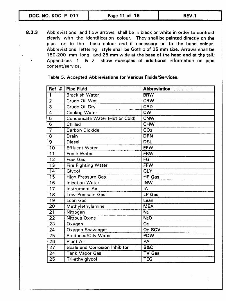
8.3.3 Abbreviations and flow arrows shall be in black or white in order to contrast clearly with the identification colour. They shall be painted directly on the pipe on to the base colour and if necessary on t o the band colour. Abbreviations lettering style shall be Gothic of 25 mm size. Arrows shall be 150-200 mm long and 25 mm wide at the base of the head and at the tail. Appendices 1 & 2 show examples of additional information on pipe
Table 3. Accepted Abbreviations for Various FluidsIServices.
I Ref. # I Pbe Fluid 1 Abbreviation 1 Brackish Water BRW 2 Crude Oil Wet CRW 3 Crude Oil Dry CRD 4 Cooling Water CW 5 Condensate Water (Hot or Coldl CNW
I
I Chilled I CHW 7 Carbon Dioxide Con 8 Drain DRN
19 I Diesel I DSL 1 10 1 Effluent Water I EFW 111 I Fresh Water I FRW
12 Fuel Gas FG 13 Fire Fighting Water FFW 14 Glycol GLY 15 High Pressure Gas HP Gas 16 lniection Water INW 17 Instrument Air I A 18 Low Pressure Gas LP Gas
I 1 9 I I
I Lean Gas I Lean 1 20 1 Methvlethvlamine 1 MEA 1 21 1 Nitrogen I N2 1 22 1 Nitrous Oxide I N20
23 Oxygen 0 2
24 Oxygen Scavenger 0 2 SCV 25 ProducedlOily water PDW 26 Plant Air PA 27 Scale and Corrosion Inhibitor S&CI 24 Tank V a ~ o r Gas TV Gas
I I
I Tri-ethvlalvcol 1 TEG

INSPECTION & TESTING
Colour identification paint material shall be checked for conformance wi th- clause 7.0 of this Standard.
Colour identification band dimension and location(s) shall be checked for conformance with paras. 8.2.1 (b) and 8.2.1 (c).
Identification colours and their codes for the specified pipe content shall be shall be checked for conformance with Tables 1 & 2
Colour coding painted areas shall be tested for minimum DFT as specified in para. 8.1.3.
Abbreviations and f low arrows dimensions and location shall be shall be checked for conformance with para. 8.3.3.
QUALITY ASSURANCE
The manufacturer and contractor shall operate quality system t o ensure that the requirements of this Standard are achieved. The quality system shall preferably be based on IS0 9000 series of standards and certificate shall be furnished. Certification shall be done by internationally reputed inspection agencies. Verification of a manufacturer's or contractor's quality system is normally part of the pre-qualification procedure, and therefore not detailed in the core text of this Standard.
DOCUMENTATION
All correspondence, drawings, instructions, data sheets, design calculations, or any other information shall be in English language.
All dimensions, units of measurements, physical constants, etc. shall be in SI units, unless otherwise specified.
Manufacturer's technical data sheets, material safety data sheets, material analysis certificate and laboratory test certificate for colour identification materials shall be provided.
12.0 APPENDICES
APPENDIX 1
EXAMPLES OF BASE COLOUR IDENTIFICATION AND ADDITIONAL INFORMATION ON THE PIPE cONTENTS/SERVICE.
I SEA WATER (SW)
FIGURE 1.1
FIRE FIGHTING WATER (FEW)
/ / BASE COLOUR RED (M B 63)
FIGURE 1.2
I PROCESS CHEMICALS
GLYCOL \
BASE COWUR mom (22 c 37)
FIGURE 1.3
FIGURE 1.4
UNPAJNTED (NON METAL)
WATER OR DECORATIYE COLOUR I
. l?RESH/POTABLE
1 /
EASE COLOUR 150mm BLUE (20 D 46) Y[NIMUld*
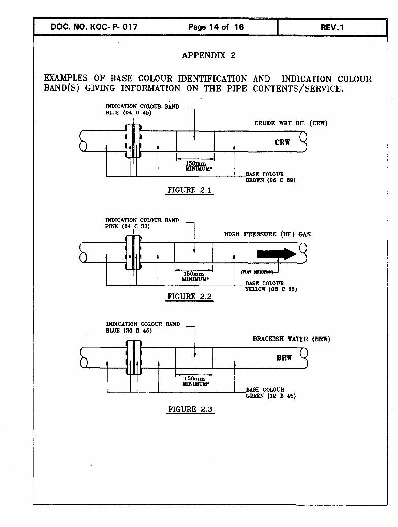
APPENDIX 2
EXAMPLES OF BASE COLOUR IDENTIFICATION AND INDICATION COLOUR BAND(S) G M N G INFORMATION ON THE PIPE CONTENTS/SERVICE.
mDICATI0N c o r n BAND BLUE (04 D 45) 1
BASE COLOUR BROWN (06 c 30)
FIGURE 2.1
INDICATION COUlUR BBND
1 HIGH PRESSURE (HP) GAS
FIGURE 2.2
Ilmm'm
INDICATION COUlUR BAND BLUE (20 D 46)
GREEN (12 D 45)
BASE COLOUR
FIGURE 2.3
YELLOW 108 C 361
DOC. NO. KOC- P- 01 7 I Page 15 of 16 I REV.l
APPENDIX 2/CONT.
INDICATION COLOUR BAND (1) PINK (04 C 33)
INDlCATlON COLOUR BAND (2) BUCK ( 0 0 E 53)
I I I
BASE COMUR YELLOW (08 C 35
FIGURE 2.4
INDICATION COLOUR BAND ( I ) EldERatD GREEN (14 E 63) 1 INDICATION COLOUR BAND (2) I
LP GAS
BASE c o r n FIGURE 2.5 YELLOW ( 0 8 C 9 5 )
INDICATION COLOUR BAND (1) wm'm (00 E 55)
INTlICATION COLOUR BAND (2) I DARK GREY (10 A 11 )
D WATER
BASE c o r n FIGURE 2.6 BLUE (20 D 46)
MINIMUM LENGTH OF EACH BAND SHALL BE 160 mm FOR UP TD 6 INCH DIAMETER PIPES. FOR PIPE DLMTERS GREATER THAN 6 INCH , THE BAND LBNGTH SHALL BE APPROXIMATELY PIPE DIAMHER.
HP GAS
DOC. NO. KOC- P- 01 7 I Page 16 of 16 I REV. 1
APPENDIX 3
EXAMPLES OF BASE COLOUR IDENTIFICATION BANDS AND INDICATION COLOUR BAND(S) GIVING INFORMATION ON THE PIPE CONTENTS/SERVICE
INDICATION COLOUR BLUE (20 D 45)
BASE COUlUR GREEN (12 D 45) 1 m I I I BRACKISH WATER
FIGURE 3.1
INDICATION COLOUR (I), PINK (04 C 33)
INDICATION COLOUR (2). BUCK (00 E 53)
BASE COLOUR YELUJW (08 D 96)
I I 1
FIGURE 3.2
! HP FLARE GAS
INDICATION COLOUR (1) . WIlTE (04 E 6 9
INDICATION COLOUR (2), D M G m
BASE COLOUR BLUE (20 D 46)
1 + I A
TEE WNlMUM LENGTH OF EACB BASE COUlUR BAND SHALL BE 150 mm AND TEE LENGTH OF EACH INDICATION C0U)UR BAND SHALL BE 75 mm FOR PIPES OF UP TO 6 INCHES DIAMETER . FOR PPE DUUtETERS GREATER THAN 6 INCH& TEE BAND LENGTH SlULL BE APPROXIMATELY PIPE DIAMETER IN TBE CASE OF BASE COtOUR BAND AND 1 / 2 PIPE D-R [N TEE CASE OF lNDICATION COMlUR BAND.
l50mm
OR DECOEUT[YB COLOUR
! CHILLeD WATER
I 1
.I. -
A
UNP- (NON
l6Omm - 1bOmm MINIMUM'
OR DECORATIVE COLOUR FIGURE 3.3