KNOWLEDGE-BASED DESIGN FOR FUTURE COMBAT AIRCRAFT CONCEPTS€¦ · KNOWLEDGE-BASED DESIGN FOR...
9
KNOWLEDGE-BASED DESIGN FOR FUTURE COMBAT AIRCRAFT CONCEPTS Raghu Chaitanya Munjulury * , Ingo Staack * , Alvaro Abdalla ** , Tomas Melin * , Christopher Jouannet * , Petter Krus * * Linköping University, Linköping, Sweden ** USP, Sao Carlos, Brazil Keywords: Conceptual design, Aircraft design, Engine design, Knowledge-based Abstract A new fighter aircraft will most likely be a collaborative project. In this study conceptual knowledge-based design is demonstrated, using models of comparable fidelity for sizing, geome- try design, aerodynamic analysis and system sim- ulation for aircraft conceptual design. A new generation fighter is likely to involve advanced control concept where an assessment of feasi- bility through simulation is needed already at the conceptual stage. This co-design leads to a deeper understanding of the trade-offs involved. In this paper a study for a future combat aircraft is made. Conceptual knowledge-based design is demonstrated by optimizing for a design mission, including a super-cruise segment. 1 Introduction In object for this design study a future combat aircraft with a hypothetical time of deployment in 2030. Within this time frame an enormous amount of development will take place. Never- theless, considering the time frames involved in aircraft design means that the initiation of such a project would not be far off. The aircraft under study is a stealth design with super-cruise capa- bility. The aircraft have provision to carry a pilot, although an unmanned version is also possible. The concept is relatively small for two reasons. First, size drives cost and therefore the market for small aircraft should be bigger, second, payload tend to become more efficient over time mean- ing that a high capability can be obtained also in a small platform. Furthermore, a small aircraft has inherently smaller signature and more agility than a large one. In this case the empty weight is set to 7000 kg and the maximum takeoff weight is 9000 kg. The reference area of the wing is 32 m 2 . In order to minimize drag and signature, there is no vertical tail. To achieve high maneu- verability there is thrust vectoring. This also adds the capability of high AOA landings [1], as well as quicker rotation on take-off producing STOL capability. Since thrust vectoring is inefficient in the absent of thrust, additional yaw control is achieved with differential canard, and with dif- ferential/split elevons as shown in Fig. 1. Fig. 1 : Baseline design for Combat aircraft with no-vertical tail design. For the aircraft design the software suite of Tango, RAPID, Tornado, and Hopsan are used. For the engine design a generic engine model is used, this engine is adapted to suit the aircraft ca- pability. Tango is used for the initial sizing and 1
Transcript of KNOWLEDGE-BASED DESIGN FOR FUTURE COMBAT AIRCRAFT CONCEPTS€¦ · KNOWLEDGE-BASED DESIGN FOR...

KNOWLEDGE-BASED DESIGN FOR FUTURE COMBATAIRCRAFT CONCEPTS
Raghu Chaitanya Munjulury∗, Ingo Staack∗, Alvaro Abdalla∗∗, Tomas Melin∗, ChristopherJouannet∗ , Petter Krus∗
∗Linköping University, Linköping, Sweden∗∗USP, Sao Carlos, Brazil
Keywords: Conceptual design, Aircraft design, Engine design, Knowledge-based
Abstract
A new fighter aircraft will most likely be acollaborative project. In this study conceptualknowledge-based design is demonstrated, usingmodels of comparable fidelity for sizing, geome-try design, aerodynamic analysis and system sim-ulation for aircraft conceptual design. A newgeneration fighter is likely to involve advancedcontrol concept where an assessment of feasi-bility through simulation is needed already atthe conceptual stage. This co-design leads to adeeper understanding of the trade-offs involved.In this paper a study for a future combat aircraftis made. Conceptual knowledge-based design isdemonstrated by optimizing for a design mission,including a super-cruise segment.
1 Introduction
In object for this design study a future combataircraft with a hypothetical time of deploymentin 2030. Within this time frame an enormousamount of development will take place. Never-theless, considering the time frames involved inaircraft design means that the initiation of such aproject would not be far off. The aircraft understudy is a stealth design with super-cruise capa-bility. The aircraft have provision to carry a pilot,although an unmanned version is also possible.The concept is relatively small for two reasons.First, size drives cost and therefore the market forsmall aircraft should be bigger, second, payloadtend to become more efficient over time mean-
ing that a high capability can be obtained also ina small platform. Furthermore, a small aircrafthas inherently smaller signature and more agilitythan a large one. In this case the empty weight isset to 7000 kg and the maximum takeoff weightis 9000 kg. The reference area of the wing is32 m2. In order to minimize drag and signature,there is no vertical tail. To achieve high maneu-verability there is thrust vectoring. This also addsthe capability of high AOA landings [1], as wellas quicker rotation on take-off producing STOLcapability. Since thrust vectoring is inefficientin the absent of thrust, additional yaw control isachieved with differential canard, and with dif-ferential/split elevons as shown in Fig. 1.
Fig. 1 : Baseline design for Combat aircraft withno-vertical tail design.
For the aircraft design the software suite ofTango, RAPID, Tornado, and Hopsan are used.For the engine design a generic engine model isused, this engine is adapted to suit the aircraft ca-pability. Tango is used for the initial sizing and
1
MUNJULURY, STAACK, ABDALLA, MELIN, JOUANNET, KRUS
RAPID, which is a CATIA based tool, for themore detailed geometric design, and in particu-lar for estimation of area distribution and wavedrag estimation. Tornado is used for initial esti-mation of aerodynamic characteristics. The de-sign is simulated in the system simulation toolHopsan where a mission of the complete aircraftsystem can be simulated. Furthermore, it can beused to make an initial study of the control sys-tem in order to assess the feasibility of the con-cept, from a flight dynamics perspective.
1.1 Engine-Airframe Co-Design
It is likely, or at least desirable, that this devel-opment would include also the development of adedicated engine. In this way the trade-off be-tween engine cross-section regarding engine effi-ciency and airframe drag can be studied and bal-anced [2].
1.2 Basic Aerodynamic/Control Concept
As a concept close to the intended layout, theMcDonnell Douglas X-36 [3] had been used asa start guess for the design. The main differenceis the engine outlet which is projected to be a 2-axis thrust vector nozzle (TVN) compared withthe stealth design engine outlet on the X-36. Thescaled model of X-36 for future fighter conceptwill henceforth be termed as FX5 for all futurereferences in this paper.
This project is intended to prove and assessthe possibility of yaw control of a tailless config-uration by the ailerons and TVN; with the helpof simulations, the requirements regarding dy-namic and deflection angles of the TVN shouldbe stated. As complement for low thrust or en-gine out, flight conditions differential canard op-eration is suggested (see [4]) for side force gener-ation. This is particularly efficient at high alphas.Furthermore, there is also the possibility to usedifferential ailerons/elevons or split ailerons.
1.3 Analysis of the X-36
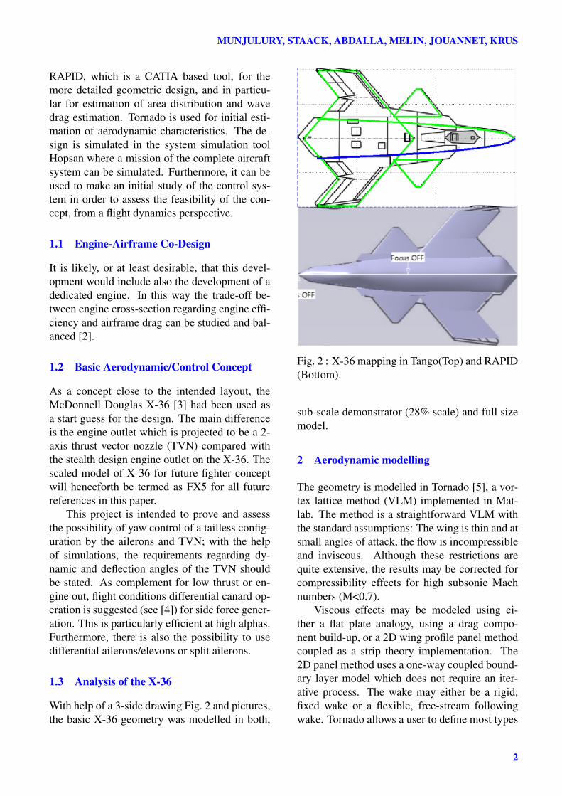
With help of a 3-side drawing Fig. 2 and pictures,the basic X-36 geometry was modelled in both,
Fig. 2 : X-36 mapping in Tango(Top) and RAPID(Bottom).
sub-scale demonstrator (28% scale) and full sizemodel.
2 Aerodynamic modelling
The geometry is modelled in Tornado [5], a vor-tex lattice method (VLM) implemented in Mat-lab. The method is a straightforward VLM withthe standard assumptions: The wing is thin and atsmall angles of attack, the flow is incompressibleand inviscous. Although these restrictions arequite extensive, the results may be corrected forcompressibility effects for high subsonic Machnumbers (M<0.7).
Viscous effects may be modeled using ei-ther a flat plate analogy, using a drag compo-nent build-up, or a 2D wing profile panel methodcoupled as a strip theory implementation. The2D panel method uses a one-way coupled bound-ary layer model which does not require an iter-ative process. The wake may either be a rigid,fixed wake or a flexible, free-stream followingwake. Tornado allows a user to define most types
2
KNOWLEDGE-BASED DESIGN FOR FUTURE COMBAT AIRCRAFT CONCEPTS
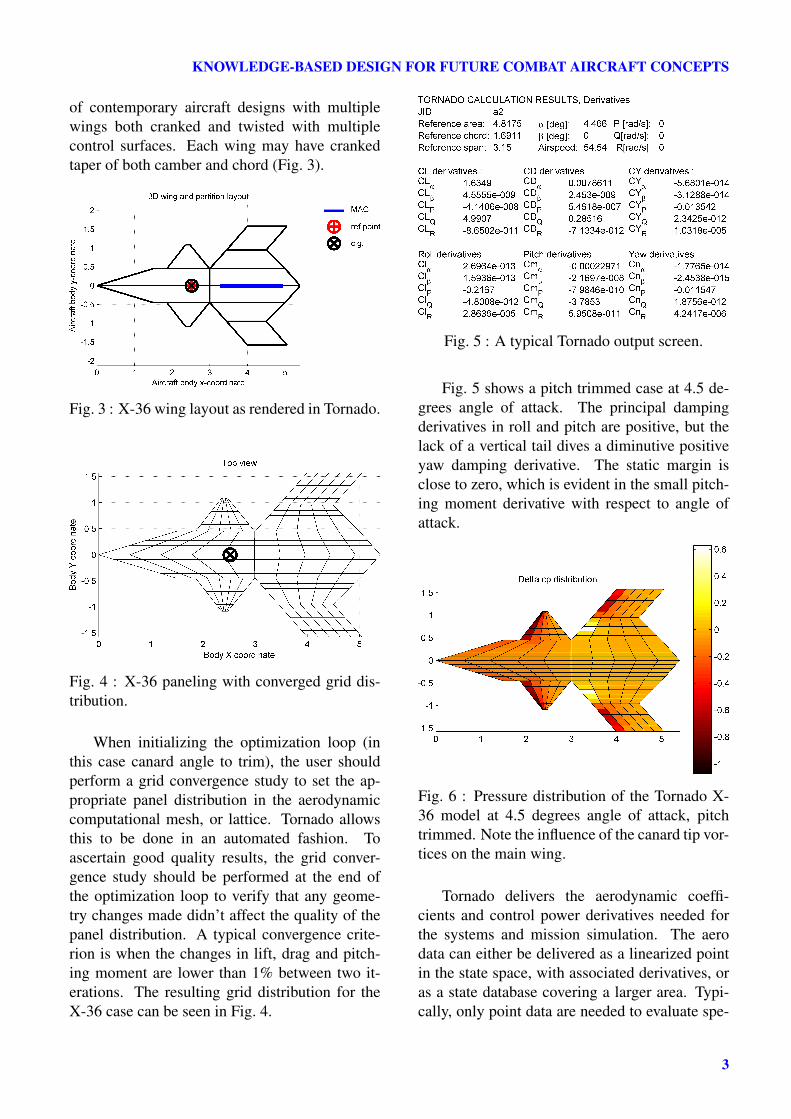
of contemporary aircraft designs with multiplewings both cranked and twisted with multiplecontrol surfaces. Each wing may have crankedtaper of both camber and chord (Fig. 3).
Fig. 3 : X-36 wing layout as rendered in Tornado.
Fig. 4 : X-36 paneling with converged grid dis-tribution.
When initializing the optimization loop (inthis case canard angle to trim), the user shouldperform a grid convergence study to set the ap-propriate panel distribution in the aerodynamiccomputational mesh, or lattice. Tornado allowsthis to be done in an automated fashion. Toascertain good quality results, the grid conver-gence study should be performed at the end ofthe optimization loop to verify that any geome-try changes made didn’t affect the quality of thepanel distribution. A typical convergence crite-rion is when the changes in lift, drag and pitch-ing moment are lower than 1% between two it-erations. The resulting grid distribution for theX-36 case can be seen in Fig. 4.
Fig. 5 : A typical Tornado output screen.
Fig. 5 shows a pitch trimmed case at 4.5 de-grees angle of attack. The principal dampingderivatives in roll and pitch are positive, but thelack of a vertical tail dives a diminutive positiveyaw damping derivative. The static margin isclose to zero, which is evident in the small pitch-ing moment derivative with respect to angle ofattack.
Fig. 6 : Pressure distribution of the Tornado X-36 model at 4.5 degrees angle of attack, pitchtrimmed. Note the influence of the canard tip vor-tices on the main wing.
Tornado delivers the aerodynamic coeffi-cients and control power derivatives needed forthe systems and mission simulation. The aerodata can either be delivered as a linearized pointin the state space, with associated derivatives, oras a state database covering a larger area. Typi-cally, only point data are needed to evaluate spe-
3
MUNJULURY, STAACK, ABDALLA, MELIN, JOUANNET, KRUS
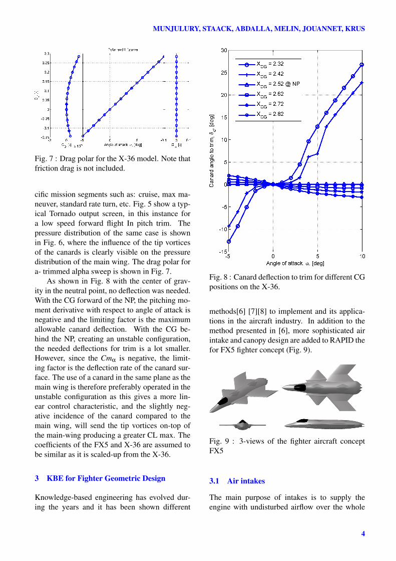
Fig. 7 : Drag polar for the X-36 model. Note thatfriction drag is not included.
cific mission segments such as: cruise, max ma-neuver, standard rate turn, etc. Fig. 5 show a typ-ical Tornado output screen, in this instance fora low speed forward flight In pitch trim. Thepressure distribution of the same case is shownin Fig. 6, where the influence of the tip vorticesof the canards is clearly visible on the pressuredistribution of the main wing. The drag polar fora- trimmed alpha sweep is shown in Fig. 7.
As shown in Fig. 8 with the center of grav-ity in the neutral point, no deflection was needed.With the CG forward of the NP, the pitching mo-ment derivative with respect to angle of attack isnegative and the limiting factor is the maximumallowable canard deflection. With the CG be-hind the NP, creating an unstable configuration,the needed deflections for trim is a lot smaller.However, since the Cmα is negative, the limit-ing factor is the deflection rate of the canard sur-face. The use of a canard in the same plane as themain wing is therefore preferably operated in theunstable configuration as this gives a more lin-ear control characteristic, and the slightly neg-ative incidence of the canard compared to themain wing, will send the tip vortices on-top ofthe main-wing producing a greater CL max. Thecoefficients of the FX5 and X-36 are assumed tobe similar as it is scaled-up from the X-36.
3 KBE for Fighter Geometric Design
Knowledge-based engineering has evolved dur-ing the years and it has been shown different
Fig. 8 : Canard deflection to trim for different CGpositions on the X-36.
methods[6] [7][8] to implement and its applica-tions in the aircraft industry. In addition to themethod presented in [6], more sophisticated airintake and canopy design are added to RAPID thefor FX5 fighter concept (Fig. 9).
Fig. 9 : 3-views of the fighter aircraft conceptFX5
3.1 Air intakes
The main purpose of intakes is to supply theengine with undisturbed airflow over the whole
4
KNOWLEDGE-BASED DESIGN FOR FUTURE COMBAT AIRCRAFT CONCEPTS
flight envelope. There are different types of airintakes to study during the design process. Inthis case, the ramp inlet considered for concep-tual design and eventually designed in RAPID.Capture area calculations implemented using theempirical equations [9] [10]. A S-duct is de-signed around the F110-132 engine and the fuse-lage tweaked around to obtain a stealth fighter forthe future. Required number of sections neededcan be chosen and the cross-section (similar tothe fuselage cross-section [11]) can be modifiedafter the instantiation, depending on the neces-sity.
3.2 Canopy Design
Two canopy designs can be designed in RAPID,Conventional and Blended canopy (Fig. 10). Thecanopy is designed by placing the pilot eye posi-tion and checked for minimum visibility criteria[12]. A mock-up of the pilot is used for the er-gonomic study (Fig. 11) which further helps inthe design of the cockpit.
Fig. 10 : Left: Conventional canopy for a twinseat fighter. Right: Fuselage Blended canopy fora single seat fighter.
Fig. 11 : Left: Areas of good and poor accessibil-ity in color code [12] and the arm positions colorcoded in RAPID[13]
4 Drag Prediction
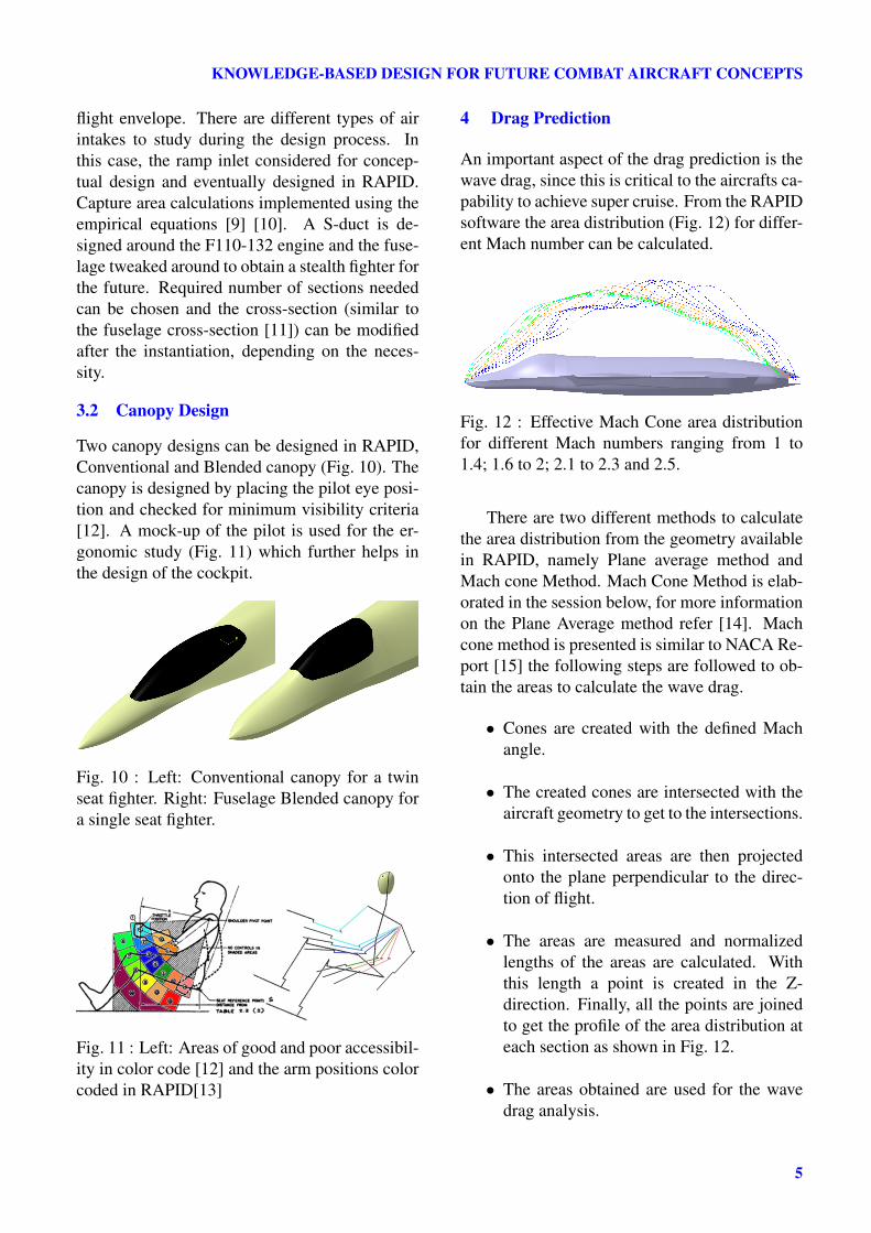
An important aspect of the drag prediction is thewave drag, since this is critical to the aircrafts ca-pability to achieve super cruise. From the RAPIDsoftware the area distribution (Fig. 12) for differ-ent Mach number can be calculated.
Fig. 12 : Effective Mach Cone area distributionfor different Mach numbers ranging from 1 to1.4; 1.6 to 2; 2.1 to 2.3 and 2.5.
There are two different methods to calculatethe area distribution from the geometry availablein RAPID, namely Plane average method andMach cone Method. Mach Cone Method is elab-orated in the session below, for more informationon the Plane Average method refer [14]. Machcone method is presented is similar to NACA Re-port [15] the following steps are followed to ob-tain the areas to calculate the wave drag.
• Cones are created with the defined Machangle.
• The created cones are intersected with theaircraft geometry to get to the intersections.
• This intersected areas are then projectedonto the plane perpendicular to the direc-tion of flight.
• The areas are measured and normalizedlengths of the areas are calculated. Withthis length a point is created in the Z-direction. Finally, all the points are joinedto get the profile of the area distribution ateach section as shown in Fig. 12.
• The areas obtained are used for the wavedrag analysis.
5
MUNJULURY, STAACK, ABDALLA, MELIN, JOUANNET, KRUS
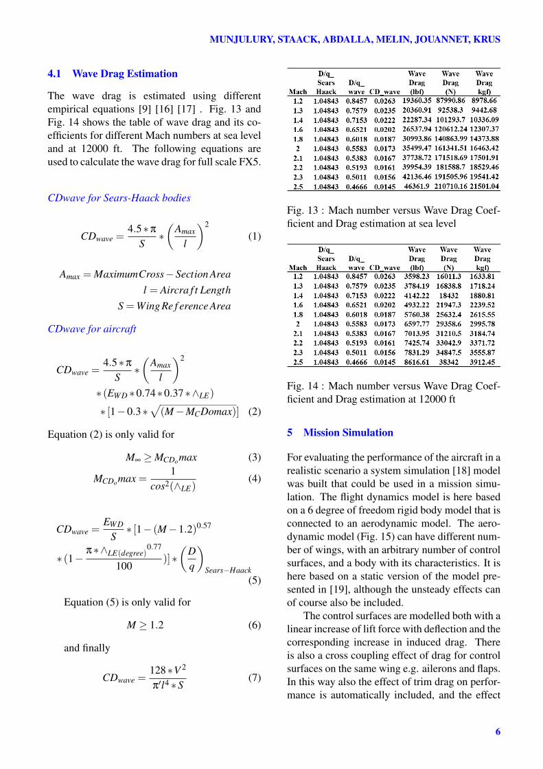
4.1 Wave Drag Estimation
The wave drag is estimated using differentempirical equations [9] [16] [17] . Fig. 13 andFig. 14 shows the table of wave drag and its co-efficients for different Mach numbers at sea leveland at 12000 ft. The following equations areused to calculate the wave drag for full scale FX5.
CDwave for Sears-Haack bodies
CDwave =4.5∗π
S∗(
Amax
l
)2
(1)
Amax = MaximumCross−Section Areal = Aircra f t Length
S =Wing Re f erence Area
CDwave for aircraft
CDwave =4.5∗π
S∗(
Amax
l
)2
∗ (EWD ∗0.74∗0.37∗∧LE)
∗ [1−0.3∗√(M−MCDomax)] (2)
Equation (2) is only valid for
M∞ ≥MCDomax (3)
MCDomax =1
cos2(∧LE)(4)
CDwave =EWD
S∗ [1− (M−1.2)0.57
∗ (1−π∗∧LE(degree)
0.77
100)]∗(
Dq
)Sears−Haack
(5)
Equation (5) is only valid for
M ≥ 1.2 (6)
and finally
CDwave =128∗V 2
π′l4 ∗S(7)
Fig. 13 : Mach number versus Wave Drag Coef-ficient and Drag estimation at sea level
Fig. 14 : Mach number versus Wave Drag Coef-ficient and Drag estimation at 12000 ft
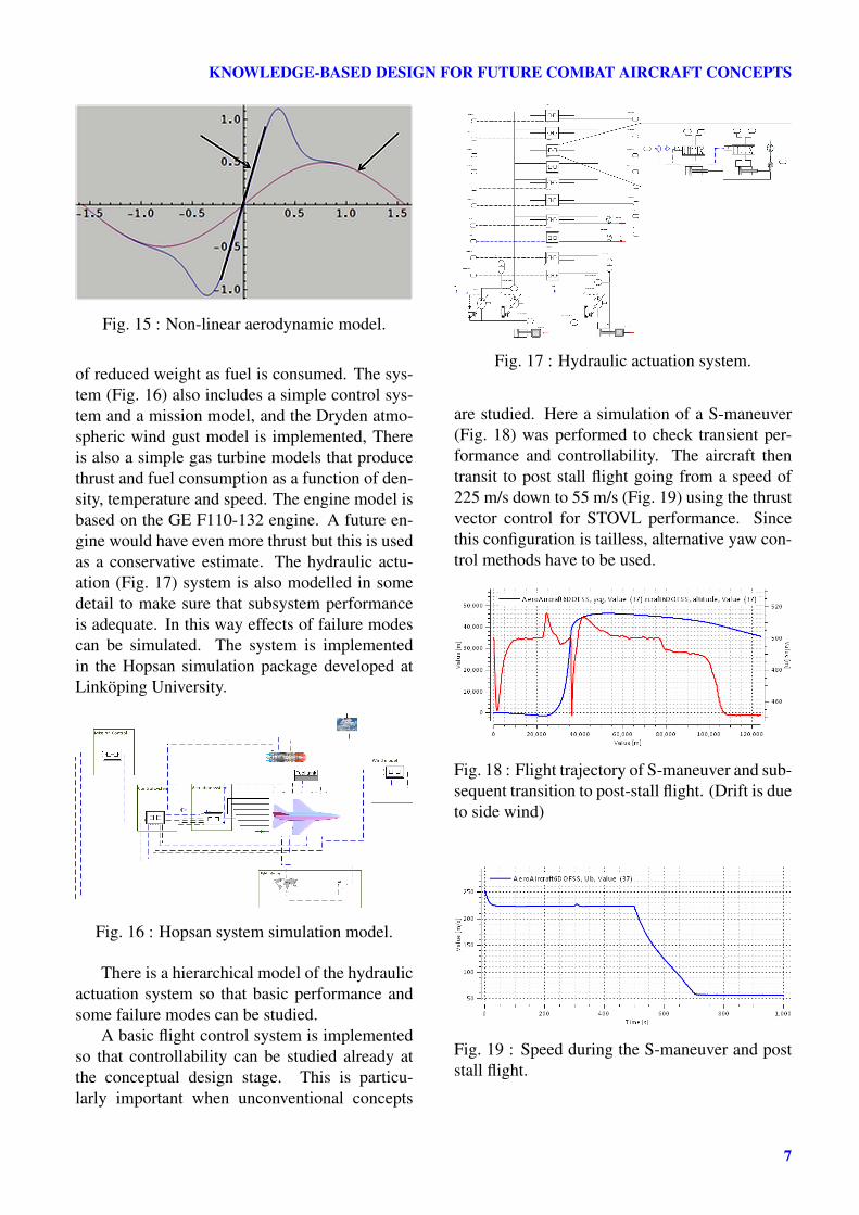
5 Mission Simulation
For evaluating the performance of the aircraft in arealistic scenario a system simulation [18] modelwas built that could be used in a mission simu-lation. The flight dynamics model is here basedon a 6 degree of freedom rigid body model that isconnected to an aerodynamic model. The aero-dynamic model (Fig. 15) can have different num-ber of wings, with an arbitrary number of controlsurfaces, and a body with its characteristics. It ishere based on a static version of the model pre-sented in [19], although the unsteady effects canof course also be included.
The control surfaces are modelled both with alinear increase of lift force with deflection and thecorresponding increase in induced drag. Thereis also a cross coupling effect of drag for controlsurfaces on the same wing e.g. ailerons and flaps.In this way also the effect of trim drag on perfor-mance is automatically included, and the effect
6
KNOWLEDGE-BASED DESIGN FOR FUTURE COMBAT AIRCRAFT CONCEPTS
Fig. 15 : Non-linear aerodynamic model.
of reduced weight as fuel is consumed. The sys-tem (Fig. 16) also includes a simple control sys-tem and a mission model, and the Dryden atmo-spheric wind gust model is implemented, Thereis also a simple gas turbine models that producethrust and fuel consumption as a function of den-sity, temperature and speed. The engine model isbased on the GE F110-132 engine. A future en-gine would have even more thrust but this is usedas a conservative estimate. The hydraulic actu-ation (Fig. 17) system is also modelled in somedetail to make sure that subsystem performanceis adequate. In this way effects of failure modescan be simulated. The system is implementedin the Hopsan simulation package developed atLinköping University.
Fig. 16 : Hopsan system simulation model.
There is a hierarchical model of the hydraulicactuation system so that basic performance andsome failure modes can be studied.
A basic flight control system is implementedso that controllability can be studied already atthe conceptual design stage. This is particu-larly important when unconventional concepts
Fig. 17 : Hydraulic actuation system.
are studied. Here a simulation of a S-maneuver(Fig. 18) was performed to check transient per-formance and controllability. The aircraft thentransit to post stall flight going from a speed of225 m/s down to 55 m/s (Fig. 19) using the thrustvector control for STOVL performance. Sincethis configuration is tailless, alternative yaw con-trol methods have to be used.
Fig. 18 : Flight trajectory of S-maneuver and sub-sequent transition to post-stall flight. (Drift is dueto side wind)
Fig. 19 : Speed during the S-maneuver and poststall flight.
7
MUNJULURY, STAACK, ABDALLA, MELIN, JOUANNET, KRUS
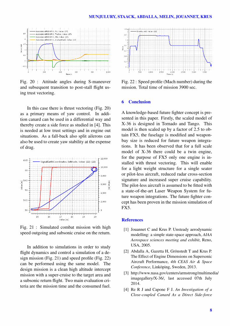
Fig. 20 : Attitude angles during S-maneuverand subsequent transition to post-stall flight us-ing trust vectoring.
In this case there is thrust vectoring (Fig. 20)as a primary means of yaw control. In addi-tion canard can be used in a differential way andthereby create a side force as studied in [4]. Thisis needed at low trust settings and in engine outsituations. As a fall-back also split ailerons canalso be used to create yaw stability at the expenseof drag.
Fig. 21 : Simulated combat mission with highspeed outgoing and subsonic cruise on the return.
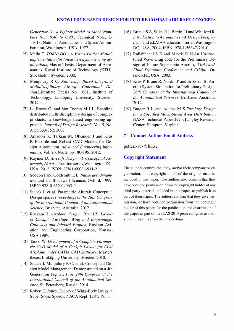
In addition to simulations in order to studyflight dynamics and control a simulation of a de-sign mission (Fig. 21) and speed profile (Fig. 22)can be performed using the same model. Thedesign mission is a clean high altitude interceptmission with a super-cruise to the target area anda subsonic return flight. Two main evaluation cri-teria are the mission time and the consumed fuel.
Fig. 22 : Speed profile (Mach number) during themission. Total time of mission 3900 sec.
6 Conclusion
A knowledge-based future fighter concept is pre-sented in this paper. Firstly, the scaled model ofX-36 is designed in Tornado and Tango. Thismodel is then scaled up by a factor of 2.5 to ob-tain FX5, the fuselage is modified and weapon-bay size is reduced for future weapon integra-tions. It has been observed that for a full scalemodel of X-36 there could be a twin engine,for the purpose of FX5 only one engine is in-stalled with thrust vectoring. This will enablefor a light weight structure for a single seateror pilot-less aircraft, reduced radar cross-sectionsignature and increased super cruise capability.The pilot-less aircraft is assumed to be fitted witha state-of-the-art Laser Weapon System for fu-ture weapon integrations. The future fighter con-cept has been proven in the mission simulation ofFX5.
References
[1] Jouannet C and Krus P. Unsteady aerodynamicmodelling: a simple state-space approach, AIAAAerospace sciences meeting and exhibit, Reno,USA, 2005.
[2] Abdalla A, Gazetta H, Grönstedt T and Krus P.The Effect of Engine Dimensions on SupersonicAircraft Performance, 4th CEAS Air & SpaceConference, Linköping, Sweden, 2013.
[3] http://www.nasa.gov/centers/armstrong/multimedia/imagegallery/X-36/, last accessed 07th July2014.
[4] Re R J and Capone F J. An Investigation of aClose-coupled Canard As a Direct Side-force
8
KNOWLEDGE-BASED DESIGN FOR FUTURE COMBAT AIRCRAFT CONCEPTS
Generator On a Fighter Model At Mach Num-bers from 0.40 to 0.90., Technical Note, L-11613, National Aeronautics and Space Admin-istration, Washington, USA, 1977.
[5] Melin T. TORNADO - A Vortex-Lattice Matlabimplementation for linear aerodynamic wing ap-plications, Master Thesis, Department of Aero-nautics, Royal Institute of Technology (KTH),Stockholm, Sweden, 2000.
[6] Munjulury R C. Knowledge Based IntegratedMultidisciplinary Aircraft Conceptual De-sign,Licentiate Thesis No. 1661, Institute ofTechnology, Linköping University, Sweden,2014
[7] La Rocca G. and Van Tooren M J L. Enablingdistributed multi-disciplinary design of complexproducts: a knowledge based engineering ap-proach. Journal of Design Research, Vol. 5, No.3, pp 333-352, 2007.
[8] Amadori K, Tarkian M, Ölvander J and KrusP. Flexible and Robust CAD Models for De-sign Automation. Advanced Engineering Infor-matics, Vol. 26, No. 2, pp 180-195, 2012.
[9] Raymer D. Aircraft design - A Conceptual Ap-proach, AIAA education series,Washington DC,USA, 2012, ISBN: 978-1-60086-911-2.
[10] Seddon J and Goldsmith E L. Intake aerodynam-ics, 2nd ed, Blackwell Science, Oxford, 1999,ISBN: 978-0-632-04963-9.
[11] Staack I, et al. Parametric Aircraft ConceptualDesign space, Proceedings of the 28th Congressof the International Council of the AeronauticalScience, Brisbane, Australia, 2012
[12] Roskam J. Airplane design, Part III: Layoutof Cockpit, Fuselage, Wing and Empennage:Cutaways and Inboard Profiles, Roskam Avi-ation and Engineering Corporation, Kansas,USA,1989.
[13] Tassel W. Development of a Complete Paramet-ric CAD Model of a Cockpit Layout for CivilAirplane under CATIA CAD Software, Mastersthesis, Linköping University, Sweden, 2010.
[14] Staack I, Munjulury R C, et al. Conceptual De-sign Model Management Demonstrated on a 4thGeneration Fighter, Proc 29th Congress of theInternational Council of the Aeronautical Sci-ence, St. Petersberg, Russia, 2014.
[15] Robert T. Jones, Theory of Wing-Body Drags atSuper Sonic Speeds. NACA Rept. 1284, 1953.
[16] Brandt S A, Stiles R J, Bertin J J and Whitford R.Introduction to Aeronautics - A Design Perspec-tive , 2nd ed,AIAA education series,WashingtonDC, USA, 2004, ISBN: 978-1-56347-701-0.
[17] Rallabhandi S K and Mavris D N.An Unstruc-tured Wave Drag code for the Preliminary De-sign of Future Supersonic Aircraft, 33rd AIAAFluid Dynamics Conference and Exhibit, Or-lando,FL, USA, 2003.
[18] Krus P, Braun R, Nordin P and Eriksson B. Air-craft System Simulation for Preliminary Design,28th Congress of the International Council ofthe Aeronautical Sciences, Brisbane, Australia,2012.
[19] Barger R L and Adams M S.Fuselage Designfor a Specified Mach-Sliced Area Distribution,NASA Technical Paper 2975, Langley ResearchCenter, Hampton, Virginia.
7 Contact Author Email Address
Copyright Statement
The authors confirm that they, and/or their company or or-ganization, hold copyright on all of the original materialincluded in this paper. The authors also confirm that theyhave obtained permission, from the copyright holder of anythird party material included in this paper, to publish it aspart of their paper. The authors confirm that they give per-mission, or have obtained permission from the copyrightholder of this paper, for the publication and distribution ofthis paper as part of the ICAS 2014 proceedings or as indi-vidual off-prints from the proceedings.
9